WO2020196026A1 - Imaging control device, imaging control method, program, and imaging system - Google Patents
Imaging control device, imaging control method, program, and imaging system Download PDFInfo
- Publication number
- WO2020196026A1 WO2020196026A1 PCT/JP2020/011447 JP2020011447W WO2020196026A1 WO 2020196026 A1 WO2020196026 A1 WO 2020196026A1 JP 2020011447 W JP2020011447 W JP 2020011447W WO 2020196026 A1 WO2020196026 A1 WO 2020196026A1
- Authority
- WO
- WIPO (PCT)
- Prior art keywords
- optical member
- point
- rotation
- axis
- rotation axis
- Prior art date
Links
- 0 CCI(C[C@@](C)I)II1*CCC1 Chemical compound CCI(C[C@@](C)I)II1*CCC1 0.000 description 1
Images


Classifications
-
- A—HUMAN NECESSITIES
- A61—MEDICAL OR VETERINARY SCIENCE; HYGIENE
- A61B—DIAGNOSIS; SURGERY; IDENTIFICATION
- A61B1/00—Instruments for performing medical examinations of the interior of cavities or tubes of the body by visual or photographical inspection, e.g. endoscopes; Illuminating arrangements therefor
- A61B1/00147—Holding or positioning arrangements
-
- A—HUMAN NECESSITIES
- A61—MEDICAL OR VETERINARY SCIENCE; HYGIENE
- A61B—DIAGNOSIS; SURGERY; IDENTIFICATION
- A61B1/00—Instruments for performing medical examinations of the interior of cavities or tubes of the body by visual or photographical inspection, e.g. endoscopes; Illuminating arrangements therefor
- A61B1/00163—Optical arrangements
- A61B1/00174—Optical arrangements characterised by the viewing angles
- A61B1/00179—Optical arrangements characterised by the viewing angles for off-axis viewing
-
- A—HUMAN NECESSITIES
- A61—MEDICAL OR VETERINARY SCIENCE; HYGIENE
- A61B—DIAGNOSIS; SURGERY; IDENTIFICATION
- A61B1/00—Instruments for performing medical examinations of the interior of cavities or tubes of the body by visual or photographical inspection, e.g. endoscopes; Illuminating arrangements therefor
- A61B1/00002—Operational features of endoscopes
- A61B1/00004—Operational features of endoscopes characterised by electronic signal processing
- A61B1/00006—Operational features of endoscopes characterised by electronic signal processing of control signals
-
- A—HUMAN NECESSITIES
- A61—MEDICAL OR VETERINARY SCIENCE; HYGIENE
- A61B—DIAGNOSIS; SURGERY; IDENTIFICATION
- A61B1/00—Instruments for performing medical examinations of the interior of cavities or tubes of the body by visual or photographical inspection, e.g. endoscopes; Illuminating arrangements therefor
- A61B1/00002—Operational features of endoscopes
- A61B1/00004—Operational features of endoscopes characterised by electronic signal processing
- A61B1/00009—Operational features of endoscopes characterised by electronic signal processing of image signals during a use of endoscope
-
- A—HUMAN NECESSITIES
- A61—MEDICAL OR VETERINARY SCIENCE; HYGIENE
- A61B—DIAGNOSIS; SURGERY; IDENTIFICATION
- A61B1/00—Instruments for performing medical examinations of the interior of cavities or tubes of the body by visual or photographical inspection, e.g. endoscopes; Illuminating arrangements therefor
- A61B1/00147—Holding or positioning arrangements
- A61B1/00149—Holding or positioning arrangements using articulated arms
-
- A—HUMAN NECESSITIES
- A61—MEDICAL OR VETERINARY SCIENCE; HYGIENE
- A61B—DIAGNOSIS; SURGERY; IDENTIFICATION
- A61B1/00—Instruments for performing medical examinations of the interior of cavities or tubes of the body by visual or photographical inspection, e.g. endoscopes; Illuminating arrangements therefor
- A61B1/005—Flexible endoscopes
-
- A—HUMAN NECESSITIES
- A61—MEDICAL OR VETERINARY SCIENCE; HYGIENE
- A61B—DIAGNOSIS; SURGERY; IDENTIFICATION
- A61B1/00—Instruments for performing medical examinations of the interior of cavities or tubes of the body by visual or photographical inspection, e.g. endoscopes; Illuminating arrangements therefor
- A61B1/04—Instruments for performing medical examinations of the interior of cavities or tubes of the body by visual or photographical inspection, e.g. endoscopes; Illuminating arrangements therefor combined with photographic or television appliances
- A61B1/045—Control thereof
-
- A—HUMAN NECESSITIES
- A61—MEDICAL OR VETERINARY SCIENCE; HYGIENE
- A61B—DIAGNOSIS; SURGERY; IDENTIFICATION
- A61B1/00—Instruments for performing medical examinations of the interior of cavities or tubes of the body by visual or photographical inspection, e.g. endoscopes; Illuminating arrangements therefor
- A61B1/04—Instruments for performing medical examinations of the interior of cavities or tubes of the body by visual or photographical inspection, e.g. endoscopes; Illuminating arrangements therefor combined with photographic or television appliances
- A61B1/05—Instruments for performing medical examinations of the interior of cavities or tubes of the body by visual or photographical inspection, e.g. endoscopes; Illuminating arrangements therefor combined with photographic or television appliances characterised by the image sensor, e.g. camera, being in the distal end portion
-
- A—HUMAN NECESSITIES
- A61—MEDICAL OR VETERINARY SCIENCE; HYGIENE
- A61B—DIAGNOSIS; SURGERY; IDENTIFICATION
- A61B34/00—Computer-aided surgery; Manipulators or robots specially adapted for use in surgery
- A61B34/30—Surgical robots
-
- A—HUMAN NECESSITIES
- A61—MEDICAL OR VETERINARY SCIENCE; HYGIENE
- A61B—DIAGNOSIS; SURGERY; IDENTIFICATION
- A61B90/00—Instruments, implements or accessories specially adapted for surgery or diagnosis and not covered by any of the groups A61B1/00 - A61B50/00, e.g. for luxation treatment or for protecting wound edges
- A61B90/36—Image-producing devices or illumination devices not otherwise provided for
- A61B90/37—Surgical systems with images on a monitor during operation
-
- G—PHYSICS
- G03—PHOTOGRAPHY; CINEMATOGRAPHY; ANALOGOUS TECHNIQUES USING WAVES OTHER THAN OPTICAL WAVES; ELECTROGRAPHY; HOLOGRAPHY
- G03B—APPARATUS OR ARRANGEMENTS FOR TAKING PHOTOGRAPHS OR FOR PROJECTING OR VIEWING THEM; APPARATUS OR ARRANGEMENTS EMPLOYING ANALOGOUS TECHNIQUES USING WAVES OTHER THAN OPTICAL WAVES; ACCESSORIES THEREFOR
- G03B17/00—Details of cameras or camera bodies; Accessories therefor
- G03B17/56—Accessories
- G03B17/561—Support related camera accessories
-
- G—PHYSICS
- G03—PHOTOGRAPHY; CINEMATOGRAPHY; ANALOGOUS TECHNIQUES USING WAVES OTHER THAN OPTICAL WAVES; ELECTROGRAPHY; HOLOGRAPHY
- G03B—APPARATUS OR ARRANGEMENTS FOR TAKING PHOTOGRAPHS OR FOR PROJECTING OR VIEWING THEM; APPARATUS OR ARRANGEMENTS EMPLOYING ANALOGOUS TECHNIQUES USING WAVES OTHER THAN OPTICAL WAVES; ACCESSORIES THEREFOR
- G03B37/00—Panoramic or wide-screen photography; Photographing extended surfaces, e.g. for surveying; Photographing internal surfaces, e.g. of pipe
- G03B37/005—Photographing internal surfaces, e.g. of pipe
-
- A—HUMAN NECESSITIES
- A61—MEDICAL OR VETERINARY SCIENCE; HYGIENE
- A61B—DIAGNOSIS; SURGERY; IDENTIFICATION
- A61B34/00—Computer-aided surgery; Manipulators or robots specially adapted for use in surgery
- A61B34/20—Surgical navigation systems; Devices for tracking or guiding surgical instruments, e.g. for frameless stereotaxis
- A61B2034/2046—Tracking techniques
- A61B2034/2065—Tracking using image or pattern recognition
-
- A—HUMAN NECESSITIES
- A61—MEDICAL OR VETERINARY SCIENCE; HYGIENE
- A61B—DIAGNOSIS; SURGERY; IDENTIFICATION
- A61B34/00—Computer-aided surgery; Manipulators or robots specially adapted for use in surgery
- A61B34/30—Surgical robots
- A61B2034/301—Surgical robots for introducing or steering flexible instruments inserted into the body, e.g. catheters or endoscopes
-
- A—HUMAN NECESSITIES
- A61—MEDICAL OR VETERINARY SCIENCE; HYGIENE
- A61B—DIAGNOSIS; SURGERY; IDENTIFICATION
- A61B90/00—Instruments, implements or accessories specially adapted for surgery or diagnosis and not covered by any of the groups A61B1/00 - A61B50/00, e.g. for luxation treatment or for protecting wound edges
- A61B90/36—Image-producing devices or illumination devices not otherwise provided for
- A61B90/37—Surgical systems with images on a monitor during operation
- A61B2090/371—Surgical systems with images on a monitor during operation with simultaneous use of two cameras
Definitions
- the present technology relates to an imaging control device, an imaging control method, a program, and an imaging system, and is particularly suitable for imaging control when imaging is performed using an optical member whose observation optical axis is tilted with respect to the central axis. It relates to an apparatus, a shooting control method, a program, and a shooting system.
- a squint mirror capable of photographing an angle inclined with respect to the central axis has been used for an insertion part of an endoscope system into a living body.
- the subject can be photographed from a different angle by rotating the squint mirror and changing the direction of the observation window at the tip of the squint mirror.
- the area of interest moves to the edge of the image or goes out of the angle of view, and the area of interest to the user. You may lose sight of it. Therefore, when rotating the perspective mirror, the user needs to carefully adjust the angle of the perspective mirror and the like while checking the image so as not to lose sight of the region of interest.
- Patent Document 1 a method of rotating the insertion portion so that the observation optical axis of the insertion portion draws a conical trajectory with a point on the affected part of the patient as the apex has been proposed (for example, Patent Document 1). reference).
- This technology was made in view of such a situation, and when shooting with an optical member whose observation optical axis is tilted with respect to the central axis, the direction in which the subject is shot can be easily changed. It allows you to do it.
- the imaging control device on the first side surface of the present technology serves as a fulcrum of a rod-shaped optical member whose observation optical axis is tilted with respect to the central axis, and is a pivot point that is not on the observation optical axis and a point of interest on the subject.
- a rotation axis setting unit for setting the rotation axis and an attitude control unit for rotating the optical member around the rotation axis are provided based on the above.
- the imaging control device serves as a fulcrum of a rod-shaped optical member whose observation optical axis is tilted with respect to the central axis, and a pivot point that is not on the observation optical axis, and A rotation axis is set based on a point of interest on the subject, and the optical member is rotated about the rotation axis.
- the program of the first aspect of the present technology serves as a fulcrum of a rod-shaped optical member whose observation optical axis is tilted with respect to the central axis, and is based on a pivot point that is not on the observation optical axis and a point of interest on the subject. Then, the rotation axis is set, and the computer is made to execute the process of rotating the optical member around the rotation axis.
- the imaging system on the second side of the present technology includes an imaging unit including a rod-shaped optical member whose observation optical axis is tilted with respect to the central axis, and a pivot point that serves as a fulcrum of the optical member and is not on the observation optical axis.
- a rotation axis setting unit that sets a rotation axis based on a point of interest on the subject, and an attitude control unit that rotates the optical member around the rotation axis are provided.
- the observation optical axis serves as a fulcrum of a rod-shaped optical member tilted with respect to the central axis, and is based on a pivot point that is not on the observation optical axis and a point of interest on the subject.
- the rotation axis is set, and the optical member is rotated around the rotation axis.
- a pivot point that serves as a fulcrum of the optical member of the photographing unit including a rod-shaped optical member whose observation optical axis is tilted with respect to the central axis, and a pivot point that is not on the observation optical axis, and A rotation axis is set based on a point of interest on the subject, and the optical member is rotated about the rotation axis.
- FIG. 1 shows a configuration example of a photographing system 11 to which the present technology is applied.
- the imaging system 11 is, for example, an endoscope system used in the medical field, and is used for imaging and observation in a living body.
- the photographing system 11 includes an input unit 21, a photographing control unit 22, an imaging unit 23, an image processing unit 24, a display unit 25, and an arm mechanism 26.
- the input unit 21 includes operation devices such as buttons, switches, and a touch panel, and accepts operations by the user.
- the input unit 21 supplies the input signal input by the user operation to the photographing control unit 22.
- the shooting control unit 22 controls the shooting of the subject by the shooting unit 23.
- the shooting control unit 22 includes a shooting processing control unit 31 and a shooting posture control unit 32.
- the shooting processing control unit 31 controls the shooting processing (for example, shooting timing, etc.) of the shooting unit 23 based on the input signal supplied from the input unit 21 and the shot image supplied from the shooting unit 23, and , Set various shooting parameters.
- the shooting posture control unit 32 controls the shooting unit 23 and the arm mechanism 26 based on the input signal supplied from the input unit 21, the shooting image supplied from the shooting unit 23, and the like, thereby causing the shooting unit 23 to control the shooting unit 23.
- the posture (hereinafter referred to as a shooting posture) is controlled.
- the position hereinafter referred to as a shooting position
- the direction hereinafter referred to as a shooting direction
- the photographing unit 23 photographs the subject under the control of the photographing control unit 22.
- the photographing unit 23 supplies an image obtained by photographing (hereinafter, referred to as a photographed image) to the photographing control unit 22 and the image processing unit 24.
- the image processing unit 24 performs various image processing on the captured image, and supplies the captured image after the image processing to the display unit 25.
- the display unit 25 includes, for example, a display or the like.
- the display unit 25 displays an image based on the captured image.
- the image displayed on the display unit 25 is used, for example, as a monitor image for a doctor or the like to confirm the surgical field or the like.
- the arm mechanism 26 is composed of, for example, a robot arm.
- the arm mechanism 26 supports the photographing unit 23 and changes the posture of the photographing unit 23 by moving the photographing unit 23 under the control of the photographing control unit 22.
- FIG. 2 schematically shows a configuration example of the photographing unit 23 of FIG.
- the photographing unit 23 includes a camera 51, a rotary actuator 52, an insertion unit 53, and an observation window 54a and an observation window 54b.
- the camera 51 and the insertion portion 53 are connected via a rotary actuator 52.
- the observation window 54a and the observation window 54b are provided on the tip surface 53A of the insertion portion 53, as shown in the enlarged view.
- the camera 51 is composed of, for example, an imaging device including an image sensor such as CMOS (Complementary MOS).
- the camera 51 shoots the subject using the light from the subject incident through the insertion unit 53 (hereinafter referred to as subject light), and the obtained shot image is sent to the shooting control unit 22 and the image processing unit 24. Supply.
- the camera 51 is provided with, for example, two image pickup elements (not shown) and can perform stereo imaging.
- the rotary actuator 52 rotates the camera 51 with respect to the insertion portion 53 about the optical axis of the camera 51 (hereinafter, referred to as a photographing optical axis). That is, the camera 51 is provided at one end of the insertion portion 53 so as to be rotatable around the photographing optical axis via the rotary actuator 52. As the camera 51 rotates about the shooting optical axis, the coordinate system of the camera 51 (hereinafter referred to as the camera coordinate system) rotates about the shooting optical axis.
- the x-axis of the camera coordinate system will be the lateral direction of the camera 51
- the y-axis will be the height direction of the camera 51
- the z-axis will be the direction of the shooting optical axis.
- the insertion portion 53 includes an optical system such as a lens and a mirror, and is a rod-shaped and tubular optical member that is inserted into the living body.
- the rod-shaped optical member includes a curved optical member and a linear optical member.
- the insertion portion 53 is composed of a perspective mirror made of a rigid mirror.
- the insertion portion 53 is connected to the camera 51 via the rotary actuator 52 so that the central axis coincides with the photographing optical axis of the camera 51.
- the tip surface 53A of the insertion portion 53 is inclined with respect to the central axis of the insertion portion 53.
- An observation window 54a and an observation window 54b made of a lens are provided on the tip surface 53A of the insertion portion 53, respectively.
- the observation window 54a and the observation window 54b are arranged side by side at the same height in the inclination direction of the tip surface 53A.
- the subject light incident on the insertion unit 53 from the observation window 54a and the observation window 54b passes through the insertion unit 53 and is incident on the light receiving surfaces of different image pickup devices of the camera 51.
- the camera 51 uses a captured image based on the subject light incident from the observation window 54a (hereinafter referred to as a left captured image) and a captured image based on the subject light incident from the observation window 54b (hereinafter referred to as a right captured image). ) Are photographed respectively. That is, the camera 51 is capable of stereo shooting.
- the camera 51 supplies the left captured image and the right captured image to the photographing control unit 22 and the image processing unit 24.
- the observation optical axis of the insertion portion 53 which is the optical axis of the observation window 54a and the observation window 54b, is perpendicular to the tip surface 53A and is inclined with respect to the central axis of the insertion portion 53. Therefore, the photographing unit 23 photographs the image in the oblique direction with respect to the central axis of the insertion unit 53 via the insertion unit 53.
- observation window 54 when it is not necessary to distinguish the observation window 54a and the observation window 54b individually, the observation window 54 is simply referred to as the observation window 54.
- the observation window 54 when it is not necessary to distinguish the left photographed image and the right photographed image individually, it is simply referred to as a photographed image.
- FIG. 3 shows an example of a method of inserting the insertion portion 53 into the living body.
- This example shows an example in which the insertion portion 53 is inserted into the abdomen of the patient using the trocca 62. Specifically, the trocca 62 is inserted into the skin 61 of the abdomen. Then, the insertion portion 53 is inserted from the insertion port of the trocca 62, and the tip of the insertion portion 53 protrudes from the tip opening of the trocca 62. As a result, the insertion portion 53 is inserted into the living body, and the position of the insertion portion 53 is stabilized.
- FIG. 4 schematically shows a configuration example of the arm mechanism 26 of FIG.
- the photographing unit 23 is also schematically shown, and the rotary actuator 52 is not shown.
- the photographing unit 23 is basically shown schematically, and the rotary actuator 52 is not shown.
- the arm mechanism 26 includes a base portion 101 and an arm portion 102.
- the arm portion 102 includes links 111-1 to 111-3, and joint portions 112-1 to 112-4.
- One end of the link 111-1 is connected to the base 101 via the joint 112-1, and the other end of the link 111-1 is connected to one end of the link 111-2 via the joint 112-2.
- the other end of the link 111-2 is connected to one end of the link 111-3 via a joint 112-3.
- the other end of the link 111-3 is connected to the camera 51 via the joint portion 112-4.
- the base unit 101 supports, for example, the arm unit 102, and all or part of the imaging control unit 22 of the imaging system 11 is built in to control the movement of the arm unit 102.
- the joint portions 112-1 to 112-4 are independently driven under the control of the imaging control unit 22. As a result, the posture of the arm unit 102 changes, and the photographing unit 23 moves, so that the photographing posture changes.
- link 111 when it is not necessary to individually distinguish the link 111-1 to the link 111-3, it is simply referred to as the link 111. Further, hereinafter, when it is not necessary to individually distinguish the joint portion 112-1 to the joint portion 112-4, it is simply referred to as the joint portion 112.
- FIG. 5 shows a configuration example of the function of the shooting posture control unit 32 of the shooting system 11 of FIG.
- the shooting attitude control unit 32 includes a distance detection unit 151, an observation optical axis detection unit 152, a pivot point setting unit 153, a rotation axis setting unit 154, and an attitude control unit 155.
- the attitude control unit 155 includes a target attitude setting unit 161, a camera attitude control unit 162, and an arm attitude control unit 163.
- the distance detection unit 151 detects the distance to the subject based on the left shot image and the right shot image supplied from the camera 51. For example, the distance detection unit 151 detects the distance between an arbitrary point on the subject (hereinafter referred to as a point of interest) and the observation window 54. The distance detection unit 151 supplies data indicating the detection result to the rotation axis setting unit 154.
- the observation optical axis detection unit 152 is based on data indicating the posture of the arm unit 102 supplied from the arm attitude control unit 163 (hereinafter referred to as arm posture data), and the posture (particularly the observation window 54) of the insertion unit 53 (particularly the observation window 54) Position and orientation) is detected. Further, the observation optical axis detection unit 152 detects the observation optical axis based on the posture of the observation window 54. The observation optical axis detection unit 152 supplies data indicating the detection result to the rotation axis setting unit 154 and the target attitude setting unit 161.
- the pivot point setting unit 153 sets the position of the pivot point based on the left shot image and the right shot image supplied from the camera 51 and the arm posture data supplied from the arm posture control unit 163.
- the pivot point is a point that serves as a fulcrum when the insertion portion 53 is rotated.
- the pivot point setting unit 153 supplies data indicating the position of the pivot point to the rotation axis setting unit 154 and the target posture setting unit 161.
- the rotation axis setting unit 154 sets the rotation axis based on the distance to the point of interest on the subject, the posture of the observation optical axis, and the position of the pivot point.
- This rotation axis is a central axis for rotating the insertion portion 53 when changing the shooting direction of the subject.
- the rotating shaft setting unit 154 supplies data indicating the posture (position and orientation) of the rotating shaft to the target posture setting unit 161.
- the target posture setting unit 161 sets a target shooting posture (hereinafter referred to as a target posture) based on the operation content when the user performs an operation of changing the shooting posture via the input unit 21. Further, the target posture setting unit 161 is based on the posture of the observation window 54, the posture of the observation optical axis, the position of the pivot point, the posture of the rotation axis, and the like, and the posture of the arm unit 102 for realizing the target posture ( The posture of the camera 51 (hereinafter referred to as the target camera posture) and the posture of the camera 51 (hereinafter referred to as the target camera posture) are calculated.
- the target posture setting unit 161 supplies data indicating the target camera posture to the camera posture control unit 162. Further, the target posture setting unit 161 supplies data indicating the target arm posture to the arm posture control unit 163.
- the camera attitude control unit 162 drives the rotary actuator 52 so that the attitude of the camera 51 becomes the target camera attitude.
- the camera attitude control unit 162 detects the attitude of the camera 51 based on the data indicating the rotation angle supplied from the rotary actuator 52.
- the rotation angle of the rotary actuator 52 is detected by using, for example, a potentiometer included in the rotary actuator 52.
- the arm posture control unit 163 has actuators 171-1 to 171-n for driving the joints 112-1 to 112-4 of the arm 102 so that the posture of the arm 102 is the target arm posture. To drive. Further, the arm posture control unit 163 detects the posture of the arm unit 102 based on the data indicating the rotation angle supplied from the actuators 171-1 to 171-n.
- the rotation angles of the actuators 171-1 to 171-n are detected by using, for example, a potentiometer or the like provided in the actuators 171-1 to 171-n, respectively.
- actuator 171-1 to 171-n are simply referred to as the actuator 171.
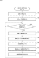
- the shooting direction change process is a process of changing the shooting direction of the subject, particularly a process of changing the shooting direction of the area of interest on the subject.
- This process starts, for example, when the power of the photographing system 11 is turned on, and ends when the power of the photographing system 11 is turned off.
- step S1 the camera 51 starts shooting. Specifically, the camera 51 starts shooting under the control of the shooting control unit 22, and starts supplying the shot image to the shooting control unit 22 and the image processing unit 24.
- step S2 the pivot point setting unit 153 sets the pivot point.
- FIG. 7 an example is shown in which the insertion portion 53 is inserted from the insertion port 202A of the patient's skin 202 and the inside of the patient's body is photographed.
- the user operates the arm unit 102 via the input unit 21 to align the tip of the insertion unit 53 with the vicinity of the center of the insertion port 202A.
- the user presses the button 201 included in the input unit 21.
- the input unit 21 supplies an input signal indicating that the button 201 has been pressed to the shooting attitude control unit 32.
- the arm posture control unit 163 detects the posture of the arm unit 102 in the global coordinate system based on the rotation angle of each actuator 171.
- the global coordinate system is a coordinate system representing the entire three-dimensional space in which the photographing system 11 exists, and is also called a world coordinate system.
- the arm posture control unit 163 supplies the arm posture data indicating the detected posture of the arm unit 102 to the pivot point setting unit 153.
- the pivot point setting unit 153 calculates the position of the tip of the insertion unit 53 in the global coordinate system based on the posture of the arm unit 102. Then, the pivot point setting unit 153 sets the calculated position of the tip of the insertion unit 53 at the pivot point P1. As a result, the pivot point P1 is set substantially at the center of the insertion port 202A.
- the pivot point setting unit 153 supplies data indicating the position of the pivot point P1 in the global coordinate system to the rotation axis setting unit 154 and the target posture setting unit 161.
- the user further inserts the insertion unit 53 into the living body by operating the arm unit 102 via the input unit 21.
- the insertion portion 53 is inserted into the living body through the insertion port 202A.
- the insertion portion 53 is inserted into the living body so that the pivot point P1 is located on the insertion portion 53. Therefore, the pivot point P1 is on the insertion portion 53 and not on the observation optical axis A1.
- step S3 the input unit 21 determines whether or not a rotation operation, that is, an operation of rotating the insertion unit 53 in order to change the shooting direction of the subject has been performed. This determination process is repeated until it is determined that the rotation operation has been performed, and when it is determined that the rotation operation has been performed, the process proceeds to step S4.
- the user specifies an angle and a direction in which the insertion unit 53 is rotated around the rotation axis via the input unit 21 as a rotation operation.
- the angle at which the insertion portion 53 is rotated may be represented by either a relative angle or an absolute angle.
- the angle and direction at which the insertion portion 53 is rotated are specified in a form such as x degrees clockwise or counterclockwise from the current position. ..
- the angle at which the insertion portion 53 is rotated is represented by an absolute angle, for example, the angle at which the insertion portion 53 is rotated is specified in a form such as a direction of x degrees with respect to a predetermined reference position.
- step S4 the observation optical axis detection unit 152 detects the observation optical axis.
- the input unit 21 supplies an input signal indicating the content of the rotation operation to the photographing control unit 22.
- the arm posture control unit 163 detects the posture of the arm unit 102 in the global coordinate system based on the rotation angle of each actuator 171.
- the arm posture control unit 163 supplies the arm posture data indicating the detected posture of the arm unit 102 to the observation optical axis detection unit 152.
- the observation optical axis detection unit 152 calculates the posture of the insertion unit 53 in the global coordinate system, particularly the posture of the observation window 54, based on the posture of the arm unit 102. Further, the observation optical axis detection unit 152 calculates the posture (position and direction) of the observation optical axis in the global coordinate system based on the posture of the observation window 54. The observation optical axis detection unit 152 supplies data indicating the attitudes of the observation window 54 and the observation optical axis to the rotation axis setting unit 154 and the target attitude setting unit 161.
- step S5 the distance detection unit 151 detects the distance to the point of interest.
- the distance detection unit 151 sets a point on the subject corresponding to the center of the captured image as a point of interest.
- the intersection P2 between the observation optical axis A1 and the surface of the subject 203 is set as the point of interest.
- the distance detection unit 151 detects the distance between the observation window 54 and the point of interest based on the left captured image and the right captured image.
- the distance detection unit 151 supplies data indicating the detection result to the rotation axis setting unit 154. For example, in the example of FIG. 8, the distance between the observation window 54 and the point of interest P2 is detected.
- Any method can be adopted as the method for detecting the distance between the observation window 54 and the point of interest.
- step S6 the rotation axis setting unit 154 sets the rotation axis. Specifically, the rotation axis setting unit 154 sets a straight line connecting the pivot point and the point of interest as the rotation axis. For example, in the example of FIG. 8, a straight line connecting the pivot point P1 and the point of interest P2 is set on the rotation axis A2.
- the rotation axis setting unit 154 supplies data indicating the attitude of the rotation axis in the global coordinate system to the target attitude setting unit 161.
- the rotation axis setting unit 154 can calculate the position of the point of interest P2 in the global coordinate system. Also, the position of the pivot point P1 in the global coordinate system is known. Therefore, the rotation axis setting unit 154 can calculate the posture of the rotation axis A2 connecting the pivot point P1 and the attention point P2.
- step S7 the target posture setting unit 161 sets the target posture of the photographing unit 23.
- the target posture setting unit 161 sets the direction and amount (rotation angle) of rotating the insertion unit 53 around the rotation axis based on the content of the rotation operation.
- the camera 51 (camera coordinate system) also rotates.
- the subject 203 may rotate significantly in the captured image before and after the rotation of the insertion portion 53, and the visibility may decrease.
- the target posture setting unit 161 has substantially the same x-axis and y-axis directions of the camera coordinate system in the global coordinate system before and after the rotation of the insertion unit 53.
- the direction and amount (rotation angle) of rotating the camera 51 around the shooting optical axis (z-axis) are calculated so as to be.
- the rotation direction of the camera 51 around the photographing optical axis is opposite to the rotation direction of the insertion portion 53 around the rotation axis A2. For example, when the rotation direction of the insertion portion 53 around the rotation axis A2 is clockwise, the rotation direction of the camera 51 around the photographing optical axis is counterclockwise.
- the target attitude setting unit 161 supplies data indicating the rotation direction and the amount of rotation of the insertion unit 53 around the rotation axis to the arm attitude control unit 163. Further, the target attitude setting unit 161 supplies data indicating the rotation direction and the amount of rotation of the camera 51 around the photographing optical axis to the camera attitude control unit 162.
- step S8 the attitude control unit 155 changes the posture of the photographing unit 23.
- the arm posture control unit 163 drives each actuator 171 to move the arm unit 102, and rotates the insertion unit 53 around the rotation axis by the rotation direction and rotation amount set by the target posture setting unit 161.
- the observation window 54 rotates on the circumference centered on the intersection of the perpendicular line drawn from the observation window 54 to the rotation axis and the rotation axis.
- the insertion portion 53 rotates around the rotation axis A2 and changes from the state shown in FIG. 8 to the state shown in FIG.
- the rotation axis A2 connects the pivot point P1 and the attention point P2
- the observation optical axis A1 intersects the subject 203 at the attention point P2 while the insertion portion 53 rotates around the rotation axis A2. Is maintained. Therefore, during and after the rotation of the insertion portion 53, the state in which the point corresponding to the point of interest P2 is located substantially at the center of the captured image is maintained.
- the camera attitude control unit 162 drives the rotary actuator 52 to rotate the camera 51 around the shooting optical axis by the rotation direction and the amount of rotation set by the target attitude setting unit 161.
- the camera 51 rotates around the photographing optical axis so that the rotation of the camera 51 accompanying the rotation of the insertion portion 53 is canceled according to the rotation of the insertion portion 53 around the rotation axis A2.
- the x-axis and y-axis directions of the camera coordinate system in the global coordinate system are kept substantially constant even after the insertion portion 53 is rotated. Then, it is prevented that the subject is greatly rotated around the shooting optical axis in the shot image.
- the arm attitude control unit 163 and the camera attitude control unit 162 are linked so that the x-axis and y-axis directions of the camera coordinate system in the global coordinate system are kept substantially constant even during the rotation of the insertion unit 53. , It is desirable to match the timing of rotating the insertion portion 53 and the camera 51.
- step S3 After that, the process returns to step S3, and the processes after step S3 are executed.
- the shooting direction of the subject can be easily changed. That is, in a situation where the movement of the insertion unit 53 is restricted by the pivot point (insertion port), the user can change the shooting direction of the subject without finely adjusting the movement of the insertion unit 53. Further, even if the shooting direction of the subject is changed, the movement of the point of interest in the captured image and the change in the vertical direction of the subject are suppressed. As a result, the user can easily observe the area of interest from different directions without losing sight of the area of interest on the subject.
- steps S1 to S4 the same processing as described above is performed.
- step S5 the distance detection unit 151 detects the distance to the point of interest.
- the user indicates an arbitrary point in the captured image.
- the distance detection unit 151 detects the distance between the observation window 54 and the point of interest P11 on the subject 203 corresponding to the point instructed by the user, based on the left captured image and the right captured image.
- the distance detection unit 151 supplies data indicating the detection result to the rotation axis setting unit 154.
- step S6 the rotation axis setting unit 154 sets the rotation axis.
- the rotation axis setting unit 154 is based on the position of the observation window 54 in the global coordinate system, the attitude of the observation optical axis A1, and the distance between the observation window 54 and the point of interest P11 in the global coordinate system. The position of the point of interest P11 in is calculated. Further, the rotation axis setting unit 154 is a perpendicular line drawn from the attention point P11 to the observation optical axis as shown in A of FIG. 11 based on the position of the attention point P11 and the attitude of the observation optical axis A1 in the global coordinate system. The position of the intersection P12 between L11 and the observation optical axis A1 in the global coordinate system is calculated.
- the rotation axis setting unit 154 sets the straight line connecting the pivot point P1 and the intersection point P12 on the rotation axis A11, and calculates the posture of the rotation axis A11 in the global coordinate system.
- the rotation axis setting unit 154 supplies data indicating the attitude of the rotation axis A11 in the global coordinate system to the target attitude setting unit 161.
- step S7 the target posture setting unit 161 sets the target posture of the photographing unit 23.
- the target posture setting unit 161 sets the direction and amount of rotation of the insertion unit 53 around the rotation axis A11 based on the content of the rotation operation. Further, the target posture setting unit 161 is centered on the shooting optical axis so that the x-axis and y-axis directions of the camera coordinate system in the global coordinate system are substantially the same before and after the rotation of the insertion unit 53. Calculate the direction and amount of rotation of 51.
- the target posture setting unit 161 sets the target position of the attention point P11 in the captured image after the insertion unit 53 and the camera 51 are rotated.
- the target position of the point of interest P11 may be set by the user, for example, or may be automatically set by the target posture setting unit 161.
- the target posture setting unit 161 rotates the insertion unit 53 around the pivot point P1 so that the attention point P11 moves to the target position in the captured image after the rotation of the insertion unit 53 and the camera 51. Calculate (rotation angle).
- the target attitude setting unit 161 supplies the arm attitude control unit 163 with data indicating the rotation direction and rotation amount of the insertion unit 53 around the rotation axis A11, and the rotation direction and rotation amount centered on the pivot point P1. Further, the target attitude setting unit 161 supplies data indicating the rotation direction and the amount of rotation of the insertion unit 53 around the photographing optical axis to the camera attitude control unit 162.
- step S8 the attitude control unit 155 changes the posture of the photographing unit 23.
- the arm attitude control unit 163 drives each actuator 171 to move the arm unit 102, and as shown in B of FIG. 11, the rotation direction and the amount of rotation set by the target attitude setting unit 161. Only the insertion portion 53 is rotated around the rotation axis A11.
- the camera attitude control unit 162 drives the rotary actuator 52 to rotate the camera 51 around the photographing optical axis by the rotation direction and the amount of rotation set by the target attitude setting unit 161.
- the arm posture control unit 163 drives each actuator 171 to move the arm unit 102, and inserts only the rotation direction and the rotation amount set by the target posture setting unit 161 as shown in C of FIG.
- the portion 53 is rotated around the pivot point P1.
- the observation window 54 rotates on the circumference centered on the pivot point P1.
- the point of interest P11 reaches the target position in the captured image.
- step S3 After that, the process returns to step S3, and the processes after step S3 are executed.
- the position of the point of interest P11 in the captured image is controlled by controlling the rotation of the insertion portion 53 around the rotation axis A11 and the rotation around the pivot point P1.
- the target position of the attention point P11 in the captured image is set to the same position as before the rotation, the direction in which the subject 203 is photographed is changed without moving the attention point P11 on the subject 203 in the captured image. be able to.
- the posture of is adjusted.
- the point of interest P11 on the subject 203 can be moved to the center of the captured image while changing the shooting direction of the subject 203.
- the point of interest P11 in the shot image May move to the target position.
- a in FIG. 13 shows the same state as A in FIG. 13
- the insertion portion 53 is rotated around the rotation axis A11 by a predetermined amount.
- the camera 51 is rotated around the photographing optical axis in accordance with the rotation of the insertion portion 53 around the rotation axis A11.
- the insertion portion 53 is rotated about the pivot point P1 by a predetermined amount so that the position of the attention point P11 in the captured image approaches the target position.
- the target position of the attention point P11 is set to the same position as the position before rotation, the insertion portion 53 is centered on the pivot point P1 so that the position of the attention point P11 in the captured image moves to the target position. Is rotated to.
- the point of interest P11 is set to the target position in the captured image almost at the same time as the rotation of the insertion portion 53 around the rotation axis A11 is completed. Moving.
- the attention point P11 when the target position of the attention point P11 is the same as the position before the rotation, the attention point P11 is fixed at substantially the same position in the captured image during and after the rotation of the insertion portion 53.
- the target position of the attention point P11 when the target position of the attention point P11 is different from the position before rotation, the attention point P11 is gradually brought closer to the target position in the captured image. Therefore, for example, it is possible to prevent the user from losing sight of the area of interest around the point of interest P11.
- the user can easily change the shooting direction of the subject, set an arbitrary point on the subject as the attention point, and move the attention point to an arbitrary target position in the captured image. ..
- a marker 301 is provided around the insertion port 202A of the patient's skin 202, and the camera 51 photographs the periphery of the marker 301 before inserting the insertion portion 53.
- the marker 301 is realized by any method such as sticking, printing, and irradiation of pattern light. Then, the distance between the observation window 54 and the center of the insertion port 202A in the marker 301 is detected based on the left captured image and the right captured image. Further, the position of the observation window 54 in the global coordinate system is detected based on the posture of the arm portion 102.
- the position of the center of the insertion port 202A in the global coordinate system is detected based on the position of the observation window 54 in the global coordinate system and the distance between the observation window 54 and the center of the insertion port 202A in the marker 301. To. Then, the position of the center of the insertion port 202A in the global coordinate system is set as the pivot point.
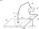
- an insertion unit 321 is provided instead of the insertion unit 53 of the photographing unit 23.
- An observation window 322 is provided on the tip surface of the insertion portion 321 as in the insertion portion 53.
- a marker (not shown) having a predetermined pattern is provided at the tip of the insertion portion 321.
- the camera 323 photographs the surroundings of the insertion port 202A, and supplies the obtained captured image to the pivot point setting unit 153 in the base unit 101.
- the pivot point setting unit 153 receives the image taken from the camera 323 with the tip of the insertion portion 321 entering the insertion port 202A and the tip of the insertion portion 321. Detects the moment when the marker disappears.
- the pivot point setting unit 153 calculates the position of the tip of the insertion unit 321 in the global coordinate system based on the posture of the arm unit 102 at the time of shooting the captured image at the moment when the marker at the tip of the insertion unit 321 disappears. Then, the pivot point setting unit 153 sets the calculated position of the tip of the insertion unit 321 as the pivot point.
- a light emitting element may be provided at the tip of the insertion unit 321 instead of the marker, and the pivot point setting unit 153 may detect the moment when the light emitting element disappears in the captured image from the camera 51.
- the pivot point setting process may be omitted.
- the pivot point setting process may be performed every time the rotation operation is performed.
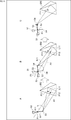
- the angle of the observation optical axis A1 with respect to the normal vector at the point P22 of the subject 353 becomes large. That is, the image is taken from the direction in which the periphery of the point P22 is greatly inclined from the front. Therefore, the visibility around the point P22 in the captured image may decrease.
- the observation window 54 (observation optical axis) is directed in the direction in which the observation window 54 (insertion portion 53) rotates, and then the insertion portion 53 is inserted. It may be rotated.
- the direction of the observation window 54 (the direction of the observation optical axis A1) is in the rotation direction around the pivot point P1 of the observation window 54 (insertion portion 53).
- the insertion portion 53 is rotated about the rotation axis A21 connecting the pivot point P1 and the point P21 so as to approach each other.
- the insertion portion 53 is rotated around the pivot point P1 so that the observation optical axis A1 intersects the point P22 on the subject 353.
- the insertion portion 53', the observation window 54', and the observation optical axis A1'of C in FIG. 16 are when the insertion portion 53 is rotated around the pivot point P1 without being rotated around the rotation axis A21.
- the positions of the insertion portion 53, the observation window 54, and the observation optical axis A1 are shown.
- the observation optical axis A1 has a smaller angle with respect to the normal vector at the point P22 of the subject 353 as compared with the observation optical axis A1'. That is, by rotating the insertion portion 53 around the rotation axis A21, the vicinity of the point P22 can be photographed from a direction closer to the front surface, and the visibility is improved.
- the process of directing the observation window 54 (observation optical axis A1) in the rotation direction of the observation window 54 may be automatically performed or may be performed by a user operation.
- the stick 351A of the stick controller 351 provided in the input unit 21 is tilted by a predetermined angle or more, or when it is continuously tilted in the same direction for a predetermined time or longer, it is observed in the rotation direction of the observation window 54.
- the process of pointing the window 54 may be performed.
- the function of pointing the observation window 54 in the rotation direction of the observation window 54 may be switched on / off.
- the rotation of the insertion portion 53 around the pivot point P1 and the rotation around the rotation axis A21 may be repeated little by little alternately.
- a laser an ultrasonic sensor, an infrared sensor, a depth sensor, or the like may be used to detect the distance to the point of interest.
- the distance to each point around the point of interest may be detected according to the degree of unevenness on the surface of the subject, and the average value of the detected distances may be used as the distance to the point of interest.
- the detection process of the distance to the point of interest may be omitted. This is assumed, for example, when the three-dimensional shape inside the patient's body is known by CT (Computed Tomography) scan or the like.
- markers may be provided in each part of the arm part 102, the position of each marker may be detected by a motion capture system or the like, and the posture of the arm part 102 may be detected based on the position of each marker.
- the arm portion is not limited to the above-mentioned configuration, and can be arbitrarily changed. For example, it is possible to increase the number of joints and change the direction and angle of bending the joints.
- insertion portion configured by a rigid mirror
- present technology can also be applied to, for example, a case where the insertion portion is configured by a flexible mirror such as a fiberscope.
- This technology is applied not only to the above-mentioned case of photographing the inside of a living body, but also to the case of rotating a rod-shaped optical member whose observation optical axis is tilted with respect to the central axis with the pivot point as a fulcrum. be able to.
- FIG. 17 is a block diagram showing a configuration example of the hardware of the computer 1000 that executes the above-mentioned series of processes programmatically.
- the CPU Central Processing Unit
- ROM Read Only Memory
- RAM Random Access Memory
- An input / output interface 1005 is further connected to the bus 1004.
- An input unit 1006, an output unit 1007, a storage unit 1008, a communication unit 1009, and a drive 1010 are connected to the input / output interface 1005.
- the input unit 1006 includes a keyboard, a mouse, a microphone, and the like.
- the output unit 1007 includes a display, a speaker, and the like.
- the storage unit 1008 includes a hard disk, a non-volatile memory, and the like.
- the communication unit 1009 includes a network interface and the like.
- the drive 1010 drives a removable medium 1011 such as a magnetic disk, an optical disk, a magneto-optical disk, or a semiconductor memory.
- the CPU 1001 loads and executes the program stored in the storage unit 1008 into the RAM 1003 via the input / output interface 1005 and the bus 1004, for example. A series of processing is performed.
- the program executed by the computer 1000 can be recorded and provided on the removable media 1011 as a package media or the like, for example. Programs can also be provided via wired or wireless transmission media such as local area networks, the Internet, and digital satellite broadcasting.
- the program can be installed in the storage unit 1008 via the input / output interface 1005 by mounting the removable media 1011 in the drive 1010.
- the program can be received by the communication unit 1009 and installed in the storage unit 1008 via a wired or wireless transmission medium.
- the program can be pre-installed in the ROM 1002 or the storage unit 1008.
- the program executed by the computer 1000 may be a program in which processing is performed in chronological order in the order described in this specification, or at a required timing such as in parallel or when a call is made. It may be a program that is processed by.
- the system means a set of a plurality of components (devices, modules (parts), etc.), and it does not matter whether all the components are in the same housing. Therefore, a plurality of devices housed in separate housings and connected via a network, and a device in which a plurality of modules are housed in one housing are both systems. ..
- this technology can have a cloud computing configuration in which one function is shared by a plurality of devices via a network and processed jointly.
- each step described in the above flowchart can be executed by one device or can be shared and executed by a plurality of devices.
- one step includes a plurality of processes
- the plurality of processes included in the one step can be executed by one device or shared by a plurality of devices.
- the present technology can also have the following configurations.
- a rotation axis setting unit that serves as a fulcrum of a rod-shaped optical member whose observation optical axis is tilted with respect to the central axis, and sets a rotation axis based on a pivot point that is not on the observation optical axis and a point of interest on the subject.
- An imaging control device including an attitude control unit that rotates the optical member around the rotation axis.
- An imaging device that photographs the subject via the optical member is rotatably connected to the optical member about the optical axis of the imaging device.
- the attitude control unit moves in a second direction opposite to the first direction around the optical axis of the photographing apparatus in accordance with the rotation of the optical member in the first direction about the rotation axis.
- the imaging control device which rotates the imaging device.
- the attitude control unit controls the rotation of the optical member around the rotation axis and the rotation of the optical member around the pivot point, and photographs the subject through the optical member.
- the imaging control device according to (1) or (2), which controls the position of the point of interest in an image.
- the attitude control unit controls the rotation of the optical member around the pivot point so that the point of interest in the captured image after the rotation of the optical member about the rotation axis reaches a target position.
- the imaging control device according to (5) above.
- the attitude control unit rotates the optical member about the rotation axis by a predetermined amount of rotation, and the optics centering on the rotation axis until the point of interest in the captured image reaches the target position.
- the imaging control device according to (6) or (7) above, wherein the rotation of the member and the rotation of the optical member about the pivot point are alternately repeated.
- the imaging control device according to any one of (5) to (8) above, wherein the point of interest is a point on the subject corresponding to the designated point in the captured image.
- the rotation axis setting unit sets a straight line connecting the intersection of the perpendicular line drawn from the attention point to the observation optical axis and the observation optical axis and the pivot point on the rotation axis (5) to (9). ).
- the imaging control device according to any one of.
- the optical member is inserted into the living body and The imaging control device according to any one of (1) to (10) above, wherein the pivot point is a point on the optical member near the insertion port for inserting the optical member into the living body.
- the attitude control unit rotates the optical member in the first direction around the pivot point
- the attitude control unit rotates the optical member in the second direction around the rotation axis and directs the observation optical axis.
- the imaging control device according to any one of (1) to (13), wherein the image is brought closer to the first direction.
- the posture control unit controls the rotation of the optical member by controlling the posture of the arm unit that moves the optical member.
- a rotation axis is set based on a pivot point that is not on the observation optical axis and a point of interest on the subject, which serves as a fulcrum of a rod-shaped optical member whose observation optical axis is tilted with respect to the central axis.
- a rotation axis is set based on a pivot point that is not on the observation optical axis and a point of interest on the subject, which serves as a fulcrum of a rod-shaped optical member whose observation optical axis is tilted with respect to the central axis.
- An imaging unit equipped with a rod-shaped optical member whose observation optical axis is tilted with respect to the central axis, A rotation axis setting unit that serves as a fulcrum of the optical member and sets a rotation axis based on a pivot point that is not on the observation optical axis and a point of interest on the subject.
- An imaging system including an attitude control unit that rotates the optical member around the rotation axis.
- 11 shooting system 22 shooting control unit, 23 shooting unit, 26 arm mechanism, 51 camera, 52 rotary actuator, 53 insertion part, 54a, 54b observation window, 102 arm part, 112-1 to 112-4 joint part, 151 distance Detection unit, 152 Observation optical axis detection unit, 153 Pivot point setting unit, 154 Rotation axis setting unit, 155 Attitude control unit, 161 Target attitude setting unit, 162 Camera attitude control unit, 163 Arm attitude control unit, 171-1 to 171 -N actuator
Landscapes
- Health & Medical Sciences (AREA)
- Life Sciences & Earth Sciences (AREA)
- Surgery (AREA)
- Engineering & Computer Science (AREA)
- Nuclear Medicine, Radiotherapy & Molecular Imaging (AREA)
- Veterinary Medicine (AREA)
- Public Health (AREA)
- General Health & Medical Sciences (AREA)
- Physics & Mathematics (AREA)
- Animal Behavior & Ethology (AREA)
- Molecular Biology (AREA)
- Biomedical Technology (AREA)
- Heart & Thoracic Surgery (AREA)
- Medical Informatics (AREA)
- Pathology (AREA)
- Radiology & Medical Imaging (AREA)
- Optics & Photonics (AREA)
- Biophysics (AREA)
- General Physics & Mathematics (AREA)
- Signal Processing (AREA)
- Oral & Maxillofacial Surgery (AREA)
- Gynecology & Obstetrics (AREA)
- Robotics (AREA)
- Endoscopes (AREA)
- Accessories Of Cameras (AREA)
- Details Of Cameras Including Film Mechanisms (AREA)
- Instruments For Viewing The Inside Of Hollow Bodies (AREA)
- Stereoscopic And Panoramic Photography (AREA)
Abstract
This technology relates to: an imaging control device which, during imaging using an optical member having an observation optical axis inclined with respect to the central axis, makes it possible to easily change the direction of imaging of a subject; an imaging control method; a program; and an imaging system. This imaging control device is provided with a rotation axis setting unit which serves as a fulcrum for a rod-like optical member having an observation optical axis inclined with respect to the central axis and sets the rotation axis on the basis of a pivot point which is not on the observation optical axis and a point of interest on the subject; and an orientation control unit for rotating the optical member about the rotation axis. The present technology can be applied, for example, to endoscope systems.
Description
本技術は、撮影制御装置、撮影制御方法、プログラム、及び、撮影システムに関し、特に、観察光軸が中心軸に対して傾いている光学部材を用いて撮影を行う場合に用いて好適な撮影制御装置、撮影制御方法、プログラム、及び、撮影システムに関する。
The present technology relates to an imaging control device, an imaging control method, a program, and an imaging system, and is particularly suitable for imaging control when imaging is performed using an optical member whose observation optical axis is tilted with respect to the central axis. It relates to an apparatus, a shooting control method, a program, and a shooting system.
従来、中心軸に対して傾斜した角度を撮影することが可能な斜視鏡が、内視鏡システムの生体内への挿入部に用いられている。斜視鏡を用いた内視鏡システムでは、斜視鏡を回転させて、斜視鏡の先端の観察窓の向きを変えることにより、被写体を別の角度から撮影することができる。
Conventionally, a squint mirror capable of photographing an angle inclined with respect to the central axis has been used for an insertion part of an endoscope system into a living body. In an endoscope system using a squint mirror, the subject can be photographed from a different angle by rotating the squint mirror and changing the direction of the observation window at the tip of the squint mirror.
しかし、斜視鏡を単純に回転させると、ユーザが注目する領域(以下、注目領域と称する)が画像の端部に移動したり、画角の外に出てしまったりして、ユーザが注目領域を見失ってしまうおそれがある。そのため、ユーザは、斜視鏡を回転させる場合に、注目領域を見失わないように画像を確認しながら、斜視鏡の角度等を慎重に調整する必要がある。
However, when the perspective mirror is simply rotated, the area of interest to the user (hereinafter referred to as the area of interest) moves to the edge of the image or goes out of the angle of view, and the area of interest to the user. You may lose sight of it. Therefore, when rotating the perspective mirror, the user needs to carefully adjust the angle of the perspective mirror and the like while checking the image so as not to lose sight of the region of interest.
これに対して、従来、挿入部の観察光軸が患者の患部上の点を頂点とする円錐状に軌跡を描くように、挿入部を回転させる方法が提案されている(例えば、特許文献1参照)。
On the other hand, conventionally, a method of rotating the insertion portion so that the observation optical axis of the insertion portion draws a conical trajectory with a point on the affected part of the patient as the apex has been proposed (for example, Patent Document 1). reference).
しかしながら、特許文献1に記載の方法では、患者の患部の注目領域に合わせて予め回転機構全体の位置を調整する必要があるため、注目領域を容易に変更することができない。
However, in the method described in Patent Document 1, since it is necessary to adjust the position of the entire rotation mechanism in advance according to the region of interest of the affected area of the patient, the region of interest cannot be easily changed.
本技術は、このような状況に鑑みてなされたものであり、観察光軸が中心軸に対して傾いている光学部材を用いて撮影を行う場合に、被写体を撮影する方向を容易に変更することができるようにするものである。
This technology was made in view of such a situation, and when shooting with an optical member whose observation optical axis is tilted with respect to the central axis, the direction in which the subject is shot can be easily changed. It allows you to do it.
本技術の第1の側面の撮影制御装置は、観察光軸が中心軸に対して傾いている棒状の光学部材の支点となり、前記観察光軸上にないピボット点、及び、被写体上の注目点に基づいて、回転軸を設定する回転軸設定部と、前記回転軸を中心にして前記光学部材を回転させる姿勢制御部とを備える。
The imaging control device on the first side surface of the present technology serves as a fulcrum of a rod-shaped optical member whose observation optical axis is tilted with respect to the central axis, and is a pivot point that is not on the observation optical axis and a point of interest on the subject. A rotation axis setting unit for setting the rotation axis and an attitude control unit for rotating the optical member around the rotation axis are provided based on the above.
本技術の第1の側面の撮影制御方法は、撮影制御装置が、観察光軸が中心軸に対して傾いている棒状の光学部材の支点となり、前記観察光軸上にないピボット点、及び、被写体上の注目点に基づいて、回転軸を設定し、前記回転軸を中心にして前記光学部材を回転させる。
In the imaging control method of the first aspect of the present technology, the imaging control device serves as a fulcrum of a rod-shaped optical member whose observation optical axis is tilted with respect to the central axis, and a pivot point that is not on the observation optical axis, and A rotation axis is set based on a point of interest on the subject, and the optical member is rotated about the rotation axis.
本技術の第1の側面のプログラムは、観察光軸が中心軸に対して傾いている棒状の光学部材の支点となり、前記観察光軸上にないピボット点、及び、被写体上の注目点に基づいて、回転軸を設定し、前記回転軸を中心にして前記光学部材を回転させる処理をコンピュータに実行させる。
The program of the first aspect of the present technology serves as a fulcrum of a rod-shaped optical member whose observation optical axis is tilted with respect to the central axis, and is based on a pivot point that is not on the observation optical axis and a point of interest on the subject. Then, the rotation axis is set, and the computer is made to execute the process of rotating the optical member around the rotation axis.
本技術の第2の側面の撮影システムは、観察光軸が中心軸に対して傾いている棒状の光学部材を備える撮影部と、前記光学部材の支点となり、前記観察光軸上にないピボット点、及び、被写体上の注目点に基づいて、回転軸を設定する回転軸設定部と、前記回転軸を中心にして前記光学部材を回転させる姿勢制御部とを備える。
The imaging system on the second side of the present technology includes an imaging unit including a rod-shaped optical member whose observation optical axis is tilted with respect to the central axis, and a pivot point that serves as a fulcrum of the optical member and is not on the observation optical axis. A rotation axis setting unit that sets a rotation axis based on a point of interest on the subject, and an attitude control unit that rotates the optical member around the rotation axis are provided.
本技術の第1の側面においては、観察光軸が中心軸に対して傾いている棒状の光学部材の支点となり、前記観察光軸上にないピボット点、及び、被写体上の注目点に基づいて、回転軸が設定され、前記回転軸を中心にして前記光学部材が回転される。
In the first aspect of the present technology, the observation optical axis serves as a fulcrum of a rod-shaped optical member tilted with respect to the central axis, and is based on a pivot point that is not on the observation optical axis and a point of interest on the subject. , The rotation axis is set, and the optical member is rotated around the rotation axis.
本技術の第2の側面においては、観察光軸が中心軸に対して傾いている棒状の光学部材を備える撮影部の前記光学部材の支点となり、前記観察光軸上にないピボット点、及び、被写体上の注目点に基づいて、回転軸が設定され、前記回転軸を中心にして前記光学部材が回転される。
In the second aspect of the present technology, a pivot point that serves as a fulcrum of the optical member of the photographing unit including a rod-shaped optical member whose observation optical axis is tilted with respect to the central axis, and a pivot point that is not on the observation optical axis, and A rotation axis is set based on a point of interest on the subject, and the optical member is rotated about the rotation axis.
以下、本技術を実施するための形態について説明する。説明は以下の順序で行う。
1.実施の形態
2.変形例
3.その他 Hereinafter, modes for implementing the present technology will be described. The explanation will be given in the following order.
1. 1. Embodiment 2. Modification example 3. Other
1.実施の形態
2.変形例
3.その他 Hereinafter, modes for implementing the present technology will be described. The explanation will be given in the following order.
1. 1. Embodiment 2. Modification example 3. Other
<<1.実施の形態>>
まず、図1乃至図10を参照して、本技術の実施の形態について説明する。 << 1. Embodiment >>
First, an embodiment of the present technology will be described with reference to FIGS. 1 to 10.
まず、図1乃至図10を参照して、本技術の実施の形態について説明する。 << 1. Embodiment >>
First, an embodiment of the present technology will be described with reference to FIGS. 1 to 10.
<撮影システムの構成例>
図1は、本技術を適用した撮影システム11の構成例を示している。 <Configuration example of shooting system>
FIG. 1 shows a configuration example of aphotographing system 11 to which the present technology is applied.
図1は、本技術を適用した撮影システム11の構成例を示している。 <Configuration example of shooting system>
FIG. 1 shows a configuration example of a
撮影システム11は、例えば医療分野で用いられる内視鏡のシステムであり、生体内の撮影及び観察に用いられる。撮影システム11は、入力部21、撮影制御部22、撮影部23、画像処理部24、表示部25、及び、アーム機構26を備える。
The imaging system 11 is, for example, an endoscope system used in the medical field, and is used for imaging and observation in a living body. The photographing system 11 includes an input unit 21, a photographing control unit 22, an imaging unit 23, an image processing unit 24, a display unit 25, and an arm mechanism 26.
入力部21は、ボタン、スイッチ、タッチパネル等の操作デバイスを備え、ユーザによる操作を受け付ける。入力部21は、ユーザ操作により入力された入力信号を撮影制御部22に供給する。
The input unit 21 includes operation devices such as buttons, switches, and a touch panel, and accepts operations by the user. The input unit 21 supplies the input signal input by the user operation to the photographing control unit 22.
撮影制御部22は、撮影部23による被写体の撮影の制御を行う。撮影制御部22は、撮影処理制御部31及び撮影姿勢制御部32を備える。
The shooting control unit 22 controls the shooting of the subject by the shooting unit 23. The shooting control unit 22 includes a shooting processing control unit 31 and a shooting posture control unit 32.
撮影処理制御部31は、入力部21から供給される入力信号、及び、撮影部23から供給される撮影画像等に基づいて、撮影部23の撮影処理(例えば、撮影タイミング等)の制御、及び、各種の撮影パラメータ等の設定を行う。
The shooting processing control unit 31 controls the shooting processing (for example, shooting timing, etc.) of the shooting unit 23 based on the input signal supplied from the input unit 21 and the shot image supplied from the shooting unit 23, and , Set various shooting parameters.
撮影姿勢制御部32は、入力部21から供給される入力信号、及び、撮影部23から供給される撮影画像等に基づいて、撮影部23及びアーム機構26を制御することにより、撮影部23の姿勢(以下、撮影姿勢と称する)を制御する。これにより、撮影部23が撮影する位置(以下、撮影位置と称する)及び方向(以下、撮影方向と称する)が制御される。
The shooting posture control unit 32 controls the shooting unit 23 and the arm mechanism 26 based on the input signal supplied from the input unit 21, the shooting image supplied from the shooting unit 23, and the like, thereby causing the shooting unit 23 to control the shooting unit 23. The posture (hereinafter referred to as a shooting posture) is controlled. As a result, the position (hereinafter referred to as a shooting position) and the direction (hereinafter referred to as a shooting direction) in which the shooting unit 23 shoots are controlled.
撮影部23は、撮影制御部22の制御の下に、被写体の撮影を行う。撮影部23は、撮影により得られた画像(以下、撮影画像と称する)を撮影制御部22及び画像処理部24に供給する。
The photographing unit 23 photographs the subject under the control of the photographing control unit 22. The photographing unit 23 supplies an image obtained by photographing (hereinafter, referred to as a photographed image) to the photographing control unit 22 and the image processing unit 24.
画像処理部24は、撮影画像に対して、各種の画像処理を行い、画像処理後の撮影画像を表示部25に供給する。
The image processing unit 24 performs various image processing on the captured image, and supplies the captured image after the image processing to the display unit 25.
表示部25は、例えば、ディスプレイ等を備える。表示部25は、撮影画像に基づく画像を表示する。表示部25に表示される画像は、例えば、医師等が術野等を確認するためのモニタ画像に用いられる。
The display unit 25 includes, for example, a display or the like. The display unit 25 displays an image based on the captured image. The image displayed on the display unit 25 is used, for example, as a monitor image for a doctor or the like to confirm the surgical field or the like.
アーム機構26は、例えば、ロボットアームにより構成される。アーム機構26は、撮影部23を支持するとともに、撮影制御部22の制御の下に、撮影部23を動かすことにより、撮影部23の姿勢を変化させる。
The arm mechanism 26 is composed of, for example, a robot arm. The arm mechanism 26 supports the photographing unit 23 and changes the posture of the photographing unit 23 by moving the photographing unit 23 under the control of the photographing control unit 22.
<撮影部23の構成例>
図2は、図1の撮影部23の構成例を模式的に示している。 <Structure example ofshooting unit 23>
FIG. 2 schematically shows a configuration example of the photographingunit 23 of FIG.
図2は、図1の撮影部23の構成例を模式的に示している。 <Structure example of
FIG. 2 schematically shows a configuration example of the photographing
撮影部23は、カメラ51、ロータリアクチュエータ52、挿入部53、並びに、観察窓54a及び観察窓54bを備えている。カメラ51と挿入部53は、ロータリアクチュエータ52を介して接続されている。観察窓54a及び観察窓54bは、拡大図に示されるように、挿入部53の先端面53Aに設けられている。
The photographing unit 23 includes a camera 51, a rotary actuator 52, an insertion unit 53, and an observation window 54a and an observation window 54b. The camera 51 and the insertion portion 53 are connected via a rotary actuator 52. The observation window 54a and the observation window 54b are provided on the tip surface 53A of the insertion portion 53, as shown in the enlarged view.
カメラ51は、例えば、CMOS(Complementary MOS)等の撮像素子を備える撮影装置により構成される。カメラ51は、挿入部53を介して入射される被写体からの光(以下、被写体光と称する)を用いて被写体の撮影を行い、得られた撮影画像を撮影制御部22及び画像処理部24に供給する。また、カメラ51は、例えば、2つの撮像素子(不図示)を備え、ステレオ撮影が可能である。
The camera 51 is composed of, for example, an imaging device including an image sensor such as CMOS (Complementary MOS). The camera 51 shoots the subject using the light from the subject incident through the insertion unit 53 (hereinafter referred to as subject light), and the obtained shot image is sent to the shooting control unit 22 and the image processing unit 24. Supply. Further, the camera 51 is provided with, for example, two image pickup elements (not shown) and can perform stereo imaging.
ロータリアクチュエータ52は、挿入部53に対して、カメラ51の光軸(以下、撮影光軸と称する)を中心にしてカメラ51を回転させる。すなわち、カメラ51は、ロータリアクチュエータ52を介して、撮影光軸を中心にして回転可能に挿入部53の一端に設けられている。カメラ51が撮影光軸を中心にして回転することにより、カメラ51の座標系(以下、カメラ座標系と称する)が、撮影光軸を中心にして回転する。
The rotary actuator 52 rotates the camera 51 with respect to the insertion portion 53 about the optical axis of the camera 51 (hereinafter, referred to as a photographing optical axis). That is, the camera 51 is provided at one end of the insertion portion 53 so as to be rotatable around the photographing optical axis via the rotary actuator 52. As the camera 51 rotates about the shooting optical axis, the coordinate system of the camera 51 (hereinafter referred to as the camera coordinate system) rotates about the shooting optical axis.
なお、以下、カメラ座標系のx軸をカメラ51の横方向とし、y軸をカメラ51の高さ方向とし、z軸を撮影光軸の方向とする。
Hereinafter, the x-axis of the camera coordinate system will be the lateral direction of the camera 51, the y-axis will be the height direction of the camera 51, and the z-axis will be the direction of the shooting optical axis.
挿入部53は、レンズ、ミラー等の光学系を備え、生体内に挿入される棒状かつ筒状の光学部材である。なお、棒状の光学部材は、曲線状の光学部材や直線状の光学部材を含む。例えば、挿入部53は、硬性鏡からなる斜視鏡により構成される。
The insertion portion 53 includes an optical system such as a lens and a mirror, and is a rod-shaped and tubular optical member that is inserted into the living body. The rod-shaped optical member includes a curved optical member and a linear optical member. For example, the insertion portion 53 is composed of a perspective mirror made of a rigid mirror.
挿入部53は、中心軸がカメラ51の撮影光軸と一致するように、ロータリアクチュエータ52を介してカメラ51に接続されている。挿入部53の先端面53Aは、挿入部53の中心軸に対して傾いている。挿入部53の先端面53Aには、それぞれレンズからなる観察窓54a及び観察窓54bが設けられている。観察窓54a及び観察窓54bは、先端面53Aの傾斜方向において同じ高さの位置に横に並べられている。
The insertion portion 53 is connected to the camera 51 via the rotary actuator 52 so that the central axis coincides with the photographing optical axis of the camera 51. The tip surface 53A of the insertion portion 53 is inclined with respect to the central axis of the insertion portion 53. An observation window 54a and an observation window 54b made of a lens are provided on the tip surface 53A of the insertion portion 53, respectively. The observation window 54a and the observation window 54b are arranged side by side at the same height in the inclination direction of the tip surface 53A.
観察窓54a及び観察窓54bから挿入部53に入射した被写体光は、それぞれ挿入部53を通って、カメラ51の異なる撮像素子の受光面に入射する。そして、カメラ51は、観察窓54aから入射した被写体光に基づく撮影画像(以下、左撮影画像と称する)、及び、観察窓54bから入射した被写体光に基づく撮影画像(以下、右撮影画像と称する)をそれぞれ撮影する。すなわち、カメラ51は、ステレオ撮影が可能である。カメラ51は、左撮影画像及び右撮影画像を撮影制御部22及び画像処理部24に供給する。
The subject light incident on the insertion unit 53 from the observation window 54a and the observation window 54b passes through the insertion unit 53 and is incident on the light receiving surfaces of different image pickup devices of the camera 51. Then, the camera 51 uses a captured image based on the subject light incident from the observation window 54a (hereinafter referred to as a left captured image) and a captured image based on the subject light incident from the observation window 54b (hereinafter referred to as a right captured image). ) Are photographed respectively. That is, the camera 51 is capable of stereo shooting. The camera 51 supplies the left captured image and the right captured image to the photographing control unit 22 and the image processing unit 24.
ここで、観察窓54a及び観察窓54bの光軸である挿入部53の観察光軸は、先端面53Aに対して垂直であり、挿入部53の中心軸に対して傾いている。従って、撮影部23は、挿入部53を介して、挿入部53の中心軸に対して斜め方向を撮影する。
Here, the observation optical axis of the insertion portion 53, which is the optical axis of the observation window 54a and the observation window 54b, is perpendicular to the tip surface 53A and is inclined with respect to the central axis of the insertion portion 53. Therefore, the photographing unit 23 photographs the image in the oblique direction with respect to the central axis of the insertion unit 53 via the insertion unit 53.
なお、以下、観察窓54a及び観察窓54bを個々に区別する必要がない場合、単に観察窓54と称する。また、以下、左撮影画像及び右撮影画像を個々に区別する必要がない場合、単に撮影画像と称する。
Hereinafter, when it is not necessary to distinguish the observation window 54a and the observation window 54b individually, the observation window 54 is simply referred to as the observation window 54. In addition, hereinafter, when it is not necessary to distinguish the left photographed image and the right photographed image individually, it is simply referred to as a photographed image.
<挿入部53の挿入方法の例>
図3は、挿入部53の生体内への挿入方法の例を示している。 <Example of insertion method ofinsertion portion 53>
FIG. 3 shows an example of a method of inserting theinsertion portion 53 into the living body.
図3は、挿入部53の生体内への挿入方法の例を示している。 <Example of insertion method of
FIG. 3 shows an example of a method of inserting the
この例では、挿入部53が、トロッカ62を用いて患者の腹部に挿入されている例を示している。具体的には、トロッカ62は、腹部の皮膚61に差し込まれている。そして、トロッカ62の挿入口から挿入部53が挿入され、トロッカ62の先端口から挿入部53の先端が突出している。これにより、挿入部53が生体内に挿入されるとともに、挿入部53の位置が安定する。
This example shows an example in which the insertion portion 53 is inserted into the abdomen of the patient using the trocca 62. Specifically, the trocca 62 is inserted into the skin 61 of the abdomen. Then, the insertion portion 53 is inserted from the insertion port of the trocca 62, and the tip of the insertion portion 53 protrudes from the tip opening of the trocca 62. As a result, the insertion portion 53 is inserted into the living body, and the position of the insertion portion 53 is stabilized.
<アーム機構26の構成例>
図4は、図1のアーム機構26の構成例を模式的に示している。なお、図中、撮影部23も模式的に示されており、ロータリアクチュエータ52の図示が省略されている。なお、以下の同様の図でも、基本的に撮影部23を模式的に示し、ロータリアクチュエータ52の図示を省略するものとする。 <Structure example ofarm mechanism 26>
FIG. 4 schematically shows a configuration example of thearm mechanism 26 of FIG. In the drawing, the photographing unit 23 is also schematically shown, and the rotary actuator 52 is not shown. In the same figure below, the photographing unit 23 is basically shown schematically, and the rotary actuator 52 is not shown.
図4は、図1のアーム機構26の構成例を模式的に示している。なお、図中、撮影部23も模式的に示されており、ロータリアクチュエータ52の図示が省略されている。なお、以下の同様の図でも、基本的に撮影部23を模式的に示し、ロータリアクチュエータ52の図示を省略するものとする。 <Structure example of
FIG. 4 schematically shows a configuration example of the
アーム機構26は、ベース部101及びアーム部102を備える。アーム部102は、リンク111-1乃至リンク111-3、及び、関節部112-1乃至関節部112-4を備えている。リンク111-1の一端は、関節部112-1を介してベース部101に接続され、リンク111-1の他端は、関節部112-2を介してリンク111-2の一端に接続されている。リンク111-2の他端は、関節部112-3を介してリンク111-3の一端に接続されている。リンク111-3の他端は、関節部112-4を介してカメラ51に接続されている。
The arm mechanism 26 includes a base portion 101 and an arm portion 102. The arm portion 102 includes links 111-1 to 111-3, and joint portions 112-1 to 112-4. One end of the link 111-1 is connected to the base 101 via the joint 112-1, and the other end of the link 111-1 is connected to one end of the link 111-2 via the joint 112-2. There is. The other end of the link 111-2 is connected to one end of the link 111-3 via a joint 112-3. The other end of the link 111-3 is connected to the camera 51 via the joint portion 112-4.
ベース部101は、例えば、アーム部102を支持するとともに、撮影システム11の撮影制御部22の全部又は一部が内蔵されており、アーム部102の動きを制御する。
The base unit 101 supports, for example, the arm unit 102, and all or part of the imaging control unit 22 of the imaging system 11 is built in to control the movement of the arm unit 102.
関節部112-1乃至関節部112-4は、撮影制御部22の制御の下に、それぞれ独立して駆動される。これにより、アーム部102の姿勢が変化し、撮影部23が動くことにより、撮影姿勢が変化する。
The joint portions 112-1 to 112-4 are independently driven under the control of the imaging control unit 22. As a result, the posture of the arm unit 102 changes, and the photographing unit 23 moves, so that the photographing posture changes.
なお、以下、リンク111-1乃至リンク111-3を個々に区別する必要がない場合、単にリンク111と称する。また、以下、関節部112-1乃至関節部112-4を個々に区別する必要がない場合、単に関節部112と称する。
Hereinafter, when it is not necessary to individually distinguish the link 111-1 to the link 111-3, it is simply referred to as the link 111. Further, hereinafter, when it is not necessary to individually distinguish the joint portion 112-1 to the joint portion 112-4, it is simply referred to as the joint portion 112.
<撮影姿勢制御部32の構成例>
図5は、図1の撮影システム11の撮影姿勢制御部32の機能の構成例を示している。 <Structure example of shootingposture control unit 32>
FIG. 5 shows a configuration example of the function of the shootingposture control unit 32 of the shooting system 11 of FIG.
図5は、図1の撮影システム11の撮影姿勢制御部32の機能の構成例を示している。 <Structure example of shooting
FIG. 5 shows a configuration example of the function of the shooting
撮影姿勢制御部32は、距離検出部151、観察光軸検出部152、ピボット点設定部153、回転軸設定部154、及び、姿勢制御部155を備える。姿勢制御部155は、目標姿勢設定部161、カメラ姿勢制御部162、及び、アーム姿勢制御部163を備える。
The shooting attitude control unit 32 includes a distance detection unit 151, an observation optical axis detection unit 152, a pivot point setting unit 153, a rotation axis setting unit 154, and an attitude control unit 155. The attitude control unit 155 includes a target attitude setting unit 161, a camera attitude control unit 162, and an arm attitude control unit 163.
距離検出部151は、カメラ51から供給される左撮影画像及び右撮影画像に基づいて、被写体までの距離を検出する。例えば、距離検出部151は、被写体上の任意の点(以下、注目点と称する)と観察窓54との間の距離を検出する。距離検出部151は、検出結果を示すデータを回転軸設定部154に供給する。
The distance detection unit 151 detects the distance to the subject based on the left shot image and the right shot image supplied from the camera 51. For example, the distance detection unit 151 detects the distance between an arbitrary point on the subject (hereinafter referred to as a point of interest) and the observation window 54. The distance detection unit 151 supplies data indicating the detection result to the rotation axis setting unit 154.
観察光軸検出部152は、アーム姿勢制御部163から供給されるアーム部102の姿勢を示すデータ(以下、アーム姿勢データと称する)に基づいて、挿入部53(特に観察窓54)の姿勢(位置及び向き)を検出する。また、観察光軸検出部152は、観察窓54の姿勢に基づいて観察光軸を検出する。観察光軸検出部152は、検出結果を示すデータを回転軸設定部154及び目標姿勢設定部161に供給する。
The observation optical axis detection unit 152 is based on data indicating the posture of the arm unit 102 supplied from the arm attitude control unit 163 (hereinafter referred to as arm posture data), and the posture (particularly the observation window 54) of the insertion unit 53 (particularly the observation window 54) Position and orientation) is detected. Further, the observation optical axis detection unit 152 detects the observation optical axis based on the posture of the observation window 54. The observation optical axis detection unit 152 supplies data indicating the detection result to the rotation axis setting unit 154 and the target attitude setting unit 161.
ピボット点設定部153は、カメラ51から供給される左撮影画像及び右撮影画像、並びに、アーム姿勢制御部163から供給されるアーム姿勢データに基づいて、ピボット点の位置を設定する。ピボット点とは、挿入部53を回転させる場合の支点となる点である。ピボット点設定部153は、ピボット点の位置を示すデータを回転軸設定部154及び目標姿勢設定部161に供給する。
The pivot point setting unit 153 sets the position of the pivot point based on the left shot image and the right shot image supplied from the camera 51 and the arm posture data supplied from the arm posture control unit 163. The pivot point is a point that serves as a fulcrum when the insertion portion 53 is rotated. The pivot point setting unit 153 supplies data indicating the position of the pivot point to the rotation axis setting unit 154 and the target posture setting unit 161.
回転軸設定部154は、被写体上の注目点までの距離、観察光軸の姿勢、並びに、ピボット点の位置に基づいて、回転軸を設定する。この回転軸は、被写体を撮影する方向を変える場合に挿入部53を回転させる中心となる軸である。回転軸設定部154は、回転軸の姿勢(位置及び向き)を示すデータを目標姿勢設定部161に供給する。
The rotation axis setting unit 154 sets the rotation axis based on the distance to the point of interest on the subject, the posture of the observation optical axis, and the position of the pivot point. This rotation axis is a central axis for rotating the insertion portion 53 when changing the shooting direction of the subject. The rotating shaft setting unit 154 supplies data indicating the posture (position and orientation) of the rotating shaft to the target posture setting unit 161.
目標姿勢設定部161は、ユーザにより入力部21を介して撮影姿勢を変更する操作が行われた場合、操作内容に基づいて、目標となる撮影姿勢(以下、目標姿勢と称する)を設定する。また、目標姿勢設定部161は、観察窓54の姿勢、観察光軸の姿勢、ピボット点の位置、及び、回転軸の姿勢等に基づいて、目標姿勢を実現するためのアーム部102の姿勢(以下、目標アーム姿勢と称する)、及び、カメラ51の姿勢(以下、目標カメラ姿勢と称する)を計算する。目標姿勢設定部161は、目標カメラ姿勢を示すデータをカメラ姿勢制御部162に供給する。また、目標姿勢設定部161は、目標アーム姿勢を示すデータをアーム姿勢制御部163に供給する。
The target posture setting unit 161 sets a target shooting posture (hereinafter referred to as a target posture) based on the operation content when the user performs an operation of changing the shooting posture via the input unit 21. Further, the target posture setting unit 161 is based on the posture of the observation window 54, the posture of the observation optical axis, the position of the pivot point, the posture of the rotation axis, and the like, and the posture of the arm unit 102 for realizing the target posture ( The posture of the camera 51 (hereinafter referred to as the target camera posture) and the posture of the camera 51 (hereinafter referred to as the target camera posture) are calculated. The target posture setting unit 161 supplies data indicating the target camera posture to the camera posture control unit 162. Further, the target posture setting unit 161 supplies data indicating the target arm posture to the arm posture control unit 163.
カメラ姿勢制御部162は、カメラ51の姿勢が目標カメラ姿勢となるように、ロータリアクチュエータ52を駆動する。
The camera attitude control unit 162 drives the rotary actuator 52 so that the attitude of the camera 51 becomes the target camera attitude.
また、カメラ姿勢制御部162は、ロータリアクチュエータ52から供給される回転角を示すデータに基づいて、カメラ51の姿勢を検出する。なお、ロータリアクチュエータ52の回転角は、例えば、ロータリアクチュエータ52が備えるポテンションメータ等を用いて検出される。
Further, the camera attitude control unit 162 detects the attitude of the camera 51 based on the data indicating the rotation angle supplied from the rotary actuator 52. The rotation angle of the rotary actuator 52 is detected by using, for example, a potentiometer included in the rotary actuator 52.
アーム姿勢制御部163は、アーム部102の姿勢が目標アーム姿勢となるように、アーム部102の関節部112-1乃至関節部112-4を駆動するためのアクチュエータ171-1乃至アクチュエータ171-nを駆動する。また、アーム姿勢制御部163は、アクチュエータ171-1乃至アクチュエータ171-nから供給される回転角を示すデータに基づいて、アーム部102の姿勢を検出する。
The arm posture control unit 163 has actuators 171-1 to 171-n for driving the joints 112-1 to 112-4 of the arm 102 so that the posture of the arm 102 is the target arm posture. To drive. Further, the arm posture control unit 163 detects the posture of the arm unit 102 based on the data indicating the rotation angle supplied from the actuators 171-1 to 171-n.
なお、アクチュエータ171-1乃至アクチュエータ171-nの回転角は、例えば、アクチュエータ171-1乃至アクチュエータ171-nがそれぞれ備えるポテンションメータ等を用いて検出される。
The rotation angles of the actuators 171-1 to 171-n are detected by using, for example, a potentiometer or the like provided in the actuators 171-1 to 171-n, respectively.
また、以下、アクチュエータ171-1乃至アクチュエータ171-nを個々に区別する必要がない場合、単にアクチュエータ171と称する。
Further, hereinafter, when it is not necessary to individually distinguish the actuators 171-1 to 171-n, they are simply referred to as the actuator 171.
<撮影方向変更処理>
次に、図6のフローチャートを参照して、撮影システム11により実行される撮影方向変更処理について説明する。 <Shooting direction change process>
Next, the shooting direction changing process executed by theshooting system 11 will be described with reference to the flowchart of FIG.
次に、図6のフローチャートを参照して、撮影システム11により実行される撮影方向変更処理について説明する。 <Shooting direction change process>
Next, the shooting direction changing process executed by the
ここで、撮影方向変更処理とは、被写体を撮影する方向を変更する処理、特に、被写体上の注目領域を撮影する方向を変更する処理である。
Here, the shooting direction change process is a process of changing the shooting direction of the subject, particularly a process of changing the shooting direction of the area of interest on the subject.
この処理は、例えば、撮影システム11の電源がオンされたとき開始され、オフされたとき終了する。
This process starts, for example, when the power of the photographing system 11 is turned on, and ends when the power of the photographing system 11 is turned off.
なお、適宜、図7乃至図10に示される例を具体例として挙げながら説明する。
It should be noted that the examples shown in FIGS. 7 to 10 will be described as appropriate as specific examples.
ステップS1において、カメラ51は、撮影を開始する。具体的には、カメラ51は、撮影制御部22の制御の下に、撮影を開始し、撮影制御部22及び画像処理部24への撮影画像の供給を開始する。
In step S1, the camera 51 starts shooting. Specifically, the camera 51 starts shooting under the control of the shooting control unit 22, and starts supplying the shot image to the shooting control unit 22 and the image processing unit 24.
ステップS2において、ピボット点設定部153は、ピボット点を設定する。
In step S2, the pivot point setting unit 153 sets the pivot point.
ここで、図7を参照して、ピボット点の設定方法の例について説明する。この図では、患者の皮膚202の挿入口202Aから挿入部53を挿入し、患者の生体内を撮影する例が示されている。
Here, an example of how to set the pivot point will be described with reference to FIG. 7. In this figure, an example is shown in which the insertion portion 53 is inserted from the insertion port 202A of the patient's skin 202 and the inside of the patient's body is photographed.
例えば、ユーザは、入力部21を介してアーム部102を操作することにより、挿入部53の先端を挿入口202Aの中心付近に合わせる。この状態で、ユーザは、入力部21が備えるボタン201を押下する。入力部21は、ボタン201を押下されたことを示す入力信号を撮影姿勢制御部32に供給する。
For example, the user operates the arm unit 102 via the input unit 21 to align the tip of the insertion unit 53 with the vicinity of the center of the insertion port 202A. In this state, the user presses the button 201 included in the input unit 21. The input unit 21 supplies an input signal indicating that the button 201 has been pressed to the shooting attitude control unit 32.
アーム姿勢制御部163は、各アクチュエータ171の回転角に基づいて、グローバル座標系におけるアーム部102の姿勢を検出する。ここで、グローバル座標系とは、撮影システム11が存在する3次元空間全体を表す座標系であり、ワールド座標系とも呼ばれる。アーム姿勢制御部163は、検出したアーム部102の姿勢を示すアーム姿勢データをピボット点設定部153に供給する。
The arm posture control unit 163 detects the posture of the arm unit 102 in the global coordinate system based on the rotation angle of each actuator 171. Here, the global coordinate system is a coordinate system representing the entire three-dimensional space in which the photographing system 11 exists, and is also called a world coordinate system. The arm posture control unit 163 supplies the arm posture data indicating the detected posture of the arm unit 102 to the pivot point setting unit 153.
ピボット点設定部153は、アーム部102の姿勢に基づいて、グローバル座標系における挿入部53の先端の位置を計算する。そして、ピボット点設定部153は、算出した挿入部53の先端の位置をピボット点P1に設定する。これにより、挿入口202Aのほぼ中心にピボット点P1が設定される。ピボット点設定部153は、グローバル座標系におけるピボット点P1の位置を示すデータを回転軸設定部154及び目標姿勢設定部161に供給する。
The pivot point setting unit 153 calculates the position of the tip of the insertion unit 53 in the global coordinate system based on the posture of the arm unit 102. Then, the pivot point setting unit 153 sets the calculated position of the tip of the insertion unit 53 at the pivot point P1. As a result, the pivot point P1 is set substantially at the center of the insertion port 202A. The pivot point setting unit 153 supplies data indicating the position of the pivot point P1 in the global coordinate system to the rotation axis setting unit 154 and the target posture setting unit 161.
その後、ユーザは、入力部21を介してアーム部102を操作することにより、挿入部53をさらに生体内に挿入する。
After that, the user further inserts the insertion unit 53 into the living body by operating the arm unit 102 via the input unit 21.
例えば、図8に示されるように、挿入部53が、挿入口202Aから生体内に挿入される。このとき、例えば、ピボット点P1が挿入部53上に位置するように、挿入部53が生体内に挿入される。従って、ピボット点P1は、挿入部53上にあって、観察光軸A1上にはない点となる。
For example, as shown in FIG. 8, the insertion portion 53 is inserted into the living body through the insertion port 202A. At this time, for example, the insertion portion 53 is inserted into the living body so that the pivot point P1 is located on the insertion portion 53. Therefore, the pivot point P1 is on the insertion portion 53 and not on the observation optical axis A1.
ステップS3において、入力部21は、回転操作、すなわち、被写体の撮影方向を変えるために挿入部53を回転させる操作が行われたか否かを判定する。この判定処理は、回転操作が行われたと判定されるまで繰り返され、回転操作が行われたと判定された場合、処理はステップS4に進む。
In step S3, the input unit 21 determines whether or not a rotation operation, that is, an operation of rotating the insertion unit 53 in order to change the shooting direction of the subject has been performed. This determination process is repeated until it is determined that the rotation operation has been performed, and when it is determined that the rotation operation has been performed, the process proceeds to step S4.
なお、例えば、ユーザは、回転操作として、入力部21を介して、挿入部53を回転軸周りに回転する角度及び方向を指定する。
Note that, for example, the user specifies an angle and a direction in which the insertion unit 53 is rotated around the rotation axis via the input unit 21 as a rotation operation.
このとき、挿入部53を回転する角度は、相対角度又は絶対角度のいずれで表されてもよい。挿入部53を回転する角度が相対角度で表される場合、例えば、現在の位置から時計回り又は反時計回りにx度のような形式で、挿入部53を回転する角度及び方向が指定される。一方、挿入部53を回転する角度が絶対角度で表される場合、例えば、所定の基準位置を基準にしてx度の方向のような形式で、挿入部53を回転する角度が指定される。
At this time, the angle at which the insertion portion 53 is rotated may be represented by either a relative angle or an absolute angle. When the angle at which the insertion portion 53 is rotated is represented by a relative angle, the angle and direction at which the insertion portion 53 is rotated are specified in a form such as x degrees clockwise or counterclockwise from the current position. .. On the other hand, when the angle at which the insertion portion 53 is rotated is represented by an absolute angle, for example, the angle at which the insertion portion 53 is rotated is specified in a form such as a direction of x degrees with respect to a predetermined reference position.
ステップS4において、観察光軸検出部152は、観察光軸を検出する。具体的には、入力部21は、回転操作の内容を示す入力信号を撮影制御部22に供給する。アーム姿勢制御部163は、各アクチュエータ171の回転角に基づいて、グローバル座標系におけるアーム部102の姿勢を検出する。アーム姿勢制御部163は、検出したアーム部102の姿勢を示すアーム姿勢データを観察光軸検出部152に供給する。
In step S4, the observation optical axis detection unit 152 detects the observation optical axis. Specifically, the input unit 21 supplies an input signal indicating the content of the rotation operation to the photographing control unit 22. The arm posture control unit 163 detects the posture of the arm unit 102 in the global coordinate system based on the rotation angle of each actuator 171. The arm posture control unit 163 supplies the arm posture data indicating the detected posture of the arm unit 102 to the observation optical axis detection unit 152.
観察光軸検出部152は、アーム部102の姿勢に基づいて、グローバル座標系における挿入部53の姿勢、特に観察窓54の姿勢を計算する。また、観察光軸検出部152は、観察窓54の姿勢に基づいて、グローバル座標系における観察光軸の姿勢(位置及び方向)を計算する。観察光軸検出部152は、観察窓54及び観察光軸の姿勢を示すデータを回転軸設定部154及び目標姿勢設定部161に供給する。
The observation optical axis detection unit 152 calculates the posture of the insertion unit 53 in the global coordinate system, particularly the posture of the observation window 54, based on the posture of the arm unit 102. Further, the observation optical axis detection unit 152 calculates the posture (position and direction) of the observation optical axis in the global coordinate system based on the posture of the observation window 54. The observation optical axis detection unit 152 supplies data indicating the attitudes of the observation window 54 and the observation optical axis to the rotation axis setting unit 154 and the target attitude setting unit 161.
ステップS5において、距離検出部151は、注目点までの距離を検出する。例えば、距離検出部151は、撮影画像の中心に対応する被写体上の点を注目点に設定する。これにより、例えば、図8の例において、観察光軸A1と被写体203の表面との交点P2が注目点に設定される。
In step S5, the distance detection unit 151 detects the distance to the point of interest. For example, the distance detection unit 151 sets a point on the subject corresponding to the center of the captured image as a point of interest. As a result, for example, in the example of FIG. 8, the intersection P2 between the observation optical axis A1 and the surface of the subject 203 is set as the point of interest.
そして、距離検出部151は、左撮影画像及び右撮影画像に基づいて、観察窓54と注目点との間の距離を検出する。距離検出部151は、検出結果を示すデータを回転軸設定部154に供給する。例えば、図8の例において、観察窓54と注目点P2との間の距離が検出される。
Then, the distance detection unit 151 detects the distance between the observation window 54 and the point of interest based on the left captured image and the right captured image. The distance detection unit 151 supplies data indicating the detection result to the rotation axis setting unit 154. For example, in the example of FIG. 8, the distance between the observation window 54 and the point of interest P2 is detected.
なお、観察窓54と注目点との間の距離の検出方法には、任意の方法を採用することができる。
Any method can be adopted as the method for detecting the distance between the observation window 54 and the point of interest.
ステップS6において、回転軸設定部154は、回転軸を設定する。具体的には、回転軸設定部154は、ピボット点と注目点とを結ぶ直線を回転軸に設定する。例えば、図8の例において、ピボット点P1と注目点P2とを結ぶ直線が回転軸A2に設定される。回転軸設定部154は、グローバル座標系における回転軸の姿勢を示すデータを目標姿勢設定部161に供給する。
In step S6, the rotation axis setting unit 154 sets the rotation axis. Specifically, the rotation axis setting unit 154 sets a straight line connecting the pivot point and the point of interest as the rotation axis. For example, in the example of FIG. 8, a straight line connecting the pivot point P1 and the point of interest P2 is set on the rotation axis A2. The rotation axis setting unit 154 supplies data indicating the attitude of the rotation axis in the global coordinate system to the target attitude setting unit 161.
ここで、図8の例において、グローバル座標系における観察窓54の位置及び観察光軸A1の姿勢、並びに、観察窓54と注目点P2との間の距離が既知である。従って、回転軸設定部154は、グローバル座標系における注目点P2の位置を算出することができる。また、グローバル座標系におけるピボット点P1の位置が既知である。従って、回転軸設定部154は、ピボット点P1と注目点P2とを結ぶ回転軸A2の姿勢を算出することができる。
Here, in the example of FIG. 8, the position of the observation window 54 in the global coordinate system, the attitude of the observation optical axis A1, and the distance between the observation window 54 and the point of interest P2 are known. Therefore, the rotation axis setting unit 154 can calculate the position of the point of interest P2 in the global coordinate system. Also, the position of the pivot point P1 in the global coordinate system is known. Therefore, the rotation axis setting unit 154 can calculate the posture of the rotation axis A2 connecting the pivot point P1 and the attention point P2.
ステップS7において、目標姿勢設定部161は、撮影部23の目標姿勢を設定する。
In step S7, the target posture setting unit 161 sets the target posture of the photographing unit 23.
具体的には、目標姿勢設定部161は、回転操作の内容に基づいて、回転軸を中心にして挿入部53を回転する方向及び量(回転角)を設定する。
Specifically, the target posture setting unit 161 sets the direction and amount (rotation angle) of rotating the insertion unit 53 around the rotation axis based on the content of the rotation operation.
また、図9のAに示されるように、回転軸A2を中心にして挿入部53が回転すると、カメラ51(カメラ座標系)も回転する。その結果、挿入部53の回転前と後で、撮影画像内において被写体203が大きく回転し、視認性が低下するおそれがある。
Further, as shown in A of FIG. 9, when the insertion portion 53 rotates around the rotation axis A2, the camera 51 (camera coordinate system) also rotates. As a result, the subject 203 may rotate significantly in the captured image before and after the rotation of the insertion portion 53, and the visibility may decrease.
これに対して、図9のBに示されるように、目標姿勢設定部161は、挿入部53の回転前と後で、グローバル座標系におけるカメラ座標系のx軸及びy軸の方向がほぼ同じになるように、撮影光軸(z軸)を中心にしてカメラ51を回転する方向及び量(回転角)を計算する。なお、カメラ51の撮影光軸周りの回転方向は、挿入部53の回転軸A2回りの回転方向と逆になる。例えば、挿入部53の回転軸A2回りの回転方向が時計回りである場合、カメラ51の撮影光軸周りの回転方向は反時計回りとなる。
On the other hand, as shown in B of FIG. 9, the target posture setting unit 161 has substantially the same x-axis and y-axis directions of the camera coordinate system in the global coordinate system before and after the rotation of the insertion unit 53. The direction and amount (rotation angle) of rotating the camera 51 around the shooting optical axis (z-axis) are calculated so as to be. The rotation direction of the camera 51 around the photographing optical axis is opposite to the rotation direction of the insertion portion 53 around the rotation axis A2. For example, when the rotation direction of the insertion portion 53 around the rotation axis A2 is clockwise, the rotation direction of the camera 51 around the photographing optical axis is counterclockwise.
目標姿勢設定部161は、挿入部53の回転軸回りの回転方向及び回転量を示すデータをアーム姿勢制御部163に供給する。また、目標姿勢設定部161は、カメラ51の撮影光軸周りの回転方向及び回転量を示すデータをカメラ姿勢制御部162に供給する。
The target attitude setting unit 161 supplies data indicating the rotation direction and the amount of rotation of the insertion unit 53 around the rotation axis to the arm attitude control unit 163. Further, the target attitude setting unit 161 supplies data indicating the rotation direction and the amount of rotation of the camera 51 around the photographing optical axis to the camera attitude control unit 162.
ステップS8において、姿勢制御部155は、撮影部23の姿勢を変える。具体的には、アーム姿勢制御部163は、各アクチュエータ171を駆動し、アーム部102を動かして、目標姿勢設定部161により設定された回転方向及び回転量だけ挿入部53を回転軸周りに回転させる。この場合、観察窓54から回転軸に下した垂線と回転軸との交点を中心とする円周上を観察窓54が回転する。
In step S8, the attitude control unit 155 changes the posture of the photographing unit 23. Specifically, the arm posture control unit 163 drives each actuator 171 to move the arm unit 102, and rotates the insertion unit 53 around the rotation axis by the rotation direction and rotation amount set by the target posture setting unit 161. Let me. In this case, the observation window 54 rotates on the circumference centered on the intersection of the perpendicular line drawn from the observation window 54 to the rotation axis and the rotation axis.
これにより、例えば、挿入部53が回転軸A2周りに回転し、図8に示される状態から図10に示される状態に変化する。ここで、回転軸A2はピボット点P1と注目点P2とを結んでいるため、挿入部53が回転軸A2周りに回転している間、観察光軸A1が注目点P2で被写体203と交わる状態が維持される。従って、挿入部53の回転中及び回転後において、注目点P2に対応する点が撮影画像内のほぼ中心に位置する状態が維持される。
As a result, for example, the insertion portion 53 rotates around the rotation axis A2 and changes from the state shown in FIG. 8 to the state shown in FIG. Here, since the rotation axis A2 connects the pivot point P1 and the attention point P2, the observation optical axis A1 intersects the subject 203 at the attention point P2 while the insertion portion 53 rotates around the rotation axis A2. Is maintained. Therefore, during and after the rotation of the insertion portion 53, the state in which the point corresponding to the point of interest P2 is located substantially at the center of the captured image is maintained.
また、カメラ姿勢制御部162は、ロータリアクチュエータ52を駆動して、目標姿勢設定部161により設定された回転方向及び回転量だけカメラ51を撮影光軸周りに回転させる。これにより、挿入部53の回転軸A2回りの回転に応じて、挿入部53の回転に伴うカメラ51の回転がキャンセルされるように、カメラ51が撮影光軸周りに回転する。その結果、上述した図9に示されるように、挿入部53を回転させた後も、グローバル座標系におけるカメラ座標系のx軸及びy軸の方向がほぼ一定に保たれる。そして、撮影画像内において被写体が撮影光軸周りに大きく回転することが防止される。
Further, the camera attitude control unit 162 drives the rotary actuator 52 to rotate the camera 51 around the shooting optical axis by the rotation direction and the amount of rotation set by the target attitude setting unit 161. As a result, the camera 51 rotates around the photographing optical axis so that the rotation of the camera 51 accompanying the rotation of the insertion portion 53 is canceled according to the rotation of the insertion portion 53 around the rotation axis A2. As a result, as shown in FIG. 9 described above, the x-axis and y-axis directions of the camera coordinate system in the global coordinate system are kept substantially constant even after the insertion portion 53 is rotated. Then, it is prevented that the subject is greatly rotated around the shooting optical axis in the shot image.
なお、挿入部53の回転中もグローバル座標系におけるカメラ座標系のx軸及びy軸の方向がほぼ一定に保たれるように、アーム姿勢制御部163とカメラ姿勢制御部162とが連動して、挿入部53及びカメラ51を回転するタイミングを合わせるようにすることが望ましい。
The arm attitude control unit 163 and the camera attitude control unit 162 are linked so that the x-axis and y-axis directions of the camera coordinate system in the global coordinate system are kept substantially constant even during the rotation of the insertion unit 53. , It is desirable to match the timing of rotating the insertion portion 53 and the camera 51.
その後、処理はステップS3に戻り、ステップS3以降の処理が実行される。
After that, the process returns to step S3, and the processes after step S3 are executed.
以上のようにして、被写体を撮影する方向を容易に変更することができる。すなわち、ピボット点(挿入口)で挿入部53の動きが制限された状況下において、ユーザが挿入部53の動きを細かく調整しなくても、被写体を撮影する方向を変えることができる。また、被写体を撮影する方向が変わっても、撮影画像内の注目点の動き、及び、被写体の上下方向の向きの変化が抑制される。これにより、ユーザは、被写体上の注目領域を見失うことなく、容易に注目領域を異なる方向から観察することができる。
As described above, the shooting direction of the subject can be easily changed. That is, in a situation where the movement of the insertion unit 53 is restricted by the pivot point (insertion port), the user can change the shooting direction of the subject without finely adjusting the movement of the insertion unit 53. Further, even if the shooting direction of the subject is changed, the movement of the point of interest in the captured image and the change in the vertical direction of the subject are suppressed. As a result, the user can easily observe the area of interest from different directions without losing sight of the area of interest on the subject.
<撮影方向変更処理の変形例>
次に、図11乃至図13を参照して、図6の撮影方向変更処理の変形例について説明する。 <Modification example of shooting direction change processing>
Next, a modified example of the photographing direction changing process of FIG. 6 will be described with reference to FIGS. 11 to 13.
次に、図11乃至図13を参照して、図6の撮影方向変更処理の変形例について説明する。 <Modification example of shooting direction change processing>
Next, a modified example of the photographing direction changing process of FIG. 6 will be described with reference to FIGS. 11 to 13.
ステップS1乃至ステップS4において、上述した処理と同様の処理が行われる。
In steps S1 to S4, the same processing as described above is performed.
ステップS5において、距離検出部151は、注目点までの距離を検出する。ここでは、例えば、ユーザが撮影画像内の任意の点を指示する。そして、距離検出部151は、左撮影画像及び右撮影画像に基づいて、観察窓54と、ユーザにより指示された点に対応する被写体203上の注目点P11との間の距離を検出する。距離検出部151は、検出結果を示すデータを回転軸設定部154に供給する。
In step S5, the distance detection unit 151 detects the distance to the point of interest. Here, for example, the user indicates an arbitrary point in the captured image. Then, the distance detection unit 151 detects the distance between the observation window 54 and the point of interest P11 on the subject 203 corresponding to the point instructed by the user, based on the left captured image and the right captured image. The distance detection unit 151 supplies data indicating the detection result to the rotation axis setting unit 154.
ステップS6において、回転軸設定部154は、回転軸を設定する。
In step S6, the rotation axis setting unit 154 sets the rotation axis.
具体的には、回転軸設定部154は、グローバル座標系における観察窓54の位置及び観察光軸A1の姿勢、並びに、観察窓54と注目点P11との間の距離に基づいて、グローバル座標系における注目点P11の位置を算出する。また、回転軸設定部154は、グローバル座標系における注目点P11の位置及び観察光軸A1の姿勢に基づいて、図11のAに示されるように、注目点P11から観察光軸に下した垂線L11と観察光軸A1との交点P12のグローバル座標系における位置を算出する。
Specifically, the rotation axis setting unit 154 is based on the position of the observation window 54 in the global coordinate system, the attitude of the observation optical axis A1, and the distance between the observation window 54 and the point of interest P11 in the global coordinate system. The position of the point of interest P11 in is calculated. Further, the rotation axis setting unit 154 is a perpendicular line drawn from the attention point P11 to the observation optical axis as shown in A of FIG. 11 based on the position of the attention point P11 and the attitude of the observation optical axis A1 in the global coordinate system. The position of the intersection P12 between L11 and the observation optical axis A1 in the global coordinate system is calculated.
そして、回転軸設定部154は、ピボット点P1と交点P12とを結ぶ直線を回転軸A11に設定し、回転軸A11のグローバル座標系における姿勢を算出する。回転軸設定部154は、グローバル座標系における回転軸A11の姿勢を示すデータを目標姿勢設定部161に供給する。
Then, the rotation axis setting unit 154 sets the straight line connecting the pivot point P1 and the intersection point P12 on the rotation axis A11, and calculates the posture of the rotation axis A11 in the global coordinate system. The rotation axis setting unit 154 supplies data indicating the attitude of the rotation axis A11 in the global coordinate system to the target attitude setting unit 161.
ステップS7において、目標姿勢設定部161は、撮影部23の目標姿勢を設定する。
In step S7, the target posture setting unit 161 sets the target posture of the photographing unit 23.
具体的には、目標姿勢設定部161は、回転操作の内容に基づいて、回転軸A11を中心にして挿入部53を回転する方向及び量を設定する。また、目標姿勢設定部161は、挿入部53の回転前と後で、グローバル座標系におけるカメラ座標系のx軸及びy軸の方向がほぼ同じになるように、撮影光軸を中心にしてカメラ51を回転する方向及び量を計算する。
Specifically, the target posture setting unit 161 sets the direction and amount of rotation of the insertion unit 53 around the rotation axis A11 based on the content of the rotation operation. Further, the target posture setting unit 161 is centered on the shooting optical axis so that the x-axis and y-axis directions of the camera coordinate system in the global coordinate system are substantially the same before and after the rotation of the insertion unit 53. Calculate the direction and amount of rotation of 51.
さらに、目標姿勢設定部161は、挿入部53及びカメラ51の回転後の撮影画像内における注目点P11の目標位置を設定する。この注目点P11の目標位置は、例えば、ユーザが設定するようにしてもよいし、目標姿勢設定部161が自動的に設定するようにしてもよい。そして、目標姿勢設定部161は、挿入部53及びカメラ51の回転後の撮影画像内において注目点P11が目標位置に移動するように、ピボット点P1を中心に挿入部53を回転させる方向及び量(回転角)を計算する。
Further, the target posture setting unit 161 sets the target position of the attention point P11 in the captured image after the insertion unit 53 and the camera 51 are rotated. The target position of the point of interest P11 may be set by the user, for example, or may be automatically set by the target posture setting unit 161. Then, the target posture setting unit 161 rotates the insertion unit 53 around the pivot point P1 so that the attention point P11 moves to the target position in the captured image after the rotation of the insertion unit 53 and the camera 51. Calculate (rotation angle).
目標姿勢設定部161は、挿入部53の回転軸A11周りの回転方向及び回転量、並びに、ピボット点P1を中心とする回転方向及び回転量を示すデータをアーム姿勢制御部163に供給する。また、目標姿勢設定部161は、挿入部53の撮影光軸周りの回転方向及び回転量を示すデータをカメラ姿勢制御部162に供給する。
The target attitude setting unit 161 supplies the arm attitude control unit 163 with data indicating the rotation direction and rotation amount of the insertion unit 53 around the rotation axis A11, and the rotation direction and rotation amount centered on the pivot point P1. Further, the target attitude setting unit 161 supplies data indicating the rotation direction and the amount of rotation of the insertion unit 53 around the photographing optical axis to the camera attitude control unit 162.
ステップS8において、姿勢制御部155は、撮影部23の姿勢を変える。具体的には、アーム姿勢制御部163は、各アクチュエータ171を駆動し、アーム部102を動かして、図11のBに示されるように、目標姿勢設定部161により設定された回転方向及び回転量だけ挿入部53を回転軸A11周りに回転させる。また、カメラ姿勢制御部162は、ロータリアクチュエータ52を駆動して、目標姿勢設定部161により設定された回転方向及び回転量だけカメラ51を撮影光軸周りに回転させる。なお、上述したように、アーム姿勢制御部163とカメラ姿勢制御部162とが連動して、挿入部53及びカメラ51を回転するタイミングを合わせるようにすることが望ましい。
In step S8, the attitude control unit 155 changes the posture of the photographing unit 23. Specifically, the arm attitude control unit 163 drives each actuator 171 to move the arm unit 102, and as shown in B of FIG. 11, the rotation direction and the amount of rotation set by the target attitude setting unit 161. Only the insertion portion 53 is rotated around the rotation axis A11. Further, the camera attitude control unit 162 drives the rotary actuator 52 to rotate the camera 51 around the photographing optical axis by the rotation direction and the amount of rotation set by the target attitude setting unit 161. As described above, it is desirable that the arm attitude control unit 163 and the camera attitude control unit 162 are interlocked with each other to match the timing of rotating the insertion unit 53 and the camera 51.
次に、アーム姿勢制御部163は、各アクチュエータ171を駆動し、アーム部102を動かして、図11のCに示されるように、目標姿勢設定部161により設定された回転方向及び回転量だけ挿入部53をピボット点P1を中心に回転させる。この場合、ピボット点P1を中心とする円周上を観察窓54が回転する。これにより、撮影画像内において注目点P11が目標位置に達する。
Next, the arm posture control unit 163 drives each actuator 171 to move the arm unit 102, and inserts only the rotation direction and the rotation amount set by the target posture setting unit 161 as shown in C of FIG. The portion 53 is rotated around the pivot point P1. In this case, the observation window 54 rotates on the circumference centered on the pivot point P1. As a result, the point of interest P11 reaches the target position in the captured image.
その後、処理はステップS3に戻り、ステップS3以降の処理が実行される。
After that, the process returns to step S3, and the processes after step S3 are executed.
このように、挿入部53の回転軸A11周りの回転、及び、ピボット点P1を中心とする回転が制御されることにより、撮影画像内の注目点P11の位置が制御される。
In this way, the position of the point of interest P11 in the captured image is controlled by controlling the rotation of the insertion portion 53 around the rotation axis A11 and the rotation around the pivot point P1.
例えば、撮影画像内の注目点P11の目標位置が回転前と同じ位置に設定されている場合、撮影画像内において被写体203上の注目点P11をほぼ動かさずに、被写体203を撮影する方向を変えることができる。
For example, when the target position of the attention point P11 in the captured image is set to the same position as before the rotation, the direction in which the subject 203 is photographed is changed without moving the attention point P11 on the subject 203 in the captured image. be able to.
また、例えば、撮影画像内の注目点P11の目標位置が撮影画像の中心に設定されている場合、図12に示されるように、観察光軸A1が注目点P11を通るように、挿入部53の姿勢が調整される。これにより、被写体203を撮影する方向を変えながら、被写体203上の注目点P11を撮影画像の中心に移動させることができる。
Further, for example, when the target position of the attention point P11 in the captured image is set at the center of the captured image, as shown in FIG. 12, the insertion portion 53 so that the observation optical axis A1 passes through the attention point P11. The posture of is adjusted. As a result, the point of interest P11 on the subject 203 can be moved to the center of the captured image while changing the shooting direction of the subject 203.
なお、例えば、挿入部53を回転軸A11周りに回転させるのと並行して、ピボット点P1を中心に回転させることにより、被写体の撮影方向の変更と並行して、撮影画像内において注目点P11が目標位置に移動するようにしてもよい。
Note that, for example, by rotating the insertion portion 53 around the rotation axis A11 and rotating the pivot point P1 around the pivot point P1, in parallel with changing the shooting direction of the subject, the point of interest P11 in the shot image. May move to the target position.
例えば、図13のAは、図11のAと同じ状態を示している。
For example, A in FIG. 13 shows the same state as A in FIG.
次に、図13のBに示されるように、挿入部53が回転軸A11周りに所定量だけ回転される。このとき、挿入部53の回転軸A11周りの回転に合わせて、カメラ51が撮影光軸周りに回転される。
Next, as shown in B of FIG. 13, the insertion portion 53 is rotated around the rotation axis A11 by a predetermined amount. At this time, the camera 51 is rotated around the photographing optical axis in accordance with the rotation of the insertion portion 53 around the rotation axis A11.
次に、図13のCに示されるように、撮影画像内の注目点P11の位置が目標位置に近づくように、挿入部53がピボット点P1を中心に所定量だけ回転される。なお、注目点P11の目標位置が回転前の位置と同じ位置に設定されている場合、撮影画像内の注目点P11の位置が目標位置に移動するように、挿入部53がピボット点P1を中心に回転される。
Next, as shown in C of FIG. 13, the insertion portion 53 is rotated about the pivot point P1 by a predetermined amount so that the position of the attention point P11 in the captured image approaches the target position. When the target position of the attention point P11 is set to the same position as the position before rotation, the insertion portion 53 is centered on the pivot point P1 so that the position of the attention point P11 in the captured image moves to the target position. Is rotated to.
そして、図13のB及び図13のCの処理が交互に繰り返されることにより、挿入部53の回転軸A11周りの回転が終了するのとほぼ同時に、撮影画像内において注目点P11が目標位置に移動する。
Then, by alternately repeating the processes of B in FIG. 13 and C in FIG. 13, the point of interest P11 is set to the target position in the captured image almost at the same time as the rotation of the insertion portion 53 around the rotation axis A11 is completed. Moving.
なお、図13のB及び図13のCの処理は、カメラ51のフレーム間隔と同期して行われる。例えば、図13のB及び図13のCの処理が終了する毎に、撮影画像の撮影が行われる。
Note that the processes of B in FIG. 13 and C in FIG. 13 are performed in synchronization with the frame interval of the camera 51. For example, each time the processing of B in FIG. 13 and C in FIG. 13 is completed, the photographed image is photographed.
これにより、例えば、注目点P11の目標位置が回転前の位置と同じである場合、挿入部53の回転中及び回転後において、撮影画像内において注目点P11がほぼ同じ位置に固定される。一方、注目点P11の目標位置が回転前の位置と異なる場合、撮影画像内において注目点P11が徐々に目標位置に近づけられる。従って、例えば、ユーザが注目点P11の周辺の注目領域を見失うことが抑制される。
As a result, for example, when the target position of the attention point P11 is the same as the position before the rotation, the attention point P11 is fixed at substantially the same position in the captured image during and after the rotation of the insertion portion 53. On the other hand, when the target position of the attention point P11 is different from the position before rotation, the attention point P11 is gradually brought closer to the target position in the captured image. Therefore, for example, it is possible to prevent the user from losing sight of the area of interest around the point of interest P11.
なお、図13のCにおいて、挿入部53がピボット点P1を中心に回転することにより、注目点P11から観察光軸A1に下した垂線と観察光軸との交点が移動する。従って、例えば、図13のCの処理の後、図13のBの処理を行う前に、ピボット点P1と移動後の交点を結ぶように回転軸A11を変更することが望ましい。
Note that in C of FIG. 13, when the insertion portion 53 rotates around the pivot point P1, the intersection of the perpendicular line drawn from the attention point P11 to the observation optical axis A1 and the observation optical axis moves. Therefore, for example, after the process of C in FIG. 13 and before the process of B in FIG. 13, it is desirable to change the rotation axis A11 so as to connect the pivot point P1 and the intersection after movement.
以上のように、ユーザは、容易に、被写体を撮影する方向を変えるともに、被写体上の任意の点を注目点に設定し、撮影画像内において注目点を任意の目標位置に移動させることができる。
As described above, the user can easily change the shooting direction of the subject, set an arbitrary point on the subject as the attention point, and move the attention point to an arbitrary target position in the captured image. ..
<<2.変形例>>
以下、上述した本技術の実施の形態の変形例について説明する。 << 2. Modification example >>
Hereinafter, a modified example of the above-described embodiment of the present technology will be described.
以下、上述した本技術の実施の形態の変形例について説明する。 << 2. Modification example >>
Hereinafter, a modified example of the above-described embodiment of the present technology will be described.
<ピボット点の設定方法に関する変形例>
例えば、図14に示されるように、患者の皮膚202の挿入口202Aの周囲にマーカ301が設けられ、挿入部53の挿入前にカメラ51がマーカ301の周辺を撮影する。なお、マーカ301は、例えば、貼付、印刷、パターン光の照射等の任意の方法により実現される。そして、左撮影画像及び右撮影画像に基づいて、観察窓54とマーカ301内の挿入口202Aの中心との間の距離が検出される。また、アーム部102の姿勢に基づいて、グローバル座標系における観察窓54の位置が検出される。そして、グローバル座標系における観察窓54の位置、及び、観察窓54とマーカ301内の挿入口202Aの中心との間の距離に基づいて、グローバル座標系における挿入口202Aの中心の位置が検出される。そして、グローバル座標系における挿入口202Aの中心の位置がピボット点に設定される。 <Modification example of how to set the pivot point>
For example, as shown in FIG. 14, amarker 301 is provided around the insertion port 202A of the patient's skin 202, and the camera 51 photographs the periphery of the marker 301 before inserting the insertion portion 53. The marker 301 is realized by any method such as sticking, printing, and irradiation of pattern light. Then, the distance between the observation window 54 and the center of the insertion port 202A in the marker 301 is detected based on the left captured image and the right captured image. Further, the position of the observation window 54 in the global coordinate system is detected based on the posture of the arm portion 102. Then, the position of the center of the insertion port 202A in the global coordinate system is detected based on the position of the observation window 54 in the global coordinate system and the distance between the observation window 54 and the center of the insertion port 202A in the marker 301. To. Then, the position of the center of the insertion port 202A in the global coordinate system is set as the pivot point.
例えば、図14に示されるように、患者の皮膚202の挿入口202Aの周囲にマーカ301が設けられ、挿入部53の挿入前にカメラ51がマーカ301の周辺を撮影する。なお、マーカ301は、例えば、貼付、印刷、パターン光の照射等の任意の方法により実現される。そして、左撮影画像及び右撮影画像に基づいて、観察窓54とマーカ301内の挿入口202Aの中心との間の距離が検出される。また、アーム部102の姿勢に基づいて、グローバル座標系における観察窓54の位置が検出される。そして、グローバル座標系における観察窓54の位置、及び、観察窓54とマーカ301内の挿入口202Aの中心との間の距離に基づいて、グローバル座標系における挿入口202Aの中心の位置が検出される。そして、グローバル座標系における挿入口202Aの中心の位置がピボット点に設定される。 <Modification example of how to set the pivot point>
For example, as shown in FIG. 14, a
また、例えば、図15に示されるように、撮影部23の挿入部53の代わりに挿入部321が設けられる。挿入部321の先端面には、挿入部53と同様に観察窓322が設けられる。また、挿入部321の先端には、所定のパターンのマーカ(不図示)が設けられている。さらに、カメラ323は、挿入口202Aの周囲を撮影し、得られた撮影画像をベース部101内のピボット点設定部153に供給する。
Further, for example, as shown in FIG. 15, an insertion unit 321 is provided instead of the insertion unit 53 of the photographing unit 23. An observation window 322 is provided on the tip surface of the insertion portion 321 as in the insertion portion 53. Further, a marker (not shown) having a predetermined pattern is provided at the tip of the insertion portion 321. Further, the camera 323 photographs the surroundings of the insertion port 202A, and supplies the obtained captured image to the pivot point setting unit 153 in the base unit 101.
挿入部321を挿入口202Aから生体内に挿入する過程において、ピボット点設定部153は、カメラ323からの撮影画像において、挿入部321の先端が挿入口202A内に入り、挿入部321の先端のマーカが見えなくなる瞬間を検出する。ピボット点設定部153は、挿入部321の先端のマーカが見えなくなった瞬間の撮影画像の撮影時のアーム部102の姿勢に基づいて、グローバル座標系における挿入部321の先端の位置を計算する。そして、ピボット点設定部153は、計算した挿入部321の先端の位置をピボット点に設定する。
In the process of inserting the insertion portion 321 into the living body from the insertion port 202A, the pivot point setting unit 153 receives the image taken from the camera 323 with the tip of the insertion portion 321 entering the insertion port 202A and the tip of the insertion portion 321. Detects the moment when the marker disappears. The pivot point setting unit 153 calculates the position of the tip of the insertion unit 321 in the global coordinate system based on the posture of the arm unit 102 at the time of shooting the captured image at the moment when the marker at the tip of the insertion unit 321 disappears. Then, the pivot point setting unit 153 sets the calculated position of the tip of the insertion unit 321 as the pivot point.
なお、例えば、挿入部321の先端にマーカの代わりに発光素子を設け、ピボット点設定部153は、カメラ51からの撮影画像において、発光素子が見えなくなる瞬間を検出するようにしてもよい。
Note that, for example, a light emitting element may be provided at the tip of the insertion unit 321 instead of the marker, and the pivot point setting unit 153 may detect the moment when the light emitting element disappears in the captured image from the camera 51.
また、例えば、ピボット点が固定されている場合、例えば、固定された機械の所定の挿入口から挿入部を挿入して撮影する場合、ピボット点の設定処理を省略してもよい。
Further, for example, when the pivot point is fixed, for example, when the insertion portion is inserted from a predetermined insertion port of the fixed machine and a picture is taken, the pivot point setting process may be omitted.
さらに、例えば、ピボット点が移動する可能性がある場合、例えば、図6の処理において、回転操作が行われる度に、ピボット点の設定処理を行うようにしてもよい。
Further, for example, when there is a possibility that the pivot point moves, for example, in the process of FIG. 6, the pivot point setting process may be performed every time the rotation operation is performed.
<注目点を移動する場合の処理>
例えば、図16のAに示されるように、ピボット点P1を中心に挿入部53を回転させることにより、注目点を被写体352上の点P21から被写体353上の点P22に移動させる場合について説明する。 <Processing when moving the point of interest>
For example, as shown in FIG. 16A, a case where the point of interest is moved from the point P21 on the subject 352 to the point P22 on the subject 353 by rotating theinsertion portion 53 around the pivot point P1 will be described. ..
例えば、図16のAに示されるように、ピボット点P1を中心に挿入部53を回転させることにより、注目点を被写体352上の点P21から被写体353上の点P22に移動させる場合について説明する。 <Processing when moving the point of interest>
For example, as shown in FIG. 16A, a case where the point of interest is moved from the point P21 on the subject 352 to the point P22 on the subject 353 by rotating the
この場合、挿入部53をそのままピボット点P1を中心に回転させた場合、被写体353の点P22における法線ベクトルに対する観察光軸A1の角度が大きくなる。すなわち、点P22周辺が正面から大きく斜めに傾いた方向から撮影されるようになる。そのため、撮影画像において点P22周辺の視認性が低下するおそれがある。
In this case, when the insertion portion 53 is rotated around the pivot point P1 as it is, the angle of the observation optical axis A1 with respect to the normal vector at the point P22 of the subject 353 becomes large. That is, the image is taken from the direction in which the periphery of the point P22 is greatly inclined from the front. Therefore, the visibility around the point P22 in the captured image may decrease.
これに対して、ピボット点P1を中心に挿入部53を回転する場合に、観察窓54(挿入部53)が回転する方向に観察窓54(観察光軸)を向けてから、挿入部53を回転させるようにしてもよい。
On the other hand, when the insertion portion 53 is rotated around the pivot point P1, the observation window 54 (observation optical axis) is directed in the direction in which the observation window 54 (insertion portion 53) rotates, and then the insertion portion 53 is inserted. It may be rotated.
具体的には、例えば、まず図16のBに示されるように、観察窓54の向き(観察光軸A1の向き)が、観察窓54(挿入部53)のピボット点P1周りの回転方向に近づくように、ピボット点P1と点P21とを結ぶ回転軸A21を中心に挿入部53が回転される。
Specifically, for example, first, as shown in B of FIG. 16, the direction of the observation window 54 (the direction of the observation optical axis A1) is in the rotation direction around the pivot point P1 of the observation window 54 (insertion portion 53). The insertion portion 53 is rotated about the rotation axis A21 connecting the pivot point P1 and the point P21 so as to approach each other.
そして、図16のCに示されるように、観察光軸A1が被写体353上の点P22と交わるように、挿入部53がピボット点P1周りに回転される。
Then, as shown in C of FIG. 16, the insertion portion 53 is rotated around the pivot point P1 so that the observation optical axis A1 intersects the point P22 on the subject 353.
なお、図16のCの挿入部53’、観察窓54’、及び、観察光軸A1’は、挿入部53を回転軸A21周りに回転させずに、ピボット点P1周りに回転させた場合の挿入部53、観察窓54、及び、観察光軸A1の位置を示している。観察光軸A1は、観察光軸A1’と比較して、被写体353の点P22における法線ベクトルに対する角度が小さくなっている。すなわち、挿入部53を回転軸A21周りに回転させることにより、より正面に近い方向から点P22周辺を撮影することができ、視認性が向上する。
The insertion portion 53', the observation window 54', and the observation optical axis A1'of C in FIG. 16 are when the insertion portion 53 is rotated around the pivot point P1 without being rotated around the rotation axis A21. The positions of the insertion portion 53, the observation window 54, and the observation optical axis A1 are shown. The observation optical axis A1 has a smaller angle with respect to the normal vector at the point P22 of the subject 353 as compared with the observation optical axis A1'. That is, by rotating the insertion portion 53 around the rotation axis A21, the vicinity of the point P22 can be photographed from a direction closer to the front surface, and the visibility is improved.
なお、観察窓54の回転方向に観察窓54(観察光軸A1)を向ける処理は、自動的に行われるようにしてもよいし、ユーザ操作により行われるようにしてもよい。
The process of directing the observation window 54 (observation optical axis A1) in the rotation direction of the observation window 54 may be automatically performed or may be performed by a user operation.
後者の場合、例えば、入力部21が備えるスティックコントローラ351のスティック351Aが所定の角度以上倒された場合、又は、所定の時間以上同じ方向に倒し続けられた場合、観察窓54の回転方向に観察窓54を向ける処理を行うようにしてもよい。
In the latter case, for example, when the stick 351A of the stick controller 351 provided in the input unit 21 is tilted by a predetermined angle or more, or when it is continuously tilted in the same direction for a predetermined time or longer, it is observed in the rotation direction of the observation window 54. The process of pointing the window 54 may be performed.
また、自動又はユーザ操作のいずれの場合においても、観察窓54の回転方向に観察窓54を向ける機能のオン/オフを切り替えられるようにしてもよい。
Further, in either case of automatic or user operation, the function of pointing the observation window 54 in the rotation direction of the observation window 54 may be switched on / off.
さらに、上述した図13の例と同様に、挿入部53のピボット点P1周りの回転と回転軸A21周りの回転を少しずつ交互に繰り返し行うようにしてもよい。
Further, similarly to the example of FIG. 13 described above, the rotation of the insertion portion 53 around the pivot point P1 and the rotation around the rotation axis A21 may be repeated little by little alternately.
<注目点までの距離の検出方法に関する変形例>
以上の説明では、ステレオカメラ方式を用いて、観察窓54と注目点との間の距離を検出する例を示したが、他の検出方法を用いてもよい。 <Modification example of the method of detecting the distance to the point of interest>
In the above description, an example of detecting the distance between theobservation window 54 and the point of interest using the stereo camera method has been shown, but other detection methods may be used.
以上の説明では、ステレオカメラ方式を用いて、観察窓54と注目点との間の距離を検出する例を示したが、他の検出方法を用いてもよい。 <Modification example of the method of detecting the distance to the point of interest>
In the above description, an example of detecting the distance between the
例えば、レーザ、超音波センサ、赤外線センサ、デプスセンサ等を用いて、注目点までの距離を検出するようにしてもよい。
For example, a laser, an ultrasonic sensor, an infrared sensor, a depth sensor, or the like may be used to detect the distance to the point of interest.
また、被写体の表面の凹凸の度合いに応じて、注目点の周辺の各点までの距離も検出し、検出した距離の平均値等を注目点までの距離として用いるようにしてもよい。
Further, the distance to each point around the point of interest may be detected according to the degree of unevenness on the surface of the subject, and the average value of the detected distances may be used as the distance to the point of interest.
また、例えば、挿入部53と被写体の位置関係、及び、被写体の3次元形状が予め分かっている場合、注目点までの距離の検出処理を省略してもよい。これは、例えば、CT(Computed Tomography)スキャン等により、患者の体内の3次元形状が既知である場合等が想定される。
Further, for example, when the positional relationship between the insertion portion 53 and the subject and the three-dimensional shape of the subject are known in advance, the detection process of the distance to the point of interest may be omitted. This is assumed, for example, when the three-dimensional shape inside the patient's body is known by CT (Computed Tomography) scan or the like.
<アーム部に関する変形例>
以上の説明では、各アクチュエータ171の回転角に基づいて、アーム部102の姿勢を検出する例を示したが、他の検出方向を用いてもよい。 <Modification example of arm part>
In the above description, an example of detecting the posture of thearm portion 102 based on the rotation angle of each actuator 171 has been shown, but other detection directions may be used.
以上の説明では、各アクチュエータ171の回転角に基づいて、アーム部102の姿勢を検出する例を示したが、他の検出方向を用いてもよい。 <Modification example of arm part>
In the above description, an example of detecting the posture of the
例えば、アーム部102の各部にマーカを設け、各マーカの位置をモーションキャプチャシステム等により検出し、各マーカの位置に基づいてアーム部102の姿勢を検出するようにしてもよい。
For example, markers may be provided in each part of the arm part 102, the position of each marker may be detected by a motion capture system or the like, and the posture of the arm part 102 may be detected based on the position of each marker.
また、アーム部は、上述した構成に限定されるものではなく、任意に変更することが可能である。例えば、関節の数を増やしたり、関節を曲げる方向や角度を変えたりすることが可能である。
Further, the arm portion is not limited to the above-mentioned configuration, and can be arbitrarily changed. For example, it is possible to increase the number of joints and change the direction and angle of bending the joints.
<挿入部に関する変形例>
以上の説明では、挿入部を硬性鏡により構成する例を示したが、本技術は、例えば、挿入部をファイバスコープ等の軟性鏡により構成する場合にも適用することができる。 <Modification example of insertion part>
In the above description, an example in which the insertion portion is configured by a rigid mirror is shown, but the present technology can also be applied to, for example, a case where the insertion portion is configured by a flexible mirror such as a fiberscope.
また、例えば、挿入部の先端に撮影部を設けるようにしてもよい。すなわち、挿入部の中心軸に対して光軸(撮影光軸=観察光軸)が傾くように撮影部を設けるようにしてもよい。
Further, for example, a photographing portion may be provided at the tip of the insertion portion. That is, the imaging unit may be provided so that the optical axis (photographing optical axis = observation optical axis) is tilted with respect to the central axis of the insertion unit.
<本技術の適用例>
本技術は、上述した生体内を撮影する場合以外にも、観察光軸が中心軸に対して傾いている棒状の光学部材を、ピボット点を支点にして回転させて撮影する場合全般に適用することができる。 <Application example of this technology>
This technology is applied not only to the above-mentioned case of photographing the inside of a living body, but also to the case of rotating a rod-shaped optical member whose observation optical axis is tilted with respect to the central axis with the pivot point as a fulcrum. be able to.
<<3.その他>>
<コンピュータの構成例>
上述した一連の処理は、ハードウエアにより実行することもできるし、ソフトウエアにより実行することもできる。一連の処理をソフトウエアにより実行する場合には、そのソフトウエアを構成するプログラムが、コンピュータにインストールされる。ここで、コンピュータには、専用のハードウエアに組み込まれているコンピュータや、各種のプログラムをインストールすることで、各種の機能を実行することが可能な、例えば汎用のパーソナルコンピュータなどが含まれる。 << 3. Others >>
<Computer configuration example>
The series of processes described above can be executed by hardware or by software. When a series of processes are executed by software, the programs constituting the software are installed on the computer. Here, the computer includes a computer embedded in dedicated hardware and, for example, a general-purpose personal computer capable of executing various functions by installing various programs.
図17は、上述した一連の処理をプログラムにより実行するコンピュータ1000のハードウエアの構成例を示すブロック図である。
FIG. 17 is a block diagram showing a configuration example of the hardware of the computer 1000 that executes the above-mentioned series of processes programmatically.
コンピュータ1000において、CPU(Central Processing Unit)1001,ROM(Read Only Memory)1002,RAM(Random Access Memory)1003は、バス1004により相互に接続されている。
In the computer 1000, the CPU (Central Processing Unit) 1001, the ROM (Read Only Memory) 1002, and the RAM (Random Access Memory) 1003 are connected to each other by the bus 1004.
バス1004には、さらに、入出力インタフェース1005が接続されている。入出力インタフェース1005には、入力部1006、出力部1007、記憶部1008、通信部1009、及びドライブ1010が接続されている。
An input / output interface 1005 is further connected to the bus 1004. An input unit 1006, an output unit 1007, a storage unit 1008, a communication unit 1009, and a drive 1010 are connected to the input / output interface 1005.
入力部1006は、キーボード、マウス、マイクロフォンなどよりなる。出力部1007は、ディスプレイ、スピーカなどよりなる。記憶部1008は、ハードディスクや不揮発性のメモリなどよりなる。通信部1009は、ネットワークインタフェースなどよりなる。ドライブ1010は、磁気ディスク、光ディスク、光磁気ディスク、又は半導体メモリなどのリムーバブルメディア1011を駆動する。
The input unit 1006 includes a keyboard, a mouse, a microphone, and the like. The output unit 1007 includes a display, a speaker, and the like. The storage unit 1008 includes a hard disk, a non-volatile memory, and the like. The communication unit 1009 includes a network interface and the like. The drive 1010 drives a removable medium 1011 such as a magnetic disk, an optical disk, a magneto-optical disk, or a semiconductor memory.
以上のように構成されるコンピュータ1000では、CPU1001が、例えば、記憶部1008に記憶されているプログラムを、入出力インタフェース1005及びバス1004を介して、RAM1003にロードして実行することにより、上述した一連の処理が行われる。
In the computer 1000 configured as described above, the CPU 1001 loads and executes the program stored in the storage unit 1008 into the RAM 1003 via the input / output interface 1005 and the bus 1004, for example. A series of processing is performed.
コンピュータ1000(CPU1001)が実行するプログラムは、例えば、パッケージメディア等としてのリムーバブルメディア1011に記録して提供することができる。また、プログラムは、ローカルエリアネットワーク、インターネット、デジタル衛星放送といった、有線または無線の伝送媒体を介して提供することができる。
The program executed by the computer 1000 (CPU1001) can be recorded and provided on the removable media 1011 as a package media or the like, for example. Programs can also be provided via wired or wireless transmission media such as local area networks, the Internet, and digital satellite broadcasting.
コンピュータ1000では、プログラムは、リムーバブルメディア1011をドライブ1010に装着することにより、入出力インタフェース1005を介して、記憶部1008にインストールすることができる。また、プログラムは、有線または無線の伝送媒体を介して、通信部1009で受信し、記憶部1008にインストールすることができる。その他、プログラムは、ROM1002や記憶部1008に、あらかじめインストールしておくことができる。
In the computer 1000, the program can be installed in the storage unit 1008 via the input / output interface 1005 by mounting the removable media 1011 in the drive 1010. In addition, the program can be received by the communication unit 1009 and installed in the storage unit 1008 via a wired or wireless transmission medium. In addition, the program can be pre-installed in the ROM 1002 or the storage unit 1008.
なお、コンピュータ1000が実行するプログラムは、本明細書で説明する順序に沿って時系列に処理が行われるプログラムであっても良いし、並列に、あるいは呼び出しが行われたとき等の必要なタイミングで処理が行われるプログラムであっても良い。
The program executed by the computer 1000 may be a program in which processing is performed in chronological order in the order described in this specification, or at a required timing such as in parallel or when a call is made. It may be a program that is processed by.
また、本明細書において、システムとは、複数の構成要素(装置、モジュール(部品)等)の集合を意味し、すべての構成要素が同一筐体中にあるか否かは問わない。したがって、別個の筐体に収納され、ネットワークを介して接続されている複数の装置、及び、1つの筐体の中に複数のモジュールが収納されている1つの装置は、いずれも、システムである。
Further, in the present specification, the system means a set of a plurality of components (devices, modules (parts), etc.), and it does not matter whether all the components are in the same housing. Therefore, a plurality of devices housed in separate housings and connected via a network, and a device in which a plurality of modules are housed in one housing are both systems. ..
なお、本技術の実施の形態は、上述した実施の形態に限定されるものではなく、本技術の要旨を逸脱しない範囲において種々の変更が可能である。
It should be noted that the embodiment of the present technology is not limited to the above-described embodiment, and various changes can be made without departing from the gist of the present technology.
例えば、本技術は、1つの機能をネットワークを介して複数の装置で分担、共同して処理するクラウドコンピューティングの構成をとることができる。
For example, this technology can have a cloud computing configuration in which one function is shared by a plurality of devices via a network and processed jointly.
また、上述のフローチャートで説明した各ステップは、1つの装置で実行する他、複数の装置で分担して実行することができる。
Further, each step described in the above flowchart can be executed by one device or can be shared and executed by a plurality of devices.
さらに、1つのステップに複数の処理が含まれる場合には、その1つのステップに含まれる複数の処理は、1つの装置で実行する他、複数の装置で分担して実行することができる。
Further, when one step includes a plurality of processes, the plurality of processes included in the one step can be executed by one device or shared by a plurality of devices.
<構成の組み合わせ例>
本技術は、以下のような構成をとることもできる。 <Example of configuration combination>
The present technology can also have the following configurations.
本技術は、以下のような構成をとることもできる。 <Example of configuration combination>
The present technology can also have the following configurations.
(1)
観察光軸が中心軸に対して傾いている棒状の光学部材の支点となり、前記観察光軸上にないピボット点、及び、被写体上の注目点に基づいて、回転軸を設定する回転軸設定部と、
前記回転軸を中心にして前記光学部材を回転させる姿勢制御部と
を備える撮影制御装置。
(2)
前記光学部材を介して前記被写体の撮影を行う撮影装置が、前記撮影装置の光軸を中心に回転可能に前記光学部材に接続されており、
前記姿勢制御部は、前記回転軸を中心とする前記光学部材の第1の方向の回転に応じて、前記撮影装置の光軸を中心に前記第1の方向と逆の第2の方向に前記撮影装置を回転させる
前記(1)に記載の撮影制御装置。
(3)
前記回転軸設定部は、前記ピボット点と前記注目点とを結ぶ直線を前記回転軸に設定する
前記(1)又は(2)に記載の撮影制御装置。
(4)
前記注目点は、前記光学部材を介して前記被写体を撮影した撮影画像の中心に対応する前記被写体上の点である
前記(3)に記載の撮影制御装置。
(5)
前記姿勢制御部は、前記回転軸を中心とする前記光学部材の回転、及び、前記ピボット点を中心とする前記光学部材の回転を制御して、前記光学部材を介して前記被写体を撮影した撮影画像内における前記注目点の位置を制御する
前記(1)又は(2)に記載の撮影制御装置。
(6)
前記姿勢制御部は、前記回転軸を中心とする前記光学部材の回転後の前記撮影画像内における前記注目点が目標位置に達するように、前記ピボット点を中心とする前記光学部材の回転を制御する
前記(5)に記載の撮影制御装置。
(7)
前記目標位置は、前記回転軸を中心とする前記光学部材の回転前の前記撮影画像内の前記注目点の位置、又は、前記撮影画像の中心に設定される
前記(6)に記載の撮影制御装置。
(8)
前記姿勢制御部は、前記光学部材が前記回転軸を中心にして所定の回転量だけ回転し、前記撮影画像内における前記注目点が前記目標位置に達するまで、前記回転軸を中心とする前記光学部材の回転、及び、前記ピボット点を中心とする前記光学部材の回転を交互に繰り返させる
前記(6)又は(7)に記載の撮影制御装置。
(9)
前記注目点は、前記撮影画像内において指示された点に対応する前記被写体上の点である
前記(5)乃至(8)のいずれかに記載の撮影制御装置。
(10)
前記回転軸設定部は、前記注目点から前記観察光軸に下した垂線と前記観察光軸との交点と、前記ピボット点とを結ぶ直線を前記回転軸に設定する
前記(5)乃至(9)のいずれかに記載の撮影制御装置。
(11)
前記光学部材は、生体内に挿入され、
前記ピボット点は、前記光学部材を前記生体内に挿入する挿入口付近の前記光学部材上の点である
前記(1)乃至(10)のいずれかに記載の撮影制御装置。
(12)
前記挿入口付近の前記光学部材上の点を前記ピボット点に設定するピボット点設定部を
さらに備える前記(11)に記載の撮影制御装置。
(13)
前記光学部材は、硬性鏡又は軟性鏡である
前記(11)又は(12)に記載の撮影制御装置。
(14)
前記姿勢制御部は、前記ピボット点を中心にして前記光学部材を第1の方向回転させる場合、前記回転軸を中心にして前記光学部材を第2の方向に回転させ、前記観察光軸の方向を前記第1の方向に近づける
前記(1)乃至(13)のいずれかに記載の撮影制御装置。
(15)
前記光学部材の姿勢に基づいて前記観察光軸を検出する観察光軸検出部を
さらに備える前記(1)乃至(14)のいずれかに記載の撮影制御装置。
(16)
前記姿勢制御部は、前記光学部材を動かすアーム部の姿勢を制御することにより、前記光学部材の回転を制御する
前記(1)乃至(15)のいずれかに記載の撮影制御装置。
(17)
観察光軸が中心軸に対して傾いている棒状の光学部材の支点となり、前記観察光軸上にないピボット点、及び、被写体上の注目点に基づいて、回転軸を設定し、
前記回転軸を中心にして前記光学部材を回転させる
撮影制御方法。
(18)
観察光軸が中心軸に対して傾いている棒状の光学部材の支点となり、前記観察光軸上にないピボット点、及び、被写体上の注目点に基づいて、回転軸を設定し、
前記回転軸を中心にして前記光学部材を回転させる
処理をコンピュータに実行させるためのプログラム。
(19)
観察光軸が中心軸に対して傾いている棒状の光学部材を備える撮影部と、
前記光学部材の支点となり、前記観察光軸上にないピボット点、及び、被写体上の注目点に基づいて、回転軸を設定する回転軸設定部と、
前記回転軸を中心にして前記光学部材を回転させる姿勢制御部と
を備える撮影システム。 (1)
A rotation axis setting unit that serves as a fulcrum of a rod-shaped optical member whose observation optical axis is tilted with respect to the central axis, and sets a rotation axis based on a pivot point that is not on the observation optical axis and a point of interest on the subject. When,
An imaging control device including an attitude control unit that rotates the optical member around the rotation axis.
(2)
An imaging device that photographs the subject via the optical member is rotatably connected to the optical member about the optical axis of the imaging device.
The attitude control unit moves in a second direction opposite to the first direction around the optical axis of the photographing apparatus in accordance with the rotation of the optical member in the first direction about the rotation axis. The imaging control device according to (1) above, which rotates the imaging device.
(3)
The imaging control device according to (1) or (2), wherein the rotation axis setting unit sets a straight line connecting the pivot point and the attention point on the rotation axis.
(4)
The imaging control device according to (3), wherein the point of interest is a point on the subject corresponding to the center of a captured image obtained by photographing the subject via the optical member.
(5)
The attitude control unit controls the rotation of the optical member around the rotation axis and the rotation of the optical member around the pivot point, and photographs the subject through the optical member. The imaging control device according to (1) or (2), which controls the position of the point of interest in an image.
(6)
The attitude control unit controls the rotation of the optical member around the pivot point so that the point of interest in the captured image after the rotation of the optical member about the rotation axis reaches a target position. The imaging control device according to (5) above.
(7)
The imaging control according to (6), wherein the target position is set at the position of the point of interest in the captured image before rotation of the optical member about the rotation axis, or at the center of the captured image. apparatus.
(8)
The attitude control unit rotates the optical member about the rotation axis by a predetermined amount of rotation, and the optics centering on the rotation axis until the point of interest in the captured image reaches the target position. The imaging control device according to (6) or (7) above, wherein the rotation of the member and the rotation of the optical member about the pivot point are alternately repeated.
(9)
The imaging control device according to any one of (5) to (8) above, wherein the point of interest is a point on the subject corresponding to the designated point in the captured image.
(10)
The rotation axis setting unit sets a straight line connecting the intersection of the perpendicular line drawn from the attention point to the observation optical axis and the observation optical axis and the pivot point on the rotation axis (5) to (9). ). The imaging control device according to any one of.
(11)
The optical member is inserted into the living body and
The imaging control device according to any one of (1) to (10) above, wherein the pivot point is a point on the optical member near the insertion port for inserting the optical member into the living body.
(12)
The imaging control device according to (11), further including a pivot point setting unit that sets a point on the optical member near the insertion slot as the pivot point.
(13)
The imaging control device according to (11) or (12) above, wherein the optical member is a rigid mirror or a flexible mirror.
(14)
When the attitude control unit rotates the optical member in the first direction around the pivot point, the attitude control unit rotates the optical member in the second direction around the rotation axis and directs the observation optical axis. The imaging control device according to any one of (1) to (13), wherein the image is brought closer to the first direction.
(15)
The imaging control device according to any one of (1) to (14), further comprising an observation optical axis detection unit that detects the observation optical axis based on the posture of the optical member.
(16)
The imaging control device according to any one of (1) to (15), wherein the posture control unit controls the rotation of the optical member by controlling the posture of the arm unit that moves the optical member.
(17)
A rotation axis is set based on a pivot point that is not on the observation optical axis and a point of interest on the subject, which serves as a fulcrum of a rod-shaped optical member whose observation optical axis is tilted with respect to the central axis.
An imaging control method in which the optical member is rotated about the rotation axis.
(18)
A rotation axis is set based on a pivot point that is not on the observation optical axis and a point of interest on the subject, which serves as a fulcrum of a rod-shaped optical member whose observation optical axis is tilted with respect to the central axis.
A program for causing a computer to perform a process of rotating the optical member around the rotation axis.
(19)
An imaging unit equipped with a rod-shaped optical member whose observation optical axis is tilted with respect to the central axis,
A rotation axis setting unit that serves as a fulcrum of the optical member and sets a rotation axis based on a pivot point that is not on the observation optical axis and a point of interest on the subject.
An imaging system including an attitude control unit that rotates the optical member around the rotation axis.
なお、本明細書に記載された効果はあくまで例示であって限定されるものではなく、他の効果があってもよい。
Note that the effects described in the present specification are merely examples and are not limited, and other effects may be obtained.
11 撮影システム, 22 撮影制御部, 23 撮影部, 26 アーム機構, 51 カメラ, 52 ロータリアクチュエータ, 53 挿入部, 54a,54b 観察窓, 102 アーム部, 112-1乃至112-4 関節部, 151 距離検出部, 152 観察光軸検出部, 153 ピボット点設定部, 154 回転軸設定部, 155 姿勢制御部, 161 目標姿勢設定部, 162 カメラ姿勢制御部, 163 アーム姿勢制御部, 171-1乃至171-n アクチュエータ
11 shooting system, 22 shooting control unit, 23 shooting unit, 26 arm mechanism, 51 camera, 52 rotary actuator, 53 insertion part, 54a, 54b observation window, 102 arm part, 112-1 to 112-4 joint part, 151 distance Detection unit, 152 Observation optical axis detection unit, 153 Pivot point setting unit, 154 Rotation axis setting unit, 155 Attitude control unit, 161 Target attitude setting unit, 162 Camera attitude control unit, 163 Arm attitude control unit, 171-1 to 171 -N actuator
Claims (19)
- 観察光軸が中心軸に対して傾いている棒状の光学部材の支点となり、前記観察光軸上にないピボット点、及び、被写体上の注目点に基づいて、回転軸を設定する回転軸設定部と、
前記回転軸を中心にして前記光学部材を回転させる姿勢制御部と
を備える撮影制御装置。 A rotation axis setting unit that serves as a fulcrum of a rod-shaped optical member whose observation optical axis is tilted with respect to the central axis, and sets a rotation axis based on a pivot point that is not on the observation optical axis and a point of interest on the subject. When,
An imaging control device including an attitude control unit that rotates the optical member around the rotation axis. - 前記光学部材を介して前記被写体の撮影を行う撮影装置が、前記撮影装置の光軸を中心に回転可能に前記光学部材に接続されており、
前記姿勢制御部は、前記回転軸を中心とする前記光学部材の第1の方向の回転に応じて、前記撮影装置の光軸を中心に前記第1の方向と逆の第2の方向に前記撮影装置を回転させる
請求項1に記載の撮影制御装置。 An imaging device that photographs the subject via the optical member is rotatably connected to the optical member about the optical axis of the imaging device.
The attitude control unit moves in a second direction opposite to the first direction around the optical axis of the photographing apparatus in accordance with the rotation of the optical member in the first direction about the rotation axis. The imaging control device according to claim 1, wherein the imaging device is rotated. - 前記回転軸設定部は、前記ピボット点と前記注目点とを結ぶ直線を前記回転軸に設定する
請求項1に記載の撮影制御装置。 The imaging control device according to claim 1, wherein the rotation axis setting unit sets a straight line connecting the pivot point and the attention point on the rotation axis. - 前記注目点は、前記光学部材を介して前記被写体を撮影した撮影画像の中心に対応する前記被写体上の点である
請求項3に記載の撮影制御装置。 The imaging control device according to claim 3, wherein the point of interest is a point on the subject corresponding to the center of a captured image obtained by photographing the subject via the optical member. - 前記姿勢制御部は、前記回転軸を中心とする前記光学部材の回転、及び、前記ピボット点を中心とする前記光学部材の回転を制御して、前記光学部材を介して前記被写体を撮影した撮影画像内における前記注目点の位置を制御する
請求項1に記載の撮影制御装置。 The attitude control unit controls the rotation of the optical member around the rotation axis and the rotation of the optical member around the pivot point, and photographs the subject through the optical member. The imaging control device according to claim 1, which controls the position of the point of interest in the image. - 前記姿勢制御部は、前記回転軸を中心とする前記光学部材の回転後の前記撮影画像内における前記注目点が目標位置に達するように、前記ピボット点を中心とする前記光学部材の回転を制御する
請求項5に記載の撮影制御装置。 The attitude control unit controls the rotation of the optical member around the pivot point so that the point of interest in the captured image after the rotation of the optical member about the rotation axis reaches the target position. The imaging control device according to claim 5. - 前記目標位置は、前記回転軸を中心とする前記光学部材の回転前の前記撮影画像内の前記注目点の位置、又は、前記撮影画像の中心に設定される
請求項6に記載の撮影制御装置。 The imaging control device according to claim 6, wherein the target position is set at the position of the point of interest in the captured image before the rotation of the optical member around the rotation axis, or at the center of the captured image. .. - 前記姿勢制御部は、前記光学部材が前記回転軸を中心にして所定の回転量だけ回転し、前記撮影画像内における前記注目点が前記目標位置に達するまで、前記回転軸を中心とする前記光学部材の回転、及び、前記ピボット点を中心とする前記光学部材の回転を交互に繰り返させる
請求項6に記載の撮影制御装置。 The attitude control unit rotates the optical member about the rotation axis by a predetermined amount of rotation, and the optics centering on the rotation axis until the point of interest in the captured image reaches the target position. The imaging control device according to claim 6, wherein the rotation of the member and the rotation of the optical member about the pivot point are alternately repeated. - 前記注目点は、前記撮影画像内において指示された点に対応する前記被写体上の点である
請求項5に記載の撮影制御装置。 The imaging control device according to claim 5, wherein the point of interest is a point on the subject corresponding to the designated point in the captured image. - 前記回転軸設定部は、前記注目点から前記観察光軸に下した垂線と前記観察光軸との交点と、前記ピボット点とを結ぶ直線を前記回転軸に設定する
請求項5に記載の撮影制御装置。 The imaging according to claim 5, wherein the rotation axis setting unit sets a straight line connecting the intersection of the perpendicular line drawn from the attention point to the observation optical axis and the observation optical axis and the pivot point on the rotation axis. Control device. - 前記光学部材は、生体内に挿入され、
前記ピボット点は、前記光学部材を前記生体内に挿入する挿入口付近の前記光学部材上の点である
請求項1に記載の撮影制御装置。 The optical member is inserted into the living body and
The imaging control device according to claim 1, wherein the pivot point is a point on the optical member near the insertion port for inserting the optical member into the living body. - 前記挿入口付近の前記光学部材上の点を前記ピボット点に設定するピボット点設定部を
さらに備える請求項11に記載の撮影制御装置。 The imaging control device according to claim 11, further comprising a pivot point setting unit that sets a point on the optical member near the insertion slot as the pivot point. - 前記光学部材は、硬性鏡又は軟性鏡である
請求項11に記載の撮影制御装置。 The imaging control device according to claim 11, wherein the optical member is a rigid mirror or a flexible mirror. - 前記姿勢制御部は、前記ピボット点を中心にして前記光学部材を第1の方向回転させる場合、前記回転軸を中心にして前記光学部材を第2の方向に回転させ、前記観察光軸の方向を前記第1の方向に近づける
請求項1に記載の撮影制御装置。 When the attitude control unit rotates the optical member in the first direction around the pivot point, the attitude control unit rotates the optical member in the second direction around the rotation axis, and the direction of the observation optical axis. The imaging control device according to claim 1, wherein the image is brought closer to the first direction. - 前記光学部材の姿勢に基づいて前記観察光軸を検出する観察光軸検出部を
さらに備える請求項1に記載の撮影制御装置。 The imaging control device according to claim 1, further comprising an observation optical axis detection unit that detects the observation optical axis based on the posture of the optical member. - 前記姿勢制御部は、前記光学部材を動かすアーム部の姿勢を制御することにより、前記光学部材の回転を制御する
請求項1に記載の撮影制御装置。 The imaging control device according to claim 1, wherein the posture control unit controls the rotation of the optical member by controlling the posture of the arm unit that moves the optical member. - 撮影制御装置が、
観察光軸が中心軸に対して傾いている棒状の光学部材の支点となり、前記観察光軸上にないピボット点、及び、被写体上の注目点に基づいて、回転軸を設定し、
前記回転軸を中心にして前記光学部材を回転させる
撮影制御方法。 The shooting control device
A rotation axis is set based on a pivot point that is not on the observation optical axis and a point of interest on the subject, which serves as a fulcrum of a rod-shaped optical member whose observation optical axis is tilted with respect to the central axis.
An imaging control method in which the optical member is rotated around the rotation axis. - 観察光軸が中心軸に対して傾いている棒状の光学部材の支点となり、前記観察光軸上にないピボット点、及び、被写体上の注目点に基づいて、回転軸を設定し、
前記回転軸を中心にして前記光学部材を回転させる
処理をコンピュータに実行させるためのプログラム。 A rotation axis is set based on a pivot point that is not on the observation optical axis and a point of interest on the subject, which serves as a fulcrum of a rod-shaped optical member whose observation optical axis is tilted with respect to the central axis.
A program for causing a computer to perform a process of rotating the optical member around the rotation axis. - 観察光軸が中心軸に対して傾いている棒状の光学部材を備える撮影部と、
前記光学部材の支点となり、前記観察光軸上にないピボット点、及び、被写体上の注目点に基づいて、回転軸を設定する回転軸設定部と、
前記回転軸を中心にして前記光学部材を回転させる姿勢制御部と
を備える撮影システム。 An imaging unit equipped with a rod-shaped optical member whose observation optical axis is tilted with respect to the central axis,
A rotation axis setting unit that serves as a fulcrum of the optical member and sets a rotation axis based on a pivot point that is not on the observation optical axis and a point of interest on the subject.
An imaging system including an attitude control unit that rotates the optical member around the rotation axis.
Priority Applications (2)
| Application Number | Priority Date | Filing Date | Title |
|---|---|---|---|
| EP20777446.4A EP3949828A4 (en) | 2019-03-28 | 2020-03-16 | Imaging control device, imaging control method, program, and imaging system |
| US17/430,226 US20220160214A1 (en) | 2019-03-28 | 2020-03-16 | Imaging control device, imaging control method, program, and imaging system |
Applications Claiming Priority (2)
| Application Number | Priority Date | Filing Date | Title |
|---|---|---|---|
| JP2019063439A JP2020162633A (en) | 2019-03-28 | 2019-03-28 | Imaging control device, imaging control method, program and imaging system |
| JP2019-063439 | 2019-03-28 |
Publications (1)
| Publication Number | Publication Date |
|---|---|
| WO2020196026A1 true WO2020196026A1 (en) | 2020-10-01 |
Family
ID=72611491
Family Applications (1)
| Application Number | Title | Priority Date | Filing Date |
|---|---|---|---|
| PCT/JP2020/011447 WO2020196026A1 (en) | 2019-03-28 | 2020-03-16 | Imaging control device, imaging control method, program, and imaging system |
Country Status (4)
| Country | Link |
|---|---|
| US (1) | US20220160214A1 (en) |
| EP (1) | EP3949828A4 (en) |
| JP (1) | JP2020162633A (en) |
| WO (1) | WO2020196026A1 (en) |
Families Citing this family (1)
| Publication number | Priority date | Publication date | Assignee | Title |
|---|---|---|---|---|
| DE112021008246T5 (en) * | 2021-11-30 | 2024-07-04 | Olympus Corporation | ENDOSCOPE SYSTEM AND COORDINATE SYSTEM CORRECTION PROCEDURE |
Citations (3)
| Publication number | Priority date | Publication date | Assignee | Title |
|---|---|---|---|---|
| JP2001149301A (en) * | 1999-11-29 | 2001-06-05 | Olympus Optical Co Ltd | Rigid scope system |
| WO2015083459A1 (en) * | 2013-12-05 | 2015-06-11 | オリンパス株式会社 | Stereoscopic endoscope system |
| JP2018075218A (en) * | 2016-11-10 | 2018-05-17 | ソニー株式会社 | Medical support arm and medical system |
Family Cites Families (15)
| Publication number | Priority date | Publication date | Assignee | Title |
|---|---|---|---|---|
| US5876325A (en) * | 1993-11-02 | 1999-03-02 | Olympus Optical Co., Ltd. | Surgical manipulation system |
| US20200337534A1 (en) * | 2011-12-03 | 2020-10-29 | Koninklijke Philips N.V. | Surgical port localization |
| CN106572887B (en) * | 2014-07-15 | 2020-05-12 | 皇家飞利浦有限公司 | Image integration and robotic endoscope control in an X-ray suite |
| JP6519144B2 (en) * | 2014-11-06 | 2019-05-29 | ソニー株式会社 | Endoscope system, image processing apparatus, image processing method, and program |
| JP6886968B2 (en) * | 2015-10-09 | 2021-06-16 | コヴィディエン リミテッド パートナーシップ | How to use an angled endoscope to visualize body cavities using a robotic surgical system |
| WO2017091704A1 (en) * | 2015-11-25 | 2017-06-01 | Camplex, Inc. | Surgical visualization systems and displays |
| DE102016105907A1 (en) * | 2016-03-31 | 2017-10-05 | Tuebingen Scientific Medical Gmbh | Surgical Robotic Instrument System |
| CN109069213B (en) * | 2016-03-31 | 2022-12-27 | 皇家飞利浦有限公司 | Image-guided robotic system for tumor aspiration |
| US11478133B2 (en) * | 2017-02-28 | 2022-10-25 | Sony Corporation | Medical observation system, apparatus for controlling the same, and method for controlling the same |
| WO2018217951A1 (en) * | 2017-05-24 | 2018-11-29 | Camplex, Inc. | Surgical visualization systems and displays |
| EP3705018A4 (en) * | 2017-11-01 | 2020-10-14 | Sony Corporation | Surgical arm system and surgical arm control system |
| CA3089681A1 (en) * | 2018-02-07 | 2019-08-15 | Distalmotion Sa | Surgical robot systems comprising robotic telemanipulators and integrated laparoscopy |
| US20210330407A1 (en) * | 2018-02-07 | 2021-10-28 | Distalmotion Sa | Surgical robot systems comprising robotic telemanipulators and integrated laparoscopy |
| DE102018103968A1 (en) * | 2018-02-22 | 2019-08-22 | Karl Storz Se & Co. Kg | Device for the simultaneous fixation of medical instruments and corresponding system |
| US20230218365A1 (en) * | 2020-07-09 | 2023-07-13 | Sony Group Corporation | Medical arm device |
-
2019
- 2019-03-28 JP JP2019063439A patent/JP2020162633A/en active Pending
-
2020
- 2020-03-16 US US17/430,226 patent/US20220160214A1/en active Pending
- 2020-03-16 WO PCT/JP2020/011447 patent/WO2020196026A1/en unknown
- 2020-03-16 EP EP20777446.4A patent/EP3949828A4/en active Pending
Patent Citations (3)
| Publication number | Priority date | Publication date | Assignee | Title |
|---|---|---|---|---|
| JP2001149301A (en) * | 1999-11-29 | 2001-06-05 | Olympus Optical Co Ltd | Rigid scope system |
| WO2015083459A1 (en) * | 2013-12-05 | 2015-06-11 | オリンパス株式会社 | Stereoscopic endoscope system |
| JP2018075218A (en) * | 2016-11-10 | 2018-05-17 | ソニー株式会社 | Medical support arm and medical system |
Non-Patent Citations (1)
| Title |
|---|
| See also references of EP3949828A4 * |
Also Published As
| Publication number | Publication date |
|---|---|
| JP2020162633A (en) | 2020-10-08 |
| US20220160214A1 (en) | 2022-05-26 |
| EP3949828A4 (en) | 2022-05-18 |
| EP3949828A1 (en) | 2022-02-09 |
Similar Documents
| Publication | Publication Date | Title |
|---|---|---|
| JP7248554B2 (en) | Systems and methods for controlling the orientation of an imaging instrument | |
| EP2822445B1 (en) | Overall endoscopic control system | |
| JP7081584B2 (en) | Medical observation system, control device and control method | |
| KR102117273B1 (en) | Surgical robot system and method for controlling the same | |
| JP5737796B2 (en) | Endoscope operation system and endoscope operation program | |
| JP5814938B2 (en) | Calibration-free visual servo using real-time speed optimization | |
| CN108601626A (en) | Robot guiding based on image | |
| JP2013516264A5 (en) | ||
| US20230180998A1 (en) | Endoscope system, controller, control method, and recording medium | |
| US20240268899A1 (en) | System and method of displaying images from imaging devices | |
| CN114730454A (en) | Scene awareness system and method | |
| WO2020196026A1 (en) | Imaging control device, imaging control method, program, and imaging system | |
| US20230139425A1 (en) | Systems and methods for optimizing configurations of a computer-assisted surgical system for reachability of target objects | |
| JP6609201B2 (en) | Multi-view video generation system, multi-view video generation device and program thereof | |
| WO2018025484A1 (en) | Photographing system, photographing method, and control apparatus | |
| WO2023195326A1 (en) | Endoscope system, procedure supporting method, and procedure supporting program | |
| US11986969B2 (en) | Robot device for guiding a robotic arm | |
| JP2008017347A (en) | Video display apparatus, and distortion correction processing method of video signal | |
| JP4290084B2 (en) | 3D viewpoint position / line-of-sight input device | |
| CN116509540A (en) | Endoscope motion control method, device, computer device and storage medium | |
| CN116614695A (en) | Camera rotating device, control method thereof, head-mounted display device and electronic device |
Legal Events
| Date | Code | Title | Description |
|---|---|---|---|
| 121 | Ep: the epo has been informed by wipo that ep was designated in this application |
Ref document number: 20777446 Country of ref document: EP Kind code of ref document: A1 |
|
| NENP | Non-entry into the national phase |
Ref country code: DE |
|
| ENP | Entry into the national phase |
Ref document number: 2020777446 Country of ref document: EP Effective date: 20211028 |