WO2020195865A1 - Optometry attachment, control device, and ophthalmic microscope system - Google Patents
Optometry attachment, control device, and ophthalmic microscope system Download PDFInfo
- Publication number
- WO2020195865A1 WO2020195865A1 PCT/JP2020/010690 JP2020010690W WO2020195865A1 WO 2020195865 A1 WO2020195865 A1 WO 2020195865A1 JP 2020010690 W JP2020010690 W JP 2020010690W WO 2020195865 A1 WO2020195865 A1 WO 2020195865A1
- Authority
- WO
- WIPO (PCT)
- Prior art keywords
- optical system
- lens
- image
- information
- optometry
- Prior art date
Links
- 230000003287 optical effect Effects 0.000 claims abstract description 373
- 238000004891 communication Methods 0.000 claims abstract description 60
- 238000012545 processing Methods 0.000 claims description 50
- 238000000034 method Methods 0.000 claims description 42
- 230000008569 process Effects 0.000 claims description 36
- 238000012937 correction Methods 0.000 claims description 32
- 230000004075 alteration Effects 0.000 claims description 20
- 239000000463 material Substances 0.000 claims description 13
- 230000010287 polarization Effects 0.000 claims description 12
- 230000007274 generation of a signal involved in cell-cell signaling Effects 0.000 claims description 11
- 238000005516 engineering process Methods 0.000 abstract description 10
- 210000000695 crystalline len Anatomy 0.000 description 328
- 210000001508 eye Anatomy 0.000 description 100
- 238000001514 detection method Methods 0.000 description 28
- 238000005286 illumination Methods 0.000 description 28
- 230000009467 reduction Effects 0.000 description 22
- 230000008859 change Effects 0.000 description 21
- 238000001356 surgical procedure Methods 0.000 description 19
- 238000003702 image correction Methods 0.000 description 17
- 238000010586 diagram Methods 0.000 description 7
- 239000013307 optical fiber Substances 0.000 description 7
- 238000003384 imaging method Methods 0.000 description 4
- 210000005252 bulbus oculi Anatomy 0.000 description 3
- 210000004087 cornea Anatomy 0.000 description 3
- 210000000554 iris Anatomy 0.000 description 3
- 230000002093 peripheral effect Effects 0.000 description 3
- 210000001747 pupil Anatomy 0.000 description 3
- 230000002207 retinal effect Effects 0.000 description 3
- 235000002673 Dioscorea communis Nutrition 0.000 description 2
- 241000544230 Dioscorea communis Species 0.000 description 2
- 208000035753 Periorbital contusion Diseases 0.000 description 2
- 238000010276 construction Methods 0.000 description 2
- 230000004907 flux Effects 0.000 description 2
- 210000001525 retina Anatomy 0.000 description 2
- 208000010412 Glaucoma Diseases 0.000 description 1
- 125000002066 L-histidyl group Chemical group [H]N1C([H])=NC(C([H])([H])[C@](C(=O)[*])([H])N([H])[H])=C1[H] 0.000 description 1
- 241001469893 Oxyzygonectes dovii Species 0.000 description 1
- 210000004204 blood vessel Anatomy 0.000 description 1
- 230000000295 complement effect Effects 0.000 description 1
- 238000003708 edge detection Methods 0.000 description 1
- 239000011521 glass Substances 0.000 description 1
- 210000003128 head Anatomy 0.000 description 1
- 239000012528 membrane Substances 0.000 description 1
- 229910044991 metal oxide Inorganic materials 0.000 description 1
- 150000004706 metal oxides Chemical class 0.000 description 1
- 230000000649 photocoagulation Effects 0.000 description 1
- 238000003825 pressing Methods 0.000 description 1
- 230000000717 retained effect Effects 0.000 description 1
- 210000003786 sclera Anatomy 0.000 description 1
- 239000004065 semiconductor Substances 0.000 description 1
- 238000012546 transfer Methods 0.000 description 1
- 210000004127 vitreous body Anatomy 0.000 description 1
Images


Classifications
-
- H—ELECTRICITY
- H04—ELECTRIC COMMUNICATION TECHNIQUE
- H04N—PICTORIAL COMMUNICATION, e.g. TELEVISION
- H04N13/00—Stereoscopic video systems; Multi-view video systems; Details thereof
- H04N13/20—Image signal generators
- H04N13/204—Image signal generators using stereoscopic image cameras
- H04N13/239—Image signal generators using stereoscopic image cameras using two 2D image sensors having a relative position equal to or related to the interocular distance
-
- A—HUMAN NECESSITIES
- A61—MEDICAL OR VETERINARY SCIENCE; HYGIENE
- A61B—DIAGNOSIS; SURGERY; IDENTIFICATION
- A61B3/00—Apparatus for testing the eyes; Instruments for examining the eyes
- A61B3/0016—Operational features thereof
-
- A—HUMAN NECESSITIES
- A61—MEDICAL OR VETERINARY SCIENCE; HYGIENE
- A61B—DIAGNOSIS; SURGERY; IDENTIFICATION
- A61B3/00—Apparatus for testing the eyes; Instruments for examining the eyes
- A61B3/0016—Operational features thereof
- A61B3/0041—Operational features thereof characterised by display arrangements
-
- A—HUMAN NECESSITIES
- A61—MEDICAL OR VETERINARY SCIENCE; HYGIENE
- A61B—DIAGNOSIS; SURGERY; IDENTIFICATION
- A61B3/00—Apparatus for testing the eyes; Instruments for examining the eyes
- A61B3/0075—Apparatus for testing the eyes; Instruments for examining the eyes provided with adjusting devices, e.g. operated by control lever
-
- A—HUMAN NECESSITIES
- A61—MEDICAL OR VETERINARY SCIENCE; HYGIENE
- A61B—DIAGNOSIS; SURGERY; IDENTIFICATION
- A61B3/00—Apparatus for testing the eyes; Instruments for examining the eyes
- A61B3/02—Subjective types, i.e. testing apparatus requiring the active assistance of the patient
- A61B3/08—Subjective types, i.e. testing apparatus requiring the active assistance of the patient for testing binocular or stereoscopic vision, e.g. strabismus
-
- A—HUMAN NECESSITIES
- A61—MEDICAL OR VETERINARY SCIENCE; HYGIENE
- A61B—DIAGNOSIS; SURGERY; IDENTIFICATION
- A61B3/00—Apparatus for testing the eyes; Instruments for examining the eyes
- A61B3/10—Objective types, i.e. instruments for examining the eyes independent of the patients' perceptions or reactions
- A61B3/13—Ophthalmic microscopes
-
- A—HUMAN NECESSITIES
- A61—MEDICAL OR VETERINARY SCIENCE; HYGIENE
- A61B—DIAGNOSIS; SURGERY; IDENTIFICATION
- A61B3/00—Apparatus for testing the eyes; Instruments for examining the eyes
- A61B3/10—Objective types, i.e. instruments for examining the eyes independent of the patients' perceptions or reactions
- A61B3/14—Arrangements specially adapted for eye photography
-
- A—HUMAN NECESSITIES
- A61—MEDICAL OR VETERINARY SCIENCE; HYGIENE
- A61F—FILTERS IMPLANTABLE INTO BLOOD VESSELS; PROSTHESES; DEVICES PROVIDING PATENCY TO, OR PREVENTING COLLAPSING OF, TUBULAR STRUCTURES OF THE BODY, e.g. STENTS; ORTHOPAEDIC, NURSING OR CONTRACEPTIVE DEVICES; FOMENTATION; TREATMENT OR PROTECTION OF EYES OR EARS; BANDAGES, DRESSINGS OR ABSORBENT PADS; FIRST-AID KITS
- A61F9/00—Methods or devices for treatment of the eyes; Devices for putting-in contact lenses; Devices to correct squinting; Apparatus to guide the blind; Protective devices for the eyes, carried on the body or in the hand
- A61F9/007—Methods or devices for eye surgery
-
- G06T5/80—
-
- H—ELECTRICITY
- H04—ELECTRIC COMMUNICATION TECHNIQUE
- H04N—PICTORIAL COMMUNICATION, e.g. TELEVISION
- H04N9/00—Details of colour television systems
- H04N9/64—Circuits for processing colour signals
- H04N9/646—Circuits for processing colour signals for image enhancement, e.g. vertical detail restoration, cross-colour elimination, contour correction, chrominance trapping filters
-
- G—PHYSICS
- G06—COMPUTING; CALCULATING OR COUNTING
- G06T—IMAGE DATA PROCESSING OR GENERATION, IN GENERAL
- G06T2207/00—Indexing scheme for image analysis or image enhancement
- G06T2207/10—Image acquisition modality
- G06T2207/10004—Still image; Photographic image
- G06T2207/10012—Stereo images
-
- G—PHYSICS
- G06—COMPUTING; CALCULATING OR COUNTING
- G06T—IMAGE DATA PROCESSING OR GENERATION, IN GENERAL
- G06T2207/00—Indexing scheme for image analysis or image enhancement
- G06T2207/10—Image acquisition modality
- G06T2207/10024—Color image
-
- G—PHYSICS
- G06—COMPUTING; CALCULATING OR COUNTING
- G06T—IMAGE DATA PROCESSING OR GENERATION, IN GENERAL
- G06T2207/00—Indexing scheme for image analysis or image enhancement
- G06T2207/10—Image acquisition modality
- G06T2207/10056—Microscopic image
-
- G—PHYSICS
- G06—COMPUTING; CALCULATING OR COUNTING
- G06T—IMAGE DATA PROCESSING OR GENERATION, IN GENERAL
- G06T2207/00—Indexing scheme for image analysis or image enhancement
- G06T2207/30—Subject of image; Context of image processing
- G06T2207/30004—Biomedical image processing
- G06T2207/30041—Eye; Retina; Ophthalmic
-
- H—ELECTRICITY
- H04—ELECTRIC COMMUNICATION TECHNIQUE
- H04N—PICTORIAL COMMUNICATION, e.g. TELEVISION
- H04N13/00—Stereoscopic video systems; Multi-view video systems; Details thereof
- H04N13/20—Image signal generators
- H04N13/296—Synchronisation thereof; Control thereof
Definitions
- This technology relates to optometry attachments, control devices and ophthalmic microscope systems used in ophthalmic surgery and the like.
- an optometry attachment with a front lens may be added to the ophthalmic surgery microscope.
- a wide-angle lens is widely used as a front lens in vitrectomy, and an angle mirror is widely used as a front lens in minimally invasive glaucoma surgery (MIGS), which treats the angle.
- MIGS minimally invasive glaucoma surgery
- an ophthalmologic operating microscope to which an attachment for wide-angle observation including a wide-angle lens, which is an attachment for optometry, is added is suitable for observing a wide range of fundus.
- the addition of this wide-angle observation attachment causes distortion in the image of the eye to be inspected obtained through the wide-angle lens.
- various optical conditions in the microscope are changed by adding the attachment for wide-angle observation.
- Patent Document 1 describes that the image inversion system of the microscope is switched on by joining the optometry attachment.
- the purpose of this technique is to provide an optometry attachment, a control device, and an ophthalmic microscope system capable of providing an image suitable for observing the eye to be examined.
- the optometry attachment includes a joint, a pre-optical system, and a communication unit.
- the joint can be joined to an ophthalmic microscope.
- the front optical system includes a front lens that can be placed in front of the eye to be inspected.
- the communication unit transmits information about the pre-optical system to an external device.
- a storage unit for storing optical characteristic information of the pre-optical system may be further provided as information regarding the pre-optical system.
- the optical characteristic information of the front optical system may include at least one of the functional characteristic information of the front lens, the shape of the front lens, and the material of the front lens.
- the functional characteristic information may include at least one of the focal length, distortion coefficient, refractive index, wavelength characteristic, and polarization characteristic of the front lens.
- a state information acquisition unit for acquiring state information of the optical system may be further provided as information regarding the pre-optical system.
- the state information of the front optical system may include the position information of the front lens.
- the front optical system has the front lens and an intermediate lens arranged between the front lens and the ophthalmic microscope, and the state information of the front optical system is the position of the intermediate lens. Information, at least one of the distance information between the intermediate lens and the front lens may be further included.
- the front lens may be configured to be replaceable, and the storage unit may be configured to be writable with optical characteristic information of the front optical system.
- a pre-optical system control unit that controls the pre-optical system based on the control signal from the external device may be further provided.
- control device includes a communication unit.
- the communication unit receives information about the anterior optical system of an optometry attachment having an anterior optical system including an anterior lens that can be placed in front of the eye to be inspected.
- An image acquisition unit that acquires an image of the eye to be inspected in which the front lens is arranged in front, and an image generation unit that performs image processing on the captured image using information about the front optical system to generate a display image. May be further provided.
- the optometry attachment may further include a storage unit that stores optical characteristic information of the pre-optical system as information regarding the pre-optical system.
- the information about the front optical system includes the distortion coefficient of the front lens.
- the image generation unit may generate the display image by correcting the distortion of the captured image using the distortion coefficient.
- the information regarding the front optical system includes the material of the front lens, and the image generation unit may generate the display image by controlling the maximum magnification based on the material of the lens.
- the information regarding the front optical system includes the polarization characteristics of the front lens, and the image generation unit performs specular reflection removal processing on the captured image based on the polarization characteristics of the front lens to display the display image. It may be generated.
- the information regarding the front optical system includes the shape of the front lens, and the image generation unit uses the shape information of the front lens to perform chromatic aberration correction processing on the captured image to generate the display image. You may.
- the captured image is a stereo image
- the information about the front optical system includes the focal length of the front lens
- the image generator uses the focal length of the front lens to obtain the disparity of the stereo image.
- the display image may be generated under control.
- the optometry attachment is configured to be connectable to an ophthalmic microscope having an observation optical system, and is controlled to control at least one of the observation optical system and the pre-optical system by using information on the pre-optical system.
- a microscope control signal generation unit that generates a signal may be further provided.
- the ophthalmologic microscope system includes an ophthalmology microscope, an optometry attachment, and a control device.
- the optometry attachment includes a junction to be joined to the ophthalmic microscope, a pre-optical system including a pre-lens that can be placed in front of the eye to be inspected, and a communication unit that transmits information about the pre-optical system.
- the control device includes a communication unit that receives information about the pre-optical system.
- the ophthalmic microscope further includes an image pickup element
- the control device includes an image acquisition unit for acquiring an image of the eye to be inspected in which the front lens taken by the image pickup element is arranged in front, and the front lens.
- An image generation unit that processes the captured image using information about the optical system to generate a display image is further provided.
- the ophthalmic microscope further includes an observation optical system, and the control device uses information about the pre-optical system to generate a control signal for controlling at least one of the observation optical system and the pre-optical system. It further includes a microscope control signal generation unit to generate.
- the ophthalmic microscope system according to the embodiment of the present technology will be described.
- an example of performing vitrectomy using an ophthalmic microscope in which a wide-angle observation attachment equipped with a front optical system including a wide-angle lens (front lens) is attached to the microscope as an attachment for optometry is given. I will explain.
- HUS Heads Up Surgery
- an ophthalmic microscope such as a doctor or an assistant to observe and perform surgery while viewing an image taken by an image sensor on a display device instead of looking through the microscope.
- An example applied to the system will be explained.
- a display image is displayed, which is a surgical field image obtained by performing image processing on the captured image taken by the image sensor provided in the microscope.
- the optometry attachment has information on the pre-optical system, and in the ophthalmic microscope system of the present embodiment, the image of the captured image is used by using the optical characteristic information of the pre-optical system, which is information on the pre-optical system. Processing is done.
- the optometry attachment has a state information acquisition unit for acquiring state information of the front optical system, and in the ophthalmic microscope system of the present embodiment, the front optical system is information about the front optical system.
- the optical system of the microscope is controlled using the state information.
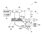
- FIG. 1 is a schematic view showing the configuration of an ophthalmic microscope system (hereinafter referred to as a microscope system) 100 according to the present embodiment.
- the microscope system 100 includes an ophthalmic microscope with an optometry attachment (hereinafter referred to as a microscope with an attachment) 10 and a camera control unit as a control device (hereinafter referred to as a CCU (Camera Control Unit)). .) 20, a display device 40, and an input device 41 are provided.
- the microscope 10 with an attachment is used by the user of the microscope system 100 to observe a magnified image of the eye 6 to be inspected in a medical examination or surgery in the field of ophthalmology.
- reference numeral 1 indicates the user's eye of the microscope 10 with an attachment.
- the user can perform a medical examination and an operation while looking at the display image displayed on the display device 40.
- the eye to be inspected 6 is the eye of a patient to be examined or operated on.
- the microscope 10 with an attachment includes an ophthalmic microscope (hereinafter referred to as a microscope) 11 and an optometry attachment 13.
- the microscope 11 includes a lens barrel main body 112 having an observation lens barrel 111, a microscope illumination light source 161 as an external illumination light source, and an intraocular illuminator 19.
- the microscope 11 can be an optical microscope having a general configuration. Two observation lens barrels 111 are provided for both the left and right eyes, but the present invention is not limited to this. Details of the microscope 10 with an attachment will be described later.
- the CCU 20 uses the information of the pre-optical system 130 of the optometry attachment 13 described later to perform image processing of the captured image acquired by the image pickup device 181 mounted on the microscope 11 to generate a display image. .. Details of CCU 20 will be described later.
- the display device 40 displays a display image that has been subjected to image processing by the CCU 20 based on the image captured by the image sensor 181.
- the display device 40 is a general display or a head-mounted display. Further, the display device 40 may be a plurality of displays, for example, a display for a doctor who operates and a display for an assistant.
- the input device 41 is an input interface to the microscope system 100.
- the user can input physical information of the patient, various information related to surgery, and the like via the input device 41. Further, for example, the user can input an instruction or the like to change various settings related to the microscope according to the situation via the input device 41.
- the type of the input device 41 is not limited, and the input device 41 may be various known input devices.
- the input device 41 for example, a mouse, a keyboard, a touch panel, a switch, a foot switch, a lever, or the like can be applied.
- the touch panel may be provided on the display surface of the display device 40.
- the input device 41 includes a microphone capable of collecting the user's voice, and various inputs may be performed by voice via the microphone.
- the input device 41 is configured to be able to input various information in a non-contact manner, so that a user belonging to a clean area can operate a device belonging to a dirty area in a non-contact manner.
- the convenience of the user is improved.
- FIG. 4 and 5 are schematic views showing a state of retinal vitreous surgery with the microscope system 100. 4 and 5 show the surgical tool T used for eye surgery.
- FIG. 4 is a schematic perspective view of the eyeball of the eye 6 to be inspected, showing a state in which the intraocular illuminator 19 and the surgical instrument T are inserted into the eye, and the front lens is not shown.
- FIG. 5 corresponds to a front view of the eye 6 to be inspected in which the wide-angle lens 132a or the magnifying lens 132b as the front lens is arranged in front, and before the intraocular illuminator 19 and the surgical tool T are inserted. Shows the state of.
- FIG. 6 is a partial cross-sectional view of the eye 6 to be inspected.
- the surgical tool T is suitable for the treatment at that time.
- the surgical tool T includes a vitreous cutter, forceps, a backflush needle, an ILM (internal limiting membrane) tweezers, a laser device for retinal photocoagulation, and the like.
- ILM internal limiting membrane
- the eye 6 to be inspected is composed of tissues such as the iris 61, the crystalline lens 65, and the cornea 66.
- the pupil 64 is located between the irises 61 on the surface of the crystalline lens 65, and the angle 62 is located on the peripheral edge of the cornea 66.
- the vitreous 68 is a jelly-like tissue that occupies most of the eyeball from the back of the crystalline lens 65 to the retina 69.
- reference numeral 671 indicates a blood vessel of the fundus 67.
- the surgical instrument is in a state where the intraocular illuminator 19 is inserted inside the eye 6 to be inspected and the inside of the eye is irradiated. T is inserted into the eye and surgery is performed.
- an intraocular illuminator 19 When performing surgery, an intraocular illuminator 19, a vitreous cutter that excises and sucks the vitreous body, and a tube (not shown) for injecting perfusate to maintain the shape of the eyeball during surgery are taken in and out.
- a tubular trocca 50 serving as a guide is arranged on the eye 6 to be inspected.
- the wide-angle lens 132a (or magnifying lens 132b) is provided corresponding to the black eye when placed in front of the eye 6 to be inspected.
- the pupil 64 is observed in a state of being considerably close to the edge of the wide-angle lens 132a (or the magnifying lens 132b) in order to observe the fundus 67.
- FIG. 2 is a block diagram showing the configuration of the microscope 10 with an attachment shown in FIG. As shown in FIG. 2, the microscope 10 with an attachment includes a microscope 11 and an optometry attachment 13.
- the microscope 11 includes an eyepiece unit 12, an inverted image correction inverter 14, an objective lens 15, a microscope illumination optical system 16, an observation optical system 17, a photographing system 18, and an intraocular illuminator 19.
- the eyepiece unit 12 is further enlarged for visually observing the image created by the observation optical system 17.
- the user can observe the image transmitted through the eyepiece lens unit 12 through the observation lens barrel 111.
- the image observed by eyepiece observation is referred to as an observation image.
- the lens barrel main body 112 accommodates an inverted image correction inverter 14, an objective lens 15, a part of the microscope illumination optical system 16, an observation optical system 17, and a photographing system 18.
- the inverted image correction inverter 14 performs an inversion process of returning an inverted image inverted by a wide-angle lens 132a (or a magnifying lens 132b) to a normal image.
- the inverted image correction inverter 14 is controlled to be turned on and off, for example, based on the detection result of the connection between the microscope 11 and the optometry attachment 13.
- the microscope illumination optical system 16 illuminates the eye 6 to be inspected through the objective lens 15.
- the microscope illumination optical system 16 is divided into a microscope illumination optical system for the user's left eye and a microscope illumination optical system for the right eye. In the following description, when it is not necessary to distinguish between the right eye and the left eye, it will be referred to as a microscope illumination optical system 16.
- the microscope illumination optical system 16 is housed in a microscope illumination light source 161 and an optical fiber 162 arranged outside the lens barrel main body 112 and a lens barrel main body 112, and each of them is not shown. It has a lens, a collimating lens, and a reflection mirror.
- the microscope illumination light source 161 emits illumination light for illuminating the eye 6 from the outside of the eye 6 during a medical examination, surgery, or the like.
- One end of the optical fiber 162 is connected to the microscope illumination light source 161 and the other end is connected to the lens barrel main body 112.
- the illumination light (external illumination light) output from the microscope illumination light source 161 is guided by the optical fiber 162 and incident on the condenser lens, and becomes a parallel luminous flux by the collimating lens.
- the parallel luminous flux illumination light is reflected by the reflection mirror toward the objective lens 15 and passes through the objective lens 15 to irradiate the eye 6 to be inspected.
- the illumination light applied to the eye 6 to be inspected is reflected and scattered by the tissues of the eye 6 to be inspected such as the cornea 66 and the retina 69.
- the reflected and scattered return light passes through the objective lens 15 and is incident on the observation optical system 17.
- the return light passes through the wide-angle lens 132a (or magnifying lens 132b) described later, the reduction lens 131 as an intermediate lens, and the objective lens 15, and the observation optical system. It is incident on 17.
- the intraocular illuminator 19 is provided outside the lens barrel main body 112 and illuminates the inside of the eye 6 to be inspected.
- the intraocular illuminator 19 has an intraocular illumination light source 191 and an optical fiber 192.
- the intraocular illumination light source 191 emits illumination light (intraocular illumination light) for illuminating the inside of the eye 6 to be inspected, for example, for vitrectomy, which requires observation of the fundus over a wide range.
- One end of the optical fiber 192 can be connected to the intraocular illumination light source 191 and the other end can be inserted inside the eye 6 to be inspected.
- the illumination light output from the intraocular illumination light source 191 is guided by the optical fiber 192, and the eye to be inspected 6 is guided from the other end of the optical fiber 192. It is emitted to the inside of.
- the observation optical system 17 is for observing the eye 6 illuminated by the microscope illumination optical system 16 and the intraocular illuminator 19 through the objective lens 15.
- the observation optical system 17 transmits the projected image of the eye 6 to be inspected to the user's eye 1 or the image sensor 181 described later.
- the return light (image of the optometry) reflected and scattered by the tissue of the optometry 6 is the pre-optical system 130 of the optometry attachment 13, which will be described later.
- the image is formed on the image pickup element 181 via the objective lens 15 and the observation optical system 17, or is incident on the optometry lens unit 12. More specifically, the return light transmits the wide-angle lens 132a (or magnifying lens 132b), the reduction lens 131 as an intermediate lens, the objective lens 15, and the observation optical system 17, and forms an image on the image pickup element 181 or an eyepiece. It is incident on the lens unit 12.
- the return light (image of the optometry eye) from the optometry 6 is connected to the image pickup element 181 via the objective lens 15 and the observation optical system 17. It is incident on the image or the eyepiece lens unit 12.
- the observation optical system 17 is divided into an observation optical system for the user's left eye and an observation optical system for the right eye, each of which has an observation optical path. In particular, when it is not necessary to distinguish between the right eye and the left eye, it will be referred to as an observation optical system 17.
- the observation optical system 17 includes a focusing device 171, a variable magnification lens system 172 including a plurality of zoom lenses, an imaging lens (not shown), a variable aperture 173, and a beam splitter (not shown).
- the focusing device 171 can move the microscope 10 with an attachment up and down. As a result, the movement interval between the objective lens 15 and the patient's eye 6 to be examined can be adjusted, and the microscope 10 with the attachment is focused on the examination target area of the eye 6 to be examined. Therefore, by controlling the focusing device 171, it is possible to control the focal position of the optical system through which the return light (image of the eye to be inspected) from the eye to be inspected 6 passes until the image is formed on the image sensor 181.
- the plurality of zoom lenses of the variable magnification lens system 172 can be moved along the optical axis of the observation optical system.
- the movement of the plurality of zoom lenses changes the magnification of the captured image of the eye 6 to be inspected. Therefore, by controlling the variable magnification lens system 172, it is possible to control the magnification of the optical system through which the return light (image of the eye to be inspected) from the eye to be inspected 6 passes until the image is formed on the image sensor 181.
- the angle of view of the image, the display image, and the observation image can be controlled.
- the depth of field of the optical system that the return light from the eye 6 to be inspected (the image of the eye to be inspected) passes through until the image is formed on the image sensor 181 depends on the focal length, the aperture value, and the shooting distance of the lens. Therefore, by controlling the focusing device 171 and the variable aperture 173, the depth of field of the optical system through which the return light (image of the eye to be inspected) from the eye to be inspected 6 passes until the image is formed on the image sensor 181 is controlled. Can be done.
- the return light incident on the observation optical system 17 is magnified by the variable magnification lens system 172, passes through the imaging lens and the variable diaphragm 173, and is incident on the beam splitter.
- the beam splitter guides a part of the return light to the photographing system 18 and guides the other part of the return light to the eyepiece unit 12. Eyepiece observation can be performed by the return light incident on the eyepiece lens unit 12.
- the photographing system 18 includes an imaging lens (not shown), an image sensor 181 and the like.
- the image sensor 181 is composed of an image sensor such as a CCD (Charge Coupled Devices) or a CMOS (Complementary Metal Oxide Semiconductor), for example.
- the light receiving surface of the image sensor 181 is arranged at a position optically conjugate with the focal position of the objective lens 15.
- the photographing system 18 may correspond to both the left and right observation optical systems 17, or may correspond to either the left or right observation optical system 17.
- two image pickup elements 181 are provided, whereby a stereo image can be obtained.
- the image sensor 181 is mounted on the microscope 10 with an attachment, and the eye 6 to be inspected can be photographed via the front optical system 130 and the observation optical system 17.
- the captured image captured by the image sensor 181 is output to the CCU 20.
- the optometry attachment 13 is removably arranged in the microscope 11. As shown in FIG. 1, the optometry attachment 13 is installed between the objective lens 15 and the optometry 6.
- the optometry attachment 13 has a joint portion 133, a front optical system 130, an arm 134, a holding plate 132c, and an arm drive unit 135.
- the joint portion 133 is a portion that detachably joins the optometry attachment 13 to the microscope 11.
- the attachment of the optometry attachment 13 to the microscope 11 can be detected by energizing the contacts arranged at the portion where the optometry attachment 13 and the microscope 11 are in contact with each other. In this way, the bonding may be detected depending on whether or not the power is turned on, or a bonding state switching switch is provided so that the user can switch the bonding between the optometry attachment 13 and the microscope 11 by the switch. May be good.
- the front optical system 130 includes a reduction lens 131, a wide-angle lens 132a as a front lens, and a magnifying lens 132b.
- the wide-angle lens 132a or magnifying lens 132b
- the reduction lens 131 and the objective lens are on the observation optical path. 15.
- the observation optical system 17 is located.
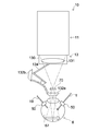
- FIG. 7 is a schematic view showing a state of eye surgery using a microscope 10 with an attachment to which an optometry attachment 13 is attached.
- FIG. 7 shows a state in which the wide-angle lens 132a is arranged in front of the eye 6 to be inspected.
- the reduction lens 131 displaces the focal plane of the observation optical path of the microscope 10 with an attachment so that it coincides with the intermediate image plane 70.
- the reduction lens 131 is not always necessary depending on the optical system of the microscope, but when a wide-angle lens is used as the front lens, the optometry attachment typically includes a reduction lens in addition to the wide-angle lens.
- the wide-angle lens 132a enables observation of the fundus 67 of the eye 6 to be inspected.
- the wide-angle lens 132a By arranging the wide-angle lens 132a in the observation optical path, it is possible to observe the fundus 67 of the eye 6 to be inspected.
- the wide-angle lens 132a produces an intermediate image in which the fundus 67 is inverted on the intermediate image plane 70.
- the magnifying lens 132b is for magnifying and observing the eye 6 to be inspected.
- the wide-angle lens 132a and the magnifying lens 132b are each held by a holding plate 132c connected to the tip of the arm 134.
- the wide-angle lens 132a and the magnifying lens 132b are fixedly arranged at both ends of the holding plate 132c having a longitudinal direction.
- the central portion of the holding plate 132c is rotatably connected to the tip of the arm 134.
- the user can select whether the lens to be arranged in front of the eye 6 to be examined is a wide-angle lens 132a or a magnifying lens 132b by rotating the holding plate 132c according to the situation.
- the switching between the wide-angle lens 132a and the magnifying lens 132b by the rotational movement of the holding plate 132c may be performed manually or may be configured to be performed automatically.
- the arm 134 supports the pre-optical system 130.
- the arm 134 has a first link 134a, a second link 134c, and a joint portion 134b, and the arm 134 is foldable.
- the first link 134a and the second link 134c are connected via the joint portion 134b, and are configured so that the positional relationship can be changed by the joint portion 134b.
- the end of the first link 134a opposite to the end where the joint 134b is located is joined to the joint 133, and the first link 134a is configured to have a variable positional relationship with respect to the joint 133.
- the end of the second link 134c opposite to the end where the joint 134b is located corresponds to the tip of the arm 134, to which the holding plate 132c is connected.
- the positional relationship between the second link 134c and the holding plate 132c is configured to be variable.
- the positions of the reduction lens 131, the wide-angle lens 132a, and the magnifying lens 132b can be changed.
- the wide-angle lens 132a (or the magnifying lens 132b) can be positioned or removed from the observation optical path.
- the positions of the reduction lens 131, the wide-angle lens 132a, and the magnifying lens 132b can be changed by moving the arm 134 and the holding plate 132c.
- the arm drive unit 135 is composed of an actuator provided on the joint unit 134b and drives the arm 134.
- the arm drive unit 135 is controlled based on the microscope control signal generated by the CCU 20.
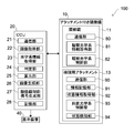
- the microscope 11 includes a communication unit 80, an observation optical system information acquisition unit 81, and an observation optical system control unit 82 that controls the observation optical system 17.
- the communication unit 80 communicates wirelessly or by wire with an external device such as the CCU 20.
- the communication unit 80 transmits the captured image captured by the image sensor 181 to the CCU 20.
- the communication unit 80 receives the microscope control signal generated by the CCU 20.
- the observation optical system information acquisition unit 81 acquires the state information of the observation optical system 17.
- the state information of the observation optical system 17 includes focal position information that changes depending on the position of the focusing device 171 and magnification (aperture angle) information that changes depending on the position of each lens in the variable magnification lens system 172 including a plurality of zoom lenses.
- the focal position information can also be said to be the position information of the focusing device 171.
- the magnification (angle of view) information can also be said to be the position information of each lens in the variable magnification lens system 172.
- the aperture value information can also be said to be the aperture state information of the variable aperture 173.
- the observation optical system control unit 82 controls the observation optical system 17. More specifically, the observation optical system control unit 82 controls the focusing device 171, the variable magnification lens system, and the variable aperture 173 based on the microscope control signal generated by the CCU 20 based on the information about the front optical system 130. ..
- the optometry attachment 13 includes a communication unit 90, an information storage unit 91, a state information acquisition unit 92, a pre-optical system control unit 93, and a state detection unit 94.
- the communication unit 90 communicates wirelessly or by wire with an external device such as the CCU 20.
- the communication unit 90 transmits the optical characteristic information of the pre-optical system 130 stored in the information storage unit 91 to the CCU 20.
- the communication unit 90 receives the microscope control signal generated by the CCU 20. Further, when the connection between the microscope 11 and the optometry attachment 13 is detected, the communication unit 90 transmits information to the CCU 20 that the connection is in the state of connection.
- the communication unit 90 of the optometry attachment 13 and the communication unit 21 of the CCU 20 described later directly communicate with each other will be described as an example, but the present invention is not limited to this.
- the communication unit 90 of the optometry attachment 13 and the communication unit 80 of the microscope 11 can communicate with each other, and the communication unit 90 of the optometry attachment 13 and the communication unit 21 of the CCU 20 communicate with each other via the communication unit 80 of the microscope 11. It may be configured to be used.
- the information storage unit 91 stores the optical characteristic information of the pre-optical system 130 in advance.
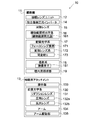
- the optical characteristic information of the front optical system 130 includes at least one of the functional characteristic information of the front lens (wide-angle lens 132a, magnifying lens 132b), the shape of the front lens, and the material of the front lens.
- the functional characteristic information includes at least one of the focal length, distortion coefficient, refractive index, wavelength characteristic, polarization characteristic, NA (Numerical Aperture), and depth of field of each of the wide-angle lens 132a and the magnifying lens 132b as the front lens. One is included.
- the information storage unit 91 stores specific optical characteristic information of the front optical system 130, but the present invention is not limited to this.
- a different ID may be assigned to each of the different types of pre-optical systems, and the information storage unit 91 may store this ID as optical characteristic information.
- the ID of the pre-optical system and the specific optical characteristic information of the pre-optical system associated with the ID are stored in a database on a server which is an external device (not shown).
- the CCU 20 acquires an ID from the microscope 10 with an attachment via the communication unit 21, and then acquires specific optical characteristic information of the pre-optical system corresponding to the ID from the database on the server.
- the storage unit 28 of the CCU 20 described later stores the IDs assigned to the different types of pre-optical systems in advance and the specific optical characteristic information associated with the IDs. You may.
- the CCU 20 acquires stage optical characteristic information of the pre-optical system corresponding to the ID from the storage unit 28 based on the ID acquired from the microscope 10 with the attachment.
- a different ID is assigned to each type of the pre-optical system, and this ID can be used to acquire specific optical characteristic information of the pre-optical system from an external device or by a CCU. Good.
- the state information acquisition unit 92 acquires the state information of the front optical system 130.
- the state information includes the reduction lens 131, the wide-angle lens 132a, the magnifying lens 132b, and the position information of each lens.
- the position information of each lens can be detected by using, for example, an encoder (not shown).
- the state information may include distance information between lenses, orientation information of each lens by switching between the wide-angle lens 132a and the magnifying lens 132b, and the like.
- the state information is information that fluctuates due to the movement of the arm 134 and the holding plate 132c.
- the inter-lens distance information is, for example, the distance between the wide-angle lens 132a or the magnifying lens 132b and the reduction lens 131.
- the distance between lenses may be calculated using the position information of each lens.
- the lens orientation information is switching information between the wide-angle lens 132a and the magnifying lens 132b that can be arranged in front of the eye 6 to be inspected, and is information related to the orientation of the lens with respect to the eye 6 to be inspected. For example, when the wide-angle lens 132a is arranged in front of the eye 6 to be inspected, the wide-angle lens 132a is positioned in front of the eye 6 to be inspected, and the magnifying lens 132b is oriented so as not to be located in front of the eye 6 to be inspected. It becomes the direction information. In other words, the lens switching information can be said to be rotation information of the holding plate 132c.
- the front optical system control unit 93 controls the front optical system 130. More specifically, the front optical system control unit 93 controls the arm drive unit 135 based on the microscope control signal generated by the CCU 20 based on the information about the front optical system 130. As a result, the arm 134 is driven to change the positions of the reduction lens 131, the wide-angle lens 132a, and the magnifying lens 132b, and the distance between the reduction lens 131 and the wide-angle lens 132a (or the magnifying lens 132b) can be changed. ..
- the state detection unit 94 detects the presence / absence of connection between the optometry attachment 13 and the microscope 11 based on the presence / absence of energization of contacts arranged at a portion where the optometry attachment 13 and the microscope 11 are in contact with each other. Further, the state detection unit 94 detects mechanical changes in the front optical system 130, for example, the movement of the arm 134 and the movement of the holding plate 132c. The information detected by the state detection unit 94 is transmitted to the CCU 20.
- the CCU 20 includes a communication unit 21, an image acquisition unit 22, an optical system information acquisition unit 23, a determination unit 24, a calculation unit 25, an image generation unit 26, a microscope control signal generation unit 27, and a storage unit 28.
- a communication unit 21 an image acquisition unit 22, an optical system information acquisition unit 23, a determination unit 24, a calculation unit 25, an image generation unit 26, a microscope control signal generation unit 27, and a storage unit 28.
- the communication unit 21 wirelessly or wiredly communicates with an external device such as a display device 40, a microscope 11 of a microscope 10 with an attachment, and an optometry attachment 13.
- an external device such as a display device 40, a microscope 11 of a microscope 10 with an attachment, and an optometry attachment 13.
- the communication unit 21 receives, for example, information about the pre-optical system 130 from the optometry attachment 13.
- the communication unit 21 receives the information detected by the state detection unit 94 from the optometry attachment 13.
- the information detected by the state detection unit 94 receives information that the microscope 11 and the optometry attachment 13 are in a bonded state and information on the presence or absence of mechanical changes in the pre-optical system 130.
- the communication unit 21 receives the state information of the observation optical system 17 from the microscope 11. In addition, the communication unit 21 receives the captured image from the microscope 11.
- the communication unit 21 transmits the microscope control signal generated by using the information of the front optical system 130 to the microscope 11 and the optometry attachment 13.
- the communication unit 21, the communication unit 80, and the communication unit 90 may be configured to perform wired communication, for example, via a communication cable, Wifi, Bluetooth (registered trademark), and a short-range wireless communication system (NFC (Near)). It may be configured to perform wireless communication such as Field Communication)).
- the image acquisition unit 22 acquires an image captured by the image sensor 181 from the microscope 11 via the communication unit 21.
- the optical system information acquisition unit 23 acquires information about the optical system of the microscope 10 with an attachment via the communication unit 21.
- the information regarding the optical system of the microscope 10 with attachment includes the optical characteristic information of the front optical system 130 and the optical system through which the return light (image of the eye to be inspected) from the eye to be inspected 6 passes until the image is formed on the image sensor 181. Contains information about.
- the information about the optical system that the return light passes through before forming an image on the image sensor 181 includes the state information of the pre-optical system 130 and the state information of the observation optical system 17.
- the optical characteristic information and the state information of the front optical system 130 which are information about the front optical system 130, are acquired from the optometry attachment 13.
- the optical characteristic information of the front optical system 130 is information stored in advance in the information storage unit 137 of the optometry attachment 13.
- the optical system information acquisition unit 23 acquires the optical characteristic information of the pre-optical system 130 stored in the information storage unit 137.
- the state information of the front optical system 130 is information acquired by the state information acquisition unit 92 of the optometry attachment 13.
- the optical system information acquisition unit 23 acquires the state information of the pre-optical system 130 acquired by the state information acquisition unit 92.
- the optical system information acquisition unit 23 acquires the state information of the observation optical system 17 acquired by the observation optical system information acquisition unit 81 of the microscope 11.
- the determination unit 24 determines whether or not the optometry attachment 13 and the microscope 11 are joined based on the detection result of the state detection unit 94.
- the communication unit 21 receives the detection result that the state detection unit 94 has detected the connection between the microscope 11 and the optometry attachment 13, the determination unit 24 joins the optometry attachment 13 and the microscope 11. If it is not received, it is determined that it is not joined.
- the determination unit 24 determines whether or not the state of the front optical system 130 has changed based on the detection result of the state detection unit 94.
- the determination unit 24 determines that the state change of the front optical system 130 has occurred. If it is not received, it is determined that there is no state change. In this way, the presence or absence of a change in the state of the front optical system 130 may be determined based on the change in the physical movement in the optometry attachment 13, or the captured image may be used for image recognition. The presence or absence of a state change of the front optical system 130 may be determined.
- the determination unit 24 determines whether or not the state of the front optical system 130 has changed based on the detection result of the movement of the arm 134 and the movement of the holding plate 132c by the state detection unit 94. I gave it, but it is not limited to this. For example, when there is a change in the position information detected by the encoders of the reduction lens 131, the wide-angle lens 132a, and the magnifying lens 132b, it may be determined that the state of the front optical system 130 has changed.
- the calculation unit 25 uses the information about the optical system of the microscope 10 with the attachment acquired by the optical system information acquisition unit 23 to correct the captured image, and the return light from the eye 6 of the microscope 10 with the attachment is the image sensor.
- the focal position of the optical system until the image is formed on 181 is calculated.
- a magnification suitable for the display image is calculated.
- the calculation unit 25 sets the correction parameters as follows. calculate. That is, for example, the calculation unit 25 uses the distortion coefficient of the wide-angle lens 132a as the optical characteristic information of the front optical system 130, and the distortion aberration is corrected so that the distortion of the captured image due to the arrangement of the wide-angle lens 132a is corrected. Calculate the correction parameters.
- the calculation unit 25 determines the focal position as follows. Calculate the magnification. That is, the calculation unit 25 aims so that the position of the rear focal point of the front lens (wide-angle lens 132a or the magnifying lens 132b) coincides with the position of the front focal point of the objective lens 15 and the fundus 67 is in focus.
- the focal position is calculated so as to adjust the relative positional relationship with the lens 15, the front lens (wide-angle lens 132a or the magnifying lens 132b), and the eye 6 to be inspected, and the magnification is calculated.
- the image generation unit 26 corrects the captured image based on the correction parameters calculated by the calculation unit 25, performs image processing such as color enhancement as necessary to generate a display image, and via the communication unit 21. Is output to the display device 40.
- the microscope control signal generation unit 27 generates a microscope control signal based on the calculation results of the magnification and the focal position calculated by the calculation unit 25, and outputs the microscope control signal to the microscope 10 with an attachment via the communication unit 21.
- the microscope control signal includes at least one of a control signal related to the control of the observation optical system 17 of the microscope 11 and a control signal related to the control of the pre-optical system 130 of the optometry attachment 13.
- the storage unit 28 stores the information acquired by the optical system information acquisition unit 23 in chronological order. Further, the storage unit 28 stores the distortion aberration correction parameter, the focal position, and the magnification calculated by the calculation unit 25.
- FIG. 8 is a flow chart showing the operation of the CCU 20.
- FIG. 9 is a diagram for explaining an image correction process using the optical characteristic information of the front optical system 130.
- FIG. 9A is a schematic view showing a captured image of the eye to be inspected which has not been subjected to the inversion process and the distortion correction process.
- FIG. 9B is a schematic view showing a display image which has not been subjected to inversion processing and has been subjected to distortion aberration correction processing.
- FIG. 9C is a schematic view showing a display image to which the inversion process and the distortion aberration correction process are performed.
- the communication unit 21 acquires an image captured by the image sensor 181 and a detection result detected by the state detection unit 94 from the microscope 10 with an attachment (St1).
- the captured image is output to the image acquisition unit 22.
- the detection result is output to the determination unit 24.
- the captured image G will be described with reference to FIG. 9A.
- the region inside the peripheral edge S of the wide-angle lens 132a is the inverted region R1 in which the image is inverted.
- the inversion region R1 is a region in which an image is formed by a wide-angle lens 132a as a front lens.
- a region where the image is not inverted is shown as a non-inverted region R2.
- distortion is generated by the wide-angle lens 132a, and the surgical tool T whose actual object is linear is curved.
- the determination unit 24 determines whether or not the optometry attachment 13 and the microscope 11 are joined based on the detection result received by the communication unit 21, or if the optometry attachment 13 is already joined, the pre-optical The presence or absence of a state change in the system 130 is determined (St2).
- the process proceeds to St3. On the other hand, when it is determined that the optometry attachment 13 and the microscope 11 are not joined or the state of the pre-optical system 130 does not change (NO), the process returns to St1 and the process is repeated.
- the optical system information acquisition unit 23 acquires information on the pre-optical system 130 and state information of the observation optical system 17.
- the distortion coefficient (optical characteristic information of the front optical system) of the wide-angle lens 132a (or magnifying lens 132b) as the front lens and the state of the front optical system 130 Information is acquired.
- the state information of the observation optical system 17 the magnification (angle of view) information of the observation optical system 17 is acquired.
- the information acquired by the optical system information acquisition unit 23 is stored in the storage unit 28 in chronological order.
- the calculation unit 25 uses the wide-angle lens 132a by using the distortion coefficient of the wide-angle lens 132a (or the magnifying lens 132b), the state information of the pre-optical system 130, and the magnification (image angle) information of the observation optical system 17.
- the distortion correction parameter for correcting the distortion on the captured image is calculated (St4).
- the magnification information of the observation optical system 17 is used to calculate the range to which the distortion aberration correction is applied in the captured image.
- the distortion aberration correction parameter is recalculated.
- the calculated distortion aberration correction parameter is stored in the storage unit 28.
- the image generation unit 26 may perform distortion aberration correction processing of the captured image using the distortion aberration correction parameter calculated by the calculation unit 25, or may perform correction processing such as enhancement processing.
- the display image generated by the image processing is output to the display device 40 (St5).
- the display device 40 displays the display image generated by the image generation unit 26.
- the distortion in the region of the inversion region R1 is reduced, and the shape of the surgical tool T in the image becomes linear as in the actual product. ..
- the inverted image correction inverter 14 performs an inversion process in which the inverted image of the inversion region R1 is made a normal image. Due to the inversion process by the inverted image correction inverter 14, the inverted region R1 that has become an inverted image due to the presence of the wide-angle lens becomes a normal image, while the non-inverted region that does not have a wide-angle lens and does not become an inverted image. The image is inverted in the region R2. The non-inverted region R2 whose image is inverted by the inverted image correction inverter 14 is subjected to inversion correction processing by the image generation unit 26 so as to be a normal image.
- the image generation unit 26 synthesizes the inverted region R1 that has become a normal image by the inverted processing of the inverted image correction inverter 14, and the non-inverted region R2 that has undergone the inverted correction processing, and FIG. 9C shows.
- a display image that does not give a sense of discomfort to the user is generated.
- the inversion process by the inverted image correction inverter 14 may be configured so that, for example, when the state detection unit 94 detects the connection between the optometry attachment 13 and the microscope 11, the inversion process is performed by the inverted image correction inverter 14. Good.
- the inversion processing is performed after the distortion aberration correction processing is given, but the order is not limited, and the distortion aberration correction processing may be performed after the inversion processing, or may be performed at the same time. Not done.
- the process shown in FIG. 8 is repeated.
- the distortion correction processing suitable for the state of the optical system of the microscope 10 with the attachment at that time is performed on the captured image, so that the user can use the image. , It is possible to perform surgery while always observing an appropriate display image.
- the distortion coefficient of the front lens is used as the optical characteristic information of the front optical system 130 and the captured image is subjected to distortion correction processing to generate a display image. Not limited.
- the maximum magnification of the digital zoom may be controlled by using the material information of the front lens as the optical characteristic information of the front optical system 130 to generate a display image.
- the front lens is made of, for example, plastic or glass. Since the resolution of a lens such as an MTF (Modulation Transfer Function) differs depending on the material of the front lens, the maximum magnification of the digital zoom may be controlled by the material of the front lens so that the magnification cannot exceed the resolution of the front lens. ..
- MTF Modulation Transfer Function
- the specular reflection component is obtained from the polarized image (image taken) taken by the image sensor by a known method.
- a display image may be generated by performing a specular reflection removal process for removal.
- the captured image may be subjected to chromatic aberration correction processing to generate a display image by using the shape information of the lens constituting the front optical system 130 as the optical characteristic information of the front optical system 130.
- the parallax of the stereo image may be controlled by using the focal length of the front optical system 130 as the optical characteristic information of the front optical system 130 to generate a display image.
- the distortion aberration correction processing is automatically performed using the distortion coefficient, but the user may select whether or not to perform the distortion aberration correction processing.
- a menu button for selecting whether or not to perform distortion aberration correction processing on the display surface May be displayed so that the user can select whether or not to perform distortion correction processing.
- a menu button for selecting whether or not to perform specular reflection removal processing is displayed on the display surface, and the user selects whether or not to perform specular reflection removal processing. You may be able to do it.
- the optometry attachment 13 since the optometry attachment 13 has the optical characteristic information of the pre-optical system in advance, the optical characteristic information is used to provide the user with a display image suitable for the situation. be able to.
- the microscope system 100 even if there is a change in the state of the front optical system 130, for example, a change in the positions of the front lens and the reduction lens due to the movement of the arm 134 and the holding plate 132c, information on the optical system of the microscope 10 with attachment can be obtained. Image processing is performed using this, and it is possible to always provide the user with a display image or an observation image suitable for the situation.
- the optical characteristic information of the front optical system 130 is used to pass the return light from the optical system of the microscope 10 with an attachment, more specifically, the return light from the eye 6 to be examined until the image is formed on the image pickup element 181.
- a microscope control signal for controlling the optical system is generated, and the optical system of the microscope 10 with an attachment is automatically adjusted based on the microscope control signal.
- FIG. 10 is a flow chart showing the operation of the CCU 20.
- the communication unit 21 acquires an image captured by the image sensor 181 and a detection result detected by the state detection unit 94 from the microscope 10 with an attachment (St21).
- the captured image is output to the image acquisition unit 22.
- the detection result is output to the determination unit 24.
- the determination unit 24 determines whether or not the optometry attachment 13 and the microscope 11 are joined based on the detection result received by the communication unit 21, or if the optometry attachment 13 is already joined, the pre-optical The presence or absence of a state change in the system 130 is determined (St22).
- the process proceeds to St23.
- the process returns to St21 and the process is repeated.
- the optical system information acquisition unit 23 acquires information on the pre-optical system 130 and state information of the observation optical system 17 as optical system information.
- the focal length (optical characteristic information) of the wide-angle lens 132a (or the magnifying lens 132b) as the front lens and the state information of the front optical system 130 are acquired. ..
- the state information of the front optical system 130 is the position information of each lens.
- information such as the magnification (angle of view), the focal position, and the aperture value of the observation optical system 17 is acquired.
- the information acquired by the optical system information acquisition unit 23 is stored in the storage unit 28 in chronological order.
- the calculation unit 25 uses the state information of the front optical system 130, the state information of the observation optical system 17, and the focal length of the wide-angle lens 132a (or the magnifying lens 132b) to generate the return light from the eye 6 to be inspected.
- the focal length and magnification of the optical system that passes through the image pickup element 181 before forming an image are calculated. That is, the calculation unit 25 aims so that the position of the rear focal point of the front lens (wide-angle lens 132a or the magnifying lens 132b) coincides with the position of the front focal point of the objective lens 15 and the fundus 67 is in focus.
- the focal position is calculated so as to adjust the relative positional relationship with the lens 15, the front lens (wide-angle lens 132a or the magnifying lens 132b), and the eye 6 to be inspected.
- a magnification suitable for the display image is calculated.
- the calculated focal position and magnification are stored in the storage unit 28.
- the microscope control signal generation unit 27 generates a microscope control signal for controlling each of the focusing device 171 and the variable magnification lens system 172 of the microscope 11 based on the calculated focal position and magnification, and has an attachment. It is output to the microscope 10 (St25). In this way, the process shown in FIG. 10 is repeated.
- the observation optical system control unit 82 controls the driving of the focusing device 171 and the variable magnification lens system 172 based on the microscope control signal generated by the CCU 20.
- the focal position and magnification of the optical system of the microscope 10 with the attachment to which the optometry attachment 13 is attached are automatically adjusted, and the image of the eye 6 to be observed through the front lens is observed with an appropriate display image. can do.
- the pre-optical system 130 may be controlled so that the magnification and the focal position can be adjusted.
- St25 generates and outputs a microscope control signal for driving the arm drive unit 135 of the optometry attachment 13.
- both the observation optical system 17 and the pre-optical system 130 may be controlled.
- St25 generates and outputs a microscope control signal for controlling the driving of the focusing device 171 and the variable magnification lens system 172 and a microscope control signal for driving the arm driving unit 135.
- the lens shape (for example, the curvature of the lens) is changed by electrical control such as applying pressure to the reduction lens 131 and the front lens (wide-angle lens 132a and magnifying lens 132b) constituting the front optical system 130 with an electromagnetic actuator.
- a tunable lens variable focus lens
- the optical characteristic information of the tunable lens (optical characteristic information of the front optical system), the state information of the front optical system 130 acquired from the microscope 10 with the attachment, and the state information of the observation optical system 17 are obtained. It is used to generate a microscope control signal.
- This microscope control signal is a reduction lens made of a tunable lens, a front lens, so that the position of the back focus of the front lens and the position of the front focus of the objective lens 15 coincide with each other and the fundus 67 is in focus. This is a signal for changing the lens shape of the lens.
- the optical characteristic information of the tunable lens includes the focal length range associated with each other, the distortion coefficient of the lens, the shape, and the like that the tunable lens can take.
- the observation optical system uses the NA (Numerical Aperture) of the front optical system and the depth of field information as the optical characteristic information of the front optical system 130. It may be configured to control the variable aperture 173 of 17. For example, when the depth of field of the front optical system 130 is shallow, the variable aperture 173 is controlled so that the depth of field of the observation optical system 17 is deep.
- NA Numerical Aperture
- a display device and an imaging element are not always necessary, and the present technology is applied by a user who does not use the display device. It can also be applied to an ophthalmic microscope system that performs observation and surgery by eyepiece observation with a microscope. Also in this system, the user can observe the image of the eye 6 to be observed through the front lens with an appropriate observation image.
- the optical system that the return light from the optometry 6 passes through before forming an image on the image sensor 181 is controlled. By doing so, it is possible to provide the user with a display image or an observation image of the eye 6 to be inspected suitable for a situation in which the focal position is adjusted.
- the user does not have to worry about adjusting the optical system of the microscope 10 with the attachment by joining the optometry attachment 13.
- the optometry attachment 13 having the front optical system 130 has the optical characteristic information of the front optical system 130, it assists the user in setting the microscope. can do.
- the optics of the microscope 10 with the attachment is controlled using the information about the system, and it is possible to always provide the user with a display image or an observation image suitable for the situation where the focal point is located.
- the inversion process is performed by using the inverted image correction inverter 14, but the present invention is not limited to this, and the image captured by the image sensor 181 is image-processed.
- the inversion process may be performed by the above, and will be described with reference to FIG.
- FIG. 9A is a schematic view showing an image of an eye to be inspected that has not been subjected to inversion processing and distortion correction processing.
- FIG. 9C is a schematic view showing a display image to which the inversion process and the distortion aberration correction process are performed.
- the surgical instrument T is projected in a considerably curved form through the wide-angle lens 132a.
- the distortion coefficient of the captured image G is corrected by using the distortion coefficient of the wide-angle lens 132a, which is the optical characteristic information of the front optical system, and further, the inversion processing is performed by the image processing.
- the image of the surgical instrument T becomes linear, and a display image in which the inverted region R1 is inverted is obtained.
- the inversion region R1 in the captured image G is detected by the inversion region detection unit (not shown) included in the CCU 20.
- the inversion region R1 can be detected by using object recognition. Further, the outside of the front lens (wide-angle lens 132a and magnifying lens 132b) is a region corresponding to the sclera (white eye 63), while the inside of the front lens has a color and texture like the iris and the pupil. It is also possible to detect the inverted region R1 by utilizing the fact that the appearance is a different region (black eye).
- the peripheral edge S of the front lens in the captured image since a clear edge exists on the peripheral edge S of the front lens in the captured image, it is possible to perform edge detection processing and detect the region inside the detected edge as the inversion region R1.
- the above detection method detects the inverted region R1 from one captured image.
- the image sensors 181 are mounted on the left and right sides of the microscope 10 with attachments, it is possible to obtain images captured by both the left eye and the right eye. Depth information can be extracted from the parallax information of these two captured images, and the inverted region R1 can be detected by utilizing the fact that the front lens is in front of the eye.
- the inverted region R1 it is also possible to detect the inverted region R1 by using a plurality of captured images. Specifically, the captured image when the front lens is not attached is retained, the captured image is compared with the captured image including the front lens, and the region having a large difference is detected as the inverted region R1. You may.
- the detected range of the inverted region R1 is supplied to the image generation unit 26.
- the image generation unit 26 inverts the inverted region R1 included in the captured image G output from the image sensor 181 so as to be point-symmetrical with the center of the inverted region R1 as the center point. Further, the image generation unit 26 synthesizes the inverted region R1 and the non-inverted region R2 by matching the outer circumference of the inverted inverted region R1 with the inner circumference of the non-inverted region R2.
- the image generation unit 26 can generate a display image in which the inversion is eliminated, as shown in FIG. 9C.
- the image generation unit 26 outputs the generated display image to the display device 40 and displays it on the display device 40.
- the display image may be generated by performing inversion processing by image processing, and the user can observe and treat the eye 6 to be inspected while observing the display image displayed on the display device 40. ..
- a wide-angle lens for observing the fundus of the eye has been described as an example, but an angle mirror may be used.
- the angle can be observed by using an angle mirror.
- the angle mirror is used in contact with the eye 6 to be inspected.
- intraocular illumination and reduction lens are not required.
- the optometry attachment 13 is configured to include two front lenses, a wide-angle lens 132a and a magnifying lens 132b, but may be configured to include one front lens.
- the wide-angle lens 132a and the magnifying lens 132b may be detachably configured with respect to the holding plate 132c, respectively, and the type of front lens to be used can be changed to any one. it can.
- the holding plate 132c may be configured to be detachable from the arm 134, and the front lens can be changed to an arbitrary one in the same manner.
- the information storage unit 91 of the optometry attachment 13 provides optical characteristic information of the newly mounted front lens. It may be configured so that the ID can be written. As a result, it is not necessary to change the microscope 11, and the optometry attachment can be made highly customizable and expandable.
- a joint that can be joined to an ophthalmic microscope A pre-optical system that includes a pre-lens that can be placed in front of the eye to be inspected, An optometry attachment equipped with a communication unit that transmits information about the above-mentioned pre-optical system to an external device.
- An optometry attachment further comprising a storage unit that stores optical characteristic information of the pre-optical system as information on the pre-optical system.
- the optical characteristic information of the front optical system is an optometry attachment including at least one of the functional characteristic information of the front lens, the shape of the front lens, and the material of the front lens.
- the functional characteristic information is an optometry attachment including at least one of the focal length, distortion coefficient, refractive index, wavelength characteristic, and polarization characteristic of the front lens.
- An optometry attachment further comprising a state information acquisition unit that acquires state information of the optical system as information on the pre-optical system.
- the state information of the front optical system is an attachment for optometry including the position information of the front lens.
- the optometry attachment according to (6) above has the front lens and an intermediate lens arranged between the front lens and the ophthalmologic microscope.
- the state information of the front optical system is an optometry attachment that further includes at least one of the position information of the intermediate lens and the distance information between the intermediate lens and the front lens.
- the optometry attachment according to (2) above is configured to be replaceable,
- the storage unit is an optometry attachment in which the optical characteristic information of the front optical system can be written.
- An optometry attachment further comprising a pre-optical system control unit that controls the pre-optical system based on a control signal from the external device.
- a control device including a communication unit for receiving information about the optometry, which is included in an optometry attachment having a optometry including a front lens that can be placed in front of the eye to be inspected.
- control device (11) The control device according to (10) above.
- An image acquisition unit that acquires an image of the eye to be inspected with the front lens placed in front
- a control device further comprising an image generation unit that performs image processing on the captured image using information on the pre-optical system to generate a display image.
- the control device is a control device further including a storage unit that stores optical characteristic information of the front optical system as information about the front optical system.
- the control device according to (11) or (12) above.
- the information about the front optical system includes the distortion coefficient of the front lens.
- the image generation unit is a control device that uses the distortion coefficient to correct distortion in the captured image and generate the display image.
- the control device according to (11) or (12) above.
- the information regarding the front optical system includes the material of the front lens.
- the image generation unit is a control device that controls the maximum magnification based on the material of the lens to generate the display image.
- the control device according to (11) or (12) above.
- the information about the front optical system includes the polarization characteristics of the front lens.
- the image generation unit is a control device that generates the display image by performing specular reflection removal processing on the captured image based on the polarization characteristics of the front lens.
- the control device according to (11) or (12) above.
- the information about the front optical system includes the shape of the front lens.
- the image generation unit is a control device that uses the shape information of the front lens to perform chromatic aberration correction processing on the captured image to generate the display image.
- the control device according to (11) or (12) above.
- the above captured image is a stereo image
- the information about the front optical system includes the focal length of the front lens.
- the image generation unit is a control device that uses the focal length of the front lens to control the parallax of the stereo image to generate the display image.
- the control device according to any one of (10) to (17) above.
- the optometry attachment is configured to be connectable to an ophthalmic microscope having an observation optical system.
- a control device further comprising a microscope control signal generation unit that generates a control signal for controlling at least one of the observation optical system and the pre-optical system by using the information about the pre-optical system.
- the ophthalmic microscope system according to (19) above.
- the ophthalmic microscope further includes an image sensor.
- the control device captures the captured image by using the image acquisition unit that acquires the captured image of the eye to be inspected in which the front lens is arranged in front and the information about the front optical system taken by the image sensor.
- An ophthalmic microscope system further comprising an image generator that processes and generates a display image.
- the ophthalmic microscope system according to (19) or (20) above.
- the ophthalmic microscope further includes an observation optical system.
- the control device is an ophthalmic microscope further comprising a microscope control signal generation unit that generates a control signal for controlling at least one of the observation optical system and the pre-optical system by using information about the pre-optical system. system.
Abstract
[Problem] To provide an optometry attachment, a control device, and an ophthalmic microscope system that can provide an image suitable for observing an eye to be examined. [Solution] An optometry attachment according to the present technology is provided with a junction part, a front optical system, and a communication unit. The junction part can be joined to an ophthalmic microscope. The front optical system includes a front lens that can be disposed in front of the eye to be examined. The communication unit transmits information on the front optical system to an external device.
Description
本技術は、眼科手術等に利用される検眼用アタッチメント、制御装置及び眼科用顕微鏡システムに関する。
This technology relates to optometry attachments, control devices and ophthalmic microscope systems used in ophthalmic surgery and the like.
眼科手術において、前置レンズを有する検眼用アタッチメントが眼科手術顕微鏡に追加されて用いられることがある。網膜硝子体手術では広角レンズが、隅角を処置する低侵襲緑内障手術(MIGS:minimally invasive glaucoma surgery)では隅角鏡が、それぞれ前置レンズとして広く使われている。
In ophthalmic surgery, an optometry attachment with a front lens may be added to the ophthalmic surgery microscope. A wide-angle lens is widely used as a front lens in vitrectomy, and an angle mirror is widely used as a front lens in minimally invasive glaucoma surgery (MIGS), which treats the angle.
例えば、検眼用アタッチメントである広角レンズを含む広角観察用アタッチメントが追加された眼科手術顕微鏡は、広い範囲の眼底を観察するのに適している。この広角観察用アタッチメントが追加されることにより、広角レンズを介して得られる被検眼の像に歪が生じる。また、広角観察用アタッチメントが追加されることにより顕微鏡内の様々な光学条件が変更される。
For example, an ophthalmologic operating microscope to which an attachment for wide-angle observation including a wide-angle lens, which is an attachment for optometry, is added is suitable for observing a wide range of fundus. The addition of this wide-angle observation attachment causes distortion in the image of the eye to be inspected obtained through the wide-angle lens. In addition, various optical conditions in the microscope are changed by adding the attachment for wide-angle observation.
特許文献1には、検眼用アタッチメントの接合により顕微鏡の像反転用システムがオンに切り替わることが記載されている。
Patent Document 1 describes that the image inversion system of the microscope is switched on by joining the optometry attachment.
検眼用アタッチメントが追加された際、観察に適した被検眼の像を顕微鏡のユーザに対して提供することが望まれている。
When an optometry attachment is added, it is desired to provide the user of the microscope with an image of the optometry that is suitable for observation.
以上のような事情に鑑み、本技術の目的は、被検眼の観察に適した像を提供することができる検眼用アタッチメント、制御装置及び眼科用顕微鏡システムを提供することにある。
In view of the above circumstances, the purpose of this technique is to provide an optometry attachment, a control device, and an ophthalmic microscope system capable of providing an image suitable for observing the eye to be examined.
上記目的を達成するため、本技術の一形態に係る検眼用アタッチメントは、接合部と、前置光学系と、通信部を具備する。
上記接合部は、眼科用顕微鏡に接合可能である。
上記前置光学系は、被検眼の前に配置可能な前置レンズを含む。
上記通信部は、上記前置光学系に関する情報を外部機器へ送信する。 In order to achieve the above object, the optometry attachment according to one embodiment of the present technology includes a joint, a pre-optical system, and a communication unit.
The joint can be joined to an ophthalmic microscope.
The front optical system includes a front lens that can be placed in front of the eye to be inspected.
The communication unit transmits information about the pre-optical system to an external device.
この構成によれば、検眼用アタッチメントが有する前置光学系に関する情報を外部機器へ提供することができる。
According to this configuration, it is possible to provide information on the pre-optical system of the optometry attachment to an external device.
上記前置光学系に関する情報として上記前置光学系の光学特性情報を記憶する記憶部を更に具備してもよい。
A storage unit for storing optical characteristic information of the pre-optical system may be further provided as information regarding the pre-optical system.
上記前置光学系の光学特性情報は、上記前置レンズの機能的特性情報、上記前置レンズの形状、上記前置レンズの材質のうち少なくとも一つを含んでもよい。
The optical characteristic information of the front optical system may include at least one of the functional characteristic information of the front lens, the shape of the front lens, and the material of the front lens.
上記機能的特性情報は、上記前置レンズの、焦点距離、歪係数、屈折率、波長特性、偏光特性のうち少なくとも一つを含んでもよい。
The functional characteristic information may include at least one of the focal length, distortion coefficient, refractive index, wavelength characteristic, and polarization characteristic of the front lens.
上記前置光学系に関する情報として上記光学系の状態情報を取得する状態情報取得部を更に具備してもよい。
A state information acquisition unit for acquiring state information of the optical system may be further provided as information regarding the pre-optical system.
上記前置光学系の状態情報は、上記前置レンズの位置情報を含んでもよい。
The state information of the front optical system may include the position information of the front lens.
上記前置光学系は、上記前置レンズと、上記前置レンズと上記眼科用顕微鏡との間に配置される中間レンズを有し、上記前置光学系の状態情報は、上記中間レンズの位置情報、上記中間レンズと上記前置レンズとの距離情報のうち少なくとも一つを更に含んでもよい。
The front optical system has the front lens and an intermediate lens arranged between the front lens and the ophthalmic microscope, and the state information of the front optical system is the position of the intermediate lens. Information, at least one of the distance information between the intermediate lens and the front lens may be further included.
上記前置レンズは取り換え可能に構成され、上記記憶部は、上記前置光学系の光学特性情報が書き込み可能に構成されてもよい。
The front lens may be configured to be replaceable, and the storage unit may be configured to be writable with optical characteristic information of the front optical system.
上記外部機器からの制御信号に基づいて、上記前置光学系を制御する前置光学系制御部を更に具備してもよい。
A pre-optical system control unit that controls the pre-optical system based on the control signal from the external device may be further provided.
上記目的を達成するため、本技術の一形態に係る制御装置は、通信部を具備する。
上記通信部は、被検眼の前に配置可能な前置レンズを含む前置光学系を備える検眼用アタッチメントが有する上記前置光学系に関する情報を受信する。 In order to achieve the above object, the control device according to one embodiment of the present technology includes a communication unit.
The communication unit receives information about the anterior optical system of an optometry attachment having an anterior optical system including an anterior lens that can be placed in front of the eye to be inspected.
上記前置レンズが前に配置された被検眼の撮像画像を取得する画像取得部と、上記前置光学系に関する情報を用いて上記撮像画像に画像処理を行って表示画像を生成する画像生成部を更に具備してもよい。
An image acquisition unit that acquires an image of the eye to be inspected in which the front lens is arranged in front, and an image generation unit that performs image processing on the captured image using information about the front optical system to generate a display image. May be further provided.
上記検眼用アタッチメントは、上記前置光学系に関する情報として上記前置光学系の光学特性情報を記憶する記憶部を更に備えてもよい。
The optometry attachment may further include a storage unit that stores optical characteristic information of the pre-optical system as information regarding the pre-optical system.
上記前置光学系に関する情報は上記前置レンズの歪係数を含み、
上記画像生成部は、上記歪係数を用いて上記撮像画像に歪曲収差補正を行って上記表示画像を生成してもよい。 The information about the front optical system includes the distortion coefficient of the front lens.
The image generation unit may generate the display image by correcting the distortion of the captured image using the distortion coefficient.
上記画像生成部は、上記歪係数を用いて上記撮像画像に歪曲収差補正を行って上記表示画像を生成してもよい。 The information about the front optical system includes the distortion coefficient of the front lens.
The image generation unit may generate the display image by correcting the distortion of the captured image using the distortion coefficient.
上記前置光学系に関する情報は上記前置レンズの材質を含み、上記画像生成部は、上記レンズの材質に基づいて最大倍率を制御して上記表示画像を生成してもよい。
The information regarding the front optical system includes the material of the front lens, and the image generation unit may generate the display image by controlling the maximum magnification based on the material of the lens.
上記前置光学系に関する情報は上記前置レンズの偏光特性を含み、上記画像生成部は、上記前置レンズの偏光特性に基づいて、上記撮像画像に鏡面反射除去処理を行って上記表示画像を生成してもよい。
The information regarding the front optical system includes the polarization characteristics of the front lens, and the image generation unit performs specular reflection removal processing on the captured image based on the polarization characteristics of the front lens to display the display image. It may be generated.
上記前置光学系に関する情報は上記前置レンズの形状を含み、上記画像生成部は、上記前置レンズの形状情報を用いて、上記撮像画像に色収差補正処理を行って上記表示画像を生成してもよい。
The information regarding the front optical system includes the shape of the front lens, and the image generation unit uses the shape information of the front lens to perform chromatic aberration correction processing on the captured image to generate the display image. You may.
上記撮像画像はステレオ画像であり、上記前置光学系に関する情報は上記前置レンズの焦点距離を含み、上記画像生成部は、上記前置レンズの焦点距離を用いて、上記ステレオ画像の視差を制御して上記表示画像を生成してもよい。
The captured image is a stereo image, the information about the front optical system includes the focal length of the front lens, and the image generator uses the focal length of the front lens to obtain the disparity of the stereo image. The display image may be generated under control.
上記検眼用アタッチメントは、観察光学系を有する眼科用顕微鏡に接合可能に構成され、上記前置光学系に関する情報を用いて、上記観察光学系、上記前置光学系のうち少なくとも一方を制御する制御信号を生成する顕微鏡制御信号生成部を更に具備してもよい。
The optometry attachment is configured to be connectable to an ophthalmic microscope having an observation optical system, and is controlled to control at least one of the observation optical system and the pre-optical system by using information on the pre-optical system. A microscope control signal generation unit that generates a signal may be further provided.
上記目的を達成するため、本技術の一形態に係る眼科用顕微鏡システムは、眼科用顕微鏡と、検眼用アタッチメントと、制御装置を具備する。
上記検眼用アタッチメントは、上記眼科用顕微鏡に接合する接合部と、被検眼の前に配置可能な前置レンズを含む前置光学系と、上記前置光学系に関する情報を送信する通信部と、を備える。
上記制御装置は、上記前置光学系に関する情報を受信する通信部を備える。 In order to achieve the above object, the ophthalmologic microscope system according to one embodiment of the present technology includes an ophthalmology microscope, an optometry attachment, and a control device.
The optometry attachment includes a junction to be joined to the ophthalmic microscope, a pre-optical system including a pre-lens that can be placed in front of the eye to be inspected, and a communication unit that transmits information about the pre-optical system. To be equipped.
The control device includes a communication unit that receives information about the pre-optical system.
上記眼科用顕微鏡は、撮像素子を更に備え、上記制御装置は、上記撮像素子により撮影された上記前置レンズが前に配置された被検眼の撮像画像を取得する画像取得部と、上記前置光学系に関する情報を用いて上記撮像画像を画像処理して表示画像を生成する画像生成部を更に備える。
The ophthalmic microscope further includes an image pickup element, and the control device includes an image acquisition unit for acquiring an image of the eye to be inspected in which the front lens taken by the image pickup element is arranged in front, and the front lens. An image generation unit that processes the captured image using information about the optical system to generate a display image is further provided.
上記眼科用顕微鏡は、観察光学系を更に備え、上記制御装置は、上記前置光学系に関する情報を用いて、上記観察光学系、上記前置光学系のうち少なくとも一つを制御する制御信号を生成する顕微鏡制御信号生成部を更に備える。
The ophthalmic microscope further includes an observation optical system, and the control device uses information about the pre-optical system to generate a control signal for controlling at least one of the observation optical system and the pre-optical system. It further includes a microscope control signal generation unit to generate.
本技術の実施形態に係る眼科用顕微鏡システムについて説明する。ここでは、顕微鏡に、検眼用アタッチメントとして、広角レンズ(前置レンズ)を含む前置光学系を備えた広角観察用アタッチメントを接合した眼科用顕微鏡を用いて、網膜硝子体手術を行う例をあげて説明する。
The ophthalmic microscope system according to the embodiment of the present technology will be described. Here, an example of performing vitrectomy using an ophthalmic microscope in which a wide-angle observation attachment equipped with a front optical system including a wide-angle lens (front lens) is attached to the microscope as an attachment for optometry is given. I will explain.
本実施形態において、医師や補助者等の眼科用顕微鏡のユーザが、顕微鏡をのぞく代わりに撮像素子で撮影された映像を表示装置で見ながら観察や手術を行うことが可能なHUS(Heads Up Surgery)システムに適用した例をあげて説明する。表示装置には、顕微鏡に備えられた撮像素子により撮影された撮像画像に画像処理が施された術野画像となる表示画像が表示される。
In the present embodiment, HUS (Heads Up Surgery) enables a user of an ophthalmic microscope such as a doctor or an assistant to observe and perform surgery while viewing an image taken by an image sensor on a display device instead of looking through the microscope. ) An example applied to the system will be explained. On the display device, a display image is displayed, which is a surgical field image obtained by performing image processing on the captured image taken by the image sensor provided in the microscope.
検眼用アタッチメントは、前置光学系の情報を有しており、本実施形態の眼科用顕微鏡システムでは、前置光学系に関する情報である前置光学系の光学特性情報を用いて撮像画像の画像処理が行われる。
The optometry attachment has information on the pre-optical system, and in the ophthalmic microscope system of the present embodiment, the image of the captured image is used by using the optical characteristic information of the pre-optical system, which is information on the pre-optical system. Processing is done.
また、検眼用アタッチメントは、前置光学系の状態情報を取得する状態情報取得部を有しており、本実施形態の眼科用顕微鏡システムでは、前置光学系に関する情報である前置光学系の状態情報を用いて顕微鏡の光学系が制御される。
Further, the optometry attachment has a state information acquisition unit for acquiring state information of the front optical system, and in the ophthalmic microscope system of the present embodiment, the front optical system is information about the front optical system. The optical system of the microscope is controlled using the state information.
[眼科用顕微鏡システムの構成]
図1は本実施形態に係る眼科用顕微鏡システム(以下、顕微鏡システムと称する。)100の構成を示す模式図である。 [Configuration of ophthalmic microscope system]
FIG. 1 is a schematic view showing the configuration of an ophthalmic microscope system (hereinafter referred to as a microscope system) 100 according to the present embodiment.
図1は本実施形態に係る眼科用顕微鏡システム(以下、顕微鏡システムと称する。)100の構成を示す模式図である。 [Configuration of ophthalmic microscope system]
FIG. 1 is a schematic view showing the configuration of an ophthalmic microscope system (hereinafter referred to as a microscope system) 100 according to the present embodiment.
図1に示すように、顕微鏡システム100は、検眼用アタッチメント付き眼科用顕微鏡(以下、アタッチメント付き顕微鏡と称する。)10と、制御装置としてのカメラコントロールユニット(以下、CCU(Camera Control Unit)と称する。)20と、表示装置40と、入力装置41を備える。
As shown in FIG. 1, the microscope system 100 includes an ophthalmic microscope with an optometry attachment (hereinafter referred to as a microscope with an attachment) 10 and a camera control unit as a control device (hereinafter referred to as a CCU (Camera Control Unit)). .) 20, a display device 40, and an input device 41 are provided.
アタッチメント付き顕微鏡10は、眼科分野における診察や手術において被検眼6の拡大像を顕微鏡システム100のユーザが観察するために使用される。図中、符号1はアタッチメント付き顕微鏡10のユーザの眼を示す。ユーザは、表示装置40に表示される表示画像を見ながら、診察や手術を行うことができる。被検眼6は、診察や手術の対象となる患者の眼である。
The microscope 10 with an attachment is used by the user of the microscope system 100 to observe a magnified image of the eye 6 to be inspected in a medical examination or surgery in the field of ophthalmology. In the figure, reference numeral 1 indicates the user's eye of the microscope 10 with an attachment. The user can perform a medical examination and an operation while looking at the display image displayed on the display device 40. The eye to be inspected 6 is the eye of a patient to be examined or operated on.
アタッチメント付き顕微鏡10は、眼科用顕微鏡(以下、顕微鏡と称する。)11と、検眼用アタッチメント13とを備える。
顕微鏡11は、観察用鏡筒111を有する鏡筒本体112と、眼外用照明光源としての顕微鏡照明光源161と、眼内用照明器19を備える。 Themicroscope 10 with an attachment includes an ophthalmic microscope (hereinafter referred to as a microscope) 11 and an optometry attachment 13.
Themicroscope 11 includes a lens barrel main body 112 having an observation lens barrel 111, a microscope illumination light source 161 as an external illumination light source, and an intraocular illuminator 19.
顕微鏡11は、観察用鏡筒111を有する鏡筒本体112と、眼外用照明光源としての顕微鏡照明光源161と、眼内用照明器19を備える。 The
The
顕微鏡11は、一般的構成を有する光学顕微鏡とすることができる。観察用鏡筒111は、左右両眼用に二つ設けられているが、これに限定されない。
アタッチメント付き顕微鏡10の詳細については後述する。 Themicroscope 11 can be an optical microscope having a general configuration. Two observation lens barrels 111 are provided for both the left and right eyes, but the present invention is not limited to this.
Details of themicroscope 10 with an attachment will be described later.
アタッチメント付き顕微鏡10の詳細については後述する。 The
Details of the
CCU20は、後述する検眼用アタッチメント13の前置光学系130の情報を用いて、顕微鏡11にマウントされている後述する撮像素子181により取得された撮像画像の画像処理を行って表示画像を生成する。
CCU20の詳細については後述する。 TheCCU 20 uses the information of the pre-optical system 130 of the optometry attachment 13 described later to perform image processing of the captured image acquired by the image pickup device 181 mounted on the microscope 11 to generate a display image. ..
Details ofCCU 20 will be described later.
CCU20の詳細については後述する。 The
Details of
表示装置40は、撮像素子181で取得された撮像画像を基にCCU20で画像処理が施されてなる表示画像を表示する。表示装置40は一般的なディスプレイやヘッドマウントディスプレイである。また、表示装置40は複数のディスプレイであってもよく、例えば執刀する医師用のディスプレイと補助者用のディスプレイとすることができる。
The display device 40 displays a display image that has been subjected to image processing by the CCU 20 based on the image captured by the image sensor 181. The display device 40 is a general display or a head-mounted display. Further, the display device 40 may be a plurality of displays, for example, a display for a doctor who operates and a display for an assistant.
入力装置41は、顕微鏡システム100に対する入力インターフェースである。ユーザは、入力装置41を介して、患者の身体情報や、手術に関する各種の情報等を入力することができる。また、例えば、ユーザは、入力装置41を介して、状況に応じた顕微鏡に係る各種設定を変更する旨の指示等を入力することができる。
The input device 41 is an input interface to the microscope system 100. The user can input physical information of the patient, various information related to surgery, and the like via the input device 41. Further, for example, the user can input an instruction or the like to change various settings related to the microscope according to the situation via the input device 41.
入力装置41の種類は限定されず、入力装置41は各種の公知の入力装置であってよい。入力装置41としては、例えば、マウス、キーボード、タッチパネル、スイッチ、フットスイッチ、レバー等が適用され得る。入力装置41としてタッチパネルが用いられる場合には、当該タッチパネルは表示装置40の表示面上に設けられてもよい。
The type of the input device 41 is not limited, and the input device 41 may be various known input devices. As the input device 41, for example, a mouse, a keyboard, a touch panel, a switch, a foot switch, a lever, or the like can be applied. When a touch panel is used as the input device 41, the touch panel may be provided on the display surface of the display device 40.
また、入力装置41は、ユーザの声を集音可能なマイクロフォンを含み、当該マイクロフォンを介して音声によって各種の入力が行われてもよい。このように、入力装置41が非接触で各種の情報を入力可能に構成されることにより、特に清潔域に属するユーザが、不潔域に属する機器を非接触で操作することが可能となる。また、ユーザは、所持している術具から手を離すことなく機器を操作することが可能となるため、ユーザの利便性が向上する。
Further, the input device 41 includes a microphone capable of collecting the user's voice, and various inputs may be performed by voice via the microphone. As described above, the input device 41 is configured to be able to input various information in a non-contact manner, so that a user belonging to a clean area can operate a device belonging to a dirty area in a non-contact manner. In addition, since the user can operate the device without taking his / her hand off the surgical tool he / she has, the convenience of the user is improved.
図4及び図5は、顕微鏡システム100での網膜硝子体手術の様子を示す概略図である。図4及び図5には眼の手術に用いられる術具Tを示す。図4は被検眼6の眼球の概略斜視図であり、眼内用照明器19及び術具Tが眼内に挿入された様子を示し、前置レンズの図示は省略している。図5は、前置レンズとしての広角レンズ132a又は拡大レンズ132bが前に配置された被検眼6を正面方向からみた図に相当し、眼内用照明器19及び術具Tが挿入される前の様子を示す。
図6は、被検眼6の部分断面図である。 4 and 5 are schematic views showing a state of retinal vitreous surgery with themicroscope system 100. 4 and 5 show the surgical tool T used for eye surgery. FIG. 4 is a schematic perspective view of the eyeball of the eye 6 to be inspected, showing a state in which the intraocular illuminator 19 and the surgical instrument T are inserted into the eye, and the front lens is not shown. FIG. 5 corresponds to a front view of the eye 6 to be inspected in which the wide-angle lens 132a or the magnifying lens 132b as the front lens is arranged in front, and before the intraocular illuminator 19 and the surgical tool T are inserted. Shows the state of.
FIG. 6 is a partial cross-sectional view of theeye 6 to be inspected.
図6は、被検眼6の部分断面図である。 4 and 5 are schematic views showing a state of retinal vitreous surgery with the
FIG. 6 is a partial cross-sectional view of the
術具Tには、その時の処置に適したものが使用される。例えば、術具Tとしては、硝子体カッター、鉗子、バックフラッシュニードル、ILM(internal limiting membrane:内境界膜)鑷子、網膜光凝固用のレーザ装置等ある。
The surgical tool T is suitable for the treatment at that time. For example, the surgical tool T includes a vitreous cutter, forceps, a backflush needle, an ILM (internal limiting membrane) tweezers, a laser device for retinal photocoagulation, and the like.
図5及び図6に示すように、被検眼6は、虹彩61、水晶体65及び角膜66等の組織で構成されている。水晶体65の表面において虹彩61の間が瞳孔64であり、角膜66の周縁には隅角62が位置する。硝子体68は、水晶体65の後方から網膜69に達するまでの眼球の大部分を占めるゼリー状の組織である。図5において、符号671は眼底67の血管を示す。
As shown in FIGS. 5 and 6, the eye 6 to be inspected is composed of tissues such as the iris 61, the crystalline lens 65, and the cornea 66. The pupil 64 is located between the irises 61 on the surface of the crystalline lens 65, and the angle 62 is located on the peripheral edge of the cornea 66. The vitreous 68 is a jelly-like tissue that occupies most of the eyeball from the back of the crystalline lens 65 to the retina 69. In FIG. 5, reference numeral 671 indicates a blood vessel of the fundus 67.
図4に示すように、網膜硝子体手術では、眼底67の観察を必要とするため、眼内用照明器19が被検眼6の内部に挿入されて眼内が照射された状態で、術具Tが眼内に挿入されて手術が行われる。手術を行う際、眼内用照明器19、硝子体を切除、吸引する硝子体カッター、術中に眼球の形態を保つための灌流液を注入するための管(図示せず)を出し入れするためのガイドとなる筒状のトロッカ50が被検眼6上に配置される。
As shown in FIG. 4, since retinal vitreous surgery requires observation of the fundus 67, the surgical instrument is in a state where the intraocular illuminator 19 is inserted inside the eye 6 to be inspected and the inside of the eye is irradiated. T is inserted into the eye and surgery is performed. When performing surgery, an intraocular illuminator 19, a vitreous cutter that excises and sucks the vitreous body, and a tube (not shown) for injecting perfusate to maintain the shape of the eyeball during surgery are taken in and out. A tubular trocca 50 serving as a guide is arranged on the eye 6 to be inspected.
図5に示すように、広角レンズ132a(又は拡大レンズ132b)は、被検眼6の前に配置した際、黒目に対応して設けられる。広角レンズ132aを用いた広角観察では、眼底67を観察するため、瞳孔64は広角レンズ132a(又は拡大レンズ132b)の縁にかなり近づいた状態で観察される。
As shown in FIG. 5, the wide-angle lens 132a (or magnifying lens 132b) is provided corresponding to the black eye when placed in front of the eye 6 to be inspected. In the wide-angle observation using the wide-angle lens 132a, the pupil 64 is observed in a state of being considerably close to the edge of the wide-angle lens 132a (or the magnifying lens 132b) in order to observe the fundus 67.
[検眼用アタッチメント付き眼科用顕微鏡の構成]
次に、アタッチメント付き顕微鏡10について説明する。
図2は、図1に示すアタッチメント付き顕微鏡10の構成を示す構成ブロック図である。
図2に示すように、アタッチメント付き顕微鏡10は、顕微鏡11と、検眼用アタッチメント13を備える。 [Construction of an ophthalmic microscope with an optometry attachment]
Next, themicroscope 10 with an attachment will be described.
FIG. 2 is a block diagram showing the configuration of themicroscope 10 with an attachment shown in FIG.
As shown in FIG. 2, themicroscope 10 with an attachment includes a microscope 11 and an optometry attachment 13.
次に、アタッチメント付き顕微鏡10について説明する。
図2は、図1に示すアタッチメント付き顕微鏡10の構成を示す構成ブロック図である。
図2に示すように、アタッチメント付き顕微鏡10は、顕微鏡11と、検眼用アタッチメント13を備える。 [Construction of an ophthalmic microscope with an optometry attachment]
Next, the
FIG. 2 is a block diagram showing the configuration of the
As shown in FIG. 2, the
(眼科用顕微鏡の構成)
顕微鏡11は、接眼レンズユニット12と、倒立像補正用インバータ14と、対物レンズ15と、顕微鏡照明光学系16と、観察光学系17と、撮影系18と、眼内用照明器19を備える。 (Construction of ophthalmic microscope)
Themicroscope 11 includes an eyepiece unit 12, an inverted image correction inverter 14, an objective lens 15, a microscope illumination optical system 16, an observation optical system 17, a photographing system 18, and an intraocular illuminator 19.
顕微鏡11は、接眼レンズユニット12と、倒立像補正用インバータ14と、対物レンズ15と、顕微鏡照明光学系16と、観察光学系17と、撮影系18と、眼内用照明器19を備える。 (Construction of ophthalmic microscope)
The
接眼レンズユニット12は、観察光学系17でつくられた像を眼で観察するために更に拡大する。ユーザは、接眼レンズユニット12を伝送した像を、観察用鏡筒111により接眼観察することができる。以下、接眼観察により観察される像を観察像と称する。
The eyepiece unit 12 is further enlarged for visually observing the image created by the observation optical system 17. The user can observe the image transmitted through the eyepiece lens unit 12 through the observation lens barrel 111. Hereinafter, the image observed by eyepiece observation is referred to as an observation image.
鏡筒本体112は、倒立像補正用インバータ14と、対物レンズ15と、顕微鏡照明光学系16の一部と、観察光学系17と、撮影系18を収容する。
The lens barrel main body 112 accommodates an inverted image correction inverter 14, an objective lens 15, a part of the microscope illumination optical system 16, an observation optical system 17, and a photographing system 18.
倒立像補正用インバータ14は、広角レンズ132a(又は拡大レンズ132b)により反転した倒立像を正像に戻す反転処理を行うものである。
倒立像補正用インバータ14は、例えば、顕微鏡11と検眼用アタッチメント13との接合の検知結果に基づいて、オン、オフが制御される。 The inverted image correction inverter 14 performs an inversion process of returning an inverted image inverted by a wide-angle lens 132a (or a magnifying lens 132b) to a normal image.
The inverted image correction inverter 14 is controlled to be turned on and off, for example, based on the detection result of the connection between themicroscope 11 and the optometry attachment 13.
倒立像補正用インバータ14は、例えば、顕微鏡11と検眼用アタッチメント13との接合の検知結果に基づいて、オン、オフが制御される。 The inverted image correction inverter 14 performs an inversion process of returning an inverted image inverted by a wide-
The inverted image correction inverter 14 is controlled to be turned on and off, for example, based on the detection result of the connection between the
顕微鏡照明光学系16は、対物レンズ15を介して、被検眼6を照明する。
顕微鏡照明光学系16は、ユーザの左眼用の顕微鏡照明光学系と右眼用の顕微鏡照明光学系に分かれている。以下の説明で、特に右眼用、左眼用とで区別する必要がない場合は顕微鏡照明光学系16と称して説明する。 The microscope illuminationoptical system 16 illuminates the eye 6 to be inspected through the objective lens 15.
The microscope illuminationoptical system 16 is divided into a microscope illumination optical system for the user's left eye and a microscope illumination optical system for the right eye. In the following description, when it is not necessary to distinguish between the right eye and the left eye, it will be referred to as a microscope illumination optical system 16.
顕微鏡照明光学系16は、ユーザの左眼用の顕微鏡照明光学系と右眼用の顕微鏡照明光学系に分かれている。以下の説明で、特に右眼用、左眼用とで区別する必要がない場合は顕微鏡照明光学系16と称して説明する。 The microscope illumination
The microscope illumination
図1及び図2に示すように、顕微鏡照明光学系16は、鏡筒本体112外に配置される顕微鏡照明光源161及び光ファイバ162と、鏡筒本体112内に収容され、それぞれ図示しない集光レンズ、コリメートレンズ、反射ミラーを有する。
As shown in FIGS. 1 and 2, the microscope illumination optical system 16 is housed in a microscope illumination light source 161 and an optical fiber 162 arranged outside the lens barrel main body 112 and a lens barrel main body 112, and each of them is not shown. It has a lens, a collimating lens, and a reflection mirror.
顕微鏡照明光源161は、診察や手術時等に被検眼6の外側から被検眼6を照明するための照明光を発する。
光ファイバ162の一端は顕微鏡照明光源161に接続され、他端は鏡筒本体112に接続される。
顕微鏡照明光源161から出力された照明光(眼外用照明光)は、光ファイバ162により導光されて集光レンズに入射し、コリメートレンズにより平行光束となる。平行光束化された照明光は反射ミラーで対物レンズ15に向けて反射し、対物レンズ15を透過して被検眼6を照射する。被検眼6に照射された照明光は、角膜66や網膜69等の被検眼6の組織で反射、散乱される。
その反射、散乱した戻り光は、検眼用アタッチメント13が観察光路上に位置しない場合は、対物レンズ15を透過して、観察光学系17に入射する。一方、検眼用アタッチメント13が観察光路上に位置する場合、戻り光は、後述する広角レンズ132a(又は拡大レンズ132b)、中間レンズとしてのリダクションレンズ131、対物レンズ15を透過して、観察光学系17に入射する。 The microscopeillumination light source 161 emits illumination light for illuminating the eye 6 from the outside of the eye 6 during a medical examination, surgery, or the like.
One end of theoptical fiber 162 is connected to the microscope illumination light source 161 and the other end is connected to the lens barrel main body 112.
The illumination light (external illumination light) output from the microscopeillumination light source 161 is guided by the optical fiber 162 and incident on the condenser lens, and becomes a parallel luminous flux by the collimating lens. The parallel luminous flux illumination light is reflected by the reflection mirror toward the objective lens 15 and passes through the objective lens 15 to irradiate the eye 6 to be inspected. The illumination light applied to the eye 6 to be inspected is reflected and scattered by the tissues of the eye 6 to be inspected such as the cornea 66 and the retina 69.
When theoptometry attachment 13 is not located on the observation optical path, the reflected and scattered return light passes through the objective lens 15 and is incident on the observation optical system 17. On the other hand, when the optometry attachment 13 is located on the observation optical path, the return light passes through the wide-angle lens 132a (or magnifying lens 132b) described later, the reduction lens 131 as an intermediate lens, and the objective lens 15, and the observation optical system. It is incident on 17.
光ファイバ162の一端は顕微鏡照明光源161に接続され、他端は鏡筒本体112に接続される。
顕微鏡照明光源161から出力された照明光(眼外用照明光)は、光ファイバ162により導光されて集光レンズに入射し、コリメートレンズにより平行光束となる。平行光束化された照明光は反射ミラーで対物レンズ15に向けて反射し、対物レンズ15を透過して被検眼6を照射する。被検眼6に照射された照明光は、角膜66や網膜69等の被検眼6の組織で反射、散乱される。
その反射、散乱した戻り光は、検眼用アタッチメント13が観察光路上に位置しない場合は、対物レンズ15を透過して、観察光学系17に入射する。一方、検眼用アタッチメント13が観察光路上に位置する場合、戻り光は、後述する広角レンズ132a(又は拡大レンズ132b)、中間レンズとしてのリダクションレンズ131、対物レンズ15を透過して、観察光学系17に入射する。 The microscope
One end of the
The illumination light (external illumination light) output from the microscope
When the
眼内用照明器19は、鏡筒本体112の外部に設けられ、被検眼6の内部を照明する。
眼内用照明器19は、眼内用照明光源191と光ファイバ192とを有する。
眼内用照明光源191は、例えば広い範囲の眼底の観察を必要とする網膜硝子体手術等の被検眼6の内部を照射するための照明光(眼内用照明光)を発する。
光ファイバ192の一端は眼内用照明光源191に接続され、他端は被検眼6の内部に挿入され得る。 Theintraocular illuminator 19 is provided outside the lens barrel main body 112 and illuminates the inside of the eye 6 to be inspected.
Theintraocular illuminator 19 has an intraocular illumination light source 191 and an optical fiber 192.
The intraocularillumination light source 191 emits illumination light (intraocular illumination light) for illuminating the inside of the eye 6 to be inspected, for example, for vitrectomy, which requires observation of the fundus over a wide range.
One end of theoptical fiber 192 can be connected to the intraocular illumination light source 191 and the other end can be inserted inside the eye 6 to be inspected.
眼内用照明器19は、眼内用照明光源191と光ファイバ192とを有する。
眼内用照明光源191は、例えば広い範囲の眼底の観察を必要とする網膜硝子体手術等の被検眼6の内部を照射するための照明光(眼内用照明光)を発する。
光ファイバ192の一端は眼内用照明光源191に接続され、他端は被検眼6の内部に挿入され得る。 The
The
The intraocular
One end of the
図4に示すように、被検眼6の眼底67を観察する場合、眼内用照明光源191から出力された照明光は、光ファイバ192で導光され、光ファイバ192の他端から被検眼6の内部へ出射される。
As shown in FIG. 4, when observing the fundus 67 of the eye 6 to be inspected, the illumination light output from the intraocular illumination light source 191 is guided by the optical fiber 192, and the eye to be inspected 6 is guided from the other end of the optical fiber 192. It is emitted to the inside of.
図2に示すように、観察光学系17は、顕微鏡照明光学系16や眼内用照明器19により照明されている被検眼6を、対物レンズ15を介して観察するためのものである。観察光学系17は、被検眼6の投影像をユーザの眼1或いは後述する撮像素子181に伝送する。
As shown in FIG. 2, the observation optical system 17 is for observing the eye 6 illuminated by the microscope illumination optical system 16 and the intraocular illuminator 19 through the objective lens 15. The observation optical system 17 transmits the projected image of the eye 6 to be inspected to the user's eye 1 or the image sensor 181 described later.
検眼用アタッチメント13が接合された状態のアタッチメント付き顕微鏡10では、被検眼6の組織で反射、散乱された戻り光(被検眼の像)は、後述する検眼用アタッチメント13の前置光学系130、対物レンズ15、観察光学系17を介して撮像素子181に結像、又は、接眼レンズユニット12に入射する。
より詳細には、戻り光は、広角レンズ132a(又は拡大レンズ132b)、中間レンズとしてのリダクションレンズ131、対物レンズ15、観察光学系17を伝送して、撮像素子181に結像、又は、接眼レンズユニット12に入射する。 In themicroscope 10 with an attachment in which the optometry attachment 13 is joined, the return light (image of the optometry) reflected and scattered by the tissue of the optometry 6 is the pre-optical system 130 of the optometry attachment 13, which will be described later. The image is formed on the image pickup element 181 via the objective lens 15 and the observation optical system 17, or is incident on the optometry lens unit 12.
More specifically, the return light transmits the wide-angle lens 132a (or magnifying lens 132b), the reduction lens 131 as an intermediate lens, the objective lens 15, and the observation optical system 17, and forms an image on the image pickup element 181 or an eyepiece. It is incident on the lens unit 12.
より詳細には、戻り光は、広角レンズ132a(又は拡大レンズ132b)、中間レンズとしてのリダクションレンズ131、対物レンズ15、観察光学系17を伝送して、撮像素子181に結像、又は、接眼レンズユニット12に入射する。 In the
More specifically, the return light transmits the wide-
一方、検眼用アタッチメント13が接合されていない状態のアタッチメント付き顕微鏡10では、被検眼6からの戻り光(被検眼の像)は、対物レンズ15、観察光学系17を介して撮像素子181に結像、又は、接眼レンズユニット12に入射する。
On the other hand, in the microscope 10 with an attachment in which the optometry attachment 13 is not joined, the return light (image of the optometry eye) from the optometry 6 is connected to the image pickup element 181 via the objective lens 15 and the observation optical system 17. It is incident on the image or the eyepiece lens unit 12.
観察光学系17は、ユーザの左眼用の観察光学系と右眼用の観察光学系に分かれており、それぞれに観察光路を有している。特に右眼用、左眼用とで区別する必要がない場合は観察光学系17と称して説明する。
The observation optical system 17 is divided into an observation optical system for the user's left eye and an observation optical system for the right eye, each of which has an observation optical path. In particular, when it is not necessary to distinguish between the right eye and the left eye, it will be referred to as an observation optical system 17.
観察光学系17は、フォーカシング装置171と、複数のズームレンズを含む変倍レンズ系172と、結像レンズ(図示せず)と、可変絞り173と、ビームスプリッタ(図示せず)を有する。
The observation optical system 17 includes a focusing device 171, a variable magnification lens system 172 including a plurality of zoom lenses, an imaging lens (not shown), a variable aperture 173, and a beam splitter (not shown).
フォーカシング装置171により、アタッチメント付き顕微鏡10を上下動させることができる。これにより、対物レンズ15と患者の被検眼6との間の動作間隔を調整することができ、アタッチメント付き顕微鏡10は被検眼6の診察対象領域にフォーカシングされる。したがって、フォーカシング装置171を制御することにより、被検眼6からの戻り光(被検眼の像)が撮像素子181に結像するまでに通過する光学系の焦点位置を制御することができる。
The focusing device 171 can move the microscope 10 with an attachment up and down. As a result, the movement interval between the objective lens 15 and the patient's eye 6 to be examined can be adjusted, and the microscope 10 with the attachment is focused on the examination target area of the eye 6 to be examined. Therefore, by controlling the focusing device 171, it is possible to control the focal position of the optical system through which the return light (image of the eye to be inspected) from the eye to be inspected 6 passes until the image is formed on the image sensor 181.
変倍レンズ系172の複数のズームレンズは、観察光学系の光軸に沿って移動可能となっている。複数のズームレンズの移動により、被検眼6の撮像画像における拡大倍率が変更される。したがって、変倍レンズ系172を制御することにより、被検眼6からの戻り光(被検眼の像)が撮像素子181に結像するまでに通過する光学系の倍率を制御することができ、撮像画像、表示画像の画角、観察像の画角を制御することができる。
The plurality of zoom lenses of the variable magnification lens system 172 can be moved along the optical axis of the observation optical system. The movement of the plurality of zoom lenses changes the magnification of the captured image of the eye 6 to be inspected. Therefore, by controlling the variable magnification lens system 172, it is possible to control the magnification of the optical system through which the return light (image of the eye to be inspected) from the eye to be inspected 6 passes until the image is formed on the image sensor 181. The angle of view of the image, the display image, and the observation image can be controlled.
被検眼6からの戻り光(被検眼の像)が撮像素子181に結像するまでに通過する光学系の被写界深度は、レンズの焦点距離、絞り値、撮影距離に依存する。したがって、フォーカシング装置171及び可変絞り173を制御することにより被検眼6からの戻り光(被検眼の像)が撮像素子181に結像するまでに通過する光学系の被写界深度を制御することができる。
The depth of field of the optical system that the return light from the eye 6 to be inspected (the image of the eye to be inspected) passes through until the image is formed on the image sensor 181 depends on the focal length, the aperture value, and the shooting distance of the lens. Therefore, by controlling the focusing device 171 and the variable aperture 173, the depth of field of the optical system through which the return light (image of the eye to be inspected) from the eye to be inspected 6 passes until the image is formed on the image sensor 181 is controlled. Can be done.
観察光学系17に入射した戻り光は、変倍レンズ系172で倍率が制御され、結像レンズ、可変絞り173を透過し、ビームスプリッタに入射する。ビームスプリッタは、戻り光の一部を撮影系18に案内し、戻り光の他の部分を接眼レンズユニット12に案内する。接眼レンズユニット12に入射する戻り光により接眼観察することができる。
The return light incident on the observation optical system 17 is magnified by the variable magnification lens system 172, passes through the imaging lens and the variable diaphragm 173, and is incident on the beam splitter. The beam splitter guides a part of the return light to the photographing system 18 and guides the other part of the return light to the eyepiece unit 12. Eyepiece observation can be performed by the return light incident on the eyepiece lens unit 12.
撮影系18は、結像レンズ(図示せず)、撮像素子181等を有する。撮像素子181は、例えばCCD(Charge Coupled Devices)やCMOS(Complementary Metal Oxide Semiconductor)といったイメージセンサ等から構成される。撮像素子181の受光面は対物レンズ15の焦点位置と光学的に共役な位置に配置される。
The photographing system 18 includes an imaging lens (not shown), an image sensor 181 and the like. The image sensor 181 is composed of an image sensor such as a CCD (Charge Coupled Devices) or a CMOS (Complementary Metal Oxide Semiconductor), for example. The light receiving surface of the image sensor 181 is arranged at a position optically conjugate with the focal position of the objective lens 15.
撮影系18は左右双方の観察光学系17に対応してあってもよいし、左右のいずれか一方の観察光学系17に対応してあってもよい。撮影系18が左右双方の観察光学系17に対応してある場合、撮像素子181は2つ設けられ、これによりステレオ画像の撮像画像を得ることができる。
The photographing system 18 may correspond to both the left and right observation optical systems 17, or may correspond to either the left or right observation optical system 17. When the photographing system 18 corresponds to both the left and right observation optical systems 17, two image pickup elements 181 are provided, whereby a stereo image can be obtained.
撮像素子181は、アタッチメント付き顕微鏡10にマウントされ、前置光学系130及び観察光学系17を介して被検眼6を撮影することが可能となっている。撮像素子181により撮影された撮像画像は、CCU20へ出力される。
The image sensor 181 is mounted on the microscope 10 with an attachment, and the eye 6 to be inspected can be photographed via the front optical system 130 and the observation optical system 17. The captured image captured by the image sensor 181 is output to the CCU 20.
(検眼用アタッチメントの構成)
検眼用アタッチメント13は、顕微鏡11に取り外し可能に配置される。
図1に示すように、検眼用アタッチメント13は、対物レンズ15と被検眼6との間に設置される。 (Structure of optometry attachment)
Theoptometry attachment 13 is removably arranged in the microscope 11.
As shown in FIG. 1, theoptometry attachment 13 is installed between the objective lens 15 and the optometry 6.
検眼用アタッチメント13は、顕微鏡11に取り外し可能に配置される。
図1に示すように、検眼用アタッチメント13は、対物レンズ15と被検眼6との間に設置される。 (Structure of optometry attachment)
The
As shown in FIG. 1, the
図1及び図2に示すように、検眼用アタッチメント13は、接合部133と、前置光学系130と、アーム134と、保持板132cと、アーム駆動部135とを有する。
As shown in FIGS. 1 and 2, the optometry attachment 13 has a joint portion 133, a front optical system 130, an arm 134, a holding plate 132c, and an arm drive unit 135.
接合部133は、顕微鏡11に検眼用アタッチメント13を着脱可能に接合する部分である。検眼用アタッチメント13と顕微鏡11とが接する部分に配設された接点の通電により、検眼用アタッチメント13の顕微鏡11への取り付けが検知可能となっている。
このように、接合の検知は通電されたか否かにより行ってもよいし、接合状態切り替えスイッチを設け、検眼用アタッチメント13と顕微鏡11との接合の有無をスイッチによってユーザが切り替えるように構成してもよい。 Thejoint portion 133 is a portion that detachably joins the optometry attachment 13 to the microscope 11. The attachment of the optometry attachment 13 to the microscope 11 can be detected by energizing the contacts arranged at the portion where the optometry attachment 13 and the microscope 11 are in contact with each other.
In this way, the bonding may be detected depending on whether or not the power is turned on, or a bonding state switching switch is provided so that the user can switch the bonding between theoptometry attachment 13 and the microscope 11 by the switch. May be good.
このように、接合の検知は通電されたか否かにより行ってもよいし、接合状態切り替えスイッチを設け、検眼用アタッチメント13と顕微鏡11との接合の有無をスイッチによってユーザが切り替えるように構成してもよい。 The
In this way, the bonding may be detected depending on whether or not the power is turned on, or a bonding state switching switch is provided so that the user can switch the bonding between the
前置光学系130は、リダクションレンズ131と、前置レンズとしての広角レンズ132a及び拡大レンズ132bとを有する。検眼用アタッチメント13が接合されたアタッチメント付き顕微鏡10において、前置レンズを介して被検眼6を観察する場合、観察光学路上には、広角レンズ132a(又は拡大レンズ132b)、リダクションレンズ131、対物レンズ15、観察光学系17が位置する。
The front optical system 130 includes a reduction lens 131, a wide-angle lens 132a as a front lens, and a magnifying lens 132b. When observing the eye 6 to be inspected through the front lens in the microscope 10 with an attachment to which the attachment 13 for optometry is attached, the wide-angle lens 132a (or magnifying lens 132b), the reduction lens 131, and the objective lens are on the observation optical path. 15. The observation optical system 17 is located.
リダクションレンズ131は、対物レンズ15の屈折力を増幅させる。
図7は、検眼用アタッチメント13が接合されたアタッチメント付き顕微鏡10を用いた眼の手術の様子を示す模式図である。図7では、被検眼6の前に広角レンズ132aが配置された状態を示す。
図7に示すように、リダクションレンズ131は、アタッチメント付き顕微鏡10の観察光路の合焦面を変位させて中間像面70と一致させる。
リダクションレンズ131は、顕微鏡の光学系によっては必ずしも必要ではないが、前置レンズとして広角レンズを用いる場合、典型的には、検眼用アタッチメントは、広角レンズの他、リダクションレンズも備える。 Thereduction lens 131 amplifies the refractive power of the objective lens 15.
FIG. 7 is a schematic view showing a state of eye surgery using amicroscope 10 with an attachment to which an optometry attachment 13 is attached. FIG. 7 shows a state in which the wide-angle lens 132a is arranged in front of the eye 6 to be inspected.
As shown in FIG. 7, thereduction lens 131 displaces the focal plane of the observation optical path of the microscope 10 with an attachment so that it coincides with the intermediate image plane 70.
Thereduction lens 131 is not always necessary depending on the optical system of the microscope, but when a wide-angle lens is used as the front lens, the optometry attachment typically includes a reduction lens in addition to the wide-angle lens.
図7は、検眼用アタッチメント13が接合されたアタッチメント付き顕微鏡10を用いた眼の手術の様子を示す模式図である。図7では、被検眼6の前に広角レンズ132aが配置された状態を示す。
図7に示すように、リダクションレンズ131は、アタッチメント付き顕微鏡10の観察光路の合焦面を変位させて中間像面70と一致させる。
リダクションレンズ131は、顕微鏡の光学系によっては必ずしも必要ではないが、前置レンズとして広角レンズを用いる場合、典型的には、検眼用アタッチメントは、広角レンズの他、リダクションレンズも備える。 The
FIG. 7 is a schematic view showing a state of eye surgery using a
As shown in FIG. 7, the
The
広角レンズ132aは、被検眼6の眼底67の観察を可能とするものである。広角レンズ132aが観察光路に配置されることにより、被検眼6の眼底67の観察が可能となる。
図7に示すように、広角レンズ132aは、眼底67を反転させた中間像を中間像面70に生じさせる。
拡大レンズ132bは、被検眼6を拡大して観察するためのものである。 The wide-angle lens 132a enables observation of the fundus 67 of the eye 6 to be inspected. By arranging the wide-angle lens 132a in the observation optical path, it is possible to observe the fundus 67 of the eye 6 to be inspected.
As shown in FIG. 7, the wide-angle lens 132a produces an intermediate image in which the fundus 67 is inverted on the intermediate image plane 70.
The magnifyinglens 132b is for magnifying and observing the eye 6 to be inspected.
図7に示すように、広角レンズ132aは、眼底67を反転させた中間像を中間像面70に生じさせる。
拡大レンズ132bは、被検眼6を拡大して観察するためのものである。 The wide-
As shown in FIG. 7, the wide-
The magnifying
広角レンズ132a及び拡大レンズ132bは、それぞれアーム134の先端に接続される保持板132cによって保持されている。広角レンズ132a及び拡大レンズ132bは、長手方向を有する保持板132cの両端にそれぞれ固定配置される。保持板132cは、その中央部がアーム134の先端に回転可能に接続される。ユーザは、状況に応じて、保持板132cを回転させることにより、被検眼6の前に配置するレンズを、広角レンズ132aとするか拡大レンズ132bとするかを選択することができる。保持板132cの回転移動による広角レンズ132aと拡大レンズ132bの切り替えは、手動で行われてもよいし、自動的に行われるように構成してもよい。
The wide-angle lens 132a and the magnifying lens 132b are each held by a holding plate 132c connected to the tip of the arm 134. The wide-angle lens 132a and the magnifying lens 132b are fixedly arranged at both ends of the holding plate 132c having a longitudinal direction. The central portion of the holding plate 132c is rotatably connected to the tip of the arm 134. The user can select whether the lens to be arranged in front of the eye 6 to be examined is a wide-angle lens 132a or a magnifying lens 132b by rotating the holding plate 132c according to the situation. The switching between the wide-angle lens 132a and the magnifying lens 132b by the rotational movement of the holding plate 132c may be performed manually or may be configured to be performed automatically.
図1及び図7に示すように、アーム134は、前置光学系130を支持する。
アーム134は、第1のリンク134aと、第2のリンク134cと、関節部134bを有し、アーム134は折り畳み可能となっている。 As shown in FIGS. 1 and 7, thearm 134 supports the pre-optical system 130.
Thearm 134 has a first link 134a, a second link 134c, and a joint portion 134b, and the arm 134 is foldable.
アーム134は、第1のリンク134aと、第2のリンク134cと、関節部134bを有し、アーム134は折り畳み可能となっている。 As shown in FIGS. 1 and 7, the
The
第1のリンク134aと第2のリンク134cは、関節部134bを介して接続され、関節部134bにより位置関係が可変するように構成される。
第1のリンク134aの関節部134bが位置する端部と反対側の端部は接合部133に接合され、第1のリンク134aは接合部133に対して位置関係が可変するように構成されている。
第2のリンク134cの関節部134bが位置する端部と反対側の端部はアーム134の先端に相当し、保持板132cが接続されている。第2のリンク134cと保持板132cとの位置関係が可変するように構成される。 Thefirst link 134a and the second link 134c are connected via the joint portion 134b, and are configured so that the positional relationship can be changed by the joint portion 134b.
The end of thefirst link 134a opposite to the end where the joint 134b is located is joined to the joint 133, and the first link 134a is configured to have a variable positional relationship with respect to the joint 133. There is.
The end of thesecond link 134c opposite to the end where the joint 134b is located corresponds to the tip of the arm 134, to which the holding plate 132c is connected. The positional relationship between the second link 134c and the holding plate 132c is configured to be variable.
第1のリンク134aの関節部134bが位置する端部と反対側の端部は接合部133に接合され、第1のリンク134aは接合部133に対して位置関係が可変するように構成されている。
第2のリンク134cの関節部134bが位置する端部と反対側の端部はアーム134の先端に相当し、保持板132cが接続されている。第2のリンク134cと保持板132cとの位置関係が可変するように構成される。 The
The end of the
The end of the
アーム134の移動により、リダクションレンズ131、広角レンズ132a及び拡大レンズ132bの位置を変更することができる。アーム134の移動により、広角レンズ132a(又は拡大レンズ132b)を観察光路上に位置させたり外したりすることができる。
By moving the arm 134, the positions of the reduction lens 131, the wide-angle lens 132a, and the magnifying lens 132b can be changed. By moving the arm 134, the wide-angle lens 132a (or the magnifying lens 132b) can be positioned or removed from the observation optical path.
このように、アーム134及び保持板132cの移動により、リダクションレンズ131、広角レンズ132a、拡大レンズ132bの位置を変更することができる。
In this way, the positions of the reduction lens 131, the wide-angle lens 132a, and the magnifying lens 132b can be changed by moving the arm 134 and the holding plate 132c.
アーム駆動部135は、関節部134bに設けられるアクチュエータから構成され、アーム134を駆動する。アーム駆動部135は、CCU20で生成された顕微鏡制御信号に基づいて制御される。
The arm drive unit 135 is composed of an actuator provided on the joint unit 134b and drives the arm 134. The arm drive unit 135 is controlled based on the microscope control signal generated by the CCU 20.
[眼科用顕微鏡システムの主要機能]
次に、図3に示す顕微鏡システム100の主要機能ブロック図を用いて、顕微鏡システム100の主要機能について説明する。 [Main functions of ophthalmic microscope system]
Next, the main functions of themicroscope system 100 will be described with reference to the main function block diagram of the microscope system 100 shown in FIG.
次に、図3に示す顕微鏡システム100の主要機能ブロック図を用いて、顕微鏡システム100の主要機能について説明する。 [Main functions of ophthalmic microscope system]
Next, the main functions of the
(顕微鏡の主要機能)
図3に示すように、顕微鏡11は、通信部80と、観察光学系情報取得部81と、観察光学系17を制御する観察光学系制御部82とを有する。 (Main function of microscope)
As shown in FIG. 3, themicroscope 11 includes a communication unit 80, an observation optical system information acquisition unit 81, and an observation optical system control unit 82 that controls the observation optical system 17.
図3に示すように、顕微鏡11は、通信部80と、観察光学系情報取得部81と、観察光学系17を制御する観察光学系制御部82とを有する。 (Main function of microscope)
As shown in FIG. 3, the
通信部80は、CCU20等の外部機器と無線又は有線で通信を行う。
通信部80は、撮像素子181で撮影された撮像画像をCCU20へ送信する。また、通信部80は、CCU20で生成された顕微鏡制御信号を受信する。 Thecommunication unit 80 communicates wirelessly or by wire with an external device such as the CCU 20.
Thecommunication unit 80 transmits the captured image captured by the image sensor 181 to the CCU 20. In addition, the communication unit 80 receives the microscope control signal generated by the CCU 20.
通信部80は、撮像素子181で撮影された撮像画像をCCU20へ送信する。また、通信部80は、CCU20で生成された顕微鏡制御信号を受信する。 The
The
観察光学系情報取得部81は、観察光学系17の状態情報を取得する。
観察光学系17の状態情報には、フォーカシング装置171の位置により変化する焦点位置情報、複数のズームレンズを含む変倍レンズ系172における各レンズの位置により変化する倍率(画角)情報、レンズから入る光の量を調整する可変絞り173の開口状態により変化する絞り値情報等がある。焦点位置情報は、フォーカシング装置171の位置情報ともいえる。倍率(画角)情報は、変倍レンズ系172における各レンズの位置情報ともいえる。絞り値情報は、可変絞り173の開口状態情報ともいえる。 The observation optical systeminformation acquisition unit 81 acquires the state information of the observation optical system 17.
The state information of the observationoptical system 17 includes focal position information that changes depending on the position of the focusing device 171 and magnification (aperture angle) information that changes depending on the position of each lens in the variable magnification lens system 172 including a plurality of zoom lenses. There is aperture value information that changes depending on the opening state of the variable aperture 173 that adjusts the amount of incoming light. The focal position information can also be said to be the position information of the focusing device 171. The magnification (angle of view) information can also be said to be the position information of each lens in the variable magnification lens system 172. The aperture value information can also be said to be the aperture state information of the variable aperture 173.
観察光学系17の状態情報には、フォーカシング装置171の位置により変化する焦点位置情報、複数のズームレンズを含む変倍レンズ系172における各レンズの位置により変化する倍率(画角)情報、レンズから入る光の量を調整する可変絞り173の開口状態により変化する絞り値情報等がある。焦点位置情報は、フォーカシング装置171の位置情報ともいえる。倍率(画角)情報は、変倍レンズ系172における各レンズの位置情報ともいえる。絞り値情報は、可変絞り173の開口状態情報ともいえる。 The observation optical system
The state information of the observation
観察光学系制御部82は、観察光学系17を制御する。
より具体的には、観察光学系制御部82は、CCU20が前置光学系130に関する情報を基に生成した顕微鏡制御信号に基づいて、フォーカシング装置171、変倍レンズ系、可変絞り173を制御する。 The observation opticalsystem control unit 82 controls the observation optical system 17.
More specifically, the observation opticalsystem control unit 82 controls the focusing device 171, the variable magnification lens system, and the variable aperture 173 based on the microscope control signal generated by the CCU 20 based on the information about the front optical system 130. ..
より具体的には、観察光学系制御部82は、CCU20が前置光学系130に関する情報を基に生成した顕微鏡制御信号に基づいて、フォーカシング装置171、変倍レンズ系、可変絞り173を制御する。 The observation optical
More specifically, the observation optical
(検眼用アタッチメントの主要機能)
検眼用アタッチメント13は、通信部90と、情報記憶部91と、状態情報取得部92と、前置光学系制御部93と、状態検知部94を有する。 (Main functions of optometry attachment)
Theoptometry attachment 13 includes a communication unit 90, an information storage unit 91, a state information acquisition unit 92, a pre-optical system control unit 93, and a state detection unit 94.
検眼用アタッチメント13は、通信部90と、情報記憶部91と、状態情報取得部92と、前置光学系制御部93と、状態検知部94を有する。 (Main functions of optometry attachment)
The
通信部90は、CCU20等の外部機器と無線又は有線で通信を行う。
通信部90は、情報記憶部91に記憶されている前置光学系130の光学特性情報をCCU20に送信する。また、通信部90は、CCU20で生成された顕微鏡制御信号を受信する。また、通信部90は、顕微鏡11と検眼用アタッチメント13との接合が検知された場合、CCU20へ接合状態であるという情報を送信する。 Thecommunication unit 90 communicates wirelessly or by wire with an external device such as the CCU 20.
Thecommunication unit 90 transmits the optical characteristic information of the pre-optical system 130 stored in the information storage unit 91 to the CCU 20. In addition, the communication unit 90 receives the microscope control signal generated by the CCU 20. Further, when the connection between the microscope 11 and the optometry attachment 13 is detected, the communication unit 90 transmits information to the CCU 20 that the connection is in the state of connection.
通信部90は、情報記憶部91に記憶されている前置光学系130の光学特性情報をCCU20に送信する。また、通信部90は、CCU20で生成された顕微鏡制御信号を受信する。また、通信部90は、顕微鏡11と検眼用アタッチメント13との接合が検知された場合、CCU20へ接合状態であるという情報を送信する。 The
The
尚、本実施形態では、検眼用アタッチメント13の通信部90と、後述するCCU20の通信部21とが直接通信する構成を例にあげて説明するが、これに限定されない。例えば、検眼用アタッチメント13の通信部90と顕微鏡11の通信部80とを通信可能とし、顕微鏡11の通信部80を介して、検眼用アタッチメント13の通信部90とCCU20の通信部21とが通信する構成であってもよい。
In the present embodiment, a configuration in which the communication unit 90 of the optometry attachment 13 and the communication unit 21 of the CCU 20 described later directly communicate with each other will be described as an example, but the present invention is not limited to this. For example, the communication unit 90 of the optometry attachment 13 and the communication unit 80 of the microscope 11 can communicate with each other, and the communication unit 90 of the optometry attachment 13 and the communication unit 21 of the CCU 20 communicate with each other via the communication unit 80 of the microscope 11. It may be configured to be used.
情報記憶部91は、前置光学系130の光学特性情報を予め記憶する。
前置光学系130の光学特性情報には、前置レンズ(広角レンズ132a、拡大レンズ132b)の機能的特性情報、前置レンズの形状、前置レンズの材質のうち少なくとも一つが含まれる。
上記機能的特性情報には、前置レンズとしての広角レンズ132a、拡大レンズ132bそれぞれの焦点距離、歪係数、屈折率、波長特性、偏光特性、NA(Numerical Aperture)、被写界深度のうち少なくとも一つが含まれる。 Theinformation storage unit 91 stores the optical characteristic information of the pre-optical system 130 in advance.
The optical characteristic information of the frontoptical system 130 includes at least one of the functional characteristic information of the front lens (wide-angle lens 132a, magnifying lens 132b), the shape of the front lens, and the material of the front lens.
The functional characteristic information includes at least one of the focal length, distortion coefficient, refractive index, wavelength characteristic, polarization characteristic, NA (Numerical Aperture), and depth of field of each of the wide-angle lens 132a and the magnifying lens 132b as the front lens. One is included.
前置光学系130の光学特性情報には、前置レンズ(広角レンズ132a、拡大レンズ132b)の機能的特性情報、前置レンズの形状、前置レンズの材質のうち少なくとも一つが含まれる。
上記機能的特性情報には、前置レンズとしての広角レンズ132a、拡大レンズ132bそれぞれの焦点距離、歪係数、屈折率、波長特性、偏光特性、NA(Numerical Aperture)、被写界深度のうち少なくとも一つが含まれる。 The
The optical characteristic information of the front
The functional characteristic information includes at least one of the focal length, distortion coefficient, refractive index, wavelength characteristic, polarization characteristic, NA (Numerical Aperture), and depth of field of each of the wide-
本実施形態においては、情報記憶部91が前置光学系130の具体的な光学特性情報を記憶している例をあげたが、これに限定されない。
In the present embodiment, an example is given in which the information storage unit 91 stores specific optical characteristic information of the front optical system 130, but the present invention is not limited to this.
例えば、異なる種類の前置光学系毎に異なるID(identification)を付し、情報記憶部91がこのIDを光学特性情報として記憶していてもよい。この場合、図示しない外部機器であるサーバ上のデータベースに、前置光学系のIDと当該IDに紐づけされた前置光学系の具体的な光学特性情報を格納しておく。CCU20は、通信部21を介して、アタッチメント付き顕微鏡10からIDを取得した後、サーバ上のデータベースから当該IDに対応する前置光学系の具体的な光学特性情報を取得する。
For example, a different ID (identification) may be assigned to each of the different types of pre-optical systems, and the information storage unit 91 may store this ID as optical characteristic information. In this case, the ID of the pre-optical system and the specific optical characteristic information of the pre-optical system associated with the ID are stored in a database on a server which is an external device (not shown). The CCU 20 acquires an ID from the microscope 10 with an attachment via the communication unit 21, and then acquires specific optical characteristic information of the pre-optical system corresponding to the ID from the database on the server.
或いは、サーバ上のデータベースではなく、後述するCCU20の記憶部28に、予め異なる種類の前置光学系にそれぞれ付されるIDと当該IDに紐づけされた具体的な光学特性情報が格納されていてもよい。CCU20は、アタッチメント付き顕微鏡10から取得したIDに基づいて、記憶部28からIDに対応する前置光学系の舞台的な光学特性情報を取得する。
Alternatively, instead of the database on the server, the storage unit 28 of the CCU 20 described later stores the IDs assigned to the different types of pre-optical systems in advance and the specific optical characteristic information associated with the IDs. You may. The CCU 20 acquires stage optical characteristic information of the pre-optical system corresponding to the ID from the storage unit 28 based on the ID acquired from the microscope 10 with the attachment.
このように、前置光学系の種類毎に異なるIDを付し、このIDを用いて、外部機器から或いはCCUで前置光学系の具体的な光学特性情報を取得するように構成してもよい。
In this way, a different ID is assigned to each type of the pre-optical system, and this ID can be used to acquire specific optical characteristic information of the pre-optical system from an external device or by a CCU. Good.
状態情報取得部92は、前置光学系130の状態情報を取得する。
状態情報は、リダクションレンズ131、広角レンズ132a、拡大レンズ132b、それぞれのレンズの位置情報を含む。各レンズの位置情報は、例えば図示しないエンコーダを用いて検出することができる。状態情報は、レンズ間の距離情報、広角レンズ132aと拡大レンズ132bの切り替えによる各レンズの向き情報等を含んでもよい。状態情報は、アーム134や保持板132cの移動により変動する情報である。
レンズ間距離情報は、例えば、広角レンズ132a又は拡大レンズ132bと、リダクションレンズ131との距離である。尚、各レンズの位置情報を用いてレンズ間距離を算出してもよい。
レンズの向き情報は、被検眼6の前に配置され得る広角レンズ132aと拡大レンズ132bの切り替え情報であり、被検眼6に対するレンズの向きに係る情報である。例えば、被検眼6の前に広角レンズ132aが配置される場合は、広角レンズ132aは被検眼6の前に位置し、拡大レンズ132bは被検眼6の前に位置していないように向いているという向き情報となる。レンズの切り替え情報は、換言すると、保持板132cの回転情報ともいえる。 The stateinformation acquisition unit 92 acquires the state information of the front optical system 130.
The state information includes thereduction lens 131, the wide-angle lens 132a, the magnifying lens 132b, and the position information of each lens. The position information of each lens can be detected by using, for example, an encoder (not shown). The state information may include distance information between lenses, orientation information of each lens by switching between the wide-angle lens 132a and the magnifying lens 132b, and the like. The state information is information that fluctuates due to the movement of the arm 134 and the holding plate 132c.
The inter-lens distance information is, for example, the distance between the wide-angle lens 132a or the magnifying lens 132b and the reduction lens 131. The distance between lenses may be calculated using the position information of each lens.
The lens orientation information is switching information between the wide-angle lens 132a and the magnifying lens 132b that can be arranged in front of the eye 6 to be inspected, and is information related to the orientation of the lens with respect to the eye 6 to be inspected. For example, when the wide-angle lens 132a is arranged in front of the eye 6 to be inspected, the wide-angle lens 132a is positioned in front of the eye 6 to be inspected, and the magnifying lens 132b is oriented so as not to be located in front of the eye 6 to be inspected. It becomes the direction information. In other words, the lens switching information can be said to be rotation information of the holding plate 132c.
状態情報は、リダクションレンズ131、広角レンズ132a、拡大レンズ132b、それぞれのレンズの位置情報を含む。各レンズの位置情報は、例えば図示しないエンコーダを用いて検出することができる。状態情報は、レンズ間の距離情報、広角レンズ132aと拡大レンズ132bの切り替えによる各レンズの向き情報等を含んでもよい。状態情報は、アーム134や保持板132cの移動により変動する情報である。
レンズ間距離情報は、例えば、広角レンズ132a又は拡大レンズ132bと、リダクションレンズ131との距離である。尚、各レンズの位置情報を用いてレンズ間距離を算出してもよい。
レンズの向き情報は、被検眼6の前に配置され得る広角レンズ132aと拡大レンズ132bの切り替え情報であり、被検眼6に対するレンズの向きに係る情報である。例えば、被検眼6の前に広角レンズ132aが配置される場合は、広角レンズ132aは被検眼6の前に位置し、拡大レンズ132bは被検眼6の前に位置していないように向いているという向き情報となる。レンズの切り替え情報は、換言すると、保持板132cの回転情報ともいえる。 The state
The state information includes the
The inter-lens distance information is, for example, the distance between the wide-
The lens orientation information is switching information between the wide-
前置光学系制御部93は、前置光学系130を制御する。より具体的には、前置光学系制御部93は、CCU20が前置光学系130に関する情報を基に生成した顕微鏡制御信号に基づいて、アーム駆動部135を制御する。これにより、アーム134が駆動し、リダクションレンズ131、広角レンズ132a、拡大レンズ132bの位置を変化することができ、リダクションレンズ131と広角レンズ132a(又は拡大レンズ132b)の距離を変化させることができる。
The front optical system control unit 93 controls the front optical system 130. More specifically, the front optical system control unit 93 controls the arm drive unit 135 based on the microscope control signal generated by the CCU 20 based on the information about the front optical system 130. As a result, the arm 134 is driven to change the positions of the reduction lens 131, the wide-angle lens 132a, and the magnifying lens 132b, and the distance between the reduction lens 131 and the wide-angle lens 132a (or the magnifying lens 132b) can be changed. ..
状態検知部94は、検眼用アタッチメント13と顕微鏡11とが接する部分に配設された接点の通電の有無により、検眼用アタッチメント13と顕微鏡11との接続の有無を検知する。
また、状態検知部94は、前置光学系130における機械的な変化、例えばアーム134の移動や保持板132cの移動を検知する。
状態検知部94で検知された情報は、CCU20に送信される。 Thestate detection unit 94 detects the presence / absence of connection between the optometry attachment 13 and the microscope 11 based on the presence / absence of energization of contacts arranged at a portion where the optometry attachment 13 and the microscope 11 are in contact with each other.
Further, thestate detection unit 94 detects mechanical changes in the front optical system 130, for example, the movement of the arm 134 and the movement of the holding plate 132c.
The information detected by thestate detection unit 94 is transmitted to the CCU 20.
また、状態検知部94は、前置光学系130における機械的な変化、例えばアーム134の移動や保持板132cの移動を検知する。
状態検知部94で検知された情報は、CCU20に送信される。 The
Further, the
The information detected by the
(CCUの主要機能)
CCU20は、通信部21と、画像取得部22と、光学系情報取得部23と、判定部24と、算出部25と、画像生成部26と、顕微鏡制御信号生成部27と、記憶部28を有する。 (Main function of CCU)
TheCCU 20 includes a communication unit 21, an image acquisition unit 22, an optical system information acquisition unit 23, a determination unit 24, a calculation unit 25, an image generation unit 26, a microscope control signal generation unit 27, and a storage unit 28. Have.
CCU20は、通信部21と、画像取得部22と、光学系情報取得部23と、判定部24と、算出部25と、画像生成部26と、顕微鏡制御信号生成部27と、記憶部28を有する。 (Main function of CCU)
The
通信部21は、表示装置40、アタッチメント付き顕微鏡10の顕微鏡11、検眼用アタッチメント13等といった外部機器と無線又は有線で通信を行う。
The communication unit 21 wirelessly or wiredly communicates with an external device such as a display device 40, a microscope 11 of a microscope 10 with an attachment, and an optometry attachment 13.
通信部21は、例えば、検眼用アタッチメント13から前置光学系130に関する情報を受信する。
The communication unit 21 receives, for example, information about the pre-optical system 130 from the optometry attachment 13.
また、通信部21は、検眼用アタッチメント13から状態検知部94で検知された情報を受信する。状態検知部94で検知された情報には、顕微鏡11と検眼用アタッチメント13とが接合状態であるという情報や前置光学系130における機械的な変化の有無の情報を受信する。
Further, the communication unit 21 receives the information detected by the state detection unit 94 from the optometry attachment 13. The information detected by the state detection unit 94 receives information that the microscope 11 and the optometry attachment 13 are in a bonded state and information on the presence or absence of mechanical changes in the pre-optical system 130.
通信部21は、顕微鏡11から観察光学系17の状態情報を受信する。また、通信部21は、顕微鏡11から撮像画像を受信する。
The communication unit 21 receives the state information of the observation optical system 17 from the microscope 11. In addition, the communication unit 21 receives the captured image from the microscope 11.
通信部21は、前置光学系130の情報を用いて生成された顕微鏡制御信号を顕微鏡11、検眼用アタッチメント13に送信する。
The communication unit 21 transmits the microscope control signal generated by using the information of the front optical system 130 to the microscope 11 and the optometry attachment 13.
通信部21、通信部80、通信部90は、それぞれ、例えば通信ケーブルを介して有線通信を行う構成であってもよいし、Wifi、Bluetooth(登録商標)、近距離無線通信方式(NFC(Near Field Communication))等の無線通信を行う構成であってもよい。
The communication unit 21, the communication unit 80, and the communication unit 90 may be configured to perform wired communication, for example, via a communication cable, Wifi, Bluetooth (registered trademark), and a short-range wireless communication system (NFC (Near)). It may be configured to perform wireless communication such as Field Communication)).
画像取得部22は、通信部21を介して、顕微鏡11から、撮像素子181で撮影された撮像画像を取得する。
The image acquisition unit 22 acquires an image captured by the image sensor 181 from the microscope 11 via the communication unit 21.
光学系情報取得部23は、通信部21を介して、アタッチメント付き顕微鏡10の光学系に関する情報を取得する。
アタッチメント付き顕微鏡10の光学系に関する情報には、前置光学系130の光学特性情報と、被検眼6からの戻り光(被検眼の像)が撮像素子181に結像するまでに通過する光学系に関する情報とが含まれる。
戻り光が撮像素子181に結像するまでに通過する光学系に関する情報には、前置光学系130の状態情報と観察光学系17の状態情報が含まれる。 The optical systeminformation acquisition unit 23 acquires information about the optical system of the microscope 10 with an attachment via the communication unit 21.
The information regarding the optical system of themicroscope 10 with attachment includes the optical characteristic information of the front optical system 130 and the optical system through which the return light (image of the eye to be inspected) from the eye to be inspected 6 passes until the image is formed on the image sensor 181. Contains information about.
The information about the optical system that the return light passes through before forming an image on theimage sensor 181 includes the state information of the pre-optical system 130 and the state information of the observation optical system 17.
アタッチメント付き顕微鏡10の光学系に関する情報には、前置光学系130の光学特性情報と、被検眼6からの戻り光(被検眼の像)が撮像素子181に結像するまでに通過する光学系に関する情報とが含まれる。
戻り光が撮像素子181に結像するまでに通過する光学系に関する情報には、前置光学系130の状態情報と観察光学系17の状態情報が含まれる。 The optical system
The information regarding the optical system of the
The information about the optical system that the return light passes through before forming an image on the
前置光学系130に関する情報である、前置光学系130の光学特性情報と状態情報とは、検眼用アタッチメント13から取得される。
前置光学系130の光学特性情報は、検眼用アタッチメント13の情報記憶部137に予め記憶されている情報である。光学系情報取得部23は、情報記憶部137に記憶されている前置光学系130の光学特性情報を取得する。
前置光学系130の状態情報は、検眼用アタッチメント13の状態情報取得部92により取得された情報である。光学系情報取得部23は、状態情報取得部92で取得された前置光学系130の状態情報を取得する。 The optical characteristic information and the state information of the frontoptical system 130, which are information about the front optical system 130, are acquired from the optometry attachment 13.
The optical characteristic information of the frontoptical system 130 is information stored in advance in the information storage unit 137 of the optometry attachment 13. The optical system information acquisition unit 23 acquires the optical characteristic information of the pre-optical system 130 stored in the information storage unit 137.
The state information of the frontoptical system 130 is information acquired by the state information acquisition unit 92 of the optometry attachment 13. The optical system information acquisition unit 23 acquires the state information of the pre-optical system 130 acquired by the state information acquisition unit 92.
前置光学系130の光学特性情報は、検眼用アタッチメント13の情報記憶部137に予め記憶されている情報である。光学系情報取得部23は、情報記憶部137に記憶されている前置光学系130の光学特性情報を取得する。
前置光学系130の状態情報は、検眼用アタッチメント13の状態情報取得部92により取得された情報である。光学系情報取得部23は、状態情報取得部92で取得された前置光学系130の状態情報を取得する。 The optical characteristic information and the state information of the front
The optical characteristic information of the front
The state information of the front
光学系情報取得部23は、顕微鏡11の観察光学系情報取得部81により取得された観察光学系17の状態情報を取得する。
The optical system information acquisition unit 23 acquires the state information of the observation optical system 17 acquired by the observation optical system information acquisition unit 81 of the microscope 11.
判定部24は、状態検知部94の検知結果に基づいて検眼用アタッチメント13と顕微鏡11との接合の有無を判定する。判定部24は、通信部21が、顕微鏡11と検眼用アタッチメント13との接合を状態検知部94が検知したという検知結果を受信している場合、検眼用アタッチメント13と顕微鏡11とが接合していると判定し、受信していない場合、接合していないと判定する。
The determination unit 24 determines whether or not the optometry attachment 13 and the microscope 11 are joined based on the detection result of the state detection unit 94. When the communication unit 21 receives the detection result that the state detection unit 94 has detected the connection between the microscope 11 and the optometry attachment 13, the determination unit 24 joins the optometry attachment 13 and the microscope 11. If it is not received, it is determined that it is not joined.
更に、判定部24は、状態検知部94の検知結果に基づいて前置光学系130の状態が変化したか否かを判定する。判定部24は、通信部21が、前置光学系130の状態変化を状態検知部94が検知したという検知結果を受信している場合、前置光学系130の状態変化があると判定し、受信していない場合、状態変化がないと判定する。
このように、検眼用アタッチメント13内の物理的な動きの変化に基づいて、前置光学系130の状態変化の有無を判定してもよいし、撮影された撮像画像を用いて画像認識により、前置光学系130の状態変化の有無を判定してもよい。 Further, thedetermination unit 24 determines whether or not the state of the front optical system 130 has changed based on the detection result of the state detection unit 94. When the communication unit 21 receives the detection result that the state detection unit 94 has detected the state change of the front optical system 130, the determination unit 24 determines that the state change of the front optical system 130 has occurred. If it is not received, it is determined that there is no state change.
In this way, the presence or absence of a change in the state of the frontoptical system 130 may be determined based on the change in the physical movement in the optometry attachment 13, or the captured image may be used for image recognition. The presence or absence of a state change of the front optical system 130 may be determined.
このように、検眼用アタッチメント13内の物理的な動きの変化に基づいて、前置光学系130の状態変化の有無を判定してもよいし、撮影された撮像画像を用いて画像認識により、前置光学系130の状態変化の有無を判定してもよい。 Further, the
In this way, the presence or absence of a change in the state of the front
前置光学系130の状態変化としては、例えば、保持板132cの回転移動による広角レンズ132aと拡大レンズ132bとの切り替えがある。他には、アーム134の移動による観察光路上に位置するリダクションレンズ131と広角レンズ132a(又は拡大レンズ132b)との距離の変化等がある。
As a state change of the front optical system 130, for example, there is switching between the wide-angle lens 132a and the magnifying lens 132b due to the rotational movement of the holding plate 132c. In addition, there is a change in the distance between the reduction lens 131 located on the observation optical path and the wide-angle lens 132a (or the magnifying lens 132b) due to the movement of the arm 134.
尚、ここでは、状態検知部94によるアーム134の移動や保持板132cの移動の検知結果に基づいて、判定部24が、前置光学系130の状態が変化したか否かを判定する例をあげたが、これに限定されない。
例えば、リダクションレンズ131、広角レンズ132a、拡大レンズ132bそれぞれのエンコーダにより検出される位置情報の変化があった場合、前置光学系130の状態変化があったと判定してもよい。 Here, an example in which thedetermination unit 24 determines whether or not the state of the front optical system 130 has changed based on the detection result of the movement of the arm 134 and the movement of the holding plate 132c by the state detection unit 94. I gave it, but it is not limited to this.
For example, when there is a change in the position information detected by the encoders of thereduction lens 131, the wide-angle lens 132a, and the magnifying lens 132b, it may be determined that the state of the front optical system 130 has changed.
例えば、リダクションレンズ131、広角レンズ132a、拡大レンズ132bそれぞれのエンコーダにより検出される位置情報の変化があった場合、前置光学系130の状態変化があったと判定してもよい。 Here, an example in which the
For example, when there is a change in the position information detected by the encoders of the
算出部25は、光学系情報取得部23で取得したアタッチメント付き顕微鏡10の光学系に関する情報を用いて、撮像画像を補正する補正パラメータ、アタッチメント付き顕微鏡10の被検眼6からの戻り光が撮像素子181に結像するまでの光学系の焦点位置の算出を行う。また、表示画像に適した倍率を算出する。
The calculation unit 25 uses the information about the optical system of the microscope 10 with the attachment acquired by the optical system information acquisition unit 23 to correct the captured image, and the return light from the eye 6 of the microscope 10 with the attachment is the image sensor. The focal position of the optical system until the image is formed on 181 is calculated. In addition, a magnification suitable for the display image is calculated.
例えば、検眼用アタッチメント13が顕微鏡11に接合され、広角レンズ132aや拡大レンズ132bといった前置レンズが被検眼6の前に位置している状態において、算出部25は、次のように補正パラメータを算出する。
すなわち、算出部25は、例えば、前置光学系130の光学特性情報として広角レンズ132aの歪係数を用いて、広角レンズ132aが配置されることによる撮像画像の歪が補正されるように歪曲収差補正パラメータを算出する。 For example, in a state where theoptometry attachment 13 is joined to the microscope 11 and a front lens such as a wide-angle lens 132a or a magnifying lens 132b is located in front of the optometry 6, the calculation unit 25 sets the correction parameters as follows. calculate.
That is, for example, thecalculation unit 25 uses the distortion coefficient of the wide-angle lens 132a as the optical characteristic information of the front optical system 130, and the distortion aberration is corrected so that the distortion of the captured image due to the arrangement of the wide-angle lens 132a is corrected. Calculate the correction parameters.
すなわち、算出部25は、例えば、前置光学系130の光学特性情報として広角レンズ132aの歪係数を用いて、広角レンズ132aが配置されることによる撮像画像の歪が補正されるように歪曲収差補正パラメータを算出する。 For example, in a state where the
That is, for example, the
また、検眼用アタッチメント13が顕微鏡11に接合され、広角レンズ132aや拡大レンズ132bといった前置レンズが被検眼6の前に位置している状態において、算出部25は、次のように焦点位置、倍率の算出を行う。
すなわち、算出部25は、前置レンズ(広角レンズ132a又は拡大レンズ132b)の後ろ側焦点の位置と対物レンズ15の前側焦点の位置とが一致し、かつ、眼底67にピントがあうように対物レンズ15、前置レンズ(広角レンズ132a又は拡大レンズ132b)、被検眼6との相対位置関係を調整するように焦点位置の算出を行い、また、倍率の算出を行う。 Further, in a state where theoptometry attachment 13 is joined to the microscope 11 and a front lens such as a wide-angle lens 132a or a magnifying lens 132b is located in front of the optometry 6, the calculation unit 25 determines the focal position as follows. Calculate the magnification.
That is, thecalculation unit 25 aims so that the position of the rear focal point of the front lens (wide-angle lens 132a or the magnifying lens 132b) coincides with the position of the front focal point of the objective lens 15 and the fundus 67 is in focus. The focal position is calculated so as to adjust the relative positional relationship with the lens 15, the front lens (wide-angle lens 132a or the magnifying lens 132b), and the eye 6 to be inspected, and the magnification is calculated.
すなわち、算出部25は、前置レンズ(広角レンズ132a又は拡大レンズ132b)の後ろ側焦点の位置と対物レンズ15の前側焦点の位置とが一致し、かつ、眼底67にピントがあうように対物レンズ15、前置レンズ(広角レンズ132a又は拡大レンズ132b)、被検眼6との相対位置関係を調整するように焦点位置の算出を行い、また、倍率の算出を行う。 Further, in a state where the
That is, the
画像生成部26は、算出部25で算出された補正パラメータを基に撮像画像を補正し、また、必要に応じて色強調などの画像処理を行って表示画像を生成し、通信部21を介して表示装置40へ出力する。
The image generation unit 26 corrects the captured image based on the correction parameters calculated by the calculation unit 25, performs image processing such as color enhancement as necessary to generate a display image, and via the communication unit 21. Is output to the display device 40.
顕微鏡制御信号生成部27は、算出部25で算出された倍率、焦点位置の算出結果に基づき、顕微鏡制御信号を生成し、通信部21を介してアタッチメント付き顕微鏡10へ出力する。顕微鏡制御信号には、顕微鏡11の観察光学系17の制御に係る制御信号と、検眼用アタッチメント13の前置光学系130の制御に係る制御信号のうち少なくとも一方が含まれる。
The microscope control signal generation unit 27 generates a microscope control signal based on the calculation results of the magnification and the focal position calculated by the calculation unit 25, and outputs the microscope control signal to the microscope 10 with an attachment via the communication unit 21. The microscope control signal includes at least one of a control signal related to the control of the observation optical system 17 of the microscope 11 and a control signal related to the control of the pre-optical system 130 of the optometry attachment 13.
記憶部28は、光学系情報取得部23により取得された情報を時系列に記憶する。また、記憶部28は、算出部25により算出された歪曲収差補正パラメータ、焦点位置、倍率を記憶する。
The storage unit 28 stores the information acquired by the optical system information acquisition unit 23 in chronological order. Further, the storage unit 28 stores the distortion aberration correction parameter, the focal position, and the magnification calculated by the calculation unit 25.
[CCUの動作]
次に、上述の顕微鏡システム100のCCU20の動作について説明する。
以下、第1の実施形態では、広角レンズ132aが観察光路上に位置し、前置光学系130の光学特性情報である広角レンズの歪係数を用いて画像補正を行って表示画像を生成する例をあげて説明する。
第2の実施形態では、前置光学系130の状態情報を用いて顕微鏡制御信号を生成する例を説明する。 [CCU operation]
Next, the operation of theCCU 20 of the above-mentioned microscope system 100 will be described.
Hereinafter, in the first embodiment, an example in which the wide-angle lens 132a is located on the observation optical path and image correction is performed using the distortion coefficient of the wide-angle lens, which is the optical characteristic information of the front optical system 130, to generate a display image. I will explain with.
In the second embodiment, an example of generating a microscope control signal by using the state information of the frontoptical system 130 will be described.
次に、上述の顕微鏡システム100のCCU20の動作について説明する。
以下、第1の実施形態では、広角レンズ132aが観察光路上に位置し、前置光学系130の光学特性情報である広角レンズの歪係数を用いて画像補正を行って表示画像を生成する例をあげて説明する。
第2の実施形態では、前置光学系130の状態情報を用いて顕微鏡制御信号を生成する例を説明する。 [CCU operation]
Next, the operation of the
Hereinafter, in the first embodiment, an example in which the wide-
In the second embodiment, an example of generating a microscope control signal by using the state information of the front
<第1の実施形態>
図8は、CCU20の動作を示すフロー図である。
図9は、前置光学系130の光学特性情報を用いた画像補正処理を説明するための図である。
図9(A)は、反転処理及び歪曲収差補正処理が施されていない被検眼の撮像画像を示す模式図である。
図9(B)は、反転処理は施されておらず、歪曲収差補正処理が施されている表示画像を示す模式図である。
図9(C)は、反転処理及び歪曲収差補正処理が施されている表示画像を示す模式図である。 <First Embodiment>
FIG. 8 is a flow chart showing the operation of theCCU 20.
FIG. 9 is a diagram for explaining an image correction process using the optical characteristic information of the frontoptical system 130.
FIG. 9A is a schematic view showing a captured image of the eye to be inspected which has not been subjected to the inversion process and the distortion correction process.
FIG. 9B is a schematic view showing a display image which has not been subjected to inversion processing and has been subjected to distortion aberration correction processing.
FIG. 9C is a schematic view showing a display image to which the inversion process and the distortion aberration correction process are performed.
図8は、CCU20の動作を示すフロー図である。
図9は、前置光学系130の光学特性情報を用いた画像補正処理を説明するための図である。
図9(A)は、反転処理及び歪曲収差補正処理が施されていない被検眼の撮像画像を示す模式図である。
図9(B)は、反転処理は施されておらず、歪曲収差補正処理が施されている表示画像を示す模式図である。
図9(C)は、反転処理及び歪曲収差補正処理が施されている表示画像を示す模式図である。 <First Embodiment>
FIG. 8 is a flow chart showing the operation of the
FIG. 9 is a diagram for explaining an image correction process using the optical characteristic information of the front
FIG. 9A is a schematic view showing a captured image of the eye to be inspected which has not been subjected to the inversion process and the distortion correction process.
FIG. 9B is a schematic view showing a display image which has not been subjected to inversion processing and has been subjected to distortion aberration correction processing.
FIG. 9C is a schematic view showing a display image to which the inversion process and the distortion aberration correction process are performed.
以下、図8のフローに従って、必要に応じて図9を用いて説明する。
Hereinafter, description will be made with reference to FIG. 9 as necessary according to the flow of FIG.
図8に示すように、通信部21は、アタッチメント付き顕微鏡10から、撮像素子181で撮影された撮像画像と、状態検知部94で検知された検知結果を取得する(St1)。撮像画像は画像取得部22に出力される。検知結果は判定部24に出力される。
As shown in FIG. 8, the communication unit 21 acquires an image captured by the image sensor 181 and a detection result detected by the state detection unit 94 from the microscope 10 with an attachment (St1). The captured image is output to the image acquisition unit 22. The detection result is output to the determination unit 24.
ここで、図9(A)を用いて撮像画像Gについて説明する。図9(A)に示すように、撮像画像Gにおいて、広角レンズ132aが被検眼6の前に配置されることにより、広角レンズ132aの周縁Sより内側の領域は像が反転する反転領域R1となる。反転領域R1は、前置レンズとしての広角レンズ132aにより像が結像している領域である。図9において、像が反転しない領域を非反転領域R2として示す。
また、図9(A)に示すように、撮像画像Gにおいて、反転領域R1では、広角レンズ132aにより歪曲収差が生じ、実物が直線状である術具Tが湾曲した画像となっている。 Here, the captured image G will be described with reference to FIG. 9A. As shown in FIG. 9A, in the captured image G, when the wide-angle lens 132a is arranged in front of the eye 6 to be inspected, the region inside the peripheral edge S of the wide-angle lens 132a is the inverted region R1 in which the image is inverted. Become. The inversion region R1 is a region in which an image is formed by a wide-angle lens 132a as a front lens. In FIG. 9, a region where the image is not inverted is shown as a non-inverted region R2.
Further, as shown in FIG. 9A, in the captured image G, in the inversion region R1, distortion is generated by the wide-angle lens 132a, and the surgical tool T whose actual object is linear is curved.
また、図9(A)に示すように、撮像画像Gにおいて、反転領域R1では、広角レンズ132aにより歪曲収差が生じ、実物が直線状である術具Tが湾曲した画像となっている。 Here, the captured image G will be described with reference to FIG. 9A. As shown in FIG. 9A, in the captured image G, when the wide-
Further, as shown in FIG. 9A, in the captured image G, in the inversion region R1, distortion is generated by the wide-
次に、判定部24により、通信部21で受信した検知結果に基づいて、検眼用アタッチメント13と顕微鏡11との接合の有無、又は、既に検眼用アタッチメント13が接合されている場合は前置光学系130の状態変化の有無が判定される(St2)。
Next, the determination unit 24 determines whether or not the optometry attachment 13 and the microscope 11 are joined based on the detection result received by the communication unit 21, or if the optometry attachment 13 is already joined, the pre-optical The presence or absence of a state change in the system 130 is determined (St2).
検眼用アタッチメント13と顕微鏡11とが接合されている、又は、前置光学系130の状態変化があると判定された場合(YES)、St3に進む。
一方、検眼用アタッチメント13と顕微鏡11とは接合されていない、又は、前置光学系130の状態変化がないと判定された場合(NO)、St1に戻り、処理が繰り返される。 If it is determined that theoptometry attachment 13 and the microscope 11 are joined together, or that there is a change of state in the pre-optical system 130 (YES), the process proceeds to St3.
On the other hand, when it is determined that theoptometry attachment 13 and the microscope 11 are not joined or the state of the pre-optical system 130 does not change (NO), the process returns to St1 and the process is repeated.
一方、検眼用アタッチメント13と顕微鏡11とは接合されていない、又は、前置光学系130の状態変化がないと判定された場合(NO)、St1に戻り、処理が繰り返される。 If it is determined that the
On the other hand, when it is determined that the
St3では、光学系情報取得部23により、前置光学系130に関する情報及び観察光学系17の状態情報が取得される。
本実施形態では、前置光学系130に関する情報として、前置レンズとしての広角レンズ132a(又は拡大レンズ132b)の歪係数(前置光学系の光学特性情報)と、前置光学系130の状態情報が取得される。観察光学系17の状態情報として、観察光学系17の倍率(画角)情報が取得される。
光学系情報取得部23により取得された情報は時系列に記憶部28により記憶される。 In St3, the optical systeminformation acquisition unit 23 acquires information on the pre-optical system 130 and state information of the observation optical system 17.
In the present embodiment, as information regarding the frontoptical system 130, the distortion coefficient (optical characteristic information of the front optical system) of the wide-angle lens 132a (or magnifying lens 132b) as the front lens and the state of the front optical system 130 Information is acquired. As the state information of the observation optical system 17, the magnification (angle of view) information of the observation optical system 17 is acquired.
The information acquired by the optical systeminformation acquisition unit 23 is stored in the storage unit 28 in chronological order.
本実施形態では、前置光学系130に関する情報として、前置レンズとしての広角レンズ132a(又は拡大レンズ132b)の歪係数(前置光学系の光学特性情報)と、前置光学系130の状態情報が取得される。観察光学系17の状態情報として、観察光学系17の倍率(画角)情報が取得される。
光学系情報取得部23により取得された情報は時系列に記憶部28により記憶される。 In St3, the optical system
In the present embodiment, as information regarding the front
The information acquired by the optical system
次に、算出部25により、広角レンズ132a(又は拡大レンズ132b)の歪係数、前置光学系130の状態情報、観察光学系17の倍率(画角)情報を用いて、広角レンズ132aを用いることによる撮像画像上の歪を補正するための歪曲収差補正パラメータが算出される(St4)。観察光学系17の倍率情報は、撮像画像における歪曲収差補正を適用する範囲の算出に利用する。
ここで、前置光学系130の状態変化が有ると判定された場合においても、歪曲収差補正パラメータは再度算出しなおされる。
算出された歪曲収差補正パラメータは、記憶部28に記憶される。 Next, thecalculation unit 25 uses the wide-angle lens 132a by using the distortion coefficient of the wide-angle lens 132a (or the magnifying lens 132b), the state information of the pre-optical system 130, and the magnification (image angle) information of the observation optical system 17. The distortion correction parameter for correcting the distortion on the captured image is calculated (St4). The magnification information of the observation optical system 17 is used to calculate the range to which the distortion aberration correction is applied in the captured image.
Here, even when it is determined that the state of the frontoptical system 130 has changed, the distortion aberration correction parameter is recalculated.
The calculated distortion aberration correction parameter is stored in thestorage unit 28.
ここで、前置光学系130の状態変化が有ると判定された場合においても、歪曲収差補正パラメータは再度算出しなおされる。
算出された歪曲収差補正パラメータは、記憶部28に記憶される。 Next, the
Here, even when it is determined that the state of the front
The calculated distortion aberration correction parameter is stored in the
次に、画像生成部26により、算出部25で算出された歪曲収差補正パラメータを用いて、撮像画像の歪曲収差補正処理が行われ、また、強調処理等の補正処理が行われてもよく、画像処理により生成された表示画像が表示装置40へ出力される(St5)。
Next, the image generation unit 26 may perform distortion aberration correction processing of the captured image using the distortion aberration correction parameter calculated by the calculation unit 25, or may perform correction processing such as enhancement processing. The display image generated by the image processing is output to the display device 40 (St5).
表示装置40では、画像生成部26により生成された表示画像が表示される。
The display device 40 displays the display image generated by the image generation unit 26.
歪曲収差補正処理により補正された画像では、図9(B)に示すように、反転領域R1の領域の歪曲収差が低減されて、画像における術具Tの形状が現物と同様に直線的となる。
In the image corrected by the distortion correction processing, as shown in FIG. 9B, the distortion in the region of the inversion region R1 is reduced, and the shape of the surgical tool T in the image becomes linear as in the actual product. ..
更に、倒立像補正用インバータ14により、反転領域R1の倒立像を正像とする反転処理が行われる。
倒立像補正用インバータ14による反転処理により、広角レンズが存在することによって倒立像となった反転領域R1が正像となる一方、広角レンズが存在せず倒立像となっていない領域である非反転領域R2では画像が反転する。この倒立像補正用インバータ14により画像が反転した非反転領域R2は、画像生成部26により、正像となるように反転補正処理が行われる。
次に、画像生成部26により、倒立像補正用インバータ14の反転処理により正像となった反転領域R1と、反転補正処理が行われた非反転領域R2とが合成され、図9(C)に示すように、ユーザにとって違和感のない表示画像が生成される。
倒立像補正用インバータ14による反転処理は、例えば、状態検知部94が検眼用アタッチメント13と顕微鏡11との接合を検知した場合、倒立像補正用インバータ14による反転処理を行うように構成してもよい。
尚、ここでは、歪曲収差補正処理後に反転処理を行う例をあげたが、この順番は限定されず、反転処理後に歪曲収差補正処理が行われてもよいし、同時に行われてもよく、限定されない。 Further, the inverted image correction inverter 14 performs an inversion process in which the inverted image of the inversion region R1 is made a normal image.
Due to the inversion process by the inverted image correction inverter 14, the inverted region R1 that has become an inverted image due to the presence of the wide-angle lens becomes a normal image, while the non-inverted region that does not have a wide-angle lens and does not become an inverted image. The image is inverted in the region R2. The non-inverted region R2 whose image is inverted by the inverted image correction inverter 14 is subjected to inversion correction processing by theimage generation unit 26 so as to be a normal image.
Next, theimage generation unit 26 synthesizes the inverted region R1 that has become a normal image by the inverted processing of the inverted image correction inverter 14, and the non-inverted region R2 that has undergone the inverted correction processing, and FIG. 9C shows. As shown in, a display image that does not give a sense of discomfort to the user is generated.
The inversion process by the inverted image correction inverter 14 may be configured so that, for example, when thestate detection unit 94 detects the connection between the optometry attachment 13 and the microscope 11, the inversion process is performed by the inverted image correction inverter 14. Good.
Here, an example in which the inversion processing is performed after the distortion aberration correction processing is given, but the order is not limited, and the distortion aberration correction processing may be performed after the inversion processing, or may be performed at the same time. Not done.
倒立像補正用インバータ14による反転処理により、広角レンズが存在することによって倒立像となった反転領域R1が正像となる一方、広角レンズが存在せず倒立像となっていない領域である非反転領域R2では画像が反転する。この倒立像補正用インバータ14により画像が反転した非反転領域R2は、画像生成部26により、正像となるように反転補正処理が行われる。
次に、画像生成部26により、倒立像補正用インバータ14の反転処理により正像となった反転領域R1と、反転補正処理が行われた非反転領域R2とが合成され、図9(C)に示すように、ユーザにとって違和感のない表示画像が生成される。
倒立像補正用インバータ14による反転処理は、例えば、状態検知部94が検眼用アタッチメント13と顕微鏡11との接合を検知した場合、倒立像補正用インバータ14による反転処理を行うように構成してもよい。
尚、ここでは、歪曲収差補正処理後に反転処理を行う例をあげたが、この順番は限定されず、反転処理後に歪曲収差補正処理が行われてもよいし、同時に行われてもよく、限定されない。 Further, the inverted image correction inverter 14 performs an inversion process in which the inverted image of the inversion region R1 is made a normal image.
Due to the inversion process by the inverted image correction inverter 14, the inverted region R1 that has become an inverted image due to the presence of the wide-angle lens becomes a normal image, while the non-inverted region that does not have a wide-angle lens and does not become an inverted image. The image is inverted in the region R2. The non-inverted region R2 whose image is inverted by the inverted image correction inverter 14 is subjected to inversion correction processing by the
Next, the
The inversion process by the inverted image correction inverter 14 may be configured so that, for example, when the
Here, an example in which the inversion processing is performed after the distortion aberration correction processing is given, but the order is not limited, and the distortion aberration correction processing may be performed after the inversion processing, or may be performed at the same time. Not done.
このように、図8に示す処理が繰り返される。
本実施形態においては、前置光学系130の状態が変更された場合においても、その時のアタッチメント付き顕微鏡10の光学系の状態に適した歪曲収差補正処理が撮像画像に対して行われるのでユーザは、常に適切な表示画像を観察しながら手術を行うことができる。 In this way, the process shown in FIG. 8 is repeated.
In the present embodiment, even when the state of the frontoptical system 130 is changed, the distortion correction processing suitable for the state of the optical system of the microscope 10 with the attachment at that time is performed on the captured image, so that the user can use the image. , It is possible to perform surgery while always observing an appropriate display image.
本実施形態においては、前置光学系130の状態が変更された場合においても、その時のアタッチメント付き顕微鏡10の光学系の状態に適した歪曲収差補正処理が撮像画像に対して行われるのでユーザは、常に適切な表示画像を観察しながら手術を行うことができる。 In this way, the process shown in FIG. 8 is repeated.
In the present embodiment, even when the state of the front
また、本実施形態では、前置光学系130の光学特性情報として前置レンズの歪係数を用いて、撮像画像に歪曲収差補正処理を行って表示画像を生成する例をあげたが、これに限定されない。
Further, in the present embodiment, an example is given in which the distortion coefficient of the front lens is used as the optical characteristic information of the front optical system 130 and the captured image is subjected to distortion correction processing to generate a display image. Not limited.
例えば、前置光学系130の光学特性情報として前置レンズの材質情報を用いて、デジタルズームの最大倍率を制御し、表示画像を生成してもよい。
ここで、表示画像をズームするには、観察光学系17を制御して光学的にズームする方法と、撮像画像の画像処理によりズームする方法(デジタルズーム)がある。
前置レンズは例えばプラスチックやガラス等から構成される。前置レンズの材質によってMTF(Modulation Transfer Function)などのレンズの分解能が異なるので、前置レンズの分解能以上の拡大ができないように、前置レンズの材質によってデジタルズームの最大倍率を制御してもよい。 For example, the maximum magnification of the digital zoom may be controlled by using the material information of the front lens as the optical characteristic information of the frontoptical system 130 to generate a display image.
Here, in order to zoom the displayed image, there are a method of controlling the observationoptical system 17 to optically zoom and a method of zooming by image processing of the captured image (digital zoom).
The front lens is made of, for example, plastic or glass. Since the resolution of a lens such as an MTF (Modulation Transfer Function) differs depending on the material of the front lens, the maximum magnification of the digital zoom may be controlled by the material of the front lens so that the magnification cannot exceed the resolution of the front lens. ..
ここで、表示画像をズームするには、観察光学系17を制御して光学的にズームする方法と、撮像画像の画像処理によりズームする方法(デジタルズーム)がある。
前置レンズは例えばプラスチックやガラス等から構成される。前置レンズの材質によってMTF(Modulation Transfer Function)などのレンズの分解能が異なるので、前置レンズの分解能以上の拡大ができないように、前置レンズの材質によってデジタルズームの最大倍率を制御してもよい。 For example, the maximum magnification of the digital zoom may be controlled by using the material information of the front lens as the optical characteristic information of the front
Here, in order to zoom the displayed image, there are a method of controlling the observation
The front lens is made of, for example, plastic or glass. Since the resolution of a lens such as an MTF (Modulation Transfer Function) differs depending on the material of the front lens, the maximum magnification of the digital zoom may be controlled by the material of the front lens so that the magnification cannot exceed the resolution of the front lens. ..
また、前置光学系130の光学特性情報として前置光学系130が偏光特性を有するという情報に基づいて、撮像素子で撮影された偏光画像(撮像画像)から、既知の方法で鏡面反射成分を除去する鏡面反射除去処理を行って表示画像を生成しても良い。鏡面反射除去処理により、レンズに映り込んだ部屋の照明等が除去され、ユーザに対して適切な表示画像を提示することができ、鏡面反射の抑えられた画像によるより安全な処置が期待できる。
Further, based on the information that the front optical system 130 has polarization characteristics as the optical characteristic information of the front optical system 130, the specular reflection component is obtained from the polarized image (image taken) taken by the image sensor by a known method. A display image may be generated by performing a specular reflection removal process for removal. By the specular reflection removal process, the lighting of the room reflected on the lens is removed, an appropriate display image can be presented to the user, and a safer treatment can be expected by the image in which the specular reflection is suppressed.
また、前置光学系130の光学特性情報として前置光学系130を構成するレンズの形状情報を用いて、撮像画像に対して色収差補正処理を行って表示画像を生成してもよい。
Further, the captured image may be subjected to chromatic aberration correction processing to generate a display image by using the shape information of the lens constituting the front optical system 130 as the optical characteristic information of the front optical system 130.
また、ステレオ画像が得られる構成の場合、前置光学系130の光学特性情報として前置光学系130の焦点距離を用いてステレオ画像の視差を制御して表示画像を生成してもよい。
Further, in the case of a configuration in which a stereo image can be obtained, the parallax of the stereo image may be controlled by using the focal length of the front optical system 130 as the optical characteristic information of the front optical system 130 to generate a display image.
このように、前置光学系130の光学特性情報を用いて撮像画像に対して画像処理を行って表示画像を得ることができる。尚、このような前置光学系130の光学特性情報を用いた画像処理は少なくとも1つ行われればよい。
In this way, it is possible to obtain a display image by performing image processing on the captured image using the optical characteristic information of the front optical system 130. It should be noted that at least one image processing using the optical characteristic information of the pre-optical system 130 may be performed.
また、上述では、歪係数を用いて自動的に歪曲収差補正処理が行われる例をあげたが、歪曲収差補正処理を行うか否かをユーザが選択できるように構成してもよい。
Further, in the above-mentioned example, the distortion aberration correction processing is automatically performed using the distortion coefficient, but the user may select whether or not to perform the distortion aberration correction processing.
例えば、表示装置40の表示面上に入力装置41としてタッチパネルを設け、検眼用アタッチメント13と顕微鏡11が接合されている場合に、表示面に歪曲収差補正処理を行うか否かを選択するメニューボタンを表示させて、ユーザが歪曲収差補正処理の有無を選択できるようにしてもよい。
更に他の例として、前置光学系130が偏光特性を有する場合、表示面に鏡面反射除去処理を施すか否かを選択するメニューボタンを表示させて、ユーザが鏡面反射除去処理の有無を選択できるようにしてもよい。 For example, when a touch panel is provided as aninput device 41 on the display surface of the display device 40 and the optometry attachment 13 and the microscope 11 are joined, a menu button for selecting whether or not to perform distortion aberration correction processing on the display surface. May be displayed so that the user can select whether or not to perform distortion correction processing.
As yet another example, when thepre-optical system 130 has polarization characteristics, a menu button for selecting whether or not to perform specular reflection removal processing is displayed on the display surface, and the user selects whether or not to perform specular reflection removal processing. You may be able to do it.
更に他の例として、前置光学系130が偏光特性を有する場合、表示面に鏡面反射除去処理を施すか否かを選択するメニューボタンを表示させて、ユーザが鏡面反射除去処理の有無を選択できるようにしてもよい。 For example, when a touch panel is provided as an
As yet another example, when the
以上のように、顕微鏡システム100では、検眼用アタッチメント13は前置光学系の光学特性情報を予め有しているので、この光学特性情報を用いて、状況に適した表示画像をユーザに提供することができる。
As described above, in the microscope system 100, since the optometry attachment 13 has the optical characteristic information of the pre-optical system in advance, the optical characteristic information is used to provide the user with a display image suitable for the situation. be able to.
また、顕微鏡システム100では、前置光学系130の状態変化、例えばアーム134や保持板132cの移動による前置レンズ、リダクションレンズの位置変化があっても、アタッチメント付き顕微鏡10の光学系に関する情報を用いて画像処理が行われ、状況に適した表示画像や観察像を常にユーザに提供することができる。
Further, in the microscope system 100, even if there is a change in the state of the front optical system 130, for example, a change in the positions of the front lens and the reduction lens due to the movement of the arm 134 and the holding plate 132c, information on the optical system of the microscope 10 with attachment can be obtained. Image processing is performed using this, and it is possible to always provide the user with a display image or an observation image suitable for the situation.
<第2の実施形態>
次に、顕微鏡システム100において、前置光学系130の光学特性情報を用いて顕微鏡制御信号を生成し、この顕微鏡制御信号を用いてアタッチメント付き顕微鏡10を制御する例について説明する。 <Second embodiment>
Next, in themicroscope system 100, an example in which a microscope control signal is generated using the optical characteristic information of the front optical system 130 and the microscope 10 with an attachment is controlled using the microscope control signal will be described.
次に、顕微鏡システム100において、前置光学系130の光学特性情報を用いて顕微鏡制御信号を生成し、この顕微鏡制御信号を用いてアタッチメント付き顕微鏡10を制御する例について説明する。 <Second embodiment>
Next, in the
ここで、検眼用アタッチメント13を顕微鏡11に接合することにより、像を結ぶ位置が変化するため、アタッチメント付き顕微鏡10の光学系の調整が必要となる。
本実施形態では、前置光学系130の光学特性情報を用いて、アタッチメント付き顕微鏡10の光学系、より具体的には、被検眼6からの戻り光が撮像素子181に結像するまでに通過する光学系を制御する顕微鏡制御信号が生成され、この顕微鏡制御信号に基づいて自動的にアタッチメント付き顕微鏡10の光学系が調整される。
以下、図10を用いて説明する。 Here, by joining theoptometry attachment 13 to the microscope 11, the position where the image is formed changes, so that it is necessary to adjust the optical system of the microscope 10 with the attachment.
In the present embodiment, the optical characteristic information of the frontoptical system 130 is used to pass the return light from the optical system of the microscope 10 with an attachment, more specifically, the return light from the eye 6 to be examined until the image is formed on the image pickup element 181. A microscope control signal for controlling the optical system is generated, and the optical system of the microscope 10 with an attachment is automatically adjusted based on the microscope control signal.
Hereinafter, it will be described with reference to FIG.
本実施形態では、前置光学系130の光学特性情報を用いて、アタッチメント付き顕微鏡10の光学系、より具体的には、被検眼6からの戻り光が撮像素子181に結像するまでに通過する光学系を制御する顕微鏡制御信号が生成され、この顕微鏡制御信号に基づいて自動的にアタッチメント付き顕微鏡10の光学系が調整される。
以下、図10を用いて説明する。 Here, by joining the
In the present embodiment, the optical characteristic information of the front
Hereinafter, it will be described with reference to FIG.
図10は、CCU20の動作を示すフロー図である。
図10に示すように、通信部21は、アタッチメント付き顕微鏡10から、撮像素子181で撮影された撮像画像と、状態検知部94で検知された検知結果を取得する(St21)。撮像画像は画像取得部22に出力される。検知結果は判定部24に出力される。 FIG. 10 is a flow chart showing the operation of theCCU 20.
As shown in FIG. 10, thecommunication unit 21 acquires an image captured by the image sensor 181 and a detection result detected by the state detection unit 94 from the microscope 10 with an attachment (St21). The captured image is output to the image acquisition unit 22. The detection result is output to the determination unit 24.
図10に示すように、通信部21は、アタッチメント付き顕微鏡10から、撮像素子181で撮影された撮像画像と、状態検知部94で検知された検知結果を取得する(St21)。撮像画像は画像取得部22に出力される。検知結果は判定部24に出力される。 FIG. 10 is a flow chart showing the operation of the
As shown in FIG. 10, the
次に、判定部24により、通信部21で受信した検知結果に基づいて、検眼用アタッチメント13と顕微鏡11との接合の有無、又は、既に検眼用アタッチメント13が接合されている場合は前置光学系130の状態変化の有無が判定される(St22)。
Next, the determination unit 24 determines whether or not the optometry attachment 13 and the microscope 11 are joined based on the detection result received by the communication unit 21, or if the optometry attachment 13 is already joined, the pre-optical The presence or absence of a state change in the system 130 is determined (St22).
検眼用アタッチメント13と顕微鏡11とが接合されている、又は、前置光学系130の状態変化があると判定された場合(YES)、St23に進む。
一方、検眼用アタッチメント13と顕微鏡11とは接合されていない、又は、前置光学系130の状態変化がないと判定された場合(NO)、St21に戻り、処理が繰り返される。 If it is determined that theoptometry attachment 13 and the microscope 11 are joined together, or that there is a change of state in the pre-optical system 130 (YES), the process proceeds to St23.
On the other hand, when it is determined that theoptometry attachment 13 and the microscope 11 are not joined or the state of the pre-optical system 130 does not change (NO), the process returns to St21 and the process is repeated.
一方、検眼用アタッチメント13と顕微鏡11とは接合されていない、又は、前置光学系130の状態変化がないと判定された場合(NO)、St21に戻り、処理が繰り返される。 If it is determined that the
On the other hand, when it is determined that the
St23では、光学系情報取得部23により、光学系情報として、前置光学系130に関する情報及び観察光学系17の状態情報が取得される。
本実施形態では、前置光学系130に関する情報として、前置レンズとしての広角レンズ132a(又は拡大レンズ132b)の焦点距離(光学特性情報)と、前置光学系130の状態情報が取得される。前置光学系130の状態情報は、各レンズの位置情報である。
また、観察光学系17の状態情報として、観察光学系17の倍率(画角)、焦点位置、絞り値等の情報が取得される。
光学系情報取得部23により取得された情報は時系列に記憶部28により記憶される。 In St23, the optical systeminformation acquisition unit 23 acquires information on the pre-optical system 130 and state information of the observation optical system 17 as optical system information.
In the present embodiment, as information about the frontoptical system 130, the focal length (optical characteristic information) of the wide-angle lens 132a (or the magnifying lens 132b) as the front lens and the state information of the front optical system 130 are acquired. .. The state information of the front optical system 130 is the position information of each lens.
Further, as the state information of the observationoptical system 17, information such as the magnification (angle of view), the focal position, and the aperture value of the observation optical system 17 is acquired.
The information acquired by the optical systeminformation acquisition unit 23 is stored in the storage unit 28 in chronological order.
本実施形態では、前置光学系130に関する情報として、前置レンズとしての広角レンズ132a(又は拡大レンズ132b)の焦点距離(光学特性情報)と、前置光学系130の状態情報が取得される。前置光学系130の状態情報は、各レンズの位置情報である。
また、観察光学系17の状態情報として、観察光学系17の倍率(画角)、焦点位置、絞り値等の情報が取得される。
光学系情報取得部23により取得された情報は時系列に記憶部28により記憶される。 In St23, the optical system
In the present embodiment, as information about the front
Further, as the state information of the observation
The information acquired by the optical system
次に、算出部25により、前置光学系130の状態情報、観察光学系17の状態情報、及び広角レンズ132a(又は拡大レンズ132b)の焦点距離を用いて、被検眼6からの戻り光が撮像素子181に結像するまでに通過する光学系の焦点位置、倍率が算出される。
すなわち、算出部25は、前置レンズ(広角レンズ132a又は拡大レンズ132b)の後ろ側焦点の位置と対物レンズ15の前側焦点の位置とが一致し、かつ、眼底67にピントがあうように対物レンズ15、前置レンズ(広角レンズ132a又は拡大レンズ132b)、被検眼6との相対位置関係を調整するように、焦点位置の算出を行う。また、表示画像に適した倍率を算出する。
算出された焦点位置、倍率は、記憶部28に記憶される。 Next, thecalculation unit 25 uses the state information of the front optical system 130, the state information of the observation optical system 17, and the focal length of the wide-angle lens 132a (or the magnifying lens 132b) to generate the return light from the eye 6 to be inspected. The focal length and magnification of the optical system that passes through the image pickup element 181 before forming an image are calculated.
That is, thecalculation unit 25 aims so that the position of the rear focal point of the front lens (wide-angle lens 132a or the magnifying lens 132b) coincides with the position of the front focal point of the objective lens 15 and the fundus 67 is in focus. The focal position is calculated so as to adjust the relative positional relationship with the lens 15, the front lens (wide-angle lens 132a or the magnifying lens 132b), and the eye 6 to be inspected. In addition, a magnification suitable for the display image is calculated.
The calculated focal position and magnification are stored in thestorage unit 28.
すなわち、算出部25は、前置レンズ(広角レンズ132a又は拡大レンズ132b)の後ろ側焦点の位置と対物レンズ15の前側焦点の位置とが一致し、かつ、眼底67にピントがあうように対物レンズ15、前置レンズ(広角レンズ132a又は拡大レンズ132b)、被検眼6との相対位置関係を調整するように、焦点位置の算出を行う。また、表示画像に適した倍率を算出する。
算出された焦点位置、倍率は、記憶部28に記憶される。 Next, the
That is, the
The calculated focal position and magnification are stored in the
次に、顕微鏡制御信号生成部27により、算出された焦点位置、倍率に基づいて、顕微鏡11のフォーカシング装置171、変倍レンズ系172、それぞれを制御するための顕微鏡制御信号が生成され、アタッチメント付き顕微鏡10へ出力される(St25)。
このように、図10に示す処理が繰り返される。 Next, the microscope controlsignal generation unit 27 generates a microscope control signal for controlling each of the focusing device 171 and the variable magnification lens system 172 of the microscope 11 based on the calculated focal position and magnification, and has an attachment. It is output to the microscope 10 (St25).
In this way, the process shown in FIG. 10 is repeated.
このように、図10に示す処理が繰り返される。 Next, the microscope control
In this way, the process shown in FIG. 10 is repeated.
顕微鏡11では、観察光学系制御部82が、CCU20により生成された顕微鏡制御信号に基づいてフォーカシング装置171、変倍レンズ系172の駆動を制御する。
In the microscope 11, the observation optical system control unit 82 controls the driving of the focusing device 171 and the variable magnification lens system 172 based on the microscope control signal generated by the CCU 20.
これにより、検眼用アタッチメント13が接合されたアタッチメント付き顕微鏡10の光学系の焦点位置、倍率が自動的に調整され、前置レンズを介して観察する被検眼6の像を適切な表示画像で観察することができる。
As a result, the focal position and magnification of the optical system of the microscope 10 with the attachment to which the optometry attachment 13 is attached are automatically adjusted, and the image of the eye 6 to be observed through the front lens is observed with an appropriate display image. can do.
尚、ここでは、観察光学系17を制御する例をあげたが、前置光学系130を制御して、倍率、焦点位置が調整されるように構成してもよい。この場合、St25で、検眼用アタッチメント13のアーム駆動部135を駆動するための顕微鏡制御信号が生成され、出力される。
また、観察光学系17と前置光学系130の双方を制御するように構成してもよい。この場合、St25で、フォーカシング装置171及び変倍レンズ系172の駆動を制御する顕微鏡制御信号と、アーム駆動部135を駆動するための顕微鏡制御信号が生成され、出力される。 Although an example of controlling the observationoptical system 17 is given here, the pre-optical system 130 may be controlled so that the magnification and the focal position can be adjusted. In this case, St25 generates and outputs a microscope control signal for driving the arm drive unit 135 of the optometry attachment 13.
Further, both the observationoptical system 17 and the pre-optical system 130 may be controlled. In this case, St25 generates and outputs a microscope control signal for controlling the driving of the focusing device 171 and the variable magnification lens system 172 and a microscope control signal for driving the arm driving unit 135.
また、観察光学系17と前置光学系130の双方を制御するように構成してもよい。この場合、St25で、フォーカシング装置171及び変倍レンズ系172の駆動を制御する顕微鏡制御信号と、アーム駆動部135を駆動するための顕微鏡制御信号が生成され、出力される。 Although an example of controlling the observation
Further, both the observation
前置光学系130を構成するリダクションレンズ131、前置レンズ(広角レンズ132aや拡大レンズ132b)に、電磁アクチュエータで圧力を加える等の電気的な制御によりレンズ形状(例えばレンズの曲率)が変化するチューナブルレンズ(焦点可変レンズ)を用いてもよい。
The lens shape (for example, the curvature of the lens) is changed by electrical control such as applying pressure to the reduction lens 131 and the front lens (wide-angle lens 132a and magnifying lens 132b) constituting the front optical system 130 with an electromagnetic actuator. A tunable lens (variable focus lens) may be used.
チューナブルレンズを用いる場合、チューナブルレンズの光学特性情報(前置光学系の光学特性情報)と、アタッチメント付き顕微鏡10から取得した前置光学系130の状態情報、観察光学系17の状態情報を用いて、顕微鏡制御信号が生成される。この顕微鏡制御信号は、前置レンズの後ろ側焦点の位置と対物レンズ15の前側焦点の位置とが一致し、かつ、眼底67にピントがあうように、チューナブルレンズからなるリダクションレンズ、前置レンズのレンズ形状を変化させるための信号である。また、チューナブルレンズの光学特性情報には、チューナブルレンズが取り得る、互いに紐づけされた焦点距離範囲、レンズの歪係数、形状等が含まれる。
When a tunable lens is used, the optical characteristic information of the tunable lens (optical characteristic information of the front optical system), the state information of the front optical system 130 acquired from the microscope 10 with the attachment, and the state information of the observation optical system 17 are obtained. It is used to generate a microscope control signal. This microscope control signal is a reduction lens made of a tunable lens, a front lens, so that the position of the back focus of the front lens and the position of the front focus of the objective lens 15 coincide with each other and the fundus 67 is in focus. This is a signal for changing the lens shape of the lens. Further, the optical characteristic information of the tunable lens includes the focal length range associated with each other, the distortion coefficient of the lens, the shape, and the like that the tunable lens can take.
また、焦点位置、倍率(画角)の制御に加え、前置光学系130の光学特性情報として、前置光学系のNA(Numerical Aperture)や被写界深度の情報を用いて、観察光学系17の可変絞り173を制御するように構成してもよい。
例えば、前置光学系130の被写界深度が浅いときは、観察光学系17の被写界深度が深くなるように、可変絞り173を制御する。 In addition to controlling the focal position and magnification (angle of view), the observation optical system uses the NA (Numerical Aperture) of the front optical system and the depth of field information as the optical characteristic information of the frontoptical system 130. It may be configured to control the variable aperture 173 of 17.
For example, when the depth of field of the frontoptical system 130 is shallow, the variable aperture 173 is controlled so that the depth of field of the observation optical system 17 is deep.
例えば、前置光学系130の被写界深度が浅いときは、観察光学系17の被写界深度が深くなるように、可変絞り173を制御する。 In addition to controlling the focal position and magnification (angle of view), the observation optical system uses the NA (Numerical Aperture) of the front optical system and the depth of field information as the optical characteristic information of the front
For example, when the depth of field of the front
本実施形態のように、前置光学系に関する情報を用いて顕微鏡の光学系を自動的に調整する場合、必ずしも表示装置や撮像素子は必要ではなく、本技術を、表示装置を用いないユーザによる顕微鏡の接眼観察によって観察や手術を行う眼科用顕微鏡システムに適用することも可能である。このシステムにおいても、ユーザは前置レンズを介して観察する被検眼6の像を適切な観察像で観察することができる。
When automatically adjusting the optical system of the microscope using the information about the pre-optical system as in the present embodiment, a display device and an imaging element are not always necessary, and the present technology is applied by a user who does not use the display device. It can also be applied to an ophthalmic microscope system that performs observation and surgery by eyepiece observation with a microscope. Also in this system, the user can observe the image of the eye 6 to be observed through the front lens with an appropriate observation image.
以上のように、検眼用アタッチメント13が予め有している前置光学系の光学特性情報を用いて、被検眼6からの戻り光が撮像素子181に結像するまでに通過する光学系を制御することにより、焦点位置が調整された状況に適した被検眼6の表示画像や観察像をユーザに提供することができる。
As described above, using the optical characteristic information of the pre-optical system that the optometry attachment 13 has in advance, the optical system that the return light from the optometry 6 passes through before forming an image on the image sensor 181 is controlled. By doing so, it is possible to provide the user with a display image or an observation image of the eye 6 to be inspected suitable for a situation in which the focal position is adjusted.
また、本実施形態においては、ユーザは、検眼用アタッチメント13の接合によるアタッチメント付き顕微鏡10の光学系の調整に手を煩わされることがない。このように、本実施形態の顕微鏡システム100では、前置光学系130を有する検眼用アタッチメント13が、前置光学系130の光学特性情報を有しているので、ユーザの顕微鏡の設定作業を補助することができる。
Further, in the present embodiment, the user does not have to worry about adjusting the optical system of the microscope 10 with the attachment by joining the optometry attachment 13. As described above, in the microscope system 100 of the present embodiment, since the optometry attachment 13 having the front optical system 130 has the optical characteristic information of the front optical system 130, it assists the user in setting the microscope. can do.
また、本実施形態の顕微鏡システム100では、前置光学系130の状態変化、例えばアーム134や保持板132cの移動による前置レンズ、リダクションレンズの位置変化があっても、アタッチメント付き顕微鏡10の光学系に関する情報を用いて顕微鏡が制御され、焦点位置があった、状況に適した表示画像や観察像を常にユーザに提供することができる。
Further, in the microscope system 100 of the present embodiment, even if the state of the front optical system 130 changes, for example, the positions of the front lens and the reduction lens change due to the movement of the arm 134 and the holding plate 132c, the optics of the microscope 10 with the attachment The microscope is controlled using the information about the system, and it is possible to always provide the user with a display image or an observation image suitable for the situation where the focal point is located.
本技術の実施の形態は、上述した実施の形態に限定されるものではなく、本技術の要旨を逸脱しない範囲において種々の変更が可能である。
The embodiment of the present technology is not limited to the above-described embodiment, and various changes can be made without departing from the gist of the present technology.
例えば、上述の実施形態では、説明をわかりやすくするために、前置光学系の光学特性情報を用いた画像補正処理と顕微鏡制御信号生成処理をそれぞれ異なる実施形態で説明したが、双方の処理を行ってもよい。
For example, in the above-described embodiment, in order to make the explanation easier to understand, the image correction process and the microscope control signal generation process using the optical characteristic information of the pre-optical system have been described in different embodiments, but both processes are described. You may go.
また、例えば、上述の実施形態において、反転処理は、倒立像補正用インバータ14を用いて行う例をあげたが、これに限定されず、撮像素子181で取得された撮像画像を画像処理することによって反転処理を行ってもよく、図9を用いて説明する。
Further, for example, in the above-described embodiment, the inversion process is performed by using the inverted image correction inverter 14, but the present invention is not limited to this, and the image captured by the image sensor 181 is image-processed. The inversion process may be performed by the above, and will be described with reference to FIG.
図9(A)は、反転処理及び歪曲収差補正処理が施されていない被検眼の画像を示す模式図である。
図9(C)は、反転処理及び歪曲収差補正処理が施されている表示画像を示す模式図である。 FIG. 9A is a schematic view showing an image of an eye to be inspected that has not been subjected to inversion processing and distortion correction processing.
FIG. 9C is a schematic view showing a display image to which the inversion process and the distortion aberration correction process are performed.
図9(A)に示すように、歪曲収差補正処理が施されていない撮像画像では、広角レンズ132aを介することにより、術具Tがかなり湾曲した形態で映し出される。
As shown in FIG. 9A, in the captured image that has not been subjected to the distortion correction processing, the surgical instrument T is projected in a considerably curved form through the wide-angle lens 132a.
上述と同様に、前置光学系の光学特性情報である広角レンズ132aの歪係数を用いて撮像画像Gの歪曲収差補正が行われ、更に、画像処理によって反転処理が行われることにより、図9(C)に示すように、術具Tの画像が直線的となり、更に、反転領域R1が反転処理された表示画像が得られる。
Similar to the above, the distortion coefficient of the captured image G is corrected by using the distortion coefficient of the wide-angle lens 132a, which is the optical characteristic information of the front optical system, and further, the inversion processing is performed by the image processing. As shown in (C), the image of the surgical instrument T becomes linear, and a display image in which the inverted region R1 is inverted is obtained.
画像処理による反転処理では、まずCCU20が備える図示しない反転領域検出部により、撮像画像Gにおける反転領域R1の検出が行なわれる。
In the inversion process by image processing, first, the inversion region R1 in the captured image G is detected by the inversion region detection unit (not shown) included in the CCU 20.
反転領域R1の検出は物体認識を利用して検出することができる。また、前置レンズ(広角レンズ132aや拡大レンズ132b)の外側は強膜に相当する領域(白目63)である一方、前置レンズの内側は虹彩及び瞳孔のように白目とは色やテクスチャの様子が異なる領域(黒目)であることを利用して反転領域R1を検出することもできる。
The inversion region R1 can be detected by using object recognition. Further, the outside of the front lens (wide-angle lens 132a and magnifying lens 132b) is a region corresponding to the sclera (white eye 63), while the inside of the front lens has a color and texture like the iris and the pupil. It is also possible to detect the inverted region R1 by utilizing the fact that the appearance is a different region (black eye).
また、撮像画像において前置レンズの周縁Sには明確なエッジが存在するため、エッジ検出処理を行い、検出されたエッジの内側の領域を反転領域R1として検出することも可能である。
以上の検出方法は1つの撮像画像から反転領域R1を検出するものである。 Further, since a clear edge exists on the peripheral edge S of the front lens in the captured image, it is possible to perform edge detection processing and detect the region inside the detected edge as the inversion region R1.
The above detection method detects the inverted region R1 from one captured image.
また、アタッチメント付き顕微鏡10に左右それぞれに撮像素子181を搭載する場合、左眼用と右眼用の両方の撮像画像を得ることができる。この二つの撮像画像の視差情報から奥行情報を抽出し、前置レンズは眼の手前にあることを利用して反転領域R1を検出することもできる。
Further, when the image sensors 181 are mounted on the left and right sides of the microscope 10 with attachments, it is possible to obtain images captured by both the left eye and the right eye. Depth information can be extracted from the parallax information of these two captured images, and the inverted region R1 can be detected by utilizing the fact that the front lens is in front of the eye.
また、複数の撮像画像を利用して反転領域R1を検出することもできる。具体的には、前置レンズが装着されていない時の撮像画像を保持しておき、その撮像画像と前置レンズが含まれる撮像画像を比較し、差分が大きい領域を反転領域R1として検出してもよい。
It is also possible to detect the inverted region R1 by using a plurality of captured images. Specifically, the captured image when the front lens is not attached is retained, the captured image is compared with the captured image including the front lens, and the region having a large difference is detected as the inverted region R1. You may.
検出された反転領域R1の範囲は画像生成部26に供給される。
The detected range of the inverted region R1 is supplied to the image generation unit 26.
画像生成部26は、撮像素子181から出力された撮像画像Gに含まれる反転領域R1を、反転領域R1の中心を中心点として点対称となるように反転させる。さらに、画像生成部26は、反転させた反転領域R1の外周と非反転領域R2の内周を一致させることによって反転領域R1と非反転領域R2とを合成する。
The image generation unit 26 inverts the inverted region R1 included in the captured image G output from the image sensor 181 so as to be point-symmetrical with the center of the inverted region R1 as the center point. Further, the image generation unit 26 synthesizes the inverted region R1 and the non-inverted region R2 by matching the outer circumference of the inverted inverted region R1 with the inner circumference of the non-inverted region R2.
これにより、画像生成部26は、図9(C)に示すように、反転が解消された表示画像を生成することができる。画像生成部26は、生成した表示画像を表示装置40に出力し、表示装置40に表示させる。
As a result, the image generation unit 26 can generate a display image in which the inversion is eliminated, as shown in FIG. 9C. The image generation unit 26 outputs the generated display image to the display device 40 and displays it on the display device 40.
以上のように、画像処理により反転処理を行って、表示画像を生成してもよく、ユーザは表示装置40に表示される表示画像をみながら、被検眼6の観察、処置を行うことができる。
As described above, the display image may be generated by performing inversion processing by image processing, and the user can observe and treat the eye 6 to be inspected while observing the display image displayed on the display device 40. ..
また、例えば、上述の実施形態では、眼底を観察するための広角レンズを例にあげて説明したが、隅角鏡であってもよい。隅角鏡を用いることにより隅角を観察することができる。隅角鏡を用いる場合、隅角鏡は被検眼6に接触して用いられる。隅角観察の場合は、眼内照明、リダクションレンズは不要となる。
Further, for example, in the above-described embodiment, a wide-angle lens for observing the fundus of the eye has been described as an example, but an angle mirror may be used. The angle can be observed by using an angle mirror. When an angle mirror is used, the angle mirror is used in contact with the eye 6 to be inspected. In the case of angle observation, intraocular illumination and reduction lens are not required.
また、例えば、上述の実施形態では、検眼用アタッチメント13は、広角レンズ132aと拡大レンズ132bの2つの前置レンズを備える構成としたが、1つの前置レンズを備える構成としてもよい。
Further, for example, in the above-described embodiment, the optometry attachment 13 is configured to include two front lenses, a wide-angle lens 132a and a magnifying lens 132b, but may be configured to include one front lens.
また、例えば、上述の実施形態において、広角レンズ132a、拡大レンズ132bは、それぞれ保持板132cに対し着脱可能に構成されていてもよく、用いる前置レンズの種類を任意のものに変更することができる。
又は、保持板132cがアーム134に対し着脱可能に構成されていてもよく、同様に前置レンズを任意のものに変更することができる。 Further, for example, in the above-described embodiment, the wide-angle lens 132a and the magnifying lens 132b may be detachably configured with respect to the holding plate 132c, respectively, and the type of front lens to be used can be changed to any one. it can.
Alternatively, the holdingplate 132c may be configured to be detachable from the arm 134, and the front lens can be changed to an arbitrary one in the same manner.
又は、保持板132cがアーム134に対し着脱可能に構成されていてもよく、同様に前置レンズを任意のものに変更することができる。 Further, for example, in the above-described embodiment, the wide-
Alternatively, the holding
このように前置レンズを着脱可能とする場合、例えば、異なる前置レンズを新たに搭載した際に、検眼用アタッチメント13の情報記憶部91は、新たに搭載した前置レンズの光学特性情報やIDの書き込みが可能なように構成されてもよい。これにより、顕微鏡11に変更を加える必要がなく、カスタマイズ性、拡張性に優れた検眼用アタッチメントとすることができる。
When the front lens is detachable in this way, for example, when a different front lens is newly mounted, the information storage unit 91 of the optometry attachment 13 provides optical characteristic information of the newly mounted front lens. It may be configured so that the ID can be written. As a result, it is not necessary to change the microscope 11, and the optometry attachment can be made highly customizable and expandable.
なお、本技術は以下のような構成もとることができる。
Note that this technology can have the following configurations.
(1)
眼科用顕微鏡に接合可能な接合部と、
被検眼の前に配置可能な前置レンズを含む前置光学系と、
上記前置光学系に関する情報を外部機器へ送信する通信部
を具備する検眼用アタッチメント。 (1)
A joint that can be joined to an ophthalmic microscope,
A pre-optical system that includes a pre-lens that can be placed in front of the eye to be inspected,
An optometry attachment equipped with a communication unit that transmits information about the above-mentioned pre-optical system to an external device.
(2)
上記(1)に記載の検眼用アタッチメントであって、
上記前置光学系に関する情報として上記前置光学系の光学特性情報を記憶する記憶部
を更に具備する検眼用アタッチメント。 (2)
The optometry attachment according to (1) above.
An optometry attachment further comprising a storage unit that stores optical characteristic information of the pre-optical system as information on the pre-optical system.
(3)
上記(2)に記載の検眼用アタッチメントであって、
上記前置光学系の光学特性情報は、上記前置レンズの機能的特性情報、上記前置レンズの形状、上記前置レンズの材質のうち少なくとも一つを含む
検眼用アタッチメント。 (3)
The optometry attachment according to (2) above.
The optical characteristic information of the front optical system is an optometry attachment including at least one of the functional characteristic information of the front lens, the shape of the front lens, and the material of the front lens.
(4)
上記(3)に記載の検眼用アタッチメントであって、
上記機能的特性情報は、上記前置レンズの、焦点距離、歪係数、屈折率、波長特性、偏光特性のうち少なくとも一つを含む
検眼用アタッチメント。 (4)
The optometry attachment according to (3) above.
The functional characteristic information is an optometry attachment including at least one of the focal length, distortion coefficient, refractive index, wavelength characteristic, and polarization characteristic of the front lens.
(5)
上記(1)~(4)のいずれか1つに記載の検眼用アタッチメントであって、
上記前置光学系に関する情報として上記光学系の状態情報を取得する状態情報取得部
を更に具備する検眼用アタッチメント。 (5)
The attachment for optometry according to any one of (1) to (4) above.
An optometry attachment further comprising a state information acquisition unit that acquires state information of the optical system as information on the pre-optical system.
(6)
上記(5)に記載の検眼用アタッチメントであって、
上記前置光学系の状態情報は、上記前置レンズの位置情報を含む
検眼用アタッチメント。 (6)
The optometry attachment according to (5) above.
The state information of the front optical system is an attachment for optometry including the position information of the front lens.
上記(5)に記載の検眼用アタッチメントであって、
上記前置光学系の状態情報は、上記前置レンズの位置情報を含む
検眼用アタッチメント。 (6)
The optometry attachment according to (5) above.
The state information of the front optical system is an attachment for optometry including the position information of the front lens.
(7)
上記(6)に記載の検眼用アタッチメントであって、
上記前置光学系は、上記前置レンズと、上記前置レンズと上記眼科用顕微鏡との間に配置される中間レンズを有し、
上記前置光学系の状態情報は、上記中間レンズの位置情報、上記中間レンズと上記前置レンズとの距離情報のうち少なくとも一つを更に含む
検眼用アタッチメント。 (7)
The optometry attachment according to (6) above.
The front optical system has the front lens and an intermediate lens arranged between the front lens and the ophthalmologic microscope.
The state information of the front optical system is an optometry attachment that further includes at least one of the position information of the intermediate lens and the distance information between the intermediate lens and the front lens.
(8)
上記(2)に記載の検眼用アタッチメントであって、
上記前置レンズは取り換え可能に構成され、
上記記憶部は、上記前置光学系の光学特性情報が書き込み可能に構成される
検眼用アタッチメント。 (8)
The optometry attachment according to (2) above.
The above front lens is configured to be replaceable,
The storage unit is an optometry attachment in which the optical characteristic information of the front optical system can be written.
(9)
上記(1)~(8)のいずれか1つに記載の検眼用アタッチメントであって、
上記外部機器からの制御信号に基づいて、上記前置光学系を制御する前置光学系制御部
を更に具備する検眼用アタッチメント。 (9)
The attachment for optometry according to any one of (1) to (8) above.
An optometry attachment further comprising a pre-optical system control unit that controls the pre-optical system based on a control signal from the external device.
(10)
被検眼の前に配置可能な前置レンズを含む前置光学系を備える検眼用アタッチメントが有する上記前置光学系に関する情報を受信する通信部
を具備する制御装置。 (10)
A control device including a communication unit for receiving information about the optometry, which is included in an optometry attachment having a optometry including a front lens that can be placed in front of the eye to be inspected.
(11)
上記(10)に記載の制御装置であって、
上記前置レンズが前に配置された被検眼の撮像画像を取得する画像取得部と、
上記前置光学系に関する情報を用いて上記撮像画像に画像処理を行って表示画像を生成する画像生成部
を更に具備する制御装置。 (11)
The control device according to (10) above.
An image acquisition unit that acquires an image of the eye to be inspected with the front lens placed in front,
A control device further comprising an image generation unit that performs image processing on the captured image using information on the pre-optical system to generate a display image.
(12)
上記(11)に記載の制御装置であって、
上記検眼用アタッチメントは、上記前置光学系に関する情報として上記前置光学系の光学特性情報を記憶する記憶部を更に備える
制御装置。 (12)
The control device according to (11) above.
The optometry attachment is a control device further including a storage unit that stores optical characteristic information of the front optical system as information about the front optical system.
(13)
上記(11)又は(12)に記載の制御装置であって、
上記前置光学系に関する情報は上記前置レンズの歪係数を含み、
上記画像生成部は、上記歪係数を用いて上記撮像画像に歪曲収差補正を行って上記表示画像を生成する
制御装置。 (13)
The control device according to (11) or (12) above.
The information about the front optical system includes the distortion coefficient of the front lens.
The image generation unit is a control device that uses the distortion coefficient to correct distortion in the captured image and generate the display image.
(14)
上記(11)又は(12)に記載の制御装置であって、
上記前置光学系に関する情報は上記前置レンズの材質を含み、
上記画像生成部は、上記レンズの材質に基づいて最大倍率を制御して上記表示画像を生成する
制御装置。 (14)
The control device according to (11) or (12) above.
The information regarding the front optical system includes the material of the front lens.
The image generation unit is a control device that controls the maximum magnification based on the material of the lens to generate the display image.
(15)
上記(11)又は(12)に記載の制御装置であって、
上記前置光学系に関する情報は上記前置レンズの偏光特性を含み、
上記画像生成部は、上記前置レンズの偏光特性に基づいて、上記撮像画像に鏡面反射除去処理を行って上記表示画像を生成する
制御装置。 (15)
The control device according to (11) or (12) above.
The information about the front optical system includes the polarization characteristics of the front lens.
The image generation unit is a control device that generates the display image by performing specular reflection removal processing on the captured image based on the polarization characteristics of the front lens.
(16)
上記(11)又は(12)に記載の制御装置であって、
上記前置光学系に関する情報は上記前置レンズの形状を含み、
上記画像生成部は、上記前置レンズの形状情報を用いて、上記撮像画像に色収差補正処理を行って上記表示画像を生成する
制御装置。 (16)
The control device according to (11) or (12) above.
The information about the front optical system includes the shape of the front lens.
The image generation unit is a control device that uses the shape information of the front lens to perform chromatic aberration correction processing on the captured image to generate the display image.
(17)
上記(11)又は(12)に記載の制御装置であって、
上記撮像画像はステレオ画像であり、
上記前置光学系に関する情報は上記前置レンズの焦点距離を含み、
上記画像生成部は、上記前置レンズの焦点距離を用いて、上記ステレオ画像の視差を制御して上記表示画像を生成する
制御装置。 (17)
The control device according to (11) or (12) above.
The above captured image is a stereo image,
The information about the front optical system includes the focal length of the front lens.
The image generation unit is a control device that uses the focal length of the front lens to control the parallax of the stereo image to generate the display image.
(18)
上記(10)~(17)のいずれか1つに記載の制御装置であって、
上記検眼用アタッチメントは、観察光学系を有する眼科用顕微鏡に接合可能に構成され、
上記前置光学系に関する情報を用いて、上記観察光学系、上記前置光学系のうち少なくとも一方を制御する制御信号を生成する顕微鏡制御信号生成部
を更に具備する制御装置。 (18)
The control device according to any one of (10) to (17) above.
The optometry attachment is configured to be connectable to an ophthalmic microscope having an observation optical system.
A control device further comprising a microscope control signal generation unit that generates a control signal for controlling at least one of the observation optical system and the pre-optical system by using the information about the pre-optical system.
(19)
眼科用顕微鏡と、
上記眼科用顕微鏡に接合する接合部と、
被検眼の前に配置可能な前置レンズを含む前置光学系と、
上記前置光学系に関する情報を送信する通信部と、を備える
検眼用アタッチメントと、
上記前置光学系に関する情報を受信する通信部を備える
制御装置
を具備する眼科用顕微鏡システム。 (19)
Ophthalmic microscope and
The joint to be joined to the above ophthalmic microscope and
A pre-optical system that includes a pre-lens that can be placed in front of the eye to be inspected,
An optometry attachment that includes a communication unit that transmits information about the pre-optical system, and
An ophthalmic microscope system including a control device including a communication unit for receiving information on the pre-optical system.
(20)
上記(19)に記載の眼科用顕微鏡システムであって、
上記眼科用顕微鏡は、撮像素子を更に備え、
上記制御装置は、上記撮像素子により撮影された上記前置レンズが前に配置された被検眼の撮像画像を取得する画像取得部と、上記前置光学系に関する情報を用いて上記撮像画像を画像処理して表示画像を生成する画像生成部を更に備える
眼科用顕微鏡システム。 (20)
The ophthalmic microscope system according to (19) above.
The ophthalmic microscope further includes an image sensor.
The control device captures the captured image by using the image acquisition unit that acquires the captured image of the eye to be inspected in which the front lens is arranged in front and the information about the front optical system taken by the image sensor. An ophthalmic microscope system further comprising an image generator that processes and generates a display image.
(21)
上記(19)又は(20)に記載の眼科用顕微鏡システムであって、
上記眼科用顕微鏡は、観察光学系を更に備え、
上記制御装置は、上記前置光学系に関する情報を用いて、上記観察光学系、上記前置光学系のうち少なくとも一つを制御する制御信号を生成する顕微鏡制御信号生成部を更に備える
眼科用顕微鏡システム。 (21)
The ophthalmic microscope system according to (19) or (20) above.
The ophthalmic microscope further includes an observation optical system.
The control device is an ophthalmic microscope further comprising a microscope control signal generation unit that generates a control signal for controlling at least one of the observation optical system and the pre-optical system by using information about the pre-optical system. system.
6…被検眼
11…眼科用顕微鏡
13…検眼用アタッチメント
17…観察光学系
20…CCU(制御装置、外部機器)
21…通信部
22…画像取得部
26…画像生成部
27…顕微鏡制御信号生成部
90…通信部
91…情報記憶部(記憶部)
93…前置光学系制御部
100…眼科用顕微鏡システム
130…前置光学系
131…リダクションレンズ(中間レンズ)
132a…広角レンズ(前置レンズ)
132b…拡大レンズ(前置レンズ)
133…接合部
181…撮像素子 6 ...Optometry 11 ... Ophthalmic microscope 13 ... Optometry attachment 17 ... Observation optical system 20 ... CCU (control device, external device)
21 ...Communication unit 22 ... Image acquisition unit 26 ... Image generation unit 27 ... Microscope control signal generation unit 90 ... Communication unit 91 ... Information storage unit (storage unit)
93 ... Front opticalsystem control unit 100 ... Ophthalmic microscope system 130 ... Front optical system 131 ... Reduction lens (intermediate lens)
132a ... Wide-angle lens (front lens)
132b ... Magnifying lens (front lens)
133 ...Junction 181 ... Image sensor
11…眼科用顕微鏡
13…検眼用アタッチメント
17…観察光学系
20…CCU(制御装置、外部機器)
21…通信部
22…画像取得部
26…画像生成部
27…顕微鏡制御信号生成部
90…通信部
91…情報記憶部(記憶部)
93…前置光学系制御部
100…眼科用顕微鏡システム
130…前置光学系
131…リダクションレンズ(中間レンズ)
132a…広角レンズ(前置レンズ)
132b…拡大レンズ(前置レンズ)
133…接合部
181…撮像素子 6 ...
21 ...
93 ... Front optical
132a ... Wide-angle lens (front lens)
132b ... Magnifying lens (front lens)
133 ...
Claims (21)
- 眼科用顕微鏡に接合可能な接合部と、
被検眼の前に配置可能な前置レンズを含む前置光学系と、
前記前置光学系に関する情報を外部機器へ送信する通信部
を具備する検眼用アタッチメント。 A joint that can be joined to an ophthalmic microscope,
A pre-optical system that includes a pre-lens that can be placed in front of the eye to be inspected,
An optometry attachment provided with a communication unit that transmits information about the pre-optical system to an external device. - 請求項1に記載の検眼用アタッチメントであって、
前記前置光学系に関する情報として前記前置光学系の光学特性情報を記憶する記憶部
を更に具備する検眼用アタッチメント。 The optometry attachment according to claim 1.
An optometry attachment further comprising a storage unit that stores optical characteristic information of the pre-optical system as information regarding the pre-optical system. - 請求項2に記載の検眼用アタッチメントであって、
前記前置光学系の光学特性情報は、前記前置レンズの機能的特性情報、前記前置レンズの形状、前記前置レンズの材質のうち少なくとも一つを含む
検眼用アタッチメント。 The optometry attachment according to claim 2.
The optical characteristic information of the front optical system is an optometry attachment including at least one of the functional characteristic information of the front lens, the shape of the front lens, and the material of the front lens. - 請求項3に記載の検眼用アタッチメントであって、
前記機能的特性情報は、前記前置レンズの、焦点距離、歪係数、屈折率、波長特性、偏光特性のうち少なくとも一つを含む
検眼用アタッチメント。 The optometry attachment according to claim 3.
The functional characteristic information is an optometry attachment including at least one of the focal length, distortion coefficient, refractive index, wavelength characteristic, and polarization characteristic of the front lens. - 請求項1に記載の検眼用アタッチメントであって、
前記前置光学系に関する情報として前記光学系の状態情報を取得する状態情報取得部
を更に具備する検眼用アタッチメント。 The optometry attachment according to claim 1.
An optometry attachment further comprising a state information acquisition unit that acquires state information of the optical system as information about the pre-optical system. - 請求項5に記載の検眼用アタッチメントであって、
前記前置光学系の状態情報は、前記前置レンズの位置情報を含む
検眼用アタッチメント。 The optometry attachment according to claim 5.
The state information of the front optical system is an optometry attachment including the position information of the front lens. - 請求項6に記載の検眼用アタッチメントであって、
前記前置光学系は、前記前置レンズと、前記前置レンズと前記眼科用顕微鏡との間に配置される中間レンズを有し、
前記前置光学系の状態情報は、前記中間レンズの位置情報、前記中間レンズと前記前置レンズとの距離情報のうち少なくとも一つを更に含む
検眼用アタッチメント。 The optometry attachment according to claim 6.
The front optical system has the front lens and an intermediate lens arranged between the front lens and the ophthalmologic microscope.
The state information of the front optical system is an optometry attachment that further includes at least one of the position information of the intermediate lens and the distance information between the intermediate lens and the front lens. - 請求項2に記載の検眼用アタッチメントであって、
前記前置レンズは取り換え可能に構成され、
前記記憶部は、前記前置光学系の光学特性情報が書き込み可能に構成される
検眼用アタッチメント。 The optometry attachment according to claim 2.
The front lens is configured to be replaceable
The storage unit is an optometry attachment in which optical characteristic information of the front optical system can be written. - 請求項1に記載の検眼用アタッチメントであって、
前記外部機器からの制御信号に基づいて、前記前置光学系を制御する前置光学系制御部
を更に具備する検眼用アタッチメント。 The optometry attachment according to claim 1.
An optometry attachment further comprising a pre-optical system control unit that controls the pre-optical system based on a control signal from the external device. - 被検眼の前に配置可能な前置レンズを含む前置光学系を備える検眼用アタッチメントが有する前記前置光学系に関する情報を受信する通信部
を具備する制御装置。 A control device including a communication unit for receiving information about the optometry attachment included in an optometry attachment having a front optics including a front lens that can be placed in front of the eye to be inspected. - 請求項10に記載の制御装置であって、
前記前置レンズが前に配置された被検眼の撮像画像を取得する画像取得部と、
前記前置光学系に関する情報を用いて前記撮像画像に画像処理を行って表示画像を生成する画像生成部
を更に具備する制御装置。 The control device according to claim 10.
An image acquisition unit that acquires an image of the eye to be inspected in which the front lens is arranged in front, and an image acquisition unit.
A control device further comprising an image generation unit that performs image processing on the captured image using information about the pre-optical system to generate a display image. - 請求項11に記載の制御装置であって、
前記検眼用アタッチメントは、前記前置光学系に関する情報として前記前置光学系の光学特性情報を記憶する記憶部を更に備える
制御装置。 The control device according to claim 11.
The optometry attachment is a control device further including a storage unit that stores optical characteristic information of the front optical system as information about the front optical system. - 請求項12に記載の制御装置であって、
前記前置光学系に関する情報は前記前置レンズの歪係数を含み、
前記画像生成部は、前記歪係数を用いて前記撮像画像に歪曲収差補正を行って前記表示画像を生成する
制御装置。 The control device according to claim 12.
The information about the front optical system includes the distortion coefficient of the front lens.
The image generation unit is a control device that generates the display image by correcting distortion aberration in the captured image using the distortion coefficient. - 請求項12に記載の制御装置であって、
前記前置光学系に関する情報は前記前置レンズの材質を含み、
前記画像生成部は、前記レンズの材質に基づいて最大倍率を制御して前記表示画像を生成する
制御装置。 The control device according to claim 12.
Information about the front optics includes the material of the front lens.
The image generation unit is a control device that controls the maximum magnification based on the material of the lens to generate the display image. - 請求項12に記載の制御装置であって、
前記前置光学系に関する情報は前記前置レンズの偏光特性を含み、
前記画像生成部は、前記前置レンズの偏光特性に基づいて、前記撮像画像に鏡面反射除去処理を行って前記表示画像を生成する
制御装置。 The control device according to claim 12.
The information about the front optical system includes the polarization characteristics of the front lens.
The image generation unit is a control device that generates the display image by performing specular reflection removal processing on the captured image based on the polarization characteristics of the front lens. - 請求項12に記載の制御装置であって、
前記前置光学系に関する情報は前記前置レンズの形状を含み、
前記画像生成部は、前記前置レンズの形状情報を用いて、前記撮像画像に色収差補正処理を行って前記表示画像を生成する
制御装置。 The control device according to claim 12.
Information about the front optics includes the shape of the front lens.
The image generation unit is a control device that uses the shape information of the front lens to perform chromatic aberration correction processing on the captured image to generate the display image. - 請求項12に記載の制御装置であって、
前記撮像画像はステレオ画像であり、
前記前置光学系に関する情報は前記前置レンズの焦点距離を含み、
前記画像生成部は、前記前置レンズの焦点距離を用いて、前記ステレオ画像の視差を制御して前記表示画像を生成する
制御装置。 The control device according to claim 12.
The captured image is a stereo image and is
The information about the front optical system includes the focal length of the front lens.
The image generation unit is a control device that uses the focal length of the front lens to control the parallax of the stereo image to generate the display image. - 請求項10に記載の制御装置であって、
前記検眼用アタッチメントは、観察光学系を有する眼科用顕微鏡に接合可能に構成され、
前記前置光学系に関する情報を用いて、前記観察光学系、前記前置光学系のうち少なくとも一方を制御する制御信号を生成する顕微鏡制御信号生成部
を更に具備する制御装置。 The control device according to claim 10.
The optometry attachment is configured to be connectable to an ophthalmic microscope having an observation optical system.
A control device further comprising a microscope control signal generation unit that generates a control signal for controlling at least one of the observation optical system and the pre-optical system by using the information about the pre-optical system. - 眼科用顕微鏡と、
前記眼科用顕微鏡に接合する接合部と、
被検眼の前に配置可能な前置レンズを含む前置光学系と、
前記前置光学系に関する情報を送信する通信部と、を備える
検眼用アタッチメントと、
前記前置光学系に関する情報を受信する通信部を備える
制御装置
を具備する眼科用顕微鏡システム。 Ophthalmic microscope and
The joint to be joined to the ophthalmic microscope and
A pre-optical system that includes a pre-lens that can be placed in front of the eye to be inspected,
An optometry attachment comprising a communication unit that transmits information about the pre-optical system.
An ophthalmic microscope system including a control device including a communication unit for receiving information about the pre-optical system. - 請求項19に記載の眼科用顕微鏡システムであって、
前記眼科用顕微鏡は、撮像素子を更に備え、
前記制御装置は、前記撮像素子により撮影された、前記前置レンズが前に配置された被検眼の撮像画像を取得する画像取得部と、前記前置光学系に関する情報を用いて前記撮像画像を画像処理して表示画像を生成する画像生成部を更に備える
眼科用顕微鏡システム。 The ophthalmic microscope system according to claim 19.
The ophthalmic microscope further includes an image sensor.
The control device obtains the captured image by using the image acquisition unit that acquires the captured image of the eye to be inspected in which the front lens is arranged in front and the information about the front optical system, which is taken by the image sensor. An ophthalmic microscope system further including an image generator that processes an image to generate a display image. - 請求項19に記載の眼科用顕微鏡システムであって、
前記眼科用顕微鏡は、観察光学系を更に備え、
前記制御装置は、前記前置光学系に関する情報を用いて、前記観察光学系、前記前置光学系のうち少なくとも一つを制御する制御信号を生成する顕微鏡制御信号生成部を更に備える
眼科用顕微鏡システム。 The ophthalmic microscope system according to claim 19.
The ophthalmic microscope further includes an observation optical system.
The control device further includes a microscope control signal generation unit that generates a control signal for controlling at least one of the observation optical system and the pre-optical system by using information about the pre-optical system. system.
Priority Applications (3)
| Application Number | Priority Date | Filing Date | Title |
|---|---|---|---|
| JP2021509017A JPWO2020195865A1 (en) | 2019-03-26 | 2020-03-12 | |
| DE112020001487.8T DE112020001487T5 (en) | 2019-03-26 | 2020-03-12 | Optical attachment, control device and ophthalmic microscope system |
| US17/593,097 US20220175245A1 (en) | 2019-03-26 | 2020-03-12 | Eye examination attachment, control device, and ophthalmic microscope system |
Applications Claiming Priority (2)
| Application Number | Priority Date | Filing Date | Title |
|---|---|---|---|
| JP2019-058159 | 2019-03-26 | ||
| JP2019058159 | 2019-03-26 |
Publications (1)
| Publication Number | Publication Date |
|---|---|
| WO2020195865A1 true WO2020195865A1 (en) | 2020-10-01 |
Family
ID=72611414
Family Applications (1)
| Application Number | Title | Priority Date | Filing Date |
|---|---|---|---|
| PCT/JP2020/010690 WO2020195865A1 (en) | 2019-03-26 | 2020-03-12 | Optometry attachment, control device, and ophthalmic microscope system |
Country Status (4)
| Country | Link |
|---|---|
| US (1) | US20220175245A1 (en) |
| JP (1) | JPWO2020195865A1 (en) |
| DE (1) | DE112020001487T5 (en) |
| WO (1) | WO2020195865A1 (en) |
Families Citing this family (1)
| Publication number | Priority date | Publication date | Assignee | Title |
|---|---|---|---|---|
| US20230076002A1 (en) * | 2020-02-13 | 2023-03-09 | Leica Camera Aktiengesellschaft | Digital viewing device |
Citations (5)
| Publication number | Priority date | Publication date | Assignee | Title |
|---|---|---|---|---|
| US5216456A (en) * | 1990-10-29 | 1993-06-01 | Volk Donald A | Optical device for use with a slit lamp biomicroscope |
| JP2017124204A (en) * | 2017-03-06 | 2017-07-20 | 株式会社トプコン | Ophthalmological observation device |
| JP2017522112A (en) * | 2014-07-14 | 2017-08-10 | ノバルティス アーゲー | Mobile wide-angle ophthalmic surgery system |
| US20190038135A1 (en) * | 2016-02-05 | 2019-02-07 | Samsung Electronics Co., Ltd. | Electronic device, mobile terminal and control method thereof |
| US20190076019A1 (en) * | 2017-09-08 | 2019-03-14 | Arkadiy Farberov | Ophthalmic Lens Doublet for Ophthalmoscopy |
Family Cites Families (6)
| Publication number | Priority date | Publication date | Assignee | Title |
|---|---|---|---|---|
| US6893398B2 (en) * | 2001-04-19 | 2005-05-17 | Odc Ophthalmic Development Company Ag | Device for measuring intraocular pressure, in particular a tonometer |
| DE102006047459A1 (en) | 2006-10-07 | 2008-04-10 | Carl Zeiss Surgical Gmbh | Ophthalmic surgical microscope system |
| CN101742958B (en) * | 2007-07-17 | 2013-03-27 | 海德堡工程有限责任公司 | Method and device for assessing the field of vision |
| GB201120771D0 (en) * | 2011-12-02 | 2012-01-11 | Ljt Projects Ltd | tear duct resistance measuring system |
| US20190042698A1 (en) * | 2017-08-03 | 2019-02-07 | Intel Corporation | Vision deficiency adjusted graphics rendering |
| MX2021008923A (en) * | 2019-01-24 | 2022-01-04 | 6 OVER 6 VISION Ltd | Apparatus, system and method of determining one or more parameters of a refractive error of a tested eye. |
-
2020
- 2020-03-12 US US17/593,097 patent/US20220175245A1/en active Pending
- 2020-03-12 WO PCT/JP2020/010690 patent/WO2020195865A1/en active Application Filing
- 2020-03-12 DE DE112020001487.8T patent/DE112020001487T5/en active Pending
- 2020-03-12 JP JP2021509017A patent/JPWO2020195865A1/ja active Pending
Patent Citations (5)
| Publication number | Priority date | Publication date | Assignee | Title |
|---|---|---|---|---|
| US5216456A (en) * | 1990-10-29 | 1993-06-01 | Volk Donald A | Optical device for use with a slit lamp biomicroscope |
| JP2017522112A (en) * | 2014-07-14 | 2017-08-10 | ノバルティス アーゲー | Mobile wide-angle ophthalmic surgery system |
| US20190038135A1 (en) * | 2016-02-05 | 2019-02-07 | Samsung Electronics Co., Ltd. | Electronic device, mobile terminal and control method thereof |
| JP2017124204A (en) * | 2017-03-06 | 2017-07-20 | 株式会社トプコン | Ophthalmological observation device |
| US20190076019A1 (en) * | 2017-09-08 | 2019-03-14 | Arkadiy Farberov | Ophthalmic Lens Doublet for Ophthalmoscopy |
Also Published As
| Publication number | Publication date |
|---|---|
| JPWO2020195865A1 (en) | 2020-10-01 |
| DE112020001487T5 (en) | 2021-12-09 |
| US20220175245A1 (en) | 2022-06-09 |
Similar Documents
| Publication | Publication Date | Title |
|---|---|---|
| AU2015290147B2 (en) | Movable wide-angle ophthalmic surgical system | |
| CN105473055B (en) | Optical coherence tomography system and laser scanning system including movable lens | |
| ES2865137T3 (en) | Wide field of view surgical OCT display system | |
| WO2009110175A1 (en) | Stereomicroscope | |
| JP5084594B2 (en) | Ophthalmic imaging device | |
| US20220115122A1 (en) | Control device, ophthalmic microscope system, ophthalmic microscope, and image processing apparatus | |
| CN108652824B (en) | Ophthalmic surgery microscope system | |
| AU2016278755B2 (en) | Tracking system for surgical optical coherence tomography | |
| US20160235299A1 (en) | Ophthalmic surgical microscope and ophthalmic surgical attachment | |
| JP2018500123A (en) | OCT surgery visualization system with a molecular contact lens | |
| JP6456206B2 (en) | Ophthalmic apparatus, control method and program for ophthalmic apparatus | |
| JP5101370B2 (en) | Fundus photographing device | |
| WO2020195865A1 (en) | Optometry attachment, control device, and ophthalmic microscope system | |
| JP5745864B2 (en) | Fundus photographing device | |
| JP2019048161A (en) | Laser treatment device | |
| JP6638050B2 (en) | Ophthalmic surgery microscope and ophthalmic surgery attachment | |
| JP6912230B2 (en) | Ophthalmic equipment | |
| JP6961066B2 (en) | Ophthalmic equipment | |
| JP7171162B2 (en) | ophthalmic camera | |
| CN116507266A (en) | Ophthalmic observation device | |
| JP2012223643A (en) | Ophthalmic photographing device and method thereof |
Legal Events
| Date | Code | Title | Description |
|---|---|---|---|
| 121 | Ep: the epo has been informed by wipo that ep was designated in this application |
Ref document number: 20779930 Country of ref document: EP Kind code of ref document: A1 |
|
| ENP | Entry into the national phase |
Ref document number: 2021509017 Country of ref document: JP Kind code of ref document: A |
|
| 122 | Ep: pct application non-entry in european phase |
Ref document number: 20779930 Country of ref document: EP Kind code of ref document: A1 |