WO2020195403A1 - 生体情報測定用ハーネスおよび生体情報処理システム - Google Patents
生体情報測定用ハーネスおよび生体情報処理システム Download PDFInfo
- Publication number
- WO2020195403A1 WO2020195403A1 PCT/JP2020/006743 JP2020006743W WO2020195403A1 WO 2020195403 A1 WO2020195403 A1 WO 2020195403A1 JP 2020006743 W JP2020006743 W JP 2020006743W WO 2020195403 A1 WO2020195403 A1 WO 2020195403A1
- Authority
- WO
- WIPO (PCT)
- Prior art keywords
- electrocardiographic
- signal
- harness
- unit
- electric signal
- Prior art date
- Legal status (The legal status is an assumption and is not a legal conclusion. Google has not performed a legal analysis and makes no representation as to the accuracy of the status listed.)
- Ceased
Links
Images









Classifications
-
- A—HUMAN NECESSITIES
- A61—MEDICAL OR VETERINARY SCIENCE; HYGIENE
- A61B—DIAGNOSIS; SURGERY; IDENTIFICATION
- A61B5/00—Measuring for diagnostic purposes; Identification of persons
- A61B5/24—Detecting, measuring or recording bioelectric or biomagnetic signals of the body or parts thereof
- A61B5/316—Modalities, i.e. specific diagnostic methods
- A61B5/318—Heart-related electrical modalities, e.g. electrocardiography [ECG]
- A61B5/346—Analysis of electrocardiograms
- A61B5/349—Detecting specific parameters of the electrocardiograph cycle
Definitions
- This disclosure relates to a technique for acquiring the mental or physical state of an organism.
- Patent Document 1 discloses a system for detecting whether or not the heartbeat and the contact between electrodes are good.
- this system installs a plurality of textile electrodes on a woven fabric, utilizes an electrocardiogram isopotential diagram, takes into consideration the interference caused by human body movement, and sets the separated electrode structure.
- the system detects heartbeats by electrode position, area and lead layout, and selects "whether to collect electrocardiographic signals with dry batteries or capacitively coupled electrodes" by changing environmental conditions.
- the system also measures noise, body surface impedance, and muscle impedance to detect good contact between electrodes and the human body.
- the posture and movement of the human body can be estimated from the electrocardiographic signal waveform and noise.
- the purpose of the present disclosure is to provide a technique for determining whether or not an electrocardiographic signal has been normally acquired.
- a harness for measuring biological information to be attached to an animal receives an animal electrocardiographic signal, amplifies the electrocardiographic signal, and performs a filter process that cuts a predetermined frequency, and an electrocardiographic processing circuit amplified by the electrocardiographic processing circuit.
- a detection circuit that detects the beat interval of an animal based on an electric signal, an electric signal generation circuit that generates an electric signal with a fixed cycle, and an electric signal generated by the periodic signal generation circuit are acquired, and the beat interval and electricity are acquired. It is provided with a control unit for determining whether or not an electrocardiographic signal can be normally acquired by determining whether or not the period of the signal substantially matches.
- FIG. 5 is a Poincare plot diagram of a dog according to the first embodiment in a state in which respiration is stable in a normal state.
- FIG. 5 is a Poincare plot diagram of a dog according to the first embodiment in a normal state. It is a Poincare plot figure in the resting state of the dog which concerns on 1st Embodiment. It is a flowchart which shows the processing procedure for calculating the 2nd autonomic nerve balance of the biological information processing system 1 which concerns on 1st Embodiment.
- FIG. 1 is a diagram showing an overall configuration of the biometric information processing system 1 according to the present embodiment.
- FIG. 2 is a diagram showing a functional configuration of the biometric information processing system 1 according to the present embodiment. In the following, a case of determining the state of a dog having a respiratory arrhythmia on behalf of an organism will be described.
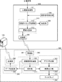
- the biometric information processing system 1 mainly serves as electrodes 401, 402, 403 for acquiring electrocardiograms attached to the chest of a dog and a harness for measuring biometric information for processing electrocardiographic signals. It includes a signal acquisition device 500 and a communication terminal 300 as a state processing device capable of communicating with the signal acquisition device 500.
- the electrodes 401, 402, 403 for acquiring electrocardiogram are attached to the chest or the like so as to sandwich the heart, and for example, the paws of both forefoot (or forefoot and hindfoot) have hair. It may not be in a place. Further, it is desirable that the hair is in a cut state, an electrode to which gel or the like is attached, or a structure having a protruding structure and contact with the skin even if there is hair. Alternatively, a form that induces electrocardiography through a capacitive material in a non-contact manner in the presence of hair is desirable. As a result, even an organism whose epidermis is covered with hair, such as a dog, can acquire an electrocardiogram. In the present embodiment, three electrodes 401, 402, and 403 are used, but the number of electrodes may be two or more, and more electrodes may be used. ⁇ Configuration of signal acquisition device 500>
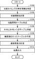
- FIG. 3 is a flowchart showing the entire process executed by the signal acquisition device 500 according to the present embodiment.
- the signal acquisition device 500 includes an electrocardiographic preprocessing unit 511, a pulsation timing acquisition unit 512, a storage unit 520, a cycle determination unit 513, a transmission unit 560, and the like.
- the electrocardiographic preprocessing unit 511 includes a filter and an amplifier.
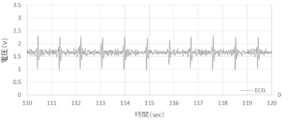
- the electrocardiographic preprocessing unit 511 converts the signal sent from the electrodes 401, 402, 403 into electrocardiographic signal data as shown in FIG. 4 and passes it to the pulsation timing acquisition unit 512 (step S002). ..
- the electrocardiographic preprocessing unit 511 includes a filter device such as a high-pass filter and a low-pass filter, an amplification device composed of an operational amplifier, an A / D conversion device that converts an electrocardiographic analog signal into a digital signal, and the like. Is included.
- the filter device, amplification device, and the like may be implemented by software.
- the A / D converter it is desirable to perform sampling with a period and accuracy that can discriminate the difference in the amount of fluctuation of the beat interval. That is, it is desirable that the frequency of A / D conversion be acquired at a frequency of 25 Hz or higher.
- the electrocardiographic signal is sampled at 1000 Hz. By increasing the sampling frequency, it is possible to accurately grasp the amount of fluctuation of the beat interval.
- the pulsation timing acquisition unit 512 is realized by, for example, a control unit including a CPU (Central Processing Unit) 510 and a memory. More specifically, the CPU 510 identifies a peak that can be determined to be an R wave by various determination methods by executing a program stored in the memory (step S004). That is, the pulsation timing acquisition unit 512 adds time information as the pulsation timing to the peak that can be determined to be an R wave, and stores it in the storage unit 520.
- the method of extracting the peak of the electrocardiographic waveform and specifying the pulsation timing is not particularly limited.
- the pulsation timing acquisition unit (detection circuit that detects the pulsation interval) 512 calculates the time from the previous pulsation timing to the current pulsation timing as the current pulsation interval, and the pulsation timing is also stored in the storage unit 520. Store (step S006).
- the CPU 510 has, for each predetermined time zone, a time stamp indicating a reference time of the predetermined time zone and a beat included in the predetermined time zone.
- the storage unit 520 stores the detailed elapsed time from the reference time in the predetermined time zone for each timing.
- the length of the predetermined time zone is 1 second
- the detailed elapsed time from the reference time of the predetermined time zone is indicated by msec.
- the storage unit 520 is realized, for example, by a non-volatile recording medium such as an SD card or a USB memory, and a memory interface for writing data to the recording medium.
- the periodic signal generation unit 590 is a circuit that generates an electric signal having a constant period as shown in FIG. When the electrodes are not in proper contact with the living body, there is little noise at the baseline as shown in FIG. 6, and only the amplitude of the electric signal having a fixed period is observed.
- the periodic signal generation unit 590 generates an electric signal at intervals of X (ms).
- the configuration for actively generating a periodic signal is not particularly limited.
- the cycle determination unit 513 is realized by, for example, a control unit including a CPU 510 and a memory. More specifically, the CPU 510 determines whether or not the electrocardiographic waveform can be normally acquired by executing the program stored in the memory by the determination method described later (step S008).
- the cycle determination unit 513 calculates the average value Y (ms), standard deviation Z (ms), and the like of the beat interval obtained from the electrocardiographic waveform at a predetermined time, for example, 5 seconds. To do. Then, by determining whether or not the average value Y (ms) of the beat interval is close to the average value X (ms) of the interval of the electric signals of the periodic signal generation unit 590, the obtained electrocardiographic signal has a period. It is determined whether or not the signal is generated by the signal generation unit 590.
- Whether or not the average value Y (ms) of the beat interval is close to the average value X (ms) of the interval of the electric signals of the periodic signal generation unit 590 is determined, for example, by the average value Y (ms) of the beat interval. ) Is within 5% of the average value X (ms) of the interval of electric signals.
- the cycle determination unit 513 may determine whether or not the standard deviation Z (ms) of the beat interval is equal to or less than a predetermined value.
- the predetermined value here may be, for example, 2 ms or 1% of the average value Y (ms), but is not particularly limited.
- the period determination unit 513 determines that the electrocardiographic signal is due to the electric signal generated by the period signal generation unit 590 (YES in step S008)
- the period determination unit 513 passes through the transmission unit 560.
- the predetermined error information is transmitted to the communication terminal 300 and the server 100 (step S010).
- the communication terminal 300 can display information indicating that the signal acquisition device 500 is not normally attached to the living body on the display 330 or output voice to the speaker.
- the CPU 510 of the signal acquisition device 500 may output a warning voice from the speaker, output a warning message from the display, or emit a warning light.
- the period determination unit 513 determines that the electrocardiographic signal is due to the electric signal generated by the period signal generation unit 590 (NO in step S008)
- the period determination unit 513 passes through the transmission unit 560.
- the normal information is transmitted to the communication terminal 300 (step S012).
- the transmission unit 560 uses a time stamp indicating a reference time of the predetermined time zone for each predetermined time zone and a reference time of the predetermined time zone for each pulsation timing included in the predetermined time zone. The detailed elapsed time of is transmitted to the communication terminal 300.
- the pulsation interval usually fluctuates slightly in both humans and animals, as shown in FIG. Especially in dogs, this fluctuation is known to be large (respiratory arrhythmia). That is, when the electrocardiographic signal is normally obtained, the fluctuation of the beat interval should be detected.
- the mechanically generated electric signal has a constant period as shown in FIG. 6, when the mechanical signal is detected, the period does not vary and is the same as the transmitted period. Become. That is, when a regular electrocardiographic waveform is obtained, it is not a signal indicating the heartbeat but a signal generated on the circuit, which means that the electrocardiographic signal is not normally obtained from the living body. That is, it means that the contact state between the electrode and the living body is not suitable for electrocardiographic measurement. It can be said that the state unsuitable for electrocardiographic measurement is not in contact with the electrode and the living body, or the contact resistance between the electrode and the living body is large and the energization state is not appropriate.
- the electrocardiographic signal is normally generated from the living body depending on the contact state between the electrode and the living body. You may judge that it has not been taken.
- the period of the input signal is preferably in the range of 0.2 seconds to 10 seconds. This is because in peak detection, it is detected as early as possible that there is no pulsation from a short period (corresponding to 0.2 seconds ⁇ 300 bpm) in the detectable range.
- an electrocardiographic signal with a certain cycle can be obtained due to a heart disease or its treatment (pacemaker, etc.) in advance
- an electric signal with a cycle different from the normal heart cycle is used. It is preferable to enter it.
- the threshold value of the electrocardiographic signal for peak detection shall be a numerical value that can detect the periodic signal.
- the amplitude of the electric signal from the periodic signal generator 590 is preferably set to an amplitude that does not interfere with the detection of the pulsation timing of the living body, for example, less than 10% of the peak of the normal electrocardiographic signal.
- FIG. 7 is a flowchart showing a process executed by the communication terminal 300 according to the present embodiment.
- the communication terminal 300 includes a receiving unit 361, a pulsation interval acquisition unit 321 and an analysis unit 311, a graph creating unit 312, a result output unit 313, a display 330, and a data storage unit. 322 and a transmission unit 362 are included.
- the receiving unit 361 and the transmitting unit 362 are realized by, for example, a communication interface 360 including an antenna, a connector, and the like.
- the receiving unit 361 receives data indicating the pulsation timing from the signal acquisition device 500 (step S100).
- the pulsation interval acquisition unit 321 is composed of various memories 320 and the like, and stores the data received from the signal acquisition device 500.
- the CPU 310 calculates the time between beats based on the beat timing received via the communication interface 360 (step S102).
- the CPU 310 sequentially stores the pulsation interval as a pulsation interval table (see FIG. 5) in the memory 320 (step S104).
- the beat interval is calculated in units of msec (milliseconds), for example, as shown in FIG.
- these data may be stored in the memory 320 of the communication terminal 300, or may be stored in another device accessible from the communication terminal 300.
- the line at the time when 9 is entered in the beat times 1 and 2 indicates a time zone in which the beat is not originally detected. This indicates a time zone in which there is no pulsation by temporarily inputting a numerical value of 9, and may be another numerical value or symbol.
- the CPU 310 when the data indicating the pulsation timing from the signal acquisition device 500 is lost for some reason, the CPU 310 performs various plots for the period during which the pulsation interval cannot be calculated, as will be described later. Instead, various plots are restarted after the relevant period has passed. More details will be described later as a method of handling missing data.
- the analysis unit 311, the graph creation unit 312, and the result output unit 313 are realized, for example, by the CPU 310 executing the program of the memory 320.
- the analysis unit 311 reads the pulsation interval data from the pulsation interval acquisition unit 321 in a fixed time unit, for example, 1 minute, 10 minutes, 1 hour, etc., in a time unit necessary for determining the state, and pulsates.
- a pulsation interval table of the interval RR (n) and the next pulsation interval RR (n + 1) is created (step S106).
- the analysis unit 311 calculates the standard deviation of the numerical strings constituting each axis after the axis conversion (step S110).
- the analysis unit 311 may specify the axis at which the variance is maximized by a method such as principal component analysis, and calculate the standard deviation between the axis and the axis perpendicular to the axis. Further, the analysis unit 311 may calculate the standard deviation with respect to the X-axis and the Y-axis without performing the axis conversion.
- the directions with large variance are the X-axis direction and the Y-axis direction
- the variation state of the beat interval plotted by Poincare is evaluated by calculating the standard deviation of the X-axis and the Y-axis without performing axis conversion. it can. In this case, since it is not necessary to perform axis conversion, the amount of calculation can be reduced.
- the biometric information processing system 1 may include a server with which the communication terminal 300 can communicate.
- the CPU 310 as the result output unit 313 accumulates in the data storage unit 322 such as the standard deviation and the relation table, or transmits to the server via the Internet or the like by using the transmission unit 362.
- the output result of this time can be used for grasping the short-term or long-term stress state of the observation target.
- the graph creating unit 312 sets the pulsation interval RR (n) in the range used for calculating the standard deviation from the pulsation interval table of FIG. 5 and the next.
- the data with the beat interval RR (n + 1) of the above is acquired, and Poincare plot diagrams as shown in FIGS. 10 to 13 are created.
- the result output unit 313 displays the created Poincare plot diagram on its own or external output device such as a display.
- the graph creation unit 312 may create and output a Poincare plot diagram after axis conversion by using the result of step S108.
- FIG. 10 is a Poincare plot diagram of the dog in the excited state according to the present embodiment.
- FIG. 11 is a Poincare plot diagram of the dog according to the present embodiment in a state in which respiration is stable in a normal state.
- FIG. 12 is a Poincare plot diagram of the dog according to the present embodiment in a normal state.
- FIG. 13 is a Poincare plot diagram of the dog according to the present embodiment in a resting state.
- the heart rate increases (the pulsation interval becomes shorter), the fluctuation of the pulsation interval becomes smaller, and the plot is made. It becomes a state where the points of are gathered in a certain place.
- the heart rate is not as low as in the resting state (the spread of the plot points is not as large as in the resting state), but at the center of the distribution of the plot points.
- the analysis unit 311 calculates the degree of variation in the Poincare plot, that is, the standard deviation of the pulsation interval, as a numerical value indicating the autonomic nerve balance. ⁇ Another form of autonomic balance values>
- the product of these two standard deviations may be calculated as a numerical value indicating the autonomic nerve balance.
- FIG. 14 is a flowchart showing a processing procedure of the biological information processing system 1 according to the present embodiment. Since steps S100 to S108 are the same as those in FIG. 7, the description is not repeated here.
- the CPU 310 as the analysis unit 311 calculates the standard deviation for each axis after the axis conversion (step S110).
- the analysis unit 311 may specify the axis having the maximum variance and calculate the standard deviation of the axis and the axis perpendicular to the axis.
- the analysis unit 311 calculates the product of these two standard deviations, the square root of the product, and the like as numerical values indicating the autonomic nerve balance (step S112).
- the result output unit 313 stores the standard deviation, the product of the standard deviations, the square root of the product, the beat interval table, etc. in the data storage unit 322, or uses the transmission unit 362 to use the transmission unit 362, etc., via the Internet or the like. And send it to the server 100.
- the output result of this time can be used for grasping the short-term or long-term stress state of the observation target.
- the analysis unit 311 calculates the product of the standard deviations of the two axes, the square root of the product, etc., but may also calculate the product of the standard deviations of the three or more axes, the root of the product, and the like. ..
- the CPU 310 performs the above calculation for a predetermined period, for example, every few minutes, and stores the calculation result in the database of the memory 320 for creating a diagnostic graph described later.
- the signal acquisition device 500 is equipped with the periodic signal generation unit 590.
- other configurations may be used as long as the signal is periodically emitted.
- signals generated from the storage unit 520 and the transmission unit 560 may be used.
- the storage unit 520 may record the pulsation timing and the pulsation interval on the SD card at regular intervals. For example, when the CPU 510 calculates the pulsation timing and the pulsation interval, it temporarily stores the pulsation timing and the pulsation interval in the RAM, and at a fixed cycle, for example, 1 second, via a memory interface such as the SD card slot 522. Information on the beat timing and beat interval for one line of FIG. 5 may be written on the SD card. As a result, electric signals are naturally generated at regular intervals. That is, the storage unit 520 may include a periodic signal generation circuit that transmits an electric signal at a constant cycle.
- the transmission unit 560 may transmit the pulsation timing and the pulsation interval to the communication terminal 300 at regular intervals.
- the CPU 510 calculates the pulsation timing and the pulsation interval, it temporarily stores the pulsation timing and the pulsation interval in the RAM, and at a fixed cycle, for example, 1 second, via a communication interface such as an antenna or a connector.
- Information on the beat timing and beat interval for one line in FIG. 5 may be transmitted to the communication terminal 300 or the server 100. As a result, signals are naturally generated at regular intervals.
- the signal generated by the periodic signal generation unit 590 is not detected at the same time as the pulsation by the pulsation timing acquisition unit 512, but may be detected as the periodic signal.
- a beat threshold value for detecting the beat and a periodic signal threshold value for detecting the periodic signal are provided, and the periodic signal has an amplitude that is detected by the periodic signal beat threshold value but not detected by the beat threshold value.
- the pulsation is detected even at the periodic signal threshold value, but the detected period is different from the periodic signal.
- the cycle discriminating unit 513 normally performs the electrocardiographic signal based on whether or not the pulsation interval obtained from the electrocardiographic signal is close to the writing cycle by the storage unit 520 and the transmission cycle by the transmitting unit 560. Judge whether or not it has been acquired.
- the periodic signal generation unit 590 periodically matches the timing when the signal is generated by the storage unit 520 and the timing when the signal is generated by the transmission unit 560. It may be configured to generate a signal.
- the cycle determination unit 513 can normally acquire the electrocardiographic signal based on whether or not the pulsation interval obtained from the electrocardiographic signal is close to the signal generation cycle by the periodic signal generation unit 590. Judge whether or not.
- the signal generation timing of the periodic signal generation unit 590 is the same as the timing of signal generation by the storage unit 520 and the timing of signal generation by the transmission unit 560, it is generated from the storage unit 520.
- the signal and the signal generated from the transmission unit 560 are less likely to interfere with the determination in step S008.
- the signal acquisition device 500 acquires the beat timing and the beat interval based on the electrocardiographic signals from the electrodes 401, 402, 403, and the communication terminal 300 beats.
- the information for judging the state of the living thing or the information of the judgment result of the state of the living thing was calculated and output from the interval.
- the roles of all or part of one of those devices may be shared by another device or by a plurality of devices. On the contrary, one device may play the role of all or a part of the plurality of devices, or another device may play the role.
- the server 100 may play the role of the communication terminal 300.
- the communication terminal 300 transmits necessary information such as a pulsation timing and a pulsation interval from the signal acquisition device 500 to the server 100 via a router, a carrier network, the Internet, or the like.
- the server 100 calculates the information for determining the state of the living thing or the information indicating the determination result of the state of the living thing, transmits the information to the communication terminal 300, and the communication terminal 300 displays the information of the final result. And output to the speaker.
- the communication terminal 300 or the server 100 may realize the function of the signal acquisition device 500.
- the communication terminal 300 or the server 100 receives an electrocardiographic signal from the signal acquisition device 500 to specify the pulsation timing, calculate the pulsation interval, and generate the pulsation interval and the periodic electric signal. It may be determined whether or not the electrocardiographic signal can be normally acquired based on the period.
- a harness for measuring biological information to be attached to an animal receives an animal electrocardiographic signal, amplifies the electrocardiographic signal, and performs a filter process that cuts a predetermined frequency, and an electrocardiographic processing circuit amplified by the electrocardiographic processing circuit.
- a detection circuit that detects the beat interval of an animal based on an electric signal, an electric signal generation circuit that generates an electric signal with a fixed cycle, and an electric signal generated by the periodic signal generation circuit are acquired, and the beat interval and electricity are acquired. It is provided with a control unit for determining whether or not an electrocardiographic signal can be normally acquired by determining whether or not the period of the signal substantially matches.
- the biometric information measurement harness further comprises a communication interface or a memory interface.
- the electrical signal generation circuit is included in the communication interface or memory interface.
- the electric signal generation circuit generates an electric signal in accordance with the timing of transmission / reception of beat interval data by the communication interface or the timing of writing the beat interval data to the recording medium by the memory interface.
- the biometric information measurement harness further comprises a communication interface or a memory interface.
- the electrical signal generation circuit is included in the communication interface or memory interface. An electric signal is generated when the beat interval data is transmitted / received by the communication interface or when the beat interval data is written to the recording medium by the memory interface.
- the biological information measurement harness further includes an electrode for acquiring an electrocardiographic signal and a notification unit for notifying a determination result of the control unit.
- the control unit determines poor contact between the electrode and the animal and transmits the determination result to the notification unit.
- a biometric information measurement system including a biometric information measurement harness to be attached to an animal and a computer capable of communicating with the biometric information measurement harness.
- the biological information measurement harness receives an animal's electrocardiographic signal, amplifies the electrocardiographic signal, and performs a filter process that cuts a predetermined frequency, and amplifies the electrocardiographic signal and the electrocardiographic processing unit. It includes a control unit that acquires the obtained electrocardiographic signal and detects the beat interval of the animal based on the electrocardiographic signal amplified by the electrocardiographic processing unit.
- the computer includes a control unit for determining whether or not the electrocardiographic signal can be normally acquired by determining whether or not the beat interval and the period of the electric signal substantially match.
- Biometric information processing system 100 Server 300: Communication terminal 310: CPU 311: Analysis unit 312: Graph creation unit 313: Result output unit 320: Memory 321: Beat interval acquisition unit 322: Data storage unit 330: Display 360: Communication interface 361: Reception unit 362: Transmission unit 401: Electrode 402: Electrode 403: Electrode 500: Signal acquisition device 510: CPU 511: Electrocardiographic preprocessing unit 512: Pulsation timing acquisition unit 513: Period determination unit 520: Storage unit 522: SD card slot 560: Transmission unit 590: Periodic signal generation unit X: Average value of periodic signal generation intervals Y: Average value of beat interval Z: Standard deviation of beat interval
Landscapes
- Health & Medical Sciences (AREA)
- Life Sciences & Earth Sciences (AREA)
- Cardiology (AREA)
- Heart & Thoracic Surgery (AREA)
- Molecular Biology (AREA)
- Pathology (AREA)
- Engineering & Computer Science (AREA)
- Biomedical Technology (AREA)
- Physics & Mathematics (AREA)
- Medical Informatics (AREA)
- Biophysics (AREA)
- Surgery (AREA)
- Animal Behavior & Ethology (AREA)
- General Health & Medical Sciences (AREA)
- Public Health (AREA)
- Veterinary Medicine (AREA)
- Measurement And Recording Of Electrical Phenomena And Electrical Characteristics Of The Living Body (AREA)
- Measuring Pulse, Heart Rate, Blood Pressure Or Blood Flow (AREA)
Abstract
動物に装着するための生体情報測定用ハーネス(500)が提供される。生体情報測定用ハーネスは、動物の心電信号を受信し、心電信号を増幅し、かつ、所定の周波数をカットするフィルタ処理を行う心電処理回路(511)と、増幅された心電信号および電気信号を取得し、増幅された心電信号に基づいて動物の拍動間隔を検出し、拍動間隔と電気信号の周期とが略一致するかどうかを判定することによって心電信号が正常に取得できているか否かを判定するための制御部(510)と、を備える。
Description
本国際出願は、2019年3月25日に日本国特許庁に出願された日本国特許出願第2019-056154号に基づく優先権を主張するものであり、日本国特許出願第2019-056154号の全内容を参照により本国際出願に援用する。
本開示は、生物の精神的状態または肉体的状態を取得するための技術に関する。
従来から、生物の精神的または肉体的な状態を取得するための技術が知られている。例えば、特開2017-213391号公報(特許文献1)には、心拍や電極の接触が良いかどうかを検出するシステムが開示されている。特許文献1によると、このシステムは、織物に複数の織物電極を設置し、心電図の等電位線図を利用し、人体移動のもたらす干渉を考慮に入れ、分離式電極構造に設定する。このシステムは、電極位置、面積及び導線レイアウトにより心拍を検出し、環境状態の変更によって「ドライ電池または容量結合電極により心電信号を採取するか」を選択する。また、このシステムは、ノイズ、体表インピーダンス、筋肉インピーダンスの測定により、電極と人体の接触が良いかどうかを検出する。また、心電信号波形とノイズにより人体姿勢と動作を推測することができる。
本開示の目的は、心電信号が正常に取得できているかを判断するための技術を提供することにある。
本開示の一態様に従うと、動物に装着するための生体情報測定用ハーネスが提供される。生体情報測定用ハーネスは、動物の心電信号を受信し、心電信号を増幅し、かつ、所定の周波数をカットするフィルタ処理を行う心電処理回路と、心電処理回路によって増幅された心電信号に基づいて動物の拍動間隔を検出する検出回路と、一定周期の電気信号を発生させる電気信号生成回路と、周期信号発生回路が発生させた電気信号を取得し、拍動間隔と電気信号の周期とが略一致するかどうかを判定することによって心電信号が正常に取得できているか否かを判定するための制御部と、を備える。
以上のように、本開示によれば、心電信号が正常に取得できているかを、判断するための技術が提供される。
以下、図面を参照しつつ、本開示の実施の形態について説明する。以下の説明では、同一の部品には同一の符号を付してある。それらの名称および機能も同じである。したがって、それらについての詳細な説明は繰り返さない。
<第1の実施の形態>
<生体情報処理システムの全体構成>
<第1の実施の形態>
<生体情報処理システムの全体構成>
まず、図1および図2を参照して、本実施の形態にかかる生体情報処理システム1の全体構成について説明する。図1は、本実施の形態にかかる生体情報処理システム1の全体構成を示す図である。図2は、本実施の形態にかかる生体情報処理システム1の機能構成を示す図である。なお、以下では、生物を代表して、呼吸性の不整脈を有する犬の状態を判断する場合について説明する。
本実施の形態にかかる生体情報処理システム1は、主に、犬の胸部に取り付けられる心電取得用の電極401,402,403と、心電信号を処理するための生体情報測定用ハーネスとしての信号取得装置500と、信号取得装置500と通信可能な状態処理装置としての通信端末300とを含む。
心電取得用の電極401,402,403は、胸部等において、心臓部を挟むような位置に取り付けることが望ましく、例えば、両前足(または、前足と後ろ足)の肉球部など毛の生えていない場所であってもよい。また、毛を刈った状態であるか、ゲルなどが付着した電極、あるいは、突起状の構造を持ち、毛があっても皮膚と接触する構成であることが望ましい。あるいは、毛がある状態で、非接触で容量性材料を介して心電を誘導する形態が望ましい。それにより、犬等の表皮が毛に覆われた生物であっても心電を取得することが可能となる。本実施の形態においては、3個の電極401,402,403を使用する構成としているが、電極は、2個以上であればよく、さらに、多くの電極を使用する構成としてもよい。
<信号取得装置500の構成>
<信号取得装置500の構成>
次に、図2および図3を参照して、信号取得装置500の構成と処理とについて説明する。なお、図3は、本実施の形態にかかる信号取得装置500が実行する全体処理を示すフローチャートである。信号取得装置500は、心電前処理部511と拍動タイミング取得部512と記憶部520と周期判別部513と送信部560などを含む。
心電前処理部511は、フィルタや増幅器を含む。心電前処理部511は、電極401,402,403から送られている信号を、図4に示すような心電信号データに変換して、拍動タイミング取得部512に受け渡す(ステップS002)。
より詳細には、心電前処理部511には、ハイパスフィルタ、ローパスフィルタなどのフィルタ装置、オペアンプなどから構成される増幅装置、心電のアナログ信号をデジタル信号に変換するA/D変換装置等が含まれる。尚、フィルタ装置、増幅装置などは、ソフトウェアにより実装される形態であってもよい。また、A/D変換装置においては、拍動間隔のゆらぎ量の差異が判別できる周期と精度でのサンプリングを行うことが望ましい。すなわち、A/D変換の周波数が、25Hz以上の周波数で取得することが望ましい。例えば、本実施の形態においては、1000Hzでの心電信号のサンプリングを行っている。サンプリングの周波数を高めることにより、拍動間隔の揺らぎ量を正確に把握することが可能となる。
拍動タイミング取得部512は、たとえば、CPU(Central Processing Unit)510やメモリを含む制御部によって実現される。より詳細には、CPU510が、メモリに格納されているプログラムを実行することによって、各種の判断方法により、R波と判断できるピークを特定する(ステップS004)。すなわち、拍動タイミング取得部512は、R波と判断できるピークに対して拍動タイミングとしての時刻情報を付与して、記憶部520に格納する。なお、心電波形のピークの抽出や拍動タイミングの特定の方法に関しては、特に限定しない。
拍動タイミング取得部(拍動間隔を検出する検出回路)512は、前回の拍動タイミングから今回の拍動タイミングまでの時間を今回の拍動間隔として計算し、拍動タイミングも記憶部520に格納する(ステップS006)。
たとえば、CPU510は、ステップS004やステップS006において、図5に示すように、所定の時間帯毎に、当該所定の時間帯の基準時刻を示すタイムスタンプと、当該所定の時間帯に含まれる拍動タイミング毎の、所定の時間帯の基準時刻からの詳細な経過時間とを記憶部520に記憶させる。本実施の形態においては、所定の時間帯の長さは1秒間であって、所定の時間帯の基準時刻からの詳細な経過時間はmsecで示される。なお、記憶部520は、一例として、SDカードやUSBメモリなどの不揮発性の記録媒体と、当該記録媒体にデータを書き込むためのメモリインターフェイスなどによって実現される。
周期信号発生部590は、図6に示すような、一定の周期の電気信号を発生させる回路である。電極が生体に適切に接触していない場合においては、図6に示すような、ベースラインにノイズが少なく、一定周期の電気信号の振幅のみが観測される。ここでは説明のために、周期信号発生部590は、X(ms)の間隔をあけて、電気信号を発生させるものとする。周期的な信号を能動的に発生させるための構成については特に限定しない。
周期判別部513は、たとえば、CPU510やメモリを含む制御部によって実現される。より詳細には、CPU510が、メモリに格納されているプログラムを実行することによって、後述する判断方法により、正常に心電波形を取得出来ているか否かを判断する(ステップS008)。
本実施の形態においては、周期判別部513は、心電波形から得られた拍動間隔の、所定時間、たとえば5秒間など、における平均値Y(ms)や標準偏差Z(ms)などを計算する。そして、拍動間隔の平均値Y(ms)が、周期信号発生部590の電気信号の間隔の平均値X(ms)に近いか否かを判断することによって、得られた心電信号が周期信号発生部590によって作られた電気信号によるものであるか否かを判断する。
なお、拍動間隔の平均値Y(ms)が周期信号発生部590の電気信号の間隔の平均値X(ms)に近いか否かの判断は、たとえば、拍動間隔の平均値Y(ms)が電気信号の間隔の平均値X(ms)から5%以内である、ことを判断することによって実行できる。
あるいは、周期判別部513は、拍動間隔の標準偏差Z(ms)が所定値以下であるか否かを判断してもよい。なお、ここでの所定値とは、たとえば、2msであったり、平均値Y(ms)の1%あったりするが、特に限定されない。
そして、周期判別部513は、心電信号が周期信号発生部590によって作られた電気信号によるものであると判断された場合(ステップS008にてYESである場合)、送信部560を介して、所定のエラー情報を通信端末300やサーバ100に送信する(ステップS010)。これによって、通信端末300が、信号取得装置500が正常に生体に取り付けられていない旨の情報を、ディスプレイ330に表示したり、スピーカに音声出力したりすることができる。
ただし、ステップS008においてYESである場合、信号取得装置500のCPU510がスピーカから警告音声を出力したり、ディスプレイから警告メッセージを出力したり、警告用のライトを発光させたりしてもよい。
逆に、周期判別部513は、心電信号が周期信号発生部590によって作られた電気信号によるものであると判断されなかった場合(ステップS008にてNOである場合)、送信部560を介して、正常情報を通信端末300に送信する(ステップS012)。たとえば、送信部560は、所定の時間帯毎に、当該所定の時間帯の基準時刻を示すタイムスタンプと、当該所定の時間帯に含まれる拍動タイミング毎の、所定の時間帯の基準時刻からの詳細な経過時間とを通信端末300に送信する。
より詳細には、拍動間隔は、通常、人においても、動物においても、図4に示すように、僅かに揺らいでいる。特に犬においては、この揺らぎが大きいことが知られている(呼吸性不整脈)。つまり、正常に心電信号が得られた場合には、拍動間隔の揺らぎが検知できるはずである。
一方、機械的に発生させた電気信号は、図6に示すように、一定の周期をもつため、機械的な信号が検出された場合には、周期にばらつきが無く、発信した周期と同一になる。つまり、規則正しい心電波形が得られた場合には、心拍の拍動を示す信号ではなく、回路上で発生した信号となり、生体から正常に心電信号が取れていないことを意味する。すなわち、電極と生体の接触状態が心電計測に適さない状態であることを意味する。心電計測に適さない状態とは、電極と生体に接していない、または電極と生体間の接触抵抗が大きく、適切な通電状態ではない、と言える。例えば、周期判別部513が機械的に発生させた電気信号のみを所定の期間(例えば3秒間)以上連続して取得した場合に、電極と生体の接触状態によって、生体から正常に心電信号を取れていない、と判断してよい。
入力する信号の周期は、0.2秒から10秒までの範囲が好ましい。これは、ピーク検出において、検出可能な範囲の短い周期(0.2秒→300bpmに相当)から拍動が無いことをできるだけ早期に検出するためである。
なお、予め心臓の病気やその治療(ペースメーカーなど)などの原因により、一定の周期をもつ心電信号が得られる可能性が高い場合には、通常の心臓の周期とは異なる周期の電気信号を入力することが好ましい。
また、ピーク検出のための心電信号の閾値は、周期信号が検出可能な数値とする。周期信号発生部590からの電気信号の振幅は、生体の拍動タイミングの検出の妨げにならない程度の振幅、たとえば正常な心電信号のピークの10%未満程度に設定されることが好ましい。
また、電極が生体に適切に接触ができている状態では、図4のように心電信号のベースラインにノイズが混入している状態となる。つまり、周期信号発生部590からの電気信号の振幅をノイズレベル以下の振幅となるように設定することで、電極が生体に良好に接触ができている状態では、周期信号を検出できない状態とすることができる。この場合、生体への電極の接触が良好ではない場合には、周期信号が検出される。逆に接触が良好な場合には、拍動の周期が検出される。また、電極と生体の接触が良好であるが、上記のようにノイズに埋もれて、周期信号が検出されない場合には、接触が良好でない状態であることを排除することが可能となり、心臓の活動に何らかの異常があることが判別できるため、異常を早期に見つけることが可能となる。
<通信端末300の構成>
<通信端末300の構成>
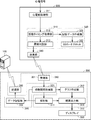
次に、通信端末300の構成と処理について説明する。なお、図7は、本実施の形態にかかる通信端末300が実行する処理を示すフローチャートである。図2および図7を参照して、通信端末300は、受信部361、拍動間隔取得部321、解析部311と、グラフ作成部312と、結果出力部313と、ディスプレイ330と、データ記憶部322と、送信部362とを含む。
まず、受信部361と送信部362は、例えば、アンテナやコネクタなどを含む通信インターフェイス360によって実現される。受信部361は、信号取得装置500からの拍動タイミングを示すデータを受信する(ステップS100)。
拍動間隔取得部321は各種のメモリ320などによって構成され、信号取得装置500から受信したデータを格納する。本実施の形態においては、CPU310が、通信インターフェイス360を介して受信した拍動タイミングに基づいて拍動と拍動の間の時間を計算する(ステップS102)。CPU310は、拍動間隔を拍動間隔テーブル(図5参照。)として逐次メモリ320に蓄積していく(ステップS104)。本実施の形態においては、拍動間隔は、例えば、図5に示すようにmsec(ミリセック)の単位で計算される。ただし、これらのデータは、通信端末300のメモリ320に記憶されてもよいし、通信端末300からアクセス可能な他の装置に記憶されてもよい。なお、図5において拍動時刻1及び2に9が記入されている時刻の行は、もともと拍動が検出されていない時間帯示すものである。これは、拍動が無い時間帯を仮に9の数値を入力して示すものであり、その他の数値や記号であってもよい。
なお、本実施の形態においては、CPU310は、何らかの原因によって信号取得装置500からの拍動タイミングを示すデータが欠損した場合、後述する通り、拍動間隔が計算できない期間に関しては各種のプロットを行わず、当該期間を経過したところから各種のプロットを再開する。より詳細には、欠損データの取り扱い方法として後述する。
解析部311と、グラフ作成部312と、結果出力部313とは、例えばCPU310がメモリ320のプログラムを実行することによって実現される。解析部311は、一定時間単位、例えば、1分、10分、1時間など、状態を判定するために必要な時間単位で、拍動間隔取得部321から拍動間隔データを読み出して、拍動間隔R-R(n)とその次の拍動間隔R-R(n+1)との拍動間隔テーブルを作成する(ステップS106)。
解析部311は、図8に示すように、拍動間隔R-R(n)とその次の拍動間隔R-R(n+1)との拍動間隔テーブルからY=X方向とそれに垂直な方向の軸への変換を行う(ステップS108)。
解析部311は、軸の変換を行った後のそれぞれの軸を構成する数値列に関する標準偏差を算出する(ステップS110)。なお、解析部311は、Y=X軸に関する標準偏差だけを算出してもよいし、Y=Xと垂直な軸に関する標準偏差だけを算出してもよいし、両方を算出してもよい。図9は、犬の精神状態または肉体的状態毎の、Y=X軸に関する標準偏差と、Y=Xと垂直な軸に関する標準偏差との目安を示す表である。
なお、解析部311は、主成分分析などの方法により分散が最大になる軸を特定し、当該軸と当該軸に垂直な軸に関する標準偏差を算出してもよい。さらには、解析部311は、軸変換を行わずに、X軸とY軸に関する標準偏差を算出するものであってもよい。分散の大きい方向がX軸方向とY軸方向である場合には、軸変換を行わなくとも、X軸とY軸の標準偏差を算出することで、ポアンカレプロットした拍動間隔のばらつき状態を評価できる。この場合、軸変換を行う必要が無いために、計算量を低減することができる。
結果出力部313は、例えば、自身の、あるいは外部の、ディスプレイ330やスピーカなどの出力装置に、標準偏差を表示させたり、音声メッセージを出力させたりする(ステップS114)。より詳細には、結果出力部313は、Y=X軸に関する標準偏差だけを出力させてもよいし、Y=Xと垂直な軸に関する標準偏差だけを出力させてもよいし、両方を出力させてもよいし、大きい方だけを出力させてもよいし、小さい方だけを出力させてもよい。
標準偏差を計算することにより、拍動間隔R-R(n)とその次の拍動間隔R-R(n+1)とをそれぞれ軸としてポアンカレプロットした拍動間隔のばらつき状態が評価できる。
なお、本実施の形態にかかる生体情報処理システム1は、通信端末300が通信可能なサーバを含む形態であってもよい。その場合、結果出力部313としてのCPU310は、標準偏差や関係テーブルなどデータ記憶部322に蓄積したり、送信部362を利用することによって、インターネットなどを介してサーバに送信したりする。これによって、今回の出力結果を観察対象の短期または長期のストレス状態の把握などに利用することができる。
本実施の形態においては、ステップS108とは別に、同時にグラフ作成部312は、図5の拍動間隔テーブルから、標準偏差の計算に使用した範囲の拍動間隔R-R(n)とその次の拍動間隔R-R(n+1)とのデータを取得して、図10~図13に示すようなポアンカレプロット図を作成する。
そして、結果出力部313は、作成されたポアンカレプロット図を、自身の、または外部の、ディスプレイなどの出力装置に表示させる。なお、グラフ作成部312は、ステップS108の結果を利用して、軸変換後のポアンカレプロット図を作成して出力してもよい。
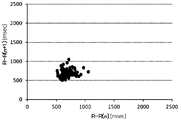
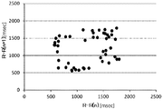
ここで、ポアンカレプロット図に関して説明する。図10は、本実施の形態にかかる犬の興奮状態におけるポアンカレプロット図である。図11は、本実施の形態にかかる犬の通常状態で呼吸が安定している状態におけるポアンカレプロット図である。図12は、本実施の形態にかかる犬の通常状態におけるポアンカレプロット図である。図13は、本実施の形態にかかる犬の安静状態におけるポアンカレプロット図である。
まず、例えば犬などの呼吸性の不整脈を有する生物の場合、図10のような興奮状態においては、心拍数が上昇し(拍動間隔は短くなる)、拍動間隔の揺らぎは小さくなり、プロットの点が一定の場所に集まるような状態になる。
そして、図11のような呼吸が安定している通常の状態においては、心拍数が安静状態ほどは少なくない(プロットの点の広がりが安静状態ほど大きくない)が、プロット点の分布の中心にプロットが少ない(穴の空白)領域が存在する。このような形状になるのは、犬の心拍が呼吸の影響を大きく受けるため、拍動変動が周期的に変化することが原因と考えられる(呼吸性不整脈)。そのため、リラックスした緩やかな拍動ではないが、呼吸が安定して行われているため、空白の存在する状態になると考えられる。
そして、図12のような通常状態においては、拍動に揺らぎがみられ、ばらつきは大きくなる(プロット点が広がる)が、プロット点が散乱している状態となる。
そして、図13の安静状態においては、犬がリラックスしているために拍動の間隔が大きくなり、さらに呼吸性不整脈の影響を大きく受けるために、プロット点の広がりが大きくなると共に、円形や四角形に近い形状や、三角形に近い形状となる。そのいずれの形状においても、安静状態ではポアンカレプロットのプロット点の分布の中心部に空白部分が見られる形状となる。
このように、本実施の形態においては、算出結果に基づいて間接的に、ポアンカレプロットのプロット点の分布の広がりの大きさや形状、中心部にプロットが多くみられるか少なくみられるかを予想することができ、その結果、生物の精神的状態または肉体的状態を予想することができる。そして、上述した通り、解析部311は、自律神経バランスを示す数値として、ポアンカレプロットのバラツキ具合すなわち拍動間隔の標準偏差を算出するものである。
<自律神経バランスの数値に関する別の形態>
<自律神経バランスの数値に関する別の形態>
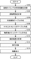
上記の実施の形態においては、通信端末300が、ポアンカレプロットのY=Xの軸に沿った標準偏差またはY=Xと垂直な軸に沿った標準偏差を出力するものであった。しかしながら、自律神経バランスを示す数値として、それら2つの標準偏差の積を算出してもよい。以下では、図14を参照して、本実施の形態にかかる生体情報処理システム1の処理手順について説明する。
図14は、本実施の形態にかかる生体情報処理システム1の処理手順を示すフローチャートである。ステップS100~ステップS108は、図7のものと同様であるため、ここでは説明を繰り返さない。
解析部311としてのCPU310は、軸の変換を行った後のそれぞれの軸に関する標準偏差を算出する(ステップS110)。なお、解析部311は、分散が最大になる軸を特定し、当該軸と当該軸に垂直な軸に関する標準偏差を算出してもよい。
そして、解析部311は、自律神経バランスを示す数値として、それらの2つの標準偏差の積や積の平方根などを計算する(ステップS112)。
結果出力部313は、例えば、通信端末300の、または外部の、ディスプレイやスピーカなどの出力装置に、標準偏差の積や積の平方根などを表示させたり、音声メッセージを出力させたりする(ステップS114)。より詳細には、結果出力部313は、Y=X軸に関する標準偏差と、Y=-Xの軸に関する標準偏差と、両者の積や積の平方根などとを出力させてもよい。
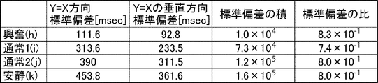
図15は、犬の精神状態または肉体的状態毎の、Y=X軸に関する標準偏差と、Y=Xと垂直な軸に関する標準偏差と、自律神経バランスを示す数値としての標準偏差の積や積の平方根などと、標準偏差の比との目安を示す表である。
標準偏差の積を計算することにより、拍動間隔R-R(n)とその次の拍動間隔R-R(n+1)とをそれぞれ軸としてポアンカレプロットした拍動間隔の分布の広がりの大きさや形状、一様に分散している、中心に空白がある等のばらつき状態が評価できる。また、縦横比が同じで大きさのみ変化している状態や分布の広がり面積が同じで中心部のばらつき状態が異なる場合などに有効にばらつき状態を評価できる。
この場合も、結果出力部313は、標準偏差や標準偏差の積や積の平方根や拍動間隔テーブルなどをデータ記憶部322に蓄積したり、送信部362を利用することによって、インターネットなどを介してサーバ100に送信したりする。これによって、今回の出力結果を観察対象の短期または長期のストレス状態の把握などに利用することができる。
解析部311は、2つの軸の標準偏差の積や積の平方根などを計算するものであるが、3つ以上の軸の標準偏差の積やその累乗根などを計算するものであってもよい。
CPU310は、所定の期間たとえば数分間毎に上記の計算を行い、当該計算結果を後述する診断グラフ作成のためにメモリ320のデータベースに蓄積していく。
<第2の実施の形態>
<第2の実施の形態>
上記の実施の形態においては、信号取得装置500が、周期信号発生部590を搭載するものであった。しかしながら、周期的に信号を発するものであれば、他の構成であってもよい。たとえば、図16に示すように、記憶部520や送信部560から発生する信号を利用してもよい。
たとえば、記憶部520が、一定の周期で、拍動タイミングや拍動間隔をSDカードに記録してもよい。例えば、CPU510は、拍動タイミングや拍動間隔を計算した際に、RAM上に一時的に記憶しておき、一定の周期、たとえば1秒など、でSDカードスロット522などのメモリインターフェイスを介してSDカードに、図5の1行分の拍動タイミングや拍動間隔の情報を書き込んでいってもよい。これによって、自然に一定の周期で電気信号が発生するようになる。つまり、記憶部520が一定の周期で電気信号を発信させる周期信号生成回路を含んでいてもよい。
あるいは、送信部560が、一定の周期で、拍動タイミングや拍動間隔を通信端末300に送信してもよい。例えば、CPU510は、拍動タイミングや拍動間隔を計算した際に、RAM上に一時的に記憶しておき、一定の周期、たとえば1秒など、でアンテナやコネクタなどの通信インターフェイスを介して、図5の1行分の拍動タイミングや拍動間隔の情報を通信端末300やサーバ100に送信してもよい。これによって、自然に一定の周期で信号が発生するようになる。
また、周期信号発生部590が発生する信号は、拍動タイミング取得部512において、拍動と同時には検出されないが、周期信号としては、検出されるものとしてもよい。具体的には、拍動を検出する拍動閾値と周期信号を検出する周期信号閾値を設け、周期信号は、周期信号拍動閾値では検出されるが、拍動閾値では検出されない振幅とする。生体と電極の接触状態が良好な場合、拍動は、周期信号閾値でも検出されてしまうが、検出された周期は、周期信号とは異なるものとなる。
そして、周期判別部513は、心電信号から得られた拍動間隔が、記憶部520による書き込み周期や、送信部560による送信周期に近いか否か、に基づいて、心電信号が正常に取得できているか否かを判断する。
<第3の実施の形態>
<第3の実施の形態>
あるいは、信号取得装置500が周期信号発生部590を搭載しつつ、当該周期信号発生部590が、記憶部520によって信号が発生するタイミングや送信部560によって信号が発生するタイミングに合わせて、周期的に信号を発生するように構成されてもよい。
そして、周期判別部513は、心電信号から得られた拍動間隔が、周期信号発生部590による信号の発生周期に近いか否か、に基づいて、心電信号が正常に取得できているか否かを判断する。本実施の形態においては、周期信号発生部590の信号の発生タイミングが、記憶部520によって信号が発生するタイミングや送信部560によって信号が発生するタイミングと同じであるため、記憶部520から発生する信号や送信部560から発生する信号が、ステップS008の判断の妨げになりにくくなる。
<第4の実施の形態>
<第4の実施の形態>
上記の実施の形態にかかる生体情報処理システム1は、電極401,402,403からの心電信号に基づいて信号取得装置500が拍動タイミングや拍動間隔を取得し、通信端末300が拍動間隔から生物の状態を判断するための情報または生物の状態の判定結果の情報を算出して出力するものであった。しかしながら、それらの1つの装置の全部または一部の役割が、別の装置によって担われてもよいし、複数の装置によって分担されてもよい。逆に、それら複数の装置の全部または一部の役割を、1つの装置が担ってもよいし、別の装置が担ってもよい。
例えば、通信端末300の役割をサーバ100が担ってもよい。具体的には、通信端末300が信号取得装置500からの拍動タイミングや拍動間隔などの必要な情報をルータやキャリア網やインターネットなどを介してサーバ100に送信する。そして、サーバ100が生物の状態を判断するための情報または生物の状態の判定結果を示す情報を算出し、当該情報を通信端末300に送信し、通信端末300が最終的な結果の情報をディスプレイやスピーカに出力する。
あるいは、信号取得装置500の機能を通信端末300やサーバ100が実現しても良い。たとえば、通信端末300やサーバ100が、信号取得装置500から心電信号を受信して、拍動タイミングを特定したり、拍動間隔を計算したり、拍動間隔と周期的な電気信号の発生周期とに基づいて心電信号が正常に取得できているか否かを判断したりしてもよい。
<まとめ>
<まとめ>
上記の実施の形態においては、動物に装着するための生体情報測定用ハーネスが提供される。生体情報測定用ハーネスは、動物の心電信号を受信し、心電信号を増幅し、かつ、所定の周波数をカットするフィルタ処理を行う心電処理回路と、心電処理回路によって増幅された心電信号に基づいて動物の拍動間隔を検出する検出回路と、一定周期の電気信号を発生させる電気信号生成回路と、周期信号発生回路が発生させた電気信号を取得し、拍動間隔と電気信号の周期とが略一致するかどうかを判定することによって心電信号が正常に取得できているか否かを判定するための制御部と、を備える。
好ましくは、生体情報測定用ハーネスは、通信インターフェイスまたはメモリインターフェイスをさらに備える。電気信号発生回路が通信インターフェイスまたはメモリインターフェイスに含まれる。電気信号生成回路は、通信インターフェイスによる拍動間隔データの送受信のタイミングまたはメモリインターフェイスによる拍動間隔データの記録媒体への書き込みのタイミングに合わせて、電気信号を発生させる。
好ましくは、生体情報測定用ハーネスは、通信インターフェイスまたはメモリインターフェイスをさらに備える。電気信号発生回路が通信インターフェイスまたはメモリインターフェイスに含まれる。通信インターフェイスによる拍動間隔データの送受信のタイミングまたメモリインターフェイスによる拍動間隔データの記録媒体への書き込み時に、電気信号が発生する。
好ましくは、生体情報測定用ハーネスは、さらに、心電信号を取得する電極と、制御部の判定結果を通知する通知部と、を備える。制御部は、検出回路が検出した2つの拍動の間に、3秒間以上連続して電気信号のみを取得した場合、電極と動物の接触不良を判定し、判定結果を通知部に送信する。
上記の実施の形態においては、動物に装着するための生体情報測定用ハーネスと、生体情報測定用ハーネスと通信可能なコンピュータとを備える生体情報測定システムが提供される。生体情報測定用ハーネスは、動物の心電信号を受信し、心電信号を増幅し、かつ、所定の周波数をカットするフィルタ処理を行う心電処理回路と、電気信号および心電処理部で増幅された心電信号を取得し、心電処理部で増幅された心電信号に基づいて動物の拍動間隔を検出する制御部とを含む。コンピュータは、拍動間隔と電気信号の周期とが略一致するかどうかを判定することによって心電信号が正常に取得できているか否かを判定するための制御部を含む。
今回開示された実施の形態はすべての点で例示であって制限的なものではないと考えられるべきである。本開示の範囲は、上記した説明ではなく、特許請求の範囲によって示され、特許請求の範囲と均等の意味および範囲内でのすべての変更が含まれることが意図される。
1 :生体情報処理システム
100 :サーバ
300 :通信端末
310 :CPU
311 :解析部
312 :グラフ作成部
313 :結果出力部
320 :メモリ
321 :拍動間隔取得部
322 :データ記憶部
330 :ディスプレイ
360 :通信インターフェイス
361 :受信部
362 :送信部
401 :電極
402 :電極
403 :電極
500 :信号取得装置
510 :CPU
511 :心電前処理部
512 :拍動タイミング取得部
513 :周期判別部
520 :記憶部
522 :SDカードスロット
560 :送信部
590 :周期信号発生部
X :周期的な信号の発生間隔の平均値
Y :拍動間隔の平均値
Z :拍動間隔の標準偏差
100 :サーバ
300 :通信端末
310 :CPU
311 :解析部
312 :グラフ作成部
313 :結果出力部
320 :メモリ
321 :拍動間隔取得部
322 :データ記憶部
330 :ディスプレイ
360 :通信インターフェイス
361 :受信部
362 :送信部
401 :電極
402 :電極
403 :電極
500 :信号取得装置
510 :CPU
511 :心電前処理部
512 :拍動タイミング取得部
513 :周期判別部
520 :記憶部
522 :SDカードスロット
560 :送信部
590 :周期信号発生部
X :周期的な信号の発生間隔の平均値
Y :拍動間隔の平均値
Z :拍動間隔の標準偏差
Claims (5)
- 動物に装着するための生体情報測定用ハーネスであって、
動物の心電信号を受信し、前記心電信号を増幅し、かつ、所定の周波数をカットするフィルタ処理を行う心電処理回路と、
前記心電処理回路によって増幅された心電信号に基づいて前記動物の拍動間隔を検出する検出回路と、
一定周期の電気信号を発生させる電気信号生成回路と、
前記周期信号発生回路が発生させた前記電気信号を取得し、前記拍動間隔と前記電気信号の周期とが略一致するかどうかを判定することによって前記心電信号が正常に取得できているか否かを判定するための制御部と、を備える生体情報測定用ハーネス。 - 通信インターフェイスまたはメモリインターフェイスをさらに備え、
前記電気信号発生回路が前記通信インターフェイスまたはメモリインターフェイスに含まれ、
前記電気信号生成回路は、前記通信インターフェイスによる前記拍動間隔データの送受信のタイミングまたは前記メモリインターフェイスによる前記拍動間隔データの記録媒体への書き込みのタイミングに合わせて、前記電気信号を発生させる、請求項1に記載の生体情報測定用ハーネス。 - 通信インターフェイスまたはメモリインターフェイスをさらに備え、
前記電気信号発生回路が前記通信インターフェイスまたはメモリインターフェイスに含まれ、
前記通信インターフェイスによる前記拍動間隔データの送受信のタイミングまた前記メモリインターフェイスによる前記拍動間隔データの記録媒体への書き込み時に、前記電気信号が発生する、請求項1に記載の生体情報測定用ハーネス。 - さらに、心電信号を取得する電極と、
前記制御部の判定結果を通知する通知部と、を備え、
前記制御部は、前記検出回路が検出した2つの拍動の間に、3秒間以上連続して前記電気信号のみを取得した場合、前記電極と動物の接触不良を判定し、判定結果を通知部に送信する、請求項1から3いずれかに記載の生体用測定用ハーネス。 - 動物に装着するための生体情報測定用ハーネスと、前記生体情報測定用ハーネスと通信可能なコンピュータとを備え、
前記生体情報測定用ハーネスは、
動物の心電信号を受信し、前記心電信号を増幅し、かつ、所定の周波数をカットするフィルタ処理を行う心電処理回路と、
電気信号および前記心電処理部で増幅された心電信号を取得し、前記心電処理部で増幅された心電信号に基づいて前記動物の拍動間隔を検出する制御部とを含み、
前記コンピュータは、前記拍動間隔と前記電気信号の周期とが略一致するかどうかを判定することによって前記心電信号が正常に取得できているか否かを判定するための制御部を含む、生体情報測定システム。
Applications Claiming Priority (2)
| Application Number | Priority Date | Filing Date | Title |
|---|---|---|---|
| JP2019056154A JP2022074177A (ja) | 2019-03-25 | 2019-03-25 | 生体情報測定用ハーネスおよび生体情報処理システム |
| JP2019-056154 | 2019-03-25 |
Publications (1)
| Publication Number | Publication Date |
|---|---|
| WO2020195403A1 true WO2020195403A1 (ja) | 2020-10-01 |
Family
ID=72609202
Family Applications (1)
| Application Number | Title | Priority Date | Filing Date |
|---|---|---|---|
| PCT/JP2020/006743 Ceased WO2020195403A1 (ja) | 2019-03-25 | 2020-02-20 | 生体情報測定用ハーネスおよび生体情報処理システム |
Country Status (2)
| Country | Link |
|---|---|
| JP (1) | JP2022074177A (ja) |
| WO (1) | WO2020195403A1 (ja) |
Citations (3)
| Publication number | Priority date | Publication date | Assignee | Title |
|---|---|---|---|---|
| JPH1028680A (ja) * | 1996-04-12 | 1998-02-03 | Siemens Elema Ab | 測定電極と中性電極およびそれらのリード線を監視する装置 |
| JP2010538775A (ja) * | 2007-09-21 | 2010-12-16 | メドテック エイ/エス | 電極の接続状態の監視 |
| JP2016538022A (ja) * | 2013-10-23 | 2016-12-08 | ブレイン センティネル インコーポレイテッドBrain Sentinel,Inc. | 緩い電極のモニタリングを含む発作の検出 |
-
2019
- 2019-03-25 JP JP2019056154A patent/JP2022074177A/ja active Pending
-
2020
- 2020-02-20 WO PCT/JP2020/006743 patent/WO2020195403A1/ja not_active Ceased
Patent Citations (4)
| Publication number | Priority date | Publication date | Assignee | Title |
|---|---|---|---|---|
| JPH1028680A (ja) * | 1996-04-12 | 1998-02-03 | Siemens Elema Ab | 測定電極と中性電極およびそれらのリード線を監視する装置 |
| JP2010538775A (ja) * | 2007-09-21 | 2010-12-16 | メドテック エイ/エス | 電極の接続状態の監視 |
| JP2016538022A (ja) * | 2013-10-23 | 2016-12-08 | ブレイン センティネル インコーポレイテッドBrain Sentinel,Inc. | 緩い電極のモニタリングを含む発作の検出 |
| JP2018038889A (ja) * | 2013-10-23 | 2018-03-15 | ブレイン センティネル インコーポレイテッドBrain Sentinel,Inc. | 緩い電極のモニタリングを含む発作を検出するセンサシステムおよびその作動方法 |
Also Published As
| Publication number | Publication date |
|---|---|
| JP2022074177A (ja) | 2022-05-18 |
Similar Documents
| Publication | Publication Date | Title |
|---|---|---|
| US10028706B2 (en) | System for processing physiological data | |
| US20210106281A1 (en) | Implantable medical system | |
| Brugarolas et al. | Wearable heart rate sensor systems for wireless canine health monitoring | |
| EP2615972B1 (en) | Apparatus for the automated measurement of sural nerve conduction velocity and amplitude | |
| US8478389B1 (en) | System for processing physiological data | |
| US9706938B2 (en) | System and method to determine premature ventricular contraction (PVC) type and burden | |
| EP2042083A2 (en) | Necklace type of detector for electrocardiographic and temperature information | |
| JP6647415B2 (ja) | 状態取得コンピュータ、状態の取得方法、および情報処理システム | |
| US11197629B2 (en) | Method and portable monitoring module for monitoring a plurality of electrical biosignals of a person | |
| KR20180135505A (ko) | 패치형전극을 이용한 수면상태 판단장치 | |
| Foster et al. | Preliminary evaluation of a wearable sensor system for assessment of heart rate, heart rate variability, and activity level in working dogs | |
| JP2021129693A (ja) | 心臓疾患重症度判定システム | |
| Brložnik et al. | Wireless electrocardiographic monitoring in veterinary medicine | |
| CN111407287A (zh) | 综合肺压数据进行患者身体参数评分的方法和植入式医疗设备系统 | |
| WO2020195403A1 (ja) | 生体情報測定用ハーネスおよび生体情報処理システム | |
| KR102891185B1 (ko) | 인공지능 기반의 주기적 생체신호 분석 장치 및 방법 | |
| JP2018175795A (ja) | 使役犬による作業の効率を向上させるための方法およびシステム | |
| JPWO2019198691A1 (ja) | 情報処理装置、およびウェアラブル端末 | |
| EP3288457B1 (en) | Positioning a medical device based on oxygen saturation measurements | |
| JP2006061416A (ja) | 生体電位検知システム | |
| JPWO2019193998A1 (ja) | 状態取得装置、ネットワークシステム、および状態処理装置 | |
| JP2021137250A (ja) | 生体情報処理装置、生体情報処理システムおよび生体情報処理方法 | |
| JP7336616B1 (ja) | 装着型通知装置、通知方法、及び通知プログラム | |
| WO2020218195A1 (ja) | 生体情報処理システムおよび生体情報取得方法 | |
| CN217525142U (zh) | 睡眠心电监测装置 |
Legal Events
| Date | Code | Title | Description |
|---|---|---|---|
| 121 | Ep: the epo has been informed by wipo that ep was designated in this application |
Ref document number: 20779539 Country of ref document: EP Kind code of ref document: A1 |
|
| NENP | Non-entry into the national phase |
Ref country code: DE |
|
| 122 | Ep: pct application non-entry in european phase |
Ref document number: 20779539 Country of ref document: EP Kind code of ref document: A1 |
|
| NENP | Non-entry into the national phase |
Ref country code: JP |