WO2020194980A1 - Wire harness - Google Patents
Wire harness Download PDFInfo
- Publication number
- WO2020194980A1 WO2020194980A1 PCT/JP2020/000086 JP2020000086W WO2020194980A1 WO 2020194980 A1 WO2020194980 A1 WO 2020194980A1 JP 2020000086 W JP2020000086 W JP 2020000086W WO 2020194980 A1 WO2020194980 A1 WO 2020194980A1
- Authority
- WO
- WIPO (PCT)
- Prior art keywords
- shrink tube
- core wire
- wire
- tube
- insulating coating
- Prior art date
Links
Images


Classifications
-
- H—ELECTRICITY
- H01—ELECTRIC ELEMENTS
- H01B—CABLES; CONDUCTORS; INSULATORS; SELECTION OF MATERIALS FOR THEIR CONDUCTIVE, INSULATING OR DIELECTRIC PROPERTIES
- H01B7/00—Insulated conductors or cables characterised by their form
- H01B7/0045—Cable-harnesses
-
- B—PERFORMING OPERATIONS; TRANSPORTING
- B60—VEHICLES IN GENERAL
- B60R—VEHICLES, VEHICLE FITTINGS, OR VEHICLE PARTS, NOT OTHERWISE PROVIDED FOR
- B60R16/00—Electric or fluid circuits specially adapted for vehicles and not otherwise provided for; Arrangement of elements of electric or fluid circuits specially adapted for vehicles and not otherwise provided for
- B60R16/02—Electric or fluid circuits specially adapted for vehicles and not otherwise provided for; Arrangement of elements of electric or fluid circuits specially adapted for vehicles and not otherwise provided for electric constitutive elements
- B60R16/0207—Wire harnesses
- B60R16/0215—Protecting, fastening and routing means therefor
-
- H—ELECTRICITY
- H01—ELECTRIC ELEMENTS
- H01R—ELECTRICALLY-CONDUCTIVE CONNECTIONS; STRUCTURAL ASSOCIATIONS OF A PLURALITY OF MUTUALLY-INSULATED ELECTRICAL CONNECTING ELEMENTS; COUPLING DEVICES; CURRENT COLLECTORS
- H01R4/00—Electrically-conductive connections between two or more conductive members in direct contact, i.e. touching one another; Means for effecting or maintaining such contact; Electrically-conductive connections having two or more spaced connecting locations for conductors and using contact members penetrating insulation
- H01R4/70—Insulation of connections
- H01R4/72—Insulation of connections using a heat shrinking insulating sleeve
-
- H—ELECTRICITY
- H02—GENERATION; CONVERSION OR DISTRIBUTION OF ELECTRIC POWER
- H02G—INSTALLATION OF ELECTRIC CABLES OR LINES, OR OF COMBINED OPTICAL AND ELECTRIC CABLES OR LINES
- H02G1/00—Methods or apparatus specially adapted for installing, maintaining, repairing or dismantling electric cables or lines
- H02G1/14—Methods or apparatus specially adapted for installing, maintaining, repairing or dismantling electric cables or lines for joining or terminating cables
-
- H—ELECTRICITY
- H02—GENERATION; CONVERSION OR DISTRIBUTION OF ELECTRIC POWER
- H02G—INSTALLATION OF ELECTRIC CABLES OR LINES, OR OF COMBINED OPTICAL AND ELECTRIC CABLES OR LINES
- H02G15/00—Cable fittings
- H02G15/02—Cable terminations
- H02G15/04—Cable-end sealings
-
- H—ELECTRICITY
- H02—GENERATION; CONVERSION OR DISTRIBUTION OF ELECTRIC POWER
- H02G—INSTALLATION OF ELECTRIC CABLES OR LINES, OR OF COMBINED OPTICAL AND ELECTRIC CABLES OR LINES
- H02G15/00—Cable fittings
- H02G15/08—Cable junctions
- H02G15/18—Cable junctions protected by sleeves, e.g. for communication cable
- H02G15/1806—Heat shrinkable sleeves
-
- B—PERFORMING OPERATIONS; TRANSPORTING
- B60—VEHICLES IN GENERAL
- B60R—VEHICLES, VEHICLE FITTINGS, OR VEHICLE PARTS, NOT OTHERWISE PROVIDED FOR
- B60R16/00—Electric or fluid circuits specially adapted for vehicles and not otherwise provided for; Arrangement of elements of electric or fluid circuits specially adapted for vehicles and not otherwise provided for
- B60R16/02—Electric or fluid circuits specially adapted for vehicles and not otherwise provided for; Arrangement of elements of electric or fluid circuits specially adapted for vehicles and not otherwise provided for electric constitutive elements
- B60R16/0207—Wire harnesses
-
- H—ELECTRICITY
- H01—ELECTRIC ELEMENTS
- H01R—ELECTRICALLY-CONDUCTIVE CONNECTIONS; STRUCTURAL ASSOCIATIONS OF A PLURALITY OF MUTUALLY-INSULATED ELECTRICAL CONNECTING ELEMENTS; COUPLING DEVICES; CURRENT COLLECTORS
- H01R11/00—Individual connecting elements providing two or more spaced connecting locations for conductive members which are, or may be, thereby interconnected, e.g. end pieces for wires or cables supported by the wire or cable and having means for facilitating electrical connection to some other wire, terminal, or conductive member, blocks of binding posts
- H01R11/11—End pieces or tapping pieces for wires, supported by the wire and for facilitating electrical connection to some other wire, terminal or conductive member
- H01R11/12—End pieces terminating in an eye, hook, or fork
-
- H—ELECTRICITY
- H01—ELECTRIC ELEMENTS
- H01R—ELECTRICALLY-CONDUCTIVE CONNECTIONS; STRUCTURAL ASSOCIATIONS OF A PLURALITY OF MUTUALLY-INSULATED ELECTRICAL CONNECTING ELEMENTS; COUPLING DEVICES; CURRENT COLLECTORS
- H01R2201/00—Connectors or connections adapted for particular applications
- H01R2201/26—Connectors or connections adapted for particular applications for vehicles
Abstract
A wire harness 10 has: an electrical cable 20; a connection terminal 30 that is electrically connected to a core wire of the electrical cable 20; and a cylindrical shrink tube 50 that covers a connection section of the core wire and the connection terminal 30. Printed on an outer circumferential surface of the shrink tube 50 is a distinguishing pattern 60, which includes a first distinguishing pattern 61 by which the shrinkage rate in the radial direction of the shrink tube 50 can be distinguished.
Description
本開示は、ワイヤハーネスに関するものである。
This disclosure relates to wire harnesses.
従来、車両に用いられるワイヤハーネスでは、被覆電線の芯線の端部と金属製の接続端子とが電気的に接続されたものが知られている(例えば、特許文献1参照)。この種のワイヤハーネスでは、芯線と接続端子との接続部分を絶縁保護するために、その接続部分が熱収縮チューブによって被覆されている。なお、接続端子は、車両の電気機器に接続される。
Conventionally, in wire harnesses used in vehicles, it is known that the end of the core wire of a covered electric wire and a metal connection terminal are electrically connected (see, for example, Patent Document 1). In this type of wire harness, the connection portion is covered with a heat shrink tube in order to insulate and protect the connection portion between the core wire and the connection terminal. The connection terminal is connected to the electrical equipment of the vehicle.
ところが、熱収縮チューブを過剰に収縮させてしまうと、例えば接続部分の角部などに熱収縮チューブが押し付けられて熱収縮チューブが破れるおそれがある。熱収縮チューブが破れると、絶縁信頼性の低下といったワイヤハーネスの品質低下を招く。
However, if the heat-shrinkable tube is excessively contracted, the heat-shrinkable tube may be pressed against the corners of the connection portion and the heat-shrinkable tube may be torn. If the heat shrink tubing is torn, the quality of the wire harness will deteriorate, such as a decrease in insulation reliability.
そこで、品質低下を抑制できるワイヤハーネスを提供することを目的とする。
Therefore, the purpose is to provide a wire harness that can suppress quality deterioration.
本開示のワイヤハーネスは、第1導体と、前記第1導体と電気的に接続された第2導体と、前記第1導体と前記第2導体との接続部分を覆う筒状の収縮チューブと、を有し、前記収縮チューブの外周面には、前記収縮チューブの径方向における収縮率が判別可能な第1判別パターンを含む判別パターンが印字されている。
The wire harness of the present disclosure includes a first conductor, a second conductor electrically connected to the first conductor, and a tubular shrink tube covering a connecting portion between the first conductor and the second conductor. On the outer peripheral surface of the shrink tube, a discrimination pattern including a first discrimination pattern capable of discriminating the shrinkage rate in the radial direction of the shrink tube is printed.
本開示のワイヤハーネスによれば、品質低下を抑制できるという効果を奏する。
According to the wire harness of the present disclosure, it has the effect of suppressing quality deterioration.
[本開示の実施形態の説明]
最初に本開示の実施形態を列挙して説明する。
[1]本開示のワイヤハーネスは、第1導体と、前記第1導体と電気的に接続された第2導体と、前記第1導体と前記第2導体との接続部分を覆う筒状の収縮チューブと、を有し、前記収縮チューブの外周面には、前記収縮チューブの径方向における収縮率が判別可能な第1判別パターンを含む判別パターンが印字されている。 [Explanation of Embodiments of the present disclosure]
First, the embodiments of the present disclosure will be listed and described.
[1] The wire harness of the present disclosure has a tubular shrinkage that covers a first conductor, a second conductor electrically connected to the first conductor, and a connecting portion between the first conductor and the second conductor. A discrimination pattern including a first discrimination pattern capable of discriminating the shrinkage rate in the radial direction of the shrink tube is printed on the outer peripheral surface of the shrink tube.
この構成によれば、収縮チューブの径方向における収縮率を判別パターンの第1判別パターンによって判別することができる。このため、第1判別パターンに基づいて、収縮チューブの径方向における収縮率が過剰なワイヤハーネスや、収縮チューブの径方向における収縮率が不十分なワイヤハーネスを容易に判別することができる。これにより、第1判別パターンを介して接続部分における絶縁信頼性や止水性を視認できるため、ワイヤハーネスの品質低下を抑制することができる。さらに、収縮チューブにおける止水性を評価するためのリーク検査等を省略できるため、ワイヤハーネスの組立作業性を向上させることができる。
According to this configuration, the shrinkage rate in the radial direction of the shrink tube can be discriminated by the first discriminating pattern of the discriminating pattern. Therefore, based on the first discrimination pattern, it is possible to easily discriminate a wire harness having an excessive contraction rate in the radial direction of the shrink tube and a wire harness having an insufficient shrinkage rate in the radial direction of the shrink tube. As a result, the insulation reliability and water stoppage at the connection portion can be visually recognized through the first discrimination pattern, so that deterioration of the quality of the wire harness can be suppressed. Further, since the leak inspection for evaluating the water stoppage of the shrink tube can be omitted, the workability of assembling the wire harness can be improved.
[2]前記判別パターンは、前記収縮チューブの長さ方向における収縮率が判別可能な第2判別パターンを含むことが好ましい。
この構成によれば、収縮チューブの長さ方向における収縮率を判別パターンの第2判別パターンによって判別することができる。このため、第2判別パターンに基づいて、収縮チューブの長さ方向における収縮率が過剰なワイヤハーネスや、収縮チューブの長さ方向における収縮率が不十分なワイヤハーネスを容易に判別することができる。 [2] The discrimination pattern preferably includes a second discrimination pattern in which the shrinkage rate in the length direction of the shrink tube can be discriminated.
According to this configuration, the shrinkage rate in the length direction of the shrink tube can be discriminated by the second discriminating pattern of the discriminating pattern. Therefore, based on the second discrimination pattern, it is possible to easily discriminate a wire harness having an excessive shrinkage rate in the length direction of the shrink tube and a wire harness having an insufficient shrinkage rate in the length direction of the shrink tube. ..
[3]前記第1判別パターンは、前記収縮チューブの長さ方向に沿って延びる複数の第1パターンが前記収縮チューブの周方向に沿って等間隔に印字されたパターンであり、前記第2判別パターンは、前記収縮チューブの周方向に沿って延びる複数の第2パターンが前記収縮チューブの長さ方向に沿って等間隔に印字されたパターンである。
[3] The first discrimination pattern is a pattern in which a plurality of first patterns extending along the length direction of the shrink tube are printed at equal intervals along the circumferential direction of the shrink tube, and the second discrimination pattern. The pattern is a pattern in which a plurality of second patterns extending along the circumferential direction of the shrink tube are printed at equal intervals along the length direction of the shrink tube.
この構成によれば、収縮後の収縮チューブにおいて、隣り合う第1パターンの間隔が収縮前と比べてどの程度狭くなったかを測定することにより、収縮チューブの径方向における収縮率を判別することができる。また、収縮後の収縮チューブにおいて、隣り合う第2パターンの間隔が収縮前と比べてどの程度狭くなったかを測定することにより、収縮チューブの長さ方向における収縮率を判別することができる。
According to this configuration, in the contracted tube after contraction, the contraction rate in the radial direction of the contracted tube can be determined by measuring how narrow the interval between adjacent first patterns is as compared with that before contraction. it can. Further, in the contracted tube after contraction, the contraction rate in the length direction of the contracted tube can be determined by measuring how narrow the interval between adjacent second patterns is as compared with that before contraction.
[4]前記判別パターンは、前記収縮チューブの外周面全面に印字されていることが好ましい。この構成によれば、収縮チューブの周方向全周及び長さ方向の全長において、収縮チューブの収縮率を判別することができる。
[4] It is preferable that the discrimination pattern is printed on the entire outer peripheral surface of the shrink tube. According to this configuration, the shrinkage rate of the shrink tube can be determined from the entire circumference in the circumferential direction and the total length in the length direction of the shrink tube.
[5]前記第1導体は、芯線と前記芯線の外周を被覆する絶縁被覆とを有する電線の前記芯線であり、前記第2導体は、金属製の接続端子であり、前記被覆電線から露出された前記芯線が前記接続端子に電気的に接続されており、前記収縮チューブは、前記芯線と前記接続端子との接続部分から前記絶縁被覆の端部までを被覆するように形成されている。
[5] The first conductor is the core wire of an electric wire having a core wire and an insulating coating covering the outer periphery of the core wire, and the second conductor is a metal connection terminal and is exposed from the coated electric wire. The core wire is electrically connected to the connection terminal, and the shrinkable tube is formed so as to cover from the connection portion between the core wire and the connection terminal to the end portion of the insulation coating.
この構成によれば、収縮チューブによって、芯線と接続端子との接続部分を絶縁保護することができる。このため、収縮チューブに印字された判別パターンを介して、芯線と接続端子との接続部分における絶縁信頼性や止水性を視認できる。
According to this configuration, the connection portion between the core wire and the connection terminal can be insulated and protected by the shrink tube. Therefore, the insulation reliability and water stoppage at the connection portion between the core wire and the connection terminal can be visually recognized through the discrimination pattern printed on the shrink tube.
[6]前記第1導体は、第1芯線と前記第1芯線の外周を被覆する第1絶縁被覆とを有する第1電線の前記第1芯線であり、前記第2導体は、前記第2芯線と前記第2芯線の外周を被覆する第2絶縁被覆とを有する第2電線の前記第2芯線であり、前記第1絶縁被覆の端部から露出された前記第1芯線と前記第2絶縁被覆の端部から露出された前記第2芯線とが電気的に接続されており、前記収縮チューブは、前記第1絶縁被覆の端部から前記第2絶縁被覆の端部までを被覆するように形成されていることが好ましい。
[6] The first conductor is the first core wire of a first electric wire having a first core wire and a first insulating coating that covers the outer periphery of the first core wire, and the second conductor is the second core wire. The second core wire of the second electric wire having the above and the second insulation coating covering the outer periphery of the second core wire, the first core wire exposed from the end portion of the first insulation coating, and the second insulation coating. The second core wire exposed from the end of the first insulating coating is electrically connected, and the shrinkable tube is formed so as to cover from the end of the first insulating coating to the end of the second insulating coating. It is preferable that the cable is used.
この構成によれば、収縮チューブによって、第1芯線と第2芯線との接続部分を絶縁保護することができる。このため、収縮チューブに印字された判別パターンを介して、第1芯線と第2芯線との接続部分における絶縁信頼性や信頼性を視認できる。
According to this configuration, the connection portion between the first core wire and the second core wire can be insulated and protected by the shrink tube. Therefore, the insulation reliability and reliability at the connecting portion between the first core wire and the second core wire can be visually recognized through the discrimination pattern printed on the shrink tube.
[7]前記収縮チューブの一端部の内周面は、前記第1絶縁被覆の端部の外周面と溶着により接着されており、前記収縮チューブの他端部の内周面は、前記第2絶縁被覆の端部の外周面と溶着により接着されていることが好ましい。
[7] The inner peripheral surface of one end of the shrink tube is adhered to the outer peripheral surface of the end of the first insulating coating by welding, and the inner peripheral surface of the other end of the shrink tube is the second. It is preferable that it is adhered to the outer peripheral surface of the end portion of the insulating coating by welding.
この構成によれば、収縮チューブと第1絶縁被覆との間の隙間が塞がれ、収縮チューブと第2絶縁被覆との間の隙間が塞がれる。これにより、収縮チューブと第1絶縁被覆との間、及び収縮チューブと第2絶縁被覆との間から水等の液体が収縮チューブの内部に浸入することを抑制できる。
According to this configuration, the gap between the shrink tube and the first insulating coating is closed, and the gap between the shrink tube and the second insulating coating is closed. As a result, it is possible to prevent liquids such as water from entering the inside of the shrink tube from between the shrink tube and the first insulating coating and between the shrink tube and the second insulating coating.
[8]前記収縮チューブは、熱収縮チューブと、前記熱収縮チューブの内周面に形成された接着層とを含む積層構造を有していることが好ましい。
この構成によれば、熱収縮チューブの内周面に形成された接着層によって、熱収縮チューブと絶縁被覆等との密着性を向上させることができる。 [8] The shrinkable tube preferably has a laminated structure including a heat-shrinkable tube and an adhesive layer formed on the inner peripheral surface of the heat-shrinkable tube.
According to this configuration, the adhesive layer formed on the inner peripheral surface of the heat-shrinkable tube can improve the adhesion between the heat-shrinkable tube and the insulating coating or the like.
[本開示の実施形態の詳細]
本開示のワイヤハーネスの具体例を、以下に図面を参照しつつ説明する。各図面では、説明の便宜上、構成の一部を誇張又は簡略化して示す場合がある。また、各部分の寸法比率については各図面で異なる場合がある。なお、本発明はこれらの例示に限定されるものではなく、特許請求の範囲によって示され、特許請求の範囲と均等の意味及び範囲内でのすべての変更が含まれることが意図される。本明細書における「直交」は、厳密に直交の場合のみでなく、本実施形態における作用効果を奏する範囲内で概ね直交の場合も含まれる。 [Details of Embodiments of the present disclosure]
Specific examples of the wire harness of the present disclosure will be described below with reference to the drawings. In each drawing, a part of the structure may be exaggerated or simplified for convenience of explanation. In addition, the dimensional ratio of each part may differ in each drawing. It should be noted that the present invention is not limited to these examples, and is indicated by the scope of claims, and is intended to include all modifications within the meaning and scope equivalent to the scope of claims. The term "orthogonal" as used herein includes not only the case of being strictly orthogonal, but also the case of being substantially orthogonal within the range in which the action and effect in the present embodiment are exhibited.
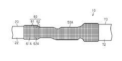
図1に示すワイヤハーネス10は、2個又は3個以上の電気機器(機器)を電気的に接続する。ワイヤハーネス10は、例えば、ハイブリッド車や電気自動車等の車両Vに搭載されるものである。ワイヤハーネス10は、例えば、車両Vの前部に設置されたインバータ11と、そのインバータ11よりも車両Vの後方に設置された高圧バッテリ12とを電気的に接続する。ワイヤハーネス10は、例えば、車両の床下等を通るように配索される。インバータ11は、車両走行の動力源となる車輪駆動用のモータ(図示略)と接続される。インバータ11は、高圧バッテリ12の直流電力から交流電力を生成し、その交流電力をモータに供給する。高圧バッテリ12は、例えば、数百ボルトの電圧を供給可能なバッテリである。
The wire harness 10 shown in FIG. 1 electrically connects two or three or more electric devices (equipment). The wire harness 10 is mounted on a vehicle V such as a hybrid vehicle or an electric vehicle, for example. The wire harness 10 electrically connects, for example, an inverter 11 installed in the front part of the vehicle V and a high-voltage battery 12 installed behind the vehicle V from the inverter 11. The wire harness 10 is arranged so as to pass under the floor of the vehicle, for example. The inverter 11 is connected to a wheel drive motor (not shown) that is a power source for traveling the vehicle. The inverter 11 generates AC power from the DC power of the high-voltage battery 12 and supplies the AC power to the motor. The high voltage battery 12 is, for example, a battery capable of supplying a voltage of several hundred volts.
ワイヤハーネス10は、1本又は複数本の電線20と、電線20の両端部に取り付けられた一対のコネクタC1と、複数の電線20を一括して包囲する外装部材25とを有している。電線20の一端部はコネクタC1を介してインバータ11と接続され、電線20の他端部はコネクタC1を介して高圧バッテリ12と接続されている。電線20は、例えば、高電圧・大電流に対応可能な高圧電線である。電線20は、例えば、自身に電磁シールド構造を有するシールド電線であってもよいし、自身に電磁シールドを有しないノンシールド電線であってもよい。
The wire harness 10 has one or a plurality of electric wires 20, a pair of connectors C1 attached to both ends of the electric wires 20, and an exterior member 25 that collectively surrounds the plurality of electric wires 20. One end of the electric wire 20 is connected to the inverter 11 via the connector C1, and the other end of the electric wire 20 is connected to the high voltage battery 12 via the connector C1. The electric wire 20 is, for example, a high-voltage electric wire that can handle high voltage and large current. The electric wire 20 may be, for example, a shielded electric wire having an electromagnetic shield structure by itself, or a non-shielded electric wire having no electromagnetic shield by itself.
外装部材25は、全体として長尺の筒状をなしている。外装部材25の内部空間には、1本又は複数本の電線20が収容されている。外装部材25は、例えば、複数の電線20の外周を周方向全周にわたって包囲するように形成されている。外装部材25は、内部に収容した電線20を飛翔物や水滴から保護する。外装部材25としては、例えば、金属製又は樹脂製のパイプや、樹脂製のプロテクタ、樹脂等からなり可撓性を有するコルゲートチューブやゴム製の防水カバー又はこれらを組み合わせて用いることができる。
The exterior member 25 has a long tubular shape as a whole. One or a plurality of electric wires 20 are housed in the internal space of the exterior member 25. The exterior member 25 is formed so as to surround the outer periphery of the plurality of electric wires 20 over the entire circumference in the circumferential direction, for example. The exterior member 25 protects the electric wire 20 housed therein from flying objects and water droplets. As the exterior member 25, for example, a pipe made of metal or resin, a protector made of resin, a flexible corrugated tube made of resin or the like, a waterproof cover made of rubber, or a combination thereof can be used.
(電線20の構成)
図2に示すように、電線20は、導体よりなる芯線21と、芯線21の外周を被覆する絶縁被覆22とを有している。芯線21としては、例えば、複数の金属素線を撚り合わせてなる撚り線、内部が中実構造をなす柱状の1本の金属棒からなる柱状導体や内部が中空構造をなす筒状導体などを用いることができる。また、芯線21としては、撚り線、柱状導体や筒状導体を組み合わせて用いてもよい。柱状導体としては、例えば、単芯線やバスバなどを挙げることができる。本実施形態の芯線21は、撚り線である。芯線21の材料としては、例えば、銅系やアルミニウム系などの金属材料を用いることができる。芯線21は、例えば、押出成形によって形成されている。 (Structure of electric wire 20)
As shown in FIG. 2, theelectric wire 20 has a core wire 21 made of a conductor and an insulating coating 22 that covers the outer periphery of the core wire 21. The core wire 21 includes, for example, a stranded wire formed by twisting a plurality of metal strands, a columnar conductor composed of one columnar metal rod having a solid structure inside, a tubular conductor having a hollow structure inside, and the like. Can be used. Further, as the core wire 21, a stranded wire, a columnar conductor or a tubular conductor may be used in combination. Examples of the columnar conductor include a single core wire and a bass bar. The core wire 21 of this embodiment is a stranded wire. As the material of the core wire 21, for example, a metal material such as copper-based or aluminum-based can be used. The core wire 21 is formed by, for example, extrusion molding.
図2に示すように、電線20は、導体よりなる芯線21と、芯線21の外周を被覆する絶縁被覆22とを有している。芯線21としては、例えば、複数の金属素線を撚り合わせてなる撚り線、内部が中実構造をなす柱状の1本の金属棒からなる柱状導体や内部が中空構造をなす筒状導体などを用いることができる。また、芯線21としては、撚り線、柱状導体や筒状導体を組み合わせて用いてもよい。柱状導体としては、例えば、単芯線やバスバなどを挙げることができる。本実施形態の芯線21は、撚り線である。芯線21の材料としては、例えば、銅系やアルミニウム系などの金属材料を用いることができる。芯線21は、例えば、押出成形によって形成されている。 (Structure of electric wire 20)
As shown in FIG. 2, the
芯線21の長さ方向と直交する平面によって芯線21を切断した断面形状は、任意の形状にすることができる。すなわち、芯線21の横断面形状は、任意の形状にすることができる。芯線21の横断面形状は、例えば、円形状、半円状、多角形状、正方形状や扁平形状に形成されている。本実施形態の芯線21の横断面形状は、円形状に形成されている。
The cross-sectional shape of the core wire 21 cut by a plane orthogonal to the length direction of the core wire 21 can be any shape. That is, the cross-sectional shape of the core wire 21 can be any shape. The cross-sectional shape of the core wire 21 is formed, for example, into a circular shape, a semicircular shape, a polygonal shape, a square shape, or a flat shape. The cross-sectional shape of the core wire 21 of the present embodiment is formed in a circular shape.
絶縁被覆22は、例えば、芯線21の外周面を周方向全周にわたって被覆している。絶縁被覆22は、例えば、合成樹脂などの絶縁材料によって構成されている。絶縁被覆22の材料としては、例えば、架橋ポリエチレンや架橋ポリプロピレンなどのポリオレフィン系樹脂を主成分とする合成樹脂を用いることができる。絶縁被覆22の材料としては、1種の材料を単独で、又は2種以上の材料を適宜組み合わせて用いることができる。絶縁被覆22は、例えば、芯線21に対する押出成形(押出被覆)によって形成することができる。
The insulating coating 22 covers, for example, the outer peripheral surface of the core wire 21 over the entire circumference in the circumferential direction. The insulating coating 22 is made of an insulating material such as a synthetic resin. As the material of the insulating coating 22, for example, a synthetic resin containing a polyolefin resin such as cross-linked polyethylene or cross-linked polypropylene as a main component can be used. As the material of the insulating coating 22, one kind of material can be used alone, or two or more kinds of materials can be used in combination as appropriate. The insulating coating 22 can be formed, for example, by extrusion molding (extrusion coating) on the core wire 21.
なお、本明細書では、「主成分」と表現した場合には、特に記載しない限り、当該主成分の機能を妨げない範囲で他の成分を含有する意を包含し、主成分の含有量は50質量%以上を占める意を包含するものである。
In addition, in this specification, when it is expressed as "principal component", unless otherwise specified, it includes the meaning of containing other components within a range that does not interfere with the function of the principal component, and the content of the principal component is It includes the meaning of occupying 50% by mass or more.
電線20の端部では、芯線21の端部が絶縁被覆22から露出されている。例えば、電線20の端部では、電線20の端末から一定の長さの分の絶縁被覆22が剥がされることにより、芯線21の端部が絶縁被覆22から露出されている。
At the end of the electric wire 20, the end of the core wire 21 is exposed from the insulating coating 22. For example, at the end of the electric wire 20, the end of the core wire 21 is exposed from the insulating coating 22 by peeling off the insulating coating 22 for a certain length from the end of the electric wire 20.
以下の説明では、単に「周方向」と記載した場合には、電線20の中心軸線の周方向を意味するものとする。
図2及び図3に示すように、ワイヤハーネス10は、電線20の端部に接続された金属製の接続端子30と、電線20と接続端子30との接続部分40を覆う収縮チューブ50とを有している。 In the following description, when the term "circumferential direction" is simply used, it means the circumferential direction of the central axis of theelectric wire 20.
As shown in FIGS. 2 and 3, thewire harness 10 has a metal connection terminal 30 connected to the end of the electric wire 20 and a shrink tube 50 covering the connection portion 40 between the electric wire 20 and the connection terminal 30. Have.
図2及び図3に示すように、ワイヤハーネス10は、電線20の端部に接続された金属製の接続端子30と、電線20と接続端子30との接続部分40を覆う収縮チューブ50とを有している。 In the following description, when the term "circumferential direction" is simply used, it means the circumferential direction of the central axis of the
As shown in FIGS. 2 and 3, the
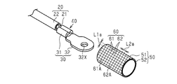
(接続端子30の構成)
図2に示すように、接続端子30は、電線20の端部と接続される電線接続部31と、相手端子(図示略)と接続される端子接続部32とを有している。接続端子30は、例えば、電線接続部31と端子接続部32とが連なって一体に形成された単一部品である。接続端子30の材料としては、例えば、銅、銅合金、アルミニウム、アルミニウム合金、ステンレス鋼などの金属材料を用いることができる。接続端子30は、その構成金属の種類や使用環境に応じて、銀メッキ、錫メッキやアルミニウムメッキ等の表面処理を施してもよい。接続端子30は、例えば、導電性に優れた金属板をプレス加工することによって形成することができる。なお、端子接続部32が接続される相手端子としては、例えば、バスバ、電気機器の端子部や他の電線の端子を挙げることができる。 (Configuration of connection terminal 30)
As shown in FIG. 2, theconnection terminal 30 has an electric wire connection portion 31 connected to the end portion of the electric wire 20 and a terminal connection portion 32 connected to a mating terminal (not shown). The connection terminal 30 is, for example, a single component in which the electric wire connection portion 31 and the terminal connection portion 32 are connected and integrally formed. As the material of the connection terminal 30, for example, a metal material such as copper, copper alloy, aluminum, aluminum alloy, or stainless steel can be used. The connection terminal 30 may be subjected to surface treatment such as silver plating, tin plating, or aluminum plating, depending on the type of the constituent metal and the usage environment. The connection terminal 30 can be formed, for example, by pressing a metal plate having excellent conductivity. Examples of the mating terminal to which the terminal connecting portion 32 is connected include a bus bar, a terminal portion of an electric device, and a terminal of another electric wire.
図2に示すように、接続端子30は、電線20の端部と接続される電線接続部31と、相手端子(図示略)と接続される端子接続部32とを有している。接続端子30は、例えば、電線接続部31と端子接続部32とが連なって一体に形成された単一部品である。接続端子30の材料としては、例えば、銅、銅合金、アルミニウム、アルミニウム合金、ステンレス鋼などの金属材料を用いることができる。接続端子30は、その構成金属の種類や使用環境に応じて、銀メッキ、錫メッキやアルミニウムメッキ等の表面処理を施してもよい。接続端子30は、例えば、導電性に優れた金属板をプレス加工することによって形成することができる。なお、端子接続部32が接続される相手端子としては、例えば、バスバ、電気機器の端子部や他の電線の端子を挙げることができる。 (Configuration of connection terminal 30)
As shown in FIG. 2, the
(電線接続部31の構成)
電線接続部31は、電線20の端部と電気的に接続されている。電線接続部31は、例えば、絶縁被覆22から露出された芯線21の端部に対して接続されている。電線接続部31は、例えば、圧着や超音波溶接などによって芯線21に接続されている。これにより、電線接続部31と芯線21とが電気的に接続されている。 (Structure of electric wire connection portion 31)
The electricwire connecting portion 31 is electrically connected to the end portion of the electric wire 20. The electric wire connecting portion 31 is connected to, for example, the end portion of the core wire 21 exposed from the insulating coating 22. The electric wire connecting portion 31 is connected to the core wire 21 by, for example, crimping or ultrasonic welding. As a result, the electric wire connecting portion 31 and the core wire 21 are electrically connected.
電線接続部31は、電線20の端部と電気的に接続されている。電線接続部31は、例えば、絶縁被覆22から露出された芯線21の端部に対して接続されている。電線接続部31は、例えば、圧着や超音波溶接などによって芯線21に接続されている。これにより、電線接続部31と芯線21とが電気的に接続されている。 (Structure of electric wire connection portion 31)
The electric
(端子接続部32の構成)
端子接続部32は、収縮チューブ50から露出され、収縮チューブ50の外方に突出するように形成されている。端子接続部32は、例えば、平板状に形成されている。端子接続部32には、例えば、ネジ等の固定具(図示略)が挿入される貫通孔32Xが形成されている。貫通孔32Xは、例えば、端子接続部32を板厚方向に貫通するように形成されている。なお、端子接続部32は、貫通孔32Xを有さない板状又は棒状などの他の形状に形成されていてもよい。 (Structure of terminal connection portion 32)
Theterminal connection portion 32 is exposed from the shrink tube 50 and is formed so as to project outward from the shrink tube 50. The terminal connection portion 32 is formed in a flat plate shape, for example. The terminal connection portion 32 is formed with, for example, a through hole 32X into which a fixture (not shown) such as a screw is inserted. The through hole 32X is formed so as to penetrate the terminal connection portion 32 in the plate thickness direction, for example. The terminal connection portion 32 may be formed in another shape such as a plate shape or a rod shape having no through hole 32X.
端子接続部32は、収縮チューブ50から露出され、収縮チューブ50の外方に突出するように形成されている。端子接続部32は、例えば、平板状に形成されている。端子接続部32には、例えば、ネジ等の固定具(図示略)が挿入される貫通孔32Xが形成されている。貫通孔32Xは、例えば、端子接続部32を板厚方向に貫通するように形成されている。なお、端子接続部32は、貫通孔32Xを有さない板状又は棒状などの他の形状に形成されていてもよい。 (Structure of terminal connection portion 32)
The
(収縮チューブ50の構成)
収縮チューブ50は、例えば、長尺の筒状に形成されている。収縮チューブ50は、例えば、電線接続部31と芯線21との接続部分40を覆うように形成されている。収縮チューブ50は、例えば、絶縁被覆22から露出された芯線21を覆うように形成されている。収縮チューブ50は、例えば、絶縁被覆22の端部から接続部分40までを覆うように形成されている。収縮チューブ50は、例えば、接続部分40よりも端子接続部32側に位置する電線接続部31を覆うように形成されている。例えば、収縮チューブ50の一端部は絶縁被覆22の端部の外周面を被覆しており、収縮チューブ50の他端部は接続端子30の電線接続部31の外周面を被覆している。収縮チューブ50は、絶縁被覆22の端部の外周面及び接続部分40の外周を、周方向全周にわたって包囲するように形成されている。 (Structure of shrink tube 50)
Theshrink tube 50 is formed, for example, in a long tubular shape. The shrink tube 50 is formed so as to cover, for example, the connecting portion 40 between the electric wire connecting portion 31 and the core wire 21. The shrink tube 50 is formed so as to cover, for example, the core wire 21 exposed from the insulating coating 22. The shrink tube 50 is formed so as to cover, for example, from the end portion of the insulating coating 22 to the connecting portion 40. The shrink tube 50 is formed so as to cover, for example, the electric wire connecting portion 31 located closer to the terminal connecting portion 32 than the connecting portion 40. For example, one end of the shrink tube 50 covers the outer peripheral surface of the end of the insulating coating 22, and the other end of the shrink tube 50 covers the outer peripheral surface of the electric wire connecting portion 31 of the connection terminal 30. The shrink tube 50 is formed so as to surround the outer peripheral surface of the end portion of the insulating coating 22 and the outer peripheral surface of the connecting portion 40 over the entire circumference in the circumferential direction.
収縮チューブ50は、例えば、長尺の筒状に形成されている。収縮チューブ50は、例えば、電線接続部31と芯線21との接続部分40を覆うように形成されている。収縮チューブ50は、例えば、絶縁被覆22から露出された芯線21を覆うように形成されている。収縮チューブ50は、例えば、絶縁被覆22の端部から接続部分40までを覆うように形成されている。収縮チューブ50は、例えば、接続部分40よりも端子接続部32側に位置する電線接続部31を覆うように形成されている。例えば、収縮チューブ50の一端部は絶縁被覆22の端部の外周面を被覆しており、収縮チューブ50の他端部は接続端子30の電線接続部31の外周面を被覆している。収縮チューブ50は、絶縁被覆22の端部の外周面及び接続部分40の外周を、周方向全周にわたって包囲するように形成されている。 (Structure of shrink tube 50)
The
(収縮チューブ50の具体的構成)
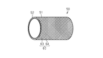
本実施形態の収縮チューブ50は、筒状をなす熱収縮チューブ51と、熱収縮チューブ51の内周面に形成された接着層52とを有している。 (Specific configuration of shrink tube 50)
Theshrinkable tube 50 of the present embodiment has a heat-shrinkable tube 51 having a tubular shape and an adhesive layer 52 formed on the inner peripheral surface of the heat-shrinkable tube 51.
本実施形態の収縮チューブ50は、筒状をなす熱収縮チューブ51と、熱収縮チューブ51の内周面に形成された接着層52とを有している。 (Specific configuration of shrink tube 50)
The
図4Aに示すように、熱収縮チューブ51は、例えば、接続部分40が収縮チューブ50の内部に配置される前の状態からすでに筒体(ここでは、円筒体)として形成されているものである。熱収縮チューブ51は、例えば、押出成形によりごく細い筒状に成形された樹脂部材が、加熱された状態で太い筒状へ引き伸ばされた後に冷却されることによって得られる。このようにして得られた熱収縮チューブ51は、加熱された場合に、引き伸ばされる前の細い筒状まで収縮する形状記憶特性を有する。熱収縮チューブ51の材料としては、例えば、ポリオレフィン系、ポリエステル系、ナイロン系、シリコン系やフッ素樹脂系などの合成樹脂を用いることができる。熱収縮チューブ51の材料としては、1種の材料を単独で、又は2種以上の材料を適宜組み合わせて用いることができる。
As shown in FIG. 4A, the heat-shrinkable tube 51 is, for example, already formed as a cylinder (here, a cylinder) from the state before the connecting portion 40 is arranged inside the shrink tube 50. .. The heat-shrinkable tube 51 is obtained, for example, by cooling a resin member that has been formed into a very thin tubular shape by extrusion molding after being stretched into a thick tubular shape in a heated state. The heat-shrinkable tube 51 thus obtained has a shape memory property that shrinks to a thin tubular shape before being stretched when heated. As the material of the heat-shrinkable tube 51, for example, synthetic resins such as polyolefin-based, polyester-based, nylon-based, silicon-based, and fluororesin-based can be used. As the material of the heat-shrinkable tube 51, one kind of material can be used alone, or two or more kinds of materials can be used in combination as appropriate.
接着層52は、例えば、接続部分40が収縮チューブ50の内部に配置される前の状態において、熱収縮チューブ51の内周面に均一な厚みに形成されており、筒状(ここでは、円筒状)をなすように形成されている。接着層52は、例えば、熱収縮チューブ51の内周面の周方向全周及び長さ方向の全長にわたって形成されている。接着層52は、例えば、内部に接続部分40及び絶縁被覆22の端部等が配置される前の状態では、その内径が接続部分40の外径及び絶縁被覆22の外径よりも大きくなっている。接着層52としては、例えば、熱可塑性の接着剤を用いることができる。接着層52としては、例えば、変性オレフィン系やポリエステル系のホットメルト接着剤を用いることができる。接着層52の材料としては、例えば、絶縁被覆22を構成する材料と同種の樹脂材料であることが好ましい。また、接着層52の材料としては、例えば、熱収縮チューブ51を構成する材料と同種の樹脂材料であることが好ましい。接着層52の材料としては、1種の材料を単独で、又は2種以上の材料を適宜組み合わせて用いることができる。なお、接着層52は、例えば、加熱によって溶融された後に、冷えて固化されることによって形成される層である。
The adhesive layer 52 is formed on the inner peripheral surface of the heat-shrinkable tube 51 to a uniform thickness in a state before the connecting portion 40 is arranged inside the shrinkable tube 50, and has a tubular shape (here, a cylinder). It is formed so as to form a shape). The adhesive layer 52 is formed, for example, over the entire circumference of the inner peripheral surface of the heat-shrinkable tube 51 in the circumferential direction and the entire length in the length direction. The inner diameter of the adhesive layer 52 is larger than the outer diameter of the connecting portion 40 and the outer diameter of the insulating coating 22 in the state before the connection portion 40 and the end portion of the insulating coating 22 are arranged inside, for example. There is. As the adhesive layer 52, for example, a thermoplastic adhesive can be used. As the adhesive layer 52, for example, a modified olefin-based or polyester-based hot melt adhesive can be used. The material of the adhesive layer 52 is preferably, for example, a resin material of the same type as the material constituting the insulating coating 22. Further, the material of the adhesive layer 52 is preferably, for example, a resin material of the same type as the material constituting the heat-shrinkable tube 51. As the material of the adhesive layer 52, one kind of material can be used alone, or two or more kinds of materials can be used in combination as appropriate. The adhesive layer 52 is, for example, a layer formed by being melted by heating and then cooled and solidified.
次に、図2に従って、熱収縮された後の熱収縮チューブ51及び接着層52の構造について説明する。
図2に示すように、熱収縮チューブ51は、例えば、絶縁被覆22の端部から接続部分40までを覆うように形成されている。熱収縮チューブ51は、例えば、絶縁被覆22の端部から、接続部分40よりも端子接続部32側に位置する電線接続部31までを覆うように形成されている。熱収縮チューブ51は、例えば、絶縁被覆22の端部の外周面及び接続部分40の外周面を、周方向全周にわたって包囲するように形成されている。熱収縮チューブ51は、例えば、電線接続部31を周方向全周にわたって包囲するように形成されている。熱収縮チューブ51には、例えば、絶縁被覆22の外周面とその絶縁被覆22から露出された芯線21と接続部分40と電線接続部31とによって形成される段差に沿って段差が形成されている。例えば、熱収縮チューブ51は、接続部分40を覆う部分の外径が絶縁被覆22の外周面を覆う部分の外径よりも小さく形成されている。例えば、熱収縮チューブ51は、接続部分40よりも端子接続部32側に位置する電線接続部31を覆う部分の外径が接続部分40を覆う部分の外径よりも小さく形成されている。 Next, the structures of the heat-shrinkable tube 51 and the adhesive layer 52 after heat-shrinking will be described with reference to FIG.
As shown in FIG. 2, the heat-shrinkable tube 51 is formed so as to cover, for example, from the end portion of the insulating coating 22 to the connecting portion 40. The heat-shrinkable tube 51 is formed so as to cover, for example, from the end portion of the insulating coating 22 to the electric wire connecting portion 31 located closer to the terminal connecting portion 32 than the connecting portion 40. The heat-shrinkable tube 51 is formed so as to surround, for example, the outer peripheral surface of the end portion of the insulating coating 22 and the outer peripheral surface of the connecting portion 40 over the entire circumference in the circumferential direction. The heat-shrinkable tube 51 is formed so as to surround, for example, the electric wire connecting portion 31 over the entire circumference in the circumferential direction. In the heat-shrinkable tube 51, for example, a step is formed along a step formed by an outer peripheral surface of the insulating coating 22, a core wire 21 exposed from the insulating coating 22, a connecting portion 40, and an electric wire connecting portion 31. .. For example, the heat-shrinkable tube 51 is formed so that the outer diameter of the portion covering the connecting portion 40 is smaller than the outer diameter of the portion covering the outer peripheral surface of the insulating coating 22. For example, the heat-shrinkable tube 51 is formed so that the outer diameter of the portion covering the electric wire connecting portion 31 located on the terminal connecting portion 32 side of the connecting portion 40 is smaller than the outer diameter of the portion covering the connecting portion 40.
図2に示すように、熱収縮チューブ51は、例えば、絶縁被覆22の端部から接続部分40までを覆うように形成されている。熱収縮チューブ51は、例えば、絶縁被覆22の端部から、接続部分40よりも端子接続部32側に位置する電線接続部31までを覆うように形成されている。熱収縮チューブ51は、例えば、絶縁被覆22の端部の外周面及び接続部分40の外周面を、周方向全周にわたって包囲するように形成されている。熱収縮チューブ51は、例えば、電線接続部31を周方向全周にわたって包囲するように形成されている。熱収縮チューブ51には、例えば、絶縁被覆22の外周面とその絶縁被覆22から露出された芯線21と接続部分40と電線接続部31とによって形成される段差に沿って段差が形成されている。例えば、熱収縮チューブ51は、接続部分40を覆う部分の外径が絶縁被覆22の外周面を覆う部分の外径よりも小さく形成されている。例えば、熱収縮チューブ51は、接続部分40よりも端子接続部32側に位置する電線接続部31を覆う部分の外径が接続部分40を覆う部分の外径よりも小さく形成されている。 Next, the structures of the heat-
As shown in FIG. 2, the heat-
熱収縮チューブ51の長さ方向の一端部は、例えば、絶縁被覆22の端部の外周面の周方向全周にわたって、接着層52によって接着されている。例えば、収縮チューブ50の長さ方向の一端部における接着層52は、絶縁被覆22の端部の外周面に周方向全周にわたって隙間無く接着するとともに、熱収縮チューブ51の内周面に周方向全周にわたって隙間無く接着している。また、熱収縮チューブ51の長さ方向の他端部は、例えば、電線接続部31の外周面の周方向全周にわたって、接着層52によって接着されている。例えば、収縮チューブ50の長さ方向の他端部における接着層52は、電線接続部31の外周面に周方向全周にわたって隙間無く接着するとともに、熱収縮チューブ51の内周面に周方向全周にわたって隙間無く接着している。これらにより、熱収縮チューブ51と絶縁被覆22との間の隙間が塞がれ、熱収縮チューブ51と電線接続部31との間の隙間が塞がれる。このため、収縮チューブ50の長さ方向の両端部から収縮チューブ50の内部に水等の液体が浸入することを抑制できる。この結果、電線20の芯線21と接続端子30の電線接続部31との接続部分40に液体が浸入することを抑制できる。すなわち、本実施形態の収縮チューブ50は、接続部分40を絶縁保護する絶縁保護機能を有するとともに、接続部分40を止水する止水機能を有している。
One end of the heat-shrinkable tube 51 in the length direction is adhered by an adhesive layer 52 over the entire circumference of the outer peripheral surface of the end of the insulating coating 22 in the circumferential direction, for example. For example, the adhesive layer 52 at one end of the shrink tubing 50 in the length direction adheres to the outer peripheral surface of the end of the insulating coating 22 without a gap over the entire circumference in the circumferential direction, and is circumferentially attached to the inner peripheral surface of the heat shrink tubing 51. It adheres without gaps all around. Further, the other end of the heat-shrinkable tube 51 in the length direction is adhered by the adhesive layer 52 over the entire circumference of the outer peripheral surface of the electric wire connecting portion 31 in the circumferential direction, for example. For example, the adhesive layer 52 at the other end of the shrink tube 50 in the length direction adheres to the outer peripheral surface of the electric wire connecting portion 31 without a gap over the entire circumference in the circumferential direction, and also adheres to the inner peripheral surface of the heat shrink tube 51 in the circumferential direction. It adheres tightly over the circumference. As a result, the gap between the heat-shrinkable tube 51 and the insulating coating 22 is closed, and the gap between the heat-shrinkable tube 51 and the electric wire connecting portion 31 is closed. Therefore, it is possible to prevent liquid such as water from entering the inside of the shrink tube 50 from both ends in the length direction of the shrink tube 50. As a result, it is possible to prevent the liquid from entering the connection portion 40 between the core wire 21 of the electric wire 20 and the electric wire connection portion 31 of the connection terminal 30. That is, the shrink tube 50 of the present embodiment has an insulation protection function for insulatingly protecting the connection portion 40 and a water stop function for stopping the connection portion 40.
接着層52は、例えば、収縮チューブ50の長さ方向の中間部において、熱収縮チューブ51の内周面と、芯線21及び電線接続部31の外周面との間の隙間を充填するように形成されている。なお、接着層52は、収縮チューブ50の長さ方向の中間部において、熱収縮チューブ51の内周面に沿って形成されていてもよい。また、接着層52は、熱収縮チューブ51の長さ方向の端部よりも外側に突出して形成されていてもよい。
The adhesive layer 52 is formed so as to fill a gap between the inner peripheral surface of the heat-shrinkable tube 51 and the outer peripheral surface of the core wire 21 and the electric wire connecting portion 31 at the intermediate portion in the length direction of the shrinkable tube 50, for example. Has been done. The adhesive layer 52 may be formed along the inner peripheral surface of the heat-shrinkable tube 51 at the intermediate portion in the length direction of the shrinkable tube 50. Further, the adhesive layer 52 may be formed so as to project outward from the end portion in the length direction of the heat shrink tube 51.
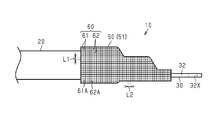
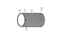
図3に示すように、熱収縮チューブ51の外周面には、その熱収縮チューブ51(収縮チューブ50)の収縮率が判別可能な判別パターン60が印字されている。本実施形態の判別パターン60は、熱収縮チューブ51の径方向における収縮率が判別可能な第1判別パターン61と、熱収縮チューブ51の長さ方向における収縮率が判別可能な第2判別パターン62とを有している。
As shown in FIG. 3, a discrimination pattern 60 capable of discriminating the shrinkage rate of the heat-shrinkable tube 51 (shrinkable tube 50) is printed on the outer peripheral surface of the heat-shrinkable tube 51. The discrimination pattern 60 of the present embodiment has a first discrimination pattern 61 capable of discriminating the shrinkage rate in the radial direction of the heat shrink tube 51 and a second discrimination pattern 62 capable of discriminating the shrinkage rate in the length direction of the heat shrink tube 51. And have.
第1判別パターン61は、例えば、熱収縮チューブ51の長さ方向に沿って延びる複数の第1パターン61Aが熱収縮チューブ51の周方向に沿って等間隔に印字されたパターンである。第1判別パターン61では、熱収縮チューブ51の収縮後において、隣り合う第1パターン61Aの間隔L1が、熱収縮チューブ51の収縮前と比べてどの程度狭くなったかを判別することにより、熱収縮チューブ51の径方向における収縮率を判別することができる。
The first discrimination pattern 61 is, for example, a pattern in which a plurality of first patterns 61A extending along the length direction of the heat shrink tube 51 are printed at equal intervals along the circumferential direction of the heat shrink tube 51. In the first determination pattern 61, after the heat-shrinkable tube 51 is contracted, the distance L1 between the adjacent first patterns 61A is determined to be narrower than that before the heat-shrinkable tube 51 is contracted. The shrinkage rate of the tube 51 in the radial direction can be determined.
第2判別パターン62は、例えば、熱収縮チューブ51の周方向に沿って延びる複数の第2パターン62Aが熱収縮チューブ51の長さ方向に沿って等間隔に印字されたパターンである。第2判別パターン62では、熱収縮チューブ51の収縮後において、隣り合う第2パターン62Aの間隔L2が、熱収縮チューブ51の収縮前と比べてどの程度狭くなったかを判別することにより、熱収縮チューブ51の長さ方向における収縮率を判別することができる。
The second discrimination pattern 62 is, for example, a pattern in which a plurality of second patterns 62A extending along the circumferential direction of the heat shrink tube 51 are printed at equal intervals along the length direction of the heat shrink tube 51. In the second determination pattern 62, after the heat-shrinkable tube 51 is contracted, the distance L2 between the adjacent second patterns 62A is determined to be narrower than that before the heat-shrinkable tube 51 is contracted. The shrinkage rate of the tube 51 in the length direction can be determined.
本実施形態の判別パターン60は、第1判別パターン61と第2判別パターン62とによって、全体が格子状に形成されている。なお、判別パターン60(第1判別パターン61及び第2判別パターン62)は、例えば、レーザや印刷などによって熱収縮チューブ51の外周面に印字されている。
The entire discrimination pattern 60 of the present embodiment is formed in a grid pattern by the first discrimination pattern 61 and the second discrimination pattern 62. The discrimination pattern 60 (first discrimination pattern 61 and second discrimination pattern 62) is printed on the outer peripheral surface of the heat-shrinkable tube 51 by, for example, a laser or printing.
(ワイヤハーネス10の製造方法)
次に、図4A~図4Cに従って、ワイヤハーネス10の製造方法について説明する。
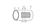
まず、図4Aに示す工程では、芯線21の端部に接続端子30の電線接続部31が電気的に接続された電線20と、収縮前の収縮チューブ50とを準備する。図示の例では、電線接続部31が圧着により芯線21に接続されている。収縮前の収縮チューブ50は、筒状(ここでは、円筒状)をなす熱収縮チューブ51と、熱収縮チューブ51の内周面に形成された熱可塑性の接着層52とを含む積層構造を有している。この収縮前の収縮チューブ50は、その内径が絶縁被覆22、接続部分40及び電線接続部31を内部に収容可能な大きさに形成されている。ここで、熱収縮チューブ51の外周面には、第1判別パターン61及び第2判別パターン62を含む判別パターン60が印字されている。例えば、収縮前の熱収縮チューブ51における第1判別パターン61では、隣り合う第1パターン61Aの間隔が間隔L1aとなるように設定されている。例えば、収縮前の熱収縮チューブ51における第2判別パターン62では、隣り合う第2パターン62Aの間隔が間隔L2aとなるように設定されている。 (Manufacturing method of wire harness 10)
Next, a method of manufacturing thewire harness 10 will be described with reference to FIGS. 4A to 4C.
First, in the process shown in FIG. 4A, anelectric wire 20 to which the electric wire connecting portion 31 of the connecting terminal 30 is electrically connected to the end of the core wire 21 and a shrinkable tube 50 before shrinkage are prepared. In the illustrated example, the electric wire connecting portion 31 is connected to the core wire 21 by crimping. The shrinkable tube 50 before shrinkage has a laminated structure including a heat-shrinkable tube 51 having a tubular shape (here, a cylindrical shape) and a thermoplastic adhesive layer 52 formed on the inner peripheral surface of the heat-shrinkable tube 51. are doing. The inner diameter of the shrink tube 50 before shrinkage is formed so as to accommodate the insulating coating 22, the connecting portion 40, and the electric wire connecting portion 31 inside. Here, a discrimination pattern 60 including a first discrimination pattern 61 and a second discrimination pattern 62 is printed on the outer peripheral surface of the heat-shrinkable tube 51. For example, in the first discrimination pattern 61 in the heat-shrinkable tube 51 before shrinkage, the distance between adjacent first patterns 61A is set to be the distance L1a. For example, in the second discrimination pattern 62 in the heat-shrinkable tube 51 before shrinkage, the distance between adjacent second patterns 62A is set to be the distance L2a.
次に、図4A~図4Cに従って、ワイヤハーネス10の製造方法について説明する。
まず、図4Aに示す工程では、芯線21の端部に接続端子30の電線接続部31が電気的に接続された電線20と、収縮前の収縮チューブ50とを準備する。図示の例では、電線接続部31が圧着により芯線21に接続されている。収縮前の収縮チューブ50は、筒状(ここでは、円筒状)をなす熱収縮チューブ51と、熱収縮チューブ51の内周面に形成された熱可塑性の接着層52とを含む積層構造を有している。この収縮前の収縮チューブ50は、その内径が絶縁被覆22、接続部分40及び電線接続部31を内部に収容可能な大きさに形成されている。ここで、熱収縮チューブ51の外周面には、第1判別パターン61及び第2判別パターン62を含む判別パターン60が印字されている。例えば、収縮前の熱収縮チューブ51における第1判別パターン61では、隣り合う第1パターン61Aの間隔が間隔L1aとなるように設定されている。例えば、収縮前の熱収縮チューブ51における第2判別パターン62では、隣り合う第2パターン62Aの間隔が間隔L2aとなるように設定されている。 (Manufacturing method of wire harness 10)
Next, a method of manufacturing the
First, in the process shown in FIG. 4A, an
次に、図4Bに示す工程では、接続端子30と接続された電線20の端部が収縮チューブ50の内部に挿入される。具体的には、絶縁被覆22の端部の外周と、絶縁被覆22から露出された芯線21の外周と、接続部分40の外周と、電線接続部31の外周とが収縮チューブ50によって包囲されるように、接続端子30と接続された電線20が収縮チューブ50の内部に挿入される。
Next, in the process shown in FIG. 4B, the end of the electric wire 20 connected to the connection terminal 30 is inserted into the shrink tube 50. Specifically, the outer circumference of the end portion of the insulating coating 22, the outer circumference of the core wire 21 exposed from the insulating coating 22, the outer circumference of the connecting portion 40, and the outer circumference of the electric wire connecting portion 31 are surrounded by the shrink tube 50. As described above, the electric wire 20 connected to the connection terminal 30 is inserted into the shrink tube 50.
続いて、収縮チューブ50に対して加熱処理が施される。例えば、収縮チューブ50がヒータ等により加熱される。この加熱処理では、例えば、熱収縮チューブ51の収縮温度よりも高く、かつ熱収縮チューブ51の溶融温度よりも低い加熱温度(例えば、120℃~140℃程度)で所定時間だけ収縮チューブ50が加熱される。この加熱処理により、熱収縮チューブ51が径方向及び長さ方向に収縮されるとともに、熱可塑性の接着層52が軟化又は溶融されることで接着層52に接着性が発現される。これにより、熱収縮チューブ51は、絶縁被覆22の端部の外周面に対して周方向全周にわたって接着層52によって隙間無く接着されるとともに、電線接続部31の外周面に対して周方向全周にわたって接着層52によって隙間無く接着される。このような収縮後の収縮チューブ50は、接続部分40を止水する止水部材として機能させることができる。
Subsequently, the shrink tube 50 is heat-treated. For example, the shrink tube 50 is heated by a heater or the like. In this heat treatment, for example, the shrink tube 50 is heated for a predetermined time at a heating temperature (for example, about 120 ° C. to 140 ° C.) higher than the shrinkage temperature of the heat shrink tube 51 and lower than the melting temperature of the heat shrink tube 51. Will be done. By this heat treatment, the heat-shrinkable tube 51 is contracted in the radial direction and the length direction, and the thermoplastic adhesive layer 52 is softened or melted, so that the adhesive layer 52 exhibits adhesiveness. As a result, the heat-shrinkable tube 51 is firmly adhered to the outer peripheral surface of the end portion of the insulating coating 22 by the adhesive layer 52 over the entire circumference in the circumferential direction, and is also adhered to the outer peripheral surface of the electric wire connecting portion 31 in the circumferential direction. It is adhered without a gap by the adhesive layer 52 over the circumference. The contracted tube 50 after such contraction can function as a water blocking member that stops the connecting portion 40.
ここで、本工程の加熱処理によって熱収縮チューブ51を過剰に収縮させてしまうと、例えば接続部分40の角部などに熱収縮チューブ51が押し付けられ、熱収縮チューブ51が破れるという問題が生じる。一方で、加熱処理による熱収縮チューブ51の収縮が不十分である場合には、熱収縮チューブ51を絶縁被覆22の外周面や電線接続部31の外周面に密着させることができなくなる。このため、熱収縮チューブ51の収縮が不十分である場合には、熱収縮チューブ51において所望の止水性能を得ることができないという問題が生じる。これに対し、従来は、加熱処理における加熱温度及び加熱時間という製造条件のみによって、熱収縮チューブ51の収縮率を保証していた。しかし、従来の方法では、熱収縮チューブ51の実際の収縮率が所望の収縮率になっているか否かを判別することができない。このため、例えば収縮チューブ50を止水部材として用いる場合には、製造した全てのワイヤハーネス10に対して、収縮チューブ50が所望の止水性能を有しているか否かを評価するリーク検査を行う必要があった。このため、従来のワイヤハーネスでは、収縮チューブ50における止水性能を保証するために、多大な工数を要することになり、製造コストが増大するという問題があった。
Here, if the heat-shrinkable tube 51 is excessively contracted by the heat treatment in this step, the heat-shrinkable tube 51 is pressed against, for example, the corners of the connecting portion 40, causing a problem that the heat-shrinkable tube 51 is torn. On the other hand, if the heat-shrinkable tube 51 is not sufficiently shrunk by the heat treatment, the heat-shrinkable tube 51 cannot be brought into close contact with the outer peripheral surface of the insulating coating 22 or the outer peripheral surface of the electric wire connecting portion 31. Therefore, if the heat-shrinkable tube 51 is not sufficiently shrunk, there arises a problem that the heat-shrinkable tube 51 cannot obtain the desired water stopping performance. On the other hand, conventionally, the shrinkage rate of the heat-shrinkable tube 51 has been guaranteed only by the manufacturing conditions of the heating temperature and the heating time in the heat treatment. However, with the conventional method, it is not possible to determine whether or not the actual shrinkage rate of the heat shrink tube 51 is a desired shrinkage rate. Therefore, for example, when the shrink tube 50 is used as a water stop member, a leak inspection is performed on all the manufactured wire harnesses 10 to evaluate whether or not the shrink tube 50 has a desired water stop performance. I had to do it. For this reason, the conventional wire harness has a problem that a large amount of man-hours are required to guarantee the water-stopping performance of the shrink tube 50, and the manufacturing cost increases.
これに対し、図4Cに示すように、本実施形態のワイヤハーネス10では、熱収縮チューブ51(収縮チューブ50)の外周面に、収縮チューブ50の収縮率を判別可能な判別パターン60が印字されている。このため、収縮後の収縮チューブ50における判別パターン60から収縮チューブ50の収縮率を判別することができる。
On the other hand, as shown in FIG. 4C, in the wire harness 10 of the present embodiment, a discrimination pattern 60 capable of discriminating the shrinkage rate of the shrink tube 50 is printed on the outer peripheral surface of the heat shrink tube 51 (shrink tube 50). ing. Therefore, the shrinkage rate of the shrinkage tube 50 can be discriminated from the discrimination pattern 60 of the shrinkage tube 50 after shrinkage.
図4Cに示すように、収縮後の収縮チューブ50における第1判別パターン61では、隣り合う第1パターン61Aの間隔が、収縮前の間隔L1a(図4A参照)よりも狭い間隔L1になっている。すなわち、熱収縮チューブ51の径方向の収縮、つまり熱収縮チューブ51の内径が縮径されることに伴って、隣り合う第1パターン61Aの間隔が狭くなる。また、収縮後の収縮チューブ50における第2判別パターン62では、隣り合う第2パターン62Aの間隔が、収縮前の間隔L2a(図4A参照)よりも狭い間隔L2になっている。すなわち、熱収縮チューブ51の長さ方向の収縮に伴って、隣り合う第2パターン62Aの間隔が狭くなる。このとき、収縮前の第1判別パターン61における間隔L1aと、収縮後の第1判別パターン61における間隔L1との比L1/L1aに基づいて、収縮チューブ50の径方向の収縮率を判別することができる。また、収縮前の第2判別パターン62における間隔L2aと、収縮後の第2判別パターン62における間隔L2との比L2/L2aに基づいて、収縮チューブ50の長さ方向の収縮率を判別することができる。
As shown in FIG. 4C, in the first discrimination pattern 61 in the shrink tube 50 after shrinkage, the distance between adjacent first patterns 61A is narrower than the distance L1a before shrinkage (see FIG. 4A). .. That is, as the heat-shrinkable tube 51 shrinks in the radial direction, that is, the inner diameter of the heat-shrinkable tube 51 is reduced, the distance between adjacent first patterns 61A becomes narrower. Further, in the second discriminant pattern 62 in the contracted tube 50 after contraction, the interval between adjacent second patterns 62A is narrower than the interval L2a before contraction (see FIG. 4A). That is, as the heat-shrinkable tube 51 shrinks in the length direction, the distance between the adjacent second patterns 62A becomes narrower. At this time, the radial contraction rate of the shrink tube 50 is determined based on the ratio L1 / L1a of the interval L1a in the first discrimination pattern 61 before contraction and the interval L1 in the first discrimination pattern 61 after contraction. Can be done. Further, the contraction rate in the length direction of the contraction tube 50 is discriminated based on the ratio L2 / L2a of the interval L2a in the second discrimination pattern 62 before contraction and the interval L2 in the second discrimination pattern 62 after contraction. Can be done.
本実施形態では、例えば実験等により、収縮チューブ50が所望の収縮率で収縮した際における比L1/L1a及び比L2/L2aを予め求めておく。このとき、収縮前の間隔L1a,L2aをそれぞれ一定の値とすることにより、上記求めた比L1/L1a及び比L2/L2aから、収縮チューブ50が所望の収縮率で収縮した際の間隔L1,L2、つまり間隔L1,L2の適正範囲を求めることができる。このような間隔L1,L2の適正範囲を利用して、上記加熱処理で収縮された収縮チューブ50が所望の収縮率になっているか否かを判別することができる。なお、「所望の収縮率」とは、収縮チューブ50に求められている機能(ここでは、絶縁保護機能及び止水機能)を、収縮後の収縮チューブ50が得ることのできるときの収縮率のことをいう。
In the present embodiment, for example, the ratio L1 / L1a and the ratio L2 / L2a when the shrink tube 50 contracts at a desired contraction rate are obtained in advance by an experiment or the like. At this time, by setting the intervals L1a and L2a before contraction to constant values, the intervals L1 when the contraction tube 50 contracts at a desired contraction rate from the ratios L1 / L1a and the ratio L2 / L2a obtained above. The appropriate range of L2, that is, the intervals L1 and L2 can be obtained. By utilizing such an appropriate range of intervals L1 and L2, it is possible to determine whether or not the shrinkage tube 50 shrunk by the heat treatment has a desired shrinkage rate. The "desired shrinkage rate" is the shrinkage rate when the shrinkage tube 50 can obtain the functions (here, the insulation protection function and the water blocking function) required for the shrinkage tube 50. Say that.
収縮チューブ50の収縮率を判別する工程では、まず、上記加熱処理により収縮した後の収縮チューブ50の判別パターン60における間隔L1,L2が、目視や画像解析などによって測定される。続いて、測定された間隔L1,L2が、予め求めておいた適正範囲に含まれているか否かが求められる。このとき、測定された間隔L1,L2が適性範囲に含まれている場合には、収縮チューブ50が所望の収縮率で収縮されており、収縮後の収縮チューブ50が所望の機能(ここでは、絶縁保護機能及び止水機能)を有していると判断することができる。このように、判別パターン60を介して、接続部分40における絶縁信頼性及び止水性を視認することができる。さらに、間隔L1,L2の測定というリーク検査よりも簡易な方法によって、収縮チューブ50の収縮率が所望の収縮率になっているかを判別できるため、従来の方法よりも工数を減らすことができる。これにより、ワイヤハーネス10の組立作業性を向上させることができる。
In the step of determining the shrinkage rate of the shrink tube 50, first, the intervals L1 and L2 in the discrimination pattern 60 of the shrink tube 50 after shrinking by the heat treatment are measured visually or by image analysis. Subsequently, it is determined whether or not the measured intervals L1 and L2 are included in the predetermined appropriate range. At this time, when the measured intervals L1 and L2 are included in the appropriate range, the shrink tube 50 is contracted at a desired contraction rate, and the contracted tube 50 after contraction has a desired function (here, here). It can be judged that it has an insulation protection function and a water blocking function). In this way, the insulation reliability and water stoppage at the connection portion 40 can be visually recognized through the discrimination pattern 60. Further, since it is possible to determine whether the shrinkage rate of the shrink tube 50 is a desired shrinkage rate by a method simpler than the leak inspection of measuring the intervals L1 and L2, the man-hours can be reduced as compared with the conventional method. Thereby, the assembly workability of the wire harness 10 can be improved.
なお、測定された間隔L1,L2が適性範囲よりも大きい値の場合には、収縮チューブ50の収縮率が不十分であると判別することができる。また、測定された間隔L1,L2が適性範囲よりも小さい値の場合には、収縮チューブ50の収縮率が過剰であると判断することができる。
If the measured intervals L1 and L2 are larger than the appropriate range, it can be determined that the shrinkage rate of the shrink tube 50 is insufficient. Further, when the measured intervals L1 and L2 are smaller than the appropriate range, it can be determined that the shrinkage rate of the shrink tube 50 is excessive.
次に、本実施形態の作用効果を説明する。
(1)電線20の芯線21と接続端子30の電線接続部31との接続部分を覆う筒状の収縮チューブ50を設けた。収縮チューブ50の外周面には、収縮チューブ50の径方向における収縮率が判別可能な第1判別パターン61を含む判別パターン60が印字されている。 Next, the action and effect of this embodiment will be described.
(1) Atubular shrink tube 50 is provided to cover the connection portion between the core wire 21 of the electric wire 20 and the electric wire connection portion 31 of the connection terminal 30. A discrimination pattern 60 including a first discrimination pattern 61 capable of discriminating the shrinkage rate in the radial direction of the shrink tube 50 is printed on the outer peripheral surface of the shrink tube 50.
(1)電線20の芯線21と接続端子30の電線接続部31との接続部分を覆う筒状の収縮チューブ50を設けた。収縮チューブ50の外周面には、収縮チューブ50の径方向における収縮率が判別可能な第1判別パターン61を含む判別パターン60が印字されている。 Next, the action and effect of this embodiment will be described.
(1) A
この構成によれば、収縮チューブ50の径方向における収縮率を第1判別パターン61によって、例えば視覚的にまたは光学的に、判別することができる。このため、第1判別パターン61に基づいて、収縮チューブ50の径方向における収縮率が過剰なワイヤハーネス10や、収縮チューブ50の径方向における収縮率が不十分なワイヤハーネス10を容易に判別することができる。これにより、第1判別パターン61を介して接続部分40における絶縁信頼性や止水性を視認できるため、ワイヤハーネス10の品質低下を抑制することができる。さらに、収縮チューブ50における止水性を評価するためのリーク検査等を省略できるため、ワイヤハーネス10の組立作業性を向上させることができる。
According to this configuration, the shrinkage rate of the shrink tube 50 in the radial direction can be discriminated visually or optically by the first discriminating pattern 61, for example. Therefore, based on the first discrimination pattern 61, the wire harness 10 having an excessive contraction rate in the radial direction of the shrink tube 50 and the wire harness 10 having an insufficient shrinkage rate in the radial direction of the shrink tube 50 can be easily discriminated. be able to. As a result, the insulation reliability and water stoppage at the connection portion 40 can be visually recognized via the first discrimination pattern 61, so that deterioration of the quality of the wire harness 10 can be suppressed. Further, since the leak inspection and the like for evaluating the water stoppage of the shrink tube 50 can be omitted, the assembly workability of the wire harness 10 can be improved.
(2)判別パターン60は、収縮チューブ50の長さ方向における収縮率が判別可能な第2判別パターン62を含む。この構成によれば、収縮チューブ50の長さ方向における収縮率を第2判別パターン62によって判別することができる。このため、第2判別パターン62に基づいて、収縮チューブ50の長さ方向における収縮率が過剰なワイヤハーネス10や、収縮チューブ50の長さ方向における収縮率が不十分なワイヤハーネス10を容易に判別することができる。
(2) The discrimination pattern 60 includes a second discrimination pattern 62 in which the shrinkage rate of the shrink tube 50 in the length direction can be discriminated. According to this configuration, the shrinkage rate of the shrink tube 50 in the length direction can be discriminated by the second discrimination pattern 62. Therefore, based on the second discrimination pattern 62, the wire harness 10 having an excessive shrinkage rate in the length direction of the shrink tube 50 and the wire harness 10 having an insufficient shrinkage rate in the length direction of the shrink tube 50 can be easily provided. It can be determined.
(3)第1判別パターン61は、収縮チューブ50の長さ方向に沿って延びる複数の第1パターン61Aが収縮チューブ50の周方向に沿って等間隔に印字されたパターンである。第2判別パターン62は、収縮チューブ50の周方向に沿って延びる複数の第2パターン62Aが収縮チューブ50の長さ方向に沿って等間隔に印字されたパターンである。
(3) The first discrimination pattern 61 is a pattern in which a plurality of first patterns 61A extending along the length direction of the shrink tube 50 are printed at equal intervals along the circumferential direction of the shrink tube 50. The second discrimination pattern 62 is a pattern in which a plurality of second patterns 62A extending along the circumferential direction of the shrink tube 50 are printed at equal intervals along the length direction of the shrink tube 50.
この構成によれば、収縮後の収縮チューブ50において、隣り合う第1パターン61Aの間隔L1が収縮前と比べてどの程度狭くなったかを測定することにより、収縮チューブ50の径方向における収縮率を判別することができる。また、収縮後の収縮チューブ50において、隣り合う第2パターン62Aの間隔L2が収縮前と比べてどの程度狭くなったかを測定することにより、収縮チューブ50の長さ方向における収縮率を判別することができる。
According to this configuration, in the contracted tube 50 after contraction, the contraction rate in the radial direction of the contracted tube 50 is measured by measuring how narrow the interval L1 of the adjacent first patterns 61A is as compared with that before contraction. It can be determined. Further, in the contracted tube 50 after contraction, the contraction rate in the length direction of the contracted tube 50 is determined by measuring how narrow the interval L2 of the adjacent second patterns 62A is as compared with that before contraction. Can be done.
(4)判別パターン60は、収縮チューブ50の外周面全面に印字されている。この構成によれば、収縮チューブ50の周方向全周及び長さ方向の全長において、収縮チューブ50の収縮率を判別することができる。
(4) The discrimination pattern 60 is printed on the entire outer peripheral surface of the shrink tube 50. According to this configuration, the shrinkage rate of the shrink tube 50 can be determined from the entire circumference in the circumferential direction and the total length in the length direction of the shrink tube 50.
(5)収縮チューブ50は、熱収縮チューブ51と、熱収縮チューブ51の内周面に形成された接着層52とを含む積層構造を有している。この構成によれば、熱収縮チューブ51の内周面に形成された接着層52によって、熱収縮チューブ51と絶縁被覆22との密着性、及び熱収縮チューブ51と電線接続部31との密着性を向上させることができる。
(5) The shrinkable tube 50 has a laminated structure including a heat-shrinkable tube 51 and an adhesive layer 52 formed on the inner peripheral surface of the heat-shrinkable tube 51. According to this configuration, the adhesive layer 52 formed on the inner peripheral surface of the heat-shrinkable tube 51 allows the heat-shrinkable tube 51 to adhere to the insulating coating 22, and the heat-shrinkable tube 51 to adhere to the electric wire connecting portion 31. Can be improved.
(他の実施形態)
上記実施形態は、以下のように変更して実施することができる。上記実施形態及び以下の変更例は、技術的に矛盾しない範囲で互いに組み合わせて実施することができる。 (Other embodiments)
The above embodiment can be modified and implemented as follows. The above-described embodiment and the following modified examples can be implemented in combination with each other within a technically consistent range.
・上記実施形態の収縮チューブ50における接着層52を省略してもよい。
・上記実施形態の収縮チューブ50における止水機能を省略してもよい。
・上記実施形態では、第1導体としての芯線21と第2導体としての接続端子30との接続部分40を覆う収縮チューブ50に具体化したが、これに限定されない。 -Theadhesive layer 52 in the shrink tube 50 of the above embodiment may be omitted.
-The water blocking function of theshrink tube 50 of the above embodiment may be omitted.
-In the above embodiment, theshrink tube 50 that covers the connecting portion 40 between the core wire 21 as the first conductor and the connecting terminal 30 as the second conductor is embodied, but the present invention is not limited to this.
・上記実施形態の収縮チューブ50における止水機能を省略してもよい。
・上記実施形態では、第1導体としての芯線21と第2導体としての接続端子30との接続部分40を覆う収縮チューブ50に具体化したが、これに限定されない。 -The
-The water blocking function of the
-In the above embodiment, the
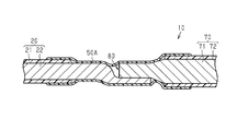
例えば図5に示すように、電線20の芯線21(第1導体)と電線70の芯線71(第2導体)との接続部分80を覆う収縮チューブ50Aに具体化してもよい。本変更例のワイヤハーネス10は、互いに種類の異なる電線20と電線70と、それら電線20と電線70とを電気的に接続する接続部分80と、接続部分80を被覆する収縮チューブ50Aとを有している。ワイヤハーネス10は、例えば、電線20と、その電線20とは別に独立して形成された電線70とがワイヤハーネス10の長さ方向に接続してなるものである。
For example, as shown in FIG. 5, it may be embodied in a shrink tube 50A that covers the connecting portion 80 between the core wire 21 (first conductor) of the electric wire 20 and the core wire 71 (second conductor) of the electric wire 70. The wire harness 10 of this modified example has electric wires 20 and 70 of different types, a connecting portion 80 for electrically connecting the electric wires 20 and the electric wire 70, and a shrink tube 50A covering the connecting portion 80. are doing. The wire harness 10 is formed by, for example, connecting an electric wire 20 and an electric wire 70 formed independently of the electric wire 20 in the length direction of the wire harness 10.
電線70は、導体よりなる芯線71と、芯線71の外周を被覆する絶縁被覆72とを有している。芯線71としては、例えば、撚り線、柱状導体や筒状導体などを用いることができる。芯線71の材料としては、例えば、銅系やアルミニウム系などの金属材料を用いることができる。芯線71は、例えば、押出成形によって形成されている。本変更例では、電線20の芯線21が撚り線であり、電線70の芯線71が単芯線である。
The electric wire 70 has a core wire 71 made of a conductor and an insulating coating 72 that covers the outer circumference of the core wire 71. As the core wire 71, for example, a stranded wire, a columnar conductor, a tubular conductor, or the like can be used. As the material of the core wire 71, for example, a metal material such as copper-based or aluminum-based can be used. The core wire 71 is formed by, for example, extrusion molding. In this modified example, the core wire 21 of the electric wire 20 is a stranded wire, and the core wire 71 of the electric wire 70 is a single core wire.
絶縁被覆72は、例えば、芯線71の外周面を周方向全周にわたって被覆している。絶縁被覆72は、例えば、合成樹脂などの絶縁材料によって構成されている。絶縁被覆72の材料としては、例えば、架橋ポリエチレンや架橋ポリプロピレンなどのポリオレフィン系樹脂を主成分とする合成樹脂を用いることができる。絶縁被覆72の材料としては、1種の材料を単独で、又は2種以上の材料を適宜組み合わせて用いることができる。絶縁被覆72は、例えば、芯線71に対する押出成形によって形成することができる。また、絶縁被覆72としては、熱収縮チューブやゴム製のチューブを用いることもできる。
The insulating coating 72 covers, for example, the outer peripheral surface of the core wire 71 over the entire circumference in the circumferential direction. The insulating coating 72 is made of an insulating material such as a synthetic resin. As the material of the insulating coating 72, for example, a synthetic resin containing a polyolefin resin such as cross-linked polyethylene or cross-linked polypropylene as a main component can be used. As the material of the insulating coating 72, one kind of material can be used alone, or two or more kinds of materials can be used in combination as appropriate. The insulating coating 72 can be formed, for example, by extrusion molding on the core wire 71. Further, as the insulating coating 72, a heat-shrinkable tube or a rubber tube can also be used.
接続部分80では、電線20の芯線21と電線70の芯線71とが接合されている。詳述すると、電線20の端部では、電線20の端末から所定長さ範囲にわたって絶縁被覆22が剥がされ、芯線21が露出されている。また、電線70の端部では、電線70の端末から所定長さ範囲にわたって絶縁被覆72が剥がされ、芯線71が露出されている。そして、接続部分80では、絶縁被覆22の端部から露出された芯線21に対して、絶縁被覆72の端部から露出された芯線71が接合されている。例えば、接続部分80では、芯線21と芯線71とが径方向(芯線21,71の長さ方向と交差する方向)に重ね合わされて接合されている。なお、芯線21と芯線71との接続方法は特に限定されない。例えば、芯線21と芯線71との接続方法としては、超音波溶着やレーザ溶着などを用いることができる。
At the connecting portion 80, the core wire 21 of the electric wire 20 and the core wire 71 of the electric wire 70 are joined. More specifically, at the end of the electric wire 20, the insulating coating 22 is peeled off from the end of the electric wire 20 over a predetermined length range to expose the core wire 21. Further, at the end of the electric wire 70, the insulating coating 72 is peeled off from the end of the electric wire 70 over a predetermined length range to expose the core wire 71. Then, in the connecting portion 80, the core wire 71 exposed from the end portion of the insulating coating 72 is joined to the core wire 21 exposed from the end portion of the insulating coating 22. For example, in the connecting portion 80, the core wire 21 and the core wire 71 are overlapped and joined in the radial direction (the direction intersecting the length direction of the core wires 21 and 71). The method of connecting the core wire 21 and the core wire 71 is not particularly limited. For example, as a method of connecting the core wire 21 and the core wire 71, ultrasonic welding, laser welding, or the like can be used.
収縮チューブ50Aは、例えば、長尺の筒状に形成されている。収縮チューブ50Aは、例えば、熱収縮チューブである。本変更例の収縮チューブ50Aは、単一層からなる部材である。すなわち、本変更例の収縮チューブ50Aは、接着層を有していない。
The shrink tube 50A is formed, for example, in a long tubular shape. The shrink tube 50A is, for example, a heat shrink tube. The shrink tube 50A of this modification is a member made of a single layer. That is, the shrink tube 50A of this modified example does not have an adhesive layer.
収縮チューブ50Aの材料としては、例えば、熱可塑性の合成樹脂を用いることができる。熱可塑性の合成樹脂としては、例えば、架橋構造を有する熱可塑性樹脂を用いることができる。例えば、熱可塑性の合成樹脂としては、電子線を照射して架橋した架橋構造を有する熱可塑性樹脂を用いることができる。収縮チューブ50Aの材料としては、例えば、架橋ポリエチレンや架橋ポリプロピレンなどのポリオレフィン系樹脂を主成分とする合成樹脂を用いることができる。収縮チューブ50Aの材料としては、絶縁被覆22,72を構成する材料と同種の樹脂材料であることが好ましい。収縮チューブ50Aの材料としては、1種の材料を単独で、又は2種以上の材料を適宜組み合わせて用いることができる。
As the material of the shrink tube 50A, for example, a thermoplastic synthetic resin can be used. As the thermoplastic synthetic resin, for example, a thermoplastic resin having a crosslinked structure can be used. For example, as the thermoplastic synthetic resin, a thermoplastic resin having a crosslinked structure that is crosslinked by irradiating an electron beam can be used. As the material of the shrink tube 50A, for example, a synthetic resin containing a polyolefin resin such as cross-linked polyethylene or cross-linked polypropylene as a main component can be used. The material of the shrink tube 50A is preferably a resin material of the same type as the material constituting the insulating coatings 22 and 72. As the material of the shrink tube 50A, one kind of material can be used alone, or two or more kinds of materials can be used in combination as appropriate.
収縮チューブ50Aは、芯線21と芯線71との接続部分80を覆うように形成されている。収縮チューブ50Aは、例えば、絶縁被覆22から露出された芯線21及び絶縁被覆72から露出された芯線71を覆うように形成されている。収縮チューブ50Aは、電線20の外周及び電線70の外周を、周方向全周にわたって包囲するように形成されている。収縮チューブ50Aは、例えば、電線20の絶縁被覆22の端部と電線70の絶縁被覆72の端部との間に架け渡されるように形成されている。例えば、収縮チューブ50Aの一端部は絶縁被覆22の端部の外周面を被覆しており、収縮チューブ50Aの他端部は絶縁被覆72の端部の外周面を被覆している。収縮チューブ50Aの一端部の内周面は、例えば、絶縁被覆22の外周面に対して周方向全周にわたって隙間無く接着されている。収縮チューブ50Aの他端部の内周面は、例えば、絶縁被覆72の外周面に対して周方向全周にわたって隙間無く接着されている。例えば、収縮チューブ50Aの一端部の内周面が溶着により絶縁被覆22の外周面に接着されており、収縮チューブ50Aの他端部の内周面が溶着により絶縁被覆72の外周面に接着されている。ここで、溶着(熱溶着)としては、例えば、超音波溶着、振動溶着、高周波溶着、レーザ溶着、赤外線溶着、摩擦溶着、熱板溶着や熱風溶着を用いることができる。
The shrink tube 50A is formed so as to cover the connecting portion 80 between the core wire 21 and the core wire 71. The shrink tube 50A is formed so as to cover, for example, the core wire 21 exposed from the insulating coating 22 and the core wire 71 exposed from the insulating coating 72. The shrink tube 50A is formed so as to surround the outer circumference of the electric wire 20 and the outer circumference of the electric wire 70 over the entire circumference in the circumferential direction. The shrink tube 50A is formed so as to be bridged between, for example, the end of the insulating coating 22 of the electric wire 20 and the end of the insulating coating 72 of the electric wire 70. For example, one end of the shrink tube 50A covers the outer peripheral surface of the end of the insulating coating 22, and the other end of the shrink tube 50A covers the outer peripheral surface of the end of the insulating coating 72. The inner peripheral surface of one end of the shrink tube 50A is adhered to, for example, the outer peripheral surface of the insulating coating 22 without a gap over the entire circumference in the circumferential direction. The inner peripheral surface of the other end of the shrink tube 50A is adhered to, for example, the outer peripheral surface of the insulating coating 72 without a gap over the entire circumference in the circumferential direction. For example, the inner peripheral surface of one end of the shrink tube 50A is adhered to the outer peripheral surface of the insulating coating 22 by welding, and the inner peripheral surface of the other end of the shrink tube 50A is adhered to the outer peripheral surface of the insulating coating 72 by welding. ing. Here, as the welding (heat welding), for example, ultrasonic welding, vibration welding, high-frequency welding, laser welding, infrared welding, friction welding, hot plate welding, or hot air welding can be used.
収縮チューブ50Aを収縮させる際には、例えば、収縮前の収縮チューブ50Aが接続部分80を包囲する位置に配置された状態において、ヒータ等により収縮チューブ50Aが加熱される。この加熱により、熱収縮チューブである収縮チューブ50Aが径方向及び長さ方向に収縮して絶縁被覆22,72の外周面に密着されるとともに、熱可塑性樹脂からなる収縮チューブ50Aの内周面が溶着により絶縁被覆22,72の外周面に接着される。すなわち、収縮チューブ50Aを収縮させるための熱によって、収縮チューブ50Aの内周面が絶縁被覆22,72の外周面に接着される。このとき、収縮チューブ50Aと絶縁被覆22,72とを同種の合成樹脂で構成している場合には、相互に分子レベルで結合しやすいため、強固に接合することができる。この構成によれば、収縮チューブ50Aと絶縁被覆22との間の隙間が塞がれ、収縮チューブ50Aと絶縁被覆72との間の隙間が塞がれる。これにより、収縮チューブ50Aと絶縁被覆22との間、及び収縮チューブ50Aと絶縁被覆72との間から収縮チューブ50Aの内部に液体が浸入することを抑制できる。
When contracting the shrink tube 50A, for example, the shrink tube 50A is heated by a heater or the like in a state where the shrink tube 50A before shrinkage is arranged at a position surrounding the connection portion 80. By this heating, the shrink tube 50A, which is a heat shrink tube, shrinks in the radial direction and the length direction and is brought into close contact with the outer peripheral surfaces of the insulating coatings 22, 72, and the inner peripheral surface of the shrink tube 50A made of a thermoplastic resin It is adhered to the outer peripheral surfaces of the insulating coatings 22 and 72 by welding. That is, the inner peripheral surface of the shrinkable tube 50A is adhered to the outer peripheral surfaces of the insulating coatings 22 and 72 by the heat for shrinking the shrinkage tube 50A. At this time, when the shrink tube 50A and the insulating coatings 22 and 72 are made of the same type of synthetic resin, they can be easily bonded to each other at the molecular level, so that they can be firmly bonded. According to this configuration, the gap between the shrink tube 50A and the insulating coating 22 is closed, and the gap between the shrink tube 50A and the insulating coating 72 is closed. As a result, it is possible to prevent liquid from entering the inside of the shrink tube 50A from between the shrink tube 50A and the insulating coating 22, and between the shrink tube 50A and the insulating coating 72.
図6に示すように、収縮チューブ50Aの外周面には、その収縮チューブ50Aの収縮率が判別可能な判別パターン60が印字されている。判別パターン60は、収縮チューブ50Aの径方向における収縮率が判別可能な第1判別パターン61と、収縮チューブ50Aの長さ方向における収縮率が判別可能な第2判別パターン62とを有している。このような判別パターン60を設けたことにより、上記実施形態の(1)~(4)と同様の効果を得ることができる。
As shown in FIG. 6, a discrimination pattern 60 capable of discriminating the shrinkage rate of the shrink tube 50A is printed on the outer peripheral surface of the shrink tube 50A. The discrimination pattern 60 has a first discrimination pattern 61 capable of discriminating the shrinkage rate in the radial direction of the shrink tube 50A, and a second discrimination pattern 62 capable of discriminating the shrinkage rate in the length direction of the shrink tube 50A. .. By providing such a discrimination pattern 60, the same effect as in (1) to (4) of the above-described embodiment can be obtained.
・図5に示した変更例において、芯線21と芯線71との組み合わせは特に限定されない。例えば、芯線21及び芯線71の双方を撚り線としてもよい。また、芯線21及び芯線71の双方を単芯線としてもよい。
-In the modification shown in FIG. 5, the combination of the core wire 21 and the core wire 71 is not particularly limited. For example, both the core wire 21 and the core wire 71 may be stranded wires. Further, both the core wire 21 and the core wire 71 may be a single core wire.
・図5に示した収縮チューブ50Aを、熱収縮チューブと、その熱収縮チューブの内周面に形成された接着層とを有する積層構造に変更してもよい。
・上記実施形態の収縮チューブ50における判別パターン60の形状は特に限定されない。すなわち、収縮チューブ50の径方向及び長さ方向の収縮率を判別可能な形状であれば、判別パターン60の形状は特に限定されない。 Theshrinkable tube 50A shown in FIG. 5 may be changed to a laminated structure having a heat-shrinkable tube and an adhesive layer formed on the inner peripheral surface of the heat-shrinkable tube.
The shape of thediscrimination pattern 60 in the shrink tube 50 of the above embodiment is not particularly limited. That is, the shape of the discrimination pattern 60 is not particularly limited as long as it has a shape capable of discriminating the shrinkage rate in the radial direction and the length direction of the shrink tube 50.
・上記実施形態の収縮チューブ50における判別パターン60の形状は特に限定されない。すなわち、収縮チューブ50の径方向及び長さ方向の収縮率を判別可能な形状であれば、判別パターン60の形状は特に限定されない。 The
The shape of the
・例えば図7に示すように、判別パターン60の形状を変更してもよい。すなわち、判別パターン60を、収縮チューブ50の周方向及び長さ方向の双方に対して傾斜する第1方向に沿って延びる複数のパターン63が第1方向と直交する第2方向に沿って等間隔に設けられ、第2方向に沿って延びる複数のパターン64が第1方向に沿って等間隔に設けられた形状に変更してもよい。この場合の判別パターン60は、複数のパターン63と複数のパターン64とによって、全体として格子状に形成されている。
-For example, as shown in FIG. 7, the shape of the discrimination pattern 60 may be changed. That is, the discrimination pattern 60 is evenly spaced along the second direction in which the plurality of patterns 63 extending along the first direction inclined with respect to both the circumferential direction and the length direction of the shrink tube 50 are orthogonal to the first direction. The plurality of patterns 64 provided in the above direction and extending along the second direction may be changed to a shape provided at equal intervals along the first direction. The discrimination pattern 60 in this case is formed in a grid pattern as a whole by the plurality of patterns 63 and the plurality of patterns 64.
・例えば図8に示すように、判別パターン60の形状を変更してもよい。すなわち、判別パターン60を、複数のドットパターン65が並べられた形状に変更してもよい。例えば、判別パターン60を、複数のドットパターン65が収縮チューブ50の周方向に沿って等間隔に設けられ、複数のドットパターン65が収縮チューブ50の長さ方向に沿って等間隔に設けられた形状に変更してもよい。図示の例では、各ドットパターン65は、菱形状に形成されている。各ドットパターン65の形状は、菱形以外の形状(例えば、円形状)に変更してもよい。
-For example, as shown in FIG. 8, the shape of the discrimination pattern 60 may be changed. That is, the discrimination pattern 60 may be changed to a shape in which a plurality of dot patterns 65 are arranged. For example, in the discrimination pattern 60, a plurality of dot patterns 65 are provided at equal intervals along the circumferential direction of the shrink tube 50, and a plurality of dot patterns 65 are provided at equal intervals along the length direction of the shrink tube 50. It may be changed to a shape. In the illustrated example, each dot pattern 65 is formed in a diamond shape. The shape of each dot pattern 65 may be changed to a shape other than a rhombus (for example, a circular shape).
・例えば、収縮前の判別パターン60を意図的に歪ませた画像や文字とし、所望の収縮率で収縮される場合に上記歪みの解消されたきれいな画像や文字となるように判別パターン60の形状を変更してもよい。この構成によれば、収縮後の判別パターン60に基づいて、収縮チューブ50の収縮率が所望の収縮率であるか否かを容易に判別することができる。
-For example, the discriminant pattern 60 before shrinkage is intentionally distorted as an image or character, and the shape of the discriminant pattern 60 is such that when the discriminant pattern 60 is shrunk at a desired shrinkage rate, the distorted image or character is eliminated. May be changed. According to this configuration, it is possible to easily determine whether or not the shrinkage rate of the shrinkage tube 50 is a desired shrinkage rate based on the discrimination pattern 60 after shrinkage.
・上記実施形態の判別パターン60は、収縮チューブ50の径方向及び長さ方向の収縮率を判別可能なパターンに具体化したが、これに限定されない。例えば、判別パターン60を、収縮チューブ50の径方向の収縮率のみを判別可能なパターンに変更してもよい。
-The discrimination pattern 60 of the above embodiment is embodied in a pattern capable of discriminating the contraction rate in the radial direction and the length direction of the shrink tube 50, but is not limited to this. For example, the discrimination pattern 60 may be changed to a pattern in which only the radial shrinkage rate of the shrink tube 50 can be discriminated.
例えば図9に示すように、収縮チューブ50(熱収縮チューブ51)の外周面に、収縮チューブ50の径方向の収縮率を判別可能な第1判別パターン61のみを印字するようにしてもよい。
For example, as shown in FIG. 9, only the first discrimination pattern 61 capable of discriminating the radial shrinkage rate of the shrink tube 50 may be printed on the outer peripheral surface of the shrink tube 50 (heat shrink tube 51).
・上記実施形態では、収縮チューブ50(熱収縮チューブ51)の外周面全面に判別パターン60を印字するようにしたが、これに限定されない。
例えば図10に示すように、収縮チューブ50の外周面の一部に部分的に判別パターン60を印字するようにしてもよい。 -In the above embodiment, thediscrimination pattern 60 is printed on the entire outer peripheral surface of the shrink tube 50 (heat shrink tube 51), but the present invention is not limited to this.
For example, as shown in FIG. 10, thediscrimination pattern 60 may be partially printed on a part of the outer peripheral surface of the shrink tube 50.
例えば図10に示すように、収縮チューブ50の外周面の一部に部分的に判別パターン60を印字するようにしてもよい。 -In the above embodiment, the
For example, as shown in FIG. 10, the
・上記実施形態における外装部材25の内部に電磁シールド部材を設けるようにしてもよい。電磁シールド部材は、例えば、外装部材25の内周面と電線20の外周面との間に設けられる。電磁シールド部材としては、例えば、可撓性を有する編組線や金属箔を用いることができる。
-The electromagnetic shield member may be provided inside the exterior member 25 in the above embodiment. The electromagnetic shield member is provided, for example, between the inner peripheral surface of the exterior member 25 and the outer peripheral surface of the electric wire 20. As the electromagnetic shield member, for example, a flexible braided wire or metal foil can be used.
・上記実施形態では、ワイヤハーネス10が有する電線20の本数は、特に限定されるものではなく、車両Vの仕様に応じて電線20の本数は変更することができる。例えば、ワイヤハーネス10が有する電線として、低圧バッテリと各種低電圧機器(例えば、ランプ、カーオーディオ等)とを接続する低圧電線を追加した構成としてもよい。
-In the above embodiment, the number of electric wires 20 included in the wire harness 10 is not particularly limited, and the number of electric wires 20 can be changed according to the specifications of the vehicle V. For example, as the electric wire included in the wire harness 10, a low-voltage electric wire for connecting the low-voltage battery and various low-voltage devices (for example, a lamp, a car audio, etc.) may be added.
・車両Vにおけるインバータ11と高圧バッテリ12の配置関係は、上記実施形態に限定されるものではなく、車両構成に応じて適宜変更してもよい。
・上記実施形態では、電線20によって接続される電気機器としてインバータ11及び高圧バッテリ12を採用したが、これに限定されない。例えば、インバータ11と車輪駆動用のモータとを接続する電線に採用してもよい。すなわち、車両に搭載される電気機器間を電気的に接続するものであれば適用可能である。 -The arrangement relationship between theinverter 11 and the high-voltage battery 12 in the vehicle V is not limited to the above embodiment, and may be appropriately changed according to the vehicle configuration.
-In the above embodiment, theinverter 11 and the high-voltage battery 12 are adopted as the electric devices connected by the electric wires 20, but the present invention is not limited thereto. For example, it may be used for an electric wire connecting the inverter 11 and the motor for driving the wheels. That is, it is applicable as long as it electrically connects the electric devices mounted on the vehicle.
・上記実施形態では、電線20によって接続される電気機器としてインバータ11及び高圧バッテリ12を採用したが、これに限定されない。例えば、インバータ11と車輪駆動用のモータとを接続する電線に採用してもよい。すなわち、車両に搭載される電気機器間を電気的に接続するものであれば適用可能である。 -The arrangement relationship between the
-In the above embodiment, the
・収縮チューブの外周面は、判別パターンと、判別パターンを除く非判別パターン部分とを含むことができる。判別パターンは収縮チューブの印字部分と呼称することがあり、非判別パターン部分は、収縮チューブの非印字部分と呼称することがある。判別パターンは、視覚的にまたは光学的に検出可能な材料によって形成されてよい。判別パターンは、第1の光学特性を有してよく、非判別パターン部分は、前記第1の光学特性とは異なる第2の光学特性を有してよい。判別パターンは、例えば所定波長の光に対する反射率または吸収率において、非判別パターン部分と異なってよい。
-The outer peripheral surface of the shrink tube can include a discrimination pattern and a non-discrimination pattern portion excluding the discrimination pattern. The discrimination pattern may be referred to as a printed portion of the shrink tube, and the non-discrimination pattern portion may be referred to as a non-printed portion of the shrink tube. The discriminant pattern may be formed of a material that is visually or optically detectable. The discrimination pattern may have a first optical characteristic, and the non-discrimination pattern portion may have a second optical characteristic different from the first optical characteristic. The discrimination pattern may differ from the non-discrimination pattern portion in, for example, the reflectance or absorption rate for light having a predetermined wavelength.
・開示された実施の形態はすべての点で例示であって制限的なものではないと考えられるべきである。本発明の範囲は、上記した意味ではなく、特許請求の範囲によって示され、特許請求の範囲と均等の意味及び範囲内でのすべての変更が含まれることが意図される。
-The disclosed embodiments should be considered to be exemplary in all respects and not restrictive. The scope of the present invention is indicated by the scope of claims, not the above-mentioned meaning, and is intended to include all modifications within the meaning and scope equivalent to the scope of claims.
C1 コネクタ
L1,L1a 間隔
L2,L2a 間隔
V 車両
10 ワイヤハーネス
11 インバータ
12 高圧バッテリ
20 電線(第1電線)
21 芯線(第1導体、第1芯線)
22 絶縁被覆(第1絶縁被覆)
25 外装部材
30 接続端子
31 電線接続部(第2導体)
32 端子接続部
32X 貫通孔
40 接続部分
50,50A 収縮チューブ
51 熱収縮チューブ
52 接着層
60 判別パターン
61 第1判別パターン
61A 第1パターン
62 第2判別パターン
62A 第2パターン
63,64 パターン
65 ドットパターン
70 電線(第2電線)
71 芯線(第2導体、第2芯線)
72 絶縁被覆(第2絶縁被覆)
80 接続部分 C1 connector L1, L1a interval L2, L2ainterval V vehicle 10 wire harness 11 inverter 12 high voltage battery 20 electric wire (first electric wire)
21 core wire (1st conductor, 1st core wire)
22 Insulation coating (first insulation coating)
25Exterior member 30 Connection terminal 31 Electric wire connection (second conductor)
32Terminal connection part 32X Through hole 40 Connection part 50, 50A Shrink tube 51 Heat shrink tube 52 Adhesive layer 60 Discrimination pattern 61 First discrimination pattern 61A First pattern 62 Second discrimination pattern 62A Second pattern 63, 64 pattern 65 Dot pattern 70 electric wire (second electric wire)
71 Core wire (2nd conductor, 2nd core wire)
72 Insulation coating (second insulation coating)
80 connection part
L1,L1a 間隔
L2,L2a 間隔
V 車両
10 ワイヤハーネス
11 インバータ
12 高圧バッテリ
20 電線(第1電線)
21 芯線(第1導体、第1芯線)
22 絶縁被覆(第1絶縁被覆)
25 外装部材
30 接続端子
31 電線接続部(第2導体)
32 端子接続部
32X 貫通孔
40 接続部分
50,50A 収縮チューブ
51 熱収縮チューブ
52 接着層
60 判別パターン
61 第1判別パターン
61A 第1パターン
62 第2判別パターン
62A 第2パターン
63,64 パターン
65 ドットパターン
70 電線(第2電線)
71 芯線(第2導体、第2芯線)
72 絶縁被覆(第2絶縁被覆)
80 接続部分 C1 connector L1, L1a interval L2, L2a
21 core wire (1st conductor, 1st core wire)
22 Insulation coating (first insulation coating)
25
32
71 Core wire (2nd conductor, 2nd core wire)
72 Insulation coating (second insulation coating)
80 connection part
Claims (8)
- 第1導体と、
前記第1導体と電気的に接続された第2導体と、
前記第1導体と前記第2導体との接続部分を覆う筒状の収縮チューブと、を有し、
前記収縮チューブの外周面には、前記収縮チューブの径方向における収縮率が判別可能な第1判別パターンを含む判別パターンが印字されているワイヤハーネス。 With the first conductor
A second conductor electrically connected to the first conductor,
It has a tubular shrink tube that covers the connecting portion between the first conductor and the second conductor.
A wire harness on which a discrimination pattern including a first discrimination pattern capable of discriminating the shrinkage rate in the radial direction of the shrink tube is printed on the outer peripheral surface of the shrink tube. - 前記判別パターンは、前記収縮チューブの長さ方向における収縮率が判別可能な第2判別パターンを含む請求項1に記載のワイヤハーネス。 The wire harness according to claim 1, wherein the discrimination pattern includes a second discrimination pattern in which the shrinkage rate in the length direction of the shrink tube can be discriminated.
- 前記第1判別パターンは、前記収縮チューブの長さ方向に沿って延びる複数の第1パターンが前記収縮チューブの周方向に沿って等間隔に印字されたパターンであり、
前記第2判別パターンは、前記収縮チューブの周方向に沿って延びる複数の第2パターンが前記収縮チューブの長さ方向に沿って等間隔に印字されたパターンである請求項2に記載のワイヤハーネス。 The first discrimination pattern is a pattern in which a plurality of first patterns extending along the length direction of the shrink tube are printed at equal intervals along the circumferential direction of the shrink tube.
The wire harness according to claim 2, wherein the second discrimination pattern is a pattern in which a plurality of second patterns extending along the circumferential direction of the shrink tube are printed at equal intervals along the length direction of the shrink tube. .. - 前記判別パターンは、前記収縮チューブの外周面全面に印字されている請求項1から請求項3のいずれか1項に記載のワイヤハーネス。 The wire harness according to any one of claims 1 to 3, wherein the discrimination pattern is printed on the entire outer peripheral surface of the shrink tube.
- 前記第1導体は、芯線と前記芯線の外周を被覆する絶縁被覆とを有する電線の前記芯線であり、
前記第2導体は、金属製の接続端子であり、
前記絶縁被覆から露出された前記芯線が前記接続端子に電気的に接続されており、
前記収縮チューブは、前記芯線と前記接続端子との接続部分から前記絶縁被覆の端部までを被覆するように形成されている請求項1から請求項4のいずれか1項に記載のワイヤハーネス。 The first conductor is the core wire of an electric wire having a core wire and an insulating coating that covers the outer periphery of the core wire.
The second conductor is a metal connection terminal.
The core wire exposed from the insulating coating is electrically connected to the connection terminal.
The wire harness according to any one of claims 1 to 4, wherein the shrink tube is formed so as to cover from a connecting portion between the core wire and the connecting terminal to an end portion of the insulating coating. - 前記第1導体は、第1芯線と前記第1芯線の外周を被覆する第1絶縁被覆とを有する第1電線の前記第1芯線であり、
前記第2導体は、第2芯線と前記第2芯線の外周を被覆する第2絶縁被覆とを有する第2電線の前記第2芯線であり、
前記第1絶縁被覆の端部から露出された前記第1芯線と前記第2絶縁被覆の端部から露出された前記第2芯線とが電気的に接続されており、
前記収縮チューブは、前記第1絶縁被覆の端部から前記第2絶縁被覆の端部までを被覆するように形成されている請求項1から請求項4のいずれか1項に記載のワイヤハーネス。 The first conductor is the first core wire of a first electric wire having a first core wire and a first insulating coating that covers the outer periphery of the first core wire.
The second conductor is the second core wire of a second electric wire having a second core wire and a second insulating coating that covers the outer periphery of the second core wire.
The first core wire exposed from the end of the first insulation coating and the second core wire exposed from the end of the second insulation coating are electrically connected to each other.
The wire harness according to any one of claims 1 to 4, wherein the shrink tube is formed so as to cover from the end of the first insulating coating to the end of the second insulating coating. - 前記収縮チューブの一端部の内周面は、前記第1絶縁被覆の端部の外周面と溶着により接着されており、
前記収縮チューブの他端部の内周面は、前記第2絶縁被覆の端部の外周面と溶着により接着されている請求項6に記載のワイヤハーネス。 The inner peripheral surface of one end of the shrink tube is adhered to the outer peripheral surface of the end of the first insulating coating by welding.
The wire harness according to claim 6, wherein the inner peripheral surface of the other end of the shrink tube is adhered to the outer peripheral surface of the end of the second insulating coating by welding. - 前記収縮チューブは、熱収縮チューブと、前記熱収縮チューブの内周面に形成された接着層とを含む積層構造を有している請求項1から請求項6のいずれか1項に記載のワイヤハーネス。 The wire according to any one of claims 1 to 6, wherein the shrink tube has a laminated structure including a heat shrink tube and an adhesive layer formed on an inner peripheral surface of the heat shrink tube. Harness.
Priority Applications (2)
| Application Number | Priority Date | Filing Date | Title |
|---|---|---|---|
| CN202080023699.7A CN113614855B (en) | 2019-03-28 | 2020-01-06 | Wire harness |
| US17/441,511 US20220166153A1 (en) | 2019-03-28 | 2020-01-06 | Wire harness |
Applications Claiming Priority (2)
| Application Number | Priority Date | Filing Date | Title |
|---|---|---|---|
| JP2019064327A JP7099387B2 (en) | 2019-03-28 | 2019-03-28 | Wire harness |
| JP2019-064327 | 2019-03-28 |
Publications (1)
| Publication Number | Publication Date |
|---|---|
| WO2020194980A1 true WO2020194980A1 (en) | 2020-10-01 |
Family
ID=72609723
Family Applications (1)
| Application Number | Title | Priority Date | Filing Date |
|---|---|---|---|
| PCT/JP2020/000086 WO2020194980A1 (en) | 2019-03-28 | 2020-01-06 | Wire harness |
Country Status (4)
| Country | Link |
|---|---|
| US (1) | US20220166153A1 (en) |
| JP (1) | JP7099387B2 (en) |
| CN (1) | CN113614855B (en) |
| WO (1) | WO2020194980A1 (en) |
Families Citing this family (1)
| Publication number | Priority date | Publication date | Assignee | Title |
|---|---|---|---|---|
| JP7371550B2 (en) * | 2020-03-23 | 2023-10-31 | 株式会社オートネットワーク技術研究所 | wire harness |
Citations (3)
| Publication number | Priority date | Publication date | Assignee | Title |
|---|---|---|---|---|
| JP2016167342A (en) * | 2015-03-09 | 2016-09-15 | 株式会社オートネットワーク技術研究所 | Heat-shrinkable tube-fitted electric wire and sealing inspection method using the same |
| JP2017091642A (en) * | 2015-11-04 | 2017-05-25 | 株式会社オートネットワーク技術研究所 | Wire electric module manufacturing method and electric wire module |
| JP2018129924A (en) * | 2017-02-08 | 2018-08-16 | 住友電装株式会社 | Heat-shrinkable tube and terminal fitting with heat-shrinkable tube |
Family Cites Families (7)
| Publication number | Priority date | Publication date | Assignee | Title |
|---|---|---|---|---|
| JP3927855B2 (en) * | 2002-04-26 | 2007-06-13 | 住友電工ファインポリマー株式会社 | Flame-retardant heat-shrinkable tube and manufacturing method thereof |
| JP2010148335A (en) * | 2008-12-22 | 2010-07-01 | Sumitomo Wiring Syst Ltd | Net-like protection material for wire harness and method of manufacturing the same |
| JP5391700B2 (en) * | 2009-01-19 | 2014-01-15 | 株式会社オートネットワーク技術研究所 | Electric wire with terminal |
| JP4879334B2 (en) * | 2010-04-02 | 2012-02-22 | 持田商工株式会社 | Shrinkage control method |
| CN201696749U (en) * | 2010-06-13 | 2011-01-05 | 青岛市海青机械总厂 | Breakage prevention structure for thin-wall metal pipe |
| JP5899593B2 (en) * | 2012-07-31 | 2016-04-06 | 矢崎総業株式会社 | Aluminum wire with crimp terminal |
| JP6152110B2 (en) * | 2012-09-20 | 2017-06-21 | 住友電気工業株式会社 | Flame retardant resin composition, flame retardant heat shrinkable tube, and flame retardant insulated wire |
-
2019
- 2019-03-28 JP JP2019064327A patent/JP7099387B2/en active Active
-
2020
- 2020-01-06 WO PCT/JP2020/000086 patent/WO2020194980A1/en active Application Filing
- 2020-01-06 CN CN202080023699.7A patent/CN113614855B/en active Active
- 2020-01-06 US US17/441,511 patent/US20220166153A1/en active Pending
Patent Citations (3)
| Publication number | Priority date | Publication date | Assignee | Title |
|---|---|---|---|---|
| JP2016167342A (en) * | 2015-03-09 | 2016-09-15 | 株式会社オートネットワーク技術研究所 | Heat-shrinkable tube-fitted electric wire and sealing inspection method using the same |
| JP2017091642A (en) * | 2015-11-04 | 2017-05-25 | 株式会社オートネットワーク技術研究所 | Wire electric module manufacturing method and electric wire module |
| JP2018129924A (en) * | 2017-02-08 | 2018-08-16 | 住友電装株式会社 | Heat-shrinkable tube and terminal fitting with heat-shrinkable tube |
Also Published As
| Publication number | Publication date |
|---|---|
| CN113614855A (en) | 2021-11-05 |
| JP7099387B2 (en) | 2022-07-12 |
| CN113614855B (en) | 2022-12-06 |
| JP2020166966A (en) | 2020-10-08 |
| US20220166153A1 (en) | 2022-05-26 |
Similar Documents
| Publication | Publication Date | Title |
|---|---|---|
| WO2013012077A1 (en) | High-voltage wire harness for vehicle, and method for producing said wire harness | |
| US20150175095A1 (en) | Concentric core wire insulating structure and insulating method | |
| JP6437510B2 (en) | Wire harness | |
| US10672538B2 (en) | Composite cable | |
| US20150170796A1 (en) | Wire harness | |
| US11177056B2 (en) | Waterproofing structure and waterproofing method for shielded cable | |
| WO2020194980A1 (en) | Wire harness | |
| US11170913B2 (en) | Waterproofing structure and waterproofing method for shielded cable | |
| WO2019215995A1 (en) | Wiring member attachment structure | |
| CN112425020A (en) | Hot melt block, method for manufacturing cable, and cable | |
| JP6838576B2 (en) | Wire harness | |
| WO2021002222A1 (en) | Connection terminal and wire harness | |
| JP6897620B2 (en) | Wire harness | |
| JP2022003644A (en) | Wire with terminal and production method for wire with terminal | |
| JP2020053130A (en) | Wire harness | |
| WO2017061249A1 (en) | Connector | |
| WO2021182113A1 (en) | Wire harness | |
| JP6897621B2 (en) | Wire harness | |
| WO2023238727A1 (en) | Wire harness | |
| JP7107298B2 (en) | Wiring member mounting structure | |
| JP4691973B2 (en) | Shielded wire and manufacturing method thereof | |
| WO2021100568A1 (en) | Wire harness | |
| WO2022059357A1 (en) | Wire harness | |
| WO2023190054A1 (en) | Wire harness | |
| JP2022123749A (en) | wire harness |
Legal Events
| Date | Code | Title | Description |
|---|---|---|---|
| 121 | Ep: the epo has been informed by wipo that ep was designated in this application |
Ref document number: 20780019 Country of ref document: EP Kind code of ref document: A1 |
|
| NENP | Non-entry into the national phase |
Ref country code: DE |
|
| 122 | Ep: pct application non-entry in european phase |
Ref document number: 20780019 Country of ref document: EP Kind code of ref document: A1 |