WO2020194723A1 - Display device and mounting structure for display device - Google Patents
Display device and mounting structure for display device Download PDFInfo
- Publication number
- WO2020194723A1 WO2020194723A1 PCT/JP2019/013824 JP2019013824W WO2020194723A1 WO 2020194723 A1 WO2020194723 A1 WO 2020194723A1 JP 2019013824 W JP2019013824 W JP 2019013824W WO 2020194723 A1 WO2020194723 A1 WO 2020194723A1
- Authority
- WO
- WIPO (PCT)
- Prior art keywords
- display device
- heater
- film body
- windshield
- display
- Prior art date
Links
Images


Classifications
-
- B—PERFORMING OPERATIONS; TRANSPORTING
- B60—VEHICLES IN GENERAL
- B60R—VEHICLES, VEHICLE FITTINGS, OR VEHICLE PARTS, NOT OTHERWISE PROVIDED FOR
- B60R11/00—Arrangements for holding or mounting articles, not otherwise provided for
- B60R11/02—Arrangements for holding or mounting articles, not otherwise provided for for radio sets, television sets, telephones, or the like; Arrangement of controls thereof
-
- G—PHYSICS
- G09—EDUCATION; CRYPTOGRAPHY; DISPLAY; ADVERTISING; SEALS
- G09F—DISPLAYING; ADVERTISING; SIGNS; LABELS OR NAME-PLATES; SEALS
- G09F9/00—Indicating arrangements for variable information in which the information is built-up on a support by selection or combination of individual elements
-
- H—ELECTRICITY
- H05—ELECTRIC TECHNIQUES NOT OTHERWISE PROVIDED FOR
- H05B—ELECTRIC HEATING; ELECTRIC LIGHT SOURCES NOT OTHERWISE PROVIDED FOR; CIRCUIT ARRANGEMENTS FOR ELECTRIC LIGHT SOURCES, IN GENERAL
- H05B3/00—Ohmic-resistance heating
- H05B3/84—Heating arrangements specially adapted for transparent or reflecting areas, e.g. for demisting or de-icing windows, mirrors or vehicle windshields
- H05B3/86—Heating arrangements specially adapted for transparent or reflecting areas, e.g. for demisting or de-icing windows, mirrors or vehicle windshields the heating conductors being embedded in the transparent or reflecting material
-
- Y—GENERAL TAGGING OF NEW TECHNOLOGICAL DEVELOPMENTS; GENERAL TAGGING OF CROSS-SECTIONAL TECHNOLOGIES SPANNING OVER SEVERAL SECTIONS OF THE IPC; TECHNICAL SUBJECTS COVERED BY FORMER USPC CROSS-REFERENCE ART COLLECTIONS [XRACs] AND DIGESTS
- Y02—TECHNOLOGIES OR APPLICATIONS FOR MITIGATION OR ADAPTATION AGAINST CLIMATE CHANGE
- Y02B—CLIMATE CHANGE MITIGATION TECHNOLOGIES RELATED TO BUILDINGS, e.g. HOUSING, HOUSE APPLIANCES OR RELATED END-USER APPLICATIONS
- Y02B30/00—Energy efficient heating, ventilation or air conditioning [HVAC]
Definitions
- the present invention relates to a display device and a mounting structure of the display device.
- Patent Document 1 discloses a transmissive liquid crystal display panel integrally incorporated with an automobile windshield. This transmissive liquid crystal display panel is provided above the windshield in front of the driver's seat.
- the display device is used in a temperature and humidity environment that changes more widely than before due to the diversification of the place where it is installed or the place where it is carried.
- the temperature and humidity around the display device can change independently with time.
- the display device is required to be able to promptly and accurately visually recognize the displayed image to the user even under such a situation where the physical environment changes widely and variously.
- an object of the present disclosure is to provide a display device capable of preventing or eliminating a decrease in visibility of a display image due to a change in the surrounding environment, and a mounting structure of the display device.
- the display device includes a substrate including a plurality of pixels and a driving element for driving the plurality of pixels on a first surface, and has a display screen composed of the plurality of pixels. And a heater provided on the opposite surface of the first surface of the substrate so as to generate heat for heating the display screen when energized.
- the mounting structure of the display device of another embodiment of the present disclosure includes the display device of one embodiment of the present disclosure and a film body provided on one surface consisting of a predetermined plane or curved surface facing the interior of the vehicle.
- the film body has a higher thermal conductivity than the substrate, and the display panel receives heat that is emitted from the heater and conducted through the film body while the display screen is directed toward the room. Therefore, it is attached to the one surface via the film body.
- FIG. 1A It is a front view which shows an example of the display device of one Embodiment of this disclosure. It is a rear view of the display device of FIG. 1A. It is a bottom view of the display device of FIG. 1A. It is sectional drawing which shows an example of the internal structure of the display device of FIG. 1A. It is a figure which shows another example of the heater in the display device of one Embodiment. It is a figure which shows still another example of the heater in the display device of one Embodiment. It is a block diagram which shows each element included in the display device of one Embodiment. It is a figure which shows an example of the display device attached to the windshield of an automobile which has the attachment structure of the display device of another embodiment of this disclosure.
- FIG. 11A is a cross-sectional view taken along the line XIB-XIB of FIG. 11A.
- the present inventor has found a problem that the visibility of the display screen may be lowered in the actual use of the display device even under the physical environment within the range assumed at the time of design.
- a vehicle such as an automobile
- the temperature of the wall that separates the inside of the vehicle from the outside of the vehicle, such as a window glass decreases, and dew condensation may occur on the surface thereof.
- dew condensation may occur as the humidity rises.
- a liquid crystal display panel is provided on the windshield of an automobile like the liquid crystal display panel of Patent Document 1 described above, dew condensation occurs on the display screen and the visibility thereof deteriorates.
- the safety confirmation in front of the vehicle may be hindered.
- the liquid crystal display panel is provided to display a scene behind or to the side of the automobile, safety confirmation in each direction may be hindered.
- Automobiles are generally equipped with a defroster (defroster) that eliminates dew condensation by blowing hot air on the windshield from below.
- a defroster defroster
- the windshield is fixed to the vehicle body so that its upper side is inclined to the rear of the vehicle.
- the present inventor further describes that the display device provided on the upper part of the windshield has a problem of eye focus adjustment based on the proximity of the display device to the human eye in the vehicle interior, as will be described in detail later. I found it to be inherent. Therefore, from these viewpoints, when the display device is provided in the interior of the vehicle, particularly in the windshield of the automobile, it is considered that there is a benefit in providing the display device in the lower part of the windshield.
- the hot air of the defroster provided to eliminate the dew condensation on the entire windshield is directly applied to the display device, there is a concern that the heat will accelerate the deterioration of the display device. Furthermore, it may be difficult to evenly apply hot air to the display device. In such a case, there is a concern that the hot air hit by the non-uniformity causes the non-uniformity of the temperature rise of the display device, and as a result, the progress of deterioration is locally promoted. In particular, since the heat resistance of the organic EL element contained in the organic EL display device is lower than that of the liquid crystal or the like, there is a concern that the organic EL element may be deteriorated by the hot air repeatedly blown in the organic EL display device.
- the display device when the display device is fixed to the front panel by using an adhesive or the like, there is a concern that the display device may be peeled off from the windshield due to a decrease in adhesive force due to heat and wind pressure. Therefore, it is desired that the display device that can be mounted on the vehicle can prevent or eliminate dew condensation on the display screen without relying on the action of the defroster and regardless of the mounting position. In view of such a situation, the present inventor has found a novel display device, a display device mounting structure, and technical matters related thereto.
- FIGS. 1A to 1D show a front view and a rear view of the display device 1 which is an example of the display device of the present embodiment.
- the surface of the display device 1 provided with the display screen 11 is the front surface, and the opposite surface of the front surface is the back surface.
- FIG. 1C shows a bottom view of the display device 1 (viewed from below in FIG. 1A), and
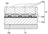
- FIG. 1D shows a cutting line passing through the pixel 10p along the ID-ID line shown in FIG. 1A. The cross section is shown enlarged.
- the display device 1 of the present embodiment includes a display panel 10 having a display screen 11 and a heater 13 provided to heat the display screen 11.
- the display panel 10 includes a substrate 10s having a first surface 10a and a second surface 10b opposite to the first surface 10a.
- the substrate 10s includes a driving element 10d for driving the plurality of pixels 10p and the plurality of pixels 10p on the first surface 10a.
- the display screen 11 is composed of a plurality of pixels 10p arranged in a matrix.
- the heater 13 is provided on the second surface 10b of the substrate 10s.
- the heater 13 is formed of a material capable of passing an electric current, and when energized, it generates Joule heat that warms the display screen 11.
- the display screen 11 can be heated by energizing the heater 13, and the temperature of the display screen 11 can be made higher than the ambient temperature thereof. it can. Therefore, even when the ambient temperature of the display device 1 is low and the saturated water vapor amount is small, dew condensation on the display screen 11 can be prevented. Further, when dew condensation has occurred, the dew condensation can be eliminated by passing an electric current through the heater 13. Similarly, even when the amount of water vapor increases remarkably and exceeds the saturated amount of water vapor without increasing the temperature, dew condensation on the display screen 11 may be prevented or eliminated by passing an electric current through the heater 13. Therefore, it is possible to prevent a decrease in the visibility of the display device 1 due to dew condensation or restore the visibility.
- the dew condensation on the display screen 11 can be prevented or eliminated without relying on the action of the defroster to reduce the visibility. It can be prevented or the visibility can be restored.
- restrictions on the mounting position of the display device 1 can be reduced, and the degree of freedom thereof can be increased. Therefore, it is considered that it can contribute to the improvement of vehicle operation safety and vehicle convenience.
- the display device 1 of FIG. 1 is provided with a temperature sensor 12.
- the temperature sensor 12 mainly detects the temperature of the display screen 11 heated by the heat of the heater 13.
- the temperature sensor 12 can also detect the temperature around the display screen 11 if it has appropriate detection performance.
- the detection result of the temperature sensor 12, that is, the output of the temperature sensor 12 including the temperature information around the display screen 11 and / or the display device 1 is transmitted to the control unit 7 (see FIG. 3) described later.
- Examples of the display panel 10 in the display device 1 of the present embodiment include an organic EL display panel, a liquid crystal display panel, and a micro LED display panel which may have a thin form.
- the organic EL display panel, the liquid crystal display panel, and the micro LED display panel include a plurality of pixels 10p and a substrate 10s arranged in a matrix as shown in FIGS. 1A and 1D.
- a plurality of driving elements 10d mainly composed of a thin film transistor (TFT) are formed.
- Pixels (sub-pixels) 10p driven by the individual drive elements 10d are formed on the corresponding drive elements 10d.
- the display panel 10 is an organic EL display panel
- a light emitting layer containing, for example, a hole injection layer, a hole transport layer, a host material such as Alq 3, and a dopant corresponding to the emission color is provided between the two electrodes.
- An electron transport layer, and an organic layer including an electron injection layer and the like are laminated.
- an opposing substrate (not shown) is arranged so as to face the substrate 10s. Then, one of the two electrodes is provided on the facing substrate, each substrate is further provided with an alignment film, a polarizing plate, and the like, and a liquid crystal material is filled between the two substrates.
- the display panel 10 may be formed by using a material having translucency.
- the display panel 10 is translucent, when the display device 1 is attached to a window glass such as a windshield of a vehicle, the user of the display device 1 sees the scene beyond the window through the display device 1. Is possible.
- the display panel 10 is an organic EL display panel
- the display panel 10 having translucency can be formed by using a material having translucency for each component.
- a glass plate or a transparent polyimide film is used as a substrate 10s
- a conductive material having a translucent property such as indium tin oxide (ITO) is used as a conductive element such as an electrode
- an oxide composed of indium, gallium, and zinc is used.
- Oxide semiconductors can be used in the formation of TFTs (driving elements 10d), respectively.
- the display panel 10 has translucency as such, it is preferable that the heater 13 is also made of a translucent material.
- the organic EL display panel, the liquid crystal display panel, and the micro LED display panel are merely examples, and the display panel 10 is not limited to the organic EL display panel, the liquid crystal display panel, and the micro LED display panel.
- the heater 13 generates Joule heat according to the amount of current flowing through it.
- the heater 13 is not limited in its form as long as heat for warming the display screen 11 is generated by energization.
- the heater 13 may be composed of a heater wire made of nichrome, an alloy of iron, nickel, aluminum, or the like.
- a thin film-shaped heating element is suitable for the display device 1 including the display panel 10 having a plate-like shape.
- the display device 1 illustrated in FIG. 1A and the like includes a heater 13 made of a thin film body.
- the thin film body constituting the heater 13 is formed by, for example, sputtering or printing.
- the heater 13 has an appropriate electric resistance Rg through which a current sufficient to heat the display screen 11 can flow.
- the electric resistance Rg required when it is desired to raise the temperature of the display screen 11 by 10 ° C. within 1 minute is illustrated below.
- the specific heat capacity Cp of the display panel 10 having a front size of 0.3 m ⁇ 0.15 m is 1.5 J / g ⁇ ° C.
- the specific heat of the polyimide resin used as a substrate for the organic EL display panel 1. Assumed to be slightly larger based on 13 J / g ⁇ ° C.) and its mass is 25 g to 30 g, the calorific value Q of the heater 13 is required to be about 400 J to 500 J.
- the amount of heat required to raise the temperature of the water droplet having a specific heat capacity of 4.2 J / g ⁇ ° C. is also required.
- the temperature drops on the screen of the display panel 10 of the above size attached to the windshield having a width of 1.5 m and a height of 1 m in a passenger compartment having a volume of 3 m 3.
- the amount of water adhering with the decrease in the amount of saturated water vapor is estimated to be about 0.5 g to 1 g.
- the calorific value Q also includes a calorific value that raises the temperature of this amount of water droplets by 10 ° C.
- a 24V power supply it is possible to obtain the same calorific value Q as when using a 12V power supply by using a heater 13 having four times the electric resistance as compared with the case of using a 12V power supply.
- the current flowing through the heater 13 can be halved as compared with the case of using the 12V power supply.
- a booster circuit 7e such as a booster DC / DC converter may be provided between the power supply and the heater 13. By doing so, the current value can be reduced as described above, and the usable range of the electric resistance of the heater 13 can be expanded.
- the booster circuit 7e may be used to increase the amount of heat generated per unit time. By doing so, the time required to bring the display panel 10 to a predetermined temperature rise can be shortened. For example, by using the booster circuit 7e that doubles the voltage without changing the electric resistance of the heater 13, the time for obtaining a predetermined temperature rise can be reduced to 1/4.
- the heater 13 is formed by using a material capable of forming an appropriate electric resistance Rg as described above. Further, the material of the heater 13 is selected in consideration of the above-mentioned translucency and the goodness of film formation by sputtering or the like when forming the film-shaped heater 13. Therefore, examples of the material of the heater 13 include ITO and zinc oxide, which have both relatively low conductivity suitable for heat generation and good light transmission. Further, when a film-like heater 13 formed thinner than that formed by using these inorganic compounds, a metal having higher conductivity such as titanium, chromium, rhodium, nickel or aluminum is used in the heater 13. It may be used as a material for.
- the film-shaped heater 13 can have, for example, an electric conductivity (conductivity) of 0.1 ⁇ 10 6 S / m or more and 7 ⁇ 10 7 S / m or less. Further, when the heater 13 is formed by using ITO, zinc oxide or the like, the heater 13 may have a conductivity of 0.2 ⁇ 10 6 S / m or more and 1 ⁇ 10 6 S / m or less.
- the thickness T that the heater 13 having a predetermined conductivity should have, the length L in the direction parallel to the current flow, and the length (width) W in the direction orthogonal to the current flow are appropriate. Correlate with each other to provide electrical resistance Rg.
- the heater 13 formed by sputtering or the like is formed within a thickness range of, for example, 10 nm or more and 5000 nm or less when ITO or zinc oxide having high translucency is used. obtain.
- a metal such as titanium or nickel is used as the material of the heater 13, the heater 13 is formed to have a thickness of 1 nm or more and 50 ⁇ m or less.
- the heater 13 having such a thickness T has appropriate electrical resistance and mechanical strength, and may be provided with higher transparency.
- a material having a conductivity of 0.2 ⁇ 10 6 S / m or more and 1 ⁇ 10 6 S / m or less such as ITO or zinc oxide
- the ratio (L / W) of the length L and the width W of the heater 13 is set to 2 or more and 100 or less to obtain the above-mentioned appropriate electric resistance Rg: 2 ⁇ to 100 ⁇ .
- the above-mentioned appropriate electrical resistance Rg: 100 ⁇ can be obtained by setting L / W to 1.
- the heater 13 when the heater 13 is formed by using a material having a conductivity of, for example, 2 ⁇ 10 6 S / m or more and 7 ⁇ 10 7 S / m or less, such as metal, the heater 13 is, for example, 0.01 ⁇ sq. It is formed to have a thickness of 5 nm or more and 1.4 ⁇ m or less so as to have a sheet resistance Rs of about 100 ⁇ sq.
- the heater 13 has a shape meandering in a zigzag manner as shown in FIG. 1B. That is, the heater 13 defines the current path from the current inflow point Ps, which is one end of the heater 13, to the outflow point Pd, which is the other end opposite to the inflow point Ps, by its own shape. And the current path meanders in a zigzag manner.
- the ratio (L / W) of the length L and the width W in the heater 13 described above can be increased. Therefore, even when the sheet resistance Rs of the film body 2 is small, the heater 13 having an appropriate electric resistance can be formed in the region having a predetermined area.
- the heater 13 made of a metal such as titanium or nickel having high conductivity is formed so thick that it cannot have translucency regardless of translucency (for example, 50 nm or more), the L / W ratio It is considered that a large meandering shape is preferable as the shape of the heater 13.
- the film-like heater 13 made of metal can be easily formed thick by using a low-cost plating method or the like. Therefore, the metal material may be suitable for forming a heater 13 having a thickness of, for example, 1 ⁇ m or more and an L / W ratio of about 1000 to 10000.
- ITO or zinc oxide has a lower conductivity than metal
- a simple rectangular shape having a low L / W ratio for example, an L / W ratio of 2 to 100 or less, depending on the thickness of the heater 13.
- the shape of the heater 13 made of ITO or the like may be preferable.
- the heater 13 made of metal is formed to have a thickness of about 20 nm or less at the thickest.
- the heater 13 made of a transparent material such as ITO can have transparency even with a thickness of 200 nm or more, for example. Therefore, the sheet resistance Rs of the heater 13 may be lower when ITO, zinc oxide, or the like is used than when using metal. Therefore, ITO or the like may be more suitable for forming the meandering heater 13 which can have a large L / W ratio as in the example of FIG. 1B as in the example of FIG. 1B. In any case, it is preferable to use thermal simulation to form the heater 13 having an appropriate shape capable of generating heat as uniformly as possible. By doing so, it is possible to prevent a decrease in local display characteristics and life due to uneven heating of the display device 1.
- the heater 13 may be electrically connected to a power supply source of the display device 1 at the current inflow point Ps and the current outflow point Pd, for example, a power storage means such as a battery of the display device 1.
- a power supply source of the display device 1 for example, a power storage means such as a battery of the display device 1.
- the substrate 10s of the display panel 10 is provided with a through hole or wiring for electrically connecting the feeder line (not shown) on the first surface 10a and the heater 13 on the second surface 10b. Good.
- the heater 13 does not necessarily have to be connected to the power supply source at one end and the other end of the heater 13, and the voltage for energizing the heater 13 can be applied between any two points in the heater 13.
- one end of the heater 13 is the current inflow point Ps and the other end opposite to the current outflow point Pd is the current outflow point Pd in that the entire display screen 11 can be heated uniformly. ..
- the heater 13 does not necessarily have to be supplied with electric power from the inside of the display device 1. For example, when the display device 1 is attached to an automobile as described later, electric power based on a storage means such as a battery included in the automobile may be supplied to the heater 13.
- the heater 13a of another example shown in FIG. 2A has four regions (regions 13a1, regions 13a2, regions 13a3 and regions 13a4) electrically separated from each other, each including a meandering shape similar to the heater 13 of FIG. 1B. ) Is included. Then, electric power based on the power source E is supplied to each of the regions 13a1 to 13a4. Also in the heater 13a of the example of FIG. 2A, an appropriate electric resistance can be provided within a predetermined area.
- the distribution of the calorific value in the entire heater 13a is uniform as compared with the example of FIG. 1B. May increase sex.
- the voltage applied to each of the regions 13a1 to 13a4 in order to obtain the desired calorific value Q may be smaller than the voltage to be applied in the example of FIG. 1B.
- the total electrical resistance of the regions 13a1 to 13a4 is the same as the electrical resistance of the heater 13 of FIG. 1B and each region has substantially the same electrical resistance to each other, in order to obtain the calorific value Q in the example of FIG. 1B.
- the calorific value Q can be obtained by applying a voltage having a magnitude of 1/4 of the voltage to be applied to the film body 2 to each region.
- the heater 13a is not limited to the example of FIG. 2A, and may include a plurality of regions of 3 or less or 5 or more.
- each region By dividing the heater 13 into n regions having substantially the same electrical resistance and connecting each region in parallel, the required voltage can be reduced to 1 / n.
- FIG. 2A a symbol indicating a power source is drawn for each area, but a voltage may be applied to each area from one power source.
- each region can suppress unevenness in the amount of heat generated in each region by applying a voltage corresponding to the electrical resistance to each region. It is preferable to use a separate power supply for the power supply.
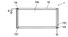
- the heater (heater 13b) shown in FIG. 2B is formed in a solid shape on substantially the entire back surface of the display device 1, that is, substantially the entire area occupied by the heater 13b without any gap. ..
- the heater 13b has a rectangular front shape that is substantially similar to the front shape of the display device 1, and is formed so as to have an area smaller than the area of the display device 1 in front view (or back view). ..
- the heater provided in the display device 1 of the present embodiment may be formed on the entire surface of a predetermined region as in the heater 13b of FIG. 2B, and may have an arbitrary front shape. Further, the heaters 13b formed in a solid shape may be formed in a plurality of regions, for example, in a plurality of regions arranged in a grid pattern.
- the heater 13b having a rectangular front shape is provided with electrodes 131 on each of its two opposing short sides.
- the heater 13b overlaps the electrode 131 on each of the two short sides.
- Power based on the power source E is supplied to the heater 13b through the electrode 131.
- the electrode 131 is preferably made of a material having higher conductivity than the material forming the heater 13b.
- the electrode 131 is made of a conductor film containing aluminum, nickel, or the like.
- the electrode 131 may be electrically connected to a power supply source of the display device 1, for example, a power storage means such as a battery of the display device 1 at any part thereof.
- a voltage is applied to the electrode 131 in the vicinity of each of the pair of diagonals of the heater 13b as in the pair of voltage application points Vs and Vd shown in FIG. 2B. It is presumed that heat can be generated more uniformly in the heater 13b by supplying electric power from the vicinity of each pair of diagonals of the heater 13b.
- the electrode 131 may be formed so as to overlap the long side along the long side of the heater 13b. Further, the electrode 131 may not be in contact with one side of the heater 13b over the entire length of one side, and may be in contact with the heater 13b at one or more arbitrary positions on each side of the heater 13b. Further, the electrode 13b does not necessarily have to be provided, and electric power may be directly supplied to the heater 13b.
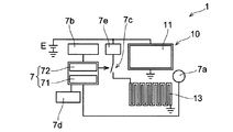
- FIG. 3 shows a block diagram of the main elements involved in controlling the energization of the heater 13.
- the display device 1 of the present embodiment includes a temperature measuring unit 7a, a time measuring unit 7b, a first control unit 71, and a second control unit.
- a control unit 7 including 72 and a switching element 7c are provided.
- the temperature measuring unit 7a monitors one or both of the temperature of the display screen 11 and the ambient temperature of the display screen 11.
- the first control unit 71 is connected to the temperature measuring unit 7a, and controls the energization of the heater 13 based on the output of the temperature measuring unit 7a.
- the timekeeping unit 7b is connected to the second control unit 72.
- the timekeeping unit 7b monitors, for example, the arrival of a preset time, and notifies the second control unit 72 of the arrival.
- the second control unit 72 controls the energization of the heater 13 based on the output of the timekeeping unit 7b.
- the display panel 10 and the heater 13 are connected to the power supply E in parallel and share the power supply E.
- the power source E is, for example, a battery (not shown) included in the display device 1. In that case, the battery of the display device 1 alone can supply electric power to both the display panel 10 and the heater 13.
- the power source E may be an external power supply source, such as a vehicle battery, instead of the battery of the display device 1.
- the heater 13 may be supplied with electric power from a power source different from the power source for the display panel 10.
- the heater 13 is connected to the power supply E via the switching element 7c.
- the booster circuit 7e described above is further provided.
- the booster circuit 7e is provided between the power source E and the heater 13, and increases the voltage applied to the heater 13 to energize the heater 13.
- the booster circuit 7e is provided as needed.
- the switching element 7c has an input terminal for a signal that controls the open / closed state of the switching element 7c, and the output of the control unit 7 is input to this input terminal.
- Examples of the switching element 7c include semiconductor elements such as various transistors, switching ICs, and electromagnetic relays.
- the first and second control units 71 and 72 start or stop energization of the heater 13 by switching between the open state and the closed state of the switching element 7c, and the energization state of the heater 13 is set. Switch between non-energized state.
- the control unit 7 may be composed of a semiconductor integrated circuit such as a microcomputer, a gate array, or a programmable logic device that operates according to a control program consisting of a series of instruction sets.
- the control unit 7 may be configured by a semiconductor integrated circuit such as a microcomputer that has other functions of the display device 1.
- the first control unit 71 and the second control unit 72 are internal same functional blocks or different functional blocks such as a microcomputer constituting the control unit 7, and a series of instruction sets in a control program corresponding to those functional blocks. Can be composed of.
- the temperature measuring unit 7a is composed of the display screen 11 or an arbitrary detection element capable of detecting the ambient temperature of the display screen 11 including the display screen 11, as in the temperature sensor 12 (see FIG. 1A) described above. ..
- Examples of the temperature measuring unit 7a include a thermistor, a thermocouple, an IC temperature sensor, and the like, but the detection element constituting the temperature measuring unit 7a is not limited to these.
- the first control unit 71 starts energizing the heater 13 when the temperature (detection temperature) detected by the temperature measuring unit 7a falls below the predetermined first temperature or falls below the first temperature. By doing so, dew condensation on the display screen 11 may be prevented. Further, the first control unit 71 stops the energization of the heater 13 when the detection temperature of the temperature measuring unit 7a becomes a predetermined second temperature or higher or exceeds the second temperature. By doing so, it may be possible to prevent the display device 1 from becoming overheated. When the display device 1 is an organic EL display device having relatively low heat resistance, such an overheat prevention function is particularly useful because an excessive temperature rise in eliminating dew condensation promotes a decrease in display characteristics and life. ..
- the timekeeping unit 7b is composed of, for example, a counter IC and a timer IC, and measures the passage of time.
- the timekeeping unit 7b is controlled by, for example, the control unit 7.
- the timekeeping unit 7b may be composed of a counter function block or a timer function block included in a microcomputer or the like constituting the control unit 7.
- the timekeeping unit 7b may have both a calendar function and a 24-hour clock function according to the time system.
- the timekeeping unit 7b notifies the second control unit 72 of the arrival of a preset time and / or the passage of a preset time.
- the time measuring unit 7b may, for example, measure the elapsed time from the start of energization of the heater 13, or may measure the elapsed time from the stop of energization of the heater 13.
- the second control unit 72 starts energizing the heater 13 when it receives the output of the time measuring unit 7b that notifies the arrival of a predetermined time. By doing so, when the display device 1 is used every day at the approximate time, the dew condensation that has already occurred before the use may be eliminated. Further, the second control unit 72 stops the energization of the heater 13 when, for example, receives the output of the time measuring unit 7b that notifies that a predetermined time has elapsed from the start of energization of the heater 13. In that case, by setting the time measuring unit 7b so as to notify the passage of time expected to eliminate the dew condensation, the energization of the heater 13 is automatically stopped after the dew condensation is eliminated to prevent waste of electric power. Can be done.
- a communication unit 7d is further provided and connected to the control unit 7.
- the communication unit 7d exchanges signals with an external electronic device via an arbitrary communication protocol such as Bluetooth (registered trademark) or an arbitrary communication network such as a mobile phone network.
- the communication unit 7d communicates with a mobile device such as a smartphone owned by the user of the display device 1 and transmits an instruction transmitted from the user to the control unit 7.
- the control unit 7 starts energizing the heater 13 based on the dew condensation elimination instruction sent from the user.
- the communication unit 7d may be composed of a communication control module such as a Bluetooth (registered trademark) module, for example.
- the display device 1 constitutes a display unit of a portable communication device such as a smartphone
- the communication unit 7d may be configured by a functional block having a communication function in the communication device.
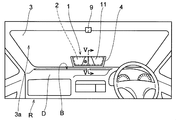
- FIG. 4 shows the display device 1 having the mounting structure of the display device of the present embodiment together with the inside of the vehicle interior R.
- the display device 1 is attached to the windshield 3 of an automobile.
- FIG. 5 shows a cross-sectional view of an example of the mounting structure of the display device of the present embodiment corresponding to the cross-sectional view taken along the line VV of FIG.
- the mounting structure of the present embodiment will be described by taking as an example the case where the display device is mounted on the windshield of an ordinary passenger car as shown in FIG.
- the mounting structure of the display device of the present embodiment can be adopted not only in ordinary automobiles but also in various vehicles such as buses, trucks and trains.
- the mounting structure of the display device of the present embodiment includes the display device 1 and a film body 2 provided on one surface of a predetermined flat surface or curved surface facing the interior of the vehicle.
- the display device 1 is a display device according to an embodiment of the present disclosure, in which some examples have been described with reference to FIGS. 1 to 3.
- the film body 2 is provided on one side 3a of the windshield 3 of the automobile facing the passenger compartment R.
- the display panel 10 is attached to one side 3a of the windshield 3 with the display screen 11 facing the inside of the vehicle interior R and via the film body 2.
- the film body 2 has a thermal conductivity higher than that of the substrate 10s (see FIG. 1D) included in the display device 1.
- the heat generated from the heater 13 of the display device 1 can be conducted and diffused not only in the substrate 10s and the heater 13 but also in the inside of the film body 2. Then, the heat conducted through the film body 2 can be received by the display panel 10.
- the display panel 10 has a portion that is not in contact with the heater 13 (see FIG. 1B)
- heat conduction or diffusion by the film body 2 is particularly beneficial.
- the display panel 10 is attached to one surface 3a via the film body 2 in order to receive heat emitted from the heater 13 and conducted through the film body 2. Therefore, the heating of the display screen 11 may be promoted.
- the display device 1 in the example of FIG. 4 is a lower region of the windshield 3 and is attached to a central portion in the vehicle width direction.
- a defroster (not shown) outlet B is provided on the upper surface of the dashboard D, which is close to the lower part of the display device 1.
- the display device 1 provided with the heater 13 can prevent or eliminate dew condensation on the display screen 11 without using the hot air of the defroster.
- the display device 1 is held on one surface 3a of the windshield 3 by using the holding member 4. That is, the holding member 4 is fixed to one surface 3a of the windshield 3 using an arbitrary adhesive (not shown), and the movement of the display device 1 on the one surface 3a and the separation of the display device 1 from the one surface 3a are the holding members. Limited by 4.
- the holding member 4 has a square frame-shaped front shape, and specifically, has a flat U-shaped front shape lacking one side of the square front shape. Each side of the holding member 4 has an L-shaped cross section so as to abut the side surface of the display device 1 and the front surface of the display device 1 having the display screen 11.
- the display device 1 having a rectangular front shape is fixed to one surface 3a of the windshield 3 by being held by a holding member 4 at edges along three sides of the rectangular shape.
- the holding member 4 is formed of, for example, a synthetic resin such as a silicone resin or an epoxy resin.
- the holding member 4 is provided with a connection terminal 41 that comes into contact with an input terminal (not shown) of the display device 1 into which an image signal, a control signal, or the like is input.
- the connection terminal 41 is connected to a display control circuit (not shown) such as a timing controller via wiring provided on one surface 3a of the windshield 3.
- the display device 1 When the display device 1 is attached to a window glass such as a windshield 3, an organic EL display panel that is more easily formed to have translucency than a liquid crystal display panel is preferable as the display panel 10. Further, it is preferable that the heater 13 and the film body 2 are also formed by using a material having translucency. Further, the holding member 4 is also preferably formed by using a highly transparent material such as a silicone resin or an acrylic resin. When the display panel 10, the heater 13, and the film body 2 are translucent, in the example of FIG. 4, a person in the vehicle interior R can see the front view through the display device 1.
- an image pickup device 9 for capturing a front view through the windshield 3 is provided on the ceiling of the passenger compartment R above the windshield 3.
- the display device 1 displays, for example, an image captured by the image pickup device 9.
- the display device 1 may display an image based on an image signal sent from a navigation system or the like.
- the image pickup device 9 is a digital camera having, for example, a CCD image sensor or a CMOS image sensor.
- the film body 2 may be provided on one surface of any vehicle including buses, trucks, trains, etc., which is not limited to ordinary passenger cars, and which is an arbitrary flat surface or curved surface facing the inside of the passenger compartment R. Further, the "predetermined flat surface or curved surface" on which the film body 2 is provided is not limited to the windshield of an automobile. For example, the film body 2 may be provided on the side or rear window of the automobile, or on the window of the driver's seat or the passenger's seat of the train, or may be provided on the surface of any interior material facing the interior of the vehicle.
- the film body 2 can be formed by using any material having a higher thermal conductivity than the substrate 10s of the display panel 10.
- a thin film body formed of an insulating material such as silicone or ceramics may be attached as a film body 2 on one surface 3a.
- the film body 2 may be formed by using a material capable of passing an electric current.
- an inorganic compound such as ITO and zinc oxide, or a metal such as titanium, chromium, rhodium, nickel, and aluminum exemplified as the material of the heater 13 is used as the material of the film body 2, and is subjected to sputtering, printing, or the like.
- the film body 2 may be formed.
- FIG. 6 shows another example of a display device mounting structure that is configured to allow the film body 2 to be energized.
- the display device 1 is arranged on the film body 2 via the weak adhesive layer 14 having an insulating property. That is, the heater 13 and the energized film body 2 are insulated by the weak adhesive layer 14.
- a current that causes the film body 2 itself to generate Joule heat that can heat the display screen 11 is preferably passed through the film body 2. In that case, the heating of the display screen 11 is further promoted.
- a power supply path 23, which is a power supply path for passing an electric current through the film body 2, is formed on one surface 3a of the windshield 3.
- the power supply path 23 is formed by using, for example, a metal such as copper, silver, or aluminum, or an inorganic compound such as ITO or zinc oxide, and is patterned into an appropriate shape.
- One end of the power supply path 23 is connected to the membrane body 2.
- the power supply path 23 is covered with an insulating coating film 25.
- the coating film 25 is formed using any insulating material such as polyvinyl chloride or polyester.
- a power supply control unit 6 for controlling energization of the film body 2 is arranged inside the dashboard D.
- the power supply control unit 6 is represented simply by a simple rectangular block so that its existence is conceptually shown.
- the power supply control unit 6 controls the start and stop of energization of the film body 2.
- Power is supplied to the power supply control unit 6 and the film body 2 from a power source (not shown), for example, a battery of an automobile.
- the power supply control unit 6 may be provided inside the display device 1, and the energization of the film body 2 may be controlled by the control unit 7 described above. In that case, the display device 1 and the film body 2 may be connected via the connection terminal 41 of the holding member 4 and the power supply path 23.
- the display device 1 (specifically, the heater 13) and the film body 2 are surely brought into close contact with each other by the action of the weak adhesive layer 14. Therefore, floating from the windshield 3 during use of the display device 1 and entrainment of air bubbles at the interface between the display device 1 and the film body 2 are prevented.
- weak adhesive adheres exactly to the adherend, it can be easily peeled off without damaging the adherend and without leaving glue or the like on the adherent surface by simply applying force in the peeling direction. It means the degree of adhesion that can be obtained.
- the adhesion strength between the weak adhesive layer 14 and either or both of the display device 1 and the film body 2 is, for example, 0.02 N / 10 mm or more and 5.0 N / 10 mm or less, preferably 1.5 N / 10 mm or more. , 2.0 N / 10 mm or less. If the adhesion strength in this range is obtained, it is considered unlikely that the display device 1 will peel off from the film body 2 during use of the display device 1.
- the display device 1 when the display device 1 is intentionally removed, the display device 1 can be easily removed from the one side 3a by simply pulling the display device 1 with an appropriate force or inserting a thin plate into the interface to inject air. Can be done. For example, when the display device 1 is damaged, the display device 1 can be easily replaced.
- the weak adhesive layer 14 is composed of, for example, an adhesive containing an acrylic, silicone, or urethane resin alone or in combination of two or more as a main component.
- an acrylic or silicone-based resin having transparency is suitable as a material for the weak adhesive layer 14, and the weak adhesive layer 14 contains, for example, these resins as main components. It is formed by arranging a weak adhesive sheet in which the adhesive material to be used is formed into a predetermined shape between the display device 1 and the film body 2.
- the components other than the weak adhesive layer 14, the power supply path 23, and the power supply control unit 6 are the same as those in the example shown in FIG. 5, and therefore the description thereof will be omitted.
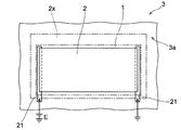
- FIG. 7A shows an example of the film body 2 provided on one surface 3a of the windshield 3 in the example of FIG.
- the film body 2 in the example of FIG. 4 has a rectangular front shape that is substantially similar to the front shape of the display device 1 indicated by the alternate long and short dash line.
- the film body 2 of FIG. 4 is an example of the film body 2 through which an electric current is passed to generate heat, and electrodes 21 are provided on each of the two opposite sides of the film body 2.
- a voltage based on the power source E is applied to the film body 2 via the electrode 21, and a current is passed through the film body 2.
- the electrode 21 may not be provided. Further, even when the film body 2 is energized, the electrode 21 does not necessarily have to be provided. That is, electric power may be directly supplied to the film body 2.
- the film body 2 is formed so as to have an area smaller than the area of the display device 1 in the front view, and the entire surface thereof is covered by the display device 1. Therefore, it is considered that the aesthetic appearance around the display device 1 is not spoiled.
- the film body 2 may have a larger area than the display device 1, such as the film body 2x drawn by the alternate long and short dash line on the outside of the display device 1 in FIG. 7A. It may be formed so that a part is exposed to the outside.
- the film body 2 having a higher thermal conductivity than the substrate 10s (see FIG. 1D) of the display device 1 may have a higher thermal conductivity than the windshield 3. Therefore, as will be described later, heating of the display screen 11 (see FIG. 4) may be promoted by heating the exposed portion of the film body 2 using a heat source other than the heater 13.
- the electrode 21 is preferably made of a material having higher conductivity than the material forming the film body 2.
- the electrode 21 is composed of a conductor film containing aluminum, nickel, or the like.
- the electrode 21 may be connected to the power supply path 23 (see FIG. 6) at any portion thereof, or may be integrally formed with the power supply path 23. Further, the electrode 21 does not necessarily have to be along the short side of the film body 2 as shown in FIG. 7A, and may be formed so as to overlap the long side along the long side of the film body 2. Further, the electrode 21 does not have to be in contact with one side over the entire length of one side of the film body 2, and may be in contact with the film body 2 at one or more arbitrary positions on each side of the film body 2.
- each of the two electrodes 21 is arranged as in the example of FIG. 7A, it is considered that the feeding path to the film body 2 is short and it is difficult to be noticed.
- the electrodes 21 are provided on the two opposite sides of the film body 2, they may be formed as in the example of FIG. 7B.
- one electrode 21a first electrode
- the other electrode 21b second electrode
- the positive electrode of the power source E may be connected to the electrode 21b in the example of FIG. 7B.
- the film body 2 does not have to be provided in a solid shape over substantially the entire surface of a certain region of one surface 3a as in the examples of FIGS. 7A and 7B, and meanders like the heater 13 in FIG. 1B. It may have a shape.
- the film body 2 may have an arbitrary front shape.
- a power supply path (not shown) to the heater 13 of the display device 1 may be provided on the one surface 3a on which the film body 2 is provided in the same manner as the power supply path 23.
- the coating film 25 may cover not only the power supply path 23 but also the power supply path to the heater 13.
- the power supply path to the heater 13 and the heater 13 can be connected by using, for example, a conductive paste. In that case, the heater 13 may be supplied with electric power based on, for example, a battery provided in the vehicle.
- the film body 2 through which an electric current can pass is preferably formed so as to have an appropriate electric resistance so as to generate Joule heat sufficient to heat the display screen 11.
- Examples of the material of the film body 2 include ITO, zinc oxide, titanium, chromium, rhodium, nickel, and aluminum, similarly to the heater 13. Therefore, the film body 2 can have, for example, a conductivity of 0.1 ⁇ 10 6 S / m or more and 7 ⁇ 10 7 S / m or less.
- the film body 2 may have a conductivity of 0.2 ⁇ 10 6 S / m or more and 1 ⁇ 10 6 S / m or less.
- the film body 2 is formed by a method such as sputtering or printing like the heater 13, and the thickness of the film body 2 is exemplified by a thickness of 1 nm or more and 50 ⁇ m or less.
- the electrical resistance of the film body 2 is, for example, 1 ⁇ or more and 1000 ⁇ or less, preferably 2 ⁇ or more and 100 ⁇ or less.
- the film body 2 having an electric resistance in this range is easily formed under the above-mentioned material and thickness, and heats the display screen 11 by self-heating by applying a voltage of 3.5 V or more and 100 V or less. It is thought that it can be promoted.
- FIGS. 8A and 8B Other examples of the membrane body 2 will be described with reference to FIGS. 8A and 8B. Note that in FIGS. 8A and 8B, the electrodes 21 shown in FIGS. 7A and 7B are omitted.
- the membrane body 2a of another example shown in FIG. 8A includes two regions 2a1 and 2a2 electrically separated from each other. That is, the film body 2a of FIG. 8A includes a region 2a1 and a region 2a2 that are separated from each other, and electric power is supplied to each of the regions 2a1 and 2a2.
- the membrane body 2a When the membrane body 2 generates heat, the membrane body 2a is separated into a plurality of regions having an area smaller than that of the membrane body 2a as shown in FIG. 8A, as compared with the examples of FIGS. 7A and 7B. It may be possible to increase the uniformity of the calorific value distribution throughout the body 2a.
- the film body 2a is not limited to the example of FIG. 8A, and may include a plurality of regions more than 2.
- the film body 2a may include a plurality of regions separated in a grid pattern.
- the film body 2b of another example shown in FIG. 8B is formed in a solid shape, that is, substantially the entire surface of the region 2R that can be occupied by the film body 2b, similarly to the film body 2 shown in FIGS. 7A and 7B. ing. However, the film body 2b is provided with a separating portion 2b1 that partially divides the film body 2b. By providing the separating portion 2b1, the stress that may be generated due to the difference in the coefficient of thermal expansion between the film body 2b and the object such as the windshield 3 (FIG. 4) on which the film body 2b is formed may be relaxed. In the example of FIG. 8B, six slit-shaped separating portions 2b1 having a rectangular front shape are provided. Any number of separators 2b1, each of which has an arbitrary shape, may be provided.
- the separating portion 2b1 By providing the separating portion 2b1, the current flowing through the film body 2b is divided like the current I1 and the current I2, for example. Therefore, the separating portion 2b1 is preferably provided so as to obtain a branching channel having an appropriate width and length in which the current flowing through the film body 2b can be appropriately diverted. By appropriately providing the separating portion 2b1 in this way, it is possible to obtain a heat generation distribution with good uniformity in the film body 2b.
- the separation portion 2b1 as in the example of FIG. 8B is not provided, by using a material having a coefficient of thermal expansion close to the coefficient of thermal expansion of the object formed on one surface of the film body 2 for the film body 2. , The stress generated in the film body 2 can be reduced.
- the film body 2 is provided on the windshield 3, for example, Kovar and Invar having a coefficient of thermal expansion close to that of glass are suitable as materials for the film body 2.
- the heater 13b in FIG. 2B referred to earlier may be provided with a separating portion such as the separating portion 2b1 that partially divides the heater 13b.
- FIG. 9 shows a display device 1 having the mounting structure of the present embodiment as viewed from the side of the automobile C together with the automobile C. Further, the display device 1x is shown as a virtual display device provided on the upper part of the windshield 3. In front of the automobile C, an object OB to be visually recognized by the driver M, such as a pedestrian or a preceding vehicle, is shown.
- the upper side is usually tilted toward the rear of the vehicle, that is, toward the passenger compartment. Therefore, the distance between the upper part of the windshield 3 and the driver M is shorter than the distance between the lower part of the windshield 3 and the driver M. Therefore, when the display device 1x is provided on the upper part of the windshield 3, the distance L1 between the display device 1x and the driver M is the distance L2 between the display device 1 provided on the lower part of the windshield 3 and the driver M. Shorter than.
- the driver M looks further ahead than the windshield 3 for many hours while driving, and focuses his eyes on the object OB to be visually recognized, for example, a pedestrian.
- the distance L3 between the object OB to be visually recognized and the driver M is longer than both the distance L1 and the distance L2, but the difference between the distance L2 and the distance L3 is smaller than the difference between the distance L1 and the distance L3. Therefore, the driver M looking at the object OB outside the vehicle can focus faster by focusing on the display device 1 than by focusing on the display device 1x.
- the driver M looking at the display device 1 or the display device 1x provided on the windshield 3 is faster when looking at the display device 1 than when looking at the display device 1x.
- adjusting the focus of the human eye can take more than a second.
- a car traveling at a speed of 60 km / h travels more than 15 m in one second. Therefore, from the viewpoint of safe vehicle operation, it is preferable that the fluctuation of the distance between the object to be focused on while driving (for example, the object OB and the display device 1) and the driver M is as small as possible.
- the display device 1 when the display device 1 is attached to the windshield of an automobile, it is preferably attached to the lower part of the windshield 3 in order to secure an appropriate distance between the display device 1 and the driver M.
- a defroster (not shown) is operated at the time of dew condensation, a high temperature strong wind is blown to the lower part of the windshield 3, but in the present embodiment, the dew condensation on the display screen 11 can be eliminated without using the defroster.
- the display device 1 is attached to the windshield 3 below the center of the automobile C in the vertical direction. In that case, the display device 1 can be moved away from the driver M as compared with the case where the display device 1 is attached to the upper side of the windshield 3.
- the display device 1 may be attached to a region of the windshield 3 within 150 mm from its lower edge. In that case, the display device 1 may be the farthest away from the driver M.
- the display device 1 and the film body 2 do not have transparency, they may satisfy the criteria regarding the transparency of the windshield of the vehicle in the country of use of the vehicle.
- the mounting structure of the display device of the present embodiment has two display devices, that is, the first display device 1a and the second display device, as display devices mounted on one surface facing the vehicle interior via the film body 2.
- the first display device 1a and the second display device 1b are attached to one surface of the windshield 3 of the automobile C facing the vehicle interior.
- the automobile C in the example of FIG. 10 is not provided with the side mirror SM as depicted by the alternate long and short dash line in FIG.
- the automobile C is provided with a first image pickup device 9a for photographing the left rear view of the automobile C and a second image pickup device 9b for photographing the right rear view of the automobile C.
- the first and second image pickup devices 9a and 9b are generally attached to the outside of the left and right doors to which the side mirror (door mirror) SM is attached.
- the first and second image pickup devices 9a and 9b are digital cameras having, for example, a CCD image sensor or a CMOS image sensor.
- the first display device 1a displays at least the left rear view of the automobile C taken by the first image pickup device 9a.
- the second display device 1b displays at least the right rear view of the automobile C taken by the second image pickup device 9b.
- display target data is selected from the captured image data generated by each imaging device, and the display target data is displayed image data suitable for each display device. It is provided with a processing circuit that converts to and enlarges or reduces the image as needed.
- the first and second display devices 1a and 1b are attached to the lower region of the windshield 3 as in the display device 1 of the example of FIG. Therefore, the driver M can quickly switch the focal position of the eyes between when looking at the scene outside the vehicle ahead and when looking at the first display device 1a or the second display device 1b.
- the first display device 1a is attached to the intersection of the left end of the front edge of the automobile C on the windshield 3 and the virtual straight line IL1 connecting the driver's seat DS of the automobile C in the top view.
- the second display device 1b is attached to the intersection of the right end of the front edge of the automobile C on the windshield 3 and the virtual straight line IL2 connecting the driver's seat DS of the automobile C in the top view.
- the driver M can see the scene in the direction corresponding to his / her movement with respect to the left and right, as compared with the case where both the left and right scenes are displayed close to each other in the central portion in the vehicle width direction, for example. Therefore, it is presumed that there is little misunderstanding regarding the left and right in the safety confirmation behind the driver M.
- the rounded portion is the left end portion or the right end portion.
- the virtual straight lines IL1 and IL2 are straight lines connecting any part of the rounded portion with the driver's seat DS. Further, the virtual straight lines IL1 and IL2 are straight lines connecting any part of the driver's seat DS in the vehicle width direction with the left end portion or the right end portion of the front edge of the automobile C, respectively.
- the first display device 1a is attached so as to overlap the intersection of the windshield 3 and the virtual straight line IL1
- the second display device 1b is attached to the windshield 3 and the virtual straight line IL2. It means that it will be installed so that it overlaps the intersection.
- Windshield As described above, it may be preferable that the display device 1 is not exposed to hot air.
- a defroster (not shown) is used to eliminate dew condensation on the windshield 3.
- 11A and 11B show another example of the mounting structure of this embodiment, which comprises a windshield 8 which is an example of means for blocking hot air toward the display device 1.
- 11B is a cross-sectional view taken along the line XIB-XIB of FIG. 11A.
- the mounting structure of the display device of the examples of FIGS. 11A and 11B includes the display device 1 and the film body 2, and further includes a windshield 8 against the wind blowing into the display screen 11.
- the display device 1 is attached to one surface 3a of the windshield 3 via a film body 2 (the heater 13 is not shown in FIG. 11B).
- the display device 1 is provided in the lower region of the windshield 3 as in the example of FIG. Therefore, although not shown in FIGS. 11A and 11B, a defroster outlet B (see FIG. 4) is provided further below the display device 1. Therefore, the windshield 8 is provided between the display device 1 and the lower edge of the windshield 3, for example, on one surface 3a of the windshield 3 in order to block the wind blowing into the display screen 11 mainly from below.
- the windshield 8 has a plate-like shape having a longitudinal direction and being curved two-dimensionally.
- the windshield 8 has substantially the same length in the longitudinal direction as the length in the longitudinal direction of the display device 1.
- One end surface (side surface) along the longitudinal direction of the windshield 8 is fixed to one surface 3a of the windshield 3, and a partition wall made of the windshield 8 is formed between the display device 1 and the outlet of the defroster (not shown). ing. Therefore, the windshield 8 can block the wind H blown from the outlet of the defroster toward the display screen 11.
- the windshield 8 is preferably provided so as not to cover the display screen 11.
- the windshield 8 may be formed by using a material having translucency, and in that case, the display screen 11 may be covered by the windshield 8.
- the material of the windshield 8 is not particularly limited, and any synthetic resin, metal, or the like can be used.
- the windshield 8 is formed by using a material capable of having translucency such as acrylic or silicone, and the means for fixing the windshield 8 to one surface 3a is not particularly limited.
- an epoxy-based or acrylic-based adhesive is used for fixing the windshield 8 to one surface 3a.
- the film body 2 has a front shape larger than that of the display device 1, and the film body 2 has an exposed portion 24 that is not covered by the display device 1.
- the film body 2 has a relatively large exposed portion 24 on the right and left sides of the display device 1 in the vehicle width direction (X direction in FIG. 11A) and on the upper side in the vertical direction of the vehicle (Y direction in FIG. 11A).
- the exposed portion 24 of the film body 2 can be used to promote the heating of the display screen 11.
- the windshield 8 is provided so that the wind H toward the display device 1, such as hot air from the defroster, is blown into the exposed portion 24 without being blown into the display device 1.
- the windshield 8 is provided with a portion that functions as a guide for directing the wind H from the outlet of the defroster toward the display device 1 toward the exposed portion 24. By doing so, it is possible to prevent the hot air from the defroster from blowing into the display device 1 and to promote the heating of the display device 1 by using the heat of the hot air.
- the windshield 8 has an outer surface 8a that is directed in the direction opposite to the display device 1 and faces the wind H that hits the windshield 8, and the outer surface 8a is convex in the direction opposite to the display device 1. It is curved so that it becomes.
- the outer surface 8a protrudes most in the central portion in the vehicle width direction in the direction opposite to the display device 1. That is, the outer surface 8a is closest to the outlet of the defroster (not shown) at the central portion in the vehicle width direction, and is closest to the display device 1 and the film body 2 at both ends in the vehicle width direction. Therefore, the wind H blown to the windshield 8 flows along the curved outer surface 8a in the XY plane shown in FIG. 11A, and reaches the exposed portion 24 of the film body 2 exposed on the right side and the left side of the display device 1, respectively. Is guided.
- the windshield 8 is curved so as to be convex in the direction opposite to the display device 1 even in the front-rear direction of the vehicle (Z direction in FIG. 11B). Therefore, the wind H blown onto the windshield 8 flows to the end of the windshield 8 along the outer surface 8a even in the YY plane shown in FIG. 11B. Then, the wind H flowing out from the end portion of the windshield 8 rises toward the windshield 3 because its temperature is higher than the ambient air, and hits the exposed portion 24 on the upper side of the display device 1 in the film body 2.
- the windshield 8 has, as the outer surface 8a, a guide portion extending to the exposed portion 24 so as to direct the wind H corresponding to the windshield 8 to the exposed portion 24 of the film body 2.
- the wind H guided to the exposed portion 24 along the outer surface 8a heats the exposed portion 24.
- the film body 2 that can be formed of ITO or the like can generally have a higher thermal conductivity than the windshield 3. Therefore, the heat of the exposed portion 24 is efficiently conducted to the portion of the film body 2 covered by the display device 1. Therefore, the heat can accelerate the heating of the display device 1.
- the shape of the windshield 8 is not limited to the examples of FIGS. 11A and 11B. It can function as a windshield 8 as long as it can at least weaken the wind blowing into the display device 1.
- the display device of the first embodiment of the present disclosure includes a substrate including a plurality of pixels and a driving element for driving the plurality of pixels on a first surface, and is a display screen composed of the plurality of pixels.
- the display panel is provided with a heater provided on the opposite surface of the first surface of the substrate so as to generate heat for heating the display screen when energized.
- the heater may include two or more regions electrically separated from each other. In that case, the uniformity of the heat generation distribution in the entire heater may be improved.
- the heater may be formed in a film shape by using a translucent material. In that case, the user of the display device may be able to visually recognize the scene beyond the display device through the display device.
- the heater is made of a material having an electric conductivity of 0.1 ⁇ 10 6 S / m or more and 7 ⁇ 10 7 S / m or less. It may be formed into a film by using. In that case, an inorganic compound such as ITO having translucency or a metal can be used as the material of the heater.
- the display device has a temperature measuring unit that monitors the temperature of the display screen and a second that controls energization of the heater based on the output of the temperature measuring unit. It may further include one control unit. In that case, the heater can appropriately generate heat according to the temperature of the display screen.
- the display device has a time measuring unit that monitors the arrival of a preset time and controls energization of the heater based on the output of the time measuring unit. 2 A control unit may be further provided. In that case, the heater can automatically start or stop heat generation at a desired timing.
- the display panel and the heater may share a power source.
- the battery of the display device alone may be able to supply power to both the display panel and the heater.
- the display device may further include a booster circuit that increases the voltage applied to the heater so as to pass a current through the heater. In that case, the current flowing through the heater can be reduced.
- the mounting structure of the display device according to the second embodiment of the present disclosure is provided on one surface consisting of any one of the display devices (1) to (8) above and a predetermined flat surface or curved surface facing the interior of the vehicle.
- the film body has a higher thermal conductivity than the substrate, and the display panel has the display screen directed toward the room and is emitted from the heater. It is attached to the one surface via the film body in order to receive heat conducted through the film body. According to this configuration, heating of the display screen may be promoted.
- the film body is formed of a material capable of passing an electric current, and even if it is energized to generate heat for warming the display screen. Good. In that case, the heating of the display screen may be further promoted.
- the film body and the display panel may be formed by using a translucent material. In that case, a person in the vehicle interior can see the scene beyond the display device through the display device.
- the film body may be provided with a separating portion for partially dividing the film body. In that case, the stress generated in the film body may be relaxed.
- the film body may have an exposed portion not covered by the display device. In that case, the exposed portion may be used to promote the heating of the display screen.
- a windshield against the wind blowing into the display screen may be further provided.
- the display device can be protected from hot air such as a defroster.
- the film body has an exposed portion not covered by the display device, and the windshield does not blow the wind toward the display device into the display device. May be provided so as to blow into the exposed portion. In that case, the heat of the wind toward the display device may be used to promote the heating of the display screen.
- the windshield may have a portion extending to the exposed portion so as to direct the wind hitting the windshield toward the exposed portion. In that case, the wind toward the display device can be efficiently directed to the exposed portion of the film body.
- the mounting structure of the display device (10) to (16) further includes an insulating coating film covering the power supply path formed on one surface as a power supply path to the film body. You may. In that case, electric shock can be prevented.
Abstract
This display device is provided with: a display panel that includes a substrate in which a plurality of pixels and a drive element for driving the plurality of pixels are provided on a first surface, said display panel comprising a display screen configured from the plurality of pixels; and a heater that is energized and thereby generates heat for warming the display screen, said heater being provided to the opposite surface from the first surface in the substrate. A mounting structure for the display device includes the display device and a film body provided to one surface comprising a predetermined flat surface or curved surface facing the interior of a vehicle. The film body has a higher thermal conductivity than the substrate included in the display device. The display panel is mounted via the film body to the one surface facing the interior of a vehicle so that the display screen faces the interior of the vehicle and heat generated from the heater of the display device is transmitted through the film body and received by said display panel.
Description
本発明は、表示装置、及び、表示装置の取り付け構造に関する。
The present invention relates to a display device and a mounting structure of the display device.
液晶ディスプレイ及び有機ELディスプレイなどの表示装置は、薄型化及び軽量化の進展、並びに、表示性能及び多様な使用環境への適応性の向上などに伴って、建物の屋内に限らず、乗り物の内部、又は屋外でも用いられている。例えば、特許文献1には、自動車のフロントガラスと一体的に組み込まれた透過型液晶表示パネルが開示されている。この透過型液晶表示パネルは、運転席前方のフロントガラスの上部に設けられている。
Display devices such as liquid crystal displays and organic EL displays are not limited to indoors in buildings, but inside vehicles, as they become thinner and lighter, and their display performance and adaptability to various usage environments are improved. Or, it is also used outdoors. For example, Patent Document 1 discloses a transmissive liquid crystal display panel integrally incorporated with an automobile windshield. This transmissive liquid crystal display panel is provided above the windshield in front of the driver's seat.
表示装置は、設置される場所又は携行される場所の多様化に伴って、従来よりも広範に変化する温湿度環境下で使用される。また表示装置の周囲の温度及び湿度は、時間と共にそれぞれ独自に変化し得る。表示装置には、そのように物理的環境が広範且つ多様に変化する状況下においても、その使用者に表示画像を速やかに且つ的確に視認させ得ることが求められる。
The display device is used in a temperature and humidity environment that changes more widely than before due to the diversification of the place where it is installed or the place where it is carried. In addition, the temperature and humidity around the display device can change independently with time. The display device is required to be able to promptly and accurately visually recognize the displayed image to the user even under such a situation where the physical environment changes widely and variously.
そこで、本開示は、周囲の環境の変化による表示画像の視認性の低下を防止又は解消し得る表示装置、及び、表示装置の取り付け構造を提供することを目的とする。
Therefore, an object of the present disclosure is to provide a display device capable of preventing or eliminating a decrease in visibility of a display image due to a change in the surrounding environment, and a mounting structure of the display device.
本開示の一実施形態の表示装置は、複数の画素及び前記複数の画素を駆動する駆動素子を第1面に備える基板を含んでいて、前記複数の画素によって構成される表示画面を有する表示パネルと、通電されることによって前記表示画面を温める熱を発生させるべく、前記基板における前記第1面の反対面に設けられているヒーターと、を備える。
The display device according to the embodiment of the present disclosure includes a substrate including a plurality of pixels and a driving element for driving the plurality of pixels on a first surface, and has a display screen composed of the plurality of pixels. And a heater provided on the opposite surface of the first surface of the substrate so as to generate heat for heating the display screen when energized.
本開示の他の実施形態の表示装置の取り付け構造は、本開示の一実施形態の表示装置と、車両の室内を向く所定の平面又は曲面からなる一面に設けられている膜体と、を含み、前記膜体は、前記基板よりも高い熱伝導率を有し、前記表示パネルは、前記表示画面を前記室内に向けて、且つ、前記ヒーターから発せられて前記膜体を通じて伝導する熱を受熱すべく前記膜体を介して前記一面に取り付けられる。
The mounting structure of the display device of another embodiment of the present disclosure includes the display device of one embodiment of the present disclosure and a film body provided on one surface consisting of a predetermined plane or curved surface facing the interior of the vehicle. The film body has a higher thermal conductivity than the substrate, and the display panel receives heat that is emitted from the heater and conducted through the film body while the display screen is directed toward the room. Therefore, it is attached to the one surface via the film body.
本開示の各実施形態によれば、周囲の環境の変化による表示画像の視認性の低下を容易に防止又は解消することができる。
According to each embodiment of the present disclosure, it is possible to easily prevent or eliminate the deterioration of the visibility of the displayed image due to the change in the surrounding environment.
本発明者は、設計時に想定された範囲内の物理的環境下にあっても、表示装置の実使用においてその表示画面の視認性が低下し得るという問題を見出した。一例として自動車などの車両では、外気の温度の低下と共に、窓ガラスのように車内と車外とを隔てる壁の温度が低下し、その表面に結露が生じ得る。また、寒冷時における人の乗車の際にも、湿度の上昇に伴って結露が生じ得る。そのような場合、前述した特許文献1の液晶表示パネルのように、自動車のフロントガラスに液晶表示パネルが設けられていると、その表示画面において結露が生じ、その視認性が低下する。その結果、車両の前方の安全確認に支障が生じることがある。さらにその液晶表示パネルが自動車の後方又は側方の光景を表示すべく設けられている場合は、各方向の安全確認にも支障が生じ得る。また、そのような結露が無くなるまで自動車の発進を待機せざるを得ないこともある。
The present inventor has found a problem that the visibility of the display screen may be lowered in the actual use of the display device even under the physical environment within the range assumed at the time of design. As an example, in a vehicle such as an automobile, as the temperature of the outside air decreases, the temperature of the wall that separates the inside of the vehicle from the outside of the vehicle, such as a window glass, decreases, and dew condensation may occur on the surface thereof. Also, when a person gets on board in cold weather, dew condensation may occur as the humidity rises. In such a case, if a liquid crystal display panel is provided on the windshield of an automobile like the liquid crystal display panel of Patent Document 1 described above, dew condensation occurs on the display screen and the visibility thereof deteriorates. As a result, the safety confirmation in front of the vehicle may be hindered. Further, if the liquid crystal display panel is provided to display a scene behind or to the side of the automobile, safety confirmation in each direction may be hindered. In addition, it may be necessary to wait for the vehicle to start until such dew condensation disappears.
自動車には、一般に、フロントガラスにその下方から熱風を当てることによって結露を解消させる霜取り装置(デフロスタ)が備えられている。しかし特許文献1の液晶表示パネルのようにフロントガラスの上部に表示装置が設けられる場合、デフロスタから送られる風で結露を解消するには一定の時間が必要になる。また、一般にフロントガラスは、その上側が車両の後方に傾斜するように車体に固定される。この点に関し本発明者は、さらに、後に詳述するようにフロントガラスの上部に設けられる表示装置には、表示装置と車室内の人の目との近接性に基づく目の焦点調整に関する問題が内在することを見出した。従ってこれらの観点からは、表示装置を車両の室内に設ける場合、特に自動車のフロントガラスに設ける場合には、フロントガラスの下部に設けることによる利益があると考えられる。
Automobiles are generally equipped with a defroster (defroster) that eliminates dew condensation by blowing hot air on the windshield from below. However, when a display device is provided on the upper part of the windshield as in the liquid crystal display panel of Patent Document 1, a certain amount of time is required to eliminate the dew condensation by the wind sent from the defroster. Further, in general, the windshield is fixed to the vehicle body so that its upper side is inclined to the rear of the vehicle. In this regard, the present inventor further describes that the display device provided on the upper part of the windshield has a problem of eye focus adjustment based on the proximity of the display device to the human eye in the vehicle interior, as will be described in detail later. I found it to be inherent. Therefore, from these viewpoints, when the display device is provided in the interior of the vehicle, particularly in the windshield of the automobile, it is considered that there is a benefit in providing the display device in the lower part of the windshield.
しかしながら、フロントガラス全体の結露を解消すべく設けられているデフロスタの熱風を直接表示装置に当てると、その熱が表示装置の劣化を加速させることが懸念される。さらに、熱風を均一に表示装置に当てることが困難な場合も想定される。そういったときには、不均一に当たった熱風が表示装置の温度上昇の不均一性を招き、その結果として劣化の進行が局所的に促進されることも懸念される。特に、有機EL表示装置に含まれる有機EL素子の耐熱性は液晶などと比べて低いため、有機EL表示装置では、繰り返し吹き付けられる熱風による有機EL素子の劣化が懸念される。また、表示装置がフロントパネルに接着剤などを用いて固定されている場合、熱による接着力の低下と風圧とによって表示装置がフロントガラスから剥離することも懸念される。従って、車両にも取り付けられ得る表示装置には、デフロスタの作用に頼ることなく、さらには取り付けられる位置に関係なく、表示画面における結露を防止又は解消し得ることが望まれる。本発明者は、そのような状況に鑑み、それぞれ新規な、表示装置、及び表示装置の取り付け構造、並びに、それらに関連する技術事項を見出した。
However, if the hot air of the defroster provided to eliminate the dew condensation on the entire windshield is directly applied to the display device, there is a concern that the heat will accelerate the deterioration of the display device. Furthermore, it may be difficult to evenly apply hot air to the display device. In such a case, there is a concern that the hot air hit by the non-uniformity causes the non-uniformity of the temperature rise of the display device, and as a result, the progress of deterioration is locally promoted. In particular, since the heat resistance of the organic EL element contained in the organic EL display device is lower than that of the liquid crystal or the like, there is a concern that the organic EL element may be deteriorated by the hot air repeatedly blown in the organic EL display device. Further, when the display device is fixed to the front panel by using an adhesive or the like, there is a concern that the display device may be peeled off from the windshield due to a decrease in adhesive force due to heat and wind pressure. Therefore, it is desired that the display device that can be mounted on the vehicle can prevent or eliminate dew condensation on the display screen without relying on the action of the defroster and regardless of the mounting position. In view of such a situation, the present inventor has found a novel display device, a display device mounting structure, and technical matters related thereto.
以下、図面を参照し、本発明の実施形態の表示装置、及び、表示装置の取り付け構造を説明する。なお、以下に説明される実施形態における各構成要素の材質、形状、及び、それらの相対的な位置関係などはあくまで例示に過ぎない。各実施形態の表示装置、及び、表示装置の取り付け構造は、これらによって限定的に解釈されるものではない。
Hereinafter, the display device according to the embodiment of the present invention and the mounting structure of the display device will be described with reference to the drawings. The materials, shapes, and relative positional relationships of the components in the embodiments described below are merely examples. The display device of each embodiment and the mounting structure of the display device are not limitedly interpreted by these.
[表示装置の全体構造]
図1A~図1Dを参照して、一実施形態の表示装置の基本構造が説明される。図1A及び図1Bには、本実施形態の表示装置の一例である表示装置1の正面図及び背面図が示されている。なお、表示装置1において表示画面11を備える面が正面であり、この正面の反対面が背面である。図1Cには表示装置1の底面図(図1Aの下方から見た図)が示され、図1Dには、図1Aに示されるID-ID線に沿った、画素10pを通る切断線での断面が拡大して示されている。 [Overall structure of display device]
The basic structure of the display device of one embodiment will be described with reference to FIGS. 1A to 1D. 1A and 1B show a front view and a rear view of thedisplay device 1 which is an example of the display device of the present embodiment. The surface of the display device 1 provided with the display screen 11 is the front surface, and the opposite surface of the front surface is the back surface. FIG. 1C shows a bottom view of the display device 1 (viewed from below in FIG. 1A), and FIG. 1D shows a cutting line passing through the pixel 10p along the ID-ID line shown in FIG. 1A. The cross section is shown enlarged.
図1A~図1Dを参照して、一実施形態の表示装置の基本構造が説明される。図1A及び図1Bには、本実施形態の表示装置の一例である表示装置1の正面図及び背面図が示されている。なお、表示装置1において表示画面11を備える面が正面であり、この正面の反対面が背面である。図1Cには表示装置1の底面図(図1Aの下方から見た図)が示され、図1Dには、図1Aに示されるID-ID線に沿った、画素10pを通る切断線での断面が拡大して示されている。 [Overall structure of display device]
The basic structure of the display device of one embodiment will be described with reference to FIGS. 1A to 1D. 1A and 1B show a front view and a rear view of the
図1A~図1Dに示されるように、本実施形態の表示装置1は、表示画面11を有する表示パネル10と、表示画面11を温めるべく設けられているヒーター13とを備えている。表示パネル10は、第1面10a及び第1面10aの反対面である第2面10bを有する基板10sを含んでいる。基板10sは、複数の画素10p及び複数の画素10pを駆動する駆動素子10dを第1面10aに備えている。表示画面11は、マトリクス状に並ぶ複数の画素10pによって構成されている。ヒーター13は基板10sにおける第2面10bに設けられている。ヒーター13は、電流を通流させ得る材料を用いて形成されており、通電されることによって表示画面11を温めるジュール熱を発生させる。
As shown in FIGS. 1A to 1D, the display device 1 of the present embodiment includes a display panel 10 having a display screen 11 and a heater 13 provided to heat the display screen 11. The display panel 10 includes a substrate 10s having a first surface 10a and a second surface 10b opposite to the first surface 10a. The substrate 10s includes a driving element 10d for driving the plurality of pixels 10p and the plurality of pixels 10p on the first surface 10a. The display screen 11 is composed of a plurality of pixels 10p arranged in a matrix. The heater 13 is provided on the second surface 10b of the substrate 10s. The heater 13 is formed of a material capable of passing an electric current, and when energized, it generates Joule heat that warms the display screen 11.
本実施形態の表示装置1はヒーター13を備えているので、ヒーター13に通電することによって表示画面11を温めることができ、そして、表示画面11の温度を、その周囲温度よりも高くすることができる。従って、表示装置1の周囲の温度が低く、そのため飽和水蒸気量が少ない場合でも、表示画面11における結露を防止することができる。また、結露が生じてしまった場合には、ヒーター13に電流を流すことによって結露を解消することができる。同様に、温度の上昇を伴わずに水蒸気量が顕著に増加して飽和水蒸気量を超える場合でも、ヒーター13に電流を流すことによって表示画面11における結露を防止又は解消し得ることがある。従って、結露による表示装置1の視認性の低下を予防し又は視認性を回復させることができる。
Since the display device 1 of the present embodiment includes the heater 13, the display screen 11 can be heated by energizing the heater 13, and the temperature of the display screen 11 can be made higher than the ambient temperature thereof. it can. Therefore, even when the ambient temperature of the display device 1 is low and the saturated water vapor amount is small, dew condensation on the display screen 11 can be prevented. Further, when dew condensation has occurred, the dew condensation can be eliminated by passing an electric current through the heater 13. Similarly, even when the amount of water vapor increases remarkably and exceeds the saturated amount of water vapor without increasing the temperature, dew condensation on the display screen 11 may be prevented or eliminated by passing an electric current through the heater 13. Therefore, it is possible to prevent a decrease in the visibility of the display device 1 due to dew condensation or restore the visibility.
例えば表示装置1が自動車のフロントガラスに取り付けられ、その車内が結露を生じさせる環境下にあっても、デフロスタの作用に頼ることなく表示画面11における結露を予防又は解消し、視認性の低下を予防し又は視認性を回復させることができる。また、表示装置1の取り付け位置に関する制約を少なくすることができ、その自由度を高めることができる。従って、車両の運行の安全や車両の利便性の向上にも寄与し得ると考えられる。
For example, even if the display device 1 is attached to the windshield of an automobile and the inside of the vehicle is in an environment where dew condensation occurs, the dew condensation on the display screen 11 can be prevented or eliminated without relying on the action of the defroster to reduce the visibility. It can be prevented or the visibility can be restored. In addition, restrictions on the mounting position of the display device 1 can be reduced, and the degree of freedom thereof can be increased. Therefore, it is considered that it can contribute to the improvement of vehicle operation safety and vehicle convenience.
図1の表示装置1には、温度センサ12が備えられている。温度センサ12は、主に、ヒーター13の熱によって温められる表示画面11の温度を検知する。温度センサ12は、適切な検知性能を有する場合、表示画面11の周囲の温度も検知し得る。温度センサ12の検知結果、すなわち表示画面11及び/又は表示装置1の周囲の温度情報を含む温度センサ12の出力は、後述する制御部7(図3参照)に伝えられる。このように、表示装置1に温度センサ12と制御部7とが備えられることによって、結露解消に不必要な過熱を防止できるようになるため、表示装置1の表示特性や寿命を無用に劣化させることがない。
The display device 1 of FIG. 1 is provided with a temperature sensor 12. The temperature sensor 12 mainly detects the temperature of the display screen 11 heated by the heat of the heater 13. The temperature sensor 12 can also detect the temperature around the display screen 11 if it has appropriate detection performance. The detection result of the temperature sensor 12, that is, the output of the temperature sensor 12 including the temperature information around the display screen 11 and / or the display device 1 is transmitted to the control unit 7 (see FIG. 3) described later. By providing the display device 1 with the temperature sensor 12 and the control unit 7 in this way, it becomes possible to prevent unnecessary overheating for eliminating dew condensation, so that the display characteristics and life of the display device 1 are unnecessarily deteriorated. Never.
[表示パネル]
本実施形態の表示装置1における表示パネル10としては、例えば、薄型の形態を有し得る有機EL表示パネル、液晶表示パネル、及び、マイクロLED表示パネルが例示される。有機EL表示パネル、液晶表示パネル、及び、マイクロLED表示パネルは、図1A及び図1Dに示されるように、マトリクス状に配置された複数の画素10p及び基板10sを備える。基板10sの第1面10aには、例えば薄膜トランジスタ(TFT)によって主に構成される複数の駆動素子10dが形成されている。そして個々の駆動素子10dによってそれぞれ駆動される画素(サブ画素)10pが、対応する個々の駆動素子10dの上に形成されている。 [Display panel]
Examples of thedisplay panel 10 in the display device 1 of the present embodiment include an organic EL display panel, a liquid crystal display panel, and a micro LED display panel which may have a thin form. The organic EL display panel, the liquid crystal display panel, and the micro LED display panel include a plurality of pixels 10p and a substrate 10s arranged in a matrix as shown in FIGS. 1A and 1D. On the first surface 10a of the substrate 10s, for example, a plurality of driving elements 10d mainly composed of a thin film transistor (TFT) are formed. Pixels (sub-pixels) 10p driven by the individual drive elements 10d are formed on the corresponding drive elements 10d.
本実施形態の表示装置1における表示パネル10としては、例えば、薄型の形態を有し得る有機EL表示パネル、液晶表示パネル、及び、マイクロLED表示パネルが例示される。有機EL表示パネル、液晶表示パネル、及び、マイクロLED表示パネルは、図1A及び図1Dに示されるように、マトリクス状に配置された複数の画素10p及び基板10sを備える。基板10sの第1面10aには、例えば薄膜トランジスタ(TFT)によって主に構成される複数の駆動素子10dが形成されている。そして個々の駆動素子10dによってそれぞれ駆動される画素(サブ画素)10pが、対応する個々の駆動素子10dの上に形成されている。 [Display panel]
Examples of the
図1Dでは、画素10pの詳細な構成は省略されているが、複数の画素10pそれぞれには、対向する二つの電極(陽極及び陰極)が設けられている。表示パネル10が有機EL表示パネルである場合は、二つの電極の間には、例えば、正孔注入層、正孔輸送層、Alq3などのホスト材料及び発光色に応じたドーパントを含む発光層、電子輸送層、並びに電子注入層などを含む有機層が積層されている。表示パネル10が液晶表示パネルである場合には、基板10sに対向させて対向基板(図示せず)が配置されている。そして、対向基板に二つの電極の一方が設けられて、各基板にはさらに配向膜及び偏光板などが設けられており、二つの基板の間には液晶材料が充填されている。
Although the detailed configuration of the pixel 10p is omitted in FIG. 1D, two electrodes (anode and cathode) facing each other are provided for each of the plurality of pixels 10p. When the display panel 10 is an organic EL display panel, a light emitting layer containing, for example, a hole injection layer, a hole transport layer, a host material such as Alq 3, and a dopant corresponding to the emission color is provided between the two electrodes. , An electron transport layer, and an organic layer including an electron injection layer and the like are laminated. When the display panel 10 is a liquid crystal display panel, an opposing substrate (not shown) is arranged so as to face the substrate 10s. Then, one of the two electrodes is provided on the facing substrate, each substrate is further provided with an alignment film, a polarizing plate, and the like, and a liquid crystal material is filled between the two substrates.
本実施形態において表示パネル10は、透光性を有する材料を用いて形成されていてもよい。表示パネル10が透光性を有する場合、表示装置1が車両のフロントガラスなどの窓ガラスに取り付けられたときに、表示装置1の使用者は、表示装置1を通して窓の向こうの光景を見ることが可能となる。表示パネル10が有機EL表示パネルである場合、透光性を有する材料を各構成要素に用いることによって、透光性を有する表示パネル10を形成することができる。例えば、ガラス板又は透明ポリイミドフィルムが基板10sに、酸化インジウムスズ(ITO)などの透光性を有する導電性材料が電極などの導電性要素に、そして、インジウム・ガリウム・亜鉛からなる酸化物などの酸化物半導体がTFT(駆動素子10d)の形成に、それぞれ用いられ得る。なお、そのように表示パネル10が透光性を有する場合、ヒーター13も透光性を有する材料で形成されることが好ましい。なお、有機EL表示パネル、液晶表示パネル、及びマイクロLED表示パネルは単なる例示に過ぎず、表示パネル10は有機EL表示パネル、液晶表示パネル、及びマイクロLED表示パネルに限定されない。
In the present embodiment, the display panel 10 may be formed by using a material having translucency. When the display panel 10 is translucent, when the display device 1 is attached to a window glass such as a windshield of a vehicle, the user of the display device 1 sees the scene beyond the window through the display device 1. Is possible. When the display panel 10 is an organic EL display panel, the display panel 10 having translucency can be formed by using a material having translucency for each component. For example, a glass plate or a transparent polyimide film is used as a substrate 10s, a conductive material having a translucent property such as indium tin oxide (ITO) is used as a conductive element such as an electrode, and an oxide composed of indium, gallium, and zinc is used. Oxide semiconductors can be used in the formation of TFTs (driving elements 10d), respectively. When the display panel 10 has translucency as such, it is preferable that the heater 13 is also made of a translucent material. The organic EL display panel, the liquid crystal display panel, and the micro LED display panel are merely examples, and the display panel 10 is not limited to the organic EL display panel, the liquid crystal display panel, and the micro LED display panel.
[ヒーター]
ヒーター13は、自身に流される電流量に応じたジュール熱を発生させる。ヒーター13は、通電に伴って表示画面11を温める熱が生じさえすれば、その形態に関して限定されない。例えば、ヒーター13は、ニクロム、又は、鉄・ニッケル・アルミニウムの合金などからなるヒーター線で構成されていてもよい。しかし板状の形態である表示パネル10を備える表示装置1には、薄い膜状の発熱体が好適である。図1Aなどに例示の表示装置1は、図1B~図1Dに示されるように、薄膜体からなるヒーター13を備えている。ヒーター13を構成する薄膜体は、例えばスパッタリング又は印刷などによって成膜される。 [heater]
Theheater 13 generates Joule heat according to the amount of current flowing through it. The heater 13 is not limited in its form as long as heat for warming the display screen 11 is generated by energization. For example, the heater 13 may be composed of a heater wire made of nichrome, an alloy of iron, nickel, aluminum, or the like. However, a thin film-shaped heating element is suitable for the display device 1 including the display panel 10 having a plate-like shape. As shown in FIGS. 1B to 1D, the display device 1 illustrated in FIG. 1A and the like includes a heater 13 made of a thin film body. The thin film body constituting the heater 13 is formed by, for example, sputtering or printing.
ヒーター13は、自身に流される電流量に応じたジュール熱を発生させる。ヒーター13は、通電に伴って表示画面11を温める熱が生じさえすれば、その形態に関して限定されない。例えば、ヒーター13は、ニクロム、又は、鉄・ニッケル・アルミニウムの合金などからなるヒーター線で構成されていてもよい。しかし板状の形態である表示パネル10を備える表示装置1には、薄い膜状の発熱体が好適である。図1Aなどに例示の表示装置1は、図1B~図1Dに示されるように、薄膜体からなるヒーター13を備えている。ヒーター13を構成する薄膜体は、例えばスパッタリング又は印刷などによって成膜される。 [heater]
The
ヒーター13は、表示画面11を加温し得る程度の電流が流れ得る適度な電気抵抗Rgを有している。一例として、表示画面11の温度を1分以内に10℃上昇させることが所望される場合に必要な電気抵抗Rgが以下に例示される。例えば、0.3m×0.15mの正面サイズを有する表示パネル10について、その比熱容量Cpが1.5J/g・℃である場合(有機EL表示パネルに基板として用いられるポリイミド樹脂の比熱1.13J/g・℃に基づいて少し大きめに想定)、且つ、その質量が25g~30gである場合、ヒーター13の発熱量Qとしては400J~500J程度が必要とされる。従って、ヒーター13に供給し得る電圧Vpが例えば3.5V~24Vである場合の適度な電気抵抗Rgとしては、Rg=Vp2×60sec/Qであるため、2Ω~100Ω程度の値が例示される。
The heater 13 has an appropriate electric resistance Rg through which a current sufficient to heat the display screen 11 can flow. As an example, the electric resistance Rg required when it is desired to raise the temperature of the display screen 11 by 10 ° C. within 1 minute is illustrated below. For example, when the specific heat capacity Cp of the display panel 10 having a front size of 0.3 m × 0.15 m is 1.5 J / g · ° C. (the specific heat of the polyimide resin used as a substrate for the organic EL display panel 1. (Assumed to be slightly larger based on 13 J / g · ° C.) and its mass is 25 g to 30 g, the calorific value Q of the heater 13 is required to be about 400 J to 500 J. Therefore, when the voltage Vp that can be supplied to the heater 13 is, for example, 3.5 V to 24 V, the appropriate electric resistance Rg is Rg = Vp 2 × 60 sec / Q, and therefore, a value of about 2 Ω to 100 Ω is exemplified. To.
なお、結露の解消には、比熱容量が4.2J/g・℃である水滴を昇温させるための熱量も必要である。例えば、周囲温度が30℃から0℃まで低下した時に、容積3m3の車室において幅1,5m×高さ1mのフロントガラスに取り付けられた上記サイズの表示パネル10の画面に、その温度低下による飽和水蒸気量の減少に伴って付着する水分の量は0.5g~1g程度と推定される。上記発熱量Qには、この量の水滴を10℃昇温させる熱量も含まれている。
In order to eliminate the dew condensation, the amount of heat required to raise the temperature of the water droplet having a specific heat capacity of 4.2 J / g · ° C. is also required. For example, when the ambient temperature drops from 30 ° C to 0 ° C, the temperature drops on the screen of the display panel 10 of the above size attached to the windshield having a width of 1.5 m and a height of 1 m in a passenger compartment having a volume of 3 m 3. The amount of water adhering with the decrease in the amount of saturated water vapor is estimated to be about 0.5 g to 1 g. The calorific value Q also includes a calorific value that raises the temperature of this amount of water droplets by 10 ° C.
ヒーター13に印加する電圧Vpが高いほど、高い電気抵抗を有するヒーター13を用いることが可能となり、従ってヒーター13に流れる電流を小さくすることができる。例えば24Vの電源を用いることによって、12Vの電源を用いる場合と比べて4倍の電気抵抗を有するヒーター13を用いて、12Vの電源を用いる場合と同一の発熱量Qを得ることができる。その結果、ヒーター13に流れる電流を、12V電源の使用時に比べて1/2にすることができる。例えば、昇圧型DC/DCコンバータなどの昇圧回路7e(図3参照)が、電源とヒーター13との間に設けられてもよい。そうすることによって、前述したような電流値の低減を図ることができ、また、ヒーター13の電気抵抗に関して使用可能な範囲を広げることができる。
The higher the voltage Vp applied to the heater 13, the higher the electric resistance of the heater 13 can be used, and therefore the current flowing through the heater 13 can be reduced. For example, by using a 24V power supply, it is possible to obtain the same calorific value Q as when using a 12V power supply by using a heater 13 having four times the electric resistance as compared with the case of using a 12V power supply. As a result, the current flowing through the heater 13 can be halved as compared with the case of using the 12V power supply. For example, a booster circuit 7e (see FIG. 3) such as a booster DC / DC converter may be provided between the power supply and the heater 13. By doing so, the current value can be reduced as described above, and the usable range of the electric resistance of the heater 13 can be expanded.
昇圧回路7eは、単位時間あたりの発熱量を高めるために用いられてもよい。そうすることによって、表示パネル10に所定の温度上昇をもたらすための時間を短縮することができる。例えば、ヒーター13の電気抵抗を変えることなく、電圧を2倍に高める昇圧回路7eを用いることによって、所定の温度上昇を得るための時間を1/4にすることができる。
The booster circuit 7e may be used to increase the amount of heat generated per unit time. By doing so, the time required to bring the display panel 10 to a predetermined temperature rise can be shortened. For example, by using the booster circuit 7e that doubles the voltage without changing the electric resistance of the heater 13, the time for obtaining a predetermined temperature rise can be reduced to 1/4.
ヒーター13は、上記のような適度な電気抵抗Rgを形成し得る材料を用いて形成される。また、ヒーター13の材料は、前述した透光性、及び、膜状のヒーター13を形成する際のスパッタリングなどによる成膜の良好性なども勘案して選択される。そのため、ヒーター13の材料としては、発熱に関して好適である比較的低い導電性と、光の良好な透過性とを併せ持つITO又は酸化亜鉛などが例示される。また、これらの無機化合物を用いて形成される場合よりも薄い膜状のヒーター13が形成される場合、チタン、クロム、ロジウム、ニッケル又はアルミニウムなどの、より高い導電性を有する金属が、ヒーター13の材料として用いられてもよい。従って、膜状のヒーター13は、例えば、0.1×10⁶S/m以上、7×107S/m以下の電気伝導率(導電率)を有し得る。また、ヒーター13は、ITO又は酸化亜鉛などを用いて形成される場合、0.2×106S/m以上、1×106S/m以下の導電率を有し得る。
The heater 13 is formed by using a material capable of forming an appropriate electric resistance Rg as described above. Further, the material of the heater 13 is selected in consideration of the above-mentioned translucency and the goodness of film formation by sputtering or the like when forming the film-shaped heater 13. Therefore, examples of the material of the heater 13 include ITO and zinc oxide, which have both relatively low conductivity suitable for heat generation and good light transmission. Further, when a film-like heater 13 formed thinner than that formed by using these inorganic compounds, a metal having higher conductivity such as titanium, chromium, rhodium, nickel or aluminum is used in the heater 13. It may be used as a material for. Therefore, the film-shaped heater 13 can have, for example, an electric conductivity (conductivity) of 0.1 × 10 6 S / m or more and 7 × 10 7 S / m or less. Further, when the heater 13 is formed by using ITO, zinc oxide or the like, the heater 13 may have a conductivity of 0.2 × 10 6 S / m or more and 1 × 10 6 S / m or less.
ITO及び酸化亜鉛などの化合物、並びに、チタン及びクロムなどの金属は、赤外線に対する反射特性を有している。従って、これらの化合物又は金属を用いてヒーター13を形成することによって、太陽光の照射による表示装置1の意図せぬ過度な温度上昇を防ぐことができる。
Compounds such as ITO and zinc oxide, and metals such as titanium and chromium have reflection characteristics against infrared rays. Therefore, by forming the heater 13 using these compounds or metals, it is possible to prevent an unintended excessive temperature rise of the display device 1 due to irradiation with sunlight.
一方、所定の導電率を有するヒーター13が有するべき厚さT、並びに、電流の流れに平行な方向の長さL及び電流の流れに直交する方向の長さ(幅)Wそれぞれは、適度な電気抵抗Rgを備えるべく互いに相関する。ここで、前述したようにスパッタリングなどで成膜されるヒーター13は、高い透光性を有するITO又は酸化亜鉛などが用いられる場合、例えば、10nm以上、5000nm以下の厚さの範囲内で形成され得る。また、ヒーター13の材料としてチタン又はニッケルなどの金属が用いられる場合、ヒーター13は1nm以上、50μm以下の厚さに形成される。このような厚さTを有するヒーター13は、適度な電気抵抗と機械的強度とを備え、さらに高い透明性を備え得ることがある。
On the other hand, the thickness T that the heater 13 having a predetermined conductivity should have, the length L in the direction parallel to the current flow, and the length (width) W in the direction orthogonal to the current flow are appropriate. Correlate with each other to provide electrical resistance Rg. Here, as described above, the heater 13 formed by sputtering or the like is formed within a thickness range of, for example, 10 nm or more and 5000 nm or less when ITO or zinc oxide having high translucency is used. obtain. When a metal such as titanium or nickel is used as the material of the heater 13, the heater 13 is formed to have a thickness of 1 nm or more and 50 μm or less. The heater 13 having such a thickness T has appropriate electrical resistance and mechanical strength, and may be provided with higher transparency.
例えば、ITO又は酸化亜鉛などのように、0.2×10⁶S/m以上、1×106S/m以下の導電率を有する材料を用いてヒーター13が形成される場合、ヒーター13は、1Ω/sq以上、100Ω/sq以下のシート抵抗Rs(Rs=1/(ヒーター13の導電率・ヒーター13の厚さT))を有するように、50nm以上、1000nm以下の厚さに形成される。例えばRs=1Ωsqの場合、ヒーター13の長さLと幅Wとの比率(L/W)を、2以上、100以下とすることによって、前述した適度な電気抵抗Rg:2Ω~100Ωを得ることができ、Rs=100Ω/sqの場合、L/Wを1とすることによって、前述した適度な電気抵抗Rg:100Ωを得ることができる。
For example, when the heater 13 is formed by using a material having a conductivity of 0.2 × 10 6 S / m or more and 1 × 10 6 S / m or less, such as ITO or zinc oxide, the heater 13 is used. It is formed to have a thickness of 50 nm or more and 1000 nm or less so as to have a sheet resistance Rs (Rs = 1 / (conductivity of the heater 13 / thickness T of the heater 13)) of 1 Ω / sq or more and 100 Ω / sq or less. To. For example, when Rs = 1Ωsq, the ratio (L / W) of the length L and the width W of the heater 13 is set to 2 or more and 100 or less to obtain the above-mentioned appropriate electric resistance Rg: 2Ω to 100Ω. When Rs = 100Ω / sq, the above-mentioned appropriate electrical resistance Rg: 100Ω can be obtained by setting L / W to 1.
また金属のように、例えば2×10⁶S/m以上、7×107S/m以下の導電率を有する材料を用いてヒーター13が形成される場合、ヒーター13は、例えば、0.01Ωsq~100Ωsqのシート抵抗Rsを有するように、5nm以上、1.4μm以下の厚さを有するように形成される。例えば、シート抵抗Rsが0.01Ωsqである場合、ヒーター13の長さLと幅Wとの比率(L/W)を、50以上、10000以下とすることによって、前述した適度な電気抵抗Rg2Ω~100Ωを得ることができ、Rs=100Ω/sqの場合、L/Wを1とすることによって、前述した適度な電気抵抗Rg:100Ωを得ることができる。
Further, when the heater 13 is formed by using a material having a conductivity of, for example, 2 × 10 6 S / m or more and 7 × 10 7 S / m or less, such as metal, the heater 13 is, for example, 0.01 Ωsq. It is formed to have a thickness of 5 nm or more and 1.4 μm or less so as to have a sheet resistance Rs of about 100 Ωsq. For example, when the sheet resistance Rs is 0.01Ωsq, the ratio (L / W) of the length L and the width W of the heater 13 is set to 50 or more and 10000 or less, so that the above-mentioned appropriate electric resistance Rg2Ω to 100Ω can be obtained, and when Rs = 100Ω / sq, the above-mentioned appropriate electric resistance Rg: 100Ω can be obtained by setting L / W to 1.
図1A~図1Dに例示される表示装置1において、ヒーター13は、図1Bに示されるように、ジグザグに蛇行する形状を有している。すなわち、ヒーター13は、ヒーター13の一端である電流の流入箇所Psから、流入箇所Psと反対の他端である流出箇所Pdまでの電流経路を自らの形状によって画定している。そして、その電流経路がジグザグに蛇行している。図1Bのようにヒーター13を形成することによって、前述したヒーター13における長さLと幅Wとの比率(L/W)を大きくすることができる。従って、膜体2のシート抵抗Rsが小さい場合でも、所定の面積を有する領域内に適切な電気抵抗を有するヒーター13を形成することができる。
In the display device 1 exemplified in FIGS. 1A to 1D, the heater 13 has a shape meandering in a zigzag manner as shown in FIG. 1B. That is, the heater 13 defines the current path from the current inflow point Ps, which is one end of the heater 13, to the outflow point Pd, which is the other end opposite to the inflow point Ps, by its own shape. And the current path meanders in a zigzag manner. By forming the heater 13 as shown in FIG. 1B, the ratio (L / W) of the length L and the width W in the heater 13 described above can be increased. Therefore, even when the sheet resistance Rs of the film body 2 is small, the heater 13 having an appropriate electric resistance can be formed in the region having a predetermined area.
例えば高い導電率を有するチタン又はニッケルなどの金属からなるヒーター13が、透光性に対する拘りなく透光性を有し得ない程度(例えば50nm以上)に厚く形成される場合、L/W比の大きな蛇行する形状がヒーター13の形状として好ましいと考えられる。金属からなる膜状のヒーター13は、低コストのめっき法などを用いて、容易に厚く形成され得る。従って、金属材料は、例えば1μm以上の厚さを有し、1000~10000程度のL/W比を有するヒーター13の形成に適することがある。一方、ITO又は酸化亜鉛などは金属と比べて導電率が低いため、ヒーター13の厚さ次第では、L/W比の低い、例えば2~100以下のL/W比を有する単純な矩形の形状が、ITOなどからなるヒーター13の形状として好ましいことがある。
For example, when the heater 13 made of a metal such as titanium or nickel having high conductivity is formed so thick that it cannot have translucency regardless of translucency (for example, 50 nm or more), the L / W ratio It is considered that a large meandering shape is preferable as the shape of the heater 13. The film-like heater 13 made of metal can be easily formed thick by using a low-cost plating method or the like. Therefore, the metal material may be suitable for forming a heater 13 having a thickness of, for example, 1 μm or more and an L / W ratio of about 1000 to 10000. On the other hand, since ITO or zinc oxide has a lower conductivity than metal, a simple rectangular shape having a low L / W ratio, for example, an L / W ratio of 2 to 100 or less, depending on the thickness of the heater 13. However, the shape of the heater 13 made of ITO or the like may be preferable.
また、ヒーター13が透光性を有するべく形成される場合、金属からなるヒーター13は、厚くても20nm程度以下の厚さに形成される。一方、ITOなどの透明性を有する材料からなるヒーター13は、例えば200nm以上の厚さでも透明性を有し得る。そのため、金属よりもITO又は酸化亜鉛などを用いる時の方が、ヒーター13のシート抵抗Rsが低くなることがある。従って、金属よりもITOなどの方が、図1Bの例のように大きなL/W比を有し得る、蛇行する形状のヒーター13の形成に適することがある。いずれにせよ、熱シミュレーションを利用して、できるだけ均一に発熱し得る適切な形状を有するヒーター13を形成することが好ましい。そうすることによって、表示装置1が不均一に加熱されることによる局所的な表示特性や寿命の低下を防止することができる。
Further, when the heater 13 is formed to have translucency, the heater 13 made of metal is formed to have a thickness of about 20 nm or less at the thickest. On the other hand, the heater 13 made of a transparent material such as ITO can have transparency even with a thickness of 200 nm or more, for example. Therefore, the sheet resistance Rs of the heater 13 may be lower when ITO, zinc oxide, or the like is used than when using metal. Therefore, ITO or the like may be more suitable for forming the meandering heater 13 which can have a large L / W ratio as in the example of FIG. 1B as in the example of FIG. 1B. In any case, it is preferable to use thermal simulation to form the heater 13 having an appropriate shape capable of generating heat as uniformly as possible. By doing so, it is possible to prevent a decrease in local display characteristics and life due to uneven heating of the display device 1.
なお、図1Bにおいて、ヒーター13は、電流の流入箇所Ps及び流出箇所Pdにおいて表示装置1が有する電力供給源、例えば表示装置1のバッテリなどの蓄電手段に電気的に接続されていてもよい。その場合、表示パネル10の基板10sには、第1面10a上の給電線(図示せず)と第2面10b上のヒーター13とを電気的に接続するスルーホール又は配線が設けられてもよい。
Note that, in FIG. 1B, the heater 13 may be electrically connected to a power supply source of the display device 1 at the current inflow point Ps and the current outflow point Pd, for example, a power storage means such as a battery of the display device 1. In that case, even if the substrate 10s of the display panel 10 is provided with a through hole or wiring for electrically connecting the feeder line (not shown) on the first surface 10a and the heater 13 on the second surface 10b. Good.
なお、ヒーター13は、必ずしもヒーター13の一端及び他端において電力供給源に接続されなくてもよく、ヒーター13への通電のための電圧は、ヒーター13における任意の二点間に印加され得る。しかし、表示画面11の全体が均一に加温され得るという点で、ヒーター13の一端が電流の流入箇所Psであって、その一端の反対の他端が電流の流出箇所Pdであることが好ましい。また、ヒーター13には、必ずしも表示装置1の内部から電力が供給されなくてもよい。例えば、後述するように表示装置1が自動車に取り付けられる場合は、その自動車が備えるバッテリなどの蓄電手段に基づく電力がヒーター13に供給されてもよい。
The heater 13 does not necessarily have to be connected to the power supply source at one end and the other end of the heater 13, and the voltage for energizing the heater 13 can be applied between any two points in the heater 13. However, it is preferable that one end of the heater 13 is the current inflow point Ps and the other end opposite to the current outflow point Pd is the current outflow point Pd in that the entire display screen 11 can be heated uniformly. .. Further, the heater 13 does not necessarily have to be supplied with electric power from the inside of the display device 1. For example, when the display device 1 is attached to an automobile as described later, electric power based on a storage means such as a battery included in the automobile may be supplied to the heater 13.
図2A及び図2Bを参照してヒーター13の他の例が説明される。図2Aに示される他の例のヒーター13aは、図1Bのヒーター13と同様に蛇行する形状をそれぞれ含む、互いに電気的に分離された四つの領域(領域13a1、領域13a2、領域13a3及び領域13a4)を含んでいる。そして、領域13a1~領域13a4それぞれに、電源Eに基づく電力が供給される。図2Aの例のヒーター13aにおいても、所定の面積内に適切な電気抵抗を設けることができる。しかも、ヒーター13a全体が占有する面積よりも小さい面積をそれぞれが占有する複数の領域へとヒーター13aを分離することによって、図1Bの例に比べて、ヒーター13a全体での発熱量の分布の均一性を高め得ることがある。
Other examples of the heater 13 will be described with reference to FIGS. 2A and 2B. The heater 13a of another example shown in FIG. 2A has four regions (regions 13a1, regions 13a2, regions 13a3 and regions 13a4) electrically separated from each other, each including a meandering shape similar to the heater 13 of FIG. 1B. ) Is included. Then, electric power based on the power source E is supplied to each of the regions 13a1 to 13a4. Also in the heater 13a of the example of FIG. 2A, an appropriate electric resistance can be provided within a predetermined area. Moreover, by separating the heater 13a into a plurality of regions each occupying an area smaller than the area occupied by the entire heater 13a, the distribution of the calorific value in the entire heater 13a is uniform as compared with the example of FIG. 1B. May increase sex.
また、図2Aの例では、所望の発熱量Qを得るために領域13a1~13a4それぞれに印加する電圧を、図1Bの例において印加すべき電圧よりも小さくできることがある。例えば領域13a1~13a4の合計の電気抵抗が図1Bのヒーター13の電気抵抗と同じであり、各領域が互いに略同じ電気抵抗を有している場合、図1Bの例において発熱量Qを得るために膜体2に印加すべき電圧と比べて1/4の大きさの電圧を各領域に印加することによって、発熱量Qを得ることができる。ヒーター13aは、図2Aの例に限定されず、3以下又は5以上の複数の領域を含んでいてもよい。
Further, in the example of FIG. 2A, the voltage applied to each of the regions 13a1 to 13a4 in order to obtain the desired calorific value Q may be smaller than the voltage to be applied in the example of FIG. 1B. For example, when the total electrical resistance of the regions 13a1 to 13a4 is the same as the electrical resistance of the heater 13 of FIG. 1B and each region has substantially the same electrical resistance to each other, in order to obtain the calorific value Q in the example of FIG. 1B. The calorific value Q can be obtained by applying a voltage having a magnitude of 1/4 of the voltage to be applied to the film body 2 to each region. The heater 13a is not limited to the example of FIG. 2A, and may include a plurality of regions of 3 or less or 5 or more.
ヒーター13を、略同じ電気抵抗を有するn個の領域に分割して各領域を並列接続することによって、必要な電圧を1/nに減少させることができる。なお、図2Aでは、各領域に対して電源を示す記号が描かれているが、各領域には一つの電源から電圧が印加されてもよい。なお、個々の領域が互いに異なる電気抵抗を有している場合は、各領域にその電気抵抗に応じた電圧を印加して領域毎の発熱量のムラを抑制し得るように、個々の領域毎に個別の電源を用いることが好ましい。
By dividing the heater 13 into n regions having substantially the same electrical resistance and connecting each region in parallel, the required voltage can be reduced to 1 / n. In FIG. 2A, a symbol indicating a power source is drawn for each area, but a voltage may be applied to each area from one power source. When the individual regions have different electrical resistances, each region can suppress unevenness in the amount of heat generated in each region by applying a voltage corresponding to the electrical resistance to each region. It is preferable to use a separate power supply for the power supply.
図2Bに示される、ヒーターのさらに他の例(ヒーター13b)は、表示装置1の背面の略全体にベタ状に、すなわち、ヒーター13bが占有し得る領域の略全面にすき間なく形成されている。ヒーター13bは、表示装置1の正面形状と略相似する矩形の正面形状を有しており、表示装置1の正面視(又は背面視)での面積よりも小さい面積を有するように形成されている。本実施形態の表示装置1に設けられるヒーターは、図2Bのヒーター13bのように、所定の領域の全面に形成されてもよく、また任意の正面形状を有し得る。さらに、ベタ状に形成されるヒーター13bが、複数の領域に、例えば格子状に並ぶ複数の領域に形成されていてもよい。
Yet another example of the heater (heater 13b) shown in FIG. 2B is formed in a solid shape on substantially the entire back surface of the display device 1, that is, substantially the entire area occupied by the heater 13b without any gap. .. The heater 13b has a rectangular front shape that is substantially similar to the front shape of the display device 1, and is formed so as to have an area smaller than the area of the display device 1 in front view (or back view). .. The heater provided in the display device 1 of the present embodiment may be formed on the entire surface of a predetermined region as in the heater 13b of FIG. 2B, and may have an arbitrary front shape. Further, the heaters 13b formed in a solid shape may be formed in a plurality of regions, for example, in a plurality of regions arranged in a grid pattern.
図2Bの例では、矩形の正面形状を有するヒーター13bには、その対向する二つの短辺それぞれに電極131が設けられている。ヒーター13bは二つの短辺それぞれにおいて、電極131と重なっている。電極131を通じて、ヒーター13bに電源Eに基づく電力が供給される。電極131は、好ましくは、ヒーター13bを形成する材料よりも高い導電性を有する材料で形成されている。例えばヒーター13bがITOを用いて形成されている場合、電極131は、アルミニウム又はニッケルなどを含む導電体膜で構成される。図2Bのように電極131を形成することによって、ヒーター13bの長辺方向に流れる電流の短辺方向における電流密度の均一性を高めることができる。すなわち、ヒーター13bにおける発熱量のばらつきを小さくすることができる。
In the example of FIG. 2B, the heater 13b having a rectangular front shape is provided with electrodes 131 on each of its two opposing short sides. The heater 13b overlaps the electrode 131 on each of the two short sides. Power based on the power source E is supplied to the heater 13b through the electrode 131. The electrode 131 is preferably made of a material having higher conductivity than the material forming the heater 13b. For example, when the heater 13b is formed by using ITO, the electrode 131 is made of a conductor film containing aluminum, nickel, or the like. By forming the electrode 131 as shown in FIG. 2B, the uniformity of the current density in the short side direction of the current flowing in the long side direction of the heater 13b can be improved. That is, the variation in the amount of heat generated in the heater 13b can be reduced.
電極131は、その任意の部分において、表示装置1が有する電力供給源、例えば表示装置1のバッテリなどの蓄電手段に電気的に接続されていてもよい。好ましくは、図2Bに示される一対の電圧印加箇所Vs、Vdのようにヒーター13bの一対の対角それぞれの近傍において、電極131に電圧が印加される。ヒーター13bの一対の対角それぞれの近傍から電力を供給することによって、ヒーター13bに一層均一に熱を生じさせることができると推察される。
The electrode 131 may be electrically connected to a power supply source of the display device 1, for example, a power storage means such as a battery of the display device 1 at any part thereof. Preferably, a voltage is applied to the electrode 131 in the vicinity of each of the pair of diagonals of the heater 13b as in the pair of voltage application points Vs and Vd shown in FIG. 2B. It is presumed that heat can be generated more uniformly in the heater 13b by supplying electric power from the vicinity of each pair of diagonals of the heater 13b.
なお、電極131は、ヒーター13bの長辺に沿って長辺に重なるように形成されていてもよい。また、電極131は、ヒーター13bの一辺の全長に渡ってその一辺と接していなくてもよく、ヒーター13bの各辺の1以上の任意の箇所でヒーター13bと接していてもよい。また、電極13bは必ずしも設けられなくてもよく、ヒーター13bに直接電力が供給されてもよい。
The electrode 131 may be formed so as to overlap the long side along the long side of the heater 13b. Further, the electrode 131 may not be in contact with one side of the heater 13b over the entire length of one side, and may be in contact with the heater 13b at one or more arbitrary positions on each side of the heater 13b. Further, the electrode 13b does not necessarily have to be provided, and electric power may be directly supplied to the heater 13b.
[ヒーターへの通電の制御]
図3には、ヒーター13への通電の制御に関連する主な要素についてのブロック図が示されている。図3に示されるように、本実施形態の表示装置1は、前述した表示パネル10及びヒーター13に加えて、測温部7aと、計時部7bと、第1制御部71及び第2制御部72を含む制御部7と、スイッチング素子7cとを備える。測温部7aは、表示画面11の温度及び表示画面11の周囲の温度のいずれか又は両方を監視する。第1制御部71は測温部7aに接続されており、測温部7aの出力に基づいてヒーター13への通電を制御する。計時部7bは第2制御部72に接続されている。計時部7bは、例えば、予め設定された時刻の到来を監視し、その到来を第2制御部72に通知する。第2制御部72は、計時部7bの出力に基づいてヒーター13への通電を制御する。 [Control of energization to heater]
FIG. 3 shows a block diagram of the main elements involved in controlling the energization of theheater 13. As shown in FIG. 3, in addition to the display panel 10 and the heater 13 described above, the display device 1 of the present embodiment includes a temperature measuring unit 7a, a time measuring unit 7b, a first control unit 71, and a second control unit. A control unit 7 including 72 and a switching element 7c are provided. The temperature measuring unit 7a monitors one or both of the temperature of the display screen 11 and the ambient temperature of the display screen 11. The first control unit 71 is connected to the temperature measuring unit 7a, and controls the energization of the heater 13 based on the output of the temperature measuring unit 7a. The timekeeping unit 7b is connected to the second control unit 72. The timekeeping unit 7b monitors, for example, the arrival of a preset time, and notifies the second control unit 72 of the arrival. The second control unit 72 controls the energization of the heater 13 based on the output of the timekeeping unit 7b.
図3には、ヒーター13への通電の制御に関連する主な要素についてのブロック図が示されている。図3に示されるように、本実施形態の表示装置1は、前述した表示パネル10及びヒーター13に加えて、測温部7aと、計時部7bと、第1制御部71及び第2制御部72を含む制御部7と、スイッチング素子7cとを備える。測温部7aは、表示画面11の温度及び表示画面11の周囲の温度のいずれか又は両方を監視する。第1制御部71は測温部7aに接続されており、測温部7aの出力に基づいてヒーター13への通電を制御する。計時部7bは第2制御部72に接続されている。計時部7bは、例えば、予め設定された時刻の到来を監視し、その到来を第2制御部72に通知する。第2制御部72は、計時部7bの出力に基づいてヒーター13への通電を制御する。 [Control of energization to heater]
FIG. 3 shows a block diagram of the main elements involved in controlling the energization of the
図3の例において表示パネル10及びヒーター13は並列に電源Eに接続されており、電源Eを共用している。電源Eは、例えば、表示装置1が備えるバッテリ(図示せず)である。その場合、表示装置1のバッテリだけで、表示パネル10とヒーター13との両方に電力を供給することができる。しかし、電源Eは、表示装置1のバッテリではなく、外部の、例えば車両のバッテリのような任意の電力供給源であってもよい。また、ヒーター13は、表示パネル10に対する電源と別の電源から電力を供給されてもよい。
In the example of FIG. 3, the display panel 10 and the heater 13 are connected to the power supply E in parallel and share the power supply E. The power source E is, for example, a battery (not shown) included in the display device 1. In that case, the battery of the display device 1 alone can supply electric power to both the display panel 10 and the heater 13. However, the power source E may be an external power supply source, such as a vehicle battery, instead of the battery of the display device 1. Further, the heater 13 may be supplied with electric power from a power source different from the power source for the display panel 10.
ヒーター13は、具体的にはスイッチング素子7cを介して電源Eに接続されている。図3の例では、さらに、前述した昇圧回路7eが設けられている。昇圧回路7eは、電源Eとヒーター13との間に設けられており、ヒーター13への通電のためにヒーター13に印加される電圧を増加させる。昇圧回路7eは、必要に応じて設けられる。スイッチング素子7cは、スイチング素子7cの開閉状態を制御する信号に対する入力端子を有し、この入力端子に制御部7の出力が入力される。スイッチング素子7cとしては、各種のトランジスタなどの半導体素子、スイッチングIC、及び、電磁リレーなどが例示される。図3の例において第1及び第2の制御部71、72は、スイッチング素子7cの開状態と閉状態とを切り換えることによって、ヒーター13への通電を開始又は停止させ、ヒーター13の通電状態と非通電状態とを切り換える。
Specifically, the heater 13 is connected to the power supply E via the switching element 7c. In the example of FIG. 3, the booster circuit 7e described above is further provided. The booster circuit 7e is provided between the power source E and the heater 13, and increases the voltage applied to the heater 13 to energize the heater 13. The booster circuit 7e is provided as needed. The switching element 7c has an input terminal for a signal that controls the open / closed state of the switching element 7c, and the output of the control unit 7 is input to this input terminal. Examples of the switching element 7c include semiconductor elements such as various transistors, switching ICs, and electromagnetic relays. In the example of FIG. 3, the first and second control units 71 and 72 start or stop energization of the heater 13 by switching between the open state and the closed state of the switching element 7c, and the energization state of the heater 13 is set. Switch between non-energized state.
制御部7は、一連の命令セットからなる制御プログラムに従って動作するマイコン、ゲートアレイ、又はプログラマブルロジックデバイスなどの半導体集積回路によって構成され得る。制御部7は、表示装置1の他の機能を担うマイコンなどの半導体集積回路によって構成されていてもよい。第1制御部71及び第2制御部72は、制御部7を構成するマイコンなどの内部の同一の機能ブロック又は異なる機能ブロック、並びに、それらの機能ブロックに対応する制御プログラム中の一連の命令セットによって構成され得る。
The control unit 7 may be composed of a semiconductor integrated circuit such as a microcomputer, a gate array, or a programmable logic device that operates according to a control program consisting of a series of instruction sets. The control unit 7 may be configured by a semiconductor integrated circuit such as a microcomputer that has other functions of the display device 1. The first control unit 71 and the second control unit 72 are internal same functional blocks or different functional blocks such as a microcomputer constituting the control unit 7, and a series of instruction sets in a control program corresponding to those functional blocks. Can be composed of.
測温部7aは、前述した温度センサ12(図1A参照)のように、表示画面11、又は、表示画面11を含む表示画面11の周囲の温度を検知し得る任意の検知素子によって構成される。測温部7aとしては、サーミスタ、熱電対、IC温度センサなどが例示されるが、測温部7aを構成する検知素子は、これらに限定されない。
The temperature measuring unit 7a is composed of the display screen 11 or an arbitrary detection element capable of detecting the ambient temperature of the display screen 11 including the display screen 11, as in the temperature sensor 12 (see FIG. 1A) described above. .. Examples of the temperature measuring unit 7a include a thermistor, a thermocouple, an IC temperature sensor, and the like, but the detection element constituting the temperature measuring unit 7a is not limited to these.
例えば、第1制御部71は、測温部7aによって検知された温度(検知温度)が所定の第1温度以下になるか第1温度を下回ると、ヒーター13への通電を開始させる。そうすることによって表示画面11における結露を防止し得ることがある。また第1制御部71は、測温部7aの検知温度が所定の第2温度以上になるか第2温度を上回ると、ヒーター13への通電を停止させる。そうすることによって、表示装置1が過熱状態になることを防止し得ることがある。表示装置1が比較的低い耐熱性を有する有機EL表示装置である場合、結露解消において必要以上の温度上昇は表示特性や寿命の低下を促進させるため、このような過熱防止機能は特に有益である。
For example, the first control unit 71 starts energizing the heater 13 when the temperature (detection temperature) detected by the temperature measuring unit 7a falls below the predetermined first temperature or falls below the first temperature. By doing so, dew condensation on the display screen 11 may be prevented. Further, the first control unit 71 stops the energization of the heater 13 when the detection temperature of the temperature measuring unit 7a becomes a predetermined second temperature or higher or exceeds the second temperature. By doing so, it may be possible to prevent the display device 1 from becoming overheated. When the display device 1 is an organic EL display device having relatively low heat resistance, such an overheat prevention function is particularly useful because an excessive temperature rise in eliminating dew condensation promotes a decrease in display characteristics and life. ..
計時部7bは、例えば、カウンタIC及びタイマICなどによって構成され、時間の経過を計測する。計時部7bは、例えば制御部7によって制御される。計時部7bは、制御部7を構成するマイコンなどが備えるカウンタ機能ブロック又はタイマ機能ブロックによって構成されてもよい。計時部7bは、カレンダー機能、及び、時法に沿った24時間周期の時計機能を併せ持っていてもよい。計時部7bは、予め設定された時刻の到来、及び/又は、予め設定された時間の経過などを第2制御部72に通知する。計時部7bは、例えば、ヒーター13への通電の開始からの経過時間を計測してもよく、ヒーター13への通電の停止からの経過時間を計測してもよい。
The timekeeping unit 7b is composed of, for example, a counter IC and a timer IC, and measures the passage of time. The timekeeping unit 7b is controlled by, for example, the control unit 7. The timekeeping unit 7b may be composed of a counter function block or a timer function block included in a microcomputer or the like constituting the control unit 7. The timekeeping unit 7b may have both a calendar function and a 24-hour clock function according to the time system. The timekeeping unit 7b notifies the second control unit 72 of the arrival of a preset time and / or the passage of a preset time. The time measuring unit 7b may, for example, measure the elapsed time from the start of energization of the heater 13, or may measure the elapsed time from the stop of energization of the heater 13.
第2制御部72は、例えば、所定の時刻の到来を報せる計時部7bの出力を受け取ると、ヒーター13への通電を開始させる。そうすることによって、連日、略定時に表示装置1が用いられる場合に、その使用前に既に発生していた結露を解消し得ることがある。また第2制御部72は、例えば、ヒーター13への通電の開始から所定の時間が経過したことを報せる計時部7bの出力を受け取ると、ヒーター13への通電を停止させる。その場合、結露が解消すると見込まれる時間の経過を報せるように計時部7bを設定しておくことによって、結露の解消後に自動的にヒーター13への通電を停止させ、電力の浪費を防ぐことができる。
The second control unit 72, for example, starts energizing the heater 13 when it receives the output of the time measuring unit 7b that notifies the arrival of a predetermined time. By doing so, when the display device 1 is used every day at the approximate time, the dew condensation that has already occurred before the use may be eliminated. Further, the second control unit 72 stops the energization of the heater 13 when, for example, receives the output of the time measuring unit 7b that notifies that a predetermined time has elapsed from the start of energization of the heater 13. In that case, by setting the time measuring unit 7b so as to notify the passage of time expected to eliminate the dew condensation, the energization of the heater 13 is automatically stopped after the dew condensation is eliminated to prevent waste of electric power. Can be done.
なお、図3の例では、さらに通信部7dが備えられ、制御部7に接続されている。通信部7dは、Bluetooth(登録商標)などの任意の通信プロトコル、又は携帯電話網などの任意の通信ネットワークを介して、外部の電子機器との間で信号の交換を行う。例えば、通信部7dは、表示装置1の使用者が所有するスマートフォンなどの携帯機器と通信し、使用者から送信された指示を制御部7に伝達する。例えば制御部7は、使用者から送られた結露解消の指示に基づいて、ヒーター13への通電を開始させる。通信部7dは、例えば、Bluetooth(登録商標)モジュールなどの通信制御モジュールによって構成され得る。表示装置1が、スマートフォンなどのような携帯型通信機器の表示部を構成している場合、通信部7dは、その通信機器において通信機能を担う機能ブロックによって構成されてもよい。
In the example of FIG. 3, a communication unit 7d is further provided and connected to the control unit 7. The communication unit 7d exchanges signals with an external electronic device via an arbitrary communication protocol such as Bluetooth (registered trademark) or an arbitrary communication network such as a mobile phone network. For example, the communication unit 7d communicates with a mobile device such as a smartphone owned by the user of the display device 1 and transmits an instruction transmitted from the user to the control unit 7. For example, the control unit 7 starts energizing the heater 13 based on the dew condensation elimination instruction sent from the user. The communication unit 7d may be composed of a communication control module such as a Bluetooth (registered trademark) module, for example. When the display device 1 constitutes a display unit of a portable communication device such as a smartphone, the communication unit 7d may be configured by a functional block having a communication function in the communication device.
[表示装置の取り付け構造]
図4及び図5を参照して、本開示の他の実施形態である表示装置の取り付け構造の全体的な構成が説明される。図4には、本実施形態の表示装置の取り付け構造を有する表示装置1が、車室Rの内部と共に示されている。表示装置1は自動車のフロントガラス3に取り付けられている。図5には、図4のV-V線での断面に対応する、本実施形態の表示装置の取り付け構造の一例の断面図が示されている。なお、以下では、図4に示されるように普通乗用車のフロントガラスに表示装置が取り付けられる場合を例に、本実施形態の取り付け構造が説明される。しかし、本実施形態の表示装置の取り付け構造は、普通自動車に限らず、バス、トラック及び列車などの各種の車両において採用され得る。 [Display device mounting structure]
With reference to FIGS. 4 and 5, the overall configuration of the display device mounting structure according to another embodiment of the present disclosure will be described. FIG. 4 shows thedisplay device 1 having the mounting structure of the display device of the present embodiment together with the inside of the vehicle interior R. The display device 1 is attached to the windshield 3 of an automobile. FIG. 5 shows a cross-sectional view of an example of the mounting structure of the display device of the present embodiment corresponding to the cross-sectional view taken along the line VV of FIG. In the following, the mounting structure of the present embodiment will be described by taking as an example the case where the display device is mounted on the windshield of an ordinary passenger car as shown in FIG. However, the mounting structure of the display device of the present embodiment can be adopted not only in ordinary automobiles but also in various vehicles such as buses, trucks and trains.
図4及び図5を参照して、本開示の他の実施形態である表示装置の取り付け構造の全体的な構成が説明される。図4には、本実施形態の表示装置の取り付け構造を有する表示装置1が、車室Rの内部と共に示されている。表示装置1は自動車のフロントガラス3に取り付けられている。図5には、図4のV-V線での断面に対応する、本実施形態の表示装置の取り付け構造の一例の断面図が示されている。なお、以下では、図4に示されるように普通乗用車のフロントガラスに表示装置が取り付けられる場合を例に、本実施形態の取り付け構造が説明される。しかし、本実施形態の表示装置の取り付け構造は、普通自動車に限らず、バス、トラック及び列車などの各種の車両において採用され得る。 [Display device mounting structure]
With reference to FIGS. 4 and 5, the overall configuration of the display device mounting structure according to another embodiment of the present disclosure will be described. FIG. 4 shows the
図4及び図5に示されるように、本実施形態の表示装置の取り付け構造は、表示装置1と、車両の室内を向く所定の平面又は曲面からなる一面に設けられている膜体2とを含んでいる。表示装置1は、図1~図3を参照しながら幾つかの例について説明された、本開示の一実施形態の表示装置である。膜体2は、図4の例では自動車のフロントガラス3における車室Rを向く一面3aに設けられている。表示パネル10は、表示画面11を車室Rの内部に向けて、且つ、膜体2を介して、フロントガラス3の一面3aに取り付けられている。膜体2は、表示装置1に含まれる基板10s(図1D参照)の熱伝導率よりも高い熱伝導率を有している。そのため、表示装置1のヒーター13から発せられた熱は、基板10s及びヒーター13だけでなく、膜体2の内部においても伝導及び拡散し得る。そして、膜体2を通じて伝導する熱は、表示パネル10によって受熱され得る。例えば、表示パネル10がヒーター13と接していない部分を有する場合(図1B参照)、膜体2による熱の伝導又は拡散は特に有益である。このように表示パネル10は、ヒーター13から発せられて膜体2を通じて伝導する熱を受熱すべく膜体2を介して一面3aに取り付けられている。従って、表示画面11の加温が促進されることがある。
As shown in FIGS. 4 and 5, the mounting structure of the display device of the present embodiment includes the display device 1 and a film body 2 provided on one surface of a predetermined flat surface or curved surface facing the interior of the vehicle. Includes. The display device 1 is a display device according to an embodiment of the present disclosure, in which some examples have been described with reference to FIGS. 1 to 3. In the example of FIG. 4, the film body 2 is provided on one side 3a of the windshield 3 of the automobile facing the passenger compartment R. The display panel 10 is attached to one side 3a of the windshield 3 with the display screen 11 facing the inside of the vehicle interior R and via the film body 2. The film body 2 has a thermal conductivity higher than that of the substrate 10s (see FIG. 1D) included in the display device 1. Therefore, the heat generated from the heater 13 of the display device 1 can be conducted and diffused not only in the substrate 10s and the heater 13 but also in the inside of the film body 2. Then, the heat conducted through the film body 2 can be received by the display panel 10. For example, when the display panel 10 has a portion that is not in contact with the heater 13 (see FIG. 1B), heat conduction or diffusion by the film body 2 is particularly beneficial. In this way, the display panel 10 is attached to one surface 3a via the film body 2 in order to receive heat emitted from the heater 13 and conducted through the film body 2. Therefore, the heating of the display screen 11 may be promoted.
図4の例の表示装置1は、フロントガラス3の下部領域であって車幅方向における中央部に取り付けられている。表示装置1の下方に近接するダッシュボードDの上面には、デフロスタ(図示せず)の吹き出し口Bが設けられている。しかし、前述したようにヒーター13を備える表示装置1は、デフロスタの熱風を利用することなく表示画面11における結露を予防又は解消することができる。
The display device 1 in the example of FIG. 4 is a lower region of the windshield 3 and is attached to a central portion in the vehicle width direction. A defroster (not shown) outlet B is provided on the upper surface of the dashboard D, which is close to the lower part of the display device 1. However, as described above, the display device 1 provided with the heater 13 can prevent or eliminate dew condensation on the display screen 11 without using the hot air of the defroster.
表示装置1は保持部材4を用いてフロントガラス3の一面3a上に保持されている。すなわち、保持部材4が、図示されない任意の接着剤を用いてフロントガラス3の一面3aに固定されており、一面3a上における表示装置1の移動及び一面3aからの表示装置1の離間が保持部材4によって制限されている。保持部材4は、四角い枠状の正面形状を有しており、具体的には、その四角い正面形状の一辺を欠く扁平なU字状の正面形状を有している。保持部材4の各辺は、表示装置1の側面、及び表示装置1における表示画面11を有する正面それぞれと当接すべくL字状の断面を有している。矩形の正面形状を有する表示装置1は、その矩形の形状の三辺に沿った縁部を保持部材4に保持されることによってフロントガラス3の一面3aに固定されている。保持部材4は、例えば、シリコーン樹脂又はエポキシ樹脂などの合成樹脂によって形成される。
The display device 1 is held on one surface 3a of the windshield 3 by using the holding member 4. That is, the holding member 4 is fixed to one surface 3a of the windshield 3 using an arbitrary adhesive (not shown), and the movement of the display device 1 on the one surface 3a and the separation of the display device 1 from the one surface 3a are the holding members. Limited by 4. The holding member 4 has a square frame-shaped front shape, and specifically, has a flat U-shaped front shape lacking one side of the square front shape. Each side of the holding member 4 has an L-shaped cross section so as to abut the side surface of the display device 1 and the front surface of the display device 1 having the display screen 11. The display device 1 having a rectangular front shape is fixed to one surface 3a of the windshield 3 by being held by a holding member 4 at edges along three sides of the rectangular shape. The holding member 4 is formed of, for example, a synthetic resin such as a silicone resin or an epoxy resin.
保持部材4には、画像信号及び制御信号などが入力される表示装置1の入力端子(図示せず)と接触する接続端子41が設けられている。図示されていないが、接続端子41は、フロントガラス3の一面3aに設けられる配線を介して、タイミングコントローラのような表示制御回路(図示せず)に接続されている。
The holding member 4 is provided with a connection terminal 41 that comes into contact with an input terminal (not shown) of the display device 1 into which an image signal, a control signal, or the like is input. Although not shown, the connection terminal 41 is connected to a display control circuit (not shown) such as a timing controller via wiring provided on one surface 3a of the windshield 3.
表示装置1がフロントガラス3のような窓ガラスに取り付けられる場合は、液晶表示パネルと比べて透光性を有するように形成され易い有機EL表示パネルが、表示パネル10として好ましい。また、ヒーター13及び膜体2も透光性を有する材料を用いて形成されることが好ましい。さらに、保持部材4も、透明度の高い材料、例えばシリコーン樹脂又はアクリル樹脂などを用いて形成されていることが好ましい。表示パネル10、ヒーター13、及び膜体2が透光性を有する場合、図4の例では、車室R内の人が、表示装置1を通して前方の光景を見ることができる。
When the display device 1 is attached to a window glass such as a windshield 3, an organic EL display panel that is more easily formed to have translucency than a liquid crystal display panel is preferable as the display panel 10. Further, it is preferable that the heater 13 and the film body 2 are also formed by using a material having translucency. Further, the holding member 4 is also preferably formed by using a highly transparent material such as a silicone resin or an acrylic resin. When the display panel 10, the heater 13, and the film body 2 are translucent, in the example of FIG. 4, a person in the vehicle interior R can see the front view through the display device 1.
図4の例では、フロントガラス3を通して前方の光景を撮像する撮像装置9が、フロントガラス3の上方の車室Rの天井部に備えられている。表示装置1は、例えば撮像装置9によって撮影された映像を表示する。表示装置1は、ナビゲーションシステムなどから送られる画像信号に基づく画像を表示してもよい。撮像装置9は、例えばCCDイメージセンサ又はCMOSイメージセンサなどを有するデジタルカメラである。
In the example of FIG. 4, an image pickup device 9 for capturing a front view through the windshield 3 is provided on the ceiling of the passenger compartment R above the windshield 3. The display device 1 displays, for example, an image captured by the image pickup device 9. The display device 1 may display an image based on an image signal sent from a navigation system or the like. The image pickup device 9 is a digital camera having, for example, a CCD image sensor or a CMOS image sensor.
膜体2は、普通乗用車に限らず、バス、トラック及び列車などを含む任意の車両における、車室Rの内部を向く任意の平面又は曲面からなる一面に設けられ得る。また、膜体2が設けられる「所定の平面又は曲面」は、自動車のフロントガラスに限定されない。例えば膜体2は、自動車の側方又は後方の窓、或いは、列車の運転席又は客席の窓に設けられてもよく、車両の室内を向く任意の内装材の表面に設けられてもよい。
The film body 2 may be provided on one surface of any vehicle including buses, trucks, trains, etc., which is not limited to ordinary passenger cars, and which is an arbitrary flat surface or curved surface facing the inside of the passenger compartment R. Further, the "predetermined flat surface or curved surface" on which the film body 2 is provided is not limited to the windshield of an automobile. For example, the film body 2 may be provided on the side or rear window of the automobile, or on the window of the driver's seat or the passenger's seat of the train, or may be provided on the surface of any interior material facing the interior of the vehicle.
膜体2は、表示パネル10の基板10sよりも高い熱伝導率を有している任意の材料を用いて形成され得る。たとえば、シリコーン又はセラミックスなどの絶縁性材料で形成された薄膜体が、一面3aに膜体2として貼り付けられてもよい。また、膜体2は、電流を通流させ得る材料を用いて形成されてもよい。例えば、ヒーター13の材料として例示された、ITO及び酸化亜鉛などの無機化合物、又は、チタン、クロム、ロジウム、ニッケル、及びアルミニウムなどの金属が膜体2の材料として用いられ、スパッタリング又は印刷などによって膜体2が形成されてもよい。
The film body 2 can be formed by using any material having a higher thermal conductivity than the substrate 10s of the display panel 10. For example, a thin film body formed of an insulating material such as silicone or ceramics may be attached as a film body 2 on one surface 3a. Further, the film body 2 may be formed by using a material capable of passing an electric current. For example, an inorganic compound such as ITO and zinc oxide, or a metal such as titanium, chromium, rhodium, nickel, and aluminum exemplified as the material of the heater 13 is used as the material of the film body 2, and is subjected to sputtering, printing, or the like. The film body 2 may be formed.
膜体2が電流を通流させ得る材料を用いて形成される場合、膜体2は、通電されることによって表示画面11を温める熱を発生させてもよい。図6には、膜体2に通電し得るように構成されている、表示装置の取り付け構造の他の例が示されている。図6の例において、表示装置1は、絶縁性を有する弱粘着層14を介して膜体2の上に配置されている。すなわち、ヒーター13と、通電される膜体2との間は弱粘着層14によって絶縁されている。膜体2には、好ましくは、表示画面11を加温し得る程度のジュール熱を、膜体2自身に発生させる電流が流される。その場合、表示画面11の加温が一層促進される。
When the film body 2 is formed by using a material capable of passing an electric current, the film body 2 may generate heat for warming the display screen 11 by being energized. FIG. 6 shows another example of a display device mounting structure that is configured to allow the film body 2 to be energized. In the example of FIG. 6, the display device 1 is arranged on the film body 2 via the weak adhesive layer 14 having an insulating property. That is, the heater 13 and the energized film body 2 are insulated by the weak adhesive layer 14. A current that causes the film body 2 itself to generate Joule heat that can heat the display screen 11 is preferably passed through the film body 2. In that case, the heating of the display screen 11 is further promoted.
図6の例において、フロントガラス3の一面3aには、膜体2に電流を流すための電力の供給路である給電路23が形成されている。給電路23は、例えば、銅、銀、若しくはアルミニウムなどの金属、又は、ITO若しくは酸化亜鉛などの無機化合物を用いて形成され、適切な形状にパターニングされている。給電路23の一端は膜体2に接続されている。図6の例では、給電路23は、絶縁性の被覆膜25によって覆われている。被覆膜25は、例えば、ポリ塩化ビニル又はポリエステルなどの任意の絶縁性材料を用いて形成される。膜体2に印加する電圧が比較的高い(例えば25V以上)場合、膜体2への給電路23を絶縁性の被覆膜25で覆うことが、予期せぬ感電を防ぐうえで好ましい。
In the example of FIG. 6, a power supply path 23, which is a power supply path for passing an electric current through the film body 2, is formed on one surface 3a of the windshield 3. The power supply path 23 is formed by using, for example, a metal such as copper, silver, or aluminum, or an inorganic compound such as ITO or zinc oxide, and is patterned into an appropriate shape. One end of the power supply path 23 is connected to the membrane body 2. In the example of FIG. 6, the power supply path 23 is covered with an insulating coating film 25. The coating film 25 is formed using any insulating material such as polyvinyl chloride or polyester. When the voltage applied to the film body 2 is relatively high (for example, 25 V or more), it is preferable to cover the power supply path 23 to the film body 2 with the insulating coating film 25 in order to prevent an unexpected electric shock.
図6の例において、ダッシュボードDの内部には、膜体2への通電を制御する給電制御部6が配置されている。図6において給電制御部6は、単にその存在が概念的に示されるように単純な矩形のブロックで示されている。給電制御部6は、膜体2への通電の開始及び停止を制御する。給電制御部6及び膜体2には、図示されない電源、例えば自動車のバッテリから電力が供給される。なお、給電制御部6は、表示装置1の内部に設けられていてもよく、前述した制御部7によって、膜体2への通電が制御されてもよい。その場合、表示装置1と膜体2とは、保持部材4の接続端子41及び給電路23を介して接続されていてもよい。
In the example of FIG. 6, a power supply control unit 6 for controlling energization of the film body 2 is arranged inside the dashboard D. In FIG. 6, the power supply control unit 6 is represented simply by a simple rectangular block so that its existence is conceptually shown. The power supply control unit 6 controls the start and stop of energization of the film body 2. Power is supplied to the power supply control unit 6 and the film body 2 from a power source (not shown), for example, a battery of an automobile. The power supply control unit 6 may be provided inside the display device 1, and the energization of the film body 2 may be controlled by the control unit 7 described above. In that case, the display device 1 and the film body 2 may be connected via the connection terminal 41 of the holding member 4 and the power supply path 23.
図6の例では、弱粘着層14の作用によって、表示装置1(具体的にはヒーター13)と膜体2とが確実に密着する。従って、表示装置1の使用中におけるフロントガラス3からの浮き、及び表示装置1と膜体2との界面への気泡の巻き込みなどが防止される。なお「弱粘着」は、被着体にぴったり付着するものの、剥離方向に力を加えられるだけで、被着体を破損させることなく、また、糊などを付着面に残さずに容易に剥離され得る程度の付着を意味している。
In the example of FIG. 6, the display device 1 (specifically, the heater 13) and the film body 2 are surely brought into close contact with each other by the action of the weak adhesive layer 14. Therefore, floating from the windshield 3 during use of the display device 1 and entrainment of air bubbles at the interface between the display device 1 and the film body 2 are prevented. Although "weak adhesive" adheres exactly to the adherend, it can be easily peeled off without damaging the adherend and without leaving glue or the like on the adherent surface by simply applying force in the peeling direction. It means the degree of adhesion that can be obtained.
弱粘着層14と表示装置1及び膜体2のいずれか又は両方との密着強度は、たとえば、0.02N/10mm以上、5.0N/10mm以下であり、好ましくは、1.5N/10mm以上、2.0N/10mm以下である。この範囲の密着強度が得られていれば、表示装置1の使用中に表示装置1が膜体2から剥離する可能性は低いと考えられる。一方、意図的に表示装置1を取り外す場合には、単に表示装置1を適度な力で引っ張ったり、界面に薄板を差し込んで空気を入れたりするだけで容易に表示装置1を一面3aから取り外すことができる。例えば、表示装置1の破損時に表示装置1を容易に交換することができる。
The adhesion strength between the weak adhesive layer 14 and either or both of the display device 1 and the film body 2 is, for example, 0.02 N / 10 mm or more and 5.0 N / 10 mm or less, preferably 1.5 N / 10 mm or more. , 2.0 N / 10 mm or less. If the adhesion strength in this range is obtained, it is considered unlikely that the display device 1 will peel off from the film body 2 during use of the display device 1. On the other hand, when the display device 1 is intentionally removed, the display device 1 can be easily removed from the one side 3a by simply pulling the display device 1 with an appropriate force or inserting a thin plate into the interface to inject air. Can be done. For example, when the display device 1 is damaged, the display device 1 can be easily replaced.
弱粘着層14は、たとえば、アクリル系、シリコーン系又はウレタン系の樹脂を単独で、又は複数組み合わせて主成分として含む粘着剤から構成される。表示装置1が透光性を有する場合、透明性を有し得るアクリル系又はシリコーン系の樹脂が、弱粘着層14の材料として好適である、弱粘着層14は、例えばこれらの樹脂を主成分とする粘着材が所定の形状に成形されてなる弱粘着シートを、表示装置1と膜体2との間に配置することによって形成される。なお、図6に示される例において弱粘着層14、給電路23及び給電制御部6以外の構成要素は、図5に示される例と同様であるため、それらについての説明は省略される。
The weak adhesive layer 14 is composed of, for example, an adhesive containing an acrylic, silicone, or urethane resin alone or in combination of two or more as a main component. When the display device 1 has translucency, an acrylic or silicone-based resin having transparency is suitable as a material for the weak adhesive layer 14, and the weak adhesive layer 14 contains, for example, these resins as main components. It is formed by arranging a weak adhesive sheet in which the adhesive material to be used is formed into a predetermined shape between the display device 1 and the film body 2. In the example shown in FIG. 6, the components other than the weak adhesive layer 14, the power supply path 23, and the power supply control unit 6 are the same as those in the example shown in FIG. 5, and therefore the description thereof will be omitted.
[膜体]
図7Aには、図4の例においてフロントガラス3の一面3aに設けられる膜体2の一例が示されている。図4の例の膜体2は、二点鎖線で示される表示装置1の正面形状と略相似する矩形の正面形状を有している。図4の膜体2は、発熱すべく電流を流される膜体2の例であり、膜体2の対向する二辺それぞれに電極21が備えられている。電極21を介して電源Eに基づく電圧が膜体2に印加され、膜体2に電流が流される。なお、膜体2が通電されない場合は、電極21が設けられなくてもよい。また膜体2が通電される場合でも、必ずしも電極21が設けられなくてもよい。すなわち、膜体2に直接電力が供給されてもよい。 [Membrane body]
FIG. 7A shows an example of thefilm body 2 provided on one surface 3a of the windshield 3 in the example of FIG. The film body 2 in the example of FIG. 4 has a rectangular front shape that is substantially similar to the front shape of the display device 1 indicated by the alternate long and short dash line. The film body 2 of FIG. 4 is an example of the film body 2 through which an electric current is passed to generate heat, and electrodes 21 are provided on each of the two opposite sides of the film body 2. A voltage based on the power source E is applied to the film body 2 via the electrode 21, and a current is passed through the film body 2. When the film body 2 is not energized, the electrode 21 may not be provided. Further, even when the film body 2 is energized, the electrode 21 does not necessarily have to be provided. That is, electric power may be directly supplied to the film body 2.
図7Aには、図4の例においてフロントガラス3の一面3aに設けられる膜体2の一例が示されている。図4の例の膜体2は、二点鎖線で示される表示装置1の正面形状と略相似する矩形の正面形状を有している。図4の膜体2は、発熱すべく電流を流される膜体2の例であり、膜体2の対向する二辺それぞれに電極21が備えられている。電極21を介して電源Eに基づく電圧が膜体2に印加され、膜体2に電流が流される。なお、膜体2が通電されない場合は、電極21が設けられなくてもよい。また膜体2が通電される場合でも、必ずしも電極21が設けられなくてもよい。すなわち、膜体2に直接電力が供給されてもよい。 [Membrane body]
FIG. 7A shows an example of the
図7Aの例において膜体2は、表示装置1の正面視での面積よりも小さい面積を有するように形成されており、その全面が表示装置1に覆われている。そのため、表示装置1の周囲の美観を損ね難いと考えられる。しかし膜体2は、図7Aにおいて表示装置1の外側に二点鎖線で描かれた膜体2xのように、表示装置1よりも大きな面積を有していてもよく、従って、表示装置1の外側に一部が露出するように形成されていてもよい。表示装置1の基板10s(図1D参照)よりも高い熱伝導率を有する膜体2は、フロントガラス3よりも高い熱伝導率を有し得る。従って、後述するように膜体2の露出部分をヒーター13以外の熱源を用いて加熱することによって、表示画面11(図4参照)の加温を促進し得ることがある。
In the example of FIG. 7A, the film body 2 is formed so as to have an area smaller than the area of the display device 1 in the front view, and the entire surface thereof is covered by the display device 1. Therefore, it is considered that the aesthetic appearance around the display device 1 is not spoiled. However, the film body 2 may have a larger area than the display device 1, such as the film body 2x drawn by the alternate long and short dash line on the outside of the display device 1 in FIG. 7A. It may be formed so that a part is exposed to the outside. The film body 2 having a higher thermal conductivity than the substrate 10s (see FIG. 1D) of the display device 1 may have a higher thermal conductivity than the windshield 3. Therefore, as will be described later, heating of the display screen 11 (see FIG. 4) may be promoted by heating the exposed portion of the film body 2 using a heat source other than the heater 13.
膜体2における対向する二つの短辺それぞれは電極21と重なっている。電極21は、好ましくは、膜体2を形成する材料よりも高い導電性を有する材料で形成されている。例えば膜体2が、後述するようにITOを用いて形成される場合、電極21は、アルミニウム又はニッケルなどを含む導電体膜で構成される。図7Aのように電極21を形成することによって、膜体2の長辺方向に流れる電流の短辺方向における電流密度の均一性を高めることができる。すなわち、膜体2における発熱量のばらつきを小さくすることができる。
Each of the two opposing short sides of the film body 2 overlaps with the electrode 21. The electrode 21 is preferably made of a material having higher conductivity than the material forming the film body 2. For example, when the film body 2 is formed by using ITO as described later, the electrode 21 is composed of a conductor film containing aluminum, nickel, or the like. By forming the electrode 21 as shown in FIG. 7A, the uniformity of the current density in the short side direction of the current flowing in the long side direction of the film body 2 can be improved. That is, the variation in the amount of heat generated in the film body 2 can be reduced.
電極21は、その任意の部分において給電路23(図6参照)と接続されていてもよく、給電路23と一体的に形成されていてもよい。また電極21は、必ずしも図7Aのように膜体2の短辺に沿っていなくてもよく、膜体2の長辺に沿って長辺に重なるように形成されていてもよい。また、電極21は、膜体2の一辺の全長に渡ってその一辺と接していなくてもよく、膜体2の各辺の1以上の任意の箇所で膜体2と接していてもよい。
The electrode 21 may be connected to the power supply path 23 (see FIG. 6) at any portion thereof, or may be integrally formed with the power supply path 23. Further, the electrode 21 does not necessarily have to be along the short side of the film body 2 as shown in FIG. 7A, and may be formed so as to overlap the long side along the long side of the film body 2. Further, the electrode 21 does not have to be in contact with one side over the entire length of one side of the film body 2, and may be in contact with the film body 2 at one or more arbitrary positions on each side of the film body 2.
図7Aの例のように、二つの電極21それぞれが配置されると、膜体2への給電経路が短く、且つ人目に付き難いと考えられる。しかし、電極21は、膜体2の対向する二辺に設けられる場合、図7Bの例のように形成されてもよい。図7Bの例では、膜体2の任意の内角22a(第1内角)の近傍から一方の電極21a(第1電極)が一方の電圧印加箇所Vsへと延び、他方の電極21b(第2電極)が、内角22aの対角である内角22b(第2内角)の近傍から他方の電圧印加箇所Vdへと延びている。図7Bのように電極21a、21bを形成することによって、図7Aの例よりも一層均一に膜体2に熱を生じさせることができると推察される。なお、電源Eの正極は、図7Bの例において電極21bに接続されてもよい。
When each of the two electrodes 21 is arranged as in the example of FIG. 7A, it is considered that the feeding path to the film body 2 is short and it is difficult to be noticed. However, when the electrodes 21 are provided on the two opposite sides of the film body 2, they may be formed as in the example of FIG. 7B. In the example of FIG. 7B, one electrode 21a (first electrode) extends from the vicinity of an arbitrary internal angle 22a (first internal angle) of the film body 2 to one voltage application point Vs, and the other electrode 21b (second electrode) ) Extends from the vicinity of the internal angle 22b (second internal angle), which is the diagonal of the internal angle 22a, to the other voltage application point Vd. It is presumed that by forming the electrodes 21a and 21b as shown in FIG. 7B, heat can be generated in the film body 2 more uniformly than in the example of FIG. 7A. The positive electrode of the power source E may be connected to the electrode 21b in the example of FIG. 7B.
なお膜体2は、図7A及び図7Bの例の様に、一面3aの一定の領域の略全面に渡ってベタ状に設けられなくてもよく、図1Bにおけるヒーター13のように、蛇行する形状を有していてもよい。膜体2は、任意の正面形状を有し得る。
The film body 2 does not have to be provided in a solid shape over substantially the entire surface of a certain region of one surface 3a as in the examples of FIGS. 7A and 7B, and meanders like the heater 13 in FIG. 1B. It may have a shape. The film body 2 may have an arbitrary front shape.
また、膜体2が設けられる一面3aには、表示装置1のヒーター13への給電路(図示せず)が、給電路23と同様に設けられていてもよい。被覆膜25は、給電路23だけでなく、ヒーター13への給電路を覆っていてもよい。ヒーター13への給電路とヒーター13とは、例えば導電性ペーストなどを用いて接続され得る。その場合、ヒーター13は、例えば車両が備えるバッテリなどに基づく電力を供給されてもよい。
Further, a power supply path (not shown) to the heater 13 of the display device 1 may be provided on the one surface 3a on which the film body 2 is provided in the same manner as the power supply path 23. The coating film 25 may cover not only the power supply path 23 but also the power supply path to the heater 13. The power supply path to the heater 13 and the heater 13 can be connected by using, for example, a conductive paste. In that case, the heater 13 may be supplied with electric power based on, for example, a battery provided in the vehicle.
電流を通流させ得る膜体2は、好ましくは、表示画面11を温め得る程度のジュール熱を発生させるべく適度な電気抵抗を有するように成膜される。膜体2の材料は、ヒーター13と同様に、ITO、酸化亜鉛、チタン、クロム、ロジウム、ニッケル、及び、アルミニウムなどが例示される。従って、膜体2は、例えば、0.1×10⁶S/m以上、7×107S/m以下の導電率を有し得る。膜体2は、ITO又は酸化亜鉛などを用いて形成される場合、0.2×106S/m以上、1×106S/m以下の導電率を有し得る。また、膜体2は、ヒーター13と同様に、スパッタリング又は印刷などの方法によって形成され、膜体2の厚さとしては、1nm以上、50μm以下の厚さが例示される。膜体2の電気抵抗は、例えば、1Ω以上、1000Ω以下であり、好ましくは、2Ω以上、100Ω以下である。この範囲の電気抵抗を有する膜体2は、前述した材料及び厚さの下で容易に形成され、且つ、3.5V以上、100V以下の電圧の印加による自己発熱によって表示画面11の加温を促進させ得ると考えられる。
The film body 2 through which an electric current can pass is preferably formed so as to have an appropriate electric resistance so as to generate Joule heat sufficient to heat the display screen 11. Examples of the material of the film body 2 include ITO, zinc oxide, titanium, chromium, rhodium, nickel, and aluminum, similarly to the heater 13. Therefore, the film body 2 can have, for example, a conductivity of 0.1 × 10 6 S / m or more and 7 × 10 7 S / m or less. When the film body 2 is formed using ITO, zinc oxide, or the like, the film body 2 may have a conductivity of 0.2 × 10 6 S / m or more and 1 × 10 6 S / m or less. Further, the film body 2 is formed by a method such as sputtering or printing like the heater 13, and the thickness of the film body 2 is exemplified by a thickness of 1 nm or more and 50 μm or less. The electrical resistance of the film body 2 is, for example, 1Ω or more and 1000Ω or less, preferably 2Ω or more and 100Ω or less. The film body 2 having an electric resistance in this range is easily formed under the above-mentioned material and thickness, and heats the display screen 11 by self-heating by applying a voltage of 3.5 V or more and 100 V or less. It is thought that it can be promoted.
図8A及び図8Bを参照して膜体2の他の例が説明される。なお図8A及び図8Bでは、図7A及び図7Bに示されている電極21は省略されている。
Other examples of the membrane body 2 will be described with reference to FIGS. 8A and 8B. Note that in FIGS. 8A and 8B, the electrodes 21 shown in FIGS. 7A and 7B are omitted.
図8Aに示される他の例の膜体2aは、互いに電気的に分離された二つの領域2a1、2a2を含んでいる。すなわち図8Aの膜体2aは、互いから離間する領域2a1及び領域2a2を含んでおり、領域2a1、2a2それぞれに電力が供給される。膜体2が熱を発生させる場合、図8Aのように、膜体2aよりも小さい面積を有する複数の領域に膜体2aを分離することによって、図7A及び図7Bの例に比べて、膜体2a全体における発熱量の分布の均一性を高め得ることがある。膜体2aは、図8Aの例に限定されず、2よりも多い複数の領域を含んでいてもよい。例えば、膜体2aは、格子状に分離された複数の領域を含んでいてもよい。
The membrane body 2a of another example shown in FIG. 8A includes two regions 2a1 and 2a2 electrically separated from each other. That is, the film body 2a of FIG. 8A includes a region 2a1 and a region 2a2 that are separated from each other, and electric power is supplied to each of the regions 2a1 and 2a2. When the membrane body 2 generates heat, the membrane body 2a is separated into a plurality of regions having an area smaller than that of the membrane body 2a as shown in FIG. 8A, as compared with the examples of FIGS. 7A and 7B. It may be possible to increase the uniformity of the calorific value distribution throughout the body 2a. The film body 2a is not limited to the example of FIG. 8A, and may include a plurality of regions more than 2. For example, the film body 2a may include a plurality of regions separated in a grid pattern.
図8Bに示される他の例の膜体2bは、図7A及び図7Bに示される膜体2と同様に、ベタ状に、すなわち、膜体2bが占有し得る領域2Rの略全面に形成されている。しかし、膜体2bには、膜体2bを部分的に分断する離間部2b1が設けられている。離間部2b1を設けることによって、膜体2bと、膜体2bがその一面に形成されるフロントガラス3(図4)などの物体との熱膨張率の違いによって生じ得る応力を緩和できることがある。図8Bの例では長方形の正面形状を有するスリット状の六つの離間部2b1が設けられている。それぞれが任意の形状を有する任意の数量の離間部2b1が設けられ得る。
The film body 2b of another example shown in FIG. 8B is formed in a solid shape, that is, substantially the entire surface of the region 2R that can be occupied by the film body 2b, similarly to the film body 2 shown in FIGS. 7A and 7B. ing. However, the film body 2b is provided with a separating portion 2b1 that partially divides the film body 2b. By providing the separating portion 2b1, the stress that may be generated due to the difference in the coefficient of thermal expansion between the film body 2b and the object such as the windshield 3 (FIG. 4) on which the film body 2b is formed may be relaxed. In the example of FIG. 8B, six slit-shaped separating portions 2b1 having a rectangular front shape are provided. Any number of separators 2b1, each of which has an arbitrary shape, may be provided.
離間部2b1を設けることによって、膜体2bを流れる電流は、例えば、電流I1及び電流I2のように分流する。従って、離間部2b1は、好ましくは、膜体2bを流れる電流が適切に分流し得る適切な幅及び長さをそれぞれが有する分流路が得られるように設けられる。そのように適切に離間部2b1を設けることによって、膜体2bにおいて均一性の良好な発熱分布を得ることができる。
By providing the separating portion 2b1, the current flowing through the film body 2b is divided like the current I1 and the current I2, for example. Therefore, the separating portion 2b1 is preferably provided so as to obtain a branching channel having an appropriate width and length in which the current flowing through the film body 2b can be appropriately diverted. By appropriately providing the separating portion 2b1 in this way, it is possible to obtain a heat generation distribution with good uniformity in the film body 2b.
なお、図8Bの例のような離間部2b1が設けられない場合でも、膜体2がその一面に形成される物体の熱膨張率と近い熱膨張率を有する材料を膜体2に用いることによって、膜体2に生じる応力を小さくすることができる。膜体2がフロントガラス3に設けられる場合には、例えば、ガラスに近い熱膨張率を有するコバール及びインバーなどが膜体2の材料として好適である。なお、先に参照した図2Bのヒーター13bに、離間部2b1のような、ヒーター13bを部分的に分断する離間部が設けられていてもよい。
Even when the separation portion 2b1 as in the example of FIG. 8B is not provided, by using a material having a coefficient of thermal expansion close to the coefficient of thermal expansion of the object formed on one surface of the film body 2 for the film body 2. , The stress generated in the film body 2 can be reduced. When the film body 2 is provided on the windshield 3, for example, Kovar and Invar having a coefficient of thermal expansion close to that of glass are suitable as materials for the film body 2. The heater 13b in FIG. 2B referred to earlier may be provided with a separating portion such as the separating portion 2b1 that partially divides the heater 13b.
図9を参照して、図1の例のように表示装置1を自動車Cのフロントガラス3の上部よりも下部に設けることによって得られるメリットが説明される。図9には、本実施形態の取り付け構造を有する表示装置1が自動車Cと共に、自動車Cの側方から視た図で示されている。さらに、フロントガラス3の上部に設けられた仮想的な表示装置として表示装置1xが示されている。自動車Cの前方には、歩行者又は先行車両などの、運転者Mによって視認されるべき対象物OBが示されている。
With reference to FIG. 9, the merits obtained by providing the display device 1 below the upper part of the windshield 3 of the automobile C as in the example of FIG. 1 will be described. FIG. 9 shows a display device 1 having the mounting structure of the present embodiment as viewed from the side of the automobile C together with the automobile C. Further, the display device 1x is shown as a virtual display device provided on the upper part of the windshield 3. In front of the automobile C, an object OB to be visually recognized by the driver M, such as a pedestrian or a preceding vehicle, is shown.
図9の自動車Cのように乗用車タイプの自動車のフロントガラスでは、通常、上側が車両の後方に向って、すなわち車室に向って傾いている。従って、フロントガラス3の上部と運転者Mとの距離は、フロントガラス3の下部と運転者Mとの距離よりも短い。従って、フロントガラス3の上部に表示装置1xが設けられた場合、表示装置1xと運転者Mとの距離L1は、フロントガラス3の下部に設けられた表示装置1と運転者Mとの距離L2よりも短い。
In the windshield of a passenger car type automobile such as the automobile C in FIG. 9, the upper side is usually tilted toward the rear of the vehicle, that is, toward the passenger compartment. Therefore, the distance between the upper part of the windshield 3 and the driver M is shorter than the distance between the lower part of the windshield 3 and the driver M. Therefore, when the display device 1x is provided on the upper part of the windshield 3, the distance L1 between the display device 1x and the driver M is the distance L2 between the display device 1 provided on the lower part of the windshield 3 and the driver M. Shorter than.
一方、運転者Mは、運転中の多くの時間において、フロントガラス3よりもさらに前方を見ており、例えば、歩行者などの視認すべき対象物OBに目の焦点を合わせている。視認すべき対象物OBと運転者Mとの距離L3は、距離L1及び距離L2のいずれよりも長いが、距離L2と距離L3との差は、距離L1と距離L3との差よりも小さい。従って、車外の対象物OBを見ている運転者Mは、表示装置1xに焦点を合わせるよりも、表示装置1に焦点を合わせる方が焦点を早く合わせることができる。
On the other hand, the driver M looks further ahead than the windshield 3 for many hours while driving, and focuses his eyes on the object OB to be visually recognized, for example, a pedestrian. The distance L3 between the object OB to be visually recognized and the driver M is longer than both the distance L1 and the distance L2, but the difference between the distance L2 and the distance L3 is smaller than the difference between the distance L1 and the distance L3. Therefore, the driver M looking at the object OB outside the vehicle can focus faster by focusing on the display device 1 than by focusing on the display device 1x.
また、フロントガラス3に設けられた表示装置1又は表示装置1xを見ている運転者Mは、表示装置1xを見ているときよりも、表示装置1を見ているときの方が素早く対象物OBに焦点を合わせることができる。従って、表示装置1xよりも表示装置1を見ているときの方が、より早く前方の危険を察知し得ることがある。例えば人の目の焦点の調節には1秒以上の時間を要することがある。時速60kmで走行している自動車は1秒で15m以上も走行する。従って、安全な自動車運行の観点から、運転中に焦点を合わせるべき物(例えば対象物OB及び表示装置1)と運転者Mとの距離の変動は少しでも小さいことが好ましい。すなわち、自動車のフロントガラスに表示装置1を取付ける場合は、表示装置1と運転者Mとの間になるべく適切な距離を確保すべく、フロントガラス3の下部に取り付けることが好ましい。フロントガラス3の下部には、結露時にデフロスタ(図示せず)が稼働されると高温の強風が吹き付けられるが、本実施形態ではデフロスタを使わずに表示画面11の結露を解消することができる。
Further, the driver M looking at the display device 1 or the display device 1x provided on the windshield 3 is faster when looking at the display device 1 than when looking at the display device 1x. You can focus on the OB. Therefore, it may be possible to detect the danger ahead more quickly when looking at the display device 1 than when looking at the display device 1x. For example, adjusting the focus of the human eye can take more than a second. A car traveling at a speed of 60 km / h travels more than 15 m in one second. Therefore, from the viewpoint of safe vehicle operation, it is preferable that the fluctuation of the distance between the object to be focused on while driving (for example, the object OB and the display device 1) and the driver M is as small as possible. That is, when the display device 1 is attached to the windshield of an automobile, it is preferably attached to the lower part of the windshield 3 in order to secure an appropriate distance between the display device 1 and the driver M. When a defroster (not shown) is operated at the time of dew condensation, a high temperature strong wind is blown to the lower part of the windshield 3, but in the present embodiment, the dew condensation on the display screen 11 can be eliminated without using the defroster.
例えば、表示装置1は、フロントガラス3における自動車Cの上下方向の中央よりも下側に取り付けられる。その場合、フロントガラス3の上側に表示装置1が取り付けられる場合よりも、表示装置1を運転者Mから遠ざけることができる。表示装置1は、フロントガラス3におけるその下縁から150mm以内の領域に取り付けられてもよい。その場合、表示装置1を運転者Mから最も遠ざけ得ることがある。しかも、表示装置1及び膜体2が透明性を有しない場合でも、車両の使用国における車両のフロントガラスの透過性に関する基準を満たすことがある。例えば、日本の国土交通省による「道路運送車両の保安基準」における「道路運送車両の保安基準の細目を定める告示[2018.10.16]〈第1節〉第39条(窓ガラス)」では、一定の要件を満たす車両について、フロントガラスへの各種機器の装着が認められている。
For example, the display device 1 is attached to the windshield 3 below the center of the automobile C in the vertical direction. In that case, the display device 1 can be moved away from the driver M as compared with the case where the display device 1 is attached to the upper side of the windshield 3. The display device 1 may be attached to a region of the windshield 3 within 150 mm from its lower edge. In that case, the display device 1 may be the farthest away from the driver M. Moreover, even when the display device 1 and the film body 2 do not have transparency, they may satisfy the criteria regarding the transparency of the windshield of the vehicle in the country of use of the vehicle. For example, according to the "Notification [2018.10.16] <Section 1> Article 39 (Windshield)" in the "Safety Standards for Road Transport Vehicles" by the Ministry of Land, Infrastructure, Transport and Tourism of Japan, the details are fixed. Various devices are allowed to be mounted on the windshield of vehicles that meet the requirements of.
[複数の表示装置の配置例]
図10を参照して、表示装置1の他の配置例が説明される。図10の例において本実施形態の表示装置の取り付け構造は、車室を向く一面に膜体2を介して取付けられる表示装置として、二つの表示装置、すなわち、第1表示装置1a及び第2表示装置1bを含んでいる。第1表示装置1a及び第2表示装置1bは、自動車Cのフロントガラス3における車室に向けられている一面に取り付けられている。 [Example of arrangement of multiple display devices]
Another arrangement example of thedisplay device 1 will be described with reference to FIG. In the example of FIG. 10, the mounting structure of the display device of the present embodiment has two display devices, that is, the first display device 1a and the second display device, as display devices mounted on one surface facing the vehicle interior via the film body 2. Includes device 1b. The first display device 1a and the second display device 1b are attached to one surface of the windshield 3 of the automobile C facing the vehicle interior.
図10を参照して、表示装置1の他の配置例が説明される。図10の例において本実施形態の表示装置の取り付け構造は、車室を向く一面に膜体2を介して取付けられる表示装置として、二つの表示装置、すなわち、第1表示装置1a及び第2表示装置1bを含んでいる。第1表示装置1a及び第2表示装置1bは、自動車Cのフロントガラス3における車室に向けられている一面に取り付けられている。 [Example of arrangement of multiple display devices]
Another arrangement example of the
図10の例の自動車Cには、図10中に二点鎖線で描かれているようなサイドミラーSMが備えられていない。しかし、自動車Cには、自動車Cの左後方の光景を撮影する第1撮像装置9a、及び、自動車Cの右後方の光景を撮影する第2撮像装置9bが備えられている。第1及び第2の撮像装置9a、9bは、一般的にサイドミラー(ドアミラー)SMが取付けられる左右のドアの外側に、それぞれ取り付けられている。第1及び第2の撮像装置9a、9bは、例えばCCDイメージセンサ又はCMOSイメージセンサなどを有するデジタルカメラである。
The automobile C in the example of FIG. 10 is not provided with the side mirror SM as depicted by the alternate long and short dash line in FIG. However, the automobile C is provided with a first image pickup device 9a for photographing the left rear view of the automobile C and a second image pickup device 9b for photographing the right rear view of the automobile C. The first and second image pickup devices 9a and 9b are generally attached to the outside of the left and right doors to which the side mirror (door mirror) SM is attached. The first and second image pickup devices 9a and 9b are digital cameras having, for example, a CCD image sensor or a CMOS image sensor.
図10の例において、第1表示装置1aは、少なくとも、第1撮像装置9aによって撮影された、自動車Cの左後方の光景を表示する。また、第2表示装置1bは、少なくとも、第2撮像装置9bによって撮影された、自動車Cの右後方の光景を表示する。図示されていないが、各撮像装置と各表示装置との間には、各撮像装置によって生成された撮像画像データから表示対象データを選択し、表示対象データを各表示装置に適した表示画像データに変換し、及び、必要に応じて画像の拡大又は縮小を行う処理回路が備えられている。
In the example of FIG. 10, the first display device 1a displays at least the left rear view of the automobile C taken by the first image pickup device 9a. Further, the second display device 1b displays at least the right rear view of the automobile C taken by the second image pickup device 9b. Although not shown, between each imaging device and each display device, display target data is selected from the captured image data generated by each imaging device, and the display target data is displayed image data suitable for each display device. It is provided with a processing circuit that converts to and enlarges or reduces the image as needed.
第1及び第2の表示装置1a、1bは、図4の例の表示装置1と同様に、フロントガラス3の下部領域に取り付けられている。従って運転者Mは、前方の車外の光景を見るときと、第1表示装置1a又は第2表示装置1bを見るときとの間で目の焦点位置の切り換えを速やかに行うことができる。
The first and second display devices 1a and 1b are attached to the lower region of the windshield 3 as in the display device 1 of the example of FIG. Therefore, the driver M can quickly switch the focal position of the eyes between when looking at the scene outside the vehicle ahead and when looking at the first display device 1a or the second display device 1b.
また図10の例において、第1表示装置1aは、上面視においてフロントガラス3における自動車Cの前縁の左端部と自動車Cの運転席DSとを結ぶ仮想直線IL1との交差部に取り付けられている。また、第2表示装置1bは、上面視においてフロントガラス3における自動車Cの前縁の右端部と自動車Cの運転席DSとを結ぶ仮想直線IL2との交差部に取り付けられている。図10の例のように二つの表示装置(第1及び第2の表示装置1a、1b)が配置されると、運転者Mは、右前方を見ることによって、右後方の光景を見ることができ、左前方を見ることによって左後方の光景を見ることができる。従って運転者Mは、例えば車幅方向の中央部に左右両方の光景が近接して表示される場合と比べて、左右に関して自らの動作と対応する方向の光景を見ることができる。従って、運転者Mの後方の安全確認における左右に関する誤認が少ないと推察される。
Further, in the example of FIG. 10, the first display device 1a is attached to the intersection of the left end of the front edge of the automobile C on the windshield 3 and the virtual straight line IL1 connecting the driver's seat DS of the automobile C in the top view. There is. Further, the second display device 1b is attached to the intersection of the right end of the front edge of the automobile C on the windshield 3 and the virtual straight line IL2 connecting the driver's seat DS of the automobile C in the top view. When two display devices (first and second display devices 1a and 1b) are arranged as in the example of FIG. 10, the driver M can see the scene of the right rear by looking at the right front. You can see the scene of the left rear by looking at the left front. Therefore, the driver M can see the scene in the direction corresponding to his / her movement with respect to the left and right, as compared with the case where both the left and right scenes are displayed close to each other in the central portion in the vehicle width direction, for example. Therefore, it is presumed that there is little misunderstanding regarding the left and right in the safety confirmation behind the driver M.
なお、自動車Cが前縁の左右それぞれの端部において側縁との間に丸みを有している場合は、その丸みを帯びている部分が左端部又は右端部である。仮想直線IL1、IL2は、この丸みを帯びている部分のうちのいずれかの箇所と運転席DSとを結ぶ直線である。また、仮想直線IL1、IL2は、それぞれ、運転席DSにおける車幅方向のいずれかの箇所と、自動車Cの前縁における左端部又は右端部とを結ぶ直線である。また「交差部に取り付けられる」は、第1表示装置1aが、フロントガラス3と仮想直線IL1との交差点と重なるように取り付けられ、第2表示装置1bが、フロントガラス3と仮想直線IL2との交差点と重なるように取り付けられることを意味している。
If the automobile C has a roundness between the left and right ends of the front edge and the side edge, the rounded portion is the left end portion or the right end portion. The virtual straight lines IL1 and IL2 are straight lines connecting any part of the rounded portion with the driver's seat DS. Further, the virtual straight lines IL1 and IL2 are straight lines connecting any part of the driver's seat DS in the vehicle width direction with the left end portion or the right end portion of the front edge of the automobile C, respectively. In "attached to the intersection", the first display device 1a is attached so as to overlap the intersection of the windshield 3 and the virtual straight line IL1, and the second display device 1b is attached to the windshield 3 and the virtual straight line IL2. It means that it will be installed so that it overlaps the intersection.
[風防]
表示装置1においては、前述したように、熱風に晒されない方が好ましいことがある。一方、自動車Cでは、フロントガラス3の結露を解消すべくデフロスタ(図示せず)が用いられる。図11A及び図11Bには、表示装置1に向かう熱風を遮る手段の一例である風防8を備える、本実施形態の取り付け構造の他の例が示されている。なお図11Bは、図11AのXIB-XIB線での断面図である。 [Windshield]
As described above, it may be preferable that thedisplay device 1 is not exposed to hot air. On the other hand, in automobile C, a defroster (not shown) is used to eliminate dew condensation on the windshield 3. 11A and 11B show another example of the mounting structure of this embodiment, which comprises a windshield 8 which is an example of means for blocking hot air toward the display device 1. 11B is a cross-sectional view taken along the line XIB-XIB of FIG. 11A.
表示装置1においては、前述したように、熱風に晒されない方が好ましいことがある。一方、自動車Cでは、フロントガラス3の結露を解消すべくデフロスタ(図示せず)が用いられる。図11A及び図11Bには、表示装置1に向かう熱風を遮る手段の一例である風防8を備える、本実施形態の取り付け構造の他の例が示されている。なお図11Bは、図11AのXIB-XIB線での断面図である。 [Windshield]
As described above, it may be preferable that the
図11A及び図11Bの例の表示装置の取り付け構造は、表示装置1及び膜体2を備え、さらに、表示画面11に吹き込む風に対する風防8を備えている。表示装置1は、フロントガラス3の一面3aに膜体2を介して取り付けられている(図11Bにおいてヒーター13の図示は省略されている)。表示装置1は、図1の例と同様にフロントガラス3の下部領域に設けられている。そのため表示装置1のさらに下側には、図11A及び図11Bには示されていないが、デフロスタの吹き出し口B(図4参照)が設けられている。従って、風防8は、主に下方から表示画面11に吹き込む風を遮るべく、例えば、フロントガラス3の一面3aにおいて、表示装置1とフロントガラス3の下側の縁との間に設けられる。
The mounting structure of the display device of the examples of FIGS. 11A and 11B includes the display device 1 and the film body 2, and further includes a windshield 8 against the wind blowing into the display screen 11. The display device 1 is attached to one surface 3a of the windshield 3 via a film body 2 (the heater 13 is not shown in FIG. 11B). The display device 1 is provided in the lower region of the windshield 3 as in the example of FIG. Therefore, although not shown in FIGS. 11A and 11B, a defroster outlet B (see FIG. 4) is provided further below the display device 1. Therefore, the windshield 8 is provided between the display device 1 and the lower edge of the windshield 3, for example, on one surface 3a of the windshield 3 in order to block the wind blowing into the display screen 11 mainly from below.
図11A及び図11Bの例において風防8は、長手方向を有し且つ2次元的に湾曲する板状の形状を有している。風防8は、その長手方向において、表示装置1の長手方向の長さと略同じ長さを有している。風防8の長手方向に沿った一つの端面(側面)がフロントガラス3の一面3aに固着されており、表示装置1と、図示されないデフロスタの吹き出し口との間に風防8からなる隔壁が形成されている。従って、デフロスタの吹き出し口から表示画面11に向って吹き込む風Hを風防8によって遮ることができる。
In the examples of FIGS. 11A and 11B, the windshield 8 has a plate-like shape having a longitudinal direction and being curved two-dimensionally. The windshield 8 has substantially the same length in the longitudinal direction as the length in the longitudinal direction of the display device 1. One end surface (side surface) along the longitudinal direction of the windshield 8 is fixed to one surface 3a of the windshield 3, and a partition wall made of the windshield 8 is formed between the display device 1 and the outlet of the defroster (not shown). ing. Therefore, the windshield 8 can block the wind H blown from the outlet of the defroster toward the display screen 11.
風防8は、好ましくは、表示画面11を覆わないように設けられる。しかし、風防8は透光性を有する材料を用いて形成されてもよく、その場合、風防8によって表示画面11が覆われてもよい。風防8の材料は、特に限定されず、任意の合成樹脂及び金属などが用いられる。好ましくは、風防8は、アクリル又はシリコーンなどの透光性を有し得る材料を用いて形成される、風防8を一面3aに固着する手段は特に限定されない。例えば、エポキシ系又はアクリル系などの接着剤が風防8の一面3aへの固着に用いられる。
The windshield 8 is preferably provided so as not to cover the display screen 11. However, the windshield 8 may be formed by using a material having translucency, and in that case, the display screen 11 may be covered by the windshield 8. The material of the windshield 8 is not particularly limited, and any synthetic resin, metal, or the like can be used. Preferably, the windshield 8 is formed by using a material capable of having translucency such as acrylic or silicone, and the means for fixing the windshield 8 to one surface 3a is not particularly limited. For example, an epoxy-based or acrylic-based adhesive is used for fixing the windshield 8 to one surface 3a.
図11A及び図11Bの例において、膜体2は、表示装置1よりも大きな正面形状を有しており、膜体2は表示装置1に覆われていない露出部24を有している。膜体2は、車幅方向(図11A中のX方向)において表示装置1の右側及び左側に、そして車両の上下方向(図11A中のY方向)において上側に、比較的大きな露出部24を有している。前述したように、膜体2の露出部24は、表示画面11の加温の促進のために利用することができる。例えば風防8が、デフロスタからの熱風のような、表示装置1に向かう風Hを表示装置1に吹き込ませずに露出部24へと吹き込ませるように設けられる。例えばデフロスタの吹き出し口から表示装置1に向う風Hを露出部24へと向けるガイドとして機能する部分が風防8に設けられる。そうすることによって、デフロスタからの熱風が表示装置1に吹き込むのを防ぎ、且つ、熱風の熱を用いて表示装置1の加温を促進させることができる。
In the examples of FIGS. 11A and 11B, the film body 2 has a front shape larger than that of the display device 1, and the film body 2 has an exposed portion 24 that is not covered by the display device 1. The film body 2 has a relatively large exposed portion 24 on the right and left sides of the display device 1 in the vehicle width direction (X direction in FIG. 11A) and on the upper side in the vertical direction of the vehicle (Y direction in FIG. 11A). Have. As described above, the exposed portion 24 of the film body 2 can be used to promote the heating of the display screen 11. For example, the windshield 8 is provided so that the wind H toward the display device 1, such as hot air from the defroster, is blown into the exposed portion 24 without being blown into the display device 1. For example, the windshield 8 is provided with a portion that functions as a guide for directing the wind H from the outlet of the defroster toward the display device 1 toward the exposed portion 24. By doing so, it is possible to prevent the hot air from the defroster from blowing into the display device 1 and to promote the heating of the display device 1 by using the heat of the hot air.
図11A及び図11Bの例では、風防8は表示装置1と反対方向に向けられて風防8に当たる風Hと対向する外面8aを有しており、外面8aは、表示装置1と反対方向に凸となるように湾曲している。そして、外面8aは、車幅方向における中央部において最も表示装置1と反対方向に出っ張っている。すなわち、外面8aは、車幅方向の中央部において、図示されないデフロスタの吹き出し口と最も近接し、車幅方向の両端部において最も表示装置1及び膜体2に近接する。そのため、風防8に吹き付けられた風Hは、図11Aに示されるX-Y平面において湾曲する外面8aに沿って流れ、表示装置1の右側及び左側それぞれに露出する膜体2の露出部24へと導かれる。
In the examples of FIGS. 11A and 11B, the windshield 8 has an outer surface 8a that is directed in the direction opposite to the display device 1 and faces the wind H that hits the windshield 8, and the outer surface 8a is convex in the direction opposite to the display device 1. It is curved so that it becomes. The outer surface 8a protrudes most in the central portion in the vehicle width direction in the direction opposite to the display device 1. That is, the outer surface 8a is closest to the outlet of the defroster (not shown) at the central portion in the vehicle width direction, and is closest to the display device 1 and the film body 2 at both ends in the vehicle width direction. Therefore, the wind H blown to the windshield 8 flows along the curved outer surface 8a in the XY plane shown in FIG. 11A, and reaches the exposed portion 24 of the film body 2 exposed on the right side and the left side of the display device 1, respectively. Is guided.
また風防8は、図11Bに示されるように、車両の前後方向(図11B中のZ方向)においても表示装置1と反対方向に凸となるように湾曲している。そのため、風防8に吹き付けられた風Hは、図11Bに示されるY-Z平面においても外面8aに沿って風防8の端部へと流れる。そして、風防8の端部から流れ出た風Hは、その温度が周囲の空気よりも高いためフロントガラス3に向って上昇し、膜体2における表示装置1の上側の露出部24に当たる。
Further, as shown in FIG. 11B, the windshield 8 is curved so as to be convex in the direction opposite to the display device 1 even in the front-rear direction of the vehicle (Z direction in FIG. 11B). Therefore, the wind H blown onto the windshield 8 flows to the end of the windshield 8 along the outer surface 8a even in the YY plane shown in FIG. 11B. Then, the wind H flowing out from the end portion of the windshield 8 rises toward the windshield 3 because its temperature is higher than the ambient air, and hits the exposed portion 24 on the upper side of the display device 1 in the film body 2.
このように、風防8は、風防8に当たる風Hを膜体2の露出部24へと向けるべく露出部24へと延びるガイド部を、外面8aとして有している。外面8aに沿って露出部24へと導かれた風Hは、露出部24を加熱する。例えばITOなどで形成され得る膜体2は、概してフロントガラス3よりも高い熱伝導率を有し得る。そのため、露出部24の熱は、膜体2における表示装置1に覆われている部分に効率よく伝導する。従って、その熱によって表示装置1の加温を促進させることができる。なお、風防8の形状は、図11A及び図11Bの例に限定されない。少なくとも表示装置1に吹き込む風を弱めることができるものであれば、風防8として機能し得る。
As described above, the windshield 8 has, as the outer surface 8a, a guide portion extending to the exposed portion 24 so as to direct the wind H corresponding to the windshield 8 to the exposed portion 24 of the film body 2. The wind H guided to the exposed portion 24 along the outer surface 8a heats the exposed portion 24. For example, the film body 2 that can be formed of ITO or the like can generally have a higher thermal conductivity than the windshield 3. Therefore, the heat of the exposed portion 24 is efficiently conducted to the portion of the film body 2 covered by the display device 1. Therefore, the heat can accelerate the heating of the display device 1. The shape of the windshield 8 is not limited to the examples of FIGS. 11A and 11B. It can function as a windshield 8 as long as it can at least weaken the wind blowing into the display device 1.
[まとめ]
(1)本開示の第1実施形態の表示装置は、複数の画素及び前記複数の画素を駆動する駆動素子を第1面に備える基板を含んでいて、前記複数の画素によって構成される表示画面を有する表示パネルと、通電されることによって前記表示画面を温める熱を発生させるべく、前記基板における前記第1面の反対面に設けられているヒーターと、を備える。 [Summary]
(1) The display device of the first embodiment of the present disclosure includes a substrate including a plurality of pixels and a driving element for driving the plurality of pixels on a first surface, and is a display screen composed of the plurality of pixels. The display panel is provided with a heater provided on the opposite surface of the first surface of the substrate so as to generate heat for heating the display screen when energized.
(1)の構成によれば、周囲の環境の変化による表示画像の視認性の低下を容易に防止又は解消することができる。
According to the configuration of (1), it is possible to easily prevent or eliminate the deterioration of the visibility of the displayed image due to the change in the surrounding environment.
(2)上記(1)の表示装置において、前記ヒーターは、互いに電気的に分離された2以上の領域を含んでいてもよい。その場合、ヒーター全体における発熱量の分布の均一性を高め得ることがある。
(2) In the display device of (1) above, the heater may include two or more regions electrically separated from each other. In that case, the uniformity of the heat generation distribution in the entire heater may be improved.
(3)上記(1)又は(2)の表示装置において、前記ヒーターは、透光性を有する材料を用いて膜状に形成されていてもよい。その場合、表示装置の使用者が、表示装置を通して表示装置の向こうの光景を視認し得ることがある。
(3) In the display device of the above (1) or (2), the heater may be formed in a film shape by using a translucent material. In that case, the user of the display device may be able to visually recognize the scene beyond the display device through the display device.
(4)上記(1)~(3)のいずれかの表示装置において、前記ヒーターは、0.1×10⁶S/m以上、7×107S/m以下の電気伝導率を有する材料を用いて膜状に形成されていてもよい。その場合、ヒーターの材料に、透光性を備えるITOなどの無機化合物、又は、金属を用いることができる。
(4) In any of the display devices (1) to (3) above, the heater is made of a material having an electric conductivity of 0.1 × 10 6 S / m or more and 7 × 10 7 S / m or less. It may be formed into a film by using. In that case, an inorganic compound such as ITO having translucency or a metal can be used as the material of the heater.
(5)上記(1)~(4)のいずれかの表示装置は、前記表示画面の温度を監視する測温部と、前記測温部の出力に基づいて前記ヒーターへの通電を制御する第1制御部と、をさらに備えていてもよい。その場合、表示画面の温度に応じて、適切にヒーターに発熱させることができる。
(5) The display device according to any one of (1) to (4) above has a temperature measuring unit that monitors the temperature of the display screen and a second that controls energization of the heater based on the output of the temperature measuring unit. It may further include one control unit. In that case, the heater can appropriately generate heat according to the temperature of the display screen.
(6)上記(1)~(5)のいずれかの表示装置は、予め設定された時刻の到来を監視する計時部と、前記計時部の出力に基づいて前記ヒーターへの通電を制御する第2制御部と、をさらに備えていてもよい。その場合、所望のタイミングで自動的にヒーターに発熱を開始させ、又は停止させることができる。
(6) The display device according to any one of (1) to (5) above has a time measuring unit that monitors the arrival of a preset time and controls energization of the heater based on the output of the time measuring unit. 2 A control unit may be further provided. In that case, the heater can automatically start or stop heat generation at a desired timing.
(7)上記(1)~(6)のいずれかの表示装置において、前記表示パネルと前記ヒーターとが電源を共用してもよい。その場合、表示装置のバッテリだけで、表示パネルとヒーターとの両方に電力を供給し得ることがある。
(7) In any of the display devices (1) to (6), the display panel and the heater may share a power source. In that case, the battery of the display device alone may be able to supply power to both the display panel and the heater.
(8)上記(1)~(7)のいずれかの表示装置は、前記ヒーターに電流を流すべく前記ヒーターに印加される電圧を増加させる昇圧回路をさらに備えていてもよい。その場合、ヒーターに流れる電流を小さくすることができる。
(8) The display device according to any one of (1) to (7) may further include a booster circuit that increases the voltage applied to the heater so as to pass a current through the heater. In that case, the current flowing through the heater can be reduced.
(9)本開示の第2実施形態の表示装置の取り付け構造は、上記(1)~(8)のいずれか一つの表示装置と、車両の室内を向く所定の平面又は曲面からなる一面に設けられている膜体と、を含み、前記膜体は、前記基板よりも高い熱伝導率を有し、前記表示パネルは、前記表示画面を前記室内に向けて、且つ、前記ヒーターから発せられて前記膜体を通じて伝導する熱を受熱すべく前記膜体を介して前記一面に取り付けられる。この構成によれば、表示画面の加温が促進されることがある。
(9) The mounting structure of the display device according to the second embodiment of the present disclosure is provided on one surface consisting of any one of the display devices (1) to (8) above and a predetermined flat surface or curved surface facing the interior of the vehicle. The film body has a higher thermal conductivity than the substrate, and the display panel has the display screen directed toward the room and is emitted from the heater. It is attached to the one surface via the film body in order to receive heat conducted through the film body. According to this configuration, heating of the display screen may be promoted.
(10)上記(9)の表示装置の取り付け構造において、前記膜体は、電流を通流させ得る材料を用いて形成されていて通電されることによって前記表示画面を温める熱を発生させてもよい。その場合、表示画面の加温が一層促進されることがある。
(10) In the mounting structure of the display device of (9) above, the film body is formed of a material capable of passing an electric current, and even if it is energized to generate heat for warming the display screen. Good. In that case, the heating of the display screen may be further promoted.
(11)上記(9)又は(10)の表示装置の取り付け構造において、前記膜体及び前記表示パネルは透光性を有する材料を用いて形成されていてもよい。その場合、車室内の人が、表示装置の向こうの光景を表示装置越しに見ることができる。
(11) In the mounting structure of the display device according to (9) or (10), the film body and the display panel may be formed by using a translucent material. In that case, a person in the vehicle interior can see the scene beyond the display device through the display device.
(12)上記(9)~(11)の表示装置の取り付け構造において、前記膜体に、前記膜体を部分的に分断する離間部が設けられていてもよい。その場合、膜体に生じる応力を緩和できることがある。
(12) In the mounting structure of the display device according to (9) to (11) above, the film body may be provided with a separating portion for partially dividing the film body. In that case, the stress generated in the film body may be relaxed.
(13)上記(9)~(12)の表示装置の取り付け構造において、前記膜体は、前記表示装置に覆われていない露出部を有していてもよい。その場合、その露出部を用いて表示画面の加温を促進させ得ることがある。
(13) In the mounting structure of the display device (9) to (12), the film body may have an exposed portion not covered by the display device. In that case, the exposed portion may be used to promote the heating of the display screen.
(14)上記(9)~(13)の表示装置の取り付け構造において、前記表示画面に吹き込む風に対する風防をさらに備えていてもよい。その場合、例えば、デフロスタなどの熱風から、表示装置を保護することができる。
(14) In the mounting structure of the display devices (9) to (13), a windshield against the wind blowing into the display screen may be further provided. In that case, for example, the display device can be protected from hot air such as a defroster.
(15)上記(14)の表示装置の取り付け構造において、前記膜体が前記表示装置に覆われていない露出部を有し、前記風防は、前記表示装置に向かう風が前記表示装置に吹き込まずに前記露出部へと吹き込むように設けられていてもよい。その場合、表示装置に向かう風の熱を利用して表示画面の加温を促進させ得ることがある。
(15) In the mounting structure of the display device of (14), the film body has an exposed portion not covered by the display device, and the windshield does not blow the wind toward the display device into the display device. May be provided so as to blow into the exposed portion. In that case, the heat of the wind toward the display device may be used to promote the heating of the display screen.
(16)上記(15)の表示装置の取り付け構造において、前記風防が、前記風防に当たる風を前記露出部へと向けるべく前記露出部へと延びる部分を有していてもよい。その場合、表示装置に向かう風を効率よく膜体の露出部に向けることができる。
(16) In the mounting structure of the display device of (15), the windshield may have a portion extending to the exposed portion so as to direct the wind hitting the windshield toward the exposed portion. In that case, the wind toward the display device can be efficiently directed to the exposed portion of the film body.
(17)上記(10)~(16)の表示装置の取り付け構造は、前記膜体への電力の供給路として前記一面に形成されている給電路を覆う絶縁性の被覆膜をさらに備えていてもよい。その場合、感電を防ぐことができる。
(17) The mounting structure of the display device (10) to (16) further includes an insulating coating film covering the power supply path formed on one surface as a power supply path to the film body. You may. In that case, electric shock can be prevented.
1 表示装置
1a 第1表示装置
1b 第2表示装置
10 表示パネル
10a 第1面
10d 駆動素子
10p 画素
10s 基板
11 表示画面
13、13a、13b ヒーター
13a1~13a4 領域
14 弱粘着層
2、2a、2b 膜体
2d1 離間部
24 露出部
25 被覆膜
3 フロントガラス
3a フロントガラスにおける車室を向く一面
71 第1制御部
72 第2制御部
7a 測温部
7b 計時部
7e 昇圧回路
8 風防
C 自動車
DS 運転席
IL1、IL2 仮想直線
R 車室 1Display device 1a 1st display device 1b 2nd display device 10 Display panel 10a 1st surface 10d Drive element 10p Pixel 10s Board 11 Display screens 13, 13a, 13b Heaters 13a1 to 13a4 Region 14 Weak adhesive layers 2, 2a, 2b films Body 2d1 Separation part 24 Exposed part 25 Coating film 3 Windshield 3a One side of the windshield facing the passenger compartment 71 1st control unit 72 2nd control unit 7a Temperature measuring unit 7b Measuring unit 7e Booster circuit 8 Windshield C Automobile DS Driver's seat IL1, IL2 Virtual straight line R cabin
1a 第1表示装置
1b 第2表示装置
10 表示パネル
10a 第1面
10d 駆動素子
10p 画素
10s 基板
11 表示画面
13、13a、13b ヒーター
13a1~13a4 領域
14 弱粘着層
2、2a、2b 膜体
2d1 離間部
24 露出部
25 被覆膜
3 フロントガラス
3a フロントガラスにおける車室を向く一面
71 第1制御部
72 第2制御部
7a 測温部
7b 計時部
7e 昇圧回路
8 風防
C 自動車
DS 運転席
IL1、IL2 仮想直線
R 車室 1
Claims (17)
- 複数の画素及び前記複数の画素を駆動する駆動素子を第1面に備える基板を含んでいて、前記複数の画素によって構成される表示画面を有する表示パネルと、
通電されることによって前記表示画面を温める熱を発生させるべく、前記基板における前記第1面の反対面に設けられているヒーターと、
を備える表示装置。 A display panel including a substrate including a plurality of pixels and a driving element for driving the plurality of pixels on a first surface and having a display screen composed of the plurality of pixels.
A heater provided on the opposite surface of the first surface of the substrate to generate heat for heating the display screen when energized.
A display device comprising. - 前記ヒーターは、互いに電気的に分離された2以上の領域を含んでいる、請求項1に記載の表示装置。 The display device according to claim 1, wherein the heater includes two or more regions electrically separated from each other.
- 前記ヒーターは、透光性を有する材料を用いて膜状に形成されている、請求項1又は2に記載の表示装置。 The display device according to claim 1 or 2, wherein the heater is formed in a film shape using a translucent material.
- 前記ヒーターは、0.1×10⁶S/m以上、7×107S/m以下の電気伝導率を有する材料を用いて膜状に形成されている、請求項1~3のいずれか1項に記載の表示装置。 Any one of claims 1 to 3, wherein the heater is formed in a film shape using a material having an electric conductivity of 0.1 × 10 6 S / m or more and 7 × 10 7 S / m or less. The display device described in the section.
- 前記表示画面の温度を監視する測温部と、
前記測温部の出力に基づいて前記ヒーターへの通電を制御する第1制御部と、をさらに備える、請求項1~4のいずれか1項に記載の表示装置。 A temperature measuring unit that monitors the temperature of the display screen and
The display device according to any one of claims 1 to 4, further comprising a first control unit that controls energization of the heater based on the output of the temperature measuring unit. - 予め設定された時刻の到来を監視する計時部と、
前記計時部の出力に基づいて前記ヒーターへの通電を制御する第2制御部と、をさらに備える、請求項1~5のいずれか1項に記載の表示装置。 A timekeeping unit that monitors the arrival of a preset time,
The display device according to any one of claims 1 to 5, further comprising a second control unit that controls energization of the heater based on the output of the timekeeping unit. - 前記表示パネルと前記ヒーターとが電源を共用する、請求項1~6のいずれか1項に記載の表示装置。 The display device according to any one of claims 1 to 6, wherein the display panel and the heater share a power source.
- 前記ヒーターに電流を流すべく前記ヒーターに印加される電圧を増加させる昇圧回路をさらに備える請求項1~7のいずれか1項に記載の表示装置。 The display device according to any one of claims 1 to 7, further comprising a booster circuit for increasing the voltage applied to the heater so as to pass a current through the heater.
- 請求項1~8のいずれか1項に記載の表示装置と、
車両の室内を向く所定の平面又は曲面からなる一面に設けられている膜体と、
を含み、
前記膜体は、前記基板よりも高い熱伝導率を有し、
前記表示パネルは、前記表示画面を前記室内に向けて、且つ、前記ヒーターから発せられて前記膜体を通じて伝導する熱を受熱すべく前記膜体を介して前記一面に取り付けられる、表示装置の取り付け構造。 The display device according to any one of claims 1 to 8.
A film body provided on one surface consisting of a predetermined flat surface or curved surface facing the interior of the vehicle,
Including
The film body has a higher thermal conductivity than the substrate and has a higher thermal conductivity.
The display panel is attached to one surface of the display panel via the film body so as to direct the display screen into the room and receive heat emitted from the heater and conducted through the film body. Construction. - 前記膜体は、電流を通流させ得る材料を用いて形成されていて通電されることによって前記表示画面を温める熱を発生させる、請求項9に記載の取り付け構造。 The mounting structure according to claim 9, wherein the film body is formed of a material capable of passing an electric current and generates heat for warming the display screen when energized.
- 前記膜体及び前記表示パネルは透光性を有する材料を用いて形成されている、請求項9又は10に記載の取り付け構造。 The mounting structure according to claim 9 or 10, wherein the film body and the display panel are formed of a material having translucency.
- 前記膜体に、前記膜体を部分的に分断する離間部が設けられている、請求項9~11のいずれか1項に記載の取り付け構造。 The mounting structure according to any one of claims 9 to 11, wherein the film body is provided with a separating portion that partially divides the film body.
- 前記膜体は、前記表示装置に覆われていない露出部を有している、請求項9~12のいずれか1項に記載の取り付け構造。 The mounting structure according to any one of claims 9 to 12, wherein the film body has an exposed portion that is not covered by the display device.
- 前記表示画面に吹き込む風に対する風防をさらに備える、請求項9~13のいずれか1項に記載の取り付け構造。 The mounting structure according to any one of claims 9 to 13, further comprising a windshield against the wind blowing into the display screen.
- 前記膜体が前記表示装置に覆われていない露出部を有し、
前記風防は、前記表示装置に向かう風が前記表示装置に吹き込まずに前記露出部へと吹き込むように設けられている、請求項14に記載の取り付け構造。 The film body has an exposed portion that is not covered by the display device, and the film body has an exposed portion.
The mounting structure according to claim 14, wherein the windshield is provided so that the wind toward the display device does not blow into the display device but blows into the exposed portion. - 前記風防が、前記風防に当たる風を前記露出部へと向けるべく前記露出部へと延びる部分を有する、請求項15に記載の取り付け構造。 The mounting structure according to claim 15, wherein the windshield has a portion extending to the exposed portion so as to direct the wind hitting the windshield toward the exposed portion.
- 前記膜体への電力の供給路として前記一面に形成されている給電路を覆う絶縁性の被覆膜をさらに備える請求項10~16のいずれか1項に記載の取り付け構造。 The mounting structure according to any one of claims 10 to 16, further comprising an insulating coating film that covers a power supply path formed on one surface as a power supply path to the film body.
Priority Applications (2)
| Application Number | Priority Date | Filing Date | Title |
|---|---|---|---|
| PCT/JP2019/013824 WO2020194723A1 (en) | 2019-03-28 | 2019-03-28 | Display device and mounting structure for display device |
| JP2021508646A JPWO2020194723A1 (en) | 2019-03-28 | 2019-03-28 |
Applications Claiming Priority (1)
| Application Number | Priority Date | Filing Date | Title |
|---|---|---|---|
| PCT/JP2019/013824 WO2020194723A1 (en) | 2019-03-28 | 2019-03-28 | Display device and mounting structure for display device |
Publications (1)
| Publication Number | Publication Date |
|---|---|
| WO2020194723A1 true WO2020194723A1 (en) | 2020-10-01 |
Family
ID=72611223
Family Applications (1)
| Application Number | Title | Priority Date | Filing Date |
|---|---|---|---|
| PCT/JP2019/013824 WO2020194723A1 (en) | 2019-03-28 | 2019-03-28 | Display device and mounting structure for display device |
Country Status (2)
| Country | Link |
|---|---|
| JP (1) | JPWO2020194723A1 (en) |
| WO (1) | WO2020194723A1 (en) |
Citations (9)
| Publication number | Priority date | Publication date | Assignee | Title |
|---|---|---|---|---|
| JPS6346723B2 (en) * | 1979-09-27 | 1988-09-19 | Japan Atomic Energy Res Inst | |
| JP2004087289A (en) * | 2002-08-27 | 2004-03-18 | Matsushita Electric Ind Co Ltd | Plasma display apparatus |
| JP2006335115A (en) * | 2005-05-31 | 2006-12-14 | Junji Mizuma | Snow melting heater for automobile |
| JP2008176008A (en) * | 2007-01-18 | 2008-07-31 | Seiko Epson Corp | Display device and stand device |
| US20090251397A1 (en) * | 2008-04-02 | 2009-10-08 | American Panel Corporation | Liquid crystal flat panel display with an integral heater of predeterminable capacity |
| JP2011033973A (en) * | 2009-08-05 | 2011-02-17 | Seiko Epson Corp | Electro-optic device and electronic equipment |
| JP2017138570A (en) * | 2015-09-30 | 2017-08-10 | 株式会社半導体エネルギー研究所 | Electronic device, display device, method for manufacturing the same, and system including a plurality of display devices |
| JP2018049113A (en) * | 2016-09-21 | 2018-03-29 | シチズンファインデバイス株式会社 | Liquid crystal display device |
| WO2019049274A1 (en) * | 2017-09-07 | 2019-03-14 | 堺ディスプレイプロダクト株式会社 | Display device |
Family Cites Families (5)
| Publication number | Priority date | Publication date | Assignee | Title |
|---|---|---|---|---|
| JPH0745108Y2 (en) * | 1987-10-23 | 1995-10-11 | シチズン時計株式会社 | Liquid crystal display |
| GB9522249D0 (en) * | 1995-10-31 | 1996-01-03 | Smiths Industries Ltd | Display associates |
| JPH1195192A (en) * | 1997-09-19 | 1999-04-09 | Citizen Watch Co Ltd | Liquid crystal display device |
| DE112008003679B4 (en) * | 2008-02-19 | 2013-07-11 | Mitsubishi Electric Corp. | Vehicle-mounted display device |
| WO2019092818A1 (en) * | 2017-11-08 | 2019-05-16 | 堺ディスプレイプロダクト株式会社 | Method for attaching display panel and method for manufacturing display device |
-
2019
- 2019-03-28 WO PCT/JP2019/013824 patent/WO2020194723A1/en active Application Filing
- 2019-03-28 JP JP2021508646A patent/JPWO2020194723A1/ja active Pending
Patent Citations (9)
| Publication number | Priority date | Publication date | Assignee | Title |
|---|---|---|---|---|
| JPS6346723B2 (en) * | 1979-09-27 | 1988-09-19 | Japan Atomic Energy Res Inst | |
| JP2004087289A (en) * | 2002-08-27 | 2004-03-18 | Matsushita Electric Ind Co Ltd | Plasma display apparatus |
| JP2006335115A (en) * | 2005-05-31 | 2006-12-14 | Junji Mizuma | Snow melting heater for automobile |
| JP2008176008A (en) * | 2007-01-18 | 2008-07-31 | Seiko Epson Corp | Display device and stand device |
| US20090251397A1 (en) * | 2008-04-02 | 2009-10-08 | American Panel Corporation | Liquid crystal flat panel display with an integral heater of predeterminable capacity |
| JP2011033973A (en) * | 2009-08-05 | 2011-02-17 | Seiko Epson Corp | Electro-optic device and electronic equipment |
| JP2017138570A (en) * | 2015-09-30 | 2017-08-10 | 株式会社半導体エネルギー研究所 | Electronic device, display device, method for manufacturing the same, and system including a plurality of display devices |
| JP2018049113A (en) * | 2016-09-21 | 2018-03-29 | シチズンファインデバイス株式会社 | Liquid crystal display device |
| WO2019049274A1 (en) * | 2017-09-07 | 2019-03-14 | 堺ディスプレイプロダクト株式会社 | Display device |
Also Published As
| Publication number | Publication date |
|---|---|
| JPWO2020194723A1 (en) | 2020-10-01 |
Similar Documents
| Publication | Publication Date | Title |
|---|---|---|
| JP6360828B2 (en) | Sunroof including lighting means | |
| JP6594203B2 (en) | Glass roof including illumination means and light transmittance control means | |
| US10027860B2 (en) | Arrangement for an image recording device in a vehicle | |
| JP6920330B2 (en) | Hybrid heater for vehicle sensor system | |
| RU2722551C2 (en) | Multilayer vehicle glass with amoled-display | |
| JP6473973B2 (en) | Laminated glass and vehicle display device | |
| CN111200881B (en) | Window glass heating device | |
| US20150321621A1 (en) | Vehicle vision system camera with graphene lens | |
| US7009156B2 (en) | Laminated glass plane with electrically controlled functional element | |
| JP5212367B2 (en) | Temperature control device | |
| JP2018538678A (en) | Electrically heatable composite pane with capacitive switch area | |
| CN111655554A (en) | Heating device | |
| CN103994381A (en) | Backlight module, liquid crystal display device and organic light-emitting diode display device | |
| KR102461245B1 (en) | folding exterior display mirror | |
| US10703072B2 (en) | Heatable laminated vehicle window with improved heat distribution | |
| CN111212819B (en) | Laminated glass for vehicle | |
| WO2023045999A1 (en) | Vehicle window assembly and vehicle | |
| WO2020194723A1 (en) | Display device and mounting structure for display device | |
| WO2020194722A1 (en) | Structure for mounting display device, method for mounting display device, and method for preventing dew condensation on display device | |
| WO2020194724A1 (en) | Display device and mounting structure for display device | |
| WO2021117352A1 (en) | Window glass system and window glass apparatus | |
| JP2021044097A (en) | Screen heater system | |
| US20220289001A1 (en) | Anti-fogging structure for window glass | |
| US20220274563A1 (en) | Heater device, imaging device for vehicle and heater device manufacturing method | |
| CN117616871A (en) | Glass module for vehicle |
Legal Events
| Date | Code | Title | Description |
|---|---|---|---|
| 121 | Ep: the epo has been informed by wipo that ep was designated in this application |
Ref document number: 19922050 Country of ref document: EP Kind code of ref document: A1 |
|
| ENP | Entry into the national phase |
Ref document number: 2021508646 Country of ref document: JP Kind code of ref document: A |
|
| NENP | Non-entry into the national phase |
Ref country code: DE |
|
| 122 | Ep: pct application non-entry in european phase |
Ref document number: 19922050 Country of ref document: EP Kind code of ref document: A1 |