WO2020194458A1 - ヘッドマウントディスプレイ及びヘッドマウントディスプレイの遮光制御方法 - Google Patents
ヘッドマウントディスプレイ及びヘッドマウントディスプレイの遮光制御方法 Download PDFInfo
- Publication number
- WO2020194458A1 WO2020194458A1 PCT/JP2019/012555 JP2019012555W WO2020194458A1 WO 2020194458 A1 WO2020194458 A1 WO 2020194458A1 JP 2019012555 W JP2019012555 W JP 2019012555W WO 2020194458 A1 WO2020194458 A1 WO 2020194458A1
- Authority
- WO
- WIPO (PCT)
- Prior art keywords
- display
- light
- shielding
- head
- shading
- Prior art date
- Legal status (The legal status is an assumption and is not a legal conclusion. Google has not performed a legal analysis and makes no representation as to the accuracy of the status listed.)
- Ceased
Links
Images






Classifications
-
- G—PHYSICS
- G02—OPTICS
- G02B—OPTICAL ELEMENTS, SYSTEMS OR APPARATUS
- G02B27/00—Optical systems or apparatus not provided for by any of the groups G02B1/00 - G02B26/00, G02B30/00
- G02B27/02—Viewing or reading apparatus
Definitions
- the present invention relates to a head-mounted display and a method for controlling shading of a head-mounted display.
- HMD head-mounted display
- a transmissive display that is equipped with a transmissive display and is visible through the display in the real world, where the display object is displayed on the display and the user can visually recognize the landscape on which the display object is superimposed.
- a transmissive HMD when the external light is strong, the user wearing the HMD feels glare.
- Patent Document 1 discloses an HMD that displays an image in front of at least one eye and includes a light-shielding plate that limits the amount of transmitted light in front of one eye of the user.
- Patent Document 2 discloses an HMD of a type attached to a brim of a sun visor, in which a light-shielding filter is attached to the brim.
- Patent Document 3 discloses an HMD in which a light-shielding plate is inserted between the HMD and the eye, and the light-shielding plate is raised and lowered as needed.
- the present invention has been made to solve the above problems, and an object of the present invention is to improve the visibility of a display object even when the external light is strong in a head-mounted display, and to secure the visibility in the real world. To do.
- the present invention includes the configurations described in the claims.
- a head-mounted display a display that transmits external light
- a light-shielding filter that blocks external light
- a display control device connected to the display and the light-shielding filter, respectively.
- the light-shielding filter is arranged on the side opposite to the side where the user's eyes are located with reference to the display when the user wears the head-mounted display
- the display control device is the display of the display.
- a position-corresponding data storage unit that stores position-corresponding data in which the pixel position and the pixel position of the light-shielding filter are associated with each other, a display object is displayed on the display, and the pixel position of the display on which the display object is displayed is shown.
- the display control unit that outputs display data, the position-corresponding data, and the display data, the pixel position of the light-shielding filter corresponding to the display position of the display object is determined, and the light-shielding region including the pixel position is determined.
- the light-shielding filter includes a light-shielding control unit that controls light-shielding only in the light-shielding region.
- FIG. 1 Schematic diagram of the appearance of the HMD system HMD hardware configuration diagram Functional block diagram showing the functions of the display control device
- FIG. 1 A flowchart showing the flow of pixel alignment processing of a display and a light-shielding filter.
- the figure which shows the pixel alignment processing of a display and a shading filter Flow chart showing the flow of shading control processing performed when using the HMD
- the figure which shows the display state of a display object and a shading filter The figure which shows the example of how to obtain the light-shielding area Diagram showing an example of how to obtain a light-shielding area (plan view)
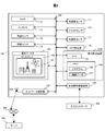
- FIG. 1 is a schematic external view of the HMD system 1 (HMD: head-mounted display) according to the present embodiment.
- FIG. 2 is a hardware configuration diagram of the HMD 100.
- the HMD system 1 includes an HMD 100 and an input controller 400 mounted on the user's head.
- the input controller 400 is communicated and connected to the HMD 100 via a short-range wireless communication line to transmit and receive information. Information may be transmitted and received by wire.
- the input controller 400 includes an operation member including a keyboard, key buttons, a touch panel, etc., and a short-range wireless communication device.
- the input controller 400 may be configured such that a smartphone is equipped with the function.
- the server 200 creates a display object and transmits it to the HMD 100 via the external network 300.
- the HMD 100 may be configured to generate and display a display object by itself.
- the HMD 100 includes a camera 111, an in-camera 112, a distance measuring sensor 113, an illuminance sensor 114, an acceleration sensor 115, a gyro sensor 116, a geomagnetic sensor 117, a GPS receiver 118, a display 119, and a network communication device 120.
- CPU 125, memory 128, short-range wireless communication device 129, shading filter 150, and each component are connected to each other via a bus 140 connecting the components.
- the network communication device 120 is connected to the antenna 123 that receives the wireless communication radio wave.
- the light-shielding filter 150 is a polarizing filter that switches between a state in which external light is incident on a part of the light-shielding filter 150 and a light-shielding state.
- the network communication device 120 is a communication interface that communicates with an external server 200 by wireless LAN, wired LAN, or base station communication. During wireless communication, the network communication device 120 connects to the external network 300 via the antenna 123 to transmit and receive information. The network communication device 120 can receive the display object generated by the server 200 via the external network 300 and send and receive the operation control signal to and from the server 200.
- the network communication device 120 is composed of a communication device compatible with a long-distance wireless communication standard such as W-CDMA (Wideband Code Division Multiple Access) and GSM (registered trademark) (Global System for Mobile communications).
- the short-range wireless communication device 129 is a communication interface that performs short-range wireless communication between the input controller 400 and the HMD 100.
- the short-range wireless communication device 129 is performed using, for example, an electronic tag, but is not limited to this, and is not limited to Bluetooth (registered trademark), IrDA (Infrared Data Association), Zigbee (registered trademark), HomeRF (Home Radio Frequency, registration). Trademark) or a communication device compatible with wireless LAN (IEEE802.11a, IEEE802.11b, IEEE802.11g).
- the HMD 100 is connected to the input controller 400 via the short-range wireless communication device 129.
- the HMD 100 receives the operation information received by the input controller 400 via the short-range wireless communication line.
- the CPU 125 loads and executes the program 126 stored in the memory 128, reads out the information data 127 as needed, and uses it for the execution process of the program 126.
- the CPU 125 displays the display object 131 on the display 119, and controls the light-shielding filter 150 to partially block light as needed. Therefore, the CPU 125, the memory 128, the program 126, and the information data 127 are collectively referred to as a display control device 1200.
- the display control device 1200 may be configured to have a function mounted on the input controller 400 side.
- the display 119 is installed in front of one or both eyes of the user wearing the HMD 100.
- the CPU 125 displays the display object 131 received from the server 200 on the display 119.
- Display 119 is a transmissive display. External light transmitted through the display 119 is incident on the user's eyes. A display object is displayed on the display 119, and the display light is also incident on the user's eyes. As a result, the user visually recognizes the scenery in which the display object is superimposed on the real world.
- a light blocking filter 150 is arranged on the outside of the display 119.
- the side facing the user wearing the HMD 100 is referred to as the inside, and the side not facing the user is referred to as the outside.
- the CPU 125 constitutes the control controller of the HMD 100, and executes a program 126 such as an OS (Operating System) and an operation control application stored in the memory 128.
- a program 126 such as an OS (Operating System) and an operation control application stored in the memory 128.
- the memory 128 is a flash memory or the like, and stores various programs 126 used by the CPU 125. Further, the memory 128 stores the display object received from the server 200 as information data 127.
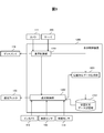
- FIG. 3 is a functional block diagram showing the functions of the display control device 1200.
- the display control device 1200 corresponds to a display control unit 1201 that controls the display of the display 119, a light-shielding control unit 1202 that controls the light-shielding of the light-shielding filter 150, and a position correspondence in which the pixel position of the display 119 and the pixel position of the light-shielding filter 150 are associated with each other. It includes a position-corresponding data generation unit 1203 that generates data 160 (see FIG. 5), and a position-corresponding data storage unit 1204 that stores position-corresponding data 160.
- Each of the display control unit 1201, the light-shielding control unit 1202, and the position-corresponding data generation unit 1203 is configured by the CPU 125 loading the program 126 that realizes the functions of each unit into the work area of the memory 128 and executing the program 126.
- the position-corresponding data storage unit 1204 is composed of a memory 128.
- the position correspondence data 160 is included in the information data 127.
- FIG. 4 is a flowchart showing the flow of pixel alignment processing of the display 119 and the shading filter 150.
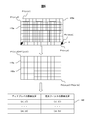
- FIG. 5 is a diagram showing pixel alignment processing of the display 119 and the light blocking filter 150.
- the pixel alignment process is a process for satisfying this need.
- the display control unit 1201 displays the first grid pattern 119a on the display 119, and the pixel positions p1 (x1, y1), p2 (x2, y2), ... pn (xn, yn) (n is the number of vertices of the first grid pattern) is output to the position-corresponding data generation unit 1203.
- the light-shielding control unit 1202 displays the second grid pattern 150a having the same shape as the first grid pattern 119a on the light-shielding filter 150. In the initial state, it is assumed that the first grid pattern 119a and the second grid pattern 150a are misaligned as shown in the upper part of FIG.
- the display position of the second grid pattern 150a is shifted by the arrow A so that the first grid pattern 119a and the second grid pattern 150a overlap neatly, and the two are adjusted so as to match (S101).
- the first grid pattern 119a and the second grid pattern 150a overlap.
- the number of vertices is output to the position-corresponding data generation unit 1203 by the shading control unit 1202.
- the position-corresponding data generation unit 1203 includes pixel positions p1 (x1, y1), p2 (x2, y2), ..., Pn (xn, yn) at each vertex of the display 119, and each of the light-shielding filter 150.
- Position correspondence data 160 corresponding to each of the pixel positions p1 (s1, t1), p2 (s2, t2), ..., Pn (sn, tun) of the apex is generated, and the position correspondence data storage unit 1204 It is stored in (S102).
- S101 and S102 are operations in the factory. Here, an example in which a grid pattern is used for the pixel alignment process is shown, but a rectangle indicating a display area or a sample of a display object may be used as the adjustment pattern.
- FIG. 6 is a flowchart showing the flow of shading control processing performed when the HMD 100 is used.
- FIG. 7 is a diagram showing a display state of the display object and the shading filter.
- the illuminance sensor 114 detects external light, and the light blocking control unit 1202 determines the external light intensity (S201).
- the process ends.
- the light-shielding control unit 1202 determines that the external light intensity is equal to or higher than a predetermined light-shielding control threshold value (S202 / Yes)
- the light-shielding control unit 1202 acquires display data from the display control unit 1201.
- the display data includes the pixel positions of the display 119 that displays the display object.
- the shading control unit 1202 extracts the contour line of the display object based on the display data (S203). Any known method may be used as the contour line extraction processing method.
- the pixel position of the contour line may be extracted by extracting the maximum coordinates and the minimum coordinates of each row of the area for displaying the display object 131 and the coordinates of each column corresponding to each.
- the shading control unit 1202 determines the shading region 150b (see FIG. 7) using the pixel positions of the extracted contour lines (S204).
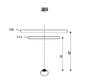
- FIG. 8 is a diagram showing an example of how to obtain the light-shielding region 150b.
- an ultrasonic sensor is used as the distance measuring sensor 113, and the distance a from the HMD 100 to the face of the user wearing the HMD 100 is obtained.
- the user's eyes are not detected, and the distance from the HMD 100 to the face is regarded as the distance from the HMD 100 to the user's eyes.
- the shading filter 150 and the display 119 may be in close contact with each other or may be spatially separated depending on the display method.
- the shading control unit 1202 acquires the distance b.
- the distance ⁇ d between the light-shielding filter 150 and the display 119 is known at the time of shipment. Therefore, the distance ⁇ d is stored as information data 127.
- the shading control unit 1202 calculates the distance a from the user's eyes to the shading filter 150 by (distance b-distance ⁇ d).
- the light-shielding control unit 1202 obtains the enlargement ratio on the light-shielding filter 150 by b / a.
- the display area of the display object 131 on the display 119 is enlarged at the enlargement ratio b / a.
- the enlarged area becomes an area corresponding to the display area of the display object on the shading filter 150.
- the shading control unit 1202 obtains an area including all the areas corresponding to the display area of the display object as the shading area 150b.
- a predetermined margin area for example, a pixel outside 100 pixels is connected to a region corresponding to the display area of the display object to determine the outer shape of the light-shielding area 150b, and a closed area consisting of a slightly larger inside is defined as the light-shielding area 150b. May be determined as.
- the light-shielding area 150b defines a geometric shape having a size including all the areas corresponding to the display area of the display object, for example, an elliptical shape, and the closed area including the outline of the elliptical shape and the inside thereof is defined as the light-shielding area 150b. May be determined as.
- FIG. 9 is a diagram (plan view) showing another example of how to obtain the light-shielding region 150b.
- the in-camera 112 of the HMD 100 is mounted on the inner surface of the HMD 100 and in the same plane as the light shielding filter 150 near the center of the left and right sides of the user facing surface. Then, when the user wears the HMD 100, the in-camera 112 is arranged substantially at the center of the left and right sides of the face. The user's eye is detected using the in-camera 112, and the angle ⁇ and the distance c from the in-camera 112 to the user's eye are obtained.
- the shading control unit 1202 calculates the distance b from the user's eyes to the shading filter 150 by the following equation (1).
- Distance b cCOS ⁇ ... (1)
- the display area of the display object is enlarged at the enlargement ratio b / a.
- the horizontal position of the light-shielding region 150b will be described, but the in-camera 112 also detects the distance and angle in the height direction to the user's eyes for the height position. Then, the shading control unit 1202 calculates the enlargement ratio in the height direction using the detected value. The shading control unit 1202 uses the distance b thus obtained to perform the same processing as in FIG.
- the light-shielding control unit 1202 reads the position-corresponding data from the position-corresponding data storage unit 1204, and converts the light-shielding region 150b defined based on the pixel position of the display data into the pixel position of the light-shielding filter 150. Then, in the light-shielding filter 150, only the light-shielding region is light-shielded (S205).
- the display control unit 1201 displays the display object 131 on the display 119 (S206).
- the area including the display object displayed on the display 119 is partially blocked by the light blocking filter 150. , Prevents outside light from passing through the display object 131 and its surroundings. As a result, the contrast between the display object 131 and its surroundings is maintained above a certain level, and the visibility of the display object 131 is enhanced. On the other hand, since the outside light is transmitted to the region other than the periphery of the display object 131, the visibility of the landscape in the real world is not deteriorated. As a result, the visibility of the display object 131 can be improved while ensuring the visibility in the real world.
- the present invention is not limited to the above-described embodiment, and includes various modifications.
- the above-described embodiment has been described in detail in order to explain the present invention in an easy-to-understand manner, and is not necessarily limited to those having all the described configurations.
- it is possible to replace a part of the configuration of one embodiment with the configuration of another embodiment and it is also possible to add the configuration of another embodiment to the configuration of one embodiment.
- each of the above configurations may be configured so that a part or all of them may be configured by hardware or may be realized by executing a program on a processor.
- control lines and information lines are shown as necessary for explanation, and not all control lines and information lines are necessarily shown in the product. In practice, it can be considered that almost all configurations are interconnected.
- the light-shielding filter 150 uses a polarizing filter that switches between incident and light-shielding external light, but the light-shielding filter 150 may be provided with an RGB element.
- the RGB data of the display object 131 is added to the display data.
- the shading control unit 1202 determines the color tone of the display object 131, selects a color different from the color tone, for example, the opposite color in the hue circle, and displays the shading area 150c in the opposite color. May be good.
- the shading control unit 1202 determines the color tone of the display object 131, selects a color different from the color tone, for example, the opposite color in the hue circle, and displays the shading area 150c in the opposite color. May be good.
- the light-shielding control unit 1202 may determine the background color of the real world on which the 131 is superimposed, and display the light-shielding region 150c using the opposite color.
- HMD system 100 HMD 111: Camera 112: In-camera 113: Distance measurement sensor 114: Illuminance sensor 115: Acceleration sensor 116: Gyro sensor 117: Geomagnetic sensor 118: GPS receiver 119: Display 119a: First lattice pattern 120: Network communication device 123: Antenna 125: CPU 126: Program 127: Information data 128: Memory 129: Short-range wireless communication device 130: Video 131: Display object 140: Bus 150: Shading filter 150a: Second grid pattern 150b, 150c: Shading area 200: Server 300: External network 400: Input controller 1200: Display control device 1201: Display control unit 1202: Light-shielding control unit 1203: Position-corresponding data generation unit 1204: Position-corresponding data storage unit
Landscapes
- Physics & Mathematics (AREA)
- General Physics & Mathematics (AREA)
- Optics & Photonics (AREA)
Abstract
ヘッドマウントディスプレイ(100)であって、外光を透過するディスプレイ(119)と、その外側に遮光フィルタ(150)を配置して構成され、ディスプレイ(119)に表示オブジェクト(131)を表示し、表示オブジェクト(131)が表示されたディスプレイ(119)の画素位置を示す表示データを出力し、当該表示データと、予め用意したディスプレイ(119)の画素位置と遮光フィルタ(150)の画素位置とを対応付けた位置対応データに基づいて、表示オブジェクト(131)の表示位置に対応する遮光フィルタ(150)の画素位置を決定し、当該画素位置を内包する遮光領域を決定し、遮光フィルタ(150)の内、遮光領域のみを遮光制御する。
Description
本発明は、ヘッドマウントディスプレイ及びヘッドマウントディスプレイの遮光制御方法に関する。
透過型ディスプレイを搭載し、ディスプレイ越しに視認する現実世界に、ディスプレイに表示オブジェクトを表示して、ユーザに表示オブジェクトが重畳された風景を視認させるヘッドマウントディスプレイ(HMD)がある。このような透過型のHMDでは、外光が強いとHMDを装着したユーザが眩しさを感じる。
そこで、特許文献1には、少なくとも一方の眼の前において画像を表示するHMDで、ユーザの一方の眼前において透過光量を制限する遮光板を備えたHMDが開示されている。
また特許文献2には、サンバイザのつばの部分に取り付けるタイプのHMDで、つばに遮光フィルタを付けたHMDが開示されている。
更に特許文献3には、HMDと眼の間に遮光板を入れて、必要に応じて、遮光板を上げ下げするHMDが開示されている。
HMDを装着して屋外で作業する場合のように、外光が強いとコントラストの弱いHMDの表示領域の視認性が低くなり、情報が読めなくなる。特許文献1から特許文献3のHMDでは、ユーザの眩しさを軽減し、表示領域の視認性の低下を改善することができるものの、HMDを通した視界全体を遮光する結果、ユーザの視界全体の視認性が下がるという課題が残る。
本発明は、上記課題を解決するためになされたものであり、ヘッドマウントディスプレイにおいて外光が強いときにも表示オブジェクトの視認性を向上させつつ、現実世界の視認性も確保することを目的とする。
上記課題を解決するために、本発明は、請求の範囲に記載の構成を備える。その一例を挙げるならば、ヘッドマウントディスプレイであって、外光を透過するディスプレイと、前記外光を遮光する遮光フィルタと、前記ディスプレイ及び前記遮光フィルタの其々に接続された表示制御装置と、を備え、前記遮光フィルタは、前記ヘッドマウントディスプレイをユーザが装着した状態において、前記ディスプレイを基準として前記ユーザの眼が位置する側とは反対側に配置され、前記表示制御装置は、前記ディスプレイの画素位置と前記遮光フィルタの画素位置とを対応付けた位置対応データを記憶する位置対応データ記憶部と、前記ディスプレイに表示オブジェクトを表示し、前記表示オブジェクトが表示された前記ディスプレイの画素位置を示す表示データを出力する表示制御部と、前記位置対応データ及び前記表示データに基づいて、前記表示オブジェクトの表示位置に対応する前記遮光フィルタの画素位置を決定し、当該画素位置を内包する遮光領域を決定し、前記遮光フィルタの内、前記遮光領域のみを遮光制御する遮光制御部と、を含む、ことを特徴とする。
本発明によれば、ヘッドマウントディスプレイにおいて外光が強いときにも表示オブジェクトの視認性を向上させつつ、現実世界の視認性も確保することができる。上述した以外の目的、構成、効果については以下の実施形態において明らかにされる。
以下、本発明の実施形態について図面を用いて説明する。全図を通じて同一の構成、処理には同一の符号を付し、重複説明を省略する。図1は、本実施形態に係るHMDシステム1(HMD:ヘッドマウントディスプレイ)の外観模式図である。図2は、HMD100のハードウェア構成図である。
図1に示すように、HMDシステム1は、ユーザの頭部に装着されたHMD100及び入力コントローラ400を含む。入力コントローラ400は、近距離無線通信回線を介してHMD100に通信接続され、情報の送受信を行う。なお、有線で情報の送受信を行ってもよい。
入力コントローラ400は、キーボードやキーボタン、タッチパネル等からなる操作部材と、近距離無線通信器とを含んで構成される。この入力コントローラ400は、スマートフォンがその機能を搭載する構成でも構わない。
サーバ200は表示オブジェクトを生成し、HMD100に対して外部ネットワーク300を介して送信する。HMD100が自ら表示オブジェクトを生成し、表示するように構成してもよい。
図2に示すように、HMD100は、カメラ111、インカメラ112、測距センサ113、照度センサ114、加速度センサ115、ジャイロセンサ116、地磁気センサ117、GPS受信器118、ディスプレイ119、ネットワーク通信器120、CPU125、メモリ128、近距離無線通信器129、遮光フィルタ150と、各構成要素を接続するバス140を介して互いに接続される。ネットワーク通信器120は、無線通信電波を受信するアンテナ123に接続される。遮光フィルタ150は、遮光フィルタ150の一部領域に外光が入射する状態、または遮光状態に切り替える偏光フィルタである。
ネットワーク通信器120は、無線LAN、有線LAN或いは基地局通信により外部のサーバ200と通信を行う通信インターフェースであり、無線通信に際してはアンテナ123を介して外部ネットワーク300に接続し情報の送受信を行う。ネットワーク通信器120は、外部ネットワーク300を経由してサーバ200で生成された表示オブジェクトを受信し、サーバ200と動作制御信号の送受信を行うことができる。ネットワーク通信器120は、W-CDMA(Wideband Code Division Multiple Access)やGSM(登録商標)(Global System for Mobile communications)などの遠距離の無線通信規格に対応した通信器により構成される。
近距離無線通信器129は、入力コントローラ400とHMD100との間で近距離無線通信を行う通信インターフェースである。近距離無線通信器129は、例えば電子タグを用いて行われるが、これに限定されず、Bluetooth(登録商標)、IrDA(Infrared Data Association)、Zigbee(登録商標)、HomeRF(Home Radio Frequency、登録商標)、又は、無線LAN(IEEE802.11a、IEEE802.11b、IEEE802.11g)に対応した通信器により構成される。
HMD100は、近距離無線通信器129を介して入力コントローラ400に接続される。HMD100は、近距離無線通信回線を介して入力コントローラ400が受け付けた操作情報を受信する。CPU125は、メモリ128に格納されたプログラム126をロードして実行し、必要に応じて情報データ127を読み出してプログラム126の実行処理に用いる。CPU125は、表示オブジェクト131をディスプレイ119に表示し、遮光フィルタ150を必要に応じて部分的に遮光制御する。よって、CPU125、メモリ128、プログラム126、及び情報データ127を総称して表示制御装置1200という。この表示制御装置1200は、入力コントローラ400側に機能を搭載する構成でも構わない。
ディスプレイ119は、HMD100を装着したユーザの片眼もしくは両眼の前方に設置される。CPU125は、サーバ200から受信した表示オブジェクト131をディスプレイ119に表示する。
ディスプレイ119は透過型ディスプレイである。ユーザの眼にディスプレイ119を透過した外光が入射する。またディスプレイ119に表示オブジェクトが表示され、その表示光もユーザの眼に入射する。これにより、ユーザは現実世界に表示オブジェクトが重畳された景色を視認する。
ディスプレイ119の外側には、遮光フィルタ150が配置される。本実施形態において、HMD100を装着したユーザに対向する側を内側、ユーザに対向しない側を外側と称する。
CPU125は、HMD100の制御コントローラを構成し、メモリ128に格納されているOS(Operating System)や動作制御用アプリケーションなどのプログラム126を実行する。
メモリ128は、フラッシュメモリなどであり、CPU125が使用する各種のプログラム126を記憶する。更にメモリ128は、サーバ200から受信した表示オブジェクトを情報データ127として記憶している。
図3は、表示制御装置1200の機能を示す機能ブロック図である。表示制御装置1200は、ディスプレイ119の表示制御を行う表示制御部1201、遮光フィルタ150の遮光制御を行う遮光制御部1202、ディスプレイ119の画素位置と遮光フィルタ150の画素位置とを対応付けた位置対応データ160(図5参照)を生成する位置対応データ生成部1203、及び位置対応データ160を記憶する位置対応データ記憶部1204を含む。表示制御部1201、遮光制御部1202、及び位置対応データ生成部1203の其々は、各部の機能を実現するプログラム126をCPU125がメモリ128のワークエリアにロードして実行することにより構成される。また位置対応データ記憶部1204は、メモリ128により構成される。位置対応データ160は情報データ127に含まれる。
図4はディスプレイ119及び遮光フィルタ150の画素位置合わせ処理の流れを示すフローチャートである。図5は、ディスプレイ119及び遮光フィルタ150の画素位置合わせ処理を示す図である。
ディスプレイ119に表示される表示オブジェクト131の周囲だけを、遮光フィルタ150を用いて遮光するためには、ディスプレイ119の画素位置と遮光フィルタ150の画素位置とを対応付ける必要がある。画素位置合わせ処理はこの必要を満たすための処理である。
そこで、表示制御部1201は、図5に示すように、ディスプレイ119に第1格子パターン119aを表示し、各頂点の画素位置p1(x1,y1)、p2(x2,y2)、・・・、pn(xn,yn)(nは第1格子パターンの頂点の数)を位置対応データ生成部1203に出力する。同様に遮光制御部1202は、遮光フィルタ150に第1格子パターン119aと同一形状の第2格子パターン150aを表示する。初期状態では、図5上段に示すように第1格子パターン119aと第2格子パターン150aとがずれているとする。
そこで、第1格子パターン119aと第2格子パターン150aとがきれいに重なるように、第2格子パターン150aの表示位置を矢印A分ずらし、両者が一致するように調整する(S101)。これにより、図5下段に示すように、第1格子パターン119aと第2格子パターン150aが重なる。このときの遮光フィルタ150における第2格子パターン150aの各頂点の画素位置p1(s1,t1)、p2(s2,t2)、・・・、pn(sn,tn)(nは第2格子パターンの頂点の数)を、遮光制御部1202は、位置対応データ生成部1203に出力する。
位置対応データ生成部1203は、ディスプレイ119の各頂点の画素位置p1(x1,y1)、p2(x2,y2)、・・・、pn(xn,yn)の其々と、遮光フィルタ150の各頂点の画素位置p1(s1,t1)、p2(s2,t2)、・・・、pn(sn,tn)の其々とを対応づけた位置対応データ160を生成し、位置対応データ記憶部1204に記憶する(S102)。S101、S102は工場での作業である。ここでは画素位置合わせ処理に格子パターンを用いた例を示したが、表示領域を示す長方形や表示オブジェクトのサンプルを調整パターンに用いても良い。
図6はHMD100の使用時に行われる遮光制御処理の流れを示すフローチャートである。図7は、表示オブジェクト及び遮光フィルタの表示状態を示す図である。
HMD100の主電源がONになると、照度センサ114は外光を検出し、遮光制御部1202が外光強度判定を行う(S201)。
遮光制御部1202は、外光強度が予め定められた遮光制御閾値未満であると判定すると(S202/No)、処理を終了する。
遮光制御部1202は、外光強度が予め定められた遮光制御閾値以上であると判定すると(S202/Yes)、表示制御部1201から表示データを取得する。表示データには、表示オブジェクトを表示するディスプレイ119の画素位置が含まれる。
遮光制御部1202は、表示データを基に表示オブジェクトの輪郭線を抽出する(S203)。輪郭線の抽出処理方法は公知の手法のいずれを用いてもよい。例えば表示オブジェクト131を表示する領域の各行の最大座標、最小座標及び其々に対応する各列の座標を抽出して輪郭線の画素位置を抽出してもよい。
遮光制御部1202は、抽出した輪郭線の画素位置を用いて遮光領域150b(図7参照)を決定する(S204)。
図8は、遮光領域150bの求め方例を示す図である。測距センサ113として例えば超音波センサを用い、HMD100からHMD100を装着したユーザの顔までの距離aを求める。本例では、ユーザの眼は検出せず、HMD100から顔面までの距離をHMD100からユーザの眼までの距離と見做す。
遮光フィルタ150とディスプレイ119は、表示方式により密着している場合と空間的に距離が離れている場合がある。ここで、測距センサが遮光フィルタと同じ面内に配置されている場合には、遮光制御部1202は距離bを取得する。
一方、遮光フィルタ150とディスプレイ119とはHMD100に固定的に配置されているので、遮光フィルタ150とディスプレイ119との距離Δdは出荷時に既知である。よって距離Δdを情報データ127として記憶しておく。
そして遮光制御部1202は、ユーザの眼から遮光フィルタ150までの距離aを(距離b-距離Δd)により演算する。遮光制御部1202は、遮光フィルタ150上の拡大率をb/aにより求める。
その後表示オブジェクト131のディスプレイ119での表示領域を拡大率b/aで拡大する。拡大した領域が遮光フィルタ150上における表示オブジェクトの表示領域に対応する領域となる。
遮光制御部1202は、表示オブジェクトの表示領域に対応する領域を全て内包する領域を遮光領域150bとして求める。例えば表示オブジェクトの表示領域に対応する領域に予め定めたマージン領域、例えば100画素外側の画素をつないで遮光領域150bの外郭を決定し、それよりも一回り大きな内側からなる閉領域を遮光領域150bとして決定してもよい。
また遮光領域150bは、表示オブジェクトの表示領域に対応する領域を全て内包する大きさの幾何学形状、例えば楕円形状を定義し、この楕円形状の輪郭線及びその内部からなる閉領域を遮光領域150bとして決定してもよい。
図9は、遮光領域150bの求め方の他例を示す図(平面視)である。
HMD100のインカメラ112を、HMD100の内側面、かつユーザ対向面の左右中央付近で遮光フィルタ150と同じ面内に搭載する。そうすると、ユーザがHMD100を装着した際、ほぼ顔の左右中央にインカメラ112が配置される。そのインカメラ112を用いてユーザの眼を検出し、インカメラ112からユーザの眼までの角度θと距離cを求める。
そこで、遮光制御部1202は、ユーザの眼から遮光フィルタ150までの距離bを下式(1)により演算する。
距離b=cCOSθ・・・(1)
距離b=cCOSθ・・・(1)
その後表示オブジェクトの表示領域を拡大率b/aで拡大する。上記では、遮光領域150bの水平方向位置について説明するが、高さ方向位置についてもインカメラ112がユーザの眼までの高さ方向の距離と角度とを検出する。そして遮光制御部1202が検出値を用いて高さ方向の拡大率を演算する。遮光制御部1202は、こうして求めた距離bを使い、図8と同等の処理を実行する。
遮光制御部1202は、位置対応データ記憶部1204から位置対応データを読み出し、表示データの画素位置を基準に定義された遮光領域150bを遮光フィルタ150の画素位置に変換する。そして遮光フィルタ150において、遮光領域のみを遮光制御する(S205)。
S1205と並行して、表示制御部1201は、表示オブジェクト131をディスプレイ119に表示する(S206)。
上記実施形態によれば、HMD100を使用時に外光の強さが遮光制御閾値以上になったことを検出すると、ディスプレイ119に表示した表示オブジェクトを内包する領域を遮光フィルタ150で部分的に遮光し、外光が表示オブジェクト131及びその周囲を透過することを防ぐ。これにより、表示オブジェクト131とその周辺とのコントラストを一定以上に保ち、表示オブジェクト131の視認性を高める。一方で、表示オブジェクト131の周辺を除く領域は、外光が透過するので現実世界の風景の視認性が低下することがない。これにより、現実世界の視認性を確保しつつ表示オブジェクト131の視認性を向上させることができる。
なお、本発明は上記した実施形態に限定されるものではなく、様々な変形例が含まれる。例えば、上記した実施例は本発明を分かりやすく説明するために詳細に説明したものであり、必ずしも説明した全ての構成を備えるものに限定されるものではない。また、ある実施例の構成の一部を他の実施例の構成に置き換えることが可能であり、また、ある実施例の構成に他の実施例の構成を加えることも可能である。また、各実施例の構成の一部について、他の構成の追加・削除・置換をすることが可能である。
また、上記の各構成は、それらの一部又は全部が、ハードウェアで構成されても、プロセッサでプログラムが実行されることにより実現されるように構成されてもよい。また、制御線や情報線は説明上必要と考えられるものを示しており、製品上必ずしも全ての制御線や情報線を示しているとは限らない。実際には殆ど全ての構成が相互に接続されていると考えてもよい。
例えば、上記では遮光フィルタ150は外光を入射、遮光に切り替える偏光フィルタを用いたが、遮光フィルタ150にRGB素子を備えてもよい。この場合、表示データに表示オブジェクト131のRGBデータを付加しておく。そして、図10に示すように遮光制御部1202は表示オブジェクト131の色調を判定し、その色調とは異なる色、例えば色相環における反対色を選択し、遮光領域150cをその反対色で表示してもよい。これにより、表示オブジェクト131と遮光領域150cとを明度だけでなく色調のコントラストを強調し、視認性を向上させることができる。
また、カメラ111で現実世界を撮影した映像の外光がディスプレイ119を透過することから、カメラ111の映像をディスプレイ119に映したときの画素位置、及び遮光フィルタ150の画素位置を関連付け、表示オブジェクト131を重畳する現実世界の背景色を遮光制御部1202が判定し、その反対色を用いた遮光領域150c表示してもよい。
1 :HMDシステム
100 :HMD
111 :カメラ
112 :インカメラ
113 :測距センサ
114 :照度センサ
115 :加速度センサ
116 :ジャイロセンサ
117 :地磁気センサ
118 :GPS受信器
119 :ディスプレイ
119a :第1格子パターン
120 :ネットワーク通信器
123 :アンテナ
125 :CPU
126 :プログラム
127 :情報データ
128 :メモリ
129 :近距離無線通信器
130 :映像
131 :表示オブジェクト
140 :バス
150 :遮光フィルタ
150a :第2格子パターン
150b、150c:遮光領域
200 :サーバ
300 :外部ネットワーク
400 :入力コントローラ
1200 :表示制御装置
1201 :表示制御部
1202 :遮光制御部
1203 :位置対応データ生成部
1204 :位置対応データ記憶部
100 :HMD
111 :カメラ
112 :インカメラ
113 :測距センサ
114 :照度センサ
115 :加速度センサ
116 :ジャイロセンサ
117 :地磁気センサ
118 :GPS受信器
119 :ディスプレイ
119a :第1格子パターン
120 :ネットワーク通信器
123 :アンテナ
125 :CPU
126 :プログラム
127 :情報データ
128 :メモリ
129 :近距離無線通信器
130 :映像
131 :表示オブジェクト
140 :バス
150 :遮光フィルタ
150a :第2格子パターン
150b、150c:遮光領域
200 :サーバ
300 :外部ネットワーク
400 :入力コントローラ
1200 :表示制御装置
1201 :表示制御部
1202 :遮光制御部
1203 :位置対応データ生成部
1204 :位置対応データ記憶部
Claims (5)
- ヘッドマウントディスプレイであって、
外光を透過するディスプレイと、
前記外光を遮光する遮光フィルタと、
前記ディスプレイ及び前記遮光フィルタの其々に接続された表示制御装置と、を備え、
前記遮光フィルタは、前記ヘッドマウントディスプレイをユーザが装着した状態において、前記ディスプレイを基準として前記ユーザの眼が位置する側とは反対側に配置され、
前記表示制御装置は、
前記ディスプレイの画素位置と前記遮光フィルタの画素位置とを対応付けた位置対応データを記憶する位置対応データ記憶部と、
前記ディスプレイに表示オブジェクトを表示し、前記表示オブジェクトが表示された前記ディスプレイの画素位置を示す表示データを出力する表示制御部と、
前記位置対応データ及び前記表示データに基づいて、前記表示オブジェクトの表示位置に対応する前記遮光フィルタの画素位置を決定し、当該画素位置を内包する遮光領域を決定し、前記遮光フィルタの内、前記遮光領域のみを遮光制御する遮光制御部と、を含む、
ことを特徴とするヘッドマウントディスプレイ。 - 請求項1に記載のヘッドマウントディスプレイであって、
前記遮光制御部は、前記表示オブジェクトの表示位置に対応する前記遮光フィルタの画素位置を内包する幾何学形状領域を前記遮光領域として決定する、
ことを特徴とするヘッドマウントディスプレイ。 - 請求項1に記載のヘッドマウントディスプレイであって、
前記遮光制御部は、前記表示オブジェクトの表示位置に対応する前記遮光フィルタの画素位置を求め、当該画素位置を含む閉領域の輪郭から予め定められたマージン分外側の領域を含む閉領域を前記遮光領域として決定する、
ことを特徴とするヘッドマウントディスプレイ。 - 請求項1に記載のヘッドマウントディスプレイであって、
前記ディスプレイ及び前記遮光フィルタの其々は、RGB素子を含んで構成され、
前記表示制御部は、前記表示オブジェクトのRGBデータを更に含む前記表示データを出力し、
前記遮光制御部は、前記表示データのRGBデータを参照し、前記表示オブジェクトとは異なる遮光色を決定し、前記遮光フィルタの前記遮光領域を前記遮光色で表示することにより遮光制御する、
ことを特徴とするヘッドマウントディスプレイ。 - ヘッドマウントディスプレイの遮光制御方法であって、
前記ヘッドマウントディスプレイは、外光を透過するディスプレイと、前記外光を遮光する遮光フィルタと、前記ディスプレイ及び前記遮光フィルタの其々に接続された表示制御装置と、を備え、
前記遮光フィルタは、前記ヘッドマウントディスプレイをユーザが装着した状態において、前記ディスプレイを基準として前記ユーザの眼が位置する側とは反対側に配置され、
前記表示制御装置は、
前記ディスプレイに表示オブジェクトを表示し、前記表示オブジェクトが表示された前記ディスプレイの画素位置を示す表示データを出力し、
前記ディスプレイの画素位置と前記遮光フィルタの画素位置とを対応付けた位置対応データ及び前記表示データに基づいて、前記表示オブジェクトの表示位置に対応する前記遮光フィルタの画素位置を決定し、当該画素位置を内包する遮光領域を決定し、前記遮光フィルタの内、前記遮光領域のみを遮光制御する、
ことを特徴とするヘッドマウントディスプレイの遮光制御方法。
Priority Applications (1)
| Application Number | Priority Date | Filing Date | Title |
|---|---|---|---|
| PCT/JP2019/012555 WO2020194458A1 (ja) | 2019-03-25 | 2019-03-25 | ヘッドマウントディスプレイ及びヘッドマウントディスプレイの遮光制御方法 |
Applications Claiming Priority (1)
| Application Number | Priority Date | Filing Date | Title |
|---|---|---|---|
| PCT/JP2019/012555 WO2020194458A1 (ja) | 2019-03-25 | 2019-03-25 | ヘッドマウントディスプレイ及びヘッドマウントディスプレイの遮光制御方法 |
Publications (1)
| Publication Number | Publication Date |
|---|---|
| WO2020194458A1 true WO2020194458A1 (ja) | 2020-10-01 |
Family
ID=72609242
Family Applications (1)
| Application Number | Title | Priority Date | Filing Date |
|---|---|---|---|
| PCT/JP2019/012555 Ceased WO2020194458A1 (ja) | 2019-03-25 | 2019-03-25 | ヘッドマウントディスプレイ及びヘッドマウントディスプレイの遮光制御方法 |
Country Status (1)
| Country | Link |
|---|---|
| WO (1) | WO2020194458A1 (ja) |
Citations (5)
| Publication number | Priority date | Publication date | Assignee | Title |
|---|---|---|---|---|
| JP2000171750A (ja) * | 1998-12-03 | 2000-06-23 | Sony Corp | ヘッドマウントディスプレイ、表示方法、および提供媒体 |
| JP2002244074A (ja) * | 2001-02-15 | 2002-08-28 | Mixed Reality Systems Laboratory Inc | 画像表示装置 |
| JP2014228595A (ja) * | 2013-05-20 | 2014-12-08 | コニカミノルタ株式会社 | 拡張現実空間表示装置 |
| JP2017146373A (ja) * | 2016-02-15 | 2017-08-24 | 株式会社菊池製作所 | 画像表示装置 |
| US20180314066A1 (en) * | 2017-04-28 | 2018-11-01 | Microsoft Technology Licensing, Llc | Generating dimming masks to enhance contrast between computer-generated images and a real-world view |
-
2019
- 2019-03-25 WO PCT/JP2019/012555 patent/WO2020194458A1/ja not_active Ceased
Patent Citations (5)
| Publication number | Priority date | Publication date | Assignee | Title |
|---|---|---|---|---|
| JP2000171750A (ja) * | 1998-12-03 | 2000-06-23 | Sony Corp | ヘッドマウントディスプレイ、表示方法、および提供媒体 |
| JP2002244074A (ja) * | 2001-02-15 | 2002-08-28 | Mixed Reality Systems Laboratory Inc | 画像表示装置 |
| JP2014228595A (ja) * | 2013-05-20 | 2014-12-08 | コニカミノルタ株式会社 | 拡張現実空間表示装置 |
| JP2017146373A (ja) * | 2016-02-15 | 2017-08-24 | 株式会社菊池製作所 | 画像表示装置 |
| US20180314066A1 (en) * | 2017-04-28 | 2018-11-01 | Microsoft Technology Licensing, Llc | Generating dimming masks to enhance contrast between computer-generated images and a real-world view |
Similar Documents
| Publication | Publication Date | Title |
|---|---|---|
| US10643400B2 (en) | Head-mounted display device, method of controlling head-mounted display device, and computer program | |
| US10101586B2 (en) | Display device and control method for display device | |
| US10725300B2 (en) | Display device, control method for display device, and program | |
| US11178344B2 (en) | Head-mounted display apparatus, display system, and method of controlling head-mounted display apparatus | |
| US9870048B2 (en) | Head-mounted display device, method of controlling the same, and computer program | |
| US9817628B2 (en) | Display system, display terminal, display method and computer readable recording medium having program thereof | |
| WO2018008232A1 (ja) | 情報処理装置、情報処理方法、及びプログラム | |
| US10613333B2 (en) | Head-mounted display device, computer program, and control method for head-mounted display device | |
| US12444122B2 (en) | Stylized image painting | |
| KR102559686B1 (ko) | 차량 및 차량 영상 제어방법 | |
| KR20230079411A (ko) | 증강 현실 및 컴퓨터 비전 애플리케이션들을 위한 다목적 카메라들 | |
| US20150271457A1 (en) | Display device, image display system, and information processing method | |
| KR101682705B1 (ko) | 알에프리더를 이용한 증강현실 제공 방법 | |
| US20150279110A1 (en) | Head mounted display, and control method for head mounted display | |
| US20200184199A1 (en) | Controlling a display device | |
| TW202034292A (zh) | 顯示牆的排版辨識方法以及使用此方法的電子裝置 | |
| US11774764B2 (en) | Digital glasses having display vision enhancement | |
| JP2016161611A (ja) | 表示システム、及び表示制御方法 | |
| US20250016456A1 (en) | Wearable device, method, and non-transitory computer readable storage medium processing camera image based on region of interest | |
| JP6561606B2 (ja) | 表示装置、及び、表示装置の制御方法 | |
| KR102235903B1 (ko) | 2개의 조도센서를 이용한 머리 착용형 디스플레이 장치의 영상 최적화 방법 | |
| US9784975B2 (en) | Display device and control method for display device | |
| CN120108310A (zh) | 一种显示屏的显示方法、装置和电子设备 | |
| JP6892960B1 (ja) | 制御装置、情報処理システム、制御方法及びプログラム | |
| JP2016031373A (ja) | 表示装置、表示方法、表示システム、及び、プログラム |
Legal Events
| Date | Code | Title | Description |
|---|---|---|---|
| 121 | Ep: the epo has been informed by wipo that ep was designated in this application |
Ref document number: 19921472 Country of ref document: EP Kind code of ref document: A1 |
|
| NENP | Non-entry into the national phase |
Ref country code: DE |
|
| 122 | Ep: pct application non-entry in european phase |
Ref document number: 19921472 Country of ref document: EP Kind code of ref document: A1 |
|
| NENP | Non-entry into the national phase |
Ref country code: JP |