WO2020194009A1 - Power reception control method of power storage elements, and power reception control device - Google Patents
Power reception control method of power storage elements, and power reception control device Download PDFInfo
- Publication number
- WO2020194009A1 WO2020194009A1 PCT/IB2019/000321 IB2019000321W WO2020194009A1 WO 2020194009 A1 WO2020194009 A1 WO 2020194009A1 IB 2019000321 W IB2019000321 W IB 2019000321W WO 2020194009 A1 WO2020194009 A1 WO 2020194009A1
- Authority
- WO
- WIPO (PCT)
- Prior art keywords
- power
- electric vehicle
- priority
- electric
- power storage
- Prior art date
Links
- 238000000034 method Methods 0.000 title claims abstract description 86
- 238000012545 processing Methods 0.000 claims description 47
- 230000005540 biological transmission Effects 0.000 abstract description 61
- 238000004088 simulation Methods 0.000 description 86
- 230000004048 modification Effects 0.000 description 83
- 238000012986 modification Methods 0.000 description 83
- 238000004364 calculation method Methods 0.000 description 82
- 238000012937 correction Methods 0.000 description 51
- 230000001965 increasing effect Effects 0.000 description 28
- 230000008859 change Effects 0.000 description 18
- 238000004891 communication Methods 0.000 description 17
- 230000006854 communication Effects 0.000 description 17
- 230000006870 function Effects 0.000 description 12
- 230000002093 peripheral effect Effects 0.000 description 11
- 238000010586 diagram Methods 0.000 description 10
- 230000004043 responsiveness Effects 0.000 description 7
- 238000011144 upstream manufacturing Methods 0.000 description 7
- 230000005611 electricity Effects 0.000 description 6
- 239000006185 dispersion Substances 0.000 description 5
- 230000010365 information processing Effects 0.000 description 5
- 238000010295 mobile communication Methods 0.000 description 5
- 238000010248 power generation Methods 0.000 description 5
- 238000013459 approach Methods 0.000 description 4
- 230000007423 decrease Effects 0.000 description 4
- 230000000694 effects Effects 0.000 description 4
- 238000005516 engineering process Methods 0.000 description 4
- 238000003672 processing method Methods 0.000 description 4
- 230000007175 bidirectional communication Effects 0.000 description 3
- 230000006399 behavior Effects 0.000 description 2
- 230000000052 comparative effect Effects 0.000 description 2
- 230000006872 improvement Effects 0.000 description 2
- 230000008520 organization Effects 0.000 description 2
- 239000002028 Biomass Substances 0.000 description 1
- 230000004888 barrier function Effects 0.000 description 1
- 238000004590 computer program Methods 0.000 description 1
- 238000010276 construction Methods 0.000 description 1
- 230000003247 decreasing effect Effects 0.000 description 1
- 238000013461 design Methods 0.000 description 1
- 230000003028 elevating effect Effects 0.000 description 1
- 238000004146 energy storage Methods 0.000 description 1
- 239000000446 fuel Substances 0.000 description 1
- 230000008569 process Effects 0.000 description 1
- 238000005096 rolling process Methods 0.000 description 1
- 239000002356 single layer Substances 0.000 description 1
- 230000009466 transformation Effects 0.000 description 1
Images


Classifications
-
- B—PERFORMING OPERATIONS; TRANSPORTING
- B60—VEHICLES IN GENERAL
- B60L—PROPULSION OF ELECTRICALLY-PROPELLED VEHICLES; SUPPLYING ELECTRIC POWER FOR AUXILIARY EQUIPMENT OF ELECTRICALLY-PROPELLED VEHICLES; ELECTRODYNAMIC BRAKE SYSTEMS FOR VEHICLES IN GENERAL; MAGNETIC SUSPENSION OR LEVITATION FOR VEHICLES; MONITORING OPERATING VARIABLES OF ELECTRICALLY-PROPELLED VEHICLES; ELECTRIC SAFETY DEVICES FOR ELECTRICALLY-PROPELLED VEHICLES
- B60L53/00—Methods of charging batteries, specially adapted for electric vehicles; Charging stations or on-board charging equipment therefor; Exchange of energy storage elements in electric vehicles
- B60L53/60—Monitoring or controlling charging stations
- B60L53/66—Data transfer between charging stations and vehicles
-
- H—ELECTRICITY
- H02—GENERATION; CONVERSION OR DISTRIBUTION OF ELECTRIC POWER
- H02J—CIRCUIT ARRANGEMENTS OR SYSTEMS FOR SUPPLYING OR DISTRIBUTING ELECTRIC POWER; SYSTEMS FOR STORING ELECTRIC ENERGY
- H02J7/00—Circuit arrangements for charging or depolarising batteries or for supplying loads from batteries
- H02J7/007—Regulation of charging or discharging current or voltage
- H02J7/00712—Regulation of charging or discharging current or voltage the cycle being controlled or terminated in response to electric parameters
- H02J7/00714—Regulation of charging or discharging current or voltage the cycle being controlled or terminated in response to electric parameters in response to battery charging or discharging current
-
- B—PERFORMING OPERATIONS; TRANSPORTING
- B60—VEHICLES IN GENERAL
- B60L—PROPULSION OF ELECTRICALLY-PROPELLED VEHICLES; SUPPLYING ELECTRIC POWER FOR AUXILIARY EQUIPMENT OF ELECTRICALLY-PROPELLED VEHICLES; ELECTRODYNAMIC BRAKE SYSTEMS FOR VEHICLES IN GENERAL; MAGNETIC SUSPENSION OR LEVITATION FOR VEHICLES; MONITORING OPERATING VARIABLES OF ELECTRICALLY-PROPELLED VEHICLES; ELECTRIC SAFETY DEVICES FOR ELECTRICALLY-PROPELLED VEHICLES
- B60L53/00—Methods of charging batteries, specially adapted for electric vehicles; Charging stations or on-board charging equipment therefor; Exchange of energy storage elements in electric vehicles
- B60L53/60—Monitoring or controlling charging stations
- B60L53/62—Monitoring or controlling charging stations in response to charging parameters, e.g. current, voltage or electrical charge
-
- B—PERFORMING OPERATIONS; TRANSPORTING
- B60—VEHICLES IN GENERAL
- B60L—PROPULSION OF ELECTRICALLY-PROPELLED VEHICLES; SUPPLYING ELECTRIC POWER FOR AUXILIARY EQUIPMENT OF ELECTRICALLY-PROPELLED VEHICLES; ELECTRODYNAMIC BRAKE SYSTEMS FOR VEHICLES IN GENERAL; MAGNETIC SUSPENSION OR LEVITATION FOR VEHICLES; MONITORING OPERATING VARIABLES OF ELECTRICALLY-PROPELLED VEHICLES; ELECTRIC SAFETY DEVICES FOR ELECTRICALLY-PROPELLED VEHICLES
- B60L53/00—Methods of charging batteries, specially adapted for electric vehicles; Charging stations or on-board charging equipment therefor; Exchange of energy storage elements in electric vehicles
- B60L53/60—Monitoring or controlling charging stations
- B60L53/63—Monitoring or controlling charging stations in response to network capacity
-
- B—PERFORMING OPERATIONS; TRANSPORTING
- B60—VEHICLES IN GENERAL
- B60L—PROPULSION OF ELECTRICALLY-PROPELLED VEHICLES; SUPPLYING ELECTRIC POWER FOR AUXILIARY EQUIPMENT OF ELECTRICALLY-PROPELLED VEHICLES; ELECTRODYNAMIC BRAKE SYSTEMS FOR VEHICLES IN GENERAL; MAGNETIC SUSPENSION OR LEVITATION FOR VEHICLES; MONITORING OPERATING VARIABLES OF ELECTRICALLY-PROPELLED VEHICLES; ELECTRIC SAFETY DEVICES FOR ELECTRICALLY-PROPELLED VEHICLES
- B60L58/00—Methods or circuit arrangements for monitoring or controlling batteries or fuel cells, specially adapted for electric vehicles
- B60L58/10—Methods or circuit arrangements for monitoring or controlling batteries or fuel cells, specially adapted for electric vehicles for monitoring or controlling batteries
- B60L58/12—Methods or circuit arrangements for monitoring or controlling batteries or fuel cells, specially adapted for electric vehicles for monitoring or controlling batteries responding to state of charge [SoC]
-
- H—ELECTRICITY
- H02—GENERATION; CONVERSION OR DISTRIBUTION OF ELECTRIC POWER
- H02J—CIRCUIT ARRANGEMENTS OR SYSTEMS FOR SUPPLYING OR DISTRIBUTING ELECTRIC POWER; SYSTEMS FOR STORING ELECTRIC ENERGY
- H02J7/00—Circuit arrangements for charging or depolarising batteries or for supplying loads from batteries
- H02J7/0013—Circuit arrangements for charging or depolarising batteries or for supplying loads from batteries acting upon several batteries simultaneously or sequentially
-
- H—ELECTRICITY
- H02—GENERATION; CONVERSION OR DISTRIBUTION OF ELECTRIC POWER
- H02J—CIRCUIT ARRANGEMENTS OR SYSTEMS FOR SUPPLYING OR DISTRIBUTING ELECTRIC POWER; SYSTEMS FOR STORING ELECTRIC ENERGY
- H02J7/00—Circuit arrangements for charging or depolarising batteries or for supplying loads from batteries
- H02J7/0047—Circuit arrangements for charging or depolarising batteries or for supplying loads from batteries with monitoring or indicating devices or circuits
- H02J7/0048—Detection of remaining charge capacity or state of charge [SOC]
-
- H—ELECTRICITY
- H02—GENERATION; CONVERSION OR DISTRIBUTION OF ELECTRIC POWER
- H02J—CIRCUIT ARRANGEMENTS OR SYSTEMS FOR SUPPLYING OR DISTRIBUTING ELECTRIC POWER; SYSTEMS FOR STORING ELECTRIC ENERGY
- H02J7/00—Circuit arrangements for charging or depolarising batteries or for supplying loads from batteries
- H02J7/14—Circuit arrangements for charging or depolarising batteries or for supplying loads from batteries for charging batteries from dynamo-electric generators driven at varying speed, e.g. on vehicle
-
- B—PERFORMING OPERATIONS; TRANSPORTING
- B60—VEHICLES IN GENERAL
- B60L—PROPULSION OF ELECTRICALLY-PROPELLED VEHICLES; SUPPLYING ELECTRIC POWER FOR AUXILIARY EQUIPMENT OF ELECTRICALLY-PROPELLED VEHICLES; ELECTRODYNAMIC BRAKE SYSTEMS FOR VEHICLES IN GENERAL; MAGNETIC SUSPENSION OR LEVITATION FOR VEHICLES; MONITORING OPERATING VARIABLES OF ELECTRICALLY-PROPELLED VEHICLES; ELECTRIC SAFETY DEVICES FOR ELECTRICALLY-PROPELLED VEHICLES
- B60L2240/00—Control parameters of input or output; Target parameters
- B60L2240/80—Time limits
-
- H—ELECTRICITY
- H02—GENERATION; CONVERSION OR DISTRIBUTION OF ELECTRIC POWER
- H02J—CIRCUIT ARRANGEMENTS OR SYSTEMS FOR SUPPLYING OR DISTRIBUTING ELECTRIC POWER; SYSTEMS FOR STORING ELECTRIC ENERGY
- H02J2310/00—The network for supplying or distributing electric power characterised by its spatial reach or by the load
- H02J2310/40—The network being an on-board power network, i.e. within a vehicle
- H02J2310/48—The network being an on-board power network, i.e. within a vehicle for electric vehicles [EV] or hybrid vehicles [HEV]
-
- H—ELECTRICITY
- H02—GENERATION; CONVERSION OR DISTRIBUTION OF ELECTRIC POWER
- H02J—CIRCUIT ARRANGEMENTS OR SYSTEMS FOR SUPPLYING OR DISTRIBUTING ELECTRIC POWER; SYSTEMS FOR STORING ELECTRIC ENERGY
- H02J2310/00—The network for supplying or distributing electric power characterised by its spatial reach or by the load
- H02J2310/50—The network for supplying or distributing electric power characterised by its spatial reach or by the load for selectively controlling the operation of the loads
- H02J2310/56—The network for supplying or distributing electric power characterised by its spatial reach or by the load for selectively controlling the operation of the loads characterised by the condition upon which the selective controlling is based
- H02J2310/58—The condition being electrical
-
- Y—GENERAL TAGGING OF NEW TECHNOLOGICAL DEVELOPMENTS; GENERAL TAGGING OF CROSS-SECTIONAL TECHNOLOGIES SPANNING OVER SEVERAL SECTIONS OF THE IPC; TECHNICAL SUBJECTS COVERED BY FORMER USPC CROSS-REFERENCE ART COLLECTIONS [XRACs] AND DIGESTS
- Y02—TECHNOLOGIES OR APPLICATIONS FOR MITIGATION OR ADAPTATION AGAINST CLIMATE CHANGE
- Y02E—REDUCTION OF GREENHOUSE GAS [GHG] EMISSIONS, RELATED TO ENERGY GENERATION, TRANSMISSION OR DISTRIBUTION
- Y02E60/00—Enabling technologies; Technologies with a potential or indirect contribution to GHG emissions mitigation
-
- Y—GENERAL TAGGING OF NEW TECHNOLOGICAL DEVELOPMENTS; GENERAL TAGGING OF CROSS-SECTIONAL TECHNOLOGIES SPANNING OVER SEVERAL SECTIONS OF THE IPC; TECHNICAL SUBJECTS COVERED BY FORMER USPC CROSS-REFERENCE ART COLLECTIONS [XRACs] AND DIGESTS
- Y02—TECHNOLOGIES OR APPLICATIONS FOR MITIGATION OR ADAPTATION AGAINST CLIMATE CHANGE
- Y02T—CLIMATE CHANGE MITIGATION TECHNOLOGIES RELATED TO TRANSPORTATION
- Y02T10/00—Road transport of goods or passengers
- Y02T10/60—Other road transportation technologies with climate change mitigation effect
- Y02T10/70—Energy storage systems for electromobility, e.g. batteries
-
- Y—GENERAL TAGGING OF NEW TECHNOLOGICAL DEVELOPMENTS; GENERAL TAGGING OF CROSS-SECTIONAL TECHNOLOGIES SPANNING OVER SEVERAL SECTIONS OF THE IPC; TECHNICAL SUBJECTS COVERED BY FORMER USPC CROSS-REFERENCE ART COLLECTIONS [XRACs] AND DIGESTS
- Y02—TECHNOLOGIES OR APPLICATIONS FOR MITIGATION OR ADAPTATION AGAINST CLIMATE CHANGE
- Y02T—CLIMATE CHANGE MITIGATION TECHNOLOGIES RELATED TO TRANSPORTATION
- Y02T10/00—Road transport of goods or passengers
- Y02T10/60—Other road transportation technologies with climate change mitigation effect
- Y02T10/7072—Electromobility specific charging systems or methods for batteries, ultracapacitors, supercapacitors or double-layer capacitors
-
- Y—GENERAL TAGGING OF NEW TECHNOLOGICAL DEVELOPMENTS; GENERAL TAGGING OF CROSS-SECTIONAL TECHNOLOGIES SPANNING OVER SEVERAL SECTIONS OF THE IPC; TECHNICAL SUBJECTS COVERED BY FORMER USPC CROSS-REFERENCE ART COLLECTIONS [XRACs] AND DIGESTS
- Y02—TECHNOLOGIES OR APPLICATIONS FOR MITIGATION OR ADAPTATION AGAINST CLIMATE CHANGE
- Y02T—CLIMATE CHANGE MITIGATION TECHNOLOGIES RELATED TO TRANSPORTATION
- Y02T90/00—Enabling technologies or technologies with a potential or indirect contribution to GHG emissions mitigation
- Y02T90/10—Technologies relating to charging of electric vehicles
- Y02T90/12—Electric charging stations
-
- Y—GENERAL TAGGING OF NEW TECHNOLOGICAL DEVELOPMENTS; GENERAL TAGGING OF CROSS-SECTIONAL TECHNOLOGIES SPANNING OVER SEVERAL SECTIONS OF THE IPC; TECHNICAL SUBJECTS COVERED BY FORMER USPC CROSS-REFERENCE ART COLLECTIONS [XRACs] AND DIGESTS
- Y02—TECHNOLOGIES OR APPLICATIONS FOR MITIGATION OR ADAPTATION AGAINST CLIMATE CHANGE
- Y02T—CLIMATE CHANGE MITIGATION TECHNOLOGIES RELATED TO TRANSPORTATION
- Y02T90/00—Enabling technologies or technologies with a potential or indirect contribution to GHG emissions mitigation
- Y02T90/10—Technologies relating to charging of electric vehicles
- Y02T90/16—Information or communication technologies improving the operation of electric vehicles
-
- Y—GENERAL TAGGING OF NEW TECHNOLOGICAL DEVELOPMENTS; GENERAL TAGGING OF CROSS-SECTIONAL TECHNOLOGIES SPANNING OVER SEVERAL SECTIONS OF THE IPC; TECHNICAL SUBJECTS COVERED BY FORMER USPC CROSS-REFERENCE ART COLLECTIONS [XRACs] AND DIGESTS
- Y04—INFORMATION OR COMMUNICATION TECHNOLOGIES HAVING AN IMPACT ON OTHER TECHNOLOGY AREAS
- Y04S—SYSTEMS INTEGRATING TECHNOLOGIES RELATED TO POWER NETWORK OPERATION, COMMUNICATION OR INFORMATION TECHNOLOGIES FOR IMPROVING THE ELECTRICAL POWER GENERATION, TRANSMISSION, DISTRIBUTION, MANAGEMENT OR USAGE, i.e. SMART GRIDS
- Y04S10/00—Systems supporting electrical power generation, transmission or distribution
- Y04S10/12—Monitoring or controlling equipment for energy generation units, e.g. distributed energy generation [DER] or load-side generation
- Y04S10/126—Monitoring or controlling equipment for energy generation units, e.g. distributed energy generation [DER] or load-side generation the energy generation units being or involving electric vehicles [EV] or hybrid vehicles [HEV], i.e. power aggregation of EV or HEV, vehicle to grid arrangements [V2G]
Landscapes
- Engineering & Computer Science (AREA)
- Power Engineering (AREA)
- Transportation (AREA)
- Mechanical Engineering (AREA)
- Life Sciences & Earth Sciences (AREA)
- Sustainable Development (AREA)
- Sustainable Energy (AREA)
- Charge And Discharge Circuits For Batteries Or The Like (AREA)
- Electric Propulsion And Braking For Vehicles (AREA)
Abstract
This power reception control method of power storage elements is for controlling, in a power system that supplies electric energy to a load group (11) including a plurality of power storage elements (EV) through a power supply base point (10), element reception power received by the power storage elements (EV). The power reception control method involves: acquiring differential power obtained by subtracting, from a maximum value of total transmission power that can be transmitted to the entirety of the load group (11) through the power supply base point (10), a present value of the total transmission power; calculating a priority of each of the power storage elements (EV) on the basis of numerical values indicating the demands of users of the power storage elements; calculating element differential power by multiplying the differential power by the priority of each of the power storage elements (EV); and updating the element reception power by adding the element differential power to the previous element reception power.
Description
本発明は、蓄電要素の受電制御方法、及び蓄電要素の受電制御装置に関する。
The present invention relates to a power receiving control method for a power storage element and a power receiving control device for the power storage element.
特許第6168528号公報(特許文献1)には、複数の電力消費要素を含むグループ全体で消費される総消費電力の制約に基づいて、各電力消費要素の消費電力を制御する技術が記載されている。具体的には、次の事項が記載されている。同報送信要素が、総消費電力の現在値と総消費電力の基準値との差の関数(総消費電力調整指示値)をグループ内に同報送信する。各電力消費要素が、この関数と自己に与えられた優先度とを用いて自己の消費電力を制御する。これによってグループ全体の総消費電力の現在値が総消費電力の基準値に収束されて制約される。結果として、各電力消費要素は、電力制御同報送信要素及び他の電力消費要素から独立して制御することができる。
Japanese Patent No. 6168528 (Patent Document 1) describes a technique for controlling the power consumption of each power consumption element based on the constraint of the total power consumption consumed by the entire group including a plurality of power consumption elements. There is. Specifically, the following items are described. The broadcast transmission element broadcasts a function (total power consumption adjustment instruction value) of the difference between the current value of total power consumption and the reference value of total power consumption within the group. Each power consumption element controls its own power consumption using this function and the priority given to itself. As a result, the current value of the total power consumption of the entire group is converged to the reference value of the total power consumption and constrained. As a result, each power consumption element can be controlled independently of the power control broadcast transmission element and other power consumption elements.
しかし、特許文献1では、優先度を設定する際に、各電力消費要素のユーザの要求を考慮していない。よって、総消費電力の現在値と総消費電力の基準値との差を各電力消費要素に均等に分配することはできても、差の分配に、電力消費要素毎に異なるユーザの要求を反映させることはできない。
However, in Patent Document 1, when setting the priority, the user's request of each power consumption element is not taken into consideration. Therefore, even if the difference between the current value of the total power consumption and the reference value of the total power consumption can be evenly distributed to each power consumption element, the difference distribution reflects the user's request different for each power consumption element. I can't let you.
本発明は、上記課題に鑑みて成されたものであり、その目的は、複数の蓄電要素の充電率を平準化しつつ、各蓄電要素のユーザの要求に応じて適切に電力を分配することができる蓄電要素の受電制御方法及び受電制御装置を提供することである。
The present invention has been made in view of the above problems, and an object of the present invention is to appropriately distribute electric power according to a user's request of each power storage element while leveling the charge rates of a plurality of power storage elements. It is to provide the power receiving control method and the power receiving control device of the power storage element which can be done.
本発明の一態様は、複数の蓄電要素を含む負荷群へ電力供給基点を経由して電気エネルギーを供給する電力システムにおいて、蓄電要素が受電する要素受電電力を、処理サイクルを繰り返すことにより制御する蓄電要素の受電制御方法である。処理サイクルには、電力供給基点を経由して負荷群の全体に送ることができる総送電電力の最大値から、電力供給基点を経由して負荷群の全体に送っている総送電電力の現在値を減じて得られる差分電力を取得し、蓄電要素の優先度を、蓄電要素のユーザの要求を表す数値に基づいて算出し、差分電力に蓄電要素の優先度を乗じることにより要素差分電力を算出し、前回の処理サイクルにおける要素受電電力に、要素差分電力を加算することにより、要素受電電力を更新する、ことを含まれる。
One aspect of the present invention is to control the element received power received by the electricity storage element by repeating a processing cycle in an electric power system that supplies electric energy to a load group including a plurality of electricity storage elements via a power supply base point. This is a power receiving control method for power storage elements. In the processing cycle, the maximum value of the total transmitted power that can be sent to the entire load group via the power supply base point to the current value of the total transmitted power that can be sent to the entire load group via the power supply base point. The differential power obtained by subtracting is calculated, the priority of the power storage element is calculated based on the numerical value representing the user's request of the power storage element, and the element differential power is calculated by multiplying the differential power by the priority of the power storage element. Then, the element received power is updated by adding the element differential power to the element received power in the previous processing cycle.
本発明の一態様によれば、複数の蓄電要素の充電率を平準化しつつ、各蓄電要素のユーザの要求に応じて適切に電力を分配することができる。
According to one aspect of the present invention, it is possible to appropriately distribute electric power according to the user's request of each power storage element while leveling the charge rates of a plurality of power storage elements.
図面を参照して、実施形態及びその変形例、実施形態又はその変形例を適用した具体的な実施例を説明する。図面の記載において同一部分には同一符号を付して説明を省略する。
With reference to the drawings, an embodiment and a modified example thereof, and a specific embodiment to which the embodiment or the modified example is applied will be described. In the description of the drawings, the same parts are designated by the same reference numerals and the description thereof will be omitted.
(第1実施形態)
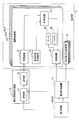
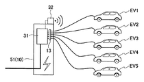
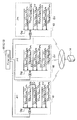
図1を参照して、第1実施形態に係わる電気自動車(受電要素の一例)の受電制御装置及びその周辺装置の構成を説明する。受電制御装置は、複数の電気自動車(EV1、EV2、EV3、・・・)を含む負荷群11へ、電力設備12(電力供給基点10の一例)を経由して電気エネルギーを供給する電力システムにおいて、負荷群11に含まれる電気自動車EV1が受電する電力である要素受電電力を、所定の処理サイクルを繰り返すことにより制御する。 (First Embodiment)
With reference to FIG. 1, the configuration of the power receiving control device and its peripheral devices of the electric vehicle (an example of the power receiving element) according to the first embodiment will be described. The power receiving control device is used in a power system that supplies electric energy to aload group 11 including a plurality of electric vehicles (EV1, EV2, EV3, ...) Via a power facility 12 (an example of a power supply base point 10). The element received power, which is the power received by the electric vehicle EV1 included in the load group 11, is controlled by repeating a predetermined processing cycle.
図1を参照して、第1実施形態に係わる電気自動車(受電要素の一例)の受電制御装置及びその周辺装置の構成を説明する。受電制御装置は、複数の電気自動車(EV1、EV2、EV3、・・・)を含む負荷群11へ、電力設備12(電力供給基点10の一例)を経由して電気エネルギーを供給する電力システムにおいて、負荷群11に含まれる電気自動車EV1が受電する電力である要素受電電力を、所定の処理サイクルを繰り返すことにより制御する。 (First Embodiment)
With reference to FIG. 1, the configuration of the power receiving control device and its peripheral devices of the electric vehicle (an example of the power receiving element) according to the first embodiment will be described. The power receiving control device is used in a power system that supplies electric energy to a
受電制御装置は、外部から電気信号を受信する受信装置21と、電気自動車EV1の状態を示す情報を取得する車両状態取得装置22と、電気自動車EV1の要素受電電力を算出する計算装置23とを備える。電気自動車EV1は、外部から電力を受ける受電装置24と、受電装置24が受けた電力(要素受電電力)を蓄えるバッテリ25と、バッテリ25が蓄える電気エネルギー又は要素受電電力に基づいて駆動するモータ26とを備える。
The power receiving control device includes a receiving device 21 that receives an electric signal from the outside, a vehicle state acquisition device 22 that acquires information indicating the state of the electric vehicle EV1, and a calculation device 23 that calculates the element received power of the electric vehicle EV1. Be prepared. The electric vehicle EV1 includes a power receiving device 24 that receives power from the outside, a battery 25 that stores the power received by the power receiving device 24 (element power received), and a motor 26 that is driven based on the electric energy stored by the battery 25 or the element power received. And.
「処理サイクル」には、(a)~(e)の処理ステップが含まれる。
The "processing cycle" includes the processing steps (a) to (e).
(a)受信装置21は、電力設備12を経由して負荷群11の全体に送ることができる総送電電力の最大値(Pall_max)から、電力設備12を経由して負荷群11の全体に送っている総送電電力の現在値(Pall_now)を減じて得られる差分電力(ΔP)を示す情報を取得する。
(A) The receiving device 21 transmits from the maximum value (Pall_max) of the total transmitted power that can be sent to the entire load group 11 via the power facility 12 to the entire load group 11 via the power facility 12. Information indicating the differential power (ΔP) obtained by subtracting the current value (Pall_now) of the total transmitted power is acquired.
(b)計算装置23は、他の電気自動車(EV2、2V3、・・・)の受電よりも自己(電気自動車EV1)の受電が優先される度合いを示す電気自動車EV1の優先度(β)を、電気自動車EV1のユーザの要求を表す数値に基づいて算出する。
(B) The calculation device 23 determines the priority (β) of the electric vehicle EV1, which indicates the degree to which the power reception of the self (electric vehicle EV1) is prioritized over the power reception of the other electric vehicles (EV2, 2V3, ...). , Calculated based on a numerical value representing the user's request for the electric vehicle EV1.
(c)計算装置23は、取得した情報が示す差分電力(ΔP)に優先度(β)を乗じることにより要素差分電力(βΔP)を算出する。
(C) The calculation device 23 calculates the element differential power (βΔP) by multiplying the differential power (ΔP) indicated by the acquired information by the priority (β).
(d)計算装置23は、前回の処理サイクルにおける要素受電電力(Pt)に、要素差分電力(βΔP)を加算することにより、要素受電電力(Pt+1)を更新する。
(D) The calculation device 23 updates the element received power (Pt + 1) by adding the element difference power (βΔP) to the element received power (Pt) in the previous processing cycle.
(e)計算装置23は、更新後の要素受電電力(Pt+1)を受電するように電気自動車EV1を制御する。
(E) The calculation device 23 controls the electric vehicle EV1 so as to receive the updated element power receiving power (Pt + 1).
ここで、実施形態、変形例、及び実施例において、「電気自動車」は、電力設備12を経由して伝送される電力を受電する「蓄電要素」又は「受電要素」の一例である。蓄電要素は、受電した電力をバッテリ(二次電池、蓄電池、充電式電池を含む)に蓄える。「蓄電要素」には、車両(電気自動車、ハイブリッド車、建設機械、農業機械を含む)、鉄道車両、遊具、工具、家庭製品、日用品など、バッテリを備える、あらゆる機器及び装置が含まれる。
Here, in the embodiments, modifications, and embodiments, the "electric vehicle" is an example of a "storage element" or a "power receiving element" that receives electric power transmitted via the electric power facility 12. The power storage element stores the received power in a battery (including a secondary battery, a storage battery, and a rechargeable battery). "Power storage elements" include all equipment and devices equipped with batteries, such as rolling stock (including electric vehicles, hybrid vehicles, construction machinery, agricultural machinery), railroad vehicles, play equipment, tools, household products, daily necessities, etc.
「蓄電要素」は、電力設備12を経由して伝送される電力を受電する「受電要素」の一例である。「受電要素」には、「蓄電要素」の他に、受電した電力を蓄えずに消費する「電力消費要素」も含まれる。「電力消費要素」には、鉄道車両、遊具、工具、家庭製品、日用品など、が含まれる。「電力消費要素」は、電気自動車のように、バッテリを備えていても構わない。電気自動車が受電した電力をバッテリに蓄えずに、直接、モータへ電送し、モータの駆動力として消費する場合、電気自動車は「電力消費要素」の一例となる。このように、「電力消費要素」には、バッテリを備えるか否かに係わらず、受電した電力を蓄電せずに消費する、あらゆる機器及び装置が含まれる。
The "storage element" is an example of a "power receiving element" that receives electric power transmitted via the electric power facility 12. The "power receiving element" includes not only the "storage element" but also the "power consumption element" that consumes the received power without storing it. "Power consumption factors" include railroad vehicles, playground equipment, tools, household products, daily necessities, and the like. The "power consumption element" may include a battery, such as an electric vehicle. An electric vehicle is an example of a "power consumption factor" when the electric vehicle receives power and is directly transmitted to a motor without being stored in a battery and consumed as a driving force of the motor. As described above, the "power consumption element" includes all devices and devices that consume the received power without storing it, regardless of whether or not the battery is provided.
「蓄電要素」及び「受電要素」は、いずれも受電制御装置による受電制御の単位構成を示す。即ち、蓄電要素又は受電要素を単位として実施形態、実施例、及び変形例に係わる受電制御が行われる。例えば、複数の電気自動車(EV1、EV2、EV3、・・・)の各々について、互いに独立して並列に実施形態、実施例、及び変形例に係わる受電制御が行われる。
Both the "storage element" and the "power receiving element" indicate the unit configuration of the power receiving control by the power receiving control device. That is, power receiving control according to the embodiment, the embodiment, and the modified example is performed in units of the power storage element or the power receiving element. For example, for each of the plurality of electric vehicles (EV1, EV2, EV3, ...), the power receiving control according to the embodiment, the embodiment, and the modified example is performed independently and in parallel with each other.
実施形態では、受電要素の一例として蓄電要素を挙げ、更に、蓄電要素の一例として、電気をエネルギー源とし、モータ26を動力源として走行する電気自動車(EV)を挙げる。しかし、本発明における受電要素及び蓄電要素をそれぞれ電気自動車(EV)に限定することは意図していない。
In the embodiment, a power storage element is given as an example of the power receiving element, and further, an electric vehicle (EV) traveling with electricity as an energy source and a motor 26 as a power source is given as an example of the power storage element. However, it is not intended that the power receiving element and the power storage element in the present invention are limited to electric vehicles (EVs), respectively.
実施形態及び変形例において、「電力設備12」は、電力供給基点10の一例である。「電力設備12」には、例えば、以下の<1>~<6>が含まれる。
In the embodiment and the modified example, the "power equipment 12" is an example of the power supply base point 10. The "electric power facility 12" includes, for example, the following <1> to <6>.
なお、具体的な適用事例は、第1~第7実施例において、後述する。
<1>電気自動車EV用の「充電スタンド」;
<2>住宅、オフィスビル、商業施設、工場、又は高速道路のパーキングエリア等の敷地内に設置された「変電装置」;
<3>水力、火力、原子力などの「発電所」、発電された電力を所定の電圧へ変換する「変電所」、
<4>変電所を経由して伝送された電力を分配するための様々な「配電設備」
<5>これらの装置又は設備の間を接続する「配線(ケーブル、フィーダーを含む)」、及び
<6>近隣にある小規模な蓄電要素のエネルギーを束ね、1つの大規模な発電所のように機能させる「バーチャルパワープラント(仮想発電所:VPP)」。 Specific application examples will be described later in the first to seventh embodiments.
<1>"Chargingstand" for EVs of electric vehicles;
<2>"Substationdevice" installed on the premises of a house, office building, commercial facility, factory, or highway parking area;
<3>"Powerplants" such as hydraulic power, thermal power, and nuclear power, "substations" that convert generated power to a predetermined voltage,
<4> Various "distribution equipment" for distributing the power transmitted via the substation
<5>"Wiring (including cables and feeders)" that connects these devices or equipment, and <6> Bundles the energy of small storage elements in the vicinity, like one large power plant. "Virtual power plant (virtual power plant: VPP)" to function.
実施形態、その変形例、及び実施例では、受電制御装置が、電気自動車EV1に搭載されている例を説明するが、勿論、受電制御装置は、短距離無線、無線LAN、無線WANなどの近距離無線通信技術、或いは、携帯電話通信網を利用して、電気自動車EV1の外部から電気自動車EV1の要素受電電力を制御してもよい。
In the embodiments, modifications thereof, and embodiments, an example in which the power receiving control device is mounted on the electric vehicle EV1 will be described. Of course, the power receiving control device is close to a short-range wireless device, a wireless LAN, a wireless WAN, or the like. The element received power of the electric vehicle EV1 may be controlled from the outside of the electric vehicle EV1 by using the range wireless communication technology or the mobile phone communication network.
また、負荷群11に含まれる複数の電気自動車(EV1、EV2、EV3、・・・)のうちの1台の電気自動車EV1の構成を例に取り説明するが、負荷群11に含まれる他の電気自動車(EV2、EV3、・・・)も電気自動車EV1と同じ構成を有している。
Further, the configuration of one electric vehicle EV1 among the plurality of electric vehicles (EV1, EV2, EV3, ...) Included in the load group 11 will be described as an example, but the other electric vehicles included in the load group 11 will be described. The electric vehicle (EV2, EV3, ...) Has the same configuration as the electric vehicle EV1.
受電制御装置は、電力設備12を経由して電気自動車EV1が受電する電力を制御する。電気自動車EV1は、オンボードチャージャー(OBC)と呼ばれる受電装置24を備える。計算装置23は、受電装置24が電力設備12を経由して受電する電力を制御する。受電装置24が受電した電力は、バッテリ25に蓄えられる。又は、電気自動車EV1は、受電装置が受電した電力を、バッテリ25に蓄えず、駆動源としてのモータ26へ直接送電しても構わない。
The power receiving control device controls the power received by the electric vehicle EV1 via the power equipment 12. The electric vehicle EV1 includes a power receiving device 24 called an onboard charger (OBC). The calculation device 23 controls the power received by the power receiving device 24 via the power equipment 12. The electric power received by the power receiving device 24 is stored in the battery 25. Alternatively, the electric vehicle EV1 may directly transmit the electric power received by the electric power receiving device to the motor 26 as a drive source without storing it in the battery 25.
電力設備12を経由して電気自動車EV1へ供給される電力は、電流計測装置13により計測される。電流計測装置13により計測された電力値は、差分情報送信装置14へ送信される。
The electric power supplied to the electric vehicle EV1 via the electric power facility 12 is measured by the current measuring device 13. The power value measured by the current measuring device 13 is transmitted to the difference information transmitting device 14.
1つの電力設備12を経由して、負荷群11に含まれる複数の電気自動車(EV1、EV2、EV3、・・・)に対して電気エネルギーが供給される。更に、1つの電力設備12を経由して、複数の電気自動車(EV1、EV2、EV3、・・・)のみならず、負荷群11に含まれる1又は2以上の他の電力消費要素15に対しても電気エネルギーが供給されてもよい。電力設備12を経由して電気エネルギーの供給を受ける複数の電気自動車(EV1、EV2、EV3、・・・)及び1又は2以上の他の電力消費要素15は、1つのグループ(負荷群11)を形成している。
Electric energy is supplied to a plurality of electric vehicles (EV1, EV2, EV3, ...) Included in the load group 11 via one electric power facility 12. Further, for not only a plurality of electric vehicles (EV1, EV2, EV3, ...) But also one or two or more other power consumption elements 15 included in the load group 11 via one power facility 12. Also, electrical energy may be supplied. A plurality of electric vehicles (EV1, EV2, EV3, ...) And one or more other power consuming elements 15 that receive electrical energy supply via the power equipment 12 are one group (load group 11). Is forming.
電流計測装置13は、電力設備12を経由して1つの負荷群11に含まれる全ての電気自動車(EV1、EV2、EV3、・・・)及び他の電力消費要素15へ送られている総送電電力の現在値(Pall_now)、換言すれば、負荷群11の全体の総送電電力を計測する。
The current measuring device 13 is the total power transmission transmitted to all the electric vehicles (EV1, EV2, EV3, ...) And other power consuming elements 15 included in one load group 11 via the power equipment 12. The current value of electric power (Pall_now), in other words, the total transmitted electric power of the load group 11 is measured.
ここで、負荷群11の全体の電力容量、即ち、電力設備12を経由して負荷群11の全体に送ることができる総送電電力の最大値(Pall_max)が予め定められている。実施形態に係わる受電制御装置は、総送電電力の最大値(Pall_max)の制約に基づき、電気自動車EV1の要素受電電力を制御する。例えば、受電制御装置は、電流計測装置13が計測する総送電電力の現在値(Pall_now)が、電力の最大値(Pall_max)を超えないように、電気自動車EV1の受電電力を制御する。勿論、総送電電力の現在値(Pall_now)が電力の最大値(Pall_max)を一時的に超えることを許容するように、電気自動車EV1の受電電力を制御しても構わない。なお、総送電電力の最大値(Pall_max)は、様々な要因により定まるが、その詳細は後述する実施例において説明する。
Here, the total power capacity of the load group 11, that is, the maximum value (Pall_max) of the total transmitted power that can be sent to the entire load group 11 via the power equipment 12 is predetermined. The power receiving control device according to the embodiment controls the element power receiving power of the electric vehicle EV1 based on the constraint of the maximum value (Pall_max) of the total transmitted power. For example, the power receiving control device controls the power received by the electric vehicle EV1 so that the current value (Pall_now) of the total transmitted power measured by the current measuring device 13 does not exceed the maximum value (Pall_max) of the power. Of course, the received power of the electric vehicle EV1 may be controlled so as to allow the current value (Pall_now) of the total transmitted power to temporarily exceed the maximum value (Pall_max) of the electric power. The maximum value (Pall_max) of the total transmitted power is determined by various factors, and the details thereof will be described in Examples described later.
図1に示すように、第1実施形態では、電力設備12、電流計測装置13及び電気自動車EV1の各々に対して、差分情報送信装置14が無線又は有線により通信可能に接続されている。電力設備12は、差分情報送信装置14へ総送電電力の最大値(Pall_max)を示す電気信号を送信する。電流計測装置13は、計測した総送電電力の現在値(Pall_now)を示す電気信号を差分情報送信装置14へ送信する。
As shown in FIG. 1, in the first embodiment, the difference information transmitting device 14 is wirelessly or wiredly connected to each of the electric power equipment 12, the current measuring device 13, and the electric vehicle EV1. The electric power facility 12 transmits an electric signal indicating the maximum value (Pall_max) of the total transmitted power to the difference information transmitting device 14. The current measuring device 13 transmits an electric signal indicating the current value (Pall_now) of the measured total transmitted power to the difference information transmitting device 14.
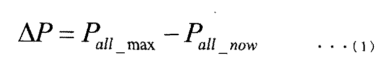
差分情報送信装置14は、計算部31と送信部32とを備える。計算部31は、(1)式に示すように、総送電電力の最大値(Pall_max)から総送電電力の現在値(Pall_now)を減ずることにより差分電力(ΔP)を算出する。送信部32は、差分電力(ΔP)を示す電気信号を、負荷群11に含まれる全ての電気自動車(EV1、EV2、EV3、・・・)に対して、移動体通信により送信(ブロードキャスト)する。差分電力(ΔP)を示す電気信号は受信装置21により受信され、計算装置23へ転送される。これにより、受電制御装置は、電力設備12を経由して負荷群11の全体に送ることができる総送電電力の最大値(Pall_max)から、電力設備12を経由して負荷群11の全体に送っている総送電電力の現在値(Pall_now)を減じて得られる差分電力(ΔP)を示す情報を取得することができる。
The difference information transmission device 14 includes a calculation unit 31 and a transmission unit 32. As shown in the equation (1), the calculation unit 31 calculates the differential power (ΔP) by subtracting the current value (Pall_now) of the total transmitted power from the maximum value (Pall_max) of the total transmitted power. The transmission unit 32 transmits (broadcasts) an electric signal indicating the differential power (ΔP) to all the electric vehicles (EV1, EV2, EV3, ...) Included in the load group 11 by mobile communication. .. The electric signal indicating the differential power (ΔP) is received by the receiving device 21 and transferred to the computing device 23. As a result, the power receiving control device sends the maximum value (Pall_max) of the total transmitted power that can be sent to the entire load group 11 via the power facility 12 to the entire load group 11 via the power facility 12. It is possible to acquire information indicating the differential power (ΔP) obtained by subtracting the current value (Pall_now) of the total transmitted power.
なお、差分情報送信装置14は、送信部32を用いて、負荷群11に含まれる全ての電気自動車(EV1、EV2、EV3、・・・)の受信装置21に対して、無線通信により差分電力(ΔP)を示す情報を送信(ブロードキャスト)する。または、差分電力(ΔP)を示す情報の送信には有線による通信でもよい。
The difference information transmitting device 14 uses the transmitting unit 32 to wirelessly communicate the differential power to the receiving devices 21 of all the electric vehicles (EV1, EV2, EV3, ...) Included in the load group 11. Information indicating (ΔP) is transmitted (broadcast). Alternatively, wired communication may be used for transmitting information indicating the differential power (ΔP).
図1に示す例において、差分情報送信装置14は、各電気自動車から送信される、例えばバッテリ25の充電率(SOC)や受電を終了する時刻(Td)など、各電気自動車の状態を示す信号を受信する受信装置を備えていなくてもよい。即ち、差分情報送信装置14と各電気自動車との間は、差分情報送信装置14から各電気自動車への片方向のみに通信できればよい。なお、双方向の通信が必要な例は、図3を参照して後述する。
In the example shown in FIG. 1, the difference information transmitting device 14 indicates the state of each electric vehicle, such as the charge rate (SOC) of the battery 25 and the time (T d ) at which power reception ends, which are transmitted from each electric vehicle. It is not necessary to have a receiving device for receiving the signal. That is, it suffices that the difference information transmitting device 14 and each electric vehicle can communicate in only one direction from the difference information transmitting device 14 to each electric vehicle. An example in which bidirectional communication is required will be described later with reference to FIG.
差分情報送信装置14は、例えば、コンピュータネットワークを介して、電力設備12、電流計測装置13、及び負荷群11に接続されたサーバであってもよい。或いは、差分情報送信装置14は、電力設備12の一部分として構成されていてもよい。
The difference information transmitting device 14 may be, for example, a server connected to the power equipment 12, the current measuring device 13, and the load group 11 via a computer network. Alternatively, the difference information transmitting device 14 may be configured as a part of the electric power facility 12.
車両状態取得装置22は、電気自動車EV1の状態を表す情報を取得する。例えば、「電気自動車EV1の状態」とは、電気自動車EV1のユーザの要求を表す数値である。電気自動車EV1のユーザの要求を表す数値は、電気自動車EV1の受電を終了する時刻(受電の終了時刻Td)までの残り時間(T)である。残り時間(T)は、電気自動車EV1が受電を終了する時刻から算出可能である。残り時間(T)は、電気自動車EV1のバッテリ25を充電することができる残り時間である。
The vehicle state acquisition device 22 acquires information representing the state of the electric vehicle EV1. For example, the "state of the electric vehicle EV1" is a numerical value representing a request of a user of the electric vehicle EV1. The numerical value representing the user's request of the electric vehicle EV1 is the remaining time (T) until the time when the electric vehicle EV1 ends receiving power (power receiving end time T d ). The remaining time (T) can be calculated from the time when the electric vehicle EV1 ends receiving power. The remaining time (T) is the remaining time during which the battery 25 of the electric vehicle EV1 can be charged.
例えば、自宅に帰宅したユーザが、自宅の駐車場にて電気自動車EV1のバッテリ25の充電を開始し、翌日の午前7時に電気自動車EV1にて外出する予定がある場合、翌日の午前7時から所定時間(5分)前の時刻を、受電の終了時刻として設定することができる。このように、“翌日の午前7時に外出したい”という「ユーザの要求」は、受電の終了時刻(午前6時55分=Td)及び受電の終了時刻までの残り時間(T)を表している。「受電の終了時刻(Td)」とは、電気自動車EV1が受電を続けることが可能な期間が終了する時刻を意味し、受電制御フロー(図2)において、受電を継続しない(S03でNO)と判断する時刻から区別される。
For example, if a user who has returned home starts charging the battery 25 of the electric vehicle EV1 in the parking lot at home and plans to go out with the electric vehicle EV1 at 7:00 am the next day, the user will start charging from 7:00 am the next day. The time before the predetermined time (5 minutes) can be set as the end time of power reception. In this way, the "user's request" that "I want to go out at 7:00 am the next day" represents the end time of power reception (6:55 am = T d ) and the remaining time (T) until the end time of power reception. There is. The “power reception end time (T d )” means the time when the period during which the electric vehicle EV1 can continue to receive power ends, and the power reception is not continued in the power reception control flow (FIG. 2) (NO in S03). ) Is distinguished from the time of judgment.
受電の終了時刻(Td)は、ユーザがスマートフォンなどの情報通信端末又は電気自動車EV1に搭載されたユーザインターフェースを用いて実際に設定した時刻であってもよい。又は、ユーザからの具体的な指示又は設定が無い場合、ユーザの過去の行動履歴(過去の出発時刻の履歴など)を調査して得られる統計データから推定される時刻であっても構わない。
The power reception end time (T d ) may be a time actually set by the user using an information communication terminal such as a smartphone or a user interface mounted on the electric vehicle EV1. Alternatively, if there is no specific instruction or setting from the user, the time may be estimated from the statistical data obtained by investigating the user's past behavior history (history of past departure time, etc.).
計算装置23は、電気自動車EV1のユーザの要求を表す数値(電気自動車EV1の状態)に基づいて、他の電気自動車(EV2、2V3、・・・)の受電よりも自己EV1の受電が優先される度合いを示す電気自動車EV1の優先度(β)を算出する。具体的に、計算装置23は、(2)式を用いて、現時刻(To)から受電の終了時刻(Td)までの残り時間(T)から優先度(β)を算出する。(2)式において、Nは、負荷群11内で受電を行う電気自動車の総数を示す。
Based on the numerical value (state of the electric vehicle EV1) representing the user's request of the electric vehicle EV1, the calculation device 23 gives priority to the power reception of the self EV1 over the power reception of other electric vehicles (EV2, 2V3, ...). The priority (β) of the electric vehicle EV1 indicating the degree of the change is calculated. Specifically, the computing device 23, (2) using the equation to calculate the priority (beta) from the remaining time to the end time of the receiving from the current time (T o) (T d) (T). In equation (2), N indicates the total number of electric vehicles that receive power in the load group 11.
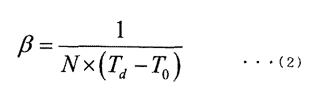
(2)式に示すように、優先度(β)は残り時間(T)に反比例する。残り時間(T)が短くなるにつれて、優先度(β)は高くなる。(2)式は一例にすぎず、例えば、優先度(β)は、残り時間(T)を2以上のg回(gは正数)掛け算した「残り時間(T)のg乗」に反比例してもよい。
As shown in equation (2), the priority (β) is inversely proportional to the remaining time (T). As the remaining time (T) becomes shorter, the priority (β) becomes higher. Equation (2) is only an example. For example, the priority (β) is inversely proportional to the “remaining time (T) to the g-th power” obtained by multiplying the remaining time (T) by two or more g times (g is a positive number). You may.
電気自動車の総数(N)は、負荷群11における過去の受電履歴を調査して得られる統計データ(数量データ)であってもよいし、電力の現在値(Pall_now)から、おおよその電気自動車の総数(N)を推定することも可能である。総数(N)は差分電力(ΔP)と同様に差分情報送信装置14もしくは差分情報送信装置14に付随する装置から同報送信される。または、充電システムの位置情報や識別信号などで、総数(N)を特定してもよい。
The total number of electric vehicles (N) may be statistical data (quantity data) obtained by investigating the past power reception history in the load group 11, or may be approximate from the current value of electric power (Pall_now). It is also possible to estimate the total number (N). The total number (N) is broadcasted from the difference information transmission device 14 or the device attached to the difference information transmission device 14 in the same manner as the difference power (ΔP). Alternatively, the total number (N) may be specified by the position information of the charging system, the identification signal, or the like.
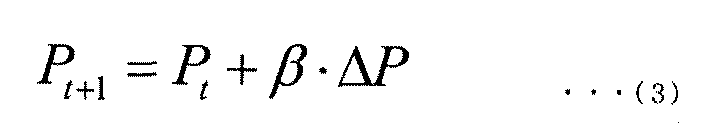
計算装置23は、(3)式に示すように、差分電力(ΔP)に優先度(β)を乗じることにより要素差分電力(βΔP)を算出し、前回の処理サイクルにおける要素受電電力(Pt)に、要素差分電力(βΔP)を加算することにより、要素受電電力(Pt+1)を更新する。なお、要素受電電力を示す記号「P」の添え字(右下付文字)「t」「t+1」は、「処理サイクル」の繰り返し回数を示す。tは、零を含む正の整数である。
As shown in the equation (3), the calculation device 23 calculates the element differential power (βΔP) by multiplying the differential power (ΔP) by the priority (β), and the element received power (Pt) in the previous processing cycle. The element received power (Pt + 1) is updated by adding the element differential power (βΔP) to. The subscripts (subscripts in the lower right) "t" and "t + 1" of the symbol "P" indicating the element received power indicate the number of repetitions of the "processing cycle". t is a positive integer containing zero.
計算装置23は、受電装置24が更新後の要素受電電力(Pt+1)を受電するように受電装置24に対して指示信号を送信し、指示信号を受信した受電装置24は、更新後の要素受電電力(Pt+1)を、電力設備12を経由して受電する。
The calculation device 23 transmits an instruction signal to the power receiving device 24 so that the power receiving device 24 receives the updated element power receiving power (Pt + 1), and the power receiving device 24 receiving the instruction signal receives the updated element power. The electric power (Pt + 1) is received via the electric power equipment 12.
受電制御装置は、(a)~(e)の処理ステップを含む「処理サイクル」を一定の周期で繰り返し実行することにより、電気自動車EV1の受電装置24が受電する電力(要素受電電力Pt)を制御する。
The power receiving control device repeatedly executes a "processing cycle" including the processing steps (a) to (e) at a fixed cycle to generate electric power (element power receiving power Pt) received by the power receiving device 24 of the electric vehicle EV1. Control.
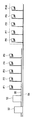
図2のフローチャートを参照して、図1の受電制御装置による受電制御方法の一例を説明する。なお、当業者であれば、図1の受電制御装置の具体的な構成及び機能の説明から、受電制御装置による受電処理方法の具体的な手順を、容易に理解できる。よって、ここでは、図1の受電制御装置による受電処理方法として、受電制御装置の主要な処理動作を説明し、詳細な処理動作の説明は、図1を参照した説明と重複するため割愛する。
An example of the power receiving control method by the power receiving control device of FIG. 1 will be described with reference to the flowchart of FIG. Those skilled in the art can easily understand the specific procedure of the power receiving processing method by the power receiving control device from the explanation of the specific configuration and function of the power receiving control device of FIG. Therefore, here, the main processing operation of the power receiving control device will be described as the power receiving processing method by the power receiving control device of FIG. 1, and the detailed description of the processing operation will be omitted because it overlaps with the description with reference to FIG.
まず、ステップS01で、受信装置21は、計算部31により算出された差分電力(ΔP)を示す情報を取得する。ステップS02に進み、車両状態取得装置22は、電気自動車EV1の状態を示す情報の例として、受電の終了時刻(Td)を示す情報を取得する。
First, in step S01, the receiving device 21 acquires information indicating the differential power (ΔP) calculated by the calculation unit 31. Proceeding to step S02, the vehicle state acquisition device 22 acquires information indicating the end time (T d ) of receiving power as an example of the information indicating the state of the electric vehicle EV1.
ステップS03に進み、受電制御装置は、受電を継続するか否かを判断する。例えば、電気自動車EV1のユーザから受電終了の指示信号を受信した場合(S03でNO)、又は、現時刻が受電の終了時刻(Td)となった場合、受電の継続を終了する。或いは、充電ポートの未接続を検知した場合など(S03でNO)、それから数分の内に、電気自動車EV1が移動を開始する可能性が高まるため、受電の継続を終了する。更に、バッテリ25の充電率(SOC)が目標値に達した場合(S03でNO)、受電の継続を終了する。これらの状況が無ければ(S03でYES)、受電制御装置は、受電を継続するために、ステップS04へ進む。
Proceeding to step S03, the power receiving control device determines whether or not to continue receiving power. For example, when the user of the electric vehicle EV1 receives an instruction signal for the end of power reception (NO in S03), or when the current time becomes the end time of power reception (T d ), the continuation of power reception is terminated. Alternatively, when it is detected that the charging port is not connected (NO in S03), the possibility that the electric vehicle EV1 starts moving within a few minutes increases, so that the continuation of power reception is terminated. Further, when the charge rate (SOC) of the battery 25 reaches the target value (NO in S03), the continuation of power reception is terminated. If these situations are not present (YES in S03), the power receiving control device proceeds to step S04 in order to continue receiving power.
ステップS04では、計算装置23は、(2)式を用いて、受電の終了時刻(Td)から、電気自動車EV1の優先度(β)を算出する。ステップS05へ進み、計算装置23は、(3)式に、差分電力(ΔP)及び優先度(β)を代入することにより、要素受電電力(Pt+1)を更新する。
In step S04, the calculation device 23 calculates the priority (β) of the electric vehicle EV1 from the power receiving end time (T d ) using the equation (2). Proceeding to step S05, the calculation device 23 updates the element received power (Pt + 1) by substituting the differential power (ΔP) and the priority (β) into the equation (3).
ステップS06へ進み、計算装置23は、受電装置24が更新後の要素受電電力(Pt+1)を受電するように受電装置24を制御する。受電制御装置は、ステップS01からステップS06までを単位とする処理サイクルを、ステップS03でNOと判定されるまで、繰り返し実行することにより、要素受電電力(P)を制御する。
Proceeding to step S06, the calculation device 23 controls the power receiving device 24 so that the power receiving device 24 receives the updated element power receiving power (Pt + 1). The power receiving control device controls the element power receiving power (P) by repeatedly executing the processing cycle in units of steps S01 to S06 until NO is determined in step S03.
(第1変形例)
第1実施形態では、図1に示したように、差分情報送信装置14から各電気自動車への片方向通信を行う場合を説明した。本発明はこれに限定されず、例えば、差分情報送信装置14と各電気自動車の間は、双方向に通信可能であってもよい。第1実施形態の第1変形例では、電気自動車EV1の受電装置24が送信部28を備え、送信部28から差分情報送信装置14へ、電気自動車EV1の要素受電電力(Pt)を示す電気信号を送信する例を説明する。なお、負荷群1に含まれる他の全ての電気自動車(EV2、EV3、・・・)は、電気自動車EV1と同じ構成を備えるため、説明を割愛する。第1実施形態との相違点を中心に説明し、第1実施形態と共通する点については説明を割愛する。 (First modification)
In the first embodiment, as shown in FIG. 1, a case where one-way communication from the differenceinformation transmitting device 14 to each electric vehicle is performed has been described. The present invention is not limited to this, and for example, bidirectional communication may be possible between the difference information transmitting device 14 and each electric vehicle. In the first modification of the first embodiment, the power receiving device 24 of the electric vehicle EV1 includes a transmitting unit 28, and an electric signal indicating the element power receiving power (Pt) of the electric vehicle EV1 from the transmitting unit 28 to the difference information transmitting device 14 An example of transmitting is described. Since all the other electric vehicles (EV2, EV3, ...) Included in the load group 1 have the same configuration as the electric vehicle EV1, the description thereof will be omitted. The differences from the first embodiment will be mainly described, and the common points with the first embodiment will be omitted.
第1実施形態では、図1に示したように、差分情報送信装置14から各電気自動車への片方向通信を行う場合を説明した。本発明はこれに限定されず、例えば、差分情報送信装置14と各電気自動車の間は、双方向に通信可能であってもよい。第1実施形態の第1変形例では、電気自動車EV1の受電装置24が送信部28を備え、送信部28から差分情報送信装置14へ、電気自動車EV1の要素受電電力(Pt)を示す電気信号を送信する例を説明する。なお、負荷群1に含まれる他の全ての電気自動車(EV2、EV3、・・・)は、電気自動車EV1と同じ構成を備えるため、説明を割愛する。第1実施形態との相違点を中心に説明し、第1実施形態と共通する点については説明を割愛する。 (First modification)
In the first embodiment, as shown in FIG. 1, a case where one-way communication from the difference
受電装置24は、電気自動車EV1が受電した電力(要素受電電力)を測定する電流計測装置27と、要素受電電力(Pt)を示す電気信号を差分情報送信装置14へ無線通信により送信する送信部28とを備える。具体的に、電流計測装置27は、受電装置24へ流入する電流値を測定し、受電時の電圧から要素受電電力(Pt)を算出する。送信部28と差分情報送信装置14は、コンピュータネットワークを介して通信可能に接続されている。更に、送信部28と受信装置21とが一体を成し、送受信装置を構成していてもよい。送信部28として、例えば、4G、5Gなどの移動体通信規格に基づく通信を行う送信機を用いることができる。
The power receiving device 24 is a transmission unit that wirelessly transmits an electric signal indicating the element received power (Pt) to the current measuring device 27 that measures the power received by the electric vehicle EV1 (element received power) and the difference information transmitting device 14. 28 and. Specifically, the current measuring device 27 measures the value of the current flowing into the power receiving device 24, and calculates the element received power (Pt) from the voltage at the time of receiving power. The transmission unit 28 and the difference information transmission device 14 are communicably connected to each other via a computer network. Further, the transmitting unit 28 and the receiving device 21 may be integrated to form a transmitting / receiving device. As the transmitter 28, for example, a transmitter that performs communication based on a mobile communication standard such as 4G or 5G can be used.
これに伴い、電流計測装置13は、電力設備12を経由して送られる電力のうち、他の電力消費要素15へ伝送される電力を計測し、各電気自動車(EV1、EV2、EV3、・・・)へ伝送される電力は計測しなくてもよい。電流計測装置13は、負荷群11に含まれる他の電力消費要素15へ供給される総送電電力を計測し、計測した総送電電力を示す電気信号を差分情報送信装置14へ送信する。
Along with this, the current measuring device 13 measures the electric power transmitted to the other electric power consuming element 15 among the electric power transmitted via the electric power equipment 12, and each electric vehicle (EV1, EV2, EV3, ... -) It is not necessary to measure the power transmitted to. The current measuring device 13 measures the total transmitted power supplied to the other power consuming elements 15 included in the load group 11, and transmits an electric signal indicating the measured total transmitted power to the difference information transmitting device 14.
計算部31は、他の電力消費要素15へ供給される総送電電力と、全ての電気自動車(EV1、EV2、EV3、・・・)の要素受電電力とを合算することにより、電力設備12を経由して負荷群11の全体に送られている総送電電力の現在値(Pall_now)を算出する。
The calculation unit 31 adds the total transmitted power supplied to the other power consuming elements 15 and the element received power of all the electric vehicles (EV1, EV2, EV3, ...) To make the electric power facility 12 The current value (Pall_now) of the total transmitted power transmitted to the entire load group 11 via the load group 11 is calculated.
このように、受電装置24及び電流計測装置13の構成、及び総送電電力の現在値(Pall_now)の算出方法は、図1の場合と相違するが、その他の構成は、図1の場合と同じであり、説明を割愛する。
As described above, the configurations of the power receiving device 24 and the current measuring device 13 and the method of calculating the current value (Pall_now) of the total transmitted power are different from those in FIG. 1, but the other configurations are the same as in the case of FIG. Therefore, the explanation is omitted.
第1変形例における受電制御装置の動作、すなわち受電制御方法は、図2に示した手順と共通する。しかし、ステップS06の動作に違いがある。すなわち、ステップS06において、計算装置23は、受電装置24が更新後の要素受電電力(Pt+1)を受電するように受電装置24を制御する。そして、電流計測装置27は要素受電電力を測定し、送信部28は、測定した要素受電電力を示す電気信号を、差分情報送信装置14へ送信する。その他のステップは、第1実施形態と共通するため、再度の説明を割愛する。
The operation of the power receiving control device in the first modification, that is, the power receiving control method is the same as the procedure shown in FIG. However, there is a difference in the operation of step S06. That is, in step S06, the calculation device 23 controls the power receiving device 24 so that the power receiving device 24 receives the updated element power receiving power (Pt + 1). Then, the current measuring device 27 measures the element received power, and the transmitting unit 28 transmits an electric signal indicating the measured element received power to the difference information transmitting device 14. Since the other steps are common to the first embodiment, the explanation will be omitted again.
(第2変形例)
第1実施形態及び第1変形例では、受信装置21が、受電制御装置の外部(差分情報送信装置14)で演算された差分電力(ΔP)を示す情報を受信する例を示した。しかし、本発明はこれに限定されず、受信装置21が自ら、(1)式に基づいて、差分電力(ΔP)を演算しても構わない。この場合、図4に示すように、受信装置21は、電力設備12を経由して負荷群11の全体に送ることができる総送電電力の最大値(Pall_max)を示す電気信号を、電力設備12から受信し、総送電電力の現在値(Pall_now)を示す電気信号を、電流計測装置13から受信する。 (Second modification)
In the first embodiment and the first modification, an example is shown in which the receivingdevice 21 receives information indicating the differential power (ΔP) calculated outside the power receiving control device (difference information transmitting device 14). However, the present invention is not limited to this, and the receiving device 21 may calculate the differential power (ΔP) by itself based on the equation (1). In this case, as shown in FIG. 4, the receiving device 21 transmits an electric signal indicating the maximum value (Pall_max) of the total transmitted power that can be sent to the entire load group 11 via the power equipment 12 to the power equipment 12. The electric signal indicating the current value (Pall_now) of the total transmitted power is received from the current measuring device 13.
第1実施形態及び第1変形例では、受信装置21が、受電制御装置の外部(差分情報送信装置14)で演算された差分電力(ΔP)を示す情報を受信する例を示した。しかし、本発明はこれに限定されず、受信装置21が自ら、(1)式に基づいて、差分電力(ΔP)を演算しても構わない。この場合、図4に示すように、受信装置21は、電力設備12を経由して負荷群11の全体に送ることができる総送電電力の最大値(Pall_max)を示す電気信号を、電力設備12から受信し、総送電電力の現在値(Pall_now)を示す電気信号を、電流計測装置13から受信する。 (Second modification)
In the first embodiment and the first modification, an example is shown in which the receiving
受信装置21は、自らが演算した差分電力(ΔP)を示す電気信号を計算装置23へ転送する。その他の構成は、図1(第1実施形態)と同じであり説明を割愛する。
The receiving device 21 transfers an electric signal indicating the differential power (ΔP) calculated by itself to the calculating device 23. Other configurations are the same as those in FIG. 1 (first embodiment), and the description thereof will be omitted.
第2変形例における受電制御装置の動作、すなわち受電制御方法は、図2に示した手順と共通する。しかし、ステップS01の動作に違いがある。すなわち、ステップS01で、受信装置21は、総送電電力の最大値(Pall_max)を示す電気信号を、電力設備12から受信し、総送電電力の現在値(Pall_now)を示す電気信号を、電流計測装置13から受信する。受信装置21は、(1)式に基づいて、差分電力(ΔP)を演算し、差分電力(ΔP)を示す電気信号を計算装置23へ転送する。その他のステップは、第1実施形態と共通するため、再度の説明を割愛する。
The operation of the power receiving control device in the second modification, that is, the power receiving control method is the same as the procedure shown in FIG. However, there is a difference in the operation of step S01. That is, in step S01, the receiving device 21 receives the electric signal indicating the maximum value (Pall_max) of the total transmitted power from the power equipment 12, and measures the electric signal indicating the current value (Pall_now) of the total transmitted power. Received from device 13. The receiving device 21 calculates the differential power (ΔP) based on the equation (1), and transfers the electric signal indicating the differential power (ΔP) to the calculation device 23. Since the other steps are common to the first embodiment, the explanation will be omitted again.
(シミュレーション結果)
次に、第1の実施形態に係わる受電制御方法に従って受電制御を実行したシミュレーションの結果を説明する。 (simulation result)
Next, the result of the simulation in which the power receiving control is executed according to the power receiving control method according to the first embodiment will be described.
次に、第1の実施形態に係わる受電制御方法に従って受電制御を実行したシミュレーションの結果を説明する。 (simulation result)
Next, the result of the simulation in which the power receiving control is executed according to the power receiving control method according to the first embodiment will be described.
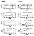
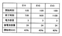
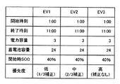
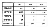
先ずは、第1実施形態のシミュレーションの条件を説明する。図5Aに示すように、3台の電気自動車(EV1、EV2、EV3)の各々が、第1実施形態に係わる受電制御方法により受電制御を実行する。各電気自動車が受電を開始する時刻(開始時刻)は同時刻(午前1時)であるが、各電気自動車が受電を終了する時刻(終了時刻)は、異なる。電気自動車EV1は午前7時であり、電気自動車EV2は午前9時であり、電気自動車EV3は午前11時である。各電気自動車(EV1、EV2、EV3)の受電装置24が受電することができる電力(要素受電電力)の最大値は同じ3kWであり、各電気自動車(EV1、EV2、EV3)のバッテリ25の容量(蓄電池容量)も同じ24kWhである。更に、受電の開始時刻における各電気自動車(EV1、EV2、EV3)の充電率(SOC)も同じ40%である。各電気自動車(EV1、EV2、EV3)の充電率の目標値(目標SOC)は、ユーザによる設定は無く、デフォルト値のまま、100%(満充電)である。
First, the conditions for the simulation of the first embodiment will be described. As shown in FIG. 5A, each of the three electric vehicles (EV1, EV2, EV3) executes power reception control by the power reception control method according to the first embodiment. The time (start time) at which each electric vehicle starts receiving power is the same time (1:00 am), but the time (end time) at which each electric vehicle ends receiving power is different. The electric vehicle EV1 is 7:00 am, the electric vehicle EV2 is 9:00 am, and the electric vehicle EV3 is 11:00 am. The maximum value of the power (elemental power received) that can be received by the power receiving device 24 of each electric vehicle (EV1, EV2, EV3) is the same 3 kW, and the capacity of the battery 25 of each electric vehicle (EV1, EV2, EV3). (Storage battery capacity) is also the same 24 kWh. Further, the charge rate (SOC) of each electric vehicle (EV1, EV2, EV3) at the start time of power reception is also 40%. The target value (target SOC) of the charge rate of each electric vehicle (EV1, EV2, EV3) is not set by the user and is 100% (fully charged) with the default value.
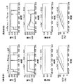
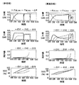
次に、シミュレーションの結果を説明する。図5Bは、第1実施形態のシミュレーションの結果を示す8つのグラフであり、左側の4つのグラフが参考例に係わり、右側の4つのグラフが第1実施形態に係わる。全てのグラフの横軸は、時間軸である。
Next, the results of the simulation will be explained. FIG. 5B is eight graphs showing the results of the simulation of the first embodiment, four graphs on the left side relate to the reference example, and four graphs on the right side relate to the first embodiment. The horizontal axis of all graphs is the time axis.
先ず、最上段の2つのグラフの縦軸が、電力設備12を経由して負荷群11の全体に送る総送電電力の現在値(Pall_now)と、電力設備12を経由して負荷群11の全体に送ることができる総送電電力の最大値(Pall_max)と、最大値(Pall_max)から現在値(Pall_now)を減算した差分電力(ΔP)を示す。
First, the vertical axis of the top two graphs is the current value (Pall_now) of the total transmitted power sent to the entire load group 11 via the power facility 12 and the entire load group 11 via the power facility 12. The maximum value (Pall_max) of the total transmitted power that can be sent to is shown, and the differential power (ΔP) obtained by subtracting the current value (Pall_now) from the maximum value (Pall_max).
上から2段目の2つのグラフの縦軸は、各電気自動車(EV1、EV2、EV3)が電力設備12を経由して受電する電力(要素受電電力)を示す。下から2段目の2つのグラフの縦軸は、各電気自動車(EV1、EV2、EV3)の優先度(β)を示す。最下段の2つのグラフの縦軸は、各電気自動車(EV1、EV2、EV3)の充電率(SOC)を示す。
The vertical axis of the two graphs in the second row from the top shows the electric power (elemental power received) that each electric vehicle (EV1, EV2, EV3) receives via the electric power facility 12. The vertical axis of the two graphs in the second row from the bottom shows the priority (β) of each electric vehicle (EV1, EV2, EV3). The vertical axis of the two graphs at the bottom shows the charge rate (SOC) of each electric vehicle (EV1, EV2, EV3).
参考例では、各電気自動車(EV1、EV2、EV3)の優先度(β)を固定値(1/3)とした。すなわち、電気自動車の総数(N)が3であり、且つ(2)式の右辺の分母から(Td−To)を取り除いた。これにより、差分電力(ΔP)は、各電気自動車(EV1、EV2、EV3)に1/3ずつ均等に分配されるので、(3)式から算出される要素受電電力(Pt)も、3台ともに等しく変化する。よって、午前1時に同時に受電を開始した3台の電気自動車(EV1、EV2、EV3)は、同じ要素受電電力(Pt)を受けるため、3台の充電率(SOC)は、同じ傾きで増加する。
In the reference example, the priority (β) of each electric vehicle (EV1, EV2, EV3) was set to a fixed value (1/3). That is, the total number (N) of the electric vehicles is 3, and (Td-To) is removed from the denominator on the right side of the equation (2). As a result, the differential power (ΔP) is evenly distributed to each electric vehicle (EV1, EV2, EV3) by 1/3, so that the element power receiving power (Pt) calculated from the equation (3) is also three. Both change equally. Therefore, since the three electric vehicles (EV1, EV2, EV3) that started receiving power at the same time at 1:00 am receive the same element power received (Pt), the charging rates (SOC) of the three vehicles increase with the same inclination. ..
そして、午前7時に、最初の電気自動車EV1が受電の継続を終了する(図2のS03でNO)。その時、電気自動車EV1の要素受電電力が差分電力(ΔP)へ変化し、2台の電気自動車(EV2、EV3)により再分配される。このため、午前7時以後、電気自動車(EV2、EV3)の要素受電電力が増加する。そして、受電の終了時刻(Td)を迎える前に、2台の電気自動車(EV2、EV3)の充電率が満充電(100%)となったため、電気自動車(EV2,EV3)が受電の継続を終了する(図2のS03でNO)。受電の終了時刻(午前7時)における電気自動車EV1の充電率は82%であった。
Then, at 7:00 am, the first electric vehicle EV1 ends the continuation of power reception (NO in S03 of FIG. 2). At that time, the element received power of the electric vehicle EV1 changes to the differential power (ΔP) and is redistributed by the two electric vehicles (EV2 and EV3). Therefore, after 7:00 am, the elemental power received by the electric vehicles (EV2, EV3) increases. Then, before the end time of power reception (T d ) is reached, the charging rates of the two electric vehicles (EV2 and EV3) are fully charged (100%), so that the electric vehicles (EV2 and EV3) continue to receive power. (NO in S03 of FIG. 2). The charge rate of the electric vehicle EV1 at the end time of power reception (7:00 am) was 82%.
これに対して、第1実施形態では、各電気自動車(EV1、EV2、EV3)の優先度(β)は、(2)式に従い、時間の経過と共に変化する。具体的には、受電の終了時刻までの残り時間(T=Td−To)が短くなるにつれて、優先度(β)は高くなる。より詳細には、各電気自動車(EV1、EV2、EV3)の優先度(β)は、受電の終了時刻(Td)までの残り時間(T=Td−To)に反比例する。これにより、残り時間(T)が短いほど、要素受電電力(Pt)が高くなり、充電率を早期に高めることができる。3台の中で受電の終了時刻(Td)が最も早い電気自動車EV1の受電の終了時刻(Td)における要素受電電力は、参考例のそれ(82%)よりも高くなり、受電の終了時刻(午前7時)における電気自動車EV1の充電率を93%まで高めることができた。また、他の電気自動車(EV2、EV3)は、受電の終了時刻(午前9時、午前11時)を迎える前に、それぞれ満充電に到達することができた。このように、負荷群11に含まれる全ての電気自動車(EV1、EV2、EV3)の終了時刻(Td)における充電率の平均値を高め、充電率の分散を小さくすることができた。
On the other hand, in the first embodiment, the priority (β) of each electric vehicle (EV1, EV2, EV3) changes with the passage of time according to the equation (2). Specifically, as the remaining time to the end time of power reception (T = T d -T o) is shorter, the priority (beta) is high. More specifically, the priority (β) of each electric vehicle (EV1, EV2, EV3) is inversely proportional to the remaining time (T = T d − To o ) until the end time (T d ) of receiving power. As a result, the shorter the remaining time (T), the higher the element received power (Pt), and the earlier the charging rate can be increased. The element power received at the power receiving end time (T d ) of the electric vehicle EV1 having the earliest power receiving end time (T d ) among the three units is higher than that of the reference example (82%), and the power receiving end time. The charging rate of the electric vehicle EV1 at the time (7:00 am) could be increased to 93%. In addition, the other electric vehicles (EV2, EV3) were able to reach full charge before the end time of power reception (9:00 am, 11:00 am). In this way, it was possible to increase the average value of the charge rates at the end times ( Td ) of all the electric vehicles (EV1, EV2, EV3) included in the load group 11 and reduce the dispersion of the charge rates.
以上説明したように、第1実施形態によれば、以下の作用効果を得ることができる。
As described above, according to the first embodiment, the following effects can be obtained.
各電気自動車のユーザの要求を表す数値に基づいて優先度(β)を算出することにより、差分電力(ΔP)を、各電気自動車の状態に応じて分け合うことができる。よって、受電の終了時刻(Td)までの残り時間(T)など、電気自動車毎に異なるユーザの要求を表す数値に応じた優先度(β)を設定することができる。よって、各電気自動車の充電率を平準化しつつ、ユーザの要望に応じて適切に差分電力(ΔP)を分配することができる。
By calculating the priority (β) based on the numerical value representing the user's request of each electric vehicle, the differential power (ΔP) can be shared according to the state of each electric vehicle. Therefore, it is possible to set the priority (β) according to a numerical value representing a different user's request for each electric vehicle, such as the remaining time (T) until the end time of power reception (T d ). Therefore, the differential power (ΔP) can be appropriately distributed according to the user's request while leveling the charge rate of each electric vehicle.
ユーザの要求を表す数値は、受電の終了時刻(Td)までの残り時間(T)である。残り時間(T)に応じた優先度(β)を設定することができる。
The numerical value representing the user's request is the remaining time (T) until the end time (T d ) of receiving power. The priority (β) can be set according to the remaining time (T).
(2)式に示すように、受電の終了時刻(Td)までの残り時間(T)が短くなるにつれて、優先度(β)は高くなる。これにより、電気自動車(EV1、EV2、EV3)の受電の終了時刻における充電率を高めることができる。
As shown in the equation (2), the priority (β) increases as the remaining time (T) until the end time (T d ) of power reception becomes shorter. As a result, the charging rate of the electric vehicle (EV1, EV2, EV3) at the end time of receiving power can be increased.
残り時間(T)が短い電気自動車に対して高い優先度(β)を設定することが出来るので、残り時間(T)が短い電気自動車に対して、多くの電力を割り当てることが出来る。よって、受電を終了する時刻における各電気自動車の充電率を平準化することができる。
Since a high priority (β) can be set for an electric vehicle having a short remaining time (T), a large amount of electric power can be allocated to an electric vehicle having a short remaining time (T). Therefore, it is possible to level the charge rate of each electric vehicle at the time when the power reception ends.
(2)式に示すように、優先度(β)は、残り時間(T)に反比例する。これにより、残り時間(T)が短い電気自動車に対して、多くの電力を割り当てることができる。
As shown in equation (2), the priority (β) is inversely proportional to the remaining time (T). As a result, a large amount of electric power can be allocated to the electric vehicle having a short remaining time (T).
(第2実施形態)
第2実施形態では、電気自動車EV1の優先度(β)を、(2)式に示した終了時刻(Td)までの残り時間(T)の代わりに、電気自動車EV1が備えるバッテリ25の充電率の目標値(SOCgoal)から算出する例を説明する。 (Second Embodiment)
In the second embodiment, the priority (β) of the electric vehicle EV1 is set to the charge of thebattery 25 included in the electric vehicle EV1 instead of the remaining time (T) until the end time (T d ) shown in the equation (2). An example of calculating from the target value (SOCgoal) of the rate will be described.
第2実施形態では、電気自動車EV1の優先度(β)を、(2)式に示した終了時刻(Td)までの残り時間(T)の代わりに、電気自動車EV1が備えるバッテリ25の充電率の目標値(SOCgoal)から算出する例を説明する。 (Second Embodiment)
In the second embodiment, the priority (β) of the electric vehicle EV1 is set to the charge of the
バッテリ25の充電率の目標値(SOCgoal)は、電気自動車EV1のユーザの要求を表す数値の他の例である。
The target value (SOCgoal) of the charge rate of the battery 25 is another example of a numerical value representing a user's request for the electric vehicle EV1.
例えば、近所のショッピングセンターに買い出しに来たユーザが、ショッピングセンターの駐車場にて電気自動車EV1のバッテリ25の充電を開始する。買い出しの後は自宅に帰宅するだけの短距離の走行を予定しているため、ユーザは、バッテリ25の充電率として60%まで充電できればよい、と考えた。この場合、バッテリ25の充電率の目標値(SOCgoal)として、満充電(100%)ではなく、比較的に小さい60%を設定することができる。このように、“60%まで充電できればよい”という「ユーザの要求」は、そのまま、バッテリ25の充電率の目標値(SOCgoal)を表している。
For example, a user who comes to a shopping center in the neighborhood starts charging the battery 25 of the electric vehicle EV1 at the parking lot of the shopping center. After the purchase, the user plans to travel a short distance just to return home, so the user thought that the charge rate of the battery 25 should be up to 60%. In this case, the target value (SOCgoal) of the charge rate of the battery 25 can be set to 60%, which is relatively small, instead of being fully charged (100%). As described above, the "user's request" that "it is sufficient to charge up to 60%" directly represents the target value (SOCgoal) of the charge rate of the battery 25.
充電率の目標値(SOCgoal)は、ユーザがスマートフォンなどの情報通信端末又は電気自動車EV1に搭載されたユーザインターフェースを用いて実際に設定した値であってもよい。又は、ユーザからの具体的な指示又は設定が無い場合、ユーザの過去の行動履歴(過去の目標値(SOCgoal)の設定履歴など)を調査して得られる統計データから推定される値であっても構わない。或いは、ユーザからの具体的な指示又は設定が無い場合、目標値(SOCgoal)と100%(満充電)に設定してもよい。
The target value (SOCgoal) of the charging rate may be a value actually set by the user using an information communication terminal such as a smartphone or a user interface mounted on the electric vehicle EV1. Or, if there is no specific instruction or setting from the user, it is a value estimated from statistical data obtained by investigating the user's past behavior history (past target value (SOCgoal) setting history, etc.). It doesn't matter. Alternatively, if there is no specific instruction or setting from the user, the target value (SOCgoal) and 100% (fully charged) may be set.
車両状態取得装置22は、電気自動車EV1のユーザの要求を表す数値として、充電率の目標値(SOCgoal)及びバッテリ25の充電率の現在値(SOCnow)とを取得する。バッテリ25の充電率の現在値(SOCnow)は、例えば、図2に示す処理サイクルのステップS02において、車両状態取得装置22が測定するバッテリ25の充電率の値である。
The vehicle state acquisition device 22 acquires the target value of the charge rate (SOCgoal) and the current value (SOCnow) of the charge rate of the battery 25 as numerical values representing the user's request of the electric vehicle EV1. The current value (SOCnow) of the charge rate of the battery 25 is, for example, the value of the charge rate of the battery 25 measured by the vehicle state acquisition device 22 in step S02 of the processing cycle shown in FIG.
計算装置23は、(2)式の代わりに、(4)式を用いて、バッテリ25の充電率の目標値(SOCgoal)から電気自動車EV1の優先度(β)を算出する。
The calculation device 23 uses the formula (4) instead of the formula (2) to calculate the priority (β) of the electric vehicle EV1 from the target value (SOCgoal) of the charge rate of the battery 25.
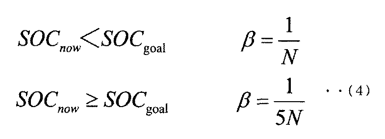
(4)式に示すように、計算装置23は、バッテリ25の充電率の目標値(SOCgoal)と、バッテリ25の充電率の現在値(SOCnow)とを比較することにより、優先度(β)を算出する。
As shown in the equation (4), the calculation device 23 compares the target value (SOCgoal) of the charge rate of the battery 25 with the current value (SOCnow) of the charge rate of the battery 25 to obtain the priority (β). Is calculated.
現在値(SOCnow)が目標値(SOCgoal)より小さい場合の優先度(β)は、現在値(SOCnow)が目標値(SOCgoal)以上である場合の優先度(β)よりも大きい。例えば、現在値(SOCnow)が目標値(SOCgoal)よりも小さい場合、優先度(β)は、受電を行う電気自動車の総数(N)の逆数となる。現在値(SOCnow)が目標値(SOCgoal)以上となる場合、優先度(β)は、受電を行う電気自動車の総数(N)の逆数を5で除算した値となる。なお、(4)式中の5は例示であり、1よりも大きい数値であれば、その他の数値であってもよい。
The priority (β) when the current value (SOCnow) is smaller than the target value (SOCgoal) is higher than the priority (β) when the current value (SOCnow) is equal to or higher than the target value (SOCgoal). For example, when the current value (SOCnow) is smaller than the target value (SOCgoal), the priority (β) is the reciprocal of the total number of electric vehicles receiving power (N). When the current value (SOCnow) is equal to or higher than the target value (SOCgoal), the priority (β) is a value obtained by dividing the reciprocal of the total number of electric vehicles receiving power (N) by 5. Note that 5 in Eq. (4) is an example, and any numerical value larger than 1 may be used.
このように、第2実施形態の受電制御装置は、第1実施形態と比べて、優先度(β)を算出する際に用いる「電気自動車EV1のユーザの要求を表す数値」が相違する。しかし、その他の構成は、第1実施形態(図1)と共通しているため、再度の説明を割愛する。
As described above, the power receiving control device of the second embodiment is different from the first embodiment in the "numerical value representing the user's request of the electric vehicle EV1" used when calculating the priority (β). However, since the other configurations are the same as those of the first embodiment (FIG. 1), the description thereof will be omitted again.
第2実施形態における受電制御装置の動作、すなわち受電制御方法は、図2に示した手順と共通する。しかし、ステップS02及びS04の動作に違いがある。すなわち、ステップS02で、車両状態取得装置22は、充電率の目標値(SOCgoal)及び現在値を示す情報を取得する。ステップS04で、計算装置23は、(2)式の代わりに、(4)式を用いて、バッテリ25の充電率の目標値(SOCgoal)から電気自動車EV1の優先度(β)を算出する。その他のステップは、第1実施形態と共通するため、再度の説明を割愛する。
The operation of the power receiving control device in the second embodiment, that is, the power receiving control method is common to the procedure shown in FIG. However, there is a difference in the operation of steps S02 and S04. That is, in step S02, the vehicle state acquisition device 22 acquires information indicating the target value (SOCgoal) and the current value of the charge rate. In step S04, the calculation device 23 calculates the priority (β) of the electric vehicle EV1 from the target value (SOCgoal) of the charge rate of the battery 25 by using the equation (4) instead of the equation (2). Since the other steps are common to the first embodiment, the explanation will be omitted again.
さらに、第1実施形態に対して総送電電力の現在値(Pall_now)の算出方法を変更した第1変形例(図3)、及び、差分電力(ΔP)の算出方法を変更する第2変形例(図4)を、第2実施形態の受電制御装置及び受電制御方法に、適用できることは言うまでもない。
Further, a first modified example (FIG. 3) in which the calculation method of the current value (Pall_now) of the total transmitted power is changed with respect to the first embodiment, and a second modified example in which the calculation method of the differential power (ΔP) is changed. Needless to say, FIG. 4 can be applied to the power receiving control device and the power receiving control method of the second embodiment.
(シミュレーション結果)
次に、第2実施形態に係わる受電制御方法に従って受電制御を実行したシミュレーションの結果を説明する。 (simulation result)
Next, the result of the simulation in which the power receiving control is executed according to the power receiving control method according to the second embodiment will be described.
次に、第2実施形態に係わる受電制御方法に従って受電制御を実行したシミュレーションの結果を説明する。 (simulation result)
Next, the result of the simulation in which the power receiving control is executed according to the power receiving control method according to the second embodiment will be described.
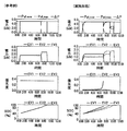
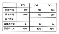
先ずは、第2実施形態のシミュレーションの条件を説明する。図6Aに示すように、3台の電気自動車(EV1、EV2、EV3)の各々が、第2実施形態に係わる受電制御方法により受電制御を実行する。各電気自動車が受電を開始する時刻(開始時刻)は同時刻(午前1時)であり、各電気自動車が受電を終了する時刻(終了時刻)は同時(午前11時)である。各電気自動車(EV1、EV2、EV3)の受電装置24が受電することができる電力(要素受電電力)の最大値は同じ3kWであり、各電気自動車(EV1、EV2、EV3)のバッテリ25の容量(蓄電池容量)も同じ24kWhである。更に、受電の開始時刻における各電気自動車(EV1、EV2、EV3)の充電率(以後、「開始時SOC」と呼ぶ)は異なる。電気自動車EV1の開始時SOCは10%であり、電気自動車EV2の開始時SOCは40%であり、電気自動車EV3の開始時SOCは70%である。各電気自動車(EV1、EV2、EV3)の充電率の目標値(以後、「目標SOC」と呼ぶ)は、同じ60%である。
First, the conditions for the simulation of the second embodiment will be described. As shown in FIG. 6A, each of the three electric vehicles (EV1, EV2, EV3) executes power reception control by the power reception control method according to the second embodiment. The time (start time) at which each electric vehicle starts receiving power is the same time (1 am), and the time (end time) at which each electric vehicle ends receiving power is the same time (11:00 am). The maximum value of the power (elemental power received) that can be received by the power receiving device 24 of each electric vehicle (EV1, EV2, EV3) is the same 3 kW, and the capacity of the battery 25 of each electric vehicle (EV1, EV2, EV3). (Storage battery capacity) is also the same 24 kWh. Further, the charge rate (hereinafter referred to as "starting SOC") of each electric vehicle (EV1, EV2, EV3) at the start time of receiving power is different. The starting SOC of the electric vehicle EV1 is 10%, the starting SOC of the electric vehicle EV2 is 40%, and the starting SOC of the electric vehicle EV3 is 70%. The target value (hereinafter referred to as "target SOC") of the charge rate of each electric vehicle (EV1, EV2, EV3) is the same 60%.
次に、シミュレーションの結果を説明する。図6Bは、第2実施形態のシミュレーションの結果を示す8つのグラフであり、左側の4つのグラフが参考例に係わり、右側の4つのグラフが第2実施形態に係わる。各グラフの縦軸及び横軸が示す数値の種類は、図5Bの各グラフのそれらと同じであるため、再度の説明を割愛する。
Next, the results of the simulation will be explained. FIG. 6B is eight graphs showing the results of the simulation of the second embodiment, the four graphs on the left side relate to the reference example, and the four graphs on the right side relate to the second embodiment. Since the types of numerical values indicated by the vertical and horizontal axes of each graph are the same as those of each graph of FIG. 5B, the description thereof will be omitted again.
参考例では、電気自動車の総数(N)が3であるため、各電気自動車(EV1、EV2、EV3)の優先度(β)を固定値(1/3)とした。すなわち、(4)式に示す、充電率の現在値(SOCnow)が充電率の目標値(SOCgoal)より小さい場合の優先度(β)と同じ値とした。これにより、差分電力(ΔP)は、各電気自動車(EV1、EV2、EV3)に1/3ずつ均等に分配されるので、(3)式から算出される要素受電電力(Pt)も、3台ともに等しく変化する。よって、午前1時に同時に受電を開始した3台の電気自動車(EV1、EV2、EV3)は、同じ要素受電電力(Pt)を受ける。このため、各電気自動車(EV1、EV2、EV3)の開始時SOCは異なるが、3台の充電率(SOC)は、同じ傾きで増加する。
In the reference example, since the total number of electric vehicles (N) is 3, the priority (β) of each electric vehicle (EV1, EV2, EV3) is set to a fixed value (1/3). That is, it is set to the same value as the priority (β) when the current value (SOCnow) of the charge rate is smaller than the target value (SOCgoal) of the charge rate shown in the equation (4). As a result, the differential power (ΔP) is evenly distributed to each electric vehicle (EV1, EV2, EV3) by 1/3, so that the element power receiving power (Pt) calculated from the equation (3) is also three. Both change equally. Therefore, the three electric vehicles (EV1, EV2, EV3) that started receiving power at the same time at 1:00 am receive the same element power received (Pt). Therefore, although the starting SOCs of each electric vehicle (EV1, EV2, EV3) are different, the charging rates (SOCs) of the three vehicles increase with the same inclination.
そして、午前5時過ぎに、開始時SOCが最も高い電気自動車EV3が満充電となったため、受電の継続を終了する(図2のS03でNO)。その時、電気自動車EV3の要素受電電力が差分電力(ΔP)へ変化し、2台の電気自動車(EV1、EV2)により再分配される。このため、午前5時過ぎ以後、電気自動車(EV1、EV2)の要素受電電力が増加する。
Then, after 5 am, the electric vehicle EV3 with the highest SOC at the start was fully charged, so the continuation of power reception was terminated (NO in S03 in FIG. 2). At that time, the element received power of the electric vehicle EV3 changes to the differential power (ΔP) and is redistributed by the two electric vehicles (EV1 and EV2). Therefore, after 5 am, the elemental power received by the electric vehicles (EV1, EV2) increases.
そして、午前8時過ぎに、開始時SOCが2番目に高い電気自動車EV2が満充電となったため、受電の継続を終了する(図2のS03でNO)。その時、電気自動車EV2の要素受電電力が差分電力(ΔP)へ変化し、1台の電気自動車(EV1)により再分配される。このため、午前8時過ぎ以後、電気自動車(EV1)の要素受電電力が増加するが、電気自動車(EV1)の要素受電電力が、電気自動車(EV1)の受電装置24の電力容量(3kW)を超えることはない。
Then, after 8:00 am, the electric vehicle EV2, which has the second highest SOC at the start, is fully charged, so the continuation of power reception is terminated (NO in S03 in FIG. 2). At that time, the element received power of the electric vehicle EV2 changes to the differential power (ΔP) and is redistributed by one electric vehicle (EV1). Therefore, after 8:00 am, the element received power of the electric vehicle (EV1) increases, but the element received power of the electric vehicle (EV1) reduces the power capacity (3 kW) of the power receiving device 24 of the electric vehicle (EV1). It will not exceed.
最後に、午前10時過ぎに、開始時SOCが最も低い電気自動車EV1が満充電となったため、受電の継続を終了する(図2のS03でNO)。
Finally, after 10 am, the electric vehicle EV1 with the lowest SOC at the start was fully charged, so the continuation of power reception was terminated (NO in S03 in FIG. 2).
これに対して、第2実施形態では、各電気自動車(EV1、EV2、EV3)の優先度(β)は、(4)式に従って算出される。具体的には、電気自動車EV3の開始時SOCは、既に電気自動車EV3の目標SOC以上であるため、多くの充電を必要としていない。よって、受電開始時から、電気自動車EV3の優先度(β)は、1/15となる。他の2台の電気自動車(EV1、EV2)の開始時SOCは、電気自動車EV3の目標SOCよりも低い。よって、電気自動車(EV1、EV2)の優先度(β)は、1/3となる。よって、差分電力(ΔP)は、電気自動車EV3よりも電気自動車(EV1、EV2)に多く分配されることになる。すなわち、電気自動車EV3の要素受電電力は、電気自動車(EV1、EV2)の要素受電電力よりも小さくなるため、電気自動車EV3の増加率は、電気自動車(EV1、EV2)の増加率よりも小さくなる。
On the other hand, in the second embodiment, the priority (β) of each electric vehicle (EV1, EV2, EV3) is calculated according to the equation (4). Specifically, since the starting SOC of the electric vehicle EV3 is already equal to or higher than the target SOC of the electric vehicle EV3, a large amount of charging is not required. Therefore, the priority (β) of the electric vehicle EV3 becomes 1/15 from the start of receiving power. The starting SOC of the other two electric vehicles (EV1, EV2) is lower than the target SOC of the electric vehicle EV3. Therefore, the priority (β) of the electric vehicles (EV1, EV2) is 1/3. Therefore, the differential power (ΔP) is distributed to the electric vehicles (EV1, EV2) more than the electric vehicle EV3. That is, since the element received power of the electric vehicle EV3 is smaller than the element received power of the electric vehicle (EV1, EV2), the rate of increase of the electric vehicle EV3 is smaller than the rate of increase of the electric vehicle (EV1, EV2). ..
そして、午前3時頃に、電気自動車EV2の充電率の現在値(SOCnow)は、電気自動車EV2の目標SOCに到達したため、(4)式に従い、電気自動車EV2の優先度(β)は、1/3から1/15へ減少する。しかし、この時、差分電力(ΔP)は零であるため、電気自動車EV2の要素受電電力は、変化していない。
Then, around 3:00 am, the current value (SOCnow) of the charge rate of the electric vehicle EV2 has reached the target SOC of the electric vehicle EV2, so that the priority (β) of the electric vehicle EV2 is 1 according to the equation (4). It decreases from / 3 to 1/15. However, at this time, since the differential power (ΔP) is zero, the element received power of the electric vehicle EV2 has not changed.
そして、午前6時過ぎに、電気自動車EV1の充電率の現在値(SOCnow)は、電気自動車EV1の目標SOCに到達したため、(4)式に従い、電気自動車EV1の優先度(β)は、1/3から1/15へ減少する。しかし、この時、差分電力(ΔP)は零であるため、電気自動車EV2の要素受電電力は、変化していない。
Then, after 6 am, the current value (SOCnow) of the charge rate of the electric vehicle EV1 has reached the target SOC of the electric vehicle EV1, so the priority (β) of the electric vehicle EV1 is 1 according to the equation (4). It decreases from / 3 to 1/15. However, at this time, since the differential power (ΔP) is zero, the element received power of the electric vehicle EV2 has not changed.
そして、午前7時過ぎに、電気自動車EV2が満充電となったため、受電の継続を終了する(図2のS03でNO)。その時、電気自動車EV2の要素受電電力が差分電力(ΔP)へ変化し、2台の電気自動車(EV1、EV3)により再分配される。このため、午前7時過ぎ以後、各電気自動車(EV1、EV3)の要素受電電力が増加する。
Then, after 7:00 am, the electric vehicle EV2 was fully charged, so the continuation of power reception was terminated (NO in S03 in Fig. 2). At that time, the element received power of the electric vehicle EV2 changes to the differential power (ΔP) and is redistributed by the two electric vehicles (EV1, EV3). Therefore, after 7:00 am, the elemental power received by each electric vehicle (EV1, EV3) increases.
そして、午前10時前に、2台の電気自動車(EV1、EV3)が満充電となったため、受電の継続を終了する(図2のS03でNO)。
Then, before 10:00 am, the two electric vehicles (EV1 and EV3) were fully charged, so the continuation of power reception was terminated (NO in S03 in FIG. 2).
このように、第2実施形態では、現在値(SOCnow)が目標SOC未満である電気自動車を、現在値(SOCnow)が目標SOC以上である電気自動車よりも優先的に受電する。これにより、参考例と比べて、各電気自動車の充電率が満充電となる時刻を揃えることができた。換言すれば、各電気自動車の受電を終了するタイミングの分散を小さくすることができた。各電気自動車の充電率を平準化しつつ、ユーザの要望に応じて適切に差分電力(ΔP)を分配することができた。
As described above, in the second embodiment, the electric vehicle whose current value (SOCnow) is less than the target SOC is preferentially received over the electric vehicle whose current value (SOCnow) is equal to or higher than the target SOC. As a result, compared to the reference example, it was possible to align the time when the charging rate of each electric vehicle is fully charged. In other words, it was possible to reduce the dispersion of the timing at which each electric vehicle ends receiving power. While leveling the charge rate of each electric vehicle, it was possible to appropriately distribute the differential power (ΔP) according to the user's request.
以上説明したように、第2実施形態によれば、以下の作用効果を得ることができる。
As described above, according to the second embodiment, the following effects can be obtained.
なお、第2実施形態において、優先度(β)が変化しても差分電力(ΔP)が零であることにより充電速度(要素受電電力)が変化しないことに対応する方式、例えば、一度に非常に大きな信号を意図的に送信して電気自動車EV1の受電を停止させた後に、差分電力(ΔP)を示す信号の送信を再開する方式などを併用することができる。これにより、現在値(SOCnow)が目標SOC以上である電気自動車の充電速度(要素受電電力)を低減させて、現在値(SOCnow)が目標SOC未満である電気自動車の充電速度(要素受電電力)を更に向上させることも可能である。
In the second embodiment, a method corresponding to the fact that the charging speed (element received power) does not change because the differential power (ΔP) is zero even if the priority (β) changes, for example, very much at once. After intentionally transmitting a large signal to the electric vehicle EV1 to stop receiving power, it is possible to use a method of restarting the transmission of the signal indicating the differential power (ΔP). As a result, the charging speed (element power received) of the electric vehicle whose current value (SOCnow) is equal to or higher than the target SOC is reduced, and the charging speed (element received power) of the electric vehicle whose current value (SOCnow) is less than the target SOC is reduced. It is also possible to further improve.
第2実施形態において、「ユーザの要求を表す数値」の例として、蓄電要素の充電率の目標値(SOCgoal)を採用した。これにより、各電気自動車の充電率を平準化しつつ、ユーザの要望(充電率の目標値)に応じて適切に差分電力(ΔP)を分配することができる。
In the second embodiment, the target value (SOCgoal) of the charge rate of the power storage element was adopted as an example of the "numerical value representing the user's request". As a result, the differential power (ΔP) can be appropriately distributed according to the user's request (target value of the charging rate) while leveling the charging rate of each electric vehicle.
計算装置23は、バッテリ25の充電率の目標値(SOCgoal)と、バッテリ25の充電率の現在値(SOCnow)とを比較することにより、優先度(β)を算出する。これにより、ユーザの要望(充電率の目標値)に応じて適切に優先度(β)を算出することができる。
The calculation device 23 calculates the priority (β) by comparing the target value (SOCgoal) of the charge rate of the battery 25 with the current value (SOCnow) of the charge rate of the battery 25. As a result, the priority (β) can be appropriately calculated according to the user's request (target value of charge rate).
現在値(SOCnow)が目標値(SOCgoal)より小さい場合の優先度(β)は、現在値(SOCnow)が目標値(SOCgoal)以上である場合の優先度(β)よりも大きい。これにより、現在値(SOCnow)が目標SOC未満である電気自動車を、現在値(SOCnow)が目標SOC以上である電気自動車よりも優先的に充電することができる。
The priority (β) when the current value (SOCnow) is smaller than the target value (SOCgoal) is higher than the priority (β) when the current value (SOCnow) is equal to or higher than the target value (SOCgoal). As a result, the electric vehicle whose current value (SOCnow) is less than the target SOC can be charged preferentially over the electric vehicle whose current value (SOCnow) is equal to or higher than the target SOC.
(第3実施形態)
第3実施形態では、電気自動車EV1の優先度(β)を、現時刻(To)から受電の終了時刻(Td)までの残り時間(T)及びバッテリ25の充電率の目標値(SOCgoal)の双方に基づいて算出する例を説明する。 (Third Embodiment)
In the third embodiment, the priority of the electric vehicle EV1 (beta) to the current time (T o) from the power receiving end time (T d) remaining time until (T) and the target value of the charging rate of the battery 25 (SOCgoal ) Will be described as an example of calculation based on both.
計算装置23は、(2)式及び(4)式の代わりに、(5)式を用いて、受電の終了時刻(Td)までの残り時間(T)及びバッテリ25の充電率の目標値(SOCgoal)から電気自動車EV1の優先度(β)を算出する。
The calculation device 23 uses the equation (5) instead of the equations (2) and (4) to measure the remaining time (T) until the end time of power reception (T d ) and the target value of the charge rate of the battery 25. The priority (β) of the electric vehicle EV1 is calculated from (SOCgoal).
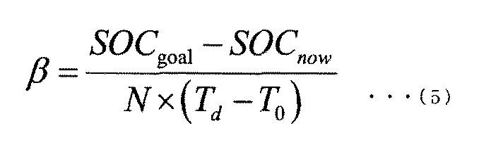
(5)式に示すように、優先度(β)は残り時間(T)に反比例する。「残り時間(T)」は、現時刻(To)から受電の終了時刻(Td)までの時間である。残り時間(T)が短くなるにつれて、優先度(β)は高くなる。(5)式は一例にすぎず、例えば、優先度(β)は、残り時間(T)を2以上のg回(gは正数)掛け算した「残り時間(T)のg乗」に反比例してもよい。
As shown in the equation (5), the priority (β) is inversely proportional to the remaining time (T). "Remaining time (T)" is the time to the end time of the power-receiving from the current time (T o) (T d) . As the remaining time (T) becomes shorter, the priority (β) becomes higher. Equation (5) is only an example. For example, the priority (β) is inversely proportional to the “remaining time (T) to the g-th power” obtained by multiplying the remaining time (T) by 2 or more g times (g is a positive number). You may.
(5)式に示すように、計算装置23は、バッテリ25の充電率の目標値(SOCgoal)からバッテリ25の充電率の現在値(SOCnow)を減算して未充電率(ΔSOC)を求める。優先度(β)は未充電率(ΔSOC)に比例する。或いは、優先度(β)は未充電率(ΔSOC)のg乗に比例していてもよい。バッテリ25の充電率の現在値(SOCnow)は、例えば、処理サイクル毎に、ステップS02において測定される充電率の値である。
As shown in the equation (5), the calculation device 23 subtracts the current value (SOCnow) of the charge rate of the battery 25 from the target value (SOCgoal) of the charge rate of the battery 25 to obtain the uncharge rate (ΔSOC). The priority (β) is proportional to the uncharged rate (ΔSOC). Alternatively, the priority (β) may be proportional to the uncharged rate (ΔSOC) to the gth power. The current value (SOCnow) of the charge rate of the battery 25 is, for example, the value of the charge rate measured in step S02 for each processing cycle.
優先度(β)は、充電率の目標値(SOCgoal)から電気自動車EV1の現在の充電率を測定した測定値(SOCnow)を減算した未充電率(ΔSOC)に基づいて算出される。未充電率(ΔSOC)が大きくなるにつれて、優先度(β)を高くする。これにより、未充電率(ΔSOC)が大きい電気自動車に対して、優先的に差分電力(ΔP)を分配することができる。各電気自動車の充電率を平準化しつつ、ユーザの要望(充電率の目標値)に応じて適切に差分電力(ΔP)を分配することができる。
The priority (β) is calculated based on the uncharged rate (ΔSOC) obtained by subtracting the measured value (SOCnow) obtained by measuring the current charge rate of the electric vehicle EV1 from the target value (SOCgoal) of the charge rate. As the uncharged rate (ΔSOC) increases, the priority (β) increases. As a result, the differential power (ΔP) can be preferentially distributed to the electric vehicle having a large uncharged rate (ΔSOC). While leveling the charge rate of each electric vehicle, the differential power (ΔP) can be appropriately distributed according to the user's request (target value of the charge rate).
なお、計算装置23は、(5)式の代わりに、(6)式を用いて、終了時刻(Td)までの残り時間(T)及びバッテリ25の充電率の目標値(SOCgoal)から電気自動車EV1の優先度(β)を算出してもよい。(6)式は、(2)式と(4)式を組み合わせた式に相当する。
In addition, the calculation device 23 uses the formula (6) instead of the formula (5) to generate electricity from the remaining time (T) until the end time (T d ) and the target value (SOCgoal) of the charge rate of the battery 25. The priority (β) of the automobile EV1 may be calculated. Equation (6) corresponds to an equation that combines equations (2) and (4).
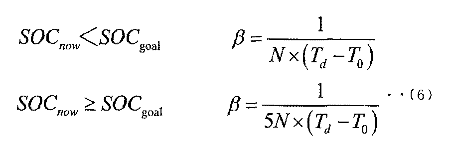
現在値(SOCnow)が目標値(SOCgoal)より小さい場合の優先度(β)は、現在値(SOCnow)が目標値(SOCgoal)以上である場合の優先度(β)よりも大きい。例えば、現在値(SOCnow)が目標値(SOCgoal)よりも小さい場合、優先度(β)は、受電を行う電気自動車の総数(N)の逆数となる。現在値(SOCnow)が目標値(SOCgoal)以上となる場合、優先度(β)は、受電を行う電気自動車の総数(N)の逆数を5で除算した値となる。なお、(6)式中のβを算出する式の右辺の分母の「5」は例示であり、1よりも大きい数値であれば、その他の数値であってもよい。
The priority (β) when the current value (SOCnow) is smaller than the target value (SOCgoal) is higher than the priority (β) when the current value (SOCnow) is equal to or higher than the target value (SOCgoal). For example, when the current value (SOCnow) is smaller than the target value (SOCgoal), the priority (β) is the reciprocal of the total number of electric vehicles receiving power (N). When the current value (SOCnow) is equal to or higher than the target value (SOCgoal), the priority (β) is a value obtained by dividing the reciprocal of the total number of electric vehicles receiving power (N) by 5. The denominator "5" on the right side of the equation for calculating β in the equation (6) is an example, and any numerical value larger than 1 may be used.
このように、第3実施形態の受電制御装置は、第1実施形態及び第2実施形態と比べて、優先度(β)を算出する際に用いる「電気自動車EV1のユーザの要求を表す数値」が相違する。しかし、その他の構成は、第1実施形態(図1)と共通しているため、再度の説明を割愛する。
As described above, the power receiving control device of the third embodiment is used when calculating the priority (β) as compared with the first embodiment and the second embodiment, and is used as a “numerical value representing the user's request of the electric vehicle EV1”. Is different. However, since the other configurations are the same as those of the first embodiment (FIG. 1), the description thereof will be omitted again.
第3実施形態における受電制御装置の動作、すなわち受電制御方法は、図2に示した手順と共通する。しかし、ステップS02及びS04の動作に違いがある。すなわち、車両状態取得装置22は、ステップS02において、受電の終了時刻(Td)を示す情報、及び充電率の目標値(SOCgoal)及び充電率の現在値(SOCnow)を示す情報を取得し、受電の終了時刻(Td)までの残り時間(T)を算出する。ステップS04で、計算装置23は、(2)式の代わりに、(5)式又は(6)式を用いて、終了時刻(Td)までの残り時間(T)及びバッテリ25の充電率の目標値(SOCgoal)から電気自動車EV1の優先度(β)を算出する。その他のステップは、第1実施形態と共通するため、再度の説明を割愛する。
The operation of the power receiving control device in the third embodiment, that is, the power receiving control method is common to the procedure shown in FIG. However, there is a difference in the operation of steps S02 and S04. That is, in step S02, the vehicle state acquisition device 22 acquires information indicating the end time (T d ) of power reception, and information indicating the target value (SOCgoal) of the charge rate and the current value (SOCnow) of the charge rate. The remaining time (T) until the end time (T d ) of receiving power is calculated. In step S04, the calculation device 23 uses the equation (5) or the equation (6) instead of the equation (2) to determine the remaining time (T) until the end time (T d ) and the charge rate of the battery 25. The priority (β) of the electric vehicle EV1 is calculated from the target value (SOCgoal). Since the other steps are common to the first embodiment, the explanation will be omitted again.
さらに、第1実施形態に対して総送電電力の現在値(Pall_now)の算出方法を変更した第1変形例(図3)、及び、差分電力(ΔP)の算出方法を変更する第2変形例(図4)を、第3実施形態の受電制御装置及び受電制御方法に、適用できることは言うまでもない。
Further, a first modified example (FIG. 3) in which the calculation method of the current value (Pall_now) of the total transmitted power is changed with respect to the first embodiment, and a second modified example in which the calculation method of the differential power (ΔP) is changed. Needless to say, FIG. 4 can be applied to the power receiving control device and the power receiving control method of the third embodiment.
(第1シミュレーション結果)
次に、第3実施形態に係わる受電制御方法に従って受電制御を実行した第1~第3シミュレーションの結果を説明する。第1~第3シミュレーションでは、(5)式を用いて、電気自動車EV1の優先度(β)を算出した。 (Result of the first simulation)
Next, the results of the first to third simulations in which the power receiving control is executed according to the power receiving control method according to the third embodiment will be described. In the first to third simulations, the priority (β) of the electric vehicle EV1 was calculated using the equation (5).
先ずは、第1シミュレーションの条件を説明する。図7Aに示すように、3台の電気自動車(EV1、EV2、EV3)の各々が、第3実施形態に係わる受電制御方法により受電制御を実行する。各電気自動車が受電を開始する時刻(受電の開始時刻)は同時刻(午前1時)であり、各電気自動車が受電を終了する時刻(受電の終了時刻)は同時(午前11時)である。各電気自動車(EV1、EV2、EV3)の受電装置24が受電することができる電力(要素受電電力)の最大値は同じ3kWであり、各電気自動車(EV1、EV2、EV3)のバッテリ25の容量(蓄電池容量)も同じ24kWhである。更に、受電の開始時刻における各電気自動車(EV1、EV2、EV3)の充電率(開始時SOC)は異なる。電気自動車EV1の開始時SOCは60%であり、電気自動車EV2の開始時SOCは40%であり、電気自動車EV3の開始時SOCは20%である。各電気自動車(EV1、EV2、EV3)の充電率の目標値(目標SOC)は、ユーザによる設定が無く、デフォルト値のまま、100%(満充電)である。
First, the conditions for the first simulation will be explained. As shown in FIG. 7A, each of the three electric vehicles (EV1, EV2, EV3) executes power reception control by the power reception control method according to the third embodiment. The time when each electric vehicle starts receiving power (starting time of receiving power) is the same time (1 am), and the time when each electric vehicle ends receiving power (end time of receiving power) is the same time (11:00 am). .. The maximum value of the power (elemental power received) that can be received by the power receiving device 24 of each electric vehicle (EV1, EV2, EV3) is the same 3 kW, and the capacity of the battery 25 of each electric vehicle (EV1, EV2, EV3). (Storage battery capacity) is also the same 24 kWh. Further, the charging rate (SOC at the start) of each electric vehicle (EV1, EV2, EV3) at the start time of receiving power is different. The starting SOC of the electric vehicle EV1 is 60%, the starting SOC of the electric vehicle EV2 is 40%, and the starting SOC of the electric vehicle EV3 is 20%. The target value (target SOC) of the charge rate of each electric vehicle (EV1, EV2, EV3) is 100% (fully charged) with the default value without being set by the user.
次に、第1シミュレーションの結果を説明する。図7Bは、第1シミュレーションの結果を示す8つのグラフであり、左側の4つのグラフが参考例に係わり、右側の4つのグラフが第3実施形態に係わる。各グラフの縦軸及び横軸が示す数値の種類は、図5Bの各グラフのそれらと同じであるため、再度の説明を割愛する。
Next, the result of the first simulation will be described. FIG. 7B is eight graphs showing the results of the first simulation. The four graphs on the left side relate to the reference example, and the four graphs on the right side relate to the third embodiment. Since the types of numerical values indicated by the vertical and horizontal axes of each graph are the same as those of each graph of FIG. 5B, the description thereof will be omitted again.
図7Bの参考例では、図6Bの参考例と比べて、各電気自動車の開始時SOCは異なるが、優先度の計算方法を含むその他の条件は、図6Bの参考例と共通しているため、同様なシミュレーション結果となった。
In the reference example of FIG. 7B, the SOC at the start of each electric vehicle is different from that of the reference example of FIG. 6B, but other conditions including the priority calculation method are common to the reference example of FIG. 6B. , The same simulation result was obtained.
電気自動車の総数(N)が3であるため、各電気自動車(EV1、EV2、EV3)の優先度(β)を固定値(1/3)とした。これにより、差分電力(ΔP)は、各電気自動車(EV1、EV2、EV3)に1/3ずつ均等に分配されるので、(3)式から算出される要素受電電力(Pt)も、3台ともに等しく変化する。よって、午前1時に同時に受電を開始した3台の電気自動車(EV1、EV2、EV3)は、同じ要素受電電力(Pt)を受ける。このため、各電気自動車(EV1、EV2、EV3)の開始時SOCは異なるが、3台の充電率(SOC)は、同じ傾きで増加する。
Since the total number of electric vehicles (N) is 3, the priority (β) of each electric vehicle (EV1, EV2, EV3) is set to a fixed value (1/3). As a result, the differential power (ΔP) is evenly distributed to each electric vehicle (EV1, EV2, EV3) by 1/3, so that the element power receiving power (Pt) calculated from the equation (3) is also three. Both change equally. Therefore, the three electric vehicles (EV1, EV2, EV3) that started receiving power at the same time at 1:00 am receive the same element power received (Pt). Therefore, although the starting SOCs of each electric vehicle (EV1, EV2, EV3) are different, the charging rates (SOCs) of the three vehicles increase with the same inclination.
そして、午前6時過ぎに、開始時SOCが最も高い電気自動車EV1が満充電となったため、受電の継続を終了する(図2のS03でNO)。その時、電気自動車EV1の要素受電電力が差分電力(ΔP)へ変化し、2台の電気自動車(EV2、EV3)により再分配される。このため、午前6時過ぎ以後、電気自動車(EV2、EV3)の要素受電電力が増加する。
Then, after 6:00 am, the electric vehicle EV1 with the highest SOC at the start was fully charged, so the continuation of power reception was terminated (NO in S03 in FIG. 2). At that time, the element received power of the electric vehicle EV1 changes to the differential power (ΔP) and is redistributed by the two electric vehicles (EV2 and EV3). Therefore, after 6:00 am, the elemental power received by the electric vehicles (EV2, EV3) increases.
そして、午前8時過ぎに、開始時SOCが2番目に高い電気自動車EV2が満充電となったため、受電の継続を終了する(図2のS03でNO)。その時、電気自動車EV2の要素受電電力が差分電力(ΔP)へ変化し、1台の電気自動車(EV1)により再分配される。このため、午前8時過ぎ以後、電気自動車(EV1)の要素受電電力が増加するが、電気自動車(EV1)の要素受電電力が、電気自動車(EV1)の受電装置24の電力容量(3kW)を超えることはない。
Then, after 8:00 am, the electric vehicle EV2, which has the second highest SOC at the start, is fully charged, so the continuation of power reception is terminated (NO in S03 in FIG. 2). At that time, the element received power of the electric vehicle EV2 changes to the differential power (ΔP) and is redistributed by one electric vehicle (EV1). Therefore, after 8:00 am, the element received power of the electric vehicle (EV1) increases, but the element received power of the electric vehicle (EV1) reduces the power capacity (3 kW) of the power receiving device 24 of the electric vehicle (EV1). It will not exceed.
最後に、午前10時過ぎに、開始時SOCが最も低い電気自動車EV3が満充電となったため、受電の継続を終了する(図2のS03でNO)。
Finally, after 10 am, the electric vehicle EV3 with the lowest SOC at the start was fully charged, so the continuation of power reception was terminated (NO in S03 in Fig. 2).
これに対して、図7Bの第3実施形態では、各電気自動車(EV1、EV2、EV3)の優先度(β)は、(5)式に従い、時間の経過と共に変化する。具体的には、受電の終了時刻(午前11時)までの残り時間(T=Td−To)が短くなるにつれて、優先度(β)は高くなる。一方、充電率の現在値(SOCnow)が目標値(SOCgoal)に近づくにつれて、未充電率(ΔSOC)が小さくなるため、優先度(β)は低くなる。
On the other hand, in the third embodiment of FIG. 7B, the priority (β) of each electric vehicle (EV1, EV2, EV3) changes with the passage of time according to the equation (5). Specifically, as the end time (11:00 AM) remaining up to the time of power reception (T = T d -T o) is shorter, the priority (beta) is high. On the other hand, as the current value (SOCnow) of the charge rate approaches the target value (SOCgoal), the uncharge rate (ΔSOC) becomes smaller, so that the priority (β) becomes lower.
午前11時よりも前に、各電気自動車(EV1、EV2、EV3)の充電率の現在値(SOCnow)が、目標SOC(100%)に到達したため、(5)式において、分母(残り時間T)よりも分子(未充電率)が先に零になる。このため、各電気自動車(EV1、EV2、EV3)の優先度(β)は、目標SOCと開始時SOCの差に基づいて定まる。つまり、開始時SOCが低い電気自動車に対して優先的に差分電力(ΔP)を割り当てることができるので、開始時SOCが低い電気自動車の要素受電電力(Pt)を増やして、充電速度を早めることができる。結果的に、各電気自動車(EV1、EV2、EV3)が充電を終了する時刻(SOCが100%に到達する時刻)の分散を小さくすることができる。
Before 11:00 am, the current value (SOCnow) of the charge rate of each electric vehicle (EV1, EV2, EV3) reached the target SOC (100%), so in equation (5), the denominator (remaining time T). ), The numerator (uncharged rate) becomes zero first. Therefore, the priority (β) of each electric vehicle (EV1, EV2, EV3) is determined based on the difference between the target SOC and the starting SOC. That is, since the differential power (ΔP) can be preferentially allocated to the electric vehicle having a low SOC at the start, the element received power (Pt) of the electric vehicle having a low SOC at the start can be increased to accelerate the charging speed. Can be done. As a result, it is possible to reduce the dispersion of the time when each electric vehicle (EV1, EV2, EV3) finishes charging (the time when the SOC reaches 100%).
(第2シミュレーション結果)
次に、第2シミュレーションの条件を説明する。図8Aに示すように、3台の電気自動車(EV1、EV2、EV3)の各々のパラメータは、図5Aに示すシミュレーション条件と同じであるため、再度の説明を割愛する。 (Result of the second simulation)
Next, the conditions of the second simulation will be described. As shown in FIG. 8A, the parameters of each of the three electric vehicles (EV1, EV2, EV3) are the same as the simulation conditions shown in FIG. 5A, so the description thereof will be omitted again.
次に、第2シミュレーションの結果を説明する。図8Bは、第2シミュレーションの結果を示す8つのグラフであり、左側の4つのグラフが参考例に係わり、右側の4つのグラフが第3実施形態に係わる。各グラフの縦軸及び横軸が示す数値の種類は、図5Bの各グラフのそれらと同じであるため、再度の説明を割愛する。
Next, the result of the second simulation will be described. FIG. 8B shows eight graphs showing the results of the second simulation. The four graphs on the left side relate to the reference example, and the four graphs on the right side relate to the third embodiment. Since the types of numerical values indicated by the vertical and horizontal axes of each graph are the same as those of each graph of FIG. 5B, the description thereof will be omitted again.
図8Aの参考例のシミュレーション条件は、図5Aの参考例のシミュレーション条件と等しいため、図8Bの参考例のシミュレーション結果は、図5Bの参考例のシミュレーション結果であった。よって、再度の説明は割愛する。
Since the simulation conditions of the reference example of FIG. 8A are the same as the simulation conditions of the reference example of FIG. 5A, the simulation result of the reference example of FIG. 8B was the simulation result of the reference example of FIG. 5B. Therefore, the explanation is omitted again.
これに対して、図8Bの第3実施形態では、各電気自動車(EV1、EV2、EV3)の受電の開始時刻は等しく、且つ受電の終了時刻が異なるため、残り時間(T=Td−To)に違いが生じる。受電開始時(午前1時)における未充電率(ΔSOC)は等しい。よって、(5)式によれば、受電開始時(午前1時)において、主に、残り時間(T)の差に応じた優先度(β)の差が各電気自動車(EV1、EV2、EV3)の間に生じる。具体的には、残り時間(T)が最も短い電気自動車EV1の優先度が最も高く、残り時間(T)が最も長い電気自動車EV3の優先度が最も低くなる。優先度(β)の差に応じて、各電気自動車(EV1、EV2、EV3)の間に、要素受電電力(Pt)及び充電率(SOC)の増加率の差が生じている。よって、残り時間(T)が最も短い電気自動車EV1を、他の電気自動車(EV2,EV3)よりも優先的に、差分電力(ΔP)を割り当てて、充電することができる。
On the other hand, in the third embodiment of FIG. 8B, since the power reception start times of the electric vehicles (EV1, EV2, EV3) are the same and the power reception end times are different, the remaining time (T = T d − T ). There is a difference in o ). The uncharged rate (ΔSOC) at the start of power reception (1 am) is equal. Therefore, according to the equation (5), at the start of power reception (1 am), the difference in priority (β) according to the difference in the remaining time (T) is mainly for each electric vehicle (EV1, EV2, EV3). ) Occurs. Specifically, the electric vehicle EV1 having the shortest remaining time (T) has the highest priority, and the electric vehicle EV3 having the longest remaining time (T) has the lowest priority. Depending on the difference in priority (β), there is a difference in the rate of increase in the element received power (Pt) and the charging rate (SOC) among the electric vehicles (EV1, EV2, EV3). Therefore, the electric vehicle EV1 having the shortest remaining time (T) can be charged by allocating the differential power (ΔP) with priority over the other electric vehicles (EV2 and EV3).
そして、午前7時に近づくと、電気自動車EV1の残り時間(T)が零に近づくため、電気自動車EV1の優先度(β)が急速に高まり、午前7時に、電気自動車EV1の充電の継続が終了する(図2のS03でNO)。
Then, when approaching 7:00 am, the remaining time (T) of the electric vehicle EV1 approaches zero, so that the priority (β) of the electric vehicle EV1 rapidly increases, and the continuation of charging of the electric vehicle EV1 ends at 7:00 am. (NO in S03 of FIG. 2).
そして、午前8時過ぎに、電気自動車EV2が満充電となったため、受電の継続を終了する(図2のS03でNO)。そして、午前10時頃に、電気自動車EV3が満充電となったため、受電の継続を終了する(図2のS03でNO)。
Then, after 8:00 am, the electric vehicle EV2 was fully charged, so the continuation of power reception was terminated (NO in S03 in Fig. 2). Then, at around 10 am, the electric vehicle EV3 is fully charged, so that the continuation of power reception is terminated (NO in S03 in FIG. 2).
このように、図8Bの参考例では、受電の終了時刻(午前7時)における電気自動車EV1の充電率は82%であった。図8Bの実施形態では、受電の終了時刻(午前7時)における電気自動車EV1の充電率を約90%まで高めることができた。
As described above, in the reference example of FIG. 8B, the charging rate of the electric vehicle EV1 at the end time of power reception (7:00 am) was 82%. In the embodiment of FIG. 8B, the charging rate of the electric vehicle EV1 at the end time of power reception (7:00 am) could be increased to about 90%.
電気自動車EV3の受電の終了時刻を比べると、図8Bの参考例よりも図8Bの実施形態が遅くなっている。しかし、電気自動車EV3の出発時刻までには、満充電まで充電することが出来ている。電気自動車EV3のユーザ毎の要求(出発時刻)を満たしつつ、負荷群11内での各電気自動車(EV1、EV2、EV3)の最終的な充電率のバラツキを抑制して、充電率を平準化することができる。
Comparing the end times of receiving power of the electric vehicle EV3, the embodiment of FIG. 8B is later than the reference example of FIG. 8B. However, by the departure time of the electric vehicle EV3, it can be fully charged. While satisfying the requirements (departure time) for each user of the electric vehicle EV3, the variation in the final charge rate of each electric vehicle (EV1, EV2, EV3) in the load group 11 is suppressed to level the charge rate. can do.
(第3シミュレーション結果)
次に、第3シミュレーションの条件を説明する。図9Aに示すように、3台の電気自動車(EV1、EV2、EV3)の各々が、第3実施形態に係わる受電制御方法により受電制御を実行する。各電気自動車が受電を開始する時刻(受電の開始時刻)は同時刻(午前1時)であるが、各電気自動車が受電を終了する時刻(受電の終了時刻)は、異なる。電気自動車EV1は午前7時であり、電気自動車EV2は午前9時であり、電気自動車EV3は午前11時である。各電気自動車(EV1、EV2、EV3)の受電装置24が受電することができる電力(要素受電電力)の最大値は同じ3kWであり、各電気自動車(EV1、EV2、EV3)のバッテリ25の容量(蓄電池容量)も同じ24kWhである。更に、受電の開始畤刻における各電気自動車(EV1、EV2、EV3)の充電率(開始時SOC)は異なる。電気自動車EV1の開始時SOCは60%であり、電気自動車EV2の開始時SOCは40%であり、電気自動車EV3の開始時SOCは20%である。各電気自動車(EV1、EV2、EV3)の充電率の目標値(目標SOC)は、ユーザによる設定は無く、デフォルト値のまま、100%(満充電)である。 (Result of 3rd simulation)
Next, the conditions of the third simulation will be described. As shown in FIG. 9A, each of the three electric vehicles (EV1, EV2, EV3) executes power reception control by the power reception control method according to the third embodiment. The time when each electric vehicle starts receiving power (start time of receiving power) is the same time (1 am), but the time when each electric vehicle ends receiving power (end time of receiving power) is different. The electric vehicle EV1 is 7:00 am, the electric vehicle EV2 is 9:00 am, and the electric vehicle EV3 is 11:00 am. The maximum value of the power (elemental power received) that can be received by thepower receiving device 24 of each electric vehicle (EV1, EV2, EV3) is the same 3 kW, and the capacity of the battery 25 of each electric vehicle (EV1, EV2, EV3). (Storage battery capacity) is also the same 24 kWh. Further, the charge rate (SOC at the start) of each electric vehicle (EV1, EV2, EV3) at the start of power reception is different. The starting SOC of the electric vehicle EV1 is 60%, the starting SOC of the electric vehicle EV2 is 40%, and the starting SOC of the electric vehicle EV3 is 20%. The target value (target SOC) of the charge rate of each electric vehicle (EV1, EV2, EV3) is not set by the user and is 100% (fully charged) with the default value.
次に、第3シミュレーションの条件を説明する。図9Aに示すように、3台の電気自動車(EV1、EV2、EV3)の各々が、第3実施形態に係わる受電制御方法により受電制御を実行する。各電気自動車が受電を開始する時刻(受電の開始時刻)は同時刻(午前1時)であるが、各電気自動車が受電を終了する時刻(受電の終了時刻)は、異なる。電気自動車EV1は午前7時であり、電気自動車EV2は午前9時であり、電気自動車EV3は午前11時である。各電気自動車(EV1、EV2、EV3)の受電装置24が受電することができる電力(要素受電電力)の最大値は同じ3kWであり、各電気自動車(EV1、EV2、EV3)のバッテリ25の容量(蓄電池容量)も同じ24kWhである。更に、受電の開始畤刻における各電気自動車(EV1、EV2、EV3)の充電率(開始時SOC)は異なる。電気自動車EV1の開始時SOCは60%であり、電気自動車EV2の開始時SOCは40%であり、電気自動車EV3の開始時SOCは20%である。各電気自動車(EV1、EV2、EV3)の充電率の目標値(目標SOC)は、ユーザによる設定は無く、デフォルト値のまま、100%(満充電)である。 (Result of 3rd simulation)
Next, the conditions of the third simulation will be described. As shown in FIG. 9A, each of the three electric vehicles (EV1, EV2, EV3) executes power reception control by the power reception control method according to the third embodiment. The time when each electric vehicle starts receiving power (start time of receiving power) is the same time (1 am), but the time when each electric vehicle ends receiving power (end time of receiving power) is different. The electric vehicle EV1 is 7:00 am, the electric vehicle EV2 is 9:00 am, and the electric vehicle EV3 is 11:00 am. The maximum value of the power (elemental power received) that can be received by the
次に、第3シミュレーションの結果を説明する。図9Bは、第3シミュレーションの結果を示す8つのグラフであり、左側の4つのグラフが参考例に係わり、右側の4つのグラフが第3実施形態に係わる。各グラフの縦軸及び横軸が示す数値の種類は、図5Bの各グラフのそれらと同じであるため、再度の説明を割愛する。
Next, the result of the third simulation will be described. FIG. 9B shows eight graphs showing the results of the third simulation. The four graphs on the left side relate to the reference example, and the four graphs on the right side relate to the third embodiment. Since the types of numerical values indicated by the vertical and horizontal axes of each graph are the same as those of each graph of FIG. 5B, the description thereof will be omitted again.
図9Bの参考例では、電気自動車の総数(N)が3であるため、各電気自動車(EV1、EV2、EV3)の優先度(β)を固定値(1/3)とした。これにより、差分電力(ΔP)は、各電気自動車(EV1、EV2、EV3)に1/3ずつ均等に分配されるので、(3)式から算出される要素受電電力(Pt)も、3台ともに等しく変化する。よって、午前1時に同時に受電を開始した3台の電気自動車(EV1、EV2、EV3)は、同じ要素受電電力(Pt)を受ける。このため、各電気自動車(EV1、EV2、EV3)の開始時SOCは異なるが、3台の充電率(SOC)は、同じ傾きで増加する。
In the reference example of FIG. 9B, since the total number of electric vehicles (N) is 3, the priority (β) of each electric vehicle (EV1, EV2, EV3) is set to a fixed value (1/3). As a result, the differential power (ΔP) is evenly distributed to each electric vehicle (EV1, EV2, EV3) by 1/3, so that the element power receiving power (Pt) calculated from the equation (3) is also three. Both change equally. Therefore, the three electric vehicles (EV1, EV2, EV3) that started receiving power at the same time at 1:00 am receive the same element power received (Pt). Therefore, although the starting SOCs of each electric vehicle (EV1, EV2, EV3) are different, the charging rates (SOCs) of the three vehicles increase with the same inclination.
そして、午前6時過ぎに、開始時SOCが最も高い電気自動車EV3が満充電となったため、受電の継続を終了する(図2のS03でNO)。その時、電気自動車EV3の要素受電電力が差分電力(ΔP)へ変化し、2台の電気自動車(EV1、EV2)により再分配される。このため、午前6時過ぎ以後、電気自動車(EV1、EV2)の要素受電電力が増加する。
Then, after 6:00 am, the electric vehicle EV3, which has the highest SOC at the start, is fully charged, so the continuation of power reception is terminated (NO in S03 in FIG. 2). At that time, the element received power of the electric vehicle EV3 changes to the differential power (ΔP) and is redistributed by the two electric vehicles (EV1 and EV2). Therefore, after 6:00 am, the elemental power received by the electric vehicles (EV1, EV2) increases.
そして、午前7時に、開始時SOCが最も低い電気自動車EV1の出発時刻となるため、電気自動車EV1は、受電の継続を終了する(図2のS03でNO)。その時、電気自動車EV1の要素受電電力が差分電力(ΔP)へ変化し、1台の電気自動車EV2により再分配される。このため、午前7時以後、電気自動車EV2の要素受電電力が増加するが、電気自動車EV2の要素受電電力が、電気自動車EV2の受電装置24の電力容量(3kW)を超えることはない。
Then, at 7:00 am, the departure time of the electric vehicle EV1 having the lowest SOC at the start is reached, so that the electric vehicle EV1 ends the continuation of power reception (NO in S03 of FIG. 2). At that time, the element received power of the electric vehicle EV1 changes to the differential power (ΔP) and is redistributed by one electric vehicle EV2. Therefore, after 7:00 am, the element received power of the electric vehicle EV2 increases, but the element received power of the electric vehicle EV2 does not exceed the power capacity (3 kW) of the power receiving device 24 of the electric vehicle EV2.
そして、午前8時過ぎに、電気自動車EV2が満充電となったため、受電の継続を終了する(図2のS03でNO)。なお、受電の継続を終了するときの電気自動車EV1の充電率は、約50%であった。
Then, after 8:00 am, the electric vehicle EV2 was fully charged, so the continuation of power reception was terminated (NO in S03 in Fig. 2). The charging rate of the electric vehicle EV1 at the end of the continuation of power reception was about 50%.
これに対して、図9Bの第3実施形態では、各電気自動韋(EV1、EV2、EV3)の受電の開始時刻は等しく、且つ受電の終了時刻が異なるため、残り時間(T=Td−To)に違いが生じる。受電開始時(午前1時)における未充電率(ΔSOC)も異なる。具体的には、残り時間(T)は、EV1、EV2、EV3の順番で短く、未充電率(ΔSOC)も、EV1、EV2、EV3の順番で高い。
On the other hand, in the third embodiment of FIG. 9B, since the power receiving start times of the electric automatic hooks (EV1, EV2, EV3) are the same and the power receiving end times are different, the remaining time (T = T d − the difference in T o) occurs. The uncharged rate (ΔSOC) at the start of power reception (1:00 am) is also different. Specifically, the remaining time (T) is shorter in the order of EV1, EV2, and EV3, and the uncharged rate (ΔSOC) is also higher in the order of EV1, EV2, and EV3.
よって、(5)式における分母は、EV1、EV2、EV3の順番で小さく、分子は、EV1、EV2、EV3の順番で大きいため、(5)式から算出される優先度(β)も、EV1、EV2、EV3の順番で大きい。従って、図9Bの第3実施形態に示すように、要素受電電力(Pt)及び充電率(SOC)の増加率も、EV1、EV2、EV3の順番で大きい。
Therefore, since the denominator in the formula (5) is smaller in the order of EV1, EV2, and EV3, and the numerator is larger in the order of EV1, EV2, and EV3, the priority (β) calculated from the formula (5) is also EV1. , EV2, EV3 in that order. Therefore, as shown in the third embodiment of FIG. 9B, the rate of increase in the element received power (Pt) and the charge rate (SOC) is also large in the order of EV1, EV2, and EV3.
これにより、各電気自動車(EV1、EV2、EV3)の開始時SOCの差は、充電時間の経過と共に減少し、充電率のバラツキを抑制して、充電率を平準化することができた。結果的に、開始時SOCが最も小さかった電気自動車EV1の出発時刻における充電率を、約50%から90%近くまで高めることができた。すなわち、各電気自動車の充電率を平準化しつつ、ユーザの要望(出発時刻)に応じて適切に差分電力(ΔP)を分配することができた。
As a result, the difference in SOC at the start of each electric vehicle (EV1, EV2, EV3) decreased with the passage of the charging time, the variation in the charging rate was suppressed, and the charging rate could be leveled. As a result, the charge rate at the departure time of the electric vehicle EV1 having the lowest SOC at the start could be increased from about 50% to nearly 90%. That is, it was possible to appropriately distribute the differential power (ΔP) according to the user's request (departure time) while leveling the charge rate of each electric vehicle.
2台の電気自動車(EV2、EV3)の受電の終了時刻を比べると、図9Bの参考例よりも図9Bの実施形態が遅くなっている。しかし、各電気自動車(EV2、EV3)の出発時刻までには、満充電まで充電することが出来ている。電気自動車EV1のユーザ毎の要求(出発時刻)を満たしつつ、負荷群11内での各電気自動車(EV1、EV2、EV3)の最終的な充電率のバラツキを抑制して、充電率を平準化することができる。
Comparing the end times of power reception of the two electric vehicles (EV2, EV3), the embodiment of FIG. 9B is later than the reference example of FIG. 9B. However, by the departure time of each electric vehicle (EV2, EV3), the electric vehicle can be fully charged. While satisfying the requirements (departure time) for each user of the electric vehicle EV1, the variation in the final charge rate of each electric vehicle (EV1, EV2, EV3) in the load group 11 is suppressed to level the charge rate. can do.
(第4実施形態)
第4実施形態では、電気自動車EV1の優先度(β)を、電気自動車EV1の受電に関してユーザが契約した形態に基づいて算出する例を説明する。 (Fourth Embodiment)
In the fourth embodiment, an example of calculating the priority (β) of the electric vehicle EV1 based on the form contracted by the user regarding the power reception of the electric vehicle EV1 will be described.
ユーザは、電気自動車EV1の受電に関して、様々な契約形態を締結することができる場合がある。例えば、優先度(β)の高さに関して、1等級、2等級、3等級、・・・などの複数の等級の中から、ユーザは希望する等級(契約形態)を選択して契約することができる。ユーザは、電力設備12を経由して供給される電力の利用に対する料金を支払う相手先との間で、電気自動車EV1の受電に関する契約を結ぶ。料金を支払う相手先は、例えば、電力供給に係わるインフラストラクチャーを管理・運営する組織、機構である。
The user may be able to conclude various contract forms regarding the power reception of the electric vehicle EV1. For example, regarding the high priority (β), the user can select a desired grade (contract form) from a plurality of grades such as 1st grade, 2nd grade, 3rd grade, and so on to make a contract. it can. The user concludes a contract regarding power reception of the electric vehicle EV1 with a partner who pays a fee for using the electric power supplied via the electric power facility 12. The payee is, for example, an organization or organization that manages and operates the infrastructure related to power supply.
勿論、「電気自動車EV1の受電に関してユーザが契約した形態(以後、「受電契約形態」と呼ぶ)」は、優先度(β)の高さに関する直接的な契約に限らない。この他にも、包括的な電力供給サービスの等級(グレード)についての契約形態であっても構わない。この場合、包括的な電力供給サービスの等級の違いに応じた優先度(β)の高さが予め設定されている。
Of course, the "form contracted by the user regarding the power reception of the electric vehicle EV1 (hereinafter referred to as the" power reception contract form ")" is not limited to the direct contract regarding the high priority (β). In addition to this, a contract form for a comprehensive power supply service grade may be used. In this case, the high priority (β) is set in advance according to the difference in the grade of the comprehensive power supply service.
計算装置23は、受電契約形態から定まる数値に基づいて、電気自動車EV1の優先度(β)を算出する。受電契約形態から定まる数値は、例えば、受電契約形態に応じて予め定められた補正係数である。各受電契約形態(1等級、2等級、3等級、・・・)に、各調整係数(1、4/5、3/5、・・・)が対応付けられている。計算装置23は、優先度のデフォルト値(例えば、1/N)に対して、受電契約形態から定まる調整係数を乗じることにより、電気自動車EV1の優先度(β)を算出する。Nは、負荷群11内で受電を行う電気自動車の総数を示す。受電契約形態及び受電契約形態から定まる調整係数を示す電子データは、計算装置23内のメモリ(CPU内のレジスタ、バッファメモリ、キャッシュメモリ、ROM、RAM等)に予め記憶されている。
The calculation device 23 calculates the priority (β) of the electric vehicle EV1 based on the numerical value determined from the power receiving contract form. The numerical value determined from the power receiving contract type is, for example, a correction coefficient predetermined according to the power receiving contract type. Each adjustment coefficient (1, 4/5, 3/5, ...) Is associated with each power receiving contract form (1st grade, 2nd grade, 3rd grade, ...). The calculation device 23 calculates the priority (β) of the electric vehicle EV1 by multiplying the default value of the priority (for example, 1 / N) by the adjustment coefficient determined from the power receiving contract form. N indicates the total number of electric vehicles that receive power in the load group 11. Electronic data indicating the power receiving contract form and the adjustment coefficient determined from the power receiving contract form is stored in advance in the memory (register, buffer memory, cache memory, ROM, RAM, etc. in the CPU) in the computing device 23.
このように、第4実施形態の受電制御装置は、第1実施形態乃至第3実施形態と比べて、優先度(β)を算出する際に用いる「電気自動車EV1のユーザの要求を表す数値」が相違する。しかし、その他の構成は、第1実施形態(図1)と共通しているため、再度の説明を割愛する。
As described above, the power receiving control device of the fourth embodiment is used when calculating the priority (β) as compared with the first to third embodiments, "a numerical value representing a user's request of the electric vehicle EV1". Is different. However, since the other configurations are the same as those of the first embodiment (FIG. 1), the description thereof will be omitted again.
第4実施形態における受電制御装置の動作、すなわち受電制御方法は、図2に示した手順と共通する。しかし、ステップS02及びS04の動作に違いがある。すなわち、ステップS02で、車両状態取得装置22は、受電契約形態を示す情報を取得する。ステップS04で、計算装置23は、受電契約形態から定まる数値(例えば、補正係数)から電気自動車EV1の優先度(β)を算出する。その他のステップは、第1実施形態と共通するため、再度の説明を割愛する。
The operation of the power receiving control device in the fourth embodiment, that is, the power receiving control method is common to the procedure shown in FIG. However, there is a difference in the operation of steps S02 and S04. That is, in step S02, the vehicle state acquisition device 22 acquires information indicating the power receiving contract form. In step S04, the calculation device 23 calculates the priority (β) of the electric vehicle EV1 from the numerical value (for example, the correction coefficient) determined from the power receiving contract form. Since the other steps are common to the first embodiment, the explanation will be omitted again.
さらに、第1実施形態に対して総送電電力の現在値(Pall_now)の算出方法を変更した第1変形例(図3)、及び、差分電力(ΔP)の算出方法を変更する第2変形例(図4)を、第4実施形態の受電制御装置及び受電制御方法に、適用できることは言うまでもない。
Further, a first modified example (FIG. 3) in which the calculation method of the current value (Pall_now) of the total transmitted power is changed with respect to the first embodiment, and a second modified example in which the calculation method of the differential power (ΔP) is changed. Needless to say, FIG. 4 can be applied to the power receiving control device and the power receiving control method of the fourth embodiment.
(シミュレーション結果)
次に、第4実施形態に係わる受電制御方法に従って受電制御を実行したシミュレーションの結果を説明する。 (simulation result)
Next, the result of the simulation in which the power receiving control is executed according to the power receiving control method according to the fourth embodiment will be described.
次に、第4実施形態に係わる受電制御方法に従って受電制御を実行したシミュレーションの結果を説明する。 (simulation result)
Next, the result of the simulation in which the power receiving control is executed according to the power receiving control method according to the fourth embodiment will be described.
先ずは、第4実施形態のシミュレーションの条件を説明する。図10Aに示すように、3台の電気自動車(EV1、EV2、EV3)の各々が、第4実施形態に係わる受電制御方法により受電制御を実行する。各電気自動車が受電を開始する時刻(受電の開始時刻)は同時刻(午前1時)であり、各電気自動車が受電を終了する時刻(受電の終了時刻)は同時刻(午前11時)である。各電気自動車(EV1、EV2、EV3)の受電装置24が受電することができる電力(要素受電電力)の最大値は同じ3kWであり、各電気自動車(EV1、EV2、EV3)のバッテリ25の容量(蓄電池容量)も同じ24kWhである。更に、受電の開始時刻における各電気自動車(EV1、EV2、EV3)の充電率(開始時SOC)も同じ40%である。各電気自動車(EV1、EV2、EV3)の充電率の目標値(目標SOC)は、ユーザによる設定は無く、デフォルト値のまま、100%(満充電)である。
First, the conditions for the simulation of the fourth embodiment will be described. As shown in FIG. 10A, each of the three electric vehicles (EV1, EV2, EV3) executes power reception control by the power reception control method according to the fourth embodiment. The time when each electric vehicle starts receiving power (starting time of receiving power) is the same time (1 am), and the time when each electric vehicle ends receiving power (end time of receiving power) is the same time (11:00 am). is there. The maximum value of the power (elemental power received) that can be received by the power receiving device 24 of each electric vehicle (EV1, EV2, EV3) is the same 3 kW, and the capacity of the battery 25 of each electric vehicle (EV1, EV2, EV3). (Storage battery capacity) is also the same 24 kWh. Further, the charging rate (SOC at the start) of each electric vehicle (EV1, EV2, EV3) at the start time of receiving power is also 40%. The target value (target SOC) of the charge rate of each electric vehicle (EV1, EV2, EV3) is not set by the user and is 100% (fully charged) with the default value.
各電気自動車(EV1、EV2、EV3)の優先度は、異なる。電気自動車EV1の補正係数は1/3であり、電気自動車EV2の補正係数は2/3であり、電気自動車EV3の補正係数は1である。優先度は、EV3、EV2、EV1の順番で高い。電気自動車の総数(N)が3であるため、電気自動車EV1の優先度は1/9であり、電気自動車EV2の優先度は2/9であり、電気自動車EV3の優先度は1/3である。
The priority of each electric vehicle (EV1, EV2, EV3) is different. The correction coefficient of the electric vehicle EV1 is 1/3, the correction coefficient of the electric vehicle EV2 is 2/3, and the correction coefficient of the electric vehicle EV3 is 1. The priority is higher in the order of EV3, EV2, and EV1. Since the total number of electric vehicles (N) is 3, the priority of the electric vehicle EV1 is 1/9, the priority of the electric vehicle EV2 is 2/9, and the priority of the electric vehicle EV3 is 1/3. is there.
次に、シミュレーションの結果を説明する。図10Bは、第4実施形態のシミュレーションの結果を示す8つのグラフであり、左側の4つのグラフが参考例に係わり、右側の4つのグラフが第4実施形態に係わる。各グラフの縦軸及び横軸が示す数値の種類は、図5Bの各グラフのそれらと同じであるため、再度の説明を割愛する。
Next, the results of the simulation will be explained. FIG. 10B shows eight graphs showing the results of the simulation of the fourth embodiment, the four graphs on the left side relate to the reference example, and the four graphs on the right side relate to the fourth embodiment. Since the types of numerical values indicated by the vertical and horizontal axes of each graph are the same as those of each graph of FIG. 5B, the description thereof will be omitted again.
参考例では、電気自動車の総数(N)が3であるため、各電気自動車(EV1、EV2、EV3)の優先度(β)を固定値(1/3)とした。これにより、差分電力(ΔP)は、各電気自動車(EV1、EV2、EV3)に1/3ずつ均等に分配されるので、(3)式から算出される要素受電電力(Pt)も、3台ともに等しく変化する。よって、午前1時に同時に受電を開始した3台の電気自動車(EV1、EV2、EV3)は、同じ要素受電電力(Pt)を受ける。このため、各電気自動車(EV1、EV2、EV3)の開始時SOCは等しいので、3台の充電率(SOC)は、同じ傾きで増加し、等しく変化する。
In the reference example, since the total number of electric vehicles (N) is 3, the priority (β) of each electric vehicle (EV1, EV2, EV3) is set to a fixed value (1/3). As a result, the differential power (ΔP) is evenly distributed to each electric vehicle (EV1, EV2, EV3) by 1/3, so that the element power receiving power (Pt) calculated from the equation (3) is also three. Both change equally. Therefore, the three electric vehicles (EV1, EV2, EV3) that started receiving power at the same time at 1:00 am receive the same element power received (Pt). Therefore, since the starting SOCs of the electric vehicles (EV1, EV2, EV3) are the same, the charge rates (SOCs) of the three vehicles increase with the same slope and change equally.
そして、午前10時前に、3台の電気自動車(EV1、EV2、EV3)が満充電となったため、受電の継続を終了する(図2のS03でNO)。
Then, before 10:00 am, the three electric vehicles (EV1, EV2, EV3) were fully charged, so the continuation of power reception was terminated (NO in S03 in FIG. 2).
これに対して、第4実施形態では、各電気自動車(EV1、EV2、EV3)の優先度(β)が異なるため、差分電力(ΔP)は、等しくは分配されず、EV3、EV2、EV1の順番で多く分配される。よって、要素受電電力(Pt)も、電気自動車EV3が最も大きく、電気自動車EV1が最も小さくなる。このように、電気自動車(EV1、EV2、EV3)の開始時SOCは等しいが、優先度(β)は互いに相違する。このため、優先度(β)が最も高い電気自動車EV3が、最も早い時刻(午前6時過ぎ)に満充電となり、受電の継続を終了する(図2のS03でNO)。その時、電気自動車EV3の要素受電電力が差分電力(ΔP)へ変化し、2台の電気自動車(EV1、EV2)により再分配される。このため、午前6時過ぎ以後、2台の電気自動車(EV1、EV2)の要素受電電力が増加する。
On the other hand, in the fourth embodiment, since the priority (β) of each electric vehicle (EV1, EV2, EV3) is different, the differential power (ΔP) is not equally distributed, and EV3, EV2, EV1 Many are distributed in order. Therefore, the element received power (Pt) is also the largest in the electric vehicle EV3 and the smallest in the electric vehicle EV1. Thus, the starting SOCs of the electric vehicles (EV1, EV2, EV3) are equal, but the priorities (β) are different from each other. Therefore, the electric vehicle EV3 having the highest priority (β) is fully charged at the earliest time (after 6:00 am) and ends the continuation of power reception (NO in S03 of FIG. 2). At that time, the element received power of the electric vehicle EV3 changes to the differential power (ΔP) and is redistributed by the two electric vehicles (EV1 and EV2). Therefore, after 6:00 am, the elemental power received by the two electric vehicles (EV1 and EV2) increases.
その後、優先度(β)が次に高い電気自動車EV2が、次に早い時刻(午前8時過ぎ)に満充電となり、受電の継続を終了する(図2のS03でNO)。その時、電気自動車EV2の要素受電電力が差分電力(ΔP)へ変化し、1台の電気自動車(EV1)により再分配される。このため、午前8時過ぎ以後、1台の電気自動車(EV1)の要素受電電力が増加する。
After that, the electric vehicle EV2 with the next highest priority (β) becomes fully charged at the next earliest time (after 8:00 am), and the continuation of power reception ends (NO in S03 in FIG. 2). At that time, the element received power of the electric vehicle EV2 changes to the differential power (ΔP) and is redistributed by one electric vehicle (EV1). Therefore, after 8:00 am, the elemental power received by one electric vehicle (EV1) increases.
最後に、優先度(β)が最も低い電気自動車EV1が、最も遅い時刻(午前10時過ぎ)に満充電となり、受電の継続を終了する(図2のS03でNO)。
Finally, the electric vehicle EV1 with the lowest priority (β) is fully charged at the latest time (after 10 am) and ends the continuation of power reception (NO in S03 in FIG. 2).
このように、いずれの電気自動車(EV1、EV2、EV3)も、終了時刻(午前11時)前に、満充電に到達することができると同時に、電気自動車EV1の受電に関してユーザが契約した形態の違いに応じて、電気自動車(EV1、EV2、EV3)毎に異なる受電制御を行うことができる。よって、各電気自動車の充電率を平準化しつつ、ユーザの要求に応じて適切に差分電力(ΔP)を分配することができる。
In this way, all the electric vehicles (EV1, EV2, EV3) can reach full charge before the end time (11:00 am), and at the same time, the electric vehicle EV1 can receive power in a form contracted by the user. Depending on the difference, different power receiving control can be performed for each electric vehicle (EV1, EV2, EV3). Therefore, the differential power (ΔP) can be appropriately distributed according to the user's request while leveling the charge rate of each electric vehicle.
ここで、第1実施形態及びその変形例、第2実施形態~第4実施形態において、電気自動車は、「蓄電要素」の一例である。第1実施形態及びその変形例、第2実施形態~第4実施形態に係わる受電制御装置及び受電制御方法は、電気自動車のみならず、住宅、ビル、施設などに設置された据置式バッテリ(据置蓄電池を含む)や、パソコン、マートフォンなどの移動通信端末に搭載されたバッテリなど、他の蓄電要素に適用することができる。
Here, in the first embodiment and its modifications, and the second to fourth embodiments, the electric vehicle is an example of the "storage element". The power receiving control device and the power receiving control method according to the first embodiment and its modifications, the second embodiment to the fourth embodiment are stationary batteries (stationary) installed not only in electric vehicles but also in houses, buildings, facilities and the like. It can be applied to other power storage elements such as batteries (including storage batteries) and batteries mounted on mobile communication terminals such as personal computers and martphones.
(第5実施形態)
(3)式に示したように、計算装置23は、前回の処理サイクルにおける要素受電電力(Pt)に、要素差分電力(βΔP)を加算することにより、要素受電電力(Pt+1)を更新する。このため、処理サイクルを繰り返す度に各電気自動車の要素受電電力(Pt)は増加し、電流計測装置13で計測される総送電電力の現在値(Pall_now)は、電力設備12を経由して負荷群11の全体に送ることができる総送電電力の最大値(Pall_max)に近づく。これにより(1)式に示す差分電力(ΔP)も零に近づくため、総送電電力の現在値(Pall_now)は、総送電電力の最大値(Pall_max)に収束する。 (Fifth Embodiment)
As shown in the equation (3), thecalculation device 23 updates the element received power (Pt + 1) by adding the element difference power (βΔP) to the element received power (Pt) in the previous processing cycle. Therefore, each time the processing cycle is repeated, the element received power (Pt) of each electric vehicle increases, and the current value (Pall_now) of the total transmitted power measured by the current measuring device 13 is loaded via the power equipment 12. It approaches the maximum value (Pall_max) of the total transmitted power that can be sent to the entire group 11. As a result, the differential power (ΔP) shown in Eq. (1) also approaches zero, so that the current value (Pall_now) of the total transmitted power converges to the maximum value (Pall_max) of the total transmitted power.
(3)式に示したように、計算装置23は、前回の処理サイクルにおける要素受電電力(Pt)に、要素差分電力(βΔP)を加算することにより、要素受電電力(Pt+1)を更新する。このため、処理サイクルを繰り返す度に各電気自動車の要素受電電力(Pt)は増加し、電流計測装置13で計測される総送電電力の現在値(Pall_now)は、電力設備12を経由して負荷群11の全体に送ることができる総送電電力の最大値(Pall_max)に近づく。これにより(1)式に示す差分電力(ΔP)も零に近づくため、総送電電力の現在値(Pall_now)は、総送電電力の最大値(Pall_max)に収束する。 (Fifth Embodiment)
As shown in the equation (3), the
差分電力(ΔP)が零である時に、負荷群11内の他の電気自動車が、新たに受電を開始しようとした場合を考える。新たな電気自動車の要素受電電力の初期値(P0)は零であり、要素差分電力(βΔP)も零であるため、差分電力(ΔP)が零である限りにおいて、新たな電気自動車の要素受電電力(Pt)は増加せず、新たな電気自動車の受電は開始されない。
Consider a case where another electric vehicle in the load group 11 tries to newly start receiving power when the differential power (ΔP) is zero. Since the initial value (P 0 ) of the element received power of the new electric vehicle is zero and the element differential power (βΔP) is also zero, as long as the differential power (ΔP) is zero, the element of the new electric vehicle The power received (Pt) does not increase and new electric vehicles do not start receiving power.
そこで、第5実施形態及びその変形例では、要素受電電力(Pt+1)を更新する際に、前回の要素受電電力(Pt)から、一定の電力補正値(αPt)を減算することにより、更新後の要素受電電力(Pt+1)を補正する。差分電力(ΔP)を零に成り難くすることができる。新たに受電を開始したい電気自動車は、早期に受電を開始することができる。
Therefore, in the fifth embodiment and its modification, when the element received power (Pt + 1) is updated, a certain power correction value (αPt) is subtracted from the previous element received power (Pt) after the update. The element received power (Pt + 1) of is corrected. The differential power (ΔP) can be made difficult to become zero. An electric vehicle that wants to start receiving new power can start receiving power at an early stage.
以下に、第5実施形態及びその変形例に係わる受電制御装置及び受電制御方法の具体的な構成及び手順を説明する。
The specific configuration and procedure of the power receiving control device and the power receiving control method according to the fifth embodiment and its modified example will be described below.
第5実施形態に係わる受電制御装置の構成を説明する。図1に示す第1実施形態に係わる受電制御装置と比べて、第5実施形態に係わる受電制御装置は、計算装置23による要素受電電力(Pt+1)の更新処理に違いが有る。その他の構成は、図1に示す受電制御装置と等しい。また、受電制御装置の周辺装置(電気自動車EV1、電力設備12、電流計測装置13、差分情報送信装置14、他の電力消費要素15)の構成は、第1実施形態のそれらと等しい。よって、相違する部分を中心に説明し、等しい部分については再度の説明を割愛する。
The configuration of the power receiving control device according to the fifth embodiment will be described. Compared with the power receiving control device according to the first embodiment shown in FIG. 1, the power receiving control device according to the fifth embodiment has a difference in the update processing of the element power receiving power (Pt + 1) by the calculation device 23. Other configurations are the same as those of the power receiving control device shown in FIG. Further, the configurations of the peripheral devices of the power receiving control device (electric vehicle EV1, power equipment 12, current measuring device 13, difference information transmitting device 14, and other power consuming elements 15) are the same as those of the first embodiment. Therefore, the differences will be mainly explained, and the same parts will not be explained again.
第5実施形態に係わる受電制御装置は、複数の電気自動車(EV1、EV2、EV3、・・・)を含む負荷群11へ電気エネルギーを供給する電力設備12を経由して、負荷群11に含まれる電気自動車EV1が受電する電力である要素受電電力(Pt)を、所定の処理サイクルを繰り返すことにより制御する。
The power receiving control device according to the fifth embodiment is included in the load group 11 via the electric power facility 12 that supplies electric energy to the load group 11 including a plurality of electric vehicles (EV1, EV2, EV3, ...). The element received power (Pt), which is the power received by the electric vehicle EV1, is controlled by repeating a predetermined processing cycle.
「処理サイクル」には、(i)~(iv)の処理ステップが含まれる。
The "processing cycle" includes the processing steps (i) to (iv).
(i)受信装置21は、電力設備12を経由して負荷群11の全体に送ることができる総送電電力の最大値(Pall_max)から、電力設備12を経由して負荷群11の全体に送っている総送電電力の現在値(Pall_now)を減じて得られる差分電力(ΔP)を示す情報を取得する。
(I) The receiving device 21 transmits from the maximum value (Pall_max) of the total transmitted power that can be sent to the entire load group 11 via the power facility 12 to the entire load group 11 via the power facility 12. Information indicating the differential power (ΔP) obtained by subtracting the current value (Pall_now) of the total transmitted power is acquired.
(ii)計算装置23は、取得した情報が示す差分電力(ΔP)に、他の電気自動車(EV2、2V3、・・・)の受電よりも自己(電気自動車EV1)の受電が優先される度合いを示す電気自動車EV1の優先度(β)を乗じることにより要素差分電力(βΔP)を算出する。
(Ii) The degree to which the calculation device 23 gives priority to the power reception of its own (electric vehicle EV1) over the power reception of other electric vehicles (EV2, 2V3, ...) In the differential power (ΔP) indicated by the acquired information. The element differential power (βΔP) is calculated by multiplying the priority (β) of the electric vehicle EV1 indicating.
(iii)計算装置23は、前回の処理サイクルにおける要素受電電力(Pt)に、要素差分電力(βΔP)を加算し、且つ、電力補正値(αPt)を減算することにより、要素受電電力(Pt+1)を更新する。なお、電力補正値(αPt)は、所定の補正率(α)及び要素受電電力(Pt)から算出される。
(Iii) The calculation device 23 adds the element differential power (βΔP) to the element received power (Pt) in the previous processing cycle and subtracts the power correction value (αPt) to obtain the element received power (Pt + 1). ) Is updated. The power correction value (αPt) is calculated from a predetermined correction factor (α) and the element received power (Pt).
(iv)計算装置23は、更新後の要素受電電力(Pt+1)を受電するように電気自動車EV1を制御する。
(Iv) The calculation device 23 controls the electric vehicle EV1 so as to receive the updated element power receiving power (Pt + 1).
ここで、第5実施形態及びその変形例において、電気自動車は、「受電要素」の一例である。第5実施形態及びその変形例に係わる受電制御装置及び受電制御方法は、電気自動車のみならず、据置式バッテリなどの他の蓄電要素、及びバッテリを有さない他の電力消費要素を含む、あらゆる受電要素に適用することができる。
Here, in the fifth embodiment and its modified example, the electric vehicle is an example of the "power receiving element". The power receiving control device and the power receiving control method according to the fifth embodiment and its modifications include not only electric vehicles but also other power storage elements such as stationary batteries, and other power consumption elements having no battery. It can be applied to the power receiving element.
図1に示すように、受電制御装置は、外部から電気信号を受信する受信装置21と、電気自動車EV1の要素受電電力(Pt)を算出する計算装置23とを備える。第5実施形態に係わる受電制御装置は、優先度(β)を固定値とするため、車両状態取得装置22を備えていなくても構わない。
As shown in FIG. 1, the power receiving control device includes a receiving device 21 that receives an electric signal from the outside and a calculation device 23 that calculates an element power receiving power (Pt) of the electric vehicle EV1. Since the power receiving control device according to the fifth embodiment has a fixed priority (β), the vehicle state acquisition device 22 may not be provided.
受信装置21は、送信部32から送信される差分電力(ΔP)を示す電気信号を受信する。差分電力(ΔP)を示す電気信号は、計算装置23へ転送される。
The receiving device 21 receives an electric signal indicating the differential power (ΔP) transmitted from the transmitting unit 32. The electric signal indicating the differential power (ΔP) is transferred to the calculation device 23.
車両状態取得装置22は、電気自動車EV1の状態を表す情報を取得する。例えば、「電気自動車EV1の状態」とは、電気自動車EV1のユーザの要求を表す数値である。電気自動車EV1のユーザの要求を表す数値は、例えば、電気自動車EV1の受電の終了時刻(Td)までの残り時間(T)、電気自動車EV1の目標SOCである。電気自動車EV1のユーザの要求の他の例として、電気自動車EV1の受電に関してユーザが契約した形態(受電契約形態)が挙げられる。
The vehicle state acquisition device 22 acquires information representing the state of the electric vehicle EV1. For example, the "state of the electric vehicle EV1" is a numerical value representing a request of a user of the electric vehicle EV1. The numerical values representing the user's request of the electric vehicle EV1 are, for example, the remaining time (T) until the end time (T d ) of receiving power of the electric vehicle EV1 and the target SOC of the electric vehicle EV1. As another example of the request of the user of the electric vehicle EV1, there is a form in which the user contracts for receiving power of the electric vehicle EV1 (power receiving contract form).
計算装置23は、(7)式に示すように、差分電力(ΔP)に優先度(β)を乗じることにより要素差分電力(βΔP)を算出する。そして、計算装置23は、前回の処理サイクルにおける要素受電電力(Pt)に、要素差分電力(βΔP)を加算し、且つ、電力補正値(αPt)を減算することにより、要素受電電力(Pt+1)を更新する。なお、電力補正値(αPt)は、要素受電電力(Pt)に補正率αを積算することにより算出される。
As shown in equation (7), the calculation device 23 calculates the element differential power (βΔP) by multiplying the differential power (ΔP) by the priority (β). Then, the calculation device 23 adds the element differential power (βΔP) to the element received power (Pt) in the previous processing cycle and subtracts the power correction value (αPt) to obtain the element received power (Pt + 1). To update. The power correction value (αPt) is calculated by integrating the correction factor α into the element received power (Pt).
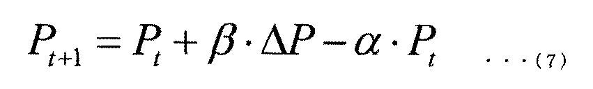
なお、第5実施形態において、計算装置23は、優先度(β)として、固定値(1/N)を用いる。
In the fifth embodiment, the calculation device 23 uses a fixed value (1 / N) as the priority (β).
(7)式中の補正率αは、補正の強さを示す。補正率αを小さくすると補正効果は小さくなり、補正率αを大きくすると電力設備12を経由して供給される総送電電力に余白、すなわち差分電力が生じ易くなる。補正率αは、負荷群11全体の適切な応答性が得られるように決定される。具体的には、統計的な契約者全体の受電時間(受電継続可能時間Tcharge)が長いほど、補正率αを小さくして、応答性を低くする。例えば、負荷群11全体で各電気自動車が平均11時間受電する(午後7時~午前6時)場合、受電継続可能時間は十分に長い。よって、補正率αを小さくしても、午前6時までに目標SOCまで充電することができる。
The correction factor α in Eq. (7) indicates the strength of correction. When the correction factor α is reduced, the correction effect is reduced, and when the correction factor α is increased, a margin, that is, a differential power is likely to occur in the total transmitted power supplied via the power equipment 12. The correction factor α is determined so that an appropriate responsiveness of the entire load group 11 can be obtained. Specifically, the longer the statistical power receiving time of the entire contractor (power receiving continuation time Tcharge), the smaller the correction factor α and the lower the responsiveness. For example, when each electric vehicle receives power for an average of 11 hours (7:00 pm to 6:00 am) in the entire load group 11, the power reception continuation time is sufficiently long. Therefore, even if the correction factor α is reduced, the target SOC can be charged by 6:00 am.
応答性の他の要因として、処理サイクルの繰り返し周期又は制御間隔がある。処理サイクルの繰り返し周期又は制御間隔が短いほど、応答性は高まるため、補正率αを小さくすることができる。想定される受電継続可能時間Tchargeと制御間隔を考慮すると、例えば、α=0.015を設定することができる。
Another factor of responsiveness is the repetition cycle of the processing cycle or the control interval. The shorter the repetition cycle or control interval of the processing cycle, the higher the responsiveness, so that the correction factor α can be reduced. Considering the assumed power reception continuation time Tcharge and the control interval, for example, α = 0.015 can be set.
計算装置23は、受電装置24が更新後の要素受電電力(Pt+1)を受電するように受電装置24に対して指示信号を送信し、指示信号を受信した受電装置24は、更新後の要素受電電力(Pt+1)を、電力設備12を経由して受電する。
The calculation device 23 transmits an instruction signal to the power receiving device 24 so that the power receiving device 24 receives the updated element power receiving power (Pt + 1), and the power receiving device 24 receiving the instruction signal receives the updated element power. The electric power (Pt + 1) is received via the electric power equipment 12.
受電制御装置は、(i)~(iv)の処理ステップを含む「処理サイクル」を一定の周期で繰り返し実行することにより、電気自動車EV1の受電装置24が受電する電力(要素受電電力Pt)を制御する。
The power receiving control device repeatedly executes a "processing cycle" including the processing steps (i) to (iv) at a fixed cycle to generate electric power (element power receiving power Pt) received by the power receiving device 24 of the electric vehicle EV1. Control.
図2のフローチャートを参照して、第5実施形態に係わる受電制御装置による受電制御方法の一例を説明する。なお、当業者であれば、図1の受電制御装置の具体的な構成及び機能の説明から、受電制御装置による受電処理方法の具体的な手順を、容易に理解できる。よって、ここでは、第5実施形態に係わる受電制御装置による受電処理方法として、受電制御装置の主要な処理動作を説明し、詳細な処理動作の説明は、受電制御装置の説明と重複するため割愛する。
An example of the power receiving control method by the power receiving control device according to the fifth embodiment will be described with reference to the flowchart of FIG. Those skilled in the art can easily understand the specific procedure of the power receiving processing method by the power receiving control device from the explanation of the specific configuration and function of the power receiving control device of FIG. Therefore, here, as a power receiving processing method by the power receiving control device according to the fifth embodiment, the main processing operation of the power receiving control device will be described, and the detailed description of the processing operation will be omitted because it overlaps with the description of the power receiving control device. To do.
まず、ステップS01で、受信装置21は、計算部31により算出された差分電力(ΔP)を示す情報を取得する。
First, in step S01, the receiving device 21 acquires information indicating the differential power (ΔP) calculated by the calculation unit 31.
その後、ステップS02を実施せずに、ステップS03に進み、受電制御装置は、受電を継続するか否かを判断する。例えば、電気自動車EV1のユーザから受電終了の指示信号を受信した場合(S03でNO)、又は、現時刻が受電の終了時刻(Td)となった場合、受電の継続を終了する。或いは、充電ポートの未接続を検知した場合など(S03でNO)、それから数分の内に、電気自動車EV1が移動を開始する可能性が高まるため、受電の継続を終了する。更に、バッテリ25の充電率(SOC)が目標値に達した場合(S03でNO)、受電の継続を終了する。これらの状況が無ければ(S03でYES)、受電制御装置は、受電を継続するために、ステップS04へ進む。
After that, the process proceeds to step S03 without executing step S02, and the power receiving control device determines whether or not to continue receiving power. For example, when the user of the electric vehicle EV1 receives an instruction signal for the end of power reception (NO in S03), or when the current time becomes the end time of power reception (T d ), the continuation of power reception is terminated. Alternatively, when it is detected that the charging port is not connected (NO in S03), the possibility that the electric vehicle EV1 starts moving within a few minutes increases, so that the continuation of power reception is terminated. Further, when the charge rate (SOC) of the battery 25 reaches the target value (NO in S03), the continuation of power reception is terminated. If these situations are not present (YES in S03), the power receiving control device proceeds to step S04 in order to continue receiving power.
ステップS04では、計算装置23は、電気自動車EV1の優先度(β)として、固定値(1/N)を設定する。ステップS05へ進み、計算装置23は、(7)式に、差分電力(ΔP)、優先度(β)、及び補正率(α=0.015)を代入することにより、要素受電電力(Pt+1)を更新する。
In step S04, the calculation device 23 sets a fixed value (1 / N) as the priority (β) of the electric vehicle EV1. Proceeding to step S05, the calculation device 23 substitutes the differential power (ΔP), the priority (β), and the correction factor (α = 0.015) into the equation (7) to obtain the element received power (Pt + 1). To update.
ステップS06へ進み、計算装置23は、受電装置24が更新後の要素受電電力(Pt+1)を受電するように受電装置24を制御する。受電制御装置は、ステップS01からステップS06までを単位とする処理サイクルを、ステップS03でNOと判定されるまで、繰り返し実行することにより、要素受電電力(Pt)を制御する。
Proceeding to step S06, the calculation device 23 controls the power receiving device 24 so that the power receiving device 24 receives the updated element power receiving power (Pt + 1). The power receiving control device controls the element power receiving power (Pt) by repeatedly executing the processing cycle in steps S01 to S06 as a unit until NO is determined in step S03.
なお、第1実施形態に対して総送電電力の現在値(Pall_now)の算出方法を変更した第1変形例(図3)、及び、差分電力(ΔP)の算出方法を変更する第2変形例(図4)を、第5実施形態及びその変形例に係わる受電制御装置及び受電制御方法に、適用できることは言うまでもない。
A first modified example (FIG. 3) in which the calculation method of the current value (Pall_now) of the total transmitted power is changed with respect to the first embodiment, and a second modified example in which the calculation method of the differential power (ΔP) is changed. Needless to say, FIG. 4 can be applied to the power receiving control device and the power receiving control method according to the fifth embodiment and its modified examples.
(シミュレーション結果)
次に、第5実施形態に係わる受電制御方法に従って受電制御を実行したシミュレーションの結果を説明する。 (simulation result)
Next, the result of the simulation in which the power receiving control is executed according to the power receiving control method according to the fifth embodiment will be described.
次に、第5実施形態に係わる受電制御方法に従って受電制御を実行したシミュレーションの結果を説明する。 (simulation result)
Next, the result of the simulation in which the power receiving control is executed according to the power receiving control method according to the fifth embodiment will be described.
先ずは、第5実施形態のシミュレーションの条件を説明する。図11Aに示すように、3台の電気自動車(EV1、EV2、EV3)の各々が、第5実施形態に係わる受電制御方法により受電制御を実行する。各電気自動車が受電を開始する時刻(開始時刻)は、異なる。電気自動車EV1の開始時刻は、午前1時であり、電気自動車EV2の開始時刻は、午前2時であり、電気自動車EV3の開始時刻は、午前3時である。各電気自動車が受電を終了する時刻(受電の終了時刻)は、異なる。電気自動車EV1の受電の終了時刻は、午前11時であり、電気自動車EV2の受電の終了時刻は、午前10時であり、電気自動車EV3の受電の終了時刻は、午前9時である。各電気自動車(EV1、EV2、EV3)の受電装置24が受電することができる電力(要素受電電力)の最大値は同じ3kWであり、各電気自動車(EV1、EV2、EV3)のバッテリ25の容量(蓄電池容量)も同じ24kWhである。更に、受電の開始時刻における各電気自動車(EV1、EV2、EV3)の充電率(開始時SOC)は同じ40%である。各電気自動車(EV1、EV2、EV3)の充電率の目標値(目標SOC)は、ユーザによる設定が無く、デフォルト値のまま、100%(満充電)である。各電気自動車(EV1、EV2、EV3)の補正率αは0.015に設定され、優先度βは1/3(固定値)に設定されている。
First, the conditions for the simulation of the fifth embodiment will be described. As shown in FIG. 11A, each of the three electric vehicles (EV1, EV2, EV3) executes power reception control by the power reception control method according to the fifth embodiment. The time (start time) at which each electric vehicle starts receiving power is different. The start time of the electric vehicle EV1 is 1:00 am, the start time of the electric vehicle EV2 is 2:00 am, and the start time of the electric vehicle EV3 is 3:00 am. The time when each electric vehicle ends receiving power (the end time of receiving power) is different. The end time of power reception of the electric vehicle EV1 is 11:00 am, the end time of power reception of the electric vehicle EV2 is 10:00 am, and the end time of power reception of the electric vehicle EV3 is 9:00 am. The maximum value of the power (elemental power received) that can be received by the power receiving device 24 of each electric vehicle (EV1, EV2, EV3) is the same 3 kW, and the capacity of the battery 25 of each electric vehicle (EV1, EV2, EV3). (Storage battery capacity) is also the same 24 kWh. Further, the charging rate (SOC at the start) of each electric vehicle (EV1, EV2, EV3) at the start time of receiving power is the same 40%. The target value (target SOC) of the charge rate of each electric vehicle (EV1, EV2, EV3) is 100% (fully charged) with the default value without being set by the user. The correction factor α of each electric vehicle (EV1, EV2, EV3) is set to 0.015, and the priority β is set to 1/3 (fixed value).
次に、シミュレーションの結果を説明する。図11Bは、シミュレーションの結果を示す8つのグラフであり、左側の4つのグラフが参考例に係わり、右側の4つのグラフが第5実施形態に係わる。各グラフの縦軸及び横軸が示す数値の種類は、図5Bの各グラフのそれらと同じであるため、再度の説明を割愛する。
Next, the results of the simulation will be explained. FIG. 11B shows eight graphs showing the results of the simulation. The four graphs on the left side relate to the reference example, and the four graphs on the right side relate to the fifth embodiment. Since the types of numerical values indicated by the vertical and horizontal axes of each graph are the same as those of each graph of FIG. 5B, the description thereof will be omitted again.
参考例では、計算装置23が、(3)式に従って、要素受電電力(Pt+1)を更新する。(3)式は、(7)式に比べて、右辺に電力補正値(αPt)の項を備えていない。よって、午前1時に受電を開始した電気自動車EV1の要素受電電力(Pt)は、自己の電力容量(3kW)まで増加する。午前2時に受電を開始した電気自動車EV2の要素受電電力(Pt)は、総送電電力の最大値(5kW)から電気自動車EV1の要素受電電力(3kW)を減算した差分電力(2kW)まで増加する。
In the reference example, the calculation device 23 updates the element received power (Pt + 1) according to the equation (3). The equation (3) does not have a power correction value (αPt) term on the right side as compared with the equation (7). Therefore, the element power receiving power (Pt) of the electric vehicle EV1 that started receiving power at 1:00 am increases to its own power capacity (3 kW). The element received power (Pt) of the electric vehicle EV2 that started receiving power at 2:00 am increases to the differential power (2 kW) obtained by subtracting the element received power (3 kW) of the electric vehicle EV1 from the maximum value of the total transmitted power (5 kW). ..
この時点において、差分電力(ΔP)は零のまま変化しない。よって、午前3時に受電を開始した電気自動車EV3の要素受電電力(Pt)は、零のまま増加しない。つまり、電気自動車EV3は受電を開始できず、充電率SOCは開始時SOCのまま変化しない。
At this point, the differential power (ΔP) remains zero and does not change. Therefore, the elemental received power (Pt) of the electric vehicle EV3, which started receiving power at 3:00 am, remains zero and does not increase. That is, the electric vehicle EV3 cannot start receiving power, and the charge rate SOC remains unchanged at the start SOC.
その後、電気自動車EV1は、午前6時頃に満充電となり、受電の継続を終了する(図2のS03でNO)。この時、電気自動車EV1の要素受電電力(3kW)が差分電力(ΔP)へ変化し、2台の電気自動車(EV2、EV3)により再分配される。これにより、電気自動車EV3の要素受電電力(Pt)は、2kWまで増加する。つまり、電気自動車EV3は受電を開始し、充電率SOCが増加し始める。
After that, the electric vehicle EV1 will be fully charged around 6 am and will end the continuation of power reception (NO in S03 in Fig. 2). At this time, the element received power (3 kW) of the electric vehicle EV1 changes to the differential power (ΔP) and is redistributed by the two electric vehicles (EV2, EV3). As a result, the element received power (Pt) of the electric vehicle EV3 is increased to 2 kW. That is, the electric vehicle EV3 starts receiving power, and the charge rate SOC starts to increase.
その後、電気自動車EV2は、午前8時頃に満充電となり、受電の継続を終了する(図2のS03でNO)。その時、電気自動車EV2の要素受電電力(3kW)が差分電力(ΔP)へ変化し、1台の電気自動車(EV3)により再分配される。
After that, the electric vehicle EV2 will be fully charged around 8:00 am, and the continuation of power reception will end (NO in S03 in Fig. 2). At that time, the element received power (3 kW) of the electric vehicle EV2 changes to the differential power (ΔP) and is redistributed by one electric vehicle (EV3).
その後、午前9時に、電気自動車EV3の「受電の終了時刻(Td)」を迎えたため、電気自動車EV3は、受電の継続を終了する(図2のS03でNO)。この時の電気自動車EV3の充電率は、約60%であった。
After that, at 9:00 am, the "end time of power reception (T d )" of the electric vehicle EV3 was reached, so that the electric vehicle EV3 ends the continuation of power reception (NO in S03 of FIG. 2). The charging rate of the electric vehicle EV3 at this time was about 60%.
このように、参考例において、差分電力(ΔP)が零である時に、新たな電気自動車EV3が受電を開始しようとしても、他の電気自動車EV1が受電の継続を終了する(図2のS03でNO)まで、電気自動車EV3は受電を開始することができない。よって、新たな電気自動車EV3の受電を早期に開始することが難しい。
As described above, in the reference example, when the differential power (ΔP) is zero, even if the new electric vehicle EV3 tries to start receiving power, the other electric vehicle EV1 ends the continuation of power receiving (in S03 of FIG. 2). Until NO), the electric vehicle EV3 cannot start receiving power. Therefore, it is difficult to start receiving power of the new electric vehicle EV3 at an early stage.
これに対して、第5実施形態では、計算装置23が、右辺に電力補正値(αPt)の項を備える(7)式に従って、要素受電電力(Pt+1)を更新する。よって、午前2時に電気自動車EV2が受電を開始した後、電力設備12を経由して供給される総送電電力の現在値(Pall_now)に余白が生じる。つまり、差分電力(ΔP)が零になりにくくなる。総送電電力の現在値(Pall_now)の余白が、差分電力(ΔP)として、新たに受電を開始しようと試みた電気自動車EV3にも分配される。
On the other hand, in the fifth embodiment, the calculation device 23 updates the element received power (Pt + 1) according to the equation (7) including the term of the power correction value (αPt) on the right side. Therefore, after the electric vehicle EV2 starts receiving power at 2:00 am, a margin is generated in the current value (Pall_now) of the total transmitted power supplied via the power facility 12. That is, the differential power (ΔP) is less likely to become zero. The margin of the current value (Pall_now) of the total transmitted power is also distributed as the differential power (ΔP) to the electric vehicle EV3 that has tried to newly start receiving power.
よって、電気自動車EV3の要素受電電力は、受電を開始した時刻(午前3時)から増加している。これにより、電気自動車EV3の「受電の終了時刻(午前9時)」における充電率SOCを、約60%から約70%まで高めることができた。このように、電気自動車EV3は、他の電気自動車EV1の受電の終了を待たずに、早期に受電を開始することができるので、電気自動車EV3の受電終了時の充電率を高めることができた。
Therefore, the elemental power reception of the electric vehicle EV3 has increased from the time when the power reception was started (3:00 am). As a result, the charge rate SOC at the "end time of power reception (9:00 am)" of the electric vehicle EV3 could be increased from about 60% to about 70%. In this way, the electric vehicle EV3 can start receiving power at an early stage without waiting for the end of power reception of the other electric vehicle EV1, so that the charging rate at the end of power reception of the electric vehicle EV3 can be increased. ..
(7)式に示したように、電力補正値(αPt)は、要素受電電力(Pt)に比例している。これにより、要素受電電力(Pt)に応じて、総送電電力に生じる余白を、複数の電気自動車の間で負担し合うことができる。
As shown in equation (7), the power correction value (αPt) is proportional to the element received power (Pt). As a result, the margin generated in the total transmitted power can be shared among the plurality of electric vehicles according to the element received power (Pt).
(第3変形例)
第5実施形態における優先度(β)は、固定値(1/N)であった。これに対して、第3変形例では、バッテリ25の充電率の目標値(SOCgoal)からバッテリ25の充電率の現在値(SOCnow)を減算して得られる未充電率(ΔSOC)に基づいて、優先度(β)を算出する例を説明する。 (Third modification example)
The priority (β) in the fifth embodiment was a fixed value (1 / N). On the other hand, in the third modification, based on the uncharged rate (ΔSOC) obtained by subtracting the current value (SOCnow) of the charge rate of thebattery 25 from the target value (SOCgoal) of the charge rate of the battery 25. An example of calculating the priority (β) will be described.
第5実施形態における優先度(β)は、固定値(1/N)であった。これに対して、第3変形例では、バッテリ25の充電率の目標値(SOCgoal)からバッテリ25の充電率の現在値(SOCnow)を減算して得られる未充電率(ΔSOC)に基づいて、優先度(β)を算出する例を説明する。 (Third modification example)
The priority (β) in the fifth embodiment was a fixed value (1 / N). On the other hand, in the third modification, based on the uncharged rate (ΔSOC) obtained by subtracting the current value (SOCnow) of the charge rate of the
第3変形例に係わる受電制御装置は、車両状態取得装置22を備える。車両状態取得装置22は、バッテリ25の充電率の目標値(SOCgoal)及びバッテリ25の充電率の現在値(SOCnow)を示す情報を取得する。具体的には、図2に示す処理サイクルのステップS02において、車両状態取得装置22は、バッテリ25の充電率を測定し、測定した値を、現在値(SOCnow)として取得する。
The power receiving control device according to the third modification includes a vehicle state acquisition device 22. The vehicle state acquisition device 22 acquires information indicating a target value (SOCgoal) of the charge rate of the battery 25 and a current value (SOCnow) of the charge rate of the battery 25. Specifically, in step S02 of the processing cycle shown in FIG. 2, the vehicle state acquisition device 22 measures the charge rate of the battery 25 and acquires the measured value as the current value (SOCnow).
計算装置23は、図2のステップS04において、(8)式を用いて、バッテリ25の充電率の目標値(SOCgoal)から電気自動車EV1の優先度(β)を算出する。優先度(β)は未充電率(ΔSOC)に比例する。或いは、優先度(β)は未充電率(ΔSOC)のg乗(gは2以上の正数)に比例していてもよい。ユーザが目標値(SOCgoal)を設定していない場合は、目標値(SOCgoal)を100%即ち1.00に設定する。
In step S04 of FIG. 2, the calculation device 23 calculates the priority (β) of the electric vehicle EV1 from the target value (SOCgoal) of the charge rate of the battery 25 by using the equation (8). The priority (β) is proportional to the uncharged rate (ΔSOC). Alternatively, the priority (β) may be proportional to the uncharged rate (ΔSOC) raised to the gth power (g is a positive number of 2 or more). If the user has not set a target value (SOCgoal), the target value (SOCgoal) is set to 100%, that is, 1.00.

なお、第3変形例において、現在値(SOCnow)が目標値(SOCgoal)に到達した時、図2のステップS03において、計算装置23は、受電の継続を終了すると判断してもよい。
In the third modification, when the current value (SOCnow) reaches the target value (SOCgoal), the calculation device 23 may determine that the continuation of power reception is terminated in step S03 of FIG.
(シミュレーション結果)
次に、第3変形例に係わる受電制御方法に従って受電制御を実行したシミュレーションの結果を説明する。 (simulation result)
Next, the result of the simulation in which the power receiving control is executed according to the power receiving control method according to the third modification will be described.
次に、第3変形例に係わる受電制御方法に従って受電制御を実行したシミュレーションの結果を説明する。 (simulation result)
Next, the result of the simulation in which the power receiving control is executed according to the power receiving control method according to the third modification will be described.
第3変形例のシミュレーションの条件は、図11A及び図12Aに示すように、第5実施形態のシミュレーションの条件と同じである。各電気自動車(EV1、EV2、EV3)の補正率αは0.015に設定され、優先度βは、参考例及び第3変形例の双方とも、(8)式に従って計算される。
As shown in FIGS. 11A and 12A, the simulation conditions of the third modification are the same as the simulation conditions of the fifth embodiment. The correction factor α of each electric vehicle (EV1, EV2, EV3) is set to 0.015, and the priority β is calculated according to the equation (8) in both the reference example and the third modification.
次に、シミュレーションの結果を説明する。図12Bは、シミュレーションの結果を示す8つのグラフであり、左側の4つのグラフが参考例に係わり、右側の4つのグラフが第3変形例に係わる。各グラフの縦軸及び横軸が示す数値の種類は、図5Bの各グラフのそれらと同じであるため、再度の説明を割愛する。
Next, the results of the simulation will be explained. FIG. 12B shows eight graphs showing the results of the simulation. The four graphs on the left side relate to the reference example, and the four graphs on the right side relate to the third modified example. Since the types of numerical values indicated by the vertical and horizontal axes of each graph are the same as those of each graph of FIG. 5B, the description thereof will be omitted again.
参考例では、計算装置23が、(3)式に従って、要素受電電力(Pt+1)を更新する。(3)式は、(7)式に比べて、右辺に電力補正値(αPt)の項を備えていない。よって、電気自動車EV2が受電を開始した午前2時以降、差分電力(ΔP)は零のまま変化しない。よって、午前3時に受電を開始した電気自動車EV3の優先度が、他の電気自動車(EV1、EV2)よりも高いにも係わらず、電気自動車EV3は、他の電気自動車EV1の受電が終了する午前6時まで、受電を開始できず、充電率SOCは開始時SOCのまま変化しない。受電の終了時刻(午前9時)における電気自動車EV3の充電率は、約60%であった。
In the reference example, the calculation device 23 updates the element received power (Pt + 1) according to the equation (3). The equation (3) does not have a power correction value (αPt) term on the right side as compared with the equation (7). Therefore, after 2:00 am when the electric vehicle EV2 starts receiving power, the differential power (ΔP) remains zero and does not change. Therefore, although the electric vehicle EV3 that started receiving power at 3:00 am has a higher priority than the other electric vehicles (EV1, EV2), the electric vehicle EV3 is in the morning when the power reception of the other electric vehicle EV1 ends. Until 6 o'clock, power reception cannot be started, and the charge rate SOC remains unchanged at the start SOC. The charge rate of the electric vehicle EV3 at the end time of power reception (9:00 am) was about 60%.
これに対して、第3変形例では、計算装置23が、右辺に電力補正値(αPt)の項を備える(7)式に従って、要素受電電力(Pt+1)を更新する。よって、午前2時に電気自動車EV2が受電を開始した後、電力設備12を経由して供給される総送電電力の現在値(Pall_now)に余白が生じる。つまり、差分電力(ΔP)が零に成りにくくなる。総送電電力の現在値(Pall_now)に余白が、差分電力(ΔP)として、新たに受電を開始しようと試みた電気自動車EV3にも分配される。
On the other hand, in the third modification, the calculation device 23 updates the element received power (Pt + 1) according to the equation (7) having the term of the power correction value (αPt) on the right side. Therefore, after the electric vehicle EV2 starts receiving power at 2:00 am, a margin is generated in the current value (Pall_now) of the total transmitted power supplied via the power facility 12. That is, the differential power (ΔP) is less likely to become zero. A margin is distributed to the current value (Pall_now) of the total transmitted power as the differential power (ΔP) to the electric vehicle EV3 that has tried to newly start receiving power.
よって、電気自動車EV3の要素受電電力は、受電を開始した時刻(午前3時)から増加している。これにより、電気自動車EV3の「受電の終了時刻(午前9時)」における充電率SOCを、約60%から約80%まで高めることができた。このように、電気自動車EV3は、他の電気自動車EV1の受電の終了を待たずに、早期に受電を開始することができるので、電気自動車EV3の受電終了時の充電率を高めることができた。
Therefore, the elemental power reception of the electric vehicle EV3 has increased from the time when the power reception was started (3:00 am). As a result, the charge rate SOC at the "end time of power reception (9:00 am)" of the electric vehicle EV3 could be increased from about 60% to about 80%. In this way, the electric vehicle EV3 can start receiving power at an early stage without waiting for the end of power reception of the other electric vehicle EV1, so that the charging rate at the end of power reception of the electric vehicle EV3 can be increased. ..
(第4変形例)
第4変形例では、未充電率(ΔSOC)の代わりに、現時刻(To)から受電の終了時刻(Td)までの残り時間(T)に基づいて、優先度(β)を算出する例を説明する。 (Fourth modification)
In the fourth modification, in place of the non-charging rate ([Delta] SOC), based on the end time of receiving from the current time (T o) (T d) remaining up to the time (T), calculates priority (beta) An example will be described.
第4変形例に係わる受電制御装置は、車両状態取得装置22を備える。車両状態取得装置22は、現時刻(To)から電気自動車EV1の受電の終了時刻(Td)までの残り時間(T)を示す情報を取得する。具体的には、図2に示す処理サイクルのステップS02において、車両状態取得装置22は、残り時間(T)を示す情報を取得する。或いは、受電の終了時刻(Td)を示す情報を取得し、現時刻(To)から受電の終了時刻(Td)までの残り時間(T)を算出しても構わない。
The power receiving control device according to the fourth modification includes a vehicle state acquisition device 22. Vehicle state obtaining apparatus 22 acquires information indicating the current time (T o) from the end time of the power receiving electric vehicle EV1 (T d) remaining up to the time (T). Specifically, in step S02 of the processing cycle shown in FIG. 2, the vehicle state acquisition device 22 acquires information indicating the remaining time (T). Alternatively, to get the information indicating the end time of the power-receiving (T d), it is also possible to calculate the current time (T o) end time (T d) until the remaining time of receiving from (T).
計算装置23は、図2のステップS04において、(2)式を用いて、現時刻(To)から受電の終了時刻(Td)までの残り時間(T)から優先度(β)を算出する。優先度(β)は残り時間(T)に反比例する。残り時間(T)が短くなるにつれて、優先度(β)は高くなる。(2)式は一例にすぎず、例えば、優先度(β)は、残り時間(T)を2以上のg回(gは正数)掛け算した「残り時間(T)のg乗」に反比例してもよい。
Calculating computing device 23 in step S04 of FIG. 2, (2) using the formula, priority from the end time of receiving from the current time (T o) (T d) remaining up to the time (T) (beta) To do. The priority (β) is inversely proportional to the remaining time (T). As the remaining time (T) becomes shorter, the priority (β) becomes higher. Equation (2) is only an example. For example, the priority (β) is inversely proportional to the “remaining time (T) to the g-th power” obtained by multiplying the remaining time (T) by two or more g times (g is a positive number). You may.
(シミュレーション結果)
次に、第4変形例に係わる受電制御方法に従って受電制御を実行したシミュレーションの結果を説明する。 (simulation result)
Next, the result of the simulation in which the power receiving control is executed according to the power receiving control method according to the fourth modification will be described.
次に、第4変形例に係わる受電制御方法に従って受電制御を実行したシミュレーションの結果を説明する。 (simulation result)
Next, the result of the simulation in which the power receiving control is executed according to the power receiving control method according to the fourth modification will be described.
第4変形例のシミュレーションの条件は、図11A及び図13Aに示すように、第5実施形態のシミュレーションの条件と同じである。各電気自動車(EV1、EV2、EV3)の補正率αは0.015に設定され、優先度βは、参考例及び第4変形例の双方とも、(2)式に従って計算される。
As shown in FIGS. 11A and 13A, the simulation conditions of the fourth modification are the same as the simulation conditions of the fifth embodiment. The correction factor α of each electric vehicle (EV1, EV2, EV3) is set to 0.015, and the priority β is calculated according to the equation (2) in both the reference example and the fourth modification.
次に、シミュレーションの結果を説明する。図13Bは、シミュレーションの結果を示す8つのグラフであり、左側の4つのグラフが参考例に係わり、右側の4つのグラフが第4変形例に係わる。各グラフの縦軸及び横軸が示す数値の種類は、図5Bの各グラフのそれらと同じであるため、再度の説明を割愛する。
Next, the results of the simulation will be explained. FIG. 13B shows eight graphs showing the results of the simulation. The four graphs on the left side relate to the reference example, and the four graphs on the right side relate to the fourth modified example. Since the types of numerical values indicated by the vertical and horizontal axes of each graph are the same as those of each graph of FIG. 5B, the description thereof will be omitted again.
参考例では、計算装置23が、(3)式に従って、要素受電電力(Pt+1)を更新する。(3)式は、(7)式に比べて、右辺に電力補正値(αPt)の項を備えていない。よって、電気自動車EV2の要素受電電力が安定した午前3時以降、差分電力(ΔP)は零のまま変化しない。よって、午前3時に受電を開始した電気自動車EV3の優先度が、他の電気自動車(EV1、EV2)よりも高いにも係わらず、電気自動車EV3の要素受電電力(Pt)は増加せず、ほぼ零のままを維持する。よって、他の電気自動車EV1の受電が終了する午前6時まで、電気自動車EV3は受電を開始できず、充電率SOCは開始時SOCのまま、ほとんど変化しない。受電の終了時刻(午前9時)における電気自動車EV3の充電率は、約60%であった。
In the reference example, the calculation device 23 updates the element received power (Pt + 1) according to the equation (3). The equation (3) does not have a power correction value (αPt) term on the right side as compared with the equation (7). Therefore, after 3:00 am when the element received power of the electric vehicle EV2 is stable, the differential power (ΔP) remains zero and does not change. Therefore, although the priority of the electric vehicle EV3 that started receiving power at 3:00 am is higher than that of the other electric vehicles (EV1, EV2), the element power received power (Pt) of the electric vehicle EV3 does not increase and is almost the same. Keep at zero. Therefore, the electric vehicle EV3 cannot start receiving power until 6:00 am when the power reception of the other electric vehicle EV1 ends, and the charge rate SOC remains the SOC at the start and hardly changes. The charge rate of the electric vehicle EV3 at the end time of power reception (9:00 am) was about 60%.
これに対して、第4変形例では、計算装置23が、右辺に電力補正値(αPt)の項を備える(7)式に従って、要素受電電力(Pt+1)を更新する。よって、午前2時に電気自動車EV2が受電を開始した後、電気自動車EV1の要素受電電力が減少し始め、午前3時以降においても、差分電力(ΔP)が零にならず、総送電電力の現在値(Pall_now)に余白が残った。これにより、総送電電力の現在値(Pall_now)の余白が、差分電力(ΔP)として、午前3時に新たに受電を開始しようと試みた電気自動車EV3にも分配され、早期に、電気自動車EV3の要素受電電力が増加した。このように、総送電電力の現在値(Pall_now)に余白が残ることにより、新たに受電を開始しようとする電気自動車EV3に早期に受電を開始させることができた。
On the other hand, in the fourth modification, the calculation device 23 updates the element received power (Pt + 1) according to the equation (7) having the term of the power correction value (αPt) on the right side. Therefore, after the electric vehicle EV2 starts receiving power at 2:00 am, the element power received by the electric vehicle EV1 begins to decrease, and even after 3:00 am, the differential power (ΔP) does not become zero, and the total transmitted power is now. A margin remained in the value (Pall_now). As a result, the margin of the current value (Pall_now) of the total transmitted power is distributed as the differential power (ΔP) to the electric vehicle EV3 that tried to newly start receiving power at 3:00 am, and the electric vehicle EV3 at an early stage. Element power received has increased. As described above, since a margin remains in the current value (Pall_now) of the total transmitted power, the electric vehicle EV3, which is about to newly start receiving power, can be started to receive power at an early stage.
電気自動車EV3の要素受電電力は、受電を開始した時刻(午前3時)から増加している。これにより、電気自動車EV3の「受電の終了時刻(午前9時)」における充電率SOCを、約60%から約80%まで高めることができた。このように、電気自動車EV3は、他の電気自動車EV1の受電の終了を待たずに、早期に受電を開始することができるので、電気自動車EV3の受電終了時の充電率を高めることができた。
The elemental power received by the electric vehicle EV3 has increased since the time when power reception started (3:00 am). As a result, the charge rate SOC at the "end time of power reception (9:00 am)" of the electric vehicle EV3 could be increased from about 60% to about 80%. In this way, the electric vehicle EV3 can start receiving power at an early stage without waiting for the end of power reception of the other electric vehicle EV1, so that the charging rate at the end of power reception of the electric vehicle EV3 can be increased. ..
電気自動車EV1の満充電となる時刻は、参考例より遅くなったが、電気自動車EV1の受電の終了時刻(Td)までには満充電に到達したため、ユーザの要求は満たされている。また、受電の終了時刻(10時=Td)における電気自動車EV2の充電率は、満充電に到達しなかったが、95%以上の充電率まで到達しているため、ユーザの要求は十分に満たされていると判断できる。このように、負荷群11に含まれる全ての電気自動車(EV1~VE3)のユーザの要求を満たしつつ、各電気自動車の充電率を平準化することができた。換言すれば、各電気自動車の終了時刻(Td)における充電率の分散を小さくすることができた。
The time when the electric vehicle EV1 is fully charged is later than the reference example, but the user's request is satisfied because the electric vehicle EV1 has reached the full charge by the end time (T d ) of receiving power. In addition, the charging rate of the electric vehicle EV2 at the end time of power reception (10 o'clock = T d ) did not reach full charge, but reached a charging rate of 95% or more, so that the user's request is sufficient. It can be judged that it is satisfied. In this way, it was possible to level the charge rate of each electric vehicle while satisfying the user requirements of all the electric vehicles (EV1 to VE3) included in the load group 11. In other words, it was possible to reduce the dispersion of the charge rate at the end time (T d ) of each electric vehicle.
(第5変形例)
第5変形例では、未充電率(ΔSOC)及び受電の終了時刻(Td)までの残り時間(T)に基づいて、優先度(β)を算出する例を説明する。なお、第5変形例では、優先度(β)を算出する方法として、第3実施形態で説明した(5)式を用いた優先度(β)の算出方法を援用することができる。 (Fifth modification)
In the fifth modification, an example of calculating the priority (β) based on the uncharged rate (ΔSOC) and the remaining time (T) until the end time of power reception (T d ) will be described. In the fifth modification, as a method for calculating the priority (β), the method for calculating the priority (β) using the equation (5) described in the third embodiment can be used.
第5変形例に係わる受電制御装置は、車両状態取得装置22を備える。車両状態取得装置22は、充電率の目標値(SOCgoal)及びバッテリ25の充電率の現在値(SOCnow)を示す情報、及び残り時間(T)を示す情報を取得する。具体的には、図2に示す処理サイクルのステップS02において、車両状態取得装置22は、バッテリ25の充電率を測定し、測定した値を、現在値(SOCnow)として取得する。更に、車両状態取得装置22は、残り時間(T)を示す情報を取得する。或いは、車両状態取得装置22は、受電の終了時刻(Td)を示す情報を取得し、受電の終了時刻(Td)までの残り時間(T)を算出しても構わない。
The power receiving control device according to the fifth modification includes a vehicle state acquisition device 22. The vehicle state acquisition device 22 acquires information indicating a target value (SOCgoal) of the charge rate, a current value (SOCnow) of the charge rate of the battery 25, and information indicating the remaining time (T). Specifically, in step S02 of the processing cycle shown in FIG. 2, the vehicle state acquisition device 22 measures the charge rate of the battery 25 and acquires the measured value as the current value (SOCnow). Further, the vehicle state acquisition device 22 acquires information indicating the remaining time (T). Alternatively, the vehicle-state obtaining apparatus 22 acquires the information indicating the end time of power reception (T d), it may be calculated end time of power reception (T d) remaining time until (T).
ステップS04で、計算装置23は、(2)式の代わりに、(5)式を用いて、終了時刻(Td)までの残り時間(T)及びバッテリ25の充電率の目標値(SOCgoal)から電気自動車EV1の優先度(β)を算出する。第5変形例では、(5)式を用いて優先度(β)を算出するが、(5)式の代わりに(6)式を用いても構わない。
In step S04, the calculation device 23 uses the equation (5) instead of the equation (2) to obtain the target value (SOCgoal) of the remaining time (T) until the end time (T d ) and the charge rate of the battery 25. The priority (β) of the electric vehicle EV1 is calculated from. In the fifth modification, the priority (β) is calculated using the equation (5), but the equation (6) may be used instead of the equation (5).
(シミュレーション結果)
次に、第5変形例に係わる受電制御方法に従って受電制御を実行したシミュレーションの結果を説明する。 (simulation result)
Next, the result of the simulation in which the power receiving control is executed according to the power receiving control method according to the fifth modification will be described.
次に、第5変形例に係わる受電制御方法に従って受電制御を実行したシミュレーションの結果を説明する。 (simulation result)
Next, the result of the simulation in which the power receiving control is executed according to the power receiving control method according to the fifth modification will be described.
第5変形例のシミュレーションの条件は、図11A及び図14Aに示すように、第5実施形態のシミュレーションの条件と同じである。各電気自動車(EV1、EV2、EV3)の補正率αは0.015に設定され、優先度βは、参考例及び第5変形例の双方とも、(5)式に従って計算される。ただし、充電率の目標値(SOCgoal)は、デフォルト値である満充電(100%=1.00)に設定されている。
As shown in FIGS. 11A and 14A, the simulation conditions of the fifth modification are the same as the simulation conditions of the fifth embodiment. The correction factor α of each electric vehicle (EV1, EV2, EV3) is set to 0.015, and the priority β is calculated according to the equation (5) in both the reference example and the fifth modification. However, the target value (SOCgoal) of the charge rate is set to the default value of full charge (100% = 1.00).
次に、シミュレーションの結果を説明する。図14Bは、シミュレーションの結果を示す8つのグラフであり、左側の4つのグラフが参考例に係わり、右側の4つのグラフが第5変形例に係わる。各グラフの縦軸及び横軸が示す数値の種類は、図5Bの各グラフのそれらと同じであるため、再度の説明を割愛する。
Next, the results of the simulation will be explained. FIG. 14B shows eight graphs showing the results of the simulation. The four graphs on the left side relate to the reference example, and the four graphs on the right side relate to the fifth modified example. Since the types of numerical values indicated by the vertical and horizontal axes of each graph are the same as those of each graph of FIG. 5B, the description thereof will be omitted again.
参考例では、計算装置23が、(3)式に従って、要素受電電力(Pt+1)を更新する。(3)式は、(7)式に比べて、右辺に電力補正値(αPt)の項を備えていない。よって、電気自動車EV2の要素受電電力が安定した午前4時以降、差分電力(ΔP)は零のまま変化しない。ただし、電気自動車EV3が受電を開始した午前3時の時点において、差分電力(ΔP)は僅かに残っていたため、電気自動車EV3の要素受電電力(Pt)は僅かに増加するが、差分電力(ΔP)が零になった午前4時以降、増加していない。よって、午前3時に受電を開始した電気自動車EV3の優先度が、他の電気自動車(EV1、EV2)よりも高いにも係わらず、電気自動車EV3の要素受電電力(Pt)は、他の電気自動車(EV1、EV2)の要素受電電力(Pt)よりも大きくなっていない。よって、他の電気自動車EV1の受電が終了する午前6時まで、電気自動車EV3は受電を開始できず、充電率SOCは開始時SOCのまま、ほとんど変化しない。受電の終了時刻(午前9時)における電気自動車EV3の充電率は、約60%であった。
In the reference example, the calculation device 23 updates the element received power (Pt + 1) according to the equation (3). The equation (3) does not have a power correction value (αPt) term on the right side as compared with the equation (7). Therefore, after 4:00 am when the element received power of the electric vehicle EV2 is stable, the differential power (ΔP) remains zero and does not change. However, since the differential power (ΔP) remained slightly at 3:00 am when the electric vehicle EV3 started receiving power, the element power received power (Pt) of the electric vehicle EV3 slightly increased, but the differential power (ΔP). ) Has not increased since 4:00 am when it became zero. Therefore, although the priority of the electric vehicle EV3 that started receiving power at 3:00 am is higher than that of the other electric vehicles (EV1, EV2), the element power received (Pt) of the electric vehicle EV3 is the other electric vehicle. It is not larger than the element power receiving power (Pt) of (EV1, EV2). Therefore, the electric vehicle EV3 cannot start receiving power until 6:00 am when the power reception of the other electric vehicle EV1 ends, and the charge rate SOC remains the SOC at the start and hardly changes. The charge rate of the electric vehicle EV3 at the end time of power reception (9:00 am) was about 60%.
これに対して、第5変形例では、計算装置23が、右辺に電力補正値(αPt)の項を備える(7)式に従って、要素受電電力(Pt+1)を更新する。よって、午前2時に電気自動車EV2が受電を開始した後、電気自動車EV1の要素受電電力が減少し始め、午前3時以降においても、差分電力(ΔP)が零にならず、総送電電力の現在値(Pall_now)に余白が残った。これにより、総送電電力の現在値(Pall_now)の余白が、差分電力(ΔP)として、午前3時に新たに受電を開始しようとした電気自動車EV3にも分配され、早期に、電気自動車EV3の要素受電電力が増加した。このように、総送電電力の現在値(Pall_now)に余白が残ることにより、新たに受電を開始しようとする電気自動車EV3に早期に受電を開始させることができた。
On the other hand, in the fifth modification, the calculation device 23 updates the element received power (Pt + 1) according to the equation (7) having the term of the power correction value (αPt) on the right side. Therefore, after the electric vehicle EV2 starts receiving power at 2:00 am, the element power received by the electric vehicle EV1 begins to decrease, and even after 3:00 am, the differential power (ΔP) does not become zero, and the total transmitted power is now. A margin remained in the value (Pall_now). As a result, the margin of the current value (Pall_now) of the total transmitted power is distributed as the differential power (ΔP) to the electric vehicle EV3 that is about to start receiving new power at 3:00 am, and the elements of the electric vehicle EV3 are early. Power received has increased. As described above, since a margin remains in the current value (Pall_now) of the total transmitted power, the electric vehicle EV3, which is about to newly start receiving power, can be started to receive power at an early stage.
電気自動車EV3の要素受電電力は、受電を開始した時刻(午前3時)から増加している。これにより、電気自動車EV3の「受電の終了時刻(午前9時)」における充電率SOCを、約60%から約80%まで高めることができた。このように、電気自動車EV3は、他の電気自動車EV1の受電の終了を待たずに、早期に受電を開始することができるので、電気自動車EV3の受電終了時の充電率を高めることができた。
The elemental power received by the electric vehicle EV3 has increased since the time when power reception started (3:00 am). As a result, the charge rate SOC at the "end time of power reception (9:00 am)" of the electric vehicle EV3 could be increased from about 60% to about 80%. In this way, the electric vehicle EV3 can start receiving power at an early stage without waiting for the end of power reception of the other electric vehicle EV1, so that the charging rate at the end of power reception of the electric vehicle EV3 can be increased. ..
受電の終了時刻(11時=Td)における電気自動車EV1の充電率は、満充電に到達しなかったが、95%以上の充電率まで到達しているため、ユーザの要求は十分に満たされていると判断できる。同様に、受電の終了時刻(10時=Td)における電気自動車EV2の充電率は、満充電に到達しなかったが、約90%の充電率まで到達しているため、ユーザの要求は十分に満たされていると判断できる。このように、負荷群11に含まれる全ての電気自動車(EV1~VE3)のユーザの要求を満たしつつ、各電気自動車の充電率を平準化することができた。換言すれば、各電気自動車の終了時刻(Td)における充電率の分散を小さくすることができた。
The charging rate of the electric vehicle EV1 at the end time of power reception (11:00 = Td ) did not reach full charge, but reached a charging rate of 95% or more, so that the user's request was fully satisfied. It can be judged that it is. Similarly, the charge rate of the electric vehicle EV2 at the end time of power reception (10 o'clock = T d ) did not reach full charge, but reached a charge rate of about 90%, so the user's request is sufficient. It can be judged that the condition is satisfied. In this way, it was possible to level the charge rate of each electric vehicle while satisfying the user requirements of all the electric vehicles (EV1 to VE3) included in the load group 11. In other words, it was possible to reduce the dispersion of the charge rate at the end time (T d ) of each electric vehicle.
(第6変形例)
第5実施形態の受電制御装置は、(7)式に示すように、要素受電電力(Pt)を更新する際に、前回の要素受電電力(Pt)から、電力補正値(αPt)を減算することにより、差分電力(ΔP)を零に成り難くしている。これにより、総送電電力の現在値(Pall_now)に余白が生じて、新たに受電を開始しようとする電気自動車に早期に受電を開始させることができる。 (6th modification)
As shown in the equation (7), the power receiving control device of the fifth embodiment subtracts the power correction value (αPt) from the previous element power receiving power (Pt) when updating the element power receiving power (Pt). This makes it difficult for the differential power (ΔP) to become zero. As a result, a margin is generated in the current value (Pall_now) of the total transmitted power, and the electric vehicle that is about to newly start receiving power can start receiving power at an early stage.
その一方で、電力補正値(αPt)を減算することにより、電力供給基点10を経由して負荷群11の全体に送っている総送電電力の現在値(Pall_now)は、総送電電力の最大値(Pall_max)に収束せずに、総送電電力の最大値(Pall_max)よりも小さくなる。これにより、総送電電力の利用効率、すなわち、総送電電力の最大値(Pall_max)に対する総送電電力の現在値(Pall_now)の割合は低くなる。
On the other hand, by subtracting the power correction value (αPt), the current value (Pall_now) of the total transmitted power transmitted to the entire load group 11 via the power supply base point 10 is the maximum value of the total transmitted power. It does not converge to (Pall_max) and becomes smaller than the maximum value (Pall_max) of the total transmitted power. As a result, the utilization efficiency of the total transmitted power, that is, the ratio of the current value (Pall_now) of the total transmitted power to the maximum value (Pall_max) of the total transmitted power becomes low.
電力補正値(αPt)の減算が必要となるのは、差分電力(ΔP)が零となる場合であって、差分電力(ΔP)が零で無ければ、電力補正値(αPt)を減算する必要はない。
The power correction value (αPt) needs to be subtracted when the differential power (ΔP) becomes zero, and if the differential power (ΔP) is not zero, the power correction value (αPt) needs to be subtracted. There is no.
そこで、第6変形例の受電制御方法は、図2に示す処理サイクルに、差分電力(ΔP)が零であるか否かを判断する処理ステップを追加し、その判断結果に応じてステップS05の要素受電電力(Pt)の更新ステップにおいて使用する計算式を、(3)式と(7)式とで使い分ける。
Therefore, the power receiving control method of the sixth modification adds a processing step for determining whether or not the differential power (ΔP) is zero to the processing cycle shown in FIG. 2, and in step S05 according to the determination result. The calculation formula used in the update step of the element received power (Pt) is properly used by the formula (3) and the formula (7).
計算装置23は、図2のステップS05において、更新後の要素受電電力(Pt+1)を算出する前に、ステップS01で取得した情報が示す差分電力(ΔP)が零であるか否かを判断する。
In step S05 of FIG. 2, the calculation device 23 determines whether or not the differential power (ΔP) indicated by the information acquired in step S01 is zero before calculating the updated element received power (Pt + 1). ..
第6変形例において、「差分電力(ΔP)が零である」とは、差分電力(ΔP)が正確に零である場合のみならず、差分電力(ΔP)が零であると見なすことができる一定の範囲(以後、「零の範囲」よ呼ぶ)内である場合も含まれる。零の範囲は、差分電力(ΔP)が0以上、しきい電力(ΔPth)以下である範囲である。
In the sixth modification, "the differential power (ΔP) is zero" can be considered not only when the differential power (ΔP) is exactly zero, but also when the differential power (ΔP) is zero. It also includes the case where it is within a certain range (hereinafter referred to as "zero range"). The range of zero is a range in which the differential power (ΔP) is 0 or more and the threshold power (ΔPth) or less.
零の範囲に応じて、受電制御システムの応答性が変化する。零の範囲を広げることにより、総送電電力の余白を早く発生させることができる、つまり、総送電電力の余白を作る応答性を高めることができる。これにより、新たな電気自動車に早期に受電を開始させることができる。一方、零の範囲を狭めることにより、差分電力の余白の発生を遅らせることができる。つまり、総送電電力の余白を作る応答性を低くすることができる。これにより、総送電電力の現在値(Pall_now)を総送電電力の最大値(Pall_max)により近づけることができるので、総送電電力の利用効率(Pall_now/Pall_max)を高めることができる。このように、零の範囲、つまり、しきい電圧(ΔPth)は、新たな電気自動車の早期受電開始と、総送電電力の利用効率の向上とを勘案して、定められるパラメータである。
The responsiveness of the power receiving control system changes according to the range of zero. By expanding the range of zero, the margin of the total transmitted power can be generated quickly, that is, the responsiveness of creating the margin of the total transmitted power can be improved. As a result, the new electric vehicle can start receiving power at an early stage. On the other hand, by narrowing the range of zero, it is possible to delay the generation of the margin of the differential power. That is, the responsiveness that creates the margin of the total transmitted power can be lowered. As a result, the current value (Pall_now) of the total transmitted power can be brought closer to the maximum value (Pall_max) of the total transmitted power, so that the utilization efficiency (Pall_now / Pall_max) of the total transmitted power can be improved. As described above, the zero range, that is, the threshold voltage (ΔPth) is a parameter determined in consideration of the early start of power reception of a new electric vehicle and the improvement of the utilization efficiency of the total transmitted power.
差分電力(ΔP)が零であると判断した場合、計算装置23は、総送電電力の現在値(Pall_now)に余白を生成する必要があるため、(7)式に基づいて、要素受電電力(Pt+1)を更新する。即ち、計算装置23は、前回の処理サイクルにおける要素受電電力(Pt)に、要素差分電力(βΔP)を加算し、且つ、電力補正値(αPt)を減算することにより、要素受電電力(Pt+1)を更新する。
When it is determined that the differential power (ΔP) is zero, the calculation device 23 needs to generate a margin in the current value (Pall_now) of the total transmitted power. Therefore, based on the equation (7), the element received power (7) Pt + 1) is updated. That is, the calculation device 23 adds the element differential power (βΔP) to the element received power (Pt) in the previous processing cycle and subtracts the power correction value (αPt) to obtain the element received power (Pt + 1). To update.
差分電力(ΔP)が零でないと判断した場合、総送電電力の現在値(Pall_now)に既に余白が生成されているため、新たな余白を作るための電力補正値(αPt)の項は不要である。よって、計算装置23は、(3)式に基づいて、要素受電電力(Pt+1)を更新する。即ち、計算装置23は、前回の処理サイクルにおける要素受電電力(Pt)に、要素差分電力(βΔP)を加算することにより、要素受電電力(Pt+1)を更新する。
When it is determined that the differential power (ΔP) is not zero, a margin has already been generated in the current value (Pall_now) of the total transmitted power, so the power correction value (αPt) term for creating a new margin is unnecessary. is there. Therefore, the calculation device 23 updates the element received power (Pt + 1) based on the equation (3). That is, the calculation device 23 updates the element received power (Pt + 1) by adding the element difference power (βΔP) to the element received power (Pt) in the previous processing cycle.
上記した処理サイクルを繰り返すことにより、差分電力(ΔP)が零であるか否かの判断結果に応じて、ステップS05の要素受電電力(Pt)の更新ステップにおいて使用する計算式を、(3)式と(7)式とで切り替えることができる。
By repeating the above processing cycle, the calculation formula used in the update step of the element received power (Pt) in step S05 is calculated according to the determination result of whether or not the differential power (ΔP) is zero (3). It is possible to switch between the equation and the equation (7).
これにより、新たに受電を開始しようとする電気自動車に早期に受電を開始させることができると同時に、電力供給基点10を経由して供給される総送電電力の利用効率(Pall_now/Pall_max)を高めることができる。
As a result, the electric vehicle that is about to start receiving power can be started to receive power at an early stage, and at the same time, the utilization efficiency (Pall_now / Pall_max) of the total transmitted power supplied via the power supply base point 10 is improved. be able to.
(3)式と(7)式とで切り替える具体的な方法として、例えば、計算装置23は、差分電力(ΔP)が零でないと判断した場合、(7)式における補正率αを零に設定し、差分電力(ΔP)が零であると判断した場合、(7)式における補正率αを零ではない値(例えば、0.015)に設定する。これにより、計算装置23は、(7)式における電力補正値(αPt)の項の有無を切り替えて、要素受電電力(Pt+1)を更新することができる。
As a specific method of switching between the equation (3) and the equation (7), for example, when the calculation device 23 determines that the differential power (ΔP) is not zero, the correction factor α in the equation (7) is set to zero. If it is determined that the differential power (ΔP) is zero, the correction factor α in the equation (7) is set to a non-zero value (for example, 0.015). As a result, the calculation device 23 can update the element received power (Pt + 1) by switching the presence or absence of the power correction value (αPt) term in the equation (7).
なお、第6変形例において、優先度(β)の算出方法は、特に問わない。優先度(β)は、第5実施形態のように固定値(1/N)であってもよいし、(8)式のように未充電率(ΔSOC)に基づいて算出してもよいし、(2)式のように残り時間(T)に基づいて優先度(β)を算出してもよし、或いは、(4)式又は(5)式のように未充電率(ΔSOC)と残り時間(T)とを組み合わせて算出してもよいし、その他の算出方法を用いて算出してもよい。
In the sixth modification, the method of calculating the priority (β) is not particularly limited. The priority (β) may be a fixed value (1 / N) as in the fifth embodiment, or may be calculated based on the uncharged rate (ΔSOC) as in the equation (8). , The priority (β) may be calculated based on the remaining time (T) as in Eq. (2), or the uncharged rate (ΔSOC) and remaining as in Eq. (4) or (5). It may be calculated in combination with the time (T), or may be calculated using another calculation method.
(シミュレーション結果)
次に、第6変形例に係わる受電制御方法に従って受電制御を実行したシミュレーションの結果を説明する。 (simulation result)
Next, the result of the simulation in which the power receiving control is executed according to the power receiving control method according to the sixth modification will be described.
次に、第6変形例に係わる受電制御方法に従って受電制御を実行したシミュレーションの結果を説明する。 (simulation result)
Next, the result of the simulation in which the power receiving control is executed according to the power receiving control method according to the sixth modification will be described.
第6変形例のシミュレーションの条件は、図14A及び図15Aに示すように、第5変形例のシミュレーションの条件と同じである。各電気自動車(EV1、EV2、EV3)の補正率αは0.015に設定され、優先度βは、第5変形例及び第6変形例の双方とも、(5)式に従って計算される。ただし、充電率の目標値(SOCgoal)は、デフォルト値である満充電(100%=1.00)に設定されている。第5変形例では、差分電力(ΔP)が零であるか否かに係わらず、常に、(7)式の補正率αを0.015に設定して要素受電電力(Pt+1)を更新した。これに対して、第6変形例では、差分電力(ΔP)が零である場合に限り、(7)式の補正率αを0.015に設定して、要素受電電力(Pt+1)を更新し、差分電力(ΔP)が零でない場合、(7)式の補正率αを零に設定して、すなわち(3)式用いて、要素受電電力(Pt+1)を更新した。
As shown in FIGS. 14A and 15A, the simulation conditions of the sixth modification are the same as the simulation conditions of the fifth modification. The correction factor α of each electric vehicle (EV1, EV2, EV3) is set to 0.015, and the priority β is calculated according to the equation (5) in both the fifth modification and the sixth modification. However, the target value (SOCgoal) of the charge rate is set to the default value of full charge (100% = 1.00). In the fifth modification, regardless of whether the differential power (ΔP) is zero or not, the correction factor α of the equation (7) is always set to 0.015 and the element received power (Pt + 1) is updated. On the other hand, in the sixth modification, only when the differential power (ΔP) is zero, the correction factor α of the equation (7) is set to 0.015, and the element received power (Pt + 1) is updated. When the differential power (ΔP) is not zero, the correction factor α in the equation (7) is set to zero, that is, the element received power (Pt + 1) is updated using the equation (3).
次に、シミュレーションの結果を説明する。図15Bは、シミュレーションの結果を示す8つのグラフであり、左側の4つのグラフが第5変形例に係わり、右側の4つのグラフが第6変形例に係わる。各グラフの縦軸及び横軸が示す数値の種類は、図5Bの各グラフのそれらと同じであるため、再度の説明を割愛する。
Next, the results of the simulation will be explained. FIG. 15B shows eight graphs showing the results of the simulation. The four graphs on the left side relate to the fifth modification, and the four graphs on the right side relate to the sixth modification. Since the types of numerical values indicated by the vertical and horizontal axes of each graph are the same as those of each graph of FIG. 5B, the description thereof will be omitted again.
第5変形例(左側の4つのグラフ)と比べた第6変形例(右側の4つのグラフ)の相違点を説明する。午前1時に受電を開始した電気自動車EV1、及び午前2時に受電を開始した電気自動車EV2の双方の要素受電電力(Pt)が、受電開始直後から急速に増加している。更に、総送電電力の現在値(Pall_now)も急速に増加している。なぜなら、この時、差分電力(ΔP)が零でないと判断されるため、電力補正値(αPt)の項を用いずに、電気自動車(EV1、EV2)の要素受電電力(Pt)を更新しているからである。
The difference between the 6th modified example (4 graphs on the right) and the 5th modified example (4 graphs on the left) will be described. The elemental power reception (Pt) of both the electric vehicle EV1 that started receiving power at 1:00 am and the electric vehicle EV2 that started receiving power at 2:00 am has increased rapidly immediately after the start of power reception. Furthermore, the current value of total transmitted power (Pall_now) is also increasing rapidly. This is because it is determined that the differential power (ΔP) is not zero at this time, so the element received power (Pt) of the electric vehicles (EV1, EV2) is updated without using the power correction value (αPt) term. Because there is.
午前3時に電気自動車EV3が受電を開始した後、差分電力(ΔP)が零にならず、総送電電力の現在値(Pall_now)に余白が残った。なぜなら、差分電力(ΔP)が零であると判断されるため、電力補正値(αPt)の項を用いて、電気自動車(EV1~EV3)の要素受電電力(Pt)を更新しているからである。
After the electric vehicle EV3 started receiving power at 3:00 am, the differential power (ΔP) did not become zero, and a margin remained in the current value (Pall_now) of the total transmitted power. This is because it is determined that the differential power (ΔP) is zero, so the element received power (Pt) of the electric vehicles (EV1 to EV3) is updated using the power correction value (αPt) term. is there.
第6変形例によれば、第5変形例に比べて、総送電電力の現在値(Pall_now)と総送電電力の最大値(Pall_max)との差を小さくしつつ、総送電電力の現在値(Pall_now)に余白を残して差分電力(ΔP)を零になりにくくすることもできる。換言すれば、電力供給基点10を経由して負荷群11に供給される総送電電力の利用効率(Pall_now/Pall_max)を高め、且つ新たに受電を開始しようとする電気自動車に早期に受電を開始させることができる。
According to the sixth modification, the difference between the current value of the total transmission power (Pall_now) and the maximum value of the total transmission power (Pall_max) is smaller than that of the fifth modification, and the current value of the total transmission power (Pall_max) is reduced. It is also possible to leave a margin in Pall_now) to prevent the differential power (ΔP) from becoming zero. In other words, the utilization efficiency (Pall_now / Pall_max) of the total transmitted power supplied to the load group 11 via the power supply base point 10 is increased, and the electric vehicle that is about to newly start receiving power starts receiving power at an early stage. Can be made to.
なお、電力補正値(αPt)は、要素受電電力(Pt)の代わりに、電気自動車EV1の受電することができる要素受電電力の最大値(Ptmax)に比例させてもよい。これにより、総送電電力の現在値(Pall_now)の余白の生成を、要素受電電力の最大値(電力容量)に応じて、複数の電気自動車の間で適切に負担し合うことができる。
Note that the power correction value (αPt) may be proportional to the maximum value (Ptmax) of the element received power that can be received by the electric vehicle EV1 instead of the element received power (Pt). As a result, the generation of the margin of the current value (Pall_now) of the total transmitted power can be appropriately shared among the plurality of electric vehicles according to the maximum value (power capacity) of the element received power.
上述した全ての実施形態及びその変形例に係わる受電制御装置及び受電制御方法は、電気エネルギーの発生(発電)から輸送(送電・変電)、消費(需要)、及び供給(配電)に至る電力システムの全体における様々な段階、レベル、又はシーンに対して適用することができる。
The power receiving control device and the power receiving control method according to all the above-described embodiments and modifications thereof are power systems ranging from generation (power generation) of electric energy to transportation (transmission / transformation), consumption (demand), and supply (distribution). It can be applied to various stages, levels, or scenes throughout.
ここでは、第1~第7実施例として、実施形態及びその変形例に係わる受電制御装置及び受電制御方法を適用することができる主な段階、レベル、又はシーンの例を例示する。しかし、電制御装置及び受電制御方法の適用可能な範囲を限定する意図はない。実施形態及びその変形例に係わる受電制御装置及び受電制御方法によれば、電力システム上において任意に設定された電力供給基点10に基づいて、様々な受電要素又は蓄電要素の受電制御を実施することができる。
Here, as the first to seventh embodiments, examples of main stages, levels, or scenes to which the power receiving control device and the power receiving control method related to the embodiment and its modifications can be applied will be illustrated. However, there is no intention to limit the applicable range of the electric control device and the power receiving control method. According to the power receiving control device and the power receiving control method according to the embodiment and its modification, the power receiving control of various power receiving elements or power storage elements is performed based on the power supply base point 10 arbitrarily set on the power system. Can be done.
なお、第1~第7実施例において、受電制御装置は電気自動車EVに搭載されているが、受電制御装置は、制御対象となる電気自動車(受電要素)の外部に配置されていても構わない。
In the first to seventh embodiments, the power receiving control device is mounted on the electric vehicle EV, but the power receiving control device may be arranged outside the electric vehicle (power receiving element) to be controlled. ..
第1実施例では、住宅、オフィスビル、商業施設、工場、又は高速道路のパーキングエリア等の敷地内に設置された電気自動車EV用の充電スタンドに適用した例を説明する。図16に示すように、1台のポール型の充電スタンド51に複数の充電ケーブルが接続され、各充電ケーブルの端部に充電コネクタが設けられている。このような充電スタンド51は、「マルチポート充電器」とも呼ばれる。各充電コネクタは、電気自動車(EV1~EV5)の充電ポートにそれぞれ接続されている。充電スタンド51の上流から供給される電気エネルギーは、充電スタンド51を経由して、電気自動車(EV1~EV5)へ供給される。
In the first embodiment, an example applied to a charging station for an electric vehicle EV installed in a premises such as a house, an office building, a commercial facility, a factory, or a parking area on a highway will be described. As shown in FIG. 16, a plurality of charging cables are connected to one pole-type charging stand 51, and a charging connector is provided at the end of each charging cable. Such a charging stand 51 is also called a "multiport charger". Each charging connector is connected to a charging port of an electric vehicle (EV1 to EV5). The electric energy supplied from the upstream of the charging stand 51 is supplied to the electric vehicles (EV1 to EV5) via the charging stand 51.
第1実施例において、充電スタンド51が「電力供給基点10」に相当し、負荷群11は電気自動車(EV1~EV5)により構成される。負荷群11に、その他の電力消費要素15に相当する構成は含まれていない。しかし、負荷群11に、実施形態又は変形例に係わる受電制御装置及び受電制御方法を適用した他の受電要素又は他の蓄電要素が含まれていても構わない。
In the first embodiment, the charging stand 51 corresponds to the "power supply base point 10", and the load group 11 is composed of electric vehicles (EV1 to EV5). The load group 11 does not include a configuration corresponding to the other power consumption element 15. However, the load group 11 may include a power receiving control device according to the embodiment or a modification and another power receiving element or another power storage element to which the power receiving control method is applied.
充電スタンド51を経由して、全ての電気自動車(EV1~EV5)へ供給することができる総送電電力の最大値(Pall_max)は、予め定められ、例えば10kWである。充電スタンド51は、充電スタンド51を経由して全ての電気自動車(EV1~EV5)に送られている総送電電力の現在値(Pall_now)を計測する電流計測装置13と、総送電電力の最大値(Pall_max)から総送電電力の現在値(Pall_now)を減ずることにより差分電力(ΔP)を算出する計算部31とを備える。そして、充電スタンド51に隣接して送信部32が設置されている。送信部32は、差分電力(ΔP)を示す電気信号を、負荷群11に含まれる全ての電気自動車(EV1、EV2、EV3、・・・)に対して、例えば、無線LAN、Bluetooth(登録商標)等の無線通信技術を用いて送信(ブロードキャスト)する。送信部32の代わりに、充電ケーブルを介した有線通信により同報送信してもよい。
The maximum value (Pall_max) of the total transmitted power that can be supplied to all the electric vehicles (EV1 to EV5) via the charging stand 51 is predetermined, for example, 10 kW. The charging stand 51 includes a current measuring device 13 that measures the current value (Pall_now) of the total transmitted power sent to all the electric vehicles (EV1 to EV5) via the charging stand 51, and the maximum value of the total transmitted power. It is provided with a calculation unit 31 that calculates the differential power (ΔP) by subtracting the current value (Pall_now) of the total transmitted power from (Pall_max). A transmission unit 32 is installed adjacent to the charging stand 51. The transmission unit 32 transmits an electric signal indicating the differential power (ΔP) to all the electric vehicles (EV1, EV2, EV3, ...) Included in the load group 11, for example, wireless LAN, Bluetooth (registered trademark). ) And other wireless communication technologies are used for transmission (broadcast). Instead of the transmission unit 32, broadcast transmission may be performed by wired communication via a charging cable.
各電気自動車(EV1~EV5)が受電可能な最大電力を例えば3kWとすると、3台までは最大電力3kWで同時に充電することができる。4台又は5台同時に受電を行う場合、電気自動車(EV1~EV5)の間で電力の分け合う必要が生じる。よって、実施形態又はその変形例に係わる受電制御装置及び受電制御方法を適用することにより、優先度(β)に応じて、電気自動車(EV1~EV5)の充電時間をずらす、又は要素受電電力(Pt)を制限することができる。よって、上記説明した技術的な効果及び意義を得ることができる。
Assuming that the maximum power that each electric vehicle (EV1 to EV5) can receive is, for example, 3 kW, up to three vehicles can be charged at the same time with a maximum power of 3 kW. When four or five electric vehicles receive electric power at the same time, it becomes necessary to share the electric power among the electric vehicles (EV1 to EV5). Therefore, by applying the power receiving control device and the power receiving control method according to the embodiment or its modification, the charging time of the electric vehicles (EV1 to EV5) can be shifted or the element power receiving power (EV1 to EV5) can be shifted according to the priority (β). Pt) can be restricted. Therefore, the technical effect and significance described above can be obtained.
例えば、車両での通勤を行う場合、職場に設置された充電設備での充電時間は、一般的に1台あたり約2~3時間であり、勤務時間(8時間)に対して短い。全ての電気自動車(EV1~EV5)が、出勤時にほぼ同時に、最大電力(3kW)で受電を開始するためには契約電力が膨大になり、充電スタンド51の数も増えてしまう。電気自動車(EV1~EV5)の充電時間をずらす、又は要素受電電力(Pt)を制限することにより、契約電力及び充電スタンド51の数を低く抑えることができる。
For example, when commuting by vehicle, the charging time at the charging facility installed in the workplace is generally about 2 to 3 hours per vehicle, which is shorter than the working time (8 hours). In order for all electric vehicles (EV1 to EV5) to start receiving power at the maximum power (3 kW) almost at the same time when they go to work, the contract power becomes enormous and the number of charging stations 51 also increases. By shifting the charging time of the electric vehicles (EV1 to EV5) or limiting the element received power (Pt), the contract power and the number of charging stations 51 can be kept low.
既存の設備(充電スタンド51)は、電流計測装置13及び計算部31を備えているので、送信部32のみをデバイスとして追加すれば、実現可能である。よって、既存の設備に対して低コストで導入することができる。また、優先度(β)を決めるために、電気自動車(EV1~EV5)から充電スタンド51への送信機能は不要であり、送信部32は片方向送信のみで良いので、増設する送信部32の機能も低く抑えることができる。
Since the existing equipment (charging stand 51) is provided with the current measuring device 13 and the calculation unit 31, it can be realized by adding only the transmitting unit 32 as a device. Therefore, it can be introduced into existing equipment at low cost. Further, in order to determine the priority (β), the transmission function from the electric vehicles (EV1 to EV5) to the charging stand 51 is not required, and the transmission unit 32 only needs to transmit in one direction. The function can also be kept low.
電気自動車(EV1~EV5)の各々が、個別に並列に、自己の優先度(β)を決定して、自己の要素受電電力(Pt)を制御する。充電スタンド51は、差分電力(ΔP)を算出し、電気自動車(EV1~EV5)へ同報送信すればよい。よって、既存の設備(充電スタンド51)に対して追加する機能を低く抑えることができる。
Each of the electric vehicles (EV1 to EV5) individually determines its own priority (β) in parallel and controls its own element received power (Pt). The charging stand 51 may calculate the differential power (ΔP) and broadcast it to the electric vehicles (EV1 to EV5). Therefore, the function to be added to the existing equipment (charging stand 51) can be suppressed to a low level.
第1実施例は、およそ3台~10台程度の電気自動車を含む負荷群11に電力を送る充電スタンド51を「電力供給基点10」とした適用事例である。充電スタンド51の充電形式は特に問わず、普通充電(出力:単層100V/200V交流)及び急速充電(出力:最大500V直流)のいずれにも適用できる。
The first embodiment is an application example in which the charging station 51 that sends power to the load group 11 including about 3 to 10 electric vehicles is set as the “power supply base point 10”. The charging type of the charging stand 51 is not particularly limited, and can be applied to both normal charging (output: single layer 100V / 200V AC) and quick charging (output: maximum 500V DC).
第2実施例では、住宅、オフィスビル、商業施設、工場、又は高速道路のパーキングエリア等の施設内に設置された変電装置を「電力供給基点10」とした例を説明する。施設内の変電装置は、充電スタンド51よりも上流側の電力設備12の一例である。図17Aに示すように、ケーブルが無いコンセント型の充電ポート(P1~P5)へ電力を送る変電設備52が従前から設置されていた。しかし、充電ポート(P6~P10)を増設する必要が生じた場合を考える。比較例では、図17Aに示すように、充電ポート(P6~P10)へ電力を送る第2の変電設備53を増設した。参考例では、第1の変電設備52及び第2の変電装置53の双方を経由する電力の分だけ、契約電力が必要であり、従前よりも電力コストが増加してしまう。
In the second embodiment, an example in which a substation device installed in a facility such as a house, an office building, a commercial facility, a factory, or a parking area on an expressway is set as a “power supply base point 10” will be described. The substation device in the facility is an example of the electric power facility 12 on the upstream side of the charging stand 51. As shown in FIG. 17A, a substation facility 52 that sends power to outlet-type charging ports (P1 to P5) without a cable has been previously installed. However, consider the case where it becomes necessary to add charging ports (P6 to P10). In the comparative example, as shown in FIG. 17A, a second substation facility 53 that sends power to the charging ports (P6 to P10) was added. In the reference example, the contract power is required by the amount of the power passing through both the first substation facility 52 and the second substation device 53, and the power cost increases as compared with the conventional case.
これに対して、第2実施例では、図17Bに示すように、充電ポート(P1~P5)へ電力を送る送電ケーブルを延長し、延長した送電ケーブルに充電ポート(P6~P10)を接続する。充電ポート(P1~P10)から受電を行う全ての電気自動車に対して、実施形態又はその変形例に係わる受電制御装置及び受電制御方法を適用する。
On the other hand, in the second embodiment, as shown in FIG. 17B, the power transmission cable that sends power to the charging ports (P1 to P5) is extended, and the charging ports (P6 to P10) are connected to the extended power transmission cable. .. The power receiving control device and the power receiving control method according to the embodiment or its modification are applied to all the electric vehicles that receive power from the charging ports (P1 to P10).
従前から設置されていた変電設備52を経由する総送電電力の最大値(Pall_max、契約電力)及び送電ケーブルの電力容量を増量する必要はなく、送信部32のみをデバイスとして追加している。変電設備52は、電流計測装置13としての機能を備えていればよい。
It is not necessary to increase the maximum value (Pall_max, contract power) of the total power transmitted via the substation equipment 52 that has been installed before and the power capacity of the power transmission cable, and only the transmission unit 32 is added as a device. The substation equipment 52 may have a function as a current measuring device 13.
なお、第2実施例では、図4に示した第2変形例をベースにしている。すなわち、充電ポート(P1~P10)に接続された各電気自動車に搭載された受信装置21が、変電設備52を経由して電気自動車の全体に送ることができる総送電電力の最大値(Pall_max、契約電力)を示す電気信号と、総送電電力の現在値(Pall_now)を示す電気信号とを受信し、各電気自動車に搭載された計算装置23が差分電力(ΔP)を計算し、自己の要素受電電力(Pt)を制御する。勿論、電流計測装置13が差分電力(ΔP)を計算して、送信部32が、差分電力(ΔP)を示す電気信号を送信しても構わない。
Note that the second embodiment is based on the second modification shown in FIG. That is, the maximum value (Pall_max,) of the total transmitted power that the receiving device 21 mounted on each electric vehicle connected to the charging ports (P1 to P10) can send to the entire electric vehicle via the substation equipment 52. The electric signal indicating the contract power) and the electric signal indicating the current value (Pall_now) of the total transmitted power are received, and the calculation device 23 mounted on each electric vehicle calculates the differential power (ΔP) and is an element of itself. Controls the received power (Pt). Of course, the current measuring device 13 may calculate the differential power (ΔP), and the transmission unit 32 may transmit an electric signal indicating the differential power (ΔP).
第2実施例において、変電設備52が「電力供給基点10」に相当し、負荷群11は充電ポート(P1~P10)に接続された電気自動車により構成される。負荷群11に、その他の電力消費要素15に相当する構成は含まれていない。しかし、負荷群11に、実施形態又は変形例に係わる受電制御装置及び受電制御方法を適用した他の受電要素又は他の蓄電要素が含まれていても構わない。
In the second embodiment, the substation equipment 52 corresponds to the "power supply base point 10", and the load group 11 is composed of electric vehicles connected to the charging ports (P1 to P10). The load group 11 does not include a configuration corresponding to the other power consumption element 15. However, the load group 11 may include a power receiving control device according to the embodiment or a modification and another power receiving element or another power storage element to which the power receiving control method is applied.
その他の構成は、第1実施例と共通するため、再度の説明は割愛する。
Since the other configurations are the same as those in the first embodiment, the explanation will be omitted again.
第3実施例では、発電所で発電され、変電所を経由して伝送された電力を分配する配電設備を「電力供給基点10」とした例を説明する。
In the third embodiment, an example will be described in which the distribution facility that distributes the power generated at the power plant and transmitted via the substation is set as the “power supply base point 10”.
図18に示すように、配電設備53(電力供給基点10の一例)を経由する電力は、複数の柱上変圧器71へ分配され、各柱上変圧器71を経由した電力は、複数の住宅(H1~HM)及び複数の電気自動車(EV1~EVM)へ分配される。Mは、住宅及び電気自動車の数を示す。
As shown in FIG. 18, the electric power passing through the distribution facility 53 (an example of the power supply base point 10) is distributed to a plurality of pole transformers 71, and the electric power passing through each pole transformer 71 is a plurality of houses. It is distributed to (H1 to HM) and a plurality of electric vehicles (EV1 to EVM). M indicates the number of houses and electric vehicles.
複数の柱上変圧器71より上流側の配電設備53上に、電流計測装置13が設置されている。電流計測装置13は、配電設備53を経由して複数の住宅(H1~HM)及び複数の電気自動車(EV1~EVM)の全体に送られている総送電電力の現在値(Pall_now)を計測する。電流計測装置13により計測された総送電電力の現在値(Pall_now)を示す電気信号は送信部32に送信される。送信部32は、全ての住宅(H1~HM)及び電気自動車(EV1~EVM)に対して、例えば、無線LAN、Bluetooth(登録商標)等の無線通信技術を用いて送信(ブロードキャスト)する。送信部32は、送電ケーブルを介した有線通信により同報送信してもよい。
The current measuring device 13 is installed on the distribution equipment 53 on the upstream side of the plurality of pole transformers 71. The current measuring device 13 measures the current value (Pall_now) of the total transmitted power transmitted to the entire plurality of houses (H1 to HM) and the plurality of electric vehicles (EV1 to EVM) via the distribution facility 53. .. An electric signal indicating the current value (Pall_now) of the total transmitted power measured by the current measuring device 13 is transmitted to the transmission unit 32. The transmission unit 32 transmits (broadcasts) to all the houses (H1 to HM) and the electric vehicles (EV1 to EVM) using, for example, wireless LAN, Bluetooth (registered trademark) or other wireless communication technology. The transmission unit 32 may perform broadcast transmission by wired communication via a power transmission cable.
配電設備53を経由して電力を受電する全ての住宅(H1~HM)及び全ての電気自動車(EV1~EVM)に対して、実施形態又はその変形例に係わる受電制御装置及び受電制御方法を適用する。第3実施例において、配電設備53が「電力供給基点10」に相当し、負荷群11は、複数の住宅(H1~HM)及び複数の電気自動車(EV1~EVM)により構成される。複数の住宅(H1~HM)は、その他の電力消費要素15に相当する。
The power receiving control device and the power receiving control method according to the embodiment or its modification are applied to all the houses (H1 to HM) and all the electric vehicles (EV1 to EVM) that receive power via the power distribution facility 53. To do. In the third embodiment, the power distribution facility 53 corresponds to the “power supply base point 10”, and the load group 11 is composed of a plurality of houses (H1 to HM) and a plurality of electric vehicles (EV1 to EVM). The plurality of houses (H1 to HM) correspond to the other power consumption factor 15.
なお、複数の住宅(H1~HM)の中で、据置型バッテリが設置されている住宅がある場合、据置型バッテリを充電する時の受電制御に対して、実施形態又はその変形例に係わる受電制御装置及び受電制御方法を適用することができる。この場合、据置型バッテリは、他の蓄電要素の一例となる。
In addition, when there is a house in which a stationary battery is installed among a plurality of houses (H1 to HM), the power receiving control according to the embodiment or a modification thereof is performed with respect to the power receiving control when charging the stationary battery. A control device and a power receiving control method can be applied. In this case, the stationary battery is an example of another power storage element.
なお、第3実施例も、第2実施例と同様に、図4に示した第2変形例をベースにしている。すなわち、電気自動車(EV1~EVM)が備える受信装置21が、総送電電力の最大値(Pall_max、契約電力)を示す電気信号と、総送電電力の現在値(Pall_now)を示す電気信号とを受信し、差分電力(ΔP)を計算する。勿論、電流計測装置13が差分電力(ΔP)を計算して、送信部32が差分電力(ΔP)を示す電気信号を送信しても構わない。
Note that the third embodiment is also based on the second modification shown in FIG. 4, as in the second embodiment. That is, the receiving device 21 included in the electric vehicles (EV1 to EVM) receives an electric signal indicating the maximum value (Pall_max, contract power) of the total transmitted power and an electric signal indicating the current value (Pall_now) of the total transmitted power. Then, the differential power (ΔP) is calculated. Of course, the current measuring device 13 may calculate the differential power (ΔP), and the transmission unit 32 may transmit an electric signal indicating the differential power (ΔP).
第3実施例における配電設備53には、配電線、開閉器、電圧調整器、フィーダーなど、柱上変圧器71よりも上流側の設備又は機器が含まれる。
The distribution equipment 53 in the third embodiment includes equipment or equipment on the upstream side of the pole transformer 71, such as distribution lines, switches, voltage regulators, and feeders.
第3実施例によれば、配電設備53を経由して電力が供給される地域又は区画内で、充電を行う電気自動車(EV1~EVM)が増加した場合であっても、配電設備53の送電電力の容量オーバーを防止することができる。
According to the third embodiment, even when the number of electric vehicles (EV1 to EVM) to be charged increases in the area or section where electric power is supplied via the power distribution equipment 53, the power transmission of the power distribution equipment 53 It is possible to prevent the power capacity from being exceeded.
第1~第3実施例において、電力供給基点(51、52、53)を経由して負荷群11の全体に送ることができる総送電電力の最大値(Pall_max)は、変動しない固定値である場合を説明した。しかし、総送電電力の最大値(Pall_max)が時間で変動する場合であっても、実施形態又はその変形例に係わる受電制御装置及び受電制御方法を適用することができる。
In the first to third embodiments, the maximum value (Pall_max) of the total transmitted power that can be sent to the entire load group 11 via the power supply base points (51, 52, 53) is a fixed value that does not fluctuate. The case was explained. However, even when the maximum value (Pall_max) of the total transmitted power fluctuates with time, the power receiving control device and the power receiving control method according to the embodiment or its modification can be applied.
第4実施例では、総送電電力の最大値(Pall_max)が時間で変動する一例を説明する。図19Aに示すように、オフィスビル、商業施設、工場、高速道路のパーキングエリア等の施設内には、電気自動車EV用の充電スタンドのみならず、照明装置、空調装置、昇降装置など、電力を消費する施設内機器56が存在する。
In the fourth embodiment, an example in which the maximum value (Pall_max) of the total transmitted power fluctuates with time will be described. As shown in FIG. 19A, electric power is supplied not only to a charging station for an electric vehicle EV but also to a lighting device, an air conditioner, an elevating device, etc. in facilities such as office buildings, commercial facilities, factories, and highway parking areas. There is an in-facility device 56 to consume.
施設内に設置された変電装置54は、充電スタンドに接続された電気自動車(EV1~EVM)に電力を伝送するのみならず、施設内機器56にも電力を伝送する。図19Bに示すように、施設内機器56が消費する電力(以後、「施設消費電力」と呼ぶ)は、時間帯に応じて大きく異なる。午前8時から午後9時までの施設消費電力は、午前0時から午前7時までの施設消費電力の3倍以上、大きい。
The substation device 54 installed in the facility not only transmits electric power to the electric vehicles (EV1 to EVM) connected to the charging station, but also transmits electric power to the equipment 56 in the facility. As shown in FIG. 19B, the electric power consumed by the in-facility device 56 (hereinafter referred to as “facility power consumption”) varies greatly depending on the time zone. The facility power consumption from 8:00 am to 9:00 pm is more than three times as large as the facility power consumption from 0:00 am to 7:00 am.
施設の管理者は、変電装置54を経由して施設内機器56及び充電スタンドに接続された電気自動車(EV1~EVM)の全体に送ることができる総送電電力の上限値(Pth)に基づいて、電力容量の契約を締結するのが一般的である。
The facility manager is based on the upper limit (Pth) of the total transmitted power that can be sent to the entire electric vehicle (EV1 to EVM) connected to the facility equipment 56 and the charging station via the substation 54. , It is common to conclude a power capacity contract.
よって、施設内機器56の消費電力が最も多くなる正午前後の時間帯において、電気自動車(EV1~EVM)へ送る電力を低く抑え、施設内機器56の消費電力が比較的に少ない時間帯において、電気自動車(EV1~EVM)へ送る電力を増やすことで、総送電電力の上限値(Pth)低く抑えることができる。
Therefore, in the time zone after noon when the power consumption of the in-facility device 56 is the highest, the power sent to the electric vehicles (EV1 to EVM) is kept low, and in the time zone when the power consumption of the in-facility device 56 is relatively low. By increasing the power sent to the electric vehicles (EV1 to EVM), the upper limit value (Pth) of the total transmitted power can be kept low.
そこで、図19Bに示すように、施設消費電力の時間変化、及び予め定められた総送電電力の上限値(Pth)に基づいて、電気自動車(EV1~EVM)の全体に送ることができる総送電電力の最大値(Pall_max)を変化させる。つまり、総送電電力の最大値(Pall_max)を、総送電電力の上限値(Pth)から施設消費電力を減算した値とする。これにより、総送電電力の最大値(Pall_max)は、施設消費電力に連動して変化することになる。
Therefore, as shown in FIG. 19B, the total power transmission that can be sent to the entire electric vehicle (EV1 to EVM) based on the time change of the facility power consumption and the predetermined upper limit value (Pth) of the total power transmission power. The maximum value of electric power (Pall_max) is changed. That is, the maximum value of the total transmitted power (Pall_max) is set to the value obtained by subtracting the facility power consumption from the upper limit value (Pth) of the total transmitted power. As a result, the maximum value (Pall_max) of the total transmitted power changes in conjunction with the facility power consumption.
なお、第4実施例において「負荷群11」に、全ての電気自動車(EV1~EVM)は含まれるが、施設内機器56は含まれない。変電装置54の下流側に変電設備52が設けられている。変電設備52は、電気自動車(EV1~EVM)の全体に電力を送る。変電設備52は、図17Bに示した変電設備52と同じ構成を備える。第4実施例において、変電設備52が「電力供給基点10」に相当する。
In the fourth embodiment, the "load group 11" includes all electric vehicles (EV1 to EVM), but does not include the in-facility equipment 56. A substation facility 52 is provided on the downstream side of the substation device 54. The substation equipment 52 sends electric power to the entire electric vehicle (EV1 to EVM). The substation equipment 52 has the same configuration as the substation equipment 52 shown in FIG. 17B. In the fourth embodiment, the substation equipment 52 corresponds to the “power supply base point 10”.
第4実施例において、施設消費電力の現在値を計測する施設電力計測器57を設置してもよい。施設電力計測器57が計測する施設消費電力の現在値を示す電気信号は、変電設備52に送信される。変電設備52内の計算部は、総送電電力の上限値(Pth)から施設消費電力の現在値を減算することにより、総送電電力の最大値(Pall_max)を算出する。
In the fourth embodiment, the facility power measuring instrument 57 that measures the current value of the facility power consumption may be installed. An electric signal indicating the current value of the facility power consumption measured by the facility power measuring instrument 57 is transmitted to the substation facility 52. The calculation unit in the substation facility 52 calculates the maximum value (Pall_max) of the total power transmission power by subtracting the current value of the facility power consumption from the upper limit value (Pth) of the total power transmission power.
なお、施設電力計測器57を設置する代わりに、施設消費電力の時間変化の履歴を分析することにより得られる施設消費電力の統計データを予め用意してもよい。変電設備52内の計算部が、総送電電力の上限値(Pth)から施設消費電力の統計データを減算することにより、総送電電力の最大値(Pall_max)を算出する。
Instead of installing the facility power measuring instrument 57, statistical data of facility power consumption obtained by analyzing the history of time change of facility power consumption may be prepared in advance. The calculation unit in the substation facility 52 calculates the maximum value (Pall_max) of the total power transmission power by subtracting the statistical data of the facility power consumption from the upper limit value (Pth) of the total power transmission power.
変電設備52に隣接して送信部32が設置されている。送信部32は、総送電電力の最大値(Pall_max)を示す電気信号と、総送電電力の現在値(Pall_now)を示す電気信号とを、全ての電気自動車(EV1~EVM)に対して送信する。電気自動車(EV1~EVM)が備える受信装置21が、総送電電力の最大値(Pall_max)及び総送電電力の現在値(Pall_now)から差分電力(ΔP)を計算する。勿論、変電設備52内の電流計測装置13が差分電力(ΔP)を計算して、送信部32が差分電力(ΔP)を示す電気信号を送信しても構わない。
A transmission unit 32 is installed adjacent to the substation equipment 52. The transmission unit 32 transmits an electric signal indicating the maximum value (Pall_max) of the total transmitted power and an electric signal indicating the current value (Pall_now) of the total transmitted power to all the electric vehicles (EV1 to EVM). .. The receiving device 21 included in the electric vehicles (EV1 to EVM) calculates the differential power (ΔP) from the maximum value (Pall_max) of the total transmitted power and the current value (Pall_now) of the total transmitted power. Of course, the current measuring device 13 in the substation equipment 52 may calculate the differential power (ΔP), and the transmission unit 32 may transmit an electric signal indicating the differential power (ΔP).
或いは、変電設備52が差分電力(ΔP)を計算してもよい。この場合、送信部32は、差分電力(ΔP)を示す電気信号を送信する。
Alternatively, the substation equipment 52 may calculate the differential power (ΔP). In this case, the transmission unit 32 transmits an electric signal indicating the differential power (ΔP).
第4実施例では、時間の経過と共に変化する総送電電力の最大値(Pall_max)に基づいて差分電力(ΔP)を計算することにより、総送電電力の上限値(Pth)を下げて、電力コストを低く抑えることができる。
In the fourth embodiment, the upper limit value (Pth) of the total transmitted power is lowered by calculating the differential power (ΔP) based on the maximum value (Pall_max) of the total transmitted power that changes with the passage of time, and the power cost. Can be kept low.
実施形態及びその変形例に係わる受電制御装置は、オフィスビル、商業施設、工場、高速道路のパーキングエリア等の電気を消費する施設が、太陽光・風力・地熱・中小水力・バイオマスといった再生可能エネルギーの発電設備を自ら備えている場合にも適用することができる。この場合、図19Cに示すように、総送電電力の上限値(Pth)の上に、自家発電電力が加算された第2の上限値(Pthb)に基づいて、総送電電力の最大値(Pall_max)を変化させることができる。つまり、第2の上限値(Pthb)から施設消費電力を減算した値を、総送電電力の最大値(Pall_max)として設定することができる。
In the power receiving control device related to the embodiment and its modification, facilities that consume electricity such as office buildings, commercial facilities, factories, and parking areas on highways are renewable energies such as solar power, wind power, geothermal power, small and medium-sized hydropower, and biomass. It can also be applied when you have your own power generation equipment. In this case, as shown in FIG. 19C, the maximum value (Pall_max) of the total transmitted power is based on the second upper limit value (Pthb) in which the privately generated power is added on the upper limit value (Pth) of the total transmitted power. ) Can be changed. That is, a value obtained by subtracting the facility power consumption from the second upper limit value (Pthb) can be set as the maximum value (Pall_max) of the total transmitted power.
太陽光や風力といった一部の再生可能エネルギーは、その発電電力が季節や天候に左右される。第5実施例において、図19Aの施設電力計測器57は、施設消費電力の現在値を計測し、且つ、自家発電電力の現在値を計測する。施設電力計測器57が計測する施設消費電力の現在値及び自家発電電力の現在値を示す電気信号は、変電設備52に送信される。変電設備52内の計算部は、総送電電力の上限値(Pth)から施設消費電力の現在値を減算し、更に、自家発電電力の現在値を加算することにより、総送電電力の最大値(Pall_max)を算出する。
For some renewable energies such as solar power and wind power, the generated power depends on the season and weather. In the fifth embodiment, the facility power measuring instrument 57 of FIG. 19A measures the current value of the facility power consumption and also measures the current value of the privately generated power. An electric signal indicating the current value of the facility power consumption and the current value of the privately generated power measured by the facility power measuring instrument 57 is transmitted to the substation facility 52. The calculation unit in the substation facility 52 subtracts the current value of the facility power consumption from the upper limit value (Pth) of the total transmitted power, and further adds the current value of the privately generated power to the maximum value of the total transmitted power (Pth). Pall_max) is calculated.
なお、施設電力計測器57を設置する代わりに、自家発電電力の時間変化の履歴を分析することにより得られる自家発電電力の統計データを予め用意してもよい。変電設備52内の計算部が、総送電電力の上限値(Pth)から施設消費電力の統計データを減算し、更に、自家発電電力の統計データを加算することにより、総送電電力の最大値(Pall_max)を算出することにより、総送電電力の最大値(Pall_max)を算出する。
Instead of installing the facility power measuring instrument 57, statistical data of the privately generated power obtained by analyzing the history of time changes of the privately generated power may be prepared in advance. The calculation unit in the substation facility 52 subtracts the statistical data of the facility power consumption from the upper limit value (Pth) of the total transmitted power, and further adds the statistical data of the privately generated power to obtain the maximum value of the total transmitted power (Pth). By calculating Pall_max), the maximum value (Pall_max) of the total transmitted power is calculated.
第5実施例では、総送電電力の上限値(Pth)の上に、自家発電電力が加算された第2の上限値(Pthb)に基づいて差分電力(ΔP)を計算することにより、総送電電力の上限値(Pth)を下げて電力コストを低く抑えることができる。また同時に、再生可能エネルギーの主力電源化に向けて、自家発電電力を有効に利用した受電制御を行うことができる。
In the fifth embodiment, the total power transmission is performed by calculating the differential power (ΔP) based on the second upper limit value (Pthb) in which the privately generated power is added on the upper limit value (Pth) of the total power transmission power. The upper limit value (Pth) of electric power can be lowered to keep the electric power cost low. At the same time, it is possible to perform power reception control that effectively utilizes the privately generated power toward the main power source of renewable energy.
図20Aに示すように、複数(ここでは、n個)の地域又は区画(以後、「区画」と略す)が1つの自治体を形成し、n個の区画(61、62、63)の全体へ、n個の区画(61、62、63)よりも上流側の電力設備(例えば、変電所55)を経由して電力が供給される送電シーンに対して、実施形態又はその変形例に係わる受電制御装置及び受電制御方法を適用することができる。なお、区画(61、62、63)の各々は、図18の構成に対応している。
As shown in FIG. 20A, a plurality of (here, n) areas or divisions (hereinafter abbreviated as “division”) form one municipality, and the entire n divisions (61, 62, 63) are formed. , Power receiving according to the embodiment or a modification thereof for a power transmission scene in which power is supplied via a power facility (for example, a substation 55) upstream of the n compartments (61, 62, 63). A control device and a power receiving control method can be applied. Each of the compartments (61, 62, 63) corresponds to the configuration of FIG.
変電所55には、自治体の全体に供給することができる総送電電力の限界値(Pcity_max)が設定されている。総送電電力の限界値(Pcity_max)は、各区画(J)へ分配される。電力設備55は、(9)式に示すように、各区画(J)へ分配された最大電力(Pall_max_J)の合計が総送電電力の限界値(Pcity_max)に一致するように、各区画(J)の最大電力(Pall_max_J)を制御する。なお、総送電電力の限界値(Pcity_max)は、区画(J)毎に予め定めた分配率に従って、分配される。
The substation 55 is set with a limit value (Pcity_max) of total transmitted power that can be supplied to the entire municipality. The limit value (Pcity_max) of the total transmitted power is distributed to each section (J). As shown in the equation (9), the electric power facility 55 has each section (J) so that the total of the maximum power (Pall_max_J) distributed to each section (J) matches the limit value (Pcity_max) of the total transmitted power. ) Maximum power (Pall_max_J) is controlled. The limit value (Pcity_max) of the total transmitted power is distributed according to a predetermined distribution rate for each section (J).
図20Bに示すように、総送電電力の限界値(Pcity_max)は、発電所から電力設備55へ供給される電力の時間変化などに伴って変動する。よって、各区画(J)へ分配される電力(Pall_max_J)も、総送電電力の限界値(Pcity_max)の変動に伴って変化する。
As shown in FIG. 20B, the limit value (Pcity_max) of the total transmitted power fluctuates with the time change of the power supplied from the power plant to the power facility 55. Therefore, the electric power (Pall_max_J) distributed to each section (J) also changes as the limit value (Pcity_max) of the total transmitted power fluctuates.
第6実施例において、各区画(J)の最大電力(Pall_max_J)が、電力供給基点10から負荷群11の全体に送ることができる総送電電力の最大値(Pall_max)に相当する。第6実施例における電力供給基点10は、各区画内の変電設備52に相当し、負荷群11は、各区画(61、62、63)に相当する。
In the sixth embodiment, the maximum power (Pall_max_J) of each section (J) corresponds to the maximum value (Pall_max) of the total transmitted power that can be sent from the power supply base point 10 to the entire load group 11. The power supply base point 10 in the sixth embodiment corresponds to the substation equipment 52 in each section, and the load group 11 corresponds to each section (61, 62, 63).

電力設備55を経由して電力が送られる全ての区画(61、62、63)に対して、実施形態又はその変形例に係わる受電制御装置及び受電制御方法を適用する。詳細には、全ての区画(61、62、63)に含まれる全ての受電要素及び蓄電要素に対して、受電制御装置及び受電制御方法を適用する。これにより、区画(61、62、63)よりも上流側の電力設備55から、各区画(J)の最大電力(Pall_max_J)を指示することにより、全ての区画(61、62、63)内の全ての受電要素及び蓄電要素の受電を制御することができる。
The power receiving control device and the power receiving control method according to the embodiment or its modification are applied to all the sections (61, 62, 63) to which power is transmitted via the power equipment 55. Specifically, the power receiving control device and the power receiving control method are applied to all the power receiving elements and the power storage elements included in all the compartments (61, 62, 63). As a result, by instructing the maximum power (Pall_max_J) of each section (J) from the power facility 55 on the upstream side of the section (61, 62, 63), all the sections (61, 62, 63) can be used. It is possible to control the power reception of all power receiving elements and power storage elements.
第1~第6実施例において、負荷群11に含まれる複数の電気自動車EVは、電力系統における一定の現実的な領域内に位置していた。しかし、電力の自由化のもと、多様な電力ビジネスが存在し、且つ様々な電力サービスの提供者が存在する。一部の電力ビジネス又は電力サービスの提供者は、自己に割り当てられた総送電電力の最大値(Pall_max)の範囲内で、電力契約を結んだ複数の需要家に電力を供給するが、電力契約を結んだ需要家が、電力系統における一定の現実的な領域内に位置しているとは限らない。
In the first to sixth embodiments, the plurality of electric vehicle EVs included in the load group 11 were located within a certain realistic region in the electric power system. However, under the liberalization of electric power, there are various electric power businesses and various electric power service providers. Some power business or power service providers supply power to multiple consumers with a power contract within the maximum value (Pall_max) of the total transmitted power allocated to them, but the power contract The consumers who connect the above are not always located within a certain realistic area in the power system.
例えば、図21に示すように、電力サービスの提供者と電力契約を結んだ複数の電気自動車EV(需要家の一例)が、複数の区画(61~63)に跨って位置し、且つ、複数の区画(61~63)内には、他の電力サービスの提供者と電力契約を結んだ他の電気自動車も含まれている。
For example, as shown in FIG. 21, a plurality of electric vehicle EVs (an example of a consumer) having a power contract with a power service provider are located across a plurality of sections (61 to 63) and a plurality of electric vehicles. The compartments (61-63) also include other electric vehicles that have power contracts with other power service providers.
この場合、負荷群11には、複数の電気自動車EVは含まれるが、他の電気自動車は含まれない。そして、負荷群11の全体に電力を送る電力供給基点10は、配電設備53よりも上流側の変電所55となる。ただし、変電所55を経由する電力の一部は、他の電気自動車にも送られる。
In this case, the load group 11 includes a plurality of electric vehicles EV, but does not include other electric vehicles. The power supply base point 10 that sends power to the entire load group 11 is the substation 55 on the upstream side of the distribution facility 53. However, a part of the electric power passing through the substation 55 is also sent to other electric vehicles.
そこで、電力サービスの提供者は、電力契約を結んだ全ての電気自動車EVと双方向に通信が可能なサーバ14を配置する。そして、図3に示したように、各電気自動車EVの受電装置24は、電気自動車EV1が受電した電力(要素受電電力)を測定する電流計測装置27と、要素受電電力(Pt)を示す電気信号を差分情報送信装置14へ無線通信により送信する送信部28とを備える。送信部28として、例えば、4G、5Gなどの移動体通信規格に基づく通信を行う送信機を用いることができる。
Therefore, the electric power service provider arranges a server 14 capable of bidirectional communication with all electric vehicle EVs having an electric power contract. Then, as shown in FIG. 3, the power receiving device 24 of each electric vehicle EV includes a current measuring device 27 for measuring the electric power (elemental received power) received by the electric vehicle EV1 and electricity indicating the element received power (Pt). It includes a transmission unit 28 that transmits a signal to the difference information transmission device 14 by wireless communication. As the transmitter 28, for example, a transmitter that performs communication based on a mobile communication standard such as 4G or 5G can be used.
サーバ14は、電力契約を結んだ全ての電気自動車EVの要素受電電力を合算することにより、変電所55から負荷群11の全体に送られている総送電電力の現在値(Pall_now)を算出する。サーバ14は、総送電電力の現在値(Pall_now)と、変電所55を経由する総送電電力のうち、電力サービスの提供者に割り当てられた総送電電力の最大値(Pall_max)とに基づいて、差分電力(ΔP)を算出する。そして、サーバ14は、差分電力(ΔP)を示す電気信号を、インターネットを介して電力契約を結んだ全ての電気自動車EVへ送信(ブロードキャスト)する。
The server 14 calculates the current value (Pall_now) of the total transmitted power transmitted from the substation 55 to the entire load group 11 by adding up the element received powers of all the electric vehicle EVs for which the power contract has been concluded. .. The server 14 is based on the current value of the total transmission power (Pall_now) and the maximum value of the total transmission power allocated to the power service provider (Pall_max) among the total transmission power passing through the substation 55. The differential power (ΔP) is calculated. Then, the server 14 transmits (broadcasts) an electric signal indicating the differential power (ΔP) to all the electric vehicle EVs having a power contract via the Internet.
全ての電気自動車EVが、実施形態又はその変形例に係わる受電制御装置を用いて、受電制御方法を実行することができる。これにより、負荷群11に含まれる複数の電気自動車EVが、電力系統における一定の現実的な領域内に位置していない場合であっても、実施形態又はその変形例に係わる受電制御装置及び受電制御方法を適用することができる。
All electric vehicle EVs can execute the power receiving control method by using the power receiving control device according to the embodiment or its modification. As a result, even when the plurality of electric vehicle EVs included in the load group 11 are not located within a certain realistic region in the power system, the power receiving control device and power receiving related to the embodiment or its modified example. The control method can be applied.
(その他の実施例)
実施形態及びその変形例に係わる受電制御装置及び受電制御方法は、太陽光発電や風力発電、蓄電池、燃料電池など、各地域に分散している小規模の発電設備で発電される電気エネルギーを、IoT(Internet of Things)技術を活用して束ね(アグリゲーション)、束ねた電気エネルギーを制御・管理して使用する電力システムに適用可能である。近隣にある小規模な蓄電要素のエネルギーを束ね、1つの大規模な発電所のように機能させることから、電力システムは、バーチャルパワープラント(仮想発電所:VPP)と呼ばれる。 (Other Examples)
The power receiving control device and the power receiving control method according to the embodiment and its modification are electric energy generated by small-scale power generation facilities distributed in each region, such as photovoltaic power generation, wind power generation, storage battery, and fuel cell. It can be applied to a power system that uses IoT (Internet of Things) technology to bundle (aggregate) and control and manage the bundled electrical energy. The power system is called a virtual power plant (virtual power plant: VPP) because it bundles the energy of nearby small energy storage elements and makes it function like one large power plant.
実施形態又はその変形例に係わる受電制御装置及び受電制御方法を用いて、電気エネルギーを束ねるアグリゲータ(電力供給基点10の一例)を経由して、複数の受電要素を含む負荷群11へ電気エネルギーを供給するバーチャルパワープラントにおいて、負荷群11に含まれる受電要素が受電する要素受電電力を制御することができる。
Using the power receiving control device and the power receiving control method according to the embodiment or its modification, the electric energy is transferred to the load group 11 including a plurality of power receiving elements via an aggregator (an example of the power supply base point 10) that bundles the electric energy. In the virtual power plant to be supplied, it is possible to control the element received power received by the power receiving element included in the load group 11.
アグリゲータは、自らを経由して負荷群11の全体に送ることができる総送電電力の最大値(Pall_max)を示す情報、及び自らを経由して負荷群の全体に送っている総送電電力の現在値(Pall_now)を示す情報を取得し、当該情報から算出される差分電力(ΔP)を示す電気信号を、負荷群11に含まれる複数の受電要素に対して同報送信する。差分電力(ΔP)を示す電気信号を受信した受電要素の各々は、実施形態又はその変形例に係わる受電制御装置及び受電制御方法に従って、自己の要素受電電力(Pt)を、アグリゲータ及び他の受電要素から独立して並列に制御することができる。
The aggregator provides information indicating the maximum value (Pall_max) of the total transmitted power that can be sent to the entire load group 11 via itself, and the current total transmitted power that is sent to the entire load group via itself. Information indicating a value (Pall_now) is acquired, and an electric signal indicating a differential power (ΔP) calculated from the information is broadcast-transmitted to a plurality of power receiving elements included in the load group 11. Each of the power receiving elements that received the electric signal indicating the differential power (ΔP) receives its own element power receiving power (Pt) from the aggregator and other power receiving elements according to the power receiving control device and the power receiving control method according to the embodiment or its modification. It can be controlled in parallel independently of the elements.
実施形態及びその変形例に係わる受電制御装置及び受電制御方法は、電力の流れを供給側及び需要側の両方から制御し、最適化できる次世代送電網(所謂、スマートグリッド)に対しても適用可能である。送電網の一部に組み込まれている専用の機器及びソフトウェアが、総送電電力の最大値(Pall_max、契約電力)、総送電電力の現在値(Pall_now)、又は差分電力(ΔP)を示す電気信号を、負荷群11に含まれる各受電要素又は各蓄電要素に対して送信(ブロードキャスト)することができる。当該電気信号を受信した各受電要素又は各蓄電要素が、実施形態及びその変形例に係わる受電制御装置を用いて、受電制御装置を実行することができる。
The power receiving control device and the power receiving control method according to the embodiment and its modification are also applied to a next-generation power transmission network (so-called smart grid) that can control and optimize the flow of power from both the supply side and the demand side. It is possible. Dedicated equipment and software embedded in a part of the grid is an electrical signal that indicates the maximum value of total transmission power (Pall_max, contract power), the current value of total transmission power (Pall_now), or differential power (ΔP). Can be transmitted (broadcast) to each power receiving element or each power storage element included in the load group 11. Each power receiving element or each power storage element that has received the electric signal can execute the power receiving control device by using the power receiving control device according to the embodiment and its modification.
再生可能エネルギーの主力電源化において、再生可能エネルギーの電力源を、大規模電源と需要地を結ぶ従来の電力系統に対して接続することが喫緊の重要な課題である。これに対し、スマートグリッドなどを利用したバーチャルパワープラントの制御システムにおいて、アグリゲータが集中制御を行った場合、アグリゲータは、全ての受電要素又は蓄電要素の要素受電電力(Pt)、総送電電力の現在値(Pall_now)、差分電力(ΔP)などを含む、あらゆるデータを収集する必要がある。よって、双方向通信環境の整備、アグリゲータの情報処理能力の確保など様々な課題があり、導入障壁が高い。
In making renewable energy the main power source, it is an urgent and important issue to connect the power source of renewable energy to the conventional power system that connects the large-scale power source and the demand area. On the other hand, in the control system of a virtual power plant using a smart grid or the like, when the aggregator performs centralized control, the aggregator has the current power received (Pt) of all the power receiving elements or the elements of the power storage element and the total transmitted power. It is necessary to collect all data including the value (Pall_now), differential power (ΔP), and so on. Therefore, there are various problems such as improvement of two-way communication environment and securing of information processing ability of aggregator, and introduction barrier is high.
これに対して、実施形態又はその変形例に係わる受電制御装置及び受電制御方法を用いることにより、バーチャルパワープラントの制御システムにおいて、分散制御を実現することができる。つまり、各受電要素又は各蓄電要素が、自らの要素受電電力(Pt)を、アグリゲータ及び他の受電要素又は蓄電要素から独立して並列に制御することにより、双方向通信環境の整備、アグリゲータの情報処理能力の確保など様々な課題を解決することができる。この場合、アグリゲータは、差分電力(ΔP)又は総送電電力の現在値(Pall_now)等のデータを送信(ブロードキャスト)し、各受電要素又は各蓄電要素は当該データを受信すればよい。つまり、アグリゲータから各受電要素又は各蓄電要素への片方向通信だけが必要とされる。
On the other hand, distributed control can be realized in the control system of the virtual power plant by using the power receiving control device and the power receiving control method according to the embodiment or its modified example. That is, each power receiving element or each power storage element controls its own element power receiving power (Pt) in parallel independently of the aggregator and other power receiving elements or power storage elements, thereby improving the two-way communication environment and the aggregator. It can solve various problems such as securing information processing capacity. In this case, the aggregator may transmit (broadcast) data such as the differential power (ΔP) or the current value (Pall_now) of the total transmitted power, and each power receiving element or each power storage element may receive the data. That is, only one-way communication from the aggregator to each power receiving element or each power storage element is required.
実施形態及びその変形例では、主に、電気自動車EVに搭載された駆動用のバッテリ25を充電するシーンにおける、電気自動車EVの受電制御例を示した。この場合、電気自動車EVは、「蓄電要素」の一例となる。しかし、バッテリ25を搭載する電気自動車EVが「電力消費要素」ひいては「受電要素」の一例となるシーンにおいても、実施形態及びその変形例に係わる受電制御装置又は受電制御方法を適用することができる。つまり、電気自動車EVが、受電した電力をバッテリ25に蓄えずに、そのまま消費するシーンに適用される実施例がある。
In the embodiment and its modification, an example of power reception control of the electric vehicle EV is mainly shown in a scene of charging the drive battery 25 mounted on the electric vehicle EV. In this case, the electric vehicle EV is an example of a "storage element". However, even in a scene where the electric vehicle EV equipped with the battery 25 is an example of the "power consumption element" and thus the "power receiving element", the power receiving control device or the power receiving control method according to the embodiment and its modified example can be applied. .. That is, there is an embodiment in which the electric vehicle EV is applied to a scene in which the received electric power is consumed as it is without being stored in the battery 25.
例えば、走行中の車両に対して非接触給電を行うことができる走行レーンを有する高速道路を、非接触受電装置を備える複数の車両が走行するシーンがある。この時、複数の車両が走行中に非接触給電を行い、受電した電力をそのまま駆動源としてのモータ26が消費することにより、車両は走行を継続することができる。このような走行中の非接触給電シーンにおいて、バッテリ25の充電が行われない場合がある。この場合、車両は、「蓄電要素」の一例ではなく、受電した電力を蓄電せずに消費する「電力消費要素」の一例となる。
For example, there is a scene in which a plurality of vehicles equipped with a non-contact power receiving device travel on an expressway having a traveling lane capable of providing non-contact power supply to a traveling vehicle. At this time, the vehicles can continue to travel by supplying non-contact power while the plurality of vehicles are traveling and consuming the received electric power as it is by the motor 26 as a drive source. In such a non-contact power feeding scene during traveling, the battery 25 may not be charged. In this case, the vehicle is not an example of a "power storage element", but an example of a "power consumption element" that consumes the received power without storing it.
走行レーンを走行する複数の車両は、走行レーンから非接触給電にて、同時に受電を行う。電気自動車EVは、走行中においても、4G、5G等の移動通信システムを用いて情報通信を行うことができる。よって、高速道路に設置された送信部32は、差分電力(ΔP)又は総送電電力の現在値(Pall_now)等のデータを送信(ブロードキャスト)し、複数の車両は当該データを受信することができる。複数の車両の各々は、実施形態又はその変形例に係わる受電制御装置を用いて、受電制御方法を実行することができる。
Multiple vehicles traveling in the traveling lane receive power from the traveling lane at the same time by non-contact power supply. The electric vehicle EV can perform information communication using a mobile communication system such as 4G or 5G even while traveling. Therefore, the transmission unit 32 installed on the expressway transmits (broadcasts) data such as the differential power (ΔP) or the current value (Pall_now) of the total transmitted power, and the plurality of vehicles can receive the data. .. Each of the plurality of vehicles can execute the power receiving control method by using the power receiving control device according to the embodiment or the modification thereof.
なお、上述の実施形態、その変形例、及び実施例は、本発明を実施する形態の例である。このため、本発明は、上述の実施形態、その変形例、及び実施例に限定されることはなく、これ以外の形態であっても、本発明に係る技術的思想を逸脱しない範囲であれば、設計などに応じて種々の変更が可能であることは言うまでもない。
The above-described embodiment, its modification, and the embodiment are examples of the embodiment of the present invention. Therefore, the present invention is not limited to the above-described embodiments, modifications thereof, and examples, and other embodiments are within the range that does not deviate from the technical idea of the present invention. Needless to say, various changes can be made depending on the design and the like.
実施形態及びその変形例に係わる受電制御装置は、CPU(中央処理装置)、メモリ、及び入出力部を備えるマイクロコンピュータを用いて実現可能である。マイクロコンピュータを受電制御装置として機能させるためのコンピュータプログラム(受電制御プログラム)を、マイクロコンピュータにインストールして実行する。これにより、マイクロコンピュータは、受電制御が備える複数の情報処理部として機能する。なお、ここでは、ソフトウェアによって受電制御装置を実現する例を示すが、もちろん、各情報処理を実行するための専用のハードウェアを用意して、受電制御装置を構成することも可能である。専用のハードウェアには、実施形態、その変形例又は実施例に記載された機能を実行するようにアレンジされた特定用途向け集積回路(ASIC)や従来型の回路部品のような装置を含む。また、受電制御装置に含まれる複数の情報処理部を個別のハードウェアにより構成してもよい。受電制御装置は、車両にかかわる他の制御に用いる電子制御ユニット(ECU)と兼用してもよい。
The power receiving control device according to the embodiment and its modification can be realized by using a microcomputer including a CPU (central processing unit), a memory, and an input / output unit. A computer program (power receiving control program) for operating the microcomputer as a power receiving control device is installed and executed on the microcomputer. As a result, the microcomputer functions as a plurality of information processing units included in the power receiving control. Here, an example in which the power receiving control device is realized by software is shown, but of course, it is also possible to prepare the dedicated hardware for executing each information processing to configure the power receiving control device. Dedicated hardware includes devices such as application specific integrated circuits (ASICs) and conventional circuit components arranged to perform embodiments, variations thereof, or the functions described in the embodiments. Further, a plurality of information processing units included in the power receiving control device may be configured by individual hardware. The power receiving control device may also be used as an electronic control unit (ECU) used for other control related to the vehicle.
10 電力供給基点
11 負荷群
12 電力設備(電力供給基点)
15 他の電力消費要素(受電要素)
51 充電スタンド(電力供給基点)
52、53 変電設備(電力供給基点)
55 変電所(電力供給基点)
71 柱上変圧器(電力供給基点)
EV1~EV5、・・・、EVM 電気自動車(蓄電要素、受電要素)
Pall_max 総送電電力の最大値
Pall_now 総送電電力の現在値
Pt 要素受電電力
Ptmax 要素受電電力の最大値
T 残り時間
SOCgoal 蓄電要素の充電率の目標値
SOCnow 蓄電要素の充電率の現在値
β 優先度
βΔP 要素差分電力
ΔP 差分電力
ΔSOC 未充電率 10 Powersupply base point 11 Load group 12 Power equipment (power supply base point)
15 Other power consumption factors (power receiving factors)
51 Charging station (power supply base point)
52, 53 Substation equipment (power supply base point)
55 Substation (power supply base point)
71 Pole transformer (power supply base point)
EV1 to EV5, ..., EVM electric vehicle (power storage element, power receiving element)
Pall_max Maximum value of total transmission power Pall_now Current value of total transmission power Pt element Power received power Ptmax element Maximum value of power reception T Remaining time SOCgoal Target value of charge rate of power storage element SOCnow Current value of charge rate of power storage element β Priority βΔP Element differential power ΔP differential power ΔSOC uncharged rate
11 負荷群
12 電力設備(電力供給基点)
15 他の電力消費要素(受電要素)
51 充電スタンド(電力供給基点)
52、53 変電設備(電力供給基点)
55 変電所(電力供給基点)
71 柱上変圧器(電力供給基点)
EV1~EV5、・・・、EVM 電気自動車(蓄電要素、受電要素)
Pall_max 総送電電力の最大値
Pall_now 総送電電力の現在値
Pt 要素受電電力
Ptmax 要素受電電力の最大値
T 残り時間
SOCgoal 蓄電要素の充電率の目標値
SOCnow 蓄電要素の充電率の現在値
β 優先度
βΔP 要素差分電力
ΔP 差分電力
ΔSOC 未充電率 10 Power
15 Other power consumption factors (power receiving factors)
51 Charging station (power supply base point)
52, 53 Substation equipment (power supply base point)
55 Substation (power supply base point)
71 Pole transformer (power supply base point)
EV1 to EV5, ..., EVM electric vehicle (power storage element, power receiving element)
Pall_max Maximum value of total transmission power Pall_now Current value of total transmission power Pt element Power received power Ptmax element Maximum value of power reception T Remaining time SOCgoal Target value of charge rate of power storage element SOCnow Current value of charge rate of power storage element β Priority βΔP Element differential power ΔP differential power ΔSOC uncharged rate
Claims (10)
- 複数の蓄電要素を含む負荷群へ電力供給基点を経由して電気エネルギーを供給する電力システムにおいて、前記負荷群に含まれる蓄電要素が受電する電力である要素受電電力を、処理サイクルを繰り返すことにより制御する蓄電要素の受電制御方法であって、
前記処理サイクルには、
前記電力供給基点を経由して前記負荷群の全体に送ることができる総送電電力の最大値から、前記電力供給基点を経由して前記負荷群の全体に送っている総送電電力の現在値を減じて得られる差分電力を示す情報を取得し、
他の蓄電要素の充電よりも自己の充電が優先される度合いを示す前記蓄電要素の優先度を、前記蓄電要素のユーザの要求を表す数値に基づいて算出し、
取得した前記情報が示す差分電力に前記優先度を乗じることにより前記蓄電要素の要素差分電力を算出し、
前回の処理サイクルにおける前記要素受電電力に、前記要素差分電力を加算することにより、前記要素受電電力を更新し、
更新後の前記要素受電電力を受電するように前記蓄電要素を制御する
ことが含まれる蓄電要素の受電制御方法。 In a power system that supplies electric energy to a load group including a plurality of power storage elements via a power supply base point, the element power received, which is the power received by the power storage elements included in the load group, is processed by repeating a processing cycle. It is a power receiving control method for the power storage element to be controlled.
In the processing cycle,
From the maximum value of the total transmitted power that can be sent to the entire load group via the power supply base point, the current value of the total transmitted power transmitted to the entire load group via the power supply base point is calculated. Obtain information indicating the differential power obtained by subtraction,
The priority of the power storage element, which indicates the degree to which self-charging is prioritized over the charging of other power storage elements, is calculated based on a numerical value representing the user's request of the power storage element.
The element differential power of the power storage element is calculated by multiplying the acquired differential power indicated by the information by the priority.
The element received power is updated by adding the element difference power to the element received power in the previous processing cycle.
A method for controlling power reception of a power storage element, which includes controlling the power storage element so as to receive the power received by the element after updating. - 前記ユーザの要求を表す数値は、前記蓄電要素を充電することができる残り時間であることを特徴とする請求項1に記載の蓄電要素の受電制御方法。 The power receiving control method for a power storage element according to claim 1, wherein the numerical value representing the user's request is the remaining time during which the power storage element can be charged.
- 前記残り時間が短くなるにつれて、前記優先度は高くなることを特徴とする請求項2に記載の蓄電要素の受電制御方法。 The power receiving control method for a power storage element according to claim 2, wherein the priority becomes higher as the remaining time becomes shorter.
- 前記優先度は、前記残り時間に反比例することを特徴とする請求項3に記載の蓄電要素の受電制御方法。 The power receiving control method for a power storage element according to claim 3, wherein the priority is inversely proportional to the remaining time.
- 前記ユーザの要求を表す数値は、前記蓄電要素の充電率の目標値であることを特徴とする請求項1~4のいずれか一項に記載の蓄電要素の受電制御方法。 The power receiving control method for a power storage element according to any one of claims 1 to 4, wherein the numerical value representing the user's request is a target value of the charge rate of the power storage element.
- 前記優先度は、前記充電率の目標値と前記蓄電要素の充電率の現在値とを比較することにより算出されることを特徴とする請求項5に記載の蓄電要素の受電制御方法。 The power receiving control method for a power storage element according to claim 5, wherein the priority is calculated by comparing the target value of the charge rate with the current value of the charge rate of the power storage element.
- 前記現在値が前記目標値より小さい場合の優先度は、前記現在値が前記目標値以上である場合の優先度よりも大きいことを特徴とする請求項6に記載の蓄電要素の受電制御方法。 The power receiving control method for a power storage element according to claim 6, wherein the priority when the current value is smaller than the target value is higher than the priority when the current value is equal to or larger than the target value.
- 前記優先度は、前記充電率の目標値から前記蓄電要素の充電率の現在値を減算した未充電率に基づいて算出されることを特徴とする請求項5に記載の蓄電要素の受電制御方法。 The power receiving control method for a power storage element according to claim 5, wherein the priority is calculated based on an uncharge rate obtained by subtracting the current value of the charge rate of the power storage element from the target value of the charge rate. ..
- 前記ユーザの要求を表す数値は、前記蓄電要素の充電に関して前記ユーザが契約した形態から定まる数値であることを特徴とする請求項1に記載の蓄電要素の受電制御方法。 The power receiving control method for a power storage element according to claim 1, wherein the numerical value representing the user's request is a numerical value determined from the form contracted by the user regarding the charging of the power storage element.
- 複数の蓄電要素を含む負荷群へ電力供給基点を経由して電気エネルギーを供給する電力システムにおいて、前記負荷群に含まれる蓄電要素が受電する電力である要素受電電力を、処理サイクルを繰り返すことにより制御する蓄電要素の受電制御装置であって、
前記処理サイクルには、
前記電力供給基点を経由して前記負荷群の全体に送ることができる総送電電力の最大値から、前記電力供給基点を経由して前記負荷群の全体に送っている総送電電力の現在値を減じて得られる差分電力を示す情報を取得し、
他の蓄電要素の充電よりも自己の充電が優先される度合いを示す前記蓄電要素の優先度を、前記蓄電要素のユーザの要求を表す数値に基づいて算出し、
取得した前記情報が示す差分電力に前記優先度を乗じることにより前記蓄電要素の要素差分電力を算出し、
前回の処理サイクルにおける前記要素受電電力に、前記要素差分電力を加算することにより、前記要素受電電力を更新し、
更新後の前記要素受電電力を受電するように前記蓄電要素を制御する
ことが含まれる蓄電要素の受電制御装置。 In a power system that supplies electric energy to a load group including a plurality of power storage elements via a power supply base point, the element power received, which is the power received by the power storage elements included in the load group, is processed by repeating a processing cycle. It is a power receiving control device for the power storage element to be controlled.
In the processing cycle,
From the maximum value of the total transmitted power that can be sent to the entire load group via the power supply base point, the current value of the total transmitted power transmitted to the entire load group via the power supply base point is calculated. Obtain information indicating the differential power obtained by subtraction,
The priority of the power storage element, which indicates the degree to which self-charging is prioritized over the charging of other power storage elements, is calculated based on a numerical value representing the user's request of the power storage element.
The element differential power of the power storage element is calculated by multiplying the acquired differential power indicated by the information by the priority.
The element received power is updated by adding the element difference power to the element received power in the previous processing cycle.
A power receiving control device for a power storage element, which includes controlling the power storage element so as to receive the updated power received by the element.
Priority Applications (5)
| Application Number | Priority Date | Filing Date | Title |
|---|---|---|---|
| CN201980094245.6A CN113573943A (en) | 2019-03-22 | 2019-03-22 | Power reception control method and power reception control device for power storage element |
| EP19920650.9A EP3943336A4 (en) | 2019-03-22 | 2019-03-22 | Power reception control method of power storage elements, and power reception control device |
| US17/440,308 US11843271B2 (en) | 2019-03-22 | 2019-03-22 | Power reception control method for power storage element and power reception control device |
| PCT/IB2019/000321 WO2020194009A1 (en) | 2019-03-22 | 2019-03-22 | Power reception control method of power storage elements, and power reception control device |
| JP2021508083A JP7377854B2 (en) | 2019-03-22 | 2019-03-22 | Power reception control method for power storage element and power reception control device |
Applications Claiming Priority (1)
| Application Number | Priority Date | Filing Date | Title |
|---|---|---|---|
| PCT/IB2019/000321 WO2020194009A1 (en) | 2019-03-22 | 2019-03-22 | Power reception control method of power storage elements, and power reception control device |
Publications (1)
| Publication Number | Publication Date |
|---|---|
| WO2020194009A1 true WO2020194009A1 (en) | 2020-10-01 |
Family
ID=72609865
Family Applications (1)
| Application Number | Title | Priority Date | Filing Date |
|---|---|---|---|
| PCT/IB2019/000321 WO2020194009A1 (en) | 2019-03-22 | 2019-03-22 | Power reception control method of power storage elements, and power reception control device |
Country Status (5)
| Country | Link |
|---|---|
| US (1) | US11843271B2 (en) |
| EP (1) | EP3943336A4 (en) |
| JP (1) | JP7377854B2 (en) |
| CN (1) | CN113573943A (en) |
| WO (1) | WO2020194009A1 (en) |
Cited By (3)
| Publication number | Priority date | Publication date | Assignee | Title |
|---|---|---|---|---|
| CN116745796A (en) * | 2021-02-10 | 2023-09-12 | 日产自动车株式会社 | Charge/discharge control method and charge/discharge control device |
| JP7443214B2 (en) | 2020-09-29 | 2024-03-05 | 株式会社日立製作所 | Electric vehicle delivery control system |
| EP4293604A4 (en) * | 2021-02-10 | 2024-03-27 | Nissan Motor | Charge/discharge loss reduction method and charge/discharge loss reduction device |
Families Citing this family (2)
| Publication number | Priority date | Publication date | Assignee | Title |
|---|---|---|---|---|
| US11603010B2 (en) * | 2020-09-23 | 2023-03-14 | Ford Global Technologies, Llc | Predicting charging time for battery of electrified vehicle |
| JP2024024797A (en) * | 2022-08-10 | 2024-02-26 | トヨタ自動車株式会社 | Energy management methods, programs, computer equipment |
Citations (7)
| Publication number | Priority date | Publication date | Assignee | Title |
|---|---|---|---|---|
| JP2013118759A (en) * | 2011-12-02 | 2013-06-13 | Chugoku Electric Power Co Inc:The | Charge controller for plurality of quick chargers |
| JP2013158146A (en) * | 2012-01-30 | 2013-08-15 | Toyota Industries Corp | Charging system |
| JP2014187766A (en) * | 2013-03-22 | 2014-10-02 | Toyota Industries Corp | Charger |
| JP2015186338A (en) * | 2014-03-24 | 2015-10-22 | 住友電気工業株式会社 | Charge manager, charge management method, and charge management program |
| JP6168528B2 (en) | 2014-07-28 | 2017-07-26 | 国立研究開発法人宇宙航空研究開発機構 | Power control system, method, and information transmission capability control system, method |
| JP2018093613A (en) * | 2016-12-02 | 2018-06-14 | 本田技研工業株式会社 | Electric power transmission management device and electric power transmission method |
| JP2018161034A (en) * | 2017-03-22 | 2018-10-11 | 矢崎総業株式会社 | Power supply system |
Family Cites Families (23)
| Publication number | Priority date | Publication date | Assignee | Title |
|---|---|---|---|---|
| JP2008067418A (en) * | 2006-09-04 | 2008-03-21 | Nippon Telegr & Teleph Corp <Ntt> | Charging control method, electricity accumulator and charging control system |
| US8013570B2 (en) * | 2009-07-23 | 2011-09-06 | Coulomb Technologies, Inc. | Electrical circuit sharing for electric vehicle charging stations |
| US7928699B2 (en) | 2009-11-05 | 2011-04-19 | Tesla Motors, Inc. | Battery charging time optimization system |
| CN102823109B (en) * | 2010-04-13 | 2015-01-28 | 富士通株式会社 | Power supply system, power transmitter, and power receiver |
| JP2012060834A (en) | 2010-09-10 | 2012-03-22 | Panasonic Electric Works Co Ltd | Charge control device |
| EP2683048B1 (en) * | 2011-03-03 | 2016-05-18 | Nec Corporation | Charging power control system |
| US9248752B2 (en) * | 2011-03-04 | 2016-02-02 | Nec Corporation | Charging control system, charging control method, and recording medium |
| US8731730B2 (en) * | 2011-04-27 | 2014-05-20 | Ev Patent Holdings, Llc | Electric vehicle clustered charge distribution and prioritization method, system and apparatus |
| CN103503263B (en) | 2011-08-11 | 2015-12-16 | 三菱电机株式会社 | The demand control device of machinery equipment |
| US9682633B2 (en) | 2011-11-01 | 2017-06-20 | Nec Corporation | Charge control device, battery management device, charge control method, and record medium |
| JP6018380B2 (en) * | 2011-12-27 | 2016-11-02 | 川崎重工業株式会社 | Grid controller for smart grid system, smart grid system including the same, and control method thereof |
| NL2008058C2 (en) * | 2011-12-29 | 2013-07-03 | Epyon B V | Method, system and charger for charging a battery of an electric vehicle. |
| US9142978B2 (en) * | 2012-11-06 | 2015-09-22 | EV Connect, Inc. | Queue prioritization for electric vehicle charging stations |
| WO2015008467A1 (en) * | 2013-07-19 | 2015-01-22 | パナソニックIpマネジメント株式会社 | System controlling base station device connected to power grid, base station device, base station device control device, and charging control method therefor |
| FR3013514B1 (en) | 2013-11-19 | 2016-09-09 | Commissariat Energie Atomique | DEVICE AND METHOD FOR RECHARGING ELECTRIC OR HYBRID VEHICLES |
| WO2015115385A1 (en) | 2014-01-28 | 2015-08-06 | 川口淳一郎 | Power control system and method, and information communication ability control system and method |
| JP6226193B2 (en) * | 2014-03-05 | 2017-11-08 | 清水建設株式会社 | Charge / discharge management device, charge / discharge management method, and program |
| JP6137497B2 (en) * | 2014-10-23 | 2017-05-31 | トヨタ自動車株式会社 | Power supply management system |
| JP6173382B2 (en) | 2015-05-29 | 2017-08-02 | 三菱電機株式会社 | Control device, energy management system, control method and program |
| US20160380440A1 (en) * | 2015-06-26 | 2016-12-29 | TEQ Charging, Inc. | Electric charging power management |
| US9705327B2 (en) * | 2015-07-14 | 2017-07-11 | Restore Nv | Self-learning, real-time, data-driven power metering system |
| JP2019095196A (en) | 2016-03-09 | 2019-06-20 | 日本電気株式会社 | System, method, and program for guiding charging facility |
| US20180358839A1 (en) * | 2017-06-12 | 2018-12-13 | S&C Electric Company | Multi-Function Energy Station |
-
2019
- 2019-03-22 US US17/440,308 patent/US11843271B2/en active Active
- 2019-03-22 CN CN201980094245.6A patent/CN113573943A/en active Pending
- 2019-03-22 WO PCT/IB2019/000321 patent/WO2020194009A1/en active Application Filing
- 2019-03-22 EP EP19920650.9A patent/EP3943336A4/en active Pending
- 2019-03-22 JP JP2021508083A patent/JP7377854B2/en active Active
Patent Citations (7)
| Publication number | Priority date | Publication date | Assignee | Title |
|---|---|---|---|---|
| JP2013118759A (en) * | 2011-12-02 | 2013-06-13 | Chugoku Electric Power Co Inc:The | Charge controller for plurality of quick chargers |
| JP2013158146A (en) * | 2012-01-30 | 2013-08-15 | Toyota Industries Corp | Charging system |
| JP2014187766A (en) * | 2013-03-22 | 2014-10-02 | Toyota Industries Corp | Charger |
| JP2015186338A (en) * | 2014-03-24 | 2015-10-22 | 住友電気工業株式会社 | Charge manager, charge management method, and charge management program |
| JP6168528B2 (en) | 2014-07-28 | 2017-07-26 | 国立研究開発法人宇宙航空研究開発機構 | Power control system, method, and information transmission capability control system, method |
| JP2018093613A (en) * | 2016-12-02 | 2018-06-14 | 本田技研工業株式会社 | Electric power transmission management device and electric power transmission method |
| JP2018161034A (en) * | 2017-03-22 | 2018-10-11 | 矢崎総業株式会社 | Power supply system |
Cited By (4)
| Publication number | Priority date | Publication date | Assignee | Title |
|---|---|---|---|---|
| JP7443214B2 (en) | 2020-09-29 | 2024-03-05 | 株式会社日立製作所 | Electric vehicle delivery control system |
| CN116745796A (en) * | 2021-02-10 | 2023-09-12 | 日产自动车株式会社 | Charge/discharge control method and charge/discharge control device |
| EP4293605A4 (en) * | 2021-02-10 | 2024-03-27 | Nissan Motor | Charging/discharging control method and charging/discharging control device |
| EP4293604A4 (en) * | 2021-02-10 | 2024-03-27 | Nissan Motor | Charge/discharge loss reduction method and charge/discharge loss reduction device |
Also Published As
| Publication number | Publication date |
|---|---|
| EP3943336A1 (en) | 2022-01-26 |
| CN113573943A (en) | 2021-10-29 |
| US20220158470A1 (en) | 2022-05-19 |
| JP7377854B2 (en) | 2023-11-10 |
| US11843271B2 (en) | 2023-12-12 |
| JPWO2020194009A1 (en) | 2020-10-01 |
| EP3943336A4 (en) | 2022-03-30 |
Similar Documents
| Publication | Publication Date | Title |
|---|---|---|
| WO2020194010A1 (en) | Power reception control method of power reception elements, and power reception control device | |
| WO2020194009A1 (en) | Power reception control method of power storage elements, and power reception control device | |
| Zheng et al. | A novel real-time scheduling strategy with near-linear complexity for integrating large-scale electric vehicles into smart grid | |
| Kumar et al. | V2G capacity estimation using dynamic EV scheduling | |
| García-Villalobos et al. | Multi-objective optimization control of plug-in electric vehicles in low voltage distribution networks | |
| US8054048B2 (en) | Power grid load management for plug-in vehicles | |
| CN112234638B (en) | Power grid peak regulation system and method based on load side intelligent charging pile cluster control | |
| KR20130025201A (en) | Centralized electric vehicle charging system, and power management method of centralized electric vehicle charging system | |
| CN110705745B (en) | Optimized planning and orderly quitting method for electric bus charging station | |
| He et al. | An optimal charging/discharging strategy for smart electrical car parks | |
| JP2014096866A (en) | Energy management system, energy management method, program, and server device | |
| CN113165547A (en) | Method for the optimized management of the charging of a fleet of electric vehicles | |
| Meikandasivam | Optimal distribution of plug-in-electric vehicle’s storage capacity using water filling algorithm for load flattening and vehicle prioritization using ANFIS | |
| Brenna et al. | Synergy between renewable sources and electric vehicles for energy integration in distribution systems | |
| Datta et al. | The strategies of EV charge/discharge management in smart grid vehicle-to-everything (V2X) communication networks | |
| CN109693573B (en) | Electric automobile cluster charging power optimization method for promoting consumption of renewable energy | |
| CN105896619A (en) | V2G AC/DC hybrid micro-grid control method | |
| WO2022172044A1 (en) | Charging/discharging control method and charging/discharging control device | |
| CN111224418A (en) | Micro-grid scheduling method and system based on electric vehicle energy storage | |
| Wu et al. | Optimization methods for evaluating PEV charging considering customer behavior | |
| Gharbaoui et al. | Effective management of a public charging infrastructure through a smart management system for electric vehicles | |
| Ota et al. | Aggregated storage strategy of electric vehicles combining scheduled charging and V2G | |
| Jalilzadeh Hamidi | Distributed charging management of electric vehicles in smart microgrids | |
| Liu et al. | Operation-Area-Constrained Adaptive Primary Frequency Support Strategy for Electric Vehicle Clusters | |
| Kumar et al. | Electric Vehicles as Energy Storage: V2G Capacity Estimation |
Legal Events
| Date | Code | Title | Description |
|---|---|---|---|
| 121 | Ep: the epo has been informed by wipo that ep was designated in this application |
Ref document number: 19920650 Country of ref document: EP Kind code of ref document: A1 |
|
| ENP | Entry into the national phase |
Ref document number: 2021508083 Country of ref document: JP Kind code of ref document: A |
|
| NENP | Non-entry into the national phase |
Ref country code: DE |
|
| WWE | Wipo information: entry into national phase |
Ref document number: 2019920650 Country of ref document: EP |