WO2020190162A1 - Adjustable circle sprinkler - Google Patents
Adjustable circle sprinkler Download PDFInfo
- Publication number
- WO2020190162A1 WO2020190162A1 PCT/PT2020/050011 PT2020050011W WO2020190162A1 WO 2020190162 A1 WO2020190162 A1 WO 2020190162A1 PT 2020050011 W PT2020050011 W PT 2020050011W WO 2020190162 A1 WO2020190162 A1 WO 2020190162A1
- Authority
- WO
- WIPO (PCT)
- Prior art keywords
- guide
- sprinkler according
- adjustable circular
- central body
- circular sprinkler
- Prior art date
Links
Images


Classifications
-
- B—PERFORMING OPERATIONS; TRANSPORTING
- B05—SPRAYING OR ATOMISING IN GENERAL; APPLYING FLUENT MATERIALS TO SURFACES, IN GENERAL
- B05B—SPRAYING APPARATUS; ATOMISING APPARATUS; NOZZLES
- B05B3/00—Spraying or sprinkling apparatus with moving outlet elements or moving deflecting elements
- B05B3/02—Spraying or sprinkling apparatus with moving outlet elements or moving deflecting elements with rotating elements
- B05B3/04—Spraying or sprinkling apparatus with moving outlet elements or moving deflecting elements with rotating elements driven by the liquid or other fluent material discharged, e.g. the liquid actuating a motor before passing to the outlet
- B05B3/0409—Spraying or sprinkling apparatus with moving outlet elements or moving deflecting elements with rotating elements driven by the liquid or other fluent material discharged, e.g. the liquid actuating a motor before passing to the outlet with moving, e.g. rotating, outlet elements
- B05B3/0472—Spraying or sprinkling apparatus with moving outlet elements or moving deflecting elements with rotating elements driven by the liquid or other fluent material discharged, e.g. the liquid actuating a motor before passing to the outlet with moving, e.g. rotating, outlet elements the spray jet actuating a movable deflector which is successively moved out of the jet by jet action and brought back into the jet by spring action
- B05B3/0481—Impact motive means
-
- B—PERFORMING OPERATIONS; TRANSPORTING
- B05—SPRAYING OR ATOMISING IN GENERAL; APPLYING FLUENT MATERIALS TO SURFACES, IN GENERAL
- B05B—SPRAYING APPARATUS; ATOMISING APPARATUS; NOZZLES
- B05B3/00—Spraying or sprinkling apparatus with moving outlet elements or moving deflecting elements
- B05B3/02—Spraying or sprinkling apparatus with moving outlet elements or moving deflecting elements with rotating elements
- B05B3/021—Spraying or sprinkling apparatus with moving outlet elements or moving deflecting elements with rotating elements with means for regulating the jet relative to the horizontal angular position of the nozzle, e.g. for spraying non circular areas by changing the elevation of the nozzle or by varying the nozzle flow-rate
Definitions
- the present invention relates to an adjustable circular sprinkler that has the functionality of watering all or part of a field with a square, rectangular or other shape.
- the water is distributed through a piping system, in some cases driven by a water pump.
- the piping, the engine, and the sprinkler must be designed so that the water flow is as uniform as possible.
- Circular sprinklers comprised in the prior art are impact sprinklers, i.e. sprinklers designed to rotate in a full or partial circle.
- Said circular sprinklers are characterized by the fact that the head of the circular sprinkler moves in a circular motion caused by the force of the water, thus rotating the sprinkler around a bearing that is fixed on a thread.
- the sprinkler arm is repeatedly pushed into the water flow, by means of a spring, thus dispersing the water flow allowing uniform watering around the sprinkler.
- Circular sprinklers are placed in order to water the entire crop, but as they water in a circular fashion, they invariably create spaces in the crop that are not watered, pressing farmers to place a new sprinkler in that area to water the missing part.
- the sine wave serves to clarify how the innovative mechanism claimed here works.
- the sinusoidal wave represents the inclination of the water nozzle of the sprinkler from which the water comes out, ie, unlike normal sprinklers, in the present invention the end through which the water is expelled is mobile and not fixed, allowing with the aid of a guide , that said sprinkler water nozzle moves horizontally, vertically, circularly and in line with a central body of the adjustable circular sprinkler described and claimed herein.
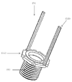
- FIG. 1 Perspective view of the regular adjustable sprinkler
- FIG. 2 Perspective view of the regular adjustable sprinkler where the window (13) can be seen;
- FIG. 3 Perspective view of the guide (1)
- FIG. 4 Perspective view of the nozzle (2)
- FIG. 5 Perspective view of the nozzle (2) and the guide (1)
- FIG. 6 Perspective view of the central body (2)
- FIG. 7 Perspective view of the fixation device (5)
- FIG. 8 Perspective view of the fixation device (5) and the guide (1);
- FIG. 10 View of an area watered by a circular sprinkler and an adjustable circular sprinkler
- FIG. 11 View of an area watered by a circular sprinkler
- FIG. 12 View of an area watered by an adjustable circular sprinkler and representation of the sinusoidal mathematical function.
- the guide (1) shown in figures 1, 2, 3, 5 and 8, horizontally, vertically and circularly controls a water nozzle (2), which rotates in line with a central sprinkler body (3).
- Figures 1, 2, 3, 5 and 8 show the guide (1) which comprises a shape that is predefined according to the position where it is placed and also with the shape of the field to be watered.
- the guide (1) has a sinusoidal shape or, according to another embodiment of the present invention, a shape that is defined according to the position and shape of the field to be watered, as is the case, among others, of a toothed shape.
- the guide (1) is continuous and is located around the central body (3) and fixed to the fixing device (5).
- the profile of the guide (1) also comprises different shapes, such as:
- Figures 1, 2, 3, 5 and 8 show the guide (1) which comprises a shape that is predefined according to the position where it is placed and also with the shape of the field to be watered.
- the guide (1) has a sinusoidal shape or, according to another embodiment of the present invention, a shape that is defined according to the position and shape of the field to be watered, as is the case, among others, of a toothed shape.
- the guide (1) can be located around all or part (not shown in the figures) of the central body (3) and also attached to the fixing device (5).
- the guide (1) comprises projections (20) located along the path of the guide (1) to section and temporally limit the movement of the water nozzle (20).
- ridges (20) The location of these ridges (20) is stipulated according to the need for irrigation intensity, ie, if there is a certain area that for some reason requires a larger amount of water, 1, 2, 3 or more ridges will be placed (20 ) consecutively, so that the water nozzle (2) remains longer to release water in that respective area of the field.
- the flexible intermediate tube (22) will allow the water nozzle (2) to move horizontally, vertically and circularly, in line and concentrically with the central body (3).
- the central body (3) comprises on the surface of the upper part (6) a window (13) for fitting, passing and moving the tube (8), which rotates in line and concentrically with the central body, through the mechanism (7 ).
- the tube (8) mentioned above is made of a rigid material.
- the intermediate tube (22), attached to the end of the tube (8) is made of a flexible material, so that it can move in line and concentrically with the central body (3).
- Figures 1, 2, 7 and 8 show the fixation device (5) which is located below the central body (3) and is fitted to the central body (3), in order to rotate freely around the central body (3).
- the thread of the fixture (4) has the functionality of screwing the adjustable circular sprinkler, described and claimed here, to a hose for water supply.
- Figures 1, 2 and 7 show the mechanism (7) for dispersing water and for rotating the central body (3) and the water nozzle (2) which is fitted to the vertical and central spike (19).
Abstract
The present invention relates to an adjustable circle sprinkler that is intended for watering an entire quadrangular field or a field of some other shape, and comprises a guide (1) that allows a water nozzle (2) and a central body (3) of the sprinkler to rotate simultaneously and concentrically, a fastening device (5) and a mechanism (7) for dispersing water and rotating the central body (3) and the water nozzle (2).
Description
A presente invenção diz respeito a um aspersor circular ajustável que tem a funcionalidade de regar a totalidade ou parte de um campo com uma forma quadrangular, retangular ou outra.The present invention relates to an adjustable circular sprinkler that has the functionality of watering all or part of a field with a square, rectangular or other shape.
Com a utilização do aspersor circular ajustável descrito e reivindicado na presente invenção, deixam de existir zonas de cultivo por regar e/ ou zonas onde a água chega em demasia devido à sobreposição das regas causadas pelos diversos aspersores circulares conhecidos do estado da técnica.With the use of the adjustable circular sprinkler described and claimed in the present invention, there are no more growing areas for irrigation and / or areas where water reaches too much due to the overlapping of irrigation caused by the various circular sprinklers known in the art.
Através da rega por aspersão, são lançados jatos de água ao ar que caem sobre o cultivo na forma de chuva. Through sprinkler irrigation, water jets are launched into the air that fall on the crop in the form of rain.
A água é distribuída através de um sistema de tubagem, sendo em certos casos impulsionada por uma bomba de água.The water is distributed through a piping system, in some cases driven by a water pump.
É então pulverizada no ar através de aspersores para este separar o fluxo de água em pequenas gotículas que caem no solo. It is then sprayed into the air through sprinklers to separate the water flow into small droplets that fall on the ground.
A tubagem, o motor, e o aspersor devem ser projetados de forma a que o fluxo de água seja o mais uniforme possível.The piping, the engine, and the sprinkler must be designed so that the water flow is as uniform as possible.
Os aspersores circulares compreendidos no estado da técnica são aspersores de impacto, i.e. são aspersores projetados para girar num círculo completo ou parcial.Circular sprinklers comprised in the prior art are impact sprinklers, i.e. sprinklers designed to rotate in a full or partial circle.
Os referidos aspersores circulares caracterizam-se pelo facto da cabeça do aspersor circular deslocar-se num movimento circular causado pela força da água, girando assim o aspersor em torno de um rolamento que está fixo numa rosca.Said circular sprinklers are characterized by the fact that the head of the circular sprinkler moves in a circular motion caused by the force of the water, thus rotating the sprinkler around a bearing that is fixed on a thread.
O braço do aspersor é repetidamente empurrado para o fluxo de água, através de uma mola, dispersando assim o fluxo de água permitindo uma rega uniforme ao redor do aspersor.The sprinkler arm is repeatedly pushed into the water flow, by means of a spring, thus dispersing the water flow allowing uniform watering around the sprinkler.
Os aspersores circulares foram inventados no ano de 1933, por Orton Englehardt, sendo que o seu uso se tornou rapidamente generalizado.Circular sprinklers were invented in 1933, by Orton Englehardt, and their use quickly became widespread.
Os aspersores circulares são colocados de forma a regarem toda a cultura, mas como regam de forma circular, invariavelmente originam espaços na cultura que não são regados, pressionando os agricultores a colocarem um novo aspersor nessa zona para regar a parte que está em falta.Circular sprinklers are placed in order to water the entire crop, but as they water in a circular fashion, they invariably create spaces in the crop that are not watered, pressing farmers to place a new sprinkler in that area to water the missing part.
Porém, por causa da colocação do aspersor suplementar, existem partes da cultura que são regadas não uma vez, mas sim duas vezes, causando desta forma a morte desnecessária da cultura nessa zona devido à rega excessiva, i.e. essa rega excessiva é originada pela sobreposição da rega dos diferentes aspersores.However, because of the placement of the supplementary sprinkler, there are parts of the crop that are watered not once, but twice, thus causing the unnecessary death of the crop in that area due to over-watering, ie this over-watering is caused by the overlapping of the watering of the different sprinklers.
Os problemas associados à utilização do aspersor circular são:
- existem partes do cultivo onde a água não chega; e/ ou
- existem outras partes do cultivo onde a água chega de forma excessiva, causando a morte da cultura em ambos casos.
- there are parts of cultivation where water does not reach; and / or
- there are other parts of the crop where water reaches excessively, causing the crop to die in both cases.
É assim evidente uma má eficiência na utilização de água e influência negativa na quantidade de produtos produzidos.It is thus evident a poor efficiency in the use of water and a negative influence on the quantity of products produced.
Baseada no aspersor de impacto compreendido na técnica anterior, a presente invenção recorre a um mecanismo inovador que permite regar uma cultura ou parte da mesma, de forma quadrangular, retangular ou qualquer outra forma. Based on the impact sprinkler comprised in the prior art, the present invention uses an innovative mechanism that allows watering a crop or part of it, in a quadrangular, rectangular or any other way.
Para a presente invenção alcançar esta funcionalidade que diz respeito à rega de uma área com uma determinada forma, é utilizada uma conhecida função matemática: a função sinusoidal, a qual se apresenta como uma das características técnicas do aspersor circular ajustável descrito e reivindicado na presente invenção.For the present invention to achieve this functionality that concerns the irrigation of an area with a certain shape, a known mathematical function is used: the sinusoidal function, which is presented as one of the technical characteristics of the adjustable circular sprinkler described and claimed in the present invention. .
A onda sinusoidal serve para clarificar como funciona o mecanismo inovador aqui reivindicado. The sine wave serves to clarify how the innovative mechanism claimed here works.
A onda sinusoidal representa a inclinação do bocal da água do aspersor de onde a água sai, i.e., ao contrário dos aspersores normais, na presente invenção a extremidade por onde a água é expelida é móvel e não fixa, permitindo com o auxílio de uma guia, que esse citado bocal da água do aspersor se movimente horizontalmente, verticalmente,circularmente e em consonância com um corpo central do aspersor circular ajustável aqui descrito e reivindicado.The sinusoidal wave represents the inclination of the water nozzle of the sprinkler from which the water comes out, ie, unlike normal sprinklers, in the present invention the end through which the water is expelled is mobile and not fixed, allowing with the aid of a guide , that said sprinkler water nozzle moves horizontally, vertically, circularly and in line with a central body of the adjustable circular sprinkler described and claimed herein.
Isto significa que quando o bocal da água está numa das posição mais elevada da linha sinusoidal, alcança um dos cantos mais distantes do quadrado do terreno, sendo a inclinação do bocal da água perto dos 45 graus.This means that when the water nozzle is in one of the highest positions of the sinusoidal line, it reaches one of the most distant corners of the land square, with the water nozzle's inclination close to 45 degrees.
Logo, quando a inclinação é reduzida da posição 1 para a 2, que diz respeito a uma das posição mais baixas da linha sinusoidal, o raio do alcance da água expelida decresce.Therefore, when the slope is reduced from position 1 to position 2, which concerns one of the lowest positions of the sinusoidal line, the radius of the reach of the expelled water decreases.
Quando chega à posição 2, a inclinação volta a subir para fazer novamente um vértice do quadrado (posição 3) e assim sucessivamente e repetidamente, tantas vezes quantas as necessárias
.
When it reaches position 2, the slope rises again to make a vertex of the square again (position 3) and so on successively and repeatedly, as many times as necessary .
A descrição que se apresenta a seguir é feita com referência às figuras em anexo que é apresentada apenas a título de referência, sem qualquer carácter limitativo:The description that follows is made with reference to the attached figures, which is presented for reference only, without any limiting character:
[Fig. 1] Vista em perspetiva do aspersor ajustável regular;
[Fig. 1] Perspective view of the regular adjustable sprinkler;
[Fig. 2] Vista em perspetiva do aspersor ajustável regular onde se pode ver a janela (13);
[Fig. 2] Perspective view of the regular adjustable sprinkler where the window (13) can be seen;
[Fig. 3] Vista em perspetiva da guia (1);
[Fig. 3] Perspective view of the guide (1);
[Fig. 4] Vista em perspetiva do bocal (2);
[Fig. 4] Perspective view of the nozzle (2);
[Fig. 5] Vista em perspetiva do bocal (2) e da guia (1);
[Fig. 5] Perspective view of the nozzle (2) and the guide (1);
[Fig. 6] Vista em perspetiva do corpo central (2);
[Fig. 6] Perspective view of the central body (2);
[Fig. 7] Vista em perspetiva do aparelho de fixação (5);
[Fig. 7] Perspective view of the fixation device (5);
[Fig. 8] Vista em perspetiva do aparelho de fixação (5) e da guia (1);
[Fig. 8] Perspective view of the fixation device (5) and the guide (1);
[Fig. 9] Vista em perspetiva do mecanismo de dispersão da água e de rotação do aspersor (7);
[Fig. 9] Perspective view of the water dispersion and rotation mechanism of the sprinkler (7);
[Fig. 10] Vista de uma zona regada por um aspersor circular e por um aspersor circular ajustável;
[Fig. 10] View of an area watered by a circular sprinkler and an adjustable circular sprinkler;
[Fig. 11] Vista de uma zona regada por um aspersor circular; e
[Fig. 11] View of an area watered by a circular sprinkler; and
[Fig. 12] Vista de uma zona regada por um aspersor circular ajustável e representação da função matemática sinusoidal.
[Fig. 12] View of an area watered by an adjustable circular sprinkler and representation of the sinusoidal mathematical function.
A presente invenção diz respeito a um aspersor circular ajustável que tem a funcionalidade de regar a totalidade ou parte de um campo com uma forma quadrangular, representada na figura 10, retangular ou outra.The present invention relates to an adjustable circular sprinkler that has the functionality of watering all or part of a field with a square shape, shown in figure 10, rectangular or otherwise.
Os aspersores circulares são colocados de forma a regarem toda a cultura, mas como regam de forma circular, conforme se pode observar na figura 11, invariavelmente originam espaços na cultura que não são regados, pressionando os agricultores a colocarem um novo aspersor nessa zona para regar a parte que está em falta.Circular sprinklers are placed in order to water the entire crop, but as they irrigate in a circular manner, as shown in figure 11, they invariably create spaces in the crop that are not watered, pressing farmers to place a new sprinkler in that area to water the missing part.
Para a presente invenção alcançar esta funcionalidade que diz respeito à rega de uma área com uma determinada forma, é utilizada uma conhecida função matemática: a função sinusoidal, a qual se apresenta como uma das características técnicas do aspersor circular ajustável descrito e reivindicado na presente invenção, conforme se pode observar na figura 12.For the present invention to achieve this functionality that concerns the irrigation of an area with a certain shape, a known mathematical function is used: the sinusoidal function, which is presented as one of the technical characteristics of the adjustable circular sprinkler described and claimed in the present invention. , as shown in figure 12.
Conforme se pode observar nas figuras 1 e 2 o aspersor circular ajustável descrito e reivindicado na presente invenção compreende os seguintes 5 principais componentes:
- uma guia (1) para comando de um bocal da água (2), a qual gira concentricamente em consonância com um corpo central (3) do aspersor;
- um aparelho de fixação (5); e
- um mecanismo (7) de dispersão da água e de rotação corpo central (3) e do bocal da água (2).
- a guide (1) for controlling a water nozzle (2), which rotates concentrically in line with a central body (3) of the sprinkler;
- a fixation device (5); and
- a mechanism (7) for dispersing the water and rotating the central body (3) and the water nozzle (2).
A guia (1), representada nas figuras 1, 2, 3, 5 e 8, comanda horizontal, vertical e circularmente um bocal da água (2), o qual gira em consonância com um corpo central (3) do aspersor.The guide (1), shown in figures 1, 2, 3, 5 and 8, horizontally, vertically and circularly controls a water nozzle (2), which rotates in line with a central sprinkler body (3).
Guia (1)Guide (1)
Nas figuras n.ºs 1, 2, 3, 5 e 8 está representada a guia (1) que compreende uma forma que é predefinida de acordo com a posição onde é colocado e também com a forma do campo a regar.Figures 1, 2, 3, 5 and 8 show the guide (1) which comprises a shape that is predefined according to the position where it is placed and also with the shape of the field to be watered.
A guia (1) apresenta uma forma sinusoidal ou, de acordo com outro modo de realização da presente invenção, uma forma que é definida de acordo com a posição e a forma do campo a regar, como é o caso, entre outras, de uma forma dentada.The guide (1) has a sinusoidal shape or, according to another embodiment of the present invention, a shape that is defined according to the position and shape of the field to be watered, as is the case, among others, of a toothed shape.
A guia (1) é contínua e está localizada em torno do corpo central (3) e fixa ao aparelho de fixação (5).The guide (1) is continuous and is located around the central body (3) and fixed to the fixing device (5).
De acordo com o modo de realização da invenção a guia (1) pode estar localizada em torno, de todo ou de parte (não representada nas figuras) do corpo central (3) e também fixa ao aparelho de fixação (5).According to the embodiment of the invention, the guide (1) can be located around all or part (not shown in the figures) of the central body (3) and also attached to the fixing device (5).
De acordo com o modo de realização da presente invenção, consoante a forma da peça para guiamento (21) o perfil da guia (1) compreende também diferentes formas, como é o caso de:According to the embodiment of the present invention, depending on the shape of the guide piece (21) the profile of the guide (1) also comprises different shapes, such as:
Nas figuras n.ºs 1, 2, 3, 5 e 8 está representada a guia (1) que compreende uma forma que é predefinida de acordo com a posição onde é colocado e também com a forma do campo a regar.Figures 1, 2, 3, 5 and 8 show the guide (1) which comprises a shape that is predefined according to the position where it is placed and also with the shape of the field to be watered.
A guia (1) apresenta uma forma sinusoidal ou, de acordo com outro modo de realização da presente invenção, uma forma que é definida de acordo com a posição e a forma do campo a regar, como é o caso, entre outras, de uma forma dentada.The guide (1) has a sinusoidal shape or, according to another embodiment of the present invention, a shape that is defined according to the position and shape of the field to be watered, as is the case, among others, of a toothed shape.
A guia (1) é contínua e está localizada em torno do corpo central (3) e fixa ao aparelho de fixação (5).The guide (1) is continuous and is located around the central body (3) and fixed to the fixing device (5).
De acordo com o modo de realização da invenção a guia (1) pode estar localizada em torno, de todo ou de parte (não representada nas figuras) do corpo central (3) e também fixa ao aparelho de fixação (5).According to the embodiment of the invention, the guide (1) can be located around all or part (not shown in the figures) of the central body (3) and also attached to the fixing device (5).
De acordo com o modo de realização da presente invenção, consoante a forma da peça para guiamento (21) o perfil da guia (1) compreende também diferentes formas, como é o caso de:
- uma forma semelhante a um “U”;
- uma forma semelhante a um “I”; e
- uma forma semelhante a um “V”.
- a shape similar to a "U";
- a shape similar to an "I"; and
- a shape similar to a "V".
A guia (1) compreende no seu interior ressaltos (20) localizados ao longo do percurso da guia (1) para seccionar e delimitar temporalmente o movimento do bocal da água (20).The guide (1) comprises projections (20) located along the path of the guide (1) to section and temporally limit the movement of the water nozzle (20).
A localização desses ressaltos (20) é estipulada de acordo com a necessidade da intensidade da rega, i.e., se existir uma determinada zona que por algum motivo necessitar de uma maior quantidade de água, será colocado 1, 2, 3 ou mais ressaltos (20) consecutivos, para que o bocal da água (2) permaneça mais tempo a libertar água nessa respetiva zona do campo.The location of these ridges (20) is stipulated according to the need for irrigation intensity, ie, if there is a certain area that for some reason requires a larger amount of water, 1, 2, 3 or more ridges will be placed (20 ) consecutively, so that the water nozzle (2) remains longer to release water in that respective area of the field.
De acordo com os diferentes modos de realização da presente invenção a peça para guiamento (21), representada nas figuras 4 e 5, apresenta diferentes formas como é o caso de:
- ter a forma de uma esfera;
- ter a forma de uma roda dentada; e
- ter a forma de uma roda dentada com ressaltos (20) entre os dentes da mesma, que faz com que essa mesma roda dentada, não seja regular.
- have the shape of a sphere;
- have the shape of a cog wheel; and
- have the shape of a toothed wheel with shoulders (20) between its teeth, which makes this same toothed wheel not regular.
Bocal da água (2)Water nozzle (2)
Nas figuras n.ºs 1, 2 e 4 está representado o bocal da água (2) que compreende:
- um tubo (8) para a passagem e fornecimento da água para a rega;
- um tubo intermédio (22) flexível, fixado na extremidade do tubo (8);
- uma ponteira (9) fixada na extremidade do tubo intermédio (22); e
- - uma haste (10) que está simultaneamente fixada à ponteira (9) e ligada à guia (1), por meio de uma peça para guiamento (21), para movimentar em qualquer direção o bocal da água (2) por meio do mecanismo (7), o qual gira em consonância e concentricamente com o corpo central (3).
- a tube (8) for the passage and supply of water for irrigation;
- a flexible intermediate tube (22), attached to the end of the tube (8);
- a tip (9) attached to the end of the intermediate tube (22); and
- - a rod (10) which is simultaneously attached to the tip (9) and connected to the guide (1), by means of a guide piece (21), to move the water nozzle (2) in any direction by means of the mechanism (7), which rotates in line and concentrically with the central body (3).
O tubo intermédio (22) flexível vai permitir que o bocal da água (2) se movimente horizontal, vertical e circularmente, em consonância e concentricamente com o corpo central (3).The flexible intermediate tube (22) will allow the water nozzle (2) to move horizontally, vertically and circularly, in line and concentrically with the central body (3).
Corpo central (3)Central body (3)
Nas figuras n.ºs 1, 2 e 6 está representado o corpo central (3) que compreende:
- um aro (14), fixo no topo do corpo central (3); e
- um espigão vertical e central (19), também fixo ao topo do corpo central (3).
- a rim (14), fixed on top of the central body (3); and
- a vertical and central post (19), also attached to the top of the central body (3).
O corpo central (3) compreende na superfície da parte superior (6) uma janela (13) para encaixe, passagem e movimentação do tubo (8), o qual gira em consonância e concentricamente com o corpo central, por meio do mecanismo (7).The central body (3) comprises on the surface of the upper part (6) a window (13) for fitting, passing and moving the tube (8), which rotates in line and concentrically with the central body, through the mechanism (7 ).
O tubo (8) anteriormente referido é fabricado com um material rígido.The tube (8) mentioned above is made of a rigid material.
Enquanto o tubo intermédio (22), fixado na extremidade do tubo (8) é fabricado com um material flexível, de modo a que o mesmo se possa movimentar em consonância e concentricamente com o corpo central (3).While the intermediate tube (22), attached to the end of the tube (8) is made of a flexible material, so that it can move in line and concentrically with the central body (3).
Aparelho de fixação (5)Fixing device (5)
Nas figuras n.ºs 1, 2, 7 e 8 está representado o aparelho de fixação (5) que está localizado abaixo do corpo central (3) e encaixado no corpo central (3), de modo a rodar livremente em torno do corpo central (3).Figures 1, 2, 7 and 8 show the fixation device (5) which is located below the central body (3) and is fitted to the central body (3), in order to rotate freely around the central body (3).
O aparelho de fixação (5) compreende:
- uma anilha (11);
- pelo menos um espigão vertical (12), fixado à anilha (11) e para fixação da guia (1); e
- uma rosca do aparelho de fixação (4), também fixada à anilha (11).
- a washer (11);
- at least one vertical post (12), fixed to the washer (11) and for fixing the guide (1); and
- a thread on the fixing device (4), also attached to the washer (11).
A rosca do aparelho de fixação (4) tem a funcionalidade de fixar por enroscamento o aspersor circular ajustável, aqui descrito e reivindicado, a uma mangueira para fornecimento da água.The thread of the fixture (4) has the functionality of screwing the adjustable circular sprinkler, described and claimed here, to a hose for water supply.
Mecanismo (7) de dispersão da água e de rotação do aspersorWater dispersion and sprinkler rotation mechanism (7)
Nas figuras n.ºs 1, 2 e 7 está representado o mecanismo (7) de dispersão da água e de rotação do corpo central (3) e do bocal da água (2) que está encaixado no espigão vertical e central (19).Figures 1, 2 and 7 show the mechanism (7) for dispersing water and for rotating the central body (3) and the water nozzle (2) which is fitted to the vertical and central spike (19).
O referido mecanismo (7) compreende:
- uma mola (15); e
- um braço (16) horizontal que inclui um contrapeso (17) e um aro direcional (18), respetivamente fixados em cada uma das extremidades do braço (16).
- a spring (15); and
- a horizontal arm (16) including a counterweight (17) and a directional ring (18), respectively fixed at each end of the arm (16).
A presente invenção deve apenas ser limitada pelo espírito das reivindicações que se seguem.The present invention should only be limited by the spirit of the claims that follow.
- uma guia (1);a guide (1);
- um bocal da água (2); a water nozzle (2);
- um corpo central (3);a central body (3);
- uma rosca do aparelho de fixação (4);a thread on the fixing device (4);
- um aparelho de fixação (5);a fixation device (5);
- uma parte superior (6);an upper part (6);
- um mecanismo de dispersão da água e de rotação do aspersor (7);a water dispersion and rotation mechanism for the sprinkler (7);
- um tubo (8);a tube (8);
- uma ponteira (9);a tip (9);
- uma haste (10); a rod (10);
- uma anilha (11);a washer (11);
- um espigão vertical (12);a vertical post (12);
- uma janela (13);a window (13);
- um aro (14);a ring (14);
- uma mola (15);a spring (15);
- um braço (16);an arm (16);
- um contrapeso (17);a counterweight (17);
- um aro direcional (18);a directional ring (18);
- um espigão vertical e central (19);a vertical and central post (19);
- um ressalto (20);a shoulder (20);
- um peça para guiamento (21); ea guide piece (21); and
- um tubo intermédio (22).an intermediate tube (22).
Claims (23)
- Aspersor circular ajustável caracterizado por compreender:
● uma guia (1) para comando de um bocal da água (2), bocal esse que se movimente horizontalmente, verticalmente, circularmente e em consonância com um corpo central (3) do aspersor;
● um aparelho de fixação (5); e
● um mecanismo (7) de dispersão da água e de rotação do corpo central (3) e do bocal da água (2). Adjustable circular sprinkler characterized by comprising:
● a guide (1) for controlling a water nozzle (2), which nozzle moves horizontally, vertically, circularly and in line with a central body (3) of the sprinkler;
● a fixing device (5); and
● a mechanism (7) for dispersing water and for rotating the central body (3) and the water nozzle (2). - Aspersor circular ajustável de acordo com a reivindicação n.º1, caracterizado por o bocal da água (2) compreender:
● um tubo (8) para a passagem e fornecimento da água para a rega;
● um tubo intermédio (22) flexível, fixado na extremidade do tubo (8);
● uma ponteira (9) fixada na extremidade do tubo intermédio (22); e
● uma haste (10) que está simultaneamente fixada à ponteira (9) e ligada à guia (1), por meio de uma peça para guiamento (21), para movimentar circularmente e em qualquer direção e sentido o bocal da água (2) por meio do mecanismo (7) e em consonância com o corpo central (3). Adjustable circular sprinkler according to claim 1, characterized in that the water nozzle (2) comprises:
● a tube (8) for the passage and supply of water for irrigation;
● a flexible intermediate tube (22), attached to the end of the tube (8);
● a tip (9) attached to the end of the intermediate tube (22); and
● a rod (10) that is simultaneously attached to the tip (9) and connected to the guide (1), by means of a guide piece (21), to move the water nozzle (2) in a circular and in any direction and direction through the mechanism (7) and in line with the central body (3). - Aspersor circular ajustável de acordo com a reivindicação n.º1, caracterizado por o tubo intermédio (22) flexível movimentar circularmente e em consonância com o corpo central (3) o bocal da água (2).Adjustable circular sprinkler according to claim 1, characterized in that the flexible intermediate tube (22) moves circularly and in line with the central body (3) the water nozzle (2).
- Aspersor circular ajustável de acordo com a reivindicação n.º1, caracterizado por o corpo central (3) compreender:
● um aro (14), fixo no topo do corpo central (3); e
● um espigão vertical e central (19), também fixo ao topo do corpo central (3). Adjustable circular sprinkler according to claim 1, characterized in that the central body (3) comprises:
● a ring (14), attached to the top of the central body (3); and
● a vertical and central post (19), also attached to the top of the central body (3). - Aspersor circular ajustável de acordo com a reivindicação n.º1, caracterizado por o aparelho de fixação (5) estar:
● localizado abaixo do corpo central (3); e
● encaixado ao corpo central (3)de modo a rodar livremente e em consonância com o corpo central (3).
Adjustable circular sprinkler according to claim 1, characterized in that the fixture (5) is:
● located below the central body (3); and
● attached to the central body (3) in order to rotate freely and in line with the central body (3).
- Aspersor circular ajustável de acordo com a reivindicação n.º1, caracterizado por o aparelho de fixação (5) compreender:
● uma anilha (11);
● pelo menos um espigão vertical (12), fixado à anilha (11), para fixação da guia (1); e
● uma rosca do aparelho de fixação (4), também fixada à anilha (11). Adjustable circular sprinkler according to claim 1, characterized in that the fixture (5) comprises:
● a washer (11);
● at least one vertical post (12), attached to the washer (11), for fixing the guide (1); and
● a thread on the fixture (4), also attached to the washer (11). - Aspersor circular ajustável de acordo com a reivindicação n.º1, caracterizado por o corpo central (3) compreender:
● na sua parte superior (6) uma janela (13) para encaixe, passagem e movimentação do tubo (8) por meio do mecanismo (7). Adjustable circular sprinkler according to claim 1, characterized in that the central body (3) comprises:
● in its upper part (6) a window (13) for fitting, passing and moving the tube (8) by means of the mechanism (7). - Aspersor circular ajustável de acordo com a reivindicação n.º1, caracterizado por o mecanismo (7) de dispersão da água e de rotação do corpo central (3) e do bocal da água (2):
● estar encaixado no espigão vertical e central (19);
e por compreender:
● - uma mola (15); e
● - um braço (16) horizontal que inclui:
● - um contrapeso (17) e um aro direcional (18), respetivamente fixados em cada uma das extremidades do braço (16). Adjustable circular sprinkler according to claim 1, characterized in that the mechanism (7) for dispersing water and rotating the central body (3) and the water nozzle (2):
● be seated on the vertical and central post (19);
and for understanding:
● - a spring (15); and
● - a horizontal arm (16) that includes:
● - a counterweight (17) and a directional ring (18), respectively attached to each end of the arm (16). - Aspersor circular ajustável de acordo com a reivindicação n.º1, caracterizado por a guia (1) compreender uma forma sinusoidal.Adjustable circular sprinkler according to claim 1, characterized in that the guide (1) comprises a sinusoidal shape.
- Aspersor circular ajustável de acordo com a reivindicação n.º1, caracterizado por a guia (1) estar localizada em torno do corpo central (3).Adjustable circular sprinkler according to claim 1, characterized in that the guide (1) is located around the central body (3).
- Aspersor circular ajustável de acordo com a reivindicação n.º1, caracterizado por a guia (1) estar localizada em parte do torno do corpo central (3).Adjustable circular sprinkler according to claim 1, characterized in that the guide (1) is located in part of the central body around (3).
- Aspersor circular ajustável de acordo com a reivindicação n.º1, caracterizado por a guia (1) ser continua.Adjustable circular sprinkler according to claim 1, characterized in that the guide (1) is continuous.
- Aspersor circular ajustável de acordo com a reivindicação n.º1, caracterizado por a guia (1) compreender uma forma de acordo com a forma do campo a regar.Adjustable circular sprinkler according to claim 1, characterized in that the guide (1) comprises a shape according to the shape of the field to be watered.
- Aspersor circular ajustável de acordo com a reivindicação n.º1, caracterizado por a guia (1) compreender um perfil dentado.Adjustable circular sprinkler according to claim 1, characterized in that the guide (1) comprises a toothed profile.
- Aspersor circular ajustável de acordo com a reivindicação n.º1, caracterizado por a guia (1) compreender um perfil com uma forma semelhante a um “U”.Adjustable circular sprinkler according to claim 1, characterized in that the guide (1) comprises a profile similar to a "U" shape.
- Aspersor circular ajustável de acordo com a reivindicação n.º1, caracterizado por a guia (1) compreender um perfil com uma forma semelhante a um “I”.Adjustable circular sprinkler according to claim 1, characterized in that the guide (1) comprises a profile shaped like an "I".
- Aspersor circular ajustável de acordo com a reivindicação n.º1, caracterizado por a guia (1) compreender um perfil com uma forma semelhante a um “V”.Adjustable circular sprinkler according to claim 1, characterized in that the guide (1) comprises a profile with a shape similar to a "V".
- Aspersor circular ajustável de acordo com a reivindicação n.º1, caracterizado por a guia (1) compreender ressaltos (20) localizados ao longo do percurso da guia (1) para seccionar e delimitar temporalmente o movimento do bocal da água (20).Adjustable circular sprinkler according to claim 1, characterized in that the guide (1) comprises projections (20) located along the path of the guide (1) to section and temporally limit the movement of the water nozzle (20).
- Aspersor circular ajustável de acordo com a reivindicação n.º1, caracterizado por a peça para guiamento (21) ter a forma de uma esfera para deslizar por entre o perfil em “U”.Adjustable circular sprinkler according to claim 1, characterized in that the guide piece (21) is in the form of a sphere to slide through the “U” profile.
- Aspersor circular ajustável de acordo com a reivindicação n.º1, caracterizado por a peça para guiamento (21) ter a forma de uma roda dentada.Adjustable circular sprinkler according to claim 1, characterized in that the guiding part (21) is in the form of a sprocket.
- Aspersor circular ajustável de acordo com a reivindicação n.º1, caracterizado por a peça para guiamento (21) ter a forma de uma roda dentada com ressaltos (20) entre os dentes da mesma.Adjustable circular sprinkler according to claim 1, characterized in that the guiding part (21) is in the form of a toothed wheel with projections (20) between its teeth.
- Aspersor circular ajustável de acordo com a reivindicação n.º1, caracterizado por o tubo (8) ser de material rígido.Adjustable circular sprinkler according to claim 1, characterized in that the tube (8) is made of rigid material.
- Aspersor circular ajustável de acordo com a reivindicação n.º1, caracterizado por o tubo (22) ser de material flexível.Adjustable circular sprinkler according to claim 1, characterized in that the tube (22) is made of flexible material.
Applications Claiming Priority (2)
| Application Number | Priority Date | Filing Date | Title |
|---|---|---|---|
| PT115381A PT115381A (en) | 2019-03-20 | 2019-03-20 | ADJUSTABLE CIRCULAR SPRAYER. |
| PT115381 | 2019-03-20 |
Publications (2)
| Publication Number | Publication Date |
|---|---|
| WO2020190162A1 true WO2020190162A1 (en) | 2020-09-24 |
| WO2020190162A8 WO2020190162A8 (en) | 2020-10-29 |
Family
ID=70614568
Family Applications (1)
| Application Number | Title | Priority Date | Filing Date |
|---|---|---|---|
| PCT/PT2020/050011 WO2020190162A1 (en) | 2019-03-20 | 2020-03-20 | Adjustable circle sprinkler |
Country Status (2)
| Country | Link |
|---|---|
| PT (1) | PT115381A (en) |
| WO (1) | WO2020190162A1 (en) |
Citations (5)
| Publication number | Priority date | Publication date | Assignee | Title |
|---|---|---|---|---|
| US1593918A (en) * | 1925-08-10 | 1926-07-27 | Stanton Lenthel | Sprinkler |
| US3428256A (en) * | 1967-03-20 | 1969-02-18 | William L Painter | Rotary pop-up sprinkler |
| US3528093A (en) * | 1968-01-03 | 1970-09-08 | Cornelis Eerkens | Square pattern irrigation sprinkling device |
| FR2405621A7 (en) * | 1977-10-05 | 1979-05-04 | Sdg | ROTARY SPRINKLER WITH ADJUSTABLE IRRIGATION SURFACE |
| US4637549A (en) * | 1985-04-30 | 1987-01-20 | Joel Schwartzman | Rotation speed control device for a rotary, impulse water sprinkler and a water sprinkler having same |
-
2019
- 2019-03-20 PT PT115381A patent/PT115381A/en unknown
-
2020
- 2020-03-20 WO PCT/PT2020/050011 patent/WO2020190162A1/en active Application Filing
Patent Citations (5)
| Publication number | Priority date | Publication date | Assignee | Title |
|---|---|---|---|---|
| US1593918A (en) * | 1925-08-10 | 1926-07-27 | Stanton Lenthel | Sprinkler |
| US3428256A (en) * | 1967-03-20 | 1969-02-18 | William L Painter | Rotary pop-up sprinkler |
| US3528093A (en) * | 1968-01-03 | 1970-09-08 | Cornelis Eerkens | Square pattern irrigation sprinkling device |
| FR2405621A7 (en) * | 1977-10-05 | 1979-05-04 | Sdg | ROTARY SPRINKLER WITH ADJUSTABLE IRRIGATION SURFACE |
| US4637549A (en) * | 1985-04-30 | 1987-01-20 | Joel Schwartzman | Rotation speed control device for a rotary, impulse water sprinkler and a water sprinkler having same |
Also Published As
| Publication number | Publication date |
|---|---|
| WO2020190162A8 (en) | 2020-10-29 |
| PT115381A (en) | 2020-09-21 |
Similar Documents
| Publication | Publication Date | Title |
|---|---|---|
| US20080083839A1 (en) | Inverted-sprinkler system: base and support | |
| US5381960A (en) | Wobbling irrigation sprinkler head including a magnet for initial tilt | |
| WO2020190162A1 (en) | Adjustable circle sprinkler | |
| US3782637A (en) | Wind-responsive sprinkler regulator | |
| US3791585A (en) | Adjustable pattern water sprinkler system | |
| US3731878A (en) | Agricultural sprayer | |
| KR102029714B1 (en) | Automatic pest controller for greenhouse | |
| US9403176B2 (en) | Stream deflector | |
| RU2729823C1 (en) | Sprinkler device for positional action | |
| US2859064A (en) | Rotary square lawn sprinkler | |
| CN106012747A (en) | Garden lawn trimming anti-pedaling device | |
| US20070221758A1 (en) | Precision irrigator apparatus, system and method | |
| CN108849828A (en) | A kind of big spraying swath wind of lift send spray rod device | |
| RU189319U1 (en) | RAIN INSTALLATION FOR GREENHOUSES | |
| CN212589408U (en) | Multi-angle sprinkling irrigation equipment is used in view gardens | |
| CN211064468U (en) | Novel treegarden irrigation device | |
| CN113748959A (en) | Sprinkling irrigation equipment suitable for regional irrigation of dysmorphism | |
| US2674492A (en) | Lawn sprinkler | |
| RU204127U1 (en) | GREENHOUSE SPRINKLING | |
| US3602433A (en) | Side spray nozzles | |
| RU2722032C1 (en) | Method of controlling distribution of irrigation water during irrigation and device for implementation thereof | |
| RU166617U1 (en) | SPRAY NOZZLE | |
| RU2682053C1 (en) | Sprinkler | |
| CN220157239U (en) | Greening sprinkling irrigation device | |
| RU2516275C2 (en) | Wide-coverage sprinkler unit |
Legal Events
| Date | Code | Title | Description |
|---|---|---|---|
| 121 | Ep: the epo has been informed by wipo that ep was designated in this application |
Ref document number: 20724596 Country of ref document: EP Kind code of ref document: A1 |
|
| NENP | Non-entry into the national phase |
Ref country code: DE |
|
| 122 | Ep: pct application non-entry in european phase |
Ref document number: 20724596 Country of ref document: EP Kind code of ref document: A1 |