WO2020189577A1 - ミキサー部材 - Google Patents
ミキサー部材 Download PDFInfo
- Publication number
- WO2020189577A1 WO2020189577A1 PCT/JP2020/011235 JP2020011235W WO2020189577A1 WO 2020189577 A1 WO2020189577 A1 WO 2020189577A1 JP 2020011235 W JP2020011235 W JP 2020011235W WO 2020189577 A1 WO2020189577 A1 WO 2020189577A1
- Authority
- WO
- WIPO (PCT)
- Prior art keywords
- exhaust
- mixer member
- exhaust pipe
- fin
- stress relaxation
- Prior art date
- Legal status (The legal status is an assumption and is not a legal conclusion. Google has not performed a legal analysis and makes no representation as to the accuracy of the status listed.)
- Ceased
Links
Images




Classifications
-
- F—MECHANICAL ENGINEERING; LIGHTING; HEATING; WEAPONS; BLASTING
- F01—MACHINES OR ENGINES IN GENERAL; ENGINE PLANTS IN GENERAL; STEAM ENGINES
- F01N—GAS-FLOW SILENCERS OR EXHAUST APPARATUS FOR MACHINES OR ENGINES IN GENERAL; GAS-FLOW SILENCERS OR EXHAUST APPARATUS FOR INTERNAL-COMBUSTION ENGINES
- F01N3/00—Exhaust or silencing apparatus having means for purifying, rendering innocuous, or otherwise treating exhaust
- F01N3/08—Exhaust or silencing apparatus having means for purifying, rendering innocuous, or otherwise treating exhaust for rendering innocuous
-
- F—MECHANICAL ENGINEERING; LIGHTING; HEATING; WEAPONS; BLASTING
- F01—MACHINES OR ENGINES IN GENERAL; ENGINE PLANTS IN GENERAL; STEAM ENGINES
- F01N—GAS-FLOW SILENCERS OR EXHAUST APPARATUS FOR MACHINES OR ENGINES IN GENERAL; GAS-FLOW SILENCERS OR EXHAUST APPARATUS FOR INTERNAL-COMBUSTION ENGINES
- F01N3/00—Exhaust or silencing apparatus having means for purifying, rendering innocuous, or otherwise treating exhaust
- F01N3/08—Exhaust or silencing apparatus having means for purifying, rendering innocuous, or otherwise treating exhaust for rendering innocuous
- F01N3/10—Exhaust or silencing apparatus having means for purifying, rendering innocuous, or otherwise treating exhaust for rendering innocuous by thermal or catalytic conversion of noxious components of exhaust
- F01N3/24—Exhaust or silencing apparatus having means for purifying, rendering innocuous, or otherwise treating exhaust for rendering innocuous by thermal or catalytic conversion of noxious components of exhaust characterised by constructional aspects of converting apparatus
Definitions
- the present disclosure relates to a mixer member, and more particularly to a mixer member that agitates and mixes the exhaust gas discharged from the engine and the reducing agent supplied to the reduction catalyst.
- Nitrogen oxides contained in exhaust gas as a reducing agent, which is produced by hydrolyzing urea water injected from a urea water injector by exhaust heat or steam in the exhaust gas as an engine exhaust purification device.
- a selective reduction catalyst Selective Catalytic Reduction: hereinafter, SCR catalyst for reducing and purifying NOx
- a mixer member having a plurality of fins is arranged on the downstream side of the urea water injector in the exhaust pipe, and the exhaust gas is swirled by the fins so that the reducing agent and the exhaust gas are uniform.
- Techniques for mixing are disclosed.
- each fin is joined and fixed substantially perpendicularly to the outer circumference of the inner ring arranged at the axial center of the exhaust pipe. Therefore, for example, when each fin thermally expands due to the influence of exhaust heat or the like and extends in the radial direction, stress concentrates on the joint portion between each fin and the inner ring to cause a crack, resulting in damage to the mixer member. May lead to.
- the technique of the present disclosure aims to effectively prevent damage to the mixer member.
- the mixer member of the present disclosure is a mixer member provided in an exhaust pipe through which exhaust gas flows, and agitates and mixes the exhaust gas flowing in the exhaust pipe and a reducing agent, and is directed outward in the radial direction from the axial side of the exhaust pipe. It is provided with a plurality of fin portions extending radially and a stress relaxing portion that connects the base end portions of the fin portions on the axial side to each other and deforms as the fin portions extend in the radial direction. ..
- the stress relaxation portion includes an arc portion whose cross-sectional shape along the axis of the exhaust pipe is curved so as to be convex in a semicircular shape toward the downstream side of the exhaust, and the arc portion is the fin portion. It is preferable that it is curved and deformed as it extends in the radial direction.
- the stress relaxation portion has a shape in which a plurality of irregularities are alternately continuous.
- FIG. 1 is a schematic overall configuration diagram showing an engine exhaust system according to an embodiment.
- FIG. 2 is a schematic perspective view showing a mixer member according to an embodiment.
- FIG. 3 is a schematic cross-sectional view showing the mixer member according to the embodiment notched in the axial direction.
- FIG. 4A is a schematic diagram illustrating a mixer member according to an embodiment.
- FIG. 4B is a schematic view illustrating a mixer member of a comparative example.
- FIG. 5 is a schematic cross-sectional view showing a mixer member according to another embodiment cut out in the axial direction.
- FIG. 1 is a schematic overall configuration diagram showing an exhaust system of the engine 10 according to the embodiment.
- the engine 10 includes an engine main body 11 including a cylinder head, a cylinder block in which a plurality of cylinders are formed, and the like.
- the cylinder head of the engine body 11 is provided with an exhaust manifold 12 that collects exhaust gas discharged from each cylinder.
- the upstream exhaust pipe 13, the front casing 21 of the front post-treatment device 20, the connection exhaust pipe 14, the rear casing 41 of the rear post-treatment device 40, the downstream exhaust pipe 15, and the like are connected to the exhaust manifold 12 in this order from the exhaust upstream side. Has been done.
- the upstream exhaust pipe 13 is formed in a substantially cylindrical shape, and its upstream end is connected to the exhaust collecting portion 12A of the exhaust manifold 12. The downstream end of the upstream exhaust pipe 13 is connected to the upstream opening of the front casing 21.
- the front casing 21 is formed in a substantially cylindrical shape, and the oxidation catalyst 22 and the filter 23 are housed in the casing 21 in this order from the upstream side of the exhaust gas.
- the oxidation catalyst 22 is formed by supporting a catalyst component or the like on the surface of a ceramic carrier such as a cordierite honeycomb structure.
- a ceramic carrier such as a cordierite honeycomb structure.
- the filter 23 is formed, for example, by arranging a large number of cells partitioned by a porous partition wall along the flow direction of the exhaust gas, and alternately sealing the upstream side and the downstream side of these cells. ..
- the filter 23 collects particulate matter (PM) in the exhaust gas in the pores and surface of the partition wall, and when the PM deposition amount reaches a predetermined amount, it burns and removes the particulate matter (PM). Is carried out.
- connection exhaust pipe 14 is formed in a substantially S-shaped cylindrical shape as a whole, and connects the downstream opening of the front casing 21 and the upstream opening of the rear casing 41.
- a urea water injector 35 forming a part of the urea water injection device 30 is provided at a predetermined portion of the connection exhaust pipe 14.
- the urea water injection device 30 supplies the urea water tank 31 that stores the urea water, the strainer 32 that is immersed in the urea water in the urea water tank 31 to remove foreign matter, and the supply pipe 33 that is connected to the strainer 32.
- a urea water pump 34 provided in the pipe 33 to pump urea water from the urea water tank 31 and a urea water injector 35 for injecting the urea water supplied from the supply pipe 33 into the connecting exhaust pipe 14 are provided.
- the urea water injected from the urea water injector 35 into the connection exhaust pipe 14 is hydrolyzed by exhaust heat and water vapor in the exhaust gas to generate ammonia (NH3), which is supplied to the downstream SCR catalyst 48 as a reducing agent. Will be done.
- NH3 ammonia
- the rear casing 41 is formed in a substantially cylindrical shape.
- the SCR catalyst 48 is housed inside the rear casing 41.
- the SCR catalyst 48 is formed by supporting zeolite or the like on a porous ceramic carrier, for example.
- the SCR catalyst 48 adsorbs ammonia supplied as a reducing agent from the urea water injector 35, and selectively reduces and purifies NOx from the exhaust gas passing by the adsorbed ammonia.
- the downstream exhaust pipe 15 is formed in a substantially cylindrical shape, and its upstream end is connected to the downstream opening of the rear casing 41.
- a tail pipe (not shown) that discharges exhaust gas to the atmosphere is connected to the downstream side of the downstream exhaust pipe 15.
- a mixer member 50 for stirring and mixing the exhaust gas flowing in the connecting exhaust pipe 14 and the reducing agent is provided in the connecting exhaust pipe 14 on the downstream side of the urea water injector 35.
- the details of the mixer member 50 according to the present embodiment will be described with reference to FIGS. 2 and 3.
- FIG. 2 is a schematic perspective view showing the mixer member 50 according to the present embodiment.
- the mixer member 50 includes a fixing ring portion 51 fixed to the connecting exhaust pipe 14, a plurality of fin portions 52 for swirling the exhaust gas, and a stress relaxation portion 53 for relieving stress. ing.
- the fixing ring portion 51 is formed in a substantially annular shape having an outer diameter substantially the same as the inner diameter of the connecting exhaust pipe 14.
- the fixing ring portion 51 is fixed to a predetermined portion on the downstream side of the urea water injector 35 (see FIG. 1) of the connecting exhaust pipe 14 by joining the outer circumference thereof to the inner circumference of the connecting exhaust pipe 14 by welding or the like. There is.
- the fixing ring portion 51 may be fixed to the connecting exhaust pipe 14 with bolts, nuts, or the like.
- the shape of the fixing ring portion 51 is not limited to the annular shape, and may be another shape as long as it can be fixed to the connecting exhaust pipe 14.
- each fin portion 52 has its surface direction tilted at a predetermined angle with respect to the axial center X of the fixing ring portion 51, and the radial outer edge portion 52A is the inner circumference of the fixing ring portion 51. It is joined and fixed to the surface by welding or the like.
- the fixing of each fin portion 52 is not limited to welding, and may be fixed to the fixing ring portion 51 with bolts, nuts, or the like. Further, the number of fin portions 52 is not limited to the four in the illustrated example, and can be appropriately set according to the inner diameter of the connecting exhaust pipe 14 and the like.
- the stress relaxation portion 53 is provided at the axial center X of the fixing ring portion 51, and connects the base end portions 52B on the radial inner side of each fin portion 52 to each other.
- the details of the stress relaxation unit 53 will be described with reference to FIG.
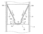
- FIG. 3 is a schematic cross-sectional view showing the mixer member 50 according to the present embodiment cut out in the axial direction.
- each fin portion 52 has its radial inner base end portion 52B located on the exhaust downstream side of the radial outer edge portion 52A fixed to the fixing ring portion 51.
- the surface direction is inclined with respect to the axis X of the fixing ring portion 51 at a predetermined angle.
- the stress relaxation portion 53 is formed by being curved so that the cross-sectional shape of the fixed ring portion 51 (or the connecting exhaust pipe 14) along the axis X is convex in a semicircular shape toward the exhaust downstream side.
- the base end portions 52B of each fin portion 52 are connected to each other.
- the stress relaxation portion 53 is a semicircle connecting a straight portion 54 extending in the axial X direction from the base end portion 52B of each fin portion 52 toward the exhaust downstream side and the exhaust downstream end of each straight portion 54. It is provided with an arc-shaped arc portion 55.
- the angle ⁇ formed by the surface of the fin portion 52 facing the axial center X side and the surface of the straight portion 54 facing the axial center X side is set to be larger than 180 ° (degrees).
- Each fin portion 52, these straight portions 54, and the stress relaxation portion 53 including the arc portion 55 are preferably integrally formed by pressing a single plate material or the like.
- each fin portion 52 extends inward in the radial direction with the fixed side edge portion 52A as a fulcrum due to the influence of high-temperature exhaust gas or the like, the arc portion 55 is curved and deformed accordingly to form each fin portion 52.
- the stress acting on the joint portion A between each fin portion 52 and the stress relaxation portion 53 can be relaxed.
- each fin portion 52' is connected to each other by a central portion 58 having a plane substantially orthogonal to the axis X. That is, the angle ⁇ 'formed by the surface direction of each fin portion 52'and the surface direction of the central portion 58 is set to be smaller than 180 ° (degrees).
- each fin portion 52' extends radially inward with the fixed side edge portion 52A' as a fulcrum due to the influence of high-temperature exhaust gas or the like, the extension is absorbed in the Y direction in the drawing.
- the stress is concentrated on the joint portion A'between the fin portions 52'and the central portion 58 by bending the fin portions 52'and the central portion 58 so as to reduce the angle ⁇ '. become.
- the base end portions 52B of each fin portion 52 are mutually formed by the stress relaxation portion 53 whose cross section along the axis X is curved in a semicircular shape toward the exhaust downstream side. Is connected to.
- the stress relaxation portion 53 includes a straight line portion 54 extending from the base end portion 52B of each fin portion 52 and a semicircular arcuate arc portion 55 connecting the exhaust downstream side ends of the straight line portions 54.
- each fin portion 52 when each fin portion 52 extends in the radial direction inward with the fixed side edge portion 52A as a fulcrum due to the influence of high-temperature exhaust gas or the like, the arc portion 55 is indicated by a broken line in the figure. As shown, it is curved and deformed to absorb the elongation of each fin portion 52, so that a large change in the angle ⁇ formed by each fin portion 52 and the straight portion 54 is effectively suppressed. As a result, the stress concentration of the joint portion A between each fin portion 52 and the stress relaxation portion 53 is surely relaxed, and the damage of the mixer member 50 in which each fin portion 52 is separated by the crack of the joint portion A is effective. It becomes possible to prevent it.
- a plurality of irregularities are alternately formed on the stress relaxation portion 53 whose cross section along the axis X is curved in a semicircular shape from the base end portion 52B of each fin portion 52 toward the downstream side of the exhaust.
- the entire stress relaxation portion 53 may be formed in a substantially corrugated serration shape by continuously providing the stress relaxation portions 53. Also in this case, since the stress relaxation portion 53 of the corrugated shape is curved and deformed, the elongation of each fin portion 52 can be effectively absorbed, and the same action and effect as those of the above-described embodiment can be obtained.
- the shape of the stress relaxation portion 53 is not limited to the shapes shown in FIGS. 3 and 5, and other as long as the extension can be absorbed by deforming following the elongation of each fin portion 52. It may be in shape.
- the direction of the mixer member 50 can be provided by reversing the direction of the exhaust upstream side and the exhaust downstream side.
- the mixer member of the present disclosure is useful in that it effectively prevents damage to the mixer member.
Landscapes
- Engineering & Computer Science (AREA)
- Chemical & Material Sciences (AREA)
- Combustion & Propulsion (AREA)
- Mechanical Engineering (AREA)
- General Engineering & Computer Science (AREA)
- Chemical Kinetics & Catalysis (AREA)
- Health & Medical Sciences (AREA)
- Toxicology (AREA)
- Exhaust Gas After Treatment (AREA)
Abstract
ミキサー部材(50)は、排気を流通させる排気管(14)内に設けられ、排気管(14)内を流れる排気と還元剤とを撹拌混合させる。ミキサー部材(50)は、排気管(14)の軸心X側から径方向外側に向かって放射状に延びる複数枚のフィン部(52)と、フィン部(52)の軸心側の基端部(52B)を相互に連結すると共に、フィン部(52)の径方向への伸長に伴う変形により基端部(52B)との接合部位に作用する応力を緩和する応力緩和部(53)とを備える。
Description
本開示は、ミキサー部材に関し、特に、エンジンから排出される排気ガスと還元触媒に供給される還元剤とを撹拌混合させるミキサー部材に関する。
エンジンの排気浄化装置として、尿素水インジェクタから噴射される尿素水を排気熱や排気ガス中の水蒸気によって加水分解することにより生成されるアンモニアを還元剤として、排気ガス中に含まれる窒素酸化物(以下、NOx)を還元浄化する選択還元型触媒(Selective Catalytic Reduction:以下、SCR触媒)を備えるものが知られている。
例えば、特許文献1には、排気管内の尿素水インジェクタよりも下流側に複数枚のフィンを有するミキサー部材を配置し、フィンにより排気ガスを旋回させることにより、還元剤と排気ガスとの均一な混合を図る技術が開示されている。
ところで、上記特許文献1に記載のミキサー部材では、各フィンの基端部を排気管の軸中心に配される内側リングの外周に略垂直に接合固定している。このため、例えば、各フィンが排気熱等の影響により熱膨張して径方向に伸長すると、各フィンと内側リングとの接合部位に応力が集中して亀裂を生じさせることで、ミキサー部材の破損を招く可能性がある。
本開示の技術は、ミキサー部材の破損を効果的に防止することを目的とする。
本開示のミキサー部材は、排気を流通させる排気管内に設けられ、該排気管内を流れる排気と還元剤とを撹拌混合させるミキサー部材であって、前記排気管の軸心側から径方向外側に向かって放射状に延びる複数枚のフィン部と、前記フィン部の前記軸心側の基端部を相互に連結すると共に、前記フィン部の径方向への伸長に伴い変形する応力緩和部と、を備える。
また、前記応力緩和部は、前記排気管の軸心に沿った断面形状が排気下流側に向けて半円弧状に凸となるように湾曲する円弧部を含み、該円弧部が前記フィン部の径方向への伸長に伴い湾曲変形することが好ましい。
また、前記応力緩和部は、複数の凹凸が交互に連続した形状を有することが好ましい。
本開示の技術によれば、ミキサー部材の破損を効果的に防止することができる。
以下、添付図面に基づいて、一実施形態に係るミキサー部材を説明する。同一の部品には同一の符号を付してあり、それらの名称および機能も同じである。したがって、それらについての詳細な説明は繰返さない。
[全体構成]
図1は、一実施形態に係るエンジン10の排気系を示す模式的な全体構成図である。
図1は、一実施形態に係るエンジン10の排気系を示す模式的な全体構成図である。
図1に示すように、エンジン10は、シリンダヘッドや複数の気筒が形成されたシリンダブロック等を含むエンジン本体部11を備えている。エンジン本体部11のシリンダヘッドには、各気筒から排出される排気ガスを集合させる排気マニホールド12が設けられている。
排気マニホールド12には、排気上流側から順に、上流排気管13、前段後処理装置20の前段ケーシング21、接続排気管14、後段後処理装置40の後段ケーシング41及び、下流排気管15等が接続されている。
上流排気管13は、略円筒状に形成されており、その上流端を排気マニホールド12の排気集合部12Aに接続されている。上流排気管13の下流端は、前段ケーシング21の上流側開口部に接続されている。
前段ケーシング21は、略円筒状に形成されており、その内部には、排気上流側から順に、酸化触媒22及び、フィルタ23が収容されている。
酸化触媒22は、例えば、コーディエライトハニカム構造体等のセラミック製担体の表面に触媒成分等を担持して形成されている。酸化触媒22は、エンジン10のポスト噴射や図示しない排気管インジェクタの排気管噴射によって未燃燃料(炭化水素:HC)が供給されると、これを酸化して排気温度を上昇させる。
フィルタ23は、例えば、多孔質性の隔壁で区画された多数のセルを排気の流れ方向に沿って配置し、これらセルの上流側と下流側とを交互に目封止して形成されている。フィルタ23は、排気ガス中の粒子状物質(Particulate Matter:以下、PM)を隔壁の細孔や表面に捕集すると共に、PM堆積量が所定量に達すると、これを燃焼除去するフィルタ強制再生が実施される。
接続排気管14は、全体として略S字状の円筒状に形成されており、前段ケーシング21の下流側開口部と後段ケーシング41の上流側開口部とを接続する。接続排気管14の所定部位には、尿素水噴射装置30の一部を構成する尿素水インジェクタ35が設けられている。
尿素水噴射装置30は、尿素水を貯留する尿素水タンク31と、尿素水タンク31内の尿素水に浸漬されて異物を除去するストレーナ32と、ストレーナ32に接続された供給配管33と、供給配管33に設けられて尿素水タンク31から尿素水を汲み上げる尿素水ポンプ34と、供給配管33から供給される尿素水を接続排気管14内に噴射する尿素水インジェクタ35とを備えている。
尿素水インジェクタ35から接続排気管14内に噴射された尿素水は、排気熱や排気ガス中の水蒸気により加水分解されてアンモニア(NH3)に生成され、下流側のSCR触媒48に還元剤として供給される。
後段ケーシング41は、略円筒状に形成されている。後段ケーシング41の内部には、SCR触媒48が収容されている。
SCR触媒48は、例えば多孔質のセラミック製担体にゼオライト等を担持して形成されている。SCR触媒48は、尿素水インジェクタ35から還元剤として供給されるアンモニアを吸着すると共に、吸着したアンモニアで通過する排気ガス中からNOxを選択的に還元浄化する。
下流排気管15は、略円筒状に形成されており、その上流端を後段ケーシング41の下流側開口部に接続されている。下流排気管15の下流側には、排気ガスを大気に放出する不図示のテールパイプ等が接続されている。
本実施形態において、尿素水インジェクタ35よりも下流側の接続排気管14内には、接続排気管14内を流れる排気ガスと還元剤とを撹拌混合するミキサー部材50が設けられている。以下、本実施形態に係るミキサー部材50の詳細を図2,3に基づいて説明する。
[ミキサー部材]
図2は、本実施形態に係るミキサー部材50を示す模式的な斜視図である。
図2は、本実施形態に係るミキサー部材50を示す模式的な斜視図である。
図2に示すように、ミキサー部材50は、接続排気管14に固定される固定リング部51と、排気ガスを旋回させる複数枚のフィン部52と、応力を緩和する応力緩和部53とを備えている。
固定リング部51は、接続排気管14の内径と略同径の外径を有する略円環状に形成されている。固定リング部51は、その外周を接続排気管14の内周に溶接等で接合することにより、接続排気管14の尿素水インジェクタ35(図1参照)よりも下流側の所定部位に固定されている。なお、固定リング部51は、ボルト・ナット等により接続排気管14に固定してもよい。また、固定リング部51の形状は、円環状に限定されず、接続排気管14に固定可能な形状であれば、他の形状であってもよい。
複数枚のフィン部52は、固定リング部51(又は、接続排気管14)の軸心X側から径方向外側に向かって放射状に設けられている。具体的には、各フィン部52は、その面方向を固定リング部51の軸心Xに対して所定の角度で傾けた状態で、径方向外側の縁部52Aを固定リング部51の内周面に溶接等で接合固定されている。なお、各フィン部52の固定は溶接に限定されず、ボルト・ナット等で固定リング部51に固定してもよい。また、フィン部52の枚数は、図示例の4枚に限定されず、接続排気管14の管内径等に応じて適宜に設定することができる。
応力緩和部53は、固定リング部51の軸心Xに位置して設けられており、各フィン部52の径方向内側の基端部52Bを相互に連結する。以下、図3に基づいて、応力緩和部53の詳細を説明する。
図3は、本実施形態に係るミキサー部材50を軸方向に切り欠いて示す模式的な断面図である。
図3に示すように、各フィン部52は、径方向内側の基端部52Bが、固定リング部51に固定される径方向外側の縁部52Aよりも排気下流側に位置するように、その面方向を固定リング部51の軸心Xに対して所定の角度で傾けて設けられている。
応力緩和部53は、固定リング部51(又は、接続排気管14)の軸心Xに沿った断面形状が排気下流側に向けて半円弧状に凸となるように湾曲して形成されており、各フィン部52の基端部52Bを相互に連結する。具体的には、応力緩和部53は、各フィン部52の基端部52Bから排気下流側に向けて軸心X方向に延びる直線部54と、各直線部54の排気下流側端を繋ぐ半円弧状の円弧部55とを備えている。フィン部52の軸心X側に臨む面と直線部54の軸心X側に臨む面とがなす角度θは、180°(度)よりも大きい角度とされている。各フィン部52と、これら直線部54及び、円弧部55を含めた応力緩和部53とは、好ましくは、一枚のプレート材をプレス加工等することにより一体に形成されている。
すなわち、高温の排気ガスの影響等により、各フィン部52が固定側の縁部52Aを支点に径方向内側に向けて伸長すると、これに伴い円弧部55が湾曲変形して各フィン部52の伸長を吸収することにより、各フィン部52と応力緩和部53との接合部位Aに作用する応力の緩和が図られるようになっている。
以下、図4A及び図4Bに基づいて、図4Bに示す比較例を用いながら、図4Aに示す本実施形態に係るミキサー部材50の作用効果を説明する。
図4Bに示す比較例のミキサー部材50’において、各フィン部52’の基端部52B’は、軸心Xと略直交する面を有する中央部58によって相互に連結されている。すなわち、各フィン部52’の面方向と中央部58の面方向とがなす角度θ’は、180°(度)よりも小さい角度とされている。
このため、例えば、高温の排気ガスの影響等により、各フィン部52’が固定側の縁部52A’を支点に径方向内側に向けて図中Y方向へ伸長すると、当該伸長を吸収することができず、各フィン部52’及び、中央部58が角度θ’を減少させるように屈曲することで、これら各フィン部52’と中央部58との接合部位A’に応力を集中させることになる。このような状態で、各フィン部52’に、例えば排気ガスの脈動等により繰り返し圧力が作用すると、各フィン部52’と中央部58との接合部位A’に亀裂が生じ、各フィン部52’と中央部58とを分離させることにより、ミキサー部材50’を破損させる可能性がある。
これに対し、図4Aに示す本実施形態では、各フィン部52の基端部52Bを、排気下流側に向けて軸心Xに沿った断面が半円弧状に湾曲する応力緩和部53によって相互に連結している。応力緩和部53は、各フィン部52の基端部52Bから延びる直線部54と、各直線部54の排気下流側端を繋ぐ半円弧状の円弧部55とを備えている。
すなわち、高温の排気ガスの影響等により、各フィン部52が固定側の縁部52Aを支点に径方向内側に向けて図中Y方向へ伸長すると、これに伴い円弧部55が図中破線で示すように湾曲変形し、各フィン部52の伸長を吸収することにより、各フィン部52と直線部54とのなす角度θの大きな変化が効果的に抑えられるように構成されている。これにより、各フィン部52と応力緩和部53との接合部位Aの応力集中が確実に緩和されるようになり、各フィン部52が接合部位Aの亀裂により分離するミキサー部材50の破損を効果的に防止することが可能になる。
[その他]
なお、本開示は、上述の実施形態に限定されるものではなく、本開示の趣旨を逸脱しない範囲で、適宜変形して実施することが可能である。
なお、本開示は、上述の実施形態に限定されるものではなく、本開示の趣旨を逸脱しない範囲で、適宜変形して実施することが可能である。
例えば、図5に示すように、各フィン部52の基端部52Bから排気下流側に向けて軸心Xに沿った断面が半円弧状に湾曲する応力緩和部53に、複数の凹凸を交互に連続して設けることにより、応力緩和部53全体を略波形のセレーション(serration)状に形成してもよい。この場合も、波形の応力緩和部53が湾曲変形することにより、各フィン部52の伸長を効果的に吸収することが可能となり、上記実施形態と同様の作用効果を奏することができる。
また、応力緩和部53の形状は、図3及び図5に示す形状に限定されず、各フィン部52の伸長に追従して変形することにより、該伸長を吸収できるものであれば、他の形状であってもよい。
また、上記実施形態において、ミキサー部材50の向きは、排気上流側と排気下流側とを反転させて設けることも可能である。
本出願は、2019年3月20日付で出願された日本国特許出願(特願2019-053459)に基づくものであり、その内容はここに参照として取り込まれる。
本開示のミキサー部材は、ミキサー部材の破損を効果的に防止するといった点において有用である。
10 エンジン
14 接続排気管(排気管)
35 尿素水インジェクタ
50 ミキサー部材
51 固定リング部
52 フィン部
53 応力緩和部
54 直線部
55 円弧部
14 接続排気管(排気管)
35 尿素水インジェクタ
50 ミキサー部材
51 固定リング部
52 フィン部
53 応力緩和部
54 直線部
55 円弧部
Claims (3)
- 排気を流通させる排気管内に設けられ、該排気管内を流れる排気と還元剤とを撹拌混合させるミキサー部材であって、
前記排気管の軸心側から径方向外側に向かって放射状に延びる複数枚のフィン部と、
前記フィン部の前記軸心側の基端部を相互に連結すると共に、前記フィン部の径方向への伸長に伴い変形する応力緩和部と、を備える
ミキサー部材。 - 前記応力緩和部は、前記排気管の軸心に沿った断面形状が排気下流側に向けて半円弧状に凸となるように湾曲する円弧部を含み、該円弧部が前記フィン部の径方向への伸長に伴い湾曲変形する
請求項1に記載のミキサー部材。 - 前記応力緩和部は、複数の凹凸が交互に連続した形状を有する
請求項1に記載のミキサー部材。
Applications Claiming Priority (2)
| Application Number | Priority Date | Filing Date | Title |
|---|---|---|---|
| JP2019053459A JP2020153313A (ja) | 2019-03-20 | 2019-03-20 | ミキサー部材 |
| JP2019-053459 | 2019-03-20 |
Publications (1)
| Publication Number | Publication Date |
|---|---|
| WO2020189577A1 true WO2020189577A1 (ja) | 2020-09-24 |
Family
ID=72519402
Family Applications (1)
| Application Number | Title | Priority Date | Filing Date |
|---|---|---|---|
| PCT/JP2020/011235 Ceased WO2020189577A1 (ja) | 2019-03-20 | 2020-03-13 | ミキサー部材 |
Country Status (2)
| Country | Link |
|---|---|
| JP (1) | JP2020153313A (ja) |
| WO (1) | WO2020189577A1 (ja) |
Citations (3)
| Publication number | Priority date | Publication date | Assignee | Title |
|---|---|---|---|---|
| JP2009156198A (ja) * | 2007-12-27 | 2009-07-16 | Mitsubishi Fuso Truck & Bus Corp | エンジンの排気浄化装置 |
| JP2014095367A (ja) * | 2012-11-12 | 2014-05-22 | Honda Motor Co Ltd | ミキサの製造方法 |
| JP2015172364A (ja) * | 2014-03-12 | 2015-10-01 | 株式会社ユタカ技研 | 排気浄化装置のミキサ |
-
2019
- 2019-03-20 JP JP2019053459A patent/JP2020153313A/ja active Pending
-
2020
- 2020-03-13 WO PCT/JP2020/011235 patent/WO2020189577A1/ja not_active Ceased
Patent Citations (3)
| Publication number | Priority date | Publication date | Assignee | Title |
|---|---|---|---|---|
| JP2009156198A (ja) * | 2007-12-27 | 2009-07-16 | Mitsubishi Fuso Truck & Bus Corp | エンジンの排気浄化装置 |
| JP2014095367A (ja) * | 2012-11-12 | 2014-05-22 | Honda Motor Co Ltd | ミキサの製造方法 |
| JP2015172364A (ja) * | 2014-03-12 | 2015-10-01 | 株式会社ユタカ技研 | 排気浄化装置のミキサ |
Also Published As
| Publication number | Publication date |
|---|---|
| JP2020153313A (ja) | 2020-09-24 |
Similar Documents
| Publication | Publication Date | Title |
|---|---|---|
| JP5114219B2 (ja) | 内燃機関用の排ガス浄化装置 | |
| JP5602495B2 (ja) | 排気ガス浄化装置 | |
| US7533520B2 (en) | Exhaust aftertreatment mixer with stamped muffler flange | |
| JP4496226B2 (ja) | 内燃機関の排気ガス浄化装置 | |
| US10100700B2 (en) | Cantilevered flow distributing apparatus | |
| CN102933810B (zh) | 环式还原剂混合器 | |
| US8938954B2 (en) | Integrated exhaust treatment device having compact configuration | |
| JP6662144B2 (ja) | 排気浄化システム | |
| WO2016158993A1 (ja) | 排気浄化ユニット | |
| JP5567921B2 (ja) | 排気ガス浄化装置 | |
| US20140208723A1 (en) | Catalytic converter and muffler | |
| GB2512896A (en) | A mixer module and an emissions cleaning module | |
| JP2010144569A (ja) | 選択還元触媒装置 | |
| JP2016188579A (ja) | 排気浄化ユニット | |
| JP6981156B2 (ja) | 内燃機関の排気浄化装置 | |
| CN111742122B (zh) | 还原剂喷射装置 | |
| JP2016205188A (ja) | 排気浄化ユニット | |
| JP2020153313A (ja) | ミキサー部材 | |
| JP2015209799A (ja) | 内燃機関の排気浄化装置 | |
| CN111183275B (zh) | 内燃机的排气净化装置 | |
| JP7327232B2 (ja) | 管接合方法及び、管接合構造 | |
| JP7314840B2 (ja) | 排気構造 | |
| JP2020133508A (ja) | 流路構造 | |
| JP2022107917A (ja) | 管接続構造 | |
| JP2021055634A (ja) | 排気系構造体 |
Legal Events
| Date | Code | Title | Description |
|---|---|---|---|
| 121 | Ep: the epo has been informed by wipo that ep was designated in this application |
Ref document number: 20774754 Country of ref document: EP Kind code of ref document: A1 |
|
| NENP | Non-entry into the national phase |
Ref country code: DE |
|
| 122 | Ep: pct application non-entry in european phase |
Ref document number: 20774754 Country of ref document: EP Kind code of ref document: A1 |