WO2020189207A1 - Controller system - Google Patents
Controller system Download PDFInfo
- Publication number
- WO2020189207A1 WO2020189207A1 PCT/JP2020/007802 JP2020007802W WO2020189207A1 WO 2020189207 A1 WO2020189207 A1 WO 2020189207A1 JP 2020007802 W JP2020007802 W JP 2020007802W WO 2020189207 A1 WO2020189207 A1 WO 2020189207A1
- Authority
- WO
- WIPO (PCT)
- Prior art keywords
- control
- security
- incident
- unit
- mode
- Prior art date
Links
Images


Classifications
-
- G—PHYSICS
- G05—CONTROLLING; REGULATING
- G05B—CONTROL OR REGULATING SYSTEMS IN GENERAL; FUNCTIONAL ELEMENTS OF SUCH SYSTEMS; MONITORING OR TESTING ARRANGEMENTS FOR SUCH SYSTEMS OR ELEMENTS
- G05B19/00—Programme-control systems
- G05B19/02—Programme-control systems electric
- G05B19/04—Programme control other than numerical control, i.e. in sequence controllers or logic controllers
- G05B19/05—Programmable logic controllers, e.g. simulating logic interconnections of signals according to ladder diagrams or function charts
- G05B19/058—Safety, monitoring
-
- G—PHYSICS
- G06—COMPUTING; CALCULATING OR COUNTING
- G06F—ELECTRIC DIGITAL DATA PROCESSING
- G06F21/00—Security arrangements for protecting computers, components thereof, programs or data against unauthorised activity
- G06F21/50—Monitoring users, programs or devices to maintain the integrity of platforms, e.g. of processors, firmware or operating systems
- G06F21/55—Detecting local intrusion or implementing counter-measures
- G06F21/554—Detecting local intrusion or implementing counter-measures involving event detection and direct action
-
- G—PHYSICS
- G05—CONTROLLING; REGULATING
- G05B—CONTROL OR REGULATING SYSTEMS IN GENERAL; FUNCTIONAL ELEMENTS OF SUCH SYSTEMS; MONITORING OR TESTING ARRANGEMENTS FOR SUCH SYSTEMS OR ELEMENTS
- G05B23/00—Testing or monitoring of control systems or parts thereof
- G05B23/02—Electric testing or monitoring
- G05B23/0205—Electric testing or monitoring by means of a monitoring system capable of detecting and responding to faults
- G05B23/0259—Electric testing or monitoring by means of a monitoring system capable of detecting and responding to faults characterized by the response to fault detection
- G05B23/0286—Modifications to the monitored process, e.g. stopping operation or adapting control
- G05B23/0291—Switching into safety or degraded mode, e.g. protection and supervision after failure
-
- G—PHYSICS
- G06—COMPUTING; CALCULATING OR COUNTING
- G06F—ELECTRIC DIGITAL DATA PROCESSING
- G06F2221/00—Indexing scheme relating to security arrangements for protecting computers, components thereof, programs or data against unauthorised activity
- G06F2221/03—Indexing scheme relating to G06F21/50, monitoring users, programs or devices to maintain the integrity of platforms
- G06F2221/034—Test or assess a computer or a system
Definitions
- the present invention relates to a security function for a controller system that controls a controlled object.
- a control device such as a PLC (programmable logic controller) is used to control various facilities and various devices arranged in each facility.
- the control device can monitor an abnormality that occurs in the equipment or machine to be controlled, and can also monitor an abnormality of the control device itself. When any abnormality is detected, the control device notifies the outside in some way.
- Patent Document 1 Japanese Patent Application Laid-Open No. 2000-137506 is a programmable controller that sends an e-mail to a predetermined destination when an abnormality history is registered or when a predetermined time has arrived. To disclose.
- control device Information and Communication Technology
- ICT Information and Communication Technology
- the control device is also connected to various external devices via a network, and the processing executed by the control device is becoming more sophisticated.
- the types of threats that can be assumed are increasing. Therefore, it is necessary to protect control devices and control systems against such threats. While a threat to the control device and control system is present, it is required to increase the certainty of protecting the control device and control system from the threat.
- One object of the present invention is to increase the certainty of protection against threats that may occur due to networking or intelligentization of control devices and control systems.
- An example of the present disclosure is a controller system, which includes a control unit that executes a control operation for controlling a controlled object, and a security unit that is connected to the control unit and is in charge of a security function for the controller system.
- the control unit includes a detection means for detecting the presence or absence of a security-related incident in the controller system, and when an incident is detected by the detection means, the control unit shifts the control mode to the reduced mode, and the incident is released by the detection means. Keep the control mode in retracted mode until detected.
- control unit operates in degraded mode until the security incident is cleared. It is possible to prevent the control unit from operating in the normal mode even though the security incident has not been released. Therefore, it is possible to increase the certainty of protection against threats that may occur with the networking or intelligentization of control devices and control systems.
- control unit acquires incident information regarding the detection of the incident from the detection means, and when the incident information indicates the cancellation of the incident, the control unit changes the control mode from the degraded mode to the normal mode, and the incident information If indicates continuation of the incident, the control unit sets the control mode to degenerate mode.
- control unit can set the control mode to the normal mode or the degraded mode based on the information from the security unit. This can increase the certainty of protection against threats that may arise with the networking or intelligentization of control devices and control systems.
- control unit determines the control mode based on the incident information when executing the restart process of the control unit.
- the control mode is set to the degraded mode even after the control unit is restarted. Even though the incident has not been released, it is possible to prevent the control mode from being set to the normal mode by the restart process of the control unit.
- the security unit non-volatilely stores information about incident detection, and when the controller system is restarted by power cycle to the controller system, the security unit is based on the information stored in the security unit. The status of the security unit is restored, and the control unit sets the control mode based on the status of the security unit.
- the control mode is set to the degraded mode based on the information stored in the security unit even if the entire controller system is reset by power cycle. .. Even though the incident has not been cleared, it is possible to prevent the control mode from being set to the normal mode by the restart process of the controller system.
- the security unit changes the status of the security unit related to incident detection by prioritizing operations from users with administrator privileges over incident information.
- the controller system 1 can be restored at an early stage.
- the control unit limits the control operation. According to the above, the operation of the system can be maintained.
- the control unit limits the operation of the controlled object. According to the above, the operation of the system can be maintained.
- Controller system 1 First, the configuration of the controller system 1 according to the present embodiment will be described.
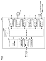
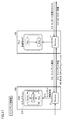
- FIG. 1 is an external view showing a configuration example of the controller system 1 according to the present embodiment.
- the controller system 1 includes a control unit 100, a security unit 200, a safety unit 300, one or more functional units 400, and a power supply unit 450.
- control unit 100 and the security unit 200 are connected via an arbitrary data transmission line (for example, PCI Express (registered trademark) or Ethernet (registered trademark)).
- control unit 100 and the safety unit 300 and one or more functional units 400 are connected via an internal bus (not shown).
- the control unit 100 executes a central process in the controller system 1.
- the control unit 100 executes a control operation for controlling a controlled object according to an arbitrarily designed requirement specification.
- the control calculation executed by the control unit 100 is also referred to as "standard control" in comparison with the control calculation executed by the safety unit 300 described later.
- the control unit 100 has one or a plurality of communication ports.
- the security unit 200 is connected to the control unit 100 and is in charge of the security function for the controller system 1.
- the security unit 200 has one or more communication ports. Details of the security function provided by the security unit 200 will be described later.
- the safety unit 300 executes a control calculation for realizing a safety function related to a controlled object independently of the control unit 100.
- the control calculation executed by the safety unit 300 is also referred to as "safety control".
- safety control is designed to meet the requirements for realizing the safety function specified in IEC 61508 or the like.
- Safety control is a general term for processes for preventing human safety from being threatened by equipment or machines.
- the functional unit 400 provides various functions for realizing control for various control targets by the controller system 1.
- the functional unit 400 may typically include an I / O unit, a safety I / O unit, a communication unit, a motion controller unit, a temperature control unit, a pulse counter unit, and the like.
- the I / O unit for example, a digital input (DI) unit, a digital output (DO) unit, an analog output (AI) unit, an analog output (AO) unit, a pulse catch input unit, and a plurality of types are mixed. Examples include a composite unit.
- the safety I / O unit is in charge of I / O processing related to safety control.
- the power supply unit 450 supplies power of a predetermined voltage to each unit constituting the controller system 1.
- FIG. 2 is a schematic diagram showing a hardware configuration example of the control unit 100 constituting the controller system 1 according to the present embodiment.
- the control unit 100 has a processor 102 such as a CPU (Central Processing Unit) and a GPU (Graphical Processing Unit), a chipset 104, a main storage device 106, and a secondary storage device as main components. It includes 108, a communication controller 110, a USB (Universal Serial Bus) controller 112, a memory card interface 114, network controllers 116, 118, 120, an internal bus controller 122, and an indicator 124.
- a processor 102 such as a CPU (Central Processing Unit) and a GPU (Graphical Processing Unit)
- chipset 104 such as a main storage device 106
- main storage device 106 main storage device
- secondary storage device main components. It includes 108, a communication controller 110, a USB (Universal Serial Bus) controller 112, a memory card interface 114, network controllers 116, 118, 120, an internal bus controller 122,
- the processor 102 reads various programs stored in the secondary storage device 108, expands them in the main storage device 106, and executes them to realize control operations related to standard control and various processes as described later. ..
- the chipset 104 realizes the processing of the control unit 100 as a whole by mediating the exchange of data between the processor 102 and each component.
- the secondary storage device 108 stores a control program that operates in the execution environment provided by the system program.
- the communication controller 110 is in charge of exchanging data with the security unit 200.
- the communication controller 110 for example, a communication chip corresponding to PCI Express or Ethernet can be adopted.
- the USB controller 112 is in charge of exchanging data with an arbitrary information processing device via a USB connection.
- the memory card interface 114 is configured so that the memory card 115 can be attached and detached, and data such as a control program and various settings can be written to the memory card 115, or data such as a control program and various settings can be written from the memory card 115. It is possible to read it.
- Each of the network controllers 116, 118, 120 is in charge of exchanging data with and from any device via the network.
- the network controllers 116, 118, 120 may employ industrial network protocols such as EtherCAT®, EtherNet / IP®, DeviceNet®, CompoNet®.
- the internal bus controller 122 is in charge of exchanging data with the safety unit 300 and one or a plurality of functional units 400 constituting the controller system 1.
- a manufacturer-specific communication protocol may be used, or a communication protocol that is the same as or compliant with any industrial network protocol may be used.
- the indicator 124 notifies the operating state of the control unit 100 and the like, and is composed of one or a plurality of LEDs arranged on the surface of the unit.
- FIG. 2 shows a configuration example in which the necessary functions are provided by the processor 102 executing the program, and some or all of these provided functions are provided by a dedicated hardware circuit (for example, ASIC). It may be implemented using (Application Specific Integrated Circuit) or FPGA (Field-Programmable Gate Array). Alternatively, the main part of the control unit 100 may be realized by using hardware that follows a general-purpose architecture (for example, an industrial personal computer based on a general-purpose personal computer). In this case, virtualization technology may be used to execute a plurality of OSs (Operating Systems) having different uses in parallel, and to execute necessary applications on each OS.
- OSs Operating Systems
- FIG. 3 is a schematic diagram showing a hardware configuration example of the security unit 200 constituting the controller system 1 according to the present embodiment.
- the security unit 200 has, as main components, a processor 202 such as a CPU and a GPU, a chipset 204, a main storage device 206, a secondary storage device 208, a communication controller 210, and a USB controller. Includes 212, memory card interface 214, network controllers 216, 218, and indicator 224.
- the processor 202 realizes various security functions as described later by reading various programs stored in the secondary storage device 208, deploying them in the main storage device 206, and executing the programs.
- the chipset 204 realizes the processing of the security unit 200 as a whole by mediating the exchange of data between the processor 202 and each component.
- the secondary storage device 208 stores the security system program that operates in the execution environment provided by the system program.
- the communication controller 210 is in charge of exchanging data with and from the control unit 100.
- a communication chip corresponding to, for example, PCI Express or Ethernet can be adopted for the control unit 100 in the same manner as the communication controller 210.
- the USB controller 212 is in charge of exchanging data with an arbitrary information processing device via a USB connection.
- the memory card interface 214 is configured so that the memory card 215 can be attached and detached, and data such as a control program and various settings can be written to the memory card 215, or data such as a control program and various settings can be written from the memory card 215. It is possible to read it.
- Each of the network controllers 216 and 218 is in charge of exchanging data with and from any device via the network.
- the network controllers 216 and 218 may employ a general-purpose network protocol such as Ethernet®.
- the indicator 224 notifies the operating state of the security unit 200, etc., and is composed of one or a plurality of LEDs arranged on the surface of the unit.
- FIG. 3 shows a configuration example in which the necessary functions are provided by the processor 202 executing the program, and some or all of these provided functions are provided by a dedicated hardware circuit (for example, ASIC). Alternatively, it may be implemented using an FPGA or the like). Alternatively, the main part of the security unit 200 may be realized by using hardware that follows a general-purpose architecture (for example, an industrial personal computer based on a general-purpose personal computer). In this case, virtualization technology may be used to execute a plurality of OSs having different uses in parallel, and to execute necessary applications on each OS.
- a general-purpose architecture for example, an industrial personal computer based on a general-purpose personal computer.
- virtualization technology may be used to execute a plurality of OSs having different uses in parallel, and to execute necessary applications on each OS.
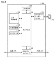
- FIG. 4 is a schematic diagram showing a hardware configuration example of the safety unit 300 constituting the controller system 1 according to the present embodiment.
- the safety unit 300 has, as main components, a processor 302 such as a CPU and GPU, a chipset 304, a main storage device 306, a secondary storage device 308, a memory card interface 314, and an internal structure. It includes a bus controller 322 and an indicator 324.
- the processor 302 reads various programs stored in the secondary storage device 308, expands them in the main storage device 306, and executes them to realize control calculations related to safety control and various processes as described later. ..
- the chipset 304 realizes the processing of the safety unit 300 as a whole by mediating the exchange of data between the processor 302 and each component.
- the secondary storage device 308 stores a safety program that operates in the execution environment provided by the system program.
- the memory card interface 314 is configured so that the memory card 315 can be attached and detached, and data such as a safety program and various settings can be written to the memory card 315, or data such as a safety program and various settings can be written from the memory card 315. It is possible to read it.
- the internal bus controller 322 is in charge of exchanging data with the control unit 100 via the internal bus.
- the indicator 324 notifies the operating state of the safety unit 300 and the like, and is composed of one or a plurality of LEDs arranged on the surface of the unit.
- FIG. 4 shows a configuration example in which the necessary functions are provided by the processor 302 executing the program, and some or all of these provided functions are provided by a dedicated hardware circuit (for example, ASIC). Alternatively, it may be implemented using an FPGA or the like). Alternatively, the main part of the safety unit 300 may be realized by using hardware that follows a general-purpose architecture (for example, an industrial personal computer based on a general-purpose personal computer). In this case, virtualization technology may be used to execute a plurality of OSs having different uses in parallel, and to execute necessary applications on each OS.
- a general-purpose architecture for example, an industrial personal computer based on a general-purpose personal computer.
- virtualization technology may be used to execute a plurality of OSs having different uses in parallel, and to execute necessary applications on each OS.
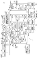
- FIG. 5 is a schematic diagram showing a typical example of the control system 10 including the controller system 1 according to the present embodiment.
- control system 10 shown in FIG. 5 targets two lines (line A and line B) as control targets.
- each line is equipped with a conveyor that conveys the work, as well as a robot that can exert any physical action on the work on the conveyor.
- the control unit 100 is arranged on each of the line A and the line B.
- the security unit 200 and the safety unit 300 constitute the controller system 1.
- the description of the functional unit 400 and the power supply unit 450 is omitted in FIG.
- the security unit 200 of the controller system 1 is connected to the first network 2 via the communication port 242 (network controller 216 in FIG. 3). It is assumed that the support device 600 and the SCADA (Supervisory Control And Data Acquisition) device 700 are connected to the first network 2.
- SCADA Supervisory Control And Data Acquisition
- the support device 600 has at least access to the control unit 100, and provides the user with functions such as creating a program executed by each unit included in the controller system 1, debugging, and setting various parameters.
- the SCADA device 700 presents various information obtained by the control calculation in the controller system 1 to the operator, and generates an internal command or the like for the controller system 1 according to the operation from the operator.
- the SCADA device 700 also has a function of collecting data handled by the controller system 1.
- the control unit 100 of the controller system 1 is connected to the second network 4 via the communication port 142 (network controller 116 in FIG. 2). It is assumed that the HMI (Human Machine Interface) 800 and the database 900 are connected to the second network 4.
- HMI Human Machine Interface
- the HMI 800 presents various information obtained by the control calculation in the controller system 1 to the operator, and generates an internal command or the like for the controller system 1 according to the operation from the operator.
- the database 900 collects various data transmitted from the controller system 1 (for example, information on traceability measured from each work).
- the control unit 100 of the controller system 1 is connected to one or more field devices 500 via the communication port 144 (network controller 118 in FIG. 2).
- the field device 500 includes a sensor and a detector that collect various information necessary for control calculation from a controlled object, an actuator that exerts some action on the controlled object, and the like.
- the field device 500 exchanges signals with a robot that exerts some external action on the work, a conveyor that conveys the work, and sensors and actuators arranged in the field. Including units and so on.
- control unit 100 in charge of line B is also connected to one or more field devices 500 via the communication port 144 (network controller 118 in FIG. 2).
- the control unit 100 is an information engine 160 that exchanges data between a control engine 150, which is a processing execution unit that executes control calculations related to standard control, and an external device. And include.
- the security unit 200 includes a security engine 250 for realizing a security function as described later.
- the safety unit 300 includes a safety engine 350, which is a processing execution unit that executes a control calculation related to safety control.
- Each engine is realized by any hardware element such as the processor of each unit, any software element such as various programs, or a combination of these elements.
- Each engine can be implemented in any form.
- controller system 1 includes a broker 170 that mediates the exchange between engines.
- the entity of the broker 170 may be located in one or both of the control unit 100 and the security unit 200.
- the control engine 150 holds a variable table, a function block (FB), and the like necessary for executing a control operation for controlling a controlled object.
- Each variable stored in the variable table is periodically collected by the value acquired from the field device 500 by the I / O refresh process, and each value is periodically reflected in the field device 500.
- the log of the control operation in the control engine 150 may be stored in the log database 180.
- the information engine 160 executes arbitrary information processing on the data (variable values held in the variable table) held by the control unit 100.
- the information engine 160 includes a process of periodically transmitting data held by the control unit 100 to a database 900 or the like. SQL or the like is used for transmitting such data.
- the security engine 250 detects an unauthorized intrusion that occurs in the controller system 1, processes according to the detected unauthorized intrusion, determines whether or not an incident has occurred, and executes processing according to the incident that has occurred.
- the behavior of the security engine 250 is stored as security information 260. Therefore, the security engine 250 corresponds to a detection means for detecting the presence or absence of a security-related incident.
- the security engine 250 notifies with an indicator 224 that some security-related event has occurred or the level of the security-related event that has occurred.
- the safety engine 350 corresponds to a detection means for detecting whether or not some kind of unauthorized intrusion has occurred in the controller system 1.
- the safety engine 350 acquires and reflects the safety I / O variables necessary for executing the control calculation related to the safety control via the control unit 100.
- the log of the safety control in the safety engine 350 may be stored in the log database 360.
- the broker 170 changes the operations of the control engine 150, the information engine 160, the safety engine 350, and the like.
- the controller system 1 can detect any security threat that hinders the normal operation of the equipment or machine and take necessary measures.
- normal operation means a state in which equipment and machines can be continuously operated according to the system design and the production plan. It should be noted that the concept of "normal operation” includes the start-up, maintenance, setup change, and other ancillary processing of equipment and machinery to continue operation of equipment and machinery according to the system design and production plan.
- a control device centered on a PLC typically, (1) an attack from a higher-level device such as a database, (2) an attack from a field device, (3) an attack via a support device, and (4) a memory.
- Security threats can be considered from four aspects, such as an attack via a storage medium attached to a control device such as a card.
- all physical ports on the controller pose a security risk of being attacked.
- the security unit 200 detects security threats or risks that occur in each of these aspects and executes a process for executing necessary countermeasures.
- FIG. 6 is a schematic diagram showing an example of a countermeasure cycle against security threats.
- the countermeasure cycle against security threats is roughly divided into (1) countermeasures during development (steps S1, S2, S9) and (2) countermeasures during operation (steps S3 to S8). ..
- (1) Measures during development mainly mean measures at the stage of determining the design and specifications of equipment and machines to be controlled
- (2) Measures during operation mainly mean operating equipment and machines to be controlled. It means measures at the stage of
- step S1 a threat analysis for the equipment or machine to be controlled is executed.
- step S2 the security requirement definition is determined.
- step S2 the security function design is executed.
- security functions such as encryption method, authentication method, and access restriction are designed.
- step S3 normal operation includes processing such as start-up of equipment and machinery, production operation, maintenance, and setup change.
- step S4 the security threat primary response is executed (step S4).
- intrusion detection means detecting a phenomenon or abnormality that may pose a security threat.
- the detection of unauthorized intrusion only means detecting the occurrence of an unusual phenomenon or condition, and usually no incident has occurred (however, there is a risk of occurrence of an incident).
- the security threat primary response is executed as a primary measure (step S4).
- the primary security threat response is a primary measure in a situation where there is a risk of an incident occurring, and it may be possible to prevent the progress of the incident occurrence. Even if an incident occurs, the damage can be minimized by implementing the primary security threat response.
- the security threat primary response is automatically executed by setting in advance.
- the primary security threat response can be roughly divided into three types: continuation, degeneration, and suspension. “Continuing” the primary security threat response means continuing the operation as it was immediately before the unauthorized intrusion was detected. However, it is preferable to notify the security threat by an alarm or the like so that further measures can be taken promptly.
- Degenerate for the primary security threat means that the controller system will continue to operate in a limited way, such as partial outage (only part of the operation), performance reduction (performance degradation), and functional restrictions. That is, in “degenerate”, the operation itself continues even though there are some restrictions in terms of hardware or software as compared with the operation immediately before the detection of unauthorized intrusion.
- the "degenerate" of the primary security threat response may include general degenerate operation (fallback).
- a general degenerate operation means that the operation is maintained in a state where the function or performance of the system is partially stopped. After switching to the degenerate operation, the available functions are often suppressed to the minimum, or the response speed is often reduced. Therefore, “degenerate” may be either limiting the control operation of the control unit 100 or limiting the operation of the controlled object.
- “Stop” for the primary security threat response means to safely stop the operation of the system.
- the recovery work is executed.
- the field side of the controller system 1 and the controller system 1 is in charge of the workers in the OT (Operation Technology) department, and the upper side of the controller system 1 (first network 2 and first). 2 Network 4 and devices connected to each network) are handled by workers in the IT (Information Technology) department.
- the workers in the OT department perform the necessary processing for the equipment and machines to be controlled (on-site response) (step S5). Specifically, work such as restoration work and monitoring of equipment and machines is executed. On the other hand, the worker in the IT department performs threat analysis and countermeasures against the security threat that has occurred (step S6). Measures taken by IT department workers may include provisional and permanent measures.
- test run is executed (step S7). If there is no problem with this test run, the operation is restarted and the normal operation is restored (step S3).
- the security threat primary response is executed (step S4)
- the incident response is executed (step S8).
- Incident response is a response after an incident occurs, and includes urgent measures to restore the site and limit the scope of impact.
- the incident response is automatically executed by setting in advance.
- step S5 After the incident response is executed, the workers in the OT department perform the necessary processing for the equipment and machines to be controlled (on-site response) (step S5), and the workers in the IT department raise the security threat. Threat analysis and countermeasures against the above are performed (step S6). Further, an incident report is created (step S9), and threat analysis (step S1), security function design (step S2), and the like are executed again based on the contents of the created incident report.
- the incident report may be created even if no incident has occurred.
- the controller system 1 provides a mechanism that can reliably execute the countermeasure cycle against the security threat shown in FIG.
- FIG. 7 is a schematic diagram showing an example of a response at the time of unauthorized intrusion detection in the control system 10 including the controller system 1 according to the present embodiment.
- FIG. 7 shows an example in which the SCADA device 700 is infected with a virus in the control system 10 shown in FIG. 5 and attacked from the communication port 242 of the first network 2 and the security unit 200.
- incident characteristics is a term that includes the attributes of detected unauthorized intrusions (security threats) (for example, attack type, attack characteristics, attack level, severity, urgency, etc.).
- the security engine 250 of the security unit 200 determines the incident characteristics of the detected unauthorized intrusion (security threat) based on a predetermined detection logic, and outputs the incident characteristics to the control unit 100 or the like. That is, the security engine 250 of the security unit 200 functions as a notification means for notifying the control unit 100 of the incident characteristic indicating the attribute of unauthorized intrusion detected by the detection function.
- the control unit 100 executes the security threat primary response and / or the incident response according to the incident characteristics from the security unit 200. That is, the control unit 100 changes the control operation according to the incident characteristic notified from the security engine 250 of the security unit 200.
- FIG. 7 shows an example in which the primary security threat response is executed.
- the line A is such that the work transported on the conveyor is processed by a robot.
- the process of safely stopping the robot that processes the work and evacuating the work in process on the conveyor to the warehouse is the primary security threat response. Is executed as.
- the control engine 150 of the control unit 100 safely stops the robot and executes the process of moving the work-in-process on the conveyor to the warehouse for the line A (step). S41).
- the robot of the field device 500 is safely stopped (stopped) (step S42), and the conveyor of the field device 500 switches the transport speed to a low speed and moves the work in process to the warehouse.
- the special sorting process is executed (degenerate) (step S43).
- the I / O unit of the field device 500 continues the operation (operation) (step S44). This is because the input / output data that the I / O unit updates periodically is necessary for the control engine 150 to properly execute the process.
- Step S45 since the attack from the SCADA device 700 shown in FIG. 7 does not affect the control unit 100 in charge of the line B, the control engine 150 of the control unit 100 in charge of the line B continues to operate. (Step S45).
- step S46 only the minimum communication for continuing production may be permitted (step S46). That is, the communication of the communication physical port of the control unit 100 may be controlled. Not limited to the communication physical port of the control unit 100, if any unauthorized intrusion (security threat) is detected, communication of any communication physical port of the security unit 200 and / or the safety unit 300 may be restricted. Good.
- control unit 100 displays an alarm indicating the detection of an unauthorized intrusion (security threat) on the indicator 824 of the HMI 800 (step S47).
- control unit 100 may display an incident report on the HMI 800 (step S48).
- controller system 1 when the controller system 1 detects an unauthorized intrusion (security threat), it can execute a primary security threat response according to the incident characteristics of the detected unauthorized intrusion.
- information communication processing basically, communication is blocked and isolated from other equipment (information communication processing), and the work processed after being attacked by data tampering is specified (information processing). Security threats such as primary response are adopted.
- DDoS attack on a filling machine For example, a DDoS (Distributed Denial of Service) attack on a liquid filling machine (bottling machine) for a can or a bottle is assumed. Since the filling machine usually performs the filling operation at a high speed, sudden stoppage may cause problems in terms of damage to the equipment and post-treatment of the can or bottle during filling. On the other hand, in the DDoS attack, only the communication with the outside is affected, and it is often possible to operate the filling machine itself. Therefore, the filling machine takes a primary security threat response such as normal operation or degenerate operation (for example, the transport speed is gradually reduced).
- a primary security threat response such as normal operation or degenerate operation (for example, the transport speed is gradually reduced).
- the communication is blocked and isolated from other equipment (communication processing), and the work processed after being attacked by data tampering is specified ().
- Primary security threat response such as information processing
- processing for receiving information that is, the target of DDoS attack
- processing for transmitting information for example, transmission of production information to a higher-level server
- FIG. 8 is a schematic diagram showing an example of an attack on a line including a production machine and an inspection device. With reference to FIG. 8, for example, it is assumed that the production machine produces the product and the product produced by the production machine is inspected by the inspection device arranged on the downstream side of the production machine before being shipped.
- the attacker intended to release defective products to the market.
- the attacker tampers with the production machine so as to produce the defective product, and further tampers the inspection device so that the defective product cannot be detected.
- the quality judgment logic of the inspection device is falsified. That is, an attack is made in which the quality determination logic is intentionally rewritten so that the inspection device does not determine that the product is defective.
- the controller system 1 controls the control unit 100 and / or the safety unit 300 (that is, the security threat primary response or the incident response) according to the incident characteristics of the detected unauthorized intrusion (security threat).
- the content can be different.
- an example of determining the control content according to such an incident characteristic will be described.
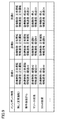
- FIG. 9 is a diagram showing an example of control operations for each facility according to the incident characteristics in the controller system 1 according to the present embodiment.
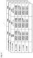
- FIG. 10 is a diagram showing another example of the control operation for each facility according to the incident characteristics in the controller system 1 according to the present embodiment.
- FIG. 11 is a diagram showing an example of control operations for each state in each facility according to the incident characteristics in the controller system 1 according to the present embodiment.
- FIG. 9 shows an example in which the type of attack or the state after the attack (for example, random tampering, resource exhaustion, DDoS attack, etc.) is output from the security unit 200 as an incident characteristic. Responses will be taken according to each incident characteristic output from the security unit 200. Responses according to such incident characteristics may be set in more detail for each facility or machine.
- the type of attack or the state after the attack for example, random tampering, resource exhaustion, DDoS attack, etc.
- Equipment control mainly means the processing in charge of the control engine 150 of the control unit 100 and / or the safety engine 350 of the safety unit 300 (both refer to FIG. 5), and corresponds to the operation of the equipment or machine to be controlled.
- Information communication mainly means the processing in charge of the information engine 160 of the control unit 100, and handles the exchange of data between the control unit 100 and the external device and the handling of information inside the control unit 100.
- normal operation means a state in which equipment and machines can be continuously operated according to the system design and the production plan.
- Degenerate (in the figure, “degenerate” is expressed by adding identification information such as "A1") is a partial stop of the controller system 1 (only a part is in operation) and performance reduction (performance deterioration). ), Function restrictions, etc., which means to continue operation in a limited way.
- Stand means to safely stop the operation of the target equipment or machine or the controller system 1. The same applies to FIGS. 10 and 11.
- FIG. 10 shows an example in which the detected unauthorized intrusion (security threat) level (severity or urgency, etc.) is output from the security unit 200 as an incident characteristic.
- Each level is calculated based on the type of attack detected or the state after the attack. Responses will be taken according to each incident characteristic output from the security unit 200. Responses according to such incident characteristics may be set in more detail for each facility or machine.
- FIG. 11 shows an example of setting a response according to each incident characteristic for each state of each facility or machine.
- the state of operation, maintenance, setup change, etc. may be specified for each facility, and the response to each facility may be determined based on the detected incident characteristics and the current state.
- FIG. 11 exemplifies the state of equipment and machines, but the present invention is not limited to this, and the contents of correspondence may differ depending on, for example, the operating state of PLC (during normal operation, during remote access, during debugging, etc.). You may let me.
- the response according to each incident characteristic may be determined based only on the state. That is, the response may be determined based only on the state when the security threat is detected, regardless of the difference in equipment or machine.
- the level shown in FIG. 10 may be used as the incident characteristic shown in FIG.
- the necessary measures are dynamically determined for each facility and / or each state according to the incident characteristics output from the security unit 200. it can. By dynamically determining the content of such measures, it is possible to flexibly implement measures for maintaining productivity and security measures by continuing the operation of equipment and machines.
- the control operations related to the standard control are illustrated in FIGS. 9 to 11, the same control operations can be defined for the safety control.
- Degeneration of equipment control means operating in a restricted state in terms of range, function, productivity, and the like.
- the zone to be controlled can be limited.
- the control side such as a control device, a module mounted on the control device, and a unit mounted on the control device can be restricted.
- the controlled side controlled object
- the controlled side controlled object
- a specific machine, line, floor, or the entire factory can be restricted.
- productivity for example, line speed, number of production per unit time, production amount per unit time, etc.
- productivity can be temporarily limited for safety and security.
- Degeneracy of information communication means operating in a restricted state in terms of range, direction, bandwidth, quality of service (QoS), data, and the like.
- communication physical port for example, communication physical port, communication logic port, network withdrawal, etc. can be restricted.
- the available TCP / UDP port may be limited, or the available communication protocol may be limited. Furthermore, the MAC address and IP address that accept access may be restricted.
- the direction in which data flows in each port may be limited to only one direction.
- the direction in which data flows in each port may be limited to only one direction.
- only data reception is permitted, or data transmission only is permitted.
- the communication speed may be limited (for example, changed from 1 Gbps to 100 Mbps) in order to reduce the communication load or the processing load of the controller system 1.
- the priority of packets to be passed may be dynamically changed. For example, when some kind of security threat is detected, the priority of the packet to be passed may be changed to a higher priority.
- the process data communication may be enabled / disabled and the update of the output value may be restricted (update stop / zero clear / hold the previous value, etc.).
- degenerate can include operation in a state where any restriction is applied to normal operation. It should be noted that “degenerate” can be regarded as a partial stop, and “stop” can be regarded as an extension of “degenerate” because it can include stopping a specific function entirely.
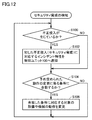
- FIG. 12 is a flowchart showing a processing procedure when a security threat is detected in the controller system 1 according to the present embodiment. Each step shown in FIG. 12 is realized by executing a program by the processor 102 of the control unit 100, the processor 202 of the security unit 200, and the processor 302 of the safety unit 300, respectively.
- the security unit 200 determines whether or not an unauthorized intrusion has occurred based on the processing generated by the control unit 100, the packets flowing on the network, and the like (step S100). If no unauthorized intrusion has occurred (NO in step S100), the process of step S100 is repeated.
- step S100 the security unit 200 notifies the control unit 100 of the incident characteristics corresponding to the detected unauthorized intrusion (security threat) (step S102).
- the control unit 100 determines whether or not it meets the condition relating to the predetermined change in operation (step S104).
- control unit 100 changes the operation of the target equipment or machine corresponding to the matched condition (step S106).
- step S104 if the condition relating to the change of the predetermined operation is not met (NO in step S104), the process of step S106 is skipped. Then, the process of step S100 or less is repeated.
- the indicator 224 arranged on the surface of the security unit 200, the indicator 124 arranged on the surface of the control unit 100, the indicator 824 of the HMI 800 (see FIG. 5), etc. May be used to notify the user.
- any change in display mode such as lighting color change, lighting start, and blinking start may be used before and after the detection of unauthorized intrusion. Further, not only the display but also a sound or a voice message may be used.
- Security threats can also be quantified according to security risks.
- security risk is a term that quantitatively indicates the probability or degree of detection as an unauthorized intrusion.
- the "security risk” can be calculated, for example, by the frequency of arrival of packets for random alteration, the degree of DDoS attack, and the like.
- the calculated degree may be displayed on the indicator 124 and the indicator 824 of the HMI 800 arranged on the surface of the control unit 100.
- FIG. 13 is a schematic diagram showing an example of an indicator adopted in the controller system 1 according to the present embodiment.
- FIG. 13 shows a configuration example when displaying the quantified security risk.
- the indicator 224 three LEDs are arranged. The lighting colors of the three LEDs are green, yellow, and red, respectively. When the risk level is low, only the green LED lights up. When the risk level is medium, the green and yellow LEDs are lit. When the risk level is high, the green LED, the yellow LED, and the red LED are lit.
- the security unit 200 has a presentation means for presenting the security risk calculated from the detection operation by the security engine 250, which is the detection means, to the user.
- the indicator 224 By arranging the indicator 224 as described above, even an operator without specialized knowledge can easily grasp the current security risk status.
- any indicator may be adopted as long as it can present a security risk.
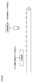
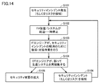
- FIG. 14 is a diagram showing a situation assumed in the restoration of the control system 10 after the occurrence of an incident.
- a security incident occurs when the control system 10 operates.
- a security risk is detected in the security unit 200 (step S101).
- the FA (Factory Automation) device / control system 10 performs a degenerate operation or temporarily stops (step S102).
- the engineer in the IT department executes recovery and countermeasure work in order to resolve the security incident (step S103).
- step S104 the security damage may increase, and for example, information leakage, device failure, or the like may occur (step S105).
- step S106 a security incident (or security risk) is detected again.
- the FA device / control system 10 is degenerated or temporarily stopped again (step S102). In this way, the processes of steps S102 to S106 may be repeated many times.
- FIG. 15 is a diagram showing a state of the system corresponding to the situation shown in FIG.
- the control unit 100 (denoted as “PLC” in FIG. 15) has a “Run” mode and a “Safe” mode as control modes.
- Run mode is a normal mode.
- the Safe mode is a degenerate mode, which is a mode for executing the limited operation of the controller system 1.
- the security engine 250 of the security unit 200 detects three levels of “Green”, “Yello”, and “Red” as the security level (Lv) according to the security risk. "Green”, “Yellow”, and “Red” also correspond to the lighting color of the LED of the indicator 224.
- the Green level is the level when security is safe.
- the Yellow level is the level at which an incident is detected.
- the Red level is the level at the time of the incident.
- control mode When the controller system is operating normally, the control mode is Run mode and the security level is Green level. When an incident is detected, the security level changes from “Green” to "Yello", and the control mode shifts from Run mode to Safe mode.
- control unit 100 is restored, even if the control mode is returned to the Run mode, the incident has not been released, so the control mode shifts to the Safe mode. While the incident is not released, even if the control unit 100 is restored, the control mode temporarily returns to the Run mode due to the detection of the incident, but the mode shifts to the Safe mode. Even though the incident has not been released, it is possible that an infinite loop may occur in the transition of the control mode by repeating the recovery of the control unit 100.
- the incident cancellation check logic is included in the flow of the restart processing of the control unit. As a result, it is possible to prevent erroneous restart of the controller system, and thus it is possible to prevent the spread of security damage (secondary damage).
- FIG. 16 is a diagram for showing a flow of restart processing according to the present embodiment.
- the control mode of the control unit 100 shifts from the Run mode to the Safe mode. Since this point has already been explained, the explanation will not be repeated here.
- the control mode cannot transition to the Run mode until the incident is cleared. Therefore, the control mode is kept in Safe mode.
- the security level will be "Green" level.
- the control unit 100 executes a restart process.
- the control mode shifts from Safe mode to Run mode, and the control system operates normally. Even if the control unit 100 is restarted (reset) while the security level is a level other than Green (Yellow or Red), the control mode of the control unit 100 is Safe mode.
- the security level is checked when the control mode is returned from the Safe mode to the Run mode. If the security level is Green, the control mode can be returned from Safe mode to Run mode. On the contrary, when the security level is a level other than Green (Yellow or Red) by the incident detection, the control mode is kept in Safe mode.
- the security unit 200 In order to restart the controller system 1, it is conceivable to turn off the entire power of the controller system 1 and then turn on the power of the controller system 1 again.
- the security unit 200 holds information about the status or security level non-volatilely. Therefore, when the power is turned on again in the controller system 1, the security unit 200 sets the security level based on the information stored in the security unit 200. As a result, the status of the security unit 200 before the power of the controller system 1 is turned off is maintained.
- the information regarding the status or the security level may be the information included in the security information 260 shown in FIG.
- the control unit 100 sets the control mode based on the status of the security unit 200. Therefore, the control mode is set to the mode before the power is turned off. Even if the reset by turning on the power to the controller system 1 is executed, the control mode of the control unit 100 can be maintained in the Safe mode until the incident is released.
- FIG. 17 is a first diagram for explaining a flow of restart processing of the control system according to the present embodiment.
- FIG. 17 shows the processing flow of the control system before the incident is cleared.
- the control mode of the control unit 100 is shifted to the Safe mode by the detection of the incident.
- a Run mode change request is input to the control unit 100 for normal operation (step S11).
- the control runtime unit 11 confirms the incident with respect to the security unit 200 (step S12).
- the control runtime unit 21 of the security unit 200 acquires incident information from the security engine 250 (step S13).
- the incident information may be information that the change to the Run mode is not possible (“NG”) or information indicating the security level (security level is “Yello”).
- the control runtime unit 21 transmits the acquired incident information to the control unit 100 (step S14).
- the incident information may be the information included in the security information 260 shown in FIG.
- the control runtime unit 11 of the control unit 100 acquires incident information from the control runtime unit 21.
- the control runtime unit 11 outputs a response to the Run mode change request based on the incident information (step S15).
- This response may include information that the change to Run mode is not possible (“NG”) or error information.
- FIG. 18 is a second diagram for explaining a flow of restart processing of the control system according to the present embodiment.
- FIG. 18 shows the processing flow of the control system after the incident is cleared.
- step S20 information indicating that the incident has been canceled is input to the security unit 200 (step S20).
- the control mode of the control unit 100 at this time is the Safe mode.
- the Run mode change request is input to the control unit 100 (step S21).
- the control runtime unit 11 confirms the incident with respect to the security unit 200 (step S22).
- the control runtime unit 21 of the security unit 200 acquires incident information from the security engine 250 (step S23). This incident information may be information that the change to Run mode is possible (“OK”), or information indicating a security level (security level is “Green”).
- the control runtime unit 21 transmits the acquired incident information to the control unit 100 (step S24).
- the control runtime unit 11 of the control unit 100 acquires incident information from the control runtime unit 21.
- the control runtime unit 11 changes the control mode from Safe mode to Run mode based on the incident information (step S25). Further, the control runtime unit 11 outputs a response to the change request (step S26). This response can include information that the change to Run mode is possible (“OK”).
- control unit 100 determines the control mode based on the incident information from the security unit 200 when the control unit is restarted. If the security incident has not been released, the control mode is set to the degraded mode even after the control unit 100 is restarted. Even though the incident has not been released, it is possible to prevent the control mode from being set to the normal mode by the restart process of the control unit.
- the control unit 100 changes the control mode to the Run mode based on the incident information meaning that the incident has been canceled.
- a command from a user with administrator authority may be prioritized over the above incident information. For example, when the administrator determines that the security level is Yellow but the administrator can return the control unit 100, the control unit 100 may return the control mode to the Run mode by receiving an input from the administrator.
- the control mode of the control unit 100 can be returned from the degraded mode to the control mode. Further, when it is clear that the incident has been canceled, the controller system 1 can be restored at an early stage.
- the control unit when the control unit is switched from the degenerate mode to the normal mode, it is determined whether or not the incident has been released. If the incident has not been cleared, the control mode cannot be changed from the degraded mode to the normal mode. As a result, it is possible to prevent the control system from being erroneously restarted (operating the control unit in the same manner as in normal times without canceling the incident), and thus it is possible to prevent the spread of security damage (secondary damage). Therefore, it is possible to increase the certainty of protection against threats that may occur with the networking or intelligentization of control devices and control systems.
- the controller system (1) A control unit (100) that executes a control operation for controlling a controlled object, and It is provided with a security unit (200) connected to the control unit (100) and in charge of a security function for the controller system (1).
- the control unit (100) has a normal mode and a degenerate mode for executing a limited operation of the controller system (1) as a control mode related to the control operation, and the normal mode and the degenerate mode Can transition to each other
- the controller system (1) includes a detection means (250) for detecting the presence or absence of a security-related incident.
- control unit (100) shifts the control mode to the degenerate mode, and the detection means (250) detects the release of the incident.
- a controller system (1) that keeps the control mode in the degenerate mode until it is done.
- the control unit (100) acquires incident information related to the detection of the incident from the detection means (250), and obtains incident information. When the incident information indicates the cancellation of the incident, the control unit (100) changes the control mode from the degenerate mode to the normal mode. When the incident information indicates the continuation of the incident, the control unit (100) sets the control mode to the degenerate mode.
- the controller system (1)
- control unit (100) executes the restart process of the control unit (100)
- the control unit (100) determines the control mode based on the incident information.
- the controller system (1) The controller system (1).
- the security unit (200) non-volatilely stores information regarding the detection of the incident.
- the security unit (200) is based on the information stored in the security unit (200).
- the control unit (100) sets the control mode based on the status of the security unit (200). From 3.
- the controller system (1) according to any one of.
- the security unit (200) changes the status of the security unit (200) regarding the detection of the incident by giving priority to the operation from the user having the administrator authority over the incident information. From 4.
- the controller system (1) according to any one of.
- control unit (100) limits the control operation. From 5.
- the controller system (1) according to any one of the above items.
- control unit (100) limits the operation of the controlled object. From 5.
- the controller system (1) according to any one of.
Abstract
This controller system (1) is provided with: a control unit (100) which executes a control operation for controlling a subject to be controlled; and a security unit (200) which takes charge of a security function for the controller system (1). The security unit (200) includes a detection means for detecting whether there is an incident pertaining to security in the controller system (1). When the incident is detected by the detection means, the control unit (100) transitions a control mode to a degeneration mode and maintains the control mode as the degeneration mode until a release of the incident is detected by the detection means.
Description
本発明は、制御対象を制御するコントローラシステムに対するセキュリティ機能に関する。
The present invention relates to a security function for a controller system that controls a controlled object.
各種設備および各設備に配置される各種装置の制御には、PLC(プログラマブルロジックコントローラ)などの制御装置が用いられる。制御装置は、制御対象の設備や機械に生じる異常を監視するとともに、制御装置自体の異常を監視することも可能である。何らかの異常が検知されると、制御装置から外部に対して何らかの方法で通知がなされる。
A control device such as a PLC (programmable logic controller) is used to control various facilities and various devices arranged in each facility. The control device can monitor an abnormality that occurs in the equipment or machine to be controlled, and can also monitor an abnormality of the control device itself. When any abnormality is detected, the control device notifies the outside in some way.
例えば、特開2000-137506号公報(特許文献1)は、異常履歴が登録されたとき、または、予め定められた時間が到来したときに、予め指定された宛先に電子メールを送信するプログラマブルコントローラを開示する。
For example, Japanese Patent Application Laid-Open No. 2000-137506 (Patent Document 1) is a programmable controller that sends an e-mail to a predetermined destination when an abnormality history is registered or when a predetermined time has arrived. To disclose.
近年のICT(Information and Communication Technology)の進歩に伴って、制御装置も様々な外部装置とネットワーク接続されるとともに、制御装置において実行される処理も高度化している。このようなネットワーク化あるいはインテリジェント化に伴って、想定される脅威の種類も増加している。したがって、このような脅威に対する制御装置および制御システムの保護が必要となっている。制御装置および制御システムに対する脅威が存在する間、その脅威から制御装置および制御システムを保護することの確実性を高くすることが求められる。
With the progress of ICT (Information and Communication Technology) in recent years, the control device is also connected to various external devices via a network, and the processing executed by the control device is becoming more sophisticated. With such networking or intelligentization, the types of threats that can be assumed are increasing. Therefore, it is necessary to protect control devices and control systems against such threats. While a threat to the control device and control system is present, it is required to increase the certainty of protecting the control device and control system from the threat.
本発明は、制御装置および制御システムのネットワーク化あるいはインテリジェント化に伴って生じ得る脅威に対する保護の確実性を高めることを一つの目的としている。
One object of the present invention is to increase the certainty of protection against threats that may occur due to networking or intelligentization of control devices and control systems.
本開示の一例は、コントローラシステムであって、制御対象を制御するための制御動作を実行する制御ユニットと、制御ユニットに接続され、コントローラシステムに対するセキュリティ機能を担当するセキュリティユニットとを備え、制御ユニットは、制御動作に関する制御モードとして、正常モードと、コントローラシステムの限定的な動作を実行するための縮退モードとを有し、正常モードと縮退モードとは相互に遷移可能であり、セキュリティユニットは、コントローラシステムにおける、セキュリティに関するインシデントの有無を検知する検知手段を含み、制御ユニットは、検知手段によりインシデントが検知された場合には、制御モードを縮退モードに遷移させて、インシデントの解除が検知手段によって検知されるまで制御モードを縮退モードに保つ。
An example of the present disclosure is a controller system, which includes a control unit that executes a control operation for controlling a controlled object, and a security unit that is connected to the control unit and is in charge of a security function for the controller system. Has a normal mode and a retracted mode for executing a limited operation of the controller system as a control mode related to the control operation, and the normal mode and the retracted mode can be interchanged with each other. The control unit includes a detection means for detecting the presence or absence of a security-related incident in the controller system, and when an incident is detected by the detection means, the control unit shifts the control mode to the reduced mode, and the incident is released by the detection means. Keep the control mode in retracted mode until detected.
上記によれば、セキュリティに関するインシデントが解除されるまで、制御ユニットは縮退モードで稼働する。セキュリティに関するインシデントが解除されていないにもかかわらず、制御ユニットが正常モードで稼働することを防止できる。したがって、制御装置および制御システムのネットワーク化あるいはインテリジェント化に伴って生じ得る脅威に対する保護の確実性を高めることができる。
According to the above, the control unit operates in degraded mode until the security incident is cleared. It is possible to prevent the control unit from operating in the normal mode even though the security incident has not been released. Therefore, it is possible to increase the certainty of protection against threats that may occur with the networking or intelligentization of control devices and control systems.
好ましくは、制御ユニットは、検知手段からインシデントの検知に関するインシデント情報を取得し、インシデント情報がインシデントの解除を示す場合には、制御ユニットは、縮退モードから正常モードへ制御モードを変更し、インシデント情報がインシデントの継続を示す場合には、制御ユニットは、制御モードを縮退モードに設定する。
Preferably, the control unit acquires incident information regarding the detection of the incident from the detection means, and when the incident information indicates the cancellation of the incident, the control unit changes the control mode from the degraded mode to the normal mode, and the incident information If indicates continuation of the incident, the control unit sets the control mode to degenerate mode.
上記によれば、制御ユニットは、セキュリティユニットからの情報に基づいて、制御モードを正常モードまたは縮退モードに設定することができる。これにより、制御装置および制御システムのネットワーク化あるいはインテリジェント化に伴って生じ得る脅威に対する保護の確実性を高めることができる。
According to the above, the control unit can set the control mode to the normal mode or the degraded mode based on the information from the security unit. This can increase the certainty of protection against threats that may arise with the networking or intelligentization of control devices and control systems.
好ましくは、制御ユニットは、制御ユニットの再起動処理を実行する場合に、インシデント情報に基づいて、制御モードを決定する。
Preferably, the control unit determines the control mode based on the incident information when executing the restart process of the control unit.
上記によれば、セキュリティに関するインシデントが解除されていない場合には、制御ユニットを再起動した後も制御モードは縮退モードに設定される。インシデントが解除されていないにもかかわらず、制御ユニットの再起動処理によって制御モードが正常モードに設定されることを防止できる。
According to the above, if the security incident has not been released, the control mode is set to the degraded mode even after the control unit is restarted. Even though the incident has not been released, it is possible to prevent the control mode from being set to the normal mode by the restart process of the control unit.
好ましくは、セキュリティユニットは、インシデントの検知に関する情報を不揮発的に記憶して、コントローラシステムへの電源再投入によるコントローラシステムの再起動時に、セキュリティユニットは、セキュリティユニットに記憶された情報に基づいて、セキュリティユニットのステータスを復帰させ、制御ユニットは、セキュリティユニットのステータスに基づいて、制御モードを設定する。
Preferably, the security unit non-volatilely stores information about incident detection, and when the controller system is restarted by power cycle to the controller system, the security unit is based on the information stored in the security unit. The status of the security unit is restored, and the control unit sets the control mode based on the status of the security unit.
上記によれば、セキュリティに関するインシデントが解除されていない場合には、コントローラシステム全体を電源再投入によりリセットしても、セキュリティユニットに記憶された情報に基づいて、制御モードは縮退モードに設定される。インシデントが解除されていないにもかかわらず、コントローラシステムの再起動処理によって制御モードが正常モードに設定されることを防止できる。
According to the above, if the security incident has not been cleared, the control mode is set to the degraded mode based on the information stored in the security unit even if the entire controller system is reset by power cycle. .. Even though the incident has not been cleared, it is possible to prevent the control mode from being set to the normal mode by the restart process of the controller system.
好ましくは、セキュリティユニットは、管理者権限を持つユーザからの操作をインシデント情報に優先させてインシデントの検知に関するセキュリティユニットのステータスを変更する。
Preferably, the security unit changes the status of the security unit related to incident detection by prioritizing operations from users with administrator privileges over incident information.
上記によれば、たとえばインシデントが解除されたことが明らかな場合に、コントローラシステム1を早期に復旧させることができる。
According to the above, for example, when it is clear that the incident has been canceled, the controller system 1 can be restored at an early stage.
好ましくは、縮退モードにおいて、制御ユニットは、制御動作を制限する。
上記によれば、システムの稼働を維持することができる。 Preferably, in the degenerate mode, the control unit limits the control operation.
According to the above, the operation of the system can be maintained.
上記によれば、システムの稼働を維持することができる。 Preferably, in the degenerate mode, the control unit limits the control operation.
According to the above, the operation of the system can be maintained.
好ましくは、縮退モードにおいて、制御ユニットは、制御対象の動作を制限する。
上記によれば、システムの稼働を維持することができる。 Preferably, in the degenerate mode, the control unit limits the operation of the controlled object.
According to the above, the operation of the system can be maintained.
上記によれば、システムの稼働を維持することができる。 Preferably, in the degenerate mode, the control unit limits the operation of the controlled object.
According to the above, the operation of the system can be maintained.
本発明によれば、制御装置および制御システムのネットワーク化あるいはインテリジェント化に伴って生じ得る脅威に対する保護の確実性を高めることができる。
According to the present invention, it is possible to increase the certainty of protection against threats that may occur due to networking or intelligentization of control devices and control systems.
本発明の実施の形態について、図面を参照しながら詳細に説明する。なお、図中の同一または相当部分については、同一符号を付してその説明は繰り返さない。
An embodiment of the present invention will be described in detail with reference to the drawings. The same or corresponding parts in the drawings are designated by the same reference numerals and the description thereof will not be repeated.
<A.コントローラシステム1>
まず、本実施の形態に従うコントローラシステム1の構成について説明する。 <A. Controller system 1>
First, the configuration of thecontroller system 1 according to the present embodiment will be described.
まず、本実施の形態に従うコントローラシステム1の構成について説明する。 <
First, the configuration of the
図1は、本実施の形態に係るコントローラシステム1の構成例を示す外観図である。図1を参照して、コントローラシステム1は、制御ユニット100と、セキュリティユニット200と、セーフティユニット300と、1または複数の機能ユニット400と、電源ユニット450とを含む。
FIG. 1 is an external view showing a configuration example of the controller system 1 according to the present embodiment. With reference to FIG. 1, the controller system 1 includes a control unit 100, a security unit 200, a safety unit 300, one or more functional units 400, and a power supply unit 450.
制御ユニット100とセキュリティユニット200との間は、任意のデータ伝送路(例えば、PCI Express(登録商標)あるいはイーサネット(登録商標)など)を介して接続されている。制御ユニット100とセーフティユニット300および1または複数の機能ユニット400との間は、図示しない内部バスを介して接続されている。
The control unit 100 and the security unit 200 are connected via an arbitrary data transmission line (for example, PCI Express (registered trademark) or Ethernet (registered trademark)). The control unit 100 and the safety unit 300 and one or more functional units 400 are connected via an internal bus (not shown).
制御ユニット100は、コントローラシステム1において中心的な処理を実行する。制御ユニット100は、任意に設計された要求仕様に従って、制御対象を制御するための制御演算を実行する。後述のセーフティユニット300で実行される制御演算との対比で、制御ユニット100で実行される制御演算を「標準制御」とも称す。図1に示す構成例において、制御ユニット100は、1または複数の通信ポートを有している。
The control unit 100 executes a central process in the controller system 1. The control unit 100 executes a control operation for controlling a controlled object according to an arbitrarily designed requirement specification. The control calculation executed by the control unit 100 is also referred to as "standard control" in comparison with the control calculation executed by the safety unit 300 described later. In the configuration example shown in FIG. 1, the control unit 100 has one or a plurality of communication ports.
セキュリティユニット200は、制御ユニット100に接続され、コントローラシステム1に対するセキュリティ機能を担当する。図1に示す構成例において、セキュリティユニット200は、1または複数の通信ポートを有している。セキュリティユニット200が提供するセキュリティ機能の詳細については、後述する。
The security unit 200 is connected to the control unit 100 and is in charge of the security function for the controller system 1. In the configuration example shown in FIG. 1, the security unit 200 has one or more communication ports. Details of the security function provided by the security unit 200 will be described later.
セーフティユニット300は、制御ユニット100とは独立して、制御対象に関するセーフティ機能を実現するための制御演算を実行する。セーフティユニット300で実行される制御演算を「セーフティ制御」とも称す。通常、「セーフティ制御」は、IEC 61508などに規定されたセーフティ機能を実現するための要件を満たすように設計される。「セーフティ制御」は、設備や機械などによって人の安全が脅かされることを防止するための処理を総称する。
The safety unit 300 executes a control calculation for realizing a safety function related to a controlled object independently of the control unit 100. The control calculation executed by the safety unit 300 is also referred to as "safety control". Usually, the "safety control" is designed to meet the requirements for realizing the safety function specified in IEC 61508 or the like. "Safety control" is a general term for processes for preventing human safety from being threatened by equipment or machines.
機能ユニット400は、コントローラシステム1による様々な制御対象に対する制御を実現するための各種機能を提供する。機能ユニット400は、典型的には、I/Oユニット、セーフティI/Oユニット、通信ユニット、モーションコントローラユニット、温度調整ユニット、パルスカウンタユニットなどを包含し得る。I/Oユニットとしては、例えば、デジタル入力(DI)ユニット、デジタル出力(DO)ユニット、アナログ出力(AI)ユニット、アナログ出力(AO)ユニット、パルスキャッチ入力ユニット、および、複数の種類を混合させた複合ユニットなどが挙げられる。セーフティI/Oユニットは、セーフティ制御に係るI/O処理を担当する。
The functional unit 400 provides various functions for realizing control for various control targets by the controller system 1. The functional unit 400 may typically include an I / O unit, a safety I / O unit, a communication unit, a motion controller unit, a temperature control unit, a pulse counter unit, and the like. As the I / O unit, for example, a digital input (DI) unit, a digital output (DO) unit, an analog output (AI) unit, an analog output (AO) unit, a pulse catch input unit, and a plurality of types are mixed. Examples include a composite unit. The safety I / O unit is in charge of I / O processing related to safety control.
電源ユニット450は、コントローラシステム1を構成する各ユニットに対して、所定電圧の電源を供給する。
The power supply unit 450 supplies power of a predetermined voltage to each unit constituting the controller system 1.
<B.各ユニットのハードウェア構成例>
次に、本実施の形態に従うコントローラシステム1を構成する各ユニットのハードウェア構成例について説明する。 <B. Hardware configuration example of each unit>
Next, a hardware configuration example of each unit constituting thecontroller system 1 according to the present embodiment will be described.
次に、本実施の形態に従うコントローラシステム1を構成する各ユニットのハードウェア構成例について説明する。 <B. Hardware configuration example of each unit>
Next, a hardware configuration example of each unit constituting the
(b1:制御ユニット100)
図2は、本実施の形態に従うコントローラシステム1を構成する制御ユニット100のハードウェア構成例を示す模式図である。図2を参照して、制御ユニット100は、主たるコンポーネントとして、CPU(Central Processing Unit)やGPU(Graphical Processing Unit)などのプロセッサ102と、チップセット104と、主記憶装置106と、二次記憶装置108と、通信コントローラ110と、USB(Universal Serial Bus)コントローラ112と、メモリカードインターフェイス114と、ネットワークコントローラ116,118,120と、内部バスコントローラ122と、インジケータ124とを含む。 (B1: Control unit 100)
FIG. 2 is a schematic diagram showing a hardware configuration example of thecontrol unit 100 constituting the controller system 1 according to the present embodiment. With reference to FIG. 2, the control unit 100 has a processor 102 such as a CPU (Central Processing Unit) and a GPU (Graphical Processing Unit), a chipset 104, a main storage device 106, and a secondary storage device as main components. It includes 108, a communication controller 110, a USB (Universal Serial Bus) controller 112, a memory card interface 114, network controllers 116, 118, 120, an internal bus controller 122, and an indicator 124.
図2は、本実施の形態に従うコントローラシステム1を構成する制御ユニット100のハードウェア構成例を示す模式図である。図2を参照して、制御ユニット100は、主たるコンポーネントとして、CPU(Central Processing Unit)やGPU(Graphical Processing Unit)などのプロセッサ102と、チップセット104と、主記憶装置106と、二次記憶装置108と、通信コントローラ110と、USB(Universal Serial Bus)コントローラ112と、メモリカードインターフェイス114と、ネットワークコントローラ116,118,120と、内部バスコントローラ122と、インジケータ124とを含む。 (B1: Control unit 100)
FIG. 2 is a schematic diagram showing a hardware configuration example of the
プロセッサ102は、二次記憶装置108に格納された各種プログラムを読み出して、主記憶装置106に展開して実行することで、標準制御に係る制御演算、および、後述するような各種処理を実現する。チップセット104は、プロセッサ102と各コンポーネントとの間のデータの遣り取りを仲介することで、制御ユニット100全体としての処理を実現する。
The processor 102 reads various programs stored in the secondary storage device 108, expands them in the main storage device 106, and executes them to realize control operations related to standard control and various processes as described later. .. The chipset 104 realizes the processing of the control unit 100 as a whole by mediating the exchange of data between the processor 102 and each component.
二次記憶装置108には、システムプログラムに加えて、システムプログラムが提供する実行環境上で動作する制御プログラムが格納される。
In addition to the system program, the secondary storage device 108 stores a control program that operates in the execution environment provided by the system program.
通信コントローラ110は、セキュリティユニット200との間のデータの遣り取りを担当する。通信コントローラ110としては、例えば、PCI Expressあるいはイーサネットなどに対応する通信チップを採用できる。
The communication controller 110 is in charge of exchanging data with the security unit 200. As the communication controller 110, for example, a communication chip corresponding to PCI Express or Ethernet can be adopted.
USBコントローラ112は、USB接続を介して任意の情報処理装置との間のデータの遣り取りを担当する。
The USB controller 112 is in charge of exchanging data with an arbitrary information processing device via a USB connection.
メモリカードインターフェイス114は、メモリカード115を着脱可能に構成されており、メモリカード115に対して制御プログラムや各種設定などのデータを書込み、あるいは、メモリカード115から制御プログラムや各種設定などのデータを読出すことが可能になっている。
The memory card interface 114 is configured so that the memory card 115 can be attached and detached, and data such as a control program and various settings can be written to the memory card 115, or data such as a control program and various settings can be written from the memory card 115. It is possible to read it.
ネットワークコントローラ116,118,120の各々は、ネットワークを介した任意のデバイスとの間のデータの遣り取りを担当する。ネットワークコントローラ116,118,120は、EtherCAT(登録商標)、EtherNet/IP(登録商標)、DeviceNet(登録商標)、CompoNet(登録商標)などの産業用ネットワークプロトコルを採用してもよい。
Each of the network controllers 116, 118, 120 is in charge of exchanging data with and from any device via the network. The network controllers 116, 118, 120 may employ industrial network protocols such as EtherCAT®, EtherNet / IP®, DeviceNet®, CompoNet®.
内部バスコントローラ122は、コントローラシステム1を構成するセーフティユニット300や1または複数の機能ユニット400との間のデータの遣り取りを担当する。内部バスには、メーカ固有の通信プロトコルを用いてもよいし、いずれかの産業用ネットワークプロトコルと同一あるいは準拠した通信プロトコルを用いてもよい。
The internal bus controller 122 is in charge of exchanging data with the safety unit 300 and one or a plurality of functional units 400 constituting the controller system 1. For the internal bus, a manufacturer-specific communication protocol may be used, or a communication protocol that is the same as or compliant with any industrial network protocol may be used.
インジケータ124は、制御ユニット100の動作状態などを通知するものであり、ユニット表面に配置された1または複数のLEDなどで構成される。
The indicator 124 notifies the operating state of the control unit 100 and the like, and is composed of one or a plurality of LEDs arranged on the surface of the unit.
図2には、プロセッサ102がプログラムを実行することで必要な機能が提供される構成例を示したが、これらの提供される機能の一部または全部を、専用のハードウェア回路(例えば、ASIC(Application Specific Integrated Circuit)またはFPGA(Field-Programmable Gate Array)など)を用いて実装してもよい。あるいは、制御ユニット100の主要部を、汎用的なアーキテクチャに従うハードウェア(例えば、汎用パソコンをベースとした産業用パソコン)を用いて実現してもよい。この場合には、仮想化技術を用いて、用途の異なる複数のOS(Operating System)を並列的に実行させるとともに、各OS上で必要なアプリケーションを実行させるようにしてもよい。
FIG. 2 shows a configuration example in which the necessary functions are provided by the processor 102 executing the program, and some or all of these provided functions are provided by a dedicated hardware circuit (for example, ASIC). It may be implemented using (Application Specific Integrated Circuit) or FPGA (Field-Programmable Gate Array). Alternatively, the main part of the control unit 100 may be realized by using hardware that follows a general-purpose architecture (for example, an industrial personal computer based on a general-purpose personal computer). In this case, virtualization technology may be used to execute a plurality of OSs (Operating Systems) having different uses in parallel, and to execute necessary applications on each OS.
(b2:セキュリティユニット200)
図3は、本実施の形態に従うコントローラシステム1を構成するセキュリティユニット200のハードウェア構成例を示す模式図である。図3を参照して、セキュリティユニット200は、主たるコンポーネントとして、CPUやGPUなどのプロセッサ202と、チップセット204と、主記憶装置206と、二次記憶装置208と、通信コントローラ210と、USBコントローラ212と、メモリカードインターフェイス214と、ネットワークコントローラ216,218と、インジケータ224とを含む。 (B2: Security unit 200)
FIG. 3 is a schematic diagram showing a hardware configuration example of thesecurity unit 200 constituting the controller system 1 according to the present embodiment. With reference to FIG. 3, the security unit 200 has, as main components, a processor 202 such as a CPU and a GPU, a chipset 204, a main storage device 206, a secondary storage device 208, a communication controller 210, and a USB controller. Includes 212, memory card interface 214, network controllers 216, 218, and indicator 224.
図3は、本実施の形態に従うコントローラシステム1を構成するセキュリティユニット200のハードウェア構成例を示す模式図である。図3を参照して、セキュリティユニット200は、主たるコンポーネントとして、CPUやGPUなどのプロセッサ202と、チップセット204と、主記憶装置206と、二次記憶装置208と、通信コントローラ210と、USBコントローラ212と、メモリカードインターフェイス214と、ネットワークコントローラ216,218と、インジケータ224とを含む。 (B2: Security unit 200)
FIG. 3 is a schematic diagram showing a hardware configuration example of the
プロセッサ202は、二次記憶装置208に格納された各種プログラムを読み出して、主記憶装置206に展開して実行することで、後述するような各種セキュリティ機能を実現する。チップセット204は、プロセッサ202と各コンポーネントとの間のデータの遣り取りを仲介することで、セキュリティユニット200全体としての処理を実現する。
The processor 202 realizes various security functions as described later by reading various programs stored in the secondary storage device 208, deploying them in the main storage device 206, and executing the programs. The chipset 204 realizes the processing of the security unit 200 as a whole by mediating the exchange of data between the processor 202 and each component.
二次記憶装置208には、システムプログラムに加えて、システムプログラムが提供する実行環境上で動作するセキュリティシステムプログラムが格納される。
In addition to the system program, the secondary storage device 208 stores the security system program that operates in the execution environment provided by the system program.
通信コントローラ210は、制御ユニット100との間のデータの遣り取りを担当する。通信コントローラ210としては、制御ユニット100に通信コントローラ210と同様に、例えば、PCI Expressあるいはイーサネットなどに対応する通信チップを採用できる。
The communication controller 210 is in charge of exchanging data with and from the control unit 100. As the communication controller 210, a communication chip corresponding to, for example, PCI Express or Ethernet can be adopted for the control unit 100 in the same manner as the communication controller 210.
USBコントローラ212は、USB接続を介して任意の情報処理装置との間のデータの遣り取りを担当する。
The USB controller 212 is in charge of exchanging data with an arbitrary information processing device via a USB connection.
メモリカードインターフェイス214は、メモリカード215を着脱可能に構成されており、メモリカード215に対して制御プログラムや各種設定などのデータを書込み、あるいは、メモリカード215から制御プログラムや各種設定などのデータを読出すことが可能になっている。
The memory card interface 214 is configured so that the memory card 215 can be attached and detached, and data such as a control program and various settings can be written to the memory card 215, or data such as a control program and various settings can be written from the memory card 215. It is possible to read it.
ネットワークコントローラ216,218の各々は、ネットワークを介した任意のデバイスとの間のデータの遣り取りを担当する。ネットワークコントローラ216,218は、イーサネット(登録商標)などの汎用的なネットワークプロトコルを採用してもよい。
Each of the network controllers 216 and 218 is in charge of exchanging data with and from any device via the network. The network controllers 216 and 218 may employ a general-purpose network protocol such as Ethernet®.
インジケータ224は、セキュリティユニット200の動作状態などを通知するものであり、ユニット表面に配置された1または複数のLEDなどで構成される。
The indicator 224 notifies the operating state of the security unit 200, etc., and is composed of one or a plurality of LEDs arranged on the surface of the unit.
図3には、プロセッサ202がプログラムを実行することで必要な機能が提供される構成例を示したが、これらの提供される機能の一部または全部を、専用のハードウェア回路(例えば、ASICまたはFPGAなど)を用いて実装してもよい。あるいは、セキュリティユニット200の主要部を、汎用的なアーキテクチャに従うハードウェア(例えば、汎用パソコンをベースとした産業用パソコン)を用いて実現してもよい。この場合には、仮想化技術を用いて、用途の異なる複数のOSを並列的に実行させるとともに、各OS上で必要なアプリケーションを実行させるようにしてもよい。
FIG. 3 shows a configuration example in which the necessary functions are provided by the processor 202 executing the program, and some or all of these provided functions are provided by a dedicated hardware circuit (for example, ASIC). Alternatively, it may be implemented using an FPGA or the like). Alternatively, the main part of the security unit 200 may be realized by using hardware that follows a general-purpose architecture (for example, an industrial personal computer based on a general-purpose personal computer). In this case, virtualization technology may be used to execute a plurality of OSs having different uses in parallel, and to execute necessary applications on each OS.
(b3:セーフティユニット300)
図4は、本実施の形態に従うコントローラシステム1を構成するセーフティユニット300のハードウェア構成例を示す模式図である。図4を参照して、セーフティユニット300は、主たるコンポーネントとして、CPUやGPUなどのプロセッサ302と、チップセット304と、主記憶装置306と、二次記憶装置308と、メモリカードインターフェイス314と、内部バスコントローラ322と、インジケータ324とを含む。 (B3: Safety unit 300)
FIG. 4 is a schematic diagram showing a hardware configuration example of thesafety unit 300 constituting the controller system 1 according to the present embodiment. With reference to FIG. 4, the safety unit 300 has, as main components, a processor 302 such as a CPU and GPU, a chipset 304, a main storage device 306, a secondary storage device 308, a memory card interface 314, and an internal structure. It includes a bus controller 322 and an indicator 324.
図4は、本実施の形態に従うコントローラシステム1を構成するセーフティユニット300のハードウェア構成例を示す模式図である。図4を参照して、セーフティユニット300は、主たるコンポーネントとして、CPUやGPUなどのプロセッサ302と、チップセット304と、主記憶装置306と、二次記憶装置308と、メモリカードインターフェイス314と、内部バスコントローラ322と、インジケータ324とを含む。 (B3: Safety unit 300)
FIG. 4 is a schematic diagram showing a hardware configuration example of the
プロセッサ302は、二次記憶装置308に格納された各種プログラムを読み出して、主記憶装置306に展開して実行することで、セーフティ制御に係る制御演算、および、後述するような各種処理を実現する。チップセット304は、プロセッサ302と各コンポーネントとの間のデータの遣り取りを仲介することで、セーフティユニット300全体としての処理を実現する。
The processor 302 reads various programs stored in the secondary storage device 308, expands them in the main storage device 306, and executes them to realize control calculations related to safety control and various processes as described later. .. The chipset 304 realizes the processing of the safety unit 300 as a whole by mediating the exchange of data between the processor 302 and each component.
二次記憶装置308には、システムプログラムに加えて、システムプログラムが提供する実行環境上で動作するセーフティプログラムが格納される。
In addition to the system program, the secondary storage device 308 stores a safety program that operates in the execution environment provided by the system program.
メモリカードインターフェイス314は、メモリカード315を着脱可能に構成されており、メモリカード315に対してセーフティプログラムや各種設定などのデータを書込み、あるいは、メモリカード315からセーフティプログラムや各種設定などのデータを読出すことが可能になっている。
The memory card interface 314 is configured so that the memory card 315 can be attached and detached, and data such as a safety program and various settings can be written to the memory card 315, or data such as a safety program and various settings can be written from the memory card 315. It is possible to read it.
内部バスコントローラ322は、内部バスを介した制御ユニット100との間のデータの遣り取りを担当する。
The internal bus controller 322 is in charge of exchanging data with the control unit 100 via the internal bus.
インジケータ324は、セーフティユニット300の動作状態などを通知するものであり、ユニット表面に配置された1または複数のLEDなどで構成される。
The indicator 324 notifies the operating state of the safety unit 300 and the like, and is composed of one or a plurality of LEDs arranged on the surface of the unit.
図4には、プロセッサ302がプログラムを実行することで必要な機能が提供される構成例を示したが、これらの提供される機能の一部または全部を、専用のハードウェア回路(例えば、ASICまたはFPGAなど)を用いて実装してもよい。あるいは、セーフティユニット300の主要部を、汎用的なアーキテクチャに従うハードウェア(例えば、汎用パソコンをベースとした産業用パソコン)を用いて実現してもよい。この場合には、仮想化技術を用いて、用途の異なる複数のOSを並列的に実行させるとともに、各OS上で必要なアプリケーションを実行させるようにしてもよい。
FIG. 4 shows a configuration example in which the necessary functions are provided by the processor 302 executing the program, and some or all of these provided functions are provided by a dedicated hardware circuit (for example, ASIC). Alternatively, it may be implemented using an FPGA or the like). Alternatively, the main part of the safety unit 300 may be realized by using hardware that follows a general-purpose architecture (for example, an industrial personal computer based on a general-purpose personal computer). In this case, virtualization technology may be used to execute a plurality of OSs having different uses in parallel, and to execute necessary applications on each OS.
<C.制御システム10>
次に、本実施の形態に従うコントローラシステム1を含む制御システム10の典型例について説明する。図5は、本実施の形態に従うコントローラシステム1を含む制御システム10の典型例を示す模式図である。 <C. Control system 10>
Next, a typical example of thecontrol system 10 including the controller system 1 according to the present embodiment will be described. FIG. 5 is a schematic diagram showing a typical example of the control system 10 including the controller system 1 according to the present embodiment.
次に、本実施の形態に従うコントローラシステム1を含む制御システム10の典型例について説明する。図5は、本実施の形態に従うコントローラシステム1を含む制御システム10の典型例を示す模式図である。 <
Next, a typical example of the
一例として、図5に示す制御システム10は、2つのライン(ラインAおよびラインB)を制御対象とする。典型的には、各ラインは、ワークを搬送するコンベアに加えて、コンベア上のワークに対して任意の物理的作用を与えることが可能なロボットが配置されているとする。
As an example, the control system 10 shown in FIG. 5 targets two lines (line A and line B) as control targets. Typically, each line is equipped with a conveyor that conveys the work, as well as a robot that can exert any physical action on the work on the conveyor.
ラインAおよびラインBのそれぞれに制御ユニット100が配置されている。ラインAを担当する制御ユニット100に加えて、セキュリティユニット200およびセーフティユニット300がコントローラシステム1を構成する。なお、説明の便宜上、図5には、機能ユニット400および電源ユニット450の記載を省略している。
The control unit 100 is arranged on each of the line A and the line B. In addition to the control unit 100 in charge of line A, the security unit 200 and the safety unit 300 constitute the controller system 1. For convenience of explanation, the description of the functional unit 400 and the power supply unit 450 is omitted in FIG.
コントローラシステム1のセキュリティユニット200は、通信ポート242(図3のネットワークコントローラ216)を介して第1ネットワーク2に接続されている。第1ネットワーク2には、サポート装置600およびSCADA(Supervisory Control And Data Acquisition)装置700が接続されているとする。
The security unit 200 of the controller system 1 is connected to the first network 2 via the communication port 242 (network controller 216 in FIG. 3). It is assumed that the support device 600 and the SCADA (Supervisory Control And Data Acquisition) device 700 are connected to the first network 2.
サポート装置600は、少なくとも制御ユニット100にアクセス可能になっており、コントローラシステム1に含まれる各ユニットで実行されるプログラムの作成、デバッグ、各種パラメータの設定などの機能をユーザへ提供する。
The support device 600 has at least access to the control unit 100, and provides the user with functions such as creating a program executed by each unit included in the controller system 1, debugging, and setting various parameters.
SCADA装置700は、コントローラシステム1での制御演算によって得られる各種情報をオペレータへ提示するとともに、オペレータからの操作に従って、コントローラシステム1に対して内部コマンドなどを生成する。SCADA装置700は、コントローラシステム1が扱うデータを収集する機能も有している。
The SCADA device 700 presents various information obtained by the control calculation in the controller system 1 to the operator, and generates an internal command or the like for the controller system 1 according to the operation from the operator. The SCADA device 700 also has a function of collecting data handled by the controller system 1.
コントローラシステム1の制御ユニット100は、通信ポート142(図2のネットワークコントローラ116)を介して第2ネットワーク4に接続されている。第2ネットワーク4には、HMI(Human Machine Interface)800およびデータベース900が接続されているとする。
The control unit 100 of the controller system 1 is connected to the second network 4 via the communication port 142 (network controller 116 in FIG. 2). It is assumed that the HMI (Human Machine Interface) 800 and the database 900 are connected to the second network 4.
HMI800は、コントローラシステム1での制御演算によって得られる各種情報をオペレータへ提示するとともに、オペレータからの操作に従って、コントローラシステム1に対して内部コマンドなどを生成する。データベース900は、コントローラシステム1から送信される各種データ(例えば、各ワークから計測されたトレーサビリティに関する情報など)を収集する。
The HMI 800 presents various information obtained by the control calculation in the controller system 1 to the operator, and generates an internal command or the like for the controller system 1 according to the operation from the operator. The database 900 collects various data transmitted from the controller system 1 (for example, information on traceability measured from each work).
コントローラシステム1の制御ユニット100は、通信ポート144(図2のネットワークコントローラ118)を介して、1または複数のフィールドデバイス500と接続されている。フィールドデバイス500は、制御対象から制御演算に必要な各種情報を収集するセンサや検出器、および、制御対象に対して何らかの作用を与えるアクチュエータなどを含む。図5に示す例では、フィールドデバイス500は、ワークに対して何らかの外的な作用を与えるロボット、ワークを搬送するコンベヤ、フィールドに配置されたセンサやアクチュエータとの間で信号を遣り取りするI/Oユニットなどを含む。
The control unit 100 of the controller system 1 is connected to one or more field devices 500 via the communication port 144 (network controller 118 in FIG. 2). The field device 500 includes a sensor and a detector that collect various information necessary for control calculation from a controlled object, an actuator that exerts some action on the controlled object, and the like. In the example shown in FIG. 5, the field device 500 exchanges signals with a robot that exerts some external action on the work, a conveyor that conveys the work, and sensors and actuators arranged in the field. Including units and so on.
同様に、ラインBを担当する制御ユニット100についても同様に、通信ポート144(図2のネットワークコントローラ118)を介して、1または複数のフィールドデバイス500と接続されている。
Similarly, the control unit 100 in charge of line B is also connected to one or more field devices 500 via the communication port 144 (network controller 118 in FIG. 2).
ここで、コントローラシステム1の機能面に着目すると、制御ユニット100は、標準制御に係る制御演算を実行する処理実行部である制御エンジン150と、外部装置との間でデータを遣り取りする情報エンジン160とを含む。セキュリティユニット200は、後述するようなセキュリティ機能を実現するためのセキュリティエンジン250を含む。セーフティユニット300は、セーフティ制御に係る制御演算を実行する処理実行部であるセーフティエンジン350を含む。
Focusing on the functional aspect of the controller system 1, the control unit 100 is an information engine 160 that exchanges data between a control engine 150, which is a processing execution unit that executes control calculations related to standard control, and an external device. And include. The security unit 200 includes a security engine 250 for realizing a security function as described later. The safety unit 300 includes a safety engine 350, which is a processing execution unit that executes a control calculation related to safety control.
各エンジンは、各ユニットのプロセッサなどの任意のハードウェア要素または各種プログラムなどの任意のソフトウェア要素、あるいは、それら要素の組合せによって実現される。各エンジンは任意の形態で実装できる。
Each engine is realized by any hardware element such as the processor of each unit, any software element such as various programs, or a combination of these elements. Each engine can be implemented in any form.
さらに、コントローラシステム1は、エンジン同士の遣り取りを仲介するブローカー170を含む。ブローカー170の実体は、制御ユニット100およびセキュリティユニット200の一方または両方に配置してもよい。
Further, the controller system 1 includes a broker 170 that mediates the exchange between engines. The entity of the broker 170 may be located in one or both of the control unit 100 and the security unit 200.
制御エンジン150は、制御対象を制御するための制御演算の実行に必要な変数テーブルおよびファンクションブロック(FB)などを保持している。変数テーブルに格納される各変数は、I/Oリフレッシュ処理により、フィールドデバイス500から取得された値で周期的に収集されるとともに、フィールドデバイス500へ各値が周期的に反映される。制御エンジン150での制御演算のログはログデータベース180に格納されてもよい。
The control engine 150 holds a variable table, a function block (FB), and the like necessary for executing a control operation for controlling a controlled object. Each variable stored in the variable table is periodically collected by the value acquired from the field device 500 by the I / O refresh process, and each value is periodically reflected in the field device 500. The log of the control operation in the control engine 150 may be stored in the log database 180.
情報エンジン160は、制御ユニット100が保持するデータ(変数テーブルで保持される変数値)に対して任意の情報処理を実行する。典型的には、情報エンジン160は、制御ユニット100が保持するデータを周期的にデータベース900などへ送信する処理を含む。このようなデータの送信には、SQLなどが用いられる。
The information engine 160 executes arbitrary information processing on the data (variable values held in the variable table) held by the control unit 100. Typically, the information engine 160 includes a process of periodically transmitting data held by the control unit 100 to a database 900 or the like. SQL or the like is used for transmitting such data.
セキュリティエンジン250は、コントローラシステム1に発生する不正侵入の検知、検知された不正侵入に応じた処理、インシデントの発生有無判断、発生したインシデントに応じた処理などを実行する。セキュリティエンジン250の挙動は、セキュリティ情報260として保存される。したがってセキュリティエンジン250は、セキュリティに関するインシデントの有無を検知する検知手段に相当する。
The security engine 250 detects an unauthorized intrusion that occurs in the controller system 1, processes according to the detected unauthorized intrusion, determines whether or not an incident has occurred, and executes processing according to the incident that has occurred. The behavior of the security engine 250 is stored as security information 260. Therefore, the security engine 250 corresponds to a detection means for detecting the presence or absence of a security-related incident.
セキュリティエンジン250は、セキュリティに関する何らかのイベントが発生したこと、あるいは発生しているセキュリティに関するイベントのレベルなどを、インジケータ224で通知する。
The security engine 250 notifies with an indicator 224 that some security-related event has occurred or the level of the security-related event that has occurred.
セーフティエンジン350は、コントローラシステム1において何らかの不正侵入が発生したか否かを検知する検知手段に相当する。セーフティエンジン350は、制御ユニット100を介して、セーフティ制御に係る制御演算の実行に必要なセーフティI/O変数を取得および反映する。セーフティエンジン350でのセーフティ制御のログはログデータベース360に格納されてもよい。
The safety engine 350 corresponds to a detection means for detecting whether or not some kind of unauthorized intrusion has occurred in the controller system 1. The safety engine 350 acquires and reflects the safety I / O variables necessary for executing the control calculation related to the safety control via the control unit 100. The log of the safety control in the safety engine 350 may be stored in the log database 360.
ブローカー170は、例えば、セキュリティエンジン250が何らかのイベントを検知すると、制御エンジン150、情報エンジン160およびセーフティエンジン350の動作などを変化させる。
For example, when the security engine 250 detects some event, the broker 170 changes the operations of the control engine 150, the information engine 160, the safety engine 350, and the like.
<D.セキュリティ脅威に対する対策サイクル>
本実施の形態に従うコントローラシステム1は、設備や機械を正常運転することを妨げる任意のセキュリティ脅威を検知し、必要な対策を実行可能になっている。 <D. Security threat countermeasure cycle>
Thecontroller system 1 according to the present embodiment can detect any security threat that hinders the normal operation of the equipment or machine and take necessary measures.
本実施の形態に従うコントローラシステム1は、設備や機械を正常運転することを妨げる任意のセキュリティ脅威を検知し、必要な対策を実行可能になっている。 <D. Security threat countermeasure cycle>
The
本明細書において、「セキュリティ脅威」は、設備や機械を正常運転することを妨げる任意の事象を意味する。ここで、「正常運転」は、システム設計通りおよび生産計画通りに、設備や機械を運転継続できる状態を意味する。なお、システム設計通りおよび生産計画通りに、設備や機械を運転継続するための、設備や機械の立ち上げ、メンテナンス、段取り替えなども付属的な処理も「正常運転」の概念には含まれる。
In this specification, "security threat" means any event that prevents the equipment or machine from operating normally. Here, "normal operation" means a state in which equipment and machines can be continuously operated according to the system design and the production plan. It should be noted that the concept of "normal operation" includes the start-up, maintenance, setup change, and other ancillary processing of equipment and machinery to continue operation of equipment and machinery according to the system design and production plan.
PLCを中心とする制御装置においては、典型的には、(1)データベースなどの上位装置からの攻撃、(2)フィールドデバイスからの攻撃、(3)サポート装置を介した攻撃、(4)メモリカードなどの制御装置に装着される記憶媒体を介した攻撃、といった4つの局面からのセキュリティ脅威が考えられる。さらに、制御装置に搭載されているすべての物理ポートは攻撃を受けるセキュリティリスクが存在している。
In a control device centered on a PLC, typically, (1) an attack from a higher-level device such as a database, (2) an attack from a field device, (3) an attack via a support device, and (4) a memory. Security threats can be considered from four aspects, such as an attack via a storage medium attached to a control device such as a card. In addition, all physical ports on the controller pose a security risk of being attacked.
本実施の形態に従うセキュリティユニット200は、これらの各局面で生じるセキュリティ脅威あるいはリスクを検知し、必要な対策が実行できるようにするための処理を実行する。
The security unit 200 according to the present embodiment detects security threats or risks that occur in each of these aspects and executes a process for executing necessary countermeasures.
通常、セキュリティ脅威は順次進化するため、セキュリティ脅威に対する対策は継続的に実行する必要がある。このようなセキュリティ脅威に対する継続的な対策について説明する。
Normally, security threats evolve in sequence, so it is necessary to continuously implement countermeasures against security threats. The continuous countermeasures against such security threats will be described.
図6は、セキュリティ脅威に対する対策サイクルの一例を示す模式図である。図6を参照して、セキュリティ脅威に対する対策サイクルは、主として、(1)開発時の対策(ステップS1,S2,S9)および(2)運用時の対策(ステップS3~S8)に大別される。(1)開発時の対策は、主として、制御対象の設備や機械の設計・仕様を決定する段階における対策を意味し、(2)運用時の対策は、主として、制御対象の設備や機械を運転する段階における対策を意味する。
FIG. 6 is a schematic diagram showing an example of a countermeasure cycle against security threats. With reference to FIG. 6, the countermeasure cycle against security threats is roughly divided into (1) countermeasures during development (steps S1, S2, S9) and (2) countermeasures during operation (steps S3 to S8). .. (1) Measures during development mainly mean measures at the stage of determining the design and specifications of equipment and machines to be controlled, and (2) Measures during operation mainly mean operating equipment and machines to be controlled. It means measures at the stage of
より具体的には、まず、制御対象の設備や機械に対する脅威分析が実行される(ステップS1)。ステップS1の脅威分析においては、セキュリティ要件定義が決定される。続いて、セキュリティ機能設計が実行される(ステップS2)。このセキュリティ機能設計においては、暗号方式、認証方式、アクセス制限などのセキュリティ機能が設計される。
More specifically, first, a threat analysis for the equipment or machine to be controlled is executed (step S1). In the threat analysis of step S1, the security requirement definition is determined. Subsequently, the security function design is executed (step S2). In this security function design, security functions such as encryption method, authentication method, and access restriction are designed.
これらのステップS1およびS2において設計された内容が制御対象の設備や機械に反映された上で、運用が開始される。この時点では、通常は正常運転となる(ステップS3)。上述したように、正常運転は、設備や機械の立ち上げ、本稼働、メンテナンス、段取り替えなどの処理を含む。
The contents designed in these steps S1 and S2 are reflected in the equipment or machine to be controlled, and then the operation is started. At this point, normal operation is normally performed (step S3). As described above, normal operation includes processing such as start-up of equipment and machinery, production operation, maintenance, and setup change.
このような正常運転中において、何らかの不正侵入を検知したとする。すると、セキュリティ脅威1次対応が実行される(ステップS4)。
It is assumed that some kind of unauthorized intrusion is detected during such normal operation. Then, the security threat primary response is executed (step S4).
ここで、本明細書において、「不正侵入の検知」あるいは「不正侵入検知」は、何らかのセキュリティ脅威となり得る現象または異常を検知することを意味する。言い換えれば、不正侵入の検知は、通常とは異なる現象または状態の発生を検知することを意味するのみであり、通常インシデントが発生しておらず(但し、インシデントの発生のリスク存在している)、また、通常とは異なる現象または状態が不正なものであるか否かを確実に判断することまではできない。そのため、不正侵入が検知されただけでは、すべての処理やイベントをブロックすることは、生産活動を維持する観点からは好ましくない。
Here, in the present specification, "intrusion detection" or "intrusion detection" means detecting a phenomenon or abnormality that may pose a security threat. In other words, the detection of unauthorized intrusion only means detecting the occurrence of an unusual phenomenon or condition, and usually no incident has occurred (however, there is a risk of occurrence of an incident). Moreover, it is not possible to reliably determine whether or not an unusual phenomenon or state is illegal. Therefore, it is not preferable from the viewpoint of maintaining production activities to block all processes and events just by detecting an unauthorized intrusion.
そのため、図6に示されるセキュリティ脅威に対する対策サイクルにおいては、不正侵入が検知されると、1次的な措置として、セキュリティ脅威1次対応が実行される(ステップS4)。
Therefore, in the security threat countermeasure cycle shown in FIG. 6, when an unauthorized intrusion is detected, the security threat primary response is executed as a primary measure (step S4).
セキュリティ脅威1次対応は、インシデント発生のリスクがある状況における1次的な措置であり、インシデント発生への進展を防止できる場合もある。仮にインシデントが発生したとしても、セキュリティ脅威1次対応を実行することで、被害を最小限に抑えることができる。本実施の形態に従うコントローラシステム1においては、事前設定することで、セキュリティ脅威1次対応を自動的に実行するようになっている。
The primary security threat response is a primary measure in a situation where there is a risk of an incident occurring, and it may be possible to prevent the progress of the incident occurrence. Even if an incident occurs, the damage can be minimized by implementing the primary security threat response. In the controller system 1 according to the present embodiment, the security threat primary response is automatically executed by setting in advance.
典型的には、セキュリティ脅威1次対応は、継続、縮退、停止の3つに大別できる。
セキュリティ脅威1次対応の「継続」は、不正侵入が検知される直前と同様に稼働を続行することを意味する。但し、セキュリティ脅威をアラームなどで通知することにより、さらなる対応を迅速に取れる状態としておくのが好ましい。 Typically, the primary security threat response can be roughly divided into three types: continuation, degeneration, and suspension.
“Continuing” the primary security threat response means continuing the operation as it was immediately before the unauthorized intrusion was detected. However, it is preferable to notify the security threat by an alarm or the like so that further measures can be taken promptly.
セキュリティ脅威1次対応の「縮退」は、コントローラシステムの部分停止(一部のみ稼働)、性能縮小(性能低下)、機能制限などの、限定的ながら稼働を続行することを意味する。すなわち、「縮退」においては、不正侵入が検知される直前の稼働に比較して、ハード面あるいはソフト面で何らかの制限を受けながらも稼働自体は継続する。
"Degenerate" for the primary security threat means that the controller system will continue to operate in a limited way, such as partial outage (only part of the operation), performance reduction (performance degradation), and functional restrictions. That is, in "degenerate", the operation itself continues even though there are some restrictions in terms of hardware or software as compared with the operation immediately before the detection of unauthorized intrusion.
セキュリティ脅威1次対応の「縮退」は、一般的な縮退運転(フォールバック)も含み得る。このような一般的な縮退運転は、システムの機能や性能を部分的に停止させた状態で稼働を維持することを意味する。縮退運転に切り替えた後には、利用できる機能が最低限に抑制され、あるいは、応答速度が低下するといった状態になることが多い。したがって「縮退」は、制御ユニット100の制御動作を制限すること、制御対象の動作を制限すること、のいずれであってもよい。
The "degenerate" of the primary security threat response may include general degenerate operation (fallback). Such a general degenerate operation means that the operation is maintained in a state where the function or performance of the system is partially stopped. After switching to the degenerate operation, the available functions are often suppressed to the minimum, or the response speed is often reduced. Therefore, "degenerate" may be either limiting the control operation of the control unit 100 or limiting the operation of the controlled object.
セキュリティ脅威1次対応の「停止」は、安全にシステムの動作を止めることを意味する。
"Stop" for the primary security threat response means to safely stop the operation of the system.
このようなセキュリティ脅威1次対応が実行された後に、復旧作業が実行される。図5に示すような制御システム10においては、コントローラシステム1およびコントローラシステム1のフィールド側は、OT(Operation Technology)部門の作業者が担当し、コントローラシステム1の上位側(第1ネットワーク2および第2ネットワーク4ならびに各ネットワークに接続される装置)については、IT(Information Technology)部門の作業者が担当する。
After the first response to such a security threat is executed, the recovery work is executed. In the control system 10 as shown in FIG. 5, the field side of the controller system 1 and the controller system 1 is in charge of the workers in the OT (Operation Technology) department, and the upper side of the controller system 1 (first network 2 and first). 2 Network 4 and devices connected to each network) are handled by workers in the IT (Information Technology) department.
より具体的には、OT部門の作業者は、制御対象の設備や機械に対して必要な処理を行う(現場対応)(ステップS5)。具体的には、設備や機械の復旧作業や監視などの作業が実行される。一方、IT部門の作業者は、発生したセキュリティ脅威に対する脅威解析およびその対策などを行う(ステップS6)。IT部門の作業者による対策は、暫定的なものと、恒久的なものとを含み得る場合もある。
More specifically, the workers in the OT department perform the necessary processing for the equipment and machines to be controlled (on-site response) (step S5). Specifically, work such as restoration work and monitoring of equipment and machines is executed. On the other hand, the worker in the IT department performs threat analysis and countermeasures against the security threat that has occurred (step S6). Measures taken by IT department workers may include provisional and permanent measures.
OT部門およびIT部門の作業者による対策が完了すると、試運転が実行される(ステップS7)。この試運転が問題なければ、運用が再開され、正常運転に復帰する(ステップS3)。
When the measures taken by the workers in the OT department and the IT department are completed, the test run is executed (step S7). If there is no problem with this test run, the operation is restarted and the normal operation is restored (step S3).
一方、セキュリティ脅威1次対応を実行したものの(ステップS4)、インシデントが発生すると、インシデント対応が実行される(ステップS8)。インシデント対応は、インシデントが発生した後の対応であり、現場復旧や影響範囲を限定するために緊急的に行う措置を含む。本実施の形態に従うコントローラシステム1においては、事前設定することで、インシデント対応についても自動的に実行するようになっている。
On the other hand, although the security threat primary response is executed (step S4), when an incident occurs, the incident response is executed (step S8). Incident response is a response after an incident occurs, and includes urgent measures to restore the site and limit the scope of impact. In the controller system 1 according to the present embodiment, the incident response is automatically executed by setting in advance.
インシデント対応が実行された後に、OT部門の作業者は、制御対象の設備や機械に対して必要な処理を行う(現場対応)(ステップS5)とともに、IT部門の作業者は、発生したセキュリティ脅威に対する脅威解析およびその対策などを行う(ステップS6)。さらに、インシデントレポートが作成され(ステップS9)、その作成されたインシデントレポートの内容に基づいて、脅威分析(ステップS1)およびセキュリティ機能設計(ステップS2)などが再度実行される。
After the incident response is executed, the workers in the OT department perform the necessary processing for the equipment and machines to be controlled (on-site response) (step S5), and the workers in the IT department raise the security threat. Threat analysis and countermeasures against the above are performed (step S6). Further, an incident report is created (step S9), and threat analysis (step S1), security function design (step S2), and the like are executed again based on the contents of the created incident report.
このように、インシデントが発生した場合には、その発生したインシデントの内容が開発段階までフィードバックされることになる。
In this way, when an incident occurs, the content of the incident will be fed back to the development stage.
なお、インシデントレポートは、インシデントが発生していなくても作成するようにしてもよい。
The incident report may be created even if no incident has occurred.
後述するように、本実施の形態に従うコントローラシステム1は、図6に示すセキュリティ脅威に対する対策サイクルを確実に実行できるような仕組みを提供する。
As will be described later, the controller system 1 according to the present embodiment provides a mechanism that can reliably execute the countermeasure cycle against the security threat shown in FIG.
<E.セキュリティ脅威1次対応>
次に、図6に示されるセキュリティ脅威1次対応(ステップS4)について説明する。 <E. Security threat primary response>
Next, the security threat primary response (step S4) shown in FIG. 6 will be described.
次に、図6に示されるセキュリティ脅威1次対応(ステップS4)について説明する。 <E. Security threat primary response>
Next, the security threat primary response (step S4) shown in FIG. 6 will be described.
(e1:制御システム10でのセキュリティ脅威1次対応)
まず、制御システム10に生じる不正侵入(セキュリティ脅威)の検知およびそれに応じたセキュリティ脅威1次対応の一例について説明する。 (E1: Primary security threat response in control system 10)
First, an example of detecting an unauthorized intrusion (security threat) occurring in thecontrol system 10 and first responding to the security threat corresponding to the detection will be described.
まず、制御システム10に生じる不正侵入(セキュリティ脅威)の検知およびそれに応じたセキュリティ脅威1次対応の一例について説明する。 (E1: Primary security threat response in control system 10)
First, an example of detecting an unauthorized intrusion (security threat) occurring in the
図7は、本実施の形態に従うコントローラシステム1を含む制御システム10における不正侵入検知時の対応の一例を示す模式図である。図7には、図5に示す制御システム10において、SCADA装置700がウィルスに感染して、第1ネットワーク2およびセキュリティユニット200の通信ポート242から攻撃された例を示す。
FIG. 7 is a schematic diagram showing an example of a response at the time of unauthorized intrusion detection in the control system 10 including the controller system 1 according to the present embodiment. FIG. 7 shows an example in which the SCADA device 700 is infected with a virus in the control system 10 shown in FIG. 5 and attacked from the communication port 242 of the first network 2 and the security unit 200.
図7に示す例では、ラインAを担当するコントローラシステム1に対してのみ攻撃されており、ラインBを担当する制御ユニット100に対する攻撃はないものとする。セキュリティユニット200は、不正侵入を検知すると、その検知した不正侵入のインシデント特性を制御ユニット100などへ通知する。
In the example shown in FIG. 7, it is assumed that only the controller system 1 in charge of line A is attacked, and the control unit 100 in charge of line B is not attacked. When the security unit 200 detects an unauthorized intrusion, it notifies the control unit 100 and the like of the incident characteristics of the detected unauthorized intrusion.
本明細書において、「インシデント特性」は、検知された不正侵入(セキュリティ脅威)の属性(例えば、攻撃種類、攻撃特性、攻撃レベル、深刻度、緊急度など)を包含する用語である。セキュリティユニット200のセキュリティエンジン250は、予め定められた検知ロジックに基づいて、検知した不正侵入(セキュリティ脅威)のインシデント特性を決定し、制御ユニット100などへ出力する。すなわち、セキュリティユニット200のセキュリティエンジン250は、検知機能により検知された不正侵入の属性を示すインシデント特性を制御ユニット100へ通知する通知手段として機能する。
In this specification, "incident characteristics" is a term that includes the attributes of detected unauthorized intrusions (security threats) (for example, attack type, attack characteristics, attack level, severity, urgency, etc.). The security engine 250 of the security unit 200 determines the incident characteristics of the detected unauthorized intrusion (security threat) based on a predetermined detection logic, and outputs the incident characteristics to the control unit 100 or the like. That is, the security engine 250 of the security unit 200 functions as a notification means for notifying the control unit 100 of the incident characteristic indicating the attribute of unauthorized intrusion detected by the detection function.
制御ユニット100は、セキュリティユニット200からのインシデント特性に応じた、セキュリティ脅威1次対応および/またはインシデント対応を実行する。すなわち、制御ユニット100は、セキュリティユニット200のセキュリティエンジン250から通知されたインシデント特性に応じて、制御動作を変更する。
The control unit 100 executes the security threat primary response and / or the incident response according to the incident characteristics from the security unit 200. That is, the control unit 100 changes the control operation according to the incident characteristic notified from the security engine 250 of the security unit 200.
図7には、セキュリティ脅威1次対応が実行される例を示す。具体的には、コンベア上を搬送されるワークをロボットで加工するようなラインAを想定する。このようなラインAにおいて、不正侵入が検知されることで、一例として、ワークを加工するロボットを安全に停止させるとともに、コンベア上の仕掛品のワークを倉庫へ退避する処理がセキュリティ脅威1次対応として実行される。
FIG. 7 shows an example in which the primary security threat response is executed. Specifically, it is assumed that the line A is such that the work transported on the conveyor is processed by a robot. When an unauthorized intrusion is detected on such line A, as an example, the process of safely stopping the robot that processes the work and evacuating the work in process on the conveyor to the warehouse is the primary security threat response. Is executed as.
このようなセキュリティ脅威1次対応を実現するにあたって、制御ユニット100の制御エンジン150は、ラインAについて、ロボットを安全に停止するとともに、コンベア上の仕掛品を倉庫に移動する処理を実行する(ステップS41)。制御エンジン150が出力する命令に従って、フィールドデバイス500のロボットは安全停止(停止)し(ステップS42)、フィールドデバイス500のコンベアは搬送のスピードを低速に切り替えるとともに、仕掛品を倉庫へ移動させるための特殊仕分け処理を実行(縮退)する(ステップS43)。一方、フィールドデバイス500のI/Oユニットは、運転(動作)を継続する(ステップS44)。I/Oユニットが周期的に更新する入出力データは、制御エンジン150が適切に処理を実行するために必要になるからである。
In order to realize such a primary security threat response, the control engine 150 of the control unit 100 safely stops the robot and executes the process of moving the work-in-process on the conveyor to the warehouse for the line A (step). S41). According to the command output by the control engine 150, the robot of the field device 500 is safely stopped (stopped) (step S42), and the conveyor of the field device 500 switches the transport speed to a low speed and moves the work in process to the warehouse. The special sorting process is executed (degenerate) (step S43). On the other hand, the I / O unit of the field device 500 continues the operation (operation) (step S44). This is because the input / output data that the I / O unit updates periodically is necessary for the control engine 150 to properly execute the process.
また、上述したように、図7に示すSCADA装置700からの攻撃では、ラインBを担当する制御ユニット100には影響はないので、ラインBを担当する制御ユニット100の制御エンジン150は運転を継続する(ステップS45)。
Further, as described above, since the attack from the SCADA device 700 shown in FIG. 7 does not affect the control unit 100 in charge of the line B, the control engine 150 of the control unit 100 in charge of the line B continues to operate. (Step S45).
また、制御ユニット100の通信ポート142については、生産継続のための最小限の通信のみを許可するようにしてもよい(ステップS46)。すなわち、制御ユニット100の通信物理ポートの通信を制御するようにしてもよい。なお、制御ユニット100の通信物理ポートに限らず、何らかの不正侵入(セキュリティ脅威)が検知されると、セキュリティユニット200および/またはセーフティユニット300の任意の通信物理ポートの通信を制限するようにしてもよい。
Further, with respect to the communication port 142 of the control unit 100, only the minimum communication for continuing production may be permitted (step S46). That is, the communication of the communication physical port of the control unit 100 may be controlled. Not limited to the communication physical port of the control unit 100, if any unauthorized intrusion (security threat) is detected, communication of any communication physical port of the security unit 200 and / or the safety unit 300 may be restricted. Good.
また、制御ユニット100は、不正侵入(セキュリティ脅威)が検知を知らせるアラームをHMI800のインジケータ824に表示する(ステップS47)。
Further, the control unit 100 displays an alarm indicating the detection of an unauthorized intrusion (security threat) on the indicator 824 of the HMI 800 (step S47).
さらに、制御ユニット100は、セキュリティユニット200からインシデントの発生を受けると、インシデントレポートをHMI800に表示してもよい(ステップS48)。
Further, when the control unit 100 receives an incident from the security unit 200, the control unit 100 may display an incident report on the HMI 800 (step S48).
図7に示すように、コントローラシステム1は、不正侵入(セキュリティ脅威)を検知すると、当該検知された不正侵入のインシデント特性に応じたセキュリティ脅威1次対応を実行できる。
As shown in FIG. 7, when the controller system 1 detects an unauthorized intrusion (security threat), it can execute a primary security threat response according to the incident characteristics of the detected unauthorized intrusion.
(e2:その他の設備/機械でのセキュリティ脅威1次対応)
上述の図7においては、コンベア上のワークに対して任意の物理的作用を与えることが可能なロボットが配置されたラインを制御対象とする制御システム10において、SCADA装置から攻撃を受けた場合のセキュリティ脅威1次対応について例示した。しかしながら、セキュリティ脅威1次対応は、少なくとも、制御対象に含まれる設備や機械、および、インシデント特性に応じて、対応内容を異ならせることが好ましい。 (E2: Primary response to security threats in other equipment / machines)
In FIG. 7 described above, in thecontrol system 10 whose control target is a line on which a robot capable of giving an arbitrary physical action to a work on a conveyor is arranged, an attack is made by a SCADA device. An example of the primary security threat response was given. However, it is preferable that the security threat primary response is different depending on at least the equipment and machines included in the controlled object and the incident characteristics.
上述の図7においては、コンベア上のワークに対して任意の物理的作用を与えることが可能なロボットが配置されたラインを制御対象とする制御システム10において、SCADA装置から攻撃を受けた場合のセキュリティ脅威1次対応について例示した。しかしながら、セキュリティ脅威1次対応は、少なくとも、制御対象に含まれる設備や機械、および、インシデント特性に応じて、対応内容を異ならせることが好ましい。 (E2: Primary response to security threats in other equipment / machines)
In FIG. 7 described above, in the
(i)加工機に対するデータ改ざんの攻撃
例えば、NC(Numerical Control)などによるワークの加工機に対して、加工データ(仕上がり形状などを規定したデータ)が改ざんされたような場合を想定する。この場合、加工機および加工機の周辺設備の制御に関しては、セキュリティ脅威1次対応として停止が採用され、人の安全が優先されることになる。 (I) Attack of data tampering against the processing machine For example, it is assumed that the processing data (data that defines the finished shape, etc.) is tampered with the processing machine of the workpiece by NC (Numerical Control) or the like. In this case, regarding the control of the processing machine and the peripheral equipment of the processing machine, stoppage is adopted as the primary security threat response, and human safety is prioritized.
例えば、NC(Numerical Control)などによるワークの加工機に対して、加工データ(仕上がり形状などを規定したデータ)が改ざんされたような場合を想定する。この場合、加工機および加工機の周辺設備の制御に関しては、セキュリティ脅威1次対応として停止が採用され、人の安全が優先されることになる。 (I) Attack of data tampering against the processing machine For example, it is assumed that the processing data (data that defines the finished shape, etc.) is tampered with the processing machine of the workpiece by NC (Numerical Control) or the like. In this case, regarding the control of the processing machine and the peripheral equipment of the processing machine, stoppage is adopted as the primary security threat response, and human safety is prioritized.
一方、情報通信処理に関しては、基本的には、通信を遮断して他の設備から隔離する(情報通信処理)とともに、データ改ざんの攻撃を受けた後に加工されたワークを特定する(情報処理)といったセキュリティ脅威1次対応が採用される。
On the other hand, regarding information communication processing, basically, communication is blocked and isolated from other equipment (information communication processing), and the work processed after being attacked by data tampering is specified (information processing). Security threats such as primary response are adopted.
(ii)充填機に対するDDoS攻撃
例えば、缶や瓶などへの液体の充填機(ボトリングマシーン)に対するDDoS(Distributed Denial of Service)攻撃を想定する。通常、充填機は高速に充填動作を行っているので、急停止させることは、設備に対するダメージおよび充填中の缶または瓶の後処理といった面で問題が生じ得る。一方で、DDoS攻撃は、外部との通信が影響を受けるだけであり、充填機自体を動作させることは可能である場合が多い。そのため、充填機は正常運転または縮退運転(例えば、搬送速度を緩やかに低下させる)といったセキュリティ脅威1次対応がとられる。 (Ii) DDoS attack on a filling machine For example, a DDoS (Distributed Denial of Service) attack on a liquid filling machine (bottling machine) for a can or a bottle is assumed. Since the filling machine usually performs the filling operation at a high speed, sudden stoppage may cause problems in terms of damage to the equipment and post-treatment of the can or bottle during filling. On the other hand, in the DDoS attack, only the communication with the outside is affected, and it is often possible to operate the filling machine itself. Therefore, the filling machine takes a primary security threat response such as normal operation or degenerate operation (for example, the transport speed is gradually reduced).
例えば、缶や瓶などへの液体の充填機(ボトリングマシーン)に対するDDoS(Distributed Denial of Service)攻撃を想定する。通常、充填機は高速に充填動作を行っているので、急停止させることは、設備に対するダメージおよび充填中の缶または瓶の後処理といった面で問題が生じ得る。一方で、DDoS攻撃は、外部との通信が影響を受けるだけであり、充填機自体を動作させることは可能である場合が多い。そのため、充填機は正常運転または縮退運転(例えば、搬送速度を緩やかに低下させる)といったセキュリティ脅威1次対応がとられる。 (Ii) DDoS attack on a filling machine For example, a DDoS (Distributed Denial of Service) attack on a liquid filling machine (bottling machine) for a can or a bottle is assumed. Since the filling machine usually performs the filling operation at a high speed, sudden stoppage may cause problems in terms of damage to the equipment and post-treatment of the can or bottle during filling. On the other hand, in the DDoS attack, only the communication with the outside is affected, and it is often possible to operate the filling machine itself. Therefore, the filling machine takes a primary security threat response such as normal operation or degenerate operation (for example, the transport speed is gradually reduced).
一方、制御ユニット100における情報通信処理に関しては、基本的には、通信を遮断して他の設備から隔離する(通信処理)とともに、データ改ざんの攻撃を受けた後に加工されたワークを特定する(情報処理)といったセキュリティ脅威1次対応が採用される。
On the other hand, regarding the information communication processing in the control unit 100, basically, the communication is blocked and isolated from other equipment (communication processing), and the work processed after being attacked by data tampering is specified (). Primary security threat response such as information processing) is adopted.
一方、情報通信処理に関しては、情報を受信する処理(すなわち、DDoS攻撃の対象)については遮断し、情報を送信する処理(例えば、上位サーバへの生産情報の送信)については有効化を継続する。
On the other hand, regarding information communication processing, processing for receiving information (that is, the target of DDoS attack) is blocked, and processing for transmitting information (for example, transmission of production information to a higher-level server) is continuously enabled. ..
このように、制御対象に含まれる設備や機械、および、インシデント特性に応じて、対応内容を異ならせることが好ましい。
In this way, it is preferable to make the corresponding contents different according to the equipment and machines included in the controlled object and the incident characteristics.
<F.インシデントに応じた対応>
次に、図6に示されるインシデント対応(ステップS8)について説明する。 <F. Response according to the incident>
Next, the incident response (step S8) shown in FIG. 6 will be described.
次に、図6に示されるインシデント対応(ステップS8)について説明する。 <F. Response according to the incident>
Next, the incident response (step S8) shown in FIG. 6 will be described.
図8は、生産機械および検査装置を含むラインに対する攻撃例を示す模式図である。図8を参照して、例えば、生産機械が製品を生産するとともに、生産機械の下流側に配置された検査装置によって生産機械が生産した製品を検査した上で出荷するようなラインを想定する。
FIG. 8 is a schematic diagram showing an example of an attack on a line including a production machine and an inspection device. With reference to FIG. 8, for example, it is assumed that the production machine produces the product and the product produced by the production machine is inspected by the inspection device arranged on the downstream side of the production machine before being shipped.
このようなラインに対して、攻撃者は、不良品を市場に流出させることを目論んだとする。このような目論みを実現するために、攻撃者は、不良品を生産するように生産機械を改ざんし、さらに、その不良品を検出できないように検査装置を改ざんする。
For such a line, the attacker intended to release defective products to the market. In order to realize such a plan, the attacker tampers with the production machine so as to produce the defective product, and further tampers the inspection device so that the defective product cannot be detected.
このような攻撃の具体的な内容としては、例えば、検査装置に対して、良否判定ロジックを改ざんする。すなわち、検査装置が不良品であると判断しないように、良否判定ロジックを意図的に書き換えるといった攻撃がなされる。
As a specific content of such an attack, for example, the quality judgment logic of the inspection device is falsified. That is, an attack is made in which the quality determination logic is intentionally rewritten so that the inspection device does not determine that the product is defective.
併せて、生産機械に対して、レシピ情報および/または制御ロジックを改ざんする。すなわち、生産機械が不良品を生産するように制御内容を変更するといった攻撃がなされる。
At the same time, falsify the recipe information and / or control logic for the production machine. That is, an attack is made in which the control content is changed so that the production machine produces defective products.
このような攻撃を受けた場合には、インシデントの発生となり、インシデントに応じた対応が必要となる。インシデントに応じた対応についても、インシデント特性に応じてその対応内容を変化させることが好ましい。
In the event of such an attack, an incident will occur and it will be necessary to take action according to the incident. Regarding the response to the incident, it is preferable to change the response content according to the incident characteristics.
本事例において、具体的なインシデントに応じた対応としては、以下のようなものが想定される。
In this case, the following measures are assumed as responses to specific incidents.
・改ざんされた可能性のある検査装置を使用せずに、別の検査装置に切り替える(検査装置を冗長化しておく、あるいは、別のラインにある安全な検査装置へ製品を流す)
・改ざん前のロジック(良否判定ロジックあるいは制御ロジック)をバックアップしておき、自動的にリストアする(自動的にリストアすることで、エンドユーザが定期的にバックアップをとらなくてもよく、また、安全と判断できる過去のバックアップがどれなのかを特定できる)
・リスクが存在し得る工程の生産を停止する一方で、その他の脅威がない工程については生産を継続する(仕掛品が増加するが、全工程を止める必要はない)
・既に生産された製品の良否判定結果も疑わしいので、正規の倉庫へ保管するのではなく、再度検査を行うことで、そのまま市場へ流通させない(再検査用のラインへ流すようにしてもよいし、人手で再検査してもよい)
上述したように本実施の形態においては、検知された不正侵入(セキュリティ脅威)のインシデント特性を利用できるので、例えば、製品の良否判定が適切に実行されていることが保証できれば、生産ラインを全停止する必要はない。また、再検査の対象となる商品を絞り込むことができれば、全品回収などの被害拡大を回避できる。 -Switch to another inspection device without using an inspection device that may have been tampered with (make the inspection device redundant, or send the product to a safe inspection device on another line).
-Back up the logic before tampering (good / bad judgment logic or control logic) and restore it automatically (By automatically restoring, the end user does not have to make regular backups, and it is safe. You can identify which past backup you can determine)
-Stop production of processes that may have risks, while continue production of processes that do not have other threats (work in process will increase, but it is not necessary to stop all processes)
・ Since the quality judgment result of the already produced product is doubtful, it may not be distributed to the market as it is by performing the inspection again instead of storing it in the regular warehouse (it may be sent to the line for re-inspection). , May be re-examined manually)
As described above, in the present embodiment, the incident characteristics of the detected unauthorized intrusion (security threat) can be used. Therefore, for example, if it can be guaranteed that the quality judgment of the product is properly executed, the entire production line can be used. There is no need to stop. In addition, if the products to be re-inspected can be narrowed down, it is possible to avoid the spread of damage such as collection of all products.
<G.インシデント特性に応じた対応>
上述したように、本実施の形態に従うコントローラシステム1においては、セキュリティユニット200が不正侵入(セキュリティ脅威)を検知すると、その検知された不正侵入(セキュリティ脅威)のインシデント特性を制御ユニット100などに通知する(図7など参照)。制御ユニット100およびセーフティユニット300においては、インシデント特性に基づいて、セキュリティ脅威に対する適切な範囲および内容の対応が可能となる(図6のステップS4およびS8)。 <G. Response according to incident characteristics>
As described above, in thecontroller system 1 according to the present embodiment, when the security unit 200 detects an unauthorized intrusion (security threat), the incident characteristic of the detected unauthorized intrusion (security threat) is notified to the control unit 100 or the like. (See Fig. 7 etc.). In the control unit 100 and the safety unit 300, it is possible to respond to an appropriate range and content against a security threat based on the incident characteristics (steps S4 and S8 in FIG. 6).
上述したように、本実施の形態に従うコントローラシステム1においては、セキュリティユニット200が不正侵入(セキュリティ脅威)を検知すると、その検知された不正侵入(セキュリティ脅威)のインシデント特性を制御ユニット100などに通知する(図7など参照)。制御ユニット100およびセーフティユニット300においては、インシデント特性に基づいて、セキュリティ脅威に対する適切な範囲および内容の対応が可能となる(図6のステップS4およびS8)。 <G. Response according to incident characteristics>
As described above, in the
本実施の形態に従うコントローラシステム1は、検知された不正侵入(セキュリティ脅威)のインシデント特性に応じて、制御ユニット100および/またはセーフティユニット300における制御(すなわち、セキュリティ脅威1次対応またはインシデント対応)の内容を異ならせることができる。以下、このようなインシデント特性に応じた制御内容の決定例について説明する。
The controller system 1 according to the present embodiment controls the control unit 100 and / or the safety unit 300 (that is, the security threat primary response or the incident response) according to the incident characteristics of the detected unauthorized intrusion (security threat). The content can be different. Hereinafter, an example of determining the control content according to such an incident characteristic will be described.
図9は、本実施の形態に従うコントローラシステム1におけるインシデント特性に応じた設備別の制御動作の一例を示す図である。図10は、本実施の形態に従うコントローラシステム1におけるインシデント特性に応じた設備別の制御動作の別の一例を示す図である。図11は、本実施の形態に従うコントローラシステム1におけるインシデント特性に応じた各設備における状態別の制御動作の一例を示す図である。
FIG. 9 is a diagram showing an example of control operations for each facility according to the incident characteristics in the controller system 1 according to the present embodiment. FIG. 10 is a diagram showing another example of the control operation for each facility according to the incident characteristics in the controller system 1 according to the present embodiment. FIG. 11 is a diagram showing an example of control operations for each state in each facility according to the incident characteristics in the controller system 1 according to the present embodiment.
図9には、インシデント特性として、攻撃の種類あるいは攻撃後の状態(例えば、無作為改ざん、リソース枯渇、DDoS攻撃など)がセキュリティユニット200から出力される例を示す。セキュリティユニット200から出力される各インシデント特性に応じた対応が実行されることになる。このようなインシデント特性に応じた対応は、設備や機械毎にさらに細かく設定されてもよい。
FIG. 9 shows an example in which the type of attack or the state after the attack (for example, random tampering, resource exhaustion, DDoS attack, etc.) is output from the security unit 200 as an incident characteristic. Responses will be taken according to each incident characteristic output from the security unit 200. Responses according to such incident characteristics may be set in more detail for each facility or machine.
インシデント特性に応じた対応としては、設備制御についての対応、および、情報通信についての対応に大別できる。設備制御は、主として、制御ユニット100の制御エンジン150および/またはセーフティユニット300のセーフティエンジン350(いずれも図5参照)が担当する処理を意味し、制御対象の設備や機械の動作についての対応を意味する。情報通信は、主として、制御ユニット100の情報エンジン160が担当する処理を意味し、制御ユニット100と外部装置との間のデータの遣り取りや、制御ユニット100内部での情報の取り扱いなどについての対応を意味する。
Responses according to incident characteristics can be broadly divided into response for equipment control and response for information communication. Equipment control mainly means the processing in charge of the control engine 150 of the control unit 100 and / or the safety engine 350 of the safety unit 300 (both refer to FIG. 5), and corresponds to the operation of the equipment or machine to be controlled. means. Information communication mainly means the processing in charge of the information engine 160 of the control unit 100, and handles the exchange of data between the control unit 100 and the external device and the handling of information inside the control unit 100. means.
図9に示す制御動作のうち、「正常運転」は、システム設計通りおよび生産計画通りに、設備や機械を運転継続できる状態を意味する。「縮退」(図中には、「縮退」に「A1」などの識別情報を付加して表現している。)は、コントローラシステム1の部分停止(一部のみ稼働)、性能縮小(性能低下)、機能制限などの、限定的ながら稼働を続行することを意味する。「停止」は、安全に、対象の設備や機械あるいはコントローラシステム1の動作を止めることを意味する。なお、図10および図11においても同様である。
Among the control operations shown in FIG. 9, "normal operation" means a state in which equipment and machines can be continuously operated according to the system design and the production plan. "Degenerate" (in the figure, "degenerate" is expressed by adding identification information such as "A1") is a partial stop of the controller system 1 (only a part is in operation) and performance reduction (performance deterioration). ), Function restrictions, etc., which means to continue operation in a limited way. “Stop” means to safely stop the operation of the target equipment or machine or the controller system 1. The same applies to FIGS. 10 and 11.
図10には、インシデント特性としては、検知された不正侵入(セキュリティ脅威)のレベル(重篤度あるいは緊急度など)がセキュリティユニット200から出力される例を示す。各レベルは、検知された攻撃の種類あるいは攻撃後の状態などに基づいて算出される。セキュリティユニット200から出力される各インシデント特性に応じた対応が実行されることになる。このようなインシデント特性に応じた対応は、設備や機械毎にさらに細かく設定されてもよい。
FIG. 10 shows an example in which the detected unauthorized intrusion (security threat) level (severity or urgency, etc.) is output from the security unit 200 as an incident characteristic. Each level is calculated based on the type of attack detected or the state after the attack. Responses will be taken according to each incident characteristic output from the security unit 200. Responses according to such incident characteristics may be set in more detail for each facility or machine.
図11には、各設備や機械の状態毎に各インシデント特性に応じた対応を設定する例を示す。例えば、設備毎に運転中、メンテナンス中、段取り替え中などの状態を特定するとともに、検知されたインシデント特性と、現在の状態とに基づいて、各設備に対する対応を決定してもよい。
FIG. 11 shows an example of setting a response according to each incident characteristic for each state of each facility or machine. For example, the state of operation, maintenance, setup change, etc. may be specified for each facility, and the response to each facility may be determined based on the detected incident characteristics and the current state.
なお、図11には、設備や機械の状態を例示するが、これに限らず、例えば、PLCの動作状態(通常運転中、リモートアクセス中、デバッグ中など)に応じて、対応の内容を異ならせてもよい。さらに、各インシデント特性に応じた対応を状態のみに基づいて決定してもよい。すなわち、設備や機械の違いによらず、セキュリティ脅威が検知されたときの状態のみに基づいて対応を決定するようにしてもよい。
Note that FIG. 11 exemplifies the state of equipment and machines, but the present invention is not limited to this, and the contents of correspondence may differ depending on, for example, the operating state of PLC (during normal operation, during remote access, during debugging, etc.). You may let me. Furthermore, the response according to each incident characteristic may be determined based only on the state. That is, the response may be determined based only on the state when the security threat is detected, regardless of the difference in equipment or machine.
また、図11に示すインシデント特性として、図10に示すレベルを用いてもよい。
図9~図11に示すように、本実施の形態に従うコントローラシステム1においては、セキュリティユニット200から出力されるインシデント特性に応じて、設備毎および/または状態毎に必要な対応を動的に決定できる。このような対応の内容を動的に決定することで、設備や機械の運転を継続することによる生産性の維持と、セキュリティに対する対処とを柔軟に実行できる。なお、図9~図11には、標準制御に関する制御動作を例示するが、セーフティ制御についても同様の制御動作を定義できる。 In addition, the level shown in FIG. 10 may be used as the incident characteristic shown in FIG.
As shown in FIGS. 9 to 11, in thecontroller system 1 according to the present embodiment, the necessary measures are dynamically determined for each facility and / or each state according to the incident characteristics output from the security unit 200. it can. By dynamically determining the content of such measures, it is possible to flexibly implement measures for maintaining productivity and security measures by continuing the operation of equipment and machines. Although the control operations related to the standard control are illustrated in FIGS. 9 to 11, the same control operations can be defined for the safety control.
図9~図11に示すように、本実施の形態に従うコントローラシステム1においては、セキュリティユニット200から出力されるインシデント特性に応じて、設備毎および/または状態毎に必要な対応を動的に決定できる。このような対応の内容を動的に決定することで、設備や機械の運転を継続することによる生産性の維持と、セキュリティに対する対処とを柔軟に実行できる。なお、図9~図11には、標準制御に関する制御動作を例示するが、セーフティ制御についても同様の制御動作を定義できる。 In addition, the level shown in FIG. 10 may be used as the incident characteristic shown in FIG.
As shown in FIGS. 9 to 11, in the
次に、図9~図11に示す「縮退」の一例について説明する。
(1)設備制御の縮退
設備制御の縮退は、範囲、機能、生産性などの面において制限を受けた状態で運転することを意味する。 Next, an example of "degeneration" shown in FIGS. 9 to 11 will be described.
(1) Degeneration of equipment control Degeneration of equipment control means operating in a restricted state in terms of range, function, productivity, and the like.
範囲としては、制御対象となるゾーンを制限することができる。制御対象となるゾーンとしては、例えば、制御装置、制御装置に装着されるモジュール、制御装置に装着されるユニットなどの制御側を制限することができる。あるいは、特定の機械、ライン、フロア、工場全体といった被制御側(制御対象)を制限することができる。
As a range, the zone to be controlled can be limited. As the zone to be controlled, for example, the control side such as a control device, a module mounted on the control device, and a unit mounted on the control device can be restricted. Alternatively, the controlled side (controlled object) such as a specific machine, line, floor, or the entire factory can be restricted.
機能としては、コントローラシステム1が提供する処理のうち特定の処理(例えば、情報制御、標準制御、セーフティ制御など)を制限することができる。
As a function, it is possible to limit specific processes (for example, information control, standard control, safety control, etc.) among the processes provided by the controller system 1.
生産性としては、安全、安心のために一時的に生産性(例えば、ラインスピード、単位時間あたりの生産数、単位時間あたりの生産量など)を制限することができる。
As for productivity, productivity (for example, line speed, number of production per unit time, production amount per unit time, etc.) can be temporarily limited for safety and security.
(2)情報通信の縮退
情報通信の縮退は、範囲、方向、帯域、QoS(Quality of Service)、データなどの面において制限を受けた状態で運転することを意味する。 (2) Degeneracy of information communication Degeneration of information communication means operating in a restricted state in terms of range, direction, bandwidth, quality of service (QoS), data, and the like.
情報通信の縮退は、範囲、方向、帯域、QoS(Quality of Service)、データなどの面において制限を受けた状態で運転することを意味する。 (2) Degeneracy of information communication Degeneration of information communication means operating in a restricted state in terms of range, direction, bandwidth, quality of service (QoS), data, and the like.
範囲としては、例えば、通信物理ポート、通信論理ポート、ネットワーク離脱などを制限できる。
As the range, for example, communication physical port, communication logic port, network withdrawal, etc. can be restricted.
通信物理ポートを制限する場合には、制御ユニット100およびセキュリティユニット200にそれぞれ配置されている通信ポートのうち特定のポート使用を制限することができる。あるいは、コントローラシステム1に実装される通信ポートのうち、上位側あるいはフィールド側のみを有効化してもよい。
When limiting the communication physical port, it is possible to limit the use of a specific port among the communication ports arranged in the control unit 100 and the security unit 200, respectively. Alternatively, of the communication ports implemented in the controller system 1, only the upper side or the field side may be enabled.
通信論理ポートを制限する場合には、利用可能なTCP/UDPポートを制限してもよいし、利用可能な通信プロトコルを制限してもよい。さらに、アクセスを受け付けるMACアドレスやIPアドレスを制限してもよい。
When limiting the communication logical port, the available TCP / UDP port may be limited, or the available communication protocol may be limited. Furthermore, the MAC address and IP address that accept access may be restricted.
方向としては、例えば、各ポートにおいてデータが流れる方向を一方向のみに制限してもよい。例えば、特定のポートについて、データの受信のみ許可、あるいは、データの送信のみ許可といった具合である。このような一方向のデータのみを許可することで、何らかのセキュリティ脅威が検知されたときに、コントローラシステム1からデータが流出することを防止できる。
As the direction, for example, the direction in which data flows in each port may be limited to only one direction. For example, for a specific port, only data reception is permitted, or data transmission only is permitted. By allowing only such one-way data, it is possible to prevent the data from leaking from the controller system 1 when some kind of security threat is detected.
帯域としては、コントローラシステム1の通信負荷あるいは処理負荷を低減させるために、通信速度を制限(例えば、1Gbpsから100Mbpsに変更)してもよい。
As the band, the communication speed may be limited (for example, changed from 1 Gbps to 100 Mbps) in order to reduce the communication load or the processing load of the controller system 1.
QoSとしては、通過させるパケットの優先度を動的に変化させてもよい。例えば、何らかのセキュリティ脅威が検知された場合には、通過させるパケットの優先度を高く変更してもよい。
As QoS, the priority of packets to be passed may be dynamically changed. For example, when some kind of security threat is detected, the priority of the packet to be passed may be changed to a higher priority.
データとしては、例えば、EtherCATなどの産業用ネットワークプロトコルにおいては、プロセスデータ通信の有効/無効の切り替えや、出力値の更新を制限(更新停止/ゼロクリア/前回値を保持など)してもよい。
As the data, for example, in an industrial network protocol such as EtherCAT, the process data communication may be enabled / disabled and the update of the output value may be restricted (update stop / zero clear / hold the previous value, etc.).
上述したものに限らず、「縮退」は、正常運転に対して任意の制限が加えられた状態での運転を包含し得る。なお、「縮退」は、部分停止と見なすこともでき、「停止」は、特定の機能を全面的に停止することを包含し得るので、「縮退」を拡張した概念と見なすこともできる。
Not limited to those described above, "degenerate" can include operation in a state where any restriction is applied to normal operation. It should be noted that "degenerate" can be regarded as a partial stop, and "stop" can be regarded as an extension of "degenerate" because it can include stopping a specific function entirely.
図12は、本実施の形態に従うコントローラシステム1におけるセキュリティ脅威が検知された場合の処理手順を示すフローチャートである。図12に示す各ステップは、制御ユニット100のプロセッサ102、セキュリティユニット200のプロセッサ202、およびセーフティユニット300のプロセッサ302がそれぞれプログラムを実行することで実現される。
FIG. 12 is a flowchart showing a processing procedure when a security threat is detected in the controller system 1 according to the present embodiment. Each step shown in FIG. 12 is realized by executing a program by the processor 102 of the control unit 100, the processor 202 of the security unit 200, and the processor 302 of the safety unit 300, respectively.
図12を参照して、セキュリティユニット200は、制御ユニット100で生じる処理、および、ネットワーク上を流れるパケットなどに基づいて、不正侵入が生じているか否かを判断する(ステップS100)。不正侵入が生じていなければ(ステップS100においてNO)、ステップS100の処理が繰り返される。
With reference to FIG. 12, the security unit 200 determines whether or not an unauthorized intrusion has occurred based on the processing generated by the control unit 100, the packets flowing on the network, and the like (step S100). If no unauthorized intrusion has occurred (NO in step S100), the process of step S100 is repeated.
不正侵入が生じていなければ(ステップS100においてYES)、セキュリティユニット200は、検知した不正侵入(セキュリティ脅威)に対応するインシデント特性を制御ユニット100へ通知する(ステップS102)。制御ユニット100は、セキュリティユニット200からのインシデント特性の通知を受けて、予め定められた動作の変更に係る条件に合致するか否かを判断する(ステップS104)。
If no unauthorized intrusion has occurred (YES in step S100), the security unit 200 notifies the control unit 100 of the incident characteristics corresponding to the detected unauthorized intrusion (security threat) (step S102). Upon receiving the notification of the incident characteristic from the security unit 200, the control unit 100 determines whether or not it meets the condition relating to the predetermined change in operation (step S104).
予め定められた動作の変更に係る条件に合致すれば(ステップS104においてYES)、制御ユニット100は、当該合致した条件に対応する対象の設備や機械の動作を変更する(ステップS106)。
If the condition relating to the change of the predetermined operation is met (YES in step S104), the control unit 100 changes the operation of the target equipment or machine corresponding to the matched condition (step S106).
これに対して、予め定められた動作の変更に係る条件に合致しなければ(ステップS104においてNO)、ステップS106の処理はスキップされる。そして、ステップS100以下の処理が繰り返される。
On the other hand, if the condition relating to the change of the predetermined operation is not met (NO in step S104), the process of step S106 is skipped. Then, the process of step S100 or less is repeated.
<H.セキュリティ情報の可視化・ユーザ支援>
通常、セキュリティ事象は目に見えないので、特に、OT部門の作業者にとってみれば、現在どのようなステータスであるのかを把握することが難しい。そのため、本実施の形態に従うコントローラシステム1は、セキュリティ情報を可視化するとともに、不正侵入が検知されたときなどのユーザ支援を提供する。 <H. Security information visualization / user support>
Since security events are usually invisible, it is difficult for workers in the OT department to know what the current status is. Therefore, thecontroller system 1 according to the present embodiment visualizes the security information and provides user support when an unauthorized intrusion is detected.
通常、セキュリティ事象は目に見えないので、特に、OT部門の作業者にとってみれば、現在どのようなステータスであるのかを把握することが難しい。そのため、本実施の形態に従うコントローラシステム1は、セキュリティ情報を可視化するとともに、不正侵入が検知されたときなどのユーザ支援を提供する。 <H. Security information visualization / user support>
Since security events are usually invisible, it is difficult for workers in the OT department to know what the current status is. Therefore, the
(h1:ステータス)
セキュリティユニット200が何らかの不正侵入を検知した場合には、セキュリティユニット200の表面に配置されたインジケータ224、制御ユニット100の表面に配置されたインジケータ124、HMI800のインジケータ824(いずれも図5参照)などを用いて、ユーザに通知を行うようにしてもよい。この場合、不正侵入の検知前後で、点灯色変更、点灯開始、点滅開始などの任意の表示態様の変化を利用すればよい。さらに、表示だけではなく、音や音声メッセージなどを用いてもよい。 (H1: Status)
When thesecurity unit 200 detects some kind of intrusion, the indicator 224 arranged on the surface of the security unit 200, the indicator 124 arranged on the surface of the control unit 100, the indicator 824 of the HMI 800 (see FIG. 5), etc. May be used to notify the user. In this case, any change in display mode such as lighting color change, lighting start, and blinking start may be used before and after the detection of unauthorized intrusion. Further, not only the display but also a sound or a voice message may be used.
セキュリティユニット200が何らかの不正侵入を検知した場合には、セキュリティユニット200の表面に配置されたインジケータ224、制御ユニット100の表面に配置されたインジケータ124、HMI800のインジケータ824(いずれも図5参照)などを用いて、ユーザに通知を行うようにしてもよい。この場合、不正侵入の検知前後で、点灯色変更、点灯開始、点滅開始などの任意の表示態様の変化を利用すればよい。さらに、表示だけではなく、音や音声メッセージなどを用いてもよい。 (H1: Status)
When the
セキュリティ脅威は、セキュリティリスクに応じて定量化することもできる。本明細書において、「セキュリティリスク」は、不正侵入として検知される確率あるいは度合いを定量的に示す用語である。「セキュリティリスク」は、例えば、無作為改ざんを行うためのパケットの到来頻度やDDoS攻撃の度合いなどにより算出できる。このような定量化されたセキュリティリスクが得られる場合には、制御ユニット100の表面に配置されたインジケータ124、HMI800のインジケータ824には、算出される度合いを表示するようにしてもよい。
Security threats can also be quantified according to security risks. In the present specification, "security risk" is a term that quantitatively indicates the probability or degree of detection as an unauthorized intrusion. The "security risk" can be calculated, for example, by the frequency of arrival of packets for random alteration, the degree of DDoS attack, and the like. When such a quantified security risk is obtained, the calculated degree may be displayed on the indicator 124 and the indicator 824 of the HMI 800 arranged on the surface of the control unit 100.
図13は、本実施の形態に従うコントローラシステム1に採用されるインジケータの一例を示す模式図である。図13には、定量化されたセキュリティリスクを表示する場合の構成例を示す。たとえばインジケータ224において、3つのLEDが配置されている。3つのLEDの点灯色は、それぞれ緑色、黄色、赤色である。リスクレベルが低いときには緑色LEDのみが点灯する。リスクレベルが中であるときには、緑色LEDおよび黄色LEDが点灯する。リスクレベルが高であるときには、緑色LED、黄色LEDおよび、赤色LEDが点灯する。
FIG. 13 is a schematic diagram showing an example of an indicator adopted in the controller system 1 according to the present embodiment. FIG. 13 shows a configuration example when displaying the quantified security risk. For example, in the indicator 224, three LEDs are arranged. The lighting colors of the three LEDs are green, yellow, and red, respectively. When the risk level is low, only the green LED lights up. When the risk level is medium, the green and yellow LEDs are lit. When the risk level is high, the green LED, the yellow LED, and the red LED are lit.
このように、セキュリティユニット200は、検知手段であるセキュリティエンジン250による検知動作から算出されるセキュリティリスクをユーザに提示する提示手段を有している。上述したようなインジケータ224を配置することで、専門知識のない作業者であっても、現在のセキュリティリスクのステータスを容易に把握できる。なお、図13に示すようなインジケータに限らず、セキュリティリスクを提示できる形態であれば、どのようなインジケータを採用してもよい。
As described above, the security unit 200 has a presentation means for presenting the security risk calculated from the detection operation by the security engine 250, which is the detection means, to the user. By arranging the indicator 224 as described above, even an operator without specialized knowledge can easily grasp the current security risk status. In addition to the indicators shown in FIG. 13, any indicator may be adopted as long as it can present a security risk.
<I.システムの復旧時における課題>
セキュリティリスクが発生する確率は小さいほど好ましい。しかしその一方で、ユーザにとっては、セキュリティリスクが発生したときに適切な処理を行う機会が少なくなる。このために、インジケータ224によって示される事象(セキュリティリスクの発生)を作業者が正確に把握できない可能性も生じうる。たとえばユーザが、黄色LEDの点灯を、コントローラシステム1の動作の異常(たとえばプログラムの暴走)と判断することも想定される。このような場合には、ユーザがシステムを誤って再起動(リセット)する可能性がある。 <I. Issues during system recovery>
The smaller the probability that a security risk will occur, the better. However, on the other hand, users have less chance to take appropriate action when a security risk occurs. For this reason, there is a possibility that the operator cannot accurately grasp the event (occurrence of security risk) indicated by theindicator 224. For example, it is assumed that the user determines that the lighting of the yellow LED is an abnormality in the operation of the controller system 1 (for example, a runaway program). In such cases, the user may accidentally reboot (reset) the system.
セキュリティリスクが発生する確率は小さいほど好ましい。しかしその一方で、ユーザにとっては、セキュリティリスクが発生したときに適切な処理を行う機会が少なくなる。このために、インジケータ224によって示される事象(セキュリティリスクの発生)を作業者が正確に把握できない可能性も生じうる。たとえばユーザが、黄色LEDの点灯を、コントローラシステム1の動作の異常(たとえばプログラムの暴走)と判断することも想定される。このような場合には、ユーザがシステムを誤って再起動(リセット)する可能性がある。 <I. Issues during system recovery>
The smaller the probability that a security risk will occur, the better. However, on the other hand, users have less chance to take appropriate action when a security risk occurs. For this reason, there is a possibility that the operator cannot accurately grasp the event (occurrence of security risk) indicated by the
図14は、インシデント発生後の制御システム10の復旧において想定される事態を示した図である。制御システム10の動作時に、セキュリティインシデントが発生する。あるいはセキュリティユニット200においてセキュリティリスクが検知される(ステップS101)。
FIG. 14 is a diagram showing a situation assumed in the restoration of the control system 10 after the occurrence of an incident. A security incident occurs when the control system 10 operates. Alternatively, a security risk is detected in the security unit 200 (step S101).
この場合、FA(Factory Automation)装置/制御システム10が縮退動作を行う、あるいは一時的に停止する(ステップS102)。IT部門のエンジニアは、セキュリティインシデントの解消のために復旧および対策作業を実行する(ステップS103)。
In this case, the FA (Factory Automation) device / control system 10 performs a degenerate operation or temporarily stops (step S102). The engineer in the IT department executes recovery and countermeasure work in order to resolve the security incident (step S103).
一方、OT部門のエンジニアは、制御システム10(生産システム)を再稼働する。しかし、インシデントが解消されていない状態では、制御システム10が誤って再稼働されることになる(ステップS104)。この場合、セキュリティ被害が拡大し、たとえば情報の漏洩、装置の故障等が生じる可能性がある(ステップS105)。
On the other hand, the engineer in the OT department restarts the control system 10 (production system). However, if the incident has not been resolved, the control system 10 will be erroneously restarted (step S104). In this case, the security damage may increase, and for example, information leakage, device failure, or the like may occur (step S105).
あるいは、制御システム10が再稼働した後に、再びセキュリティインシデント(またはセキュリティリスク)が検知される(ステップS106)。この場合、FA装置/制御システム10が再び縮退または一時的に停止する(ステップS102)。このように、ステップS102~S106の処理が何度も繰り返される可能性がある。
Alternatively, after the control system 10 is restarted, a security incident (or security risk) is detected again (step S106). In this case, the FA device / control system 10 is degenerated or temporarily stopped again (step S102). In this way, the processes of steps S102 to S106 may be repeated many times.
図15は、図14に示した事態に対応するシステムの状態を示した図である。図15を参照して、制御ユニット100(図15では「PLC」と表記)は、制御モードとして、「Run」モードおよび「Safe」モードを有する。Runモードは正常モードである。Safeモードは縮退モードであり、コントローラシステム1の限定的な動作を実行するためのモードである。
FIG. 15 is a diagram showing a state of the system corresponding to the situation shown in FIG. With reference to FIG. 15, the control unit 100 (denoted as “PLC” in FIG. 15) has a “Run” mode and a “Safe” mode as control modes. Run mode is a normal mode. The Safe mode is a degenerate mode, which is a mode for executing the limited operation of the controller system 1.
セキュリティユニット200のセキュリティエンジン250は、セキュリティリスクに応じたセキュリティレベル(Lv)として、「Green」、「Yellow」、「Red」の3つのレベルを検知する。「Green」、「Yellow」、「Red」は、インジケータ224のLEDの点灯色にも対応する。Greenレベルはセキュリティが安全なときのレベルである。Yellowレベルは、インシデントが検知されたときのレベルである。Redレベルはインシデントが発生したときのレベルである。
The security engine 250 of the security unit 200 detects three levels of "Green", "Yello", and "Red" as the security level (Lv) according to the security risk. "Green", "Yellow", and "Red" also correspond to the lighting color of the LED of the indicator 224. The Green level is the level when security is safe. The Yellow level is the level at which an incident is detected. The Red level is the level at the time of the incident.
コントローラシステムの正常稼働時には、制御モードはRunモードであり、セキュリティレベルはGreenレベルである。インシデントが検知されると、セキュリティレベルが「Green」から「Yellow」へと変化するとともに、制御モードがRunモードからSafeモードに遷移する。
When the controller system is operating normally, the control mode is Run mode and the security level is Green level. When an incident is detected, the security level changes from "Green" to "Yello", and the control mode shifts from Run mode to Safe mode.
この状態で、制御ユニット100を復旧させたとする。制御モードはSafeモードからRunモードへと復帰する。しかし、セキュリティユニット200で検知されるセキュリティレベルは「Red」である。すなわちインシデントは解除されていない。インシデントが解除されないまま制御ユニット100に通常の動作を行わせることによって、セキュリティ被害が拡大する可能性がある。
In this state, it is assumed that the control unit 100 is restored. The control mode returns from Safe mode to Run mode. However, the security level detected by the security unit 200 is "Red". That is, the incident has not been resolved. By causing the control unit 100 to perform normal operation without canceling the incident, the security damage may increase.
あるいは、制御ユニット100を一旦復旧させることにより、制御モードをRunモードに戻しても、インシデントが解除されていないため、制御モードがSafeモードへと移行する。インシデントが解除されない間は、制御ユニット100を復旧させてもインシデントの検知によって、制御モードは一旦Runモードに戻るものの、Safeモードへと移行する。インシデントが解除されていないにもかかわらず、制御ユニット100の復旧を繰り返すことにより、制御モードの遷移に無限ループが生じることも起こり得る。
Alternatively, once the control unit 100 is restored, even if the control mode is returned to the Run mode, the incident has not been released, so the control mode shifts to the Safe mode. While the incident is not released, even if the control unit 100 is restored, the control mode temporarily returns to the Run mode due to the detection of the incident, but the mode shifts to the Safe mode. Even though the incident has not been released, it is possible that an infinite loop may occur in the transition of the control mode by repeating the recovery of the control unit 100.
<J.インシデント解除のチェック>
本実施の形態では、制御ユニットの再稼働処理のフローの中に、インシデント解除のチェックロジックが含まれる。これによりコントローラシステムの誤った再稼働を防止できるので、セキュリティ被害(2次被害)の拡大を防ぐことができる。 <J. Check for incident cancellation >
In the present embodiment, the incident cancellation check logic is included in the flow of the restart processing of the control unit. As a result, it is possible to prevent erroneous restart of the controller system, and thus it is possible to prevent the spread of security damage (secondary damage).
図16は、本実施の形態に係る再稼働処理のフローを示すための図である。インシデントを検知したときに、制御ユニット100の制御モードはRunモードからSafeモードに遷移する。この点については既に説明したのでここでは説明を繰り返さない。本実施の形態では、インシデントが解除されるまで、制御モードはRunモードに遷移することができない。したがって制御モードはSafeモードのままに保たれる。
FIG. 16 is a diagram for showing a flow of restart processing according to the present embodiment. When an incident is detected, the control mode of the control unit 100 shifts from the Run mode to the Safe mode. Since this point has already been explained, the explanation will not be repeated here. In the present embodiment, the control mode cannot transition to the Run mode until the incident is cleared. Therefore, the control mode is kept in Safe mode.
インシデントが解除された後、セキュリティレベルは「Green」レベルになる。この状態で制御ユニット100のみを復旧させる。たとえば制御ユニット100は再起動処理を実行する。制御モードがSafeモードからRunモードへと遷移して、制御システムが正常に稼働する。セキュリティレベルがGreen以外のレベル(YellowまたはRed)である状態で、制御ユニット100を再起動(リセット)しても、制御ユニット100の制御モードはSafeモードである。
After the incident is cleared, the security level will be "Green" level. In this state, only the control unit 100 is restored. For example, the control unit 100 executes a restart process. The control mode shifts from Safe mode to Run mode, and the control system operates normally. Even if the control unit 100 is restarted (reset) while the security level is a level other than Green (Yellow or Red), the control mode of the control unit 100 is Safe mode.
本実施の形態では、制御モードをSafeモードからRunモードへと復帰させる際に、セキュリティレベルがチェックされる。セキュリティレベルがGreenであれば、制御モードをSafeモードからRunモードに復帰することができる。逆に、インシデントの検知によって、セキュリティレベルがGreen以外のレベル(YellowまたはRed)である場合、制御モードはSafeモードに保たれる。
In the present embodiment, the security level is checked when the control mode is returned from the Safe mode to the Run mode. If the security level is Green, the control mode can be returned from Safe mode to Run mode. On the contrary, when the security level is a level other than Green (Yellow or Red) by the incident detection, the control mode is kept in Safe mode.
コントローラシステム1の再起動のために、コントローラシステム1の全体の電源を一旦切って、その後にコントローラシステム1に電源を再投入することも考えられる。しかしセキュリティユニット200は、ステータスあるいはセキュリティレベルに関する情報を不揮発的に保持する。したがって、コントローラシステム1に電源を再投入した場合、セキュリティユニット200に記憶された情報に基づいて、セキュリティユニット200は、セキュリティレベルを設定する。これにより、コントローラシステム1の電源切断前のセキュリティユニット200のステータスが保持される。ステータスあるいはセキュリティレベルに関する情報は、図5に示すセキュリティ情報260に含まれる情報であってもよい。
In order to restart the controller system 1, it is conceivable to turn off the entire power of the controller system 1 and then turn on the power of the controller system 1 again. However, the security unit 200 holds information about the status or security level non-volatilely. Therefore, when the power is turned on again in the controller system 1, the security unit 200 sets the security level based on the information stored in the security unit 200. As a result, the status of the security unit 200 before the power of the controller system 1 is turned off is maintained. The information regarding the status or the security level may be the information included in the security information 260 shown in FIG.
制御ユニット100は、セキュリティユニット200のステータスに基づいて、制御モードを設定する。したがって、制御モードは電源切断前のモードに設定される。コントローラシステム1への電源再投入によるリセットが実行されても、インシデントが解除されるまでは、制御ユニット100の制御モードをSafeモードに維持することができる。
The control unit 100 sets the control mode based on the status of the security unit 200. Therefore, the control mode is set to the mode before the power is turned off. Even if the reset by turning on the power to the controller system 1 is executed, the control mode of the control unit 100 can be maintained in the Safe mode until the incident is released.
図17は、本実施の形態における制御システムの再稼働処理のフローを説明するための第1の図である。図17には、インシデント解除前の制御システムの処理フローが示されている。
FIG. 17 is a first diagram for explaining a flow of restart processing of the control system according to the present embodiment. FIG. 17 shows the processing flow of the control system before the incident is cleared.
図17に示すように、インシデントの検知により、制御ユニット100の制御モードはSafeモードに移行されている。正常稼働のために、Runモード変更リクエストが制御ユニット100に入力される(ステップS11)。制御ランタイム部11は、セキュリティユニット200に対して、インシデントの確認を行う(ステップS12)。セキュリティユニット200の制御ランタイム部21は、セキュリティエンジン250からインシデント情報を取得する(ステップS13)。このインシデント情報は、Runモードへの変更が不可である(「NG」)という情報でもよく、セキュリティレベルを示す情報(セキュリティレベルが「Yellow」)という情報でもよい。制御ランタイム部21は、取得したインシデント情報を、制御ユニット100に送信する(ステップS14)。インシデント情報は、図5に示すセキュリティ情報260に含まれる情報であってもよい。
As shown in FIG. 17, the control mode of the control unit 100 is shifted to the Safe mode by the detection of the incident. A Run mode change request is input to the control unit 100 for normal operation (step S11). The control runtime unit 11 confirms the incident with respect to the security unit 200 (step S12). The control runtime unit 21 of the security unit 200 acquires incident information from the security engine 250 (step S13). The incident information may be information that the change to the Run mode is not possible (“NG”) or information indicating the security level (security level is “Yello”). The control runtime unit 21 transmits the acquired incident information to the control unit 100 (step S14). The incident information may be the information included in the security information 260 shown in FIG.
制御ユニット100の制御ランタイム部11は、インシデント情報を制御ランタイム部21から取得する。制御ランタイム部11は、そのインシデント情報に基づき、Runモード変更リクエストに対する応答を出力する(ステップS15)。この応答は、Runモードへの変更が不可である(「NG」)という情報、あるいは、エラーの情報を含むことができる。
The control runtime unit 11 of the control unit 100 acquires incident information from the control runtime unit 21. The control runtime unit 11 outputs a response to the Run mode change request based on the incident information (step S15). This response may include information that the change to Run mode is not possible (“NG”) or error information.
図18は、本実施の形態における制御システムの再稼働処理のフローを説明するための第2の図である。図18には、インシデント解除後の制御システムの処理フローが示されている。
FIG. 18 is a second diagram for explaining a flow of restart processing of the control system according to the present embodiment. FIG. 18 shows the processing flow of the control system after the incident is cleared.
まず、インシデントが解除されたことを示す情報がセキュリティユニット200に入力される(ステップS20)。このときの制御ユニット100の制御モードはSafeモードである。
First, information indicating that the incident has been canceled is input to the security unit 200 (step S20). The control mode of the control unit 100 at this time is the Safe mode.
Runモード変更リクエストが制御ユニット100に入力される(ステップS21)。制御ランタイム部11は、セキュリティユニット200に対して、インシデントの確認を行う(ステップS22)。セキュリティユニット200の制御ランタイム部21は、セキュリティエンジン250からインシデント情報を取得する(ステップS23)。このインシデント情報は、Runモードへの変更が可能である(「OK」)という情報でもよく、セキュリティレベルを示す情報(セキュリティレベルが「Green」)という情報でもよい。制御ランタイム部21は、取得したインシデント情報を、制御ユニット100に送信する(ステップS24)。
The Run mode change request is input to the control unit 100 (step S21). The control runtime unit 11 confirms the incident with respect to the security unit 200 (step S22). The control runtime unit 21 of the security unit 200 acquires incident information from the security engine 250 (step S23). This incident information may be information that the change to Run mode is possible (“OK”), or information indicating a security level (security level is “Green”). The control runtime unit 21 transmits the acquired incident information to the control unit 100 (step S24).
制御ユニット100の制御ランタイム部11は、インシデント情報を制御ランタイム部21から取得する。制御ランタイム部11は、そのインシデント情報に基づき、制御モードをSafeモードからRunモードに変更する(ステップS25)。さらに、制御ランタイム部11は、変更リクエストに対する応答を出力する(ステップS26)。この応答は、Runモードへの変更が可能である(「OK」)という情報を含むことができる。
The control runtime unit 11 of the control unit 100 acquires incident information from the control runtime unit 21. The control runtime unit 11 changes the control mode from Safe mode to Run mode based on the incident information (step S25). Further, the control runtime unit 11 outputs a response to the change request (step S26). This response can include information that the change to Run mode is possible (“OK”).
このように、制御ユニット100は、制御ユニットの再起動処理の際に、セキュリティユニット200からのインシデント情報に基づいて、制御モードを決定する。セキュリティに関するインシデントが解除されていない場合には、制御ユニット100を再起動した後も制御モードは縮退モードに設定される。インシデントが解除されていないにもかかわらず、制御ユニットの再起動処理によって制御モードが正常モードに設定されることを防止できる。
In this way, the control unit 100 determines the control mode based on the incident information from the security unit 200 when the control unit is restarted. If the security incident has not been released, the control mode is set to the degraded mode even after the control unit 100 is restarted. Even though the incident has not been released, it is possible to prevent the control mode from being set to the normal mode by the restart process of the control unit.
図18に示したフローでは、制御ユニット100は、インシデントが解除されたことを意味するインシデント情報に基づいて、制御モードをRunモードに変更する。しかし管理者権限を持つユーザ(セキュリティ管理者等)からの命令を上記のインシデント情報に優先させてもよい。たとえばセキュリティレベルがYellowであってもアドミニストレータが復帰可能と判断した場合、制御ユニット100は、アドミニストレータからの入力を受け付けることにより、制御モードをRunモードに復帰させてもよい。たとえば、セキュリティユニット200の誤動作(誤った検知等)によりセキュリティレベルを変更した場合に、制御ユニット100の制御モードを縮退モードから制御モードに戻すことができる。また、インシデントが解除されたことが明らかな場合に、コントローラシステム1を早期に復旧させることができる。
In the flow shown in FIG. 18, the control unit 100 changes the control mode to the Run mode based on the incident information meaning that the incident has been canceled. However, a command from a user with administrator authority (security administrator, etc.) may be prioritized over the above incident information. For example, when the administrator determines that the security level is Yellow but the administrator can return the control unit 100, the control unit 100 may return the control mode to the Run mode by receiving an input from the administrator. For example, when the security level is changed due to a malfunction (erroneous detection, etc.) of the security unit 200, the control mode of the control unit 100 can be returned from the degraded mode to the control mode. Further, when it is clear that the incident has been canceled, the controller system 1 can be restored at an early stage.
以上のように、本実施の形態によれば、制御ユニットを縮退モードから正常モードへと切り替える際に、インシデントが解除されているかどうかを判断する。インシデントが解除されていない場合、制御モードを縮退モードから正常モードへと遷移することはできない。これにより制御システムの誤った再稼働(インシデントが解除されないまま、制御ユニットを通常時と同様に稼働させること)を防止できるので、セキュリティ被害(2次被害)の拡大を防ぐことができる。したがって、制御装置および制御システムのネットワーク化あるいはインテリジェント化に伴って生じ得る脅威に対する保護の確実性を高めることができる。
As described above, according to the present embodiment, when the control unit is switched from the degenerate mode to the normal mode, it is determined whether or not the incident has been released. If the incident has not been cleared, the control mode cannot be changed from the degraded mode to the normal mode. As a result, it is possible to prevent the control system from being erroneously restarted (operating the control unit in the same manner as in normal times without canceling the incident), and thus it is possible to prevent the spread of security damage (secondary damage). Therefore, it is possible to increase the certainty of protection against threats that may occur with the networking or intelligentization of control devices and control systems.
<K.付記>
以上説明したように、本実施形態は以下に列挙する開示を含む。 <K. Addendum>
As described above, the present embodiment includes the disclosures listed below.
以上説明したように、本実施形態は以下に列挙する開示を含む。 <K. Addendum>
As described above, the present embodiment includes the disclosures listed below.
1.コントローラシステム(1)であって、
制御対象を制御するための制御動作を実行する制御ユニット(100)と、
前記制御ユニット(100)に接続され、前記コントローラシステム(1)に対するセキュリティ機能を担当するセキュリティユニット(200)とを備え、
前記制御ユニット(100)は、前記制御動作に関する制御モードとして、正常モードと、前記コントローラシステム(1)の限定的な動作を実行するための縮退モードとを有し、前記正常モードと前記縮退モードとは相互に遷移可能であり、
前記セキュリティユニット(200)は、
前記コントローラシステム(1)における、セキュリティに関するインシデントの有無を検知する検知手段(250)を含み、
前記制御ユニット(100)は、前記検知手段(250)により前記インシデントが検知された場合には、前記制御モードを前記縮退モードに遷移させて、前記インシデントの解除が前記検知手段(250)によって検知されるまで前記制御モードを前記縮退モードに保つ、コントローラシステム(1)。 1. 1. The controller system (1)
A control unit (100) that executes a control operation for controlling a controlled object, and
It is provided with a security unit (200) connected to the control unit (100) and in charge of a security function for the controller system (1).
The control unit (100) has a normal mode and a degenerate mode for executing a limited operation of the controller system (1) as a control mode related to the control operation, and the normal mode and the degenerate mode Can transition to each other
The security unit (200)
The controller system (1) includes a detection means (250) for detecting the presence or absence of a security-related incident.
When the incident is detected by the detection means (250), the control unit (100) shifts the control mode to the degenerate mode, and the detection means (250) detects the release of the incident. A controller system (1) that keeps the control mode in the degenerate mode until it is done.
2.前記制御ユニット(100)は、前記検知手段(250)から前記インシデントの検知に関するインシデント情報を取得し、
前記インシデント情報が前記インシデントの解除を示す場合には、前記制御ユニット(100)は、前記縮退モードから前記正常モードへ前記制御モードを変更し、
前記インシデント情報が前記インシデントの継続を示す場合には、前記制御ユニット(100)は、前記制御モードを前記縮退モードに設定する、1.に記載のコントローラシステム(1)。 2. 2. The control unit (100) acquires incident information related to the detection of the incident from the detection means (250), and obtains incident information.
When the incident information indicates the cancellation of the incident, the control unit (100) changes the control mode from the degenerate mode to the normal mode.
When the incident information indicates the continuation of the incident, the control unit (100) sets the control mode to the degenerate mode. The controller system (1).
3.前記制御ユニット(100)は、前記制御ユニット(100)の再起動処理を実行する場合に、前記インシデント情報に基づいて、前記制御モードを決定する、2.に記載のコントローラシステム(1)。
3. 2. When the control unit (100) executes the restart process of the control unit (100), the control unit (100) determines the control mode based on the incident information. The controller system (1).
4.前記セキュリティユニット(200)は、前記インシデントの検知に関する情報を不揮発的に記憶して、
前記コントローラシステム(1)への電源再投入による前記コントローラシステム(1)の再起動時に、前記セキュリティユニット(200)は、前記セキュリティユニット(200)に記憶された前記情報に基づいて、前記セキュリティユニット(200)のステータスを復帰させ、
前記制御ユニット(100)は、前記セキュリティユニット(200)の前記ステータスに基づいて、前記制御モードを設定する、1.から3.のいずれかに記載のコントローラシステム(1)。 4. The security unit (200) non-volatilely stores information regarding the detection of the incident.
When the controller system (1) is restarted by turning on the power to the controller system (1) again, the security unit (200) is based on the information stored in the security unit (200). Restore the status of (200) and
The control unit (100) sets the control mode based on the status of the security unit (200). From 3. The controller system (1) according to any one of.
5.前記セキュリティユニット(200)は、管理者権限を持つユーザからの操作を前記インシデント情報に優先させて、前記インシデントの検知に関する前記セキュリティユニット(200)のステータスを変更する、1.から4.のいずれかに記載のコントローラシステム(1)。
5. The security unit (200) changes the status of the security unit (200) regarding the detection of the incident by giving priority to the operation from the user having the administrator authority over the incident information. From 4. The controller system (1) according to any one of.
6.前記縮退モードにおいて、前記制御ユニット(100)は、前記制御動作を制限する、1.から5.のいずれか1項に記載のコントローラシステム(1)。
6. In the degenerate mode, the control unit (100) limits the control operation. From 5. The controller system (1) according to any one of the above items.
7.前記縮退モードにおいて、前記制御ユニット(100)は、前記制御対象の動作を制限する、1.から5.のいずれかに記載のコントローラシステム(1)。
7. In the degenerate mode, the control unit (100) limits the operation of the controlled object. From 5. The controller system (1) according to any one of.
今回開示された実施の形態はすべての点で例示であって制限的なものではないと考えられるべきである。本発明の範囲は、上記した説明ではなく、請求の範囲によって示され、請求の範囲と均等の意味および範囲内でのすべての変更が含まれることが意図される。
It should be considered that the embodiments disclosed this time are exemplary in all respects and not restrictive. The scope of the present invention is shown by the scope of claims, not the above description, and is intended to include all modifications within the meaning and scope of the claims.
1 コントローラシステム、2 第1ネットワーク、4 第2ネットワーク、10 制御システム、11,21 制御ランタイム部、100 制御ユニット、102,202,302 プロセッサ、104,204,304 チップセット、106,206,306 主記憶装置、108,208,308 二次記憶装置、110,210 通信コントローラ、112,212 USBコントローラ、114,214,314 メモリカードインターフェイス、115,215,315 メモリカード、116,118,120,216,218 ネットワークコントローラ、122,322 内部バスコントローラ、124,224,324,824 インジケータ、142,144,242 通信ポート、150 制御エンジン、160 情報エンジン、170 ブローカー、180,360 ログデータベース、200 セキュリティユニット、250 セキュリティエンジン、260 セキュリティ情報、300 セーフティユニット、350 セーフティエンジン、400 機能ユニット、450 電源ユニット、500 フィールドデバイス、600 サポート装置、700 SCADA装置、800 HMI、900 データベース、S1~S106 ステップ。
1 controller system, 2 1st network, 4 2nd network, 10 control system, 11 and 21 control runtime unit, 100 control unit, 102, 202, 302 processor, 104, 204, 304 chipset, 106, 206, 306 main Storage device, 108,208,308 secondary storage device, 110,210 communication controller, 112,212 USB controller, 114,214,314 memory card interface, 115,215,315 memory card, 116,118,120,216 218 network controller, 122,322 internal bus controller, 124,224,324,824 indicator, 142,144,242 communication port, 150 control engine, 160 information engine, 170 broker, 180,360 log database, 200 security unit, 250 Security engine, 260 security information, 300 safety unit, 350 safety engine, 400 functional unit, 450 power supply unit, 500 field device, 600 support device, 700 SCADA device, 800 HMI, 900 database, S1 to S106 steps.
Claims (7)
- コントローラシステムであって、
制御対象を制御するための制御動作を実行する制御ユニットと、
前記制御ユニットに接続され、前記コントローラシステムに対するセキュリティ機能を担当するセキュリティユニットとを備え、
前記制御ユニットは、前記制御動作に関する制御モードとして、正常モードと、前記コントローラシステムの限定的な動作を実行するための縮退モードとを有し、前記正常モードと前記縮退モードとは相互に遷移可能であり、
前記セキュリティユニットは、
前記コントローラシステムにおける、セキュリティに関するインシデントの有無を検知する検知手段を含み、
前記制御ユニットは、前記検知手段により前記インシデントが検知された場合には、前記制御モードを前記縮退モードに遷移させて、前記インシデントの解除が前記検知手段によって検知されるまで前記制御モードを前記縮退モードに保つ、コントローラシステム。 It ’s a controller system,
A control unit that executes control operations to control the control target,
It is provided with a security unit that is connected to the control unit and is in charge of security functions for the controller system.
The control unit has a normal mode and a degenerate mode for executing a limited operation of the controller system as a control mode related to the control operation, and the normal mode and the degenerate mode can be interchanged with each other. And
The security unit is
Including a detection means for detecting the presence or absence of a security-related incident in the controller system.
When the incident is detected by the detection means, the control unit shifts the control mode to the degenerate mode and degenerates the control mode until the release of the incident is detected by the detection means. Controller system to keep in mode. - 前記制御ユニットは、前記検知手段から前記インシデントの検知に関するインシデント情報を取得し、
前記インシデント情報が前記インシデントの解除を示す場合には、前記制御ユニットは、前記縮退モードから前記正常モードへ前記制御モードを変更し、
前記インシデント情報が前記インシデントの継続を示す場合には、前記制御ユニットは、前記制御モードを前記縮退モードに設定する、請求項1に記載のコントローラシステム。 The control unit acquires incident information related to the detection of the incident from the detection means, and obtains incident information.
When the incident information indicates the cancellation of the incident, the control unit changes the control mode from the degenerate mode to the normal mode.
The controller system according to claim 1, wherein when the incident information indicates the continuation of the incident, the control unit sets the control mode to the degenerate mode. - 前記制御ユニットは、前記制御ユニットの再起動処理を実行する場合に、前記インシデント情報に基づいて、前記制御モードを決定する、請求項2に記載のコントローラシステム。 The controller system according to claim 2, wherein the control unit determines the control mode based on the incident information when executing the restart process of the control unit.
- 前記セキュリティユニットは、前記インシデントの検知に関する情報を不揮発的に記憶して、
前記コントローラシステムへの電源再投入による前記コントローラシステムの再起動時に、前記セキュリティユニットは、前記セキュリティユニットに記憶された前記情報に基づいて、前記セキュリティユニットのステータスを復帰させ、
前記制御ユニットは、前記セキュリティユニットの前記ステータスに基づいて、前記制御モードを設定する、請求項1から請求項3のいずれか1項に記載のコントローラシステム。 The security unit non-volatilely stores information regarding the detection of the incident.
When the controller system is restarted by turning on the power to the controller system again, the security unit restores the status of the security unit based on the information stored in the security unit.
The controller system according to any one of claims 1 to 3, wherein the control unit sets the control mode based on the status of the security unit. - 前記セキュリティユニットは、管理者権限を持つユーザからの操作を前記インシデント情報に優先させて、前記インシデントの検知に関する前記セキュリティユニットのステータスを変更する、請求項1から請求項4のいずれか1項に記載のコントローラシステム。 The security unit changes the status of the security unit with respect to the detection of the incident by prioritizing the operation from the user having the administrator authority over the incident information, according to any one of claims 1 to 4. Described controller system.
- 前記縮退モードにおいて、前記制御ユニットは、前記制御動作を制限する、請求項1から請求項5のいずれか1項に記載のコントローラシステム。 The controller system according to any one of claims 1 to 5, wherein in the degenerate mode, the control unit limits the control operation.
- 前記縮退モードにおいて、前記制御ユニットは、前記制御対象の動作を制限する、請求項1から請求項5のいずれか1項に記載のコントローラシステム。 The controller system according to any one of claims 1 to 5, wherein in the degenerate mode, the control unit limits the operation of the controlled object.
Priority Applications (3)
| Application Number | Priority Date | Filing Date | Title |
|---|---|---|---|
| US17/434,658 US20220171850A1 (en) | 2019-03-15 | 2020-02-26 | Controller system |
| EP20773570.5A EP3940476A4 (en) | 2019-03-15 | 2020-02-26 | Controller system |
| CN202080017554.6A CN113518949A (en) | 2019-03-15 | 2020-02-26 | Controller system |
Applications Claiming Priority (2)
| Application Number | Priority Date | Filing Date | Title |
|---|---|---|---|
| JP2019-047995 | 2019-03-15 | ||
| JP2019047995A JP7243326B2 (en) | 2019-03-15 | 2019-03-15 | controller system |
Publications (1)
| Publication Number | Publication Date |
|---|---|
| WO2020189207A1 true WO2020189207A1 (en) | 2020-09-24 |
Family
ID=72430641
Family Applications (1)
| Application Number | Title | Priority Date | Filing Date |
|---|---|---|---|
| PCT/JP2020/007802 WO2020189207A1 (en) | 2019-03-15 | 2020-02-26 | Controller system |
Country Status (5)
| Country | Link |
|---|---|
| US (1) | US20220171850A1 (en) |
| EP (1) | EP3940476A4 (en) |
| JP (1) | JP7243326B2 (en) |
| CN (1) | CN113518949A (en) |
| WO (1) | WO2020189207A1 (en) |
Families Citing this family (1)
| Publication number | Priority date | Publication date | Assignee | Title |
|---|---|---|---|---|
| JP2022057120A (en) * | 2020-09-30 | 2022-04-11 | オムロン株式会社 | Apparatus, method and program for examination |
Citations (4)
| Publication number | Priority date | Publication date | Assignee | Title |
|---|---|---|---|---|
| JPS60159904A (en) * | 1984-01-30 | 1985-08-21 | Hitachi Ltd | Plant restarting system |
| JP2000137506A (en) | 1998-11-02 | 2000-05-16 | Omron Corp | Programmable controller |
| WO2015001594A1 (en) * | 2013-07-01 | 2015-01-08 | 株式会社日立製作所 | Control system, control method, and controller |
| JP2018200731A (en) * | 2018-10-01 | 2018-12-20 | オムロン株式会社 | Support device and support program |
Family Cites Families (26)
| Publication number | Priority date | Publication date | Assignee | Title |
|---|---|---|---|---|
| JP2001298426A (en) * | 2000-04-14 | 2001-10-26 | Hitachi Electronics Service Co Ltd | Network fault supervisory system and fault supervisory computer, and computer for supervisory center, and recording medium |
| RU30009U1 (en) * | 2002-12-20 | 2003-06-10 | Жидков Сергей Владимирович | Control unit, protection and alarm piston compressor unit |
| US6998849B2 (en) * | 2003-09-27 | 2006-02-14 | Agilent Technologies, Inc. | Capacitive sensor measurement method for discrete time sampled system for in-circuit test |
| CA2619742C (en) * | 2005-06-10 | 2010-04-13 | Hitachi, Ltd. | An input/output control apparatus for performing high reliability computations |
| JP4356716B2 (en) * | 2006-08-03 | 2009-11-04 | パナソニック電工株式会社 | Abnormality monitoring device |
| JP2010231737A (en) * | 2009-03-30 | 2010-10-14 | Fanuc Ltd | Numerical control device having interference check function |
| US8949668B2 (en) * | 2011-05-23 | 2015-02-03 | The Boeing Company | Methods and systems for use in identifying abnormal behavior in a control system including independent comparisons to user policies and an event correlation model |
| JP5665723B2 (en) * | 2011-11-29 | 2015-02-04 | アラクサラネットワークス株式会社 | Packet relay apparatus and system, and fault detection method |
| EP2795280A4 (en) * | 2011-12-21 | 2015-12-16 | Skf Ab | Method of monitoring a health status of a bearing with a warning device in a percentage mode |
| JP6442843B2 (en) * | 2014-03-14 | 2018-12-26 | オムロン株式会社 | Control device |
| EP3065076A1 (en) * | 2015-03-04 | 2016-09-07 | Secure-Nok AS | System and method for responding to a cyber-attack-related incident against an industrial control system |
| JP6693114B2 (en) * | 2015-12-15 | 2020-05-13 | 横河電機株式会社 | Controller and integrated production system |
| US9998487B2 (en) * | 2016-04-25 | 2018-06-12 | General Electric Company | Domain level threat detection for industrial asset control system |
| US10986107B2 (en) * | 2016-05-20 | 2021-04-20 | Georgia Tech Research Corporation | Systems and methods for detecting anomalous software on a programmable logic controller |
| CN106101163A (en) * | 2016-08-29 | 2016-11-09 | 北京工业大学 | Network architecture safety monitoring system based on OpenFlow |
| US11099951B2 (en) * | 2016-09-16 | 2021-08-24 | Siemens Aktiengesellschaft | Cyberattack-resilient control system design |
| WO2018120209A1 (en) * | 2016-12-30 | 2018-07-05 | 深圳配天智能技术研究院有限公司 | Mode switching warning circuit and method for robot, and robot |
| JP6880795B2 (en) * | 2017-02-08 | 2021-06-02 | オムロン株式会社 | Control device and its control method |
| JP2018185712A (en) * | 2017-04-27 | 2018-11-22 | 株式会社日立製作所 | Security monitoring system and security monitoring method |
| US20180359272A1 (en) * | 2017-06-12 | 2018-12-13 | ARIM Technologies Pte Ltd. | Next-generation enhanced comprehensive cybersecurity platform with endpoint protection and centralized management |
| SG10201913461UA (en) * | 2017-07-05 | 2020-03-30 | Univ Singapore Technology & Design | Communication method and apparatus for an industrial control system |
| CN111936991A (en) * | 2018-04-10 | 2020-11-13 | 三菱电机株式会社 | Security device and embedded device |
| US11477667B2 (en) * | 2018-06-14 | 2022-10-18 | Mark Cummings | Using orchestrators for false positive detection and root cause analysis |
| WO2020106470A1 (en) * | 2018-11-20 | 2020-05-28 | Siemens Aktiengesellschaft | Multilevel consistency check for a cyber attack detection in an automation and control system |
| US11579592B2 (en) * | 2019-08-12 | 2023-02-14 | Battelle Energy Alliance, Llc | Systems and methods for control system security |
| US11902318B2 (en) * | 2019-10-10 | 2024-02-13 | Alliance For Sustainable Energy, Llc | Network visualization, intrusion detection, and network healing |
-
2019
- 2019-03-15 JP JP2019047995A patent/JP7243326B2/en active Active
-
2020
- 2020-02-26 US US17/434,658 patent/US20220171850A1/en active Pending
- 2020-02-26 CN CN202080017554.6A patent/CN113518949A/en active Pending
- 2020-02-26 EP EP20773570.5A patent/EP3940476A4/en active Pending
- 2020-02-26 WO PCT/JP2020/007802 patent/WO2020189207A1/en active Application Filing
Patent Citations (4)
| Publication number | Priority date | Publication date | Assignee | Title |
|---|---|---|---|---|
| JPS60159904A (en) * | 1984-01-30 | 1985-08-21 | Hitachi Ltd | Plant restarting system |
| JP2000137506A (en) | 1998-11-02 | 2000-05-16 | Omron Corp | Programmable controller |
| WO2015001594A1 (en) * | 2013-07-01 | 2015-01-08 | 株式会社日立製作所 | Control system, control method, and controller |
| JP2018200731A (en) * | 2018-10-01 | 2018-12-20 | オムロン株式会社 | Support device and support program |
Non-Patent Citations (1)
| Title |
|---|
| See also references of EP3940476A4 |
Also Published As
| Publication number | Publication date |
|---|---|
| EP3940476A4 (en) | 2022-12-28 |
| US20220171850A1 (en) | 2022-06-02 |
| JP7243326B2 (en) | 2023-03-22 |
| JP2020149528A (en) | 2020-09-17 |
| CN113518949A (en) | 2021-10-19 |
| EP3940476A1 (en) | 2022-01-19 |
Similar Documents
| Publication | Publication Date | Title |
|---|---|---|
| JP5715199B2 (en) | Test unit, system, and device test execution method | |
| JP2017111532A (en) | Control device and integrated production system | |
| WO2020189207A1 (en) | Controller system | |
| AU2021286376B2 (en) | Detecting path faults in parallel redundancy protocol communications | |
| US10320747B2 (en) | Automation network and method for monitoring the security of the transfer of data packets | |
| JP2023068023A (en) | controller system | |
| WO2020202882A1 (en) | Control system and setting method | |
| WO2020166329A1 (en) | Control system | |
| JP7016837B2 (en) | Controller system | |
| WO2020110876A1 (en) | Controller system | |
| WO2020246088A1 (en) | Control system | |
| WO2020213271A1 (en) | Communication monitoring system and communication monitoring method | |
| WO2020240969A1 (en) | Support device and setting program | |
| WO2020195640A1 (en) | Monitoring system, setting device, and monitoring method |
Legal Events
| Date | Code | Title | Description |
|---|---|---|---|
| 121 | Ep: the epo has been informed by wipo that ep was designated in this application |
Ref document number: 20773570 Country of ref document: EP Kind code of ref document: A1 |
|
| NENP | Non-entry into the national phase |
Ref country code: DE |
|
| WWE | Wipo information: entry into national phase |
Ref document number: 2020773570 Country of ref document: EP |