WO2020188902A1 - Secondary battery - Google Patents
Secondary battery Download PDFInfo
- Publication number
- WO2020188902A1 WO2020188902A1 PCT/JP2019/047576 JP2019047576W WO2020188902A1 WO 2020188902 A1 WO2020188902 A1 WO 2020188902A1 JP 2019047576 W JP2019047576 W JP 2019047576W WO 2020188902 A1 WO2020188902 A1 WO 2020188902A1
- Authority
- WO
- WIPO (PCT)
- Prior art keywords
- battery
- secondary battery
- insulating
- insulating sheet
- current collector
- Prior art date
Links
- 238000004804 winding Methods 0.000 claims description 78
- 239000000853 adhesive Substances 0.000 claims description 13
- 230000001070 adhesive effect Effects 0.000 claims description 13
- 239000002390 adhesive tape Substances 0.000 claims description 9
- 239000000203 mixture Substances 0.000 description 32
- 239000010410 layer Substances 0.000 description 18
- 239000011888 foil Substances 0.000 description 16
- 239000000463 material Substances 0.000 description 9
- -1 lithium hexafluorophosphate Chemical compound 0.000 description 8
- 238000002347 injection Methods 0.000 description 7
- 239000007924 injection Substances 0.000 description 7
- 238000009413 insulation Methods 0.000 description 7
- 239000011347 resin Substances 0.000 description 7
- 229920005989 resin Polymers 0.000 description 7
- 238000003466 welding Methods 0.000 description 7
- 239000007788 liquid Substances 0.000 description 6
- 230000001681 protective effect Effects 0.000 description 6
- 239000002002 slurry Substances 0.000 description 6
- 239000008151 electrolyte solution Substances 0.000 description 5
- 230000002093 peripheral effect Effects 0.000 description 5
- RYGMFSIKBFXOCR-UHFFFAOYSA-N Copper Chemical compound [Cu] RYGMFSIKBFXOCR-UHFFFAOYSA-N 0.000 description 4
- 239000002033 PVDF binder Substances 0.000 description 4
- 229910052782 aluminium Inorganic materials 0.000 description 4
- XAGFODPZIPBFFR-UHFFFAOYSA-N aluminium Chemical compound [Al] XAGFODPZIPBFFR-UHFFFAOYSA-N 0.000 description 4
- 239000011230 binding agent Substances 0.000 description 4
- 239000007773 negative electrode material Substances 0.000 description 4
- 229920002981 polyvinylidene fluoride Polymers 0.000 description 4
- 239000007774 positive electrode material Substances 0.000 description 4
- 230000037303 wrinkles Effects 0.000 description 4
- SECXISVLQFMRJM-UHFFFAOYSA-N N-Methylpyrrolidone Chemical compound CN1CCCC1=O SECXISVLQFMRJM-UHFFFAOYSA-N 0.000 description 3
- 239000004743 Polypropylene Substances 0.000 description 3
- QHGJSLXSVXVKHZ-UHFFFAOYSA-N dilithium;dioxido(dioxo)manganese Chemical compound [Li+].[Li+].[O-][Mn]([O-])(=O)=O QHGJSLXSVXVKHZ-UHFFFAOYSA-N 0.000 description 3
- 238000004519 manufacturing process Methods 0.000 description 3
- 229910052751 metal Inorganic materials 0.000 description 3
- 239000002184 metal Substances 0.000 description 3
- 229920001155 polypropylene Polymers 0.000 description 3
- 229910000838 Al alloy Inorganic materials 0.000 description 2
- OKTJSMMVPCPJKN-UHFFFAOYSA-N Carbon Chemical compound [C] OKTJSMMVPCPJKN-UHFFFAOYSA-N 0.000 description 2
- 229910000881 Cu alloy Inorganic materials 0.000 description 2
- HBBGRARXTFLTSG-UHFFFAOYSA-N Lithium ion Chemical compound [Li+] HBBGRARXTFLTSG-UHFFFAOYSA-N 0.000 description 2
- 239000004698 Polyethylene Substances 0.000 description 2
- 239000003522 acrylic cement Substances 0.000 description 2
- 229910003481 amorphous carbon Inorganic materials 0.000 description 2
- 239000002131 composite material Substances 0.000 description 2
- 229910052802 copper Inorganic materials 0.000 description 2
- 239000010949 copper Substances 0.000 description 2
- 239000011889 copper foil Substances 0.000 description 2
- 239000013078 crystal Substances 0.000 description 2
- 239000006185 dispersion Substances 0.000 description 2
- 238000001035 drying Methods 0.000 description 2
- 238000010292 electrical insulation Methods 0.000 description 2
- 238000010438 heat treatment Methods 0.000 description 2
- 238000005304 joining Methods 0.000 description 2
- 229910052744 lithium Inorganic materials 0.000 description 2
- 229910001416 lithium ion Inorganic materials 0.000 description 2
- 238000002844 melting Methods 0.000 description 2
- 230000008018 melting Effects 0.000 description 2
- 229920000573 polyethylene Polymers 0.000 description 2
- 229920001343 polytetrafluoroethylene Polymers 0.000 description 2
- 239000004810 polytetrafluoroethylene Substances 0.000 description 2
- 239000002904 solvent Substances 0.000 description 2
- 238000003860 storage Methods 0.000 description 2
- 229920003002 synthetic resin Polymers 0.000 description 2
- 239000000057 synthetic resin Substances 0.000 description 2
- BQCIDUSAKPWEOX-UHFFFAOYSA-N 1,1-Difluoroethene Chemical compound FC(F)=C BQCIDUSAKPWEOX-UHFFFAOYSA-N 0.000 description 1
- OFHQVNFSKOBBGG-UHFFFAOYSA-N 1,2-difluoropropane Chemical compound CC(F)CF OFHQVNFSKOBBGG-UHFFFAOYSA-N 0.000 description 1
- KXJGSNRAQWDDJT-UHFFFAOYSA-N 1-acetyl-5-bromo-2h-indol-3-one Chemical compound BrC1=CC=C2N(C(=O)C)CC(=O)C2=C1 KXJGSNRAQWDDJT-UHFFFAOYSA-N 0.000 description 1
- 239000004925 Acrylic resin Substances 0.000 description 1
- 229920000178 Acrylic resin Polymers 0.000 description 1
- NLHHRLWOUZZQLW-UHFFFAOYSA-N Acrylonitrile Chemical compound C=CC#N NLHHRLWOUZZQLW-UHFFFAOYSA-N 0.000 description 1
- KMTRUDSVKNLOMY-UHFFFAOYSA-N Ethylene carbonate Chemical compound O=C1OCCO1 KMTRUDSVKNLOMY-UHFFFAOYSA-N 0.000 description 1
- KRHYYFGTRYWZRS-UHFFFAOYSA-M Fluoride anion Chemical compound [F-] KRHYYFGTRYWZRS-UHFFFAOYSA-M 0.000 description 1
- 229910015643 LiMn 2 O 4 Inorganic materials 0.000 description 1
- 229910013870 LiPF 6 Inorganic materials 0.000 description 1
- WHXSMMKQMYFTQS-UHFFFAOYSA-N Lithium Chemical compound [Li] WHXSMMKQMYFTQS-UHFFFAOYSA-N 0.000 description 1
- 229920000459 Nitrile rubber Polymers 0.000 description 1
- 239000000020 Nitrocellulose Substances 0.000 description 1
- 239000004813 Perfluoroalkoxy alkane Substances 0.000 description 1
- 239000005062 Polybutadiene Substances 0.000 description 1
- 239000004642 Polyimide Substances 0.000 description 1
- 239000004734 Polyphenylene sulfide Substances 0.000 description 1
- 239000004793 Polystyrene Substances 0.000 description 1
- 229910008484 TiSi Inorganic materials 0.000 description 1
- RTAQQCXQSZGOHL-UHFFFAOYSA-N Titanium Chemical compound [Ti] RTAQQCXQSZGOHL-UHFFFAOYSA-N 0.000 description 1
- KLARSDUHONHPRF-UHFFFAOYSA-N [Li].[Mn] Chemical compound [Li].[Mn] KLARSDUHONHPRF-UHFFFAOYSA-N 0.000 description 1
- 229910021383 artificial graphite Inorganic materials 0.000 description 1
- 238000005452 bending Methods 0.000 description 1
- 229920005549 butyl rubber Polymers 0.000 description 1
- 239000003575 carbonaceous material Substances 0.000 description 1
- 150000004651 carbonic acid esters Chemical class 0.000 description 1
- YACLQRRMGMJLJV-UHFFFAOYSA-N chloroprene Chemical compound ClC(=C)C=C YACLQRRMGMJLJV-UHFFFAOYSA-N 0.000 description 1
- 239000000571 coke Substances 0.000 description 1
- 150000001875 compounds Chemical class 0.000 description 1
- 239000012141 concentrate Substances 0.000 description 1
- 239000004020 conductor Substances 0.000 description 1
- 238000005520 cutting process Methods 0.000 description 1
- 229920001971 elastomer Polymers 0.000 description 1
- XUCNUKMRBVNAPB-UHFFFAOYSA-N fluoroethene Chemical compound FC=C XUCNUKMRBVNAPB-UHFFFAOYSA-N 0.000 description 1
- 229910002804 graphite Inorganic materials 0.000 description 1
- 239000010439 graphite Substances 0.000 description 1
- 239000007770 graphite material Substances 0.000 description 1
- 239000012212 insulator Substances 0.000 description 1
- 238000010030 laminating Methods 0.000 description 1
- 229910000625 lithium cobalt oxide Inorganic materials 0.000 description 1
- 229910003002 lithium salt Inorganic materials 0.000 description 1
- 159000000002 lithium salts Chemical class 0.000 description 1
- BFZPBUKRYWOWDV-UHFFFAOYSA-N lithium;oxido(oxo)cobalt Chemical compound [Li+].[O-][Co]=O BFZPBUKRYWOWDV-UHFFFAOYSA-N 0.000 description 1
- 239000002905 metal composite material Substances 0.000 description 1
- 229910021382 natural graphite Inorganic materials 0.000 description 1
- 229920001220 nitrocellulos Polymers 0.000 description 1
- 239000003960 organic solvent Substances 0.000 description 1
- 239000002245 particle Substances 0.000 description 1
- 230000000149 penetrating effect Effects 0.000 description 1
- 229920011301 perfluoro alkoxyl alkane Polymers 0.000 description 1
- 229920002857 polybutadiene Polymers 0.000 description 1
- 229920001707 polybutylene terephthalate Polymers 0.000 description 1
- 229920013716 polyethylene resin Polymers 0.000 description 1
- 229920001721 polyimide Polymers 0.000 description 1
- 229920000642 polymer Polymers 0.000 description 1
- 229920000069 polyphenylene sulfide Polymers 0.000 description 1
- 229920002223 polystyrene Polymers 0.000 description 1
- 239000005077 polysulfide Substances 0.000 description 1
- 229920001021 polysulfide Polymers 0.000 description 1
- 150000008117 polysulfides Polymers 0.000 description 1
- 239000005060 rubber Substances 0.000 description 1
- 229910052596 spinel Inorganic materials 0.000 description 1
- 239000011029 spinel Substances 0.000 description 1
- 229920003048 styrene butadiene rubber Polymers 0.000 description 1
- 239000000126 substance Substances 0.000 description 1
- 229920005992 thermoplastic resin Polymers 0.000 description 1
- 229910052718 tin Inorganic materials 0.000 description 1
- 239000002023 wood Substances 0.000 description 1
Images


Classifications
-
- H—ELECTRICITY
- H01—ELECTRIC ELEMENTS
- H01M—PROCESSES OR MEANS, e.g. BATTERIES, FOR THE DIRECT CONVERSION OF CHEMICAL ENERGY INTO ELECTRICAL ENERGY
- H01M50/00—Constructional details or processes of manufacture of the non-active parts of electrochemical cells other than fuel cells, e.g. hybrid cells
- H01M50/10—Primary casings, jackets or wrappings of a single cell or a single battery
- H01M50/102—Primary casings, jackets or wrappings of a single cell or a single battery characterised by their shape or physical structure
- H01M50/103—Primary casings, jackets or wrappings of a single cell or a single battery characterised by their shape or physical structure prismatic or rectangular
-
- H—ELECTRICITY
- H01—ELECTRIC ELEMENTS
- H01M—PROCESSES OR MEANS, e.g. BATTERIES, FOR THE DIRECT CONVERSION OF CHEMICAL ENERGY INTO ELECTRICAL ENERGY
- H01M10/00—Secondary cells; Manufacture thereof
- H01M10/05—Accumulators with non-aqueous electrolyte
- H01M10/058—Construction or manufacture
- H01M10/0587—Construction or manufacture of accumulators having only wound construction elements, i.e. wound positive electrodes, wound negative electrodes and wound separators
-
- H—ELECTRICITY
- H01—ELECTRIC ELEMENTS
- H01M—PROCESSES OR MEANS, e.g. BATTERIES, FOR THE DIRECT CONVERSION OF CHEMICAL ENERGY INTO ELECTRICAL ENERGY
- H01M50/00—Constructional details or processes of manufacture of the non-active parts of electrochemical cells other than fuel cells, e.g. hybrid cells
- H01M50/10—Primary casings, jackets or wrappings of a single cell or a single battery
- H01M50/147—Lids or covers
- H01M50/148—Lids or covers characterised by their shape
- H01M50/15—Lids or covers characterised by their shape for prismatic or rectangular cells
-
- H—ELECTRICITY
- H01—ELECTRIC ELEMENTS
- H01M—PROCESSES OR MEANS, e.g. BATTERIES, FOR THE DIRECT CONVERSION OF CHEMICAL ENERGY INTO ELECTRICAL ENERGY
- H01M50/00—Constructional details or processes of manufacture of the non-active parts of electrochemical cells other than fuel cells, e.g. hybrid cells
- H01M50/10—Primary casings, jackets or wrappings of a single cell or a single battery
- H01M50/183—Sealing members
- H01M50/186—Sealing members characterised by the disposition of the sealing members
- H01M50/188—Sealing members characterised by the disposition of the sealing members the sealing members being arranged between the lid and terminal
-
- H—ELECTRICITY
- H01—ELECTRIC ELEMENTS
- H01M—PROCESSES OR MEANS, e.g. BATTERIES, FOR THE DIRECT CONVERSION OF CHEMICAL ENERGY INTO ELECTRICAL ENERGY
- H01M50/00—Constructional details or processes of manufacture of the non-active parts of electrochemical cells other than fuel cells, e.g. hybrid cells
- H01M50/40—Separators; Membranes; Diaphragms; Spacing elements inside cells
- H01M50/409—Separators, membranes or diaphragms characterised by the material
- H01M50/411—Organic material
- H01M50/414—Synthetic resins, e.g. thermoplastics or thermosetting resins
-
- H—ELECTRICITY
- H01—ELECTRIC ELEMENTS
- H01M—PROCESSES OR MEANS, e.g. BATTERIES, FOR THE DIRECT CONVERSION OF CHEMICAL ENERGY INTO ELECTRICAL ENERGY
- H01M50/00—Constructional details or processes of manufacture of the non-active parts of electrochemical cells other than fuel cells, e.g. hybrid cells
- H01M50/50—Current conducting connections for cells or batteries
- H01M50/572—Means for preventing undesired use or discharge
- H01M50/584—Means for preventing undesired use or discharge for preventing incorrect connections inside or outside the batteries
- H01M50/59—Means for preventing undesired use or discharge for preventing incorrect connections inside or outside the batteries characterised by the protection means
- H01M50/593—Spacers; Insulating plates
-
- H—ELECTRICITY
- H01—ELECTRIC ELEMENTS
- H01M—PROCESSES OR MEANS, e.g. BATTERIES, FOR THE DIRECT CONVERSION OF CHEMICAL ENERGY INTO ELECTRICAL ENERGY
- H01M10/00—Secondary cells; Manufacture thereof
- H01M10/04—Construction or manufacture in general
- H01M10/0431—Cells with wound or folded electrodes
-
- H—ELECTRICITY
- H01—ELECTRIC ELEMENTS
- H01M—PROCESSES OR MEANS, e.g. BATTERIES, FOR THE DIRECT CONVERSION OF CHEMICAL ENERGY INTO ELECTRICAL ENERGY
- H01M50/00—Constructional details or processes of manufacture of the non-active parts of electrochemical cells other than fuel cells, e.g. hybrid cells
- H01M50/10—Primary casings, jackets or wrappings of a single cell or a single battery
- H01M50/172—Arrangements of electric connectors penetrating the casing
- H01M50/174—Arrangements of electric connectors penetrating the casing adapted for the shape of the cells
- H01M50/176—Arrangements of electric connectors penetrating the casing adapted for the shape of the cells for prismatic or rectangular cells
-
- H—ELECTRICITY
- H01—ELECTRIC ELEMENTS
- H01M—PROCESSES OR MEANS, e.g. BATTERIES, FOR THE DIRECT CONVERSION OF CHEMICAL ENERGY INTO ELECTRICAL ENERGY
- H01M50/00—Constructional details or processes of manufacture of the non-active parts of electrochemical cells other than fuel cells, e.g. hybrid cells
- H01M50/50—Current conducting connections for cells or batteries
- H01M50/531—Electrode connections inside a battery casing
- H01M50/533—Electrode connections inside a battery casing characterised by the shape of the leads or tabs
-
- H—ELECTRICITY
- H01—ELECTRIC ELEMENTS
- H01M—PROCESSES OR MEANS, e.g. BATTERIES, FOR THE DIRECT CONVERSION OF CHEMICAL ENERGY INTO ELECTRICAL ENERGY
- H01M50/00—Constructional details or processes of manufacture of the non-active parts of electrochemical cells other than fuel cells, e.g. hybrid cells
- H01M50/50—Current conducting connections for cells or batteries
- H01M50/572—Means for preventing undesired use or discharge
- H01M50/584—Means for preventing undesired use or discharge for preventing incorrect connections inside or outside the batteries
- H01M50/586—Means for preventing undesired use or discharge for preventing incorrect connections inside or outside the batteries inside the batteries, e.g. incorrect connections of electrodes
-
- Y—GENERAL TAGGING OF NEW TECHNOLOGICAL DEVELOPMENTS; GENERAL TAGGING OF CROSS-SECTIONAL TECHNOLOGIES SPANNING OVER SEVERAL SECTIONS OF THE IPC; TECHNICAL SUBJECTS COVERED BY FORMER USPC CROSS-REFERENCE ART COLLECTIONS [XRACs] AND DIGESTS
- Y02—TECHNOLOGIES OR APPLICATIONS FOR MITIGATION OR ADAPTATION AGAINST CLIMATE CHANGE
- Y02E—REDUCTION OF GREENHOUSE GAS [GHG] EMISSIONS, RELATED TO ENERGY GENERATION, TRANSMISSION OR DISTRIBUTION
- Y02E60/00—Enabling technologies; Technologies with a potential or indirect contribution to GHG emissions mitigation
- Y02E60/10—Energy storage using batteries
-
- Y—GENERAL TAGGING OF NEW TECHNOLOGICAL DEVELOPMENTS; GENERAL TAGGING OF CROSS-SECTIONAL TECHNOLOGIES SPANNING OVER SEVERAL SECTIONS OF THE IPC; TECHNICAL SUBJECTS COVERED BY FORMER USPC CROSS-REFERENCE ART COLLECTIONS [XRACs] AND DIGESTS
- Y02—TECHNOLOGIES OR APPLICATIONS FOR MITIGATION OR ADAPTATION AGAINST CLIMATE CHANGE
- Y02P—CLIMATE CHANGE MITIGATION TECHNOLOGIES IN THE PRODUCTION OR PROCESSING OF GOODS
- Y02P70/00—Climate change mitigation technologies in the production process for final industrial or consumer products
- Y02P70/50—Manufacturing or production processes characterised by the final manufactured product
Definitions
- This disclosure relates to a secondary battery.
- Patent Document 1 Conventionally, inventions relating to a square secondary battery that charges and discharges are known (see Patent Document 1 below).
- a flat winding group and a current collector plate connected to the winding group are covered with an insulating protective film and housed in a battery can.
- This conventional square secondary battery is characterized in that a heat-resistant film is provided between the insulating protective film and the current collector plate (see the same document, claim 1 and the like).
- the conventional square secondary battery is excellent in that the above-mentioned configuration can improve the insulation reliability by preventing the insulation protective film from melting without lowering the insertability of the winding group into the battery can. (See the same document, paragraph 0008, etc.).
- the insulating protective film is composed of a single sheet made of synthetic resin or a plurality of film members, and is oriented along the flat surface of the winding group and in the winding axis direction of the winding group. It is wound around the winding group with the orthogonal direction as the central axis direction (see the same document, paragraph 0022, FIG. 2, etc.).
- the insulating protective film may shift to the battery lid side due to contact with the battery can and be sandwiched between the battery lid and the battery can. If the battery lid and the battery can are welded in such a state, the welding between the battery lid and the battery can becomes insufficient, and the airtightness of the battery container may decrease.
- the present disclosure provides a secondary battery capable of ensuring the airtightness of the battery container more reliably than before.
- a wound body in which a positive electrode and a negative electrode are wound with a separator interposed therebetween, a pair of current collector plates connected to the positive electrode and the negative electrode, respectively, and the wound.
- a battery can accommodating a body and the current collector plate, a battery lid joined to an opening of the battery can, an insulating plate arranged between the current collector plate and the battery lid, and the battery can.
- An insulating sheet that covers the winder and the current collector plate inside, and a pair of external surfaces that are connected to each of the current collector plates and that penetrate the insulating plate and the battery lid and are exposed to the outside of the battery lid.
- a secondary battery comprising a terminal and having an end portion of the insulating sheet adjacent to the battery lid fixed to the insulating plate.
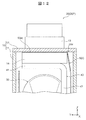
- FIG. 6 is a schematic cross-sectional view taken along the line IV-IV of the secondary battery shown in FIG.
- FIG. 6 is a schematic cross-sectional view taken along the line VV of the secondary battery shown in FIG.
- FIG. 6 is a schematic cross-sectional view corresponding to FIG. 4 of the secondary battery according to the second embodiment of the present disclosure.
- FIG. 5 is a schematic cross-sectional view corresponding to FIG. 5 of the secondary battery according to the second embodiment of the present disclosure.
- FIG. 6 is a schematic cross-sectional view corresponding to FIG.
- FIG. 5 is a schematic cross-sectional view corresponding to FIG. 5 of the secondary battery according to the third embodiment of the present disclosure.
- FIG. 5 is a schematic cross-sectional view corresponding to FIG. 5 of the secondary battery according to the fourth embodiment of the present disclosure. An enlarged view of the vicinity of the insulating plate of the secondary battery shown in FIG.
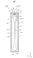
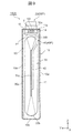
- FIG. 1 is a perspective view of the secondary battery 100 according to the first embodiment of the present disclosure.
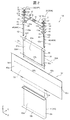
- FIG. 2 is an exploded perspective view of the secondary battery 100 shown in FIG.
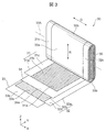
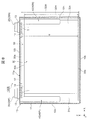
- FIG. 3 is an exploded perspective view of the winding body 30 of the secondary battery 100 shown in FIG.
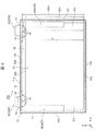
- FIG. 4 is a schematic cross-sectional view taken along the line IV-IV of the secondary battery 100 shown in FIG.
- FIG. 5 is a schematic cross-sectional view taken along the line VV of the secondary battery 100 shown in FIG.
- FIGS. 4 and 5 in order to clarify the positional relationship between each part of the secondary battery 100 and the insulating sheet 50, only the outer shape of the insulating sheet 50 is shown by a broken line.
- the secondary battery 100 of the present embodiment is, for example, an in-vehicle square secondary battery used in a power storage device of an electric vehicle (EV) or a hybrid electric vehicle (HEV). More specifically, the secondary battery 100 is, for example, a square lithium ion secondary battery. The secondary battery 100 is required to ensure airtightness more reliably. Although details will be described later, the secondary battery 100 of the present embodiment is characterized by the following configuration.
- the secondary battery 100 includes a winding body 30, a pair of current collector plates 40, a battery can 11, a battery lid 12, an insulating plate 14, an insulating sheet 50, and a pair of external terminals 20.
- the wound body 30 the positive electrode 31 and the negative electrode 32 are wound with the separators 33 and 34 interposed therebetween.
- the pair of current collector plates 40 are connected to the positive electrode 31 and the negative electrode 32, respectively.
- the battery can 11 houses the winding body 30 and the current collector plate 40.
- the battery lid 12 is joined to the opening 11a of the battery can 11.
- the insulating plate 14 is arranged between the current collector plate 40 and the battery lid 12.
- the insulating sheet 50 covers the winding body 30 and the current collector plate 40 inside the battery can 11.
- the pair of external terminals 20 are connected to the respective current collector plates 40, penetrate the insulating plate 14 and the battery lid 12, and are exposed to the outside of the battery lid 12.
- the secondary battery 100 is characterized in that the end portion 50e of the insulating sheet 50 adjacent to the battery lid 12 is fixed to the insulating plate 14.
- each part of the secondary battery 100 of the present embodiment will be described in detail.
- a three-dimensional Cartesian coordinate system consisting of an X-axis parallel to the width direction, a Y-axis parallel to the thickness direction, and a Z-axis parallel to the height direction of the flat-angle secondary battery 100 is used.
- the configuration of each part of the secondary battery 100 may be described.
- the directions such as up / down, left / right, and front / back in the following description are convenient directions for explaining the configuration of each part of the secondary battery 100 based on the drawings, and are not limited to the vertical direction and the horizontal direction. It does not limit the direction in which the secondary battery 100 is used.
- the secondary battery 100 includes, for example, a battery container 10, an external terminal 20, a winding body 30, a current collector plate 40, and an insulating sheet 50.
- the battery container 10 is, for example, a metal container having a flat rectangular box shape.
- the battery container 10 has a pair of wide side surfaces 10w along the width direction (X direction), a pair of narrow side surfaces 10n along the thickness direction (Y direction), and an elongated rectangular upper surface 10t and bottom surface 10b. Of these wide side surface 10w, narrow side surface 10n, top surface 10t and bottom surface 10b, the wide side surface 10w has the largest area.
- the battery container 10 has, for example, a flat square battery can 11 having one end open in the height direction (Z direction) and a rectangular plate-shaped battery lid 12 that closes the opening 11a of the battery can 11. ing.
- the winding body 30 which is a power storage element is inserted into the inside through the opening 11a of the battery can 11.
- the battery lid 12 is welded over the entire circumference of the opening 11a of the battery can 11 by laser welding, so that the opening 11a of the battery can 11 is sealed by the battery lid 12.
- the battery lid 12 has through holes 12a through which a part of the external terminal 20 is inserted at both ends in the longitudinal direction, which is the width direction (X direction) of the secondary battery 100. Further, the battery lid 12 has a gas discharge valve 15 at the center in the longitudinal direction.
- the gas discharge valve 15 is, for example, a portion in which a part of the battery lid 12 is pressed to be thinned to form a slit, and is provided integrally with the battery lid 12.
- the gas discharge valve 15 opens when the internal pressure of the battery container 10 rises to a predetermined pressure, and discharges the gas inside the battery container 10 to reduce the internal pressure of the battery container 10 and reduce the internal pressure of the battery container 10 to the secondary battery 100. To ensure the safety of.
- the battery lid 12 has, for example, a liquid injection hole 16 between the through hole 12a and the gas discharge valve 15.
- the liquid injection hole 16 is provided for injecting the electrolytic solution into the battery lid 12, and is sealed by joining the liquid injection plug 17 by, for example, laser welding after the injection of the electrolytic solution.
- a non-aqueous electrolytic solution to be injected into the battery container 10 for example, a non-aqueous electrolytic solution in which a lithium salt such as lithium hexafluorophosphate (LiPF 6 ) is dissolved in a carbonic acid ester-based organic solvent such as ethylene carbonate is used. Can be used.
- the pair of external terminals 20 are arranged apart from each other in the longitudinal direction of the outer surface of the battery lid 12, that is, the upper surface 10t of the battery container 10, penetrate the battery lid 12, and inside the battery container 10, each of the pair of current collector plates 40. It is connected to the base 41.
- the external terminal 20 includes a positive electrode external terminal 20P and a negative electrode external terminal 20N.
- the material of the positive electrode external terminal 20P is, for example, aluminum or an aluminum alloy.
- the material of the negative electrode external terminal 20N is, for example, copper or a copper alloy.
- the external terminal 20 has, for example, a joint portion 21 joined to the bus bar and a connecting portion 22 connected to the current collector plate 40.
- the joint portion 21 has a rectangular block shape having a substantially rectangular parallelepiped shape, and is arranged on the outer surface of the battery lid 12, that is, the upper surface 10t of the battery container 10 via a gasket 13 having electrical insulation.
- the connecting portion 22 is a columnar or cylindrical portion extending in a direction penetrating the battery lid 12 from the bottom surface of the joint portion 21 facing the battery lid 12.
- the current collector plate 40 is a plate-shaped member bent into a predetermined shape and is connected to the winding body 30.
- the current collector plate 40 includes a positive electrode current collector plate 40P that connects the positive electrode electrode 31 and the positive electrode external terminal 20P, and a negative electrode current collector plate 40N that connects the negative electrode electrode 32 and the negative electrode external terminal 20N.
- the material of the positive electrode current collector plate 40P is, for example, aluminum or an aluminum alloy.
- the material of the negative electrode current collector plate 40N is, for example, copper or a copper alloy.
- the current collector plate 40 is, for example, a joint portion 42a of a base portion 41 connected to the external terminal 20, an extension portion 42 extending in a direction intersecting the base portion 41, and an extension portion 42 joined to the winding body 30. It has a bent portion 43 provided between the base portion 41 and the base portion 41.
- the base 41 is arranged along the inner surface of the battery lid 12, and the extending portion 42 extends in a direction orthogonal to the inner surface of the battery lid 12.
- the bonding portion 42a of the extending portion 42 is bonded to the laminated portion 35 in which the positive electrode current collecting portion 31c or the negative electrode current collecting portion 32c of the winding body 30 is wound and laminated flat, for example, by ultrasonic bonding. Has been done.
- the wound body 30 includes, for example, a positive electrode 31, a negative electrode 32, and a first separator 33 and a second separator 34, which are insulators that insulate these electrodes.
- the winding body 30 is a winding electrode group having a structure in which a first separator 33, a positive electrode 31, a second separator 34, and a negative electrode 32 are laminated and wound in the winding direction R.
- the wound body 30 is formed into a flat shape for being accommodated in a flat square battery can 11, and has a flat portion 30a and a pair of curved portions 30b provided at both ends of the flat portion 30a. There is.
- the positive electrode 31, the negative electrode 32, and the separators 33, 34 are wound in a plane substantially parallel to the width direction (X direction) and the height direction (Z direction) of the secondary battery 100.
- the positive electrode 31, the negative electrode 32, and the separators 33, 34 constituting the winding body 30 are centered on the width direction of the secondary battery 100, that is, the axis substantially parallel to the winding shaft 30A. It is curved and wound in a semi-cylindrical shape.
- the electrodes wound around the innermost circumference and the outermost circumference are the negative electrode electrodes 32, and the first separator 33 is further wound around the outer periphery of the negative electrode electrode 32 wound around the outermost circumference. ing.
- the negative electrode electrode 32 includes a negative electrode current collecting foil 32a, a negative electrode mixture layer 32b formed on both the front and back surfaces thereof, and a negative electrode current collecting portion 32c which is a portion where the negative electrode current collecting foil 32a is exposed from the negative electrode mixture layer 32b. have.
- the negative electrode current collector 32c of the negative electrode 32 is provided in the width direction (X direction) of the long strip-shaped negative electrode 32, that is, on one side of the winding axial direction D of the winding body 30.
- the negative electrode current collecting foil 32a for example, a copper foil having a thickness of about 6 ⁇ m to about 12 ⁇ m can be used, and an electrolytic copper foil having a thickness of about 8 ⁇ m is preferable.
- the negative electrode mixture layer 32b for example, a slurry negative electrode mixture is applied to both the front and back surfaces of the negative electrode current collector foil 32a except for the negative electrode current collector 32c, and the applied negative electrode mixture is dried and pressed. Is formed of. After that, the negative electrode electrode 32 can be manufactured by appropriately cutting the negative electrode current collecting foil 32a on which the negative electrode mixture layer 32b is formed.
- the thickness of the negative electrode mixture layer 32b that does not include the negative electrode current collector foil 32a is, for example, about 70 ⁇ m.
- the slurry of the negative electrode mixture can be prepared, for example, as follows. To 100 parts by weight of the amorphous carbon powder which is the negative electrode active material, 10 parts by weight of polyvinylidene fluoride (PVDF) is added as a binder. N-Methylpyrrolidone (NMP) is added as a dispersion solvent to this mixture and kneaded, and this mixture can be used as a slurry of the negative electrode mixture.
- PVDF polyvinylidene fluoride
- NMP N-Methylpyrrolidone
- the negative electrode active material contained in the negative electrode mixture layer 32b is not limited to the above-mentioned amorphous carbon.
- the negative electrode active material natural graphite capable of inserting and removing lithium ions, various artificial graphite materials, carbonaceous materials such as coke, compounds such as Si and Sn (for example, SiO, TiSi 2 and the like), or these.
- a composite material may be used.
- the particle shape of the negative electrode active material is not particularly limited, and may be, for example, scaly, spherical, fibrous, or lumpy.
- the positive electrode electrode 31 is a portion where the positive electrode current collector foil 31a, which is a positive electrode current collector, the positive electrode mixture layer 31b formed on both the front and back surfaces thereof, and the positive electrode current collector foil 31a are exposed from the positive electrode mixture layer 31b. It has a positive electrode current collector 31c.
- the positive electrode current collector 31c of the positive electrode 31 is opposite to the negative electrode current collector 32c of the negative electrode 32 in the width direction (X direction) of the long strip-shaped positive electrode 31, that is, in the winding axis direction D of the winding body 30. It is provided on one side of the side.
- the positive electrode current collector foil 31a for example, an aluminum foil having a thickness of about 10 ⁇ m to about 20 ⁇ m can be used, and an aluminum foil having a thickness of about 15 ⁇ m is preferable.
- the positive electrode mixture layer 31b for example, a slurry positive electrode mixture is applied to both the front and back surfaces of the positive electrode current collector foil 31a except for the positive electrode current collector 31c, and the applied positive electrode mixture is dried and pressed. Is formed of. After that, the positive electrode current collector foil 31a on which the positive electrode mixture layer 31b is formed can be appropriately cut to manufacture the positive electrode electrode 31.
- the thickness of the positive electrode mixture layer 31b that does not include the positive electrode current collector foil 31a is, for example, about 90 ⁇ m.
- the slurry of the positive electrode mixture can be prepared, for example, as follows. To 100 parts by weight of lithium manganate (chemical formula LiMn 2 O 4 ) which is a positive electrode active material, 10 parts by weight of scaly graphite which is a conductive material and 10 parts by weight of PVDF which is a binder are added. NMP is added as a dispersion solvent to this mixture and kneaded, and this mixture can be used as a slurry of the positive electrode mixture.
- lithium manganate chemical formula LiMn 2 O 4
- PVDF which is a binder
- the positive electrode active material contained in the positive electrode mixture layer 31b is not limited to the above-mentioned lithium manganate.
- the positive electrode active material another lithium manganate having a spinel crystal structure, or a lithium manganese composite oxide partially substituted or doped with a metal element can be used.
- the positive electrode active material lithium cobalt oxide or lithium titanate having a layered crystal structure, or a lithium-metal composite oxide obtained by substituting or doping a part of these with a metal element may be used.
- the binder used for the negative electrode mixture and the positive electrode mixture is not limited to PVDF.
- the binder include polytetrafluoroethylene (PTFE), polyethylene, polystyrene, polybutadiene, butyl rubber, nitrile rubber, styrene butadiene rubber, polysulfide rubber, nitrocellulose, cyanoethyl cellulose, various latexes, acrylonitrile, vinyl fluoride, and the like.
- PTFE polytetrafluoroethylene
- Polyethylene polystyrene, polybutadiene, butyl rubber, nitrile rubber, styrene butadiene rubber, polysulfide rubber, nitrocellulose, cyanoethyl cellulose, various latexes, acrylonitrile, vinyl fluoride, and the like.
- Polymers such as vinylidene fluoride, propylene fluoride, chloroprene fluoride, and acrylic resins, and mixtures thereof
- the separators 33 and 34 are manufactured of, for example, a porous polyethylene resin or a polypropylene resin or a resin obtained by combining them, and are interposed between the positive electrode 31 and the negative electrode 32 to electrically insulate them. Further, the separators 33 and 34 are also wound on the outside of the negative electrode electrode 32 wound on the outermost circumference.
- the winding body 30 may have a shaft core for laminating and winding the negative electrode electrode 32, the first separator 33, the positive electrode electrode 31, and the second separator 34.
- the shaft core for example, a resin sheet having a higher bending rigidity than the positive electrode current collecting foil 31a, the negative electrode current collecting foil 32a, and the separators 33 and 34 can be used.
- the size of the negative electrode mixture layer 32b is larger than the size of the positive electrode mixture layer 31b in the winding axis direction D (X direction), and the positive electrode mixture layer 31b is always the negative electrode mixture layer 32b. It is configured to be sandwiched between them.
- the positive electrode current collecting portion 31c of the positive electrode 31 and the negative electrode current collecting portion 32c of the negative electrode 32 are at one end and the other end in the winding axial direction D (X direction), respectively, as shown in FIG. It is wound and laminated. Further, the positive electrode current collector 31c and the negative electrode current collector 32c are each bundled flat as shown in FIG. 2, and are bonded to the joint 42a of the extending portion 42 of the current collector plate 40 by, for example, ultrasonic bonding or resistance welding. It is joined.
- the dimensions of the separators 33 and 34 are larger than the dimensions of the negative electrode mixture layer 32b.
- the ends of the separators 33 and 34 are arranged at positions inside the winding axis direction D (X direction) with respect to the ends of the positive electrode current collector 31c and the negative electrode current collector 32c, respectively. Therefore, there is no problem when the positive electrode current collector 31c and the negative electrode current collector 32c are bundled and joined to the joint portion 42a of the extension portion 42 of the positive electrode current collector plate 40P and the negative electrode current collector plate 40N, respectively.
- the secondary battery 100 of the present embodiment is separated from one end and the other end in the longitudinal direction of the battery lid 12, that is, the width direction (X direction) of the secondary battery 100, for example. It includes a pair of arranged insulating plates 14. More specifically, of the pair of insulating plates 14, one insulating plate 14 is arranged between the positive electrode external terminal 20P and the positive electrode current collecting plate 40P, and the other insulating plate 14 is arranged between the negative electrode external terminal 20N and the negative electrode current collector. It is arranged between the plate 40N and the plate 40N. Then, there is a space between the pair of insulating plates 14 in which the insulating plates 14 are not arranged.
- the base 41 of the current collector plate 40 is fixed to the battery lid 12 via the insulating plate 14 and is electrically connected to the external terminal 20. More specifically, the connection portion 22 of the external terminal 20 is, for example, a through hole 13a of the gasket 13, a through hole 12a of the battery lid 12, a through hole 14a of the insulating plate 14, and a base 41 of the current collector plate 40. It is inserted through the through hole 41a and plastically deformed and crimped on the lower surface of the base 41 of the current collector plate 40 so as to increase the diameter of the tip.
- the external terminal 20 and the current collector plate 40 are electrically connected to each other and fixed to the battery lid 12 in a state of being electrically insulated via the gasket 13 and the insulating plate 14, and the lid assembly It is assembled as.
- the material of the gasket 13 and the insulating plate 14 is a resin having electrical insulating properties such as polybutylene terephthalate, polyphenylene sulfide, and perfluoroalkoxy alkane resin.
- the joint portion 42a of the extending portion 42 of the current collector plate 40 is formed on the laminated portion 35 of the positive electrode current collector portion 31c and the negative electrode current collector portion 32c of the winding body 30. It is joined. As a result, the positive electrode 31 and the negative electrode 32 constituting the wound body 30 are electrically connected to the external terminal 20 via the current collector plate 40.
- the winding body 30 is fixed to the battery lid 12 via the current collector plate 40 by being joined to the current collector plate 40, and is electrically connected to the external terminal 20 and has electrical insulation. It is covered with an insulating sheet 50 made of wood and inserted into the battery can 11 through the opening 11a of the battery can 11.
- the insulating sheet 50 is, for example, a single sheet made of a synthetic resin such as polypropylene. Further, although not shown, the insulating sheet 50 may have, for example, a plurality of partially insulating sheets.
- the insulating sheet 50 has a size and a shape capable of covering substantially the entire winding body 30 to which the current collector plate 40 is joined together with the current collector plate 40.
- the insulating sheet 50 is interposed between the winding body 30 and the current collector plate 40 and the battery can 11, and electrically insulates between them.
- the insulating sheet 50 is wound in the circumferential direction of the battery can 11 along the opening edge of the opening 11a of the battery can 11 shown in FIG. 2 with the winding body 30 covered.
- the body 30 is covered over the entire circumference, and the peripheral ends 50s and 50s of the battery can 11 overlap each other.
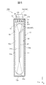
- the insulating sheet 50 has a length of 50 L along the width direction (X direction) of the secondary battery 100, that is, the winding shaft 30A of the winding body 30 in a state of being unfolded in a plane as shown in FIG. However, it is longer than the peripheral length of the winding body 30 in the circumferential direction of the battery can 11.
- the peripheral length of the winding body 30 is set with the outer surfaces of the winding body 30 and the current collecting plate 40 in a state where the current collecting plate 40 is joined to the positive electrode current collecting unit 31c and the negative electrode current collecting unit 32c, respectively. It is a length that goes around the winding body 30 along the circumferential direction of the battery can 11.
- the length 50L of the insulating sheet 50 along the winding shaft 30A of the winding body 30 is the width direction of the secondary battery 100. It is larger than the sum of twice the length 30L of the winding body 30 and twice the thickness 30T of the flat portion 30a of the winding body 30.
- the insulating sheet 50 covers the entire winding body 30 as shown in FIGS. 4 and 5.
- the insulating sheet 50 has the above-mentioned length of 50 L, and thus covers the winding body 30 over the entire circumference in the circumferential direction of the battery can 11 along the opening edge of the opening 11a of the battery can 11.
- the peripheral ends 50s and 50s of the battery can 11 overlap each other.
- the ends 50s and 50s of the insulating sheet 50 in the circumferential direction of the battery can 11 are arranged at positions that do not overlap with the pair of insulating plates 14. That is, the ends 50s and 50s of the insulating sheet 50 in the circumferential direction of the battery can 11 are arranged in the space where the insulating plate 14 is not arranged.
- the height 50H of the insulating sheet 50 is from the apex of one curved portion 30b of the wound body 30 to the other.
- the height to the apex of the curved portion 30b is larger than 30H.
- the height 50H of the insulating sheet 50 is adjacent to the bottom surface 10b of the battery container 10 from a position facing the side surface of the insulating plate 14. It is larger than the distance d to the apex of the curved portion 30b of the winding body 30.
- the insulating sheet 50 covers the entire area from the apex of one curved portion 30b of the winding body 30 to the apex of the other curved portion 30b in the height direction of the secondary battery 100. Further, the insulating sheet 50 extends from the apex of one curved portion 30b of the winding body 30 adjacent to the battery lid 12 toward the battery lid 12, and the end portion 50e adjacent to the battery lid 12 is a side surface of the insulating plate 14. Facing.
- the secondary battery 100 of the present embodiment is characterized in that the end portion 50e of the insulating sheet 50 adjacent to the battery lid 12 is fixed to the insulating plate 14. More specifically, in the secondary battery 100 of the present embodiment, the end portion 50e of the insulating sheet 50 is fixed to the insulating plate 14 via the welding portion W as shown in FIGS. 4 and 5.
- the welded portion W for example, the insulating sheet 50 made of a thermoplastic resin material and the insulating plate 14 are brought into close contact with each other, and at least one of them is heated to a temperature exceeding the melting point of the resin material and pressed to pressurize the insulating sheet 50. This is a portion where the insulating plate 14 and the insulating plate 14 are integrally joined.
- a plurality of point-shaped welded portions W are provided at intervals along the circumferential direction of the battery can 11 along the opening edge of the opening 11a of the battery can 11. More specifically, as shown in FIG. 4, the plurality of welded portions W are formed on the side surface of the insulating plate 14 facing the wide side surface 10w of the battery container 10, in the width direction (X direction) of the secondary battery 100. It is provided at intervals. In the example shown in FIG. 4, the welded portions W are provided at three locations at equal intervals in the width direction of the secondary battery 100. Further, as shown in FIG.
- the plurality of welded portions W are spaced apart from the side surface of the insulating plate 14 facing the narrow side surface 10n of the battery container 10 in the thickness direction (Y direction) of the secondary battery 100, for example. It is provided open. In the example shown in FIG. 5, three welded portions W are provided at equal intervals in the thickness direction of the secondary battery 100.
- the welded portion W may be provided only on the side surface of the insulating plate 14 facing the narrow side surface 10n of the battery container 10, or may be provided only on the side surface of the insulating plate 14 facing the wide side surface 10w of the battery container 10. You may be. Further, the number of welded portions W provided on each side surface of the insulating plate 14 may be one, two, or four or more. Further, the welded portion W does not have to be point-shaped, and may be provided linearly along each side surface of the insulating plate 14, for example, the dotted welded portion W and the linear welded portion W may be provided. It may be combined. Further, a welded portion W may be formed between the entire side surface of the insulating plate 14 and the end portion 50e of the insulating sheet 50.
- the insulating sheet 50 has the end portion 50e adjacent to the battery lid 12 in a state of covering the winding body 30 and the current collector plate 40, for example, the welded portion W. It is fixed to the insulating plate 14 via.
- the winding body 30 is attached to the lid assembly composed of the battery lid 12, the gasket 13, the insulating plate 14, the pair of external terminals 20, the pair of current collector plates 40, and the winding body 30.
- an insulating sheet 50 that covers the current collector plate 40 is attached.
- the opening of the battery can 11 from the curved portion 30b at the lower end of the winding body 30 so that the winding axial direction D of the winding body 30 is along the width direction (X direction) of the secondary battery 100. It is inserted into the portion 11a.
- the upper curved portion 30b faces the battery lid 12
- the lower curved portion 30b faces the bottom surface 10b of the battery container 10.
- the battery lid 12 closes the opening 11a of the battery can 11. After that, as described above, the battery lid 12 is joined over the entire circumference of the opening 11a of the battery can 11 to form the battery container 10.
- the electrolytic solution is injected into the battery container 10 through the liquid injection hole 16, and the liquid injection plug 17 is joined to and sealed in the liquid injection hole 16.
- the secondary battery 100 can connect the external terminal 20 and an external device (not shown) via a bus bar (not shown), a cable, or the like.
- power is supplied from the external device to the external terminal 20, and the secondary battery 100 is located between the positive electrode 31 and the negative electrode 32 of the winding body 30 connected to the external terminal 20 via the current collector plate 40. Electric energy is stored and charged. Further, the charged secondary battery 100 receives electromotive force from a pair of external terminals 20 connected to the positive electrode 31 and the negative electrode 32 of the winding body 30 in which electric energy is stored via a current collector plate 40, respectively. Can be generated and power can be supplied to an external device.
- the secondary battery 100 of the present embodiment has the following configurations.
- a wound body 30 in which a positive electrode 31 and a negative electrode 32 are wound with separators 33 and 34 interposed therebetween.
- a pair of current collector plates 40 connected to the positive electrode 31 and the negative electrode 32, respectively.
- a battery can 11 that houses the winding body 30 and the current collector plate 40.
- a battery lid 12 joined to the opening 11a of the battery can 11.
- An insulating plate 14 arranged between the current collector plate 40 and the battery lid 12.
- An insulating sheet 50 that covers the winding body 30 and the insulating plate 14 inside the battery can 11.
- a pair of external terminals 20 that are connected to each current collector plate 40 and that penetrate the insulating plate 14 and the battery lid 12 and are exposed to the outside of the battery lid 12.
- the secondary battery 100 of the present embodiment is characterized in that the end portion 50e of the insulating sheet 50 adjacent to the battery lid 12 is fixed to the insulating plate 14.
- the battery lid 12 when assembling the secondary battery 100 as described above, it is possible to prevent the end portion 50e of the insulating sheet 50 adjacent to the battery lid 12 from being sandwiched between the battery lid 12 and the battery can 11. Can be done. More specifically, when assembling the secondary battery 100, for example, as described above, the battery lid 12, the gasket 13, the insulating plate 14, the pair of external terminals 20, the pair of current collector plates 40, and so on. A lid assembly in which the winding body 30 is integrated is assembled. The insulating sheet 50 is arranged so as to cover the winding body 30 of the lid assembly, and the end portion 50e of the insulating sheet 50 adjacent to the battery lid 12 is fixed to the insulating plate 14. Then, the winding body 30 of the lid assembly covered with the insulating sheet 50 is inserted into the opening 11a of the battery can 11 from the curved portion 30b on the lower side.
- the insulating sheet 50 covering the winding body 30 may come into contact with the inner surface of the battery can 11, and a force for moving the insulating sheet 50 toward the battery lid 12 may act.
- the end portion 50e of the insulating sheet 50 adjacent to the battery lid 12 is fixed to the insulating plate 14. Therefore, the end portion 50e of the insulating sheet 50 adjacent to the battery lid 12 is prevented from moving toward the battery lid 12, and is prevented from being sandwiched between the battery lid 12 and the battery can 11.
- welding between the battery lid 12 and the battery can 11 can be performed more reliably than before, and the airtightness of the battery container 10 can be ensured more reliably than before.
- the secondary battery 100 of the present embodiment includes a pair of insulating plates 14 arranged apart from each other at one end and the other end of the battery lid 12, as described above.
- the end portion 50e of the insulating sheet 50 adjacent to the battery lid 12 is fixed to the insulating plate 14 at one end and the other end of the battery lid 12, and is not fixed between the pair of insulating plates 14 in a free state. become.
- the center of the battery lid 12 is from one end and the other end of the battery lid 12. There is a risk that force will act toward the part.
- the end portion 50e of the insulating sheet 50 adjacent to the battery lid 12 can be flexed relatively freely because it is not fixed between the pair of insulating plates 14 and is in a free state. , It is possible to prevent wrinkles from being generated at the end portion 50e of the insulating sheet 50.
- the insulating plate 14 is continuous from one end to the other end of the battery lid 12, and the end portion 50e of the insulating sheet 50 is fixed to the side surface of the insulating plate 14 over the entire circumference.
- the end portion 50e of the insulating sheet 50 can freely bend.
- wrinkles may occur at the end portion 50e of the insulating sheet 50.
- Such wrinkles at the end 50e of the insulating sheet 50 may concentrate the stress acting on the insulating sheet 50 and damage the insulating sheet 50.
- the secondary battery 100 of the present embodiment as described above, it is possible to prevent the end portion 50e of the insulating sheet 50 from being wrinkled, and it is possible to prevent the insulating sheet 50 from being damaged.
- the insulating sheet 50 has the wound body 30 all around in the circumferential direction of the battery can 11 along the opening edge of the opening 11a of the battery can 11. It covers all over. Further, the insulating sheet 50 is arranged at a position where the peripheral end 50s does not overlap with the pair of insulating plates 14. Then, one end 50s and the other end 50s of the insulating sheet 50 in the circumferential direction of the battery can 11 overlap each other.
- the insulating sheet 50 covers the entire circumference of the winding body 30 in the circumferential direction of the battery can 11, and can move freely to some extent in the circumferential direction of the battery can 11. Therefore, when the winding body 30 covered with the insulating sheet 50 is inserted into the opening 11a of the battery can 11, for example, even if a force in the circumferential direction of the battery can 11 acts on the insulating sheet 50, it is insulated. It is possible to prevent the sheet 50 from moving in the circumferential direction of the battery can 11 and causing wrinkles on the insulating sheet 50. If sufficient insulation can be ensured, the ends 50s and 50s of the insulating sheet 50 in the circumferential direction of the battery can 11 do not necessarily have to overlap.
- the insulating sheet 50 may have a plurality of partially insulating sheets.
- the insulating sheet 50 may be divided into a plurality of partially insulating sheets.
- the plurality of partially insulating sheets constituting the insulating sheet 50 cover the entire circumference of the wound body 30 and allow relative movement between the partially insulating sheets adjacent to each other and the partially insulating sheets. Therefore, when the winding body 30 covered with the insulating sheet 50 is inserted into the opening 11a of the battery can 11, even if a force acts on the insulating sheet 50, the plurality of partially insulating sheets move relatively. Therefore, it is possible to prevent the insulating sheet 50 from being wrinkled. Further, each partially insulating sheet only needs to cover a part of the winding body 30. Therefore, the entire winding body 30 can be easily covered by a plurality of partially insulating sheets, as compared with the case where one insulating sheet 50 covers the entire winding body 30.
- the end portion 50e of the insulating sheet 50 is fixed to the insulating plate 14 via the welding portion W.
- the end portion 50e of the insulating sheet 50 can be fixed to the insulating plate 14 by heating and pressurizing at least one of the insulating sheet 50 and the insulating plate 14. Further, the joining of the insulating sheet 50 and the insulating plate 14 via the welded portion W does not require a separate joining material and is excellent in productivity. Therefore, the productivity of the secondary battery 100 can be improved and the manufacturing cost can be reduced.
- the end portion 50e of the insulating sheet 50 is prevented from being sandwiched between the battery can 11 and the battery lid 12, and the airtightness of the battery container 10 is more reliable than before. It is possible to provide a secondary battery 100 capable of ensuring the above.
- FIG. 6 is a schematic cross-sectional view corresponding to FIG. 4 of the secondary battery 100A according to the second embodiment of the present disclosure.
- FIG. 7 is a schematic cross-sectional view corresponding to FIG. 5 of the secondary battery 100A according to the second embodiment of the present disclosure.
- the secondary battery 100A of the present embodiment is different from the secondary battery 100 according to the first embodiment in that the end portion 50e of the insulating sheet 50 is fixed to the insulating plate 14 via the adhesive portion A. There is. Since the other points of the secondary battery 100A of the present embodiment are the same as those of the secondary battery 100 according to the first embodiment, the same reference numerals are given to the same parts and the description thereof will be omitted.
- the end portion 50e of the insulating sheet 50 is fixed to the insulating plate 14 via the adhesive portion A.
- the end portion 50e of the insulating sheet 50 adjacent to the battery lid 12 is prevented from being sandwiched between the battery lid 12 and the battery can 11. Can be done. Therefore, according to the present embodiment, it is possible to provide the secondary battery 100A capable of ensuring the airtightness of the battery container 10 more reliably than in the conventional case, as in the above-described first embodiment.
- the adhesive portion A is formed, for example, by applying an acrylic adhesive or an adhesive to at least one of the insulating sheet 50 and the insulating plate 14 and drying or curing between the insulating sheet 50 and the insulating plate 14. Can be done.
- a plurality of adhesive portions A may be arranged at intervals in the circumferential direction of the battery can 11 along the opening edge of the opening 11a of the battery can 11, but as shown in FIGS. 6 and 7, insulation is provided. It is preferable to arrange the adhesive portion A in a linear, strip-like, or planar shape along the side surface of the plate 14. As a result, the adhesive area by the adhesive portion A can be increased, and the end portion 50e of the insulating sheet 50 can be more firmly fixed to the insulating plate 14. Further, the adhesive portion A can be arbitrarily combined with two or more of the point-shaped, linear, strip-shaped, and planar arrangements.
- FIG. 8 is a schematic cross-sectional view corresponding to FIG. 4 of the secondary battery 100B according to the third embodiment of the present disclosure.
- FIG. 9 is a schematic cross-sectional view corresponding to FIG. 5 of the secondary battery 100B according to the third embodiment of the present disclosure.
- the secondary battery 100B of the present embodiment is different from the secondary battery 100 according to the first embodiment in that the end portion 50e of the insulating sheet 50 is fixed to the insulating plate 14 by the adhesive tape T. Since the other points of the secondary battery 100B of the present embodiment are the same as those of the secondary battery 100 according to the first embodiment, the same reference numerals are given to the same parts and the description thereof will be omitted.
- the end portion 50e of the insulating sheet 50 is fixed to the insulating plate 14 by the adhesive tape T.
- the end portion 50e of the insulating sheet 50 adjacent to the battery lid 12 is prevented from being sandwiched between the battery lid 12 and the battery can 11. Can be done. Therefore, according to the present embodiment, similarly to the above-described first embodiment, it is possible to provide the secondary battery 100B capable of ensuring the airtightness of the battery container 10 more reliably than before.
- the adhesive tape T for example, one having an acrylic adhesive layer on the surface of a resin base material such as polyethylene, polypropylene, or polyimide can be used.
- the adhesive tape T is attached to, for example, the side surface of the insulating plate 14 facing the wide side surface 10w of the battery container 10 and the side surface of the insulating plate 14 facing the narrow side surface 10n of the battery container 10.
- the adhesive tape T may be attached only to the side surface of the insulating plate 14 facing the narrow side surface 10n of the battery container 10, and may be attached only to the side surface of the insulating plate 14 facing the wide side surface 10w of the battery container 10. It may be worn.
- the end portion 50e of the insulating sheet 50 can be fixed to the insulating plate 14 without heating and pressurizing the insulating sheet 50 and the insulating plate 14. Further, by using the adhesive tape T, the step of applying the adhesive and the step of drying or curing the applied adhesive can be omitted. Therefore, the manufacturing process of the secondary battery 100 can be simplified and the productivity of the secondary battery 100 can be improved.
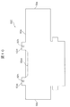
- FIG. 10 is a developed view of the insulating sheet 50C of the secondary battery 100C according to the fourth embodiment of the present disclosure.
- FIG. 11 is a schematic cross-sectional view corresponding to FIG. 5 of the secondary battery 100C according to the fourth embodiment of the present disclosure.
- FIG. 12 is an enlarged view of the vicinity of the insulating plate 14 of the secondary battery 100C shown in FIG.
- the end portion 50e of the insulating sheet 50C is sandwiched between the current collector plate 40 and the insulating plate 14 or between the battery lid 12 and the insulating plate 14 to form the insulating plate 14. It differs from the secondary battery 100 according to the first embodiment in that it is fixed. Since the other points of the secondary battery 100C of the present embodiment are the same as those of the secondary battery 100 according to the first embodiment, the same reference numerals are given to the same parts and the description thereof will be omitted.
- the end portion 50e of the insulating sheet 50C is sandwiched between the battery lid 12 and the insulating plate 14 and fixed to the insulating plate 14.
- the end portion 50e of the insulating sheet 50C may be sandwiched between the current collector plate 40 and the insulating plate 14 and fixed to the insulating plate 14.
- the insulating sheet 50C is provided with a pair of tab portions 50et at the end portion 50e adjacent to the battery lid 12, for example, as shown in FIG.
- the tab portion 50et is provided in a tab shape protruding from the other portion of the end portion 50e of the insulating sheet 50.
- the pair of tab portions 50et are provided at intervals corresponding to the pair of insulating plates 14.
- the width of the tab portion 50et in the protruding direction is approximately equal to, for example, the width of the insulating plate 14 in the thickness direction (Y direction) of the secondary battery 100C.
- the length of the tab portion 50et along the edge of the end portion 50e of the insulating sheet 50 is approximately equal to, for example, the length of the insulating plate 14 in the width direction (X direction) of the secondary battery 100C.
- the tab portion 50et has, for example, a through hole 50h through which the connection portion 22 of the external terminal 20 is inserted.
- the tab portion 50et may have a notch through which the connection portion 22 of the external terminal 20 is inserted instead of the through hole 50h.
- the tab portion 50et does not have to have a through hole 50h through which the connection portion 22 is inserted and a notch as long as the width in the protruding direction is narrow and does not interfere with the connection portion 22 of the external terminal 20.
- the end portion 50e of the insulating sheet 50 may have, for example, a concave notch portion 50ec between the pair of tab portions 50et.
- a concave notch portion 50ec between the pair of tab portions 50et.
Abstract
The objective of the present invention is to provide a secondary battery in which the hermetic properties of a battery container can be maintained more reliably than in the past. A secondary battery 100 is provided with a wound body 30, a pair of collector plates 40, a battery can 11, a battery lid 12, an insulating plate 14, an insulating sheet 50, and a pair of external terminals 20, wherein an end portion 50e of the insulating sheet 50 adjacent to the battery lid 12 is fixed to the insulating plate 14.
Description
本開示は、二次電池に関する。
This disclosure relates to a secondary battery.
従来から充放電を行う角形二次電池に関する発明が知られている(下記特許文献1を参照)。特許文献1に記載された角形二次電池は、扁平状の捲回群と、その捲回群に接続された集電板が絶縁保護フィルムで覆われて電池缶に収容されている。この従来の角形二次電池は、絶縁保護フィルムと集電板との間に耐熱フィルムが設けられていることを特徴としている(同文献、請求項1等を参照)。
Conventionally, inventions relating to a square secondary battery that charges and discharges are known (see Patent Document 1 below). In the square secondary battery described in Patent Document 1, a flat winding group and a current collector plate connected to the winding group are covered with an insulating protective film and housed in a battery can. This conventional square secondary battery is characterized in that a heat-resistant film is provided between the insulating protective film and the current collector plate (see the same document, claim 1 and the like).
上記従来の角形二次電池は、上記構成により、捲回群の電池缶への挿入性を低下させることなく、かつ絶縁保護フィルムの溶融を防止して絶縁信頼性を向上させることができるという優れた効果を奏することができる(同文献、第0008段落等を参照)。
The conventional square secondary battery is excellent in that the above-mentioned configuration can improve the insulation reliability by preventing the insulation protective film from melting without lowering the insertability of the winding group into the battery can. (See the same document, paragraph 0008, etc.).
上記従来の角形二次電池において、絶縁保護フィルムは、合成樹脂製の一枚のシートまたは複数のフィルム部材からなり、捲回群の平坦面に沿う方向でかつ捲回群の捲回軸方向に直交する方向を中心軸方向として捲回群の周囲に巻き付けられている(同文献、第0022段落および図2等を参照)。
In the conventional square secondary battery, the insulating protective film is composed of a single sheet made of synthetic resin or a plurality of film members, and is oriented along the flat surface of the winding group and in the winding axis direction of the winding group. It is wound around the winding group with the orthogonal direction as the central axis direction (see the same document, paragraph 0022, FIG. 2, etc.).
しかし、絶縁保護フィルムが巻き付けられた捲回群を電池缶へ挿入すると、絶縁保護フィルムが電池缶との接触により電池蓋側にずれて電池蓋と電池缶との間に挟み込まれるおそれがある。このような状態で電池蓋と電池缶とを溶接すると、電池蓋と電池缶との間の溶接が不十分になり、電池容器の気密性が低下するおそれがある。
However, if the winding group around which the insulating protective film is wound is inserted into the battery can, the insulating protective film may shift to the battery lid side due to contact with the battery can and be sandwiched between the battery lid and the battery can. If the battery lid and the battery can are welded in such a state, the welding between the battery lid and the battery can becomes insufficient, and the airtightness of the battery container may decrease.
本開示は、従来よりも確実に電池容器の気密性を確保することが可能な二次電池を提供する。
The present disclosure provides a secondary battery capable of ensuring the airtightness of the battery container more reliably than before.
本開示の一態様は、正極電極と負極電極とがセパレータが介在されて捲回された捲回体と、前記正極電極と前記負極電極にそれぞれ接続された一対の集電板と、前記捲回体および前記集電板を収容する電池缶と、前記電池缶の開口部に接合された電池蓋と、前記集電板と前記電池蓋との間に配置された絶縁板と、前記電池缶の内部で前記捲回体および前記集電板を覆う絶縁シートと、各々の前記集電板に接続されるとともに前記絶縁板および前記電池蓋を貫通して前記電池蓋の外側に露出した一対の外部端子と、を備え、前記電池蓋に隣接する前記絶縁シートの端部が前記絶縁板に固定されていることを特徴とする二次電池である。
One aspect of the present disclosure is a wound body in which a positive electrode and a negative electrode are wound with a separator interposed therebetween, a pair of current collector plates connected to the positive electrode and the negative electrode, respectively, and the wound. A battery can accommodating a body and the current collector plate, a battery lid joined to an opening of the battery can, an insulating plate arranged between the current collector plate and the battery lid, and the battery can. An insulating sheet that covers the winder and the current collector plate inside, and a pair of external surfaces that are connected to each of the current collector plates and that penetrate the insulating plate and the battery lid and are exposed to the outside of the battery lid. A secondary battery comprising a terminal and having an end portion of the insulating sheet adjacent to the battery lid fixed to the insulating plate.
本開示の上記一態様によれば、電池蓋と電池缶との間に絶縁シートの端部が挟み込まれることを防止することができる。これにより、電池蓋と電池缶によって構成される電池容器の気密性を従来よりも確実に確保することが可能な二次電池を提供することができる。
According to the above aspect of the present disclosure, it is possible to prevent the end portion of the insulating sheet from being pinched between the battery lid and the battery can. This makes it possible to provide a secondary battery capable of ensuring the airtightness of the battery container composed of the battery lid and the battery can more reliably than before.
以下、図面を参照して本開示に係る二次電池の実施形態を説明する。
Hereinafter, embodiments of the secondary battery according to the present disclosure will be described with reference to the drawings.
(実施形態1)
図1は、本開示の実施形態1に係る二次電池100の斜視図である。図2は、図1に示す二次電池100の分解斜視図である。図3は、図2に示す二次電池100の捲回体30の分解斜視図である。図4は、図1に示す二次電池100のIV-IV線に沿う模式的な断面図である。図5は、図1に示す二次電池100のV-V線に沿う模式的な断面図である。なお、図4および図5では、二次電池100の各部と絶縁シート50との位置関係を明確にするために、絶縁シート50は破線で外形のみを示している。 (Embodiment 1)
FIG. 1 is a perspective view of thesecondary battery 100 according to the first embodiment of the present disclosure. FIG. 2 is an exploded perspective view of the secondary battery 100 shown in FIG. FIG. 3 is an exploded perspective view of the winding body 30 of the secondary battery 100 shown in FIG. FIG. 4 is a schematic cross-sectional view taken along the line IV-IV of the secondary battery 100 shown in FIG. FIG. 5 is a schematic cross-sectional view taken along the line VV of the secondary battery 100 shown in FIG. In addition, in FIGS. 4 and 5, in order to clarify the positional relationship between each part of the secondary battery 100 and the insulating sheet 50, only the outer shape of the insulating sheet 50 is shown by a broken line.
図1は、本開示の実施形態1に係る二次電池100の斜視図である。図2は、図1に示す二次電池100の分解斜視図である。図3は、図2に示す二次電池100の捲回体30の分解斜視図である。図4は、図1に示す二次電池100のIV-IV線に沿う模式的な断面図である。図5は、図1に示す二次電池100のV-V線に沿う模式的な断面図である。なお、図4および図5では、二次電池100の各部と絶縁シート50との位置関係を明確にするために、絶縁シート50は破線で外形のみを示している。 (Embodiment 1)
FIG. 1 is a perspective view of the
本実施形態の二次電池100は、たとえば、電気自動車(EV)やハイブリッド電気自動車(HEV)の蓄電装置に使用される車載用の角形二次電池である。より詳細には、二次電池100は、たとえば、角形リチウムイオン二次電池である。二次電池100は、気密性をより確実に確保することが要求される。詳細については後述するが、本実施形態の二次電池100は、以下の構成を特徴としている。
The secondary battery 100 of the present embodiment is, for example, an in-vehicle square secondary battery used in a power storage device of an electric vehicle (EV) or a hybrid electric vehicle (HEV). More specifically, the secondary battery 100 is, for example, a square lithium ion secondary battery. The secondary battery 100 is required to ensure airtightness more reliably. Although details will be described later, the secondary battery 100 of the present embodiment is characterized by the following configuration.
二次電池100は、捲回体30と、一対の集電板40と、電池缶11と、電池蓋12と、絶縁板14と、絶縁シート50と、一対の外部端子20と、を備えている。捲回体30は、正極電極31と負極電極32とが、セパレータ33,34が介在されて捲回されている。一対の集電板40は、正極電極31と負極電極32にそれぞれ接続されている。電池缶11は、捲回体30および集電板40を収容している。電池蓋12は、電池缶11の開口部11aに接合されている。絶縁板14は、集電板40と電池蓋12との間に配置されている。絶縁シート50は、電池缶11の内部で捲回体30および集電板40を覆っている。一対の外部端子20は、各々の集電板40に接続されるとともに、絶縁板14および電池蓋12を貫通して、電池蓋12の外側に露出している。二次電池100は、電池蓋12に隣接する絶縁シート50の端部50eが、絶縁板14に固定されていることを特徴としている。
The secondary battery 100 includes a winding body 30, a pair of current collector plates 40, a battery can 11, a battery lid 12, an insulating plate 14, an insulating sheet 50, and a pair of external terminals 20. There is. In the wound body 30, the positive electrode 31 and the negative electrode 32 are wound with the separators 33 and 34 interposed therebetween. The pair of current collector plates 40 are connected to the positive electrode 31 and the negative electrode 32, respectively. The battery can 11 houses the winding body 30 and the current collector plate 40. The battery lid 12 is joined to the opening 11a of the battery can 11. The insulating plate 14 is arranged between the current collector plate 40 and the battery lid 12. The insulating sheet 50 covers the winding body 30 and the current collector plate 40 inside the battery can 11. The pair of external terminals 20 are connected to the respective current collector plates 40, penetrate the insulating plate 14 and the battery lid 12, and are exposed to the outside of the battery lid 12. The secondary battery 100 is characterized in that the end portion 50e of the insulating sheet 50 adjacent to the battery lid 12 is fixed to the insulating plate 14.
以下、本実施形態の二次電池100の各部の構成を詳細に説明する。なお、各図面では、扁平角形の二次電池100の幅方向に平行なX軸、厚さ方向に平行なY軸、高さ方向に平行なZ軸からなる三次元の直交座標系を用いて、二次電池100の各部の構成を説明する場合がある。また、以下の説明における上下、左右、前後などの方向は、図面に基づいて二次電池100の各部の構成を説明するための便宜的な方向であり、鉛直方向や水平方向に限定されず、二次電池100の使用時の方向を限定するものでもない。
Hereinafter, the configuration of each part of the secondary battery 100 of the present embodiment will be described in detail. In each drawing, a three-dimensional Cartesian coordinate system consisting of an X-axis parallel to the width direction, a Y-axis parallel to the thickness direction, and a Z-axis parallel to the height direction of the flat-angle secondary battery 100 is used. , The configuration of each part of the secondary battery 100 may be described. Further, the directions such as up / down, left / right, and front / back in the following description are convenient directions for explaining the configuration of each part of the secondary battery 100 based on the drawings, and are not limited to the vertical direction and the horizontal direction. It does not limit the direction in which the secondary battery 100 is used.
二次電池100は、たとえば、電池容器10と、外部端子20と、捲回体30と、集電板40と、絶縁シート50と、を備えている。電池容器10は、たとえば扁平な矩形箱形の形状を有する金属製の容器である。電池容器10は、幅方向(X方向)に沿う一対の広側面10wと、厚さ方向(Y方向)に沿う一対の狭側面10nと、細長い長方形の上面10tおよび底面10bを有している。これら広側面10w、狭側面10n、上面10tおよび底面10bのうち、広側面10wが最大の面積を有している。
The secondary battery 100 includes, for example, a battery container 10, an external terminal 20, a winding body 30, a current collector plate 40, and an insulating sheet 50. The battery container 10 is, for example, a metal container having a flat rectangular box shape. The battery container 10 has a pair of wide side surfaces 10w along the width direction (X direction), a pair of narrow side surfaces 10n along the thickness direction (Y direction), and an elongated rectangular upper surface 10t and bottom surface 10b. Of these wide side surface 10w, narrow side surface 10n, top surface 10t and bottom surface 10b, the wide side surface 10w has the largest area.
電池容器10は、たとえば、高さ方向(Z方向)の一端が開放された扁平角形の電池缶11と、その電池缶11の開口部11aを閉塞する長方形板状の電池蓋12とを有している。電池容器10は、電池缶11の開口部11aから蓄電要素である捲回体30が内部に挿入されている。電池容器10は、たとえば、レーザ溶接によって電池缶11の開口部11aの全周にわたって電池蓋12が溶接されることで、電池缶11の開口部11aが電池蓋12によって封止されている。
The battery container 10 has, for example, a flat square battery can 11 having one end open in the height direction (Z direction) and a rectangular plate-shaped battery lid 12 that closes the opening 11a of the battery can 11. ing. In the battery container 10, the winding body 30 which is a power storage element is inserted into the inside through the opening 11a of the battery can 11. In the battery container 10, for example, the battery lid 12 is welded over the entire circumference of the opening 11a of the battery can 11 by laser welding, so that the opening 11a of the battery can 11 is sealed by the battery lid 12.
電池蓋12は、二次電池100の幅方向(X方向)である長手方向の両端部に外部端子20の一部を挿通させる貫通孔12aを有している。また、電池蓋12は、長手方向の中央部にガス排出弁15を有している。ガス排出弁15は、たとえば、電池蓋12の一部をプレス加工して薄肉化し、スリットを形成した部分であり、電池蓋12と一体的に設けられている。ガス排出弁15は、電池容器10の内圧が所定の圧力まで上昇したときに開裂して、電池容器10の内部のガスを排出することで、電池容器10の内圧を低減して二次電池100の安全性を確保する。
The battery lid 12 has through holes 12a through which a part of the external terminal 20 is inserted at both ends in the longitudinal direction, which is the width direction (X direction) of the secondary battery 100. Further, the battery lid 12 has a gas discharge valve 15 at the center in the longitudinal direction. The gas discharge valve 15 is, for example, a portion in which a part of the battery lid 12 is pressed to be thinned to form a slit, and is provided integrally with the battery lid 12. The gas discharge valve 15 opens when the internal pressure of the battery container 10 rises to a predetermined pressure, and discharges the gas inside the battery container 10 to reduce the internal pressure of the battery container 10 and reduce the internal pressure of the battery container 10 to the secondary battery 100. To ensure the safety of.
電池蓋12は、たとえば貫通孔12aとガス排出弁15との間に注液孔16を有している。注液孔16は、電池蓋12の内部に電解液を注入するために設けられ、電解液の注入後に、たとえばレーザ溶接によって注液栓17を接合することによって封止される。電池容器10内に注入する非水電解液としては、たとえば、エチレンカーボネート等の炭酸エステル系の有機溶媒に6フッ化リン酸リチウム(LiPF6)等のリチウム塩が溶解された非水電解液を用いることができる。
The battery lid 12 has, for example, a liquid injection hole 16 between the through hole 12a and the gas discharge valve 15. The liquid injection hole 16 is provided for injecting the electrolytic solution into the battery lid 12, and is sealed by joining the liquid injection plug 17 by, for example, laser welding after the injection of the electrolytic solution. As the non-aqueous electrolytic solution to be injected into the battery container 10, for example, a non-aqueous electrolytic solution in which a lithium salt such as lithium hexafluorophosphate (LiPF 6 ) is dissolved in a carbonic acid ester-based organic solvent such as ethylene carbonate is used. Can be used.
一対の外部端子20は、電池蓋12の外面すなわち電池容器10の上面10tの長手方向に離隔して配置され、電池蓋12を貫通して電池容器10の内部でそれぞれ一対の集電板40の基部41に接続されている。外部端子20は、正極外部端子20Pと負極外部端子20Nを含んでいる。正極外部端子20Pの素材は、たとえばアルミニウムまたはアルミニウム合金である。負極外部端子20Nの素材は、たとえば銅または銅合金である。
The pair of external terminals 20 are arranged apart from each other in the longitudinal direction of the outer surface of the battery lid 12, that is, the upper surface 10t of the battery container 10, penetrate the battery lid 12, and inside the battery container 10, each of the pair of current collector plates 40. It is connected to the base 41. The external terminal 20 includes a positive electrode external terminal 20P and a negative electrode external terminal 20N. The material of the positive electrode external terminal 20P is, for example, aluminum or an aluminum alloy. The material of the negative electrode external terminal 20N is, for example, copper or a copper alloy.
外部端子20は、たとえば、バスバーに接合される接合部21と、集電板40に接続される接続部22とを有している。接合部21は、おおむね直方体形状の矩形のブロック状の形状を有し、電気絶縁性を有するガスケット13を介して電池蓋12の外面すなわち電池容器10の上面10tに配置される。接続部22は、電池蓋12に対向する接合部21の底面から電池蓋12を貫通する方向に延びる円柱状または円筒状の部分である。
The external terminal 20 has, for example, a joint portion 21 joined to the bus bar and a connecting portion 22 connected to the current collector plate 40. The joint portion 21 has a rectangular block shape having a substantially rectangular parallelepiped shape, and is arranged on the outer surface of the battery lid 12, that is, the upper surface 10t of the battery container 10 via a gasket 13 having electrical insulation. The connecting portion 22 is a columnar or cylindrical portion extending in a direction penetrating the battery lid 12 from the bottom surface of the joint portion 21 facing the battery lid 12.
集電板40は、図2に示すように、所定の形状に屈曲された板状の部材であり、捲回体30に接続されている。集電板40は、正極電極31と正極外部端子20Pとを接続する正極集電板40Pと、負極電極32と負極外部端子20Nとを接続する負極集電板40Nとを含む。正極集電板40Pの素材は、たとえばアルミニウムまたはアルミニウム合金である。負極集電板40Nの素材は、たとえば銅または銅合金である。
As shown in FIG. 2, the current collector plate 40 is a plate-shaped member bent into a predetermined shape and is connected to the winding body 30. The current collector plate 40 includes a positive electrode current collector plate 40P that connects the positive electrode electrode 31 and the positive electrode external terminal 20P, and a negative electrode current collector plate 40N that connects the negative electrode electrode 32 and the negative electrode external terminal 20N. The material of the positive electrode current collector plate 40P is, for example, aluminum or an aluminum alloy. The material of the negative electrode current collector plate 40N is, for example, copper or a copper alloy.
集電板40は、たとえば、外部端子20に接続された基部41と、その基部41に交差する方向に延びる延在部42と、捲回体30に接合された延在部42の接合部42aと基部41との間に設けられた屈曲部43と、を有している。基部41は、電池蓋12の内面に沿って配置され、延在部42は、電池蓋12の内面に直交する方向へ向けて延びている。延在部42の接合部42aは、捲回体30の正極集電部31cまたは負極集電部32cが捲回されて扁平に積層された積層部35に対して、たとえば、超音波接合によって接合されている。
The current collector plate 40 is, for example, a joint portion 42a of a base portion 41 connected to the external terminal 20, an extension portion 42 extending in a direction intersecting the base portion 41, and an extension portion 42 joined to the winding body 30. It has a bent portion 43 provided between the base portion 41 and the base portion 41. The base 41 is arranged along the inner surface of the battery lid 12, and the extending portion 42 extends in a direction orthogonal to the inner surface of the battery lid 12. The bonding portion 42a of the extending portion 42 is bonded to the laminated portion 35 in which the positive electrode current collecting portion 31c or the negative electrode current collecting portion 32c of the winding body 30 is wound and laminated flat, for example, by ultrasonic bonding. Has been done.
捲回体30は、たとえば、正極電極31と、負極電極32と、これらの電極を絶縁する絶縁体である第1のセパレータ33および第2のセパレータ34とを備えている。捲回体30は、第1のセパレータ33、正極電極31、第2のセパレータ34、および負極電極32が積層され、捲回方向Rに捲回された構成を有する捲回電極群である。捲回体30は、扁平な角形の電池缶11に収容するための扁平な形状に成形され、平坦部30aと、その平坦部30aの両端に設けられた一対の湾曲部30bとを有している。
The wound body 30 includes, for example, a positive electrode 31, a negative electrode 32, and a first separator 33 and a second separator 34, which are insulators that insulate these electrodes. The winding body 30 is a winding electrode group having a structure in which a first separator 33, a positive electrode 31, a second separator 34, and a negative electrode 32 are laminated and wound in the winding direction R. The wound body 30 is formed into a flat shape for being accommodated in a flat square battery can 11, and has a flat portion 30a and a pair of curved portions 30b provided at both ends of the flat portion 30a. There is.
平坦部30aにおいて、正極電極31、負極電極32、およびセパレータ33,34は、二次電池100の幅方向(X方向)および高さ方向(Z方向)におおむね平行な平面状に捲回されている。一方、湾曲部30bにおいて、捲回体30を構成する正極電極31、負極電極32、およびセパレータ33,34は、二次電池100の幅方向、すなわち捲回軸30Aにおおむね平行な軸を中心とする半円筒状に湾曲して捲回されている。捲回体30において、たとえば、最内周と最外周に捲回された電極は負極電極32であり、最外周に捲回された負極電極32の外周にさらに第1のセパレータ33が捲回されている。
In the flat portion 30a, the positive electrode 31, the negative electrode 32, and the separators 33, 34 are wound in a plane substantially parallel to the width direction (X direction) and the height direction (Z direction) of the secondary battery 100. There is. On the other hand, in the curved portion 30b, the positive electrode 31, the negative electrode 32, and the separators 33, 34 constituting the winding body 30 are centered on the width direction of the secondary battery 100, that is, the axis substantially parallel to the winding shaft 30A. It is curved and wound in a semi-cylindrical shape. In the wound body 30, for example, the electrodes wound around the innermost circumference and the outermost circumference are the negative electrode electrodes 32, and the first separator 33 is further wound around the outer periphery of the negative electrode electrode 32 wound around the outermost circumference. ing.
負極電極32は、負極集電箔32aと、その表裏両面に形成された負極合剤層32bと、その負極合剤層32bから負極集電箔32aが露出した部分である負極集電部32cとを有している。負極電極32の負極集電部32cは、長尺帯状の負極電極32の幅方向(X方向)、すなわち捲回体30の捲回軸方向Dの一側に設けられている。負極集電箔32aは、たとえば約6μmから約12μmの厚さの銅箔を使用することができ、好ましくは8μm程度の電解銅箔である。
The negative electrode electrode 32 includes a negative electrode current collecting foil 32a, a negative electrode mixture layer 32b formed on both the front and back surfaces thereof, and a negative electrode current collecting portion 32c which is a portion where the negative electrode current collecting foil 32a is exposed from the negative electrode mixture layer 32b. have. The negative electrode current collector 32c of the negative electrode 32 is provided in the width direction (X direction) of the long strip-shaped negative electrode 32, that is, on one side of the winding axial direction D of the winding body 30. As the negative electrode current collecting foil 32a, for example, a copper foil having a thickness of about 6 μm to about 12 μm can be used, and an electrolytic copper foil having a thickness of about 8 μm is preferable.
負極合剤層32bは、たとえば、負極集電箔32aの表裏両面に、負極集電部32cを除いてスラリー状の負極合剤を塗布し、塗布された負極合剤を乾燥させてプレスすることで形成されている。その後、負極合剤層32bが形成された負極集電箔32aを、適宜、裁断することによって負極電極32を製作することができる。負極集電箔32aを含まない負極合剤層32bの厚さは、たとえば約70μm程度である。
For the negative electrode mixture layer 32b, for example, a slurry negative electrode mixture is applied to both the front and back surfaces of the negative electrode current collector foil 32a except for the negative electrode current collector 32c, and the applied negative electrode mixture is dried and pressed. Is formed of. After that, the negative electrode electrode 32 can be manufactured by appropriately cutting the negative electrode current collecting foil 32a on which the negative electrode mixture layer 32b is formed. The thickness of the negative electrode mixture layer 32b that does not include the negative electrode current collector foil 32a is, for example, about 70 μm.
負極合剤のスラリーは、たとえば、次のように調製することができる。負極活物質である100重量部の非晶質炭素粉末に対し、結着剤として10重量部のポリフッ化ビニリデン(PVDF)を添加する。この混合物に、分散溶媒としてN-メチルピロリドン(NMP)を添加して混練したものを、負極合剤のスラリーとして用いることができる。
The slurry of the negative electrode mixture can be prepared, for example, as follows. To 100 parts by weight of the amorphous carbon powder which is the negative electrode active material, 10 parts by weight of polyvinylidene fluoride (PVDF) is added as a binder. N-Methylpyrrolidone (NMP) is added as a dispersion solvent to this mixture and kneaded, and this mixture can be used as a slurry of the negative electrode mixture.
なお、負極合剤層32bに含まれる負極活物質は、前述の非晶質炭素に限定されない。たとえば、負極活物質として、リチウムイオンを挿入脱離可能な天然黒鉛、人造の各種黒鉛材、コークスなどの炭素質材料、SiやSnなどの化合物(たとえば、SiO、TiSi2など)、またはこれらの複合材料を用いてもよい。また、負極活物質の粒子形状は特に制限されず、たとえば、鱗片状、球状、繊維状、塊状などであってもよい。
The negative electrode active material contained in the negative electrode mixture layer 32b is not limited to the above-mentioned amorphous carbon. For example, as the negative electrode active material, natural graphite capable of inserting and removing lithium ions, various artificial graphite materials, carbonaceous materials such as coke, compounds such as Si and Sn (for example, SiO, TiSi 2 and the like), or these. A composite material may be used. The particle shape of the negative electrode active material is not particularly limited, and may be, for example, scaly, spherical, fibrous, or lumpy.
正極電極31は、正極集電体である正極集電箔31aと、その表裏両面に形成された正極合剤層31bと、その正極合剤層31bから正極集電箔31aが露出した部分である正極集電部31cとを有している。正極電極31の正極集電部31cは、長尺帯状の正極電極31の幅方向(X方向)、すなわち捲回体30の捲回軸方向Dにおいて、負極電極32の負極集電部32cと反対側の一側に設けられている。正極集電箔31aは、たとえば約10μmから約20μmの厚さのアルミニウム箔を使用することができ、好ましくは15μm程度の厚さのアルミニウム箔である。
The positive electrode electrode 31 is a portion where the positive electrode current collector foil 31a, which is a positive electrode current collector, the positive electrode mixture layer 31b formed on both the front and back surfaces thereof, and the positive electrode current collector foil 31a are exposed from the positive electrode mixture layer 31b. It has a positive electrode current collector 31c. The positive electrode current collector 31c of the positive electrode 31 is opposite to the negative electrode current collector 32c of the negative electrode 32 in the width direction (X direction) of the long strip-shaped positive electrode 31, that is, in the winding axis direction D of the winding body 30. It is provided on one side of the side. As the positive electrode current collector foil 31a, for example, an aluminum foil having a thickness of about 10 μm to about 20 μm can be used, and an aluminum foil having a thickness of about 15 μm is preferable.
正極合剤層31bは、たとえば、正極集電箔31aの表裏両面に、正極集電部31cを除いてスラリー状の正極合剤を塗布し、塗布された正極合剤を乾燥させてプレスすることで形成されている。その後、正極合剤層31bが形成された正極集電箔31aを、適宜、裁断することによって正極電極31を製作することができる。正極集電箔31aを含まない正極合剤層31bの厚さは、たとえば約90μm程度である。
For the positive electrode mixture layer 31b, for example, a slurry positive electrode mixture is applied to both the front and back surfaces of the positive electrode current collector foil 31a except for the positive electrode current collector 31c, and the applied positive electrode mixture is dried and pressed. Is formed of. After that, the positive electrode current collector foil 31a on which the positive electrode mixture layer 31b is formed can be appropriately cut to manufacture the positive electrode electrode 31. The thickness of the positive electrode mixture layer 31b that does not include the positive electrode current collector foil 31a is, for example, about 90 μm.
正極合剤のスラリーは、たとえば、次のように調製することができる。正極活物質である100重量部のマンガン酸リチウム(化学式LiMn2O4)に対し、導電材である10重量部の鱗片状黒鉛と、結着剤である10重量部のPVDFとを添加する。この混合物に、分散溶媒としてNMPを添加して混練したものを、正極合剤のスラリーとして用いることができる。
The slurry of the positive electrode mixture can be prepared, for example, as follows. To 100 parts by weight of lithium manganate (chemical formula LiMn 2 O 4 ) which is a positive electrode active material, 10 parts by weight of scaly graphite which is a conductive material and 10 parts by weight of PVDF which is a binder are added. NMP is added as a dispersion solvent to this mixture and kneaded, and this mixture can be used as a slurry of the positive electrode mixture.
なお、正極合剤層31bに含まれる正極活物質は、前述のマンガン酸リチウムに限定されない。たとえば、正極活物質として、スピネル結晶構造を有する他のマンガン酸リチウム、一部を金属元素で置換またはドープしたリチウムマンガン複合酸化物を用いることができる。また、正極活物質として、層状結晶構造を有するコバルト酸リチウムやチタン酸リチウム、これらの一部を金属元素で置換またはドープしたリチウム-金属複合酸化物を用いてもよい。
The positive electrode active material contained in the positive electrode mixture layer 31b is not limited to the above-mentioned lithium manganate. For example, as the positive electrode active material, another lithium manganate having a spinel crystal structure, or a lithium manganese composite oxide partially substituted or doped with a metal element can be used. Further, as the positive electrode active material, lithium cobalt oxide or lithium titanate having a layered crystal structure, or a lithium-metal composite oxide obtained by substituting or doping a part of these with a metal element may be used.
また、負極合剤および正極合剤に用いられる結着剤は、PVDFに限定されない。結着剤としては、たとえば、ポリテトラフルオロエチレン(PTFE)、ポリエチレン、ポリスチレン、ポリブタジエン、ブチルゴム、ニトリルゴム、スチレンブタジエンゴム、多硫化ゴム、ニトロセルロース、シアノエチルセルロース、各種ラテックス、アクリロニトリル、フッ化ビニル、フッ化ビニリデン、フッ化プロピレン、フッ化クロロプレン、アクリル系樹脂などの重合体およびこれらの混合体などを用いることができる。
Further, the binder used for the negative electrode mixture and the positive electrode mixture is not limited to PVDF. Examples of the binder include polytetrafluoroethylene (PTFE), polyethylene, polystyrene, polybutadiene, butyl rubber, nitrile rubber, styrene butadiene rubber, polysulfide rubber, nitrocellulose, cyanoethyl cellulose, various latexes, acrylonitrile, vinyl fluoride, and the like. Polymers such as vinylidene fluoride, propylene fluoride, chloroprene fluoride, and acrylic resins, and mixtures thereof can be used.
セパレータ33,34は、たとえば、多孔質のポリエチレン樹脂もしくはポリプロピレン樹脂またはそれらを複合させた樹脂によって製作され、正極電極31と負極電極32との間に介在してこれらを電気的に絶縁する。また、最外周に捲回された負極電極32の外側にもセパレータ33,34が捲回される。図示は省略するが、捲回体30は、負極電極32、第1のセパレータ33、正極電極31、および第2のセパレータ34を積層させて捲回するための軸芯を有してもよい。
The separators 33 and 34 are manufactured of, for example, a porous polyethylene resin or a polypropylene resin or a resin obtained by combining them, and are interposed between the positive electrode 31 and the negative electrode 32 to electrically insulate them. Further, the separators 33 and 34 are also wound on the outside of the negative electrode electrode 32 wound on the outermost circumference. Although not shown, the winding body 30 may have a shaft core for laminating and winding the negative electrode electrode 32, the first separator 33, the positive electrode electrode 31, and the second separator 34.
軸芯としては、たとえば、正極集電箔31a、負極集電箔32a、セパレータ33,34よりも曲げ剛性の高い樹脂シートを捲回したものを用いることができる。また、捲回体30は、捲回軸方向D(X方向)において負極合剤層32bの寸法が正極合剤層31bの寸法よりも大きく、正極合剤層31bが必ず負極合剤層32bの間に挟まれるように構成されている。
As the shaft core, for example, a resin sheet having a higher bending rigidity than the positive electrode current collecting foil 31a, the negative electrode current collecting foil 32a, and the separators 33 and 34 can be used. Further, in the wound body 30, the size of the negative electrode mixture layer 32b is larger than the size of the positive electrode mixture layer 31b in the winding axis direction D (X direction), and the positive electrode mixture layer 31b is always the negative electrode mixture layer 32b. It is configured to be sandwiched between them.
捲回体30において、正極電極31の正極集電部31cと負極電極32の負極集電部32cは、それぞれ、図3に示すように捲回軸方向D(X方向)の一端と他端で捲回されて積層されている。さらに、正極集電部31c、負極集電部32cは、それぞれ、図2に示すように扁平に束ねられ、たとえば超音波接合や抵抗溶接によって集電板40の延在部42の接合部42aに接合されている。
In the winding body 30, the positive electrode current collecting portion 31c of the positive electrode 31 and the negative electrode current collecting portion 32c of the negative electrode 32 are at one end and the other end in the winding axial direction D (X direction), respectively, as shown in FIG. It is wound and laminated. Further, the positive electrode current collector 31c and the negative electrode current collector 32c are each bundled flat as shown in FIG. 2, and are bonded to the joint 42a of the extending portion 42 of the current collector plate 40 by, for example, ultrasonic bonding or resistance welding. It is joined.
なお、捲回軸方向D(X方向)において、セパレータ33,34の寸法は、負極合剤層32bの寸法よりも大きい。しかし、セパレータ33,34の端部は、それぞれ、正極集電部31c、負極集電部32cの端部よりも、捲回軸方向D(X方向)における内側の位置に配置されている。そのため、正極集電部31cおよび負極集電部32cを束ねて、それぞれ、正極集電板40Pおよび負極集電板40Nの延在部42の接合部42aに接合する際に支障はない。
In the winding axis direction D (X direction), the dimensions of the separators 33 and 34 are larger than the dimensions of the negative electrode mixture layer 32b. However, the ends of the separators 33 and 34 are arranged at positions inside the winding axis direction D (X direction) with respect to the ends of the positive electrode current collector 31c and the negative electrode current collector 32c, respectively. Therefore, there is no problem when the positive electrode current collector 31c and the negative electrode current collector 32c are bundled and joined to the joint portion 42a of the extension portion 42 of the positive electrode current collector plate 40P and the negative electrode current collector plate 40N, respectively.
図2および図4に示すように、本実施形態の二次電池100は、たとえば、電池蓋12の長手方向、すなわち二次電池100の幅方向(X方向)の一端と他端に離隔して配置された一対の絶縁板14を備えている。より詳細には、一対の絶縁板14のうち、一方の絶縁板14は正極外部端子20Pと正極集電板40Pとの間に配置され、他方の絶縁板14は負極外部端子20Nと負極集電板40Nとの間に配置されている。そして、一対の絶縁板14の間には、絶縁板14が配置されていない空間がある。
As shown in FIGS. 2 and 4, the secondary battery 100 of the present embodiment is separated from one end and the other end in the longitudinal direction of the battery lid 12, that is, the width direction (X direction) of the secondary battery 100, for example. It includes a pair of arranged insulating plates 14. More specifically, of the pair of insulating plates 14, one insulating plate 14 is arranged between the positive electrode external terminal 20P and the positive electrode current collecting plate 40P, and the other insulating plate 14 is arranged between the negative electrode external terminal 20N and the negative electrode current collector. It is arranged between the plate 40N and the plate 40N. Then, there is a space between the pair of insulating plates 14 in which the insulating plates 14 are not arranged.
集電板40の基部41は、絶縁板14を介して電池蓋12に固定され、外部端子20に電気的に接続されている。より詳細には、外部端子20の接続部22が、たとえば、ガスケット13の貫通孔13aと、電池蓋12の貫通孔12aと、絶縁板14の貫通孔14aと、集電板40の基部41の貫通孔41aに挿通され、集電板40の基部41の下面で先端を拡径させるように塑性変形させてかしめられている。
The base 41 of the current collector plate 40 is fixed to the battery lid 12 via the insulating plate 14 and is electrically connected to the external terminal 20. More specifically, the connection portion 22 of the external terminal 20 is, for example, a through hole 13a of the gasket 13, a through hole 12a of the battery lid 12, a through hole 14a of the insulating plate 14, and a base 41 of the current collector plate 40. It is inserted through the through hole 41a and plastically deformed and crimped on the lower surface of the base 41 of the current collector plate 40 so as to increase the diameter of the tip.
これにより、外部端子20と集電板40とが、互いに電気的に接続され、電池蓋12に対してガスケット13と絶縁板14を介して電気的に絶縁された状態で固定され、蓋組立体としてアッセンブリ化されている。ガスケット13および絶縁板14の素材は、たとえば、ポリブチレンテレフタレート、ポリフェニレンサルファイド、ペルフルオロアルコキシフッ素樹脂などの電気絶縁性を有する樹脂である。
As a result, the external terminal 20 and the current collector plate 40 are electrically connected to each other and fixed to the battery lid 12 in a state of being electrically insulated via the gasket 13 and the insulating plate 14, and the lid assembly It is assembled as. The material of the gasket 13 and the insulating plate 14 is a resin having electrical insulating properties such as polybutylene terephthalate, polyphenylene sulfide, and perfluoroalkoxy alkane resin.
また、アッセンブリ化された蓋組立体においては、集電板40の延在部42の接合部42aが、捲回体30の正極集電部31c、負極集電部32cのそれぞれの積層部35に接合されている。これにより、捲回体30を構成する正極電極31および負極電極32が、集電板40を介して外部端子20に電気的に接続されている。捲回体30は、集電板40に接合されることで、集電板40を介して電池蓋12に固定され、外部端子20に電気的に接続された状態で、電気絶縁性を有する樹脂製の絶縁シート50によって覆われて、電池缶11の開口部11aから電池缶11内に挿入される。
Further, in the assembled lid assembly, the joint portion 42a of the extending portion 42 of the current collector plate 40 is formed on the laminated portion 35 of the positive electrode current collector portion 31c and the negative electrode current collector portion 32c of the winding body 30. It is joined. As a result, the positive electrode 31 and the negative electrode 32 constituting the wound body 30 are electrically connected to the external terminal 20 via the current collector plate 40. The winding body 30 is fixed to the battery lid 12 via the current collector plate 40 by being joined to the current collector plate 40, and is electrically connected to the external terminal 20 and has electrical insulation. It is covered with an insulating sheet 50 made of wood and inserted into the battery can 11 through the opening 11a of the battery can 11.
絶縁シート50は、たとえば、ポリプロピレンなどの合成樹脂を素材とする一枚のシートである。また、図示は省略するが、絶縁シート50は、たとえば、複数の部分絶縁シートを有してもよい。絶縁シート50は、集電板40が接合された捲回体30のおおむね全体を集電板40とともに覆うことができる寸法および形状を有している。絶縁シート50は、捲回体30および集電板40と、電池缶11との間に介在し、これらの間を電気的に絶縁する。
The insulating sheet 50 is, for example, a single sheet made of a synthetic resin such as polypropylene. Further, although not shown, the insulating sheet 50 may have, for example, a plurality of partially insulating sheets. The insulating sheet 50 has a size and a shape capable of covering substantially the entire winding body 30 to which the current collector plate 40 is joined together with the current collector plate 40. The insulating sheet 50 is interposed between the winding body 30 and the current collector plate 40 and the battery can 11, and electrically insulates between them.
絶縁シート50は、図4および図5に示すように捲回体30を覆った状態で、図2に示す電池缶11の開口部11aの開口縁に沿う電池缶11の周方向において、捲回体30を全周に亘って覆うとともに、電池缶11の周方向の端部50s,50sが重なり合う。より具体的には、絶縁シート50は、図2に示すように平面に展開した状態で、二次電池100の幅方向(X方向)すなわち捲回体30の捲回軸30Aに沿う長さ50Lが、電池缶11の周方向における捲回体30の周長よりも長くなっている。ここで、捲回体30の周長は、正極集電部31cおよび負極集電部32cにそれぞれ集電板40が接合された状態で、捲回体30および集電板40の外表面と、電池缶11の周方向に沿って、捲回体30を一周する長さである。
As shown in FIGS. 4 and 5, the insulating sheet 50 is wound in the circumferential direction of the battery can 11 along the opening edge of the opening 11a of the battery can 11 shown in FIG. 2 with the winding body 30 covered. The body 30 is covered over the entire circumference, and the peripheral ends 50s and 50s of the battery can 11 overlap each other. More specifically, the insulating sheet 50 has a length of 50 L along the width direction (X direction) of the secondary battery 100, that is, the winding shaft 30A of the winding body 30 in a state of being unfolded in a plane as shown in FIG. However, it is longer than the peripheral length of the winding body 30 in the circumferential direction of the battery can 11. Here, the peripheral length of the winding body 30 is set with the outer surfaces of the winding body 30 and the current collecting plate 40 in a state where the current collecting plate 40 is joined to the positive electrode current collecting unit 31c and the negative electrode current collecting unit 32c, respectively. It is a length that goes around the winding body 30 along the circumferential direction of the battery can 11.
より具体的には、図2に示すように絶縁シート50を平面に展開した状態で、捲回体30の捲回軸30Aに沿う絶縁シート50の長さ50Lは、二次電池100の幅方向における捲回体30の長さ30Lの二倍と、捲回体30の平坦部30aの厚さ30Tの二倍との合計よりも大きい。これにより、絶縁シート50は、たとえば、図2に示す折線50fに沿って折り曲げられると、図4および図5に示すように捲回体30の全体を覆う。この状態で、絶縁シート50は、前述の長さ50Lを有することで、電池缶11の開口部11aの開口縁に沿う電池缶11の周方向において、捲回体30を全周に亘って覆うとともに、電池缶11の周方向の端部50s,50sが重なり合う。なお、これら電池缶11の周方向における絶縁シート50の端部50s,50sは、一対の絶縁板14と重ならない位置に配置される。すなわち、絶縁板14が配置されていない空間に、電池缶11の周方向における絶縁シート50の端部50s,50sが配置される。
More specifically, with the insulating sheet 50 unfolded in a plane as shown in FIG. 2, the length 50L of the insulating sheet 50 along the winding shaft 30A of the winding body 30 is the width direction of the secondary battery 100. It is larger than the sum of twice the length 30L of the winding body 30 and twice the thickness 30T of the flat portion 30a of the winding body 30. As a result, when the insulating sheet 50 is bent along the folding line 50f shown in FIG. 2, for example, the insulating sheet 50 covers the entire winding body 30 as shown in FIGS. 4 and 5. In this state, the insulating sheet 50 has the above-mentioned length of 50 L, and thus covers the winding body 30 over the entire circumference in the circumferential direction of the battery can 11 along the opening edge of the opening 11a of the battery can 11. At the same time, the peripheral ends 50s and 50s of the battery can 11 overlap each other. The ends 50s and 50s of the insulating sheet 50 in the circumferential direction of the battery can 11 are arranged at positions that do not overlap with the pair of insulating plates 14. That is, the ends 50s and 50s of the insulating sheet 50 in the circumferential direction of the battery can 11 are arranged in the space where the insulating plate 14 is not arranged.
また、図4および図5に示す状態で、二次電池100の高さ方向(Z方向)において、絶縁シート50の高さ50Hは、捲回体30の一方の湾曲部30bの頂点から他方の湾曲部30bの頂点までの高さ30Hよりも大きい。また、図4および図5に示す状態で、二次電池100の高さ方向において、絶縁シート50の高さ50Hは、絶縁板14の側面に対向する位置から、電池容器10の底面10bに隣接する捲回体30の湾曲部30bの頂点までの距離dよりも大きい。これにより、絶縁シート50は、二次電池100の高さ方向において、捲回体30の一方の湾曲部30bの頂点から他方の湾曲部30bの頂点までの全体を覆う。また、絶縁シート50は、電池蓋12に隣接する捲回体30の一方の湾曲部30bの頂点から電池蓋12へ向けて延び、電池蓋12に隣接する端部50eが、絶縁板14の側面に対向する。
Further, in the state shown in FIGS. 4 and 5, in the height direction (Z direction) of the secondary battery 100, the height 50H of the insulating sheet 50 is from the apex of one curved portion 30b of the wound body 30 to the other. The height to the apex of the curved portion 30b is larger than 30H. Further, in the state shown in FIGS. 4 and 5, in the height direction of the secondary battery 100, the height 50H of the insulating sheet 50 is adjacent to the bottom surface 10b of the battery container 10 from a position facing the side surface of the insulating plate 14. It is larger than the distance d to the apex of the curved portion 30b of the winding body 30. As a result, the insulating sheet 50 covers the entire area from the apex of one curved portion 30b of the winding body 30 to the apex of the other curved portion 30b in the height direction of the secondary battery 100. Further, the insulating sheet 50 extends from the apex of one curved portion 30b of the winding body 30 adjacent to the battery lid 12 toward the battery lid 12, and the end portion 50e adjacent to the battery lid 12 is a side surface of the insulating plate 14. Facing.
本実施形態の二次電池100は、前述のように、電池蓋12に隣接する絶縁シート50の端部50eが、絶縁板14に固定されていることを特徴としている。より具体的には、本実施形態の二次電池100において、絶縁シート50の端部50eは、図4および図5に示すように、溶着部Wを介して絶縁板14に固定されている。溶着部Wは、たとえば、熱可塑性の樹脂材料からなる絶縁シート50と絶縁板14とを密着させ、これらの少なくとも一方を樹脂材料の融点を超える温度まで加熱して加圧することで、絶縁シート50と絶縁板14とが一体化して接合された部分である。
As described above, the secondary battery 100 of the present embodiment is characterized in that the end portion 50e of the insulating sheet 50 adjacent to the battery lid 12 is fixed to the insulating plate 14. More specifically, in the secondary battery 100 of the present embodiment, the end portion 50e of the insulating sheet 50 is fixed to the insulating plate 14 via the welding portion W as shown in FIGS. 4 and 5. In the welded portion W, for example, the insulating sheet 50 made of a thermoplastic resin material and the insulating plate 14 are brought into close contact with each other, and at least one of them is heated to a temperature exceeding the melting point of the resin material and pressed to pressurize the insulating sheet 50. This is a portion where the insulating plate 14 and the insulating plate 14 are integrally joined.
図4および図5に示すように、たとえば、複数の点状の溶着部Wが、電池缶11の開口部11aの開口縁に沿う電池缶11の周方向に沿って間隔をあけて設けられる。より具体的には、複数の溶着部Wは、たとえば、図4に示すように、電池容器10の広側面10wに対向する絶縁板14の側面に、二次電池100の幅方向(X方向)に間隔をあけて設けられている。図4に示す例において、溶着部Wは、二次電池100の幅方向に三箇所が等間隔に設けられている。また、複数の溶着部Wは、たとえば、図5に示すように、電池容器10の狭側面10nに対向する絶縁板14の側面に、二次電池100の厚さ方向(Y方向)に間隔をあけて設けられている。図5に示す例において、溶着部Wは、二次電池100の厚さ方向に三箇所が等間隔に設けられている。
As shown in FIGS. 4 and 5, for example, a plurality of point-shaped welded portions W are provided at intervals along the circumferential direction of the battery can 11 along the opening edge of the opening 11a of the battery can 11. More specifically, as shown in FIG. 4, the plurality of welded portions W are formed on the side surface of the insulating plate 14 facing the wide side surface 10w of the battery container 10, in the width direction (X direction) of the secondary battery 100. It is provided at intervals. In the example shown in FIG. 4, the welded portions W are provided at three locations at equal intervals in the width direction of the secondary battery 100. Further, as shown in FIG. 5, the plurality of welded portions W are spaced apart from the side surface of the insulating plate 14 facing the narrow side surface 10n of the battery container 10 in the thickness direction (Y direction) of the secondary battery 100, for example. It is provided open. In the example shown in FIG. 5, three welded portions W are provided at equal intervals in the thickness direction of the secondary battery 100.
なお、溶着部Wは、電池容器10の狭側面10nに対向する絶縁板14の側面のみに設けられていてもよく、電池容器10の広側面10wに対向する絶縁板14の側面のみに設けられていてもよい。また、絶縁板14の各側面に設けられる溶着部Wの数は、一箇所であってもよく、二箇所または四箇所以上であってもよい。また、溶着部Wは、点状でなくてもよく、たとえば、絶縁板14の各側面に沿って線状に設けられていてもよく、点状の溶着部Wと線状の溶着部Wを組み合わせてもよい。さらに、絶縁板14の側面全体と絶縁シート50の端部50eとの間に、溶着部Wが形成されていてもよい。
The welded portion W may be provided only on the side surface of the insulating plate 14 facing the narrow side surface 10n of the battery container 10, or may be provided only on the side surface of the insulating plate 14 facing the wide side surface 10w of the battery container 10. You may be. Further, the number of welded portions W provided on each side surface of the insulating plate 14 may be one, two, or four or more. Further, the welded portion W does not have to be point-shaped, and may be provided linearly along each side surface of the insulating plate 14, for example, the dotted welded portion W and the linear welded portion W may be provided. It may be combined. Further, a welded portion W may be formed between the entire side surface of the insulating plate 14 and the end portion 50e of the insulating sheet 50.
以上のように、本実施形態の二次電池100において、絶縁シート50は、捲回体30および集電板40を覆った状態で、電池蓋12に隣接する端部50eが、たとえば溶着部Wを介して、絶縁板14に固定されている。これにより、電池蓋12と、ガスケット13と、絶縁板14と、一対の外部端子20と、一対の集電板40と、捲回体30とによって構成された蓋組立体に、捲回体30および集電板40を覆う絶縁シート50が取り付けられる。
As described above, in the secondary battery 100 of the present embodiment, the insulating sheet 50 has the end portion 50e adjacent to the battery lid 12 in a state of covering the winding body 30 and the current collector plate 40, for example, the welded portion W. It is fixed to the insulating plate 14 via. As a result, the winding body 30 is attached to the lid assembly composed of the battery lid 12, the gasket 13, the insulating plate 14, the pair of external terminals 20, the pair of current collector plates 40, and the winding body 30. And an insulating sheet 50 that covers the current collector plate 40 is attached.
この蓋組立体は、捲回体30の捲回軸方向Dが二次電池100の幅方向(X方向)に沿うように、捲回体30の下端の湾曲部30bから、電池缶11の開口部11aに挿入される。これにより、捲回体30は、上方側の湾曲部30bが電池蓋12に対向し、下方側の湾曲部30bが電池容器10の底面10bに対向した状態になる。また、電池蓋12によって電池缶11の開口部11aが閉じられる。その後、前述のように、電池蓋12を電池缶11の開口部11aの全周にわたって接合して電池容器10を構成する。その後、注液孔16を介して電池容器10内に電解液を注入し、注液孔16に注液栓17を接合して封止する。
In this lid assembly, the opening of the battery can 11 from the curved portion 30b at the lower end of the winding body 30 so that the winding axial direction D of the winding body 30 is along the width direction (X direction) of the secondary battery 100. It is inserted into the portion 11a. As a result, in the wound body 30, the upper curved portion 30b faces the battery lid 12, and the lower curved portion 30b faces the bottom surface 10b of the battery container 10. Further, the battery lid 12 closes the opening 11a of the battery can 11. After that, as described above, the battery lid 12 is joined over the entire circumference of the opening 11a of the battery can 11 to form the battery container 10. After that, the electrolytic solution is injected into the battery container 10 through the liquid injection hole 16, and the liquid injection plug 17 is joined to and sealed in the liquid injection hole 16.
以上の構成により、二次電池100は、外部端子20と図示を省略する外部機器とを、図示を省略するバスバーおよびケーブルなどを介して接続することができる。二次電池100は、外部機器から外部端子20へ電力が供給されることで、集電板40を介して外部端子20に接続された捲回体30の正極電極31と負極電極32の間に電気エネルギーが蓄積されて充電される。また、充電された二次電池100は、電気エネルギーが蓄積された捲回体30の正極電極31と負極電極32とにそれぞれ集電板40を介して接続された一対の外部端子20に起電力を生じさせ、外部機器へ電力を供給することができる。
With the above configuration, the secondary battery 100 can connect the external terminal 20 and an external device (not shown) via a bus bar (not shown), a cable, or the like. In the secondary battery 100, power is supplied from the external device to the external terminal 20, and the secondary battery 100 is located between the positive electrode 31 and the negative electrode 32 of the winding body 30 connected to the external terminal 20 via the current collector plate 40. Electric energy is stored and charged. Further, the charged secondary battery 100 receives electromotive force from a pair of external terminals 20 connected to the positive electrode 31 and the negative electrode 32 of the winding body 30 in which electric energy is stored via a current collector plate 40, respectively. Can be generated and power can be supplied to an external device.
以下、本実施形態の二次電池100の作用を説明する。
Hereinafter, the operation of the secondary battery 100 of the present embodiment will be described.
本実施形態の二次電池100は、前述のように、次の各構成を備えている。正極電極31と負極電極32とがセパレータ33,34が介在されて捲回された捲回体30。正極電極31と負極電極32にそれぞれ接続された一対の集電板40。捲回体30および集電板40を収容する電池缶11。電池缶11の開口部11aに接合された電池蓋12。集電板40と電池蓋12との間に配置された絶縁板14。電池缶11の内部で捲回体30および絶縁板14を覆う絶縁シート50。各々の集電板40に接続されるとともに絶縁板14および電池蓋12を貫通して電池蓋12の外側に露出した一対の外部端子20。そして、本実施形態の二次電池100は、電池蓋12に隣接する絶縁シート50の端部50eが絶縁板14に固定されていることを特徴としている。
As described above, the secondary battery 100 of the present embodiment has the following configurations. A wound body 30 in which a positive electrode 31 and a negative electrode 32 are wound with separators 33 and 34 interposed therebetween. A pair of current collector plates 40 connected to the positive electrode 31 and the negative electrode 32, respectively. A battery can 11 that houses the winding body 30 and the current collector plate 40. A battery lid 12 joined to the opening 11a of the battery can 11. An insulating plate 14 arranged between the current collector plate 40 and the battery lid 12. An insulating sheet 50 that covers the winding body 30 and the insulating plate 14 inside the battery can 11. A pair of external terminals 20 that are connected to each current collector plate 40 and that penetrate the insulating plate 14 and the battery lid 12 and are exposed to the outside of the battery lid 12. The secondary battery 100 of the present embodiment is characterized in that the end portion 50e of the insulating sheet 50 adjacent to the battery lid 12 is fixed to the insulating plate 14.
この構成により、前述のように二次電池100を組み立てるときに、電池蓋12に隣接する絶縁シート50の端部50eが、電池蓋12と電池缶11との間に挟み込まれるのを防止することができる。より具体的には、二次電池100を組み立てるときには、たとえば、前述のように、電池蓋12と、ガスケット13と、絶縁板14と、一対の外部端子20と、一対の集電板40と、捲回体30とを一体化させた、蓋組立体が組み立てられる。絶縁シート50は、この蓋組立体の捲回体30を覆うように配置され、電池蓋12に隣接する絶縁シート50の端部50eが絶縁板14に固定される。そして、絶縁シート50によって覆われた蓋組立体の捲回体30が、下方側の湾曲部30bから電池缶11の開口部11aに挿入される。
With this configuration, when assembling the secondary battery 100 as described above, it is possible to prevent the end portion 50e of the insulating sheet 50 adjacent to the battery lid 12 from being sandwiched between the battery lid 12 and the battery can 11. Can be done. More specifically, when assembling the secondary battery 100, for example, as described above, the battery lid 12, the gasket 13, the insulating plate 14, the pair of external terminals 20, the pair of current collector plates 40, and so on. A lid assembly in which the winding body 30 is integrated is assembled. The insulating sheet 50 is arranged so as to cover the winding body 30 of the lid assembly, and the end portion 50e of the insulating sheet 50 adjacent to the battery lid 12 is fixed to the insulating plate 14. Then, the winding body 30 of the lid assembly covered with the insulating sheet 50 is inserted into the opening 11a of the battery can 11 from the curved portion 30b on the lower side.
このとき、捲回体30を覆う絶縁シート50が電池缶11の内面に接触し、絶縁シート50を電池蓋12へ向けて移動させる力が作用するおそれがある。しかし、本実施形態の二次電池100は、前述のように、電池蓋12に隣接する絶縁シート50の端部50eが絶縁板14に固定されている。そのため、電池蓋12に隣接する絶縁シート50の端部50eが、電池蓋12へ向けて移動することが防止され、電池蓋12と電池缶11との間に挟み込まれることが防止される。これにより、従来よりも確実に電池蓋12と電池缶11との間の溶接を行うことができ、従来よりも確実に電池容器10の気密性を確保することができる。
At this time, the insulating sheet 50 covering the winding body 30 may come into contact with the inner surface of the battery can 11, and a force for moving the insulating sheet 50 toward the battery lid 12 may act. However, in the secondary battery 100 of the present embodiment, as described above, the end portion 50e of the insulating sheet 50 adjacent to the battery lid 12 is fixed to the insulating plate 14. Therefore, the end portion 50e of the insulating sheet 50 adjacent to the battery lid 12 is prevented from moving toward the battery lid 12, and is prevented from being sandwiched between the battery lid 12 and the battery can 11. As a result, welding between the battery lid 12 and the battery can 11 can be performed more reliably than before, and the airtightness of the battery container 10 can be ensured more reliably than before.
また、本実施形態の二次電池100は、前述のように、電池蓋12の一端と他端に離隔して配置された一対の絶縁板14を備えている。
Further, the secondary battery 100 of the present embodiment includes a pair of insulating plates 14 arranged apart from each other at one end and the other end of the battery lid 12, as described above.
この構成により、電池蓋12に隣接する絶縁シート50の端部50eは、電池蓋12の一端と他端で絶縁板14に固定され、一対の絶縁板14の間では固定されていない自由な状態になる。これにより、一対の絶縁板14の間で、絶縁シート50にしわができるのを防止して、絶縁シート50の損傷を防止することができる。より具体的には、前述のように、絶縁シート50によって覆われた捲回体30を電池缶11の開口部11aに挿入するときに、電池蓋12の一端と他端から電池蓋12の中央部へ向けて力が作用するおそれがある。このような場合でも、電池蓋12に隣接する絶縁シート50の端部50eは、一対の絶縁板14の間で固定されていない自由な状態であることから、比較的に自由にたわむことができ、絶縁シート50の端部50eにしわが発生するのを防止できる。
With this configuration, the end portion 50e of the insulating sheet 50 adjacent to the battery lid 12 is fixed to the insulating plate 14 at one end and the other end of the battery lid 12, and is not fixed between the pair of insulating plates 14 in a free state. become. As a result, it is possible to prevent the insulating sheet 50 from wrinkling between the pair of insulating plates 14 and prevent the insulating sheet 50 from being damaged. More specifically, as described above, when the winding body 30 covered with the insulating sheet 50 is inserted into the opening 11a of the battery can 11, the center of the battery lid 12 is from one end and the other end of the battery lid 12. There is a risk that force will act toward the part. Even in such a case, the end portion 50e of the insulating sheet 50 adjacent to the battery lid 12 can be flexed relatively freely because it is not fixed between the pair of insulating plates 14 and is in a free state. , It is possible to prevent wrinkles from being generated at the end portion 50e of the insulating sheet 50.
これに対し、たとえば、絶縁板14が電池蓋12の一端から他端まで連続し、絶縁シート50の端部50eが全周にわたって絶縁板14の側面に固定されている場合を想定する。この場合、絶縁シート50の端部50eに対し、電池蓋12の一端と他端から電池蓋12の中央部へ向けて力が作用すると、絶縁シート50の端部50eが自由にたわむことができず、絶縁シート50の端部50eにしわが発生するおそれがある。このような絶縁シート50の端部50eのしわは、絶縁シート50に作用する応力を集中させ、絶縁シート50を損傷させるおそれがある。一方、本実施形態の二次電池100によれば、前述のように、絶縁シート50の端部50eにしわが発生するのを防止することができ、絶縁シート50の損傷を防止することができる。
On the other hand, for example, it is assumed that the insulating plate 14 is continuous from one end to the other end of the battery lid 12, and the end portion 50e of the insulating sheet 50 is fixed to the side surface of the insulating plate 14 over the entire circumference. In this case, when a force acts on the end portion 50e of the insulating sheet 50 from one end and the other end of the battery lid 12 toward the central portion of the battery lid 12, the end portion 50e of the insulating sheet 50 can freely bend. However, wrinkles may occur at the end portion 50e of the insulating sheet 50. Such wrinkles at the end 50e of the insulating sheet 50 may concentrate the stress acting on the insulating sheet 50 and damage the insulating sheet 50. On the other hand, according to the secondary battery 100 of the present embodiment, as described above, it is possible to prevent the end portion 50e of the insulating sheet 50 from being wrinkled, and it is possible to prevent the insulating sheet 50 from being damaged.
また、本実施形態の二次電池100において、絶縁シート50は、前述のように、電池缶11の開口部11aの開口縁に沿う電池缶11の周方向において、捲回体30を全周に亘って覆っている。また、絶縁シート50は、周方向の端部50sが一対の絶縁板14と重ならない位置に配置されている。そして、この電池缶11の周方向における絶縁シート50の一方の端部50sと他方の端部50sとが重なり合っている。
Further, in the secondary battery 100 of the present embodiment, as described above, the insulating sheet 50 has the wound body 30 all around in the circumferential direction of the battery can 11 along the opening edge of the opening 11a of the battery can 11. It covers all over. Further, the insulating sheet 50 is arranged at a position where the peripheral end 50s does not overlap with the pair of insulating plates 14. Then, one end 50s and the other end 50s of the insulating sheet 50 in the circumferential direction of the battery can 11 overlap each other.
この構成により、絶縁シート50は、電池缶11の周方向において捲回体30の全周を覆うとともに、電池缶11の周方向に、ある程度、自由に動くことができる。そのため、絶縁シート50によって覆われた捲回体30を電池缶11の開口部11aに挿入するときに、たとえば、絶縁シート50に対して電池缶11の周方向の力が作用しても、絶縁シート50が電池缶11の周方向に移動して、絶縁シート50にしわが発生するのを防止することができる。なお、十分な絶縁性を確保できれば、電池缶11の周方向における絶縁シート50の端部50s,50sは、必ずしも重なり合っていなくてもよい。
With this configuration, the insulating sheet 50 covers the entire circumference of the winding body 30 in the circumferential direction of the battery can 11, and can move freely to some extent in the circumferential direction of the battery can 11. Therefore, when the winding body 30 covered with the insulating sheet 50 is inserted into the opening 11a of the battery can 11, for example, even if a force in the circumferential direction of the battery can 11 acts on the insulating sheet 50, it is insulated. It is possible to prevent the sheet 50 from moving in the circumferential direction of the battery can 11 and causing wrinkles on the insulating sheet 50. If sufficient insulation can be ensured, the ends 50s and 50s of the insulating sheet 50 in the circumferential direction of the battery can 11 do not necessarily have to overlap.
また、本実施形態の二次電池100において、絶縁シート50は、複数の部分絶縁シートを有する場合がある。換言すると、絶縁シート50は、複数の部分絶縁シートに分割される場合がある。
Further, in the secondary battery 100 of the present embodiment, the insulating sheet 50 may have a plurality of partially insulating sheets. In other words, the insulating sheet 50 may be divided into a plurality of partially insulating sheets.
この場合、絶縁シート50を構成する複数の部分絶縁シートによって、捲回体30の全周を覆うとともに、互いに隣接する部分絶縁シートと部分絶縁シートとの間の相対的な移動が可能になる。そのため、絶縁シート50によって覆われた捲回体30を電池缶11の開口部11aに挿入するときに、絶縁シート50に対して力が作用しても、複数の部分絶縁シートが相対的に移動して、絶縁シート50にしわが発生するのを防止することができる。また、各々の部分絶縁シートは、捲回体30の一部を覆うだけでよい。そのため、一枚の絶縁シート50によって捲回体30の全体を覆う場合よりも、複数の部分絶縁シートによって捲回体30の全体を容易に覆うことができる。
In this case, the plurality of partially insulating sheets constituting the insulating sheet 50 cover the entire circumference of the wound body 30 and allow relative movement between the partially insulating sheets adjacent to each other and the partially insulating sheets. Therefore, when the winding body 30 covered with the insulating sheet 50 is inserted into the opening 11a of the battery can 11, even if a force acts on the insulating sheet 50, the plurality of partially insulating sheets move relatively. Therefore, it is possible to prevent the insulating sheet 50 from being wrinkled. Further, each partially insulating sheet only needs to cover a part of the winding body 30. Therefore, the entire winding body 30 can be easily covered by a plurality of partially insulating sheets, as compared with the case where one insulating sheet 50 covers the entire winding body 30.
また、本実施形態の二次電池100において、絶縁シート50の端部50eは、溶着部Wを介して絶縁板14に固定されている。
Further, in the secondary battery 100 of the present embodiment, the end portion 50e of the insulating sheet 50 is fixed to the insulating plate 14 via the welding portion W.
この構成により、絶縁シート50と絶縁板14の少なくとも一方を加熱および加圧することによって、絶縁シート50の端部50eを絶縁板14に固定することができる。また、溶着部Wを介した絶縁シート50と絶縁板14の接合は、別途の接合材料を必要とせず、生産性に優れている。したがって、二次電池100の生産性を向上させ、製造コストを低減することができる。
With this configuration, the end portion 50e of the insulating sheet 50 can be fixed to the insulating plate 14 by heating and pressurizing at least one of the insulating sheet 50 and the insulating plate 14. Further, the joining of the insulating sheet 50 and the insulating plate 14 via the welded portion W does not require a separate joining material and is excellent in productivity. Therefore, the productivity of the secondary battery 100 can be improved and the manufacturing cost can be reduced.
以上説明したように、本実施形態によれば、絶縁シート50の端部50eが電池缶11と電池蓋12との間に挟まれるのを防止し、従来よりも確実に電池容器10の気密性を確保することが可能な二次電池100を提供することができる。
As described above, according to the present embodiment, the end portion 50e of the insulating sheet 50 is prevented from being sandwiched between the battery can 11 and the battery lid 12, and the airtightness of the battery container 10 is more reliable than before. It is possible to provide a secondary battery 100 capable of ensuring the above.
(実施形態2)
次に、図1から図3を援用し、図6および図7を参照して、本開示の二次電池の実施形態2を説明する。図6は、本開示の実施形態2に係る二次電池100Aの図4に相当する模式的な断面図である。図7は、本開示の実施形態2に係る二次電池100Aの図5に相当する模式的な断面図である。 (Embodiment 2)
Next, the second embodiment of the secondary battery of the present disclosure will be described with reference to FIGS. 6 and 7 with reference to FIGS. 1 to 3. FIG. 6 is a schematic cross-sectional view corresponding to FIG. 4 of thesecondary battery 100A according to the second embodiment of the present disclosure. FIG. 7 is a schematic cross-sectional view corresponding to FIG. 5 of the secondary battery 100A according to the second embodiment of the present disclosure.
次に、図1から図3を援用し、図6および図7を参照して、本開示の二次電池の実施形態2を説明する。図6は、本開示の実施形態2に係る二次電池100Aの図4に相当する模式的な断面図である。図7は、本開示の実施形態2に係る二次電池100Aの図5に相当する模式的な断面図である。 (Embodiment 2)
Next, the second embodiment of the secondary battery of the present disclosure will be described with reference to FIGS. 6 and 7 with reference to FIGS. 1 to 3. FIG. 6 is a schematic cross-sectional view corresponding to FIG. 4 of the
本実施形態の二次電池100Aは、絶縁シート50の端部50eが、接着部Aを介して絶縁板14に固定されている点で、前述の実施形態1に係る二次電池100と異なっている。本実施形態の二次電池100Aのその他の点は、前述の実施形態1に係る二次電池100と同様であるので、同様の部分には同一の符号を付して説明を省略する。
The secondary battery 100A of the present embodiment is different from the secondary battery 100 according to the first embodiment in that the end portion 50e of the insulating sheet 50 is fixed to the insulating plate 14 via the adhesive portion A. There is. Since the other points of the secondary battery 100A of the present embodiment are the same as those of the secondary battery 100 according to the first embodiment, the same reference numerals are given to the same parts and the description thereof will be omitted.
本実施形態の二次電池100Aは、絶縁シート50の端部50eが接着部Aを介して絶縁板14に固定されている。これにより、前述のように、二次電池100Aを組み立てるときに、電池蓋12に隣接する絶縁シート50の端部50eが、電池蓋12と電池缶11との間に挟み込まれるのを防止することができる。したがって、本実施形態によれば、前述の実施形態1と同様に、従来よりも確実に電池容器10の気密性を確保することが可能な二次電池100Aを提供することができる。
In the secondary battery 100A of the present embodiment, the end portion 50e of the insulating sheet 50 is fixed to the insulating plate 14 via the adhesive portion A. As a result, as described above, when assembling the secondary battery 100A, the end portion 50e of the insulating sheet 50 adjacent to the battery lid 12 is prevented from being sandwiched between the battery lid 12 and the battery can 11. Can be done. Therefore, according to the present embodiment, it is possible to provide the secondary battery 100A capable of ensuring the airtightness of the battery container 10 more reliably than in the conventional case, as in the above-described first embodiment.
接着部Aは、たとえば、アクリル系の接着剤または粘着剤を絶縁シート50と絶縁板14の少なくとも一方に塗布し、絶縁シート50と絶縁板14との間で乾燥または硬化させることによって形成することができる。たとえば、電池缶11の開口部11aの開口縁に沿う電池缶11の周方向において、複数の接着部Aを間隔をあけて配置してもよいが、図6および図7に示すように、絶縁板14の側面に沿って線状、帯状、または面状に接着部Aを配置することが好ましい。これにより、接着部Aによる接着面積を増加させ、絶縁シート50の端部50eを絶縁板14に対してより強固に固定することができる。また、接着部Aは、点状、線状、帯状、および面状の配置のうち、二以上の配置を任意に組み合わせることも可能である。
The adhesive portion A is formed, for example, by applying an acrylic adhesive or an adhesive to at least one of the insulating sheet 50 and the insulating plate 14 and drying or curing between the insulating sheet 50 and the insulating plate 14. Can be done. For example, a plurality of adhesive portions A may be arranged at intervals in the circumferential direction of the battery can 11 along the opening edge of the opening 11a of the battery can 11, but as shown in FIGS. 6 and 7, insulation is provided. It is preferable to arrange the adhesive portion A in a linear, strip-like, or planar shape along the side surface of the plate 14. As a result, the adhesive area by the adhesive portion A can be increased, and the end portion 50e of the insulating sheet 50 can be more firmly fixed to the insulating plate 14. Further, the adhesive portion A can be arbitrarily combined with two or more of the point-shaped, linear, strip-shaped, and planar arrangements.
(実施形態3)
次に、図1から図3を援用し、図8および図9を参照して、本開示の二次電池の実施形態3を説明する。図8は、本開示の実施形態3に係る二次電池100Bの図4に相当する模式的な断面図である。図9は、本開示の実施形態3に係る二次電池100Bの図5に相当する模式的な断面図である。 (Embodiment 3)
Next, the third embodiment of the secondary battery of the present disclosure will be described with reference to FIGS. 8 and 9 with reference to FIGS. 1 to 3. FIG. 8 is a schematic cross-sectional view corresponding to FIG. 4 of thesecondary battery 100B according to the third embodiment of the present disclosure. FIG. 9 is a schematic cross-sectional view corresponding to FIG. 5 of the secondary battery 100B according to the third embodiment of the present disclosure.
次に、図1から図3を援用し、図8および図9を参照して、本開示の二次電池の実施形態3を説明する。図8は、本開示の実施形態3に係る二次電池100Bの図4に相当する模式的な断面図である。図9は、本開示の実施形態3に係る二次電池100Bの図5に相当する模式的な断面図である。 (Embodiment 3)
Next, the third embodiment of the secondary battery of the present disclosure will be described with reference to FIGS. 8 and 9 with reference to FIGS. 1 to 3. FIG. 8 is a schematic cross-sectional view corresponding to FIG. 4 of the
本実施形態の二次電池100Bは、絶縁シート50の端部50eが、粘着テープTによって絶縁板14に固定されている点で、前述の実施形態1に係る二次電池100と異なっている。本実施形態の二次電池100Bのその他の点は、前述の実施形態1に係る二次電池100と同様であるので、同様の部分には同一の符号を付して説明を省略する。
The secondary battery 100B of the present embodiment is different from the secondary battery 100 according to the first embodiment in that the end portion 50e of the insulating sheet 50 is fixed to the insulating plate 14 by the adhesive tape T. Since the other points of the secondary battery 100B of the present embodiment are the same as those of the secondary battery 100 according to the first embodiment, the same reference numerals are given to the same parts and the description thereof will be omitted.
本実施形態の二次電池100Bは、絶縁シート50の端部50eが粘着テープTによって絶縁板14に固定されている。これにより、前述のように、二次電池100Bを組み立てるときに、電池蓋12に隣接する絶縁シート50の端部50eが、電池蓋12と電池缶11との間に挟み込まれるのを防止することができる。したがって、本実施形態によれば、前述の実施形態1と同様に、従来よりも確実に電池容器10の気密性を確保することが可能な二次電池100Bを提供することができる。
In the secondary battery 100B of the present embodiment, the end portion 50e of the insulating sheet 50 is fixed to the insulating plate 14 by the adhesive tape T. As a result, as described above, when assembling the secondary battery 100B, the end portion 50e of the insulating sheet 50 adjacent to the battery lid 12 is prevented from being sandwiched between the battery lid 12 and the battery can 11. Can be done. Therefore, according to the present embodiment, similarly to the above-described first embodiment, it is possible to provide the secondary battery 100B capable of ensuring the airtightness of the battery container 10 more reliably than before.
粘着テープTとしては、たとえば、ポリエチレン、ポリプロピレン、ポリイミドなどの樹脂基材の表面に、アクリル系の粘着層を有するものを用いることができる。粘着テープTは、たとえば、電池容器10の広側面10wに対向する絶縁板14の側面と、電池容器10の狭側面10nに対向する絶縁板14の側面に貼着されている。なお、粘着テープTは、電池容器10の狭側面10nに対向する絶縁板14の側面のみに貼着されていてもよく、電池容器10の広側面10wに対向する絶縁板14の側面のみに貼着されていてもよい。
As the adhesive tape T, for example, one having an acrylic adhesive layer on the surface of a resin base material such as polyethylene, polypropylene, or polyimide can be used. The adhesive tape T is attached to, for example, the side surface of the insulating plate 14 facing the wide side surface 10w of the battery container 10 and the side surface of the insulating plate 14 facing the narrow side surface 10n of the battery container 10. The adhesive tape T may be attached only to the side surface of the insulating plate 14 facing the narrow side surface 10n of the battery container 10, and may be attached only to the side surface of the insulating plate 14 facing the wide side surface 10w of the battery container 10. It may be worn.
また、粘着テープTを用いることで、絶縁シート50および絶縁板14を加熱および加圧することなく、絶縁シート50の端部50eを絶縁板14に固定することができる。また、粘着テープTを用いることで、接着剤を塗布する工程および塗布した接着剤を乾燥または硬化させる工程を省略することができる。したがって、二次電池100の製造工程を簡潔にして、二次電池100の生産性を向上させることができる。
Further, by using the adhesive tape T, the end portion 50e of the insulating sheet 50 can be fixed to the insulating plate 14 without heating and pressurizing the insulating sheet 50 and the insulating plate 14. Further, by using the adhesive tape T, the step of applying the adhesive and the step of drying or curing the applied adhesive can be omitted. Therefore, the manufacturing process of the secondary battery 100 can be simplified and the productivity of the secondary battery 100 can be improved.
(実施形態4)
次に、図1から図3を援用し、図10から図12を参照して、本開示の二次電池の実施形態4を説明する。図10は、本開示の実施形態4に係る二次電池100Cの絶縁シート50Cの展開図である。図11は、本開示の実施形態4に係る二次電池100Cの図5に相当する模式的な断面図である。図12は、図11に示す二次電池100Cの絶縁板14の近傍の拡大図である。 (Embodiment 4)
Next, the fourth embodiment of the secondary battery of the present disclosure will be described with reference to FIGS. 1 to 3 and FIGS. 10 to 12. FIG. 10 is a developed view of the insulatingsheet 50C of the secondary battery 100C according to the fourth embodiment of the present disclosure. FIG. 11 is a schematic cross-sectional view corresponding to FIG. 5 of the secondary battery 100C according to the fourth embodiment of the present disclosure. FIG. 12 is an enlarged view of the vicinity of the insulating plate 14 of the secondary battery 100C shown in FIG.
次に、図1から図3を援用し、図10から図12を参照して、本開示の二次電池の実施形態4を説明する。図10は、本開示の実施形態4に係る二次電池100Cの絶縁シート50Cの展開図である。図11は、本開示の実施形態4に係る二次電池100Cの図5に相当する模式的な断面図である。図12は、図11に示す二次電池100Cの絶縁板14の近傍の拡大図である。 (Embodiment 4)
Next, the fourth embodiment of the secondary battery of the present disclosure will be described with reference to FIGS. 1 to 3 and FIGS. 10 to 12. FIG. 10 is a developed view of the insulating
本実施形態の二次電池100Cは、絶縁シート50Cの端部50eが、集電板40と絶縁板14との間または電池蓋12と絶縁板14との間に挟まれて、絶縁板14に固定されている点で、前述の実施形態1に係る二次電池100と異なっている。本実施形態の二次電池100Cのその他の点は、前述の実施形態1に係る二次電池100と同様であるので、同様の部分には同一の符号を付して説明を省略する。
In the secondary battery 100C of the present embodiment, the end portion 50e of the insulating sheet 50C is sandwiched between the current collector plate 40 and the insulating plate 14 or between the battery lid 12 and the insulating plate 14 to form the insulating plate 14. It differs from the secondary battery 100 according to the first embodiment in that it is fixed. Since the other points of the secondary battery 100C of the present embodiment are the same as those of the secondary battery 100 according to the first embodiment, the same reference numerals are given to the same parts and the description thereof will be omitted.
本実施形態の二次電池100Cは、図12に示すように、絶縁シート50Cの端部50eが、電池蓋12と絶縁板14との間に挟まれて、絶縁板14に固定されている。なお、絶縁シート50Cの端部50eは、集電板40と絶縁板14との間に挟まれて、絶縁板14に固定されていてもよい。このような構成により、前述のように、二次電池100Cを組み立てるときに、電池蓋12に隣接する絶縁シート50の端部50eが絶縁板14に固定され、電池蓋12と電池缶11との間に挟み込まれるのを防止することができる。したがって、本実施形態によれば、前述の実施形態1と同様に、従来よりも確実に電池容器10の気密性を確保することが可能な二次電池100Cを提供することができる。
In the secondary battery 100C of the present embodiment, as shown in FIG. 12, the end portion 50e of the insulating sheet 50C is sandwiched between the battery lid 12 and the insulating plate 14 and fixed to the insulating plate 14. The end portion 50e of the insulating sheet 50C may be sandwiched between the current collector plate 40 and the insulating plate 14 and fixed to the insulating plate 14. With such a configuration, as described above, when the secondary battery 100C is assembled, the end portion 50e of the insulating sheet 50 adjacent to the battery lid 12 is fixed to the insulating plate 14, and the battery lid 12 and the battery can 11 are attached to each other. It is possible to prevent it from being sandwiched between them. Therefore, according to the present embodiment, it is possible to provide the secondary battery 100C capable of ensuring the airtightness of the battery container 10 more reliably than in the conventional case, as in the above-described first embodiment.
また、本実施形態の二次電池100Cにおいて、絶縁シート50Cは、たとえば、図10に示すように、電池蓋12に隣接する端部50eに一対のタブ部50etが設けられている。タブ部50etは、絶縁シート50の端部50eのその他の部分よりも突出したタブ状に設けられている。一対のタブ部50etは、一対の絶縁板14に対応する間隔で設けられている。タブ部50etの突出方向の幅は、たとえば、二次電池100Cの厚さ方向(Y方向)における絶縁板14の幅におおむね等しい。また、絶縁シート50の端部50eの端縁に沿うタブ部50etの長さは、たとえば、二次電池100Cの幅方向(X方向)における絶縁板14の長さにおおむね等しい。このような構成により、絶縁シート50の端部50eに設けられたタブ部50etを、集電板40と絶縁板14との間または電池蓋12と絶縁板14との間に挟み込み、端部50eを絶縁板14に固定することができる。
Further, in the secondary battery 100C of the present embodiment, the insulating sheet 50C is provided with a pair of tab portions 50et at the end portion 50e adjacent to the battery lid 12, for example, as shown in FIG. The tab portion 50et is provided in a tab shape protruding from the other portion of the end portion 50e of the insulating sheet 50. The pair of tab portions 50et are provided at intervals corresponding to the pair of insulating plates 14. The width of the tab portion 50et in the protruding direction is approximately equal to, for example, the width of the insulating plate 14 in the thickness direction (Y direction) of the secondary battery 100C. Further, the length of the tab portion 50et along the edge of the end portion 50e of the insulating sheet 50 is approximately equal to, for example, the length of the insulating plate 14 in the width direction (X direction) of the secondary battery 100C. With such a configuration, the tab portion 50et provided on the end portion 50e of the insulating sheet 50 is sandwiched between the current collector plate 40 and the insulating plate 14 or between the battery lid 12 and the insulating plate 14, and the end portion 50e Can be fixed to the insulating plate 14.
また、本実施形態の二次電池100Cにおいて、タブ部50etは、たとえば、外部端子20の接続部22を挿通させる貫通孔50hを有している。この構成により、タブ部50etが集電板40と絶縁板14との間または電池蓋12と絶縁板14との間から抜け落ちることが防止され、絶縁シート50の端部50eをより確実に絶縁板14に固定することができる。なお、タブ部50etは、貫通孔50hに代えて、外部端子20の接続部22を挿通させる切欠きを有してもよい。なお、タブ部50etは、突出方向の幅が狭く、外部端子20の接続部22と干渉しなければ、接続部22を挿通させる貫通孔50hおよび切欠きを有しなくてもよい。
Further, in the secondary battery 100C of the present embodiment, the tab portion 50et has, for example, a through hole 50h through which the connection portion 22 of the external terminal 20 is inserted. With this configuration, the tab portion 50et is prevented from falling out between the current collector plate 40 and the insulating plate 14 or between the battery lid 12 and the insulating plate 14, and the end portion 50e of the insulating sheet 50 is more reliably insulated. It can be fixed to 14. The tab portion 50et may have a notch through which the connection portion 22 of the external terminal 20 is inserted instead of the through hole 50h. The tab portion 50et does not have to have a through hole 50h through which the connection portion 22 is inserted and a notch as long as the width in the protruding direction is narrow and does not interfere with the connection portion 22 of the external terminal 20.
また、本実施形態の二次電池100Cにおいて、絶縁シート50の端部50eは、たとえば、一対のタブ部50etの間に凹状の切欠き部50ecを有してもよい。たとえば、一対のタブ部50etを集電板40と絶縁板14との間または電池蓋12と絶縁板14との間に挟み込んだときに、一対のタブ部50etの間で絶縁シート50の端部50eがたわむおそれがある。このような場合でも、一対のタブ部50etの間の切欠き部50ecによって、絶縁シート50の端部50eを電池蓋12から遠ざけることができる。これにより、一対のタブ部50etの間で絶縁シート50の端部50eがたわんでも、絶縁シート50の端部50eが電池缶11と電池蓋12との間に挟み込まれるのを防止することができる。
Further, in the secondary battery 100C of the present embodiment, the end portion 50e of the insulating sheet 50 may have, for example, a concave notch portion 50ec between the pair of tab portions 50et. For example, when a pair of tab portions 50et is sandwiched between the current collector plate 40 and the insulating plate 14 or between the battery lid 12 and the insulating plate 14, the end portion of the insulating sheet 50 is sandwiched between the pair of tab portions 50et. There is a risk that the 50e will bend. Even in such a case, the end portion 50e of the insulating sheet 50 can be kept away from the battery lid 12 by the notch portion 50ec between the pair of tab portions 50et. As a result, even if the end portion 50e of the insulating sheet 50 bends between the pair of tab portions 50et, it is possible to prevent the end portion 50e of the insulating sheet 50 from being sandwiched between the battery can 11 and the battery lid 12. ..
以上、図面を用いて本開示に係る二次電池の実施形態を詳述してきたが、具体的な構成はこの実施形態に限定されるものではなく、本開示の要旨を逸脱しない範囲における設計変更等があっても、それらは本開示に含まれるものである。
Although the embodiment of the secondary battery according to the present disclosure has been described in detail with reference to the drawings, the specific configuration is not limited to this embodiment, and the design change is not deviated from the gist of the present disclosure. Etc., but they are included in this disclosure.
11 電池缶
11a 開口部
12 電池蓋
14 絶縁板
20 外部端子
30 捲回体
31 正極電極
32 負極電極
33 セパレータ
34 セパレータ
40 集電板
50 絶縁シート
50e 端部
50s 端部
100 二次電池
100A 二次電池
100B 二次電池
100C 二次電池
A 接着部
T 粘着テープ
W 溶着部 11 Battery can11a Opening 12 Battery lid 14 Insulation plate 20 External terminal 30 Winding body 31 Positive electrode 32 Negative electrode 33 Separator 34 Separator 40 Current collector plate 50 Insulation sheet 50e End 50s End 100 Secondary battery 100A Secondary battery 100B Rechargeable battery 100C Rechargeable battery A Adhesive part T Adhesive tape W Welding part
11a 開口部
12 電池蓋
14 絶縁板
20 外部端子
30 捲回体
31 正極電極
32 負極電極
33 セパレータ
34 セパレータ
40 集電板
50 絶縁シート
50e 端部
50s 端部
100 二次電池
100A 二次電池
100B 二次電池
100C 二次電池
A 接着部
T 粘着テープ
W 溶着部 11 Battery can
Claims (9)
- 正極電極と負極電極とがセパレータが介在されて捲回された捲回体と、
前記正極電極と前記負極電極にそれぞれ接続された一対の集電板と、
前記捲回体および前記集電板を収容する電池缶と、
前記電池缶の開口部に接合された電池蓋と、
前記集電板と前記電池蓋との間に配置された絶縁板と、
前記電池缶の内部で前記捲回体および前記集電板を覆う絶縁シートと、
各々の前記集電板に接続されるとともに前記絶縁板および前記電池蓋を貫通して前記電池蓋の外側に露出した一対の外部端子と、を備え、
前記電池蓋に隣接する前記絶縁シートの端部が前記絶縁板に固定されていることを特徴とする二次電池。 A wound body in which a positive electrode and a negative electrode are wound with a separator interposed therebetween.
A pair of current collector plates connected to the positive electrode and the negative electrode, respectively.
A battery can accommodating the winding body and the current collector plate,
The battery lid joined to the opening of the battery can and
An insulating plate arranged between the current collector plate and the battery lid,
An insulating sheet that covers the winder and the current collector plate inside the battery can, and
It is provided with a pair of external terminals that are connected to each of the current collector plates and that penetrate the insulating plate and the battery lid and are exposed to the outside of the battery lid.
A secondary battery characterized in that an end portion of the insulating sheet adjacent to the battery lid is fixed to the insulating plate. - 前記電池蓋の一端と他端に離隔して配置された一対の前記絶縁板を備えることを特徴とする請求項1に記載の二次電池。 The secondary battery according to claim 1, further comprising a pair of the insulating plates disposed at one end and the other end of the battery lid.
- 前記絶縁シートは、前記開口部の開口縁に沿う前記電池缶の周方向において、前記捲回体を覆うとともに、前記周方向の端部が一対の前記絶縁板と重ならない位置に配置されていることを特徴とする請求項2に記載の二次電池。 The insulating sheet covers the wound body in the circumferential direction of the battery can along the opening edge of the opening, and is arranged at a position where the end portion in the circumferential direction does not overlap with the pair of the insulating plates. The secondary battery according to claim 2, wherein the secondary battery is characterized in that.
- 前記絶縁シートは、前記開口部の開口縁に沿う前記電池缶の周方向において、前記捲回体を全周に亘って覆うとともに、前記周方向の端部が重なり合っていることを特徴とする請求項1または請求項2に記載の二次電池。 The insulating sheet covers the winding body over the entire circumference in the circumferential direction of the battery can along the opening edge of the opening, and the end portions in the circumferential direction overlap each other. The secondary battery according to claim 1 or 2.
- 前記絶縁シートは、複数の部分絶縁シートを有することを特徴とする請求項3または請求項4に記載の二次電池。 The secondary battery according to claim 3 or 4, wherein the insulating sheet has a plurality of partially insulating sheets.
- 前記絶縁シートの前記端部は、溶着部を介して前記絶縁板に固定されていることを特徴とする請求項1に記載の二次電池。 The secondary battery according to claim 1, wherein the end portion of the insulating sheet is fixed to the insulating plate via a welded portion.
- 前記絶縁シートの前記端部は、接着部を介して前記絶縁板に固定されていることを特徴とする請求項1に記載の二次電池。 The secondary battery according to claim 1, wherein the end portion of the insulating sheet is fixed to the insulating plate via an adhesive portion.
- 前記絶縁シートの前記端部は、粘着テープによって前記絶縁板に固定されていることを特徴とする請求項1に記載の二次電池。 The secondary battery according to claim 1, wherein the end portion of the insulating sheet is fixed to the insulating plate by an adhesive tape.
- 前記絶縁シートの前記端部は、前記集電板と前記絶縁板との間または前記電池蓋と前記絶縁板との間に挟まれていることを特徴とする請求項1に記載の二次電池。 The secondary battery according to claim 1, wherein the end portion of the insulating sheet is sandwiched between the current collector plate and the insulating plate or between the battery lid and the insulating plate. ..
Priority Applications (4)
| Application Number | Priority Date | Filing Date | Title |
|---|---|---|---|
| EP19919560.3A EP3944355A4 (en) | 2019-03-20 | 2019-12-05 | Secondary battery |
| US17/299,494 US20220085421A1 (en) | 2019-03-20 | 2019-12-05 | Secondary battery |
| CN201980079452.4A CN113287222B (en) | 2019-03-20 | 2019-12-05 | Secondary battery |
| JP2021506154A JP7118242B2 (en) | 2019-03-20 | 2019-12-05 | secondary battery |
Applications Claiming Priority (2)
| Application Number | Priority Date | Filing Date | Title |
|---|---|---|---|
| JP2019052050 | 2019-03-20 | ||
| JP2019-052050 | 2019-03-20 |
Publications (1)
| Publication Number | Publication Date |
|---|---|
| WO2020188902A1 true WO2020188902A1 (en) | 2020-09-24 |
Family
ID=72520604
Family Applications (1)
| Application Number | Title | Priority Date | Filing Date |
|---|---|---|---|
| PCT/JP2019/047576 WO2020188902A1 (en) | 2019-03-20 | 2019-12-05 | Secondary battery |
Country Status (5)
| Country | Link |
|---|---|
| US (1) | US20220085421A1 (en) |
| EP (1) | EP3944355A4 (en) |
| JP (1) | JP7118242B2 (en) |
| CN (1) | CN113287222B (en) |
| WO (1) | WO2020188902A1 (en) |
Families Citing this family (3)
| Publication number | Priority date | Publication date | Assignee | Title |
|---|---|---|---|---|
| WO2023133823A1 (en) * | 2022-01-14 | 2023-07-20 | 宁德时代新能源科技股份有限公司 | Insulating patch, battery cell, battery and device |
| WO2023200303A1 (en) * | 2022-04-15 | 2023-10-19 | 주식회사 엘지에너지솔루션 | Battery module having enhanced safety |
| KR102649356B1 (en) * | 2022-04-15 | 2024-03-19 | 주식회사 엘지에너지솔루션 | Battery module with reinforced safety |
Citations (7)
| Publication number | Priority date | Publication date | Assignee | Title |
|---|---|---|---|---|
| JP2015011895A (en) * | 2013-06-28 | 2015-01-19 | 日立オートモティブシステムズ株式会社 | Square secondary battery |
| JP2015041523A (en) * | 2013-08-22 | 2015-03-02 | 株式会社豊田自動織機 | Power storage device and method of manufacturing power storage device |
| JP2015103277A (en) | 2013-11-21 | 2015-06-04 | 日立オートモティブシステムズ株式会社 | Square secondary battery |
| JP2015213042A (en) * | 2014-05-07 | 2015-11-26 | 日立オートモティブシステムズ株式会社 | Secondary battery |
| WO2016088506A1 (en) * | 2014-12-04 | 2016-06-09 | 日立オートモティブシステムズ株式会社 | Rectangular secondary battery |
| JP2016197555A (en) * | 2015-04-03 | 2016-11-24 | トヨタ自動車株式会社 | battery |
| JP2018056085A (en) * | 2016-09-30 | 2018-04-05 | 日立オートモティブシステムズ株式会社 | Secondary battery |
Family Cites Families (3)
| Publication number | Priority date | Publication date | Assignee | Title |
|---|---|---|---|---|
| US9362588B2 (en) * | 2011-08-25 | 2016-06-07 | Hitachi Automotive Systems, Ltd. | Lithium-ion secondary battery and manufacturing method for same |
| CN104067411A (en) * | 2012-01-23 | 2014-09-24 | 日立汽车系统株式会社 | Secondary battery |
| WO2016035395A1 (en) * | 2014-09-03 | 2016-03-10 | 日立オートモティブシステムズ株式会社 | Prismatic secondary battery |
-
2019
- 2019-12-05 EP EP19919560.3A patent/EP3944355A4/en active Pending
- 2019-12-05 CN CN201980079452.4A patent/CN113287222B/en active Active
- 2019-12-05 JP JP2021506154A patent/JP7118242B2/en active Active
- 2019-12-05 US US17/299,494 patent/US20220085421A1/en active Pending
- 2019-12-05 WO PCT/JP2019/047576 patent/WO2020188902A1/en unknown
Patent Citations (7)
| Publication number | Priority date | Publication date | Assignee | Title |
|---|---|---|---|---|
| JP2015011895A (en) * | 2013-06-28 | 2015-01-19 | 日立オートモティブシステムズ株式会社 | Square secondary battery |
| JP2015041523A (en) * | 2013-08-22 | 2015-03-02 | 株式会社豊田自動織機 | Power storage device and method of manufacturing power storage device |
| JP2015103277A (en) | 2013-11-21 | 2015-06-04 | 日立オートモティブシステムズ株式会社 | Square secondary battery |
| JP2015213042A (en) * | 2014-05-07 | 2015-11-26 | 日立オートモティブシステムズ株式会社 | Secondary battery |
| WO2016088506A1 (en) * | 2014-12-04 | 2016-06-09 | 日立オートモティブシステムズ株式会社 | Rectangular secondary battery |
| JP2016197555A (en) * | 2015-04-03 | 2016-11-24 | トヨタ自動車株式会社 | battery |
| JP2018056085A (en) * | 2016-09-30 | 2018-04-05 | 日立オートモティブシステムズ株式会社 | Secondary battery |
Non-Patent Citations (1)
| Title |
|---|
| See also references of EP3944355A4 |
Also Published As
| Publication number | Publication date |
|---|---|
| US20220085421A1 (en) | 2022-03-17 |
| EP3944355A1 (en) | 2022-01-26 |
| JP7118242B2 (en) | 2022-08-15 |
| JPWO2020188902A1 (en) | 2021-10-21 |
| CN113287222B (en) | 2024-03-19 |
| CN113287222A (en) | 2021-08-20 |
| EP3944355A4 (en) | 2023-11-15 |
Similar Documents
| Publication | Publication Date | Title |
|---|---|---|
| CN109326813B (en) | Power storage device and insulating holder | |
| US20170125778A1 (en) | Rectangular Secondary Battery | |
| WO2013111256A1 (en) | Secondary battery | |
| WO2020188902A1 (en) | Secondary battery | |
| JP6270613B2 (en) | Prismatic secondary battery | |
| US11303002B2 (en) | Secondary battery | |
| JP6232213B2 (en) | Secondary battery and manufacturing method thereof | |
| JP6530819B2 (en) | Secondary battery | |
| JP6715936B2 (en) | Prismatic secondary battery | |
| JP6809860B2 (en) | Rechargeable battery | |
| JP2016139532A (en) | Rectangular secondary battery | |
| JP6382336B2 (en) | Prismatic secondary battery | |
| JP6562726B2 (en) | Rectangular secondary battery and manufacturing method thereof | |
| JP2019071259A (en) | Power storage element, and method for manufacturing the same | |
| JP6235422B2 (en) | Secondary battery | |
| JP7065965B2 (en) | Secondary battery | |
| JP6360305B2 (en) | Prismatic secondary battery | |
| WO2022190439A1 (en) | Rectangular secondary cell and method for manufacturing same | |
| JP2015204236A (en) | Secondary battery and battery module | |
| JP7459029B2 (en) | Battery and method for manufacturing the battery | |
| JP6892338B2 (en) | Power storage device and manufacturing method of power storage device | |
| WO2023007756A1 (en) | Secondary battery | |
| JP7322872B2 (en) | Storage element | |
| JP6752737B2 (en) | Prismatic secondary battery | |
| JP2016081751A (en) | Square secondary battery |
Legal Events
| Date | Code | Title | Description |
|---|---|---|---|
| 121 | Ep: the epo has been informed by wipo that ep was designated in this application |
Ref document number: 19919560 Country of ref document: EP Kind code of ref document: A1 |
|
| ENP | Entry into the national phase |
Ref document number: 2021506154 Country of ref document: JP Kind code of ref document: A |
|
| NENP | Non-entry into the national phase |
Ref country code: DE |
|
| ENP | Entry into the national phase |
Ref document number: 2019919560 Country of ref document: EP Effective date: 20211020 |