WO2020185313A1 - Catalyst regeneration in a process to make arylchlorosilanes - Google Patents
Catalyst regeneration in a process to make arylchlorosilanes Download PDFInfo
- Publication number
- WO2020185313A1 WO2020185313A1 PCT/US2020/015135 US2020015135W WO2020185313A1 WO 2020185313 A1 WO2020185313 A1 WO 2020185313A1 US 2020015135 W US2020015135 W US 2020015135W WO 2020185313 A1 WO2020185313 A1 WO 2020185313A1
- Authority
- WO
- WIPO (PCT)
- Prior art keywords
- reactor
- starting materials
- feeding
- catalyst
- reactor effluent
- Prior art date
- Legal status (The legal status is an assumption and is not a legal conclusion. Google has not performed a legal analysis and makes no representation as to the accuracy of the status listed.)
- Ceased
Links
Classifications
-
- B—PERFORMING OPERATIONS; TRANSPORTING
- B01—PHYSICAL OR CHEMICAL PROCESSES OR APPARATUS IN GENERAL
- B01J—CHEMICAL OR PHYSICAL PROCESSES, e.g. CATALYSIS OR COLLOID CHEMISTRY; THEIR RELEVANT APPARATUS
- B01J21/00—Catalysts comprising the elements, oxides, or hydroxides of magnesium, boron, aluminium, carbon, silicon, titanium, zirconium, or hafnium
- B01J21/02—Boron or aluminium; Oxides or hydroxides thereof
- B01J21/04—Alumina
-
- B—PERFORMING OPERATIONS; TRANSPORTING
- B01—PHYSICAL OR CHEMICAL PROCESSES OR APPARATUS IN GENERAL
- B01J—CHEMICAL OR PHYSICAL PROCESSES, e.g. CATALYSIS OR COLLOID CHEMISTRY; THEIR RELEVANT APPARATUS
- B01J21/00—Catalysts comprising the elements, oxides, or hydroxides of magnesium, boron, aluminium, carbon, silicon, titanium, zirconium, or hafnium
- B01J21/20—Regeneration or reactivation
-
- B—PERFORMING OPERATIONS; TRANSPORTING
- B01—PHYSICAL OR CHEMICAL PROCESSES OR APPARATUS IN GENERAL
- B01J—CHEMICAL OR PHYSICAL PROCESSES, e.g. CATALYSIS OR COLLOID CHEMISTRY; THEIR RELEVANT APPARATUS
- B01J38/00—Regeneration or reactivation of catalysts, in general
- B01J38/04—Gas or vapour treating; Treating by using liquids vaporisable upon contacting spent catalyst
- B01J38/42—Gas or vapour treating; Treating by using liquids vaporisable upon contacting spent catalyst using halogen-containing material
-
- C—CHEMISTRY; METALLURGY
- C07—ORGANIC CHEMISTRY
- C07F—ACYCLIC, CARBOCYCLIC OR HETEROCYCLIC COMPOUNDS CONTAINING ELEMENTS OTHER THAN CARBON, HYDROGEN, HALOGEN, OXYGEN, NITROGEN, SULFUR, SELENIUM OR TELLURIUM
- C07F7/00—Compounds containing elements of Groups 4 or 14 of the Periodic Table
- C07F7/02—Silicon compounds
- C07F7/08—Compounds having one or more C—Si linkages
- C07F7/12—Organo silicon halides
- C07F7/121—Preparation or treatment not provided for in C07F7/14, C07F7/16 or C07F7/20
- C07F7/122—Preparation or treatment not provided for in C07F7/14, C07F7/16 or C07F7/20 by reactions involving the formation of Si-C linkages
-
- Y—GENERAL TAGGING OF NEW TECHNOLOGICAL DEVELOPMENTS; GENERAL TAGGING OF CROSS-SECTIONAL TECHNOLOGIES SPANNING OVER SEVERAL SECTIONS OF THE IPC; TECHNICAL SUBJECTS COVERED BY FORMER USPC CROSS-REFERENCE ART COLLECTIONS [XRACs] AND DIGESTS
- Y02—TECHNOLOGIES OR APPLICATIONS FOR MITIGATION OR ADAPTATION AGAINST CLIMATE CHANGE
- Y02P—CLIMATE CHANGE MITIGATION TECHNOLOGIES IN THE PRODUCTION OR PROCESSING OF GOODS
- Y02P20/00—Technologies relating to chemical industry
- Y02P20/50—Improvements relating to the production of bulk chemicals
- Y02P20/582—Recycling of unreacted starting or intermediate materials
-
- Y—GENERAL TAGGING OF NEW TECHNOLOGICAL DEVELOPMENTS; GENERAL TAGGING OF CROSS-SECTIONAL TECHNOLOGIES SPANNING OVER SEVERAL SECTIONS OF THE IPC; TECHNICAL SUBJECTS COVERED BY FORMER USPC CROSS-REFERENCE ART COLLECTIONS [XRACs] AND DIGESTS
- Y02—TECHNOLOGIES OR APPLICATIONS FOR MITIGATION OR ADAPTATION AGAINST CLIMATE CHANGE
- Y02P—CLIMATE CHANGE MITIGATION TECHNOLOGIES IN THE PRODUCTION OR PROCESSING OF GOODS
- Y02P20/00—Technologies relating to chemical industry
- Y02P20/50—Improvements relating to the production of bulk chemicals
- Y02P20/584—Recycling of catalysts
Definitions
- a process for producing arylchlorosilanes involves a solid catalyst.
- the method includes regenerating spent catalyst to minimize or eliminate catalyst deactivation.
- Arylhalosilanes such as phenylmethyldichlorosilane
- Grignard technology can produce relatively large amounts of by-products.
- a process for producing an arylchlorosilane using a solid catalyst comprises:
- starting materials comprising
- step 1 repeating step 1 ), thereby producing additional reactor effluent.
- Starting material A) in the method described above is an aromatic hydrocarbon, which may optionally be halogenated.
- aromatic hydrocarbons for starting material A) include, but are not limited to, benzene, toluene, 1 ,3-dimethylbenzene, 1 ,4-dimethylbenzene, 1 ,3-diethylbenzene, 1 ,4-diethylbenzene, butylbenzene, 1 -phenylethene, 1 -phenyl-1 -propene, naphthalene, xylene, 1 ,1 - diphenylethene, and naphthalene.
- the aromatic hydrocarbon may be benzene.
- halogenated aromatic hydrocarbons for starting material A) include, but are not limited to, the aromatic hydrocarbons exemplified above with a fluorine, chlorine, bromine, or iodine atom, alternatively a chlorine atom, substituted for one of the hydrogen atoms of the aromatic compound, such as chlorobenzene or dichlorobenzene.
- Starting material B) in the method described above is a hydridochlorosilane of formula where subscript a is 0 or 1 , subscript b is 1 or 2, and each R 1 is an independently selected alkyl group.
- the hydridochlorosilane be trichlorosilane of formula HSiCl3 or dichlorosilane of formula F ⁇ SiC ⁇ ; alternatively, starting material B) may be HSiC ⁇ .
- Suitable alkyl groups for R 1 may have 1 to 18 carbon atoms, alternatively 1 to 12 carbon atoms, alternatively 1 to 6 carbon atoms, and alternatively 1 to 4 carbon atoms.
- Exemplary alkyl groups include methyl, ethyl, propyl (including n-propyl and isopropyl), and butyl (including n- butyl, tert-butyl, sec-butyl, and iso-butyl).
- Examples of alkylhydridochlorosilanes for starting material B) include methylhydrogendichlorosilane, ethylhydrogendichlorosilane,
- methyldihydrogenchlorosilane methyldihydrogenchlorosilane, ethyldihydrogenchlorosilane, and combinations thereof.
- Suitable hydridochlorosilanes for starting material B) are known in the art and are commercially available, e.g., from Dow Silicones Corporation of Midland, Michigan, USA or Millipore Sigma of St. Louis, Missouri USA.
- Starting materials A) and B) are used in relative molar amounts A) :B) of 10:1 to 0.5:1 , alternatively 2:1 to 1 :1 (molar ratio).
- Starting material C) in the method described above is a solid Lewis Acid catalyst.
- the catalyst may comprise alumina in any form, such as eta-alumina, a-alumina, and y-alumina.
- Aluminas are known in the art and available commercially in their different forms.
- gamma-alumina may be purchased from Clariant International, Ltd., of Kunststoff, Germany.
- Starting material C) may be in any shape.
- C) the solid Lewis acid catalyst may be in nanosheet, powder, granule, pellet, or any extrudate form.
- the alumina may comprise 70% to 100% aluminum oxide and 0 to 30% silicon dioxide, alternatively 95% to 100% aluminum oxide and 0 to 5% silicon dioxide.
- the composition of starting material C) may be determined using methods known in the art. For example, one or more of elemental analysis, X-ray crystallography, electron microscopy, mass spectroscopy, and electrochemical methods known in the art may be used.
- the process described herein may be performed continuously or be may conducted in a batch mode.
- “continuously” means that a stream of starting materials A) and B) may be constantly or intermittently fed to the reactor containing C) the solid Lewis acid catalyst while the arylchlorosilane product, unreacted starting materials A) and B), and by products, if any, are removed.
- the process described above can be performed in any reactor suitable for the combining of gases and solids.
- a batch reactor such as a sealed tube reactor or autoclave.
- Reactors such as tube reactors and packed columns are available commercially.
- sealed tube reactors and autoclaves may be purchased from the Parr Instrument Company, having offices in Moline, IL.
- Other manufactures of suitable pressure reactors include High Pressure Equipment Company of Erie, Pennsylvania, Parker Autoclave Engineers of Erie Pennsylvania, Buchi AG of Uster, Switzerland, Berghof of Eningen, Germany, and Zeyon, Inc., of Erie, Pennsylvania.
- the reactor when the process will be performed continuously, can be a packed column or packed bed, stirred bed, vibrating bed, moving bed, re circulating bed, or a fluidized bed.
- C) the solid Lewis Acid catalyst can be circulated from a bed for conducting step 1 ) to a separate bed for conducting step 3).
- the reactor should have means to control the temperature of the reaction zone, e.g., the portion of the reactor in which starting materials A) and B) contact one another and C) the solid Lewis acid catalyst.
- the method described above may optionally further comprise one or more additional steps.
- the method may comprise:
- step 3 optionally pre-3) purging the reactor with E) inert gas for a time sufficient to remove all or a portion of unreacted starting materials and reactor effluent after step 2) and before step 3)
- step 1 repeating step 1 ), thereby producing additional reactor effluent;
- step 1 optionally 7) recycling unreacted starting materials in step 1 ).
- Step pre-1 is optional and comprises treating the solid Lewis acid catalyst before feeding starting materials A) and B) into the reactor in step 1 ).
- Step pre-1 ) may be performed by purging the reactor containing the solid Lewis acid catalyst with E) inert gas for 2 to 6 hours at a temperature of 200°C to 400°C.
- the inert gas may be nitrogen.
- treating the solid Lewis acid catalyst in step pre-1 ) may be performed to remove water from the reactor.
- Step pre-1 ) may be performed by any convenient means to remove water.
- the process of the invention is carried out at a temperature of at least 100 °C, alternative from 100°C to 300°C, alternatively from 150°C to 275°C. At temperatures much above 300°C, the metal oxides may become unstable and ineffective as heterogeneous catalysts.
- the process of the invention may be carried out at an absolute pressure of at least 590 kPa; alternatively at least 690 kPa; alternatively at least 3500 kPa; alternatively 4000 kPa to 15,000 kPa; alternatively 4000 kPa to 1 1000 kPa; alternatively 4000 kPa to 9000 kPa;
- the contact time is 0.001 second (s) to 100 minutes; alternatively 1 s to 50 minutes; alternatively 10 to 30 minutes.
- contact time is intended to mean the time for one reactor volume of the reactants (i.e., starting materials A) and B)) to pass through the reactor charged with C) the solid Lewis acid catalyst.
- Starting material C) the solid Lewis acid catalyst is typically in a catalytic effective amount with respect to starting materials A) and B).
- a catalytic effective amount in reactor for running a continuous process is an amount sufficient to catalyze the reaction between starting materials A) and B).
- a catalytic effective amount of catalyst may be at least 0.01 mg catalyst/cm 2 of reactor volume; alternatively at least 0.5 mg catalyst/cm 2 of reactor volume; alternatively 1 to 10,000 mg catalyst/cm 2 of reactor volume, alternatively a catalytic effective amount may be 0.01 mol % to 50 mol %, alternatively 0.1 mol % to 15 mol %, and alternatively 0.1 mol % to 5 mol %, based on the weight of starting materials A) and B) in the reactor.
- One skilled in the art would know how to determine the correct amount of catalyst depending upon whether using a batch or continuous process and the type of reactor being used. For example, in a continuous reaction in a packed column, the reactor may be filled with catalyst and the reactants passed between the voids in the catalyst.
- A) the aromatic hydrocarbon, and B) the hydridochlorosilane are typically contacted together in the presence of C) the solid Lewis acid catalyst.
- starting materials A) and B) may be mixed and flowed together over C) the solid Lewis acid catalyst in a continuous reaction.
- Step 2) discontinuing feeding the starting materials into the reactor is performed when the catalyst is spent.
- “Spent” means the amount of arylhalosilane of formula R 1 a R2 bSiX(4-a-b) in the reactor effluent decreases to none or decreases to an amount less than when beginning step 1 ).
- the catalyst may be deemed spent when the amount of arylhalosilane in the reactor effluent may decrease by 20%, alternatively by 30%, alternatively by 40%.
- Discontinuing feeding the starting materials and going to the next step in the method may be optimized by one skilled in the art depending on various factors including cost benefit of the time needed to regenerate the catalyst as compared to continuing to produce reactor effluent with reduced yield of the arylhalosilane and the additional steps that may be used to recover the arylhalosilane and/or recycle unreacted starting materials.
- the process may optionally further comprises additional step pre-3), purging the reactor with E) inert gas for a time sufficient to remove all or a portion of unreacted starting materials and reactor effluent after step 2) and before step 3).
- step 3) is performed to regenerate the catalyst.
- Step 3) comprises feeding the compound of formula R 2 CI under conditions sufficient to generate halosilanes.
- R 2 is selected from the group consisting of hydrogen, an alkyl group and an aryl group.
- the alkyl group for R 2 may be as described above for R 1 .
- the alkyl group for R3 may be methyl.
- the aryl group for R 2 may be phenyl.
- Step 3) may optionally further comprise feeding E) inert gas with D) the compound of formula R 2 CI.
- Step 3) may be performed at a temperature of 200°C to 300°C.
- the reactor effluent may be analyzed during step 3), e.g., via the GC-MS technique set forth in Reference Example 2.
- step 4) of the process may be performed.
- Step 4) comprises repeating step 1 ), thereby producing additional reactor effluent.
- the process may optionally further comprise step 5) repeating steps 2) to 4) two or more times.
- the process may be repeated as many times as desired to produce additional reactor effluent.
- the process may optionally further comprise step 6) recovering the arylchlorosilane from the reactor effluent. Recovering may be performed by any convenient means, such as stripping and/or fractional distillation.
- the process may optionally further comprise step 7) recycling unreacted starting materials in step 1 ).
- the reactor effluent typically contains unreacted starting materials in addition to the arylchlorosilane.
- the unreacted starting materials may be collected after step 6).
- the unreacted starting materials may be recycled in step 1 ).
- arylchlorosilane of formula R 1 a R 2 pSiCI(4_ a. p), where R 1 and subscripts a and b are as described above, and R 2 is an aryl group formed by reacting A) the aromatic compound with the silicon bonded hydrogen atom of starting material B).
- arylchlorosilanes that may be produced by this method include phenyltrichlorosilane and phenylmethyldichlorosilane.
- the arylchlorosilanes produced as described above are useful as precursors for the preparation of aryl- functional siloxane polymers and network resins.
- Aryl- functional resins are used in high temperature coatings and adhesives, and in cookware.
- the aryl- functional resins are also useful in optoelectronic applications such as for LEDs and optical interconnects.
- the arylhalosilanes that further include alkyl groups are useful to make aryl-j functional siloxane polymers, which further include alkyl groups (aryl-, alkyl- functional siloxane polymers).
- the aryl-, alkyl- functional siloxane polymers are stable at relatively high temperatures and are useful as pump fluids, heat exchange fluids, and base oils for high temperature fluids. Therefore, the process described above may further comprise hydrolyzing the arylchlorosilane to form an aryl- functional siloxane polymer or network resin.
- Gamma-Alumina catalyst was Aluminum Oxide CS331 -4 from Clariant.
- MeHSiCl2 was methylhydrogendichlorosilane from Dow Silicones Corporation of Midland, Michigan, USA.
- the reactor effluent was periodically sampled and analyzed by GC-MS/TCD to monitor water from the effluent to make sure no water is coming out of the reactor before introducing the starting materials. Then, the reactor was cooled to room temperature and left overnight under N2 atmosphere to purge out any water that may have been condensed in the lines.
- the reactor was filled and pressurized with starting materials, Benzene and MeHSiCl2 in a molar ratio of 2:1 Benzene: MeHSiC ⁇ to 8274 kPa using Teledyne ISCO pump, then heated to 300°C while feeding the reactor with a constant flow rate of the starting materials at 5mL/h.
- the reactor effluent was periodically sampled and analyzed by GC-MS/TCD to determine weight percent of PhMeSiCl2 and other chlorosilanes.
- the reaction was continued for 25 h, until the catalyst was deemed spent when a continuous decrease in PhMeSiCl2 concentration was observed in the GC-MS/TCD analysis of the reactor effluent.
- the reactor was then flushed with 100SCCM N2 at 350°C and atmospheric pressure for 4-8 h to remove all the remaining starting materials and reaction product from the process lines.
- the reactor temperature was then decreased to 300°C, and a mixture of anhydrous HCI (10 SCCM) and N2 (90SCCM) was fed to the reactor for 4-6 h to regenerate the catalyst.
- the reactor effluent, during regeneration, was periodically sampled and analyzed by GC-MS for qualitative analysis.
- the GC-MS analysis showed the formation of HSiCl3 and SiCl4 when the spent catalyst was treated with anhydrous HCI.
- the amount of chlorosilanes (HSiCl3 and SiCl4) decreased with time.
- chlorosilanes were indicative of HCI reacting with deposited polysilane or silicon species to remove them from the catalyst surface.
- the drop-off of chlorosilane generation over time during regeneration showed that the amount of removable Si decreased with time. It is proposed that the drop-off in chlorosilane species being generated indicated that the catalyst has been cleaned of Si species and sufficient to be deemed regenerated.
- the example demonstrated the feasibility of using HCI treatment to remove Si species depositing on alumina catalysts during the het-PFC process.
- the alumina catalyst was successfully regenerated with periodic HCI treatment and showed normal activity without any performance drop off to make PhMeSiCl2 under het-PFC reaction conditions. Yield (wt%) of
- PhMeSiCl2 in het-PFC reaction with time in this example is shown below in Table 2.
- the 6-port valve was left in the injection position to maintain a He flow through the sample loop to prevent blockages.
- the transfer line from the sample valve to the GC inlet was 1/16” Monel line that was part of an O’Brien self-limiting heat traced tube bundle, maintained at 120°C.
- the setup included the simultaneous detection by MS (mass spectroscopy) and TCD (Thermal Conductivity Detector) from a single injection. This allowed a normalized adjusted area calculation to be used to determine the wt. % composition of the stream from the TCD data. The MS detection allowed identifications to be confirmed. This was accomplished using a Secure“Y” Connector from the Restek Corporation. The single analytical column connected the inlet and the connector. From the Y connector, an 40cm x 0.25mm ID fused silica transfer line connected to the TCD and ⁇ 5m x 0.25mm ID fused silica transfer line connected to the MS. The difference in transfer line length was required to provide an appropriate pressure drop to allow splitting of the sample between the MS and the TCD.
- MS mass spectroscopy
- TCD Thermal Conductivity Detector
- the process described herein solves the problem of deposition of silicon by reacting short polysilane precursors by adding a compound of formula R ⁇ CI, such as HCI or CH3CI to react with the polysilanes.
- R ⁇ CI such as HCI or CH3CI
- the process provides the further benefit of forming corresponding chlorosilanes, which may be recycled in step 1 ) of the method to produce additional arylchlorosilanes.
- This process can be used as an alternative to Grignard technology to produce arylchlorosilanes such as phenylmethyldichlorosilane.
- the problem to be solved by the process described herein is that the solid Lewis acid catalyst (e.g., gamma-Alumina catalyst employed in the reaction in the example above) became spent and exhibited shorter than desired lifetime ⁇ e.g., at hours 9-10 and 19-21 ). Without wishing to be bound by theory, it is thought that the deactivation of the catalyst was found to be due to the deposition of nano-crystalline
- phenylmethyldichlorosilane ⁇ e.g., at hours 1 1 -12 and 22-23).
- a hyphen or dash in a range of values is “to” or“through”; a“>” is“above” or“greater-than”; a“>” is“at least” or“greater-than or equal to”; a“ ⁇ ” is“below” or“less-than”; and a“£” is“at most” or“less-than or equal to.”
Landscapes
- Chemical & Material Sciences (AREA)
- Organic Chemistry (AREA)
- Chemical Kinetics & Catalysis (AREA)
- Engineering & Computer Science (AREA)
- Materials Engineering (AREA)
Abstract
Arylhalosilanes such as phenylmethyldichlorosilane can be prepared via a reaction using a solid catalyst. The method includes a means for catalyst regeneration. The arylhalosilanes can be hydrolyzed to form aryl-functional siloxane polymers or network resins.
Description
CATALYST REGENERATION IN A PROCESS TO MAKE ARYLCHLOROSILANES
CROSS REFERENCE TO RELATED APPLICATIONS
[0001] This application claims the benefit of U.S. Provisional Patent Application No.
62/816240 filed 1 1 March 2019 under 35 U.S.C. §1 19 (e). U.S. Provisional Patent Application No. 62/816240 is hereby incorporated by reference.
TECHNICAL FIELD
[0002] A process for producing arylchlorosilanes involves a solid catalyst. The method includes regenerating spent catalyst to minimize or eliminate catalyst deactivation.
BACKGROUND
[0003] Arylhalosilanes, such as phenylmethyldichlorosilane, are currently produced via Grignard technology, which can produce relatively large amounts of by-products. There is an industry need to find different methods for producing arylchlorosilanes.
SUMMARY OF THE INVENTION
[0004] A process for producing an arylchlorosilane using a solid catalyst is disclosed. The process comprises:
1 ) feeding into a reactor, starting materials comprising
A) an aromatic hydrocarbon, and
B) a hydridochlorosilane of formula R1 aHbSiCI(4-a-t>), where a is 0 or 1 , b is 1 or 2, and each R1 is an independently selected alkyl group,
where the reactor contains
C) a solid Lewis acid catalyst;
thereby producing a reactor effluent comprising R1 aR2bSiCI(4-a-b)’ where R2 is an aryl group;
2) discontinuing feeding A) the aromatic hydrocarbon compound and B) the hydridochlorosilane when C) the solid Lewis acid catalyst is spent;
3) feeding D) a compound of formula R2CI, where R2 is selected from the group consisting hydrogen, an alkyl group, and an aryl group into the reactor, thereby regenerating C) the solid Lewis acid catalyst; and
4) repeating step 1 ), thereby producing additional reactor effluent.
DETAILED DESCRIPTION OF THE INVENTION
[0005] Starting material A) in the method described above is an aromatic hydrocarbon, which may optionally be halogenated. Examples of aromatic hydrocarbons for starting material A) include, but are not limited to, benzene, toluene, 1 ,3-dimethylbenzene, 1 ,4-dimethylbenzene,
1 ,3-diethylbenzene, 1 ,4-diethylbenzene, butylbenzene, 1 -phenylethene, 1 -phenyl-1 -propene, naphthalene, xylene, 1 ,1 - diphenylethene, and naphthalene. Alternatively, the aromatic hydrocarbon may be benzene. Examples of halogenated aromatic hydrocarbons for starting material A) include, but are not limited to, the aromatic hydrocarbons exemplified above with a fluorine, chlorine, bromine, or iodine atom, alternatively a chlorine atom, substituted for one of the hydrogen atoms of the aromatic compound, such as chlorobenzene or dichlorobenzene.
[0006] Starting material B) in the method described above is a hydridochlorosilane of formula
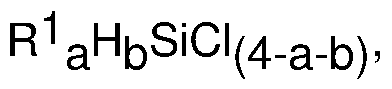 where subscript a is 0 or 1 , subscript b is 1 or 2, and each R1 is an independently selected alkyl group. When subscript a = 0, the hydridochlorosilane be trichlorosilane of formula HSiCl3 or dichlorosilane of formula F^SiC^; alternatively, starting material B) may be HSiC^.
[0007] Alternatively, starting material B) may be an alkylhydridochlorosilane when subscript a = 1. Suitable alkyl groups for R1 may have 1 to 18 carbon atoms, alternatively 1 to 12 carbon atoms, alternatively 1 to 6 carbon atoms, and alternatively 1 to 4 carbon atoms. Exemplary alkyl groups include methyl, ethyl, propyl (including n-propyl and isopropyl), and butyl (including n- butyl, tert-butyl, sec-butyl, and iso-butyl). Examples of alkylhydridochlorosilanes for starting material B) include methylhydrogendichlorosilane, ethylhydrogendichlorosilane,
methyldihydrogenchlorosilane, ethyldihydrogenchlorosilane, and combinations thereof.
[0008] Suitable hydridochlorosilanes for starting material B) are known in the art and are commercially available, e.g., from Dow Silicones Corporation of Midland, Michigan, USA or Millipore Sigma of St. Louis, Missouri USA. Starting materials A) and B) are used in relative molar amounts A) :B) of 10:1 to 0.5:1 , alternatively 2:1 to 1 :1 (molar ratio).
[0009] Starting material C) in the method described above is a solid Lewis Acid catalyst.
Examples of the catalyst may comprise alumina in any form, such as eta-alumina, a-alumina, and y-alumina. Aluminas are known in the art and available commercially in their different forms. For example, gamma-alumina may be purchased from Clariant International, Ltd., of Munich, Germany. Starting material C) may be in any shape. For example, C) the solid Lewis acid catalyst may be in nanosheet, powder, granule, pellet, or any extrudate form. One skilled in the art would recognize that certain commercially available aluminas may contain more than one component, for example, the alumina may comprise 70% to 100% aluminum oxide and 0 to 30% silicon dioxide, alternatively 95% to 100% aluminum oxide and 0 to 5% silicon dioxide.
[0010] The composition of starting material C) may be determined using methods known in the art. For example, one or more of elemental analysis, X-ray crystallography, electron microscopy, mass spectroscopy, and electrochemical methods known in the art may be used.
[0011] The process described herein may be performed continuously or be may conducted in a batch mode. As used herein,“continuously” means that a stream of starting materials A) and B) may be constantly or intermittently fed to the reactor containing C) the solid Lewis acid catalyst while the arylchlorosilane product, unreacted starting materials A) and B), and by products, if any, are removed.
[0012] The process described above can be performed in any reactor suitable for the combining of gases and solids. For example, when the process will be performed batchwise, the process may be carried out in a batch reactor, such as a sealed tube reactor or autoclave. Reactors such as tube reactors and packed columns are available commercially. For example, sealed tube reactors and autoclaves may be purchased from the Parr Instrument Company, having offices in Moline, IL. Other manufactures of suitable pressure reactors include High Pressure Equipment Company of Erie, Pennsylvania, Parker Autoclave Engineers of Erie Pennsylvania, Buchi AG of Uster, Switzerland, Berghof of Eningen, Germany, and Zeyon, Inc., of Erie, Pennsylvania. Alternatively, when the process will be performed continuously, the reactor can be a packed column or packed bed, stirred bed, vibrating bed, moving bed, re circulating bed, or a fluidized bed. When using a re-circulating bed, C) the solid Lewis Acid catalyst can be circulated from a bed for conducting step 1 ) to a separate bed for conducting step 3). To facilitate reaction, the reactor should have means to control the temperature of the reaction zone, e.g., the portion of the reactor in which starting materials A) and B) contact one another and C) the solid Lewis acid catalyst.
[0013] The method described above may optionally further comprise one or more additional steps. For example, the method may comprise:
optionally pre-1 ) treating C) a solid Lewis Acid catalyst before feeding starting materials into a reactor;
1 ) feeding into the reactor, the starting materials comprising
A) an aromatic hydrocarbon, and
B) a hydridochlorosilane of formula R1
 where a is 0 or 1 , b is 1 or 2, and each R1 is independently selected from the group consisting of an alkyl group and an aryl group;
thereby producing a reactor effluent comprising an arylchlorosilane of formula R1 aR2bSiCI(4_a. b), where R2 is an aryl group;
2) discontinuing feeding A) the aromatic hydrocarbon compound and B) the hydridochlorosilane when C) the solid Lewis acid catalyst is spent;
optionally pre-3) purging the reactor with E) inert gas for a time sufficient to remove all or a portion of unreacted starting materials and reactor effluent after step 2) and before step 3)
3) feeding D) a compound of formula R2CI, where R2 is H, an alkyl group or an aryl group into the reactor, thereby regenerating C) the solid Lewis acid catalyst;
4) repeating step 1 ), thereby producing additional reactor effluent;
optionally 5) repeating steps 2) to 4) two or more times;
optionally 6) recovering the arylchlorosilane from the reactor effluent; and
optionally 7) recycling unreacted starting materials in step 1 ).
[0014] Step pre-1 ) is optional and comprises treating the solid Lewis acid catalyst before feeding starting materials A) and B) into the reactor in step 1 ). Step pre-1 ) may be performed by purging the reactor containing the solid Lewis acid catalyst with E) inert gas for 2 to 6 hours at a temperature of 200°C to 400°C. The inert gas may be nitrogen. Without wishing to be bound by theory, it is thought that treating the solid Lewis acid catalyst in step pre-1 ) may be performed to remove water from the reactor. Step pre-1 ) may be performed by any convenient means to remove water.
[0015] The process of the invention is carried out at a temperature of at least 100 °C, alternative from 100°C to 300°C, alternatively from 150°C to 275°C. At temperatures much above 300°C, the metal oxides may become unstable and ineffective as heterogeneous catalysts.
[0016] The process of the invention may be carried out at an absolute pressure of at least 590 kPa; alternatively at least 690 kPa; alternatively at least 3500 kPa; alternatively 4000 kPa to 15,000 kPa; alternatively 4000 kPa to 1 1000 kPa; alternatively 4000 kPa to 9000 kPa;
alternatively 4000 kPa to 6000 kPa; alternatively 5000 kPa to 12,000 kPa; and alternatively 8000 kPa to 12,000 kPa.
[0017] When the process of the invention is performed continuously, the contact time is 0.001 second (s) to 100 minutes; alternatively 1 s to 50 minutes; alternatively 10 to 30 minutes. As used herein“contact time” is intended to mean the time for one reactor volume of the reactants (i.e., starting materials A) and B)) to pass through the reactor charged with C) the solid Lewis acid catalyst.
[0018] Starting material C), the solid Lewis acid catalyst is typically in a catalytic effective amount with respect to starting materials A) and B). A catalytic effective amount in reactor for running a continuous process is an amount sufficient to catalyze the reaction between starting materials A) and B). For example, a catalytic effective amount of catalyst may be at least 0.01 mg catalyst/cm2 of reactor volume; alternatively at least 0.5 mg catalyst/cm2 of reactor volume; alternatively 1 to 10,000 mg catalyst/cm2 of reactor volume, alternatively a catalytic effective amount may be 0.01 mol % to 50 mol %, alternatively 0.1 mol % to 15 mol %, and alternatively 0.1 mol % to 5 mol %, based on the weight of starting materials A) and B) in the reactor. One skilled in the art would know how to determine the correct amount of catalyst depending upon whether using a batch or continuous process and the type of reactor being used. For example, in a continuous reaction in a packed column, the reactor may be filled with catalyst and the reactants passed between the voids in the catalyst.
[0019] There is no required order of addition for the reaction when a batch process is used. In a continuous process A) the aromatic hydrocarbon, and B) the hydridochlorosilane are typically contacted together in the presence of C) the solid Lewis acid catalyst. For example, starting materials A) and B) may be mixed and flowed together over C) the solid Lewis acid catalyst in a continuous reaction.
[0020] Step 2) discontinuing feeding the starting materials into the reactor is performed when the catalyst is spent. “Spent” means the amount of arylhalosilane of formula R1 aR2bSiX(4-a-b) in the reactor effluent decreases to none or decreases to an amount less than when beginning step 1 ). For example, the catalyst may be deemed spent when the amount of arylhalosilane in the reactor effluent may decrease by 20%, alternatively by 30%, alternatively by 40%.
Discontinuing feeding the starting materials and going to the next step in the method may be optimized by one skilled in the art depending on various factors including cost benefit of the time needed to regenerate the catalyst as compared to continuing to produce reactor effluent with reduced yield of the arylhalosilane and the additional steps that may be used to recover the arylhalosilane and/or recycle unreacted starting materials.
[0021] The process may optionally further comprises additional step pre-3), purging the reactor with E) inert gas for a time sufficient to remove all or a portion of unreacted starting materials and reactor effluent after step 2) and before step 3).
[0022] In the process described above, step 3) is performed to regenerate the catalyst. Step 3) comprises feeding the compound of formula R2CI under conditions sufficient to generate halosilanes. R2 is selected from the group consisting of hydrogen, an alkyl group and an aryl
group. The alkyl group for R2 may be as described above for R1 . Alternatively, the alkyl group for R3 may be methyl. Alternatively, the aryl group for R2 may be phenyl. Step 3) may optionally further comprise feeding E) inert gas with D) the compound of formula R2CI. Step 3) may be performed at a temperature of 200°C to 300°C. The reactor effluent may be analyzed during step 3), e.g., via the GC-MS technique set forth in Reference Example 2.
[0023] When the amount of halosilanes in the reactor effluent is non -detectable, or reduced by a desired percentage, such as reduced by 90% to 100%, alternatively 80% to 100%, as compared to the amount present in the first sample analyzed, then step 4) of the process may be performed. Step 4) comprises repeating step 1 ), thereby producing additional reactor effluent. The process may optionally further comprise step 5) repeating steps 2) to 4) two or more times. The process may be repeated as many times as desired to produce additional reactor effluent.
[0024] The process may optionally further comprise step 6) recovering the arylchlorosilane from the reactor effluent. Recovering may be performed by any convenient means, such as stripping and/or fractional distillation.
[0025] The process may optionally further comprise step 7) recycling unreacted starting materials in step 1 ). The reactor effluent typically contains unreacted starting materials in addition to the arylchlorosilane. The unreacted starting materials may be collected after step 6). The unreacted starting materials may be recycled in step 1 ).
[0026] The process described above produces an arylchlorosilane of formula R1 aR2pSiCI(4_ a.p), where R1 and subscripts a and b are as described above, and R2 is an aryl group formed by reacting A) the aromatic compound with the silicon bonded hydrogen atom of starting material B). Examples of arylchlorosilanes that may be produced by this method include phenyltrichlorosilane and phenylmethyldichlorosilane.
[0027] The arylchlorosilanes produced as described above are useful as precursors for the preparation of aryl- functional siloxane polymers and network resins. Aryl- functional resins are used in high temperature coatings and adhesives, and in cookware. The aryl- functional resins are also useful in optoelectronic applications such as for LEDs and optical interconnects. The arylhalosilanes that further include alkyl groups are useful to make aryl-j functional siloxane polymers, which further include alkyl groups (aryl-, alkyl- functional siloxane polymers). The aryl-, alkyl- functional siloxane polymers are stable at relatively high temperatures and are useful as pump fluids, heat exchange fluids, and base oils for high temperature fluids.
Therefore, the process described above may further comprise hydrolyzing the arylchlorosilane to form an aryl- functional siloxane polymer or network resin.
EXAMPLES
[0028] These examples are intended to illustrate some embodiments of the invention and should not be interpreted as limiting the scope of the invention set forth in the claims. The following ingredients were used in the examples. Anhydrous HCI was anhydrous hydrogen chloride from AIR GAS. Benzene was HPLC ³99.9% from Millipore Sigma of St. Louis,
Missouri, USA. Gamma-Alumina catalyst was Aluminum Oxide CS331 -4 from Clariant.
MeHSiCl2 was methylhydrogendichlorosilane from Dow Silicones Corporation of Midland, Michigan, USA.
[0029] In this example 1 , 3.6 g of Gamma-Alumina catalyst was loaded in to a 3/8” Inconel reactor. The reactor was purged with nitrogen (N2) and pressure checked at 8274 kPa for any leaks. Then the reactor was heated under 100 SCCM of N2 at 300°C, atmospheric pressure for
4-6h. The reactor effluent was periodically sampled and analyzed by GC-MS/TCD to monitor water from the effluent to make sure no water is coming out of the reactor before introducing the starting materials. Then, the reactor was cooled to room temperature and left overnight under N2 atmosphere to purge out any water that may have been condensed in the lines.
[0030] The next day, the reactor was filled and pressurized with starting materials, Benzene and MeHSiCl2 in a molar ratio of 2:1 Benzene: MeHSiC^ to 8274 kPa using Teledyne ISCO pump, then heated to 300°C while feeding the reactor with a constant flow rate of the starting materials at 5mL/h. The reactor effluent was periodically sampled and analyzed by GC-MS/TCD to determine weight percent of PhMeSiCl2 and other chlorosilanes. The reaction was continued for 25 h, until the catalyst was deemed spent when a continuous decrease in PhMeSiCl2 concentration was observed in the GC-MS/TCD analysis of the reactor effluent.
[0031] The reactor was then flushed with 100SCCM N2 at 350°C and atmospheric pressure for 4-8 h to remove all the remaining starting materials and reaction product from the process lines. The reactor temperature was then decreased to 300°C, and a mixture of anhydrous HCI (10 SCCM) and N2 (90SCCM) was fed to the reactor for 4-6 h to regenerate the catalyst. The reactor effluent, during regeneration, was periodically sampled and analyzed by GC-MS for qualitative analysis. The GC-MS analysis showed the formation of HSiCl3 and SiCl4 when the spent catalyst was treated with anhydrous HCI. As the HCI treatment continued, the amount of chlorosilanes (HSiCl3 and SiCl4) decreased with time. Without wishing to be bound by theory, it
was thought that the generation of chlorosilanes was indicative of HCI reacting with deposited polysilane or silicon species to remove them from the catalyst surface. The drop-off of chlorosilane generation over time during regeneration showed that the amount of removable Si decreased with time. It is proposed that the drop-off in chlorosilane species being generated indicated that the catalyst has been cleaned of Si species and sufficient to be deemed regenerated.
[0032] After regenerating the catalyst with HCI, the catalyst was observed to perform similarly to the fresh catalyst in the het-PFC reaction with benzene and MeHSiCl2 repeated under similar reaction conditions as described above. The catalyst bed was evaluated for a total of 75 hours reaction without any performance drop under het-PFC reaction conditions.
[0033] The example demonstrated the feasibility of using HCI treatment to remove Si species depositing on alumina catalysts during the het-PFC process. The alumina catalyst was successfully regenerated with periodic HCI treatment and showed normal activity without any performance drop off to make PhMeSiCl2 under het-PFC reaction conditions. Yield (wt%) of
PhMeSiCl2 in het-PFC reaction with time in this example is shown below in Table 2.
Table 2


Reference Example 2
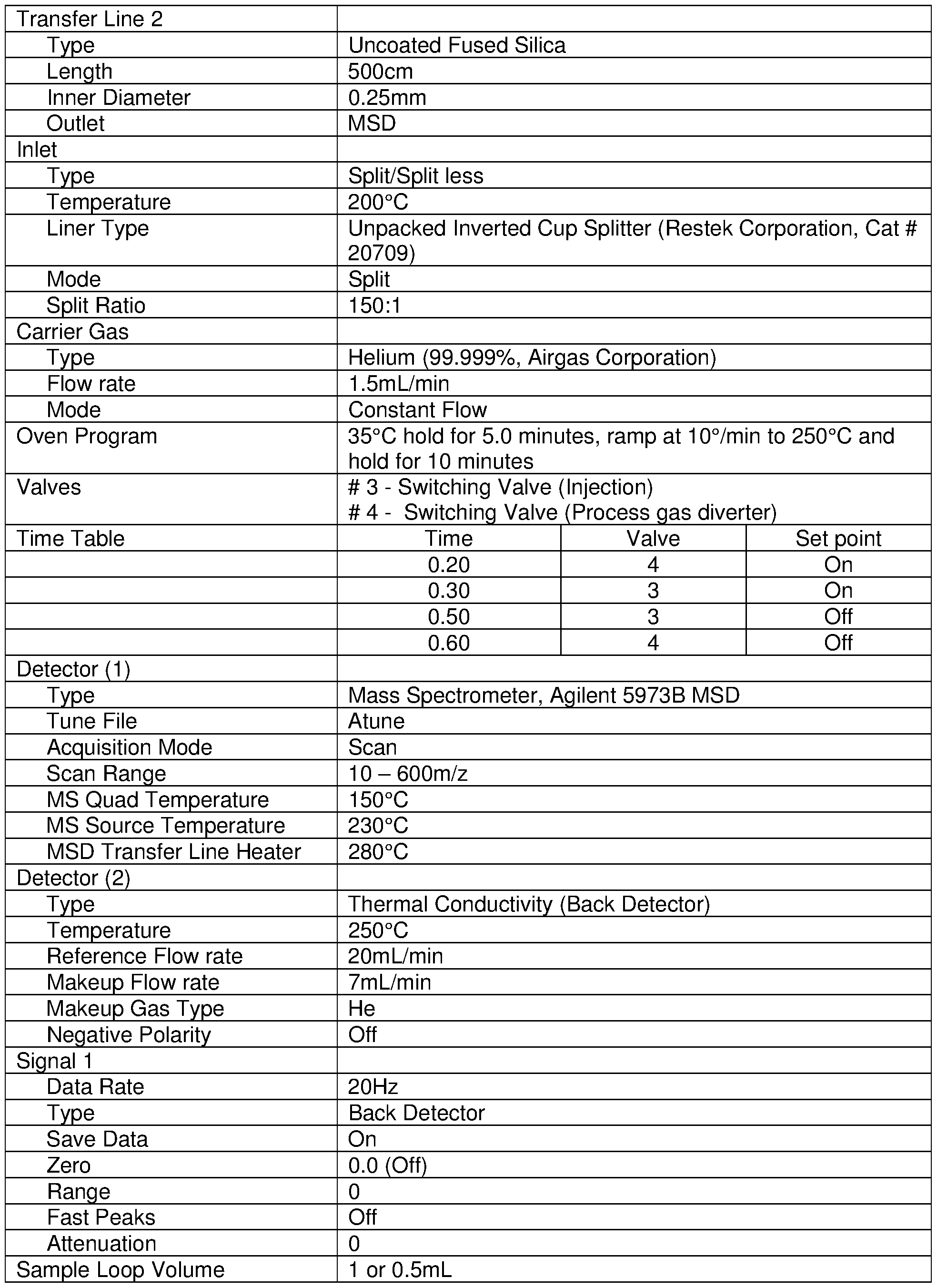
[0034] The on-line analysis (during pre-treatment with N2/activation with Benzene & methylhydrogendichlorosilane, MeHSiCl2, and regeneration with HCI) was completed utilizing an Agilent GC-MS (Gas Chromatography-Mass Spectrometer) instrument, which was connected to the reactor effluent line. A remote sampling system was used to transfer sample from the reactor effluent line to the GC inlet. Sampling was accomplished using a set of 2 pneumatically driven valves. The first valve was a 3-way valve which diverted the process flow to the second valve, a 6-port sampling valve. During the non-process sampling time, the 6-port valve was left in the injection position to maintain a He flow through the sample loop to prevent blockages. The transfer line from the sample valve to the GC inlet was 1/16” Monel line that was part of an O’Brien self-limiting heat traced tube bundle, maintained at 120°C.
[0035] The setup included the simultaneous detection by MS (mass spectroscopy) and TCD (Thermal Conductivity Detector) from a single injection. This allowed a normalized adjusted area calculation to be used to determine the wt. % composition of the stream from the TCD data. The MS detection allowed identifications to be confirmed. This was accomplished using a Secure“Y” Connector from the Restek Corporation. The single analytical column connected the inlet and the connector. From the Y connector, an 40cm x 0.25mm ID fused silica transfer line connected to the TCD and ~5m x 0.25mm ID fused silica transfer line connected to the MS. The difference in transfer line length was required to provide an appropriate pressure drop to allow splitting of the sample between the MS and the TCD.

[0036] The process described herein solves the problem of deposition of silicon by reacting short polysilane precursors by adding a compound of formula R^CI, such as HCI or CH3CI to react with the polysilanes. In addition to regenerating the catalyst, the process provides the further benefit of forming corresponding chlorosilanes, which may be recycled in step 1 ) of the method to produce additional arylchlorosilanes.
[0037] This process can be used as an alternative to Grignard technology to produce arylchlorosilanes such as phenylmethyldichlorosilane. The problem to be solved by the process described herein is that the solid Lewis acid catalyst (e.g., gamma-Alumina catalyst employed in the reaction in the example above) became spent and exhibited shorter than desired lifetime {e.g., at hours 9-10 and 19-21 ). Without wishing to be bound by theory, it is thought that the deactivation of the catalyst was found to be due to the deposition of nano-crystalline
silicon/poly-silanes in to the pores of the catalyst which blocked active sites. However, the example above further showed that the process described herein provided an effective solution in the method for catalyst regeneration of spent catalyst in the process to make
phenylmethyldichlorosilane {e.g., at hours 1 1 -12 and 22-23).
[0038] Surface and bulk analysis of the spent catalyst showed the presence of nano crystalline silicon particles on the surface and in the pores of the alumina catalyst when the catalyst was spent in the example herein. However, the alumina catalyst was successfully regenerated with periodic HCI treatment and showed normal activity without any performance drop off to make phenylmethyldichlorosilane, PhMeSiC^, under the reaction conditions in the example above.
Definitions and Usage of Terms
[0039] All amounts, ratios, and percentages are by weight unless otherwise indicated. The amounts of all starting materials in a composition total 100% by weight. The Brief Summary of the Invention and the Abstract are hereby incorporated by reference. The articles‘a’,‘an’, and ‘the’ each refer to one or more, unless otherwise indicated by the context of specification. The singular includes the plural unless otherwise indicated. The disclosure of Markush groups includes the entire group and also any individual members and subgroups subsumed therein. For example, disclosure of the Markush group a hydrogen atom, an alkyl group, an alkenyl group, or an aryl group, includes the member alkyl individually; the subgroup alkyl and aryl; and any other individual member and subgroup subsumed therein. Abbreviations used in this application are as defined below in Table 2.
Table 2 - Abbreviations

[0040] The terms“comprising” or“comprise” are used herein in their broadest sense to mean and encompass the notions of“including,”“include,”“consist(ing) essentially of,” and
“consist(ing) of. The use of“for example,”“e.g. "“such as,” and“including” to list illustrative examples does not limit to only the listed examples. Thus,“for example” or“such as” means“for example, but not limited to” or“such as, but not limited to” and encompasses other similar or equivalent examples. Generally, as used herein a hyphen or dash
 in a range of values is “to” or“through”; a“>” is“above” or“greater-than”; a“>” is“at least” or“greater-than or equal to”; a“<” is“below” or“less-than”; and a“£” is“at most” or“less-than or equal to.”
[0041] It is to be understood that the appended claims are not limited to express and particular compounds, compositions, or methods described in the detailed description, which may vary between particular embodiments which fall within the scope of the appended claims. With respect to any Markush groups relied upon herein for describing particular features or aspects of various embodiments, different, special, and/or unexpected results may be obtained from each member of the respective Markush group independent from all other Markush members. Each member of a Markush group may be relied upon individually and or in combination and provides adequate support for specific embodiments within the scope of the appended claims.
Claims
1. A process comprising:
1 ) feeding into a reactor, starting materials comprising
A) an aromatic hydrocarbon, and
B) a hydridochlorosilane of formula R1
 where a is 0 or 1 , b is 1 or 2, and each R1 is an independently selected alkyl group,
where the reactor contains
C) a solid Lewis Acid catalyst;
thereby producing a reactor effluent comprising
 where R2 is an aryl group;
2) discontinuing feeding A) the aromatic hydrocarbon compound and B) the halosilane when C) the heterogeneous alumina catalyst is spent;
3) feeding D) a compound of formula R2CI, where R2 is selected from the group consisting of H, an alkyl group and an aryl group into the reactor, thereby regenerating C) the solid Lewis acid catalyst; and
4) repeating step 1 ), thereby producing additional reactor effluent.
2. The process of claim 1 , where one or more of conditions (i) to (iii) is met, where:
(i) the aromatic hydrocarbon is benzene,
(ii) the hydridochlorosilane is methylhydrogendichlorosilane or trichlorosilane, and
(iii) the solid Lewis Acid catalyst is alumina.
3. The process of claim 1 or claim 2, further comprising: pre-1 ) treating starting material C) before feeding starting materials A) and B) into the reactor in step 1.
4. The process of claim 3, where step pre-1 ) is performed by purging the reactor containing starting material C) with E) inert gas for 2 to 6 hours at a temperature of 200°C to 400°C.
5. The process of any one of the preceding claims, where starting materials A) and B) are fed in amounts sufficient to provide a molar ratio A): B) of 10:1 to 0.5:1.
6. The process of any one of the preceding claims, where step 1 ) is performed at a temperature of 100°C to 300°C and a pressure of 3447 kPa to 8274 kPa.
7. The process of any one of the preceding claims, further comprising pre-3), purging the reactor with E) inert gas for a time sufficient to remove unreacted starting materials and the reactor effluent after step 2) and before step 3).
8. The process of any one of the preceding claims, where step 3) further comprises feeding E) inert gas with D) the compound of formula R2CI, and step 3) is performed at 200°C to 300°C.
9. The process of any one of the preceding claims, further comprising analyzing the reactor effluent during step 3), and going to step 4) when chlorosilanes of formula R2SiCl3 and S1CI4 are not detectable
10. The process of any one of the preceding claims, further comprising 5) repeating steps 2) through 4) two or more times.
1 1 . The process of any one of the preceding claims, further comprising 6) recovering the arylchlorosilane from the reactor effluent.
12. The process of any one of the preceding claims, further comprising 7) recycling unreacted starting materials in step 1 ).
13. Use of the arylchlorosilane of made by the method of any one of the preceding claims as a precursor for the preparation of aryl- functional siloxane polymers and network resins.
14. A process comprising:
1 ) feeding into a reactor, starting materials comprising
A) an aromatic hydrocarbon, and
B) a hydridochlorosilane of formula R1
 where a is 0 or 1 , b is 1 or 2, and each R1 is an independently selected alkyl group,
where the reactor contains
C) a solid Lewis Acid catalyst;
thereby producing a reactor effluent comprising R1 aR2bSid(4-a-b)’ where R2 is an aryl group;
2) discontinuing feeding A) the aromatic hydrocarbon compound and B) the halosilane when C) the heterogeneous alumina catalyst is spent;
3) feeding D) a compound of formula R^CI, where is selected from the group consisting of H, an alkyl group and an aryl group into the reactor, thereby regenerating C) the solid Lewis acid catalyst;
4) repeating step 1 ), thereby producing additional reactor effluent;
optionally, 5) repeating steps 2) through 4) two or more times;
6) recovering the arylchlorosilane from the reactor effluent;
optionally 7) recycling unreacted starting materials in step 1 ); and
8) hydrolyzing the arylchlorosilane, thereby forming an aryl- functional siloxane polymer or network resin.
15. The process of claim 14 comprising one or both of:
pre-1 ) treating starting material C) before feeding starting materials A) and B) into the reactor in step 1 ) and
pre-3), purging the reactor with E) inert gas for a time sufficient to remove unreacted starting materials and the reactor effluent after step 2) and before step 3).
Applications Claiming Priority (2)
| Application Number | Priority Date | Filing Date | Title |
|---|---|---|---|
| US201962816240P | 2019-03-11 | 2019-03-11 | |
| US62/816,240 | 2019-03-11 |
Publications (1)
| Publication Number | Publication Date |
|---|---|
| WO2020185313A1 true WO2020185313A1 (en) | 2020-09-17 |
Family
ID=69740574
Family Applications (1)
| Application Number | Title | Priority Date | Filing Date |
|---|---|---|---|
| PCT/US2020/015135 Ceased WO2020185313A1 (en) | 2019-03-11 | 2020-01-27 | Catalyst regeneration in a process to make arylchlorosilanes |
Country Status (1)
| Country | Link |
|---|---|
| WO (1) | WO2020185313A1 (en) |
Citations (2)
| Publication number | Priority date | Publication date | Assignee | Title |
|---|---|---|---|---|
| WO2016126808A1 (en) * | 2015-02-06 | 2016-08-11 | Dow Corning Corporation | Method of producing organohalosilanes |
| WO2016126804A1 (en) * | 2015-02-06 | 2016-08-11 | Dow Corning Corporation | Method of producing organohalosilanes |
-
2020
- 2020-01-27 WO PCT/US2020/015135 patent/WO2020185313A1/en not_active Ceased
Patent Citations (2)
| Publication number | Priority date | Publication date | Assignee | Title |
|---|---|---|---|---|
| WO2016126808A1 (en) * | 2015-02-06 | 2016-08-11 | Dow Corning Corporation | Method of producing organohalosilanes |
| WO2016126804A1 (en) * | 2015-02-06 | 2016-08-11 | Dow Corning Corporation | Method of producing organohalosilanes |
Similar Documents
| Publication | Publication Date | Title |
|---|---|---|
| TWI602780B (en) | Process for workup of chlorosilanes or chlorosilane mixtures contaminated with carbon compounds | |
| RU2499801C2 (en) | Method of producing trichlorosilane and tetrachlorosilane | |
| KR20130079349A (en) | A method for preparing a diorganodihalosilane | |
| KR102082629B1 (en) | Method of preparing halogenated silahydrocarbylenes | |
| USRE46657E1 (en) | Method of making a trihalosilane | |
| JP5474945B2 (en) | Method for producing linear and cyclic trisilaalkanes | |
| US8865927B2 (en) | Method for preparing a diorganodihalosilane | |
| WO2014149224A1 (en) | Method for preparing a halosilane using copper silicides as catalysts | |
| AU2011341476A1 (en) | Method of making a diorganodihalosilane | |
| EP3253771B1 (en) | Method of producing organohalosilanes | |
| WO2014099125A1 (en) | Method for preparing a diorganodihalosilane | |
| JP4256998B2 (en) | Method for producing disproportionation reaction product of silane compound | |
| US2887500A (en) | Redistribution of organosilanes | |
| JP2551901B2 (en) | Contact alkylation method | |
| JP6725510B2 (en) | Method for producing aryl functional silanes | |
| EP3253770B1 (en) | Method of producing organohalosilanes | |
| CN109503646B (en) | A method for processing high boiling point polymers produced by polycrystalline silicon and organic silicon | |
| JP2016530277A (en) | Direct slurry phase synthesis of organohalosilanes from cyclone fine particles | |
| KR20260002126A (en) | Method for manufacturing of chlorosilane | |
| KR102299593B1 (en) | Method for preparing a halosilane | |
| RU2203900C2 (en) | Method for production of methylchlorosilanes | |
| JPH11189598A (en) | Production of chlorosilane containing fluorine |
Legal Events
| Date | Code | Title | Description |
|---|---|---|---|
| 121 | Ep: the epo has been informed by wipo that ep was designated in this application |
Ref document number: 20708773 Country of ref document: EP Kind code of ref document: A1 |
|
| NENP | Non-entry into the national phase |
Ref country code: DE |
|
| 122 | Ep: pct application non-entry in european phase |
Ref document number: 20708773 Country of ref document: EP Kind code of ref document: A1 |