WO2020184323A1 - スイッチギヤおよびインターロック装置 - Google Patents
スイッチギヤおよびインターロック装置 Download PDFInfo
- Publication number
- WO2020184323A1 WO2020184323A1 PCT/JP2020/009064 JP2020009064W WO2020184323A1 WO 2020184323 A1 WO2020184323 A1 WO 2020184323A1 JP 2020009064 W JP2020009064 W JP 2020009064W WO 2020184323 A1 WO2020184323 A1 WO 2020184323A1
- Authority
- WO
- WIPO (PCT)
- Prior art keywords
- connector
- pin
- interlock
- circuit breaker
- housing
- Prior art date
- Legal status (The legal status is an assumption and is not a legal conclusion. Google has not performed a legal analysis and makes no representation as to the accuracy of the status listed.)
- Ceased
Links
Images

Classifications
-
- H—ELECTRICITY
- H02—GENERATION; CONVERSION OR DISTRIBUTION OF ELECTRIC POWER
- H02B—BOARDS, SUBSTATIONS OR SWITCHING ARRANGEMENTS FOR THE SUPPLY OR DISTRIBUTION OF ELECTRIC POWER
- H02B11/00—Switchgear having carriage withdrawable for isolation
- H02B11/02—Details
- H02B11/04—Isolating-contacts, e.g. mountings or shieldings
-
- H—ELECTRICITY
- H02—GENERATION; CONVERSION OR DISTRIBUTION OF ELECTRIC POWER
- H02B—BOARDS, SUBSTATIONS OR SWITCHING ARRANGEMENTS FOR THE SUPPLY OR DISTRIBUTION OF ELECTRIC POWER
- H02B11/00—Switchgear having carriage withdrawable for isolation
- H02B11/12—Switchgear having carriage withdrawable for isolation with isolation by horizontal withdrawal
- H02B11/127—Withdrawal mechanism
- H02B11/133—Withdrawal mechanism with interlock
Definitions
- the present invention relates to an interlock device provided in a switchgear, and relates to a mechanical interlock device between a connector on the circuit breaker side and a connection position of the circuit breaker.
- the switchgear is equipped with a housing that detachably stores the circuit breaker body and the circuit breaker body. Therefore, the circuit breaker (for example, vacuum circuit breaker (VCB)) side electric circuit used in the switchgear is operated by connecting the connector provided in the electric circuit to the connector provided in the control circuit on the housing side. Is possible. Therefore, if the operation of the switchgear is started in a state where the connector on the circuit breaker side and the connector on the housing side are not connected, the function is not established and causes trouble.
- VVB vacuum circuit breaker
- switchgear used overseas may require an interlock mechanism that prevents the circuit breaker from moving to the connection position unless the connector on the circuit breaker side and the connector on the housing side are connected.
- interlock mechanism that prevents the circuit breaker from moving to the connection position unless the connector on the circuit breaker side and the connector on the housing side are connected.
- JP-A-2007-31526 Japanese Unexamined Patent Publication No. 2011-201113 Jikkai Sho 55-163717 Jikkai Sho 59-97518
- the mechanism part may become complicated and the manufacturing cost may increase.
- the present invention has been made in view of the above circumstances, and an object of the present invention is to provide an interlock device having a simple structure and a switchgear including the interlock device.
- One aspect of the switchgear of the present invention that achieves the above object is a circuit breaker main body, a housing including a storage portion in which the circuit breaker main body is detachably housed, and a first connector provided in the circuit breaker main body.
- a second connector provided above the storage portion of the housing and electrically connected to the first connector, and a first connector and the second connector provided above the storage portion of the housing. It is provided with an interlock device for preventing the circuit breaker main body from moving to the storage portion when the circuit breaker is not connected.
- the interlock device includes a rod-shaped interlock pin that is supported so as to be movable in the axial direction by its own weight, and a control pin that is provided on the interlock pin and can prevent the connection between the first connector and the second connector.
- the control pin is locked to the upper part of the first connector connected to the second connector, and the interlock pin is the accommodating portion.
- the first connector of the second connector is connected to the control pin, which is supported at a position where the breaker body can be moved.
- the interlock pin is supported at a position facing the connection portion, and the interlock pin is supported so that the lower end portion of the interlock pin extends into the storage portion.
- the switchgear of the present invention that achieves the above object is provided with the interlock pin in the above switchgear, and has an operation pin extending in a direction perpendicular to the axis of the interlock pin and the interlock pin.
- the protective frame includes a guide plate that slidably supports the guide plate, a frame body to which the guide plate is fixed, and a protective frame that is attached to the frame body so as to cover the interlock pin. Is characterized in that an elongated hole is formed through which the operation pin is inserted.
- the interlock device of the present invention that achieves the above object includes a circuit breaker main body, a housing including a storage portion in which the circuit breaker main body is detachably housed, and a first connector provided in the circuit breaker main body.
- a switchgear including a second connector provided above the housing portion of the housing and electrically connected to the first connector, and the first connector and the second connector are connected to each other. It is an interlock device that prevents the circuit breaker body from moving to the storage portion when it is not present.
- This interlock device includes a rod-shaped interlock pin that is supported so as to be movable in the axial direction by its own weight, and a control pin that is provided on the interlock pin and can prevent the connection between the first connector and the second connector.
- the control pin is locked to the upper part of the first connector connected to the second connector, and the interlock pin is the accommodating portion.
- the first connector of the second connector is connected to the control pin, which is supported at a position where the breaker body can be moved.
- the interlock pin is supported at a position facing the connection portion, and the interlock pin is supported so that the lower end portion of the interlock pin extends into the storage portion.
- the configuration of the interlock device is simplified.
- switchgear and the interlock device according to the embodiment of the present invention will be described in detail with reference to the drawings.
- a switchboard containing a vacuum breaker will be described as an example, but the switchgear and the interlock device of the present invention can be applied to various types of switchgear.
- the switchgear 1 includes a circuit breaker main body 2, a housing 3 for accommodating the circuit breaker main body 2, and an interlock device 4.
- the circuit breaker main body 2 includes a vacuum circuit breaker 2a that opens and closes the charging circuit.
- the vacuum circuit breaker 2a includes, for example, a fixed electrode and a movable electrode, and the movable electrode is driven by an operation rod to open and close the fixed electrode.
- the operation unit that drives the operation rod for example, applies a control current to the control unit of the operation electromagnet, drives the operation rod by the electromagnetic force of the excited electromagnet, and separates the movable electrode from the fixed electrode to the power supply side. It opens and closes electrically with the load side.
- the circuit breaker main body 2 includes a power supply side contactor and a load side contactor pulled out to the housing 3 side (not shown), and is taken in and out of the housing 3.
- the housing 3 includes a storage unit 3a in which the circuit breaker main body 2 is stored.
- the storage portion 3a of the housing 3 is provided with a power-side disconnecting portion and a load-side disconnecting portion facing the power-side contact and the load-side contact of the circuit breaker main body 2 (not shown).
- the circuit breaker main body 2 is pulled out from the housing 3, and the power supply side contactor and the load side contactor are electrically disconnected from the power supply side disconnector and the load side disconnector. Further, the circuit breaker main body 2 is pulled into the housing 3 so that the power supply side contactor and the load side contactor are electrically connected to the power supply side disconnector and the load side disconnector.
- the position where the circuit breaker main body 2 is disconnected is defined as the disconnecting position
- the position where the circuit breaker body 2 is connected is defined as the connecting position.
- the circuit breaker main body 2 includes a control plug 5 connected to the control unit of the operation unit.
- the control plug 5 is a connector (first connector) provided in the circuit breaker main body 2.
- the housing 3 is provided with a receptacle 6 into which the control plug 5 is inserted.
- the receptacle 6 is a connector (second connector) that is electrically connected to the control plug 5.
- the receptacle 6 is provided above the storage unit 3a of the housing 3 and is connected to a control unit that controls the vacuum circuit breaker 2a.
- the operation rod is driven by the electromagnetic force of the electromagnet excited by the control current from the control unit, the movable electrode is brought into contact with the fixed electrode, and the vacuum circuit breaker 2a is turned on. Further, the breaking operation of the vacuum circuit breaker 2a is performed by releasing the energy of the breaking spring accumulated at the time of closing and pulling the movable electrode away from the fixed electrode.
- the interlock device 4 prevents the circuit breaker main body 2 from moving to the connection position when the control plug 5 is not inserted in the receptacle 6.
- the interlock device 4 is provided inside the housing 3.
- the interlock device 4 is provided above the storage portion 3a of the housing 3 and in the vicinity of the receptacle 6.
- the interlock device 4 includes an interlock pin 7, a control pin 8 and an operation pin 9 provided on the interlock pin 7, and a guide for supporting the interlock pin 7.
- a plate 10 and a frame portion 11 to which the guide plate 10 is fixed are provided.
- the interlock pin 7 has a rod shape such as a square bar, and is provided at a position that does not interfere with the connection between the receptacle 6 and the control plug 5.
- the interlock pin 7 is supported by the guide plate 10 so as to be movable in the axial direction by its own weight (for example, in the Y-axis direction in FIG. 2C).
- the control pin 8 is a member capable of preventing the connection between the control plug 5 and the receptacle 6.
- the control pin 8 extends in a direction perpendicular to the axis of the interlock pin 7 and is provided on the interlock pin 7 (in the X-axis direction in FIG. 2C).
- the control pin 8 is provided, for example, extending in a direction parallel to the connection surface into which the control plug 5 of the receptacle 6 is inserted.
- the operation pin 9 is a member that moves the interlock pin 7 in the axial direction.
- the operation pin 9 extends in a direction perpendicular to the axis of the interlock pin 7 and is provided on the interlock pin 7 (in the Z-axis direction in FIG. 2C).
- the operation pin 9 is provided, for example, extending in the direction perpendicular to the connection surface into which the control plug 5 of the receptacle 6 is inserted.
- the guide plate 10 is a member that supports the interlock pin 7 so as to be movable in the axial direction.
- the guide plate 10 is a plate having a U-shaped vertical cross section including an upper plate 10a and a lower plate 10b.
- the upper plate 10a and the lower plate 10b are provided so as to extend substantially vertically from the upper end or the lower end of the middle plate 10c, respectively.
- Holes having the same shape as the cross section of the interlock pin 7 are formed in the upper plate 10a and the lower plate 10b, respectively, and the interlock pin 7 slides on the guide plate 10 by inserting the interlock pin 7 into the holes. Supported as possible.
- the frame portion 11 includes a frame main body 12 to which the guide plate 10 is fixed, and a side frame 13 and a protective frame 14 provided on the side portions of the frame main body 12, respectively.
- the frame portion 11 is provided on the ceiling portion of the housing 3, for example.
- the frame body 12 is, for example, a rectangular parallelepiped box body, and includes a mounting plate 12a to which the guide plate 10 is mounted, an upper plate 12b and a pair of side plates 12c and 12d extending substantially vertically from the mounting plate 12a, respectively. .. An opening is formed on the surface of the frame body 12 facing the mounting plate 12a.
- the mounting plate 12a is formed with a hole for providing the guide plate 10
- the upper plate 12b is formed with a hole for fixing the frame body 12 to the ceiling of the housing 3.
- the side plates 12c and 12d are formed with holes provided with the side frame 13 or the protective frame 14, respectively.
- the side frame 13 includes a side plate 13a fixed to the frame body 12 and an upper plate 13b fixed to the housing 3.
- the upper plate 13b is provided so as to extend from the upper end portion of the side plate 13a in a direction substantially perpendicular to the side plate 13a.
- the protective frame 14 includes a protective plate 14a fixed to the frame body 12, an upper plate 14b fixed to the housing 3, a first bent portion 14c substantially perpendicular to the protective plate 14a, and a first bent.
- a second bent portion 14d that is substantially perpendicular to the portion 14c is provided.
- the protective plate 14a is provided so as to extend in a direction perpendicular to the surface of the mounting plate 12a from the side end portion of the mounting plate 12a of the frame main body 12.
- the upper plate 14b is provided so as to extend from the upper end portion of the protective plate 14a in a direction substantially perpendicular to the protective plate 14a.
- the first bent portion 14c is formed by bending horizontally from the end portion of the protective plate 14a extending from the side end portion of the mounting plate 12a with respect to the surface of the mounting plate 12a.
- An elongated hole 14e extending in the vertical direction is formed in the first bent portion 14c, and an operation pin 9 is provided through the elongated hole 14e.
- the first bent portion 14c extends so as to cover the guide plate 10, and its end portion is bent in the direction of the side frame 13 to form the second bent portion 14d.
- the operation pin 9 is provided by inserting the elongated hole 14e formed in the protective frame 14. Further, a gap 15 is formed between the tip end portion of the second bent portion 14d and the end portion of the side frame 13, and the control pin 8 is provided so as to project from the gap 15.
- the interlock pin 7 and the control pin 8 move in the axial direction (vertical direction) of the interlock pin 7. Further, by locking the operation pin 9 to the lower end portion of the elongated hole 14e, the interlock pin 7 is prevented from falling from the guide plate 10 due to its own weight.
- the lower end of the interlock pin 7 extends into and is supported in the storage portion 3a of the housing 3.
- the circuit breaker main body 2 is engaged with the lower end portion of the interlock pin 7 to prevent the circuit breaker main body 2 from moving to the connection position.
- the control pin 8 is extended and supported at a position facing the connection surface (that is, the connection portion of the control plug 5) to which the control plug 5 of the receptacle 6 is connected. In this state, the control plug 5 cannot be connected to the receptacle 6.
- the interlock pin 7 falls by its own weight, and the operation pin 9 is an elongated hole 14e formed in the protective frame 14 (shown). It is locked to the lower end of the). As a result, the lower end of the interlock pin 7 is supported by extending into the storage portion 3a of the housing 3, and the lower end of the interlock pin 7 is moved to the connection position of the circuit breaker main body 2. It will be in a state of being extended to a position that hinders this.
- the interlock device 4 may be damaged. Therefore, by providing the frame portion 11 in the interlock device 4, the deformation of the interlock pin 7 and the guide plate 10 is suppressed by the frame portion 11, and the deformation of the interlock device 4 is suppressed.
- the interlock pin 7 by supporting the interlock pin 7 between the upper plate 10a and the lower plate 10b, deformation of the interlock pin 7 can be suppressed. Further, when the interlock pin 7 is slidably contacted with the middle plate 10c of the guide plate 10, the force applied to the interlock pin 7 is received by the entire guide plate 10, and the deformation of the interlock pin 7 and the deformation of the guide plate are suppressed. can do. Further, by protecting the guide plate 10 with the protective frame 14, deformation of the guide plate 10 can be suppressed.
- the interlock pin 7 is supported in a state where the lower end portion of the interlock pin 7 does not extend into the storage portion 3a of the housing 3.
- the circuit breaker main body 2 can be moved to the connection position (indicated by the arrow D in the figure).
- the switchgear 1 and the interlock device 4 according to the embodiment of the present invention as described above have a configuration in which the interlock pin 7 is dropped by its own weight, no spring component is required. Therefore, since the interlock device 4 has a small number of parts and can perform interlock control with a simple structure, it is possible to reduce failures as compared with an interlock device using a link mechanism or a spring.
- the interlock device 4 can be easily replaced. Further, by fixing the interlock device 4 at a predetermined position, the interlock function can be realized. Therefore, if necessary, the interlock device 4 can be easily added to the switchgear as a retrofit.
- switchgear and the interlock device of the present invention have been described above with reference to specific embodiments, the switchgear and the interlock device of the present invention are not limited to the embodiments and do not impair their characteristics. Design changes can be made as appropriate within the scope, and those with design changes also belong to the technical scope of the present invention.
- the operation pin 9 may be provided so as to extend in the direction opposite to the extending direction of the control pin 8. Further, the control pin 8 can also be used as the operation pin 9.
- the interlock pin 7 can also be used as the control pin 8.
- the interlock pin 7 when the control plug 5 and the receptacle 6 are not connected, the interlock pin 7 is supported so as to face the connection portion of the receptacle 6, and the lower end portion of the interlock pin 7 is the storage portion of the housing 3. It is provided extending within 3a. Further, when the control plug 5 and the receptacle 6 are connected, the lower end of the interlock pin 7 is locked to the body of the control plug 5.
Landscapes
- Engineering & Computer Science (AREA)
- Power Engineering (AREA)
- Trip Switchboards (AREA)
Abstract
遮断器本体(2)と、遮断器本体(2)を収納する筐体(3)と、インターロック装置(4)を備えるスイッチギヤ(1)である。インターロック装置(4)は、インターロックピン(7)、制御ピン(8)および操作ピン(9)を備える。制御プラグ(5)がレセプタクル(6)に接続されていない場合、インターロックピン(7)の下端部が筐体(3)の収納部(3a)内に延在し、遮断器本体(2)が収納部(3a)内に移動することが妨げられるとともに、制御ピン(8)が制御プラグ(5)とレセプタクル(6)の接続を妨げる。制御プラグ(5)がレセプタクル(6)に接続された場合、制御プラグ(5)のボディに制御ピン(8)が乗っかり、インターロックピン(7)は、インターロックピン(7)の下端部が筐体(3)の収納部(3a)内に延びていない状態で支持される。
Description
本発明は、スイッチギヤに備えられるインターロック装置に関し、遮断器側のコネクタと遮断器の接続位置との機械的インターロック装置に関する。
スイッチギヤは、遮断器本体と遮断器本体を着脱可能に収納する筐体を備える。したがって、スイッチギヤで使用される遮断器(例えば、真空遮断器(VCB))側の電気回路は、電気回路に備えられたコネクタを筐体側の制御回路に備えられたコネクタに接続することにより運用が可能となる。よって、遮断器側のコネクタと筺体側のコネクタが接続されていない状態でスイッチギヤの運用を開始すると機能として成立せず、トラブルの原因となる。
海外で使用されるスイッチギヤでは、このようなトラブルを避けるため、遮断器側のコネクタと筺体側のコネクタが接続されていないと遮断器が接続位置に移動できないインターロック機構を要求される場合がある(例えば、特許文献1、2)。
このようなインターロック機構に復帰ばねを使用した場合、使用しない場合と比較して部品点数が増加し、故障率が大きくなるおそれがある。
また、インターロック機構にリンク機構を採用すると、機構部が複雑となり製造コストが大きくなるおそれがある。
本発明は、上記事情に鑑みてなされたものであり、簡素な構造を有するインターロック装置およびインターロック装置を備えるスイッチギヤを提供することを目的としている。
上記目的を達成する本発明のスイッチギヤの一態様は、遮断器本体と、前記遮断器本体が着脱可能に収納される収納部を備える筐体と、前記遮断器本体に備えられる第1コネクタと、前記筐体の前記収納部上方に備えられ、前記第1コネクタと電気的に接続される第2コネクタと、前記筐体の前記収納部上方に備えられ、前記第1コネクタと前記第2コネクタが接続されていないときに、前記収納部に前記遮断器本体が移動することを防止するインターロック装置と、を備えたものである。
前記インターロック装置は、自重によって軸方向に移動可能に支持される棒状のインターロックピンと、前記インターロックピンに備えられ、前記第1コネクタと前記第2コネクタの接続を防止可能な制御ピンと、を備え、前記第1コネクタと前記第2コネクタが接続されているとき、前記制御ピンが前記第2コネクタに接続された前記第1コネクタの上部に係止し、前記インターロックピンは、前記収納部に前記遮断器本体を移動することが可能な位置に支持され、前記第1コネクタと前記第2コネクタが接続されていないとき、前記制御ピンは前記第2コネクタの前記第1コネクタが接続される接続部と向かい合う位置に支持され、前記インターロックピンは当該インターロックピンの下端部が前記収納部内に延びるように支持される、ことを特徴としている。
また、上記目的を達成する本発明のスイッチギヤは、上記のスイッチギヤにおいて、前記インターロックピンに備えられ、前記インターロックピンの軸に対して垂直方向に延在する操作ピンと、前記インターロックピンを軸方向に摺動可能に支持するガイド板と、前記ガイド板が固定されるフレーム本体と、前記インターロックピンを覆うように、前記フレーム本体に取り付けられる保護フレームと、を備え、前記保護フレームには、前記操作ピンが挿通して備えられる長孔が形成された、ことを特徴としている。
また、上記目的を達成する本発明のインターロック装置は、遮断器本体と、前記遮断器本体が着脱可能に収納される収納部を備える筐体と、前記遮断器本体に備えられる第1コネクタと、前記筐体の前記収納部上方に備えられ、前記第1コネクタと電気的に接続される第2コネクタと、を備えるスイッチギヤに備えられ、前記第1コネクタと前記第2コネクタが接続されていないときに、前記収納部に前記遮断器本体が移動することを防止するインターロック装置である。
このインターロック装置は、自重によって軸方向に移動可能に支持される棒状のインターロックピンと、前記インターロックピンに備えられ、前記第1コネクタと前記第2コネクタの接続を防止可能な制御ピンと、を備え、前記第1コネクタと前記第2コネクタが接続されているとき、前記制御ピンが前記第2コネクタに接続された前記第1コネクタの上部に係止し、前記インターロックピンは、前記収納部に前記遮断器本体を移動することが可能な位置に支持され、前記第1コネクタと前記第2コネクタが接続されていないとき、前記制御ピンは前記第2コネクタの前記第1コネクタが接続される接続部と向かい合う位置に支持され、前記インターロックピンは当該インターロックピンの下端部が前記収納部内に延びるように支持される、ことを特徴としている。
以上示したように本発明によれば、インターロック装置の構成が簡素になる。
本発明の実施形態に係るスイッチギヤおよびインターロック装置について、図面に基づいて詳細に説明する。実施形態の説明では、真空遮断器を収納した配電盤を例示して説明するが、本発明のスイッチギヤおよびインターロック装置は、様々な種類のスイッチギヤに適用することができる。
図1に示すように、本発明の実施形態に係るスイッチギヤ1は、遮断器本体2と、遮断器本体2を収納する筐体3と、インターロック装置4を備える。
遮断器本体2は、充電回路を開閉する真空遮断器2aを備える。真空遮断器2aは、例えば固定電極と可動電極を備え、可動電極は操作ロッドにより駆動されて固定電極に接離開閉される。操作ロッドを駆動する操作部は、例えば操作用電磁石の制御部に制御電流を流し、励磁された電磁石の電磁力により操作ロッドを駆動し、可動電極を固定電極に接離することで電源側と負荷側とを電気的に開閉する。遮断器本体2は、筐体3側に引き出された電源側接触子および負荷側接触子を備え(図示せず)、筐体3に出し入れされる。
筐体3は、遮断器本体2が収納される収納部3aを備える。筐体3の収納部3aには、遮断器本体2の電源側接触子および負荷側接触子に対向して電源側断路部および負荷側断路部が備えられる(図示せず)。遮断器本体2は、筐体3から引き出されて電源側接触子および負荷側接触子が電源側断路部および負荷側断路部に対して電気的に非接続状態になる。また、遮断器本体2は、筐体3に引き入れられて電源側接触子および負荷側接触子が電源側断路部および負荷側断路部に対して電気的に接続された状態になる。以下、遮断器本体2が非接続状態になる位置を断路位置とし、接続された状態になる位置を接続位置とする。
接続位置での可動電極と固定電極とを接離することによる電源側と負荷側の電気的開閉は、操作部の制御部に入力される制御信号により行われる。したがって、遮断器本体2は、操作部の制御部に接続される制御プラグ5を備える。制御プラグ5は、遮断器本体2に備えられるコネクタ(第1コネクタ)である。また、筐体3には、制御プラグ5が挿入されるレセプタクル6が備えられる。レセプタクル6は、制御プラグ5と電気的に接続されるコネクタ(第2コネクタ)である。レセプタクル6は、筐体3の収納部3a上方に備えられ、真空遮断器2aを制御する制御部に接続される。この制御部からの制御電流により励磁された電磁石の電磁力により操作ロッドが駆動され、可動電極を固定電極に接触させて真空遮断器2aが投入される。また、真空遮断器2aの遮断動作は、投入時に蓄積された遮断ばねのエネルギーを開放して可動電極を固定電極から引き離して行われる。
インターロック装置4は、制御プラグ5がレセプタクル6に挿入されていない状態で、遮断器本体2が接続位置に移動すること防止する。インターロック装置4は、筐体3の内部に備えられる。例えば、インターロック装置4は、筐体3の収納部3aの上方であってレセプタクル6の近傍に備えられる。
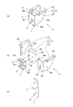
図2(a)、(b)に示すように、インターロック装置4は、インターロックピン7と、インターロックピン7に備えられる制御ピン8および操作ピン9と、インターロックピン7を支持するガイド板10と、ガイド板10が固定されるフレーム部11を備える。
図2(c)に示すように、インターロックピン7は、例えば、角棒等の棒状であり、レセプタクル6と制御プラグ5との接続を妨げない位置に設けられる。インターロックピン7は、自重により軸方向に移動可能なようにガイド板10に支持される(例えば、図2(c)中のY軸方向)。
制御ピン8は、制御プラグ5とレセプタクル6の接続を防止可能な部材である。制御ピン8は、インターロックピン7の軸に対して垂直方向に延びてインターロックピン7に備えられる(図2(c)中のX軸方向)。制御ピン8は、例えば、レセプタクル6の制御プラグ5が挿入される接続面に対して平行方向に延びて備えられる。
操作ピン9は、インターロックピン7を軸方向に移動させる部材である。操作ピン9は、インターロックピン7の軸に対して垂直方向に延びてインターロックピン7に備えられる(図2(c)中のZ軸方向)。操作ピン9は、例えば、レセプタクル6の制御プラグ5が挿入される接続面に対して垂直方向に延びて備えられる。
ガイド板10は、インターロックピン7を軸方向に移動可能に支持する部材である。例えば、図2(b)に示すように、ガイド板10は、上板10aと下板10bを備える縦断面コ字状の板である。上板10aおよび下板10bは、中板10cの上端または下端からそれぞれ略垂直方向に延びて備えられる。上板10aおよび下板10bにはそれぞれインターロックピン7の横断面と同じ形状の孔が形成され、この孔にインターロックピン7を挿通することで、ガイド板10にインターロックピン7が摺動可能に支持される。
フレーム部11は、ガイド板10が固定されるフレーム本体12と、フレーム本体12の側部にそれぞれ備えられる側部フレーム13および保護フレーム14を備える。フレーム部11は、例えば、筐体3の天井部に備えられる。
フレーム本体12は、例えば、直方体状の箱体であり、ガイド板10が取り付けられる取付板12aと、取付板12aから略垂直にそれぞれ延びて備えられる上板12bおよび一対の側板12c、12dを備える。フレーム本体12の取付板12aと対向する面には開口部が形成される。取付板12aには、ガイド板10が備えられる孔が形成され、上板12bには、フレーム本体12を筐体3の天井部に固定するための孔が形成される。また、側板12c、12dには、側部フレーム13または保護フレーム14が備えられる孔がそれぞれ形成される。
側部フレーム13は、フレーム本体12に固定される側板13aと筐体3に固定される上板13bを備える。上板13bは、側板13aの上端部から側板13aに対して略垂直方向に延びて備えられる。
保護フレーム14は、フレーム本体12に固定される保護板14aと、筐体3に固定される上板14bと、保護板14aに対して略直角な第1折曲部14cと、第1折曲部14cに対して略直角な第2折曲部14dと、を備える。保護板14aは、フレーム本体12の取付板12aの側端部から取付板12aの面に対して垂直方向に延びて備えられる。上板14bは、保護板14aの上端部から保護板14aに対して略垂直方向に延びて備えられる。第1折曲部14cは、取付板12aの側端部から延在する保護板14aの端部から、取付板12aの面に対して水平方向に折り曲げて形成される。第1折曲部14cには、上下方向に延びる長孔14eが形成され、この長孔14eを挿通して操作ピン9が備えられる。第1折曲部14cはガイド板10を覆うように延在し、その端部は側部フレーム13方向に折り曲げられ第2折曲部14dが形成される。
図2(a)に示すように、操作ピン9は、保護フレーム14に形成された長孔14eを挿通して設けられる。また、第2折曲部14dの先端部と側部フレーム13の端部との間には隙間15が形成されており、この隙間15から制御ピン8が突出して備えられる。
操作ピン9を長孔14eに沿って移動させると、インターロックピン7および制御ピン8がインターロックピン7の軸方向(上下方向)に移動する。また、操作ピン9が長孔14eの下端部に係止することで、インターロックピン7が自重によりガイド板10から落下することが防止される。
操作ピン9が長孔14eの下端部に係止している場合、インターロックピン7の下端部は、筐体3の収納部3a内に延びて支持される。これにより、遮断器本体2がインターロックピン7の下端部と係わり合うことで、遮断器本体2が接続位置に移動することが妨げられる。一方、制御ピン8はレセプタクル6の制御プラグ5が接続される接続面(すなわち、制御プラグ5の接続部)と対向する位置に延びて支持される。この状態では、制御プラグ5をレセプタクル6に接続することができない。したがって、制御プラグ5をレセプタクル6に接続する際には、操作ピン9(つまりは、制御ピン8)を持ち上げて、制御ピン8が制御プラグ5とレセプタクル6との接続を妨げない位置に移動させる必要がある。
次に、本発明の実施形態に係るスイッチギヤ1およびインターロック装置4の動作について詳細に説明する。
図1(a)に示すように、制御プラグ5がレセプタクル6に接続されていない場合、インターロックピン7は自重で落下し、操作ピン9が保護フレーム14に形成された長孔14e(図示せず)の下端部に係止される。その結果、インターロックピン7は、インターロックピン7の下端部が筐体3の収納部3a内に延びて支持され、インターロックピン7の下端部が、遮断器本体2が接続位置に移動することを妨げる位置に延びた状態となる。このように、操作ピン9が長孔14eの下端部に係止した状態では、インターロックピン7の下端部が遮断器本体2のフレームに干渉し、遮断器本体2を接続位置に移動することができない(図中矢印Aで示す)。また、操作ピン9が長孔14eの下端部に係止した状態では、制御ピン8が、レセプタクル6の接続部と対向する位置に延びて存在し、制御プラグ5の接続を妨げる(図中矢印Bで示す)。したがって、制御プラグ5をレセプタクル6に差し込む場合には、必ずインターロックピン7および制御ピン8を持ち上げる必要がある。
万が一、インターロックピン7が下がった状態で、遮断器本体2を無理に押し込んだ場合、インターロック装置4が破損するおそれがある。そこで、インターロック装置4にフレーム部11を備えることで、このフレーム部11でインターロックピン7やガイド板10の変形が抑制され、延いてはインターロック装置4の変形が抑制される。
具体的には、インターロックピン7を、上板10aと下板10b間に支持することで、インターロックピン7の変形を抑制することができる。さらに、インターロックピン7をガイド板10の中板10cに摺接させると、インターロックピン7にかかる力をガイド板10全体で受けることとなり、インターロックピン7の変形およびガイド板の変形を抑制することができる。また、ガイド板10を保護フレーム14で保護することで、ガイド板10の変形を抑制することができる。
図1(b)に示すように、保護フレーム14に形成された長孔14e(図示せず)に沿って操作ピン9を手で持ち上げると、制御ピン8が上方に移動し、制御プラグ5をレセプタクル6に差し込める状態となる。操作ピン9を持ち上げる方向を図中矢印Cで示す。レセプタクル6に制御プラグ5を差し込むと、制御プラグ5のボディに制御ピン8が乗っかり、インターロックピン7が図1(a)の状態よりも上方に保持される。この状態では、インターロックピン7の下端部が遮断器本体2が接続位置に移動することを妨げない位置に移動する。すなわち、インターロックピン7は、インターロックピン7の下端部が筐体3の収納部3a内に延びていない状態で支持される。その結果、遮断器本体2を接続位置に移動させることが可能となる(図中矢印Dで示す)。
以上のような、本発明の実施形態に係るスイッチギヤ1およびインターロック装置4は、インターロックピン7を自重で落下させる構成とするため、ばね部品を必要としない。したがって、インターロック装置4は、部品点数が少なく、簡素な構造でインターロック制御が可能なことから、リンク機構やばねを使用したインターロック装置と比較して故障を低減することができる。
また、インターロック装置4を筐体3側に備えることで、万が一インターロック装置4が故障した場合でも、容易にインターロック装置4を交換することができる。また、インターロック装置4を所定の位置に固定することで、インターロック機能を実現することができる。したがって、必要に応じて後付けでスイッチギヤにインターロック装置4を容易に追加することもできる。
以上、具体的な実施形態を示して本発明のスイッチギヤおよびインターロック装置について説明したが、本発明のスイッチギヤおよびインターロック装置は、実施形態に限定されるものではなく、その特徴を損なわない範囲で適宜設計変更が可能であり、設計変更されたものも、本発明の技術的範囲に属する。
例えば、操作ピン9は、制御ピン8の延在方向と反対側に延びて備える態様とすることもできる。また、制御ピン8を操作ピン9として用いることもできる。
また、インターロックピン7を制御ピン8として用いることもできる。この場合、制御プラグ5とレセプタクル6が接続されていないとき、インターロックピン7は、レセプタクル6の接続部と対向して支持されるとともに、インターロックピン7の下端部が筐体3の収納部3a内に延在して備えられる。また、制御プラグ5とレセプタクル6が接続されているとき、インターロックピン7の下端部は、制御プラグ5のボディに係止する。
Claims (3)
- 遮断器本体と、
前記遮断器本体が着脱可能に収納される収納部を備える筐体と、
前記遮断器本体に備えられる第1コネクタと、
前記筐体の前記収納部上方に備えられ、前記第1コネクタと電気的に接続される第2コネクタと、
前記筐体の前記収納部上方に備えられ、前記第1コネクタと前記第2コネクタが接続されていないときに、前記収納部に前記遮断器本体が移動することを防止するインターロック装置と、を備え、
前記インターロック装置は、
自重によって軸方向に移動可能に支持される棒状のインターロックピンと、
前記インターロックピンに備えられ、前記第1コネクタと前記第2コネクタの接続を防止可能な制御ピンと、を備え、
前記第1コネクタと前記第2コネクタが接続されているとき、前記制御ピンが前記第2コネクタに接続された前記第1コネクタの上部に係止し、前記インターロックピンは、前記収納部に前記遮断器本体を移動することが可能な位置に支持され、
前記第1コネクタと前記第2コネクタが接続されていないとき、前記制御ピンは前記第2コネクタの前記第1コネクタが接続される接続部と向かい合う位置に支持され、前記インターロックピンは当該インターロックピンの下端部が前記収納部内に延びるように支持される、スイッチギヤ。 - 前記インターロックピンに備えられ、前記インターロックピンの軸に対して垂直方向に延在する操作ピンと、
前記インターロックピンを軸方向に摺動可能に支持するガイド板と、
前記ガイド板が固定されるフレーム本体と、
前記インターロックピンを覆うように、前記フレーム本体に取り付けられる保護フレームと、を備え、
前記保護フレームには、前記操作ピンが挿通して備えられる長孔が形成された、請求項1に記載のスイッチギヤ。 - 遮断器本体と、前記遮断器本体が着脱可能に収納される収納部を備える筐体と、前記遮断器本体に備えられる第1コネクタと、前記筐体の前記収納部上方に備えられ、前記第1コネクタと電気的に接続される第2コネクタと、を備えるスイッチギヤに備えられ、前記第1コネクタと前記第2コネクタが接続されていないときに、前記収納部に前記遮断器本体が移動することを防止するインターロック装置であって、
自重によって軸方向に移動可能に支持される棒状のインターロックピンと、
前記インターロックピンに備えられ、前記第1コネクタと前記第2コネクタの接続を防止可能な制御ピンと、を備え、
前記第1コネクタと前記第2コネクタが接続されているとき、前記制御ピンが前記第2コネクタに接続された前記第1コネクタの上部に係止し、前記インターロックピンは、前記収納部に前記遮断器本体を移動することが可能な位置に支持され、
前記第1コネクタと前記第2コネクタが接続されていないとき、前記制御ピンは前記第2コネクタの前記第1コネクタが接続される接続部と向かい合う位置に支持され、前記インターロックピンは当該インターロックピンの下端部が前記収納部内に延びるように支持される、インターロック装置。
Priority Applications (1)
| Application Number | Priority Date | Filing Date | Title |
|---|---|---|---|
| SG11202109540XA SG11202109540XA (en) | 2019-03-11 | 2020-03-04 | Switch gear and interlock device |
Applications Claiming Priority (2)
| Application Number | Priority Date | Filing Date | Title |
|---|---|---|---|
| JP2019043322A JP7127583B2 (ja) | 2019-03-11 | 2019-03-11 | スイッチギヤおよびインターロック装置 |
| JP2019-043322 | 2019-03-11 |
Publications (1)
| Publication Number | Publication Date |
|---|---|
| WO2020184323A1 true WO2020184323A1 (ja) | 2020-09-17 |
Family
ID=72427398
Family Applications (1)
| Application Number | Title | Priority Date | Filing Date |
|---|---|---|---|
| PCT/JP2020/009064 Ceased WO2020184323A1 (ja) | 2019-03-11 | 2020-03-04 | スイッチギヤおよびインターロック装置 |
Country Status (3)
| Country | Link |
|---|---|
| JP (1) | JP7127583B2 (ja) |
| SG (1) | SG11202109540XA (ja) |
| WO (1) | WO2020184323A1 (ja) |
Citations (3)
| Publication number | Priority date | Publication date | Assignee | Title |
|---|---|---|---|---|
| JPH02290110A (ja) * | 1989-02-27 | 1990-11-30 | Fuji Electric Co Ltd | 遮断器補助回路接続器のインタロック装置 |
| JPH0442709A (ja) * | 1990-06-07 | 1992-02-13 | Fuji Electric Co Ltd | 引出形遮断器 |
| JP2007037287A (ja) * | 2005-07-27 | 2007-02-08 | Fuji Electric Systems Co Ltd | 移動形機器におけるコネクタのインターロック機構 |
Family Cites Families (2)
| Publication number | Priority date | Publication date | Assignee | Title |
|---|---|---|---|---|
| JPH07274324A (ja) * | 1994-03-29 | 1995-10-20 | Aichi Denki Seisakusho:Kk | 引出し型機器における制御回路コネクタのインタロック機構 |
| JPH10201020A (ja) * | 1997-01-10 | 1998-07-31 | Toshiba Corp | スイッチギャ収納機器 |
-
2019
- 2019-03-11 JP JP2019043322A patent/JP7127583B2/ja active Active
-
2020
- 2020-03-04 SG SG11202109540XA patent/SG11202109540XA/en unknown
- 2020-03-04 WO PCT/JP2020/009064 patent/WO2020184323A1/ja not_active Ceased
Patent Citations (3)
| Publication number | Priority date | Publication date | Assignee | Title |
|---|---|---|---|---|
| JPH02290110A (ja) * | 1989-02-27 | 1990-11-30 | Fuji Electric Co Ltd | 遮断器補助回路接続器のインタロック装置 |
| JPH0442709A (ja) * | 1990-06-07 | 1992-02-13 | Fuji Electric Co Ltd | 引出形遮断器 |
| JP2007037287A (ja) * | 2005-07-27 | 2007-02-08 | Fuji Electric Systems Co Ltd | 移動形機器におけるコネクタのインターロック機構 |
Also Published As
| Publication number | Publication date |
|---|---|
| JP7127583B2 (ja) | 2022-08-30 |
| SG11202109540XA (en) | 2021-09-29 |
| JP2020150573A (ja) | 2020-09-17 |
Similar Documents
| Publication | Publication Date | Title |
|---|---|---|
| EP3514818B1 (en) | Dc relay having auxilary contact | |
| EP2309525B1 (en) | Circuit breaker | |
| US8173916B2 (en) | Move-out type interlock apparatus for circuit breaker | |
| CN101599396B (zh) | 一种电路断路器 | |
| KR101694312B1 (ko) | 조작 장치 또는 진공 개폐기 | |
| US20180277326A1 (en) | Circuit breakers | |
| US11189994B2 (en) | Circuit breaker | |
| WO2020184323A1 (ja) | スイッチギヤおよびインターロック装置 | |
| KR101939828B1 (ko) | 진공 인터럽터 타입 기체절연 개폐장치 | |
| EP3624156B1 (en) | Improved contactor device structure with improved auxiliary switch | |
| CN113905547B (zh) | 包括断路器和插头的电气装置 | |
| JP5090276B2 (ja) | 開閉装置 | |
| WO2013145058A1 (ja) | 電池ユニット盤のインターロック装置 | |
| KR20110131753A (ko) | 회로차단기 | |
| EP0322986B1 (en) | Switch, in particular for use as automatic switch | |
| EP4105958B1 (en) | Circuit breaker | |
| KR101793549B1 (ko) | 진공 차단기의 인터록 장치 | |
| KR20020045251A (ko) | 배선용 차단기의 가동자 연결 장치 | |
| CN223427439U (zh) | 断路器及电气控制柜 | |
| KR101045465B1 (ko) | 회로차단기 | |
| CN218482147U (zh) | 真空接触器 | |
| KR101026579B1 (ko) | 회로 차단기 | |
| HK40082557B (en) | Circuit breaker | |
| JPWO2019021385A1 (ja) | 遮断器 | |
| JPH0136214B2 (ja) |
Legal Events
| Date | Code | Title | Description |
|---|---|---|---|
| 121 | Ep: the epo has been informed by wipo that ep was designated in this application |
Ref document number: 20770921 Country of ref document: EP Kind code of ref document: A1 |
|
| NENP | Non-entry into the national phase |
Ref country code: DE |
|
| 122 | Ep: pct application non-entry in european phase |
Ref document number: 20770921 Country of ref document: EP Kind code of ref document: A1 |