WO2020184066A1 - 関節位置推定装置、関節位置推定方法およびコンピュータ読み取り可能な記録媒体 - Google Patents
関節位置推定装置、関節位置推定方法およびコンピュータ読み取り可能な記録媒体 Download PDFInfo
- Publication number
- WO2020184066A1 WO2020184066A1 PCT/JP2020/005836 JP2020005836W WO2020184066A1 WO 2020184066 A1 WO2020184066 A1 WO 2020184066A1 JP 2020005836 W JP2020005836 W JP 2020005836W WO 2020184066 A1 WO2020184066 A1 WO 2020184066A1
- Authority
- WO
- WIPO (PCT)
- Prior art keywords
- image data
- joint position
- human body
- area
- body part
- Prior art date
- Legal status (The legal status is an assumption and is not a legal conclusion. Google has not performed a legal analysis and makes no representation as to the accuracy of the status listed.)
- Ceased
Links
Images




Classifications
-
- G—PHYSICS
- G06—COMPUTING OR CALCULATING; COUNTING
- G06T—IMAGE DATA PROCESSING OR GENERATION, IN GENERAL
- G06T7/00—Image analysis
-
- G—PHYSICS
- G06—COMPUTING OR CALCULATING; COUNTING
- G06T—IMAGE DATA PROCESSING OR GENERATION, IN GENERAL
- G06T7/00—Image analysis
- G06T7/70—Determining position or orientation of objects or cameras
Definitions
- the present invention relates to a joint position estimation device and a joint position estimation method for estimating joint positions from image data, and further to a computer-readable recording medium that stores a program for realizing these.
- Non-Patent Document 1 discloses a technique of estimating the joint position of a person and estimating the posture of the person.
- a human body part of a person is estimated from a depth image, and the joint position is estimated by a joint position estimator using the estimation result.
- Non-Patent Document 1 there is a problem that the estimation accuracy of the joint position is lowered unless the human body part is estimated accurately.
- An example of an object of the present invention is to provide a joint position estimation device, a joint position estimation method, and a computer-readable recording medium capable of accurately estimating a joint position.
- the joint position estimation device in one aspect of the present invention is used.
- the image data acquisition unit that acquires image data and An estimation unit that estimates a human body part from the image data acquired by the image data acquisition unit, and an estimation unit.
- the estimation unit estimates a plurality of human body parts
- a marking unit that marks one or a plurality of pixels for each of the region of the human body part estimated by the estimation unit and the region other than the region of the human body part.
- a watershed algorithm is applied to the image data after marking by the marking unit to divide the area in the image data into a plurality of divided units.
- a calculation unit that calculates the joint position from two regions corresponding to the human body part adjacent to the joint among the regions divided by the division portion. To be equipped.
- the joint position estimation method in one aspect of the present invention is: Steps to get image data and A step of estimating a human body part based on the image data, When a plurality of human body parts are estimated based on the image data, one or a plurality of pixels are marked for each of the estimated human body part region and the region other than the human body part region. A step of applying the watershed algorithm to the image data after marking to divide the area in the image data into a plurality of areas, and A step of calculating the joint position from two regions corresponding to the human body part adjacent to the joint among the divided regions, and To be equipped.
- the computer-readable recording medium in one aspect of the present invention is used in a computer for acquiring image data.
- a step of estimating a human body part based on the image data When a plurality of human body parts are estimated, a step of marking one or a plurality of pixels for each of the estimated human body part area and the area other than the human body part area, and A step of applying the watershed algorithm to the image data after marking to divide the area in the image data into a plurality of areas, and A step of calculating the joint position from two regions corresponding to the human body part adjacent to the joint among the divided regions, and
- the program is recorded, including the instruction to execute.
- the joint position can be estimated accurately.
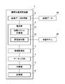
- FIG. 1 is a block diagram showing a schematic configuration of the joint position estimation device according to the first embodiment.
- FIG. 2 is a block diagram specifically showing the configuration of the joint position estimation device.
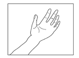
- FIG. 3 is a diagram showing an example of image data.
- FIG. 4 is a diagram showing a feature amount obtained by the feature vector calculation unit.
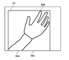
- FIG. 5 is a diagram showing a region set for the estimation result by the estimation unit shown in FIG.
- FIG. 6 is a diagram showing a marking result by the marking unit.
- FIG. 7 is a diagram showing the result of region division by the division portion.
- FIG. 8 is a diagram for explaining a calculation method by the calculation unit.
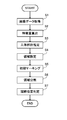
- FIG. 9 is a flow chart showing the operation of the joint position estimation device.
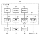
- FIG. 10 is a block diagram showing an example of a computer that realizes the joint position estimation device according to the embodiment.
- FIG. 1 is a block diagram showing a schematic configuration of the joint position estimation device 1 according to the first embodiment.
- the joint position estimation device 1 is a device that estimates parts of the human body (for example, palm and forearm) from image data and calculates the position of joints from the estimated human body parts.
- the joint position estimation device 1 includes an image data acquisition unit 2, an estimation unit 3, a marking unit 4, a division unit 5, and a calculation unit 6.
- the image data acquisition unit 2 acquires image data.
- the estimation unit 3 estimates the human body part from the image data acquired by the image data acquisition unit 2.
- the marking unit 4 has one or a plurality of pixels for each of the region of the human body part estimated by the estimation unit 3 and the region other than the region of the human body part. Mark.
- the division unit 5 applies the watershed algorithm to the image data after marking by the marking unit 4 to divide the area in the image data into a plurality of areas.
- the calculation unit 6 calculates the joint position from two regions corresponding to the human body part adjacent to the joint among the regions divided by the division unit 5.
- the estimation result of the human body part is marked and the watershed algorithm is applied. Therefore, marking can be performed with high accuracy, and by applying the watershed algorithm with the result as an input, it is possible to accurately divide the area of the image data. As a result, the region of the human body adjacent to the joint can be estimated accurately, so that a highly reliable calculation result of the joint (wrist) position can be obtained.
- FIG. 2 is a block diagram specifically showing the configuration of the joint position estimation device 1.
- the joint position estimation device 1 includes an area setting unit 7 in addition to the image data acquisition unit 2, the estimation unit 3, the marking unit 4, the division unit 5, and the calculation unit 6 described above.
- the image data acquisition unit 2 acquires the image data 50.
- the image data acquisition unit 2 may acquire the image data 50 via a network such as a wired or wireless LAN (Local Area Network), or may acquire the image data 50 by short-range wireless communication or the like.
- an image pickup device may be directly connected to the joint position estimation device 1, or the joint position estimation device 1 may include an image pickup device, and the image data acquisition unit 2 may acquire image data 50 from the image pickup device.
- FIG. 3 is a diagram showing an example of image data 50.
- the image data 50 is an image captured from the forearm to the finger of the human body.
- the image data 50 in this embodiment is image data to which a depth for each pixel is added (hereinafter, referred to as a TOF image).
- the TOF image is an image in which information (depth information) indicating the distance from the imaging device to the imaging target is associated with each pixel.
- the image data 50 is not limited to the TOF image, and may be a two-dimensional image.
- the image data 50 may be an image in which the entire image of a person is captured.
- the image data acquisition unit 2 may estimate a portion including a joint (for example, the entire hand) from an image in which the entire image of the person is captured, and extract image data of that portion. Then, the subsequent processing may be performed on the extracted image data.
- the estimation unit 3 estimates the type of human body part (forearm, finger, etc.) shown in the image data 50.
- the estimation unit 3 has a feature vector calculation unit 31 and an estimation execution unit 32.
- the feature vector calculation unit 31 obtains a feature amount (feature vector) for each pixel of the image data 50.
- FIG. 4 is a diagram showing a feature amount obtained by the feature vector calculation unit 31. As shown in FIG. 4, the feature vector calculation unit 31 obtains each feature amount 51, 52, 53, 54.
- the estimation execution unit 32 performs machine learning using a neural network or the like, and uses the learning model 60 to estimate the type of the object shown in the image data 50 from the feature amount obtained by the feature vector calculation unit 31. In the case of FIG. 4, the estimation execution unit 32 estimates that the feature amount 51 is the feature amount of the forearm, the feature amount 52 is the feature amount of the palm, and the feature amount 53 is the feature amount of the finger.
- the estimation execution unit 32 estimates that the feature amount 54 is a feature amount of an object reflected in the background other than the human body part.
- the human body part shown in FIG. 3 is shown by a broken line in order to understand the feature amount obtained by the feature vector calculation unit 31.
- the estimation accuracy of the human body part by the estimation unit 3 becomes high.
- the feature vector calculation unit 31 can accurately obtain the feature amount by using the depth information for each pixel even if the joints are in a bent posture. Can be done. As a result, the estimation accuracy of the human body part by the estimation execution unit 32 becomes high.
- the area setting unit 7 sets an area including the forearm and the palm, which are the human body parts adjacent to the joints, among the human body parts estimated by the estimation unit 3.
- FIG. 5 is a diagram showing a region 55 set for the estimation result by the estimation unit 3 shown in FIG.
- the region 55 includes the finger feature 53, but at least the forearm feature 51 adjacent to the joint (wrist) and the palm feature 52 may be included.
- FIG. 6 is a diagram showing a marking result by the marking unit 4.
- the marking portion 4 initially marks the human body part (forearm, palm) adjacent to the joint (wrist) and the area other than the human body part (background) in the area 55.
- the marking 56 shown in FIG. 6 is an initial marking set for the feature amount 51 of the forearm.
- the marking 57 is an initial marking set for the feature amount 52 of the palm.
- the marking 58 indicates an initial marking set for the background area.
- the marking portion 4 When the marking portion 4 initially marks the feature amount 51 of the forearm and the feature amount 52 of the palm, noise affects when it is close to the boundary with other regions. Therefore, in order to prevent the influence of noise, each feature is used. Mark the center of the area of quantity. Further, when initial marking is performed on the background area, the marking portion 4 marks a position outside a certain distance range from the markings 56 and 57.
- the marking unit 4 may mark only one pixel, but in the watershed algorithm described later, if the change in the depth value of the TOF image is not smooth, the marked area may not be widened. Therefore, it is preferable that the marking unit 4 marks a plurality of pixels.
- the division unit 5 applies the watershed algorithm that inputs the markings 56, 57, and 58 set by the marking unit 4, and divides the area 55 set by the area setting unit 7 into a plurality of areas.
- the markings 56, 57, and 58 are set as the minimum value (or maximum value) of the pixel value (depth value), and the point where the maximum value (or minimum value) of the pixel value is obtained while expanding the area is obtained.
- the area where the pixel values (depth values) are close to each other is defined as one area with the point at which the maximum value is the boundary.
- FIG. 7 is a diagram showing the result of region division by the division unit 5.
- the region 55 is divided into a forearm region 59A, a palm region 59B, and a background region 59C.
- the watershed algorithm is not necessarily divided into the same number of regions as the number of markings, and may be divided into four or more regions in FIG. 7. Further, although the division portion 5 expands the marked area using the depth value, the luminance value or the like may be used as long as it is the information of each pixel of the image data 50.
- the calculation unit 6 calculates the joint position from the two regions 59A and 59B corresponding to the human body part among the regions divided by the division unit 5.
- FIG. 8 is a diagram for explaining a calculation method by the calculation unit 6.
- the calculation unit 6 performs labeling processing on each of the areas 59A and 59B, and acquires the contour of each area.
- the contour is shown schematically.
- the calculation unit 6 obtains the coordinate positions 59A1 and 59B1 closest to each other in the two areas 59A and 59B.
- the calculation unit 6 calculates a region 59D including the shortest straight line L connecting the coordinate positions 59A1 and 59B1 to obtain the joint position.
- the calculation unit 6 may use the overlapping portion as the joint position.
- FIG. 9 is a flow chart showing the operation of the joint position estimation device 1.
- FIGS. 1 to 8 will be referred to as appropriate.
- the joint position estimation method is carried out by operating the joint position estimation device. Therefore, the description of the joint position estimation method in the present embodiment is replaced with the following operation description of the joint position estimation device.
- the human body part including the joint is imaged by the image pickup device and the image data is input to the joint position estimation device 1.
- the image data acquisition unit 2 acquires the input image data (S1).
- the feature vector calculation unit 31 of the estimation unit 3 obtains the feature amounts 51 to 54 (see FIG. 4) for each pixel of the image data 50 (S2).
- the estimation execution unit 32 of the estimation unit 3 recognizes the type of the object having the feature amount from the feature amount obtained by the feature vector calculation unit 31, and estimates the human body part in the image data 50 (S3).
- the region setting unit 7 sets a region 55 (see FIG. 5) adjacent to the joint whose position is to be estimated and which includes the human body part estimated by the estimation unit 3 (S4).
- the marking unit 4 makes initial markings in the area 55 set by the area setting unit 7 (S5).
- the marking portion 4 provides a marking 56 for the forearm (see FIG. 6) adjacent to the joint (wrist) to be estimated for position, a marking 57 for the palm, and a marking 58 for an area (background) other than the human body part.
- the division unit 5 applies a watershed algorithm that inputs markings 56, 57, and 58 to divide the area 55 set in S4 into a plurality of areas 59A, 59B, and 59C (see FIG. 7) (S6). Then, the calculation unit 6 calculates the joint position from the two regions 59A and 59B corresponding to the human body portion among the regions divided by the division unit 5 (S7).
- the human body part is estimated from the image data 50, and the estimation result is initially marked. Therefore, in the image data 50, even if the target area to be marked, for example, the shape of the forearm or the palm is a complicated shape, the initial marking can be performed accurately.
- the estimation accuracy of the two regions of the forearm and the palm, which are the regions adjacent to the joint is improved. If one area of the forearm or palm cannot be clearly determined, the position of the joint (wrist) between the two areas cannot be calculated accurately, but by estimating the two areas accurately, a highly reliable joint can be calculated. The calculation result of the position of (wrist) can be obtained.
- the position of the joint for example, the wrist
- it can be applied to a device that recognizes a gesture of moving a hand.
- the program according to the embodiment of the present invention may be any program that causes a computer to execute steps S1 to S7 shown in FIG. By installing this program on a computer and executing it, the joint position estimation device and the joint position estimation method according to the present embodiment can be realized.
- the computer processor functions as an image data acquisition unit 2, an estimation unit 3, a marking unit 4, a division unit 5, and a calculation unit 6 to perform processing.
- the image data acquisition unit 2, the estimation unit 3, the marking unit 4, the division unit 5, and the calculation unit 6 store the data files constituting them in a storage device such as a hard disk provided in the computer. This is achieved by doing so or by mounting the recording medium in which this data file is stored in a reader connected to a computer.
- each computer may function as any of the image data acquisition unit 2, the estimation unit 3, the marking unit 4, the division unit 5, and the calculation unit 6, respectively.
- FIG. 10 is a block diagram showing an example of a computer that realizes the joint position estimation device 1 according to the present embodiment.
- the computer 110 includes a CPU 111, a main memory 112, a storage device 113, an input interface 114, a display controller 115, a data reader / writer 116, and a communication interface 117. These respective units are connected to each other via a bus 121 so as to be capable of data communication.
- the computer 110 may include a GPU (Graphics Processing Unit) or an FPGA (Field-Programmable Gate Array) in addition to the CPU 111 or in place of the CPU 111.
- the CPU 111 expands the programs (codes) of the present embodiment stored in the storage device 113 into the main memory 112 and executes them in a predetermined order to perform various operations.
- the main memory 112 is typically a volatile storage device such as a DRAM (Dynamic Random Access Memory).
- the program in the present embodiment is provided in a state of being stored in a computer-readable recording medium 120.
- the program in this embodiment may be distributed on the Internet connected via the communication interface 117.
- the storage device 113 include a semiconductor storage device such as a flash memory in addition to a hard disk drive.
- the input interface 114 mediates data transmission between the CPU 111 and an input device 118 such as a keyboard and mouse.
- the display controller 115 is connected to the display device 119 and controls the display on the display device 119.
- the data reader / writer 116 mediates the data transmission between the CPU 111 and the recording medium 120, reads the program from the recording medium 120, and writes the processing result in the computer 110 to the recording medium 120.
- the communication interface 117 mediates data transmission between the CPU 111 and another computer.
- the recording medium 120 include a general-purpose semiconductor storage device such as CF (CompactFlash (registered trademark)) and SD (SecureDigital), a magnetic recording medium such as a flexible disk, or a CD-.
- CF CompactFlash (registered trademark)
- SD Secure Digital
- magnetic recording medium such as a flexible disk
- CD- CompactDiskReadOnlyMemory
- optical recording media such as ROM (CompactDiskReadOnlyMemory).
- the joint position estimation device 1 in the present embodiment can also be realized by using the hardware corresponding to each part instead of the computer in which the program is installed. Further, the joint position estimation device 1 may be partially realized by a program and the rest may be realized by hardware.
- the image data acquisition unit that acquires image data and An estimation unit that estimates a human body part from the image data acquired by the image data acquisition unit, and an estimation unit.
- the estimation unit estimates a plurality of human body parts
- a marking unit that marks one or a plurality of pixels for each of the region of the human body part estimated by the estimation unit and the region other than the region of the human body part.
- a watershed algorithm is applied to the image data after marking by the marking unit to divide the area in the image data into a plurality of divided units.
- a calculation unit that calculates the joint position from two regions corresponding to the human body part adjacent to the joint among the regions divided by the division portion.
- a joint position estimation device is
- Appendix 2 The joint position estimation device according to Appendix 1.
- An area setting unit that sets an area adjacent to a joint that includes a human body part estimated by the estimation unit, With more The marking unit marks within the area set by the area setting unit.
- the division unit divides the area set by the area setting unit into a plurality of areas. Joint position estimation device.
- Appendix 3 The joint position estimation device according to Appendix 1 or Appendix 2.
- the image data is image data to which a depth for each pixel is added. Joint position estimation device.
- the joint position estimation device according to any one of Supplementary note 1 to Supplementary note 3.
- the dividing portion divides the region into a plurality of regions, with the pixels marked by the marking portion and the pixels whose pixel values are within a predetermined range of the pixels as the same region. Joint position estimation device.
- Step 6 Steps to get image data and Steps to estimate the human body part from the acquired image data, When a plurality of human body parts are estimated, a step of marking one or a plurality of pixels for each of the estimated human body part area and the area other than the human body part area, and A step of applying the watershed algorithm to the image data after marking to divide the area in the image data into a plurality of areas, and A step of calculating the joint position from two regions corresponding to the human body part adjacent to the joint among the divided regions, and A method for estimating joint position.
- Appendix 7 The joint position estimation method described in Appendix 6 Steps to set the area adjacent to the joint and containing the estimated human body part, With more In the step of marking one or more pixels, marking is performed within the set area. In the step of dividing the area in the image data into a plurality of areas, the set area is divided into a plurality of areas. Joint position estimation method.
- Appendix 8 The joint position estimation method according to Appendix 6 or Appendix 7.
- the image data is image data to which a depth for each pixel is added. Joint position estimation method.
- Appendix 12 The computer-readable recording medium according to Appendix 11.
- the program On the computer Steps to set the area adjacent to the joint and containing the estimated human body part, Including additional instructions to execute In the step of marking one or more pixels, marking is performed within a set area. In the step of dividing the area in the image data into a plurality of areas, the set area is divided into a plurality of areas.
- a computer-readable recording medium In the step of dividing the area in the image data into a plurality of areas, the set area is divided into a plurality of areas.
- Appendix 13 A computer-readable recording medium according to Appendix 11 or Appendix 12.
- the image data is image data to which a depth for each pixel is added.
- a computer-readable recording medium A computer-readable recording medium.
- the present invention can accurately estimate the joint position.
- Joint position estimation device 2 Image data acquisition unit 3: Estimate unit 4: Marking unit 5: Division unit 6: Calculation unit 7: Area setting unit 31: Feature vector calculation unit 32: Estimation execution unit 50: Image data 60: Learning models 51, 52, 53, 54: Feature 55: Areas 56, 57, 58: Marking
Landscapes
- Engineering & Computer Science (AREA)
- Computer Vision & Pattern Recognition (AREA)
- Physics & Mathematics (AREA)
- General Physics & Mathematics (AREA)
- Theoretical Computer Science (AREA)
- Image Analysis (AREA)
Abstract
関節位置判定装置1は、画像データを取得する画像データ取得部2と、取得した画像データから人体部位を推定する推定部3と、推定部3が推定した人体部位の領域、および、人体部位の領域以外の領域それぞれに対して、一または複数の画素にマーキングするマーキング部4と、マーキング部4によるマーキング後の画像データに対して、分水嶺アルゴリズムを適用して、画像データ内の領域を複数に分割する分割部5と、分割部5が分割した領域のうち、関節に隣接する人体部位に対応する2つの領域から、関節位置を計算する計算部6と、を備える。
Description
本発明は、画像データから関節位置を推定する関節位置推定装置および関節位置推定方法に関し、さらには、これらを実現するためのプログラムを記憶したコンピュータ読み取り可能な記録媒体に関する。
従来、人物を撮像装置で撮像し、その人物の姿勢、人物が行う動作(ジェスチャなど)を推定する様々な技術が提案されている。例えば、非特許文献1には、人物の関節位置を推定して、人物の姿勢を推定する技術が開示されている。非特許文献1では、深度画像から人物の人体部位を推定し、その推定結果を用いて関節位置推定器により関節位置を推定している。
高橋龍平、"特別研究報告書 CNNによる深度画像を用いた視点不変な人物姿勢推定"、平成30年2月8日、インターネット<URL:http://www.mm.media.kyoto-u.ac.jp/wp-content/uploads/2018/02/2017-b-takahashi.pdf>
しかしながら、非特許文献1では、人体部位の推定を精度よく行わないと、関節位置の推定精度が低下するという問題点があった。
本発明の目的の一例は、関節位置を精度よく推定できる、関節位置推定装置、関節位置推定方法およびコンピュータ読み取り可能な記録媒体を提供することにある。
上記目的を達成するため、本発明の一側面における関節位置推定装置は、
画像データを取得する画像データ取得部と、
前記画像データ取得部が取得した画像データから人体部位を推定する推定部と、
前記推定部が複数の人体部位を推定した場合、前記推定部が推定した人体部位の領域、および、前記人体部位の領域以外の領域それぞれに対して、一または複数の画素にマーキングするマーキング部と、
前記マーキング部によるマーキング後の画像データに対して、分水嶺アルゴリズムを適用して、前記画像データ内の領域を複数に分割する分割部と、
前記分割部が分割した領域のうち、関節に隣接する人体部位に対応する2つの領域から、関節位置を計算する計算部と、
を備える。
画像データを取得する画像データ取得部と、
前記画像データ取得部が取得した画像データから人体部位を推定する推定部と、
前記推定部が複数の人体部位を推定した場合、前記推定部が推定した人体部位の領域、および、前記人体部位の領域以外の領域それぞれに対して、一または複数の画素にマーキングするマーキング部と、
前記マーキング部によるマーキング後の画像データに対して、分水嶺アルゴリズムを適用して、前記画像データ内の領域を複数に分割する分割部と、
前記分割部が分割した領域のうち、関節に隣接する人体部位に対応する2つの領域から、関節位置を計算する計算部と、
を備える。
また、上記目的を達成するため、本発明の一側面における関節位置推定方法は、
画像データを取得するステップと、
前記画像データに対して、人体部位を推定するステップと、
前記画像データに対して複数の人体部位を推定した場合、推定した人体部位の領域、および、前記人体部位の領域以外の領域それぞれに対して、一または複数の画素にマーキングするステップと、
マーキング後の画像データに対して、分水嶺アルゴリズムを適用して、前記画像データ内の領域を複数に分割するステップと、
分割した領域のうち、関節に隣接する人体部位に対応する2つの領域から、関節位置を計算するステップと、
を備える。
画像データを取得するステップと、
前記画像データに対して、人体部位を推定するステップと、
前記画像データに対して複数の人体部位を推定した場合、推定した人体部位の領域、および、前記人体部位の領域以外の領域それぞれに対して、一または複数の画素にマーキングするステップと、
マーキング後の画像データに対して、分水嶺アルゴリズムを適用して、前記画像データ内の領域を複数に分割するステップと、
分割した領域のうち、関節に隣接する人体部位に対応する2つの領域から、関節位置を計算するステップと、
を備える。
更に、上記目的を達成するため、本発明の一側面におけるコンピュータ読み取り可能な記録媒体は、画像データを取得するコンピュータに、
前記画像データに対して、人体部位を推定するステップと、
複数の人体部位を推定した場合、推定した人体部位の領域、および、前記人体部位の領域以外の領域それぞれに対して、一または複数の画素にマーキングするステップと、
マーキング後の画像データに対して、分水嶺アルゴリズムを適用して、前記画像データ内の領域を複数に分割するステップと、
分割した領域のうち、関節に隣接する人体部位に対応する2つの領域から、関節位置を計算するステップと、
を実行させる命令を含む、プログラムを記録している。
前記画像データに対して、人体部位を推定するステップと、
複数の人体部位を推定した場合、推定した人体部位の領域、および、前記人体部位の領域以外の領域それぞれに対して、一または複数の画素にマーキングするステップと、
マーキング後の画像データに対して、分水嶺アルゴリズムを適用して、前記画像データ内の領域を複数に分割するステップと、
分割した領域のうち、関節に隣接する人体部位に対応する2つの領域から、関節位置を計算するステップと、
を実行させる命令を含む、プログラムを記録している。
以上のように本発明によれば、関節位置を精度よく推定できる。
以下、本発明における一実施形態の関節位置推定装置および関節位置推定方法について、図1~図10を参照しながら説明する。
[装置構成]
図1は、実施形態1における関節位置推定装置1の概略構成を示すブロック図である。
図1は、実施形態1における関節位置推定装置1の概略構成を示すブロック図である。
関節位置推定装置1は、画像データから、人体の部位(例えば手のひらと前腕など)を推定して、推定した人体部位から関節の位置を計算する装置である。この関節位置推定装置1は、画像データ取得部2、推定部3、マーキング部4、分割部5、および計算部6を備えている。
画像データ取得部2は画像データを取得する。
推定部3は、画像データ取得部2が取得した画像データから人体部位を推定する。
マーキング部4は、推定部3が複数の人体部位を推定した場合、推定部3が推定した人体部位の領域、および、その人体部位の領域以外の領域それぞれに対して、一または複数の画素にマーキングする。
分割部5は、マーキング部4によるマーキング後の画像データに対して、分水嶺アルゴリズムを適用して、画像データ内の領域を複数に分割する。
計算部6は、分割部5が分割した領域のうち、関節に隣接する人体部位に対応する2つの領域から、関節位置を計算する。
このように、本実施形態においては、人体部位の推定した結果に対してマーキングをし、分水嶺アルゴリズムを適用している。このため、マーキングを精度よく行うことができ、その結果を入力として、分水嶺アルゴリズムを適用することで、画像データの領域分割を精度よく行える。その結果、関節に隣接する人体部位の領域も精度よく推定できるため、信頼度の高い、関節(手首)の位置の計算結果が得られる。
続いて、図2を参照して、本実施形態における関節位置推定装置1の構成をより具体的に説明する。図2は、関節位置推定装置1の構成を具体的に示すブロック図である。
関節位置推定装置1は、上記した画像データ取得部2、推定部3、マーキング部4、分割部5、および計算部6に加え、領域設定部7を備えている。
画像データ取得部2は画像データ50を取得する。画像データ取得部2は、有線または無線LAN(Local Area Network)等のネットワークを介して、画像データ50を取得してもよいし、近距離無線通信などにより画像データ50を取得してもよい。また、関節位置推定装置1には撮像装置が直接接続され、または、関節位置推定装置1は撮像装置を備え、画像データ取得部2は、その撮像装置から画像データ50を取得してもよい。
図3は、画像データ50の一例を示す図である。画像データ50は、人体の前腕から指にかけて撮像された画像である。本実施形態における画像データ50は、画素毎の深度が付加された画像データ(以下、TOF画像と言う)である。TOF画像は、撮像装置から撮像対象までの距離を示す情報(深度情報)が各画素に対応づけられた画像である。なお、画像データ50は、TOF画像に限定されるものではなく、2次元画像であってもよい。
また、画像データ50は、人物の全体像が撮像された画像であってもよい。この場合、例えば画像データ取得部2が、人物の全体像が撮像された画像から関節を含む部位(例えば、手全体)を推定して、その部位の画像データを抽出するようにしてもよい。そして、以降の処理は、抽出した画像データに対して行われるようにしてもよい。
推定部3は、画像データ50に写っている人体部位の種別(前腕、指など)を推定する。推定部3は、特徴ベクトル計算部31と、推定実行部32とを有している。
特徴ベクトル計算部31は、画像データ50の画素ごとに特徴量(特徴ベクトル)を求める。図4は、特徴ベクトル計算部31が求めた特徴量を示す図である。図4に示すように、特徴ベクトル計算部31は、各特徴量51、52、53、54を求める。推定実行部32は、ニューラルネットワークなどによる機械学習を行い、その学習モデル60を用いて、特徴ベクトル計算部31が求めた特徴量から、画像データ50に写っている物体の種別を推定する。図4の場合、推定実行部32は、特徴量51は前腕の特徴量であり、特徴量52は手のひらの特徴量であり、特徴量53は指の特徴量であると推定する。また、推定実行部32は、特徴量54は、人体部位以外であり、背景に写った物体の特徴量であると推定する。なお、図4では、特徴ベクトル計算部31が求めた特徴量の理解のために、図3で示す人体部位を破線で示している。
なお、画像データ50がTOF画像であることにより、推定部3での人体部位の推定精度は高くなる。例えば、画像データ50が関節を含む画像である場合、関節が曲げられた姿勢であっても、特徴ベクトル計算部31は、画素ごとの深度情報を利用することで、特徴量を精度よく求めることができる。その結果、推定実行部32による人体部位の推定精度は高くなる。
領域設定部7は、推定部3が推定した人体部位のうち、関節に隣接する人体部位である前腕および手のひらを包含する領域を設定する。図5は、図4に示す推定部3による推定結果に対して設定した領域55を示す図である。図5では、領域55は、指の特徴量53を包含しているが、少なくとも、関節(手首)に隣接する前腕の特徴量51、および手のひらの特徴量52を包含していればよい。領域55を設定することで、以降の処理において、不要な領域に対して処理が行われないようにできる。
マーキング部4は、領域設定部7が設定した領域55内の一または複数の画素をマーキングする。図6は、マーキング部4によるマーキング結果を示す図である。マーキング部4は、領域55内において、関節(手首)に隣接する人体部位(前腕、手のひら)と、人体部位以外の領域(背景)に対して初期マーキングする。図6に示すマーキング56は、前腕の特徴量51に対して設定した初期マーキングである。マーキング57は、手のひらの特徴量52に対して設定した初期マーキングである。マーキング58は、背景の領域に対して設定した初期マーキングを示す。
マーキング部4は、前腕の特徴量51、および、手のひらの特徴量52に対して初期マーキングする場合、他の領域との境界に近いとノイズが影響するため、ノイズの影響を防ぐために、各特徴量の領域の中心部をマーキングする。また、マーキング部4は、背景の領域に対して初期マーキングする場合、マーキング56、57より一定距離範囲外の位置にマーキングする。なお、マーキング部4は、一画素のみをマーキングしてもよいが、後述する分水嶺アルゴリズムにおいて、TOF画像の深度値の変化が滑らかではない場合、マーキングした領域が広がらないことがある。したがって、マーキング部4は、複数の画素をマーキングすることが好ましい。
分割部5は、マーキング部4が設定したマーキング56、57、58を入力とする分水嶺アルゴリズムを適用して、領域設定部7が設定した領域55を複数の領域に分割する。分水嶺アルゴリズムでは、マーキング56、57、58を、画素値(深度値)の極小値(または極大値)として、領域を広げつつ画素値の極大値(または極小値)となる点を求めていく。その極大値となる点を境界として、画素値(深度値)が近い領域を一つの領域とする。図7は、分割部5による領域分割結果を示す図である。図7では、領域55は、前腕領域59Aと、手のひら領域59Bと、背景領域59Cとに分割されている。
なお、分水嶺アルゴリズムでは、必ずしもマーキング数と同じ数の領域に分割されるわけではなく、図7において、4つ以上の領域に分割される場合もある。また、分割部5は、深度値を用いてマーキングした領域を広げているが、画像データ50の各画素の情報であれば、輝度値などを用いてもよい。
計算部6は、分割部5が分割した領域のうち、人体部位に対応する2つの領域59A、59Bから、関節位置を計算する。図8は、計算部6による計算方法を説明するための図である。計算部6は、領域59A、59Bそれぞれに対してラベリング処理を行い、各領域の輪郭を取得する。図8では、輪郭は概略的に示している。図8に示すように、領域59Aと、領域59Bとが離れている場合、計算部6は、2つの領域59A、59Bにおいて、互いに最も近くなる座標位置59A1、59B1を求める。計算部6は、座標位置59A1、59B1を繋ぐ最短直線Lを包含する領域59Dを計算して、関節位置とする。なお、2つの領域59A、59Bの輪郭が重なる場合、計算部6は、重なり部分を関節位置としてもよい。
[動作説明]
次に、本実施形態における関節位置判定装置の動作について図9を用いて説明する。図9は、関節位置推定装置1による動作を示すフロー図である。以下の説明においては、適宜図1~図8を参酌する。また、本実施形態では、関節位置推定装置を動作させることによって、関節位置推定法が実施される。よって、本実施形態における関節位置推定方法の説明は、以下の関節位置推定装置の動作説明に代える。
次に、本実施形態における関節位置判定装置の動作について図9を用いて説明する。図9は、関節位置推定装置1による動作を示すフロー図である。以下の説明においては、適宜図1~図8を参酌する。また、本実施形態では、関節位置推定装置を動作させることによって、関節位置推定法が実施される。よって、本実施形態における関節位置推定方法の説明は、以下の関節位置推定装置の動作説明に代える。
まず、前提として、撮像装置で関節を含む人体部位が撮像され、その画像データが関節位置推定装置1に入力されるものとする。
上述の前提において、画像データ取得部2は入力された画像データを取得する(S1)。次に、推定部3の特徴ベクトル計算部31は、画像データ50の画素ごとに特徴量51~54(図4参照)を求める(S2)。そして、推定部3の推定実行部32は、特徴ベクトル計算部31が求めた特徴量から、その特徴量をもつ物体の種別を認識し、画像データ50内における人体部位を推定する(S3)。
続いて、領域設定部7は、位置推定対象の関節に隣接する、推定部3が推定した人体部位を包含する領域55(図5参照)を設定する(S4)。マーキング部4は、領域設定部7が設定した領域55内において、初期マーキングする(S5)。S5では、マーキング部4は、位置推定対象の関節(手首)に隣接する前腕のマーキング56(図6参照)、および、手のひらのマーキング57と、人体部位以外の領域(背景)のマーキング58とを設定する。
分割部5は、マーキング56、57、58を入力とする分水嶺アルゴリズムを適用して、S4で設定した領域55を複数の領域59A、59B、59C(図7参照)に分割する(S6)。そして、計算部6は、分割部5が分割した領域のうち、人体部位に対応する2つの領域59A、59Bから、関節位置を計算する(S7)。
[本実施形態による効果]
以上のように本実施形態によれば、画像データ50から人体部位を推定し、推定結果に対して初期マーキングしている。このため、画像データ50において、マーキングする対象領域、例えば前腕または手のひらの形状が、複雑な形状であっても、初期マーキングを精度よく行える。その初期マーキングを入力として、分水嶺アルゴリズムを利用することで、関節に隣接する部位である、前腕および手のひらの2つの領域の推定精度は高くなる。前腕または手のひらの一方の領域が明確に判断できないと、2つの領域の間にある関節(手首)の位置を精度よく計算できないが、2つの領域を精度よく推定することで、信頼度の高い関節(手首)の位置の計算結果を得ることができる。
以上のように本実施形態によれば、画像データ50から人体部位を推定し、推定結果に対して初期マーキングしている。このため、画像データ50において、マーキングする対象領域、例えば前腕または手のひらの形状が、複雑な形状であっても、初期マーキングを精度よく行える。その初期マーキングを入力として、分水嶺アルゴリズムを利用することで、関節に隣接する部位である、前腕および手のひらの2つの領域の推定精度は高くなる。前腕または手のひらの一方の領域が明確に判断できないと、2つの領域の間にある関節(手首)の位置を精度よく計算できないが、2つの領域を精度よく推定することで、信頼度の高い関節(手首)の位置の計算結果を得ることができる。
また、関節、例えば手首の位置が決まると、手首の先にある指の位置を推定しやすくなり、また、手の動作、手の姿勢も推定しやすくなる。その結果、手を動かしたジェスチャーを認識する装置などに適用することができる。
[プログラム]
本発明の実施形態におけるプログラムは、コンピュータに、図9に示すステップS1~S7を実行させるプログラムであれば良い。このプログラムをコンピュータにインストールし、実行することによって、本実施形態における関節位置推定装置と関節位置推定方法とを実現することができる。この場合、コンピュータのプロセッサは、画像データ取得部2、推定部3、マーキング部4、分割部5および計算部6として機能し、処理を行なう。
本発明の実施形態におけるプログラムは、コンピュータに、図9に示すステップS1~S7を実行させるプログラムであれば良い。このプログラムをコンピュータにインストールし、実行することによって、本実施形態における関節位置推定装置と関節位置推定方法とを実現することができる。この場合、コンピュータのプロセッサは、画像データ取得部2、推定部3、マーキング部4、分割部5および計算部6として機能し、処理を行なう。
また、本実施形態では、画像データ取得部2、推定部3、マーキング部4、分割部5および計算部6は、コンピュータに備えられたハードディスク等の記憶装置に、これらを構成するデータファイルを格納することによって、またはこのデータファイルが格納された記録媒体をコンピュータと接続された読取装置に搭載することによって実現されている。
また、本実施形態におけるプログラムは、複数のコンピュータによって構築されたコンピュータシステムによって実行されても良い。この場合は、例えば、各コンピュータが、それぞれ、画像データ取得部2、推定部3、マーキング部4、分割部5および計算部6のいずれかとして機能しても良い。
[物理構成]
ここで、本実施形態におけるプログラムを実行することによって、関節位置推定装置1を実現するコンピュータについて図10を用いて説明する。図10は、本実施形態における関節位置推定装置1を実現するコンピュータの一例を示すブロック図である。
ここで、本実施形態におけるプログラムを実行することによって、関節位置推定装置1を実現するコンピュータについて図10を用いて説明する。図10は、本実施形態における関節位置推定装置1を実現するコンピュータの一例を示すブロック図である。
図10に示すように、コンピュータ110は、CPU111と、メインメモリ112と、記憶装置113と、入力インターフェイス114と、表示コントローラ115と、データリーダ/ライタ116と、通信インターフェイス117とを備える。これらの各部は、バス121を介して、互いにデータ通信可能に接続される。なお、コンピュータ110は、CPU111に加えて、またはCPU111に代えて、GPU(Graphics Processing Unit)、又はFPGA(Field-Programmable Gate Array)を備えていても良い。
CPU111は、記憶装置113に格納された、本実施形態におけるプログラム(コード)をメインメモリ112に展開し、これらを所定順序で実行することにより、各種の演算を実施する。メインメモリ112は、典型的には、DRAM(Dynamic Random Access Memory)等の揮発性の記憶装置である。また、本実施形態におけるプログラムは、コンピュータ読み取り可能な記録媒体120に格納された状態で提供される。なお、本実施形態におけるプログラムは、通信インターフェイス117を介して接続されたインターネット上で流通するものであっても良い。
また、記憶装置113の具体例としては、ハードディスクドライブの他、フラッシュメモリ等の半導体記憶装置が挙げられる。入力インターフェイス114は、CPU111と、キーボード及びマウスといった入力機器118との間のデータ伝送を仲介する。表示コントローラ115は、ディスプレイ装置119と接続され、ディスプレイ装置119での表示を制御する。
データリーダ/ライタ116は、CPU111と記録媒体120との間のデータ伝送を仲介し、記録媒体120からのプログラムの読み出し、及びコンピュータ110における処理結果の記録媒体120への書き込みを実行する。通信インターフェイス117は、CPU111と、他のコンピュータとの間のデータ伝送を仲介する。
また、記録媒体120の具体例としては、CF(Compact Flash(登録商標))及びSD(Secure Digital)等の汎用的な半導体記憶デバイス、フレキシブルディスク(Flexible Disk)等の磁気記録媒体、またはCD-ROM(Compact Disk Read Only Memory)などの光学記録媒体が挙げられる。
なお、本実施形態における関節位置推定装置1は、プログラムがインストールされたコンピュータではなく、各部に対応したハードウェアを用いることによっても実現可能である。更に、関節位置推定装置1は、一部がプログラムで実現され、残りの部分がハードウェアで実現されていてもよい。
上述した実施形態の一部又は全部は、以下に記載する(付記1)~(付記15)によって表現することができるが、以下の記載に限定されるものではない。
(付記1)
画像データを取得する画像データ取得部と、
前記画像データ取得部が取得した画像データから人体部位を推定する推定部と、
前記推定部が複数の人体部位を推定した場合、前記推定部が推定した人体部位の領域、および、前記人体部位の領域以外の領域それぞれに対して、一または複数の画素にマーキングするマーキング部と、
前記マーキング部によるマーキング後の画像データに対して、分水嶺アルゴリズムを適用して、前記画像データ内の領域を複数に分割する分割部と、
前記分割部が分割した領域のうち、関節に隣接する人体部位に対応する2つの領域から、関節位置を計算する計算部と、
を備える、関節位置推定装置。
画像データを取得する画像データ取得部と、
前記画像データ取得部が取得した画像データから人体部位を推定する推定部と、
前記推定部が複数の人体部位を推定した場合、前記推定部が推定した人体部位の領域、および、前記人体部位の領域以外の領域それぞれに対して、一または複数の画素にマーキングするマーキング部と、
前記マーキング部によるマーキング後の画像データに対して、分水嶺アルゴリズムを適用して、前記画像データ内の領域を複数に分割する分割部と、
前記分割部が分割した領域のうち、関節に隣接する人体部位に対応する2つの領域から、関節位置を計算する計算部と、
を備える、関節位置推定装置。
(付記2)
付記1に記載の関節位置推定装置であって、
関節に隣接する、前記推定部が推定した人体部位を包含する領域を設定する領域設定部、
をさらに備え、
前記マーキング部は、前記領域設定部が設定した領域内でマーキングし、
前記分割部は、前記領域設定部が設定した領域を複数に分割する、
関節位置推定装置。
付記1に記載の関節位置推定装置であって、
関節に隣接する、前記推定部が推定した人体部位を包含する領域を設定する領域設定部、
をさらに備え、
前記マーキング部は、前記領域設定部が設定した領域内でマーキングし、
前記分割部は、前記領域設定部が設定した領域を複数に分割する、
関節位置推定装置。
(付記3)
付記1または付記2に記載の関節位置推定装置であって、
前記画像データは、画素毎の深度が付加された画像データである、
関節位置推定装置。
付記1または付記2に記載の関節位置推定装置であって、
前記画像データは、画素毎の深度が付加された画像データである、
関節位置推定装置。
(付記4)
付記1から付記3までのいずれか一つに記載の関節位置推定装置であって、
前記分割部は、前記マーキング部がマーキングした画素と、画素値が前記画素の所定範囲内である画素とを同じ領域として、領域を複数に分割する、
関節位置推定装置。
付記1から付記3までのいずれか一つに記載の関節位置推定装置であって、
前記分割部は、前記マーキング部がマーキングした画素と、画素値が前記画素の所定範囲内である画素とを同じ領域として、領域を複数に分割する、
関節位置推定装置。
(付記5)
付記1から付記4までのいずれか一つに記載の関節位置推定装置であって、
前記計算部は、前記2つの領域間が最小距離となる前記2つの領域それぞれにおける位置を基準として、関節位置を計算する、
関節位置推定装置。
付記1から付記4までのいずれか一つに記載の関節位置推定装置であって、
前記計算部は、前記2つの領域間が最小距離となる前記2つの領域それぞれにおける位置を基準として、関節位置を計算する、
関節位置推定装置。
(付記6)
画像データを取得するステップと、
取得した画像データに対して、人体部位を推定するステップと、
複数の人体部位を推定した場合、推定した人体部位の領域、および、前記人体部位の領域以外の領域それぞれに対して、一または複数の画素にマーキングするステップと、
マーキング後の画像データに対して、分水嶺アルゴリズムを適用して、前記画像データ内の領域を複数に分割するステップと、
分割した領域のうち、関節に隣接する人体部位に対応する2つの領域から、関節位置を計算するステップと、
を備える、関節位置推定方法。
画像データを取得するステップと、
取得した画像データに対して、人体部位を推定するステップと、
複数の人体部位を推定した場合、推定した人体部位の領域、および、前記人体部位の領域以外の領域それぞれに対して、一または複数の画素にマーキングするステップと、
マーキング後の画像データに対して、分水嶺アルゴリズムを適用して、前記画像データ内の領域を複数に分割するステップと、
分割した領域のうち、関節に隣接する人体部位に対応する2つの領域から、関節位置を計算するステップと、
を備える、関節位置推定方法。
(付記7)
付記6に記載の関節位置推定方法であって、
関節に隣接する、推定した人体部位を包含する領域を設定するステップ、
をさらに備え、
前記一または複数の画素にマーキングするステップでは、設定した領域内でマーキングし、
前記画像データ内の領域を複数に分割するステップでは、設定した領域を複数に分割する、
関節位置推定方法。
付記6に記載の関節位置推定方法であって、
関節に隣接する、推定した人体部位を包含する領域を設定するステップ、
をさらに備え、
前記一または複数の画素にマーキングするステップでは、設定した領域内でマーキングし、
前記画像データ内の領域を複数に分割するステップでは、設定した領域を複数に分割する、
関節位置推定方法。
(付記8)
付記6または付記7に記載の関節位置推定方法であって、
前記画像データは、画素毎の深度が付加された画像データである、
関節位置推定方法。
付記6または付記7に記載の関節位置推定方法であって、
前記画像データは、画素毎の深度が付加された画像データである、
関節位置推定方法。
(付記9)
付記6から付記8までのいずれか一つに記載の関節位置推定方法であって、
前記画像データ内の領域を複数に分割するステップでは、マーキングした画素と、画素値が前記画素の所定範囲内である画素とを同じ領域として、領域を複数に分割する、
関節位置推定方法。
付記6から付記8までのいずれか一つに記載の関節位置推定方法であって、
前記画像データ内の領域を複数に分割するステップでは、マーキングした画素と、画素値が前記画素の所定範囲内である画素とを同じ領域として、領域を複数に分割する、
関節位置推定方法。
(付記10)
付記6から付記9までのいずれか一つに記載の関節位置推定方法であって、
前記関節位置を計算するステップでは、前記2つの領域間が最小距離となる前記2つの領域それぞれにおける位置を基準として、関節位置を計算する、
関節位置推定方法。
付記6から付記9までのいずれか一つに記載の関節位置推定方法であって、
前記関節位置を計算するステップでは、前記2つの領域間が最小距離となる前記2つの領域それぞれにおける位置を基準として、関節位置を計算する、
関節位置推定方法。
(付記11)
画像データを取得するコンピュータに、
前記画像データに対して、人体部位を推定するステップと、
複数の人体部位を推定した場合、推定した人体部位の領域、および、前記人体部位の領域以外の領域それぞれに対して、一または複数の画素にマーキングするステップと、
マーキング後の画像データに対して、分水嶺アルゴリズムを適用して、前記画像データ内の領域を複数に分割するステップと、
分割した領域のうち、関節に隣接する人体部位に対応する2つの領域から、関節位置を計算するステップと、
を実行させる命令を含む、プログラムを記録したコンピュータ読み取り可能な記録媒体。
画像データを取得するコンピュータに、
前記画像データに対して、人体部位を推定するステップと、
複数の人体部位を推定した場合、推定した人体部位の領域、および、前記人体部位の領域以外の領域それぞれに対して、一または複数の画素にマーキングするステップと、
マーキング後の画像データに対して、分水嶺アルゴリズムを適用して、前記画像データ内の領域を複数に分割するステップと、
分割した領域のうち、関節に隣接する人体部位に対応する2つの領域から、関節位置を計算するステップと、
を実行させる命令を含む、プログラムを記録したコンピュータ読み取り可能な記録媒体。
(付記12)
付記11に記載のコンピュータ読み取り可能な記録媒体であって、
前記プログラムは、
前記コンピュータに、
関節に隣接する、推定された人体部位を包含する領域を設定するステップ、
を実行させる命令をさらに含み、
前記前記一または複数の画素にマーキングするステップでは、設定された領域内でマーキングし、
前記画像データ内の領域を複数に分割するステップでは、設定された領域を複数に分割する、
コンピュータ読み取り可能な記録媒体。
付記11に記載のコンピュータ読み取り可能な記録媒体であって、
前記プログラムは、
前記コンピュータに、
関節に隣接する、推定された人体部位を包含する領域を設定するステップ、
を実行させる命令をさらに含み、
前記前記一または複数の画素にマーキングするステップでは、設定された領域内でマーキングし、
前記画像データ内の領域を複数に分割するステップでは、設定された領域を複数に分割する、
コンピュータ読み取り可能な記録媒体。
(付記13)
付記11または付記12に記載のコンピュータ読み取り可能な記録媒体であって、
前記画像データは、画素毎の深度が付加された画像データである、
コンピュータ読み取り可能な記録媒体。
付記11または付記12に記載のコンピュータ読み取り可能な記録媒体であって、
前記画像データは、画素毎の深度が付加された画像データである、
コンピュータ読み取り可能な記録媒体。
(付記14)
付記11から付記13までのいずれか一つに記載のコンピュータ読み取り可能な記録媒体であって、
前記画像データ内の領域を複数に分割するステップでは、マーキングされた画素と、画素値が前記画素の所定範囲内である画素とを同じ領域として、領域を複数に分割する、
コンピュータ読み取り可能な記録媒体。
付記11から付記13までのいずれか一つに記載のコンピュータ読み取り可能な記録媒体であって、
前記画像データ内の領域を複数に分割するステップでは、マーキングされた画素と、画素値が前記画素の所定範囲内である画素とを同じ領域として、領域を複数に分割する、
コンピュータ読み取り可能な記録媒体。
(付記15)
付記11から付記14までのいずれか一つに記載のコンピュータ読み取り可能な記録媒体であって、
前記関節位置を計算するステップでは、前記2つの領域間が最小距離となる前記2つの領域それぞれにおける位置を基準として、関節位置を計算する、
コンピュータ読み取り可能な記録媒体。
付記11から付記14までのいずれか一つに記載のコンピュータ読み取り可能な記録媒体であって、
前記関節位置を計算するステップでは、前記2つの領域間が最小距離となる前記2つの領域それぞれにおける位置を基準として、関節位置を計算する、
コンピュータ読み取り可能な記録媒体。
以上、実施の形態を参照して本願発明を説明したが、本願発明は上記実施の形態に限定されるものではない。本願発明の構成や詳細には、本願発明のスコープ内で当業者が理解し得る様々な変更をすることができる。
この出願は、2019年3月13日に出願された日本出願特願2019-46390を基礎とする優先権を主張し、その開示の全てをここに取り込む。
本発明は、関節位置を精度よく推定できる。
1 :関節位置推定装置
2 :画像データ取得部
3 :推定部
4 :マーキング部
5 :分割部
6 :計算部
7 :領域設定部
31 :特徴ベクトル計算部
32 :推定実行部
50 :画像データ
60 :学習モデル
51、52、53、54 :特徴量
55 :領域
56、57、58 :マーキング
2 :画像データ取得部
3 :推定部
4 :マーキング部
5 :分割部
6 :計算部
7 :領域設定部
31 :特徴ベクトル計算部
32 :推定実行部
50 :画像データ
60 :学習モデル
51、52、53、54 :特徴量
55 :領域
56、57、58 :マーキング
Claims (15)
- 画像データを取得する画像データ取得手段と、
前記画像データ取得手段が取得した画像データから人体部位を推定する推定手段と、
前記推定手段が複数の人体部位を推定した場合、前記推定手段が推定した人体部位の領域、および、前記人体部位の領域以外の領域それぞれに対して、一または複数の画素にマーキングするマーキング手段と、
前記マーキング手段によるマーキング後の画像データに対して、分水嶺アルゴリズムを適用して、前記画像データ内の領域を複数に分割する分割手段と、
前記分割手段が分割した領域のうち、関節に隣接する人体部位に対応する2つの領域から、関節位置を計算する計算手段と、
を備える、関節位置推定装置。 - 請求項1に記載の関節位置推定装置であって、
関節に隣接する、前記推定手段が推定した人体部位を包含する領域を設定する領域設定手段、
をさらに備え、
前記マーキング手段は、前記領域設定手段が設定した領域内でマーキングし、
前記分割手段は、前記領域設定手段が設定した領域を複数に分割する、
関節位置推定装置。 - 請求項1または請求項2に記載の関節位置推定装置であって、
前記画像データは、画素毎の深度が付加された画像データである、
関節位置推定装置。 - 請求項1から請求項3までのいずれか一つに記載の関節位置推定装置であって、
前記分割手段は、前記マーキング手段がマーキングした画素と、画素値が前記画素の所定範囲内である画素とを同じ領域として、領域を複数に分割する、
関節位置推定装置。 - 請求項1から請求項4までのいずれか一つに記載の関節位置推定装置であって、
前記計算手段は、前記2つの領域間が最小距離となる前記2つの領域それぞれにおける位置を基準として、関節位置を計算する、
関節位置推定装置。 - 画像データを取得し、
前記画像データに対して、人体部位を推定し、
前記画像データに対して複数の人体部位を推定した場合、推定した人体部位の領域、および、前記人体部位の領域以外の領域それぞれに対して、一または複数の画素にマーキングし、
マーキング後の画像データに対して、分水嶺アルゴリズムを適用して、前記画像データ内の領域を複数に分割し、
分割した複数の領域のうち、関節に隣接する人体部位に対応する2つの領域から、関節位置を計算する、
関節位置推定方法。 - 請求項6に記載の関節位置推定方法であって、
前記画像データに対して推定した人体部位のうち、関節に隣接する人体部位を包含する領域を設定し、
前記一または複数の画素にマーキングする場合、関節に隣接する人体部位を包含する領域内でマーキングし、
前記画像データ内の領域を複数に分割する場合、関節に隣接する人体部位を包含する領域を複数に分割する
関節位置推定方法。 - 請求項6または請求項7に記載の関節位置推定方法であって、
前記画像データは、画素毎の深度が付加された画像データである、
関節位置推定方法。 - 請求項6から請求項8までのいずれか一つに記載の関節位置推定方法であって、
前記画像データ内の領域を複数に分割する場合、マーキングした一または複数の画素と、画素値が前記画素の所定範囲内である画素とを同じ領域として、領域を複数に分割する、
関節位置推定方法。 - 請求項6から請求項9までのいずれか一つに記載の関節位置推定方法であって、
前記関節位置を計算する場合、前記2つの領域間が最小距離となる前記2つの領域それぞれにおける位置を基準として、関節位置を計算する、
関節位置推定方法。 - 画像データを取得するコンピュータに、
前記画像データに対して、人体部位を推定させ、
複数の人体部位が推定された場合、推定された人体部位の領域、および、前記人体部位の領域以外の領域それぞれに対して、一または複数の画素にマーキングさせ、
前記マーキング後の画像データに対して、分水嶺アルゴリズムを適用して、前記画像データ内の領域を複数に分割させ、
分割された領域のうち、関節に隣接する人体部位に対応する2つの領域から、関節位置を計算させる、
命令を実行させるプログラムを記録したコンピュータ読み取り可能な記録媒体。 - 請求項11に記載のコンピュータ読み取り可能な記録媒体であって、
前記プログラムは、
前記コンピュータに、
関節に隣接する、推定された人体部位を包含する領域を設定させる、
命令をさらに含み、
前記一または複数の画素にマーキングさせる場合、設定された前記領域内でマーキングさせ、
前記画像データ内の領域を複数に分割させる場合、設定された前記領域を複数に分割させる、
コンピュータ読み取り可能な記録媒体。 - 請求項11または請求項12に記載のコンピュータ読み取り可能な記録媒体であって、
前記画像データは、画素毎の深度が付加された画像データである、
コンピュータ読み取り可能な記録媒体。 - 請求項11から請求項13までのいずれか一つに記載のコンピュータ読み取り可能な記録媒体であって、
前記画像データ内の領域を複数に分割させる場合、マーキングされた画素と、画素値が前記画素の所定範囲内である画素とを同じ領域として、領域を複数に分割させる、
コンピュータ読み取り可能な記録媒体。 - 請求項11から請求項14までのいずれか一つに記載のコンピュータ読み取り可能な記録媒体であって、
前記関節位置を計算させる場合、前記2つの領域間が最小距離となる前記2つの領域それぞれにおける位置を基準として、関節位置を計算させる、
コンピュータ読み取り可能な記録媒体。
Priority Applications (2)
| Application Number | Priority Date | Filing Date | Title |
|---|---|---|---|
| JP2021505611A JP7120690B2 (ja) | 2019-03-13 | 2020-02-14 | 関節位置推定装置、関節位置推定方法およびプログラム |
| CN202080010103.XA CN113330482A (zh) | 2019-03-13 | 2020-02-14 | 关节位置推断装置、关节位置推断方法及计算机可读取的记录介质 |
Applications Claiming Priority (2)
| Application Number | Priority Date | Filing Date | Title |
|---|---|---|---|
| JP2019046390 | 2019-03-13 | ||
| JP2019-046390 | 2019-03-13 |
Publications (1)
| Publication Number | Publication Date |
|---|---|
| WO2020184066A1 true WO2020184066A1 (ja) | 2020-09-17 |
Family
ID=72427251
Family Applications (1)
| Application Number | Title | Priority Date | Filing Date |
|---|---|---|---|
| PCT/JP2020/005836 Ceased WO2020184066A1 (ja) | 2019-03-13 | 2020-02-14 | 関節位置推定装置、関節位置推定方法およびコンピュータ読み取り可能な記録媒体 |
Country Status (3)
| Country | Link |
|---|---|
| JP (1) | JP7120690B2 (ja) |
| CN (1) | CN113330482A (ja) |
| WO (1) | WO2020184066A1 (ja) |
Citations (3)
| Publication number | Priority date | Publication date | Assignee | Title |
|---|---|---|---|---|
| JP2001195599A (ja) * | 2000-01-14 | 2001-07-19 | Nippon Telegr & Teleph Corp <Ntt> | 画像処理方法,画像処理装置および画像処理プログラム記憶媒体 |
| JP2016091108A (ja) * | 2014-10-30 | 2016-05-23 | パナソニックIpマネジメント株式会社 | 人体部位検出システムおよび人体部位検出方法 |
| JP2017116403A (ja) * | 2015-12-24 | 2017-06-29 | トヨタ自動車株式会社 | 姿勢推定装置、姿勢推定方法、およびプログラム |
Family Cites Families (6)
| Publication number | Priority date | Publication date | Assignee | Title |
|---|---|---|---|---|
| US7916126B2 (en) * | 2007-06-13 | 2011-03-29 | Apple Inc. | Bottom-up watershed dataflow method and region-specific segmentation based on historic data to identify patches on a touch sensor panel |
| US9031286B2 (en) * | 2010-12-09 | 2015-05-12 | Panasonic Corporation | Object detection device and object detection method |
| JP4994525B1 (ja) * | 2011-01-26 | 2012-08-08 | パナソニック株式会社 | 関節領域表示装置、関節領域検出装置、関節領域帰属度算出装置、関節状領域帰属度算出装置および関節領域表示方法 |
| CN102609683B (zh) * | 2012-01-13 | 2014-02-05 | 北京邮电大学 | 一种基于单目视频的人体关节自动标注方法 |
| CN103198492A (zh) * | 2013-03-28 | 2013-07-10 | 沈阳航空航天大学 | 一种人体运动捕获方法 |
| CN107451568A (zh) * | 2017-08-03 | 2017-12-08 | 重庆邮电大学 | 使用深度卷积神经网络的姿态检测方法及设备 |
-
2020
- 2020-02-14 WO PCT/JP2020/005836 patent/WO2020184066A1/ja not_active Ceased
- 2020-02-14 JP JP2021505611A patent/JP7120690B2/ja active Active
- 2020-02-14 CN CN202080010103.XA patent/CN113330482A/zh active Pending
Patent Citations (3)
| Publication number | Priority date | Publication date | Assignee | Title |
|---|---|---|---|---|
| JP2001195599A (ja) * | 2000-01-14 | 2001-07-19 | Nippon Telegr & Teleph Corp <Ntt> | 画像処理方法,画像処理装置および画像処理プログラム記憶媒体 |
| JP2016091108A (ja) * | 2014-10-30 | 2016-05-23 | パナソニックIpマネジメント株式会社 | 人体部位検出システムおよび人体部位検出方法 |
| JP2017116403A (ja) * | 2015-12-24 | 2017-06-29 | トヨタ自動車株式会社 | 姿勢推定装置、姿勢推定方法、およびプログラム |
Also Published As
| Publication number | Publication date |
|---|---|
| JP7120690B2 (ja) | 2022-08-17 |
| JPWO2020184066A1 (ja) | 2021-11-11 |
| CN113330482A (zh) | 2021-08-31 |
Similar Documents
| Publication | Publication Date | Title |
|---|---|---|
| KR102013814B1 (ko) | 수술영상을 이용한 가상신체모델 생성 방법 및 장치 | |
| KR101606628B1 (ko) | 포인팅 방향 검출 장치 및 그 방법과, 프로그램 및 컴퓨터 판독가능한 매체 | |
| JP6918053B2 (ja) | デジタルインクの平滑化及びgpu−対応レンダリング | |
| US10394318B2 (en) | Scene analysis for improved eye tracking | |
| CN109716392B (zh) | 一种光流计算方法及计算设备 | |
| KR102870672B1 (ko) | 3차원 공간 정보 생성 방법 및 장치 | |
| KR101956275B1 (ko) | 영상으로부터 신체 골격 및 신체 부위 정보 검출 방법 및 장치 | |
| JP6075888B2 (ja) | 画像処理方法、ロボットの制御方法 | |
| JP6501806B2 (ja) | 情報処理装置、操作検出方法、及びコンピュータプログラム | |
| CN119672766B (zh) | 眼镜设备中手关节检测的方法、存储介质、电子设备及产品 | |
| JP7003617B2 (ja) | 推定装置、推定方法、及び推定プログラム | |
| WO2018032700A1 (zh) | 跟踪指蹼位置的方法及其装置 | |
| JP7254262B2 (ja) | 作業推定装置、作業推定方法、及び、作業推定プログラム | |
| JP7120690B2 (ja) | 関節位置推定装置、関節位置推定方法およびプログラム | |
| JP4694624B2 (ja) | 画像補正装置及び方法、並びにコンピュータプログラム | |
| JP6892155B2 (ja) | 人体部位推定装置、人体部位推定方法、及びプログラム | |
| JP2021144359A (ja) | 学習装置、推定装置、学習方法、及びプログラム | |
| CN110992400A (zh) | 基于边缘的动态投影映射对象跟踪方法和装置 | |
| JP7276968B2 (ja) | 3次元データ更新装置、顔向き推定装置、3次元データ更新方法およびプログラム | |
| WO2022181253A1 (ja) | 関節点検出装置、学習モデル生成装置、関節点検出方法、学習モデル生成方法、及びコンピュータ読み取り可能な記録媒体 | |
| WO2022181252A1 (ja) | 関節点検出装置、学習モデル生成装置、関節点検出方法、学習モデル生成方法、及びコンピュータ読み取り可能な記録媒体 | |
| WO2019186833A1 (ja) | 画像処理装置、画像処理方法、及び、コンピュータ読み取り可能な記録媒体 | |
| KR101373397B1 (ko) | 증강현실의 호모그래피 정확도 향상을 위한 csp 기반의 ransac 샘플링 방법 | |
| KR20240080579A (ko) | 증강 현실 환경에서 상호 작용을 위한 손 자세 추정 장치 및 방법 | |
| JP6958951B2 (ja) | 操作推定装置、操作推定方法、及びプログラム |
Legal Events
| Date | Code | Title | Description |
|---|---|---|---|
| 121 | Ep: the epo has been informed by wipo that ep was designated in this application |
Ref document number: 20769848 Country of ref document: EP Kind code of ref document: A1 |
|
| ENP | Entry into the national phase |
Ref document number: 2021505611 Country of ref document: JP Kind code of ref document: A |
|
| NENP | Non-entry into the national phase |
Ref country code: DE |
|
| 122 | Ep: pct application non-entry in european phase |
Ref document number: 20769848 Country of ref document: EP Kind code of ref document: A1 |