WO2020184060A1 - Heat source unit for a heat pump - Google Patents
Heat source unit for a heat pump Download PDFInfo
- Publication number
- WO2020184060A1 WO2020184060A1 PCT/JP2020/005754 JP2020005754W WO2020184060A1 WO 2020184060 A1 WO2020184060 A1 WO 2020184060A1 JP 2020005754 W JP2020005754 W JP 2020005754W WO 2020184060 A1 WO2020184060 A1 WO 2020184060A1
- Authority
- WO
- WIPO (PCT)
- Prior art keywords
- compressor
- support plate
- heat source
- source unit
- casing
- Prior art date
- Legal status (The legal status is an assumption and is not a legal conclusion. Google has not performed a legal analysis and makes no representation as to the accuracy of the status listed.)
- Ceased
Links
Images



Classifications
-
- F—MECHANICAL ENGINEERING; LIGHTING; HEATING; WEAPONS; BLASTING
- F25—REFRIGERATION OR COOLING; COMBINED HEATING AND REFRIGERATION SYSTEMS; HEAT PUMP SYSTEMS; MANUFACTURE OR STORAGE OF ICE; LIQUEFACTION SOLIDIFICATION OF GASES
- F25B—REFRIGERATION MACHINES, PLANTS OR SYSTEMS; COMBINED HEATING AND REFRIGERATION SYSTEMS; HEAT PUMP SYSTEMS
- F25B31/00—Compressor arrangements
-
- F—MECHANICAL ENGINEERING; LIGHTING; HEATING; WEAPONS; BLASTING
- F24—HEATING; RANGES; VENTILATING
- F24F—AIR-CONDITIONING; AIR-HUMIDIFICATION; VENTILATION; USE OF AIR CURRENTS FOR SCREENING
- F24F1/00—Room units for air-conditioning, e.g. separate or self-contained units or units receiving primary air from a central station
- F24F1/06—Separate outdoor units, e.g. outdoor unit to be linked to a separate room comprising a compressor and a heat exchanger
- F24F1/08—Compressors specially adapted for separate outdoor units
- F24F1/12—Vibration or noise prevention thereof
-
- F—MECHANICAL ENGINEERING; LIGHTING; HEATING; WEAPONS; BLASTING
- F25—REFRIGERATION OR COOLING; COMBINED HEATING AND REFRIGERATION SYSTEMS; HEAT PUMP SYSTEMS; MANUFACTURE OR STORAGE OF ICE; LIQUEFACTION SOLIDIFICATION OF GASES
- F25B—REFRIGERATION MACHINES, PLANTS OR SYSTEMS; COMBINED HEATING AND REFRIGERATION SYSTEMS; HEAT PUMP SYSTEMS
- F25B2500/00—Problems to be solved
- F25B2500/12—Sound
Definitions
- the present disclosure relates to heat pumps for cooling and/or heating purposes.
- the disclosure relates to split-type heat pumps comprising a heat source unit and at least one heat consumer unit.
- Heat source units of heat pumps comprise an outer casing accommodating a portion of the refrigerant circuit of the heat pump, including a compressor.
- the heat source units are primarily mounted outside the buildings and are also often referred to as outdoor units. Yet, in certain applications, the heat source units are also arranged inside the buildings. This applies for air heat pumps but also for heat pumps using a different heat source such as ground heat pumps.
- the outdoor units were in the past primarily arranged in hidden locations, such as on the roofs of buildings, the outdoor units are nowadays often installed in front of residential buildings and sometimes even right beside the front door.
- noises are inter alia generated by the compressor of the refrigerant circuit of the heat pump.
- a heat source unit for a heat pump having a refrigerant circuit may at least comprise a heat source heat exchanger disposed in the heat source unit, a heat consumer heat exchanger, which may be disposed in an indoor unit, an expansion valve and a compressor connected by refrigerant pipes.
- the heat source unit comprises an outer casing comprising a bottom plate.
- the heat source unit may be mounted to a horizontal surface or brackets fixed to a vertical wall with the bottom plate being oriented horizontally.
- the feet may be provided at a lower side of the bottom plate, the feet being configured for mounting on the horizontal surface or the brackets.
- the heat source unit comprises a compressor assembly which is accommodated in the outer casing of the heat source unit.
- the compressor assembly comprises the compressor of the refrigerant circuit of the heat pump.
- the compressor has a compressor housing containing the compressing mechanism.
- the compressor housing including the compressing mechanism, i.e. the compressor, is supported (mounted) on a support plate.
- the support plate may be made from sheet metal and is relatively rigid in order to allow fixing of the compressor on the support plate.
- the support plate is mounted via dampers to the bottom plate.
- a compressor casing is provided, which encloses the compressor including the compressor housing. The compressor casing is fixed to the support plate out of contact with the compressor housing.
- out of contact means that the compressor casing does not contact the compressor housing, but allows that components connecting to the compressor and the compressor housing, such as piping, directly or indirectly contact the compressor casing. In this case, it is however suggested to provide some elastic sealing between those components and the compressor casing. Furthermore, additional damping is provided by a damping mechanism arranged between the compressor, particularly the compressor housing, and the support plate.
- two level damping is realized between the bottom plate of the heat source unit and the compressor, particularly the compressor housing.
- the support plate is dampened by the dampers positioned between the support plate and the bottom plate relative to the bottom plate and the compressor, particularly the compressor housing containing the compressing mechanism, is dampened by the damping mechanism positioned between the compressor (compressor housing) and the support plate relative to the support plate.
- the compressor casing provides for a sound insulation insulating the compressor so that no or only little noises may propagate to the outside of the heat source unit.
- the compressor casing is mounted to the support plate, being vibrationally decoupled from the compressor due to the damping mechanism, and is out of contact with the compressor housing, no or only little vibrations are propagated from the compressor to the compressor casing. This further reduces vibrations being propagated from the compressor to other components and finally to the outer casing of the heat source unit.
- At least one additional (other than the compressor) refrigerant component of the refrigerant circuit of the heat pump is mounted to the support plate.
- the components are directly mounted to the support plate. “Directly” in this context does not exclude any intermediate parts being located between the components in the support plate, but excludes that the components are mounted to the support plate we are other components of the refrigerant circuit, such as refrigerant pipes. Examples of such components are an accumulator, a receiver, a heat exchanger, such as a water plate heat exchanger, etc..
- the support plate may be used to dampen also vibrations originating from the other components of the refrigerant circuit mounted on the support plate relative to the bottom plate and thereby further decrease noises of the heat source unit.
- the support plate comprises a plurality of mounting preparations so that a plurality of the refrigerant components is mountable on the support plate.
- the same support plate may be used in the manufacturing process for different types of units being differently equipped.
- some units may only comprise an accumulator, but no water plate heat exchanger or at least a different heat exchanger than the water plate heat exchanger whereas other units comprise the accumulator and the water plate heat exchanger. Either of these units may use the same support plate.
- the at least one additional refrigerant component of the refrigerant circuit of the heat pump is mounted to the support plate outside the compressor casing.
- the compressor casing may be kept small and simple in shape and the available space within the heat source unit can be kept at a minimum.
- the compressor casing is made of a rigid material, preferably sheet metal, and has a fixing structure to fix at least one component of the refrigerant circuit (other than the compressor) of the heat pump, preferably a refrigerant pipe of the refrigerant circuit of the heat pump, to the compressor casing.
- the compressor casing becomes multifunctional in that it serves for sound insulation and fixing of other components. Because the compressor casing is mounted on the support plate being dampened relative to the bottom plate and out of contact with the compressor housing, the compressor casing does basically not vibrate. Accordingly, refrigerant pipes may be kept straight and relatively long when being fixed to the compressor casing without the risk of being damaged. Otherwise, the refrigerant pipes would need to be bent various times to compensate for changes in length between fixing points due to vibrations.
- the compressor casing is at least two layered comprising an outer layer and an inner layer.
- the outer layer is made of a first material configured to absorb sounds in a first frequency range and the inner layer is made of a second material configured to absorb sounds in a second frequency range.
- the first frequency range and the second frequency range do at most overlap (i.e. the frequency ranges may also be entirely different without overlap).
- the first frequency range contains higher frequencies than the second frequency range.
- the inner layer is less rigid than the outer layer.
- outer layer is more rigid than the inner layer, higher frequencies are absorbed by the outer layer whereas lower frequencies are absorbed by the inner layer.
- a more rigid outer layer enables the possibility to fix other refrigerant components to the compressor casing as particularized above.
- the outer layer may be made of sheet-metal.
- the inner layer may be made of a needle felt. Yet, the present disclosure is not limited to those materials.
- the compressor casing comprises a front part, a rear part and a top part, wherein the front part is detachable from the support plate separately from the rear part.
- Heat source units have to be serviced from time to time.
- the compressor may need to be inspected.
- the front part of the compressor casing is detachable separately from the rear part and the top part so as to access the compressor. As a result, access to the compressor is easy and simple.
- the rear part has a maintenance opening closed by a cover, the maintenance opening being arranged for giving access to parts of or parts mounted to the compressor.
- Such parts include but are not limited to sensors, such as a thermistor.
- the maintenance opening closed by a cover allows easy access to those parts.
- At least part of a side wall of the outer casing is removable allowing access to and opening and/or removing of the cover.
- the arrangement of the heat source heat exchanger and the compressor require the refrigerant pipes to be primarily accommodated between the rear part of the compressor casing and a rear side of the outer casing of the heat source unit.
- the outer casing however allows to remove at least a part of a side wall of the outer casing.
- the cover is configured to allow opening and/or removing of the cover from the rear part of the compressor casing from a side.
- the cover is maintained in the closed position by a fastening mechanism which may be opened without the need of tools and preferably by using only one hand.
- a clamping lever may be embodied as a fastening mechanism. Accordingly, serviceability is improved according to this aspect.
- the compressor is fixed to the support plate via the damping mechanism only at a side of the compressor, which faces the front part of the compressor casing.
- the locations at which the compressor is fixed to the support plate are easily accessible from a front side.
- those locations are accessible and the compressor may be detached from the support plate and withdrawn from the compressor casing from the front.
- the compressor is supported on the support plate via the damping mechanism at at least three discrete locations and fixed at only two of the locations.
- compressors are mounted and fixed to the support plate via the dampers at three locations.
- the dampers are maintained at three locations, but the compressor is only fixed to the support plate at two of the locations.
- the compressor can be detached and removed from the compressor casing from the front still providing for the same damping properties.
- a fourteenth aspect wherein a plurality of compressor mounting preparations are provided on the support plate and being configured to allow mounting of at least two different types of compressors on the support plate.
- the same support plate may be used in the manufacturing process for different types of units being equipped with different type of compressor.
- some units may embody a large capacity compressor whereas others may embody a small capacity compressor.
- Either type of the compressors may be mounted on the same support plate improving ease of manufacture of different types of units.
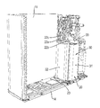
- FIG. 1 shows a perspective view of a heat source unit (outdoor unit) in accordance with the present disclosure
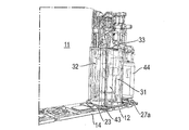
- Fig. 2 shows a perspective view of the heat source unit of figure 1 with parts being removed to show an interior of a machine chamber of the heat source unit
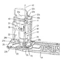
- Fig. 3A shows an enlarged perspective of figure 2 with the compressor casing being shown in transparent
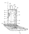
- Fig. 3B shows an enlarged perspective of figure 2 with the compressor casing being removed
- Fig. 4 shows a bottom view of figure 2 with the bottom plate being removed;
- Fig. 1 shows a perspective view of a heat source unit (outdoor unit) in accordance with the present disclosure
- Fig. 2 shows a perspective view of the heat source unit of figure 1 with parts being removed to show an interior of a machine chamber of the heat source unit
- Fig. 3A shows an enlarged perspective of figure 2 with the compressor casing being shown in transparent
- Fig. 3B shows an enlarged perspective of figure 2 with the compressor casing being removed
- Fig. 4 shows a bottom view of
- FIG. 5 shows a perspective front view of figure 3A with further components of the refrigerant circuit being removed, wherein the compressor casing is shown in transparent;
- Fig. 6 shows a perspective back view of figure 5, wherein the compressor casing is shown in transparent;
- Fig. 7 shows a perspective left view of figure 5, wherein the compressor casing is shown in transparent.
- the compressor casing has been shown in transparent in some figures to make the parts housed in the compressor casing visible.
- the parts within the compressor casing have been referenced by using dotted lines.
- FIG. 1 shows a perspective view of heat source unit 10 (in the shown embodiment an outdoor unit) of a split type heat pump.
- the heat pump comprises a refrigerant circuit, at least comprising a heat source heat exchanger 11, a compressor 12, a heat consumer heat exchanger (not shown), such as an indoor heat exchanger, and an expansion valve (not visible) connected by refrigerant pipes.
- the shown outdoor unit 10 comprises an outer casing 13.
- the outer casing 13 has a bottom plate 14. Feet (not shown) for mounting the outdoor unit on a horizontal surface or via brackets to a vertical wall are fixed to the bottom plate 14. Further, the outer casing 13 has a top plate 16 and a side plate 17. In the shown embodiment, the side plate 17 extends around a rearward corner of the outdoor unit 10 being connected to (integrally formed with/forming a one piece structure with) a back plate 18 of the outer casing 13.
- the heat source heat exchanger 11 occupies a part of the rear side of the outer casing 13 and the side of the outer casing 13 opposite to the side plate 17.
- the heat source heat exchanger 11 is “L” - shaped in a top view.
- the front side of the outer casing 13 is closed by a front panel including a grille 19.
- a compressor assembly 20 is accommodated in the outer casing 13 of the heat source unit 10 as shown in figure 2.
- the present disclosure mainly relates to mounting of the compressor assembly 20 within the heat source unit 10.
- the compressor assembly 20 (see figures 5 to 7) comprises the compressor 12 of the refrigerant circuit of the heat pump.
- the compressor 12 comprises a compressor housing 21 containing the compression mechanism.
- the compressor housing 21 comprises at is lower end a fixation plate 24 for mounting the compressor 12.
- Refrigerant pipes 22a-c of the refrigerant circuit are connected to the compressor housing 21 in order to feed refrigerant to the compressor 12 and discharge compressed refrigerant from the compressor 12.
- the compressor assembly comprises a support plate 23 for supporting the compressor 12 including the compressor housing 21.
- a set of three dampers 25 (damping mechanism), such as rubber dampers, is fixed at three locations 26a-c of the fixation plate 24 to the fixation plate 24.
- the dampers 25 are affixed to the support plate 23, whereby the fixation plate 24 and, hence, the compressor 12 including the compressor housing 21, are fixed to the support plate 23 via the dampers 25.
- the damper 25 is not fixed to (loose from) the support plate 25.
- the fixation of the dampers 25 to the fixation plate 24 and/or the support plate 23 is preferably obtained by using screws so that the dampers 25 are replaceable.
- the compressor 12 including the compressor housing 21 and the fixation plate 24 are vibrationally decoupled from the support plate 23.
- the support plate 23 comprises a plurality of compressor mounting preparations 28a-c. These mounting preparations 28a-c configured to allow mounting of different types of compressors 12, particularly compressors 12 having a different capacity.
- the mounting preparation 28b at the location 26b provides for one screw hole only.
- the mounting preparations 28a and 28c respectively at the locations 26a and 26c provide for two screw holes (an inner screw hole 29a and an outer screw hole 29b), respectively.
- the larger capacity compressor 12 may as shown be mounted using the outer screw holes 29b, whereas a not shown smaller capacity compressor may be mounted using the inner screw holes 29a.
- the compressor assembly 20 further comprises a compressor casing 30.
- the compressor casing 30 encloses the compressor 12 including the compressor housing 21, the fixation plate 24 and the dampers 25.
- the compressor casing 30 is entirely closed except for the refrigerant pipes 22a to c entering and exiting the compressor casing 30.
- elastic sealings are provided between the refrigerant pipes 22a to c and the compressor casing 30 to avoid any openings at these locations.
- the compressor casing 30 may be “hermetic” to some extent.
- the compressor casing 30 is fixed at its lower end to the support plate 23.
- the compressor casing 30 is sized so as to not contact with the compressor housing 21. To put it differently, there is always air in between the compressor housing 21 and an inner side surface of the compressor casing 30 facing the compressor housing 21.
- the compressor casing comprises in the depicted embodiment three parts.
- the three parts consist of a front part 31, a rear part 32 and a top part 33.
- the top part 33 may comprise two parts, 33a and 33b.
- the front part 31 and the rear part 32 respectively independently connected to the support plate 23.
- the front part 31 is connected to the rear part 32 and the top part 33 and the rear part 32 is connected to the top part 33 and supports the top part.
- the front part 31 may be disconnected from the rear part 32 and the top part 33 as well as the support plate 23 without having to detach the rear part 32 and the top part 33 from the support plate 23 and each other.
- the compressor 12 When detaching the front part 31 of the compressor casing 30, one obtains access to the compressor 12 without the need to remove other parts of the compressor casing 30. Thus, the compressor 12 is easily accessible for inspection during maintenance.
- the fixation plate 24 is only fixed via the dampers 25 to the support plate 23 at the locations 26a and 26b, the compressor 12 may even be easily removed from the compressor casing 30 through the front (if the front part 31 is removed).
- the fixation at the locations 26a and 26b and because the compressor 12 is not fixed at the location 26c one may easily remove the compressor 12 if required.
- the damper 25 is not omitted at the location 26c and the fixation plate 24 is still supported on the damper 25 at said location 26c, the damping characteristics are not deteriorated even though the damper is not fixed to the support plate 23.
- sensors or other parts are connected or related to the compressor 12 and/or attached to the compressor housing 21.
- a thermistor 34 (figure 7) is mounted to the compressor 12.
- the compressor casing 30 is additionally provided with a maintenance opening 35 closed by a cover 36.
- the cover 36 which is best visible in figures 6 and 7 is at one end hinged to the rear part 32 of the compressor casing 13.
- a fastening structure 37 is provided at the opposite end to fix the cover 36 in the closed position.
- the fastening structure 37 may loosen the cover 36 at the opposite end so that the cover 36 may be opened or even be detached. Subsequently, the thermistor 34 may for example be replaced and the cover 36 again closed and fastened to the rear part 32 by the fastening structure 37. Hence, neither one of the parts 31 to 33 of the compressor casing 30 needs to be removed for replacing the thermistor 34.
- the back plate 18 and the side plate 17 are integrally formed and may be removed for giving access to a machine chamber accommodating the compressor assembly 20 and other components of the refrigerant circuit.
- a plurality of refrigerant pipes is located between the rear part 32 of the compressor casing 30 and the rear plate 18.
- the cover 36 is arranged on the rear part 32 so as to be accessible via the side of the outer casing 13 corresponding to the side plate 17. Hence, removing the side plate 17 allows access to the cover 36. Referring to figure 6, a user may access the cover 36 from the left side.
- the fastening structure 37 is configured so as to allow opening and/or removing of the cover 36 without the need of a tool.
- the cover may be slid into a guide and held in a direction towards the rear plate 18 by the guide.
- the cover 36 is slid towards the right in figure 6 into the closed position engaging with the guide so that a form fit in a direction perpendicular to the sliding direction is obtained.
- a clamping lever may be used to fix the cover 36 in that position.
- the clamping lever may be operated without the use of tools and preferably by using one hand only.
- the compressor casing 30 comprises two layers, an inner layer 38 and an outer layer 39 (see partial broken view in figure 5).
- the outer layer 39 is more rigid than the inner layer 38.
- the outer layer 39 is made of sheet-metal and therefore rigid.
- a sheet-metal having a thickness between 0.6 millimeter and 1 millimeter may be used as outer layer 39.
- the inner layer 38 is made of an elastic material, such as needle felt.
- the sound insulation properties of the compressor casing 30 are improved.
- the more rigid outer layer 39 (sheet-metal layer) is able to absorb frequencies in a relatively high frequency range (first frequency range).
- the less rigid inner layer 38 (needle felt layer) which is soft and elastic, is able to absorb frequencies in a relatively low frequency range (second frequency range).
- the second frequency range comprises frequencies which are lower than the frequencies in the first frequency range and vice versa. Accordingly, the compressor casing 30 of the present disclosure is able to absorb noises in a broader frequency range.
- the outer layer 39 becomes multifunctional. On the one hand, it serves to absorb the high-frequency noises and, on the other hand, it may be used to support the less rigid in a layer, enables fixation of the compressor casing 30 to the support plate 23 and loves to even attach other components of the refrigerant circuit of the heat pump to the compressor casing 30. Yet, the latter is only possible, because the compressor casing 30, i.e. the outer layer 39 is vibrationally decoupled from the compressor 12 via the dampers 25 and configured to be out of contact with the compressor 12 including the compressor housing 21 and the fixation plate 24. Accordingly, the compressor casing 30 does itself not vibrate or at least not in to the same extent as the compressor 12.
- the compressor casing 30 (in the example the rear part 32) has at least one engagement member 40 (in the present example two such engagement members 40 are provided) fixed to the compressor casing 30, particularly the outer layer 39 thereof.
- the component of the refrigerant circuit of the heat pump which in the present example is fixed to the compressor casing 30 is a refrigerant pipe 42.
- the refrigerant pipe 42 has a least one engaging member 41 (in the present example 2 such engaging members 41 are provided) fixed to the refrigerant pipe 42.
- the engagement member 40 and the engaging member 41 represent the fixing structure.
- the engaging member 41 is engaged with the engaging member 41 to fix the refrigerant pipe 42 to the compressor casing 30.
- the engagement member 40 may be shaped like a T - guide in cross section and the engaging member 41 may have a C - shaped cross section catching behind the horizontal legs of the “T”.
- the engaging member 41 may further have a stop at an upper end.
- the engaging members 41 of the refrigerant pipe 42 may, together with the refrigerant pipe 42, be slid from the top onto the engagement members 40 at the compressor casing 30, wherein the movement is limited by the stop.
- the refrigerant pipe 24 is held in a horizontal direction by the cross-section engaging behind the horizontal legs of the “T” and in the vertical direction by the stop.
- a similar fastening structure 37 may as well be implemented in which the engagement member 40 forms a hole and the engaging member 41 is formed like a hook hooking into the whole of the engagement member 40. The mounting process would then be the same as explained above.
- the refrigerant pipe 42 may be relatively long and straight without the risk of becoming damaged.
- the support plate 23 is fixed to the bottom plate 14 of the heat source unit 10.
- the support plate 23 is mounted to the bottom plate 14 via a second set of dampers 43 (five dampers 43 are provided in the present embodiment (figure 4)).
- the dampers 43 are screwed to both the support plate 23 or more particularly a lower side of the support plate 23 and an upper side of the bottom plate 14.
- the dampers 43 may even be replaced if it becomes necessary over the lifetime of the heat source unit 10.
- components than the compressor 12 including the compressor housing 21 and the fixation plate 24 as well as the compressor casing 30 may be mounted to the support plate 23.
- those components are components of the refrigerant circuit of the heat pump such as an accumulator 44 or a water plate heat exchanger.
- other components may be mounted on the support plate 23. It is particularly beneficial to mount those components on the support plate 23 which also tend to produce or propagate vibrations and, therefore, noises. Because the support plate 23 is vibrationally decoupled from the bottom plate 14 via the dampers 43 those vibrations and noises are hence not transferred to the bottom plate 14 and hence the outer casing 13 of the heat source unit 10.
- the support plate 23 comprises a plurality of mounting preparations 27a,b.
- the mounting preparations 27a are used for mounting the accumulator 44.
- the mounting preparations 27b are provided for mounting a water plate heat exchanger (not shown) which is required for some types of heat source units 10. If as in the present example the water plate heat exchanger is not part of the respective heat source unit 10, the mounting preparations 27b are not used but still present.
- the accumulator 44 is mounted to the support plate 23 outside the compressor casing 30. Accordingly, the size of the compressor casing 30 may be minimized so as to accommodate a minimum space within the heat source unit 10.
- dampers 25 or dampers 43 may be provided.
- other components than the accumulator 44 may as well be supported on the support plate 23.
- other components may be fixed to the compressor casing 30.
- heat source unit (outdoor unit) 11 heat source heat exchanger 12 compressor 13 outer casing 14 bottom plate 16 top plate 17 side plate 18 back plate 19 grille 20 compressor assembly 21 compressor housing 22a-c refrigerant pipes 23 support plate 24 fixation plate 25 damper 26a-c locations 27a-b mounting preparations 28a-c compressor mounting preparations 29a-b inner and outer screw hole 30 compressor casing 31 front part 32 rear part 33 top part 34 thermistor 35 maintenance opening 36 cover 37 fastening structure 38 inner layer 39 outer layer 40 engagement member 41 engaging member 42 refrigerant pipe 43 damper 44 accumulator
Landscapes
- Engineering & Computer Science (AREA)
- Mechanical Engineering (AREA)
- General Engineering & Computer Science (AREA)
- Chemical & Material Sciences (AREA)
- Combustion & Propulsion (AREA)
- Physics & Mathematics (AREA)
- Thermal Sciences (AREA)
- Compressor (AREA)
Abstract
Description
Fig. 1 shows a perspective view of a heat source unit (outdoor unit) in accordance with the present disclosure;
Fig. 2 shows a perspective view of the heat source unit of figure 1 with parts being removed to show an interior of a machine chamber of the heat source unit;
Fig. 3A shows an enlarged perspective of figure 2 with the compressor casing being shown in transparent;
Fig. 3B shows an enlarged perspective of figure 2 with the compressor casing being removed;
Fig. 4 shows a bottom view of figure 2 with the bottom plate being removed;
Fig. 5 shows a perspective front view of figure 3A with further components of the refrigerant circuit being removed, wherein the compressor casing is shown in transparent;
Fig. 6 shows a perspective back view of figure 5, wherein the compressor casing is shown in transparent; and
Fig. 7 shows a perspective left view of figure 5, wherein the compressor casing is shown in transparent.
Further, the
11 heat source heat exchanger
12 compressor
13 outer casing
14 bottom plate
16 top plate
17 side plate
18 back plate
19 grille
20 compressor assembly
21 compressor housing
22a-c refrigerant pipes
23 support plate
24 fixation plate
25 damper
26a-c locations
27a-b mounting preparations
28a-c compressor mounting preparations
29a-b inner and outer screw hole
30 compressor casing
31 front part
32 rear part
33 top part
34 thermistor
35 maintenance opening
36 cover
37 fastening structure
38 inner layer
39 outer layer
40 engagement member
41 engaging member
42 refrigerant pipe
43 damper
44 accumulator
[PATENT LITERATURE 2] EP 2 159 497 B1
Claims (14)
- Heat source unit (10) for a heat pump having a refrigerant circuit, the heat source unit comprising:
an outer casing (13) comprising a bottom plate (14); and
a compressor assembly accommodated in the outer casing (13), the compressor assembly (20) comprising
a compressor (12) of the refrigerant circuit of the heat pump including a compressor housing (21),
a support plate (23) supporting the compressor (12), the support plate (23) being mounted via dampers (43) to the bottom plate (14), and
a compressor casing (30) enclosing the compressor housing (21),
wherein
a damping mechanism (25) is arranged between the compressor (12) and the support plate (23), and
the compressor casing (30) is fixed to the support plate (23) out of contact with the compressor housing (21). - Heat source unit according to claim 1, wherein at least one refrigerant component (44) of the refrigerant circuit of the heat pump is mounted to the support plate (23).
- Heat source unit according to claim 2, wherein the at least one refrigerant component (44) of the refrigerant circuit of the heat pump is mounted to the support plate (23) outside the compressor casing (30).
- Heat source unit according to claim 2 or 3, wherein the support plate comprises a plurality of mounting preparations (27a, 27b) so that a plurality of the refrigerant components (44) is mountable on the support plate (23).
- Heat source unit according to any one of the preceding claims, wherein the compressor casing (30) is made of a rigid material, preferably sheet metal, and has a fixing structure (40, 41) to fix at least one component (42) of the refrigerant circuit of the heat pump, preferably a refrigerant pipe (42) of the refrigerant circuit of the heat pump, to the compressor casing (30).
- Heat source unit according to any one of the preceding claims, wherein the compressor casing (30) is at least two layered comprising an outer layer (39) and an inner layer (38).
- Heat source unit according to claim 6, wherein the outer layer (39) is made of a first material configured to absorb sounds in a first frequency range and the inner layer (38) is made of a second material configured to absorb sounds in a second frequency range.
- Heat source unit according to claim 6 or 7, wherein the inner layer (3) is less rigid than the outer layer (39).
- Heat source unit according to any one of the preceding claims, wherein the compressor casing (30) comprises a front part (31), a rear part (32) and a top part (33), wherein the front part (31) is detachable from the support plate (23) separately from the rear part (32).
- Heat source unit according to claim 9, wherein the rear part (32) has a maintenance opening (35) closed by a cover (36), the maintenance opening (35) being arranged for giving access to the compressor (12) or a part attached to or related to the compressor (12).
- Heat source unit according to claim 10, wherein at least part of a side plate (17) of the outer casing (13) is removable allowing access to and opening and/or removing of the cover (36).
- Heat source unit according to claim 9, 10 or 11, wherein the compressor (12) is fixed to the support plate (23) via the damping mechanism (25) only at a side of the compressor (12), which faces the front part of the compressor (12) casing.
- Heat source unit according to claim 12, wherein the compressor (12) is supported on the support plate (23) via the damping mechanism (25) at at least three discrete locations (26a-c) and fixed at only two of the locations (26a, b).
- Heat source unit according to any one of the preceding claims, wherein a plurality of compressor mounting preparations (28a-c) are provided on the support plate (23) and being configured to allow mounting of at least two different types of compressors (12) on the support plate (23).
Priority Applications (4)
| Application Number | Priority Date | Filing Date | Title |
|---|---|---|---|
| CN202080018191.8A CN113498465A (en) | 2019-03-08 | 2020-02-14 | Heat source unit for heat pump |
| CN202310128366.6A CN116067045A (en) | 2019-03-08 | 2020-02-14 | Heat source unit for heat pump |
| US17/436,825 US12235000B2 (en) | 2019-03-08 | 2020-02-14 | Heat source unit for a heat pump |
| JP2021553303A JP2022524771A (en) | 2019-03-08 | 2020-02-14 | Heat source unit of heat pump |
Applications Claiming Priority (2)
| Application Number | Priority Date | Filing Date | Title |
|---|---|---|---|
| EP19161607.7A EP3705793B1 (en) | 2019-03-08 | 2019-03-08 | Heat source unit for a heat pump |
| EP19161607.7 | 2019-03-08 |
Publications (1)
| Publication Number | Publication Date |
|---|---|
| WO2020184060A1 true WO2020184060A1 (en) | 2020-09-17 |
Family
ID=65729211
Family Applications (1)
| Application Number | Title | Priority Date | Filing Date |
|---|---|---|---|
| PCT/JP2020/005754 Ceased WO2020184060A1 (en) | 2019-03-08 | 2020-02-14 | Heat source unit for a heat pump |
Country Status (6)
| Country | Link |
|---|---|
| US (1) | US12235000B2 (en) |
| EP (1) | EP3705793B1 (en) |
| JP (1) | JP2022524771A (en) |
| CN (2) | CN116067045A (en) |
| ES (1) | ES2877120T3 (en) |
| WO (1) | WO2020184060A1 (en) |
Families Citing this family (3)
| Publication number | Priority date | Publication date | Assignee | Title |
|---|---|---|---|---|
| EP1762696A3 (en) | 1999-03-02 | 2016-07-20 | Weatherford Technology Holdings, LLC | Iinternal riser rotating control head |
| CN114440395B (en) * | 2022-02-24 | 2023-10-27 | 海信空调有限公司 | Air conditioner noise reduction control method and device, air conditioner and storage medium |
| EP4602308A1 (en) * | 2022-10-10 | 2025-08-20 | Vertiv Srl | Heat pump comprising a vibration influencer |
Citations (7)
| Publication number | Priority date | Publication date | Assignee | Title |
|---|---|---|---|---|
| JPS5534554U (en) * | 1978-08-29 | 1980-03-05 | ||
| JPS59113182U (en) * | 1983-01-21 | 1984-07-31 | 三菱電機株式会社 | air conditioner |
| US6062033A (en) * | 1998-01-20 | 2000-05-16 | Samsung Electronics Co., Ltd. | Apparatus for reducing noise in an air conditioner |
| JP2009293870A (en) * | 2008-06-05 | 2009-12-17 | Daikin Ind Ltd | Refrigerating device |
| EP2159497B1 (en) | 2008-08-26 | 2016-11-09 | Mitsubishi Electric Corporation | Outdoor unit of conditioning apparatus |
| EP3290697A1 (en) | 2015-04-28 | 2018-03-07 | Daikin Industries, Ltd. | Soundproof cover of compressor for air conditioner |
| CN208238057U (en) * | 2018-05-04 | 2018-12-14 | 广东美的制冷设备有限公司 | Air-conditioner outdoor unit and air conditioner |
Family Cites Families (18)
| Publication number | Priority date | Publication date | Assignee | Title |
|---|---|---|---|---|
| US4982812A (en) * | 1989-10-24 | 1991-01-08 | Hwang Min Su | Noise-preventive means for compressor used in air conditioner |
| JP3066305B2 (en) * | 1996-02-15 | 2000-07-17 | 三洋電機株式会社 | Air conditioner |
| JPH11182891A (en) * | 1997-12-18 | 1999-07-06 | Matsushita Electric Ind Co Ltd | Integrated air conditioner |
| JP2005241197A (en) * | 2004-02-27 | 2005-09-08 | Kimura Kohki Co Ltd | Heat pump air conditioner |
| US7398855B2 (en) * | 2004-05-14 | 2008-07-15 | Emerson Climate Technologies, Inc. | Compressor sound attenuation enclosure |
| CN101178059A (en) * | 2006-11-10 | 2008-05-14 | 乐金电子(天津)电器有限公司 | Mounting structure for compressor of air conditioner |
| CN101280887B (en) | 2007-06-06 | 2012-01-11 | 中国人民解放军总后勤部军需装备研究所 | Pipe gas pressure stabilizing regulation system |
| CN101260887A (en) * | 2008-04-14 | 2008-09-10 | 王荣华 | Low noise compressor assembly |
| US8348218B2 (en) * | 2008-11-05 | 2013-01-08 | Emerson Climate Technologies, Inc. | Compressor mounting structure and assembly method |
| JP2010151343A (en) * | 2008-12-24 | 2010-07-08 | Daikin Ind Ltd | Refrigerating apparatus |
| KR101936192B1 (en) * | 2010-12-29 | 2019-01-08 | 엘지전자 주식회사 | Outdoor unit for air conditioner |
| JP5104993B1 (en) * | 2011-05-20 | 2012-12-19 | ダイキン工業株式会社 | Refrigeration unit outdoor unit |
| JP6098154B2 (en) * | 2012-12-18 | 2017-03-22 | ダイキン工業株式会社 | Soundproof cover for compressor |
| CN204285896U (en) * | 2014-11-25 | 2015-04-22 | 金国达科技(湖南)有限公司 | A kind of family formula water source heat pump units |
| CN106091454A (en) * | 2016-07-19 | 2016-11-09 | 广东美的制冷设备有限公司 | Refrigerating plant |
| JP2018115788A (en) * | 2017-01-17 | 2018-07-26 | 日立ジョンソンコントロールズ空調株式会社 | Air conditioner outdoor unit |
| CN107504595B (en) * | 2017-08-22 | 2024-06-25 | 广东美的制冷设备有限公司 | Air conditioner outdoor unit and air conditioner having the same |
| CN109186136A (en) * | 2018-11-08 | 2019-01-11 | 珠海格力节能环保制冷技术研究中心有限公司 | A kind of compressor assembly and air conditioner |
-
2019
- 2019-03-08 EP EP19161607.7A patent/EP3705793B1/en active Active
- 2019-03-08 ES ES19161607T patent/ES2877120T3/en active Active
-
2020
- 2020-02-14 CN CN202310128366.6A patent/CN116067045A/en active Pending
- 2020-02-14 CN CN202080018191.8A patent/CN113498465A/en active Pending
- 2020-02-14 US US17/436,825 patent/US12235000B2/en active Active
- 2020-02-14 JP JP2021553303A patent/JP2022524771A/en active Pending
- 2020-02-14 WO PCT/JP2020/005754 patent/WO2020184060A1/en not_active Ceased
Patent Citations (7)
| Publication number | Priority date | Publication date | Assignee | Title |
|---|---|---|---|---|
| JPS5534554U (en) * | 1978-08-29 | 1980-03-05 | ||
| JPS59113182U (en) * | 1983-01-21 | 1984-07-31 | 三菱電機株式会社 | air conditioner |
| US6062033A (en) * | 1998-01-20 | 2000-05-16 | Samsung Electronics Co., Ltd. | Apparatus for reducing noise in an air conditioner |
| JP2009293870A (en) * | 2008-06-05 | 2009-12-17 | Daikin Ind Ltd | Refrigerating device |
| EP2159497B1 (en) | 2008-08-26 | 2016-11-09 | Mitsubishi Electric Corporation | Outdoor unit of conditioning apparatus |
| EP3290697A1 (en) | 2015-04-28 | 2018-03-07 | Daikin Industries, Ltd. | Soundproof cover of compressor for air conditioner |
| CN208238057U (en) * | 2018-05-04 | 2018-12-14 | 广东美的制冷设备有限公司 | Air-conditioner outdoor unit and air conditioner |
Also Published As
| Publication number | Publication date |
|---|---|
| CN113498465A (en) | 2021-10-12 |
| EP3705793B1 (en) | 2021-05-19 |
| EP3705793A1 (en) | 2020-09-09 |
| US12235000B2 (en) | 2025-02-25 |
| CN116067045A (en) | 2023-05-05 |
| JP2022524771A (en) | 2022-05-10 |
| US20220178557A1 (en) | 2022-06-09 |
| ES2877120T3 (en) | 2021-11-16 |
Similar Documents
| Publication | Publication Date | Title |
|---|---|---|
| US12235000B2 (en) | Heat source unit for a heat pump | |
| CN100547325C (en) | Modular refrigeration unit and method of assembling a modular refrigeration unit to a refrigeration equipment enclosure | |
| US10254037B2 (en) | Evaporator box fan mounting solution | |
| JP2011052842A (en) | Heat pump outdoor unit | |
| EP3705820A1 (en) | Heat source unit for a heat pump | |
| JP2011106756A (en) | Outdoor unit | |
| KR20100063879A (en) | Refrigerator and assembling method for machinery room of refrigerator | |
| JP6682009B2 (en) | Outdoor unit | |
| CN219063603U (en) | Shock-absorbing structure and window type air conditioner with same | |
| JPH11280662A (en) | Water supply system | |
| CN107449060B (en) | Window type air conditioner | |
| JP2011112324A (en) | Outdoor unit of air conditioner | |
| WO2023169931A1 (en) | Support assembly | |
| JP2009109028A (en) | Bathroom ventilation air conditioner | |
| CN211552192U (en) | refrigerator | |
| CN210397260U (en) | Fan noise and vibration reduction system and fan equipment with noise and vibration reduction functions | |
| JP5245550B2 (en) | Refrigeration equipment | |
| JP2013104592A (en) | Air conditioner indoor unit | |
| CN219875327U (en) | Vibration reduction bracket for fan motor and air conditioner outdoor unit | |
| JP5633974B2 (en) | refrigerator | |
| CN112833586A (en) | An air source heat pump | |
| JPH0460389A (en) | Heat exchanger | |
| CN219083223U (en) | Fume exhaust fan | |
| CN121720155A (en) | Air conditioner indoor unit and air conditioner thereof | |
| JP2025118255A (en) | outdoor unit |
Legal Events
| Date | Code | Title | Description |
|---|---|---|---|
| 121 | Ep: the epo has been informed by wipo that ep was designated in this application |
Ref document number: 20706602 Country of ref document: EP Kind code of ref document: A1 |
|
| ENP | Entry into the national phase |
Ref document number: 2021553303 Country of ref document: JP Kind code of ref document: A |
|
| NENP | Non-entry into the national phase |
Ref country code: DE |
|
| 122 | Ep: pct application non-entry in european phase |
Ref document number: 20706602 Country of ref document: EP Kind code of ref document: A1 |
|
| WWG | Wipo information: grant in national office |
Ref document number: 17436825 Country of ref document: US |