WO2020183907A1 - 歩行アシスト装置 - Google Patents
歩行アシスト装置 Download PDFInfo
- Publication number
- WO2020183907A1 WO2020183907A1 PCT/JP2020/001514 JP2020001514W WO2020183907A1 WO 2020183907 A1 WO2020183907 A1 WO 2020183907A1 JP 2020001514 W JP2020001514 W JP 2020001514W WO 2020183907 A1 WO2020183907 A1 WO 2020183907A1
- Authority
- WO
- WIPO (PCT)
- Prior art keywords
- link
- rotation axis
- assist device
- orthosis
- user
- Prior art date
- Legal status (The legal status is an assumption and is not a legal conclusion. Google has not performed a legal analysis and makes no representation as to the accuracy of the status listed.)
- Ceased
Links
Images





Classifications
-
- A—HUMAN NECESSITIES
- A61—MEDICAL OR VETERINARY SCIENCE; HYGIENE
- A61H—PHYSICAL THERAPY APPARATUS, e.g. DEVICES FOR LOCATING OR STIMULATING REFLEX POINTS IN THE BODY; ARTIFICIAL RESPIRATION; MASSAGE; BATHING DEVICES FOR SPECIAL THERAPEUTIC OR HYGIENIC PURPOSES OR SPECIFIC PARTS OF THE BODY
- A61H3/00—Appliances for aiding patients or disabled persons to walk about
Definitions
- the present invention relates to a walking assist device that assists the user in walking in the front-rear direction by imparting an assisting force that causes the foot to flex or dorsiflex to the foot of the user.
- walking that transmits the driving force from the driving source to the user's leg to assist the movement of at least one of the user's knee joint and ankle joint to assist the user in walking in the anterior-posterior direction.
- Assist devices are known.
- the foot brace worn on the user's foot is rotated around the pitch axis at a position corresponding to the user's ankle (that is, the pitch axis of the ankle joint).
- an assist force is applied to a user's foot to cause the user's foot to flex or dorsiflex (see, for example, Patent Document 1).
- the devices for driving and controlling the joint mechanism such as the drive source and the control device are miniaturized and lightened by shortening the cable and the like, and the user's joint and the walking assist device. It is arranged on the side of the user's joint for reasons such as simplification of control by bringing the rotation axis of the.
- the left and right width of the user when the walking assist device is attached and the left and right width of the user when the walking assist device is not attached are different. Become.
- the user may bring the drive source or the like into contact with an object existing in the surroundings, which may hinder walking.
- the drive source or the like when the drive source or the like is arranged inside the joint, the drive source or the like is the foot or lower leg on the opposite side of the foot or lower leg to which the assist force is applied during use. Since there is a risk of contact with the user, the user may have to walk with the left and right feet or lower legs separated from each other.
- the present invention has been made in view of the above points, and an object of the present invention is to provide a walking assist device in which the user's walking is hindered and the walking method is not easily restricted.
- the assist device of the present invention A walking assist device that assists the user in walking in the front-rear direction by applying an assisting force that causes the foot to flex or dorsiflex to the user's foot.
- the lower leg orthosis attached to the lower leg of the user and A foot orthosis attached to the foot of the user,
- the drive source attached to the lower leg orthosis and It is provided with a link mechanism that is connected to the foot orthosis, transmits the driving force from the driving source to the foot orthosis, and applies the assisting force to the foot.
- the drive source is attached to the lower leg orthosis so as to be located on the front side or the back side of the lower leg of the user in the mounted state.
- the “wearing state” means a state in which the user wears the walking assist device.
- the state in which the user does not wear the walking assist device is called the “non-wearing state”.
- the drive source having the largest size in general among the devices for driving and controlling the joint mechanism is positioned on the front surface or the back surface of the lower leg of the user in the worn state. It is attached to the lower leg brace so that it does.
- the difference between the left and right width of the user in the wearing state and the left and right width of the user in the non-wearing state becomes smaller than the difference in the conventional walking assist device. Therefore, in the walking assist device of the present invention, the user is less likely to bring the drive source into contact with an object existing in the surroundings during walking, as compared with the case where the conventional walking assist device is attached. Therefore, according to the walking assist device of the present invention, the user is less likely to be hindered by the driving source even in the wearing state.
- the walking assist device of the present invention as compared with the case where the conventional walking assist device is attached, the foot or the lower part on the side opposite to the foot or the lower leg to which the assist force is applied during walking. It is difficult for the drive source to come into contact with the thigh. Therefore, according to the walking assist device of the present invention, even in the wearing state, the user can easily walk in the same manner as in the wearing state, and by extension, the walking method is less likely to be restricted.
- the drive source is attached to the front surface of the lower leg orthosis so as to be located on the front surface side of the lower leg portion of the user in the mounted state.
- the drive source If the drive source is placed in front, the drive source will be located above the user's foot in the mounted state. As a result, the difference between the front-back width of the user in the worn state and the front-back width of the user in the worn state is also smaller than the difference in the conventional walking assist device. As a result, when walking, it becomes difficult for the user to bring the drive source into contact with an object existing behind. As a result, the user is less likely to be hindered by the drive source.
- the link mechanism when the drive source is attached to the front surface of the lower leg orthosis,
- the link mechanism is rotated by a driving force from the drive source about a first rotation axis extending in the pitch axis direction in front of the lower leg orthosis and above the foot orthosis. It has at least a first link and a second link that is rotatable about a second rotation axis extending in the pitch axis direction at a position corresponding to the user's ankle joint in the worn state. It is preferable that the rotating end of the second link is connected to the foot orthosis and transmits the driving force from the driving source to the foot orthosis.
- the first rotation axis which is the rotation axis of the first link rotated by the drive force from the drive source, is the ankle joint of the user in the attached state. It is a position that does not correspond to.
- a predetermined calculation must be performed to calculate the driving force to be output to the driving source.
- the operation of the second link is performed. (By extension, the movement of the foot orthosis guided by the second link) is similar to the movement of the user's foot.
- the second link configured in this way is incorporated into the link mechanism as a link for transmitting the driving force to the heel orthosis 3, and the foot orthosis is driven from the drive source via the second link.
- the force is transmitted (that is, when the assist force is applied to the foot of the user), it becomes easy to predict the assist force to be applied to the foot of the user.
- the calculation (and thus the control) when determining the operation of the assist force to be applied can be simplified.
- the movements of the second link and the foot orthosis are the same, so that the control can be further simplified.
- the link mechanism is rotatably connected to the first link with the first link, the second link, and the first rotation axis as a center, and connects the second rotation axis.
- a third link rotatably connected to the second link and a third rotation axis extending in the pitch axis direction are rotatably connected to the first link.
- it is a four-node link mechanism having a fourth link rotatably connected to the second link about a fourth rotation axis extending in the pitch axis direction.
- the third rotation axis is located on one side in the front-rear direction with respect to the first rotation axis in a side view. It is preferable that the fourth rotation axis is located on one side in the front-rear direction with respect to the second rotation axis in a side view.
- the four links form a quadrangle in side view.
- the rotation direction of the first link and the rotation direction of the second link correspond to each other.
- the calculation (and thus the control) in determining the operation of the assist force to be applied can be further simplified.
- the link mechanism is rotatably connected to the first link with the first link, the second link, and the first rotation axis as a center, and connects the second rotation axis.
- a third link rotatably connected to the second link and a third rotation axis extending in the pitch axis direction are rotatably connected to the first link.
- it is a four-node link mechanism having a fourth link rotatably connected to the second link about a fourth rotation axis extending in the pitch axis direction.
- the third rotation axis is located on one side in the front-rear direction with respect to the first rotation axis in a side view. It is preferable that the fourth rotation axis is located on the other side in the front-rear direction with respect to the second rotation axis in a side view.
- the first link, the second link, and the third link or the fourth link form a Z shape in a side view.
- the rotation direction of the first link and the rotation direction of the second link correspond to each other, as in the case where the link forms a quadrangle.
- the calculation (and thus the control) in determining the operation of the assist force to be applied can be further simplified.
- the third rotation axis is located behind the first rotation axis in a side view. It is preferable that the fourth rotation axis is located in front of the second rotation axis in a side view.
- the first rotation axis can be positioned on the side of the user's lower leg or foot in the mounted state.
- the first rotation axis can be retracted from above the user's foot, so that when the foot bends dorsiflexively in the mounted state, the foot and the member constituting the first rotation axis can be used. It becomes difficult to hit. As a result, the way the user walks is less likely to be restricted.
- the four-section link is connected to one of the first links, a pair of left and right second links connected to each of both side surfaces of the foot orthosis, and each of the first link and the second link.
- a pair of left and right third links and one fourth link are provided.
- the fourth link has a pair of left and right other ends that are bifurcated and extended from one end. The one end of the fourth link is connected to the first link. It is preferable that each of the pair of left and right other ends of the fourth link is connected to each of the pair of left and right second links.
- the four-section link is connected to one of the first links, a pair of left and right second links connected to each of both side surfaces of the foot orthosis, and each of the first link and the second link.
- a pair of left and right third links and a pair of left and right fourth links connected to each of the second links are provided.
- the first link has a pair of left and right other ends that are bifurcated and extended from one end. The one end of the first link is connected to the third link. It is preferable that each of the pair of left and right other ends of the first link is connected to each of the pair of left and right fourth links.
- the link mechanism when the link mechanism is a four-section link mechanism,
- the four-section link includes one first link, one second link, one third link, and one fourth link. It is preferable that at least a part of the second link and the fourth link is provided at a position on the side of the user's foot in the worn state.
- the link mechanism exists only on one side of the foot orthosis (specifically, one side in the left-right direction).
- the user is less likely to bring the link mechanism into contact with an object existing in the surroundings, and thus is less likely to be hindered from walking.
- it becomes difficult for the link mechanism to come into contact with the other foot or lower leg it becomes more difficult to restrict the way of walking.
- the mechanism when the mechanism includes the second link, The rotating end of the second link is connected to the foot orthosis between the second rotating axis and the user's ball or hypothenar in the mounted state in a side view. It is preferable to have.
- the position where the assist force is applied is between the user's ankle (that is, the pitch axis of the ankle joint) and the ball of the mother's finger or the little finger. The closer the part is to the ball of the mother's finger or the ball of the little finger, the easier it is for the user to feel the assisting force.
- the rotating end of the second link that transmits the driving force from the driving source that is, causes the foot orthosis to apply the assisting force to the user's foot
- approaches the portion that is, causes the foot orthosis to apply the assisting force to the user's foot
- the assist device of the present invention It is preferable to have an adjusting mechanism for changing the length of at least one of the links constituting the link mechanism.
- the link mechanism can be used as a part of the speed reducer for adjusting the speed and magnitude of the driving force from the driving source.
- the speed reducer used as the drive source can be made smaller and lighter.
- a battery that supplies electric power to the drive source and a control device that controls the operation of the drive source are provided. It is preferable that the drive source, the battery, and the control device are arranged side by side inside the width of the lower leg orthosis in a front view.
- a battery that supplies electric power to the drive source and a control device that controls the operation of the drive source are provided.
- the drive source, the battery, and the control device are triangular in a side view, formed by the upper end of the lower leg brace, the user's toes in the mounted state, and the user's heel in the mounted state. It is preferably located inside.
- a control device for controlling the operation of the drive source and a gait detection device attached to the lower leg orthosis or the foot orthosis are provided. It is preferable that the control device controls the operation of the drive source based on the output of the gait detection device.
- the gait detection device When the gait detection device is attached to the lower leg orthosis or the foot orthosis, the timing of contacting the user's heel or toe (that is, the user's walking pattern) can be accurately grasped. Then, if the operation of the drive source is controlled based on the output of the gait detection device, it becomes easy to apply the assist force at an appropriate timing.
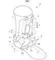
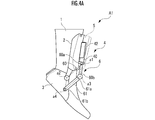
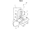
- the front view of the walking assist device of FIG. The side view of the walking assist device of FIG. It is a side view which shows the operation of the walking assist device of FIG. 1, and is the figure which shows the state which the heel orthosis 3 is bent bottom. It is a side view which shows the operation of the walking assist device of FIG. 1, and is the figure which shows the state which the heel brace 3 is not bending back and dorsiflexion. It is a side view which shows the operation of the walking assist device of FIG. 1, and is the figure which shows the state which the heel orthosis 3 is dorsiflexed.
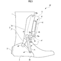
- the side view of the walking assist device which concerns on 2nd Embodiment.
- the side view of the walking assist device which concerns on 3rd Embodiment.
- the walking assist device A1 includes a boot-type accommodating body 1, a shin orthosis 2 (lower leg orthosis) attached to the front surface of the shin of the accommodating body 1, and the accommodating body 1.
- the heel orthosis 3 (foot orthosis, second link) attached to the heel portion, the drive unit 4 attached to the front surface of the shin orthosis 2, and the shin orthosis 2 so as to cover the drive unit 4.
- It includes a cover 5 that is detachably attached, and a link mechanism 6 that connects the drive unit 4 and the heel orthosis 3.
- the accommodating body 1 accommodates the lower part of the lower leg and the foot of the user in the worn state.
- the housing 1 is made of a flexible material such as synthetic resin or cloth.
- the “wearing state” means a state in which the user wears the walking assist device A1.
- the state in which the user does not wear the walking assist device A1 is referred to as a "non-wearing state”.
- the walking assist device of the present invention is not limited to the one provided with an accommodating body, and may be provided with a lower leg orthosis and a foot orthosis as a configuration for being worn by the user.
- the housing is not a boot type that accommodates the lower part of the lower leg and the foot of the user as in the present embodiment, but a shoe type or sandal type that accommodates only the foot. May be good.
- the boot type may have a shape in which the portion on the side where the lower leg orthosis is not attached is open.
- the container is omitted and fixed to the user's feet and legs directly or through the shoes that the user normally uses. It may be configured as follows. However, when the housing is omitted, it is desirable that the lower leg orthosis and the foot orthosis be provided with a belt or the like for fixing them to the lower leg or foot of the user.
- the shin orthosis 2 (lower leg orthosis) is attached to the lower leg of the user via the housing body 1.
- the shin orthosis 2 is attached to the shin portion of the housing body 1 and is located on the front side of the lower leg of the user in the mounted state, and the frame portion 21 extending from below the main body 20. have.
- the main body 20 and the frame 21 are integrally molded with synthetic resin.
- the drive unit 4 is fixed to the front surface of the main body 20. As a result, the drive unit 4 is located in front of the user's lower leg in the mounted state.
- Mounting holes 20a for fixing the cover 5 with mounting screws 50 are provided on both side surfaces of the main body 20.
- the frame portion 21 extends downward from the rear portion of the lower end portion of the main body portion 20. That is, the base end portion of the frame portion 21 is fixed to the main body portion 20. On the other hand, the tip of the frame portion 21 is rotatably connected to the heel orthosis 3.
- the heel orthosis 3 (foot orthosis, second link) is attached to the heel portion of the user's foot via the housing body 1, and has a shape that covers from the heel portion to the ankle portion. There is.
- the heel orthosis 3 is made of a flexible synthetic resin, and can be deformed so that the user's foot can be deformed or tilted to some extent during walking.
- the tip of the frame portion 21 of the shin orthosis 2 is rotatably connected to both sides of the heel orthosis 3 at a portion corresponding to the user's ankle (that is, the pitch axis of the ankle joint) in the worn state.
- a pair of left and right fourth end portions 61b of the second link member 61 (fourth link) described later of the link mechanism 6 rotates around the front end portions 30 (rotating end portions) on both side surfaces of the heel orthosis 3. It is freely connected.
- the position where the assist force is applied is the user's ankle (that is, the pitch axis of the ankle joint) and the ball of the mother's finger or the little finger. The closer the part is to the ball of the mother's finger or the ball of the little finger, the easier it is for the user to feel the assisting force.
- the front end portion 30 of the heel orthosis 3 has a portion corresponding to the user's ankle and a portion corresponding to the user's thumb ball or hypothenar ball in the side view. It is located in between (see FIG. 3).
- the walking assist device A1 makes it easier for the user to feel the assist force.
- the foot orthosis of the present invention is not limited to a shape that covers from the heel portion to the ankle portion of the user's foot like the heel orthosis 3, but is transmitted via the link mechanism 6. It suffices that the provided driving force can be applied to the user's foot as an assisting force.
- the foot orthosis one having a shape that covers the entire foot may be used. Further, it may be a band-shaped object fixed at a position on the lower surface side of the user's ball or hypothenar in the worn state.
- An IMU sensor 31 (gait detection device) for detecting the walking state of the user is attached to the back portion of the heel orthosis 3. This is because by providing the IMU sensor 31 at such a position, the timing of the contact of the user's heel or toe (that is, the walking pattern of the user) can be accurately grasped. As a result, the assist force is applied at an appropriate timing by controlling the operation of the actuator 40 based on the output of the IMU sensor 31.
- the gait detection device of the present invention may be any device that can detect the walking state of the user during walking, and the mounting position is not limited to the back surface of the foot orthosis. For example, it may be attached to the bottom surface of the foot orthosis. It may also be attached to the lower leg orthosis.
- the gait detection device in addition to the IMU sensor, for example, a foot switch or the like may be used.
- the "foot switch” is a switch that switches ON / OFF according to the grounding of the user's foot.
- the walking assist device A1 is configured as a boot-type walking assist device by the housing body 1, the shin orthosis 2, and the heel orthosis 3. Therefore, the user attaches the walking assist device A1 by inserting the lower leg and the foot into the housing 1 as if wearing boots.
- the drive unit 4 includes an actuator 40, a battery 41 that supplies electric power to the actuator 40, and a control device 42 that controls the operation (output) of the actuator 40.
- the control device 42 controls the operation of the actuator 40 based on the output value from the IMU sensor 31.
- the actuator 40, the battery 41, and the control device 42 are arranged side by side inside the width of the shin brace 2 in a front view. This is to improve the weight balance while suppressing the increase in size in the left-right direction.
- the actuator 40, the battery 41, and the control device 42 are viewed from the side with the upper end of the shin brace 2, the toes of the user in the worn state, and the heel of the user in the worn state. It is located inside the formed triangle (in FIG. 3, the triangle shown by the broken line with a large interval). More specifically, at least the center of gravity of the actuator 40, the battery 41, and the control device 42 is located inside the triangle.
- the arrangement of the drive source, the battery and the control device of the present invention is not limited to such a configuration, and the weight of the actuator, the battery, the control device and other components, the foot orthosis and the shin orthosis. It may be set as appropriate according to the shape and the like.
- the walking assist device A1 is attached to the front surface of the shin orthosis 2 so that the drive unit 4 is located on the front surface side of the lower leg of the user in the mounted state.
- the difference between the left and right width of the user in the wearing state and the left and right width of the user in the non-wearing state becomes smaller than the difference in the conventional walking assist device. Therefore, in the walking assist device A1, it is less likely that the user will bring the drive unit 4 into contact with an object existing in the surroundings during walking, as compared with the case where the conventional walking assist device is attached. Therefore, according to the walking assist device A1, the user is less likely to be hindered by the drive unit 4 even in the wearing state.
- the walking assist device A1 the foot or lower leg on the side opposite to the foot or lower leg to which the assist force is applied during walking, as compared with the case where the conventional walking assist device is attached.
- the drive unit 4 is difficult to contact. Therefore, according to the walking assist device A1, even in the wearing state, the user can easily walk in the same manner as in the wearing state, and by extension, the walking method is less likely to be restricted.
- the link mechanism 6 is connected to the heel orthosis 3 and transmits the driving force from the actuator 40 to the heel orthosis 3 to give the user's foot an assisting force that causes the foot to flex or dorsiflex. Is what you do.
- the link mechanism 6 connects any one of the first rotation axis a1, the second rotation axis a2, the third rotation axis a3, and the fourth rotation axis a4 extending in the pitch axis direction. As a center, it has four links rotatably connected to each other.
- the first rotation axis a1 is located in front of the shin orthosis 2 and above the heel orthosis 3.
- the second rotation axis a2 is located at a position corresponding to the user's ankle (that is, the pitch axis of the ankle joint) in the worn state.
- the third rotation axis a3 is located in front of the first rotation axis a1 in the side view and at a position between the first rotation axis a1 and the second rotation axis a2 in the vertical direction.
- the fourth rotation axis a4 is a position in the front-rear direction, between the first rotation axis a2 and the second rotation axis, and below the first rotation axis a1 and the second rotation axis a2 in the side view. Is located in.
- the first link which is one of the four links constituting the link mechanism 6, is composed of the first link member 60.
- the first link member 60 which is the first link, is fixed to the drive shaft of the actuator 40 at the first end 60a, which is one end. As a result, the first link member 60 is rotated by the driving force of the actuator 40 with respect to the shin orthosis 2, which is the second link described later, about the first rotation axis a1.
- first link member 60 is a second end portion 60b, which is an end portion on the other side, and rotates with respect to the second link member 61, which is a fourth link described later, about the third rotation axis a3. It is connected freely.
- the second link which is one of the four links, is composed of the upper edge of the heel orthosis 3. Specifically, the area including the upper edge of the heel orthosis 3 from the front end 30 (rotating end) to the portion corresponding to the user's ankle (that is, the pitch axis of the ankle joint) in the worn state. However, it is the second link.
- the heel orthosis 3 which is the second link, is rotatably connected to the shin orthosis 2, which is the third link described later, at a position corresponding to the ankle, about the second rotation axis a2. There is.
- heel orthosis 3 is rotatably connected to the second link member 61, which is the fourth link described later, at the front end portion 30 about the fourth rotation axis a4.
- the third link which is one of the four links, is composed of a lower portion of the main body portion 20 of the shin orthosis 2 and a frame portion 21.
- the shin brace 2 which is the third link is rotatably connected to the first link member 60 which is the first link by the main body 20 about the first rotation axis a1. That is, the first link member 60 is rotatable with respect to the shin orthosis 2 fixed to the lower leg of the user.
- the shin orthosis 2 is rotatably connected to the heel orthosis 3 which is the second link by the frame portion 21 about the second rotation axis a2. That is, the heel orthosis 3 is rotatable with respect to the shin orthosis 2 so as to bend plantarly or dorsiflexively.
- the fourth link which is one of the four links, is composed of the second link member 61.
- the second link member 61 which is the fourth link, is the third end 61a (one end), which is one end, with respect to the first link member 60, which is the first link, and the third rotation axis a3. It is rotatably connected around the center.
- the second link member 61 is a fourth end portion 61b (the other end portion) which is the other end portion, and is centered on the fourth rotation axis a4 with respect to the heel portion orthosis 3 which is the second link. , Are rotatably connected.
- the first rotation axis a2 which is the rotation axis of the first link member 60 rotated by the driving force from the actuator 40, is in the attached state.
- the position does not correspond to the user's ankle joint.
- the driving force to be output to the actuator 40 must be calculated by performing a predetermined calculation.
- the heel orthosis 3 which is the second link, is composed of a region including the front end 30 of the upper edge of the heel orthosis 3.
- the heel orthosis 3 is rotatably configured about the second rotation axis a2 corresponding to the ankle joint. Therefore, the movement of the heel orthosis 3 (that is, the movement of the second link) is similar to the movement of the user's foot.
- the walking assist device A1 is attached to the user's foot. It is easier to predict the assist power to be given. As a result, the walking assist device A1 is provided with this configuration, which simplifies the calculation (and thus the control) in determining the operation of the assist force to be applied.
- the link mechanism 6 is configured as a four-node link mechanism having four links, and the four links constituting the four-node link form a quadrangle (more specifically, a parallelogram) in a side view. Is forming.
- the walking assist device A1 also has such a configuration, which simplifies the calculation (and thus the control) when determining the operation of the assist force to be applied.
- the link mechanism 6 includes one first link member 60 and a pair of left and right second links formed at the upper edge ends of each of the side surfaces of the heel orthosis 3.
- a frame portion 21 of a pair of left and right shin orthosis 2 connected to both side surfaces of the first link member 60 and the heel orthosis 3 and one second link member 61 are provided.
- the second link member 61 has a pair of left and right fourth end portions 61b that are bifurcated and extended from the third end portion 61a.
- the third end portion 61a is connected to the first link member 60.
- Each of the left and right pair of fourth end portions 61b is connected to each of the both side surfaces of the left and right pair of heel orthosis 3.
- the driving force from the actuator 40 is transmitted to the first link member 60, then divided into left and right by the second link member 61, and is transmitted to both side surfaces of the heel orthosis 3.
- a well-balanced assist force is applied to the user's foot in the left-right direction.
- the shape of the link constituting the link mechanism of the present invention is not limited to such a configuration, and the foot is connected to the foot orthosis and transmits the driving force from the drive source to the foot orthosis. Any shape may be used as long as the link mechanism that applies an assist force to the portion can be configured.
- the link mechanism constitutes a four-section link as in the present embodiment
- one first link, a pair of left and right second links connected to each of both side surfaces of the foot orthosis, the first link, and A pair of left and right third links connected to each of the second links and a pair of left and right fourth links connected to each of the second links are provided, and the first link bifurcates from one end and extends. It has a pair of left and right other ends provided, one end of the first link is connected to the third link, and each of the pair of left and right other ends of the first link is of the pair of left and right fourth links. It may be connected to each.
- the first link may be a bifurcated member instead of the fourth link. Even with this configuration, it is possible to apply a well-balanced assist force in the left-right direction to the user's foot, as in the case of the walking assist device A1 of the present embodiment.
- the link mechanism when the link mechanism constitutes a four-section link as in the present embodiment, it includes one first link, one second link, one third link, and one fourth link.
- the second link, and at least a part of the fourth link may be provided at a position on the side of the user's foot in the worn state.
- the link mechanism exists only on one side of the foot orthosis (specifically, one side in the left-right direction).
- the user is less likely to bring the link mechanism into contact with an object existing in the surroundings, and thus is less likely to be hindered from walking.
- it becomes difficult for the link mechanism to come into contact with the other foot or lower leg it becomes more difficult to restrict the way of walking.
- FIG. 4A shows a state in which the heel orthosis 3 is bottom-bent.
- FIG. 4B shows a state in which the heel orthosis 3 is not flexed or dorsiflexed.
- FIG. 4C shows a state in which the heel orthosis 3 is dorsiflexed.
- the walking assist device A1 transmits the driving force from the actuator 40 to the heel orthosis 3 via the link mechanism 6. Then, the heel orthosis 3 is rotated with respect to the shin orthosis 2 by the transmitted driving force. Then, the walking assist device A1 applies an assist force for bending the foot to the plantar or dorsiflexion to the user's foot via the heel orthosis 3 to assist the user in walking in the front-rear direction. To do.
- the walking assist device A1 When the user's foot is bent to the bottom, the walking assist device A1 operates from the state shown in FIG. 4B to the state shown in FIG. 4A.
- the actuator 40 rotates the drive shaft to rotate the first link member 60, which is the first link, with respect to the tibial orthosis 2 with the first rotation axis a1 as the center.
- step 4 rotate clockwise downward.
- the second link member 61 which is the fourth link, is rotatably connected to the second end 60b, which is the rotating end of the first link member 60, at the third end 61a. ..
- the second link member 61 when the first link member 60 rotates clockwise with respect to the first rotation axis a1, the second link member 61 also has the first end portion of the first link member 60 as a whole. Together with 60a, it rotates clockwise and downward about the first rotation axis a1.
- the second link member 61 is not only rotatably connected to the first link member 60 at the third end portion 61a, but also at the fourth end portion 61b at the second link. It is also rotatably connected to a certain heel orthosis 3.
- the second link member 61 rotates by pulling the third end portion 61a by the first link member 60, but the fourth end portion 61b is the heel portion. By being pushed by the device 3, its rotation is suppressed.
- the second link member 61 rotates clockwise and downward with respect to the first rotation axis a1
- the second link member 61 is opposite to the first link member 60 with the third rotation axis a3 as the center. It rotates in the direction (counterclockwise in FIG. 4).
- the second link member 61 operates so as to open with respect to the first link member 60, and the amount of movement of the fourth end portion 61b of the second link member 61 in the vertical direction is the first of the first link member 60. It becomes larger than the movement amount of the two-end portion 60b.
- the heel orthosis 3 which is the second link is not only rotatably connected to the second link member 61 at the front end portion 30, but also the ankle of the user in the mounted state ( That is, the portion corresponding to the pitch axis of the ankle joint) is rotatably connected to the shin orthosis 2. Further, the shin orthosis 2 is fixed to the lower leg of the user.
- the toe is lowered clockwise around the pitch axis of the ankle joint (that is, the toe is lowered).
- An assist force is applied to rotate the foot (so that it bends to the bottom).
- the walking assist device A1 operates from the state shown in FIG. 4B to the state shown in FIG. 4C.
- the actuator 40 rotates the drive shaft to rotate the first link member 60, which is the first link, with respect to the shin orthosis 2 with the first rotation axis a1 as the center. In step 4, it is rotated counterclockwise upward.
- the second link member 61 which is the fourth link, is rotatably connected to the second end 60b, which is the rotating end of the first link member 60, at the third end 61a. ..
- the second link member 61 as a whole is also the first end of the first link member 60. Together with the portion 60a, it rotates counterclockwise upward about the first rotation axis a1.
- the second link member 61 is not only rotatably connected to the first link member 60 at the third end portion 61a, but also at the fourth end portion 61b at the second link. It is also rotatably connected to a certain heel orthosis 3.
- the second link member 61 rotates by pulling the third end portion 61a by the first link member 60, but the fourth end portion 61b is the heel portion. By being pulled by the device 3, its rotation is suppressed.
- the second link member 61 rotates counterclockwise and upward about the first rotation axis a1
- the second link member 61 and the first link member 60 are centered on the third rotation axis a3. It rotates in the opposite direction (clockwise in FIG. 4).
- the second link member 61 operates so as to close with respect to the first link member 60, and the amount of movement of the fourth end portion 61b of the second link member 61 in the vertical direction is the first of the first link member 60. It becomes larger than the movement amount of the two-end portion 60b.
- the heel orthosis 3 which is the second link is not only rotatably connected to the second link member 61 at the front end portion 30, but also the ankle of the user in the mounted state ( That is, the portion corresponding to the pitch axis of the ankle joint) is rotatably connected to the shin orthosis 2. Further, the shin orthosis 2 is fixed to the lower leg of the user.
- the toes are turned upward (that is, the toes) counterclockwise around the pitch axis of the ankle joint.
- An assisting force is applied to rotate it (so that it is raised and dorsiflexed).
- the timing of the operation for the plantar flexion and the dorsiflexion (that is, the timing for controlling the operation of the drive source) is determined by the control device 42 of the drive unit 4 in a predetermined general walking pattern or in advance. It is determined based on the walking pattern of the user and the output of the IMU sensor 31 attached to the heel orthosis 3.
- the four links constituting the link mechanism 6 form a parallelogram in a side view.
- the third link which is one of the four links, is composed of the tibial brace 2 fixed to the user.
- the operation of the first link (first link member 60) required to operate the second link (heel orthosis 3) until the target state is reached can be easily calculated. Can be done.
- the control device 42 can easily control the output of the actuator 40.
- the walking assist device A2 according to the second embodiment has the same configuration as the walking assist device A1 according to the first embodiment, except that the link mechanism 7 is provided instead of the link mechanism 6.
- the same or similar configuration as the walking assist device A1 of the first embodiment will be omitted and the same reference numerals will be given.
- the first rotation axis a1 is located in front of the shin orthosis 2 and above the heel orthosis 3.
- the second rotation axis a2 is located at a position corresponding to the user's ankle (that is, the pitch axis of the ankle joint) in the worn state.
- the third rotation axis a3 is located at a position between the first rotation axis a1 and the second rotation axis a2 in the front-rear direction and the up-down direction in the side view.
- the fourth rotation axis a4 is located between the first rotation axis a2 and the second rotation axis in the front-rear direction and below the first rotation axis a1 and the second rotation axis a2 in the side view. Is located in.
- the first link which is one of the four links constituting the link mechanism 7, is composed of the first link member 70.
- the first link member 70 which is the first link, is fixed to the drive shaft of the actuator 40 at the first end 70a, which is one end. As a result, the first link member 70 is rotated by the driving force of the actuator 40 with respect to the shin orthosis 2, which is the second link described later, about the first rotation axis a1.
- first link member 70 is a second end portion 70b, which is an end portion on the other side, and is rotated around the third rotation axis a3 with respect to the second link member 71, which is the fourth link described later. It is connected freely.
- the second link which is one of the four links, is composed of the upper edge of the heel orthosis 3. Specifically, the area including the upper edge of the heel orthosis 3 from the front end 30 (rotating end) to the portion corresponding to the user's ankle (that is, the pitch axis of the ankle joint) in the worn state. However, it is the second link.
- the heel orthosis 3 which is the second link, is rotatably connected to the shin orthosis 2, which is the third link described later, at a position corresponding to the ankle, about the second rotation axis a2. There is.
- heel orthosis 3 is rotatably connected to the second link member 71, which is the fourth link described later, at the front end portion 30 about the fourth rotation axis a4.
- the third link which is one of the four links, is composed of a lower portion of the main body portion 20 of the shin orthosis 2 and a frame portion 21.
- the shin brace 2 which is the third link is rotatably connected to the first link member 70 which is the first link by the main body 20 about the first rotation axis a1. That is, the first link member 70 is rotatable with respect to the shin orthosis 2 fixed to the lower leg of the user.
- the shin orthosis 2 is rotatably connected to the heel orthosis 3 which is the second link by the frame portion 21 about the second rotation axis a2. That is, the heel orthosis 3 is rotatable with respect to the shin orthosis 2 so as to bend plantarly or dorsiflexively.
- the fourth link which is one of the four links, is composed of the second link member 71.
- the second link member 71 which is the fourth link, is the third end portion 71a (one end portion), which is one end, and the third rotation axis a3 with respect to the first link member 70, which is the first link. It is rotatably connected around the center.
- the second link member 71 is a fourth end portion 71b (the other end portion) which is the other end portion, and is centered on the fourth rotation axis a4 with respect to the heel portion orthosis 3 which is the second link. , Are rotatably connected.
- the link mechanism 7 is configured as a four-section link mechanism having four links, and among the four links constituting the four-section link, the first link, the second link, and the third link.
- the link or the fourth link forms a Z shape in a side view.
- the walking assist device A2 can further simplify the calculation (and thus the control) when determining the operation of the assist force to be applied.
- the link mechanism 7 includes one first link member 70, one second link formed at the upper edge end of one side surface (the side surface on the front side in FIG. 5) of the heel orthosis 3, and a second link. It includes one link member 70, a frame portion 21 of one shin orthosis 2 connected to the heel orthosis 3, and one second link member 71.
- the third rotation axis a3 is located behind the first rotation axis a1 in the side view. Further, the fourth rotation axis a4 is located in front of the second rotation axis a2 in a side view.
- the first rotation axis a1 is located on the side of the lower leg and the foot of the user in the mounted state.
- the first rotation axis a1 can be retracted from above the user's foot, so that when the foot bends dorsiflexively in the mounted state, the member constituting the foot and the first rotation axis. (In this embodiment, the first link member 70) is less likely to collide.
- the walking assist device A2 according to the present embodiment configured as described above can also obtain the same effect as the walking assist device A1 according to the first embodiment.
- the walking assist device A3 according to the third embodiment is provided with the link mechanism 8 instead of the link mechanism 6, the shape of the accommodating body 1 is different, and the heel orthosis 3 is omitted. It has the same configuration as the walking assist device A1 according to the first embodiment.
- the same or similar configuration as the walking assist device A1 of the first embodiment will be omitted and the same reference numerals will be given.
- the housing body 1 of the present embodiment like the housing body 1 of the first embodiment and the second embodiment, accommodates the lower portion and the foot portion of the lower leg of the user. It is a boot-type housing.
- the housing of the present embodiment is directly grounded by the entire housing 1. Therefore, the accommodating body 1 has an accommodating portion 10 for accommodating the lower portion and the foot portion of the lower leg portion of the user, and a sole portion 11 attached to the lower surface of the accommodating portion 10. Further, the accommodating portion 10 is divided into a foot accommodating portion 10a for accommodating the user's foot and a leg accommodating portion 10b for accommodating the user's leg.
- the link mechanism 8 is connected to the sole portion 11 and transmits the driving force from the actuator 40 to the foot accommodating portion 10a via the sole portion 11 to transmit the foot accommodating portion 10a to the foot accommodating portion 10a. Gives an assist force that causes plantar flexion or dorsiflexion.
- the link mechanism 8 has two links and a mechanism for relatively rotating the links.
- the fifth link which is one of the two links constituting the link mechanism 8, is the lower portion and the frame portion of the main body portion 20 of the shin orthosis 2, similarly to the third link in the first embodiment and the second embodiment. It is composed of 21 and.
- the shin orthosis 2 is rotatably connected to the third link member 80, which is the sixth link described later, by the frame portion 21 about the second rotation axis a2.
- the second rotation axis a2 is an axis extending in the pitch axis direction, and like the second rotation axis a2 in the first embodiment and the second embodiment, the user's ankle (that is, that is) in the mounted state. It is located at a position corresponding to the pitch axis of the ankle joint.
- the sixth link which is one of the two links constituting the link mechanism 8, is composed of the third link member 80.
- the third link member 80 which is the sixth link, is rotatably connected to the shin orthosis 2 at the fifth end 80a, which is one end, about the second rotation axis a2. ing.
- a driven pulley 82 which will be described later, is fixed to the fifth end portion 80a. As a result, the fifth end portion 80a (and by extension, the third link member 80) rotates integrally with the driven pulley 82.
- the third link member 80 is fixed to the side of the central portion of the sole portion 11 of the housing body 1 at the sixth end portion 80b, which is the other end portion.
- the sole portion 11 (and by extension, the foot portion accommodating portion 10a) rotates about the second rotation axis 2a as the third link member 80 rotates. That is, the sole portion 11 and the foot portion accommodating portion 10a bend plantarly or dorsiflexively according to the rotation of the third link member 80.
- the fixed position of the sixth end portion 80b of the third link member 80 does not necessarily have to be the central portion of the sole portion 11, and the user's ankle (that is, the pitch axis of the ankle joint) is viewed from the side. ) May be in front of or behind. In particular, it is preferable that the position is between the ball of the thumb or the ball of the little finger of the user in the worn state, because the user can easily feel the assisting force.
- the mechanism for relatively rotating the two links constituting the link mechanism 8 is a drive pulley 81 that is rotatable around the first rotation axis a1 and a mechanism that rotates around the second rotation axis a2. It is composed of a movable driven pulley 82, a drive pulley 81, and a power transmission belt 83 bridged to the driven pulley 82.
- the first rotation axis a1 is an axis extending in the pitch axis direction, and like the first rotation axis a1 in the first embodiment and the second embodiment, the front of the shin orthosis 2 and the heel. It is located above the portion that accommodates the user's foot (and thus the heel) of the containment body 1 corresponding to the orthosis 3.
- the drive pulley 81 is fixed to the drive shaft of the actuator 40. As a result, the drive pulley 81 is rotated with respect to the shin orthosis 2, which is the fifth link, by the driving force of the actuator 40 about the first rotation axis a1.
- the driven pulley 82 is rotatably connected to the frame portion 21 of the shin orthosis 2, which is the fifth link, about the second rotation axis a2. Further, the driven pulley 82 is fixed to the fifth end portion 80a of the third link member 80 as described above. As a result, the fifth end portion 80a (and by extension, the third link member 80) rotates integrally with the driven pulley 82 with respect to the frame portion 21.
- the driving force from the actuator 40 is applied to the driven pulley 82 via the drive pulley 81 and the power transmission belt 83. Is transmitted to.
- the driven pulley 82 to which the driving force is transmitted in this way includes the third link member 80 to which the driven pulley 82 is fixed, the sole portion 11 of the housing body 1 fixed to the third link member 80, and the sole. Together with the foot accommodating portion 10a from which the portion 11 is removed, it rotates about the second rotation axis a2 (that is, with respect to the leg accommodating portion 10b).
- an assist force for flexing or dorsiflexing the foot is given to the user's foot via the foot accommodating portion 10a, and the user's walking in the front-back direction is assisted.
- the walking assist device A3 according to the present embodiment configured as described above can also obtain the same effects as the walking assist device A1 according to the first embodiment and the walking assist device A2 according to the second embodiment.
- the walking assist device A3 it is possible to reduce the weight and space by making the link mechanism a simple structure.
- the walking assist device A4 according to the fourth embodiment is provided with the link mechanism 9 instead of the link mechanism 7, the points that the shapes of the housing body 1 and the shin orthosis 2 are different, and the heel orthosis 3 is omitted. It has the same configuration as the walking assist device A1 according to the first embodiment except for the above points.
- the same or similar configuration as the walking assist device A1 of the first embodiment will be omitted and the same reference numerals will be given.
- the housing body 1 of the present embodiment accommodates only the foot of the user. It is a shoe-type housing.
- the shin brace 2 of the present embodiment does not have a frame portion 21 unlike the shin brace 2 of the first embodiment, the second embodiment and the third embodiment.
- the shin orthosis 2 of the present embodiment has a structure for fixing the shin orthosis 2, the drive unit 4 and the cover 5 to the leg of the user in the worn state, and the lower leg of the user in the worn state. It has a belt portion 22 that is wound around the portion. At least one of the ends of the belt portion 22 is removable to the corresponding side surface of the main body portion 20.
- the link mechanism 9 is connected to the upper surface of the toe portion of the accommodating body 1, transmits the driving force from the actuator 40 to the portion through the accommodating body 1, and bottoms the foot portion with respect to the foot portion of the user. Gives an assisting force to bend or dorsiflex.
- the link mechanism 9 is composed of a telescopic rod-shaped member that can be expanded and contracted according to the driving force from the actuator 40.
- the link mechanism 9 is fixed to the drive shaft of the actuator 40 at the seventh end 9a, which is one end.
- the drive shaft of the actuator 40 is arranged so as to coincide with the first rotation axis a1. Therefore, the link mechanism 9 is rotatable with respect to the tibial brace 2 about the first rotation axis a1.
- the first rotation axis a1 is an axis extending in the pitch axis direction, and like the first rotation axis a1 in the first embodiment, the second embodiment, and the third embodiment, the tibial orthosis 2 It is located forward and above the portion that accommodates the user's foot (and thus the heel) of the containment body 1 corresponding to the heel orthosis 3.
- the link mechanism 9 is rotatably connected to the upper surface of the toe portion of the accommodating body 1 at the eighth end portion 9b, which is the other end portion, about the fifth rotation axis a5.
- the fifth rotation axis a5 is an axis extending in the pitch axis direction, and is located at a position on the upper surface of the toe portion of the housing body 1.
- the link mechanism 9 when applying an assist force to the user, first, the link mechanism 9 is rotated about the first rotation axis a1 by the driving force from the actuator 40. To do. Then, by the rotation, a force for pushing down or pulling up the foot (that is, an assisting force for causing the foot to flexure or dorsiflexion) is applied to the foot of the user through the housing body 1, and the user is given a force. Walking in the front-back direction is assisted.
- the link mechanism 9 is a telescopic rod-shaped member, it expands and contracts appropriately according to the position of the toe of the housing body 1 (that is, the degree of rotation of the ankle joint of the user). As a result, in the walking assist device A3, when the driving force is transmitted, the link mechanism 9 prevents the movement of the toe position of the housing body 1 from being hindered.
- the walking assist device A4 according to the present embodiment configured as described above also has the walking assist device A1 according to the first embodiment, the walking assist device A2 according to the second embodiment, and the walking according to the third embodiment. The same effect as that of the assist device A3 can be obtained.
- the walking assist device A4 weight reduction and space saving can be achieved by making the link mechanism a simple structure. Further, since the walking assist device A4 has only the eighth end portion 9b of the link mechanism 9 connected to the housing body 1, it can be easily attached to the existing housing body.
- the drive unit 4 (that is, the actuator 40) is attached to the front surface of the tibial brace 2 so as to be located in front of the lower leg of the user in the mounted state.
- the actuator 40 By arranging the actuator 40 in the front, the actuator 40 is positioned above the user's foot in the mounted state, and the width of the front and rear of the user in the mounted state and the front and rear of the user in the mounted state. This is because the difference from the width of the above is smaller than the difference in the conventional walking assist device. As a result, according to the walking assist devices A1 and A2, it is difficult for the user to bring the actuator 40 into contact with an object existing behind when walking.
- the walking assist device of the present invention is not limited to such a configuration, and the lower leg orthosis is such that the drive source is located on the front side or the back side of the user's lower leg in the worn state. It suffices if it is attached to.
- the drive source may be located on the back side of the user in the mounted state. Even in such a configuration, it becomes difficult for the drive source to come into contact with the objects existing on the left and right sides of the user, or the foot or lower leg on the opposite side of the user.
- the drive source does not necessarily have to be located on the front surface of the lower leg orthosis. It may be located on the back surface of the body (for example, between the lower leg orthosis and the housing). Similarly, the drive source may be located in front of the lower leg orthosis, even if it is configured to be located on the back of the user in the worn state.
- the actuator 40 is configured to rotate the connected first link member 60 about the first rotation axis a1.
- the drive source of the present invention is not limited to such a configuration, and may be any one that is attached to the lower leg orthosis and can transmit the driving force to the foot orthosis via the link mechanism.
- the driving force may be transmitted to the link mechanism connected to the driving shaft by expanding and contracting the driving shaft.
- the third rotation axis a3 is located at a position forward and below the first rotation axis in the side view.
- the fourth rotation axis a4 is located in front of and below the second rotation axis in a side view.
- the link mechanisms 6 and 7 are configured as a four-section link mechanism.
- the link mechanism of the present invention is not limited to such a configuration, and is connected to the foot orthosis, transmits the driving force from the drive source to the foot orthosis, and assists the user's foot. Anything that gives power may be used.
- the third rotation axis a3 is positioned behind the first rotation axis in a side view
- the fourth rotation axis a4 is positioned in a side view. It may be located at a position behind the second rotation axis. Further, the third rotation axis a3 may be positioned above the first rotation axis in a side view. Further, the fourth rotation axis a4 may be positioned above the second rotation axis in a side view.
- the third rotation axis a3 is positioned in front of the first rotation axis in the side view, and the fourth rotation axis a4 is viewed in the side view. Then, it may be positioned at a position behind the second rotation axis.
- link mechanisms 6 and 7 may be configured as a link having five or more links instead of the four-section link.
- the second link is composed of the heel orthosis 3
- the third link is composed of the shin orthosis 2.
- the second link and the third link of the present invention are not limited to such a configuration, and may be configured as a member independent of the foot orthosis or the lower leg orthosis.
- a frame extending from the housing of the drive source is used as a second link
- a rod-shaped member rotatably connected to the second link is used as a third link
- the third link is connected to the foot orthosis. You may.
- the link mechanism when the length of the link constituting the link mechanism is changed, the speed and magnitude of the driving force transmitted through the link mechanism change. Therefore, if a configuration is provided with an adjusting mechanism for changing the length of at least one of the plurality of links constituting the link mechanism, the link mechanism can be used to adjust the speed and magnitude of the driving force from the driving source. It can be used as part of the reducer. As a result, the speed reducer used as the drive source can be made smaller and lighter.
- first link member first link
- 60a, 70a ... first end, 60b, 70b ... second end 61, 71 ... second Link member (fourth link), 61a, 71a ... Third end (one end), 61b, 71b ... Fourth end (other end), 80 ... Third link member (sixth link), 80a ... 5 end, 80b ... 6th end, 81 ... drive pulley, 82 ... driven pulley, 83 ... power transmission belt, A1, A2, A3, A4 ... walking assist device, a1 ... first rotation axis, a2 ... 2 rotation axes, a3 ... 3rd rotation axis, a4 ... 4th rotation axis, a5 ... 5th rotation axis.
Landscapes
- Health & Medical Sciences (AREA)
- Epidemiology (AREA)
- Pain & Pain Management (AREA)
- Physical Education & Sports Medicine (AREA)
- Rehabilitation Therapy (AREA)
- Life Sciences & Earth Sciences (AREA)
- Animal Behavior & Ethology (AREA)
- General Health & Medical Sciences (AREA)
- Public Health (AREA)
- Veterinary Medicine (AREA)
- Rehabilitation Tools (AREA)
- Manipulator (AREA)
Abstract
歩行アシスト装置A1は、脛部装具2と、踵部装具3と、アクチュエータ40と、踵部装具3に接続され、アクチュエータ40からの駆動力を踵部装具3に伝達して、使用者の足部にアシスト力を付与するリンク機構6とを備える。アクチュエータ40は、装着状態で使用者の下腿部の前面側に位置するように、脛部装具2に取り付けられる。
Description
本発明は、使用者の足部に対し、足部を底屈又は背屈させるアシスト力を付与して、使用者の前後方向の歩行を補助する歩行アシスト装置に関する。
従来、使用者の脚部に対し、駆動源からの駆動力を伝達して、使用者の膝関節及び足首関節の少なくとも一方の動作を補助して、使用者の前後方向の歩行を補助する歩行アシスト装置が知られている。
この種のアシスト装置としては、使用者の足部に装着される足部装具を、使用者のくるぶし(すなわち、足首関節のピッチ軸)に対応する位置にあるピッチ軸周りに回動させることによって、使用者の足部にアシスト力を付与して、使用者の足部を底屈又は背屈させるものが知られている(例えば、特許文献1参照)。
特許文献1に記載の歩行アシスト装置では、駆動源、制御装置といった関節機構を駆動及び制御するための機器は、ケーブル等を短縮することによる小型化及び軽量化、使用者の関節と歩行アシスト装置の回動軸を近づけることによる制御の簡素化等といった理由から、使用者の関節の側方に配置されている。
しかし、特許文献1の歩行アシスト装置のように、駆動源、制御装置といった関節機構を駆動及び制御するための機器を使用者の関節の側方に配置すると、その駆動源等によって、使用者の歩行の阻害、歩行の仕方が制限されてしまうおそれがあった。
例えば、駆動源等が関節の外側に配置された場合には、歩行アシスト装置を装着した状態における使用者の左右の幅と、装着していない状態における使用者の左右の幅とが異なることになる。その結果、歩行時に、使用者が、駆動源等を周囲に存在する物体に接触させてしまい、歩行が阻害されてしまうおそれがあった。
一方で、駆動源等が関節の内側に配置された場合には、使用時に、駆動源等が、アシスト力を付与されている足部又は下腿部とは反対側の足部又は下腿部に接触してしまうおそれがあるので、使用者は左右の足部又は下腿部を通常よりも離した状態で歩行を行わなければならないおそれがあった。
本発明は以上の点に鑑みてなされたものであり、使用者の歩行の阻害、歩行の仕方が制限されにくい歩行アシスト装置を提供することを目的とする。
本発明のアシスト装置は、
使用者の足部に対し、前記足部を底屈又は背屈させるアシスト力を付与して、前記使用者の前後方向の歩行を補助する歩行アシスト装置であって、
前記使用者の下腿部に装着される下腿部装具と、
前記使用者の前記足部に装着される足部装具と、
前記下腿部装具に取り付けられている駆動源と、
前記足部装具に接続され、前記駆動源からの駆動力を前記足部装具に伝達して、前記足部に前記アシスト力を付与するリンク機構とを備え、
前記駆動源は、装着状態で前記使用者の下腿部の前面側又は背面側に位置するように、前記下腿部装具に取り付けられていることを特徴とする。
使用者の足部に対し、前記足部を底屈又は背屈させるアシスト力を付与して、前記使用者の前後方向の歩行を補助する歩行アシスト装置であって、
前記使用者の下腿部に装着される下腿部装具と、
前記使用者の前記足部に装着される足部装具と、
前記下腿部装具に取り付けられている駆動源と、
前記足部装具に接続され、前記駆動源からの駆動力を前記足部装具に伝達して、前記足部に前記アシスト力を付与するリンク機構とを備え、
前記駆動源は、装着状態で前記使用者の下腿部の前面側又は背面側に位置するように、前記下腿部装具に取り付けられていることを特徴とする。
ここで、「装着状態」とは、使用者が歩行アシスト装置を装着した状態をいう。これに対し、使用者が歩行アシスト装置を装着していない状態は、「非装着状態」という。
このように、本発明の歩行アシスト装置は、関節機構を駆動及び制御するための機器のうち一般的に最もサイズの大きい駆動源を、装着状態で使用者の下腿部の前面又は背面に位置するように、下腿部装具に取り付けている。
これにより、装着状態における使用者の左右の幅と、非装着状態における使用者の左右の幅との差は、従来の歩行アシスト装置における差に比べ、小さくなる。そのため、本発明の歩行アシスト装置では、従来の歩行アシスト装置を装着した場合に比べ、歩行時に、使用者が、周囲に存在する物体に、駆動源を接触させてしまいにくくなっている。したがって、本発明の歩行アシスト装置によれば、装着状態においても、使用者は、駆動源によって歩行が阻害されにくくなっている。
また、これにより、本発明の歩行アシスト装置では、従来の歩行アシスト装置を装着した場合に比べ、歩行時に、アシスト力を付与されている足部又は下腿部とは反対側の足部又は下腿部に、駆動源が接触しにくくなっている。したがって、本発明の歩行アシスト装置によれば、装着状態においても、使用者は、被装着状態と同様の歩行を行いやすく、ひいては、歩行の仕方を制限されにくくなっている。
また、本発明のアシスト装置においては、
前記駆動源は、装着状態で前記使用者の下腿部の前面側に位置するように、前記下腿部装具の前面に取り付けられていることが好ましい。
前記駆動源は、装着状態で前記使用者の下腿部の前面側に位置するように、前記下腿部装具の前面に取り付けられていることが好ましい。
駆動源を前方に配置すると、装着状態においては、駆動源が使用者の足部の上方に位置することになる。これにより、装着状態における使用者の前後の幅と、被装着状態における使用者の前後の幅との差も、従来の歩行アシスト装置における差に比べ、小さくなる。これにより、歩行時に、使用者が後方に存在する物体にも、駆動源を接触させてしまいにくくなる。その結果、使用者は、さらに、駆動源によって歩行が阻害されにくくなる。
また、本発明のアシスト装置においては、駆動源が下腿部装具の前面に取り付けられている構成の場合、
前記リンク機構は、前記下腿部装具の前方、且つ、前記足部装具の上方の位置でピッチ軸方向に延びる第1回動軸線を中心として、前記駆動源からの駆動力によって回動される第1リンクと、装着状態で前記使用者の前記足首関節に対応する位置でピッチ軸方向に延びる第2回動軸線を中心として、回動自在な第2リンクとを、少なくとも有し、
前記第2リンクの回動端部は、前記足部装具に接続されて、前記駆動源からの駆動力を前記足部装具に伝達することが好ましい。
前記リンク機構は、前記下腿部装具の前方、且つ、前記足部装具の上方の位置でピッチ軸方向に延びる第1回動軸線を中心として、前記駆動源からの駆動力によって回動される第1リンクと、装着状態で前記使用者の前記足首関節に対応する位置でピッチ軸方向に延びる第2回動軸線を中心として、回動自在な第2リンクとを、少なくとも有し、
前記第2リンクの回動端部は、前記足部装具に接続されて、前記駆動源からの駆動力を前記足部装具に伝達することが好ましい。
駆動源を下腿部装具の前面に取り付けた場合、その駆動源からの駆動力によって回動される第1リンクの回動軸線である第1回動軸線は、装着状態で使用者の足首関節に対応していない位置となる。
そのため、第1リンクを含むリンク機構を介して、使用者の足部の底屈及び背屈の度合いを制御するためには(すなわち、付与するアシスト力の大きさを決定するためには)、所定の計算を行って駆動源に出力させる駆動力を算出しなければならない。
ここで、第2リンクを足首関節に対応する第2回動軸線を中心として回動自在に構成するとともに、その第2リンクの回動端部を足部装具に接続すると、第2リンクの動作(ひいては、第2リンクによって導かれる足部装具の動作)は、使用者の足部の動作に近似したものになる。
そこで、このように構成された第2リンクを、踵部装具3に駆動力を伝達するためのリンクとしてリンク機構に組み込んで、その第2リンクを介して、足部装具に駆動源からの駆動力を伝達するようにすると(すなわち、使用者の足部にアシスト力を付与するようにすると)、使用者の足部に付与するアシスト力を予測しやすくなる。
その結果、付与するアシスト力の動作を決定する際における計算(ひいては、制御)を、簡素化することができる。特に、第2リンクと足部装具とが一体に動作する場合には、第2リンクと足部装具との動きが一致したものとなるので、制御をさらに簡素化することができる。
また、本発明のアシスト装置においては、第1リンク及び第2リンクを備えている構成の場合、
前記リンク機構は、前記第1リンクと、前記第2リンクと、前記第1回動軸線を中心として、前記第1リンクに対して回動自在に接続され、且つ、前記第2回動軸線を中心として、前記第2リンクに対して回動自在に接続されている第3リンクと、ピッチ軸方向に延びる第3回動軸線を中心として、前記第1リンクに対して回動自在に接続され、且つ、ピッチ軸方向に延びる第4回動軸線を中心として、前記第2リンクに回動自在に接続されている第4リンクとを有している四節リンク機構であり、
前記第3回動軸線は、側面視で、前記第1回動軸線よりも、前後方向一方側に位置し、
前記第4回動軸線は、側面視で、前記第2回動軸線よりも、前後方向一方側に位置していることが好ましい。
前記リンク機構は、前記第1リンクと、前記第2リンクと、前記第1回動軸線を中心として、前記第1リンクに対して回動自在に接続され、且つ、前記第2回動軸線を中心として、前記第2リンクに対して回動自在に接続されている第3リンクと、ピッチ軸方向に延びる第3回動軸線を中心として、前記第1リンクに対して回動自在に接続され、且つ、ピッチ軸方向に延びる第4回動軸線を中心として、前記第2リンクに回動自在に接続されている第4リンクとを有している四節リンク機構であり、
前記第3回動軸線は、側面視で、前記第1回動軸線よりも、前後方向一方側に位置し、
前記第4回動軸線は、側面視で、前記第2回動軸線よりも、前後方向一方側に位置していることが好ましい。
このように構成された四節リンク機構では、その4つのリンクが、側面視で四角形を形成する。これにより、第1リンクの回動方向と第2リンクの回動方向とが対応したものになる。その結果、付与するアシスト力の動作を決定する際における計算(ひいては、制御)を、さらに簡素化することができる。
また、本発明のアシスト装置においては、第1リンク及び第2リンクを備えている構成の場合、
前記リンク機構は、前記第1リンクと、前記第2リンクと、前記第1回動軸線を中心として、前記第1リンクに対して回動自在に接続され、且つ、前記第2回動軸線を中心として、前記第2リンクに対して回動自在に接続されている第3リンクと、ピッチ軸方向に延びる第3回動軸線を中心として、前記第1リンクに対して回動自在に接続され、且つ、ピッチ軸方向に延びる第4回動軸線を中心として、前記第2リンクに回動自在に接続されている第4リンクとを有している四節リンク機構であり、
前記第3回動軸線は、側面視で、前記第1回動軸線よりも、前後方向一方側に位置し、
前記第4回動軸線は、側面視で、前記第2回動軸線よりも、前後方向他方側に位置していることが好ましい。
前記リンク機構は、前記第1リンクと、前記第2リンクと、前記第1回動軸線を中心として、前記第1リンクに対して回動自在に接続され、且つ、前記第2回動軸線を中心として、前記第2リンクに対して回動自在に接続されている第3リンクと、ピッチ軸方向に延びる第3回動軸線を中心として、前記第1リンクに対して回動自在に接続され、且つ、ピッチ軸方向に延びる第4回動軸線を中心として、前記第2リンクに回動自在に接続されている第4リンクとを有している四節リンク機構であり、
前記第3回動軸線は、側面視で、前記第1回動軸線よりも、前後方向一方側に位置し、
前記第4回動軸線は、側面視で、前記第2回動軸線よりも、前後方向他方側に位置していることが好ましい。
このように構成された四節リンク機構では、第1リンクと、第2リンクと、第3リンク又は第4リンクとが、側面視でZ形を形成する。これにより、リンクが四角形を形成する場合と同様に、第1リンクの回動方向と第2リンクの回動方向とが対応したものになる。その結果、付与するアシスト力の動作を決定する際における計算(ひいては、制御)を、さらに簡素化することができる。
また、本発明のアシスト装置においては、リンクが側面視でZ形を形成する場合、
前記第3回動軸線は、側面視で、前記第1回動軸線よりも後方に位置し、
前記第4回動軸線は、側面視で、前記第2回動軸線よりも前方に位置していることが好ましい。
前記第3回動軸線は、側面視で、前記第1回動軸線よりも後方に位置し、
前記第4回動軸線は、側面視で、前記第2回動軸線よりも前方に位置していることが好ましい。
このように構成すると、装着状態において、第1回動軸線を使用者の下腿部又は足部の側方に位置させることができる。これにより、第1回動軸線を利用者の足部の上方から退避させることができるので、装着状態において、足部が背屈した際に、足部と第1回動軸線を構成する部材とがぶつかりにくくなる。その結果、使用者の歩行の仕方がさらに制限されにくくなる。
また、本発明のアシスト装置においては、リンクが側面視で四角形を形成する場合、
前記四節リンクは、1つの前記第1リンクと、前記足部装具の両側面の各々に接続された左右一対の前記第2リンクと、前記第1リンク及び前記第2リンクの各々に接続された左右一対の前記第3リンクと、1つの前記第4リンクとを備え、
前記第4リンクは、一端部から二股に分岐して延設された左右一対の他端部を有し、
前記第4リンクの前記一端部は、前記第1リンクに接続され、
前記第4リンクの左右一対の前記他端部の各々は、左右一対の前記第2リンクの各々に接続されていることが好ましい。
前記四節リンクは、1つの前記第1リンクと、前記足部装具の両側面の各々に接続された左右一対の前記第2リンクと、前記第1リンク及び前記第2リンクの各々に接続された左右一対の前記第3リンクと、1つの前記第4リンクとを備え、
前記第4リンクは、一端部から二股に分岐して延設された左右一対の他端部を有し、
前記第4リンクの前記一端部は、前記第1リンクに接続され、
前記第4リンクの左右一対の前記他端部の各々は、左右一対の前記第2リンクの各々に接続されていることが好ましい。
又は、
前記四節リンクは、1つの前記第1リンクと、前記足部装具の両側面の各々に接続された左右一対の前記第2リンクと、前記第1リンク及び前記第2リンクの各々に接続された左右一対の前記第3リンクと、前記第2リンクの各々に接続された左右一対の前記第4リンクとを備え、
前記第1リンクは、一端部から二股に分岐して延設された左右一対の他端部を有し、
前記第1リンクの前記一端部は、前記第3リンクに接続され、
前記第1リンクの左右一対の前記他端部の各々は、左右一対の前記第4リンクの各々に接続されていることが好ましい。
前記四節リンクは、1つの前記第1リンクと、前記足部装具の両側面の各々に接続された左右一対の前記第2リンクと、前記第1リンク及び前記第2リンクの各々に接続された左右一対の前記第3リンクと、前記第2リンクの各々に接続された左右一対の前記第4リンクとを備え、
前記第1リンクは、一端部から二股に分岐して延設された左右一対の他端部を有し、
前記第1リンクの前記一端部は、前記第3リンクに接続され、
前記第1リンクの左右一対の前記他端部の各々は、左右一対の前記第4リンクの各々に接続されていることが好ましい。
このように構成すると、駆動源からの駆動力は、足部装具の両側面に伝達されることになる。これにより、使用者の足部に対して、左右方向でバランスの良いアシスト力が付与することができる。
また、本発明のアシスト装置においては、リンク機構が四節リンク機構である場合、
前記四節リンクは、1つの前記第1リンクと、1つの前記第2リンクと、1つの前記第3リンクと、1つの前記第4リンクとを備え、
前記第2リンク、及び、前記第4リンクの少なくとも一部は、装着状態で前記使用者の足部の側方となる位置に設けられていることが好ましい。
前記四節リンクは、1つの前記第1リンクと、1つの前記第2リンクと、1つの前記第3リンクと、1つの前記第4リンクとを備え、
前記第2リンク、及び、前記第4リンクの少なくとも一部は、装着状態で前記使用者の足部の側方となる位置に設けられていることが好ましい。
このように構成すると、リンク機構は、足部装具の一方の側方(具体的には、左右方向の一方側)にのみ存在することになる。これにより、使用者は、歩行時に、リンク機構を周囲に存在する物体に接触させにくくなるので、さらに歩行を阻害されにくくなる。又は、リンク機構を他方の足部若しくは下腿部に接触させにくくなるので、さらに歩行の仕方を制限されにくくなる。
また、本発明のアシスト装置においては、第2リンクを備える機構である場合、
前記第2リンクの前記回動端部は、側面視で、前記第2回動軸線と、装着状態で前記使用者の母指球又は小指球との間で、前記足部装具に接続されていることが好ましい。
前記第2リンクの前記回動端部は、側面視で、前記第2回動軸線と、装着状態で前記使用者の母指球又は小指球との間で、前記足部装具に接続されていることが好ましい。
使用者の足部にアシスト力を付与して歩行を補助する場合、そのアシスト力の付与される位置が、使用者のくるぶし(すなわち、足首関節のピッチ軸)と母指球又は小指球との間であって、母指球又は小指球に近い部分であるほど、使用者はアシスト力を実感しやすくなる。
そこで、このように構成すると、その部分に、駆動源からの駆動力を伝達する(すなわち、足部装具から使用者の足部にアシスト力を付与させる)第2リンクの回動端部が近づくことになるので、使用者にアシスト力を実感させやすくすることができる。
また、本発明のアシスト装置においては、
前記リンク機構を構成するリンクの少なくとも1つの長さを変更する調節機構を備えていることが好ましい。
前記リンク機構を構成するリンクの少なくとも1つの長さを変更する調節機構を備えていることが好ましい。
リンク機構を構成するリンクの長さを変更すると、そのリンク機構を介して伝達される駆動力の速度及び大きさが変化する。そこで、このように構成すると、リンク機構を、駆動源からの駆動力の速度及び大きさを調節するための減速機の一部として利用することができる。これにより、駆動源に用いる減速機を小型化・軽量化することができる。
また、本発明のアシスト装置においては、
前記駆動源に電力を供給するバッテリーと、前記駆動源の動作を制御する制御装置とを備え、
前記駆動源、前記バッテリー及び前記制御装置は、正面視で、前記下腿部装具の幅の内側で、左右に並んで配置されていることが好ましい。
前記駆動源に電力を供給するバッテリーと、前記駆動源の動作を制御する制御装置とを備え、
前記駆動源、前記バッテリー及び前記制御装置は、正面視で、前記下腿部装具の幅の内側で、左右に並んで配置されていることが好ましい。
このように構成すると、左右方向において、サイズの大型化を抑制しつつ、重量のバランスを良好なものにすることができる。
また、本発明のアシスト装置においては、
前記駆動源に電力を供給するバッテリーと、前記駆動源の動作を制御する制御装置とを備え、
前記駆動源、前記バッテリー及び前記制御装置は、側面視で、前記下腿部装具の上端と、装着状態における前記使用者のつま先と、装着状態における前記使用者の踵とで形成される三角形の内側に位置していることが好ましい。
前記駆動源に電力を供給するバッテリーと、前記駆動源の動作を制御する制御装置とを備え、
前記駆動源、前記バッテリー及び前記制御装置は、側面視で、前記下腿部装具の上端と、装着状態における前記使用者のつま先と、装着状態における前記使用者の踵とで形成される三角形の内側に位置していることが好ましい。
このように構成すると、前後方向において、サイズの大型化を抑制しつつ、重量のバランスを良好なものにすることができる。
また、本発明のアシスト装置においては、
前記駆動源の動作を制御する制御装置と、前記下腿部装具又は前記足部装具に取り付けられた歩容検出装置とを備え、
前記制御装置は、前記歩容検出装置の出力に基づいて、前記駆動源の動作を制御することが好ましい。
前記駆動源の動作を制御する制御装置と、前記下腿部装具又は前記足部装具に取り付けられた歩容検出装置とを備え、
前記制御装置は、前記歩容検出装置の出力に基づいて、前記駆動源の動作を制御することが好ましい。
歩容検出装置を下腿部装具又は足部装具に取り付けると、使用者の踵又はつま先の接地のタイミング(すなわち、使用者の歩行のパターン)を、精確に把握することができる。そして、その歩容検出装置の出力に基づいて駆動源の動作を制御すると、適切なタイミングでアシスト力を付与しやすくなる。
[第1実施形態]
以下、図1~図4を参照して、第1実施形態に係る歩行アシスト装置A1について説明する。
以下、図1~図4を参照して、第1実施形態に係る歩行アシスト装置A1について説明する。
まず、図1~図3を参照して、歩行アシスト装置A1の構成を説明する。
図1に示すように、歩行アシスト装置A1は、ブーツ型の収容体1と、収容体1の脛部の前面に取り付けられている脛部装具2(下腿部装具)と、収容体1の踵部分に取り付けられている踵部装具3(足部装具、第2リンク)と、脛部装具2の前面に取り付けられている駆動ユニット4と、駆動ユニット4を覆うように脛部装具2に着脱自在に取り付けられているカバー5と、駆動ユニット4と踵部装具3とを接続するリンク機構6とを備えている。
収容体1は、装着状態で、使用者の下腿部の下方部分及び足部を収容する。収容体1は、合成樹脂、布等の柔軟性のある素材によって形成されている。
ここで、「装着状態」とは、使用者が歩行アシスト装置A1を装着した状態をいう。これに対し、使用者が歩行アシスト装置A1を装着していない状態は、「非装着状態」という。
なお、本発明の歩行アシスト装置は、収容体を備えたものに限定されるものではなく、使用者に装着するための構成としては、下腿部装具及び足部装具を備えていればよい。
例えば、収容体を、本実施形態のように使用者の下腿部の下方部分及び足部を収容するようなブーツ型とせずに、足部のみを収容するシューズ型、サンダル型のものにしてもよい。また、ブーツ型であって、下腿部装具を取り付けていない側の部分が開放されている形状としてもよい。
また、例えば、収容体を省略して、使用者の足部及び下腿部に直接、又は、使用者の普段使用している靴を介して、使用者の下腿部及び足部に固定するように構成してもよい。ただし、収容体を省略する場合には、下腿部装具及び足部装具に、それらを使用者の下腿部及び足部に固定するためのベルト等を設けることが望ましい。
脛部装具2(下腿部装具)は、収容体1を介して、使用者の下腿部に装着される。脛部装具2は、収容体1の脛部分に取り付けられ、装着状態で使用者の下腿部の前面側に位置する本体部20と、本体部20の下方から延設されたフレーム部21とを有している。本体部20及びフレーム部21は、合成樹脂によって一体成型されている。
本体部20の前面には、駆動ユニット4が固定されている。これにより、駆動ユニット4は、装着状態で使用者の下腿部の前面に位置する。本体部20の両側面には、カバー5を、取付ネジ50(図2参照)によって固定するための取付孔20aが設けられている。
フレーム部21は、本体部20の下端部の後方側の部分から、下方に向かって延設されている。すなわち、フレーム部21の基端部は、本体部20に固定されている。一方、フレーム部21の先端部は、踵部装具3に回動自在に接続されている。
踵部装具3(足部装具、第2リンク)は、収容体1を介して、使用者の足部の踵部分に装着されるものであり、踵部分からくるぶし部分までを覆う形状となっている。踵部装具3は、柔軟性を有する合成樹脂製であり、歩行時における使用者の足部の変形、傾き等をある程度許容できるように変形可能になっている。
踵部装具3の両側面には、装着状態で使用者のくるぶし(すなわち、足首関節のピッチ軸)に対応する部分で、脛部装具2のフレーム部21の先端部が、回動自在に接続されている。また、踵部装具3の両側面の前端部30(回動端部)には、リンク機構6の後述する第2リンク部材61(第4リンク)の左右一対の第4端部61bが回動自在に接続されている。
ところで、使用者の足部にアシスト力を付与して歩行を補助する場合、そのアシスト力の付与される位置が、使用者のくるぶし(すなわち、足首関節のピッチ軸)と母指球又は小指球との間であって、母指球又は小指球に近い部分であるほど、使用者はアシスト力を実感しやすくなる。
そこで、歩行アシスト装置A1では、踵部装具3の前端部30は、側面視で、装着状態で使用者のくるぶしに対応する部分と、使用者の母指球又は小指球に対応する部分との間に位置させている(図3参照)。
これは、踵部装具3の前端部30の周辺部分には、後述する第2リンク部材61の第4端部61bが接続されているので、リンク機構6を介して、駆動ユニット4からの駆動源が伝達される(すなわち、その部分を介して、使用者の足部にアシスト力を付与される)ためである。これにより、歩行アシスト装置A1では、使用者に、アシスト力を実感させやすくなっている。
なお、本発明の足部装具は、踵部装具3のように、使用者の足部の踵部分からくるぶし部分までを覆う形状のものに限定されるものではなく、リンク機構6を介して伝達された駆動力を、アシスト力として使用者の足部に付与可能なものであればよい。例えば、足部装具として、足部全体を覆う形状のものを用いてもよい。また、装着状態で使用者の母指球又は小指球の下面側となる位置に固定される帯状のものであってもよい。
踵部装具3の背面部には、使用者の歩行状態を検出するためのIMUセンサ31(歩容検出装置)が取り付けられている。これは、このような位置にIMUセンサ31を設けことによって、使用者の踵又はつま先の接地のタイミング(すなわち、使用者の歩行のパターン)を、精確に把握するためである。ひいては、IMUセンサ31の出力に基づいてアクチュエータ40の動作を制御することによって、適切なタイミングでアシスト力を付与するためである。
なお、本発明の歩容検出装置は、歩行時に使用者の歩行状態を検出することができるものであればよく、取り付けられる位置は、足部装具の背面に限定されるものではない。例えば、例えば、足部装具の底面に取り付けられていてもよい。また、下腿部装具に取り付けられていてもよい。
また、歩容検出装置としては、IMUセンサの他、例えば、フットスイッチ等を用いてもよい。ここで、「フットスイッチ」とは、使用者の足の接地に応じて、ON/OFFの切り換えを行うスイッチである。
これらの収容体1、脛部装具2及び踵部装具3によって、歩行アシスト装置A1は、ブーツ型の歩行アシスト装置として構成されている。そのため、使用者は、ブーツを履くように収容体1に下腿部及び足部を挿入することによって、歩行アシスト装置A1を装着する。
駆動ユニット4は、アクチュエータ40と、アクチュエータ40に電力を供給するバッテリー41と、アクチュエータ40の動作(出力)を制御する制御装置42とを備えている。制御装置42は、IMUセンサ31からの出力値に基づいて、アクチュエータ40の動作を制御する。
図2に示すように、アクチュエータ40、バッテリー41、制御装置42は、正面視で、脛部装具2の幅の内側で、左右に並んで配置されている。これは、左右方向において、サイズの大型化を抑制しつつ、重量のバランスを良好なものにするためである。
また、図3に示すように、アクチュエータ40、バッテリー41、制御装置42は、側面視で、脛部装具2の上端と、装着状態における使用者のつま先と、装着状態における使用者の踵とで形成される三角形(図3において、間隔の大きい破線で示した三角形)の内部に位置している。さらに詳細には、少なくとも、アクチュエータ40、バッテリー41、制御装置42の重心は、その三角形の内側に位置している。
これは、前後方向において、サイズの大型化を抑制しつつ、重量のバランスを良好なものにするためである。
なお、本発明の駆動源、バッテリー及び制御装置の配置は、このような構成に限定されるものではなく、アクチュエータ、バッテリー、制御装置及びその他の構成部材の重量、足部装具及び脛部装具の形状等に応じて、適宜設定してよい。
以上説明したように、歩行アシスト装置A1は、駆動ユニット4を、装着状態で使用者の下腿部の前面側に位置するように、脛部装具2の前面に取り付けている。
これにより、装着状態における使用者の左右の幅と、非装着状態における使用者の左右の幅との差は、従来の歩行アシスト装置における差に比べ、小さくなる。そのため、歩行アシスト装置A1では、従来の歩行アシスト装置を装着した場合に比べ、歩行時に、使用者が、周囲に存在する物体に、駆動ユニット4を接触させてしまいにくくなっている。したがって、歩行アシスト装置A1によれば、装着状態においても、使用者は、駆動ユニット4によって歩行が阻害されにくくなっている。
また、これにより、歩行アシスト装置A1では、従来の歩行アシスト装置を装着した場合に比べ、歩行時に、アシスト力を付与されている足部又は下腿部とは反対側の足部又は下腿部に、駆動ユニット4が接触しにくくなっている。したがって、歩行アシスト装置A1によれば、装着状態においても、使用者は、被装着状態と同様の歩行を行いやすく、ひいては、歩行の仕方を制限されにくくなっている。
次に、図1、図3及び図4を参照してリンク機構6について詳細に説明する。リンク機構6は、踵部装具3に接続され、アクチュエータ40からの駆動力を踵部装具3に伝達して、使用者の足部に対し、足部を底屈又は背屈させるアシスト力を付与するものである。
まず、図1及び図3を参照して、リンク機構6の構成について説明する。
図1に示すように、リンク機構6は、ピッチ軸方向に延びる第1回動軸線a1、第2回動軸線a2、第3回動軸線a3、及び、第4回動軸線a4のいずれかを中心として、互いに回動自在に接続された4つのリンクを有している。
図3に示すように、第1回動軸線a1は、脛部装具2の前方、且つ、踵部装具3の上方の位置に位置している。第2回動軸線a2は、装着状態で使用者のくるぶし(すなわち、足首関節のピッチ軸)に対応する位置に位置している。
また、第3回動軸線a3は、側面視で、第1回動軸線a1よりも前方、且つ、上下方向で第1回動軸線a1と第2回動軸線a2との間の位置に位置している。第4回動軸線a4は、側面視で、前後方向及び第1回動軸線a2と第2回動軸線との間、且つ、第1回動軸線a1及び第2回動軸線a2の下方の位置に位置している。
リンク機構6を構成する4つのリンクの1つである第1リンクは、第1リンク部材60によって構成されている。
第1リンクである第1リンク部材60は、一方側の端部である第1端部60aで、アクチュエータ40の駆動軸に固定されている。これにより、第1リンク部材60は、後述する第2リンクである脛部装具2に対して、第1回動軸線a1を中心として、アクチュエータ40の駆動力により回動される。
また、第1リンク部材60は、他方側の端部である第2端部60bで、後述する第4リンクである第2リンク部材61に対して、第3回動軸線a3を中心として、回動自在に接続されている。
4つのリンクの1つである第2リンクは、踵部装具3の上縁部によって構成されている。具体的には、踵部装具3の上縁部のうち、前端部30(回動端部)から装着状態で使用者のくるぶし(すなわち、足首関節のピッチ軸)に対応する部分までを含む領域が、第2リンクとなっている。
第2リンクである踵部装具3は、くるぶしに対応する位置で、後述する第3リンクである脛部装具2に対して、第2回動軸線a2を中心として、回動自在に接続されている。
また、踵部装具3は、前端部30で、後述する第4リンクである第2リンク部材61に対して、第4回動軸線a4を中心として、回動自在に接続されている。
4つのリンクの1つである第3リンクは、脛部装具2の本体部20の下方部分とフレーム部21とによって構成されている。
第3リンクである脛部装具2は、本体部20で、第1リンクである第1リンク部材60に対して、第1回動軸線a1を中心として、回動自在に接続されている。すなわち、使用者の下腿部に固定されている脛部装具2に対し、第1リンク部材60が回動自在となっている。
また、脛部装具2は、フレーム部21で、第2リンクである踵部装具3に対して、第2回動軸線a2を中心として、回動自在に接続されている。すなわち、踵部装具3は、脛部装具2に対して、底屈又は背屈するように回動自在となっている。
4つのリンクの1つである第4リンクは、第2リンク部材61によって構成されている。
第4リンクである第2リンク部材61は、一方側の端部である第3端部61a(一端部)で、第1リンクである第1リンク部材60に対して、第3回動軸線a3を中心として、回動自在に接続されている。
また、第2リンク部材61は、他方側の端部である第4端部61b(他端部)で、第2リンクである踵部装具3に対して、第4回動軸線a4を中心として、回動自在に接続されている。
ところで、アクチュエータ40を、脛部装具2の前面に取り付けた場合、そのアクチュエータ40からの駆動力によって回動される第1リンク部材60の回動軸線である第1回動軸線a2は、装着状態で使用者の足首関節に対応していない位置となる。
そのため、第1リンク部材60を含むリンク機構6を介して、使用者の足部の底屈及び背屈の度合いを制御するためには(すなわち、付与するアシスト力の大きさを決定するためには)、所定の計算を行ってアクチュエータ40に出力させる駆動力を算出しなければならない。
ここで、前述したように、第2リンクである踵部装具3は、踵部装具3の上縁部のうち、前端部30を含む領域によって構成されている。そして、踵部装具3は、足首関節に対応する第2回動軸線a2を中心として回動自在に構成されている。そのため、踵部装具3の動作(すなわち、第2リンクの動作)は、使用者の足部の動作に近似したものになる。
すなわち、使用者の足部の動作に近似した第2リンクを、踵部装具3に駆動力を伝達するためのリンクとしてリンク機構に組み込むことによって、歩行アシスト装置A1では、使用者の足部に付与するアシスト力を予測しやすくなっている。ひいては、歩行アシスト装置A1では、この構成を備えることによって、付与するアシスト力の動作を決定する際における計算(ひいては、制御)が、簡素化されている。
また、リンク機構6は、4つのリンクを有する四節リンク機構として構成されており、その四節リンクを構成する4つのリンクは、側面視で、四角形(さらに詳細には、平行四辺形)を形成している。
このように構成されたリンク機構6では、第1リンクである第1リンク部材60の回動方向と第2リンクである踵部装具3の回動方向とが対応したものになる(図4参照)。歩行アシスト装置A1では、このような構成を備えることによっても、付与するアシスト力の動作を決定する際における計算(ひいては、制御)が、簡素化されている。
また、図1及び図2に示すように、リンク機構6は、1つの第1リンク部材60と、踵部装具3の両側面の各々の上縁端で形成された左右一対の第2リンクと、第1リンク部材60及び踵部装具3の両側面に接続された左右一対の脛部装具2のフレーム部21と、1つの第2リンク部材61とを備えている。
そして、第2リンク部材61は、第3端部61aからから二股に分岐して延設された左右一対の第4端部61bを有している。第3端部61aは、第1リンク部材60に接続されている。左右一対の第4端部61bの各々は、左右一対の踵部装具3の両側面の各々に接続されている。
これにより、アクチュエータ40からの駆動力は、第1リンク部材60に伝達された後、第2リンク部材61で左右に分割されて、踵部装具3の両側面に伝達されることになる。その結果、歩行アシスト装置A1では、使用者の足部に対して、左右方向でバランスの良いアシスト力が付与される。
なお、本発明のリンク機構を構成するリンクの形状は、このような構成に限定されるものではなく、足部装具に接続され、駆動源からの駆動力を足部装具に伝達して、足部にアシスト力を付与するリンク機構を構成可能な形状であればよい。
例えば、本実施形態と同様にリンク機構が四節リンクを構成する場合、1つの第1リンクと、足部装具の両側面の各々に接続された左右一対の第2リンクと、第1リンク及び第2リンクの各々に接続された左右一対の第3リンクと、第2リンクの各々に接続された左右一対の第4リンクとを備え、第1リンクは、一端部から二股に分岐して延設された左右一対の他端部を有し、第1リンクの一端部は、第3リンクに接続され、第1リンクの左右一対の他端部の各々は、左右一対の前記第4リンクの各々に接続されていてもよい。
すなわち、本実施形態とは異なり、第4リンクではなく、第1リンクを二股の部材としてもよい。このように構成した場合であっても、本実施形態の歩行アシスト装置A1と同様に、使用者の足部に対して、左右方向でバランスの良いアシスト力を付与することができる。
また、例えば、本実施形態と同様にリンク機構が四節リンクを構成する場合、1つの第1リンクと、1つの第2リンクと、1つの第3リンクと、1つの第4リンクとを備え、第2リンク、及び、第4リンクの少なくとも一部が、装着状態で使用者の足部の側方となる位置に設けられていてもよい。
このように構成すると、リンク機構は、足部装具の一方の側方(具体的には、左右方向の一方側)にのみ存在することになる。これにより、使用者は、歩行時に、リンク機構を周囲に存在する物体に接触させにくくなるので、さらに歩行を阻害されにくくなる。又は、リンク機構を他方の足部若しくは下腿部に接触させにくくなるので、さらに歩行の仕方を制限されにくくなる。
次に、図4を参照して、歩行アシスト装置A1が、使用者の歩行を補助する際におけるリンク機構6の動作について説明する。なお、図4Aは、踵部装具3が底屈している状態を示す。図4Bは、踵部装具3が底屈及び背屈していない状態を示す。図4Cは、踵部装具3が背屈している状態を示す。
歩行アシスト装置A1は、アクチュエータ40からの駆動力を、リンク機構6を介して、踵部装具3に伝達する。そして、その伝達された駆動力によって、踵部装具3は、脛部装具2に対して、回動される。そして、歩行アシスト装置A1は、踵部装具3を介して、使用者の足部に対して、足部を底屈又は背屈させるアシスト力を付与して、使用者の前後方向の歩行を補助する。
使用者の足部を底屈させる場合、歩行アシスト装置A1は、図4Bに示す状態から、図4Aに示す状態となるように動作する。
具体的には、まず、アクチュエータ40が、駆動軸を回動させることによって、第1リンクである第1リンク部材60を、脛部装具2に対して、第1回動軸線a1を中心として図4において時計回りに下方に向かって回動させる。
ここで、第1リンク部材60の回動端部である第2端部60bには、第4リンクである第2リンク部材61が、第3端部61aで、回動自在に接続されている。
これにより、第1リンク部材60が第1回動軸線a1を中心として時計回りに下方に向かって回動するときには、第2リンク部材61も、全体として、第1リンク部材60の第1端部60aと一体に、第1回動軸線a1を中心として、時計回りに下方に向かって回動する。
また、ここで、第2リンク部材61は、第3端部61aで、第1リンク部材60に対して、回動自在に接続されるだけではなく、第4端部61bで、第2リンクである踵部装具3に対しても、回動自在に接続されている。
そのため、第2リンク部材61は、第1リンク部材60が回動するときには、第3端部61aが第1リンク部材60に引かれることによって、回動するものの、第4端部61bが踵部装具3に押されることによって、その回動が抑制される。
これにより、第2リンク部材61は、第1回動軸線a1を中心として時計回りに下方に向かって回動するときに、第3回動軸線a3を中心として、第1リンク部材60とは反対方向(図4において反時計回り)に回動する。これにより、第1リンク部材60に対して第2リンク部材61が開くように動作して、第2リンク部材61の第4端部61bの上下方向の移動量が、第1リンク部材60の第2端部60bの移動量よりも大きくなる。
また、ここで、第2リンクである踵部装具3は、前端部30で、第2リンク部材61に対して、回動自在に接続されているだけでなく、装着状態で使用者のくるぶし(すなわち、足首関節のピッチ軸)に対応する部分で、脛部装具2に対しても、回動自在に接続されている。さらに、脛部装具2は、使用者の下腿部に固定されている。
これにより、第1リンク部材60が第1回動軸線a1を中心として時計回りに下方に向かって回動するときには、踵部装具3は、前端部30が第2リンク部材61に押されることによって、装着状態で使用者の足首関節のピッチ軸に対応する第2回動軸線a2を中心として、時計回りに下方に向かって回動する。
その結果、収容体1を介して踵部装具3が取り付けられている使用者の足部に対しては、足首関節のピッチ軸を中心として、時計回りに下方に向かって(すなわち、つま先を下げて底屈するように)回動させるようなアシスト力が加えられる。
一方、使用者の足部を背屈させる場合、歩行アシスト装置A1は、図4Bに示す状態から、図4Cに示す状態となるように動作する。
具体的には、まず、アクチュエータ40が、駆動軸を回動させることによって、第1リンクである第1リンク部材60を、脛部装具2に対して、第1回動軸線a1を中心として図4において反時計回りに上方に向かって回動させる。
ここで、第1リンク部材60の回動端部である第2端部60bには、第4リンクである第2リンク部材61が、第3端部61aで、回動自在に接続されている。
これにより、第1リンク部材60が第1回動軸線a1を中心として反時計回りに上方に向かって回動するときには、第2リンク部材61も、全体として、第1リンク部材60の第1端部60aと一体に、第1回動軸線a1を中心として、反時計回りに上方に向かって回動する。
また、ここで、第2リンク部材61は、第3端部61aで、第1リンク部材60に対して、回動自在に接続されるだけではなく、第4端部61bで、第2リンクである踵部装具3に対しても、回動自在に接続されている。
そのため、第2リンク部材61は、第1リンク部材60が回動するときには、第3端部61aが第1リンク部材60に引かれることによって、回動するものの、第4端部61bが踵部装具3に引かれることによって、その回動が抑制される。
これにより、第2リンク部材61は、第1回動軸線a1を中心として反時計回りに上方に向かって回動するときに、第3回動軸線a3を中心として、第1リンク部材60とは反対方向(図4において時計回り)に回動する。これにより、第1リンク部材60に対して第2リンク部材61が閉じるように動作して、第2リンク部材61の第4端部61bの上下方向の移動量が、第1リンク部材60の第2端部60bの移動量よりも大きくなる。
また、ここで、第2リンクである踵部装具3は、前端部30で、第2リンク部材61に対して、回動自在に接続されているだけでなく、装着状態で使用者のくるぶし(すなわち、足首関節のピッチ軸)に対応する部分で、脛部装具2に対しても、回動自在に接続されている。さらに、脛部装具2は、使用者の下腿部に固定されている。
これにより、第1リンク部材60が第1回動軸線a1を中心として反時計回りに上方に向かって回動するときには、踵部装具3は、前端部30が第2リンク部材61に引かれることによって、装着状態で使用者の足首関節のピッチ軸に対応する第2回動軸線a2を中心として、反時計回りに上方に向かって回動する。
その結果、収容体1を介して踵部装具3が取り付けられている使用者の足部に対しては、足首関節のピッチ軸を中心として、反時計回りに上方に向かって(すなわち、つま先を上げて背屈するように)回動させるようなアシスト力が加えられる。
この底屈及び背屈のための動作のタイミング(すなわち、駆動源の動作を制御するタイミング)は、駆動ユニット4の制御装置42によって、予め定められている一般的な歩行パターン、又は、予め計測された使用者の歩行パターンと、踵部装具3に取り付けられているIMUセンサ31の出力とに基づいて決定される。
ところで、前述したように、リンク機構6を構成する4つのリンクは、側面視で、平行四辺形を形成している。また、4つのリンクの1つである第3リンクは、使用者に固定する脛部装具2によって構成されている。
そのため、踵部装具3を底屈及び背屈させる動作においては、それらの4つのリンクのうち、第3リンク(脛部装具2)に接続されている第1リンク(第1リンク部材60)及び第2リンク(踵部装具3)については、常に同じ姿勢が維持されている。
これにより、歩行アシスト装置A1では、第2リンク(踵部装具3)を目標の状態となるまで動作させるために必要な第1リンク(第1リンク部材60)の動作を、容易に算出することができるようになっている。ひいては、制御装置42は、アクチュエータ40の出力を容易に制御することができるようになっている。
[第2実施形態]
以下、図5を参照して、第2実施形態に係る歩行アシスト装置A2について説明する。なお、第2実施形態に係る歩行アシスト装置A2は、リンク機構6に代わりリンク機構7を備えている点を除き、第1実施形態に係る歩行アシスト装置A1と同様の構成を備えている。
以下、図5を参照して、第2実施形態に係る歩行アシスト装置A2について説明する。なお、第2実施形態に係る歩行アシスト装置A2は、リンク機構6に代わりリンク機構7を備えている点を除き、第1実施形態に係る歩行アシスト装置A1と同様の構成を備えている。
そこで、本実施形態の歩行アシスト装置A2の説明においては、第1実施形態の歩行アシスト装置A1と同一又は同様の構成については、説明を省略するとともに、同一の符号を付す。
図5に示すように、第1回動軸線a1は、脛部装具2の前方、且つ、踵部装具3の上方の位置に位置している。第2回動軸線a2は、装着状態で使用者のくるぶし(すなわち、足首関節のピッチ軸)に対応する位置に位置している。
また、第3回動軸線a3は、側面視で、前後方向及び上下方向で第1回動軸線a1と第2回動軸線a2との間の位置に位置している。第4回動軸線a4は、側面視で、前後方向で第1回動軸線a2と第2回動軸線との間、且つ、第1回動軸線a1及び第2回動軸線a2の下方の位置に位置している。
リンク機構7を構成する4つのリンクの1つである第1リンクは、第1リンク部材70によって構成されている。
第1リンクである第1リンク部材70は、一方側の端部である第1端部70aで、アクチュエータ40の駆動軸に固定されている。これにより、第1リンク部材70は、後述する第2リンクである脛部装具2に対して、第1回動軸線a1を中心として、アクチュエータ40の駆動力により回動される。
また、第1リンク部材70は、他方側の端部である第2端部70bで、後述する第4リンクである第2リンク部材71に対して、第3回動軸線a3を中心として、回動自在に接続されている。
4つのリンクの1つである第2リンクは、踵部装具3の上縁部によって構成されている。具体的には、踵部装具3の上縁部のうち、前端部30(回動端部)から装着状態で使用者のくるぶし(すなわち、足首関節のピッチ軸)に対応する部分までを含む領域が、第2リンクとなっている。
第2リンクである踵部装具3は、くるぶしに対応する位置で、後述する第3リンクである脛部装具2に対して、第2回動軸線a2を中心として、回動自在に接続されている。
また、踵部装具3は、前端部30で、後述する第4リンクである第2リンク部材71に対して、第4回動軸線a4を中心として、回動自在に接続されている。
4つのリンクの1つである第3リンクは、脛部装具2の本体部20の下方部分とフレーム部21とによって構成されている。
第3リンクである脛部装具2は、本体部20で、第1リンクである第1リンク部材70に対して、第1回動軸線a1を中心として、回動自在に接続されている。すなわち、使用者の下腿部に固定されている脛部装具2に対し、第1リンク部材70が回動自在となっている。
また、脛部装具2は、フレーム部21で、第2リンクである踵部装具3に対して、第2回動軸線a2を中心として、回動自在に接続されている。すなわち、踵部装具3は、脛部装具2に対して、底屈又は背屈するように回動自在となっている。
4つのリンクの1つである第4リンクは、第2リンク部材71によって構成されている。
第4リンクである第2リンク部材71は、一方側の端部である第3端部71a(一端部)で、第1リンクである第1リンク部材70に対して、第3回動軸線a3を中心として、回動自在に接続されている。
また、第2リンク部材71は、他方側の端部である第4端部71b(他端部)で、第2リンクである踵部装具3に対して、第4回動軸線a4を中心として、回動自在に接続されている。
このように、リンク機構7は、4つのリンクを有する四節リンク機構として構成されており、その四節リンクを構成する4つのリンクのうちは、第1リンクと、第2リンクと、第3リンク又は第4リンクとは、側面視で、Z形を形成している。
これにより、第1実施形態のようにリンクが四角形を形成する場合と同様に、第1リンクの回動方向と第2リンクの回動方向とが対応したものになる。その結果、歩行アシスト装置A2でも、付与するアシスト力の動作を決定する際における計算(ひいては、制御)を、さらに簡素化することができるようになっている。
また、リンク機構7は、1つの第1リンク部材70と、踵部装具3の一方の側面(図5で手前側となる側面)の上縁端で形成された1つの第2リンクと、第1リンク部材70及び踵部装具3に接続された1つの脛部装具2のフレーム部21と、1つの第2リンク部材71とを備えている。
これに加え、第3回動軸線a3は、側面視で、第1回動軸線a1よりも後方に位置している。また、第4回動軸線a4は、側面視で、第2回動軸線a2よりも前方に位置している。
このように構成されている歩行アシスト装置A2では、装着状態において、第1回動軸線a1は、使用者の下腿部及び足部の側方に位置する。これにより、第1回動軸線a1を利用者の足部の上方から退避させることができるので、装着状態において、足部が背屈した際に、足部と第1回動軸線を構成する部材(本実施形態では、第1リンク部材70)とがぶつかりにくくなっている。
以上のように構成された本実施形態に係る歩行アシスト装置A2によっても、第1実施形態に係る歩行アシスト装置A1と同様の効果を得ることができる。
[第3実施形態]
以下、図6を参照して、第3実施形態に係る歩行アシスト装置A3について説明する。なお、第3実施形態に係る歩行アシスト装置A3は、リンク機構6に代わりリンク機構8を備えている点、収容体1の形状が異なる点、踵部装具3が省略されている点を除き、第1実施形態に係る歩行アシスト装置A1と同様の構成を備えている。
以下、図6を参照して、第3実施形態に係る歩行アシスト装置A3について説明する。なお、第3実施形態に係る歩行アシスト装置A3は、リンク機構6に代わりリンク機構8を備えている点、収容体1の形状が異なる点、踵部装具3が省略されている点を除き、第1実施形態に係る歩行アシスト装置A1と同様の構成を備えている。
そこで、本実施形態の歩行アシスト装置A3の説明においては、第1実施形態の歩行アシスト装置A1と同一又は同様の構成については、説明を省略するとともに、同一の符号を付す。
図6に示すように、本実施形態の収容体1は、第1実施形態及び第2実施形態の収容体1と同様に、使用者の下腿部の下方部分及び足部を収容するようなブーツ型の収容体である。
しかし、本実施形態の収容体は、第1実施形態の収容体1及び第2実施形態の収容体1とは異なり、収容体1全体で直接地面に接地するものである。そのため、収容体1は、使用者の下腿部の下方部分及び足部を収容する収容部10と、その収容部10の下面に取り付けられたソール部11とを有している。また、収容部10は、使用者の足部を収容する足部収容部10aと、使用者の脚部を収容する脚部収容部10bとに分かれている。
リンク機構8は、ソール部11に接続され、ソール部11を介して、アクチュエータ40からの駆動力を足部収容部10aに伝達して、足部収容部10aに対し、足部収容部10aを底屈又は背屈させるアシスト力を付与する。
リンク機構8は、2つのリンクと、それらのリンクを相対的に回動させるための機構とを有している。
リンク機構8を構成する2つのリンクの1つである第5リンクは、第1実施形態及び第2実施形態における第3リンクと同様に、脛部装具2の本体部20の下方部分とフレーム部21とによって構成されている。
また、脛部装具2は、フレーム部21で、後述する第6リンクである第3リンク部材80に対して、第2回動軸線a2を中心として、回動自在に接続されている。
ここで、第2回動軸線a2は、ピッチ軸方向に延びる軸線であり、第1実施形態及び第2実施形態における第2回動軸線a2と同様に、装着状態で使用者のくるぶし(すなわち、足首関節のピッチ軸)に対応する位置に位置している。
リンク機構8を構成する2つのリンクの1つである第6リンクは、第3リンク部材80によって構成されている。
第6リンクである第3リンク部材80は、一方側の端部である第5端部80aで、脛部装具2に対して、第2回動軸線a2を中心として、回動自在に接続されている。なお、第5端部80aには、後述する従動プーリ82が固定されている。これにより、第5端部80a(ひいては、第3リンク部材80)は、従動プーリ82と一体に回動する。
また、第3リンク部材80は、他方側の端部である第6端部80bで、収容体1のソール部11の中央部側方に固定されている。これにより、ソール部11(ひいては、足部収容部10a)は、第3リンク部材80の回動とともに、第2回動軸線2aを中心として回動する。すなわち、ソール部11及び足部収容部10aは、第3リンク部材80の回動に応じて、底屈又は背屈する。
なお、第3リンク部材80の第6端部80bの固定位置は、必ずしもソール部11の中央部である必要はなく、側面視で、装着状態で使用者のくるぶし(すなわち、足首関節のピッチ軸)よりも前方又は後方であればよい。特に、装着状態で使用者の母指球又は小指球との間となる位置であると、使用者がアシスト力を実感しやすくなるので、好ましい。
リンク機構8を構成する、2つのリンクを相対的に回動させるための機構は、第1回動軸線a1を中心として回動自在な駆動プーリ81と、第2回動軸線a2を中心として回動自在な従動プーリ82と、駆動プーリ81及び従動プーリ82に掛け渡された動力伝達ベルト83とによって構成されている。
ここで、第1回動軸線a1は、ピッチ軸方向に延びる軸線であり、第1実施形態及び第2実施形態における第1回動軸線a1と同様に、脛部装具2の前方、且つ、踵部装具3に対応する収容体1の使用者の足部(ひいては、踵部)を収容する部分の上方の位置に位置している。
駆動プーリ81は、アクチュエータ40の駆動軸に固定されている。これにより、駆動プーリ81は、第5リンクである脛部装具2に対して、第1回動軸線a1を中心として、アクチュエータ40の駆動力により回動される。
従動プーリ82は、第5リンクである脛部装具2のフレーム部21に対して、第2回動軸線a2を中心として、回動自在に接続されている。また、従動プーリ82は、前述のように、第3リンク部材80の第5端部80aに固定されている。これにより、第5端部80a(ひいては、第3リンク部材80)は、フレーム部21に対して、従動プーリ82と一体に回動する。
このように構成されている歩行アシスト装置A3では、使用者にアシスト力を付与する際には、まず、アクチュエータ40からの駆動力が、駆動プーリ81及び動力伝達ベルト83を介して、従動プーリ82に伝達される。
そのようにして駆動力が伝達された従動プーリ82は、従動プーリ82が固定されている第3リンク部材80、第3リンク部材80に固定されている収容体1のソール部11、及び、ソール部11が取りけられている足部収容部10aとともに、第2回動軸線a2を中心として(すなわち、脚部収容部10bに対して)回動する。
これにより、足部収容部10aを介して、使用者の足部に対し、足部を底屈又は背屈させるアシスト力が付与され、使用者の前後方向の歩行が補助される。
以上のように構成された本実施形態に係る歩行アシスト装置A3によっても、第1実施形態に係る歩行アシスト装置A1及び第2実施形態に係る歩行アシスト装置A2と同様の効果を得ることができる。
さらに、歩行アシスト装置A3によれば、リンク機構を簡易な構造にすることによって、軽量化、省スペース化を図ることができる。
[第4実施形態]
以下、図7を参照して、第4実施形態に係る歩行アシスト装置A4について説明する。なお、第4実施形態に係る歩行アシスト装置A4は、リンク機構7に代わりリンク機構9を備えている点、収容体1及び脛部装具2の形状が異なる点、踵部装具3が省略されている点を除き、第1実施形態に係る歩行アシスト装置A1と同様の構成を備えている。
以下、図7を参照して、第4実施形態に係る歩行アシスト装置A4について説明する。なお、第4実施形態に係る歩行アシスト装置A4は、リンク機構7に代わりリンク機構9を備えている点、収容体1及び脛部装具2の形状が異なる点、踵部装具3が省略されている点を除き、第1実施形態に係る歩行アシスト装置A1と同様の構成を備えている。
そこで、本実施形態の歩行アシスト装置A4の説明においては、第1実施形態の歩行アシスト装置A1と同一又は同様の構成については、説明を省略するとともに、同一の符号を付す。
図7に示すように、本実施形態の収容体1は、第1実施形態、第2実施形態及び第3実施形態のブーツ型の収容体1とは異なり、使用者の足部のみを収容するシューズ型の収容体である。
本実施形態の脛部装具2は、第1実施形態、第2実施形態及び第3実施形態の脛部装具2とは異なり、フレーム部21を有していない。一方で、本実施形態の脛部装具2は、装着状態において、脛部装具2、駆動ユニット4及びカバー5を使用者の脚部に固定するための構造として、装着状態で使用者の下腿部に巻き付けられるベルト部22を有している。ベルト部22の端部の少なくとも一方は、本体部20の対応する側面に着脱自在となっている。
リンク機構9は、収容体1のつま先部分の上面に接続され、収容体1を介して、アクチュエータ40からの駆動力をその部分に伝達して、使用者の足部に対し、足部を底屈又は背屈させるアシスト力を付与する。
リンク機構9は、アクチュエータ40からの駆動力に応じて伸縮自在なテレスコピック式のロッド状の部材で構成されている。
リンク機構9は、一方側の端部である第7端部9aで、アクチュエータ40の駆動軸に固定されている。本実施形態では、アクチュエータ40の駆動軸は、第1回動軸線a1と一致するように配置されている。そのため、リンク機構9は、第1回動軸線a1を中心として、脛部装具2に対して回動自在となっている。
ここで、第1回動軸線a1は、ピッチ軸方向に延びる軸線であり、第1実施形態、第2実施形態及び第3実施形態における第1回動軸線a1と同様に、脛部装具2の前方、且つ、踵部装具3に対応する収容体1の使用者の足部(ひいては、踵部)を収容する部分の上方の位置に位置している。
リンク機構9は、他方側の端部である第8端部9bで、収容体1のつま先部分の上面に、第5回動軸線a5を中心として、回動自在に接続されている。
ここで、第5回動軸線a5は、ピッチ軸方向に延びる軸線であり、収容体1のつま先部分の上面の位置に位置している。
このように構成されている歩行アシスト装置A4では、使用者にアシスト力を付与する際には、まず、アクチュエータ40からの駆動力によって、リンク機構9が第1回動軸線a1を中心として回動する。そして、その回動によって、収容体1を介して、使用者の足部に対し、足部を押し下げる又は引き上げる力(すなわち、足部を底屈又は背屈させるアシスト力)が付与され、使用者の前後方向の歩行が補助される。
このとき、リンク機構9はテレスコピック式のロッド状の部材であるので、収容体1のつま先の位置(すなわち、使用者の足首関節の回動の度合い)に応じて、適宜伸縮する。これにより、歩行アシスト装置A3では、駆動力の伝達の際に、リンク機構9によって、収容体1のつま先の位置の移動が阻害されることが防止されている。
以上のように構成された本実施形態に係る歩行アシスト装置A4によっても、第1実施形態に係る歩行アシスト装置A1、第2実施形態に係る歩行アシスト装置A2、及び、第3実施形態に係る歩行アシスト装置A3と同様の効果を得ることができる。
さらに、歩行アシスト装置A4によれば、リンク機構を簡易な構造にすることによって、軽量化、省スペース化を図ることができる。また、歩行アシスト装置A4は、収容体1に対する接続部分が、リンク機構9の第8端部9bのみであるので、既存の収容体に対しても、容易に取り付けることができる。
[その他の実施形態]
以上、図示の実施形態について説明したが、本発明はこのような形態に限定されるものではない。
以上、図示の実施形態について説明したが、本発明はこのような形態に限定されるものではない。
例えば、上記実施形態では、駆動ユニット4(すなわち、アクチュエータ40)は、装着状態で使用者の下腿部の前面に位置するように、脛部装具2の前面に取り付けられている。
これは、アクチュエータ40を前方に配置することによって、装着状態でアクチュエータ40を使用者の足部の上方に位置させて、装着状態における使用者の前後の幅と、被装着状態における使用者の前後の幅との差を、従来の歩行アシスト装置における差に比べ、小さくするためである。これにより、歩行アシスト装置A1,A2によれば、歩行時に、使用者がアクチュエータ40を後方に存在する物体に、接触させてしまいにくくなっている。
しかし、本発明の歩行アシスト装置はそのような構成に限定されるものではなく、駆動源は、装着状態で使用者の下腿部の前面側又は背面側に位置するように、下腿部装具に取り付けられていればよい。
例えば、駆動源が装着状態で使用者の背面側に位置していてもよい。このように構成された場合であっても、使用者の左右に存在する物体、又は、使用者の反対側の足部若しくは下腿部に対しては、駆動源が接触しにくくなる。
また、例えば、下腿部装具が、装着状態において使用者の下腿の前面に位置する構成であっても、駆動源は、必ずしも下腿部装具の前面に位置する必要はなく、下腿部装具の背面(例えば、下腿部装具と収容体との間)に配置されていてもよい。同様に、装着状態において使用者の背面に位置する構成であっても、駆動源は、下腿部装具の前面に配置されていてもよい。
また、上記実施形態では、アクチュエータ40は、接続されている第1リンク部材60を、第1回動軸線a1を中心として回動させるものとして構成されている。しかし、本発明の駆動源はそのような構成に限定されるものではなく、下腿部装具に取り付けられ、リンク機構を介して足部装具に駆動力を伝達できるものであればよい。例えば、駆動軸を伸縮することによって、駆動軸に接続されたリンク機構に駆動力を伝達するものであってもよい。
また、上記実施形態では、リンク機構6,7の回動軸線のうち、第3回動軸線a3は、側面視で、第1回動軸線よりも前方、且つ、下方の位置に位置しており、第4回動軸線a4は、側面視で、第2回動軸線よりも前方、且つ、下方の位置に位置している。また、リンク機構6,7は、四節リンク機構として構成されている。
しかし、本発明のリンク機構は、このような構成に限定されるものではなく、足部装具に接続され、駆動源からの駆動力を足部装具に伝達して、使用者の足部にアシスト力を付与するものであればよい。
例えば、第1実施形態のリンク機構6において、第3回動軸線a3を、側面視で、第1回動軸線よりも後方の位置に位置させ、第4回動軸線a4を、側面視で、第2回動軸線よりも後方の位置に位置させてもよい。また、第3回動軸線a3を、側面視で、第1回動軸線よりも上方の位置に位置させてもよい。また、第4回動軸線a4を、側面視で、第2回動軸線よりも上方の位置に位置させてもよい。
また、例えば、第2実施形態のリンク機構7において、第3回動軸線a3を、側面視で、第1回動軸線よりも前方の位置に位置させ、第4回動軸線a4を、側面視で、第2回動軸線よりも後方の位置に位置させてもよい。
また、リンク機構6,7を、四節リンクではなく、5つ以上のリンクを有するリンク構成してもよい。
また、上記実施形態では、第2リンクを踵部装具3で構成し、第3リンクを脛部装具2で構成している。しかし、本発明の第2リンク及び第3リンクはこのような構成に限定されるものではなく、足部装具又は下腿部装具とは独立した部材として構成してもよい。
例えば、駆動源の筐体から延設されたフレームを第2リンクとし、第2リンクに回動自在に接続されたロッド状の部材を第3リンクとして、その第3リンクを足部装具に接続してもよい。
ところで、リンク機構では、そのリンク機構を構成するリンクの長さを変更すると、そのリンク機構を介して伝達される駆動力の速度及び大きさが変化する。そこで、リンク機構を構成する複数のリンクのうちの少なくとも1つの長さを変更する調節機構を備えた構成にすると、リンク機構を、駆動源からの駆動力の速度及び大きさを調節するための減速機の一部として利用することができる。これにより、駆動源に用いる減速機を小型化・軽量化することができる。
1…収容体、2…脛部装具(下腿部装具、第3リンク、第5リンク)、3…踵部装具(足部装具、第2リンク)、4…駆動ユニット、5…カバー、6,7,8,9…リンク機構、9a…第7端部、9b…第8端部、10…収容部、10a…足部収容部、10b…脚部収容部、11…ソール部、20…本体部、20a…取付孔、21…フレーム部、22…ベルト部、30…前端部(回動端部)、31…IMUセンサ(歩容検出装置)、40…アクチュエータ(駆動源)、41…バッテリー、42…制御装置、50…取付ネジ、60,70…第1リンク部材(第1リンク)、60a,70a…第1端部、60b,70b…第2端部、61,71…第2リンク部材(第4リンク)、61a,71a…第3端部(一端部)、61b,71b…第4端部(他端部)、80…第3リンク部材(第6リンク)、80a…第5端部、80b…第6端部、81…駆動プーリ、82…従動プーリ、83…動力伝達ベルト、A1,A2,A3,A4…歩行アシスト装置、a1…第1回動軸線、a2…第2回動軸線、a3…第3回動軸線、a4…第4回動軸線、a5…第5回動軸線。
Claims (14)
- 使用者の足部に対し、前記足部を底屈又は背屈させるアシスト力を付与して、前記使用者の前後方向の歩行を補助する歩行アシスト装置であって、
前記使用者の下腿部に装着される下腿部装具と、
前記使用者の前記足部に装着される足部装具と、
前記下腿部装具に取り付けられている駆動源と、
前記足部装具に接続され、前記駆動源からの駆動力を前記足部装具に伝達して、前記足部に前記アシスト力を付与するリンク機構とを備え、
前記駆動源は、装着状態で前記使用者の下腿部の前面側又は背面側に位置するように、前記下腿部装具に取り付けられていることを特徴とする歩行アシスト装置。 - 請求項1に記載の歩行アシスト装置において、
前記駆動源は、装着状態で前記使用者の下腿部の前面側に位置するように、前記下腿部装具の前面に取り付けられていることを特徴とする歩行アシスト装置。 - 請求項2に記載の歩行アシスト装置において、
前記リンク機構は、前記下腿部装具の前方、且つ、前記足部装具の上方の位置でピッチ軸方向に延びる第1回動軸線を中心として、前記駆動源からの駆動力によって回動される第1リンクと、装着状態で前記使用者の足首関節に対応する位置でピッチ軸方向に延びる第2回動軸線を中心として、回動自在な第2リンクとを、少なくとも有し、
前記第2リンクの回動端部は、前記足部装具に接続されて、前記駆動源からの駆動力を前記足部装具に伝達することを特徴とする歩行アシスト装置。 - 請求項3に記載の歩行アシスト装置において、
前記リンク機構は、前記第1リンクと、前記第2リンクと、前記第1回動軸線を中心として、前記第1リンクに対して回動自在に接続され、且つ、前記第2回動軸線を中心として、前記第2リンクに対して回動自在に接続されている第3リンクと、ピッチ軸方向に延びる第3回動軸線を中心として、前記第1リンクに対して回動自在に接続され、且つ、ピッチ軸方向に延びる第4回動軸線を中心として、前記第2リンクに回動自在に接続されている第4リンクとを有している四節リンク機構であり、
前記第3回動軸線は、側面視で、前記第1回動軸線よりも、前後方向一方側に位置し、
前記第4回動軸線は、側面視で、前記第2回動軸線よりも、前後方向一方側に位置していることを特徴とする歩行アシスト装置。 - 請求項3に記載の歩行アシスト装置において、
前記リンク機構は、前記第1リンクと、前記第2リンクと、前記第1回動軸線を中心として、前記第1リンクに対して回動自在に接続され、且つ、前記第2回動軸線を中心として、前記第2リンクに対して回動自在に接続されている第3リンクと、ピッチ軸方向に延びる第3回動軸線を中心として、前記第1リンクに対して回動自在に接続され、且つ、ピッチ軸方向に延びる第4回動軸線を中心として、前記第2リンクに回動自在に接続されている第4リンクとを有している四節リンク機構であり、
前記第3回動軸線は、側面視で、前記第1回動軸線よりも、前後方向一方側に位置し、
前記第4回動軸線は、側面視で、前記第2回動軸線よりも、前後方向他方側に位置していることを特徴とする歩行アシスト装置。 - 請求項5に記載の歩行アシスト装置において、
前記第3回動軸線は、側面視で、前記第1回動軸線よりも後方に位置し、
前記第4回動軸線は、側面視で、前記第2回動軸線よりも前方に位置していることを特徴とする歩行アシスト装置。 - 請求項4に記載の歩行アシスト装置において、
前記リンク機構は、1つの前記第1リンクと、前記足部装具の両側面の各々に接続された左右一対の前記第2リンクと、前記第1リンク及び前記第2リンクの各々に接続された左右一対の前記第3リンクと、1つの前記第4リンクとを備え、
前記第4リンクは、一端部から二股に分岐して延設された左右一対の他端部を有し、
前記第4リンクの前記一端部は、前記第1リンクに接続され、
前記第4リンクの左右一対の前記他端部の各々は、左右一対の前記第2リンクの各々に接続されていることを特徴とする歩行アシスト装置。 - 請求項4に記載の歩行アシスト装置において、
前記リンク機構は、1つの前記第1リンクと、前記足部装具の両側面の各々に接続された左右一対の前記第2リンクと、前記第1リンク及び前記第2リンクの各々に接続された左右一対の前記第3リンクと、前記第2リンクの各々に接続された左右一対の前記第4リンクとを備え、
前記第1リンクは、一端部から二股に分岐して延設された左右一対の他端部を有し、
前記第1リンクの前記一端部は、前記第3リンクに接続され、
前記第1リンクの左右一対の前記他端部の各々は、左右一対の前記第4リンクの各々に接続されていることを特徴とする歩行アシスト装置。 - 請求項4~請求項6のいずれか1項に記載の歩行アシスト装置において、
前記リンク機構は、1つの前記第1リンクと、1つの前記第2リンクと、1つの前記第3リンクと、1つの前記第4リンクとを備え、
前記第2リンク、及び、前記第4リンクの少なくとも一部は、装着状態で前記使用者の足部の側方となる位置に設けられていることを特徴とする歩行アシスト装置。 - 請求項3~請求項9のいずれか1項に記載の歩行アシスト装置において、
前記第2リンクの前記回動端部は、側面視で、前記第2回動軸線と、装着状態で前記使用者の母指球又は小指球との間で、前記足部装具に接続されていることを特徴とする歩行アシスト装置。 - 請求項1~請求項10のいずれか1項に記載の歩行アシスト装置において、
前記リンク機構を構成するリンクの少なくとも1つの長さを変更する調節機構を備えていることを特徴とする歩行アシスト装置。 - 請求項1~請求項11のいずれか1項に記載の歩行アシスト装置において、
前記駆動源に電力を供給するバッテリーと、前記駆動源の動作を制御する制御装置とを備え、
前記駆動源、前記バッテリー及び前記制御装置は、正面視で、前記下腿部装具の幅の内側で、左右に並んで配置されていることを特徴とする歩行アシスト装置。 - 請求項1~請求項12のいずれか1項に記載の歩行アシスト装置において、
前記駆動源に電力を供給するバッテリーと、前記駆動源の動作を制御する制御装置とを備え、
前記駆動源、前記バッテリー及び前記制御装置は、側面視で、前記下腿部装具の上端と、装着状態における前記使用者のつま先と、装着状態における前記使用者の踵とで形成される三角形の内側に位置していることを特徴とする歩行アシスト装置。 - 請求項1~請求項13のいずれか1項に記載の歩行アシスト装置において、
前記駆動源の動作を制御する制御装置と、前記下腿部装具又は前記足部装具に取り付けられた歩容検出装置とを備え、
前記制御装置は、前記歩容検出装置の出力に基づいて、前記駆動源の動作を制御することを特徴とする歩行アシスト装置。
Priority Applications (1)
| Application Number | Priority Date | Filing Date | Title |
|---|---|---|---|
| JP2021505552A JP7076038B2 (ja) | 2019-03-11 | 2020-01-17 | 歩行アシスト装置 |
Applications Claiming Priority (2)
| Application Number | Priority Date | Filing Date | Title |
|---|---|---|---|
| JP2019-043739 | 2019-03-11 | ||
| JP2019043739 | 2019-03-11 |
Publications (1)
| Publication Number | Publication Date |
|---|---|
| WO2020183907A1 true WO2020183907A1 (ja) | 2020-09-17 |
Family
ID=72427252
Family Applications (1)
| Application Number | Title | Priority Date | Filing Date |
|---|---|---|---|
| PCT/JP2020/001514 Ceased WO2020183907A1 (ja) | 2019-03-11 | 2020-01-17 | 歩行アシスト装置 |
Country Status (2)
| Country | Link |
|---|---|
| JP (1) | JP7076038B2 (ja) |
| WO (1) | WO2020183907A1 (ja) |
Citations (3)
| Publication number | Priority date | Publication date | Assignee | Title |
|---|---|---|---|---|
| US20060069336A1 (en) * | 2004-09-27 | 2006-03-30 | Massachusetts Institute Of Technology | Ankle interface |
| JP2010110543A (ja) * | 2008-11-10 | 2010-05-20 | Toyota Motor Corp | 歩行補助装置 |
| JP2018033641A (ja) * | 2016-08-31 | 2018-03-08 | 株式会社テック技販 | 脚の筋肉萎縮防止装置 |
Family Cites Families (3)
| Publication number | Priority date | Publication date | Assignee | Title |
|---|---|---|---|---|
| US8353854B2 (en) * | 2007-02-14 | 2013-01-15 | Tibion Corporation | Method and devices for moving a body joint |
| US20090306548A1 (en) * | 2008-06-05 | 2009-12-10 | Bhugra Kern S | Therapeutic method and device for rehabilitation |
| US20100198124A1 (en) * | 2009-01-30 | 2010-08-05 | Kern Bhugra | System and method for controlling the joint motion of a user based on a measured physiological property |
-
2020
- 2020-01-17 JP JP2021505552A patent/JP7076038B2/ja active Active
- 2020-01-17 WO PCT/JP2020/001514 patent/WO2020183907A1/ja not_active Ceased
Patent Citations (3)
| Publication number | Priority date | Publication date | Assignee | Title |
|---|---|---|---|---|
| US20060069336A1 (en) * | 2004-09-27 | 2006-03-30 | Massachusetts Institute Of Technology | Ankle interface |
| JP2010110543A (ja) * | 2008-11-10 | 2010-05-20 | Toyota Motor Corp | 歩行補助装置 |
| JP2018033641A (ja) * | 2016-08-31 | 2018-03-08 | 株式会社テック技販 | 脚の筋肉萎縮防止装置 |
Also Published As
| Publication number | Publication date |
|---|---|
| JPWO2020183907A1 (ja) | 2021-11-25 |
| JP7076038B2 (ja) | 2022-05-26 |
Similar Documents
| Publication | Publication Date | Title |
|---|---|---|
| US20250241769A1 (en) | Unidirectional actuated exoskeleton device | |
| CN109381841B (zh) | 运动辅助设备 | |
| KR101713901B1 (ko) | 라쳇기어를 이용한 발목 강성 보조 장치 및 제어 방법 | |
| JP4784771B2 (ja) | 歩行補助装置 | |
| US11590047B2 (en) | Walking assistance apparatus | |
| KR102708848B1 (ko) | 운동 보조 장치 | |
| JP2009207840A (ja) | 歩行動作補助装置 | |
| JP2014073199A (ja) | 歩行支援装置、及び歩行支援プログラム | |
| JPWO2014002200A1 (ja) | 装着型パワーアシストシステム | |
| KR20200078107A (ko) | 보행 보조 방법 및 그 방법을 수행하는 보행 보조 장치 | |
| KR20170000928A (ko) | 발목 강성 보조를 위한 신발 결합형 착용기 | |
| KR101696771B1 (ko) | 발목 추진 보조를 위한 착용형 장비 | |
| JP7076038B2 (ja) | 歩行アシスト装置 | |
| KR102330974B1 (ko) | 중족지관절 보조장치 | |
| EP3572060B1 (en) | Device for preventing falls when walking, control device, control method, and program | |
| US10219581B2 (en) | Method and apparatus to assist foot motion about the pronation axis | |
| KR102556920B1 (ko) | 운동 보조 장치 | |
| JP5477064B2 (ja) | 歩行補助装置 | |
| KR102322466B1 (ko) | 신발 형태의 발목 보조 장치 | |
| JP5549487B2 (ja) | 歩行支援装置 | |
| JP7457471B2 (ja) | 短下肢装具 | |
| JP2021186394A (ja) | 歩行アシスト装置 |
Legal Events
| Date | Code | Title | Description |
|---|---|---|---|
| 121 | Ep: the epo has been informed by wipo that ep was designated in this application |
Ref document number: 20769630 Country of ref document: EP Kind code of ref document: A1 |
|
| ENP | Entry into the national phase |
Ref document number: 2021505552 Country of ref document: JP Kind code of ref document: A |
|
| NENP | Non-entry into the national phase |
Ref country code: DE |
|
| 122 | Ep: pct application non-entry in european phase |
Ref document number: 20769630 Country of ref document: EP Kind code of ref document: A1 |