WO2020183844A1 - ヘッドアップディスプレイ装置 - Google Patents
ヘッドアップディスプレイ装置 Download PDFInfo
- Publication number
- WO2020183844A1 WO2020183844A1 PCT/JP2019/049514 JP2019049514W WO2020183844A1 WO 2020183844 A1 WO2020183844 A1 WO 2020183844A1 JP 2019049514 W JP2019049514 W JP 2019049514W WO 2020183844 A1 WO2020183844 A1 WO 2020183844A1
- Authority
- WO
- WIPO (PCT)
- Prior art keywords
- light
- wave
- external light
- plate
- head
- Prior art date
- Legal status (The legal status is an assumption and is not a legal conclusion. Google has not performed a legal analysis and makes no representation as to the accuracy of the status listed.)
- Ceased
Links
Images









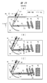
Classifications
-
- B—PERFORMING OPERATIONS; TRANSPORTING
- B60—VEHICLES IN GENERAL
- B60K—ARRANGEMENT OR MOUNTING OF PROPULSION UNITS OR OF TRANSMISSIONS IN VEHICLES; ARRANGEMENT OR MOUNTING OF PLURAL DIVERSE PRIME-MOVERS IN VEHICLES; AUXILIARY DRIVES FOR VEHICLES; INSTRUMENTATION OR DASHBOARDS FOR VEHICLES; ARRANGEMENTS IN CONNECTION WITH COOLING, AIR INTAKE, GAS EXHAUST OR FUEL SUPPLY OF PROPULSION UNITS IN VEHICLES
- B60K35/00—Instruments specially adapted for vehicles; Arrangement of instruments in or on vehicles
- B60K35/20—Output arrangements, i.e. from vehicle to user, associated with vehicle functions or specially adapted therefor
- B60K35/21—Output arrangements, i.e. from vehicle to user, associated with vehicle functions or specially adapted therefor using visual output, e.g. blinking lights or matrix displays
- B60K35/23—Head-up displays [HUD]
- B60K35/231—Head-up displays [HUD] characterised by their arrangement or structure for integration into vehicles
-
- B—PERFORMING OPERATIONS; TRANSPORTING
- B60—VEHICLES IN GENERAL
- B60K—ARRANGEMENT OR MOUNTING OF PROPULSION UNITS OR OF TRANSMISSIONS IN VEHICLES; ARRANGEMENT OR MOUNTING OF PLURAL DIVERSE PRIME-MOVERS IN VEHICLES; AUXILIARY DRIVES FOR VEHICLES; INSTRUMENTATION OR DASHBOARDS FOR VEHICLES; ARRANGEMENTS IN CONNECTION WITH COOLING, AIR INTAKE, GAS EXHAUST OR FUEL SUPPLY OF PROPULSION UNITS IN VEHICLES
- B60K35/00—Instruments specially adapted for vehicles; Arrangement of instruments in or on vehicles
- B60K35/20—Output arrangements, i.e. from vehicle to user, associated with vehicle functions or specially adapted therefor
- B60K35/28—Output arrangements, i.e. from vehicle to user, associated with vehicle functions or specially adapted therefor characterised by the type of the output information, e.g. video entertainment or vehicle dynamics information; characterised by the purpose of the output information, e.g. for attracting the attention of the driver
-
- B—PERFORMING OPERATIONS; TRANSPORTING
- B60—VEHICLES IN GENERAL
- B60K—ARRANGEMENT OR MOUNTING OF PROPULSION UNITS OR OF TRANSMISSIONS IN VEHICLES; ARRANGEMENT OR MOUNTING OF PLURAL DIVERSE PRIME-MOVERS IN VEHICLES; AUXILIARY DRIVES FOR VEHICLES; INSTRUMENTATION OR DASHBOARDS FOR VEHICLES; ARRANGEMENTS IN CONNECTION WITH COOLING, AIR INTAKE, GAS EXHAUST OR FUEL SUPPLY OF PROPULSION UNITS IN VEHICLES
- B60K37/00—Dashboards
- B60K37/20—Dashboard panels
-
- G—PHYSICS
- G02—OPTICS
- G02B—OPTICAL ELEMENTS, SYSTEMS OR APPARATUS
- G02B27/00—Optical systems or apparatus not provided for by any of the groups G02B1/00 - G02B26/00, G02B30/00
- G02B27/01—Head-up displays
-
- G—PHYSICS
- G02—OPTICS
- G02B—OPTICAL ELEMENTS, SYSTEMS OR APPARATUS
- G02B5/00—Optical elements other than lenses
- G02B5/30—Polarising elements
Definitions
- the present invention relates to a technology such as an in-vehicle head-up display device (HUD).
- HUD head-up display device
- the in-vehicle HUD device projects image light onto the windshield or combiner of the vehicle to superimpose and display a virtual image on the real image in a predetermined area viewed from the driver's point of view.
- the combiner is a dedicated reflector.
- Examples of the virtual image include images related to support for driving a car.
- the in-vehicle HUD device is required to have good visibility of the virtual image seen by the driver. For example, external light such as sunlight from the outside of the automobile may enter the HUD device. The external light may be reflected in the HUD device, emitted from the HUD device again, reflected by a windshield or the like, and incident on the driver's eyes. In this case, the external light may become noise to the driver's eyes and the visibility of the virtual image may be reduced. Therefore, it is desirable that the in-vehicle HUD device is provided with means for taking measures against such external light incident.
- the HUD device of the prior art example is provided with an antiglare plate (so-called glare trap) at the emission portion of the image light of the housing.
- This anti-glare plate reduces the influence of glare caused by external light by designing the characteristics of transmitting and reflecting predetermined light.
- Patent Document 1 describes a configuration (FIG. 2) including a glare trap which is a glare prevention means (216) as an optical relay of a small HUD, and the following.
- This glare trap is a means for capturing glare and the like to prevent reflection, is composed of a glass plate, a plastic plate, or a plate of another transparent material, and has a flat surface or a curved surface (paragraph 0012, etc.).
- the glare trap may include an optical coating or layer (eg, a dielectric) to act as a filter that has selective properties with respect to the angle of incident light. This glare trap is used multiple times as an optical surface of an optical relay.
- Patent Document 2 describes a configuration (FIG. 1, F5) of the HUD device including an optical filter arranged in an optical path between the concave mirror and the windshield, and the following.
- This optical filter is configured so that the posture can be changed so that the external light incident on the reflecting surface from an arbitrary direction on the windshield side is reflected toward a region other than the image display region.
- This optical filter is a reflective bandpass filter, and most of the external light incident from the windshield side is reflected by the reflecting surface (paragraph 0019, etc.).
- the reflection of external light by the diffuser in the HUD device can be reduced, and the temperature rise in the concave mirror or the diffuser can be reduced (paragraph 0021, etc.).
- the in-vehicle HUD device has problems such as deterioration of visibility or display quality of a virtual image due to the influence of external light incident, temperature rise of parts inside the HUD device, and the like.
- the antiglare plate (glare trap) of the HUD device of the prior art example has room for improvement in terms of the above-mentioned visibility and temperature.
- An object of the present invention is to provide a technique for a HUD device that can improve the decrease in visibility of a virtual image due to the influence of external light incident or the temperature rise of parts inside the HUD device. Issues and effects other than the above will be described in the mode for carrying out the invention.
- a typical embodiment of the present invention is an in-vehicle head-up display device, which has the following configuration.
- the vehicle-mounted head-up display device of one embodiment is a head-up display device that provides a virtual image by projecting image light onto a windshield or combiner region of a vehicle, and has a light source and the light source in a housing.
- a display element that generates image light based on the light from the display element, a polarizing element that transmits the image light from the display element, and a first reflecting element that reflects the image light from the refracting element toward the region.
- a polarizing plate that cuts the P wave of external light on the optical path between the image light emitting portion of the housing and the display element, and a position closer to the display element than the polarizing plate. It has a first wavelength plate, which is a quarter wavelength plate, and is arranged in.
- FIG. 5 is a diagram showing a configuration of a control device and the like of a display system according to the first embodiment. It is a figure which shows the example of the vehicle-mounted mounting configuration in the HUD apparatus of Embodiment 1. It is a figure which shows the disassembled structure of the HUD apparatus of FIG. It is a figure which shows the angle of the antiglare plate and a mirror in Embodiment 1.
- FIG. 5 is a diagram showing a configuration of a control device and the like of a display system according to the first embodiment. It is a figure which shows the example of the vehicle-mounted mounting configuration in the HUD apparatus of Embodiment 1. It is a figure which shows the disassembled structure of the HUD apparatus of FIG. It is a figure which shows the angle of the antiglare plate and a mirror in Embodiment 1.
- FIG. It is a figure which shows the structure (first configuration example) of the element arrangement in the housing of the HUD apparatus of Embodiment 1.
- FIG. It is explanatory drawing which shows the change of the polarization direction in the HUD apparatus of Embodiment 1. It is explanatory drawing which shows the polarization direction of the image light in the case of Embodiment 1.
- FIG. It is a figure which shows the configuration (second configuration example) of the element arrangement in the housing in the HUD apparatus of Embodiment 2 of this invention. It is a figure which shows the structure of the element arrangement in the housing in the HUD apparatus of the modification of Embodiment 2. It is explanatory drawing which shows the change of the polarization direction in the HUD apparatus of Embodiment 2.
- FIG. 27 shows the configuration of the display system including the in-vehicle HUD device 100 of Comparative Example 1, the influence of the intrusion of external light, and the like.
- FIG. 27 shows a schematic configuration on the ZZ plane when the vicinity of the driver's seat of the automobile is viewed from the side.
- the coordinate system includes an absolute coordinate system (X, Y, Z) and a HUD coordinate system (x, y, z).
- the vertical direction is the Z axis
- the two directions forming the horizontal plane are the X axis and the Y axis
- the X axis is the lateral and horizontal directions with respect to the car and the driver
- the Y axis is the car and the driver.
- the HUD coordinate system is a coordinate system viewed from the HUD device, and the two orthogonal directions forming the region formed by the virtual image are the x-axis and the y-axis, and the direction perpendicular to the region is the z-axis.
- the x-axis corresponds to the horizontal and horizontal directions within the region
- the y-axis corresponds to the vertical and vertical directions within the region.
- the x-axis, y-axis, and z-axis of the HUD coordinate system correspond to the X-axis, Z-axis, and Y-axis of the absolute coordinate system.
- the automobile has a windshield 11 such as a windshield between the bonnet and the roof in a part of the vehicle body 12.
- a HUD device 100 is provided in the instrument panel below the windshield 11.
- the HUD device 100 is located, for example, in a position in the instrument panel in front of the driver and steering wheel.
- the HUD device 100 includes a light source 92, a display element 93, a lens 94, and a mirror 95 in a housing 90.
- the light source 92 is, for example, a backlight unit (BLU).
- the display element 93 is, for example, a liquid crystal display element (LCD).
- the display element 93 generates video light based on the video data and the light from the light source 92.
- the display element 93 is of a type that emits S waves.
- the lens 94 is a refracting element for magnifying and adjusting the image light.
- the mirror 95 is a reflecting element such as a concave mirror for reflecting, enlarging, adjusting, and the like of image light.
- the lens 94, the mirror 95, and the like constitute an optical system for projecting the windshield 11 onto the region 16.
- the HUD device 100 has an antiglare plate (glare trap) 96 at a portion (sometimes referred to as an emission portion) that emits image light from the inside of the housing 90 to the outside of the housing 90.
- the image light emitted from the HUD device 100 through the antiglare plate 96 substantially upward in the Z direction is reflected in a part region 16 (indicated by a broken line) of the windshield 11 and directed toward the driver's viewpoint 13.
- the center point of the region 16 (that is, the point through which the optical axis of the image light passes) is indicated by the point P1.
- the image light incident on the eyes of the viewpoint 13 forms an image on the retina.
- the viewpoint 13 is a viewpoint for observing a virtual image associated with the position of the driver's eyes. It has a line of sight 15 indicated by a chain line from the viewpoint 13 forward. A virtual image is formed over the area 16 beyond the line of sight 15.
- FIG. 27 also shows a case where the external light L1 is incident on the HUD device 100 through the region 16 of the windshield 11, is emitted to the outside of the HUD device 100 again through reflection in the housing 90, and is reflected toward the viewpoint 13.
- the external light L1 is external light including strong sunlight incident from the outside of the automobile.
- the external light L1 is incident on the region 16 (for example, the point P1) of the windshield 11 as indicated by the arrow of the alternate long and short dash line.
- the angle of incidence of the external light L1 with respect to the point P1 in the region 16 is indicated by the angle ⁇ 1.
- the angle ⁇ 1 is an angle formed by the direction perpendicular to the surface of the region 16 and the light beam of the external light L1.
- a part of the external light L1 (particularly the S wave) is reflected as the external light L2 by the surface of the windshield 11.
- the reflectance which is the rate at which the external light L1 is reflected on the surface of the windshield 11, differs depending on the angle of incidence ⁇ 1.
- the reflectance differs between the S wave and the P wave.
- the S wave has a higher reflectance than the P wave. That is, the external light L3 after passing through the region 16 of the windshield 11 is light in a state where there are many P waves and few S waves as components.
- the external light L3 enters the antiglare plate 96 arranged at the exit portion of the housing 90 of the HUD device 100, and enters the housing 90 through the antiglare plate 96.
- the conventional antiglare plate 96 realizes a function of reducing glare due to incident or reflection of external light to some extent by designing the transmittance and reflectance of the material and designing the curvature and inclination.
- the cross section of the antiglare plate 96 is shown as a flat surface in FIG. 27, the cross section of the antiglare plate 96 may have a curved surface.
- the external light L4 that has passed through the antiglare plate 96 and entered the housing 90 is reflected by parts such as the mirror 95 and the lens 94, the inner wall surface of the housing 90, and other structures.
- the external light L4 is reflected by the mirror 95 and heads toward the lens 94.
- a part of the external light is reflected by the lens 94 and returns to the mirror 95.
- the other part of the external light passes through the lens 94 and heads toward the display element 93.
- the external light transmitted through the lens 94 is reflected by the surface of the display element 93, returns to the lens 94, passes through the lens 94 again, and heads toward the mirror 95.
- the external light L5 reflected back to the mirror 95 returns to the antiglare plate 96 as stray light.
- the external light L5 becomes the external light L6 that passes through the antiglare plate 96 and is emitted to the outside of the HUD device 100.
- the external light L6 is reflected in the region 16 of the windshield 11, and may be incident on the viewpoint 13 as the external light L7. In this case, from the driver's viewpoint 13, the external light is superimposed on the virtual image as noise, which may reduce the visibility of the virtual image.
- the conventional HUD device 100 has a problem of deterioration of visibility (in other words, display quality) of a virtual image due to stray light based on external light incident.
- parts such as the display element 93 in the HUD device 100 may accumulate heat due to the external light and the temperature may rise.
- the external light L4 may be reflected by the mirror 95 and focused on the lens 94 or the display element 93.
- Parts such as the display element 93 have a predetermined heat resistant temperature. There is a possibility that the heat resistant temperature of the part will be exceeded due to the temperature rise due to the incident of external light. It is necessary to prevent this.
- ⁇ T be the temperature difference between the component temperature in the case of normal use without external light incident and the elevated component temperature in the case of external light incident. The temperature difference ⁇ T of each component needs to be suppressed to a predetermined value or less.
- the display element 93 for example, a small liquid crystal display panel is used for reasons such as low cost.
- the heat resistant temperature of the liquid crystal display panel is not so high. Therefore, the liquid crystal display panel may be deteriorated or damaged by the heat of external light.
- the HUD apparatus according to the first embodiment of the present invention will be described with reference to FIGS. 1 to 9.
- the HUD device of the first embodiment is an in-vehicle HUD device, and displays a virtual image corresponding to augmented reality (AR), mixed reality (MR), etc. by projecting image light onto the area of the windshield of the vehicle. Has a function to do.
- the HUD device of the first embodiment is provided with a unique antiglare plate as an external light countermeasure function for taking measures against the influence of external light incident in consideration of the above problems and the like.
- the HUD device of the first embodiment has effects such as ensuring the visibility of the virtual image and suppressing the temperature of the parts in the HUD device.
- FIG. 1 shows the configuration of an in-vehicle display system including the HUD device 1 of the first embodiment.
- FIG. 1 shows a schematic configuration of the front part of the driver's seat of an automobile and the ZZ plane when the driver is viewed from the side.
- the automobile has a windshield 11 such as a windshield between the bonnet and the roof of the vehicle body 12.
- the HUD device 1 is provided in the instrument panel under the windshield 11.
- the area 16 is a part of the transmission area (the area where the real image can be visually recognized) of the windshield 11, and is the area where the image light from the HUD device 1 is projected and reflected.
- the area 16 may be described as a HUD area or a HUD display range.
- This region 16 is within the field of view (FOV) from the viewpoint 13. From the driver's point of view 13, the virtual image 18 appears to be configured at the position of the region 17 over the windshield 11.
- the region 17 may be described as a virtual image region.
- the image light emitted from the HUD device 1 is reflected in the region 16, is incident on the eyes of the viewpoint 13, and is imaged on the retina, so that the driver visually recognizes it as a virtual image 18.
- the eye box 14 is a three-dimensional region having a predetermined size including the position of the viewpoint 13. The position of the driver's viewpoint 13 fluctuates, but when the position of the viewpoint 13 is within the range of the eyebox 14, the virtual image 18 can be seen with sufficient quality.
- the HUD device 1 has a function of superimposing a virtual image 18 on a real image (for example, a road, a car, a person, etc. in front of the own vehicle) in areas 16 and 17 viewed from the viewpoint 13.
- this function is a function of displaying a virtual image 18 corresponding to AR, MR, or the like. With this function, it is possible to support driving by displaying an image related to, for example, driving navigation or alerts at a position in front of the windshield 11.
- external light L1 such as strong sunlight is incident on the windshield 11, for example, the region 16. Similar to the description in Comparative Example 1, a part of the external light L1 (particularly the S wave) is reflected in the region 16 of the windshield 11. The remaining part of the external light L1 passes through the region 16 and is incident on the antiglare plate 6 arranged at the position of the exit portion of the housing 9 of the HUD device 1.
- the HUD device 1 is provided with an antiglare plate (glare trap) 6 or the like as an external light countermeasure function for countermeasures against adverse effects such as stray light and heat due to external light incident.
- This function uses the antiglare plate 6 to reduce stray light based on the incident of external light, reduce the external light component incident on the viewpoint 13, and make the virtual image 18 visible to the driver (in other words, display quality). ) Is a function to secure or improve. Further, this function uses the antiglare plate 6 to reduce the incident of external light into the housing 9, and suppresses the accumulation of heat and the temperature rise of the parts (particularly the display element 3) in the HUD device 1. It is a function.
- the angle of inclination of the windshield 11 differs depending on the vehicle model.
- the angle of projection of the image light of the HUD device 1 is set according to the angle of inclination of the windshield 11.
- the transmission region including the region 16 of the windshield 11 has a curved surface.
- the image light of the HUD device 1 is adjusted by an optical system or the like in the HUD device 1 so that a suitable virtual image 18 can be formed according to the curvature of the curved surface thereof.
- a predetermined optical element such as a transparent diffusion sheet may be additionally arranged on the surface of the windshield 11, for example, a part of the region including the region 16.
- a combiner (dedicated reflector) may be provided at a predetermined position between the windshield 11 and the exit portion of the HUD device 1.
- the image light from the exit portion of the HUD device 1 is projected and reflected on the region of the combiner, and a virtual image is formed through the combiner.
- FIG. 2 shows a configuration outline of the element arrangement and the like in the housing 9 of the HUD device 1 in the yz plane.
- the shape of the housing 9 of the HUD device 1 is an example and is not particularly limited.
- the HUD device 1 has an exit portion associated with an opening of an instrument panel (FIG. 4, etc. described later) on a part of the upper surface of the housing 9, and an antiglare plate 6 is arranged at the position of the exit portion. Has been done.
- the HUD device 1 has components such as a substrate 10, a light source 2, a display element 3, a lens 4, and a mirror 5 housed and held in a housing 9. As shown by the broken line, the substrate 10 and each component such as the light source 2 may be electrically connected by a driving signal line or the like.
- a predetermined optical system 11 is composed of a light source 2, a display element 3, a lens 4, and a mirror 5 in a housing 9.
- the optical system 11 is an optical system for projecting the image light from the display element 3 onto the region 16 of the windshield 11 while expanding or adjusting the image light. This adjustment includes correction of aberrations and strains.
- the BLU which is the light source 2
- the light source 2 is not limited in detail, but is configured by using, for example, an LED element (FIG. 5, etc. described later).
- the light source 2 emits light having high uniformity on the surface toward the display element 3 on the front side in the z direction.
- the optical axis of light from the light source 2 to the display element 3 is indicated by the optical axis J1.
- the solid lines on both sides of the optical axis outline the range of light rays.
- the display element 3 is a liquid crystal display element (LCD) as an implementation example in the first embodiment, but is not limited to this, and other image display devices such as an organic EL display or a projection type display device may be used.
- the display element 3 displays an image on an exit surface which is a front surface in the z direction, whereby image light is emitted toward the lens 4 from this exit surface.
- the optical axis of the image light from the display element 3 to the lens 4 is indicated by the optical axis J2.
- the lens 4 is a refracting element that transmits and magnifies the image light from the display element 3 and guides it to the mirror 5. Further, the lens 4 has a shape for correcting aberrations and distortions generated when an image is formed by a mirror 5 or the like (FIG. 5 or the like described later). The optical axis of the image light from the lens 4 to the mirror 5 is indicated by the optical axis J3.
- the mirror 5 is the first reflecting element, and reflects the image light from the lens 4 in the z direction substantially toward the antiglare plate 6 as the image light in the y direction.
- the reflected light passes through the antiglare plate 6, heads toward the region 16, is reflected, and heads toward the viewpoint 13.
- the optical axis of the image light from the mirror 5 to the antiglare plate 6 is indicated by the optical axis J4.
- the mirror 5 is a concave mirror as a mounting example, and the reflective surface which is the concave surface has a free curved surface.
- the concave surface of the mirror 5 has a shape for reducing distortion of the virtual image 18 (FIG. 5 described later).
- the shape of the concave surface is, for example, a shape in which the curvature of the free curved surface is designed according to the shape of the region 16 of the windshield 11.
- the optical axes of the display element 3 and the lens 4 are arranged so as to be slightly inclined at a predetermined angle with respect to the optical axis of the mirror 5 or the Y direction (z direction).
- a more preferable effect can be obtained with respect to correction of distortion and the like and reflection of external light.
- an element such as a conversion panel for obliquely converting the optical axis direction may be provided between the light source 2 and the display element 3.
- a pair of the polarizing plate 20 and the wave plate 31 is arranged at a predetermined position between the display element 3 and the exit portion of the housing 9 in the range of the optical path of the image light.
- the antiglare plate 6 has a polarizing plate 20 and a wave plate 31.
- the antiglare plate 6 is composed of a set of two optical elements of the polarizing plate 20 and the wavelength plate 31. These two elements have an ordinal relationship.
- the polarizing plate 20 is arranged on the upper side (in other words, the rear stage side in the optical path of the image light) in the Z direction, and the wave plate 31 is arranged on the lower side (in other words, the front stage side in the optical path of the image light).
- the wave plate 31 is, in detail, a ⁇ / 4 wave plate (a quarter wave plate), and may be referred to as a first wave plate.
- the two elements of the polarizing plate 20 and the wave plate 31 are held so that, for example, the outer periphery thereof is sandwiched and fixed by a part of the housing 9, and the two elements are brought into close contact with each other and overlapped with each other.
- the cross-sectional shape of the antiglare plate 6 is flat, but the cross-sectional shape of the antiglare plate 6 may be curved as in the example of (FIG. 6) described later. ..
- the antiglare plate 6 may include members other than the polarizing plate 20 and the wave plate 31.
- another member may be arranged so as to be sandwiched between the polarizing plate 20 and the wave plate 31, or another member may be arranged above the polarizing plate 20 or below the wavelength plate 31.
- the other member may be a transparent base material, an adhesive, or the like, or an existing optical filter or the like.
- the antiglare plate 6 may be made of a non-flexible plate, or may be made of a flexible sheet or film. In the latter case, the antiglare plate 6 can be paraphrased as an antiglare sheet or the like.
- the polarizing plate 20 is an optical element having a characteristic of cutting the P wave of the external light by absorption or the like and transmitting the S wave. Since the P wave can be cut by the polarizing plate 20, the thermal energy of the external light component that penetrates into the HUD device 1 can be reduced. For example, under daytime conditions, the P wave of the external light L3 transmitted through the windshield 11 of FIG. 27 can be cut by the polarizing plate 20 located above the mirror 5 in the Z direction.
- the P wave of the external light L3 is incident on the HUD device 100, the P wave of the external light L4 is reflected by the mirror 95 and irradiated to the display element 93, and the antiglare plate 96 It is possible to reduce the amount of light emitted to the outside again. That is, it is possible to reduce the decrease in visibility of the virtual image due to external light, and it is possible to reduce the heat storage and temperature rise of the parts in the housing.
- the wave plate 31 is an optical element for cutting the S wave remaining in the external light after the P wave is cut by the polarizing plate 20.
- the ⁇ / 4 wave plate, which is the wave plate 31 is an element that rotates the polarization direction of light in the polarizing plane by 45 degrees by causing a phase difference of 90 degrees between the high-speed axis and the low-speed axis of the incident light. Is. Details will be described later (FIG. 7 and the like), but by transmitting the external light through the wave plate 31 twice in total, when it is incident and when it is emitted, the polarization direction of the external light is rotated by a total of 90 degrees, that is, the external light.
- the S wave is converted into the P wave.
- the P wave of the external light is cut by the polarizing plate 20 at the time of emission. As a result, it is possible to reduce the amount of external light returning to the outside of the HUD device 1 toward the viewpoint 13, and it is possible to reduce the decrease in visibility of the virtual image due to the external light.
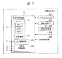
- FIG. 3 shows a functional block configuration of the control device and the like of the display system of FIG.
- the board 10 is an IC board or the like that constitutes the control device of the HUD device 1, and controls the drive of each part.
- the control device by the substrate 10 is connected to the navigation system 201, the driving support ECU 202, and the like via communication. Communication is, for example, communication via CAN (Car Area Network) or the like.
- the navigation system 201 is, for example, an in-vehicle car navigation system.
- the driving support ECU 202 is a control device such as an in-vehicle engine control unit that controls and supports the driving of a vehicle.
- the driving support ECU 202 is connected to the peripheral monitoring device 203.
- the peripheral monitoring device 203 is a device for monitoring the surrounding situation of the own vehicle, and includes a camera and an exploration device as an example.
- the camera detects an object existing around the vehicle based on an image taken around the vehicle.
- the exploration device detects objects existing around the vehicle based on the result of transmitting and receiving exploration waves.
- the driving support ECU 202 realizes driving support control by controlling the drive system and the control system according to, for example, an obstacle detected as a result of monitoring by the peripheral monitoring device 203.
- the control device by the board 10 acquires various information as foreground information from the navigation system 201.
- various types of information include the speed limit and the number of lanes of the road corresponding to the current position in which the vehicle is traveling, the planned travel route of the vehicle set in the navigation system 201, and the like.
- the control device acquires various information as foreground information from the driving support ECU 202.
- various types of information include information such as the distance to the preceding vehicle, the orientation of the preceding vehicle, and the position where an obstacle or a sign exists.
- the foreground information is used as video information for forming a virtual image 18 to be displayed as the foreground of the own vehicle.
- the ignition signal 204, the vehicle status information 205, etc. are input to the control device.
- the control device is activated, for example, by inputting an ignition signal.
- the own vehicle state information 205 is information obtained as vehicle information from various sensors and the like in the vehicle, and examples thereof include warning display information, operation result information of a direction indicator, and information such as vehicle speed and shift position.
- the control device includes a microcomputer 101, a storage device 102, a BLU drive circuit 103, an optical system drive circuit 104, and the like.
- the microcomputer 101 includes a CPU, a ROM, a RAM, and the like, and a processor or a controller is configured by these.
- the microcomputer 101 controls the HUD device 1 including the image display control of the display element 3.
- the microcomputer 101 generates video data and display control information for the virtual image 18 based on various input information, and transmits the video data and the display control information to the display element 3 and the BLU drive circuit 103.
- Various information and data for control are stored in the storage device 102, including information and video data for generating the virtual image 18.
- the BLU drive circuit 103 is a circuit that drives the light emission of the backlight unit that is the light source 2.
- the optical system drive circuit 104 is a circuit that drives the lens 4, the mirror 5, the antiglare plate 6, and the like of the optical system 11.
- the drive of the optical system 11 may include a drive for adjusting the orientation of the lens 4, the mirror 5, and the antiglare plate 6.
- FIG. 3 shows a case in which the lens 4, the mirror 5, and the antiglare plate 6 can all be driven, but the present invention is not limited to this, and some parts, for example, the mirror 5 can be driven. May be good. That is, the orientation of the lens 4, the mirror 5, or the antiglare plate 6 may be fixed.
- the drive for adjusting the orientation may be executed in response to a predetermined operation input (for example, pressing a button) of the user, or may be automatically executed at the discretion of the control device.
- FIG. 4 shows the instrument panel 301, the instrument panel 302, the steering wheel 303, etc. under the windshield 11 in the vehicle.
- the HUD device 1 is arranged in the instrument panel 301, particularly in front of the steering wheel 303 and the instrument panel 302.
- An opening 304 is provided in a part of the upper surface of the instrument panel 301, and the HUD device 1 is housed under the opening 304.
- the antiglare plate 6 is arranged according to the position of the opening 304.
- the arrow of the alternate long and short dash line indicates the outline of the optical axis of the image light from the HUD device 1.
- the housing 9 (shown by the broken line) of the HUD device 1 of this mounting example has a configuration in which the component size gradually increases from the light source 2 side to the mirror 5 side in the z direction (Y direction).
- FIG. 4 shows a state in which the light source 2, the display element 3, and the like are separated, but the components are connected to each other.
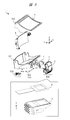
- FIG. 5 shows the disassembled configuration of the main parts in the mounting example of FIG.
- the HUD device 1 includes a housing 501 as a part of the housing 9, and the housing 501 includes a unit 504 to which the light source 2 and the display element 3 are connected, a lens 4, and a mirror 5.
- the parts are fixed. Each part is fixed with screws or the like.
- the unit 504 is fixed so that the incident surface on the back surface of the display element 3 is overlapped with the light emitting surface on the front side in the Y direction (z direction) of the light source 2. Both ends of the lens 4 in the X direction are fixed on the rear surface of the housing 501 in the Y direction.
- a housing 502 to which the antiglare plate 6 is connected is fixed to the upper side of the housing 501 while accommodating the mirror 5.
- Other components such as a drive control board 503 (corresponding to the board 10) and a motor 505 (connected to the shaft of the mirror 5) are arranged on the lower side of the housing 501.
- the flexible wiring of the display element 3 is connected to the substrate 503.
- the unit 504 which is a combination of the light source 2 and the display element 3 is used, but the present invention is not limited to this.
- a self-luminous fluorescent display tube VFD: Vacuum Fluorescent display
- a solid light source such as an LED light source is applied to the light source 2.
- the LED light source has a characteristic that the light output fluctuation with respect to the ambient temperature fluctuation is small.
- the LED light source which is the light source 2
- the LED light source 2 is composed of a plurality of LED elements, a collimator, a polarization conversion element, a light guide body, a diffuser plate, a heat sink, and the like.
- the collimator collects the light from the LED element and converts it into parallel light.
- the polarization conversion element uses a polarization beam splitter to convert the polarization direction of parallel light.
- the light guide body bends the optical axis direction of the parallel light by, for example, about 90 degrees to make it the optical axis direction to the display element 3.
- the display element 3 is composed of, for example, a liquid crystal display panel attached to a frame, a flexible printed circuit board, or the like.
- the lens 4 has a concave curved surface shape on the entrance side on the entrance surface and the exit surface.
- This curved surface shape is the shape for the above-mentioned enlargement and adjustment.
- the lens 4 controls the direction of light emission to the mirror 5 at each position in the plane according to its shape.
- the correction including the distortion correction regarding the display of the virtual image 18 is realized.
- the lens 4 realizes a correction including astigmatism correction regarding the curved surface of the windshield 11 together with the correction by the shape of the mirror 5.
- the optical system 11 including the lens 4 and the mirror 5 realizes an optical correction function for forming a suitable virtual image 18.
- the lens 4 may be composed of a plurality of lenses in order to enhance the ability of the correction function. Further, instead of the lens 4, one or more free-form curved mirrors may be arranged. In this case, an optical path including bending is configured as an optical path from the display element 3 to the mirror 5 in the housing 9, and the direction of light ray incident on the mirror 5 is controlled. Further, the shape of the lens 4 may be a shape in which the thickness of the lens 4 in the optical axis direction is different depending on each position in the plane. In this case, the optical distances of the light rays at each position in the plane can be made different between the display element 3 and the mirror 5.
- the shape of one or both of the entrance surface and the exit surface of the lens 4 is preferably a shape that prevents the reflected light from the mirror 5 from being focused on a part of the display element 3.
- a shape in which the concave surface is directed to the display element 3 side can be mentioned.
- the lens 4 may be provided with an antireflection film on the incident surface or the like to suppress unnecessary reflection of light rays.
- the mirror 5 is a concave mirror having an axis in the X direction, a substantially rectangular outer shape, and a concave curved surface on the incident side, and has a mechanism capable of rotating around the axis.
- the optical system drive circuit 104 of the control device drives the rotation of the axis of the mirror 5 through the motor 505. By this mechanism, the projection direction of the image light can be adjusted.
- the antiglare plate 6 has a curved surface having a substantially rectangular outer shape, and this curved surface is a concave curved surface on the exit side.
- the curved surface of the antiglare plate 6 is arranged so as to be slightly inclined toward the driver side with respect to the horizontal plane including the X-axis and the Y-axis.
- a HUD device or the like that provides a virtual image to a passenger in the passenger seat is also possible.
- the HUD device is arranged at another position in the instrument panel 301, for example, and projects an image onto another area of the windshield 11.
- a polarizing plate (different from the polarizing plate 20 in FIG. 2) may be arranged on the entrance surface and the exit surface of the display element 3. As a result, the contrast ratio of the image light can be increased.
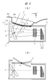
- FIG. 6 shows a schematic configuration regarding the tilt angle of the mirror 5 and the antiglare plate 6 in the mounting example of the HUD device 1.
- A shows an example of the inclination angle in relation to the antiglare plate 6 at the exit portion of the housing 9 and the opening 304 of the instrument panel 301.
- B shows an example of changing the tilt angle of the mirror 5 and the antiglare plate 6 with respect to (A).
- Each of the mirror 5 and the antiglare plate 6 may be provided with a mechanism capable of variably adjusting the tilt angle, the arrangement position, and the like.
- the opening 304 is, for example, an empty space, but is not limited to this, and a transmission member may be provided, or an opening / closing mechanism including a lid may be provided.
- the above-mentioned unit 504, lens 4, and mirror 5 are arranged in the housing 9.
- the optical axis from the lens 4 to the mirror 5 is the z direction.
- the tilt angle ⁇ of the mirror 5 is shown as an angle formed by the z direction of the optical axis and the vertical direction (corresponding axis j2) of the center point of the reflecting surface of the mirror 5.
- the motor 505 of FIG. 5 is connected to the rotation shaft 5a in the x direction of the mirror 5. By driving the motor 505 from the substrate 10, the tilt angle ⁇ of the mirror 5 can be adjusted within a predetermined range.
- the antiglare plate 6 has a concave curved surface shape on the upper side in the y direction (Z direction).
- the antiglare plate 6 is arranged with an inclination angle ⁇ as shown by a broken line with reference to the center point p1 of the surface.
- the angle ⁇ is shown as an angle formed by the z direction (Y direction) in the horizontal plane and the vertical direction (corresponding axis j1) of the center point p1 of the antiglare plate 6. This axis j1 faces slightly rearward in the z direction.
- a rotation shaft may be provided at a center point p1 or the like, a motor may be connected to the rotation shaft, and the motor may be driven from the control device. ..
- the above-mentioned housing 502 may be provided with a rotation drive mechanism.
- (A) there is a distance between the opening 304 of the instrument panel 301 and the antiglare plate 6 at the exit portion of the housing 9, but the distance is not limited to this, and the opening 304 and the antiglare plate 6 are not limited to this.
- the positions of may be almost the same.
- the cross section of the antiglare plate 6 may be a flat surface or a curved surface having a convex shape on the upper side.
- a predetermined protective cover or the like may be provided on the opening 304 of the instrument panel 301 or the antiglare plate 6.
- This protective cover has, for example, a transparent substrate and a black film.
- the black film contains black paint and is arranged, for example, in a striped shape. As a result, external light reflection can be reduced.
- the protective cover and the antiglare plate 6 may be integrally formed.
- a set of the polarizing plate 20 and the wave plate 31 corresponding to the antiglare plate 6 is provided at the position of the opening 304 of the instrument panel 301 instead of the position of the exit portion of the housing 9. It may be provided.
- the inclination of the mirror 5 is kept in a predetermined state, or when the opening 304 has an opening / closing mechanism, it is closed to make it opaque. It is possible to reduce the influence of external light incident on the.
- FIG. 28 shows the configuration of the HUD device 100 of Comparative Example 2 with respect to the first embodiment and the like.
- This Comparative Example 2 shows a configuration in which only the polarizing plate 20 that cuts the P wave is provided, and does not have the wave plate 31 in the first embodiment.
- the display element 93 a type that emits an S wave is used. The S wave of the image light passes through the polarizing plate 20 and is emitted to the outside.
- FIG. 28A shows a first configuration example of the arrangement of the polarizing plate 20 in Comparative Example 2.
- FIG. 28B shows a second configuration example of the arrangement of the polarizing plate 20.
- FIG. 28C shows a third configuration example of the arrangement of the polarizing plate 20.
- the polarizing plate 20 is arranged as the antiglare plate 96 at the position of the exit portion of the housing 90.
- the P-wave of the external light L3 (corresponding external light A1) can be cut by the polarizing plate 20, and although some S-waves are incident like the external light A2, the HUD apparatus.
- the external light entering the 100 can be reduced, the external light toward the viewpoint 13 can be reduced, and the heat inside the HUD device 100 can be reduced.
- the antiglare plate 96 of the housing 90 is configured by a known technique and does not include the polarizing plate 20 and the like.
- the polarizing plate 20 is arranged at a predetermined position between the mirror 95 and the lens 94 in the housing 90. According to this second configuration example, the polarizing plate 20 can cut the P wave of the external light A3 after being reflected by the mirror 95, and similarly, the effect of reducing the external light can be obtained.
- the size such as the area of the polarizing plate 20 can be made smaller than that of the polarizing plate 20 of the first configuration example.
- the antiglare plate 96 of the housing 90 is configured by a known technique and does not include the polarizing plate 20 and the like.
- the polarizing plate 20 is arranged at a predetermined position between the lens 94 and the display element 93 in the housing 90. According to this third configuration example, the polarizing plate 20 can cut the P wave of the external light A3 after passing through the lens 94, and similarly, the effect of reducing the external light can be obtained.
- the size such as the area of the polarizing plate 20 can be made smaller than that of the polarizing plate 20 in the second configuration example.
- the P wave which is a large number of components of the external light L3 can be cut by using the polarizing plate 20, so that appropriate effects on visibility and temperature can be obtained. ..
- the S-wave component of the external light L3 could not be reduced. Therefore, in the configuration shown in FIG. 2 of the first embodiment, the antiglare plate 6 uses the wavelength plate 31 in addition to the polarizing plate 20. As a result, the S wave of the external light L3 can also be reduced, and a higher effect on the external light countermeasure can be obtained.
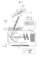
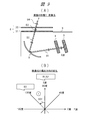
- FIG. 7 shows the element arrangement configuration in the HUD device 1 of the first embodiment, the influence of external light incident, and the like.
- FIG. 7 shows the main parts of the housing 9, the region 16 of the windshield 11, and the influence of the external light L1 on the YY plane (yz plane).
- FIG. 7 shows, in particular, a first configuration example relating to the arrangement of the pair of the polarizing plate 20 and the wave plate 31, which are the two elements constituting the antiglare plate 6.
- a pair of the polarizing plate 20 and the wave plate 31 is arranged as the antiglare plate 6 at the position of the exit portion of the housing 9.
- a space is provided between the polarizing plate 20 and the wave plate 31.
- An example of mounting the antiglare plate 6 is as shown in FIG. 2 and the like described above, but the present invention is not limited to this.
- the LCD used as the display element 3 is of a type that emits S waves.
- natural light such as sunlight is light in a wide wavelength range including ultraviolet rays to infrared rays, and is light that exists in a state where two types of light in the polarization direction (that is, P wave and S wave) are mixed.
- the light When light is incident on the boundary surface, the light can be divided into P wave and S wave.
- the P wave is indicated by an arrow of one type (dot pattern)
- the S wave is indicated by an arrow of the other type (white).
- linearly polarized light and circularly polarized light are indicated by small arrows of each type as shown in the figure.
- a part of the external light L1 (mainly S wave) is reflected as the external light L2 in the windshield 11, for example, the region 16.
- the other part of the external light L1 passes through the region 16 and enters the antiglare plate 6 at the exit portion of the HUD device 1 as the external light L3.
- the external light L3 (referred to as the corresponding external light A1) includes P waves and S waves, and has many P waves and few S waves, similarly to the HUD device 100 of Comparative Example 1 or Comparative Example 2 described above. It is light.
- the antiglare plate 6 in the HUD device 1 of the first embodiment has a configuration for cutting or reducing both the P wave and the S wave of the external light L3.
- the external light A1 first enters the polarizing plate 20.
- the polarizing plate 20 cuts the P wave of the external light A1 and transmits the S wave.
- the external light A2 transmitted through the polarizing plate 20 is light having linearly polarized light mainly including S waves.
- the external light A2 then enters the wave plate 31.
- the wave plate 31 is an optical element that is composed of a birefringent element or the like and changes the phase of light, and is an element that causes a phase difference between orthogonal polarization components to convert the polarization state of incident light. Also called.
- the wave plate 31 is a ⁇ / 4 wave plate (quarter-wavelength plate).
- the ⁇ / 4 wave plate can convert linearly polarized light to circularly polarized light by creating a phase difference of 90 degrees ( ⁇ / 4) between the light component of the high-speed axis and the light component of the low-speed axis of the incident light. It is an element capable of converting circularly polarized light to linearly polarized light.
- ⁇ represents one wavelength of light (360 degrees)
- ⁇ / 4 represents a quarter wavelength (90 degrees).
- the polarization direction in the polarizing plane is rotated by 45 degrees.
- the light passes through the ⁇ / 4 wave plate for the second time, it is further rotated by 45 degrees. That is, in the total of the two transmissions, the polarization direction is rotated by 90 degrees, that is, the conversion from the P wave to the S wave (or the conversion from the S wave to the P wave) is realized.
- the wave plate 31 rotates the polarization direction of the S wave of the external light A2 by 45 degrees.
- the external light A3 after passing through the wave plate 31 is light having circularly polarized light in a state where the polarization direction of the S wave is rotated by 45 degrees, and is indicated by a solid line arrow with a rotating arrow.
- the external light A3 is reflected by the mirror 5 and becomes the reflected external light A4.
- the external light A4 is also light in the same state as the external light A3.
- the external light A4, which is the reflected light from the mirror 5, goes toward the lens 4.
- a part of the external light A4 is reflected by the lens 4 and returns to the mirror 5 as the external light A5.
- a part of the external light A4 passes through the lens 4, is reflected by the exit surface of the display element 3, and returns to the lens 4.
- the external light passes through the lens 4 again and returns to the mirror 5 as external light A5.
- the external light A5 from the lens 4 is reflected by the mirror 5 and becomes the external light A6 which is the reflected light, and heads toward the antiglare plate 6.
- the external light A6 first enters the wave plate 31, is further rotated by 45 degrees in the polarization direction due to the transmission of the wavelength plate 31, and is emitted as the external light A7 in that state. At this time, it is the second conversion in total, and the S wave of the external light A2 is converted into a P wave by rotating the polarization direction by 90 degrees in total.
- the external light A7 having the linearly polarized light of the P wave has a relationship orthogonal to the external light A2 having the linearly polarized light of the S wave.
- the external light A7 is further incident on the polarizing plate 20 and the P wave is cut by transmission. Therefore, it is prevented that the stray light, which is external light, returns from the antiglare plate 6 to the outside and is emitted (indicated by a cross).
- the stray light which is external light
- the stray light returns from the antiglare plate 6 to the outside and is emitted (indicated by a cross).
- the HUD device 1 not only the mirror 5, the lens 4, the display element 3, etc., but also all the parts such as the end of the mirror 5 and the holding member (not shown) may cause stray light due to reflection of external light or the like. According to the HUD device 1 of the first aspect, all of them stray light can be prevented or reduced.
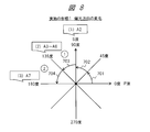
- FIG. 8 shows an explanatory diagram of a change and conversion of the polarization direction of external light using the wave plate 31 corresponding to the first configuration example of FIG. 7.
- FIG. 8 shows a plane of polarization with 360 degrees as an angle representing the polarization direction, the horizontal axes are 0 degrees and 180 degrees, the vertical axis is 90 degrees and 270 degrees, the horizontal axis is P wave, and the vertical axis is S. Corresponds to the waves.
- the transmission of light (for example, P wave) once through the wave plate 31 corresponds to the conversion 701 of rotation of 45 degrees in the polarization direction.
- the light transmitted through the wave plate 31 once more corresponds to the conversion 702 of the rotation of 45 degrees in the polarization direction, and corresponds to the conversion of the rotation of 90 degrees in the polarization direction in total. That is, the fact that light transmits through the wave plate 31 twice in total corresponds to the conversion from P wave to S wave (or conversion from S wave to P wave).
- the P wave of the external light A1 is cut by the polarizing plate 20 to become the external light A2 including the S wave.
- the S wave of the external light A2 is shown at a position of 90 degrees.
- the external light A2 passes through the wave plate 31 for the first time and enters the housing 9.
- the external light A2 becomes the external light A3 whose polarization direction is rotated by 45 degrees.
- the conversion 703 shows a 45 degree rotation from the S wave at this time.
- the external light A3 is shown at the position of 135 degrees.
- the number of transparency / conversion is indicated by a circled number.
- the external lights A4, A5, and A6 are at the position of 135 degrees because the polarization directions do not change.
- the polarization direction of the external light A6 is further rotated by 45 degrees by the second transmission of the wave plate 31.
- the conversion 704 shows the rotation from 135 degrees to 180 degrees at this time, and shows the external light A7 at the position of 180 degrees. Since this external light A7 is converted into a P wave, it is cut by the polarizing plate 20.
- the P wave of the external light A1 can be cut by the polarizing plate 20, and the remaining S wave can be cut by the wave plate 31. Stray light based on the external light L1 hardly goes out from the antiglare plate 6. Therefore, according to the HUD device 1, it is possible to reduce the external light toward the region 16 and the viewpoint 13, and to secure or improve the visibility of the virtual image 18. Further, since the antiglare plate 6 can reduce the heat energy of the external light entering the HUD device 1, the heat of the parts such as the display element 3 in the HUD device 1 can be reduced, the temperature rise can be suppressed, and the temperature rise of the parts can be suppressed. It can be below the heat resistant temperature. Further, since the temperature inside the HUD device 1 can be lowered, it becomes easy to use an inexpensive liquid crystal display element or the like as the display element 3, which is advantageous in terms of cost and the like.
- a conventional antiglare plate (corresponding element) is additionally arranged at the position of the exit portion of the housing 9. May be good.
- the conventional antiglare plate be an absorption type antiglare plate (for example, an element provided with a black film).
- the antiglare plate 6 may be additionally provided with a reflective film or the like that reflects at least one of the light in the ultraviolet region and the light in the infrared region of the external light A1.
- FIG. 9 shows the polarization direction of the image light from the LCD, which is the display element 3, in the case of the first configuration example of FIG. 7 of the first embodiment.
- FIG. 9A shows an outline of the change in the image light from the display element 3.
- the display element 3 is a type that emits S-wave video light.
- the image light B1 emitted from the exit surface of the display element 3 is mainly an S wave, and this S wave is transmitted through the lens 4 and magnified, and is reflected by the mirror 5 to become the image light B2.
- the image light B2 first enters the wave plate 31.
- the image light becomes the image light B3 having circularly polarized light in a state where the polarization direction is rotated by 45 degrees due to the transmission of the wave plate 31.
- the image light B3 is further incident on the polarizing plate 20.
- the image light B3 becomes the image light B4 having the linearly polarized light of the S wave because the P wave component is cut by the transmission of the polarizing plate 20 and only the S wave component is transmitted.
- the image light B4 heads toward the region 16, is reflected, and heads toward the viewpoint 13.
- FIG. 9 shows the change in the polarization direction of the video light on the polarization plane as in FIG. Since the image lights B1 and B2 are S waves, they are located at 90 degrees.
- the image light B3 after passing through the wave plate 31 is at the position of 135 degrees by the conversion 901 of rotation of 45 degrees in the polarization direction.
- the video light incident on the video light B4 and the viewpoint 13 among the circularly polarized video light in the state of being rotated 45 degrees from the state of the S wave of the first video light B1. It becomes linearly polarized light having the S-wave component of.
- the reflectance and the brightness are slightly lower than when the video light incident on the viewpoint 13 is the light in which the state of the first S wave is maintained. If this display quality is acceptable, the configuration of the first embodiment has a sufficient effect on measures against external light. When it is desired to further improve the display quality, for example, the fourth embodiment described later is effective.
- the HUD apparatus according to the second embodiment of the present invention will be described with reference to FIG.
- the basic configuration of the second embodiment and the like is the same as that of the first embodiment, and the components different from the first embodiment of the second embodiment and the like will be described below.
- the HUD device 1 of the second embodiment is a modification of the first configuration example of FIG. 7, and shows a second configuration example in which the arrangement of the two elements constituting the antiglare plate 6 is different.
- FIG. 10 shows a second configuration example in the HUD device 1 of the second embodiment.
- the antiglare element 62 formed by the combination of the polarizing plate 20 and the wave plate 31 is arranged at a predetermined position z1 between the mirror 5 and the lens 4.
- the antiglare element 62 is fixed to the housing 9.
- a conventional antiglare plate 60 is arranged at the exit portion of the housing 9.
- the antiglare plate 60 does not include the polarizing plate 20 and the wave plate 31.
- the polarizing plate 20 is arranged on the emitting side of the image light and the wavelength plate 31 is arranged on the incident side.
- the external light A1, A2, and A3 are light containing many P waves and a small amount of S waves, and the external light A3 reflected by the mirror 5 is cut by the transmission of the antiglare element 62.
- the external light A4 of the S wave having circularly polarized light in a state where the polarization direction is rotated by 45 degrees.
- the external light A5 reflected from the lens 4 and the like is cut by the second transmission of the antiglare element 62.
- the size of the surfaces of the polarizing plate 20 and the wave plate 31 can be made smaller than that in the first configuration example.
- the reason is that the position z1 is a position in the middle of expanding the image light as compared with the position of the emitting portion.
- the S wave of the external light A1 is incident as the external light A2 up to the region including the mirror 5 below the emitting portion.
- FIG. 11 shows the configuration of the HUD device of the modified example of the second embodiment.
- This modification is a modification relating to the second configuration example.
- the polarizing plate 20 is arranged at the position of the exit portion of the housing 9, and the wave plate 31 is arranged at the position z1 between the mirror 5 and the lens 4.
- the external light A2 and A3 transmitted through the polarizing plate 20 and incident on them are S-wave linearly polarized light.
- the external light A3 after being reflected by the mirror 5 becomes the circularly polarized external light A4 in a state of being rotated by 45 degrees due to the transmission of the wavelength plate 31.
- the external light A5 reflected from the lens 4 or the like becomes the linearly polarized external light A6 and A7 of the P wave by the second transmission of the wave plate 31.
- the external light A7 is cut by the second transmission of the polarizing plate 20. According to this modification, an effect similar to that of the second configuration example can be obtained.
- FIG. 12 shows the change in the polarization direction according to the second embodiment of FIG. 10 in the same manner as in FIG.
- the S waves of the external lights A1, A2 and A3 are at 90 degrees and are rotated 45 degrees by the conversion 1201, and the external lights A4 and A5 are at 135 degrees.
- the S wave of the image light from the display element 3 becomes light in the same state as the image light B4 of FIG. 9 after being transmitted through the antiglare element 62.
- the change is similar to that of FIG.
- the HUD apparatus according to the third embodiment of the present invention will be described with reference to FIG.
- the HUD device 1 of the third embodiment is a modification of the first configuration example of FIG. 7, and shows a third configuration example in which the arrangement of the two elements constituting the antiglare plate 6 is different.
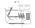
- FIG. 13 shows a third configuration example of the HUD device 1 of the second embodiment.
- the antiglare element 63 formed by the combination of the polarizing plate 20 and the wave plate 31 is arranged at a predetermined position z2 between the lens 4 and the display element 3.
- the antiglare element 63 is fixed to the housing 9.
- a conventional antiglare plate 60 is arranged at the exit portion of the housing 9.
- the polarizing plate 20 is arranged on the emitting side of the image light, and the wavelength plate 31 is arranged on the incident side.
- the change in the polarization direction in the third embodiment of FIG. 13 is as follows.
- External light A1, A2, and A3 are light including P wave and S wave, and although not shown, according to FIG. 12, the external light A3 after being reflected by the mirror 5 passes through the lens 4 and then transmits the antiglare element 63.
- the P wave is cut, and the external light A4 having circularly polarized light whose polarization direction is rotated by 45 degrees is obtained.
- the external light A4 is reflected by the surface of the display element 3 and passes through the antiglare element 63 again, so that it is cut and does not enter the lens 4.
- the S wave of the image light from the display element 3 becomes light in the same state as the image light B4 of FIG. 9 after being transmitted through the antiglare element 63.
- the size of the surfaces of the polarizing plate 20 and the wave plate 31 can be further reduced as compared with the second configuration example.
- the reason is that the position z2 is a position before the image light is enlarged by the lens 4 as compared with the position z1.
- the S wave of the external light A1 is incident as the external light A2 and A3 up to the region including the mirror 5 and the lens 4.
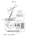
- FIG. 14 shows the configuration of the HUD device of the modified example of the third embodiment.
- This modification is a modification relating to the third configuration example.
- the polarizing plate 20 is arranged at the position z1 between the mirror 5 and the lens 4
- the wave plate 31 is arranged at the position z2 between the lens 4 and the display element 3. According to this modification, an effect similar to that of the third configuration example can be obtained.
- the change in the polarization direction in the modified example is as follows.
- the external light A3 reflected by the mirror 5 is cut off by the transmission of the polarizing plate 20 to become the external light A4 of the S wave.
- the external light A4 passes through the lens 4 and becomes the external light A5 having circularly polarized light whose polarization direction is rotated by 45 degrees by the first transmission of the wave plate 31.
- the external light A5 becomes external light A6 that is reflected by the exit surface of the display element 3 and returns to the lens 4.
- the external light A6 is further rotated by 45 degrees by the second transmission of the wave plate 31, that is, converted into a P wave.
- the external light A7 of the P wave is cut by the polarizing plate 20 after passing through the lens 4.
- a conventional antiglare plate may be additionally arranged at the position of the exit portion of the housing 9.
- the conventional antiglare plate is a reflective antiglare plate. In that case, since it is difficult for the reflective antiglare plate to accumulate heat, the heat in the HUD device 1 can be further reduced.
- FIG. 15 shows another modification regarding the arrangement of the two elements according to the first, second, and third embodiments.
- the polarizing plate 20 is arranged at the position of the exit portion of the HUD device 1, and the wave plate 31 is arranged at the position z2 between the lens 4 and the display element 3.
- the S-wave external light A2 and A3 transmitted through the polarizing plate 20 and then transmitted through the lens 4 is transmitted by the wave plate 31 to become circularly polarized external light A4 rotated by 45 degrees.
- the external light A5 after the external light A4 is reflected by the display element 3 is converted into a P wave by the transmission of the wave plate 31.
- the external light A6 and A7 of the P wave is cut by the polarizing plate 20. According to this modification, an effect similar to that of each of the above configuration examples can be obtained.
- FIG. 16 shows the configuration of the HUD device 1 of the fourth embodiment.
- the wavelength plate 32 is arranged at a predetermined position z2 between the lens 4 and the display element 3 in addition to the antiglare plate 6 as a configuration different from the configuration of the first embodiment (FIG. 7).
- This wave plate 32 is a ⁇ / 4 wave plate, and may be referred to as a second wave plate in order to distinguish it from the wave plate 31.
- the display element 3 unlike the above-mentioned display element 3, a type that emits a P wave is used.
- the display element 3 is arranged at a predetermined position z3 and the lens 4 is arranged at a predetermined position z4 in the z direction.
- the wave plate 32 is arranged at a predetermined position z2 between the lens 4 at the position z4 and the display element 3 at the position z3.
- the surface of the wave plate 32 on the incident side of the image light is arranged so as to be separated from the exit surface of the display element 3 with a predetermined distance K1.
- the surface of the wavelength plate 32 on the image light emitting side is arranged so as to be separated from the image light incident surface of the lens 4 with a predetermined distance K2.
- the external light A1 is incident on the antiglare plate 6 at the position of the exit portion of the housing 9.
- the external light A1 becomes the external light A2 having the linearly polarized light of the S wave by cutting the P wave by the polarizing plate 20.
- the external light A2 passes through the wave plate 31 and becomes the external light A3 having circularly polarized light whose polarization direction is rotated by 45 degrees.
- the external light A3 is reflected by the mirror 5, and the reflected external light A4 passes through the lens 4 and is incident on the wave plate 32 at the position z2.
- the polarization direction of the external light A4 is further rotated by 45 degrees as the second conversion due to the transmission of the wave plate 32.
- the external light A4 is rotated 90 degrees in total from the external light A2 to become the external light A5 having linearly polarized light converted into a P wave.
- the external light A5 of the P wave is reflected by the exit surface of the display element 3 and returns as the external light A6.
- the external light A6 of the P wave is incident on the wave plate 32, and the polarization direction is further rotated by 45 degrees by the conversion by the third transmission to become the external light A7 having circularly polarized light.
- the external light A7 passes through the lens 4 and is reflected by the mirror 5 to become the external light A8.
- the external light A8 is incident on the wave plate 31, and the polarization direction is further rotated by 45 degrees by the conversion by the fourth transmission to become the external light A9.
- the external light A9 of the S wave passes through the polarizing plate 20 and becomes the external light A10.
- FIG. 17 similarly shows changes in the polarization directions of the external light and the video light in the case of the fourth embodiment.
- the S wave of the external light A2 is at a right angle of 90 degrees.
- the external light A2 is rotated by 45 degrees by the first conversion 1601 by the wave plate 31, and the external lights A3 and A4 are at the position of 135 degrees.
- the external light A4 is further rotated by 45 degrees by the second conversion 1602 by the wave plate 32, and the external lights A5 and A6 are positioned at 180 degrees, that is, they become P waves.
- the external light A6 is further rotated by 45 degrees by the third conversion 1603 by the wave plate 32, and the external lights A7 and A8 are positioned at 225 degrees.
- the external light A8 is further rotated by 45 degrees by the fourth conversion 1604 by the wave plate 31, and the external light A9 is at the position of 270 degrees, that is, becomes an S wave.
- the S-wave external light A9 passes through the polarizing plate 20 and is emitted to the outside of the HUD device 1 as S-wave external light A10.
- FIG. 18 shows the change in the image light in the case of the fourth embodiment.
- the P-wave image light B1 emitted from the exit surface of the display element 3 first passes through the wave plate 32 to become circularly polarized image light B2 in a state in which the polarization direction is rotated by 45 degrees.
- FIG. 17 shows that the P wave of the image light B1 is initially at the position of 0 degrees, and is moved to the position of 45 degrees by the first conversion 1611.
- the image light B2 passes through the lens 4 and is reflected by the mirror 5.
- the image light B3 becomes the image light B3 having linearly polarized light in a state where the polarization direction is further rotated by 45 degrees.
- FIG. 17 shows that the P wave of the image light B1 is initially at the position of 0 degrees, and is moved to the position of 45 degrees by the first conversion 1611.
- the image light B2 passes through the lens 4 and is reflected by the mirror 5.
- the image light B3 becomes the image light B3 having linearly polar
- FIG. 17 shows that the video light B3 is converted to a 90-degree position, that is, an S wave by the second conversion 1612.
- the S-wave image light B3 passes through the polarizing plate 20 to become image light B4 having S-wave linearly polarized light, and the image light B4 heads toward the region 16.
- the image light from the antiglare plate 6 of the exit portion of the HUD device 1 to the outside can be the image light of the S wave, as compared with the configuration of FIG. 9 described above.
- the display quality of the virtual image 18 can be further improved.
- the external light A10 including a part of the S wave is emitted to the outside from the antiglare plate 6 at the exit portion of the HUD device 1. If you want to further improve this point, the following embodiment 5 is effective.
- FIG. 19 shows the configuration of the HUD device 1 of the fifth embodiment. This configuration is different from the configuration of the fourth embodiment (FIG. 16), in that the wave plate 32 is arranged between the lens 4 and the display element 3 at the position z5 in contact with the emission surface of the display element 3. ing.
- the type that emits a P wave is used as in the fourth embodiment.
- FIG. 20 similarly shows the change in the polarization direction of the external light and the video light in the fifth embodiment.
- FIG. 21 similarly shows the change in the image light in the fifth embodiment.
- the external light A1 becomes the external light A2 of the S wave after the P wave is cut by the polarizing plate 20.
- the external light A2 is rotated by 45 degrees in the polarization direction from the 90-degree state of the S wave by the first conversion 1801 by the wave plate 31, and becomes the external light A3 having circularly polarized light in the 135-degree state.
- the external light A3 is reflected by the mirror 5 and becomes the external light A4.
- the external light A4 passes through the lens 4 and is incident on the wave plate 32.
- the external light A4 is reflected by the surface of the wave plate 32 and becomes the external light A5.
- the external light A4 becomes the external light A5 without being subjected to the conversion action of the 45-degree rotation in the polarization direction due to the transmission of the wave plate 32.
- the external light A5 passes through the lens 4 and is reflected by the mirror 5 to become the external light A6.
- the external lights A3 to A6 are lights having circularly polarized light in a state of 135 degrees.
- the external light A6 is incident on the wave plate 31 and is further rotated by 45 degrees by the second conversion 1802 to be in a state of 180 degrees, that is, converted into a P wave.
- the external light A7 having linearly polarized light of the P wave is cut by the polarizing plate 20.
- the image light B1 emitted from the exit surface of the display element 3 is a P-wave image light, and is shown at a position of 0 degrees in FIG.
- the P-wave image light B1 becomes the image light B2 having circularly polarized light in a state where the polarization direction is rotated by 45 degrees by the first conversion 1811.
- the image light B2 passes through the lens 4 and is reflected by the mirror 5, and the reflected image light B3 is incident on the wave plate 31.
- the image light B3 is further rotated in the polarization direction by 45 degrees by the second conversion 1812 to be in a state of 90 degrees, that is, becomes the image light B4 converted into S waves. ..
- the image light B4 having the linearly polarized light of the S wave passes through the polarizing plate 20 and becomes the image light B5 having the linearly polarized light of the S wave, and heads toward the region 16.
- the external light can be prevented from being emitted from the antiglare plate 6 of the emitting portion of the HUD device 1 to the outside, and the S-wave image light B5 can be emitted, so that the virtual image 18 can be emitted. Display quality can also be maintained or improved. Further, in the configuration of the fifth embodiment, the distance between the display element 3 and the lens 4 can be made smaller than that of the configuration of the fourth embodiment, which is more advantageous in terms of miniaturization of the device.
- FIG. 22 shows the configuration of the HUD device 1 which is a modification of the fifth embodiment as another embodiment.
- the conventional antiglare plate 60 is further arranged in the pair of the polarizing plate 20 and the wave plate 31 which are the two elements of the antiglare plate 6.
- the antiglare plate 6 is composed of a combination of three elements, an antiglare plate 60, a polarizing plate 20, and a wave plate 31, in order from the upper side in the y direction. A part of the external light A1 is absorbed or reflected by the antiglare plate 60.
- a conventional antiglare plate 60 may be added to the configuration of each of the above-described embodiments.
- the arrangement of the display element 3 and the lens 4 with respect to the mirror 5 is not a configuration in which the display element 3 and the lens 4 are arranged in an obliquely inclined state as a measure against external light as in the configuration shown in FIG. It is configured so that it is arranged without tilting.
- the display element 3 at position z3 in the z direction and the lens 4 at position z4 are arranged upright in the Z direction (y direction).
- the optical axis from the display element 3 and the lens 4 extends in the Y direction (z direction).
- the display element 3 and the light source 2 are shown in the form of the unit 504 described above.
- the display elements 3 and the like are not arranged diagonally, the size of the housing 9 in the Y direction can be made smaller.
- the display element 3 and the like may not be arranged diagonally as in this embodiment.
- the display element 3 and the like can be configured not to be arranged diagonally.
- FIG. 23 shows the configuration of the HUD device 1b of the modified example of the first embodiment as another embodiment.
- the display system including the HUD device 1b has a combiner 180 at a predetermined position between the inner surface of the windshield 11 and the exit portion of the HUD device 1b.
- an antiglare plate 6 formed by a pair of the polarizing plate 20 and the wave plate 31 is provided at the position of the exit portion of the HUD device 1b.
- the housing 9 of the HUD device 1b does not have a mirror 5, but has a lens 4, a display element 3, a light source 2, and the like.
- the external light L3 that has passed through the windshield 11 described above may further pass through the combiner 180.
- the external light L3b that has passed through the combiner 180 (or other external light that has not passed through the combiner 180) is incident on the antiglare plate 6 at the exit portion of the HUD device 1 as the external light A1.
- the P wave of the external light A1 is cut by the polarizing plate 20, and the polarization direction of the remaining S wave is rotated by 45 degrees by the wave plate 31.
- the external light A2 that has passed through the wave plate 31 passes through the lens 4 and is reflected by the display element 3.
- the reflected external light A3 passes through the lens 4 again and passes through the wave plate 31 again.
- the external light A3 is further rotated in the polarization direction by 45 degrees, that is, converted into a P wave.
- the external light of the P wave is cut by the polarizing plate 20 and does not go out to the outside of the HUD device 1b.
- the image light from the display element 3 is magnified through the lens 4, is transmitted through the two elements of the antiglare plate 6, is projected onto the region 180a of the combiner 180, and is reflected toward the viewpoint 13. ..
- a set of the polarizing plate 20 and the wave plate 31 may be arranged at a predetermined position between the combiner 180 and the display element 3, and an effect similar to that of the first embodiment can be obtained. .. Similarly, the combination with the combiner 180 can be applied to each of the above-described embodiments. Further, as a modification of this configuration, a polarizing plate 20, an antiglare plate 6, or another optical element may be arranged on the surface of the combiner 180 (in other words, a part of the combiner 180).
- FIG. 24 shows the configuration of the HUD device 1 of the sixth embodiment.
- a cold mirror 7 which is a second reflecting element is added to the housing 9, whereby the optical path of the image light is bent substantially twice.
- the cold mirror 7 is arranged in the region where the light source 2, the display element 3, and the lens 4 are arranged, particularly at the position of the point Q2.
- a lens 4, a display element 3, and a light source 2 are arranged substantially below the cold mirror 7 in the Z direction.
- the polarizing plate 20 and the wave plate 31 are arranged as the antiglare plate 6 at the position of the exit portion of the housing 9, and the lens 4 and the display element 3 are arranged.
- the wave plate 32 is arranged at a position in contact with the exit surface of the display element 3 between them.
- the type that emits a P wave is used as in the fifth embodiment.
- the optical path of the image light from the display element 3 is as follows. First, there is an optical axis that is upward in the Z direction (y direction) (specifically, an optical axis that is slightly tilted backward in the z direction). On this optical axis, the corresponding image light includes the image light B1 from the display element 3, the image light B2 after passing through the wave plate 32, and the image light B3 after passing through the lens 4. Next, as the optical axis from the cold mirror 7 (point Q2) to the mirror 5 (point Q1), the optical axis roughly in the Y direction (z direction) (specifically, the light tilted slightly downward in the y direction). There is an axis). The image light B4 is on this optical axis.
- an optical axis roughly in the Z direction (y direction) (specifically, an optical axis slightly inclined to the rear side in the z direction) is used. is there.
- On this optical axis there is an image light B5 and an image light B6 after being emitted from the antiglare plate 6.
- the P-wave image light B1 is the same as in FIG. 21, but becomes the image light B2, B3, B4, B5 that has passed through the wave plate 31 and has S-wave circularly polarized light.
- the image light B5 passes through the antiglare plate 6 and becomes the image light B6 having S-wave linearly polarized light.
- the cold mirror 7 is a second reflecting element, in other words, an IR filter (infrared filter).
- the cold mirror 7 is an element that reflects image light, transmits infrared region components, and does not reflect infrared region components.
- the cold mirror 7 transmits the IR241, which is an infrared region component, with respect to the external light incident from the outside, for example, the external light A3 having the circularly polarized light of the S wave after being reflected by the mirror 5, so that the optical axis of the display element 3 or the like is transmitted. Does not reflect on the person.
- the size of the housing 9 in the Y direction can be further reduced by the configuration of the optical path using the mirror 5 and the cold mirror 7.
- the cold mirror 7 can be realized as one element by using a known technique, but the cold mirror 7 is not limited to this, and may be composed of a plurality of elements (for example, an IR film and a mirror).
- the above-mentioned unit 504 may be applied to the display element 3 and the light source 2.
- FIG. 25 shows the configuration of the HUD device 1 of the seventh embodiment.
- This configuration corresponds to a modified example of the above-described third embodiment (third configuration example of FIG. 13), and a cold mirror 7 is added to the third configuration example as in the sixth embodiment.
- the cold mirror 7 is arranged at the position of the point Q2 on the optical path of the image light.
- a conventional antiglare plate 60 is arranged at the position of the exit portion of the housing 9, and a polarizing plate 20 and a wave plate 31 are used as antiglare elements 63 between the lens 4 and the display element 3. Pairs are arranged.
- the display element 3 the type that emits an S wave is used as in the third embodiment.
- the optical path of the image light from the display element 3 is as follows. First, there is an optical axis upward in the Z direction (y direction), and on this optical axis, the image light B1 from the display element 3, the image light B2 after passing through the wave plate 32 and the polarizing plate 20, and the lens 4. There is an image light B3 after passing through. Next, there is an optical axis from the cold mirror 7 to the mirror 5, and the image light B4 is on this optical axis. Next, there is an optical axis from the mirror 5 to the antiglare plate 6, and on this optical axis, there is an image light B5 and an image light B6 after being emitted from the antiglare plate 6.
- the S-wave image light B1 is an image having the linearly polarized light of the S-wave of the transmitted component of the light rotated 45 degrees from the S-wave after being transmitted through the antiglare element 63, as in FIGS. 13 and 9.
- the seventh embodiment an effect similar to that of the sixth embodiment can be obtained. Since the external light incident on the housing 9 is cut by the antiglare element 63, stray light and heat storage of the display element 3 can be reduced. Further, for example, since IR241 is transmitted through the cold mirror 7 of the external light A3, the thermal energy of the external light A4 toward the display element 3 or the like can be reduced. As in the sixth and seventh embodiments, a set of the polarizing plate 20 and the wave plate 31 is arranged between the exit portion of the housing 9 of the HUD device and the display element 3, and the first reflecting element and the first reflecting element and the wave plate 31 are arranged. The configuration may be such that the second reflecting element is arranged.
- FIG. 26 shows the configuration of the HUD device 1 of the eighth embodiment.
- the cold mirror 7 is arranged at the position of the point Q2 in the housing 9 as in the sixth and seventh embodiments. Further, the eighth embodiment does not have the wave plate 31 as a configuration point different from each of the above-described embodiments.
- the conventional antiglare plate 60 is arranged at the position of the exit portion of the housing 9, and the polarizing plate 20 is arranged at the position between the lens 4 and the display element 3.
- the display element 3 uses a type that emits S waves.
- the optical path of the image light from the display element 3 is as follows. First, there is an optical axis upward in the Z direction (y direction), and on this optical axis, the image light B1 from the display element 3, the image light B2 after passing through the polarizing plate 20, and the image light B2 after passing through the lens 4 are transmitted. There is an image light B3. Next, there is an optical axis from the cold mirror 7 to the mirror 5, and the image light B4 is on this optical axis. Next, there is an optical axis from the mirror 5 to the antiglare plate 60, and on this optical axis, there is an image light B5 and an image light B6 after being emitted from the antiglare plate 60. The S-wave image light B1 from the display element 3 becomes image light B2, B3, B4, B5, B6 having S-wave linearly polarized light after passing through the polarizing plate 20.
- the cold mirror 7 transmits IR241 and does not reflect the external light A3 having the P wave and the S wave after being reflected by the mirror 5, to the display element 3 and the like.
- the external light A4 reflected by the cold mirror 7 does not contain an IR component and the thermal energy is reduced, so that the heat storage and temperature rise of the display element 3 and the like can be reduced.
- the size of the housing 9 in the Y direction can be made smaller as in the sixth and seventh embodiments.
- the position of the polarizing plate 20 is not limited to the position between the lens 4 and the display element 3 in FIG. 26, and may be a position on the optical path behind the display element 3 and on the exit side.
- the lens 4 is composed of a plurality of lenses, for example, a concave lens in the front stage and a free curved lens in the rear stage on the optical path.
- the polarizing plate 20 is arranged between the concave lens and the free curved lens. In the case of this configuration, the space for holding the polarizing plate 20 can be reduced, so that the size of the housing 9 in the Z direction can be made smaller.
- the HUD device can be applied not only to automobiles but also to moving objects such as trains and aircraft.
- HUD device 1 ... HUD device, 2 ... light source, 3 ... display element, 4 ... lens, 5 ... mirror, 6 ... antiglare plate, 9 ... housing, 10 ... substrate, 20 ... polarizing plate, 31 ... wavelength plate.
Landscapes
- Engineering & Computer Science (AREA)
- Chemical & Material Sciences (AREA)
- Combustion & Propulsion (AREA)
- Transportation (AREA)
- Mechanical Engineering (AREA)
- Physics & Mathematics (AREA)
- General Physics & Mathematics (AREA)
- Optics & Photonics (AREA)
- Instrument Panels (AREA)
- Polarising Elements (AREA)
Abstract
HUD装置の技術に関して、外光入射の影響による虚像の視認性の低下またはHUD装置内部の部品の温度上昇等を改善できる技術を提供する。HUD装置1は、車両のウィンドシールド11の領域に映像光を投射することによって虚像18を提供する。HUD装置1は、筐体9内に、光源2と、映像光を生成する表示素子3と、映像光を透過するレンズ4と、映像光を反射するミラー5とを備える。HUD装置1は、筐体9の映像光の出射部と表示素子3との間の光路上において、外光のP波をカットする偏光板20と、偏光板20よりも表示素子3に近い側の位置に配置され、四分の一波長板である波長板31(第1波長板)とを有する。
Description
本発明は、車載のヘッドアップディスプレイ装置(Head up display:HUD)等の技術に関する。
車載のHUD装置は、自動車のウィンドシールドやコンバイナに対し映像光を投射することで、運転者の視点から見た所定の領域において、実像上に虚像を重ね合わせて表示する。コンバイナは専用の反射板である。虚像は、自動車の運転の支援に係わる画像が挙げられる。車載のHUD装置は、運転者から見た虚像の視認性が良好であることが求められる。例えば、自動車の外部からの太陽光等の外光がHUD装置内に入射する場合がある。その外光がHUD装置内で反射等されて再びHUD装置から出射され、ウィンドシールド等で反射されて、運転者の目に入射する場合がある。この場合、運転者の目には外光がノイズとなって虚像の視認性が低下する場合がある。そのため、車載のHUD装置は、このような外光入射に対策する手段を備えることが望ましい。
従来技術例のHUD装置は、筐体の映像光の出射部に、防眩板(いわゆるグレアトラップ)を備える。この防眩板は、所定の光の透過や反射の特性の設計によって、外光による眩しさ(グレア)等の影響を低減する。
HUD装置に係わる先行技術例として、特表2012-501472号公報(特許文献1)、特開2018-185374号公報(特許文献2)が挙げられる。特許文献1には、小型HUDの光リレーとして、ぎらつき防止手段(216)であるグレアトラップを備える構成(図2)や以下の旨が記載されている。このグレアトラップは、ぎらつき等を捕捉して反射を防止する手段であり、ガラス板、プラスチック板、または他の透明な材料の板で構成され、平面または曲面を有する(段落0012等)。このグレアトラップは、入射する光の角度に関して選択的な特性を持つフィルタとして機能するために、光学的な被膜や層(例えば誘電体)を備え得る。このグレアトラップは、光リレーの光学面として複数回利用される。
特許文献2には、HUD装置において、凹面ミラーとウィンドシールドとの間の光路に配置される光学フィルタを備える構成(図1、F5)や以下の旨が記載されている。この光学フィルタは、ウィンドシールド側の任意の方向から反射面に入射する外光を、画像表示領域以外の領域に向けて反射させるように、姿勢変化可能に構成されている。この光学フィルタは、反射型バンドパスフィルタであり、ウィンドシールド側から入射する外光の殆どを反射面で反射する(段落0019等)。これにより、HUD装置内のディフューザでの外光反射を低減でき、凹面ミラーやディフューザでの温度上昇を低減できる(段落0021等)。
車載のHUD装置は、外光入射の影響による虚像の視認性または表示品質の低下、HUD装置内部の部品の温度上昇、等の課題がある。従来技術例のHUD装置の防眩板(グレアトラップ)は、上記視認性や温度の観点に関して改善余地がある。
本発明の目的は、HUD装置の技術に関して、外光入射の影響による虚像の視認性の低下またはHUD装置内部の部品の温度上昇等を改善できる技術を提供することである。上記以外の課題や効果等については、発明を実施するための形態において説明される。
本発明のうち代表的な実施の形態は、車載のヘッドアップディスプレイ装置であって、以下に示す構成を有することを特徴とする。一実施の形態の車載のヘッドアップディスプレイ装置は、車両のウィンドシールドまたはコンバイナの領域に映像光を投射することによって虚像を提供するヘッドアップディスプレイ装置であって、筐体内に、光源と、前記光源からの光に基づいて映像光を生成する表示素子と、前記表示素子からの映像光を透過する屈折素子と、前記屈折素子からの映像光を前記領域へ向けて反射する第1反射素子と、を備え、前記筐体の前記映像光の出射部と前記表示素子との間の光路上において、外光のP波をカットする偏光板と、前記偏光板よりも前記表示素子に近い側の位置に配置され、四分の一波長板である第1波長板と、を有する。
本発明のうち代表的な実施の形態によれば、HUD装置の技術に関して、外光入射の影響による虚像の視認性の低下またはHUD装置内部の部品の温度上昇等を改善できる。
以下、本発明の実施の形態を図面に基づいて詳細に説明する。なお、実施の形態を説明するための全図において同一部には原則として同一符号を付し、繰り返しの説明を省略する。
[比較例1]
図27を用いて、実施の形態1に対する比較例1のHUD装置における課題等として、HUD装置内への外光の侵入の影響について説明する。図27は、比較例1の車載のHUD装置100を含む表示システムの構成、および外光の侵入の影響等を示す。図27は、自動車の運転席付近を横側から見たY-Z面での模式的な構成を示す。なお、説明上、座標系として、絶対座標系(X,Y,Z)、HUD座標系(x,y,z)を有する。絶対座標系は、鉛直方向をZ軸とし、水平面を構成する2つの方向をX軸,Y軸とし、X軸は車や運転者に対し横、左右方向とし、Y軸は車や運転者に対し前後方向とする。HUD座標系は、HUD装置から見た座標系とし、虚像が構成される領域を構成する直交する2つの方向をx軸、y軸とし、その領域に垂直な方向をz軸とする。x軸は領域内の水平方向、横方向に対応し、y軸は領域内の垂直方向、縦方向に対応する。HUD座標系のx軸、y軸、z軸は、絶対座標系のX軸、Z軸、Y軸と対応する。
図27を用いて、実施の形態1に対する比較例1のHUD装置における課題等として、HUD装置内への外光の侵入の影響について説明する。図27は、比較例1の車載のHUD装置100を含む表示システムの構成、および外光の侵入の影響等を示す。図27は、自動車の運転席付近を横側から見たY-Z面での模式的な構成を示す。なお、説明上、座標系として、絶対座標系(X,Y,Z)、HUD座標系(x,y,z)を有する。絶対座標系は、鉛直方向をZ軸とし、水平面を構成する2つの方向をX軸,Y軸とし、X軸は車や運転者に対し横、左右方向とし、Y軸は車や運転者に対し前後方向とする。HUD座標系は、HUD装置から見た座標系とし、虚像が構成される領域を構成する直交する2つの方向をx軸、y軸とし、その領域に垂直な方向をz軸とする。x軸は領域内の水平方向、横方向に対応し、y軸は領域内の垂直方向、縦方向に対応する。HUD座標系のx軸、y軸、z軸は、絶対座標系のX軸、Z軸、Y軸と対応する。
自動車は、車体12の一部において、ボンネットとルーフとの間にフロントガラス等のウィンドシールド11を有する。ウィンドシールド11の下側でインストルメントパネル内には、HUD装置100を有する。HUD装置100は、例えば運転者およびステアリングホイールの前方のインストルメントパネル内の位置に配置されている。
HUD装置100は、筐体90内に、光源92、表示素子93、レンズ94、ミラー95を備える。光源92は、例えばバックライトユニット(BLU)である。表示素子93は、例えば液晶表示素子(LCD)である。表示素子93は、映像データおよび光源92からの光に基づいて映像光を生成する。車載のHUD装置100の場合、表示素子93は、S波を出射するタイプが用いられる。レンズ94は、映像光を拡大および調整等するための屈折素子である。ミラー95は、映像光を反射、拡大、および調整等するための凹面ミラー等の反射素子である。レンズ94およびミラー95等は、ウィンドシールド11の領域16への投射のための光学系を構成している。
HUD装置100は、筐体90内から映像光を筐体90外へ出射する部分(出射部と記載する場合がある)に、防眩板(グレアトラップ)96を有する。HUD装置100から防眩板96を通じてZ方向で概略上側に出射された映像光は、ウィンドシールド11の一部の領域16(破線で示す)で反射されて運転者の視点13の方へ向かう。領域16の中心点(すなわち映像光の光軸が通る点)を点P1で示す。視点13の目に入射された映像光は網膜に結像する。これにより、運転者は、領域16越しの前方に虚像を視認する。視点13は、運転者の目の位置に対応付けられた、虚像を観察する視点である。視点13から前方へ一点鎖線で示す視線15を有する。視線15の先の領域16越しに虚像が構成される。
図27では、外光L1がウィンドシールド11の領域16を通じてHUD装置100内に入射し、筐体90内での反射を通じて再びHUD装置100外に出射され反射されて視点13へ向かう場合についても示している。外光L1は、自動車の外部から入射する強い太陽光等を含む外光である。外光L1は、二点鎖線の矢印で示すように、ウィンドシールド11の領域16(例えば点P1)に入射する。領域16の点P1に対する外光L1の入射の角度を角度θ1で示す。角度θ1は、領域16の面に対し垂直な方向と外光L1の光線とが成す角度である。
外光L1の一部(特にS波)は、ウィンドシールド11の面によって、外光L2として反射される。例えば、外光L1の入射の角度θ1が50度以上である場合、外光L1のS波の多くが、ウィンドシールド11の面で反射される。外光L1がウィンドシールド11の面で反射される率である反射率は、入射の角度θ1に応じて異なる。詳しくは、例えば角度θ1が50度を超える領域では、S波とP波とで反射率が異なる。具体的には、S波の方がP波よりも反射率が大きい。すなわち、ウィンドシールド11の領域16を透過後の外光L3は、成分としてP波が多くS波が少ない状態の光である。
外光L3は、HUD装置100の筐体90の出射部に配置されている防眩板96に入射し、防眩板96を通じて筐体90内に侵入する。従来の防眩板96は、材料の透過率や反射率の設計、曲率や傾きの設計によって、外光の入射や反射による眩しさをある程度低減する機能を実現している。なお、図27では、防眩板96の断面を平面として図示しているが、防眩板96の断面が曲面を持つ場合もある。
防眩板96を透過して筐体90内に侵入した外光L4は、ミラー95やレンズ94等の部品、筐体90の内壁面や他の構造物によって、反射される。外光L4は、ミラー95で反射され、レンズ94へ向かう。その外光の一部は、レンズ94で反射され、ミラー95へ戻る。また、その外光の他の一部は、レンズ94を透過し、表示素子93へ向かう。レンズ94を透過した外光は、表示素子93の面で反射されてレンズ94の方へ戻り、再びレンズ94を透過して、ミラー95に向かう。ミラー95に戻って反射された外光L5は、迷光として、防眩板96に戻る。外光L5は、防眩板96を透過し、HUD装置100外に出射する外光L6となる。外光L6は、ウィンドシールド11の領域16で反射され、外光L7として、視点13に入射する場合がある。この場合、運転者の視点13からは、虚像に外光がノイズとして重畳されることで、虚像の視認性が低下する場合がある。
なお、外光L4や外光L5のように、HUD装置100内に入射し筐体90内で散乱や乱反射する場合の外光を、迷光と呼ぶ場合がある。上記のように、従来のHUD装置100は、外光入射に基づいた迷光による虚像の視認性(言い換えると表示品質)の低下の課題がある。
また、上記のようにHUD装置100内に外光が入射する場合、HUD装置100内の表示素子93等の部品が外光によって熱を蓄積し、温度が上昇する場合がある。例えば、外光L4がミラー95によって反射され、レンズ94または表示素子93へ集光される可能性がある。表示素子93等の部品には、決められた耐熱温度がある。外光入射による温度上昇によって部品の耐熱温度を超えてしまう可能性がある。このことを防止する必要がある。外光入射が無い通常利用の場合の部品温度と、外光入射が有る場合の上昇した部品温度との温度差をΔTとする。各部品の温度差ΔTについては、決められた値以下に抑える必要がある。表示素子93は、安価等の理由から例えば小型の液晶表示パネルが用いられる。しかし、その液晶表示パネルの耐熱温度はあまり高くない。よって、その液晶表示パネルは、外光の熱によって劣化や損傷する恐れがある。上記のように、外光入射によるHUD装置内の部品(特にLCD)の温度の課題もある。
(実施の形態1)
図1~図9を用いて、本発明の実施の形態1のHUD装置について説明する。実施の形態1のHUD装置は、車載のHUD装置であり、車両のウィンドシールドの領域に対し映像光を投射することで、拡張現実(AR)や混合現実(MR)等に対応する虚像を表示する機能を持つ。そして、実施の形態1のHUD装置は、上記課題等を踏まえ、外光入射の影響に対策するための外光対策機能として、特有の防眩板を備える。これにより、実施の形態1のHUD装置は、虚像の視認性の確保、およびHUD装置内の部品の温度の抑制等の効果を得る。
図1~図9を用いて、本発明の実施の形態1のHUD装置について説明する。実施の形態1のHUD装置は、車載のHUD装置であり、車両のウィンドシールドの領域に対し映像光を投射することで、拡張現実(AR)や混合現実(MR)等に対応する虚像を表示する機能を持つ。そして、実施の形態1のHUD装置は、上記課題等を踏まえ、外光入射の影響に対策するための外光対策機能として、特有の防眩板を備える。これにより、実施の形態1のHUD装置は、虚像の視認性の確保、およびHUD装置内の部品の温度の抑制等の効果を得る。
[(1)車載の表示システム]
図1は、実施の形態1のHUD装置1を含む、車載の表示システムの構成を示す。図1は、自動車の運転席前部および運転者を横側から見たY-Z面での模式的な構成を示す。自動車は、車体12のうちボンネットとルーフとの間に、フロントガラス等のウィンドシールド11を有する。ウィンドシールド11の下側で、インストルメントパネル内に、HUD装置1を有する。運転席の運転者の視点13から概略的に前方(Y方向)への視線15において、ウィンドシールド11の面の領域16があり、さらにその領域16の前方に、虚像18が構成される領域17がある。領域16は、ウィンドシールド11の透過領域(実像が視認できる領域)のうちの一部の領域であり、HUD装置1からの映像光が投射および反射される領域である。領域16をHUD領域、HUD表示範囲と記載する場合がある。この領域16は、視点13からの視野(FOV)の範囲内にある。運転者の視点13からは、虚像18は、ウィンドシールド11越しの領域17の位置に構成されているように見える。領域17を虚像領域と記載する場合がある。
図1は、実施の形態1のHUD装置1を含む、車載の表示システムの構成を示す。図1は、自動車の運転席前部および運転者を横側から見たY-Z面での模式的な構成を示す。自動車は、車体12のうちボンネットとルーフとの間に、フロントガラス等のウィンドシールド11を有する。ウィンドシールド11の下側で、インストルメントパネル内に、HUD装置1を有する。運転席の運転者の視点13から概略的に前方(Y方向)への視線15において、ウィンドシールド11の面の領域16があり、さらにその領域16の前方に、虚像18が構成される領域17がある。領域16は、ウィンドシールド11の透過領域(実像が視認できる領域)のうちの一部の領域であり、HUD装置1からの映像光が投射および反射される領域である。領域16をHUD領域、HUD表示範囲と記載する場合がある。この領域16は、視点13からの視野(FOV)の範囲内にある。運転者の視点13からは、虚像18は、ウィンドシールド11越しの領域17の位置に構成されているように見える。領域17を虚像領域と記載する場合がある。
HUD装置1から出射される映像光は、領域16で反射され、視点13の目に入射し、網膜に結像することにより、運転者が虚像18として視認する。アイボックス14は、視点13の位置を含む、所定の大きさの3次元領域である。運転者の視点13の位置は変動するが、視点13の位置がアイボックス14の範囲内にある場合には、虚像18を十分な品質で見ることができる。
HUD装置1は、基本的な機能として、視点13から見た領域16,17において、実像(例えば自車の前方の道路、車、人等)に虚像18を重ね合わせるようにして表示する機能を有する。この機能は、言い換えると、ARやMR等に対応する虚像18を表示する機能である。この機能により、ウィンドシールド11の前方の位置に、例えば運転のナビゲーションやアラート等に係わる画像を表示して、運転を支援することができる。
自動車の外部からは、強い太陽光等の外光L1が、ウィンドシールド11の例えば領域16へ入射する。比較例1での説明と同様に、外光L1の一部(特にS波)は、ウィンドシールド11の領域16で反射される。外光L1の残りの一部は、領域16を透過し、HUD装置1の筐体9の出射部の位置に配置されている防眩板6に入射する。
HUD装置1は、外光入射による迷光や熱等の悪影響に対策するための外光対策機能として、防眩板(グレアトラップ)6等を備える。この機能は、防眩板6を用いて、外光入射に基づいた迷光を低減し、視点13へ入射する外光成分を低減し、運転者から見た虚像18の視認性(言い換えると表示品質)を確保または向上する機能である。また、この機能は、防眩板6を用いて、筐体9内への外光入射を低減し、HUD装置1内の部品(特に表示素子3)等の熱の蓄積および温度上昇を抑制する機能である。
なお、ウィンドシールド11の傾きの角度は、車種によって異なる。HUD装置1の映像光の投射の角度は、ウィンドシールド11の傾きの角度に応じて設定される。また、ウィンドシールド11の領域16を含む透過領域は、曲面を持つ。HUD装置1の映像光は、その曲面の曲率に応じて好適な虚像18を構成できるように、HUD装置1内の光学系等によって調整される。また、ウィンドシールド11の面、例えば領域16を含む一部の領域には、例えば透明拡散シート等の所定の光学素子が追加で配置されてもよい。また、後述するが、他の実施の形態として、ウィンドシールド11とHUD装置1の出射部との間の所定の位置には、コンバイナ(専用の反射板)が設けられてもよい。このコンバイナを持つ表示システムの形態の場合、HUD装置1の出射部からの映像光は、コンバイナの領域に投射および反射され、コンバイナ越しに虚像が構成される。
[(2)HUD装置]
図2は、HUD装置1の筐体9内の素子配置等の構成概要をy-z面で示す。HUD装置1の筐体9の形状は一例であって特に限定しない。HUD装置1は、筐体9の上面の一部に、インストルメントパネルの開口部(後述の図4等)と対応付けられる出射部を有し、この出射部の位置に防眩板6が配置されている。
図2は、HUD装置1の筐体9内の素子配置等の構成概要をy-z面で示す。HUD装置1の筐体9の形状は一例であって特に限定しない。HUD装置1は、筐体9の上面の一部に、インストルメントパネルの開口部(後述の図4等)と対応付けられる出射部を有し、この出射部の位置に防眩板6が配置されている。
HUD装置1は、筐体9内に収容および保持されている、基板10、光源2、表示素子3、レンズ4、ミラー5等の部品を有する。基板10と光源2等の各部品とは、破線で示すように、駆動用の信号線等によって電気的に接続されてもよい。筐体9内の光源2、表示素子3、レンズ4、およびミラー5によって、所定の光学系11が構成されている。光学系11は、表示素子3からの映像光の拡大や調整をしながらウィンドシールド11の領域16への投射を行うための光学系である。この調整は、収差やひずみの補正を含む。
光源2であるBLUは、詳細については限定しないが、例えばLED素子を用いて構成されている(後述の図5等)。光源2は、面での均一性が高い光を、z方向で前側の表示素子3の方へ出射する。光源2から表示素子3への光の光軸を光軸J1で示す。光軸の両側の実線は、光線の範囲を概略的に示す。
表示素子3は、実施の形態1での実装例として、液晶表示素子(LCD)であるが、これに限らず、他の映像表示装置、例えば有機ELディスプレイや投射型表示装置としてもよい。表示素子3は、z方向で前側の面である出射面において映像を表示し、これにより、この出射面から映像光がレンズ4へ向けて出射される。表示素子3からレンズ4への映像光の光軸を光軸J2で示す。
レンズ4は、表示素子3からの映像光を透過し拡大してミラー5へ導く屈折素子である。また、レンズ4は、ミラー5等で像を形成する際に発生する収差やひずみを補正するための形状を持つ(後述の図5等)。レンズ4からミラー5への映像光の光軸を光軸J3で示す。
ミラー5は、第1反射素子であり、概略的にz方向でのレンズ4からの映像光を、概略的にy方向での映像光として防眩板6の方へ反射させる。その反射光は、防眩板6を透過し、領域16へ向かい、反射されて、視点13へ向かう。ミラー5から防眩板6への映像光の光軸を光軸J4で示す。ミラー5は、実装例として凹面ミラーであり、その凹面である反射面は、自由曲面を持つ。ミラー5の凹面は、虚像18のひずみ等を低減するための形状を持つ(後述の図5等)。この凹面の形状は、例えばウィンドシールド11の領域16の形状に合わせて自由曲面の曲率が設計されている形状である。
なお、図2の構成では、表示素子3およびレンズ4の光軸の配置は、ミラー5の光軸またはY方向(z方向)に対し、所定の角度でやや斜めの傾きを持つ配置としている。これにより、ひずみ等の補正や、外光反射に関して、より好適な効果が得られる。これに限らず、例えば、光源2と表示素子3との間に、光軸方向を斜めに変換するための変換パネル等の素子が設けられてもよい。
実施の形態1のHUD装置1は、映像光の光路の範囲において、表示素子3と筐体9の出射部との間の所定の位置に、偏光板20と波長板31との組が配置されている構成を有する。
防眩板6は、偏光板20と波長板31とを有する。防眩板6は、この偏光板20と波長板31との2つの光学素子の組によって構成されている。これらの2つの素子は、順序関係を有する。Z方向で上側(言い換えると映像光の光路において後段側)に偏光板20が配置され、下側(言い換えると映像光の光路において前段側)に波長板31が配置されている。波長板31は、詳しくは、λ/4波長板(四分の一波長板)であり、第1波長板と記載する場合がある。
実装例として、偏光板20および波長板31の2枚の素子は、例えば外周が筐体9の一部によって挟まれて固定され、それらの2枚の素子が密着し重ね合わせられるようにして保持されている。なお、図2の構成では、防眩板6の断面の形状が平面であるが、これに限らず、後述(図6)の例のように、防眩板6の断面の形状が曲面でもよい。なお、他の実装例として、防眩板6は、偏光板20および波長板31以外の他の部材を含んでもよい。例えば、偏光板20と波長板31との間に他の部材が挟まれて配置されてもよいし、偏光板20の上側や波長板31の下側に他の部材が配置されてもよい。他の部材は、透明基材や接着材等でもよいし、既存の光学フィルタ等でもよい。また、防眩板6は、可撓性を持たない板で構成されてもよいし、可撓性を持つシートやフィルムで構成されてもよい。後者の場合、防眩板6は、防眩シート等と言い換え可能である。
偏光板20は、外光のうちのP波を吸収等によってカットし、S波を透過させる特性を持つ光学素子である。偏光板20によってP波をカットできるので、HUD装置1内に侵入する外光成分の熱エネルギーを低減できる。例えば、昼間の条件において、図27のウィンドシールド11を透過した外光L3のうちのP波を、ミラー5よりも前段のZ方向で上側にある偏光板20によってカットできる。これにより、比較例1のようにHUD装置100内に外光L3のP波が入射し外光L4のP波がミラー95で反射されて表示素子93へ照射されることや、防眩板96から再び外部へ出射すること等が、低減できる。すなわち、外光による虚像の視認性の低下を低減でき、筐体内の部品の蓄熱や温度上昇を低減できる。
波長板31は、偏光板20によってP波がカットされた後の外光に残っているS波をカットするための光学素子である。波長板31であるλ/4波長板は、入射光の高速軸と低速軸との間で90度の位相差を生じさせることで、偏光面内での光の偏光方向を45度回転させる素子である。詳細は後述(図7等)するが、外光が波長板31を入射時と出射時とで合計2回透過することで、外光の偏光方向が合計で90度回転され、すなわち外光のS波がP波に変換される。よって、出射時にその外光のP波が偏光板20によってカットされる。これにより、HUD装置1外に外光が戻って視点13に向かうことが低減でき、外光による虚像の視認性の低下を低減できる。
[(3)制御装置]
図3は、図1の表示システムの制御装置等の機能ブロック構成を示す。基板10は、HUD装置1の制御装置を構成するIC基板等であり、各部の駆動を制御する。基板10による制御装置は、ナビゲーションシステム201および運転支援ECU202等と通信を介して接続される。通信は例えばCAN(Car Area Network)等を介する通信である。ナビゲーションシステム201は、例えば車載のカーナビゲーションシステムである。運転支援ECU202は、車の運転の制御や支援を行う車載のエンジン制御ユニット等の制御装置である。運転支援ECU202は、周辺監視装置203と接続されている。周辺監視装置203は、自車の周辺状況を監視する装置であり、一例としてカメラや探査装置を含む。カメラは、自車の周辺を撮影した画像に基づいて、自車の周辺に存在する物体を検出する。探査装置は、探査波を送受信した結果に基づいて、自車の周辺に存在する物体を検出する。運転支援ECU202は、例えば周辺監視装置203での監視結果として検出された障害物に従って、駆動系や制御系を制御することで、運転支援制御を実現する。
図3は、図1の表示システムの制御装置等の機能ブロック構成を示す。基板10は、HUD装置1の制御装置を構成するIC基板等であり、各部の駆動を制御する。基板10による制御装置は、ナビゲーションシステム201および運転支援ECU202等と通信を介して接続される。通信は例えばCAN(Car Area Network)等を介する通信である。ナビゲーションシステム201は、例えば車載のカーナビゲーションシステムである。運転支援ECU202は、車の運転の制御や支援を行う車載のエンジン制御ユニット等の制御装置である。運転支援ECU202は、周辺監視装置203と接続されている。周辺監視装置203は、自車の周辺状況を監視する装置であり、一例としてカメラや探査装置を含む。カメラは、自車の周辺を撮影した画像に基づいて、自車の周辺に存在する物体を検出する。探査装置は、探査波を送受信した結果に基づいて、自車の周辺に存在する物体を検出する。運転支援ECU202は、例えば周辺監視装置203での監視結果として検出された障害物に従って、駆動系や制御系を制御することで、運転支援制御を実現する。
基板10による制御装置は、ナビゲーションシステム201から、各種の情報を、前景情報として取得する。各種の情報は、自車が走行している現在位置に対応する道路の制限速度や車線数、ナビゲーションシステム201に設定されている自車の移動予定経路等が挙げられる。また、制御装置は、運転支援ECU202から、各種の情報を、前景情報として取得する。各種の情報は、例えば先行車両までの距離、先行車両の方位、障害物や標識が存在する位置等の情報が挙げられる。前景情報は、自車の前景として表示する虚像18を構成するための映像情報として使用される。
また、制御装置には、イグニッション信号204や自車状態情報205等が入力される。制御装置は、例えばイグニッション信号の入力によって起動される。自車状態情報205は、車載の各種センサ等から車両情報として得られる情報であり、例えば、警告表示情報、方向指示器の操作結果情報、車速やシフトポジション等の情報が挙げられる。
制御装置は、マイコン101、記憶装置102、BLU駆動回路103、光学系駆動回路104等を備える。マイコン101は、CPU、ROM、RAM等を含み、これらによってプロセッサまたはコントローラが構成される。マイコン101は、表示素子3の映像表示制御を含むHUD装置1の制御を行う。マイコン101は、入力の各種の情報に基づいて、虚像18のための映像データや表示制御情報を生成し、表示素子3やBLU駆動回路103へ送信する。記憶装置102には、上記虚像18の生成のための情報や映像データを含む、制御のための各種の情報やデータが記憶される。BLU駆動回路103は、光源2であるバックライトユニットの発光等を駆動する回路である。
光学系駆動回路104は、光学系11のレンズ4やミラー5や防眩板6等を駆動する回路である。光学系11の駆動は、レンズ4やミラー5や防眩板6の向きの調節のための駆動を含んでもよい。なお、図3では、レンズ4、ミラー5および防眩板6をすべて駆動可能な構成の場合を示しているが、これに限らず、一部の部品、例えばミラー5のみを駆動可能な構成としてもよい。すなわち、レンズ4、ミラー5または防眩板6の向きが固定である構成でもよい。向きの調節のための駆動は、利用者の所定の操作入力(例えばボタン押下)に応じて実行する構成としてもよいし、制御装置の判断によって自動で実行する構成としてもよい。
[(4)車載実装例]
図4および図5は、図1のHUD装置1の車載実装例を示す。図4は、車内でウィンドシールド11の下側にあるインストルメントパネル301、計器盤302、ステアリングホイール303等を示す。この実装例では、HUD装置1は、インストルメントパネル301内において、特にステアリングホイール303および計器盤302の前方の位置に配置されている。インストルメントパネル301の上面の一部には開口部304が設けられており、その開口部304の下側にHUD装置1が収容されている。開口部304の位置に合わせて防眩板6が配置されている。一点鎖線の矢印は、HUD装置1からの映像光の光軸の概要を示す。図示のように、この実装例のHUD装置1の筐体9(破線で示す)は、z方向(Y方向)で光源2側からミラー5側へと部品サイズが次第に大きくなる構成を有する。なお、図4では、光源2、表示素子3等が分離された状態を示すが、各部品は相互に接続される。
図4および図5は、図1のHUD装置1の車載実装例を示す。図4は、車内でウィンドシールド11の下側にあるインストルメントパネル301、計器盤302、ステアリングホイール303等を示す。この実装例では、HUD装置1は、インストルメントパネル301内において、特にステアリングホイール303および計器盤302の前方の位置に配置されている。インストルメントパネル301の上面の一部には開口部304が設けられており、その開口部304の下側にHUD装置1が収容されている。開口部304の位置に合わせて防眩板6が配置されている。一点鎖線の矢印は、HUD装置1からの映像光の光軸の概要を示す。図示のように、この実装例のHUD装置1の筐体9(破線で示す)は、z方向(Y方向)で光源2側からミラー5側へと部品サイズが次第に大きくなる構成を有する。なお、図4では、光源2、表示素子3等が分離された状態を示すが、各部品は相互に接続される。
図5は、図4の実装例における主な部品の分解構成を示す。HUD装置1は、筐体9の一部として筐体501を含み、この筐体501には、光源2と表示素子3とが接続されたユニット504と、レンズ4と、ミラー5とを含む各部品が固定される。各部品はねじ等を用いて固定される。ユニット504は、光源2のY方向(z方向)の前側の光出射面に対し、表示素子3の背面の入射面が重ね合わせられるようにして固定されている。筐体501のY方向の後側の面では、レンズ4のX方向の両端が固定される。筐体501のY方向の前側の面では、ミラー5のX方向の回転軸の両端が固定される。筐体501の上側には、ミラー5を収容する状態で、防眩板6が接続されている筐体502が固定される。筐体501の下側には、駆動制御用の基板503(基板10に対応する)や、モータ505(ミラー5の軸に接続される)等の他の部品が配置される。表示素子3のフレキシブル配線は、基板503と接続される。なお、この実装例では、光源2と表示素子3との組合せによるユニット504を用いているが、これに限らず可能である。例えば、ユニット504の代わりに、自発光型の蛍光表示管(VFD:Vacuum Fluorescent display)等を適用してもよい。
光源2は、LED光源等の固体光源が適用される。LED光源は、周囲温度変動に対する光出力変動が少ない特性を持つ。この実装例では、光源2であるLED光源は、複数のLED素子、コリメータ、偏光変換素子、導光体、拡散板、ヒートシンク等によって構成されている。コリメータは、LED素子からの光を集光し平行光に変換する。偏光変換素子は、偏光ビームスプリッタを用いて平行光の偏光方向を変換する。導光体は、平行光の光軸方向を例えば90度程度曲げて表示素子3への光軸方向にする。このような光源2の構成によって、光源2からの出射光は、光利用効率が高く面均一性が高い平行光として表示素子3へ供給される。表示素子3は、例えばフレームに取り付けられた液晶表示パネルおよびフレキシブルプリント回路基板等から構成される。
レンズ4は、入射面および出射面において入射側に凹型の曲面形状を持つ。この曲面形状は前述の拡大や調整のための形状である。レンズ4は、その形状によって、面内各位置でのミラー5への光線出射方向を制御する。これにより、ミラー5の形状による補正と合わせて、虚像18の表示に関する歪曲収差補正を含む補正が実現される。また、レンズ4は、ミラー5の形状による補正と合わせて、ウィンドシールド11の曲面に関する非点収差補正を含む補正を実現する。言い換えると、レンズ4およびミラー5を含む光学系11は、好適な虚像18の形成のための光学的な補正機能を実現する。
なお、補正機能の能力を高めるために、レンズ4が複数枚のレンズで構成されてもよい。また、レンズ4の代わりに、1枚以上の自由曲面ミラーが配置されてもよい。この場合、筐体9内で表示素子3からミラー5までの光路として曲げを含む光路が構成され、ミラー5への光線入射方向が制御される。また、レンズ4の形状は、レンズ4の光軸方向での厚さを面内各位置に応じて異ならせた形状としてもよい。この場合、表示素子3とミラー5との間で面内各位置の光線の光学的距離を異ならせることができる。レンズ4の入射面と出射面との一方または両方の面の形状は、ミラー5からの反射光が表示素子3の一部分に集光することを防止する形状が好ましい。その形状は、図5等の実装例に示すように、表示素子3側に凹面を向けた形状が挙げられる。また、レンズ4の入射面等に反射防止膜を設けた構成として、光線の無用な反射を抑制してもよい。
ミラー5は、X方向の軸を持ち、外形が概略矩形で入射側に凹型の曲面を持つ凹面ミラーであり、軸の周りに回転が可能な機構を有する。制御装置の光学系駆動回路104は、モータ505を通じて、ミラー5の軸の回転を駆動する。この機構によって、映像光の投射方向が調整可能である。
防眩板6は、外形が概略矩形である曲面を持ち、この曲面は出射側に凹型の曲面である。防眩板6の曲面は、X軸とY軸から成る水平面に対し、運転者側に向いてやや斜めに傾きを持つ状態で配置されている。
上記実装例に限らず可能である。例えば、助手席の同乗者に対し虚像を提供するHUD装置等も同様に可能である。そのHUD装置は、例えばインストルメントパネル301内の他の位置に配置され、ウィンドシールド11の他の領域に映像を投射する。また、表示素子3の入射面および出射面には、偏光板(図2の偏光板20とは異なる)が配置されてもよい。これにより、映像光のコントラスト比を高めることができる。
[(5)ミラー、防眩板]
図6は、HUD装置1の実装例における、ミラー5および防眩板6の傾きの角度に関する模式的な構成を示す。(A)は、筐体9の出射部の防眩板6とインストルメントパネル301の開口部304との関係で、傾きの角度の例を示す。(B)は、(A)に対し、ミラー5および防眩板6の傾きの角度の変更例を示す。ミラー5および防眩板6には、それぞれ、傾きの角度あるいは配置位置等を可変に調整できる機構を設けてもよい。開口部304は、例えば何も無い空間であるが、これに限らず、透過部材を設けてもよいし、蓋を含む開閉機構を設けてもよい。
図6は、HUD装置1の実装例における、ミラー5および防眩板6の傾きの角度に関する模式的な構成を示す。(A)は、筐体9の出射部の防眩板6とインストルメントパネル301の開口部304との関係で、傾きの角度の例を示す。(B)は、(A)に対し、ミラー5および防眩板6の傾きの角度の変更例を示す。ミラー5および防眩板6には、それぞれ、傾きの角度あるいは配置位置等を可変に調整できる機構を設けてもよい。開口部304は、例えば何も無い空間であるが、これに限らず、透過部材を設けてもよいし、蓋を含む開閉機構を設けてもよい。
(A)で、筐体9内に、前述のユニット504、レンズ4、ミラー5が配置されている。ここでは、レンズ4からミラー5への光軸をz方向としている。ミラー5の傾きの角度βを、光軸のz方向とミラー5の反射面中心点の垂直方向(対応する軸j2)とが成す角度として示す。ミラー5のx方向の回転軸5aには図5のモータ505が接続されている。基板10からそのモータ505を駆動することで、ミラー5の傾きの角度βが所定の範囲内で調整できる。
防眩板6は、y方向(Z方向)で上側に凹型の曲面形状を持つ。防眩板6は、面の中心点p1を基準として、破線で示すように、傾きの角度αを持って配置されている。角度αは、水平面のうちのz方向(Y方向)と、防眩板6の中心点p1の垂直方向(対応する軸j1)とが成す角度として示す。この軸j1は、z方向でやや後側に向いている。
防眩板6の傾きの角度αを調節できる形態とする場合、例えば、中心点p1等に回転軸を設け、その回転軸にモータが接続され、制御装置からそのモータを駆動する構成としてもよい。あるいは、前述の筐体502に回転駆動機構を設ける構成でもよい。なお、(A)では、インストルメントパネル301の開口部304と、筐体9の出射部の防眩板6との間に距離を有するが、これに限らず、開口部304と防眩板6の位置を殆ど同じにしてもよい。また、防眩板6の断面を平面としてもよいし、上側に凸型の曲面としてもよい。
インストルメントパネル301の開口部304、または防眩板6には、所定の保護カバー等が設けられてもよい。この保護カバーは、例えば透明基材と黒膜とを有する。黒膜は、黒色塗料を含み、例えばストライプ形状に配置される。これにより、外光反射が低減できる。保護カバーと防眩板6とが一体で構成されてもよい。
実施の形態1の変形例として、筐体9の出射部の位置ではなく、インストルメントパネル301の開口部304の位置に、防眩板6に相当する、偏光板20と波長板31の組が設けられてもよい。
HUD装置1を使用しない時には、ミラー5の傾きを所定の状態にしておくこと、あるいは開口部304が開閉機構を持つ場合にはそれを閉じて非透過の状態にすることによって、HUD装置1内への外光入射影響を低減できる。
[比較例2]
図28は、実施の形態1等に対する比較例2のHUD装置100の構成を示す。この比較例2は、P波をカットする偏光板20のみを設ける構成を示し、実施の形態1での波長板31を有さない。表示素子93は、S波を出射するタイプが用いられる。映像光のS波は、偏光板20を透過して外部へ出射される。図28の(A)は、比較例2における、偏光板20の配置の第1構成例を示す。図28の(B)は、偏光板20の配置の第2構成例を示す。図28の(C)は、偏光板20の配置の第3構成例を示す。
図28は、実施の形態1等に対する比較例2のHUD装置100の構成を示す。この比較例2は、P波をカットする偏光板20のみを設ける構成を示し、実施の形態1での波長板31を有さない。表示素子93は、S波を出射するタイプが用いられる。映像光のS波は、偏光板20を透過して外部へ出射される。図28の(A)は、比較例2における、偏光板20の配置の第1構成例を示す。図28の(B)は、偏光板20の配置の第2構成例を示す。図28の(C)は、偏光板20の配置の第3構成例を示す。
(A)で、第1構成例のHUD装置100は、筐体90の出射部の位置に、防眩板96として、偏光板20が配置されている。この第1構成例によれば、偏光板20によって外光L3(対応する外光A1)のP波をカットでき、外光A2等のように、一部のS波は入射するものの、HUD装置100内に侵入する外光を低減でき、視点13へ向かう外光を低減でき、HUD装置100内の熱を低減できる。
(B)で、第2構成例のHUD装置100では、筐体90の防眩板96は、公知技術で構成され、偏光板20等を含まない。第2構成例では、筐体90内で、ミラー95とレンズ94との間の所定の位置に、偏光板20が配置されている。この第2構成例によれば、偏光板20によって、ミラー95で反射後の外光A3のP波をカットでき、同様に、外光低減等の効果が得られる。第2構成例の場合、偏光板20の面積等のサイズは、第1構成例の偏光板20の場合よりも小さくできる。
(C)で、第3構成例のHUD装置100では、筐体90の防眩板96は、公知技術で構成され、偏光板20等を含まない。第3構成例では、筐体90内で、レンズ94と表示素子93との間の所定の位置に、偏光板20が配置されている。この第3構成例によれば、偏光板20によって、レンズ94を透過後の外光A3のP波をカットでき、同様に、外光低減等の効果が得られる。第3構成例の場合、偏光板20の面積等のサイズは、第2構成例の偏光板20の場合よりも小さくできる。
図28の比較例2の構成では、上記のように、偏光板20を用いて外光L3のうちの多くの成分であるP波をカットできるので、視認性および温度に関する相応の効果が得られる。しかしながら、比較例2では、外光L3のうちのS波の成分については低減できていない。そこで、実施の形態1の図2等の構成では、偏光板20に加え波長板31を用いた防眩板6としている。これにより、外光L3のうちのS波についても低減でき、外光対策に関するより高い効果が得られる。
また、外光のカットに伴って映像光に基づいた虚像の表示品質が低下することは望ましくない。そこで、後述の実施の形態4,5では、2枚の波長板(第1波長板と第2波長板)を用いることで、映像光の表示品質についても維持できる機能を実現する。
[(6)第1構成例]
図7は、実施の形態1のHUD装置1における素子配置構成、および外光入射影響等を示す。図7は、Y-Z面(y-z面)において、筐体9の主要な部品と、ウィンドシールド11の領域16と、外光L1の影響とを示す。図7は、特に、防眩板6を構成する2つの素子である偏光板20と波長板31の組の配置に関する第1構成例を示す。この第1構成例では、筐体9の出射部の位置に偏光板20と波長板31の組が防眩板6として配置されている。なお、図7では、説明のために、偏光板20と波長板31との間に間隔を空けて図示している。防眩板6の実装例は前述の図2等の通りであるが、これに限らず可能である。表示素子3であるLCDは、S波を出射するタイプが用いられている。
図7は、実施の形態1のHUD装置1における素子配置構成、および外光入射影響等を示す。図7は、Y-Z面(y-z面)において、筐体9の主要な部品と、ウィンドシールド11の領域16と、外光L1の影響とを示す。図7は、特に、防眩板6を構成する2つの素子である偏光板20と波長板31の組の配置に関する第1構成例を示す。この第1構成例では、筐体9の出射部の位置に偏光板20と波長板31の組が防眩板6として配置されている。なお、図7では、説明のために、偏光板20と波長板31との間に間隔を空けて図示している。防眩板6の実装例は前述の図2等の通りであるが、これに限らず可能である。表示素子3であるLCDは、S波を出射するタイプが用いられている。
外光L1に関して、太陽光等の自然光は、紫外線から赤外線までを含む幅広い波長領域の光であり、2種類の偏光方向の光(すなわちP波とS波)が混ざった状態で存在する光である。P波(=P偏光)は、電界成分が入射面に平行な電磁波であり、光の進行方向に対し垂直な偏光方向を持つP偏光成分である。S波(=S偏光)は、電界成分が入射面に垂直な電磁波であり、光の進行方向に対し平行な偏光方向を持つS偏光成分である。光が境界面に入射する際には、その光をP波とS波に分けて考えることができる。図面では、P波を一方の種類(ドットパターン)の矢印で示し、S波を他方の種類(白)の矢印で示す。また、直線偏光や円偏光を、図示のように各種類の小さな矢印で示す。
外光L1のうちの一部の外光L2(主にS波)は、ウィンドシールド11の例えば領域16で外光L2として反射される。外光L1の他の一部は、領域16を透過し、外光L3として、HUD装置1の出射部の防眩板6に入射する。この外光L3(対応する外光A1とする)は、前述の比較例1または比較例2のHUD装置100と同様に、P波とS波を含み、P波が多くS波が少ない状態の光である。このことに基づいて、実施の形態1のHUD装置1における防眩板6は、外光L3のP波およびS波の両方をカットまたは低減するための構成を有する。
外光A1は、まず偏光板20に入射する。偏光板20は、外光A1のうちのP波をカットし、S波を透過する。偏光板20を透過した外光A2は、主にS波を含む状態の直線偏光を持つ光である。外光A2は次に波長板31に入射する。
波長板31は、複屈折素子等で構成され、光の位相を変える光学素子であり、直交する偏光成分の間に位相差を生じさせて入射光の偏光状態を変換する素子であり、位相板とも呼ばれる。特に、この波長板31は、λ/4波長板(四分の一波長板:Quarter-wavelength plate)である。λ/4波長板は、入射光の高速軸の光成分と低速軸の光成分との間に90度(λ/4)の位相差を生じさせることで、直線偏光から円偏光への変換や円偏光から直線偏光への変換が可能な素子である。なお、λは、光の一波長(360度)を表し、λ/4は四分の一波長(90度)を表している。λ/4波長板は、入射光の電界振動方向においてλ/4(=π/2=90度)の位相差を与える。光学的に、P波がλ/4波長板を1回透過すると、偏光面内の偏光方向が45度回転される。その光がλ/4波長板を2回目に透過すると、さらに45度回転される。すなわち、2回の透過の合計では、偏光方向が90度回転されることになり、すなわち、P波からS波への変換(あるいはS波からP波への変換)が実現される。
波長板31は、外光A2のS波の偏光方向を45度回転させる。波長板31を透過した後の外光A3は、このS波の偏光方向が45度回転した状態の円偏光を持つ光であり、回転矢印付きの実線矢印で示す。外光A3は、ミラー5で反射され、反射後の外光A4となる。外光A4も外光A3と同様の状態の光である。ミラー5からの反射光である外光A4は、レンズ4に向かう。外光A4の一部は、レンズ4で反射され、外光A5としてミラー5へ戻る。あるいは、外光A4の一部は、レンズ4を透過し、表示素子3の出射面で反射され、レンズ4へ戻る。その外光は、再びレンズ4を透過し、外光A5としてミラー5へ戻る。
レンズ4からの外光A5は、ミラー5で反射され、反射光である外光A6となり、防眩板6の方へ向かう。外光A6は、まず波長板31に入射し、波長板31の透過によって、偏光方向がさらに45度回転され、その状態の外光A7として出射される。この際、合計では2回目の変換であり、外光A2のS波からは、偏光方向が合計で90度回転されることで、P波に変換されている。このP波の直線偏光を持つ外光A7は、S波の直線偏光を持つ外光A2に対し、直交する関係を持つ。2種の直線偏光を異なる種類の小さな矢印で示す。外光A7は、さらに偏光板20に入射し透過によってP波がカットされる。よって、防眩板6から外部へ外光である迷光が戻るようにして出射されることが防止される(×印で示す)。HUD装置1内において、ミラー5、レンズ4および表示素子3等のみならず、ミラー5の端部や図示しない保持部材等のすべての部品によって、外光の反射等による迷光が生じ得るが、実施の形態1のHUD装置1によれば、それらのすべての迷光を防止または低減できる。
[(7)偏光方向]
図8は、図7の第1構成例に対応した、波長板31を用いた、外光の偏光方向の変化、変換についての説明図を示す。図8は、偏光方向を表す角度として360度をとった偏光面を示し、横軸を0度、180度とし、縦軸を90度、270度とし、横軸をP波、縦軸をS波に対応させている。光(例えばP波)が波長板31を1回透過することは、偏光方向の45度の回転の変換701に対応する。さらにその光が波長板31をもう1回透過することは、偏光方向の45度の回転の変換702に対応し、合計では偏光方向の90度の回転の変換に対応する。すなわち、光が波長板31を合計で2回透過することは、P波からS波への変換(あるいはS波からP波への変換)に対応する。
図8は、図7の第1構成例に対応した、波長板31を用いた、外光の偏光方向の変化、変換についての説明図を示す。図8は、偏光方向を表す角度として360度をとった偏光面を示し、横軸を0度、180度とし、縦軸を90度、270度とし、横軸をP波、縦軸をS波に対応させている。光(例えばP波)が波長板31を1回透過することは、偏光方向の45度の回転の変換701に対応する。さらにその光が波長板31をもう1回透過することは、偏光方向の45度の回転の変換702に対応し、合計では偏光方向の90度の回転の変換に対応する。すなわち、光が波長板31を合計で2回透過することは、P波からS波への変換(あるいはS波からP波への変換)に対応する。
第1構成例で、最初、外光A1のうちのP波が偏光板20によってカットされ、S波を含む外光A2となる。図8では、この外光A2のS波を、90度の位置に示している。外光A2は、波長板31を1回目に透過して筐体9内に入射する。これにより、外光A2は、偏光方向が45度回転された外光A3となる。変換703は、この際のS波からの45度回転を示す。外光A3を135度の位置に示す。透過・変換の回数を丸付き数字で示す。その後、外光A4,A5,A6は、偏光方向が変化しないので、135度の位置にある。外光A6は、波長板31の2回目の透過によって、偏光方向がさらに45度回転される。変換704は、この際の135度から180度への回転を示し、外光A7を180度の位置に示す。この外光A7は、P波に変換されているので、偏光板20でカットされる。
上記のように、第1構成例によれば、外光A1のP波を偏光板20によってカットし、残りのS波を波長板31によってカットすることができる。外光L1に基づいた迷光は、防眩板6から外部へ殆ど出ない。よって、このHUD装置1によれば、領域16や視点13に向かう外光を低減でき、虚像18の視認性を確保または向上できる。また、防眩板6によって、HUD装置1内に侵入する外光の熱エネルギーが低減できるので、HUD装置1内の表示素子3等の部品の熱を低減でき、温度上昇を抑制でき、部品の耐熱温度以下にすることができる。また、HUD装置1内の温度を低くできることから、表示素子3として安価な液晶表示素子等を用いることが容易となり、コスト等の点で有利となる。
なお、第1構成例において、筐体9の出射部の位置に、上記2つの素子の組による防眩板6に加え、従来型の防眩板(対応する素子)を追加で配置した構成としてもよい。また特に、その従来型の防眩板は、吸収型の防眩板(例えば黒膜を備える素子)とすることが望ましい。この場合、その吸収型の防眩板によって、外光反射を抑制することができる。また、防眩板6には、外光A1のうち紫外線領域の光および赤外線領域の光の少なくとも一方の光を反射する反射膜等を追加して設けてもよい。
[(8)映像光]
図9は、実施の形態1の図7の第1構成例の場合に、表示素子3であるLCDからの映像光の偏光方向等について示す。図9の(A)は、上記表示素子3からの映像光の変化の概要を示す。表示素子3は、S波の映像光を出射するタイプである。表示素子3の出射面から出射された映像光B1は、主にS波であり、このS波は、レンズ4を透過して拡大等され、ミラー5で反射され、映像光B2となる。映像光B2は、まず波長板31に入射する。この際、この映像光は、波長板31の透過によって偏光方向が45度回転された状態の円偏光を持つ映像光B3となる。その映像光B3は、さらに偏光板20に入射する。この映像光B3は、偏光板20の透過によって、P波の成分がカットされ、S波の成分のみが透過し、S波の直線偏光を持つ映像光B4となる。この映像光B4は、領域16へ向かい、反射されて、視点13へ向かう。
図9は、実施の形態1の図7の第1構成例の場合に、表示素子3であるLCDからの映像光の偏光方向等について示す。図9の(A)は、上記表示素子3からの映像光の変化の概要を示す。表示素子3は、S波の映像光を出射するタイプである。表示素子3の出射面から出射された映像光B1は、主にS波であり、このS波は、レンズ4を透過して拡大等され、ミラー5で反射され、映像光B2となる。映像光B2は、まず波長板31に入射する。この際、この映像光は、波長板31の透過によって偏光方向が45度回転された状態の円偏光を持つ映像光B3となる。その映像光B3は、さらに偏光板20に入射する。この映像光B3は、偏光板20の透過によって、P波の成分がカットされ、S波の成分のみが透過し、S波の直線偏光を持つ映像光B4となる。この映像光B4は、領域16へ向かい、反射されて、視点13へ向かう。
図9の(B)は、上記映像光の偏光方向の変化について図8と同様に偏光面で示す。映像光B1,B2は、S波であるため、90度の位置にある。波長板31を透過後の映像光B3は、偏光方向の45度の回転の変換901によって、135度の位置にある。このように、第1構成例の場合、映像光B4および視点13に入射する映像光に関しては、最初の映像光B1のS波の状態から45度回転された状態の円偏光の映像光のうちのS波の成分を持つ直線偏光の光となる。そのため、虚像18の表示品質に関しては、視点13へ入射する映像光が、最初のS波の状態が維持されている光である場合に比べ、反射率や輝度がやや低下する。この表示品質で許容できる場合には、実施の形態1の構成で外光対策に関する十分な効果が得られる。この表示品質をさらに改善したい場合には、例えば後述の実施の形態4等が有効となる。
(実施の形態2)
図10を用いて、本発明の実施の形態2のHUD装置について説明する。実施の形態2等の基本的な構成は実施の形態1と同様であり、以下では、実施の形態2等における実施の形態1とは異なる構成部分について説明する。実施の形態2のHUD装置1は、図7の第1構成例に対する変形例であり、防眩板6を構成する2つの素子の配置が異なる第2構成例を示す。
図10を用いて、本発明の実施の形態2のHUD装置について説明する。実施の形態2等の基本的な構成は実施の形態1と同様であり、以下では、実施の形態2等における実施の形態1とは異なる構成部分について説明する。実施の形態2のHUD装置1は、図7の第1構成例に対する変形例であり、防眩板6を構成する2つの素子の配置が異なる第2構成例を示す。
図10は、実施の形態2のHUD装置1における第2構成例を示す。この第2構成例では、ミラー5とレンズ4との間の所定の位置z1に、偏光板20および波長板31の組による防眩素子62が配置されている。防眩素子62は筐体9に固定される。この第2構成例では、筐体9の出射部には、従来型の防眩板60が配置されている。この防眩板60は偏光板20および波長板31を含まない。z方向の位置z1において、映像光の出射側に偏光板20、入射側に波長板31が配置されている。外光A1,A2,A3は、多くのP波と少しのS波とを含む光であり、ミラー5で反射後の外光A3は、防眩素子62の透過によって、P波がカットされ、偏光方向が45度回転された状態の円偏光を持つS波の外光A4となる。レンズ4等から反射後の外光A5は、防眩素子62の2回目の透過によってカットされる。
第2構成例によれば、第1構成例と類似の効果が得られる。第2構成例では、第1構成例に比べ、偏光板20および波長板31の面のサイズをより小さくできる。理由は、位置z1は、出射部の位置に比べ、映像光の拡大途中の位置であるためである。ただし、第2構成例では、外光A1のうちのS波が、外光A2として、出射部よりも下側のミラー5を含む領域まで入射する。
[(2-1)変形例]
図11は、実施の形態2の変形例のHUD装置の構成を示す。この変形例は、上記第2構成例に関する変形例である。この変形例は、筐体9の出射部の位置に偏光板20が配置され、ミラー5とレンズ4との間の位置z1に波長板31が配置されている。偏光板20を透過して入射する外光A2,A3は、S波の直線偏光の光である。ミラー5で反射後の外光A3は、波長板31の透過によって、45度回転された状態の円偏光の外光A4となる。レンズ4等から反射後の外光A5は、波長板31の2回目の透過によってP波の直線偏光の外光A6,A7となる。外光A7は偏光板20の2回目の透過によってカットされる。この変形例によれば、第2構成例と類似の効果が得られる。
図11は、実施の形態2の変形例のHUD装置の構成を示す。この変形例は、上記第2構成例に関する変形例である。この変形例は、筐体9の出射部の位置に偏光板20が配置され、ミラー5とレンズ4との間の位置z1に波長板31が配置されている。偏光板20を透過して入射する外光A2,A3は、S波の直線偏光の光である。ミラー5で反射後の外光A3は、波長板31の透過によって、45度回転された状態の円偏光の外光A4となる。レンズ4等から反射後の外光A5は、波長板31の2回目の透過によってP波の直線偏光の外光A6,A7となる。外光A7は偏光板20の2回目の透過によってカットされる。この変形例によれば、第2構成例と類似の効果が得られる。
[(2-2)偏光方向]
図12は、図10の実施の形態2に関する、偏光方向の変化について、図8と同様に示す。外光A1,A2,A3のS波は、90度の位置にあり、変換1201によって45度回転し、外光A4,A5は、135度の位置になる。なお、表示素子3からの映像光のS波は、防眩素子62の透過後、図9の映像光B4と同様の状態の光となる。図11の変形例の場合にも図12と類似の変化となる。
図12は、図10の実施の形態2に関する、偏光方向の変化について、図8と同様に示す。外光A1,A2,A3のS波は、90度の位置にあり、変換1201によって45度回転し、外光A4,A5は、135度の位置になる。なお、表示素子3からの映像光のS波は、防眩素子62の透過後、図9の映像光B4と同様の状態の光となる。図11の変形例の場合にも図12と類似の変化となる。
(実施の形態3)
図13を用いて、本発明の実施の形態3のHUD装置について説明する。実施の形態3のHUD装置1は、図7の第1構成例に対する変形例であり、防眩板6を構成する2つの素子の配置が異なる第3構成例を示す。図13は、実施の形態2のHUD装置1における第3構成例を示す。この第3構成例では、レンズ4と表示素子3との間の所定の位置z2に、偏光板20および波長板31の組による防眩素子63が配置されている。防眩素子63は筐体9に固定される。この第3構成例では、筐体9の出射部には、従来型の防眩板60が配置されている。z方向の位置z2において、映像光の出射側に偏光板20、入射側に波長板31が配置されている。
図13を用いて、本発明の実施の形態3のHUD装置について説明する。実施の形態3のHUD装置1は、図7の第1構成例に対する変形例であり、防眩板6を構成する2つの素子の配置が異なる第3構成例を示す。図13は、実施の形態2のHUD装置1における第3構成例を示す。この第3構成例では、レンズ4と表示素子3との間の所定の位置z2に、偏光板20および波長板31の組による防眩素子63が配置されている。防眩素子63は筐体9に固定される。この第3構成例では、筐体9の出射部には、従来型の防眩板60が配置されている。z方向の位置z2において、映像光の出射側に偏光板20、入射側に波長板31が配置されている。
図13の実施の形態3における偏光方向の変化については以下の通りである。外光A1,A2,A3は、P波およびS波を含む光であり、図示しないが図12にならうと、ミラー5で反射後の外光A3は、レンズ4を透過後に防眩素子63を透過することで、P波がカットされ、偏光方向が45度回転された円偏光を持つ外光A4となる。外光A4は、表示素子3の面で反射し、再び防眩素子63を透過することで、カットされ、レンズ4には入射しない。なお、表示素子3からの映像光のS波は、防眩素子63の透過後、図9の映像光B4と同様の状態の光となる。
第3構成例によれば、第1構成例や第2構成例と類似の効果が得られる。第3構成例では、第2構成例に比べ、偏光板20および波長板31の面のサイズをさらに小さくできる。理由は、位置z2は、位置z1に比べ、レンズ4による映像光の拡大前の位置であるためである。ただし、第3構成例では、外光A1のうちのS波が、外光A2,A3として、ミラー5およびレンズ4を含む領域まで入射する。
[(3-1)変形例]
図14は、実施の形態3の変形例のHUD装置の構成を示す。この変形例は、第3構成例に関する変形例である。この変形例は、ミラー5とレンズ4との間の位置z1に偏光板20が配置され、レンズ4と表示素子3との間の位置z2に波長板31が配置されている。この変形例によれば、第3構成例と類似の効果が得られる。
図14は、実施の形態3の変形例のHUD装置の構成を示す。この変形例は、第3構成例に関する変形例である。この変形例は、ミラー5とレンズ4との間の位置z1に偏光板20が配置され、レンズ4と表示素子3との間の位置z2に波長板31が配置されている。この変形例によれば、第3構成例と類似の効果が得られる。
変形例における偏光方向の変化については以下の通りである。ミラー5で反射後の外光A3は、偏光板20の透過によってP波がカットされ、S波の外光A4となる。外光A4は、レンズ4を透過し、波長板31の1回目の透過によって、偏光方向が45度回転された円偏光を持つ外光A5となる。その外光A5は、表示素子3の出射面で反射し、レンズ4の方に戻る外光A6となる。その外光A6は、波長板31の2回目の透過によってさらに45度回転され、すなわちP波に変換される。そのP波の外光A7は、レンズ4を透過後、偏光板20でカットされる。
なお、第2構成例または第3構成例またはそれらの変形例において、筐体9の出射部の位置に、従来型の防眩板を追加で配置した構成としてもよい。特に、第2構成例または第3構成例では、その従来型の防眩板は、反射型の防眩板とすることが望ましい。その場合、その反射型の防眩板で熱を蓄積しにくいので、HUD装置1内の熱をより低減できる。
[変形例]
図15は、上記実施の形態1、2および3に関する2つの素子の配置に関する他の変形例を示す。この変形例は、HUD装置1の出射部の位置に偏光板20が配置され、レンズ4と表示素子3との間の位置z2に波長板31が配置されている。偏光板20を透過して入射したS波の外光A2,A3は、レンズ4を透過後、波長板31の透過によって、45度回転された状態の円偏光の外光A4となる。その外光A4が表示素子3で反射された後の外光A5は、波長板31の透過によって、P波に変換される。そのP波の外光A6,A7は、偏光板20によってカットされる。この変形例によれば、上記各構成例と類似の効果が得られる。
図15は、上記実施の形態1、2および3に関する2つの素子の配置に関する他の変形例を示す。この変形例は、HUD装置1の出射部の位置に偏光板20が配置され、レンズ4と表示素子3との間の位置z2に波長板31が配置されている。偏光板20を透過して入射したS波の外光A2,A3は、レンズ4を透過後、波長板31の透過によって、45度回転された状態の円偏光の外光A4となる。その外光A4が表示素子3で反射された後の外光A5は、波長板31の透過によって、P波に変換される。そのP波の外光A6,A7は、偏光板20によってカットされる。この変形例によれば、上記各構成例と類似の効果が得られる。
(実施の形態4)
図16~図18を用いて、本発明の実施の形態4のHUD装置について説明する。実施の形態4のHUD装置は、前述(図9)の映像光の品質をさらに改善するための構成例を示す。図16は、実施の形態4のHUD装置1の構成を示す。この構成は、実施の形態1の構成(図7)に比べて異なる構成として、防眩板6に加え、レンズ4と表示素子3との間の所定の位置z2に、波長板32が配置されている。この波長板32は、λ/4波長板であり、波長板31との区別のため、第2波長板と記載する場合がある。また、この構成は、表示素子3として、前述の表示素子3とは異なり、P波を出射するタイプを用いている。
図16~図18を用いて、本発明の実施の形態4のHUD装置について説明する。実施の形態4のHUD装置は、前述(図9)の映像光の品質をさらに改善するための構成例を示す。図16は、実施の形態4のHUD装置1の構成を示す。この構成は、実施の形態1の構成(図7)に比べて異なる構成として、防眩板6に加え、レンズ4と表示素子3との間の所定の位置z2に、波長板32が配置されている。この波長板32は、λ/4波長板であり、波長板31との区別のため、第2波長板と記載する場合がある。また、この構成は、表示素子3として、前述の表示素子3とは異なり、P波を出射するタイプを用いている。
筐体9内では、z方向において、所定の位置z3に表示素子3が配置され、所定の位置z4にレンズ4が配置されている。そして、位置z4のレンズ4と位置z3の表示素子3との間の所定の位置z2に波長板32が配置されている。この波長板32の映像光入射側の面は、表示素子3の出射面との間に所定の距離K1を持って離間して配置されている。また、この波長板32の映像光出射側の面は、レンズ4の映像光入射面との間に所定の距離K2を持って離間して配置されている。
外光A1は、筐体9の出射部の位置の防眩板6に入射する。外光A1は、偏光板20によってP波がカットされ、S波の直線偏光を持つ外光A2となる。外光A2は、波長板31を透過し、偏光方向が45度回転された円偏光を持つ外光A3となる。外光A3は、ミラー5で反射され、反射後の外光A4は、レンズ4を透過し、位置z2の波長板32に入射する。この外光A4は、波長板32の透過によって2回目の変換として偏光方向がさらに45度回転される。すなわち、この外光A4は、外光A2からは合計で90度回転されて、P波に変換された直線偏光を持つ外光A5となる。このP波の外光A5は、表示素子3の出射面で反射され、外光A6として戻る。このP波の外光A6は、波長板32に入射し、3回目の透過による変換によって、偏光方向がさらに45度回転され、円偏光を持つ外光A7となる。この外光A7は、合計では偏光方向が45度×3=135度回転した状態の光である。この外光A7は、レンズ4を透過し、ミラー5で反射され、外光A8となる。外光A8は、波長板31に入射し、4回目の透過による変換によって、偏光方向がさらに45度回転され、外光A9となる。この外光A9は、合計では偏光方向が45度×4=180度回転した状態の光であり、すなわちS波に変換された直線偏光を持つ外光A9となる。このS波の外光A9は、偏光板20を透過し、外光A10となる。
図17は、実施の形態4の場合の外光および映像光の偏光方向の変化について同様に示す。外光A2のS波は、90度の位置にある。外光A2は、波長板31による1回目の変換1601によって45度回転され、外光A3,A4は、135度の位置にある。外光A4は、波長板32による2回目の変換1602によってさらに45度回転され、外光A5,A6は、180度の位置になり、すなわちP波になる。外光A6は、波長板32による3回目の変換1603によって、さらに45度回転され、外光A7,A8は、225度の位置になる。外光A8は、波長板31による4回目の変換1604によって、さらに45度回転され、外光A9は、270度の位置になり、すなわちS波になる。このS波の外光A9は、偏光板20を透過して、S波の外光A10としてHUD装置1外へ出射される。
図18は、実施の形態4の場合の映像光の変化について示す。表示素子3の出射面から出射されたP波の映像光B1は、まず波長板32を透過することで、偏光方向が45度回転した状態の円偏光の映像光B2となる。図17では、最初、映像光B1のP波が0度の位置にあり、1回目の変換1611によって、45度の位置になることを示す。映像光B2は、レンズ4を透過し、ミラー5で反射される。この映像光B3は、波長板31を透過することで、偏光方向がさらに45度回転した状態の直線偏光を持つ映像光B3となる。図17では、この映像光B3が、2回目の変換1612によって、90度の位置になり、すなわちS波に変換されることを示す。このS波の映像光B3は、偏光板20を透過してS波の直線偏光を持つ映像光B4となり、その映像光B4が領域16へ向かう。
上記のように、実施の形態4の場合、HUD装置1の出射部の防眩板6から外部への映像光を、S波の映像光とすることができ、前述の図9の構成に比べ、虚像18の表示品質をより高めることができる。ただし、この構成の場合、HUD装置1の出射部の防眩板6から外部へ、一部のS波を含む外光A10が出射する。この点についてさらに改善したい場合には、以下の実施の形態5が有効である。
(実施の形態5)
図19~図21を用いて、本発明の実施の形態5のHUD装置について説明する。実施の形態5のHUD装置は、実施の形態4の構成からさらに工夫し、外光入射影響を低減するための構成例を示す。図19は、実施の形態5のHUD装置1の構成を示す。この構成は、実施の形態4の構成(図16)に比べて異なる構成として、波長板32が、レンズ4と表示素子3との間で、表示素子3の出射面に接する位置z5に配置されている。表示素子3は、実施の形態4と同様に、P波を出射するタイプを用いている。図20は、実施の形態5における外光および映像光の偏光方向の変化について同様に示す。図21は、実施の形態5における映像光の変化について同様に示す。
図19~図21を用いて、本発明の実施の形態5のHUD装置について説明する。実施の形態5のHUD装置は、実施の形態4の構成からさらに工夫し、外光入射影響を低減するための構成例を示す。図19は、実施の形態5のHUD装置1の構成を示す。この構成は、実施の形態4の構成(図16)に比べて異なる構成として、波長板32が、レンズ4と表示素子3との間で、表示素子3の出射面に接する位置z5に配置されている。表示素子3は、実施の形態4と同様に、P波を出射するタイプを用いている。図20は、実施の形態5における外光および映像光の偏光方向の変化について同様に示す。図21は、実施の形態5における映像光の変化について同様に示す。
外光A1は、偏光板20によってP波がカットされ、S波の外光A2となる。外光A2は、波長板31による1回目の変換1801によって、S波の90度の状態から、偏光方向が45度回転され、135度の状態の円偏光を持つ外光A3となる。外光A3は、ミラー5で反射されて外光A4となる。外光A4は、レンズ4を透過し、波長板32に入射する。この外光A4は、波長板32の表面で反射され、外光A5となる。これにより、外光A4は、波長板32の透過による偏光方向の45度回転の変換作用を受けずに、外光A5となる。この外光A5は、レンズ4を透過し、ミラー5で反射され、外光A6となる。外光A3~A6は、135度の状態の円偏光を持つ光である。外光A6は、波長板31に入射し、2回目の変換1802によって、さらに45度回転され、180度の状態になり、すなわちP波に変換される。このP波の直線偏光を持つ外光A7は、偏光板20によってカットされる。
一方、表示素子3の出射面から出射される映像光B1は、P波の映像光であり、図20では、0度の位置に示される。このP波の映像光B1は、波長板32を透過することで、1回目の変換1811によって、偏光方向が45度回転された状態の円偏光を持つ映像光B2となる。この映像光B2は、レンズ4を透過し、ミラー5で反射され、反射後の映像光B3は、波長板31に入射する。この映像光B3は、波長板31を透過することで、2回目の変換1812によって、偏光方向がさらに45度回転され、90度の状態になり、すなわちS波に変換された映像光B4となる。このS波の直線偏光を持つ映像光B4は、偏光板20を透過してS波の直線偏光を持つ映像光B5となり、領域16へ向かう。
上記のように、実施の形態5の構成では、HUD装置1の出射部の防眩板6から外部への外光の出射が防止できると共に、S波の映像光B5を出射でき、虚像18の表示品質についても維持または向上することができる。また、実施の形態5の構成では、実施の形態4の構成よりも、表示素子3とレンズ4との距離を小さくして配置できるので、装置小型化に関してより有利である。
[他の実施の形態(1)]
図22は、他の実施の形態として、実施の形態5の変形例のHUD装置1の構成を示す。この構成は、実施の形態5の筐体9の出射部の位置において、防眩板6の2つの素子である偏光板20と波長板31の組に、さらに従来型の防眩板60が配置されている。すなわち、この防眩板6は、y方向で上側から順に、防眩板60、偏光板20、および波長板31の3つの素子の組合せで構成されている。外光A1の一部は、防眩板60によって吸収または反射される。同様に、前述の各実施の形態の構成に、従来型の防眩板60を追加した構成としてもよい。
図22は、他の実施の形態として、実施の形態5の変形例のHUD装置1の構成を示す。この構成は、実施の形態5の筐体9の出射部の位置において、防眩板6の2つの素子である偏光板20と波長板31の組に、さらに従来型の防眩板60が配置されている。すなわち、この防眩板6は、y方向で上側から順に、防眩板60、偏光板20、および波長板31の3つの素子の組合せで構成されている。外光A1の一部は、防眩板60によって吸収または反射される。同様に、前述の各実施の形態の構成に、従来型の防眩板60を追加した構成としてもよい。
また、この実施の形態では、ミラー5に対する表示素子3およびレンズ4の配置に関して、前述の図19等の構成のように外光対策として斜めに傾きを持った状態で配置する構成ではなく、その傾きを持たせずに配置した構成としている。図22で、z方向で位置z3の表示素子3、および位置z4のレンズ4は、Z方向(y方向)に直立する状態で配置されている。表示素子3およびレンズ4からの光軸は、Y方向(z方向)に延在している。表示素子3および光源2は、前述のユニット504の形態とした場合を示す。この構成の場合、表示素子3等を斜めに配置しないので、筐体9のY方向でのサイズをより小型にできる。防眩板6を用いた外光対策機能によって十分な効果が得られる場合には、この実施の形態のように、表示素子3等を斜めに配置しない構成とすることができる。同様に、前述の各実施の形態で、表示素子3等を斜めに配置しない構成とすることができる。
[他の実施の形態(2)]
図23は、他の実施の形態として、実施の形態1の変形例のHUD装置1bの構成を示す。このHUD装置1bを含む表示システムは、ウィンドシールド11の内側面とHUD装置1bの出射部との間の所定の位置にコンバイナ180を有する。HUD装置1bの出射部の位置には、実施の形態1と同様に、偏光板20と波長板31の組による防眩板6が設けられている。このHUD装置1bの筐体9内には、ミラー5を有さず、レンズ4、表示素子3、光源2等を有する。
図23は、他の実施の形態として、実施の形態1の変形例のHUD装置1bの構成を示す。このHUD装置1bを含む表示システムは、ウィンドシールド11の内側面とHUD装置1bの出射部との間の所定の位置にコンバイナ180を有する。HUD装置1bの出射部の位置には、実施の形態1と同様に、偏光板20と波長板31の組による防眩板6が設けられている。このHUD装置1bの筐体9内には、ミラー5を有さず、レンズ4、表示素子3、光源2等を有する。
前述のウィンドシールド11を透過した外光L3は、さらに、コンバイナ180を透過する場合がある。このコンバイナ180を透過した外光L3b(あるいはコンバイナ180を透過していない他の外光でもよい)が、外光A1として、HUD装置1の出射部の防眩板6に入射する。外光A1は、偏光板20によってP波がカットされ、残りのS波は波長板31によって偏光方向が45度回転される。波長板31を透過した外光A2は、レンズ4を透過し、表示素子3で反射される。反射後の外光A3は、再びレンズ4を透過し、再び波長板31を透過する。その際に、その外光A3は、さらに偏光方向が45度回転され、すなわちP波に変換される。そのP波の外光は、偏光板20によってカットされ、HUD装置1bの外部には出ない。一方、表示素子3からの映像光は、レンズ4を透過して拡大等され、防眩板6の2つの素子を透過し、コンバイナ180の領域180aへ投射され、視点13の方へ反射される。
上記のように、コンバイナ180と表示素子3との間の所定の位置に、偏光板20と波長板31との組が配置されている構成でもよく、実施の形態1と類似の効果が得られる。前述の各実施の形態に関して同様にコンバイナ180との組合せが適用できる。また、この構成の変形例として、コンバイナ180の面(言い換えるとコンバイナ180の一部)に、偏光板20または防眩板6または他の光学素子が配置されていてもよい。
(実施の形態6)
図24を用いて、本発明の実施の形態6のHUD装置について説明する。図24は、実施の形態6のHUD装置1の構成を示す。実施の形態6は、筐体9内に、第2反射素子であるコールドミラー7が追加されており、これにより、映像光の光路を概略2回曲げる構成としている。この構成では、前述の光源2や表示素子3やレンズ4が配置されていた領域、特に点Q2の位置に、コールドミラー7が配置されている。コールドミラー7に対し概略的にZ方向で下側には、レンズ4、表示素子3、および光源2が配置されている。また、この構成では、前述の実施の形態5と同様に、筐体9の出射部の位置に防眩板6として偏光板20および波長板31が配置され、かつ、レンズ4と表示素子3との間で表示素子3の出射面に接する位置に、波長板32が配置されている。表示素子3は、実施の形態5と同様に、P波を出射するタイプを用いている。
図24を用いて、本発明の実施の形態6のHUD装置について説明する。図24は、実施の形態6のHUD装置1の構成を示す。実施の形態6は、筐体9内に、第2反射素子であるコールドミラー7が追加されており、これにより、映像光の光路を概略2回曲げる構成としている。この構成では、前述の光源2や表示素子3やレンズ4が配置されていた領域、特に点Q2の位置に、コールドミラー7が配置されている。コールドミラー7に対し概略的にZ方向で下側には、レンズ4、表示素子3、および光源2が配置されている。また、この構成では、前述の実施の形態5と同様に、筐体9の出射部の位置に防眩板6として偏光板20および波長板31が配置され、かつ、レンズ4と表示素子3との間で表示素子3の出射面に接する位置に、波長板32が配置されている。表示素子3は、実施の形態5と同様に、P波を出射するタイプを用いている。
表示素子3からの映像光の光路は、以下のようになる。まず、Z方向(y方向)で上方への光軸(詳細にはz方向でやや後側に傾いた光軸)がある。この光軸上では、対応する映像光として、表示素子3からの映像光B1、波長板32を透過後の映像光B2、およびレンズ4を透過後の映像光B3がある。次に、コールドミラー7(点Q2)からミラー5(点Q1)への光軸として、概略的にY方向(z方向)への光軸(詳細にはy方向でやや下側に傾いた光軸)がある。この光軸上に映像光B4がある。次に、ミラー5(点Q1)から防眩板6への光軸として、概略的にZ方向(y方向)への光軸(詳細にはz方向でやや後側に傾いた光軸)がある。この光軸上に、映像光B5、および防眩板6から出射後の映像光B6がある。P波の映像光B1は、図21と同様であるが、波長板31を透過し、S波の円偏光を持つ映像光B2,B3,B4,B5となる。映像光B5は、防眩板6を透過し、S波の直線偏光を持つ映像光B6となる。
コールドミラー7は、第2反射素子であり、言い換えると、IRフィルタ(赤外線フィルタ)である。コールドミラー7は、映像光を反射し、赤外線領域成分を透過し、赤外線領域成分を反射しない素子である。コールドミラー7は、外部から入射した外光、例えばミラー5で反射後のS波の円偏光を持つ外光A3に関して、赤外線領域成分であるIR241を透過することで、表示素子3等の光軸の方には反射しない。これにより、外光A3がコールドミラー7で反射されてレンズ4および表示素子3の方に向かった場合でも、その外光A4はIR成分を含まず、熱エネルギーが低減されている。よって、この構成では、表示素子3等の蓄熱および温度上昇をより低減することができる。また、この実施の形態6によれば、ミラー5およびコールドミラー7を用いた光路の構成によって、筐体9のY方向のサイズをより小型にすることができる。なお、コールドミラー7は、公知技術を用いて1個の素子として実現できるが、これに限らず、複数の素子(例えばIRフィルムとミラー)から構成されてもよい。表示素子3および光源2については、前述のユニット504を適用してもよい。
(実施の形態7)
図25を用いて、本発明の実施の形態7のHUD装置について説明する。図25は、実施の形態7のHUD装置1の構成を示す。この構成は、前述の実施の形態3(図13の第3構成例)の変形例に相当し、その第3構成例に、実施の形態6と同様に、コールドミラー7が追加されている。実施の形態6と同様に、映像光の光路上、点Q2の位置に、コールドミラー7が配置されている。この構成では、筐体9の出射部の位置には従来型の防眩板60が配置されており、レンズ4と表示素子3との間に、防眩素子63として偏光板20および波長板31の組が配置されている。表示素子3は、実施の形態3と同様に、S波を出射するタイプを用いている。
図25を用いて、本発明の実施の形態7のHUD装置について説明する。図25は、実施の形態7のHUD装置1の構成を示す。この構成は、前述の実施の形態3(図13の第3構成例)の変形例に相当し、その第3構成例に、実施の形態6と同様に、コールドミラー7が追加されている。実施の形態6と同様に、映像光の光路上、点Q2の位置に、コールドミラー7が配置されている。この構成では、筐体9の出射部の位置には従来型の防眩板60が配置されており、レンズ4と表示素子3との間に、防眩素子63として偏光板20および波長板31の組が配置されている。表示素子3は、実施の形態3と同様に、S波を出射するタイプを用いている。
表示素子3からの映像光の光路は、以下のようになる。まず、Z方向(y方向)で上方への光軸があり、この光軸上に、表示素子3からの映像光B1、波長板32および偏光板20を透過後の映像光B2、およびレンズ4を透過後の映像光B3がある。次に、コールドミラー7からミラー5への光軸があり、この光軸上に、映像光B4がある。次に、ミラー5から防眩板6への光軸があり、この光軸上に、映像光B5、および防眩板6から出射後の映像光B6がある。S波の映像光B1は、防眩素子63を透過後、図13や図9と同様に、S波から45度回転された状態の光のうち透過した成分のS波の直線偏光を持つ映像光B2,B3,B4,B5,B6となる。
実施の形態7によれば、実施の形態6と類似の効果が得られる。筐体9内に入射した外光は、防眩素子63でカットされるので、迷光や表示素子3の蓄熱を低減できる。また、例えば外光A3は、コールドミラー7でIR241が透過されるので、表示素子3等に向かう外光A4の熱エネルギーを低減できる。実施の形態6や実施の形態7のように、HUD装置の筐体9の出射部と表示素子3との間に偏光板20および波長板31の組が配置され、かつ、第1反射素子および第2反射素子が配置されている構成としてもよい。
(実施の形態8)
図26を用いて、本発明の実施の形態8のHUD装置について説明する。図26は、実施の形態8のHUD装置1の構成を示す。実施の形態8は、実施の形態6,7と同様に、筐体9内で点Q2の位置にコールドミラー7が配置されている。また、実施の形態8は、前述の各実施の形態と異なる構成点としては、波長板31を有さない。図26の構成では、筐体9の出射部の位置に従来型の防眩板60が配置され、レンズ4と表示素子3との間の位置に、偏光板20が配置されている。表示素子3は、S波を出射するタイプを用いている。
図26を用いて、本発明の実施の形態8のHUD装置について説明する。図26は、実施の形態8のHUD装置1の構成を示す。実施の形態8は、実施の形態6,7と同様に、筐体9内で点Q2の位置にコールドミラー7が配置されている。また、実施の形態8は、前述の各実施の形態と異なる構成点としては、波長板31を有さない。図26の構成では、筐体9の出射部の位置に従来型の防眩板60が配置され、レンズ4と表示素子3との間の位置に、偏光板20が配置されている。表示素子3は、S波を出射するタイプを用いている。
表示素子3からの映像光の光路は、以下のようになる。まず、Z方向(y方向)で上方への光軸があり、この光軸上では、表示素子3からの映像光B1、偏光板20を透過後の映像光B2、およびレンズ4を透過後の映像光B3がある。次に、コールドミラー7からミラー5への光軸があり、この光軸上に、映像光B4がある。次に、ミラー5から防眩板60への光軸があり、この光軸上に、映像光B5、および防眩板60から出射後の映像光B6がある。表示素子3からのS波の映像光B1は、偏光板20を透過後、S波の直線偏光を持つ映像光B2,B3,B4,B5,B6となる。
コールドミラー7は、例えばミラー5で反射後のP波およびS波を持つ外光A3に関して、IR241を透過し、表示素子3等の方には反射しない。これにより、コールドミラー7で反射後の外光A4はIR成分を含まず、熱エネルギーが低減されているので、表示素子3等の蓄熱および温度上昇を低減できる。また、実施の形態8によれば、実施の形態6,7と同様に、筐体9のY方向のサイズをより小型にできる。偏光板20の位置は、図26のレンズ4と表示素子3との間の位置に限らず、光路上で表示素子3よりも後段、出射側の位置であればよい。
また、実施の形態8の変形例として以下の構成も可能である。この変形例では、レンズ4は、複数のレンズ、例えば光路上で前段の凹レンズと後段の自由曲面レンズとで構成される。そして、その凹レンズと自由曲面レンズとの間に偏光板20が配置される。この構成の場合、偏光板20の保持のためのスペースを低減できるので、筐体9のZ方向のサイズをより小さくできる。
以上、本発明を実施の形態に基づいて具体的に説明したが、本発明は前述の実施の形態に限定されず、要旨を逸脱しない範囲で種々変更可能である。HUD装置は、自動車に限らず、電車や航空機等の移動体にも適用可能である。
1…HUD装置、2…光源、3…表示素子、4…レンズ、5…ミラー、6…防眩板、9…筐体、10…基板、20…偏光板、31…波長板。
Claims (13)
- 車両のウィンドシールドまたはコンバイナの領域に映像光を投射することによって虚像を提供するヘッドアップディスプレイ装置であって、
筐体内に、
光源と、
前記光源からの光に基づいて映像光を生成する表示素子と、
前記表示素子からの映像光を透過する屈折素子と、
前記屈折素子からの映像光を前記領域へ向けて反射する第1反射素子と、
を備え、
前記筐体の前記映像光の出射部と前記表示素子との間の光路上において、
外光のP波をカットする偏光板と、
前記偏光板よりも前記表示素子に近い側の位置に配置され、四分の一波長板である第1波長板と、
を有する、ヘッドアップディスプレイ装置。 - 請求項1記載のヘッドアップディスプレイ装置において、
前記筐体の出射部の位置に、前記偏光板および前記第1波長板が配置されている、
ヘッドアップディスプレイ装置。 - 請求項1記載のヘッドアップディスプレイ装置において、
前記第1反射素子と前記屈折素子との間の光路上に、前記偏光板および前記第1波長板が配置されている、
ヘッドアップディスプレイ装置。 - 請求項1記載のヘッドアップディスプレイ装置において、
前記屈折素子と前記表示素子との間の光路上に、前記偏光板および前記第1波長板が配置されている、
ヘッドアップディスプレイ装置。 - 請求項1記載のヘッドアップディスプレイ装置において、
前記屈折素子と前記表示素子との間の光路上で、前記第1波長板よりも前記表示素子に近い側の位置に、四分の一波長板である第2波長板が配置されている、
ヘッドアップディスプレイ装置。 - 請求項5記載のヘッドアップディスプレイ装置において、
前記表示素子は、P波の映像光を出射するタイプの表示素子であり、
前記第2波長板は、前記表示素子の出射面に接して配置されている、
ヘッドアップディスプレイ装置。 - 請求項1記載のヘッドアップディスプレイ装置において、
前記筐体の出射部の位置に、前記偏光板が配置され、
前記第1反射素子と前記屈折素子との間の光路上に、前記第1波長板が配置されている、
ヘッドアップディスプレイ装置。 - 請求項1記載のヘッドアップディスプレイ装置において、
前記第1反射素子と前記屈折素子との間の光路上に、前記偏光板が配置され、
前記屈折素子と前記表示素子との間の光路上に、前記第1波長板が配置されている、
ヘッドアップディスプレイ装置。 - 請求項1記載のヘッドアップディスプレイ装置において、
前記筐体の出射部の位置に、前記偏光板が配置され、
前記屈折素子と前記表示素子との間の光路上に、前記第1波長板が配置されている、
ヘッドアップディスプレイ装置。 - 請求項6記載のヘッドアップディスプレイ装置において、
前記第1反射素子と前記屈折素子との間の光路上に配置された、前記映像光を反射し、前記外光の赤外線成分を反射しない第2反射素子を有する、
ヘッドアップディスプレイ装置。 - 請求項4記載のヘッドアップディスプレイ装置において、
前記第1反射素子と前記屈折素子との間の光路上に配置された、前記映像光を反射し、前記外光の赤外線成分を反射しない第2反射素子を有する、
ヘッドアップディスプレイ装置。 - 車両のウィンドシールドまたはコンバイナの領域に映像光を投射することによって虚像を提供するヘッドアップディスプレイ装置であって、
筐体内に、
光源と、
前記光源からの光に基づいて映像光を生成する表示素子と、
前記表示素子からの映像光を透過する屈折素子と、
前記屈折素子からの映像光を前記領域へ向けて反射する第1反射素子と、
を備え、
前記筐体の前記映像光の出射部と前記表示素子との間の光路上において、
外光のP波をカットする偏光板と、
前記第1反射素子と前記屈折素子との間の光路上に配置された、前記映像光を反射し、前記外光の赤外線成分を反射しない第2反射素子と、
を有する、ヘッドアップディスプレイ装置。 - 請求項1記載のヘッドアップディスプレイ装置において、
前記光源は、バックライトユニットであり、
前記表示素子は、液晶表示素子である、
ヘッドアップディスプレイ装置。
Applications Claiming Priority (2)
| Application Number | Priority Date | Filing Date | Title |
|---|---|---|---|
| JP2019-042403 | 2019-03-08 | ||
| JP2019042403A JP7377609B2 (ja) | 2019-03-08 | 2019-03-08 | ヘッドアップディスプレイ装置 |
Publications (1)
| Publication Number | Publication Date |
|---|---|
| WO2020183844A1 true WO2020183844A1 (ja) | 2020-09-17 |
Family
ID=72354128
Family Applications (1)
| Application Number | Title | Priority Date | Filing Date |
|---|---|---|---|
| PCT/JP2019/049514 Ceased WO2020183844A1 (ja) | 2019-03-08 | 2019-12-18 | ヘッドアップディスプレイ装置 |
Country Status (2)
| Country | Link |
|---|---|
| JP (1) | JP7377609B2 (ja) |
| WO (1) | WO2020183844A1 (ja) |
Cited By (5)
| Publication number | Priority date | Publication date | Assignee | Title |
|---|---|---|---|---|
| CN113870782A (zh) * | 2021-09-22 | 2021-12-31 | 上海天马微电子有限公司 | 显示模组、平视显示系统及显示方法 |
| WO2023031732A1 (en) * | 2021-08-30 | 2023-03-09 | 3M Innovative Properties Company | Folded optical system optimized to mitigate glare |
| WO2023122549A1 (en) * | 2021-12-21 | 2023-06-29 | Atieva, Inc. | Windshield-reflected infrared imaging of vehicle occupant |
| WO2024009654A1 (ja) * | 2022-07-05 | 2024-01-11 | 矢崎総業株式会社 | 車両用表示装置 |
| WO2024105899A1 (ja) * | 2022-11-17 | 2024-05-23 | マクセル株式会社 | ヘッドアップディスプレイ装置および乗り物 |
Families Citing this family (8)
| Publication number | Priority date | Publication date | Assignee | Title |
|---|---|---|---|---|
| CN116635774A (zh) * | 2020-10-28 | 2023-08-22 | 旭硝子欧洲玻璃公司 | 平视显示器系统 |
| CN112835198A (zh) * | 2021-03-04 | 2021-05-25 | 浙江水晶光电科技股份有限公司 | 用于抬头显示的光学模组及其光学系统、车辆 |
| CN115616775A (zh) * | 2021-07-16 | 2023-01-17 | 中强光电股份有限公司 | 抬头显示器 |
| EP4120004B1 (en) * | 2021-07-16 | 2024-11-06 | Coretronic Corporation | Head up display |
| JP2023181839A (ja) * | 2022-06-13 | 2023-12-25 | マクセル株式会社 | ヘッドアップディスプレイ装置 |
| JP7813666B2 (ja) * | 2022-06-28 | 2026-02-13 | マクセル株式会社 | ヘッドアップディスプレイ装置 |
| WO2024112101A1 (ko) * | 2022-11-23 | 2024-05-30 | 엘지전자 주식회사 | 태양광을 회피하는 차량용 영상 장치 |
| US12449655B2 (en) | 2022-12-08 | 2025-10-21 | Lg Electronics Inc. | Head-up display |
Citations (2)
| Publication number | Priority date | Publication date | Assignee | Title |
|---|---|---|---|---|
| JP2017015778A (ja) * | 2015-06-26 | 2017-01-19 | 株式会社デンソー | ヘッドアップディスプレイ装置 |
| WO2017094248A1 (ja) * | 2015-12-01 | 2017-06-08 | パナソニックIpマネジメント株式会社 | 自由曲面レンズ、および、ヘッドアップディスプレイ |
-
2019
- 2019-03-08 JP JP2019042403A patent/JP7377609B2/ja active Active
- 2019-12-18 WO PCT/JP2019/049514 patent/WO2020183844A1/ja not_active Ceased
Patent Citations (3)
| Publication number | Priority date | Publication date | Assignee | Title |
|---|---|---|---|---|
| JP2017015778A (ja) * | 2015-06-26 | 2017-01-19 | 株式会社デンソー | ヘッドアップディスプレイ装置 |
| WO2017094248A1 (ja) * | 2015-12-01 | 2017-06-08 | パナソニックIpマネジメント株式会社 | 自由曲面レンズ、および、ヘッドアップディスプレイ |
| WO2017094249A1 (ja) * | 2015-12-01 | 2017-06-08 | パナソニックIpマネジメント株式会社 | ヘッドアップディスプレイ、およびヘッドアップディスプレイを搭載した移動体 |
Cited By (10)
| Publication number | Priority date | Publication date | Assignee | Title |
|---|---|---|---|---|
| WO2023031732A1 (en) * | 2021-08-30 | 2023-03-09 | 3M Innovative Properties Company | Folded optical system optimized to mitigate glare |
| CN113870782A (zh) * | 2021-09-22 | 2021-12-31 | 上海天马微电子有限公司 | 显示模组、平视显示系统及显示方法 |
| CN113870782B (zh) * | 2021-09-22 | 2022-08-16 | 上海天马微电子有限公司 | 显示模组、平视显示系统及显示方法 |
| WO2023122549A1 (en) * | 2021-12-21 | 2023-06-29 | Atieva, Inc. | Windshield-reflected infrared imaging of vehicle occupant |
| US12103462B2 (en) | 2021-12-21 | 2024-10-01 | Atieva, Inc. | Windshield-reflected infrared imaging of vehicle occupant |
| WO2024009654A1 (ja) * | 2022-07-05 | 2024-01-11 | 矢崎総業株式会社 | 車両用表示装置 |
| JP2024007196A (ja) * | 2022-07-05 | 2024-01-18 | 矢崎総業株式会社 | 車両用表示装置 |
| JP7434435B2 (ja) | 2022-07-05 | 2024-02-20 | 矢崎総業株式会社 | 車両用表示装置 |
| US12472821B2 (en) | 2022-07-05 | 2025-11-18 | Yazaki Corporation | Vehicle display device |
| WO2024105899A1 (ja) * | 2022-11-17 | 2024-05-23 | マクセル株式会社 | ヘッドアップディスプレイ装置および乗り物 |
Also Published As
| Publication number | Publication date |
|---|---|
| JP7377609B2 (ja) | 2023-11-10 |
| JP2020144306A (ja) | 2020-09-10 |
Similar Documents
| Publication | Publication Date | Title |
|---|---|---|
| JP7377609B2 (ja) | ヘッドアップディスプレイ装置 | |
| US12332435B2 (en) | Vehicle | |
| JP7202191B2 (ja) | 車両用情報表示システム | |
| JP6547138B2 (ja) | 自由曲面レンズ、および、ヘッドアップディスプレイ | |
| US7643215B2 (en) | Head up display device | |
| CN122034682A (zh) | 具有与窗集成的显示器的车门、hud及系统、车辆风挡结构 | |
| JP7046769B2 (ja) | ヘッドアップディスプレイ | |
| JPH02299934A (ja) | 車輌用のヘッドアップディスプレイ | |
| JP2021162801A (ja) | 情報表示装置 | |
| JPH08123333A (ja) | 投写ユニット | |
| JP2020037379A (ja) | 表示システム、電子ミラーシステム及び移動体 | |
| WO2019097868A1 (ja) | 虚像表示装置 | |
| CN108227193A (zh) | 机动车的投影设备和针对驾驶员显示虚拟图像的方法 | |
| JP6365646B2 (ja) | 表示装置及び表示方法 | |
| CN113970845A (zh) | 多焦平面抬头显示设备 | |
| WO2020044709A1 (ja) | ヘッドアップディスプレイ | |
| JP7002061B2 (ja) | 表示装置 | |
| JP7002021B2 (ja) | 表示装置 | |
| JP3433587B2 (ja) | 表示装置 | |
| US20250199391A1 (en) | Image projection device | |
| EP4163701B1 (en) | Image generation unit and head-up display | |
| US20240377632A1 (en) | Projector-Based HUD for a Vehicle Having An Increase In Contrast and Efficiency Via a Circular Polarizer | |
| KR100762861B1 (ko) | 헤드 업 디스플레이 | |
| CN120883114A (zh) | 用于交通工具用hup的具有入射光或背光投射器和lc矩阵的混合成像器 | |
| WO2024252323A1 (en) | Innovative projection-based display system with adjustable geometry |
Legal Events
| Date | Code | Title | Description |
|---|---|---|---|
| 121 | Ep: the epo has been informed by wipo that ep was designated in this application |
Ref document number: 19919332 Country of ref document: EP Kind code of ref document: A1 |
|
| NENP | Non-entry into the national phase |
Ref country code: DE |
|
| 122 | Ep: pct application non-entry in european phase |
Ref document number: 19919332 Country of ref document: EP Kind code of ref document: A1 |