WO2020183512A1 - Elevator operation display device - Google Patents
Elevator operation display device Download PDFInfo
- Publication number
- WO2020183512A1 WO2020183512A1 PCT/JP2019/009254 JP2019009254W WO2020183512A1 WO 2020183512 A1 WO2020183512 A1 WO 2020183512A1 JP 2019009254 W JP2019009254 W JP 2019009254W WO 2020183512 A1 WO2020183512 A1 WO 2020183512A1
- Authority
- WO
- WIPO (PCT)
- Prior art keywords
- plate
- display device
- gap adjusting
- operation display
- face plate
- Prior art date
Links
Images


Classifications
-
- B—PERFORMING OPERATIONS; TRANSPORTING
- B66—HOISTING; LIFTING; HAULING
- B66B—ELEVATORS; ESCALATORS OR MOVING WALKWAYS
- B66B1/00—Control systems of elevators in general
- B66B1/34—Details, e.g. call counting devices, data transmission from car to control system, devices giving information to the control system
- B66B1/46—Adaptations of switches or switchgear
-
- B—PERFORMING OPERATIONS; TRANSPORTING
- B66—HOISTING; LIFTING; HAULING
- B66B—ELEVATORS; ESCALATORS OR MOVING WALKWAYS
- B66B3/00—Applications of devices for indicating or signalling operating conditions of elevators
- B66B3/02—Position or depth indicators
Definitions
- the present invention relates to an elevator operation display device used for a landing or the like.
- the elevator platform is equipped with an operation display device that registers the destination floor and displays the car position.
- the equipment used in the operation display device is a precision equipment, and it is necessary to prevent the ingress of dust and the like.
- Prior literature with this measure is disclosed. (For example, Patent Document 1).
- a sealing member is arranged between the peripheral surface on the back side of the face plate and the peripheral edge of the opening on the surface of the mounting panel. This makes it possible to handle special environments such as outdoors.
- the seal member of Patent Document 1 is a rubber packing, and it is necessary to prepare several types according to the size of the operation display device. Therefore, using rubber packing is costly.
- the present invention has been made to solve the above problems, and an object of the present invention is to supply an operation display device capable of preventing the ingress of dust with a simple configuration.
- the elevator operation display device is an elevator operation display device having a display unit on the face plate, and is provided on a display unit inserted into an opening provided in the face plate and a side portion of the display unit. It is inserted into one end between a display plate having a flange portion whose outer periphery is larger than the opening, a presser plate for fixing the display plate to the back surface of the face plate, and the presser plate and the back surface of the face plate. It is provided with a spacer and a gap adjusting plate that is inserted into the other end between the holding plate and the back surface of the face plate so that the gap can be adjusted.
- Embodiment 1 1 to 3 are views for explaining the first embodiment of the present invention.
- the elevator landing 1 shown in FIG. 1 is provided with an entrance / exit 2 having a double door 3.
- An operation display device 4 that can confirm destination settings, driving conditions, and the like is installed on the building wall 5 provided with the doorway 2.
- the operation display device 4 is a type in which a part of the main body is embedded in the building wall 5.
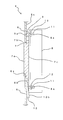
- FIG. 2 shows a cross-sectional view of the operation display device 4.
- FIG. 2 shows the area around the display board 7 in particular in the II-II cross section of FIG.
- a face plate 6 is attached to the front surface of the operation display device 4.
- the display portion 7a of the display plate 7 is inserted into the opening portion 6a of the face plate 6.
- the display plate 7 is pressed and fixed to the face plate 6 by the pressing plate 8.
- the face plate 6 is provided with studs 11 on the upper and lower parts of the back surface. Further, an opening 6a for inserting the display portion 7a of the display plate 7 is provided. A spacer 9 is inserted into the upper stud 11 of the back surface 6c of the face plate 6 through the hole 9a, and a gap adjusting plate 10 is inserted into the lower stud 11 through the elongated hole 10a.
- the display plate 7 is provided with a flange portion 7b for fixing to the face plate 6 on the side portion of the display portion 7a.
- the flange portion 7b comes into contact with the back surface 6c of the face plate 6.
- the material of the display board 7 is a translucent resin.
- a display unit (not shown) for displaying characters, numbers, etc. is provided behind the display board 7 via the display board 7.
- the pressing plate 8 has a pressing surface 8b for pressing and fixing the display plate 7 against the face plate 6.
- the pressing plate 8 is fixed to the face plate 6 by inserting the stud 11 into the holes 8a provided in the upper and lower portions and fastening the stud 11 with the nut 12.
- the spacer 9 has a hole 9a for passing the stud 11, and has substantially the same thickness as the flange portion 7b of the display plate 7.
- the gap adjusting plate 10 has a wedge-shaped cross section, and the joint surface 10b in contact with the pressing surface 8b of the pressing plate 8 is inclined.
- the gap adjusting plate 10 has an elongated hole 10a for passing the stud 11 at one end where the plate thickness is reduced due to the inclination of the joint surface 10b.
- the joint surface 10b is inclined from one end side with the elongated hole 10a toward the other end side, and the plate thickness on the other end side is larger than that on the one end side.
- the elongated hole 10a is formed from one end side to the other end side. The gap adjusting plate 10 can be moved up and down by the length of the elongated hole 10a.
- the amount of gap between the holding plate 8 and the face plate 6 can be adjusted by moving the gap adjusting plate 10 in the display plate 7 direction (up and down) when the holding plate 8 is fixed by fastening the nut 12.
- the gap adjusting plate 10 is moved in the direction of the display plate 7, the thickness of the portion in contact with the pressing plate 8 increases, so that the gap amount between the pressing plate 8 and the face plate 6 increases.
- the gap adjusting plate 10 is moved away from the display plate 7, the thickness of the portion in contact with the pressing plate 8 becomes smaller, so that the amount of gap between the pressing plate 8 and the face plate 6 becomes smaller.
- the amount of pressing of the flange portion 7b of the display plate 7 against the back surface 6c of the face plate 6 is adjusted.
- the amount of pressing of the flange portion 7b of the display plate 7 against the back surface 6c of the face plate 6 also increases.
- the amount of pressure of the flange portion 7b of the display plate 7 against the back surface 6c of the face plate 6 increases, the amount of the gap also decreases, and the seal is eventually sealed.
- the following effects can be obtained.
- the display unit 7a inserted into the opening portion 6a provided on the face plate 6 and the outer periphery provided on the side portion of the display unit 7a are larger than the opening portion 6a.
- the gap adjusting plate 10 Since the gap adjusting plate 10 is provided at the other end between the holding plate 8 and the back surface 6c of the face plate 6 so that the gap can be adjusted, the gap adjusting plate 10 can be moved to move the display plate 7. The gap between the flange portion 7b and the back surface 6c of the face plate 6 can be adjusted to seal the face plate 6.
- the gap adjusting plate 10 is used at the fixing location, so that the operation display device is sealed with a simple configuration to allow dust to enter. Can be prevented.
- gap adjusting plate 10 if one type of gap adjusting plate 10 is prepared, it can be used for operation display devices of almost all sizes, so that the cost can be reduced. Since the cross section of the gap adjusting plate 10 is formed in a substantially wedge shape, the amount of gap between the face plate 6 and the holding plate 8 can be continuously changed.
- FIG. 4 shows a gap adjusting plate according to the second embodiment. It is the same as the first embodiment except for the gap adjusting plate.
- the gap adjusting plate 13 shown in FIG. 4 is provided with a hole 14a through which the stud 11 is passed on one end side of a substantially quadrangular sheet metal 14, and a thin plate 15 is attached to the other end side.
- the thin plate 15 is attached only to one side (surface) of the sheet metal 14.
- the gap adjusting plate 13 is attached so that the stud 11 is passed through the hole 14a and the surface to which the thin plate 15 is attached is in contact with the face plate 6. Further, the gap adjusting plate 13 is attached with one end side provided with the hole 14a facing the display plate 7. Then, the pressing plate 8 sandwiches the surface of the thin plate 15 on which the thin plate 15 is not attached.
- the hole 14a may be an elongated hole formed from one end side to the other end side of the gap adjusting plate 13.
- the gap adjusting plate 13 has the thin plate 15 attached to the end of one surface of the sheet metal 14, it is possible to obtain the same effect as the gap adjusting plate 10 having a wedge-shaped cross section with a simple structure.
- FIG. 5 shows a gap adjusting plate according to the third embodiment. It is the same as the first embodiment except for the gap adjusting plate.
- the gap adjusting plate 16 shown in FIG. 5 is provided with a hole 14a through which the stud 11 is passed on one end side of a substantially quadrangular sheet metal 14, and has a coating film 17 on the other end side.
- the coating film 17 is continuously applied to both surfaces including the other end of the sheet metal 14.
- the gap adjusting plate 16 is attached by passing the stud 11 through the hole 14a. Further, the gap adjusting plate 16 is attached with the one end side having the hole 14a facing the display plate 7. Then, the portion of the gap adjusting plate 16 to which the coating film 17 is applied is sandwiched by the pressing plate 8.
- the hole 14a may be an elongated hole formed from one end side to the other end side of the gap adjusting plate 16.
- the gap adjusting plate 16 is coated with the coating film 17 on a part of the sheet metal 14, it is possible to obtain the same effect as the wedge-shaped gap adjusting plate 10 with a simple structure of simply applying the coating film 17.
Landscapes
- Engineering & Computer Science (AREA)
- Automation & Control Theory (AREA)
- Computer Networks & Wireless Communication (AREA)
- Indicating And Signalling Devices For Elevators (AREA)
Abstract
The interior of an operation display device has precision equipment, and infiltration of dust or the like must be prevented. This operation display device 4 can prevent infiltration of dust or the like by way of a configuration provided with: a display plate 7 that has a display unit 7a fit into an opening 6a provided in a faceplate 6; a holding plate 8 that secures the display plate 7 to the back face of the faceplate 6; a spacer 9 that is inserted into a space at one end between the holding plate 8 and the back face of the faceplate 6; and a gap adjusting plate 10 that is inserted into a space at the other end between the holding plate 8 and the back face of the faceplate 6 and has a cross-section that has a substantial wedge shape.
Description
この発明は、乗場等に用いるエレベータの操作表示装置に関する。
The present invention relates to an elevator operation display device used for a landing or the like.
エレベータの乗場には、行先階の登録・かご位置の表示を行う操作表示装置が設けられている。操作表示装置に用いられている機器は精密機器であり、埃等の浸入を防ぐ必要がある。この対策を施した先行文献が開示されている。(たとえば特許文献1)。特許文献1は、フェースプレートの裏側周面と取付パネルの表面の開口部周縁との間にシール部材を配している。これにより、屋外等の特殊環境にも対応できる。
The elevator platform is equipped with an operation display device that registers the destination floor and displays the car position. The equipment used in the operation display device is a precision equipment, and it is necessary to prevent the ingress of dust and the like. Prior literature with this measure is disclosed. (For example, Patent Document 1). In Patent Document 1, a sealing member is arranged between the peripheral surface on the back side of the face plate and the peripheral edge of the opening on the surface of the mounting panel. This makes it possible to handle special environments such as outdoors.
しかしながら、特許文献1のシール部材はゴムパッキンであり、操作表示装置のサイズに合わせて数種類用意する必要がある。このため、ゴムパッキンを用いるとコストが掛かってしまう。
However, the seal member of Patent Document 1 is a rubber packing, and it is necessary to prepare several types according to the size of the operation display device. Therefore, using rubber packing is costly.
この発明は上記課題を解決するためになされたもので、簡易な構成で埃の浸入を防止できる操作表示装置を供給することを目的とする。
The present invention has been made to solve the above problems, and an object of the present invention is to supply an operation display device capable of preventing the ingress of dust with a simple configuration.
この発明に係るエレベータの操作表示装置は、フェースプレートに表示部を備えるエレベータの操作表示装置において、前記フェースプレートに設けられた開口部に挿入される表示部、前記表示部の側部に設けられ外周が前記開口部よりも大きいフランジ部を有する表示板と、前記表示板を前記フェースプレートの裏面に固定する押え板と、前記押え板と前記フェースプレートの裏面との間の一端部に挿入されるスペーサーと、前記押え板と前記フェースプレートの裏面との間の他端部に隙間調整可能に挿入される隙間調整板と、を備えている。
The elevator operation display device according to the present invention is an elevator operation display device having a display unit on the face plate, and is provided on a display unit inserted into an opening provided in the face plate and a side portion of the display unit. It is inserted into one end between a display plate having a flange portion whose outer periphery is larger than the opening, a presser plate for fixing the display plate to the back surface of the face plate, and the presser plate and the back surface of the face plate. It is provided with a spacer and a gap adjusting plate that is inserted into the other end between the holding plate and the back surface of the face plate so that the gap can be adjusted.
この発明によれば、簡易な構成で操作表示装置に埃の浸入を防ぐことができる。
According to the present invention, it is possible to prevent dust from entering the operation display device with a simple configuration.
以下、この発明の詳細について、上記図面を用いて説明する。
Hereinafter, the details of the present invention will be described with reference to the above drawings.
実施の形態1
図1~図3は、この発明の実施の形態1を説明する図である。なお、図中同一符号は同一部品を示し、説明を省略する。
図1に示すエレベータの乗場1に、両開きの扉3を有する出入口2が設けられている。出入口2の設けられている建物壁5に、行先の設定と運転状況等を確認できる操作表示装置4が設置されている。この操作表示装置4は、本体の一部を建物壁5に埋め込むタイプである。Embodiment 1
1 to 3 are views for explaining the first embodiment of the present invention. In the drawings, the same reference numerals indicate the same parts, and the description thereof will be omitted.
Theelevator landing 1 shown in FIG. 1 is provided with an entrance / exit 2 having a double door 3. An operation display device 4 that can confirm destination settings, driving conditions, and the like is installed on the building wall 5 provided with the doorway 2. The operation display device 4 is a type in which a part of the main body is embedded in the building wall 5.
図1~図3は、この発明の実施の形態1を説明する図である。なお、図中同一符号は同一部品を示し、説明を省略する。
図1に示すエレベータの乗場1に、両開きの扉3を有する出入口2が設けられている。出入口2の設けられている建物壁5に、行先の設定と運転状況等を確認できる操作表示装置4が設置されている。この操作表示装置4は、本体の一部を建物壁5に埋め込むタイプである。
1 to 3 are views for explaining the first embodiment of the present invention. In the drawings, the same reference numerals indicate the same parts, and the description thereof will be omitted.
The
図2に操作表示装置4の断面図を示している。図2は図1のII-II断面の特に表示板7の周辺を表している。
FIG. 2 shows a cross-sectional view of the operation display device 4. FIG. 2 shows the area around the display board 7 in particular in the II-II cross section of FIG.
操作表示装置4の表部にはフェースプレート6が装着されている。フェースプレート6の開口部6aに表示板7の表示部7aが挿入されている。表示板7は、押え板8によりフェースプレート6に押圧されて固定されている。
A face plate 6 is attached to the front surface of the operation display device 4. The display portion 7a of the display plate 7 is inserted into the opening portion 6a of the face plate 6. The display plate 7 is pressed and fixed to the face plate 6 by the pressing plate 8.
フェースプレート6は、裏面の上部と下部にスタッド11が設けられている。また、表示板7の表示部7aを挿入するための開口部6aを設けている。フェースプレート6の裏面6cの上部のスタッド11にはスペーサー9が孔9aを通して挿入され、下部のスタッド11には隙間調整板10が長孔10aを通して挿入される。
The face plate 6 is provided with studs 11 on the upper and lower parts of the back surface. Further, an opening 6a for inserting the display portion 7a of the display plate 7 is provided. A spacer 9 is inserted into the upper stud 11 of the back surface 6c of the face plate 6 through the hole 9a, and a gap adjusting plate 10 is inserted into the lower stud 11 through the elongated hole 10a.
表示板7は、表示部7aの側部に、フェースプレート6に固定するためのフランジ部7bが設けられている。フランジ部7bはフェースプレート6の裏面6cに当接する。表示板7の材質は半透明の樹脂である。また、表示板7の後方に表示板7を介して文字、数字等を表示するための表示ユニット(図示していない)を設けている。
The display plate 7 is provided with a flange portion 7b for fixing to the face plate 6 on the side portion of the display portion 7a. The flange portion 7b comes into contact with the back surface 6c of the face plate 6. The material of the display board 7 is a translucent resin. Further, a display unit (not shown) for displaying characters, numbers, etc. is provided behind the display board 7 via the display board 7.
押え板8は、表示板7をフェースプレート6に押しつけて固定するための押え面8bを有している。押え板8のフェースプレート6への固定は、上部と下部に設けた孔8aにスタッド11を挿通し、このスタッド11をナット12で締結することで行われる。
The pressing plate 8 has a pressing surface 8b for pressing and fixing the display plate 7 against the face plate 6. The pressing plate 8 is fixed to the face plate 6 by inserting the stud 11 into the holes 8a provided in the upper and lower portions and fastening the stud 11 with the nut 12.
スペーサー9は、スタッド11を通すための孔9aを有し、表示板7のフランジ部7bとほぼ同じ厚さである。
The spacer 9 has a hole 9a for passing the stud 11, and has substantially the same thickness as the flange portion 7b of the display plate 7.
隙間調整板10は、図3にも示す様に、断面が楔状になっており、押え板8の押え面8bと接する接合面10bが傾いている。隙間調整板10は、接合面10bの傾きにより板厚が小さくなっている一端部にスタッド11を通すための長孔10aを有している。接合面10bは、長孔10aのある一端部側から他端部側に向けて傾き、一端部側より他端部側の板厚が大きい。長孔10aは、一端部側から他端部側に向けて形成されている。隙間調整板10は、長孔10aの長さ分上下に移動させることができる。
As shown in FIG. 3, the gap adjusting plate 10 has a wedge-shaped cross section, and the joint surface 10b in contact with the pressing surface 8b of the pressing plate 8 is inclined. The gap adjusting plate 10 has an elongated hole 10a for passing the stud 11 at one end where the plate thickness is reduced due to the inclination of the joint surface 10b. The joint surface 10b is inclined from one end side with the elongated hole 10a toward the other end side, and the plate thickness on the other end side is larger than that on the one end side. The elongated hole 10a is formed from one end side to the other end side. The gap adjusting plate 10 can be moved up and down by the length of the elongated hole 10a.
次に、表示板7のフェースプレート6への固定方法を詳細に説明する。
図2において、上部と下部のスタッド11に挿入されたナット12を締めることにより、表示板7はフランジ部7bがフェースプレート6の裏面6cに押圧されてフェースプレート6に固定される。また、押え板8もフェースプレート6に固定される。 Next, a method of fixing thedisplay plate 7 to the face plate 6 will be described in detail.
In FIG. 2, by tightening the nuts 12 inserted into the upper andlower studs 11, the flange portion 7b of the display plate 7 is pressed against the back surface 6c of the face plate 6 and fixed to the face plate 6. The presser plate 8 is also fixed to the face plate 6.
図2において、上部と下部のスタッド11に挿入されたナット12を締めることにより、表示板7はフランジ部7bがフェースプレート6の裏面6cに押圧されてフェースプレート6に固定される。また、押え板8もフェースプレート6に固定される。 Next, a method of fixing the
In FIG. 2, by tightening the nuts 12 inserted into the upper and
押え板8とフェースプレート6との隙間量は、押え板8をナット12の締結により固定する際に、隙間調整板10を表示板7方向(上下)に移動させることで調整することができる。隙間調整板10を表示板7方向に移動させてゆくと、押え板8と接する部分の板厚が大きくなるので押え板8とフェースプレート6との隙間量が大きくなる。隙間調整板10を表示板7から離れる方向に移動させてゆくと、押え板8と接する部分の板厚が小さくなるので押え板8とフェースプレート6との隙間量が小さくなる。
The amount of gap between the holding plate 8 and the face plate 6 can be adjusted by moving the gap adjusting plate 10 in the display plate 7 direction (up and down) when the holding plate 8 is fixed by fastening the nut 12. When the gap adjusting plate 10 is moved in the direction of the display plate 7, the thickness of the portion in contact with the pressing plate 8 increases, so that the gap amount between the pressing plate 8 and the face plate 6 increases. When the gap adjusting plate 10 is moved away from the display plate 7, the thickness of the portion in contact with the pressing plate 8 becomes smaller, so that the amount of gap between the pressing plate 8 and the face plate 6 becomes smaller.
押え板8とフェースプレート6との隙間量を調整することで表示板7のフランジ部7bのフェースプレート6の裏面6cへの押圧量が調整される。押え板8とフェースプレート6との隙間量を小さくすることで表示板7のフランジ部7bのフェースプレート6の裏面6cへの押圧量も大きくなる。表示板7のフランジ部7bのフェースプレート6の裏面6cへの押圧量が大きくなることで、その隙間量も小さくなり、やがて密閉される。
By adjusting the amount of gap between the pressing plate 8 and the face plate 6, the amount of pressing of the flange portion 7b of the display plate 7 against the back surface 6c of the face plate 6 is adjusted. By reducing the amount of gap between the pressing plate 8 and the face plate 6, the amount of pressing of the flange portion 7b of the display plate 7 against the back surface 6c of the face plate 6 also increases. As the amount of pressure of the flange portion 7b of the display plate 7 against the back surface 6c of the face plate 6 increases, the amount of the gap also decreases, and the seal is eventually sealed.
上記実施の形態1により、以下の効果を得ることができる。
フェースプレート6に表示部を有するエレベータの操作表示装置4において、フェースプレート6に設けられた開口部6aに挿入される表示部7a、表示部7aの側部に設けられ外周が開口部6aよりも大きいフランジ部7bを有する表示板7と、表示板7をフェースプレート6の裏面に固定する押え板8と、押え板8とフェースプレート6の裏面6cとの間の一端部に挿入されるスペーサー9と、押え板8とフェースプレート6の裏面6cとの間の他端部に隙間調整可能に挿入される隙間調整板10とを備えているので、隙間調整板10を移動させて表示板7のフランジ部7bとフェースプレート6の裏面6cとの隙間量を調整して密閉させることができる。表示板7のフランジ部7bをフェースプレート6の裏面6cに密閉させて固定する際に固定箇所に隙間調整板10を使用しているので、簡易な構成で操作表示装置を密閉させて埃の浸入を防ぐことができる。 According to the first embodiment, the following effects can be obtained.
In theoperation display device 4 of an elevator having a display unit on the face plate 6, the display unit 7a inserted into the opening portion 6a provided on the face plate 6 and the outer periphery provided on the side portion of the display unit 7a are larger than the opening portion 6a. A display plate 7 having a large flange portion 7b, a presser plate 8 for fixing the display plate 7 to the back surface of the face plate 6, and a spacer 9 inserted at one end between the presser plate 8 and the back surface 6c of the face plate 6. Since the gap adjusting plate 10 is provided at the other end between the holding plate 8 and the back surface 6c of the face plate 6 so that the gap can be adjusted, the gap adjusting plate 10 can be moved to move the display plate 7. The gap between the flange portion 7b and the back surface 6c of the face plate 6 can be adjusted to seal the face plate 6. When the flange portion 7b of the display plate 7 is sealed and fixed to the back surface 6c of the face plate 6, the gap adjusting plate 10 is used at the fixing location, so that the operation display device is sealed with a simple configuration to allow dust to enter. Can be prevented.
フェースプレート6に表示部を有するエレベータの操作表示装置4において、フェースプレート6に設けられた開口部6aに挿入される表示部7a、表示部7aの側部に設けられ外周が開口部6aよりも大きいフランジ部7bを有する表示板7と、表示板7をフェースプレート6の裏面に固定する押え板8と、押え板8とフェースプレート6の裏面6cとの間の一端部に挿入されるスペーサー9と、押え板8とフェースプレート6の裏面6cとの間の他端部に隙間調整可能に挿入される隙間調整板10とを備えているので、隙間調整板10を移動させて表示板7のフランジ部7bとフェースプレート6の裏面6cとの隙間量を調整して密閉させることができる。表示板7のフランジ部7bをフェースプレート6の裏面6cに密閉させて固定する際に固定箇所に隙間調整板10を使用しているので、簡易な構成で操作表示装置を密閉させて埃の浸入を防ぐことができる。 According to the first embodiment, the following effects can be obtained.
In the
また、隙間調整板10は1種類を用意すればほぼ全てのサイズの操作表示装置に用いることができるのでコスト削減できる。隙間調整板10の断面は略楔型に形成されているので、フェースプレート6と押え板8との隙間量を連続的に変化させることができる。
Further, if one type of gap adjusting plate 10 is prepared, it can be used for operation display devices of almost all sizes, so that the cost can be reduced. Since the cross section of the gap adjusting plate 10 is formed in a substantially wedge shape, the amount of gap between the face plate 6 and the holding plate 8 can be continuously changed.
実施の形態2
図4に、実施の形態2における隙間調整板を示す。隙間調整板以外は実施の形態1と同じである。Embodiment 2
FIG. 4 shows a gap adjusting plate according to the second embodiment. It is the same as the first embodiment except for the gap adjusting plate.
図4に、実施の形態2における隙間調整板を示す。隙間調整板以外は実施の形態1と同じである。
FIG. 4 shows a gap adjusting plate according to the second embodiment. It is the same as the first embodiment except for the gap adjusting plate.
図4に示す隙間調整板13は、略四角形の板金14の一端部側にスタッド11を通す孔14aを設け、他端部側に薄板15を貼り付けている。薄板15は、板金14の片面(表面)のみに貼り付けられている。
The gap adjusting plate 13 shown in FIG. 4 is provided with a hole 14a through which the stud 11 is passed on one end side of a substantially quadrangular sheet metal 14, and a thin plate 15 is attached to the other end side. The thin plate 15 is attached only to one side (surface) of the sheet metal 14.
隙間調整板13は、スタッド11を孔14aに通し、薄板15が貼り付けられている面をフェースプレート6に接するように取付けられる。また、隙間調整板13は孔14aの設けられている一端部側を表示板7に向けて取付けられる。そして、押え板8により、薄板15の貼り付けられていない面を挟みこむ。なお、孔14aは、隙間調整板13の一端部側から他端部側に向けて形成される長孔でもよい。
The gap adjusting plate 13 is attached so that the stud 11 is passed through the hole 14a and the surface to which the thin plate 15 is attached is in contact with the face plate 6. Further, the gap adjusting plate 13 is attached with one end side provided with the hole 14a facing the display plate 7. Then, the pressing plate 8 sandwiches the surface of the thin plate 15 on which the thin plate 15 is not attached. The hole 14a may be an elongated hole formed from one end side to the other end side of the gap adjusting plate 13.
上記実施の形態2により、以下の効果を得ることができる。
隙間調整板13は、板金14の片方の面の端部に薄板15を貼り付けているので、簡単な構成で、断面が楔型の隙間調整板10と同等の効果を得ることができる。 According to the second embodiment, the following effects can be obtained.
Since the gap adjusting plate 13 has the thin plate 15 attached to the end of one surface of thesheet metal 14, it is possible to obtain the same effect as the gap adjusting plate 10 having a wedge-shaped cross section with a simple structure.
隙間調整板13は、板金14の片方の面の端部に薄板15を貼り付けているので、簡単な構成で、断面が楔型の隙間調整板10と同等の効果を得ることができる。 According to the second embodiment, the following effects can be obtained.
Since the gap adjusting plate 13 has the thin plate 15 attached to the end of one surface of the
実施の形態3
図5に、実施の形態3における隙間調整板を示す。隙間調整板以外は実施の形態1と同じである。Embodiment 3
FIG. 5 shows a gap adjusting plate according to the third embodiment. It is the same as the first embodiment except for the gap adjusting plate.
図5に、実施の形態3における隙間調整板を示す。隙間調整板以外は実施の形態1と同じである。
FIG. 5 shows a gap adjusting plate according to the third embodiment. It is the same as the first embodiment except for the gap adjusting plate.
図5に示す隙間調整板16は、略四角形の板金14の一端部側にスタッド11を通す孔14aを設け、他端部側に塗膜17を有している。塗膜17は、板金14の他端部を含む両面に連続的に塗布されている。
The gap adjusting plate 16 shown in FIG. 5 is provided with a hole 14a through which the stud 11 is passed on one end side of a substantially quadrangular sheet metal 14, and has a coating film 17 on the other end side. The coating film 17 is continuously applied to both surfaces including the other end of the sheet metal 14.
隙間調整板16は、スタッド11を孔14aに通して取付けられる。また、隙間調整板16は孔14aのある一端部側を表示板7に向けて取付けられる。そして、押え板8により、隙間調整板16の塗膜17の塗布されている部分を挟みこむ。なお、孔14aは、隙間調整板16の一端部側から他端部側に向けて形成される長孔でもよい。
The gap adjusting plate 16 is attached by passing the stud 11 through the hole 14a. Further, the gap adjusting plate 16 is attached with the one end side having the hole 14a facing the display plate 7. Then, the portion of the gap adjusting plate 16 to which the coating film 17 is applied is sandwiched by the pressing plate 8. The hole 14a may be an elongated hole formed from one end side to the other end side of the gap adjusting plate 16.
上記実施の形態3により、以下の効果を得ることができる。
隙間調整板16は、板金14の一部に塗膜17を塗布しているので、塗膜17を塗布するだけの簡単な構成で楔形の隙間調整板10と同様の効果を得ることができる。 According to the third embodiment, the following effects can be obtained.
Since the gap adjusting plate 16 is coated with thecoating film 17 on a part of the sheet metal 14, it is possible to obtain the same effect as the wedge-shaped gap adjusting plate 10 with a simple structure of simply applying the coating film 17.
隙間調整板16は、板金14の一部に塗膜17を塗布しているので、塗膜17を塗布するだけの簡単な構成で楔形の隙間調整板10と同様の効果を得ることができる。 According to the third embodiment, the following effects can be obtained.
Since the gap adjusting plate 16 is coated with the
6 フェースプレート、 6a 開口部、 7 表示板、 7a 表示部、 7b フランジ部, 8 押え板、 8a 孔、 8b 押え面、 9 スペーサー、 9a 孔、 10 隙間調整板、 10a 長孔、 10b 接合面、 11 スタッド、 12 ナット、 13 隙間調整板、 14 板金、 14a 孔、 15 薄板、 16 隙間調整板、 17 塗膜。
6 face plate, 6a opening, 7 display plate, 7a display part, 7b flange part, 8 holding plate, 8a hole, 8b holding surface, 9 spacer, 9a hole, 10 gap adjustment plate, 10a long hole, 10b joint surface, 11 studs, 12 nuts, 13 gap adjustment plates, 14 sheet metal, 14a holes, 15 thin plates, 16 gap adjustment plates, 17 coating films.
Claims (4)
- フェースプレートに表示部を備えるエレベータの操作表示装置において、
前記フェースプレートに設けられた開口部に挿入される表示部、前記表示部の側部に設けられ外周が前記開口部よりも大きいフランジ部を有する表示板と、
前記表示板を前記フェースプレートの裏面に固定する押え板と、
前記押え板と前記フェースプレートの裏面との間の一端部に挿入されるスペーサーと、
前記押え板と前記フェースプレートの裏面との間の他端部に隙間調整可能に挿入される隙間調整板と、
を備えたことを特徴とするエレベータの操作表示装置。 In an elevator operation display device having a display unit on the face plate
A display unit inserted into the opening provided in the face plate, a display plate provided on the side of the display unit and having a flange portion whose outer circumference is larger than the opening.
A presser plate for fixing the display plate to the back surface of the face plate,
A spacer inserted into one end between the holding plate and the back surface of the face plate,
A gap adjusting plate inserted so that the gap can be adjusted at the other end between the holding plate and the back surface of the face plate,
Elevator operation display device characterized by being equipped with. - 前記隙間調整板は、断面が略楔型に形成されている、
ことを特徴とする請求項1に記載のエレベータの操作表示装置。 The gap adjusting plate has a substantially wedge-shaped cross section.
The elevator operation display device according to claim 1. - 前記隙間調整板は、板金の片方の面の端部に薄板を貼り付けている、
ことを特徴とする請求項1に記載のエレベータの操作表示装置。 The gap adjusting plate has a thin plate attached to the end of one side of the sheet metal.
The elevator operation display device according to claim 1. - 前記隙間調整板は、板金の一部に塗料を塗布されている、
ことを特徴とする請求項1に記載のエレベータの操作表示装置。 The gap adjusting plate is coated with a paint on a part of the sheet metal.
The elevator operation display device according to claim 1.
Priority Applications (1)
| Application Number | Priority Date | Filing Date | Title |
|---|---|---|---|
| PCT/JP2019/009254 WO2020183512A1 (en) | 2019-03-08 | 2019-03-08 | Elevator operation display device |
Applications Claiming Priority (1)
| Application Number | Priority Date | Filing Date | Title |
|---|---|---|---|
| PCT/JP2019/009254 WO2020183512A1 (en) | 2019-03-08 | 2019-03-08 | Elevator operation display device |
Publications (1)
| Publication Number | Publication Date |
|---|---|
| WO2020183512A1 true WO2020183512A1 (en) | 2020-09-17 |
Family
ID=72426011
Family Applications (1)
| Application Number | Title | Priority Date | Filing Date |
|---|---|---|---|
| PCT/JP2019/009254 WO2020183512A1 (en) | 2019-03-08 | 2019-03-08 | Elevator operation display device |
Country Status (1)
| Country | Link |
|---|---|
| WO (1) | WO2020183512A1 (en) |
Cited By (1)
| Publication number | Priority date | Publication date | Assignee | Title |
|---|---|---|---|---|
| JP7271737B1 (en) | 2022-01-17 | 2023-05-11 | 東芝エレベータ株式会社 | Button devices, control panels and cars |
Citations (6)
| Publication number | Priority date | Publication date | Assignee | Title |
|---|---|---|---|---|
| JPS62115924U (en) * | 1986-01-16 | 1987-07-23 | ||
| JPH0310403Y2 (en) * | 1984-12-07 | 1991-03-14 | ||
| JPH0698424A (en) * | 1991-06-24 | 1994-04-08 | Mitsubishi Electric Corp | Regulating device for attaching decorative panel of switchgear |
| JPH0617816Y2 (en) * | 1987-08-12 | 1994-05-11 | フジテック株式会社 | Equipment for elevators |
| JPH07223782A (en) * | 1994-02-03 | 1995-08-22 | Otis Elevator Co | Entrance of car for elevator |
| JP2002226159A (en) * | 2001-01-29 | 2002-08-14 | Toshiba Elevator Co Ltd | Cage of elevator |
-
2019
- 2019-03-08 WO PCT/JP2019/009254 patent/WO2020183512A1/en active Application Filing
Patent Citations (6)
| Publication number | Priority date | Publication date | Assignee | Title |
|---|---|---|---|---|
| JPH0310403Y2 (en) * | 1984-12-07 | 1991-03-14 | ||
| JPS62115924U (en) * | 1986-01-16 | 1987-07-23 | ||
| JPH0617816Y2 (en) * | 1987-08-12 | 1994-05-11 | フジテック株式会社 | Equipment for elevators |
| JPH0698424A (en) * | 1991-06-24 | 1994-04-08 | Mitsubishi Electric Corp | Regulating device for attaching decorative panel of switchgear |
| JPH07223782A (en) * | 1994-02-03 | 1995-08-22 | Otis Elevator Co | Entrance of car for elevator |
| JP2002226159A (en) * | 2001-01-29 | 2002-08-14 | Toshiba Elevator Co Ltd | Cage of elevator |
Cited By (2)
| Publication number | Priority date | Publication date | Assignee | Title |
|---|---|---|---|---|
| JP7271737B1 (en) | 2022-01-17 | 2023-05-11 | 東芝エレベータ株式会社 | Button devices, control panels and cars |
| JP2023104362A (en) * | 2022-01-17 | 2023-07-28 | 東芝エレベータ株式会社 | Button device, control panel, and car |
Similar Documents
| Publication | Publication Date | Title |
|---|---|---|
| US9850700B2 (en) | Waterproofing member and exterior wall structure | |
| WO2020183512A1 (en) | Elevator operation display device | |
| US4803817A (en) | Glazing assembly and method for glazing a building | |
| JP4458810B2 (en) | How to repair elevator doors | |
| WO2019205988A1 (en) | Bonding strength testing device | |
| WO2016139750A1 (en) | Operating board for elevator | |
| US5364673A (en) | Transparent plate-shaped component having a stepped edge totally surrounded by a seal | |
| JP3103924B2 (en) | Installation equipment for fireproof coatings | |
| US20230383527A1 (en) | Self-adhered system for sealing between adjacent building structural elements | |
| CN109986859A (en) | A kind of screen assembly for 3D printer touch screen | |
| JP2000211853A (en) | Elevator car | |
| JP3033527B2 (en) | Concrete body surface dust prevention method | |
| JP2009299379A (en) | Method of attaching fire-resistant coating panel | |
| KR102021407B1 (en) | Sealing structure for outerwall pannel | |
| JP2022015045A (en) | Sheet metal adhesive and bonding method thereof | |
| KR100525195B1 (en) | A Fastening Device of Building Outer Wall Ornamental | |
| JP6716042B2 (en) | Elevator hall equipment | |
| KR20170133885A (en) | Waterproof device for sash, and Sash waterproof construction method of using the same | |
| JP3249319B2 (en) | Elevator design parts | |
| JP3166342B2 (en) | Exterior wall panel joint structure | |
| JPH0542884Y2 (en) | ||
| JPH078657Y2 (en) | Sealing structure for joints on outer walls of buildings | |
| JPH0625407U (en) | Joint structure of outer wall prefabricated panel | |
| WO2020070796A1 (en) | Elevator door device of and method for repairing same | |
| JP2005026083A (en) | Organic electroluminescent display panel |
Legal Events
| Date | Code | Title | Description |
|---|---|---|---|
| 121 | Ep: the epo has been informed by wipo that ep was designated in this application |
Ref document number: 19918967 Country of ref document: EP Kind code of ref document: A1 |
|
| NENP | Non-entry into the national phase |
Ref country code: DE |
|
| 122 | Ep: pct application non-entry in european phase |
Ref document number: 19918967 Country of ref document: EP Kind code of ref document: A1 |
|
| NENP | Non-entry into the national phase |
Ref country code: JP |