WO2020182449A1 - A washer/dryer wherein unbalanced load is balanced with fluid - Google Patents
A washer/dryer wherein unbalanced load is balanced with fluid Download PDFInfo
- Publication number
- WO2020182449A1 WO2020182449A1 PCT/EP2020/054712 EP2020054712W WO2020182449A1 WO 2020182449 A1 WO2020182449 A1 WO 2020182449A1 EP 2020054712 W EP2020054712 W EP 2020054712W WO 2020182449 A1 WO2020182449 A1 WO 2020182449A1
- Authority
- WO
- WIPO (PCT)
- Prior art keywords
- drum
- washer
- dryer
- supply line
- groove
- Prior art date
- Legal status (The legal status is an assumption and is not a legal conclusion. Google has not performed a legal analysis and makes no representation as to the accuracy of the status listed.)
- Ceased
Links
Images


Classifications
-
- D—TEXTILES; PAPER
- D06—TREATMENT OF TEXTILES OR THE LIKE; LAUNDERING; FLEXIBLE MATERIALS NOT OTHERWISE PROVIDED FOR
- D06F—LAUNDERING, DRYING, IRONING, PRESSING OR FOLDING TEXTILE ARTICLES
- D06F37/00—Details specific to washing machines covered by groups D06F21/00 - D06F25/00
- D06F37/20—Mountings, e.g. resilient mountings, for the rotary receptacle, motor, tub or casing; Preventing or damping vibrations
- D06F37/22—Mountings, e.g. resilient mountings, for the rotary receptacle, motor, tub or casing; Preventing or damping vibrations in machines with a receptacle rotating or oscillating about a horizontal axis
- D06F37/225—Damping vibrations by displacing, supplying or ejecting a material, e.g. liquid, into or from counterbalancing pockets
-
- D—TEXTILES; PAPER
- D06—TREATMENT OF TEXTILES OR THE LIKE; LAUNDERING; FLEXIBLE MATERIALS NOT OTHERWISE PROVIDED FOR
- D06F—LAUNDERING, DRYING, IRONING, PRESSING OR FOLDING TEXTILE ARTICLES
- D06F25/00—Washing machines with receptacles, e.g. perforated, having a rotary movement, e.g. oscillatory movement, the receptacle serving both for washing and for centrifugally separating water from the laundry and having further drying means, e.g. using hot air
Definitions
- the present invention relates to a washer/dryer wherein the unbalanced load in the drum is balanced by using fluid.
- the laundry In washer/dryers, especially in washing machines, the laundry is placed into a drum which preferably rotates around a horizontal axis. In different steps of the washing program, the drum is rotated at different speeds, and the laundry is cleaned by means of water and detergent. During the rotation of the drum, the laundry is not homogeneously distributed in the drum and accumulates in some areas, causing an uneven load distribution. Especially, during the spin-drying step where the drum is rotated at very high speeds, the unbalanced load distribution causes vibrations. These vibrations result in noise, thus causing user dissatisfaction and also wear down the machine. Moreover, high-speed spin-drying adversely affects the performance.
- an automatic balancing mechanism wherein water is transferred through the shaft into the receptacles on the drum in case of unbalanced load.
- the rear wall of the drum stretches in case of unbalanced load, and this stretching causes a valve to open/close so as to transfer the water received through the shaft into the receptacle.
- a dynamical balancing unit which provides the transfer of water to the receptacles on the drum by means of channels formed on the shaft bearing.
- the shaft stretches with respect to the unbalanced load and opens the inlets of the channels. As the inlets of the channels open, water passes into the respective receptacle, thus performing the dynamical balancing process.
- JP2002136792 an additional grooved member is disclosed, which bears against the shaft bearing and which directs and transfers the water to the receptacles on the drum in case of unbalanced load. This additional member does not rotate, and the water in the groove is transferred to the receptacles by means of a channel as the shaft bearing rotates.
- the washer/dryer comprises one or more than one groove which is disposed between the drum rear wall and the shaft bearing, which rotates together with the drum so as to enable the water received from the mains and passing through the supply line to be continuously delivered to the distribution line and the receptacles with the centrifugal effect caused by the rotation of the drum, and which at least partially radially surrounds the part of the bearing extending into the rear wall.
- the aim of the present invention is the realization of a washer/dryer wherein the unbalanced load is efficiently balanced.
- the washer/dryer realized in order to attain the aim of the present invention, explicated in the first claim and the respective claims thereof, comprises one or more than one groove which is disposed between the drum rear wall and the shaft bearing, which rotates together with the drum so as to enable the water received from the mains and passing through the supply line positioned in the shaft to be continuously delivered to the distribution line and the receptacles with the centrifugal effect caused by the rotation of the drum, and which at least partially radially surrounds the part of the bearing extending into the rear wall.
- a housing wherein the shaft bearing is inserted is provided on the rear wall of the drum.
- the grooves are provided on the inner wall of said housing so as to at least partially surround the shaft bearing.
- the water flowing through the line in the shaft is distributed to the receptacles on the inner wall of the drum, and the imbalances which may occur during the washing, spin-drying or drying steps are eliminated.
- the required amount of water depending on the position and amount of the unbalanced load is transferred to the desired receptacle by means of this structure without calculating the opening/closing times of the valves and the positions of the receptacles.
- the groove surrounds the part of the bearing extending into the rear wall.
- the groove surrounds the part of the bearing extending into the rear wall so as to face the outlet of the supply line as an arc segment.
- a plurality of grooves are arranged on a line at intervals. During the rotation of the drum, at certain intervals at least one groove aligns with the outlet of a single supply line.
- time-controlled valves are used since the intake time of the water into the supply line is important. Thus, the length of the shaft and the shaft bearing can be decreased.
- sealing members which prevent the water from passing from one groove to another and which are positioned between the bearing and the drum are used between adjacent grooves.
- the correct amount of water is transferred to the relevant receptacle without any leaks.
- channels which are formed between the grooves, which form a water curtain when filled with water so as to prevent the water passage between the grooves and which are positioned between the bearing and the rear wall of the drum act as sealing members between the grooves.
- the water passage between the grooves is prevented without the need for using sealing members.
- the amount of water which compensate the unbalanced load so as to minimize the effect thereof can be mechanically transferred to the required region.
- Figure 1 - is the cross-sectional perspective view of a washer/dryer.
- Figure 2 - is the detailed view of the rear wall and the shaft bearing.
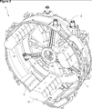
- Figure 3 - is the view of detail A in Figure 1.
- the washer/dryer (1) comprises a cylindrical drum (2) wherein the laundry to be washed is loaded and which has a rear wall (11); a tub (3) wherein the drum (2) rotates; a motor which rotates the drum (2); a shaft (4) which is borne on the tub (3) and which transfers the motion received from the motor to the drum (2); a bearing (5) which is provided at the center of the tub (3), which remains immobile together with the tub (3), which extends towards the center of the drum (2) and wherein the shaft (4) is borne; one or more than one receptacle (12) which is disposed into the drum (2) and wherein a fluid is transferred, in case of unbalanced load, to compensate the unbalanced load; at least one supply line (6) which is disposed in the shaft (4) and which has an inlet connected to the mains and an outlet opening to the outside from the shaft (4); at least one distribution line (7) which is disposed on the rear wall (11), which provides the connection between the supply line (6) and the receptacle (12) and
- the washer/dryer (1) further comprises at least one valve (9) which is provided on each supply line (6) and which provides the controlled intake of water into the supply line (6) from the mains, and a control unit (8) which detects any unbalanced load and determines the amount and position of the unbalanced load so as to determine which receptacle (12) should receive how much water and to open/close the valves (9) accordingly.
- each receptacle (12) Aligned with the outlet of each supply line (6) a groove (10) which surrounds the outlet is positioned, and the inlet of one distribution line (7) is connected to each groove (10).
- the groove (10) ensures that the fluid leaving the supply line (6) passes into the distribution line (7) with the centrifugal effect caused by the rotation of the drum (2) as long as the water flows at a certain flow rate.
- the groove (10) surrounding the outlet of the supply line (6) rotates on the bearing (5) together with the drum (2) and enables the water leaving the supply line (6) to pass into the distribution line (7), thus sucks, so to speak, the water in the supply line (6) with the centrifugal effect.
- the water is transferred to each receptacle (12) after passing through a supply line (6), a groove (10) and a distribution line (7).
- the water can be independently transferred into each receptacle (12).
- the groove (10) rotates around the bearing (5) during the rotation of the drum (2).
- the supply line (6) extending in the shaft (4) all along the shaft (4) opens into the volume defined by the groove (10) from the part of the bearing (5) in line with the groove (10).
- the distribution line (7) also opens into the volume defined by the groove (10).
- the outlet of the supply line (6) is positioned on an axis almost perpendicular to the axis of the shaft (4).
- the receptacle (12), the distribution line (7) and the groove (10) also rotate together with the drum (2).
- the control unit (8) decides which receptacle (12) should receive how much water. According to this decision, the valve (9) provided on the supply line (6) connected to the mains is opened. The water flowing through the supply line (6) reaches the outlet of the supply line (6) and passes from the supply line (6) into the groove (10) which rotates together with the drum (2).
- three receptacles (12) are provided on the drum (2) at 120o intervals, three supply lines (6) in the shaft (4) and three distribution lines (7) on the rear wall (11).
- three grooves (10) into each of which the inlet of one distribution line (7) and the outlet of one supply line (6) open are positioned side by side.
- the supply lines (6) have different lengths, and the outlet of each opens into a groove (10).
- the valve (9) on the supply line (6) which transfers the water to the relevant receptacle (12) is opened.
- the groove (10) is positioned on an arc segment or segments facing the outlet of the supply line (6) at a certain angle.
- the water leaving the supply line (6) can be taken into the groove (10) only when the groove (10) positioned on the arc segment aligns with the outlet of the supply line (6).
- the washer/dryer (1) comprises a plurality of grooves (10) on a single line into which a supply line (6) opens.
- all the grooves (10) are positioned in the same plane, and the length of the shaft (4) and the bearing (5) is shortened.
- the groove (10) surrounds the part of the bearing (5) extending into the rear wall (11).
- the water can be transferred from the supply line (6) to the distribution line (7), hence to the receptacle (12).
- the inlet of the distribution line (7) is arranged on the base of the groove (10).
- the groove (10) preferably has a conic cross-section which narrows down in the direction of the water flow.
- the cross-section of the groove (10) can be frustoconic or quadrangular.
- the width of the groove (10) is at least equal to or greater than the width of the outlet of the supply line (6).
- the washer/dryer (1) comprises one or more than one sealing member (13) which is disposed between the grooves (10) so as to prevent the water passage between the grooves (10) and to remain between the bearing (5) and the drum (2).
- the required amount of water can be transferred into the relevant receptacle (12) without any leaks.
- Gaskets produced from plastic, felt, etc. can be used as sealing members (13) ( Figure 3).
- the washer/dryer (1) comprises at least one channel which is arranged between the grooves (10).
- the washer/dryer (1) comprises one or more than channel between the grooves (10), which has a depth less than the grooves (10), which remains between the bearing (5) and the rear wall (11) and which forms a water curtain as water fills therein so as to prevent the water passage between the adjacent grooves (10).
- the water passage between the grooves (10) is prevented without the need for using sealing members (13). Since no sealing member (13) is used, any errors which may be caused by worn-out sealing members (13) are prevented.
- the amount of water which compensate the unbalanced load so as to minimize the effect thereof can be mechanically transferred to the required region in a continuous manner.
Landscapes
- Engineering & Computer Science (AREA)
- Textile Engineering (AREA)
- Detail Structures Of Washing Machines And Dryers (AREA)
Abstract
The present invention relates to a washer/dryer (1) comprising a cylindrical drum (2) wherein the laundry to be washed is loaded and which has a rear wall (11); a tub (3) wherein the drum (2) rotates; a motor which rotates the drum (2); a shaft (4) which is borne on the tub (3) and which transfers the motion received from the motor to the drum (2); a bearing (5) which is provided at the center of the tub (3), which remains immobile together with the tub (3), which extends towards the center of the drum (2) and wherein the shaft (4) is borne; and one or more than one receptacle (12) which is disposed into the drum (2) and wherein a fluid is transferred, in case of unbalanced load, to compensate the unbalanced load.
Description
The present invention relates to a washer/dryer wherein the unbalanced load in the drum is balanced by using fluid.
In washer/dryers, especially in washing machines, the laundry is placed into a drum which preferably rotates around a horizontal axis. In different steps of the washing program, the drum is rotated at different speeds, and the laundry is cleaned by means of water and detergent. During the rotation of the drum, the laundry is not homogeneously distributed in the drum and accumulates in some areas, causing an uneven load distribution. Especially, during the spin-drying step where the drum is rotated at very high speeds, the unbalanced load distribution causes vibrations. These vibrations result in noise, thus causing user dissatisfaction and also wear down the machine. Moreover, high-speed spin-drying adversely affects the performance.
In the state of the art, a large number of solutions have been developed to balance the unbalanced load. Among these solutions, adding weight to the machine to increase the inertia thereof is widely used. However, since fixed weights make the transportation of the machine difficult, in some of the state of the art embodiments, it is recommended to add a fluid, mostly water, to the machine. The water is filled into receptacles which are fixed onto the tub or the drum. In a group of embodiments, the fluid is added to the machine after transport, and the same fluid is continuously used. In another group of embodiments, the fluid required for balancing is taken into the machine during the operation and then discharged at the end of the operation.
In the state of the United Kingdom Patent Application No. GB1320605, an automatic balancing mechanism is disclosed, wherein water is transferred through the shaft into the receptacles on the drum in case of unbalanced load. In this embodiment, the rear wall of the drum stretches in case of unbalanced load, and this stretching causes a valve to open/close so as to transfer the water received through the shaft into the receptacle.
Another state of the art embodiment is explained in the United Kingdom Patent Application No. GB605731. In this document, a dynamical balancing unit is disclosed, which provides the transfer of water to the receptacles on the drum by means of channels formed on the shaft bearing. In this embodiment, the shaft stretches with respect to the unbalanced load and opens the inlets of the channels. As the inlets of the channels open, water passes into the respective receptacle, thus performing the dynamical balancing process.
In state of the art Japanese Patent Application No. JP2002136792, an additional grooved member is disclosed, which bears against the shaft bearing and which directs and transfers the water to the receptacles on the drum in case of unbalanced load. This additional member does not rotate, and the water in the groove is transferred to the receptacles by means of a channel as the shaft bearing rotates.
Another state of the art embodiment is disclosed in the International Patent Application No. WO2008125498. In this document, the washer/dryer comprises one or more than one groove which is disposed between the drum rear wall and the shaft bearing, which rotates together with the drum so as to enable the water received from the mains and passing through the supply line to be continuously delivered to the distribution line and the receptacles with the centrifugal effect caused by the rotation of the drum, and which at least partially radially surrounds the part of the bearing extending into the rear wall.
The aim of the present invention is the realization of a washer/dryer wherein the unbalanced load is efficiently balanced.
The washer/dryer realized in order to attain the aim of the present invention, explicated in the first claim and the respective claims thereof, comprises one or more than one groove which is disposed between the drum rear wall and the shaft bearing, which rotates together with the drum so as to enable the water received from the mains and passing through the supply line positioned in the shaft to be continuously delivered to the distribution line and the receptacles with the centrifugal effect caused by the rotation of the drum, and which at least partially radially surrounds the part of the bearing extending into the rear wall.
A housing wherein the shaft bearing is inserted is provided on the rear wall of the drum. The grooves are provided on the inner wall of said housing so as to at least partially surround the shaft bearing. The water flowing through the line in the shaft is distributed to the receptacles on the inner wall of the drum, and the imbalances which may occur during the washing, spin-drying or drying steps are eliminated.
Thus, the required amount of water depending on the position and amount of the unbalanced load is transferred to the desired receptacle by means of this structure without calculating the opening/closing times of the valves and the positions of the receptacles.
In another embodiment of the present invention, the groove surrounds the part of the bearing extending into the rear wall.
In yet another embodiment of the present invention, the groove surrounds the part of the bearing extending into the rear wall so as to face the outlet of the supply line as an arc segment.
In yet another embodiment of the present invention, a plurality of grooves are arranged on a line at intervals. During the rotation of the drum, at certain intervals at least one groove aligns with the outlet of a single supply line. In this embodiment, time-controlled valves are used since the intake time of the water into the supply line is important. Thus, the length of the shaft and the shaft bearing can be decreased.
In another embodiment of the present invention, sealing members which prevent the water from passing from one groove to another and which are positioned between the bearing and the drum are used between adjacent grooves. Thus, the correct amount of water is transferred to the relevant receptacle without any leaks.
In another embodiment of the present invention, channels which are formed between the grooves, which form a water curtain when filled with water so as to prevent the water passage between the grooves and which are positioned between the bearing and the rear wall of the drum act as sealing members between the grooves. Thus, the water passage between the grooves is prevented without the need for using sealing members.
By means of the present invention, in case of unbalanced load detected by the control unit, the amount of water which compensate the unbalanced load so as to minimize the effect thereof can be mechanically transferred to the required region.
A washer/dryer realized in order to attain the aim of the present invention is illustrated in the attached figures, where:
Figure 1 - is the cross-sectional perspective view of a washer/dryer.
Figure 2 - is the detailed view of the rear wall and the shaft bearing.
Figure 3 - is the view of detail A in Figure 1.
The elements illustrated in the figures are numbered as follows:
- Washer/dryer
- Drum
- Tub
- Shaft
- Bearing
- Supply line
- Distribution line
- Control unit
- Valve
- Groove
- Rear wall
- Receptacle
- Sealing member
The washer/dryer (1) comprises a cylindrical drum (2) wherein the laundry to be washed is loaded and which has a rear wall (11); a tub (3) wherein the drum (2) rotates; a motor which rotates the drum (2); a shaft (4) which is borne on the tub (3) and which transfers the motion received from the motor to the drum (2); a bearing (5) which is provided at the center of the tub (3), which remains immobile together with the tub (3), which extends towards the center of the drum (2) and wherein the shaft (4) is borne; one or more than one receptacle (12) which is disposed into the drum (2) and wherein a fluid is transferred, in case of unbalanced load, to compensate the unbalanced load; at least one supply line (6) which is disposed in the shaft (4) and which has an inlet connected to the mains and an outlet opening to the outside from the shaft (4); at least one distribution line (7) which is disposed on the rear wall (11), which provides the connection between the supply line (6) and the receptacle (12) and which rotates together with the drum (2); one or more than groove (10) which is disposed on the rear wall (11), which at least partially radially surround the part of the bearing (5) extending into the rear wall (11), which rotates around this part together with the drum (2) and which forms a volume wherein the supply line (6) and the distribution line (7) open so as to connect the supply and distribution lines (6 and 7) (Figure 1 and Figure 2).
The washer/dryer (1) further comprises at least one valve (9) which is provided on each supply line (6) and which provides the controlled intake of water into the supply line (6) from the mains, and a control unit (8) which detects any unbalanced load and determines the amount and position of the unbalanced load so as to determine which receptacle (12) should receive how much water and to open/close the valves (9) accordingly.
Aligned with the outlet of each supply line (6) a groove (10) which surrounds the outlet is positioned, and the inlet of one distribution line (7) is connected to each groove (10). The groove (10) ensures that the fluid leaving the supply line (6) passes into the distribution line (7) with the centrifugal effect caused by the rotation of the drum (2) as long as the water flows at a certain flow rate. The groove (10) surrounding the outlet of the supply line (6) rotates on the bearing (5) together with the drum (2) and enables the water leaving the supply line (6) to pass into the distribution line (7), thus sucks, so to speak, the water in the supply line (6) with the centrifugal effect. The water is transferred to each receptacle (12) after passing through a supply line (6), a groove (10) and a distribution line (7). Thus, the water can be independently transferred into each receptacle (12).
In this embodiment of the present invention, the groove (10) rotates around the bearing (5) during the rotation of the drum (2). The supply line (6) extending in the shaft (4) all along the shaft (4) opens into the volume defined by the groove (10) from the part of the bearing (5) in line with the groove (10). Moreover, the distribution line (7) also opens into the volume defined by the groove (10). In this embodiment, the outlet of the supply line (6) is positioned on an axis almost perpendicular to the axis of the shaft (4).
When the washer/dryer (1) is operated, the receptacle (12), the distribution line (7) and the groove (10) also rotate together with the drum (2). When the unbalanced load is detected by the control unit (8), the amount and position of the unbalanced load are determined, and the control unit (8) decides which receptacle (12) should receive how much water. According to this decision, the valve (9) provided on the supply line (6) connected to the mains is opened. The water flowing through the supply line (6) reaches the outlet of the supply line (6) and passes from the supply line (6) into the groove (10) which rotates together with the drum (2). With the centrifugal effect caused by the rotation of the groove (10), the water clinging onto the walls of the groove (10) is directed towards the inlet of the distribution line (7). The water received from the groove (10) into the distribution line (7) reaches the receptacle (12).
In the preferred embodiment of the present invention, three receptacles (12) are provided on the drum (2) at 120º intervals, three supply lines (6) in the shaft (4) and three distribution lines (7) on the rear wall (11). In this embodiment, moreover, three grooves (10) into each of which the inlet of one distribution line (7) and the outlet of one supply line (6) open are positioned side by side. The supply lines (6) have different lengths, and the outlet of each opens into a groove (10). Thus, depending on the receptacle (12) requiring water transfer, the valve (9) on the supply line (6) which transfers the water to the relevant receptacle (12) is opened.
In another embodiment of the present invention, at the part of the bearing (5) extending into the rear wall (11), surrounding the bearing (5), the groove (10) is positioned on an arc segment or segments facing the outlet of the supply line (6) at a certain angle. In this embodiment, the water leaving the supply line (6) can be taken into the groove (10) only when the groove (10) positioned on the arc segment aligns with the outlet of the supply line (6).
In another embodiment of the present invention, the washer/dryer (1) comprises a plurality of grooves (10) on a single line into which a supply line (6) opens. Thus, all the grooves (10) are positioned in the same plane, and the length of the shaft (4) and the bearing (5) is shortened.
In another embodiment of the present invention, the groove (10) surrounds the part of the bearing (5) extending into the rear wall (11). Thus, without requiring any timing, the water can be transferred from the supply line (6) to the distribution line (7), hence to the receptacle (12).
In another embodiment of the present invention, the inlet of the distribution line (7) is arranged on the base of the groove (10).
In another embodiment of the present invention, the groove (10) preferably has a conic cross-section which narrows down in the direction of the water flow. In this embodiment of the present invention, the cross-section of the groove (10) can be frustoconic or quadrangular.
In another embodiment of the present invention, the width of the groove (10) is at least equal to or greater than the width of the outlet of the supply line (6).
In another embodiment of the present invention, the washer/dryer (1) comprises one or more than one sealing member (13) which is disposed between the grooves (10) so as to prevent the water passage between the grooves (10) and to remain between the bearing (5) and the drum (2). Thus, the required amount of water can be transferred into the relevant receptacle (12) without any leaks. Gaskets produced from plastic, felt, etc. can be used as sealing members (13) (Figure 3).
In another embodiment of the present invention, the washer/dryer (1) comprises at least one channel which is arranged between the grooves (10). In this embodiment, the washer/dryer (1) comprises one or more than channel between the grooves (10), which has a depth less than the grooves (10), which remains between the bearing (5) and the rear wall (11) and which forms a water curtain as water fills therein so as to prevent the water passage between the adjacent grooves (10). Thus, the water passage between the grooves (10) is prevented without the need for using sealing members (13). Since no sealing member (13) is used, any errors which may be caused by worn-out sealing members (13) are prevented.
By means of the present invention, in case of unbalanced load detected by the control unit (8), the amount of water which compensate the unbalanced load so as to minimize the effect thereof can be mechanically transferred to the required region in a continuous manner.
Claims (12)
- A washer/dryer (1) characterized by a cylindrical drum (2) wherein the laundry to be washed is loaded and which has a rear wall (11); a tub (3) wherein the drum (2) rotates; a motor which rotates the drum (2); a shaft (4) which is borne on the tub (3) and which transfers the motion received from the motor to the drum (2); a bearing (5) which is provided at the center of the tub (3), which remains immobile together with the tub (3), which extends towards the center of the drum (2) and wherein the shaft (4) is borne; one or more than one receptacle (12) which is disposed into the drum (2) and wherein a fluid is transferred, in case of unbalanced load, to compensate the unbalanced load; at least one supply line (6) which is disposed in the shaft (4) and which has an inlet connected to the mains and an outlet opening to the outside from the shaft (4); at least one distribution line (7) which is disposed on the rear wall (11), which provides the connection between the supply line (6) and the receptacle (12) and which rotates together with the drum (2); one or more than groove (10) which is disposed on the rear wall (11), which at least partially radially surround the part of the bearing (5) extending into the rear wall (11), which rotates around this part together with the drum (2) and which forms a volume wherein the supply line (6) and the distribution line (7) open so as to connect the supply and distribution lines (6 and 7).
- A washer/dryer (1) as in Claim 1, characterized by at least one valve (9) which is provided on each supply line (6) and which provides the controlled intake of water into the supply line (6) from the mains, and a control unit (8) which detects any unbalanced load and determines the amount and position of the unbalanced load so as to determine which receptacle (12) should receive how much water and to open/close the valves (9) accordingly.
- A washer/dryer (1) as in Claim 1, characterized by one or more than one groove (10) which surrounds the outlet of each supply line (6) so as to be aligned with the outlet and to each of which the inlet of one distribution line (7) is connected.
- A washer/dryer (1) as in Claim 1, 3, characterized by three grooves (10) which are positioned side by side, to each of which the inlet of one distribution line (7) and the outlet of one supply line (6) open.
- A washer/dryer (1) as in Claim 1, characterized by the supply line (6) which extends in the shaft (4) all along the shaft (4) and which opens into the volume defined by the groove (10) from the part of the bearing (5) in line with the groove (10).
- A washer/dryer (1) as in Claim 1, 5, characterized by the supply line (6) of which the outlet is positioned on an axis almost perpendicular to the axis of the shaft (4).
- A washer/dryer (1) as in Claim 1, characterized by the groove (10) which is positioned at the part of the bearing (5) extending into the rear wall (11), surrounding the bearing (5), on an arc segment or segments facing the outlet of the supply line (6) at a certain angle.
- A washer/dryer (1) as in Claim 1, characterized by the groove (10) which surrounds the part of the bearing (5) extending into the rear wall (11).
- A washer/dryer (1) as in Claim 1, characterized by the distribution line (7) of which the inlet is positioned on the base of the groove (10).
- A washer/dryer (1) as in Claim 1, characterized by the groove (10) of which the cross-section narrows down in the direction of the water flow.
- A washer/dryer (1) as in Claim 1, characterized by the groove (10) of which the width is almost equal to or greater than the width of the outlet of the supply line (6).
- A washer/dryer (1) as in Claim 1, characterized by one or more than one sealing member (13) which is disposed between the grooves (10) so as to prevent the water passage between the grooves (10) and to remain between the bearing (5) and the drum (2).
Applications Claiming Priority (2)
| Application Number | Priority Date | Filing Date | Title |
|---|---|---|---|
| TR201903602 | 2019-03-11 | ||
| TR2019/03602 | 2019-03-11 |
Publications (1)
| Publication Number | Publication Date |
|---|---|
| WO2020182449A1 true WO2020182449A1 (en) | 2020-09-17 |
Family
ID=69650620
Family Applications (1)
| Application Number | Title | Priority Date | Filing Date |
|---|---|---|---|
| PCT/EP2020/054712 Ceased WO2020182449A1 (en) | 2019-03-11 | 2020-02-24 | A washer/dryer wherein unbalanced load is balanced with fluid |
Country Status (1)
| Country | Link |
|---|---|
| WO (1) | WO2020182449A1 (en) |
Citations (8)
| Publication number | Priority date | Publication date | Assignee | Title |
|---|---|---|---|---|
| GB605731A (en) | 1945-11-28 | 1948-07-29 | George Thilmeyer Hemmeter | Improvements in or relating to dynamically self-balancing units and an extractor employing the same |
| DE1214613B (en) * | 1960-10-03 | 1966-04-14 | Walter Holzer | Method and device for balancing the washing and spinning drums of washing machines with a spin cycle |
| GB1320605A (en) | 1970-08-01 | 1973-06-20 | Zanussi A Spa Industrie | Arrangement for the automatic balancing of washing and drying machines |
| DE3113771A1 (en) * | 1981-03-30 | 1982-10-14 | Životov, Jurij Grigor'evič | Device for balancing rotating bodies |
| GB2141232A (en) * | 1980-06-09 | 1984-12-12 | Mitsubishi Heavy Ind Ltd | Dry cleaning machine |
| JP2002136792A (en) | 2000-11-01 | 2002-05-14 | Sanyo Electric Co Ltd | Drum type washing machine |
| WO2008125498A1 (en) | 2007-04-16 | 2008-10-23 | Arcelik Anonim Sirketi | A washer/dryer |
| EP2432926A1 (en) * | 2009-05-22 | 2012-03-28 | Arçelik Anonim Sirketi | A washing machine having a drum wherein the unbalanced load is balanced |
-
2020
- 2020-02-24 WO PCT/EP2020/054712 patent/WO2020182449A1/en not_active Ceased
Patent Citations (8)
| Publication number | Priority date | Publication date | Assignee | Title |
|---|---|---|---|---|
| GB605731A (en) | 1945-11-28 | 1948-07-29 | George Thilmeyer Hemmeter | Improvements in or relating to dynamically self-balancing units and an extractor employing the same |
| DE1214613B (en) * | 1960-10-03 | 1966-04-14 | Walter Holzer | Method and device for balancing the washing and spinning drums of washing machines with a spin cycle |
| GB1320605A (en) | 1970-08-01 | 1973-06-20 | Zanussi A Spa Industrie | Arrangement for the automatic balancing of washing and drying machines |
| GB2141232A (en) * | 1980-06-09 | 1984-12-12 | Mitsubishi Heavy Ind Ltd | Dry cleaning machine |
| DE3113771A1 (en) * | 1981-03-30 | 1982-10-14 | Životov, Jurij Grigor'evič | Device for balancing rotating bodies |
| JP2002136792A (en) | 2000-11-01 | 2002-05-14 | Sanyo Electric Co Ltd | Drum type washing machine |
| WO2008125498A1 (en) | 2007-04-16 | 2008-10-23 | Arcelik Anonim Sirketi | A washer/dryer |
| EP2432926A1 (en) * | 2009-05-22 | 2012-03-28 | Arçelik Anonim Sirketi | A washing machine having a drum wherein the unbalanced load is balanced |
Similar Documents
| Publication | Publication Date | Title |
|---|---|---|
| EP2147142B1 (en) | A washer/dryer | |
| EP2235247B1 (en) | A washing machine with reservoirs in the ribs for balancing and wash sprays | |
| EP2362921B1 (en) | A washer/dryer | |
| US8297083B2 (en) | Washing machine having ball balancers | |
| US9003838B2 (en) | Laundry treating appliance with balancing system | |
| EP2519672A1 (en) | A washing machine wherein the unbalanced load is balanced | |
| US11180885B2 (en) | Laundry treating appliance | |
| KR20100018239A (en) | Ball balancer and washing machne having the same | |
| US8701451B2 (en) | Laundry treating appliance with balancing system | |
| CN108474165B (en) | Washing machine | |
| AU2016234990A1 (en) | Washing machine and method for controlling the same | |
| US8695383B2 (en) | Laundry treating appliance with balancing system | |
| JP2024537497A (en) | Clothes Processing Equipment | |
| EP0795639B1 (en) | Drum washer | |
| US11242638B2 (en) | Washing machine | |
| US9546444B2 (en) | Washing machine wherein the unbalanced load is balanced | |
| KR102304189B1 (en) | A clothes treating apparatus | |
| KR20070098213A (en) | Washer | |
| EP2083107A1 (en) | Washing machine and rinsing control method thereof | |
| TR2021014357T (en) | A WASHER / DRYER WITH AN UNBALANCED LOAD USING FLUID | |
| KR101716195B1 (en) | washing machine |
Legal Events
| Date | Code | Title | Description |
|---|---|---|---|
| 121 | Ep: the epo has been informed by wipo that ep was designated in this application |
Ref document number: 20706712 Country of ref document: EP Kind code of ref document: A1 |
|
| NENP | Non-entry into the national phase |
Ref country code: DE |
|
| 122 | Ep: pct application non-entry in european phase |
Ref document number: 20706712 Country of ref document: EP Kind code of ref document: A1 |