WO2020171651A1 - 무선 통신 시스템에서 복호화에 대한 오경보를 검출하기 위한 장치 및 방법 - Google Patents
무선 통신 시스템에서 복호화에 대한 오경보를 검출하기 위한 장치 및 방법 Download PDFInfo
- Publication number
- WO2020171651A1 WO2020171651A1 PCT/KR2020/002543 KR2020002543W WO2020171651A1 WO 2020171651 A1 WO2020171651 A1 WO 2020171651A1 KR 2020002543 W KR2020002543 W KR 2020002543W WO 2020171651 A1 WO2020171651 A1 WO 2020171651A1
- Authority
- WO
- WIPO (PCT)
- Prior art keywords
- decoding
- receiving end
- value
- signal
- paths
- Prior art date
- Legal status (The legal status is an assumption and is not a legal conclusion. Google has not performed a legal analysis and makes no representation as to the accuracy of the status listed.)
- Ceased
Links
Images




Classifications
-
- H—ELECTRICITY
- H04—ELECTRIC COMMUNICATION TECHNIQUE
- H04L—TRANSMISSION OF DIGITAL INFORMATION, e.g. TELEGRAPHIC COMMUNICATION
- H04L1/00—Arrangements for detecting or preventing errors in the information received
- H04L1/20—Arrangements for detecting or preventing errors in the information received using signal quality detector
-
- H—ELECTRICITY
- H04—ELECTRIC COMMUNICATION TECHNIQUE
- H04L—TRANSMISSION OF DIGITAL INFORMATION, e.g. TELEGRAPHIC COMMUNICATION
- H04L1/00—Arrangements for detecting or preventing errors in the information received
- H04L1/004—Arrangements for detecting or preventing errors in the information received by using forward error control
- H04L1/0056—Systems characterized by the type of code used
- H04L1/0061—Error detection codes
-
- H—ELECTRICITY
- H04—ELECTRIC COMMUNICATION TECHNIQUE
- H04L—TRANSMISSION OF DIGITAL INFORMATION, e.g. TELEGRAPHIC COMMUNICATION
- H04L1/00—Arrangements for detecting or preventing errors in the information received
-
- H—ELECTRICITY
- H04—ELECTRIC COMMUNICATION TECHNIQUE
- H04L—TRANSMISSION OF DIGITAL INFORMATION, e.g. TELEGRAPHIC COMMUNICATION
- H04L1/00—Arrangements for detecting or preventing errors in the information received
- H04L1/0001—Systems modifying transmission characteristics according to link quality, e.g. power backoff
- H04L1/0023—Systems modifying transmission characteristics according to link quality, e.g. power backoff characterised by the signalling
- H04L1/0026—Transmission of channel quality indication
-
- H—ELECTRICITY
- H04—ELECTRIC COMMUNICATION TECHNIQUE
- H04L—TRANSMISSION OF DIGITAL INFORMATION, e.g. TELEGRAPHIC COMMUNICATION
- H04L1/00—Arrangements for detecting or preventing errors in the information received
- H04L1/004—Arrangements for detecting or preventing errors in the information received by using forward error control
-
- H—ELECTRICITY
- H04—ELECTRIC COMMUNICATION TECHNIQUE
- H04L—TRANSMISSION OF DIGITAL INFORMATION, e.g. TELEGRAPHIC COMMUNICATION
- H04L1/00—Arrangements for detecting or preventing errors in the information received
- H04L1/004—Arrangements for detecting or preventing errors in the information received by using forward error control
- H04L1/0045—Arrangements at the receiver end
- H04L1/0046—Code rate detection or code type detection
-
- H—ELECTRICITY
- H04—ELECTRIC COMMUNICATION TECHNIQUE
- H04L—TRANSMISSION OF DIGITAL INFORMATION, e.g. TELEGRAPHIC COMMUNICATION
- H04L1/00—Arrangements for detecting or preventing errors in the information received
- H04L1/004—Arrangements for detecting or preventing errors in the information received by using forward error control
- H04L1/0045—Arrangements at the receiver end
- H04L1/0047—Decoding adapted to other signal detection operation
- H04L1/005—Iterative decoding, including iteration between signal detection and decoding operation
-
- H—ELECTRICITY
- H04—ELECTRIC COMMUNICATION TECHNIQUE
- H04L—TRANSMISSION OF DIGITAL INFORMATION, e.g. TELEGRAPHIC COMMUNICATION
- H04L1/00—Arrangements for detecting or preventing errors in the information received
- H04L1/20—Arrangements for detecting or preventing errors in the information received using signal quality detector
- H04L1/203—Details of error rate determination, e.g. BER, FER or WER
-
- H—ELECTRICITY
- H04—ELECTRIC COMMUNICATION TECHNIQUE
- H04L—TRANSMISSION OF DIGITAL INFORMATION, e.g. TELEGRAPHIC COMMUNICATION
- H04L1/00—Arrangements for detecting or preventing errors in the information received
- H04L1/24—Testing correct operation
- H04L1/242—Testing correct operation by comparing a transmitted test signal with a locally generated replica
Definitions
- the present disclosure generally relates to a wireless communication system, and more particularly, to an apparatus and method for detecting a false alarm for decoding in a wireless communication system.
- the 5G communication system or the pre-5G communication system is called a beyond 4G network communication system or a long term evolution (LTE) system and a post LTE system.
- LTE long term evolution
- the 5G communication system is being considered for implementation in the ultra-high frequency (mmWave) band (for example, the 60 gigabyte (60 GHz) band).
- mmWave ultra-high frequency
- 60 GHz 60 gigabyte
- beamforming massive array multiple input/output
- FD-MIMO full dimensional multiple input/output
- advanced small cell in 5G communication system, advanced small cell, advanced small cell, cloud radio access network (cloud RAN), ultra-dense network , Device to device communication (D2D), wireless backhaul, moving network, cooperative communication, coordinated multi-points (CoMP), and interference cancellation And other technologies are being developed.
- cloud RAN cloud radio access network
- D2D Device to device communication
- SWSC sliding window superposition coding
- ACM advanced coding modulation
- FBMC filter bank multi-carrier
- SCMA sparse code multiple access
- the present disclosure provides an apparatus and method for effectively detecting a false alarm for a successful decoding in a wireless communication system.
- the present disclosure provides an apparatus and method for determining whether decoding of encoded information is successful based on a detection metric in a wireless communication system.
- the present disclosure provides an apparatus and method for determining whether successive cancellation list (SCL) decoding is successful by using a detection metric based on an average of path metrics in a wireless communication system. do.
- the present disclosure provides an apparatus and method for determining whether to perform decoding based on energy detection in a wireless communication system.
- the present disclosure provides an apparatus and method for determining whether to perform decoding based on a signal-to-noise ratio (SNR) measurement value of a signal received in a wireless communication system.
- SNR signal-to-noise ratio
- a method of operating a receiving end in a wireless communication system includes a process of receiving a signal from a transmitting end, and obtaining a plurality of decoding paths by decoding bits included in the received signal. A process and a process of determining whether the decoding has been successful based on a detection metric determined based on a value representing path metrics of the plurality of decoding paths.
- an apparatus of a receiving end in a wireless communication system includes a transceiver and at least one processor.
- the transmission/reception unit receives a signal from a transmitter and obtains a plurality of decoding paths by performing decoding on bits included in the received signal, and the at least one processor includes path metrics of the plurality of decoding paths. Whether or not the decoding is successful may be determined based on a detection metric determined based on a representative value.
- An apparatus and method according to various embodiments of the present disclosure provide a more stable detection metric to determine whether decoding of encoded information is successful, thereby generating a false alarm rate. Can be reduced.
- the apparatus and method according to various embodiments of the present disclosure determine whether to perform decoding based on energy detection of the received signal, thereby reducing the rate of false alarms while preventing loss of a block error rate (BLER). To be able to.
- BLER block error rate
- FIG. 1 illustrates a wireless communication system according to various embodiments of the present disclosure.
- FIG. 2 illustrates a configuration of a base station in a wireless communication system according to various embodiments of the present disclosure.
- FIG. 3 illustrates a configuration of a terminal in a wireless communication system according to various embodiments of the present disclosure.
- FIG. 4 is a flowchart of a receiving end for determining whether or not decoding is successful based on a detection metric in a wireless communication system according to various embodiments of the present disclosure.
- FIG. 5 is a flowchart of a receiving end for performing successive cancellation list (SCL) decoding in a wireless communication system according to various embodiments of the present disclosure.
- FIG. 6 is a flowchart of a receiving end for determining whether to terminate early based on energy detection before performing decoding in a wireless communication system according to various embodiments of the present disclosure.
- FIG. 7 illustrates an example of selection of a threshold value for determining whether to terminate early in a wireless communication system according to various embodiments of the present disclosure.
- FIG. 8 is a flowchart of a receiving end for detecting a false alarm for successful decoding in a wireless communication system according to various embodiments of the present disclosure.
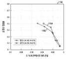
- 9A to 9C, 10A and 10B, and 11A to 11D illustrate simulation results for the performance of false alarm detection based on a detection metric in a wireless communication system according to various embodiments of the present disclosure.
- SNR signal-to-noise ratio
- 12B is a diagram illustrating simulation results according to code lengths in case of removing false alarms based on energy detection in a wireless communication system according to various embodiments of the present disclosure.
- 13A and 13B are diagrams illustrating simulation results for decoding performance in case of removing false alarms based on energy detection in a wireless communication system according to various embodiments of the present disclosure.
- the present disclosure relates to an apparatus and method for detecting false alarms on whether or not decoding is successful in a wireless communication system. Specifically, the present disclosure determines whether or not decoding is successful by using a detection metric including an average of path metrics for a plurality of decoding paths in a wireless communication system, and whether to perform decoding based on energy detection of a received signal. Describe the techniques for making decisions.
- the present disclosure describes various embodiments by using terms used in some communication standards (eg, 3rd generation partnership project (3GPP)), but this is only an example for description.
- 3GPP 3rd generation partnership project
- Various embodiments of the present disclosure may be easily modified and applied to other communication systems.
- 1 illustrates a wireless communication system according to various embodiments of the present disclosure.
- 1 illustrates a base station 110 and terminals 120 and 130 as some of nodes using a radio channel in a wireless communication system.
- 1 shows only one base station, but another base station that is the same as or similar to the base station 110 may be further included.
- the base station 110 is a network infrastructure that provides wireless access to the terminals 120 and 130.
- the base station 110 has a coverage defined as a certain geographic area based on a distance at which signals can be transmitted.
- the base station 110 includes'access point (AP)','enodeB (eNB)', '5G node','wireless point', ' It may be referred to as a transmission/reception point (TRP)' or another term having an equivalent technical meaning.
- AP access point
- eNB eNodeB
- TRP transmission/reception point
- Each of the terminal 120 and terminal 130 is a device used by a user and performs communication with the base station 110 through a radio channel. In some cases, at least one of the terminal 120 and the terminal 130 may be operated without user involvement. That is, at least one of the terminal 120 and the terminal 130 is a device that performs machine type communication (MTC) and may not be carried by a user.
- MTC machine type communication
- Each of the terminal 120 and terminal 130 is'user equipment (UE)','mobile station','subscriber station','remote terminal', and'other than terminal'. It may be referred to as'wireless terminal','user device', or another term having an equivalent technical meaning.
- the base station 110, the terminal 120, and the terminal 130 may transmit and receive radio signals in a millimeter wave (mmWave) band (eg, 28 GHz, 30 GHz, 38 GHz, 60 GHz).
- mmWave millimeter wave
- the base station 110, the terminal 120, and the terminal 130 may perform beamforming.
- beamforming may include transmission beamforming and reception beamforming. That is, the base station 110, the terminal 120, and the terminal 130 may give directivity to a transmitted signal or a received signal.
- the base station 110 and the terminals 120 and 130 may select serving beams 112, 113, 121, and 131 through a beam search or beam management procedure.
- subsequent communication may be performed through a resource having a quasi-co-located (QCL) relationship with a resource transmitting the serving beams 112, 113, 121, and 131.
- QCL quasi-co-located
- the first antenna port and the second antenna port are in a QCL relationship. Can be evaluated.
- a wide range of characteristics include delay spread, Doppler spread, Doppler shift, average gain, average delay, and spatial receiver parameter. It may include at least one of.
- FIG. 2 illustrates a configuration of a base station in a wireless communication system according to various embodiments of the present disclosure.
- the configuration illustrated in FIG. 2 can be understood as the configuration of the base station 110. Used below'... Wealth','...
- the term'group' refers to a unit that processes at least one function or operation, which may be implemented by hardware or software, or a combination of hardware and software.
- the base station includes a communication unit 210, a backhaul communication unit 220, a storage unit 230, and a control unit 240.
- the communication unit 210 performs functions for transmitting and receiving signals through a wireless channel. For example, the communication unit 210 performs a conversion function between a baseband signal and a bit stream according to the physical layer standard of the system. For example, when transmitting data, the communication unit 210 generates complex symbols by encoding and modulating a transmission bit stream. In addition, when receiving data, the communication unit 210 restores the received bit stream through demodulation and decoding of the baseband signal. In addition, the communication unit 210 up-converts the baseband signal into a radio frequency (RF) band signal and transmits it through an antenna, and down-converts the RF band signal received through the antenna into a baseband signal.
- RF radio frequency
- the communication unit 210 may include a transmission filter, a reception filter, an amplifier, a mixer, an oscillator, a digital to analog convertor (DAC), an analog to digital convertor (ADC), and the like.
- the communication unit 210 may include a plurality of transmission/reception paths.
- the communication unit 210 may include at least one antenna array composed of a plurality of antenna elements.
- the communication unit 210 may be composed of a digital unit and an analog unit, and the analog unit may be composed of a plurality of sub-units according to operation power, operation frequency, etc. I can.
- the communication unit 210 transmits and receives signals as described above. Accordingly, the communication unit 210 may be referred to as a'transmitter', a'receiver', or a'transceiver'. In addition, in the following description, transmission and reception performed through a wireless channel are used in a sense including the processing as described above is performed by the communication unit 210. In addition, the communication unit 210 may further include a backhaul communication unit for communication with another network entity connected through a backhaul network.
- the communication unit 210 includes a decoding unit 212 for decoding a received signal.
- the decoder 212 may perform decoding by using a successive cancellation list (SCL) method.
- the communication unit 210 may include an encoding unit to perform encoding.
- the backhaul communication unit 220 provides an interface for performing communication with other nodes in the network. That is, the backhaul communication unit 220 converts a bit stream transmitted from the base station to another node, for example, another access node, another base station, an upper node, a core network, etc., into a physical signal, and converts a physical signal received from another node into a bit stream. Convert to
- the storage unit 230 stores data such as a basic program, an application program, and setting information for the operation of the base station.
- the storage unit 230 may be formed of a volatile memory, a nonvolatile memory, or a combination of a volatile memory and a nonvolatile memory.
- the storage unit 230 provides stored data according to the request of the control unit 240.
- the storage unit 230 may store a threshold value of a detection metric for determining whether decoding is successful and threshold values determined to remove a false alarm based on energy detection.
- the controller 240 controls overall operations of the base station. For example, the controller 240 transmits and receives signals through the communication unit 210 or through the backhaul communication unit 220. In addition, the control unit 240 writes and reads data in the storage unit 230. To this end, the controller 240 may include at least one processor, or may be a part of the processor. In other words, the controller 240 may control an operation of each component included in the communication unit 210. Also, the controller 240 may determine whether to perform decoding based on the channel quality (eg, signal-to-noise ratio (SNR) of the received signal). Also, the controller 240 may determine whether to perform decoding based on energy detection.
- SNR signal-to-noise ratio
- the controller 240 includes a cyclic redundancy check (CRC) inspection unit 242 and a false alarm detection unit 244.
- the CRC check unit 242 may perform a CRC check on a plurality of decoding paths determined by decoding by the decoding unit 212.
- the false alarm detection unit 244 may determine whether decoding success or not for the decoding paths that have passed the CRC check by the CRC check unit 242 by using the detection metric using the average of the path metrics of the plurality of decoding paths determined by the decoding unit 212. .
- the inspection unit 242 and the false alarm detection unit 244 are included in the control unit 240, but according to various embodiments, the inspection unit 242 and the false alarm detection unit 244 may be included in the communication unit 210. According to various embodiments, the controller 240 may control the base station to perform operations according to various embodiments to be described later.
- FIG. 3 illustrates a configuration of a terminal in a wireless communication system according to various embodiments of the present disclosure.
- the configuration illustrated in FIG. 3 may be understood as the configuration of the terminal 120. Used below'... Wealth','...
- the term'group' refers to a unit that processes at least one function or operation, which may be implemented by hardware or software, or a combination of hardware and software.
- the terminal includes a communication unit 310, a storage unit 320, and a control unit 330.
- the communication unit 310 performs functions for transmitting and receiving signals through a wireless channel. For example, the communication unit 310 performs a function of converting between a baseband signal and a bit stream according to the physical layer standard of the system. For example, when transmitting data, the communication unit 310 generates complex symbols by encoding and modulating a transmission bit stream. In addition, when receiving data, the communication unit 310 restores the received bit stream through demodulation and decoding of the baseband signal. In addition, the communication unit 310 up-converts the baseband signal into a radio frequency (RF) band signal and then transmits it through an antenna, and down-converts the RF band signal received through the antenna into a baseband signal.
- RF radio frequency
- the communication unit 310 may include a transmission filter, a reception filter, an amplifier, a mixer, an oscillator, a digital to analog convertor (DAC), an analog to digital convertor (ADC), and the like.
- the communication unit 310 may include a plurality of transmission/reception paths.
- the communication unit 310 may include at least one antenna array composed of a plurality of antenna elements.
- the communication unit 310 may be composed of a digital unit and an analog unit, and the analog unit may be composed of a plurality of sub-units according to operation power, operation frequency, etc. I can.
- the communication unit 310 transmits and receives signals as described above. Accordingly, the communication unit 310 may be referred to as a'transmitter', a'reception unit', or a'transceiver'. In addition, in the following description, transmission and reception performed through a wireless channel is used in a sense including the processing as described above is performed by the communication unit 310. In addition, the communication unit 310 may further include a backhaul communication unit for communication with another network entity connected through a backhaul network.
- the communication unit 310 includes a decoding unit 312 for decoding a received signal.
- the decoder 212 may perform decoding by using the SCL method.
- the communication unit 310 may include an encoding unit to perform encoding.
- the storage unit 320 stores data such as a basic program, an application program, and setting information for the operation of the base station.
- the storage unit 320 may include a volatile memory, a nonvolatile memory, or a combination of a volatile memory and a nonvolatile memory.
- the storage unit 320 provides stored data according to the request of the control unit 330.
- the storage 320 may store a threshold value of a detection metric for determining whether or not decoding is successful and threshold values determined to remove a false alarm based on energy detection.
- the controller 330 controls overall operations of the base station. For example, the control unit 330 transmits and receives signals through the communication unit 310. Also, the control unit 330 writes and reads data in the storage unit 320. To this end, the controller 330 may include at least one processor or may be a part of a processor. In other words, the controller 330 may control the operation of each component included in the communication unit 310. Also, the controller 330 may determine whether to perform decoding based on channel quality (eg, SNR of a received signal). Also, the controller 330 may determine whether to perform decoding based on energy detection.
- channel quality eg, SNR of a received signal
- the controller 330 includes a cyclic redundancy check (CRC) inspection unit 332 and a false alarm detection unit 334.
- the CRC check unit 332 may perform CRC check on a plurality of decoding paths determined by performing decoding by the decoding unit 312.
- the false alarm detection unit 334 uses a detection metric using the average of the path metrics of the plurality of decoding paths determined by the decoding unit 312, and thus the decoding paths determined by the decoding unit 312 and the decoding paths that have passed the CRC check by the CRC check unit 332. It is possible to determine whether or not the decryption succeeds.
- the inspection unit 332 and the false alarm detection unit 334 are included in the control unit 330, but according to various embodiments, the inspection unit 332 and the false alarm detection unit 334 may be included in the communication unit 310. According to various embodiments, the controller 330 may control the terminal to perform operations according to various embodiments to be described later.
- an apparatus for performing encoding is referred to as a transmitting node
- an apparatus for performing decoding is referred to as a receiving node.
- the transmitting end may be understood as a base station (eg, base station 110), and the receiving end may be understood as a terminal (eg, terminal 120 or terminal 130), and in the case of uplink communication, the transmitting end is a terminal (eg: Terminal 120 or terminal 130) and the receiving end may be understood as a base station (eg, base station 110).
- a detection metric may be used as a criterion for determining whether or not decoding is successful for reducing the false alarm rate.
- the detection metric may be configured by utilizing the L path metrics finally determined. Since the path metric reflects reliability for each path when decoding is performed, it may be used to detect whether or not the decoding is successful, so at least one path metric may be used as a variable for determining the detection metric. In this case, it is required to provide a detection metric that minimizes block error rate (BLER) loss accompanying a case where a more stable metric is used and the false alarm rate is reduced.
- BLER block error rate
- FIG. 4 is a flowchart of a receiver for determining whether or not decoding is successful based on a detection metric in a wireless communication system according to various embodiments of the present disclosure. 4 illustrates an operation method of a base station 110, a terminal 120, or a terminal 130 as an operation of a receiving end.
- step 401 the receiving end decodes received bits.
- data encoded with a polar code and added with a CRC code may be transmitted from a transmitting end.
- the receiving end can perform CRC (CRC aided SCL, CA-SCL) decoding on data using CRC, and in this case, decoding is performed in units of bits.
- CRC CRC aided SCL, CA-SCL
- step 403 the receiving end determines whether the decoded bits pass the CRC check. According to various embodiments, when SCL decoding using CRC is performed, the receiving end may perform CRC check on the finally determined L decoding paths.
- the receiving end determines that the decoding has failed. That is, the receiving end removes at least one decoding path that has not passed the CRC check among the L decoding paths. Accordingly, the receiving end may no longer consider the bit stream indicated by the removed decoding path.
- the receiving end calculates detection metrics for the decoded paths that pass the CRC check.
- the detection metric can be used as an index for determining whether the CRC check has passed because the decoding of the received bits is successful.
- the detection metric may be determined based on values representing path metrics of a plurality of decoding paths that are finally determined.
- the detection metric may be configured based on a value that intermediately represents the route metrics.
- the detection metric may be expressed in inverse proportion to a value that intermediately represents a plurality of path metrics.
- a value intermediately representing a plurality of path metrics may be used as a standard for normalization.
- an average of a plurality of path metrics may be used as a standard for normalization.
- a median of a plurality of path metrics may be used as a criterion for normalization.
- the detection metric may be determined as shown in Equation 1 below.
- DM is a detection metric
- PM max is a maximum value among decoding path metrics of L paths
- Is the minimum value among path metrics of the decoding paths that have passed the CRC check
- PM average is the average value of path metrics of the L decoding paths.
- the deviation between path metrics can be identified as a ratio.
- the receiving end is the path metric of the least reliable path among the last L paths, regardless of whether the CRC test is passed, PM max, and the path metric of the most reliable path among the paths that passed the CRC test.
- PM max the path metric of the most reliable path among the paths that passed the CRC test.
- the average value PM average is used. This is because the average of the path metrics has a smaller variance than the individual path metrics, so that a stable detection metric can be provided.
- step 407 the receiving end determines whether the detection metric exceeds a threshold value.
- an optimized threshold may be determined according to at least one of the information bit length k, the code length n, and the code rate k/n.
- the receiving end determines that the decoding is successful.
- the high detection metric value means the deviation between the path metric of the decoding path with the lowest reliability among the L decoding paths determined by performing one decoding and the path metric of the decoding path with the highest reliability among the decoding paths that passed the CRC check. Means great. Accordingly, the detection metric greater than the threshold value is distinguishable from the rest of the decoding paths with the most reliable decoding path, and the receiving end can determine that the decoding is successful.
- the receiving end determines that the decoding has failed.
- the low detection metric value means between the path metric of the decoding path with the lowest reliability among the L decoding paths determined by performing one decoding and the path metric of the decoding path with the highest reliability among the decoding paths that passed the CRC check. It means that the deviation is small. Therefore, for a detection metric smaller than the threshold value, since the decoding path with the highest reliability cannot be sufficiently distinguished from the remaining decoding paths, the receiving end may determine that the decoding has failed.
- the threshold value of FIG. 4 may be differently determined based on types of transmitted and received information.
- a rank indicator (RI), a CQI Control information such as channel quality indicator
- RI rank indicator
- CQI Control information such as channel quality indicator
- ACK acknowledgment
- NACK NACK
- the threshold value for control information may be set to a value greater than the threshold value for data.
- the threshold value for the MIB may be set to a value greater than the threshold value for the control information.
- the decoding process described in FIG. 4 may be performed through the SCL decoding method.
- the path metric may be used as an index indicating the reliability of the corresponding decoding path, and may be expressed as in Equation 2 below.
- l is the index of each path
- i is the index of each source bit
- L is the size of the list
- N is the sign length
- the LLR value of the l-th path may be expressed as ⁇ Equation 3>.
- l is the index of each path
- i is the index of each source bit
- y is the vector of the received signal
- the penalty for the path determined as 0 and the path determined as 1 may be calculated differently when decoding is performed, and a larger penalty is imposed on the path determined as different bits.
- the above-described path metric may be updated whenever decoding is performed for every bit, and this may be expressed as Equation 4 above.
- l is the index of each path
- i is the index of each source bit
- L is the size of the list
- N is the sign length
- 5 is a flowchart of a receiving end for performing SCL decoding in a wireless communication system according to various embodiments of the present disclosure. 5 illustrates an operation method of the base station 110, the terminal 120, or the terminal 130 in the operation of the receiving end.
- the receiver sets i to 1.
- i means the index of the transmitted bits.
- the receiving end sets the number of decoding paths to 1.
- the decoding path increases by 2 times as the decoding of one index is performed.
- the receiving end may perform steps 503 to 515 below to determine at least one decoding path for a bit corresponding to one index.
- the receiving end calculates a path metric for decoding the i-th bit. Specifically, when the receiving end decodes the bit corresponding to the i-th index among the received bits, candidates (eg, 0 or 1) that may be the decoded i-th bit value are i-th before being encoded by the transmitting end. Determine the probability of being equal to the value of the bit. By determining the probability value, the receiver may calculate a path metric, which is an index indicating reliability of a decoding path for each of the candidates. According to various embodiments, the route metric may be expressed in LLR.
- step 505 the receiving end checks whether the number of decoding paths exceeds L/2. When the number of decoding paths exceeds L/2, the receiving end performs step 513, and when the number of decoding paths does not exceed L/2, the receiving end performs step 507.
- L denotes the size of a list, which is a reference value determined in advance for the number of decoding paths.
- step 507 the receiving end determines that the number of decoding paths is doubled as the number of decoding paths. In this case, even if the number of decoding paths is doubled, the determined number of decoding paths may be maintained at L or less, which is a reference value.
- step 509 the receiving end generates decoding paths as many as the determined number of decoding paths. According to the number of decoding paths determined in step 507 described above, L or less decoding paths are generated.
- step 511 the receiving end increases the value of the index i by 1 and returns to step 503 to decode the next bit.
- the receiver determines that the number of decoding paths is L.
- the receiving end can maintain the number of decoding paths at a reference value of L.
- L decoding paths may be determined according to the size of each path metric value. In this case, since a smaller value of the path metric means higher reliability, the receiving end may determine the L decoding paths in the order of the smaller path metric.
- step 515 the receiving end generates decoding paths as many as the determined number of decoding paths. In this case, since the determined number of decoding paths is L, the receiving end can generate L decoding paths.
- the operation of the receiving end to reduce the false alarm generation rate described in FIGS. 4 and 5 is based on a detection metric using a path metric of a decoding path, and may be performed after a decoding process.
- embodiments of further reducing the false alarm generation rate by considering channel quality (eg, SNR) before performing decoding are described.
- detection of a code parameter in a control channel is performed based on blind detection.
- the receiving end can use the energy of the normalized received signal by considering the noise level before performing decoding.
- the noise level for convenience of description, a case in which one code is transmitted and received and a case in which the transmitted and received signal does not exist will be described.
- H 0 is a case where a signal does not exist
- the receiving end receives a signal y including only noise z
- H 1 is a case where a signal exists
- the receiving end selects the transmission signal x and the noise z.
- Receive a signal containing As described above, after decoding is performed on the extreme code, the validity of the code parameter is determined through the CRC check, but an error that cannot be detected by the receiver may occur due to the imperfections of the CRC code. In this case, even though the signal has not been transmitted, a false alarm may occur in which it is determined that the signal is present.
- 6 is a flowchart of a receiving end for determining whether to terminate early based on energy detection before performing decoding in a wireless communication system according to various embodiments of the present disclosure. 6 illustrates an operation method of the base station 110, the terminal 120, or the terminal 130 in the operation of the receiving end.
- the receiving end measures energy of a received signal.
- the receiving end may receive a signal transmitted from the transmitting end and passed through the channel, and measure the energy of the received signal.
- the receiving end may normalize the average energy of the received signal by using the standard deviation of noise.
- the energy of the normalized signal may be referred to as an energy metric.
- the receiving end may measure the SNR of the channel.
- the receiving end checks the stored threshold.
- the threshold value may be determined and stored based on an SNR value required for each specific code rate. That is, threshold values corresponding to each of the plurality of SNRs may be predefined.
- the receiving end checks a threshold value corresponding to the code rate of the signal from among the stored threshold values. Specifically, the receiving end detects the energy of the received signal, and compares the detected energy with a threshold value determined in consideration of the operating SNR region.
- the receiving end may determine the code rate of the signal according to the type of information to be received.
- the receiving end checks whether the measured energy exceeds a threshold value. More specifically, the receiving end may compare the measured energy with a threshold value corresponding to the SNR for achieving the target value of the BLER according to the predetermined code length and code rate. Alternatively, according to various embodiments, the receiving end may check whether the energy metric obtained from the measured energy exceeds a threshold value. Alternatively, the receiving end may compare the measured SNR with the threshold value. When the energy metric does not exceed the threshold value, the receiving end may determine early termination without performing decoding on the received signal. That the energy metric does not exceed the threshold value means that the energy of the received signal is less than the threshold value corresponding to the SNR for achieving the target value of the BLER according to the predetermined code length and code rate. Accordingly, the receiving end may determine that the transmitted signal does not exist, so that the received signal may not be decoded.
- the receiver performs decoding.
- the receiving end may determine that the energy metric obtained from the measured energy exceeds a threshold value.
- the receiving end may determine that the measured SNR exceeds the threshold value.
- the measured energy exceeds the threshold value it means that the energy of the received signal is greater than the threshold value corresponding to the SNR for achieving the target value of the BLER according to the predetermined code length and code rate. Accordingly, by determining that the transmitted signal exists, the receiving end can decode the received signal.
- the receiving end does not perform the decoding process and CRC check when the transmission signal does not exist, and ends early, thereby passing the CRC check even when the transmission signal does not exist. You can block the case from happening.
- the energy of the received signal is less than the threshold value even though the transmission signal exists, the BLER may be deteriorated by the receiving end not performing decoding on the decodeable signal. Accordingly, the above-described method based on energy detection can use an appropriate threshold value for reducing the false alarm generation rate while minimizing the loss of BLER.
- a criterion for determining a threshold value will be described with reference to FIG. 7.
- the receiver can estimate the variance of noise with high accuracy, the receiver can normalize the noise by dividing the received signal by the standard deviation of the noise. In this case, the energy distribution of the received signal in the situation H 0 where the transmission signal does not exist and the energy distribution of the received signal in the situation H 1 where the transmission signal exists show different distributions. Invalid received signals can be filtered out by using different energy distributions.
- the receiving end may detect the average energy of the received signal and determine the H 0 situation when the energy distribution does not exceed a threshold value. Conversely, when the average energy distribution of the received signal exceeds the threshold value, the receiving end may determine the H 1 situation. That is, the receiving end can distinguish between the H 0 situation and the H 1 situation by considering the operating SNR region through energy detection of the received signal.
- FIG. 7 illustrates an example of selection of a threshold value for determining whether to terminate early in a wireless communication system according to various embodiments of the present disclosure.
- curve 702 represents an average energy distribution of a received signal measured by a receiving end when there is no transmission signal.
- the average energy of the signal measured by the receiver follows a central chi-square distribution of degree 2n s when the number of symbols is n s , and is approximated to a normal distribution as the degree increases. Represents.
- false alarms are defined as determining that decoding is successful because the received signal passes the CRC check even though the transmission signal does not exist.
- the threshold value should be determined as a value that reduces the rate of occurrence of such false alarms.
- the threshold should be determined as a value for reducing the BLER loss. Therefore, when a threshold value is determined to remove false alarms in a situation where a transmission signal does not exist, a trade-off in which the ratio of false alarms decreases and BLER loss occurs in a situation where a transmission signal is present. Exists.
- early termination may be determined for a received signal having energy less than a specific threshold 706.
- a BLER loss may occur for the portion 712.
- the part 714 having energy greater than the threshold value 706 passes the CRC test through the decoding process even though the transmission signal does not exist.Therefore, a false alarm may still exist for the part 714, which is a residual false alarm. Is referred to.
- the energy distribution of the signal when the transmission signal does not exist is approximately followss.
- the portion 714 represents the ratio of the portion in which the residual false alarm exists with respect to the curve 702, and the residual false alarm ratio may be expressed as ⁇ Equation 6>.
- Equation 6 FAR res denotes the residual false alarm ratio, T denotes a threshold value, ⁇ denotes a value of linear SNR, and n s denotes the number of modulation symbols.
- a curve 704 represents an average energy distribution of a received signal measured by a receiving end when a transmitting signal is present.
- the symbol energy of the signal measured by the receiver follows a non-central chi-square distribution.
- the energy distribution is normally distributed as the order increases. It shows a shape that is approximate to
- portion 712 represents the ratio of the portion where the BLER loss occurs with respect to the curve 704, and the BLER loss can be expressed as ⁇ Equation 7>.
- L BLER is the loss ratio of BLER
- T is the threshold value
- ⁇ is the value of linear SNR
- n s is the number of modulation symbols.
- Polyanskiy-poor-verdu (PPV) normal approximation can be utilized to obtain a relationship between BLER and SNR for a constant code rate and to determine a lower bound for BLER.
- the PPV normal approximation can be defined as in ⁇ Equation 8>.
- R NA is a code rate
- P e is a target BLER
- n is a code length
- ⁇ is a linear SNR value.
- ⁇ Equation 8> can be expressed as ⁇ Equation 9> for BLER.
- Equation 9> P e denotes a target BLER
- R NA denotes a code rate
- n denotes a code length
- ⁇ denotes a linear SNR value. Therefore, if the code length and the code rate have already been determined, the target BLER value may be obtained through Equation (9).
- a target SNR value corresponding to the target BLER value may be determined, and a threshold value corresponding to the target SNR value may be expressed as ⁇ Equation 10>.
- T is the threshold value
- ⁇ * is the target SNR value
- n s is the number of symbols
- ⁇ is for setting the error generated based on energy detection to be sufficiently smaller than the error due to the performance of the actual code.
- Constant, P e means the target BLER value.
- the threshold T of ⁇ Equation 10> is larger, the residual false alarm ratio FAR res represents a smaller value, and the BLER loss ratio L BLER represents a larger value. It is confirmed to exist. Accordingly, if the SNR target value is given for the predetermined code length and code rate, an appropriate threshold T for the target SNR value may be determined.
- target values for FAR res and L BLER may be differently set based on the type of transmitted and received information.
- control information such as quality indicator
- MCS modulation coding scheme
- CQI channel channel
- control information such as quality indicator
- ACK and NACK are transmitted and received to indicate whether data has been received without error.
- the threshold value for control information may be set to a value greater than the threshold value for data.
- the threshold value for the MIB may be set to a value greater than the threshold value for the control information.
- the method of removing false alarms of FIGS. 4 and 6 described above may be selectively performed by a receiver or sequentially performed, thereby reducing a residual false alarm rate while maintaining performance related to BLER loss.
- an embodiment of false alarm detection using both a detection metric and energy detection will be described with reference to FIG. 8.
- 8 is a flowchart of a receiving end for detecting a false alarm for successful decoding in a wireless communication system according to various embodiments of the present disclosure. 8 illustrates an operation method of a base station 110, a terminal 120, or a terminal 130 as an operation of a receiving end.
- the receiving end determines whether the energy of the signal exceeds a first threshold. Specifically, the receiving end may measure the energy of the received signal and compare the energy metric derived from the measured energy with a first threshold value for a given code length and code rate. Alternatively, the receiving end may compare the SNR of the signal with the first threshold.
- the first threshold may be determined according to an SNR target value corresponding to at least one of the target values of the residual false alarm rate and the BLER loss rate, and the residual false alarm rate and the BLER loss rate depend on the type of transmitted/received information. It can be set differently on the basis of.
- the receiver performs decoding on the received signal.
- the receiving end may determine that the energy metric obtained from the energy detection of the signal exceeds the first threshold.
- the receiving end may determine that the measured SNR exceeds the first threshold.
- the receiving end may determine that the transmission signal is present, and determine to perform decoding on the received signal.
- the receiving end may receive a polar code using CRC, and SCL decoding may be performed bit by bit on the received polar code.
- the receiving end may determine early termination without performing decoding on the received signal. According to various embodiments, the receiving end may determine that the energy metric obtained from energy detection of the signal does not exceed the first threshold. Alternatively, the receiving end may determine that the measured SNR does not exceed the first threshold. That is, when the distribution of the average energy of the received signal does not exceed a pre-stored first threshold, the receiving end may determine that the transmission signal does not exist, and decide to terminate early. Through the above-described process, the receiving end may block occurrence of a false alarm that passes the CRC check even when a transmission signal does not exist before performing decoding.
- step 805 the receiving end determines whether the decoded bits pass the CRC check. According to various embodiments, when SCL decoding using CRC is performed, the receiving end may perform one decoding and perform CRC check on the finally determined L decoding paths. If the decoded bits do not pass the CRC check, in step 811, the receiving end determines that the decoding has failed.
- the receiving end determines whether the detection metric exceeds the second threshold.
- the receiving end calculates a detection metric by using at least one of the L decoding paths as shown in Equation 4, and calculates the calculated detection metric by a predetermined number. 2 Can be compared with the threshold.
- the second threshold may be determined as an optimized value based on at least one of the number of information bits k, the code length n, and the code rate k/n.
- step 809 the receiving end determines that the decoding is successful. In this case, since the decoding path with the highest reliability can be sufficiently distinguished from the remaining decoding paths in the detection metric greater than the threshold value, the receiving end can determine that the decoding has been successful.
- step 811 the receiving end determines that the decoding has failed. In this case, since the decoding path with the highest reliability cannot be sufficiently distinguished from the remaining decoding paths in the detection metric smaller than the threshold value, the receiving end may determine that the decoding has failed.
- 9A to 9C, 10A and 10B, and 11A to 11D illustrate simulation results for the performance of false alarm detection based on a detection metric in a wireless communication system according to various embodiments of the present disclosure.
- QPSK quadrature phase shift keying
- AWGN additive white Gaussian noise
- curve 1 represents a performance curve when a detection metric based on the maximum value of a path metric is used compared to the case of performing the existing decoding
- curve 2 is a variety of the present disclosure compared to the case of performing the existing decoding. It shows a performance curve when a detection metric based on an average value of path metrics is used according to an embodiment.
- the y-axis represents the detected ratio of all false alarms that occur. For example, in the case of FIG.
- curve 1 902 detects a false alarm of about 60% while having an SNR loss of about 0.2 dB compared to the case of performing conventional decoding when a detection metric based on the maximum value of the path metric is used. Indicates that you can.
- curve 2904 indicates that when the detection metric based on the average value of the path metrics is used, a false alarm of about 64% can be detected while having an SNR loss of about 0.2 dB compared to the case of performing the conventional decoding. Referring to FIGS. 9A to 11D, it can be seen that in most of the measured areas, the detection metric based on the average value of the path metrics indicates a higher false alarm detection rate when the BLER loss rate is the same.
- Curve 1202 is the ratio of residual false alarms according to the threshold
- curve 1204 is the BLER loss ratio according to the threshold when the SNR value of the received signal is 0dB
- the curve 1206 is the BLER loss according to the threshold when the SNR value of the received signal is 1dB. Indicates the ratio. Referring to curve 1206, when the threshold is set to about 1.25, about 98% of all false alarms are removed without loss of BLER, and about 2% of residual false alarms exist. Referring to FIG.
- FIG. 12B is a diagram illustrating a result of a simulation according to a code length in case of removing false alarms based on energy detection in a wireless communication system according to various embodiments.
- Curve 1222 shows the residual false alarm ratio according to the code rate when the code length is 128, curve 1224 shows the residual false alarm rate according to the code rate when the code length is 256, and curve 1226 shows the residual false alarm rate according to the code rate when the code length is 512.
- the longer the code length is the smaller the residual false alarm rate is, and even at a code rate as low as 0.3, the false alarm can be removed without loss of BLER by determining an appropriate threshold.
- the method of determining whether to perform decoding based on the above-described energy detection may be used to supplement the false alarm reduction method based on the detection metric.
- FIGS. 13A and 13B are diagrams illustrating simulation results for decoding performance in case of removing false alarms based on energy detection in a wireless communication system according to various embodiments of the present disclosure.
- Curves 1302, 1304, 1322, 1324 represent the BLER according to SNR when achieving a false alarm removal rate of 99% or more.
- Curves 1302 and 1322 represent the BLER when performing the existing decoding
- curves 1304 and 1324 represent the BLER when the method of determining whether to perform decoding based on energy detection according to various embodiments is applied.
- a computer-readable storage medium storing one or more programs (software modules) may be provided.
- One or more programs stored in a computer-readable storage medium are configured to be executable by one or more processors in an electronic device (device).
- the one or more programs include instructions that cause the electronic device to execute methods according to embodiments described in the claims or specification of the present disclosure.
- These programs include random access memory, non-volatile memory including flash memory, read only memory (ROM), and electrically erasable programmable ROM. (electrically erasable programmable read only memory, EEPROM), magnetic disc storage device, compact disc-ROM (CD-ROM), digital versatile discs (DVDs) or other forms of It may be stored in an optical storage device or a magnetic cassette. Alternatively, it may be stored in a memory composed of a combination of some or all of them. In addition, a plurality of configuration memories may be included.
- non-volatile memory including flash memory, read only memory (ROM), and electrically erasable programmable ROM. (electrically erasable programmable read only memory, EEPROM), magnetic disc storage device, compact disc-ROM (CD-ROM), digital versatile discs (DVDs) or other forms of It may be stored in an optical storage device or a magnetic cassette. Alternatively, it may be stored in a memory composed of a combination of some or all of them. In addition, a plurality
- the program is through a communication network composed of a communication network such as the Internet, an intranet, a local area network (LAN), a wide area network (WAN), or a storage area network (SAN), or a combination thereof. It may be stored in an attachable storage device that can be accessed. Such a storage device may be connected to a device performing an embodiment of the present disclosure through an external port. In addition, a separate storage device on the communication network may access a device performing an embodiment of the present disclosure.
- a communication network such as the Internet, an intranet, a local area network (LAN), a wide area network (WAN), or a storage area network (SAN), or a combination thereof. It may be stored in an attachable storage device that can be accessed. Such a storage device may be connected to a device performing an embodiment of the present disclosure through an external port. In addition, a separate storage device on the communication network may access a device performing an embodiment of the present disclosure.
Landscapes
- Engineering & Computer Science (AREA)
- Computer Networks & Wireless Communication (AREA)
- Signal Processing (AREA)
- Quality & Reliability (AREA)
- Mobile Radio Communication Systems (AREA)
Abstract
본 개시는 LTE(long term evolution)와 같은 4G(4th generation) 통신 시스템 이후 보다 높은 데이터 전송률을 지원하기 위한 5G(5th generation) 또는 pre-5G 통신 시스템에 관련된 것이다. 본 개시는 무선 통신 시스템에서 복호화에 대한 오경보(false alarm)의 검출에 관한 것으로, 수신단의 동작 방법은, 송신단으로부터 신호를 수신하는 과정과, 상기 수신된 신호에 포함된 비트들에 대해 복호를 수행함으로써 복수의 복호 경로들을 획득하는 과정과, 상기 복수의 복호 경로들의 경로 메트릭들을 대표하는 값에 기반하여 결정되는 검출 메트릭에 기반하여 상기 복호가 성공하였는지 여부를 결정하는 과정을 포함한다.
Description
본 개시(disclosure)는 일반적으로 무선 통신 시스템에 관한 것으로, 보다 구체적으로 무선 통신 시스템에서 복호화에 대한 오경보(false alarm)를 검출하기 위한 장치 및 방법에 관한 것이다.
4G(4th generation) 통신 시스템 상용화 이후 증가 추세에 있는 무선 데이터 트래픽 수요를 충족시키기 위해, 개선된 5G(5th generation) 통신 시스템 또는 pre-5G 통신 시스템을 개발하기 위한 노력이 이루어지고 있다. 이러한 이유로, 5G 통신 시스템 또는 pre-5G 통신 시스템은 4G 네트워크 이후(beyond 4G network) 통신 시스템 또는 LTE(long term evolution) 시스템 이후(post LTE) 시스템이라 불리어지고 있다.
높은 데이터 전송률을 달성하기 위해, 5G 통신 시스템은 초고주파(mmWave) 대역(예를 들어, 60기가(60GHz) 대역과 같은)에서의 구현이 고려되고 있다. 초고주파 대역에서의 전파의 경로손실 완화 및 전파의 전달 거리를 증가시키기 위해, 5G 통신 시스템에서는 빔포밍(beamforming), 거대 배열 다중 입출력(massive MIMO), 전차원 다중입출력(full dimensional MIMO, FD-MIMO), 어레이 안테나(array antenna), 아날로그 빔형성(analog beam-forming), 및 대규모 안테나(large scale antenna) 기술들이 논의되고 있다.
또한 시스템의 네트워크 개선을 위해, 5G 통신 시스템에서는 진화된 소형 셀, 개선된 소형 셀(advanced small cell), 클라우드 무선 액세스 네트워크(cloud radio access network, cloud RAN), 초고밀도 네트워크(ultra-dense network), 기기 간 통신(device to device communication, D2D), 무선 백홀(wireless backhaul), 이동 네트워크(moving network), 협력 통신(cooperative communication), CoMP(coordinated multi-points), 및 수신 간섭제거(interference cancellation) 등의 기술 개발이 이루어지고 있다. 이 밖에도, 5G 시스템에서는 진보된 코딩 변조(advanced coding modulation, ACM) 방식인 FQAM(hybrid frequency shift keying and quadrature amplitude modulation) 및 SWSC(sliding window superposition coding)과, 진보된 접속 기술인 FBMC(filter bank multi carrier), NOMA(non- orthogonal multiple access), 및 SCMA(sparse code multiple access) 등이 개발되고 있다.
한편, 이러한 5G 통신 시스템에서, 신호가 송신되지 않았음에도 불구하고 채널에 존재하는 잡음으로 인해 복호화(decoding)가 성공한 것으로 잘못 판단되는 오경보(false alarm)가 발생하는 경우가 존재한다. 이에 따라, 복호 경로의 경로 메트릭을 이용함으로써 오경보의 발생을 효과적으로 감소시키기 위한 기술들이 연구되고 있다.
상술한 바와 같은 논의를 바탕으로, 본 개시(disclosure)는, 무선 통신 시스템에서 복호화(decoding) 성공에 대한 오경보(false alarm)를 효과적으로 검출하기 위한 장치 및 방법을 제공한다.
또한, 본 개시는, 무선 통신 시스템에서 검출 메트릭(detection metric)을 기반으로 부호화(encoding)된 정보에 대한 복호화가 성공하였는지 여부를 판단하기 위한 장치 및 방법을 제공한다.
또한, 본 개시는, 무선 통신 시스템에서 경로 메트릭(path metric)들의 평균에 기반한 검출 메트릭을 이용함으로써, 연속 제거 리스트(successive cancellation list, SCL) 복호화가 성공하였는지 여부를 판단하기 위한 장치 및 방법을 제공한다.
또한, 본 개시는, 무선 통신 시스템에서 에너지 검출에 기반하여 복호화를 수행할지 여부를 판단하기 위한 장치 및 방법을 제공한다.
또한, 본 개시는, 무선 통신 시스템에서 수신된 신호의 신호-대-잡음비(signal-to-noise ratio, SNR) 측정 값에 기반하여 복호화를 수행할지 여부를 판단하기 위한 장치 및 방법을 제공한다.
본 개시의 다양한 실시 예들에 따르면, 무선 통신 시스템에서 수신단의 동작 방법은, 송신단으로부터 신호를 수신하는 과정과, 상기 수신된 신호에 포함된 비트들에 대해 복호를 수행함으로써 복수의 복호 경로들을 획득하는 과정과, 상기 복수의 복호 경로들의 경로 메트릭들을 대표하는 값에 기반하여 결정되는 검출 메트릭에 기반하여 상기 복호가 성공하였는지 여부를 결정하는 과정을 포함할 수 있다.
본 개시의 다양한 실시 예들에 따르면, 무선 통신 시스템에서 수신단의 장치는, 송수신부와, 적어도 하나의 프로세서를 포함한다. 상기 송수신부는, 송신단으로부터 신호를 수신하고, 상기 수신된 신호에 포함된 비트들에 대해 복호를 수행함으로써 복수의 복호 경로들을 획득하고, 상기 적어도 하나의 프로세서는, 상기 복수의 복호 경로들의 경로 메트릭들을 대표하는 값에 기반하여 결정되는 검출 메트릭에 기반하여 상기 복호가 성공하였는지 여부를 결정할 수 있다.
본 개시의 다양한 실시 예들에 따른 장치 및 방법은, 부호화(encoding)된 정보에 대한 복호화가 성공하였는지 여부를 판단하기 위해 보다 안정적인 검출 메트릭(detection metric)을 제공함으로써, 오경보(false alarm)의 발생 비율을 감소시킬 수 있게 한다.
또한, 본 개시의 다양한 실시 예들에 따른 장치 및 방법은, 수신된 신호의 에너지 검출에 기반하여 복호화 수행 여부를 결정함으로써, 블록 에러율(block error rate, BLER)의 손실을 방지하면서 오경보의 비율을 감소시킬 수 있게 한다.
본 개시에서 얻을 수 있는 효과는 이상에서 언급한 효과들로 제한되지 않으며, 언급하지 않은 또 다른 효과들은 아래의 기재로부터 본 개시가 속하는 기술 분야에서 통상의 지식을 가진 자에게 명확하게 이해될 수 있을 것이다.
도 1은 본 개시의 다양한 실시 예들에 따른 무선 통신 시스템을 도시한다.
도 2는 본 개시의 다양한 실시 예들에 따른 무선 통신 시스템에서 기지국의 구성을 도시한다.
도 3은 본 개시의 다양한 실시 예들에 따른 무선 통신 시스템에서 단말의 구성을 도시한다.
도 4는 본 개시의 다양한 실시 예들에 따른 무선 통신 시스템에서 검출 메트릭에 기반하여 복호화(decoding) 성공 여부를 결정하기 위한 수신단의 흐름도를 도시한다.
도 5는 본 개시의 다양한 실시 예들에 따른 무선 통신 시스템에서 연속 제거 리스트(successive cancellation list, SCL) 복호화를 수행하기 위한 수신단의 흐름도를 도시한다.
도 6은 본 개시의 다양한 실시 예들에 따른 무선 통신 시스템에서 복호화 수행 전 에너지 검출에 기반하여 조기 종료 여부를 결정하기 위한 수신단의 흐름도를 도시한다.
도 7은 본 개시의 다양한 실시 예들에 따른 무선 통신 시스템에서 조기 종료 여부를 결정하기 위한 임계값 선택의 예를 도시한다.
도 8은 본 개시의 다양한 실시 예들에 따른 무선 통신 시스템에서 복호화 성공에 대한 오경보를 검출하기 위한 수신단의 흐름도를 도시한다.
도 9a 내지 도 9c, 도 10a 및 도 10b, 및 도 11a 내지 도 11d는 본 개시의 다양한 실시 예들에 따른 무선 통신 시스템에서 검출 메트릭에 기반한 오경보 검출의 성능에 대한 모의실험 결과들을 도시한다.
도 12a는 본 개시의 다양한 실시 예들에 따른 무선 통신 시스템에서 에너지 검출에 기반한 오경보 제거의 경우, 신호-대-잡음비(signal-to-noise ratio, SNR)에 따른 모의실험 결과를 도시한다.
도 12b는 본 개시의 다양한 실시 예들에 따른 무선 통신 시스템에서 에너지 검출에 기반한 오경보 제거의 경우, 부호길이에 따른 모의실험 결과를 도시한다.
도 13a 및 도 13b는 본 개시의 다양한 실시 예들에 따른 무선 통신 시스템에서 에너지 검출에 기반한 오경보 제거의 경우, 복호화 성능에 대한 모의실험 결과들을 도시한다.
본 개시에서 사용되는 용어들은 단지 특정한 실시 예를 설명하기 위해 사용된 것으로, 다른 실시 예의 범위를 한정하려는 의도가 아닐 수 있다. 단수의 표현은 문맥상 명백하게 다르게 뜻하지 않는 한, 복수의 표현을 포함할 수 있다. 기술적이거나 과학적인 용어를 포함해서 여기서 사용되는 용어들은 본 개시에 기재된 기술 분야에서 통상의 지식을 가진 자에 의해 일반적으로 이해되는 것과 동일한 의미를 가질 수 있다. 본 개시에 사용된 용어들 중 일반적인 사전에 정의된 용어들은, 관련 기술의 문맥상 가지는 의미와 동일 또는 유사한 의미로 해석될 수 있으며, 본 개시에서 명백하게 정의되지 않는 한, 이상적이거나 과도하게 형식적인 의미로 해석되지 않는다. 경우에 따라서, 본 개시에서 정의된 용어일지라도 본 개시의 실시 예들을 배제하도록 해석될 수 없다.
이하에서 설명되는 본 개시의 다양한 실시 예들에서는 하드웨어적인 접근 방법을 예시로서 설명한다. 하지만, 본 개시의 다양한 실시 예들에서는 하드웨어와 소프트웨어를 모두 사용하는 기술을 포함하고 있으므로, 본 개시의 다양한 실시 예들이 소프트웨어 기반의 접근 방법을 제외하는 것은 아니다.
이하 본 개시는 무선 통신 시스템에서 복호화 성공 여부에 대한 오경보를 검출하기 위한 장치 및 방법에 관한 것이다. 구체적으로, 본 개시는 무선 통신 시스템에서 복수의 복호 경로들에 대한 경로 메트릭의 평균을 포함하는 검출 메트릭을 이용함으로써 복호화의 성공 여부를 판단하고, 수신된 신호의 에너지 검출에 기반하여 복호화 수행 여부를 결정하기 위한 기술을 설명한다.
이하 설명에서 사용되는 네트워크 객체(network entity)들을 지칭하는 용어, 장치의 구성 요소를 지칭하는 용어, 복호화 성공 여부 판단을 위한 메트릭을 지칭하는 용어(예: 검출 메트릭, 경로 메트릭 등) 등은 설명의 편의를 위해 예시된 것이다. 따라서, 본 개시가 후술되는 용어들에 한정되는 것은 아니며, 동등한 기술적 의미를 가지는 다른 용어가 사용될 수 있다.
또한, 본 개시에서, 특정 조건의 만족(satisfied), 충족(fulfilled) 여부를 판단하기 위해, 초과 또는 미만의 표현이 사용되었으나, 이는 일 예를 표현하기 위한 기재일 뿐 이상 또는 이하의 기재를 배제하는 것이 아니다. '이상'으로 기재된 조건은 '초과', '이하'로 기재된 조건은 '미만', '이상 및 미만'으로 기재된 조건은 '초과 및 이하'로 대체될 수 있다.
또한, 본 개시는, 일부 통신 규격(예: 3GPP(3rd generation partnership project))에서 사용되는 용어들을 이용하여 다양한 실시 예들을 설명하지만, 이는 설명을 위한 예시일 뿐이다. 본 개시의 다양한 실시 예들은, 다른 통신 시스템에서도, 용이하게 변형되어 적용될 수 있다.
도 1은 본 개시의 다양한 실시 예들에 따른 무선 통신 시스템을 도시한다. 도 1은 무선 통신 시스템에서 무선 채널을 이용하는 노드(node)들의 일부로서, 기지국 110, 단말들 120, 130을 예시한다. 도 1은 하나의 기지국만을 도시하나, 기지국 110과 동일 또는 유사한 다른 기지국이 더 포함될 수 있다.
기지국 110은 단말들 120, 130에게 무선 접속을 제공하는 네트워크 인프라스트럭쳐(infrastructure)이다. 기지국 110은 신호를 송신할 수 있는 거리에 기초하여 일정한 지리적 영역으로 정의되는 커버리지(coverage)를 가진다. 기지국 110은 기지국(base station) 외에 '액세스 포인트(access point, AP)', '이노드비(enodeB, eNB)', '5G 노드(5th generation node)', '무선 포인트(wireless point)', '송수신 포인트(transmission/reception point, TRP)' 또는 이와 동등한 기술적 의미를 가지는 다른 용어로 지칭될 수 있다.
단말 120 및 단말 130 각각은 사용자에 의해 사용되는 장치로서, 기지국 110과 무선 채널을 통해 통신을 수행한다. 경우에 따라, 단말 120 및 단말 130 중 적어도 하나는 사용자의 관여 없이 운영될 수 있다. 즉, 단말 120 및 단말 130 중 적어도 하나는 기계 타입 통신(machine type communication, MTC)을 수행하는 장치로서, 사용자에 의해 휴대되지 아니할 수 있다. 단말 120 및 단말 130 각각은 단말(terminal) 외 '사용자 장비(user equipment, UE)', '이동국(mobile station)', '가입자국(subscriber station)', '원격 단말(remote terminal)', '무선 단말(wireless terminal)', 또는 '사용자 장치(user device)' 또는 이와 동등한 기술적 의미를 가지는 다른 용어로 지칭될 수 있다.
기지국 110, 단말 120, 단말 130은 밀리미터 파(mmWave) 대역(예: 28GHz, 30GHz, 38GHz, 60GHz)에서 무선 신호를 송신 및 수신할 수 있다. 이때, 채널 이득의 향상을 위해, 기지국 110, 단말 120, 단말 130은 빔포밍(beamforming)을 수행할 수 있다. 여기서, 빔포밍은 송신 빔포밍 및 수신 빔포밍을 포함할 수 있다. 즉, 기지국 110, 단말 120, 단말 130은 송신 신호 또는 수신 신호에 방향성(directivity)을 부여할 수 있다. 이를 위해, 기지국 110 및 단말들 120, 130은 빔 탐색(beam search) 또는 빔 관리(beam management) 절차를 통해 서빙(serving) 빔들 112, 113, 121, 131을 선택할 수 있다. 서빙 빔들 112, 113, 121, 131이 선택된 후, 이후 통신은 서빙 빔들 112, 113, 121, 131을 송신한 자원과 QCL(quasi co-located) 관계에 있는 자원을 통해 수행될 수 있다.
제1 안테나 포트 상의 심볼을 전달한 채널의 광범위한(large-scale) 특성들이 제2 안테나 포트 상의 심볼을 전달한 채널로부터 추정될(inferred) 수 있다면, 제1 안테나 포트 및 제2 안테나 포트는 QCL 관계에 있다고 평가될 수 있다. 예를 들어, 광범위한 특성들은 지연 스프레드(delay spread), 도플러 스프레드(doppler spread), 도플러 쉬프트(doppler shift), 평균 이득(average gain), 평균 지연(average delay), 공간적 수신 파라미터(spatial receiver parameter) 중 적어도 하나를 포함할 수 있다.
도 2는 본 개시의 다양한 실시 예들에 따른 무선 통신 시스템에서 기지국의 구성을 도시한다. 도 2에 예시된 구성은 기지국 110의 구성으로서 이해될 수 있다. 이하 사용되는 '…부', '…기' 등의 용어는 적어도 하나의 기능이나 동작을 처리하는 단위를 의미하며, 이는 하드웨어나 소프트웨어, 또는, 하드웨어 및 소프트웨어의 결합으로 구현될 수 있다.
도 2를 참고하면, 기지국은 통신부 210, 백홀 통신부 220, 저장부 230, 및 제어부 240을 포함한다.
통신부 210은 무선 채널을 통해 신호를 송수신하기 위한 기능들을 수행한다. 예를 들어, 통신부 210은 시스템의 물리 계층 규격에 따라 기저대역 신호 및 비트열 간 변환 기능을 수행한다. 예를 들어, 데이터 송신 시, 통신부 210은 송신 비트열을 부호화 및 변조함으로써 복소 심벌들을 생성한다. 또한, 데이터 수신 시, 통신부 210은 기저대역 신호를 복조 및 복호화를 통해 수신 비트열을 복원한다. 또한, 통신부 210은 기저대역 신호를 RF(radio frequency) 대역 신호로 상향변환한 후 안테나를 통해 송신하고, 안테나를 통해 수신되는 RF 대역 신호를 기저대역 신호로 하향변환한다.
이를 위해, 통신부 210은 송신 필터, 수신 필터, 증폭기, 믹서(mixer), 오실레이터(oscillator), DAC(digital to analog convertor), ADC(analog to digital convertor) 등을 포함할 수 있다. 또한, 통신부 210은 다수의 송수신 경로(path)들을 포함할 수 있다. 나아가, 통신부 210은 다수의 안테나 요소들(antenna elements)로 구성된 적어도 하나의 안테나 어레이(antenna array)를 포함할 수 있다. 하드웨어의 측면에서, 통신부 210은 디지털 유닛(digital unit) 및 아날로그 유닛(analog unit)으로 구성될 수 있으며, 아날로그 유닛은 동작 전력, 동작 주파수 등에 따라 다수의 서브 유닛(sub-unit)들로 구성될 수 있다.
통신부 210은 상술한 바와 같이 신호를 송신 및 수신한다. 이에 따라, 통신부 210은 '송신부', '수신부' 또는 '송수신부(transceiver)'로 지칭될 수 있다. 또한, 이하 설명에서, 무선 채널을 통해 수행되는 송신 및 수신은 통신부 210에 의해 상술한 바와 같은 처리가 수행되는 것을 포함하는 의미로 사용된다. 또한, 통신부 210은 백홀(backhaul) 망을 통해 연결된 다른 네트워크 개체와의 통신을 위한 백홀 통신부를 더 포함할 수 있다.
통신부 210은 수신된 신호의 복호화를 수행하기 위한 복호화부 212를 포함한다. 다양한 실시 예들에 따라 복호화부 212는 연속 제거 리스트(successive cancellation list, SCL) 방식을 이용함으로써 복호화를 수행할 수 있다. 도 2에 도시되지는 않았지만, 통신부 210은 부호화(encoding)를 수행하기 위해 부호화부를 포함할 수 있다.
백홀통신부 220은 네트워크 내 다른 노드들과 통신을 수행하기 위한 인터페이스를 제공한다. 즉, 백홀통신부 220은 기지국에서 다른 노드, 예를 들어, 다른 접속 노드, 다른 기지국, 상위 노드, 코어망 등으로 송신되는 비트열을 물리적 신호로 변환하고, 다른 노드로부터 수신되는 물리적 신호를 비트열로 변환한다.
저장부 230은 기지국의 동작을 위한 기본 프로그램, 응용 프로그램, 설정 정보 등의 데이터를 저장한다. 저장부 230은 휘발성 메모리, 비휘발성 메모리 또는 휘발성 메모리와 비휘발성 메모리의 조합으로 구성될 수 있다. 또한, 저장부 230은 제어부 240의 요청에 따라 저장된 데이터를 제공한다. 다양한 실시 예들에 따라, 저장부 230은 복호화 성공 여부를 판단하기 위한 검출 메트릭의 임계값 및 에너지 검출에 기반하여 오경보를 제거하기 위해 결정된 임계값들을 저장할 수 있다.
제어부 240은 기지국의 전반적인 동작들을 제어한다. 예를 들어, 제어부 240은 통신부 210를 통해 또는 백홀통신부 220을 통해 신호를 송신 및 수신한다. 또한, 제어부 240은 저장부 230에 데이터를 기록하고, 읽는다. 이를 위해, 제어부 240은 적어도 하나의 프로세서(processor)를 포함하거나, 또는, 프로세서의 일부일 수 있다. 다시 말해, 제어부 240은 통신부 210에 포함된 각 구성의 동작을 제어할 수 있다. 또한, 제어부 240은 채널 품질(예: 수신된 신호의 신호-대-잡음비(signal-to-noise ratio, SNR))에 기반하여 복호화를 수행할지 여부를 결정할 수 있다. 또한, 제어부 240은 에너지 검출에 기반하여 복호화를 수행할지 여부를 결정할 수 있다.
다양한 실시 예들에 따라, 제어부 240은 CRC(cyclic redundancy check) 검사부 242 및 오경보 검출부 244를 포함한다. CRC 검사부 242는 복호화부 212에 의해 복호화가 수행됨으로써 결정된 복수의 복호 경로들에 대하여 CRC 검사를 수행할 수 있다. 오경보 검출부 244는 복호화부 212에 의해 결정된 복수의 복호 경로들의 경로 메트릭들의 평균을 이용한 검출 메트릭을 이용함으로써, CRC 검사부 242에 의한 CRC 검사를 통과한 복호 경로들에 대하여 복호화 성공 여부를 판단할 수 있다. 이상에서, 검사부 242 및 오경보 검출부 244가 제어부 240에 포함되는 것으로 설명되었으나, 다양한 실시 예들에 따라, 검사부 242 및 오경보 검출부 244는 통신부 210에 포함될 수 있다. 다양한 실시 예들에 따라, 제어부 240은 후술하는 다양한 실시 예들에 따른 동작들을 수행하도록 기지국을 제어할 수 있다.
도 3은 본 개시의 다양한 실시 예들에 따른 무선 통신 시스템에서 단말의 구성을 도시한다. 도 3에 예시된 구성은 단말 120의 구성으로서 이해될 수 있다. 이하 사용되는 '…부', '…기' 등의 용어는 적어도 하나의 기능이나 동작을 처리하는 단위를 의미하며, 이는 하드웨어나 소프트웨어, 또는, 하드웨어 및 소프트웨어의 결합으로 구현될 수 있다.
도 3을 참고하면, 단말은 통신부 310, 저장부 320, 및 제어부 330을 포함한다.
통신부 310은 무선 채널을 통해 신호를 송수신하기 위한 기능들을 수행한다. 예를 들어, 통신부 310은 시스템의 물리 계층 규격에 따라 기저대역 신호 및 비트열 간 변환 기능을 수행한다. 예를 들어, 데이터 송신 시, 통신부 310은 송신 비트열을 부호화 및 변조함으로써 복소 심벌들을 생성한다. 또한, 데이터 수신 시, 통신부 310은 기저대역 신호를 복조 및 복호화를 통해 수신 비트열을 복원한다. 또한, 통신부 310은 기저대역 신호를 RF(radio frequency) 대역 신호로 상향변환한 후 안테나를 통해 송신하고, 안테나를 통해 수신되는 RF 대역 신호를 기저대역 신호로 하향변환한다.
이를 위해, 통신부 310은 송신 필터, 수신 필터, 증폭기, 믹서(mixer), 오실레이터(oscillator), DAC(digital to analog convertor), ADC(analog to digital convertor) 등을 포함할 수 있다. 또한, 통신부 310은 다수의 송수신 경로(path)들을 포함할 수 있다. 나아가, 통신부 310은 다수의 안테나 요소들(antenna elements)로 구성된 적어도 하나의 안테나 어레이(antenna array)를 포함할 수 있다. 하드웨어의 측면에서, 통신부 310은 디지털 유닛(digital unit) 및 아날로그 유닛(analog unit)으로 구성될 수 있으며, 아날로그 유닛은 동작 전력, 동작 주파수 등에 따라 다수의 서브 유닛(sub-unit)들로 구성될 수 있다.
통신부 310은 상술한 바와 같이 신호를 송신 및 수신한다. 이에 따라, 통신부 310은 '송신부', '수신부' 또는 '송수신부(transceiver)'로 지칭될 수 있다. 또한, 이하 설명에서, 무선 채널을 통해 수행되는 송신 및 수신은 통신부 310에 의해 상술한 바와 같은 처리가 수행되는 것을 포함하는 의미로 사용된다. 또한, 통신부 310은 백홀(backhaul) 망을 통해 연결된 다른 네트워크 개체와의 통신을 위한 백홀 통신부를 더 포함할 수 있다.
통신부 310은 수신된 신호의 복호화를 수행하기 위한 복호화부 312를 포함한다. 다양한 실시 예들에 따라 복호화부 212는 SCL 방식을 이용함으로써 복호화를 수행할 수 있다. 도 3에 도시되지는 않았지만, 통신부 310은 부호화(encoding)를 수행하기 위해 부호화부를 포함할 수 있다.
저장부 320은 기지국의 동작을 위한 기본 프로그램, 응용 프로그램, 설정 정보 등의 데이터를 저장한다. 저장부 320은 휘발성 메모리, 비휘발성 메모리 또는 휘발성 메모리와 비휘발성 메모리의 조합으로 구성될 수 있다. 또한, 저장부 320은 제어부 330의 요청에 따라 저장된 데이터를 제공한다. 다양한 실시 예들에 따라, 저장부 320은 복호화 성공 여부를 판단하기 위한 검출 메트릭의 임계값 및 에너지 검출에 기반하여 오경보를 제거하기 위해 결정된 임계값들을 저장할 수 있다.
제어부 330은 기지국의 전반적인 동작들을 제어한다. 예를 들어, 제어부 330은 통신부 310를 통해 신호를 송신 및 수신한다. 또한, 제어부 330은 저장부 320에 데이터를 기록하고, 읽는다. 이를 위해, 제어부 330은 적어도 하나의 프로세서(processor)를 포함하거나, 또는, 프로세서의 일부일 수 있다. 다시 말해, 제어부 330은 통신부 310에 포함된 각 구성의 동작을 제어할 수 있다. 또한, 제어부 330은 채널 품질(예: 수신된 신호의 SNR)에 기반하여 복호화를 수행할지 여부를 결정할 수 있다. 또한, 제어부 330은 에너지 검출에 기반하여 복호화를 수행할지 여부를 결정할 수 있다.
다양한 실시 예들에 따라, 제어부 330은 CRC(cyclic redundancy check) 검사부 332 및 오경보 검출부 334를 포함한다. CRC 검사부 332는 복호화부 312에 의해 복호화가 수행됨으로써 결정된 복수의 복호 경로들에 대하여 CRC 검사를 수행할 수 있다. 오경보 검출부 334는 복호화부 312에 의해 결정된 복수의 복호 경로들의 경로 메트릭들의 평균을 이용한 검출 메트릭을 이용함으로써, 복호화부 312에 의해 결정된 복호 경로들 및 CRC 검사부 332에 의한 CRC 검사를 통과한 복호 경로들에 대하여 복호화 성공 여부를 판단할 수 있다. 이상에서, 검사부 332 및 오경보 검출부 334가 제어부 330에 포함되는 것으로 설명되었으나, 다양한 실시 예들에 따라, 검사부 332 및 오경보 검출부 334는 통신부 310에 포함될 수 있다. 다양한 실시 예들에 따라, 제어부 330은 후술하는 다양한 실시 예들에 따른 동작들을 수행하도록 단말을 제어할 수 있다.
이하 설명에서, 본 개시는 부호화를 수행하는 장치를 송신단(transmitting node), 복호화를 수행하는 장치를 수신단(receiving node)으로 지칭한다. 예를 들어, 하향링크 통신의 경우, 송신단은 기지국(예: 기지국 110), 수신단은 단말(예: 단말 120 또는 단말 130)로 이해될 수 있고, 상향링크 통신의 경우, 송신단은 단말(예: 단말 120 또는 단말 130), 수신단은 기지국(예: 기지국 110)으로 이해될 수 있다.
무선 통신 시스템에서 CRC를 이용한 SCL 복호화 방식이 이용되는 경우, 송신 신호가 존재하지 않음에도 불구하고 수신 신호가 CRC 검사를 통과함으로써 복호화가 성공된 것으로 판단되는 오경보가 발생하는 경우가 존재한다. 오경보 비율을 감소시키기 위한 복호화 성공 여부의 판단 기준으로서 검출 메트릭(detection metric)이 이용될 수 있다. 특히, CRC를 이용한 SCL 복호화 방식이 이용되는 경우, 검출 메트릭은 최종적으로 결정되는 L개의 경로 메트릭들을 활용함으로써 구성될 수 있다. 경로 메트릭은 복호화 수행 시 각 경로에 대한 신뢰도(reliability)를 반영함으로써, 복호화의 성공 여부를 검출하기 위해 이용될 수 있으므로, 적어도 하나의 경로 메트릭은 검출 메트릭을 결정하기 위한 변수로서 사용될 수 있다. 이 경우, 보다 안정적인 메트릭을 사용함과 동시에, 오경보 비율이 감소되는 경우에 수반되는 블록 에러율(block error rate, BLER) 손실을 최소화하는 검출 메트릭의 제공이 요구된다.
도 4는 본 개시의 다양한 실시 예들에 따른 무선 통신 시스템에서 검출 메트릭에 기반하여 복호화 성공 여부를 결정하기 위한 수신단의 흐름도를 도시한다. 도 4는 수신단의 동작으로서 기지국 110, 단말 120 또는 단말 130의 동작 방법을 예시한다.
도 4를 참고하면, 401 단계에서, 수신단은 수신된 비트들에 대해 복호화를 수행한다. 다양한 실시 예들에 따르면, 송신단으로부터 극 부호로 부호화되고 CRC 부호가 추가된 데이터가 송신될 수 있다. 이에 따라, 수신단은 데이터에 대해 CRC를 이용한 SCL(CRC aided SCL, CA-SCL) 복호화를 수행할 수 있고, 이 경우 비트 단위로 복호화가 수행된다.
403 단계에서, 수신단은 복호화된 비트들이 CRC 검사를 통과하는지 여부를 판단한다. 다양한 실시 예들에 따라, CRC를 이용한 SCL 복호화가 수행된 경우, 수신단은 최종적으로 결정된 L개의 복호 경로들에 대해 CRC 검사를 수행할 수 있다.
복호화된 비트들이 CRC 검사를 통과하지 못한 경우, 411 단계에서, 수신단은 복호화가 실패한 것으로 결정한다. 즉, 수신단은 L개의 복호 경로들 중에서 CRC 검사를 통과하지 못한 적어도 하나의 복호 경로를 제거한다. 따라서, 수신단은 제거된 복호 경로가 나타내는 비트열에 대해서는 더 이상 고려하지 않을 수 있다.
복호화된 비트들이 CRC 검사를 통과한 경우, 405 단계에서, 수신단은 CRC 검사를 통과한 복호 경로들에 대해 검출 메트릭을 계산한다. 검출 메트릭은 수신된 비트들에 대한 복호화가 성공하였기 때문에 CRC 검사를 통과한 것인지 판단하기 위한 지표로써 사용될 수 있다. 예를 들어, CRC를 이용한 SCL 복호화가 수행된 경우, 검출 메트릭은 최종적으로 결정되는 복수의 복호 경로들의 경로 메트릭들을 대표하는 값에 기반하여 결정될 수 있다. 구체적으로, 검출 메트릭은 경로 메트릭들을 중간적으로 대표하는 값에 기반하여 구성될 수 있다. 다양한 실시 예들에 따라, 검출 메트릭은 복수의 경로 메트릭들을 중간적으로 대표하는 값에 반비례하도록 표현될 수 있다. 즉, 검출 메트릭에서, 복수의 경로 메트릭들을 중간적으로 대표하는 값이 정규화의 기준으로서 이용될 수 있다. 일 예에서, 복수의 경로 메트릭들의 평균값(average)이 정규화의 기준으로서 이용될 수 있다. 다른 예에서, 복수의 경로 메트릭들의 중간값(median)이 정규화의 기준으로서 이용될 수 있다.
복수의 경로 메트릭들의 평균값이 정규화의 기준으로 이용되는 경우, 검출 메트릭은 이하의 <수학식 1>과 같이 결정될 수 있다.

<수학식 1>에서, DM은 검출 메트릭, PMmax는 L개의 경로들의 복호 경로 메트릭들 중 최댓값,  는 CRC 검사를 통과한 복호 경로들의 경로 메트릭들 중 최솟값, PMaverage는 L개의 복호 경로들의 경로 메트릭들의 평균값을 의미한다.
<수학식 1>의 검출 메트릭을 이용함으로써, 경로 메트릭 간 편차가 비율로서 확인될 수 있다. 이를 위하여, 수신단은 CRC 검사 통과 여부와 상관없이 최종 L개의 경로들 중 가장 신뢰도가 낮은 경로의 경로 메트릭 PMmax과 CRC 검사를 통과한 경로들 중 가장 신뢰도가 높은 경로의 경로 메트릭  간의 차이를 정규화하기 위한 변수로써 L개의 경로 메트릭들의 평균값 PMaverage이 이용된다. 경로 메트릭들의 평균이 개별 경로 메트릭보다 더 작은 분산(variance)를 가지므로, 안정적인 검출 메트릭의 제공이 가능하기 때문이다.
407 단계에서, 수신단은 검출 메트릭이 임계값을 초과하는지 여부를 판단한다. 다양한 실시 예들에 따르면, 정보 비트 길이 k, 부호 길이 n, 또는 부호율 k/n 중 적어도 하나에 따라 최적화된 임계값이 결정될 수 있다.
검출 메트릭이 임계값을 초과하는 경우, 409 단계에서, 수신단은 복호화가 성공한 것으로 결정한다. 검출 메트릭 값이 크다는 것은, 한 번의 복호화 수행에 의해 결정된 L개의 복호 경로들 중 가장 신뢰도가 낮은 복호 경로의 경로 메트릭과 CRC 검사를 통과한 복호 경로들 중 가장 신뢰도가 높은 복호 경로의 경로 메트릭 간 편차가 큰 것을 의미한다. 따라서, 임계값보다 큰 검출 메트릭은 가장 신뢰도가 높은 복호 경로가 나머지 복호 경로들로부터 충분히 구별될 수 있으므로(distinguishable), 수신단은 복호화가 성공한 것으로 결정할 수 있다.
검출 메트릭이 임계값을 초과하지 않는 경우, 411 단계에서, 수신단은 복호화가 실패한 것으로 결정한다. 검출 메트릭 값이 작다는 것은, 한 번의 복호화 수행에 의해 결정된 L개의 복호 경로들 중 가장 신뢰도가 낮은 복호 경로의 경로 메트릭과 CRC 검사를 통과한 복호 경로들 중 가장 신뢰도가 높은 복호 경로의 경로 메트릭 간 편차가 작은 것을 의미한다. 따라서, 임계값보다 작은 검출 메트릭은 가장 신뢰도가 높은 복호 경로가 나머지 복호 경로들로부터 충분히 구별될 수 없으므로, 수신단은 복호화가 실패한 것으로 결정할 수 있다.
다양한 실시 예들에 따라, 도 4의 임계값은 송신 및 수신되는 정보의 종류에 기반하여 다르게 결정될 수 있다.
예를 들어, 일반적으로, 하향링크 채널 상태에 따라 적합한 하향링크 송신과 관련된 설정(예: 프리코딩 행렬, MCS(modulation and coding scheme))을 선택하는 스케줄링을 위해, RI(rank indicator), CQI(channel quality indicator) 등의 제어 정보가 송수신되어야 한다. 이 경우, 주어진 채널에서의 하향링크 송신에 대한 송신 설정을 제어하기 위해, 제어 정보의 수신 및 복호화가 성공적으로 이루어질 것이 요구된다. 또한, 데이터가 오류 없이 수신되었는지 여부를 알리기 위해 ACK(acknowledgement), NACK 등의 제어 정보가 송수신된다. 이 경우, 반드시 수신되어야 하는 데이터의 성공적인 수신 여부를 판단하기 위해, ACK, NACK 등의 제어 정보의 수신 및 복호화가 성공적으로 이루어질 것이 요구된다. 따라서, 데이터와 비교하여, 제어 정보에 대한 복호화 성공 여부가 더욱 엄격한 기준으로 판단되어야 한다. 따라서, 제어 정보에 대한 임계값은 데이터에 대한 임계값보다 큰 값으로 설정될 수 있다.
또한, 제어 정보의 송수신을 위해서는 MIB(master information block)와 같은 방송 정보의 송수신이 선행되어야 한다. 이 경우, MIB는 제어 정보의 송수신을 위한 설정 정보를 포함하므로, MIB의 복호화가 성공하였는지 여부가 정확하게 판단되어야 한다. 따라서, 제어 정보와 비교하여, MIB에 대한 복호화 성공 여부가 더욱 엄격한 기준으로 판단될 필요가 있다. 따라서, MIB에 대한 임계값은 제어 정보에 대한 임계값보다 큰 값으로 설정될 수 있다.
다양한 실시 예들에 따르면, 경로 메트릭에 기반하여 검출 메트릭을 구성하기 위해, 도 4에서 설명된 복호화 과정은 SCL 복호화 방식을 통해 수행될 수 있다. 상술한 바와 같이, SCL 복호화 수행 시 경로 메트릭은 해당 복호 경로에 대한 신뢰도를 나타내는 지표로써 사용될 수 있고, 이하의 <수학식 2>와 같이 표현될 수 있다.

<수학식 2>에서, l은 각 경로의 인덱스, i는 각 소스 비트의 인덱스, L은 리스트의 크기, N은 부호 길이,  는 i번째 비트에 대해 복호화가 수행되었을 때의 l번째 경로의 경로 메트릭,
  은 i번째 비트에 대한 복호화 수행 시 l번째 경로의 로그 우도 비(log likelihood ratio, LLR) 값을 의미한다.
또한, i번째 비트에 대한 복호화 수행 시 l번째 경로의 LLR 값은 <수학식 3>과 같이 표현될 수 있다.

<수학식 3>에서, l은 각 경로의 인덱스, i는 각 소스 비트의 인덱스,  은 i번째 비트에 대한 복호화 수행 시 l번째 경로의 LLR 값,
  은 l번째 경로에서 u0부터 ui-1까지 복호화된 소스 비트, y는 수신 신호의 벡터,
  는 채널 천이(channel transition)의 확률로서 x가 채널 W를 통해 송신된 경우 y가 수신될 확률을 의미한다.
예를 들어, 부호화 전 i번째 비트가 0이고 복호화 수행 시 i번째 비트가 0인 경우,  값이 양수로 계산되고, 부호화 전 i번째 비트가 1이고 복호화 수행 시 i번째 비트가 1인 경우,
  값은 음수로 계산된다. 따라서, 상술한 두 경우에는,
  값이 모두 양수로 계산된다. 반면, 부호화 전 i번째 비트가 0이고 복호화 수행 시 i번째 비트가 1로 결정되는 경우에는
  값이 음수로 계산된다. 따라서,
  값이 음수로 반전된다. 결국, 부호화 전 비트가 0인 경우, 복호화 수행 시 0으로 결정되는 경로와 1로 결정되는 경로에 대한 페널티(penalty)가 서로 다르게 계산될 수 있고, 다른 비트로 결정되는 경로에 대해 더 큰 페널티가 부과될 수 있다. 상술한 경로 메트릭은 매 비트에 대해 복호화가 수행될 때마다 갱신될 수 있고, 이는 <수학식 4>와 같이 표현될 수 있다.

<수학식 4>에서, l은 각 경로의 인덱스, i는 각 소스 비트의 인덱스, L은 리스트의 크기, N은 부호 길이,  은 l번째 경로에 저장된 j번째 소스 비트(0 또는 1)가 복호화된 값,
  는 i번째 비트에 대해 복호화가 수행되었을 때의 l번째 경로의 경로 메트릭,
  은 i-1번째 비트에 대해 복호화가 수행되었을 때의 l번째 경로의 경로 메트릭,
  은 i번째 비트에 대한 복호화 수행 시 l번째 경로의 LLR 값을 의미한다.
이하 도 5를 참고하여, 최종 L개의 복호 경로들을 결정하기 위한 SCL 방식 복호화 과정이 설명된다.
도 5는 본 개시의 다양한 실시 예들에 따른 무선 통신 시스템에서 SCL 복호화를 수행하기 위한 수신단의 흐름도를 도시한다. 도 5는 수신단의 동작에 있어서, 기지국 110, 단말 120 또는 단말 130의 동작 방법을 예시한다.
도 5를 참고하면, 501 단계에서, 수신단은 i를 1로 설정한다. 여기서 i는 송신된 비트들의 인덱스를 의미한다. 또한, 수신단은 복호 경로의 개수를 1로 설정한다. 복호 경로는 하나의 인덱스에 대한 복호화가 수행됨에 따라 2배씩 증가한다. 수신단은 하나의 인덱스에 대응하는 비트에 대해 적어도 하나의 복호 경로들을 결정하기 위하여 이하 503 단계 내지 515 단계를 수행할 수 있다.
503 단계에서, 수신단은 i번째 비트의 복호화를 위한 경로 메트릭을 계산한다. 구체적으로, 수신단은 수신된 비트들 중 i번째 인덱스에 대응하는 비트를 복호화하는 경우, 복호화된 i번째 비트의 값이 될 수 있는 후보들(예: 0 또는 1)이 송신단에서 부호화되기 이전의 i번째 비트의 값과 동일할 확률을 결정한다. 수신단은 확률 값을 결정함으로써, 후보들 각각에 대한 복호 경로의 신뢰도(reliability)를 나타내는 지표인 경로 메트릭을 계산할 수 있다. 다양한 실시 예들에 따라, 경로 메트릭은 LLR로 표현될 수 있다.
505 단계에서, 수신단은 복호 경로의 개수가 L/2개를 초과하는지 여부를 확인한다. 복호 경로의 개수가 L/2개를 초과하는 경우 수신단은 513 단계를 수행하고, 복호 경로의 개수가 L/2개를 초과하지 않는 경우, 수신단은 507 단계를 수행한다. 여기서, L은 복호 경로의 개수에 대해 미리 결정된 기준 값인 리스트의 크기를 의미한다. 수신단은 복호 경로의 개수를 L개로 유지함으로써 복호화 연산량이 무제한적으로 증가하는 것을 방지할 수 있다.
복호 경로의 개수가 L/2개를 초과하지 않는 것으로 확인된 경우, 507 단계에서, 수신단은 복호 경로의 개수를 2배로 증가시킨 것을 복호 경로의 개수로서 결정한다. 이 경우, 복호 경로의 개수를 2배로 증가시키더라도, 결정된 복호 경로의 개수가 기준 값인 L개 이하로 유지될 수 있다.
509 단계에서, 수신단은 결정된 복호 경로의 개수만큼 복호 경로들을 생성한다. 상술한 507 단계에서 결정된 복호 경로의 개수에 따라, L개 이하의 복호 경로들이 생성된다.
511 단계에서, 수신단은 인덱스 i의 값을 1만큼 증가시키고 다음 비트의 복호화를 위하여 503 단계로 되돌아간다.
복호 경로의 개수가 L/2개를 초과하는 것으로 확인된 경우, 513 단계에서, 수신단은 복호 경로의 개수를 L개인 것으로 결정한다. 이 경우, 복호 경로의 개수가 2배로 증가되는 경우 복호 경로의 개수가 L개를 초과하게 되기 때문에, 수신단은 복호 경로의 개수를 기준 값인 L개로 유지할 수 있다. 다양한 실시 예들에 따라, L개를 초과하는 복호 경로들 중에서 각각의 경로 메트릭 값의 크기에 따라 L개의 복호 경로들이 결정될 수 있다. 이 경우, 경로 메트릭이 작은 값을 가질수록 신뢰도가 높은 것을 의미하므로, 수신단은 경로 메트릭이 작은 순서대로 L개의 복호 경로들을 결정할 수 있다.
515 단계에서, 수신단은 결정된 복호 경로의 개수만큼 복호 경로들을 생성한다. 이 경우, 결정된 복호 경로의 개수는 L개이므로, 수신단은 L개의 복호 경로들을 생성할 수 있다.
상술한 바와 같이, 도 4 및 도 5에서 설명된 오경보 발생 비율을 감소시키기 위한 수신단의 동작은 복호 경로의 경로 메트릭을 이용한 검출 메트릭에 기반한 것으로서, 복호화 과정 이후 수행될 수 있다. 이하, 복호화를 수행하기 전, 채널 품질(예: SNR)을 고려함으로써 오경보 발생 비율을 더욱 감소시키는 실시 예들이 설명된다.
일반적으로, 제어 채널에서 부호 파라미터의 검출은 블라인드 검출(blind detection)을 기반으로 수행된다. 수신단은 복수의 부호들을 포함하는 집합 C={Ci} 에서 하나의 부호인 Ci를 선택하고, 수신된 부호어가 선택된 부호에 대응되는지 여부를 판단함으로써 메시지를 검출할 수 있다. 예를 들어, 수신단은 선택된 부호 Ci에 대해 복호화를 수행하고, 복호화 결과에 대해 CRC 검사를 수행함으로써, 부호 Ci가 송신되었는지 여부를 판단한다. 이 경우, CRC 검사만을 이용한 판단은 오경보를 발생시킬 수 있으므로, 블라인드 검출과 관련된 오경보 검출 방법이 제시되었다. 그러나, 상술한 오경보 검출 방법이 이용되더라도 잔여 오경보가 존재하고, 수신단은 부호 파라미터가 확인될 때까지 부호어 별로 복호화를 수행함으로써 복잡한 계산을 수행한다.
잔여 오경보 비율 및 계산의 복잡도를 낮추기 위해, 수신단은 복호화 수행 전 잡음 레벨을 고려함으로써 정규화된 수신 신호의 에너지를 이용할 수 있다. 이하에서, 설명의 편의를 위해 하나의 부호가 송신 및 수신된 경우와, 송신 및 수신된 신호가 존재하지 않는 경우가 설명된다.

<수학식 5>에서, H0은 신호가 존재하지 않는 경우로서, 수신단은 잡음 z만을 포함하는 신호 y를 수신하고, H1은 신호가 존재하는 경우로서, 수신단은 송신 신호 x 및 잡음 z를 포함하는 신호를 수신한다. 상술한 바와 같이, 극 부호에 대해 복호화가 수행된 후 CRC 검사를 통해 부호 파라미터의 유효성이 판단되지만, CRC 부호의 불완전성으로 인해 수신단에 의해 검출될 수 없는 오류가 발생할 수 있다. 이 경우, 신호가 송신되지 않았음에도 신호가 존재하는 것으로 판단되는 오경보가 발생할 수 있다. 즉, 송신된 신호가 존재하지 않는 상황 H0에서, 복호화 수행 결과가 CRC 검사를 통과하는 경우가 발생할 수 있다. 이하 도 6을 참고하여, 복호화 수행 전 수신된 신호의 에너지 검출을 통해 송신된 신호가 존재하는지 여부를 판단함으로써, 잔여 오경보 비율을 감소시키기 위한 실시 예가 설명된다.
도 6은 본 개시의 다양한 실시 예들에 따른 무선 통신 시스템에서 복호화 수행 전 에너지 검출에 기반하여 조기 종료 여부를 결정하기 위한 수신단의 흐름도를 도시한다. 도 6은 수신단의 동작에 있어서, 기지국 110, 단말 120 또는 단말 130의 동작 방법을 예시한다.
도 6을 참고하면, 601 단계에서, 수신단은 수신 신호의 에너지를 측정한다. 수신단은 송신단으로부터 송신되고 채널을 통과한 신호를 수신하고, 수신된 신호의 에너지를 측정할 수 있다. 다양한 실시 예들에 따라, 수신단은 잡음의 표준 편차를 이용함으로써 수신된 신호의 평균 에너지를 정규화할 수 있다. 이 경우, 정규화된 신호의 에너지는 에너지 메트릭으로 지칭될 수 있다. 다양한 실시 예들에 따라, 수신단은 채널의 SNR을 측정할 수 있다.
603 단계에서, 수신단은 저장된 임계값을 확인한다. 다양한 실시 예들에 따라, 임계값은 특정 부호율마다 요구되는 SNR 값에 기반하여 결정되고, 저장될 수 있다. 즉, 복수의 SNR들 각각에 대응되는 임계값들이 미리 정의될 수 있다. 수신단은 저장된 임계값들 중에서, 신호의 부호율에 대응하는 임계값을 확인한다. 구체적으로, 수신단은 수신된 신호의 에너지를 검출하고, 검출된 에너지를 동작 SNR 영역을 고려하여 결정된 임계값과 비교한다. 여기서, 수신단은 수신하고자 하는 정보의 종류에 따라 신호의 부호율을 판단할 수 있다.
605 단계에서, 수신단은 측정된 에너지가 임계값을 초과하는지 여부를 확인한다. 보다 구체적으로, 수신단은 미리 결정된 부호 길이 및 부호율에 따른 BLER의 목표 값을 달성하기 위한 SNR에 대응하는 임계값과 측정된 에너지를 비교할 수 있다. 또는, 다양한 실시 예들에 따라, 수신단은 측정된 에너지로부터 획득된 에너지 메트릭이 임계값을 초과하는지 여부를 확인할 수 있다. 또는, 수신단은 측정된 SNR과 임계값을 비교할 수 있다. 에너지 메트릭이 임계값을 초과하지 않는 경우, 수신단은 수신된 신호에 대해 복호화를 수행하지 않고 조기 종료를 결정할 수 있다. 에너지 메트릭이 임계값을 초과하지 않는 것은, 수신된 신호의 에너지가 미리 결정된 부호 길이 및 부호율에 따른 BLER의 목표 값을 달성하기 위한 SNR에 대응하는 임계값보다 작은 것을 의미한다. 이에 따라, 수신단은 송신된 신호가 존재하지 않는 것으로 판단함으로써, 수신된 신호의 복호화를 수행하지 않을 수 있다.
측정된 에너지가 임계값을 초과하는 경우, 607 단계에서, 수신단은 복호화를 수행한다. 다양한 실시 예들에 따라, 수신단은 측정된 에너지로부터 획득된 에너지 메트릭이 임계값을 초과한다고 판단할 수 있다. 또는, 수신단은 측정된 SNR이 임계값을 초과한다고 판단할 수 있다. 이 경우, 측정된 에너지가 임계값을 초과하는 것은, 수신된 신호의 에너지가 미리 결정된 부호 길이 및 부호율에 따른 BLER의 목표 값을 달성하기 위한 SNR에 대응하는 임계값보다 큰 것을 의미한다. 이에 따라, 수신단은 송신된 신호가 존재하는 것으로 판단함으로써, 수신된 신호의 복호화를 수행할 수 있다.
도 6에서 설명된 바와 같이, 수신 신호의 에너지 검출을 통해, 수신단은 송신 신호가 존재하지 않는 경우 복호화 과정 및 CRC 검사를 수행하지 않고 조기 종료함으로써, 송신 신호가 존재하지 않음에도 CRC 검사를 통과하는 경우가 발생하는 것을 차단할 수 있다. 그러나, 송신 신호가 존재함에도 수신된 신호의 에너지가 임계값보다 작은 경우, 수신단이 복호 가능한 신호에 대해 복호화를 수행하지 않음으로써 BLER가 열화될 수 있다. 따라서, 상술한 에너지 검출에 기반한 방법은, BLER의 손실을 최소화하면서 오경보 발생 비율을 감소시키는 적절한 임계값을 이용할 수 있다. 이하 도 7을 참고하여, 임계값을 결정하는 기준이 설명된다.
채널 부호가 적용된 통신의 경우, 일정한 값 이하의 BLER을 생성하는, 부호가 동작하는 데 적합한 동작 SNR 영역이 존재한다. 수신단이 잡음의 분산을 높은 정확도로 추정할 수 있다면, 수신단은 수신된 신호를 잡음의 표준 편차로 나눔으로써 잡음을 정규화할 수 있다. 이 경우, 송신 신호가 존재하지 않는 상황 H0의 수신 신호의 에너지 분포 및 송신 신호가 존재하는 상황 H1의 수신 신호의 에너지는 상이한 분포를 나타내고. 상이한 에너지 분포를 이용함으로써 유효하지 않은 수신 신호가 필터링될 수 있다.
예를 들어, 수신단은 수신 신호의 평균 에너지를 검출하고, 에너지 분포가 임계값을 초과하지 않는 경우 H0 상황으로 판단할 수 있다. 반대로, 수신단은 수신 신호의 평균 에너지 분포가 임계값을 초과하는 경우 H1 상황으로 판단할 수 있다. 즉, 수신단은 수신 신호의 에너지 검출을 통해 동작 SNR 영역을 고려함으로써 H0 상황 및 H1 상황을 구별할 수 있다.
도 7은 본 개시의 다양한 실시 예들에 따른 무선 통신 시스템에서 조기 종료 여부를 결정하기 위한 임계값 선택의 예를 도시한다.
도 7을 참고하면, 곡선 702는 송신 신호가 존재하지 않는 경우, 수신단이 측정한 수신 신호의 평균 에너지 분포를 나타낸다. 이 경우, 수신단이 측정하는 신호의 평균 에너지는, 심볼의 개수가 ns인 경우, 차수가 2ns인 중심 카이제곱 분포(central chi-square distribution)를 따르며, 차수가 증가할수록 정규 분포에 근사한 형태를 나타낸다.
상술한 바와 같이 오경보는 송신 신호가 존재하지 않음에도 불구하고 수신 신호가 CRC 검사를 통과함으로써 복호화가 성공된 것으로 판단되는 것으로 정의된다. 임계값은 이러한 오경보의 발생 비율을 감소시키는 값으로 결정되어야 한다. 한편, 송신 신호가 존재하는 경우에 대해, 임계값은 BLER 손실을 감소시키는 값으로 결정되어야 한다. 따라서, 송신 신호가 존재하지 않는 상황에서의 오경보를 제거하기 위해 임계값이 결정되는 경우, 오경보의 비율이 감소되는 것과 동시에 송신 신호가 존재하는 상황에서 BLER 손실이 발생하는 트레이드 오프(trade-off)가 존재한다.
도 7을 참고하면, 특정 임계값 706보다 작은 값의 에너지를 가지는 수신 신호에 대해 조기 종료가 결정될 수 있다. 이 경우, 곡선 704 중에서 임계값 706보다 작은 에너지를 가지는 부분 712는 송신 신호가 존재함에도 불구하고 복호화 과정을 거치지 않게 되므로, 부분 712에 대해 BLER 손실이 발생할 수 있다. 한편, 곡선 702 중에서 임계값 706보다 큰 에너지를 가지는 부분 714는 송신 신호가 존재하지 않음에도 불구하고 복호화 과정을 거쳐 CRC 검사를 통과하게 되므로, 부분 714에 대해 여전히 오경보가 존재할 수 있고 이는 잔여 오경보로 지칭된다.
상술한 바와 같이, 송신 신호가 존재하지 않는 경우의 신호의 에너지 분포는 근사적으로  를 따른다. 이 경우, 부분 714는 곡선 702에 대해 잔여 오경보가 존재하는 부분의 비율을 나타내고, 잔여 오경보 비율은 <수학식 6>와 같이 표현될 수 있다.

<수학식 6>에서, FARres은 잔여 오경보 비율, T는 임계값, γ는 선형 SNR의 값, ns는 변조 심볼 개수를 의미한다.
도 7을 참고하면, 곡선 704는 송신 신호가 존재하는 경우, 수신단이 측정한 수신 신호의 평균 에너지 분포를 나타낸다. 이 경우, 수신단이 측정하는 신호의 심볼 에너지는 비중심 카이제곱 분포(non-central chi-square distribution)를 따른다. 또한, 에너지 분포는 차수가 증가할수록 정규 분포  에 근사한 형태를 나타낸다.
또한, 부분 712는 곡선 704에 대해 BLER 손실이 발생하는 부분의 비율을 나타내고, BLER 손실은 <수학식 7>과 같이 표현될 수 있다.

<수학식 7>에서, LBLER은 BLER의 손실 비율, T는 임계값, γ는 선형 SNR의 값, ns는 변조 심볼 개수를 의미한다.
PPV(Polyanskiy-poor-verdu) 정규 근사는, 일정한 부호율에 대해 BLER 및 SNR 간 관계를 획득하고 BLER에 대한 하한선(lower bound)을 결정하기 위해 활용될 수 있다. PPV 정규 근사는 <수학식 8>과 같이 정의될 수 있다.

<수학식 8>에서 RNA는 부호율, Pe는 목표 BLER, n은 부호 길이, γ는 선형 SNR 값을 의미한다. 또한, 부호 길이 n 및 부호율 RNA가 이미 결정된 경우 <수학식 8>은 BLER에 대한 <수학식 9>과 같이 표현될 수 있다.

<수학식 9>에서, Pe는 목표 BLER, RNA는 부호율, n은 부호 길이, γ는 선형 SNR 값을 의미한다. 따라서, 부호 길이 및 부호율이 이미 결정되면, <수학식 9>을 통해 목표 BLER 값이 획득될 수 있다. 이 경우, 목표 BLER 값에 대응하는 목표 SNR 값이 결정될 수 있으며, 목표 SNR 값에 대응하는 임계값은 <수학식 10>와 같이 표현될 수 있다.

<수학식 10>에서, T는 임계값, γ*은 목표 SNR 값, ns는 심볼의 개수, α는 에너지 검출에 기반하여 발생하는 오류가 실제 부호의 성능에 의한 오류보다 충분히 작게 설정하기 위한 상수, Pe는 목표 BLER 값을 의미한다.
<수학식 6> 및 <수학식 7>를 참고하면, <수학식 10>의 임계값 T가 클수록 잔여 오경보 비율 FARres이 작은 값을 나타내고, BLER 손실 비율 LBLER은 큰 값을 나타내는 트레이드 오프가 존재하는 것이 확인된다. 따라서, 미리 결정된 부호 길이 및 부호율에 대해 SNR 목표 값이 주어지면, 목표 SNR 값에 대한 적절한 임계값 T가 결정될 수 있다.
다양한 실시 예들에 따라, 송신 및 수신되는 정보의 종류에 기반하여 FARres 및 LBLER에 대한 목표 값들이 다르게 설정될 수 있다.
예를 들어, 일반적으로, 하향링크 채널 상태에 따라 적합한 하향링크 송신과 관련된 설정(예: 프리코딩 행렬, MCS(modulation coding scheme))을 선택하는 스케줄링을 위해, RI(rank indicator), CQI(channel quality indicator) 등의 제어 정보가 송수신되어야 한다. 이 경우, 주어진 채널에서의 하향링크 송신에 대한 송신 설정을 제어하기 위해, 제어 정보의 수신 및 복호화가 성공적으로 이루어질 것이 요구된다. 또한, 데이터가 오류 없이 수신되었는지 여부를 알리기 위해 ACK, NACK 등의 제어 정보가 송수신된다. 이 경우, 반드시 수신되어야 하는 데이터의 성공적인 수신 여부를 판단하기 위해, ACK, NACK 등의 제어 정보의 수신 및 복호화가 성공적으로 이루어질 것이 요구된다. 따라서, 제어 정보의 잔여 오경보 비율은 데이터의 잔여 오경보 비율보다 작은 값을 가질 것이 요구된다. 이 경우, 제어 정보에 대한 임계값은 데이터에 대한 임계값보다 큰 값으로 설정될 수 있다.
또한, 제어 정보의 송수신을 위해서는 MIB와 같은 방송 정보의 송수신이 선행되어야 한다. 이 경우, MIB는 제어 정보의 송수신을 위한 설정 정보를 포함하므로, MIB의 복호화가 성공하였는지 여부가 정확하게 판단되어야 한다. 따라서, MIB의 잔여 오경보 비율은 제어 정보의 잔여 오경보 비율보다 작은 값을 가질 것이 요구된다. 이 경우, MIB에 대한 임계값은 제어 정보에 대한 임계값보다 큰 값으로 설정될 수 있다.
다양한 실시 예들에 따라, 상술한 도 4 및 도 6의 오경보 제거 방법은 수신단에 의해 선택적으로 수행되거나, 또는 순차적으로 수행됨으로써 BLER 손실과 관련된 성능을 유지하면서 잔여 오경보 비율을 감소시킬 수 있다. 이하 도 8을 참고하여, 검출 메트릭과 에너지 검출을 모두 이용하는 오경보 검출에 관한 실시 예가 설명된다.
도 8은 본 개시의 다양한 실시 예들에 따른 무선 통신 시스템에서 복호화 성공에 대한 오경보를 검출하기 위한 수신단의 흐름도를 도시한다. 도 8은 수신단의 동작으로서 기지국 110, 단말 120 또는 단말 130의 동작 방법을 예시한다.
도 8을 참고하면, 801 단계에서, 수신단은 신호의 에너지가 제1 임계값을 초과하는지 여부를 판단한다. 구체적으로, 수신단은 수신된 신호의 에너지를 측정하고, 주어진 부호 길이 및 부호율에 대한 제1 임계값과 측정된 에너지로부터 도출된 에너지 메트릭을 비교할 수 있다. 또는, 수신단은 신호의 SNR과 제1 임계값을 비교할 수 있다. 다양한 실시 예들에 따라, 제1 임계값은 잔여 오경보 비율 및 BLER 손실 비율의 목표 값 중 적어도 하나에 대응하는 SNR 목표 값에 따라 결정될 수 있고, 잔여 오경보 비율 및 BLER 손실 비율은 송수신되는 정보의 종류에 기반하여 다르게 설정될 수 있다.
신호의 에너지가 제1 임계값을 초과하는 것으로 판단된 경우, 803 단계에서, 수신단은 수신된 신호에 대해 복호화를 수행한다. 다양한 실시 예들에 따라, 수신단은 신호의 에너지 검출로부터 획득된 에너지 메트릭이 제1 임계값을 초과하는 것으로 판단할 수 있다. 또는, 수신단은 측정된 SNR이 제1 임계값을 초과하는 것으로 판단할 수 있다. 이 경우, 수신단은 송신 신호가 존재하는 경우인 것으로 판단하고, 수신된 신호에 대해 복호화를 수행할 것을 결정할 수 있다. 다양한 실시 예들에 따라, 수신단은 CRC를 이용한 극 부호를 수신할 수 있고, 수신한 극 부호에 대해 비트 별로 SCL 복호화를 수행할 수 있다.
신호의 에너지가 제1 임계값을 초과하지 않는 것으로 판단된 경우, 수신단은 수신된 신호에 대해 복호화를 수행하지 않고 조기 종료를 결정할 수 있다. 다양한 실시 예들에 따라, 수신단은 신호의 에너지 검출로부터 획득된 에너지 메트릭이 제1 임계값을 초과하지 않는 것으로 판단할 수 있다. 또는, 수신단은 측정된 SNR이 제1 임계값을 초과하지 않는 것으로 판단할 수 있다. 즉, 수신단은 수신된 신호의 평균 에너지의 분포가 미리 저장된 제1 임계값을 초과하지 않는 경우, 송신 신호가 존재하지 않는 경우인 것으로 판단하고, 조기 종료할 것을 결정할 수 있다. 상술한 과정을 통해, 수신단은 송신 신호가 존재하지 않음에도 CRC 검사를 통과하는 오경보가 발생하는 것을 복호화 수행 전에 미리 차단할 수 있다.
805 단계에서, 수신단은 복호화된 비트들이 CRC 검사를 통과하는지 여부를 판단한다. 다양한 실시 예들에 따라, CRC를 이용한 SCL 복호화가 수행된 경우, 수신단은 한 번의 복호화를 수행하고 최종적으로 결정된 L개의 복호 경로에 대해 CRC 검사를 수행할 수 있다. 복호화된 비트들이 CRC 검사를 통과하지 못한 경우, 811 단계에서, 수신단은 복호화가 실패한 것으로 결정한다.
복호화된 비트들이 CRC 검사를 통과한 경우, 807 단계에서, 수신단은 검출 메트릭이 제2 임계값을 초과하는지 여부를 판단한다. 다양한 실시 예들에 따라, CRC를 이용한 SCL 복호화가 수행된 경우, 수신단은 <수학식 4>와 같이 L개의 복호 경로들 중 적어도 하나를 이용함으로써 검출 메트릭을 계산하고, 계산된 검출 메트릭을 미리 결정된 제2 임계값과 비교할 수 있다. 이 경우, 제2 임계값은 정보 비트 수 k, 부호 길이 n, 또는 부호율 k/n 중 적어도 하나에 기반하여 최적화된 값으로 결정될 수 있다.
검출 메트릭이 제2 임계값을 초과하는 것으로 판단된 경우, 809 단계에서, 수신단은 복호화가 성공한 것으로 결정한다. 이 경우, 임계값보다 큰 검출 메트릭은 가장 신뢰도가 높은 복호 경로가 나머지 복호 경로들로부터 충분히 구별될 수 있으므로, 수신단은 복호화가 성공한 것으로 결정할 수 있다.
검출 메트릭이 제2 임계값을 초과하지 않는 것으로 판단된 경우, 811 단계에서, 수신단은 복호화가 실패한 것으로 결정한다. 이 경우, 임계값보다 작은 검출 메트릭은 가장 신뢰도가 높은 복호 경로가 나머지 복호 경로들로부터 충분히 구별될 수 없으므로, 수신단은 복호화가 실패한 것으로 결정할 수 있다.
도 9a 내지 도 9c, 도 10a 및 도 10b, 도 11a 내지 도 11d는 본 개시의 다양한 실시 예들에 따른 무선 통신 시스템에서 검출 메트릭에 기반한 오경보 검출의 성능에 대한 모의실험 결과들을 도시한다.
모의실험은 QPSK(quadrature phase shift keying) 변조 방식, AWGN(additive white Gaussian noise) 채널, 리스트 크기 L=16, 상향링크 용 11비트 CRC의 환경에서 정보 비트 수 k= 20, 30, 50, 70, 100, 부호율 R=0.20, 0.25, 0.30, 0.50, 0.75에 대해 수행되었다. 또한, 부호로는 5G 규격에서 사용되는 극 부호 시퀀스가 사용되었다.
도 9a 내지 도 11d를 참고하면, 곡선 1은 기존 복호화를 수행한 경우 대비 경로 메트릭의 최댓값에 기반한 검출 메트릭을 이용한 경우의 성능 곡선을 나타내며, 곡선 2는 기존 복호화를 수행한 경우 대비 본 개시의 다양한 실시 예에 따라 경로 메트릭들의 평균 값에 기반한 검출 메트릭을 이용한 경우의 성능 곡선을 나타낸다. 또한, 그래프의 x축은 BLER=10-3 기준의 SNR 손실율을 나타내며, y축은 전체 발생하는 오경보 중 검출되는 비율을 나타낸다. 예를 들어, 도 9a의 경우, 곡선 1 902는, 경로 메트릭의 최댓값에 기반한 검출 메트릭을 이용한 경우에 기존 복호화를 수행한 경우 대비 약 0.2dB의 SNR 손실을 가지면서 약 60% 정도의 오경보를 검출할 수 있음을 나타낸다. 한편 곡선 2 904는, 경로 메트릭들의 평균 값에 기반한 검출 메트릭을 이용한 경우에 기존 복호화를 수행한 경우 대비 약 0.2dB의 SNR 손실을 가지면서 약 64% 정도의 오경보를 검출할 수 있음을 나타낸다. 도 9a 내지 도 11d를 참고하면, 측정된 대부분의 영역에서, 경로 메트릭들의 평균 값에 기반한 검출 메트릭이 BLER 손실율이 동일할 때 더 높은 오경보 검출율을 나타내는 것을 알 수 있다.
도 12a는 본 개시의 다양한 실시 예들에 따른 무선 통신 시스템에서 에너지 검출에 기반한 오경보 제거의 경우, SNR에 따른 모의실험 결과를 도시한다. 곡선 1202는 임계값에 따른 잔여 오경보의 비율, 곡선 1204는 수신 신호의 SNR 값이 0dB인 경우 임계값에 따른 BLER 손실 비율, 곡선 1206은 수신 신호의 SNR 값이 1dB인 경우 임계값에 따른 BLER 손실 비율을 나타낸다. 곡선 1206을 참고하면, 임계값이 약 1.25로 설정된 경우 BLER 손실 없이 전체 오경보 중 약 98%가 제거되고 약 2%의 잔여 오경보가 존재한다. 도 12a를 참고하면, 수신 신호의 SNR이 클수록 수신 신호의 분포 곡선 및 곡선 1202가 겹치는 면적이 감소된다. 이에 따라, 충분히 큰 SNR을 가지는 신호의 경우 적절한 임계값을 설정함으로써 BLER 손실 없이 오경보가 제거될 수 있다.
도 12b는 다양한 실시 예들에 따른 무선 통신 시스템에서 에너지 검출에 기반한 오경보 제거의 경우, 부호길이에 따른 모의실험 결과를 도시한다. 곡선 1222는 부호 길이 128인 경우 부호율에 따른 잔여 오경보 비율, 곡선 1224는 부호 길이 256인 경우 부호율에 따른 잔여 오경보 비율, 곡선 1226은 부호 길이 512인 경우 부호율에 따른 잔여 오경보 비율을 나타낸다. 도 12b를 참고하면, 전반적으로 부호 길이가 길수록 잔여 오경보 비율이 작아지고, 0.3 정도의 낮은 부호율에서도 적절한 임계값 결정을 통해 BLER 손실 없이 오경보가 제거될 수 있다. 또한, 부호 길이가 길수록 부호율 0.1 이하의 범위에서 약 75%의 오경보가 제거될 수 있다. 따라서, 상술한 에너지 검출에 기반하여 복호화 수행 여부를 판단하는 방법은, 검출 메트릭 기반의 오경보 감소 방법을 보완하기 위해 이용될 수 있다.
도 13a 및 도 13b는 본 개시의 다양한 실시 예들에 따른 무선 통신 시스템에서 에너지 검출에 기반한 오경보 제거의 경우, 복호화 성능에 대한 모의실험 결과들을 도시한다. 곡선들 1302, 1304, 1322, 1324는 99% 이상의 오경보 제거율을 달성할 때 SNR에 따른 BLER을 나타낸다. 곡선들 1302, 1322는 기존 복호화 수행 시의 BLER을 나타내고, 곡선들 1304, 1324는 다양한 실시 예들에 따른 에너지 검출 기반의 복호화 수행 여부 판단 방법을 적용한 경우의 BLER을 나타낸다. 도 13a를 참고하면, 정보 비트 수 k=20 및 부호율 R=0.75인 경우, 에너지 검출 기반 방법을 적용한 경우의 BLER 손실이 기존 방법과 차이를 나타내지 않는 것이 확인된다. 또한, 도 13b를 참고하면, 정보 비트 수 k=50 및 부호율 R=0.75인 경우, 에너지 검출 기반 방법을 적용한 경우의 BLER 손실이 기존 방법과 차이를 나타내지 않는 것이 확인된다.
본 개시의 청구항 또는 명세서에 기재된 실시 예들에 따른 방법들은 하드웨어, 소프트웨어, 또는 하드웨어와 소프트웨어의 조합의 형태로 구현될(implemented) 수 있다.
소프트웨어로 구현하는 경우, 하나 이상의 프로그램(소프트웨어 모듈)을 저장하는 컴퓨터 판독 가능 저장 매체가 제공될 수 있다. 컴퓨터 판독 가능 저장 매체에 저장되는 하나 이상의 프로그램은, 전자 장치(device) 내의 하나 이상의 프로세서에 의해 실행 가능하도록 구성된다(configured for execution). 하나 이상의 프로그램은, 전자 장치로 하여금 본 개시의 청구항 또는 명세서에 기재된 실시 예들에 따른 방법들을 실행하게 하는 명령어(instructions)를 포함한다.
이러한 프로그램(소프트웨어 모듈, 소프트웨어)은 랜덤 액세스 메모리 (random access memory), 플래시(flash) 메모리를 포함하는 불휘발성(non-volatile) 메모리, 롬(read only memory, ROM), 전기적 삭제가능 프로그램가능 롬(electrically erasable programmable read only memory, EEPROM), 자기 디스크 저장 장치(magnetic disc storage device), 컴팩트 디스크 롬(compact disc-ROM, CD-ROM), 디지털 다목적 디스크(digital versatile discs, DVDs) 또는 다른 형태의 광학 저장 장치, 마그네틱 카세트(magnetic cassette)에 저장될 수 있다. 또는, 이들의 일부 또는 전부의 조합으로 구성된 메모리에 저장될 수 있다. 또한, 각각의 구성 메모리는 다수 개 포함될 수도 있다.
또한, 프로그램은 인터넷(internet), 인트라넷(intranet), LAN(local area network), WAN(wide area network), 또는 SAN(storage area network)과 같은 통신 네트워크, 또는 이들의 조합으로 구성된 통신 네트워크를 통하여 접근(access)할 수 있는 부착 가능한(attachable) 저장 장치(storage device)에 저장될 수 있다. 이러한 저장 장치는 외부 포트를 통하여 본 개시의 실시 예를 수행하는 장치에 접속할 수 있다. 또한, 통신 네트워크상의 별도의 저장장치가 본 개시의 실시 예를 수행하는 장치에 접속할 수도 있다.
상술한 본 개시의 구체적인 실시 예들에서, 개시에 포함되는 구성 요소는 제시된 구체적인 실시 예에 따라 단수 또는 복수로 표현되었다. 그러나, 단수 또는 복수의 표현은 설명의 편의를 위해 제시한 상황에 적합하게 선택된 것으로서, 본 개시가 단수 또는 복수의 구성 요소에 제한되는 것은 아니며, 복수로 표현된 구성 요소라 하더라도 단수로 구성되거나, 단수로 표현된 구성 요소라 하더라도 복수로 구성될 수 있다.
한편 본 개시의 상세한 설명에서는 구체적인 실시 예에 관해 설명하였으나, 본 개시의 범위에서 벗어나지 않는 한도 내에서 여러 가지 변형이 가능함은 물론이다. 그러므로 본 개시의 범위는 설명된 실시 예에 국한되어 정해져서는 아니 되며 후술하는 특허청구의 범위뿐만 아니라 이 특허청구의 범위와 균등한 것들에 의해 정해져야 한다.
Claims (12)
- 무선 통신 시스템에서 수신단의 동작 방법에 있어서,송신단으로부터 신호를 수신하는 과정과,상기 수신된 신호에 포함된 비트들에 대해 복호를 수행함으로써 복수의 복호 경로들을 획득하는 과정과,상기 복수의 복호 경로들의 경로 메트릭들을 대표하는 값에 기반하여 결정되는 검출 메트릭에 기반하여 상기 복호가 성공하였는지 여부를 결정하는 과정을 포함하는 방법.
- 청구항 1에 있어서,상기 획득된 복수의 복호 경로들에 대해 CRC(cyclic redundancy check) 검사를 수행하는 과정과,상기 CRC 검사를 통과한 적어도 하나의 복호 경로에 대해 상기 검출 메트릭을 계산하는 과정을 더 포함하는 방법.
- 청구항 1에 있어서,상기 경로 메트릭들을 대표하는 값은, 상기 복수의 복호 경로들의 경로 메트릭들의 평균값에 해당하는 방법.
- 청구항 1에 있어서,상기 검출 메트릭은, 상기 복수의 복호 경로들의 경로 메트릭들 중 최댓값 및 CRC(cyclic redundancy check) 검사를 통과한 복호 경로들의 경로 메트릭들 중 최솟값 간 차이의 절댓값을 상기 복수의 복호 경로들의 경로 메트릭들의 평균값으로 나눔으로써 결정되는 방법.
- 청구항 1에 있어서,상기 검출 메트릭에 기반하여 상기 복호가 성공하였는지 여부를 결정하는 과정은,상기 검출 메트릭이 제1 임계값을 초과하는지 여부를 식별하는 과정을 포함하는 방법.
- 청구항 5에 있어서,상기 제1 임계값은, 정보 비트 길이, 부호 길이, 또는 부호율, 또는 상기 수신단에 의해 복호되는 정보의 종류에 기반하여 결정되는 방법.
- 청구항 1에 있어서,상기 수신단 및 상기 송신단 간 채널에 대한 채널 품질을 측정하는 과정과,상기 측정된 채널 품질에 기반하여 상기 비트들에 대해 복호를 수행할지 여부를 결정하는 과정을 더 포함하는 방법.
- 청구항 7에 있어서,상기 측정된 채널 품질에 기반하여 상기 비트들에 대해 복호를 수행할지 여부를 결정하는 과정은,상기 측정된 채널 품질이 제2 임계값보다 큰 경우, 상기 비트들에 대해 상기 복호를 수행할 것을 결정하는 과정과,상기 측정된 채널 품질이 상기 제2 임계값보다 작은 경우, 조기 종료를 결정하는 과정을 포함하는 방법.
- 청구항 8에 있어서,상기 제2 임계값은, 상기 신호의 부호율에 대응하는 채널 품질의 값에 기반하여 결정되는 방법.
- 청구항 8에 있어서,상기 제2 임계값은, 상기 수신단에 의해 복호되는 정보의 종류에 기반하여 결정되는 방법.
- 무선 통신 시스템에서 수신단의 장치에 있어서,송수신부; 및적어도 하나의 프로세서를 포함하고,상기 송수신부는, 송신단으로부터 신호를 수신하고, 상기 수신된 신호에 포함된 비트들에 대해 복호를 수행함으로써 복수의 복호 경로들을 획득하고,상기 적어도 하나의 프로세서는, 상기 복수의 복호 경로들의 경로 메트릭들을 대표하는 값에 기반하여 결정되는 검출 메트릭에 기반하여 상기 복호가 성공하였는지 여부를 결정하는 장치.
- 청구항 11에 있어서,상기 적어도 하나의 프로세서는, 상기 청구항 2 내지 청구항 9의 방법을 수행하도록 구성되는 수신단 장치.
Priority Applications (1)
| Application Number | Priority Date | Filing Date | Title |
|---|---|---|---|
| US17/433,152 US12068852B2 (en) | 2019-02-21 | 2020-02-21 | Apparatus and method for detecting false alarm of decryption in wireless communication system |
Applications Claiming Priority (2)
| Application Number | Priority Date | Filing Date | Title |
|---|---|---|---|
| KR1020190020328A KR102794859B1 (ko) | 2019-02-21 | 2019-02-21 | 무선 통신 시스템에서 복호화에 대한 오경보를 검출하기 위한 장치 및 방법 |
| KR10-2019-0020328 | 2019-02-21 |
Publications (1)
| Publication Number | Publication Date |
|---|---|
| WO2020171651A1 true WO2020171651A1 (ko) | 2020-08-27 |
Family
ID=72145014
Family Applications (1)
| Application Number | Title | Priority Date | Filing Date |
|---|---|---|---|
| PCT/KR2020/002543 Ceased WO2020171651A1 (ko) | 2019-02-21 | 2020-02-21 | 무선 통신 시스템에서 복호화에 대한 오경보를 검출하기 위한 장치 및 방법 |
Country Status (3)
| Country | Link |
|---|---|
| US (1) | US12068852B2 (ko) |
| KR (1) | KR102794859B1 (ko) |
| WO (1) | WO2020171651A1 (ko) |
Families Citing this family (1)
| Publication number | Priority date | Publication date | Assignee | Title |
|---|---|---|---|---|
| KR102794859B1 (ko) * | 2019-02-21 | 2025-04-14 | 삼성전자주식회사 | 무선 통신 시스템에서 복호화에 대한 오경보를 검출하기 위한 장치 및 방법 |
Citations (4)
| Publication number | Priority date | Publication date | Assignee | Title |
|---|---|---|---|---|
| US20180034589A1 (en) * | 2016-07-29 | 2018-02-01 | Qualcomm Incorporated | Early termination techniques for successive decoding processes |
| US20180241504A1 (en) * | 2015-11-24 | 2018-08-23 | Coherent Logix, Incorporated | Path sort techniques in a polar code successive cancellation list decoder |
| EP3396862A1 (en) * | 2017-04-27 | 2018-10-31 | Nokia Technologies Oy | Use of crc and parity bits for early termination of polar code decoding for wireless networks |
| US20180323810A1 (en) * | 2017-05-05 | 2018-11-08 | Qualcomm Incorporated | Early-termination techniques for polar list decoders |
Family Cites Families (6)
| Publication number | Priority date | Publication date | Assignee | Title |
|---|---|---|---|---|
| KR102412695B1 (ko) * | 2015-07-28 | 2022-06-24 | 삼성전자주식회사 | 데이터 수신을 제어하기 위한 장치 및 방법 |
| US10149188B2 (en) * | 2016-05-23 | 2018-12-04 | Mediatek Inc. | Wireless communication method and device |
| KR102621627B1 (ko) * | 2016-06-01 | 2024-01-08 | 삼성전자주식회사 | 순환 중복 검사와 극 부호를 이용하는 부호화를 위한 장치 및 방법 |
| US10153787B2 (en) | 2016-09-20 | 2018-12-11 | Samsung Electronics Co., Ltd | Apparatus and method for parallelized successive cancellation decoding and successive cancellation list decoding of polar codes |
| CN111448771B (zh) * | 2017-11-17 | 2023-09-01 | 高通股份有限公司 | 一种极化码的用户特定加扰的方法和装置 |
| KR102794859B1 (ko) * | 2019-02-21 | 2025-04-14 | 삼성전자주식회사 | 무선 통신 시스템에서 복호화에 대한 오경보를 검출하기 위한 장치 및 방법 |
-
2019
- 2019-02-21 KR KR1020190020328A patent/KR102794859B1/ko active Active
-
2020
- 2020-02-21 WO PCT/KR2020/002543 patent/WO2020171651A1/ko not_active Ceased
- 2020-02-21 US US17/433,152 patent/US12068852B2/en active Active
Patent Citations (4)
| Publication number | Priority date | Publication date | Assignee | Title |
|---|---|---|---|---|
| US20180241504A1 (en) * | 2015-11-24 | 2018-08-23 | Coherent Logix, Incorporated | Path sort techniques in a polar code successive cancellation list decoder |
| US20180034589A1 (en) * | 2016-07-29 | 2018-02-01 | Qualcomm Incorporated | Early termination techniques for successive decoding processes |
| EP3396862A1 (en) * | 2017-04-27 | 2018-10-31 | Nokia Technologies Oy | Use of crc and parity bits for early termination of polar code decoding for wireless networks |
| US20180323810A1 (en) * | 2017-05-05 | 2018-11-08 | Qualcomm Incorporated | Early-termination techniques for polar list decoders |
Non-Patent Citations (1)
| Title |
|---|
| ALEXIOS BALATSOUKAS-STIMMING , MANI BASTANI PARIZI , ANDREAS BURG: "On Metric Sorting for Successive Cancellation List Decoding of Polar Codes", 2015 IEEE INTERNATIONAL SYMPOSIUM ON CIRCUITS AND SYSTEMS (ISCAS), 27 May 2015 (2015-05-27), pages 1 - 4, XP055330298, DOI: 10.1109/ISCAS.2015.7169066 * |
Also Published As
| Publication number | Publication date |
|---|---|
| US20220140944A1 (en) | 2022-05-05 |
| KR20200102125A (ko) | 2020-08-31 |
| US12068852B2 (en) | 2024-08-20 |
| KR102794859B1 (ko) | 2025-04-14 |
Similar Documents
| Publication | Publication Date | Title |
|---|---|---|
| US10742238B2 (en) | Frozen bits based pruning and early termination for polar decoding | |
| CN110235387B (zh) | 用于在无线通信系统中检测波束未对准的设备和方法 | |
| WO2017086662A1 (ko) | 무선 통신 시스템에서 방송 정보 수신을 위한 방법 및 장치 | |
| ES2967402T3 (es) | Método para transmitir datos de enlace descendente y producto relacionado | |
| WO2019030913A1 (ja) | ユーザ端末及び無線通信方法 | |
| WO2018230994A1 (ko) | 무선 통신 시스템에서 하향링크 제어 채널을 송신하기 위한 장치 및 방법 | |
| US10454535B2 (en) | Apparatus and method for receiving signal in wireless communication system | |
| WO2018174672A2 (ko) | 하향링크 신호 수신 방법 및 사용자기기, 그리고 하향링크 신호 전송 방법 및 기지국 | |
| CN106982172A (zh) | 确定极化码传输块大小的方法和通信设备 | |
| WO2017023030A1 (ko) | 무선 통신 시스템에서 채널 할당 장치 및 방법 | |
| CN113645649A (zh) | 用于无线通信的电子设备和方法、计算机可读存储介质 | |
| WO2021107746A1 (ko) | 통신 및 방송 시스템에서 극부호의 복호화 방법 및 장치 | |
| WO2018097688A1 (ko) | 무선 통신 시스템에서 제어 채널의 디코딩을 위한 장치 및 방법 | |
| WO2018098691A1 (zh) | 一种控制信道生成方法、控制信道检测方法及相关设备 | |
| CN113055022B (zh) | 并行软消除译码方法及相关装置 | |
| EP1641135B1 (en) | Channel estimation using a non-pilot portion of a signal | |
| WO2019035680A1 (ko) | 무선 통신 시스템에서 비-승인 통신을 위한 장치 및 방법 | |
| WO2019039864A1 (ko) | 무선 통신 시스템에서 극 부호를 결정하기 위한 장치 및 방법 | |
| WO2020145430A1 (ko) | Ldpc (low density parity check) 코딩된 신호를 디코딩하는 방법 및 이를 위한 단말 | |
| WO2020171651A1 (ko) | 무선 통신 시스템에서 복호화에 대한 오경보를 검출하기 위한 장치 및 방법 | |
| US8504030B2 (en) | Transmission of channel quality indications | |
| WO2021174484A1 (en) | Enhanced decoding for polarization code | |
| US20240113752A1 (en) | Precoded transmission of data | |
| CN109743731A (zh) | 基于物理层认证的urllc系统的性能评估方法及系统 | |
| CN116346186A (zh) | 用于在无线通信系统中检测波束未对准的设备和方法 |
Legal Events
| Date | Code | Title | Description |
|---|---|---|---|
| 121 | Ep: the epo has been informed by wipo that ep was designated in this application |
Ref document number: 20759233 Country of ref document: EP Kind code of ref document: A1 |
|
| NENP | Non-entry into the national phase |
Ref country code: DE |
|
| 122 | Ep: pct application non-entry in european phase |
Ref document number: 20759233 Country of ref document: EP Kind code of ref document: A1 |