본 문서는 다양한 변경을 가할 수 있고 여러 가지 실시예를 가질 수 있는 바, 특정 실시예들을 도면에 예시하고 상세하게 설명하고자 한다. 그러나, 이는 본 문서의 실시예들을 특정 실시예에 한정하려고 하는 것이 아니다. 본 명세서에서 상용하는 용어는 단지 특정한 실시예를 설명하기 위해 사용된 것으로, 본 문서의 기술적 사상을 한정하려는 의도로 사용되는 것은 아니다. 단수의 표현은 문맥상 명백하게 다르게 뜻하지 않는 한, 복수의 표현을 포함한다. 본 명세서에서 "포함하다" 또는 "가지다" 등의 용어는 명세서 상에 기재된 특징, 숫자, 단계, 동작, 구성 요소, 부품 또는 이들을 조합한 것이 존재함을 지정하려는 것이지, 하나 또는 그 이상의 다른 특징들이나 숫자, 단계, 동작, 구성 요소, 부품 도는 이들을 조합한 것들의 존재 또는 부가 가능성을 미리 배제하지 않는 것으로 이해되어야 한다.In this document, various changes may be made and various embodiments may be provided, and specific embodiments will be illustrated in the drawings and described in detail. However, this is not intended to limit the embodiments of this document to specific embodiments. Terms commonly used in the present specification are used only to describe specific embodiments, and are not intended to limit the technical idea of this document. Singular expressions include plural expressions unless the context clearly indicates otherwise. In the present specification, terms such as "comprise" or "have" are intended to designate the presence of features, numbers, steps, actions, components, parts, or a combination thereof described in the specification, but one or more other features or It is to be understood that the presence or addition of numbers, steps, actions, components, parts or combinations thereof does not preclude the possibility of preliminary exclusion.
한편, 본 문서에서 설명되는 도면 상의 각 구성들은 서로 다른 특징적인 기능들에 관한 설명의 편의를 위해 독립적으로 도시된 것으로서, 각 구성들이 서로 별개의 하드웨어나 별개의 소프트웨어로 구현된다는 것을 의미하지는 않는다. 예컨대, 각 구성 중 두 개 이상의 구성이 합쳐져 하나의 구성을 이룰 수도 있고, 하나의 구성이 복수의 구성으로 나뉘어질 수도 있다. 각 구성이 통합 및/또는 분리된 실시예도 본 문서의 본질에서 벗어나지 않는 한 본 문서의 권리범위에 포함된다.Meanwhile, each of the components in the drawings described in the present document is independently illustrated for convenience of description of different characteristic functions, and does not mean that the components are implemented as separate hardware or separate software. For example, two or more of the configurations may be combined to form one configuration, or one configuration may be divided into a plurality of configurations. Embodiments in which each configuration is integrated and/or separated are also included in the scope of the rights of this document, unless departing from the essence of this document.
이하, 첨부한 도면들을 참조하여, 본 문서의 바람직한 실시예를 보다 상세하게 설명하고자 한다. 이하, 도면 상의 동일한 구성 요소에 대해서는 동일한 참조 부호를 사용하고 동일한 구성 요소에 대해서 중복된 설명은 생략될 수 있다.Hereinafter, exemplary embodiments of the present document will be described in more detail with reference to the accompanying drawings. Hereinafter, the same reference numerals are used for the same components in the drawings, and redundant descriptions for the same components may be omitted.
도 1은 본 문서의 실시예들이 적용될 수 있는 비디오/영상 코딩 시스템의 예를 개략적으로 나타낸다.1 schematically shows an example of a video/video coding system to which embodiments of this document can be applied.
도 1을 참조하면, 비디오/영상 코딩 시스템은 제1 장치(소스 디바이스) 및 제2 장치(수신 디바이스)를 포함할 수 있다. 소스 디바이스는 인코딩된 비디오(video)/영상(image) 정보 또는 데이터를 파일 또는 스트리밍 형태로 디지털 저장매체 또는 네트워크를 통하여 수신 디바이스로 전달할 수 있다. Referring to FIG. 1, a video/image coding system may include a first device (a source device) and a second device (a receiving device). The source device may transmit the encoded video/image information or data in a file or streaming form to the receiving device through a digital storage medium or a network.
상기 소스 디바이스는 비디오 소스, 인코딩 장치, 전송부를 포함할 수 있다. 상기 수신 디바이스는 수신부, 디코딩 장치 및 렌더러를 포함할 수 있다. 상기 인코딩 장치는 비디오/영상 인코딩 장치라고 불릴 수 있고, 상기 디코딩 장치는 비디오/영상 디코딩 장치라고 불릴 수 있다. 송신기는 인코딩 장치에 포함될 수 있다. 수신기는 디코딩 장치에 포함될 수 있다. 렌더러는 디스플레이부를 포함할 수도 있고, 디스플레이부는 별개의 디바이스 또는 외부 컴포넌트로 구성될 수도 있다. The source device may include a video source, an encoding device, and a transmission unit. The receiving device may include a receiving unit, a decoding device, and a renderer. The encoding device may be referred to as a video/image encoding device, and the decoding device may be referred to as a video/image decoding device. The transmitter may be included in the encoding device. The receiver may be included in the decoding device. The renderer may include a display unit, and the display unit may be configured as a separate device or an external component.
비디오 소스는 비디오/영상의 캡쳐, 합성 또는 생성 과정 등을 통하여 비디오/영상을 획득할 수 있다. 비디오 소스는 비디오/영상 캡쳐 디바이스 및/또는 비디오/영상 생성 디바이스를 포함할 수 있다. 비디오/영상 캡쳐 디바이스는 예를 들어, 하나 이상의 카메라, 이전에 캡쳐된 비디오/영상을 포함하는 비디오/영상 아카이브 등을 포함할 수 있다. 비디오/영상 생성 디바이스는 예를 들어 컴퓨터, 타블렛 및 스마트폰 등을 포함할 수 있으며 (전자적으로) 비디오/영상을 생성할 수 있다. 예를 들어, 컴퓨터 등을 통하여 가상의 비디오/영상이 생성될 수 있으며, 이 경우 관련 데이터가 생성되는 과정으로 비디오/영상 캡쳐 과정이 갈음될 수 있다.The video source may acquire a video/image through a process of capturing, synthesizing, or generating video/image. The video source may include a video/image capturing device and/or a video/image generating device. The video/image capture device may include, for example, one or more cameras, a video/image archive including previously captured video/images, and the like. The video/image generating device may include, for example, a computer, a tablet and a smartphone, and may (electronically) generate a video/image. For example, a virtual video/image may be generated through a computer or the like, and in this case, a video/image capturing process may be substituted as a process of generating related data.
인코딩 장치는 입력 비디오/영상을 인코딩할 수 있다. 인코딩 장치는 압축 및 코딩 효율을 위하여 예측, 변환, 양자화 등 일련의 절차를 수행할 수 있다. 인코딩된 데이터(인코딩된 비디오/영상 정보)는 비트스트림(bitstream) 형태로 출력될 수 있다.The encoding device may encode the input video/video. The encoding apparatus may perform a series of procedures such as prediction, transformation, and quantization for compression and coding efficiency. The encoded data (encoded video/video information) may be output in the form of a bitstream.
전송부는 비트스트림 형태로 출력된 인코딩된 비디오/영상 정보 또는 데이터를 파일 또는 스트리밍 형태로 디지털 저장매체 또는 네트워크를 통하여 수신 디바이스의 수신부로 전달할 수 있다. 디지털 저장 매체는 USB, SD, CD, DVD, 블루레이, HDD, SSD 등 다양한 저장 매체를 포함할 수 있다. 전송부는 미리 정해진 파일 포멧을 통하여 미디어 파일을 생성하기 위한 엘리먼트를 포함할 수 있고, 방송/통신 네트워크를 통한 전송을 위한 엘리먼트를 포함할 수 있다. 수신부는 상기 비트스트림을 수신/추출하여 디코딩 장치로 전달할 수 있다.The transmission unit may transmit the encoded video/video information or data output in the form of a bitstream to the reception unit of the receiving device through a digital storage medium or a network in a file or streaming form. Digital storage media may include various storage media such as USB, SD, CD, DVD, Blu-ray, HDD, and SSD. The transmission unit may include an element for generating a media file through a predetermined file format, and may include an element for transmission through a broadcast/communication network. The receiver may receive/extract the bitstream and transmit it to the decoding device.
디코딩 장치는 인코딩 장치의 동작에 대응하는 역양자화, 역변환, 예측 등 일련의 절차를 수행하여 비디오/영상을 디코딩할 수 있다. The decoding device may decode the video/image by performing a series of procedures such as inverse quantization, inverse transformation, and prediction corresponding to the operation of the encoding device.
렌더러는 디코딩된 비디오/영상을 렌더링할 수 있다. 렌더링된 비디오/영상은 디스플레이부를 통하여 디스플레이될 수 있다. The renderer can render the decoded video/video. The rendered video/image may be displayed through the display unit.
이 문서는 비디오/영상 코딩에 관한 것이다. 예를 들어 이 문서에서 개시된 방법/실시예는 VVC (versatile video coding) 표준, EVC (essential video coding) 표준, AV1 (AOMedia Video 1) 표준, AVS2 (2nd generation of audio video coding standard) 또는 차세대 비디오/영상 코딩 표준(ex. H.267 or H.268 등)에 개시되는 방법에 적용될 수 있다.This document is about video/image coding. For example, the method/embodiment disclosed in this document is a versatile video coding (VVC) standard, an essential video coding (EVC) standard, an AOMedia Video 1 (AV1) standard, a 2nd generation of audio video coding standard (AVS2), or a next-generation video/ It can be applied to a method disclosed in an image coding standard (ex. H.267 or H.268, etc.).
이 문서에서는 비디오/영상 코딩에 관한 다양한 실시예들을 제시하며, 다른 언급이 없는 한 상기 실시예들은 서로 조합되어 수행될 수도 있다. In this document, various embodiments related to video/image coding are presented, and the embodiments may be performed in combination with each other unless otherwise stated.
이 문서에서 비디오(video)는 시간의 흐름에 따른 일련의 영상(image)들의 집합을 의미할 수 있다. 픽처(picture)는 일반적으로 특정 시간대의 하나의 영상을 나타내는 단위를 의미하며, 슬라이스(slice)/타일(tile)는 코딩에 있어서 픽처의 일부를 구성하는 단위이다. 슬라이스/타일은 하나 이상의 CTU(coding tree unit)을 포함할 수 있다. 하나의 픽처는 하나 이상의 슬라이스/타일로 구성될 수 있다. 하나의 픽처는 하나 이상의 타일 그룹으로 구성될 수 있다. 하나의 타일 그룹은 하나 이상의 타일들을 포함할 수 있다. 브릭은 픽처 내 타일 이내의 CTU 행들의 사각 영역을 나타낼 수 있다(a brick may represent a rectangular region of CTU rows within a tile in a picture). 타일은 다수의 브릭들로 파티셔닝될 수 있고, 각 브릭은 상기 타일 내 하나 이상의 CTU 행들로 구성될 수 있다(A tile may be partitioned into multiple bricks, each of which consisting of one or more CTU rows within the tile). 다수의 브릭들로 파티셔닝되지 않은 타일은 또한 브릭으로 불릴 수 있다(A tile that is not partitioned into multiple bricks may be also referred to as a brick). 브릭 스캔은 픽처를 파티셔닝하는 CTU들의 특정한 순차적 오더링을 나타낼 수 있으며, 상기 CTU들은 브릭 내에서 CTU 래스터 스캔으로 정렬될 수 있고, 타일 내 브릭들은 상기 타일의 상기 브릭들의 래스터 스캔으로 연속적으로 정렬될 수 있고, 그리고 픽처 내 타일들은 상기 픽처의 상기 타일들의 래스터 스캔으로 연속적으로 정렬될 수 있다(A brick scan is a specific sequential ordering of CTUs partitioning a picture in which the CTUs are ordered consecutively in CTU raster scan in a brick, bricks within a tile are ordered consecutively in a raster scan of the bricks of the tile, and tiles in a picture are ordered consecutively in a raster scan of the tiles of the picture). 타일은 특정 타일 열 및 특정 타일 열 이내의 CTU들의 사각 영역이다(A tile is a rectangular region of CTUs within a particular tile column and a particular tile row in a picture). 상기 타일 열은 CTU들의 사각 영역이고, 상기 사각 영역은 상기 픽처의 높이와 동일한 높이를 갖고, 너비는 픽처 파라미터 세트 내의 신택스 요소들에 의하여 명시될 수 있다(The tile column is a rectangular region of CTUs having a height equal to the height of the picture and a width specified by syntax elements in the picture parameter set). 상기 타일 행은 CTU들의 사각 영역이고, 상기 사각 영역은 픽처 파라미터 세트 내의 신택스 요소들에 의하여 명시되는 너비를 갖고, 높이는 상기 픽처의 높이와 동일할 수 있다(The tile row is a rectangular region of CTUs having a height specified by syntax elements in the picture parameter set and a width equal to the width of the picture). 타일 스캔은 픽처를 파티셔닝하는 CTU들의 특정 순차적 오더링을 나타낼 수 있고, 상기 CTU들은 타일 내 CTU 래스터 스캔으로 연속적으로 정렬될 수 있고, 픽처 내 타일들은 상기 픽처의 상기 타일들의 래스터 스캔으로 연속적으로 정렬될 수 있다(A tile scan is a specific sequential ordering of CTUs partitioning a picture in which the CTUs are ordered consecutively in CTU raster scan in a tile whereas tiles in a picture are ordered consecutively in a raster scan of the tiles of the picture). 슬라이스는 픽처의 정수개의 브릭들을 포함할 수 있고, 상기 정수개의 브릭들은 하나의 NAL 유닛에 포함될 수 있다(A slice includes an integer number of bricks of a picture that may be exclusively contained in a single NAL unit). 슬라이스는 다수의 완전한 타일들로 구성될 수 있고, 또는 하나의 타일의 완전한 브릭들의 연속적인 시퀀스일 수도 있다(A slice may consists of either a number of complete tiles or only a consecutive sequence of complete bricks of one tile). 이 문서에서 타일 그룹과 슬라이스는 혼용될 수 있다. 예를 들어 본 문서에서 tile group/tile group header는 slice/slice header로 불리 수 있다. In this document, video may mean a set of images over time. A picture generally refers to a unit representing one image in a specific time period, and a slice/tile is a unit constituting a part of a picture in coding. A slice/tile may include one or more coding tree units (CTU). One picture may be composed of one or more slices/tiles. One picture may consist of one or more tile groups. One tile group may include one or more tiles. A brick may represent a rectangular region of CTU rows within a tile in a picture. A tile may be partitioned into multiple bricks, each of which consisting of one or more CTU rows within the tile. ). A tile that is not partitioned into multiple bricks may be also referred to as a brick. A brick scan may represent a specific sequential ordering of CTUs partitioning a picture, the CTUs may be arranged in a CTU raster scan within a brick, and bricks in a tile may be sequentially arranged in a raster scan of the bricks of the tile. And, tiles in a picture may be sequentially aligned by raster scan of the tiles of the picture (A brick scan is a specific sequential ordering of CTUs partitioning a picture in which the CTUs are ordered consecutively in CTU raster scan in a brick. , bricks within a tile are ordered consecutively in a raster scan of the bricks of the tile, and tiles in a picture are ordered consecutively in a raster scan of the tiles of the picture). A tile is a rectangular region of CTUs within a particular tile column and a particular tile row in a picture. The tile column is a rectangular region of CTUs, the rectangular region has a height equal to the height of the picture, and the width may be specified by syntax elements in a picture parameter set (The tile column is a rectangular region of CTUs having a height equal to the height of the picture and a width specified by syntax elements in the picture parameter set). The tile row is a rectangular region of CTUs, the rectangular region has a width specified by syntax elements in a picture parameter set, and a height may be the same as the height of the picture (The tile row is a rectangular region of CTUs having a height specified by syntax elements in the picture parameter set and a width equal to the width of the picture). A tile scan may represent a specific sequential ordering of CTUs that partition a picture, the CTUs may be sequentially arranged in a CTU raster scan in a tile, and tiles in a picture may be sequentially arranged in a raster scan of the tiles of the picture. (A tile scan is a specific sequential ordering of CTUs partitioning a picture in which the CTUs are ordered consecutively in CTU raster scan in a tile whereas tiles in a picture are ordered consecutively in a raster scan of the tiles of the picture). A slice may include an integer number of bricks of a picture, and the integer number of bricks may be included in one NAL unit (A slice includes an integer number of bricks of a picture that may be exclusively contained in a single NAL unit). A slice may consist of either a number of complete tiles or only a consecutive sequence of complete bricks of one tile. ). Tile groups and slices can be used interchangeably in this document. For example, in this document, the tile group/tile group header may be referred to as a slice/slice header.
픽셀(pixel) 또는 펠(pel)은 하나의 픽처(또는 영상)을 구성하는 최소의 단위를 의미할 수 있다. 또한, 픽셀에 대응하는 용어로서 '샘플(sample)'이 사용될 수 있다. 샘플은 일반적으로 픽셀 또는 픽셀의 값을 나타낼 수 있으며, 루마(luma) 성분의 픽셀/픽셀값만을 나타낼 수도 있고, 크로마(chroma) 성분의 픽셀/픽셀 값만을 나타낼 수도 있다. A pixel or pel may mean a minimum unit constituting one picture (or image). In addition,'sample' may be used as a term corresponding to a pixel. A sample may generally represent a pixel or a value of a pixel, may represent only a pixel/pixel value of a luma component, or may represent only a pixel/pixel value of a chroma component.
유닛(unit)은 영상 처리의 기본 단위를 나타낼 수 있다. 유닛은 픽처의 특정 영역 및 해당 영역에 관련된 정보 중 적어도 하나를 포함할 수 있다. 하나의 유닛은 하나의 루마 블록 및 두개의 크로마(ex. cb, cr) 블록을 포함할 수 있다. 유닛은 경우에 따라서 블록(block) 또는 영역(area) 등의 용어와 혼용하여 사용될 수 있다. 일반적인 경우, MxN 블록은 M개의 열과 N개의 행으로 이루어진 샘플들(또는 샘플 어레이) 또는 변환 계수(transform coefficient)들의 집합(또는 어레이)을 포함할 수 있다.A unit may represent a basic unit of image processing. The unit may include at least one of a specific area of a picture and information related to the corresponding area. One unit may include one luma block and two chroma (ex. cb, cr) blocks. The unit may be used interchangeably with terms such as a block or an area depending on the case. In general, the MxN block may include samples (or sample arrays) consisting of M columns and N rows, or a set (or array) of transform coefficients.
이 문서에서 "/"와 ","는 "및/또는"으로 해석된다. 예를 들어, "A/B"는 "A 및/또는 B"로 해석되고, "A, B"는 "A 및/또는 B"로 해석된다. 추가적으로, "A/B/C"는 "A, B 및/또는 C 중 적어도 하나"를 의미한다. 또한, "A, B, C"도 "A, B 및/또는 C 중 적어도 하나"를 의미한다. (In this document, the term "/" and "," should be interpreted to indicate "and/or." For instance, the expression "A/B" may mean "A and/or B." Further, "A, B" may mean "A and/or B." Further, "A/B/C" may mean "at least one of A, B, and/or C." Also, "A/B/C" may mean "at least one of A, B, and/or C.") In this document, "/" and "," are interpreted as "and/or". For example, "A/B" is interpreted as "A and/or B", and "A, B" is interpreted as "A and/or B". Additionally, “A/B/C” means “at least one of A, B and/or C”. In addition, "A, B, C" also means "at least one of A, B and/or C". (In this document, the term "/" and "," should be interpreted to indicate "and/or." For instance, the expression "A/B" may mean "A and/or B." Further, "A, B" may mean "A and/or B." Further, "A/B/C" may mean "at least one of A, B, and/or C." Also, "A/B/C" may mean " at least one of A, B, and/or C.")
추가적으로, 본 문서에서 "또는"는 "및/또는"으로 해석된다. 예를 들어, "A 또는 B"은, 1) "A" 만을 의미하고, 2) "B" 만을 의미하거나, 3) "A 및 B"를 의미할 수 있다. 달리 표현하면, 본 문서의 "또는"은 "추가적으로 또는 대체적으로(additionally or alternatively)"를 의미할 수 있다. (Further, in the document, the term "or" should be interpreted to indicate "and/or." For instance, the expression "A or B" may comprise 1) only A, 2) only B, and/or 3) both A and B. In other words, the term "or" in this document should be interpreted to indicate "additionally or alternatively.")Additionally, in this document "or" is interpreted as "and/or". For example, "A or B" may mean only 1) "A", 2) only "B", or 3) "A and B". In other words, "or" in this document may mean "additionally or alternatively". (Further, in the document, the term "or" should be interpreted to indicate "and/or." For instance, the expression "A or B" may comprise 1) only A, 2) only B, and/or 3) both A and B. In other words, the term "or" in this document should be interpreted to indicate "additionally or alternatively.")
도 2는 본 문서의 실시예들이 적용될 수 있는 비디오/영상 인코딩 장치의 구성을 개략적으로 설명하는 도면이다. 이하 비디오 인코딩 장치라 함은 영상 인코딩 장치를 포함할 수 있다. 2 is a diagram schematically illustrating a configuration of a video/video encoding apparatus to which embodiments of the present document can be applied. Hereinafter, the video encoding device may include an image encoding device.
도 2를 참조하면, 인코딩 장치(200)는 영상 분할부(image partitioner, 210), 예측부(predictor, 220), 레지듀얼 처리부(residual processor, 230), 엔트로피 인코딩부(entropy encoder, 240), 가산부(adder, 250), 필터링부(filter, 260) 및 메모리(memory, 270)를 포함하여 구성될 수 있다. 예측부(220)는 인터 예측부(221) 및 인트라 예측부(222)를 포함할 수 있다. 레지듀얼 처리부(230)는 변환부(transformer, 232), 양자화부(quantizer 233), 역양자화부(dequantizer 234), 역변환부(inverse transformer, 235)를 포함할 수 있다. 레지듀얼 처리부(230)은 감산부(subtractor, 231)를 더 포함할 수 있다. 가산부(250)는 복원부(reconstructor) 또는 복원 블록 생성부(recontructged block generator)로 불릴 수 있다. 상술한 영상 분할부(210), 예측부(220), 레지듀얼 처리부(230), 엔트로피 인코딩부(240), 가산부(250) 및 필터링부(260)는 실시예에 따라 하나 이상의 하드웨어 컴포넌트(예를 들어 인코더 칩셋 또는 프로세서)에 의하여 구성될 수 있다. 또한 메모리(270)는 DPB(decoded picture buffer)를 포함할 수 있고, 디지털 저장 매체에 의하여 구성될 수도 있다. 상기 하드웨어 컴포넌트는 메모리(270)을 내/외부 컴포넌트로 더 포함할 수도 있다.2, the encoding device 200 includes an image partitioner 210, a predictor 220, a residual processor 230, an entropy encoder 240, and It may be configured to include an adder 250, a filter 260, and a memory 270. The prediction unit 220 may include an inter prediction unit 221 and an intra prediction unit 222. The residual processing unit 230 may include a transform unit 232, a quantizer 233, an inverse quantizer 234, and an inverse transformer 235. The residual processing unit 230 may further include a subtractor 231. The addition unit 250 may be referred to as a reconstructor or a recontructged block generator. The image segmentation unit 210, the prediction unit 220, the residual processing unit 230, the entropy encoding unit 240, the addition unit 250, and the filtering unit 260 described above may include one or more hardware components ( For example, it may be configured by an encoder chipset or a processor). In addition, the memory 270 may include a decoded picture buffer (DPB), and may be configured by a digital storage medium. The hardware component may further include the memory 270 as an internal/external component.
영상 분할부(210)는 인코딩 장치(200)에 입력된 입력 영상(또는, 픽쳐, 프레임)를 하나 이상의 처리 유닛(processing unit)으로 분할할 수 있다. 일 예로, 상기 처리 유닛은 코딩 유닛(coding unit, CU)이라고 불릴 수 있다. 이 경우 코딩 유닛은 코딩 트리 유닛(coding tree unit, CTU) 또는 최대 코딩 유닛(largest coding unit, LCU)으로부터 QTBTTT (Quad-tree binary-tree ternary-tree) 구조에 따라 재귀적으로(recursively) 분할될 수 있다. 예를 들어, 하나의 코딩 유닛은 쿼드 트리 구조, 바이너리 트리 구조, 및/또는 터너리 구조를 기반으로 하위(deeper) 뎁스의 복수의 코딩 유닛들로 분할될 수 있다. 이 경우 예를 들어 쿼드 트리 구조가 먼저 적용되고 바이너리 트리 구조 및/또는 터너리 구조가 나중에 적용될 수 있다. 또는 바이너리 트리 구조가 먼저 적용될 수도 있다. 더 이상 분할되지 않는 최종 코딩 유닛을 기반으로 본 문서에 따른 코딩 절차가 수행될 수 있다. 이 경우 영상 특성에 따른 코딩 효율 등을 기반으로, 최대 코딩 유닛이 바로 최종 코딩 유닛으로 사용될 수 있고, 또는 필요에 따라 코딩 유닛은 재귀적으로(recursively) 보다 하위 뎁스의 코딩 유닛들로 분할되어 최적의 사이즈의 코딩 유닛이 최종 코딩 유닛으로 사용될 수 있다. 여기서 코딩 절차라 함은 후술하는 예측, 변환, 및 복원 등의 절차를 포함할 수 있다. 다른 예로, 상기 처리 유닛은 예측 유닛(PU: Prediction Unit) 또는 변환 유닛(TU: Transform Unit)을 더 포함할 수 있다. 이 경우 상기 예측 유닛 및 상기 변환 유닛은 각각 상술한 최종 코딩 유닛으로부터 분할 또는 파티셔닝될 수 있다. 상기 예측 유닛은 샘플 예측의 단위일 수 있고, 상기 변환 유닛은 변환 계수를 유도하는 단위 및/또는 변환 계수로부터 레지듀얼 신호(residual signal)를 유도하는 단위일 수 있다. The image segmentation unit 210 may divide an input image (or picture, frame) input to the encoding apparatus 200 into one or more processing units. For example, the processing unit may be referred to as a coding unit (CU). In this case, the coding unit is recursively divided according to the QTBTTT (Quad-tree binary-tree ternary-tree) structure from a coding tree unit (CTU) or a largest coding unit (LCU). I can. For example, one coding unit may be divided into a plurality of coding units of a deeper depth based on a quad tree structure, a binary tree structure, and/or a ternary structure. In this case, for example, a quad tree structure may be applied first, and a binary tree structure and/or a ternary structure may be applied later. Alternatively, the binary tree structure may be applied first. The coding procedure according to this document may be performed based on the final coding unit that is no longer divided. In this case, based on the coding efficiency according to the image characteristics, the maximum coding unit can be directly used as the final coding unit, or if necessary, the coding unit is recursively divided into coding units of lower depth to be optimal. A coding unit of the size of may be used as the final coding unit. Here, the coding procedure may include a procedure such as prediction, transformation, and restoration described later. As another example, the processing unit may further include a prediction unit (PU) or a transform unit (TU). In this case, the prediction unit and the transform unit may be divided or partitioned from the above-described final coding unit, respectively. The prediction unit may be a unit of sample prediction, and the transform unit may be a unit for inducing a transform coefficient and/or a unit for inducing a residual signal from the transform coefficient.
유닛은 경우에 따라서 블록(block) 또는 영역(area) 등의 용어와 혼용하여 사용될 수 있다. 일반적인 경우, MxN 블록은 M개의 열과 N개의 행으로 이루어진 샘플들 또는 변환 계수(transform coefficient)들의 집합을 나타낼 수 있다. 샘플은 일반적으로 픽셀 또는 픽셀의 값을 나타낼 수 있으며, 휘도(luma) 성분의 픽셀/픽셀값만을 나타낼 수도 있고, 채도(chroma) 성분의 픽셀/픽셀 값만을 나타낼 수도 있다. 샘플은 하나의 픽처(또는 영상)을 픽셀(pixel) 또는 펠(pel)에 대응하는 용어로서 사용될 수 있다.The unit may be used interchangeably with terms such as a block or an area depending on the case. In general, the MxN block may represent a set of samples or transform coefficients consisting of M columns and N rows. In general, a sample may represent a pixel or a value of a pixel, may represent only a pixel/pixel value of a luminance component, or may represent only a pixel/pixel value of a saturation component. A sample may be used as a term corresponding to one picture (or image) as a pixel or pel.
인코딩 장치(200)는 입력 영상 신호(원본 블록, 원본 샘플 어레이)에서 인터 예측부(221) 또는 인트라 예측부(222)로부터 출력된 예측 신호(예측된 블록, 예측 샘플 어레이)를 감산하여 레지듀얼 신호(residual signal, 잔여 블록, 잔여 샘플 어레이)를 생성할 수 있고, 생성된 레지듀얼 신호는 변환부(232)로 전송된다. 이 경우 도시된 바와 같이 인코더(200) 내에서 입력 영상 신호(원본 블록, 원본 샘플 어레이)에서 예측 신호(예측 블록, 예측 샘플 어레이)를 감산하는 유닛은 감산부(231)라고 불릴 수 있다. 예측부는 처리 대상 블록(이하, 현재 블록이라 함)에 대한 예측을 수행하고, 상기 현재 블록에 대한 예측 샘플들을 포함하는 예측된 블록(predicted block)을 생성할 수 있다. 예측부는 현재 블록 또는 CU 단위로 인트라 예측이 적용되는지 또는 인터 예측이 적용되는지 결정할 수 있다. 예측부는 각 예측 모드에 대한 설명에서 후술하는 바와 같이 예측 모드 정보 등 예측에 관한 다양한 정보를 생성하여 엔트로피 인코딩부(240)로 전달할 수 있다. 예측에 관한 정보는 엔트로피 인코딩부(240)에서 인코딩되어 비트스트림 형태로 출력될 수 있다. The encoding apparatus 200 subtracts the prediction signal (predicted block, prediction sample array) output from the inter prediction unit 221 or the intra prediction unit 222 from the input video signal (original block, original sample array) to make a residual. A signal (residual signal, residual block, residual sample array) may be generated, and the generated residual signal is transmitted to the converter 232. In this case, as illustrated, a unit that subtracts the prediction signal (prediction block, prediction sample array) from the input image signal (original block, original sample array) in the encoder 200 may be referred to as a subtraction unit 231. The prediction unit may perform prediction on a block to be processed (hereinafter, referred to as a current block) and generate a predicted block including prediction samples for the current block. The prediction unit may determine whether intra prediction or inter prediction is applied in units of the current block or CU. The prediction unit may generate various information related to prediction, such as prediction mode information, as described later in the description of each prediction mode, and transmit it to the entropy encoding unit 240. The information on prediction may be encoded by the entropy encoding unit 240 and output in the form of a bitstream.
인트라 예측부(222)는 현재 픽처 내의 샘플들을 참조하여 현재 블록을 예측할 수 있다. 상기 참조되는 샘플들은 예측 모드에 따라 상기 현재 블록의 주변(neighbor)에 위치할 수 있고, 또는 떨어져서 위치할 수도 있다. 인트라 예측에서 예측 모드들은 복수의 비방향성 모드와 복수의 방향성 모드를 포함할 수 있다. 비방향성 모드는 예를 들어 DC 모드 및 플래너 모드(Planar 모드)를 포함할 수 있다. 방향성 모드는 예측 방향의 세밀한 정도에 따라 예를 들어 33개의 방향성 예측 모드 또는 65개의 방향성 예측 모드를 포함할 수 있다. 다만, 이는 예시로서 설정에 따라 그 이상 또는 그 이하의 개수의 방향성 예측 모드들이 사용될 수 있다. 인트라 예측부(222)는 주변 블록에 적용된 예측 모드를 이용하여, 현재 블록에 적용되는 예측 모드를 결정할 수도 있다.The intra prediction unit 222 may predict the current block by referring to samples in the current picture. The referenced samples may be located in the vicinity of the current block or may be located apart according to the prediction mode. In intra prediction, prediction modes may include a plurality of non-directional modes and a plurality of directional modes. The non-directional mode may include, for example, a DC mode and a planar mode (Planar mode). The directional mode may include, for example, 33 directional prediction modes or 65 directional prediction modes according to a detailed degree of the prediction direction. However, this is an example, and more or less directional prediction modes may be used depending on the setting. The intra prediction unit 222 may determine a prediction mode applied to the current block by using the prediction mode applied to the neighboring block.
인터 예측부(221)는 참조 픽처 상에서 움직임 벡터에 의해 특정되는 참조 블록(참조 샘플 어레이)을 기반으로, 현재 블록에 대한 예측된 블록을 유도할 수 있다. 이때, 인터 예측 모드에서 전송되는 움직임 정보의 양을 줄이기 위해 주변 블록과 현재 블록 간의 움직임 정보의 상관성에 기초하여 움직임 정보를 블록, 서브블록 또는 샘플 단위로 예측할 수 있다. 상기 움직임 정보는 움직임 벡터 및 참조 픽처 인덱스를 포함할 수 있다. 상기 움직임 정보는 인터 예측 방향(L0 예측, L1 예측, Bi 예측 등) 정보를 더 포함할 수 있다. 인터 예측의 경우에, 주변 블록은 현재 픽처 내에 존재하는 공간적 주변 블록(spatial neighboring block)과 참조 픽처에 존재하는 시간적 주변 블록(temporal neighboring block)을 포함할 수 있다. 상기 참조 블록을 포함하는 참조 픽처와 상기 시간적 주변 블록을 포함하는 참조 픽처는 동일할 수도 있고, 다를 수도 있다. 상기 시간적 주변 블록은 동일 위치 참조 블록(collocated reference block), 동일 위치 CU(colCU) 등의 이름으로 불릴 수 있으며, 상기 시간적 주변 블록을 포함하는 참조 픽처는 동일 위치 픽처(collocated picture, colPic)라고 불릴 수도 있다. 예를 들어, 인터 예측부(221)는 주변 블록들을 기반으로 움직임 정보 후보 리스트를 구성하고, 상기 현재 블록의 움직임 벡터 및/또는 참조 픽처 인덱스를 도출하기 위하여 어떤 후보가 사용되는지를 지시하는 정보를 생성할 수 있다. 다양한 예측 모드를 기반으로 인터 예측이 수행될 수 있으며, 예를 들어 스킵 모드와 머지 모드의 경우에, 인터 예측부(221)는 주변 블록의 움직임 정보를 현재 블록의 움직임 정보로 이용할 수 있다. 스킵 모드의 경우, 머지 모드와 달리 레지듀얼 신호가 전송되지 않을 수 있다. 움직임 정보 예측(motion vector prediction, MVP) 모드의 경우, 주변 블록의 움직임 벡터를 움직임 벡터 예측자(motion vector predictor)로 이용하고, 움직임 벡터 차분(motion vector difference)을 시그널링함으로써 현재 블록의 움직임 벡터를 지시할 수 있다.The inter prediction unit 221 may derive a predicted block for the current block based on a reference block (reference sample array) specified by a motion vector on the reference picture. In this case, in order to reduce the amount of motion information transmitted in the inter prediction mode, motion information may be predicted in units of blocks, subblocks, or samples based on a correlation between motion information between a neighboring block and a current block. The motion information may include a motion vector and a reference picture index. The motion information may further include inter prediction direction (L0 prediction, L1 prediction, Bi prediction, etc.) information. In the case of inter prediction, the neighboring block may include a spatial neighboring block existing in the current picture and a temporal neighboring block existing in the reference picture. The reference picture including the reference block and the reference picture including the temporal neighboring block may be the same or different. The temporal neighboring block may be called a collocated reference block, a co-located CU (colCU), and the like, and a reference picture including the temporal neighboring block may be referred to as a collocated picture (colPic). May be. For example, the inter prediction unit 221 constructs a motion information candidate list based on neighboring blocks, and provides information indicating which candidate is used to derive a motion vector and/or a reference picture index of the current block. Can be generated. Inter prediction may be performed based on various prediction modes. For example, in the case of a skip mode and a merge mode, the inter prediction unit 221 may use motion information of a neighboring block as motion information of a current block. In the case of the skip mode, unlike the merge mode, a residual signal may not be transmitted. In the case of motion vector prediction (MVP) mode, the motion vector of the current block is calculated by using the motion vector of the neighboring block as a motion vector predictor and signaling a motion vector difference. I can instruct.
예측부(220)는 후술하는 다양한 예측 방법을 기반으로 예측 신호를 생성할 수 있다. 예를 들어, 예측부는 하나의 블록에 대한 예측을 위하여 인트라 예측 또는 인터 예측을 적용할 수 있을 뿐 아니라, 인트라 예측과 인터 예측을 동시에 적용할 수 있다. 이는 combined inter and intra prediction (CIIP)라고 불릴 수 있다. 또한, 예측부는 블록에 대한 예측을 위하여 인트라 블록 카피(intra block copy, IBC) 예측 모드에 기반할 수도 있고 또는 팔레트 모드(palette mode)에 기반할 수도 있다. 상기 IBC 예측 모드 또는 팔레트 모드는 예를 들어 SCC(screen content coding) 등과 같이 게임 등의 컨텐츠 영상/동영상 코딩을 위하여 사용될 수 있다. IBC는 기본적으로 현재 픽처 내에서 예측을 수행하나 현재 픽처 내에서 참조 블록을 도출하는 점에서 인터 예측과 유사하게 수행될 수 있다. 즉, IBC는 본 문서에서 설명되는 인터 예측 기법들 중 적어도 하나를 이용할 수 있다. 팔레트 모드는 인트라 코딩 또는 인트라 예측의 일 예로 볼 수 있다. 팔레트 모드가 적용되는 경우 팔레트 테이블 및 팔레트 인덱스에 관한 정보를 기반으로 픽처 내 샘플 값을 시그널링할 수 있다. The prediction unit 220 may generate a prediction signal based on various prediction methods to be described later. For example, the prediction unit may apply intra prediction or inter prediction for prediction of one block, as well as simultaneously apply intra prediction and inter prediction. This can be called combined inter and intra prediction (CIIP). In addition, the prediction unit may be based on an intra block copy (IBC) prediction mode or a palette mode to predict a block. The IBC prediction mode or the palette mode may be used for content image/video coding such as a game, for example, screen content coding (SCC). IBC basically performs prediction in the current picture, but can be performed similarly to inter prediction in that it derives a reference block in the current picture. That is, the IBC may use at least one of the inter prediction techniques described in this document. The palette mode can be viewed as an example of intra coding or intra prediction. When the palette mode is applied, a sample value in a picture may be signaled based on information about a palette table and a palette index.
상기 예측부 (인터 예측부(221) 및/또는 상기 인트라 예측부(222) 포함)를 통해 생성된 예측 신호는 복원 신호를 생성하기 위해 이용되거나 레지듀얼 신호를 생성하기 위해 이용될 수 있다. 변환부(232)는 레지듀얼 신호에 변환 기법을 적용하여 변환 계수들(transform coefficients)를 생성할 수 있다. 예를 들어, 변환 기법은 DCT(Discrete Cosine Transform), DST(Discrete Sine Transform), KLT(Karhunen-Loeve Transform), GBT(Graph-Based Transform), 또는 CNT(Conditionally Non-linear Transform) 중 적어도 하나를 포함할 수 있다. 여기서, GBT는 픽셀 간의 관계 정보를 그래프로 표현한다고 할 때 이 그래프로부터 얻어진 변환을 의미한다. CNT는 이전에 복원된 모든 픽셀(all previously reconstructed pixel)를 이용하여 예측 신호를 생성하고 그에 기초하여 획득되는 변환을 의미한다. 또한, 변환 과정은 정사각형의 동일한 크기를 갖는 픽셀 블록에 적용될 수도 있고, 정사각형이 아닌 가변 크기의 블록에도 적용될 수 있다.The prediction signal generated through the prediction unit (including the inter prediction unit 221 and/or the intra prediction unit 222) may be used to generate a reconstructed signal or may be used to generate a residual signal. The transform unit 232 may generate transform coefficients by applying a transform technique to the residual signal. For example, the transformation technique uses at least one of DCT (Discrete Cosine Transform), DST (Discrete Sine Transform), KLT (Karhunen-Loeve Transform), GBT (Graph-Based Transform), or CNT (Conditionally Non-linear Transform). Can include. Here, GBT refers to the transformation obtained from this graph when the relationship information between pixels is expressed in a graph. CNT refers to a transformation obtained based on generating a prediction signal using all previously reconstructed pixels. In addition, the conversion process may be applied to a pixel block having the same size of a square, or may be applied to a block having a variable size other than a square.
양자화부(233)는 변환 계수들을 양자화하여 엔트로피 인코딩부(240)로 전송되고, 엔트로피 인코딩부(240)는 양자화된 신호(양자화된 변환 계수들에 관한 정보)를 인코딩하여 비트스트림으로 출력할 수 있다. 상기 양자화된 변환 계수들에 관한 정보는 레지듀얼 정보라고 불릴 수 있다. 양자화부(233)는 계수 스캔 순서(scan order)를 기반으로 블록 형태의 양자화된 변환 계수들을 1차원 벡터 형태로 재정렬할 수 있고, 상기 1차원 벡터 형태의 양자화된 변환 계수들을 기반으로 상기 양자화된 변환 계수들에 관한 정보를 생성할 수도 있다. 엔트로피 인코딩부(240)는 예를 들어 지수 골롬(exponential Golomb), CAVLC(context-adaptive variable length coding), CABAC(context-adaptive binary arithmetic coding) 등과 같은 다양한 인코딩 방법을 수행할 수 있다. 엔트로피 인코딩부(240)는 양자화된 변환 계수들 외 비디오/이미지 복원에 필요한 정보들(예컨대 신택스 요소들(syntax elements)의 값 등)을 함께 또는 별도로 인코딩할 수도 있다. 인코딩된 정보(ex. 인코딩된 비디오/영상 정보)는 비트스트림 형태로 NAL(network abstraction layer) 유닛 단위로 전송 또는 저장될 수 있다. 상기 비디오/영상 정보는 어댑테이션 파라미터 세트(APS), 픽처 파라미터 세트(PPS), 시퀀스 파라미터 세트(SPS) 또는 비디오 파라미터 세트(VPS) 등 다양한 파라미터 세트에 관한 정보를 더 포함할 수 있다. 또한 상기 비디오/영상 정보는 일반 제한 정보(general constraint information)을 더 포함할 수 있다. 본 문서에서 인코딩 장치에서 디코딩 장치로 전달/시그널링되는 정보 및/또는 신택스 요소들은 비디오/영상 정보에 포함될 수 있다. 상기 비디오/영상 정보는 상술한 인코딩 절차를 통하여 인코딩되어 상기 비트스트림에 포함될 수 있다. 상기 비트스트림은 네트워크를 통하여 전송될 수 있고, 또는 디지털 저장매체에 저장될 수 있다. 여기서 네트워크는 방송망 및/또는 통신망 등을 포함할 수 있고, 디지털 저장매체는 USB, SD, CD, DVD, 블루레이, HDD, SSD 등 다양한 저장매체를 포함할 수 있다. 엔트로피 인코딩부(240)로부터 출력된 신호는 전송하는 전송부(미도시) 및/또는 저장하는 저장부(미도시)가 인코딩 장치(200)의 내/외부 엘리먼트로서 구성될 수 있고, 또는 전송부는 엔트로피 인코딩부(240)에 포함될 수도 있다.The quantization unit 233 quantizes the transform coefficients and transmits it to the entropy encoding unit 240, and the entropy encoding unit 240 encodes the quantized signal (information on quantized transform coefficients) and outputs it as a bitstream. have. The information on the quantized transform coefficients may be called residual information. The quantization unit 233 may rearrange the quantized transform coefficients in the form of blocks into a one-dimensional vector form based on a coefficient scan order, and the quantized transform coefficients in the form of the one-dimensional vector It is also possible to generate information about transform coefficients. The entropy encoding unit 240 may perform various encoding methods such as exponential Golomb, context-adaptive variable length coding (CAVLC), and context-adaptive binary arithmetic coding (CABAC). The entropy encoding unit 240 may encode together or separately information necessary for video/image reconstruction (eg, values of syntax elements) in addition to quantized transform coefficients. The encoded information (eg, encoded video/video information) may be transmitted or stored in a bitstream format in units of network abstraction layer (NAL) units. The video/video information may further include information on various parameter sets, such as an adaptation parameter set (APS), a picture parameter set (PPS), a sequence parameter set (SPS), or a video parameter set (VPS). In addition, the video/video information may further include general constraint information. In this document, information and/or syntax elements transmitted/signaled from the encoding device to the decoding device may be included in the video/video information. The video/video information may be encoded through the above-described encoding procedure and included in the bitstream. The bitstream may be transmitted through a network or may be stored in a digital storage medium. Here, the network may include a broadcasting network and/or a communication network, and the digital storage medium may include various storage media such as USB, SD, CD, DVD, Blu-ray, HDD, and SSD. For the signal output from the entropy encoding unit 240, a transmission unit (not shown) for transmitting and/or a storage unit (not shown) for storing may be configured as an internal/external element of the encoding apparatus 200, or the transmission unit It may be included in the entropy encoding unit 240.
양자화부(233)로부터 출력된 양자화된 변환 계수들은 예측 신호를 생성하기 위해 이용될 수 있다. 예를 들어, 양자화된 변환 계수들에 역양자화부(234) 및 역변환부(235)를 통해 역양자화 및 역변환을 적용함으로써 레지듀얼 신호(레지듀얼 블록 or 레지듀얼 샘플들)를 복원할 수 있다. 가산부(250)는 복원된 레지듀얼 신호를 인터 예측부(221) 또는 인트라 예측부(222)로부터 출력된 예측 신호에 더함으로써 복원(reconstructed) 신호(복원 픽처, 복원 블록, 복원 샘플 어레이)가 생성될 수 있다. 스킵 모드가 적용된 경우와 같이 처리 대상 블록에 대한 레지듀얼이 없는 경우, 예측된 블록이 복원 블록으로 사용될 수 있다. 가산부(250)는 복원부 또는 복원 블록 생성부라고 불릴 수 있다. 생성된 복원 신호는 현재 픽처 내 다음 처리 대상 블록의 인트라 예측을 위하여 사용될 수 있고, 후술하는 바와 같이 필터링을 거쳐서 다음 픽처의 인터 예측을 위하여 사용될 수도 있다. The quantized transform coefficients output from the quantization unit 233 may be used to generate a prediction signal. For example, a residual signal (residual block or residual samples) may be restored by applying inverse quantization and inverse transform to the quantized transform coefficients through the inverse quantization unit 234 and the inverse transform unit 235. The addition unit 250 adds the reconstructed residual signal to the prediction signal output from the inter prediction unit 221 or the intra prediction unit 222 to obtain a reconstructed signal (restored picture, reconstructed block, reconstructed sample array). Can be created. When there is no residual for a block to be processed, such as when the skip mode is applied, the predicted block may be used as a reconstructed block. The addition unit 250 may be referred to as a restoration unit or a restoration block generation unit. The generated reconstructed signal may be used for intra prediction of the next processing target block in the current picture, and may be used for inter prediction of the next picture through filtering as described later.
한편 픽처 인코딩 및/또는 복원 과정에서 LMCS (luma mapping with chroma scaling)가 적용될 수도 있다.Meanwhile, luma mapping with chroma scaling (LMCS) may be applied during picture encoding and/or reconstruction.
필터링부(260)는 복원 신호에 필터링을 적용하여 주관적/객관적 화질을 향상시킬 수 있다. 예를 들어 필터링부(260)은 복원 픽처에 다양한 필터링 방법을 적용하여 수정된(modified) 복원 픽처를 생성할 수 있고, 상기 수정된 복원 픽처를 메모리(270), 구체적으로 메모리(270)의 DPB에 저장할 수 있다. 상기 다양한 필터링 방법은 예를 들어, 디블록킹 필터링, 샘플 적응적 오프셋(sample adaptive offset), 적응적 루프 필터(adaptive loop filter), 양방향 필터(bilateral filter) 등을 포함할 수 있다. 필터링부(260)은 각 필터링 방법에 대한 설명에서 후술하는 바와 같이 필터링에 관한 다양한 정보를 생성하여 엔트로피 인코딩부(240)로 전달할 수 있다. 필터링 관한 정보는 엔트로피 인코딩부(240)에서 인코딩되어 비트스트림 형태로 출력될 수 있다. The filtering unit 260 may improve subjective/objective image quality by applying filtering to the reconstructed signal. For example, the filtering unit 260 may apply various filtering methods to the reconstructed picture to generate a modified reconstructed picture, and the modified reconstructed picture may be converted to the memory 270, specifically, the DPB of the memory 270. Can be saved on. The various filtering methods may include, for example, deblocking filtering, sample adaptive offset, adaptive loop filter, bilateral filter, and the like. The filtering unit 260 may generate a variety of filtering information and transmit it to the entropy encoding unit 240 as described later in the description of each filtering method. The filtering information may be encoded by the entropy encoding unit 240 and output in the form of a bitstream.
메모리(270)에 전송된 수정된 복원 픽처는 인터 예측부(221)에서 참조 픽처로 사용될 수 있다. 인코딩 장치는 이를 통하여 인터 예측이 적용되는 경우, 인코딩 장치(200)와 디코딩 장치(300)에서의 예측 미스매치를 피할 수 있고, 부호화 효율도 향상시킬 수 있다. The modified reconstructed picture transmitted to the memory 270 may be used as a reference picture in the inter prediction unit 221. When inter prediction is applied through this, the encoding device may avoid prediction mismatch between the encoding device 200 and the decoding device 300 and improve encoding efficiency.
메모리(270) DPB는 수정된 복원 픽처를 인터 예측부(221)에서의 참조 픽처로 사용하기 위해 저장할 수 있다. 메모리(270)는 현재 픽처 내 움직임 정보가 도출된(또는 인코딩된) 블록의 움직임 정보 및/또는 이미 복원된 픽처 내 블록들의 움직임 정보를 저장할 수 있다. 상기 저장된 움직임 정보는 공간적 주변 블록의 움직임 정보 또는 시간적 주변 블록의 움직임 정보로 활용하기 위하여 인터 예측부(221)에 전달할 수 있다. 메모리(270)는 현재 픽처 내 복원된 블록들의 복원 샘플들을 저장할 수 있고, 인트라 예측부(222)에 전달할 수 있다.The memory 270 DPB may store the modified reconstructed picture for use as a reference picture in the inter prediction unit 221. The memory 270 may store motion information of a block from which motion information in a current picture is derived (or encoded) and/or motion information of blocks in a picture that have already been reconstructed. The stored motion information may be transferred to the inter prediction unit 221 in order to be used as motion information of spatial neighboring blocks or motion information of temporal neighboring blocks. The memory 270 may store reconstructed samples of reconstructed blocks in the current picture, and may be transmitted to the intra prediction unit 222.
도 3은 본 문서의 실시예들이 적용될 수 있는 비디오/영상 디코딩 장치의 구성을 개략적으로 설명하는 도면이다.3 is a diagram schematically illustrating a configuration of a video/image decoding apparatus to which embodiments of the present document can be applied.
도 3을 참조하면, 디코딩 장치(300)는 엔트로피 디코딩부(entropy decoder, 310), 레지듀얼 처리부(residual processor, 320), 예측부(predictor, 330), 가산부(adder, 340), 필터링부(filter, 350) 및 메모리(memory, 360)를 포함하여 구성될 수 있다. 예측부(330)는 인터 예측부(331) 및 인트라 예측부(332)를 포함할 수 있다. 레지듀얼 처리부(320)는 역양자화부(dequantizer, 321) 및 역변환부(inverse transformer, 322)를 포함할 수 있다. 상술한 엔트로피 디코딩부(310), 레지듀얼 처리부(320), 예측부(330), 가산부(340) 및 필터링부(350)는 실시예에 따라 하나의 하드웨어 컴포넌트(예를 들어 디코더 칩셋 또는 프로세서)에 의하여 구성될 수 있다. 또한 메모리(360)는 DPB(decoded picture buffer)를 포함할 수 있고, 디지털 저장 매체에 의하여 구성될 수도 있다. 상기 하드웨어 컴포넌트는 메모리(360)을 내/외부 컴포넌트로 더 포함할 수도 있다.3, the decoding apparatus 300 includes an entropy decoder 310, a residual processor 320, a predictor 330, an adder 340, and a filtering unit. It may be configured to include (filter, 350) and memory (memory, 360). The prediction unit 330 may include an inter prediction unit 331 and an intra prediction unit 332. The residual processing unit 320 may include a dequantizer 321 and an inverse transformer 322. The entropy decoding unit 310, the residual processing unit 320, the prediction unit 330, the addition unit 340, and the filtering unit 350 described above are one hardware component (for example, a decoder chipset or a processor). ) Can be configured. In addition, the memory 360 may include a decoded picture buffer (DPB), and may be configured by a digital storage medium. The hardware component may further include the memory 360 as an internal/external component.
비디오/영상 정보를 포함하는 비트스트림이 입력되면, 디코딩 장치(300)는 도 2의 인코딩 장치에서 비디오/영상 정보가 처리된 프로세스에 대응하여 영상을 복원할 수 있다. 예를 들어, 디코딩 장치(300)는 상기 비트스트림으로부터 획득한 블록 분할 관련 정보를 기반으로 유닛들/블록들을 도출할 수 있다. 디코딩 장치(300)는 인코딩 장치에서 적용된 처리 유닛을 이용하여 디코딩을 수행할 수 있다. 따라서 디코딩의 처리 유닛은 예를 들어 코딩 유닛일 수 있고, 코딩 유닛은 코딩 트리 유닛 또는 최대 코딩 유닛으로부터 쿼드 트리 구조, 바이너리 트리 구조 및/또는 터너리 트리 구조를 따라서 분할될 수 있다. 코딩 유닛으로부터 하나 이상의 변환 유닛이 도출될 수 있다. 그리고, 디코딩 장치(300)를 통해 디코딩 및 출력된 복원 영상 신호는 재생 장치를 통해 재생될 수 있다.When a bitstream including video/image information is input, the decoding apparatus 300 may reconstruct an image in response to a process in which the video/image information is processed by the encoding apparatus of FIG. 2. For example, the decoding apparatus 300 may derive units/blocks based on block division related information obtained from the bitstream. The decoding device 300 may perform decoding using a processing unit applied in the encoding device. Thus, the processing unit of decoding may be, for example, a coding unit, and the coding unit may be divided from a coding tree unit or a maximum coding unit along a quad tree structure, a binary tree structure and/or a ternary tree structure. One or more transform units may be derived from the coding unit. In addition, the reconstructed image signal decoded and output through the decoding device 300 may be reproduced through the playback device.
디코딩 장치(300)는 도 2의 인코딩 장치로부터 출력된 신호를 비트스트림 형태로 수신할 수 있고, 수신된 신호는 엔트로피 디코딩부(310)를 통해 디코딩될 수 있다. 예를 들어, 엔트로피 디코딩부(310)는 상기 비트스트림을 파싱하여 영상 복원(또는 픽처 복원)에 필요한 정보(ex. 비디오/영상 정보)를 도출할 수 있다. 상기 비디오/영상 정보는 어댑테이션 파라미터 세트(APS), 픽처 파라미터 세트(PPS), 시퀀스 파라미터 세트(SPS) 또는 비디오 파라미터 세트(VPS) 등 다양한 파라미터 세트에 관한 정보를 더 포함할 수 있다. 또한 상기 비디오/영상 정보는 일반 제한 정보(general constraint information)을 더 포함할 수 있다. 디코딩 장치는 상기 파라미터 세트에 관한 정보 및/또는 상기 일반 제한 정보를 더 기반으로 픽처를 디코딩할 수 있다. 본 문서에서 후술되는 시그널링/수신되는 정보 및/또는 신택스 요소들은 상기 디코딩 절차를 통하여 디코딩되어 상기 비트스트림으로부터 획득될 수 있다. 예컨대, 엔트로피 디코딩부(310)는 지수 골롬 부호화, CAVLC 또는 CABAC 등의 코딩 방법을 기초로 비트스트림 내 정보를 디코딩하고, 영상 복원에 필요한 신택스 엘리먼트의 값, 레지듀얼에 관한 변환 계수의 양자화된 값 들을 출력할 수 있다. 보다 상세하게, CABAC 엔트로피 디코딩 방법은, 비트스트림에서 각 구문 요소에 해당하는 빈을 수신하고, 디코딩 대상 구문 요소 정보와 주변 및 디코딩 대상 블록의 디코딩 정보 혹은 이전 단계에서 디코딩된 심볼/빈의 정보를 이용하여 문맥(context) 모델을 결정하고, 결정된 문맥 모델에 따라 빈(bin)의 발생 확률을 예측하여 빈의 산술 디코딩(arithmetic decoding)를 수행하여 각 구문 요소의 값에 해당하는 심볼을 생성할 수 있다. 이때, CABAC 엔트로피 디코딩 방법은 문맥 모델 결정 후 다음 심볼/빈의 문맥 모델을 위해 디코딩된 심볼/빈의 정보를 이용하여 문맥 모델을 업데이트할 수 있다. 엔트로피 디코딩부(310)에서 디코딩된 정보 중 예측에 관한 정보는 예측부(인터 예측부(332) 및 인트라 예측부(331))로 제공되고, 엔트로피 디코딩부(310)에서 엔트로피 디코딩이 수행된 레지듀얼 값, 즉 양자화된 변환 계수들 및 관련 파라미터 정보는 레지듀얼 처리부(320)로 입력될 수 있다. 레지듀얼 처리부(320)는 레지듀얼 신호(레지듀얼 블록, 레지듀얼 샘플들, 레지듀얼 샘플 어레이)를 도출할 수 있다. 또한, 엔트로피 디코딩부(310)에서 디코딩된 정보 중 필터링에 관한 정보는 필터링부(350)으로 제공될 수 있다. 한편, 인코딩 장치로부터 출력된 신호를 수신하는 수신부(미도시)가 디코딩 장치(300)의 내/외부 엘리먼트로서 더 구성될 수 있고, 또는 수신부는 엔트로피 디코딩부(310)의 구성요소일 수도 있다. 한편, 본 문서에 따른 디코딩 장치는 비디오/영상/픽처 디코딩 장치라고 불릴 수 있고, 상기 디코딩 장치는 정보 디코더(비디오/영상/픽처 정보 디코더) 및 샘플 디코더(비디오/영상/픽처 샘플 디코더)로 구분할 수도 있다. 상기 정보 디코더는 상기 엔트로피 디코딩부(310)를 포함할 수 있고, 상기 샘플 디코더는 상기 역양자화부(321), 역변환부(322), 가산부(340), 필터링부(350), 메모리(360), 인터 예측부(332) 및 인트라 예측부(331) 중 적어도 하나를 포함할 수 있다.The decoding apparatus 300 may receive a signal output from the encoding apparatus of FIG. 2 in the form of a bitstream, and the received signal may be decoded through the entropy decoding unit 310. For example, the entropy decoding unit 310 may parse the bitstream to derive information (eg, video/video information) necessary for image restoration (or picture restoration). The video/video information may further include information on various parameter sets, such as an adaptation parameter set (APS), a picture parameter set (PPS), a sequence parameter set (SPS), or a video parameter set (VPS). In addition, the video/video information may further include general constraint information. The decoding apparatus may further decode the picture based on the information on the parameter set and/or the general restriction information. Signaled/received information and/or syntax elements described later in this document may be decoded through the decoding procedure and obtained from the bitstream. For example, the entropy decoding unit 310 decodes information in the bitstream based on a coding method such as exponential Golomb coding, CAVLC, or CABAC, and a value of a syntax element required for image restoration, a quantized value of a transform coefficient related to a residual. Can be printed. In more detail, the CABAC entropy decoding method receives a bin corresponding to each syntax element in a bitstream, and includes information on a syntax element to be decoded and information on a neighboring and decoding target block or information on a symbol/bin decoded in a previous step. A context model is determined using the context model, and a symbol corresponding to the value of each syntax element can be generated by performing arithmetic decoding of the bin by predicting the probability of occurrence of a bin according to the determined context model. have. In this case, the CABAC entropy decoding method may update the context model using information of the decoded symbol/bin for the context model of the next symbol/bin after the context model is determined. Among the information decoded by the entropy decoding unit 310, information about prediction is provided to a prediction unit (inter prediction unit 332 and intra prediction unit 331), and entropy decoding is performed by the entropy decoding unit 310. The dual value, that is, quantized transform coefficients and related parameter information may be input to the residual processing unit 320. The residual processing unit 320 may derive a residual signal (a residual block, residual samples, and a residual sample array). In addition, information about filtering among information decoded by the entropy decoding unit 310 may be provided to the filtering unit 350. Meanwhile, a receiver (not shown) for receiving a signal output from the encoding device may be further configured as an inner/outer element of the decoding device 300, or the receiver may be a component of the entropy decoding unit 310. Meanwhile, the decoding apparatus according to this document may be called a video/video/picture decoding apparatus, and the decoding apparatus can be divided into an information decoder (video/video/picture information decoder) and a sample decoder (video/video/picture sample decoder). May be. The information decoder may include the entropy decoding unit 310, and the sample decoder includes the inverse quantization unit 321, an inverse transform unit 322, an addition unit 340, a filtering unit 350, and a memory 360. ), an inter prediction unit 332 and an intra prediction unit 331 may be included.
역양자화부(321)에서는 양자화된 변환 계수들을 역양자화하여 변환 계수들을 출력할 수 있다. 역양자화부(321)는 양자화된 변환 계수들을 2차원의 블록 형태로 재정렬할 수 있다. 이 경우 상기 재정렬은 인코딩 장치에서 수행된 계수 스캔 순서를 기반하여 재정렬을 수행할 수 있다. 역양자화부(321)는 양자화 파라미터(예를 들어 양자화 스텝 사이즈 정보)를 이용하여 양자화된 변환 계수들에 대한 역양자화를 수행하고, 변환 계수들(transform coefficient)를 획득할 수 있다. The inverse quantization unit 321 may inverse quantize the quantized transform coefficients and output transform coefficients. The inverse quantization unit 321 may rearrange the quantized transform coefficients in a two-dimensional block shape. In this case, the rearrangement may be performed based on the coefficient scan order performed by the encoding device. The inverse quantization unit 321 may perform inverse quantization on quantized transform coefficients by using a quantization parameter (for example, quantization step size information) and obtain transform coefficients.
역변환부(322)에서는 변환 계수들을 역변환하여 레지듀얼 신호(레지듀얼 블록, 레지듀얼 샘플 어레이)를 획득하게 된다. The inverse transform unit 322 obtains a residual signal (residual block, residual sample array) by inverse transforming the transform coefficients.
예측부는 현재 블록에 대한 예측을 수행하고, 상기 현재 블록에 대한 예측 샘플들을 포함하는 예측된 블록(predicted block)을 생성할 수 있다. 예측부는 엔트로피 디코딩부(310)로부터 출력된 상기 예측에 관한 정보를 기반으로 상기 현재 블록에 인트라 예측이 적용되는지 또는 인터 예측이 적용되는지 결정할 수 있고, 구체적인 인트라/인터 예측 모드를 결정할 수 있다. The prediction unit may perform prediction on the current block and generate a predicted block including prediction samples for the current block. The prediction unit may determine whether intra prediction or inter prediction is applied to the current block based on the information about the prediction output from the entropy decoding unit 310, and may determine a specific intra/inter prediction mode.
예측부(320)는 후술하는 다양한 예측 방법을 기반으로 예측 신호를 생성할 수 있다. 예를 들어, 예측부는 하나의 블록에 대한 예측을 위하여 인트라 예측 또는 인터 예측을 적용할 수 있을 뿐 아니라, 인트라 예측과 인터 예측을 동시에 적용할 수 있다. 이는 combined inter and intra prediction (CIIP)라고 불릴 수 있다. 또한, 예측부는 블록에 대한 예측을 위하여 인트라 블록 카피(intra block copy, IBC) 예측 모드에 기반할 수도 있고 또는 팔레트 모드(palette mode)에 기반할 수도 있다. 상기 IBC 예측 모드 또는 팔레트 모드는 예를 들어 SCC(screen content coding) 등과 같이 게임 등의 컨텐츠 영상/동영상 코딩을 위하여 사용될 수 있다. IBC는 기본적으로 현재 픽처 내에서 예측을 수행하나 현재 픽처 내에서 참조 블록을 도출하는 점에서 인터 예측과 유사하게 수행될 수 있다. 즉, IBC는 본 문서에서 설명되는 인터 예측 기법들 중 적어도 하나를 이용할 수 있다. 팔레트 모드는 인트라 코딩 또는 인트라 예측의 일 예로 볼 수 있다. 팔레트 모드가 적용되는 경우 팔레트 테이블 및 팔레트 인덱스에 관한 정보가 상기 비디오/영상 정보에 포함되어 시그널링될 수 있다. The prediction unit 320 may generate a prediction signal based on various prediction methods to be described later. For example, the prediction unit may apply intra prediction or inter prediction for prediction of one block, as well as simultaneously apply intra prediction and inter prediction. This can be called combined inter and intra prediction (CIIP). In addition, the prediction unit may be based on an intra block copy (IBC) prediction mode or a palette mode to predict a block. The IBC prediction mode or the palette mode may be used for content image/video coding such as a game, for example, screen content coding (SCC). IBC basically performs prediction in the current picture, but can be performed similarly to inter prediction in that it derives a reference block in the current picture. That is, the IBC may use at least one of the inter prediction techniques described in this document. The palette mode can be viewed as an example of intra coding or intra prediction. When the palette mode is applied, information about a palette table and a palette index may be included in the video/video information and signaled.
인트라 예측부(331)는 현재 픽처 내의 샘플들을 참조하여 현재 블록을 예측할 수 있다. 상기 참조되는 샘플들은 예측 모드에 따라 상기 현재 블록의 주변(neighbor)에 위치할 수 있고, 또는 떨어져서 위치할 수도 있다. 인트라 예측에서 예측 모드들은 복수의 비방향성 모드와 복수의 방향성 모드를 포함할 수 있다. 인트라 예측부(331)는 주변 블록에 적용된 예측 모드를 이용하여, 현재 블록에 적용되는 예측 모드를 결정할 수도 있다.The intra prediction unit 331 may predict the current block by referring to samples in the current picture. The referenced samples may be located in the vicinity of the current block or may be located apart according to the prediction mode. In intra prediction, prediction modes may include a plurality of non-directional modes and a plurality of directional modes. The intra prediction unit 331 may determine a prediction mode applied to the current block by using the prediction mode applied to the neighboring block.
인터 예측부(332)는 참조 픽처 상에서 움직임 벡터에 의해 특정되는 참조 블록(참조 샘플 어레이)을 기반으로, 현재 블록에 대한 예측된 블록을 유도할 수 있다. 이때, 인터 예측 모드에서 전송되는 움직임 정보의 양을 줄이기 위해 주변 블록과 현재 블록 간의 움직임 정보의 상관성에 기초하여 움직임 정보를 블록, 서브블록 또는 샘플 단위로 예측할 수 있다. 상기 움직임 정보는 움직임 벡터 및 참조 픽처 인덱스를 포함할 수 있다. 상기 움직임 정보는 인터 예측 방향(L0 예측, L1 예측, Bi 예측 등) 정보를 더 포함할 수 있다. 인터 예측의 경우에, 주변 블록은 현재 픽처 내에 존재하는 공간적 주변 블록(spatial neighboring block)과 참조 픽처에 존재하는 시간적 주변 블록(temporal neighboring block)을 포함할 수 있다. 예를 들어, 인터 예측부(332)는 주변 블록들을 기반으로 움직임 정보 후보 리스트를 구성하고, 수신한 후보 선택 정보를 기반으로 상기 현재 블록의 움직임 벡터 및/또는 참조 픽처 인덱스를 도출할 수 있다. 다양한 예측 모드를 기반으로 인터 예측이 수행될 수 있으며, 상기 예측에 관한 정보는 상기 현재 블록에 대한 인터 예측의 모드를 지시하는 정보를 포함할 수 있다. The inter prediction unit 332 may derive a predicted block for the current block based on a reference block (reference sample array) specified by a motion vector on the reference picture. In this case, in order to reduce the amount of motion information transmitted in the inter prediction mode, motion information may be predicted in units of blocks, subblocks, or samples based on a correlation between motion information between a neighboring block and a current block. The motion information may include a motion vector and a reference picture index. The motion information may further include inter prediction direction (L0 prediction, L1 prediction, Bi prediction, etc.) information. In the case of inter prediction, the neighboring block may include a spatial neighboring block existing in the current picture and a temporal neighboring block existing in the reference picture. For example, the inter prediction unit 332 may construct a motion information candidate list based on neighboring blocks, and derive a motion vector and/or a reference picture index of the current block based on the received candidate selection information. Inter prediction may be performed based on various prediction modes, and the information about the prediction may include information indicating a mode of inter prediction for the current block.
가산부(340)는 획득된 레지듀얼 신호를 예측부(인터 예측부(332) 및/또는 인트라 예측부(331) 포함)로부터 출력된 예측 신호(예측된 블록, 예측 샘플 어레이)에 더함으로써 복원 신호(복원 픽처, 복원 블록, 복원 샘플 어레이)를 생성할 수 있다. 스킵 모드가 적용된 경우와 같이 처리 대상 블록에 대한 레지듀얼이 없는 경우, 예측된 블록이 복원 블록으로 사용될 수 있다.The addition unit 340 is reconstructed by adding the obtained residual signal to the prediction signal (predicted block, prediction sample array) output from the prediction unit (including the inter prediction unit 332 and/or the intra prediction unit 331). Signals (restored pictures, reconstructed blocks, reconstructed sample arrays) can be generated. When there is no residual for a block to be processed, such as when the skip mode is applied, the predicted block may be used as a reconstructed block.
가산부(340)는 복원부 또는 복원 블록 생성부라고 불릴 수 있다. 생성된 복원 신호는 현재 픽처 내 다음 처리 대상 블록의 인트라 예측을 위하여 사용될 수 있고, 후술하는 바와 같이 필터링을 거쳐서 출력될 수도 있고 또는 다음 픽처의 인터 예측을 위하여 사용될 수도 있다. The addition unit 340 may be referred to as a restoration unit or a restoration block generation unit. The generated reconstructed signal may be used for intra prediction of the next processing target block in the current picture, may be output through filtering as described later, or may be used for inter prediction of the next picture.
한편, 픽처 디코딩 과정에서 LMCS (luma mapping with chroma scaling)가 적용될 수도 있다.Meanwhile, luma mapping with chroma scaling (LMCS) may be applied in the picture decoding process.
필터링부(350)는 복원 신호에 필터링을 적용하여 주관적/객관적 화질을 향상시킬 수 있다. 예를 들어 필터링부(350)는 복원 픽처에 다양한 필터링 방법을 적용하여 수정된(modified) 복원 픽처를 생성할 수 있고, 상기 수정된 복원 픽처를 메모리(360), 구체적으로 메모리(360)의 DPB에 전송할 수 있다. 상기 다양한 필터링 방법은 예를 들어, 디블록킹 필터링, 샘플 적응적 오프셋(sample adaptive offset), 적응적 루프 필터(adaptive loop filter), 양방향 필터(bilateral filter) 등을 포함할 수 있다. The filtering unit 350 may improve subjective/objective image quality by applying filtering to the reconstructed signal. For example, the filtering unit 350 may generate a modified reconstructed picture by applying various filtering methods to the reconstructed picture, and the modified reconstructed picture may be converted to the memory 360, specifically, the DPB of the memory 360. Can be transferred to. The various filtering methods may include, for example, deblocking filtering, sample adaptive offset, adaptive loop filter, bilateral filter, and the like.
메모리(360)의 DPB에 저장된 (수정된) 복원 픽처는 인터 예측부(332)에서 참조 픽쳐로 사용될 수 있다. 메모리(360)는 현재 픽처 내 움직임 정보가 도출된(또는 디코딩된) 블록의 움직임 정보 및/또는 이미 복원된 픽처 내 블록들의 움직임 정보를 저장할 수 있다. 상기 저장된 움직임 정보는 공간적 주변 블록의 움직임 정보 또는 시간적 주변 블록의 움직임 정보로 활용하기 위하여 인터 예측부(260)에 전달할 수 있다. 메모리(360)는 현재 픽처 내 복원된 블록들의 복원 샘플들을 저장할 수 있고, 인트라 예측부(331)에 전달할 수 있다.The (modified) reconstructed picture stored in the DPB of the memory 360 may be used as a reference picture in the inter prediction unit 332. The memory 360 may store motion information of a block from which motion information in a current picture is derived (or decoded) and/or motion information of blocks in a picture that have already been reconstructed. The stored motion information may be transmitted to the inter prediction unit 260 to be used as motion information of a spatial neighboring block or motion information of a temporal neighboring block. The memory 360 may store reconstructed samples of reconstructed blocks in the current picture, and may be transmitted to the intra prediction unit 331.
본 명세서에서, 인코딩 장치(200)의 필터링부(260), 인터 예측부(221) 및 인트라 예측부(222)에서 설명된 실시예들은 각각 디코딩 장치(300)의 필터링부(350), 인터 예측부(332) 및 인트라 예측부(331)에도 동일 또는 대응되도록 적용될 수 있다.In this specification, the embodiments described in the filtering unit 260, the inter prediction unit 221, and the intra prediction unit 222 of the encoding apparatus 200 are respectively the filtering unit 350 and the inter prediction of the decoding apparatus 300. The same or corresponding to the unit 332 and the intra prediction unit 331 may be applied.
상술한 내용과 같이 인코딩 장치는 예를 들어 지수 골롬(exponential Golomb), CAVLC(context-adaptive variable length coding), CABAC(context-adaptive binary arithmetic coding) 등과 같은 다양한 인코딩 방법을 수행할 수 있다. 또한, 디코딩 장치는 지수 골롬 부호화, CAVLC 또는 CABAC 등의 코딩 방법을 기초로 비트스트림 내 정보를 디코딩하고, 영상 복원에 필요한 신택스 엘리먼트의 값, 레지듀얼에 관한 변환 계수의 양자화된 값 들을 출력할 수 있다.As described above, the encoding apparatus may perform various encoding methods such as exponential Golomb, context-adaptive variable length coding (CAVLC), and context-adaptive binary arithmetic coding (CABAC). In addition, the decoding apparatus may decode information in the bitstream based on a coding method such as exponential Golomb coding, CAVLC, or CABAC, and output a value of a syntax element required for image restoration and quantized values of a transform coefficient for a residual. have.
예를 들어, 상술한 코딩 방법들은 후술하는 내용과 같이 수행될 수 있다. For example, the above-described coding methods may be performed as described below.
도 4는 신텍스 엘리먼트(syntax element)를 인코딩하기 위한 CABAC(context-adaptive binary arithmetic coding)을 예시적으로 나타낸다. 예를 들어, CABAC의 부호화 과정은 인코딩 장치는 입력 신호가 이진값이 아닌 신텍스 엘리먼트인 경우에는 상기 입력 신호의 값을 이진화(binarization)하여 입력 신호를 이진값로 변환할 수 있다. 또한, 상기 입력 신호가 이미 이진값인 경우(즉, 상기 입력 신호의 값이 이진값인 경우)에는 이진화가 수행되지 않고 바이패스(bypass)될 수 있다. 여기서, 이진값을 구성하는 각각의 이진수 0 또는 1을 빈(bin)이라고 할 수 있다. 예를 들어, 이진화된 후의 이진 스트링이 110인 경우, 1, 1, 0 각각을 하나의 빈이라고 한다. 하나의 신텍스 엘리먼트에 대한 상기 빈(들)은 상기 신텍스 엘리먼트의 값을 나타낼 수 있다.FIG. 4 exemplarily shows context-adaptive binary arithmetic coding (CABAC) for encoding a syntax element. For example, in the CABAC encoding process, when the input signal is a syntax element other than a binary value, the encoding apparatus may convert the input signal into a binary value by binarizing the value of the input signal. In addition, when the input signal is already a binary value (that is, when the value of the input signal is a binary value), the binarization may not be performed and may be bypassed. Here, each binary number 0 or 1 constituting the binary value may be referred to as a bin. For example, if the binary string after binarization is 110, each of 1, 1, and 0 is referred to as one bin. The bin(s) for one syntax element may represent a value of the syntax element.
이후, 상기 신텍스 엘리먼트의 이진화된 빈들은 정규(regular) 부호화 엔진 또는 바이패스 부호화 엔진으로 입력될 수 있다. 인코딩 장치의 정규 부호화 엔진은 해당 빈에 대해 확률값을 반영하는 컨텍스트 모델(context model)을 할당할 수 있고, 할당된 컨텍스트 모델을 기반으로 해당 빈을 인코딩할 수 있다. 인코딩 장치의 상기 정규 부호화 엔진은 각 빈에 대한 인코딩을 수행한 뒤에 해당 빈에 대한 컨텍스트 모델을 갱신할 수 있다. 상술한 내용과 같이 인코딩되는 빈은 문맥 부호화 빈(context-coded bin)이라고 나타낼 수 있다. Thereafter, the binarized bins of the syntax element may be input to a regular encoding engine or a bypass encoding engine. The regular encoding engine of the encoding device may allocate a context model that reflects a probability value to the corresponding bin, and encode the corresponding bin based on the allocated context model. The regular encoding engine of the encoding device may update the context model for the corresponding bin after encoding each bin. Bins encoded as described above may be referred to as context-coded bins.
한편, 상기 신텍스 엘리먼트의 이진화된 빈들이 상기 바이패스 부호화 엔진에 입력되는 경우에는 다음과 같이 코딩될 수 있다. 예를 들어, 인코딩 장치의 바이패스 부호화 엔진은 입력된 빈에 대해 확률을 추정하는 절차와 부호화 후에 상기 빈에 적용한 확률 모델을 갱신하는 절차를 생략한다. 바이패스 인코딩이 적용되는 경우, 인코딩 장치는 콘텍스트 모델을 할당하는 대신 균일한 확률 분포를 적용해 입력되는 빈을 인코딩할 수 있고, 이를 통하여 인코딩 속도를 향상시킬 수 있다. 상술한 내용과 같이 인코딩되는 빈은 바이패스 빈(bypass bin)이라고 나타낼 수 있다. Meanwhile, when binarized bins of the syntax element are input to the bypass encoding engine, they may be coded as follows. For example, the bypass encoding engine of the encoding device omits a procedure for estimating a probability for an input bin and a procedure for updating a probability model applied to the bin after encoding. When bypass encoding is applied, the encoding apparatus may encode an input bin by applying a uniform probability distribution instead of allocating a context model, thereby improving an encoding speed. The bin encoded as described above may be referred to as a bypass bin.
엔트로피 디코딩은 상술한 엔트로피 인코딩과 동일한 과정을 역순으로 수행하는 과정을 나타낼 수 있다.Entropy decoding may refer to a process of performing the same process as the above-described entropy encoding in reverse order.
예를 들어, 신텍스 엘리먼트가 컨텍스트 모델을 기반으로 디코딩되는 경우, 디코딩 장치는 비트스트림을 통하여 상기 신텍스 엘리먼트에 해당하는 빈을 수신할 수 있고, 상기 신텍스 엘리먼트와 디코딩 대상 블록 또는 주변 블록의 디코딩 정보 혹은 이전 단계에서 디코딩된 심볼/빈의 정보를 이용하여 컨텍스트 모델(context model)을 결정할 수 있고, 결정된 컨텍스트 모델에 따라 상기 수신된 빈(bin)의 발생 확률을 예측하여 빈의 산술 디코딩(arithmetic decoding)를 수행하여 상기 신텍스 엘리먼트의 값을 도출할 수 있다. 이후, 상기 결정된 컨텍스트 모델로 다음으로 디코딩되는 빈의 컨텍스트 모델이 업데이트될 수 있다.For example, when a syntax element is decoded based on a context model, the decoding apparatus may receive a bin corresponding to the syntax element through a bitstream, and decoding information of the syntax element and a block to be decoded or a neighboring block or A context model can be determined using information of symbols/bins decoded in the previous step, and arithmetic decoding of bins by predicting the probability of occurrence of the received bin according to the determined context model The value of the syntax element may be derived by performing. Thereafter, the context model of the next decoded bin may be updated with the determined context model.
또한, 예를 들어, 신텍스 엘리먼트가 바이패스 디코딩되는 경우, 디코딩 장치는 비트스트림을 통하여 상기 신텍스 엘리먼트에 해당하는 빈을 수신할 수 있고, 균일한 확률 분포를 적용해 입력되는 빈을 디코딩할 수 있다. 이 경우, 디코딩 장치는 신텍스 엘리먼트의 컨텍스트 모델을 도출하는 절차와 디코딩 이후에 상기 빈에 적용한 컨텍스트 모델을 갱신하는 절차는 생략될 수 있다.In addition, for example, when the syntax element is bypass-decoded, the decoding apparatus may receive a bin corresponding to the syntax element through a bitstream, and may decode an input bin by applying a uniform probability distribution. . In this case, the decoding apparatus may omit the procedure of deriving the context model of the syntax element and the procedure of updating the context model applied to the bin after decoding.
상술한 바와 같이 레지듀얼 샘플들은 변환, 양자화 과정을 거쳐서 양자화된 변환 계수들로 도출될 수 있다. 양자화된 변환 계수들은 변환 계수들이라고도 불릴 수 있다. 이 경우 블록 내 변환 계수들은 레지듀얼 정보의 형태로 시그널링될 수 있다. 상기 레지듀얼 정보는 레지듀얼 코딩 신텍스를 포함할 수 있다. 즉, 인코딩 장치는 레지듀얼 정보로 레지듀얼 코딩 신텍스를 구성하고 이를 인코딩하여 비트스트림 형태로 출력할 수 있고, 디코딩 장치는 비트스트림으로부터 레지듀얼 코딩 신텍스를 디코딩하여 레지듀얼 (양자화된) 변환 계수들을 도출할 수 있다. 상기 레지듀얼 코딩 신텍스는 후술하는 바와 같이 해당 블록에 대하여 변환이 적용되었는지, 블록 내 마지막 유효 변환 계수의 위치가 어디인지, 서브블록 내 유효 변환 계수가 존재하는지, 유효 변환 계수의 크기/부호가 어떠한지 등을 나타내는 신텍스 엘리먼트들(syntax elements)을 포함할 수 있다.As described above, residual samples may be derived into quantized transform coefficients through a transform and quantization process. Quantized transform coefficients may also be called transform coefficients. In this case, the transform coefficients within the block may be signaled in the form of residual information. The residual information may include a residual coding syntax. That is, the encoding device may construct a residual coding syntax with residual information, encode it, and output it in the form of a bitstream, and the decoding device decodes the residual coding syntax from the bitstream to obtain residual (quantized) transform coefficients. Can be derived. In the residual coding syntax, as described later, whether transformation is applied to the corresponding block, where the position of the last effective transform coefficient in the block is, whether there is an effective transform coefficient in the subblock, and the size/code of the effective transform coefficient. It may include syntax elements representing the like.
예를 들어, (양자화된) 변환 계수(즉, 상기 레지듀얼 정보)는 transform_skip_flag, last_sig_coeff_x_prefix, last_sig_coeff_y_prefix, last_sig_coeff_x_suffix, last_sig_coeff_y_suffix, coded_sub_block_flag, sig_coeff_flag, par_level_flag, abs_level_gt1_flag, abs_level_gt3_flag, abs_remainder, coeff_sign_flag, dec_abs_level, mts_idx 등의 신텍스 엘리먼트들(syntax elements)을 기반으로 인코딩 및/또는 디코딩될 수 있다. 레지듀얼 데이터 인코딩/디코딩과 관련된 신텍스 엘리먼트들은 다음의 표와 같이 나타낼 수 있다.For example, the (quantized) transformation coefficients (that is, the residual information) syntax elements such as transform_skip_flag, last_sig_coeff_x_prefix, last_sig_coeff_y_prefix, last_sig_coeff_x_suffix, last_sig_coeff_y_suffix, coded_sub_block_flag, sig_coeff_flag, par_level_flag, abs_level_gt1_flag, abs_level_gt3_flag, abs_remainder, coeff_sign_flag, dec_abs_level, mts_idx It may be encoded and/or decoded based on syntax elements. Syntax elements related to residual data encoding/decoding can be represented as shown in the following table.
transform_skip_flag는 연관된 블록(associated block)에 변환이 생략되는지 여부를 나타낸다. 상기 transform_skip_flag는 변환 스킵 플래그의 신텍스 엘리먼트일 수 있다. 상기 연관된 블록은 CB(coding block) 또는 TB(Transform block)일 수 있다. 변환(및 양자화) 및 레지듀얼 코딩 절차에 관하여, CB와 TB는 혼용될 수 있다. 예를 들어, CB에 대하여 레지듀얼 샘플들이 도출되고, 상기 레지듀얼 샘플들에 대한 변환 및 양자화를 통하여 (양자화된) 변환 계수들이 도출될 수 있음은 상술한 바와 같으며, 레지듀얼 코딩 절차를 통하여 상기 (양자화된) 변환 계수들의 위치, 크기, 부호 등을 효율적으로 나타내는 정보(예를 들어, 신텍스 엘리먼트들)이 생성되고 시그널링될 수 있다. 양자화된 변환 계수들은 간단히 변환 계수들이라고 불릴 수 있다. 일반적으로 CB가 최대 TB보다 크지 않은 경우, CB의 사이즈는 TB의 사이즈와 같을 수 있으며, 이 경우 변환(및 양자화) 및 레지듀얼 코딩되는 대상 블록은 CB 또는 TB라고 불릴 수 있다. 한편, CB가 최대 TB보다 큰 경우에는 변환(및 양자화) 및 레지듀얼 코딩되는 대상 블록은 TB라고 불릴 수 있다. 이하 레지듀얼 코딩에 관련된 신텍스 요소들이 변환 블록(TB) 단위로 시그널링되는 것으로 설명하나, 이는 예시로서 상기 TB는 코딩 블록(CB)과 혼용될 수 있음은 상술한 바와 같다. transform_skip_flag indicates whether transformation is omitted in an associated block. The transform_skip_flag may be a syntax element of a transform skip flag. The associated block may be a coding block (CB) or a transform block (TB). Regarding the transform (and quantization) and residual coding procedure, CB and TB may be used interchangeably. For example, it is as described above that residual samples are derived for CB, and (quantized) transform coefficients can be derived through transform and quantization of the residual samples, and through a residual coding procedure. Information (eg, syntax elements) efficiently representing the position, size, sign, etc. of the (quantized) transform coefficients may be generated and signaled. Quantized transform coefficients can simply be called transform coefficients. In general, when the CB is not larger than the maximum TB, the size of the CB may be the same as the size of the TB, and in this case, the target block to be transformed (and quantized) and residual coded may be referred to as CB or TB. On the other hand, when CB is larger than the maximum TB, the target block to be transformed (and quantized) and residual coded may be referred to as TB. Hereinafter, it is described that the syntax elements related to residual coding are signaled in units of transform blocks (TB), but this is an example, as described above, that the TB can be mixed with the coding block (CB).
한편, 상기 변환 스킵 플래그가 시그널링된 이후에 시그널링되는 신텍스 엘리먼트들은 후술한 표 6에 개시된 신텍스 엘리먼트들과 동일할 수 있고, 상기 신텍스 엘리먼트들에 대한 구체적인 설명은 후술하는 바와 같다.Meanwhile, the syntax elements signaled after the transform skip flag is signaled may be the same as the syntax elements disclosed in Table 6 described later, and a detailed description of the syntax elements will be described later.
한편, 상술한 신텍스 엘리먼트들을 전송하는 실시예와 다르게 tu_mts_idx 를 시그널링하는 방안이 제안될 수 있다. On the other hand, a method of signaling tu_mts_idx may be proposed differently from the embodiment in which the above-described syntax elements are transmitted.
구체적으로, 기존 VVC Draft 3에서 tu_mts_idx 를 시그널링하는 방안과 제안된 tu_mts_idx 를 시그널링하는 방안을 비교하면 다음과 같을 수 있다.Specifically, a comparison between a scheme for signaling tu_mts_idx and a scheme for signaling tu_mts_idx in the existing VVC Draft 3 may be as follows.
표 2에 도시된 바와 같이, 기존 방안에 따르면 현재 블록에 대한 MTS 플래그가 먼저 파싱된 다음 변환 스킵 플래그가 파싱되고, 이후에 MTS 인덱스에 대한 코딩이 수행될 수 있다. 여기서, 상기 MTS 인덱스에 대한 코딩은 고정 길이 이진화를 통하여 수행될 수 있고, 상기 MTS 인덱스에 대한 고정된 비트 길이는 2일 수 있다. As shown in Table 2, according to the conventional scheme, the MTS flag for the current block is first parsed, then the transform skip flag is parsed, and then coding for the MTS index may be performed. Here, the coding for the MTS index may be performed through fixed-length binarization, and the fixed bit length for the MTS index may be 2.
이와 달리 제안된 방안에 따르면, 변환 스킵 플래그 및 상기 MTS 플래그가 별도로 파싱되지 않고 상기 MTS 인덱스가 코딩될 수 있고, 상기 MTS 인덱스에 대한 코딩에는 트렁케이티드 단항 이진화(truncated unary binarization)가 사용될 수 있다. 여기서, 상기 MTS 인덱스는 현재 블록의 레지듀얼 정보에 대하여 변환이 적용되는지 여부를 나타낼 수 있고, 상기 MTS 가 적용되는지 여부를 나타낼 수 있다. 즉, 제안된 방안에서는 상기 변환 스킵 플래그, 상기 MTS 플래그 및 상기 MTS 인덱스를 하나의 신텍스 엘리먼트로 시그널링하는 방안이 제안될 수 있다. 제안된 방안에서, 상기 MTS 인덱스의 첫번째 빈은 현재 블록의 레지듀얼 정보에 대하여 변환이 적용되는지 여부를 나타낼 수 있고, 상기 MTS 인덱스의 두번째 빈은 상기 MTS 가 적용되는지 여부 및 적용되는 변환 커널을 나타낼 수 있다. Alternatively, according to the proposed scheme, the transform skip flag and the MTS flag are not separately parsed and the MTS index may be coded, and truncated unary binarization may be used for the coding of the MTS index. . Here, the MTS index may indicate whether transformation is applied to the residual information of the current block, and may indicate whether the MTS is applied. That is, in the proposed scheme, a scheme of signaling the transform skip flag, the MTS flag, and the MTS index as one syntax element may be proposed. In the proposed scheme, the first bin of the MTS index may indicate whether transformation is applied to the residual information of the current block, and the second bin of the MTS index indicates whether the MTS is applied and the applied transformation kernel. I can.
상기 제안된 방법에서 MTS 인덱스의 값이 나타내는 의미 및 이진화 값은 다음의 표와 같을 수 있다. In the proposed method, the meaning and binarization value indicated by the MTS index value may be as shown in the following table.
예를 들어, 상기 MTS 인덱스의 값이 0인 경우, 상기 MTS 인덱스는 상기 현재 블록에 대한 변환은 적용되고, MTS는 적용되지 않고, 수평 변환 커널 타입 및 수직 변환 커널 타입은 DCT-2 임을 나타낼 수 있다. 또한, 상기 MTS 인덱스의 값이 1인 경우, 상기 MTS 인덱스는 상기 현재 블록에 대한 변환이 적용되지 않음을 나타낼 수 있다(즉, MTS 도 적용되지 않고, 변환 커널 타입도 가리키지 않음). 또한, 상기 MTS 인덱스의 값이 2인 경우, 상기 MTS 인덱스는 상기 현재 블록에 대한 변환 및 MTS가 적용되고, 수평 변환 커널 타입 및 수직 변환 커널 타입은 DST-7 임을 나타낼 수 있다. 또한, 상기 MTS 인덱스의 값이 3인 경우, 상기 MTS 인덱스는 상기 현재 블록에 대한 변환 및 MTS가 적용되고, 수평 변환 커널 타입은 DCT-8 이고, 수직 변환 커널 타입은 DST-7 임을 나타낼 수 있다. 또한, 상기 MTS 인덱스의 값이 4인 경우, 상기 MTS 인덱스는 상기 현재 블록에 대한 변환 및 MTS가 적용되고, 수평 변환 커널 타입은 DST-7 이고, 수직 변환 커널 타입은 DCT-8 임을 나타낼 수 있다. 또한, 상기 MTS 인덱스의 값이 5인 경우, 상기 MTS 인덱스는 상기 현재 블록에 대한 변환 및 MTS가 적용되고, 수평 변환 커널 타입 및 수직 변환 커널 타입은 DCT-8 임을 나타낼 수 있다. For example, when the value of the MTS index is 0, the MTS index may indicate that the transformation for the current block is applied, MTS is not applied, and the horizontal transformation kernel type and the vertical transformation kernel type are DCT-2. have. In addition, when the value of the MTS index is 1, the MTS index may indicate that the transformation for the current block is not applied (that is, neither MTS is applied nor a transformation kernel type is indicated). In addition, when the value of the MTS index is 2, the MTS index may indicate that the transform and MTS for the current block are applied, and the horizontal transform kernel type and the vertical transform kernel type are DST-7. In addition, when the value of the MTS index is 3, the MTS index may indicate that the transformation and MTS for the current block are applied, the horizontal transformation kernel type is DCT-8, and the vertical transformation kernel type is DST-7. . In addition, when the value of the MTS index is 4, the MTS index may indicate that transformation and MTS for the current block are applied, a horizontal transformation kernel type is DST-7, and a vertical transformation kernel type is DCT-8. . In addition, when the value of the MTS index is 5, the MTS index may indicate that the transform and MTS for the current block are applied, and the horizontal transform kernel type and the vertical transform kernel type are DCT-8.
또는, 상기 MTS 인덱스의 값이 나타내는 의미 및 이진화 값의 다른 일 예는 다음의 표와 같을 수 있다. Alternatively, another example of the meaning of the MTS index value and the binarization value may be as shown in the following table.
예를 들어, 상기 MTS 인덱스의 값이 0인 경우, 상기 MTS 인덱스는 상기 현재 블록에 대한 변환이 적용되지 않음을 나타낼 수 있다(즉, MTS 도 적용되지 않고, 변환 커널 타입도 가리키지 않음). 또한, 상기 MTS 인덱스의 값이 1인 경우, 상기 MTS 인덱스는 상기 현재 블록에 대한 변환은 적용되고, MTS는 적용되지 않고, 수평 변환 커널 타입 및 수직 변환 커널 타입은 DCT-2 임을 나타낼 수 있다. 또한, 상기 MTS 인덱스의 값이 2인 경우, 상기 MTS 인덱스는 상기 현재 블록에 대한 변환 및 MTS가 적용되고, 수평 변환 커널 타입 및 수직 변환 커널 타입은 DST-7 임을 나타낼 수 있다. 또한, 상기 MTS 인덱스의 값이 3인 경우, 상기 MTS 인덱스는 상기 현재 블록에 대한 변환 및 MTS가 적용되고, 수평 변환 커널 타입은 DCT-8 이고, 수직 변환 커널 타입은 DST-7 임을 나타낼 수 있다. 또한, 상기 MTS 인덱스의 값이 4인 경우, 상기 MTS 인덱스는 상기 현재 블록에 대한 변환 및 MTS가 적용되고, 수평 변환 커널 타입은 DST-7 이고, 수직 변환 커널 타입은 DCT-8 임을 나타낼 수 있다. 또한, 상기 MTS 인덱스의 값이 5인 경우, 상기 MTS 인덱스는 상기 현재 블록에 대한 변환 및 MTS가 적용되고, 수평 변환 커널 타입 및 수직 변환 커널 타입은 DCT-8 임을 나타낼 수 있다.For example, when the value of the MTS index is 0, the MTS index may indicate that the transformation for the current block is not applied (that is, neither MTS is applied nor a transformation kernel type is indicated). In addition, when the value of the MTS index is 1, the MTS index may indicate that the transform for the current block is applied, the MTS is not applied, and the horizontal transform kernel type and the vertical transform kernel type are DCT-2. In addition, when the value of the MTS index is 2, the MTS index may indicate that the transform and MTS for the current block are applied, and the horizontal transform kernel type and the vertical transform kernel type are DST-7. In addition, when the value of the MTS index is 3, the MTS index may indicate that the transformation and MTS for the current block are applied, the horizontal transformation kernel type is DCT-8, and the vertical transformation kernel type is DST-7. . In addition, when the value of the MTS index is 4, the MTS index may indicate that transformation and MTS for the current block are applied, a horizontal transformation kernel type is DST-7, and a vertical transformation kernel type is DCT-8. . In addition, when the value of the MTS index is 5, the MTS index may indicate that the transform and MTS for the current block are applied, and the horizontal transform kernel type and the vertical transform kernel type are DCT-8.
한편, 컨텍스트 모델의 수는 변경되지 않을 수 있고, 상기 tu_mts_idx의 각 bin에 대한 컨텍스트 인덱스 인크리먼트(increment) ctxInc를 지정하는 방법은 다음의 표와 같을 수 있다.Meanwhile, the number of context models may not be changed, and a method of designating the context index increment ctxInc for each bin of the tu_mts_idx may be as shown in the following table.
상기 제안된 MTS 인덱스는 통합된(unified) MTS 인덱스라고 나타낼 수도 있다. The proposed MTS index may also be referred to as a unified MTS index.
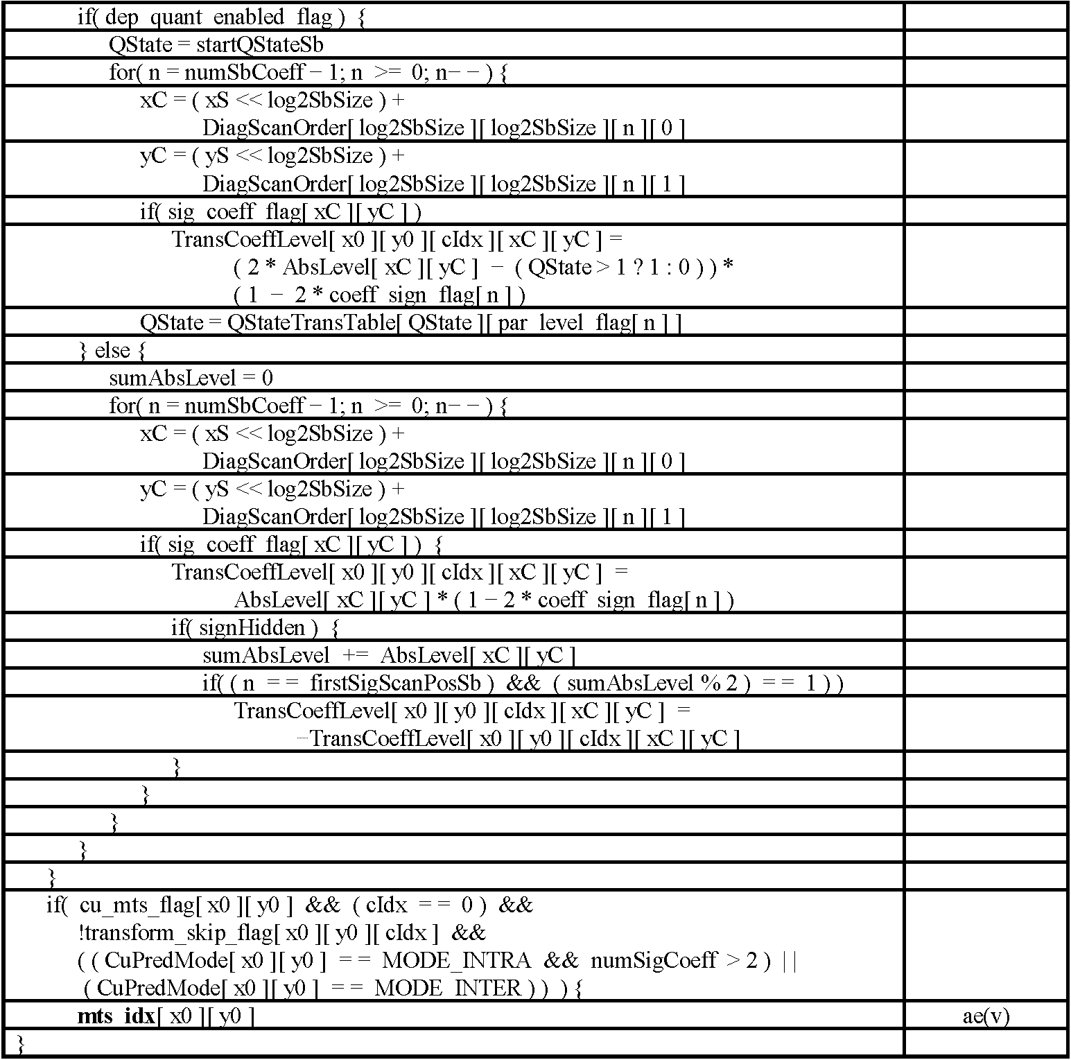
상기 통합된 MTS 인덱스를 포함하는 레지듀얼 데이터 인코딩/디코딩과 관련된 신텍스 엘리먼트들은 다음의 표와 같이 나타낼 수 있다.Syntax elements related to encoding/decoding residual data including the integrated MTS index may be represented as shown in the following table.
상술한 표 6을 참조하면 last_sig_coeff_x_prefix, last_sig_coeff_y_prefix, last_sig_coeff_x_suffix, last_sig_coeff_y_suffix, coded_sub_block_flag, sig_coeff_flag, abs_level_gt1_flag, par_level_flag, abs_level_gt3_flag, abs_remainder, dec_abs_level, 및/또는 coeff_sign_flag 가 인코딩/디코딩될 수 있다. Referring to Table 6 described above, last_sig_coeff_x_prefix, last_sig_coeff_y_prefix, last_sig_coeff_x_suffix, last_sig_coeff_y_suffix, coded_sub_block_flag, sig_coeff_flag, abs_level_gt1_flag, coeff_flag, abs_level_gt1_flag, par_level_flag, coded_flag, or par_level_flag, can be encoded.
일 실시예에서, 인코딩 장치는 신택스 엘리먼트 last_sig_coeff_x_prefix, last_sig_coeff_y_prefix, last_sig_coeff_x_suffix 및 last_sig_coeff_y_suffix를 기반으로 변환 블록 내의 마지막 0이 아닌 변환 계수의 (x, y) 위치 정보를 인코딩할 수 있다. 보다 구체적으로, 상기 last_sig_coeff_x_prefix는 변환 블록 내 스캔 순서(scanning order)에서의 마지막(last) 유효 계수(significant coefficient)의 열 위치(column position)의 프리픽스(prefix)를 나타내고, 상기 last_sig_coeff_y_prefix는 상기 변환 블록 내 상기 스캔 순서(scanning order)에서의 마지막(last) 유효 계수(significant coefficient)의 행 위치(row position)의 프리픽스(prefix)를 나타내고, 상기 last_sig_coeff_x_suffix는 상기 변환 블록 내 상기 스캔 순서(scanning order)에서의 마지막(last) 유효 계수(significant coefficient)의 열 위치(column position)의 서픽스(suffix)를 나타내고, 상기 last_sig_coeff_y_suffix는 상기 변환 블록 내 상기 스캔 순서(scanning order)에서의 마지막(last) 유효 계수(significant coefficient)의 행 위치(row position)의 서픽스(suffix)를 나타낸다. 여기서, 유효 계수는 상기 0이 아닌 계수(non-zero coefficient)를 나타낼 수 있다. 또한, 상기 스캔 순서는 우상향 대각 스캔 순서일 수 있다. 또는 상기 스캔 순서는 수평 스캔 순서, 또는 수직 스캔 순서일 수 있다. 상기 스캔 순서는 대상 블록(CB, 또는 TB를 포함하는 CB)에 인트라/인터 예측이 적용되는지 여부 및/또는 구체적인 인트라/인터 예측 모드를 기반으로 결정될 수 있다.In one embodiment, the encoding device may encode (x, y) position information of the last non-zero transform coefficient in the transform block based on the syntax elements last_sig_coeff_x_prefix, last_sig_coeff_y_prefix, last_sig_coeff_x_suffix, and last_sig_coeff_y_suffix. More specifically, the last_sig_coeff_x_prefix represents the prefix of the column position of the last significant coefficient in the scanning order in the transform block, and the last_sig_coeff_y_prefix is within the transform block. Represents a prefix of the row position of the last significant coefficient in the scanning order, and the last_sig_coeff_x_suffix is in the scanning order in the transform block. Represents the suffix of the column position of the last significant coefficient, and the last_sig_coeff_y_suffix is the last significant coefficient in the scanning order in the transform block. coefficient) represents the suffix of the row position. Here, the effective coefficient may represent the non-zero coefficient. In addition, the scan order may be an upward-right diagonal scan order. Alternatively, the scan order may be a horizontal scan order or a vertical scan order. The scan order may be determined based on whether intra/inter prediction is applied to a target block (CB or CB including TB) and/or a specific intra/inter prediction mode.
그 다음, 인코딩 장치는 상기 변환 블록을 4x4 서브 블록(sub-block)들로 분할한 후, 각 4x4 서브 블록마다 1비트의 신택스 요소 coded_sub_block_flag를 사용해 현재 서브 블록 내에 0이 아닌 계수가 존재하는지 여부를 나타낼 수 있다.Next, the encoding apparatus divides the transform block into 4x4 sub-blocks, and then determines whether a non-zero coefficient exists in the current sub-block using a 1-bit syntax element coded_sub_block_flag for each 4x4 sub-block. Can be indicated.
coded_sub_block_flag의 값이 0이면 더 이상 전송할 정보가 없으므로 인코딩 장치는 현재 서브 블록에 대한 부호화 과정을 종료할 수 있다. 반대로, coded_sub_block_flag의 값이 1이면 인코딩 장치는 sig_coeff_flag에 대한 부호화 과정을 계속해서 수행할 수 있다. 마지막 0이 아닌 계수를 포함하는 서브 블록은 coded_sub_block_flag에 대한 부호화가 불필요하고, 변환 블록의 DC 정보를 포함하고 있는 서브 블록은 0이 아닌 계수를 포함할 확률이 높으므로, coded_sub_block_flag는 부호화되지 않고 그 값이 1이라고 가정될 수 있다. If the value of coded_sub_block_flag is 0, since there is no more information to be transmitted, the encoding apparatus may end the encoding process for the current subblock. Conversely, if the value of coded_sub_block_flag is 1, the encoding device may continue to perform the encoding process for sig_coeff_flag. The coded_sub_block_flag is not coded and its value because the subblock containing the last non-zero coefficient does not require coding for coded_sub_block_flag, and the subblock containing the DC information of the transform block has a high probability of containing a non-zero coefficient. This can be assumed to be 1.
만약 coded_sub_block_flag의 값이 1이어서 현재 서브 블록 내에 0이 아닌 계수가 존재한다고 판단되는 경우, 인코딩 장치는 역으로 스캔된 순서에 따라 이진값을 갖는 sig_coeff_flag를 인코딩할 수 있다. 인코딩 장치는 스캔 순서에 따라 각각의 변환 계수에 대한 1비트 신택스 엘리먼트 sig_coeff_flag를 인코딩할 수 있다. 만약 현재 스캔 위치에서의 변환 계수의 값이 0이 아니면 sig_coeff_flag의 값은 1이 될 수 있다. 여기서, 마지막 0이 아닌 계수를 포함하고 있는 서브 블록의 경우, 마지막 0이 아닌 계수에 대해서는 sig_coeff_flag가 인코딩될 필요가 없으므로 상기 서브 블록에 대한 부호화 과정이 생략될 수 있다. sig_coeff_flag가 1인 경우에만 레벨 정보 부호화가 수행될 수 있으며, 레벨 정보 부호화 과정에는 네 개의 신택스 엘리먼트들이 사용될 수 있다. 보다 구체적으로, 각 sig_coeff_flag[xC][yC]는 현재 TB내 각 변환 계수 위치 (xC, yC)에서의 해당 변환 계수의 레벨(값)이 0이 아닌지(non-zero) 여부를 나타낼 수 있다. 일 실시예에서, 상기 sig_coeff_flag는 양자화된 변환 계수가 0이 아닌 유효 계수인지 여부를 나타내는 유효 계수 플래그의 신텍스 엘리먼트의 일 예시에 해당할 수 있다.If it is determined that a non-zero coefficient exists in the current sub-block because the value of coded_sub_block_flag is 1, the encoding apparatus may encode sig_coeff_flag having a binary value according to the reverse scan order. The encoding apparatus may encode a 1-bit syntax element sig_coeff_flag for each transform coefficient according to a scan order. If the value of the transform coefficient at the current scan position is not 0, the value of sig_coeff_flag may be 1. Here, in the case of a subblock including the last non-zero coefficient, since sig_coeff_flag does not need to be encoded for the last non-zero coefficient, the encoding process for the sub-block may be omitted. Level information encoding may be performed only when sig_coeff_flag is 1, and four syntax elements may be used in the level information encoding process. More specifically, each sig_coeff_flag[xC][yC] may indicate whether the level (value) of the corresponding transform coefficient at each transform coefficient position (xC, yC) in the current TB is non-zero (non-zero). In an embodiment, the sig_coeff_flag may correspond to an example of a syntax element of a significant coefficient flag indicating whether a quantized transform coefficient is a non-zero effective coefficient.
sig_coeff_flag에 대한 부호화 이후의 남은 레벨 값은 아래의 수학식과 같이 도출될 수 있다. 즉, 부호화해야 할 레벨 값을 나타내는 신택스 요소 remAbsLevel은 아래의 수학식과 도출될 수 있다. The level value remaining after encoding for sig_coeff_flag may be derived as shown in the following equation. That is, the syntax element remAbsLevel representing the level value to be encoded can be derived with the following equation.
여기서, coeff는 실제 변환 계수값을 의미한다.Here, coeff means an actual transform coefficient value.
또한, abs_level_gt1_flag는 해당 스캐닝 위치(n)에서의 remAbsLevel'이 1보다 큰지 여부를 나타낼 수 있다. 예를 들어, abs_level_gt1_flag의 값이 0이면 해당 위치의 변환 계수의 절댓값(absolute value)은 1일 수 있다. 또한, 상기 abs_level_gt1_flag의 값이 1이면, 이후 부호화해야 할 레벨 값을 나타내는 상기 remAbsLevel은 아래의 수학식과 같이 도출될 수 있다.Also, abs_level_gt1_flag may indicate whether remAbsLevel' at the corresponding scanning position n is greater than 1. For example, if the value of abs_level_gt1_flag is 0, the absolute value of the transform coefficient at the corresponding location may be 1. In addition, when the value of abs_level_gt1_flag is 1, the remAbsLevel indicating a level value to be encoded later may be derived as shown in the following equation.
또한, 상술한 수학식 2에 기재된 remAbsLevel의 least significant coefficient (LSB) 값은 par_level_flag을 통하여 아래의 수학식 3와 같이 인코딩될 수 있다. In addition, the least significant coefficient (LSB) value of remAbsLevel described in Equation 2 may be encoded as Equation 3 below through par_level_flag.
여기서 par_level_flag[n]는 스캐닝 위치 n에서의 변환 계수 레벨(값)의 패리티(parity)를 나타낼 수 있다. Here, par_level_flag[n] may represent parity of the transform coefficient level (value) at the scanning position n.
par_leve_flag 인코딩 후에 인코딩해야 할 변환 계수 레벨 값 remAbsLevel은 다음의 수학식과 같이 업데이트될 수 있다.After encoding par_leve_flag, the transform coefficient level value remAbsLevel to be encoded may be updated as shown in the following equation.
abs_level_gt3_flag는 해당 스캐닝 위치(n)에서의 remAbsLevel이 3보다 큰지 여부를 나타낼 수 있다. rem_abs_gt3_flag가 1인 경우에만 abs_remainder에 대한 인코딩이 수행될 수 있다. 실제 변환 계수값인 coeff와 각 신택스 요소들의 관계는 다음의 수학식과 같을 수 있다. abs_level_gt3_flag may indicate whether remAbsLevel at the corresponding scanning position n is greater than 3. Encoding for abs_remainder may be performed only when rem_abs_gt3_flag is 1. The relationship between the actual transform coefficient value coeff and each syntax element may be as follows.
또한, 다음의 표는 상술한 수학식 5와 관련된 예시들을 나타낸다. In addition, the following table shows examples related to Equation 5 above.
여기서, | coeff |는 변환 계수 레벨(값)을 나타내며, 변환 계수에 대한 AbsLevel이라고 표시될 수도 있다. 또한, 각 계수의 부호는 1비트 심볼인 coeff_sign_flag를 이용하여 인코딩될 수 있다.Where, | coeff| represents a transform coefficient level (value), and may be expressed as AbsLevel for the transform coefficient. In addition, the sign of each coefficient may be encoded using a 1-bit symbol coeff_sign_flag.
한편, 상술한 신텍스 엘리먼트들을 전송하는 실시예와 다른 예로, 레지듀얼 코딩을 위하여 변환 스킵이 적용되는지 여부에 따라 서로 상이한 레지듀얼 코딩 방식, 즉, 변환 스킵이 적용되는지 여부에 따라 상이한 레지듀얼 신텍스 엘리먼트들을 전송하는 실시예가 제안될 수 있다.Meanwhile, as an example different from the embodiment in which the above-described syntax elements are transmitted, different residual syntax elements are different depending on whether or not transform skip is applied for residual coding, that is, different residual syntax elements according to whether or not transform skip is applied. An embodiment may be proposed for transmitting the data.
상술한 예에 따른 레지듀얼 코딩에 대한 신텍스 엘리먼트들은 다음의 표들과 같이 나타낼 수 있다.Syntax elements for residual coding according to the above-described example may be represented as in the following tables.
본 실시예에 따르면, 표 8에 도시된 바와 같이 변환 스킵 플래그의 신텍스 엘리먼트 transform_skip_flag의 값에 따라 레지듀얼 코딩이 분기될 수 있다. 즉, 변환 스킵 플래그의 값을 기반으로(변환 스킵 여부를 기반으로) 레지듀얼 코딩을 위하여 상이한 신택스 엘리먼트가 사용될 수 있다. 변환 스킵이 적용되지 않은 경우(즉, 변환이 적용된 경우)에 사용되는 레지듀얼 코딩은 레귤러 레지듀얼 코딩(Regular Residual Coding, RRC)라고 불릴 수 있으며, 변환 스킵이 적용되지 않은 경우(즉, 변환이 적용되지 않은 경우)의 레지듀얼 코딩은 변환 스킵 레지듀얼 코딩(Transform Skip Residual Coding, TSRC)라고 불릴 수 있다. 상기 표 9는 transform_skip_flag의 값이 0 인 경우, 즉, 변환이 적용된 경우의 레지듀얼 코딩의 신텍스 엘리먼트를 나타낼 수 있고, 표 10은 transform_skip_flag의 값이 1 인 경우, 즉 변환이 적용되지 않은 경우의 레지듀얼 코딩의 신텍스 엘리먼트를 나타낼 수 있다.According to this embodiment, as shown in Table 8, residual coding may be branched according to the value of the syntax element transform_skip_flag of the transform skip flag. That is, a different syntax element may be used for residual coding based on the value of the transform skip flag (based on whether or not to skip transform). The residual coding used when the transform skip is not applied (i.e., when the transform is applied) may be called regular residual coding (RRC), and when the transform skip is not applied (ie, the transform is If not applied), the residual coding may be referred to as Transform Skip Residual Coding (TSRC). Table 9 above may indicate the syntax element of residual coding when the value of transform_skip_flag is 0, that is, when transform is applied, and Table 10 shows the register when the value of transform_skip_flag is 1, that is, when the transform is not applied. It may represent a syntax element of dual coding.
구체적으로, 예를 들어, 변환 블록의 변환 스킵 여부를 지시하는 변환 스킵 플래그가 파싱될 수 있고, 상기 변환 스킵 플래그가 1인지 여부가 판단될 수 있다. 상기 변환 스킵 플래그의 값이 1인 경우, 표 10에 도시된 바와 같이 변환 블록의 레지듀얼 계수에 대한 신텍스 엘리먼트들 sig_coeff_flag, coeff_sign_flag, abs_level_gtx_flag 및/또는 abs_remainder가 파싱 될 수 있고, 상기 신텍스 엘리먼트들을 기반으로 상기 레지듀얼 계수가 도출될 수 있다. 이 경우, 상기 신텍스 엘리먼트들은 순차적으로 파싱될 수도 있고, 파싱 순서가 변경될 수도 있다. 또한, 상기 abs_level_gtx_flag 는 abs_level_gt1_flag, abs_level_gt3_flag, abs_level_gt5_flag, abs_level_gt7_flag 및/또는 abs_level_gt9_flag을 나타낼 수 있다. 예를 들어, abs_level_gtx_flag[n][j]는 스캐닝 위치 n에서 변환 계수 레벨(또는 변환 계수 레벨을 우측으로 1만큼 쉬프팅한 값)의 절대값이 (j<<1)+1보다 큰지 여부를 나타내는 플래그일 수 있다. 상기 (j<<1)+1은, 경우에 따라서 제1 임계치, 제2 임계치 등 소정의 임계치로 대체될 수도 있다.Specifically, for example, a transform skip flag indicating whether to skip transform of a transform block may be parsed, and whether the transform skip flag is 1 may be determined. When the value of the transform skip flag is 1, as shown in Table 10, syntax elements sig_coeff_flag, coeff_sign_flag, abs_level_gtx_flag, and/or abs_remainder for the residual coefficient of the transform block may be parsed, and based on the syntax elements. The residual coefficient may be derived. In this case, the syntax elements may be sequentially parsed or the parsing order may be changed. In addition, the abs_level_gtx_flag may represent abs_level_gt1_flag, abs_level_gt3_flag, abs_level_gt5_flag, abs_level_gt7_flag and/or abs_level_gt9_flag. For example, abs_level_gtx_flag[n][j] indicates whether the absolute value of the transform coefficient level (or the transform coefficient level shifted by 1 to the right) at the scanning position n is greater than (j<<1)+1. It can be a flag. The (j<<1)+1 may be replaced by a predetermined threshold value, such as a first threshold value and a second threshold value, in some cases.
또한, 상기 변환 스킵 플래그의 값이 0인 경우, 표 9에 도시된 바와 같이 변환 블록의 레지듀얼 계수에 대한 신텍스 엘리먼트들 sig_coeff_flag, abs_level_gtx_flag, par_level_flag, abs_remainder, dec_abs_level, coeff_sign_flag 가 파싱될 수 있고, 상기 신텍스 엘리먼트들을 기반으로 상기 레지듀얼 계수가 도출될 수 있다. 이 경우, 상기 신텍스 엘리먼트들은 순차적으로 파싱될 수도 있고, 파싱 순서가 변경될 수도 있다. 또한, 상기 abs_level_gtx_flag 는 abs_level_gt1_flag 및/또는 abs_level_gt3_flag 을 나타낼 수 있다. 예를 들어, abs_level_gtx_flag[n][0]은 제1 변환 계수 레벨 플래그(abs_level_gt1_flag)의 일 예시일 수 있고, 상기 abs_level_gtx_flag[n][1]은 제2 변환 계수 레벨 플래그(abs_level_gt3_flag)의 일 예시일 수 있다.In addition, when the value of the transform skip flag is 0, as shown in Table 9, syntax elements sig_coeff_flag, abs_level_gtx_flag, par_level_flag, abs_remainder, dec_abs_level, coeff_sign_flag may be parsed as shown in Table 9, and the syntax The residual coefficient may be derived based on the elements. In this case, the syntax elements may be sequentially parsed or the parsing order may be changed. In addition, the abs_level_gtx_flag may represent abs_level_gt1_flag and/or abs_level_gt3_flag. For example, abs_level_gtx_flag[n][0] may be an example of a first transform coefficient level flag (abs_level_gt1_flag), and the abs_level_gtx_flag[n][1] is an example of a second transform coefficient level flag (abs_level_gt3_flag). I can.
상술한 바와 같이, 변환이 적용되지 않은 경우의 레지듀얼 계수에 대한 신텍스 엘리먼트들과 변환이 적용된 경우의 레지듀얼 계수에 대한 신텍스 엘리먼트들을 비교하면 신텍스 엘리먼트 par_level_flag이 인코딩 및 디코딩되지 않을 수 있다. 이는 레지듀얼 계수의 레벨값이 클 경우에 모든 레지듀얼 계수에 대한 sig_coeff_flag, par_level_flag, abs_level_gtx_flag 등의 신텍스 엘리먼트들을 모두 코딩하는 것이 레지듀얼 계수의 레벨값을 그대로 이진화하여 전송하는 것에 비하여 중복된 정보를 전송할 가능성이 높고, 이에, 본 실시예에서는 레지듀얼 계수의 레벨값이 클 가능성이 있는 변환 스킵이 적용되는 경우에는 신텍스 엘리먼트 par_level_flag 를 생략함으로써 코딩 효율을 향상시킬 수 있다.As described above, when the syntax elements for the residual coefficient when the transform is not applied and the syntax elements for the residual coefficient when the transform is applied are compared, the syntax element par_level_flag may not be encoded and decoded. In this case, when the level value of the residual coefficient is large, coding all of the syntax elements such as sig_coeff_flag, par_level_flag, and abs_level_gtx_flag for all residual coefficients transmits redundant information, compared to transmitting the level value of the residual coefficient as it is binarized. The possibility is high. Accordingly, in the present embodiment, when a transform skip, which may have a large residual coefficient level value, is applied, the syntax element par_level_flag may be omitted, thereby improving coding efficiency.
한편, CABAC은 높은 성능을 제공하지만 처리량(throughput) 성능이 좋지 않다는 단점을 갖는다. 이는 CABAC의 정규 부호화 엔진으로 인한 것으로, 정규 부호화(즉, CABAC의 정규 부호화 엔진을 통한 인코딩)는 이전 빈(bin)의 부호화를 통해 업데이트된 확률 상태와 범위를 사용하기 때문에 높은 데이터 의존성을 보이며, 확률 구간을 읽고 현재 상태를 판단하는데 많은 시간이 소요될 수 있다. CABAC의 처리량 문제는 문맥 부호화 빈(context-coded bin)의 수를 제한함으로써 해결될 수 있다. 예를 들어, 상술한 표 1, 표 6, 표 9 또는 표 10과 같이 sig_coeff_flag, abs_level_gt1_flag, par_level_flag, abs_level_gt3_flag를 표현하기 위해 사용된 빈의 합이 해당 블록의 사이즈에 따른 개수로 제한될 수 있다. 일 예로, 해당 블록이 4x4 사이즈의 블록인 경우, 상기 sig_coeff_flag, abs_level_gt1_flag, par_level_flag, abs_level_gt3_flag 에 대한 빈들의 합은 32개로 제한될 수 있고, 해당 블록이 2x2 사이즈의 블록인 경우, 상기 sig_coeff_flag, abs_level_gt1_flag, par_level_flag, abs_level_gt3_flag에 대한 빈들의 합은 8개로 제한될 수 있다. 상기 빈들의 제한된 개수는 remBinsPass1으로 나타낼 수 있다. On the other hand, CABAC provides high performance, but has a disadvantage of poor throughput performance. This is due to CABAC's regular encoding engine, and regular encoding (that is, encoding through CABAC's regular encoding engine) shows high data dependence because it uses the updated probability state and range through encoding of the previous bin. It can take a lot of time to read the probability interval and determine the current state. The throughput problem of CABAC can be solved by limiting the number of context-coded bins. For example, the sum of bins used to express sig_coeff_flag, abs_level_gt1_flag, par_level_flag, abs_level_gt3_flag as in Table 1, Table 6, Table 9 or Table 10 described above may be limited to the number according to the size of the corresponding block. For example, when the block is a 4x4 size block, the sum of bins for the sig_coeff_flag, abs_level_gt1_flag, par_level_flag, and abs_level_gt3_flag may be limited to 32. When the corresponding block is a 2x2 size block, the sig_coeff_flag, abs_level_flag, par_level_flag, and par_level_flag , The sum of bins for abs_level_gt3_flag may be limited to 8. The limited number of bins can be represented by remBinsPass1.
이 경우, 인코딩 장치는 문맥 요소를 부호화하는데 제한된 개수의 문맥 부호화 빈을 모두 사용하면, 나머지 계수들을 CABAC을 사용하지 않고 후술하는 상기 계수들에 대한 이진화 방법을 통하여 이진화하고, 바이패스 인코딩을 수행할 수 있다. 다시 말해, 예를 들어, 4x4 CG 에 대하여 코딩된 컨텍스트 부호화 빈(context coded bin)의 수가 32, 또는 2x2 CG 에 대하여 코딩된 컨텍스트 부호화 빈의 수가 8이 되는 경우에는 더 이상 컨텍스트 부호화 빈으로 코딩되는 sig_coeff_flag, abs_level_gt1_flag, par_level_flag, abs_level_gt3_flag는 인코딩되지 않을 수 있고, 후술한 표 8과 같이 곧바로 dec_abs_level로 인코딩될 수 있다. In this case, if all of the limited number of context encoding bins are used to encode the context element, the encoding apparatus binarizes the remaining coefficients through a binarization method for the coefficients described later without using CABAC, and performs bypass encoding. I can. In other words, for example, if the number of context coded bins coded for 4x4 CG is 32, or the number of context coded bins coded for 2x2 CG is 8, then the context coded bins are no longer coded. sig_coeff_flag, abs_level_gt1_flag, par_level_flag, abs_level_gt3_flag may not be encoded, and may be directly encoded as dec_abs_level as shown in Table 8 described later.
dec_abs_level 를 기반으로 |coeff| 값이 도출될 수 있다. 이 경우, 변환 계수값인 |coeff| 는 다음의 수학식과 같이 도출될 수 있다. Based on dec_abs_level |coeff| Values can be derived. In this case, the transform coefficient value, |coeff| Can be derived as the following equation.
또한, 상기 coeff_sign_flag은 해당 스캐닝 위치(n)에서의 변환 계수 레벨의 부호(sign)을 나타낼 수 있다. 즉, 상기 coeff_sign_flag은 해당 스캐닝 위치(n)에서의 변환 계수의 부호(sign)을 나타낼 수 있다. 또한, 상기 mts_idx는 현재 변환 블록 내 레지듀얼 샘플들에 대하여 수평 방향 및 수직 방향으로 적용되는 변환 커널들을 나타낼 수 있다.In addition, the coeff_sign_flag may represent a sign of a transform coefficient level at a corresponding scanning position n. That is, the coeff_sign_flag may represent the sign of the transform coefficient at the corresponding scanning position n. Also, the mts_idx may represent transform kernels applied in a horizontal direction and a vertical direction to residual samples in a current transform block.
도 5는 4x4 블록 내 변환 계수들의 예시를 도시하는 도면이다.5 is a diagram illustrating an example of transform coefficients in a 4x4 block.
도 5의 4x4 블록은 양자화된 계수들의 일 예를 나타낸다. 도 5에 도시된 블록은 4x4 변환 블록이거나, 또는 8x8, 16x16, 32x32, 64x64 변환 블록의 4x4 서브 블록일 수 있다. 도 5의 4x4 블록은 루마 블록 또는 크로마 블록을 나타낼 수 있다. The 4x4 block of FIG. 5 shows an example of quantized coefficients. The block shown in FIG. 5 may be a 4x4 transform block or a 4x4 sub-block of an 8x8, 16x16, 32x32, or 64x64 transform block. The 4x4 block of FIG. 5 may represent a luma block or a chroma block.
예를 들어, 도 5의 역 대각선 스캔되는 계수들에 대한 인코딩 결과는 다음의 표와 같을 수 있다. For example, encoding results of coefficients scanned inverse diagonally in FIG. 5 may be as shown in the following table.
상술한 표 12에서 scan_pos는 역 대각선 스캔에 따른 계수의 위치를 나타낸다. scan_pos 15는 4x4 블록에서 가장 먼저 스캔되는, 즉 우하단 코너의 변환 계수일 수 있고, scan_pos 0은 가장 나중에 스캔되는, 즉 좌상단 코너의 변환 계수일 수 있다. 한편 일 실시예에서, 상기 scan_pos는 스캔 위치라고 지칭될 수도 있다. 예를 들어, 상기 scan_pos 0은 스캔 위치 0이라고 지칭될 수 있다.In Table 12 described above, scan_pos indicates the position of the coefficient according to the inverse diagonal scan. scan_pos 15 may be the transform coefficient of the first scan, that is, the lower right corner, in the 4x4 block, and scan_pos 0 may be the transform coefficient of the last scan, that is, the upper left corner. Meanwhile, in an embodiment, the scan_pos may be referred to as a scan position. For example, the scan_pos 0 may be referred to as a scan position 0.
한편, 상술한 내용과 같이 인코딩 장치는 입력 신호가 이진값이 아닌 신텍스 엘리먼트인 경우에는 상기 입력 신호의 값을 이진화(binarization)하여 입력 신호를 이진값로 변환할 수 있다. 또한, 디코딩 장치는 상기 신텍스 엘리먼트를 디코딩하여 상기 신텍스 엘리먼트의 이진화된 값(즉, 이진화된 빈)을 도출할 수 있고, 상기 이진화된 값을 역 이진화하여 상기 신텍스 엘리먼트의 값을 도출할 수 있다. 상기 이진화 과정은 후술하는 트렁케이티드 라이스(Truncated Rice, TR) 이진화 프로세스(binarization process), k차 Exp-Golomb (k-th order Exp-Golomb, EGk) 이진화 프로세스(binarization process), k차 Limited Exp-Golomb (Limited k-th order Exp-Golomb, Limited EGk), 또는 고정 길이(Fixed-length, FL) 이진화 프로세스(binarization process) 등으로 수행될 수 있다. 또한, 역 이진화 과정은 상기 TR 이진화 프로세스, 상기 EGk 이진화 프로세스 또는 상기 FL 이진화 프로세스를 기반으로 수행되어 상기 신텍스 엘리먼트의 값을 도출하는 과정을 나타낼 수 있다. Meanwhile, as described above, when the input signal is a syntax element other than a binary value, the encoding apparatus may convert the input signal into a binary value by binarizing the value of the input signal. In addition, the decoding apparatus may decode the syntax element to derive a binarized value (ie, binarized bin) of the syntax element, and inverse binarize the binarized value to derive the value of the syntax element. The binarization process is a Truncated Rice (TR) binarization process, a k-th order Exp-Golomb (EGk) binarization process, a k-order Limited Exp. -Golomb (Limited k-th order Exp-Golomb, Limited EGk), or a fixed-length (FL) binarization process, etc. may be performed. In addition, the inverse binarization process may be performed based on the TR binarization process, the EGk binarization process, or the FL binarization process to derive a value of the syntax element.
예를 들어, 상기 TR 이진화 프로세스는 다음과 같이 수행될 수 있다. For example, the TR binarization process may be performed as follows.
상기 TR 이진화 프로세스의 입력(input)은 TR 이진화에 대한 요청과 신텍스 엘리먼트에 대한 cMax 및 cRiceParam 일 수 있다. 또한, 상기 TR 이진화 프로세스의 출력(output)은 빈 스트링에 대응하는 값 symbolVal 에 대한 TR 이진화일 수 있다. The input of the TR binarization process may be a request for TR binarization and cMax and cRiceParam for a syntax element. Further, the output of the TR binarization process may be TR binarization for a value symbolVal corresponding to an empty string.
구체적으로, 일 예로, 신텍스 엘리먼트에 대한 접미사(suffix) 빈 스트링이 존재하는 경우에는 상기 신텍스 엘리먼트에 대한 TR 빈 스트링은 접두사(prefix) 빈 스트링과 접미사 빈 스트링의 결합(concatenation)일 수 있고, 상기 접미사 빈 스트링이 존재하지 않는 경우에는 상기 신텍스 엘리먼트에 대한 상기 TR 빈 스트링은 상기 접두사 빈 스트링일 수 있다. 예를 들어, 상기 접두사 빈 스트링은 후술하는 바와 같이 도출될 수 있다. Specifically, for example, when there is a suffix empty string for the syntax element, the TR empty string for the syntax element may be a concatenation of a prefix empty string and a suffix empty string, and the When the suffix bin string does not exist, the TR bin string for the syntax element may be the prefix bin string. For example, the prefix empty string may be derived as described later.
상기 신텍스 엘리먼트에 대한 상기 symbolVal 의 접두사 값(prefix value)은 다음의 수학식과 같이 도출될 수 있다. The prefix value of the symbolVal for the syntax element may be derived as follows.
여기서, prefixVal 은 상기 symbolVal 의 접두사 값을 나타낼 수 있다. 상기 신텍스 엘리먼트의 상기 TR 빈 스트링의 접두사(즉, 접두사 빈 스트링)는 후술하는 바와 같이 도출될 수 있다. Here, prefixVal may represent the prefix value of the symbolVal. A prefix (ie, prefix empty string) of the TR bin string of the syntax element may be derived as described later.
예를 들어, 상기 prefixVal이 cMax >> cRiceParam보다 작은 경우, 접두사 빈 스트링은 binIdx에 의해 인덱싱되는(indexed) 길이 prefixVal + 1의 비트 스트링(bit string)일 수 있다. 즉, 상기 prefixVal이 cMax >> cRiceParam보다 작은 경우, 상기 접두사 빈 스트링은 binIdx가 가리키는 prefixVal + 1 비트수의 비트스트링일 수 있다. prefixVal보다 작은 binIdx 에 대한 빈은 1과 동일할 수 있다. 또한, prefixVal와 동일한 binIdx 에 대한 빈은 0과 동일할 수 있다. For example, when the prefixVal is smaller than cMax >> cRiceParam, the prefix bin string may be a bit string of length prefixVal + 1 indexed by binIdx. That is, when the prefixVal is smaller than cMax >> cRiceParam, the prefix empty string may be a bitstring of prefixVal + 1 bit number indicated by binIdx. The bin for binIdx less than prefixVal can be equal to 1. Also, a bin for binIdx that is identical to prefixVal may be equal to 0.
예를 들어, 상기 prefixVal에 대한 단항 이진화(unary binarization)로 도출되는 빈 스트링은 다음의 표와 같을 수 있다. For example, an empty string derived by unary binarization for the prefixVal may be as shown in the following table.
한편, 상기 prefixVal이 cMax >> cRiceParam보다 작지 않은 경우, 상기 접두사 빈 스트링은 길이가 cMax >> cRiceParam 이고 모든 빈이 1인 비트 스트링일 수 있다. Meanwhile, when the prefixVal is not smaller than cMax >> cRiceParam, the prefix bean string may be a bit string having a length of cMax >> cRiceParam and all bins being 1.
또한, cMax 가 symbolVal 보다 크고, cRiceParam 이 0보다 큰 경우, TR 빈 스트링의 접미사 빈 스트링이 존재할 수 있다. 예를 들어, 상기 접미사 빈 스트링은 후술하는 바와 같이 도출될 수 있다. In addition, when cMax is greater than symbolVal and cRiceParam is greater than 0, a suffix of the TR bin string may exist. For example, the suffix bin string may be derived as described later.
상기 신텍스 엘리먼트에 대한 상기 symbolVal 의 접미사 값(suffix value)은 다음의 수학식과 같이 도출될 수 있다. The suffix value of the symbolVal for the syntax element may be derived as the following equation.
여기서, suffixVal 은 상기 symbolVal 의 접미사 값을 나타낼 수 있다.Here, suffixVal may represent a suffix value of symbolVal.
TR 빈 스트링의 접미사(즉, 접미사 빈 스트링)은 cMax 값이 (1 << cRiceParam)-1 인 suffixVal에 대한 FL 이진화 프로세스를 기반으로 도출될 수 있다. The suffix of the TR bean string (ie, the suffix bean string) may be derived based on the FL binarization process for suffixVal whose cMax value is (1 << cRiceParam)-1.
한편, 입력 파라미터인 cRiceParam 의 값이 0이면, 상기 TR 이진화는 정확하게 트렁케이티드 단항 이진화(truncated unary binarization)일 수 있고, 항상 디코딩되는 신텍스 엘리멘트의 가능한 최대 값과 동일한 cMax 값이 사용될 수 있다. On the other hand, if the value of the input parameter cRiceParam is 0, the TR binarization may be precisely truncated unary binarization, and a cMax value equal to the maximum possible value of the syntax element to be always decoded may be used.
또한, 예를 들어, 상기 EGk 이진화 프로세스는 다음과 같이 수행될 수 있다. ue(v) 로 코딩된 신텍스 엘리먼트는 Exp-Golomb 코딩된 신텍스 엘리먼트일 수 있다. Also, for example, the EGk binarization process may be performed as follows. The syntax element coded with ue(v) may be an Exp-Golomb coded syntax element.
일 예로, 0차 Exp-Golomb (0-th order Exp-Golomb, EG0) 이진화 프로세스는 다음과 같이 수행될 수 있다. For example, a 0-th order Exp-Golomb (EG0) binarization process may be performed as follows.
상기 신텍스 엘리먼트에 대한 파싱 프로세스(parsing process)는 비트스트림의 현재 위치에서 시작하여 첫번째 논-제로(non-zero) 비트를 포함한 비트를 읽어 0과 같은 선행 비트 수를 세는 것(counting)으로 시작될 수 있다. 상기 과정은 다음의 표와 같이 나타낼 수 있다. The parsing process for the syntax element may be started by reading a bit including the first non-zero bit starting from the current position of the bitstream and counting the number of preceding bits equal to 0. have. The process can be expressed as shown in the following table.
또한, 변수 codeNum 은 다음의 수학식과 같이 도출될 수 있다. In addition, the variable codeNum can be derived as the following equation.
여기서, read_bits(leadingZeroBits)에서 반환된 값, 즉, read_bits(leadingZeroBits)가 나타내는 값은 첫번째로 기록된 가장 중요한 비트(most significant bit)에 대한 언사인드 정수(unsigned integer)의 이진 표현(binary representation)으로 해석될 수 있다. Here, the value returned from read_bits(leadingZeroBits), that is, the value indicated by read_bits(leadingZeroBits), is a binary representation of an unsigned integer for the most significant bit recorded first. Can be interpreted.
비트 스트링을 "접두사(prefix)" 비트와 "접미사(suffix)" 비트로 분리한 Exp-Golomb 코드의 구조는 다음의 표와 같이 나타낼 수 있다. The structure of the Exp-Golomb code in which the bit string is divided into "prefix" bits and "suffix" bits can be expressed as shown in the following table.
"접두사" 비트는 leadingZeroBits 계산을 위하여 상술한 내용과 같이 파싱된 비트일 수 있고, 표 15에서 비트 스트링의 0 또는 1로 표시될 수 있다. 즉, 상술한 표 15의 0 또는 1로 개시된 비트 스트링은 접두사 비트 스트링을 나타낼 수 있다. "접미사" 비트는 codeNum의 계산에서 파싱되는 비트일 수 있고, 상술한 표 15에서 xi로 표시될 수 있다. 즉, 상술한 표 15의 xi로 개시된 비트 스트링은 접미사 비트 스트링을 나타낼 수 있다. 여기서, i는 0에서 LeadingZeroBits-1의 범위의 값일 수 있다. 또한, 각 xi는 0 또는 1과 동일할 수 있다. The "prefix" bit may be a bit parsed as described above for calculating the leadingZeroBits, and may be represented as 0 or 1 of the bit string in Table 15. That is, the bit string disclosed by 0 or 1 in Table 15 described above may represent a prefix bit string. The "suffix" bit may be a bit parsed in the calculation of codeNum, and may be indicated by xi in Table 15 described above. That is, the bit string disclosed by xi in Table 15 may represent a suffix bit string. Here, i may be a value in the range of 0 to LeadingZeroBits-1. In addition, each xi may be equal to 0 or 1.
상기 codeNum 에 할당되는 비트 스트링은 다음의 표와 같을 수 있다. The bit string allocated to the codeNum may be as shown in the following table.
신텍스 엘리먼트의 디스크립터(descriptor)가 ue(v) 인 경우, 즉, 신텍스 엘리먼트가 ue(v)로 코딩된 경우, 상기 신텍스 엘리먼트의 값은 codeNum과 동일할 수 있다.When the descriptor of the syntax element is ue(v), that is, when the syntax element is coded as ue(v), the value of the syntax element may be the same as codeNum.
또한, 예를 들어, 상기 EGk 이진화 프로세스는 다음과 같이 수행될 수 있다. Also, for example, the EGk binarization process may be performed as follows.
상기 EGk 이진화 프로세스의 입력(input)은 EGk 이진화에 대한 요청일 수 있다. 또한, 상기 EGk 이진화 프로세스의 출력(output)은 빈 스트링에 대응하는 값 symbolVal 에 대한 EGk 이진화일 수 있다. An input of the EGk binarization process may be a request for EGk binarization. In addition, an output of the EGk binarization process may be EGk binarization for a value symbolVal corresponding to an empty string.
symbolVal에 대한 EGk 이진화 프로세스의 비트 스트링은 다음과 같이 도출될 수 있다. The bit string of the EGk binarization process for symbolVal can be derived as follows.
상술한 표 17을 참조하면, put(X)의 각 콜(each call)을 통하여 이진값 X를 빈 스트링의 끝에 추가될 수 있다. 여기서, X는 0 또는 1 일 수 있다. Referring to Table 17 above, a binary value X may be added to the end of an empty string through each call of put(X). Here, X may be 0 or 1.
또한, 예를 들어, 상기 Limited EGk 이진화 프로세스는 다음과 같이 수행될 수 있다.Further, for example, the Limited EGk binarization process may be performed as follows.
상기 Limited EGk 이진화 프로세스의 입력(input)은 Limited EGk 이진화에 대한 요청 및 라이스 파라미터 riceParam, 최댓값의 이진대수를 나타내는 변수인 log2TransformRange 및 최대 접두사 확장 길이를 나타내는 변수인 maxPreExtLen일 수 있다. 또한, 상기 Limited EGk 이진화 프로세스의 출력(output)은 빈 스트링에 대응하는 값 symbolVal에 대한 Limited EGk 이진화일 수 있다.The input of the Limited EGk binarization process may be a request for Limited EGk binarization and a Rice parameter riceParam, log2TransformRange, a variable representing the maximum binary logarithm, and maxPreExtLen, a variable representing the maximum prefix extension length. Also, the output of the Limited EGk binarization process may be Limited EGk binarization for a value symbolVal corresponding to an empty string.
symbolVal에 대한 Limited EGk 이진화 프로세스의 비트 스트링은 다음과 같이 도출될 수 있다.The bit string of the Limited EGk binarization process for symbolVal can be derived as follows.
또한, 예를 들어, 상기 FL 이진화 프로세스는 다음과 같이 수행될 수 있다. Also, for example, the FL binarization process may be performed as follows.
상기 FL 이진화 프로세스의 입력(input)은 FL 이진화에 대한 요청 및 상기 신텍스 엘리먼트에 대한 cMax일 수 있다. 또한, 상기 FL 이진화 프로세스의 출력(output)은 빈 스트링에 대응하는 값 symbolVal 에 대한 FL 이진화일 수 있다. An input of the FL binarization process may be a request for FL binarization and cMax for the syntax element. Also, an output of the FL binarization process may be FL binarization for a value symbolVal corresponding to an empty string.
FL 이진화는 심볼값 symbolVal의 고정길이인 비트수를 갖는 비트 스트링을 사용하여 구성될 수 있다. 여기서, 상기 고정 길이 비트는 부호없는 정수 비트 스트링(unsigned integer bit string)일 수 있다. 즉, FL 이진화를 통하여 심볼값 symbolVal 에 대한 비트 스트링이 도출될 수 있고, 상기 비트스트링의 비트길이(즉, 비트수)는 고정 길이일 수 있다. FL binarization can be constructed using a bit string having a fixed number of bits of the symbol value symbolVal. Here, the fixed length bit may be an unsigned integer bit string. That is, a bit string for the symbol value symbolVal may be derived through FL binarization, and the bit length (ie, the number of bits) of the bitstring may be a fixed length.
예를 들어, 상기 고정 길이는 다음의 수학식과 같이 도출될 수 있다.For example, the fixed length may be derived as follows.
FL 이진화에 대한 빈들의 인덱싱은 최상위 비트에서 최하위 비트 순서로 증가하는 값을 사용하는 방식일 수 있다. 예를 들어, 상기 최상위 비트와 관련된 빈 인덱스는 binIdx = 0 일 수 있다. The indexing of bins for FL binarization may be a method of using a value increasing from the most significant bit to the least significant bit. For example, the bin index related to the most significant bit may be binIdx = 0.
한편, 예를 들어, 상기 레지듀얼 정보 중 신텍스 엘리먼트 abs_remainder 에 대한 이진화 프로세스는 다음과 같이 수행될 수 있다. Meanwhile, for example, the binarization process for the syntax element abs_remainder among the residual information may be performed as follows.
상기 abs_remainder 에 대한 이진화 프로세스의 입력은 신텍스 엘리먼트 abs_remainder[n] 의 이진화에 대한 요청, 색상 성분(colour component) cIdx, 루마 위치 (x0, y0) 일 수 있다. 상기 루마 위치 (x0, y0)는 픽처의 좌상단 루마 샘플을 기준으로 하는 현재 루마 변환 블록의 좌상단 샘플을 가리킬 수 있다. The input of the binarization process for abs_remainder may be a request for binarization of the syntax element abs_remainder[n], a color component cIdx, and a luma position (x0, y0). The luma position (x0, y0) may indicate an upper left sample of the current luma transform block based on the upper left luma sample of the picture.
상기 abs_remainder 에 대한 이진화 프로세스의 출력(output)은 상기 abs_remainder 의 이진화(즉, 상기 abs_remainder 의 이진화된 빈 스트링)일 수 있다. 상기 이진화 프로세스를 통하여 상기 abs_remainder 에 대한 가용 빈 스트링들이 도출될 수 있다. The output of the binarization process for the abs_remainder may be the binarization of the abs_remainder (ie, the binarized bin string of the abs_remainder). Usable bin strings for the abs_remainder may be derived through the binarization process.
먼저, abs_remainder[n] 에 대한 lastAbsRemainder 및 lastRiceParam 이 다음과 같이 도출될 수 있다. 여기서, 상기 lastAbsRemainder 는 상기 abs_remainder[n] 이전에 도출된 abs_remainder 의 값을 나타낼 수 있고, 상기 lastRiceParam 는 상기 abs_remainder[n] 이전에 도출된 abs_remainder 에 대한 라이스 파라미터 cRiceParam 를 나타낼 수 있다. First, lastAbsRemainder and lastRiceParam for abs_remainder[n] can be derived as follows. Here, the lastAbsRemainder may indicate a value of abs_remainder derived before abs_remainder[n], and the lastRiceParam may indicate a Rice parameter cRiceParam for abs_remainder derived before abs_remainder[n].
예를 들어, 상기 abs_remainder[n] 에 대한 lastAbsRemainder 및 lastRiceParam 를 도출하는 프로세스가 현재 서브 블록에 대해 처음 호출된 경우, 즉, 상기 현재 서브 블록의 변환 계수들 중 스캐닝 순서 상 첫번째 순서의 변환 계수에 대한 abs_remainder[n]의 프로세스가 수행되는 경우, 상기 lastAbsRemainder 및 상기 lastRiceParam은 모두 0으로 설정될 수 있다.For example, when the process of deriving the lastAbsRemainder and lastRiceParam for the abs_remainder[n] is first called for the current subblock, that is, for the first transform coefficient in the scanning order among the transform coefficients of the current subblock. When the process of abs_remainder[n] is performed, both the lastAbsRemainder and the lastRiceParam may be set to 0.
또한, 상기 경우가 아닌 경우, 즉, 상기 프로세스가 현재 서브 블록 대해 처음으로 호출된 경우가 아니면, 상기 lastAbsRemainder 및 상기 lastRiceParam은 각각의 마지막 호출에서 도출된 abs_remainder[n] 및 cRiceParam의 값과 동일하게 설정될 수 있다. 즉, 상기 lastAbsRemainder 는 현재 코딩되는 abs_remainder[n] 이전에 코딩된 abs_remainder[n] 와 동일한 값으로 도출될 수 있고, 상기 lastRiceParam 는 현재 코딩되는 abs_remainder[n] 이전에 코딩된 abs_remainder[n] 에 대한 cRiceParam 와 동일한 값으로 도출될 수 있다.In addition, if this is not the case, that is, if the process is not called for the first time for the current subblock, the lastAbsRemainder and the lastRiceParam are set equal to the values of abs_remainder[n] and cRiceParam derived from each last call. Can be. That is, the lastAbsRemainder may be derived with the same value as abs_remainder[n] coded before abs_remainder[n] currently coded, and the lastRiceParam is cRiceParam for abs_remainder[n] coded before abs_remainder[n] currently coded Can be derived with the same value as
이후, 현재 코딩되는 abs_remainder[n] 에 대한 라이스 파라미터 cRiceParam 은 상기 lastAbsRemainder 및 상기 lastRiceParam 을 기반으로 도출될 수 있다. 예를 들어, 현재 코딩되는 abs_remainder[n] 에 대한 라이스 파라미터 cRiceParam 은 다음의 수학식과 같이 도출될 수 있다.Thereafter, a Rice parameter cRiceParam for abs_remainder[n] that is currently coded may be derived based on the lastAbsRemainder and the lastRiceParam. For example, the Rice parameter cRiceParam for abs_remainder[n] that is currently coded may be derived as the following equation.
또한, 예를 들어, 현재 코딩되는 abs_remainder[n] 에 대한 cMax는 상기 라이스 파라미터 cRiceParam 를 기반으로 도출될 수 있다. 상기 cMax는 다음의 수학식과 같이 도출될 수 있다.In addition, for example, cMax for abs_remainder[n] currently coded may be derived based on the Rice parameter cRiceParam. The cMax can be derived as the following equation.
또는, 예를 들어, 현재 블록의 변환 스킵 여부를 기반으로 상기 라이스 파라미터 cRiceParam이 결정될 수 있다. 즉, 현재 CG를 포함하는 현재 TB에 대해 변환이 적용되지 않는 경우, 다시 말해, 상기 현재 CG를 포함하는 상기 현재 TB에 대하여 변환 스킵(transform skip)이 적용되는 경우, 상기 라이스 파라미터 cRiceParam은 1로 도출될 수 있다. 또는, 상기 현재 CG를 포함하는 상기 현재 TB에 대해 변환이 적용되는 경우, 다시 말해, 상기 현재 CG를 포함하는 상기 현재 TB에 대하여 변환 스킵이 적용되지 않는 경우, 상기와 같이 현재 코딩되는 abs_remainder[n] 에 대한 라이스 파라미터 cRiceParam 은 이전에 코딩된 abs_remainder[n] 에 대한 cRiceParam과 동일한 값으로 도출될 수 있다.Or, for example, the Rice parameter cRiceParam may be determined based on whether the current block is skipped. That is, when transformation is not applied to the current TB including the current CG, that is, when transform skip is applied to the current TB including the current CG, the Rice parameter cRiceParam is 1 Can be derived. Or, when transformation is applied to the current TB including the current CG, that is, when transformation skip is not applied to the current TB including the current CG, the currently coded abs_remainder[n The Rice parameter cRiceParam for] can be derived with the same value as cRiceParam for abs_remainder[n] coded previously.
한편, 상기 abs_remainder 에 대한 이진화, 즉, 상기 abs_remainder 에 대한 빈 스트링은 접미사(suffix) 빈 스트링이 존재하는 경우에는 접두사(prefix) 빈 스트링과 접미사 빈 스트링의 결합(concatenation)일 수 있다. 또한, 상기 접미사 빈 스트링이 존재하지 않는 경우에는 상기 abs_remainder 에 대한 상기 빈 스트링은 상기 접두사 빈 스트링일 수 있다.On the other hand, the binarization for abs_remainder, that is, the empty string for abs_remainder may be a concatenation of a prefix empty string and a suffix empty string when a suffix empty string exists. In addition, when the suffix empty string does not exist, the empty string for abs_remainder may be the prefix empty string.
예를 들어, 상기 접두사 빈 스트링은 후술하는 바와 같이 도출될 수 있다. For example, the prefix empty string may be derived as described later.
상기 abs_remainder[n] 의 접두사 값(prefix value) prefixVal은 다음의 수학식과 같이 도출될 수 있다. The prefixVal of the abs_remainder[n] may be derived as the following equation.
상기 abs_remainder[n] 의 상기 빈 스트링의 접두사(즉, 접두사 빈 스트링)는 상기 cMax 및 상기 cRiceParam 을 입력으로 사용하는 상기 prefixVal 에 대한 TR 이진화 프로세스를 통하여 도출될 수 있다. The prefix of the empty string of abs_remainder[n] (that is, the prefix empty string) may be derived through the TR binarization process for the prefixVal using the cMax and cRiceParam as inputs.
상기 접두사 빈 스트링이 모든 비트가 1이고 비트 길이가 6인 비트 스트링과 동일하면 상기 abs_remainder[n] 의 상기 빈 스트링의 접미사 빈 스트링이 존재할 수 있고, 후술하는 바와 같이 도출될 수 있다. If the prefix bin string is equal to a bit string in which all bits are 1 and a bit length is 6, a suffix bin string of the bin string of abs_remainder[n] may exist and may be derived as described later.
상기 abs_remainder 의 접미사 값(suffix value) suffixVal은 다음의 수학식과 같이 도출될 수 있다. The suffix value suffixVal of the abs_remainder may be derived by the following equation.
상기 abs_remainder 의 상기 빈 스트링의 접미사 빈 스트링은 k 가 cRiceParam+1 로 설정되고, riceParam은 cRiceParam으로 설정되고, log2TransformRange는 15로 설정되고, maxPreExtLen은 11로 설정되는 상기 suffixVal 에 대한 Limited EGk 이진화 프로세스를 통하여 도출될 수 있다. The empty string suffix of the empty string of abs_remainder is k is set to cRiceParam+1, riceParam is set to cRiceParam, log2TransformRange is set to 15, and maxPreExtLen is set to 11 through the Limited EGk binarization process for the suffixVal. Can be derived.
한편, 예를 들어, 상기 레지듀얼 정보 중 신텍스 엘리먼트 dec_abs_level 에 대한 이진화 프로세스는 다음과 같이 수행될 수 있다. Meanwhile, for example, the binarization process for the syntax element dec_abs_level among the residual information may be performed as follows.
상기 dec_abs_level 에 대한 이진화 프로세스의 입력은 신텍스 엘리먼트 dec_abs_level[n] 의 이진화에 대한 요청, 색상 성분(colour component) cIdx, 루마 위치 (x0, y0), 현재 계수 스캔 위치 (xC, yC), 변환 블록의 폭의 이진대수(binary logarithm)인 log2TbWidth 및 변환 블록의 높이의 이진대수인 log2TbHeight 일 수 있다. 상기 루마 위치 (x0, y0)는 픽처의 좌상단 루마 샘플을 기준으로 하는 현재 루마 변환 블록의 좌상단 샘플을 가리킬 수 있다. The input of the binarization process for the dec_abs_level is a request for binarization of the syntax element dec_abs_level[n], a color component cIdx, a luma position (x0, y0), a current coefficient scan position (xC, yC), and a transform block. It may be log2TbWidth, which is the binary logarithm of the width, and log2TbHeight, which is the binary logarithm of the height of the transform block. The luma position (x0, y0) may indicate an upper left sample of the current luma transform block based on the upper left luma sample of the picture.
상기 dec_abs_level 에 대한 이진화 프로세스의 출력(output)은 상기 dec_abs_level 의 이진화(즉, 상기 dec_abs_level 의 이진화된 빈 스트링)일 수 있다. 상기 이진화 프로세스를 통하여 상기 dec_abs_level 에 대한 가용 빈 스트링들이 도출될 수 있다. The output of the binarization process for the dec_abs_level may be the binarization of the dec_abs_level (ie, the binarized bin string of the dec_abs_level). Usable bin strings for the dec_abs_level may be derived through the binarization process.
상기 dec_abs_level[n] 에 대한 라이스 파라미터 cRiceParam 은 상기 색상 성분 cIdx 및 루마 위치 (x0, y0), 현재 계수 스캔 위치 (xC, yC), 변환 블록의 폭의 이진대수인 log2TbWidth 및 변환 블록의 높이의 이진대수인 log2TbHeight 을 입력으로 수행되는 라이스 파라미터 도출 과정을 통하여 도출될 수 있다. 상기 라이스 파라미터 도출 과정에 대한 구체적인 설명은 후술한다.Rice parameter cRiceParam for the dec_abs_level[n] is the color component cIdx and luma position (x0, y0), the current coefficient scan position (xC, yC), log2TbWidth which is the binary logarithm of the width of the transform block, and the binary of the height of the transform block. It can be derived through a rice parameter derivation process performed by inputting log2TbHeight, which is an algebraic number. A detailed description of the process of deriving the rice parameter will be described later.
또한, 예를 들어, 상기 dec_abs_level[n] 에 대한 cMax는 상기 라이스 파라미터 cRiceParam 를 기반으로 도출될 수 있다. 상기 cMax는 다음의 수학식과 같이 도출될 수 있다.Also, for example, cMax for the dec_abs_level[n] may be derived based on the Rice parameter cRiceParam. The cMax can be derived as the following equation.
한편, 상기 dec_abs_level[n] 에 대한 이진화, 즉, 상기 dec_abs_level[n] 에 대한 빈 스트링은 접미사(suffix) 빈 스트링이 존재하는 경우에는 접두사(prefix) 빈 스트링과 접미사 빈 스트링의 결합(concatenation)일 수 있다. 또한, 상기 접미사 빈 스트링이 존재하지 않는 경우에는 상기 dec_abs_level[n] 에 대한 상기 빈 스트링은 상기 접두사 빈 스트링일 수 있다.On the other hand, binarization of the dec_abs_level[n], that is, the empty string for the dec_abs_level[n] is a concatenation of a prefix empty string and a suffix empty string if there is a suffix empty string. I can. In addition, when the suffix bin string does not exist, the bin string for dec_abs_level[n] may be the prefix bin string.
예를 들어, 상기 접두사 빈 스트링은 후술하는 바와 같이 도출될 수 있다. For example, the prefix empty string may be derived as described later.
상기 dec_abs_level[n] 의 접두사 값(prefix value) prefixVal은 다음의 수학식과 같이 도출될 수 있다. The prefixVal of the dec_abs_level[n] may be derived as the following equation.
상기 dec_abs_level[n] 의 상기 빈 스트링의 접두사(즉, 접두사 빈 스트링)는 상기 cMax 및 상기 cRiceParam 을 입력으로 사용하는 상기 prefixVal 에 대한 TR 이진화 프로세스를 통하여 도출될 수 있다. The prefix of the empty string of dec_abs_level[n] (that is, the prefix empty string) may be derived through a TR binarization process for the prefixVal using the cMax and cRiceParam as inputs.
상기 접두사 빈 스트링이 모든 비트가 1이고 비트 길이가 6인 비트 스트링과 동일하면 상기 dec_abs_level[n] 의 상기 빈 스트링의 접미사 빈 스트링이 존재할 수 있고, 후술하는 바와 같이 도출될 수 있다. If the prefix bin string is the same as a bit string in which all bits are 1 and a bit length is 6, a suffix bin string of the bin string of dec_abs_level[n] may exist and may be derived as described later.
상기 dec_abs_level[n] 에 대한 라이스 파라미터 도출 과정은 다음과 같을 수 있다. A process of deriving a Rice parameter for dec_abs_level[n] may be as follows.
상기 라이스 파라미터 도출 과정의 입력은 색상 성분 인덱스(colour component index) cIdx, 루마 위치 (x0, y0), 현재 계수 스캔 위치 (xC, yC), 변환 블록의 폭의 이진대수(binary logarithm)인 log2TbWidth 및 변환 블록의 높이의 이진대수 인 log2TbHeight 일 수 있다. 상기 루마 위치 (x0, y0)는 픽처의 좌상단 루마 샘플을 기준으로 하는 현재 루마 변환 블록의 좌상단 샘플을 가리킬 수 있다. 또한, 상기 라이스 파라미터 도출 과정의 출력은 상기 라이스 파라미터 cRiceParam 일 수 있다. The input of the Rice parameter derivation process includes a color component index cIdx, a luma position (x0, y0), a current count scan position (xC, yC), log2TbWidth, which is a binary logarithm of the width of a transform block, and It may be log2TbHeight, which is the binary logarithm of the height of the transform block. The luma position (x0, y0) may indicate an upper left sample of the current luma transform block based on the upper left luma sample of the picture. In addition, the output of the rice parameter derivation process may be the rice parameter cRiceParam.
예를 들어, 주어진 신텍스 엘리먼트들 sig_coeff_flag[x][y] 과 상기 컴포넌트 인덱스 cIdx, 상기 좌상단 루마 위치 (x0, y0)을 갖는 변환 블록에 대한 배열 AbsLevel[x][y] 을 기반으로 변수 locSumAbs 는 다음의 표에 개시된 슈도 코드(pseudo code)와 같이 도출될 수 있다.For example, based on the given syntax elements sig_coeff_flag[x][y], the component index cIdx, and the array AbsLevel[x][y] for transform blocks having the upper left luma position (x0, y0), the variable locSumAbs is It can be derived as a pseudo code disclosed in the following table.
상기 라이스 파라미터 cRiceParam 는 다음과 같이 도출될 수 있다. The Rice parameter cRiceParam may be derived as follows.
예를 들어, 상기 라이스 파라미터 cRiceParam 는 상기 도출된 변수 locSumAbs 및 변수 s 를 기반으로 도출될 수 있다. 상기 변수 s 는 Max(0, QState - 1) 로 설정될 수 있다. 즉, 상기 s 는 0 과 QState - 1 중 최대값으로 설정될 수 있다. For example, the Rice parameter cRiceParam may be derived based on the derived variable locSumAbs and the variable s. The variable s may be set to Max(0, QState-1). That is, the s may be set to a maximum value of 0 and QState-1.
상기 변수 locSumAbs 및 상기 변수 s 를 기반으로 도출되는 상기 라이스 파라미터 cRiceParam 및 ZeroPos[n] 는 다음의 표와 같을 수 있다. The Rice parameters cRiceParam and ZeroPos[n] derived based on the variable locSumAbs and the variable s may be as shown in the following table.
예를 들어, 상술한 표 20을 참조하면 상기 locSumAbs 가 6 이하인 경우, 상기 cRiceParam 은 0으로 설정될 수 있고, 상기 locSumAbs 가 7 이상이고 13 이하인 경우, 상기 cRiceParam 은 1로 설정될 수 있고, 상기 locSumAbs 가 14 이상이고 27 이하인 경우, 상기 cRiceParam 은 2로 설정될 수 있고, 상기 locSumAbs 28이상인 경우, 상기 cRiceParam 은 3으로 설정될 수 있다. For example, referring to Table 20 above, when the locSumAbs is 6 or less, the cRiceParam may be set to 0, and when the locSumAbs is 7 or more and 13 or less, the cRiceParam may be set to 1, and the locSumAbs When is 14 or more and 27 or less, the cRiceParam may be set to 2, and when the locSumAbs is 28 or more, the cRiceParam may be set to 3.
또한, 상술한 표 20을 참조하면 상기 s 가 0 이고, 상기 locSumAbs 가 4 이하인 경우, 상기 ZeroPos[n] 은 0으로 설정될 수 있고, 상기 s 가 0 이고, 상기 locSumAbs 가 5인 경우, 상기 ZeroPos[n] 은 1로 설정될 수 있고, 상기 s 가 0 이고, 상기 locSumAbs 가 6 이상이고 11 이하인 경우, 상기 ZeroPos[n] 은 2로 설정될 수 있고, 상기 s 가 0 이고, 상기 locSumAbs 가 12 이상이고 22 이하인 경우, 상기 ZeroPos[n] 은 4로 설정될 수 있고, 상기 s 가 0 이고, 상기 locSumAbs 가 23 이상이고 27 이하인 경우, 상기 ZeroPos[n] 은 8로 설정될 수 있고, 상기 s 가 0 이고, 상기 locSumAbs 가 28 이상인 경우, 상기 ZeroPos[n] 은 16으로 설정될 수 있다. 또한, 상술한 표 20을 참조하면 상기 s 가 1 이고, 상기 locSumAbs 가 3 이하인 경우, 상기 ZeroPos[n] 은 1로 설정될 수 있고, 상기 s 가 1 이고, 상기 locSumAbs 가 4인 경우, 상기 ZeroPos[n] 은 2로 설정될 수 있고, 상기 s 가 1 이고, 상기 locSumAbs 가 5인 경우, 상기 ZeroPos[n] 은 3으로 설정될 수 있고, 상기 s 가 1 이고, 상기 locSumAbs 가 6 이상이고 8 이하인 경우, 상기 ZeroPos[n] 은 4로 설정될 수 있고, 상기 s 가 1 이고, 상기 locSumAbs 가 9 이상이고 11 이하인 경우, 상기 ZeroPos[n] 은 6으로 설정될 수 있고, 상기 s 가 1 이고, 상기 locSumAbs 가 12이상이고 15 이하인 경우, 상기 ZeroPos[n] 은 8로 설정될 수 있고, 상기 s 가 1 이고, 상기 locSumAbs 가 16이상이고 17 이하인 경우, 상기 ZeroPos[n] 은 4로 설정될 수 있고, 상기 s 가 1 이고, 상기 locSumAbs 가 18이상이고 25 이하인 경우, 상기 ZeroPos[n] 은 12로 설정될 수 있고, 상기 locSumAbs 가 26이상이고 31 이하인 경우, 상기 ZeroPos[n] 은 16으로 설정될 수 있다. 또한, 상술한 표 20을 참조하면 상기 s 가 2 이고, 상기 locSumAbs 가 1 이하인 경우, 상기 ZeroPos[n] 은 1로 설정될 수 있고, 상기 s 가 2 이고, 상기 locSumAbs 가 2 이상이고 4이하인 경우, 상기 ZeroPos[n] 은 2로 설정될 수 있고, 상기 s 가 2 이고, 상기 locSumAbs 가 5인 경우, 상기 ZeroPos[n] 은 3으로 설정될 수 있고, 상기 s 가 2 이고, 상기 locSumAbs 가 6 이상이고 8이하인 경우, 상기 ZeroPos[n] 은 4로 설정될 수 있고, 상기 s 가 2 이고, 상기 locSumAbs 가 9 이상이고 11이하인 경우, 상기 ZeroPos[n] 은 6으로 설정될 수 있고, 상기 s 가 2 이고, 상기 locSumAbs 가 12 이상이고 17이하인 경우, 상기 ZeroPos[n] 은 8로 설정될 수 있고, 상기 s 가 2 이고, 상기 locSumAbs 가 18 이상이고 24이하인 경우, 상기 ZeroPos[n] 은 12로 설정될 수 있고, 상기 s 가 2 이고, 상기 locSumAbs 가 25이상인 경우, 상기 ZeroPos[n] 은 16으로 설정될 수 있다.Further, referring to Table 20 above, when s is 0 and locSumAbs is 4 or less, ZeroPos[n] may be set to 0, and when s is 0 and locSumAbs is 5, the ZeroPos [n] may be set to 1, and when s is 0 and locSumAbs is 6 or more and 11 or less, ZeroPos[n] may be set to 2, s is 0, and locSumAbs is 12 If it is greater than or equal to 22, the ZeroPos[n] may be set to 4, and if the s is 0 and the locSumAbs is greater than or equal to 23 and less than or equal to 27, the ZeroPos[n] may be set to 8, and the s When is 0 and the locSumAbs is 28 or more, the ZeroPos[n] may be set to 16. In addition, referring to Table 20 above, when s is 1 and locSumAbs is 3 or less, ZeroPos[n] may be set to 1, and when s is 1 and locSumAbs is 4, the ZeroPos [n] may be set to 2, and when s is 1 and locSumAbs is 5, ZeroPos[n] may be set to 3, s is 1, and locSumAbs is 6 or more and 8 In the following cases, the ZeroPos[n] may be set to 4, the s is 1, and the locSumAbs is 9 or more and 11 or less, the ZeroPos[n] may be set to 6, and the s is 1 , When the locSumAbs is 12 or more and 15 or less, the ZeroPos[n] may be set to 8, and when s is 1 and the locSumAbs is 16 or more and 17 or less, the ZeroPos[n] is set to 4 In the case where s is 1 and locSumAbs is 18 or more and 25 or less, ZeroPos[n] may be set to 12, and when locSumAbs is 26 or more and 31 or less, ZeroPos[n] is 16 Can be set. In addition, referring to Table 20 above, when s is 2 and locSumAbs is 1 or less, ZeroPos[n] may be set to 1, s is 2, and locSumAbs is 2 or more and 4 or less. , The ZeroPos[n] may be set to 2, the s is 2, and the locSumAbs is 5, the ZeroPos[n] may be set to 3, the s is 2, and the locSumAbs is 6 If it is greater than or equal to 8, the ZeroPos[n] may be set to 4, and if the s is 2 and the locSumAbs is greater than or equal to 9 and less than or equal to 11, the ZeroPos[n] may be set to 6, and the s Is 2, the locSumAbs is 12 or more and 17 or less, the ZeroPos[n] may be set to 8, and when s is 2 and the locSumAbs is 18 or more and 24 or less, the ZeroPos[n] is 12 When s is 2 and locSumAbs is 25 or more, the ZeroPos[n] may be set to 16.
상기 dec_abs_level[n] 의 접미사 값(suffix value) suffixVal은 다음의 수학식과 같이 도출될 수 있다. The suffix value suffixVal of the dec_abs_level[n] may be derived as the following equation.
상기 dec_abs_level[n] 의 상기 빈 스트링의 접미사 빈 스트링은 k 가 cRiceParam+1 로 설정되고, riceParam은 cRiceParam으로 설정되고, log2TransformRange는 15로 설정되고, maxPreExtLen은 11로 설정되는 상기 suffixVal 에 대한 Limited EGk 이진화 프로세스를 통하여 도출될 수 있다.In the suffix of the empty string of dec_abs_level[n], the empty string k is set to cRiceParam+1, riceParam is set to cRiceParam, log2TransformRange is set to 15, and maxPreExtLen is set to 11 Limited EGk binarization for the suffixVal. It can be derived through the process.
또한, 본 문서는 양자화된 예측 레지듀얼을 나타내는 변환 스킵 레벨(즉, 공간 도메인에서의 레지듀얼)의 통계 및 신호 특성을 레지듀얼 코딩에 적응시키기 위하여 기존 레지듀얼 코딩 방안에서 후술하는 내용을 수정하는 방안을 제안한다. In addition, in order to adapt statistics and signal characteristics of the transform skip level (i.e., the residual in the spatial domain) representing the quantized prediction residual to residual coding, the contents described later in the existing residual coding scheme are modified. Suggest a plan.
스캐닝 순서 : 예를 들어, TB 블록 내의 서브 블록 및 서브 블록 내의 레지듀얼 계수에 대한 스캐닝 순서는 우하단에서 좌상단으로 이동하는 대각 스캔 순서일 수 있다. 즉, TB 블록 내의 서브 블록 및 서브 블록 내의 레지듀얼 계수에 대한 스캐닝 순서는 우하단에서 좌상단 방향으로 스캔하는 대각 스캔 순서일 수 있다. 또는, 예를 들어, TB 블록 내의 서브 블록 및 서브 블록 내의 레지듀얼 계수에 대한 스캐닝 순서는 좌상단에서 우하단으로 이동하는 대각 스캔 순서일 수 있다. 즉, TB 블록 내의 서브 블록 및 서브 블록 내의 레지듀얼 계수에 대한 스캐닝 순서는 좌상단에서 우하단 방향으로 스캔하는 대각 스캔 순서일 수 있다.Scanning order: For example, the scanning order of the sub-block in the TB block and the residual coefficient in the sub-block may be a diagonal scan order moving from the lower right to the upper left. That is, the scanning order of the sub-block in the TB block and the residual coefficient in the sub-block may be a diagonal scan order of scanning from the lower right to the upper left. Alternatively, for example, the scanning order of the sub-block in the TB block and the residual coefficient in the sub-block may be a diagonal scan order moving from the upper left to the lower right. That is, the scanning order of the sub-block in the TB block and the residual coefficient in the sub-block may be a diagonal scan order of scanning from the upper left to the lower right.
마지막 논 제로(non-zero) 변환 계수 위치 없음: 레지듀얼 신호(즉, 레지듀얼 샘플)는 예측 후, 공간적 레지듀얼을 반영하고 변환 스킵(transform skip)으로 변환에 의한 에너지 압축이 수행되지 않기 때문에, 후행하는 0에 대한 높은 확률 또는 변환 블록의 우하단에 있는 중요하지 않은 레벨은 더 이상 발생하지 않을 수 있다. 따라서, 이 경우에는 마지막 논 제로 변환 계수의 스캐닝 위치에 대한 정보를 시그널링하는 것은 생략될 수 있다. 대신, 가장 먼저 코딩되는 첫번째 서브 블록은 변환 블록 내 좌상단 서브 블록일 수 있다. 한편, 상기 논 제로 변환 계수는 유효 계수(significant coefficient)라고 나타낼 수도 있다.No last non-zero transform coefficient position: Since the residual signal (i.e., residual sample) reflects the spatial residual after prediction, and energy compression by transform is not performed by transform skip , A high probability for a trailing zero or an insignificant level in the lower right corner of the transform block may no longer occur. Accordingly, in this case, signaling information on the scanning position of the last non-zero transform coefficient may be omitted. Instead, the first sub-block to be coded first may be the upper left sub-block in the transform block. Meanwhile, the non-zero transform coefficient may be expressed as a significant coefficient.
서브 블록 CBF: 마지막 논 제로 변환 계수의 스캐닝 위치에 대한 정보의 시그널링의 부재는 변환 스킵이 적용되고, coded_sub_block_flag를 갖는 서브 블록의 CBF 시그널링을 다음과 같이 수정해야한다.Subblock CBF: Transform skip is applied to the absence of signaling information on the scanning position of the last non-zero transform coefficient, and CBF signaling of a subblock having coded_sub_block_flag should be modified as follows.
양자화로 인해, 상술한 중요하지 않은 레벨의 시퀀스는 여전히 변환 블록 내에서 국부적으로 발생할 수 있다. 따라서, 마지막 논 제로 변환 계수의 스캐닝 위치에 대한 정보는 전술한 바와 같이 제거되고, coded_sub_block_flag는 모든 서브 블록에 대해 코딩될 수 있다. Due to quantization, the above-described non-critical level sequence can still occur locally within the transform block. Accordingly, information on the scanning position of the last non-zero transform coefficient is removed as described above, and coded_sub_block_flag can be coded for all sub-blocks.
또한, DC 주파수 위치에 대한 서브 블록(좌상단 서브 블록)에 대한 coded_sub_block_flag는 특별한 케이스를 나타낼 수 있다. 예를 들어, VVC Draft 3에서, 상기 좌상단 서브 블록에 대한 coded_sub_block_flag는 시그널링되지 않고 항상 1과 동일하다고 도출될 수 있다. 마지막 논 제로 변환 계수의 스캐닝 위치가 상기 좌상단 서브 블록이외의 서브 블록에 위치하는 경우는 DC 서브 블록(즉, 상기 좌상단 서브 블록) 외부에 적어도 하나의 유효 레벨(significant level)이 있음을 나타낼 수 있다. 결과적으로, 상기 DC 서브 블록에 대한 coded_sub_block_flag가 1 인 것으로 도출되지만 0/비유효(non-significant) 레벨만을 포함할 수 있다. 상술한 내용과 같이 현재 블록에 변환 스킵이 적용되고, 마지막 논 제로 변환 계수의 스캐닝 위치에 대한 정보가 없으면, 각 서브 블록에 대한 coded_sub_block_flag가 시그널링될 수 있다. 여기에는 상기 DC 서브 블록 이외의 모든 서브 블록들에 대한 coded_sub_block_flag 가 이미 0 인 경우를 제외하고 DC 서브 블록에 대한 coded_sub_block_flag도 포함될 수 있다. 한편, 예를 들어, 변환 블록의 스캐닝 순서로 우하단에서 좌상단으로 이동하는 대각 스캔 순서가 적용되고, DC 서브 블록에 대한 coded_sub_block_flag가 시그널링되지 않는 경우, 상기 DC 서브 블록에 대한 coded_sub_block_flag가 1과 같다고 도출될 수 있다(inferDcSbCbf = 1). 따라서, 상기 DC 서브 블록에는 적어도 하나의 유효 레벨이 있어야하므로 상기 DC 서브 블록 내 (0,0)의 첫번째 위치에 대한 sig_coeff_flag 이외의 sig_coeff_flag 들이 모두 0인 경우, 상기 (0,0)의 첫번째 위치에 대한 sig_coeff_flag 는 시그널링되지 않고, 1 과 동일하다고 도출될 수 있다(inferSbDcSigCoeffFlag = 1). In addition, coded_sub_block_flag for a sub-block (top left sub-block) for a DC frequency position may indicate a special case. For example, in VVC Draft 3, it may be derived that the coded_sub_block_flag for the upper left subblock is not signaled and is always equal to 1. When the scanning position of the last non-zero transform coefficient is located in a subblock other than the upper left subblock, it may indicate that there is at least one significant level outside the DC subblock (ie, the upper left subblock). . As a result, it is derived that the coded_sub_block_flag for the DC subblock is 1, but only the 0/non-significant level may be included. As described above, if the transform skip is applied to the current block and there is no information on the scanning position of the last non-zero transform coefficient, a coded_sub_block_flag for each sub-block may be signaled. Here, a coded_sub_block_flag for a DC sub-block may also be included except when the coded_sub_block_flag for all sub-blocks other than the DC sub-block is already 0. On the other hand, for example, when a diagonal scan order moving from the lower right to the upper left is applied as the scanning order of the transform block, and the coded_sub_block_flag for the DC subblock is not signaled, it is derived that the coded_sub_block_flag for the DC subblock is equal to 1. Can be (inferDcSbCbf = 1). Therefore, since there must be at least one effective level in the DC sub-block, if all sig_coeff_flag other than sig_coeff_flag for the first position of (0,0) in the DC sub-block are 0, the first position of (0,0) is The sig_coeff_flag for is not signaled and may be derived as equal to 1 (inferSbDcSigCoeffFlag = 1).
또한, coded_sub_block_flag의 컨텍스트 모델링이 변경될 수 있다. 예를 들어, 컨텍스트 모델 인덱스는 현재 서브 블록의 좌측 서브 블록의 coded_sub_block_flag 및 상기 현재 서브 블록의 상측 서브 블록의 coded_sub_block_flag의 합과 상기 coded_sub_block_flag 들의 논리적 분리로 계산될 수 있다.Also, context modeling of coded_sub_block_flag may be changed. For example, the context model index may be calculated as a sum of the coded_sub_block_flag of the left sub-block of the current sub-block and the coded_sub_block_flag of the upper sub-block of the current sub-block, and logical separation of the coded_sub_block_flags.
sig_coeff_flag 컨텍스트 모델링: sig_coeff_flag 컨텍스트 모델링의 로컬 템플릿(local template)는 현재 스캐닝 위치의 좌측 위치(NB0)와 상측 위치(NB1)만 포함하도록 수정될 수 있다. 컨텍스트 모델 오프셋은 유효 주변 위치의 sig_coeff_flag [NB0] + sig_coeff_flag [NB1]의 수로 도출될 수 있다. 따라서, 현재 변환 블록의 대각선 d에 따라 상이한 컨텍스트 세트의 선택이 제거될 수 있다. 그 결과 sig_coeff_flag 를 코딩하기 위해 3개의 컨텍스트 모델들과 단일 컨텍스트 모델이 설정될 수 있다.sig_coeff_flag context modeling: The local template of sig_coeff_flag context modeling may be modified to include only the left position NB0 and the upper position NB1 of the current scanning position. The context model offset may be derived by the number of sig_coeff_flag [NB0] + sig_coeff_flag [NB1] of the effective surrounding location. Thus, selection of different context sets may be eliminated according to the diagonal d of the current transform block. As a result, three context models and a single context model can be set to code sig_coeff_flag.
abs_level_gt1_flag 및 par_level_flag 컨텍스트 모델링: abs_level_gt1_flag 및 par_level_flag에는 단일 컨텍스트 모델이 사용될 수 있다.abs_level_gt1_flag and par_level_flag context modeling: A single context model can be used for abs_level_gt1_flag and par_level_flag.
abs_remainder 코딩: 변환 스킵 레지듀얼 절대 레벨의 경험적 분포는 여전히 라플라시안 또는 기하 분포에 맞지만, 변환 계수 절대 레벨보다 더 큰 불안정성이 존재할 수 있다. 특히, 연속적인 실현의 윈도우 내의 분산은 레지듀얼 절대 레벨에 대해 더 높을 수 있다. 이에, abs_remainder 의 이진화 및 컨텍스트 모델링은 다음과 같이 수정될 수 있다. abs_remainder coding: The empirical distribution of the transform skip residual absolute level still fits the Laplacian or geometric distribution, but there may be greater instability than the transform coefficient absolute level. In particular, the variance within the window of successive realization can be higher for the residual absolute level. Accordingly, the binarization and context modeling of abs_remainder can be modified as follows.
예를 들어, abs_remainder 의 이진화에 더 높은 컷오프(cutoff) 값이 사용될 수 있다. 이를 통하여, sig_coeff_flag, abs_level_gt1_flag, par_level_flag 및 abs_level_gt3_flag를 사용한 코딩에서 abs_remainder에 대한 라이스 코드로의 전환 지점 및 각 빈 위치에 대한 전용 컨텍스트 모델에 더 높은 압축 효율이 제공될 수 있다. 상기 컷오프를 증가시키면 "X보다 큰" 플래그(예를 들어, abs_level_gt5_flag, abs_level_gt7_flag 등)가 컷오프에 도달할 때까지 더 많이 발생할 수 있다. 컷오프는 5로 고정될 수 있다(numGtFlags = 5).For example, a higher cutoff value can be used for binarization of abs_remainder. Through this, higher compression efficiency can be provided to a conversion point from coding using sig_coeff_flag, abs_level_gt1_flag, par_level_flag, and abs_level_gt3_flag to rice code for abs_remainder and a dedicated context model for each bin location. Increasing the cutoff may cause more flags "greater than X" (eg, abs_level_gt5_flag, abs_level_gt7_flag, etc.) to occur until the cutoff is reached. The cutoff can be fixed to 5 (numGtFlags = 5).
또한, 라이스 파라미터 도출에 대한 템플릿이 수정될 수 있다. 즉, 현재 스캐닝 위치의 우측 주변 위치 및 하측 주변 위치만 sig_coeff_flag 컨텍스트 모델링의 로컬 템플릿으로 고려될 수 있다. In addition, the template for deriving rice parameters may be modified. That is, only the right peripheral position and the lower peripheral position of the current scanning position may be considered as a local template for sig_coeff_flag context modeling.
coeff_sign_flag 컨텍스트 모델링: 부호(sign) 시퀀스 내부의 불안정성 및 예측 레지듀얼이 잔차가 종종 바이어스(bias)되는 것으로 인해, 글로벌 경험적 분포(distribution)가 거의 균일하게 분포된 경우에도 부호 관련 정보는 컨텍스트 모델을 사용하여 코딩될 수 있다. 싱글 전용 컨텍스트 모델이 부호 관련 정보의 코딩에 사용될 수 있고, 부호 관련 정보는 sig_coeff_flag 이후에 파싱되어 모든 컨텍스트 부호화 빈들(context coded bins)과 함께 유지될 수 있다.coeff_sign_flag Context Modeling: Instability inside the sign sequence and prediction residuals are often biased, so even when the global empirical distribution is almost uniformly distributed, the context model is used for sign-related information. Can be coded by A single-only context model may be used for coding the code related information, and the code related information may be parsed after sig_coeff_flag and maintained together with all context coded bins.
컨텍스트 부호화 빈들의 감소: 첫 번째 스캐닝 패스에 대한 신텍스 엘리먼트들(syntax elements), 즉, sig_coeff_flag, abs_level_gt1_flag 및 par_level_flag의 전송은 변경되지 않을 수 있다. 그러나 샘플 당 컨텍스트 부호화 빈들(Context Coded Bins per sample, CCBs)의 최대치의 제한은 제거되고 다르게 조절될 수 있다. CCB 의 감소는 CCB> k 인 경우 유효하지 않은 모드로 지정하여 도출될 수 있다. 여기서, k는 양의 정수(positive integer)일 수 있다. 예를 들어, 정규 레벨 코딩 모드(regular level coding mode)의 경우, k = 2 일 수 있다. 상술한 제한은 양자화 공간의 감소에 대응할 수 있다.Reduction of context encoding bins: Transmission of syntax elements for the first scanning path, that is, sig_coeff_flag, abs_level_gt1_flag, and par_level_flag may not be changed. However, the limit of the maximum value of the context coded bins per sample (CCBs) may be removed and adjusted differently. The reduction of CCB can be derived by designating an invalid mode when CCB> k. Here, k may be a positive integer. For example, in the case of a regular level coding mode, k = 2 may be used. The above limitation may correspond to a reduction in quantization space.
상술한 수정들이 적용되어 코딩된 레지듀얼 데이터와 관련된 신텍스 엘리먼트들은 다음의 표와 같이 나타낼 수 있다.Syntax elements related to residual data coded by applying the above-described modifications may be represented as shown in the following table.
한편, 상술한 레지듀얼 정보에 포함된 컨텍스트 기반으로 코딩된 신텍스 엘리먼트의 컨텍스트 모델을 가리키는 컨텍스트 인덱스(ctxIdx)는 후술하는 설명과 같이 도출될 수 있다. Meanwhile, a context index (ctxIdx) indicating a context model of a syntax element coded based on a context included in the above-described residual information may be derived as described below.
예를 들어, 신텍스 엘리먼트에 대한 컨텍스트 인덱스를 도출하는 과정의 입력은 상기 신텍스 엘리먼트에 대한 빈 스트링에서 현재 빈의 위치를 나타내는 binIdx 가 일 수 있고, ctxTable, ctxIdx 및 bypassFlag 가 출력으로 도출될 수 있다. For example, the input of the process of deriving the context index for the syntax element may be binIdx indicating the position of the current bin in the bin string for the syntax element, and ctxTable, ctxIdx, and bypassFlag may be derived as outputs.
먼저, 신텍스 엘리먼트에 대한 현재 빈에 대한 ctxInc 가 도출될 수 있다. 즉, 상기 신텍스 엘리먼트에 대한 현재 빈의 위치를 나타내는 binIdx 를 기반으로 ctxInc 가 도출될 수 있다. 상기 ctxInc 는 컨텍스트 증가 파라미터(context increment parameter)라고 나타낼 수 있다.First, ctxInc for the current bin for the syntax element may be derived. That is, ctxInc may be derived based on binIdx indicating the location of the current bin for the syntax element. The ctxInc may be expressed as a context increment parameter.
신텍스 엘리먼트에 대한 binIdx 에 따라 도출되는 ctxInc 는 다음의 표와 같을 수 있다. CtxInc derived according to binIdx for the syntax element may be as shown in the following table.
표 22에서 "bypass", "terminate" 또는 "na"가 아닌 값을 갖는 빈의 컨텍스트 인덱스는 다음과 같이 도출될 수 있다. In Table 22, the context index of a bean having a value other than "bypass", "terminate", or "na" can be derived as follows.
신텍스 엘리먼트의 현재 빈에 대한 ctxInc 는 표 22에 상기 현재 빈에 대한 항목으로 지정된 값으로 도출될 수 있다. 또한, 상기 현재 빈에 대한 항목으로 지정된 값이 복수인 경우, 상기 항목에서 괄호 안에 개시된 절의 과정을 통하여 상기 ctxInc 가 도출될 수 있다. 상기 절은 VVC 표준에 개시된 절을 의미할 수 있다. 이후, 변수 ctxIdxOffset 가 initType의 현재 값에 따라 ctxIdx의 가장 낮은 값으로 지정될 수 있다. 또한, 신텍스 엘리먼트의 현재 빈에 대한 컨텍스트 인덱스(ctxIdx)는 ctxInc와 ctxIdxOffset의 합과 동일하게 설정될 수 있다. 즉, 상기 컨텍스트 인덱스는 ctxInc와 ctxIdxOffset의 합으로 설정될 수 있다. 또한, bypassFlag 는 0으로 설정될 수 있다. CtxInc for the current bin of the syntax element may be derived as a value designated as an item for the current bin in Table 22. In addition, when there are a plurality of values designated as the item for the current bin, the ctxInc may be derived through the process of clauses in parentheses in the item. The above clause may mean a clause disclosed in the VVC standard. Thereafter, the variable ctxIdxOffset may be designated as the lowest value of ctxIdx according to the current value of initType. In addition, the context index (ctxIdx) for the current bin of the syntax element may be set equal to the sum of ctxInc and ctxIdxOffset. That is, the context index may be set as the sum of ctxInc and ctxIdxOffset. Also, bypassFlag can be set to 0.
한편, 표 22에서 상기 현재 빈에 대한 항목이"bypass"인 경우, 상기 빈의 컨텍스트 인덱스는 다음과 같이 도출될 수 있다. 예를 들어, 상기 현재 빈에 대한 ctxTable 은 0으로 설정될 수 있다. 또한, 상기 현재 빈에 대한 컨텍스트 인덱스(ctxIdx)는 0으로 설정될 수 있다. 또한, bypassFlag 는 1로 설정될 수 있다. Meanwhile, in Table 22, when the item for the current bin is "bypass", the context index of the bin may be derived as follows. For example, ctxTable for the current bin may be set to 0. Also, the context index (ctxIdx) for the current bin may be set to 0. Also, bypassFlag may be set to 1.
한편, 표 22에서 상기 현재 빈에 대한 항목이"terminate"인 경우, 상기 빈의 컨텍스트 인덱스는 다음과 같이 도출될 수 있다. 예를 들어, 상기 현재 빈에 대한 ctxTable 은 0으로 설정될 수 있다. 또한, 상기 현재 빈에 대한 컨텍스트 인덱스(ctxIdx)는 0으로 설정될 수 있다. 또한, bypassFlag 는 0으로 설정될 수 있다. Meanwhile, in Table 22, when the item for the current bean is "terminate", the context index of the bean may be derived as follows. For example, ctxTable for the current bin may be set to 0. Also, the context index (ctxIdx) for the current bin may be set to 0. Also, bypassFlag can be set to 0.
한편, 표 22에서 상기 현재 빈에 대한 항목이"na"인 경우, 상기 빈에 대한 신텍스 엘리먼트들, 즉, 상기 빈에 대한 의 컨텍스트 인덱스는 다음과 같이 도출될 수 있다. 예를 들어, 상기 현재 빈에 대한 ctxIdx, ctxTable 및/또는 bypassFlag 는 발생하지 않을 수 있다. Meanwhile, in Table 22, when the item for the current bean is “na”, the syntax elements for the bean, that is, the context index of for the bean may be derived as follows. For example, ctxIdx, ctxTable, and/or bypassFlag for the current bin may not occur.
"bypass", "terminate" 또는 "na"가 아닌 값을 갖는 빈에 대한 ctxInc를 도출하기 위한 절들의 과정들은 후술하는 바와 같을 수 있다. The procedures of the clauses for deriving ctxInc for a bin having a value other than "bypass", "terminate" or "na" may be described later.
예를 들어, 9.5.4.2.2 절에 따른 ctxInc 를 도출하는 과정은 다음의 표와 같을 수 있다. For example, the process of deriving ctxInc according to Section 9.5.4.2.2 may be as shown in the following table.
또한, 예를 들어, 9.5.4.2.3 절에 따른 ctxInc 를 도출하는 과정은 다음의 표와 같을 수 있다. Also, for example, the process of deriving ctxInc according to Section 9.5.4.2.3 may be as shown in the following table.
또한, 예를 들어, 9.5.4.2.4 절에 따른 ctxInc 를 도출하는 과정은 다음의 표와 같을 수 있다. Also, for example, the process of deriving ctxInc according to Section 9.5.4.2.4 may be as shown in the following table.
또한, 예를 들어, 9.5.4.2.5 절에 따른 ctxInc 를 도출하는 과정은 다음의 표와 같을 수 있다. Also, for example, the process of deriving ctxInc according to Section 9.5.4.2.5 may be as shown in the following table.
또한, 예를 들어, 9.5.4.2.6 절에 따른 ctxInc 를 도출하는 과정은 다음의 표와 같을 수 있다. Also, for example, the process of deriving ctxInc according to Section 9.5.4.2.6 may be as shown in the following table.
또한, 예를 들어, 9.5.4.2.7 절에 따른 ctxInc 를 도출하는 과정은 다음의 표와 같을 수 있다. Also, for example, the process of deriving ctxInc according to Section 9.5.4.2.7 may be as shown in the following table.
또한, 예를 들어, 9.5.4.2.8 절에 따른 ctxInc 를 도출하는 과정은 다음의 표와 같을 수 있다. Also, for example, the process of deriving ctxInc according to Section 9.5.4.2.8 may be as shown in the following table.
한편, 상술한 내용과 같이 변환 인코딩을 수행하지 않는 블록, 즉, 변환이 적용되지 않은 레지듀얼 계수들을 포함하는 변환 블록은 일반적인 변환 인코딩이 수행된 블록과 레지듀얼 정보의 특성이 다르므로, 변환 인코딩을 수행하지 않는 블록 위한 효율적인 잔여 데이터 부호화 방법이 필요하다. 한편, 상술한 내용과 같이 변환 적용 여부를 나타내는 변환 스킵 플래그는 변환 블록 단위로 전송될 수 있으며, 본 문서에서는 변환 블록의 사이즈를 한정하지 않는다. 예를 들어, 변환 스킵 플래그의 값이 1인 경우, 본 문서에서 제안하는 레지듀얼 정보 인코딩/디코딩 방안이 수행될 수 있으며, 상기 변환 스킵 플래그의 값이 0인 경우, 상술한 표 1, 표 6, 또는 표 9에서 설명한 기존의 레지듀얼 정보 인코딩/디코딩 방안이 수행될 수 있다. 또는, 상기 변환 스킵 플래그가 현재 블록에 변환이 적용되지 않음(변환이 스킵됨)을 나타내는 경우, 상기 표 10 또는 표 21에 개시된 변환 스킵 모드에서의 레지듀얼 정보 인코딩/디코딩 방안이 수행될 수도 있다. On the other hand, as described above, a block that does not perform transform encoding, that is, a transform block including residual coefficients to which transform is not applied, has different characteristics of residual information from a block in which normal transform encoding has been performed. There is a need for an efficient residual data encoding method for blocks that do not perform. Meanwhile, as described above, the transform skip flag indicating whether to apply the transform may be transmitted in units of transform blocks, and the size of the transform block is not limited in this document. For example, when the value of the transform skip flag is 1, the residual information encoding/decoding scheme proposed in this document may be performed, and when the value of the transform skip flag is 0, Tables 1 and 6 described above. Or, the existing residual information encoding/decoding scheme described in Table 9 may be performed. Alternatively, when the transform skip flag indicates that transform is not applied to the current block (transform is skipped), the residual information encoding/decoding scheme in the transform skip mode disclosed in Table 10 or Table 21 may be performed. .
한편, 상기 현재 블록에 변환이 적용되지 않는 경우, 변환 계수는 레지듀얼 샘플로 도출될 수 있다. 따라서, 변환 스킵 시의 레지듀얼 샘플은 계수 또는 레지듀얼 계수라고 불릴 수 있다. Meanwhile, when a transform is not applied to the current block, a transform coefficient may be derived as a residual sample. Therefore, the residual sample at the time of skipping the transform may be referred to as a coefficient or a residual coefficient.
상술한 표 1, 표 6 또는 표 9에 기술된 바와 같이, 레지듀얼 인코딩/디코딩을 위해 유효 계수 플래그, 제1 변환 계수 레벨 플래그, 패리티 레벨 플래그, 제2 변환 계수 레벨 플래그가 인코딩/디코딩될 수 있고, 리메인 레벨 값에 대한 신텍스 엘리먼트, 즉, abs_remainder 또는 dec_abs_level 가 인코딩/디코딩될 수 있고, 이후에 각 레지듀얼 계수에 대한 사인 플래그가 인코딩/디코딩될 수 있다. 여기서, 상기 유효 계수 플래그는 sig_coeff_flag 일 수 있고, 상기 패리티 레벨 플래그는 par_level_flag 일 수 있고, 상기 제1 변환 계수 레벨 플래그는 abs_level_gt1_flag 일 수 있고, 상기 제2 변환 계수 레벨 플래그는 abs_level_gt3_flag 또는 abs_level_gtx_flag 일 수 있다. 또한, 상기 사인 플래그는 상술한 coeff_sign_flag 일 수 있다.As described in Table 1, Table 6, or Table 9 above, a significant coefficient flag, a first transform coefficient level flag, a parity level flag, and a second transform coefficient level flag may be encoded/decoded for residual encoding/decoding. In addition, the syntax element for the re-main level value, that is, abs_remainder or dec_abs_level may be encoded/decoded, and then a sign flag for each residual coefficient may be encoded/decoded. Here, the significant coefficient flag may be sig_coeff_flag, the parity level flag may be par_level_flag, the first transform coefficient level flag may be abs_level_gt1_flag, and the second transform coefficient level flag may be abs_level_gt3_flag or abs_level_gtx_flag. In addition, the sign flag may be the coeff_sign_flag described above.
한편, 상기 사인 플래그는 상기 표 21에 대한 설명에 기술된 방안과 같이 인코딩/디코딩될 수도 있다. 이 경우, 상술한 표 1, 표 6 또는 표 9에서 상기 사인 플래그가 바이패스 코딩된 것과 달리, 컨텍스트 모델을 기반으로 인코딩/디코딩될 수 있다. Meanwhile, the sign flag may be encoded/decoded in the same manner as described in the description of Table 21. In this case, unlike in Table 1, Table 6, or Table 9 described above, the sign flag is bypass-coded, and may be encoded/decoded based on a context model.
여기서, 변환 스킵 블록(즉, 변환이 적용되지 않는 블록)의 경우, 변환이 적용되지 않기 때문에 상기 변환 스킵 블록 내 레지듀얼 계수는 주변의 상기 레지듀얼 계수와 유사한 부호를 가질 가능성이 높다. Here, in the case of a transform skip block (that is, a block to which transform is not applied), since no transform is applied, a residual coefficient in the transform skip block has a high probability of having a code similar to the residual coefficient in the vicinity.
따라서, 본 문서의 본 실시예는 변환 스킵된 레지듀얼 신호, 즉, 변환 스킵된 블록의 레지듀얼 계수의 사인 플래그의 컨텍스트 테이블(ctxTable)을 상기 레지듀얼 계수 직전에 인코딩/디코딩된 레지듀얼 계수의 사인 플래그를 기반으로 결정하고, 결정된 컨텍스트 테이블을 기반으로 상기 레지듀얼 계수의 사인 플래그를 컨텍스트 코딩하는 방법을 제안한다. 즉, 본 실시예는 현재 블록의 현재 서브 블록 내 레지듀얼 계수의 사인 플래그에 대한 컨텍스트 모델을 상기 현재 서브 블록 내 상기 레지듀얼 계수 이전에 코딩된 레지듀얼 계수의 사인 플래그를 기반으로 결정하고, 결정된 컨텍스트 모델을 기반으로 사인 플래그를 코딩하는 방안을 제안한다.Accordingly, the present embodiment of the present document provides a transform skipped residual signal, that is, a context table (ctxTable) of a sign flag of a residual coefficient of a transform skipped block, of the residual coefficient encoded/decoded immediately before the residual coefficient. A method of determining based on a sign flag and context coding the sign flag of the residual coefficient based on the determined context table is proposed. That is, in the present embodiment, the context model for the sign flag of the residual coefficient in the current sub-block of the current block is determined based on the sign flag of the residual coefficient coded before the residual coefficient in the current sub-block, and the determined We propose a method of coding the sign flag based on the context model.
변환 블록의 CG(coefficient group) 내에서 상술한 표 1, 표 6 또는 표 21에 개시된 사인 플래그 인코딩/디코딩과는 다르게, 본 실시예에서는 상기 사인 플래그를 컨텍스트 인코딩/디코딩 하여 압축 성능을 향상시킬 수 있다. 상기 CG는 서브 블록라고 나타낼 수도 있다. 또한, 상기 표 21에 개시된 사인 플래그 인코딩/디코딩은 하나의 컨텍스트 모델만을 사용하지만, 본 실시예는 복수의 컨텍스트 모델들 중 상기 레지듀얼 계수 이전에 코딩된 레지듀얼 계수의 사인 플래그를 기반으로 결정된 컨텍스트 모델을 사용하여 코딩하는 차이가 있다. Unlike the sign flag encoding/decoding disclosed in Table 1, Table 6, or Table 21 described above within the coefficient group (CG) of the transform block, in this embodiment, the sign flag can be context encoded/decoded to improve compression performance. have. The CG may also be referred to as a sub-block. In addition, although the sign flag encoding/decoding disclosed in Table 21 uses only one context model, in this embodiment, a context determined based on a sign flag of a residual coefficient coded before the residual coefficient among a plurality of context models There is a difference in coding using the model.
본 실시예에 따르면, 인접한 레지듀얼 계수와의 높은 상관성(correlation)을 고려하여 사인 플래그가 코딩될 수 있다. 상술한 바와 같이 변환 스킵 블록 내 인접한 레지듀얼 계수들의 사인 플래그들은 서로 비슷한 값을 갖는 경향이 있는바, 본 실시예는 상술한 점을 고려하여, 현재 서브 블록 내 레지듀얼 계수의 사인 플래그를 인코딩/디코딩할 때, 계수 스캐닝 순서에 따른 직전 레지듀얼 계수의 사인 플래그의 값(예를 들어, 0 또는 1)을 기반으로 2개의 컨텍스트 모델(또는 컨텍스트 테이블)을 선택하는 방안을 제안한다. 한편, 상기 현재 서브 블록 내 레지듀얼 계수가 상기 현재 서브 블록의 레지듀얼 계수들 중 처음으로 코딩되는 경우, 상기 레지듀얼 계수의 사인 플래그에 대한 컨텍스트 모델은 미리 정의된 컨텍스트 모델(예를 들어, 컨텍스트 모델 0)로 도출될 수 있다. 상술한 실시예를 통하여 레지듀얼 정보에 대한 압축 성능을 향상시킬 수 있다. 한편, 상기 컨텍스트 모델은 ctxidx 또는 ctxinc를 기반으로 지시될 수 있고, 상기 ctxidx는 상기 ctxinc를 기반으로 도출될 수 있다. According to the present embodiment, a sign flag may be coded in consideration of a high correlation with adjacent residual coefficients. As described above, the sine flags of adjacent residual coefficients in the transform skip block tend to have similar values. In this embodiment, in consideration of the above, the sine flags of the residual coefficients in the current sub-block are encoded/ In decoding, a method of selecting two context models (or context tables) based on a value (eg, 0 or 1) of a sign flag of the last residual coefficient according to the coefficient scanning order is proposed. On the other hand, when the residual coefficient in the current sub-block is coded for the first time among the residual coefficients of the current sub-block, the context model for the sign flag of the residual coefficient is a predefined context model (e.g., context Model 0). Through the above-described embodiment, it is possible to improve compression performance for residual information. Meanwhile, the context model may be indicated based on ctxidx or ctxinc, and the ctxidx may be derived based on the ctxinc.
또한, 본 문서는 다른 실시예로서, 현재 서브 블록 내 레지듀얼 계수 직전에 인코딩/디코딩된 임의의 N (N>=1) 개의 사인 플래그들을 이용하여 M 개의 컨텍스트 모델들 중 하나를 선택하는 방안이 제안될 수 있다. 예를 들어, 현재 레지듀얼의 사인 플래그에 대한 컨텍스트 모델은 상기 현재 서브 블록 내 상기 현재 레지듀얼 계수 이전에 인코딩/디코딩되는 2개의 레지듀얼 계수들의 사인 플래그들을 기반으로 3개의 컨텍스트 모델들 중 하나로 도출될 수 있다. 또는, 예를 들어, 현재 레지듀얼의 사인 플래그에 대한 컨텍스트 모델은 상기 현재 서브 블록 내 상기 현재 레지듀얼 계수 이전에 인코딩/디코딩되는 2개의 레지듀얼 계수들의 사인 플래그들을 기반으로 6개의 컨텍스트 모델들 중 하나로 도출될 수 있다. 한편, 상기 현재 서브 블록 내 레지듀얼 계수가 상기 현재 서브 블록의 레지듀얼 계수들 중 처음으로 코딩되는 경우, 상기 레지듀얼 계수의 사인 플래그에 대한 컨텍스트 모델은 미리 정의된 컨텍스트 모델(예를 들어, 컨텍스트 모델 0)로 도출될 수 있다. In addition, as another embodiment, this document is a method of selecting one of the M context models using random N (N>=1) sign flags encoded/decoded immediately before the residual coefficient in the current sub-block. Can be suggested. For example, the context model for the sine flag of the current residual is derived as one of three context models based on the sign flags of two residual coefficients encoded/decoded before the current residual coefficient in the current subblock. Can be. Alternatively, for example, the context model for the sign flag of the current residual is one of six context models based on the sign flags of two residual coefficients encoded/decoded before the current residual coefficient in the current sub-block. It can be derived as one. On the other hand, when the residual coefficient in the current sub-block is coded for the first time among the residual coefficients of the current sub-block, the context model for the sign flag of the residual coefficient is a predefined context model (e.g., context Model 0).
예를 들어, 현재 서브 블록이 5개의 논-제로(non-zero) 레지듀얼 계수들을 포함하는 경우, 상기 논-제로 레지듀얼 계수들의 사인 플래그들의 값이 (0, 0, 0, 1, 0) 이면, 상기 논-제로 레지듀얼 계수들의 상기 사인 플래그들에 대한 컨텍스트 모델값은 (0, 0, 0, 0, 1)로 정의될 수 있다. 여기서, 상기 컨텍스트 모델값은 컨텍스트 모델을 나타낼 수 있다. 즉, 상기 컨텍스트 모델값이 0 인 경우, 상기 컨텍스트 모델값은 컨텍스트 모델 0을 나타낼 수 있고, 상기 컨텍스트 모델값이 1 인 경우, 상기 컨텍스트 모델값은 컨텍스트 모델 1을 나타낼 수 있다. 본 실시예를 나타내는 수도 코드(pseudo code)는 다음의 표와 같을 수 있다.For example, if the current sub-block includes 5 non-zero residual coefficients, the values of the sine flags of the non-zero residual coefficients are (0, 0, 0, 1, 0) In this case, a context model value for the sign flags of the non-zero residual coefficients may be defined as (0, 0, 0, 0, 1). Here, the context model value may represent a context model. That is, when the context model value is 0, the context model value may represent the context model 0, and when the context model value is 1, the context model value may represent the context model 1. A pseudo code representing this embodiment may be as shown in the following table.
한편, 본 문서에서 제안한 사인 플래그의 컨텍스트 모델을 도출하는 실시예들은 다음의 표와 같이 정의될 수 있다.Meanwhile, embodiments for deriving the context model of the sign flag proposed in this document may be defined as shown in the following table.
상술한 표 31에 개시된 ctxInc 도출 프로세스는 다음과 같을 수 있다. The ctxInc derivation process disclosed in Table 31 above may be as follows.
1. 라스트 사인 플래그 (코딩하려는 사인 플래그 직전에 인코딩/디코딩된 사인 플래그)를 입력한다.1. Enter the last sign flag (sign flag encoded/decoded just before the sign flag you want to code).
2. 라스트 사인 플래그를 ctxInc로 출력한다. 즉, 라스트 사인 플래그의 값을 ctxInc 로 출력한다.2. Output the last sign flag to ctxInc. That is, the value of the last sign flag is output as ctxInc.
또는, 본 문서에서 제안한 사인 플래그의 컨텍스트 모델을 도출하는 실시예들은 다음의 표와 같이 정의될 수 있다.Alternatively, embodiments for deriving the context model of the sign flag proposed in this document may be defined as shown in the following table.
상술한 표 32를 참조하면 현재 레지듀얼 계수에 대한 신텍스 엘리먼트 coeff_sign_flag (즉, 사인 플래그)의 빈에 대한 컨텍스트 모델은 lastcoeffsignflag를 기반으로 결정될 수 있다. 구체적으로, 예를 들어, 현재 레지듀얼 계수에 대한 신텍스 엘리먼트 coeff_sign_flag 의 빈에 대한 컨텍스트 모델은 ctxinc를 기반으로 결정될 수 있으며, 상기 ctxinc는 lastcoeffsignflag의 값이 0이면 0, lastcoeffsignflag의 값이 1이면 1로 도출될 수 있다. 여기서, lastcoeffsignflag는 현재 CG (즉, 현재 서브 블록) 내 계수 스캐닝 순서에 따른 현재 레지듀얼 계수 바로 이전 레지듀얼 계수에 대한 coeff_sign_flag의 값과 같을 수 있다. 한편, 상기 현재 레지듀얼 계수가 상기 현재 CG 내 첫번째 레지듀얼 계수인 경우, 상기 lastcoeffsignflag는 0으로 설정될 수 있다. 즉, 상기 lastcoeffsignflag의 초기값은 0으로 설정될 수 있다. Referring to Table 32 above, a context model for a bin of the syntax element coeff_sign_flag (ie, a sign flag) for the current residual coefficient may be determined based on lastcoeffsignflag. Specifically, for example, the context model for the bin of the syntax element coeff_sign_flag for the current residual coefficient may be determined based on ctxinc, and the ctxinc is 0 when the value of lastcoeffsignflag is 0, and 1 when the value of lastcoeffsignflag is 1. Can be derived. Here, the lastcoeffsignflag may be the same as a value of coeff_sign_flag for the residual coefficient immediately preceding the current residual coefficient according to the coefficient scanning order in the current CG (ie, the current subblock). Meanwhile, when the current residual coefficient is the first residual coefficient in the current CG, the lastcoeffsignflag may be set to 0. That is, the initial value of the lastcoeffsignflag may be set to 0.
즉, 상기 실시예에 따르면 현재 CG 내 레지듀얼 계수들 중 계수 스캐닝 순서상 현재 레지듀얼 계수의 이전 레지듀얼 계수의 coeff_sign_flag의 값을 기반으로 현재 레지듀얼 계수의 coeff_sign_flag의 빈에 대한 컨텍스트 모델이 적응적으로 결정될 수 있으며, 이를 통하여 현재 레지듀얼 계수의 coeff_sign_flag의 빈이 디코딩될 수 있고, 상기 현재 레지듀얼 계수의 coeff_sign_flag의 값이 도출될 수 있다. 이를 통하여, 인접한 레지듀얼 계수들의 상관성(correlation)을 고려할 수 있고, 코딩 게인(coding gain)을 높일 수 있다. 상기 현재 레지듀얼 계수의 coeff_sign_flag의 값을 이용하여 현재 레지듀얼 샘플의 부호(sign)이 도출될 수 있음은 상술한 바와 같다. That is, according to the embodiment, the context model for the bin of coeff_sign_flag of the current residual coefficient is adaptive based on the value of coeff_sign_flag of the previous residual coefficient of the current residual coefficient in the coefficient scanning order among residual coefficients in the current CG. May be determined, and through this, a bin of coeff_sign_flag of the current residual coefficient may be decoded, and a value of coeff_sign_flag of the current residual coefficient may be derived. Through this, correlation between adjacent residual coefficients can be considered, and coding gain can be increased. As described above, the sign of the current residual sample can be derived using the value of coeff_sign_flag of the current residual coefficient.
한편, 상술한 내용과 같이 현재 레지듀얼 계수의 coeff_sign_flag에 대한 상기 ctxinc 이 도출된 이후에 상기 ctxinc을 기반으로 컨텍스트 모델을 도출하는 과정은 상술한 바와 같을 수 있다. Meanwhile, after the ctxinc for coeff_sign_flag of the current residual coefficient is derived as described above, a process of deriving a context model based on the ctxinc may be as described above.
구체적으로, 상기 사인 플래그에 대한 ctxIdxOffset 는 상기 사인 플래그에 대한 ctxIdx 가 가질 수 있는 값들 중 가장 작은 값으로 도출될 수 있다. 예를 들어, 상술한 내용에서 ctxIdx (컨텍스트 모델을 나타내는 컨텍스트 모델 인덱스)는 0 (즉, 컨텍스트 모델 0) 또는 1 (즉, 컨텍스트 모델 1) 중 하나의 값으로 도출될 수 있으므로, 상기 ctxIdxOffset 는 0으로 도출될 수 있다. 이후, 상기 사인 플래그에 대한 ctxIdx 는 ctxIdxOffset 와 상기 ctxinc의 합으로 도출될 수 있다. 상기 ctxIdxOffset 가 0으로 도출되므로, 상기 사인 플래그에 대한 ctxIdx 는 상기 ctxinc와 동일할 수 있다. Specifically, ctxIdxOffset for the sign flag may be derived as the smallest value among values that ctxIdx for the sign flag may have. For example, in the above description, ctxIdx (context model index indicating the context model) may be derived as a value of 0 (ie, context model 0) or 1 (ie, context model 1), so the ctxIdxOffset is 0 Can be derived. Thereafter, ctxIdx for the sign flag may be derived as a sum of ctxIdxOffset and ctxinc. Since the ctxIdxOffset is derived as 0, ctxIdx for the sign flag may be the same as ctxinc.
한편, 상술한 실시예들은 모든 변환 스킵 블록에 대하여 적용될 수 있다. 또는, 사인 플래그는 논-제로 레지듀얼 계수에 대해서만 인코딩/디코딩되므로, 사인 플래그 인코딩/디코딩 대상이 될 논-제로 레지듀얼 계수의 개수가 일정 개수 이상인 경우에만 상술한 실시예들을 적용하는 것이 더욱 유리할 수도 있다. 이에, 표 1 또는 표 6에 기술된 레지듀얼 코딩 방법이 사용되는 경우에는 앞서 코딩된 논-제로 레지듀얼 계수의 개수가 도출될 수 있고, 논-제로 레지듀얼 계수의 개수에 따라 사인 플래그를 컨텍스트 코딩할지 또는 바이패스 코딩할지 여부가 결정될 수 있다. 즉, 예를 들어, 현재 서브 블록의 논-제로 레지듀얼 계수의 개수가 특정값 이상이면 상기 사인 플래그는 컨텍스트 모델을 기반으로 코딩될 수 있고, 상기 현재 서브 블록의 논-제로 레지듀얼 계수의 개수가 특정값보다 작으면 상기 사인 플래그는 바이패스 코딩될 수 있다. 일 예로, 상기 특정값은 5일 수 있다. 구체적으로, 예를 들어, 현재 서브 블록의 논-제로 레지듀얼 계수의 개수가 5 이상이면 상기 사인 플래그는 컨텍스트 모델을 기반으로 코딩될 수 있고, 상기 현재 서브 블록의 논-제로 레지듀얼 계수의 개수가 5보다 작으면 상기 사인 플래그는 바이패스 코딩될 수 있다. 한편, 상기 현재 서브 블록이 4x4 사이즈의 블록인 경우, 상기 논-제로 레지듀얼 계수의 개수는 0 내지 16 중 하나일 수 있고, 상기 현재 서브 블록이 2x2 사이즈의 블록인 경우, 상기 논-제로 레지듀얼 계수의 개수는 0 내지 4 중 하나일 수 있다. 본 문서는 사인 플래그가 코딩되는 순서를 한정하지 않으며, 현재 서브 블록의 논-제로 레지듀얼 계수의 존재 여부 혹은 논-제로 레지듀얼 계수의 개수를 파악한 이후에는 어떤 단계에서도 적용될 수 있다. Meanwhile, the above-described embodiments can be applied to all transform skip blocks. Alternatively, since the sine flag is encoded/decoded only for non-zero residual coefficients, it would be more advantageous to apply the above-described embodiments only when the number of non-zero residual coefficients to be subjected to sine flag encoding/decoding is more than a certain number. May be. Accordingly, when the residual coding method described in Table 1 or Table 6 is used, the number of previously coded non-zero residual coefficients can be derived, and a sine flag is context according to the number of non-zero residual coefficients. Whether to code or bypass coding can be determined. That is, for example, if the number of non-zero residual coefficients of the current sub-block is greater than or equal to a specific value, the sign flag may be coded based on a context model, and the number of non-zero residual coefficients of the current sub-block If is less than a specific value, the sign flag may be bypass coded. For example, the specific value may be 5. Specifically, for example, if the number of non-zero residual coefficients of the current sub-block is 5 or more, the sign flag may be coded based on the context model, and the number of non-zero residual coefficients of the current sub-block If is less than 5, the sign flag can be bypass coded. Meanwhile, when the current sub-block is a 4x4 size block, the number of the non-zero residual coefficients may be one of 0 to 16, and when the current sub-block is a 2x2 size block, the non-zero residual The number of dual coefficients may be one of 0 to 4. This document does not limit the order in which the sign flags are coded, and can be applied at any stage after determining whether there is a non-zero residual coefficient of the current sub-block or the number of non-zero residual coefficients.
또는, 현재 블록의 사이즈에 따라 도출된 특정값과 논-제로 레지듀얼 계수의 개수를 기반으로 사인 플래그의 컨텍스트 코딩/바이패스 코딩 여부를 결정하는 실시예가 제안될 수 있다. 여기서, 임계값(threshold)으로 사용되는 논-제로 레지듀얼 계수의 개수, 즉, 상기 특정값은 0에서 현재 블록(현재 서브 블록을 포함하는 블록)의 샘플 개수까지의 숫자 중 하나일 수 있고, 또는 서브 블록 단위로 제어되어 4x4 서브 블록의 경우, 0 내지 16 중 하나일 수 있고, 2x2 서브 블록의 경우, 0 내지 4 중 하나일 수 있다. 즉, 상기 현재 블록 또는 현재 서브 블록의 사이즈를 기반으로 특정값이 도출될 수 있고, 상기 현재 서브 블록의 논-제로 레지듀얼 계수의 개수가 상기 특정값 이상이면 상기 사인 플래그는 컨텍스트 모델을 기반으로 코딩될 수 있고, 상기 현재 서브 블록의 논-제로 레지듀얼 계수의 개수가 상기 특정값보다 작으면 상기 사인 플래그는 바이패스 코딩될 수 있다.Alternatively, an embodiment in which context coding/bypass coding of a sign flag is determined based on a specific value derived according to the size of the current block and the number of non-zero residual coefficients may be proposed. Here, the number of non-zero residual coefficients used as a threshold, that is, the specific value may be one of a number from 0 to the number of samples of the current block (block including the current sub-block), Alternatively, it is controlled in a sub-block unit and may be one of 0 to 16 in case of a 4x4 sub-block, and one of 0 to 4 in case of a 2x2 sub-block. That is, a specific value may be derived based on the size of the current block or the current sub-block, and if the number of non-zero residual coefficients of the current sub-block is greater than or equal to the specific value, the sign flag is based on a context model. It may be coded, and if the number of non-zero residual coefficients of the current subblock is less than the specific value, the sign flag may be bypass coded.
예를 들어, 현재 블록의 사이즈가 8x8 사이즈인 경우, 상기 특정값은 5로 도출될 수 있고, 현재 서브 블록의 논-제로 레지듀얼 계수의 개수가 5 이상이면 상기 사인 플래그는 컨텍스트 모델을 기반으로 코딩될 수 있고, 상기 현재 서브 블록의 논-제로 레지듀얼 계수의 개수가 5보다 작으면 상기 사인 플래그는 바이패스 코딩될 수 있다. 또한, 상기 현재 블록의 사이즈가 4x4 사이즈인 경우, 상기 특정값은 4로 도출될 수 있고, 현재 서브 블록의 논-제로 레지듀얼 계수의 개수가 4 이상이면 상기 사인 플래그는 컨텍스트 모델을 기반으로 코딩될 수 있고, 상기 현재 서브 블록의 논-제로 레지듀얼 계수의 개수가 4보다 작으면 상기 사인 플래그는 바이패스 코딩될 수 있다.For example, if the size of the current block is 8x8, the specific value may be derived as 5, and if the number of non-zero residual coefficients of the current subblock is 5 or more, the sign flag is based on the context model. It may be coded, and if the number of non-zero residual coefficients of the current subblock is less than 5, the sign flag may be bypass coded. In addition, when the size of the current block is 4x4, the specific value can be derived as 4, and when the number of non-zero residual coefficients of the current subblock is 4 or more, the sign flag is coded based on a context model. If the number of non-zero residual coefficients of the current subblock is less than 4, the sign flag may be bypass coded.
또는, 현재 블록의 사이즈, 현재 서브 블록의 위치에 따라 도출된 특정값과 논-제로 레지듀얼 계수의 개수를 기반으로 사인 플래그의 컨텍스트 코딩/바이패스 코딩 여부를 결정하는 실시예가 제안될 수 있다. 여기서, 임계값(threshold)으로 사용되는 논-제로 레지듀얼 계수의 개수, 즉, 상기 특정값은 0에서 현재 블록(현재 서브 블록을 포함하는 블록)의 샘플 개수까지의 숫자 중 하나일 수 있고, 또는 서브 블록 단위로 제어되어 4x4 서브 블록의 경우, 0 내지 16 중 하나일 수 있고, 2x2 서브 블록의 경우, 0 내지 4 중 하나일 수 있다. 즉, 상기 현재 블록 또는 현재 서브 블록의 사이즈 및 현재 서브 블록의 위치를 기반으로 특정값이 도출될 수 있고, 상기 현재 서브 블록의 논-제로 레지듀얼 계수의 개수가 상기 특정값 이상이면 상기 사인 플래그는 컨텍스트 모델을 기반으로 코딩될 수 있고, 상기 현재 서브 블록의 논-제로 레지듀얼 계수의 개수가 상기 특정값보다 작으면 상기 사인 플래그는 바이패스 코딩될 수 있다. Alternatively, an embodiment in which context coding/bypass coding of a sign flag is determined based on a specific value derived according to the size of the current block, the position of the current subblock, and the number of non-zero residual coefficients may be proposed. Here, the number of non-zero residual coefficients used as a threshold, that is, the specific value may be one of a number from 0 to the number of samples of the current block (block including the current sub-block), Alternatively, it is controlled in a sub-block unit and may be one of 0 to 16 in the case of a 4x4 sub-block, and one of 0 to 4 in the case of a 2x2 sub-block. That is, a specific value may be derived based on the size of the current block or the current sub-block and the position of the current sub-block, and if the number of non-zero residual coefficients of the current sub-block is greater than or equal to the specific value, the sign flag May be coded based on a context model, and if the number of non-zero residual coefficients of the current subblock is less than the specific value, the sign flag may be bypass coded.
예를 들어, 현재 블록의 사이즈가 8x8 사이즈이고, 현재 서브 블록이 대각 스캔(diagonal scan) 순서에 의해 결정된 순서 중 가장 먼저 인코딩되는 3번 CG인 경우, 상기 특정값은 5로 도출될 수 있고, 현재 서브 블록의 논-제로 레지듀얼 계수의 개수가 5 이상이면 상기 사인 플래그는 컨텍스트 모델을 기반으로 코딩될 수 있고, 상기 현재 서브 블록의 논-제로 레지듀얼 계수의 개수가 5보다 작으면 상기 사인 플래그는 바이패스 코딩될 수 있다. 여기서, 상기 3번 CG는 우하측 서브 블록일 수 있다. 또한, 현재 블록의 사이즈가 8x8 사이즈이고, 현재 서브 블록이 대각 스캔(diagonal scan) 순서에 의해 결정된 순서 중 0번 CG인 경우, 현재 서브 블록의 논-제로 레지듀얼 계수의 개수와 관계없이 상기 사인 플래그는 컨텍스트 모델을 기반으로 코딩될 수 있다. 즉, 상기 특정값은 0으로 도출될 수 있다. 여기서, 상기 0번 CG 는 좌상측 서브 블록일 수 있다. For example, if the size of the current block is 8x8, and the current sub-block is the 3rd CG encoded first among the order determined by the diagonal scan order, the specific value may be derived as 5, If the number of non-zero residual coefficients of the current sub-block is 5 or more, the sign flag may be coded based on the context model. If the number of non-zero residual coefficients of the current sub-block is less than 5, the sign The flag can be bypass coded. Here, the third CG may be a lower right sub-block. In addition, if the size of the current block is 8x8 and the current subblock is CG 0 among the order determined by the diagonal scan order, the sign is irrespective of the number of non-zero residual coefficients of the current subblock. Flags can be coded based on the context model. That is, the specific value may be derived as 0. Here, the 0th CG may be an upper left sub-block.
또는, 현재 블록의 사이즈, 현재 서브 블록의 위치 및 상기 현재 블록의 예측 모드에 따라 도출된 특정값과 논-제로 레지듀얼 계수의 개수를 기반으로 사인 플래그의 컨텍스트 코딩/바이패스 코딩 여부를 결정하는 실시예가 제안될 수 있다. 여기서, 임계값(threshold)으로 사용되는 논-제로 레지듀얼 계수의 개수, 즉, 상기 특정값은 0에서 현재 블록(현재 서브 블록을 포함하는 블록)의 샘플 개수까지의 숫자 중 하나일 수 있고, 또는 서브 블록 단위로 제어되어 4x4 서브 블록의 경우, 0 내지 16 중 하나일 수 있고, 2x2 서브 블록의 경우, 0 내지 4 중 하나일 수 있다. 즉, 상기 현재 블록 또는 현재 서브 블록의 사이즈, 현재 서브 블록의 위치 및 상기 현재 블록의 예측 모드를 기반으로 특정값이 도출될 수 있고, 상기 현재 서브 블록의 논-제로 레지듀얼 계수의 개수가 상기 특정값 이상이면 상기 사인 플래그는 컨텍스트 모델을 기반으로 코딩될 수 있고, 상기 현재 서브 블록의 논-제로 레지듀얼 계수의 개수가 상기 특정값보다 작으면 상기 사인 플래그는 바이패스 코딩될 수 있다.Or, determining whether to perform context coding/bypass coding of a sign flag based on a specific value derived according to the size of the current block, the location of the current subblock, and the prediction mode of the current block, and the number of non-zero residual coefficients. Embodiments can be proposed. Here, the number of non-zero residual coefficients used as a threshold, that is, the specific value may be one of a number from 0 to the number of samples of the current block (block including the current sub-block), Alternatively, it is controlled in a sub-block unit and may be one of 0 to 16 in the case of a 4x4 sub-block, and one of 0 to 4 in the case of a 2x2 sub-block. That is, a specific value may be derived based on the size of the current block or the current sub-block, the position of the current sub-block, and the prediction mode of the current block, and the number of non-zero residual coefficients of the current sub-block is the If the value is greater than or equal to a specific value, the sign flag may be coded based on a context model, and if the number of non-zero residual coefficients of the current sub-block is less than the specific value, the sign flag may be bypass coded.
예를 들어, 현재 블록의 사이즈가 8x8 사이즈이고, 현재 서브 블록이 대각 스캔(diagonal scan) 순서에 의해 결정된 순서 중 가장 먼저 인코딩되는 3번 CG이고, 상기 현재 블록의 예측 모드가 인트라 예측 모드인 경우, 상기 특정값은 5로 도출될 수 있고, 상기 현재 서브 블록의 논-제로 레지듀얼 계수의 개수가 5 이상이면 상기 사인 플래그는 컨텍스트 모델을 기반으로 코딩될 수 있고, 상기 현재 서브 블록의 논-제로 레지듀얼 계수의 개수가 5보다 작으면 상기 사인 플래그는 바이패스 코딩될 수 있다. 여기서, 상기 3번 CG는 우하측 서브 블록일 수 있다. 또한, 현재 서브 블록이 대각 스캔(diagonal scan) 순서에 의해 결정된 순서 중 0번 CG인 경우, 현재 서브 블록의 논-제로 레지듀얼 계수의 개수와 관계없이 상기 사인 플래그는 컨텍스트 모델을 기반으로 코딩될 수 있다. 즉, 상기 특정값은 0으로 도출될 수 있다. 여기서, 상기 0번 CG 는 좌상측 서브 블록일 수 있다. For example, if the size of the current block is 8x8, the current subblock is the first CG encoded in the order determined by the diagonal scan order, and the prediction mode of the current block is the intra prediction mode , The specific value may be derived as 5, and if the number of non-zero residual coefficients of the current sub-block is 5 or more, the sign flag may be coded based on a context model, and the non- If the number of zero residual coefficients is less than 5, the sine flag may be bypass coded. Here, the third CG may be a lower right sub-block. In addition, if the current sub-block is CG 0 among the order determined by the diagonal scan order, the sign flag will be coded based on the context model regardless of the number of non-zero residual coefficients of the current sub-block. I can. That is, the specific value may be derived as 0. Here, the 0th CG may be an upper left sub-block.
또는, 상기 현재 블록의 변환 적용 여부를 기반으로 상기 사인 플래그를 컨텍스트 모델을 기반으로 코딩할지 또는 바이패스 코딩할지 여부가 결정될 수 있다. Alternatively, it may be determined whether to code the sign flag based on a context model or bypass coding based on whether or not to apply the transformation of the current block.
도 6은 상기 현재 블록의 변환 적용 여부를 기반으로 사인 플래그를 코딩하는 방안을 결정하여 인코딩하는 일 예를 나타낸다. 6 shows an example of determining and encoding a sign flag coding scheme based on whether or not the current block has been transformed.
도 6을 참조하면 인코딩 장치는 상기 현재 블록에 변환이 적용되는지 여부를 결정할 수 있다(S600).Referring to FIG. 6, the encoding device may determine whether or not transformation is applied to the current block (S600).
상기 현재 블록에 변환이 적용되는 경우, 인코딩 장치는 2개의 컨텍스트 모델들을 기반으로 현재 서브 블록의 현재 레지듀얼 계수에 대한 사인 플래그를 인코딩할 수 있다(S610). 상술한 내용과 같이 인코딩 장치는 상기 현재 서브 블록 내 상기 현재 레지듀얼 계수 이전에 인코딩된 레지듀얼 계수에 대한 사인 플래그를 기반으로 상기 컨텍스트 모델들 중 하나를 상기 현재 레지듀얼 계수에 대한 사인 플래그의 컨텍스트 모델로 결정할 수 있다. 예를 들어, 상기 현재 레지듀얼 계수 이전에 인코딩된 레지듀얼 계수에 대한 사인 플래그의 값이 0인 경우, 상기 사인 플래그의 컨텍스트 모델로 컨텍스트 모델 0이 선택될 수 있고, 상기 현재 레지듀얼 계수 이전에 인코딩된 레지듀얼 계수에 대한 사인 플래그의 값이 1인 경우, 상기 사인 플래그의 컨텍스트 모델로 컨텍스트 모델 1이 선택될 수 있다. 인코딩 장치는 결정된 컨텍스트 모델을 기반으로 상기 현재 레지듀얼 계수에 대한 사인 플래그를 인코딩할 수 있다. When the transformation is applied to the current block, the encoding apparatus may encode a sign flag for the current residual coefficient of the current subblock based on two context models (S610). As described above, the encoding apparatus determines one of the context models based on the sign flag for the residual coefficient encoded before the current residual coefficient in the current sub-block, the context of the sign flag for the current residual coefficient. Can be determined by model. For example, if the value of the sine flag for the residual coefficient encoded before the current residual coefficient is 0, a context model 0 may be selected as the context model of the sine flag, and before the current residual coefficient When the value of the sign flag for the encoded residual coefficient is 1, the context model 1 may be selected as the context model of the sign flag. The encoding device may encode the sign flag for the current residual coefficient based on the determined context model.
상기 현재 블록에 변환이 적용되지 않는 경우, 인코딩 장치는 상기 현재 서브 블록의 상기 현재 레지듀얼 계수에 대한 사인 플래그를 바이패스 인코딩할 수 있다(S620).When the transform is not applied to the current block, the encoding apparatus may bypass encoding the sign flag for the current residual coefficient of the current subblock (S620).
도 7은 상기 현재 블록의 변환 적용 여부를 기반으로 사인 플래그를 코딩하는 방안을 결정하여 디코딩하는 일 예를 나타낸다. 7 shows an example of determining and decoding a sign flag coding scheme based on whether or not the current block is transformed.
도 7을 참조하면 디코딩 장치는 상기 현재 블록에 변환이 적용되는지 여부를 결정할 수 있다(S700). 디코딩 장치는 상기 현재 블록의 변환 스킵 플래그를 기반으로 상기 현재 블록에 변환이 적용되는지 여부를 결정할 수 있다.Referring to FIG. 7, the decoding apparatus may determine whether or not transformation is applied to the current block (S700). The decoding apparatus may determine whether to apply the transform to the current block based on the transform skip flag of the current block.
상기 현재 블록에 변환이 적용되는 경우, 디코딩 장치는 2개의 컨텍스트 모델들을 기반으로 현재 서브 블록의 현재 레지듀얼 계수에 대한 사인 플래그를 디코딩할 수 있다(S710). 상술한 내용과 같이 디코딩 장치는 상기 현재 서브 블록 내 상기 현재 레지듀얼 계수 이전에 디코딩된 레지듀얼 계수에 대한 사인 플래그를 기반으로 상기 컨텍스트 모델들 중 하나를 상기 현재 레지듀얼 계수에 대한 사인 플래그의 컨텍스트 모델로 결정할 수 있다. 예를 들어, 상기 현재 레지듀얼 계수 이전에 디코딩된 레지듀얼 계수에 대한 사인 플래그의 값이 0인 경우, 상기 사인 플래그의 컨텍스트 모델로 컨텍스트 모델 0이 선택될 수 있고, 상기 현재 레지듀얼 계수 이전에 디코딩된 레지듀얼 계수에 대한 사인 플래그의 값이 1인 경우, 상기 사인 플래그의 컨텍스트 모델로 컨텍스트 모델 1이 선택될 수 있다. 디코딩 장치는 결정된 컨텍스트 모델을 기반으로 상기 현재 레지듀얼 계수에 대한 사인 플래그를 디코딩할 수 있다. When transformation is applied to the current block, the decoding apparatus may decode a sign flag for a current residual coefficient of a current subblock based on two context models (S710). As described above, the decoding apparatus determines one of the context models based on a sine flag for a residual coefficient decoded before the current residual coefficient in the current sub-block and the context of the sine flag for the current residual coefficient. Can be determined by model. For example, if the value of the sine flag for the residual coefficient decoded before the current residual coefficient is 0, a context model 0 may be selected as the context model of the sine flag, and before the current residual coefficient When the value of the sign flag for the decoded residual coefficient is 1, the context model 1 may be selected as the context model of the sign flag. The decoding apparatus may decode the sign flag for the current residual coefficient based on the determined context model.
상기 현재 블록에 변환이 적용되지 않는 경우, 디코딩 장치는 상기 현재 서브 블록의 상기 현재 레지듀얼 계수에 대한 사인 플래그를 바이패스 디코딩할 수 있다(S720).When the transform is not applied to the current block, the decoding apparatus may bypass decoding the sign flag for the current residual coefficient of the current subblock (S720).
도 8은 본 문서에 따른 인코딩 장치에 의한 영상 인코딩 방법을 개략적으로 나타낸다. 도 8에서 개시된 방법은 도 2에서 개시된 인코딩 장치에 의하여 수행될 수 있다. 구체적으로 예를 들어, 도 8의 S800는 상기 인코딩 장치의 레지듀얼 처리부에 의하여 수행될 수 있고, S810 내지 S830은 상기 인코딩 장치의 엔트로피 인코딩부에 의하여 수행될 수 있다. 또한, 비록 도시되지는 않았으나 예측 샘플을 도출하는 과정은 상기 인코딩 장치의 예측부에 의하여 수행될 수 있고, 상기 현재 블록에 대한 원본 샘플과 예측 샘플을 기반으로 상기 현재 블록에 대한 레지듀얼 샘플을 도출하는 과정은 상기 인코딩 장치의 감산부에 의하여 수행될 수 있고, 상기 현재 블록에 대한 레지듀얼 샘플과 예측 샘플을 기반으로 상기 현재 블록에 대한 복원 샘플 및 복원 픽처를 생성하는 과정은 상기 인코딩 장치의 가산부에 의하여 수행될 수 있다.8 schematically shows an image encoding method by the encoding apparatus according to this document. The method disclosed in FIG. 8 may be performed by the encoding apparatus disclosed in FIG. 2. Specifically, for example, S800 of FIG. 8 may be performed by the residual processing unit of the encoding device, and S810 to S830 may be performed by the entropy encoding unit of the encoding device. In addition, although not shown, the process of deriving a prediction sample may be performed by the prediction unit of the encoding device, and a residual sample for the current block is derived based on the original sample and the prediction sample for the current block. The process of generating a reconstructed sample and a reconstructed picture for the current block based on a residual sample and a prediction sample for the current block may be performed by a subtraction unit of the encoding device. It can be done by wealth.
인코딩 장치는 현재 블록의 현재 서브 블록 내 현재 레지듀얼 계수를 도출한다(S800). 인코딩 장치는 현재 블록에 인터 예측을 수행할지 또는 인트라 예측을 수행할지 여부를 결정할 수 있고, 구체적인 인터 예측 모드 또는 구체적인 인트라 예측 모드를 RD 코스트 기반으로 결정할 수 있다. 결정된 모드에 따라 인코딩 장치는 상기 현재 블록에 대한 예측 샘플을 도출할 수 있고, 상기 현재 블록에 대한 원본 샘플과 상기 예측 샘플의 감산을 통하여 상기 레지듀얼 샘플을 도출할 수 있다.The encoding apparatus derives a current residual coefficient in the current subblock of the current block (S800). The encoding apparatus may determine whether to perform inter prediction or intra prediction on the current block, and may determine a specific inter prediction mode or a specific intra prediction mode based on RD cost. Depending on the determined mode, the encoding apparatus may derive a prediction sample for the current block, and may derive the residual sample by subtracting the original sample for the current block and the prediction sample.
이후, 인코딩 장치는 상기 현재 블록에 대하여 변환이 적용되는지 여부를 결정할 수 있다. 즉, 인코딩 장치는 상기 현재 블록의 상기 레지듀얼 샘플에 대하여 변환이 적용되는지 여부를 결정할 수 있다. 인코딩 장치는 코딩 효율을 고려하여 상기 현재 블록에 대한 변환 적용 여부를 결정할 수 있다. 예를 들어, 인코딩 장치는 상기 현재 블록에 대하여 변환이 적용되지 않는 것으로 결정할 수 있다. Thereafter, the encoding device may determine whether or not transformation is applied to the current block. That is, the encoding device may determine whether or not the transformation is applied to the residual sample of the current block. The encoding apparatus may determine whether to apply the transform to the current block in consideration of coding efficiency. For example, the encoding device may determine that the transformation is not applied to the current block.
상기 현재 블록에 대하여 변환이 적용되지 않는 경우, 즉, 상기 레지듀얼 샘플에 대하여 변환이 적용되지 않는 경우, 인코딩 장치는 상기 도출된 레지듀얼 샘플을 상기 현재 레지듀얼 계수로 도출할 수 있다. 또한, 상기 현재 블록에 대하여 변환이 적용되는 경우, 즉, 상기 레지듀얼 샘플에 대하여 변환이 적용되는 경우, 인코딩 장치는 상기 도출된 레지듀얼 샘플에 대한 변환을 수행하여 상기 현재 레지듀얼 계수를 도출할 수 있다. 상기 현재 레지듀얼 계수는 상기 현재 블록의 현재 서브 블록에 포함될 수 있다. 상기 현재 서브 블록은 현재 CG (coefficient croup) 라고 불릴 수 있다. 또한, 상기 현재 블록의 현재 서브 블록의 사이즈는 4x4 사이즈 또는 2x2 사이즈일 수 있다. 즉, 상기 현재 블록의 상기 현재 서브 블록은 최대 16개의 논-제로(non-zero) 레지듀얼 계수들 또는 최대 4개의 논-제로 레지듀얼 계수들을 포함할 수 있다.When transformation is not applied to the current block, that is, when transformation is not applied to the residual sample, the encoding apparatus may derive the derived residual sample as the current residual coefficient. In addition, when transformation is applied to the current block, that is, when transformation is applied to the residual sample, the encoding apparatus performs transformation on the derived residual sample to derive the current residual coefficient. I can. The current residual coefficient may be included in the current subblock of the current block. The current sub-block may be called a current coefficient croup (CG). In addition, the size of the current subblock of the current block may be a 4x4 size or a 2x2 size. That is, the current sub-block of the current block may include a maximum of 16 non-zero residual coefficients or a maximum of 4 non-zero residual coefficients.
한편, 인코딩 장치는 상기 현재 블록의 레지듀얼 계수들의 변환 적용 여부를 나타내는 변환 스킵 플래그를 생성 및 인코딩할 수 있다. 레지듀얼 정보는 상기 현재 블록에 대한 변환 스킵 플래그를 포함할 수 있다. 상기 변환 스킵 플래그는 상기 현재 블록의 레지듀얼 계수들의 변환 적용 여부를 나타낼 수 있다. 즉, 상기 변환 스킵 플래그는 상기 레지듀얼 계수들에 변환이 적용되었는지 여부를 나타낼 수 있다. 상기 변환 스킵 플래그를 나타내는 신텍스 엘리먼트는 상술한 transform_skip_flag 일 수 있다.Meanwhile, the encoding apparatus may generate and encode a transform skip flag indicating whether to apply transform of residual coefficients of the current block. The residual information may include a transform skip flag for the current block. The transform skip flag may indicate whether to apply transform of residual coefficients of the current block. That is, the transform skip flag may indicate whether a transform is applied to the residual coefficients. The syntax element representing the transform skip flag may be transform_skip_flag described above.
인코딩 장치는 상기 현재 레지듀얼 계수의 사인 플래그에 대한 컨텍스트 모델을 도출한다(S810). The encoding device derives a context model for the sign flag of the current residual coefficient (S810).
예를 들어, 인코딩 장치는 복수의 컨텍스트 모델들 중 상기 현재 레지듀얼 계수의 상기 사인 플래그에 대한 컨텍스트 모델을 도출할 수 있다. For example, the encoding apparatus may derive a context model for the sign flag of the current residual coefficient from among a plurality of context models.
일 예로, 상기 사인 플래그에 대한 상기 컨텍스트 모델은 상기 현재 서브 블록 내 상기 현재 레지듀얼 계수 이전에 인코딩되는 레지듀얼 계수의 사인 플래그를 기반으로 도출될 수 있다. 즉, 상기 현재 서브 블록 내 레지듀얼 계수들 중 계수 스캐닝 순서에서 상기 현재 레지듀얼 계수 이전에 인코딩되는 (또는 스캔되는) 레지듀얼 계수의 사인 플래그를 기반으로 도출될 수 있다. 예를 들어, 상기 현재 레지듀얼 계수 이전에 인코딩되는 상기 레지듀얼 계수의 상기 사인 플래그의 값이 0 인 경우, 상기 현재 레지듀얼 계수의 상기 사인 플래그에 대한 컨텍스트 모델을 가리키는 컨텍스트 인덱스의 값이 0으로 도출될 수 있고, 상기 현재 레지듀얼 계수 이전에 인코딩되는 상기 레지듀얼 계수의 상기 사인 플래그의 값이 1 인 경우, 상기 현재 레지듀얼 계수의 상기 사인 플래그에 대한 컨텍스트 모델을 가리키는 컨텍스트 인덱스의 값이 1로 도출될 수 있다. 즉, 상기 현재 레지듀얼 계수 이전에 인코딩되는 상기 레지듀얼 계수의 상기 사인 플래그의 값이 0 인 경우, 상기 현재 레지듀얼 계수의 상기 사인 플래그에 대한 컨텍스트 모델은 컨텍스트 모델 0으로 도출될 수 있고, 상기 현재 레지듀얼 계수 이전에 인코딩되는 상기 레지듀얼 계수의 상기 사인 플래그의 값이 1 인 경우, 상기 현재 레지듀얼 계수의 상기 사인 플래그에 대한 컨텍스트 모델은 컨텍스트 모델 1로 도출될 수 있다. 한편, 상기 현재 레지듀얼 계수가 상기 현재 서브 블록에서 첫번째로 인코딩되는 레지듀얼 계수인 경우, 상기 현재 레지듀얼 계수의 상기 사인 플래그에 대한 컨텍스트 모델을 가리키는 컨텍스트 인덱스의 값이 0으로 도출될 수 있다. 즉, 상기 현재 레지듀얼 계수가 상기 현재 서브 블록에서 첫번째로 인코딩되는 레지듀얼 계수인 경우, 상기 현재 레지듀얼 계수의 상기 사인 플래그에 대한 컨텍스트 모델은 컨텍스트 모델 0으로 도출될 수 있다. As an example, the context model for the sign flag may be derived based on a sign flag of a residual coefficient encoded before the current residual coefficient in the current sub-block. That is, it may be derived based on a sign flag of a residual coefficient encoded (or scanned) before the current residual coefficient in the coefficient scanning order among residual coefficients in the current sub-block. For example, when the value of the sine flag of the residual coefficient encoded before the current residual coefficient is 0, the value of the context index indicating the context model for the sine flag of the current residual coefficient is 0. If the value of the sine flag of the residual coefficient encoded before the current residual coefficient is 1, a value of a context index indicating a context model for the sine flag of the current residual coefficient is 1 Can be derived as That is, when the value of the sign flag of the residual coefficient encoded before the current residual coefficient is 0, a context model for the sign flag of the current residual coefficient may be derived as a context model 0, and the When the value of the sign flag of the residual coefficient encoded before the current residual coefficient is 1, a context model for the sign flag of the current residual coefficient may be derived as a context model 1. Meanwhile, when the current residual coefficient is a residual coefficient that is first encoded in the current subblock, a value of a context index indicating a context model for the sign flag of the current residual coefficient may be derived as 0. That is, when the current residual coefficient is a residual coefficient that is first encoded in the current subblock, a context model for the sign flag of the current residual coefficient may be derived as a context model 0.
또는, 다른 일 예로, 상기 사인 플래그에 대한 상기 컨텍스트 모델은 상기 현재 서브 블록 내 상기 현재 레지듀얼 계수 이전에 인코딩되는 복수의 레지듀얼 계수들의 사인 플래그들을 기반으로 도출될 수 있다. 상기 사인 플래그에 대한 상기 컨텍스트 모델은 상기 현재 서브 블록 내 상기 현재 레지듀얼 계수 이전에 인코딩되는 복수의 레지듀얼 계수들의 사인 플래그들을 기반으로 복수의 컨텍스트 모델들 중 하나로 도출될 수 있다. 예를 들어, 상기 사인 플래그에 대한 상기 컨텍스트 모델은 상기 현재 서브 블록 내 상기 현재 레지듀얼 계수 이전에 인코딩되는 2개의 레지듀얼 계수들의 사인 플래그들을 기반으로 3개의 컨텍스트 모델들 중 하나로 도출될 수 있다. 또는, 예를 들어, 상기 사인 플래그에 대한 상기 컨텍스트 모델은 상기 현재 서브 블록 내 상기 현재 레지듀얼 계수 이전에 인코딩되는 2개의 레지듀얼 계수들의 사인 플래그들을 기반으로 6개의 컨텍스트 모델들 중 하나로 도출될 수 있다.Alternatively, as another example, the context model for the sign flag may be derived based on sign flags of a plurality of residual coefficients encoded before the current residual coefficient in the current sub-block. The context model for the sign flag may be derived as one of a plurality of context models based on sign flags of a plurality of residual coefficients encoded before the current residual coefficient in the current sub-block. For example, the context model for the sign flag may be derived as one of three context models based on sign flags of two residual coefficients encoded before the current residual coefficient in the current sub-block. Alternatively, for example, the context model for the sign flag may be derived as one of six context models based on sign flags of two residual coefficients encoded before the current residual coefficient in the current sub-block. have.
한편, 인코딩 장치는 상기 사인 플래그가 상기 컨텍스트 모델을 기반으로 인코딩되는지 여부를 판단할 수 있고, 상기 사인 플래그가 플래그가 상기 컨텍스트 모델을 기반으로 인코딩되는 것으로 판단되는 경우에 상기 사인 플래그에 대한 상기 컨텍스트 모델을 도출할 수도 있다. Meanwhile, the encoding device may determine whether the sign flag is encoded based on the context model, and when the sign flag determines that the flag is encoded based on the context model, the context for the sign flag You can also derive a model.
예를 들어, 인코딩 장치는 상기 현재 블록에 대한 변환 스킵 플래그를 기반으로 상기 사인 플래그가 상기 컨텍스트 모델을 기반으로 인코딩되는지 여부를 판단할 수 있다. 즉, 인코딩 장치는 상기 현재 블록의 변환 적용 여부를 기반으로 상기 사인 플래그가 상기 컨텍스트 모델을 기반으로 인코딩되는지 여부를 판단할 수 있다. 상기 변환 스킵 플래그는 상기 현재 블록에 변환이 적용되는지 여부를 나타낼 수 있다. 즉, 상기 변환 스킵 플래그는 상기 현재 블록의 레지듀얼 계수들에 변환이 적용되는지 여부를 나타낼 수 있다. 상기 현재 블록에 대한 상기 레지듀얼 정보는 상기 변환 스킵 플래그를 포함할 수 있다. 상기 변환 스킵 플래그의 값이 0인 경우, 상기 사인 플래그는 상기 컨텍스트 모델을 기반으로 인코딩되지 않을 수 있고(즉, 상기 사인 플래그는 바이패스 인코딩될 수 있고), 상기 변환 스킵 플래그의 값이 1인 경우, 상기 사인 플래그는 상기 컨텍스트 모델을 기반으로 인코딩될 수 있다. 즉, 상기 변환 스킵 플래그의 값이 1인 경우, 상기 사인 플래그가 상기 컨텍스트 모델을 기반으로 인코딩되는 것으로 판단될 수 있고, 인코딩 장치는 상기 사인 플래그에 대한 상기 컨텍스트 모델을 도출할 수 있고, 상기 컨텍스트 모델을 기반으로 상기 사인 플래그를 인코딩할 수 있다. For example, the encoding device may determine whether the sign flag is encoded based on the context model based on the transform skip flag for the current block. That is, the encoding device may determine whether the sign flag is encoded based on the context model based on whether or not the current block is transformed. The transform skip flag may indicate whether transform is applied to the current block. That is, the transform skip flag may indicate whether or not transform is applied to residual coefficients of the current block. The residual information for the current block may include the transform skip flag. When the value of the transform skip flag is 0, the sign flag may not be encoded based on the context model (that is, the sign flag may be bypass encoded), and the value of the transform skip flag is 1 In this case, the sign flag may be encoded based on the context model. That is, when the value of the transform skip flag is 1, it may be determined that the sign flag is encoded based on the context model, and the encoding device may derive the context model for the sign flag, and the context The sign flag can be encoded based on the model.
또는, 예를 들어, 인코딩 장치는 상기 현재 서브 블록 내 논-제로(non-zero) 레지듀얼 계수들의 개수와 특정값을 비교하여 상기 사인 플래그가 상기 컨텍스트 모델을 기반으로 인코딩되는지 여부를 판단할 수 있다. 상기 논-제로 레지듀얼 계수들의 개수가 상기 특정값보다 작은 경우, 상기 사인 플래그는 상기 컨텍스트 모델을 기반으로 인코딩되지 않을 수 있고(즉, 상기 사인 플래그는 바이패스 인코딩될 수 있고), 상기 논-제로 레지듀얼 계수들의 개수가 상기 특정값 이상인 경우, 상기 사인 플래그는 상기 컨텍스트 모델을 기반으로 인코딩될 수 있다. 다시 말해, 상기 논-제로 레지듀얼 계수들의 개수가 상기 특정값 이상인 경우, 인코딩 장치는 상기 사인 플래그가 상기 컨텍스트 모델을 기반으로 인코딩되는 것으로 판단할 수 있고, 인코딩 장치는 상기 사인 플래그에 대한 상기 컨텍스트 모델을 도출할 수 있고, 상기 컨텍스트 모델을 기반으로 상기 사인 플래그를 인코딩할 수 있다. 상기 특정값은 임계값(threshold)이라고 나타낼 수도 있다.Or, for example, the encoding device may determine whether the sign flag is encoded based on the context model by comparing the number of non-zero residual coefficients in the current sub-block with a specific value. have. When the number of non-zero residual coefficients is less than the specific value, the sign flag may not be encoded based on the context model (ie, the sign flag may be bypass encoded), and the non- When the number of zero residual coefficients is greater than or equal to the specific value, the sign flag may be encoded based on the context model. In other words, when the number of the non-zero residual coefficients is greater than or equal to the specific value, the encoding device may determine that the sign flag is encoded based on the context model, and the encoding device may determine that the context for the sign flag is A model can be derived, and the sign flag can be encoded based on the context model. The specific value may also be expressed as a threshold.
여기서, 일 예로, 상기 특정값은 0 내지 상기 현재 블록의 샘플 개수 중 하나일 수 있다. 예를 들어, 상기 특정값은 0 내지 64 중 하나일 수 있다. 또는, 예를 들어, 상기 특정값은 0 내지 상기 현재 서브 블록의 샘플 개수 중 하나일 수 있다. 즉, 예를 들어, 상기 현재 서브 블록의 사이즈가 4x4 사이즈인 경우, 상기 특정값은 0 내지 16 중 하나일 수 있고, 상기 현재 서브 블록의 사이즈가 2x2 사이즈인 경우, 상기 특정값은 0 내지 4 중 하나일 수 있다. 일 예로, 상기 특정값은 5일 수 있다.Here, as an example, the specific value may be one of 0 to the number of samples of the current block. For example, the specific value may be one of 0 to 64. Alternatively, for example, the specific value may be one of 0 to the number of samples of the current sub-block. That is, for example, when the size of the current sub-block is a size of 4x4, the specific value may be one of 0 to 16, and when the size of the current sub-block is a size of 2x2, the specific value is 0 to 4 It can be one of. For example, the specific value may be 5.
또는, 일 예로, 상기 특정값은 상기 현재 블록의 사이즈를 기반으로 도출될 수 있다. 예를 들어, 상기 현재 블록의 사이즈가 8x8 사이즈인 경우, 상기 특정값은 5로 도출될 수 있고, 상기 현재 블록의 사이즈가 4x4 사이즈인 경우, 상기 특정값은 4로 도출될 수 있다.Alternatively, as an example, the specific value may be derived based on the size of the current block. For example, when the size of the current block is 8x8, the specific value may be derived as 5, and when the size of the current block is 4x4, the specific value may be derived as 4.
또는, 일 예로, 상기 특정값은 상기 현재 블록의 사이즈 및 상기 현재 블록 내 상기 현재 서브 블록의 위치를 기반으로 도출될 수 있다. Alternatively, as an example, the specific value may be derived based on the size of the current block and the location of the current sub-block in the current block.
예를 들어, 상기 현재 블록의 사이즈가 8x8 사이즈이고, 상기 현재 서브 블록이 상기 현재 블록의 우하측 서브 블록인 경우, 상기 특정값은 5로 도출될 수 있다. 여기서, 우하측 서브 블록은 대각 스캔 오더(diagonal scan order)에 의해 결정된 순서 중 3번 서브 블록(즉, 3번 CG)일 수 있다. For example, when the size of the current block is 8x8, and the current sub-block is a sub-block at the lower right of the current block, the specific value may be derived as 5. Here, the lower right sub-block may be sub-block 3 (ie, CG 3) of the order determined by a diagonal scan order.
또한, 예를 들어, 상기 현재 블록의 사이즈가 8x8 사이즈이고, 상기 현재 서브 블록이 상기 현재 블록의 좌상측 서브 블록인 경우, 상기 특정값은 4로 도출될 수 있다. 여기서, 좌상측 서브 블록은 대각 스캔 오더(diagonal scan order)에 의해 결정된 순서 중 0번 서브 블록(또는 0번 CG)일 수 있다. Further, for example, when the size of the current block is 8x8 and the current subblock is the upper left subblock of the current block, the specific value may be derived as 4. Here, the upper left sub-block may be sub-block 0 (or CG 0) among the order determined by a diagonal scan order.
또는, 일 예로, 상기 특정값은 상기 현재 블록의 사이즈, 상기 현재 블록 내 상기 서브 블록의 위치 및 상기 현재 블록의 예측 모드를 기반으로 도출될 수 있다. Alternatively, as an example, the specific value may be derived based on the size of the current block, the position of the sub-block in the current block, and a prediction mode of the current block.
예를 들어, 상기 현재 블록의 사이즈가 8x8 사이즈이고, 상기 현재 서브 블록이 상기 현재 블록의 우하측 서브 블록이고, 상기 현재 블록의 상기 예측 모드가 인트라 예측 모드인 경우, 상기 특정값은 5로 도출될 수 있다. 즉, 상기 현재 블록의 사이즈가 8x8 사이즈이고, 상기 현재 서브 블록이 상기 현재 블록의 우하측 서브 블록이고, 상기 현재 블록에 적용된 예측 모드가 상기 인트라 예측 모드인 경우, 상기 특정값은 5로 도출될 수 있다. For example, when the size of the current block is 8x8, the current sub-block is a lower-right sub-block of the current block, and the prediction mode of the current block is an intra prediction mode, the specific value is derived as 5. Can be. That is, when the size of the current block is 8x8, the current sub-block is a sub-block on the lower right of the current block, and the prediction mode applied to the current block is the intra prediction mode, the specific value will be derived as 5. I can.
또한, 예를 들어, 상기 현재 블록의 사이즈가 상기 8x8 사이즈이고, 상기 현재 서브 블록이 상기 현재 블록의 좌상측 서브 블록이고, 상기 현재 블록의 상기 예측 모드가 상기 인트라 예측 모드인 경우, 상기 특정값은 0으로 도출될 수 있다. 즉, 상기 현재 블록의 사이즈가 8x8 사이즈이고, 상기 현재 서브 블록이 상기 현재 블록의 좌상측 서브 블록이고, 상기 현재 블록에 적용된 예측 모드가 상기 인트라 예측 모드인 경우, 상기 특정값은 0으로 도출될 수 있다. 이에, 상기 논-제로 레지듀얼 계수들의 개수와 관계없이 상기 사인 플래그가 상기 컨텍스트 모델을 기반으로 인코딩되는 것으로 판단될 수 있다. Further, for example, if the size of the current block is the 8x8 size, the current subblock is the upper left subblock of the current block, and the prediction mode of the current block is the intra prediction mode, the specific value Can be derived as zero. That is, when the size of the current block is 8x8, the current subblock is the upper left subblock of the current block, and the prediction mode applied to the current block is the intra prediction mode, the specific value is derived as 0. I can. Accordingly, it may be determined that the sign flag is encoded based on the context model regardless of the number of the non-zero residual coefficients.
인코딩 장치는 상기 컨텍스트 모델을 기반으로 상기 사인 플래그를 인코딩한다(S820). 인코딩 장치는 상기 컨텍스트 모델을 기반으로 상기 사인 플래그를 인코딩할 수 있다. 즉, 인코딩 장치는 상기 컨텍스트 모델을 기반으로 상기 사인 플래그를 컨텍스트 기반으로 인코딩할 수 있다. 상기 사인 플래그는 상기 현재 레지듀얼 계수의 부호(sign)을 나타낼 수 있다. 상기 사인 플래그의 값이 0 인 경우, 상기 사인 플래그는 상기 현재 레지듀얼 계수는 양수(positive value)임을 나타낼 수 있고, 상기 사인 플래그의 값이 1 인 경우, 상기 사인 플래그는 상기 현재 레지듀얼 계수는 음수(negative value)임을 나타낼 수 있다. 즉, 상기 사인 플래그의 값이 0 인 경우, 상기 현재 레지듀얼 계수는 양수(positive value)일 수 있고, 상기 사인 플래그의 값이 1 인 경우, 상기 현재 레지듀얼 계수는 음수(negative value)일 수 있다. The encoding device encodes the sign flag based on the context model (S820). The encoding device may encode the sign flag based on the context model. That is, the encoding device may encode the sign flag based on the context based on the context model. The sign flag may indicate a sign of the current residual coefficient. When the value of the sign flag is 0, the sign flag may indicate that the current residual coefficient is a positive value, and when the value of the sign flag is 1, the sign flag is the current residual coefficient. It may indicate that it is a negative value. That is, when the value of the sine flag is 0, the current residual coefficient may be a positive value, and when the value of the sine flag is 1, the current residual coefficient may be a negative value. have.
또한, 인코딩 장치는 상기 현재 블록에 대한 레지듀얼 정보를 인코딩할 수 있다. Also, the encoding device may encode residual information for the current block.
상기 레지듀얼 정보는 상기 현재 블록의 현재 서브 블록 내 레지듀얼 계수에 대한 신텍스 엘리먼트들을 포함할 수 있다. 상기 레지듀얼 정보는 상기 현재 블록의 현재 서브 블록 내 현재 레지듀얼 계수에 대한 신텍스 엘리먼트들을 포함할 수 있다. 여기서, 상기 신텍스 엘리먼트들은 컨텍스트 기반으로 코딩된 신텍스 엘리먼트들 및 바이패스 코딩된 신텍스 엘리먼트(즉, 균일한 확률 분포를 기반으로 코딩된 신텍스 엘리먼트)를 포함할 수 있다. The residual information may include syntax elements for a residual coefficient in a current subblock of the current block. The residual information may include syntax elements for a current residual coefficient in a current subblock of the current block. Here, the syntax elements may include context-based coded syntax elements and bypass coded syntax elements (ie, syntax elements coded based on a uniform probability distribution).
예를 들어, 상기 레지듀얼 정보는 transform_skip_flag, last_sig_coeff_x_prefix, last_sig_coeff_y_prefix, last_sig_coeff_x_suffix, last_sig_coeff_y_suffix, coded_sub_block_flag, sig_coeff_flag, par_level_flag, abs_level_gt1_flag, abs_level_gtX_flag, abs_remainder, coeff_sign_flag, dec_abs_level 및/또는 mts_idx 등의 신텍스 엘리먼트들(syntax elements)을 포함할 수 있다. For example, the residual information is to include the syntax elements such as transform_skip_flag, last_sig_coeff_x_prefix, last_sig_coeff_y_prefix, last_sig_coeff_x_suffix, last_sig_coeff_y_suffix, coded_sub_block_flag, sig_coeff_flag, par_level_flag, abs_level_gt1_flag, abs_level_gtX_flag, abs_remainder, coeff_sign_flag, dec_abs_level and / or mts_idx (syntax elements) I can.
구체적으로, 예를 들어, 상기 레지듀얼 정보는 상기 현재 블록에 대한 변환 스킵 플래그를 포함할 수 있다. 상기 변환 스킵 플래그는 상기 현재 블록의 변환 적용 여부를 나타낼 수 있다. 즉, 상기 변환 스킵 플래그는 상기 현재 블록의 상기 레지듀얼 계수들에 변환이 적용되었는지 여부를 나타낼 수 있다. 상기 변환 스킵 플래그를 나타내는 신텍스 엘리먼트는 상술한 transform_skip_flag 일 수 있다. Specifically, for example, the residual information may include a transform skip flag for the current block. The transform skip flag may indicate whether to apply the transform of the current block. That is, the transform skip flag may indicate whether transform is applied to the residual coefficients of the current block. The syntax element representing the transform skip flag may be transform_skip_flag described above.
또한, 예를 들어, 상기 레지듀얼 정보는 상기 현재 블록의 레지듀얼 계수 배열(array)에서 마지막 논-제로(non-zero) 레지듀얼 계수의 위치를 나타내는 위치 정보를 포함할 수 있다. 즉, 상기 레지듀얼 정보는 상기 현재 블록의 스캐닝 순서(scanning order)에서의 마지막 논-제로(non-zero) 레지듀얼 계수의 위치를 나타내는 위치 정보를 포함할 수 있다. 상기 위치 정보는 상기 마지막 논-제로 레지듀얼 계수의 열 위치(column position)의 프리픽스(prefix)를 나타내는 정보, 상기 마지막 논-제로 레지듀얼 계수의 행 위치(row position)의 프리픽스(prefix)를 나타내는 정보, 상기 마지막 논-제로 레지듀얼 계수의 열 위치(column position)의 서픽스(suffix)를 나타내는 정보, 상기 마지막 논-제로 레지듀얼 계수의 행 위치(row position)의 서픽스(suffix)를 나타내는 정보를 포함할 수 있다. 상기 위치 정보에 대한 신텍스 엘리먼트들은 last_sig_coeff_x_prefix, last_sig_coeff_y_prefix, last_sig_coeff_x_suffix, last_sig_coeff_y_suffix 일 수 있다. 한편, 논-제로 레지듀얼 계수는 유효 계수(significant coefficient)라고 불릴 수도 있다. In addition, for example, the residual information may include position information indicating the position of the last non-zero residual coefficient in the residual coefficient array of the current block. That is, the residual information may include position information indicating the position of the last non-zero residual coefficient in the scanning order of the current block. The position information is information indicating a prefix of a column position of the last non-zero residual coefficient, and indicating a prefix of a row position of the last non-zero residual coefficient. Information, information indicating a suffix of the column position of the last non-zero residual coefficient, information indicating a suffix of the row position of the last non-zero residual coefficient May contain information. Syntax elements for the location information may be last_sig_coeff_x_prefix, last_sig_coeff_y_prefix, last_sig_coeff_x_suffix, and last_sig_coeff_y_suffix. Meanwhile, the non-zero residual coefficient may be referred to as a significant coefficient.
또한, 예를 들어, 상기 레지듀얼 정보는 상기 현재 블록의 현재 서브 블록 내 현재 레지듀얼 계수에 대한 컨텍스트 기반으로 코딩된 신텍스 엘리먼트들을 포함할 수 있다. 상기 신텍스 엘리먼트들은 상기 현재 레지듀얼 계수가 논-제로(non-zero) 레지듀얼 계수인지 여부를 나타내는 유효 계수 플래그, 상기 현재 레지듀얼 계수에 대한 계수 레벨의 패리티(parity)에 대한 패리티 레벨 플래그, 상기 계수 레벨이 제1 임계치보다 큰지 여부에 대한 제1 계수 레벨 플래그 및 상기 현재 레지듀얼 계수의 상기 계수 레벨이 제2 임계치보다 큰지 여부에 대한 제2 계수 레벨 플래그를 포함할 수 있다. 여기서, 상기 유효 계수 플래그는 sig_coeff_flag 일 수 있고, 상기 패리티 레벨 플래그는 par_level_flag 일 수 있고, 상기 제1 계수 레벨 플래그는 abs_level_gt1_flag 일 수 있고, 상기 제2 계수 레벨 플래그는 abs_level_gt3_flag 또는 abs_level_gtx_flag 일 수 있다.In addition, for example, the residual information may include syntax elements coded based on a context for a current residual coefficient in a current subblock of the current block. The syntax elements include a valid coefficient flag indicating whether the current residual coefficient is a non-zero residual coefficient, a parity level flag for parity of the coefficient level for the current residual coefficient, and the A first coefficient level flag indicating whether the coefficient level is greater than a first threshold value, and a second coefficient level flag indicating whether the coefficient level of the current residual coefficient is greater than a second threshold value. Here, the significant coefficient flag may be sig_coeff_flag, the parity level flag may be par_level_flag, the first coefficient level flag may be abs_level_gt1_flag, and the second coefficient level flag may be abs_level_gt3_flag or abs_level_gtx_flag.
또한, 예를 들어, 현재 레지듀얼 계수에 대한 컨텍스트 기반으로 코딩된 신텍스 엘리먼트들은 상기 현재 레지듀얼 계수의 부호를 나타내는 사인 플래그를 포함할 수 있다. 일 예로, 상기 현재 블록에 변환이 적용되지 않는 경우(즉, 변환 스킵 플래그의 값이 1인 경우), 상기 컨텍스트 기반으로 코딩된 신텍스 엘리먼트들은 상기 사인 플래그를 포함할 수 있다. 즉, 상기 현재 블록에 변환이 적용되지 않는 경우(즉, 변환 스킵 플래그의 값이 1인 경우), 상기 사인 플래그는 컨텍스트 모델(context model)을 기반으로 인코딩될 수 있다. Also, for example, syntax elements coded based on a context for a current residual coefficient may include a sign flag indicating a sign of the current residual coefficient. For example, when no transformation is applied to the current block (ie, when the value of the transformation skip flag is 1), the context-based coded syntax elements may include the sign flag. That is, when the transformation is not applied to the current block (ie, when the value of the transformation skip flag is 1), the sign flag may be encoded based on a context model.
또한, 예를 들어, 상기 레지듀얼 정보는 상기 현재 블록의 상기 현재 서브 블록 내 현재 레지듀얼 계수에 대한 바이패스 기반으로 코딩된 신텍스 엘리먼트를 포함할 수 있다. 상기 바이패스 코딩된 신텍스 엘리먼트는 상기 현재 레지듀얼 계수의 값에 대한 계수값 관련 정보를 포함할 수 있다. 상기 계수값 관련 정보는 abs_remainder 및/또는 dec_abs_level일 수 있다. 또한, 일 예로, 상기 현재 블록에 변환이 적용되는 경우(즉, 변환 스킵 플래그의 값이 0인 경우), 상기 바이패스 코딩된 신텍스 엘리먼트는 상기 사인 플래그를 포함할 수 있다. 즉, 상기 현재 블록에 변환이 적용되는 경우(즉, 변환 스킵 플래그의 값이 0인 경우), 상기 사인 플래그는 바이패스 인코딩(즉, 상기 사인 플래그는 균일한 확률 분포를 기반으로 인코딩)될 수 있다. In addition, for example, the residual information may include a syntax element coded based on a bypass for a current residual coefficient in the current subblock of the current block. The bypass-coded syntax element may include coefficient value related information on the value of the current residual coefficient. The coefficient value related information may be abs_remainder and/or dec_abs_level. In addition, as an example, when transformation is applied to the current block (ie, when the value of the transformation skip flag is 0), the bypass-coded syntax element may include the sign flag. That is, when a transform is applied to the current block (i.e., if the value of the transform skip flag is 0), the sine flag may be bypass encoded (i.e., the sine flag is encoded based on a uniform probability distribution) have.
인코딩 장치는 상기 사인 플래그를 포함하는 비트스트림을 생성한다(S830). 예를 들어, 인코딩 장치는 상기 사인 플래그를 포함하는 레지듀얼 정보를 포함하는 영상 정보를 비트스트림으로 출력할 수 있다. 상기 비트스트림은 상기 레지듀얼 정보를 포함할 수 있다.The encoding device generates a bitstream including the sign flag (S830). For example, the encoding device may output image information including residual information including the sign flag as a bitstream. The bitstream may include the residual information.
한편, 상기 비트스트림은 상기 현재 블록에 대한 예측 정보를 포함할 수 있다. 상기 예측 정보는 상기 현재 블록에 수행되는 인터 예측 모드 또는 인트라 예측 모드에 대한 정보를 포함할 수 있다. 인코딩 장치는 상기 현재 블록에 대한 예측 정보를 생성 및 인코딩할 수 있다. Meanwhile, the bitstream may include prediction information on the current block. The prediction information may include information on an inter prediction mode or an intra prediction mode performed on the current block. The encoding device may generate and encode prediction information for the current block.
한편, 상기 비트스트림은 네트워크 또는 (디지털) 저장매체를 통하여 디코딩 장치로 전송될 수 있다. 여기서 네트워크는 방송망 및/또는 통신망 등을 포함할 수 있고, 디지털 저장매체는 USB, SD, CD, DVD, 블루레이, HDD, SSD 등 다양한 저장매체를 포함할 수 있다.Meanwhile, the bitstream may be transmitted to a decoding device through a network or a (digital) storage medium. Here, the network may include a broadcasting network and/or a communication network, and the digital storage medium may include various storage media such as USB, SD, CD, DVD, Blu-ray, HDD, and SSD.
도 9는 본 문서에 따른 영상 인코딩 방법을 수행하는 인코딩 장치를 개략적으로 나타낸다. 도 8에서 개시된 방법은 도 9에서 개시된 인코딩 장치에 의하여 수행될 수 있다. 구체적으로 예를 들어, 도 9의 상기 인코딩 장치의 레지듀얼 처리부는 도 8의 S800을 수행할 수 있고, 도 9의 상기 인코딩 장치의 엔트로피 인코딩부는 도 8의 S810 내지 S830을 수행할 수 있다. 또한, 비록 도시되지는 않았으나 예측 샘플을 도출하는 과정은 상기 인코딩 장치의 예측부에 의하여 수행될 수 있고, 상기 현재 블록에 대한 레지듀얼 샘플과 예측 샘플을 기반으로 상기 현재 블록에 대한 복원 샘플을 도출하는 과정은 상기 인코딩 장치의 가산부에 의하여 수행될 수 있고, 상기 현재 블록에 대한 예측 정보를 인코딩하는 과정은 상기 인코딩 장치의 엔트로피 인코딩부에 의하여 수행될 수 있다.9 schematically shows an encoding apparatus that performs an image encoding method according to this document. The method disclosed in FIG. 8 may be performed by the encoding apparatus disclosed in FIG. 9. Specifically, for example, the residual processing unit of the encoding device of FIG. 9 may perform S800 of FIG. 8, and the entropy encoding unit of the encoding device of FIG. 9 may perform S810 to S830 of FIG. 8. In addition, although not shown, the process of deriving a prediction sample may be performed by the prediction unit of the encoding device, and a reconstructed sample for the current block is derived based on a residual sample and a prediction sample for the current block. The process may be performed by an adder of the encoding device, and a process of encoding prediction information for the current block may be performed by an entropy encoding unit of the encoding device.
도 10은 본 문서에 따른 디코딩 장치에 의한 영상 디코딩 방법을 개략적으로 나타낸다. 도 10에서 개시된 방법은 도 3에서 개시된 디코딩 장치에 의하여 수행될 수 있다. 구체적으로 예를 들어, 도 10의 S1000 내지 S1030은 상기 디코딩 장치의 엔트로피 디코딩부에 의하여 수행될 수 있고, S1040은 상기 디코딩 장치의 레지듀얼 처리부에 의하여 수행될 수 있고, S1050은 상기 디코딩 장치의 가산부에 의하여 수행될 수 있다. 또한, 비록 도시되지는 않았으나 예측 샘플을 도출하는 과정은 상기 디코딩 장치의 예측부에 의하여 수행될 수 있다.10 schematically shows an image decoding method by a decoding apparatus according to this document. The method disclosed in FIG. 10 may be performed by the decoding apparatus disclosed in FIG. 3. Specifically, for example, S1000 to S1030 of FIG. 10 may be performed by an entropy decoding unit of the decoding device, S1040 may be performed by a residual processing unit of the decoding device, and S1050 is an addition of the decoding device. It can be done by wealth. Further, although not shown, a process of deriving a prediction sample may be performed by a prediction unit of the decoding apparatus.
디코딩 장치는 현재 블록에 대한 레지듀얼 정보를 수신한다(S1000). 디코딩 장치는 비트스트림을 통하여 상기 현재 블록에 대한 레지듀얼 정보를 포함하는 영상 정보를 수신할 수 있다. 여기서, 상기 현재 블록은 코딩 블록(Coding Block, CB) 또는 변환 블록(Transform Block, TB)일 수 있다. 상기 레지듀얼 정보는 상기 현재 블록의 현재 서브 블록 내 레지듀얼 계수에 대한 신텍스 엘리먼트들을 포함할 수 있다. 상기 레지듀얼 정보는 상기 현재 블록의 현재 서브 블록 내 현재 레지듀얼 계수에 대한 신텍스 엘리먼트들을 포함할 수 있다. 여기서, 상기 신텍스 엘리먼트들은 컨텍스트 기반으로 코딩된 신텍스 엘리먼트들 및 바이패스 코딩된 신텍스 엘리먼트(즉, 균일한 확률 분포를 기반으로 코딩된 신텍스 엘리먼트)를 포함할 수 있다. The decoding apparatus receives residual information for the current block (S1000). The decoding apparatus may receive image information including residual information on the current block through a bitstream. Here, the current block may be a coding block (CB) or a transform block (TB). The residual information may include syntax elements for a residual coefficient in a current subblock of the current block. The residual information may include syntax elements for a current residual coefficient in a current subblock of the current block. Here, the syntax elements may include context-based coded syntax elements and bypass coded syntax elements (ie, syntax elements coded based on a uniform probability distribution).
예를 들어, 상기 레지듀얼 정보는 transform_skip_flag, last_sig_coeff_x_prefix, last_sig_coeff_y_prefix, last_sig_coeff_x_suffix, last_sig_coeff_y_suffix, coded_sub_block_flag, sig_coeff_flag, par_level_flag, abs_level_gt1_flag, abs_level_gtX_flag, abs_remainder, coeff_sign_flag, dec_abs_level 및/또는 mts_idx 등의 신텍스 엘리먼트들(syntax elements)을 포함할 수 있다. For example, the residual information is to include the syntax elements such as transform_skip_flag, last_sig_coeff_x_prefix, last_sig_coeff_y_prefix, last_sig_coeff_x_suffix, last_sig_coeff_y_suffix, coded_sub_block_flag, sig_coeff_flag, par_level_flag, abs_level_gt1_flag, abs_level_gtX_flag, abs_remainder, coeff_sign_flag, dec_abs_level and / or mts_idx (syntax elements) I can.
구체적으로, 예를 들어, 상기 레지듀얼 정보는 상기 현재 블록에 대한 변환 스킵 플래그를 포함할 수 있다. 상기 변환 스킵 플래그는 상기 현재 블록의 변환 적용 여부를 나타낼 수 있다. 즉, 상기 변환 스킵 플래그는 상기 현재 블록의 상기 레지듀얼 계수들에 변환이 적용되었는지 여부를 나타낼 수 있다. 상기 변환 스킵 플래그를 나타내는 신텍스 엘리먼트는 상술한 transform_skip_flag 일 수 있다. Specifically, for example, the residual information may include a transform skip flag for the current block. The transform skip flag may indicate whether to apply the transform of the current block. That is, the transform skip flag may indicate whether transform is applied to the residual coefficients of the current block. The syntax element representing the transform skip flag may be transform_skip_flag described above.
또한, 예를 들어, 상기 레지듀얼 정보는 상기 현재 블록의 레지듀얼 계수 배열(array)에서 마지막 논-제로(non-zero) 레지듀얼 계수의 위치를 나타내는 위치 정보를 포함할 수 있다. 즉, 상기 레지듀얼 정보는 상기 현재 블록의 스캐닝 순서(scanning order)에서의 마지막 논-제로(non-zero) 레지듀얼 계수의 위치를 나타내는 위치 정보를 포함할 수 있다. 상기 위치 정보는 상기 마지막 논-제로 레지듀얼 계수의 열 위치(column position)의 프리픽스(prefix)를 나타내는 정보, 상기 마지막 논-제로 레지듀얼 계수의 행 위치(row position)의 프리픽스(prefix)를 나타내는 정보, 상기 마지막 논-제로 레지듀얼 계수의 열 위치(column position)의 서픽스(suffix)를 나타내는 정보, 상기 마지막 논-제로 레지듀얼 계수의 행 위치(row position)의 서픽스(suffix)를 나타내는 정보를 포함할 수 있다. 상기 위치 정보에 대한 신텍스 엘리먼트들은 last_sig_coeff_x_prefix, last_sig_coeff_y_prefix, last_sig_coeff_x_suffix, last_sig_coeff_y_suffix 일 수 있다. 한편, 논-제로 레지듀얼 계수는 유효 계수(significant coefficient)라고 불릴 수도 있다. In addition, for example, the residual information may include position information indicating the position of the last non-zero residual coefficient in the residual coefficient array of the current block. That is, the residual information may include position information indicating the position of the last non-zero residual coefficient in the scanning order of the current block. The position information is information indicating a prefix of a column position of the last non-zero residual coefficient, and indicating a prefix of a row position of the last non-zero residual coefficient. Information, information indicating a suffix of the column position of the last non-zero residual coefficient, information indicating a suffix of the row position of the last non-zero residual coefficient May contain information. Syntax elements for the location information may be last_sig_coeff_x_prefix, last_sig_coeff_y_prefix, last_sig_coeff_x_suffix, and last_sig_coeff_y_suffix. Meanwhile, the non-zero residual coefficient may be referred to as a significant coefficient.
또한, 예를 들어, 상기 레지듀얼 정보는 상기 현재 블록의 현재 서브 블록 내 현재 레지듀얼 계수에 대한 컨텍스트 기반으로 코딩된 신텍스 엘리먼트들을 포함할 수 있다. 상기 신텍스 엘리먼트들은 상기 현재 레지듀얼 계수가 논-제로(non-zero) 레지듀얼 계수인지 여부를 나타내는 유효 계수 플래그, 상기 현재 레지듀얼 계수에 대한 계수 레벨의 패리티(parity)에 대한 패리티 레벨 플래그, 상기 계수 레벨이 제1 임계치보다 큰지 여부에 대한 제1 계수 레벨 플래그 및 상기 현재 레지듀얼 계수의 상기 계수 레벨이 제2 임계치보다 큰지 여부에 대한 제2 계수 레벨 플래그를 포함할 수 있다. 여기서, 상기 유효 계수 플래그는 sig_coeff_flag 일 수 있고, 상기 패리티 레벨 플래그는 par_level_flag 일 수 있고, 상기 제1 계수 레벨 플래그는 abs_level_gt1_flag 일 수 있고, 상기 제2 계수 레벨 플래그는 abs_level_gt3_flag 또는 abs_level_gtx_flag 일 수 있다.In addition, for example, the residual information may include syntax elements coded based on a context for a current residual coefficient in a current subblock of the current block. The syntax elements include a valid coefficient flag indicating whether the current residual coefficient is a non-zero residual coefficient, a parity level flag for parity of the coefficient level for the current residual coefficient, and the A first coefficient level flag indicating whether the coefficient level is greater than a first threshold value, and a second coefficient level flag indicating whether the coefficient level of the current residual coefficient is greater than a second threshold value. Here, the significant coefficient flag may be sig_coeff_flag, the parity level flag may be par_level_flag, the first coefficient level flag may be abs_level_gt1_flag, and the second coefficient level flag may be abs_level_gt3_flag or abs_level_gtx_flag.
또한, 예를 들어, 현재 레지듀얼 계수에 대한 컨텍스트 기반으로 코딩된 신텍스 엘리먼트들은 상기 현재 레지듀얼 계수의 부호를 나타내는 사인 플래그를 포함할 수 있다. 일 예로, 상기 현재 블록에 변환이 적용되지 않는 경우(즉, 변환 스킵 플래그의 값이 1인 경우), 상기 컨텍스트 기반으로 코딩된 신텍스 엘리먼트들은 상기 사인 플래그를 포함할 수 있다. 즉, 상기 현재 블록에 변환이 적용되지 않는 경우(즉, 변환 스킵 플래그의 값이 1인 경우), 상기 사인 플래그는 컨텍스트 모델(context model)을 기반으로 디코딩될 수 있다. Also, for example, syntax elements coded based on a context for a current residual coefficient may include a sign flag indicating a sign of the current residual coefficient. For example, when no transformation is applied to the current block (ie, when the value of the transformation skip flag is 1), the context-based coded syntax elements may include the sign flag. That is, when the transform is not applied to the current block (ie, the value of the transform skip flag is 1), the sign flag may be decoded based on a context model.
또한, 예를 들어, 상기 레지듀얼 정보는 상기 현재 블록의 상기 현재 서브 블록 내 현재 레지듀얼 계수에 대한 바이패스 기반으로 코딩된 신텍스 엘리먼트를 포함할 수 있다. 상기 바이패스 코딩된 신텍스 엘리먼트는 상기 현재 레지듀얼 계수의 값에 대한 계수값 관련 정보를 포함할 수 있다. 상기 계수값 관련 정보는 abs_remainder 및/또는 dec_abs_level일 수 있다. 또한, 일 예로, 상기 현재 블록에 변환이 적용되는 경우(즉, 변환 스킵 플래그의 값이 0인 경우), 상기 바이패스 코딩된 신텍스 엘리먼트는 상기 사인 플래그를 포함할 수 있다. 즉, 상기 현재 블록에 변환이 적용되는 경우(즉, 변환 스킵 플래그의 값이 0인 경우), 상기 사인 플래그는 바이패스 디코딩(즉, 상기 사인 플래그는 균일한 확률 분포를 기반으로 디코딩)될 수 있다. In addition, for example, the residual information may include a syntax element coded based on a bypass for a current residual coefficient in the current subblock of the current block. The bypass-coded syntax element may include coefficient value related information on the value of the current residual coefficient. The coefficient value related information may be abs_remainder and/or dec_abs_level. In addition, as an example, when transformation is applied to the current block (ie, when the value of the transformation skip flag is 0), the bypass-coded syntax element may include the sign flag. That is, when a transform is applied to the current block (i.e., when the value of the transform skip flag is 0), the sine flag can be bypass decoded (i.e., the sine flag is decoded based on a uniform probability distribution). have.
한편, 상기 비트스트림은 상기 현재 블록에 대한 예측 정보를 포함할 수 있다. 상기 예측 정보는 상기 현재 블록에 수행되는 인터 예측 모드 또는 인트라 예측 모드에 대한 정보를 포함할 수 있다. 디코딩 장치는 상기 비트스트림을 통하여 수신된 상기 예측 정보를 기반으로 상기 현재 블록에 대한 인터 예측 또는 인트라 예측을 수행할 수 있고 상기 현재 블록의 예측 샘플들을 도출할 수 있다.Meanwhile, the bitstream may include prediction information on the current block. The prediction information may include information on an inter prediction mode or an intra prediction mode performed on the current block. The decoding apparatus may perform inter prediction or intra prediction on the current block based on the prediction information received through the bitstream, and may derive prediction samples of the current block.
디코딩 장치는 상기 현재 블록의 현재 서브 블록 내 현재 레지듀얼 계수의 사인 플래그에 대한 컨텍스트 모델을 도출한다(S1010). The decoding apparatus derives a context model for a sign flag of a current residual coefficient in a current subblock of the current block (S1010).
예를 들어, 디코딩 장치는 복수의 컨텍스트 모델들 중 상기 현재 레지듀얼 계수의 상기 사인 플래그에 대한 컨텍스트 모델을 도출할 수 있다. For example, the decoding apparatus may derive a context model for the sign flag of the current residual coefficient from among a plurality of context models.
일 예로, 상기 사인 플래그에 대한 상기 컨텍스트 모델은 상기 현재 서브 블록 내 상기 현재 레지듀얼 계수 이전에 디코딩되는 레지듀얼 계수의 사인 플래그를 기반으로 도출될 수 있다. 즉, 상기 현재 서브 블록 내 레지듀얼 계수들 중 계수 스캐닝 순서에서 상기 현재 레지듀얼 계수 이전에 디코딩되는 (또는 스캔되는) 레지듀얼 계수의 사인 플래그를 기반으로 도출될 수 있다. 예를 들어, 상기 현재 레지듀얼 계수 이전에 디코딩되는 상기 레지듀얼 계수의 상기 사인 플래그의 값이 0 인 경우, 상기 현재 레지듀얼 계수의 상기 사인 플래그에 대한 컨텍스트 모델을 가리키는 컨텍스트 인덱스의 값이 0으로 도출될 수 있고, 상기 현재 레지듀얼 계수 이전에 디코딩되는 상기 레지듀얼 계수의 상기 사인 플래그의 값이 1 인 경우, 상기 현재 레지듀얼 계수의 상기 사인 플래그에 대한 컨텍스트 모델을 가리키는 컨텍스트 인덱스의 값이 1로 도출될 수 있다. 즉, 상기 현재 레지듀얼 계수 이전에 디코딩되는 상기 레지듀얼 계수의 상기 사인 플래그의 값이 0 인 경우, 상기 현재 레지듀얼 계수의 상기 사인 플래그에 대한 컨텍스트 모델은 컨텍스트 모델 0으로 도출될 수 있고, 상기 현재 레지듀얼 계수 이전에 디코딩되는 상기 레지듀얼 계수의 상기 사인 플래그의 값이 1 인 경우, 상기 현재 레지듀얼 계수의 상기 사인 플래그에 대한 컨텍스트 모델은 컨텍스트 모델 1로 도출될 수 있다. 한편, 상기 현재 레지듀얼 계수가 상기 현재 서브 블록에서 첫번째로 디코딩되는 레지듀얼 계수인 경우, 상기 현재 레지듀얼 계수의 상기 사인 플래그에 대한 컨텍스트 모델을 가리키는 컨텍스트 인덱스의 값이 0으로 도출될 수 있다. 즉, 상기 현재 레지듀얼 계수가 상기 현재 서브 블록에서 첫번째로 디코딩되는 레지듀얼 계수인 경우, 상기 현재 레지듀얼 계수의 상기 사인 플래그에 대한 컨텍스트 모델은 컨텍스트 모델 0으로 도출될 수 있다. As an example, the context model for the sign flag may be derived based on a sign flag of a residual coefficient decoded before the current residual coefficient in the current sub-block. That is, it may be derived based on a sign flag of a residual coefficient decoded (or scanned) before the current residual coefficient in the coefficient scanning order among residual coefficients in the current sub-block. For example, when the value of the sine flag of the residual coefficient decoded before the current residual coefficient is 0, the value of the context index indicating the context model for the sine flag of the current residual coefficient is 0 When the value of the sine flag of the residual coefficient decoded before the current residual coefficient is 1, a value of a context index indicating a context model for the sine flag of the current residual coefficient is 1 Can be derived as That is, when the value of the sign flag of the residual coefficient decoded before the current residual coefficient is 0, a context model for the sign flag of the current residual coefficient may be derived as a context model 0, and the When the value of the sine flag of the residual coefficient decoded before the current residual coefficient is 1, a context model for the sine flag of the current residual coefficient may be derived as a context model 1. Meanwhile, when the current residual coefficient is a residual coefficient that is first decoded in the current subblock, a value of a context index indicating a context model for the sign flag of the current residual coefficient may be derived as 0. That is, when the current residual coefficient is a residual coefficient first decoded in the current sub-block, a context model for the sign flag of the current residual coefficient may be derived as a context model 0.
또는, 다른 일 예로, 상기 사인 플래그에 대한 상기 컨텍스트 모델은 상기 현재 서브 블록 내 상기 현재 레지듀얼 계수 이전에 디코딩되는 복수의 레지듀얼 계수들의 사인 플래그들을 기반으로 도출될 수 있다. 상기 사인 플래그에 대한 상기 컨텍스트 모델은 상기 현재 서브 블록 내 상기 현재 레지듀얼 계수 이전에 디코딩되는 복수의 레지듀얼 계수들의 사인 플래그들을 기반으로 복수의 컨텍스트 모델들 중 하나로 도출될 수 있다. 예를 들어, 상기 사인 플래그에 대한 상기 컨텍스트 모델은 상기 현재 서브 블록 내 상기 현재 레지듀얼 계수 이전에 디코딩되는 2개의 레지듀얼 계수들의 사인 플래그들을 기반으로 3개의 컨텍스트 모델들 중 하나로 도출될 수 있다. 또는, 예를 들어, 상기 사인 플래그에 대한 상기 컨텍스트 모델은 상기 현재 서브 블록 내 상기 현재 레지듀얼 계수 이전에 디코딩되는 2개의 레지듀얼 계수들의 사인 플래그들을 기반으로 6개의 컨텍스트 모델들 중 하나로 도출될 수 있다.Alternatively, as another example, the context model for the sign flag may be derived based on sign flags of a plurality of residual coefficients decoded before the current residual coefficient in the current sub-block. The context model for the sign flag may be derived as one of a plurality of context models based on sign flags of a plurality of residual coefficients decoded before the current residual coefficient in the current sub-block. For example, the context model for the sign flag may be derived as one of three context models based on sign flags of two residual coefficients decoded before the current residual coefficient in the current sub-block. Or, for example, the context model for the sign flag may be derived as one of six context models based on sign flags of two residual coefficients decoded before the current residual coefficient in the current sub-block. have.
한편, 디코딩 장치는 상기 사인 플래그가 상기 컨텍스트 모델을 기반으로 디코딩되는지 여부를 판단할 수 있고, 상기 사인 플래그가 플래그가 상기 컨텍스트 모델을 기반으로 디코딩되는 것으로 판단되는 경우에 상기 사인 플래그에 대한 상기 컨텍스트 모델을 도출할 수도 있다. Meanwhile, the decoding apparatus may determine whether the sign flag is decoded based on the context model, and when the sign flag determines that the flag is decoded based on the context model, the context for the sign flag You can also derive a model.
예를 들어, 디코딩 장치는 상기 현재 블록에 대한 변환 스킵 플래그를 기반으로 상기 사인 플래그가 상기 컨텍스트 모델을 기반으로 디코딩되는지 여부를 판단할 수 있다. 즉, 디코딩 장치는 상기 현재 블록의 변환 적용 여부를 기반으로 상기 사인 플래그가 상기 컨텍스트 모델을 기반으로 디코딩되는지 여부를 판단할 수 있다. 상기 변환 스킵 플래그는 상기 현재 블록에 변환이 적용되는지 여부를 나타낼 수 있다. 즉, 상기 변환 스킵 플래그는 상기 현재 블록의 레지듀얼 계수들에 변환이 적용되는지 여부를 나타낼 수 있다. 상기 현재 블록에 대한 상기 레지듀얼 정보는 상기 변환 스킵 플래그를 포함할 수 있다. 상기 변환 스킵 플래그의 값이 0인 경우, 상기 사인 플래그는 상기 컨텍스트 모델을 기반으로 디코딩되지 않을 수 있고(즉, 상기 사인 플래그는 바이패스 디코딩될 수 있고), 상기 변환 스킵 플래그의 값이 1인 경우, 상기 사인 플래그는 상기 컨텍스트 모델을 기반으로 디코딩될 수 있다. 즉, 상기 변환 스킵 플래그의 값이 1인 경우, 상기 사인 플래그가 상기 컨텍스트 모델을 기반으로 디코딩되는 것으로 판단될 수 있고, 디코딩 장치는 상기 사인 플래그에 대한 상기 컨텍스트 모델을 도출할 수 있고, 상기 컨텍스트 모델을 기반으로 상기 사인 플래그를 디코딩할 수 있다. For example, the decoding apparatus may determine whether the sign flag is decoded based on the context model based on the transform skip flag for the current block. That is, the decoding apparatus may determine whether the sign flag is decoded based on the context model based on whether or not the current block has been transformed. The transform skip flag may indicate whether transform is applied to the current block. That is, the transform skip flag may indicate whether or not transform is applied to residual coefficients of the current block. The residual information for the current block may include the transform skip flag. When the value of the transform skip flag is 0, the sign flag may not be decoded based on the context model (that is, the sign flag may be bypass decoded), and the value of the transform skip flag is 1 In this case, the sign flag may be decoded based on the context model. That is, when the value of the transform skip flag is 1, it may be determined that the sign flag is decoded based on the context model, and the decoding apparatus may derive the context model for the sign flag, and the context The sign flag can be decoded based on the model.
또는, 예를 들어, 디코딩 장치는 상기 현재 서브 블록 내 논-제로(non-zero) 레지듀얼 계수들의 개수와 특정값을 비교하여 상기 사인 플래그가 상기 컨텍스트 모델을 기반으로 디코딩되는지 여부를 판단할 수 있다. 상기 논-제로 레지듀얼 계수들의 개수가 상기 특정값보다 작은 경우, 상기 사인 플래그는 상기 컨텍스트 모델을 기반으로 디코딩되지 않을 수 있고(즉, 상기 사인 플래그는 바이패스 디코딩될 수 있고), 상기 논-제로 레지듀얼 계수들의 개수가 상기 특정값 이상인 경우, 상기 사인 플래그는 상기 컨텍스트 모델을 기반으로 디코딩될 수 있다. 다시 말해, 상기 논-제로 레지듀얼 계수들의 개수가 상기 특정값 이상인 경우, 디코딩 장치는 상기 사인 플래그가 상기 컨텍스트 모델을 기반으로 디코딩되는 것으로 판단할 수 있고, 디코딩 장치는 상기 사인 플래그에 대한 상기 컨텍스트 모델을 도출할 수 있고, 상기 컨텍스트 모델을 기반으로 상기 사인 플래그를 디코딩할 수 있다. 상기 특정값은 임계값(threshold)이라고 나타낼 수도 있다.Or, for example, the decoding apparatus may determine whether the sign flag is decoded based on the context model by comparing the number of non-zero residual coefficients in the current sub-block with a specific value. have. When the number of non-zero residual coefficients is less than the specific value, the sign flag may not be decoded based on the context model (ie, the sign flag may be bypass decoded), and the non- When the number of zero residual coefficients is greater than or equal to the specific value, the sign flag may be decoded based on the context model. In other words, when the number of the non-zero residual coefficients is greater than or equal to the specific value, the decoding device may determine that the sign flag is decoded based on the context model, and the decoding device A model can be derived, and the sign flag can be decoded based on the context model. The specific value may also be expressed as a threshold.
여기서, 일 예로, 상기 특정값은 0 내지 상기 현재 블록의 샘플 개수 중 하나일 수 있다. 예를 들어, 상기 특정값은 0 내지 64 중 하나일 수 있다. 또는, 예를 들어, 상기 특정값은 0 내지 상기 현재 서브 블록의 샘플 개수 중 하나일 수 있다. 즉, 예를 들어, 상기 현재 서브 블록의 사이즈가 4x4 사이즈인 경우, 상기 특정값은 0 내지 16 중 하나일 수 있고, 상기 현재 서브 블록의 사이즈가 2x2 사이즈인 경우, 상기 특정값은 0 내지 4 중 하나일 수 있다. 일 예로, 상기 특정값은 5일 수 있다.Here, as an example, the specific value may be one of 0 to the number of samples of the current block. For example, the specific value may be one of 0 to 64. Alternatively, for example, the specific value may be one of 0 to the number of samples of the current sub-block. That is, for example, when the size of the current sub-block is a size of 4x4, the specific value may be one of 0 to 16, and when the size of the current sub-block is a size of 2x2, the specific value is 0 to 4 It can be one of. For example, the specific value may be 5.
또는, 일 예로, 상기 특정값은 상기 현재 블록의 사이즈를 기반으로 도출될 수 있다. 예를 들어, 상기 현재 블록의 사이즈가 8x8 사이즈인 경우, 상기 특정값은 5로 도출될 수 있고, 상기 현재 블록의 사이즈가 4x4 사이즈인 경우, 상기 특정값은 4로 도출될 수 있다.Alternatively, as an example, the specific value may be derived based on the size of the current block. For example, when the size of the current block is 8x8, the specific value may be derived as 5, and when the size of the current block is 4x4, the specific value may be derived as 4.
또는, 일 예로, 상기 특정값은 상기 현재 블록의 사이즈 및 상기 현재 블록 내 상기 현재 서브 블록의 위치를 기반으로 도출될 수 있다. Alternatively, as an example, the specific value may be derived based on the size of the current block and the location of the current sub-block in the current block.
예를 들어, 상기 현재 블록의 사이즈가 8x8 사이즈이고, 상기 현재 서브 블록이 상기 현재 블록의 우하측 서브 블록인 경우, 상기 특정값은 5로 도출될 수 있다. 여기서, 우하측 서브 블록은 대각 스캔 오더(diagonal scan order)에 의해 결정된 순서 중 3번 서브 블록(즉, 3번 CG)일 수 있다. For example, when the size of the current block is 8x8, and the current sub-block is a sub-block at the lower right of the current block, the specific value may be derived as 5. Here, the lower right sub-block may be sub-block 3 (ie, CG 3) of the order determined by a diagonal scan order.
또한, 예를 들어, 상기 현재 블록의 사이즈가 8x8 사이즈이고, 상기 현재 서브 블록이 상기 현재 블록의 좌상측 서브 블록인 경우, 상기 특정값은 4로 도출될 수 있다. 여기서, 좌상측 서브 블록은 대각 스캔 오더(diagonal scan order)에 의해 결정된 순서 중 0번 서브 블록(또는 0번 CG)일 수 있다. Further, for example, when the size of the current block is 8x8 and the current subblock is the upper left subblock of the current block, the specific value may be derived as 4. Here, the upper left sub-block may be sub-block 0 (or CG 0) among the order determined by a diagonal scan order.
또는, 일 예로, 상기 특정값은 상기 현재 블록의 사이즈, 상기 현재 블록 내 상기 서브 블록의 위치 및 상기 현재 블록의 예측 모드를 기반으로 도출될 수 있다. Alternatively, as an example, the specific value may be derived based on the size of the current block, the position of the sub-block in the current block, and a prediction mode of the current block.
예를 들어, 상기 현재 블록의 사이즈가 8x8 사이즈이고, 상기 현재 서브 블록이 상기 현재 블록의 우하측 서브 블록이고, 상기 현재 블록의 상기 예측 모드가 인트라 예측 모드인 경우, 상기 특정값은 5로 도출될 수 있다. 즉, 상기 현재 블록의 사이즈가 8x8 사이즈이고, 상기 현재 서브 블록이 상기 현재 블록의 우하측 서브 블록이고, 상기 현재 블록에 적용된 예측 모드가 상기 인트라 예측 모드인 경우, 상기 특정값은 5로 도출될 수 있다. For example, when the size of the current block is 8x8, the current sub-block is a lower-right sub-block of the current block, and the prediction mode of the current block is an intra prediction mode, the specific value is derived as 5. Can be. That is, when the size of the current block is 8x8, the current sub-block is a sub-block on the lower right of the current block, and the prediction mode applied to the current block is the intra prediction mode, the specific value will be derived as 5. I can.
또한, 예를 들어, 상기 현재 블록의 사이즈가 상기 8x8 사이즈이고, 상기 현재 서브 블록이 상기 현재 블록의 좌상측 서브 블록이고, 상기 현재 블록의 상기 예측 모드가 상기 인트라 예측 모드인 경우, 상기 특정값은 0으로 도출될 수 있다. 즉, 상기 현재 블록의 사이즈가 8x8 사이즈이고, 상기 현재 서브 블록이 상기 현재 블록의 좌상측 서브 블록이고, 상기 현재 블록에 적용된 예측 모드가 상기 인트라 예측 모드인 경우, 상기 특정값은 0으로 도출될 수 있다. 이에, 상기 논-제로 레지듀얼 계수들의 개수와 관계없이 상기 사인 플래그가 상기 컨텍스트 모델을 기반으로 디코딩되는 것으로 판단될 수 있다. Further, for example, if the size of the current block is the 8x8 size, the current subblock is the upper left subblock of the current block, and the prediction mode of the current block is the intra prediction mode, the specific value Can be derived as zero. That is, when the size of the current block is 8x8, the current subblock is the upper left subblock of the current block, and the prediction mode applied to the current block is the intra prediction mode, the specific value is derived as 0. I can. Accordingly, it may be determined that the sign flag is decoded based on the context model regardless of the number of the non-zero residual coefficients.
디코딩 장치는 상기 컨텍스트 모델을 기반으로 상기 사인 플래그를 디코딩한다(S1020). 디코딩 장치는 상기 컨텍스트 모델을 기반으로 상기 사인 플래그를 디코딩할 수 있다. 상기 사인 플래그는 상기 현재 레지듀얼 계수의 부호(sign)을 나타낼 수 있다. 상기 사인 플래그의 값이 0 인 경우, 상기 사인 플래그는 상기 현재 레지듀얼 계수는 양수(positive value)임을 나타낼 수 있고, 상기 사인 플래그의 값이 1 인 경우, 상기 사인 플래그는 상기 현재 레지듀얼 계수는 음수(negative value)임을 나타낼 수 있다. 즉, 상기 사인 플래그의 값이 0 인 경우, 상기 현재 레지듀얼 계수는 양수(positive value)일 수 있고, 상기 사인 플래그의 값이 1 인 경우, 상기 현재 레지듀얼 계수는 음수(negative value)일 수 있다. The decoding device decodes the sign flag based on the context model (S1020). The decoding apparatus may decode the sign flag based on the context model. The sign flag may indicate a sign of the current residual coefficient. When the value of the sign flag is 0, the sign flag may indicate that the current residual coefficient is a positive value, and when the value of the sign flag is 1, the sign flag is the current residual coefficient. It may indicate that it is a negative value. That is, when the value of the sine flag is 0, the current residual coefficient may be a positive value, and when the value of the sine flag is 1, the current residual coefficient may be a negative value. have.
디코딩 장치는 상기 사인 플래그를 기반으로 상기 현재 레지듀얼 계수를 도출한다(S1030). 디코딩 장치는 상기 레지듀얼 정보(예를 들어, 상기 현재 레지듀얼 계수에 대한 크기 관련 정보)를 기반으로 상기 현재 레지듀얼 계수의 크기(즉, 레벨값)을 도출할 수 있고, 상기 사인 플래그를 기반으로 도출된 상기 현재 레지듀얼 계수의 부호 및 상기 현재 레지듀얼 계수의 크기로 상기 현재 서브 블록 내 상기 현재 레지듀얼 계수를 도출할 수 있다. 즉, 디코딩 장치는 상기 현재 레지듀얼 계수에 대한 사인 플래그 및 상기 레지듀얼 정보(상기 현재 레지듀얼 계수에 대한 신텍스 엘리먼트들)를 기반으로 상기 현재 서브 블록 내 상기 현재 레지듀얼 계수를 도출할 수 있다.The decoding apparatus derives the current residual coefficient based on the sign flag (S1030). The decoding apparatus may derive the size (i.e., level value) of the current residual coefficient based on the residual information (eg, information related to the size of the current residual coefficient), and based on the sign flag The current residual coefficient in the current sub-block may be derived using the sign of the current residual coefficient derived by and the size of the current residual coefficient. That is, the decoding apparatus may derive the current residual coefficient in the current sub-block based on the sign flag for the current residual coefficient and the residual information (syntax elements for the current residual coefficient).
디코딩 장치는 상기 현재 레지듀얼 계수를 기반으로 레지듀얼 샘플을 도출한다(S1040). The decoding apparatus derives a residual sample based on the current residual coefficient (S1040).
디코딩 장치는 상기 현재 레지듀얼 계수를 기반으로 상기 현재 블록의 레지듀얼 샘플을 도출할 수 있다. 즉, 디코딩 장치는 상기 현재 레지듀얼 계수를 기반으로 상기 현재 블록의 상기 현재 서브 블록 내 레지듀얼 샘플을 도출할 수 있다. 일 예로, 상기 변환 스킵 플래그를 기반으로 상기 현재 블록에 대하여 변환이 적용되지 않는 것으로 도출된 경우, 즉, 상기 변환 스킵 플래그의 값이 1인 경우, 디코딩 장치는 상기 현재 레지듀얼 계수를 상기 현재 블록의 상기 레지듀얼 샘플로 도출할 수 있다. 또는, 예를 들어, 상기 변환 스킵 플래그를 기반으로 상기 현재 블록에 대하여 변환이 적용되지 않는 것으로 도출된 경우, 즉, 상기 변환 스킵 플래그의 값이 1인 경우, 디코딩 장치는 상기 현재 레지듀얼 계수를 역양자화하여 상기 현재 블록의 상기 레지듀얼 샘플을 도출할 수 있다. 또는, 예를 들어, 상기 변환 스킵 플래그를 기반으로 상기 현재 블록에 대하여 변환이 적용된 것으로 도출된 경우, 즉, 상기 변환 스킵 플래그의 값이 0인 경우, 디코딩 장치는 상기 현재 레지듀얼 계수를 역변환하여 상기 현재 블록의 상기 레지듀얼 샘플을 도출할 수 있다. 또는, 예를 들어, 상기 변환 스킵 플래그를 기반으로 상기 현재 블록에 대하여 변환이 적용된 것으로 도출된 경우, 즉, 상기 변환 스킵 플래그의 값이 0인 경우, 디코딩 장치는 상기 현재 레지듀얼 계수를 역양자화하고, 역양자화된 계수를 역변환하여 상기 현재 블록의 상기 레지듀얼 샘플을 도출할 수 있다.The decoding apparatus may derive a residual sample of the current block based on the current residual coefficient. That is, the decoding apparatus may derive a residual sample in the current subblock of the current block based on the current residual coefficient. As an example, when it is derived that the transform is not applied to the current block based on the transform skip flag, that is, when the value of the transform skip flag is 1, the decoding apparatus determines the current residual coefficient to the current block. Can be derived from the residual sample of. Or, for example, when it is derived that the transform is not applied to the current block based on the transform skip flag, that is, if the value of the transform skip flag is 1, the decoding apparatus calculates the current residual coefficient. By inverse quantization, the residual sample of the current block may be derived. Or, for example, when it is derived that the transform is applied to the current block based on the transform skip flag, that is, if the value of the transform skip flag is 0, the decoding apparatus inversely transforms the current residual coefficient. The residual sample of the current block can be derived. Or, for example, when it is derived that transformation is applied to the current block based on the transformation skip flag, that is, when the value of the transformation skip flag is 0, the decoding apparatus inverse quantizes the current residual coefficient. Then, the residual sample of the current block may be derived by inverse transforming the inverse quantized coefficient.
디코딩 장치는 상기 레지듀얼 샘플을 기반으로 복원 픽처를 생성한다(S1050). The decoding apparatus generates a reconstructed picture based on the residual sample (S1050).
예를 들어, 디코딩 장치는 비트스트림을 통하여 수신된 예측 정보를 기반으로 상기 현재 블록에 대한 인터 예측 모드 또는 인트라 예측 모드를 수행하여 예측 샘플을 도출할 수 있고, 상기 예측 샘플과 상기 레지듀얼 샘플의 가산을 통하여 상기 복원 픽처를 생성할 수 있다. 또한, 예를 들어, 상기 예측 정보는 상기 현재 블록의 인트라 예측 모드를 나타내는 정보를 포함할 수 있다. 디코딩 장치는 상기 현재 블록의 인트라 예측 모드를 나타내는 정보를 기반으로 상기 현재 블록의 상기 인트라 예측 모드를 도출할 수 있고, 상기 현재 블록의 참조 샘플들 및 상기 인트라 예측 모드를 기반으로 상기 현재 블록의 예측 샘플을 도출할 수 있다. 상기 참조 샘플들은 상기 현재 블록의 상측 참조 샘플들 및 좌측 참조 샘플들을 포함할 수 있다. 예를 들어, 상기 현재 블록의 사이즈가 NxN이고, 상기 현재 블록의 좌상단(top-left) 샘플 포지션의 x성분이 0 및 y성분이 0인 경우, 상기 좌측 참조 샘플들은 p[-1][0] 내지 p[-1][2N-1], 상기 상측 참조 샘플들은 p[0][-1] 내지 p[2N-1][-1]일 수 있다.For example, the decoding apparatus may derive a prediction sample by performing an inter prediction mode or an intra prediction mode for the current block based on prediction information received through a bitstream, and the prediction sample and the residual sample The reconstructed picture may be generated through addition. Also, for example, the prediction information may include information indicating an intra prediction mode of the current block. The decoding apparatus may derive the intra prediction mode of the current block based on information indicating the intra prediction mode of the current block, and predict the current block based on reference samples of the current block and the intra prediction mode. Samples can be derived. The reference samples may include upper reference samples and left reference samples of the current block. For example, when the size of the current block is NxN and the x component of the top-left sample position of the current block is 0 and the y component is 0, the left reference samples are p[-1][0 ] To p[-1][2N-1], and the upper reference samples may be p[0][-1] to p[2N-1][-1].
이후 필요에 따라 주관적/객관적 화질을 향상시키기 위하여 디블록킹 필터링, SAO 및/또는 ALF 절차와 같은 인루프 필터링 절차가 상기 복원 픽처에 적용될 수 있음은 상술한 바와 같다. Thereafter, as described above, an in-loop filtering procedure such as deblocking filtering, SAO and/or ALF procedure can be applied to the reconstructed picture in order to improve subjective/objective image quality as needed.
도 11은 본 문서에 따른 영상 디코딩 방법을 수행하는 디코딩 장치를 개략적으로 나타낸다. 도 10에서 개시된 방법은 도 11에서 개시된 디코딩 장치에 의하여 수행될 수 있다. 구체적으로 예를 들어, 도 11의 상기 디코딩 장치의 엔트로피 디코딩부는 도 10의 S1000 내지 S1030을 수행할 수 있고, 도 11의 상기 디코딩 장치의 레지듀얼 처리부는 도 10의 S1040을 수행할 수 있고, 도 11의 상기 디코딩 장치의 가산부는 도 10의 S1050을 수행할 수 있다. 또한, 비록 도시되지는 않았으나 예측 샘플을 도출하는 과정은 도 11의 상기 디코딩 장치의 예측부에 의하여 수행될 수 있다.11 schematically shows a decoding apparatus that performs an image decoding method according to this document. The method disclosed in FIG. 10 may be performed by the decoding apparatus disclosed in FIG. 11. Specifically, for example, the entropy decoding unit of the decoding apparatus of FIG. 11 may perform S1000 to S1030 of FIG. 10, and the residual processing unit of the decoding apparatus of FIG. 11 may perform S1040 of FIG. 10, and FIG. The adder of the decoding apparatus of 11 may perform S1050 of FIG. 10. Further, although not shown, the process of deriving the prediction sample may be performed by the prediction unit of the decoding apparatus of FIG. 11.
상술한 본 문서에 따르면 레지듀얼 코딩의 효율을 높일 수 있다. According to the above-described document, the efficiency of residual coding can be improved.
또한, 본 문서에 따르면 레지듀얼 계수의 부호(sign)를 나타내는 사인 플래그를 컨텍스트 모델을 기반으로 코딩하고, 이를 통하여 레지듀얼 계수에 대한 사인 플래그에 할당되는 비트량을 절약하고, 전반적인 레지듀얼 코딩 효율을 향상시킬 수 있다.In addition, according to this document, a sign flag indicating the sign of the residual coefficient is coded based on the context model, and through this, the amount of bits allocated to the sign flag for the residual coefficient is saved, and overall residual coding efficiency Can improve.
또한, 본 문서에 따르면 레지듀얼 계수의 부호(sign)를 나타내는 사인 플래그에 대한 컨텍스트 모델을 상기 레지듀얼 계수 이전에 코딩된 레지듀얼 계수의 사인 플래그를 기반으로 도출하고, 이를 통하여 인접한 레지듀얼 계수들 간의 상관성을 고려하여 사인 플래그를 코딩하고, 상기 사인 플래그에 할당되는 비트량을 절약하고, 전반적인 레지듀얼 코딩 효율을 향상시킬 수 있다.In addition, according to this document, a context model for a sine flag indicating the sign of the residual coefficient is derived based on the sine flag of the residual coefficient coded before the residual coefficient, and through this, adjacent residual coefficients are derived. A sign flag may be coded in consideration of correlation between the two, and an amount of bits allocated to the sign flag may be saved, and overall residual coding efficiency may be improved.
상술한 실시예에서, 방법들은 일련의 단계 또는 블록으로써 순서도를 기초로 설명되고 있지만, 본 문서는 단계들의 순서에 한정되는 것은 아니며, 어떤 단계는 상술한 바와 다른 단계와 다른 순서로 또는 동시에 발생할 수 있다. 또한, 당업자라면 순서도에 나타내어진 단계들이 배타적이지 않고, 다른 단계가 포함되거나 순서도의 하나 또는 그 이상의 단계가 본 문서의 범위에 영향을 미치지 않고 삭제될 수 있음을 이해할 수 있을 것이다.In the above-described embodiment, the methods are described on the basis of a flowchart as a series of steps or blocks, but this document is not limited to the order of the steps, and certain steps may occur in a different order or concurrently with the steps described above. have. Further, those skilled in the art will appreciate that the steps shown in the flowchart are not exclusive, other steps may be included, or one or more steps in the flowchart may be deleted without affecting the scope of this document.
본 문서에서 설명한 실시예들은 프로세서, 마이크로 프로세서, 컨트롤러 또는 칩 상에서 구현되어 수행될 수 있다. 예를 들어, 각 도면에서 도시한 기능 유닛들은 컴퓨터, 프로세서, 마이크로 프로세서, 컨트롤러 또는 칩 상에서 구현되어 수행될 수 있다. 이 경우 구현을 위한 정보(ex. information on instructions) 또는 알고리즘이 디지털 저장 매체에 저장될 수 있다. The embodiments described in this document may be implemented and performed on a processor, microprocessor, controller, or chip. For example, the functional units illustrated in each drawing may be implemented and executed on a computer, processor, microprocessor, controller, or chip. In this case, information for implementation (ex. information on instructions) or an algorithm may be stored in a digital storage medium.
또한, 본 문서의 실시예들이 적용되는 디코딩 장치 및 인코딩 장치는 멀티미디어 방송 송수신 장치, 모바일 통신 단말, 홈 시네마 비디오 장치, 디지털 시네마 비디오 장치, 감시용 카메라, 비디오 대화 장치, 비디오 통신과 같은 실시간 통신 장치, 모바일 스트리밍 장치, 저장 매체, 캠코더, 주문형 비디오(VoD) 서비스 제공 장치, OTT 비디오(Over the top video) 장치, 인터넷 스트리밍 서비스 제공 장치, 3차원(3D) 비디오 장치, 화상 전화 비디오 장치, 운송 수단 단말 (ex. 차량 단말, 비행기 단말, 선박 단말 등) 및 의료용 비디오 장치 등에 포함될 수 있으며, 비디오 신호 또는 데이터 신호를 처리하기 위해 사용될 수 있다. 예를 들어, OTT 비디오(Over the top video) 장치로는 게임 콘솔, 블루레이 플레이어, 인터넷 접속 TV, 홈시어터 시스템, 스마트폰, 태블릿 PC, DVR(Digital Video Recoder) 등을 포함할 수 있다.In addition, the decoding device and the encoding device to which the embodiments of the present document are applied include a multimedia broadcasting transmission/reception device, a mobile communication terminal, a home cinema video device, a digital cinema video device, a surveillance camera, a video chat device, and a real-time communication device such as video communication. , Mobile streaming device, storage medium, camcorder, video-on-demand (VoD) service provider, OTT video (Over the top video) device, Internet streaming service provider, three-dimensional (3D) video device, video telephony video device, vehicle It may be included in a terminal (ex. a vehicle terminal, an airplane terminal, a ship terminal, etc.) and a medical video device, and may be used to process a video signal or a data signal. For example, an OTT video (Over the top video) device may include a game console, a Blu-ray player, an Internet-connected TV, a home theater system, a smartphone, a tablet PC, and a digital video recorder (DVR).
또한, 본 문서의 실시예들이 적용되는 처리 방법은 컴퓨터로 실행되는 프로그램의 형태로 생산될 수 있으며, 컴퓨터가 판독할 수 있는 기록 매체에 저장될 수 있다. 본 문서에 따른 데이터 구조를 가지는 멀티미디어 데이터도 또한 컴퓨터가 판독할 수 있는 기록 매체에 저장될 수 있다. 상기 컴퓨터가 판독할 수 있는 기록 매체는 컴퓨터로 읽을 수 있는 데이터가 저장되는 모든 종류의 저장 장치 및 분산 저장 장치를 포함한다. 상기 컴퓨터가 판독할 수 있는 기록 매체는, 예를 들어, 블루레이 디스크(BD), 범용 직렬 버스(USB), ROM, PROM, EPROM, EEPROM, RAM, CD-ROM, 자기 테이프, 플로피 디스크 및 광학적 데이터 저장 장치를 포함할 수 있다. 또한, 상기 컴퓨터가 판독할 수 있는 기록 매체는 반송파(예를 들어, 인터넷을 통한 전송)의 형태로 구현된 미디어를 포함한다. 또한, 인코딩 방법으로 생성된 비트스트림이 컴퓨터가 판독할 수 있는 기록 매체에 저장되거나 유무선 통신 네트워크를 통해 전송될 수 있다.Further, the processing method to which the embodiments of the present document are applied may be produced in the form of a program executed by a computer, and may be stored in a computer-readable recording medium. Multimedia data having the data structure according to this document can also be stored in a computer-readable recording medium. The computer-readable recording medium includes all kinds of storage devices and distributed storage devices in which computer-readable data is stored. The computer-readable recording medium includes, for example, Blu-ray disk (BD), universal serial bus (USB), ROM, PROM, EPROM, EEPROM, RAM, CD-ROM, magnetic tape, floppy disk, and optical It may include a data storage device. Further, the computer-readable recording medium includes media implemented in the form of a carrier wave (for example, transmission through the Internet). In addition, the bitstream generated by the encoding method may be stored in a computer-readable recording medium or transmitted through a wired or wireless communication network.
또한, 본 문서의 실시예는 프로그램 코드에 의한 컴퓨터 프로그램 제품으로 구현될 수 있고, 상기 프로그램 코드는 본 문서의 실시예에 의해 컴퓨터에서 수행될 수 있다. 상기 프로그램 코드는 컴퓨터에 의해 판독가능한 캐리어 상에 저장될 수 있다.Further, an embodiment of this document may be implemented as a computer program product using a program code, and the program code may be executed in a computer according to the embodiment of this document. The program code may be stored on a carrier readable by a computer.
도 12는 본 문서의 실시예들이 적용되는 컨텐츠 스트리밍 시스템 구조도를 예시적으로 나타낸다. 12 is an exemplary structural diagram of a content streaming system to which embodiments of the present document are applied.
본 문서의 실시예들이 적용되는 컨텐츠 스트리밍 시스템은 크게 인코딩 서버, 스트리밍 서버, 웹 서버, 미디어 저장소, 사용자 장치 및 멀티미디어 입력 장치를 포함할 수 있다.The content streaming system to which the embodiments of this document are applied may largely include an encoding server, a streaming server, a web server, a media storage device, a user device, and a multimedia input device.
상기 인코딩 서버는 스마트폰, 카메라, 캠코더 등과 같은 멀티미디어 입력 장치들로부터 입력된 컨텐츠를 디지털 데이터로 압축하여 비트스트림을 생성하고 이를 상기 스트리밍 서버로 전송하는 역할을 한다. 다른 예로, 스마트폰, 카메라, 캠코더 등과 같은 멀티미디어 입력 장치들이 비트스트림을 직접 생성하는 경우, 상기 인코딩 서버는 생략될 수 있다.The encoding server serves to generate a bitstream by compressing content input from multimedia input devices such as smartphones, cameras, camcorders, etc. into digital data, and transmits it to the streaming server. As another example, when multimedia input devices such as smartphones, cameras, camcorders, etc. directly generate bitstreams, the encoding server may be omitted.
상기 비트스트림은 본 문서의 실시예들이 적용되는 인코딩 방법 또는 비트스트림 생성 방법에 의해 생성될 수 있고, 상기 스트리밍 서버는 상기 비트스트림을 전송 또는 수신하는 과정에서 일시적으로 상기 비트스트림을 저장할 수 있다.The bitstream may be generated by an encoding method or a bitstream generation method to which the embodiments of the present document are applied, and the streaming server may temporarily store the bitstream while transmitting or receiving the bitstream.
상기 스트리밍 서버는 웹 서버를 통한 사용자 요청에 기초하여 멀티미디어 데이터를 사용자 장치에 전송하고, 상기 웹 서버는 사용자에게 어떠한 서비스가 있는지를 알려주는 매개체 역할을 한다. 사용자가 상기 웹 서버에 원하는 서비스를 요청하면, 상기 웹 서버는 이를 스트리밍 서버에 전달하고, 상기 스트리밍 서버는 사용자에게 멀티미디어 데이터를 전송한다. 이때, 상기 컨텐츠 스트리밍 시스템은 별도의 제어 서버를 포함할 수 있고, 이 경우 상기 제어 서버는 상기 컨텐츠 스트리밍 시스템 내 각 장치 간 명령/응답을 제어하는 역할을 한다.The streaming server transmits multimedia data to a user device based on a user request through a web server, and the web server serves as an intermediary for notifying the user of a service. When a user requests a desired service from the web server, the web server transmits it to the streaming server, and the streaming server transmits multimedia data to the user. In this case, the content streaming system may include a separate control server, and in this case, the control server serves to control commands/responses between devices in the content streaming system.
상기 스트리밍 서버는 미디어 저장소 및/또는 인코딩 서버로부터 컨텐츠를 수신할 수 있다. 예를 들어, 상기 인코딩 서버로부터 컨텐츠를 수신하게 되는 경우, 상기 컨텐츠를 실시간으로 수신할 수 있다. 이 경우, 원활한 스트리밍 서비스를 제공하기 위하여 상기 스트리밍 서버는 상기 비트스트림을 일정 시간동안 저장할 수 있다.The streaming server may receive content from a media storage and/or encoding server. For example, when content is received from the encoding server, the content may be received in real time. In this case, in order to provide a smooth streaming service, the streaming server may store the bitstream for a predetermined time.
상기 사용자 장치의 예로는, 휴대폰, 스마트 폰(smart phone), 노트북 컴퓨터(laptop computer), 디지털방송용 단말기, PDA(personal digital assistants), PMP(portable multimedia player), 네비게이션, 슬레이트 PC(slate PC), 태블릿 PC(tablet PC), 울트라북(ultrabook), 웨어러블 디바이스(wearable device, 예를 들어, 워치형 단말기 (smartwatch), 글래스형 단말기 (smart glass), HMD(head mounted display)), 디지털 TV, 데스크탑 컴퓨터, 디지털 사이니지 등이 있을 수 있다. 상기 컨텐츠 스트리밍 시스템 내 각 서버들은 분산 서버로 운영될 수 있으며, 이 경우 각 서버에서 수신하는 데이터는 분산 처리될 수 있다.Examples of the user device include a mobile phone, a smart phone, a laptop computer, a digital broadcasting terminal, a personal digital assistant (PDA), a portable multimedia player (PMP), a navigation system, a slate PC, and Tablet PC, ultrabook, wearable device, for example, smartwatch, smart glass, head mounted display (HMD)), digital TV, desktop There may be computers, digital signage, etc. Each server in the content streaming system may be operated as a distributed server, and in this case, data received from each server may be distributedly processed.