WO2020171182A1 - ユーザ装置及び基地局装置 - Google Patents
ユーザ装置及び基地局装置 Download PDFInfo
- Publication number
- WO2020171182A1 WO2020171182A1 PCT/JP2020/006892 JP2020006892W WO2020171182A1 WO 2020171182 A1 WO2020171182 A1 WO 2020171182A1 JP 2020006892 W JP2020006892 W JP 2020006892W WO 2020171182 A1 WO2020171182 A1 WO 2020171182A1
- Authority
- WO
- WIPO (PCT)
- Prior art keywords
- coverage
- base station
- mode
- determination
- user
- Prior art date
- Legal status (The legal status is an assumption and is not a legal conclusion. Google has not performed a legal analysis and makes no representation as to the accuracy of the status listed.)
- Ceased
Links
Images




Classifications
-
- H—ELECTRICITY
- H04—ELECTRIC COMMUNICATION TECHNIQUE
- H04W—WIRELESS COMMUNICATION NETWORKS
- H04W28/00—Network traffic management; Network resource management
- H04W28/16—Central resource management; Negotiation of resources or communication parameters, e.g. negotiating bandwidth or QoS [Quality of Service]
- H04W28/18—Negotiating wireless communication parameters
-
- H—ELECTRICITY
- H04—ELECTRIC COMMUNICATION TECHNIQUE
- H04W—WIRELESS COMMUNICATION NETWORKS
- H04W4/00—Services specially adapted for wireless communication networks; Facilities therefor
- H04W4/70—Services for machine-to-machine communication [M2M] or machine type communication [MTC]
-
- H—ELECTRICITY
- H04—ELECTRIC COMMUNICATION TECHNIQUE
- H04W—WIRELESS COMMUNICATION NETWORKS
- H04W48/00—Access restriction; Network selection; Access point selection
- H04W48/08—Access restriction or access information delivery, e.g. discovery data delivery
-
- H—ELECTRICITY
- H04—ELECTRIC COMMUNICATION TECHNIQUE
- H04W—WIRELESS COMMUNICATION NETWORKS
- H04W72/00—Local resource management
- H04W72/04—Wireless resource allocation
-
- H—ELECTRICITY
- H04—ELECTRIC COMMUNICATION TECHNIQUE
- H04W—WIRELESS COMMUNICATION NETWORKS
- H04W8/00—Network data management
- H04W8/22—Processing or transfer of terminal data, e.g. status or physical capabilities
Definitions
- the present invention relates to a user device and a base station device in a wireless communication system.
- NR New Radio
- LTE Long Term Evolution
- Non-Patent Document 1 For example, for an M2M (machine to machine communications) device such as a smart meter, a category M1 or M2 is specified that realizes a reduction in throughput, a reduction in terminal cost due to a reduction in modem complexity, and an extremely low power consumption (for example, Non-Patent Document 2).
- M2M machine to machine communications
- M2M machine to machine communications
- M2M machine to machine communications
- M2M machine to machine communications
- M2M machine to machine communications
- BL-UE can be used in the coverage extension (CE) mode by repeated transmission.
- CE coverage extension
- non-BL-UE can also use CE mode.
- the parameters did not match the actual coverage of each of the BL-UE and the non-BL-UE.
- the present invention has been made in view of the above points, and an object thereof is to apply a coverage extension mode according to the capability of a user device.
- a receiving unit that receives from the base station device a plurality of thresholds for use in the determination in the coverage extension mode, and whether or not the own device is of a predetermined type is received.
- a control unit that selects a threshold value to be used for the determination in the coverage extension mode from a plurality of threshold values, and a threshold value to be used for the determination in the selected coverage extension mode, is used for the coverage determination in the coverage extension mode, and is extended.
- a user equipment having a communication unit that communicates with the base station equipment in the provided coverage.
- FIG. 1 is a diagram for explaining a wireless communication system according to an embodiment of the present invention. It is a figure for demonstrating CE mode. It is a figure for demonstrating the determination of the coverage by CE mode. It is a figure for demonstrating the example (1) of the coverage by CE mode. It is a figure for demonstrating the example (2) of the coverage by CE mode. It is a figure for demonstrating the example (3) of the coverage by CE mode. It is a specification change example (1) related to the CE mode in the embodiment of the present invention. It is a specification change example (2) related to the CE mode in the embodiment of the present invention. It is a specification change example (3) related to the CE mode in the embodiment of the present invention.
- FIG. 6 is a flowchart for explaining an operation example related to the CE mode in the embodiment of the present invention. It is a figure showing an example of functional composition of base station device 10 in an embodiment of the invention. It is a figure showing an example of functional composition of user device 20 in an embodiment of the invention. It is a figure which shows an example of the hardware constitutions of the base station apparatus 10 or the user apparatus 20 in embodiment of this invention.
- LTE Long Term Evolution
- LTE-Advanced LTE-Advanced and subsequent schemes (eg, NR) unless otherwise specified.
- SS Synchronization signal
- PSS Primary SS
- SSS Secondary SS
- PBCH Physical broadcast channel
- PRACH Physical Random access channel
- the duplex system may be a TDD (Time Division Duplex) system, an FDD (Frequency Division Duplex) system, or other (for example, Flexible Duplex). May be used.
- “configuring” a wireless parameter and the like may mean that a predetermined value is preset (Pre-configure), or the base station device 10 Alternatively, the wireless parameter notified from the user device 20 may be set.
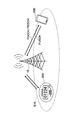
- FIG. 1 is a diagram for explaining a wireless communication system according to an embodiment of the present invention.
- the wireless communication system in the embodiment of the present invention includes a base station device 10 and a user device 20, as shown in FIG. FIG. 1 shows one each of the base station device 10, the user device 20A, and the user device 20B (hereinafter, referred to as “user device 20” when the user device 20A and the user device 20B are not distinguished). This is an example, and each may be larger in number.
- the base station device 10 is a communication device that provides one or more cells and performs wireless communication with the user device 20.
- the physical resource of the radio signal is defined in the time domain and the frequency domain, the time domain may be defined by the number of OFDM symbols, and the frequency domain may be defined by the number of subcarriers or the number of resource blocks.
- the base station device 10 transmits the synchronization signal and the system information to the user device 20.
- the synchronization signal is, for example, NR-PSS and NR-SSS.
- the system information is transmitted on the NR-PBCH, for example, and is also called broadcast information. As illustrated in FIG.
- the base station device 10 transmits a control signal or data to the user device 20 by DL (Downlink), and receives a control signal or data from the user device 20 by UL (Uplink). Both the base station apparatus 10 and the user apparatus 20 may be capable of performing beamforming and transmitting/receiving signals. Further, both the base station device 10 and the user device 20 may be able to apply MIMO (Multiple Input Multiple Output) communication to DL or UL. Moreover, both the base station apparatus 10 and the user apparatus 20 may communicate via SCell (Secondary Cell) and PCell (Primary Cell) by CA (Carrier Aggregation).
- SCell Secondary Cell
- PCell Primary Cell
- the user device 20A is a communication device having a wireless communication function such as a communication module for M2M (Machine-to-Machine), and the user device 20B has a wireless communication function such as a smartphone, a mobile phone, a tablet, a wearable terminal. It is a communication device.
- the user device 20 receives various control signals or data from the base station device 10 by DL and transmits various control signals or data to the base station device 10 by UL, thereby utilizing various communication services provided by the wireless communication system. ..
- the base station device 10 transmits a PDCCH (Physical Downlink Control Channel) or a PDSCH (Physical Downlink Shared Channel) to the user device 20.
- a PDCCH Physical Downlink Control Channel
- a PDSCH Physical Downlink Shared Channel
- the information regarding scheduling is transmitted to the user equipment 20 via the PDCCH
- the data is transmitted to the user equipment 20 via the PDSCH.
- the user apparatus 20 transmits PUSCH (Physical Downlink Shared Channel) to the base station apparatus 10 based on the information regarding scheduling.
- PUSCH Physical Downlink Shared Channel
- the user device 20A may be a BL (Bandwidth reduced Low complexity)-UE (User Equipment) with a limited bandwidth and reduced complexity.
- the BL-UE receives the system information block (for example, “SIB1-BR”) that is a set separated from the base station device 10.
- SIB1-BR system information block
- BL-UE has low transmission power and a small number of antennas.
- the UE category of BL-UE is category M1 or category M2. Both the category M1 and the category M2 may be the category M.
- the coverage of the BL-UE is narrower than that of the normal non-BL-UE. Here, the coverage refers to a range in which the connection can be maintained around the tower antenna of the cell.
- the user device 20B may be a non-BL-UE.
- the non-BL-UE realizes a higher data rate and has a higher transmission power than the BL-UE.
- the non-BL-UE uses a common system information block.
- the UE categories of the non-BL-UE are category 0, category 1, category 1bis, category 2, category 3 and the like.
- a non-BL-UE such as category 1 or category 1 bis may be used for M2M communication.
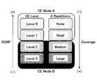
- FIG. 2 is a diagram for explaining the CE mode.
- the CE (Coverage Enhancement) mode is a mode in which BL-UE is assisted by repeatedly transmitting and receiving data in order to increase coverage under adverse conditions such as low transmission power.
- an M2M-UE for example, a smart meter installed in a house uses CE mode.
- CE mode A includes the case where the CE level is level 0 or level 1, and repeated transmission is supported at a relatively small number of times from 0 to 32 times.
- CE mode A coverage is assumed to be equivalent to UE category 1.
- CE mode B includes the case where the CE level is level 2 or level 3, and the repeated transmission is supported at a relatively large number of times from 192 times to 2048 times.
- the coverage in CE mode B is assumed to be equivalent to the coverage of +15 dB for UE category 1.
- RSRP Reference Signal Received Power
- the CE mode is mainly applied to BL-UE, but it is also possible to apply the CE mode to non-BL-UE.
- FIG. 3 is a diagram for explaining the determination of coverage in the CE mode.
- the user device 20 executes the determination based on the threshold value shown in FIG. 3 in order to determine the coverage of the user device 20.
- the user device 20 compares the measurement results Q rxlevmeas and Q qualmeas with the threshold values shown in FIG. 3.
- Q rxlevmeas indicates the measured reception level (RSRP)
- Q qualmeas indicates the measured quality level (RSRQ: Reference Signal Received Quality).
- Normal coverage is determined by Q rxlevmeas ⁇ Q rxlevmin and Q qualmeas ⁇ Q qualmin . That is, Q rxlevmin and Q qualmin are thresholds indicating the minimum required level for determining normal coverage.
- Extended coverage by CE mode A is determined by Q rxlevmin ⁇ Q rxlevmeas ⁇ Q rxlevmin_CE and Q qualmin ⁇ Q qualmeas ⁇ Q qualmin_CE . That is, Q rxlevmin_CE and Q qualmin_CE are thresholds indicating the minimum required level for determining extended coverage in CE mode A.
- Extended coverage in CE mode B is determined by Q rxlevmin_CE ⁇ Q rxlevmeas ⁇ Q rxlevmin_CE1 and Q qualmin_CE ⁇ Q qualmeas ⁇ Q qualmin_CE1 . That is, Q rxlevmin_CE1 and Q qualmin_CE1 are thresholds indicating the minimum required level for determining extended coverage in CE mode B.
- Q rxlevmin_CE1 ⁇ Q rxlevmeas and Q qualmin_CE1 ⁇ Q qualmeas are determined.
- thresholds are used for non-BL-UE and BL-UE. That is, as the thresholds Q rxlevmin and Q qualmin for determining normal coverage, different values are used for non-BL-UE and BL-UE. Q rxlevmin and Q qualmin are included in SIB1 and SIB1-BR, respectively.
- the same threshold value is used for the non-BL-UE and the BL-UE for the determination related to the extended coverage in the CE mode. That is, as the thresholds Q rxlevmin_CE , Q qualmin_CE , Q rxlevmin_CE1 and Q qualmin_CE1 , the same values are used in the non-BL-UE and the BL-UE. Q rxlevmin_CE , Q qualmin_CE , Q rxlevmin_CE1 and Q qualmin_CE1 are included only in SIB1-BR. As a result, it becomes difficult for the operator to optimize the threshold for determining the CE mode A and the CE mode B for the non-BL-UE and the BL-UE. For example, when both non-BL-UE and BL-UE are in the same cell by applying the CE mode, it is determined that the device is within the coverage even if transmission/reception cannot be actually performed. There is.
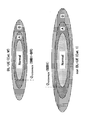
- FIG. 4 is a diagram for explaining an example (1) of coverage in CE mode.
- FIG. 4 illustrates the determination of normal coverage based on the threshold values shown in FIG.
- the area “Normal” shown in FIG. 4 corresponds to normal coverage
- the area “A” corresponds to extended coverage in CE mode A
- the area “B” corresponds to extended coverage in CE mode B.
- the threshold for determining normal coverage is set independently for non-BL-UE and BL-UE.
- the normal coverage of the BL-UE which is the category M
- Q rxlevmin included in SIB1-BR is determined by Q rxlevmin included in SIB1-BR.
- the normal coverage of the category 1 non-BL-UE is determined by Q rxlevmin included in SIB1.
- the threshold values for determining the CE mode A and the CE mode B are commonly set.
- a common threshold value that satisfies the region A or the region B satisfied by both the non-BL-UE and the BL-UE does not exist because the region A and the region B are different. Therefore, there is a discrepancy between the determination based on the commonly set threshold and the actual communication state of the UE.
- FIG. 5 is a diagram for explaining an example (2) of coverage in CE mode.
- FIG. 5 illustrates the determination of the extended coverage in the CE mode based on the threshold value shown in FIG.
- the area "Normal” shown in FIG. 5 corresponds to normal coverage
- the area "A” corresponds to extended coverage in CE mode A
- the area "B” corresponds to extended coverage in CE mode B.
- the non-BL-UE is the extended coverage of the CE mode B.
- the measurement result is worse than the threshold for determining the CE mode B, so it is determined to be out of coverage, and although communication is actually possible, communication cannot be performed.
- the non-BL-UE is located in the area “A” which is the extended coverage of the CE mode A, so that the non-BL-UE has the extended coverage of the CE mode B. It is determined to be located, and resources are excessively consumed by executing repeated transmissions in CE mode B even though communication is actually possible in CE mode A.
- FIG. 6 is a diagram for explaining an example (3) of coverage in CE mode.
- FIG. 6 illustrates determination of extended coverage in CE mode based on the threshold values shown in FIG.
- the area “Normal” shown in FIG. 6 corresponds to normal coverage
- the area “A” corresponds to extended coverage in CE mode A
- the area “B” corresponds to extended coverage in CE mode B.
- the BL-UE may be located outside the coverage. However, since the measurement result is better than the threshold for judging CE mode B, it is judged that it is located in the extended coverage of CE mode B, and the repeated transmission of CE mode B is executed despite the fact that communication is actually impossible. Excessively consumes resources. Further, although the BL-UE is located in the area “B” which is the extended coverage of the CE mode B, the BL-UE is located in the extended coverage of the CE mode A because the measurement result is better than the threshold for determining the CE mode A. It is determined that the communication is difficult because the CE mode A is used although the communication is actually possible in the CE mode B.
- non-BL-UE and BL-UE are allowed to individually set thresholds for determining extended coverage.
- the non-BL-UE and the BL-UE are notified of the threshold value for determining the separated extended coverage.
- the non-BL-UE and the BL-UE each acquire a threshold value for determining appropriate extended coverage based on whether or not the user apparatus 20 is the BL-UE.
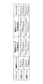
- FIG. 7 is a specification modification example (1) related to the CE mode in the embodiment of the present invention.
- the operator uses the thresholds “q-RxLevMinCE-nonBL-r13” and “threshold” used for the determination in the additional CE mode used by the non-BL-UE.
- the user device 20 may be configured to be notified of “q-QualMinRSRQ-CE-nonBL-r13”, “q-RxLevMinCE1-nonBL-r13”, and “q-QualMinRSRQ-CE1-nonBL-r13”.
- the name of the information element is an example, and another name may be used.
- the threshold values “ ⁇ 150 dBm” and “ ⁇ 22.5 dB” shown in FIG. 7 are examples, and other values may be used.
- FIG. 8 is a specification modification example (2) related to the CE mode in the embodiment of the present invention.
- user equipment 20A of UE category M that is BL-UE
- user equipment 20B of UE category 1bis that is non-BL-UE
- user equipment 20C of UE category 1
- user equipment of UE category 2+ The 20D selects the threshold value used for the determination in the CE mode notified from the base station device 10 based on whether or not the device itself is the BL-UE.
- the user apparatus 20A is a BL-UE and thus selects “q-RxLevMinCE-r13” and “q-QualMinRSRQ-CE1-r13”.
- the user apparatus 20B, the user apparatus 20C, and the user apparatus 20D select "q-RxLevMinCE-nonBL-r13" and “q-QualMinRSRQ-CE1-nonBL-r13" because they are not BL-UE.
- FIG. 9 is a specification modification example (3) related to the CE mode in the embodiment of the present invention.
- the operator may set the threshold used for the determination in the additional CE mode used by the non-BL-UE or the BL-UE for each UE category.
- “q-RxLevMinCE-Cat1-r13”, “q-QualMinRSRQ-CE-Cat1-r13”, “q-RxLevMinCE1-Cat1-r13” are set as the threshold values for the user equipment 20 of UE category 1.
- “Q-QualMinRSRQ-CE1-Cat1-r13” may be set.
- q-RxLevMinCE-Cat1bis-r13 “q-QualMinRSRQ-CE-Cat1bis-r13”, “q-RxLevMinCE1-Cat1bis-r13”, “q-QualMinRs” are set as the threshold values for the user equipment 20 of the UE category 1bis. -CE1-Cat1bis-r13” may be set. Similarly, as threshold values for the user equipment 20 of the UE category M, "q-RxLevMinCE-CatM-r13”, “q-QualMinRSRQ-CE-CatM-r13", “q-RxLevMinCE1-CatM-r13", “q-QualMinRSRQ-”.
- CE1-CatM-r13 may be set.
- the name of the information element is an example, and another name may be used.
- the threshold values “ ⁇ 143 dBm”, “ ⁇ 146 dBm”, “ ⁇ 150 dBm” and the like shown in FIG. 9 are examples, and other values may be used.
- FIG. 10 is a flowchart for explaining an operation example related to the CE mode according to the embodiment of the present invention. An operation example relating to selection of a threshold value used for determination in the CE mode in the user device 20 will be described with reference to FIG. 10.
- step S11 the user device 20 receives from the base station device 10 the threshold value used for the determination in the CE mode.
- the base station device 10 may notify the user device 20 of the threshold value used for the determination in the CE mode via broadcast information or another RRC (Radio Resource Control) message.
- the user apparatus 20 determines whether the own apparatus is BL-UE or non-BL-UE.
- the process proceeds to step S13, and when the own device is the non-BL-UE, the process proceeds to step S14.
- step S13 the user apparatus 20 uses the threshold value used for the determination in the CE mode corresponding to BL-UE.
- step S14 the user apparatus 20 uses the threshold value used for the determination in the CE mode corresponding to non-BL-UE.
- step S15 when the threshold used for determination in the CE mode for each UE category is notified from the base station device 10, the user device 20 sets the threshold used for determination in the CE mode corresponding to the UE category of the own device. May be used.
- the threshold value used for the determination in the CE mode according to the capabilities of each user device 20 is individually set. Therefore, it is possible to accurately determine and display whether the own device is within the coverage or out of the coverage in various situations.
- the base station device 10 and the user device 20 include a function for implementing the above-described embodiment. However, each of the base station device 10 and the user device 20 may be provided with only a part of the functions in the embodiment.
- FIG. 11 is a diagram showing an example of a functional configuration of the base station device 10.
- the base station device 10 includes a transmission unit 110, a reception unit 120, a setting unit 130, and a control unit 140.
- the functional configuration shown in FIG. 11 is merely an example. As long as the operation according to the embodiment of the present invention can be executed, the function categories and the names of the function units may be any names.
- the transmitting unit 110 includes a function of generating a signal to be transmitted to the user device 20 side and wirelessly transmitting the signal.
- the reception unit 120 includes a function of receiving various signals transmitted from the user device 20 and acquiring, for example, information of a higher layer from the received signals. Further, the transmission unit 110 has a function of transmitting NR-PSS, NR-SSS, NR-PBCH, DL/UL control signal, DL/UL data signal, etc. to the user apparatus 20.
- the setting unit 130 stores preset setting information and various setting information to be transmitted to the user device 20 in the storage device, and reads it from the storage device as necessary.
- the content of the setting information is, for example, the setting related to the CE mode of the user device 20.
- the control unit 140 schedules the user device 20 and controls transmission of downlink data and reception of uplink data, as described in the embodiment.
- the control unit 140 transmits the setting related to the CE mode to the user device 20.
- the functional unit related to signal transmission in the control unit 140 may be included in the transmission unit 110, and the functional unit related to signal reception in the control unit 140 may be included in the reception unit 120.
- FIG. 12 is a diagram illustrating an example of a functional configuration of the user device 20.
- the user device 20 includes a transmission unit 210, a reception unit 220, a setting unit 230, and a control unit 240.
- the functional configuration shown in FIG. 12 is merely an example. As long as the operation according to the embodiment of the present invention can be executed, the function categories and the names of the function units may be any names.
- the transmitter 210 creates a transmission signal from the transmission data and wirelessly transmits the transmission signal.
- the receiving unit 220 wirelessly receives various signals and acquires signals of higher layers from the received physical layer signals. Further, the receiving section 220 has a function of receiving NR-PSS, NR-SSS, NR-PBCH, DL/UL/SL control signals and the like transmitted from the base station apparatus 10.
- the transmission unit 210 performs P2CH communication to other user apparatuses 20 by using a PSCCH (Physical Sidelink Control Channel), a PSSCH (Physical Sidelink Shared Channel), a PSDCH (Physical Sidelink Discovery Channel), and a PSBCH (Physical Sidelink Broadcast Channel). ) Etc., and the receiving part 120 receives PSCCH, PSSCH, PSDCH, PSBCH, etc. from the other user apparatus 20.
- PSCCH Physical Sidelink Control Channel
- PSSCH Physical Sidelink Shared Channel
- PSDCH Physical Sidelink Discovery Channel
- PSBCH Physical Sidelink Broadcast Channel
- the setting unit 230 stores various setting information received from the base station device 10 or the user device 20 by the receiving unit 220 in a storage device, and reads from the storage device as necessary.
- the setting unit 230 also stores preset setting information.
- the content of the setting information is, for example, the setting related to the CE mode of the user device 20.
- the control unit 240 controls the reception of downlink data and the transmission of uplink data based on the scheduling acquired from the base station device 10, as described in the embodiment. In addition, the control unit 240 executes communication control to which the setting related to the CE mode received from the base station device 10 is applied.
- the functional unit related to signal transmission in the control unit 240 may be included in the transmission unit 210, and the functional unit related to signal reception in the control unit 240 may be included in the reception unit 220.
- each functional block may be realized by using one device physically or logically coupled, or directly or indirectly (for example, two or more devices physically or logically separated). , Wired, wireless, etc.) and may be implemented using these multiple devices.
- the functional block may be implemented by combining the one device or the plurality of devices with software.
- Functions include judgment, decision, judgment, calculation, calculation, processing, derivation, investigation, search, confirmation, reception, transmission, output, access, resolution, selection, selection, establishment, comparison, assumption, expectation, observation, Broadcasting, notifying, communicating, forwarding, configuring, reconfiguring, allocating, mapping, assigning, etc., but not limited to these.
- I can't.
- functional blocks (components) that function transmission are called a transmitting unit and a transmitter.
- the implementation method is not particularly limited.
- the base station device 10, the user device 20, and the like according to the embodiment of the present disclosure may function as a computer that performs the process of the wireless communication method of the present disclosure.
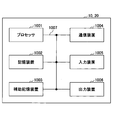
- FIG. 13 is a diagram illustrating an example of a hardware configuration of the base station device 10 and the user device 20 according to the embodiment of the present disclosure.
- the base station device 10 and the user device 20 described above are physically configured as a computer device including a processor 1001, a storage device 1002, an auxiliary storage device 1003, a communication device 1004, an input device 1005, an output device 1006, a bus 1007, and the like. May be done.
- the word “apparatus” can be read as a circuit, device, unit, or the like.
- the hardware configurations of the base station device 10 and the user device 20 may be configured to include one or a plurality of each device illustrated in the figure, or may be configured not to include some devices.
- Each function in the base station device 10 and the user device 20 causes a predetermined software (program) to be loaded onto hardware such as the processor 1001, the storage device 1002, etc., so that the processor 1001 performs an arithmetic operation and communication by the communication device 1004. It is realized by controlling or at least one of reading and writing of data in the storage device 1002 and the auxiliary storage device 1003.
- the processor 1001 operates an operating system to control the entire computer, for example.
- the processor 1001 may be configured by a central processing unit (CPU) including an interface with peripheral devices, a control device, a calculation device, a register, and the like.
- CPU central processing unit
- the control unit 140, the control unit 240, and the like described above may be realized by the processor 1001.
- the processor 1001 reads a program (program code), a software module, data or the like from at least one of the auxiliary storage device 1003 and the communication device 1004 to the storage device 1002, and executes various processes according to these.
- a program that causes a computer to execute at least part of the operations described in the above-described embodiments is used.
- the control unit 140 of the base station device 10 illustrated in FIG. 11 may be realized by a control program stored in the storage device 1002 and operated by the processor 1001.
- the control unit 240 of the user device 20 illustrated in FIG. 12 may be realized by a control program stored in the storage device 1002 and operated by the processor 1001.
- the various processes described above are executed by one processor 1001, they may be executed simultaneously or sequentially by two or more processors 1001.
- the processor 1001 may be implemented by one or more chips.
- the program may be transmitted from the network via an electric communication line.
- the storage device 1002 is a computer-readable recording medium, and is, for example, at least one of ROM (Read Only Memory), EPROM (Erasable Programmable ROM), EEPROM (ElectricallyErasable Programmable ROM), RAM (Random Access Memory), and the like. It may be configured.
- the storage device 1002 may be called a register, a cache, a main memory (main storage device), or the like.
- the storage device 1002 can store an executable program (program code), a software module, or the like for implementing the communication method according to the embodiment of the present disclosure.
- the auxiliary storage device 1003 is a computer-readable recording medium, and is, for example, an optical disc such as a CD-ROM (Compact Disc ROM), a hard disk drive, a flexible disc, a magneto-optical disc (for example, a compact disc, a digital versatile disc, a Blu disc). -Ray disk), smart card, flash memory (eg card, stick, key drive), floppy disk, magnetic strip, etc.
- the above-described storage medium may be, for example, a database including at least one of the storage device 1002 and the auxiliary storage device 1003, a server, or another appropriate medium.
- the communication device 1004 is hardware (transmission/reception device) for performing communication between computers via at least one of a wired network and a wireless network, and is also called, for example, a network device, a network controller, a network card, a communication module, or the like.
- the communication device 1004 includes, for example, a high frequency switch, a duplexer, a filter, a frequency synthesizer, etc. in order to realize at least one of a frequency division duplex (FDD: Frequency Division Duplex) and a time division duplex (TDD: Time Division Duplex). May be composed of
- FDD Frequency Division Duplex
- TDD Time Division Duplex
- the transmitter/receiver may be implemented by physically or logically separating the transmitter and the receiver.
- the input device 1005 is an input device (eg, keyboard, mouse, microphone, switch, button, sensor, etc.) that receives an input from the outside.
- the output device 1006 is an output device (for example, a display, a speaker, an LED lamp, etc.) that outputs to the outside.
- the input device 1005 and the output device 1006 may be integrated (for example, a touch panel).
- each device such as the processor 1001 and the storage device 1002 is connected by a bus 1007 for communicating information.
- the bus 1007 may be configured using a single bus, or may be configured using different buses for each device.
- the base station device 10 and the user device 20 include a microprocessor, a digital signal processor (DSP: Digital Signal Processor), an ASIC (Application Specific Integrated Circuit), a PLD (Programmable Logic Device), an FPGA (Field Programmable Gate Array), and the like. It may be configured to include hardware, and the hardware may implement part or all of each functional block. For example, the processor 1001 may be implemented using at least one of these hardware.
- DSP Digital Signal Processor
- ASIC Application Specific Integrated Circuit
- PLD Programmable Logic Device
- FPGA Field Programmable Gate Array
- the receiving unit that receives from the base station device a plurality of thresholds for use in the determination in the coverage extension mode, and whether its own device is a predetermined type Based on whether or not the control unit selects a threshold value used for the determination in the coverage extension mode from the received plurality of threshold values, and a threshold value used for the determination in the selected coverage extension mode, the coverage extension mode.
- a user equipment having a communication unit for communicating with the base station apparatus in extended coverage for use in determining the coverage in.
- the threshold value used for the determination in the CE mode according to the capabilities of each user device 20 is individually set. Therefore, in various situations, it is possible to accurately determine and display whether the own device is within the coverage or out of the coverage. That is, it is possible to apply the coverage extension mode according to the capability of the user equipment.
- the predetermined type may be BL (Bandwidth reduced Low complexity)-UE (User Equipment).
- BL Bitwidth reduced Low complexity
- UE User Equipment
- the predetermined type may be a UE category.
- the user device 20 can change the threshold value used for the coverage determination according to the UE category of its own device and execute an appropriate coverage extension operation.
- the predetermined type may be a UE category corresponding to non-BL-UE.
- the user apparatus 20 can change the threshold value used for the coverage determination and execute an appropriate coverage extension operation according to the UE category when the own apparatus is a non-BL-UE.
- the predetermined type may be a UE category corresponding to BL-UE.
- the user apparatus 20 can change the threshold value used for the coverage determination and execute an appropriate coverage extension operation according to the UE category when the own apparatus is a BL-UE.
- a transmission unit that transmits to the user device a plurality of threshold values to be used for the determination in the coverage extension mode selected based on whether or not the user device is of a predetermined type. And a threshold for use in the determination in the coverage extension mode is used in the determination of the coverage in the coverage extension mode, and a base station apparatus having a communication unit that communicates with the user apparatus in the extended coverage is provided. ..
- the threshold value used for the determination in the CE mode according to the capabilities of each user device 20 is individually set. Therefore, in various situations, it is possible to accurately determine and display whether the own device is within the coverage or out of the coverage. That is, it is possible to apply the coverage extension mode according to the capability of the user equipment.
- the operation of the plurality of functional units may be physically performed by one component, or the operation of one functional unit may be physically performed by the plurality of components.
- the order of processing may be changed as long as there is no contradiction.
- the base station apparatus 10 and the user apparatus 20 have been described using functional block diagrams for convenience of processing description, such an apparatus may be realized by hardware, software, or a combination thereof.
- the software operated by the processor included in the base station device 10 according to the embodiment of the present invention and the software operated by the processor included in the user device 20 according to the embodiment of the present invention are respectively a random access memory (RAM), a flash memory, and a read memory. It may be stored in a dedicated memory (ROM), EPROM, EEPROM, register, hard disk (HDD), removable disk, CD-ROM, database, server, or any other suitable storage medium.
- the notification of information is not limited to the mode/embodiment described in the present disclosure, and may be performed using another method.
- information is notified by physical layer signaling (for example, DCI (Downlink Control Information), UCI (Uplink Control Information)), upper layer signaling (for example, RRC (Radio Resource Control) signaling, MAC (Medium Access Control) signaling, It may be implemented by broadcast information (MIB (Master Information Block), SIB (System Information Block)), other signals, or a combination thereof, and RRC signaling may be called an RRC message, for example, RRC message. It may be a connection setup (RRC Connection Setup) message, an RRC connection reconfiguration message, or the like.
- LTE Long Term Evolution
- LTE-A Long Term Evolution-Advanced
- SUPER 3G IMT-Advanced
- 4G fourth generation mobile communication system
- 5G 5th generation mobile communication system
- FRA Full Radio Access
- NR new Radio
- W-CDMA registered trademark
- GSM registered trademark
- CDMA2000 Code Division Multiple Access 2000
- UMB Universal Mobile Broadband
- IEEE 802.11 Wi-Fi (registered trademark)
- IEEE 802.16 WiMAX (registered trademark)
- IEEE 802.20 UWB (Ultra-WideBand)
- Bluetooth registered trademark
- other systems using appropriate systems, and extensions based on these It may be applied to at least one of the next-generation systems.
- a plurality of systems may be combined and applied (for example, a combination of at least one of LTE and LTE-A and 5G).
- the specific operation that is assumed to be performed by the base station device 10 in this specification may be performed by its upper node in some cases.
- various operations performed for communication with the user device 20 are other than the base station device 10 and the base station device 10. It is clear that it can be performed by at least one of the network nodes of (for example, but not limited to, MME or S-GW, etc.).
- the other network node may be a combination of a plurality of other network nodes (for example, MME and S-GW). Good.
- Information, signals, etc. described in the present disclosure may be output from the upper layer (or lower layer) to the lower layer (or upper layer). Input/output may be performed via a plurality of network nodes.
- Information that has been input and output may be stored in a specific location (for example, memory), or may be managed using a management table. Information that is input/output may be overwritten, updated, or added. The output information and the like may be deleted. The input information and the like may be transmitted to another device.
- the determination in the present disclosure may be performed by a value (0 or 1) represented by 1 bit, may be performed by a Boolean value (Boolean: true or false), and may be performed by comparing numerical values (for example, , Comparison with a predetermined value).
- software, instructions, information, etc. may be transmitted and received via a transmission medium.
- the software uses a wired technology (coaxial cable, optical fiber cable, twisted pair, digital subscriber line (DSL: Digital Subscriber Line), etc.) and/or wireless technology (infrared, microwave, etc.) websites, When sent from a server, or other remote source, at least one of these wired and wireless technologies is included within the definition of transmission medium.
- wired technology coaxial cable, optical fiber cable, twisted pair, digital subscriber line (DSL: Digital Subscriber Line), etc.
- wireless technology infrared, microwave, etc.
- data, instructions, commands, information, signals, bits, symbols, chips, etc. that may be referred to throughout the above description include voltage, current, electromagnetic waves, magnetic fields or magnetic particles, optical fields or photons, or any of these. May be represented by a combination of
- At least one of the channel and the symbol may be a signal (signaling).
- the signal may also be a message.
- a component carrier CC:Component Carrier
- CC Component Carrier
- system and “network” used in this disclosure are used interchangeably.
- the information, parameters, etc. described in the present disclosure may be represented by using an absolute value, may be represented by using a relative value from a predetermined value, or by using other corresponding information. May be represented.
- the radio resources may be those indicated by the index.
- base station Base Station
- radio base station base station
- base station device fixed station
- NodeB NodeB
- eNodeB eNodeB
- GNB nodeB
- access point access point
- transmission point transmission point
- reception point transmission/reception point
- cell cell
- cell group carrier
- component carrier component carrier
- a base station can accommodate one or more (eg, three) cells.
- a base station accommodates multiple cells, the entire coverage area of the base station can be divided into multiple smaller areas, each smaller area being defined by a base station subsystem (eg, indoor small base station (RRH: It is also possible to provide communication services by Remote Radio Head).
- RRH indoor small base station
- the term "cell” or “sector” means a part or the whole coverage area of at least one of the base station and the base station subsystem that perform communication services in this coverage. Refers to.
- MS Mobile Station
- UE User Equipment
- Mobile stations are defined by those skilled in the art as subscriber stations, mobile units, subscriber units, wireless units, remote units, mobile devices, wireless devices, wireless communication devices, remote devices, mobile subscriber stations, access terminals, mobile terminals, wireless. It may also be referred to as a terminal, remote terminal, handset, user agent, mobile client, client, or some other suitable term.
- At least one of the base station and the mobile station may be called a transmission device, a reception device, a communication device, or the like.
- the base station and the mobile station may be a device mounted on the mobile body, the mobile body itself, or the like.
- the moving body may be a vehicle (eg, car, airplane, etc.), an unmanned moving body (eg, drone, self-driving car, etc.), or a robot (manned or unmanned).
- At least one of the base station and the mobile station also includes a device that does not necessarily move during communication operation.
- at least one of the base station and the mobile station may be an IoT (Internet of Things) device such as a sensor.
- IoT Internet of Things
- the base station in the present disclosure may be replaced by the user terminal.
- the communication between the base station and the user terminal is replaced with communication between a plurality of user devices 20 (for example, it may be called D2D (Device-to-Device), V2X (Vehicle-to-Everything), etc.).
- D2D Device-to-Device
- V2X Vehicle-to-Everything
- the user apparatus 20 may have the function of the base station apparatus 10 described above.
- the words such as “up” and “down” may be replaced with the words corresponding to the terminal-to-terminal communication (for example, “side”).
- the uplink channel and the downlink channel may be replaced with the side channel.
- the user terminal in the present disclosure may be replaced by the base station.
- the base station may have the function of the above-mentioned user terminal.
- determining and “determining” as used in this disclosure may encompass a wide variety of actions.
- “Judgment” and “decision” are, for example, judgment, calculating, computing, processing, deriving, investigating, and looking up, search, inquiry. (Eg, searching in a table, database, or another data structure), considering ascertaining as “judging” or “deciding”, and the like.
- “decision” and “decision” include receiving (eg, receiving information), transmitting (eg, transmitting information), input (input), output (output), access (accessing) (for example, accessing data in a memory) may be regarded as “judging” or “deciding”.
- judgment and “decision” are considered to be “judgment” and “decision” when things such as resolving, selecting, choosing, selecting, establishing, and comparing are done. May be included. That is, the “judgment” and “decision” may include considering some action as “judgment” and “decision”. In addition, “determination (decision)” may be read as “assuming”, “expecting”, “considering”, and the like.
- connection means any direct or indirect connection or coupling between two or more elements, and It can include the presence of one or more intermediate elements between two elements that are “connected” or “coupled.”
- the connections or connections between the elements may be physical, logical, or a combination thereof.
- connection may be read as “access”.
- two elements are in the radio frequency domain, with at least one of one or more wires, cables and printed electrical connections, and as some non-limiting and non-exhaustive examples. , Can be considered to be “connected” or “coupled” to each other, such as with electromagnetic energy having wavelengths in the microwave and light (both visible and invisible) regions.
- the reference signal may be abbreviated as RS (Reference Signal), or may be referred to as a pilot (Pilot) depending on the applied standard.
- RS Reference Signal
- Pilot pilot
- the phrase “based on” does not mean “based only on,” unless expressly specified otherwise. In other words, the phrase “based on” means both "based only on” and “based at least on.”
- references to elements using designations such as “first”, “second”, etc. used in this disclosure does not generally limit the amount or order of those elements. These designations may be used in this disclosure as a convenient way to distinguish between two or more elements. Thus, references to the first and second elements do not mean that only two elements may be employed, or that the first element must precede the second element in any way.
- a radio frame may be composed of one or more frames in the time domain. Each frame or frames in the time domain may be referred to as a subframe. A subframe may also be composed of one or more slots in the time domain. A subframe may have a fixed time length (eg, 1 ms) that does not depend on numerology.
- Numerology may be a communication parameter applied to at least one of transmission and reception of a certain signal or channel.
- Numerology includes, for example, subcarrier spacing (SCS: SubCarrier Spacing), bandwidth, symbol length, cyclic prefix length, transmission time interval (TTI: Transmission Time Interval), number of symbols per TTI, radio frame configuration, transceiver At least one of specific filtering processing performed in the frequency domain and specific windowing processing performed by the transceiver in the time domain may be shown.
- a slot may be composed of one or more symbols (OFDM (Orthogonal Frequency Division Multiplexing) symbol, SC-FDMA (Single Carrier Frequency Division Multiple Access) symbol, etc.) in the time domain.
- a slot may be a time unit based on numerology.
- a slot may include multiple minislots. Each minislot may be composed of one or more symbols in the time domain. The minislot may also be called a subslot. Minislots may be configured with fewer symbols than slots.
- a PDSCH (or PUSCH) transmitted in a time unit larger than a minislot may be referred to as PDSCH (or PUSCH) mapping type A.
- the PDSCH (or PUSCH) transmitted using the minislot may be referred to as PDSCH (or PUSCH) mapping type B.
- Radio frame, subframe, slot, minislot, and symbol all represent the time unit for signal transmission. Radio frames, subframes, slots, minislots, and symbols may have different names corresponding to them.
- one subframe may be called a transmission time interval (TTI)
- TTI transmission time interval
- TTI transmission time interval
- TTI transmission time interval
- TTI transmission time interval
- TTI means, for example, a minimum time unit of scheduling in wireless communication.
- the base station performs scheduling to allocate radio resources (frequency bandwidth that can be used in each user device 20, transmission power, etc.) to each user device 20 in units of TTI.
- the definition of TTI is not limited to this.
- the TTI may be a transmission time unit of a channel-encoded data packet (transport block), code block, codeword, or the like, or may be a processing unit of scheduling, link adaptation, or the like.
- the time interval for example, the number of symbols
- the transport block, code block, codeword, etc. may be shorter than the TTI.
- one slot or one minislot is called a TTI
- one or more TTIs may be the minimum time unit for scheduling.
- the number of slots (the number of mini-slots) forming the minimum time unit of the scheduling may be controlled.
- a TTI having a time length of 1 ms may be called a normal TTI (TTI in LTE Rel. 8-12), a normal TTI, a long TTI, a normal subframe, a normal subframe, a long subframe, a slot, or the like.
- a TTI shorter than the normal TTI may be called a shortened TTI, a short TTI, a partial TTI (partial or fractional TTI), a shortened subframe, a short subframe, a minislot, a subslot, a slot, and the like.
- a long TTI (eg, normal TTI, subframe, etc.) may be read as a TTI having a time length exceeding 1 ms, and a short TTI (eg, shortened TTI, etc.) is less than the TTI length of the long TTI and 1 ms. It may be read as a TTI having the above TTI length.
- a resource block is a resource allocation unit in the time domain and the frequency domain, and may include one or a plurality of continuous subcarriers in the frequency domain.
- the number of subcarriers included in the RB may be the same regardless of the numerology, and may be 12, for example.
- the number of subcarriers included in the RB may be determined based on numerology.
- the time domain of the RB may include one or more symbols, and may be 1 slot, 1 minislot, 1 subframe, or 1 TTI in length.
- One TTI, one subframe, etc. may be configured with one or a plurality of resource blocks.
- one or more RBs include a physical resource block (PRB: Physical RB), a subcarrier group (SCG: Sub-Carrier Group), a resource element group (REG: Resource Element Group), a PRB pair, an RB pair, etc. May be called.
- PRB Physical resource block
- SCG Sub-Carrier Group
- REG Resource Element Group
- a resource block may be composed of one or more resource elements (RE: Resource Element).
- RE Resource Element
- 1 RE may be a radio resource area of 1 subcarrier and 1 symbol.
- a bandwidth part (may also be called a partial bandwidth) may represent a subset of consecutive common RBs (common resource blocks) for a certain numerology in a certain carrier.
- the common RB may be specified by the index of the RB based on the common reference point of the carrier.
- PRBs may be defined in a BWP and numbered within the BWP.
- BWP may include BWP for UL (UL BWP) and BWP for DL (DL BWP).
- BWP for UL
- DL BWP DL BWP
- one or more BWPs may be set in one carrier.
- At least one of the configured BWPs may be active, and the UE does not have to expect to send and receive a given signal/channel outside the active BWP.
- “cell”, “carrier”, and the like in the present disclosure may be read as “BWP”.
- the structure of the wireless frame, subframe, slot, minislot, symbol, etc. described above is just an example.
- the number of subframes included in a radio frame, the number of slots per subframe or radio frame, the number of minislots included in a slot, the number of symbols and RBs included in a slot or minislot, and included in RBs The number of subcarriers, the number of symbols in the TTI, the symbol length, the cyclic prefix (CP: Cyclic Prefix) length, and the like can be variously changed.
- the term “A and B are different” may mean “A and B are different from each other”.
- the term may mean that “A and B are different from C”.
- the terms “remove”, “coupled” and the like may be construed similarly as “different”.
- the notification of the predetermined information (for example, the notification of “being X”) is not limited to the explicit notification, and is performed implicitly (for example, the notification of the predetermined information is not performed). Good.
- the transmission unit 210 and the reception unit 220 are examples of the communication unit.
- the non-BL-UE is an example of the non-BL-UE.
- the transmission unit 110 and the reception unit 120 are an example of a communication unit.
- base station device 110 transmission unit 120 reception unit 130 setting unit 140 control unit 20 user device 210 transmission unit 220 reception unit 230 setting unit 240 control unit 1001 processor 1002 storage device 1003 auxiliary storage device 1004 communication device 1005 input device 1006 output device
Landscapes
- Engineering & Computer Science (AREA)
- Computer Networks & Wireless Communication (AREA)
- Signal Processing (AREA)
- Databases & Information Systems (AREA)
- Quality & Reliability (AREA)
- Computer Security & Cryptography (AREA)
- Mobile Radio Communication Systems (AREA)
Abstract
ユーザ装置は、カバレッジ拡張モードにおける判定に使用するための複数の閾値を基地局装置から受信する受信部と、自装置が所定の種別であるか否かに基づいて、前記受信された複数の閾値からカバレッジ拡張モードにおける判定に使用する閾値を選択する制御部と、前記選択されたカバレッジ拡張モードにおける判定に使用するための閾値を、カバレッジ拡張モードにおけるカバレッジの判定に使用して、拡張されたカバレッジにおいて前記基地局装置と通信する通信部とを有する。
Description
本発明は、無線通信システムにおけるユーザ装置及び基地局装置に関する。
LTE(Long Term Evolution)の後継システムであるNR(New Radio)(「5G」ともいう。)においては、要求条件として、大容量のシステム、高速なデータ伝送速度、低遅延、多数の端末の同時接続、低コスト、省電力等を満たす技術が検討されている(例えば非特許文献1)。
LTEでは、ユーザ装置は無線アクセス能力によってカテゴライズされている(例えば非特許文献1)。例えば、スマートメータのようなM2M(machine to machine communications)デバイスを対象として、スループットを抑え、モデムの複雑性低下による端末コスト削減及び極めて低い消費電力を実現するカテゴリM1又はM2が規定される(例えば非特許文献2)。カテゴリM1又はM2に区分されるユーザ装置は、帯域幅を制限し複雑性を低下させたBL(Bandwidth reduced Low complexity)-UE(User Equipment)と呼ばれる。一方、カテゴリ0以上に区分されるユーザ装置は、non-BL-UEと呼ばれてもよい。
3GPP TS 36.306 V15.4.0(2018-12)
3GPP TS 36.300 V15.4.0(2018-12)
LTEの無線通信システムにおいて、繰り返し送信によるカバレッジ拡張(CE:Coverage Enhancement)モードは、BL-UEが使用可能である。一方、non-BL-UEもまたCEモードを使用可能である。しかしながら、BL-UEとnon-BL-UEとがCEモードに使用するパラメータは同一であったため、BL-UEとnon-BL-UEそれぞれの実際のカバレッジにパラメータが適合していなかった。
本発明は上記の点に鑑みてなされたものであり、ユーザ装置の能力に応じたカバレッジ拡張モードを適用することを目的とする。
開示の技術によれば、カバレッジ拡張モードにおける判定に使用するための複数の閾値を基地局装置から受信する受信部と、自装置が所定の種別であるか否かに基づいて、前記受信された複数の閾値からカバレッジ拡張モードにおける判定に使用する閾値を選択する制御部と、前記選択されたカバレッジ拡張モードにおける判定に使用するための閾値を、カバレッジ拡張モードにおけるカバレッジの判定に使用して、拡張されたカバレッジにおいて前記基地局装置と通信する通信部とを有するユーザ装置が提供される。
開示の技術によれば、ユーザ装置の能力に応じたカバレッジ拡張モードを適用することができる。
以下、図面を参照して本発明の実施の形態を説明する。なお、以下で説明する実施の形態は一例であり、本発明が適用される実施の形態は、以下の実施の形態に限られない。
本発明の実施の形態の無線通信システムの動作にあたっては、適宜、既存技術が使用される。ただし、当該既存技術は、例えば既存のLTEであるが、既存のLTEに限られない。また、本明細書で使用する用語「LTE」は、特に断らない限り、LTE-Advanced、及び、LTE-Advanced以降の方式(例:NR)を含む広い意味を有するものとする。
また、以下で説明する本発明の実施の形態では、既存のLTEで使用されているSS(Synchronization signal)、PSS(Primary SS)、SSS(Secondary SS)、PBCH(Physical broadcast channel)、PRACH(Physical random access channel)、等の用語を使用する。これは記載の便宜上のためであり、これらと同様の信号、機能等が他の名称で呼ばれてもよい。また、NRにおける上述の用語は、NR-SS、NR-PSS、NR-SSS、NR-PBCH、NR-PRACH等に対応する。ただし、NRに使用される信号であっても、必ずしも「NR-」と明記しない。
また、本発明の実施の形態において、複信(Duplex)方式は、TDD(Time Division Duplex)方式でもよいし、FDD(Frequency Division Duplex)方式でもよいし、又はそれ以外(例えば、Flexible Duplex等)の方式でもよい。
また、本発明の実施の形態において、無線パラメータ等が「設定される(Configure)」とは、所定の値が予め設定(Pre-configure)されることであってもよいし、基地局装置10又はユーザ装置20から通知される無線パラメータが設定されることであってもよい。
図1は、本発明の実施の形態における無線通信システムを説明するための図である。本発明の実施の形態における無線通信システムは、図1に示されるように、基地局装置10及びユーザ装置20を含む。図1には、基地局装置10、ユーザ装置20A及びユーザ装置20B(以下、ユーザ装置20Aとユーザ装置20Bを区別しない場合、「ユーザ装置20」という。)が1つずつ示されているが、これは例であり、それぞれさらに多数であってもよい。
基地局装置10は、1つ以上のセルを提供し、ユーザ装置20と無線通信を行う通信装置である。無線信号の物理リソースは、時間領域及び周波数領域で定義され、時間領域はOFDMシンボル数で定義されてもよいし、周波数領域はサブキャリア数又はリソースブロック数で定義されてもよい。基地局装置10は、同期信号及びシステム情報をユーザ装置20に送信する。同期信号は、例えば、NR-PSS及びNR-SSSである。システム情報は、例えば、NR-PBCHにて送信され、報知情報ともいう。図1に示されるように、基地局装置10は、DL(Downlink)で制御信号又はデータをユーザ装置20に送信し、UL(Uplink)で制御信号又はデータをユーザ装置20から受信する。基地局装置10及びユーザ装置20はいずれも、ビームフォーミングを行って信号の送受信を行うことが可能であってもよい。また、基地局装置10及びユーザ装置20はいずれも、MIMO(Multiple Input Multiple Output)による通信をDL又はULに適用することが可能であってもよい。また、基地局装置10及びユーザ装置20はいずれも、CA(Carrier Aggregation)によるSCell(Secondary Cell)及びPCell(Primary Cell)を介して通信を行ってもよい。
ユーザ装置20Aは、M2M(Machine-to-Machine)用通信モジュール等の無線通信機能を備えた通信装置であり、ユーザ装置20Bは、スマートフォン、携帯電話機、タブレット、ウェアラブル端末等の無線通信機能を備えた通信装置である。ユーザ装置20は、DLで制御信号又はデータを基地局装置10から受信し、ULで制御信号又はデータを基地局装置10に送信することで、無線通信システムにより提供される各種通信サービスを利用する。
基地局装置10は、PDCCH(Physical Downlink Control Channel)又はPDSCH(Physical Downlink Shared Channel)をユーザ装置20に送信する。例えば、スケジューリングに係る情報はPDCCHを介してユーザ装置20に送信され、データはPDSCHを介してユーザ装置20に送信される。また、図1に示されるように、ユーザ装置20は、スケジューリングに係る情報に基づいて、PUSCH(Physical Downlink Shared Channel)を基地局装置10に送信する。
ユーザ装置20Aは、帯域幅を制限し複雑性を低下させたBL(Bandwidth reduced Low complexity)-UE(User Equipment)であってもよい。BL-UEは、基地局装置10から分離されたセットであるシステム情報ブロック(例えば、「SIB1-BR」)を受信する。BL-UEは、低送信電力であり、アンテナ数は少ない。BL-UEのUEカテゴリは、カテゴリM1又はカテゴリM2である。カテゴリM1又はカテゴリM2は、共にカテゴリMとしてもよい。BL-UEのカバレッジは、通常のnon-BL-UEと比較して狭い。ここでカバレッジとは、セルのタワーアンテナを中心として接続を維持できる範囲を示す。
ユーザ装置20Bは、non-BL-UEであってもよい。non-BL-UEは、BL-UEと比較して高いデータレートを実現し送信電力は大きい。non-BL-UEは、共通のシステム情報ブロックを利用する。non-BL-UEのUEカテゴリは、カテゴリ0、カテゴリ1、カテゴリ1bis、カテゴリ2、カテゴリ3等である。ここで、例えば、カテゴリ1又はカテゴリ1bisのようなnon-BL-UEであっても、M2M通信に使用されることがある。
図2は、CEモードを説明するための図である。CE(Coverage Enhancement)モードは、低送信電力等の悪条件においてカバレッジを増大させるために、データを繰り返して送受信することで、BL-UEをアシストするモードである。例えば、住宅に設置されるM2M-UE(例えば、スマートメータ)が、CEモードを利用する。
図2に示されるように、CEモードAは、CEレベルがレベル0又はレベル1の場合を含み、繰り返し送信は、0回から32回程度の比較的少ない回数がサポートされる。CEモードAによるカバレッジは、UEカテゴリ1と等価になる程度のカバレッジを想定する。
図2に示されるように、CEモードBは、CEレベルがレベル2又はレベル3の場合を含み、繰り返し送信は、192回から2048回程度の比較的多い回数がサポートされる。CEモードBによるカバレッジは、UEカテゴリ1に対して+15dBとなるカバレッジと等価になる程度のカバレッジを想定する。
なお、図2に示されるRSRP(Reference Signal Received Power)は、CEレベルが低いほど受信環境が良いことを示し、カバレッジは、CEレベルが高いほどCEモードを適用しない場合に比べてカバレッジ拡張の度合いが大きいことを示す。
ここで、CEモードは、主にBL-UEに適用されるケースが想定されるが、non-BL-UEに対してもCEモードを適用することが可能である。
図3は、CEモードによるカバレッジの判定を説明するための図である。ユーザ装置20は、自装置のカバレッジを決定するため、図3に示される閾値による判定を実行する。ユーザ装置20は、測定結果であるQrxlevmeas及びQqualmeasと、図3に示される閾値を比較する。Qrxlevmeasは、測定された受信レベル(RSRP)を示し、Qqualmeasは、測定された品質レベル(RSRQ:Reference Signal Received Quality)を示す。
通常カバレッジは、Qrxlevmeas≧Qrxlevmin及びQqualmeas≧Qqualminで判定される。すなわち、Qrxlevmin及びQqualminは、通常カバレッジを判定するための最小要求レベルを示す閾値である。
CEモードAによる拡張カバレッジは、Qrxlevmin≧Qrxlevmeas≧Qrxlevmin_CE及びQqualmin≧Qqualmeas≧Qqualmin_CEで判定される。すなわち、Qrxlevmin_CE及びQqualmin_CEは、CEモードAによる拡張カバレッジを判定するための最小要求レベルを示す閾値である。
CEモードBによる拡張カバレッジは、Qrxlevmin_CE≧Qrxlevmeas≧Qrxlevmin_CE1及びQqualmin_CE≧Qqualmeas≧Qqualmin_CE1で判定される。すなわち、Qrxlevmin_CE1及びQqualmin_CE1は、CEモードBによる拡張カバレッジを判定するための最小要求レベルを示す閾値である。
カバレッジ外は、Qrxlevmin_CE1≧Qrxlevmeas及びQqualmin_CE1≧Qqualmeasで判定される。
ここで、通常カバレッジに係る判定は、non-BL-UEとBL-UEとで異なる閾値が使用される。すなわち、通常カバレッジを判定するための閾値Qrxlevmin及びQqualminは、non-BL-UEとBL-UEとで異なる値が使用される。Qrxlevmin及びQqualminは、SIB1及びSIB1-BRにそれぞれ含まれる。
しかしながら、CEモードによる拡張カバレッジに係る判定は、non-BL-UEとBL-UEとで同一の閾値が使用される。すなわち、拡張カバレッジを判定するための閾値Qrxlevmin_CE、Qqualmin_CE、Qrxlevmin_CE1及びQqualmin_CE1は、non-BL-UEとBL-UEとで同一の値が使用される。Qrxlevmin_CE、Qqualmin_CE、Qrxlevmin_CE1及びQqualmin_CE1は、SIB1-BRのみに含まれる。その結果、non-BL-UE及びBL-UEに対して、CEモードA及びCEモードBを判定する閾値のオペレータによる最適化が困難になる。例えば、non-BL-UE及びBL-UEが共にCEモードを適用して同一のセルに在圏する場合、実際には送受信ができない状態であっても、デバイスがカバレッジ内であると判定することがある。
図4は、CEモードによるカバレッジの例(1)を説明するための図である。図3に示される閾値による通常カバレッジの判定を図示したものが図4である。図4に示される領域「Normal」は通常カバレッジに対応し、領域「A」はCEモードAの拡張カバレッジに対応し、領域「B」はCEモードBの拡張カバレッジに対応する。
上述のとおり、通常カバレッジを判定する閾値は、non-BL-UEとBL-UEとで独立して設定される。図4に示されるように、カテゴリMであるBL-UEの通常カバレッジは、SIB1-BRに含まれるQrxlevminで判定される。また、図4に示されるように、カテゴリ1であるnon-BL-UEの通常カバレッジは、SIB1に含まれるQrxlevminで判定される。しかしながら、CEモードA及びCEモードBを判定する閾値は共通して設定される。一方、non-BL-UE及びBL-UE双方が満足する領域A又は領域Bを満たす共通の閾値は、領域Aと領域Bが異なるため存在しない。したがって、共通して設定された閾値による判定と、UEの実際の通信状態とで齟齬が生じる。
図5は、CEモードによるカバレッジの例(2)を説明するための図である。図3に示される閾値によるCEモードの拡張カバレッジの判定を図示したものが図5である。図5に示される領域「Normal」は通常カバレッジに対応し、領域「A」はCEモードAの拡張カバレッジに対応し、領域「B」はCEモードBの拡張カバレッジに対応する。
図5に示されるように、CEモードA及びCEモードBを判定する閾値が、カテゴリMのBL-UEを対象として設定された場合、non-BL-UEは、CEモードBの拡張カバレッジである領域「B」に位置するにもかかわらず、CEモードBを判定する閾値よりも測定結果が悪いためカバレッジ外と判定し、実際には通信可能であるにもかかわらず通信することができない。また、non-BL-UEは、CEモードAの拡張カバレッジである領域「A」に位置するにもかかわらず、CEモードAを判定する閾値よりも測定結果が悪いためCEモードBの拡張カバレッジに位置すると判定し、実際にはCEモードAで通信可能であるにもかかわらずCEモードBの繰り返し送信を実行することで過剰にリソースを消費する。
図6は、CEモードによるカバレッジの例(3)を説明するための図である。図3に示される閾値によるCEモードの拡張カバレッジの判定を図示したものが図6である。図6に示される領域「Normal」は通常カバレッジに対応し、領域「A」はCEモードAの拡張カバレッジに対応し、領域「B」はCEモードBの拡張カバレッジに対応する。
図6に示されるように、CEモードA及びCEモードBを判定する閾値が、カテゴリ1のnon-BL-UEを対象として設定された場合、BL-UEは、カバレッジ外に位置するにもかかわらず、CEモードBを判定する閾値よりも測定結果が良いためCEモードBの拡張カバレッジに位置すると判定し、実際には通信不可能であるにもかかわらずCEモードBの繰り返し送信を実行することで過剰にリソースを消費する。また、BL-UEは、CEモードBの拡張カバレッジである領域「B」に位置するにもかかわらず、CEモードAを判定する閾値よりも測定結果が良いためCEモードAの拡張カバレッジに位置すると判定し、実際にはCEモードBで通信可能であるにもかかわらずCEモードAを使用するため通信が困難となる。
そこで、non-BL-UE及びBL-UEに拡張カバレッジを判定するための閾値を個別に設定することを許容する。基地局装置10において、non-BL-UEとBL-UEとに対して、分離された拡張カバレッジを判定するための閾値を報知する。また、ユーザ装置20において、自装置がBL-UEであるか否かに基づいて、non-BL-UE及びBL-UEは、それぞれ適切な拡張カバレッジを判定するための閾値を取得する。
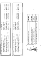
図7は、本発明の実施の形態におけるCEモードに係る仕様変更例(1)である。図7に示されるように、基地局装置10すなわちeNB又はgNBにおいて、オペレータは、non-BL-UEが使用する追加のCEモードにおける判定に使用する閾値「q-RxLevMinCE-nonBL-r13」、「q-QualMinRSRQ-CE-nonBL-r13」、「q-RxLevMinCE1-nonBL-r13」、「q-QualMinRSRQ-CE1-nonBL-r13」をユーザ装置20に通知するように設定してもよい。なお、情報要素の名称は例であり、他の名称であってもよい。また、図7に示される閾値「-150dBm」、「-22.5dB」等は例であり、他の値であってもよい。
図8は、本発明の実施の形態におけるCEモードに係る仕様変更例(2)である。
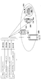
図8に示されるように、BL-UEであるUEカテゴリMのユーザ装置20A、non-BL-UEであるUEカテゴリ1bisのユーザ装置20B、UEカテゴリ1のユーザ装置20C及びUEカテゴリ2+のユーザ装置20Dは、基地局装置10から通知されたCEモードにおける判定に使用する閾値を自装置がBL-UEであるか否かに基づいて選択する。例えば、ユーザ装置20Aは、BL-UEであるため、「q-RxLevMinCE-r13」及び「q-QualMinRSRQ-CE1-r13」を選択する。一方、ユーザ装置20B、ユーザ装置20C及びユーザ装置20Dは、BL-UEではないため「q-RxLevMinCE-nonBL-r13」及び「q-QualMinRSRQ-CE1-nonBL-r13」を選択する。
図8に示されるように、BL-UEであるUEカテゴリMのユーザ装置20A、non-BL-UEであるUEカテゴリ1bisのユーザ装置20B、UEカテゴリ1のユーザ装置20C及びUEカテゴリ2+のユーザ装置20Dは、基地局装置10から通知されたCEモードにおける判定に使用する閾値を自装置がBL-UEであるか否かに基づいて選択する。例えば、ユーザ装置20Aは、BL-UEであるため、「q-RxLevMinCE-r13」及び「q-QualMinRSRQ-CE1-r13」を選択する。一方、ユーザ装置20B、ユーザ装置20C及びユーザ装置20Dは、BL-UEではないため「q-RxLevMinCE-nonBL-r13」及び「q-QualMinRSRQ-CE1-nonBL-r13」を選択する。
図9は、本発明の実施の形態におけるCEモードに係る仕様変更例(3)である。基地局装置10すなわちeNB又はgNBにおいて、オペレータは、non-BL-UE又はBL-UEが使用する追加のCEモードにおける判定に使用する閾値をUEカテゴリごとに設定してもよい。図9に示されるように、UEカテゴリ1のユーザ装置20向けの閾値として「q-RxLevMinCE-Cat1-r13」、「q-QualMinRSRQ-CE-Cat1-r13」、「q-RxLevMinCE1-Cat1-r13」、「q-QualMinRSRQ-CE1-Cat1-r13」を設定してもよい。同様に、UEカテゴリ1bisのユーザ装置20向けの閾値として「q-RxLevMinCE-Cat1bis-r13」、「q-QualMinRSRQ-CE-Cat1bis-r13」、「q-RxLevMinCE1-Cat1bis-r13」、「q-QualMinRSRQ-CE1-Cat1bis-r13」を設定してもよい。同様にUEカテゴリMのユーザ装置20向けの閾値として「q-RxLevMinCE-CatM-r13」、「q-QualMinRSRQ-CE-CatM-r13」、「q-RxLevMinCE1-CatM-r13」、「q-QualMinRSRQ-CE1-CatM-r13」を設定してもよい。なお、情報要素の名称は例であり、他の名称であってもよい。また、図9に示される閾値「-143dBm」、「-146dBm」、「-150dBm」等は例であり、他の値であってもよい。
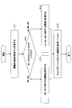
図10は、本発明の実施の形態におけるCEモードに係る動作例を説明するためのフローチャートである。図10を用いて、ユーザ装置20におけるCEモードにおける判定に使用する閾値の選択に係る動作例を説明する。
ステップS11において、ユーザ装置20は、CEモードにおける判定に使用する閾値を基地局装置10から受信する。基地局装置10は、CEモードにおける判定に使用する閾値を報知情報又は他のRRC(Radio Resource Control)メッセージを介してユーザ装置20に通知してもよい。続いて、ユーザ装置20は、自装置がBL-UE又はnon-BL-UEのいずれかを判定する。自装置がBL-UEである場合、ステップS13に進み、自装置がnon-BL-UEである場合、ステップS14に進む。ステップS13において、ユーザ装置20は、BL-UEに対応するCEモードにおける判定に使用する閾値を使用する。
ステップS14において、ユーザ装置20は、non-BL-UEに対応するCEモードにおける判定に使用する閾値を使用する。ステップS15において、基地局装置10からUEカテゴリごとのCEモードにおける判定に使用する閾値が通知されている場合、ユーザ装置20は、自装置のUEカテゴリに対応するCEモードにおける判定に使用する閾値を使用してもよい。
上述の実施例により、多数のユーザ装置20が、同一のセルに在圏している場合であっても、各ユーザ装置20の能力に応じたCEモードにおける判定に使用する閾値が個別に設定されるため、様々な状況において自装置がカバレッジ内であるかカバレッジ外であるかを正確に判定して表示することができる。
すなわち、ユーザ装置の能力に応じたカバレッジ拡張モードを適用することができる。
(装置構成)
次に、これまでに説明した処理及び動作を実行する基地局装置10及びユーザ装置20の機能構成例を説明する。基地局装置10及びユーザ装置20は上述した実施例を実施する機能を含む。ただし、基地局装置10及びユーザ装置20はそれぞれ、実施例の中の一部の機能のみを備えることとしてもよい。
次に、これまでに説明した処理及び動作を実行する基地局装置10及びユーザ装置20の機能構成例を説明する。基地局装置10及びユーザ装置20は上述した実施例を実施する機能を含む。ただし、基地局装置10及びユーザ装置20はそれぞれ、実施例の中の一部の機能のみを備えることとしてもよい。
<基地局装置10>
図11は、基地局装置10の機能構成の一例を示す図である。図11に示されるように、基地局装置10は、送信部110と、受信部120と、設定部130と、制御部140とを有する。図11に示される機能構成は一例に過ぎない。本発明の実施の形態に係る動作を実行できるのであれば、機能区分及び機能部の名称はどのようなものでもよい。
図11は、基地局装置10の機能構成の一例を示す図である。図11に示されるように、基地局装置10は、送信部110と、受信部120と、設定部130と、制御部140とを有する。図11に示される機能構成は一例に過ぎない。本発明の実施の形態に係る動作を実行できるのであれば、機能区分及び機能部の名称はどのようなものでもよい。
送信部110は、ユーザ装置20側に送信する信号を生成し、当該信号を無線で送信する機能を含む。受信部120は、ユーザ装置20から送信された各種の信号を受信し、受信した信号から、例えばより上位のレイヤの情報を取得する機能を含む。また、送信部110は、ユーザ装置20へNR-PSS、NR-SSS、NR-PBCH、DL/UL制御信号、DL/ULデータ信号等を送信する機能を有する。
設定部130は、予め設定される設定情報、及び、ユーザ装置20に送信する各種の設定情報を記憶装置に格納し、必要に応じて記憶装置から読み出す。設定情報の内容は、例えば、ユーザ装置20のCEモードに係る設定等である。
制御部140は、実施例において説明したように、ユーザ装置20にスケジューリングを行い、下りデータの送信及び上りデータの受信を制御する。制御部140は、CEモードに係る設定をユーザ装置20に送信する。制御部140における信号送信に関する機能部を送信部110に含め、制御部140における信号受信に関する機能部を受信部120に含めてもよい。
<ユーザ装置20>
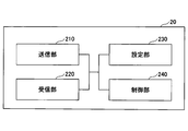
図12は、ユーザ装置20の機能構成の一例を示す図である。図12に示されるように、ユーザ装置20は、送信部210と、受信部220と、設定部230と、制御部240とを有する。図12に示される機能構成は一例に過ぎない。本発明の実施の形態に係る動作を実行できるのであれば、機能区分及び機能部の名称はどのようなものでもよい。
図12は、ユーザ装置20の機能構成の一例を示す図である。図12に示されるように、ユーザ装置20は、送信部210と、受信部220と、設定部230と、制御部240とを有する。図12に示される機能構成は一例に過ぎない。本発明の実施の形態に係る動作を実行できるのであれば、機能区分及び機能部の名称はどのようなものでもよい。
送信部210は、送信データから送信信号を作成し、当該送信信号を無線で送信する。受信部220は、各種の信号を無線受信し、受信した物理レイヤの信号からより上位のレイヤの信号を取得する。また、受信部220は、基地局装置10から送信されるNR-PSS、NR-SSS、NR-PBCH、DL/UL/SL制御信号等を受信する機能を有する。また、例えば、送信部210は、D2D通信として、他のユーザ装置20に、PSCCH(Physical Sidelink Control Channel)、PSSCH(Physical Sidelink Shared Channel)、PSDCH(Physical Sidelink Discovery Channel)、PSBCH(Physical Sidelink Broadcast Channel)等を送信し、受信部120は、他のユーザ装置20から、PSCCH、PSSCH、PSDCH又はPSBCH等を受信する。
設定部230は、受信部220により基地局装置10又はユーザ装置20から受信した各種の設定情報を記憶装置に格納し、必要に応じて記憶装置から読み出す。また、設定部230は、予め設定される設定情報も格納する。設定情報の内容は、例えば、ユーザ装置20のCEモードに係る設定等である。
制御部240は、実施例において説明したように、基地局装置10から取得したスケジューリングに基づいて、下りデータの受信及び上りデータの送信を制御する。また、制御部240は、基地局装置10から受信したCEモードに係る設定を適用した通信制御を実行する。制御部240における信号送信に関する機能部を送信部210に含め、制御部240における信号受信に関する機能部を受信部220に含めてもよい。
(ハードウェア構成)
上記実施形態の説明に用いたブロック図(図11及び図12)は、機能単位のブロックを示している。これらの機能ブロック(構成部)は、ハードウェア及びソフトウェアの少なくとも一方の任意の組み合わせによって実現される。また、各機能ブロックの実現方法は特に限定されない。すなわち、各機能ブロックは、物理的又は論理的に結合した1つの装置を用いて実現されてもよいし、物理的又は論理的に分離した2つ以上の装置を直接的又は間接的に(例えば、有線、無線などを用いて)接続し、これら複数の装置を用いて実現されてもよい。機能ブロックは、上記1つの装置又は上記複数の装置にソフトウェアを組み合わせて実現されてもよい。
上記実施形態の説明に用いたブロック図(図11及び図12)は、機能単位のブロックを示している。これらの機能ブロック(構成部)は、ハードウェア及びソフトウェアの少なくとも一方の任意の組み合わせによって実現される。また、各機能ブロックの実現方法は特に限定されない。すなわち、各機能ブロックは、物理的又は論理的に結合した1つの装置を用いて実現されてもよいし、物理的又は論理的に分離した2つ以上の装置を直接的又は間接的に(例えば、有線、無線などを用いて)接続し、これら複数の装置を用いて実現されてもよい。機能ブロックは、上記1つの装置又は上記複数の装置にソフトウェアを組み合わせて実現されてもよい。
機能には、判断、決定、判定、計算、算出、処理、導出、調査、探索、確認、受信、送信、出力、アクセス、解決、選択、選定、確立、比較、想定、期待、見做し、報知(broadcasting)、通知(notifying)、通信(communicating)、転送(forwarding)、構成(configuring)、再構成(reconfiguring)、割り当て(allocating、mapping)、割り振り(assigning)などがあるが、これらに限られない。たとえば、送信を機能させる機能ブロック(構成部)は、送信部(transmitting unit)や送信機(transmitter)と呼称される。いずれも、上述したとおり、実現方法は特に限定されない。
例えば、本開示の一実施の形態における基地局装置10、ユーザ装置20等は、本開示の無線通信方法の処理を行うコンピュータとして機能してもよい。図13は、本開示の一実施の形態に係る基地局装置10及びユーザ装置20のハードウェア構成の一例を示す図である。上述の基地局装置10及びユーザ装置20は、物理的には、プロセッサ1001、記憶装置1002、補助記憶装置1003、通信装置1004、入力装置1005、出力装置1006、バス1007などを含むコンピュータ装置として構成されてもよい。
なお、以下の説明では、「装置」という文言は、回路、デバイス、ユニット等に読み替えることができる。基地局装置10及びユーザ装置20のハードウェア構成は、図に示した各装置を1つ又は複数含むように構成されてもよいし、一部の装置を含まずに構成されてもよい。
基地局装置10及びユーザ装置20における各機能は、プロセッサ1001、記憶装置1002等のハードウェア上に所定のソフトウェア(プログラム)を読み込ませることによって、プロセッサ1001が演算を行い、通信装置1004による通信を制御したり、記憶装置1002及び補助記憶装置1003におけるデータの読み出し及び書き込みの少なくとも一方を制御したりすることによって実現される。
プロセッサ1001は、例えば、オペレーティングシステムを動作させてコンピュータ全体を制御する。プロセッサ1001は、周辺装置とのインタフェース、制御装置、演算装置、レジスタ等を含む中央処理装置(CPU:Central Processing Unit)で構成されてもよい。例えば、上述の制御部140、制御部240等は、プロセッサ1001によって実現されてもよい。
また、プロセッサ1001は、プログラム(プログラムコード)、ソフトウェアモジュール又はデータ等を、補助記憶装置1003及び通信装置1004の少なくとも一方から記憶装置1002に読み出し、これらに従って各種の処理を実行する。プログラムとしては、上述の実施の形態において説明した動作の少なくとも一部をコンピュータに実行させるプログラムが用いられる。例えば、図11に示した基地局装置10の制御部140は、記憶装置1002に格納され、プロセッサ1001で動作する制御プログラムによって実現されてもよい。また、例えば、図12に示したユーザ装置20の制御部240は、記憶装置1002に格納され、プロセッサ1001で動作する制御プログラムによって実現されてもよい。上述の各種処理は、1つのプロセッサ1001によって実行される旨を説明してきたが、2以上のプロセッサ1001により同時又は逐次に実行されてもよい。プロセッサ1001は、1以上のチップによって実装されてもよい。なお、プログラムは、電気通信回線を介してネットワークから送信されてもよい。
記憶装置1002は、コンピュータ読み取り可能な記録媒体であり、例えば、ROM(Read Only Memory)、EPROM(Erasable Programmable ROM)、EEPROM(Electrically Erasable Programmable ROM)、RAM(Random Access Memory)等の少なくとも1つによって構成されてもよい。記憶装置1002は、レジスタ、キャッシュ、メインメモリ(主記憶装置)等と呼ばれてもよい。記憶装置1002は、本開示の一実施の形態に係る通信方法を実施するために実行可能なプログラム(プログラムコード)、ソフトウェアモジュール等を保存することができる。
補助記憶装置1003は、コンピュータ読み取り可能な記録媒体であり、例えば、CD-ROM(Compact Disc ROM)等の光ディスク、ハードディスクドライブ、フレキシブルディスク、光磁気ディスク(例えば、コンパクトディスク、デジタル多用途ディスク、Blu-ray(登録商標)ディスク)、スマートカード、フラッシュメモリ(例えば、カード、スティック、キードライブ)、フロッピー(登録商標)ディスク、磁気ストリップ等の少なくとも1つによって構成されてもよい。上述の記憶媒体は、例えば、記憶装置1002及び補助記憶装置1003の少なくとも一方を含むデータベース、サーバその他の適切な媒体であってもよい。
通信装置1004は、有線ネットワーク及び無線ネットワークの少なくとも一方を介してコンピュータ間の通信を行うためのハードウェア(送受信デバイス)であり、例えばネットワークデバイス、ネットワークコントローラ、ネットワークカード、通信モジュールなどともいう。通信装置1004は、例えば周波数分割複信(FDD:Frequency Division Duplex)及び時分割複信(TDD:Time Division Duplex)の少なくとも一方を実現するために、高周波スイッチ、デュプレクサ、フィルタ、周波数シンセサイザなどを含んで構成されてもよい。例えば、送受信アンテナ、アンプ部、送受信部、伝送路インターフェース等は、通信装置1004によって実現されてもよい。送受信部は、送信部と受信部とで、物理的に、または論理的に分離された実装がなされてもよい。
入力装置1005は、外部からの入力を受け付ける入力デバイス(例えば、キーボード、マウス、マイクロフォン、スイッチ、ボタン、センサ等)である。出力装置1006は、外部への出力を実施する出力デバイス(例えば、ディスプレイ、スピーカー、LEDランプ等)である。なお、入力装置1005及び出力装置1006は、一体となった構成(例えば、タッチパネル)であってもよい。
また、プロセッサ1001及び記憶装置1002等の各装置は、情報を通信するためのバス1007によって接続される。バス1007は、単一のバスを用いて構成されてもよいし、装置間ごとに異なるバスを用いて構成されてもよい。
また、基地局装置10及びユーザ装置20は、マイクロプロセッサ、デジタル信号プロセッサ(DSP:Digital Signal Processor)、ASIC(Application Specific Integrated Circuit)、PLD(Programmable Logic Device)、FPGA(Field Programmable Gate Array)等のハードウェアを含んで構成されてもよく、当該ハードウェアにより、各機能ブロックの一部又は全てが実現されてもよい。例えば、プロセッサ1001は、これらのハードウェアの少なくとも1つを用いて実装されてもよい。
(実施の形態のまとめ)
以上、説明したように、本発明の実施の形態によれば、カバレッジ拡張モードにおける判定に使用するための複数の閾値を基地局装置から受信する受信部と、自装置が所定の種別であるか否かに基づいて、前記受信された複数の閾値からカバレッジ拡張モードにおける判定に使用する閾値を選択する制御部と、前記選択されたカバレッジ拡張モードにおける判定に使用するための閾値を、カバレッジ拡張モードにおけるカバレッジの判定に使用して、拡張されたカバレッジにおいて前記基地局装置と通信する通信部とを有するユーザ装置が提供される。
以上、説明したように、本発明の実施の形態によれば、カバレッジ拡張モードにおける判定に使用するための複数の閾値を基地局装置から受信する受信部と、自装置が所定の種別であるか否かに基づいて、前記受信された複数の閾値からカバレッジ拡張モードにおける判定に使用する閾値を選択する制御部と、前記選択されたカバレッジ拡張モードにおける判定に使用するための閾値を、カバレッジ拡張モードにおけるカバレッジの判定に使用して、拡張されたカバレッジにおいて前記基地局装置と通信する通信部とを有するユーザ装置が提供される。
上記の構成により、多数のユーザ装置20が、同一のセルに在圏している場合であっても、各ユーザ装置20の能力に応じたCEモードにおける判定に使用する閾値が個別に設定されるため、様々な状況において自装置がカバレッジ内であるかカバレッジ外であるかを正確に判定して表示することができる。すなわち、ユーザ装置の能力に応じたカバレッジ拡張モードを適用することができる。
前記所定の種別は、BL(Bandwidth reduced Low complexity)-UE(User Equipment)であってもよい。当該構成により、ユーザ装置20は、自装置がBL-UEである場合とBL-UEでない場合とで、カバレッジの判定に使用する閾値を変更して適切なカバレッジ拡張動作を実行することができる。
前記所定の種別は、UEカテゴリであってもよい。当該構成により、ユーザ装置20は、自装置のUEカテゴリに応じて、カバレッジの判定に使用する閾値を変更して適切なカバレッジ拡張動作を実行することができる。
前記所定の種別は、非BL-UEに対応するUEカテゴリであってもよい。当該構成により、ユーザ装置20は、自装置がnon-BL-UEである場合のUEカテゴリに応じて、カバレッジの判定に使用する閾値を変更して適切なカバレッジ拡張動作を実行することができる。
前記所定の種別は、BL-UEに対応するUEカテゴリであってもよい。当該構成により、ユーザ装置20は、自装置がBL-UEである場合のUEカテゴリに応じて、カバレッジの判定に使用する閾値を変更して適切なカバレッジ拡張動作を実行することができる。
また、本発明の実施の形態によれば、ユーザ装置が所定の種別であるか否かに基づいて選択されるカバレッジ拡張モードにおける判定に使用するための複数の閾値をユーザ装置に送信する送信部と、前記カバレッジ拡張モードにおける判定に使用するための閾値が、カバレッジ拡張モードにおけるカバレッジの判定に使用されて、拡張されたカバレッジにおいてユーザ装置と通信する通信部とを有する基地局装置が提供される。
上記の構成により、多数のユーザ装置20が、同一のセルに在圏している場合であっても、各ユーザ装置20の能力に応じたCEモードにおける判定に使用する閾値が個別に設定されるため、様々な状況において自装置がカバレッジ内であるかカバレッジ外であるかを正確に判定して表示することができる。すなわち、ユーザ装置の能力に応じたカバレッジ拡張モードを適用することができる。
(実施形態の補足)
以上、本発明の実施の形態を説明してきたが、開示される発明はそのような実施形態に限定されず、当業者は様々な変形例、修正例、代替例、置換例等を理解するであろう。発明の理解を促すため具体的な数値例を用いて説明がなされたが、特に断りのない限り、それらの数値は単なる一例に過ぎず適切な如何なる値が使用されてもよい。上記の説明における項目の区分けは本発明に本質的ではなく、2以上の項目に記載された事項が必要に応じて組み合わせて使用されてよいし、ある項目に記載された事項が、別の項目に記載された事項に(矛盾しない限り)適用されてよい。機能ブロック図における機能部又は処理部の境界は必ずしも物理的な部品の境界に対応するとは限らない。複数の機能部の動作が物理的には1つの部品で行われてもよいし、あるいは1つの機能部の動作が物理的には複数の部品により行われてもよい。実施の形態で述べた処理手順については、矛盾の無い限り処理の順序を入れ替えてもよい。処理説明の便宜上、基地局装置10及びユーザ装置20は機能的なブロック図を用いて説明されたが、そのような装置はハードウェアで、ソフトウェアで又はそれらの組み合わせで実現されてもよい。本発明の実施の形態に従って基地局装置10が有するプロセッサにより動作するソフトウェア及び本発明の実施の形態に従ってユーザ装置20が有するプロセッサにより動作するソフトウェアはそれぞれ、ランダムアクセスメモリ(RAM)、フラッシュメモリ、読み取り専用メモリ(ROM)、EPROM、EEPROM、レジスタ、ハードディスク(HDD)、リムーバブルディスク、CD-ROM、データベース、サーバその他の適切な如何なる記憶媒体に保存されてもよい。
以上、本発明の実施の形態を説明してきたが、開示される発明はそのような実施形態に限定されず、当業者は様々な変形例、修正例、代替例、置換例等を理解するであろう。発明の理解を促すため具体的な数値例を用いて説明がなされたが、特に断りのない限り、それらの数値は単なる一例に過ぎず適切な如何なる値が使用されてもよい。上記の説明における項目の区分けは本発明に本質的ではなく、2以上の項目に記載された事項が必要に応じて組み合わせて使用されてよいし、ある項目に記載された事項が、別の項目に記載された事項に(矛盾しない限り)適用されてよい。機能ブロック図における機能部又は処理部の境界は必ずしも物理的な部品の境界に対応するとは限らない。複数の機能部の動作が物理的には1つの部品で行われてもよいし、あるいは1つの機能部の動作が物理的には複数の部品により行われてもよい。実施の形態で述べた処理手順については、矛盾の無い限り処理の順序を入れ替えてもよい。処理説明の便宜上、基地局装置10及びユーザ装置20は機能的なブロック図を用いて説明されたが、そのような装置はハードウェアで、ソフトウェアで又はそれらの組み合わせで実現されてもよい。本発明の実施の形態に従って基地局装置10が有するプロセッサにより動作するソフトウェア及び本発明の実施の形態に従ってユーザ装置20が有するプロセッサにより動作するソフトウェアはそれぞれ、ランダムアクセスメモリ(RAM)、フラッシュメモリ、読み取り専用メモリ(ROM)、EPROM、EEPROM、レジスタ、ハードディスク(HDD)、リムーバブルディスク、CD-ROM、データベース、サーバその他の適切な如何なる記憶媒体に保存されてもよい。
また、情報の通知は、本開示で説明した態様/実施形態に限られず、他の方法を用いて行われてもよい。例えば、情報の通知は、物理レイヤシグナリング(例えば、DCI(Downlink Control Information)、UCI(Uplink Control Information))、上位レイヤシグナリング(例えば、RRC(Radio Resource Control)シグナリング、MAC(Medium Access Control)シグナリング、報知情報(MIB(Master Information Block)、SIB(System Information Block))、その他の信号又はこれらの組み合わせによって実施されてもよい。また、RRCシグナリングは、RRCメッセージと呼ばれてもよく、例えば、RRC接続セットアップ(RRC Connection Setup)メッセージ、RRC接続再構成(RRC Connection Reconfiguration)メッセージ等であってもよい。
本開示において説明した各態様/実施形態は、LTE(Long Term Evolution)、LTE-A(LTE-Advanced)、SUPER 3G、IMT-Advanced、4G(4th generation mobile communication system)、5G(5th generation mobile communication system)、FRA(Future Radio Access)、NR(new Radio)、W-CDMA(登録商標)、GSM(登録商標)、CDMA2000、UMB(Ultra Mobile Broadband)、IEEE 802.11(Wi-Fi(登録商標))、IEEE 802.16(WiMAX(登録商標))、IEEE 802.20、UWB(Ultra-WideBand)、Bluetooth(登録商標)、その他の適切なシステムを利用するシステム及びこれらに基づいて拡張された次世代システムの少なくとも一つに適用されてもよい。また、複数のシステムが組み合わされて(例えば、LTE及びLTE-Aの少なくとも一方と5Gとの組み合わせ等)適用されてもよい。
本明細書で説明した各態様/実施形態の処理手順、シーケンス、フローチャート等は、矛盾の無い限り、順序を入れ替えてもよい。例えば、本開示において説明した方法については、例示的な順序を用いて様々なステップの要素を提示しており、提示した特定の順序に限定されない。
本明細書において基地局装置10によって行われるとした特定動作は、場合によってはその上位ノード(upper node)によって行われることもある。基地局装置10を有する1つ又は複数のネットワークノード(network nodes)からなるネットワークにおいて、ユーザ装置20との通信のために行われる様々な動作は、基地局装置10及び基地局装置10以外の他のネットワークノード(例えば、MME又はS-GW等が考えられるが、これらに限られない)の少なくとも1つによって行われ得ることは明らかである。上記において基地局装置10以外の他のネットワークノードが1つである場合を例示したが、他のネットワークノードは、複数の他のネットワークノードの組み合わせ(例えば、MME及びS-GW)であってもよい。
本開示において説明した情報又は信号等は、上位レイヤ(又は下位レイヤ)から下位レイヤ(又は上位レイヤ)へ出力され得る。複数のネットワークノードを介して入出力されてもよい。
入出力された情報等は特定の場所(例えば、メモリ)に保存されてもよいし、管理テーブルを用いて管理してもよい。入出力される情報等は、上書き、更新、又は追記され得る。出力された情報等は削除されてもよい。入力された情報等は他の装置へ送信されてもよい。
本開示における判定は、1ビットで表される値(0か1か)によって行われてもよいし、真偽値(Boolean:true又はfalse)によって行われてもよいし、数値の比較(例えば、所定の値との比較)によって行われてもよい。
ソフトウェアは、ソフトウェア、ファームウェア、ミドルウェア、マイクロコード、ハードウェア記述言語と呼ばれるか、他の名称で呼ばれるかを問わず、命令、命令セット、コード、コードセグメント、プログラムコード、プログラム、サブプログラム、ソフトウェアモジュール、アプリケーション、ソフトウェアアプリケーション、ソフトウェアパッケージ、ルーチン、サブルーチン、オブジェクト、実行可能ファイル、実行スレッド、手順、機能などを意味するよう広く解釈されるべきである。
また、ソフトウェア、命令、情報などは、伝送媒体を介して送受信されてもよい。例えば、ソフトウェアが、有線技術(同軸ケーブル、光ファイバケーブル、ツイストペア、デジタル加入者回線(DSL:Digital Subscriber Line)など)及び無線技術(赤外線、マイクロ波など)の少なくとも一方を使用してウェブサイト、サーバ、又は他のリモートソースから送信される場合、これらの有線技術及び無線技術の少なくとも一方は、伝送媒体の定義内に含まれる。
本開示において説明した情報、信号などは、様々な異なる技術のいずれかを使用して表されてもよい。例えば、上記の説明全体に渡って言及され得るデータ、命令、コマンド、情報、信号、ビット、シンボル、チップなどは、電圧、電流、電磁波、磁界若しくは磁性粒子、光場若しくは光子、又はこれらの任意の組み合わせによって表されてもよい。
なお、本開示において説明した用語及び本開示の理解に必要な用語については、同一の又は類似する意味を有する用語と置き換えてもよい。例えば、チャネル及びシンボルの少なくとも一方は信号(シグナリング)であってもよい。また、信号はメッセージであってもよい。また、コンポーネントキャリア(CC:Component Carrier)は、キャリア周波数、セル、周波数キャリアなどと呼ばれてもよい。
本開示において使用する「システム」及び「ネットワーク」という用語は、互換的に使用される。
また、本開示において説明した情報、パラメータなどは、絶対値を用いて表されてもよいし、所定の値からの相対値を用いて表されてもよいし、対応する別の情報を用いて表されてもよい。例えば、無線リソースはインデックスによって指示されるものであってもよい。
上述したパラメータに使用する名称はいかなる点においても限定的な名称ではない。さらに、これらのパラメータを使用する数式等は、本開示で明示的に開示したものと異なる場合もある。様々なチャネル(例えば、PUCCH、PDCCHなど)及び情報要素は、あらゆる好適な名称によって識別できるので、これらの様々なチャネル及び情報要素に割り当てている様々な名称は、いかなる点においても限定的な名称ではない。
本開示においては、「基地局(BS:Base Station)」、「無線基地局」、「基地局装置」、「固定局(fixed station)」、「NodeB」、「eNodeB(eNB)」、「gNodeB(gNB)」、「アクセスポイント(access point)」、「送信ポイント(transmission point)」、「受信ポイント(reception point)、「送受信ポイント(transmission/reception point)」、「セル」、「セクタ」、「セルグループ」、「キャリア」、「コンポーネントキャリア」などの用語は、互換的に使用され得る。基地局は、マクロセル、スモールセル、フェムトセル、ピコセルなどの用語で呼ばれる場合もある。
基地局は、1つ又は複数(例えば、3つ)のセルを収容することができる。基地局が複数のセルを収容する場合、基地局のカバレッジエリア全体は複数のより小さいエリアに区分でき、各々のより小さいエリアは、基地局サブシステム(例えば、屋内用の小型基地局(RRH:Remote Radio Head)によって通信サービスを提供することもできる。「セル」又は「セクタ」という用語は、このカバレッジにおいて通信サービスを行う基地局及び基地局サブシステムの少なくとも一方のカバレッジエリアの一部又は全体を指す。
本開示においては、「移動局(MS:Mobile Station)」、「ユーザ端末(user terminal)」、「ユーザ装置(UE:User Equipment)」、「端末」などの用語は、互換的に使用され得る。
移動局は、当業者によって、加入者局、モバイルユニット、加入者ユニット、ワイヤレスユニット、リモートユニット、モバイルデバイス、ワイヤレスデバイス、ワイヤレス通信デバイス、リモートデバイス、モバイル加入者局、アクセス端末、モバイル端末、ワイヤレス端末、リモート端末、ハンドセット、ユーザエージェント、モバイルクライアント、クライアント、又はいくつかの他の適切な用語で呼ばれる場合もある。
基地局及び移動局の少なくとも一方は、送信装置、受信装置、通信装置などと呼ばれてもよい。なお、基地局及び移動局の少なくとも一方は、移動体に搭載されたデバイス、移動体自体などであってもよい。当該移動体は、乗り物(例えば、車、飛行機など)であってもよいし、無人で動く移動体(例えば、ドローン、自動運転車など)であってもよいし、ロボット(有人型又は無人型)であってもよい。なお、基地局及び移動局の少なくとも一方は、必ずしも通信動作時に移動しない装置も含む。例えば、基地局及び移動局の少なくとも一方は、センサなどのIoT(Internet of Things)機器であってもよい。
また、本開示における基地局は、ユーザ端末で読み替えてもよい。例えば、基地局及びユーザ端末間の通信を、複数のユーザ装置20間の通信(例えば、D2D(Device-to-Device)、V2X(Vehicle-to-Everything)などと呼ばれてもよい)に置き換えた構成について、本開示の各態様/実施形態を適用してもよい。この場合、上述の基地局装置10が有する機能をユーザ装置20が有する構成としてもよい。また、「上り」及び「下り」などの文言は、端末間通信に対応する文言(例えば、「サイド(side)」)で読み替えられてもよい。例えば、上りチャネル、下りチャネルなどは、サイドチャネルで読み替えられてもよい。
同様に、本開示におけるユーザ端末は、基地局で読み替えてもよい。この場合、上述のユーザ端末が有する機能を基地局が有する構成としてもよい。
本開示で使用する「判断(determining)」、「決定(determining)」という用語は、多種多様な動作を包含する場合がある。「判断」、「決定」は、例えば、判定(judging)、計算(calculating)、算出(computing)、処理(processing)、導出(deriving)、調査(investigating)、探索(looking up、search、inquiry)(例えば、テーブル、データベース又は別のデータ構造での探索)、確認(ascertaining)した事を「判断」「決定」したとみなす事などを含み得る。また、「判断」、「決定」は、受信(receiving)(例えば、情報を受信すること)、送信(transmitting)(例えば、情報を送信すること)、入力(input)、出力(output)、アクセス(accessing)(例えば、メモリ中のデータにアクセスすること)した事を「判断」「決定」したとみなす事などを含み得る。また、「判断」、「決定」は、解決(resolving)、選択(selecting)、選定(choosing)、確立(establishing)、比較(comparing)などした事を「判断」「決定」したとみなす事を含み得る。つまり、「判断」「決定」は、何らかの動作を「判断」「決定」したとみなす事を含み得る。また、「判断(決定)」は、「想定する(assuming)」、「期待する(expecting)」、「みなす(considering)」などで読み替えられてもよい。
「接続された(connected)」、「結合された(coupled)」という用語、又はこれらのあらゆる変形は、2又はそれ以上の要素間の直接的又は間接的なあらゆる接続又は結合を意味し、互いに「接続」又は「結合」された2つの要素間に1又はそれ以上の中間要素が存在することを含むことができる。要素間の結合又は接続は、物理的なものであっても、論理的なものであっても、或いはこれらの組み合わせであってもよい。例えば、「接続」は「アクセス」で読み替えられてもよい。本開示で使用する場合、2つの要素は、1又はそれ以上の電線、ケーブル及びプリント電気接続の少なくとも一つを用いて、並びにいくつかの非限定的かつ非包括的な例として、無線周波数領域、マイクロ波領域及び光(可視及び不可視の両方)領域の波長を有する電磁エネルギーなどを用いて、互いに「接続」又は「結合」されると考えることができる。
参照信号は、RS(Reference Signal)と略称することもでき、適用される標準によってパイロット(Pilot)と呼ばれてもよい。
本開示において使用する「に基づいて」という記載は、別段に明記されていない限り、「のみに基づいて」を意味しない。言い換えれば、「に基づいて」という記載は、「のみに基づいて」と「に少なくとも基づいて」の両方を意味する。
本開示において使用する「第1の」、「第2の」などの呼称を使用した要素へのいかなる参照も、それらの要素の量又は順序を全般的に限定しない。これらの呼称は、2つ以上の要素間を区別する便利な方法として本開示において使用され得る。したがって、第1及び第2の要素への参照は、2つの要素のみが採用され得ること、又は何らかの形で第1の要素が第2の要素に先行しなければならないことを意味しない。
上記の各装置の構成における「手段」を、「部」、「回路」、「デバイス」等に置き換えてもよい。
本開示において、「含む(include)」、「含んでいる(including)」及びそれらの変形が使用されている場合、これらの用語は、用語「備える(comprising)」と同様に、包括的であることが意図される。さらに、本開示において使用されている用語「又は(or)」は、排他的論理和ではないことが意図される。
無線フレームは時間領域において1つ又は複数のフレームによって構成されてもよい。時間領域において1つ又は複数の各フレームはサブフレームと呼ばれてもよい。サブフレームは更に時間領域において1つ又は複数のスロットによって構成されてもよい。サブフレームは、ニューメロロジ(numerology)に依存しない固定の時間長(例えば、1ms)であってもよい。
ニューメロロジは、ある信号又はチャネルの送信及び受信の少なくとも一方に適用される通信パラメータであってもよい。ニューメロロジは、例えば、サブキャリア間隔(SCS:SubCarrier Spacing)、帯域幅、シンボル長、サイクリックプレフィックス長、送信時間間隔(TTI:Transmission Time Interval)、TTIあたりのシンボル数、無線フレーム構成、送受信機が周波数領域において行う特定のフィルタリング処理、送受信機が時間領域において行う特定のウィンドウイング処理などの少なくとも1つを示してもよい。
スロットは、時間領域において1つ又は複数のシンボル(OFDM(Orthogonal Frequency Division Multiplexing)シンボル、SC-FDMA(Single Carrier Frequency Division Multiple Access)シンボル等)で構成されてもよい。スロットは、ニューメロロジに基づく時間単位であってもよい。
スロットは、複数のミニスロットを含んでもよい。各ミニスロットは、時間領域において1つ又は複数のシンボルによって構成されてもよい。また、ミニスロットは、サブスロットと呼ばれてもよい。ミニスロットは、スロットよりも少ない数のシンボルによって構成されてもよい。ミニスロットより大きい時間単位で送信されるPDSCH(又はPUSCH)は、PDSCH(又はPUSCH)マッピングタイプAと呼ばれてもよい。ミニスロットを用いて送信されるPDSCH(又はPUSCH)は、PDSCH(又はPUSCH)マッピングタイプBと呼ばれてもよい。
無線フレーム、サブフレーム、スロット、ミニスロット及びシンボルは、いずれも信号を伝送する際の時間単位を表す。無線フレーム、サブフレーム、スロット、ミニスロット及びシンボルは、それぞれに対応する別の呼称が用いられてもよい。
例えば、1サブフレームは送信時間間隔(TTI:Transmission Time Interval)と呼ばれてもよいし、複数の連続したサブフレームがTTIと呼ばれてよいし、1スロット又は1ミニスロットがTTIと呼ばれてもよい。つまり、サブフレーム及びTTIの少なくとも一方は、既存のLTEにおけるサブフレーム(1ms)であってもよいし、1msより短い期間(例えば、1-13シンボル)であってもよいし、1msより長い期間であってもよい。なお、TTIを表す単位は、サブフレームではなくスロット、ミニスロットなどと呼ばれてもよい。
ここで、TTIは、例えば、無線通信におけるスケジューリングの最小時間単位のことをいう。例えば、LTEシステムでは、基地局が各ユーザ装置20に対して、無線リソース(各ユーザ装置20において使用することが可能な周波数帯域幅、送信電力など)を、TTI単位で割り当てるスケジューリングを行う。なお、TTIの定義はこれに限られない。
TTIは、チャネル符号化されたデータパケット(トランスポートブロック)、コードブロック、コードワードなどの送信時間単位であってもよいし、スケジューリング、リンクアダプテーションなどの処理単位となってもよい。なお、TTIが与えられたとき、実際にトランスポートブロック、コードブロック、コードワードなどがマッピングされる時間区間(例えば、シンボル数)は、当該TTIよりも短くてもよい。
なお、1スロット又は1ミニスロットがTTIと呼ばれる場合、1以上のTTI(すなわち、1以上のスロット又は1以上のミニスロット)が、スケジューリングの最小時間単位となってもよい。また、当該スケジューリングの最小時間単位を構成するスロット数(ミニスロット数)は制御されてもよい。
1msの時間長を有するTTIは、通常TTI(LTE Rel.8-12におけるTTI)、ノーマルTTI、ロングTTI、通常サブフレーム、ノーマルサブフレーム、ロングサブフレーム、スロットなどと呼ばれてもよい。通常TTIより短いTTIは、短縮TTI、ショートTTI、部分TTI(partial又はfractional TTI)、短縮サブフレーム、ショートサブフレーム、ミニスロット、サブスロット、スロットなどと呼ばれてもよい。
なお、ロングTTI(例えば、通常TTI、サブフレームなど)は、1msを超える時間長を有するTTIで読み替えてもよいし、ショートTTI(例えば、短縮TTIなど)は、ロングTTIのTTI長未満かつ1ms以上のTTI長を有するTTIで読み替えてもよい。
リソースブロック(RB)は、時間領域及び周波数領域のリソース割当単位であり、周波数領域において、1つ又は複数個の連続した副搬送波(subcarrier)を含んでもよい。RBに含まれるサブキャリアの数は、ニューメロロジに関わらず同じであってもよく、例えば12であってもよい。RBに含まれるサブキャリアの数は、ニューメロロジに基づいて決定されてもよい。
また、RBの時間領域は、1つ又は複数個のシンボルを含んでもよく、1スロット、1ミニスロット、1サブフレーム、又は1TTIの長さであってもよい。1TTI、1サブフレームなどは、それぞれ1つ又は複数のリソースブロックで構成されてもよい。
なお、1つ又は複数のRBは、物理リソースブロック(PRB:Physical RB)、サブキャリアグループ(SCG:Sub-Carrier Group)、リソースエレメントグループ(REG:Resource Element Group)、PRBペア、RBペアなどと呼ばれてもよい。
また、リソースブロックは、1つ又は複数のリソースエレメント(RE:Resource Element)によって構成されてもよい。例えば、1REは、1サブキャリア及び1シンボルの無線リソース領域であってもよい。
帯域幅部分(BWP:Bandwidth Part)(部分帯域幅などと呼ばれてもよい)は、あるキャリアにおいて、あるニューメロロジ用の連続する共通RB(common resource blocks)のサブセットのことを表してもよい。ここで、共通RBは、当該キャリアの共通参照ポイントを基準としたRBのインデックスによって特定されてもよい。PRBは、あるBWPで定義され、当該BWP内で番号付けされてもよい。
BWPには、UL用のBWP(UL BWP)と、DL用のBWP(DL BWP)とが含まれてもよい。UEに対して、1キャリア内に1つ又は複数のBWPが設定されてもよい。
設定されたBWPの少なくとも1つがアクティブであってもよく、UEは、アクティブなBWPの外で所定の信号/チャネルを送受信することを想定しなくてもよい。なお、本開示における「セル」、「キャリア」などは、「BWP」で読み替えられてもよい。
上述した無線フレーム、サブフレーム、スロット、ミニスロット及びシンボルなどの構造は例示に過ぎない。例えば、無線フレームに含まれるサブフレームの数、サブフレーム又は無線フレームあたりのスロットの数、スロット内に含まれるミニスロットの数、スロット又はミニスロットに含まれるシンボル及びRBの数、RBに含まれるサブキャリアの数、並びにTTI内のシンボル数、シンボル長、サイクリックプレフィックス(CP:Cyclic Prefix)長などの構成は、様々に変更することができる。
本開示において、例えば、英語でのa, an及びtheのように、翻訳により冠詞が追加された場合、本開示は、これらの冠詞の後に続く名詞が複数形であることを含んでもよい。
本開示において、「AとBが異なる」という用語は、「AとBが互いに異なる」ことを意味してもよい。なお、当該用語は、「AとBがそれぞれCと異なる」ことを意味してもよい。「離れる」、「結合される」などの用語も、「異なる」と同様に解釈されてもよい。
本開示において説明した各態様/実施形態は単独で用いてもよいし、組み合わせて用いてもよいし、実行に伴って切り替えて用いてもよい。また、所定の情報の通知(例えば、「Xであること」の通知)は、明示的に行うものに限られず、暗黙的(例えば、当該所定の情報の通知を行わない)ことによって行われてもよい。
なお、本開示において、送信部210及び受信部220は、通信部の一例である。non-BL-UEは、非BL-UEの一例である。送信部110及び受信部120は、通信部の一例である。
以上、本開示について詳細に説明したが、当業者にとっては、本開示が本開示中に説明した実施形態に限定されるものではないということは明らかである。本開示は、請求の範囲の記載により定まる本開示の趣旨及び範囲を逸脱することなく修正及び変更態様として実施することができる。したがって、本開示の記載は、例示説明を目的とするものであり、本開示に対して何ら制限的な意味を有するものではない。
本国際特許出願は2019年2月22日に出願した日本国特許出願第2019-030370号に基づきその優先権を主張するものであり、日本国特許出願第2019-030370号の全内容を本願に援用する。
10 基地局装置
110 送信部
120 受信部
130 設定部
140 制御部
20 ユーザ装置
210 送信部
220 受信部
230 設定部
240 制御部
1001 プロセッサ
1002 記憶装置
1003 補助記憶装置
1004 通信装置
1005 入力装置
1006 出力装置
110 送信部
120 受信部
130 設定部
140 制御部
20 ユーザ装置
210 送信部
220 受信部
230 設定部
240 制御部
1001 プロセッサ
1002 記憶装置
1003 補助記憶装置
1004 通信装置
1005 入力装置
1006 出力装置
Claims (6)
- カバレッジ拡張モードにおける判定に使用するための複数の閾値を基地局装置から受信する受信部と、
自装置が所定の種別であるか否かに基づいて、前記受信された複数の閾値からカバレッジ拡張モードにおける判定に使用する閾値を選択する制御部と、
前記選択されたカバレッジ拡張モードにおける判定に使用するための閾値を、カバレッジ拡張モードにおけるカバレッジの判定に使用して、拡張されたカバレッジにおいて前記基地局装置と通信する通信部とを有するユーザ装置。 - 前記所定の種別は、BL(Bandwidth reduced Low complexity)-UE(User Equipment)である請求項1記載のユーザ装置。
- 前記所定の種別は、UEカテゴリである請求項1記載のユーザ装置。
- 前記所定の種別は、非BL-UEに対応するUEカテゴリである請求項3記載のユーザ装置。
- 前記所定の種別は、BL-UEに対応するUEカテゴリである請求項3記載のユーザ装置。
- ユーザ装置が所定の種別であるか否かに基づいて選択されるカバレッジ拡張モードにおける判定に使用するための複数の閾値をユーザ装置に送信する送信部と、
前記カバレッジ拡張モードにおける判定に使用するための閾値が、カバレッジ拡張モードにおけるカバレッジの判定に使用されて、拡張されたカバレッジにおいてユーザ装置と通信する通信部とを有する基地局装置。
Applications Claiming Priority (2)
| Application Number | Priority Date | Filing Date | Title |
|---|---|---|---|
| JP2019-030370 | 2019-02-22 | ||
| JP2019030370A JP2022065209A (ja) | 2019-02-22 | 2019-02-22 | ユーザ装置及び基地局装置 |
Publications (1)
| Publication Number | Publication Date |
|---|---|
| WO2020171182A1 true WO2020171182A1 (ja) | 2020-08-27 |
Family
ID=72144479
Family Applications (1)
| Application Number | Title | Priority Date | Filing Date |
|---|---|---|---|
| PCT/JP2020/006892 Ceased WO2020171182A1 (ja) | 2019-02-22 | 2020-02-20 | ユーザ装置及び基地局装置 |
Country Status (2)
| Country | Link |
|---|---|
| JP (1) | JP2022065209A (ja) |
| WO (1) | WO2020171182A1 (ja) |
Cited By (2)
| Publication number | Priority date | Publication date | Assignee | Title |
|---|---|---|---|---|
| US11375509B2 (en) * | 2018-02-16 | 2022-06-28 | Nokia Technologies Oy | Support for receive-limited user equipment in wireless environments |
| WO2026034100A1 (ja) * | 2024-08-06 | 2026-02-12 | パナソニック インテレクチュアル プロパティ コーポレーション オブ アメリカ | 通信装置、基地局及び通信方法 |
Citations (1)
| Publication number | Priority date | Publication date | Assignee | Title |
|---|---|---|---|---|
| JP2018026738A (ja) * | 2016-08-10 | 2018-02-15 | 株式会社Nttドコモ | 基地局及び信号送信方法 |
-
2019
- 2019-02-22 JP JP2019030370A patent/JP2022065209A/ja active Pending
-
2020
- 2020-02-20 WO PCT/JP2020/006892 patent/WO2020171182A1/ja not_active Ceased
Patent Citations (1)
| Publication number | Priority date | Publication date | Assignee | Title |
|---|---|---|---|---|
| JP2018026738A (ja) * | 2016-08-10 | 2018-02-15 | 株式会社Nttドコモ | 基地局及び信号送信方法 |
Non-Patent Citations (2)
| Title |
|---|
| NTT DOCOMO INC.: "CE Mode Threshold Adjustments for non-BL and BL UE in Standalone", 3GPP TSG RAN WG2 #106 R2-1908080, 9 May 2019 (2019-05-09), XP051740279 * |
| NTT DOCOMO INC.: "CE Mode Threshold Adjustments for non-BL and BL UE", 3GPP TSG RAN WG2 #108 R2-1914474, 8 November 2019 (2019-11-08), XP051816554 * |
Cited By (2)
| Publication number | Priority date | Publication date | Assignee | Title |
|---|---|---|---|---|
| US11375509B2 (en) * | 2018-02-16 | 2022-06-28 | Nokia Technologies Oy | Support for receive-limited user equipment in wireless environments |
| WO2026034100A1 (ja) * | 2024-08-06 | 2026-02-12 | パナソニック インテレクチュアル プロパティ コーポレーション オブ アメリカ | 通信装置、基地局及び通信方法 |
Also Published As
| Publication number | Publication date |
|---|---|
| JP2022065209A (ja) | 2022-04-27 |
Similar Documents
| Publication | Publication Date | Title |
|---|---|---|
| JPWO2020090098A1 (ja) | ユーザ装置及び基地局装置 | |
| US20220287108A1 (en) | Terminal and communication method | |
| WO2020194638A1 (ja) | ユーザ装置及び基地局装置 | |
| JPWO2020095455A1 (ja) | ユーザ装置及び基地局装置 | |
| WO2021199415A1 (ja) | 端末及び通信方法 | |
| WO2020100559A1 (ja) | ユーザ装置及び基地局装置 | |
| WO2020194636A1 (ja) | ユーザ装置 | |
| WO2020157873A1 (ja) | ユーザ装置及び基地局装置 | |
| WO2020170405A1 (ja) | ユーザ装置及び基地局装置 | |
| WO2021181707A1 (ja) | 端末及び通信方法 | |
| WO2021149246A1 (ja) | 端末、基地局及び通信方法 | |
| JP7552992B2 (ja) | 端末、通信システム及び通信方法 | |
| WO2020194746A1 (ja) | ユーザ装置及び基地局装置 | |
| WO2020174552A1 (ja) | ユーザ装置及び通信方法 | |
| JPWO2020161907A1 (ja) | ユーザ装置 | |
| WO2020171182A1 (ja) | ユーザ装置及び基地局装置 | |
| JP7296461B2 (ja) | 基地局装置、端末、及び送信方法 | |
| WO2021149110A1 (ja) | 端末及び通信方法 | |
| WO2020246185A1 (ja) | 端末及び基地局 | |
| WO2021140676A1 (ja) | 端末及び通信方法 | |
| WO2020170445A1 (ja) | ユーザ装置及び基地局装置 | |
| WO2021014621A1 (ja) | 端末及び通信方法 | |
| WO2020157874A1 (ja) | ユーザ装置及び基地局装置 | |
| JP7674471B2 (ja) | 端末、通信方法、基地局及び無線通信システム | |
| JP7427687B2 (ja) | 端末、通信システム、及び通信方法 |
Legal Events
| Date | Code | Title | Description |
|---|---|---|---|
| 121 | Ep: the epo has been informed by wipo that ep was designated in this application |
Ref document number: 20758698 Country of ref document: EP Kind code of ref document: A1 |
|
| NENP | Non-entry into the national phase |
Ref country code: DE |
|
| 122 | Ep: pct application non-entry in european phase |
Ref document number: 20758698 Country of ref document: EP Kind code of ref document: A1 |
|
| NENP | Non-entry into the national phase |
Ref country code: JP |