WO2020171013A1 - 測定装置 - Google Patents
測定装置 Download PDFInfo
- Publication number
- WO2020171013A1 WO2020171013A1 PCT/JP2020/006028 JP2020006028W WO2020171013A1 WO 2020171013 A1 WO2020171013 A1 WO 2020171013A1 JP 2020006028 W JP2020006028 W JP 2020006028W WO 2020171013 A1 WO2020171013 A1 WO 2020171013A1
- Authority
- WO
- WIPO (PCT)
- Prior art keywords
- measurement
- measuring device
- chamber
- measuring
- plate
- Prior art date
- Legal status (The legal status is an assumption and is not a legal conclusion. Google has not performed a legal analysis and makes no representation as to the accuracy of the status listed.)
- Ceased
Links
Images




Classifications
-
- G—PHYSICS
- G01—MEASURING; TESTING
- G01N—INVESTIGATING OR ANALYSING MATERIALS BY DETERMINING THEIR CHEMICAL OR PHYSICAL PROPERTIES
- G01N21/00—Investigating or analysing materials by the use of optical means, i.e. using sub-millimetre waves, infrared, visible or ultraviolet light
- G01N21/01—Arrangements or apparatus for facilitating the optical investigation
-
- G—PHYSICS
- G01—MEASURING; TESTING
- G01N—INVESTIGATING OR ANALYSING MATERIALS BY DETERMINING THEIR CHEMICAL OR PHYSICAL PROPERTIES
- G01N21/00—Investigating or analysing materials by the use of optical means, i.e. using sub-millimetre waves, infrared, visible or ultraviolet light
- G01N21/01—Arrangements or apparatus for facilitating the optical investigation
- G01N21/03—Cuvette constructions
-
- G—PHYSICS
- G01—MEASURING; TESTING
- G01N—INVESTIGATING OR ANALYSING MATERIALS BY DETERMINING THEIR CHEMICAL OR PHYSICAL PROPERTIES
- G01N21/00—Investigating or analysing materials by the use of optical means, i.e. using sub-millimetre waves, infrared, visible or ultraviolet light
- G01N21/62—Systems in which the material investigated is excited whereby it emits light or causes a change in wavelength of the incident light
- G01N21/63—Systems in which the material investigated is excited whereby it emits light or causes a change in wavelength of the incident light optically excited
- G01N21/64—Fluorescence; Phosphorescence
Definitions
- the present invention relates to a measuring device that simultaneously measures information regarding the concentration of a predetermined gas in a plurality of sample measuring chambers, and particularly to a measuring device that simultaneously measures activity that can use changes in the information as an index.
- a method of measuring photosynthetic activity by irradiating a plant with an electromagnetic wave and measuring the phase and amplitude of the electromagnetic wave modulated by the plant is known (Patent Document 1).
- a method of measuring the photosynthetic activity of a plant using a chamber is also known, which is one in which CO 2 gas or the like is introduced into the chamber and then the plant is irradiated with light, and an oxygen electrode is used to The photosynthetic activity of plants is measured by measuring the oxygen concentration.
- the conventional method can measure only one measurement sample in one measurement, and cannot simultaneously measure the photosynthetic activity of many measurement samples. Therefore, when the photosynthetic activity of a plurality of measurement samples is measured using the conventional method, a great deal of time, labor and cost are required. Therefore, it is important to provide a technique capable of more efficiently measuring photosynthetic activity. This is the same when measuring activities such as respiratory activity other than photosynthetic activity.
- the present invention has been made in view of the above problems, for example, the activity such as photosynthetic activity and respiratory activity for a plurality of measurement samples, after introducing a gas suitable for activity measurement into each sample measurement chamber, each sample measurement chamber
- a gas suitable for activity measurement into each sample measurement chamber
- each sample measurement chamber For example, to provide a measuring device capable of simultaneously measuring information based on the information by simultaneously and temporally measuring information relating to the concentration of a predetermined gas such as gas concentration (eg oxygen concentration, carbon dioxide concentration) or pH.
- the present invention is a measuring device for simultaneously measuring information relating to the concentration of a predetermined gas in a plurality of sample measuring chambers, the measuring block having a plurality of recesses to be sample measuring chambers, and a chamber containing the measuring blocks.
- the measuring device of the present invention preferably further comprises a fixing means for detachably fixing the inner lid to the chamber lid.
- the fixing means includes at least one magnet provided on one of the inner lid and the chamber lid, and at least one metal plate provided on the other of the inner lid and the chamber lid so as to face the magnet. More preferably,
- the inner lid further comprises a plurality of sealing members individually provided around the plurality of plug members, and the plurality of sealing materials are the plurality of plug members. It is preferable that when the plurality of concave portions of the working block are individually sealed, the openings of the plurality of concave portions are individually sealed by being sandwiched between the inner lid and the measurement block.
- the measurement block is configured by closing a first plate made of metal in which a plurality of through holes are formed and an opening on one side of the plurality of through holes of the first plate, A second plate fixed to the first plate to form a plurality of recesses, the second plate being capable of transmitting light, and the first plate including the plurality of through holes. It is preferable that a flow passage through which the liquid passes is formed so as to be surrounded by, and a water supply port for supplying the liquid to the flow passage and a drain port for discharging the liquid from the flow passage are provided.
- a packing that seals an opening on one side of the plurality of through holes is interposed between the first plate and the second plate.
- the measuring device is a measuring device capable of measuring information regarding the concentration of a predetermined gas such as gas concentration or pH, and the measuring device is a plurality of concave portions of the measuring block. It is set individually on the bottom, whereby the information can be obtained for each of the measurement blocks.
- the measuring device is an oxygen concentration measuring device for measuring the oxygen concentration.
- the oxygen concentration measuring device is set individually at the bottom of the plurality of recesses of the measurement block, a plurality of fluorescence emitting intensity of fluorescence according to the oxygen concentration by irradiation of excitation light.
- a fluorescent oxygen sensor a plurality of light emitting units that individually irradiate the plurality of fluorescent oxygen sensors with excitation light, and a plurality of light receiving units that individually measure the fluorescence emitted from the plurality of fluorescent oxygen sensors, It is preferable to provide. Further, it is more preferable that the plurality of recesses of the measurement block each contain a sample on the fluorescent oxygen sensor via a light-shielding sheet and/or a breathable cushioning material.
- a measuring device for simultaneously measuring information on the concentration of a predetermined gas in a sample measuring chamber, A measurement block having a plurality of concave portions to be a sample measurement chamber, A chamber body that houses the measurement block, A chamber lid for closing the upper opening of the chamber body, An inner lid that is slidable up and down with respect to the chamber body, and that has a plurality of stopper members on the bottom surface that individually seals the plurality of recesses of the measurement block as the slide moves downward; A gas inlet attached to the chamber body, for introducing an arbitrary gas into a space between the measurement block and the inner lid in the chamber body, and a gas outlet for discharging an arbitrary gas from the space; And a measuring device capable of measuring information on the concentration of the predetermined gas in each recess of the measuring block.
- the measurement device further comprising a fixing unit that detachably fixes the inner lid to the chamber lid.
- the fixing means includes at least one magnet provided on one of the inner lid and the chamber lid, and at least one metal plate provided on the other of the inner lid and the chamber lid so as to face the magnet.
- the measurement device which comprises: Item 4.
- the inner lid further comprises a plurality of sealing members individually provided around the plurality of stopper members, The plurality of sealing materials are sandwiched between the inner lid and the measurement block when the plurality of plug members individually seal the plurality of recesses of the measurement block to open the openings of the plurality of recesses.
- the measuring device according to any one of items 1 to 3, which is individually sealed. Item 5.
- the measurement block A metal first plate having a plurality of through holes, A second plate fixed to the first plate so as to form a plurality of the recesses by closing an opening on one side of the plurality of through holes of the first plate, The second plate can transmit light, A flow passage through which liquid passes is formed inside the first plate so as to collectively surround the plurality of through holes, and a water supply port for supplying the liquid to the flow passage and the liquid is discharged from the flow passage. 5.
- the measuring device according to any one of items 1 to 4 above, which is provided with a drainage port.
- Item 6. 6 The measuring device according to any one of items 1 to 5, wherein a packing that seals an opening on one side of the plurality of through holes is sandwiched between the first plate and the second plate.
- the measuring device is an oxygen concentration measuring device for measuring oxygen concentration
- the oxygen concentration measuring device is individually set on the bottom of the plurality of recesses of the measuring block, a plurality of fluorescence oxygen sensor that emits fluorescence of intensity according to the oxygen concentration by irradiation of excitation light, Item 1.
- the plurality of light-emitting units that individually irradiate the plurality of fluorescent oxygen sensors with excitation light, and the plurality of light-receiving units that individually measure the fluorescence emitted from the plurality of fluorescent oxygen sensors. 6.
- the measuring device according to any one of 6.
- the measuring device wherein a sample is stored in each of the plurality of recesses of the measurement block on the fluorescent oxygen sensor via a light-shielding sheet and/or a breathable cushioning material.
- Item 9. The measurement device according to any one of items 1 to 8, further comprising a light irradiator that irradiates light into all the concave portions of the measurement block.
- the measuring device of the present invention it is possible to replace the insides of the plurality of recesses, which are the sample measurement chambers of the measurement block, with an arbitrary gas all at once, and to seal the plurality of recesses individually by using a plurality of stopper members. .. Therefore, for example, when measuring photosynthetic activity of plants, algae, cells thereof (including cultured cells), etc. as a measurement sample, it is possible to replace all the recesses of the measurement block with the CO 2 -containing gas all at once. In addition to this, all the recesses can be simultaneously and individually sealed.
- the concentration of oxygen generated by photosynthesis of the measurement sample in each recess oxygen concentration in the recess, or pH that changes based on the concentration of oxygen dissolved in the solution in the recess
- the photosynthetic activity of multiple measurement samples can be measured simultaneously.
- the measurement can be performed efficiently, and the measurement time can be greatly reduced.
- the information regarding the predetermined gas is not limited to the gas concentration and pH, and may be any information that changes according to the gas concentration.
- the present invention can also be used to measure other activities such as respiratory activity of organisms or cells thereof (including cultured cells), which can be measured based on information about oxygen concentration or carbon dioxide concentration. Other activities that can be measured based on the information about the concentration of a predetermined gas other than the oxygen concentration and the carbon dioxide concentration can also be measured using the present invention.
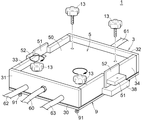
- FIG. 4 is a cross-sectional view of the measuring device taken along line X1-X1 of FIG. 3 in a state where the chamber lid and the inner lid are attached to the chamber body.
- FIG. 6 is a perspective view of the measuring device after sliding the inner lid downward while the chamber lid and the inner lid are attached to the chamber body.
- FIG. 8 is a cross-sectional view of the measuring device taken along line X1-X1 of FIG. 3 in the state of FIG. 7.
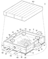
- FIG. 8 is a perspective view of the measuring device with the chamber lid removed from the chamber body after the state of FIG. 7. It is a perspective view of a measuring device in the state of measuring photosynthetic activity. It is data showing the measurement results of photosynthetic activity. It is data showing the measurement results of photosynthetic activity.
- the measuring device of the present invention measures changes in gas concentration, pH, etc. for a plurality of measurement samples by measuring information on the concentration of a predetermined gas such as gas concentration and pH in a plurality of sample measurement chambers simultaneously and over time.
- the activity which can be used as an index is simultaneously measured. For example, by measuring the oxygen concentration, carbon dioxide concentration, or pH in a plurality of sample measurement chambers simultaneously and sequentially, based on the information on the oxygen concentration such as photosynthetic activity or respiratory activity or the information on the carbon dioxide concentration for a plurality of measurement samples.
- the measured activity can be measured simultaneously.
- the activity to be measured by the measuring apparatus of the present invention is not limited to the activity measured based on the information about the oxygen concentration and the information about the carbon dioxide concentration, and the information about the concentration of a predetermined gas other than oxygen and carbon dioxide. Other activities measured based on the above are also included in the measurement target.
- the information regarding the predetermined gas is not limited to the gas concentration and pH, and includes information that changes according to other gas concentrations.
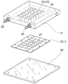
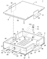
- FIG. 1 is an exploded perspective view of the measuring apparatus 1 of this embodiment
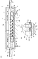
- FIG. 6 shows an internal configuration of the measuring apparatus 1 of this embodiment.
- the measuring apparatus 1 of this embodiment includes a measurement block 2 having a plurality of recesses 10 serving as sample measurement chambers, a chamber body 3 that houses the measurement block 2, and a chamber lid 4 that closes an upper opening of the chamber body 3.
- An inner lid 5 that is slidable up and down with respect to the chamber body 3 and that has a plurality of plug members 11 on the lower surface that individually seal the recesses 20 of the measurement block 2 as it slides downward;
- a gas introduction port 6A that is attached to the chamber body 3 and introduces an arbitrary gas (for example, a CO 2 -containing gas) into the space S (shown in FIG.
- a predetermined gas for example, oxygen
- the measuring block 2 has a rectangular outer shape and is a plate-like body having a predetermined thickness.
- a plurality of recesses 10 having a predetermined depth are formed on the upper surface of the measurement block 2.
- the plurality of recesses 10 are regularly arranged at equal intervals in the vertical and horizontal directions.
- Each recess 10 is designed to have a size capable of accommodating therein a measurement sample (for example, a plant leaf) that is a measurement target of photosynthetic activity or the like.
- the number of recesses 10 is not particularly limited, but is 24 in this embodiment.
- the measurement block 2 includes a first plate 21 having a plurality of through holes 20 and a second plate 21 fixed to the first plate 21, as shown in FIG. 2, FIG. 3, FIG.
- the structure includes a plate 22 and a packing 23 interposed between the first plate 21 and the second plate 22.
- the first plate 21 is made of metal in this embodiment, and is preferably made of a metal having high thermal conductivity such as aluminum or stainless steel.
- the first plate 21 does not necessarily have to be made of metal, and may be made of glass or synthetic resin, for example.
- a flow path 24 through which the liquid passes is formed so as to collectively surround the plurality of through holes 20.
- a water supply port 25 for introducing the liquid into the flow channel 24 and a drain port 26 for discharging the liquid from the flow channel 24 are attached to the inlet end and the outlet end of the flow channel 24, respectively. ing.
- water is supplied to the flow path 24 from a tank, a water tank, or the like (not shown).
- the temperature of the water supplied to the flow path 24 is adjusted to a desired temperature, and the water set to the desired temperature flows through the flow path, whereby the first plate 21 is maintained at the desired temperature.
- the temperature of the recess 10 serving as the sample measurement chamber can be set to a temperature suitable for the measurement conditions.
- the second plate 22 can transmit light, and is made of, for example, a transparent or semitransparent material as a whole.
- the second plate 22 may be made of synthetic resin such as acrylic or glass.
- the second plate 22 is fixed to the lower surface of the first plate 21 using screws (not shown) or the like so as to close the openings on one side (the lower side in the drawing) of the plurality of through holes 20 of the first plate 21. ing.
- the openings on one side of the plurality of through holes 20 of the first plate 21 are collectively closed by the second plate 22, so that the plurality of recesses 10 are formed. Thereby, each recess 10 can transmit light from the opening on the side of the first plate 21 to the bottom on the side of the second plate 22.
- the packing 23 is designed to be slightly smaller than the first plate 21 and the second plate 22.
- a plurality of openings 25 corresponding to the plurality of through holes 20 of the first plate 21 in a one-to-one correspondence are formed in the packing 23.
- the packing 23 is arranged in contact with the lower surface of the first plate 21 so that the openings 27 individually overlap the through holes 20 of the first plate 21.
- the openings on one side of the plurality of through holes 20 are collectively sealed by the packing 23.
- the packing 23 can be formed using a known material that has been conventionally used as a packing to prevent gas leakage.
- the packing 23 is sandwiched between the first plate 21 and the second plate 22 by fixing the second plate 22 to the lower surface of the first plate 21, and the second plate 22 is fixed using screws (not shown) or the like. It is also fixed to the lower surface of the first plate 21.
- the chamber body 3 includes a bottom portion 30 having a rectangular outer shape, and a pair of front and rear front wall portions 31 and rear wall portions standing upright on the periphery of the bottom portion 30. It has a configuration including the portion 32 and a pair of left and right left side wall portions 33 and right side wall portions 34, and has a box shape with an open top.
- the bottom portion 30 is fixed to the lower surface of the frame body including the front, rear, left and right wall portions 31 to 34 using screws (not shown) or the like.
- positioning projections 35 are provided in parallel with the respective wall portions 31 to 34 at inner positions of the front, rear, left and right wall portions 31 to 34.
- the measurement block 2 is placed in the four protrusions 35.
- the front side wall 31 has a gas inlet 6A for introducing gas into the chamber body 3, and the rear side wall 32 has gas from the inside of the chamber body 3.
- the gas outlet ports 6B to be led out are attached respectively.
- the gas inlet 6A and the gas outlet 6B may be attached to any of the front, rear, left and right wall portions 31 to 34.
- a pipe 60 (shown in FIG. 3 and the like) is connected to the gas inlet 6A, and an arbitrary gas such as a CO 2 -containing gas is supplied from a cylinder or the like (not shown).
- a pipe 61 (shown in FIG. 3 and the like) is connected to the gas outlet 6B, and the gas in the chamber body 3 is discharged to the outside air, a tank or the like.
- a pipe 62 (shown in FIG. 3 and the like) connected to the water supply port 25 of the measurement block 2 housed in the chamber body 3 and a pipe 63 (connected to the drain port 26 ( (Shown in FIG. 3 and the like) are formed separately from each other through two insertion openings 36.
- the left side wall portion 33 and the right side wall portion 34 have a guide groove 37 formed in a central portion in the lengthwise direction and cut out downward from the upper end. Are formed respectively.
- a pair of left and right first guide portions 51 of the inner lid 5 to be described later are inserted into the two guide grooves 37 from above and slide vertically.
- left side wall portion 33 and the right side wall portion 34 are each provided with a protruding portion 38 that protrudes outward at a lower position of the guide groove 37.
- a long hole-shaped guide hole 39 is formed in each of the two protrusions 38 at a boundary position between the left wall 33 and the right wall 34.
- a pair of left and right second guide portions 52 of the inner lid 5 described later are inserted into the two guide holes 39 from above and slide vertically.
- the chamber lid 4 has a rectangular outer shape, and exhibits a plate-like body having a predetermined thickness.
- the chamber lid 4 is designed to have substantially the same size as the outer shape formed by the front, rear, left, and right walls 31 to 34 of the chamber body 3 so as to close the upper opening of the chamber body 3.
- the chamber lid 4 can be fixed to the chamber body 3 with screws (not shown) or the like when the chamber lid 4 is covered with the upper opening of the chamber body 3.
- the chamber lid 4 may be made of metal, glass, or synthetic resin, but is preferably made of transparent synthetic resin such as acrylic.
- the inner lid 5 includes a main body portion 50 having a rectangular outer shape, and a pair of first first portions protruding from the left and right side surfaces of the main body portion 50.
- the guide unit 50 and a pair of second guide units 51 are provided so as to individually intersect the respective first guide units 50 vertically.
- the main body 50 has a plate-like body having a predetermined thickness.
- the main body 50 is designed to have a size slightly smaller than the chamber lid 4, and is inserted into the chamber main body 3 through the upper opening of the chamber main body 3 so that the main body 50 can be slid and moved to have a size substantially the same as the upper opening. Designed to size.
- On the lower surface of the main body portion 50 a plurality of plug members 11 that individually seal the plurality of concave portions 10 of the measurement block 2 when the chamber body 3 is slid downwardly are provided.
- the plurality of plug members 11 are regularly arranged at equal intervals in the vertical and horizontal directions on the lower surface of the main body 50 so as to correspond one-to-one with the recesses 10 of the measurement block 2.
- Each plug member 11 is designed to have a shape and size that fit tightly into the recess 10 of the measurement block 2, and may be formed of a known flexible or elastic material such as rubber or silicon. it can.
- a plurality of seal members 12 individually provided around the plurality of plug members 11 are provided on the lower surface of the main body portion 50. As shown in FIG. 8, the plurality of sealing materials 12 are sandwiched between the main body 50 and the measurement block 2 when the plurality of plug members 11 individually seal the plurality of recesses 10 of the measurement block 2. By doing so, the openings of the plurality of recesses 10 are individually sealed.
- the seal member 12 can be formed using a known material that has been conventionally used as a seal member to prevent gas leakage.
- the pair of first guide members 51 and the pair of second guide members 52 guide the main body section 50 so that when the main body section 50 slides up and down relative to the chamber main body 3, the main body section 50 moves straight up and down.
- Each of the pair of first guide members 51 and the pair of second guide members 52 has a rectangular outer shape and is a plate-like body having a predetermined thickness.
- the width of the first guide portion 51 is approximately the same as the width of the guide groove 37 of the chamber body 3.
- the lateral width of the second guide portion 52 is larger than the lateral width of the first guide portion 51, and is substantially the same as the lateral width of the guide hole 39 of the chamber body 3.
- the pair of first guide portions 51 slides up and down along the corresponding guide grooves 37, and the pair of second guide portions 52 slides vertically along the corresponding guide holes 39, so that the main body The part 50 slides vertically up and down with respect to the chamber body 3.
- a fixing means 8 for detachably fixing the inner lid 5 to the chamber lid 4 is provided between the inner lid 5 and the chamber lid 4 .
- the fixing means 8 temporarily holds the inner lid 5 on the chamber lid 4 when the chamber lid 4 is covered with the upper opening of the chamber body 3, so that the inner lid 5 is retained inside the chamber body 3 as shown in FIG.
- a space S is formed between the housed measurement block 2 and the inner lid 5. Then, by removing the inner lid 5 from the chamber lid 4, the inner lid 5 can be slid up and down with respect to the chamber body 3, and by sliding the inner lid 5 downward, as shown in FIG.
- the plurality of stopper members 11 can individually seal the plurality of recesses 10 of the measurement block 2.
- the fixing means 8 faces at least one magnet 80 provided on one of the inner lid 5 and the chamber lid 4, and the magnet 80 on the other of the inner lid 5 and the chamber lid 4, for example.
- at least one metal plate 81 provided so that In the present embodiment, the magnets 80 are fitted in the through holes 53 at the boundary positions between the main body portion 50 of the inner lid 5 and the pair of first guide members 51, and the lengths of the left and right side edges of the chamber lid 4 are set.
- a metal plate 81 is attached to each of the central portions in the direction so as to protrude from the lower surface of the chamber lid 4. By contact between the magnet 80 and the metal plate 81, the inner lid 5 is detachably fixed to the lower surface of the chamber lid 4, as shown in FIG.
- the concentration measuring device 7 is not particularly limited as long as it can measure the concentration of a predetermined gas (for example, oxygen) in each recess 10 of the measuring block 2, and various measuring devices can be used. Can be used.
- the concentration measuring device 7 is an oxygen concentration measuring device, and as shown in FIGS. 1, 6 and 8, the concentration measuring device 7 is individually set on the bottoms of the plurality of concave portions 10 of the measuring block 2 to generate the excitation light. It is composed of a plurality of fluorescence-type oxygen sensors 70 that emit fluorescence having an intensity corresponding to the oxygen concentration upon irradiation, and a known microplate reader 71.
- the fluorescent oxygen sensor 70 emits fluorescent light having an intensity corresponding to the oxygen concentration in the concave portion 10 of the measurement block 2 which is the sample measurement chamber when irradiated with the excitation light. Specifically, it is formed by fixing an oxygen-sensitive fluorescent substance inside.
- the microplate reader 71 includes a plurality of light emitting units (not shown) that individually emit excitation light to the fluorescent oxygen sensors 70 set in the plurality of recesses 10 of the measurement block 2, and a plurality of fluorescent oxygen sensors. It has a structure including a plurality of light receiving portions (not shown) for individually measuring the fluorescence emitted from the sensor 70.
- the light emitting portion is used to excite the fluorescent substance fixed to the fluorescent oxygen sensor 70 to emit fluorescence, and for example, a mercury lamp, a laser, an LED or the like can be used.
- the light receiving section receives fluorescence of intensity corresponding to the oxygen concentration from the fluorescence type oxygen sensor 70 excited by the light from the light emitting section, and can be, for example, a cooled CCD.
- a control device (not shown) is connected to the microplate reader 71.
- the control device receives the fluorescence image obtained by the microplate reader 71, compares the fluorescence intensity information with the oxygen concentration calibration straight line, and calculates and outputs the oxygen concentration profile and the oxygen consumption rate.
- a computer including a CPU, a ROM, a RAM, and an I/O can be used as the control device.
- the microplate reader 71 in which the light emitting unit and the light receiving unit are provided in the same device is used, but the excitation light source as the light emitting unit and the fluorescence intensity acquisition device as the light receiving unit are separately provided.
- the device may be.
- the fluorescent oxygen sensor 70 is set on the bottom of each recess 10 of the measurement block 2, while the microplate reader 71 is set below the bottom 30 of the chamber body 3.
- a plate-shaped sensor fixing member 9 having a predetermined thickness is fixed to the lower surface of the bottom portion 30 of the chamber body 3 using screws 91 (FIG. 1) and the like.
- the sensor fixing member 9 may be made of metal, glass, or synthetic resin, but is preferably made of transparent synthetic resin such as acrylic.
- the sensor fixing member 9 has a substantially rectangular outer shape, and an opening 90 for surrounding and positioning the microplate reader 71 is formed in the center thereof.
- an opening 90 for surrounding and positioning the microplate reader 71 is formed in the center thereof.
- the procedure of a method for measuring, for example, the photosynthetic activity of a plant using the measuring device 1 having the above-described configuration will be described.
- the fluorescent oxygen sensor 70 is set on the bottom of each recess 10 of the measurement block 2.
- a part of the leaf is set as the measurement sample 100 with the light shielding sheet 73 and/or the breathable cushioning material 72 placed on the fluorescent oxygen sensor 70 in each recess 10 of the measurement block 2.
- the light-shielding sheet 73 prevents light from the light irradiator 101, which illuminates all the recesses 10 from above the measurement block 2 described later, from entering the microplate reader 71 located below the measurement block 2. It is for doing.
- the light-shielding sheet 73 for example, black felt or the like can be used, but the light-shielding sheet 73 is not particularly limited to this and various materials can be used as long as they have the same function.
- the cushioning material 72 is for preventing the measurement sample 100 from directly contacting the fluorescent oxygen sensor 70, and for example, plastic wool, mesh or the like can be used, but is not particularly limited to this. Instead, various types can be used as long as they have the same function.
- the inner lid 5 and the chamber lid 4 are unfixed, and the inner lid 5 is slid downward with respect to the chamber main body 3 to measure with the plurality of plug members 11.
- the openings of the plurality of recesses 10 of the working block 2 are closed.
- all the recesses 10 of the measurement block 2 are individually and simultaneously sealed, and all the recesses 10 are filled with the CO 2 -containing gas.
- the chamber lid 4 is removed from the chamber body 3, and as shown in FIG. 9, the inner lid 5 is fixed to the measurement block 2 with screws 13 or the like, whereby all the recesses 10 of the measurement block 2 are removed. It is tightly sealed.
- the measurement sample 100 in each recess 10 of the measurement block 2 receives light to perform photosynthesis, and carbon dioxide and water in the recess 10 synthesize carbohydrates and release oxygen into the recess 10.
- the fluorescent oxygen sensor 70 in the recess 10 emits fluorescence by being irradiated with excitation light from the microplate reader 71, and this fluorescence is measured by the microplate reader 71.
- oxygen is released from the measurement sample 100 into the recess 10 by photosynthesis, the fluorescence emitted from the fluorescent oxygen sensor 70 weakens according to the oxygen concentration in the recess 10.
- the microplate reader 71 by measuring the intensity of the fluorescence emitted from the fluorescence type oxygen sensor 70 by the microplate reader 71 with time, it is possible to measure the oxygen concentration change in the concave portion 10 and measure the photosynthetic activity of the measurement sample 100. be able to.
- the measurement device of the present embodiment As described above, in order to measure the photosynthetic activity of the plant, it is necessary to replace the inside of the plurality of recesses 10 of the measurement block 2 serving as the sample measurement chamber with the CO 2 -containing gas, but the measurement device of the present embodiment. According to 1, the inside of all the recesses 10 of the measurement block 2 can be simultaneously replaced with the CO 2 -containing gas, and all the recesses 10 can be individually and simultaneously sealed. Therefore, since the photosynthetic activity can be simultaneously measured for a plurality of measurement samples, particularly when the number of measurement samples is large, the measurement can be efficiently performed, and the measurement time can be significantly shortened.
- a flow path 24 through which the liquid passes is formed inside the measurement block 2, and the temperature inside each recess 10 of the measurement block 2 is adjusted to a desired temperature by adjusting the temperature of the liquid flowing through the flow path 24. Can be maintained at. Therefore, by setting the temperature in each recess 10 to a desired temperature according to the activity to be measured, the activity such as photosynthetic activity can be satisfactorily measured.
- the inner lid 5 is detachably fixed to the chamber lid 4 that closes the upper opening of the chamber body 3, and the inner lid 5 is positioned above the measurement block 2 shown in FIG. , It is possible to easily switch to the state in which it is located directly above the measuring block 2 shown in FIG. Therefore, when introducing any gas containing CO 2 gas or the like into the chamber main body 3 is fixed at the position shown in FIG. 6, the recess 10 of the measurement block 2 is any such CO 2 containing gas After the replacement with the gas, the opening of the concave portion 10 of the measurement block 2 can be easily closed by the stopper member 11 of the inner lid 5 only by removing the fixing between the inner lid 5 and the chamber lid 4.
- the fixing means 8 is composed of the magnet 80 and the metal plate 81, but it is possible to temporarily fix the inner lid 5 to the chamber lid 4 and remove it from the chamber lid 4.
- various other configurations can be used.
- the measurement target is a plant
- the measurement target is not limited to a plant, and includes, for example, aquatic organisms such as algae, these cells (cells or cultured cells isolated from plants, algae, etc.), and even small cells. It may be an organ (for example, chloroplast or mitochondria).
- the change over time in the pH of the liquid (water, cell preservation solution, cell culture solution, etc.) contained in each recess 10 together with the measurement sample is measured by, for example, fluorescence.
- the photosynthetic activity may be measured by using a pH measuring device such as a pH sensor.
- the measuring device 1 is used to measure the photosynthetic activity of the measurement sample.
- the organism, its cells (cells or cultured cells isolated from the organism) or organelles (for example, chlorophyll) are used.
- the measuring device 1 can also be used to measure the respiratory activity of the body and mitochondria).
- an arbitrary oxygen-containing gas is replaced in each recess 10 of the measurement block 2 and is stored in each recess 10 together with the concentration of oxygen consumed by respiration, the concentration of carbon dioxide generated by respiration, or the measurement sample.
- Respiratory activity can be measured by measuring the time-dependent change in pH of a liquid (water, cell preservation solution, cell culture solution, etc.) using a measuring device.
- the cushioning material 72 and the light shielding sheet 73 are not always necessary when measuring respiratory activity.
- each of the recesses 10 of the measurement block 2 may be replaced with an arbitrary gas according to the activity to be measured, and the information regarding the concentration of the predetermined gas may be measured using a measuring instrument suitable for the measurement target.
- the measuring instrument 7 that measures the gas concentration such as the oxygen concentration in each recess 10 of the measurement block 2 measures the index (for example, the fluorescence intensity of the fluorescent gas sensor) depending on the gas concentration.
- the gas concentration is measured by this, the gas concentration may be directly measured as long as the gas concentration can be measured. Further, the gas concentration may be measured as an absolute value, a relative value, or a time change.
- Test example 1 Test Procedure The photosynthetic activity was measured using the measuring device of the above-described embodiment. A part of leaf (tomato leaf, circular shape having a diameter of 8 mm (prepared by cutting one leaf into a circular shape having a diameter of 8 mm)) was used as a measurement sample.
- the fluorescent oxygen sensor 70 is provided at the bottom of each of the four recesses 10 of the plurality of recesses 10 of the measurement block 2.
- a light-shielding sheet 73 black felt
- the fluorescent oxygen sensors 70 in the four recesses 10 was placed on the fluorescent oxygen sensors 70 in the four recesses 10, then a part of the leaf (leaf disc) as the measurement sample 100 is placed, and the back surface of the leaf is on the lower side. And put it horizontally.
- FIG. 5 and FIG. 6 with the inner lid 5 fixed to the lower surface of the chamber lid 4, the chamber lid 4 is covered with the upper opening of the chamber body 3, and the space S in the chamber body 3 is closed. Closed.
- a CO 2 -containing gas (composition: 5% CO 2 , 5% O 2 , 90% N 2 ) is introduced into the chamber main body 3 through the gas introduction port 6A, and all the recesses 10 of the measurement block 2 are introduced. Were simultaneously replaced by a CO 2 -containing gas.
- the inner lid 5 and the chamber lid 4 are unfixed, the inner lid 5 is slid downward with respect to the chamber body 3, and a plurality of stopper members 11 are used for measurement.
- the openings of the plurality of recesses 10 of the block 2 were closed, all the recesses 10 of the measurement block 2 were simultaneously and individually sealed, and all the recesses 10 were filled with the CO 2 -containing gas.
- the chamber lid 4 was removed from the chamber body 3, and the inner lid 5 was fixed to the measurement block 2 with the screw 13 as shown in FIG. In this state, water at 23° C. was circulated in the channel 24 for circulation.
- the measuring device 1 was covered with a dark curtain to start measuring the oxygen concentration.
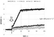
- the LED light provided on the measuring device 1 was turned on, and the measurement sample was irradiated with light (On in FIG. 11).
- a photosynthesis inhibitor (DUMU (3-(3,4-dichlorophenyl)-1,1-dimethylurea)) was made to act on two of the four measurement samples. The result is shown in FIG.
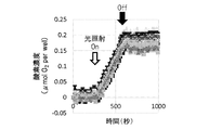
- the fluorescent oxygen sensor and the measurement sample were set in the four recesses 10 in the same manner as described above. Then, the measurement of oxygen concentration was started. In this case, 5 minutes after the LED light was turned on, the LED light was turned off (Off in FIG. 12). The result is shown in FIG.
- the measuring apparatus of the present invention can measure the photosynthetic activity of a plurality of measurement samples simultaneously and sequentially based on the oxygen concentration. Further, as described above, according to the measuring device of the present invention, the oxygen concentration can be measured simultaneously and over time for a plurality of measurement samples, so that the measuring device can detect respiratory activity regardless of photosynthetic activity. As a result, it was found that it is useful for measuring the activity that can use the change in oxygen concentration as an index. Further, it was found that the measuring device of the present invention is useful for measuring the activity which can use not only oxygen but also changes in other gas concentration, pH and the like as indexes by utilizing different fluorescent sensors. Since the measuring apparatus of the present invention can measure the activity of a plurality of measurement samples simultaneously and over time, it can efficiently measure in a short time as compared with the conventional method in which only one sample can be measured in one measurement. I understood.
Landscapes
- Health & Medical Sciences (AREA)
- Biochemistry (AREA)
- General Physics & Mathematics (AREA)
- Life Sciences & Earth Sciences (AREA)
- Chemical & Material Sciences (AREA)
- Analytical Chemistry (AREA)
- Pathology (AREA)
- General Health & Medical Sciences (AREA)
- Physics & Mathematics (AREA)
- Immunology (AREA)
- Nuclear Medicine, Radiotherapy & Molecular Imaging (AREA)
- Investigating, Analyzing Materials By Fluorescence Or Luminescence (AREA)
- Optical Measuring Cells (AREA)
- Investigating Or Analysing Materials By Optical Means (AREA)
- Apparatus Associated With Microorganisms And Enzymes (AREA)
Abstract
複数の測定試料について例えば酸素濃度等に基づく光合成活性や呼吸活性等の活性を同時に測定できる測定装置を提供することを目的とする。図6に示すように、測定装置1は、試料測定室となる凹部10を複数備えた測定用ブロック2と、測定用ブロック2を収容するチャンバー本体3と、チャンバー本体3の上部開口を塞ぐチャンバー蓋4と、チャンバー本体3に対して上下にスライド移動可能であり、下方へのスライド移動に伴い測定用ブロック2の複数の凹部10を個別に密閉する複数の栓部材11を下面に備える内蓋5と、チャンバー本体3に取り付けられ、チャンバー本体3内の測定用ブロック2と内蓋5との間の空間Sに任意のガスを導入するガス導入口6A及び空間Sから任意のガスを導出するガス導出口6Bと、測定用ブロック2の各凹部10内の所定のガスの濃度を測定可能な濃度測定器7と、を備える。
Description
本発明は、複数の試料測定室内の所定のガスの濃度に関する情報を同時に測定する測定装置に関し、特に、該情報の変化を指標とできる活性を同時に測定する測定装置に関する。
従来、植物の光合成活性の測定においては、様々な方法が知られている。例えば、電磁波を植物に照射し、植物により変調した電磁波の位相や振幅を測定することにより、光合成活性を測定する方法が知られている(特許文献1)。また、チャンバーを用いて植物の光合成活性を測定する方法も知られており、これは、チャンバー内にCO2ガス等を導入したうえで植物に光を照射し、酸素電極を用いてチャンバー内の酸素濃度を測定することにより、植物の光合成活性を測定するものである。
しかし、従来の方法は、1回の測定で1つの測定試料しか測定することができず、多数の測定試料の光合成活性を同時に測定することができない。従って、従来の方法を用いて複数の測定試料の光合成活性を測定する場合、非常に多くの時間や手間、あるいはコストを要する。このため、光合成活性をより効率良く測定できる技術を提供することは重要である。これは、光合成活性以外の呼吸活性等の活性を測定する場合も同様である。
本発明は、上記課題に鑑みてなされてものであり、複数の測定試料について例えば光合成活性や呼吸活性等の活性を、活性測定に適したガスを各試料測定室に導入後、各試料測定室内の例えばガス濃度(例えば酸素濃度、二酸化炭素濃度等)又はpH等の所定のガスの濃度に関する情報を同時にかつ経時的に測定することにより、該情報に基づいて同時に測定できる測定装置を提供することを目的とする。
本発明は、複数の試料測定室内の所定のガスの濃度に関する情報を同時に測定する測定装置であって、試料測定室となる凹部を複数備えた測定用ブロックと、前記測定用ブロックを収容するチャンバー本体と、前記チャンバー本体の上部開口を塞ぐチャンバー蓋と、前記チャンバー本体に対して上下にスライド移動可能であり、下方へのスライド移動に伴い前記測定用ブロックの複数の凹部を個別に密閉する複数の栓部材を下面に備える内蓋と、前記チャンバー本体に取り付けられ、前記チャンバー本体内の前記測定用ブロックと前記内蓋との間の空間に任意のガスを導入するガス導入口及び前記空間から任意のガスを導出するガス導出口と、前記測定用ブロックの各凹部内の前記所定のガスの濃度に関する情報を測定可能な測定器と、を備えることを特徴とする。
本発明の測定装置においては、前記内蓋を前記チャンバー蓋に着脱可能に固定する固定手段をさらに備えることが好ましい。さらに、前記固定手段は、前記内蓋及び前記チャンバー蓋の一方に設けられる少なくとも1つの磁石と、前記内蓋及び前記チャンバー蓋の他方に前記磁石と対向するように設けられる少なくとも1つの金属プレートと、を備えることがより好ましい。
また、本発明の測定装置においては、前記内蓋は、前記複数の栓部材の周囲に個別に設けられる複数のシール部材をさらに備え、前記複数のシール材は、前記複数の栓部材が前記測定用ブロックの複数の凹部を個別に密閉した際に前記内蓋と前記測定用ブロックとの間に挟まれて前記複数の凹部の開口を個別にシールすることが好ましい。
また、本発明の測定装置においては、前記測定用ブロックは、複数の貫通孔が形成された金属製の第1プレートと、前記第1プレートの複数の貫通孔の一方側の開口を塞いで前記凹部を複数形成するように前記第1プレートに固定される第2プレートと、を備え、前記第2プレートは、光を透過可能であり、前記第1プレートには、前記複数の貫通孔をまとめて囲むようにして液体が通過する流路が内部に形成されているとともに、前記流路に液体を供給する給水口及び前記流路から液体を排出する排水口が設けられていることが好ましい。
また、本発明の測定装置においては、前記第1プレートと前記第2プレートとの間には、前記複数の貫通孔の一方側の開口をシールするパッキンが介在していることが好ましい。
また、本発明の測定装置において、前記測定器は、ガス濃度又はpH等の所定のガスの濃度に関する情報を測定可能な測定器であり、前記測定器は、前記測定用ブロックの複数の凹部の底に個別にセットされ、これにより、前記測定用ブロック毎に前記情報を取得することができる。例えば酸素濃度を測定する場合、前記測定器は酸素濃度を測定する酸素濃度測定器である。本発明を制限するものではないが、前記酸素濃度測定器は、前記測定用ブロックの複数の凹部の底に個別にセットされ、励起光の照射により酸素濃度に応じた強度の蛍光を発する複数の蛍光式酸素センサーと、前記複数の蛍光式酸素センサーに励起光を個別に照射する複数の発光部と、前記複数の蛍光式酸素センサーから発せられる蛍光を個別に測定する複数の受光部と、を備えることが好ましい。さらに、前記測定用ブロックの複数の凹部には、それぞれ前記蛍光式酸素センサー上に遮光シート及び/又は通気性の緩衝材を介して試料が収容されることがより好ましい。
つまり、本開示は、上記目的を達成するため、以下の項に記載の測定装置を提供する。
項1.試料測定室内の所定のガスの濃度に関する情報を同時に測定するための測定装置であって、
試料測定室となる凹部を複数備えた測定用ブロックと、
前記測定用ブロックを収容するチャンバー本体と、
前記チャンバー本体の上部開口を塞ぐチャンバー蓋と、
前記チャンバー本体に対して上下にスライド移動可能であり、下方へのスライド移動に伴い前記測定用ブロックの複数の凹部を個別に密閉する複数の栓部材を下面に備える内蓋と、
前記チャンバー本体に取り付けられ、前記チャンバー本体内の前記測定用ブロックと前記内蓋との間の空間に任意のガスを導入するガス導入口及び前記空間から任意のガスを導出するガス導出口と、
前記測定用ブロックの各凹部内の前記所定のガスの濃度に関する情報を測定可能な測定器と、を備える測定装置。
項2.前記内蓋を前記チャンバー蓋に着脱可能に固定する固定手段をさらに備える、上記項1に記載の測定装置。
項3.前記固定手段は、前記内蓋及び前記チャンバー蓋の一方に設けられる少なくとも1つの磁石と、前記内蓋及び前記チャンバー蓋の他方に前記磁石と対向するように設けられる少なくとも1つの金属プレートと、を備える、上記項2に記載の測定装置。
項4.前記内蓋は、前記複数の栓部材の周囲に個別に設けられる複数のシール部材をさらに備え、
前記複数のシール材は、前記複数の栓部材が前記測定用ブロックの複数の凹部を個別に密閉した際に前記内蓋と前記測定用ブロックとの間に挟まれて前記複数の凹部の開口を個別にシールする、上記項1~3のいずれかに記載の測定装置。
項5.前記測定用ブロックは、
複数の貫通孔が形成された金属製の第1プレートと、
前記第1プレートの複数の貫通孔の一方側の開口を塞いで前記凹部を複数形成するように前記第1プレートに固定される第2プレートと、を備え、
前記第2プレートは、光を透過可能であり、
前記第1プレートには、前記複数の貫通孔をまとめて囲むようにして液体が通過する流路が内部に形成されているとともに、前記流路に液体を供給する給水口及び前記流路から液体を排出する排水口が設けられている、上記項1~4のいずれかに記載の測定装置。
項6.前記第1プレートと前記第2プレートとの間には、前記複数の貫通孔の一方側の開口をシールするパッキンが挟持されている、上記項1~5のいずれかに記載の測定装置。
項7.前記測定器は、酸素濃度を測定する酸素濃度測定器であり、
前記酸素濃度測定器は、前記測定用ブロックの複数の凹部の底に個別にセットされ、励起光の照射により酸素濃度に応じた強度の蛍光を発する複数の蛍光式酸素センサーと、
前記複数の蛍光式酸素センサーに励起光を個別に照射する複数の発光部と、前記複数の蛍光式酸素センサーから発せられる蛍光を個別に測定する複数の受光部と、を備える、上記項1~6のいずれかに記載の測定装置。
項8.前記測定用ブロックの複数の凹部には、それぞれ前記蛍光式酸素センサー上に遮光シート及び/又は通気性の緩衝材を介して試料が収容される、上記項7に記載の測定装置。
項9.前記測定用ブロックの全ての凹部内に光を照射する光照射器をさらに備える、上記項1~8のいずれかに記載の測定装置。
項1.試料測定室内の所定のガスの濃度に関する情報を同時に測定するための測定装置であって、
試料測定室となる凹部を複数備えた測定用ブロックと、
前記測定用ブロックを収容するチャンバー本体と、
前記チャンバー本体の上部開口を塞ぐチャンバー蓋と、
前記チャンバー本体に対して上下にスライド移動可能であり、下方へのスライド移動に伴い前記測定用ブロックの複数の凹部を個別に密閉する複数の栓部材を下面に備える内蓋と、
前記チャンバー本体に取り付けられ、前記チャンバー本体内の前記測定用ブロックと前記内蓋との間の空間に任意のガスを導入するガス導入口及び前記空間から任意のガスを導出するガス導出口と、
前記測定用ブロックの各凹部内の前記所定のガスの濃度に関する情報を測定可能な測定器と、を備える測定装置。
項2.前記内蓋を前記チャンバー蓋に着脱可能に固定する固定手段をさらに備える、上記項1に記載の測定装置。
項3.前記固定手段は、前記内蓋及び前記チャンバー蓋の一方に設けられる少なくとも1つの磁石と、前記内蓋及び前記チャンバー蓋の他方に前記磁石と対向するように設けられる少なくとも1つの金属プレートと、を備える、上記項2に記載の測定装置。
項4.前記内蓋は、前記複数の栓部材の周囲に個別に設けられる複数のシール部材をさらに備え、
前記複数のシール材は、前記複数の栓部材が前記測定用ブロックの複数の凹部を個別に密閉した際に前記内蓋と前記測定用ブロックとの間に挟まれて前記複数の凹部の開口を個別にシールする、上記項1~3のいずれかに記載の測定装置。
項5.前記測定用ブロックは、
複数の貫通孔が形成された金属製の第1プレートと、
前記第1プレートの複数の貫通孔の一方側の開口を塞いで前記凹部を複数形成するように前記第1プレートに固定される第2プレートと、を備え、
前記第2プレートは、光を透過可能であり、
前記第1プレートには、前記複数の貫通孔をまとめて囲むようにして液体が通過する流路が内部に形成されているとともに、前記流路に液体を供給する給水口及び前記流路から液体を排出する排水口が設けられている、上記項1~4のいずれかに記載の測定装置。
項6.前記第1プレートと前記第2プレートとの間には、前記複数の貫通孔の一方側の開口をシールするパッキンが挟持されている、上記項1~5のいずれかに記載の測定装置。
項7.前記測定器は、酸素濃度を測定する酸素濃度測定器であり、
前記酸素濃度測定器は、前記測定用ブロックの複数の凹部の底に個別にセットされ、励起光の照射により酸素濃度に応じた強度の蛍光を発する複数の蛍光式酸素センサーと、
前記複数の蛍光式酸素センサーに励起光を個別に照射する複数の発光部と、前記複数の蛍光式酸素センサーから発せられる蛍光を個別に測定する複数の受光部と、を備える、上記項1~6のいずれかに記載の測定装置。
項8.前記測定用ブロックの複数の凹部には、それぞれ前記蛍光式酸素センサー上に遮光シート及び/又は通気性の緩衝材を介して試料が収容される、上記項7に記載の測定装置。
項9.前記測定用ブロックの全ての凹部内に光を照射する光照射器をさらに備える、上記項1~8のいずれかに記載の測定装置。
本発明の測定装置によれば、測定用ブロックの試料測定室となる複数の凹部内を一斉に任意のガスで置換しさらに複数の栓部材を用いて複数の凹部を個別に密閉することができる。よって、例えば測定試料として植物、藻類、これらの細胞(培養細胞を含む)等の光合成活性を測定する場合には、測定用ブロックの全ての凹部内を一斉にCO2含有ガスで置換することができるとともに、全ての凹部を同時に個別に密閉することができる。よって、各凹部内で例えば測定試料の光合成により発生する酸素の濃度に関する情報(凹部内の酸素濃度、又は、凹部内の溶液に溶存する酸素濃度に基づき変化するpH等)を測定することで、複数の測定試料の光合成活性を同時に測定することができる。これにより、特に測定試料が多数の場合に効率よく測定可能であり、測定時間を大幅に短縮することができる。
なお、所定のガスに関する情報は、ガス濃度及びpHには限定されず、ガス濃度に応じて変化する情報であればよい。また、生物又はその細胞(培養細胞を含む)等の呼吸活性等、酸素濃度又は二酸化炭素濃度に関する情報に基づき測定できるその他の活性についても本発明を用いて測定することができる。また、酸素濃度及び二酸化炭素濃度以外の所定のガスの濃度に関する情報に基づき測定できるその他の活性についても本発明を用いて測定することができる。
本発明の測定装置は、複数の試料測定室内の例えばガス濃度やpH等の所定のガスの濃度に関する情報を同時にかつ経時的に測定することにより、複数の測定試料についてガス濃度やpH等の変化を指標とできる活性を同時に測定するものである。例えば複数の試料測定室内の酸素濃度、二酸化炭素濃度又はpHを同時にかつ経時的に測定することにより、複数の測定試料について光合成活性や呼吸活性等の酸素濃度に関する情報又は二酸化炭素濃度に関する情報に基づき測定される活性を同時に測定することができる。なお、本発明の測定装置が測定対象とする活性は、酸素濃度に関する情報及び二酸化炭素濃度に関する情報に基づき測定される活性には限定されず、酸素及び二酸化炭素以外の所定のガスの濃度に関する情報に基づき測定されるその他の活性についても測定対象に含まれる。また、所定のガスに関する情報は、ガス濃度及びpHには限定されず、その他のガス濃度に応じて変化する情報も含まれる。以下では、複数の植物の光合成活性を測定対象とした例について説明している。
図1は、本実施形態の測定装置1の分解斜視図であり、図6は本実施形態の測定装置1の内部構成を示す。本実施形態の測定装置1は、試料測定室となる凹部10を複数備えた測定用ブロック2と、測定用ブロック2を収容するチャンバー本体3と、チャンバー本体3の上部開口を塞ぐチャンバー蓋4と、チャンバー本体3に対して上下にスライド移動可能であり、下方へのスライド移動に伴い測定用ブロック2の複数の凹部20を個別に密閉する複数の栓部材11を下面に備える内蓋5と、チャンバー本体3に取り付けられ、チャンバー本体3内の測定用ブロック2と内蓋5との間の空間S(図6に示す)に任意のガス(例えばCO2含有ガス)を導入するガス導入口6A及び空間Sから任意のガス(例えばCO2含有ガス)を導出するガス導出口6Bと、測定用ブロック2の各凹部10内の所定のガス(例えば酸素)の濃度を測定可能な濃度測定器(例えば酸素濃度測定器)7とを備える。
まず、測定用ブロック2は、図1に示すように、外形が矩形状であり、所定の厚みを有する板状体を呈する。測定用ブロック2の上面には、所定の深さを有する凹部10が複数形成されている。複数の凹部10は、縦横に等間隔をあけて規則正しく配置されている。各凹部10は、光合成活性等の測定対象である測定試料(例えば植物の葉)を内部に収容可能な大きさに設計されている。凹部10の数は特に限定されるものではないが、本実施形態では24個である。
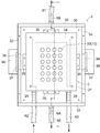
測定用ブロック2は、本実施形態では、図2、図3及び図6等に示すように、複数の貫通孔20が形成された第1プレート21と、第1プレート21に固定される第2プレート22と、第1プレート21及び第2プレート22の間に介在するパッキン23とを備えた構成のものである。
第1プレート21は、本実施形態では金属製であり、アルミニウムやステンレス等の熱伝導性が高い金属で形成することが好ましい。なお、第1プレート21は必ずしも金属製である必要はなく、例えばガラス製又は合成樹脂製であっても構わない。第1プレート21の内部には、複数の貫通孔20をまとめて囲むようにして液体が通過する流路24が形成されている。また、第1プレート21の端面には、流路24の入口端及び出口端には、それぞれ流路24に液体を導入する給水口25及び流路24から液体を導出する排水口26が取り付けられている。流路24には、図示しないタンクや水槽等から例えば水が供給される。流路24に供給される水はその温度が所望の温度に調整され、所望の温度に設定された水が流路を流れることで、第1プレート21が所望の温度に維持される。これにより、試料測定室となる凹部10の温度を、測定条件に適した温度にすることができる。
第2プレート22は、光を透過可能であり、例えば全体が透明又は半透明な材料で形成されている。第2プレート22は、例えばアクリル等の合成樹脂製、又はガラス製とすることができる。第2プレート22は、第1プレート21の複数の貫通孔20の一方側(図示では下側)の開口を塞ぐように第1プレート21の下面にネジ(図示せず)等を用いて固定されている。第1プレート21の複数の貫通孔20の一方側の開口が第2プレート22でまとめて塞がれることで、前記凹部10が複数形成される。これにより、各凹部10は、第1プレート21側の開口から第2プレート22側の底まで光を透過可能である。
パッキン23は、第1プレート21及び第2プレート22よりも一回り小さい大きさに設計されている。パッキン23には、第1プレート21の複数の貫通孔20と一対一で対応する複数の開口25が形成されている。パッキン23は、複数の開口27が個別に第1プレート21の複数の貫通孔20と重なるように第1プレート21の下面に接触状態で配置される。これにより、図6に示すように、複数の貫通孔20の一方側の開口がパッキン23によりまとめてシールされる。このパッキン23としては、ガスの漏れを防止するために従来からパッキンとして使用されている公知の材料を用いて形成することができる。パッキン23は、第2プレート22を第1プレート21の下面に固定することで、第1プレート21及び第2プレート22に挟持されるとともに、ネジ(図示せず)等を用いて第2プレート22とともに第1プレート21の下面に固定されている。
次に、チャンバー本体3は、図1、図3、図5及び図6に示すように、外形が矩形状の底部30と、底部30の周縁に起立する前後一対の前側壁部31及び後側壁部32並びに左右一対の左側壁部33及び右側壁部34と、を備えた構成のものであり、上部が開口した箱型を呈している。本実施形態では、底部30が、前後左右の各壁部31~34からなる枠体の下面にネジ(図示せず)等を用いて固定されている。
底部30の上面には、前後左右の各壁部31~34の内側位置に、それぞれ位置決め用の突起35が各壁部31~34に平行に設けられている。この4つの突起35内に測定用ブロック2が定置される。
枠体をなす前後左右の各壁部31~34のうち、前側壁部31にはチャンバー本体3内にガスを導入するガス導入口6Aが、後側壁部32にはチャンバー本体3内からガスを導出するガス導出口6Bが、それぞれ取り付けられている。なお、ガス導入口6A及びガス導出口6Bは、前後左右の各壁部31~34のいずれかに取り付けられていればよい。ガス導入口6Aには、配管60(図3等に示す)が接続され、図示しないボンベ等から例えばCO2含有ガス等の任意のガスが供給される。ガス導出口6Bには、配管61(図3等に示す)が接続され、外気やタンク等にチャンバー本体3内のガスを排出する。
また、前側壁部31には、チャンバー本体3内に収容された測定用ブロック2の給水口25に接続される配管62(図3等に示す)と、排水口26に接続される配管63(図3等に示す)とが個別に挿通される2つの挿通口36が互いに間隔をあけて形成されている。
枠体をなす前後左右の各壁部31~34のうち、左側壁部33及び右側壁部34には、長さ方向の中央部に、上端から下方に凹状に切り欠いた形状のガイド溝37がそれぞれ形成されている。この2つのガイド溝37には、後述する内蓋5の左右一対の第1ガイド部51が上方から挿入されて上下にスライド移動する。
また、左側壁部33及び右側壁部34には、それぞれのガイド溝37の下側位置に、外側に突き出る突出部38が設けられている。2つの突出部38には、それぞれ左側壁部33及び右側壁部34との境界位置に長孔状のガイド孔39が形成されている。この2つのガイド孔39には、後述する内蓋5の左右一対の第2ガイド部52が上方から挿入されて上下にスライド移動する。
次に、チャンバー蓋4は、図1、図4(A)、図5、図6及び図8に示すように、外形が矩形状であり、所定の厚みを有する板状体を呈する。チャンバー蓋4は、チャンバー本体3の上部開口を塞ぐように、チャンバー本体3の前後左右の各壁部31~34で形作られる外形の大きさとほぼ同じ大きさとなるように設計されている。チャンバー蓋4は、チャンバー本体3の上部開口に覆い被せた際に、ネジ(図示せず)等を用いてチャンバー本体3に固定することができる。チャンバー蓋4は、金属製であっても、ガラス製であっても、又は、合成樹脂製であってもよいが、アクリル等の透明な合成樹脂製であることが好ましい。
次に、内蓋5は、図1、図4(B)及び図5~図8に示すように、外形が矩形状の本体部50と、本体部50の左右の側面から突き出る一対の第1ガイド部50と、それぞれの第1ガイド部50に個別に垂直に交差するように設けられる一対の第2ガイド部51と、を備えた構成のものである。
本体部50は、所定の厚みを有する板状体を呈する。本体部50は、チャンバー蓋4よりも一回り小さい大きさに設計されており、チャンバー本体3の上部開口からチャンバー本体3内に挿入されてスライド移動が可能なように上部開口の大きさとほぼ同じ大きさに設計されている。本体部50の下面には、チャンバー本体3内を下方へスライド移動した際に、測定用ブロック2の複数の凹部10を個別に密閉する複数の栓部材11が設けられている。
複数の栓部材11は、測定用ブロック2の凹部10と一対一で対応するように、本体部50の下面に縦横に等間隔をあけて規則正しく配置されている。各栓部材11は、測定用ブロック2の凹部10に密に嵌合する形状及び大きさに設計されており、例えばゴムやシリコン等の可撓性又は弾性を有する公知の材料で形成することができる。
本体部50の下面には、複数の栓部材11の周囲に個別に設けられる複数のシール部材12が設けられている。複数のシール材12は、図8に示すように、複数の栓部材11が測定用ブロック2の複数の凹部10を個別に密閉した際に、本体部50と測定用ブロック2との間に挟まれることで、複数の凹部10の開口を個別にシールする。このシール部材12としては、ガスの漏れを防止するために従来からシール部材として使用されている公知の材料を用いて形成することができる。
一対の第1ガイド部材51及び一対の第2ガイド部材52は、本体部50がチャンバー本体3に対して上下にスライド移動する際に、上下に真っ直ぐスライド移動するように本体部50をガイドする。一対の第1ガイド部材51及び一対の第2ガイド部材52は、いずれも外形が矩形状であり、所定の厚みを有する板状体を呈する。
第1ガイド部51は、その横幅がチャンバー本体3のガイド溝37の横幅とほぼ同じ大きさである。第2ガイド部52は、その横幅が第1ガイド部51の横幅よりも大きく、かつ、チャンバー本体3のガイド孔39の横幅とほぼ同じ大きさである。一対の第1ガイド部51が、対応するガイド溝37に沿って上下にスライド移動するとともに、一対の第2ガイド部52が、対応するガイド孔39に沿って上下にスライド移動することで、本体部50はチャンバー本体3に対して上下に真っ直ぐスライド移動する。
内蓋5とチャンバー蓋4との間には、内蓋5をチャンバー蓋4に着脱可能に固定する固定手段8が設けられている。固定手段8は、チャンバー蓋4をチャンバー本体3の上部開口に覆い被せた際に、一旦は、内蓋5をチャンバー蓋4に保持させることで、図6に示すように、チャンバー本体3内に収容された測定用ブロック2と内蓋5との間の空間Sを形成する。そして、内蓋5をチャンバー蓋4から取り外すことで内蓋5がチャンバー本体3に対して上下にスライド移動が可能となり、内蓋5を下方へスライド移動させることで、図8に示すように、複数の栓部材11により測定用ブロック2の複数の凹部10を個別に密閉することができる。
固定手段8は、図1及び図4に示すように、例えば、内蓋5及びチャンバー蓋4の一方に設けられる少なくとも1つの磁石80と、内蓋5及びチャンバー蓋4の他方に磁石80と対向するように設けられる少なくとも1つの金属プレート81とにより構成することができる。本実施形態では、内蓋5の本体部50と一対の第1ガイド部材51との境界位置においてそれぞれ磁石80が貫通孔53内に嵌め込まれており、チャンバー蓋4の左右の側縁の長さ方向の中央部にそれぞれ金属プレート81がチャンバー蓋4の下面に突き出るようにして取り付けられている。この磁石80と金属プレート81との接触により、図5に示すように、内蓋5がチャンバー蓋4の下面に取り外し可能に固定される。
次に、濃度測定器7は、測定用ブロック2の各凹部10内の所定のガス(例えば酸素)の濃度を測定可能なものであれば特に限定されるものではなく、種々の構成のものを用いることができる。本実施形態では、濃度測定器7は酸素濃度測定器であり、図1、図6及び図8に示すように、測定用ブロック2の複数の凹部10の底に個別にセットされ、励起光の照射により酸素濃度に応じた強度の蛍光を発する複数の蛍光式酸素センサー70と、公知のマイクロプレートリーダー71とで構成されている。
蛍光式酸素センサー70は、励起光の照射を受けることで試料測定室である測定用ブロック2の凹部10内の酸素濃度に応じた強度の蛍光を発するものである。具体的には、酸素感受性の蛍光物質を内部に固定して成形したものである。
マイクロプレートリーダー71は、測定用ブロック2の複数の凹部10にセットされた各蛍光式酸素センサー70対して個別に励起光を照射する複数の発光部(図示せず)と、複数の蛍光式酸素センサー70から発せられる蛍光を個別に測定する複数の受光部(図示せず)とを備えた構造のものである。発光部は、蛍光式酸素センサー70に固定した蛍光物質を励起して蛍光を発するために用いられるものであり、例えば水銀ランプ、レーザ又はLED等を用いることができる。受光部は、発光部からの光で励起された蛍光式酸素センサー70からの酸素濃度に応じた強度の蛍光を受け取るものであり、例えば冷却CCD等を用いることができる。マイクロプレートリーダー71には、制御装置(図示せず)が接続されている。制御装置は、マイクロプレートリーダー71で得た蛍光画像を受け取り、蛍光強度情報を酸素濃度較正直線と比較し酸素濃度プロファイルや酸素消費速度を算出して出力するものである。制御装置としては、CPU、ROM、RAM及びI/Oを備えたコンピュータを用いることができる。
なお、本実施形態では、発光部と受光部とが同じ装置内に設けられたマイクロプレートリーダー71を用いているが、発光部としての励起光源と、受光部としての蛍光強度取得装置とが別個の装置であってもよい。
蛍光式酸素センサー70は、測定用ブロック2の各凹部10の底にセットされる一方で、マイクロプレートリーダー71は、チャンバー本体3の底部30の下方にセットされる。チャンバー本体3の底部30の下面には、所定の厚みを有する板状のセンサー固定部材9がネジ91(図1)等を用いて固定されている。センサー固定部材9は、金属製であっても、ガラス製であっても、又は、合成樹脂製であってもよいが、アクリル等の透明な合成樹脂製であることが好ましい。
センサー固定部材9は、図1、図6及び図8に示すように、外形が略矩形状であり、その中央部にマイクロプレートリーダー71を囲んで位置決めするための開口90が形成されている。マイクロプレートリーダー71はこの開口90内に配置されることで、測定用ブロック2の複数の凹部10に対して個別に励起光を照射することができる。なお、チャンバー本体3の底部30は、ネジ91の高さによりその下方にマイクロプレートリーダー71を設置するスペースを形成している。
次に、上述した構成の測定装置1を用いて例えば植物の光合成活性を測定する方法の手順について説明する。まず、図5に示すように、チャンバー本体3内に測定用ブロック2を収容した状態で、測定用ブロック2の各凹部10の底に蛍光式酸素センサー70をセットする。
そして、測定用ブロック2の各凹部10内の蛍光式酸素センサー70上に、遮光シート73及び/又は通気性の緩衝材72を載せた状態で、測定試料100として葉の一部をセットする。遮光シート73は、後述する測定用ブロック2の上方より全ての凹部10内に光を照射する光照射器101からの光を測定用ブロック2の下方に位置するマイクロプレートリーダー71に入射させないようにするためのものである。遮光シート73としては例えば黒色のフェルト等を用いることができるが、特にこれに限定されるものではなく、同様の機能を有するものであれば種々のものを用いることができる。また、緩衝材72は、測定試料100が蛍光式酸素センサー70に直接触れるのを防止するためのものであり、例えばプラスチックウールやメッシュ等を用いることができるが、特にこれに限定されるものではなく、同様の機能を有するものであれば種々のものを用いることができる。
次に、図5及び図6に示すように、内蓋5をチャンバー蓋4の下面に固定した状態で、チャンバー蓋4をチャンバー本体3の上部開口に覆い被せる。これにより、チャンバー本体3内の空間Sが閉鎖される。この状態で、ガス導入口6AよりCO2含有ガスをチャンバー本体3内に導入することで、測定用ブロック2の全ての凹部10内がCO2含有ガスにより一斉に置換される。
そして、図7及び図8に示すように、内蓋5とチャンバー蓋4との固定を外し、内蓋5をチャンバー本体3に対して下方へスライド移動させることで、複数の栓部材11により測定用ブロック2の複数の凹部10の開口を塞ぐ。これにより、測定用ブロック2の全ての凹部10が同時に個別に密閉され、全ての凹部10はCO2含有ガスが充満した状態となる。
次に、チャンバー蓋4をチャンバー本体3から取り外し、図9に示すように、ネジ13等を用いて内蓋5を測定用ブロック2に固定することで、測定用ブロック2の全ての凹部10が強固に密閉される。
そして、測定用ブロック2が植物の光合成に最適な温度となるよう流路24に所定温度の水を流しながら、図10に示すように、測定用ブロック2の上方から光照射器101により全ての凹部10内に光を照射させる。
これにより、測定用ブロック2の各凹部10内の測定試料100が光を受けることで光合成を行い、凹部10内の二酸化炭素と水から炭水化物が合成され、凹部10内に酸素が放出される。一方で、凹部10内の蛍光式酸素センサー70は、マイクロプレートリーダー71から励起光の照射を受けることで蛍光を発しており、この蛍光はマイクロプレートリーダー71で計測されている。光合成により測定試料100から酸素が凹部10内に放出されると、凹部10内の酸素濃度に応じて蛍光式酸素センサー70から発せられる蛍光が弱まる。よって、マイクロプレートリーダー71により蛍光式酸素センサー70から発せられる蛍光の強度を経時的に計測することで、凹部10内の酸素濃度変化を測定することができ、測定試料100の光合成活性を測定することができる。
以上のように、植物の光合成活性を測定するためには、試料測定室となる測定用ブロック2の複数の凹部10内をCO2含有ガスで置換する必要があるが、本実施形態の測定装置1によると、測定用ブロック2の全ての凹部10内を一斉にCO2含有ガスで置換することができるとともに、全ての凹部10を同時に個別に密閉することができる。よって、複数の測定試料について、光合成活性を同時に測定することができるので、特に測定試料が多数の場合に効率よく測定可能であり、測定時間を大幅に短縮することができる。
また、測定用ブロック2の内部に液体が通過する流路24が形成されており、流路24に流す液体の温度を調整することで測定用ブロック2の各凹部10内の温度を所望の温度に維持することができる。よって、測定対象となる活性に応じて各凹部10内の温度を所望の温度に設定することで、光合成活性等の活性を良好に測定することができる。
また、チャンバー本体3の上部開口を塞ぐチャンバー蓋4に内蓋5が着脱可能に固定されており、内蓋5を、図6に示す測定用ブロック2の上方に間隔をあけて位置する状態と、図8に示す測定用ブロック2の直上に位置する状態とに容易に切り換えることができる。よって、チャンバー本体3内にCO2含有ガス等の任意のガスを導入する際には、図6に示す位置で定置させ、測定用ブロック2の各凹部10内がCO2含有ガス等の任意のガスで置換された後は、内蓋5とチャンバー蓋4との固定を外すだけで、内蓋5の栓部材11により測定用ブロック2の凹部10の開口を容易に塞ぐことができる。
以上、本発明の一実施形態について説明したが、本発明は上記実施形態に限定されるものではなく、本発明の趣旨を逸脱しない限りにおいて種々の変更が可能である。
例えば、上記実施形態では、固定手段8が磁石80と金属プレート81とにより構成されているが、内蓋5をチャンバー蓋4に一時的に固定し、さらにチャンバー蓋4から取り外すことが可能であれば、その他の種々の構成を用いることができる。
また、上記実施形態では、光合成活性を測定する際に、測定ブロック2の各凹部10内の酸素濃度の経時的変化を測定しているが、二酸化炭素濃度の経時的変化を測定してもよい。さらに、測定対象が植物であるが、測定対象は植物に限定されず、例えば藻類等の水中の生物、これらの細胞(植物や藻類等から単離された細胞又は培養細胞)、さらには細胞小器官(例えば葉緑体やミトコンドリア)等であってもよい。藻類や細胞等の光合成活性を測定試料とする場合には、測定試料とともに各凹部10内に収容される液体(水、細胞保存液、細胞培養液等)のpHの経時的変化を、例えば蛍光式pHセンサー等のpH測定器を用いて測定することで、光合成活性を測定してもよい。
また、上記実施形態では、測定試料の光合成活性を測定するために測定装置1を用いているが、生物、その細胞(生物から単離された細胞又は培養細胞)や細胞小器官(例えば葉緑体やミトコンドリア)の呼吸活性を測定するために測定装置1を用いることもできる。この場合、任意の酸素含有ガスを測定用ブロック2の各凹部10内に置換し、呼吸により消費される酸素の濃度、呼吸により発生する二酸化炭素の濃度又は測定試料とともに各凹部10内に収容される液体(水、細胞保存液、細胞培養液等)のpH等の経時的変化を測定器を用いて測定することで、呼吸活性を測定することができる。呼吸活性を測定する場合には、緩衝材72や遮光シート73は必ずしも必要ではない。
さらに、光合成活性や呼吸活性以外で、酸素濃度に関する情報又は二酸化炭素濃度に関する情報に基づき測定できるその他の活性についても測定装置1を用いて測定することができる。そのうえ、酸素濃度及び二酸化炭素以外の所定のガスの濃度に関する情報に基づき測定できるその他の活性についても測定装置1を用いて測定することができる。この場合、測定用ブロック2の各凹部10内を測定する活性に応じた任意のガスで置換し、測定対象に合った測定器を用いて所定のガスの濃度に関する情報を測定すればよい。
また、上記実施形態では、測定用ブロック2の各凹部10内の酸素濃度等のガス濃度を測定する測定器7が、ガス濃度に依拠した指標(例えば蛍光式ガスセンサーの蛍光強度)を計測することでガス濃度を測定しているが、ガス濃度を測定可能なものであれば直接ガス濃度を計測できるものであってもよい。また、ガス濃度は絶対値を測定しても相対値を測定してもよく、さらに時間変化等を測定してもよい。
以下、実施例を示して本発明をより詳細に説明するが、本発明はこれらに限定されない。
試験例
1.試験手順
上述した実施形態の測定装置を用いて光合成活性を測定した。測定試料として葉の一部(トマトの葉、直径8mmの円形(一枚の葉を直径8mmの円形に切り取って作製))を用いた。
1.試験手順
上述した実施形態の測定装置を用いて光合成活性を測定した。測定試料として葉の一部(トマトの葉、直径8mmの円形(一枚の葉を直径8mmの円形に切り取って作製))を用いた。
より具体的には、図5に示すチャンバー本体3内に測定用ブロック2を収容した状態で、測定用ブロック2の複数の凹部10のうちの4つの凹部10の底にそれぞれ蛍光式酸素センサー70(商品名Oxygen Sensor Spot、PreSens社製)をセットした。次いで、4つの凹部10内の蛍光式酸素センサー70上に、遮光シート73(黒色フェルト)を載せ、次いで、測定試料100として前述の葉の一部(リーフディスク)を、葉の裏面が下側になるようにして水平に入れた。次いで、図5及び図6に示すように、内蓋5をチャンバー蓋4の下面に固定した状態で、チャンバー蓋4をチャンバー本体3の上部開口に覆い被せて、チャンバー本体3内の空間Sを閉鎖した。
この状態で、ガス導入口6AよりCO2含有ガス(組成:5%CO2、5%O2、90%N2)をチャンバー本体3内に導入し、測定用ブロック2の全ての凹部10内をCO2含有ガスにより一斉に置換した。次いで、図7及び図8に示すように、内蓋5とチャンバー蓋4との固定を外し、内蓋5をチャンバー本体3に対して下方へスライド移動させて、複数の栓部材11により測定用ブロック2の複数の凹部10の開口を塞ぎ、測定用ブロック2の全ての凹部10を同時且つ個別に密閉し、全ての凹部10をCO2含有ガスが充満した状態とした。次に、チャンバー蓋4をチャンバー本体3から取り外し、図9に示すようにネジ13を用いて内蓋5を測定用ブロック2に固定した。この状態で、流路24に23℃の水を流して循環させた。
最後に測定装置1の上に暗幕を被せ、酸素濃度の測定を開始した。暗所における酸素濃度の変化が一定になった時点で、測定装置1の上に備えたLEDライトを点灯し、測定試料に光照射を行った(図11中のOn)。なお、4つの測定試料のうちの2つの測定試料には光合成阻害剤(DUMU(3-(3,4-dichlorophenyl)-1,1-dimethylurea))を作用させた。その結果を図11に示す。
また、測定試料にイチョウの葉を用いるとともに測定試料の全てに光合成阻害剤を作用させてない以外は前述と同様にして、4つの凹部10に蛍光式酸素センサー、測定試料(リーフディスク)をセット等して酸素濃度の測定を開始した。なお、この場合、LEDライトを点灯させてから5分後に、LEDライトを消灯した(図12中のOff)。その結果を図12に示す。
2.結果
図11において、光合成阻害剤を作用させた測定試料(DUMU(1)、DUMU(2))においては、光照射下においても酸素濃度の有意な増加は認められなかったが、光合成阻害剤を作用させていない測定試料(Non(1)、Non(2))においては、光照射下において酸素濃度の有意な増加が認められた。これにより、前記測定装置によれば、酸素濃度に基づいて複数の測定試料の光合成活性を同時かつ経時的に測定できることが分かった。
図11において、光合成阻害剤を作用させた測定試料(DUMU(1)、DUMU(2))においては、光照射下においても酸素濃度の有意な増加は認められなかったが、光合成阻害剤を作用させていない測定試料(Non(1)、Non(2))においては、光照射下において酸素濃度の有意な増加が認められた。これにより、前記測定装置によれば、酸素濃度に基づいて複数の測定試料の光合成活性を同時かつ経時的に測定できることが分かった。
また、図12では、いずれの測定試料においても、光照射下では酸素濃度の増加が認められ、また、光照射の停止に伴い、酸素濃度の増加が停止したことが認められた。これにより、前記測定装置によれば酸素濃度に基づいて複数の測定試料の光合成活性を同時かつ経時的に測定できることが分かった。
これらのことから、本発明の測定装置によれば、酸素濃度に基づいて複数の測定試料の光合成活性を同時かつ経時的に測定できることが分かった。また、このように、本発明の測定装置によれば、酸素濃度の測定を複数の測定試料について同時かつ経時的に行うことができることから、測定装置は、光合成活性にかかわらず、呼吸活性をはじめとして酸素濃度の変化を指標とできる活性の測定に有用であることが分かった。また、本発明の測定装置は、異なる蛍光式センサーを利用することで、酸素だけでなく、他のガス濃度やpH等の変化を指標とできる活性の測定に有用であることが分かった。本発明の測定装置は複数の測定試料の活性を同時かつ経時的に測定できることから、1回の測定に1つの試料しか測定できなかった従来の方法と比較して、短時間で効率良く測定できることが分かった。
1 測定装置
2 測定用ブロック
3 チャンバー本体
4 チャンバー蓋
5 内蓋
6A ガス導入口
6B ガス導出口
7 濃度測定器
8 固定手段
10 凹部
11 栓部材
12 シール部材
21 第1プレート
22 第2プレート
24 流路
25 給水口
26 排水口
23 パッキン
70 蛍光式酸素センサー
71 マイクロプレートリーダー(発光部及び受光部)
72 緩衝材
73 遮光シート
80 磁石
81 金属プレート
100 測定試料
101 光照射器
2 測定用ブロック
3 チャンバー本体
4 チャンバー蓋
5 内蓋
6A ガス導入口
6B ガス導出口
7 濃度測定器
8 固定手段
10 凹部
11 栓部材
12 シール部材
21 第1プレート
22 第2プレート
24 流路
25 給水口
26 排水口
23 パッキン
70 蛍光式酸素センサー
71 マイクロプレートリーダー(発光部及び受光部)
72 緩衝材
73 遮光シート
80 磁石
81 金属プレート
100 測定試料
101 光照射器
Claims (9)
- 試料測定室内の所定のガスの濃度に関する情報を同時に測定するための測定装置であって、
試料測定室となる凹部を複数備えた測定用ブロックと、
前記測定用ブロックを収容するチャンバー本体と、
前記チャンバー本体の上部開口を塞ぐチャンバー蓋と、
前記チャンバー本体に対して上下にスライド移動可能であり、下方へのスライド移動に伴い前記測定用ブロックの複数の凹部を個別に密閉する複数の栓部材を下面に備える内蓋と、
前記チャンバー本体に取り付けられ、前記チャンバー本体内の前記測定用ブロックと前記内蓋との間の空間に任意のガスを導入するガス導入口及び前記空間から任意のガスを導出するガス導出口と、
前記測定用ブロックの各凹部内の前記所定のガスの濃度に関する情報を測定可能な測定器と、を備える測定装置。 - 前記内蓋を前記チャンバー蓋に着脱可能に固定する固定手段をさらに備える、請求項1に記載の測定装置。
- 前記固定手段は、
前記内蓋及び前記チャンバー蓋の一方に設けられる少なくとも1つの磁石と、
前記内蓋及び前記チャンバー蓋の他方に前記磁石と対向するように設けられる少なくとも1つの金属プレートと、を備える、請求項2に記載の測定装置。 - 前記内蓋は、前記複数の栓部材の周囲に個別に設けられる複数のシール部材をさらに備え、
前記複数のシール材は、前記複数の栓部材が前記測定用ブロックの複数の凹部を個別に密閉した際に前記内蓋と前記測定用ブロックとの間に挟まれて前記複数の凹部の開口を個別にシールする、請求項1~3のいずれかに記載の測定装置。 - 前記測定用ブロックは、
複数の貫通孔が形成された金属製の第1プレートと、
前記第1プレートの複数の貫通孔の一方側の開口を塞いで前記凹部を複数形成するように前記第1プレートに固定される第2プレートと、を備え、
前記第2プレートは、光を透過可能であり、
前記第1プレートには、前記複数の貫通孔をまとめて囲むようにして液体が通過する流路が内部に形成されているとともに、前記流路に液体を供給する給水口及び前記流路から液体を排出する排水口が設けられている、請求項1~4のいずれかに記載の測定装置。 - 前記第1プレートと前記第2プレートとの間には、前記複数の貫通孔の一方側の開口をシールするパッキンが挟持されている、請求項1~5のいずれかに記載の測定装置。
- 前記測定器は、酸素濃度を測定する酸素濃度測定器であり、
前記酸素濃度測定器は、前記測定用ブロックの複数の凹部の底に個別にセットされ、励起光の照射により酸素濃度に応じた強度の蛍光を発する複数の蛍光式酸素センサーと、
前記複数の蛍光式酸素センサーに励起光を個別に照射する複数の発光部と、前記複数の蛍光式酸素センサーから発せられる蛍光を個別に測定する複数の受光部と、を備える、請求項1~6のいずれかに記載の測定装置。 - 前記測定用ブロックの複数の凹部には、それぞれ前記蛍光式酸素センサー上に遮光シート及び/又は通気性の緩衝材を介して試料が収容される、請求項7に記載の測定装置。
- 前記測定用ブロックの全ての凹部内に光を照射する光照射器をさらに備える、請求項1~8のいずれかに記載の測定装置。
Applications Claiming Priority (2)
| Application Number | Priority Date | Filing Date | Title |
|---|---|---|---|
| JP2019-026320 | 2019-02-18 | ||
| JP2019026320A JP7190167B2 (ja) | 2019-02-18 | 2019-02-18 | 測定装置 |
Publications (1)
| Publication Number | Publication Date |
|---|---|
| WO2020171013A1 true WO2020171013A1 (ja) | 2020-08-27 |
Family
ID=72144494
Family Applications (1)
| Application Number | Title | Priority Date | Filing Date |
|---|---|---|---|
| PCT/JP2020/006028 Ceased WO2020171013A1 (ja) | 2019-02-18 | 2020-02-17 | 測定装置 |
Country Status (2)
| Country | Link |
|---|---|
| JP (1) | JP7190167B2 (ja) |
| WO (1) | WO2020171013A1 (ja) |
Families Citing this family (1)
| Publication number | Priority date | Publication date | Assignee | Title |
|---|---|---|---|---|
| WO2024218978A1 (ja) * | 2023-04-21 | 2024-10-24 | 日本電信電話株式会社 | 光合成測定方法、光合成測定装置およびプログラム |
Citations (5)
| Publication number | Priority date | Publication date | Assignee | Title |
|---|---|---|---|---|
| JP2009544034A (ja) * | 2006-07-17 | 2009-12-10 | アファンティウム・インターナショナル・ベスローテン・フェンノートシャップ | 固体(好ましくは結晶)の入手及び分析法 |
| CN204789299U (zh) * | 2015-07-14 | 2015-11-18 | 天津职业技术师范大学 | 一种便携式植物光合作用分析箱 |
| JP2016540998A (ja) * | 2013-12-06 | 2016-12-28 | バクテリオスキャン エルティーディー | 試料チャンバを有する光学測定キュベット |
| JP2017510447A (ja) * | 2014-03-26 | 2017-04-13 | コーニング インコーポレイテッド | モジュール式の流通式光化学反応器システム |
| WO2017160839A1 (en) * | 2016-03-14 | 2017-09-21 | Diassess Inc. | Devices and methods for modifying optical properties |
Family Cites Families (2)
| Publication number | Priority date | Publication date | Assignee | Title |
|---|---|---|---|---|
| DE19903506C2 (de) * | 1999-01-29 | 2002-04-04 | Inst Chemo Biosensorik | Verfahren, Gefäß und Vorrichtung zur Überwachung der Stoffwechselaktivität von Zellkulturen in flüssigen Medien |
| DK1412725T3 (en) * | 2001-06-29 | 2019-03-25 | Meso Scale Technologies Llc | Multi-well plates for LUMINESCENSE TEST MEASUREMENTS |
-
2019
- 2019-02-18 JP JP2019026320A patent/JP7190167B2/ja active Active
-
2020
- 2020-02-17 WO PCT/JP2020/006028 patent/WO2020171013A1/ja not_active Ceased
Patent Citations (5)
| Publication number | Priority date | Publication date | Assignee | Title |
|---|---|---|---|---|
| JP2009544034A (ja) * | 2006-07-17 | 2009-12-10 | アファンティウム・インターナショナル・ベスローテン・フェンノートシャップ | 固体(好ましくは結晶)の入手及び分析法 |
| JP2016540998A (ja) * | 2013-12-06 | 2016-12-28 | バクテリオスキャン エルティーディー | 試料チャンバを有する光学測定キュベット |
| JP2017510447A (ja) * | 2014-03-26 | 2017-04-13 | コーニング インコーポレイテッド | モジュール式の流通式光化学反応器システム |
| CN204789299U (zh) * | 2015-07-14 | 2015-11-18 | 天津职业技术师范大学 | 一种便携式植物光合作用分析箱 |
| WO2017160839A1 (en) * | 2016-03-14 | 2017-09-21 | Diassess Inc. | Devices and methods for modifying optical properties |
Also Published As
| Publication number | Publication date |
|---|---|
| JP7190167B2 (ja) | 2022-12-15 |
| JP2020134262A (ja) | 2020-08-31 |
Similar Documents
| Publication | Publication Date | Title |
|---|---|---|
| KR102076545B1 (ko) | 광보호성 재료 기반의 신규 포장 설계의 생산 방법 | |
| CN103080294B (zh) | 细胞培养容器及使用该容器的细胞培养方法 | |
| JP2016516206A (ja) | 培養装置を備えるマイクロプレートリーダー | |
| KR20090004938A (ko) | 멀티웰 인큐베이션 장치 및 이것을 사용한 분석 방법 | |
| CA2607086C (en) | System for rapid analysis of microbiological materials in liquid samples | |
| KR102064861B1 (ko) | 광보호성 재료 측정용 장치 | |
| WO2009125974A3 (en) | Multi-channel bio reactor with fluorescence detector and on-line monitoring apparatus of it | |
| US20210155890A1 (en) | Incubator device, cell culture environment control system, and cell culture environment control method | |
| EA021562B1 (ru) | Устройство мониторинга пространственного свертывания крови и ее компонентов | |
| WO2020171013A1 (ja) | 測定装置 | |
| KR20180003757A (ko) | 조류 모니터링 시스템 | |
| KR20090080390A (ko) | 다중 세포배양기를 구비한 인큐베이터 | |
| JP2011182731A (ja) | 藻類増殖量自動測定装置 | |
| US11635380B2 (en) | Fluorometer calibration device and method | |
| KR101087720B1 (ko) | 형광 측정장치 | |
| Koch et al. | In vivo determination of carotenoid resonance excitation profiles of Chlorella vulgaris, Haematococcus pluvialis, and Porphyridium purpureum | |
| KR20200025330A (ko) | 서로 다른 배양 환경이 조성되는 배양공간을 구비한 배양조 | |
| WO2019151542A1 (ja) | 試料計測方法、マルチウエルプレートの蓋、試料計測キット、及び、試料計測装置 | |
| KR20170001064A (ko) | 자동 개폐장치를 장착한 uv조사기 | |
| KR101399453B1 (ko) | 생태 독성 감시 장치 및 방법 | |
| KR100524344B1 (ko) | 건축자재로부터 방출되는 유해물질 측정을 위한 시험실 장치 | |
| RU123166U1 (ru) | Устройство мониторинга постранственного свертывания крови и ее компонентов | |
| US20240385147A1 (en) | Accelerated degradation testing device | |
| ES2857686T3 (es) | Dispositivo para monitorizar la dinámica espacial y temporal de trombina | |
| KR20140093389A (ko) | 광화학센서를 이용한 생태독성측정장치 |
Legal Events
| Date | Code | Title | Description |
|---|---|---|---|
| 121 | Ep: the epo has been informed by wipo that ep was designated in this application |
Ref document number: 20759551 Country of ref document: EP Kind code of ref document: A1 |
|
| NENP | Non-entry into the national phase |
Ref country code: DE |
|
| 122 | Ep: pct application non-entry in european phase |
Ref document number: 20759551 Country of ref document: EP Kind code of ref document: A1 |