WO2020170822A1 - Card holding member and connector set for card - Google Patents
Card holding member and connector set for card Download PDFInfo
- Publication number
- WO2020170822A1 WO2020170822A1 PCT/JP2020/004357 JP2020004357W WO2020170822A1 WO 2020170822 A1 WO2020170822 A1 WO 2020170822A1 JP 2020004357 W JP2020004357 W JP 2020004357W WO 2020170822 A1 WO2020170822 A1 WO 2020170822A1
- Authority
- WO
- WIPO (PCT)
- Prior art keywords
- tray
- card
- connector
- terminal
- holding member
- Prior art date
Links
Images


Classifications
-
- H—ELECTRICITY
- H01—ELECTRIC ELEMENTS
- H01R—ELECTRICALLY-CONDUCTIVE CONNECTIONS; STRUCTURAL ASSOCIATIONS OF A PLURALITY OF MUTUALLY-INSULATED ELECTRICAL CONNECTING ELEMENTS; COUPLING DEVICES; CURRENT COLLECTORS
- H01R12/00—Structural associations of a plurality of mutually-insulated electrical connecting elements, specially adapted for printed circuits, e.g. printed circuit boards [PCB], flat or ribbon cables, or like generally planar structures, e.g. terminal strips, terminal blocks; Coupling devices specially adapted for printed circuits, flat or ribbon cables, or like generally planar structures; Terminals specially adapted for contact with, or insertion into, printed circuits, flat or ribbon cables, or like generally planar structures
- H01R12/70—Coupling devices
- H01R12/7005—Guiding, mounting, polarizing or locking means; Extractors
-
- G—PHYSICS
- G06—COMPUTING; CALCULATING OR COUNTING
- G06K—GRAPHICAL DATA READING; PRESENTATION OF DATA; RECORD CARRIERS; HANDLING RECORD CARRIERS
- G06K7/00—Methods or arrangements for sensing record carriers, e.g. for reading patterns
- G06K7/0013—Methods or arrangements for sensing record carriers, e.g. for reading patterns by galvanic contacts, e.g. card connectors for ISO-7816 compliant smart cards or memory cards, e.g. SD card readers
- G06K7/0034—Methods or arrangements for sensing record carriers, e.g. for reading patterns by galvanic contacts, e.g. card connectors for ISO-7816 compliant smart cards or memory cards, e.g. SD card readers the connector being capable of simultaneously receiving a plurality of cards in the same insertion slot
- G06K7/0039—Methods or arrangements for sensing record carriers, e.g. for reading patterns by galvanic contacts, e.g. card connectors for ISO-7816 compliant smart cards or memory cards, e.g. SD card readers the connector being capable of simultaneously receiving a plurality of cards in the same insertion slot the plurality of cards being cards of the same type and format, e.g. two ISO 7816 smart cards
-
- G—PHYSICS
- G06—COMPUTING; CALCULATING OR COUNTING
- G06K—GRAPHICAL DATA READING; PRESENTATION OF DATA; RECORD CARRIERS; HANDLING RECORD CARRIERS
- G06K19/00—Record carriers for use with machines and with at least a part designed to carry digital markings
- G06K19/06—Record carriers for use with machines and with at least a part designed to carry digital markings characterised by the kind of the digital marking, e.g. shape, nature, code
- G06K19/067—Record carriers with conductive marks, printed circuits or semiconductor circuit elements, e.g. credit or identity cards also with resonating or responding marks without active components
- G06K19/07—Record carriers with conductive marks, printed circuits or semiconductor circuit elements, e.g. credit or identity cards also with resonating or responding marks without active components with integrated circuit chips
- G06K19/077—Constructional details, e.g. mounting of circuits in the carrier
- G06K19/07743—External electrical contacts
-
- G—PHYSICS
- G06—COMPUTING; CALCULATING OR COUNTING
- G06K—GRAPHICAL DATA READING; PRESENTATION OF DATA; RECORD CARRIERS; HANDLING RECORD CARRIERS
- G06K7/00—Methods or arrangements for sensing record carriers, e.g. for reading patterns
- G06K7/0013—Methods or arrangements for sensing record carriers, e.g. for reading patterns by galvanic contacts, e.g. card connectors for ISO-7816 compliant smart cards or memory cards, e.g. SD card readers
- G06K7/0056—Methods or arrangements for sensing record carriers, e.g. for reading patterns by galvanic contacts, e.g. card connectors for ISO-7816 compliant smart cards or memory cards, e.g. SD card readers housing of the card connector
- G06K7/006—Methods or arrangements for sensing record carriers, e.g. for reading patterns by galvanic contacts, e.g. card connectors for ISO-7816 compliant smart cards or memory cards, e.g. SD card readers housing of the card connector the housing being a portable casing
-
- G—PHYSICS
- G06—COMPUTING; CALCULATING OR COUNTING
- G06K—GRAPHICAL DATA READING; PRESENTATION OF DATA; RECORD CARRIERS; HANDLING RECORD CARRIERS
- G06K7/00—Methods or arrangements for sensing record carriers, e.g. for reading patterns
- G06K7/0013—Methods or arrangements for sensing record carriers, e.g. for reading patterns by galvanic contacts, e.g. card connectors for ISO-7816 compliant smart cards or memory cards, e.g. SD card readers
- G06K7/0056—Methods or arrangements for sensing record carriers, e.g. for reading patterns by galvanic contacts, e.g. card connectors for ISO-7816 compliant smart cards or memory cards, e.g. SD card readers housing of the card connector
- G06K7/0073—Methods or arrangements for sensing record carriers, e.g. for reading patterns by galvanic contacts, e.g. card connectors for ISO-7816 compliant smart cards or memory cards, e.g. SD card readers housing of the card connector having multiple insertion slots, the respective slots suited for the same or different card form factors
-
- H—ELECTRICITY
- H01—ELECTRIC ELEMENTS
- H01R—ELECTRICALLY-CONDUCTIVE CONNECTIONS; STRUCTURAL ASSOCIATIONS OF A PLURALITY OF MUTUALLY-INSULATED ELECTRICAL CONNECTING ELEMENTS; COUPLING DEVICES; CURRENT COLLECTORS
- H01R12/00—Structural associations of a plurality of mutually-insulated electrical connecting elements, specially adapted for printed circuits, e.g. printed circuit boards [PCB], flat or ribbon cables, or like generally planar structures, e.g. terminal strips, terminal blocks; Coupling devices specially adapted for printed circuits, flat or ribbon cables, or like generally planar structures; Terminals specially adapted for contact with, or insertion into, printed circuits, flat or ribbon cables, or like generally planar structures
- H01R12/70—Coupling devices
- H01R12/71—Coupling devices for rigid printing circuits or like structures
- H01R12/712—Coupling devices for rigid printing circuits or like structures co-operating with the surface of the printed circuit or with a coupling device exclusively provided on the surface of the printed circuit
- H01R12/714—Coupling devices for rigid printing circuits or like structures co-operating with the surface of the printed circuit or with a coupling device exclusively provided on the surface of the printed circuit with contacts abutting directly the printed circuit; Button contacts therefore provided on the printed circuit
-
- H—ELECTRICITY
- H01—ELECTRIC ELEMENTS
- H01R—ELECTRICALLY-CONDUCTIVE CONNECTIONS; STRUCTURAL ASSOCIATIONS OF A PLURALITY OF MUTUALLY-INSULATED ELECTRICAL CONNECTING ELEMENTS; COUPLING DEVICES; CURRENT COLLECTORS
- H01R12/00—Structural associations of a plurality of mutually-insulated electrical connecting elements, specially adapted for printed circuits, e.g. printed circuit boards [PCB], flat or ribbon cables, or like generally planar structures, e.g. terminal strips, terminal blocks; Coupling devices specially adapted for printed circuits, flat or ribbon cables, or like generally planar structures; Terminals specially adapted for contact with, or insertion into, printed circuits, flat or ribbon cables, or like generally planar structures
- H01R12/70—Coupling devices
- H01R12/71—Coupling devices for rigid printing circuits or like structures
- H01R12/72—Coupling devices for rigid printing circuits or like structures coupling with the edge of the rigid printed circuits or like structures
- H01R12/73—Coupling devices for rigid printing circuits or like structures coupling with the edge of the rigid printed circuits or like structures connecting to other rigid printed circuits or like structures
Definitions
- the present disclosure relates to a card holding member and a card connector set.
- FIG. 13 is a diagram showing a conventional card connector.
- 811 is a substrate of a card connector on the surface of which conductive connecting pads (not shown) are formed
- 861 is a shell of the card connector made of a metal plate, and covers the upper part of the connecting pad.
- the card housing space 818 of the card connector is formed between the board 811 and the shell 861.
- Reference numeral 971 denotes a card tray, which is inserted from the entrance side of the card housing space 818 as shown by an arrow in a state where the card 901 is loaded inside and is housed in the card connector.
- a plurality of conductive members 951 are attached to the bottom plate of the card tray 971.
- the card 901 When the card 901 is loaded on the card tray 971, it is exposed and formed on the lower surface of the card 901.
- Each of the plurality of electrode pads contacts the upper surface of the corresponding conductive member 951.
- the lower surface of the tip of each conductive member 951 contacts the connection pad formed on the surface of the substrate 811.
- the electrode pad and the corresponding connection pad of the card connector are connected via the conductive member 951.
- the card 901 is inserted and accommodated in the card accommodation space 818 while being loaded in the card tray 971. Therefore, when the card 901 is accommodated in the card accommodation space 818, the card 901 is accommodated in the card accommodation space 818. There is no contact with the entrance of the space 818, and the electrode pads and the like are not damaged. Moreover, since the electrode pad of the card 901 and the corresponding connection pad are connected via the conductive member 951 having elasticity, the electrical connection between the electrode pad and the connection pad is stabilized.
- the conductive member 951 attached to the bottom plate of the card tray 971 is elastically deformed to maintain contact with the electrode pad of the card 901, and Since the contact with the connection pad is maintained, it is necessary to increase the elastically deformable range of the conductive member 951, which makes it difficult to reduce the size of the conductive member 951. It becomes difficult to downsize the 971 and it becomes difficult to downsize the card connector that accommodates the card tray 971.
- the card holding member is a card holding member that can hold a card having an electrode pad and can be inserted into a card connector having a connector terminal, and has a concave portion that can accommodate the card and a concave portion of the concave portion.
- a tray housing including a bottom wall portion defining a bottom surface and a tray terminal accommodating recess formed in the bottom wall portion, and a tray terminal arranged in the bottom wall portion, at least a part of which is the bottom wall. And a first contact portion and a second contact portion, which are respectively connected to both ends of the main body portion and are held by the first and second contact portions, and which are in contact with the connector terminal and the electrode pad.
- a tray terminal including a possible second contact portion, wherein the first contact portion is fixed and exposed on a surface of the bottom wall portion opposite to the bottom surface of the recess, and the second contact portion is At least the contact points of the contacts projecting from the bottom surface of the recess are housed in the tray terminal housing recess so as to be elastically deformable.
- the second contact portion can be elastically deformed in the tray terminal accommodating recess without interfering with another member.
- the tray terminal may form a single row or a plurality of rows in which the second contact portions are arranged in a width direction orthogonal to the insertion direction of the card holding member in plan view. It is installed in.
- the tray terminal is arranged so that the main body portion extends in the insertion direction of the card holding member in a plan view.
- the tray terminal further includes a tray terminal in which the main body portion is arranged so as to extend in the insertion direction of the card holding member in plan view, and the main body portion. And a tray terminal arranged so as to extend in a width direction orthogonal to the insertion direction of the card holding member.
- At least one of the tray terminals includes a row-direction portion in which the main body portion is arranged so as to extend in the insertion direction of the card holding member in plan view,
- the main body portion includes a row direction portion arranged so as to extend in a width direction orthogonal to the insertion direction of the card holding member.
- the tray terminal further includes an inclined direction portion connecting the column direction portion and the row direction portion.
- a card holding member according to the present disclosure and a card connector into which the card holding member can be inserted, the connector including an elastically deformable contact portion that can contact the first contact portion A card connector having terminals.
- each of the connector terminals extends in the insertion direction of the card holding member, and the contact portion, in plan view, the insertion direction of the card holding member and It is arranged so as to form a single row or a plurality of rows arranged along the width direction orthogonal to each other.
- the card holding member and card connector set can be used for cards that are small and thin, and have multiple poles, and can be made compact and have a low profile and multiple poles, thus improving reliability.
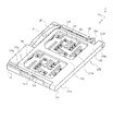
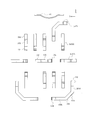
- FIG. 6 is a perspective view showing a card connector set in which a tray for holding a card is inserted into the connector in the first embodiment.
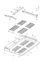
- FIG. 3 is an exploded view of the card connector set according to the first embodiment.
- FIG. 6 is a perspective view showing a state in which a connector cover of the card connector set in which a tray that does not hold a card is inserted in the connector in the first embodiment is removed. It is an exploded view of a portion other than the connector cover of the connector in the first embodiment.
- FIG. 2A is a two-sided view of a card connector set in which a tray for holding a card is inserted in the connector according to the first embodiment
- FIG. 7A is a top view
- FIG. 2A is a two-sided view of the card connector set in which a tray for holding a card is inserted in the connector according to the first embodiment with a connector cover removed, where FIG. FIG. 7 is a sectional view taken along the line AA in (a).
- FIG. 6 is a cross-sectional perspective view of a card connector set in which a tray for holding a card is inserted in the connector according to the first embodiment.
- FIG. 10 is a perspective view of a connector for a card in which a tray that does not hold a card is inserted into a connector in the second embodiment and a connector cover is removed. It is a bottom view of the card in a 2nd embodiment. It is an exploded view of the tray in a 2nd embodiment.
- FIG. 12A is a two-sided view of the card connector set in which the tray is inserted in the connector according to the second embodiment with the connector cover removed
- FIG. 7A is a sectional view taken along the line BB in FIG. 7A and showing a state in which the card is held
- FIG. 8C is a sectional view taken in the direction of CC in FIG. FIG. It is a figure which shows the conventional connector for cards.
- FIG. 1 is a perspective view showing a card connector set in which a tray for holding a card is inserted into a connector in the first embodiment
- FIG. 2 is an exploded view of the card connector set in the first embodiment
- FIG. FIG. 4 is a perspective view showing a state in which a connector cover of a card connector set in which a tray that does not hold a card is inserted into the connector in the first embodiment is removed, and FIG. 4 shows other than the connector cover of the connector in the first embodiment.
- FIG. 5 is an exploded view of a part
- FIG. 5 is a two-sided view of a card connector set in which a tray for holding a card is inserted in the connector in the first embodiment
- FIG. 6 is a drawing in which the card is held in the connector in the first embodiment.
- FIG. 7 is a two-sided view of the card connector set in which the tray for inserting the card is removed
- FIG. 7 is a sectional perspective view of the card connector set in which the tray for holding the card is inserted in the connector according to the first embodiment. It is a figure. 5 and 6, (a) is a top view and (b) is a sectional view taken along the line AA in (a).
- reference numeral 170 denotes a tray as a card holding member in the present embodiment, which is inserted into a connector 1 as a card connector mounted on a circuit board of an electronic device (not shown) in a state where the card 101 is accommodated. As a result, the card 101 is attached to the electronic device via the tray 170 and the connector 1.
- the card connector set is a tray 170 to which the card 101 is electrically connected, and the tray 170 is inserted in the same direction as the plane direction of the circuit board of the electronic device and electrically connected to the tray 170. It will be described as being provided with the connector 1 and used for connecting the card 101 and the electronic device via the card connector set.
- the card 101 is, for example, a SIM card, a micro SIM card, a nano SIM card, an MMC(R), an SD(R) card, a miniSD(R) card, an xD picture card (R), a memory. It may be a memory card itself such as a stick (R), a memory stick Duo (R), a smart media (R), a Trans-Flash (R) memory card, or, for example, a miniSD (R) card inside.
- a card adapter having a shape and dimensions suitable for insertion into the connector 1 and having a memory card accommodated therein may be used, such as an SD(R) card type adapter accommodated.
- the electronic device is, for example, a personal computer, a mobile phone, a smartphone, a communication modem, a pad computer, a digital camera, a video camera, a music player, a game machine, a vehicle navigation device, etc. It may be.
- the circuit board of the electronic device is a printed wiring board (Printed Circuit Board), a flexible flat cable (Flexible Flat Cable), a flexible printed wiring board (Flexible Printed Circuit), or the like used in the electronic device or the like. It may be any type of circuit board.
- the expressions used to describe the configurations and operations of the tray 170 and each part of the connector 1 are upward, downward, right, left, front, rear, and the like. It is not relative but is suitable when the tray 170 and the connector 1 are in the postures shown in the figure, but when the postures of the tray 170 and the connector 1 are changed, the postures are changed according to the change of the postures. It should be changed and interpreted.
- the tray 170 will be described.
- the tray 170 is connectable to a tray housing 171 having a recess 176 into which the card 101 can be mounted and an electrode pad 121 exposed in the recess 176 on the lower surface (electrode pad surface) of the card 101. And a plurality of tray terminals 151.
- the tray housing 171 is an integrally molded member made of an insulating material, and each tray terminal 151 is integrally molded by punching or bending a conductive metal plate. It is a member.
- the tray terminal 151 is preferably integrated with the tray housing 171 by a molding method such as insert molding (overmolding).
- two recesses 176 are arranged side by side in the width direction (Y-axis direction) of the tray housing 171, but the number of recesses 176 need not be two, and only one is required. There may be three or more.
- the recesses 176 do not necessarily have to be arranged in the width direction of the tray housing 171, but may be arranged in the front-rear direction of the tray housing 171 (the insertion and ejection directions of the tray 170, that is, the X-axis direction).
- the plurality of recesses 176 do not necessarily have the same size and shape as each other, but may have different sizes and shapes. Note that, for convenience of description, a case where two recesses 176 having the same size and shape as each other are arranged side by side in the width direction of the tray housing 171 will be described for convenience of description. To do.
- the tray housing 171 includes a base portion 172 extending in the width direction and a frame portion 173 connected to the front of the base portion 172.
- the frame portion 173 includes a front frame portion 173a that defines a front edge of the recess 176, a rear frame portion 173b that defines a rear edge of the recess 176, and a side frame portion 173c that defines a side edge of the recess 176.
- the front frame portion 173a is an elongated portion extending in the width direction at the front end of the tray housing 171, and the front end surface thereof is the front end surface 171f of the tray housing 171.
- the rear frame portion 173b is an elongated portion that is integrated with the base portion 172 and extends in the width direction in parallel with the front frame portion 173a.
- the side frame portions 173c are a plurality of elongated portions extending in the front-rear direction in parallel with each other, and the front and rear ends thereof are connected to the front frame portion 173a and the rear frame portion 173b.
- a flange portion 172a protruding outward in the width direction is formed at one end (right end in FIG. 5A) of the base portion 172 in the width direction, and an operation insertion hole 172b penetrates in the front and rear direction in the flange portion 172a. It is desirable that it is formed so that The rear end surface of the base 172 is a rear end surface 171r of the tray housing 171.
- the recess 176 is a recessed portion whose shape in plan view is a substantially rectangular shape having a dimension in the front-rear direction larger than a dimension in the width direction, and the bottom surface thereof is a flat bottom wall portion 177. It is closed by and its upper surface is open.
- a portion corresponding to one corner of the rectangle corresponds to a cutout portion 101c formed in a portion corresponding to one corner of the rectangle of the card 101.
- the polarity imparting convex portion 176c having an oblique shape in plan view is formed.
- the size and shape of the recess 176 in plan view are the same as the size and shape of the card 101 in plan view due to the nature of being a storage space capable of storing the card 101, and the depth ( The dimension in the Z-axis direction) is almost the same as the thickness of the card 101 (the dimension in the Z-axis direction).
- the front frame portion 173a, the rear frame portion 173b, and the side frame portion 173c function as side wall portions of the recess 176, and face the side surface of the card 101 housed in the recess 176.
- a part of the side wall portion may be provided with a holding portion 161 for preventing the stored card 101 from dropping or dropping.
- the holding portion 161 is a region that can be elastically deformed, and a part of the holding portion 161 projects into the recess 176 that is a storage space to bias the side surface of the stored card 101 to hold the card 101. Has become.
- the holder 161 is not limited to such a structure, and may have any structure as long as the card 101 is held in the recess 176 without dropping or dropping. ..
- a plurality of tray terminal accommodating recesses 178 are formed in the bottom wall portion 177, and one tray terminal 151 is disposed in each tray terminal accommodating recess 178, and the second contact portion 154 thereof is accommodated therein.
- the tray terminal accommodating recess 178 does not necessarily have to be a through hole, but here, it will be described as a through hole that penetrates the bottom wall portion 177 in the plate thickness direction or in the vertical direction (Z-axis direction).
- the tray terminals 151 do not necessarily have to be provided in all the tray terminal accommodating recesses 178, but here, one tray terminal 151 is provided in all the tray terminal accommodating recesses 178. It will be described as a thing.
- the tray terminal accommodating concave portion 178 and the tray terminal 151 are arranged so as to correspond to the arrangement of the electrode pads 121 on the lower surface of the card 101 accommodated in the concave portion 176, and in the example shown in the drawing, along the width direction. It is arranged so that two lined up rows are formed at the front and rear.
- a terminal holding portion 177a that holds the tray terminal 151 is disposed in each tray terminal accommodating recess 178.
- the terminal holding portion 177a is formed so as to cross the tray terminal accommodating recess 178 in the width direction.
- the tray terminal 151 is a member formed by subjecting a conductive metal plate to punching, bending, etc., and includes a main body 153, a first contact portion 152 connected to one end of the main body 153, The second contact portion 154 is connected to the other end of the body portion 153.
- the main body portion 153 includes a bent portion 153a bent in a crank shape in a side view, and is held by the terminal holding portion 177a in a state where at least a part thereof is embedded in the terminal holding portion 177a.
- the first contact portion 152 is a flat plate-shaped portion connected to the lower end of the bent portion 153a, and the lower surface thereof is the lower surface of the bottom wall portion 177 (in the example shown in the figure, the terminal holding portion 177a). Is exposed and fixed to the connector 1, and contacts the connector terminal 51 of the connector 1 to be electrically conductive. As shown in the figure, it is desirable that the lower surface of the first contact portion 152 and the lower surface of the bottom wall portion 177 be substantially flush with each other, that is, flush with each other. Accordingly, when the tray 170 is inserted into the connector 1, the tray 170 can be smoothly inserted into the connector 1 without being caught by the connector 1.
- the lower surface of the first contact portion 152 is not necessarily located on substantially the same plane as the lower surface of the bottom wall portion 177 as long as at least a part thereof is exposed to the lower surface of the bottom wall portion 177. Good. That is, as long as the amount of protrusion of the lower surface of the first contact portion 152 and the lower surface of the bottom wall portion 177 with respect to the other does not reduce the work efficiency when the tray 170 is inserted into the connector 1, the first contact portion.
- the lower surface of 152 and the lower surface of the bottom wall portion 177 do not have to be located on the same plane.
- the first contact portion 152 is not elastically deformable in the example shown in the drawing, it may be formed in a shape that is elastically deformable.
- the second contact portion 154 has a substantially S-shaped shape in a side view, and is connected to the first bending portion 154a and the second bending portion 154b, which are each bent about 180 degrees, and the second bending portion 154b. It has a contact portion 154c that functions as a contact which is a tip portion and contacts the electrode pad 121 on the lower surface of the card 101 to be electrically conductive. Further, the range from the connecting portion of the second contact portion 154 with the main body portion 153 to the contact portion 154c is the elastically deformable portion 154d that includes the first bending portion 154a and the second bending portion 154b.
- the elastic deformation portion 154d elastically deforms, and the contact portion 154c and the electrode.
- the pad 121 can be elastically contacted.
- the elastically deforming portion 154d is located in the tray terminal accommodating recess 178 of the bottom wall portion 177, and does not come into contact with other members or parts even when elastically deforming. Therefore, an excessive elastic force is not applied to the electrode pad 121 of the card 101, and the electrode pad 121 is neither damaged nor damaged.
- the connector 1 includes a housing 11 having a recess 12 for accommodating a tray 170, a connector cover 61 for covering the housing 11, a connector terminal 51 connectable to the tray terminal 151, and a connector 1 inserted into the connector 1. And a discharge mechanism 20 for discharging the separated tray 170.
- the housing 11 is an integrally molded member made of an insulating material, and has a bottom wall portion 11b serving as a substantially rectangular flat plate-shaped terminal holding portion, and an insertion direction of the tray 170 in the housing 11 (X-axis direction). It extends in the width direction along the front front end, extends in the insertion direction along the inner wall 11a which is thicker than the bottom wall 11b, and the left and right side edges of the housing 11, and extends more than the bottom wall 11b. It includes a pair of thick side wall portions 11d and a push rod holding portion 11g integrally formed with one side wall portion 11d (on the right side in the insertion direction of the tray 170 in the example shown in the drawing).
- a push rod housing groove 11h extending in the insertion direction is formed in the push rod holding portion 11g.
- the other side wall portion 11d (in the example shown in the drawing, the left side in the insertion direction of the tray 170) may be provided with a holding portion 75 for preventing the tray 170 housed in the recess 12 from falling or dropping.
- the holding portion 75 is a region that can be elastically deformed, and a part of the holding portion 75 projects into the concave portion 12 that is the accommodation space, and biases the side surface of the accommodated tray 170 to retain the tray 170. Has become.
- the holding portion 75 is not limited to such a structure, and may have any structure as long as the tray 170 is held in the recess 12 without dropping or dropping. .. Further, when the tray 170 is held in the recess 12 by another means such as elasticity of the connector terminal 51, the holding portion 75 may not be provided.
- the lower surface of the inner wall portion 11a, the side wall portion 11d, and the push rod holding portion 11g are flush with the lower surface of the bottom wall portion 11b, and the upper surface thereof is located above the upper surface of the bottom wall portion 11b.
- the front end face of the housing 11 in the insertion direction is referred to as a front end face 11f
- the rear end face in the insertion direction is referred to as a rear end face 11r.
- a plurality of connector terminal accommodating recesses 11k are formed in the bottom wall 11b, and one connector terminal 51 is accommodated in each connector terminal accommodating recess 11k.
- the connector terminal accommodating recess 11k does not necessarily have to be a through hole, but here, it will be described as a through hole that penetrates the bottom wall portion 11b in the plate thickness direction or in the vertical direction (Z-axis direction). Further, the connector terminals 51 do not necessarily have to be housed in all the connector terminal housing recesses 11k.
- the connector terminal accommodating recess 11k and the connector terminal 51 are disposed so as to correspond to the disposition of the first contact portion 152 of the tray terminal 151 exposed on the lower surface of the bottom wall portion 177 of the tray 170 accommodated in the recess 12,
- the plurality of connector terminals 51 are arranged so that two rows are formed in the front and rear in the width direction.
- a terminal support portion 11j that supports the tip portion 55 of the connector terminal 51 is disposed in each connector terminal housing recess 11k.
- the terminal support portion 11j is arranged at one end in the longitudinal direction within the connector terminal accommodating recess 11k.
- the connector terminal 51 is a member formed by subjecting a metal plate to stamping, bending, etc., and includes a main body portion 53, a connecting portion 52 connected to one end of the main body portion 53, and the main body portion 53. A contact portion 54 connected to the other end and a tip portion 55 connected to the tip of the contact portion 54 are provided.
- the connector terminal 51 is preferably integrated with the housing 11 by a molding method such as insert molding (overmolding).
- the main body portion 53 includes a bent portion 53a bent in a crank shape in a side view, and is held by the bottom wall portion 11b in a state where at least a part thereof is embedded in the bottom wall portion 11b.
- connection portion 52 is a flat plate-shaped portion connected to the lower end of the bent portion 53a, the lower surface of which is exposed on the lower surface of the bottom wall portion 11b and the upper surface of the circuit board of the electronic device. Are connected by a connecting means such as soldering so that they can be electrically conducted.
- the lower surface of the connecting portion 52 and the lower surface of the bottom wall portion 11b are substantially flush with each other, that is, they are flush with each other.
- the lower surface of the wall portion 11b does not necessarily have to be located on substantially the same plane, and for example, the lower surface of the connecting portion 52 may be located below the lower surface of the bottom wall portion 11b.
- the contact portion 54 has a curved shape so as to bulge upward in a side view, and is elastically deformable.
- the top portion of the contact portion 54 is located above the upper surface of the bottom wall portion 11b, and the first contact of the tray terminal 151 exposed on the lower surface of the bottom wall portion 177 of the tray 170 housed in the recess 12. It is possible to contact the portion 152.
- the contact portion 54 is elastically deformed when pressed by the first contact portion 152 of the tray terminal 151, and thus can elastically contact the first contact portion 152. Further, the contact portion 54 is located in the connector terminal accommodating concave portion 11k, and does not come into contact with other members or parts even when elastically deformed.
- the tip portion 55 connected to the tip of the contact portion 54 has a flat plate shape, the lower surface of which is in contact with the upper surface of the terminal supporting portion 11j and is supported by the terminal supporting portion 11j from below.
- the contact portion 54 functions as a leaf spring supported at both ends in the longitudinal direction, so that the elastic force thereof is improved and the contact state with the first contact portion 152 is stably maintained. Note that, for example, when the elastic force of the contact portion 54 is sufficiently large, the lower surface of the tip portion 55 does not necessarily have to abut the upper surface of the terminal support portion 11j.
- the discharging mechanism 20 includes an eject lever 21 as a discharging lever member and a push rod 22 as a discharging operation member.
- the push rod 22 is a substantially linear rod-shaped or strip-shaped member, and is attached to the push rod holding groove 11h of the push rod holding portion 11g so as to be slidable in the front-rear direction (the insertion direction and the discharge direction of the tray 170). ing.
- a bent operation portion 22a is integrally connected to the rear end portion of the push rod 22.
- An engaging portion 22b that engages with the force applying portion 21b of the eject lever 21 is formed at the front end portion of the push rod 22.
- the eject lever 21 is pivotally attached to a support shaft 11c formed on the back wall 11a at a fulcrum 21c thereof.
- the end of the eject lever 21 on the opposite side of the force point portion 21b with the fulcrum portion 21c interposed therebetween comes into contact with the front end surface 171f of the tray housing 171 of the tray 170 housed in the recess 12 and is discharged to the tray 170 in the discharging direction. Functioning as an action point portion 21a that applies the force. Therefore, when a forward pressing force is applied to the operation portion 22a from the operation member inserted through the operation insertion hole 172b, the forward pressing force is applied from the push rod 22 to the force point portion 21b. As a result, the force is applied from the point of action 21a to the tray housing 171 in the ejection direction, and the tray 170 is ejected rearward from the recess 12.
- the connector cover 61 is a member that covers the upper surface of the housing 11, and is preferably a member that is formed by subjecting a conductive metal plate to stamping, bending, and the like, and includes a flat plate-shaped top plate portion 62.
- the top plate portion 62 has a front plate portion 63a standing upright from a front end edge thereof, and a side plate portion 63b standing upright from a pair of left and right side end edges of the top plate portion 62. Then, when the connector cover 61 is attached to the housing 11, the top plate portion 62 extends parallel to the bottom wall portion 11b and covers the upper portion of the recess 12, and the periphery of the recess 12 and the top plate portion 62 is covered.
- the defined space is formed as a storage space for storing the tray 170.
- the front plate portion 63a covers the outer surface of the front end surface 11f of the housing 11
- the side plate portion 63b covers the outer surface of the side wall portion 11d
- the lower end of the front plate portion 63a is soldered to the connection pad exposed on the upper surface of the circuit board of the electronic device. It is connected by connecting means such as attachment. Since the outside of the rear end surface 11r of the housing 11 is open without being covered by the connector cover 61, the rear end surface of the connector 1 becomes an opening and functions as an insertion port for the tray 170.
- the connector cover 61 does not have to be made of metal, but in that case, the connector cover 61 cannot be expected to have an effect of suppressing noise generated from the card 101, the electronic device, or the like.
- the connector 1 is mounted on the circuit board by electrically connecting the connecting portion 52 of the connector terminal 51 to the connecting pad of the circuit board of the electronic device by connecting means such as soldering.
- the operator accommodates the card 101 in the recess 176 according to the shape of the recess 176 of the tray 170. Specifically, as shown in FIG. 6A, the attitude of the card 101 is controlled so that the cutout portion 101c of the card 101 corresponds to the polarity-imparting convex portion 176c of the concave portion 176, and the inside of the concave portion 176 is controlled. Place it. As a result, the card 101 is accommodated in the recess 176 in an appropriate posture, that is, the lower surface thereof faces the bottom wall portion 177 and the electrode pads 121 on the lower surface correspond to the corresponding tray terminals 151.
- the card 101 is urged against the frame portion 173 of the housing 171 of the tray 170, so that the card 101 does not drop or drop from the concave portion 176. Further, in this state, the electrode pad 121 on the lower surface of the card 101 does not receive the elastic force from the tray terminal 151, and contacts the second contact portion 154 of the tray terminal 151 with a force about the weight of the card 101. It is in a state of being.
- the operator moves the tray 170 in the insertion direction toward the insertion opening of the tray 170 formed by the housing 11 of the connector 1 and the connector cover 61, and moves the tray 170 in a predetermined space in the accommodation space of the connector 1. Insert to position and complete insertion.
- the elastic force of the tray terminal 151 acts on the electrode pad 121 of the card 101. That is, since the upper surface of the card 101 (the surface on which the electrode pads 121 are not formed) is prevented from moving upward due to at least a portion of the top plate portion 62 of the connector cover 61 contacting the tray terminal 151, Therefore, the elastic force can be surely applied to the electrode pad 121 of the card 101. More specifically, as shown in FIG.
- the elastically deforming portion 154d of the second contact portion 154 of the tray terminal 151 is elastically deformed, and the elastic force generated thereby elastically deforms the contact portion 154c of the second contact portion 154.
- the second contact portion 154 has a substantially S-shape when viewed from the side and has a sufficient spring length, so that the elastically movable range of the contact portion 154c located at the free end thereof is sufficient. It is possible to exert a large and sufficiently large elastic force.
- the connector terminal 51 is securely connected to the first contact portion 152 of the tray terminal 151.
- Elastic force can be added. More specifically, as shown in FIG. 7, the contact portion 54 of the connector terminal 51 is elastically deformed, and due to the elastic force generated by this, the top portion of the contact portion 54 that is curved so as to bulge upward. Is pressed by the first contact portion 152 of the tray terminal 151. Since the contact portion 54 functions as a leaf spring supported at both ends in the longitudinal direction, the elastically movable range of the top portion can be sufficiently large and a sufficiently large elastic force can be exerted.
- the tray terminals 151 and the connector terminals 51 are connected in a state in which the elastic forces exerted by the tray terminals 151 and the connector terminals 51 are applied, the electrode pads 121 of the card 101 and the connection pads of the circuit board are in the card connector set. Through the tray 170 and the connector 1, the electric connection is made reliably and stably.
- an operator inserts a thin rod-shaped operation member (not shown) such as a pin or a rod from the rear of the tray 170 into the operation insertion hole 172b formed in the flange portion 172a of the tray housing 171 to insert the operation member.
- the tip is brought into contact with the operating portion 22a of the push rod 22.
- the force point portion 21b of the eject lever 21 engaging with the engaging portion 22b of the push rod 22 is displaced forward. Therefore, the front end surface 171f of the tray housing 171 is pushed by the action point portion 21a of the eject lever 21, and the tray 170 is displaced from the predetermined position toward the rear end surface 11r of the housing 51 (discharging direction).
- the holding portion 75 urges the side surface of the tray 170 to hold the tray 170, but it is considered that the force with which the operator pushes the push rod 22 through the operating member is sufficiently large.
- the holding of the tray 170 by the holding portion 75 is easily released, and the tray 170 moves toward the rear end surface 11r of the housing 51 and is ejected from the connector 1. Then, the operator can easily take out the ejected tray 170 from the connector 1.
- the ejecting mechanism 20 is not limited to this embodiment, and may be a known mechanism such as a push-push method or a method of picking up and pulling out the tray 170 with fingers, and is a mechanism capable of ejecting the tray 170. If it is, it may be anything.
- the card 101 and the circuit board (not shown) can be electrically connected in a state where the card 101 is accommodated in the tray 170. Therefore, the electrode pad 121 of the card 101 can be electrically connected to the connector terminal 51 without sliding on the connector terminal 51, and the electrode pad 121 of the card 101 can be prevented from being damaged or damaged. You can
- the tray 170 has the two recesses 12, that is, the accommodation spaces for the two cards 101.
- the number of the recesses 12 may be one or three or more, and may be any number.
- the plurality of tray terminals 151 or the plurality of connector terminals 51 are arranged on the bottom wall portion 177 of the tray housing 171 or the bottom wall portion 11b of the housing 11 so as to form two rows.
- the number of rows of 151 or connector terminals 51 may be one row or three or more rows, and may be any number.
- the tray terminals 151 or the connector terminals 51 held on the first and second rows of the tray terminals 151 or the connector terminals 51 are arranged so that the orientations thereof are opposite to the insertion and ejection directions (front and rear directions). However, they may be arranged in the same direction, or may be arranged in any direction.
- the tray 170 can hold the card 101 having the electrode pad 121 and can be inserted into the connector 1 having the connector terminal 51.
- the tray 170 includes a tray housing 171 that includes a recess 176 that can accommodate the card 101, a bottom wall 177 that defines the bottom of the recess 176, and a tray terminal storage recess 178 that is formed in the bottom wall 177.
- the second contact portion 154 includes a tray terminal 151 including a first contact portion 152 that can contact the connector terminal 51 and a second contact portion 154 that can contact the electrode pad 121.
- the tray terminal accommodating recess 178 is fixed and exposed on the surface of the bottom wall portion 177 opposite to the bottom surface of the recess 176, and the second contact portion 154 has at least the contact portion 154c protruding from the bottom surface of the recess 176. It is accommodated inside so as to be elastically deformable.
- the card connector set is a connector including a tray 170 and a connector 1 into which the tray 170 can be inserted, the connector terminal 51 including a contact portion 54 that is elastically deformable and that can contact the first contact portion 152. 1 and.
- the first contact portion 152 that can contact the connector terminal 51 of the connector 1 is fixed, and only the second contact portion 154 that can contact the electrode pad 121 of the card 101.
- the thickness (vertical dimension) of the tray housing 171 can be suppressed even if the elastic deformation range of the second contact portion 154 is increased, and the tray 170 is small and thin.
- the entire card connector set can be made smaller and thinner, and moreover, it is possible to deal with the card 101 having a large number of electrodes and a large number of electrode pads 121.
- the second contact portion 154 can be elastically deformed in the tray terminal accommodating recess 178 without interfering with other members.
- the tray terminal 151 is arranged so that, in a plan view, the second contact portion 154 forms a single row or a plurality of rows arranged along the width direction orthogonal to the insertion direction of the tray 170.
- the tray terminal 151 is arranged such that the main body 153 extends in the insertion direction of the tray 170 in a plan view.
- each of the connector terminals 51 extends in the insertion direction of the tray 170, and the contact portion 54 has one or a plurality of rows arranged in a width direction orthogonal to the insertion direction of the tray 170 in a plan view. Are arranged to form.
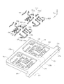
- FIG. 8 is a perspective view showing a state in which a connector cover of a card connector set in which a tray not holding a card is inserted into a connector in the second embodiment is removed
- FIG. 9 is a bottom view of the card in the second embodiment.
- FIG. 10 is an exploded view of the tray in the second embodiment
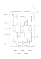
- FIG. 11 is a top view showing the arrangement of the tray terminals in the second embodiment
- FIG. 12 is the tray inserted into the connector in the second embodiment.
- FIG. 3 is a two-sided view of the card connector set in which the connector cover is removed. Note that, in FIG.
- (a) is a top view of a state in which the card is not held
- (b) is a cross-sectional view taken along the line BB in (a), showing the state of holding the card
- (C) is a sectional view taken along the line CC in (a), showing a state in which the card is held.
- the electrode pads 121 of the card 101 include a plurality of types of shapes and sizes, and form a plurality of rows and a plurality of columns in a plan view. It is located in.
- the electrode pad 121 has five rows of first to fifth rows (Line1 to 5) and five columns of first to fifth columns (Column1 to 5). Constitute.
- the electrode pads 121 do not necessarily exist in the positions corresponding to all the columns in each row, and do not necessarily exist in the positions corresponding to all the rows in each column. ..
- the electrode pads 121 are not necessarily arranged so as to correspond to all the components of the matrix made up of the first to fifth rows and the first to fifth columns.
- the electrode pad 121 existing at the position corresponding to the component (i, j) in the j-th column in the i-th row will be referred to as an electrode pad 121(i, j).
- the card 101 is a nano-SIM card (nSIM card) or the like that is small and thin and has multiple poles, a large number of electrode pads 121 of the same shape and size are densely arranged and a small number of about 1 to 2 rows. It is difficult to arrange the lower surface of the card 101 so as to form a row, and as in the example shown in FIG. 9, the electrode pads 121 having a plurality of shapes and sizes are arranged in a matrix of many rows and many columns. It only needs to be placed in locations that correspond to some of the selected.
- nSIM card nano-SIM card
- the arrangement of the connection pads exposed on the upper surface of the circuit board of the electronic device is the same as that of the first embodiment because of the wiring of the circuit board, and accordingly, the corresponding arrangement is provided.
- the arrangement of the connector terminals 51 is also the same as in the first embodiment. That is, in this embodiment, the structure of the connector 1 is the same as that of the first embodiment, and therefore the description thereof is omitted.
- the tray 170 in the present embodiment is the same as the first embodiment except for the tray terminal accommodating recess 178 formed in the bottom wall portion 177 of the tray housing 171 and the tray terminal 151 accommodated in the tray terminal accommodating recess 178.
- the configuration of the tray 170 other than the tray terminal accommodating concave portion 178 and the tray terminal 151 is omitted because it is similar to that of the first embodiment.
- the tray terminal accommodating recesses 178 in the present embodiment are arranged so as to form five rows and five columns, but in each row, not all columns are necessarily arranged. It does not exist at the corresponding position, and does not necessarily exist at the position corresponding to all rows in each column.
- the tray terminal accommodating recessed portion 178 is arranged in a component corresponding to the electrode pad 121, although not all of the components of the matrix including the first to fifth rows and the first to fifth columns. ..
- the tray terminal 151 in the present embodiment is arranged such that the second contact portion 154 thereof constitutes five rows and five columns, like the electrode pad 121 of the card 101. It does not necessarily exist in the position corresponding to all the columns in each row, and does not necessarily exist in the position corresponding to all the rows in each column.
- the second contact portion 154 of the tray terminal 151 does not necessarily include all the components of the matrix including the first to fifth rows and the first to fifth columns, but the components corresponding to the electrode pads 121 include: It is arranged.
- Each of the second contact portions 154 of the tray terminals 151 is housed in the corresponding tray terminal housing recess 178.
- the tray terminal 151 in the present embodiment includes a first type tray terminal 151A and a second type tray terminal 151B.
- the first type tray terminal 151A has the same configuration as the tray terminal 151 in the first embodiment, but its posture is the same as the tray terminal 151 in the first embodiment in the front-back direction.
- the column-direction tray terminals 151A1 arranged to be controlled so as to extend in the insertion and ejection direction of the tray 170, that is, the X-axis direction, and the posture thereof in the left-right direction (the width direction of the tray 170, that is, the Y-axis).
- Directional) and row-direction tray terminals 151A2 that are arranged to be controlled.
- the main body portion 153 connecting the first contact portion 152 contacting the connector terminal 51 and the second contact portion 154 contacting the electrode pad 121 in the plan view has a front-back direction (column direction of the matrix). ) Is arranged so as to extend. Therefore, the row-direction tray terminal 151A1 electrically connects the connector terminal 51 and the electrode pad 121, which are located along the straight line extending in the front-rear direction in plan view, with the tray 170 inserted in the connector 1.
- the row direction tray terminal 151A2 electrically connects the connector terminal 51 and the electrode pad 121, which are located along a straight line extending in the left-right direction in a plan view, with the tray 170 inserted in the connector 1.
- the main body portion 153 of the second type tray terminal 151B extends linearly in a plan view like the main body portion 153 of the tray terminal 151 and the first type tray terminal 151A in the first embodiment. However, it includes a portion extending in the front-rear direction and a portion extending in the left-right direction. Specifically, the main body 153 of the second type tray terminal 151B includes a column direction portion 153d extending in the front-rear direction and a row direction portion 153b extending in the left-right direction.
- the column-direction portion 153d is connected to the first contact portion 152 and the row-direction portion 153b is connected to the second contact portion 154, but the column-direction portion 153d is the second contact portion.
- the row-direction portion 153b may be connected to the first contact portion 152.
- the column direction portion 153d and the row direction portion 153b are connected by an inclined direction portion 153c extending in a direction intersecting the front-rear direction and the left-right direction. If necessary, the column direction portion 153d and the row direction portion 153b may be directly connected, and the tilt direction portion 153c may be omitted.
- the second type tray terminal 151B includes the column direction portion 153d and the row direction portion 153b, when the tray 170 is inserted into the connector 1, with respect to the front-back direction and the left-right direction in a plan view. , The connector terminal 51 and the electrode pad 121 at different positions are electrically connected.
- the holding portion 161 in the present embodiment is a member integrally formed by subjecting a metal plate to punching, bending, or the like similarly to the tray terminal 151.
- the present invention is not limited to this, and it is a member that is elastically deformable, and a part of it projects into the recess 176 that is the accommodation space and biases the side surface of the accommodated card 101 to It may be of any type as long as it can hold 101.
- the tray terminal 151 includes the column-direction tray terminal 151A1 in which the main body portion 153 is arranged to extend in the insertion direction of the tray 170 and the main body portion 153 in plan view. Includes a row-direction tray terminal 151A2 arranged so as to extend in the width direction orthogonal to the insertion direction of the tray 170. Further, at least one tray terminal 151 includes a column direction portion 153d in which the main body 153 extends in the insertion direction of the tray 170, and the main body 153 is orthogonal to the insertion direction of the tray 170 in plan view. And a row-direction portion 153b arranged so as to extend in the width direction. Further, the tray terminal 151 further includes an inclined direction portion 153c connecting the column direction portion 153d and the row direction portion 153b.
- the card 101 in which the electrode pads 121 having a plurality of shapes and sizes are arranged only at the positions corresponding to some selected from the components in the matrix of many rows and many columns. ..
- the present disclosure can be applied to a card holding member and a card connector set.
Abstract
The present invention can be used for a card that is downsized and thinned, has multiple poles, can ensure miniaturization, a low profile and multiple poles, and achieves improved reliability. To this end, the present invention comprises: a tray housing having a recess part in which the card can be accommodated, a bottom wall part which defines the bottom surface of the recess part, and a tray terminal accommodation recess part formed in the bottom wall part; and a tray terminal that is disposed on the bottom wall part, and includes a main body part at least a portion of which is held by the bottom wall part, a first contact part capable of contacting a connector terminal, and a second contact part capable of contacting an electrode pad, the first contact part and the second contact part being connected to both ends of the main body part, respectively, wherein the first contact part is fixed and exposed on a surface of the bottom wall part opposite to the bottom surface of the recess part, and the second contact part is accommodated in the tray terminal accommodation recess part in an elastically deformable manner in a state in which at least a contact point therebetween protrudes from the bottom surface of the recess part.
Description
本開示は、カード保持部材及びカード用コネクタセットに関するものである。
The present disclosure relates to a card holding member and a card connector set.
従来、携帯電話機、スマートフォン等の電子機器においては、SIM(Subscriber Identity Module)カード等の各種カードを利用するために、カード用コネクタを備えている。近年、電子機器の急速な小型化に伴って、カード及びカード用コネクタは、急速に小型化される傾向にある。そのため、ユーザが手指によってカードを把持したり、カード用コネクタに適切に挿入したりすることが困難である。そこで、カードをあらかじめカード用トレイにセットしておき、該カード用トレイを挿入するカード用コネクタが提案されている(例えば、特許文献1参照。)。
Conventionally, electronic devices such as mobile phones and smartphones are provided with card connectors in order to use various cards such as SIM (Subscriber Identity Module) cards. In recent years, with the rapid miniaturization of electronic devices, cards and card connectors tend to be rapidly miniaturized. Therefore, it is difficult for the user to grip the card with fingers and to insert it properly into the card connector. Therefore, there has been proposed a card connector in which a card is set in the card tray in advance and the card tray is inserted (for example, see Patent Document 1).
図13は従来のカード用コネクタを示す図である。
FIG. 13 is a diagram showing a conventional card connector.
図において、811は、表面に図示されない導電性の接続パッドが形成されたカードコネクタの基板であり、861は、金属板から成るカードコネクタのシェルであり、前記接続パッドの上方を覆うようにして、前記基板811に取付けられ、該基板811とシェル861との間にカードコネクタのカード収容空間818が形成される。また、971は、カード用トレイであり、カード901が内部に装填された状態で、矢印で示されるようにして前記カード収容空間818の入口側から挿入され、カードコネクタに収容される。
In the figure, 811 is a substrate of a card connector on the surface of which conductive connecting pads (not shown) are formed, and 861 is a shell of the card connector made of a metal plate, and covers the upper part of the connecting pad. , The card housing space 818 of the card connector is formed between the board 811 and the shell 861. Reference numeral 971 denotes a card tray, which is inserted from the entrance side of the card housing space 818 as shown by an arrow in a state where the card 901 is loaded inside and is housed in the card connector.
なお、前記カード用トレイ971の底板には、複数の導電性部材951が取付けられており、前記カード901がカード用トレイ971に装填されると、前記カード901の下面に露出して形成された複数の電極パッドの各々が対応する導電性部材951の上面に接触する。そして、前記カード用トレイ971がカード収容空間818内に収容された状態では、各導電性部材951の先端の下面が基板811の表面に形成された接続パッドに接触し、これにより、カード901の電極パッドと対応するカードコネクタの接続パッドとが導電性部材951を介して接続される。
A plurality of conductive members 951 are attached to the bottom plate of the card tray 971. When the card 901 is loaded on the card tray 971, it is exposed and formed on the lower surface of the card 901. Each of the plurality of electrode pads contacts the upper surface of the corresponding conductive member 951. When the card tray 971 is housed in the card housing space 818, the lower surface of the tip of each conductive member 951 contacts the connection pad formed on the surface of the substrate 811. The electrode pad and the corresponding connection pad of the card connector are connected via the conductive member 951.
このように、カード901は、カード用トレイ971に装填された状態でカード収容空間818内に挿入されて収容されるので、該カード収容空間818内に挿入される際に、カード901がカード収容空間818の入口部分に接触することがなく、電極パッド等が損傷することがない。また、カード901の電極パッドと対応する接続パッドとが弾性を有する導電性部材951を介して接続されるので、電極パッドと接続パッドとの導通状態が安定する。
In this way, the card 901 is inserted and accommodated in the card accommodation space 818 while being loaded in the card tray 971. Therefore, when the card 901 is accommodated in the card accommodation space 818, the card 901 is accommodated in the card accommodation space 818. There is no contact with the entrance of the space 818, and the electrode pads and the like are not damaged. Moreover, since the electrode pad of the card 901 and the corresponding connection pad are connected via the conductive member 951 having elasticity, the electrical connection between the electrode pad and the connection pad is stabilized.
しかしながら、前記従来のカード用コネクタにおいては、カード用トレイ971の底板に取付けられた導電性部材951が弾性的に変形することによって、カード901の電極パッドとの接触を維持するとともに、カードコネクタの接続パッドとの接触を維持するようになっているので、導電性部材951の弾性変形可能範囲を大きくする必要があり、該導電性部材951の小型化が困難であり、その結果、カード用トレイ971の小型化が困難になり、該カード用トレイ971を収容するカードコネクタの小型化も困難になってしまう。
However, in the conventional card connector, the conductive member 951 attached to the bottom plate of the card tray 971 is elastically deformed to maintain contact with the electrode pad of the card 901, and Since the contact with the connection pad is maintained, it is necessary to increase the elastically deformable range of the conductive member 951, which makes it difficult to reduce the size of the conductive member 951. It becomes difficult to downsize the 971 and it becomes difficult to downsize the card connector that accommodates the card tray 971.
ここでは、前記従来の問題点を解決して、小型薄肉化され、かつ、多極化されたカードに対応することができ、小型低背化及び多極化が可能な信頼性の高いカード保持部材及びカード用コネクタセットを提供することを目的とする。
Here, by solving the above-mentioned conventional problems, it is possible to deal with a small-sized, thin-walled and multi-polarized card, and a highly reliable card holding member and card that can be miniaturized, low-profile and multi-polarized. The purpose is to provide a connector set.
そのために、カード保持部材においては、電極パッドを備えるカードを保持可能、かつ、コネクタ端子を備えるカード用コネクタに挿入可能なカード保持部材であって、前記カードを収容可能な凹部と、該凹部の底面を画定する底壁部と、該底壁部に形成されたトレイ端子収容凹部とを含むトレイハウジングと、前記底壁部に配設されたトレイ端子であって、少なくとも一部が前記底壁部によって保持される本体部と、該本体部の両端のそれぞれに接続された第1接触部及び第2接触部であって、前記コネクタ端子に接触可能な第1接触部及び前記電極パッドに接触可能な第2接触部とを含むトレイ端子とを備え、前記第1接触部は、前記底壁部における前記凹部の底面と反対側の面に固定されて露出し、前記第2接触部は、少なくともその接点が前記凹部の底面から突出した状態で、前記トレイ端子収容凹部内に弾性変形可能に収容される。
Therefore, the card holding member is a card holding member that can hold a card having an electrode pad and can be inserted into a card connector having a connector terminal, and has a concave portion that can accommodate the card and a concave portion of the concave portion. A tray housing including a bottom wall portion defining a bottom surface and a tray terminal accommodating recess formed in the bottom wall portion, and a tray terminal arranged in the bottom wall portion, at least a part of which is the bottom wall. And a first contact portion and a second contact portion, which are respectively connected to both ends of the main body portion and are held by the first and second contact portions, and which are in contact with the connector terminal and the electrode pad. A tray terminal including a possible second contact portion, wherein the first contact portion is fixed and exposed on a surface of the bottom wall portion opposite to the bottom surface of the recess, and the second contact portion is At least the contact points of the contacts projecting from the bottom surface of the recess are housed in the tray terminal housing recess so as to be elastically deformable.
他のカード保持部材においては、さらに、前記第2接触部は、前記トレイ端子収容凹部内において他の部材と干渉することなく弾性変形可能である。
In another card holding member, the second contact portion can be elastically deformed in the tray terminal accommodating recess without interfering with another member.
更に他のカード保持部材においては、さらに、前記トレイ端子は、平面視において、前記第2接触部が前記カード保持部材の挿入方向と直交する幅方向に沿って並ぶ行を単数又は複数形成するように配設されている。
In still another card holding member, the tray terminal may form a single row or a plurality of rows in which the second contact portions are arranged in a width direction orthogonal to the insertion direction of the card holding member in plan view. It is installed in.
更に他のカード保持部材においては、さらに、前記トレイ端子は、平面視において、前記本体部が前記カード保持部材の挿入方向に延在するように配設されている。
In still another card holding member, the tray terminal is arranged so that the main body portion extends in the insertion direction of the card holding member in a plan view.
更に他のカード保持部材においては、さらに、前記トレイ端子は、平面視において、前記本体部が前記カード保持部材の挿入方向に延在するように配設されているトレイ端子と、前記本体部が前記カード保持部材の挿入方向と直交する幅方向に延在するように配設されているトレイ端子とを含む。
In still another card holding member, the tray terminal further includes a tray terminal in which the main body portion is arranged so as to extend in the insertion direction of the card holding member in plan view, and the main body portion. And a tray terminal arranged so as to extend in a width direction orthogonal to the insertion direction of the card holding member.
更に他のカード保持部材においては、さらに、少なくとも1つの前記トレイ端子は、平面視において、前記本体部が前記カード保持部材の挿入方向に延在するように配設される列方向部分と、前記本体部が前記カード保持部材の挿入方向と直交する幅方向に延在するように配設される行方向部分とを含む。
In still another card holding member, further, at least one of the tray terminals includes a row-direction portion in which the main body portion is arranged so as to extend in the insertion direction of the card holding member in plan view, The main body portion includes a row direction portion arranged so as to extend in a width direction orthogonal to the insertion direction of the card holding member.
更に他のカード保持部材においては、さらに、前記トレイ端子は、前記列方向部分と行方向部分とを接続する傾斜方向部分を更に含む。
In still another card holding member, the tray terminal further includes an inclined direction portion connecting the column direction portion and the row direction portion.
カード用コネクタセットにおいては、本開示のカード保持部材と、該カード保持部材を挿入可能なカード用コネクタであって、弾性変形可能、かつ、前記第1接触部に接触可能な接触部を含むコネクタ端子を備えるカード用コネクタと、を備える。
In a card connector set, a card holding member according to the present disclosure and a card connector into which the card holding member can be inserted, the connector including an elastically deformable contact portion that can contact the first contact portion A card connector having terminals.
他のカード用コネクタセットにおいては、さらに、前記コネクタ端子は、それぞれが、前記カード保持部材の挿入方向に延在し、かつ、前記接触部が、平面視において、前記カード保持部材の挿入方向と直交する幅方向に沿って並ぶ行を単数又は複数形成するように配設されている。
In another card connector set, further, each of the connector terminals extends in the insertion direction of the card holding member, and the contact portion, in plan view, the insertion direction of the card holding member and It is arranged so as to form a single row or a plurality of rows arranged along the width direction orthogonal to each other.
カード保持部材及びカード用コネクタセットは、小型薄肉化され、かつ、多極化されたカードに対応することができ、小型低背化及び多極化が可能で、信頼性を向上させることができる。
ㆍThe card holding member and card connector set can be used for cards that are small and thin, and have multiple poles, and can be made compact and have a low profile and multiple poles, thus improving reliability.
以下、実施の形態について図面を参照しながら詳細に説明する。
Hereinafter, embodiments will be described in detail with reference to the drawings.
図1は第1の実施の形態におけるコネクタにカードを保持するトレイが挿入されたカード用コネクタセットを示す斜視図、図2は第1の実施の形態におけるカード用コネクタセットの分解図、図3は第1の実施の形態におけるコネクタにカードを保持しないトレイが挿入されたカード用コネクタセットのコネクタカバーを取外した状態の斜視図、図4は第1の実施の形態におけるコネクタのコネクタカバー以外の部分の分解図、図5は第1の実施の形態におけるコネクタにカードを保持するトレイが挿入されたカード用コネクタセットの二面図、図6は第1の実施の形態におけるコネクタにカードを保持するトレイが挿入されたカード用コネクタセットのコネクタカバーを取外した状態の二面図、図7は第1の実施の形態におけるコネクタにカードを保持するトレイが挿入されたカード用コネクタセットの断面斜視図である。なお、図5及び6において、(a)は上面図であり、(b)は(a)におけるA-A矢視断面図である。
1 is a perspective view showing a card connector set in which a tray for holding a card is inserted into a connector in the first embodiment, FIG. 2 is an exploded view of the card connector set in the first embodiment, and FIG. FIG. 4 is a perspective view showing a state in which a connector cover of a card connector set in which a tray that does not hold a card is inserted into the connector in the first embodiment is removed, and FIG. 4 shows other than the connector cover of the connector in the first embodiment. FIG. 5 is an exploded view of a part, FIG. 5 is a two-sided view of a card connector set in which a tray for holding a card is inserted in the connector in the first embodiment, and FIG. 6 is a drawing in which the card is held in the connector in the first embodiment. FIG. 7 is a two-sided view of the card connector set in which the tray for inserting the card is removed, and FIG. 7 is a sectional perspective view of the card connector set in which the tray for holding the card is inserted in the connector according to the first embodiment. It is a figure. 5 and 6, (a) is a top view and (b) is a sectional view taken along the line AA in (a).
図において、170は本実施の形態におけるカード保持部材としてのトレイであり、カード101を収容した状態で、図示されない電子機器の回路基板に実装されたカード用コネクタとしてのコネクタ1に挿入される。これにより、前記カード101は、トレイ170及びコネクタ1を介して、電子機器に装着される。
In the figure, reference numeral 170 denotes a tray as a card holding member in the present embodiment, which is inserted into a connector 1 as a card connector mounted on a circuit board of an electronic device (not shown) in a state where the card 101 is accommodated. As a result, the card 101 is attached to the electronic device via the tray 170 and the connector 1.
ここでは、カード用コネクタセットは、カード101が電気的に接続されるトレイ170と、該トレイ170が電子機器の回路基板の平面方向と同一方向に挿入され、トレイ170と電気的に接続されるコネクタ1とを備えるものであって、カード用コネクタセットを介して、カード101と電子機器とを接続させるために使用されるものである、として説明する。
Here, the card connector set is a tray 170 to which the card 101 is electrically connected, and the tray 170 is inserted in the same direction as the plane direction of the circuit board of the electronic device and electrically connected to the tray 170. It will be described as being provided with the connector 1 and used for connecting the card 101 and the electronic device via the card connector set.
なお、本実施の形態において、カード101は、例えば、SIMカード、マイクロSIMカード、ナノSIMカード、MMC(R)、SD(R)カード、miniSD(R)カード、xDピクチャーカード(R)、メモリスティック(R)、メモリスティックDuo(R)、スマートメディア(R)、Trans-Flash(R)メモリカード等のメモリカード自体であってもよいし、また、例えば、miniSD(R)カードを内部に収容したSD(R)カード型アダプタのように、コネクタ1に挿入するのに適した形状及び寸法を備え、内部にメモリカードを収容したカード用アダプタであってもよい。
In the present embodiment, the card 101 is, for example, a SIM card, a micro SIM card, a nano SIM card, an MMC(R), an SD(R) card, a miniSD(R) card, an xD picture card (R), a memory. It may be a memory card itself such as a stick (R), a memory stick Duo (R), a smart media (R), a Trans-Flash (R) memory card, or, for example, a miniSD (R) card inside. A card adapter having a shape and dimensions suitable for insertion into the connector 1 and having a memory card accommodated therein may be used, such as an SD(R) card type adapter accommodated.
さらに、前記電子機器は、例えば、パーソナルコンピュータ、携帯電話機、スマートフォン、通信モデム、パッド型コンピュータ、デジタルカメラ、ビデオカメラ、音楽プレーヤ、ゲーム機、車両用ナビゲーション装置等であるが、いかなる種類の機器であってもよい。また、前記電子機器の回路基板は、電子機器等に使用されるプリント配線基板(Printed Circuit Board)、フレキシブルフラットケーブル(Flexble Flat Cable)、フレキシブルプリント配線板(Flexble Printed Circuit)等であるが、いかなる種類の回路基板であってもよい。
Further, the electronic device is, for example, a personal computer, a mobile phone, a smartphone, a communication modem, a pad computer, a digital camera, a video camera, a music player, a game machine, a vehicle navigation device, etc. It may be. In addition, the circuit board of the electronic device is a printed wiring board (Printed Circuit Board), a flexible flat cable (Flexible Flat Cable), a flexible printed wiring board (Flexible Printed Circuit), or the like used in the electronic device or the like. It may be any type of circuit board.
なお、本実施の形態において、トレイ170及びコネクタ1の各部の構成及び動作を説明するために使用される上、下、右、左、前、後等の方向を示す表現は、絶対的なものではなく相対的なものであり、トレイ170及びコネクタ1が図に示される姿勢である場合に適切であるが、トレイ170及びコネクタ1の姿勢が変化した場合には、その姿勢の変化に応じて変更して解釈されるべきものである。
It should be noted that in the present embodiment, the expressions used to describe the configurations and operations of the tray 170 and each part of the connector 1 are upward, downward, right, left, front, rear, and the like. It is not relative but is suitable when the tray 170 and the connector 1 are in the postures shown in the figure, but when the postures of the tray 170 and the connector 1 are changed, the postures are changed according to the change of the postures. It should be changed and interpreted.
前記トレイ170について説明する。
The tray 170 will be described.
図に示されるように、トレイ170は、カード101を装着可能な凹部176を備えるトレイハウジング171と、前記凹部176内にカード101の下面(電極パッド面)に露出する電極パッド121と接続可能な複数のトレイ端子151とを備える。なお、前記トレイハウジング171は、絶縁性材料から成る一体的に成形された部材であり、各トレイ端子151は、導電性の金属板に打抜き、曲げ等の加工を施して一体的に成形された部材である。前記トレイ端子151は、例えば、インサート成形(オーバーモールド成形)等の成形方法によって、トレイハウジング171と一体化されていることが望ましい。
As shown in the figure, the tray 170 is connectable to a tray housing 171 having a recess 176 into which the card 101 can be mounted and an electrode pad 121 exposed in the recess 176 on the lower surface (electrode pad surface) of the card 101. And a plurality of tray terminals 151. The tray housing 171 is an integrally molded member made of an insulating material, and each tray terminal 151 is integrally molded by punching or bending a conductive metal plate. It is a member. The tray terminal 151 is preferably integrated with the tray housing 171 by a molding method such as insert molding (overmolding).
図に示される例においては、凹部176がトレイハウジング171の幅方向(Y軸方向)に2つ並んで配置されているが、前記凹部176は、必ずしも2つである必要はなく、1つであってもよいし、3つ以上であってもよい。また、前記凹部176は、必ずしもトレイハウジング171の幅方向に並ぶ必要はなく、トレイハウジング171の前後方向(トレイ170の挿入及び排出方向、すなわちX軸方向)に並んでいてもよい。さらに、複数の凹部176は、必ずしも互いに同一の大きさ及び形状である必要はなく、相違する大きさ及び形状であってもよい。なお、ここでは、説明の都合上、図に示される例のように、互いに同一の大きさ及び形状である2つの凹部176がトレイハウジング171の幅方向に並んで配置されている場合について、説明する。
In the example shown in the figure, two recesses 176 are arranged side by side in the width direction (Y-axis direction) of the tray housing 171, but the number of recesses 176 need not be two, and only one is required. There may be three or more. The recesses 176 do not necessarily have to be arranged in the width direction of the tray housing 171, but may be arranged in the front-rear direction of the tray housing 171 (the insertion and ejection directions of the tray 170, that is, the X-axis direction). Furthermore, the plurality of recesses 176 do not necessarily have the same size and shape as each other, but may have different sizes and shapes. Note that, for convenience of description, a case where two recesses 176 having the same size and shape as each other are arranged side by side in the width direction of the tray housing 171 will be described for convenience of description. To do.
また、前記トレイハウジング171は、幅方向に延在する基部172と、該基部172の前方に接続された枠部173とを含んでいる。そして、該枠部173は、凹部176の前端縁を画定する前枠部173aと、凹部176の後端縁を画定する後枠部173bと、凹部176の側端縁を画定する側枠部173cとを含んでいる。前記前枠部173aは、トレイハウジング171の前端において幅方向に延在する細長い部分であり、その前端面は、トレイハウジング171の前端面171fとなっている。また、前記後枠部173bは、基部172と一体化し、前枠部173aと平行に、幅方向に延在する細長い部分である。さらに、前記側枠部173cは、複数であって、互いに平行に、前後方向に延在する細長い部分であり、その前後端が前枠部173a及び後枠部173bに連結されている。前記基部172の幅方向の一端(図5(a)における右端)には、幅方向外側に突出したフランジ部172aが形成され、該フランジ部172aには、操作用挿通孔172bが前後方向に貫通するように形成されていることが望ましい。また、前記基部172の後端面は、トレイハウジング171の後端面171rとなっている。
Further, the tray housing 171 includes a base portion 172 extending in the width direction and a frame portion 173 connected to the front of the base portion 172. The frame portion 173 includes a front frame portion 173a that defines a front edge of the recess 176, a rear frame portion 173b that defines a rear edge of the recess 176, and a side frame portion 173c that defines a side edge of the recess 176. Includes and. The front frame portion 173a is an elongated portion extending in the width direction at the front end of the tray housing 171, and the front end surface thereof is the front end surface 171f of the tray housing 171. The rear frame portion 173b is an elongated portion that is integrated with the base portion 172 and extends in the width direction in parallel with the front frame portion 173a. Further, the side frame portions 173c are a plurality of elongated portions extending in the front-rear direction in parallel with each other, and the front and rear ends thereof are connected to the front frame portion 173a and the rear frame portion 173b. A flange portion 172a protruding outward in the width direction is formed at one end (right end in FIG. 5A) of the base portion 172 in the width direction, and an operation insertion hole 172b penetrates in the front and rear direction in the flange portion 172a. It is desirable that it is formed so that The rear end surface of the base 172 is a rear end surface 171r of the tray housing 171.
図に示される例において、前記凹部176は、平面視における形状が前後方向の寸法が幅方向の寸法よりも大きな略長方形である凹入した部分であり、その底面は平板状の底壁部177によって閉止され、その上面が開放されている。なお、長方形の1つの角に相当する部分には、凹部176へのカード101の誤装着を防止するため、カード101の長方形の1つの角に相当する部分に形成された切欠部101cに対応するように、平面視における形状が斜めの極性付与凸部176cが形成されていることが望ましい。また、前記凹部176は、カード101を収容可能な収容空間であるという性質上、その平面視における大きさ及び形状は、カード101の平面視における大きさ及び形状と同様であり、その深さ(Z軸方向の寸法)はカード101の厚さ(Z軸方向の寸法)とほぼ同様である。
In the example shown in the drawing, the recess 176 is a recessed portion whose shape in plan view is a substantially rectangular shape having a dimension in the front-rear direction larger than a dimension in the width direction, and the bottom surface thereof is a flat bottom wall portion 177. It is closed by and its upper surface is open. In addition, in order to prevent erroneous mounting of the card 101 in the concave portion 176, a portion corresponding to one corner of the rectangle corresponds to a cutout portion 101c formed in a portion corresponding to one corner of the rectangle of the card 101. As described above, it is desirable that the polarity imparting convex portion 176c having an oblique shape in plan view is formed. Further, the size and shape of the recess 176 in plan view are the same as the size and shape of the card 101 in plan view due to the nature of being a storage space capable of storing the card 101, and the depth ( The dimension in the Z-axis direction) is almost the same as the thickness of the card 101 (the dimension in the Z-axis direction).
そして、前記前枠部173a、後枠部173b及び側枠部173cが凹部176の側壁部として機能し、凹部176に収容されたカード101の側面と対向する。なお、前記側壁部の一部は、図3に示されるように、収容されたカード101の落下乃至脱落を防止するための保持部161を備えていてもよい。該保持部161は、弾性変形が可能な部位であって、その一部が収容空間である凹部176内に突出し、収容されたカード101の側面を付勢して、カード101を保持するようになっている。なお、前記保持部161は、このような構成に限定されるものでなく、カード101が落下乃至脱落することなく凹部176内に保持されるものであれば、いかなる構成のものであってもよい。
The front frame portion 173a, the rear frame portion 173b, and the side frame portion 173c function as side wall portions of the recess 176, and face the side surface of the card 101 housed in the recess 176. As shown in FIG. 3, a part of the side wall portion may be provided with a holding portion 161 for preventing the stored card 101 from dropping or dropping. The holding portion 161 is a region that can be elastically deformed, and a part of the holding portion 161 projects into the recess 176 that is a storage space to bias the side surface of the stored card 101 to hold the card 101. Has become. The holder 161 is not limited to such a structure, and may have any structure as long as the card 101 is held in the recess 176 without dropping or dropping. ..
また、前記底壁部177には、複数のトレイ端子収容凹部178が形成され、各トレイ端子収容凹部178内には、トレイ端子151が1つずつ配設され、その第2接触部154が収容されている。前記トレイ端子収容凹部178は、必ずしも貫通孔である必要はないが、ここでは、底壁部177を板厚方向乃至上下方向(Z軸方向)に貫通する貫通孔であるものとして説明する。また、必ずしもすべてのトレイ端子収容凹部178内にトレイ端子151が配設されている必要はないが、ここでは、すべてのトレイ端子収容凹部178内にトレイ端子151が1つずつ配設されているものとして説明する。前記トレイ端子収容凹部178及びトレイ端子151は、凹部176内に収容されるカード101の下面における電極パッド121の配置と対応するように配置され、図に示される例においては、幅方向に沿って並ぶ行が前後に2本形成されるように配置されている。また、各トレイ端子収容凹部178内には、トレイ端子151を保持する端子保持部177aが配設されている。該端子保持部177aは、トレイ端子収容凹部178を幅方向に横断するように形成されている。
Further, a plurality of tray terminal accommodating recesses 178 are formed in the bottom wall portion 177, and one tray terminal 151 is disposed in each tray terminal accommodating recess 178, and the second contact portion 154 thereof is accommodated therein. Has been done. The tray terminal accommodating recess 178 does not necessarily have to be a through hole, but here, it will be described as a through hole that penetrates the bottom wall portion 177 in the plate thickness direction or in the vertical direction (Z-axis direction). Further, the tray terminals 151 do not necessarily have to be provided in all the tray terminal accommodating recesses 178, but here, one tray terminal 151 is provided in all the tray terminal accommodating recesses 178. It will be described as a thing. The tray terminal accommodating concave portion 178 and the tray terminal 151 are arranged so as to correspond to the arrangement of the electrode pads 121 on the lower surface of the card 101 accommodated in the concave portion 176, and in the example shown in the drawing, along the width direction. It is arranged so that two lined up rows are formed at the front and rear. In addition, a terminal holding portion 177a that holds the tray terminal 151 is disposed in each tray terminal accommodating recess 178. The terminal holding portion 177a is formed so as to cross the tray terminal accommodating recess 178 in the width direction.
前記トレイ端子151は、導電性の金属板に打抜き、曲げ等の加工を施して形成された部材であり、本体部153と、該本体部153の一端に接続された第1接触部152と、前記本体部153の他端に接続された第2接触部154とを備える。
The tray terminal 151 is a member formed by subjecting a conductive metal plate to punching, bending, etc., and includes a main body 153, a first contact portion 152 connected to one end of the main body 153, The second contact portion 154 is connected to the other end of the body portion 153.
前記本体部153は、側面視においてクランク状に屈曲した屈曲部153aを含み、少なくとも一部が端子保持部177a内に埋設された状態で該端子保持部177aによって保持される。
The main body portion 153 includes a bent portion 153a bent in a crank shape in a side view, and is held by the terminal holding portion 177a in a state where at least a part thereof is embedded in the terminal holding portion 177a.
また、前記第1接触部152は、前記屈曲部153aの下端に接続された平板状の部分であり、その下面が底壁部177(図に示される例においては、端子保持部177a)の下面に固定されて露出し、コネクタ1のコネクタ端子51と接触して電気的に導通可能となっている。図に示されるように、第1接触部152の下面は底壁部177の下面と、略同一平面上に位置している、すなわち、面一となっていることが望ましい。これにより、トレイ170がコネクタ1に挿入される際に、トレイ170がコネクタ1に引掛ることなく、スムーズにトレイ170がコネクタ1に挿入され得る。もっとも、第1接触部152の下面は、少なくともその一部が底壁部177の下面に露出してさえいれば、必ずしも底壁部177の下面と、略同一平面上に位置していなくてもよい。すなわち、第1接触部152の下面及び底壁部177の下面の一方の他方に対する突出量が、トレイ170がコネクタ1に挿入される際の作業効率を低下させない程度であれば、第1接触部152の下面及び底壁部177の下面は同一平面上に位置していなくてもよい。なお、図に示される例において、第1接触部152は、弾性変形しないようになっているが、弾性変形し得る形状に形成されたものであってよい。
The first contact portion 152 is a flat plate-shaped portion connected to the lower end of the bent portion 153a, and the lower surface thereof is the lower surface of the bottom wall portion 177 (in the example shown in the figure, the terminal holding portion 177a). Is exposed and fixed to the connector 1, and contacts the connector terminal 51 of the connector 1 to be electrically conductive. As shown in the figure, it is desirable that the lower surface of the first contact portion 152 and the lower surface of the bottom wall portion 177 be substantially flush with each other, that is, flush with each other. Accordingly, when the tray 170 is inserted into the connector 1, the tray 170 can be smoothly inserted into the connector 1 without being caught by the connector 1. However, the lower surface of the first contact portion 152 is not necessarily located on substantially the same plane as the lower surface of the bottom wall portion 177 as long as at least a part thereof is exposed to the lower surface of the bottom wall portion 177. Good. That is, as long as the amount of protrusion of the lower surface of the first contact portion 152 and the lower surface of the bottom wall portion 177 with respect to the other does not reduce the work efficiency when the tray 170 is inserted into the connector 1, the first contact portion. The lower surface of 152 and the lower surface of the bottom wall portion 177 do not have to be located on the same plane. Although the first contact portion 152 is not elastically deformable in the example shown in the drawing, it may be formed in a shape that is elastically deformable.
前記第2接触部154は、側面視において略S字状の形状を有し、それぞれ約180度湾曲した第1湾曲部154a及び第2湾曲部154bと、該第2湾曲部154bに接続された先端部分であって、カード101の下面における電極パッド121に接触して電気的に導通可能となる接点として機能する接点部154cとを有する。また、前記第2接触部154における本体部153との接続部分から接点部154cまでの範囲は、第1湾曲部154a及び第2湾曲部154bを含み、弾性変形可能な弾性変形部154dである。少なくとも接点部154cが凹部176の底面から突出した状態となっていて、前記接点部154cがカード101の電極パッド121によって押圧されると、弾性変形部154dが弾性変形し、接点部154cと前記電極パッド121とを弾性的に接触させることができる。また、前記弾性変形部154dは、底壁部177のトレイ端子収容凹部178内に位置しており、弾性変形しても他の部材や部位に接触することがない。そのため、カード101の電極パッド121に過剰な弾性力を付加することがなく、該電極パッド121を損傷させたり、破損させたりすることがない。
The second contact portion 154 has a substantially S-shaped shape in a side view, and is connected to the first bending portion 154a and the second bending portion 154b, which are each bent about 180 degrees, and the second bending portion 154b. It has a contact portion 154c that functions as a contact which is a tip portion and contacts the electrode pad 121 on the lower surface of the card 101 to be electrically conductive. Further, the range from the connecting portion of the second contact portion 154 with the main body portion 153 to the contact portion 154c is the elastically deformable portion 154d that includes the first bending portion 154a and the second bending portion 154b. When at least the contact portion 154c is projected from the bottom surface of the recess 176 and the contact portion 154c is pressed by the electrode pad 121 of the card 101, the elastic deformation portion 154d elastically deforms, and the contact portion 154c and the electrode. The pad 121 can be elastically contacted. Further, the elastically deforming portion 154d is located in the tray terminal accommodating recess 178 of the bottom wall portion 177, and does not come into contact with other members or parts even when elastically deforming. Therefore, an excessive elastic force is not applied to the electrode pad 121 of the card 101, and the electrode pad 121 is neither damaged nor damaged.
次に、前記コネクタ1について説明する。
Next, the connector 1 will be described.
図に示されるように、コネクタ1は、トレイ170を収容する凹部12を備えるハウジング11と、該ハウジング11を覆うコネクタカバー61と、トレイ端子151と接続可能なコネクタ端子51と、コネクタ1に挿入されたトレイ170を排出するための排出機構20とを備える。
As shown in the figure, the connector 1 includes a housing 11 having a recess 12 for accommodating a tray 170, a connector cover 61 for covering the housing 11, a connector terminal 51 connectable to the tray terminal 151, and a connector 1 inserted into the connector 1. And a discharge mechanism 20 for discharging the separated tray 170.
前記ハウジング11は、絶縁性材料から成る一体的に成形された部材であり、略矩形の平板状の端子保持部としての底壁部11bと、ハウジング11におけるトレイ170の挿入方向(X軸方向)前方の前端部に沿って幅方向に延在し、底壁部11bより肉厚の奥壁部11aと、ハウジング11における左右両側縁に沿って挿入方向に延在し、底壁部11bより肉厚の一対の側壁部11dと、一方(図に示される例において、トレイ170の挿入方向右側)の側壁部11dと一体的に形成されたプッシュロッド保持部11gとを含んでいる。なお、該プッシュロッド保持部11gには、前記挿入方向に延在するプッシュロッド収容溝11hが形成されている。また、他方(図に示される例において、トレイ170の挿入方向左側)の側壁部11dには、凹部12に収容されたトレイ170の落下乃至脱落を防止するための保持部75を備えていてもよい。該保持部75は、弾性変形が可能な部位であって、その一部が収容空間である凹部12内に突出し、収容されたトレイ170の側面を付勢して、トレイ170を保持するようになっている。なお、前記保持部75は、このような構成に限定されるものでなく、トレイ170が落下乃至脱落することなく凹部12内に保持されるものであれば、いかなる構成のものであってもよい。また、トレイ170が、例えば、コネクタ端子51の弾力等の他の手段によって、凹部12内に保持される場合には、前記保持部75を備えなくてもよい。
The housing 11 is an integrally molded member made of an insulating material, and has a bottom wall portion 11b serving as a substantially rectangular flat plate-shaped terminal holding portion, and an insertion direction of the tray 170 in the housing 11 (X-axis direction). It extends in the width direction along the front front end, extends in the insertion direction along the inner wall 11a which is thicker than the bottom wall 11b, and the left and right side edges of the housing 11, and extends more than the bottom wall 11b. It includes a pair of thick side wall portions 11d and a push rod holding portion 11g integrally formed with one side wall portion 11d (on the right side in the insertion direction of the tray 170 in the example shown in the drawing). A push rod housing groove 11h extending in the insertion direction is formed in the push rod holding portion 11g. Further, the other side wall portion 11d (in the example shown in the drawing, the left side in the insertion direction of the tray 170) may be provided with a holding portion 75 for preventing the tray 170 housed in the recess 12 from falling or dropping. Good. The holding portion 75 is a region that can be elastically deformed, and a part of the holding portion 75 projects into the concave portion 12 that is the accommodation space, and biases the side surface of the accommodated tray 170 to retain the tray 170. Has become. The holding portion 75 is not limited to such a structure, and may have any structure as long as the tray 170 is held in the recess 12 without dropping or dropping. .. Further, when the tray 170 is held in the recess 12 by another means such as elasticity of the connector terminal 51, the holding portion 75 may not be provided.
前記奥壁部11a、側壁部11d及びプッシュロッド保持部11gは、その下面が底壁部11bの下面と面一であり、その上面が底壁部11bの上面よりも上方に位置する。なお、ハウジング11における前記挿入方向前方の端面は前端面11fと称し、前記挿入方向後方の端面は、後端面11rと称する。
The lower surface of the inner wall portion 11a, the side wall portion 11d, and the push rod holding portion 11g are flush with the lower surface of the bottom wall portion 11b, and the upper surface thereof is located above the upper surface of the bottom wall portion 11b. The front end face of the housing 11 in the insertion direction is referred to as a front end face 11f, and the rear end face in the insertion direction is referred to as a rear end face 11r.
また、前記底壁部11bには、複数のコネクタ端子収容凹部11kが形成され、各コネクタ端子収容凹部11k内には、コネクタ端子51が1つずつ収容されている。前記コネクタ端子収容凹部11kは、必ずしも貫通孔である必要はないが、ここでは、底壁部11bを板厚方向乃至上下方向(Z軸方向)に貫通する貫通孔であるものとして説明する。また、必ずしもすべてのコネクタ端子収容凹部11k内にコネクタ端子51が収容されている必要はない。前記コネクタ端子収容凹部11k及びコネクタ端子51は、凹部12内に収容されるトレイ170の底壁部177の下面に露出するトレイ端子151の第1接触部152の配置と対応するように配置され、図に示される例においては、複数のコネクタ端子51が幅方向に沿って並ぶ行が前後に2本形成されるように配置されている。また、各コネクタ端子収容凹部11k内には、コネクタ端子51の先端部55を支持する端子支持部11jが配設されている。該端子支持部11jは、コネクタ端子収容凹部11k内の長手方向の一端に配設されている。
A plurality of connector terminal accommodating recesses 11k are formed in the bottom wall 11b, and one connector terminal 51 is accommodated in each connector terminal accommodating recess 11k. The connector terminal accommodating recess 11k does not necessarily have to be a through hole, but here, it will be described as a through hole that penetrates the bottom wall portion 11b in the plate thickness direction or in the vertical direction (Z-axis direction). Further, the connector terminals 51 do not necessarily have to be housed in all the connector terminal housing recesses 11k. The connector terminal accommodating recess 11k and the connector terminal 51 are disposed so as to correspond to the disposition of the first contact portion 152 of the tray terminal 151 exposed on the lower surface of the bottom wall portion 177 of the tray 170 accommodated in the recess 12, In the example shown in the drawing, the plurality of connector terminals 51 are arranged so that two rows are formed in the front and rear in the width direction. In addition, a terminal support portion 11j that supports the tip portion 55 of the connector terminal 51 is disposed in each connector terminal housing recess 11k. The terminal support portion 11j is arranged at one end in the longitudinal direction within the connector terminal accommodating recess 11k.
前記コネクタ端子51は、金属板に打抜き、曲げ等の加工を施して形成された部材であり、本体部53と、該本体部53の一端に接続された接続部52と、前記本体部53の他端に接続された接触部54と、該接触部54の先端に接続された先端部55とを備える。なお、前記コネクタ端子51は、例えば、インサート成形(オーバーモールド成形)等の成形方法によって、ハウジング11と一体化されていることが望ましい。
The connector terminal 51 is a member formed by subjecting a metal plate to stamping, bending, etc., and includes a main body portion 53, a connecting portion 52 connected to one end of the main body portion 53, and the main body portion 53. A contact portion 54 connected to the other end and a tip portion 55 connected to the tip of the contact portion 54 are provided. The connector terminal 51 is preferably integrated with the housing 11 by a molding method such as insert molding (overmolding).
前記本体部53は、側面視においてクランク状に屈曲した屈曲部53aを含み、少なくとも一部が底壁部11b内に埋設された状態で該底壁部11bによって保持される。
The main body portion 53 includes a bent portion 53a bent in a crank shape in a side view, and is held by the bottom wall portion 11b in a state where at least a part thereof is embedded in the bottom wall portion 11b.
また、前記接続部52は、前記屈曲部53aの下端に接続された平板状の部分であり、その下面が底壁部11bの下面に露出し、電子機器の回路基板の上面に露出する接続パッドに、はんだ付等の接続手段によって接続され、電気的に導通可能となっている。なお、図に示される例において、接続部52の下面は底壁部11bの下面と、略同一平面上に位置している、すなわち、面一となっているが、接続部52の下面及び底壁部11bの下面は、必ずしも略同一平面上に位置する必要はなく、例えば、接続部52の下面が底壁部11bの下面より下方に位置していてもよい。
The connection portion 52 is a flat plate-shaped portion connected to the lower end of the bent portion 53a, the lower surface of which is exposed on the lower surface of the bottom wall portion 11b and the upper surface of the circuit board of the electronic device. Are connected by a connecting means such as soldering so that they can be electrically conducted. In addition, in the example shown in the drawing, the lower surface of the connecting portion 52 and the lower surface of the bottom wall portion 11b are substantially flush with each other, that is, they are flush with each other. The lower surface of the wall portion 11b does not necessarily have to be located on substantially the same plane, and for example, the lower surface of the connecting portion 52 may be located below the lower surface of the bottom wall portion 11b.
前記接触部54は、側面視において上方に膨出するように湾曲した形状を有し、弾性変形可能になっている。そして、前記接触部54の頂上部分は、底壁部11bの上面よりも上方に位置し、凹部12内に収容されるトレイ170の底壁部177の下面に露出するトレイ端子151の第1接触部152と接触可能となっている。前記接触部54は、トレイ端子151の第1接触部152によって押圧されると、弾性変形するので、前記第1接触部152と弾性的に接触することができる。また、前記接触部54は、コネクタ端子収容凹部11k内に位置しており、弾性変形しても他の部材や部位に接触することがない。
The contact portion 54 has a curved shape so as to bulge upward in a side view, and is elastically deformable. The top portion of the contact portion 54 is located above the upper surface of the bottom wall portion 11b, and the first contact of the tray terminal 151 exposed on the lower surface of the bottom wall portion 177 of the tray 170 housed in the recess 12. It is possible to contact the portion 152. The contact portion 54 is elastically deformed when pressed by the first contact portion 152 of the tray terminal 151, and thus can elastically contact the first contact portion 152. Further, the contact portion 54 is located in the connector terminal accommodating concave portion 11k, and does not come into contact with other members or parts even when elastically deformed.
そして、接触部54の先端に接続された先端部55は、平板状であり、その下面が端子支持部11jの上面に当接し、該端子支持部11jによって下方から支えられている。これにより、接触部54は、長手方向両端で支持された板ばねとして機能するので、その弾性力が向上し、前記第1接触部152との接触状態が安定的に維持される。なお、例えば、接触部54の弾性力が十分に大きいような場合には、先端部55の下面は、必ずしも、端子支持部11jの上面に当接する必要はない。
The tip portion 55 connected to the tip of the contact portion 54 has a flat plate shape, the lower surface of which is in contact with the upper surface of the terminal supporting portion 11j and is supported by the terminal supporting portion 11j from below. Thus, the contact portion 54 functions as a leaf spring supported at both ends in the longitudinal direction, so that the elastic force thereof is improved and the contact state with the first contact portion 152 is stably maintained. Note that, for example, when the elastic force of the contact portion 54 is sufficiently large, the lower surface of the tip portion 55 does not necessarily have to abut the upper surface of the terminal support portion 11j.
前記排出機構20は、排出梃子部材としてのイジェクトレバー21と、排出操作部材としてのプッシュロッド22とを備える。
The discharging mechanism 20 includes an eject lever 21 as a discharging lever member and a push rod 22 as a discharging operation member.
該プッシュロッド22は、概略直線的な棒状又は帯板状の部材であり、プッシュロッド保持部11gのプッシュロッド収容溝11h内に前後方向(トレイ170の挿入及び排出方向)にスライド可能に取付けられている。そして、前記プッシュロッド22の後端部には、屈曲した操作部22aが一体的に接続されている。また、前記プッシュロッド22の前端部には、イジェクトレバー21の力点部21bと係合する係合部22bが形成されている。なお、トレイ170が凹部12に収容された状態において、トレイハウジング171のフランジ部172aに形成された操作用挿通孔172bは、前記プッシュロッド22の操作部22aに対向するので、前記操作用挿通孔172bに図示されない細い棒状の操作部材を挿通させて前記操作部22aを前方に押すことができる。
The push rod 22 is a substantially linear rod-shaped or strip-shaped member, and is attached to the push rod holding groove 11h of the push rod holding portion 11g so as to be slidable in the front-rear direction (the insertion direction and the discharge direction of the tray 170). ing. A bent operation portion 22a is integrally connected to the rear end portion of the push rod 22. An engaging portion 22b that engages with the force applying portion 21b of the eject lever 21 is formed at the front end portion of the push rod 22. When the tray 170 is accommodated in the recess 12, the operation insertion hole 172b formed in the flange portion 172a of the tray housing 171 faces the operation portion 22a of the push rod 22, so that the operation insertion hole is formed. A thin rod-shaped operating member (not shown) can be inserted into 172b to push the operating portion 22a forward.
前記イジェクトレバー21は、その支点部21cにおいて奥壁部11aに形成された支軸11cに枢動可能に取付けられている。そして、イジェクトレバー21における前記支点部21cを挟んで力点部21bと反対側の端部は、凹部12に収容されたトレイ170のトレイハウジング171における前端面171fに当接して、トレイ170に排出方向の力を付与する作用点部21aとして機能する。したがって、前記操作用挿通孔172bに挿通された操作部材から、前記操作部22aに対して前方に向けた押圧力が付与されると、プッシュロッド22から力点部21bに前方に向けた押圧力が伝達され、その結果、作用点部21aからトレイハウジング171に排出方向の力が付与され、トレイ170が凹部12から後方に向けて排出される。
The eject lever 21 is pivotally attached to a support shaft 11c formed on the back wall 11a at a fulcrum 21c thereof. The end of the eject lever 21 on the opposite side of the force point portion 21b with the fulcrum portion 21c interposed therebetween comes into contact with the front end surface 171f of the tray housing 171 of the tray 170 housed in the recess 12 and is discharged to the tray 170 in the discharging direction. Functioning as an action point portion 21a that applies the force. Therefore, when a forward pressing force is applied to the operation portion 22a from the operation member inserted through the operation insertion hole 172b, the forward pressing force is applied from the push rod 22 to the force point portion 21b. As a result, the force is applied from the point of action 21a to the tray housing 171 in the ejection direction, and the tray 170 is ejected rearward from the recess 12.
前記コネクタカバー61は、ハウジング11の上面を覆う部材であって、望ましくは、導電性の金属板に打抜き、曲げ等の加工を施して形成された部材であり、平板状の天板部62と、該天板部62の前端縁から立設する前板部63aと、前記天板部62の左右一対の側端縁から立設する側板部63bとを有する。そして、前記コネクタカバー61がハウジング11に取付けられると、前記天板部62が底壁部11bと平行に延在して凹部12の上方を覆い、該凹部12と天板部62とによって周囲を画定された空間がトレイ170を収容する収容空間として形成される。また、前記前板部63aはハウジング11の前端面11fの外面を覆い、側板部63bは側壁部11dの外面を覆い、その下端が、電子機器の回路基板の上面に露出する接続パッドに、はんだ付等の接続手段によって接続される。なお、ハウジング11の後端面11rの外側は、コネクタカバー61によって覆われずに開放されているので、コネクタ1の後端面が開口となり、トレイ170の挿入口として機能する。また、前記コネクタカバー61は、金属製でなくてもよいが、その場合、カード101や電子機器等から発生するノイズを抑制する効果をコネクタカバー61に期待することはできない。
The connector cover 61 is a member that covers the upper surface of the housing 11, and is preferably a member that is formed by subjecting a conductive metal plate to stamping, bending, and the like, and includes a flat plate-shaped top plate portion 62. The top plate portion 62 has a front plate portion 63a standing upright from a front end edge thereof, and a side plate portion 63b standing upright from a pair of left and right side end edges of the top plate portion 62. Then, when the connector cover 61 is attached to the housing 11, the top plate portion 62 extends parallel to the bottom wall portion 11b and covers the upper portion of the recess 12, and the periphery of the recess 12 and the top plate portion 62 is covered. The defined space is formed as a storage space for storing the tray 170. Further, the front plate portion 63a covers the outer surface of the front end surface 11f of the housing 11, the side plate portion 63b covers the outer surface of the side wall portion 11d, and the lower end of the front plate portion 63a is soldered to the connection pad exposed on the upper surface of the circuit board of the electronic device. It is connected by connecting means such as attachment. Since the outside of the rear end surface 11r of the housing 11 is open without being covered by the connector cover 61, the rear end surface of the connector 1 becomes an opening and functions as an insertion port for the tray 170. The connector cover 61 does not have to be made of metal, but in that case, the connector cover 61 cannot be expected to have an effect of suppressing noise generated from the card 101, the electronic device, or the like.
次に、前記構成のカード用コネクタセットの動作について説明する。まず、トレイ170をコネクタ1に挿入する場合の動作について説明する。
Next, the operation of the card connector set having the above configuration will be described. First, the operation of inserting the tray 170 into the connector 1 will be described.
ここで、コネクタ1は、コネクタ端子51の接続部52等が電子機器の回路基板の接続パッドにはんだ付等の接続手段で電気的に接続されることによって、前記回路基板に実装されているものとする。
Here, the connector 1 is mounted on the circuit board by electrically connecting the connecting portion 52 of the connector terminal 51 to the connecting pad of the circuit board of the electronic device by connecting means such as soldering. And
まず、作業者は、トレイ170の凹部176の形状に合せてカード101を前記凹部176に収容する。具体的には、図6(a)に示されるように、カード101の切欠部101cが凹部176の極性付与凸部176cに対応するようにカード101の姿勢を制御して、前記凹部176内に載置する。これにより、カード101は適切な姿勢、すなわち、その下面が底壁部177に対向し、前記下面における電極パッド121のそれぞれが対応するトレイ端子151に対応した姿勢で、凹部176に収容される。この際、トレイ170が保持部161を有する場合、カード101は、トレイ170のハウジング171の枠部173に対して付勢されるので、凹部176から落下乃至脱落してしまうことがない。また、この状態では、カード101の下面における電極パッド121は、トレイ端子151からの弾性力を受けておらず、カード101の自重程度の力でトレイ端子151の第2接触部154に接触している状態となっている。
First, the operator accommodates the card 101 in the recess 176 according to the shape of the recess 176 of the tray 170. Specifically, as shown in FIG. 6A, the attitude of the card 101 is controlled so that the cutout portion 101c of the card 101 corresponds to the polarity-imparting convex portion 176c of the concave portion 176, and the inside of the concave portion 176 is controlled. Place it. As a result, the card 101 is accommodated in the recess 176 in an appropriate posture, that is, the lower surface thereof faces the bottom wall portion 177 and the electrode pads 121 on the lower surface correspond to the corresponding tray terminals 151. At this time, when the tray 170 has the holding portion 161, the card 101 is urged against the frame portion 173 of the housing 171 of the tray 170, so that the card 101 does not drop or drop from the concave portion 176. Further, in this state, the electrode pad 121 on the lower surface of the card 101 does not receive the elastic force from the tray terminal 151, and contacts the second contact portion 154 of the tray terminal 151 with a force about the weight of the card 101. It is in a state of being.
次に、作業者は、コネクタ1のハウジング11とコネクタカバー61によって形成されたトレイ170の挿入口に向けて前記トレイ170を挿入方向に移動させながら、トレイ170をコネクタ1の収容空間内における所定位置まで挿入し、挿入を完了させる。この状態では、トレイ端子151の弾性力が、カード101の電極パッド121に作用する。すなわち、カード101の上面(電極パッド121が形成されていない面)は、コネクタカバー61の天板部62と少なくとも一部が当接することによって上方への移動が阻止されるため、トレイ端子151は、確実にカード101の電極パッド121に弾性力を付加することができる。より詳細には、図7に示されるように、トレイ端子151の第2接触部154における弾性変形部154dが弾性変形し、これによって発生する弾性力により、前記第2接触部154における接点部154cが電極パッド121に押圧される。前記第2接触部154は、側面視において略S字状の形状であって、十分な長さのばね長を有するので、その自由端に位置する接点部154cの弾性的な可動範囲が十分に大きく、かつ、十分に大きな弾性力を発揮することができる。
Next, the operator moves the tray 170 in the insertion direction toward the insertion opening of the tray 170 formed by the housing 11 of the connector 1 and the connector cover 61, and moves the tray 170 in a predetermined space in the accommodation space of the connector 1. Insert to position and complete insertion. In this state, the elastic force of the tray terminal 151 acts on the electrode pad 121 of the card 101. That is, since the upper surface of the card 101 (the surface on which the electrode pads 121 are not formed) is prevented from moving upward due to at least a portion of the top plate portion 62 of the connector cover 61 contacting the tray terminal 151, Therefore, the elastic force can be surely applied to the electrode pad 121 of the card 101. More specifically, as shown in FIG. 7, the elastically deforming portion 154d of the second contact portion 154 of the tray terminal 151 is elastically deformed, and the elastic force generated thereby elastically deforms the contact portion 154c of the second contact portion 154. Are pressed by the electrode pad 121. The second contact portion 154 has a substantially S-shape when viewed from the side and has a sufficient spring length, so that the elastically movable range of the contact portion 154c located at the free end thereof is sufficient. It is possible to exert a large and sufficiently large elastic force.
また、同様に、トレイ170の上面もコネクタカバー61の天板部62と当接することにより上方への移動が阻止されるため、コネクタ端子51は、確実にトレイ端子151の第1接触部152に弾性力を付加することができる。より詳細には、図7に示されるように、コネクタ端子51の接触部54が弾性変形し、これによって発生する弾性力により、上方に膨出するように湾曲した形状の接触部54における頂上部分がトレイ端子151の第1接触部152に押圧される。前記接触部54は、長手方向両端で支持された板ばねとして機能するので、前記頂上部分の弾性的な可動範囲が十分に大きく、かつ、十分に大きな弾性力を発揮することができる。
Similarly, since the upper surface of the tray 170 also comes into contact with the top plate portion 62 of the connector cover 61 to prevent the upward movement, the connector terminal 51 is securely connected to the first contact portion 152 of the tray terminal 151. Elastic force can be added. More specifically, as shown in FIG. 7, the contact portion 54 of the connector terminal 51 is elastically deformed, and due to the elastic force generated by this, the top portion of the contact portion 54 that is curved so as to bulge upward. Is pressed by the first contact portion 152 of the tray terminal 151. Since the contact portion 54 functions as a leaf spring supported at both ends in the longitudinal direction, the elastically movable range of the top portion can be sufficiently large and a sufficiently large elastic force can be exerted.
このように、トレイ端子151及びコネクタ端子51のそれぞれが発揮する弾性力が付加された状態で接続されているので、カード101の電極パッド121と回路基板の接続パッドとは、カード用コネクタセットのトレイ170及びコネクタ1を介して、確実に、かつ、安定的に電気的に接続される。
As described above, since the tray terminals 151 and the connector terminals 51 are connected in a state in which the elastic forces exerted by the tray terminals 151 and the connector terminals 51 are applied, the electrode pads 121 of the card 101 and the connection pads of the circuit board are in the card connector set. Through the tray 170 and the connector 1, the electric connection is made reliably and stably.
次に、トレイ170をコネクタ1から排出する場合の動作について説明する。
Next, the operation of ejecting the tray 170 from the connector 1 will be described.
まず、作業者は、ピン、ロッド等の図示されない細い棒状の操作部材を、トレイ170の後方から、トレイハウジング171のフランジ部172aに形成された操作用挿通孔172bに挿通させ、前記操作部材の先端をプッシュロッド22の操作部22aに当接させる。そして、作業者が操作部材を介してプッシュロッド22を前方に向けて押込むと、該プッシュロッド22の係合部22bと係合するイジェクトレバー21の力点部21bが前方に変位する。そのため、イジェクトレバー21の作用点部21aにトレイハウジング171の前端面171fが押されて、トレイ170は、前記所定位置からハウジング51の後端面11rの方向(排出方向)に向けて変位する。このとき、保持部75がトレイ170の側面を付勢して該トレイ170を保持しているが、作業者が操作部材を介してプッシュロッド22を押込む力は、十分に大きいと考えられるので、保持部75によるトレイ170の保持は容易に解消され、トレイ170は、ハウジング51の後端面11rの方向に向けて移動し、コネクタ1から排出される。そして、作業者は、排出されたトレイ170をコネクタ1から容易に取出すことができる。なお、排出機構20は、本実施の形態に限られることはなく、プッシュ-プッシュ方式やトレイ170を手指でつまみ引出す方式等の公知の機構であってもよく、トレイ170が排出可能な機構であれば、いかなるものであってもよい。
First, an operator inserts a thin rod-shaped operation member (not shown) such as a pin or a rod from the rear of the tray 170 into the operation insertion hole 172b formed in the flange portion 172a of the tray housing 171 to insert the operation member. The tip is brought into contact with the operating portion 22a of the push rod 22. When the worker pushes the push rod 22 forward through the operation member, the force point portion 21b of the eject lever 21 engaging with the engaging portion 22b of the push rod 22 is displaced forward. Therefore, the front end surface 171f of the tray housing 171 is pushed by the action point portion 21a of the eject lever 21, and the tray 170 is displaced from the predetermined position toward the rear end surface 11r of the housing 51 (discharging direction). At this time, the holding portion 75 urges the side surface of the tray 170 to hold the tray 170, but it is considered that the force with which the operator pushes the push rod 22 through the operating member is sufficiently large. The holding of the tray 170 by the holding portion 75 is easily released, and the tray 170 moves toward the rear end surface 11r of the housing 51 and is ejected from the connector 1. Then, the operator can easily take out the ejected tray 170 from the connector 1. The ejecting mechanism 20 is not limited to this embodiment, and may be a known mechanism such as a push-push method or a method of picking up and pulling out the tray 170 with fingers, and is a mechanism capable of ejecting the tray 170. If it is, it may be anything.
このように、本実施の形態におけるトレイ170及びカード用コネクタセットは、カード101をトレイ170に収容した状態で、カード101と図示されない回路基板とを電気的に接続することができる。そのため、カード101の電極パッド121は、コネクタ端子51と摺動することがなく、コネクタ端子51と電気的に接続することができ、また、カード101の電極パッド121の損傷や破損を防止することができる。
As described above, in the tray 170 and the card connector set according to the present embodiment, the card 101 and the circuit board (not shown) can be electrically connected in a state where the card 101 is accommodated in the tray 170. Therefore, the electrode pad 121 of the card 101 can be electrically connected to the connector terminal 51 without sliding on the connector terminal 51, and the electrode pad 121 of the card 101 can be prevented from being damaged or damaged. You can
なお、本実施の形態において、トレイ170は、2つの凹部12、すなわち、2つのカード101の収容空間を備えるが、凹部12の数は、1つ又は3つ以上でもよく、いかなる数であってもよい。また、複数のトレイ端子151又は複数のコネクタ端子51は、トレイハウジング171の底壁部177又はハウジング11の底壁部11bに、2本の行を形成するように配置されているが、トレイ端子151又はコネクタ端子51の行の数は、1行又は3行以上でもよく、いかなる数であってもよい。さらに、トレイ端子151又はコネクタ端子51の1行目と2行目とに保持された各トレイ端子151又は各コネクタ端子51は、その向きが挿入及び排出方向(前後方向)に関して反対向きとなるように配置されているが、同一方向に向くように配置されていてもよいし、いかなる方向に配置されていてもよい。
In the present embodiment, the tray 170 has the two recesses 12, that is, the accommodation spaces for the two cards 101. However, the number of the recesses 12 may be one or three or more, and may be any number. Good. Further, the plurality of tray terminals 151 or the plurality of connector terminals 51 are arranged on the bottom wall portion 177 of the tray housing 171 or the bottom wall portion 11b of the housing 11 so as to form two rows. The number of rows of 151 or connector terminals 51 may be one row or three or more rows, and may be any number. Further, the tray terminals 151 or the connector terminals 51 held on the first and second rows of the tray terminals 151 or the connector terminals 51 are arranged so that the orientations thereof are opposite to the insertion and ejection directions (front and rear directions). However, they may be arranged in the same direction, or may be arranged in any direction.
このように、本実施の形態において、トレイ170は、電極パッド121を備えるカード101を保持可能、かつ、コネクタ端子51を備えるコネクタ1に挿入可能である。そして、トレイ170は、カード101を収容可能な凹部176と、凹部176の底面を画定する底壁部177と、底壁部177に形成されたトレイ端子収容凹部178とを含むトレイハウジング171と、底壁部177に配設されたトレイ端子151であって、少なくとも一部が底壁部177によって保持される本体部153と、本体部153の両端のそれぞれに接続された第1接触部152及び第2接触部154であって、コネクタ端子51に接触可能な第1接触部152及び電極パッド121に接触可能な第2接触部154とを含むトレイ端子151とを備え、第1接触部152は、底壁部177における凹部176の底面と反対側の面に固定されて露出し、第2接触部154は、少なくともその接点部154cが凹部176の底面から突出した状態で、トレイ端子収容凹部178内に弾性変形可能に収容される。
As described above, in the present embodiment, the tray 170 can hold the card 101 having the electrode pad 121 and can be inserted into the connector 1 having the connector terminal 51. The tray 170 includes a tray housing 171 that includes a recess 176 that can accommodate the card 101, a bottom wall 177 that defines the bottom of the recess 176, and a tray terminal storage recess 178 that is formed in the bottom wall 177. The tray terminal 151 disposed on the bottom wall portion 177, the main body portion 153 at least a part of which is held by the bottom wall portion 177, the first contact portions 152 connected to both ends of the main body portion 153, and The second contact portion 154 includes a tray terminal 151 including a first contact portion 152 that can contact the connector terminal 51 and a second contact portion 154 that can contact the electrode pad 121. The tray terminal accommodating recess 178 is fixed and exposed on the surface of the bottom wall portion 177 opposite to the bottom surface of the recess 176, and the second contact portion 154 has at least the contact portion 154c protruding from the bottom surface of the recess 176. It is accommodated inside so as to be elastically deformable.
また、カード用コネクタセットは、トレイ170と、トレイ170を挿入可能なコネクタ1であって、弾性変形可能、かつ、第1接触部152に接触可能な接触部54を含むコネクタ端子51を備えるコネクタ1と、を備える。
Further, the card connector set is a connector including a tray 170 and a connector 1 into which the tray 170 can be inserted, the connector terminal 51 including a contact portion 54 that is elastically deformable and that can contact the first contact portion 152. 1 and.
したがって、トレイハウジング171に保持されたトレイ端子151においては、コネクタ1のコネクタ端子51に接触可能な第1接触部152が固定され、カード101の電極パッド121に接触可能な第2接触部154のみが弾性変形可能となっているので、第2接触部154の弾性変形範囲を大きくしても、トレイハウジング171の厚さ(上下方向の寸法)を抑制することが可能となり、トレイ170を小型薄肉化することができ、その結果、カード用コネクタセット全体を小型薄肉化することができ、しかも、多極化されて多数の電極パッド121を備えるカード101にも対応することができるので、小型低背化及び多極化が可能で信頼性の高いトレイ170及びカード用コネクタセットを提供することができる。
Therefore, in the tray terminal 151 held by the tray housing 171, the first contact portion 152 that can contact the connector terminal 51 of the connector 1 is fixed, and only the second contact portion 154 that can contact the electrode pad 121 of the card 101. Is elastically deformable, the thickness (vertical dimension) of the tray housing 171 can be suppressed even if the elastic deformation range of the second contact portion 154 is increased, and the tray 170 is small and thin. As a result, the entire card connector set can be made smaller and thinner, and moreover, it is possible to deal with the card 101 having a large number of electrodes and a large number of electrode pads 121. In addition, it is possible to provide a highly reliable tray 170 and a connector set for a card that can be multipolarized.
また、第2接触部154は、トレイ端子収容凹部178内において他の部材と干渉することなく弾性変形可能である。さらに、トレイ端子151は、平面視において、第2接触部154がトレイ170の挿入方向と直交する幅方向に沿って並ぶ行を単数又は複数形成するように配設されている。さらに、トレイ端子151は、平面視において、本体部153がトレイ170の挿入方向に延在するように配設されている。さらに、コネクタ端子51は、それぞれが、トレイ170の挿入方向に延在し、かつ、接触部54が、平面視において、トレイ170の挿入方向と直交する幅方向に沿って並ぶ行を単数又は複数形成するように配設されている。
Further, the second contact portion 154 can be elastically deformed in the tray terminal accommodating recess 178 without interfering with other members. Further, the tray terminal 151 is arranged so that, in a plan view, the second contact portion 154 forms a single row or a plurality of rows arranged along the width direction orthogonal to the insertion direction of the tray 170. Further, the tray terminal 151 is arranged such that the main body 153 extends in the insertion direction of the tray 170 in a plan view. Further, each of the connector terminals 51 extends in the insertion direction of the tray 170, and the contact portion 54 has one or a plurality of rows arranged in a width direction orthogonal to the insertion direction of the tray 170 in a plan view. Are arranged to form.
次に、第2の実施の形態について説明する。なお、第1の実施の形態と同じ構造を有するものについては、同じ符号を付与することによってその説明を省略する。また、前記第1の実施の形態と同じ動作及び同じ効果についても、その説明を省略する。
Next, the second embodiment will be described. In addition, about the thing which has the same structure as 1st Embodiment, the description is abbreviate|omitted by giving the same code|symbol. The description of the same operation and effect as those of the first embodiment will be omitted.
図8は第2の実施の形態におけるコネクタにカードを保持しないトレイが挿入されたカード用コネクタセットのコネクタカバーを取外した状態の斜視図、図9は第2の実施の形態におけるカードの下面図、図10は第2の実施の形態におけるトレイの分解図、図11は第2の実施の形態におけるトレイ端子の配置を示す上面図、図12は第2の実施の形態におけるコネクタにトレイが挿入されたカード用コネクタセットのコネクタカバーを取外した状態の二面図である。なお、図12において、(a)はカードを保持しない状態の上面図であり、(b)は(a)におけるB-B矢視断面図であってカードを保持した状態を示す図であり、(c)は(a)におけるC-C矢視断面図であってカードを保持した状態を示す図である。
FIG. 8 is a perspective view showing a state in which a connector cover of a card connector set in which a tray not holding a card is inserted into a connector in the second embodiment is removed, and FIG. 9 is a bottom view of the card in the second embodiment. 10, FIG. 10 is an exploded view of the tray in the second embodiment, FIG. 11 is a top view showing the arrangement of the tray terminals in the second embodiment, and FIG. 12 is the tray inserted into the connector in the second embodiment. FIG. 3 is a two-sided view of the card connector set in which the connector cover is removed. Note that, in FIG. 12, (a) is a top view of a state in which the card is not held, (b) is a cross-sectional view taken along the line BB in (a), showing the state of holding the card, (C) is a sectional view taken along the line CC in (a), showing a state in which the card is held.
図9に示されるように、本実施の形態におけるカード101の電極パッド121は、複数種類の形状及び大きさのものを含み、平面視において、複数本の行及び複数本の列を構成するように配置されている。図9に示される例において、前記電極パッド121は、第1~第5行(Line1~5)の5本の行、及び、第1~第5列(Column1~5)の5本の列を構成する。しかし、前記電極パッド121は、各行において、必ずしもすべての列に対応する位置に存在しているものでなく、また、各列において、必ずしもすべての行に対応する位置に存在しているものではない。換言すると、前記電極パッド121は第1~第5行及び第1~第5列から成る行列(Matrix)の成分の必ずしもすべてに対応するように配置されているものではない。ここでは、必要であれば、第i行目における第j列目の成分(i,j)に対応する位置に存在する電極パッド121を電極パッド121(i、j)と表記するものとする。
As shown in FIG. 9, the electrode pads 121 of the card 101 according to the present embodiment include a plurality of types of shapes and sizes, and form a plurality of rows and a plurality of columns in a plan view. It is located in. In the example shown in FIG. 9, the electrode pad 121 has five rows of first to fifth rows (Line1 to 5) and five columns of first to fifth columns (Column1 to 5). Constitute. However, the electrode pads 121 do not necessarily exist in the positions corresponding to all the columns in each row, and do not necessarily exist in the positions corresponding to all the rows in each column. .. In other words, the electrode pads 121 are not necessarily arranged so as to correspond to all the components of the matrix made up of the first to fifth rows and the first to fifth columns. Here, if necessary, the electrode pad 121 existing at the position corresponding to the component (i, j) in the j-th column in the i-th row will be referred to as an electrode pad 121(i, j).
カード101がナノSIMカード(nSIMカード)等のように、小型薄肉化かつ多極化されたものである場合、多数の同じ形状及び大きさの電極パッド121を密に並べて、1~2行程度の少数行を構成するようにカード101の下面に配置することは、困難であり、図9に示される例のように、複数種類の形状及び大きさの電極パッド121を多数行多数列の行列における成分のうちから選択されたいくつかに対応する位置にのみ配置する必要がある。
When the card 101 is a nano-SIM card (nSIM card) or the like that is small and thin and has multiple poles, a large number of electrode pads 121 of the same shape and size are densely arranged and a small number of about 1 to 2 rows. It is difficult to arrange the lower surface of the card 101 so as to form a row, and as in the example shown in FIG. 9, the electrode pads 121 having a plurality of shapes and sizes are arranged in a matrix of many rows and many columns. It only needs to be placed in locations that correspond to some of the selected.
このような場合であっても、電子機器の回路基板の上面に露出する接続パッドの配置は、前記回路基板の配線の都合上、前記第1の実施の形態と同様であり、したがって、それに対応するコネクタ端子51の配置も、前記第1の実施の形態と同様である。つまり、本実施の形態において、コネクタ1の構成は、前記第1の実施の形態と同様であるので、その説明を省略する。
Even in such a case, the arrangement of the connection pads exposed on the upper surface of the circuit board of the electronic device is the same as that of the first embodiment because of the wiring of the circuit board, and accordingly, the corresponding arrangement is provided. The arrangement of the connector terminals 51 is also the same as in the first embodiment. That is, in this embodiment, the structure of the connector 1 is the same as that of the first embodiment, and therefore the description thereof is omitted.
本実施の形態におけるトレイ170は、トレイハウジング171の底壁部177に形成されたトレイ端子収容凹部178、及び、該トレイ端子収容凹部178内に収容されるトレイ端子151を除いて、前記第1の実施の形態と同様であるので、前記トレイ端子収容凹部178及びトレイ端子151以外のトレイ170の構成は、その説明を省略する。
The tray 170 in the present embodiment is the same as the first embodiment except for the tray terminal accommodating recess 178 formed in the bottom wall portion 177 of the tray housing 171 and the tray terminal 151 accommodated in the tray terminal accommodating recess 178. The configuration of the tray 170 other than the tray terminal accommodating concave portion 178 and the tray terminal 151 is omitted because it is similar to that of the first embodiment.
本実施の形態におけるトレイ端子収容凹部178は、カード101の電極パッド121と同様に、5本の行及び5本の列を構成するように配置されているが、各行において、必ずしもすべての列に対応する位置に存在しているものでなく、また、各列において、必ずしもすべての行に対応する位置に存在しているものではない。換言すると、前記トレイ端子収容凹部178は、第1~第5行及び第1~第5列から成る行列の成分の必ずしもすべてではないが、電極パッド121に対応する成分には、配置されている。
Like the electrode pads 121 of the card 101, the tray terminal accommodating recesses 178 in the present embodiment are arranged so as to form five rows and five columns, but in each row, not all columns are necessarily arranged. It does not exist at the corresponding position, and does not necessarily exist at the position corresponding to all rows in each column. In other words, the tray terminal accommodating recessed portion 178 is arranged in a component corresponding to the electrode pad 121, although not all of the components of the matrix including the first to fifth rows and the first to fifth columns. ..
また、本実施の形態におけるトレイ端子151は、その第2接触部154が、カード101の電極パッド121と同様に、5本の行及び5本の列を構成するように配置されているが、各行において、必ずしもすべての列に対応する位置に存在しているものでなく、また、各列において、必ずしもすべての行に対応する位置に存在しているものではない。換言すると、前記トレイ端子151の第2接触部154は、第1~第5行及び第1~第5列から成る行列の成分の必ずしもすべてではないが、電極パッド121に対応する成分には、配置されている。なお、トレイ端子151の第2接触部154のそれぞれは、対応するトレイ端子収容凹部178内に収容されている。
Further, the tray terminal 151 in the present embodiment is arranged such that the second contact portion 154 thereof constitutes five rows and five columns, like the electrode pad 121 of the card 101. It does not necessarily exist in the position corresponding to all the columns in each row, and does not necessarily exist in the position corresponding to all the rows in each column. In other words, the second contact portion 154 of the tray terminal 151 does not necessarily include all the components of the matrix including the first to fifth rows and the first to fifth columns, but the components corresponding to the electrode pads 121 include: It is arranged. Each of the second contact portions 154 of the tray terminals 151 is housed in the corresponding tray terminal housing recess 178.
本実施の形態におけるトレイ端子151は、第1種トレイ端子151Aと、第2種トレイ端子151Bとを含んでいる。前記第1種トレイ端子151Aは、前記第1の実施の形態におけるトレイ端子151と構成自体は同様であるが、その姿勢が、前記第1の実施の形態におけるトレイ端子151と同様に、前後方向(トレイ170の挿入及び排出方向、すなわち、X軸方向)に延在するように制御されて配置された列方向トレイ端子151A1と、その姿勢が左右方向(トレイ170の幅方向、すなわち、Y軸方向)に延在するように制御されて配置された行方向トレイ端子151A2とを含んでいる。
The tray terminal 151 in the present embodiment includes a first type tray terminal 151A and a second type tray terminal 151B. The first type tray terminal 151A has the same configuration as the tray terminal 151 in the first embodiment, but its posture is the same as the tray terminal 151 in the first embodiment in the front-back direction. The column-direction tray terminals 151A1 arranged to be controlled so as to extend in the insertion and ejection direction of the tray 170, that is, the X-axis direction, and the posture thereof in the left-right direction (the width direction of the tray 170, that is, the Y-axis). Directional) and row-direction tray terminals 151A2 that are arranged to be controlled.
前記列方向トレイ端子151A1は、平面視において、コネクタ端子51に接触する第1接触部152と電極パッド121に接触する第2接触部154とを結ぶ本体部153が前後方向(前記行列の列方向)に延在するように配設されている。したがって、前記列方向トレイ端子151A1は、トレイ170がコネクタ1に挿入された状態で、平面視において、前後方向に延在する直線に沿って位置するコネクタ端子51と電極パッド121とを導通させる。
In the column direction tray terminal 151A1, the main body portion 153 connecting the first contact portion 152 contacting the connector terminal 51 and the second contact portion 154 contacting the electrode pad 121 in the plan view has a front-back direction (column direction of the matrix). ) Is arranged so as to extend. Therefore, the row-direction tray terminal 151A1 electrically connects the connector terminal 51 and the electrode pad 121, which are located along the straight line extending in the front-rear direction in plan view, with the tray 170 inserted in the connector 1.
これに対し、前記行方向トレイ端子151A2は、平面視において、コネクタ端子51に接触する第1接触部152と電極パッド121に接触する第2接触部154とを結ぶ本体部153が左右方向(前記行列の行方向)に延在するように配設されている。したがって、前記行方向トレイ端子151A2は、トレイ170がコネクタ1に挿入された状態で、平面視において、左右方向に延在する直線に沿って位置するコネクタ端子51と電極パッド121とを導通させる。
On the other hand, in the row direction tray terminal 151A2, the main body portion 153 connecting the first contact portion 152 contacting the connector terminal 51 and the second contact portion 154 contacting the electrode pad 121 in the left and right direction (in the above It is arranged so as to extend in the row direction of the matrix. Therefore, the row-direction tray terminal 151A2 electrically connects the connector terminal 51 and the electrode pad 121, which are located along a straight line extending in the left-right direction in a plan view, with the tray 170 inserted in the connector 1.
一方、前記第2種トレイ端子151Bは、その本体部153が、前記第1の実施の形態におけるトレイ端子151及び第1種トレイ端子151Aの本体部153のように平面視において直線的に延在するものでなく、前後方向に延在する部分と左右方向に延在する部分とを含んでいる。具体的には、第2種トレイ端子151Bの本体部153は、前後方向に延在する列方向部分153dと左右方向に延在する行方向部分153bとを含んでいる。なお、図に示される例においては、列方向部分153dが第1接触部152に接続され、行方向部分153bが第2接触部154に接続されているが、列方向部分153dが第2接触部154に接続され、行方向部分153bが第1接触部152に接続されるようにすることもできる。また、前記列方向部分153dと行方向部分153bとは、前後方向及び左右方向に対して交差する方向に延在する傾斜方向部分153cによって連結されている。なお、必要に応じて、前記列方向部分153dと行方向部分153bとを直接接続し、前記傾斜方向部分153cを省略することもできる。このように、前記第2種トレイ端子151Bは、列方向部分153d及び行方向部分153bを含んでいるので、トレイ170がコネクタ1に挿入された状態で、平面視において、前後方向及び左右方向に関して、相違する位置にあるコネクタ端子51と電極パッド121とを導通させる。
On the other hand, the main body portion 153 of the second type tray terminal 151B extends linearly in a plan view like the main body portion 153 of the tray terminal 151 and the first type tray terminal 151A in the first embodiment. However, it includes a portion extending in the front-rear direction and a portion extending in the left-right direction. Specifically, the main body 153 of the second type tray terminal 151B includes a column direction portion 153d extending in the front-rear direction and a row direction portion 153b extending in the left-right direction. In the example shown in the figure, the column-direction portion 153d is connected to the first contact portion 152 and the row-direction portion 153b is connected to the second contact portion 154, but the column-direction portion 153d is the second contact portion. Alternatively, the row-direction portion 153b may be connected to the first contact portion 152. Further, the column direction portion 153d and the row direction portion 153b are connected by an inclined direction portion 153c extending in a direction intersecting the front-rear direction and the left-right direction. If necessary, the column direction portion 153d and the row direction portion 153b may be directly connected, and the tilt direction portion 153c may be omitted. As described above, since the second type tray terminal 151B includes the column direction portion 153d and the row direction portion 153b, when the tray 170 is inserted into the connector 1, with respect to the front-back direction and the left-right direction in a plan view. , The connector terminal 51 and the electrode pad 121 at different positions are electrically connected.
また、本実施の形態における保持部161は、図10及び11に示されるように、トレイ端子151と同様に、金属板に打抜き、曲げ等の加工を施して一体的に形成された部材であるが、必ずしもこれに限定されるものでなく、弾性変形が可能な部材であって、その一部が収容空間である凹部176内に突出し、収容されたカード101の側面を付勢して、カード101を保持し得るものであれば、いかなる種類のものであってもよい。
Further, as shown in FIGS. 10 and 11, the holding portion 161 in the present embodiment is a member integrally formed by subjecting a metal plate to punching, bending, or the like similarly to the tray terminal 151. However, the present invention is not limited to this, and it is a member that is elastically deformable, and a part of it projects into the recess 176 that is the accommodation space and biases the side surface of the accommodated card 101 to It may be of any type as long as it can hold 101.
なお、本実施の形態におけるカード用コネクタセットのその他の点の構成及び動作については、前記第1の実施の形態と同様であるので、説明を省略する。
The configuration and operation of the other points of the card connector set according to the present embodiment are the same as those of the first embodiment, so description thereof will be omitted.
このように、本実施の形態においては、トレイ端子151は、平面視において、本体部153がトレイ170の挿入方向に延在するように配設されている列方向トレイ端子151A1と、本体部153がトレイ170の挿入方向と直交する幅方向に延在するように配設されている行方向トレイ端子151A2とを含んでいる。さらに、少なくとも1つのトレイ端子151は、平面視において、本体部153がトレイ170の挿入方向に延在するように配設される列方向部分153dと、本体部153がトレイ170の挿入方向と直交する幅方向に延在するように配設される行方向部分153bとを含んでいる。さらに、トレイ端子151は、列方向部分153dと行方向部分153bとを接続する傾斜方向部分153cを更に含んでいる。
As described above, in the present embodiment, the tray terminal 151 includes the column-direction tray terminal 151A1 in which the main body portion 153 is arranged to extend in the insertion direction of the tray 170 and the main body portion 153 in plan view. Includes a row-direction tray terminal 151A2 arranged so as to extend in the width direction orthogonal to the insertion direction of the tray 170. Further, at least one tray terminal 151 includes a column direction portion 153d in which the main body 153 extends in the insertion direction of the tray 170, and the main body 153 is orthogonal to the insertion direction of the tray 170 in plan view. And a row-direction portion 153b arranged so as to extend in the width direction. Further, the tray terminal 151 further includes an inclined direction portion 153c connecting the column direction portion 153d and the row direction portion 153b.
これにより、複数種類の形状及び大きさの電極パッド121を多数行多数列の行列における成分のうちから選択されたいくつかに対応する位置にのみ配置されているカード101にも対応することができる。
As a result, it is possible to correspond to the card 101 in which the electrode pads 121 having a plurality of shapes and sizes are arranged only at the positions corresponding to some selected from the components in the matrix of many rows and many columns. ..
なお、本発明は前記実施の形態に限定されるものではなく、本発明の趣旨に基づいて種々変形させることが可能であり、それらを本発明の範囲から排除するものではない。
It should be noted that the present invention is not limited to the above-described embodiments, and various modifications can be made based on the spirit of the present invention, and they are not excluded from the scope of the present invention.
本開示は一例にすぎず、本開示の主旨を保った適宜変更であって当業者が容易に想到し得るものは本開示の範囲に含まれる。図面で示す各部の幅、厚さ及び形状等は模式的に表されており、本開示の解釈を限定するものではない。
The present disclosure is merely an example, and appropriate modifications that maintain the gist of the present disclosure and can be easily conceived by those skilled in the art are included in the scope of the present disclosure. The width, thickness, shape, and the like of each portion illustrated in the drawings are schematically illustrated, and do not limit the interpretation of the present disclosure.
本開示は、カード保持部材及びカード用コネクタセットに適用することができる。
The present disclosure can be applied to a card holding member and a card connector set.
1 コネクタ
11 ハウジング
11a 奥壁部
11b、177 底壁部
11c 支軸
11d 側壁部
11f、171f 前端面
11g プッシュロッド保持部
11h プッシュロッド収容溝
11j 端子支持部
11k コネクタ端子収容凹部
11r、171r 後端面
12、176 凹部
20 排出機構
21 イジェクトレバー
21a 作用点部
21b 力点部
21c 支点部
22 プッシュロッド
22a 操作部
22b 係合部
51 コネクタ端子
52 接続部
53、153 本体部
53a、153a 屈曲部
54 接触部
55 先端部
61 コネクタカバー
62 天板部
63a 前板部
63b 側板部
75、161 保持部
101、901 カード
101c 切欠部
121 電極パッド
151 トレイ端子
151A 第1種トレイ端子
151A1 列方向トレイ端子
151A2 行方向トレイ端子
151B 第2種トレイ端子
152 第1接触部
153b 行方向部分
153c 傾斜方向部分
153d 列方向部分
154 第2接触部
154a 第1湾曲部
154b 第2湾曲部
154c 接点部
154d 弾性変形部
170 トレイ
171 トレイハウジング
172 基部
172a フランジ部
172b 操作用挿通孔
173 枠部
173a 前枠部
173b 後枠部
173c 側枠部
176c 極性付与凸部
177a 端子保持部
178 トレイ端子収容凹部
811 基板
818 カード収容空間
861 シェル
951 導電性部材
971 カード用トレイ 1Connector 11 Housing 11a Back wall 11b, 177 Bottom wall 11c Spindle 11d Side wall 11f, 171f Front end face 11g Push rod holding part 11h Push rod receiving groove 11j Terminal supporting part 11k Connector terminal receiving recess 11r, 171r Rear end face 12 176 recess 20 discharge mechanism 21 eject lever 21a action point portion 21b force point portion 21c fulcrum portion 22 push rod 22a operation portion 22b engagement portion 51 connector terminal 52 connection portion 53, 153 main body portion 53a, 153a bent portion 54 contact portion 55 tip Part 61 Connector cover 62 Top plate part 63a Front plate part 63b Side plate parts 75, 161 Holding part 101, 901 Card 101c Cutout part 121 Electrode pad 151 Tray terminal 151A Type 1 tray terminal 151A1 Column direction tray terminal 151A2 Row direction tray terminal 151B Second type tray terminal 152 First contact portion 153b Row direction portion 153c Slope direction portion 153d Column direction portion 154 Second contact portion 154a First curved portion 154b Second curved portion 154c Contact portion 154d Elastically deformable portion 170 Tray 171 Tray housing 172 Base portion 172a Flange portion 172b Operation insertion hole 173 Frame portion 173a Front frame portion 173b Rear frame portion 173c Side frame portion 176c Polarization giving convex portion 177a Terminal holding portion 178 Tray terminal accommodating recess 811 Substrate 818 Card accommodating space 861 Shell 951 Conductive member 971 card tray
11 ハウジング
11a 奥壁部
11b、177 底壁部
11c 支軸
11d 側壁部
11f、171f 前端面
11g プッシュロッド保持部
11h プッシュロッド収容溝
11j 端子支持部
11k コネクタ端子収容凹部
11r、171r 後端面
12、176 凹部
20 排出機構
21 イジェクトレバー
21a 作用点部
21b 力点部
21c 支点部
22 プッシュロッド
22a 操作部
22b 係合部
51 コネクタ端子
52 接続部
53、153 本体部
53a、153a 屈曲部
54 接触部
55 先端部
61 コネクタカバー
62 天板部
63a 前板部
63b 側板部
75、161 保持部
101、901 カード
101c 切欠部
121 電極パッド
151 トレイ端子
151A 第1種トレイ端子
151A1 列方向トレイ端子
151A2 行方向トレイ端子
151B 第2種トレイ端子
152 第1接触部
153b 行方向部分
153c 傾斜方向部分
153d 列方向部分
154 第2接触部
154a 第1湾曲部
154b 第2湾曲部
154c 接点部
154d 弾性変形部
170 トレイ
171 トレイハウジング
172 基部
172a フランジ部
172b 操作用挿通孔
173 枠部
173a 前枠部
173b 後枠部
173c 側枠部
176c 極性付与凸部
177a 端子保持部
178 トレイ端子収容凹部
811 基板
818 カード収容空間
861 シェル
951 導電性部材
971 カード用トレイ 1
Claims (9)
- (a)電極パッドを備えるカードを保持可能、かつ、コネクタ端子を備えるカード用コネクタに挿入可能なカード保持部材であって、
(b)前記カードを収容可能な凹部と、該凹部の底面を画定する底壁部と、該底壁部に形成されたトレイ端子収容凹部とを含むトレイハウジングと、
(c)前記底壁部に配設されたトレイ端子であって、少なくとも一部が前記底壁部によって保持される本体部と、該本体部の両端のそれぞれに接続された第1接触部及び第2接触部であって、前記コネクタ端子に接触可能な第1接触部及び前記電極パッドに接触可能な第2接触部とを含むトレイ端子とを備え、
(d)前記第1接触部は、前記底壁部における前記凹部の底面と反対側の面に固定されて露出し、前記第2接触部は、少なくともその接点が前記凹部の底面から突出した状態で、前記トレイ端子収容凹部内に弾性変形可能に収容されることを特徴とするカード保持部材。 (A) A card holding member capable of holding a card having an electrode pad and insertable into a card connector having a connector terminal,
(B) a tray housing including a concave portion capable of accommodating the card, a bottom wall portion defining a bottom surface of the concave portion, and a tray terminal accommodating concave portion formed in the bottom wall portion,
(C) A tray terminal disposed on the bottom wall portion, at least a part of which is held by the bottom wall portion, a first contact portion connected to each of both ends of the body portion, and A second contact portion, which includes a tray terminal including a first contact portion capable of contacting the connector terminal and a second contact portion capable of contacting the electrode pad,
(D) The first contact portion is fixed and exposed on a surface of the bottom wall portion opposite to the bottom surface of the recess, and the second contact portion has at least its contact protruding from the bottom surface of the recess. The card holding member is elastically deformably housed in the tray terminal housing recess. - 前記第2接触部は、前記トレイ端子収容凹部内において他の部材と干渉することなく弾性変形可能である請求項1に記載のカード保持部材。 The card holding member according to claim 1, wherein the second contact portion is elastically deformable in the tray terminal accommodating recess without interfering with other members.
- 前記トレイ端子は、平面視において、前記第2接触部が前記カード保持部材の挿入方向と直交する幅方向に沿って並ぶ行を単数又は複数形成するように配設されている請求項1又は2に記載のカード保持部材。 The tray terminal is arranged so as to form a single row or a plurality of rows in which the second contact portion is arranged along a width direction orthogonal to the insertion direction of the card holding member in a plan view. The card holding member according to.
- 前記トレイ端子は、平面視において、前記本体部が前記カード保持部材の挿入方向に延在するように配設されている請求項1~3のいずれか1項に記載のカード保持部材。 The card holding member according to any one of claims 1 to 3, wherein the tray terminal is arranged such that the main body portion extends in the insertion direction of the card holding member in a plan view.
- 前記トレイ端子は、平面視において、前記本体部が前記カード保持部材の挿入方向に延在するように配設されているトレイ端子と、前記本体部が前記カード保持部材の挿入方向と直交する幅方向に延在するように配設されているトレイ端子とを含む請求項1~3のいずれか1項に記載のカード保持部材。 The tray terminal is a tray terminal in which the main body portion is arranged so as to extend in the insertion direction of the card holding member, and a width in which the main body portion is orthogonal to the insertion direction of the card holding member in plan view. The card holding member according to any one of claims 1 to 3, further comprising a tray terminal arranged so as to extend in a direction.
- 少なくとも1つの前記トレイ端子は、平面視において、前記本体部が前記カード保持部材の挿入方向に延在するように配設される列方向部分と、前記本体部が前記カード保持部材の挿入方向と直交する幅方向に延在するように配設される行方向部分とを含む請求項1~3のいずれか1項に記載のカード保持部材。 At least one of the tray terminals has a row-direction portion in which the main body portion is arranged so as to extend in the insertion direction of the card holding member, and the main body portion has an insertion direction of the card holding member in plan view. The card holding member according to any one of claims 1 to 3, further comprising a row direction portion arranged so as to extend in a width direction orthogonal to each other.
- 前記トレイ端子は、前記列方向部分と行方向部分とを接続する傾斜方向部分を更に含む請求項6に記載のカード保持部材。 The card holding member according to claim 6, wherein the tray terminal further includes an inclined direction portion that connects the column direction portion and the row direction portion.
- (a)請求項1~7のいずれか1項に記載のカード保持部材と、
(b)該カード保持部材を挿入可能なカード用コネクタであって、弾性変形可能、かつ、前記第1接触部に接触可能な接触部を含むコネクタ端子を備えるカード用コネクタと、を備えることを特徴とするカード用コネクタセット。 (A) a card holding member according to any one of claims 1 to 7,
(B) A card connector into which the card holding member can be inserted, the card connector including a connector terminal that is elastically deformable and that includes a contact portion that can contact the first contact portion. Characteristic card connector set. - 前記コネクタ端子は、それぞれが、前記カード保持部材の挿入方向に延在し、かつ、前記接触部が、平面視において、前記カード保持部材の挿入方向と直交する幅方向に沿って並ぶ行を単数又は複数形成するように配設されている請求項8に記載のカード用コネクタセット。 Each of the connector terminals extends in the insertion direction of the card holding member, and the contact portion has a single line arranged in a width direction orthogonal to the insertion direction of the card holding member in plan view. Alternatively, the card connector set according to claim 8, which is arranged so as to form a plurality.
Priority Applications (3)
| Application Number | Priority Date | Filing Date | Title |
|---|---|---|---|
| JP2021501839A JPWO2020170822A1 (en) | 2019-02-20 | 2020-02-05 | Card holding member and card connector set |
| US17/429,956 US20220140510A1 (en) | 2019-02-20 | 2020-02-05 | Card retaining member and card connector set |
| CN202080014940.XA CN113439366A (en) | 2019-02-20 | 2020-02-05 | Card holding element and connector device for card |
Applications Claiming Priority (2)
| Application Number | Priority Date | Filing Date | Title |
|---|---|---|---|
| US201962807804P | 2019-02-20 | 2019-02-20 | |
| US62/807,804 | 2019-02-20 |
Publications (1)
| Publication Number | Publication Date |
|---|---|
| WO2020170822A1 true WO2020170822A1 (en) | 2020-08-27 |
Family
ID=72144453
Family Applications (1)
| Application Number | Title | Priority Date | Filing Date |
|---|---|---|---|
| PCT/JP2020/004357 WO2020170822A1 (en) | 2019-02-20 | 2020-02-05 | Card holding member and connector set for card |
Country Status (4)
| Country | Link |
|---|---|
| US (1) | US20220140510A1 (en) |
| JP (1) | JPWO2020170822A1 (en) |
| CN (1) | CN113439366A (en) |
| WO (1) | WO2020170822A1 (en) |
Families Citing this family (1)
| Publication number | Priority date | Publication date | Assignee | Title |
|---|---|---|---|---|
| TWM602292U (en) * | 2020-07-03 | 2020-10-01 | 正崴精密工業股份有限公司 | Sim card connector |
Citations (5)
| Publication number | Priority date | Publication date | Assignee | Title |
|---|---|---|---|---|
| JP3110835U (en) * | 2005-04-01 | 2005-06-30 | 詮欣股▲分▼有限公司 | Structure of standard SD memory card converter |
| US20060079133A1 (en) * | 2004-10-12 | 2006-04-13 | Samsung Electronics Co., Ltd. | Socket for trans-flash memory card |
| JP2006236261A (en) * | 2005-02-28 | 2006-09-07 | Renesas Technology Corp | Adapter for memory card, and memory card |
| CN2906997Y (en) * | 2006-05-25 | 2007-05-30 | 黄进华 | Two-in-one memory card adapter |
| WO2008038428A1 (en) * | 2006-09-27 | 2008-04-03 | Renesas Technology Corp. | Ic card and ic card socket |
Family Cites Families (10)
| Publication number | Priority date | Publication date | Assignee | Title |
|---|---|---|---|---|
| DE102004054150B4 (en) * | 2004-11-08 | 2007-11-29 | Lumberg Connect Gmbh | Contacting device for a chip card, in particular for a SIM or USIM card |
| CN102231767B (en) * | 2009-12-25 | 2013-12-25 | 深圳富泰宏精密工业有限公司 | Portable electronic device and chip card holding device |
| CN103311721B (en) * | 2012-03-16 | 2015-10-21 | 莫仕连接器(成都)有限公司 | Double SIM card pallet, connector modules and electric connector |
| JP6230242B2 (en) * | 2013-03-01 | 2017-11-15 | モレックス エルエルシー | Card connector |
| US9761971B2 (en) * | 2014-06-06 | 2017-09-12 | Molex, Llc | Card holding member and card connector, which prevents short-circuits, prevents damage and wear, enables easier handling, and improves reliability |
| JP6457885B2 (en) * | 2015-05-19 | 2019-01-23 | モレックス エルエルシー | Card connector |
| CN205335464U (en) * | 2015-12-15 | 2016-06-22 | 阿尔卑斯电气株式会社 | Connector for clamp |
| JP2018190589A (en) * | 2017-05-02 | 2018-11-29 | Smk株式会社 | Card connector |
| CN107093820B (en) * | 2017-05-23 | 2024-01-05 | 广东杰思通讯股份有限公司 | Card support and mobile terminal with same |
| US20190272453A1 (en) * | 2018-03-01 | 2019-09-05 | Apple Inc. | Dual sim card connector |
-
2020
- 2020-02-05 CN CN202080014940.XA patent/CN113439366A/en active Pending
- 2020-02-05 US US17/429,956 patent/US20220140510A1/en not_active Abandoned
- 2020-02-05 JP JP2021501839A patent/JPWO2020170822A1/en active Pending
- 2020-02-05 WO PCT/JP2020/004357 patent/WO2020170822A1/en active Application Filing
Patent Citations (5)
| Publication number | Priority date | Publication date | Assignee | Title |
|---|---|---|---|---|
| US20060079133A1 (en) * | 2004-10-12 | 2006-04-13 | Samsung Electronics Co., Ltd. | Socket for trans-flash memory card |
| JP2006236261A (en) * | 2005-02-28 | 2006-09-07 | Renesas Technology Corp | Adapter for memory card, and memory card |
| JP3110835U (en) * | 2005-04-01 | 2005-06-30 | 詮欣股▲分▼有限公司 | Structure of standard SD memory card converter |
| CN2906997Y (en) * | 2006-05-25 | 2007-05-30 | 黄进华 | Two-in-one memory card adapter |
| WO2008038428A1 (en) * | 2006-09-27 | 2008-04-03 | Renesas Technology Corp. | Ic card and ic card socket |
Also Published As
| Publication number | Publication date |
|---|---|
| CN113439366A (en) | 2021-09-24 |
| JPWO2020170822A1 (en) | 2021-11-25 |
| US20220140510A1 (en) | 2022-05-05 |
Similar Documents
| Publication | Publication Date | Title |
|---|---|---|
| JP6442258B2 (en) | Card holding member and card connector | |
| JP6395557B2 (en) | Card holding member and card connector set | |
| US9548554B2 (en) | Conductive terminal having a peripheral open portion between a frame member and a contact member | |
| JP6457885B2 (en) | Card connector | |
| US9124042B2 (en) | Holder connected to an operation member via an elastic member | |
| JP5738689B2 (en) | Card connector | |
| US20160028172A1 (en) | Card retention member and card connector | |
| JP2013134975A (en) | Card tray and card connector | |
| KR20080066761A (en) | Card connector | |
| WO2006122085A2 (en) | Card connector | |
| JP6339488B2 (en) | Card holding member and card connector | |
| KR100404629B1 (en) | Card connector | |
| US6839431B2 (en) | Card connector | |
| JP2012119070A (en) | Card connector | |
| JP4586003B2 (en) | Card connector | |
| WO2020170822A1 (en) | Card holding member and connector set for card | |
| JP2019016603A (en) | Card connector | |
| US20140148033A1 (en) | Card connector | |
| JP4489643B2 (en) | Card connector | |
| JP6636353B2 (en) | Card connector | |
| JP6295165B2 (en) | Terminal unit and card connector | |
| JP4535710B2 (en) | Card fixing device and portable terminal using the same | |
| CN105186156B (en) | Card holding member and card connector | |
| JP2017045678A (en) | Card connector | |
| JP4570644B2 (en) | Card connector |
Legal Events
| Date | Code | Title | Description |
|---|---|---|---|
| 121 | Ep: the epo has been informed by wipo that ep was designated in this application |
Ref document number: 20759312 Country of ref document: EP Kind code of ref document: A1 |
|
| ENP | Entry into the national phase |
Ref document number: 2021501839 Country of ref document: JP Kind code of ref document: A |
|
| NENP | Non-entry into the national phase |
Ref country code: DE |
|
| 122 | Ep: pct application non-entry in european phase |
Ref document number: 20759312 Country of ref document: EP Kind code of ref document: A1 |