WO2020170798A1 - Vehicle charge switching device and vehicle charging control device - Google Patents
Vehicle charge switching device and vehicle charging control device Download PDFInfo
- Publication number
- WO2020170798A1 WO2020170798A1 PCT/JP2020/004056 JP2020004056W WO2020170798A1 WO 2020170798 A1 WO2020170798 A1 WO 2020170798A1 JP 2020004056 W JP2020004056 W JP 2020004056W WO 2020170798 A1 WO2020170798 A1 WO 2020170798A1
- Authority
- WO
- WIPO (PCT)
- Prior art keywords
- vehicle
- charging
- connector
- conductive path
- connectors
- Prior art date
Links
Images


Classifications
-
- B—PERFORMING OPERATIONS; TRANSPORTING
- B60—VEHICLES IN GENERAL
- B60L—PROPULSION OF ELECTRICALLY-PROPELLED VEHICLES; SUPPLYING ELECTRIC POWER FOR AUXILIARY EQUIPMENT OF ELECTRICALLY-PROPELLED VEHICLES; ELECTRODYNAMIC BRAKE SYSTEMS FOR VEHICLES IN GENERAL; MAGNETIC SUSPENSION OR LEVITATION FOR VEHICLES; MONITORING OPERATING VARIABLES OF ELECTRICALLY-PROPELLED VEHICLES; ELECTRIC SAFETY DEVICES FOR ELECTRICALLY-PROPELLED VEHICLES
- B60L53/00—Methods of charging batteries, specially adapted for electric vehicles; Charging stations or on-board charging equipment therefor; Exchange of energy storage elements in electric vehicles
- B60L53/30—Constructional details of charging stations
-
- B—PERFORMING OPERATIONS; TRANSPORTING
- B60—VEHICLES IN GENERAL
- B60L—PROPULSION OF ELECTRICALLY-PROPELLED VEHICLES; SUPPLYING ELECTRIC POWER FOR AUXILIARY EQUIPMENT OF ELECTRICALLY-PROPELLED VEHICLES; ELECTRODYNAMIC BRAKE SYSTEMS FOR VEHICLES IN GENERAL; MAGNETIC SUSPENSION OR LEVITATION FOR VEHICLES; MONITORING OPERATING VARIABLES OF ELECTRICALLY-PROPELLED VEHICLES; ELECTRIC SAFETY DEVICES FOR ELECTRICALLY-PROPELLED VEHICLES
- B60L53/00—Methods of charging batteries, specially adapted for electric vehicles; Charging stations or on-board charging equipment therefor; Exchange of energy storage elements in electric vehicles
- B60L53/60—Monitoring or controlling charging stations
- B60L53/62—Monitoring or controlling charging stations in response to charging parameters, e.g. current, voltage or electrical charge
-
- H—ELECTRICITY
- H02—GENERATION; CONVERSION OR DISTRIBUTION OF ELECTRIC POWER
- H02J—CIRCUIT ARRANGEMENTS OR SYSTEMS FOR SUPPLYING OR DISTRIBUTING ELECTRIC POWER; SYSTEMS FOR STORING ELECTRIC ENERGY
- H02J7/00—Circuit arrangements for charging or depolarising batteries or for supplying loads from batteries
- H02J7/02—Circuit arrangements for charging or depolarising batteries or for supplying loads from batteries for charging batteries from ac mains by converters
-
- Y—GENERAL TAGGING OF NEW TECHNOLOGICAL DEVELOPMENTS; GENERAL TAGGING OF CROSS-SECTIONAL TECHNOLOGIES SPANNING OVER SEVERAL SECTIONS OF THE IPC; TECHNICAL SUBJECTS COVERED BY FORMER USPC CROSS-REFERENCE ART COLLECTIONS [XRACs] AND DIGESTS
- Y02—TECHNOLOGIES OR APPLICATIONS FOR MITIGATION OR ADAPTATION AGAINST CLIMATE CHANGE
- Y02T—CLIMATE CHANGE MITIGATION TECHNOLOGIES RELATED TO TRANSPORTATION
- Y02T10/00—Road transport of goods or passengers
- Y02T10/60—Other road transportation technologies with climate change mitigation effect
- Y02T10/70—Energy storage systems for electromobility, e.g. batteries
-
- Y—GENERAL TAGGING OF NEW TECHNOLOGICAL DEVELOPMENTS; GENERAL TAGGING OF CROSS-SECTIONAL TECHNOLOGIES SPANNING OVER SEVERAL SECTIONS OF THE IPC; TECHNICAL SUBJECTS COVERED BY FORMER USPC CROSS-REFERENCE ART COLLECTIONS [XRACs] AND DIGESTS
- Y02—TECHNOLOGIES OR APPLICATIONS FOR MITIGATION OR ADAPTATION AGAINST CLIMATE CHANGE
- Y02T—CLIMATE CHANGE MITIGATION TECHNOLOGIES RELATED TO TRANSPORTATION
- Y02T10/00—Road transport of goods or passengers
- Y02T10/60—Other road transportation technologies with climate change mitigation effect
- Y02T10/7072—Electromobility specific charging systems or methods for batteries, ultracapacitors, supercapacitors or double-layer capacitors
-
- Y—GENERAL TAGGING OF NEW TECHNOLOGICAL DEVELOPMENTS; GENERAL TAGGING OF CROSS-SECTIONAL TECHNOLOGIES SPANNING OVER SEVERAL SECTIONS OF THE IPC; TECHNICAL SUBJECTS COVERED BY FORMER USPC CROSS-REFERENCE ART COLLECTIONS [XRACs] AND DIGESTS
- Y02—TECHNOLOGIES OR APPLICATIONS FOR MITIGATION OR ADAPTATION AGAINST CLIMATE CHANGE
- Y02T—CLIMATE CHANGE MITIGATION TECHNOLOGIES RELATED TO TRANSPORTATION
- Y02T90/00—Enabling technologies or technologies with a potential or indirect contribution to GHG emissions mitigation
- Y02T90/10—Technologies relating to charging of electric vehicles
- Y02T90/12—Electric charging stations
Definitions
- the present invention relates to a charge switching device for a vehicle and a charge control device for a vehicle.
- Patent Document 1 discloses a charging system for a vehicle that prioritizes and switches charging targets according to the staying time of an electric vehicle to be charged. This vehicle charging system can reduce the output and charge another target if there is enough time to charge.
- the battery of a specific electric vehicle cannot be charged in a specific manner, and as a result, only the number of batteries corresponding to the number of outputs of the quick charger can be charged. Further, the batteries of the electric vehicle are connected to each other, which is not preferable.
- the region of the battery in which rapid charging is possible is set to 80% of the battery capacity for the purpose of suppressing deterioration of the battery.
- the output from the quick charger has to be suppressed due to the voltage increase due to the maximum voltage of the battery and the internal resistance, so that the charging time becomes long. It will be.
- the quick charger does not assume that the vehicle will stay long and charge.
- the present disclosure when controlling a charging system for a vehicle that includes a plurality of charging connectors, it is possible to perform control that efficiently charges a battery mounted in the vehicle while preventing electrical continuity between the charging connectors.
- the purpose is to propose the technology that becomes.
- a charge switching device for a vehicle which is one of the present disclosures,
- a charging system for a vehicle which includes a charger having a plurality of power output sections provided in parallel, and a connector section having a plurality of charging connectors that serve as a path for supplying the power output from the charger to the vehicle
- a charging switching device for a vehicle for switching a charging path from the charger to the connector part A plurality of first conductive paths are provided, each of the first conductive paths is provided corresponding to each of the plurality of power output sections, and each power output from each of the power output sections is supplied to each of the first power paths.
- An input side conductive path group configured to transmit by a conductive path, A plurality of second conductive paths are provided, each of the second conductive paths is provided corresponding to each of the plurality of charging connectors, and each of the second conductive paths forms a power path to each of the charging connectors.
- Output side conductive path group A plurality of branch portions formed by branching a plurality of third conductive paths are provided, each branch portion is provided corresponding to each of the plurality of first conductive paths, and each of the branch portions has a plurality of An intermediate conductive path group provided so that a third conductive path branches from the first conductive path to each of the plurality of second conductive paths;
- a plurality of switches are provided, and each of the switches is provided corresponding to each of the plurality of third conductive paths, and each of the switches sets the corresponding third conductive path to an energization permitted state and an energized cutoff state.
- a charging control device for a vehicle which is one of the present disclosures,
- the charge switching device When any one of the branches is to be energized, any one of the plurality of switches provided in the branch to be energized is set to the energization permitted state, and the other switch is And a control unit that brings the power supply into the cutoff state, including.
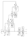
- FIG. 1 is a circuit diagram schematically showing the configuration of a vehicle charging system including a vehicle charging device including the vehicle charging control device according to the first embodiment.
- FIG. 2 is a circuit diagram showing the configuration of the quick charger in the first embodiment.
- FIG. 3 is a schematic diagram showing a state in which the vehicle is connected to one charging connector of the vehicle charging apparatus including the vehicle charging control apparatus according to the first embodiment.
- FIG. 4 is a circuit diagram schematically showing a state in which output power is supplied to one charging connector in the first embodiment.
- FIG. 5 is a schematic diagram showing a state in which one vehicle is connected to each of the charging connectors of the vehicle charging apparatus including the vehicle charging control apparatus according to the first embodiment.
- FIG. 1 is a circuit diagram schematically showing the configuration of a vehicle charging system including a vehicle charging device including the vehicle charging control device according to the first embodiment.
- FIG. 2 is a circuit diagram showing the configuration of the quick charger in the first embodiment.
- FIG. 3 is a schematic diagram showing a state in which the vehicle
- FIG. 6 is a circuit diagram schematically showing a state in which output power is distributed and supplied to each charging connector in the first embodiment.
- FIG. 7 is a flowchart showing the operation of the control unit in the first embodiment.
- FIG. 8 is a flowchart showing how to handle surplus power in the first embodiment.
- a switch group is controlled from the outside or the inside, so that it is possible to variously change a route for distributing power from a plurality of power output units to a plurality of charging connectors.
- one of the branch parts should be energized, and one of the plurality of switches provided in the energized branch part should be energized and the other switch should be deenergized.
- the configuration is such that it can be controlled selectively, and if the control is performed in this way, only one of the third conductive paths can be selectively made conductive in the branch portion to be energized. , The other third conductive path can be maintained in a non-energized state.
- the vehicle charge control device may have a configuration including the above charge switching device and the control unit.
- the control part sets one of the switches provided in the energized branch part to the energization enabled state. Then, the other switches can operate so as to be in a power-off state.
- the control unit under the control of the control unit, only one of the third conductive paths can be selectively made conductive in the branch section to be energized, and the other third conductive path can be connected. It can be maintained in a non-energized state. Therefore, it is possible to concentrate the electric power on the specific charging connector while preventing the plurality of charging connectors from being electrically connected to each other via the branch portion to be energized.
- the control unit when the control unit is any one of the plurality of charging connectors included in the connector unit and is a connected connector that is connected to the vehicle, and the rest is not a connected connector.
- the switch provided in the third conductive path of the path toward the connector being connected is set to the energized state while the switch provided in the remaining third conductive path is set to the disconnected state.
- Charging can be performed more efficiently.
- the "third conductive path of the path toward the connector being connected” refers to the upstream side (charger) connected to the branch of the plurality of third conductive paths forming the branch targeted for energization. Side) means the third conductive path arranged between the first conductive path and the "connecting connector".
- the control unit has a plurality of charging connectors forming the connector unit, two or more of which are connected connectors connected to the vehicle, and the rest are not connected connectors.
- the switch provided in the third conductive path of the path toward any one of the plurality of connected connectors is set to the energization enabled state and the remaining The switches provided in the three conductive paths may be operated so as to be in a power-off state.
- the plurality of charging connectors it is possible to prevent the plurality of charging connectors from being electrically connected to each other at the two or more branch portions through which the electric power passes. That is, a vehicle connected to any one charging connector (one connecting connector) and a vehicle connected to another charging connector (another connecting connector) are electrically connected via the branch portion. You can prevent it.
- the control unit has a plurality of charging connectors forming the connector unit, two or more of which are connected connectors connected to the vehicle, and the rest are not connected connectors.
- a switch provided on the third conductive path of the path toward any one of the plurality of connected connectors is provided at each of the branching parts of which the number is larger than the number of connected connectors.
- the switch provided in the remaining third conductive path may be operated so as to be in the power-off state while being in the power-on state.
- each electric power output from the electric power output units of which the number is larger than that of the connectors being connected is concentrated on two or more charging connectors (connecting connectors) via the plurality of branching units. Therefore, charging can be performed more efficiently.
- the control unit may perform the predetermined charging in each of the two or more branching units when the charging state of the vehicle connected to one of the connected connectors is the predetermined charging state. Except for the connected connector connected to the vehicle in the state, the switch provided in the third conductive path of the path toward one of the connected connectors is set to the energization permitting state while the remaining third conductive path is connected. The provided switch is turned off. With this configuration, when the state of charge of the vehicle connected to one of the connected connectors is the predetermined state of charge, the electric power can be concentrated to the vehicles other than the vehicle, and the charging can be performed more efficiently. Can be done.
- the vehicle While performing the operation of concentrating the electric power in this manner, while performing the operation of concentrating the electric power in this manner, the vehicle connected to any one charging connector (the connector being connected) and the other charging connector ( It is possible to prevent electrical continuity between the vehicle connected to the other connected connector) and the vehicle via the branch portion.
- the vehicle charge control device of the present disclosure includes one or more chargers, The charger may individually output power from the plurality of power output units. With such a configuration, the output of electric power from each output unit can be controlled according to the state of the battery of the vehicle connected to the charging connector and the presence or absence of the connection of the vehicle to the charging connector. It is possible to supply electric power of a magnitude that corresponds to the state of the battery in detail.
- a vehicle charging system 100 including a vehicle charging switching device 1 according to a first embodiment (hereinafter, also referred to as “charging switching device 1”) illustrated in FIG. 1 includes a plurality of quick chargers 10 that are chargers. Each of which extracts a predetermined amount of electric power from the commercial power source, and based on the extracted electric power, output power is generated in each of the plurality of power output units 12 (hereinafter, also referred to as “output unit 12 ”). The generated output power is supplied by the charge switching device 1 to one of the connector units 30 to which the parked vehicle is connected, and the battery has a function of charging the battery of the vehicle. That is, the vehicle charging system 100 can supply the electric power from the quick charger 10 to the vehicle battery via the connector unit 30.
- the charge switching device 1 targets the vehicle charging system 100 and has a function of switching the charging path from the quick charger 10 to the connector unit 30.
- a vehicle charging system 100 includes a plurality of quick chargers 10, a charge switching device 1, and a plurality of charging connectors 30A, 30B, 30C (hereinafter, also referred to as a connector unit 30). ..
- the vehicle charging system 100 also includes a vehicle charging control device 3 (hereinafter, charging control device 3) including a plurality of quick chargers 10 and a charging switching device 1.
- the plurality of quick chargers 10 have the same configuration.
- the quick charger 10 includes an AC/DC conversion unit 11, a plurality of output units 12, a control unit 13, and a communication unit 14.
- the AC/DC conversion unit 11 includes a filter unit 15, a diode bridge 16, a coil L1, a switch element Z1, a diode D5, and a capacitor C1.
- the filter unit 15 has a function of removing noise from the AC voltage input to the input terminals Tin1 and Tin2.
- the diode bridge 16 is a full-wave rectification circuit composed of four diodes D1, D2, D3, D4 connected in a bridge.
- the diode bridge 16 full-wave rectifies the AC voltage that has passed through the filter unit 15.
- One end of the coil L1 is connected to the cathodes of the diodes D1 and D2.
- the drain of the switch element Z1 is connected to the other end of the coil L1.
- the switch element Z1 for example, a FET or the like is used.
- the source of the switch element Z1 is connected to the anodes of the diodes D3 and D4.
- the diode D5 has an anode connected to the other end of the coil L1 and the drain of the switch element Z1, and a cathode connected to one end of the capacitor C1.
- the other end of the capacitor C1 is connected to the anodes of the diodes D3 and D4 and the source of the switch element Z1.
- the switch element Z1 is configured to be able to perform a switching operation by the control unit 13 (not shown).
- the switching element Z1 can perform a switching operation at a predetermined timing to bring the phase of the waveform of the current of the AC/DC conversion unit 11 closer to the phase of the waveform of the output voltage, thereby improving the power factor. ..
- the input voltage is boosted by the coil L1
- the boosted voltage is rectified and smoothed by the diode D5 and the capacitor C1.
- the circuit configured by the switch element Z1, the coil L1, the diode D5, and the capacitor C1 for improving the power factor is an example, and other known circuits may be adopted to improve the power factor.
- Each output unit 12 includes a full bridge circuit 17, a transformer T, a diode bridge 18, a coil L2, and a capacitor C2.
- the full bridge circuit 17 includes four switch elements Z2, Z3, Z4 and Z5.
- the switch elements Z2, Z3, Z4, Z5 are configured to be able to perform a switching operation by the control unit 13 (not shown).
- the full bridge circuit 17 converts the voltage output from the AC/DC converter 11 via the capacitor C1 into an AC voltage by switching the switching elements Z2, Z3, Z4, Z5.
- the drains of the switch elements Z2 and Z3 of the full bridge circuit 17 are connected to the cathode of the diode D5 of the AC/DC converter 11 and one end of the capacitor C1.
- the sources of the switch elements Z2 and Z3 are connected to the drains of the switch elements Z4 and Z5, respectively, and the sources of the switch elements Z4 and Z5 are connected to the anodes of the diodes D3 and D4, the source of the switch element Z1 and the other end of the capacitor C1. ing.
- the drains of the switch elements Z2 and Z3 are connected to the cathode of the diode D5 of the AC/DC converter 11 and one end of the capacitor C1, and the sources of the switch elements Z4 and Z5 are It is connected to the anodes of the diodes D3 and D4, the source of the switch element Z1, and the other end of the capacitor C1. That is, the output units 12 are provided in parallel with each other.
- the transformer T includes a plurality of magnetically coupled coils, for example, a primary coil and a secondary coil.
- One end of the primary coil is connected to the source of the switch element Z2 and the drain of the switch element Z4, and the other end of the primary coil is connected to the source of the switch element Z3 and the drain of the switch element Z5.
- the diode bridge 18 is a circuit that full-wave rectifies the AC voltage induced in the secondary coil of the transformer T.
- the diode bridge 18 includes diodes D6, D7, D8 and D9.
- One end of the secondary coil forming the transformer T is connected to the anode of the diode D6 and the cathode of the diode D8, and the other end of the secondary coil is connected to the anode of the diode D7 and the cathode of the diode D9.
- the cathodes of the diodes D6 and D7 are connected to one end of the coil L2, and the other end of the coil L2 is connected to the output terminal Tout1.
- the anodes of the diodes D6 and D7 are connected to the cathodes of the diodes D8 and D9, respectively.
- the anodes of the diodes D8 and D9 are connected to the output terminal Tout2.
- the other end of the coil L2 is connected to one end of the capacitor C2, and the other end of the capacitor C2 is connected to the anodes of the diodes D8 and D9.
- the capacitor C2 smoothes the full-wave rectified voltage output from the diode bridge 18, and the coil L2 suppresses the ripple current from flowing into the capacitor C2.
- the control unit 13 is configured as a microcomputer, for example, and includes a CPU, a ROM, a RAM, a non-volatile memory, and the like.
- the control unit 13 is configured to control each switch element (Z1 to Z5) to perform a switching operation. Thereby, the controller 13 can adjust the power factor in the AC/DC converter 11. Further, the control unit 13 can individually adjust the magnitude of the output power of each output unit 12.
- the communication unit 14 is connected to the communication unit 14 of another quick charger 10 by a communication line 14A (see FIG. 1).
- the control unit 13 of each quick charger 10 can exchange information via each communication unit 14 and the communication line 14A.
- the communication section 14 of the upper rapid charger 10 is connected to the connector section 30 by communication lines 14B, 14C and 14D (see FIG. 1).
- the control unit 13 of the upper rapid charger 10 can communicate with the ECU of the vehicle connected to the connector unit 30 such as CAN communication.
- the communication unit 14 is configured to be able to output information obtained from the vehicle by CAN communication or the like to the communication unit 14 of another quick charger 10 via the communication line 14A.
- the control unit 13 of each quick charger 10 can control the operation of the vehicle charging system 100 in cooperation with each other via the communication unit 14.
- the thus configured quick charger 10 can individually output output power from the plurality of output units 12.
- the charge switching device 1 includes a plurality of first conductive paths 50A, 50B, 50C, 50D, 50E, 50F (hereinafter, also referred to as an input side conductive path group 50) and a plurality of second conductive paths 51A. , 51B and 51C (hereinafter, also referred to as output side conductive path group 51), a plurality of third conductive paths 52B, and a plurality of switches 53 (hereinafter also referred to as switch group 55).
- first conductive paths 50A, 50B, 50C, 50D, 50E, and 50F are provided corresponding to each of the plurality of output units 12, and each electric power output from each output unit 12 is supplied.
- the output-side conductive path group 51 is electrically connected to each of the connector units 30.
- second conductive paths 51A, 51B, 51C are provided corresponding to the respective charging connectors 30A, 30B, 30C, and each second conductive path 51A, 51B, 51C is provided in each charging connector 30A. , 30B, 30C.
- One end of the third conductive path 52B is connected to each of the input side conductive path groups 50 by the number of the output side conductive path groups 51 (three in this case).
- the three third conductive paths 52B whose one ends are connected to each other form a branch portion 52A.
- the other end of each of the third conductive paths 52B forming the branch portion 52A is connected to each of the second conductive paths 51A, 51B, 51C.
- Each branch portion 52A formed of a plurality of third conductive paths 52B is provided corresponding to each of the first conductive paths 50A, 50B, 50C, 50D, 50E, 50F, and a plurality of branch portions 52A are provided.
- a third conductive path 52B is provided so as to branch from the first conductive path 50A, 50B, 50C, 50D, 50E, 50F to each of the second conductive paths 51A, 51B, 51C to form an intermediate conductive path group 52. ing.
- the plurality of switches 53 are configured as relay switches, for example, and are provided corresponding to each of the third conductive paths 52B. These switches 53 are configured so that the corresponding third conductive path 52B can be switched between the energization permitted state and the energization cutoff state.
- the three switches 53 connected to the third conductive paths 52B of the one branch portion 52A form a switch set 54.
- the operation of the switch set 54 can be controlled by the control unit 13. Specifically, when any one of the branch parts 52A is to be energized, the control part 13 energizes any one of the plurality of switches 53 provided in the energized branch part 52A.
- the other switches 53 are turned off and the two or more switches 53 are simultaneously controlled so as not to enter the energizing permitting state. Further, when any one of the branch parts 52A is to be energized, the control unit 13 can also turn off all the switches 53 of the switch set 54 of the branch part 52A to be energized.
- One charging connector 30A, 30B, 30C is connected to each of the output side conductive path groups 51.
- the connector unit 30 has charging connectors 30A, 30B, 30C that serve as a path for supplying the power output from the quick charger 10 to the vehicle to which the connector unit 30 is connected when the vehicle is connected.
- the connector unit 30 is configured to electrically connect the control unit 13 to the ECU of the vehicle and to transmit information such as SOC of the battery of the vehicle to the control unit 13.
- the control unit 13 performs CAN communication with the ECU of the vehicle 70 via the communication unit 14 to acquire the charging request from the vehicle and the SOC of the battery of the vehicle 70. Then, the control unit 13 sets the switch 53 of the third conductive path 52B connected to the second conductive path 51A to the energization permitted state based on the charging request from the vehicle or the acquired SOC, and at the same time, the second conductive path 51B. , 51C, the switch 53 of the third conductive path 52B is turned off.
- control unit 13 has two or more branching units when the charging connector 30A forming the connector unit 30 is a connected connector connected to the vehicle 70 and the remaining charging connectors 30B and 30C are not connected connectors.
- the switch 53 provided in the third conductive path 52B of the path toward the connected connector is set in the energization permitted state, while the switch 53 provided in the remaining third conductive path 52B is set in the deenergized state. ..
- the switch 53 of the third conductive path 52B connected to the second conductive path 51A is switched. All are energized, and all the switches 53 of the third conductive path 52B connected to the second conductive paths 51B and 51C are turned off. In this way, all the output power from the output unit 12 is concentratedly supplied to the second conductive path 51A. Then, the second conductive path 51A supplies the output power supplied from the plurality of output units 12 to the vehicle 70 via the charging connector 30A. Accordingly, the vehicle charging system 100 can charge the battery of the vehicle 70 in a shorter time.
- the control unit 13 stops the operation of at least a part of the plurality of output units 12. Therefore, it is possible to prevent the electric power from being unnecessarily supplied to the battery of the vehicle 70.
- the control unit 13 handles the amount of power corresponding to the power that can be output by the output unit 12 that has stopped operating, as surplus power. For example, when the output power of one output unit 12 is 10 kw, when the output unit 12 stops operating, the control unit 13 treats 10 kw as surplus power.
- the control unit 13 performs CAN communication with the ECUs of the vehicles 70, 71, 72 via the communication unit 14 to acquire the SOC of each of the batteries of the vehicles 70, 71, 72. Then, the control unit 13 changes the switch 53 of each switch set 54 to the energization permitted state or the energized cutoff state so as to supply electric power to the batteries of the vehicles 70, 71, 72 based on the acquired SOC.
- the control unit 13 among the plurality of charging connectors 30A, 30B, and 30C that form the connector unit 30, two or more are connected connectors that are connected to the vehicle, and the remaining part is not the connected connector or the remaining part is If there is not, in each of the branching portions 52A of two or more and more than the number of connectors being connected, the third conductive path 52B of the route toward any one of the plurality of connectors being connected is provided.
- the switch 53 provided in the remaining third conductive path 52B is turned off while the switch 53 provided is turned on.
- the battery of the vehicle 72 connected to the charging connector 30C is not in the predetermined charging state
- the battery of the vehicle 71 connected to the charging connector 30B is in the predetermined charging state, or the internal resistance increases due to deterioration of the battery or the like.
- the battery of the vehicle 70 has a higher SOC than the battery of the vehicle 72, and is not in the predetermined charging state (that is, in the batteries of the vehicles 70, 71, 72, the battery of the vehicle 71 is charged by the predetermined charge).
- the batteries of the other vehicles 70 and 72 are not in the predetermined charging state
- the vehicle 71 is supplied with electric power from a smaller number of output units 12 than in the case where the vehicle is not in the predetermined charging state, in order to prevent electric power from being supplied unnecessarily. Therefore, a part of the output unit 12 that should be supplied when the vehicle 71 is not in the predetermined charge state is treated as surplus power.
- the control unit 13 includes the second conductive path 51C in the branching portion 52A corresponding to one of the first conductive paths 50A, 50B, 50C, 50D, 50E, and 50F connected to the output unit 12 treated as surplus power.
- the switch 53 of the third conductive path 52B connected to the second conductive path 52B is turned on and the switch 53 of the third conductive path 52B connected to the second conductive paths 51A and 51B is turned off. That is, when the charging state of the vehicle 71 connected to the charging connector 30B is the predetermined charging state, the control unit 13 is connected to the vehicle 71 in the predetermined charging state at each of the two or more branch portions 52A.
- the switch 53 provided on the third conductive path 52B on the path toward the charging connector 30C except the charging connector 30B is set to the energized state while the switch 53 provided on the remaining third conductive path 52B is set to the de-energized state.
- the control unit 13 reduces the number of the output units 12 that supply the output power to the charging connector 30B and increases the number of the output units 12 that supply the output power to the charging connector 30C.
- the vehicle charging system 100 can charge the battery of the vehicle 72 connected to the charging connector 30C in a shorter time by supplying the surplus power.
- the method of assigning the output unit 12 to the vehicles 70, 71, 72 can be changed according to the required specifications.
- the predetermined charge state means, for example, a state where the SOC is 80% or more or has reached a predetermined size
- the non-predetermined charge state means that the SOC is less than 80% or a predetermined size. Is not reached.
- this vehicle charging system 100 can change the magnitude of the output power supplied to each of the charging connectors 30A, 30B, 30C according to the state of the battery of each of the vehicles 70, 71, 72. ..
- the control unit 13 determines whether the charging target is one (step S1). Specifically, whether or not there is one charging target is determined by whether or not the vehicle is connected to the charging connectors 30A, 30B, 30C and the battery of the vehicle is supplied with electric power. For example, in a vehicle connected to the charging connectors 30A, 30B, 30C, it is possible to determine whether or not only one charging target is available based on the charging request from the vehicle or the SOC of the battery of this vehicle.
- step S1 when it is determined that the charging target is one (Yes in step S1), the process proceeds to step S2, and the total power of all the quick chargers 10 is set as the power that can be output.
- the control unit 13 allocates the amount of electric power that can be output by all the quick chargers 10 to one target vehicle. For example, when there is no one to be charged, it means that no electric power is supplied from the charging system 100 for this vehicle to the outside. Therefore, the control unit 13 determines the total electric power of all the quick chargers 10. Treated as power that can be output.
- the power that can be output from the device 10) ⁇ 2 60 kw.
- the control unit 13 treats this value as the amount of power that can be output, and assigns it to one target vehicle.
- step S3 the power output from the target vehicle and the output power is determined. Specifically, when a vehicle is connected to the connector unit 30, the control unit 13 recognizes this vehicle as the target vehicle. Then, the control unit 13 determines the amount of electric power to be output to this vehicle based on the amount of electric power that can be currently output and the charging request from the vehicle.
- step S4 the charging switching device 1 is switched to the charging target, and the quick charger 10 starts supplying power.
- the control unit 13 sets the switch 53 of the plurality of third conductive paths 52B connected to any of the second conductive paths 51A, 51B, 51C corresponding to the connected connector to the energization permitted state.
- the switches 53 of the plurality of third conductive paths 52B connected to any of the second conductive paths 51A, 51B, and 51C that do not correspond to the connector being connected are turned off. In this way, the output power from the output unit 12 that is input to the input side conductive path group 50 is supplied to any of the output side conductive path groups 51 to which any of the connector sections 30 connected to the target vehicle is connected.
- step S1 When it is determined in step S1 that the charging target is not one (No in step S1), the process proceeds to step S5 and it is determined whether the charging target is two. Specifically, the control unit 13 determines whether or not there are two connected connectors and power is being supplied to the battery of each vehicle.
- step S5 When it is determined in step S5 that the number of charging targets is two (Yes in step S5), the process proceeds to step S6, and the electric power per one of the quick chargers 10 including the status of charging is output. Available power. Specifically, the control unit 13 allocates the amount of electric power (30 kw) that can be output by one quick charger 10 to one target vehicle.
- step S5 When it is determined in step S5 that the number of charging targets is not two (No in step S5), the process proceeds to step S7 and it is determined whether there is surplus power.
- the control unit 13 suppresses the output power from at least a part of the output units 12 that supply the output power to each of the target vehicles, and the output unit 12 whose output is suppressed outputs the output power.
- the amount of power corresponding to the possible power is treated as surplus power.
- the control unit 13 outputs the power to each target vehicle. The output power from 12 is not suppressed. In this case, there is no surplus power because there is no output unit 12 whose output is suppressed.
- step S7 When it is determined in step S7 that there is surplus power (Yes in step S7), the process proceeds to step S8, and the power that can be output to a new charging target is surplus power.
- a vehicle including a battery whose SOC is less than 80% or has not reached a predetermined size is connected to any of the charging connectors 30A, 30B, 30C, the control unit 13 , The second conductive path to which the charging connectors 30A, 30B, and 30C to which this vehicle is connected, respectively, the surplus power (that is, the power corresponding to the magnitude of the power that can be output by the output unit 12 whose output is suppressed) It is decided to supply to any of 51A, 51B and 51C.
- step S7 When it is determined in step S7 that there is no surplus power (No in step S7), the control unit 13 determines whether there is surplus power or a fully charged battery in step S9. Whether or not the battery is fully charged can be determined based on the charge stop request from the vehicle or the SOC level of the battery. When it is determined in step S9 that there is no surplus power and there is no fully charged battery (No in step S9), the control unit 13 repeats the determination in step S9. When it is determined in step S9 that there is excess power or there is a fully charged battery (Yes in step S9), the control unit 13 returns the process to step S1.
- step S10 it is determined whether or not there is an excess of power for one or more of the output units 12 electrically arranged in parallel in the quick charger 10 (step S10).
- the control unit 13 is configured to be able to calculate the magnitude of the electric power supplied to the battery of the target vehicle, which is connected to any of the connector units 30, based on the SOC. .. Then, the control unit 13 determines whether the difference between the calculated electric power and the electric power currently supplied to the battery is smaller than the output electric power of one output unit 12.
- step S10 determines The determination is repeated in step S10.
- step S10 when it is determined that the power of one or more of the output units 12 electrically arranged in parallel in the quick charger 10 is excessive (Yes in step S10), in step S11, the control unit 13 stops the operation of the output units 12 of the number corresponding to the magnitude of the surplus power, and continues charging the battery with the output power from the remaining output units 12. Stopping the operation of the output unit 12 means stopping the switching operation of the switch elements Z2, Z3, Z4, Z5 that are being switched by the control unit 13.
- step S12 all the switch sets 54 of the output unit 12 that have surplus power are turned off.
- the control unit 13 causes the switch 53 of the branch unit 52A connected to any of the first conductive paths 50A, 50B, 50C, 50D, 50E, and 50F connected to the output unit 12 that has stopped operating. Turn off all the power.
- the control unit 13 brings one of the first conductive paths 50A, 50B, 50C, 50D, 50E, and 50F connected to the output section 12 that has stopped operating, and the output-side conductive path group 51 into a non-conductive state. To do.
- step S13 it is determined whether there is a charging status that can accept the surplus power. Specifically, it is determined whether or not another vehicle is connected to the remaining connector section 30 and the battery of this vehicle is being supplied with power, for example, the battery of the vehicle connected to the remaining connector section 30. It is determined based on the SOC.
- step S13 When it is determined in step S13 that there is a charging status that can accept the surplus power (Yes in step S13), the process proceeds to step S14, and the target vehicle and the magnitude of the output power to the target vehicle To decide.
- the control unit 13 determines a vehicle equipped with a battery whose SOC is less than 80% or has not reached a predetermined magnitude, and the magnitude of output power output to this vehicle.
- step S15 the output unit 12 having surplus electric power is switched to the target vehicle and connected, and the output from the quick charger 10 is started.
- the control unit 13 controls the branch unit 52A connected to any of the first conductive paths 50A, 50B, 50C, 50D, 50E, and 50F connected to the output unit 12 that has stopped operating,
- the switch 53 of the third conductive path 52B connected to any of the second conductive paths 51A, 51B, 51C corresponding to the target vehicle is set to the energization permitted state, and the second non-corresponding vehicle is not supported.
- the switch 53 of the third conductive path 52B connected to any of the conductive paths 51A, 51B and 51C is turned off.
- the control unit 13 connects any one of the first conductive paths 50A, 50B, 50C, 50D, 50E, and 50F connected to the output unit 12 that has stopped operating to the vehicle determined in step S13. Any one of the two conductive paths 51A, 51B and 51C is brought into conduction. Then, the control unit 13 starts the switching operation of the switch elements Z2, Z3, Z4, Z5 of the output unit 12 which have stopped the operation. In this way, the output power generated by operating the output unit 12 that has stopped operating is supplied to the battery of the target vehicle, and the surplus power is supplied to the target vehicle.
- step S13 When it is determined in step S13 that there is no charging status that can accept the surplus power (No in step S13), the process proceeds to step S16 and the output unit 12 that has stopped the operation has a power level that can be output. The amount of the corresponding power is counted as surplus power.
- the control unit 13 of each quick charger 10 is configured to be able to transmit the presence/absence of its own surplus power, the size of the surplus power, and the like to the other control unit 13. For example, when there is excess power in the upper (lower) quick charger 10 in FIGS. 1, 4, and 6, the control unit 13 of the upper (lower) quick charger 10 controls the lower (upper) quick charger 10. The presence/absence of its own surplus power, the size of the surplus power, and the like can be transmitted to the unit 13 via the communication unit 14 and the communication line 14A.
- the switch group 55 is controlled from the outside or the inside, so that the path for distributing the power from the plurality of output units 12 to the connector unit 30 can be variously changed.
- one of the branch portions 52A is energized, and one of the plurality of switches 53 provided in the energized branch portion 52A is energized and the other switch 53 is deenergized.
- This is a configuration in which it is possible to selectively control the third conductive path 52B to be in the state, and if the control is performed in this way, only one of the third conductive paths 52B is selectively selected in the branch portion 52A to be energized.
- the vehicle charging control device 3 has a configuration including the charging switching device 1 and the control unit 13.
- the control unit 13 selects one of the plurality of switches 53 provided in the energized branch unit 52A when energizing any of the branch units 52A. It operates so that 53 is in the energization permitted state and the other switches 53 are in the energized cutoff state.
- only one of the third conductive paths 52B can be selectively made conductive in the branch portion 52A to be energized, and the other third conductive path 52B.
- the conductive path 52B can be maintained in a non-energized state. Therefore, it is possible to concentrate the power on a specific charging connector while preventing the plurality of charging connectors 30A, 30B, 30C from being electrically connected to each other via the branch portion 52A to be energized.
- the control unit 13 is a connecting connector in which any one of the plurality of charging connectors 30A, 30B, and 30C configuring the connector unit 30 is connected to the vehicle.
- the switch 53 provided in the third conductive path 52B of the path toward the connector being connected is energized to enable the remaining third conductivity.
- the switch 53 provided in the path 52B operates so as to be in a power-off state.
- the control unit 13 is a connector being connected, in which two or more of the plurality of charging connectors 30A, 30B, and 30C configuring the connector unit 30 are connected to the vehicle,
- the residual is not the connector being connected or there is no residual, it is provided in each of the two or more branch portions 52A in the third conductive path 52B which is a path toward any one of the plurality of connecting connectors. It operates so that the switch 53 provided in the remaining third conductive path 52B is turned off while the switch 53 is turned on. With this configuration, each electric power output from the two or more output units 12 can be guided to the two or more charging connectors (two or more connected connectors) via the two or more branch units 52A.
- the control unit 13 is a connector being connected, in which two or more of the plurality of charging connectors 30A, 30B, and 30C configuring the connector unit 30 are connected to the vehicle, In the case where the remainder is not the connector being connected or there is no residue, in each of the branch portions 52A having a number larger than the number of the connectors being connected, the first path of any one of the plurality of connecting connectors is connected.
- the switch 53 provided in the third conductive path 52B operates so as to be in the energized state while the switch 53 provided in the remaining third conductive path 52B is in the electrically disconnected state.
- each electric power output from the output unit 12 that is larger in number than the connected connectors is concentrated on two or more charging connectors (connecting connectors) via the plurality of branching units 52A. Therefore, the charging can be performed more efficiently.
- a vehicle connected to any one charging connector (one connecting connector) and another charging connector (another connecting connector) while performing the operation of concentrating electric power in this manner. Can be prevented from becoming conductive via the branch portion 52A.
- the control unit 13 controls each of the two or more branch units 52A when the charging state of the vehicle connected to one of the connected connectors is the predetermined charging state.
- the switch 53 provided on the third conductive path 52B on the path to any one of the connected connectors excluding the connected connector connected to the vehicle in the predetermined charging state is left in the energized state.
- the switch 53 provided in the third conductive path 52B is turned off.
- the vehicle charging control device 3 includes one or more quick chargers 10, The quick charger 10 individually outputs electric power from the plurality of output units 12. With such a configuration, the output of electric power from each output unit 12 can be controlled according to the state of the battery of the vehicle and whether or not the vehicle is connected to the charging connectors 30A, 30B, 30C. It is possible to supply electric power of a magnitude that corresponds to the state of the battery in detail.
- the relay is illustrated as an example of the switch 53 of the vehicle charge switching device 1, but other FETs or electric parts such as semiconductor switches may be used.
- each quick charger 10 has three output units 12, but the number of output units is not limited to this.
- the number of quick chargers 10 in the vehicle charging system 100 is two, but the number of quick chargers may be one or three or more.
- each quick charger 10 has one AC/DC converter 11, but the number of AC/DC converters is not limited to this. Specifically, a plurality of AC/DC converters may be electrically arranged in parallel in one quick charger.
- the third conductive path 51A connected to the charging connector 30A to which the vehicle 70 is connected is connected to the second conductive path 51A so as to supply the output power from all the output units 12.
- the switch of the third conductive path connected to the second conductive path so as to supply the output power from a part of the output parts. A part of the above may be set to the energization permitted state.
Landscapes
- Engineering & Computer Science (AREA)
- Power Engineering (AREA)
- Transportation (AREA)
- Mechanical Engineering (AREA)
- Charge And Discharge Circuits For Batteries Or The Like (AREA)
- Electric Propulsion And Braking For Vehicles (AREA)
Abstract
The present invention proposes, in a vehicle charging system equipped with a plurality of charging connectors, a techique capable of preventing conduction between the charging connectors and efficiently performing charging control on a vehicle battery. This charge switching device (1) has: an input-side conductive path group (50) for transmitting the powers from respective output units (12) through first conductive paths (50A to 50F); an output-side conductive path group (51) in which second conductive paths (51A to 51C) form power paths to respective charging connectors (30A to 30C); an intermediate conductive path group (52) in which, at a plurality of branch portions (52A) which correspond to the first conductive paths (50A to 50F) and in which a plurality of third conductive paths (52B) branch, each of the third conductive paths (52B) branches from the first conductive paths (50A to 50F) to the respective second conductive paths (51A to 51C); and a switch group (55) in which a plurality of switches (53) correspond to the respective third conductive paths (52B) and the respective switches (53) switch the corresponding third conductive paths (52B) between an energization permission state and an energization interruption state.
Description
本発明は、車両用の充電切替装置、及び車両用の充電制御装置に関するものである。
The present invention relates to a charge switching device for a vehicle and a charge control device for a vehicle.
特許文献1には、充電する電気自動車の滞在時間によって、優先順位をつけて充電する対象を切り替える車両用の充電システムが開示されている。この車両用の充電システムは充電する時間に余裕がある場合、出力を下げて別の対象に充電することができる。
[Patent Document 1] discloses a charging system for a vehicle that prioritizes and switches charging targets according to the staying time of an electric vehicle to be charged. This vehicle charging system can reduce the output and charge another target if there is enough time to charge.
電気自動車の課題の一つに、バッテリを充電する充電時間が長いという課題がある。特許文献1の車両用の充電システムでは、車両の滞在時間から必要な充電出力を算出し、充電器の出力を変動させ、低下させた出力の代わりに別の電気自動車のバッテリを充電させることができる。しかし、この車両用の充電システムの切り替えスイッチでは、充電出力を下げて別の充電器に充電するような方法は実施できない。複数の電気自動車のバッテリと一つの充電器とを電気的に接続する状態にすることができても、並列に接続されたバッテリに流れる電流はバッテリのSOC(State Of Charge)や電圧、内部抵抗の状態によって決まるため、特定の電気自動車のバッテリに対して特定の充電をすることはできず、結果的に急速充電器の出力の数に対応した数のバッテリにしか充電できない。また、電気自動車のバッテリ同士が接続されることになるため好ましくない。
One of the challenges of electric vehicles is that the charging time for charging the battery is long. In the vehicle charging system of Patent Document 1, a required charging output is calculated from the staying time of the vehicle, the output of the charger is changed, and the battery of another electric vehicle is charged instead of the reduced output. it can. However, with the changeover switch of this vehicle charging system, a method of lowering the charging output and charging another charger cannot be implemented. Even if it is possible to electrically connect the batteries of multiple electric vehicles and one charger, the current that flows in the batteries connected in parallel is the SOC (State of Charge), voltage, and internal resistance of the batteries. Therefore, the battery of a specific electric vehicle cannot be charged in a specific manner, and as a result, only the number of batteries corresponding to the number of outputs of the quick charger can be charged. Further, the batteries of the electric vehicle are connected to each other, which is not preferable.
また、一般的にバッテリにおける急速充電が可能な領域は、バッテリの劣化を抑える目的でバッテリ容量の80%までとされている。また、バッテリの劣化の他にもSOCが80%以上の充電をする場合、バッテリの最大電圧と内部抵抗による電圧上昇から急速充電器からの出力を抑制しなければならないため、充電時間は長くなることになる。しかし、より長い距離を移動したい、渋滞等になってもバッテリの充電切れを気にせず安心したい等の目的のためSOCが100%になるまでバッテリを充電したいというニーズもある。
急速充電器は車両が長く留まって充電することを想定していない。このため、SOCが100%になるまでバッテリを充電するには普通充電装置がある場所まで車両を移動して、再度充電しなければならない。また、急速充電器でSOCが80%以上の充電をしようとする場合、充電出力を下げた状態でバッテリに充電を行うことになるため急速充電器の出力が余剰な状態になってしまう。 In general, the region of the battery in which rapid charging is possible is set to 80% of the battery capacity for the purpose of suppressing deterioration of the battery. In addition to the deterioration of the battery, when the SOC is charged to 80% or more, the output from the quick charger has to be suppressed due to the voltage increase due to the maximum voltage of the battery and the internal resistance, so that the charging time becomes long. It will be. However, there is also a need to charge the battery until the SOC reaches 100% for the purpose of moving a longer distance, and not having to worry about the battery being depleted even when traffic jams occur, for the purpose of being reassured.
The quick charger does not assume that the vehicle will stay long and charge. Therefore, in order to charge the battery until the SOC reaches 100%, it is necessary to move the vehicle to the place where the normal charging device is located and charge it again. Moreover, when trying to charge the SOC of 80% or more in the quick charger, the battery is charged with the charge output being lowered, so that the output of the quick charger becomes excessive.
そこで、本開示では、複数の充電コネクタを備えた車両用の充電システムを制御するにあたり、充電コネクタ間での導通を防ぎつつ車両に搭載されたバッテリに対して効率的に充電を行う制御が可能となる技術を提案することを目的とする。
Therefore, in the present disclosure, when controlling a charging system for a vehicle that includes a plurality of charging connectors, it is possible to perform control that efficiently charges a battery mounted in the vehicle while preventing electrical continuity between the charging connectors. The purpose is to propose the technology that becomes.
本開示の一つである車両用の充電切替装置は、
並列に設けられた複数の電力出力部を有する充電器と、前記充電器から出力される電力を車両へ供給する経路となる複数の充電コネクタを有するコネクタ部と、を備えた車両用の充電システムを対象とし、前記充電器から前記コネクタ部への充電経路を切り替える車両用の充電切替装置であって、
複数の第1導電路を備えると共に、各々の前記第1導電路が複数の電力出力部の各々に対応して設けられ、各々の前記電力出力部から出力される各電力を各々の前記第1導電路によって伝送する構成をなす入力側導電路群と、
複数の第2導電路を備えると共に、各々の前記第2導電路が複数の前記充電コネクタの各々に対応して設けられ、各々の前記第2導電路が各々の前記充電コネクタへの電力経路をなす出力側導電路群と、
複数の第3導電路が分岐してなる分岐部を複数備えると共に、各々の前記分岐部が複数の前記第1導電路の各々に対応して設けられ、各々の前記分岐部において、複数の前記第3導電路が前記第1導電路から複数の前記第2導電路の各々へと分岐するように設けられる中間導電路群と、
複数のスイッチを備えると共に、各々の前記スイッチが複数の前記第3導電路の各々に対応して設けられ、各々の前記スイッチが、対応する前記第3導電路を通電許可状態と通電遮断状態とに切り替える構成をなすスイッチ群と、
を有する。 A charge switching device for a vehicle, which is one of the present disclosures,
A charging system for a vehicle, which includes a charger having a plurality of power output sections provided in parallel, and a connector section having a plurality of charging connectors that serve as a path for supplying the power output from the charger to the vehicle A charging switching device for a vehicle for switching a charging path from the charger to the connector part,
A plurality of first conductive paths are provided, each of the first conductive paths is provided corresponding to each of the plurality of power output sections, and each power output from each of the power output sections is supplied to each of the first power paths. An input side conductive path group configured to transmit by a conductive path,
A plurality of second conductive paths are provided, each of the second conductive paths is provided corresponding to each of the plurality of charging connectors, and each of the second conductive paths forms a power path to each of the charging connectors. Output side conductive path group,
A plurality of branch portions formed by branching a plurality of third conductive paths are provided, each branch portion is provided corresponding to each of the plurality of first conductive paths, and each of the branch portions has a plurality of An intermediate conductive path group provided so that a third conductive path branches from the first conductive path to each of the plurality of second conductive paths;
A plurality of switches are provided, and each of the switches is provided corresponding to each of the plurality of third conductive paths, and each of the switches sets the corresponding third conductive path to an energization permitted state and an energized cutoff state. A group of switches that are configured to switch to
Have.
本開示の一つである車両用の充電制御装置は、
上記充電切替装置と、
いずれかの前記分岐部を通電対象とする場合に、前記通電対象とされた前記分岐部に設けられた複数の前記スイッチの内、いずれかの前記スイッチを前記通電許可状態とし、他の前記スイッチを前記通電遮断状態とする制御部と、
を含む。 A charging control device for a vehicle, which is one of the present disclosures,
The charge switching device,
When any one of the branches is to be energized, any one of the plurality of switches provided in the branch to be energized is set to the energization permitted state, and the other switch is And a control unit that brings the power supply into the cutoff state,
including.
本開示の技術によれば、複数の充電コネクタを備えた車両用の充電システムを制御するにあたり、充電コネクタ間での導通を防ぐ制御が可能となり、車両に搭載されたバッテリに対して効率的に充電を行う制御が可能となる。
According to the technology of the present disclosure, when controlling a charging system for a vehicle including a plurality of charging connectors, it is possible to perform control to prevent conduction between the charging connectors, and efficiently control a battery mounted on the vehicle. It becomes possible to control the charging.
本開示の車両用の充電切替装置は、外部又は内部からスイッチ群が制御されることで、複数の電力出力部から複数の充電コネクタへ電力を分配する経路を様々に変化させることができる。特に、いずれかの分岐部を通電対象とし、通電対象とされた分岐部に設けられた複数のスイッチの内、いずれかのスイッチを通電許可状態とし、他のスイッチを通電遮断状態とするように択一的に制御することが可能な構成であり、このように制御がなされれば、通電対象とされる分岐部において、いずれかの第3導電路のみを択一的に導通させることができ、他の第3導電路を非通電状態で維持することができる。また、このように択一的に動作させつつ、特定の充電コネクタに電力を集中させるような制御も可能となり、このようにすれば、特定の充電コネクタに接続された車両のバッテリを効率的に充電することができる。
In the vehicle charge switching device according to the present disclosure, a switch group is controlled from the outside or the inside, so that it is possible to variously change a route for distributing power from a plurality of power output units to a plurality of charging connectors. In particular, one of the branch parts should be energized, and one of the plurality of switches provided in the energized branch part should be energized and the other switch should be deenergized. The configuration is such that it can be controlled selectively, and if the control is performed in this way, only one of the third conductive paths can be selectively made conductive in the branch portion to be energized. , The other third conductive path can be maintained in a non-energized state. In addition, it is possible to perform control in such a manner that the electric power is concentrated on a specific charging connector while selectively operating as described above, and in this way, the battery of the vehicle connected to the specific charging connector can be efficiently used. Can be charged.
本開示の車両用の充電制御装置は、上記の充電切替装置と制御部とを備えた構成をとり得る。このような構成のものでは、制御部は、いずれかの分岐部を通電対象とする場合に、通電対象とされた分岐部に設けられた複数のスイッチの内、いずれかのスイッチを通電許可状態とし、他のスイッチを通電遮断状態とするように動作し得る。
このように構成されていれば、制御部の制御により、通電対象とされる分岐部において、いずれかの第3導電路のみを択一的に導通させることができ、他の第3導電路を非通電状態で維持することができる。よって、通電対象とされる分岐部を経由して複数の充電コネクタが互いに導通してしまうこと防ぎつつ、特定の充電コネクタへと電力を集中させることができる。 The vehicle charge control device according to the present disclosure may have a configuration including the above charge switching device and the control unit. With such a configuration, when any one of the branch parts is to be energized, the control part sets one of the switches provided in the energized branch part to the energization enabled state. Then, the other switches can operate so as to be in a power-off state.
With this configuration, under the control of the control unit, only one of the third conductive paths can be selectively made conductive in the branch section to be energized, and the other third conductive path can be connected. It can be maintained in a non-energized state. Therefore, it is possible to concentrate the electric power on the specific charging connector while preventing the plurality of charging connectors from being electrically connected to each other via the branch portion to be energized.
本開示の車両用の充電制御装置において、制御部は、コネクタ部を構成する複数の充電コネクタの内のいずれか一つが車両に接続された接続中のコネクタであり残余が接続中のコネクタでない場合に、2以上の分岐部の各々において、接続中のコネクタへ向かう経路の第3導電路に設けられたスイッチを通電許可状態としつつ残余の第3導電路に設けられたスイッチを通電遮断状態とするように動作してもよい。
このように構成されていれば、2以上の電力出力部から出力される各電力を2以上の分岐部を経由させて1つの充電コネクタ(接続中のコネクタ)に集中させるように導くことができ、充電をより効率的に行うことができる。しかも、電力が経由する2以上の分岐部では、複数の充電コネクタが互いに導通してしまうこと防ぐことができる。
なお、「接続中のコネクタに向かう経路の第3導電路」とは、通電対象とされた分岐部を構成する複数の第3導電路の内、当該分岐部に接続される上流側(充電器側)の第1導電路と「接続中のコネクタ」との間に配置される第3導電路を意味する。 In the vehicle charging control device according to the present disclosure, when the control unit is any one of the plurality of charging connectors included in the connector unit and is a connected connector that is connected to the vehicle, and the rest is not a connected connector. In each of the two or more branch portions, the switch provided in the third conductive path of the path toward the connector being connected is set to the energized state while the switch provided in the remaining third conductive path is set to the disconnected state. May operate as
With such a configuration, it is possible to guide each electric power output from the two or more electric power output portions via the two or more branch portions so as to be concentrated on one charging connector (connecting connector). , Charging can be performed more efficiently. Moreover, it is possible to prevent the plurality of charging connectors from being electrically connected to each other at the two or more branch portions through which the electric power passes.
The "third conductive path of the path toward the connector being connected" refers to the upstream side (charger) connected to the branch of the plurality of third conductive paths forming the branch targeted for energization. Side) means the third conductive path arranged between the first conductive path and the "connecting connector".
本開示の車両用の充電制御装置において、制御部は、コネクタ部を構成する複数の充電コネクタの内、2以上が車両に接続された接続中のコネクタであり、残余が接続中のコネクタでない又は残余が無い場合に、2以上の分岐部の各々において、複数の接続中のコネクタの内のいずれか一つへ向かう経路の第3導電路に設けられたスイッチを通電許可状態としつつ残余の第3導電路に設けられたスイッチを通電遮断状態とするように動作してもよい。
このように構成されていれば、2以上の電力出力部から出力される各電力を2以上の分岐部を経由させて2以上の充電コネクタ(2以上の接続中のコネクタ)に導くことができ、充電をより効率的に行うことができる。しかも、電力が経由する2以上の分岐部では、複数の充電コネクタが互いに導通してしまうこと防ぐことができる。つまり、いずれか一の充電コネクタ(一の接続中のコネクタ)に接続された車両と、他の充電コネクタ(他の接続中のコネクタ)に接続された車両とが、分岐部を経由して導通してしまうことを防ぐことができる。 In the vehicle charging control device according to the present disclosure, the control unit has a plurality of charging connectors forming the connector unit, two or more of which are connected connectors connected to the vehicle, and the rest are not connected connectors. When there is no residue, in each of the two or more branching parts, the switch provided in the third conductive path of the path toward any one of the plurality of connected connectors is set to the energization enabled state and the remaining The switches provided in the three conductive paths may be operated so as to be in a power-off state.
With this configuration, each electric power output from the two or more power output units can be guided to the two or more charging connectors (two or more connected connectors) via the two or more branch units. , Charging can be performed more efficiently. Moreover, it is possible to prevent the plurality of charging connectors from being electrically connected to each other at the two or more branch portions through which the electric power passes. That is, a vehicle connected to any one charging connector (one connecting connector) and a vehicle connected to another charging connector (another connecting connector) are electrically connected via the branch portion. You can prevent it.
本開示の車両用の充電制御装置において、制御部は、コネクタ部を構成する複数の充電コネクタの内、2以上が車両に接続された接続中のコネクタであり、残余が接続中のコネクタでない又は残余が無い場合に、接続中のコネクタの数よりも多い数の分岐部の各々において、複数の接続中のコネクタの内のいずれか一つへ向かう経路の第3導電路に設けられたスイッチを通電許可状態としつつ残余の第3導電路に設けられたスイッチを通電遮断状態とするように動作してもよい。
このように構成されていれば、接続中のコネクタよりも多い数の電力出力部から出力される各電力を複数の分岐部を経由させて2以上の充電コネクタ(接続中のコネクタ)に集中させるように導くことができ、充電をより効率的に行うことができる。このように電力を集中させる動作を行いつつ、いずれか一の充電コネクタ(一の接続中のコネクタ)に接続された車両と、他の充電コネクタ(他の接続中のコネクタ)に接続された車両とが、分岐部を経由して導通してしまうことを防ぐことができる。 In the vehicle charging control device according to the present disclosure, the control unit has a plurality of charging connectors forming the connector unit, two or more of which are connected connectors connected to the vehicle, and the rest are not connected connectors. In the case where there is no residue, a switch provided on the third conductive path of the path toward any one of the plurality of connected connectors is provided at each of the branching parts of which the number is larger than the number of connected connectors. The switch provided in the remaining third conductive path may be operated so as to be in the power-off state while being in the power-on state.
With this configuration, each electric power output from the electric power output units of which the number is larger than that of the connectors being connected is concentrated on two or more charging connectors (connecting connectors) via the plurality of branching units. Therefore, charging can be performed more efficiently. A vehicle connected to any one charging connector (one connecting connector) and another charging connector (another connecting connector) while performing the operation of concentrating electric power in this manner. It can be prevented that and are electrically connected via the branch portion.
本開示の車両用の充電制御装置において、制御部は、いずれかの接続中のコネクタに接続される車両の充電状態が所定充電状態である場合に、2以上の分岐部の各々において、所定充電状態となっている車両に接続された接続中のコネクタを除くいずれか一つの接続中のコネクタへ向かう経路の第3導電路に設けられたスイッチを通電許可状態としつつ残余の第3導電路に設けられたスイッチを通電遮断状態とする。
このようにすれば、いずれかの接続中のコネクタに接続される車両の充電状態が所定充電状態である場合に、その車両を除く車両へと電力を集中させることができ、充電をより効率的に行うことができる。このように電力を集中させる動作を行いつつ、このように電力を集中させる動作を行いつつ、いずれか一の充電コネクタ(一の接続中のコネクタ)に接続された車両と、他の充電コネクタ(他の接続中のコネクタ)に接続された車両とが、分岐部を経由して導通してしまうことを防ぐことができる。 In the vehicle charging control device according to an embodiment of the present disclosure, the control unit may perform the predetermined charging in each of the two or more branching units when the charging state of the vehicle connected to one of the connected connectors is the predetermined charging state. Except for the connected connector connected to the vehicle in the state, the switch provided in the third conductive path of the path toward one of the connected connectors is set to the energization permitting state while the remaining third conductive path is connected. The provided switch is turned off.
With this configuration, when the state of charge of the vehicle connected to one of the connected connectors is the predetermined state of charge, the electric power can be concentrated to the vehicles other than the vehicle, and the charging can be performed more efficiently. Can be done. While performing the operation of concentrating the electric power in this manner, while performing the operation of concentrating the electric power in this manner, the vehicle connected to any one charging connector (the connector being connected) and the other charging connector ( It is possible to prevent electrical continuity between the vehicle connected to the other connected connector) and the vehicle via the branch portion.
本開示の車両用の充電制御装置は、1以上の充電器を備え、
充電器は、複数の電力出力部から個別に電力を出力し得る。
このような構成のものでは、充電コネクタに接続された車両のバッテリの状態や、充電コネクタへの車両の接続の有無に応じて各出力部からの電力の出力を制御することができるため、車両のバッテリの状態にきめ細かく対応した大きさの電力を供給することができる。 The vehicle charge control device of the present disclosure includes one or more chargers,
The charger may individually output power from the plurality of power output units.
With such a configuration, the output of electric power from each output unit can be controlled according to the state of the battery of the vehicle connected to the charging connector and the presence or absence of the connection of the vehicle to the charging connector. It is possible to supply electric power of a magnitude that corresponds to the state of the battery in detail.
以下、本発明を具体化した実施例について説明する。
Hereinafter, examples in which the present invention is embodied will be described.
<実施例1>
図1に示す、実施例1に係る車両用の充電切替装置1(以下、「充電切替装置1」ともいう)を備えた車両用の充電システム100は、充電器である複数の急速充電器10のそれぞれが商用電源から所定の大きさの電力を取り出して、取り出した電力に基づいて複数の電力出力部12(以下、出力部12ともいう)のそれぞれで出力電力を生じ、各出力部12で生じた出力電力を充電切替装置1によって駐車中の車両が接続されたコネクタ部30のいずれかに供給し、車両のバッテリを充電する機能を備えている。つまり、車両用の充電システム100は急速充電器10からの電力をコネクタ部30を介して車両のバッテリに供給することができる。充電切替装置1は車両用の充電システム100を対象とし、急速充電器10からコネクタ部30への充電経路を切り替える機能を有する。 <Example 1>
Avehicle charging system 100 including a vehicle charging switching device 1 according to a first embodiment (hereinafter, also referred to as “charging switching device 1”) illustrated in FIG. 1 includes a plurality of quick chargers 10 that are chargers. Each of which extracts a predetermined amount of electric power from the commercial power source, and based on the extracted electric power, output power is generated in each of the plurality of power output units 12 (hereinafter, also referred to as “output unit 12 ”). The generated output power is supplied by the charge switching device 1 to one of the connector units 30 to which the parked vehicle is connected, and the battery has a function of charging the battery of the vehicle. That is, the vehicle charging system 100 can supply the electric power from the quick charger 10 to the vehicle battery via the connector unit 30. The charge switching device 1 targets the vehicle charging system 100 and has a function of switching the charging path from the quick charger 10 to the connector unit 30.
図1に示す、実施例1に係る車両用の充電切替装置1(以下、「充電切替装置1」ともいう)を備えた車両用の充電システム100は、充電器である複数の急速充電器10のそれぞれが商用電源から所定の大きさの電力を取り出して、取り出した電力に基づいて複数の電力出力部12(以下、出力部12ともいう)のそれぞれで出力電力を生じ、各出力部12で生じた出力電力を充電切替装置1によって駐車中の車両が接続されたコネクタ部30のいずれかに供給し、車両のバッテリを充電する機能を備えている。つまり、車両用の充電システム100は急速充電器10からの電力をコネクタ部30を介して車両のバッテリに供給することができる。充電切替装置1は車両用の充電システム100を対象とし、急速充電器10からコネクタ部30への充電経路を切り替える機能を有する。 <Example 1>
A
車両用の充電システム100は、図1に示すように、複数の急速充電器10、充電切替装置1、及び複数の充電コネクタ30A,30B,30C(以下、コネクタ部30ともいう)を備えている。また、車両用の充電システム100は、複数の急速充電器10、及び充電切替装置1とで構成された車両用の充電制御装置3(以下、充電制御装置3)を備えている。
As shown in FIG. 1, a vehicle charging system 100 includes a plurality of quick chargers 10, a charge switching device 1, and a plurality of charging connectors 30A, 30B, 30C (hereinafter, also referred to as a connector unit 30). .. The vehicle charging system 100 also includes a vehicle charging control device 3 (hereinafter, charging control device 3) including a plurality of quick chargers 10 and a charging switching device 1.
複数の急速充電器10は互いの構成が同一である。急速充電器10はAC/DC変換部11、複数の出力部12、制御部13、及び通信部14を備えている。
The plurality of quick chargers 10 have the same configuration. The quick charger 10 includes an AC/DC conversion unit 11, a plurality of output units 12, a control unit 13, and a communication unit 14.
AC/DC変換部11は、図2に示すように、フィルタ部15、ダイオードブリッジ16、コイルL1、スイッチ素子Z1、ダイオードD5、及びコンデンサC1を具備している。
フィルタ部15は入力端子Tin1,Tin2に入力される交流電圧からノイズを除去する機能を有している。
ダイオードブリッジ16はブリッジ接続された4つのダイオードD1,D2,D3,D4で構成された全波整流回路である。ダイオードブリッジ16はフィルタ部15を通過した交流電圧を全波整流する。
コイルL1は一端がダイオードD1,D2のカソードに接続している。コイルL1の他端にはスイッチ素子Z1のドレインが接続されている。 As shown in FIG. 2, the AC/DC conversion unit 11 includes a filter unit 15, a diode bridge 16, a coil L1, a switch element Z1, a diode D5, and a capacitor C1.
Thefilter unit 15 has a function of removing noise from the AC voltage input to the input terminals Tin1 and Tin2.
Thediode bridge 16 is a full-wave rectification circuit composed of four diodes D1, D2, D3, D4 connected in a bridge. The diode bridge 16 full-wave rectifies the AC voltage that has passed through the filter unit 15.
One end of the coil L1 is connected to the cathodes of the diodes D1 and D2. The drain of the switch element Z1 is connected to the other end of the coil L1.
フィルタ部15は入力端子Tin1,Tin2に入力される交流電圧からノイズを除去する機能を有している。
ダイオードブリッジ16はブリッジ接続された4つのダイオードD1,D2,D3,D4で構成された全波整流回路である。ダイオードブリッジ16はフィルタ部15を通過した交流電圧を全波整流する。
コイルL1は一端がダイオードD1,D2のカソードに接続している。コイルL1の他端にはスイッチ素子Z1のドレインが接続されている。 As shown in FIG. 2, the AC/
The
The
One end of the coil L1 is connected to the cathodes of the diodes D1 and D2. The drain of the switch element Z1 is connected to the other end of the coil L1.
スイッチ素子Z1は、例えば、FET等が用いられる。スイッチ素子Z1のソースはダイオードD3,D4のアノードに接続されている。ダイオードD5はアノードがコイルL1の他端、及びスイッチ素子Z1のドレインに接続され、カソードがコンデンサC1の一端に接続されている。コンデンサC1の他端はダイオードD3,D4のアノード、及びスイッチ素子Z1のソースに接続されている。
スイッチ素子Z1は制御部13によってスイッチング動作し得る構成とされている(図示せず。)。スイッチ素子Z1は、所定のタイミングでスイッチング動作することによって、AC/DC変換部11の電流の波形の位相を出力電圧の波形の位相に近づけることができ、これにより力率を改善することができる。このとき、コイルL1によって入力電圧が昇圧され、ダイオードD5とコンデンサC1によって、昇圧された電圧の整流・平滑が行われる。
スイッチ素子Z1、コイルL1、ダイオードD5、及びコンデンサC1で構成された力率を改善する回路は一例であり、その他の公知の回路を採用して力率の改善を図っても良い。 For the switch element Z1, for example, a FET or the like is used. The source of the switch element Z1 is connected to the anodes of the diodes D3 and D4. The diode D5 has an anode connected to the other end of the coil L1 and the drain of the switch element Z1, and a cathode connected to one end of the capacitor C1. The other end of the capacitor C1 is connected to the anodes of the diodes D3 and D4 and the source of the switch element Z1.
The switch element Z1 is configured to be able to perform a switching operation by the control unit 13 (not shown). The switching element Z1 can perform a switching operation at a predetermined timing to bring the phase of the waveform of the current of the AC/DC conversion unit 11 closer to the phase of the waveform of the output voltage, thereby improving the power factor. .. At this time, the input voltage is boosted by the coil L1, and the boosted voltage is rectified and smoothed by the diode D5 and the capacitor C1.
The circuit configured by the switch element Z1, the coil L1, the diode D5, and the capacitor C1 for improving the power factor is an example, and other known circuits may be adopted to improve the power factor.
スイッチ素子Z1は制御部13によってスイッチング動作し得る構成とされている(図示せず。)。スイッチ素子Z1は、所定のタイミングでスイッチング動作することによって、AC/DC変換部11の電流の波形の位相を出力電圧の波形の位相に近づけることができ、これにより力率を改善することができる。このとき、コイルL1によって入力電圧が昇圧され、ダイオードD5とコンデンサC1によって、昇圧された電圧の整流・平滑が行われる。
スイッチ素子Z1、コイルL1、ダイオードD5、及びコンデンサC1で構成された力率を改善する回路は一例であり、その他の公知の回路を採用して力率の改善を図っても良い。 For the switch element Z1, for example, a FET or the like is used. The source of the switch element Z1 is connected to the anodes of the diodes D3 and D4. The diode D5 has an anode connected to the other end of the coil L1 and the drain of the switch element Z1, and a cathode connected to one end of the capacitor C1. The other end of the capacitor C1 is connected to the anodes of the diodes D3 and D4 and the source of the switch element Z1.
The switch element Z1 is configured to be able to perform a switching operation by the control unit 13 (not shown). The switching element Z1 can perform a switching operation at a predetermined timing to bring the phase of the waveform of the current of the AC/
The circuit configured by the switch element Z1, the coil L1, the diode D5, and the capacitor C1 for improving the power factor is an example, and other known circuits may be adopted to improve the power factor.
複数の出力部12の構成は互いに同一である。各出力部12は出力電力の大きさが所定の値(例えば、10kw)に設定されている。各出力部12はフルブリッジ回路17、トランスT、ダイオードブリッジ18、コイルL2、コンデンサC2を備えている。
フルブリッジ回路17は4つのスイッチ素子Z2,Z3,Z4,Z5を具備している。スイッチ素子Z2,Z3,Z4,Z5は、例えば、FET等が用いられる。スイッチ素子Z2,Z3,Z4,Z5は、制御部13によってスイッチング動作し得る構成とされている(図示せず。)。フルブリッジ回路17はコンデンサC1を介してAC/DC変換部11から出力された電圧を各スイッチ素子Z2,Z3,Z4,Z5をスイッチング動作させることによって交流電圧に変換する。 The configurations of the plurality ofoutput units 12 are the same as each other. The output power of each output unit 12 is set to a predetermined value (for example, 10 kw). Each output unit 12 includes a full bridge circuit 17, a transformer T, a diode bridge 18, a coil L2, and a capacitor C2.
Thefull bridge circuit 17 includes four switch elements Z2, Z3, Z4 and Z5. For the switch elements Z2, Z3, Z4, Z5, FETs or the like are used, for example. The switch elements Z2, Z3, Z4, Z5 are configured to be able to perform a switching operation by the control unit 13 (not shown). The full bridge circuit 17 converts the voltage output from the AC/DC converter 11 via the capacitor C1 into an AC voltage by switching the switching elements Z2, Z3, Z4, Z5.
フルブリッジ回路17は4つのスイッチ素子Z2,Z3,Z4,Z5を具備している。スイッチ素子Z2,Z3,Z4,Z5は、例えば、FET等が用いられる。スイッチ素子Z2,Z3,Z4,Z5は、制御部13によってスイッチング動作し得る構成とされている(図示せず。)。フルブリッジ回路17はコンデンサC1を介してAC/DC変換部11から出力された電圧を各スイッチ素子Z2,Z3,Z4,Z5をスイッチング動作させることによって交流電圧に変換する。 The configurations of the plurality of
The
フルブリッジ回路17のスイッチ素子Z2,Z3のドレインはAC/DC変換部11のダイオードD5のカソード、及びコンデンサC1の一端に接続している。スイッチ素子Z2,Z3のソースはそれぞれスイッチ素子Z4,Z5のドレインに接続し、スイッチ素子Z4,Z5のソースはダイオードD3,D4のアノード、スイッチ素子Z1のソース、及びコンデンサC1の他端に接続している。
また、各出力部12のフルブリッジ回路17において、スイッチ素子Z2,Z3のドレインはAC/DC変換部11のダイオードD5のカソード、及びコンデンサC1の一端に接続し、スイッチ素子Z4,Z5のソースはダイオードD3,D4のアノード、スイッチ素子Z1のソース、及びコンデンサC1の他端に接続している。つまり、各出力部12は互いに並列に設けられている。 The drains of the switch elements Z2 and Z3 of thefull bridge circuit 17 are connected to the cathode of the diode D5 of the AC/DC converter 11 and one end of the capacitor C1. The sources of the switch elements Z2 and Z3 are connected to the drains of the switch elements Z4 and Z5, respectively, and the sources of the switch elements Z4 and Z5 are connected to the anodes of the diodes D3 and D4, the source of the switch element Z1 and the other end of the capacitor C1. ing.
In thefull bridge circuit 17 of each output unit 12, the drains of the switch elements Z2 and Z3 are connected to the cathode of the diode D5 of the AC/DC converter 11 and one end of the capacitor C1, and the sources of the switch elements Z4 and Z5 are It is connected to the anodes of the diodes D3 and D4, the source of the switch element Z1, and the other end of the capacitor C1. That is, the output units 12 are provided in parallel with each other.
また、各出力部12のフルブリッジ回路17において、スイッチ素子Z2,Z3のドレインはAC/DC変換部11のダイオードD5のカソード、及びコンデンサC1の一端に接続し、スイッチ素子Z4,Z5のソースはダイオードD3,D4のアノード、スイッチ素子Z1のソース、及びコンデンサC1の他端に接続している。つまり、各出力部12は互いに並列に設けられている。 The drains of the switch elements Z2 and Z3 of the
In the
トランスTは、磁気結合した複数のコイル、例えば1次コイル及び2次コイルを備える。1次コイルの一端はスイッチ素子Z2のソースと、スイッチ素子Z4のドレインとに接続され、1次コイルの他端はスイッチ素子Z3のソースと、スイッチ素子Z5のドレインとに接続されている。フルブリッジ回路17から出力された交流電圧が1次コイルに印加されると、1次コイルにて交番磁束が発生し、この交番磁束によって2次コイルに変圧された交流電圧が生ずる。
The transformer T includes a plurality of magnetically coupled coils, for example, a primary coil and a secondary coil. One end of the primary coil is connected to the source of the switch element Z2 and the drain of the switch element Z4, and the other end of the primary coil is connected to the source of the switch element Z3 and the drain of the switch element Z5. When the alternating voltage output from the full bridge circuit 17 is applied to the primary coil, an alternating magnetic flux is generated in the primary coil, and the alternating magnetic flux causes an alternating voltage transformed into the secondary coil.
ダイオードブリッジ18は、トランスTの2次コイルに誘起された交流電圧を全波整流する回路である。ダイオードブリッジ18はダイオードD6,D7,D8,D9を備える。トランスTを構成する2次コイルの一端はダイオードD6のアノードと、ダイオードD8のカソードとに接続し、2次コイルの他端はダイオードD7のアノードと、ダイオードD9のカソードとに接続している。
ダイオードD6,D7のカソードはコイルL2の一端に接続し、コイルL2の他端は出力端子Tout1に接続している。ダイオードD6,D7のアノードはそれぞれダイオードD8,D9のカソードに接続している。ダイオードD8,D9のアノードは出力端子Tout2に接続している。また、コイルL2の他端にはコンデンサC2の一端が接続され、コンデンサC2の他端はダイオードD8,D9のアノードが接続されている。
コンデンサC2はダイオードブリッジ18から出力される全波整流電圧を平滑化し、コイルL2はリプル電流がコンデンサC2に流れ込むことを抑制する。 Thediode bridge 18 is a circuit that full-wave rectifies the AC voltage induced in the secondary coil of the transformer T. The diode bridge 18 includes diodes D6, D7, D8 and D9. One end of the secondary coil forming the transformer T is connected to the anode of the diode D6 and the cathode of the diode D8, and the other end of the secondary coil is connected to the anode of the diode D7 and the cathode of the diode D9.
The cathodes of the diodes D6 and D7 are connected to one end of the coil L2, and the other end of the coil L2 is connected to the output terminal Tout1. The anodes of the diodes D6 and D7 are connected to the cathodes of the diodes D8 and D9, respectively. The anodes of the diodes D8 and D9 are connected to the output terminal Tout2. The other end of the coil L2 is connected to one end of the capacitor C2, and the other end of the capacitor C2 is connected to the anodes of the diodes D8 and D9.
The capacitor C2 smoothes the full-wave rectified voltage output from thediode bridge 18, and the coil L2 suppresses the ripple current from flowing into the capacitor C2.
ダイオードD6,D7のカソードはコイルL2の一端に接続し、コイルL2の他端は出力端子Tout1に接続している。ダイオードD6,D7のアノードはそれぞれダイオードD8,D9のカソードに接続している。ダイオードD8,D9のアノードは出力端子Tout2に接続している。また、コイルL2の他端にはコンデンサC2の一端が接続され、コンデンサC2の他端はダイオードD8,D9のアノードが接続されている。
コンデンサC2はダイオードブリッジ18から出力される全波整流電圧を平滑化し、コイルL2はリプル電流がコンデンサC2に流れ込むことを抑制する。 The
The cathodes of the diodes D6 and D7 are connected to one end of the coil L2, and the other end of the coil L2 is connected to the output terminal Tout1. The anodes of the diodes D6 and D7 are connected to the cathodes of the diodes D8 and D9, respectively. The anodes of the diodes D8 and D9 are connected to the output terminal Tout2. The other end of the coil L2 is connected to one end of the capacitor C2, and the other end of the capacitor C2 is connected to the anodes of the diodes D8 and D9.
The capacitor C2 smoothes the full-wave rectified voltage output from the
制御部13は、例えば、マイクロコンピュータとして構成されており、CPU、ROM、RAM、不揮発性メモリ等を具備している。制御部13は各スイッチ素子(Z1~Z5)にスイッチング動作をさせる制御をし得る構成とされている。これにより、制御部13はAC/DC変換部11における力率を調整することができる。また、制御部13は各出力部12における出力電力の大きさを個別に調整することができる。
The control unit 13 is configured as a microcomputer, for example, and includes a CPU, a ROM, a RAM, a non-volatile memory, and the like. The control unit 13 is configured to control each switch element (Z1 to Z5) to perform a switching operation. Thereby, the controller 13 can adjust the power factor in the AC/DC converter 11. Further, the control unit 13 can individually adjust the magnitude of the output power of each output unit 12.
通信部14は他の急速充電器10の通信部14と通信線14Aで接続されている(図1参照。)。各急速充電器10の制御部13は各通信部14及び通信線14Aを介して情報のやり取りをすることができる。上段の急速充電器10の通信部14はコネクタ部30と通信線14B,14C,14Dで接続されている(図1参照。)。これにより、上段の急速充電器10の制御部13は、コネクタ部30に接続された車両のECUとCAN通信等の通信をすることができる。通信部14は、通信線14Aを介して、CAN通信等によって車両から得られた情報を他の急速充電器10の通信部14に出力し得る構成とされている。各急速充電器10の制御部13は通信部14を介して車両用の充電システム100の動作を連携して制御することができる。
The communication unit 14 is connected to the communication unit 14 of another quick charger 10 by a communication line 14A (see FIG. 1). The control unit 13 of each quick charger 10 can exchange information via each communication unit 14 and the communication line 14A. The communication section 14 of the upper rapid charger 10 is connected to the connector section 30 by communication lines 14B, 14C and 14D (see FIG. 1). As a result, the control unit 13 of the upper rapid charger 10 can communicate with the ECU of the vehicle connected to the connector unit 30 such as CAN communication. The communication unit 14 is configured to be able to output information obtained from the vehicle by CAN communication or the like to the communication unit 14 of another quick charger 10 via the communication line 14A. The control unit 13 of each quick charger 10 can control the operation of the vehicle charging system 100 in cooperation with each other via the communication unit 14.
こうして構成された急速充電器10は複数の出力部12から個別に出力電力を出力することができる。
The thus configured quick charger 10 can individually output output power from the plurality of output units 12.
充電切替装置1は、図1に示すように、複数の第1導電路50A,50B,50C,50D,50E、50F(以下、入力側導電路群50ともいう)、複数の第2導電路51A,51B,51C(以下、出力側導電路群51ともいう)、複数の第3導電路52B、及び複数のスイッチ53(以下、スイッチ群55ともいう)を備えている。
入力側導電路群50は第1導電路50A,50B,50C,50D,50E、50Fが複数の出力部12の各々に対応して設けられ、各々の出力部12から出力される各電力を各々の第1導電路50A,50B,50C,50D,50E、50Fによって伝送する。出力側導電路群51はコネクタ部30のそれぞれに電気的に接続される。出力側導電路群51は第2導電路51A,51B,51Cが充電コネクタ30A,30B,30Cの各々に対応して設けられ、各々の第2導電路51A,51B,51Cが各々の充電コネクタ30A,30B,30Cへの電力経路をなす。
第3導電路52Bは一端が入力側導電路群50のそれぞれに、出力側導電路群51の数だけ(この場合3つ)接続されている。第1導電路50A,50B,50C,50D,50E、50Fの内の1つにおいて、一端が接続された3つの第3導電路52Bは分岐部52Aを構成している。また、分岐部52Aを構成する第3導電路52Bのそれぞれの他端は第2導電路51A,51B,51Cのそれぞれに1つずつ接続されている。複数の第3導電路52Bで構成された各々の分岐部52Aが第1導電路50A,50B,50C,50D,50E、50Fの各々に対応して設けられ、各々の分岐部52Aにおいて、複数の第3導電路52Bが第1導電路50A,50B,50C,50D,50E、50Fから第2導電路51A,51B,51Cの各々へと分岐するように設けられて中間導電路群52を構成している。 As shown in FIG. 1, the charge switching device 1 includes a plurality of first conductive paths 50A, 50B, 50C, 50D, 50E, 50F (hereinafter, also referred to as an input side conductive path group 50) and a plurality of second conductive paths 51A. , 51B and 51C (hereinafter, also referred to as output side conductive path group 51), a plurality of third conductive paths 52B, and a plurality of switches 53 (hereinafter also referred to as switch group 55).
In the input-sideconductive path group 50, first conductive paths 50A, 50B, 50C, 50D, 50E, and 50F are provided corresponding to each of the plurality of output units 12, and each electric power output from each output unit 12 is supplied. Are transmitted by the first conductive paths 50A, 50B, 50C, 50D, 50E and 50F. The output-side conductive path group 51 is electrically connected to each of the connector units 30. In the output-side conductive path group 51, second conductive paths 51A, 51B, 51C are provided corresponding to the respective charging connectors 30A, 30B, 30C, and each second conductive path 51A, 51B, 51C is provided in each charging connector 30A. , 30B, 30C.
One end of the thirdconductive path 52B is connected to each of the input side conductive path groups 50 by the number of the output side conductive path groups 51 (three in this case). In one of the first conductive paths 50A, 50B, 50C, 50D, 50E, and 50F, the three third conductive paths 52B whose one ends are connected to each other form a branch portion 52A. The other end of each of the third conductive paths 52B forming the branch portion 52A is connected to each of the second conductive paths 51A, 51B, 51C. Each branch portion 52A formed of a plurality of third conductive paths 52B is provided corresponding to each of the first conductive paths 50A, 50B, 50C, 50D, 50E, 50F, and a plurality of branch portions 52A are provided. A third conductive path 52B is provided so as to branch from the first conductive path 50A, 50B, 50C, 50D, 50E, 50F to each of the second conductive paths 51A, 51B, 51C to form an intermediate conductive path group 52. ing.
入力側導電路群50は第1導電路50A,50B,50C,50D,50E、50Fが複数の出力部12の各々に対応して設けられ、各々の出力部12から出力される各電力を各々の第1導電路50A,50B,50C,50D,50E、50Fによって伝送する。出力側導電路群51はコネクタ部30のそれぞれに電気的に接続される。出力側導電路群51は第2導電路51A,51B,51Cが充電コネクタ30A,30B,30Cの各々に対応して設けられ、各々の第2導電路51A,51B,51Cが各々の充電コネクタ30A,30B,30Cへの電力経路をなす。
第3導電路52Bは一端が入力側導電路群50のそれぞれに、出力側導電路群51の数だけ(この場合3つ)接続されている。第1導電路50A,50B,50C,50D,50E、50Fの内の1つにおいて、一端が接続された3つの第3導電路52Bは分岐部52Aを構成している。また、分岐部52Aを構成する第3導電路52Bのそれぞれの他端は第2導電路51A,51B,51Cのそれぞれに1つずつ接続されている。複数の第3導電路52Bで構成された各々の分岐部52Aが第1導電路50A,50B,50C,50D,50E、50Fの各々に対応して設けられ、各々の分岐部52Aにおいて、複数の第3導電路52Bが第1導電路50A,50B,50C,50D,50E、50Fから第2導電路51A,51B,51Cの各々へと分岐するように設けられて中間導電路群52を構成している。 As shown in FIG. 1, the charge switching device 1 includes a plurality of first
In the input-side
One end of the third
複数のスイッチ53は、例えば、リレースイッチとして構成されており、各第3導電路52Bの各々に対応して設けられている。これらスイッチ53は対応する第3導電路52Bを通電許可状態と通電遮断状態とに切り替え得る構成とされている。1つの分岐部52Aの各第3導電路52Bに接続された3つのスイッチ53はスイッチ組54を構成している。スイッチ組54は制御部13によって動作が制御され得る構成とされている。具体的には、制御部13は、いずれかの分岐部52Aを通電対象とする場合に、通電対象とされた分岐部52Aに設けられた複数のスイッチ53の内、いずれかのスイッチ53を通電許可状態とし、他のスイッチ53を通電遮断状態とし、同時に2つ以上のスイッチ53が通電許可状態にならないように制御する。また、制御部13は、いずれかの分岐部52Aを通電対象とする場合に、通電対象とされた分岐部52Aのスイッチ組54のスイッチ53の全てを通電遮断状態にすることもできる。
The plurality of switches 53 are configured as relay switches, for example, and are provided corresponding to each of the third conductive paths 52B. These switches 53 are configured so that the corresponding third conductive path 52B can be switched between the energization permitted state and the energization cutoff state. The three switches 53 connected to the third conductive paths 52B of the one branch portion 52A form a switch set 54. The operation of the switch set 54 can be controlled by the control unit 13. Specifically, when any one of the branch parts 52A is to be energized, the control part 13 energizes any one of the plurality of switches 53 provided in the energized branch part 52A. In the permitting state, the other switches 53 are turned off and the two or more switches 53 are simultaneously controlled so as not to enter the energizing permitting state. Further, when any one of the branch parts 52A is to be energized, the control unit 13 can also turn off all the switches 53 of the switch set 54 of the branch part 52A to be energized.
充電コネクタ30A,30B,30Cは出力側導電路群51のそれぞれに1つずつ接続されている。コネクタ部30は、車両が接続されることにより、急速充電器10から出力される電力をコネクタ部30が接続された車両へ供給する経路となる充電コネクタ30A,30B,30Cを有する。コネクタ部30は制御部13と車両のECUとを電気的に接続し、車両のバッテリのSOC等の情報を制御部13に伝達し得る構成とされている。
One charging connector 30A, 30B, 30C is connected to each of the output side conductive path groups 51. The connector unit 30 has charging connectors 30A, 30B, 30C that serve as a path for supplying the power output from the quick charger 10 to the vehicle to which the connector unit 30 is connected when the vehicle is connected. The connector unit 30 is configured to electrically connect the control unit 13 to the ECU of the vehicle and to transmit information such as SOC of the battery of the vehicle to the control unit 13.
こうして構成された車両用の充電システム100において、充電コネクタ30Aに車両70が接続され、充電コネクタ30B,30Cに車両が接続されていない場合について図3、4を参照しつつ説明する。先ず、制御部13が通信部14を介して車両70のECUとCAN通信し、車両からの充電要求や車両70のバッテリのSOCを取得する。そして、制御部13は、車両からの充電要求や取得したSOCに基づいて、第2導電路51Aに接続される第3導電路52Bのスイッチ53を通電許可状態にすると共に、第2導電路51B、51Cに接続される第3導電路52Bのスイッチ53を通電遮断状態にする。
つまり、制御部13は、コネクタ部30を構成する充電コネクタ30Aが車両70に接続された接続中のコネクタであり残余の充電コネクタ30B,30Cが接続中のコネクタでない場合に、2以上の分岐部52Aの各々において、接続中のコネクタへ向かう経路の第3導電路52Bに設けられたスイッチ53を通電許可状態としつつ、残余の第3導電路52Bに設けられたスイッチ53を通電遮断状態とする。 A case where thevehicle 70 is connected to the charging connector 30A and the vehicle is not connected to the charging connectors 30B and 30C in the thus configured vehicle charging system 100 will be described with reference to FIGS. First, the control unit 13 performs CAN communication with the ECU of the vehicle 70 via the communication unit 14 to acquire the charging request from the vehicle and the SOC of the battery of the vehicle 70. Then, the control unit 13 sets the switch 53 of the third conductive path 52B connected to the second conductive path 51A to the energization permitted state based on the charging request from the vehicle or the acquired SOC, and at the same time, the second conductive path 51B. , 51C, the switch 53 of the third conductive path 52B is turned off.
In other words, thecontrol unit 13 has two or more branching units when the charging connector 30A forming the connector unit 30 is a connected connector connected to the vehicle 70 and the remaining charging connectors 30B and 30C are not connected connectors. In each of the 52A, the switch 53 provided in the third conductive path 52B of the path toward the connected connector is set in the energization permitted state, while the switch 53 provided in the remaining third conductive path 52B is set in the deenergized state. ..
つまり、制御部13は、コネクタ部30を構成する充電コネクタ30Aが車両70に接続された接続中のコネクタであり残余の充電コネクタ30B,30Cが接続中のコネクタでない場合に、2以上の分岐部52Aの各々において、接続中のコネクタへ向かう経路の第3導電路52Bに設けられたスイッチ53を通電許可状態としつつ、残余の第3導電路52Bに設けられたスイッチ53を通電遮断状態とする。 A case where the
In other words, the
例えば、充電コネクタ30Aに接続された車両70のバッテリのSOCが80%未満、又は所定の大きさに到達していない場合、第2導電路51Aに接続される第3導電路52Bのスイッチ53の全てを通電許可状態にすると共に、第2導電路51B、51Cに接続される第3導電路52Bのスイッチ53の全てを通電遮断状態にする。こうして、第2導電路51Aに出力部12からの出力電力の全てを集中して供給する。そして、第2導電路51Aは複数の出力部12から供給された出力電力を充電コネクタ30Aを介して車両70に供給する。これにより、車両用の充電システム100は、車両70のバッテリをより短時間で充電することができる。
For example, when the SOC of the battery of the vehicle 70 connected to the charging connector 30A is less than 80% or does not reach a predetermined size, the switch 53 of the third conductive path 52B connected to the second conductive path 51A is switched. All are energized, and all the switches 53 of the third conductive path 52B connected to the second conductive paths 51B and 51C are turned off. In this way, all the output power from the output unit 12 is concentratedly supplied to the second conductive path 51A. Then, the second conductive path 51A supplies the output power supplied from the plurality of output units 12 to the vehicle 70 via the charging connector 30A. Accordingly, the vehicle charging system 100 can charge the battery of the vehicle 70 in a shorter time.
これに対して、車両70のバッテリのSOCが80%以上、又は所定の大きさに到達している場合、制御部13は、複数の出力部12の内の少なくとも一部の動作を停止させて、無駄に電力が車両70のバッテリに供給されないようにすることができる。制御部13は、動作を停止した出力部12が出力し得る電力に相当する電力の大きさを余剰電力として扱う。例えば、1つの出力部12の出力電力が10kwである場合、この出力部12が動作を停止した際には、制御部13は10kwを余剰電力として扱う。
On the other hand, when the SOC of the battery of the vehicle 70 reaches 80% or more or reaches a predetermined value, the control unit 13 stops the operation of at least a part of the plurality of output units 12. Therefore, it is possible to prevent the electric power from being unnecessarily supplied to the battery of the vehicle 70. The control unit 13 handles the amount of power corresponding to the power that can be output by the output unit 12 that has stopped operating, as surplus power. For example, when the output power of one output unit 12 is 10 kw, when the output unit 12 stops operating, the control unit 13 treats 10 kw as surplus power.
次に、車両用の充電システム100において、コネクタ部30のそれぞれに(すなわち、充電コネクタ30A,30B,30Cの内の少なくとも2以上のそれぞれに)車両70,71,72が接続された場合について図5、6を参照しつつ説明する。先ず、制御部13は通信部14を介して車両70,71,72のECUとCAN通信し、車両70,71,72のバッテリのそれぞれのSOCを取得する。そして、制御部13は取得したSOCに基づいて、車両70,71,72のバッテリに電力を供給するように各スイッチ組54のスイッチ53を通電許可状態又は通電遮断状態に変化させる。
つまり、制御部13は、コネクタ部30を構成する複数の充電コネクタ30A,30B,30Cの内、2以上が車両に接続された接続中のコネクタであり、残余が接続中のコネクタでない又は残余が無い場合に、2つ以上であり接続中のコネクタの数よりも多い数の分岐部52Aの各々において、複数の接続中のコネクタの内のいずれか一つへ向かう経路の第3導電路52Bに設けられたスイッチ53を通電許可状態としつつ残余の第3導電路52Bに設けられたスイッチ53を通電遮断状態とする。 Next, in thecharging system 100 for vehicles, a case where vehicles 70, 71, 72 are connected to each of the connector parts 30 (that is, at least two or more of the charging connectors 30A, 30B, 30C, respectively) is illustrated. This will be described with reference to 5 and 6. First, the control unit 13 performs CAN communication with the ECUs of the vehicles 70, 71, 72 via the communication unit 14 to acquire the SOC of each of the batteries of the vehicles 70, 71, 72. Then, the control unit 13 changes the switch 53 of each switch set 54 to the energization permitted state or the energized cutoff state so as to supply electric power to the batteries of the vehicles 70, 71, 72 based on the acquired SOC.
That is, in thecontrol unit 13, among the plurality of charging connectors 30A, 30B, and 30C that form the connector unit 30, two or more are connected connectors that are connected to the vehicle, and the remaining part is not the connected connector or the remaining part is If there is not, in each of the branching portions 52A of two or more and more than the number of connectors being connected, the third conductive path 52B of the route toward any one of the plurality of connectors being connected is provided. The switch 53 provided in the remaining third conductive path 52B is turned off while the switch 53 provided is turned on.
つまり、制御部13は、コネクタ部30を構成する複数の充電コネクタ30A,30B,30Cの内、2以上が車両に接続された接続中のコネクタであり、残余が接続中のコネクタでない又は残余が無い場合に、2つ以上であり接続中のコネクタの数よりも多い数の分岐部52Aの各々において、複数の接続中のコネクタの内のいずれか一つへ向かう経路の第3導電路52Bに設けられたスイッチ53を通電許可状態としつつ残余の第3導電路52Bに設けられたスイッチ53を通電遮断状態とする。 Next, in the
That is, in the
具体的に、充電コネクタ30Cに接続された車両72のバッテリが所定充電状態でなく、充電コネクタ30Bに接続された車両71のバッテリが所定充電状態、又はバッテリの劣化等による内部抵抗の増大によって供給された電力が受け入れ難い状態であり、車両70のバッテリが車両72のバッテリよりもSOCが大きく、所定充電状態でない場合(すなわち、車両70,71,72のバッテリにおいて、車両71のバッテリが所定充電状態であり、他の車両70,72のバッテリが所定充電状態でない場合)について説明する。
この場合、車両71には、無駄に電力が供給されないようにするため、所定充電状態でない場合よりも少ない数の出力部12から電力が供給されることになる。このため、車両71が所定充電状態でない場合に供給されるべき出力部12の一部が余剰電力として扱われる。制御部13は、余剰電力として扱われる出力部12に接続された第1導電路50A,50B,50C,50D,50E、50Fの内の1つに対応する分岐部52Aにおいて、第2導電路51Cに接続される第3導電路52Bのスイッチ53を通電許可状態にすると共に、第2導電路51A,51Bに接続される第3導電路52Bのスイッチ53を通電遮断状態にする。
つまり、制御部13は、充電コネクタ30Bに接続される車両71の充電状態が所定充電状態である場合に、2以上の分岐部52Aの各々において、所定充電状態となっている車両71に接続された充電コネクタ30Bを除く充電コネクタ30Cへ向かう経路の第3導電路52Bに設けられたスイッチ53を通電許可状態としつつ残余の第3導電路52Bに設けられたスイッチ53を通電遮断状態とする。 Specifically, the battery of thevehicle 72 connected to the charging connector 30C is not in the predetermined charging state, and the battery of the vehicle 71 connected to the charging connector 30B is in the predetermined charging state, or the internal resistance increases due to deterioration of the battery or the like. When the generated electric power is in an unacceptable state, the battery of the vehicle 70 has a higher SOC than the battery of the vehicle 72, and is not in the predetermined charging state (that is, in the batteries of the vehicles 70, 71, 72, the battery of the vehicle 71 is charged by the predetermined charge). The case where the batteries of the other vehicles 70 and 72 are not in the predetermined charging state) will be described.
In this case, thevehicle 71 is supplied with electric power from a smaller number of output units 12 than in the case where the vehicle is not in the predetermined charging state, in order to prevent electric power from being supplied unnecessarily. Therefore, a part of the output unit 12 that should be supplied when the vehicle 71 is not in the predetermined charge state is treated as surplus power. The control unit 13 includes the second conductive path 51C in the branching portion 52A corresponding to one of the first conductive paths 50A, 50B, 50C, 50D, 50E, and 50F connected to the output unit 12 treated as surplus power. The switch 53 of the third conductive path 52B connected to the second conductive path 52B is turned on and the switch 53 of the third conductive path 52B connected to the second conductive paths 51A and 51B is turned off.
That is, when the charging state of thevehicle 71 connected to the charging connector 30B is the predetermined charging state, the control unit 13 is connected to the vehicle 71 in the predetermined charging state at each of the two or more branch portions 52A. The switch 53 provided on the third conductive path 52B on the path toward the charging connector 30C except the charging connector 30B is set to the energized state while the switch 53 provided on the remaining third conductive path 52B is set to the de-energized state.
この場合、車両71には、無駄に電力が供給されないようにするため、所定充電状態でない場合よりも少ない数の出力部12から電力が供給されることになる。このため、車両71が所定充電状態でない場合に供給されるべき出力部12の一部が余剰電力として扱われる。制御部13は、余剰電力として扱われる出力部12に接続された第1導電路50A,50B,50C,50D,50E、50Fの内の1つに対応する分岐部52Aにおいて、第2導電路51Cに接続される第3導電路52Bのスイッチ53を通電許可状態にすると共に、第2導電路51A,51Bに接続される第3導電路52Bのスイッチ53を通電遮断状態にする。
つまり、制御部13は、充電コネクタ30Bに接続される車両71の充電状態が所定充電状態である場合に、2以上の分岐部52Aの各々において、所定充電状態となっている車両71に接続された充電コネクタ30Bを除く充電コネクタ30Cへ向かう経路の第3導電路52Bに設けられたスイッチ53を通電許可状態としつつ残余の第3導電路52Bに設けられたスイッチ53を通電遮断状態とする。 Specifically, the battery of the
In this case, the
That is, when the charging state of the
こうして、制御部13は、充電コネクタ30Bに対して出力電力を供給する出力部12の数を減少させ、充電コネクタ30Cに対して出力電力を供給する出力部12の数を増加させる。これにより、車両用の充電システム100は、充電コネクタ30Cに接続された車両72のバッテリに余剰電力を供給することによって、より短時間で充電することができる。車両70,71,72への出力部12の割り当て方は、要求される仕様に応じて変更され得る。
ここで、所定充電状態であるとは、例えば、SOCが80%以上、又は所定の大きさに到達している状態であり、所定充電状態でないとは、SOCが80%未満、又は所定の大きさに到達していない状態である。 In this way, thecontrol unit 13 reduces the number of the output units 12 that supply the output power to the charging connector 30B and increases the number of the output units 12 that supply the output power to the charging connector 30C. As a result, the vehicle charging system 100 can charge the battery of the vehicle 72 connected to the charging connector 30C in a shorter time by supplying the surplus power. The method of assigning the output unit 12 to the vehicles 70, 71, 72 can be changed according to the required specifications.
Here, the predetermined charge state means, for example, a state where the SOC is 80% or more or has reached a predetermined size, and the non-predetermined charge state means that the SOC is less than 80% or a predetermined size. Is not reached.
ここで、所定充電状態であるとは、例えば、SOCが80%以上、又は所定の大きさに到達している状態であり、所定充電状態でないとは、SOCが80%未満、又は所定の大きさに到達していない状態である。 In this way, the
Here, the predetermined charge state means, for example, a state where the SOC is 80% or more or has reached a predetermined size, and the non-predetermined charge state means that the SOC is less than 80% or a predetermined size. Is not reached.
こうして、この車両用の充電システム100は、車両70,71,72のそれぞれのバッテリの状態に応じて、充電コネクタ30A,30B,30Cのそれぞれに供給する出力電力の大きさを変更することができる。
In this way, this vehicle charging system 100 can change the magnitude of the output power supplied to each of the charging connectors 30A, 30B, 30C according to the state of the battery of each of the vehicles 70, 71, 72. ..
次に、車両用の充電システム100の制御部13における動作について図7等を参照しつつ説明する。車両用の充電システム100は同時に充電することができる車両が3台(すなわち、充電コネクタ30A,30B,30Cの3つ)であることを前提として説明する。以下の説明における制御部13の動作は、図1、4、6における各急速充電器10の各制御部13のいずれが動作するものであってもよい。
先ず、制御部13は、充電対象は1台か判別する(ステップS1)。具体的には、充電対象が1台かどうかは、充電コネクタ30A,30B,30Cに車両が接続され、且つ車両のバッテリに電力が供給されているか等によって判別する。例えば、充電対象が1台かは充電コネクタ30A,30B,30Cに接続されている車両において、車両からの充電要求やこの車両のバッテリのSOCに基づいて判別することが考えられる。 Next, the operation of thecontrol unit 13 of the vehicle charging system 100 will be described with reference to FIG. The vehicle charging system 100 will be described on the assumption that there are three vehicles (that is, three charging connectors 30A, 30B, and 30C) that can be charged simultaneously. The operation of the control unit 13 in the following description may be performed by any one of the control units 13 of the quick chargers 10 shown in FIGS.
First, thecontrol unit 13 determines whether the charging target is one (step S1). Specifically, whether or not there is one charging target is determined by whether or not the vehicle is connected to the charging connectors 30A, 30B, 30C and the battery of the vehicle is supplied with electric power. For example, in a vehicle connected to the charging connectors 30A, 30B, 30C, it is possible to determine whether or not only one charging target is available based on the charging request from the vehicle or the SOC of the battery of this vehicle.
先ず、制御部13は、充電対象は1台か判別する(ステップS1)。具体的には、充電対象が1台かどうかは、充電コネクタ30A,30B,30Cに車両が接続され、且つ車両のバッテリに電力が供給されているか等によって判別する。例えば、充電対象が1台かは充電コネクタ30A,30B,30Cに接続されている車両において、車両からの充電要求やこの車両のバッテリのSOCに基づいて判別することが考えられる。 Next, the operation of the
First, the
そして、ステップS1において、充電対象が1台と判別した(ステップS1においてYes)とき、ステップS2に移行して、全ての急速充電器10の合計の電力を出力可能な電力とする。具体的には、制御部13は対象の車両1台に対して全ての急速充電器10が出力可能な電力の大きさを割り当てる。例えば、充電対象が1台もない場合、この車両用の充電システム100から外部に電力が供給されていないことになるため、制御部13は全ての急速充電器10の合計の電力の大きさを出力可能な電力として扱う。例えば、各急速充電器10の出力可能な電力は10kw(=1つの出力部12の出力電力)×3=30kwであり、全ての急速充電器10の合計の電力は30kw(=1つの急速充電器10の出力可能な電力)×2=60kwである。制御部13はこの値を出力可能な電力の大きさとして扱い、対象の車両1台に対して割り当てる。
Then, in step S1, when it is determined that the charging target is one (Yes in step S1), the process proceeds to step S2, and the total power of all the quick chargers 10 is set as the power that can be output. Specifically, the control unit 13 allocates the amount of electric power that can be output by all the quick chargers 10 to one target vehicle. For example, when there is no one to be charged, it means that no electric power is supplied from the charging system 100 for this vehicle to the outside. Therefore, the control unit 13 determines the total electric power of all the quick chargers 10. Treated as power that can be output. For example, the power that can be output from each quick charger 10 is 10 kw (=1 output power of one output unit 12)×3=30 kw, and the total power of all the quick chargers 10 is 30 kw (=1 quick charge). The power that can be output from the device 10)×2=60 kw. The control unit 13 treats this value as the amount of power that can be output, and assigns it to one target vehicle.
そして、ステップS3において、対象の車両と出力可能電力から出力する電力を決定する。具体的には、コネクタ部30に車両が接続されている場合、制御部13はこの車両を対象の車両であると認識する。そして、制御部13は現在出力可能な電力の大きさと車両からの充電要求とに基づいて、この車両に対して出力する電力の大きさを決定する。
Then, in step S3, the power output from the target vehicle and the output power is determined. Specifically, when a vehicle is connected to the connector unit 30, the control unit 13 recognizes this vehicle as the target vehicle. Then, the control unit 13 determines the amount of electric power to be output to this vehicle based on the amount of electric power that can be currently output and the charging request from the vehicle.
そして、ステップS4において、充電切替装置1を充電対象に切り替え、急速充電器10が電力の供給を開始する。具体的には、制御部13は、接続中のコネクタに対応する第2導電路51A,51B,51Cの内のいずれかに接続される複数の第3導電路52Bのスイッチ53を通電許可状態にすると共に、接続中のコネクタに対応しない第2導電路51A,51B,51Cの内のいずれかに接続される複数の第3導電路52Bのスイッチ53を通電遮断状態にする。こうして、入力側導電路群50に入力する出力部12からの出力電力を対象の車両に接続されたコネクタ部30のいずれかが接続される出力側導電路群51のいずれかに供給する。
Then, in step S4, the charging switching device 1 is switched to the charging target, and the quick charger 10 starts supplying power. Specifically, the control unit 13 sets the switch 53 of the plurality of third conductive paths 52B connected to any of the second conductive paths 51A, 51B, 51C corresponding to the connected connector to the energization permitted state. At the same time, the switches 53 of the plurality of third conductive paths 52B connected to any of the second conductive paths 51A, 51B, and 51C that do not correspond to the connector being connected are turned off. In this way, the output power from the output unit 12 that is input to the input side conductive path group 50 is supplied to any of the output side conductive path groups 51 to which any of the connector sections 30 connected to the target vehicle is connected.
ステップS1において、充電対象が1台でない(ステップS1においてNo)と判別したとき、ステップS5に移行して充電対象は2台か判別する。具体的には、接続中のコネクタが2つ、且つ各車両のバッテリに電力が供給されている状態であるかを制御部13は判別する。
When it is determined in step S1 that the charging target is not one (No in step S1), the process proceeds to step S5 and it is determined whether the charging target is two. Specifically, the control unit 13 determines whether or not there are two connected connectors and power is being supplied to the battery of each vehicle.
そして、ステップS5において、充電対象が2台である(ステップS5においてYes)と判別したとき、ステップS6に移行して、充電中のステータスを含む各急速充電器10の1台当たりの電力を出力可能電力とする。具体的には、制御部13は対象の車両1台に対して1台の急速充電器10が出力可能な電力の大きさ(30kw)を割り当てる。
When it is determined in step S5 that the number of charging targets is two (Yes in step S5), the process proceeds to step S6, and the electric power per one of the quick chargers 10 including the status of charging is output. Available power. Specifically, the control unit 13 allocates the amount of electric power (30 kw) that can be output by one quick charger 10 to one target vehicle.
ステップS5において、充電対象が2台でない(ステップS5においてNo)と判別したとき、ステップS7に移行して、余剰電力があるかどうかを判別する。
When it is determined in step S5 that the number of charging targets is not two (No in step S5), the process proceeds to step S7 and it is determined whether there is surplus power.
充電中の対象の車両が3台である場合も、充電中の対象の車両が1台である場合と同様に、バッテリのSOCが80%以上、又は所定の大きさに到達している場合、制御部13は各対象の車両のそれぞれに対して出力電力を供給している出力部12の内の少なくとも一部の出力部12からの出力電力を抑え、出力が抑えられた出力部12が出力し得る電力に相当する電力の大きさを余剰電力として扱う。そして、各対象の車両のそれぞれのバッテリのSOCが80%未満、又は所定の大きさに到達していない場合、制御部13は各対象の車両のそれぞれに対して電力を供給している出力部12からの出力電力の供給を抑えない。この場合、出力が抑えられた出力部12がないため余剰電力はない。
Even when the number of target vehicles being charged is three, as in the case where the number of target vehicles being charged is one, when the SOC of the battery reaches 80% or more, or reaches a predetermined size, The control unit 13 suppresses the output power from at least a part of the output units 12 that supply the output power to each of the target vehicles, and the output unit 12 whose output is suppressed outputs the output power. The amount of power corresponding to the possible power is treated as surplus power. When the SOC of each battery of each target vehicle is less than 80% or does not reach a predetermined size, the control unit 13 outputs the power to each target vehicle. The output power from 12 is not suppressed. In this case, there is no surplus power because there is no output unit 12 whose output is suppressed.
ステップS7において、余剰電力がある(ステップS7においてYes)と判別したとき、ステップS8に移行して、新しい充電対象への出力可能電力は余剰電力とする。具体的には、充電コネクタ30A,30B,30Cの内のいずれかにSOCが80%未満、又は所定の大きさに到達していないバッテリを備えた車両が接続されている場合、制御部13は、余剰電力(すなわち、出力が抑えられた出力部12が出力し得る電力の大きさに相当する電力)をこの車両が接続された充電コネクタ30A,30B,30Cがそれぞれ接続される第2導電路51A,51B,51Cの内のいずれかに供給することを決定する。
When it is determined in step S7 that there is surplus power (Yes in step S7), the process proceeds to step S8, and the power that can be output to a new charging target is surplus power. Specifically, when a vehicle including a battery whose SOC is less than 80% or has not reached a predetermined size is connected to any of the charging connectors 30A, 30B, 30C, the control unit 13 , The second conductive path to which the charging connectors 30A, 30B, and 30C to which this vehicle is connected, respectively, the surplus power (that is, the power corresponding to the magnitude of the power that can be output by the output unit 12 whose output is suppressed) It is decided to supply to any of 51A, 51B and 51C.
そして、ステップS7において余剰電力がない(ステップS7においてNo)と判別したとき、ステップS9に移行して、余剰電力があるか、又は充電完了したバッテリがあるかを制御部13は判別する。バッテリが充電完了した状態であるかどうかは、車両からの充電停止要求やバッテリのSOC大きさに基づいて判別することができる。
そして、ステップS9において余剰電力がなく、且つ充電完了したバッテリがない(ステップS9においてNo)と判別すると、ステップS9において、制御部13は判別を繰り返す。
ステップS9において、余剰電力があるか、又は充電完了したバッテリがある(ステップS9においてYes)と判別すると、制御部13はステップS1に処理を戻す。 When it is determined in step S7 that there is no surplus power (No in step S7), thecontrol unit 13 determines whether there is surplus power or a fully charged battery in step S9. Whether or not the battery is fully charged can be determined based on the charge stop request from the vehicle or the SOC level of the battery.
When it is determined in step S9 that there is no surplus power and there is no fully charged battery (No in step S9), thecontrol unit 13 repeats the determination in step S9.
When it is determined in step S9 that there is excess power or there is a fully charged battery (Yes in step S9), thecontrol unit 13 returns the process to step S1.
そして、ステップS9において余剰電力がなく、且つ充電完了したバッテリがない(ステップS9においてNo)と判別すると、ステップS9において、制御部13は判別を繰り返す。
ステップS9において、余剰電力があるか、又は充電完了したバッテリがある(ステップS9においてYes)と判別すると、制御部13はステップS1に処理を戻す。 When it is determined in step S7 that there is no surplus power (No in step S7), the
When it is determined in step S9 that there is no surplus power and there is no fully charged battery (No in step S9), the
When it is determined in step S9 that there is excess power or there is a fully charged battery (Yes in step S9), the
次に、余剰電力の取り扱い方について図8等を参照しつつ説明する。
先ず、急速充電器10内の電気的に並列に配置されている出力部12の内の1つ分以上の電力が余剰になっているか判別する(ステップS10)。具体的には、制御部13はコネクタ部30のいずれかに接続された対象の車両のバッテリのSOCに基づいて、このバッテリに対して供給する電力の大きさを算出し得る構成とされている。そして、制御部13は、算出した電力の大きさと、現在このバッテリに供給している電力の大きさとの差が、出力部12の1つ分の出力電力の大きさより小さいかどうかを判別する。
ステップS10において急速充電器10内の電気的に並列に配置されている出力部12の内の1つ分以上の電力が余剰になっていない(ステップS10においてNo)と判別すると、制御部13はステップS10において判別を繰り返す。 Next, how to handle surplus power will be described with reference to FIG.
First, it is determined whether or not there is an excess of power for one or more of theoutput units 12 electrically arranged in parallel in the quick charger 10 (step S10). Specifically, the control unit 13 is configured to be able to calculate the magnitude of the electric power supplied to the battery of the target vehicle, which is connected to any of the connector units 30, based on the SOC. .. Then, the control unit 13 determines whether the difference between the calculated electric power and the electric power currently supplied to the battery is smaller than the output electric power of one output unit 12.
When it is determined in step S10 that the electric power of one or more of theoutput units 12 electrically arranged in parallel in the quick charger 10 is not excessive (No in step S10), the control unit 13 determines The determination is repeated in step S10.
先ず、急速充電器10内の電気的に並列に配置されている出力部12の内の1つ分以上の電力が余剰になっているか判別する(ステップS10)。具体的には、制御部13はコネクタ部30のいずれかに接続された対象の車両のバッテリのSOCに基づいて、このバッテリに対して供給する電力の大きさを算出し得る構成とされている。そして、制御部13は、算出した電力の大きさと、現在このバッテリに供給している電力の大きさとの差が、出力部12の1つ分の出力電力の大きさより小さいかどうかを判別する。
ステップS10において急速充電器10内の電気的に並列に配置されている出力部12の内の1つ分以上の電力が余剰になっていない(ステップS10においてNo)と判別すると、制御部13はステップS10において判別を繰り返す。 Next, how to handle surplus power will be described with reference to FIG.
First, it is determined whether or not there is an excess of power for one or more of the
When it is determined in step S10 that the electric power of one or more of the
そして、ステップS10において、急速充電器10内の電気的に並列に配置されている出力部12の内の1つ分以上の電力が余剰になっている(ステップS10においてYes)と判別したとき、ステップS11に移行して、制御部13は、余剰な電力の大きさに相当する数の出力部12の動作を停止し、残りの出力部12からの出力電力によってバッテリの充電を継続する。出力部12の動作を停止するとは、制御部13によってスイッチング動作させているスイッチ素子Z2,Z3,Z4,Z5のスイッチング動作を停止することである。
Then, in step S10, when it is determined that the power of one or more of the output units 12 electrically arranged in parallel in the quick charger 10 is excessive (Yes in step S10), In step S11, the control unit 13 stops the operation of the output units 12 of the number corresponding to the magnitude of the surplus power, and continues charging the battery with the output power from the remaining output units 12. Stopping the operation of the output unit 12 means stopping the switching operation of the switch elements Z2, Z3, Z4, Z5 that are being switched by the control unit 13.
次に、ステップS12に移行して、電力が余剰となった出力部12のスイッチ組54を全て通電遮断状態にする。具体的には、制御部13は動作を停止した出力部12に接続された第1導電路50A,50B,50C,50D,50E、50Fの内のいずれかに接続される分岐部52Aのスイッチ53を全て通電遮断状態にする。こうして、制御部13は動作を停止した出力部12に接続された第1導電路50A,50B,50C,50D,50E、50Fの内のいずれかと、出力側導電路群51とを非導通状態にする。
Next, in step S12, all the switch sets 54 of the output unit 12 that have surplus power are turned off. Specifically, the control unit 13 causes the switch 53 of the branch unit 52A connected to any of the first conductive paths 50A, 50B, 50C, 50D, 50E, and 50F connected to the output unit 12 that has stopped operating. Turn off all the power. In this manner, the control unit 13 brings one of the first conductive paths 50A, 50B, 50C, 50D, 50E, and 50F connected to the output section 12 that has stopped operating, and the output-side conductive path group 51 into a non-conductive state. To do.
次に、ステップS13に移行して、余剰電力を受け入れ可能な充電中のステータスがあるか判別する。具体的には、残余したコネクタ部30に他の車両が接続され、且つこの車両のバッテリに電力が供給されている状態かどうかを、例えば、残余したコネクタ部30に接続されている車両のバッテリのSOCに基づいて判別する。
Next, the process proceeds to step S13, and it is determined whether there is a charging status that can accept the surplus power. Specifically, it is determined whether or not another vehicle is connected to the remaining connector section 30 and the battery of this vehicle is being supplied with power, for example, the battery of the vehicle connected to the remaining connector section 30. It is determined based on the SOC.
そして、ステップS13において、余剰電力を受け入れ可能な充電中のステータスがある(ステップS13においてYes)と判別した場合、ステップS14に移行して、対象の車両、及び対象の車両に対する出力電力の大きさを決定する。具体的には、制御部13は、SOCが80%未満、又は所定の大きさに到達していないバッテリを搭載する車両、及びこの車両に対して出力する出力電力の大きさを決定する。
When it is determined in step S13 that there is a charging status that can accept the surplus power (Yes in step S13), the process proceeds to step S14, and the target vehicle and the magnitude of the output power to the target vehicle To decide. Specifically, the control unit 13 determines a vehicle equipped with a battery whose SOC is less than 80% or has not reached a predetermined magnitude, and the magnitude of output power output to this vehicle.
そして、ステップS15に移行して、電力が余剰となった出力部12を対象の車両に切り替えて接続し、急速充電器10から出力を開始する。具体的には、制御部13は、動作を停止した出力部12に接続された第1導電路50A,50B,50C,50D,50E、50Fの内のいずれかに接続される分岐部52Aにおいて、対象の車両に対応した第2導電路51A,51B,51Cの内のいずれかに接続される第3導電路52Bのスイッチ53を通電許可状態にすると共に、対象の車両に対応していない第2導電路51A,51B,51Cの内のいずれかに接続される第3導電路52Bのスイッチ53を通電遮断状態にする。
これにより、制御部13は動作を停止した出力部12に接続された第1導電路50A,50B,50C,50D,50E、50Fの内のいずれかと、ステップS13において決定した車両が接続される第2導電路51A,51B,51Cの内のいずれかとを導通状態にする。そして、制御部13は動作を停止していた出力部12のスイッチ素子Z2,Z3,Z4,Z5のスイッチング動作を開始する。こうして、動作を停止していた出力部12を動作させて生じた出力電力を対象の車両のバッテリに供給し、対象の車両に余剰電力を供給する。 Then, the process proceeds to step S15, theoutput unit 12 having surplus electric power is switched to the target vehicle and connected, and the output from the quick charger 10 is started. Specifically, the control unit 13 controls the branch unit 52A connected to any of the first conductive paths 50A, 50B, 50C, 50D, 50E, and 50F connected to the output unit 12 that has stopped operating, The switch 53 of the third conductive path 52B connected to any of the second conductive paths 51A, 51B, 51C corresponding to the target vehicle is set to the energization permitted state, and the second non-corresponding vehicle is not supported. The switch 53 of the third conductive path 52B connected to any of the conductive paths 51A, 51B and 51C is turned off.
As a result, thecontrol unit 13 connects any one of the first conductive paths 50A, 50B, 50C, 50D, 50E, and 50F connected to the output unit 12 that has stopped operating to the vehicle determined in step S13. Any one of the two conductive paths 51A, 51B and 51C is brought into conduction. Then, the control unit 13 starts the switching operation of the switch elements Z2, Z3, Z4, Z5 of the output unit 12 which have stopped the operation. In this way, the output power generated by operating the output unit 12 that has stopped operating is supplied to the battery of the target vehicle, and the surplus power is supplied to the target vehicle.
これにより、制御部13は動作を停止した出力部12に接続された第1導電路50A,50B,50C,50D,50E、50Fの内のいずれかと、ステップS13において決定した車両が接続される第2導電路51A,51B,51Cの内のいずれかとを導通状態にする。そして、制御部13は動作を停止していた出力部12のスイッチ素子Z2,Z3,Z4,Z5のスイッチング動作を開始する。こうして、動作を停止していた出力部12を動作させて生じた出力電力を対象の車両のバッテリに供給し、対象の車両に余剰電力を供給する。 Then, the process proceeds to step S15, the
As a result, the
ステップS13において、余剰電力を受け入れ可能な充電中のステータスがない(ステップS13においてNo)と判別した場合、ステップS16に移行して、動作を停止した出力部12が出力し得る電力の大きさに相当する電力の大きさを余剰電力としてカウントする。各急速充電器10の制御部13は自身の余剰電力の有無や余剰電力の大きさ等を他の制御部13に送信し得る構成とされている。例えば、図1、4、6における上段(下段)の急速充電器10において余剰電力がある場合、上段(下段)の急速充電器10の制御部13は下段(上段)の急速充電器10の制御部13に対して、通信部14及び通信線14Aを介して自身の余剰電力の有無や余剰電力の大きさ等を送信することができる。
When it is determined in step S13 that there is no charging status that can accept the surplus power (No in step S13), the process proceeds to step S16 and the output unit 12 that has stopped the operation has a power level that can be output. The amount of the corresponding power is counted as surplus power. The control unit 13 of each quick charger 10 is configured to be able to transmit the presence/absence of its own surplus power, the size of the surplus power, and the like to the other control unit 13. For example, when there is excess power in the upper (lower) quick charger 10 in FIGS. 1, 4, and 6, the control unit 13 of the upper (lower) quick charger 10 controls the lower (upper) quick charger 10. The presence/absence of its own surplus power, the size of the surplus power, and the like can be transmitted to the unit 13 via the communication unit 14 and the communication line 14A.
次に、本構成の車両用の充電切替装置1、及び車両用の充電制御装置3の効果を説明する。
本開示の車両用の充電切替装置1は、外部又は内部からスイッチ群55が制御されることで、複数の出力部12からコネクタ部30へ電力を分配する経路を様々に変化させることができる。特に、いずれかの分岐部52Aを通電対象とし、通電対象とされた分岐部52Aに設けられた複数のスイッチ53の内、いずれかのスイッチ53を通電許可状態とし、他のスイッチ53を通電遮断状態とするように択一的に制御することが可能な構成であり、このように制御がなされれば、通電対象とされる分岐部52Aにおいて、いずれかの第3導電路52Bのみを択一的に導通させることができ、他の第3導電路52Bを非通電状態で維持することができる。また、このように択一的に動作させつつ、特定の充電コネクタに電力を集中させるような制御も可能となり、このようにすれば、特定の充電コネクタに接続された車両のバッテリを効率的に充電することができる。 Next, the effects of the vehicle charge switching device 1 and the vehiclecharge control device 3 of the present configuration will be described.
In the vehicle charge switching device 1 of the present disclosure, the switch group 55 is controlled from the outside or the inside, so that the path for distributing the power from the plurality ofoutput units 12 to the connector unit 30 can be variously changed. In particular, one of the branch portions 52A is energized, and one of the plurality of switches 53 provided in the energized branch portion 52A is energized and the other switch 53 is deenergized. This is a configuration in which it is possible to selectively control the third conductive path 52B to be in the state, and if the control is performed in this way, only one of the third conductive paths 52B is selectively selected in the branch portion 52A to be energized. Can be electrically conducted, and the other third conductive path 52B can be maintained in a non-energized state. In addition, it is possible to perform control in such a manner that the electric power is concentrated on a specific charging connector while selectively operating as described above, and in this way, the battery of the vehicle connected to the specific charging connector can be efficiently used. Can be charged.
本開示の車両用の充電切替装置1は、外部又は内部からスイッチ群55が制御されることで、複数の出力部12からコネクタ部30へ電力を分配する経路を様々に変化させることができる。特に、いずれかの分岐部52Aを通電対象とし、通電対象とされた分岐部52Aに設けられた複数のスイッチ53の内、いずれかのスイッチ53を通電許可状態とし、他のスイッチ53を通電遮断状態とするように択一的に制御することが可能な構成であり、このように制御がなされれば、通電対象とされる分岐部52Aにおいて、いずれかの第3導電路52Bのみを択一的に導通させることができ、他の第3導電路52Bを非通電状態で維持することができる。また、このように択一的に動作させつつ、特定の充電コネクタに電力を集中させるような制御も可能となり、このようにすれば、特定の充電コネクタに接続された車両のバッテリを効率的に充電することができる。 Next, the effects of the vehicle charge switching device 1 and the vehicle
In the vehicle charge switching device 1 of the present disclosure, the switch group 55 is controlled from the outside or the inside, so that the path for distributing the power from the plurality of
本開示の車両用の充電制御装置3は、充電切替装置1と制御部13とを備えた構成である。このような構成のものでは、制御部13は、いずれかの分岐部52Aを通電対象とする場合に、通電対象とされた分岐部52Aに設けられた複数のスイッチ53の内、いずれかのスイッチ53を通電許可状態とし、他のスイッチ53を通電遮断状態とするように動作する。
このように構成されていれば、制御部13の制御により、通電対象とされる分岐部52Aにおいて、いずれかの第3導電路52Bのみを択一的に導通させることができ、他の第3導電路52Bを非通電状態で維持することができる。よって、通電対象とされる分岐部52Aを経由して複数の充電コネクタ30A,30B,30Cが互いに導通してしまうこと防ぎつつ、特定の充電コネクタへと電力を集中させることができる。 The vehiclecharging control device 3 according to the present disclosure has a configuration including the charging switching device 1 and the control unit 13. With such a configuration, the control unit 13 selects one of the plurality of switches 53 provided in the energized branch unit 52A when energizing any of the branch units 52A. It operates so that 53 is in the energization permitted state and the other switches 53 are in the energized cutoff state.
With this configuration, under the control of thecontrol unit 13, only one of the third conductive paths 52B can be selectively made conductive in the branch portion 52A to be energized, and the other third conductive path 52B. The conductive path 52B can be maintained in a non-energized state. Therefore, it is possible to concentrate the power on a specific charging connector while preventing the plurality of charging connectors 30A, 30B, 30C from being electrically connected to each other via the branch portion 52A to be energized.
このように構成されていれば、制御部13の制御により、通電対象とされる分岐部52Aにおいて、いずれかの第3導電路52Bのみを択一的に導通させることができ、他の第3導電路52Bを非通電状態で維持することができる。よって、通電対象とされる分岐部52Aを経由して複数の充電コネクタ30A,30B,30Cが互いに導通してしまうこと防ぎつつ、特定の充電コネクタへと電力を集中させることができる。 The vehicle
With this configuration, under the control of the
本開示の車両用の充電制御装置3において、制御部13は、コネクタ部30を構成する複数の充電コネクタ30A,30B,30Cの内のいずれか一つが車両に接続された接続中のコネクタであり残余が接続中のコネクタでない場合に、2以上の分岐部52Aの各々において、接続中のコネクタへ向かう経路の第3導電路52Bに設けられたスイッチ53を通電許可状態としつつ残余の第3導電路52Bに設けられたスイッチ53を通電遮断状態とするように動作する。
このように構成されていれば、2以上の出力部12から出力される各電力を2以上の分岐部52Aを経由させて1つの充電コネクタ(接続中のコネクタ)に集中させるように導くことができ、充電をより効率的に行うことができる。しかも、電力が経由する2以上の分岐部52Aでは、複数の充電コネクタ30A,30B,30Cが互いに導通してしまうこと防ぐことができる。 In the vehicle chargingcontrol device 3 of the present disclosure, the control unit 13 is a connecting connector in which any one of the plurality of charging connectors 30A, 30B, and 30C configuring the connector unit 30 is connected to the vehicle. When the rest is not the connector being connected, in each of the two or more branching parts 52A, the switch 53 provided in the third conductive path 52B of the path toward the connector being connected is energized to enable the remaining third conductivity. The switch 53 provided in the path 52B operates so as to be in a power-off state.
With such a configuration, it is possible to guide each electric power output from the two ormore output units 12 via one or more branching units 52A so as to be concentrated in one charging connector (connecting connector). Therefore, charging can be performed more efficiently. Moreover, in the two or more branch portions 52A through which electric power passes, it is possible to prevent the plurality of charging connectors 30A, 30B, 30C from being electrically connected to each other.
このように構成されていれば、2以上の出力部12から出力される各電力を2以上の分岐部52Aを経由させて1つの充電コネクタ(接続中のコネクタ)に集中させるように導くことができ、充電をより効率的に行うことができる。しかも、電力が経由する2以上の分岐部52Aでは、複数の充電コネクタ30A,30B,30Cが互いに導通してしまうこと防ぐことができる。 In the vehicle charging
With such a configuration, it is possible to guide each electric power output from the two or
本開示の車両用の充電制御装置3において、制御部13は、コネクタ部30を構成する複数の充電コネクタ30A,30B,30Cの内、2以上が車両に接続された接続中のコネクタであり、残余が接続中のコネクタでない又は残余が無い場合に、2以上の分岐部52Aの各々において、複数の接続中のコネクタの内のいずれか一つへ向かう経路の第3導電路52Bに設けられたスイッチ53を通電許可状態としつつ、残余の第3導電路52Bに設けられたスイッチ53を通電遮断状態とするように動作する。
このように構成されていれば、2以上の出力部12から出力される各電力を2以上の分岐部52Aを経由させて2以上の充電コネクタ(2以上の接続中のコネクタ)に導くことができ、充電をより効率的に行うことができる。しかも、電力が経由する2以上の分岐部52Aでは、複数の充電コネクタ30A,30B,30Cが互いに導通してしまうこと防ぐことができる。つまり、いずれか一の充電コネクタ(一の接続中のコネクタ)に接続された車両と、他の充電コネクタ(他の接続中のコネクタ)に接続された車両とが、分岐部52Aを経由して導通してしまうことを防ぐことができる。 In the vehicle chargingcontrol device 3 according to the present disclosure, the control unit 13 is a connector being connected, in which two or more of the plurality of charging connectors 30A, 30B, and 30C configuring the connector unit 30 are connected to the vehicle, In the case where the residual is not the connector being connected or there is no residual, it is provided in each of the two or more branch portions 52A in the third conductive path 52B which is a path toward any one of the plurality of connecting connectors. It operates so that the switch 53 provided in the remaining third conductive path 52B is turned off while the switch 53 is turned on.
With this configuration, each electric power output from the two ormore output units 12 can be guided to the two or more charging connectors (two or more connected connectors) via the two or more branch units 52A. Therefore, charging can be performed more efficiently. Moreover, in the two or more branch portions 52A through which electric power passes, it is possible to prevent the plurality of charging connectors 30A, 30B, 30C from being electrically connected to each other. That is, a vehicle connected to any one charging connector (one connecting connector) and a vehicle connected to another charging connector (another connecting connector) pass through the branch portion 52A. It is possible to prevent electrical continuity.
このように構成されていれば、2以上の出力部12から出力される各電力を2以上の分岐部52Aを経由させて2以上の充電コネクタ(2以上の接続中のコネクタ)に導くことができ、充電をより効率的に行うことができる。しかも、電力が経由する2以上の分岐部52Aでは、複数の充電コネクタ30A,30B,30Cが互いに導通してしまうこと防ぐことができる。つまり、いずれか一の充電コネクタ(一の接続中のコネクタ)に接続された車両と、他の充電コネクタ(他の接続中のコネクタ)に接続された車両とが、分岐部52Aを経由して導通してしまうことを防ぐことができる。 In the vehicle charging
With this configuration, each electric power output from the two or
本開示の車両用の充電制御装置3において、制御部13は、コネクタ部30を構成する複数の充電コネクタ30A,30B,30Cの内、2以上が車両に接続された接続中のコネクタであり、残余が接続中のコネクタでない又は残余が無い場合に、接続中のコネクタの数よりも多い数の分岐部52Aの各々において、複数の接続中のコネクタの内のいずれか一つへ向かう経路の第3導電路52Bに設けられたスイッチ53を通電許可状態としつつ残余の第3導電路52Bに設けられたスイッチ53を通電遮断状態とするように動作する。
このように構成されていれば、接続中のコネクタよりも多い数の出力部12から出力される各電力を複数の分岐部52Aを経由させて2以上の充電コネクタ(接続中のコネクタ)に集中させるように導くことができ、充電をより効率的に行うことができる。このように電力を集中させる動作を行いつつ、いずれか一の充電コネクタ(一の接続中のコネクタ)に接続された車両と、他の充電コネクタ(他の接続中のコネクタ)に接続された車両とが、分岐部52Aを経由して導通してしまうことを防ぐことができる。 In the vehicle chargingcontrol device 3 according to the present disclosure, the control unit 13 is a connector being connected, in which two or more of the plurality of charging connectors 30A, 30B, and 30C configuring the connector unit 30 are connected to the vehicle, In the case where the remainder is not the connector being connected or there is no residue, in each of the branch portions 52A having a number larger than the number of the connectors being connected, the first path of any one of the plurality of connecting connectors is connected. The switch 53 provided in the third conductive path 52B operates so as to be in the energized state while the switch 53 provided in the remaining third conductive path 52B is in the electrically disconnected state.
With this configuration, each electric power output from theoutput unit 12 that is larger in number than the connected connectors is concentrated on two or more charging connectors (connecting connectors) via the plurality of branching units 52A. Therefore, the charging can be performed more efficiently. A vehicle connected to any one charging connector (one connecting connector) and another charging connector (another connecting connector) while performing the operation of concentrating electric power in this manner. Can be prevented from becoming conductive via the branch portion 52A.
このように構成されていれば、接続中のコネクタよりも多い数の出力部12から出力される各電力を複数の分岐部52Aを経由させて2以上の充電コネクタ(接続中のコネクタ)に集中させるように導くことができ、充電をより効率的に行うことができる。このように電力を集中させる動作を行いつつ、いずれか一の充電コネクタ(一の接続中のコネクタ)に接続された車両と、他の充電コネクタ(他の接続中のコネクタ)に接続された車両とが、分岐部52Aを経由して導通してしまうことを防ぐことができる。 In the vehicle charging
With this configuration, each electric power output from the
本開示の車両用の充電制御装置3において、制御部13は、いずれかの接続中のコネクタに接続される車両の充電状態が所定充電状態である場合に、2以上の分岐部52Aの各々において、所定充電状態となっている車両に接続された接続中のコネクタを除くいずれか一つの接続中のコネクタへ向かう経路の第3導電路52Bに設けられたスイッチ53を通電許可状態としつつ残余の第3導電路52Bに設けられたスイッチ53を通電遮断状態とする。
このようにすれば、いずれかの接続中のコネクタに接続される車両の充電状態が所定充電状態である場合に、その車両を除く車両へと電力を集中させることができ、充電をより効率的に行うことができる。このように電力を集中させる動作を行いつつ、いずれか一の充電コネクタ(一の接続中のコネクタ)に接続された車両と、他の充電コネクタ(他の接続中のコネクタ)に接続された車両とが、分岐部52Aを経由して導通してしまうことを防ぐことができる。 In the vehicle chargingcontrol device 3 according to the present disclosure, the control unit 13 controls each of the two or more branch units 52A when the charging state of the vehicle connected to one of the connected connectors is the predetermined charging state. , The switch 53 provided on the third conductive path 52B on the path to any one of the connected connectors excluding the connected connector connected to the vehicle in the predetermined charging state is left in the energized state. The switch 53 provided in the third conductive path 52B is turned off.
With this configuration, when the state of charge of the vehicle connected to one of the connected connectors is the predetermined state of charge, the electric power can be concentrated to the vehicles other than the vehicle, and the charging can be performed more efficiently. Can be done. A vehicle connected to any one charging connector (one connecting connector) and another charging connector (another connecting connector) while performing the operation of concentrating electric power in this manner. Can be prevented from becoming conductive via thebranch portion 52A.
このようにすれば、いずれかの接続中のコネクタに接続される車両の充電状態が所定充電状態である場合に、その車両を除く車両へと電力を集中させることができ、充電をより効率的に行うことができる。このように電力を集中させる動作を行いつつ、いずれか一の充電コネクタ(一の接続中のコネクタ)に接続された車両と、他の充電コネクタ(他の接続中のコネクタ)に接続された車両とが、分岐部52Aを経由して導通してしまうことを防ぐことができる。 In the vehicle charging
With this configuration, when the state of charge of the vehicle connected to one of the connected connectors is the predetermined state of charge, the electric power can be concentrated to the vehicles other than the vehicle, and the charging can be performed more efficiently. Can be done. A vehicle connected to any one charging connector (one connecting connector) and another charging connector (another connecting connector) while performing the operation of concentrating electric power in this manner. Can be prevented from becoming conductive via the
本開示の車両用の充電制御装置3は、1以上の急速充電器10を備え、
急速充電器10は、複数の出力部12から個別に電力を出力する。
このような構成のものでは、車両のバッテリの状態や、充電コネクタ30A,30B,30Cへの車両の接続の有無に応じて各出力部12からの電力の出力を制御することができるため、車両のバッテリの状態にきめ細かく対応した大きさの電力を供給することができる。 The vehiclecharging control device 3 according to the present disclosure includes one or more quick chargers 10,
Thequick charger 10 individually outputs electric power from the plurality of output units 12.
With such a configuration, the output of electric power from eachoutput unit 12 can be controlled according to the state of the battery of the vehicle and whether or not the vehicle is connected to the charging connectors 30A, 30B, 30C. It is possible to supply electric power of a magnitude that corresponds to the state of the battery in detail.
急速充電器10は、複数の出力部12から個別に電力を出力する。
このような構成のものでは、車両のバッテリの状態や、充電コネクタ30A,30B,30Cへの車両の接続の有無に応じて各出力部12からの電力の出力を制御することができるため、車両のバッテリの状態にきめ細かく対応した大きさの電力を供給することができる。 The vehicle
The
With such a configuration, the output of electric power from each
<他の実施例>
本発明は上記記述及び図面によって説明した実施例に限定されるものではなく、例えば次のような実施例も本発明の技術的範囲に含まれる。 <Other Examples>
The present invention is not limited to the embodiments described by the above description and the drawings, and the following embodiments are also included in the technical scope of the present invention.
本発明は上記記述及び図面によって説明した実施例に限定されるものではなく、例えば次のような実施例も本発明の技術的範囲に含まれる。 <Other Examples>
The present invention is not limited to the embodiments described by the above description and the drawings, and the following embodiments are also included in the technical scope of the present invention.
上述した実施例では、車両用の充電切替装置1のスイッチ53の例としてリレーを例示したが、その他のFETや、半導体スイッチ等の電気部品であってもよい。
In the above-described embodiment, the relay is illustrated as an example of the switch 53 of the vehicle charge switching device 1, but other FETs or electric parts such as semiconductor switches may be used.
上述した実施例では、各急速充電器10に設けられた出力部12は3つずつであるが、出力部の数はこれに限られない。
In the above-described embodiment, each quick charger 10 has three output units 12, but the number of output units is not limited to this.
上述した実施例では、車両用の充電システム100における急速充電器10の数は2つであるが、急速充電器の数は1つでもよく、3つ以上でもよい。
In the above-described embodiment, the number of quick chargers 10 in the vehicle charging system 100 is two, but the number of quick chargers may be one or three or more.
上述した実施例では、各急速充電器10において、AC/DC変換部11が1つずつであるが、AC/DC変換部の数はこれに限られない。具体的には、1つの急速充電器内に複数のAC/DC変換部を電気的に並列に配置してもよい。
In the embodiment described above, each quick charger 10 has one AC/DC converter 11, but the number of AC/DC converters is not limited to this. Specifically, a plurality of AC/DC converters may be electrically arranged in parallel in one quick charger.
上述した実施例では、車両70が接続された充電コネクタ30Aが接続される第2導電路51Aに全ての出力部12からの出力電力を供給するように第2導電路51Aに接続される第3導電路52Bのスイッチ53の全てを通電許可状態にすることが開示されているが、一部の出力部からの出力電力を供給するように第2導電路に接続される第3導電路のスイッチの一部を通電許可状態にしてもよい。
In the embodiment described above, the third conductive path 51A connected to the charging connector 30A to which the vehicle 70 is connected is connected to the second conductive path 51A so as to supply the output power from all the output units 12. Although it is disclosed that all of the switches 53 of the conductive path 52B are in the energization permitted state, the switch of the third conductive path connected to the second conductive path so as to supply the output power from a part of the output parts. A part of the above may be set to the energization permitted state.
1…車両用の充電切替装置
3…車両用の充電装置
10…急速充電器(充電器)
12…電力出力部
13…制御部
30…コネクタ部
30A,30B,30C…充電コネクタ
50…入力側導電路群
50A,50B,50C,50D,50E,50F…第1導電路
51…出力側導電路群
51A,51B,51C…第2導電路
52…中間導電路群
52A…分岐部
52B…第3導電路
53…スイッチ
55…スイッチ群
100…車両用の充電システム 1...Vehiclecharge switching device 3...Vehicle charging device 10...Quick charger (charger)
12...Power output section 13... Control section 30... Connector sections 30A, 30B, 30C... Charging connector 50... Input side conductive path group 50A, 50B, 50C, 50D, 50E, 50F... First conductive path 51... Output side conductive path Group 51A, 51B, 51C...Second conductive path 52...Intermediate conductive path group 52A...Branching portion 52B...Third conductive path 53...Switch 55...Switch group 100...Vehicle charging system
3…車両用の充電装置
10…急速充電器(充電器)
12…電力出力部
13…制御部
30…コネクタ部
30A,30B,30C…充電コネクタ
50…入力側導電路群
50A,50B,50C,50D,50E,50F…第1導電路
51…出力側導電路群
51A,51B,51C…第2導電路
52…中間導電路群
52A…分岐部
52B…第3導電路
53…スイッチ
55…スイッチ群
100…車両用の充電システム 1...Vehicle
12...
Claims (7)
- 並列に設けられた複数の電力出力部を有する充電器と、前記充電器から出力される電力を車両へ供給する経路となる複数の充電コネクタを有するコネクタ部と、を備えた車両用の充電システムを対象とし、前記充電器から前記コネクタ部への充電経路を切り替える車両用の充電切替装置であって、
複数の第1導電路を備えると共に、各々の前記第1導電路が複数の前記電力出力部の各々に対応して設けられ、各々の前記電力出力部から出力される各電力を各々の前記第1導電路によって伝送する構成をなす入力側導電路群と、
複数の第2導電路を備えると共に、各々の前記第2導電路が複数の前記充電コネクタの各々に対応して設けられ、各々の前記第2導電路が各々の前記充電コネクタへの電力経路をなす出力側導電路群と、
複数の第3導電路が分岐してなる分岐部を複数備えると共に、各々の前記分岐部が複数の前記第1導電路の各々に対応して設けられ、各々の前記分岐部において、複数の前記第3導電路が前記第1導電路から複数の前記第2導電路の各々へと分岐するように設けられる中間導電路群と、
複数のスイッチを備えると共に、各々の前記スイッチが複数の前記第3導電路の各々に対応して設けられ、各々の前記スイッチが、対応する前記第3導電路を通電許可状態と通電遮断状態とに切り替える構成をなすスイッチ群と、
を有する車両用の充電切替装置。 A charging system for a vehicle, which includes a charger having a plurality of power output sections provided in parallel, and a connector section having a plurality of charging connectors that serve as a path for supplying the power output from the charger to the vehicle A charging switching device for a vehicle for switching a charging path from the charger to the connector part,
A plurality of first conductive paths are provided, each of the first conductive paths is provided corresponding to each of the plurality of power output sections, and each power output from each of the power output sections is supplied to each of the plurality of first power paths. An input side conductive path group configured to transmit by one conductive path;
A plurality of second conductive paths are provided, each of the second conductive paths is provided corresponding to each of the plurality of charging connectors, and each of the second conductive paths forms a power path to each of the charging connectors. Output side conductive path group,
A plurality of branch portions formed by branching a plurality of third conductive paths are provided, each branch portion is provided corresponding to each of the plurality of first conductive paths, and each of the branch portions has a plurality of An intermediate conductive path group provided so that a third conductive path branches from the first conductive path to each of the plurality of second conductive paths;
A plurality of switches are provided, and each of the switches is provided corresponding to each of the plurality of third conductive paths, and each of the switches sets the corresponding third conductive path to an energization permitted state and an energized cutoff state. A group of switches that are configured to switch to
Charge switching device for a vehicle having a. - 請求項1に記載の車両用の充電切替装置と、
いずれかの前記分岐部を通電対象とする場合に、前記通電対象とされた前記分岐部に設けられた複数の前記スイッチの内、いずれかの前記スイッチを前記通電許可状態とし、他の前記スイッチを前記通電遮断状態とする制御部と、
を含む車両用の充電制御装置。 A charge switching device for the vehicle according to claim 1;
When any one of the branches is to be energized, any one of the plurality of switches provided in the branch to be energized is set to the energization permitted state, and the other switch is And a control unit that brings the power supply into the cutoff state,
A charging control device for a vehicle including the. - 前記制御部は、前記コネクタ部を構成する複数の前記充電コネクタの内のいずれか一つが車両に接続された接続中のコネクタであり残余が前記接続中のコネクタでない場合に、2以上の前記分岐部の各々において、前記接続中のコネクタへ向かう経路の前記第3導電路に設けられた前記スイッチを前記通電許可状態としつつ残余の前記第3導電路に設けられた前記スイッチを前記通電遮断状態とする
請求項2に記載の車両用の充電制御装置。 The control unit, when any one of the plurality of charging connectors forming the connector unit is a connected connector connected to a vehicle and the rest is not the connected connector, divides the two or more branches. In each of the parts, the switch provided on the third conductive path of the path toward the connected connector is set to the energization enabled state, and the switch provided on the remaining third conductive path is set to the deenergized state. The charge control device for a vehicle according to claim 2. - 前記制御部は、前記コネクタ部を構成する複数の前記充電コネクタの内、2以上が車両に接続された接続中のコネクタであり、残余が前記接続中のコネクタでない又は残余が無い場合に、2以上の前記分岐部の各々において、複数の前記接続中のコネクタの内のいずれか一つへ向かう経路の前記第3導電路に設けられた前記スイッチを前記通電許可状態としつつ残余の前記第3導電路に設けられた前記スイッチを前記通電遮断状態とする
請求項2に記載の車両用の充電制御装置。 Of the plurality of charging connectors that constitute the connector unit, the control unit is 2 or more when the connectors are connected to the vehicle and are connected, and the remainder is not the connector that is being connected or does not exist. In each of the above branching portions, the switch provided on the third conductive path of the path toward any one of the plurality of connected connectors is in the energization permitted state and the remaining third switch is provided. The charge control device for a vehicle according to claim 2, wherein the switch provided in the conductive path is set to the power-supply cutoff state. - 前記制御部は、前記コネクタ部を構成する複数の前記充電コネクタの内、2以上が車両に接続された接続中のコネクタであり、残余が前記接続中のコネクタでない又は残余が無い場合に、前記接続中のコネクタの数よりも多い数の前記分岐部の各々において、複数の前記接続中のコネクタの内のいずれか一つへ向かう経路の前記第3導電路に設けられた前記スイッチを前記通電許可状態としつつ残余の前記第3導電路に設けられた前記スイッチを前記通電遮断状態とする
請求項2に記載の車両用の充電制御装置。 In the case where the control unit has two or more of the plurality of charging connectors that form the connector unit and is a connected connector that is connected to a vehicle, and the residue is not the connector that is being connected or there is no residue, In each of the plurality of branch portions, the number of which is greater than the number of connectors being connected, the switch provided on the third conductive path of the path toward any one of the plurality of connectors being connected is energized. The charging control device for a vehicle according to claim 2, wherein the switch provided in the remaining third conductive path is set to the energization cut-off state while being set to the permitted state. - 前記制御部は、いずれかの前記接続中のコネクタに接続される車両の充電状態が所定充電状態である場合に、2以上の前記分岐部の各々において、前記所定充電状態となっている車両に接続された前記接続中のコネクタを除くいずれか一つの前記接続中のコネクタへ向かう経路の前記第3導電路に設けられた前記スイッチを前記通電許可状態としつつ残余の前記第3導電路に設けられた前記スイッチを前記通電遮断状態とする
請求項4又は請求項5に記載の車両用の充電制御装置。 When the state of charge of the vehicle connected to one of the connectors being connected is the predetermined state of charge, the control unit controls the vehicle in the predetermined state of charge in each of the two or more branch units. The switch provided on the third conductive path of any one of the connected connectors excluding the connected connector that is connected is provided on the remaining third conductive path while keeping the energization enabled state. The charging control device for a vehicle according to claim 4 or 5, wherein the switched switch is set to the energization cutoff state. - 1以上の前記充電器を備え、
前記充電器は、複数の前記電力出力部から個別に電力を出力する
請求項2から請求項6のいずれか一項に記載の車両用の充電制御装置。 With one or more of the chargers,
The vehicle charging control device according to claim 2, wherein the charger individually outputs electric power from a plurality of the electric power output units.
Applications Claiming Priority (2)
| Application Number | Priority Date | Filing Date | Title |
|---|---|---|---|
| JP2019030355A JP2020137325A (en) | 2019-02-22 | 2019-02-22 | Vehicle charge switching device and vehicle charge control device |
| JP2019-030355 | 2019-02-22 |
Publications (1)
| Publication Number | Publication Date |
|---|---|
| WO2020170798A1 true WO2020170798A1 (en) | 2020-08-27 |
Family
ID=72144665
Family Applications (1)
| Application Number | Title | Priority Date | Filing Date |
|---|---|---|---|
| PCT/JP2020/004056 WO2020170798A1 (en) | 2019-02-22 | 2020-02-04 | Vehicle charge switching device and vehicle charging control device |
Country Status (2)
| Country | Link |
|---|---|
| JP (1) | JP2020137325A (en) |
| WO (1) | WO2020170798A1 (en) |
Citations (3)
| Publication number | Priority date | Publication date | Assignee | Title |
|---|---|---|---|---|
| JP2007535282A (en) * | 2003-07-10 | 2007-11-29 | エアロヴァイロンメント インコーポレイテッド | Battery charging system and method |
| JP2011239559A (en) * | 2010-05-10 | 2011-11-24 | Takaoka Electric Mfg Co Ltd | Charger for electric vehicle |
| JP2012005341A (en) * | 2010-05-19 | 2012-01-05 | Hitachi Ltd | Charger, charge control unit, charge control method, and charge reception method |
-
2019
- 2019-02-22 JP JP2019030355A patent/JP2020137325A/en active Pending
-
2020
- 2020-02-04 WO PCT/JP2020/004056 patent/WO2020170798A1/en active Application Filing
Patent Citations (3)
| Publication number | Priority date | Publication date | Assignee | Title |
|---|---|---|---|---|
| JP2007535282A (en) * | 2003-07-10 | 2007-11-29 | エアロヴァイロンメント インコーポレイテッド | Battery charging system and method |
| JP2011239559A (en) * | 2010-05-10 | 2011-11-24 | Takaoka Electric Mfg Co Ltd | Charger for electric vehicle |
| JP2012005341A (en) * | 2010-05-19 | 2012-01-05 | Hitachi Ltd | Charger, charge control unit, charge control method, and charge reception method |
Also Published As
| Publication number | Publication date |
|---|---|
| JP2020137325A (en) | 2020-08-31 |
Similar Documents
| Publication | Publication Date | Title |
|---|---|---|
| JP5931300B2 (en) | Power converter | |
| JP5968553B2 (en) | Power converter | |
| JP5786325B2 (en) | Power conversion circuit system | |
| US10020658B2 (en) | Power transmission arrangement | |
| JP5553677B2 (en) | Output controller for hybrid generator | |
| EP2677626B1 (en) | Inverter-charger combined device for electric vehicles and method thereof | |
| CN110896245B (en) | Vehicle power supply device | |
| WO2012164798A1 (en) | Power supply apparatus and charging apparatus for electric vehicle | |
| CN111032423A (en) | Variable power charging | |
| JP2014176170A (en) | Power incoming apparatus and charging system | |
| US11305655B2 (en) | Electric power conversion system for vehicle and control method thereof | |
| US20170070155A1 (en) | Power conversion device | |
| JPH08154311A (en) | Charging for electric vehicle | |
| JP6025885B2 (en) | Power converter | |
| WO2020170798A1 (en) | Vehicle charge switching device and vehicle charging control device | |
| JP3859105B2 (en) | Hybrid vehicle charger | |
| JP2016182012A (en) | On-vehicle battery power supply device | |
| JP2015061493A (en) | Charger | |
| KR101769335B1 (en) | Dc/dc converter for using multi topology | |
| JP6270753B2 (en) | Power converter | |
| EP2916425B1 (en) | Load current regenerating circuit and electrical device having load current regenerating circuit | |
| JP2005086936A (en) | Dc/dc converter | |
| KR102252027B1 (en) | Integrated control apparatus for vehicle and method thereof | |
| JP6390179B2 (en) | Power supply vehicle, charging system, and charging method | |
| WO2021059833A1 (en) | Conversion device and conversion system |
Legal Events
| Date | Code | Title | Description |
|---|---|---|---|
| 121 | Ep: the epo has been informed by wipo that ep was designated in this application |
Ref document number: 20759309 Country of ref document: EP Kind code of ref document: A1 |
|
| NENP | Non-entry into the national phase |
Ref country code: DE |
|
| 122 | Ep: pct application non-entry in european phase |
Ref document number: 20759309 Country of ref document: EP Kind code of ref document: A1 |