WO2020170764A1 - 割当方法及び信号処理装置 - Google Patents
割当方法及び信号処理装置 Download PDFInfo
- Publication number
- WO2020170764A1 WO2020170764A1 PCT/JP2020/003692 JP2020003692W WO2020170764A1 WO 2020170764 A1 WO2020170764 A1 WO 2020170764A1 JP 2020003692 W JP2020003692 W JP 2020003692W WO 2020170764 A1 WO2020170764 A1 WO 2020170764A1
- Authority
- WO
- WIPO (PCT)
- Prior art keywords
- downlink data
- data signal
- terminal station
- time
- signal
- Prior art date
- Legal status (The legal status is an assumption and is not a legal conclusion. Google has not performed a legal analysis and makes no representation as to the accuracy of the status listed.)
- Ceased
Links
Images


Classifications
-
- H—ELECTRICITY
- H04—ELECTRIC COMMUNICATION TECHNIQUE
- H04W—WIRELESS COMMUNICATION NETWORKS
- H04W56/00—Synchronisation arrangements
- H04W56/004—Synchronisation arrangements compensating for timing error of reception due to propagation delay
-
- H—ELECTRICITY
- H04—ELECTRIC COMMUNICATION TECHNIQUE
- H04W—WIRELESS COMMUNICATION NETWORKS
- H04W72/00—Local resource management
- H04W72/50—Allocation or scheduling criteria for wireless resources
- H04W72/54—Allocation or scheduling criteria for wireless resources based on quality criteria
-
- H—ELECTRICITY
- H04—ELECTRIC COMMUNICATION TECHNIQUE
- H04W—WIRELESS COMMUNICATION NETWORKS
- H04W16/00—Network planning, e.g. coverage or traffic planning tools; Network deployment, e.g. resource partitioning or cells structures
- H04W16/14—Spectrum sharing arrangements between different networks
-
- H—ELECTRICITY
- H04—ELECTRIC COMMUNICATION TECHNIQUE
- H04W—WIRELESS COMMUNICATION NETWORKS
- H04W28/00—Network traffic management; Network resource management
- H04W28/02—Traffic management, e.g. flow control or congestion control
- H04W28/04—Error control
-
- H—ELECTRICITY
- H04—ELECTRIC COMMUNICATION TECHNIQUE
- H04W—WIRELESS COMMUNICATION NETWORKS
- H04W72/00—Local resource management
- H04W72/04—Wireless resource allocation
- H04W72/044—Wireless resource allocation based on the type of the allocated resource
- H04W72/0446—Resources in time domain, e.g. slots or frames
-
- H—ELECTRICITY
- H04—ELECTRIC COMMUNICATION TECHNIQUE
- H04W—WIRELESS COMMUNICATION NETWORKS
- H04W72/00—Local resource management
- H04W72/50—Allocation or scheduling criteria for wireless resources
- H04W72/54—Allocation or scheduling criteria for wireless resources based on quality criteria
- H04W72/541—Allocation or scheduling criteria for wireless resources based on quality criteria using the level of interference
-
- Y—GENERAL TAGGING OF NEW TECHNOLOGICAL DEVELOPMENTS; GENERAL TAGGING OF CROSS-SECTIONAL TECHNOLOGIES SPANNING OVER SEVERAL SECTIONS OF THE IPC; TECHNICAL SUBJECTS COVERED BY FORMER USPC CROSS-REFERENCE ART COLLECTIONS [XRACs] AND DIGESTS
- Y02—TECHNOLOGIES OR APPLICATIONS FOR MITIGATION OR ADAPTATION AGAINST CLIMATE CHANGE
- Y02D—CLIMATE CHANGE MITIGATION TECHNOLOGIES IN INFORMATION AND COMMUNICATION TECHNOLOGIES [ICT], I.E. INFORMATION AND COMMUNICATION TECHNOLOGIES AIMING AT THE REDUCTION OF THEIR OWN ENERGY USE
- Y02D30/00—Reducing energy consumption in communication networks
- Y02D30/70—Reducing energy consumption in communication networks in wireless communication networks
Definitions
- the present invention relates to a technology of wireless communication between a base station and a plurality of terminal stations.
- IEEE 802.11ay has been discussed as a next-generation 60 GHz band wireless LAN standard.
- Millimeter-wave distributed network is a usage model for constructing a relay network to replace optical fiber by millimeter-wave.
- a millimeter wave distribution node (equivalent to a mmWave Distribution Node; a base station) installed outdoors is connected to a wireless device (mmWave Sector: a terminal station) installed around a building.
- the millimeter wave distributed node and the wireless device are fixedly installed.
- the millimeter-wave band communication has a short propagation distance.
- the millimeter wave band communication has a problem that communication can be performed only in a limited area.
- a method of multi-hoping via multiple nodes is possible.
- the transmission efficiency deteriorates as the number of hops increases.
- the number of nodes increases as the number of hops increases, and the cost increases.
- Non-Patent Document 2 As a method for solving such a problem, as described in Non-Patent Document 2, a signal processing unit and an antenna unit are separated by using Radioon Fiber (RoF), and the antenna unit is arranged as an overhang station.
- RoF Radioon Fiber
- the apparent coverage area can be expanded.
- the coverage area can be expanded by connecting a plurality of antenna units to one signal processing unit.
- a propagation delay occurs due to a longer propagation distance (hereinafter referred to as “long delay”) than a normal wireless system.
- long delay a propagation distance
- Such propagation delay reduces the transmission efficiency. Therefore, there is a demand for a technique that eliminates a decrease in transmission efficiency under a long delay environment.
- Non-Patent Document 3 proposes a collision avoidance mechanism as an example of a wireless communication method for improving throughput characteristics in a wireless LAN system to which RoF is applied.
- Non-Patent Document 3 specifically, a method of avoiding a frame collision by extending a NAV (Network Allocation Vector: a terminal not involved in transmission/reception is prohibited from transmitting) period according to a propagation delay time. Is proposed.
- NAV Network Allocation Vector
- Non-Patent Document 4 there is a method for avoiding frame collision by extending a slot time which is a time unit in communication of the wireless LAN system according to a propagation delay time in the wireless LAN system to which RoF is applied. Have been described.
- an object of the present invention is to provide a technique capable of improving transmission efficiency in a system that performs wireless communication between a base station and a plurality of terminal stations.
- One aspect of the present invention is a method of allocating an individual downlink data signal to a position on a time axis when a base station transmits an individual downlink data signal to each of a plurality of terminal stations.
- the individual downlink data signal to the terminal station having a long time is provisionally assigned to a position having a relatively early timing, and the individual downlink data signal to the terminal station having a short propagation delay time is provided to a position having a relatively late timing.
- the provisional allocation step of tentatively allocating to the terminal and the allocation in the provisional allocation step if it is estimated that a collision occurs at the time of receiving the response signal transmitted from the terminal station, it is estimated that the collision does not occur.
- an deciding step of deciding the position on the time axis of each individual downlink data signal at the changed position in the changing step is a method of allocating an individual downlink data signal to a position on a time axis when a base station transmits an individual downlink data signal to each of a plurality of terminal
- One aspect of the present invention is the above-mentioned allocation method, wherein in the changing step, when a collision is estimated to occur at the time of receiving a response signal transmitted from the terminal station, it is estimated that a collision occurs The position of the individual downlink data signal corresponding to one response signal is replaced with the position of another individual downlink data signal to change the position.
- One aspect of the present invention is the above-described allocation method, wherein the position on the time axis is a Time Division Duplex (TDD) slot.
- TDD Time Division Duplex
- One aspect of the present invention is the above-mentioned allocation method, wherein in the changing step, when a collision is estimated to occur at the time of receiving a response signal transmitted from the terminal station, it is estimated that a collision occurs at least.
- One aspect of the present invention is a signal processing device that configures a base station that transmits an individual downlink data signal to each of a plurality of terminal stations, and an allocation unit that allocates each individual downlink data signal to a position on a time axis.
- the allocation unit provisionally allocates the dedicated downlink data signal to the terminal station having a long propagation delay time to a position at a relatively early timing, and the dedicated downlink data signal to the terminal station having a short propagation delay time is provided. If signals are tentatively assigned to positions with relatively late timing and it is estimated that a collision will occur when the response signal transmitted from the terminal station is received in the tentative assignment, it is estimated that no collision will occur.
- the signal processing device changes the position and fixes the position of each individual downlink data signal on the time axis at the changed position.
- the present invention it is possible to improve transmission efficiency in a system that performs wireless communication between a base station and a plurality of terminal stations.
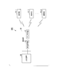
- FIG. 1 is a diagram showing a configuration example of a wireless communication system 100.
- the wireless communication system 100 includes a plurality of terminal stations 10 (10_1 to 10_m) and a base station 20. m is an integer of 2 or more.
- An upper device 30 is connected to the base station 20 of the wireless communication system 100.
- Each terminal station 10 can communicate with the host device 30 via the base station 20.
- the terminal station 10 is a device that wirelessly communicates with the base station 20.
- the terminal station 10 may be, for example, a communication device that relays communication to another device, an information device such as a mobile phone or a home electric appliance, or an IoT (Internet of Things) device. Good. Specific examples of communication devices include routers and mobile routers. A smartphone is a specific example of the mobile phone. Specific examples of home electric appliances include television receivers, white goods, personal computers, set-top boxes, and home gateways. Specific examples of IoT devices include sensors and actuators.
- the terminal station 10 may be fixedly installed, or may be a mobile body whose position changes. Specific examples of the mobile body include the above-mentioned mobile phones and wearable computers such as smart watches.
- the base station 20 is a device that relays communication between the host device 30 and the terminal station 10.
- the base station 20 includes an antenna unit 21 and a signal processing unit 22.
- the base station 20 is realized by using RoF, for example.
- the antenna unit 21 and the signal processing unit 22 are mounted in different housings and are arranged at distant positions.
- the signal processing unit 22 may be fixed to a building such as a station building and installed as a signal processing device.
- the antenna unit 21 may be fixedly installed in a building different from the station building or a facility such as a telephone pole.
- the terminal stations 10 When the terminal stations 10 are fixedly installed, they may be fixedly installed around the places where the terminal stations 10 are installed.
- the base station 20 does not necessarily have to be implemented using RoF.
- the antenna unit 21 transmits a downlink data signal to the terminal station 10 by wireless communication.
- the antenna unit 21 may communicate with the terminal station 10 by using a radio signal in the millimeter wave band, for example.
- the downlink data signal includes a plurality of dedicated downlink data signals.
- the individual downlink data signal is a signal transmitted from the higher-level device 30 to each terminal station 10.
- the antenna unit 21 receives the individual uplink data signal from the terminal station 10.
- a response signal (ACK signal) is one of the specific examples of the individual uplink data signal.
- Another specific example of the individual uplink data signal is a signal addressed to the host device 30.
- the signal processing unit 22 When the signal processing unit 22 receives an individual downlink data signal from the host device 30, the signal processing unit 22 arranges the individual downlink data signals so that they do not collide with each other on the time axis, thereby generating the downlink data signal. The signal processing unit 22 transmits the generated downlink data signal to the antenna unit 21.
- the host device 30 communicates with the terminal station 10 via the base station 20.
- the host device 30 performs information processing in response to a request transmitted from the terminal station 10, for example, and transmits data in response to the request to the terminal station 10 as a downlink data signal.
- the host device 30 may be, for example, a server device, a cloud, or may be implemented as another device.
- the base station 20 has multiple embodiments.
- the first embodiment (base station 20a) of the base station 20 and the second embodiment (base station 20b) of the base station 20 will be described respectively.
- the first embodiment (base station 20a) of the base station 20 transmits a downlink data signal to each terminal station 10 in Time Division Duplex (TDD).
- TDD Time Division Duplex
- the base station 20a allocates the individual downlink data signals to the TDD slots having earlier timings in order from those destined for the terminal station 10 having the longest propagation distance.
- ACK signal response signal
- the base station 20a changes the TDD slot to which the dedicated downlink data signal is allocated when it is estimated that the collision of the response signal will occur.
- the TDD slot to which the dedicated downlink data signal is allocated is repeatedly changed until it is estimated that no collision occurs.
- the collision of response signals is suppressed by changing the time frame (eg, TDD slot) to which the dedicated downlink data signal is assigned.
- TDD slot time frame
- FIG. 2 is a diagram illustrating a detailed configuration example of the base station 20 (base station 20a) of the first embodiment.
- the base station 20a includes an antenna unit 21 and a signal processing unit 22a.
- the antenna unit 21 includes a communication unit 211.
- the communication unit 211 receives the downlink data signal from the signal processing unit 22a via the optical cable 23.
- the communication unit 211 radiates a radio wave including the received downlink data signal from the antenna.
- the signal processing unit 22a includes a communication unit 221, a propagation distance acquisition unit 222, a reception time acquisition unit 223, a collision determination unit 224, and an allocation unit 225a.
- the communication unit 221 is configured using a communication interface.
- the communication unit 221 is communicably connected to the host device 30 via a communication path.
- the communication unit 221 transmits the uplink data signal to the host device 30.
- the communication unit 221 receives an individual downlink data signal from the host device.
- the communication unit 221 is communicatively connected to the antenna unit 21 via the optical cable 23.
- the communication unit 221 receives the uplink data signal from the antenna unit 21.
- the communication unit 221 transmits the downlink data signal generated by the allocation unit 225a to the antenna unit 21 via the optical cable 23.
- the propagation distance acquisition unit 222 acquires information indicating the propagation distance between the antenna unit 21 and the terminal station 10 (hereinafter referred to as “propagation distance information”).
- the propagation distance information may be, for example, the time required for a radio wave to reach the terminal station 10 from the antenna unit 21.
- the propagation distance information may be, for example, a physical distance from the antenna unit 21 to the terminal station 10 or a physical distance from the communication unit 221 to the terminal station 10.
- the propagation distance information may be acquired, for example, based on the propagation delay time obtained by the communication unit 221.
- a specific example of the method of acquiring the propagation delay time will be described.
- the communication unit 221 measures the time from the transmission of the individual downlink data signal addressed to the terminal station 10 which is the target of the propagation delay time transmission to the reception of the response signal.
- the communication unit 221 acquires a half of the measured time as the propagation delay time.
- the above is the first specific example.
- the communication unit 221 records and transmits the transmission time in the individual downlink data signal addressed to the terminal station 10 for which the propagation delay time is acquired.
- the terminal station 10 that has received the individual downlink data signal records, in the response signal, the transmission time included in the individual downlink data signal and the time (reception time) at which the individual downlink data signal was received by the own device. ..
- the terminal station 10 transmits a response signal to the base station 20a.
- the communication unit 221 acquires the reception time and the transmission time from the received response signal.
- the communication unit 221 acquires the difference between the reception time and the transmission time as the propagation delay time.
- the above is the second specific example.
- the method of acquiring the propagation delay time does not have to be limited to the two specific examples described above.
- the propagation delay time may be acquired as the time required per unit signal length.
- the reception time acquisition unit 223 receives, for each individual downlink data signal to be transmitted, the time at which the response signal transmitted from the terminal station 10 according to the individual downlink data signal is received by the base station 20a (hereinafter referred to as “response”). "Reception time”).
- the response reception time includes, for example, the time when the reception starts and the time when the reception ends.
- the reception time acquisition unit 223 has a scheduled transmission time of the individual downlink data signal, a propagation delay time, a processing time from the terminal station 10 receiving the individual downlink data signal to transmitting the response signal,
- the response reception time may be estimated based on the signal length (signal processing time) of the response signal.
- the processing time from the terminal station 10 receiving the individual downlink data signal to transmitting the response signal and the signal length of the response signal are stored in advance in the signal processing unit 22a as fixed values. It may have been done.
- the collision determination unit 224 determines, for each individual downlink data signal to be transmitted, when a response signal transmitted from the terminal station 10 in response to the individual downlink data signal is received by the base station 20a, another individual downlink data signal is received. It is determined whether to collide with a response signal according to the downlink data signal. For example, the collision determination unit 224 determines the presence or absence of a collision based on the reception time of each response signal acquired by the reception time acquisition unit 223.
- the allocating unit 225a determines a TDD time slot to which each individual downlink data signal is allocated according to a plurality of criteria.
- the outline of the processing of the allocation unit 225a is as follows. First, the allocating unit 225a tentatively allocates the individual downlink data signals to the early TDD slots in order from the terminal station 10 with a long propagation distance based on the propagation distance acquired by the propagation distance acquiring unit 222.
- the allocation unit 225a changes the TDD slot to which the dedicated downlink data signal is provisionally allocated.
- the idle time of the generated radio band is relatively short, and this time is utilized to perform the individual downlink to the other terminal stations 10. Creating an opportunity to transmit a link data signal is difficult. Therefore, improvement in transmission efficiency is limited.
- FIG. 3 is a flowchart showing a specific example of the operation flow of the base station 20a (first embodiment).
- the individual downlink data signal is referred to as “DL signal”
- the individual downlink data signal addressed to the terminal station 10 having the identification number i (i is an integer of 1 or more and m or less) is a “DL signal”. (I)”
- the response signal transmitted from the terminal station 10 whose identification number is i is referred to as “response signal (i)”.
- the DL signal of the terminal station 10 having the largest propagation distance is described as “DL signal (m)” and the terminal station 10 having the smallest propagation distance.
- DL signal is described as “DL signal (1)”.
- the allocation unit 225a provisionally allocates the individual downlink data signals to the early TDD slots in order from the terminal station 10 with the longest propagation distance (step S101).
- the propagation distance is acquired by the propagation distance acquisition unit 222. Further, when the base station 20a and the terminal station 10 are fixedly installed, the propagation distance may be stored in advance in the storage device of the signal processing unit 22a assuming that the propagation distance is known, and the propagation distance is acquired. The value obtained once by the unit 222 may be used for a predetermined period.
- the assigning unit 225a assigns an identification number to each terminal station 10 in ascending order of the propagation distance (step S102).
- the identification number is, for example, an integer arranged in order from 1. In this case, the identification number of the terminal station 10 having the shortest propagation distance is "1", and the identification number of the terminal station 10 having the longest propagation distance is "m”.
- the integer variables j and k are initialized (step S103). For example, "1" is substituted for j and k.
- the allocating unit 225a determines the TDD slot to which the DL signal (m), which is the dedicated downlink data signal transmitted to the m-th terminal station 10, is allocated to the provisionally allocated TDD slot (step S104). ). Specifically, the allocation destination of the DL signal (m) is set to the first TDD slot.
- the reception time acquisition unit 223 estimates the time at which the response signal transmitted by each terminal station 10 is received (response reception time) for each individual downlink data signal (step S105).
- the response reception time estimation target is all response signals.
- the collision determination unit 224 receives the response reception time of the response signal (m), which is the response signal transmitted by the m-th terminal station 10, and the response signal, which is the response signal transmitted by the mj-th terminal station 10. By comparing the response reception time of (mj) and the response reception time of (mj), it is determined whether the response signal (m) and the response commit signal (mj) collide (step S106).
- the TDD slot is set so that the transmission to the terminal station 10 (mth terminal station 10) having the largest propagation distance, which is the bottleneck of the transmission efficiency, is performed first. R. Therefore, one of the targets for comparing the time of receiving the response signal is fixed to the m-th terminal station.
- the collision determination unit 224 determines that the response signal collision occurs (step S106-YES). .. In this case, the allocation unit 225a performs the following processing.
- the value of mjk exceeds 0 (step S107-YES)
- the DL signal (mj) and the DL signal (mjk) are provisionally assigned.
- the TDD slots are exchanged (step S108).
- step S107-NO the TDD slot to which the DL signal (mj) is assigned is selected.
- the TDD slot is changed to the earliest (located in the front) TDD slot (step S109).
- the reason why the process of step S109 is performed is that in the case of step S107-NO, the collision cannot be avoided in the 1st to mth TDD slots. That is, in such a case, it is necessary to allocate dedicated downlink data signals to the m-th and subsequent TDD slots.
- step S110 the allocation unit 225a increments the value of k (step S110). Then, the processing of the signal processing unit 22a returns to the processing of step S105. In this way, by again performing the processing of step S105 and subsequent steps after the processing of step S108 or S109, it is possible to prevent a collision of response signals newly generated due to the replacement of TDD slots. You can
- step S106 when the response reception time of the response signal (m) and the response reception time of the response signal (mj) do not overlap, the collision determination unit 224 determines that the response signal collision does not occur. Yes (step S106-NO). In this case, the allocation unit 225a performs the following processing.
- the allocation unit 225a determines the TDD slot to which the DL signal (mj) is allocated to the TDD slot that was provisionally allocated at this point (step S111). Next, the value of j is incremented and the value of k is set to 1 (step S112). If the value of j is not equal to the value of m (step S113-NO), the process returns to step S106. On the other hand, when the value of j is equal to the value of m (step S113—YES), the TDD slot allocation to the individual downlink data signals of all the terminal stations 10 has been completed, so the processing is completed.
- the propagation distance between the base station 20a and each terminal station 10 is terminal station #1 ⁇ terminal station #2 ⁇ terminal station #3.
- D1, D2, and D3 represent an individual downlink data signal addressed to the terminal station #1, an individual downlink data signal addressed to the terminal station #2, and an individual downlink data signal addressed to the terminal station #3, respectively.
- A1, A2, and A3 represent a response signal transmitted from the terminal station #1, a response signal transmitted from the terminal station #2, and a response signal transmitted from the terminal station #3, respectively.
- the propagation distance between the base station 20a and each terminal station 10 is terminal station #1 ⁇ terminal station #2 ⁇ terminal station #3.
- the TDD slot length is variable, but it may be fixed.
- the upper part of FIG. 4 represents the TDD slot tentatively initially assigned to each dedicated downlink data signal in step S101.
- the lower part of FIG. 4 represents the TDD slots deterministically allocated to the individual downlink data signals by the allocation unit 225a.
- the response reception time at each terminal station 10 is acquired based on the provisional allocation as shown in the upper part of FIG.
- the response signal (A2) transmitted by the terminal station #2 and the response signal (A3) transmitted by the terminal station #3 collide. Therefore, the allocating unit 225a swaps the TDD slots between the dedicated downlink data signal addressed to the terminal station #2 and the dedicated downlink data signal addressed to the terminal station #1 by the process of step S108 shown in FIG. No collision occurs in the allocation of the TDD slots after the replacement. As a result, the TDD slot allocation as shown in the lower part of FIG. 4 is confirmed.
- the base station 20a can continuously transmit the dedicated downlink data signal to the terminal station 10. Therefore, it is possible to improve the transmission efficiency by effectively utilizing the idle time generated due to the long delay.
- the method of allocating the dedicated downlink data signal implemented in the second embodiment (base station 20b) of the base station 20 is not limited to TDD.
- a technology different from TDD may be applied to the base station 20b as long as it is a communication method capable of allocating individual downlink data signals dispersedly on the time axis.
- a free time hereinafter referred to as a free time
- the dedicated downlink data signal is not allocated as needed between the time when the dedicated downlink data signal is arranged and the time when another dedicated downlink data signal is arranged.
- guard time By setting "guard time", the collision of response times is suppressed.
- the base station 20b allocates the individual downlink data signals to the TDD slots with earlier timings in order from those destined for the terminal station 10 having the longest propagation distance.
- ACK signal response signal
- the base station 20b arranges the time when the dedicated downlink data signal is arranged and the next dedicated downlink data signal is arranged. Set guard time between time and.
- the base station 20b will be described in more detail.
- FIG. 5 is a diagram showing a detailed configuration example of the base station 20 (base station 20b) of the second embodiment.
- the base station 20b is different from the base station 20a of the first embodiment in that an allocation unit 225b is provided instead of the allocation unit 225a and a guard time determination unit 226 is provided, and other configurations are the same as those of the first embodiment. It is similar to that of the base station 20a.
- the guard time determination unit 226 determines a guard time for avoiding a collision when the collision determination unit 224 determines that a collision will occur.
- the allocation unit 225b changes the arrangement of the individual downlink data based on the determined guard time length and insertion position.
- FIG. 6 is a flowchart showing a specific example of the operation flow of the base station 20b (second embodiment).
- the description method in FIG. 6 is the same as the description method in FIG.
- the allocating unit 225b arranges the individual downlink data signals in order from the terminal station 10 having the longest propagation distance at an early time (step S201).
- the propagation distance is acquired by the propagation distance acquisition unit 222.
- the propagation distance may be stored in advance in the storage device of the signal processing unit 22b assuming that the propagation distance is known, and the propagation distance is acquired.
- the value obtained once by the unit 222 may be used for a predetermined period.
- the assigning unit 225b assigns an identification number to each terminal station 10 in ascending order of the propagation distance (step S202).
- the identification number is, for example, an integer arranged in order from 1. In this case, the identification number of the terminal station 10 having the shortest propagation distance is "1", and the identification number of the terminal station 10 having the longest propagation distance is "m”.
- the integer variables j and k are initialized (step S203). For example, "0" is substituted for the value of j, and "1" is substituted for k.
- the allocating unit 225b determines the arrangement on the time axis of the DL signal (m) which is the individual downlink data signal transmitted to the m-th terminal station 10 (step S204). By such processing, the effect of transmitting the individual downlink data signals in order from the terminal station 10 having the longest propagation distance can be obtained for the same reason as described in the first embodiment.
- the reception time acquisition unit 223 estimates the time (response reception time) at which the response signal transmitted by each terminal station 10 is received for each individual downlink data signal (step S205).
- the response reception time estimation target is all response signals.
- the collision determination unit 224 transmits the response reception time of the response signal (mj), which is the response signal transmitted by the mjth terminal station 10, and the mjkth terminal station 10 transmits. By comparing the response reception time of the response signal (mjk), which is the response signal, with the response signal (mj), it is determined whether or not the response signal (mj) and the response signal (mjk) collide. (Step S206).
- the collision determination unit 224 determines that the response signal collision occurs (step S206-YES).
- the guard time determination unit 226 prevents the DL signal (mj) and the DL signal (mj) from colliding with each other so that the response signal (mj) and the response signal (mjk) do not collide. -K) to determine the length of the guard time. For example, when the reception start time of the response signal (mj) before the guard time is set is t1 and the reception completion time of the response signal (mjk) is t2, the guard time determination unit 226 performs the guard operation.
- the time may be determined as the length of
- ⁇ is a predetermined positive constant.
- the allocation unit 225b sets a guard time between the DL signal (mj) and the DL signal (mjk) based on the length of the guard time determined by the guard time determination unit 226 ( Step S207).
- step S207 the processing of the signal processing unit 22b returns to the processing of step S205.
- step S205 by performing the processing of step S205 and the subsequent processing anew after the processing of step S207, it is possible to prevent a collision of response signals that is newly generated due to the setting of the guard time. it can.
- step S206 when the response reception time of the response signal (mj) and the response reception time of the response signal (mjk) do not overlap, the collision determination unit 224 determines that the response signals have collided. It is determined not to occur (step S206-NO). In this case, the allocation unit 225b performs the following processing.
- the allocation unit 225b increments the value of k (step S208).
- the process of the signal processing unit 22b returns to the process of step S206.
- the allocation unit 225b allocates the DL signal (m-j). It is confirmed (step S211).
- step S212-NO If the value of j is not equal to the value of m-2 (step S212-NO), the allocation unit 225b increments the value of j and sets the value of k to 1 (step S213). Then, the processing of the signal processing unit 22b returns to the processing of step S206.
- step S212 the allocation unit 225b determines the arrangement of the DL signal (1) (step S214). Then, the processing of the signal processing unit 22b is completed.
- the propagation distance between the base station 20b and each terminal station 10 is terminal station #1 ⁇ terminal station #2 ⁇ terminal station #3.
- D1, D2, and D3 represent an individual downlink data signal addressed to the terminal station #1, an individual downlink data signal addressed to the terminal station #2, and an individual downlink data signal addressed to the terminal station #3, respectively.
- A1, A2, and A3 represent a response signal transmitted from the terminal station #1, a response signal transmitted from the terminal station #2, and a response signal transmitted from the terminal station #3, respectively.
- the upper part of FIG. 7 tentatively represents the initial arrangement position of each individual downlink data signal in step S201.
- the lower part of FIG. 7 represents the positions where the individual downlink data signals are definitely arranged by the allocation unit 225b.
- the response reception time at each terminal station 10 is acquired based on the provisional allocation as shown in the upper part of FIG. 7.
- the response signal (A2) transmitted by the terminal station #2 and the response signal (A3) transmitted by the terminal station #3 collide. Therefore, the allocating unit 225b performs the processing of step S207 shown in FIG. 6 so that the collision of the response signals does not occur, the dedicated downlink data signal addressed to the terminal station #3 and the dedicated downlink data signal addressed to the terminal station #2.
- Set a guard time with the data signal No collision occurs in the placement after the guard time is set. As a result, the arrangement shown in the lower part of FIG. 7 is confirmed.
- the base station 20b can transmit the dedicated downlink data signal to the terminal station 10 by using the idle time generated due to the long delay. Therefore, it is possible to improve the transmission efficiency by effectively utilizing the idle time generated due to the long delay.
- one antenna unit 21 is provided for one signal processing unit 22 (22a, 22b).
- a plurality of antenna units 21 may be provided for one signal processing unit 22 (22a, 22b).
- the propagation delay time corresponding to each antenna unit 21 may be acquired based on, for example, the first specific example described above. In this case, since it is considered that the difference in the position of each antenna unit 21 is sufficiently short with respect to the propagation distance, even if the propagation delay time is acquired assuming that each antenna unit 21 is installed in the same place. Good.
- the present invention can be applied to a wireless communication system that transmits signals to a plurality of terminal stations by wireless communication.
- 10 Terminal station, 20, 20a, 20b... Base station, 30... Host device, 21... Antenna section, 211... Communication section, 22, 22a, 22b... Signal processing section, 221... Communication section, 222... Propagation distance acquisition section , 223...Reception time acquisition unit, 224...Collision determination unit, 225a, 225b...Allocation unit, 226...Guard time determination unit
Landscapes
- Engineering & Computer Science (AREA)
- Computer Networks & Wireless Communication (AREA)
- Signal Processing (AREA)
- Quality & Reliability (AREA)
- Mobile Radio Communication Systems (AREA)
Abstract
基地局が、複数の端末局それぞれに個別ダウンリンクデータ信号を送信する際に、各信号を時間軸上の位置に割り当てる割当方法であって、伝搬遅延時間が長い端末局への個別ダウンリンクデータ信号を相対的に早いタイミングの位置に暫定的に割り当て、伝搬遅延時間が短い端末局への個別ダウンリンクデータ信号を相対的に遅いタイミングの位置に暫定的に割り当てる暫定割当ステップと、暫定割当ステップにおける割り当てにおいて、端末局から送信される応答信号の受信時に衝突が生じると推定される場合には、衝突が生じないと推定されるように位置を変更する変更ステップと、変更ステップにおける変更後の位置で各個別ダウンリンクデータ信号の時間軸上の位置を確定させる確定ステップと、を有する割当方法である。
Description
本発明は、基地局と複数の端末局との間の無線通信の技術に関する。
近年、無線通信の需要増加に応えるため、マイクロ波帯に比べて広い無線帯域を利用可能なミリ波帯の活用が注目されている。例えば、次世代60GHz帯無線LAN規格として、IEEE802.11ayの議論が行われている。
非特許文献1に記載されているように、IEEE802.11ayでは、様々なユーセージモデルが検討されている。2017年7月に追加されたモデルに「ミリ波分散ネットワーク」(mmWave Distribution Network)がある。ミリ波分散ネットワークは、光ファイバを代替する中継網をミリ波で構築するためのユーセージモデルである。ミリ波分散ネットワークでは、屋外に設置されたミリ波分散ノード(mmWave Distribution Node;基地局に相当)と、建物周辺に設置された無線機(mmWave Sector;端末局に相当)とが接続される。ミリ波分散ノードと無線機とは固定設置される。
自由空間における伝搬損失は周波数に比例して増大する。そのため、ミリ波帯通信は伝搬距離が短くなる。その結果、ミリ波帯通信では、限られたエリアでしか通信を行うことができないという問題がある。通信エリアを拡張するために、複数のノードを介してマルチホップさせる方法が考えられる。ただし、ホップ数の増加に伴い伝送効率は悪化する。
また、ホップ数の増加に伴いノード数が増え、コストが増加する。
また、ホップ数の増加に伴いノード数が増え、コストが増加する。
このような問題を解決する方法として、非特許文献2に記載されているように、Radioon Fiber(RoF)を用いて信号処理部とアンテナ部とを分離し、アンテナ部を張出局として配置することが提案されている。このような配置により、見かけ上のカバーエリアを拡張することができる。この方法では、一つの信号処理部に対して複数のアンテナ部を接続することで、カバーエリアを拡張することも可能となる。信号処理部とアンテナ部とを分離することで、張出局の構成簡易化や省電力化が可能となる。さらに、複数の張出局を一つの信号処理部に集約することで、コスト面でのメリットも期待できる。
RoFを用いたシステムでは、通常の無線システムと比較して伝搬距離が長くなること(以下「長遅延」という。)に起因する伝搬遅延が発生する。このような伝搬遅延により、伝送効率が低下する。そのため、長遅延の環境下における伝送効率の低下を解消する技術が求められている。
非特許文献3には、RoFを適用した無線LANシステムにおいて、スループット特性を改善する無線通信方法の一例として、衝突回避メカニズムが提案されている。非特許文献3には、具体的には、伝搬遅延時間に応じてNAV(Network Allocation Vector:送受信に関与しない端末が送信を禁止される)期間を延長することで、フレームの衝突を回避する方法が提案されている。
また、非特許文献4では、RoFを適用した無線LANシステムに対して、伝搬遅延時間に応じて無線LANシステムの通信における時間単位であるスロットタイムを拡張することでフレームの衝突を回避する方法が記載されている。
「IEEE802.11 TGay Use Cases」、IEEE 802.11-2015/0625r7、2017年7月
藤瀬 雅行、「ROFマルチサービス無線通信システムについて」、電子情報通信学会論文誌B、Vol.J84-B、No.4、pp.655-665、2001年4月
岡元 佑正、三軒谷 勇貴、守倉 正博、山本 高至、布 房夫、杉山 隆利、「RoFを適用した無線LANシステムのAPによるスループット特性改善法」、信学技報、vol.112、no.443、RCS2012-300、pp.97-102、2013年2月
S.Deronne, V.Moeyaert, and S. Bette、「Analysis of the MAC Performances in 802.11g Radio-over-Fiber Systems」、Proc. 18th IEEE SCVT, pp.1-5, 2011年11月
このように、RoFを適用した無線LANシステムでは、長遅延に起因するフレーム(信号)の衝突を回避することは可能である。しかしながら、基地局とある端末局との間の通信中は、他の端末局は送信を禁止されることになる。そのため、長遅延に伴う無線帯域の空き時間が発生してしまう。その結果、伝送効率が向上しないという問題があった。このような問題は、RoFに特有の問題ではなく、基地局から複数の端末局に対して無線通信を行う際に長遅延に伴う無線帯域の空き時間が発生してしまうシステムに共通した問題であった。
上記事情に鑑み、本発明は、基地局と複数の端末局との間で無線通信を行うシステムにおいて、伝送効率を向上させることができる技術の提供を目的としている。
本発明の一態様は、基地局が、複数の端末局それぞれに個別ダウンリンクデータ信号を送信する際に、各個別ダウンリンクデータ信号を時間軸上の位置に割り当てる割当方法であって、伝搬遅延時間が長い端末局への前記個別ダウンリンクデータ信号を相対的に早いタイミングの位置に暫定的に割り当て、伝搬遅延時間が短い端末局への前記個別ダウンリンクデータ信号を相対的に遅いタイミングの位置に暫定的に割り当てる暫定割当ステップと、前記暫定割当ステップにおける割り当てにおいて、前記端末局から送信される応答信号の受信時に衝突が生じると推定される場合には、衝突が生じないと推定されるように前記位置を変更する変更ステップと、前記変更ステップにおける変更後の位置で各個別ダウンリンクデータ信号の時間軸上の位置を確定させる確定ステップと、を有する割当方法である。
本発明の一態様は上記の割当方法であって、前記変更ステップにおいて、前記端末局から送信される応答信号の受信時に衝突が生じると推定される場合には、衝突が生じると推定される少なくとも一方の応答信号に対応した個別ダウンリンクデータ信号の位置を、他の個別ダウンリンクデータ信号の位置と入れ替えることによって位置を変更する。
本発明の一態様は上記の割当方法であって、前記時間軸上の位置は、Time Division Duplex(TDD)のスロットである。
本発明の一態様は上記の割当方法であって、前記変更ステップにおいて、前記端末局から送信される応答信号の受信時に衝突が生じると推定される場合には、衝突が生じると推定される少なくとも一方の応答信号に対応した個別ダウンリンクデータ信号の位置と、前記個別ダウンリンクデータ信号に連続する他の個別ダウンリンクデータ信号の位置と、の間に、個別ダウンリンクデータ信号が割り当てられない空き時間を設定することによって位置を変更する。
本発明の一態様は、複数の端末局それぞれに個別ダウンリンクデータ信号を送信する基地局を構成する信号処理装置であって、各個別ダウンリンクデータ信号を時間軸上の位置に割り当てる割当部を備え、前記割当部は、伝搬遅延時間が長い端末局への前記個別ダウンリンクデータ信号を相対的に早いタイミングの位置に暫定的に割り当て、伝搬遅延時間が短い端末局への前記個別ダウンリンクデータ信号を相対的に遅いタイミングの位置に暫定的に割り当て、暫定的な割り当てにおいて、前記端末局から送信される応答信号の受信時に衝突が生じると推定される場合には、衝突が生じないと推定されるように前記位置を変更し、変更後の位置で各個別ダウンリンクデータ信号の時間軸上の位置を確定させる、信号処理装置である。
本発明により、基地局と複数の端末局との間で無線通信を行うシステムにおいて、伝送効率を向上させることが可能となる。
[システム構成]
図1は、無線通信システム100の構成例を示す図である。無線通信システム100は、複数の端末局10(10_1~10_m)と、基地局20とを備える。mは2以上の整数である。無線通信システム100の基地局20には上位装置30が接続される。各端末局10は、基地局20を介して上位装置30と通信することができる。
図1は、無線通信システム100の構成例を示す図である。無線通信システム100は、複数の端末局10(10_1~10_m)と、基地局20とを備える。mは2以上の整数である。無線通信システム100の基地局20には上位装置30が接続される。各端末局10は、基地局20を介して上位装置30と通信することができる。
端末局10は、基地局20との間で無線通信する装置である。端末局10は、例えば他の装置に通信を中継する通信機器であってもよいし、携帯電話機や家電機器などの情報機器であってもよいし、IoT(Internet of Things)機器であってもよい。通信機器の具体例として、ルーターやモバイルルーターがある。携帯電話機の具体例として、スマートフォンがある。家電機器の具体例として、テレビ受像器や白物家電やパーソナルコンピューターやセットトップボックスやホームゲートウェイがある。IoT機器の具体例として、センサーやアクチュエーターがある。端末局10は、固定して設置されていてもよいし、位置が変化する移動体であってもよい。移動体の具体例として、上述した携帯電話機や、スマートウォッチ等のウェアラブルコンピューターがある。
基地局20は、上位装置30と端末局10との間の通信を中継する装置である。基地局20は、アンテナ部21及び信号処理部22を備える。基地局20は、例えばRoFを用いることによって実現される。この場合、アンテナ部21と信号処理部22とはそれぞれ異なる筐体に実装され、離れた位置に配置される。例えば、信号処理部22は、局舎などの建物に固定して信号処理装置として設置されてもよい。例えばアンテナ部21は、局舎とは異なる建物や電柱などの施設に固定して設置されてもよい。端末局10が固定して設置される場合には、それらの端末局10が設置されている場所の周辺に固定して設置されてもよい。ただし、基地局20は、必ずしもRoFを用いて実装される必要は無い。
アンテナ部21は、端末局10に対して無線通信でダウンリンクデータ信号を送信する。アンテナ部21は、例えばミリ波帯の無線信号を用いて端末局10と通信してもよい。
ダウンリンクデータ信号は、複数の個別ダウンリンクデータ信号を含む。個別ダウンリンクデータ信号は、上位装置30から端末局10それぞれに対して送信された信号である。
アンテナ部21は、端末局10から個別アップリンクデータ信号を受信する。個別アップリンクデータ信号の具体例の一つに、応答信号(ACK信号)がある。個別アップリンクデータ信号の他の具体例として、上位装置30宛の信号がある。
ダウンリンクデータ信号は、複数の個別ダウンリンクデータ信号を含む。個別ダウンリンクデータ信号は、上位装置30から端末局10それぞれに対して送信された信号である。
アンテナ部21は、端末局10から個別アップリンクデータ信号を受信する。個別アップリンクデータ信号の具体例の一つに、応答信号(ACK信号)がある。個別アップリンクデータ信号の他の具体例として、上位装置30宛の信号がある。
信号処理部22は、上位装置30から個別ダウンリンクデータ信号を受信すると、各個別ダウンリンクデータ信号を時間軸上で信号同士が衝突しないように配置することによってダウンリンクデータ信号を生成する。信号処理部22は、生成されたダウンリンクデータ信号をアンテナ部21に送信する。
上位装置30は、基地局20を介して端末局10と通信する。上位装置30は、例えば端末局10から送信される要求に応じて情報処理を行い、要求に応じたデータをダウンリンクデータ信号として端末局10宛に送信する。上位装置30は、例えばサーバー装置であってもよいしクラウドであってもよいし他の装置として実装されてもよい。
次に、基地局20について詳細に説明する。基地局20には複数の実施形態がある。以下、基地局20の第1実施形態(基地局20a)と、基地局20の第2実施形態(基地局20b)と、についてそれぞれ説明する。
[第1実施形態]
基地局20の第1実施形態(基地局20a)は、Time Division Duplex(TDD)でダウンリンクデータ信号を各端末局10に対して送信する。基地局20aは、個別ダウンリンクデータ信号を、伝搬距離が大きい端末局10宛のものから順に早いタイミングのTDDスロットに割り当てる。端末局10から送信される応答信号(ACK信号)が基地局20aにおいて受信される時間が重複する場合、応答信号の衝突が発生してしまう。このような衝突を抑制するため、基地局20aは、応答信号の衝突が発生すると推定される場合には、個別ダウンリンクデータ信号を割り当てるTDDスロットを変更する。衝突が発生しないと推定されるまで、個別ダウンリンクデータ信号の割り当て先となるTDDスロットの変更を繰り返す。このように、第1実施形態では、個別ダウンリンクデータ信号の割り当て先となる時間枠(例えばTDDスロット)を変更することによって、応答信号の衝突を抑制する。以下、より詳細に基地局20aについて説明する。
基地局20の第1実施形態(基地局20a)は、Time Division Duplex(TDD)でダウンリンクデータ信号を各端末局10に対して送信する。基地局20aは、個別ダウンリンクデータ信号を、伝搬距離が大きい端末局10宛のものから順に早いタイミングのTDDスロットに割り当てる。端末局10から送信される応答信号(ACK信号)が基地局20aにおいて受信される時間が重複する場合、応答信号の衝突が発生してしまう。このような衝突を抑制するため、基地局20aは、応答信号の衝突が発生すると推定される場合には、個別ダウンリンクデータ信号を割り当てるTDDスロットを変更する。衝突が発生しないと推定されるまで、個別ダウンリンクデータ信号の割り当て先となるTDDスロットの変更を繰り返す。このように、第1実施形態では、個別ダウンリンクデータ信号の割り当て先となる時間枠(例えばTDDスロット)を変更することによって、応答信号の衝突を抑制する。以下、より詳細に基地局20aについて説明する。
図2は、第1実施形態の基地局20(基地局20a)の詳細な構成例を示す図である。
基地局20aは、アンテナ部21及び信号処理部22aを備える。アンテナ部21は、通信部211を備える。通信部211は、ダウンリンクデータ信号を信号処理部22aから光ケーブル23を経由して受信する。通信部211は、受信されたダウンリンクデータ信号を含む電波をアンテナから放射する。
基地局20aは、アンテナ部21及び信号処理部22aを備える。アンテナ部21は、通信部211を備える。通信部211は、ダウンリンクデータ信号を信号処理部22aから光ケーブル23を経由して受信する。通信部211は、受信されたダウンリンクデータ信号を含む電波をアンテナから放射する。
信号処理部22aは、通信部221、伝搬距離取得部222、受信時刻取得部223、衝突判定部224及び割当部225aを備える。
通信部221は、通信インターフェースを用いて構成される。通信部221は、上位装置30と通信路を介して通信可能に接続される。通信部221は、アップリンクデータ信号を上位装置30に送信する。通信部221は、上位装置から個別ダウンリンクデータ信号を受信する。通信部221は、光ケーブル23を介してアンテナ部21と通信可能に接続される。通信部221は、アンテナ部21からアップリンクデータ信号を受信する。通信部221は、割当部225aによって生成されたダウンリンクデータ信号を、光ケーブル23を介してアンテナ部21に送信する。
伝搬距離取得部222は、アンテナ部21と端末局10との間の伝搬距離を表す情報(以下「伝搬距離情報」という。)を取得する。伝搬距離情報は、例えばアンテナ部21から端末局10まで電波が到達するのに要する時間であってもよい。伝搬距離情報は、例えばアンテナ部21から端末局10までの物理的な距離であってもよいし、通信部221から端末局10までの物理的な距離であってもよい。伝搬距離情報は、例えば通信部221によって得られた伝搬遅延時間に基づいて取得されてもよい。以下、伝搬遅延時間の取得方法の具体例について説明する。
通信部221は、伝搬遅延時間の取得対象となっている端末局10宛の個別ダウンリンクデータ信号が送信されてから応答信号が受信されるまでの時間を測定する。通信部221は、測定された時間の半分の時間を伝搬遅延時間として取得する。以上が第1の具体例である。通信部221は、伝搬遅延時間の取得対象となっている端末局10宛の個別ダウンリンクデータ信号に送信時刻を記録して送信する。個別ダウンリンクデータ信号を受信した端末局10は、個別ダウンリンクデータ信号に含まれる送信時刻と、自装置において個別ダウンリンクデータ信号が受信された時刻(受信時刻)と、を応答信号に記録する。
端末局10は、応答信号を基地局20aに送信する。通信部221は、受信された応答信号から受信時刻と送信時刻とを取得する。通信部221は、受信時刻と送信時刻との差分を伝搬遅延時間として取得する。以上が第2の具体例である。伝搬遅延時間の取得方法は上述した2つの具体例に限定される必要はない。個別ダウンリンクデータ信号の信号長が可変の場合には、伝搬遅延時間は単位信号長当たりに要する時間として取得されてもよい。
端末局10は、応答信号を基地局20aに送信する。通信部221は、受信された応答信号から受信時刻と送信時刻とを取得する。通信部221は、受信時刻と送信時刻との差分を伝搬遅延時間として取得する。以上が第2の具体例である。伝搬遅延時間の取得方法は上述した2つの具体例に限定される必要はない。個別ダウンリンクデータ信号の信号長が可変の場合には、伝搬遅延時間は単位信号長当たりに要する時間として取得されてもよい。
受信時刻取得部223は、送信対象となる個別ダウンリンクデータ信号毎に、その個別ダウンリンクデータ信号に応じて端末局10から送信される応答信号が基地局20aにおいて受信される時刻(以下「応答受信時刻」という。)を推定する。応答受信時刻は、例えば受信が開始される時刻と、受信が終了する時刻と、を含む。例えば、受信時刻取得部223は、個別ダウンリンクデータ信号の送信予定時刻と、伝搬遅延時間と、端末局10が個別ダウンリンクデータ信号を受信してから応答信号を送信するまでの処理時間と、応答信号の信号長(信号処理時間)と、に基づいて応答受信時刻を推定してもよい。なお、端末局10が個別ダウンリンクデータ信号を受信してから応答信号を送信するまでの処理時間と、応答信号の信号長(信号処理時間)とは、予め固定値として信号処理部22aにおいて記憶されていてもよい。
衝突判定部224は、送信対象となる個別ダウンリンクデータ信号毎に、その個別ダウンリンクデータ信号に応じて端末局10から送信される応答信号が基地局20aにおいて受信されるときに、他の個別ダウンリンクデータ信号に応じた応答信号と衝突するか否か判定する。例えば、衝突判定部224は、受信時刻取得部223によって取得された各応答信号の受信時刻に基づいて衝突の有無を判定する。
割当部225aは、複数の基準にしたがって、各個別ダウンリンクデータ信号の割り当て先となるTDDタイムスロットを決定する。割当部225aの処理の概略は以下の通りである。まず、割当部225aは、伝搬距離取得部222によって取得された伝搬距離に基づいて、伝搬距離が遠い端末局10から順番に個別ダウンリンクデータ信号を早いTDDスロットに暫定的に割り当てる。割当部225aは、衝突判定部224によって応答信号の衝突が発生すると判定された場合は、個別ダウンリンクデータ信号を暫定的に割り当てているTDDスロットを変更する。
伝搬距離が遠い端末局10から順番に個別ダウンリンクデータ信号を早いTDDスロットに暫定的に割り当てる理由について説明する。伝搬距離が大きいほど、端末局10への個別ダウンリンクデータ信号の送信に要する伝搬遅延時間が長くなる。伝搬遅延時間が長くなるほど、長い無線帯域の空き時間が発生する。そのため、この端末局10への個別ダウンリンクデータ信号の送信が伝送効率のボトルネックとなる。そのため、このように伝搬遅延時間がより長い端末局10への個別ダウンリンクデータ信号の送信をできるだけ早く完了させることが効果的である。さらに、長い無線帯域の空き時間が発生している間に、他の端末局10へ個別ダウンリンクデータ信号を送信することも可能である。このような制御の実現も、伝送効率の改善につながる。一方、伝搬距離が小さい端末局10から順に個別ダウンリンクデータ信号が送信される場合は、発生する無線帯域の空き時間が相対的に短く、この時間を活用して他の端末局10へ個別ダウンリンクデータ信号を送信する機会を作ることは難しい。そのため、伝送効率の改善が限定的である。
図3は、基地局20a(第1実施形態)の動作の流れの具体例を示すフローチャートである。なお、図3において、個別ダウンリンクデータ信号を“DL信号”と記載し、識別番号がi(iは1以上m以下の整数)である端末局10宛の個別ダウンリンクデータ信号を“DL信号(i)”と記載し、識別番号がiである端末局10から送信される応答信号を“応答信号(i)”と記載する。後述の通り、識別番号は伝搬距離に対して昇順に付与されるため、最も伝搬距離が大きい端末局10のDL信号は“DL信号(m)”と記載され、最も伝搬距離が小さい端末局10のDL信号は“DL信号(1)”と記載される。
まず、割当部225aは、伝搬距離が大きい端末局10から順番に個別ダウンリンクデータ信号を早いTDDスロットに暫定的に割り当てる(ステップS101)。伝搬距離は、伝搬距離取得部222によって取得される。また、基地局20aと端末局10とがそれぞれ固定して設置されている場合には、伝搬距離は既知であるとして予め信号処理部22aの記憶装置に記憶されていてもよいし、伝搬距離取得部222によって一度取得された値が所定の期間にわたって使用されてもよい。
割当部225aは、伝搬距離に対して昇順に各端末局10に識別番号を付与する(ステップS102)。識別番号は例えば1から順番に並ぶ整数である。この場合、最も伝搬距離が短い端末局10の識別番号が“1”であり、最も伝搬距離が長い端末局10の識別番号が“m”である。整数の変数j及びkを初期化する(ステップS103)。例えば、j及びkに対し“1”を代入する。
割当部225aは、m番目の端末局10に対して送信される個別ダウンリンクデータ信号であるDL信号(m)を割り当てるTDDスロットを、暫定的に割り当てられていたTDDスロットに確定させる(ステップS104)。具体的には、DL信号(m)の割り当て先を、先頭のTDDスロットに確定させる。
次に、受信時刻取得部223は、各個別ダウンリンクデータ信号について、各端末局10が送信する応答信号を受信する時刻(応答受信時刻)を推定する(ステップS105)。応答受信時刻の推定対象は、全ての応答信号である。
ここで、衝突判定部224は、m番目の端末局10が送信する応答信号である応答信号(m)の応答受信時刻と、m-j番目の端末局10が送信する応答信号である応答信号(m-j)の応答受信時刻と、を比較することによって、応答信号(m)と応答委信号(m-j)とが衝突するか否か判定する(ステップS106)。なお、本実施形態では、上述の通り、最も伝送効率のボトルネックとなる伝搬距離が最大の端末局10(m番目の端末局10)への送信が最初に行われるようにTDDスロットが設定される。そのため、応答信号を受信する時間を比較する対象の一方はm番目の端末局に固定されている。
応答信号(m)の応答受信時刻と応答信号(m-j)の応答受信時刻とが重複している場合、衝突判定部224は、応答信号の衝突が発生すると判定する(ステップS106-YES)。この場合、割当部225aは、以下の処理を行う。m-j-kの値が0を超えている場合(ステップS107-YES)、DL信号(m-j)とDL信号(m-j-k)とで、暫定的に割り当て先となっているTDDスロットを入れ替える(ステップS108)。
一方、m-j-kの値が0以下である(0を超えていない又は0である)場合(ステップS107-NO)、DL信号(m-j)の割り当て先となっているTDDスロットを、現在のTDDスロットよりも後方に位置している空きスロットの中で最も早い(前方に位置している)TDDスロットに変更する(ステップS109)。このようなステップS109の処理が行われる理由は、ステップS107-NOの場合には、1~m番目のTDDスロットでは衝突を回避することができなかったためである。すなわち、このような場合には、m番目以降のTDDスロットに個別ダウンリンクデータ信号を割り当てる必要がある。
ステップS108又はステップS109の処理の後、割当部225aは、kの値をインクリメントする(ステップS110)。そして、信号処理部22aの処理は、ステップS105の処理に戻る。このようにステップS108又はS109の処理の後に改めてステップS105及びそれ以降の処理が実行されることによって、TDDスロットの入れ替えが行われたことに起因して新たに生じる応答信号の衝突を防止することができる。
ステップS106の処理において、応答信号(m)の応答受信時刻と応答信号(m-j)の応答受信時刻とが重複していない場合、衝突判定部224は、応答信号の衝突が発生しないと判定する(ステップS106-NO)。この場合、割当部225aは、以下の処理を行う。
まず、割当部225aは、DL信号(m-j)を割り当てるTDDスロットを、この時点で暫定的に割り当てられていたTDDスロットに確定させる(ステップS111)。次に、jの値をインクリメントし、kの値を1に設定する(ステップS112)。jの値がmの値と等しくない場合(ステップS113-NO)、ステップS106の処理に戻る。
一方、jの値がmの値と等しい場合(ステップS113-YES)、全ての端末局10の個別ダウンリンクデータ信号に対するTDDスロットの割り当てが完了しているため、処理を完了する。
一方、jの値がmの値と等しい場合(ステップS113-YES)、全ての端末局10の個別ダウンリンクデータ信号に対するTDDスロットの割り当てが完了しているため、処理を完了する。
図4は、3台の端末局10(m=3)に対して基地局20aから個別ダウンリンクデータ信号が送信される場合の処理の具体例を示す図である。なお、図4の例では、基地局20aと各端末局10との伝搬距離は、端末局#1<端末局#2<端末局#3である。また、D1、D2、D3は、それぞれ端末局#1宛の個別ダウンリンクデータ信号、端末局#2宛の個別ダウンリンクデータ信号、端末局#3宛の個別ダウンリンクデータ信号を表す。また、A1、A2、A3は、それぞれ端末局#1から送信される応答信号、端末局#2から送信される応答信号、端末局#3から送信される応答信号、を表す。図4の例では、TDDスロット長が可変長であるが、固定長であってもよい。図4の上段は、ステップS101において暫定的に各個別ダウンリンクデータ信号に対して最初に割り当てられたTDDスロットを表す。図4の下段は、割当部225aによって確定的に各個別ダウンリンクデータ信号に対して割り当てられたTDDスロットを表す。
まず、図4の上段に示されるような暫定的な割り当てに基づいて、各端末局10における応答受信時刻が取得される。この例では、端末局#2が送信する応答信号(A2)と端末局#3が送信する応答信号(A3)とが衝突する。そこで、割当部225aは、図3に示されるステップS108の処理によって、端末局#2宛の個別ダウンリンクデータ信号と端末局#1宛の個別ダウンリンクデータ信号とで、TDDスロットを入れ替える。入れ替え後のTDDスロットの割り当てでは、衝突が発生しない。その結果、図4の下段に示されるようなTDDスロットの割り当てが確定する。
このように構成された第1実施形態では、端末局10から送信される応答信号の受信時に衝突が生じるか否か判定される。衝突が発生すると判定された場合は、個別ダウンリンクデータ信号の割り当て先となるTDDスロットが変更される。そのため、基地局20aは端末局10に連続して個別ダウンリンクデータ信号を送信することができる。したがって、長遅延に伴い発生する空き時間を有効に活用することで伝送効率を向上することが可能である。
[第2実施形態]
基地局20の第2実施形態(基地局20b)に実装される個別ダウンリンクデータ信号の割り当て方は、TDDに限定されない。基地局20bには、時間軸上に分散して個別ダウンリンクデータ信号を割り当てることができる通信方法であれば、TDDとは異なる技術が適用されてもよい。基地局20bは、個別ダウンリンクデータ信号が配置された時間と他の個別ダウンリンクデータ信号が配置された時間との間に、必要に応じて個別ダウンリンクデータ信号が割り当てられない空き時間(以下「ガードタイム」という。)を設けることによって、応答時間の衝突を抑制する。
基地局20の第2実施形態(基地局20b)に実装される個別ダウンリンクデータ信号の割り当て方は、TDDに限定されない。基地局20bには、時間軸上に分散して個別ダウンリンクデータ信号を割り当てることができる通信方法であれば、TDDとは異なる技術が適用されてもよい。基地局20bは、個別ダウンリンクデータ信号が配置された時間と他の個別ダウンリンクデータ信号が配置された時間との間に、必要に応じて個別ダウンリンクデータ信号が割り当てられない空き時間(以下「ガードタイム」という。)を設けることによって、応答時間の衝突を抑制する。
基地局20bは、個別ダウンリンクデータ信号を、伝搬距離が大きい端末局10宛のものから順に早いタイミングのTDDスロットに割り当てる。端末局10から送信される応答信号(ACK信号)が基地局20bにおいて受信される時間が重複する場合、応答信号の衝突が発生してしまう。このような衝突を抑制するため、基地局20bは、応答信号の衝突が発生すると推定される場合には、個別ダウンリンクデータ信号が配置された時間と次の個別ダウンリンクデータ信号が配置された時間との間にガードタイムを設定する。以下、より詳細に基地局20bについて説明する。
図5は、第2実施形態の基地局20(基地局20b)の詳細な構成例を示す図である。
基地局20bは、割当部225aに代えて割当部225bが備えられる点と、ガードタイム決定部226が備えられる点と、で第1実施形態の基地局20aと異なり、他の構成は第1実施形態の基地局20aと同様である。
基地局20bは、割当部225aに代えて割当部225bが備えられる点と、ガードタイム決定部226が備えられる点と、で第1実施形態の基地局20aと異なり、他の構成は第1実施形態の基地局20aと同様である。
ガードタイム決定部226は、衝突判定部224において衝突が発生すると判定された場合に、衝突を回避するためのガードタイムを決定する。
割当部225bは、ガードタイム決定部226によってガードタイムが決定された場合に、決定されたガードタイムの長さと挿入位置とに基づいて個別ダウンリンクデータの配置を変更する。
図6は、基地局20b(第2実施形態)の動作の流れの具体例を示すフローチャートである。なお、図6における記載方法は、図3における記載方法と同様である。
まず、割当部225bは、伝搬距離が大きい端末局10から順番に個別ダウンリンクデータ信号を早い時間に配置する(ステップS201)。伝搬距離は、伝搬距離取得部222によって取得される。また、基地局20bと端末局10とがそれぞれ固定して設置されている場合には、伝搬距離は既知であるとして予め信号処理部22bの記憶装置に記憶されていてもよいし、伝搬距離取得部222によって一度取得された値が所定の期間にわたって使用されてもよい。
割当部225bは、伝搬距離に対して昇順に各端末局10に識別番号を付与する(ステップS202)。識別番号は例えば1から順番に並ぶ整数である。この場合、最も伝搬距離が短い端末局10の識別番号が“1”であり、最も伝搬距離が長い端末局10の識別番号が“m”である。整数の変数j及びkを初期化する(ステップS203)。例えば、jの値に“0”を代入し、kに対し“1”を代入する。
割当部225bは、m番目の端末局10に対して送信される個別ダウンリンクデータ信号であるDL信号(m)の時間軸上の配置を確定させる(ステップS204)。このような処理によって、第1の実施形態で述べた理由と同様に、個別ダウンリンクデータ信号を伝搬距離が大きい端末局10宛から順に送信することによる効果を得ることができる。
次に、受信時刻取得部223は、各個別ダウンリンクデータ信号について、各端末局10が送信する応答信号を受信する時刻(応答受信時刻)を推定する(ステップS205)。応答受信時刻の推定対象は、全ての応答信号である。
ここで、衝突判定部224は、m-j番目の端末局10が送信する応答信号である応答信号(m-j)の応答受信時刻と、m-j-k番目の端末局10が送信する応答信号である応答信号(m-j-k)の応答受信時刻と、を比較することによって、応答信号(m-j)と応答信号(m-j-k)とが衝突するか否か判定する(ステップS206)。
応答信号(m-j)の応答受信時刻と応答信号(m-j-k)の応答受信時刻とが重複している場合、衝突判定部224は、応答信号の衝突が発生すると判定する(ステップS206-YES)。この場合、ガードタイム決定部226は、応答信号(m-j)と応答信号(m-j-k)との衝突が発生しないように、DL信号(m-j)とDL信号(m-j-k)との間のガードタイムの長さを決定する。ガードタイム決定部226は、例えばガードタイムが設定される前の応答信号(m-j)の受信開始時刻がt1、応答信号(m-j-k)の受信完了時刻がt2である場合、ガードタイムを|t2-t1|+αの長さに決定してもよい。なお、αは正の所定の定数である。割当部225bは、ガードタイム決定部226によって決定されたガードタイムの長さに基づいて、DL信号(m-j)とDL信号(m-j-k)との間にガードタイムを設定する(ステップS207)。
ステップS207の処理の後、信号処理部22bの処理は、ステップS205の処理に戻る。このように、ステップS207の処理の後に改めてステップS205及びそれ以降の処理が実行されることによって、ガードタイムの設定が行われたことに起因して新たに生じる応答信号の衝突を防止することができる。
ステップS206の処理において、応答信号(m-j)の応答受信時刻と応答信号(m-j-k)の応答受信時刻とが重複していない場合、衝突判定部224は、応答信号の衝突が発生しないと判定する(ステップS206-NO)。この場合、割当部225bは、以下の処理を行う。
まず、割当部225bは、kの値をインクリメントする(ステップS208)。j+kの値がmの値に等しくない場合(ステップS209-NO)、信号処理部22bの処理は、ステップS206の処理に戻る。一方、j+kの値がmの値に等しい場合(ステップS209-YES)であって、jの値が0でない場合(ステップS210-YES)、割当部225bはDL信号(m-j)の配置を確定させる(ステップS211)。
jの値がm-2の値に等しくない場合(ステップS212-NO)、割当部225bは、jの値をインクリメントし、kの値を1に設定する(ステップS213)。そして、信号処理部22bの処理は、ステップS206の処理に戻る。jの値がm-2の値に等しい場合(ステップS212)、割当部225bは、DL信号(1)の配置を確定させる(ステップS214)。そして信号処理部22bの処理は完了する。
図7は、3台の端末局10(m=3)に対して基地局20bから個別ダウンリンクデータ信号が送信される場合の処理の具体例を示す図である。なお、図7の例では、基地局20bと各端末局10との伝搬距離は、端末局#1<端末局#2<端末局#3である。また、D1、D2、D3は、それぞれ端末局#1宛の個別ダウンリンクデータ信号、端末局#2宛の個別ダウンリンクデータ信号、端末局#3宛の個別ダウンリンクデータ信号を表す。また、A1、A2、A3は、それぞれ端末局#1から送信される応答信号、端末局#2から送信される応答信号、端末局#3から送信される応答信号、を表す。図7の上段は、ステップS201において暫定的に各個別ダウンリンクデータ信号の最初の配置位置を表す。図7の下段は、割当部225bによって確定的に各個別ダウンリンクデータ信号が配置された位置を表す。
まず、図7の上段に示されるような暫定的な割り当てに基づいて、各端末局10における応答受信時刻が取得される。この例では、端末局#2が送信する応答信号(A2)と端末局#3が送信する応答信号(A3)とが衝突する。そこで、割当部225bは、図6に示されるステップS207の処理によって、応答信号の衝突が発生しなくなるように、端末局#3宛の個別ダウンリンクデータ信号と端末局#2宛の個別ダウンリンクデータ信号との間にガードタイムを設定する。ガードタイムが設定された後の配置では、衝突が発生しない。その結果、図7の下段に示されるような配置が確定する。
このように構成された第2実施形態では、第1実施形態と同様に、端末局10から送信される応答信号の受信時に衝突が生じるか否か判定される。衝突が発生すると判定された場合は、個別ダウンリンクデータ信号間にガードタイムが設定されることによって、衝突が生じないように応答信号の受信タイミングが変更される。そのため、基地局20bは長遅延に伴い発生する空き時間を用いて端末局10に対して個別ダウンリンクデータ信号を送信することができる。したがって、長遅延に伴い発生する空き時間を有効に活用することで伝送効率を向上することが可能である。
(変形例)
上述した第1実施形態及び第2実施形態では、1台の信号処理部22(22a,22b)に対して1台のアンテナ部21が設けられていた。しかしながら、1台の信号処理部22(22a,22b)に対して複数台のアンテナ部21が設けられてもよい。この場合、各アンテナ部21に応じた伝搬遅延時間は、例えば上述した第1の具体例に基づいて取得されてもよい。この場合、各アンテナ部21の位置の相違は伝搬距離に対して十分に短いと考えられるため、同一の場所に各アンテナ部21が設置されていると想定して伝搬遅延時間が取得されてもよい。また、第2の具体例に基づいて取得される場合には、個々のアンテナ部21の位置の違いも反映された伝搬遅延時間を取得することができる。
上述した第1実施形態及び第2実施形態では、1台の信号処理部22(22a,22b)に対して1台のアンテナ部21が設けられていた。しかしながら、1台の信号処理部22(22a,22b)に対して複数台のアンテナ部21が設けられてもよい。この場合、各アンテナ部21に応じた伝搬遅延時間は、例えば上述した第1の具体例に基づいて取得されてもよい。この場合、各アンテナ部21の位置の相違は伝搬距離に対して十分に短いと考えられるため、同一の場所に各アンテナ部21が設置されていると想定して伝搬遅延時間が取得されてもよい。また、第2の具体例に基づいて取得される場合には、個々のアンテナ部21の位置の違いも反映された伝搬遅延時間を取得することができる。
以上、この発明の実施形態について図面を参照して詳述してきたが、具体的な構成はこの実施形態に限られるものではなく、この発明の要旨を逸脱しない範囲の設計等も含まれる。
本発明は、複数の端末局に対して無線通信で信号を送信する無線通信システムに適用できる。
10…端末局, 20,20a,20b…基地局, 30…上位装置, 21…アンテナ部, 211…通信部, 22,22a,22b…信号処理部, 221…通信部, 222…伝搬距離取得部, 223…受信時刻取得部, 224…衝突判定部, 225a、225b…割当部, 226…ガードタイム決定部
Claims (5)
- 基地局が、複数の端末局それぞれに個別ダウンリンクデータ信号を送信する際に、各個別ダウンリンクデータ信号を時間軸上の位置に割り当てる割当方法であって、
伝搬遅延時間が長い端末局への前記個別ダウンリンクデータ信号を相対的に早いタイミングの位置に暫定的に割り当て、伝搬遅延時間が短い端末局への前記個別ダウンリンクデータ信号を相対的に遅いタイミングの位置に暫定的に割り当てる暫定割当ステップと、
前記暫定割当ステップにおける割り当てにおいて、前記端末局から送信される応答信号の受信時に衝突が生じると推定される場合には、衝突が生じないと推定されるように前記位置を変更する変更ステップと、
前記変更ステップにおける変更後の位置で各個別ダウンリンクデータ信号の時間軸上の位置を確定させる確定ステップと、
を有する割当方法。 - 前記変更ステップにおいて、前記端末局から送信される応答信号の受信時に衝突が生じると推定される場合には、衝突が生じると推定される少なくとも一方の応答信号に対応した個別ダウンリンクデータ信号の位置を、他の個別ダウンリンクデータ信号の位置と入れ替えることによって位置を変更する、請求項1に記載の割当方法。
- 前記時間軸上の位置は、Time Division Duplex(TDD)のスロットである、請求項2に記載の割当方法。
- 前記変更ステップにおいて、前記端末局から送信される応答信号の受信時に衝突が生じると推定される場合には、衝突が生じると推定される少なくとも一方の応答信号に対応した個別ダウンリンクデータ信号の位置と、前記個別ダウンリンクデータ信号に連続する他の個別ダウンリンクデータ信号の位置と、の間に、個別ダウンリンクデータ信号が割り当てられない空き時間を設定することによって位置を変更する、請求項1に記載の割当方法。
- 複数の端末局それぞれに個別ダウンリンクデータ信号を送信する基地局を構成する信号処理装置であって、
各個別ダウンリンクデータ信号を時間軸上の位置に割り当てる割当部を備え、
前記割当部は、伝搬遅延時間が長い端末局への前記個別ダウンリンクデータ信号を相対的に早いタイミングの位置に暫定的に割り当て、伝搬遅延時間が短い端末局への前記個別ダウンリンクデータ信号を相対的に遅いタイミングの位置に暫定的に割り当て、暫定的な割り当てにおいて、前記端末局から送信される応答信号の受信時に衝突が生じると推定される場合には、衝突が生じないと推定されるように前記位置を変更し、変更後の位置で各個別ダウンリンクデータ信号の時間軸上の位置を確定させる、信号処理装置。
Priority Applications (1)
| Application Number | Priority Date | Filing Date | Title |
|---|---|---|---|
| US17/431,694 US11974312B2 (en) | 2019-02-19 | 2020-01-31 | Allocation method and signal processing apparatus |
Applications Claiming Priority (2)
| Application Number | Priority Date | Filing Date | Title |
|---|---|---|---|
| JP2019-027783 | 2019-02-19 | ||
| JP2019027783A JP7125612B2 (ja) | 2019-02-19 | 2019-02-19 | 割当方法及び信号処理装置 |
Publications (1)
| Publication Number | Publication Date |
|---|---|
| WO2020170764A1 true WO2020170764A1 (ja) | 2020-08-27 |
Family
ID=72144517
Family Applications (1)
| Application Number | Title | Priority Date | Filing Date |
|---|---|---|---|
| PCT/JP2020/003692 Ceased WO2020170764A1 (ja) | 2019-02-19 | 2020-01-31 | 割当方法及び信号処理装置 |
Country Status (3)
| Country | Link |
|---|---|
| US (1) | US11974312B2 (ja) |
| JP (1) | JP7125612B2 (ja) |
| WO (1) | WO2020170764A1 (ja) |
Citations (3)
| Publication number | Priority date | Publication date | Assignee | Title |
|---|---|---|---|---|
| JP2007129570A (ja) * | 2005-11-04 | 2007-05-24 | Oki Electric Ind Co Ltd | パケット衝突回避方法、通信端末及び通信システム |
| JP2008167010A (ja) * | 2006-12-27 | 2008-07-17 | Sanyo Electric Co Ltd | 基地局及びスロット割当て方法 |
| JP2017092942A (ja) * | 2015-11-09 | 2017-05-25 | 株式会社東芝 | 無線通信装置および無線通信方法 |
Family Cites Families (4)
| Publication number | Priority date | Publication date | Assignee | Title |
|---|---|---|---|---|
| JP2012249119A (ja) * | 2011-05-30 | 2012-12-13 | Sony Corp | 無線リソース割当方法及び無線リソース割当装置、並びに通信システム |
| JP2017085416A (ja) * | 2015-10-29 | 2017-05-18 | Kddi株式会社 | 基地局装置、端末装置、通信方法及びプログラム |
| KR102313906B1 (ko) * | 2016-05-13 | 2021-10-18 | 한국전자통신연구원 | 제어 채널을 위한 자원의 설정 정보를 전송하는 방법 및 장치, 상향링크 drs를 위한 자원의 설정 정보를 전송하는 방법 및 장치, 서브프레임/슬롯의 타입을 지시하는 지시자를 전송하는 방법 및 장치, 그리고 하향링크 심볼의 개수를 전송하는 방법 및 장치 |
| KR102309741B1 (ko) * | 2017-03-23 | 2021-10-08 | 삼성전자 주식회사 | 무선 셀룰라 통신 시스템에서 상향링크 전력제어 방법 및 장치 |
-
2019
- 2019-02-19 JP JP2019027783A patent/JP7125612B2/ja active Active
-
2020
- 2020-01-31 WO PCT/JP2020/003692 patent/WO2020170764A1/ja not_active Ceased
- 2020-01-31 US US17/431,694 patent/US11974312B2/en active Active
Patent Citations (3)
| Publication number | Priority date | Publication date | Assignee | Title |
|---|---|---|---|---|
| JP2007129570A (ja) * | 2005-11-04 | 2007-05-24 | Oki Electric Ind Co Ltd | パケット衝突回避方法、通信端末及び通信システム |
| JP2008167010A (ja) * | 2006-12-27 | 2008-07-17 | Sanyo Electric Co Ltd | 基地局及びスロット割当て方法 |
| JP2017092942A (ja) * | 2015-11-09 | 2017-05-25 | 株式会社東芝 | 無線通信装置および無線通信方法 |
Also Published As
| Publication number | Publication date |
|---|---|
| JP7125612B2 (ja) | 2022-08-25 |
| JP2020136896A (ja) | 2020-08-31 |
| US20220141838A1 (en) | 2022-05-05 |
| US11974312B2 (en) | 2024-04-30 |
Similar Documents
| Publication | Publication Date | Title |
|---|---|---|
| US12538154B2 (en) | Methods and systems for managing reflecting surface | |
| US11153890B2 (en) | Method and system for managing UE-to-UE interference in a mobile telecommunication network | |
| JP7535607B2 (ja) | 統合アクセスおよびバックホールノードのためのランダムアクセスリソース配分 | |
| CN106465409B (zh) | 用于调度无线设备间的通信以减少与多小区网络中全双工通信相关联的干扰的系统和方法 | |
| US8982930B2 (en) | Communication apparatus, communication method, computer program, and communication system | |
| US20200337115A1 (en) | Relay Transmission Method And Apparatus | |
| US20150223184A1 (en) | Timing Advance Timer Start for Uplink Transmissions | |
| CN106664289B (zh) | 用于实现数据传输的干扰管理的通信设备和方法 | |
| US11115869B2 (en) | SDN-controlled bandwidth sharing method for use with terminal small cell, and bandwidth sharing device | |
| US11330630B2 (en) | Dynamic random access response (RAR) reception termination | |
| JP6406767B2 (ja) | チャネルコンテンション方法、アクセスポイント、及びステーション | |
| JP7552860B2 (ja) | 第1の端末装置、第2の端末装置、第1の端末装置の方法、および第2の端末装置の方法 | |
| EP3298846B1 (en) | Uplink data transfer | |
| CN103703809B (zh) | 扇区配置方法、业务切换方法、装置及基站 | |
| JP7125612B2 (ja) | 割当方法及び信号処理装置 | |
| RU2758459C2 (ru) | Устройство беспроводной связи и способ беспроводной связи | |
| EP3900469A1 (en) | Bidirectional scheduling in low-power wide-area networks | |
| CN108810978A (zh) | 用于通信资源管理的方法和设备 | |
| CN114175565A (zh) | 随机接入方法、装置、设备及存储介质 | |
| CN117813864A (zh) | 用于子网的动态通信配置 | |
| CN114286328A (zh) | 一种无线通信系统中的信号处理方法和装置 | |
| JP7485987B2 (ja) | 通信制御方法及び信号処理装置 | |
| US10142954B2 (en) | Base station and wireless communication method | |
| US20240259859A1 (en) | Methods and apparatus for supporting operator device sharing of time and frequency resources in a band | |
| KR101458446B1 (ko) | 복수의 기지국으로 레인징 신호를 전송하는 레인징 시스템 |
Legal Events
| Date | Code | Title | Description |
|---|---|---|---|
| 121 | Ep: the epo has been informed by wipo that ep was designated in this application |
Ref document number: 20759541 Country of ref document: EP Kind code of ref document: A1 |
|
| NENP | Non-entry into the national phase |
Ref country code: DE |
|
| 122 | Ep: pct application non-entry in european phase |
Ref document number: 20759541 Country of ref document: EP Kind code of ref document: A1 |