WO2020166367A1 - 二重化運転システム及びその方法 - Google Patents
二重化運転システム及びその方法 Download PDFInfo
- Publication number
- WO2020166367A1 WO2020166367A1 PCT/JP2020/003585 JP2020003585W WO2020166367A1 WO 2020166367 A1 WO2020166367 A1 WO 2020166367A1 JP 2020003585 W JP2020003585 W JP 2020003585W WO 2020166367 A1 WO2020166367 A1 WO 2020166367A1
- Authority
- WO
- WIPO (PCT)
- Prior art keywords
- virtual machine
- general
- purpose device
- stopped
- reset
- Prior art date
- Legal status (The legal status is an assumption and is not a legal conclusion. Google has not performed a legal analysis and makes no representation as to the accuracy of the status listed.)
- Ceased
Links
Images


Classifications
-
- G—PHYSICS
- G06—COMPUTING OR CALCULATING; COUNTING
- G06F—ELECTRIC DIGITAL DATA PROCESSING
- G06F11/00—Error detection; Error correction; Monitoring
- G06F11/07—Responding to the occurrence of a fault, e.g. fault tolerance
- G06F11/16—Error detection or correction of the data by redundancy in hardware
- G06F11/20—Error detection or correction of the data by redundancy in hardware using active fault-masking, e.g. by switching out faulty elements or by switching in spare elements
- G06F11/202—Error detection or correction of the data by redundancy in hardware using active fault-masking, e.g. by switching out faulty elements or by switching in spare elements where processing functionality is redundant
- G06F11/2023—Failover techniques
- G06F11/2028—Failover techniques eliminating a faulty processor or activating a spare
-
- G—PHYSICS
- G06—COMPUTING OR CALCULATING; COUNTING
- G06F—ELECTRIC DIGITAL DATA PROCESSING
- G06F11/00—Error detection; Error correction; Monitoring
- G06F11/07—Responding to the occurrence of a fault, e.g. fault tolerance
- G06F11/0703—Error or fault processing not based on redundancy, i.e. by taking additional measures to deal with the error or fault not making use of redundancy in operation, in hardware, or in data representation
- G06F11/0751—Error or fault detection not based on redundancy
-
- G—PHYSICS
- G06—COMPUTING OR CALCULATING; COUNTING
- G06F—ELECTRIC DIGITAL DATA PROCESSING
- G06F11/00—Error detection; Error correction; Monitoring
- G06F11/07—Responding to the occurrence of a fault, e.g. fault tolerance
- G06F11/16—Error detection or correction of the data by redundancy in hardware
- G06F11/20—Error detection or correction of the data by redundancy in hardware using active fault-masking, e.g. by switching out faulty elements or by switching in spare elements
- G06F11/202—Error detection or correction of the data by redundancy in hardware using active fault-masking, e.g. by switching out faulty elements or by switching in spare elements where processing functionality is redundant
- G06F11/2023—Failover techniques
- G06F11/2025—Failover techniques using centralised failover control functionality
-
- G—PHYSICS
- G06—COMPUTING OR CALCULATING; COUNTING
- G06F—ELECTRIC DIGITAL DATA PROCESSING
- G06F11/00—Error detection; Error correction; Monitoring
- G06F11/07—Responding to the occurrence of a fault, e.g. fault tolerance
- G06F11/16—Error detection or correction of the data by redundancy in hardware
- G06F11/20—Error detection or correction of the data by redundancy in hardware using active fault-masking, e.g. by switching out faulty elements or by switching in spare elements
- G06F11/202—Error detection or correction of the data by redundancy in hardware using active fault-masking, e.g. by switching out faulty elements or by switching in spare elements where processing functionality is redundant
- G06F11/2023—Failover techniques
- G06F11/2033—Failover techniques switching over of hardware resources
-
- G—PHYSICS
- G06—COMPUTING OR CALCULATING; COUNTING
- G06F—ELECTRIC DIGITAL DATA PROCESSING
- G06F11/00—Error detection; Error correction; Monitoring
- G06F11/07—Responding to the occurrence of a fault, e.g. fault tolerance
- G06F11/16—Error detection or correction of the data by redundancy in hardware
- G06F11/20—Error detection or correction of the data by redundancy in hardware using active fault-masking, e.g. by switching out faulty elements or by switching in spare elements
- G06F11/202—Error detection or correction of the data by redundancy in hardware using active fault-masking, e.g. by switching out faulty elements or by switching in spare elements where processing functionality is redundant
- G06F11/2038—Error detection or correction of the data by redundancy in hardware using active fault-masking, e.g. by switching out faulty elements or by switching in spare elements where processing functionality is redundant with a single idle spare processing component
-
- G—PHYSICS
- G06—COMPUTING OR CALCULATING; COUNTING
- G06F—ELECTRIC DIGITAL DATA PROCESSING
- G06F9/00—Arrangements for program control, e.g. control units
- G06F9/06—Arrangements for program control, e.g. control units using stored programs, i.e. using an internal store of processing equipment to receive or retain programs
- G06F9/44—Arrangements for executing specific programs
- G06F9/455—Emulation; Interpretation; Software simulation, e.g. virtualisation or emulation of application or operating system execution engines
- G06F9/45533—Hypervisors; Virtual machine monitors
- G06F9/45558—Hypervisor-specific management and integration aspects
-
- G—PHYSICS
- G06—COMPUTING OR CALCULATING; COUNTING
- G06F—ELECTRIC DIGITAL DATA PROCESSING
- G06F9/00—Arrangements for program control, e.g. control units
- G06F9/06—Arrangements for program control, e.g. control units using stored programs, i.e. using an internal store of processing equipment to receive or retain programs
- G06F9/44—Arrangements for executing specific programs
- G06F9/455—Emulation; Interpretation; Software simulation, e.g. virtualisation or emulation of application or operating system execution engines
- G06F9/45533—Hypervisors; Virtual machine monitors
- G06F9/45558—Hypervisor-specific management and integration aspects
- G06F2009/45562—Creating, deleting, cloning virtual machine instances
-
- G—PHYSICS
- G06—COMPUTING OR CALCULATING; COUNTING
- G06F—ELECTRIC DIGITAL DATA PROCESSING
- G06F9/00—Arrangements for program control, e.g. control units
- G06F9/06—Arrangements for program control, e.g. control units using stored programs, i.e. using an internal store of processing equipment to receive or retain programs
- G06F9/44—Arrangements for executing specific programs
- G06F9/455—Emulation; Interpretation; Software simulation, e.g. virtualisation or emulation of application or operating system execution engines
- G06F9/45533—Hypervisors; Virtual machine monitors
- G06F9/45558—Hypervisor-specific management and integration aspects
- G06F2009/45575—Starting, stopping, suspending or resuming virtual machine instances
-
- G—PHYSICS
- G06—COMPUTING OR CALCULATING; COUNTING
- G06F—ELECTRIC DIGITAL DATA PROCESSING
- G06F9/00—Arrangements for program control, e.g. control units
- G06F9/06—Arrangements for program control, e.g. control units using stored programs, i.e. using an internal store of processing equipment to receive or retain programs
- G06F9/44—Arrangements for executing specific programs
- G06F9/455—Emulation; Interpretation; Software simulation, e.g. virtualisation or emulation of application or operating system execution engines
- G06F9/45533—Hypervisors; Virtual machine monitors
- G06F9/45558—Hypervisor-specific management and integration aspects
- G06F2009/45591—Monitoring or debugging support
-
- G—PHYSICS
- G06—COMPUTING OR CALCULATING; COUNTING
- G06F—ELECTRIC DIGITAL DATA PROCESSING
- G06F2201/00—Indexing scheme relating to error detection, to error correction, and to monitoring
- G06F2201/815—Virtual
Definitions
- the present invention relates to a technology capable of providing a highly available network system.
- the server In the network system that provides services, the server is duplicated into two systems, an active system and a standby system, for the purpose of ensuring the reliability of service provision.
- an active system ACT
- SBY standby system
- Availability is the ability of a system to continue operating.
- Non-Patent Document 1 Such a duplex operation system is disclosed in Non-Patent Document 1, for example.
- NTN next-generation networks
- the conventional redundant operation is stipulated that when a failure is detected in the standby system, switching does not occur and the virtual machine that detected the failure is stopped. Therefore, the duplex operation state collapses, resulting in a single operation state. Maintenance work was required to restore the redundant operation status.
- the present invention has been made in view of this problem, and an object of the present invention is to provide a duplex operation system and method in which the range in which the duplex operation state can be maintained is expanded.
- a redundant operation system includes a plurality of general-purpose devices in which a plurality of virtual machines are installed, and a virtual machine control device that controls a redundant operation by two systems of a virtual machine operating system and a standby system. And a standby system corresponding to the stopped operating system, wherein the virtual machine control device stops a virtual machine of the operating system when a failure of the operating system is detected.
- the gist is to reset the standby system of the failed virtual machine to a general-purpose device different from the stopped general-purpose device of the operating virtual machine.
- a duplexing operation direction is a duplexing operation method executed by the above virtual machine control device, wherein the virtual machine control device operates when the failure of the operating system is detected.
- the virtual system of the system is stopped, the virtual machine of the standby system corresponding to the stopped operating system is activated, and the standby system of the activated virtual machine is placed on the hardware of the stopped virtual machine.
- a failure is detected in the reset standby virtual machine, the standby system of the virtual machine that has failed in a general-purpose device different from the stopped general-purpose device of the operating virtual machine.
- the gist is to perform the virtual machine control step for resetting.
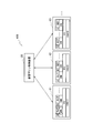
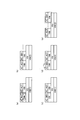
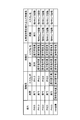
- FIG. 1 It is a block diagram showing an example of composition of a duplex operation system concerning a 1st embodiment of the present invention. It is a flowchart which shows the rough process procedure of the duplex operation system shown in FIG. It is a figure which shows typically the content of a process which the duplex operation system shown in FIG. 1 performs. It is a flow chart which shows a part of processing procedure of the outline of the duplexing operating system concerning a 2nd embodiment of the present invention. It is a figure which shows the result of having compared this embodiment with a comparative example.
- FIG. 1 is a block diagram showing a configuration example of a duplex operation system according to a first embodiment of the present invention.
- FIG. 2 is a flowchart showing a schematic processing procedure of the duplex operation system 100 shown in FIG.
- the redundant operation system 100 includes a plurality of general-purpose devices 11, 12, 13 and a virtual machine control device 20. Two or more (A, B,...) Multiple virtual machines (VM) are mounted on each of the multiple general-purpose devices 11, 12, and 13.
- the virtual machine control device 20 controls duplex operation by two systems of an operating system (ACT) and a standby system (SBY) of the virtual machine.
- ACT operating system
- SBY standby system
- the general-purpose device may be equipped with three or more units.
- a general-purpose device 11 when there is no need to specify a general-purpose device, it will be referred to as a general-purpose device 11.
- the type of virtual machine is represented by ACT, SBY, and alphabet.
- the virtual machine A ACT
- HW(1) shown in FIG. 1 means hardware.
- the HV is a hypervisor for operating a plurality of virtual machines A, B,... In parallel.
- the general-purpose device 11 and the virtual machine control device 20 can be realized by, for example, a computer including a ROM, a RAM, a CPU and the like. In that case, the processing contents of the functions that the general-purpose device 11 and the virtual machine control device 20 should have are described by a program. This also applies to other embodiments described later.
- the virtual machine control device 20 When the virtual machine control device 20 starts the operation, it detects a failure of the working virtual machine (ACT) (step S1). The failure is detected by, for example, whether the process ID has been correctly updated, whether or not there is a health check response, and the time-out of the watchdog timer. The failure detection is repeated until it is detected (NO in step S2).
- ACT working virtual machine
- step S2 When the virtual machine control device 20 detects a failure of, for example, the virtual machine A (ACT) in the active system (YES in step S2), the virtual machine A in the active system is stopped. This state is schematically shown in FIG. The virtual machine A is transited from (ACT) to (FLT). (FLT) means a fault.
- the virtual machine control device 20 activates the standby virtual machine A corresponding to the stopped virtual machine A (step S3).
- This state is schematically shown in FIG.
- the virtual machine A(SBY) on the HV of the general-purpose device 12 (HW(2)) is switched to the active system (virtual machine A(SBY) ⁇ (virtual machine A(ACT)).
- the virtual machine control device 20 resets the standby virtual machine A on the failed operating hardware (step S4). As shown in FIG. 3C, the virtual machine A (SBY) is reset on the HV of the general-purpose device 11 (HW(1)).
- the virtual machine control device 20 determines whether or not the reset virtual machine (the virtual machine A (SBY) installed in the general-purpose device 11 in this example) is normal (step S5). Even the virtual machine A (SBY) of the standby system is in the state immediately before the operation, and whether it is normal or not can be determined by the same method as in the case of detecting the failure of the active system such as the presence/absence of the health check response.
- step S5 If the reset virtual machine A (SBY) is normal (YES in step S5), the process returns to the process of detecting the failure of the active virtual machine (ACT) (NO in step S9).
- step S5 If the reset virtual machine A(SBY) is abnormal (FIG. 3(d)) (NO in step S5), the virtual machine control device 20 resets the virtual machine A(SBY) in steps S3 and S4.
- the standby virtual machine A (SBY) is reset to a general-purpose device different from the device 11 (for example, the general-purpose device 13) (step S6). This state is schematically shown in FIG.
- step S7 the virtual machine A (SBY) surrounded by the alternate long and short dash line is reset to the general-purpose device 13 (HW(3)). It is determined whether the virtual machine A (SBY) reset in the general-purpose device 13 is normal (step S7). If it is normal (YES in step S7), the process returns to the process for detecting the failure of the active virtual machine (ACT) (step S1).
- the general-purpose device is changed to another general-purpose device until it is determined that the reset virtual machine A (SBY) is normal, for example, in step S6. And the processing of S7 are repeated (step S8).
- the virtual machine A (SBY) may be reset in the general-purpose device 13 again.
- the virtual machine A(SBY) may be reset by changing the general-purpose device to the general-purpose device 14 (not shown).
- the normal virtual machine A (SBY) can be reset to any general-purpose device. That is, the duplex operation state can be maintained.
- the redundant operation system 100 includes a plurality of general-purpose devices 11 to 13 in which a plurality of virtual machines A, B,... Are mounted, an operating system (ACT) of a virtual machine, and a standby system ( SBY) is a duplex operation system configured with a virtual machine controller 20 for controlling duplex operation by two systems, wherein the virtual machine controller 20 detects the failure of the active system (ACT), The virtual machine of (ACT) is stopped, the virtual machine of the standby system (SBY) corresponding to the stopped active system (ACT) is operated, and the standby system (SBY) is placed on the hardware of the stopped virtual machine.
- ACT operating system
- SBY standby system
- FIG. 4 is a flowchart showing a schematic processing procedure of the duplex operation system according to the second embodiment of the present invention.
- a redundant operation system 200 (not shown) that executes the processing procedure illustrated in FIG. 4 detects a suspicion of a hardware failure from the states of a plurality of virtual machines installed in one general-purpose device, and detects the hardware failure. This virtual machine is reset to another general-purpose device.
- the virtual machine control device 22 (not shown) that configures the redundant operation system 200 is configured such that, in any of the general-purpose devices 11, when a predetermined number or more of virtual machines are restarted at a predetermined level within a predetermined period, or When a failure (abnormality) of more than the number of virtual machines is detected, the virtual machines mounted on the general-purpose device 11 are reset by another general-purpose device 15 (not shown).
- ⁇ Resume at a predetermined level is, for example, resumption of phase 0.5 or higher.
- Resumption of Phase 0.5 means individual process reset. Therefore, for example, when the phase 0.5 is restarted within a predetermined period, for example, in the general-purpose device 11, when one virtual machine fails three times or each of the three virtual machines fails, the failure (abnormality) is detected.
- the virtual machine mounted on the general-purpose device 11 is reset by another general-purpose device 15, for example.
- the condition for resetting the virtual machine to another general-purpose device 15 is not limited to the restart of phase 0.5 three times.
- Table 1 shows an example of conditions for resetting the virtual machine to another general-purpose device 15.
- m 1 to m 6 are arbitrary integers.
- m 6 is the number of virtual machines stopped (FLT) due to a failure.
- FLT virtual machines stopped
- phase 1.0 is the process reset of all applications and the resumption of switching between the active system and the standby system.
- phase 1.0 is the process reset of all applications and the resumption of switching between the active system and the standby system.
- phase 1.0 is the process reset of all applications and the resumption of switching between the active system and the standby system.
- the virtual machine control device 22 is configured to restart the virtual machines on the same general-purpose device 11 in the phase 0.5 or more within the predetermined period, or to restart the same general-purpose device 11.
- the case where a plurality of virtual machines of (1) have failed is detected (step S10).
- the predetermined period is a time interval such as 10 minutes
- the plurality is a number such as 3 units.
- step S11 When a plurality of failures are detected within a predetermined period (step S11), it is determined whether there is a virtual machine in operation (ACT) on the general-purpose device 11 (step S12). When there is a virtual machine in operation (ACT), the virtual machine in operation (ACT) on the general-purpose device 11 is stopped. Then, if there is a standby-system (SBY) virtual machine corresponding to the stopped virtual machine of another general-purpose apparatus (for example, the general-purpose apparatus 12), the virtual machine is activated (step S13).
- ACT virtual machine in operation
- SBY standby-system
- the virtual machine control device 22 causes a general-purpose device (for example, a general-purpose device 12) different from the general-purpose device 11 that has detected a plurality of failures to be a virtual machine of a standby system (SBY) corresponding to the virtual machine activated in step S13.
- a general-purpose device for example, a general-purpose device 12
- SBY standby system
- step S15 the virtual machine that was the standby system (SBY) on the general-purpose device 11 that originally detected a plurality of failures is reset to another general-purpose device (other than the general-purpose device 11) (step S15). If there is no virtual machine running (ACT) on the general-purpose device 11 (NO in step S12), the virtual machine on the general-purpose device 11 is reset to another general-purpose device (other than the general-purpose device 11). (Step S16).
- the virtual machine control device 22 in the general-purpose device, when the phase 0.5 or more restart of the predetermined number or more virtual machines occurs within the predetermined period, or the number of virtual machines of the predetermined number or more of virtual machines.
- the virtual machine mounted on the general-purpose device is reset to another general-purpose device.
- FIG. 5 is a figure which shows the result of having compared the dual operation system of a comparative example and the dual operation system which concerns on this embodiment.
- the first column from the left in FIG. 5 indicates the level of phase resumption
- the operating system in the second column is a comparative example
- the standby system in the third column is a comparative example
- the standby system in the fourth column is this embodiment.
- the escalation destination is a restart escalation
- the restart of the operating system of PH0.5 in the first line means executing the restart of phase 0.5.
- PH 1.0 on the right side of the table means that if the phase 0.5 restart is executed but is not restarted, then the phase 1.0 restart is executed next.
- the restart of the standby system of PH 0.5 in the first line indicates that the work by the maintainer is required if the restart of phase 0.5 is executed and it is not restarted.
- the standby virtual machine of the comparative example indicates that all work by the maintenance person is required when the phase 0.5 restart is executed and not restarted.
- the standby system in which the present embodiment is incorporated with respect to this comparative example indicates that the virtual machine is reconfigured on another general-purpose device when any level of restart is executed.
- the duplex operation system according to the present embodiment can widen the range in which the duplex operation state can be maintained. Further, it is possible to reduce the work which requires the intervention of the maintenance person.
- the redundant operation system 100 or 200 According to the redundant operation system 100 or 200 according to the present embodiment, it is possible to provide the redundant operation system and the method thereof in which the range in which the redundant operation state can be maintained is expanded.
Landscapes
- Engineering & Computer Science (AREA)
- Theoretical Computer Science (AREA)
- Physics & Mathematics (AREA)
- General Engineering & Computer Science (AREA)
- General Physics & Mathematics (AREA)
- Quality & Reliability (AREA)
- Software Systems (AREA)
- Hardware Redundancy (AREA)
Abstract
二重化運転状態が維持できる範囲を広げた二重化運転システムを提供する。複数の仮想マシンが搭載された複数の汎用装置11,12,13と、仮想マシンの稼働系と待機系の二系統による二重化運転を制御する仮想マシン制御装置20とで構成される二重化運転システムであって、仮想マシン制御装置20は、稼働系の故障を検出した場合に、該稼働系の仮想マシンを停止させ、該停止させた稼働系に対応する待機系の仮想マシンを稼働させ、該停止させた仮想マシンのハードウェアの上に該稼働させた仮想マシンの待機系を再設定し、該再設定した待機系の仮想マシンに故障が検出された場合に、稼働系の仮想マシンを停止させた汎用装置11と異なる汎用装置13に故障した仮想マシンの待機系を再設定させる。
Description
本発明は、可用性の高いネットワークシステムを提供できる技術に関する。
サービスを提供するネットワークシステムは、サービス提供の信頼性を確保する目的でサーバを稼働系と待機系の二系統に二重化している。つまり、稼働系(ACT)で故障を検出した場合は、待機系(SBY)に切り替えることでサービスの提供が中断しないようにして可用性を高めている。可用性とは、システムが継続して稼働できる能力のことである。
そのような二重化運転システムは、例えば非特許文献1に開示されている。
[平成31年2月5日検索]、黒川章、他3名「次世代ネットワーク(NGN)を支えるネットワーク基盤技術」、インターネット<URL: https://www.jstage.jst.go.jp/article/bplus/2010/13/2010_13_13_10/_pdf/-char/ja>
しかしながら、従来の二重化運転は、待機系で故障が検出された場合は切り替えが発生せず故障を検出した仮想マシンを停止させる規定となっている。よって、二重化運転状態が崩れ一重化運転状態になってしまう。二重化運転状態に復旧させるためには保守者による作業を必要としていた。
つまり、二重化運転状態を維持できる範囲が狭くサービス提供の可用性を低下させてしまうという課題がある。
本発明は、この課題に鑑みてなされたものであり、二重化運転状態を維持できる範囲を広げた二重化運転システム及びその方法を提供することを目的とする。
本発明の一態様に係る二重化運転システムは、複数の仮想マシンが搭載された複数の汎用装置と、仮想マシンの稼働系と待機系の二系統による二重化運転を制御する仮想マシン制御装置とで構成される二重化運転システムであって、前記仮想マシン制御装置は、前記稼働系の故障を検出した場合に、該稼働系の仮想マシンを停止させ、該停止させた前記稼働系に対応する前記待機系の仮想マシンを稼働させ、該停止させた仮想マシンのハードウェアの上に該稼働させた仮想マシンの前記待機系を再設定し、該再設定した前記待機系の仮想マシンに故障が検出された場合に、前記稼働系の仮想マシンを前記停止させた汎用装置と異なる汎用装置に故障した仮想マシンの前記待機系を再設定させることを要旨とする。
また、本発明の一態様に係る二重化運転方向は、上記の仮想マシン制御装置が実行する二重化運転方法であって、前記仮想マシン制御装置は、前記稼働系の故障を検出した場合に、該稼働系の仮想マシンを停止させ、該停止させた前記稼働系に対応する前記待機系の仮想マシンを稼働させ、該停止させた仮想マシンのハードウェアの上に該稼働させた仮想マシンの前記待機系を再設定し、該再設定した前記待機系の仮想マシンに故障が検出された場合に、前記稼働系の仮想マシンを前記停止させた汎用装置と異なる汎用装置に故障した仮想マシンの前記待機系を再設定させる仮想マシン制御ステップを行うことを要旨とする。
本発明によれば、二重化運転状態を維持できる範囲を広げた二重化運転システム及びその方法を提供することができる。
以下、本発明の実施形態について図面を用いて説明する。複数の図面中同一のものには同じ参照符号を付し、説明は繰り返さない。
〔第1実施形態〕
図1は、本発明の第1実施形態に係る二重化運転システムの構成例を示すブロック図である。図2は、図1に示す二重化運転システム100の概略の処理手順を示すフローチャートである。
図1は、本発明の第1実施形態に係る二重化運転システムの構成例を示すブロック図である。図2は、図1に示す二重化運転システム100の概略の処理手順を示すフローチャートである。
二重化運転システム100は、複数の汎用装置11,12,13と、仮想マシン制御装置20とで構成される。複数の汎用装置11,12,13のそれぞれには、2台(A,B,…)以上の複数の仮想マシン(VM)が搭載される。仮想マシン制御装置20は、仮想マシンの稼働系(ACT)と待機系(SBY)の二系統による二重化運転を制御する。
なお、汎用装置は3台以上を備えても良い。以降の説明において、汎用装置を特定する必要が無い場合、汎用装置11と表記することにする。また、仮想マシンの種別を、ACT,SBY,及びアルファベットで表記する。例えば、仮想マシンA(ACT)は、稼働系の仮想マシンAを意味する。また、図1に示すHW(1)はハードウェアを意味する。またHVは、複数の仮想マシンA,B,…を並列して稼働させるためのハイパーバイザである。
汎用装置11及び仮想マシン制御装置20は、例えば、ROM、RAM、CPU等からなるコンピュータで実現することができる。その場合、汎用装置11及び仮想マシン制御装置20が有すべき機能の処理内容はプログラムによって記述される。このことは、後述する他の実施形態でも同じである。
図1と2を参照して二重化運転システム100の動作を説明する。仮想マシン制御装置20は、動作を開始すると稼働系の仮想マシン(ACT)の故障を検出する(ステップS1)。故障の検出は、例えば、プロセスIDが正しく更新されているか、ヘルスチェックの応答の有無、及びウオッチドックタイマーのタイムアップ等の何れかで行う。故障の検出は、検出されるまで繰り返される(ステップS2のNO)。
仮想マシン制御装置20は、稼働系の例えば仮想マシンA(ACT)の故障を検出すると(ステップS2のYES)、当該稼働系の仮想マシンAを停止させる。この様子を図3(a)に模式的に示す。仮想マシンAは、(ACT)から(FLT)に遷移させられる。(FLT)は、フォールト(Fault)を意味する。
次に、仮想マシン制御装置20は、停止させた仮想マシンAに対応する待機系の仮想マシンAを稼働させる(ステップS3)。この様子を図3(b)に模式的に示す。この例では、汎用装置12(HW(2))のHV上にある仮想マシンA(SBY)が、稼働系に切り替わる(仮想マシンA(SBY)→(仮想マシンA(ACT))。
次に、仮想マシン制御装置20は、故障した稼働系のハードウェアの上に待機系の仮想マシンAを再設定する(ステップS4、)。図3(c)に示すように、汎用装置11(HW(1))のHV上に仮想マシンA(SBY)が再設定されている。
次に、仮想マシン制御装置20は、再設定した仮想マシン(この例では汎用装置11に搭載された仮想マシンA(SBY))が正常であるか否かを判定する(ステップS5)。待機系の仮想マシンA(SBY)であっても稼働直前の状態にあり、正常であるか否かはヘルスチェックの応答の有無等、稼働系の故障を検出する場合と同様の方法で行える。
再設定した仮想マシンA(SBY)が正常(ステップS5のYES)であれば、稼働系の仮想マシン(ACT)の故障を検出する処理に戻る(ステップS9のNO)。
再設定した仮想マシンA(SBY)が異常(図3(d))の場合(ステップS5のNO)、仮想マシン制御装置20は、ステップS3及びS4で仮想マシンA(SBY)を再設定した汎用装置11と異なる汎用装置(例えば汎用装置13)に待機系の仮想マシンA(SBY)を再設定する(ステップS6)。この様子を図3(e)に模式的に示す。
図3(e)に示すように、一点鎖線で囲った仮想マシンA(SBY)が汎用装置13(HW(3))に再設定されている。汎用装置13に再設定された仮想マシンA(SBY)は、正常であるか否か判定される(ステップS7)。正常(ステップS7のYES)であれば、稼働系の仮想マシン(ACT)の故障を検出する処理に戻る(ステップS1)。
汎用装置13に再設定された仮想マシンA(SBY)が異常の場合は、再設定した仮想マシンA(SBY)が正常と判定されるまで、例えば汎用装置を他の汎用装置に変えてステップS6とS7の処理を繰り返す(ステップS8)。なお、ここでは汎用装置13に再度、仮想マシンA(SBY)を再設定しても良い。汎用装置13に再度設定した仮想マシンA(SBY)が異常の場合に、例えば汎用装置14(図示せず)に汎用装置を変えて仮想マシンA(SBY)を再設定するようにしても良い。
ステップS6とS7の処理を繰り返すことで、正常な仮想マシンA(SBY)を何れかの汎用装置に再設定することができる。つまり、二重化運転状態を維持することができる。
以上説明したように本実施形態に係る二重化運転システム100は、複数の仮想マシンA,B,…が搭載された複数の汎用装置11~13と、仮想マシンの稼働系(ACT)と待機系(SBY)の二系統による二重化運転を制御する仮想マシン制御装置20とで構成される二重化運転システムであって、仮想マシン制御装置20は、稼働系(ACT)の故障を検出した場合、当該稼働系(ACT)の仮想マシンを停止させ、該停止させた稼働系(ACT)に対応する待機系(SBY)の仮想マシンを稼働させ、該停止させた仮想マシンのハードウェアの上に待機系(SBY)の仮想マシンを再設定し、該再設定した待機系(SBY)の仮想マシンに故障が検出された場合に仮想マシンを該停止させた汎用装置11と異なる汎用装置13に故障した仮想マシンの待機系(SBY)の仮想マシンを再設定させる。これにより、二重化運転状態を維持できる範囲を広げた二重化運転システム100を提供することができる。また、保守者の介在が必要な作業を削減することができる。
〔第2実施形態〕
図4は、本発明の第2実施形態に係る二重化運転システムの概略の処理手順を示すフローチャートである。図4に示す処理手順を実行する二重化運転システム200(図示せず)は、1台の汎用装置に搭載された複数の仮想マシンの状態から、ハードウェア故障の疑いを検知し、そのハードウェア上の仮想マシンを他の汎用装置に再設定するようにしたものである。
図4は、本発明の第2実施形態に係る二重化運転システムの概略の処理手順を示すフローチャートである。図4に示す処理手順を実行する二重化運転システム200(図示せず)は、1台の汎用装置に搭載された複数の仮想マシンの状態から、ハードウェア故障の疑いを検知し、そのハードウェア上の仮想マシンを他の汎用装置に再設定するようにしたものである。
二重化運転システム200を構成する仮想マシン制御装置22(図示せず)は、何れかの汎用装置11において、所定期間内に所定台数以上の仮想マシンの所定のレベルの再開が生じた場合、又は所定台数以上の仮想マシンの故障(異常)を検出した場合に当該汎用装置11に搭載された仮想マシンを他の例えば汎用装置15(図示せず)に再設定させる。
所定のレベルの再開とは、例えばフェーズ0.5以上の再開のことである。フェーズ0.5の再開とは、個別のプロセスリセットを意味する。よって、所定期間内に例えばフェーズ0.5の再開が例えば汎用装置11において、1台の仮想マシンが3回故障した場合又は3台の仮想マシンがそれぞれ故障した場合に、その故障(異常)を検出した汎用装置11に搭載された仮想マシンを他の例えば汎用装置15に再設定させる。
仮想マシンを他の汎用装置15に再設定させる条件は、3回のフェーズ0.5の再開に限られない。表1は、仮想マシンを他の汎用装置15に再設定させる条件の例を示す。

ここでm1~m6はそれぞれ任意の整数である。m6は故障によって停止(FLT)させられた仮想マシンの数である。フェーズ再開の数値が大きくなるに従ってリセットされるプロセスの範囲は大きくなる関係にある。例えばフェーズ1.0は、全てのアプリケーションのプロセスリセットと、稼働系と待機系の切り替えを行う再開である。このように仮想マシンを他の汎用装置15に再設定させる条件はいくつも考えられる。
図4を参照して本実施形態の二重化運転システム200の動作を詳しく説明する。仮想マシン制御装置22は、上記の実施形態の処理に加えて、所定期間内に同じ汎用装置11の上の複数の仮想マシンのフェーズ0.5以上の再開が生じた場合、又は同じ汎用装置11の上の複数の仮想マシンが故障した場合を検出する(ステップS10)。ここで、所定期間とは例えば10分間といった時間間隔であり、複数とは例えば3台といった台数である。
所定期間内に複数の故障を検出した場合(ステップS11)、その汎用装置11の上で稼働(ACT)中の仮想マシンがあるか否か判定する(ステップS12)。稼働(ACT)中の仮想マシンがある場合、汎用装置11の上の稼働(ACT)中の仮想マシンを停止させる。そして、他の汎用装置(例えば汎用装置12)その停止させた仮想マシンに対応する待機系(SBY)の仮想マシンが在れば、その仮想マシンを起動させる(ステップS13)。
次に、仮想マシン制御装置22は、複数の故障を検出した汎用装置11と異なる汎用装置(例えば汎用装置12)に、ステップS13で起動させた仮想マシンに対応する待機系(SBY)の仮想マシンを再設定する(ステップS14)。
そして、そもそも複数の故障を検出した汎用装置11の上で待機系(SBY)であった仮想マシンを他の汎用装置(汎用装置11以外)に再設定させる(ステップS15)。また、その汎用装置11の上で稼働(ACT)中の仮想マシンがない場合(ステップS12のNO)は、汎用装置11の上の仮想マシンは他の汎用装置(汎用装置11以外)に再設定させる(ステップS16)。
このように、所定期間の間に1台の例えば汎用装置11において複数の故障が検出された場合、その汎用装置11の上の仮想マシンは他の汎用装置(汎用装置11以外)に退避させられる。
以上説明したように本実施形態に係る仮想マシン制御装置22は、汎用装置において、所定期間内に、所定台数以上の仮想マシンのフェーズ0.5以上の再開が生じた場合又は所定台数以上の仮想マシンの故障を検出した場合に当該汎用装置に搭載された仮想マシンを他の汎用装置に再設定させる。これにより、故障が疑われるハードウェア(汎用装置)上の全ての仮想マシンを先んじて退避させることで、サービスの提供が不安定になる時間を短くすることができる。つまり、二重化運転システムの信頼性を向上させることができる。
(比較例との対比)
図5は、比較例の二重化運転システムと本実施形態に係る二重化運転システムを対比した結果を示す図である。図5の左から1列目はフェーズ再開のレベル、2列目の稼働系は比較例、3列目の待機系は比較例、4列目の待機系は本実施形態をそれぞれ示す。エスカレ先とは、再開エスカレーションのことであり、1行目のPH0.5の稼働系の再開は、フェーズ0.5の再開を実行する事を意味する。その右隣のPH1.0は、フェーズ0.5の再開を実行して再開しない場合は、次にフェーズ1.0の再開を実行することを意味している。
図5は、比較例の二重化運転システムと本実施形態に係る二重化運転システムを対比した結果を示す図である。図5の左から1列目はフェーズ再開のレベル、2列目の稼働系は比較例、3列目の待機系は比較例、4列目の待機系は本実施形態をそれぞれ示す。エスカレ先とは、再開エスカレーションのことであり、1行目のPH0.5の稼働系の再開は、フェーズ0.5の再開を実行する事を意味する。その右隣のPH1.0は、フェーズ0.5の再開を実行して再開しない場合は、次にフェーズ1.0の再開を実行することを意味している。
1行目のPH0.5の待機系の再開は、フェーズ0.5の再開を実行して再開しない場合は保守者による作業が必要であることを表している。図5に示すように、比較例の待機系の仮想マシンは、フェーズ0.5の再開を実行して再開しない場合は、全て保守者による作業が必要であることを表している。
この比較例に対して本実施形態を組み込んだ待機系は、何れのレベルの再開を実行した場合でも他の汎用装置の上に仮想マシンが再設定されることを表している。このように、本実施形態に係る二重化運転システムによれば二重化運転状態を維持できる範囲を広げることができる。また、保守者の介在が必要な作業を削減することができる。
以上説明したように本実施形態に係る二重化運転システム100,200によれば、二重化運転状態を維持できる範囲を広げた二重化運転システム及びその方法を提供することができる。
本発明はここでは記載していない様々な実施形態等を含むことは勿論である。したがって、本発明の技術的範囲は上記の説明から妥当な特許請求の範囲に係る発明特定事項によってのみ定められるものである。
100,200:二重化運転システム
11,12,13:汎用装置
20,22:仮想マシン制御装置
VM:仮想マシン
HV:ハイパーバイザ
ACT:稼働系
SBY:待機系
11,12,13:汎用装置
20,22:仮想マシン制御装置
VM:仮想マシン
HV:ハイパーバイザ
ACT:稼働系
SBY:待機系
Claims (4)
- 複数の仮想マシンが搭載された複数の汎用装置と、仮想マシンの稼働系と待機系の二系統による二重化運転を制御する仮想マシン制御装置とで構成される二重化運転システムであって、
前記仮想マシン制御装置は、
前記稼働系の故障を検出した場合に、該稼働系の仮想マシンを停止させ、該停止させた前記稼働系に対応する前記待機系の仮想マシンを稼働させ、該停止させた仮想マシンのハードウェアの上に該稼働させた仮想マシンの前記待機系を再設定し、該再設定した前記待機系の仮想マシンに故障が検出された場合に、前記稼働系の仮想マシンを前記停止させた汎用装置と異なる汎用装置に故障した仮想マシンの前記待機系を再設定させる
ことを特徴とする二重化運転システム。 - 前記仮想マシン制御装置は、
前記汎用装置において、所定期間内に、所定台数以上の仮想マシンのフェーズ0.5以上の再開が生じた場合又は所定台数以上の仮想マシンの故障を検出した場合に当該汎用装置に搭載された仮想マシンを他の汎用装置に再設定させる
ことを特徴とする請求項1に記載の二重化運転システム。 - 複数の仮想マシンが搭載された複数の汎用装置と、仮想マシンの稼働系と待機系の二系統による二重化運転を制御する仮想マシン制御装置とで構成される二重化運転システムの前記仮想マシン制御装置が実行する二重化運転方法であって、
前記仮想マシン制御装置は、
前記稼働系の故障を検出した場合に、該稼働系の仮想マシンを停止させ、該停止させた前記稼働系に対応する前記待機系の仮想マシンを稼働させ、該停止させた仮想マシンのハードウェアの上に該稼働させた仮想マシンの前記待機系を再設定し、該再設定した前記待機系の仮想マシンに故障が検出された場合に、前記稼働系の仮想マシンを前記停止させた汎用装置と異なる汎用装置に故障した仮想マシンの前記待機系を再設定させる仮想マシン制御ステップを
行うことを特徴とする二重化運転方法。 - 前記仮想マシン制御ステップは、
前記汎用装置において、所定期間内に、所定台数以上の仮想マシンのフェーズ0.5以上の再開が生じた場合又は所定台数以上の仮想マシンの故障を検出した場合に当該汎用装置に搭載された仮想マシンを他の汎用装置に再設定させる
ことを特徴とする請求項3に記載の二重化運転方法。
Priority Applications (1)
| Application Number | Priority Date | Filing Date | Title |
|---|---|---|---|
| US17/429,059 US11803452B2 (en) | 2019-02-14 | 2020-01-31 | Duplexed operation system and method therefor |
Applications Claiming Priority (2)
| Application Number | Priority Date | Filing Date | Title |
|---|---|---|---|
| JP2019-024387 | 2019-02-14 | ||
| JP2019024387A JP7128419B2 (ja) | 2019-02-14 | 2019-02-14 | 二重化運転システム及びその方法 |
Publications (1)
| Publication Number | Publication Date |
|---|---|
| WO2020166367A1 true WO2020166367A1 (ja) | 2020-08-20 |
Family
ID=72043972
Family Applications (1)
| Application Number | Title | Priority Date | Filing Date |
|---|---|---|---|
| PCT/JP2020/003585 Ceased WO2020166367A1 (ja) | 2019-02-14 | 2020-01-31 | 二重化運転システム及びその方法 |
Country Status (3)
| Country | Link |
|---|---|
| US (1) | US11803452B2 (ja) |
| JP (1) | JP7128419B2 (ja) |
| WO (1) | WO2020166367A1 (ja) |
Families Citing this family (2)
| Publication number | Priority date | Publication date | Assignee | Title |
|---|---|---|---|---|
| JP7519868B2 (ja) * | 2020-10-20 | 2024-07-22 | 三菱重工業株式会社 | コントローラ仮想化装置、及び、制御システム |
| JP7519408B2 (ja) * | 2022-06-20 | 2024-07-19 | 株式会社日立製作所 | 計算機システム、及び冗長化要素構成方法 |
Citations (2)
| Publication number | Priority date | Publication date | Assignee | Title |
|---|---|---|---|---|
| JP2014032475A (ja) * | 2012-08-02 | 2014-02-20 | Hitachi Ltd | 仮想計算機システムおよび仮想計算機の制御方法 |
| JP2014075027A (ja) * | 2012-10-04 | 2014-04-24 | Nippon Telegr & Teleph Corp <Ntt> | 仮想マシン配置装置および仮想マシン配置方法 |
Family Cites Families (13)
| Publication number | Priority date | Publication date | Assignee | Title |
|---|---|---|---|---|
| JP4256693B2 (ja) * | 2003-02-18 | 2009-04-22 | 株式会社日立製作所 | 計算機システム、i/oデバイス及びi/oデバイスの仮想共有方法 |
| JP5035011B2 (ja) * | 2008-02-22 | 2012-09-26 | 日本電気株式会社 | 仮想サーバ管理装置および仮想サーバ管理方法 |
| JP5392594B2 (ja) * | 2008-03-05 | 2014-01-22 | 日本電気株式会社 | 仮想計算機冗長化システム、コンピュータシステム、仮想計算機冗長化方法、及びプログラム |
| US8769535B2 (en) * | 2009-09-24 | 2014-07-01 | Avaya Inc. | Providing virtual machine high-availability and fault tolerance via solid-state backup drives |
| JP5742410B2 (ja) * | 2011-04-11 | 2015-07-01 | 日本電気株式会社 | フォールトトレラント計算機システム、フォールトトレラント計算機システムの制御方法、及びフォールトトレラント計算機システムの制御プログラム |
| JP6077945B2 (ja) * | 2013-06-17 | 2017-02-08 | 日本電信電話株式会社 | ネットワークシステム及び制御方法 |
| JP2015060375A (ja) * | 2013-09-18 | 2015-03-30 | 日本電気株式会社 | クラスタシステム、クラスタ制御方法及びクラスタ制御プログラム |
| WO2015195834A1 (en) * | 2014-06-17 | 2015-12-23 | Rangasamy Govind | Resiliency director |
| US9513946B2 (en) * | 2014-06-27 | 2016-12-06 | Vmware, Inc. | Maintaining high availability during network partitions for virtual machines stored on distributed object-based storage |
| JP6247648B2 (ja) * | 2015-01-22 | 2017-12-13 | 日本電信電話株式会社 | ライブマイグレーション実行装置およびその動作方法 |
| KR101924746B1 (ko) * | 2015-01-27 | 2019-02-27 | 닛본 덴끼 가부시끼가이샤 | 네트워크 기능 가상화의 관리, 및 오케스트레이션 장치, 시스템, 관리 방법 및 프로그램 |
| CN106817238A (zh) * | 2015-11-30 | 2017-06-09 | 中兴通讯股份有限公司 | 虚拟机修复方法、虚拟机装置、系统及业务功能网元 |
| JP6668275B2 (ja) * | 2017-02-16 | 2020-03-18 | 日本電信電話株式会社 | 制御装置及び制御方法 |
-
2019
- 2019-02-14 JP JP2019024387A patent/JP7128419B2/ja active Active
-
2020
- 2020-01-31 US US17/429,059 patent/US11803452B2/en active Active
- 2020-01-31 WO PCT/JP2020/003585 patent/WO2020166367A1/ja not_active Ceased
Patent Citations (2)
| Publication number | Priority date | Publication date | Assignee | Title |
|---|---|---|---|---|
| JP2014032475A (ja) * | 2012-08-02 | 2014-02-20 | Hitachi Ltd | 仮想計算機システムおよび仮想計算機の制御方法 |
| JP2014075027A (ja) * | 2012-10-04 | 2014-04-24 | Nippon Telegr & Teleph Corp <Ntt> | 仮想マシン配置装置および仮想マシン配置方法 |
Also Published As
| Publication number | Publication date |
|---|---|
| US11803452B2 (en) | 2023-10-31 |
| JP7128419B2 (ja) | 2022-08-31 |
| US20220129359A1 (en) | 2022-04-28 |
| JP2020135101A (ja) | 2020-08-31 |
Similar Documents
| Publication | Publication Date | Title |
|---|---|---|
| US8312318B2 (en) | Systems and methods of high availability cluster environment failover protection | |
| US8185776B1 (en) | System and method for monitoring an application or service group within a cluster as a resource of another cluster | |
| US11640314B2 (en) | Service provision system, resource allocation method, and resource allocation program | |
| US9020894B2 (en) | Service version modification of a high-availability system | |
| US8423816B2 (en) | Method and computer system for failover | |
| CN106533736B (zh) | 一种网络设备重启方法和装置 | |
| CN101216793A (zh) | 一种多处理器系统故障恢复的方法及装置 | |
| US10331472B2 (en) | Virtual machine service availability | |
| JP7128419B2 (ja) | 二重化運転システム及びその方法 | |
| CN111314098A (zh) | 一种ha系统中实现vip地址漂移的方法和装置 | |
| CN108737153B (zh) | 区块链灾备系统、方法、服务器和计算机可读存储介质 | |
| US9047250B2 (en) | Failover processing | |
| CN117435405A (zh) | 双机热备和故障切换系统和方法 | |
| US11954509B2 (en) | Service continuation system and service continuation method between active and standby virtual servers | |
| JP2000324121A (ja) | ネットワーク管理システムにおける系切り替え装置および方法 | |
| JP5353378B2 (ja) | Haクラスタシステムおよびそのクラスタリング方法 | |
| JP3325785B2 (ja) | 計算機の故障検出・回復方式 | |
| JP3910967B2 (ja) | 2重化システム及び多重化制御方法 | |
| CN117493081A (zh) | 高可用架构的处理方法和装置 | |
| CN102916793B (zh) | 一种网络通信设备高可靠性实现方法及系统 | |
| JP6654662B2 (ja) | サーバ装置およびサーバシステム | |
| JP2007280155A (ja) | 分散システムにおける信頼性向上方法 | |
| US12499094B2 (en) | Automatic failover system for CRON jobs | |
| CN111211924A (zh) | 一种计算节点单点高可用控制方法及装置 | |
| CN110752955A (zh) | 一种席位不变故障迁移系统和方法 |
Legal Events
| Date | Code | Title | Description |
|---|---|---|---|
| 121 | Ep: the epo has been informed by wipo that ep was designated in this application |
Ref document number: 20756273 Country of ref document: EP Kind code of ref document: A1 |
|
| NENP | Non-entry into the national phase |
Ref country code: DE |
|
| 122 | Ep: pct application non-entry in european phase |
Ref document number: 20756273 Country of ref document: EP Kind code of ref document: A1 |