WO2020166250A1 - Motor-integrated fluid machine and vertical takeoff and landing aircraft - Google Patents
Motor-integrated fluid machine and vertical takeoff and landing aircraft Download PDFInfo
- Publication number
- WO2020166250A1 WO2020166250A1 PCT/JP2020/000805 JP2020000805W WO2020166250A1 WO 2020166250 A1 WO2020166250 A1 WO 2020166250A1 JP 2020000805 W JP2020000805 W JP 2020000805W WO 2020166250 A1 WO2020166250 A1 WO 2020166250A1
- Authority
- WO
- WIPO (PCT)
- Prior art keywords
- blade
- motor
- rotating
- outer peripheral
- blades
- Prior art date
Links
Images

Classifications
-
- B—PERFORMING OPERATIONS; TRANSPORTING
- B64—AIRCRAFT; AVIATION; COSMONAUTICS
- B64C—AEROPLANES; HELICOPTERS
- B64C29/00—Aircraft capable of landing or taking-off vertically, e.g. vertical take-off and landing [VTOL] aircraft
- B64C29/0008—Aircraft capable of landing or taking-off vertically, e.g. vertical take-off and landing [VTOL] aircraft having its flight directional axis horizontal when grounded
- B64C29/0016—Aircraft capable of landing or taking-off vertically, e.g. vertical take-off and landing [VTOL] aircraft having its flight directional axis horizontal when grounded the lift during taking-off being created by free or ducted propellers or by blowers
-
- B—PERFORMING OPERATIONS; TRANSPORTING
- B64—AIRCRAFT; AVIATION; COSMONAUTICS
- B64C—AEROPLANES; HELICOPTERS
- B64C11/00—Propellers, e.g. of ducted type; Features common to propellers and rotors for rotorcraft
- B64C11/001—Shrouded propellers
-
- B—PERFORMING OPERATIONS; TRANSPORTING
- B64—AIRCRAFT; AVIATION; COSMONAUTICS
- B64D—EQUIPMENT FOR FITTING IN OR TO AIRCRAFT; FLIGHT SUITS; PARACHUTES; ARRANGEMENTS OR MOUNTING OF POWER PLANTS OR PROPULSION TRANSMISSIONS IN AIRCRAFT
- B64D27/00—Arrangement or mounting of power plant in aircraft; Aircraft characterised thereby
- B64D27/02—Aircraft characterised by the type or position of power plant
- B64D27/24—Aircraft characterised by the type or position of power plant using steam, electricity, or spring force
-
- F—MECHANICAL ENGINEERING; LIGHTING; HEATING; WEAPONS; BLASTING
- F04—POSITIVE - DISPLACEMENT MACHINES FOR LIQUIDS; PUMPS FOR LIQUIDS OR ELASTIC FLUIDS
- F04D—NON-POSITIVE-DISPLACEMENT PUMPS
- F04D19/00—Axial-flow pumps
- F04D19/02—Multi-stage pumps
-
- F—MECHANICAL ENGINEERING; LIGHTING; HEATING; WEAPONS; BLASTING
- F04—POSITIVE - DISPLACEMENT MACHINES FOR LIQUIDS; PUMPS FOR LIQUIDS OR ELASTIC FLUIDS
- F04D—NON-POSITIVE-DISPLACEMENT PUMPS
- F04D25/00—Pumping installations or systems
- F04D25/02—Units comprising pumps and their driving means
- F04D25/06—Units comprising pumps and their driving means the pump being electrically driven
- F04D25/0606—Units comprising pumps and their driving means the pump being electrically driven the electric motor being specially adapted for integration in the pump
-
- F—MECHANICAL ENGINEERING; LIGHTING; HEATING; WEAPONS; BLASTING
- F04—POSITIVE - DISPLACEMENT MACHINES FOR LIQUIDS; PUMPS FOR LIQUIDS OR ELASTIC FLUIDS
- F04D—NON-POSITIVE-DISPLACEMENT PUMPS
- F04D29/00—Details, component parts, or accessories
- F04D29/26—Rotors specially for elastic fluids
- F04D29/32—Rotors specially for elastic fluids for axial flow pumps
- F04D29/325—Rotors specially for elastic fluids for axial flow pumps for axial flow fans
- F04D29/326—Rotors specially for elastic fluids for axial flow pumps for axial flow fans comprising a rotating shroud
-
- H—ELECTRICITY
- H02—GENERATION; CONVERSION OR DISTRIBUTION OF ELECTRIC POWER
- H02K—DYNAMO-ELECTRIC MACHINES
- H02K1/00—Details of the magnetic circuit
- H02K1/06—Details of the magnetic circuit characterised by the shape, form or construction
- H02K1/12—Stationary parts of the magnetic circuit
- H02K1/17—Stator cores with permanent magnets
-
- H—ELECTRICITY
- H02—GENERATION; CONVERSION OR DISTRIBUTION OF ELECTRIC POWER
- H02K—DYNAMO-ELECTRIC MACHINES
- H02K1/00—Details of the magnetic circuit
- H02K1/06—Details of the magnetic circuit characterised by the shape, form or construction
- H02K1/22—Rotating parts of the magnetic circuit
- H02K1/27—Rotor cores with permanent magnets
- H02K1/2793—Rotors axially facing stators
-
- H—ELECTRICITY
- H02—GENERATION; CONVERSION OR DISTRIBUTION OF ELECTRIC POWER
- H02K—DYNAMO-ELECTRIC MACHINES
- H02K7/00—Arrangements for handling mechanical energy structurally associated with dynamo-electric machines, e.g. structural association with mechanical driving motors or auxiliary dynamo-electric machines
- H02K7/006—Structural association of a motor or generator with the drive train of a motor vehicle
-
- H—ELECTRICITY
- H02—GENERATION; CONVERSION OR DISTRIBUTION OF ELECTRIC POWER
- H02K—DYNAMO-ELECTRIC MACHINES
- H02K7/00—Arrangements for handling mechanical energy structurally associated with dynamo-electric machines, e.g. structural association with mechanical driving motors or auxiliary dynamo-electric machines
- H02K7/14—Structural association with mechanical loads, e.g. with hand-held machine tools or fans
Definitions
- the present invention relates to a motor-integrated fluid machine and a vertical take-off and landing aircraft.
- a ring motor including a stator, a rotor, and a plurality of propeller blades
- the stator has a stator support ring and a plurality of windings arranged in the circumferential direction of the fixed support ring.
- a plurality of pitch blades are coupled to the stator support ring.
- the rotor has a rotor support ring, a plurality of magnetic poles arranged in the circumferential direction of the rotation support ring, and a central hub.
- the central hub is coupled to a portion of the stator.
- a plurality of propeller blades are coupled to the rotating support ring. Therefore, the rotor rotates around the central hub that is coupled to the stator by the winding and the magnetic pole, so that the plurality of propeller blades rotate.
- a motor-integrated fluid machine such as the ring motor of Patent Document 1
- the generated thrust acts on the blade.
- the shaft portion such as the hub
- the tip end side (free end side) of the blade is displaced by the thrust.
- the rotation support ring is displaced in the axial direction of the rotation axis along with the displacement of the blade, and the plurality of magnetic poles provided on the rotation support ring are also displaced from the plurality of windings. If the positional relationship between the plurality of magnetic poles and the plurality of windings is deviated and, for example, the gap between the magnetic poles and the windings is widened, the performance of the motor is degraded and the thrust is reduced.
- an object of the present invention is to provide a motor-integrated fluid machine and a vertical take-off and landing machine that can suppress the performance deterioration of the motor due to the rotation of the blade.
- a motor-integrated fluid machine of the present invention is a motor-integrated fluid machine that sucks fluid from a suction port and blows out the sucked fluid from an outlet, with a shaft portion provided at the center of a rotary shaft and a shaft centered around the shaft portion.
- the rotating part is rotatably supported by the shaft part, While the part side is the fixed end side, the outer peripheral part side is the free end side, and the motor is an outer peripheral drive motor that applies power from the outer peripheral part to rotate the rotating part.
- the predetermined portion of the first blade and the predetermined portion of the second blade can be provided so as to be displaced in the axial direction, so that the rigidity in the axial direction of the plurality of blades can be improved. it can.
- the axial displacement of the blade due to the thrust can be suppressed, the position of the portion on the free end side can be suppressed from being displaced toward the suction port side due to the thrust.
- the predetermined part for example, a part on the shaft part side (fixed end side), a part on the outer peripheral part side (free end side), or all parts (entire blade).
- the rotor-side magnet and the stator-side magnet are provided to face each other in the axial direction of the rotating shaft.
- the rotor-side magnet and the stator-side magnet are provided to face each other in the radial direction of the rotation shaft.
- the plurality of blades may be provided in multiple stages in the axial direction of the rotating shaft by the first blade being provided closer to the suction port side than the second blade in the axial direction of the rotating shaft. ,preferable.
- a plurality of blades can be divided into a first blade and a second blade to form a multi-stage configuration in which they are arranged in the axial direction. Therefore, the axial rigidity of the plurality of blades can be further improved.
- first blades and the second blades are alternately arranged in the circumferential direction of the rotation shaft.
- the weight balance of the first blade can be made uniform in the circumferential direction, and similarly, the weight balance of the second blade can be made uniform in the circumferential direction. Therefore, when the plurality of blades are rotated, the whirling of the rotating portion due to uneven distribution of weight can be suppressed.
- the second blade has a pitch angle, which is an angle with respect to the circumferential direction of the rotating shaft, larger than that of the first blade.
- the fluid that has passed through the first blade flows down the second blade, that is, along the axial direction of the rotating shaft. Therefore, by increasing the pitch angle of the second blade, it is possible to suitably generate thrust in the second blade. Further, by increasing the pitch angle of the second blade, the second blade can be oriented along the axial direction of the rotating shaft, so that the axial rigidity of the second blade can be further improved.
- the plurality of blades when the surface formed at the end portion on the suction port side is a rotation surface, the plurality of blades is the rotation surface at the outer peripheral side portion of the first blade.
- the outer surface of the second blade is flush with the rotating surface, and the inner surface of the first blade is located on the inner surface of the second blade in the axial direction of the rotating shaft.
- the inner peripheral side (fixed end side) portions of the first blade and the second blade can be provided with axial displacement. Therefore, the rigidity in the axial direction on the inner peripheral side of the plurality of blades can be improved.
- the inner peripheral side portion of the blade greatly contributes to the displacement of the position on the outer peripheral side of the blade, so by improving the axial rigidity on the inner peripheral side of the plurality of blades, in the axial direction on the outer peripheral side of the blade. Can be suitably suppressed.
- the outer peripheral side portions of the plurality of blades can be made to be the rotation surfaces that are in the same plane, the thrust can be efficiently generated.
- the length of the portion on the inner peripheral side of the blade which is not the same plane is preferably 0.5R or less.
- the outer peripheral portion of the plurality of blades can be made larger than the inner peripheral portion of the plurality of blades, so that the thrust can be generated more efficiently.
- a vertical take-off and landing aircraft of the present invention includes the above-described motor-integrated fluid machine and a machine body that moves by thrust generated by the motor-integrated fluid machine.
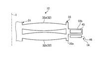
- FIG. 1 is a cross-sectional view of a motor-integrated fan according to the first embodiment.
- FIG. 2 is an explanatory diagram schematically showing the periphery of the blade of the motor-integrated fan according to the first embodiment.
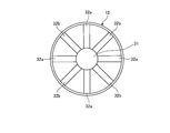
- FIG. 3 is a plan view of the rotating portion of the motor-integrated fan according to the first embodiment as seen from the axial direction.
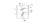
- FIG. 4 is an explanatory diagram of the blade of the motor-integrated fan according to the first embodiment as viewed from the radial direction.
- FIG. 5 is an explanatory diagram schematically showing the periphery of the blade of the motor-integrated fan according to the second embodiment.
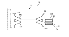
- FIG. 6 is an explanatory view schematically showing the periphery of the blade of the motor-integrated fan according to the third embodiment.
- FIG. 1 is a cross-sectional view of a motor-integrated fan according to the first embodiment.
- FIG. 2 is an explanatory diagram schematically showing the periphery of the blade of the motor-integr
- FIG. 7 is an explanatory diagram schematically showing the periphery of the blade of the motor-integrated fan according to the fourth embodiment.
- FIG. 8 is an explanatory view schematically showing the periphery of the blade of the motor-integrated fan according to the modified examples of the first to fourth embodiments.
- the motor-integrated fluid machine according to the first embodiment is an axial fluid machine.
- the motor-integrated fluid machine is a motor-integrated fan 1 (hereinafter also simply referred to as fan 1) that takes in air from a suction port and blows air from a blowout port to generate propulsive force.
- the motor-integrated fluid machine is described as being applied to the motor-integrated fan 1, but the configuration is not particularly limited to this.
- the motor-integrated fluid machine may be applied as, for example, a motor-integrated propulsion device such as a propeller that takes in a liquid such as water or seawater from a suction port and injects the liquid from an outlet to generate a propulsion force. ..
- the motor-integrated fan 1 is provided, for example, in a vertical take-off and landing aircraft such as a helicopter or a drone.
- the motor-integrated fan 1 provided in the vertical takeoff and landing aircraft generates a propulsive force for levitating the airframe and a propulsive force for controlling the attitude of the airframe.
- the motor-integrated fan 1 may be applied to an air cushion vehicle such as a hovercraft. Further, when applied as a motor-integrated propulsion device, it may be applied to a ship.
- FIG. 1 is a cross-sectional view of a motor-integrated fan according to the first embodiment.
- the motor-integrated fan 1 is called a duct type propeller or a ducted fan.
- the motor-integrated fan 1 is used, for example, in a horizontal state in which the axial direction of the rotary shaft I is the vertical direction, and takes in air from the upper side in the vertical direction and blows air to the lower side in the vertical direction. There is.
- the motor-integrated fan 1 may be used in a vertical state in which the axial direction of the rotary shaft I is horizontal.
- the motor-integrated fan 1 is a flat fan whose axial length of the rotary shaft I is shorter than the radial length of the rotary shaft I.
- the motor-integrated fan 1 is a fan in which one motor is integrally provided, and includes a shaft portion 11, a rotating portion 12, an outer peripheral portion 13, a motor 14, a rolling bearing 15, and a current plate 16. ing.
- the shaft 11 is provided at the center of the rotating shaft I and serves as a support system (fixed side).
- the axis of rotation of the rotary shaft I is the vertical direction in FIG. 1, and is the direction along the vertical direction. Therefore, the flow direction of the air is along the axial direction of the rotation axis I, and the air flows from the upper side to the lower side in FIG.
- the shaft portion 11 includes a shaft-side fitting portion 25 that is a portion provided on the upstream side in the axial direction of the rotating shaft I and a shaft body 26 that is a portion provided on the downstream side of the shaft-side fitting portion 25.
- the hub 31 of the rotating part 12 described later is fitted to the shaft-side fitting part 25.
- the shaft-side fitting portion 25 has a cylindrical shape, and is provided so as to project in the axial direction from the upstream end surface of the shaft body 26.
- the shaft-side fitting portion 25 has a cylindrical space formed on the center side of the rotation axis I. A part of the hub 31 of the rotating unit 12 is inserted into this space.
- the outer peripheral side of the shaft side fitting portion 25 is surrounded by a part of the hub 31 of the rotating portion 12.
- the shaft body 26 has a substantially conical shape that tapers from the upstream side toward the downstream side in the axial direction. Therefore, the outer peripheral surface of the shaft main body 26 is a surface from the outer side to the inner side in the radial direction from the upstream side to the downstream side in the axial direction.
- a device Inside the shaft body 26, an internal space in which a device can be installed is formed.
- the device is, for example, a control device, a camera, or the like. Further, an outer end surface of the rectifying plate 16 described later is connected to the outer peripheral surface of the shaft body 26 in the radial direction.
- the rotating portion 12 is a rotating system (rotating side) that rotates around the shaft portion 11.
- FIG. 2 is a cross-sectional view schematically showing the periphery of the blade of the motor-integrated fan according to the first embodiment.
- the rotating portion 12 is provided on the inflow side, through which air flows, with respect to the shaft portion 11 in the axial direction of the rotating shaft I.
- the rotating portion 12 has a hub 31, a plurality of blades 32, and a rotation support ring (rotation outer peripheral portion) 33.
- the rotating part 12 has a configuration in which a plurality of blades 32 are arranged in multiple stages in the axial direction.
- the hub 31 is provided on the upstream side of the shaft portion 11 in the axial direction, and is rotatably fitted to the shaft-side fitting portion 25.
- the hub 31 has a hub main body 35 that is a portion provided on the upstream side in the axial direction and a hub side fitting portion 36 that is a portion provided on the downstream side of the hub main body 35.
- the hub body 35 is formed into a hemispherical surface whose upstream end surface has a predetermined radius of curvature.
- the hub-side fitting portion 36 has a shape complementary to the shaft-side fitting portion 25.
- the hub-side fitting portion 36 includes a central shaft 36a provided at the center of the rotating shaft and a cylindrical portion 36b having a cylindrical shape provided on the outer peripheral side of the central shaft 36a.
- the central shaft 36a is inserted into the space at the center of the rotation shaft of the shaft-side fitting portion 25.
- the cylindrical portion 36b is provided so as to project in the axial direction from the end surface on the downstream side of the hub body 35.
- the cylindrical portion 36b is arranged so as to surround the outer periphery of the shaft-side fitting portion 25.
- the rolling bearing 15 is provided between the inner peripheral surface of the shaft-side fitting portion 25 and the outer peripheral surface of the central shaft 36a of the hub 31.
- the surface from the end surface of the hub main body 35 to the outer peripheral surface of the shaft main body 26 through the outer peripheral surface of the cylindrical portion 36b is a smooth surface without steps.
- the plurality of blades 32 are provided so as to extend from the hub 31 toward the outside in the radial direction, and are arranged side by side at a predetermined interval in the circumferential direction. Each blade 32 has a wing shape.
- the plurality of blades 32 are made of a composite material.
- the plurality of blades 32 are configured by using a composite material, but are not particularly limited, and may be configured by using a metal material, for example.
- the plurality of blades 32 are configured to include a first blade 32a that is a part of the blade 32 and a second blade 32b that is a remaining part of the blade 32.
- the first blade 32a and the second blade 32b are at different positions in the axial direction of the rotation axis I.
- the first blade 32a is provided on the suction port 38 side of the second blade 32b in the axial direction of the rotating shaft I.
- the second blade 32b is provided on the air outlet 39 side of the first blade 32a in the axial direction of the rotating shaft I. Therefore, the plurality of blades 32 are arranged in multiple stages (two stages) in the axial direction.
- FIG. 3 is a plan view of the rotating portion of the motor-integrated fan according to the first embodiment as seen from the axial direction.
- the first blades 32a and the second blades 32b are alternately arranged in the circumferential direction of the rotation axis I in a plan view. That is, the plurality of first blades 32a are evenly arranged at predetermined intervals in the circumferential direction. Further, the plurality of second blades 32b are evenly arranged in the circumferential direction with a predetermined interval. The plurality of second blades 32b are provided at the center between the first blades 32a adjacent to each other in the circumferential direction.
- FIG. 4 is an explanatory view of the blade of the motor-integrated fan according to the first embodiment as viewed from the radial direction.
- the first blade 32a and the second blade 32b have different pitch angles ⁇ 1 and ⁇ 2 with respect to the circumferential direction (rotational direction) of the rotation axis I.
- the first blade 32a and the second blade 32b are arranged side by side in the axial direction so as to facilitate comparison.
- the pitch angles ⁇ 1 and ⁇ 2 are angles formed by the circumferential direction and the front-rear direction connecting the leading edge side (the tip side in the rotation direction) and the trailing edge side (the trailing end side in the rotation direction) of the blade 32.
- the pitch angle ⁇ 2 of the second blade 32b is larger than the pitch angle ⁇ 1 of the first blade 32a.
- the rotation support ring 33 is formed in an annular shape around the rotation axis I.
- the rotation support ring 33 is connected to the outer peripheral side of the plurality of blades 32 in the radial direction of the rotation axis I.
- the rotation support ring 33 includes an inner ring portion 33a that is a portion that forms a part of the inner peripheral surface of the outer peripheral portion 13 described below, and a flange portion 33b that is a portion that is provided so as to project radially outward of the inner ring portion 33a. Is included.
- the inner peripheral surface of the inner ring portion 33 a on the radially inner side is a part of the inner peripheral surface of the outer peripheral portion 13.
- the radially outer ends of the blades 32 are connected to the inner peripheral surface of the inner ring portion 33a.
- the axial length of the inner ring portion 33a is a length at which the plurality of blades 32 arranged in multiple stages can be connected.
- the flange portion 33b is provided on the upstream side in the axial direction of the inner ring portion 33a.
- the flange portion 33b holds a permanent magnet 45 of the motor 14, which will be described later.
- the flange portion 33b holds the permanent magnet 45 so that the permanent magnet 45 faces the downstream side in the axial direction.
- the above-mentioned rotating part 12 is integrated with a hub 31, a plurality of blades 32, and a rotation support ring 33, and rotates around the hub 31.
- part or all of the rotating portion 12 may be integrally molded.
- the plurality of blades 32 and the rotation support ring 33 may be integrally molded using a composite material, or the hub 31, the plurality of blades 32, and the rotation support ring 33. May be integrally molded using a composite material.
- the rotating part 12 may be made of a metal material, and in this case as well, a part or all of the rotating part 12 may be integrated.
- the outer peripheral portion 13 is provided on the outer side in the radial direction of the shaft portion 11 and serves as a support system (fixed side).
- the outer peripheral portion 13 is formed in an annular shape and serves as a duct that generates a thrust by the rotation of the rotating portion 12.
- an opening on the upstream side serves as a suction port 38 and an opening on the downstream side serves as an air outlet 39 in the axial direction of the rotating shaft I.
- the duct 13 has a shape in which air is sucked from the suction port 38 and the sucked air is blown out from the air outlet 39 by the rotation of the rotating portion 12, thereby generating thrust.
- the inner peripheral surface of the duct 13 on the downstream side of the rotating portion 12 is a surface that widens from the suction port 38 side toward the blowout port 39 side.
- the duct 13 has an annular internal space formed therein for accommodating a flange portion 33b of the rotation support ring 33 of the rotating portion 12 and a coil 46 of the motor 14, which will be described later.
- the duct 13 holds a coil 46 provided inside the duct 13 at a position facing the permanent magnet 45 held by the rotating unit 12.
- the motor 14 is an outer peripheral drive motor that rotates the rotating part 12 by applying power from the duct 13 side to the rotating part 12.
- the motor 14 has a rotor-side magnet provided on the rotating portion 12 side and a stator-side magnet provided on the duct 13 side.
- the rotor-side magnet is the permanent magnet 45
- the stator-side magnet is the coil 46 that is an electromagnet.
- the permanent magnet 45 is provided so as to be held by the flange portion 33b of the rotation support ring 33, and is arranged in an annular shape in the circumferential direction. Further, the permanent magnet 45 is configured such that the positive electrode and the negative electrode are alternately arranged at predetermined intervals in the circumferential direction.
- the permanent magnets 45 may have a Halbach array.
- the permanent magnet 45 is provided at a position facing the coil 46 in the axial direction of the rotation axis I.
- the permanent magnet 45 has a length in the radial direction of the rotating shaft I that is longer than the length in the axial direction of the rotating shaft I.
- the coils 46 are provided while being held inside the duct 13, and a plurality of coils 46 are provided so as to face each pole of the permanent magnet 45 and are arranged side by side in the circumferential direction.
- the coil 46 is provided at a position facing the permanent magnet 45 held by the rotating portion 12 in the axial direction of the rotating shaft I. That is, the permanent magnet 45 and the coil 46 are arranged axially so as to face each other in the axial direction of the rotation axis I.
- the rolling bearing 15 is provided between the inner peripheral surface of the shaft-side fitting portion 25 of the shaft portion 11 and the outer peripheral surface of the central shaft 36a of the hub 31 of the rotating portion 12.
- the rolling bearing 15 connects the shaft portion 11 and the rotation portion 12 while allowing the rotation portion 12 to rotate with respect to the shaft portion 11.
- the rolling bearing 15 is, for example, a ball bearing or the like.
- the current plate 16 is provided by connecting the shaft portion 11 and the duct 13.
- the current plate 16 is provided on the downstream side of the rotating unit 12 in the axial direction of the rotating shaft I. That is, the current plate 16 is provided at the position of the downstream portion 43 of the duct 13 in the axial direction.
- a plurality of straightening vanes 16 are arranged side by side in the circumferential direction of the rotation axis I. Further, the straightening vane 16 has a streamlined shape such as a blade shape, and straightens the air flowing from the rotating portion 12 to generate thrust.
- the shape of the current plate 16 is not limited to the blade shape, and may be a flat plate shape.
- the rotating portion 12 is rotated by applying power from the duct 13 side to the rotating portion 12 by the magnetic field by the motor 14.
- the motor-integrated fan 1 sucks air from the suction port 38 and blows air toward the air outlet 39.
- the air blown out from the rotating part 12 flows along the inner peripheral surface of the duct 13 to generate thrust.
- the flow of air is rectified by the rectifying plate 16, and the rectifying plate 16 also generates thrust.
- the air sucked from the suction port 38 passes through the first blade 32a.
- the air that has passed through the first blade 32a flows downward to the second blade 32b, that is, along the axial direction of the rotation axis I.
- the air flowing downwards passes through the second blade 32b, is rectified by the rectifying plate 16, and is then blown out from the air outlet 39.
- the first blade 32a and the second blade 32b can be displaced in the axial direction to have a multi-stage configuration, so that the axial rigidity of the plurality of blades 32 can be increased. Can be improved. Therefore, since the axial displacement of the blade 32 due to the thrust can be suppressed, it is possible to suppress the position of the portion on the free end side, which is the outer peripheral side, from being displaced toward the suction port 38 side by the thrust. As a result, it is possible to prevent the permanent magnet 45 and the coil 46 of the motor 14 from separating from each other and widen the gap, and it is possible to prevent the performance of the motor 14 from being deteriorated due to the rotation of the blade 32. Further, since it is not necessary to change the blade area and the number of blades of the plurality of blades 32, the influence on the design of the blades 32 can be suppressed.
- the first blades 32a and the second blades 32b can be arranged alternately in the circumferential direction of the rotation axis I. Therefore, the weight balance of the first blade 32a can be made uniform in the circumferential direction, and similarly, the weight balance of the second blade 32b can be made uniform in the circumferential direction. Accordingly, when the plurality of blades 32 are rotated, it is possible to suppress the whirling of the rotating portion 12 due to the uneven distribution of the weight.
- the pitch angle ⁇ 2 of the second blade 32b can be made larger than the pitch angle ⁇ 1 of the first blade 32a, so that the air that has passed through the first blade 32a does not contact the second blade 32b. Even when the air flows so as to be blown down, the thrust can be appropriately generated in the second blade 32b. Further, by increasing the pitch angle ⁇ 2 of the second blade 32b, the chord length of the second blade 32b can be oriented along the axial direction of the rotation axis I, so that the rigidity of the second blade 32b in the axial direction can be increased. Can be further improved.
- the motor-integrated fan 1 in which the performance deterioration of the motor 14 due to the rotation of the blade 32 is suppressed, it is possible to provide a vertical take-off and landing aircraft with stable thrust.
- FIG. 5 is an explanatory diagram schematically showing the periphery of the blade of the motor-integrated fan according to the second embodiment.
- the motor-integrated fan 60 of the second embodiment is a modification of the blade 32 of the motor-integrated fan 1 of the first embodiment.
- the plurality of blades 32 are configured to include a first blade 32a and a second blade 32b.
- the inner peripheral side portion of the first blade 32a and the inner peripheral side portion of the second blade 32b are at different positions in the axial direction of the rotation axis I.
- the outer peripheral side portion of the first blade 32a and the outer peripheral side portion of the second blade 32b are at the same position in the axial direction of the rotation axis I.
- the surface formed at the end portion of the blade 32 on the suction port 38 side by the rotation of the plurality of blades 32 is referred to as a rotation surface P.
- the portion on the inner peripheral side of the first blade 32a is located on the suction port 38 side with respect to the rotation surface P in the portion on the outer peripheral side of the first blade 32a in the axial direction of the rotation axis I, and is located on the outer peripheral side.
- the air outlet 39 is inclined as it goes.
- the portion on the inner peripheral side of the second blade 32b is located on the blower outlet 39 side with respect to the rotation surface P in the portion on the outer peripheral side of the second blade 32b in the axial direction of the rotation axis I, and is located on the outer peripheral side. As it goes, it is inclined to the suction port 38.
- the rotation surface P on the outer peripheral side portion of the first blade 32a and the rotation surface P on the outer peripheral side portion of the second blade 32b are the same surface.
- the rotation surface P at the inner peripheral side portion of the first blade 32a and the rotation surface P at the inner peripheral side portion of the second blade 32b are not the same surface.
- the length of the portion on the inner peripheral side of the blade 32 that is not on the same plane is 0.5R or less.
- the inner peripheral side (fixed end side) portions of the first blade 32a and the second blade 32b can be provided with axial displacement so that a plurality of blades can be provided.
- the rigidity in the axial direction on the inner peripheral side of 32 can be improved.
- the portion on the inner peripheral side of the blade 32 greatly contributes to the displacement of the position on the outer peripheral side of the blade 32. Therefore, by improving the axial rigidity on the inner peripheral side of the blade 32, the shaft on the outer peripheral side of the blade 32 is improved.
- the displacement in the direction can be suitably suppressed.
- the outer peripheral side portions of the plurality of blades 32 can be the rotation surface P that is in the same plane, the thrust can be efficiently generated.
- the outer peripheral side portions of the plurality of blades 32 can be made larger than the inner peripheral side portions of the plurality of blades 32, so that the thrust can be generated more efficiently. it can.
- the inner circumferential side (fixed end side) of the first blade 32a and the second blade 32b are provided with axial displacement, but the present invention is not limited to this configuration.
- the outer peripheral side (free end side) of the first blade 32a and the second blade 32b may be axially displaced.
- the portions on the inner peripheral side (fixed end side) of the first blade 32a and the second blade 32b are the rotation surface P that is in the same plane.
- FIG. 6 is an explanatory view schematically showing the periphery of the blade of the motor-integrated fan according to the third embodiment.
- the motor-integrated fan 70 of the third embodiment is a modification of the blade 32 of the motor-integrated fan 60 of the second embodiment.
- the plurality of blades 32 are configured to include a first blade 32a and a second blade 32b.
- the inner peripheral side and outer peripheral side portions of the first blade 32a and the inner peripheral side and outer peripheral side portions of the second blade 32b are at different positions in the axial direction of the rotation axis I.
- the central portion of the first blade 32a and the central portion of the second blade 32b are at the same position in the axial direction of the rotation axis I.
- the surface formed at the end portion of the blade 32 on the suction port 38 side by the rotation of the plurality of blades 32 is referred to as a rotation surface P.
- the portion on the inner peripheral side of the first blade 32a is located on the suction port 38 side with respect to the rotation surface P in the central portion of the first blade 32a in the axial direction of the rotation axis I, and heads toward the outer peripheral side. Accordingly, the outlet 39 is inclined. Further, the outer peripheral side portion of the first blade 32a is located on the blowout port 39 side with respect to the rotation surface P in the central portion of the first blade 32a in the axial direction of the rotation axis I, and the inner peripheral side thereof. Inclining to the suction port 38 as it goes to.
- the inner peripheral side portion of the second blade 32b is located on the blower outlet 39 side with respect to the rotation surface P in the central portion of the second blade 32b in the axial direction of the rotation axis I, and heads toward the outer peripheral side. Accordingly, the suction port 38 is inclined. Further, the outer peripheral side portion of the second blade 32b is located on the suction port 38 side with respect to the rotation surface P in the central portion of the second blade 32b in the axial direction of the rotation axis I, and the inner peripheral side thereof. Toward the outlet 39.
- the rotation surface P in the central portion of the first blade 32a and the rotation surface P in the central portion of the second blade 32b are the same surface.
- the rotation surface P at the inner peripheral side portion of the first blade 32a and the rotation surface P at the inner peripheral side portion of the second blade 32b are not the same surface.
- the rotation surface P on the outer peripheral side portion of the first blade 32a and the rotation surface P on the outer peripheral side portion of the second blade 32b are not the same surface.
- the inner peripheral side portions of the first blade 32a and the second blade 32b can be displaced in the axial direction, and the first blade 32a and the second blade 32b can be displaced.
- the portion on the outer peripheral side can be displaced in the axial direction. Therefore, the rigidity in the axial direction on the inner peripheral side and the outer peripheral side of the plurality of blades 32 can be improved.
- the rotation surfaces P in the central portions of the first blade 32a and the second blade 32b are the same surface, but the configuration is not particularly limited to this configuration, and the central portions may be inclined. That is, the first blade 32a may be inclined toward the air outlet 39 from the inner peripheral side toward the outer peripheral side, and the second blade 32b may be inclined toward the suction port 38 from the inner peripheral side toward the outer peripheral side.
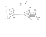
- FIG. 7 is an explanatory diagram schematically showing the periphery of the blade of the motor-integrated fan according to the fourth embodiment.
- the motor-integrated fan 80 of the fourth embodiment is a modification of the blade 32 of the motor-integrated fan 70 of the third embodiment.
- the plurality of blades 32 are configured to include a first blade 32a and a second blade 32b. Similar to the third embodiment, the inner peripheral side and outer peripheral side portions of the first blade 32a and the inner peripheral side and outer peripheral side portions of the second blade 32b have different positions in the axial direction of the rotation axis I. ing. On the other hand, the central portion of the first blade 32a and the central portion of the second blade 32b are at the same position in the axial direction of the rotation axis I.
- the surface formed at the end portion of the blade 32 on the suction port 38 side by the rotation of the plurality of blades 32 is referred to as a rotation surface P.
- the portion on the inner peripheral side of the first blade 32a is located on the suction port 38 side with respect to the rotation surface P in the central portion of the first blade 32a in the axial direction of the rotation axis I, and heads toward the outer peripheral side. Accordingly, the outlet 39 is inclined. Further, the outer peripheral side portion of the first blade 32a is located on the suction port 38 side with respect to the rotation surface P in the central portion of the first blade 32a in the axial direction of the rotation axis I, and the inner peripheral side thereof. Toward the outlet 39.
- the inner peripheral side portion of the second blade 32b is located on the blower outlet 39 side with respect to the rotation surface P in the central portion of the second blade 32b in the axial direction of the rotation axis I, and heads toward the outer peripheral side. Accordingly, the suction port 38 is inclined. Further, the outer peripheral side portion of the second blade 32b is located on the blowout port 39 side with respect to the rotation surface P in the central portion of the second blade 32b in the axial direction of the rotation axis I, and the inner peripheral side thereof. Inclining to the suction port 38 as it goes to.
- the rotation surface P in the central portion of the first blade 32a and the rotation surface P in the central portion of the second blade 32b are the same surface.
- the rotation surface P at the inner peripheral side portion of the first blade 32a and the rotation surface P at the inner peripheral side portion of the second blade 32b are not the same surface.
- the rotation surface P on the outer peripheral side portion of the first blade 32a and the rotation surface P on the outer peripheral side portion of the second blade 32b are not the same surface.
- the inner peripheral portions of the first blade 32a and the second blade 32b can be displaced in the axial direction, and the first blade 32a and the second blade 32b can be displaced.
- the portion on the outer peripheral side can be displaced in the axial direction. Therefore, the rigidity in the axial direction on the inner peripheral side and the outer peripheral side of the plurality of blades 32 can be improved.
- the inner peripheral side portion of the first blade 32a and the inner peripheral side portion of the second blade 32b are not flush with each other, and the outer peripheral side portion of the first blade 32a and the second blade
- the outer peripheral portion of 32b has a non-coplanar surface, and the central portion of the first blade 32a and the central portion of the second blade 32b have the same surface, but the configuration is not particularly limited.
- the inner peripheral side portion of the first blade 32a and the inner peripheral side portion of the second blade 32b are on the same plane, and the outer peripheral side portion of the first blade 32a and the outer peripheral side portion of the second blade 32b are Alternatively, the central portion of the first blade 32a and the central portion of the second blade 32b may not be flush with each other.
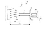
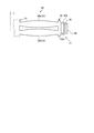
- FIG. 8 is an explanatory view schematically showing the periphery of the blade of the motor-integrated fan according to the modified examples of the first to fourth embodiments.
- the permanent magnet 45 and the coil 46 are arranged in a radial arrangement in which they are arranged to face each other in the radial direction of the rotation axis I.
- FIG. 8 is a diagram applied to the motor-integrated fan 1 of the first embodiment.
- the rotary support ring 33 holding the permanent magnet 45 holds the permanent magnet 45 in the flange portion 33b provided on the outer peripheral side of the inner ring portion 33a.
- the permanent magnet 45 is provided on the outer peripheral side of the inner ring portion 33a of the rotation support ring 33 and is held by the flange portion 33b.
- the permanent magnets 45 are annularly arranged in the circumferential direction.
- the permanent magnet 45 is provided at a position facing the coil 46 in the radial direction of the rotation axis I.
- the coils 46 are provided while being held inside the duct 13, and a plurality of coils 46 are provided so as to face each pole of the permanent magnet 45 and are arranged side by side in the circumferential direction.
- the coil 46 is provided at a position facing the permanent magnet 45 held by the rotating portion 12 in the radial direction of the rotating shaft I. In this way, the permanent magnets 45 and the coils 46 may be arranged radially so as to face each other in the radial direction of the rotation axis I.
- Motor integrated fan (Embodiment 1) 11 Shaft 12 Rotating Part (Embodiment 1) 13 duct 14 motor 15 rolling bearing 16 straightening plate 31 hub 32 blade 33 rotation support ring 38 suction port 39 air outlet 45 permanent magnet 46 coil 60 motor integrated fan (Embodiment 2) 62 Rotating part (Embodiment 2) 70 Motor Integrated Fan (Embodiment 3) 72 Rotating part (Embodiment 3) 80 Motor integrated fan (Embodiment 4) 82 Rotating part (Embodiment 4)
Abstract
A motor-integrated fan having an intake port and a blow-out port comprises a rotary part 12 that is rotatably supported by a shaft, and a motor 14 that rotates the rotary part 12. The motor 14 is an outer periphery drive motor that rotates the rotary part 12 by supplying motive power from a duct provided on the outer peripheral side of the shaft. The motor 14 includes: a permanent magnet 45 provided on a rotary support ring 33 connected to the outer peripheral side of blades 32 of the rotary part 12; and a coil 46 provided opposite the permanent magnet 45 in the axial direction of the axis of rotation. Among the plurality of blades 32, a first blade 32a and a second blade 32b are located at different positions in the axial direction.
Description
本発明は、モータ一体型流体機械及び垂直離着陸機に関するものである。
The present invention relates to a motor-integrated fluid machine and a vertical take-off and landing aircraft.
従来、固定子、回転子、及び複数のプロペラブレードを含むリングモータが知られている(例えば、特許文献1参照)。固定子は、固定子支持リングと、固定支持リングの周方向に配置された複数の巻線とを有する。固定子支持リングには、複数のピッチブレードが結合されている。回転子は、回転子支持リングと、回転支持リングの周方向に配置され複数の磁極と、中心ハブとを有する。中心ハブは、固定子の一部分に結合されている。複数のプロペラブレードは、回転支持リングに結合されている。このため、回転子は、巻線及び磁極により、固定子に結合する中心ハブを中心に回転することで、複数のプロペラブレードが回転する。
Conventionally, a ring motor including a stator, a rotor, and a plurality of propeller blades has been known (for example, see Patent Document 1). The stator has a stator support ring and a plurality of windings arranged in the circumferential direction of the fixed support ring. A plurality of pitch blades are coupled to the stator support ring. The rotor has a rotor support ring, a plurality of magnetic poles arranged in the circumferential direction of the rotation support ring, and a central hub. The central hub is coupled to a portion of the stator. A plurality of propeller blades are coupled to the rotating support ring. Therefore, the rotor rotates around the central hub that is coupled to the stator by the winding and the magnetic pole, so that the plurality of propeller blades rotate.
ところで、特許文献1のリングモータのようなモータ一体型流体機械において、ブレードを回転させて推力を生じさせると、発生した推力がブレードに作用する。このとき、複数のブレードがハブ等の軸部に支持されていることから、ブレードの先端側(自由端側)が推力により変位する。ブレードが変位すると、ブレードの変位に伴って、回転支持リングが回転軸の軸方向に変位し、回転支持リングに設けられる複数の磁極も、複数の巻線に対して位置ずれしてしまう。複数の磁極と複数の巻線との位置関係がずれることにより、例えば、磁極と巻線との隙間が広がってしまうと、モータの性能が低下してしまい、推力の低下を招いてしまう。
By the way, in a motor-integrated fluid machine such as the ring motor of Patent Document 1, when a blade is rotated to generate a thrust, the generated thrust acts on the blade. At this time, since the plurality of blades are supported by the shaft portion such as the hub, the tip end side (free end side) of the blade is displaced by the thrust. When the blade is displaced, the rotation support ring is displaced in the axial direction of the rotation axis along with the displacement of the blade, and the plurality of magnetic poles provided on the rotation support ring are also displaced from the plurality of windings. If the positional relationship between the plurality of magnetic poles and the plurality of windings is deviated and, for example, the gap between the magnetic poles and the windings is widened, the performance of the motor is degraded and the thrust is reduced.
そこで、本発明は、ブレードの回転に伴うモータの性能低下を抑制することができるモータ一体型流体機械及び垂直離着陸機を提供することを課題とする。
Therefore, an object of the present invention is to provide a motor-integrated fluid machine and a vertical take-off and landing machine that can suppress the performance deterioration of the motor due to the rotation of the blade.
本発明のモータ一体型流体機械は、吸込口から流体を吸い込み、吸い込んだ前記流体を吹出口から吹き出すモータ一体型流体機械において、回転軸の中心に設けられる軸部と、前記軸部を中心に回転する回転部と、前記軸部の外周に設けられる外周部と、前記回転部を回転させるモータと、を備え、前記回転部は、前記軸部に回転自在に支持されることで、前記軸部側が固定端側となる一方で、前記外周部側が自由端側となり、前記モータは、前記外周部から動力を与えて前記回転部を回転させる外周駆動のモータとなっており、前記回転部は、前記回転軸の周方向において並べて設けられる複数のブレードと、複数の前記ブレードの外周側に設けられる回転外周部と、を有し、前記モータは、前記回転外周部に設けられる回転子側磁石と、前記外周部に設けられ、前記回転子側磁石に対向して設けられる固定子側磁石と、を有し、複数の前記ブレードのうち、一部の前記ブレードとなる第1ブレードにおける少なくとも所定の部位と、他の一部の前記ブレードとなる第2ブレードにおける少なくとも所定の部位とが、前記回転軸の軸方向において異なる位置となっている。
A motor-integrated fluid machine of the present invention is a motor-integrated fluid machine that sucks fluid from a suction port and blows out the sucked fluid from an outlet, with a shaft portion provided at the center of a rotary shaft and a shaft centered around the shaft portion. A rotating part that rotates, an outer peripheral part that is provided on the outer periphery of the shaft part, and a motor that rotates the rotating part. The rotating part is rotatably supported by the shaft part, While the part side is the fixed end side, the outer peripheral part side is the free end side, and the motor is an outer peripheral drive motor that applies power from the outer peripheral part to rotate the rotating part. A plurality of blades arranged side by side in the circumferential direction of the rotating shaft, and a rotating outer peripheral portion provided on the outer peripheral side of the plurality of blades, wherein the motor is a rotor-side magnet provided on the rotating outer peripheral portion. And a stator-side magnet that is provided on the outer peripheral portion and that is provided so as to face the rotor-side magnet, and at least a predetermined value in the first blade that is a part of the blade among the plurality of blades. And a portion of at least a predetermined portion of the second blade, which is the other portion of the blade, are different positions in the axial direction of the rotating shaft.
この構成によれば、第1ブレードの所定の部位と第2ブレードの所定の部位とを、軸方向に位置ずれして設けることができるため、複数のブレードにおける軸方向の剛性を向上させることができる。このため、推力によるブレードの軸方向への変位を抑制できることから、自由端側の部位の位置が推力によって吸込口側へ変位することを抑制することができる。これにより、モータの回転子側磁石と固定子側磁石とが離れて隙間が広がってしまうことを抑制することができ、ブレードの回転に伴うモータの性能低下を抑制することができる。また、複数のブレードの翼面積及び翼枚数を変える必要がないため、ブレードに関する設計への影響を抑制できる。なお、所定の部位としては、例えば、軸部側(固定端側)の部位、外周部側(自由端側)の部位、または全ての部位(ブレード全体)である。
According to this configuration, the predetermined portion of the first blade and the predetermined portion of the second blade can be provided so as to be displaced in the axial direction, so that the rigidity in the axial direction of the plurality of blades can be improved. it can. For this reason, since the axial displacement of the blade due to the thrust can be suppressed, the position of the portion on the free end side can be suppressed from being displaced toward the suction port side due to the thrust. As a result, it is possible to prevent the rotor-side magnet and the stator-side magnet of the motor from separating from each other and widening the gap, and it is possible to prevent the performance of the motor from deteriorating due to the rotation of the blade. Further, since it is not necessary to change the blade area and the number of blades of the plurality of blades, it is possible to suppress the influence on the design of the blades. In addition, as the predetermined part, for example, a part on the shaft part side (fixed end side), a part on the outer peripheral part side (free end side), or all parts (entire blade).
また、前記回転子側磁石と前記固定子側磁石とは、前記回転軸の軸方向に対向して設けられることが、好ましい。
Further, it is preferable that the rotor-side magnet and the stator-side magnet are provided to face each other in the axial direction of the rotating shaft.
この構成によれば、回転子側磁石及び固定子側磁石が軸方向に対向して設けられる場合であっても、ブレードの回転に伴うモータの性能低下を抑制することができる。
According to this configuration, even when the rotor-side magnet and the stator-side magnet are provided so as to face each other in the axial direction, it is possible to suppress deterioration of the motor performance due to the rotation of the blade.
また、前記回転子側磁石と前記固定子側磁石とは、前記回転軸の径方向に対向して設けられることが、好ましい。
Further, it is preferable that the rotor-side magnet and the stator-side magnet are provided to face each other in the radial direction of the rotation shaft.
この構成によれば、回転子側磁石及び固定子側磁石が径方向に対向して設けられる場合であっても、ブレードの回転に伴うモータの性能低下を抑制することができる。
According to this configuration, even when the rotor-side magnet and the stator-side magnet are provided to face each other in the radial direction, it is possible to suppress deterioration in motor performance due to rotation of the blade.
また、複数の前記ブレードは、前記第1ブレードが、前記回転軸の軸方向において、前記第2ブレードよりも吸込口側に設けられることで、前記回転軸の軸方向に多段に設けられることが、好ましい。
Further, the plurality of blades may be provided in multiple stages in the axial direction of the rotating shaft by the first blade being provided closer to the suction port side than the second blade in the axial direction of the rotating shaft. ,preferable.
この構成によれば、複数のブレードを、第1ブレード及び第2ブレードに分けて、軸方向に並べた多段の構成とすることができる。このため、複数のブレードにおける軸方向の剛性をさらに向上させることができる。
According to this configuration, a plurality of blades can be divided into a first blade and a second blade to form a multi-stage configuration in which they are arranged in the axial direction. Therefore, the axial rigidity of the plurality of blades can be further improved.
また、前記第1ブレードと前記第2ブレードとは、前記回転軸の周方向において、交互に配置されていることが、好ましい。
Further, it is preferable that the first blades and the second blades are alternately arranged in the circumferential direction of the rotation shaft.
この構成によれば、第1ブレードの重量バランスを周方向において均等とすることができ、同様に、第2ブレードの重量バランスを周方向において均等とすることができる。このため、複数のブレードの回転時において、重量の偏在による回転部の振れ回りの発生を抑制することができる。
According to this configuration, the weight balance of the first blade can be made uniform in the circumferential direction, and similarly, the weight balance of the second blade can be made uniform in the circumferential direction. Therefore, when the plurality of blades are rotated, the whirling of the rotating portion due to uneven distribution of weight can be suppressed.
また、前記第2ブレードは、前記第1ブレードに比して、前記回転軸の周方向に対する角度であるピッチ角が大きくなっていることが、好ましい。
Further, it is preferable that the second blade has a pitch angle, which is an angle with respect to the circumferential direction of the rotating shaft, larger than that of the first blade.
この構成によれば、第1ブレードを通過した流体は、第2ブレードに対して吹き降ろすように流れる、つまり、回転軸の軸方向に沿うように流れる。このため、第2ブレードのピッチ角を大きくすることで、第2ブレードにおいて推力を好適に発生させることができる。また、第2ブレードのピッチ角を大きくすることで、第2ブレードを回転軸の軸方向に沿う向きとすることができるため、第2ブレードにおける軸方向の剛性をさらに向上させることができる。
According to this configuration, the fluid that has passed through the first blade flows down the second blade, that is, along the axial direction of the rotating shaft. Therefore, by increasing the pitch angle of the second blade, it is possible to suitably generate thrust in the second blade. Further, by increasing the pitch angle of the second blade, the second blade can be oriented along the axial direction of the rotating shaft, so that the axial rigidity of the second blade can be further improved.
また、複数の前記ブレードが回転することにより、前記吸込口側の端部において形成される面を回転面とすると、複数の前記ブレードは、前記第1ブレードの外周側の部位における前記回転面と、前記第2ブレードの外周側の部位における前記回転面とが同一面となり、前記第1ブレードの内周側の部位が、前記回転軸の軸方向において、前記第2ブレードの内周側の部位よりも吸込口側に設けられることで、前記第1ブレードの内周側の部位における前記回転面と、前記第2ブレードの内周側の部位における前記回転面とが非同一面となることが、好ましい。
Further, by rotating the plurality of blades, when the surface formed at the end portion on the suction port side is a rotation surface, the plurality of blades is the rotation surface at the outer peripheral side portion of the first blade. The outer surface of the second blade is flush with the rotating surface, and the inner surface of the first blade is located on the inner surface of the second blade in the axial direction of the rotating shaft. By being provided closer to the suction port side than that, the rotation surface at the inner peripheral side portion of the first blade and the rotation surface at the inner peripheral side portion of the second blade may become non-coplanar. ,preferable.
この構成によれば、第1ブレード及び第2ブレードの内周側(固定端側)の部位を、軸方向に位置ずれして設けることができる。このため、複数のブレードの内周側における軸方向の剛性を向上させることができる。ブレードの内周側の部位は、ブレードの外周側における位置の変位に大きく寄与することから、複数のブレードの内周側における軸方向の剛性を向上させることで、ブレードの外周側における軸方向への変位を好適に抑制することができる。また、複数のブレードの外周側の部位を、同一面内となる回転面とすることができるため、推力を効率よく発生させることができる。
According to this configuration, the inner peripheral side (fixed end side) portions of the first blade and the second blade can be provided with axial displacement. Therefore, the rigidity in the axial direction on the inner peripheral side of the plurality of blades can be improved. The inner peripheral side portion of the blade greatly contributes to the displacement of the position on the outer peripheral side of the blade, so by improving the axial rigidity on the inner peripheral side of the plurality of blades, in the axial direction on the outer peripheral side of the blade. Can be suitably suppressed. Moreover, since the outer peripheral side portions of the plurality of blades can be made to be the rotation surfaces that are in the same plane, the thrust can be efficiently generated.
また、前記回転軸の径方向において、前記ブレードの全長をRとすると、非同一面となる前記ブレードの内周側の部位の長さは、0.5R以下であることが、好ましい。
Further, when the total length of the blade is R in the radial direction of the rotating shaft, the length of the portion on the inner peripheral side of the blade which is not the same plane is preferably 0.5R or less.
この構成によれば、複数のブレードの外周側の部位を、複数のブレードの内周側の部位に比して大きくすることができるため、推力をさらに効率よく発生させることができる。
According to this configuration, the outer peripheral portion of the plurality of blades can be made larger than the inner peripheral portion of the plurality of blades, so that the thrust can be generated more efficiently.
本発明の垂直離着陸機は、上記のモータ一体型流体機械と、前記モータ一体型流体機械から発生する推力によって移動する機体と、を備える。
A vertical take-off and landing aircraft of the present invention includes the above-described motor-integrated fluid machine and a machine body that moves by thrust generated by the motor-integrated fluid machine.
この構成によれば、ブレードの回転に伴うモータの性能低下が抑制されたモータ一体型流体機械を搭載することで、安定した推力となる垂直離着陸機を提供することができる。
According to this configuration, it is possible to provide a vertical take-off and landing machine with stable thrust by mounting a motor-integrated fluid machine in which deterioration of the motor performance due to blade rotation is suppressed.
以下に、本発明に係る実施形態を図面に基づいて詳細に説明する。なお、この実施形態によりこの発明が限定されるものではない。また、下記実施形態における構成要素には、当業者が置換可能かつ容易なもの、あるいは実質的に同一のものが含まれる。さらに、以下に記載した構成要素は適宜組み合わせることが可能であり、また、実施形態が複数ある場合には、各実施形態を組み合わせることも可能である。
Embodiments according to the present invention will be described below in detail with reference to the drawings. The present invention is not limited to this embodiment. In addition, constituent elements in the following embodiments include elements that can be easily replaced by those skilled in the art, or substantially the same elements. Further, the constituent elements described below can be combined as appropriate, and when there are a plurality of embodiments, the respective embodiments can be combined.
[実施形態1]
実施形態1に係るモータ一体型流体機械は、軸流の流体機械となっている。モータ一体型流体機械は、吸込口から空気を取り込み、吹出口から空気を吹き出すことで、推進力を発生させるモータ一体型ファン1(以下、単にファン1ともいう)である。なお、実施形態1では、モータ一体型流体機械として、モータ一体型ファン1に適用して説明するが、この構成に特に限定されない。モータ一体型流体機械は、例えば、吸込口から水または海水等の液体を取り込み、吹出口から液体を噴射することで、推進力を発生させるプロペラ等のモータ一体型推進器として適用してもよい。 [Embodiment 1]
The motor-integrated fluid machine according to the first embodiment is an axial fluid machine. The motor-integrated fluid machine is a motor-integrated fan 1 (hereinafter also simply referred to as fan 1) that takes in air from a suction port and blows air from a blowout port to generate propulsive force. In the first embodiment, the motor-integrated fluid machine is described as being applied to the motor-integrated fan 1, but the configuration is not particularly limited to this. The motor-integrated fluid machine may be applied as, for example, a motor-integrated propulsion device such as a propeller that takes in a liquid such as water or seawater from a suction port and injects the liquid from an outlet to generate a propulsion force. ..
モータ一体型ファン1は、例えば、ヘリコプタまたはドローン等の垂直離着陸機に設けられている。垂直離着陸機に設けられるモータ一体型ファン1は、機体を浮上させるための推進力を発生させたり、機体の姿勢を制御するための推進力を発生させたりする。なお、モータ一体型ファン1は、例えば、ホバークラフト等の空気クッション車両に適用してもよい。さらに、モータ一体型推進器として適用する場合には、船舶に適用してもよい。
The motor-integrated fan 1 is provided, for example, in a vertical take-off and landing aircraft such as a helicopter or a drone. The motor-integrated fan 1 provided in the vertical takeoff and landing aircraft generates a propulsive force for levitating the airframe and a propulsive force for controlling the attitude of the airframe. The motor-integrated fan 1 may be applied to an air cushion vehicle such as a hovercraft. Further, when applied as a motor-integrated propulsion device, it may be applied to a ship.
図1を参照して、モータ一体型ファン1について説明する。図1は、実施形態1に係るモータ一体型ファンに関する断面図である。モータ一体型ファン1は、ダクト型プロペラ、または、ダクテッドファンと呼ばれるものである。このモータ一体型ファン1は、例えば、回転軸Iの軸方向を鉛直方向とする水平状態で使用され、鉛直方向の上方側から空気を取り込み、鉛直方向の下方側へ空気を吹き出すものとなっている。なお、モータ一体型ファン1は、回転軸Iの軸方向を水平方向とする鉛直状態で使用されてもよい。
The motor-integrated fan 1 will be described with reference to FIG. FIG. 1 is a cross-sectional view of a motor-integrated fan according to the first embodiment. The motor-integrated fan 1 is called a duct type propeller or a ducted fan. The motor-integrated fan 1 is used, for example, in a horizontal state in which the axial direction of the rotary shaft I is the vertical direction, and takes in air from the upper side in the vertical direction and blows air to the lower side in the vertical direction. There is. The motor-integrated fan 1 may be used in a vertical state in which the axial direction of the rotary shaft I is horizontal.
モータ一体型ファン1は、回転軸Iの軸方向における長さが、回転軸Iの径方向における長さよりも短い扁平のファンとなっている。モータ一体型ファン1は、1つのモータが一体に設けられたファンであり、軸部11と、回転部12と、外周部13と、モータ14と、転がり軸受15と、整流板16とを備えている。
The motor-integrated fan 1 is a flat fan whose axial length of the rotary shaft I is shorter than the radial length of the rotary shaft I. The motor-integrated fan 1 is a fan in which one motor is integrally provided, and includes a shaft portion 11, a rotating portion 12, an outer peripheral portion 13, a motor 14, a rolling bearing 15, and a current plate 16. ing.
軸部11は、回転軸Iの中心に設けられ、支持系(固定側)となっている。回転軸Iは、軸方向が図1の上下方向となっており、鉛直方向に沿った方向となっている。このため、空気の流れ方向は、回転軸Iの軸方向に沿った方向となっており、図1の上方側から下方側に向かって空気が流れる。軸部11は、回転軸Iの軸方向において、その上流側に設けられる部位となる軸側嵌合部25と、軸側嵌合部25の下流側に設けられる部位となる軸本体26とを有している。
The shaft 11 is provided at the center of the rotating shaft I and serves as a support system (fixed side). The axis of rotation of the rotary shaft I is the vertical direction in FIG. 1, and is the direction along the vertical direction. Therefore, the flow direction of the air is along the axial direction of the rotation axis I, and the air flows from the upper side to the lower side in FIG. The shaft portion 11 includes a shaft-side fitting portion 25 that is a portion provided on the upstream side in the axial direction of the rotating shaft I and a shaft body 26 that is a portion provided on the downstream side of the shaft-side fitting portion 25. Have
軸側嵌合部25は、後述する回転部12のハブ31が嵌め合わされる。軸側嵌合部25は、円筒形状となっており、軸本体26の上流側の端面から軸方向に突出して設けられている。軸側嵌合部25は、回転軸Iの中心側に円柱形状の空間が形成されている。この空間には、回転部12のハブ31の一部が挿入される。また、軸側嵌合部25の外周側は、回転部12のハブ31の一部によって取り囲まれている。
The hub 31 of the rotating part 12 described later is fitted to the shaft-side fitting part 25. The shaft-side fitting portion 25 has a cylindrical shape, and is provided so as to project in the axial direction from the upstream end surface of the shaft body 26. The shaft-side fitting portion 25 has a cylindrical space formed on the center side of the rotation axis I. A part of the hub 31 of the rotating unit 12 is inserted into this space. The outer peripheral side of the shaft side fitting portion 25 is surrounded by a part of the hub 31 of the rotating portion 12.
軸本体26は、軸方向の上流側から下流側に向かって先細りとなる略円錐形状となっている。このため、軸本体26は、その外周面が、軸方向の上流側から下流側に向かうにつれて、径方向の外側から内側に向かう面となっている。軸本体26の内部には、機器を設置可能な内部空間が形成されている。機器としては、例えば、制御装置、カメラ等である。また、軸本体26の外周面には、後述する整流板16の径方向内側の端部が接続されている。
The shaft body 26 has a substantially conical shape that tapers from the upstream side toward the downstream side in the axial direction. Therefore, the outer peripheral surface of the shaft main body 26 is a surface from the outer side to the inner side in the radial direction from the upstream side to the downstream side in the axial direction. Inside the shaft body 26, an internal space in which a device can be installed is formed. The device is, for example, a control device, a camera, or the like. Further, an outer end surface of the rectifying plate 16 described later is connected to the outer peripheral surface of the shaft body 26 in the radial direction.
図1及び図2に示すように、回転部12は、軸部11を中心に回転する回転系(回転側)となっている。図2は、実施形態1に係るモータ一体型ファンのブレード周りを模式的に表した断面図である。回転部12は、回転軸Iの軸方向において、軸部11に対して、空気が流入する流入側に設けられている。回転部12は、ハブ31と、複数のブレード32と、回転支持リング(回転外周部)33と、を有している。回転部12は、複数のブレード32が軸方向において多段となる構成となっている。
As shown in FIGS. 1 and 2, the rotating portion 12 is a rotating system (rotating side) that rotates around the shaft portion 11. FIG. 2 is a cross-sectional view schematically showing the periphery of the blade of the motor-integrated fan according to the first embodiment. The rotating portion 12 is provided on the inflow side, through which air flows, with respect to the shaft portion 11 in the axial direction of the rotating shaft I. The rotating portion 12 has a hub 31, a plurality of blades 32, and a rotation support ring (rotation outer peripheral portion) 33. The rotating part 12 has a configuration in which a plurality of blades 32 are arranged in multiple stages in the axial direction.
ハブ31は、軸部11の軸方向の上流側に設けられ、軸側嵌合部25に回転自在に嵌め合わされる。ハブ31は、軸方向の上流側に設けられる部位となるハブ本体35と、ハブ本体35の下流側に設けられる部位となるハブ側嵌合部36とを有している。ハブ本体35は、上流側の端面が所定の曲率半径となる半球面に形成されている。ハブ側嵌合部36は、軸側嵌合部25と相補的な形状となっている。ハブ側嵌合部36は、回転軸の中心に設けられる中心軸36aと、中心軸36aの外周側に設けられる円筒形状の円筒部36bとを含んでいる。中心軸36aは、軸側嵌合部25の回転軸の中心の空間に挿入される。円筒部36bは、ハブ本体35の下流側の端面から軸方向に突出して設けられている。円筒部36bは、軸側嵌合部25の外周を取り囲むように配置される。このとき、軸側嵌合部25の内周面とハブ31の中心軸36aの外周面との間には、転がり軸受15が設けられる。
The hub 31 is provided on the upstream side of the shaft portion 11 in the axial direction, and is rotatably fitted to the shaft-side fitting portion 25. The hub 31 has a hub main body 35 that is a portion provided on the upstream side in the axial direction and a hub side fitting portion 36 that is a portion provided on the downstream side of the hub main body 35. The hub body 35 is formed into a hemispherical surface whose upstream end surface has a predetermined radius of curvature. The hub-side fitting portion 36 has a shape complementary to the shaft-side fitting portion 25. The hub-side fitting portion 36 includes a central shaft 36a provided at the center of the rotating shaft and a cylindrical portion 36b having a cylindrical shape provided on the outer peripheral side of the central shaft 36a. The central shaft 36a is inserted into the space at the center of the rotation shaft of the shaft-side fitting portion 25. The cylindrical portion 36b is provided so as to project in the axial direction from the end surface on the downstream side of the hub body 35. The cylindrical portion 36b is arranged so as to surround the outer periphery of the shaft-side fitting portion 25. At this time, the rolling bearing 15 is provided between the inner peripheral surface of the shaft-side fitting portion 25 and the outer peripheral surface of the central shaft 36a of the hub 31.
そして、ハブ本体35の端面から、円筒部36bの外周面を経て、軸本体26の外周面に至る面は、段差のない滑らかな面となっている。
The surface from the end surface of the hub main body 35 to the outer peripheral surface of the shaft main body 26 through the outer peripheral surface of the cylindrical portion 36b is a smooth surface without steps.
複数のブレード32は、ハブ31から径方向の外側へ向かって延在して設けられると共に、周方向に所定の間隔を空けて並べて設けられる。各ブレード32は、翼形状となっている。複数のブレード32は、複合材を用いて構成されている。なお、本実施形態において、複数のブレード32は、複合材を用いて構成したが、特に限定されず、例えば、金属材料を用いて構成してもよい。
The plurality of blades 32 are provided so as to extend from the hub 31 toward the outside in the radial direction, and are arranged side by side at a predetermined interval in the circumferential direction. Each blade 32 has a wing shape. The plurality of blades 32 are made of a composite material. In addition, in the present embodiment, the plurality of blades 32 are configured by using a composite material, but are not particularly limited, and may be configured by using a metal material, for example.
複数のブレード32は、一部のブレード32となる第1ブレード32aと、残りの他の一部のブレード32となる第2ブレード32bと、を含んで構成されている。第1ブレード32aと第2ブレード32bとは、回転軸Iの軸方向において、異なる位置となっている。具体的に、第1ブレード32aは、回転軸Iの軸方向において、第2ブレード32bの吸込口38側に設けられている。言い換えれば、第2ブレード32bは、回転軸Iの軸方向において、第1ブレード32aの吹出口39側に設けられている。このため、複数のブレード32は、軸方向において多段(二段)配置となっている。
The plurality of blades 32 are configured to include a first blade 32a that is a part of the blade 32 and a second blade 32b that is a remaining part of the blade 32. The first blade 32a and the second blade 32b are at different positions in the axial direction of the rotation axis I. Specifically, the first blade 32a is provided on the suction port 38 side of the second blade 32b in the axial direction of the rotating shaft I. In other words, the second blade 32b is provided on the air outlet 39 side of the first blade 32a in the axial direction of the rotating shaft I. Therefore, the plurality of blades 32 are arranged in multiple stages (two stages) in the axial direction.
図3は、実施形態1に係るモータ一体型ファンの回転部を軸方向から見た平面図である。図3に示すように、平面視において、第1ブレード32aと第2ブレード32bとは、回転軸Iの周方向において、交互に配置されている。つまり、複数の第1ブレード32aは、周方向に所定の間隔を空けて均等に並べて設けられている。また、複数の第2ブレード32bは、周方向に所定の間隔を空けて均等に並べて設けられている。そして、複数の第2ブレード32bは、周方向において隣接する第1ブレード32aの間の中央に位置して設けられている。
FIG. 3 is a plan view of the rotating portion of the motor-integrated fan according to the first embodiment as seen from the axial direction. As shown in FIG. 3, the first blades 32a and the second blades 32b are alternately arranged in the circumferential direction of the rotation axis I in a plan view. That is, the plurality of first blades 32a are evenly arranged at predetermined intervals in the circumferential direction. Further, the plurality of second blades 32b are evenly arranged in the circumferential direction with a predetermined interval. The plurality of second blades 32b are provided at the center between the first blades 32a adjacent to each other in the circumferential direction.
図4は、実施形態1に係るモータ一体型ファンのブレードを径方向から見た説明図である。図4に示すように、第1ブレード32aと第2ブレード32bとは、回転軸Iの周方向(回転方向)に対する角度であるピッチ角θ1、θ2が異なる角度となっている。なお、図4では、第1ブレード32aと第2ブレード32bとを比較し易いように、軸方向に並べた配置としている。ここで、ピッチ角θ1、θ2は、ブレード32の前縁側(回転方向の先端側)と後縁側(回転方向の後端側)とを結ぶ前後方向と、周方向とが為す角度である。具体的に、第2ブレード32bのピッチ角θ2は、第1ブレード32aのピッチ角θ1に比して大きくなっている。
FIG. 4 is an explanatory view of the blade of the motor-integrated fan according to the first embodiment as viewed from the radial direction. As shown in FIG. 4, the first blade 32a and the second blade 32b have different pitch angles θ1 and θ2 with respect to the circumferential direction (rotational direction) of the rotation axis I. In FIG. 4, the first blade 32a and the second blade 32b are arranged side by side in the axial direction so as to facilitate comparison. Here, the pitch angles θ1 and θ2 are angles formed by the circumferential direction and the front-rear direction connecting the leading edge side (the tip side in the rotation direction) and the trailing edge side (the trailing end side in the rotation direction) of the blade 32. Specifically, the pitch angle θ2 of the second blade 32b is larger than the pitch angle θ1 of the first blade 32a.
回転支持リング33は、回転軸Iを中心とする円環形状に形成されている。回転支持リング33は、回転軸Iの径方向において、複数のブレード32の外周側に接続される。回転支持リング33は、後述する外周部13の内周面の一部を構成する部位である内環部33aと、内環部33aの径方向外側に突出して設けられる部位であるフランジ部33bとを含んでいる。内環部33aは、径方向内側の内周面が、外周部13の内周面の一部となっている。また、内環部33aの内周面には、各ブレード32の径方向外側の端部が接続している。このとき、複数のブレード32は、軸方向において多段配置となっていることから、内環部33aの軸方向における長さは、多段配置となる複数のブレード32が接続可能な長さとなっている。フランジ部33bは、内環部33aの軸方向の上流側に設けられている。フランジ部33bは、後述するモータ14の永久磁石45を保持している。フランジ部33bは、永久磁石45が軸方向の下流側を向くように、永久磁石45を保持している。
The rotation support ring 33 is formed in an annular shape around the rotation axis I. The rotation support ring 33 is connected to the outer peripheral side of the plurality of blades 32 in the radial direction of the rotation axis I. The rotation support ring 33 includes an inner ring portion 33a that is a portion that forms a part of the inner peripheral surface of the outer peripheral portion 13 described below, and a flange portion 33b that is a portion that is provided so as to project radially outward of the inner ring portion 33a. Is included. The inner peripheral surface of the inner ring portion 33 a on the radially inner side is a part of the inner peripheral surface of the outer peripheral portion 13. Further, the radially outer ends of the blades 32 are connected to the inner peripheral surface of the inner ring portion 33a. At this time, since the plurality of blades 32 are arranged in multiple stages in the axial direction, the axial length of the inner ring portion 33a is a length at which the plurality of blades 32 arranged in multiple stages can be connected. .. The flange portion 33b is provided on the upstream side in the axial direction of the inner ring portion 33a. The flange portion 33b holds a permanent magnet 45 of the motor 14, which will be described later. The flange portion 33b holds the permanent magnet 45 so that the permanent magnet 45 faces the downstream side in the axial direction.
上記の回転部12は、ハブ31と、複数のブレード32と、回転支持リング33とが一体となっており、ハブ31を中心に回転する。このとき、回転部12は、複合材を用いて構成する場合、その一部または全部を一体成型してもよい。例えば、回転部12において、複数のブレード32と回転支持リング33とは、複合材を用いて一体に成型されたものであってもよいし、ハブ31と複数のブレード32と回転支持リング33とは、複合材を用いて一体に成型されたものであってもよい。また、回転部12は、金属材料を用いて構成してもよく、この場合においても、その一部または全部を一体としてもよい。
The above-mentioned rotating part 12 is integrated with a hub 31, a plurality of blades 32, and a rotation support ring 33, and rotates around the hub 31. At this time, when the rotating portion 12 is made of a composite material, part or all of the rotating portion 12 may be integrally molded. For example, in the rotating unit 12, the plurality of blades 32 and the rotation support ring 33 may be integrally molded using a composite material, or the hub 31, the plurality of blades 32, and the rotation support ring 33. May be integrally molded using a composite material. The rotating part 12 may be made of a metal material, and in this case as well, a part or all of the rotating part 12 may be integrated.
外周部13は、軸部11の径方向外側に設けられ、支持系(固定側)となっている。外周部13は、円環形状に形成され、回転部12の回転によって推力を生じさせるダクトとなっている。外周部13(以下、ダクト13という)は、回転軸Iの軸方向において、上流側の開口が吸込口38となっており、下流側の開口が吹出口39となっている。また、ダクト13は、回転部12が回転することによって、吸込口38から空気を吸い込み、吸い込んだ空気を吹出口39から吹き出すことで、推力を発生させる形状となっている。具体的に、ダクト13は、回転部12の下流側の内周面が、吸込口38側から吹出口39側に向かって広がる面となっている。
The outer peripheral portion 13 is provided on the outer side in the radial direction of the shaft portion 11 and serves as a support system (fixed side). The outer peripheral portion 13 is formed in an annular shape and serves as a duct that generates a thrust by the rotation of the rotating portion 12. In the outer peripheral portion 13 (hereinafter referred to as the duct 13), an opening on the upstream side serves as a suction port 38 and an opening on the downstream side serves as an air outlet 39 in the axial direction of the rotating shaft I. In addition, the duct 13 has a shape in which air is sucked from the suction port 38 and the sucked air is blown out from the air outlet 39 by the rotation of the rotating portion 12, thereby generating thrust. Specifically, the inner peripheral surface of the duct 13 on the downstream side of the rotating portion 12 is a surface that widens from the suction port 38 side toward the blowout port 39 side.
ダクト13は、その内部に、回転部12の回転支持リング33のフランジ部33bと、後述するモータ14のコイル46とを収容する環状の内部空間が形成されている。ダクト13は、その内部において、回転部12に保持される永久磁石45と対向する位置に設けられるコイル46を保持している。
The duct 13 has an annular internal space formed therein for accommodating a flange portion 33b of the rotation support ring 33 of the rotating portion 12 and a coil 46 of the motor 14, which will be described later. The duct 13 holds a coil 46 provided inside the duct 13 at a position facing the permanent magnet 45 held by the rotating unit 12.
モータ14は、ダクト13側から回転部12へ向けて動力を与えることにより、回転部12を回転させる外周駆動のモータとなっている。モータ14は、回転部12側に設けられる回転子側磁石と、ダクト13側に設けられる固定子側磁石とを有している。実施形態1において、回転子側磁石は、永久磁石45となっており、固定子側磁石は、電磁石となるコイル46となっている。
The motor 14 is an outer peripheral drive motor that rotates the rotating part 12 by applying power from the duct 13 side to the rotating part 12. The motor 14 has a rotor-side magnet provided on the rotating portion 12 side and a stator-side magnet provided on the duct 13 side. In the first embodiment, the rotor-side magnet is the permanent magnet 45, and the stator-side magnet is the coil 46 that is an electromagnet.
永久磁石45は、回転支持リング33のフランジ部33bに保持されて設けられ、周方向に円環状に配置されている。また、永久磁石45は、周方向において所定の間隔ごとに正極及び負極が交互となるように構成されている。なお、永久磁石45は、ハルバッハ配列としてもよい。永久磁石45は、回転軸Iの軸方向においてコイル46と対向する位置に設けられる。永久磁石45は、回転軸Iの径方向における長さが、回転軸Iの軸方向における長さに比して長くなっている。
The permanent magnet 45 is provided so as to be held by the flange portion 33b of the rotation support ring 33, and is arranged in an annular shape in the circumferential direction. Further, the permanent magnet 45 is configured such that the positive electrode and the negative electrode are alternately arranged at predetermined intervals in the circumferential direction. The permanent magnets 45 may have a Halbach array. The permanent magnet 45 is provided at a position facing the coil 46 in the axial direction of the rotation axis I. The permanent magnet 45 has a length in the radial direction of the rotating shaft I that is longer than the length in the axial direction of the rotating shaft I.
コイル46は、ダクト13の内部に保持されて設けられ、永久磁石45の各極に対向して複数設けられると共に、周方向に並べて設けられる。コイル46は、回転軸Iの軸方向において回転部12に保持される永久磁石45と対向する位置に設けられる。つまり、永久磁石45及びコイル46は、回転軸Iの軸方向に対向させて配置したアキシャル配置となっている。
The coils 46 are provided while being held inside the duct 13, and a plurality of coils 46 are provided so as to face each pole of the permanent magnet 45 and are arranged side by side in the circumferential direction. The coil 46 is provided at a position facing the permanent magnet 45 held by the rotating portion 12 in the axial direction of the rotating shaft I. That is, the permanent magnet 45 and the coil 46 are arranged axially so as to face each other in the axial direction of the rotation axis I.
転がり軸受15は、軸部11の軸側嵌合部25の内周面と、回転部12のハブ31における中心軸36aの外周面との間に設けられている。転がり軸受15は、軸部11に対する回転部12の回転を許容しつつ、軸部11と回転部12とを連結している。転がり軸受15は、例えば、ボールベアリング等である。
The rolling bearing 15 is provided between the inner peripheral surface of the shaft-side fitting portion 25 of the shaft portion 11 and the outer peripheral surface of the central shaft 36a of the hub 31 of the rotating portion 12. The rolling bearing 15 connects the shaft portion 11 and the rotation portion 12 while allowing the rotation portion 12 to rotate with respect to the shaft portion 11. The rolling bearing 15 is, for example, a ball bearing or the like.
整流板16は、軸部11とダクト13とを連結して設けられている。整流板16は、回転軸Iの軸方向において、回転部12の下流側に設けられている。つまり、整流板16は、軸方向において、ダクト13の下流側部位43の位置に設けられている。整流板16は、回転軸Iの周方向に複数並べて設けられている。また、整流板16は、翼形状等の流線形状となっており、回転部12から流れ込む空気を整流し、推力を発生させている。なお、整流板16の形状は、翼形状に限定されず、平板形状であってもよい。
The current plate 16 is provided by connecting the shaft portion 11 and the duct 13. The current plate 16 is provided on the downstream side of the rotating unit 12 in the axial direction of the rotating shaft I. That is, the current plate 16 is provided at the position of the downstream portion 43 of the duct 13 in the axial direction. A plurality of straightening vanes 16 are arranged side by side in the circumferential direction of the rotation axis I. Further, the straightening vane 16 has a streamlined shape such as a blade shape, and straightens the air flowing from the rotating portion 12 to generate thrust. The shape of the current plate 16 is not limited to the blade shape, and may be a flat plate shape.
このようなモータ一体型ファン1は、モータ14により、ダクト13側から回転部12に磁界による動力を与えることで、回転部12が回転する。モータ一体型ファン1は、回転部12が回転すると、吸込口38から空気を吸い込むと共に、吹出口39へ向けて空気を吹き出す。回転部12から吹き出された空気は、ダクト13の内周面に沿って流れることで、推力を発生させる。このとき、整流板16により空気の流れが整流されて、整流板16においても推力を発生させる。
In such a motor-integrated fan 1, the rotating portion 12 is rotated by applying power from the duct 13 side to the rotating portion 12 by the magnetic field by the motor 14. When the rotating unit 12 rotates, the motor-integrated fan 1 sucks air from the suction port 38 and blows air toward the air outlet 39. The air blown out from the rotating part 12 flows along the inner peripheral surface of the duct 13 to generate thrust. At this time, the flow of air is rectified by the rectifying plate 16, and the rectifying plate 16 also generates thrust.
また、回転部12が回転することで、吸込口38から吸い込んだ空気は、第1ブレード32aを通過する。第1ブレード32aを通過した空気は、第2ブレード32bに対して吹き降ろすように流れる、つまり、回転軸Iの軸方向に沿うように流れる。吹き降ろすように流れる空気は、第2ブレード32bを通過し、整流板16で整流された後、吹出口39から吹き出される。
Further, as the rotating unit 12 rotates, the air sucked from the suction port 38 passes through the first blade 32a. The air that has passed through the first blade 32a flows downward to the second blade 32b, that is, along the axial direction of the rotation axis I. The air flowing downwards passes through the second blade 32b, is rectified by the rectifying plate 16, and is then blown out from the air outlet 39.
以上のように、実施形態1によれば、第1ブレード32aと第2ブレード32bとを、軸方向に位置ずれして多段の構成とすることができるため、複数のブレード32における軸方向の剛性を向上させることができる。このため、推力によるブレード32の軸方向への変位を抑制できることから、外周側となる自由端側の部位の位置が推力によって吸込口38側へ変位することを抑制することができる。これにより、モータ14の永久磁石45とコイル46とが離れて隙間が広がってしまうことを抑制することができ、ブレード32の回転に伴うモータ14の性能低下を抑制することができる。また、複数のブレード32の翼面積及び翼枚数を変える必要がないため、ブレード32に関する設計への影響を抑制できる。
As described above, according to the first embodiment, the first blade 32a and the second blade 32b can be displaced in the axial direction to have a multi-stage configuration, so that the axial rigidity of the plurality of blades 32 can be increased. Can be improved. Therefore, since the axial displacement of the blade 32 due to the thrust can be suppressed, it is possible to suppress the position of the portion on the free end side, which is the outer peripheral side, from being displaced toward the suction port 38 side by the thrust. As a result, it is possible to prevent the permanent magnet 45 and the coil 46 of the motor 14 from separating from each other and widen the gap, and it is possible to prevent the performance of the motor 14 from being deteriorated due to the rotation of the blade 32. Further, since it is not necessary to change the blade area and the number of blades of the plurality of blades 32, the influence on the design of the blades 32 can be suppressed.
また、実施形態1によれば、第1ブレード32aと第2ブレード32bとを、回転軸Iの周方向において、交互に配置することができる。このため、第1ブレード32aの重量バランスを周方向において均等とすることができ、同様に、第2ブレード32bの重量バランスを周方向において均等とすることができる。これにより、複数のブレード32の回転時において、重量の偏在による回転部12の振れ回りの発生を抑制することができる。
Further, according to the first embodiment, the first blades 32a and the second blades 32b can be arranged alternately in the circumferential direction of the rotation axis I. Therefore, the weight balance of the first blade 32a can be made uniform in the circumferential direction, and similarly, the weight balance of the second blade 32b can be made uniform in the circumferential direction. Accordingly, when the plurality of blades 32 are rotated, it is possible to suppress the whirling of the rotating portion 12 due to the uneven distribution of the weight.
また、実施形態1によれば、第2ブレード32bのピッチ角θ2を、第1ブレード32aのピッチ角θ1に比して大きくできるため、第1ブレード32aを通過した空気が第2ブレード32bに対して吹き降ろすように流れる場合であっても、第2ブレード32bにおいて推力を好適に発生させることができる。また、第2ブレード32bのピッチ角θ2を大きくすることで、第2ブレード32bの翼弦長を回転軸Iの軸方向に沿う向きとすることができるため、第2ブレード32bにおける軸方向の剛性をさらに向上させることができる。
Further, according to the first embodiment, the pitch angle θ2 of the second blade 32b can be made larger than the pitch angle θ1 of the first blade 32a, so that the air that has passed through the first blade 32a does not contact the second blade 32b. Even when the air flows so as to be blown down, the thrust can be appropriately generated in the second blade 32b. Further, by increasing the pitch angle θ2 of the second blade 32b, the chord length of the second blade 32b can be oriented along the axial direction of the rotation axis I, so that the rigidity of the second blade 32b in the axial direction can be increased. Can be further improved.
また、実施形態1によれば、ブレード32の回転に伴うモータ14の性能低下が抑制されたモータ一体型ファン1を搭載することで、安定した推力となる垂直離着陸機を提供することができる。
Further, according to the first embodiment, by mounting the motor-integrated fan 1 in which the performance deterioration of the motor 14 due to the rotation of the blade 32 is suppressed, it is possible to provide a vertical take-off and landing aircraft with stable thrust.
[実施形態2]
次に、図5を参照して、実施形態2に係るモータ一体型ファン60について説明する。なお、実施形態2では、重複した記載を避けるべく、実施形態1と異なる部分について説明し、実施形態1と同様の構成である部分については、同じ符号を付して説明する。図5は、実施形態2に係るモータ一体型ファンのブレード周りを模式的に表した説明図である。 [Embodiment 2]
Next, the motor-integratedfan 60 according to the second embodiment will be described with reference to FIG. In the second embodiment, in order to avoid duplicated description, parts different from the first embodiment will be described, and parts having the same configuration as the first embodiment will be described with the same reference numerals. FIG. 5 is an explanatory diagram schematically showing the periphery of the blade of the motor-integrated fan according to the second embodiment.
次に、図5を参照して、実施形態2に係るモータ一体型ファン60について説明する。なお、実施形態2では、重複した記載を避けるべく、実施形態1と異なる部分について説明し、実施形態1と同様の構成である部分については、同じ符号を付して説明する。図5は、実施形態2に係るモータ一体型ファンのブレード周りを模式的に表した説明図である。 [Embodiment 2]
Next, the motor-integrated
実施形態2のモータ一体型ファン60は、実施形態1のモータ一体型ファン1のブレード32を変更したものである。実施形態2のモータ一体型ファン60の回転部62において、複数のブレード32は、第1ブレード32aと第2ブレード32bとを含んで構成されている。第1ブレード32aの内周側の部位と第2ブレード32bの内周側の部位とは、回転軸Iの軸方向において、異なる位置となっている。一方で、第1ブレード32aの外周側の部位と第2ブレード32bの外周側の部位とは、回転軸Iの軸方向において、同じ位置となっている。
The motor-integrated fan 60 of the second embodiment is a modification of the blade 32 of the motor-integrated fan 1 of the first embodiment. In the rotating portion 62 of the motor-integrated fan 60 according to the second embodiment, the plurality of blades 32 are configured to include a first blade 32a and a second blade 32b. The inner peripheral side portion of the first blade 32a and the inner peripheral side portion of the second blade 32b are at different positions in the axial direction of the rotation axis I. On the other hand, the outer peripheral side portion of the first blade 32a and the outer peripheral side portion of the second blade 32b are at the same position in the axial direction of the rotation axis I.
具体的に、複数のブレード32が回転することにより、ブレード32の吸込口38側の端部において形成される面を回転面Pとする。第1ブレード32aの内周側の部位は、回転軸Iの軸方向において、第1ブレード32aの外周側の部位における回転面Pに対して、吸込口38側に位置しており、外周側に向かうにつれて吹出口39に傾斜している。第2ブレード32bの内周側の部位は、回転軸Iの軸方向において、第2ブレード32bの外周側の部位における回転面Pに対して、吹出口39側に位置しており、外周側に向かうにつれて吸込口38に傾斜している。
Specifically, the surface formed at the end portion of the blade 32 on the suction port 38 side by the rotation of the plurality of blades 32 is referred to as a rotation surface P. The portion on the inner peripheral side of the first blade 32a is located on the suction port 38 side with respect to the rotation surface P in the portion on the outer peripheral side of the first blade 32a in the axial direction of the rotation axis I, and is located on the outer peripheral side. The air outlet 39 is inclined as it goes. The portion on the inner peripheral side of the second blade 32b is located on the blower outlet 39 side with respect to the rotation surface P in the portion on the outer peripheral side of the second blade 32b in the axial direction of the rotation axis I, and is located on the outer peripheral side. As it goes, it is inclined to the suction port 38.
また、第1ブレード32aの外周側の部位における回転面Pと、第2ブレード32bの外周側の部位における回転面Pとは同一面となる。一方で、第1ブレード32aの内周側の部位における回転面Pと、第2ブレード32bの内周側の部位における回転面Pとは非同一面となる。
Further, the rotation surface P on the outer peripheral side portion of the first blade 32a and the rotation surface P on the outer peripheral side portion of the second blade 32b are the same surface. On the other hand, the rotation surface P at the inner peripheral side portion of the first blade 32a and the rotation surface P at the inner peripheral side portion of the second blade 32b are not the same surface.
また、回転軸Iの径方向において、ブレード32の全長(翼長)をRとすると、非同一面となるブレード32の内周側の部位の長さは、0.5R以下となっている。
Further, when the total length (blade length) of the blade 32 is R in the radial direction of the rotation axis I, the length of the portion on the inner peripheral side of the blade 32 that is not on the same plane is 0.5R or less.
以上のように、実施形態2によれば、第1ブレード32a及び第2ブレード32bの内周側(固定端側)の部位を、軸方向に位置ずれして設けることができるため、複数のブレード32の内周側における軸方向の剛性を向上させることができる。ブレード32の内周側の部位は、ブレード32の外周側における位置の変位に大きく寄与することから、ブレード32の内周側における軸方向の剛性を向上させることで、ブレード32の外周側における軸方向への変位を好適に抑制することができる。また、複数のブレード32の外周側の部位を、同一面内となる回転面Pとすることができるため、推力を効率よく発生させることができる。
As described above, according to the second embodiment, the inner peripheral side (fixed end side) portions of the first blade 32a and the second blade 32b can be provided with axial displacement so that a plurality of blades can be provided. The rigidity in the axial direction on the inner peripheral side of 32 can be improved. The portion on the inner peripheral side of the blade 32 greatly contributes to the displacement of the position on the outer peripheral side of the blade 32. Therefore, by improving the axial rigidity on the inner peripheral side of the blade 32, the shaft on the outer peripheral side of the blade 32 is improved. The displacement in the direction can be suitably suppressed. Further, since the outer peripheral side portions of the plurality of blades 32 can be the rotation surface P that is in the same plane, the thrust can be efficiently generated.
また、実施形態2によれば、複数のブレード32の外周側の部位を、複数のブレード32の内周側の部位に比して大きくすることができるため、推力をさらに効率よく発生させることができる。
Further, according to the second embodiment, the outer peripheral side portions of the plurality of blades 32 can be made larger than the inner peripheral side portions of the plurality of blades 32, so that the thrust can be generated more efficiently. it can.
なお、実施形態2では、第1ブレード32a及び第2ブレード32bの内周側(固定端側)の部位を、軸方向に位置ずれして設けたが、この構成に特に限定されない。第1ブレード32a及び第2ブレード32bの外周側(自由端側)の部位を、軸方向に位置ずれして設けてもよい。この場合、第1ブレード32a及び第2ブレード32bの内周側(固定端側)の部位を、同一面内となる回転面Pとする。
In the second embodiment, the inner circumferential side (fixed end side) of the first blade 32a and the second blade 32b are provided with axial displacement, but the present invention is not limited to this configuration. The outer peripheral side (free end side) of the first blade 32a and the second blade 32b may be axially displaced. In this case, the portions on the inner peripheral side (fixed end side) of the first blade 32a and the second blade 32b are the rotation surface P that is in the same plane.
[実施形態3]
次に、図6を参照して、実施形態3に係るモータ一体型ファン70について説明する。なお、実施形態3でも、重複した記載を避けるべく、実施形態1及び2と異なる部分について説明し、実施形態1及び2と同様の構成である部分については、同じ符号を付して説明する。図6は、実施形態3に係るモータ一体型ファンのブレード周りを模式的に表した説明図である。 [Third Embodiment]
Next, a motor-integratedfan 70 according to the third embodiment will be described with reference to FIG. In addition, also in the third embodiment, in order to avoid redundant description, portions different from those of the first and second embodiments will be described, and portions having the same configurations as those of the first and second embodiments will be described with the same reference numerals. FIG. 6 is an explanatory view schematically showing the periphery of the blade of the motor-integrated fan according to the third embodiment.
次に、図6を参照して、実施形態3に係るモータ一体型ファン70について説明する。なお、実施形態3でも、重複した記載を避けるべく、実施形態1及び2と異なる部分について説明し、実施形態1及び2と同様の構成である部分については、同じ符号を付して説明する。図6は、実施形態3に係るモータ一体型ファンのブレード周りを模式的に表した説明図である。 [Third Embodiment]
Next, a motor-integrated
実施形態3のモータ一体型ファン70は、実施形態2のモータ一体型ファン60のブレード32を変更したものである。実施形態3のモータ一体型ファン70の回転部72において、複数のブレード32は、第1ブレード32aと第2ブレード32bとを含んで構成されている。第1ブレード32aの内周側及び外周側の部位と、第2ブレード32bの内周側及び外周側の部位とは、回転軸Iの軸方向において、異なる位置となっている。一方で、第1ブレード32aの中央の部位と、第2ブレード32bの中央の部位とは、回転軸Iの軸方向において、同じ位置となっている。
The motor-integrated fan 70 of the third embodiment is a modification of the blade 32 of the motor-integrated fan 60 of the second embodiment. In the rotating portion 72 of the motor-integrated fan 70 of the third embodiment, the plurality of blades 32 are configured to include a first blade 32a and a second blade 32b. The inner peripheral side and outer peripheral side portions of the first blade 32a and the inner peripheral side and outer peripheral side portions of the second blade 32b are at different positions in the axial direction of the rotation axis I. On the other hand, the central portion of the first blade 32a and the central portion of the second blade 32b are at the same position in the axial direction of the rotation axis I.
具体的に、複数のブレード32が回転することにより、ブレード32の吸込口38側の端部において形成される面を回転面Pとする。第1ブレード32aの内周側の部位は、回転軸Iの軸方向において、第1ブレード32aの中央の部位における回転面Pに対して、吸込口38側に位置しており、外周側に向かうにつれて吹出口39に傾斜している。また、第1ブレード32aの外周側の部位は、回転軸Iの軸方向において、第1ブレード32aの中央の部位における回転面Pに対して、吹出口39側に位置しており、内周側に向かうにつれて吸込口38に傾斜している。第2ブレード32bの内周側の部位は、回転軸Iの軸方向において、第2ブレード32bの中央の部位における回転面Pに対して、吹出口39側に位置しており、外周側に向かうにつれて吸込口38に傾斜している。また、第2ブレード32bの外周側の部位は、回転軸Iの軸方向において、第2ブレード32bの中央の部位における回転面Pに対して、吸込口38側に位置しており、内周側に向かうにつれて吹出口39に傾斜している。
Specifically, the surface formed at the end portion of the blade 32 on the suction port 38 side by the rotation of the plurality of blades 32 is referred to as a rotation surface P. The portion on the inner peripheral side of the first blade 32a is located on the suction port 38 side with respect to the rotation surface P in the central portion of the first blade 32a in the axial direction of the rotation axis I, and heads toward the outer peripheral side. Accordingly, the outlet 39 is inclined. Further, the outer peripheral side portion of the first blade 32a is located on the blowout port 39 side with respect to the rotation surface P in the central portion of the first blade 32a in the axial direction of the rotation axis I, and the inner peripheral side thereof. Inclining to the suction port 38 as it goes to. The inner peripheral side portion of the second blade 32b is located on the blower outlet 39 side with respect to the rotation surface P in the central portion of the second blade 32b in the axial direction of the rotation axis I, and heads toward the outer peripheral side. Accordingly, the suction port 38 is inclined. Further, the outer peripheral side portion of the second blade 32b is located on the suction port 38 side with respect to the rotation surface P in the central portion of the second blade 32b in the axial direction of the rotation axis I, and the inner peripheral side thereof. Toward the outlet 39.
また、第1ブレード32aの中央の部位における回転面Pと、第2ブレード32bの中央の部位における回転面Pとは同一面となる。一方で、第1ブレード32aの内周側の部位における回転面Pと、第2ブレード32bの内周側の部位における回転面Pとは非同一面となる。同様に、第1ブレード32aの外周側の部位における回転面Pと、第2ブレード32bの外周側の部位における回転面Pとは非同一面となる。
Further, the rotation surface P in the central portion of the first blade 32a and the rotation surface P in the central portion of the second blade 32b are the same surface. On the other hand, the rotation surface P at the inner peripheral side portion of the first blade 32a and the rotation surface P at the inner peripheral side portion of the second blade 32b are not the same surface. Similarly, the rotation surface P on the outer peripheral side portion of the first blade 32a and the rotation surface P on the outer peripheral side portion of the second blade 32b are not the same surface.
以上のように、実施形態3によれば、第1ブレード32a及び第2ブレード32bの内周側の部位を、軸方向において位置ずれさせることができ、また、第1ブレード32a及び第2ブレード32bの外周側の部位を、軸方向において位置ずれさせることができる。このため、複数のブレード32の内周側及び外周側における軸方向の剛性を向上させることができる。
As described above, according to the third embodiment, the inner peripheral side portions of the first blade 32a and the second blade 32b can be displaced in the axial direction, and the first blade 32a and the second blade 32b can be displaced. The portion on the outer peripheral side can be displaced in the axial direction. Therefore, the rigidity in the axial direction on the inner peripheral side and the outer peripheral side of the plurality of blades 32 can be improved.
なお、実施形態3では、第1ブレード32a及び第2ブレード32bの中央の部位における回転面Pを同一面としたが、この構成に特に限定されず、中央の部位も傾斜させてもよい。つまり、第1ブレード32aを、内周側から外周側に向かうにつれて吹出口39に傾斜させ、第2ブレード32bを、内周側から外周側に向かうにつれて吸込口38に傾斜させてもよい。
In addition, in the third embodiment, the rotation surfaces P in the central portions of the first blade 32a and the second blade 32b are the same surface, but the configuration is not particularly limited to this configuration, and the central portions may be inclined. That is, the first blade 32a may be inclined toward the air outlet 39 from the inner peripheral side toward the outer peripheral side, and the second blade 32b may be inclined toward the suction port 38 from the inner peripheral side toward the outer peripheral side.
[実施形態4]
次に、図7を参照して、実施形態4に係るモータ一体型ファン80について説明する。なお、実施形態4でも、重複した記載を避けるべく、実施形態1から3と異なる部分について説明し、実施形態1から3と同様の構成である部分については、同じ符号を付して説明する。図7は、実施形態4に係るモータ一体型ファンのブレード周りを模式的に表した説明図である。 [Embodiment 4]
Next, a motor-integratedfan 80 according to the fourth embodiment will be described with reference to FIG. 7. In addition, also in Embodiment 4, in order to avoid duplicated description, portions different from those in Embodiments 1 to 3 will be described, and portions having the same configurations as those in Embodiments 1 to 3 will be denoted by the same reference numerals. FIG. 7 is an explanatory diagram schematically showing the periphery of the blade of the motor-integrated fan according to the fourth embodiment.
次に、図7を参照して、実施形態4に係るモータ一体型ファン80について説明する。なお、実施形態4でも、重複した記載を避けるべく、実施形態1から3と異なる部分について説明し、実施形態1から3と同様の構成である部分については、同じ符号を付して説明する。図7は、実施形態4に係るモータ一体型ファンのブレード周りを模式的に表した説明図である。 [Embodiment 4]
Next, a motor-integrated
実施形態4のモータ一体型ファン80は、実施形態3のモータ一体型ファン70のブレード32を変更したものである。実施形態4のモータ一体型ファン80の回転部82において、複数のブレード32は、第1ブレード32aと第2ブレード32bとを含んで構成されている。実施形態3と同様に、第1ブレード32aの内周側及び外周側の部位と、第2ブレード32bの内周側及び外周側の部位とは、回転軸Iの軸方向において、異なる位置となっている。一方で、第1ブレード32aの中央の部位と、第2ブレード32bの中央の部位とは、回転軸Iの軸方向において、同じ位置となっている。
The motor-integrated fan 80 of the fourth embodiment is a modification of the blade 32 of the motor-integrated fan 70 of the third embodiment. In the rotating portion 82 of the motor-integrated fan 80 of the fourth embodiment, the plurality of blades 32 are configured to include a first blade 32a and a second blade 32b. Similar to the third embodiment, the inner peripheral side and outer peripheral side portions of the first blade 32a and the inner peripheral side and outer peripheral side portions of the second blade 32b have different positions in the axial direction of the rotation axis I. ing. On the other hand, the central portion of the first blade 32a and the central portion of the second blade 32b are at the same position in the axial direction of the rotation axis I.
具体的に、複数のブレード32が回転することにより、ブレード32の吸込口38側の端部において形成される面を回転面Pとする。第1ブレード32aの内周側の部位は、回転軸Iの軸方向において、第1ブレード32aの中央の部位における回転面Pに対して、吸込口38側に位置しており、外周側に向かうにつれて吹出口39に傾斜している。また、第1ブレード32aの外周側の部位は、回転軸Iの軸方向において、第1ブレード32aの中央の部位における回転面Pに対して、吸込口38側に位置しており、内周側に向かうにつれて吹出口39に傾斜している。第2ブレード32bの内周側の部位は、回転軸Iの軸方向において、第2ブレード32bの中央の部位における回転面Pに対して、吹出口39側に位置しており、外周側に向かうにつれて吸込口38に傾斜している。また、第2ブレード32bの外周側の部位は、回転軸Iの軸方向において、第2ブレード32bの中央の部位における回転面Pに対して、吹出口39側に位置しており、内周側に向かうにつれて吸込口38に傾斜している。
Specifically, the surface formed at the end portion of the blade 32 on the suction port 38 side by the rotation of the plurality of blades 32 is referred to as a rotation surface P. The portion on the inner peripheral side of the first blade 32a is located on the suction port 38 side with respect to the rotation surface P in the central portion of the first blade 32a in the axial direction of the rotation axis I, and heads toward the outer peripheral side. Accordingly, the outlet 39 is inclined. Further, the outer peripheral side portion of the first blade 32a is located on the suction port 38 side with respect to the rotation surface P in the central portion of the first blade 32a in the axial direction of the rotation axis I, and the inner peripheral side thereof. Toward the outlet 39. The inner peripheral side portion of the second blade 32b is located on the blower outlet 39 side with respect to the rotation surface P in the central portion of the second blade 32b in the axial direction of the rotation axis I, and heads toward the outer peripheral side. Accordingly, the suction port 38 is inclined. Further, the outer peripheral side portion of the second blade 32b is located on the blowout port 39 side with respect to the rotation surface P in the central portion of the second blade 32b in the axial direction of the rotation axis I, and the inner peripheral side thereof. Inclining to the suction port 38 as it goes to.
また、実施形態3と同様に、第1ブレード32aの中央の部位における回転面Pと、第2ブレード32bの中央の部位における回転面Pとは同一面となる。一方で、第1ブレード32aの内周側の部位における回転面Pと、第2ブレード32bの内周側の部位における回転面Pとは非同一面となる。同様に、第1ブレード32aの外周側の部位における回転面Pと、第2ブレード32bの外周側の部位における回転面Pとは非同一面となる。
Further, similarly to the third embodiment, the rotation surface P in the central portion of the first blade 32a and the rotation surface P in the central portion of the second blade 32b are the same surface. On the other hand, the rotation surface P at the inner peripheral side portion of the first blade 32a and the rotation surface P at the inner peripheral side portion of the second blade 32b are not the same surface. Similarly, the rotation surface P on the outer peripheral side portion of the first blade 32a and the rotation surface P on the outer peripheral side portion of the second blade 32b are not the same surface.
以上のように、実施形態4によれば、第1ブレード32a及び第2ブレード32bの内周側の部位を、軸方向において位置ずれさせることができ、また、第1ブレード32a及び第2ブレード32bの外周側の部位を、軸方向において位置ずれさせることができる。このため、複数のブレード32の内周側及び外周側における軸方向の剛性を向上させることができる。
As described above, according to the fourth embodiment, the inner peripheral portions of the first blade 32a and the second blade 32b can be displaced in the axial direction, and the first blade 32a and the second blade 32b can be displaced. The portion on the outer peripheral side can be displaced in the axial direction. Therefore, the rigidity in the axial direction on the inner peripheral side and the outer peripheral side of the plurality of blades 32 can be improved.
なお、実施形態3及び4では、第1ブレード32aの内周側の部位と第2ブレード32bの内周側の部位とを非同一面とし、第1ブレード32aの外周側の部位と第2ブレード32bの外周側の部位とを非同一面とし、第1ブレード32aの中央の部位と第2ブレード32bの中央の部位とを同一面としたが、この構成に特に限定されない。例えば、第1ブレード32aの内周側の部位と第2ブレード32bの内周側の部位とを同一面とし、第1ブレード32aの外周側の部位と第2ブレード32bの外周側の部位とを同一面とし、第1ブレード32aの中央の部位と第2ブレード32bの中央の部位とを非同一面としてもよい。
In the third and fourth embodiments, the inner peripheral side portion of the first blade 32a and the inner peripheral side portion of the second blade 32b are not flush with each other, and the outer peripheral side portion of the first blade 32a and the second blade The outer peripheral portion of 32b has a non-coplanar surface, and the central portion of the first blade 32a and the central portion of the second blade 32b have the same surface, but the configuration is not particularly limited. For example, the inner peripheral side portion of the first blade 32a and the inner peripheral side portion of the second blade 32b are on the same plane, and the outer peripheral side portion of the first blade 32a and the outer peripheral side portion of the second blade 32b are Alternatively, the central portion of the first blade 32a and the central portion of the second blade 32b may not be flush with each other.
また、実施形態1から4では、永久磁石45及びコイル46を、回転軸Iの軸方向に対向させて配置したアキシャル配置となっていたが、図8に示す変形例としてもよい。図8は、実施形態1から4の変形例に係るモータ一体型ファンのブレード周りを模式的に表した説明図である。図8に示す変形例では、永久磁石45及びコイル46を、回転軸Iの径方向に対向させて配置させたラジアル配置となっている。なお、図8では、実施形態1のモータ一体型ファン1に適用した図としている。
In the first to fourth embodiments, the permanent magnet 45 and the coil 46 are arranged axially so as to face each other in the axial direction of the rotation axis I, but a modification shown in FIG. 8 may be used. FIG. 8 is an explanatory view schematically showing the periphery of the blade of the motor-integrated fan according to the modified examples of the first to fourth embodiments. In the modification shown in FIG. 8, the permanent magnet 45 and the coil 46 are arranged in a radial arrangement in which they are arranged to face each other in the radial direction of the rotation axis I. Note that FIG. 8 is a diagram applied to the motor-integrated fan 1 of the first embodiment.
永久磁石45を保持する回転支持リング33は、内環部33aの外周側に設けられるフランジ部33bにおいて、永久磁石45を保持している。
The rotary support ring 33 holding the permanent magnet 45 holds the permanent magnet 45 in the flange portion 33b provided on the outer peripheral side of the inner ring portion 33a.
永久磁石45は、回転支持リング33の内環部33aの外周側に設けられると共に、フランジ部33bに保持されている。永久磁石45は、周方向に円環状に配置されている。永久磁石45は、回転軸Iの径方向においてコイル46と対向する位置に設けられる。
The permanent magnet 45 is provided on the outer peripheral side of the inner ring portion 33a of the rotation support ring 33 and is held by the flange portion 33b. The permanent magnets 45 are annularly arranged in the circumferential direction. The permanent magnet 45 is provided at a position facing the coil 46 in the radial direction of the rotation axis I.
コイル46は、ダクト13の内部に保持されて設けられ、永久磁石45の各極に対向して複数設けられると共に、周方向に並べて設けられる。コイル46は、回転軸Iの径方向において回転部12に保持される永久磁石45と対向する位置に設けられる。このように、永久磁石45及びコイル46は、回転軸Iの径方向に対向させて配置したラジアル配置としてもよい。
The coils 46 are provided while being held inside the duct 13, and a plurality of coils 46 are provided so as to face each pole of the permanent magnet 45 and are arranged side by side in the circumferential direction. The coil 46 is provided at a position facing the permanent magnet 45 held by the rotating portion 12 in the radial direction of the rotating shaft I. In this way, the permanent magnets 45 and the coils 46 may be arranged radially so as to face each other in the radial direction of the rotation axis I.
1 モータ一体型ファン(実施形態1)
11 軸部
12 回転部(実施形態1)
13 ダクト
14 モータ
15 転がり軸受
16 整流板
31 ハブ
32 ブレード
33 回転支持リング
38 吸込口
39 吹出口
45 永久磁石
46 コイル
60 モータ一体型ファン(実施形態2)
62 回転部(実施形態2)
70 モータ一体型ファン(実施形態3)
72 回転部(実施形態3)
80 モータ一体型ファン(実施形態4)
82 回転部(実施形態4) 1 Motor integrated fan (Embodiment 1)
11Shaft 12 Rotating Part (Embodiment 1)
13duct 14 motor 15 rolling bearing 16 straightening plate 31 hub 32 blade 33 rotation support ring 38 suction port 39 air outlet 45 permanent magnet 46 coil 60 motor integrated fan (Embodiment 2)
62 Rotating part (Embodiment 2)
70 Motor Integrated Fan (Embodiment 3)
72 Rotating part (Embodiment 3)
80 Motor integrated fan (Embodiment 4)
82 Rotating part (Embodiment 4)
11 軸部
12 回転部(実施形態1)
13 ダクト
14 モータ
15 転がり軸受
16 整流板
31 ハブ
32 ブレード
33 回転支持リング
38 吸込口
39 吹出口
45 永久磁石
46 コイル
60 モータ一体型ファン(実施形態2)
62 回転部(実施形態2)
70 モータ一体型ファン(実施形態3)
72 回転部(実施形態3)
80 モータ一体型ファン(実施形態4)
82 回転部(実施形態4) 1 Motor integrated fan (Embodiment 1)
11
13
62 Rotating part (Embodiment 2)
70 Motor Integrated Fan (Embodiment 3)
72 Rotating part (Embodiment 3)
80 Motor integrated fan (Embodiment 4)
82 Rotating part (Embodiment 4)
Claims (9)
- 吸込口から流体を吸い込み、吸い込んだ前記流体を吹出口から吹き出すモータ一体型流体機械において、
回転軸の中心に設けられる軸部と、
前記軸部を中心に回転する回転部と、
前記軸部の外周に設けられる外周部と、
前記回転部を回転させるモータと、を備え、
前記回転部は、前記軸部に回転自在に支持されることで、前記軸部側が固定端側となる一方で、前記外周部側が自由端側となり、
前記モータは、前記外周部から動力を与えて前記回転部を回転させる外周駆動のモータとなっており、
前記回転部は、
前記回転軸の周方向において並べて設けられる複数のブレードと、
複数の前記ブレードの外周側に設けられる回転外周部と、を有し、
前記モータは、
前記回転外周部に設けられる回転子側磁石と、
前記外周部に設けられ、前記回転子側磁石に対向して設けられる固定子側磁石と、を有し、
複数の前記ブレードのうち、一部の前記ブレードとなる第1ブレードにおける少なくとも所定の部位と、他の一部の前記ブレードとなる第2ブレードにおける少なくとも所定の部位とが、前記回転軸の軸方向において異なる位置となっているモータ一体型流体機械。 In a motor-integrated fluid machine that sucks fluid from a suction port and blows out the sucked fluid from a blowing port,
A shaft portion provided at the center of the rotating shaft,
A rotating portion that rotates around the shaft portion,
An outer peripheral portion provided on the outer periphery of the shaft portion,
A motor for rotating the rotating portion,
The rotating portion is rotatably supported by the shaft portion, so that the shaft portion side is a fixed end side, while the outer peripheral portion side is a free end side,
The motor is an outer peripheral drive motor that applies power from the outer peripheral portion to rotate the rotating portion,
The rotating part is
A plurality of blades provided side by side in the circumferential direction of the rotating shaft,
And a rotating outer peripheral portion provided on the outer peripheral side of the plurality of blades,
The motor is
A rotor side magnet provided on the rotating outer peripheral portion,
A stator-side magnet that is provided on the outer peripheral portion and that is provided so as to face the rotor-side magnet,
Among the plurality of blades, at least a predetermined portion of the first blade that serves as a portion of the blade and at least a predetermined portion of the second blade that serves as another portion of the blade are in the axial direction of the rotating shaft. A fluid machine with a built-in motor in different positions. - 前記回転子側磁石と前記固定子側磁石とは、前記回転軸の軸方向に対向して設けられる請求項1に記載のモータ一体型流体機械。 The motor-integrated fluid machine according to claim 1, wherein the rotor-side magnet and the stator-side magnet are provided to face each other in the axial direction of the rotating shaft.
- 前記回転子側磁石と前記固定子側磁石とは、前記回転軸の径方向に対向して設けられる請求項1に記載のモータ一体型流体機械。 The motor-integrated fluid machine according to claim 1, wherein the rotor-side magnet and the stator-side magnet are provided to face each other in a radial direction of the rotating shaft.
- 複数の前記ブレードは、前記第1ブレードが、前記回転軸の軸方向において、前記第2ブレードよりも吸込口側に設けられることで、前記回転軸の軸方向に多段に設けられる請求項1から3のいずれか1項に記載のモータ一体型流体機械。 The plurality of blades, wherein the first blade is provided on the suction port side with respect to the second blade in the axial direction of the rotating shaft, and thus is provided in multiple stages in the axial direction of the rotating shaft. 4. The motor-integrated fluid machine according to any one of 3 above.
- 前記第1ブレードと前記第2ブレードとは、前記回転軸の周方向において、交互に配置されている請求項4に記載のモータ一体型流体機械。 The motor-integrated fluid machine according to claim 4, wherein the first blade and the second blade are alternately arranged in a circumferential direction of the rotating shaft.
- 前記第2ブレードは、前記第1ブレードに比して、前記回転軸の周方向に対する角度であるピッチ角が大きくなっている請求項4または5に記載のモータ一体型流体機械。 The motor-integrated fluid machine according to claim 4 or 5, wherein the second blade has a pitch angle, which is an angle with respect to the circumferential direction of the rotating shaft, larger than that of the first blade.
- 複数の前記ブレードが回転することにより、前記吸込口側の端部において形成される面を回転面とすると、
複数の前記ブレードは、前記第1ブレードの外周側の部位における前記回転面と、前記第2ブレードの外周側の部位における前記回転面とが同一面となり、前記第1ブレードの内周側の部位が、前記回転軸の軸方向において、前記第2ブレードの内周側の部位よりも吸込口側に設けられることで、前記第1ブレードの内周側の部位における前記回転面と、前記第2ブレードの内周側の部位における前記回転面とが非同一面となる請求項1から3のいずれか1項に記載のモータ一体型流体機械。 By rotating the plurality of blades, the surface formed at the end portion on the suction port side is a rotation surface,
In the plurality of blades, the rotation surface in the outer peripheral side portion of the first blade and the rotation surface in the outer peripheral side portion of the second blade are the same surface, and the inner peripheral side portion of the first blade Is provided closer to the suction port side than the inner peripheral side portion of the second blade in the axial direction of the rotating shaft, so that the rotating surface at the inner peripheral side portion of the first blade and the second The motor-integrated fluid machine according to any one of claims 1 to 3, wherein an inner peripheral side portion of the blade is not flush with the rotating surface. - 前記回転軸の径方向において、前記ブレードの全長をRとすると、非同一面となる前記ブレードの内周側の部位の長さは、0.5R以下である請求項7に記載のモータ一体型流体機械。 The motor-integrated type according to claim 7, wherein, in the radial direction of the rotation shaft, when the total length of the blade is R, the length of the portion on the inner peripheral side of the blade that is not flush is 0.5R or less. Fluid machinery.
- 請求項1から8のいずれか1項に記載のモータ一体型流体機械と、
前記モータ一体型流体機械から発生する推力によって移動する機体と、を備える垂直離着陸機。 A motor-integrated fluid machine according to any one of claims 1 to 8,
A vertical take-off and landing aircraft comprising: a body that moves by thrust generated from the motor-integrated fluid machine.
Priority Applications (2)
| Application Number | Priority Date | Filing Date | Title |
|---|---|---|---|
| EP20755522.8A EP3904216A4 (en) | 2019-02-12 | 2020-01-14 | Motor-integrated fluid machine and vertical takeoff and landing aircraft |
| US17/426,381 US11952133B2 (en) | 2019-02-12 | 2020-01-14 | Motor-integrated fluid machine and vertical takeoff and landing aircraft |
Applications Claiming Priority (2)
| Application Number | Priority Date | Filing Date | Title |
|---|---|---|---|
| JP2019-022928 | 2019-02-12 | ||
| JP2019022928A JP7325191B2 (en) | 2019-02-12 | 2019-02-12 | Motor-integrated fluid machine and vertical take-off and landing aircraft |
Publications (1)
| Publication Number | Publication Date |
|---|---|
| WO2020166250A1 true WO2020166250A1 (en) | 2020-08-20 |
Family
ID=72045544
Family Applications (1)
| Application Number | Title | Priority Date | Filing Date |
|---|---|---|---|
| PCT/JP2020/000805 WO2020166250A1 (en) | 2019-02-12 | 2020-01-14 | Motor-integrated fluid machine and vertical takeoff and landing aircraft |
Country Status (4)
| Country | Link |
|---|---|
| US (1) | US11952133B2 (en) |
| EP (1) | EP3904216A4 (en) |
| JP (1) | JP7325191B2 (en) |
| WO (1) | WO2020166250A1 (en) |
Families Citing this family (2)
| Publication number | Priority date | Publication date | Assignee | Title |
|---|---|---|---|---|
| JP7413013B2 (en) * | 2019-12-27 | 2024-01-15 | 三菱重工業株式会社 | Design method for motor-integrated fluid machinery, vertical take-off and landing aircraft, and motor-integrated fluid machinery |
| DE102020133449B3 (en) * | 2020-12-15 | 2021-12-30 | Dr. Ing. H.C. F. Porsche Aktiengesellschaft | Ducted propeller of an aircraft, aircraft and component thereof |
Citations (8)
| Publication number | Priority date | Publication date | Assignee | Title |
|---|---|---|---|---|
| US3708251A (en) * | 1968-07-01 | 1973-01-02 | North American Rockwell | Gearless drive method and means |
| US4459087A (en) * | 1982-06-02 | 1984-07-10 | Aciers Et Outillage Peugeot | Fan unit for an internal combustion engine of automobile vehicle |
| US4483658A (en) * | 1979-12-11 | 1984-11-20 | Levine Elliott M | Rotational wake reaction steps for Foils |
| US4953811A (en) * | 1988-10-19 | 1990-09-04 | The United States Of America As Represented By The Secretary Of The Army | Self-driving helicopter tail rotor |
| JP2001097288A (en) * | 1999-09-30 | 2001-04-10 | Mitsubishi Heavy Ind Ltd | Helicopter ducted fan |
| US20110272520A1 (en) * | 2009-10-30 | 2011-11-10 | Beijing University Of Technology | Electrical driven flying saucer based on magnetic suspension |
| DE102011054849B3 (en) * | 2011-10-27 | 2013-01-31 | Deutsches Zentrum für Luft- und Raumfahrt e.V. | Tail rotor assembly for helicopter to generate power thrust for compensating turning moment generated by main rotor of helicopter, has tail rotor with multiple rotor blades arranged in rotatable rotor spindle |
| JP2017109726A (en) | 2015-10-08 | 2017-06-22 | ロッキード マーティン コーポレイションLockheed Martin Corporation | Reduced-complexity ring motor design for propeller driven vehicles |
Family Cites Families (2)
| Publication number | Priority date | Publication date | Assignee | Title |
|---|---|---|---|---|
| US5185545A (en) * | 1990-08-23 | 1993-02-09 | Westinghouse Electric Corp. | Dual propeller shock resistant submersible propulsor unit |
| US10086933B2 (en) | 2015-12-17 | 2018-10-02 | Amazon Technologies, Inc. | Redundant aircraft propulsion system using multiple motors per drive shaft |
-
2019
- 2019-02-12 JP JP2019022928A patent/JP7325191B2/en active Active
-
2020
- 2020-01-14 EP EP20755522.8A patent/EP3904216A4/en not_active Withdrawn
- 2020-01-14 WO PCT/JP2020/000805 patent/WO2020166250A1/en unknown
- 2020-01-14 US US17/426,381 patent/US11952133B2/en active Active
Patent Citations (8)
| Publication number | Priority date | Publication date | Assignee | Title |
|---|---|---|---|---|
| US3708251A (en) * | 1968-07-01 | 1973-01-02 | North American Rockwell | Gearless drive method and means |
| US4483658A (en) * | 1979-12-11 | 1984-11-20 | Levine Elliott M | Rotational wake reaction steps for Foils |
| US4459087A (en) * | 1982-06-02 | 1984-07-10 | Aciers Et Outillage Peugeot | Fan unit for an internal combustion engine of automobile vehicle |
| US4953811A (en) * | 1988-10-19 | 1990-09-04 | The United States Of America As Represented By The Secretary Of The Army | Self-driving helicopter tail rotor |
| JP2001097288A (en) * | 1999-09-30 | 2001-04-10 | Mitsubishi Heavy Ind Ltd | Helicopter ducted fan |
| US20110272520A1 (en) * | 2009-10-30 | 2011-11-10 | Beijing University Of Technology | Electrical driven flying saucer based on magnetic suspension |
| DE102011054849B3 (en) * | 2011-10-27 | 2013-01-31 | Deutsches Zentrum für Luft- und Raumfahrt e.V. | Tail rotor assembly for helicopter to generate power thrust for compensating turning moment generated by main rotor of helicopter, has tail rotor with multiple rotor blades arranged in rotatable rotor spindle |
| JP2017109726A (en) | 2015-10-08 | 2017-06-22 | ロッキード マーティン コーポレイションLockheed Martin Corporation | Reduced-complexity ring motor design for propeller driven vehicles |
Also Published As
| Publication number | Publication date |
|---|---|
| US20220161937A1 (en) | 2022-05-26 |
| EP3904216A4 (en) | 2022-03-09 |
| JP7325191B2 (en) | 2023-08-14 |
| US11952133B2 (en) | 2024-04-09 |
| JP2020137138A (en) | 2020-08-31 |
| EP3904216A1 (en) | 2021-11-03 |
Similar Documents
| Publication | Publication Date | Title |
|---|---|---|
| WO2020121671A1 (en) | Motor-integrated fluid machine and vertical take-off and landing aircraft | |
| US11414198B2 (en) | Aircraft propulsion system | |
| WO2020122056A1 (en) | Motor-integrated fan, and vertical takeoff and landing craft | |
| JP2013139247A (en) | Electrical powered tail rotor of helicopter | |
| WO2020166250A1 (en) | Motor-integrated fluid machine and vertical takeoff and landing aircraft | |
| GB2565886B (en) | Electric engine | |
| WO2020158361A1 (en) | Motor-integrated fluid machine and vertical take-off and landing machine | |
| US20230415903A1 (en) | Electically powered engine | |
| WO2021131196A1 (en) | Motor integrated type fluid machine, vertical take-off and landing aircraft, and design method for motor integrated type fluid machine | |
| WO2021059665A1 (en) | Motor-integrated fluid machine and vertical take-off and landing aircraft | |
| CA3043193A1 (en) | A rotor with pitch control apparatus | |
| US11220332B2 (en) | Rotor with pitch control apparatus | |
| JP7358280B2 (en) | Ducted fans and aircraft | |
| JP2021146981A5 (en) | ||
| JP2022129157A (en) | Fluid machine and vertical takeoff/landing aircraft | |
| CN115042967A (en) | Ducted fan and aircraft |
Legal Events
| Date | Code | Title | Description |
|---|---|---|---|
| 121 | Ep: the epo has been informed by wipo that ep was designated in this application |
Ref document number: 20755522 Country of ref document: EP Kind code of ref document: A1 |
|
| ENP | Entry into the national phase |
Ref document number: 2020755522 Country of ref document: EP Effective date: 20210728 |
|
| NENP | Non-entry into the national phase |
Ref country code: DE |