WO2020166038A1 - Terminal, et procédé de contrôle de communication sans fil - Google Patents
Terminal, et procédé de contrôle de communication sans fil Download PDFInfo
- Publication number
- WO2020166038A1 WO2020166038A1 PCT/JP2019/005443 JP2019005443W WO2020166038A1 WO 2020166038 A1 WO2020166038 A1 WO 2020166038A1 JP 2019005443 W JP2019005443 W JP 2019005443W WO 2020166038 A1 WO2020166038 A1 WO 2020166038A1
- Authority
- WO
- WIPO (PCT)
- Prior art keywords
- terminal
- pmax
- control
- base station
- communication
- Prior art date
Links
Images


Classifications
-
- H—ELECTRICITY
- H04—ELECTRIC COMMUNICATION TECHNIQUE
- H04W—WIRELESS COMMUNICATION NETWORKS
- H04W52/00—Power management, e.g. TPC [Transmission Power Control], power saving or power classes
- H04W52/04—TPC
- H04W52/18—TPC being performed according to specific parameters
- H04W52/28—TPC being performed according to specific parameters using user profile, e.g. mobile speed, priority or network state, e.g. standby, idle or non transmission
- H04W52/283—Power depending on the position of the mobile
-
- H—ELECTRICITY
- H04—ELECTRIC COMMUNICATION TECHNIQUE
- H04W—WIRELESS COMMUNICATION NETWORKS
- H04W52/00—Power management, e.g. TPC [Transmission Power Control], power saving or power classes
- H04W52/04—TPC
- H04W52/38—TPC being performed in particular situations
- H04W52/44—TPC being performed in particular situations in connection with interruption of transmission
-
- H—ELECTRICITY
- H04—ELECTRIC COMMUNICATION TECHNIQUE
- H04W—WIRELESS COMMUNICATION NETWORKS
- H04W52/00—Power management, e.g. TPC [Transmission Power Control], power saving or power classes
- H04W52/04—TPC
- H04W52/30—TPC using constraints in the total amount of available transmission power
- H04W52/36—TPC using constraints in the total amount of available transmission power with a discrete range or set of values, e.g. step size, ramping or offsets
- H04W52/367—Power values between minimum and maximum limits, e.g. dynamic range
-
- H—ELECTRICITY
- H04—ELECTRIC COMMUNICATION TECHNIQUE
- H04W—WIRELESS COMMUNICATION NETWORKS
- H04W88/00—Devices specially adapted for wireless communication networks, e.g. terminals, base stations or access point devices
- H04W88/02—Terminal devices
- H04W88/06—Terminal devices adapted for operation in multiple networks or having at least two operational modes, e.g. multi-mode terminals
Definitions
- the present disclosure relates to a terminal and a wireless communication control method.
- LTE Long Term Evolution
- UMTS Universal Mobile Telecommunication System
- a successor system to LTE is also under study for the purpose of further widening the bandwidth and speeding up from LTE.
- LTE successor systems include, for example, LTE-Advanced (LTE-A), Future Radio Access (FRA), 5th generation mobile communication system (5G), 5Gplus (5G+), Radio Access Technology (New-RAT), New.
- LTE-A LTE-Advanced
- FAA Future Radio Access
- 5G 5th generation mobile communication system
- 5G+ 5th generation mobile communication system
- 5G+ 5th generation mobile communication system
- New-RAT Radio Access Technology
- NR Radio
- a wireless communication device for example, a terminal
- controls transmission power to reduce interference with other devices for example, Non-Patent Document 1).
- One of the purposes of the present disclosure is to reduce the interference of the wireless communication device with other devices as compared with the existing technology.
- a terminal determines a receiving unit that receives control information about transmission power in a first frequency band, and whether to transmit an uplink signal in a second frequency band based on the control information. And a control unit for controlling.
- the interference of the wireless communication device with other devices can be reduced as compared with the existing technology.
- FIG. 6 is a block diagram which shows an example of a structure of the base station which concerns on one Embodiment. It is a block diagram which shows an example of a structure of the terminal which concerns on one Embodiment.
- 6 is a flowchart showing an example of a control flow based on control method 1 according to one embodiment. 6 is a flowchart showing an example of a control flow based on control method 2 according to one embodiment. 6 is a flowchart showing an example of a control flow based on control method 3 according to one embodiment. It is a figure which shows an example of the hardware constitutions of the base station and terminal which concern on one Embodiment.
- NR uses a wider range of frequencies than the LTE frequency band, including the existing LTE frequency band.
- frequency bands are classified into two frequency bands called Frequency Range 1 (FR1) and Frequency Range 2 (FR2).
- FR1 indicates a frequency band of 6 GHz or less.
- FR1 is also referred to as Sub6.
- FR2 indicates a frequency band higher than FR1 and includes, for example, a millimeter wave band.
- -Transmission power control is stipulated in wireless communication using the existing LTE frequency band and NR FR1.
- the base station instructs the terminal to perform transmission power control
- information to be notified to the terminal by the base station is defined.
- the control information instructing the transmission power control may be described as Pmax or Pmax control information, for example.
- LTE frequency band may be described as “LTE band”.
- FR1 of NR and FR2 of NR may be described as “FR1” and “FR2”, respectively.
- FR1 of LTE band and/or NR may be described as "LTE/FR1.”
- Pmax is designated by the base station side.
- Pmax indicates the maximum value of the transmission power, for example.
- the terminal controls the transmission power based on Pmax, for example, in the range of Pmax or less.
- transmission power control is not performed in a wireless communication system that supports FR2 communication, for example, precision equipment that is affected by radio waves may malfunction or interfere with other systems. Due to such concerns, there is a possibility that the arrangement of devices (for example, base stations) that support FR2 may be restricted.
- the terminal when the terminal receives a signal of FR2 (for example, millimeter wave band) from the base station in an area where NR communication is possible, the terminal receives the signal of FR2 (for example, millimeter wave band) according to the reception. May be sent.
- FR2 for example, millimeter wave band
- a terminal when a terminal receives a reference signal (Reference Signal) of FR2 (for example, millimeter wave band), a beam having directivity in Uplink (UL) for reporting Reference Signal Received Power (RSRP). , And may send a UL signal.
- Reference Signal Reference Signal
- RSRP Reference Signal Received Power
- the UL signal transmitted by the terminal in the area around the terminal has stronger power than the Downlink (DL) signal received by the terminal. Therefore, in the peripheral area of the terminal, there is a possibility that a precision instrument affected by radio waves may malfunction or may interfere with other systems.
- the wireless communication device for example, a terminal
- the communication operation in the present disclosure includes an operation in which a terminal transmits a UL signal (transmission operation), an operation in which a terminal receives a DL signal (reception operation), and an operation in which a terminal searches for a signal from a base station. May be included. Further, the transmission operation and the reception operation may include an operation of forming a beam and sweeping the formed beam.
- FIG. 1 is a block diagram showing an example of the configuration of base station 10 according to the present embodiment.
- the base station 10 includes, for example, a transmission unit 101, a reception unit 102, and a control unit 103.
- the base station 10 communicates with the terminal 20 (see FIG. 2) in the LTE band and/or FR1 and FR2.
- the base station communicating with the terminal 20 in the LTE band, the base station communicating with the terminal 20 in FR1 and the base station communicating with the terminal 20 in FR2 may be different base stations.
- the base station may support some or all of LTE band communication, FR1 communication, and FR2 communication.
- the transmitter 101 transmits a DL signal for the terminal 20 to the terminal 20.
- the transmission unit 101 transmits the DL signal under the control of the control unit 103.
- the DL signal transmitted by the base station 10 may include information instructing transmission power control in LTE.
- the DL signal transmitted by the base station 10 may include information instructing transmission power control in FR1.
- information about transmission power control in LTE or FR1 is called Pmax.
- Pmax indicates the maximum value of transmission power in LTE or FR1, for example.
- the receiving unit 102 receives the UL signal transmitted from the terminal 20.
- the receiving unit 102 receives the UL signal under the control of the control unit 103.
- the control unit 103 controls the transmission process of the transmission unit 101 and the reception process of the reception unit 102.
- the control unit 103 receives data, control information and the like from an upper layer (not shown) and outputs the data and control information to the transmission unit 101.
- the control unit 103 also outputs the data, control information, and the like received from the receiving unit 102 to the upper layer.
- the control unit 103 may determine whether to instruct the terminal 20 to perform transmission power control in LTE.
- the control unit 103 may determine whether or not to instruct the terminal 20 to perform transmission power control in FR1. Then, the control unit 103 may determine Pmax for the terminal 20 that instructs the transmission power control, and output the determined Pmax to the transmission unit 101.
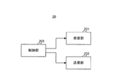
- FIG. 2 is a block diagram showing an example of the configuration of the terminal 20 according to the present embodiment.
- the terminal 20 includes, for example, a reception unit 201, a transmission unit 202, and a control unit 203.
- the terminal 20 communicates with the base station 10 in the LTE band and/or FR1 and FR2.
- the base station communicating with the terminal 20 in the LTE band, the base station communicating with the terminal 20 in FR1 and the base station communicating with the terminal 20 in FR2 may be different base stations.
- the base station with which the terminal 20 communicates may support some or all of LTE band communication, FR1 communication, and FR2 communication.
- the terminal 20 may be connected to the base station 10 operating in the LTE band and/or FR1 and the base station 10 operating in FR2 by, for example, Dual Connectivity (DC).
- DC Dual Connectivity
- the base station 10 operating in the LTE band and/or FR1 may be described as “LTE/FR1 base station 10”.
- the LTE/FR1 base station 10 supports at least one of LTE band and FR1 communication, but may support FR2 communication, for example.
- the base station 10 operating in FR2 may be described as "FR2 base station 10".
- the FR2 base station 10 supports at least FR2 communication, but may support, for example, LTE band and/or FR1 communication.
- the receiving unit 201 receives the DL signal transmitted from the base station 10. For example, the receiving unit 201 receives the DL signal in the LTE frequency band and/or FR1 under the control of the control unit 203. Further, for example, the receiving unit 201 receives the DL signal in FR2 under the control of the control unit 203.
- the source of the DL signal received by the receiving unit 201 may be the same base station 10 (base station 10 operating in the LTE frequency band and/or FR1 and FR2), or may be a different base station. 10 (eg, LTE/FR1 base station 10 and FR2 base station 10).
- the transmitting unit 202 transmits the UL signal to the base station 10.
- the transmission unit 202 transmits a UL signal in the LTE band and/or FR1 under the control of the control unit 203.
- the transmission unit 202 transmits the UL signal in FR2 under the control of the control unit 203.
- the transmission destination of the UL signal transmitted by the transmission unit 202 may be the same base station 10 or a different base station 10.
- the control unit 203 controls a communication operation including a reception process in the reception unit 201 and a transmission process in the transmission unit 202.
- the control unit 203 detects Pmax included in the DL signal in the LTE band and/or FR1.
- the control unit 20 controls the transmission power in the LTE band based on Pmax.
- the control unit 20 detects Pmax included in the DL signal in FR1
- the control unit 20 controls the transmission power in FR1 based on Pmax.
- the control unit 203 detects Pmax included in the DL signal in the LTE band and/or FR1
- the control unit 203 controls the communication operation in FR2 based on Pmax.
- the terminal 20 may form a directional beam when operating in FR2.
- the terminal 20 may form a beam in a specific direction when transmitting a UL signal.
- the terminal 20 may sweep the beam when searching for the base station 10 to be connected in FR2 and/or when searching for a DL signal including control information and the like from the base station 10 in FR2.
- control of the communication operation of the terminal 20 in the FR2 includes, for example, control of the transmission power of the UL signal in the FR2, control of ON (continuation) or OFF (stop) of communication (for example, transmission of the UL signal), and Any one or more of beam pattern control and the like may be included.
- the terminal 20 may be a FR2 standalone (SA: Standalone: SA) operation.
- the terminal 20 may be a non-standalone (NSA) operation.
- the terminal 20 may communicate in a combination of FR2 and FR1 and/or LTE band.
- control method in the present disclosure is not limited to these three methods.
- Control method 1 In the control method 1, the terminal 20 controls whether to reduce the transmission power of the UL signal in FR2 based on the control information on the transmission power in the LTE band and/or FR1.
- the reception unit 201 of the terminal 20 receives control information (for example, Pmax) regarding the transmission power in the LTE band and/or FR1, and the control unit 203 determines the transmission power of the UL signal in FR2 based on the control information. Controls whether or not it drops.
- control information for example, Pmax
- Pmax control information regarding the transmission power in the LTE band and/or FR1
- the control unit 203 determines the transmission power of the UL signal in FR2 based on the control information. Controls whether or not it drops.
- control for reducing the transmission power may be executed by a baseband chip that performs baseband signal processing such as modulation processing.
- the control for reducing the transmission power is performed by measuring the transmission power with an RF device that performs signal processing in the Radio Frequency (RF) band such as frequency conversion processing (up conversion), and adjusts based on the measured transmission power.
- RF Radio Frequency
- the control to reduce the transmission power is performed by setting Power-Maximum Power Reduction (P-MPR), which is an example of the backoff value for the maximum transmission power of the terminal, so that the terminal Total Radiated Power (TRP) or Peak Equivalent Isotropic It may be control to reduce Radiated Power (Peak EIRP).
- P-MPR Power-Maximum Power Reduction
- TRP Total Radiated Power
- Peak Equivalent Isotropic It may be control to reduce Radiated Power (Peak EIRP).
- control to reduce the transmission power may be the control to reduce the Peak EIRP by changing the beam pattern of the transmission beam.
- control for reducing the transmission power may be the control for reducing the power of the beam directed in a specific direction (for example, the direction in which it is desirable that the radio wave of FR2 does not reach) by changing the beam pattern of the transmission beam.
- the control for reducing the power of the beam directed in a specific direction may be, for example, control for directing a null in a specific direction.
- Controlling independently corresponds to autonomously controlling, for example, controlling regardless of an instruction from the base station 10 regarding the magnitude of transmission power.
- the terminal 20 may notify the base station 10 that the transmission power in FR2 will be reduced.
- the base station 10 may reduce the transmission power instructed to the terminal 20 and may instruct the terminal 20 to reduce the transmission power.
- the terminal 20 reduces the transmission power when receiving Pmax based on the presence or absence of receiving Pmax, but the present disclosure is not limited to this.
- the terminal 20 may determine whether to reduce the transmission power based on the value indicated by Pmax and/or the number of received Pmax. Further, for example, when the terminal 20 determines to reduce the transmission power, the terminal 20 may control the amount of reduction in the transmission power based on the value indicated by Pmax and/or the number of received Pmax.
- the terminal 20 may be provided with a first threshold value to be compared with the value of Pmax, and whether or not to reduce the transmission power may be determined based on the result of the comparison. For example, the terminal 20 may reduce the transmission power when the value of Pmax is less than or equal to the first threshold, and may not reduce the transmission power when the value of Pmax is greater than the first threshold. Further, a second threshold value that is equal to or less than the first threshold value is provided, and the terminal 20 may control the amount of decrease in the transmission power based on the result of the comparison. For example, the terminal 20 may change the reduction amount of the transmission power to be reduced when the value of Pmax is equal to or less than the second threshold value and when the value of Pmax is greater than the second threshold value.
- ⁇ Pmax is information about power control in the LTE band and/or FR1, but it can be inferred that power control in FR2 is also desired in areas where power control is desired in the LTE band and/or FR1. Therefore, the terminal 20 determines whether to reduce the transmission power in FR2 according to the magnitude of the value of Pmax, that is, the magnitude of the power reduced in FR1, and when reducing the transmission power, The amount of decrease in transmission power may be controlled.
- the terminal 20 may determine whether or not to reduce the transmission power based on the number of Pmax received per predetermined time. For example, the terminal 20 may reduce the transmission power when the number of received Pmax is a predetermined number or more, and may not reduce the transmission power when the notified number of Pmax is less than the predetermined number. Further, the terminal 20 may control the amount of decrease in the transmission power based on the number of Pmax received per unit time.
- the case where the terminal 20 receives a plurality of Pmax may be, for example, a case where the terminal 20 receives a Pmax notification from a plurality of LTE/FR1 base stations 10.
- the predetermined number may be an integer of 1 or more, for example.
- the terminal 20 may determine whether to reduce the transmission power according to the number of received Pmax, and control the reduction range of the transmission power when the transmission power is reduced.
- the terminal 20 may determine whether to reduce the transmission power based on both the value of Pmax and the number of Pmax. For example, the terminal 20 may determine that the transmission power is reduced when a predetermined number or more of Pmax that is equal to or less than the threshold is received, and otherwise the transmission power is not reduced. In addition, for example, the terminal 20 may control the amount of reduction when the transmission power is reduced, based on both the value of Pmax and the number of Pmax.
- the terminal 20 may determine whether to reduce the transmission power based on other information, not limited to Pmax notified from the base station 10. For example, the terminal 20 may determine whether to reduce the transmission power based on the position information of other devices.
- a device that operates in the LTE band and/or FR1 and notifies the LTE/FR1 base station 10 of position information (hereinafter, may be referred to as a “reference device”) is an area that needs to be protected with respect to radio waves ( Hereinafter, it may be described as a "protected area").
- the installed reference device supports LTE band and/or FR1 transmit power control based on Pmax.
- the terminal 20 receives, for example, the position information of the terminal 20 and the position information of the reference device via the LTE/FR1 base station 10.
- the terminal 20 may determine whether the terminal 20 exists in the protected area based on the position information of the terminal 20 and the position information of the reference device. Then, the terminal 20 may reduce the transmission power in the FR2 when it exists in the protected area.
- the FR2 base station 10 may receive the position information of the reference device via the LTE/FR1 base station 10 and specify the direction in which the protected area exists. Then, the FR2 base station 10 may perform control so that the beam is not directed in the specified direction. In this case, since the terminal 20 does not communicate with the FR2 base station 10 in FR2 even if it exists in the protected area, it does not have to transmit the UL signal of FR2.
- the terminal 20 When receiving Pmax, the terminal 20 estimates the distance between the base station 10 and the terminal 20 based on the reference signal from the base station 10 in the LTE band and/or FR1 and controls the transmission power. You may.
- the terminal 20 that determines that the vicinity of the LTE/FR1 base station 10 is a protected area reduces the transmission power in FR2 when the distance between the LTE/FR1 base station 10 and the terminal 20 is a predetermined distance or more. do not do. On the other hand, when the distance is shorter than the predetermined distance, the terminal 20 reduces the transmission power in FR2.
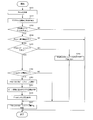
- FIG. 3 is a flowchart showing an example of a control flow based on the control method 1 according to this embodiment.
- the flowchart shown in FIG. 3 starts, for example, when the terminal 20 receives Pmax from the base station 10.
- the terminal 20 receives Pmax from the base station 10 (S101).
- the terminal 20 executes the transmission power control of LTE and/or FR1 based on Pmax (S102).
- the terminal 20 determines whether or not the Pmax received per predetermined time is equal to or more than a predetermined number (S103). In addition, when the predetermined number is 1, the terminal 20 may not perform the determination process.
- the terminal 20 determines whether Pmax is less than or equal to the first threshold (S104).
- the Pmax to be compared with the first threshold may be all or a part of the plurality of Pmax, or may be the smallest Pmax among the plurality of Pmax, It may be the maximum Pmax or the average of a plurality of Pmax.
- the terminal 20 determines in FR2 whether or not data communication is in progress (S105).
- the terminal executes the transmission power control of FR2 based on Pmax (S106).
- the terminal 20 continues the signal search in FR2 (S107). Then, the control flow based on the control method 1 ends.
- the terminal 20 determines to perform FR2 transmission power control (S108).
- the terminal 20 determines whether Pmax is less than or equal to the second threshold value (S109).
- the second threshold may be, for example, the first threshold used in S104 or less.
- the terminal 20 sets the reduction amount of the transmission power of FR2 to the first reduction amount (S110). For example, the first reduction amount is larger than the second reduction amount in S111 described below. The terminal 20 continues the data communication with the transmission power reduced by the first reduction amount. Then, the control flow based on the control method 1 ends.
- the terminal 20 sets the reduction amount of the transmission power of FR2 to the second reduction amount (S111). The terminal 20 continues the data communication with the transmission power reduced by the second reduction amount. Then, the control flow based on the control method 1 ends.
- the process of S103 does not have to be executed.
- S103 may be skipped after the process of S102.
- the process of S104 may not be executed. In this case, for example, S104 may be skipped after the process of S103.
- the terminal 20 determines the transmission power based on the information regarding the position of another device. May be determined.
- the information regarding the position of the other device may be, for example, the distance between the terminal 20 and the base station 10, or operates in the LTE band and/or FR1 and supports the transmission power control based on Pmax. It may be the position coordinates of the device being used.
- the terminal 20 may gradually reduce the transmission power in S110 and/or S111.
- the terminal 20 may reduce the transmission power by 1 dB per unit time.
- the initial reduction amount of the transmission power and the reduction amount of the transmission power may be set in advance or may be notified from the base station 10.
- an initial reduction range that is relatively larger than S111 may be set, and the reduction range that is gradually decreased may be greater than S111.
- the terminal 20 does not have to execute the FR2 transmission power control.
- the processing of S109 to S111 is processing of changing the setting of the reduction range of the transmission power of FR2 according to the value of Pmax, but these processing may be omitted.
- a predetermined reduction range of the transmission power may be used.
- the terminal 20 determines the transmission power control of FR2 (S108), and sets the reduction width of the transmission power of FR2 to the preset reduction width. Then, the terminal 20 may continue the data communication with the transmission power reduced by the set reduction amount.
- the terminal 20 controls whether or not the terminal 20 reduces the transmission power of the UL signal in FR2 based on the control information regarding the transmission power in the LTE band and/or FR1.
- the terminal 20 can reduce the interference given to other devices as compared with the existing technology by appropriately reducing the transmission power even in the wireless communication using the FR2 in which the transmission power control is not defined.
- the terminal 20 determines whether to control the transmission power in FR2 based on the value of Pmax and/or the number of Pmax.
- the terminal 20 can perform control without performing power control in FR2.
- Control method 2 In the control method 2, the terminal 20 controls whether or not to stop communication (for example, transmission of UL signal) in FR2 based on the control information regarding the transmission power in the LTE band and/or FR1.
- the control unit 203 stops the communication in FR2 based on the control information.
- the terminal 20 may stop the communication in FR2 by stopping the supply of the power related to the communication in FR2.
- the terminal 20 may continue communication by falling back the communication system (frequency band) to be used to another communication system such as the LTE band and/or FR1 instead of stopping the communication in FR2. ..
- the terminal 20 may stop communication in FR2 after falling back the communication system to be used to another communication system, or may fall back to another communication system after stopping communication in FR2. Good.
- fallback to another communication system and stop of communication in FR2 may be performed at the same time.
- the terminal 20 When the terminal 20 receives Pmax, it may voluntarily stop the FR2 transmission request. Alternatively, the terminal 20 may notify the base station 10 that the UL transmission of FR2 will be stopped. In this case, the FR2 base station 10 that has received the notification does not have to give the terminal 20 an opportunity to transmit in FR2. Since the terminal 20 is not given the opportunity of transmission in FR2, the transmission of FR2 is stopped.
- the base station 10 does not have to allocate the FR2 transmission grant to the terminal 20.
- the terminal 20 stops the transmission.
- the terminal 20 stops communication in the FR2 when receiving Pmax based on the presence or absence of receiving Pmax, but the present disclosure is not limited to this.
- the terminal 20 may determine whether to stop the communication in the FR2 based on the value indicated by Pmax and/or the number of received Pmax.
- the terminal 20 may be provided with a threshold value to be compared with the value of Pmax, and the stop of communication may be controlled based on the result of the comparison. For example, the terminal 20 does not have to stop the communication in FR2 when the value of Pmax is less than or equal to the threshold, and does not stop the communication in FR2 when the value of Pmax is greater than the threshold.
- ⁇ Pmax is information about power control in the LTE band and/or FR1, but it can be inferred that power control in FR2 is also desired in areas where power control is desired in the LTE band and/or FR1. Therefore, the terminal 20 determines whether or not to stop the communication in FR2 depending on whether or not the value of Pmax is equal to or less than the threshold value, that is, whether or not the power to be reduced in the LTE band and/or FR1 is large. Good.
- the terminal 20 may determine whether or not to stop the communication based on the number of Pmax received per predetermined time. For example, the terminal 20 may determine that the communication in FR2 is stopped when the number of received Pmax is a predetermined number or more, and the communication is not stopped (continued) when the number of Pmax is less than the predetermined number.
- the terminal 20 may determine whether or not to stop the communication in FR2 according to the number of received Pmax.
- the terminal 20 may determine whether or not to stop the communication in FR2, based on both the value of Pmax and the number of Pmax. For example, the terminal 20 may determine that the communication in the FR2 is stopped when Pmax, which is equal to or less than the threshold value, is received by a predetermined number or more, and is not stopped otherwise.
- the terminal 20 determines whether to immediately stop the communication in the FR2 or to stop after the transmission power is gradually reduced based on at least one of the value of Pmax and the number of Pmax. Good.
- the terminal 20 may determine whether or not to stop the communication in the FR2 based on other information, not limited to Pmax notified from the base station 10. For example, the terminal 20 may determine whether to stop the communication in the FR2, based on the position information of the other device.
- a reference device that operates in the LTE band and/or FR1 and notifies the LTE/FR1 base station 10 of position information may be installed in the protected area.
- the installed reference device supports LTE band and/or FR1 transmit power control based on Pmax.
- the terminal 20 receives the position information of the terminal 20 and the position information of the reference device via the LTE/FR1 base station 10.
- the terminal 20 may determine whether the terminal 20 exists in the protected area based on the position information of the terminal 20 and the position information of the reference device. And the terminal 20 may stop the communication in FR2, when it exists in a protected area.
- the FR2 base station 10 may receive the position information of the reference device via the LTE/FR1 base station 10 and specify the direction in which the protected area exists. Then, the FR2 base station 10 may perform control so that the beam is not directed in the specified direction. In this case, since the terminal 20 does not communicate with the FR2 base station 10 in FR2 even if it exists in the protected area, it does not have to transmit the UL signal of FR2.
- the terminal 20 may estimate the distance between the base station 10 and the terminal 20 based on the reference signal from the base station 10 in the LTE band and/or FR1.
- the terminal 20 that determines that the vicinity of the LTE/FR1 base station 10 is the protected area does not stop the communication in the FR2 when the distance between the LTE/FR1 base station 10 and the terminal 20 is a predetermined distance or more. .. On the other hand, when the distance is shorter than the predetermined distance, the terminal 20 stops the communication in FR2.
- FIG. 4 is a flowchart showing an example of a control flow based on the control method 2 according to this embodiment.
- the flowchart shown in FIG. 4 starts, for example, when the terminal 20 receives Pmax from the base station 10. Note that, in FIG. 4, the same processes as those in FIG. 3 are denoted by the same reference numerals, and description thereof may be omitted.
- the terminal 20 determines in FR2 whether or not data communication is in progress (S105).
- the terminal 20 stops the operation of FR2 (S201). Then, the control flow based on the control method 2 ends.
- the terminal 20 determines to stop communication of FR2 (S202).
- the terminal 20 determines whether Pmax is less than or equal to the second threshold value (S203).
- the second threshold may be, for example, the first threshold used in S104 or less.
- the terminal 20 stops communication of FR2 (S205). Then, the control flow based on the control method 2 ends.
- the terminal 20 performs control to gradually reduce the transmission power of FR2 (S204). For example, the transmission power may be gradually reduced until the data communication for a certain period of time (for example, the time until a predetermined amount of data is transmitted) has elapsed. Then, the terminal stops communication of FR2 (S205), and the control flow based on the control method 2 ends.
- the terminal 20 transmits information regarding the positions of other devices. Whether to stop the communication may be determined based on the above.
- the processes of S203 and S204 do not have to be executed.
- the terminal 20 determines to stop the transmission of FR2 (after the process of S202), and then executes the process of S205 (the process of stopping the transmission of FR2). You may
- the terminal 20 uses the communication system to be used as another communication system (for example, the communication system in LTE and/or FR1 or Wi-fi). (Registered trademark)).
- the communication system for example, the communication system in LTE and/or FR1 or Wi-fi). (Registered trademark)).
- the terminal 20 controls whether or not to stop communication (for example, transmission of UL signal) in FR2 based on the control information regarding the transmission power in the LTE band and/or FR1.
- the terminal 20 can reduce the interference given to other devices as compared with the existing technology by appropriately stopping the communication even in the wireless communication using the FR2 in which the transmission power control is not defined.
- the terminal 20 determines whether or not to stop communication in FR2, based on the value of Pmax and/or the number of Pmax.
- the terminal 20 can perform control not to stop communication in FR2.
- Control method 3 In the control method 1 and the control method 2 described above, an example is shown in which the communication operation is controlled (transmission power control or communication stop) when the terminal 20 performs data communication.
- the control method 3 for example, a part of the process of searching for a signal when the terminal 20 searches for the base station 10 connected to FR2 is stopped.
- the signal searching process is, for example, one of a process of searching for a DL signal including control information from the base station 10 and a process of performing UL beam sweep for establishing a connection with the base station 10. , Or both.
- the receiving unit 201 of the terminal 20 receives control information (for example, Pmax) regarding transmission power in the LTE band and/or FR1.
- the control unit 203 controls, based on the control information, whether or not to stop the process of searching the signal in FR2 (for example, the UL beam sweep process in FR2 and/or the DL signal search process in FR2). ..
- the terminal 20 may perform control such that the beam peak value is suppressed in the UL beam sweep.
- the terminal 20 may determine whether to stop the process of searching for a signal in FR2 based on the value indicated by Pmax and/or the number of received Pmax.
- the terminal 20 may be provided with a threshold value that is compared with the value of Pmax, and may be controlled based on the result of the comparison. For example, the terminal 20 may stop the process of searching for a signal in FR2 when the value of Pmax is less than or equal to the threshold value, and may not stop the process of searching for a signal in FR2 when the value of Pmax is greater than the threshold value.
- ⁇ Pmax is information regarding power control in the LTE band and/or FR1, but it can be expected that power control in FR2 is also desired in areas where power control is desired in the LTE band and/or FR1. Therefore, the terminal 20 determines whether to stop the process of searching the signal in FR2 depending on whether the value of Pmax is equal to or less than the threshold value, that is, whether the power to be reduced in the LTE band and/or FR1 is large. May be determined.
- the terminal 20 may be controlled based on the number of Pmax received per predetermined time. For example, the terminal 20 does not stop the process of searching for a signal in FR2 when the number of received Pmax is a predetermined number or more, and does not stop the process of searching for a signal in FR2 when the number of Pmax is less than the predetermined number. You may
- a request for power control in an area where the base station 10 is provided is less than a predetermined number of base stations 10 (for example, It is estimated to be strict compared with the case where one base station 10) notifies Pmax. Therefore, the terminal 20 may determine whether to stop the process of searching for a signal in FR2 according to the number of received Pmax.
- the terminal 20 may determine whether to stop the process of searching for a signal in FR2 based on both the value of Pmax and the number of Pmax. For example, the terminal 20 may determine that the process of searching for a signal in FR2 is stopped when Pmax, which is equal to or less than the threshold, is received by a predetermined number or more, and is not stopped otherwise.
- FIG. 5 is a flowchart showing an example of a control flow based on the control method 3 according to the present embodiment.
- the flowchart shown in FIG. 5 starts, for example, when the terminal 20 receives Pmax from the base station 10.
- processes similar to those in FIG. 3 are denoted by the same reference numerals, and description thereof may be omitted.
- the terminal 20 determines whether or not the beam sweep is being performed in FR2 (S301).
- the terminal 20 determines whether Pmax is equal to or less than the second threshold value (S302).
- the terminal 20 stops the beam sweep in FR2 (S303).
- the terminal 20 suspends (or stops) the transmission of SRS (Sounding Reference Signal) for notifying the beam information (S304).
- SRS Sounding Reference Signal
- the terminal 20 cancels the setting by Pmax and cancels the stop of the communication operation in FR2 (S305). Then, the terminal 20 executes the process of S307.
- the terminal 20 when beam sweep is not being performed (NO in S301), the terminal 20 does not perform DL signal search and/or UL beam sweep (S306). Then, the terminal 20 executes the process of S307.
- the process of S302 need not be executed.
- the terminal 20 skips S302 and performs the process of S303 (the process of stopping the beam sweep in FR2) when the beam sweep is being performed in FR2 (YES in S301). You can do it.
- the process of S307 need not be executed.
- the terminal 20 may continue stopping the beam sweep.
- the process of S305 may be executed based on Pmax. For example, when the value of Pmax received after the predetermined timing is larger than the threshold value and/or the number of Pmax is less than the predetermined number, the terminal 20 cancels the setting by Pmax and stops the communication operation in FR2. You may cancel.
- the "predetermined timing" may correspond to the timing when the terminal 20 receives Pmax in the process of S101, or the timing when the terminal 20 stops the beam sweep in FR2 in the process of S303. Good.
- the process of S307 may be executed based on Pmax.
- the terminal 20 may cancel the stop of the beam sweep in FR2 when the value of Pmax received after the predetermined timing is larger than the threshold value and/or the number of Pmax is less than the predetermined number.
- the “predetermined timing” may correspond to, for example, the timing when the terminal 20 receives Pmax in the process of S101, or the timing when the terminal 20 stops the beam sweep in FR2 in the process of S303. You may.
- the terminal 20 may cancel the suspension of the communication operation in FR2, for example, the suspension of the beam sweep in FR2. Therefore, the stop of the communication operation in FR2, for example, whether or not to stop the stop of the beam sweep in FR2 may be performed based on the value of Pmax received and the number of received Pmax.
- the control of other communication operations in FR2 may be released.
- the terminal 20 may cancel the decrease in the transmission power in FR2 based on the control method 1.
- the terminal 20 may cancel the suspension of communication in FR2 based on the control method 2.
- the determination as to whether or not the user has left the area of the base station 10 for which Pmax is set may be made based on the value of Pmax received and the number of Pmax received.
- the terminal 20 controls whether or not to stop the process of searching for a signal in FR2, based on the control information regarding the transmission power in the LTE band and/or FR1.
- the terminal 20 reduces the interference given to other devices as compared with the existing technology by stopping the process of appropriately searching for a signal even in the wireless communication using the FR2 in which the transmission power control is not defined. it can.
- the terminal 20 determines whether or not to stop the process of searching for a signal in FR2, based on the value of Pmax and/or the number of Pmax.
- the power consumption in the terminal 20 can be saved by stopping the signal search processing in the FR2.
- the terminal 20 may use any one of the control methods 1 to 3 described above, or may use a combination of two or more.
- the terminal 20 may perform control for reducing the transmission power in FR2 based on the control method 1.
- the terminal 20 stops the process of searching for a signal in FR2 based on the control method 3, or controls the communication in FR2 based on the control method 2. You may go.
- the terminal 20 may determine whether or not to continue the data communication when the data communication is being performed. Then, when continuing the data communication, the terminal 20 may perform control to reduce the transmission power in the FR2 and continue the data communication. On the other hand, when the terminal 20 does not continue the data communication, the terminal 20 may perform control to stop the communication in the FR2. When stopping the communication in FR2, the terminal 20 may fall back to another communication system (for example, the communication system in LTE and/or FR1 or Wi-fi (registered trademark)).
- another communication system for example, the communication system in LTE and/or FR1 or Wi-fi (registered trademark)
- whether or not to continue the data communication may be determined based on the value of Pmax and/or the number of Pmax. For example, the terminal 20 determines that data communication should not be continued when Pmax is less than or equal to the threshold value and/or the number of Pmax is greater than or equal to a predetermined number, and Pmax is greater than the threshold value and/or Pmax When the number is less than the predetermined number, it may be determined that the data communication should be continued.
- the terminal 20 may perform control for stopping the process of searching for a signal in FR2 and/or control for stopping communication in FR2 regardless of whether or not data communication is being performed.
- whether or not the control for stopping the process of searching the signal in FR2 and/or the control for stopping the communication in FR2 may be determined based on the value of Pmax and/or the number of Pmax.
- the terminal 20 performs control to stop the process of searching for a signal in FR2 and/or control to stop communication in FR2 when Pmax is less than or equal to a threshold value and/or the number of Pmax is greater than or equal to a predetermined number. You may decide to do.
- Pmax in the above-described embodiment is an example of control information regarding transmission power in the LTE band and/or FR1, and the present disclosure is not limited to this.
- the control information regarding the transmission power in the LTE band and/or FR1 may be replaced with other terms.
- the respective thresholds that are compared with the value indicated by Pmax may be different from each other.
- the threshold values may be different from each other in each of the control methods 1 to 3 described above.
- the respective predetermined numbers to be compared with the number of Pmax may be different from each other.
- the predetermined number may be different from each other in each of the control methods 1 to 3 described above.
- the terminal 20 receives Pmax corresponds to, for example, “the terminal 20 receives the notification of Pmax” or “the terminal 20 detects Pmax”. May be. Further, “detection” may be replaced with other expressions such as “detection”, “identification”, and “specification”. Further, “the terminal 20 does not receive Pmax” may correspond to “the number of Pmax received by the terminal 20 is zero”.
- each functional block may be realized by using one device physically or logically coupled, or directly or indirectly (for example, two or more devices physically or logically separated). , Wired, wireless, etc.) and may be implemented using these multiple devices.
- the functional block may be implemented by combining the one device or the plurality of devices with software.
- Functions include judgment, decision, judgment, calculation, calculation, processing, derivation, investigation, search, confirmation, reception, transmission, output, access, resolution, selection, selection, establishment, comparison, assumption, expectation, observation, Broadcasting, notifying, communicating, forwarding, configuration, reconfiguring, allocating, mapping, assigning, etc., but not limited to these.
- I can't.
- functional blocks (components) that function transmission are called a transmitting unit and a transmitter.
- the implementation method is not particularly limited.
- the base station, the terminal, and the like according to the embodiment of the present disclosure may function as a computer that performs the process of the wireless communication method of the present disclosure.
- FIG. 6 is a diagram showing an example of a hardware configuration of a base station and a terminal according to an embodiment of the present disclosure.
- the base station 10 and the terminal 20 described above may be physically configured as a computer device including a processor 1001, a memory 1002, a storage 1003, a communication device 1004, an input device 1005, an output device 1006, a bus 1007, and the like.
- the word “device” can be read as a circuit, device, unit, or the like.
- the hardware configurations of the base station 10 and the terminal 20 may be configured to include one or a plurality of each device illustrated in the figure, or may be configured not to include some devices.
- Each function in the base station 10 and the terminal 20 causes a predetermined software (program) to be loaded on hardware such as the processor 1001 and the memory 1002, so that the processor 1001 performs an operation and controls communication by the communication device 1004. It is realized by controlling at least one of reading and writing of data in the memory 1002 and the storage 1003.
- the processor 1001 operates an operating system to control the entire computer, for example.
- the processor 1001 may be configured by a central processing unit (CPU) including an interface with peripheral devices, a control device, an arithmetic device, a register, and the like.
- CPU central processing unit
- the control unit 103 and the control unit 203 described above may be realized by the processor 1001.
- the processor 1001 reads a program (program code), a software module, data, and the like from at least one of the storage 1003 and the communication device 1004 into the memory 1002, and executes various processes according to these.
- a program program that causes a computer to execute at least part of the operations described in the above-described embodiments is used.
- the control unit 103 of the base station 10 or the control unit 203 of the terminal 20 may be implemented by a control program stored in the memory 1002 and operating in the processor 1001, or may be implemented similarly for other functional blocks. Good.
- the various processes described above are executed by one processor 1001, they may be executed simultaneously or sequentially by two or more processors 1001.
- the processor 1001 may be implemented by one or more chips.
- the program may be transmitted from the network via an electric communication line.
- the memory 1002 is a computer-readable recording medium, and is configured by at least one of, for example, ROM (Read Only Memory), EPROM (Erasable Programmable ROM), EEPROM (Electrically Erasable Programmable ROM), RAM (Random Access Memory), and the like. May be done.
- the memory 1002 may be called a register, a cache, a main memory (main storage device), or the like.
- the memory 1002 can store a program (program code) that can be executed to implement the wireless communication method according to the embodiment of the present disclosure, a software module, and the like.
- the storage 1003 is a computer-readable recording medium, for example, an optical disc such as a CD-ROM (Compact Disc ROM), a hard disc drive, a flexible disc, a magneto-optical disc (for example, a compact disc, a digital versatile disc, a Blu-ray disc). (Registered trademark) disk, smart card, flash memory (for example, card, stick, key drive), floppy (registered trademark) disk, magnetic strip, and the like.
- the storage 1003 may be called an auxiliary storage device.
- the above-mentioned storage medium may be, for example, a database including at least one of the memory 1002 and the storage 1003, a server, or another appropriate medium.
- the communication device 1004 is hardware (transmission/reception device) for performing communication between computers via at least one of a wired network and a wireless network, and is also called, for example, a network device, a network controller, a network card, a communication module, or the like.
- the communication device 1004 includes, for example, a high frequency switch, a duplexer, a filter, a frequency synthesizer, etc. in order to realize at least one of frequency division duplex (FDD: Frequency Division Duplex) and time division duplex (TDD). May be composed of
- FDD Frequency Division Duplex
- TDD time division duplex
- the input device 1005 is an input device (for example, a keyboard, a mouse, a microphone, a switch, a button, a sensor, etc.) that receives an input from the outside.
- the output device 1006 is an output device (for example, a display, a speaker, an LED lamp, etc.) that performs output to the outside.
- the input device 1005 and the output device 1006 may be integrated (for example, a touch panel).
- Each device such as the processor 1001 and the memory 1002 is connected by a bus 1007 for communicating information.
- the bus 1007 may be configured using a single bus, or may be configured using different buses for each device.
- the base station 10 and the terminal 20 include hardware such as a microprocessor, a digital signal processor (DSP), an ASIC (Application Specific Integrated Circuit), a PLD (Programmable Logic Device), and an FPGA (Field Programmable Gate Array). May be included, and a part or all of each functional block may be realized by the hardware.
- the processor 1001 may be implemented using at least one of these hardware.
- the notification of information is not limited to the aspect/embodiment described in the present disclosure, and may be performed using another method.
- the information is notified by physical layer signaling (for example, DCI (Downlink Control Information), UCI (Uplink Control Information)), upper layer signaling (for example, RRC (Radio Resource Control) signaling, MAC (Medium Access Control) signaling, It may be implemented by notification information (MIB (Master Information Block), SIB (System Information Block)), another signal, or a combination thereof.
- the RRC signaling may be referred to as an RRC message, and may be, for example, an RRC connection setup (RRC Connection Setup) message, an RRC connection reconfiguration message, or the like.
- LTE Long Term Evolution
- LTE-A Long Term Evolution
- SUPER 3G IMT-Advanced
- 4G 4th generation mobile communication system
- 5G 5th generation mobile communication
- FRA Full Radio
- NR New Radio
- W-CDMA registered trademark
- GSM registered trademark
- CDMA2000 Code Division Multiple Access 2000
- UMB Universal Mobile Broadband
- IEEE 802.11 Wi-Fi (registered trademark)
- IEEE 802.16 WiMAX (registered trademark)
- IEEE 802.20 UWB (Ultra-WideBand
- Bluetooth registered trademark
- a plurality of systems may be combined and applied (for example, a combination of at least one of LTE and LTE-A and 5G).
- the specific operation performed by the base station may be performed by its upper node in some cases.
- the various operations performed for communication with a terminal are the base station and other network nodes than the base station (eg MME or S-GW and the like are conceivable, but are not limited to these).
- MME or S-GW network nodes
- a combination of a plurality of other network nodes for example, MME and S-GW may be used.
- Information and the like can be output from the upper layer (or lower layer) to the lower layer (or upper layer). Input/output may be performed via a plurality of network nodes.
- the input/output information and the like may be stored in a specific place (for example, a memory), or may be managed using a management table. Information that is input/output may be overwritten, updated, or added. The output information and the like may be deleted. The input information and the like may be transmitted to another device.
- the determination may be performed by a value represented by 1 bit (whether 0 or 1), may be performed by a true/false value (Boolean: true or false), and may be performed by comparing numerical values (for example, a predetermined value). Value comparison).
- software, instructions, information, etc. may be transmitted and received via a transmission medium.
- the software uses a wired technology (coaxial cable, optical fiber cable, twisted pair, digital subscriber line (DSL: Digital Subscriber Line), etc.) and/or wireless technology (infrared, microwave, etc.) websites, When sent from a server, or other remote source, at least one of these wired and wireless technologies is included within the definition of transmission medium.
- wired technology coaxial cable, optical fiber cable, twisted pair, digital subscriber line (DSL: Digital Subscriber Line), etc.
- wireless technology infrared, microwave, etc.
- Information, signal The information, signals, etc. described in this disclosure may be represented using any of a variety of different technologies.
- data, instructions, commands, information, signals, bits, symbols, chips, etc. that may be referred to throughout the above description include voltage, current, electromagnetic waves, magnetic fields or magnetic particles, optical fields or photons, or any of these. May be represented by a combination of
- At least one of the channel and the symbol may be a signal (signaling).
- the signal may also be a message.
- a component carrier CC:Component Carrier
- CC Component Carrier
- the information, parameters, etc. described in the present disclosure may be represented by using an absolute value, may be represented by using a relative value from a predetermined value, or by using other corresponding information. May be represented.
- the radio resources may be those indicated by the index.
- Base station wireless base station
- base station radio base station
- radio base station fixed station
- NodeB nodeB
- eNodeB eNodeB
- gNodeB gNodeB
- a base station may be referred to by terms such as macro cell, small cell, femto cell, and pico cell.
- a base station can accommodate one or more (eg, three) cells.
- a base station accommodates multiple cells, the entire coverage area of the base station can be partitioned into multiple smaller areas, each smaller area being defined by a base station subsystem (eg, indoor small base station (RRH: It is also possible to provide communication service by Remote Radio Head)).
- RRH indoor small base station
- the term "cell” or “sector” refers to part or all of the coverage area of a base station and/or a base station subsystem providing communication services in this coverage.
- Mobile stations are defined by those skilled in the art as subscriber stations, mobile units, subscriber units, wireless units, remote units, mobile devices, wireless devices, wireless communication devices, remote devices, mobile subscriber stations, access terminals, mobile terminals, wireless. It may also be referred to as a terminal, remote terminal, handset, user agent, mobile client, client, or some other suitable term.
- At least one of the base station and the mobile station may be called a transmitting device, a receiving device, a communication device, or the like.
- the base station and the mobile station may be a device mounted on the mobile body, the mobile body itself, or the like.
- the moving body may be a vehicle (eg, car, airplane, etc.), an unmanned moving body (eg, drone, self-driving car, etc.), or a robot (manned type or unmanned type).
- At least one of the base station and the mobile station also includes a device that does not necessarily move during communication operation.
- at least one of the base station and the mobile station may be an IoT (Internet of Things) device such as a sensor.
- IoT Internet of Things
- the base station in the present disclosure may be replaced by the user terminal.
- the communication between the base station and the user terminal is replaced with the communication between a plurality of user terminals (eg, D2D (Device-to-Device), V2X (Vehicle-to-Everything), etc.).
- the terminal 20 may have the function of the above-described base station 10.
- the wording such as “up” and “down” may be replaced with the wording corresponding to the terminal-to-terminal communication (for example, “side”).
- the uplink channel and the downlink channel may be replaced with the side channel.
- the terminal in the present disclosure may be replaced by the base station.
- the base station 10 may have the function of the terminal 20 described above.
- determining and “determining” as used in this disclosure may encompass a wide variety of actions.
- “Judgment”, “decision” means, for example, judgment (judging), calculation (calculating), calculation (computing), processing (processing), derivation (deriving), investigating (investigating), searching (looking up, search, inquiry) (Eg, searching in a table, database, or another data structure), considering ascertaining as “judging” or “deciding”, and the like.
- “decision” and “decision” include receiving (eg, receiving information), transmitting (eg, transmitting information), input (input), output (output), access (accessing) (for example, accessing data in a memory) may be regarded as “judging” and “deciding”.
- “judgment” and “decision” are considered to be “judgment” and “decision” when things such as resolving, selecting, choosing, establishing, establishing, and comparing are done. May be included. That is, the “judgment” and “decision” may include considering some action as “judgment” and “decision”.
- “determination (decision)” may be read as “assuming", “expecting", “considering”, and the like.
- connection means any direct or indirect connection or coupling between two or more elements, and It can include the presence of one or more intermediate elements between two elements that are “connected” or “coupled”.
- the connections or connections between the elements may be physical, logical, or a combination thereof.
- connection may be read as “access”.
- two elements are in the radio frequency domain, with at least one of one or more wires, cables and printed electrical connections, and as some non-limiting and non-exhaustive examples. , Can be considered to be “connected” or “coupled” to each other, such as with electromagnetic energy having wavelengths in the microwave and light (both visible and invisible) regions.
- the reference signal may be abbreviated as RS (Reference Signal), or may be referred to as a pilot (Pilot) depending on the applied standard.
- RS Reference Signal
- Pilot pilot
- the phrase “based on” does not mean “based only on,” unless expressly specified otherwise. In other words, the phrase “based on” means both "based only on” and “based at least on.”
- references to elements using nomenclature such as “first”, “second” etc. does not generally limit the amount or order of those elements. These designations may be used in this disclosure as a convenient way to distinguish between two or more elements. Thus, references to the first and second elements do not mean that only two elements may be employed, or that the first element must precede the second element in any way.
- Parts in the configuration of each device described above may be replaced with “means”, “circuit”, “device”, and the like.
- a radio frame may be composed of one or more frames in the time domain. Each frame or frames in the time domain may be referred to as a subframe. A subframe may also be composed of one or more slots in the time domain. The subframe may have a fixed time length (for example, 1 ms) that does not depend on the numerology.
- Numerology may be a communication parameter applied to at least one of transmission and reception of a signal or channel.
- Numerology includes, for example, subcarrier spacing (SCS: SubCarrier Spacing), bandwidth, symbol length, cyclic prefix length, transmission time interval (TTI: Transmission Time Interval), number of symbols per TTI, radio frame configuration, transmission/reception
- SCS subcarrier spacing
- TTI Transmission Time Interval
- At least one of a specific filtering process performed by the device in the frequency domain and a specific windowing process performed by the transceiver in the time domain may be indicated.
- a slot may be composed of one or more symbols (OFDM (Orthogonal Frequency Division Multiplexing) symbol, SC-FDMA (Single Carrier Frequency Division Multiple Access) symbol, etc.) in the time domain.
- a slot may be a time unit based on numerology.
- a slot may include multiple minislots. Each minislot may be composed of one or more symbols in the time domain. The minislot may also be called a subslot. Minislots may be configured with fewer symbols than slots.
- a PDSCH (or PUSCH) transmitted in a time unit larger than a minislot may be referred to as PDSCH (or PUSCH) mapping type A.
- the PDSCH (or PUSCH) transmitted using the minislot may be referred to as PDSCH (or PUSCH) mapping type B.
- Radio frame, subframe, slot, minislot, and symbol all represent the time unit for signal transmission. Radio frames, subframes, slots, minislots, and symbols may have different names corresponding to them.
- one subframe may be called a transmission time interval (TTI)
- TTI transmission time interval
- TTI transmission time interval
- TTI transmission time interval
- TTI transmission time interval
- TTI means, for example, a minimum time unit of scheduling in wireless communication.
- the base station performs scheduling to allocate radio resources (frequency bandwidth that can be used in each user terminal, transmission power, etc.) to each user terminal in units of TTI.
- the definition of TTI is not limited to this.
- the TTI may be a transmission time unit of a channel-encoded data packet (transport block), code block, codeword, or the like, or may be a processing unit of scheduling, link adaptation, or the like.
- the time interval for example, the number of symbols
- the transport block, code block, codeword, etc. may be shorter than the TTI.
- one slot or one minislot is called a TTI
- one or more TTIs may be the minimum time unit for scheduling.
- the number of slots (the number of mini-slots) forming the minimum time unit of the scheduling may be controlled.
- a TTI having a time length of 1 ms may be called a normal TTI (TTI in LTE Rel. 8-12), a normal TTI, a long TTI, a normal subframe, a normal subframe, a long subframe, a slot, or the like.
- a TTI shorter than the normal TTI may be called a shortened TTI, a short TTI, a partial TTI (partial or fractional TTI), a shortened subframe, a short subframe, a minislot, a subslot, a slot, and the like.
- a long TTI (eg, normal TTI, subframe, etc.) may be read as a TTI having a time length of more than 1 ms, and a short TTI (eg, shortened TTI, etc.) is less than the TTI length of the long TTI and 1 ms. It may be read as a TTI having the above TTI length.
- a resource block is a resource allocation unit in the time domain and the frequency domain, and may include one or a plurality of continuous subcarriers in the frequency domain.
- the number of subcarriers included in the RB may be the same regardless of the numerology, and may be 12, for example.
- the number of subcarriers included in the RB may be determined based on numerology.
- the time domain of RB may include one or more symbols, and may be one slot, one minislot, one subframe, or one TTI in length.
- One TTI, one subframe, etc. may be configured with one or a plurality of resource blocks.
- One or more RBs are physical resource blocks (PRBs: Physical RBs), subcarrier groups (SCGs: Sub-Carrier Groups), resource element groups (REGs: Resource Element Groups), PRB pairs, RB pairs, etc. May be called.
- PRBs Physical resource blocks
- SCGs Sub-Carrier Groups
- REGs Resource Element Groups
- PRB pairs RB pairs, etc. May be called.
- a resource block may be composed of one or more resource elements (RE: Resource Element).
- RE Resource Element
- 1 RE may be a radio resource area of 1 subcarrier and 1 symbol.
- a bandwidth part (may also be called a partial bandwidth) represents a subset of continuous common RBs (common resource blocks) for a certain neurology in a certain carrier. Good.
- the common RB may be specified by the index of the RB based on the common reference point of the carrier.
- PRBs may be defined in a BWP and numbered within the BWP.
- BWP may include BWP for UL (UL BWP) and BWP for DL (DL BWP).
- BWP for UL
- DL BWP DL BWP
- one or more BWPs may be set in one carrier.
- At least one of the configured BWPs may be active, and the UE does not have to expect to send and receive a given signal/channel outside the active BWP.
- “cell”, “carrier”, and the like in the present disclosure may be read as “BWP”.
- the structure of the wireless frame, subframe, slot, minislot, symbol, etc. described above is just an example.
- the number of subframes included in a radio frame, the number of slots per subframe or radio frame, the number of minislots included in a slot, the number of symbols and RBs included in a slot or minislot, and included in RBs The number of subcarriers, the number of symbols in the TTI, the symbol length, the cyclic prefix (CP: Cyclic Prefix) length, and the like can be variously changed.
- the term “A and B are different” may mean “A and B are different from each other”.
- the term may mean that “A and B are different from C”.
- the terms “remove”, “coupled” and the like may be construed similarly as “different”.
- the notification of the predetermined information (for example, the notification of “being X”) is not limited to the explicit notification, and is performed implicitly (for example, the notification of the predetermined information is not performed). Good.
- One aspect of the present disclosure is useful for mobile communication systems.
Landscapes
- Engineering & Computer Science (AREA)
- Computer Networks & Wireless Communication (AREA)
- Signal Processing (AREA)
- Mobile Radio Communication Systems (AREA)
Abstract
L'invention concerne un terminal comprenant : une unité de réception qui reçoit des informations de commande relatives à une puissance d'émission dans une première bande de fréquences ; et une unité de contrôle qui contrôle si un signal de liaison montante sur une seconde bande de fréquences est transmis ou non, d'après les informations de commande.
Priority Applications (2)
| Application Number | Priority Date | Filing Date | Title |
|---|---|---|---|
| EP19915252.1A EP3927030A4 (fr) | 2019-02-14 | 2019-02-14 | Terminal, et procédé de contrôle de communication sans fil |
| PCT/JP2019/005443 WO2020166038A1 (fr) | 2019-02-14 | 2019-02-14 | Terminal, et procédé de contrôle de communication sans fil |
Applications Claiming Priority (1)
| Application Number | Priority Date | Filing Date | Title |
|---|---|---|---|
| PCT/JP2019/005443 WO2020166038A1 (fr) | 2019-02-14 | 2019-02-14 | Terminal, et procédé de contrôle de communication sans fil |
Publications (1)
| Publication Number | Publication Date |
|---|---|
| WO2020166038A1 true WO2020166038A1 (fr) | 2020-08-20 |
Family
ID=72045242
Family Applications (1)
| Application Number | Title | Priority Date | Filing Date |
|---|---|---|---|
| PCT/JP2019/005443 WO2020166038A1 (fr) | 2019-02-14 | 2019-02-14 | Terminal, et procédé de contrôle de communication sans fil |
Country Status (2)
| Country | Link |
|---|---|
| EP (1) | EP3927030A4 (fr) |
| WO (1) | WO2020166038A1 (fr) |
Family Cites Families (3)
| Publication number | Priority date | Publication date | Assignee | Title |
|---|---|---|---|---|
| US8280387B2 (en) * | 2008-05-22 | 2012-10-02 | Ntt Docomo, Inc. | Femtocell channel assignment and power control for improved femtocell coverage and efficient cell search |
| EP3136798B1 (fr) * | 2014-04-20 | 2020-09-02 | LG Electronics Inc. | Procédé permettant de déterminer la puissance de transmission pour une communication de dispositif à dispositif directe dans un système de communication sans fil, et appareil associé |
| WO2015170667A1 (fr) * | 2014-05-09 | 2015-11-12 | 株式会社Nttドコモ | Dispositif utilisateur et procédé de gestion d'émissions |
-
2019
- 2019-02-14 WO PCT/JP2019/005443 patent/WO2020166038A1/fr unknown
- 2019-02-14 EP EP19915252.1A patent/EP3927030A4/fr not_active Withdrawn
Non-Patent Citations (4)
| Title |
|---|
| "User Equipment (UE) radio transmission and reception (Release 15", 3GPP TS 36.101, December 2018 (2018-12-01) |
| HUAWEI ET AL.: "Discussion on remaining issues for power control", 3GPP TSG RAN WG2 #101BIS R2-1805593, 5 April 2018 (2018-04-05), XP051415312, Retrieved from the Internet <URL:http://www.3gpp.org/ftp/tsg_ran/WG2_RL2/TSGR2_101bis/Docs/R2-1805593.zip> * |
| INTEL CORPORATION: "On PCMAX definition for mmWave NR", 3GPP TSG RAN WG4 ADHOC_TSGR4_NR_SEP2017 R4-1709409, 11 September 2017 (2017-09-11), XP051331891, Retrieved from the Internet <URL:http://www.3gpp.org/ftp/tsg_ran/WG4_Radio/TSGR4_AHs/TSGR4_NR_Sep2017/Docs/R4-1709409.zip> * |
| KDDI CORPORATION: "RRC parameters for NR EN-DC Power sharing", 3GPP TSG RAN WG2 ADHOC_2018_01_NR R2-1800572, 11 January 2018 (2018-01-11), XP051385784, Retrieved from the Internet <URL:http://www.3gpp.org/ftp/tsg_ran/WG2_RL2/TSGR2_AHs/2018_01_NR/Docs/R2-1800572.zip> * |
Also Published As
| Publication number | Publication date |
|---|---|
| EP3927030A1 (fr) | 2021-12-22 |
| EP3927030A4 (fr) | 2022-09-28 |
Similar Documents
| Publication | Publication Date | Title |
|---|---|---|
| WO2020129229A1 (fr) | Nœud sans fil et procédé de communication sans fil | |
| WO2020144824A1 (fr) | Terminal utilisateur et procédé de communication sans fil | |
| WO2020217513A1 (fr) | Terminal utilisateur et procédé de communication sans fil | |
| WO2021149260A1 (fr) | Terminal, procédé de communication sans fil, et station de base | |
| WO2021149259A1 (fr) | Terminal, procédé de communication sans fil, et station de base | |
| JP7152587B2 (ja) | 端末及び送信方法 | |
| JP7217291B2 (ja) | 端末及び通信方法 | |
| JP7223026B2 (ja) | 端末、基地局、無線通信システム、及び通信方法 | |
| WO2020222273A1 (fr) | Terminal utilisateur, et procédé de communication sans fil | |
| WO2022157953A1 (fr) | Terminal, station de base et procédé de communication | |
| JP7467478B2 (ja) | 端末及び通信方法 | |
| WO2021161483A1 (fr) | Terminal et procédé de communication | |
| JP7273859B2 (ja) | ユーザ装置及び基地局装置 | |
| WO2021029071A1 (fr) | Terminal et procédé de commande du fonctionnement d'un terminal | |
| WO2020144785A1 (fr) | Terminal et procédé de communication | |
| WO2020166038A1 (fr) | Terminal, et procédé de contrôle de communication sans fil | |
| WO2020166042A1 (fr) | Terminal et procédé de commande de communication sans fil | |
| WO2020166040A1 (fr) | Terminal et procédé de commande de communication sans fil | |
| WO2020202429A1 (fr) | Équipement d'utilisateur et procédé de communication sans fil | |
| CN114208327A (zh) | 终端以及通信方法 | |
| WO2022157952A1 (fr) | Terminal, station de base et procédé de communication | |
| WO2022163153A1 (fr) | Terminal et procédé de communication | |
| WO2022153467A1 (fr) | Terminal, système et procédé de communication | |
| WO2022244122A1 (fr) | Terminal et procédé de communication | |
| WO2022079874A1 (fr) | Terminal, station de base et procédé de communication |
Legal Events
| Date | Code | Title | Description |
|---|---|---|---|
| 121 | Ep: the epo has been informed by wipo that ep was designated in this application |
Ref document number: 19915252 Country of ref document: EP Kind code of ref document: A1 |
|
| NENP | Non-entry into the national phase |
Ref country code: DE |
|
| ENP | Entry into the national phase |
Ref document number: 2019915252 Country of ref document: EP Effective date: 20210914 |
|
| NENP | Non-entry into the national phase |
Ref country code: JP |