WO2020165621A1 - Soundproofing structure - Google Patents
Soundproofing structure Download PDFInfo
- Publication number
- WO2020165621A1 WO2020165621A1 PCT/IB2019/000198 IB2019000198W WO2020165621A1 WO 2020165621 A1 WO2020165621 A1 WO 2020165621A1 IB 2019000198 W IB2019000198 W IB 2019000198W WO 2020165621 A1 WO2020165621 A1 WO 2020165621A1
- Authority
- WO
- WIPO (PCT)
- Prior art keywords
- soundproof
- soundproofing
- sheet
- vibration isolation
- isolation layer
- Prior art date
Links
Images


Classifications
-
- G—PHYSICS
- G10—MUSICAL INSTRUMENTS; ACOUSTICS
- G10K—SOUND-PRODUCING DEVICES; METHODS OR DEVICES FOR PROTECTING AGAINST, OR FOR DAMPING, NOISE OR OTHER ACOUSTIC WAVES IN GENERAL; ACOUSTICS NOT OTHERWISE PROVIDED FOR
- G10K11/00—Methods or devices for transmitting, conducting or directing sound in general; Methods or devices for protecting against, or for damping, noise or other acoustic waves in general
- G10K11/16—Methods or devices for protecting against, or for damping, noise or other acoustic waves in general
- G10K11/172—Methods or devices for protecting against, or for damping, noise or other acoustic waves in general using resonance effects
-
- B—PERFORMING OPERATIONS; TRANSPORTING
- B32—LAYERED PRODUCTS
- B32B—LAYERED PRODUCTS, i.e. PRODUCTS BUILT-UP OF STRATA OF FLAT OR NON-FLAT, e.g. CELLULAR OR HONEYCOMB, FORM
- B32B15/00—Layered products comprising a layer of metal
- B32B15/18—Layered products comprising a layer of metal comprising iron or steel
-
- B—PERFORMING OPERATIONS; TRANSPORTING
- B32—LAYERED PRODUCTS
- B32B—LAYERED PRODUCTS, i.e. PRODUCTS BUILT-UP OF STRATA OF FLAT OR NON-FLAT, e.g. CELLULAR OR HONEYCOMB, FORM
- B32B15/00—Layered products comprising a layer of metal
- B32B15/04—Layered products comprising a layer of metal comprising metal as the main or only constituent of a layer, which is next to another layer of the same or of a different material
- B32B15/046—Layered products comprising a layer of metal comprising metal as the main or only constituent of a layer, which is next to another layer of the same or of a different material of foam
-
- B—PERFORMING OPERATIONS; TRANSPORTING
- B32—LAYERED PRODUCTS
- B32B—LAYERED PRODUCTS, i.e. PRODUCTS BUILT-UP OF STRATA OF FLAT OR NON-FLAT, e.g. CELLULAR OR HONEYCOMB, FORM
- B32B15/00—Layered products comprising a layer of metal
- B32B15/04—Layered products comprising a layer of metal comprising metal as the main or only constituent of a layer, which is next to another layer of the same or of a different material
- B32B15/08—Layered products comprising a layer of metal comprising metal as the main or only constituent of a layer, which is next to another layer of the same or of a different material of synthetic resin
- B32B15/082—Layered products comprising a layer of metal comprising metal as the main or only constituent of a layer, which is next to another layer of the same or of a different material of synthetic resin comprising vinyl resins; comprising acrylic resins
-
- B—PERFORMING OPERATIONS; TRANSPORTING
- B32—LAYERED PRODUCTS
- B32B—LAYERED PRODUCTS, i.e. PRODUCTS BUILT-UP OF STRATA OF FLAT OR NON-FLAT, e.g. CELLULAR OR HONEYCOMB, FORM
- B32B15/00—Layered products comprising a layer of metal
- B32B15/14—Layered products comprising a layer of metal next to a fibrous or filamentary layer
-
- B—PERFORMING OPERATIONS; TRANSPORTING
- B32—LAYERED PRODUCTS
- B32B—LAYERED PRODUCTS, i.e. PRODUCTS BUILT-UP OF STRATA OF FLAT OR NON-FLAT, e.g. CELLULAR OR HONEYCOMB, FORM
- B32B15/00—Layered products comprising a layer of metal
- B32B15/20—Layered products comprising a layer of metal comprising aluminium or copper
-
- B—PERFORMING OPERATIONS; TRANSPORTING
- B32—LAYERED PRODUCTS
- B32B—LAYERED PRODUCTS, i.e. PRODUCTS BUILT-UP OF STRATA OF FLAT OR NON-FLAT, e.g. CELLULAR OR HONEYCOMB, FORM
- B32B25/00—Layered products comprising a layer of natural or synthetic rubber
- B32B25/04—Layered products comprising a layer of natural or synthetic rubber comprising rubber as the main or only constituent of a layer, which is next to another layer of the same or of a different material
- B32B25/08—Layered products comprising a layer of natural or synthetic rubber comprising rubber as the main or only constituent of a layer, which is next to another layer of the same or of a different material of synthetic resin
-
- B—PERFORMING OPERATIONS; TRANSPORTING
- B32—LAYERED PRODUCTS
- B32B—LAYERED PRODUCTS, i.e. PRODUCTS BUILT-UP OF STRATA OF FLAT OR NON-FLAT, e.g. CELLULAR OR HONEYCOMB, FORM
- B32B25/00—Layered products comprising a layer of natural or synthetic rubber
- B32B25/12—Layered products comprising a layer of natural or synthetic rubber comprising natural rubber
-
- B—PERFORMING OPERATIONS; TRANSPORTING
- B32—LAYERED PRODUCTS
- B32B—LAYERED PRODUCTS, i.e. PRODUCTS BUILT-UP OF STRATA OF FLAT OR NON-FLAT, e.g. CELLULAR OR HONEYCOMB, FORM
- B32B27/00—Layered products comprising a layer of synthetic resin
- B32B27/06—Layered products comprising a layer of synthetic resin as the main or only constituent of a layer, which is next to another layer of the same or of a different material
- B32B27/065—Layered products comprising a layer of synthetic resin as the main or only constituent of a layer, which is next to another layer of the same or of a different material of foam
-
- B—PERFORMING OPERATIONS; TRANSPORTING
- B32—LAYERED PRODUCTS
- B32B—LAYERED PRODUCTS, i.e. PRODUCTS BUILT-UP OF STRATA OF FLAT OR NON-FLAT, e.g. CELLULAR OR HONEYCOMB, FORM
- B32B27/00—Layered products comprising a layer of synthetic resin
- B32B27/06—Layered products comprising a layer of synthetic resin as the main or only constituent of a layer, which is next to another layer of the same or of a different material
- B32B27/08—Layered products comprising a layer of synthetic resin as the main or only constituent of a layer, which is next to another layer of the same or of a different material of synthetic resin
-
- B—PERFORMING OPERATIONS; TRANSPORTING
- B32—LAYERED PRODUCTS
- B32B—LAYERED PRODUCTS, i.e. PRODUCTS BUILT-UP OF STRATA OF FLAT OR NON-FLAT, e.g. CELLULAR OR HONEYCOMB, FORM
- B32B27/00—Layered products comprising a layer of synthetic resin
- B32B27/12—Layered products comprising a layer of synthetic resin next to a fibrous or filamentary layer
-
- B—PERFORMING OPERATIONS; TRANSPORTING
- B32—LAYERED PRODUCTS
- B32B—LAYERED PRODUCTS, i.e. PRODUCTS BUILT-UP OF STRATA OF FLAT OR NON-FLAT, e.g. CELLULAR OR HONEYCOMB, FORM
- B32B27/00—Layered products comprising a layer of synthetic resin
- B32B27/30—Layered products comprising a layer of synthetic resin comprising vinyl (co)polymers; comprising acrylic (co)polymers
- B32B27/304—Layered products comprising a layer of synthetic resin comprising vinyl (co)polymers; comprising acrylic (co)polymers comprising vinyl halide (co)polymers, e.g. PVC, PVDC, PVF, PVDF
-
- B—PERFORMING OPERATIONS; TRANSPORTING
- B32—LAYERED PRODUCTS
- B32B—LAYERED PRODUCTS, i.e. PRODUCTS BUILT-UP OF STRATA OF FLAT OR NON-FLAT, e.g. CELLULAR OR HONEYCOMB, FORM
- B32B27/00—Layered products comprising a layer of synthetic resin
- B32B27/30—Layered products comprising a layer of synthetic resin comprising vinyl (co)polymers; comprising acrylic (co)polymers
- B32B27/308—Layered products comprising a layer of synthetic resin comprising vinyl (co)polymers; comprising acrylic (co)polymers comprising acrylic (co)polymers
-
- B—PERFORMING OPERATIONS; TRANSPORTING
- B32—LAYERED PRODUCTS
- B32B—LAYERED PRODUCTS, i.e. PRODUCTS BUILT-UP OF STRATA OF FLAT OR NON-FLAT, e.g. CELLULAR OR HONEYCOMB, FORM
- B32B27/00—Layered products comprising a layer of synthetic resin
- B32B27/40—Layered products comprising a layer of synthetic resin comprising polyurethanes
-
- B—PERFORMING OPERATIONS; TRANSPORTING
- B32—LAYERED PRODUCTS
- B32B—LAYERED PRODUCTS, i.e. PRODUCTS BUILT-UP OF STRATA OF FLAT OR NON-FLAT, e.g. CELLULAR OR HONEYCOMB, FORM
- B32B3/00—Layered products comprising a layer with external or internal discontinuities or unevennesses, or a layer of non-planar form; Layered products having particular features of form
- B32B3/10—Layered products comprising a layer with external or internal discontinuities or unevennesses, or a layer of non-planar form; Layered products having particular features of form characterised by a discontinuous layer, i.e. formed of separate pieces of material
- B32B3/12—Layered products comprising a layer with external or internal discontinuities or unevennesses, or a layer of non-planar form; Layered products having particular features of form characterised by a discontinuous layer, i.e. formed of separate pieces of material characterised by a layer of regularly- arranged cells, e.g. a honeycomb structure
-
- B—PERFORMING OPERATIONS; TRANSPORTING
- B32—LAYERED PRODUCTS
- B32B—LAYERED PRODUCTS, i.e. PRODUCTS BUILT-UP OF STRATA OF FLAT OR NON-FLAT, e.g. CELLULAR OR HONEYCOMB, FORM
- B32B3/00—Layered products comprising a layer with external or internal discontinuities or unevennesses, or a layer of non-planar form; Layered products having particular features of form
- B32B3/26—Layered products comprising a layer with external or internal discontinuities or unevennesses, or a layer of non-planar form; Layered products having particular features of form characterised by a particular shape of the outline of the cross-section of a continuous layer; characterised by a layer with cavities or internal voids ; characterised by an apertured layer
- B32B3/266—Layered products comprising a layer with external or internal discontinuities or unevennesses, or a layer of non-planar form; Layered products having particular features of form characterised by a particular shape of the outline of the cross-section of a continuous layer; characterised by a layer with cavities or internal voids ; characterised by an apertured layer characterised by an apertured layer, the apertures going through the whole thickness of the layer, e.g. expanded metal, perforated layer, slit layer regular cells B32B3/12
-
- B—PERFORMING OPERATIONS; TRANSPORTING
- B32—LAYERED PRODUCTS
- B32B—LAYERED PRODUCTS, i.e. PRODUCTS BUILT-UP OF STRATA OF FLAT OR NON-FLAT, e.g. CELLULAR OR HONEYCOMB, FORM
- B32B5/00—Layered products characterised by the non- homogeneity or physical structure, i.e. comprising a fibrous, filamentary, particulate or foam layer; Layered products characterised by having a layer differing constitutionally or physically in different parts
- B32B5/02—Layered products characterised by the non- homogeneity or physical structure, i.e. comprising a fibrous, filamentary, particulate or foam layer; Layered products characterised by having a layer differing constitutionally or physically in different parts characterised by structural features of a fibrous or filamentary layer
-
- B—PERFORMING OPERATIONS; TRANSPORTING
- B32—LAYERED PRODUCTS
- B32B—LAYERED PRODUCTS, i.e. PRODUCTS BUILT-UP OF STRATA OF FLAT OR NON-FLAT, e.g. CELLULAR OR HONEYCOMB, FORM
- B32B5/00—Layered products characterised by the non- homogeneity or physical structure, i.e. comprising a fibrous, filamentary, particulate or foam layer; Layered products characterised by having a layer differing constitutionally or physically in different parts
- B32B5/18—Layered products characterised by the non- homogeneity or physical structure, i.e. comprising a fibrous, filamentary, particulate or foam layer; Layered products characterised by having a layer differing constitutionally or physically in different parts characterised by features of a layer of foamed material
-
- G—PHYSICS
- G10—MUSICAL INSTRUMENTS; ACOUSTICS
- G10K—SOUND-PRODUCING DEVICES; METHODS OR DEVICES FOR PROTECTING AGAINST, OR FOR DAMPING, NOISE OR OTHER ACOUSTIC WAVES IN GENERAL; ACOUSTICS NOT OTHERWISE PROVIDED FOR
- G10K11/00—Methods or devices for transmitting, conducting or directing sound in general; Methods or devices for protecting against, or for damping, noise or other acoustic waves in general
- G10K11/16—Methods or devices for protecting against, or for damping, noise or other acoustic waves in general
- G10K11/162—Selection of materials
- G10K11/168—Plural layers of different materials, e.g. sandwiches
-
- B—PERFORMING OPERATIONS; TRANSPORTING
- B32—LAYERED PRODUCTS
- B32B—LAYERED PRODUCTS, i.e. PRODUCTS BUILT-UP OF STRATA OF FLAT OR NON-FLAT, e.g. CELLULAR OR HONEYCOMB, FORM
- B32B2250/00—Layers arrangement
- B32B2250/44—Number of layers variable across the laminate
-
- B—PERFORMING OPERATIONS; TRANSPORTING
- B32—LAYERED PRODUCTS
- B32B—LAYERED PRODUCTS, i.e. PRODUCTS BUILT-UP OF STRATA OF FLAT OR NON-FLAT, e.g. CELLULAR OR HONEYCOMB, FORM
- B32B2266/00—Composition of foam
- B32B2266/02—Organic
- B32B2266/0214—Materials belonging to B32B27/00
- B32B2266/0278—Polyurethane
-
- B—PERFORMING OPERATIONS; TRANSPORTING
- B32—LAYERED PRODUCTS
- B32B—LAYERED PRODUCTS, i.e. PRODUCTS BUILT-UP OF STRATA OF FLAT OR NON-FLAT, e.g. CELLULAR OR HONEYCOMB, FORM
- B32B2307/00—Properties of the layers or laminate
- B32B2307/10—Properties of the layers or laminate having particular acoustical properties
- B32B2307/102—Insulating
-
- B—PERFORMING OPERATIONS; TRANSPORTING
- B32—LAYERED PRODUCTS
- B32B—LAYERED PRODUCTS, i.e. PRODUCTS BUILT-UP OF STRATA OF FLAT OR NON-FLAT, e.g. CELLULAR OR HONEYCOMB, FORM
- B32B2307/00—Properties of the layers or laminate
- B32B2307/50—Properties of the layers or laminate having particular mechanical properties
- B32B2307/51—Elastic
-
- B—PERFORMING OPERATIONS; TRANSPORTING
- B32—LAYERED PRODUCTS
- B32B—LAYERED PRODUCTS, i.e. PRODUCTS BUILT-UP OF STRATA OF FLAT OR NON-FLAT, e.g. CELLULAR OR HONEYCOMB, FORM
- B32B2307/00—Properties of the layers or laminate
- B32B2307/50—Properties of the layers or laminate having particular mechanical properties
- B32B2307/54—Yield strength; Tensile strength
-
- B—PERFORMING OPERATIONS; TRANSPORTING
- B32—LAYERED PRODUCTS
- B32B—LAYERED PRODUCTS, i.e. PRODUCTS BUILT-UP OF STRATA OF FLAT OR NON-FLAT, e.g. CELLULAR OR HONEYCOMB, FORM
- B32B2307/00—Properties of the layers or laminate
- B32B2307/70—Other properties
- B32B2307/72—Density
-
- B—PERFORMING OPERATIONS; TRANSPORTING
- B32—LAYERED PRODUCTS
- B32B—LAYERED PRODUCTS, i.e. PRODUCTS BUILT-UP OF STRATA OF FLAT OR NON-FLAT, e.g. CELLULAR OR HONEYCOMB, FORM
- B32B2605/00—Vehicles
- B32B2605/003—Interior finishings
Definitions
- the present invention relates to a soundproof structure.
- the vehicle exterior noise regulations introduced in the European Union (EU) in 2013 are finally stricter than the conventional regulation value by -3 dB (need to reduce the sound pressure energy to 1/2). ..
- Various soundproofing components such as the engine top cover on the upper surface of the engine have been used so far, but further improvement in performance is required. Further, from the viewpoint of reducing fuel consumption, it is preferable that the soundproofing measures can meet the demand for weight reduction.
- acoustic metamaterial is an artificial medium designed to exhibit acoustic properties that a substance existing in nature normally does not exhibit.
- development of an acoustic metamaterial showing a desired soundproofing effect has been earnestly made, and various proposals have been made.
- the value of the transmission loss (TL; Transmission Loss) due to the single wall when a sound wave of a certain frequency is vertically incident on the single wall made of a homogeneous material is the frequency (f) and the surface density of the single wall. It is known that TL ⁇ 20 log 10 (m ⁇ f) ⁇ 43 [dB] is calculated using (m) (mass rule). That is, generally, the lighter the soundproof material is and the smaller the frequency of the sound wave is, the smaller the transmission loss (TL) is, and the soundproof performance is deteriorated.
- a concrete wall needs to have a size of 12 cm, and a urethane foam sound insulation material needs to have a size of more than 35 cm.
- Ni Sui et al. Applied Physics Letters 106, 171905 (2015) is an acoustic structure consisting of a lattice-shaped structure in which a latex rubber film is airtightly supported by a honeycomb made of an aramid fiber sheet having a plurality of cylindrical cells formed continuously. Metamaterials have been proposed.
- the lattice-shaped structure has a latex rubber membrane having a regular hexagonal shape (one side length is 3.65 mm) formed by a plurality of tubular cells. It is divided into compartments.
- the present inventors conducted a study for the purpose of providing a means capable of exhibiting high soundproofing performance over a wide frequency range of 2000 Hz or less.
- a soundproof material having an elastic sheet and a supporting portion that supports the sheet and divides the sheet into compartments (acoustic metamaterial).
- high soundproofing performance can be exhibited over a wide frequency range of 2000 Hz or less (particularly 400 to 1000 Hz).
- the soundproof material acoustic metamaterial
- it is common to laminate it with a substrate for disposing the soundproof material.
- further studies by the present inventors have revealed that the soundproofing performance of the soundproofing material may not be sufficiently exerted depending on the application form of the soundproofing material in use.
- an object of the present invention is to provide a means capable of suppressing deterioration of the soundproof performance of a soundproof material capable of exhibiting high soundproof performance over a wide range of a frequency range of 2000 Hz or less.
- the present inventors have conducted earnest studies in view of the above problems.
- the soundproofing material acoustic metamaterial
- the surface rigidity and the surface density of the sheet forming the partition are controlled so as to satisfy a predetermined relationship, and the soundproofing material and the substrate are separated from each other.
- the vibration isolation layer it was found that it is possible to suppress the deterioration of the soundproof performance, and the present invention has been completed.
- a soundproof structure including a substrate, a soundproof material disposed on the substrate, and a vibration isolation layer disposed between the soundproof material and the substrate.
- the soundproof material includes a sheet having elasticity and a support portion that supports the sheet and divides the sheet into partition portions.
- the soundproof material is characterized in that the surface rigidity (k) and the surface density (m) of the sheet in the partition section satisfy the relationship of the following mathematical formula 1.
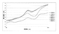
- the soundproofing performance (transmission loss) of the soundproofing material according to the present invention is compared with a soundproofing material consisting only of a lattice-shaped structure (supporting part) having a honeycomb structure, a soundproofing material consisting of only a single wall, and a soundproofing material consisting of an iron plate.
- a graph for explaining It is a figure for demonstrating the soundproof performance according to a rigidity law.
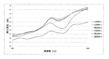
- FIG. 12 is a graph showing the results of Comparative Examples 1-1 to 1-5 and Examples 1-1 to 1-2. It is a graph which shows the result of having measured the insertion loss about the soundproof material produced in the section of the example mentioned below.
- FIG. 13 is a graph showing the results of Comparative Examples 2-1 to 2-5 and Examples 2-1 to 2-2.
- FIG. 14 is a graph showing the results of Comparative Examples 3-1 to 3-5 and Examples 3-1 to 3-2. It is a graph which shows the result of having measured the insertion loss about the soundproof material produced in the section of the example mentioned below.
- FIG. 15 is a graph showing the results of Comparative Examples 4-1 to 4-2 and Examples 4-1 to 4-4. It is a graph which shows the result of having measured the insertion loss about the soundproof material produced in the section of the example mentioned below.
- FIG. 16 is a graph showing the results of Comparative Examples 5-1 to 5-2 and Examples 5-1 to 5-4.
- FIG. 17 is a graph showing the results of Comparative Examples 6-1 to 6-2 and Examples 6-1 to 6-3. It is a graph which shows the result of having measured the insertion loss about the soundproof material produced in the section of the example mentioned below.
- FIG. 18 is a graph showing the results of Comparative Examples 7-1 to 7-2 and Example 7-1.
- One embodiment of the present invention includes a substrate and a soundproof material disposed on the substrate, wherein the soundproof material supports a sheet having elasticity, and a support that partitions the sheet into partition sections. And a surface density (k) of the sheet and a surface density (m) of the sheet in the partition portion satisfy the relationship of the following mathematical formula 1, and vibrate between the soundproof material and the substrate.
- the soundproof structure further includes a separation layer.
- FIG. 1 is a side view showing the appearance of a soundproof structure according to an embodiment of the present invention.
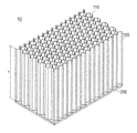
- FIG. 2 is a perspective view showing the external appearance of the soundproof material that constitutes the soundproof structure according to the embodiment of the present invention.
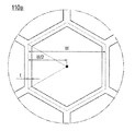
- FIG. 3 is a top view of the soundproof material that constitutes the soundproof structure according to the embodiment of the present invention.
- FIG. 4 is an enlarged cross-sectional view for explaining the cross-sectional shape and size of the support portion of the soundproof material that constitutes the soundproof structure according to the embodiment of the present invention.
- a soundproof structure 1 includes a soundproof material 10 and a substrate 20.
- a soundproofing material 10 according to an embodiment of the present invention includes a lattice-shaped structure 100 (supporting portion) composed of tubular cells arranged continuously (regularly).
- a latex rubber sheet 200 made of latex rubber having elasticity.
- the latex rubber sheet 200 is airtightly joined to the lattice-shaped structure 100 so as to close one side of the openings on both sides of the lattice-shaped structure 100, and functions as a sheet-shaped base material.
- the latex rubber sheet 200 in this embodiment has a thickness of 0.25 mm (250 ⁇ m).
- the lattice structure 100 is made of polyvinyl chloride resin.
- the lattice structure 100 has a large number of cylindrical cells 110 formed continuously (regularly).
- the soundproofing material 10 is arranged on the substrate 20 such that the surface (on the side opposite to the surface) faces the substrate.
- An acrylic plate 300 is arranged between the soundproof material 10 and the substrate 20. This acrylic plate has a square shape when viewed in the stacking direction of the rectangular soundproofing material and the substrate, is arranged at the four corners of the region between the soundproofing material and the substrate, and functions as a vibration isolation layer. ..
- the “vibration isolation layer” is disposed between the soundproof material and the substrate, separates the vibration of the soundproof material from the vibration of the substrate, and suppresses these vibrations from interfering with each other. Means the layer to be applied. Since the vibration isolation layer having such a function is arranged between the soundproof material and the substrate, these vibrations are less likely to interfere with each other. As a result, the soundproof material (in particular, the elastic sheet constituting the soundproof material) can sufficiently vibrate, and the soundproof effect can be sufficiently exhibited.
- the cross-sectional shape of the tubular cell 110 in the cross section (paper surface of FIG. 3) perpendicular to the extending direction of the lattice-shaped structure 100 is It is a regular hexagon. That is, the lattice-shaped structure 100 has a so-called honeycomb structure.
- the lattice-shaped structure 100 according to the present embodiment supports the latex rubber sheet 200 as the sheet-shaped base material and divides the latex rubber sheet 200 into a plurality of (many in FIG. 2 and FIG. 3) partition portions. It is partitioned. Then, the plurality of partition portions form a regular array structure in which the plurality of partition portions having the same outer shape are regularly arrayed.
- the cell size of one cylindrical cell (110a shown in FIG. 4) constituting the honeycomb structure is 4 mm.
- the lattice-shaped structure 100 is configured by connecting a large number of cylindrical cells 110 having walls around them.
- the wall thickness of this tubular cell (distance t shown in FIG. 4) is 0.07 mm (70 ⁇ m).
- the height (distance h shown in FIG. 2) of the lattice-shaped structure (cylindrical cell) in the extending direction is 25 mm, and the lattice-shaped structure (cylindrical cell) is composed of a single structure having a uniform height.
- the soundproof material having the structure shown in FIGS. 2 and 3 can realize excellent soundproof performance with a very simple structure.
- the present inventors energetically studied the mechanism by which the soundproofing material as in the above-described embodiment exhibits such excellent soundproofing performance. As a result, the inventors have found out that a mechanism different from the soundproof material conventionally applied to vehicles and the like is involved, and completed the present invention. The finally discovered mechanism overturns the conventional wisdom regarding soundproofing materials applied to vehicles and the like.
- the mechanism by which the soundproofing material according to the present embodiment exhibits excellent soundproofing performance and the configuration of the present invention completed based on the mechanism clarified by the present inventors will be described step by step.
- FIG. 5 shows the soundproofing performance (@500 Hz) of the soundproofing material according to the present invention in comparison with the performance trend of the conventionally known soundproofing material.
- the conventionally known soundproof material has a performance trend that the soundproof performance (transmission loss) is improved as the density of the constituent material is increased.
- the performance trend of such a conventionally known soundproof material is known as “mass law”.
- the theoretical value (TL) of the transmission loss in the soundproofing material according to this mass rule is calculated according to the following mathematical formula 2 using the frequency (f) of the target sound wave and the surface density (m; mass per unit area) of the soundproofing material. To be done.
- the soundproof performance (transmission loss (TL)) can be improved, but on the other hand, in order to improve the soundproof performance, the surface density of the soundproof material must be increased. That was the common sense in the prior art based on the mass law (Fig. 6). In other words, it was believed that it is impossible to construct a soundproof material that exhibits high soundproofing performance over a wide frequency range of 2000 Hz or less from a lightweight material. On the other hand, the soundproofing material according to the present invention exhibits excellent soundproofing performance by largely deviating from this performance trend (that is, relatively high soundproofing performance even at low density (light weight)) (Fig. 7).
- the soundproof performance is not exhibited at all by only the lattice-shaped structure (supporting part) having the honeycomb structure. Also, in the case of a soundproof material consisting of a single wall, only the elastic sheet (rubber film) has the soundproofing performance according to the mass law (the transmission loss increases in the high frequency range but the transmission loss decreases in the low frequency range). Only to be demonstrated. Therefore, in order to exhibit the soundproof performance in the low frequency range (particularly in the range of 2000 Hz or less), it is necessary to use a material having a very large areal density (that is, a heavy material) such as an iron plate.
- a material having a very large areal density that is, a heavy material
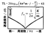
- the soundproofing material according to the present invention having the above-described structure exhibits soundproofing performance in accordance with the mass law in the high frequency range, and the value of the transmission loss decreases as the frequency decreases.
- the soundproofing material according to the present invention is lightweight, it can exhibit excellent soundproofing performance even in the low frequency range (particularly in the range of 2000 Hz or less) with a certain frequency (resonance frequency) as a boundary.
- the theoretical value (TL) of the transmission loss in a soundproofing material that complies with the rigidity law is defined by the frequency (f) of the target sound wave, the surface density (m; mass per unit area) of the soundproofing material, and the surface rigidity (K) of the soundproofing material. It is calculated according to the following Equation 3.
- the surface rigidity (K) is approximate to a mass spring model in which one of the partition parts of the sheet partitioned by the support part (lattice-like structure) has a mass of mass m and vibrates in response to the incidence of sound waves. This is the spring constant at the time of performing, and the larger K is, the more difficult it is to deform with respect to the input.
- Equation 4 Equation 4
- the reason why not only the mass law but also the rigidity law is involved is not completely clear, but the partition portions of the elastic sheet are respectively, It is considered that the rigidity of the sheet is improved (that is, it is less likely to vibrate) by being partitioned by the support portion (the lattice-shaped structure having the tubular cells). Therefore, the present inventors speculate that the mechanism can be well explained by the approximation by the above-mentioned mass spring model.
- the present inventors have further studied the elements necessary for designing the soundproof properties of the soundproof material.
- the present inventors approximate each of the partition portions of the elastic sheet with a disk having a radius a having an equal area, and the surface rigidity (k;
- the value of surface rigidity in the case of following this approximation is represented by a small letter k), and the average deflection (w ave ) when the disk vibrates in the peripheral fixed/uniform load mode is used. And calculated according to the following mathematical formula 5.
- this value of k is used in Expression 1.
- Equation 5 ⁇ is the Poisson's ratio of the sheet in the partition, E is the Young's modulus [Pa] of the sheet in the partition, and h is the film thickness [m] of the sheet in the partition.
- the radius a when the partition is approximated to a disk is the area equivalent circular radius [m] of the partition.
- the partition portion is a hexagon with one side having a length of l (ell)
- the area S hex of the partition portion (hexagon) is calculated as in Equation 6 below.
- sheet areal density (m) in the compartment can be expressed as in the following mathematical formula 9.
- Equation 3 ⁇ is the sheet density [kg/m 3 ] in the partition section, and h is the film thickness [m] of the sheet in the partition section.
- the value of the resonance frequency (f 0 ) is the value of the density ( ⁇ ; mass per unit volume; kg/m 3 ) of the sheet in the partition and the value in the partition described above.
- the value of the film thickness [m] of the sheet it can be expressed as the following Expression 10. This means that the value of the resonance frequency (f 0 ) indicated by the soundproofing material can be controlled by variously changing the size and shape of the partition, the material and the film thickness of the sheet in the partition.
- the problem to be solved by the present invention is to provide a soundproof material capable of exhibiting high soundproofing performance over a wide frequency range of 2000 Hz or less.
- the resonance frequency (f 0 ) as a boundary, the smaller the frequency is, the more excellent the soundproofing performance (value of transmission loss) according to the rigidity law is. Therefore, the present inventors thought that the soundproof performance for sounds in the frequency range of 2000 Hz or lower could be improved by setting the resonance frequency (f 0 ) to a value above a certain level.
- the size and shape of the partitioning portion A large number of soundproof materials having different resonance frequencies (f 0 ) were produced by variously changing the material and the film thickness of the sheet in the compartment, and the soundproof performance was evaluated for each of them (especially in the frequency range of 2000 Hz or less).
- the sheet surface rigidity (k; calculated by the above formula 5) and the sheet surface density (m; calculated by the above formula 9) in the above-mentioned partition satisfy the relationship of the following formula 1, In particular, it was confirmed that excellent soundproofing performance can be exhibited even in a frequency range of 2000 Hz or less.
- Formula 1 below means that the resonance frequency (f 0 ) calculated based on the above-mentioned approximation is greater than 900 [Hz].
- the form of the value on the left side of Equation 1 is not particularly limited, and can be set as appropriate according to the frequency region in which the soundproof material is desired to exhibit soundproof performance.
- the resonance frequency shifts to the higher frequency side as the value on the left side of Expression 1 increases, and therefore the resonance frequency may be appropriately set in consideration of this.
- the value on the left side of Formula 1 is preferably 2000 Hz or higher, more preferably 3000 Hz or higher, even more preferably 4000 Hz or higher, and particularly preferably 5000 Hz or higher.
- the value on the left side in Expression 1 is, for example, 10000 Hz or higher, for example, 50000 Hz or higher, and for example, 100000 Hz or higher.
- the upper limit value of the value on the left side of Formula 1 is preferably 1,000,000 Hz or less, more preferably 800,000 Hz or less, and It is preferably 600,000 Hz or less.
- Non-Patent Document 1 As a result of the cell size being too large, the surface rigidity of the elastic sheet becomes small, and the value of (k/m) 1/2 /2 ⁇ does not become 900 Hz or more. Therefore, it is considered that excellent soundproofing performance cannot be exerted particularly in the frequency range of 2000 Hz or less.
- a resin structure including a core layer formed by arranging a plurality of cells in parallel and skin layers arranged on both surfaces of the core layer has been proposed for various applications, and the resin structure absorbs sound. It has also been attempted to provide sound and sound insulation.
- the conventional technique intended to give such a resin structure a sound absorbing property or a sound insulating property is based on the premise that the skin layer is provided with a communication hole for communicating the inside and outside of the cells constituting the core layer. There is. Even when the skin layer is provided with the communication holes as described above, the surface rigidity of the elastic sheet cannot be sufficiently secured.
- the skin layer is required to contain an impact resistance improving material for lowering the elastic modulus of the skin layer.
- an impact resistance improving material for lowering the elastic modulus of the skin layer.
- a metal member having a thickness of about 0.05 to several mm is arranged as a skin layer, and a material having high rigidity is also used for the skin layer. .. Therefore, in the related art relating to the resin structure in which the communication holes are not provided in the skin layer, the value of the surface rigidity in the present invention becomes too large, so that the value of (k/m) 1/2 /2 ⁇ cannot be measured. It is considered that the value becomes large (on the high frequency side).
- the constituent material of the elastic sheet (corresponding to the latex rubber sheet 200 shown in FIGS. 1 and 2) is not particularly limited, and various materials can be used as long as they are elastic materials.
- that a certain material has “elasticity” means that the material has a Young's modulus value within the range of 0.001 to 70 [GPa].
- the value of the Young's modulus of the resin can be measured according to JIS K7161-1 (2014).
- the Young's modulus of metal can be measured according to JIS Z2241 (2011).
- the Young's modulus of rubber can be measured according to JIS Z6251 (2010).
- chloroprene rubber CR
- SBR styrene/butadiene rubber
- EPDM ethylene/propylene/diene rubber
- a rubber material such as rubber (NBR) may be used as well.
- a resin material, a metal material, a paper material, or the like may be used as the elastic sheet.
- a material having a cushioning function such as an air cushion can also be used. All of these materials, including rubber materials, have high elasticity to the extent that the effect of the soundproof material according to the present embodiment can be exhibited.
- the resin material examples include polyethylene (for example, low-density polyethylene, high-density polyethylene, etc.), polyolefin resin such as polypropylene, polyvinyl chloride resin, acrylic resin, methacrylic resin, acrylonitrile-butadiene-styrene resin, vinyl acetate resin, ethylene-acetic acid. Examples include vinyl resins and styrene-butadiene resins.
- thermosetting resin silicone resin, urethane resin, melamine resin, thermosetting acrylic resin, urea resin, phenol resin, resorcin resin, alkylresorcin resin, epoxy resin, thermosetting polyester, etc. may be used.
- urethane resin prepolymers urethane resin prepolymers, urea resin prepolymers (initial condensation products), phenol resin prepolymers (initial condensation products), diallyl phthalate prepolymers, acrylic oligomers, polyvalent isocyanates, methacrylic ester monomers, which produce these resins, Prepolymers such as diallyl phthalate monomers, oligomers, resin precursors such as monomers may be used.
- the metal material include copper and aluminum.
- the constituent material of the elastic sheet is not limited to the above, and other materials may of course be used. A rubber material is preferable as the constituent material of the elastic sheet, and latex rubber or EPDM rubber is more preferable.
- these rubber materials are particularly preferable materials because they are lightweight, and particularly when considering application to vehicles, they greatly contribute to fuel efficiency reduction.
- polyolefin resin such as polypropylene is also preferable as a constituent material of the elastic sheet.
- the thickness of the elastic sheet is preferably 10 to 1000 ⁇ m, more preferably 100 to 500 ⁇ m from the viewpoint of the soundproof effect of the soundproof material.
- the support part supports the above-mentioned elastic sheet and partitions the sheet into partition parts (airtightly partitioned).
- FIGS. 1 to 3 are described as having a large number of compartments, even if there is only one compartment, it is within the scope of the present invention.
- the constituent material of the supporting portion is not particularly limited, and conventionally known thermoplastic resins or thermosetting resins can be used in addition to the polyvinyl chloride resin used in the above-described embodiment. Further, a metal material or another material may be used as a constituent material of the support portion. Each of these materials has physical properties suitable for holding an elastic sheet and partitioning it into compartments.
- thermoplastic resin in addition to polyvinyl chloride resin, polyethylene (for example, low-density polyethylene, high-density polyethylene, etc.), polyolefin resin such as polypropylene, acrylic resin, methacrylic resin, acrylonitrile-butadiene-styrene resin, vinyl acetate resin, Examples thereof include ethylene-vinyl acetate resin and styrene-butadiene resin.
- thermosetting resin urethane resin, melamine resin, thermosetting acrylic resin, urea resin, phenol resin, resorcin resin, alkylresorcin resin, epoxy resin, thermosetting polyester, etc. may be used.
- urethane resin prepolymers urethane resin prepolymers, urea resin prepolymers (initial condensation products), phenol resin prepolymers (initial condensation products), diallyl phthalate prepolymers, acrylic oligomers, polyvalent isocyanates, methacrylic ester monomers, which produce these resins, Prepolymers such as diallyl phthalate monomers, oligomers, resin precursors such as monomers may be used.
- a thermoplastic resin is preferably used from the viewpoint of easy molding, and a vinyl chloride resin and a polyolefin resin are particularly preferable because they are lightweight, excellent in durability and inexpensive.
- the support portion is preferably a lattice-shaped structure having a large number of continuously formed cylindrical cells.
- the support section partitions the elastic sheet into a plurality of partition sections.
- at least a part of the plurality of partition sections constitutes a regular array structure in which a plurality of partition sections having the same outer shape are regularly arrayed.
- the ratio of the area of the ordered array structure to the area of the elastic sheet is preferably 80 to 100%, more preferably 90 to 100%, from the viewpoint of further exhibiting the soundproof performance.
- At least one lattice-shaped structure (support portion) for one sheet may be divided into a plurality of members.
- the soundproofing material according to the present embodiment has flexibility as a whole.
- the support portion is not divided into a plurality of members, it is a preferred embodiment that the soundproof material has flexibility as a whole. Since the soundproof material is flexible in this manner, it is possible to arrange the soundproof material in a manner to follow sound sources of various shapes, which is preferable.
- the outer shape of the partition part in the above-described regular array structure is not limited to the regular hexagon as shown in FIGS. 2 to 4, Other shapes may be used. If a large number of cylindrical cells are arranged by continuously forming regular polygons having the same cross-sectional shape, regular hexagons, regular squares (squares), and regular triangles can be adopted as the cross-sectional shape. .. By adopting these shapes, it is possible to provide a support that is easy to manufacture and exhibits excellent strength.
- the cross-section of the lattice-like structure is a pattern in which a plurality of regular polygons are regularly arranged, for example, by Archimedes' plane filling method (four regular triangles, one regular hexagon), ( 3 regular triangles, 2 regular squares (square) x 2 ways (1 regular triangle, 2 regular squares, 1 regular hexagon), (2 regular triangles, 2 regular hexagons), (One regular triangle, two regular dodecagons), (one regular square (square), one regular hexagon, one regular dodecagon), (one regular square (square), two regular octagons) Any combination can be configured so that the cross section of the lattice structure has the above pattern.
- the cross-sectional shape of the tubular cell is a regular hexagon (that is, the lattice-shaped structure has a honeycomb structure. Most preferably).
- the size of the tubular cells forming the lattice-like structure there is no particular limitation on the specific value as long as it satisfies the above-mentioned mathematical formula 1.
- the size of the tubular cell is 6. It is preferably 0 mm or less. By having such a size, excellent soundproofing performance can be exhibited.
- the size of the tubular cell is 5.9 mm or less, 5.8 mm or less, 5.7 mm or less, 5.6 mm or less, 5.5 mm or less, 5 0.4 mm or less, 5.3 mm or less, 5.2 mm or less, 5.1 mm or less, 5.0 mm or less, 4.9 mm or less, 4.8 mm or less, 4.7 mm or less, 4.6 mm or less, 4.5 mm or less, 4 It may be less than or equal to 4.4 mm, less than or equal to 4.3 mm, less than or equal to 4.2 mm, less than or equal to 4.1 mm, less than or equal to 4.0 mm, and the narrower the numerical value range, the more preferable.
- the lower limit of the size of the tubular cell is not particularly limited, but if the size of the tubular cell is too small, the mass of the lattice-like structure (and by extension, the soundproofing material) increases, so it should be 2.0 mm or more. Is preferred.
- the thickness of the wall of the tubular cell (distance t shown in FIG. 4) is preferably 10 to 150 ⁇ m, more preferably 30 to 100 ⁇ m.
- the lattice-like structure (supporting portion) is provided only on one side of the elastic sheet.
- the lattice-like structure (supporting portion) is provided on both surfaces of at least one sheet having elasticity, it is possible to similarly exhibit excellent soundproofing performance.
- the shapes of the lattice-like structures (supporting portions) provided on both sides of the elastic sheet may be the same or different. Above all, it is preferable that the lattice-shaped structures (supporting portions) provided on both surfaces of the elastic sheet have different forms.
- the respective lattice-shaped structures so that the shape of the tubular cells of the lattice-shaped structure (supporting portion) is exactly overlapped on both sides of the elastic sheet.
- the lattice-shaped structure (supporting portion) in the extending direction is larger, particularly excellent soundproof performance tends to be exhibited over a wide range of low frequency range of 2000 Hz or less. From this point of view, it is preferable that the lattice-shaped structure (support portion) is a single structure having a uniform height. Further, in this case, the height of the lattice-shaped structure in the extending direction (distance h shown in FIG. 2) is preferably 5 mm or more, more preferably 6 mm or more, further preferably 13 mm or more, It is more preferably 19 mm or more, particularly preferably 22 mm or more, and most preferably 25 mm or more.
- the soundproof material according to this embodiment is preferably lightweight.
- the surface density of the overall sound insulation according to the present embodiment is preferably less than 3.24kg / m 2, more preferably not more than 2.0 kg / m 2, more preferably 1.5 kg / m 2 or less, particularly preferably 1.0 kg/m 2 or less.
- the soundproof material according to the present embodiment can be suitably used for shielding noise from various sound sources by arranging the soundproof structure on a substrate to form a soundproof structure.
- a metal plate iron plate, aluminum plate, etc.
- the thickness of the substrate is preferably 0.5 to 2.0 mm in the case of a metal plate, and 0.5 to 20 mm in the case of a resin plate.
- the vibration isolation layer is disposed between the soundproof material and the substrate to separate the vibration of the soundproof material from the vibration of the substrate, and to prevent the vibrations from interfering with each other.
- Any constituent material, shape, and arrangement form can be adopted as long as it is a layer having.
- the vibration isolation layer may be arranged in a partial area between the soundproofing material and the substrate as shown in FIG.
- an air layer can be provided between the soundproof material and the substrate, and the soundproof material in contact with the air layer can sufficiently vibrate to exhibit an excellent soundproofing effect.
- the composition of the vibration isolation layer and the physical properties are taken into consideration in determining the proportion of the area between the soundproofing material and the substrate to occupy. It may be determined accordingly.
- the constituent material of the vibration isolation layer is preferably a material having elasticity. Thereby, the vibration of the base material and the vibration of the soundproof material can be surely made independent, which can contribute to the improvement of the soundproof performance.
- each vibration isolation layer is not particularly limited, and examples thereof include a square shape as shown in FIG. 1, a regular triangle, a regular hexagon, a circle, and an ellipse.
- the thickness of each vibration isolation layer is also not particularly limited, and is 0.5 to 20 mm as an example.
- the vibration isolation layer When the vibration isolation layer is arranged in a part of the area between the soundproof material and the substrate as shown in FIG. 1, it is preferable to arrange the vibration isolation layer regularly. With such a configuration, the vibration of the soundproofing material becomes more uniform, and the reduction of the soundproofing effect can be suppressed.
- the regular arrangement form is not particularly limited, and may be a grid arrangement as shown in FIG. 1 or an example described later.
- the Young's modulus of the constituent material of the vibration isolation layer is equal to or higher than the Young's modulus of the constituent material of the support portion that constitutes the soundproof material. It may be smaller than the Young's modulus of the constituent material of the supporting portion.
- the vibration isolation layer may be arranged in substantially the entire region between the soundproof material and the substrate.
- the vibration isolation layer is made of urethane foam 400, and this urethane foam 400 is arranged in the entire region between the soundproof material and the substrate.
- the Young's modulus of the constituent material of the vibration isolation layer is preferably smaller than the Young's modulus of the constituent material of the support portion.
- the constituent material of the vibration isolation layer as the material having a relatively large Young's modulus, various resin materials, rubber materials, metal materials, paper materials and the like described above as constituent materials of the elastic sheet forming the soundproof material are used. Can be mentioned.
- the material having a relatively small Young's modulus include batting material such as Thinsulate TM , foam material such as urethane foam and sponge, and nonwoven material such as felt.
- materials other than these may be used.
- the soundproof material according to this embodiment can be made extremely lightweight. Since the soundproofing material according to the present embodiment can be reduced in weight as described above, it is preferable to be mounted on a vehicle and used. In particular, it is most preferable to be applied to soundproofing against noise generated from a portion (inherent sound source) that generates a large noise such as an engine, a transmission, and a drive system. As an example of the application site, in the engine compartment, it can be applied to an engine head cover, an engine body cover, a hood insulator, a dash front insulator, an air box partition, an air intake air cleaner, a dust side duct, an under cover, and the like.
- dash insulators In the cabin, dash insulators, dash panels, floor carpets, spacers, door trims for doors, soundproofing materials in door trims, soundproofing materials in compartments, instrument panels, instrument center boxes, instor upper boxes, air conditioner casings, Roof trim, sound insulation in roof trim, sun visor, air conditioner duct for rear seats, cooling duct for battery cooling system in vehicles with batteries, cooling fan, center console trim, sound insulation in console, parcel trim, parcel panel It can be applied to seat headrests, front seat seat backs, rear seat seat backs, and the like. Further, in the trunk, it can be applied to a trunk floor trim, a trunk board, a trunk side trim, a soundproof material in the trim, a drafter cover, and the like.
- the invention can be applied to the inside of a frame of a vehicle or between panels, for example, to trims of pillars and fenders. Further, it can be applied to each member outside the vehicle, for example, an under cover under the floor, a fender protector, a back door, a wheel cover, and an aerodynamic cover for a suspension. Therefore, as the substrate forming the soundproof structure, the metal plate, the resin plate, or the like as the constituent material of the various application sites described above can be used as they are.
- the soundproof structure according to this embodiment is arranged with respect to the sound source.
- the elastic sheet forming the soundproof material may be arranged so as to be located on the sound source side, or the opening of the tubular cell forming the soundproof material may be arranged on the sound source side.
- the former arrangement form is more preferable from the viewpoint of more excellent soundproofing performance.
- the sound insulation performance is measured by measuring the insertion loss [unit: dB] when the sample (soundproof structure) is not arranged (control). evaluated.
- the soundproof structure was placed so that the substrate (iron plate) was located on the side opposite to the microphone for evaluation.
- the sound source generation conditions were as follows: Spectral level: White noise (100-8192Hz) F max : 8192 Hz Average value: 300 times addition average (measurement was performed 300 times while shifting the time little by little in one measurement, and the addition average was taken as the measurement value) Overlap: 75%.
- Production Example 2 A soundproof material of this Production Example was produced in the same manner as in Production Example 1 described above except that the thickness of the honeycomb structure (support) was 12.5 mm.
- Comparative Example 1-2 A conventionally known soundproof material, Thinsulate TM (manufactured by 3M), was laminated on an iron plate (thickness: 1 mm) to produce a soundproof structure of this comparative example.
- Comparative Example 1-3 A conventionally known soundproof material, urethane foam, was laminated on an iron plate (thickness: 1 mm) to produce a soundproof structure of this comparative example.
- Comparative Example 1-4 A soundproofing structure of this comparative example was produced by laminating a conventional felt, which is a known soundproofing material, on an iron plate (thickness: 1 mm).
- Example 1-1 Comparative Example 1 described above except that acrylic plates (thickness 3 mm) of 20 mm ⁇ 20 mm size were arranged as vibration isolation layers at the four corners (between the iron plate) of the opening cross section of the supporting portion constituting the soundproof material. In the same manner as in 5, the soundproof structure of this example was manufactured.
- Example 1-2 This example is the same as Example 1-1 described above except that a similar acrylic plate (thickness: 3 mm) was also arranged as a vibration isolation layer in the central portion of the opening cross section of the support portion constituting the soundproof material. A soundproof structure was manufactured.
- Fig. 12 shows the results of insertion loss obtained by evaluating the soundproofing performance of the above-mentioned examples and comparative examples.
- the soundproof structure according to the present invention is superior to the soundproof structure composed only of the substrate (iron plate) or the laminated structure of the iron plate and the conventionally known soundproof material. It shows soundproof performance.
- the soundproof structure according to the present invention uses a soundproof material having the same structure as that of the present invention, as compared with a soundproof structure in which a vibration isolation layer is not disposed between the soundproof material and the substrate. It can also be seen that even better sound insulation performance is exhibited.
- Comparative Example 2-1 The soundproof structure of Comparative Example 1-1 was used as the soundproof structure of this Comparative Example.
- Comparative Example 2-2 The soundproof structure of Comparative Example 1-2 was used as the soundproof structure of this Comparative Example.
- Comparative Example 2-3 The soundproof structure of Comparative Example 1-3 was used as the soundproof structure of this Comparative Example.
- Comparative Example 2-4 The soundproof structure of Comparative Example 1-4 was used as the soundproof structure of this Comparative Example.
- Example 2-1 Comparative Example 2 described above except that acrylic plates (thickness 3 mm) of 20 mm ⁇ 20 mm size were arranged as vibration isolation layers at the four corners (between the iron plate) of the opening cross section of the support part constituting the soundproofing material. In the same manner as in 5, the soundproof structure of this example was manufactured.
- Example 2-2 This example is the same as Example 2-1 described above except that the same acrylic plate (thickness: 3 mm) was also arranged as the vibration isolation layer in the center of the opening cross section of the supporting portion constituting the soundproof material. A soundproof structure was manufactured.
- Fig. 13 shows the insertion loss results obtained by evaluating the soundproofing performance of the above-mentioned examples and comparative examples.
- the soundproof structure according to the present invention is superior to the soundproof structure composed only of the substrate (iron plate) or the laminated structure of the iron plate and the conventionally known soundproof material. It shows soundproof performance.
- the soundproof structure according to the present invention uses a soundproof material having the same structure as that of the present invention, as compared with a soundproof structure in which a vibration isolation layer is not disposed between the soundproof material and the substrate. It can also be seen that even better sound insulation performance is exhibited.
- Comparative Example 3-1 The soundproof structure of Comparative Example 1-1 was used as the soundproof structure of this Comparative Example.
- Comparative Example 3-2 The soundproof structure of Comparative Example 1-2 was used as the soundproof structure of this Comparative Example.
- Comparative Example 3-3 The soundproof structure of Comparative Example 1-3 was used as the soundproof structure of this Comparative Example.
- Comparative Example 3-4 The soundproof structure of Comparative Example 1-4 was used as the soundproof structure of this Comparative Example.
- Example 3-1 Comparative example 3 described above except that acrylic plates (thickness 3 mm) of 20 mm ⁇ 20 mm size were arranged as vibration isolation layers at the four corners (between the iron plate) of the opening cross section of the support part constituting the soundproofing material. In the same manner as in 5, the soundproof structure of this example was manufactured.
- Example 3-2 This example is the same as Example 3-1 described above except that the same acrylic plate (thickness: 3 mm) was also placed as the vibration isolation layer in the central portion of the opening cross section of the supporting portion constituting the soundproof material. A soundproof structure was manufactured.
- Fig. 14 shows the results of insertion loss obtained by evaluating the soundproofing performance of the above-mentioned examples and comparative examples.
- the soundproof structure according to the present invention is superior to the soundproof structure composed only of the substrate (iron plate) or the laminated structure of the iron plate and the conventionally known soundproof material. It shows soundproof performance.
- the soundproof structure according to the present invention uses a soundproof material having the same structure as that of the present invention, as compared with a soundproof structure in which a vibration isolation layer is not disposed between the soundproof material and the substrate. It can also be seen that even better sound insulation performance is exhibited.
- Comparative Example 4-1 The soundproof structure of Comparative Example 1-1 was used as the soundproof structure of this Comparative Example.
- Comparative Example 4-2 The soundproof structure of Comparative Example 3-5 was used as the soundproof structure of this Comparative Example.
- Example 4-1 The soundproof structure of Example 3-1 was used as the soundproof structure of this example.
- Example 4-2 A soundproof structure of this example was produced in the same manner as in Example 4-1 described above, except that the constituent material of the vibration isolation layer was changed from an acrylic plate to Thinsulate TM (manufactured by 3M Company).
- Example 4-3 A soundproof structure according to this example was produced in the same manner as in Example 4-1 except that the constituent material of the vibration isolation layer was changed from an acrylic plate to urethane foam.
- Example 4-4 A soundproof structure of this example was produced in the same manner as in Example 4-1 described above, except that the constituent material of the vibration isolation layer was changed from acrylic plate to coarse felt.
- Fig. 15 shows the results of the insertion loss obtained by evaluating the soundproofing performance of the above Examples and Comparative Examples. As can be seen from these results, even when the constituent material of the vibration isolation layer is changed, it is compared with a soundproof structure that consists of only the substrate (iron plate) or a sound isolation structure that does not have the vibration isolation layer. All of them also show excellent soundproofing performance.
- Comparative Example 5-1 The soundproof structure of Comparative Example 1-1 was used as the soundproof structure of this Comparative Example.
- Comparative Example 5-2 The soundproof structure of Comparative Example 3-5 was used as the soundproof structure of this Comparative Example.
- Example 5-1 The soundproof structure of Example 3-2 was used as the soundproof structure of this example.
- Example 5-2 A soundproof structure of this example was produced in the same manner as in Example 5-1 described above, except that the constituent material of the vibration isolation layer was changed from an acrylic plate to Thinsulate TM (manufactured by 3M Company).
- Example 5-3 A soundproof structure of this example was produced in the same manner as in Example 5-1 described above, except that the constituent material of the vibration isolation layer was changed from an acrylic plate to urethane foam.
- Example 5-4 A soundproof structure of this example was produced in the same manner as in Example 5-1 described above, except that the constituent material of the vibration isolation layer was changed from acrylic plate to coarse felt.
- Fig. 16 shows the results of insertion loss obtained by evaluating the soundproofing performance of the above-mentioned examples and comparative examples. As can be seen from these results, even when the constituent material of the vibration isolation layer is changed, it is compared with a soundproof structure that consists of only the substrate (iron plate) or a sound isolation structure that does not have the vibration isolation layer. All of them also show excellent soundproofing performance.
- Comparative Example 6-1 The soundproof structure of Comparative Example 1-1 was used as the soundproof structure of this Comparative Example.
- Comparative Example 6-2 The soundproof structure of Comparative Example 3-5 was used as the soundproof structure of this Comparative Example.
- Example 6-1 Comparative Example 1-5 described above, except that Thinsulate TM (manufactured by 3M Co.) was arranged as a vibration isolation layer in the entire area (between the iron plate) of the opening cross section of the supporting portion constituting the soundproof material. Similarly, a soundproof structure of this example was manufactured.
- Thinsulate TM manufactured by 3M Co.
- Example 6-2 A soundproofing structure according to the present example was produced in the same manner as in Example 6-1 described above, except that the constituent material of the vibration isolation layer was changed from Thinsulate to urethane foam.
- Example 6-3 A soundproof structure according to this example was produced in the same manner as in Example 6-1 described above except that the constituent material of the vibration isolation layer was changed from synthesizer to coarse felt.
- FIG. 17 shows the results of insertion loss obtained by evaluating the soundproofing performance of the above-mentioned examples and comparative examples. As can be seen from these results, even when the vibration isolation layer is arranged in the entire area between the substrate and the soundproof structure, the soundproof structure or the vibration isolation layer made of only the board (iron plate) is arranged. All exhibit similarly excellent soundproofing performance as compared to the soundproofing structure which is not made.
- Comparative Example 7-1 The soundproof structure of Comparative Example 1-1 was used as the soundproof structure of this Comparative Example.
- Example 7-1 The same procedure as in Comparative Example 7-2 described above except that acrylic plates (thickness: 3 mm) having a size of 20 mm ⁇ 20 mm were arranged as vibration isolation layers at the four corners (between the iron plates) of the sheet constituting the soundproofing material. Thus, the soundproof structure of this example was manufactured.
- FIG. 18 shows the insertion loss results obtained by evaluating the soundproofing performance of the above-mentioned examples and comparative examples. As can be seen from these results, not only in the case where the opening cross section of the supporting portion constituting the soundproofing material is located on the iron plate side as in the above-described Example 3-1, the sheet constituting the soundproofing material is located on the iron plate side. Even if it does, by arranging the vibration isolation layer, excellent sound insulation performance is exhibited as compared with a sound insulation structure composed only of the substrate (iron plate) or a sound insulation structure not provided with the vibration isolation layer. ..
- 1 soundproof structure 10 soundproof material, 20 substrates, 100 grid-like structure (support), 110, 110a tubular cell, 200 latex rubber sheet (elastic sheet), 300 acrylic board, 400 urethane foam, h Height in the extending direction of the support (cylindrical cell), w Size of cylindrical cell (distance between parallel sides facing each other in regular hexagon of cross section), a Length of one side of a regular hexagon, which is the cross-sectional shape of the tubular cell, t Thickness of the inner wall (lattice wall) of the tubular cell.
Abstract
[Problem] To provide a means that can suppress decreases in the soundproofing performance of a soundproofing material that exhibits high soundproofing performance across a broad range of frequency bands of 2000Hz and below. [Solution] A soundproofing material comprising an elastic sheet and a support part that holds the sheet and divides the sheet into compartments, wherein the sheet rigidity (k) and the sheet surface density (m) of the compartments satisfies the relationship in formula 1. A soundproofing structure is formed by arranging said soundproofing material on a substrate, and, when doing so, further arranging a vibration isolation layer between the soundproofing material and the substrate. [formula 1]
Description
本発明は、防音構造体に関する。
The present invention relates to a soundproof structure.
自動車内には多くの音源がある。車内および車外における騒音からの静粛性が要求されることから、自動車には様々な防音対策が施されている。特に、エンジンやトランスミッション、駆動系のような大きな音を発生する部分(固有音源)については、発生源に近い位置で防音対策が必要である。このため、これらの音源に対しては吸遮音性能に優れる専用の防音カバーが使用されている。ここで、相次ぐ法改正による車外騒音レベル規制の強化や、車内騒音の静粛化が車の価値(高級感)に直結する点も相俟って、自動車における低騒音化部品の要求は非常に高い。特に、2013年度に欧州連合(EU)において導入された車外騒音規制は、最終的に従来規制値に対して−3dB(音圧エネルギーとして1/2に低減が必要)と厳しいものとなっている。これにはエンジンルーム内の主騒音発生源としてのエンジン本体およびトランスミッション等固有音源への騒音低減対策が不可欠である。これまでも、エンジン上面側のエンジントップカバー等の様々な防音部品が使用されているが、さらなる性能の向上が求められている。また、低燃費化の観点から、防音対策は軽量化の要請にも応えられるものであることが好ましい。
There are many sound sources in the car. Since it is required to be quiet from noise inside and outside the vehicle, various soundproofing measures are applied to the vehicle. In particular, sound-proofing measures are required near the source of sound (a unique sound source) such as the engine, transmission, and drive system that generate a loud noise. For this reason, a dedicated soundproof cover having excellent sound absorption/insulation performance is used for these sound sources. There is a great demand for low noise parts in automobiles, coupled with the strengthening of external noise level regulations due to successive legal revisions and the quietness of in-vehicle noise being directly linked to the value (luxury) of vehicles. .. In particular, the vehicle exterior noise regulations introduced in the European Union (EU) in 2013 are finally stricter than the conventional regulation value by -3 dB (need to reduce the sound pressure energy to 1/2). .. To this end, it is essential to take noise reduction measures for the engine itself as the main noise source in the engine room and the specific sound source such as transmission. Various soundproofing components such as the engine top cover on the upper surface of the engine have been used so far, but further improvement in performance is required. Further, from the viewpoint of reducing fuel consumption, it is preferable that the soundproofing measures can meet the demand for weight reduction.
防音を狙った防音構造体の構成は種々知られているが、なかでも「音響メタマテリアル」と称される材料がある。「音響メタマテリアル」とは、自然界に存在する物質が通常示さないような音響的性質を示すように設計された人工媒質である。従来、所望の防音効果を示す音響メタマテリアルの開発が鋭意行われており、各種の提案がなされている。
There are various known structures for soundproof structures aimed at soundproofing, but there is a material called "acoustic metamaterial" among them. An “acoustic metamaterial” is an artificial medium designed to exhibit acoustic properties that a substance existing in nature normally does not exhibit. Conventionally, development of an acoustic metamaterial showing a desired soundproofing effect has been earnestly made, and various proposals have been made.
ここで、均質な材料からなる一重壁にある周波数の音波が垂直に入射したときの当該一重壁による透過損失(TL;Transmission Loss)の値は、上記周波数(f)および上記一重壁の面密度(m)を用いて、TL≒20log10(m・f)−43[dB]と算出されることが知られている(質量則)。すなわち一般に、防音材料が軽量であるほど、また、音波の周波数が小さいほど、透過損失(TL)は小さくなり、防音性能が低下することとなる。例えば500Hzの音波の場合、20dBのSTLを達成するには、コンクリート壁では12cm、ウレタンフォーム遮音材では35cm超ものサイズが必要となる。
Here, the value of the transmission loss (TL; Transmission Loss) due to the single wall when a sound wave of a certain frequency is vertically incident on the single wall made of a homogeneous material is the frequency (f) and the surface density of the single wall. It is known that TL≈20 log 10 (m·f)−43 [dB] is calculated using (m) (mass rule). That is, generally, the lighter the soundproof material is and the smaller the frequency of the sound wave is, the smaller the transmission loss (TL) is, and the soundproof performance is deteriorated. For example, in the case of a 500 Hz sound wave, in order to achieve an STL of 20 dB, a concrete wall needs to have a size of 12 cm, and a urethane foam sound insulation material needs to have a size of more than 35 cm.
このような状況に鑑み、例えばNi Sui et al.,Applied Physics Letters 106,171905(2015)では、連続的に形成された複数の筒状セルを有するアラミド繊維シート製ハニカムによってラテックスゴム製の膜が気密に支持されてなる格子状構造体からなる音響メタマテリアルが提案されている。ここで、Ni Sui et al.,Applied Physics Letters 106,171905(2015)に開示されている格子状構造体においては、ラテックスゴム製の膜が複数の筒状セルによって正六角形(一辺の長さが3.65mm)の形状を有する区画部に区画されている。
In view of such a situation, for example, Ni Sui et al. , Applied Physics Letters 106, 171905 (2015) is an acoustic structure consisting of a lattice-shaped structure in which a latex rubber film is airtightly supported by a honeycomb made of an aramid fiber sheet having a plurality of cylindrical cells formed continuously. Metamaterials have been proposed. Here, Ni Sui et al. , Applied Physics Letters 106, 171905 (2015), the lattice-shaped structure has a latex rubber membrane having a regular hexagonal shape (one side length is 3.65 mm) formed by a plurality of tubular cells. It is divided into compartments.
Ni Sui et al.,Applied Physics Letters 106,171905(2015)によれば、このような音響メタマテリアルを用いることで、軽量でも特に低周波数の音波に対する防音性能に優れた材料を提供できるとされており、実験によって500Hz未満の周波数の音波については25dBを超えるSTLを達成可能であることも開示されている。
Ni Sui et al. According to Applied Physics Letters 106, 171905 (2015), it is said that by using such an acoustic metamaterial, it is possible to provide a material that is lightweight and has excellent soundproofing performance especially for low frequency sound waves, and it has been experimentally tested that 500 Hz. It is also disclosed that STLs above 25 dB can be achieved for sound waves of frequencies below.
しかしながら、Ni Sui et al.,Applied Physics Letters 106,171905(2015)に記載されているような上記音響メタマテリアルを防音材として用いた場合には、2000Hz以下の周波数域の広い範囲にわたって十分な防音性能を発揮することができるわけではないことが本発明者らの検討により判明した。
However, Ni Sui et al. , Applied Physics Letters 106, 171905 (2015), when the above acoustic metamaterial is used as a soundproof material, sufficient soundproof performance can be exhibited over a wide range of frequency range of 2000 Hz or less. It was found by the study of the present inventors that this is not the case.
そこで本発明者らは、2000Hz以下の周波数域の広い範囲にわたって高い防音性能を発揮することを可能とする手段を提供することを目的として検討を行った。その結果、Ni Sui et al.,Applied Physics Letters 106,171905(2015)に開示されているような、弾性を有するシートと、当該シートを支持するとともに当該シートを区画部に区画する支持部とを有する防音材(音響メタマテリアル)において、当該区画部を構成するシートの面剛性および面密度が所定の関係を満足するように制御することによって2000Hz以下(特に400~1000Hz)の周波数域の広い範囲にわたって高い防音性能が発揮されうることを見出し、その発明について特許出願を行っている(PCT/JP2018/028326)。
Therefore, the present inventors conducted a study for the purpose of providing a means capable of exhibiting high soundproofing performance over a wide frequency range of 2000 Hz or less. As a result, Ni Sui et al. , Applied Physics Letters 106, 171905 (2015), a soundproof material having an elastic sheet and a supporting portion that supports the sheet and divides the sheet into compartments (acoustic metamaterial). In the above, by controlling the surface rigidity and the surface density of the sheet forming the partition to satisfy a predetermined relationship, high soundproofing performance can be exhibited over a wide frequency range of 2000 Hz or less (particularly 400 to 1000 Hz). We have found that, and applied for a patent for the invention (PCT/JP2018/028326).
ここで、上述したような防音材(音響メタマテリアル)を車両等に適用する際には、当該防音材を配置するための基板と積層することが一般的である。しかしながら、本発明者らがさらに検討したところによれば、防音材の使用時における適用形態によっては、上記防音材が有する防音性能が十分に発揮されない場合があることが判明した。
Here, when the soundproof material (acoustic metamaterial) as described above is applied to a vehicle or the like, it is common to laminate it with a substrate for disposing the soundproof material. However, further studies by the present inventors have revealed that the soundproofing performance of the soundproofing material may not be sufficiently exerted depending on the application form of the soundproofing material in use.
そこで本発明は、2000Hz以下の周波数域の広い範囲にわたって高い防音性能を発揮しうる防音材の防音性能の低下を抑制しうる手段を提供することを目的とする。
Therefore, an object of the present invention is to provide a means capable of suppressing deterioration of the soundproof performance of a soundproof material capable of exhibiting high soundproof performance over a wide range of a frequency range of 2000 Hz or less.
本発明者らは、上記課題に鑑み鋭意検討を行った。その結果、上述したような防音材(音響メタマテリアル)において、区画部を構成するシートの面剛性および面密度が所定の関係を満足するように制御するとともに、当該防音材と基板との間に振動分離層をさらに配置することで、防音性能の低下を抑制することが可能であることを見出し、本発明を完成させるに至った。
The present inventors have conducted earnest studies in view of the above problems. As a result, in the soundproofing material (acoustic metamaterial) as described above, the surface rigidity and the surface density of the sheet forming the partition are controlled so as to satisfy a predetermined relationship, and the soundproofing material and the substrate are separated from each other. By further disposing the vibration isolation layer, it was found that it is possible to suppress the deterioration of the soundproof performance, and the present invention has been completed.
すなわち、本発明の一形態によれば、基板と、前記基板上に配置された防音材と、前記防音材と前記基板との間に配置された振動分離層とを有する防音構造体が提供される。ここで、前記防音材は、弾性を有するシートと、前記シートを支持するとともに前記シートを区画部に区画する支持部とを備える。そして、当該防音材は、上記区画部におけるシートの面剛性(k)および面密度(m)が下記数式1の関係を満足する点に特徴を有している。
That is, according to one aspect of the present invention, there is provided a soundproof structure including a substrate, a soundproof material disposed on the substrate, and a vibration isolation layer disposed between the soundproof material and the substrate. It Here, the soundproof material includes a sheet having elasticity and a support portion that supports the sheet and divides the sheet into partition portions. The soundproof material is characterized in that the surface rigidity (k) and the surface density (m) of the sheet in the partition section satisfy the relationship of the following mathematical formula 1.

本発明の一形態は、基板と、前記基板上に配置された防音材とを有し、前記防音材が、弾性を有するシートと、前記シートを支持するとともに前記シートを区画部に区画する支持部とを備え、前記区画部における前記シートの面剛性(k)および前記シートの面密度(m)が、下記数式1の関係を満足し、かつ、前記防音材と前記基板との間に振動分離層をさらに有する、防音構造体である。
One embodiment of the present invention includes a substrate and a soundproof material disposed on the substrate, wherein the soundproof material supports a sheet having elasticity, and a support that partitions the sheet into partition sections. And a surface density (k) of the sheet and a surface density (m) of the sheet in the partition portion satisfy the relationship of the following mathematical formula 1, and vibrate between the soundproof material and the substrate. The soundproof structure further includes a separation layer.

数式1における面剛性(k)および面密度(m)の算出方法については、後述する。
A method of calculating the surface rigidity (k) and the surface density (m) in the mathematical formula 1 will be described later.
以下、図面を参照しながら、本発明の実施形態を説明するが、本発明の技術的範囲は特許請求の範囲の記載に基づいて定められるべきであり、以下の形態のみに制限されない。なお、図面の寸法比率は、説明の都合上誇張されており、実際の比率とは異なる場合がある。本明細書において、範囲を示す「X~Y」は「X以上Y以下」を意味する。また、特記しない限り、操作および物性等の測定は室温(20~25℃)/相対湿度40~50%の条件で行う。
Hereinafter, embodiments of the present invention will be described with reference to the drawings, but the technical scope of the present invention should be determined based on the description of the claims, and is not limited to the following embodiments. It should be noted that the dimensional ratios in the drawings are exaggerated for convenience of explanation, and may differ from the actual ratios. In the present specification, “X to Y” indicating a range means “X or more and Y or less”. Unless otherwise specified, operations and measurements of physical properties are performed at room temperature (20 to 25° C.)/relative humidity of 40 to 50%.
図1は、本発明の一実施形態に係る防音構造体の外観を示す側面図である。図2は、本発明の一実施形態に係る防音構造体を構成する防音材の外観を示す斜視図である。図3は、本発明の一実施形態に係る防音構造体を構成する防音材の上面図である。図4は、本発明の一実施形態に係る防音構造体を構成する防音材の支持部の断面形状およびそのサイズを説明するための拡大断面図である。
FIG. 1 is a side view showing the appearance of a soundproof structure according to an embodiment of the present invention. FIG. 2 is a perspective view showing the external appearance of the soundproof material that constitutes the soundproof structure according to the embodiment of the present invention. FIG. 3 is a top view of the soundproof material that constitutes the soundproof structure according to the embodiment of the present invention. FIG. 4 is an enlarged cross-sectional view for explaining the cross-sectional shape and size of the support portion of the soundproof material that constitutes the soundproof structure according to the embodiment of the present invention.
図1に示すように、本発明の一実施形態に係る防音構造体1は、防音材10と、基板20とを有する。図1および図2に示すように、本発明の一実施形態に係る防音材10は、連続的(規則的)に配列された筒状セルから構成される格子状構造体100(支持部)と、弾性を有するラテックスゴムから構成されるラテックスゴムシート200とを備えている。このラテックスゴムシート200は、格子状構造体100の両側の開口部のうち一方の側を塞ぐように当該格子状構造体100に気密に接合されており、シート状基材として機能する。なお、本実施形態におけるラテックスゴムシート200の厚さは0.25mm(250μm)である。一方、本実施形態において、格子状構造体100は、ポリ塩化ビニル樹脂から構成されている。そして、格子状構造体100は、連続的(規則的)に形成された多数の筒状セル110を有している。
As shown in FIG. 1, a soundproof structure 1 according to an embodiment of the present invention includes a soundproof material 10 and a substrate 20. As shown in FIGS. 1 and 2, a soundproofing material 10 according to an embodiment of the present invention includes a lattice-shaped structure 100 (supporting portion) composed of tubular cells arranged continuously (regularly). And a latex rubber sheet 200 made of latex rubber having elasticity. The latex rubber sheet 200 is airtightly joined to the lattice-shaped structure 100 so as to close one side of the openings on both sides of the lattice-shaped structure 100, and functions as a sheet-shaped base material. The latex rubber sheet 200 in this embodiment has a thickness of 0.25 mm (250 μm). On the other hand, in this embodiment, the lattice structure 100 is made of polyvinyl chloride resin. The lattice structure 100 has a large number of cylindrical cells 110 formed continuously (regularly).
また、図1に示すように、本実施形態に係る防音構造体1においては、防音材10を構成する格子状構造体100(支持部)の開口断面(ラテックスゴムシート200が配置されている側とは反対側の面)が基板に対向するように、防音材10が基板20上に配置されている。そして、防音材10と基板20との間には、アクリル板300が配置されている。このアクリル板は、矩形状の防音材および基板の積層方向から見て正方形形状を有し、防音材と基板との間の領域の四隅に配置されており、振動分離層として機能するものである。ここで、本明細書において、「振動分離層」とは、防音材と基板との間に配置されて防音材の振動と基板の振動とを分離し、これらの振動が互いに干渉することを抑制する層を意味する。このような機能を有する振動分離層が防音材と基板との間に配置されていることで、これらの振動が互いに干渉しにくくなる。その結果、防音材(特に、これを構成する弾性を有するシート)が十分に振動することができ、防音効果を十分に発揮することが可能となる。
Further, as shown in FIG. 1, in the soundproof structure 1 according to the present embodiment, the opening cross section (on the side where the latex rubber sheet 200 is arranged) of the lattice-shaped structure 100 (support portion) that constitutes the soundproof material 10. The soundproofing material 10 is arranged on the substrate 20 such that the surface (on the side opposite to the surface) faces the substrate. An acrylic plate 300 is arranged between the soundproof material 10 and the substrate 20. This acrylic plate has a square shape when viewed in the stacking direction of the rectangular soundproofing material and the substrate, is arranged at the four corners of the region between the soundproofing material and the substrate, and functions as a vibration isolation layer. .. Here, in the present specification, the “vibration isolation layer” is disposed between the soundproof material and the substrate, separates the vibration of the soundproof material from the vibration of the substrate, and suppresses these vibrations from interfering with each other. Means the layer to be applied. Since the vibration isolation layer having such a function is arranged between the soundproof material and the substrate, these vibrations are less likely to interfere with each other. As a result, the soundproof material (in particular, the elastic sheet constituting the soundproof material) can sufficiently vibrate, and the soundproof effect can be sufficiently exhibited.
なお、図2および図3に示すように、本実施形態に係る防音材10において、格子状構造体100の延在方向に垂直な断面(図3の紙面)における筒状セル110の断面形状は正六角形である。すなわち、格子状構造体100はいわゆるハニカム構造を有している。これにより、本実施形態に係る格子状構造体100は、シート状基材としてのラテックスゴムシート200を支持するとともに、ラテックスゴムシート200を複数の(図2および図3では多数の)区画部に区画している。そして、当該複数の区画部は、同一の外郭形状を有する当該複数の区画部が規則的に配列されてなる規則配列構造を構成している。
As shown in FIGS. 2 and 3, in the soundproof material 10 according to the present embodiment, the cross-sectional shape of the tubular cell 110 in the cross section (paper surface of FIG. 3) perpendicular to the extending direction of the lattice-shaped structure 100 is It is a regular hexagon. That is, the lattice-shaped structure 100 has a so-called honeycomb structure. As a result, the lattice-shaped structure 100 according to the present embodiment supports the latex rubber sheet 200 as the sheet-shaped base material and divides the latex rubber sheet 200 into a plurality of (many in FIG. 2 and FIG. 3) partition portions. It is partitioned. Then, the plurality of partition portions form a regular array structure in which the plurality of partition portions having the same outer shape are regularly arrayed.
また、ハニカム構造を構成する1つの筒状セル(図4に示す110a)のセルサイズ(断面形状の正六角形における対向する平行な辺の距離;図4に示す距離w)は4mmである。このような構成とすることにより、非常に簡単な構成で優れた遮音性能を実現することができる。さらに、図4に示すように、格子状構造体100は、周囲に壁を有する多数の筒状セル110が連結されることにより構成されているとみなすことができる。本実施形態において、この筒状セルの壁の厚さ(図4に示す距離t)は0.07mm(70μm)である。なお、格子状構造体(筒状セル)の延在方向の高さ(図2に示す距離h)は25mmであり、高さが均一な単一の構造体から構成されている。
Also, the cell size of one cylindrical cell (110a shown in FIG. 4) constituting the honeycomb structure (distance between parallel sides facing each other in a regular hexagon of cross section; distance w shown in FIG. 4) is 4 mm. With such a structure, excellent sound insulation performance can be realized with a very simple structure. Furthermore, as shown in FIG. 4, it can be considered that the lattice-shaped structure 100 is configured by connecting a large number of cylindrical cells 110 having walls around them. In the present embodiment, the wall thickness of this tubular cell (distance t shown in FIG. 4) is 0.07 mm (70 μm). The height (distance h shown in FIG. 2) of the lattice-shaped structure (cylindrical cell) in the extending direction is 25 mm, and the lattice-shaped structure (cylindrical cell) is composed of a single structure having a uniform height.
上述したように、図2および図3に示すような構成を有する防音材は、非常に簡単な構成で優れた防音性能を実現することができる。特に、軽量かつ簡便な構成であるにもかかわらず2000Hz以下の周波数域の広い範囲にわたって高い防音性能を発揮することができるという従来の技術では達成し得なかった特性を発現することができる。
As described above, the soundproof material having the structure shown in FIGS. 2 and 3 can realize excellent soundproof performance with a very simple structure. In particular, it is possible to exhibit a characteristic that cannot be achieved by the conventional technique that it can exhibit high soundproofing performance over a wide range of a frequency range of 2000 Hz or less, despite its lightweight and simple structure.
本発明者らは、上述した実施形態のような防音材がこのように優れた防音性能を示すメカニズムについて精力的に検討を進めた。その結果、車両等に従来適用されていた防音材とは異なるメカニズムが関与していることを突き止め、本発明を完成させるに至った。そして、最終的に見出されたメカニズムは、車両等に適用される防音材に関する従来の常識を覆すものであった。以下、本実施形態に係る防音材が優れた防音性能を発揮するメカニズムと、本発明者らによって解明された当該メカニズムに基づき完成された本願発明の構成について、順を追って説明する。
The present inventors energetically studied the mechanism by which the soundproofing material as in the above-described embodiment exhibits such excellent soundproofing performance. As a result, the inventors have found out that a mechanism different from the soundproof material conventionally applied to vehicles and the like is involved, and completed the present invention. The finally discovered mechanism overturns the conventional wisdom regarding soundproofing materials applied to vehicles and the like. Hereinafter, the mechanism by which the soundproofing material according to the present embodiment exhibits excellent soundproofing performance and the configuration of the present invention completed based on the mechanism clarified by the present inventors will be described step by step.
まず、本発明に係る防音材の防音性能(@500Hz)を、従来公知の防音材における性能トレンドと対比する形で図5に示す。図5に示すように、従来公知の防音材では、構成材料の密度が大きくなるにつれて防音性能(透過損失)が向上するという性能トレンドが存在していた。このような従来公知の防音材における性能トレンドは「質量則」として知られているものである。この質量則に従う防音材における透過損失の理論値(TL)は、対象とする音波の周波数(f)および防音材の面密度(m;単位面積当たりの質量)を用いて、下記数式2に従って算出される。
First, FIG. 5 shows the soundproofing performance (@500 Hz) of the soundproofing material according to the present invention in comparison with the performance trend of the conventionally known soundproofing material. As shown in FIG. 5, the conventionally known soundproof material has a performance trend that the soundproof performance (transmission loss) is improved as the density of the constituent material is increased. The performance trend of such a conventionally known soundproof material is known as “mass law”. The theoretical value (TL) of the transmission loss in the soundproofing material according to this mass rule is calculated according to the following mathematical formula 2 using the frequency (f) of the target sound wave and the surface density (m; mass per unit area) of the soundproofing material. To be done.

このため、防音材の面密度を大きくすれば防音性能(透過損失(TL))を向上できるが、その一方で、防音性能を向上させるには防音材の面密度を大きくせざるを得ない、というのが質量則に基づく従来技術における常識であった(図6)。言い換えれば、2000Hz以下の周波数域の広い範囲にわたって高い防音性能を発揮する防音材を軽量の材料から構成することは不可能であると信じられていたのである。これに対し、本発明に係る防音材は、この性能トレンドから大きく外れるようにして優れた防音性能を示す(すなわち、低密度(軽量)でも相対的に高い防音性能を示す)ものである(図7)。
Therefore, if the surface density of the soundproof material is increased, the soundproof performance (transmission loss (TL)) can be improved, but on the other hand, in order to improve the soundproof performance, the surface density of the soundproof material must be increased. That was the common sense in the prior art based on the mass law (Fig. 6). In other words, it was believed that it is impossible to construct a soundproof material that exhibits high soundproofing performance over a wide frequency range of 2000 Hz or less from a lightweight material. On the other hand, the soundproofing material according to the present invention exhibits excellent soundproofing performance by largely deviating from this performance trend (that is, relatively high soundproofing performance even at low density (light weight)) (Fig. 7).
より詳細に説明すると、図7に示すように、ハニカム構造を有する格子状構造体(支持部)のみでは防音性能はまったく発揮されない。また、一重壁からなる防音材の場合、弾性を有するシート(ゴム膜)のみでは質量則に従った防音性能(高周波数域では透過損失が増大するものの低周波数域では透過損失が低減する)が発揮されるに留まる。したがって、低周波数域(特に2000Hz以下の領域)での防音性能を発揮させるためには、例えば鉄板のように面密度が非常に大きい(つまり、重い)材料を用いる必要があった。これに対し、上述したような構成を有する本発明に係る防音材は、高周波数域においては質量則に沿った防音性能を発揮し、周波数の減少に伴って透過損失の値も減少する。一方、本発明に係る防音材は軽量であるにもかかわらず、ある周波数(共振周波数)を境に低周波数域(特に2000Hz以下の領域)側においても優れた防音性能を発揮することができる。
Describing in more detail, as shown in FIG. 7, the soundproof performance is not exhibited at all by only the lattice-shaped structure (supporting part) having the honeycomb structure. Also, in the case of a soundproof material consisting of a single wall, only the elastic sheet (rubber film) has the soundproofing performance according to the mass law (the transmission loss increases in the high frequency range but the transmission loss decreases in the low frequency range). Only to be demonstrated. Therefore, in order to exhibit the soundproof performance in the low frequency range (particularly in the range of 2000 Hz or less), it is necessary to use a material having a very large areal density (that is, a heavy material) such as an iron plate. On the other hand, the soundproofing material according to the present invention having the above-described structure exhibits soundproofing performance in accordance with the mass law in the high frequency range, and the value of the transmission loss decreases as the frequency decreases. On the other hand, although the soundproofing material according to the present invention is lightweight, it can exhibit excellent soundproofing performance even in the low frequency range (particularly in the range of 2000 Hz or less) with a certain frequency (resonance frequency) as a boundary.
このような低周波数域における防音性能の著しい向上は、質量則によっては説明することができない。そこで、本発明者らは、従来の技術からは説明のつかないこのような現象を説明するためのモデルとして、種々のパターンについて鋭意検討を行った。その過程で、本発明者らは、驚くべきことに、低周波数域における防音性能が、質量則とは異なる遮音原理である「剛性則」に従って発揮されていることを発見した。以下、この点について説明する。
The significant improvement in soundproofing performance in the low frequency range cannot be explained by the mass law. Therefore, the present inventors have diligently studied various patterns as a model for explaining such a phenomenon that cannot be explained by the conventional technique. In the process, the present inventors surprisingly discovered that the soundproofing performance in the low frequency range is exerted according to the "rigidity law" which is a sound insulation principle different from the mass law. Hereinafter, this point will be described.
剛性則に従う防音材における透過損失の理論値(TL)は、対象とする音波の周波数(f)、防音材の面密度(m;単位面積当たりの質量)および防音材の面剛性(K)を用いて、下記数式3に従って算出される。なお、面剛性(K)は、支持部(格子状構造体)によって区画されたシートの区画部の1つを、質量mのマスを有し、音波の入射に対して振動するマスバネモデルに近似したときのバネ定数であり、Kが大きいほど入力に対する変形しにくさが大きいことに相当する。
The theoretical value (TL) of the transmission loss in a soundproofing material that complies with the rigidity law is defined by the frequency (f) of the target sound wave, the surface density (m; mass per unit area) of the soundproofing material, and the surface rigidity (K) of the soundproofing material. It is calculated according to the following Equation 3. The surface rigidity (K) is approximate to a mass spring model in which one of the partition parts of the sheet partitioned by the support part (lattice-like structure) has a mass of mass m and vibrates in response to the incidence of sound waves. This is the spring constant at the time of performing, and the larger K is, the more difficult it is to deform with respect to the input.

そして、この式をTLが極小値をとる条件で周波数(f)について解くと、共振周波数(f0)の値は、下記数式4のように表される(図8)。
Then, when this equation is solved for the frequency (f) under the condition that TL has the minimum value, the value of the resonance frequency (f 0 ) is expressed by the following Equation 4 (FIG. 8).

このことに基づき、本発明者らは、質量則(図6)および剛性則(図8)の双方が防音性能の発現に関与していると仮定した場合のモデル式の作成を試みた。そして、このモデル式が実際に測定された透過損失(TL)の結果と整合することを確認し、本形態に係る防音材による防音性能の発揮メカニズムには質量則および剛性則の双方が関与していることを検証するに至ったのである(図9)。
Based on this, the present inventors tried to create a model formula under the assumption that both the mass law (FIG. 6) and the rigidity law (FIG. 8) are involved in the development of the soundproof performance. Then, it was confirmed that this model formula matches the result of the actually measured transmission loss (TL), and both the mass law and the rigidity law are involved in the mechanism of exhibiting the soundproof performance of the soundproof material according to the present embodiment. We came to verify that it is (Fig. 9).
本形態に係る防音材による防音性能の発揮メカニズムにおいて、質量則のみならず剛性則も関与している理由については完全には明らかとはなっていないが、弾性を有するシートの区画部はそれぞれ、支持部(筒状セルを有する格子状構造体)によって区画されていることによりシートの剛性が向上している(すなわち、振動しにくくなっている)と考えられる。したがって、本発明者らは、上述したマスバネモデルによる近似によって、メカニズムがうまく説明されうるのではないかと推測している。
In the mechanism of exhibiting the soundproofing performance by the soundproofing material according to the present embodiment, the reason why not only the mass law but also the rigidity law is involved is not completely clear, but the partition portions of the elastic sheet are respectively, It is considered that the rigidity of the sheet is improved (that is, it is less likely to vibrate) by being partitioned by the support portion (the lattice-shaped structure having the tubular cells). Therefore, the present inventors speculate that the mechanism can be well explained by the approximation by the above-mentioned mass spring model.
以上のようなメカニズムを前提として、本発明者らは、防音材の防音特性の設計に必要な要素についてさらに検討を進めた。その過程で、本発明者らは、弾性を有するシートの区画部のそれぞれを面積が等しくなる半径aの円板で近似し、荷重pが入力されたときの当該区画部の面剛性(k;本明細書では、本近似に従う場合の面剛性の値を小文字のkで表すものとする)を、当該円板が周辺固定・等分布荷重モードで振動するときの平均たわみ(wave)を用いて下記数式5のように算出した。本明細書では、このkの値が数式1において用いられるのである。
On the premise of the mechanism as described above, the present inventors have further studied the elements necessary for designing the soundproof properties of the soundproof material. In the process, the present inventors approximate each of the partition portions of the elastic sheet with a disk having a radius a having an equal area, and the surface rigidity (k; In the present specification, the value of surface rigidity in the case of following this approximation is represented by a small letter k), and the average deflection (w ave ) when the disk vibrates in the peripheral fixed/uniform load mode is used. And calculated according to the following mathematical formula 5. In the present specification, this value of k is used in Expression 1.

なお、数式5において、νは区画部におけるシートのポアソン比であり、Eは区画部におけるシートのヤング率[Pa]であり、hは区画部におけるシートの膜厚[m]である。また、区画部を円板に近似した際の半径aは、区画部の面積等価円半径[m]である。一例として、区画部が1辺の長さがl(エル)の六角形である場合、当該区画部(六角形)の面積Shexは、下記数式6のように算出される。
In Equation 5, ν is the Poisson's ratio of the sheet in the partition, E is the Young's modulus [Pa] of the sheet in the partition, and h is the film thickness [m] of the sheet in the partition. The radius a when the partition is approximated to a disk is the area equivalent circular radius [m] of the partition. As an example, when the partition portion is a hexagon with one side having a length of l (ell), the area S hex of the partition portion (hexagon) is calculated as in Equation 6 below.

そうすると、この区画部(六角形)の等価円半径aeq(区画部(六角形)の面積と等しい面積を有する円の半径)は、下記数式7のように算出される。
Then, the equivalent circle radius a eq of this partition (hexagon) (the radius of a circle having an area equal to the area of the partition (hexagon)) is calculated by the following formula 7.

そして、このようにして算出された面剛性(k)の値を、上述した数式4における面剛性(K)の値として採用すると、共振周波数(f0)の値は、下記数式8のように表すことができる。
Then, when the value of the surface rigidity (k) calculated in this way is adopted as the value of the surface rigidity (K) in the above-mentioned mathematical expression 4, the value of the resonance frequency (f 0 ) is expressed by the following mathematical expression 8. Can be represented.

なお、区画部におけるシートの面密度(m)は、下記数式9のように表すことができる。
Note that the sheet areal density (m) in the compartment can be expressed as in the following mathematical formula 9.

数式3において、ρは前記区画部におけるシートの密度[kg/m3]であり、hは前記区画部におけるシートの膜厚[m]である。
In Equation 3, ρ is the sheet density [kg/m 3 ] in the partition section, and h is the film thickness [m] of the sheet in the partition section.
このため、数式8と数式9とから、共振周波数(f0)の値は、区画部におけるシートの密度(ρ;単位体積当たりの質量;kg/m3)の値と、上述した区画部におけるシートの膜厚[m]の値を用いて、下記数式10のように表すことができる。このことは、区画部のサイズや形状、区画部におけるシートの材質および膜厚を種々変更することにより、防音材が示す共振周波数(f0)の値を制御可能であることを意味する。
Therefore, from Equation 8 and Equation 9, the value of the resonance frequency (f 0 ) is the value of the density (ρ; mass per unit volume; kg/m 3 ) of the sheet in the partition and the value in the partition described above. By using the value of the film thickness [m] of the sheet, it can be expressed as the following Expression 10. This means that the value of the resonance frequency (f 0 ) indicated by the soundproofing material can be controlled by variously changing the size and shape of the partition, the material and the film thickness of the sheet in the partition.

上述したように、本発明が解決しようとする課題は、2000Hz以下の周波数域の広い範囲にわたって高い防音性能を発揮しうる防音材を提供するというものである。そして、図8および図9に示すように、共振周波数(f0)を境にして、周波数が小さくなるほど剛性則に従う防音性能(透過損失の値)は優れたものとなる。したがって、本発明者らは、共振周波数(f0)をある程度以上の値に設定することで、2000Hz以下の周波数域の音に対する防音性能を向上させることができるのではないかと考えた。そして、この考えのもと、上述した数式10に従い、弾性を有するシートと、前記シートを支持するとともに前記シートを区画部に区画する支持部とを備える防音材において、区画部のサイズや形状、区画部におけるシートの材質および膜厚を種々変更することにより、異なる共振周波数(f0)を有する防音材を多数作製し、そのそれぞれについて(特に2000Hz以下の周波数域における)防音性能を評価した。その結果、上記区画部におけるシートの面剛性(k;上記数式5により算出される)およびシートの面密度(m;上記数式9により算出される)が下記数式1の関係を満足することで、特に2000Hz以下の周波数域においても優れた防音性能を発揮しうることを確認した。下記数式1は、上述した近似に基づき算出される共振周波数(f0)が900[Hz]よりも大きいことを意味している。
As described above, the problem to be solved by the present invention is to provide a soundproof material capable of exhibiting high soundproofing performance over a wide frequency range of 2000 Hz or less. Then, as shown in FIG. 8 and FIG. 9, with the resonance frequency (f 0 ) as a boundary, the smaller the frequency is, the more excellent the soundproofing performance (value of transmission loss) according to the rigidity law is. Therefore, the present inventors thought that the soundproof performance for sounds in the frequency range of 2000 Hz or lower could be improved by setting the resonance frequency (f 0 ) to a value above a certain level. Then, based on this idea, in the soundproofing material including the elastic sheet and the supporting portion that supports the sheet and divides the sheet into the partitioning portions according to the above-described mathematical expression 10, the size and shape of the partitioning portion, A large number of soundproof materials having different resonance frequencies (f 0 ) were produced by variously changing the material and the film thickness of the sheet in the compartment, and the soundproof performance was evaluated for each of them (especially in the frequency range of 2000 Hz or less). As a result, the sheet surface rigidity (k; calculated by the above formula 5) and the sheet surface density (m; calculated by the above formula 9) in the above-mentioned partition satisfy the relationship of the following formula 1, In particular, it was confirmed that excellent soundproofing performance can be exhibited even in a frequency range of 2000 Hz or less. Formula 1 below means that the resonance frequency (f 0 ) calculated based on the above-mentioned approximation is greater than 900 [Hz].

ここで、数式1における左辺の値の形態は特に制限されず、防音材に対して防音性能を発揮させたい周波数領域に応じて適宜設定することができる。一般に、数式1における左辺の値を大きくするほど共振周波数は高周波数側にシフトすることから、このことを考慮して適宜設定すればよい。一例として、数式1における左辺の値は、好ましくは2000Hz以上であり、より好ましくは3000Hz以上であり、さらに好ましくは4000Hz以上であり、特に好ましくは5000Hz以上である。数式1における左辺の値は、例えば10000Hz以上であり、例えば50000Hz以上であり、例えば100000Hz以上である。なお、本発明に係る技術的思想の範囲内で防音性能を発揮する防音材において、数式1における左辺の値の上限値としては、好ましくは1000000Hz以下であり、より好ましくは800000Hz以下であり、さらに好ましくは600000Hz以下である。
Here, the form of the value on the left side of Equation 1 is not particularly limited, and can be set as appropriate according to the frequency region in which the soundproof material is desired to exhibit soundproof performance. In general, the resonance frequency shifts to the higher frequency side as the value on the left side of Expression 1 increases, and therefore the resonance frequency may be appropriately set in consideration of this. As an example, the value on the left side of Formula 1 is preferably 2000 Hz or higher, more preferably 3000 Hz or higher, even more preferably 4000 Hz or higher, and particularly preferably 5000 Hz or higher. The value on the left side in Expression 1 is, for example, 10000 Hz or higher, for example, 50000 Hz or higher, and for example, 100000 Hz or higher. In the soundproof material exhibiting soundproofing performance within the scope of the technical idea of the present invention, the upper limit value of the value on the left side of Formula 1 is preferably 1,000,000 Hz or less, more preferably 800,000 Hz or less, and It is preferably 600,000 Hz or less.
ところで、非特許文献1に開示された技術においては、セルサイズが大きすぎる結果、弾性を有するシートの面剛性が小さくなり、(k/m)1/2/2πの値が900Hz以上とはならないため、特に2000Hz以下の周波数域において優れた防音性能を発揮することができないと考えられる。
By the way, in the technique disclosed in Non-Patent Document 1, as a result of the cell size being too large, the surface rigidity of the elastic sheet becomes small, and the value of (k/m) 1/2 /2π does not become 900 Hz or more. Therefore, it is considered that excellent soundproofing performance cannot be exerted particularly in the frequency range of 2000 Hz or less.
また、従来、複数のセルが並設されてなるコア層と、当該コア層の両面に配置されたスキン層とからなる樹脂構造体が種々の用途で提案されており、当該樹脂構造体に吸音性や遮音性を持たせることも試みられている。しかしながら、このような樹脂構造体に吸音性や遮音性を持たせることを意図している従来の技術は、コア層を構成するセルの内外を連通させる連通孔をスキン層に設けることを前提としている。そして、このようにスキン層に連通孔が設けられている場合もまた、やはり弾性を有するシートの面剛性を十分に確保することができない。その結果、(k/m)1/2/2πの値が900Hz以上とはならないため、特に2000Hz以下の周波数域において優れた防音性能を発揮することはできない。一方、上記と同様の構造を有する樹脂構造体において、上述したような連通孔をスキン層に設けることを前提としていない技術も従来提案されているが、これらの技術は吸音や遮音、防音などに関するものではない。これらの技術の中には、例えば、曲げ剛性や曲げ強度といった機械的強度を向上させることを目的として、容器、棚、パレット、パネル等の剛性が求められる用途への適用を意図したものがある。さらに、同様の樹脂構造体を用いる別の提案では、スキン層に当該スキン層の弾性率を低下させるための耐衝撃性改良材を必須に含有させることとされていることから、当該スキン層は本願発明における「弾性を有するシート」には該当しない可能性が高い。また、同様の樹脂構造体を用いるさらに別の提案では、厚みが0.05~数mm程度の金属部材をスキン層として配置することとしており、やはり剛性が高い材料がスキン層に用いられている。このため、スキン層に連通孔を設けない樹脂構造体に関する従来技術においては、本願発明における面剛性の値が大きくなりすぎる結果、(k/m)1/2/2πの値が測定できない程度に大きい(高周波数側の)値になるものと考えられる。
Further, conventionally, a resin structure including a core layer formed by arranging a plurality of cells in parallel and skin layers arranged on both surfaces of the core layer has been proposed for various applications, and the resin structure absorbs sound. It has also been attempted to provide sound and sound insulation. However, the conventional technique intended to give such a resin structure a sound absorbing property or a sound insulating property is based on the premise that the skin layer is provided with a communication hole for communicating the inside and outside of the cells constituting the core layer. There is. Even when the skin layer is provided with the communication holes as described above, the surface rigidity of the elastic sheet cannot be sufficiently secured. As a result, the value of (k/m) 1/2 /2π does not exceed 900 Hz, so that excellent soundproofing performance cannot be exhibited especially in the frequency range of 2000 Hz or less. On the other hand, in the resin structure having the same structure as the above, there have been conventionally proposed techniques which are not premised on providing the above-mentioned communication holes in the skin layer, but these techniques relate to sound absorption, sound insulation, sound insulation and the like. Not a thing. Some of these technologies are intended to be applied to applications requiring rigidity of containers, shelves, pallets, panels, etc. for the purpose of improving mechanical strength such as bending rigidity and bending strength. .. Further, in another proposal using the same resin structure, the skin layer is required to contain an impact resistance improving material for lowering the elastic modulus of the skin layer. There is a high possibility that it does not correspond to the "elastic sheet" in the present invention. Further, in another proposal using the same resin structure, a metal member having a thickness of about 0.05 to several mm is arranged as a skin layer, and a material having high rigidity is also used for the skin layer. .. Therefore, in the related art relating to the resin structure in which the communication holes are not provided in the skin layer, the value of the surface rigidity in the present invention becomes too large, so that the value of (k/m) 1/2 /2π cannot be measured. It is considered that the value becomes large (on the high frequency side).
以下、防音材10の構成要素について、より詳細に説明する。
The components of the soundproofing material 10 will be described in more detail below.
(弾性を有するシート)
弾性を有するシート(図1および図2に示すラテックスゴムシート200に相当)の構成材料について特に制限はなく、弾性を有する材料であれば種々の材料が用いられうる。本明細書において、ある材料が「弾性を有する」とは、ヤング率の値が0.001~70[GPa]の範囲内の値である材料から構成されていることを意味する。なお、ヤング率の値は、樹脂についてはJIS K7161−1(2014年)により測定されうる。また、金属のヤング率についてはJIS Z2241(2011年)により測定されうる。そして、ゴムのヤング率についてはJIS Z6251(2010年)により測定されうる。弾性を有するシートの構成材料としては、上述した実施形態において用いられているラテックスゴムのほか、クロロプレンゴム(CR)、スチレン・ブタジエンゴム(SBR)、エチレン・プロピレン・ジエンゴム(EPDM)、アクリロニトリル・ブタジエンゴム(NBR)などのゴム材料が同様に用いられうる。また、樹脂材料や金属材料、紙材料などが弾性を有するシートとして用いられてもよい。さらに、エアークッションなどの緩衝機能を有する材料もまた、用いられうる。これらの材料はいずれも、ゴム材料も含め、本形態に係る防音材の効果を発現できる程度に高い弾性を有するものである。樹脂材料としては、ポリエチレン(例えば、低密度ポリエチレン、高密度ポリエチレンなど)、ポリプロピレン等のポリオレフィン樹脂、ポリ塩化ビニル樹脂、アクリル樹脂、メタクリル樹脂、アクリロニトリル−ブタジエン−スチレン樹脂、酢酸ビニル樹脂、エチレン−酢酸ビニル樹脂、スチレン−ブタジエン樹脂等が例示される。また、熱硬化性樹脂としては、シリコーン樹脂、ウレタン樹脂、メラミン樹脂、熱硬化型アクリル樹脂、尿素樹脂、フェノール樹脂、レゾルシン樹脂、アルキルレゾルシン樹脂、エポキシ樹脂、熱硬化型ポリエステル等が用いられうる。なお、これらの樹脂を生成するウレタン樹脂プレポリマー、尿素樹脂プレポリマー(初期縮合体)、フェノール樹脂プレポリマー(初期縮合体)、ジアリルフタレートプレポリマー、アクリルオリゴマー、多価イソシアナート、メタクリルエステルモノマー、ジアリルフタレートモノマー等のプレポリマー、オリゴマー、モノマー等の樹脂前駆体が用いられてもよい。金属材料としては、銅、アルミニウムなどが挙げられる。弾性を有するシートの構成材料は上記のものに限定されず、その他の材料が用いられてももちろんよい。なお、弾性を有するシートの構成材料としてはゴム材料が好ましく、なかでもラテックスゴムまたはEPDMゴムがより好ましい。これらのゴム材料を弾性を有するシートの構成材料として用いることで、本発明に係る防音体による防音効果が好適に発現しうる。また、これらのゴム材料は軽量であるという点で、特に車両用途への適用を考慮すると、低燃費化への寄与も大きいため、特に好ましい材料であると言える。さらに、低コスト化の観点からは、ポリプロピレン等のポリオレフィン樹脂もまた、弾性を有するシートの構成材料として好ましいものである。 (Sheet with elasticity)
The constituent material of the elastic sheet (corresponding to thelatex rubber sheet 200 shown in FIGS. 1 and 2) is not particularly limited, and various materials can be used as long as they are elastic materials. In the present specification, that a certain material has “elasticity” means that the material has a Young's modulus value within the range of 0.001 to 70 [GPa]. The value of the Young's modulus of the resin can be measured according to JIS K7161-1 (2014). The Young's modulus of metal can be measured according to JIS Z2241 (2011). The Young's modulus of rubber can be measured according to JIS Z6251 (2010). As the constituent material of the sheet having elasticity, in addition to the latex rubber used in the above-described embodiment, chloroprene rubber (CR), styrene/butadiene rubber (SBR), ethylene/propylene/diene rubber (EPDM), acrylonitrile/butadiene. A rubber material such as rubber (NBR) may be used as well. Further, a resin material, a metal material, a paper material, or the like may be used as the elastic sheet. Further, a material having a cushioning function such as an air cushion can also be used. All of these materials, including rubber materials, have high elasticity to the extent that the effect of the soundproof material according to the present embodiment can be exhibited. Examples of the resin material include polyethylene (for example, low-density polyethylene, high-density polyethylene, etc.), polyolefin resin such as polypropylene, polyvinyl chloride resin, acrylic resin, methacrylic resin, acrylonitrile-butadiene-styrene resin, vinyl acetate resin, ethylene-acetic acid. Examples include vinyl resins and styrene-butadiene resins. As the thermosetting resin, silicone resin, urethane resin, melamine resin, thermosetting acrylic resin, urea resin, phenol resin, resorcin resin, alkylresorcin resin, epoxy resin, thermosetting polyester, etc. may be used. It should be noted that urethane resin prepolymers, urea resin prepolymers (initial condensation products), phenol resin prepolymers (initial condensation products), diallyl phthalate prepolymers, acrylic oligomers, polyvalent isocyanates, methacrylic ester monomers, which produce these resins, Prepolymers such as diallyl phthalate monomers, oligomers, resin precursors such as monomers may be used. Examples of the metal material include copper and aluminum. The constituent material of the elastic sheet is not limited to the above, and other materials may of course be used. A rubber material is preferable as the constituent material of the elastic sheet, and latex rubber or EPDM rubber is more preferable. By using these rubber materials as the constituent material of the elastic sheet, the soundproofing effect of the soundproofing body according to the present invention can be suitably exhibited. In addition, these rubber materials are particularly preferable materials because they are lightweight, and particularly when considering application to vehicles, they greatly contribute to fuel efficiency reduction. Further, from the viewpoint of cost reduction, polyolefin resin such as polypropylene is also preferable as a constituent material of the elastic sheet.
弾性を有するシート(図1および図2に示すラテックスゴムシート200に相当)の構成材料について特に制限はなく、弾性を有する材料であれば種々の材料が用いられうる。本明細書において、ある材料が「弾性を有する」とは、ヤング率の値が0.001~70[GPa]の範囲内の値である材料から構成されていることを意味する。なお、ヤング率の値は、樹脂についてはJIS K7161−1(2014年)により測定されうる。また、金属のヤング率についてはJIS Z2241(2011年)により測定されうる。そして、ゴムのヤング率についてはJIS Z6251(2010年)により測定されうる。弾性を有するシートの構成材料としては、上述した実施形態において用いられているラテックスゴムのほか、クロロプレンゴム(CR)、スチレン・ブタジエンゴム(SBR)、エチレン・プロピレン・ジエンゴム(EPDM)、アクリロニトリル・ブタジエンゴム(NBR)などのゴム材料が同様に用いられうる。また、樹脂材料や金属材料、紙材料などが弾性を有するシートとして用いられてもよい。さらに、エアークッションなどの緩衝機能を有する材料もまた、用いられうる。これらの材料はいずれも、ゴム材料も含め、本形態に係る防音材の効果を発現できる程度に高い弾性を有するものである。樹脂材料としては、ポリエチレン(例えば、低密度ポリエチレン、高密度ポリエチレンなど)、ポリプロピレン等のポリオレフィン樹脂、ポリ塩化ビニル樹脂、アクリル樹脂、メタクリル樹脂、アクリロニトリル−ブタジエン−スチレン樹脂、酢酸ビニル樹脂、エチレン−酢酸ビニル樹脂、スチレン−ブタジエン樹脂等が例示される。また、熱硬化性樹脂としては、シリコーン樹脂、ウレタン樹脂、メラミン樹脂、熱硬化型アクリル樹脂、尿素樹脂、フェノール樹脂、レゾルシン樹脂、アルキルレゾルシン樹脂、エポキシ樹脂、熱硬化型ポリエステル等が用いられうる。なお、これらの樹脂を生成するウレタン樹脂プレポリマー、尿素樹脂プレポリマー(初期縮合体)、フェノール樹脂プレポリマー(初期縮合体)、ジアリルフタレートプレポリマー、アクリルオリゴマー、多価イソシアナート、メタクリルエステルモノマー、ジアリルフタレートモノマー等のプレポリマー、オリゴマー、モノマー等の樹脂前駆体が用いられてもよい。金属材料としては、銅、アルミニウムなどが挙げられる。弾性を有するシートの構成材料は上記のものに限定されず、その他の材料が用いられてももちろんよい。なお、弾性を有するシートの構成材料としてはゴム材料が好ましく、なかでもラテックスゴムまたはEPDMゴムがより好ましい。これらのゴム材料を弾性を有するシートの構成材料として用いることで、本発明に係る防音体による防音効果が好適に発現しうる。また、これらのゴム材料は軽量であるという点で、特に車両用途への適用を考慮すると、低燃費化への寄与も大きいため、特に好ましい材料であると言える。さらに、低コスト化の観点からは、ポリプロピレン等のポリオレフィン樹脂もまた、弾性を有するシートの構成材料として好ましいものである。 (Sheet with elasticity)
The constituent material of the elastic sheet (corresponding to the
弾性を有するシートの膜厚は、防音材の防音効果の観点から、好ましくは10~1000μmであり、より好ましくは100~500μmである。
The thickness of the elastic sheet is preferably 10 to 1000 μm, more preferably 100 to 500 μm from the viewpoint of the soundproof effect of the soundproof material.
(支持部(格子状構造体))
支持部は、上述した弾性を有するシートを支持するとともに当該シートを(気密的に区画された)区画部に区画するものである。このような機能を発現可能な構成を有するものであれば、支持部の具体的な構成について特に制限はない。図1~図3は多数の区画部が存在するように記載されているが、区画部は1つのみであっても本発明の範囲内のものである。 (Support (lattice-like structure))
The support part supports the above-mentioned elastic sheet and partitions the sheet into partition parts (airtightly partitioned). There is no particular limitation on the specific configuration of the supporting portion as long as it has a configuration capable of exhibiting such a function. Although FIGS. 1 to 3 are described as having a large number of compartments, even if there is only one compartment, it is within the scope of the present invention.
支持部の構成材料について特に制限はなく、上述した実施形態において用いられているポリ塩化ビニル樹脂のほか、従来公知の熱可塑性樹脂または熱硬化性樹脂が用いられうる。また、金属材料やその他の材料が支持部の構成材料として用いられてもよい。これらの材料はいずれも、弾性を有するシートを保持してこれを区画部に区画するのに適した物性を有している。
The constituent material of the supporting portion is not particularly limited, and conventionally known thermoplastic resins or thermosetting resins can be used in addition to the polyvinyl chloride resin used in the above-described embodiment. Further, a metal material or another material may be used as a constituent material of the support portion. Each of these materials has physical properties suitable for holding an elastic sheet and partitioning it into compartments.
熱可塑性樹脂としては、ポリ塩化ビニル樹脂のほか、ポリエチレン(例えば、低密度ポリエチレン、高密度ポリエチレンなど)、ポリプロピレン等のポリオレフィン樹脂、アクリル樹脂、メタクリル樹脂、アクリロニトリル−ブタジエン−スチレン樹脂、酢酸ビニル樹脂、エチレン−酢酸ビニル樹脂、スチレン−ブタジエン樹脂等が例示される。また、熱硬化性樹脂としては、ウレタン樹脂、メラミン樹脂、熱硬化型アクリル樹脂、尿素樹脂、フェノール樹脂、レゾルシン樹脂、アルキルレゾルシン樹脂、エポキシ樹脂、熱硬化型ポリエステル等が用いられうる。なお、これらの樹脂を生成するウレタン樹脂プレポリマー、尿素樹脂プレポリマー(初期縮合体)、フェノール樹脂プレポリマー(初期縮合体)、ジアリルフタレートプレポリマー、アクリルオリゴマー、多価イソシアナート、メタクリルエステルモノマー、ジアリルフタレートモノマー等のプレポリマー、オリゴマー、モノマー等の樹脂前駆体が用いられてもよい。なかでも、成形が容易であるという観点からは、熱可塑性樹脂が好ましく用いられ、特に塩化ビニル樹脂やポリオレフィン樹脂は軽量であって、かつ耐久性に優れ、安価であるという利点から、好ましい。
As the thermoplastic resin, in addition to polyvinyl chloride resin, polyethylene (for example, low-density polyethylene, high-density polyethylene, etc.), polyolefin resin such as polypropylene, acrylic resin, methacrylic resin, acrylonitrile-butadiene-styrene resin, vinyl acetate resin, Examples thereof include ethylene-vinyl acetate resin and styrene-butadiene resin. As the thermosetting resin, urethane resin, melamine resin, thermosetting acrylic resin, urea resin, phenol resin, resorcin resin, alkylresorcin resin, epoxy resin, thermosetting polyester, etc. may be used. It should be noted that urethane resin prepolymers, urea resin prepolymers (initial condensation products), phenol resin prepolymers (initial condensation products), diallyl phthalate prepolymers, acrylic oligomers, polyvalent isocyanates, methacrylic ester monomers, which produce these resins, Prepolymers such as diallyl phthalate monomers, oligomers, resin precursors such as monomers may be used. Among them, a thermoplastic resin is preferably used from the viewpoint of easy molding, and a vinyl chloride resin and a polyolefin resin are particularly preferable because they are lightweight, excellent in durability and inexpensive.
上述したように、支持部は、連続的に形成された多数の筒状セルを有する格子状構造体であることが好ましい。この場合、支持部は、弾性を有するシートを複数の区画部に区画することとなる。そしてさらに、当該複数の区画部の少なくとも一部は、同一の外郭形状を有する複数の区画部が規則的に配列されてなる規則配列構造を構成するものであることがより好ましい。このような構成とすることにより、製造が容易で、かつ同一形状の多数の区画部の存在によって所望の周波数域の音波に対する防音性能を特異的に発現させることができる。この際、防音性能をよりいっそう発揮させるという観点から、弾性を有するシートの面積に占める上記規則配列構造の面積の割合は、好ましくは80~100%であり、より好ましくは90~100%であり、さらに好ましくは95~100%であり、いっそう好ましくは98~100%であり、特に好ましくは99~100%であり、最も好ましくは100%である。なお、1つの上記シートに対して少なくとも1つの格子状構造体(支持部)が、複数の部材に分割されていてもよい。このような構成とすることにより、本形態に係る防音材は、全体として可撓性を有するものであることが好ましい。ただし、支持部が複数の部材に分割されていない形態であっても、防音材が全体として可撓性を有することは好ましい実施形態である。このように防音材が可撓性を有することで、種々の形状の音源に追従させた形で防音材を配置することが可能となるため、好ましい。
As described above, the support portion is preferably a lattice-shaped structure having a large number of continuously formed cylindrical cells. In this case, the support section partitions the elastic sheet into a plurality of partition sections. Further, it is more preferable that at least a part of the plurality of partition sections constitutes a regular array structure in which a plurality of partition sections having the same outer shape are regularly arrayed. With such a configuration, it is easy to manufacture, and the presence of a large number of compartments having the same shape can specifically exhibit the soundproof performance against sound waves in a desired frequency range. At this time, the ratio of the area of the ordered array structure to the area of the elastic sheet is preferably 80 to 100%, more preferably 90 to 100%, from the viewpoint of further exhibiting the soundproof performance. , More preferably 95 to 100%, further preferably 98 to 100%, particularly preferably 99 to 100%, and most preferably 100%. Note that at least one lattice-shaped structure (support portion) for one sheet may be divided into a plurality of members. With such a configuration, it is preferable that the soundproofing material according to the present embodiment has flexibility as a whole. However, even if the support portion is not divided into a plurality of members, it is a preferred embodiment that the soundproof material has flexibility as a whole. Since the soundproof material is flexible in this manner, it is possible to arrange the soundproof material in a manner to follow sound sources of various shapes, which is preferable.
上述した規則配列構造における区画部の外郭形状(格子状構造体の延在方向に垂直な断面における筒状セルの断面形状)は、図2~図4に示すような正六角形に限定されず、その他の形状であってもよい。同一の断面形状を有する正多角形を連続的に形成することによって多数の筒状セルを配置するのであれば、断面形状としては正六角形のほか、正四角形(正方形)、正三角形が採用されうる。これらの形状を採用することで、製造が容易でかつ優れた強度を示す支持体が提供されうる。なお、格子状構造体の断面を複数の正多角形が規則的に配置されたパターンとするのであれば、例えば、アルキメデスの平面充填法により、(正三角形4個,正六角形1個)、(正三角形3個,正四角形(正方形)2個)×2通り、(正三角形1個,正四角形(正方形)2個,正六角形1個)、(正三角形2個,正六角形2個)、(正三角形1個,正十二角形2個)、(正四角形(正方形)1個,正六角形1個,正十二角形1個)、(正四角形(正方形)1個,正八角形2個)のいずれかの組み合わせにより格子状構造体の断面が上記パターンを有するように構成することができる。なかでも、単位質量あたりの圧潰強度が最大となるという観点からは、図2~図4に示すように、筒状セルの断面形状は正六角形である(すなわち、格子状構造体がハニカム構造を有する)ことが最も好ましい。
The outer shape of the partition part in the above-described regular array structure (the cross-sectional shape of the tubular cell in the cross section perpendicular to the extending direction of the lattice-shaped structure) is not limited to the regular hexagon as shown in FIGS. 2 to 4, Other shapes may be used. If a large number of cylindrical cells are arranged by continuously forming regular polygons having the same cross-sectional shape, regular hexagons, regular squares (squares), and regular triangles can be adopted as the cross-sectional shape. .. By adopting these shapes, it is possible to provide a support that is easy to manufacture and exhibits excellent strength. If the cross-section of the lattice-like structure is a pattern in which a plurality of regular polygons are regularly arranged, for example, by Archimedes' plane filling method (four regular triangles, one regular hexagon), ( 3 regular triangles, 2 regular squares (square) x 2 ways (1 regular triangle, 2 regular squares, 1 regular hexagon), (2 regular triangles, 2 regular hexagons), ( (One regular triangle, two regular dodecagons), (one regular square (square), one regular hexagon, one regular dodecagon), (one regular square (square), two regular octagons) Any combination can be configured so that the cross section of the lattice structure has the above pattern. Among them, from the viewpoint of maximizing the crushing strength per unit mass, as shown in FIGS. 2 to 4, the cross-sectional shape of the tubular cell is a regular hexagon (that is, the lattice-shaped structure has a honeycomb structure. Most preferably).
格子状構造体を構成する筒状セルのサイズについては、上述した数式1を満足するものであれば具体的な値について特に制限はない。格子状構造体がハニカム構造を有する場合における好ましい実施形態においては、図2および図3に示すように、筒状セルのサイズ(断面形状の正六角形における対向する平行な辺の距離)は6.0mm以下であることが好ましい。このようなサイズを有することで、優れた防音性能が発揮されうる。また、筒状セルのサイズ(断面形状の正六角形における対向する平行な辺の距離)は、5.9mm以下、5.8mm以下、5.7mm以下、5.6mm以下、5.5mm以下、5.4mm以下、5.3mm以下、5.2mm以下、5.1mm以下、5.0mm以下、4.9mm以下、4.8mm以下、4.7mm以下、4.6mm以下、4.5mm以下、4.4mm以下、4.3mm以下、4.2mm以下、4.1mm以下、4.0mm以下などであってもよく、これらの数値範囲は狭いものほどより好ましい。なお、筒状セルのサイズの下限値について特に制限はないが、筒状セルのサイズが小さすぎると格子状構造体(ひいては防音材)の質量が増加することから、2.0mm以上であることが好ましい。
Regarding the size of the tubular cells forming the lattice-like structure, there is no particular limitation on the specific value as long as it satisfies the above-mentioned mathematical formula 1. In a preferred embodiment in the case where the lattice structure has a honeycomb structure, as shown in FIGS. 2 and 3, the size of the tubular cell (distance between parallel sides facing each other in a regular hexagon having a sectional shape) is 6. It is preferably 0 mm or less. By having such a size, excellent soundproofing performance can be exhibited. In addition, the size of the tubular cell (distance between parallel sides facing each other in the regular hexagonal cross section) is 5.9 mm or less, 5.8 mm or less, 5.7 mm or less, 5.6 mm or less, 5.5 mm or less, 5 0.4 mm or less, 5.3 mm or less, 5.2 mm or less, 5.1 mm or less, 5.0 mm or less, 4.9 mm or less, 4.8 mm or less, 4.7 mm or less, 4.6 mm or less, 4.5 mm or less, 4 It may be less than or equal to 4.4 mm, less than or equal to 4.3 mm, less than or equal to 4.2 mm, less than or equal to 4.1 mm, less than or equal to 4.0 mm, and the narrower the numerical value range, the more preferable. The lower limit of the size of the tubular cell is not particularly limited, but if the size of the tubular cell is too small, the mass of the lattice-like structure (and by extension, the soundproofing material) increases, so it should be 2.0 mm or more. Is preferred.
また、筒状セルの壁の厚さ(図4に示す距離t)は、好ましくは10~150μmであり、より好ましくは30~100μmである。
The thickness of the wall of the tubular cell (distance t shown in FIG. 4) is preferably 10 to 150 μm, more preferably 30 to 100 μm.
図1~図4に示す実施形態において、格子状構造体(支持部)は弾性を有するシートの片面のみに設けられている。ただし、少なくとも1つの弾性を有するシートの両面に、格子状構造体(支持部)が設けられた形態であっても、やはり同様にして優れた防音性能を発揮することが可能である。この場合、弾性を有するシートの両面にそれぞれ設けられる格子状構造体(支持部)の形態は互いに同一であってもよいし、異なっていてもよい。なかでも、弾性を有するシートの両面にそれぞれ設けられる格子状構造体(支持部)の形態は互いに異なるものであることが好ましい。また、この際、格子状構造体(支持部)の筒状セルの形状が弾性を有するシートの両面でちょうど重なり合うようにそれぞれの格子状構造体を配置することがより好ましい。このような構成とすることで、特に優れた防音性能が発揮されうるという利点がある。
In the embodiments shown in FIGS. 1 to 4, the lattice-like structure (supporting portion) is provided only on one side of the elastic sheet. However, even if the lattice-like structure (supporting portion) is provided on both surfaces of at least one sheet having elasticity, it is possible to similarly exhibit excellent soundproofing performance. In this case, the shapes of the lattice-like structures (supporting portions) provided on both sides of the elastic sheet may be the same or different. Above all, it is preferable that the lattice-shaped structures (supporting portions) provided on both surfaces of the elastic sheet have different forms. Further, at this time, it is more preferable to arrange the respective lattice-shaped structures so that the shape of the tubular cells of the lattice-shaped structure (supporting portion) is exactly overlapped on both sides of the elastic sheet. With such a configuration, there is an advantage that particularly excellent soundproofing performance can be exhibited.
本形態においては、格子状構造体(支持部)の延在方向の高さが大きいほど、2000Hz以下の低周波数域の広い範囲にわたって特に優れた防音性能が発揮されうる傾向にある。このような観点から、格子状構造体(支持部)は高さが均一な単一の構造体であることが好ましい。また、この場合において、格子状構造体の延在方向の高さ(図2に示す距離h)は、好ましくは5mm以上であり、より好ましくは6mm以上であり、さらに好ましくは13mm以上であり、いっそう好ましくは19mm以上であり、特に好ましくは22mm以上であり、最も好ましくは25mm以上である。
In the present embodiment, as the height of the lattice-shaped structure (supporting portion) in the extending direction is larger, particularly excellent soundproof performance tends to be exhibited over a wide range of low frequency range of 2000 Hz or less. From this point of view, it is preferable that the lattice-shaped structure (support portion) is a single structure having a uniform height. Further, in this case, the height of the lattice-shaped structure in the extending direction (distance h shown in FIG. 2) is preferably 5 mm or more, more preferably 6 mm or more, further preferably 13 mm or more, It is more preferably 19 mm or more, particularly preferably 22 mm or more, and most preferably 25 mm or more.
本形態に係る防音材は、上述したように、軽量であることが好ましい。この観点から、本形態に係る防音材の全体としての面密度は、好ましくは3.24kg/m2未満であり、より好ましくは2.0kg/m2以下であり、さらに好ましくは1.5kg/m2以下であり、特に好ましくは1.0kg/m2以下である。
As described above, the soundproof material according to this embodiment is preferably lightweight. In this respect, the surface density of the overall sound insulation according to the present embodiment is preferably less than 3.24kg / m 2, more preferably not more than 2.0 kg / m 2, more preferably 1.5 kg / m 2 or less, particularly preferably 1.0 kg/m 2 or less.
本形態に係る防音材は、基板上に配置されて防音構造体を構成することで、種々の音源由来の騒音を遮蔽する用途に好適に用いられうる。
The soundproof material according to the present embodiment can be suitably used for shielding noise from various sound sources by arranging the soundproof structure on a substrate to form a soundproof structure.
防音構造体を構成する基板としては、基本的に通気性のない金属板(鉄板、アルミニウム板など)や樹脂板などが用いられうる。基板の厚さは、金属板の場合には0.5~2.0mmの範囲が好ましく、樹脂板の場合には0.5~20mmの範囲が好ましい。
As the substrate that constitutes the soundproof structure, a metal plate (iron plate, aluminum plate, etc.) that is basically impermeable to air and a resin plate may be used. The thickness of the substrate is preferably 0.5 to 2.0 mm in the case of a metal plate, and 0.5 to 20 mm in the case of a resin plate.
また、振動分離層については、上述したように、防音材と基板との間に配置されて防音材の振動と基板の振動とを分離し、これらの振動が互いに干渉することを抑制するという機能を有する層であれば任意の構成材料や形状、配置形態が採用されうる。
Further, as described above, the vibration isolation layer is disposed between the soundproof material and the substrate to separate the vibration of the soundproof material from the vibration of the substrate, and to prevent the vibrations from interfering with each other. Any constituent material, shape, and arrangement form can be adopted as long as it is a layer having.
例えば、振動分離層は、図1に示すように、防音材と基板との間の一部の領域に配置されうる。このような構成とすることで、防音材と基板との間に空気層を設けることができ、空気層と接する防音材が十分に振動して優れた防音効果を発揮することができる。この際、防音材と基板との間の領域のどの程度の割合を占めるように振動分離層を配置するかは、振動分離層の構成材料や物性(特に、弾性(ヤング率))などを考慮して適宜決定すればよい。なかでも、振動分離層の構成材料は弾性を有する材料であることが好ましい。これにより、基材の振動と防音材の振動とを確実に独立させることができ、防音性能の向上に寄与しうる。ここで、個々の振動分離層の断面形状は特に制限されず、図1に示すような正方形形状のほか、正三角形、正六角形、円形、楕円形などが挙げられる。また、個々の振動分離層の厚さについても特に制限はなく、一例を挙げると0.5~20mmである。
For example, the vibration isolation layer may be arranged in a partial area between the soundproofing material and the substrate as shown in FIG. With such a configuration, an air layer can be provided between the soundproof material and the substrate, and the soundproof material in contact with the air layer can sufficiently vibrate to exhibit an excellent soundproofing effect. At this time, the composition of the vibration isolation layer and the physical properties (particularly elasticity (Young's modulus)) are taken into consideration in determining the proportion of the area between the soundproofing material and the substrate to occupy. It may be determined accordingly. Above all, the constituent material of the vibration isolation layer is preferably a material having elasticity. Thereby, the vibration of the base material and the vibration of the soundproof material can be surely made independent, which can contribute to the improvement of the soundproof performance. Here, the cross-sectional shape of each vibration isolation layer is not particularly limited, and examples thereof include a square shape as shown in FIG. 1, a regular triangle, a regular hexagon, a circle, and an ellipse. The thickness of each vibration isolation layer is also not particularly limited, and is 0.5 to 20 mm as an example.
図1に示すように防音材と基板との間の一部の領域に振動分離層を配置する場合には、振動分離層を規則的に配置することが好ましい。このような構成とすることで、防音材の振動がより均一なものとなり、防音効果の低下が抑制されうる。なお、規則的な配置形態について特に制限はなく、図1や後述する実施例に示すような碁盤目配列などが挙げられる。
When the vibration isolation layer is arranged in a part of the area between the soundproof material and the substrate as shown in FIG. 1, it is preferable to arrange the vibration isolation layer regularly. With such a configuration, the vibration of the soundproofing material becomes more uniform, and the reduction of the soundproofing effect can be suppressed. The regular arrangement form is not particularly limited, and may be a grid arrangement as shown in FIG. 1 or an example described later.
防音材と基板との間の一部の領域に振動分離層を配置する場合において、振動分離層の構成材料のヤング率は、防音材を構成する支持部の構成材料のヤング率以上であってもよいし、支持部の構成材料のヤング率よりも小さくてもよい。これらの形態のなかから振動分離層の構成材料を適宜選択することにより、防音効果を発揮させる対象の周波数を精密に制御することが可能となる。
In the case of disposing the vibration isolation layer in a partial region between the soundproof material and the substrate, the Young's modulus of the constituent material of the vibration isolation layer is equal to or higher than the Young's modulus of the constituent material of the support portion that constitutes the soundproof material. It may be smaller than the Young's modulus of the constituent material of the supporting portion. By appropriately selecting the constituent material of the vibration isolation layer from these modes, it becomes possible to precisely control the frequency of the object for exhibiting the soundproof effect.
一方、図10に示すように、振動分離層は、防音材と基板との間の略全体の領域に配置されていてもよい。図10に示す実施形態において、振動分離層はウレタンフォーム400から構成されており、このウレタンフォーム400が防音材と基板との間の全体の領域に配置されている。
On the other hand, as shown in FIG. 10, the vibration isolation layer may be arranged in substantially the entire region between the soundproof material and the substrate. In the embodiment shown in FIG. 10, the vibration isolation layer is made of urethane foam 400, and this urethane foam 400 is arranged in the entire region between the soundproof material and the substrate.
振動分離層が防音材と基板との間の略全体の領域に配置される場合、振動分離層の構成材料のヤング率は、支持部の構成材料のヤング率よりも小さいことが好ましい。このような構成とすることで、振動分離層は基板の振動が防音材の振動に干渉するのを効果的に防止することができる。
When the vibration isolation layer is arranged in almost the entire region between the soundproofing material and the substrate, the Young's modulus of the constituent material of the vibration isolation layer is preferably smaller than the Young's modulus of the constituent material of the support portion. With such a configuration, the vibration isolation layer can effectively prevent the vibration of the substrate from interfering with the vibration of the soundproof material.
なお、振動分離層の構成材料として、ヤング率が比較的大きい材料としては、防音材を構成する弾性を有するシートの構成材料として上述した各種の樹脂材料、ゴム材料、金属材料、紙材料などが挙げられる。一方、ヤング率が比較的小さい材料としては、シンサレート(ThinsulateTM)等の中綿素材、ウレタンフォーム、スポンジなどの発泡材料、フェルトなどの不織布材料などが挙げられる。ただし、これら以外の材料が用いられてもよいことはもちろんである。
Note that, as the constituent material of the vibration isolation layer, as the material having a relatively large Young's modulus, various resin materials, rubber materials, metal materials, paper materials and the like described above as constituent materials of the elastic sheet forming the soundproof material are used. Can be mentioned. On the other hand, examples of the material having a relatively small Young's modulus include batting material such as Thinsulate ™ , foam material such as urethane foam and sponge, and nonwoven material such as felt. However, it goes without saying that materials other than these may be used.
本形態に係る防音材は非常に軽量に構成することが可能である。本形態に係る防音材は、このように軽量化が可能であることから、車両に搭載されて用いられることが好ましい。特に、エンジンやトランスミッション、駆動系のような大きな音を発生する部分(固有音源)から発生する騒音に対する防音用途に適用されることが最も好ましい。適用部位の一例として、エンジンコンパートメントにおいては、エンジンヘッドカバー、エンジンボディカバー、フードインシュレーター、ダッシュ前インシュレーター、エアボックスの隔壁、エアインテークのエアクリーナー、ダストサイドダクト、アンダーカバーなどに適用可能である。また、キャビンにおいては、ダッシュインシュレーター、ダッシュパネル、フロアのカーペット、スペーサー、ドアのドアトリム、ドアトリム内の防音材、コンパートメント内の防音材、インストパネル、インストセンターボックス、インストアッパーボックス、エアコンの筐体、ルーフのトリム、ルーフトリム内の防音材、サンバイザー、後席向けエアコンダクト、電池搭載車両における電池冷却システムの冷却ダクト、冷却ファン、センターコンソールのトリム、コンソール内の防音材、パーセルトリム、パーセルパネル、シートのヘッドレスト、フロントシートのシートバック、リアシートのシートバックなどに適用可能である。さらに、トランクにおいては、トランクフロアのトリム、トランクボード、トランクサイドのトリム、トリム内の防音材、ドラフターカバーなどに適用可能である。また、車両の骨格内やパネル間にも適用することができ、例えば、ピラーのトリム、フェンダーに適用可能である。さらには、車外の各部材、例えば、フロア下のアンダーカバー、フェンダープロテクター、バックドア、ホイールカバー、サスペンションの空力カバーなどにも適用可能である。したがって、防音構造体を構成する基板としては、上述した各種の適用部位の構成材料としての金属板や樹脂板等をそのまま用いることができる。
The soundproof material according to this embodiment can be made extremely lightweight. Since the soundproofing material according to the present embodiment can be reduced in weight as described above, it is preferable to be mounted on a vehicle and used. In particular, it is most preferable to be applied to soundproofing against noise generated from a portion (inherent sound source) that generates a large noise such as an engine, a transmission, and a drive system. As an example of the application site, in the engine compartment, it can be applied to an engine head cover, an engine body cover, a hood insulator, a dash front insulator, an air box partition, an air intake air cleaner, a dust side duct, an under cover, and the like. In the cabin, dash insulators, dash panels, floor carpets, spacers, door trims for doors, soundproofing materials in door trims, soundproofing materials in compartments, instrument panels, instrument center boxes, instor upper boxes, air conditioner casings, Roof trim, sound insulation in roof trim, sun visor, air conditioner duct for rear seats, cooling duct for battery cooling system in vehicles with batteries, cooling fan, center console trim, sound insulation in console, parcel trim, parcel panel It can be applied to seat headrests, front seat seat backs, rear seat seat backs, and the like. Further, in the trunk, it can be applied to a trunk floor trim, a trunk board, a trunk side trim, a soundproof material in the trim, a drafter cover, and the like. Further, the invention can be applied to the inside of a frame of a vehicle or between panels, for example, to trims of pillars and fenders. Further, it can be applied to each member outside the vehicle, for example, an under cover under the floor, a fender protector, a back door, a wheel cover, and an aerodynamic cover for a suspension. Therefore, as the substrate forming the soundproof structure, the metal plate, the resin plate, or the like as the constituent material of the various application sites described above can be used as they are.
なお、本形態に係る防音構造体を音源に対して配置する際の配置形態について特に制限はない。本形態に係る防音構造体を音源に対して配置する際には、格子状構造体(支持部)を構成する筒状セルの延在方向に音源が位置するように配置することが好ましい。また、このように配置する際には、防音材を構成する弾性を有するシートが音源側に位置するように配置してもよいし、防音材を構成する筒状セルの開口部が音源側に位置するように配置してもよいが、より防音性能に優れるという観点からは、前者の配置形態がより好ましい。
Note that there is no particular limitation on the arrangement form when the soundproof structure according to this embodiment is arranged with respect to the sound source. When arranging the soundproof structure according to this embodiment with respect to the sound source, it is preferable to arrange the sound source so that the sound source is located in the extending direction of the tubular cells forming the lattice-shaped structure (supporting portion). Further, when arranged in this manner, the elastic sheet forming the soundproof material may be arranged so as to be located on the sound source side, or the opening of the tubular cell forming the soundproof material may be arranged on the sound source side. Although they may be arranged so as to be positioned, the former arrangement form is more preferable from the viewpoint of more excellent soundproofing performance.
以下、実施例により本発明をさらに詳細に説明する。ただし、本発明の技術的範囲が以下の実施例のみに制限されるわけではない。
Hereinafter, the present invention will be described in more detail with reference to examples. However, the technical scope of the present invention is not limited to the following examples.
《防音構造体の防音性能の評価》
後述する実施例および比較例で作製した防音構造体について、各周波数の音波に対する防音性能を測定した。具体的には、図11に示すような鉄壺からなる遮音ボックスの内部にスピーカー(音源)を配置し、遮音ボックスの開口部にサンプル(防音構造体)を配置した。また、遮音ボックスの開口部におけるサンプル(防音構造体)の周囲からの音漏れを防止するために、サンプル(防音構造体)の周囲にゴムシートを配置した。そして、遮音ボックスの内部に設置したスピーカー(音源)から音を発生させて、サンプル(防音構造体)を配置しない場合(コントロール)に対する挿入損失[単位:dB]を測定することにより、防音性能を評価した。ある周波数における挿入損失の値が大きいほど、当該周波数の音波に対する防音性能に優れることを意味する。なお、以下の実施例および比較例の欄において特記しない限り、基板(鉄板)がマイクとは反対の側に位置するように防音構造体を配置して評価を行った。また、音源の発生条件は以下のとおりとした:
スペクトルレベル:ホワイトノイズ(100~8192Hz)
Fmax:8192Hz
平均値:300回の加算平均(1回の測定において時間を少しずつずらしながら300回の測定を行い、その加算平均を測定値とした)
オーバーラップ:75%。 <<Evaluation of soundproof performance of soundproof structure>>
With respect to the soundproof structures manufactured in Examples and Comparative Examples described later, the soundproof performance against sound waves of each frequency was measured. Specifically, a speaker (sound source) was placed inside a sound insulation box made of an iron pot as shown in FIG. 11, and a sample (soundproof structure) was placed in the opening of the sound insulation box. Further, in order to prevent sound leakage from the periphery of the sample (soundproof structure) at the opening of the sound insulation box, a rubber sheet was arranged around the sample (soundproof structure). Then, sound is generated from the speaker (sound source) installed inside the sound insulation box, and the sound insulation performance is measured by measuring the insertion loss [unit: dB] when the sample (soundproof structure) is not arranged (control). evaluated. The larger the value of the insertion loss at a certain frequency, the better the soundproof performance against the sound wave of the frequency. Unless otherwise specified in the following Examples and Comparative Examples, the soundproof structure was placed so that the substrate (iron plate) was located on the side opposite to the microphone for evaluation. The sound source generation conditions were as follows:
Spectral level: White noise (100-8192Hz)
F max : 8192 Hz
Average value: 300 times addition average (measurement was performed 300 times while shifting the time little by little in one measurement, and the addition average was taken as the measurement value)
Overlap: 75%.
《防音材の作製》
[製造例1]
弾性を有するシート(ラテックスゴムからなるシート;膜厚0.25mm)と、ポリ塩化ビニル(PVC)からなるハニカム構造体(多数の正六角形断面を有するハニカム支持体)(支持体厚さ6mm)とを準備した。ここで、ハニカム構造体を構成する筒状セルのサイズ(ハニカム構造体の断面形状の正六角形における対向する平行な辺の距離;図4に示す距離W)を4mmとした。次いで、上記シートの一方の面に、上記ハニカム構造体の開口断面を気密的に接着して、図2に示す構造を有する防音材を作製した。 <<Preparation of soundproof material>>
[Production Example 1]
An elastic sheet (sheet made of latex rubber; film thickness 0.25 mm), and honeycomb structure made of polyvinyl chloride (PVC) (honeycomb support having a large number of regular hexagonal cross sections) (support thickness 6 mm) Prepared. Here, the size of the tubular cells forming the honeycomb structure (the distance between the parallel sides facing each other in the regular hexagon of the cross-sectional shape of the honeycomb structure; the distance W shown in FIG. 4) was set to 4 mm. Next, the opening cross section of the honeycomb structure was airtightly adhered to one surface of the sheet to fabricate a soundproof material having a structure shown in FIG.
[製造例2]
ハニカム構造体(支持体)の厚さを12.5mmとしたこと以外は、上述した製造例1と同様にして、本製造例の防音材を作製した。 [Production Example 2]
A soundproof material of this Production Example was produced in the same manner as in Production Example 1 described above except that the thickness of the honeycomb structure (support) was 12.5 mm.
ハニカム構造体(支持体)の厚さを12.5mmとしたこと以外は、上述した製造例1と同様にして、本製造例の防音材を作製した。 [Production Example 2]
A soundproof material of this Production Example was produced in the same manner as in Production Example 1 described above except that the thickness of the honeycomb structure (support) was 12.5 mm.
[製造例3]
ハニカム構造体(支持体)の厚さを25mmとしたこと以外は、上述した製造例1と同様にして、本製造例の防音材を作製した。 [Production Example 3]
A soundproof material of this production example was produced in the same manner as in Production Example 1 described above except that the thickness of the honeycomb structure (support) was 25 mm.
ハニカム構造体(支持体)の厚さを25mmとしたこと以外は、上述した製造例1と同様にして、本製造例の防音材を作製した。 [Production Example 3]
A soundproof material of this production example was produced in the same manner as in Production Example 1 described above except that the thickness of the honeycomb structure (support) was 25 mm.

《防音構造体の作製》
[比較例1−1]
鉄板(厚さ1mm)を、そのまま本比較例の防音構造体とした。 <<Preparation of soundproof structure>>
[Comparative Example 1-1]
An iron plate (thickness 1 mm) was used as it is as a soundproof structure of this comparative example.
[比較例1−1]
鉄板(厚さ1mm)を、そのまま本比較例の防音構造体とした。 <<Preparation of soundproof structure>>
[Comparative Example 1-1]
An iron plate (
[比較例1−2]
従来公知の防音材であるシンサレート(ThinsulateTM;3M社製)を、鉄板(厚さ1mm)と積層して、本比較例の防音構造体を作製した。 [Comparative Example 1-2]
A conventionally known soundproof material, Thinsulate ™ (manufactured by 3M), was laminated on an iron plate (thickness: 1 mm) to produce a soundproof structure of this comparative example.
従来公知の防音材であるシンサレート(ThinsulateTM;3M社製)を、鉄板(厚さ1mm)と積層して、本比較例の防音構造体を作製した。 [Comparative Example 1-2]
A conventionally known soundproof material, Thinsulate ™ (manufactured by 3M), was laminated on an iron plate (thickness: 1 mm) to produce a soundproof structure of this comparative example.
[比較例1−3]
従来公知の防音材であるウレタンフォームを、鉄板(厚さ1mm)と積層して、本比較例の防音構造体を作製した。 [Comparative Example 1-3]
A conventionally known soundproof material, urethane foam, was laminated on an iron plate (thickness: 1 mm) to produce a soundproof structure of this comparative example.
従来公知の防音材であるウレタンフォームを、鉄板(厚さ1mm)と積層して、本比較例の防音構造体を作製した。 [Comparative Example 1-3]
A conventionally known soundproof material, urethane foam, was laminated on an iron plate (thickness: 1 mm) to produce a soundproof structure of this comparative example.
[比較例1−4]
従来公知の防音材である雑フェルトを、鉄板(厚さ1mm)と積層して、本比較例の防音構造体を作製した。 [Comparative Example 1-4]
A soundproofing structure of this comparative example was produced by laminating a conventional felt, which is a known soundproofing material, on an iron plate (thickness: 1 mm).
従来公知の防音材である雑フェルトを、鉄板(厚さ1mm)と積層して、本比較例の防音構造体を作製した。 [Comparative Example 1-4]
A soundproofing structure of this comparative example was produced by laminating a conventional felt, which is a known soundproofing material, on an iron plate (thickness: 1 mm).
[比較例1−5]
上記製造例1で作製した防音材を、鉄板(厚さ1mm)と積層して、本比較例の防音構造体を作製した。この際、防音材を構成するシートが鉄板とは反対側に位置するように(すなわち、防音材を構成する支持部の開口断面が鉄板に隣接するように)防音材および鉄板を配置した。 [Comparative Example 1-5]
The soundproof material manufactured in the above Production Example 1 was laminated on an iron plate (thickness: 1 mm) to manufacture a soundproof structure of this comparative example. At this time, the soundproofing material and the iron plate were arranged so that the sheet forming the soundproofing material was located on the side opposite to the iron plate (that is, the opening cross section of the supporting portion forming the soundproofing material was adjacent to the iron plate).
[実施例1−1]
防音材を構成する支持部の開口断面の四隅(鉄板との間)に、20mm×20mmのサイズのアクリル板(厚さ3mm)を振動分離層として配置したこと以外は、上述した比較例1−5と同様にして、本実施例の防音構造体を作製した。 [Example 1-1]
Comparative Example 1 described above except that acrylic plates (thickness 3 mm) of 20 mm×20 mm size were arranged as vibration isolation layers at the four corners (between the iron plate) of the opening cross section of the supporting portion constituting the soundproof material. In the same manner as in 5, the soundproof structure of this example was manufactured.
防音材を構成する支持部の開口断面の四隅(鉄板との間)に、20mm×20mmのサイズのアクリル板(厚さ3mm)を振動分離層として配置したこと以外は、上述した比較例1−5と同様にして、本実施例の防音構造体を作製した。 [Example 1-1]
Comparative Example 1 described above except that acrylic plates (
[実施例1−2]
防音材を構成する支持部の開口断面の中央部にも同様のアクリル板(厚さ3mm)を振動分離層として配置したこと以外は、上述した実施例1−1と同様にして、本実施例の防音構造体を作製した。 [Example 1-2]
This example is the same as Example 1-1 described above except that a similar acrylic plate (thickness: 3 mm) was also arranged as a vibration isolation layer in the central portion of the opening cross section of the support portion constituting the soundproof material. A soundproof structure was manufactured.
上記実施例および比較例について、防音性能を評価して得られた挿入損失の結果を図12に示す。これらの結果からわかるように、本発明に係る防音構造体は、基板(鉄板)のみからなる防音構造体や、鉄板と従来公知の防音材との積層体からなる防音構造体と比較して優れた防音性能を示す。また、本発明に係る防音構造体は、本発明と同様の構成を有する防音材を用いていても当該防音材と基板との間に振動分離層が配置されていない防音構造体と比較しても、さらに優れた防音性能を示すこともわかる。
Fig. 12 shows the results of insertion loss obtained by evaluating the soundproofing performance of the above-mentioned examples and comparative examples. As can be seen from these results, the soundproof structure according to the present invention is superior to the soundproof structure composed only of the substrate (iron plate) or the laminated structure of the iron plate and the conventionally known soundproof material. It shows soundproof performance. In addition, the soundproof structure according to the present invention uses a soundproof material having the same structure as that of the present invention, as compared with a soundproof structure in which a vibration isolation layer is not disposed between the soundproof material and the substrate. It can also be seen that even better sound insulation performance is exhibited.
[比較例2−1]
比較例1−1の防音構造体を、本比較例の防音構造体とした。 [Comparative Example 2-1]
The soundproof structure of Comparative Example 1-1 was used as the soundproof structure of this Comparative Example.
比較例1−1の防音構造体を、本比較例の防音構造体とした。 [Comparative Example 2-1]
The soundproof structure of Comparative Example 1-1 was used as the soundproof structure of this Comparative Example.
[比較例2−2]
比較例1−2の防音構造体を、本比較例の防音構造体とした。 [Comparative Example 2-2]
The soundproof structure of Comparative Example 1-2 was used as the soundproof structure of this Comparative Example.
比較例1−2の防音構造体を、本比較例の防音構造体とした。 [Comparative Example 2-2]
The soundproof structure of Comparative Example 1-2 was used as the soundproof structure of this Comparative Example.
[比較例2−3]
比較例1−3の防音構造体を、本比較例の防音構造体とした。 [Comparative Example 2-3]
The soundproof structure of Comparative Example 1-3 was used as the soundproof structure of this Comparative Example.
比較例1−3の防音構造体を、本比較例の防音構造体とした。 [Comparative Example 2-3]
The soundproof structure of Comparative Example 1-3 was used as the soundproof structure of this Comparative Example.
[比較例2−4]
比較例1−4の防音構造体を、本比較例の防音構造体とした。 [Comparative Example 2-4]
The soundproof structure of Comparative Example 1-4 was used as the soundproof structure of this Comparative Example.
比較例1−4の防音構造体を、本比較例の防音構造体とした。 [Comparative Example 2-4]
The soundproof structure of Comparative Example 1-4 was used as the soundproof structure of this Comparative Example.
[比較例2−5]
上記製造例2で作製した防音材を、鉄板(厚さ1mm)と積層して、本比較例の防音構造体を作製した。この際、防音材を構成するシートが鉄板とは反対側に位置するように(すなわち、防音材を構成する支持部の開口断面が鉄板に隣接するように)防音材および鉄板を配置した。 [Comparative Example 2-5]
The soundproof material produced in Production Example 2 was laminated on an iron plate (thickness: 1 mm) to produce a soundproof structure of this comparative example. At this time, the soundproofing material and the iron plate were arranged so that the sheet forming the soundproofing material was located on the side opposite to the iron plate (that is, the opening cross section of the supporting portion forming the soundproofing material was adjacent to the iron plate).
[実施例2−1]
防音材を構成する支持部の開口断面の四隅(鉄板との間)に、20mm×20mmのサイズのアクリル板(厚さ3mm)を振動分離層として配置したこと以外は、上述した比較例2−5と同様にして、本実施例の防音構造体を作製した。 [Example 2-1]
Comparative Example 2 described above except that acrylic plates (thickness 3 mm) of 20 mm×20 mm size were arranged as vibration isolation layers at the four corners (between the iron plate) of the opening cross section of the support part constituting the soundproofing material. In the same manner as in 5, the soundproof structure of this example was manufactured.
防音材を構成する支持部の開口断面の四隅(鉄板との間)に、20mm×20mmのサイズのアクリル板(厚さ3mm)を振動分離層として配置したこと以外は、上述した比較例2−5と同様にして、本実施例の防音構造体を作製した。 [Example 2-1]
Comparative Example 2 described above except that acrylic plates (
[実施例2−2]
防音材を構成する支持部の開口断面の中央部にも同様のアクリル板(厚さ3mm)を振動分離層として配置したこと以外は、上述した実施例2−1と同様にして、本実施例の防音構造体を作製した。 [Example 2-2]
This example is the same as Example 2-1 described above except that the same acrylic plate (thickness: 3 mm) was also arranged as the vibration isolation layer in the center of the opening cross section of the supporting portion constituting the soundproof material. A soundproof structure was manufactured.
上記実施例および比較例について、防音性能を評価して得られた挿入損失の結果を図13に示す。これらの結果からわかるように、本発明に係る防音構造体は、基板(鉄板)のみからなる防音構造体や、鉄板と従来公知の防音材との積層体からなる防音構造体と比較して優れた防音性能を示す。また、本発明に係る防音構造体は、本発明と同様の構成を有する防音材を用いていても当該防音材と基板との間に振動分離層が配置されていない防音構造体と比較しても、さらに優れた防音性能を示すこともわかる。
Fig. 13 shows the insertion loss results obtained by evaluating the soundproofing performance of the above-mentioned examples and comparative examples. As can be seen from these results, the soundproof structure according to the present invention is superior to the soundproof structure composed only of the substrate (iron plate) or the laminated structure of the iron plate and the conventionally known soundproof material. It shows soundproof performance. In addition, the soundproof structure according to the present invention uses a soundproof material having the same structure as that of the present invention, as compared with a soundproof structure in which a vibration isolation layer is not disposed between the soundproof material and the substrate. It can also be seen that even better sound insulation performance is exhibited.
[比較例3−1]
比較例1−1の防音構造体を、本比較例の防音構造体とした。 [Comparative Example 3-1]
The soundproof structure of Comparative Example 1-1 was used as the soundproof structure of this Comparative Example.
比較例1−1の防音構造体を、本比較例の防音構造体とした。 [Comparative Example 3-1]
The soundproof structure of Comparative Example 1-1 was used as the soundproof structure of this Comparative Example.
[比較例3−2]
比較例1−2の防音構造体を、本比較例の防音構造体とした。 [Comparative Example 3-2]
The soundproof structure of Comparative Example 1-2 was used as the soundproof structure of this Comparative Example.
比較例1−2の防音構造体を、本比較例の防音構造体とした。 [Comparative Example 3-2]
The soundproof structure of Comparative Example 1-2 was used as the soundproof structure of this Comparative Example.
[比較例3−3]
比較例1−3の防音構造体を、本比較例の防音構造体とした。 [Comparative Example 3-3]
The soundproof structure of Comparative Example 1-3 was used as the soundproof structure of this Comparative Example.
比較例1−3の防音構造体を、本比較例の防音構造体とした。 [Comparative Example 3-3]
The soundproof structure of Comparative Example 1-3 was used as the soundproof structure of this Comparative Example.
[比較例3−4]
比較例1−4の防音構造体を、本比較例の防音構造体とした。 [Comparative Example 3-4]
The soundproof structure of Comparative Example 1-4 was used as the soundproof structure of this Comparative Example.
比較例1−4の防音構造体を、本比較例の防音構造体とした。 [Comparative Example 3-4]
The soundproof structure of Comparative Example 1-4 was used as the soundproof structure of this Comparative Example.
[比較例3−5]
上記製造例3で作製した防音材を、鉄板(厚さ1mm)と積層して、本比較例の防音構造体を作製した。この際、防音材を構成するシートが鉄板とは反対側に位置するように(すなわち、防音材を構成する支持部の開口断面が鉄板に隣接するように)防音材および鉄板を配置した。 [Comparative Example 3-5]
The soundproof material manufactured in the above Production Example 3 was laminated on an iron plate (thickness: 1 mm) to manufacture a soundproof structure of this comparative example. At this time, the soundproofing material and the iron plate were arranged so that the sheet forming the soundproofing material was located on the side opposite to the iron plate (that is, the opening cross section of the supporting portion forming the soundproofing material was adjacent to the iron plate).
[実施例3−1]
防音材を構成する支持部の開口断面の四隅(鉄板との間)に、20mm×20mmのサイズのアクリル板(厚さ3mm)を振動分離層として配置したこと以外は、上述した比較例3−5と同様にして、本実施例の防音構造体を作製した。 [Example 3-1]
Comparative example 3 described above except that acrylic plates (thickness 3 mm) of 20 mm×20 mm size were arranged as vibration isolation layers at the four corners (between the iron plate) of the opening cross section of the support part constituting the soundproofing material. In the same manner as in 5, the soundproof structure of this example was manufactured.
防音材を構成する支持部の開口断面の四隅(鉄板との間)に、20mm×20mmのサイズのアクリル板(厚さ3mm)を振動分離層として配置したこと以外は、上述した比較例3−5と同様にして、本実施例の防音構造体を作製した。 [Example 3-1]
Comparative example 3 described above except that acrylic plates (
[実施例3−2]
防音材を構成する支持部の開口断面の中央部にも同様のアクリル板(厚さ3mm)を振動分離層として配置したこと以外は、上述した実施例3−1と同様にして、本実施例の防音構造体を作製した。 [Example 3-2]
This example is the same as Example 3-1 described above except that the same acrylic plate (thickness: 3 mm) was also placed as the vibration isolation layer in the central portion of the opening cross section of the supporting portion constituting the soundproof material. A soundproof structure was manufactured.
上記実施例および比較例について、防音性能を評価して得られた挿入損失の結果を図14に示す。これらの結果からわかるように、本発明に係る防音構造体は、基板(鉄板)のみからなる防音構造体や、鉄板と従来公知の防音材との積層体からなる防音構造体と比較して優れた防音性能を示す。また、本発明に係る防音構造体は、本発明と同様の構成を有する防音材を用いていても当該防音材と基板との間に振動分離層が配置されていない防音構造体と比較しても、さらに優れた防音性能を示すこともわかる。
Fig. 14 shows the results of insertion loss obtained by evaluating the soundproofing performance of the above-mentioned examples and comparative examples. As can be seen from these results, the soundproof structure according to the present invention is superior to the soundproof structure composed only of the substrate (iron plate) or the laminated structure of the iron plate and the conventionally known soundproof material. It shows soundproof performance. In addition, the soundproof structure according to the present invention uses a soundproof material having the same structure as that of the present invention, as compared with a soundproof structure in which a vibration isolation layer is not disposed between the soundproof material and the substrate. It can also be seen that even better sound insulation performance is exhibited.
[比較例4−1]
比較例1−1の防音構造体を、本比較例の防音構造体とした。 [Comparative Example 4-1]
The soundproof structure of Comparative Example 1-1 was used as the soundproof structure of this Comparative Example.
比較例1−1の防音構造体を、本比較例の防音構造体とした。 [Comparative Example 4-1]
The soundproof structure of Comparative Example 1-1 was used as the soundproof structure of this Comparative Example.
[比較例4−2]
比較例3−5の防音構造体を、本比較例の防音構造体とした。 [Comparative Example 4-2]
The soundproof structure of Comparative Example 3-5 was used as the soundproof structure of this Comparative Example.
比較例3−5の防音構造体を、本比較例の防音構造体とした。 [Comparative Example 4-2]
The soundproof structure of Comparative Example 3-5 was used as the soundproof structure of this Comparative Example.
[実施例4−1]
実施例3−1の防音構造体を、本実施例の防音構造体とした。 [Example 4-1]
The soundproof structure of Example 3-1 was used as the soundproof structure of this example.
実施例3−1の防音構造体を、本実施例の防音構造体とした。 [Example 4-1]
The soundproof structure of Example 3-1 was used as the soundproof structure of this example.
[実施例4−2]
振動分離層の構成材料を、アクリル板からシンサレート(ThinsulateTM;3M社製)に変更したこと以外は、上述した実施例4−1と同様にして、本実施例の防音構造体を作製した。 [Example 4-2]
A soundproof structure of this example was produced in the same manner as in Example 4-1 described above, except that the constituent material of the vibration isolation layer was changed from an acrylic plate to Thinsulate ™ (manufactured by 3M Company).
[実施例4−3]
振動分離層の構成材料を、アクリル板からウレタンフォームに変更したこと以外は、上述した実施例4−1と同様にして、本実施例の防音構造体を作製した。 [Example 4-3]
A soundproof structure according to this example was produced in the same manner as in Example 4-1 except that the constituent material of the vibration isolation layer was changed from an acrylic plate to urethane foam.
[実施例4−4]
振動分離層の構成材料を、アクリル板から雑フェルトに変更したこと以外は、上述した実施例4−1と同様にして、本実施例の防音構造体を作製した。 [Example 4-4]
A soundproof structure of this example was produced in the same manner as in Example 4-1 described above, except that the constituent material of the vibration isolation layer was changed from acrylic plate to coarse felt.
上記実施例および比較例について、防音性能を評価して得られた挿入損失の結果を図15に示す。これらの結果からわかるように、振動分離層の構成材料を変化させた場合であっても、基板(鉄板)のみからなる防音構造体や、振動分離層が配置されていない防音構造体と比較して、いずれも同様に優れた防音性能を示す。
Fig. 15 shows the results of the insertion loss obtained by evaluating the soundproofing performance of the above Examples and Comparative Examples. As can be seen from these results, even when the constituent material of the vibration isolation layer is changed, it is compared with a soundproof structure that consists of only the substrate (iron plate) or a sound isolation structure that does not have the vibration isolation layer. All of them also show excellent soundproofing performance.
[比較例5−1]
比較例1−1の防音構造体を、本比較例の防音構造体とした。 [Comparative Example 5-1]
The soundproof structure of Comparative Example 1-1 was used as the soundproof structure of this Comparative Example.
比較例1−1の防音構造体を、本比較例の防音構造体とした。 [Comparative Example 5-1]
The soundproof structure of Comparative Example 1-1 was used as the soundproof structure of this Comparative Example.
[比較例5−2]
比較例3−5の防音構造体を、本比較例の防音構造体とした。 [Comparative Example 5-2]
The soundproof structure of Comparative Example 3-5 was used as the soundproof structure of this Comparative Example.
比較例3−5の防音構造体を、本比較例の防音構造体とした。 [Comparative Example 5-2]
The soundproof structure of Comparative Example 3-5 was used as the soundproof structure of this Comparative Example.
[実施例5−1]
実施例3−2の防音構造体を、本実施例の防音構造体とした。 [Example 5-1]
The soundproof structure of Example 3-2 was used as the soundproof structure of this example.
実施例3−2の防音構造体を、本実施例の防音構造体とした。 [Example 5-1]
The soundproof structure of Example 3-2 was used as the soundproof structure of this example.
[実施例5−2]
振動分離層の構成材料を、アクリル板からシンサレート(ThinsulateTM;3M社製)に変更したこと以外は、上述した実施例5−1と同様にして、本実施例の防音構造体を作製した。 [Example 5-2]
A soundproof structure of this example was produced in the same manner as in Example 5-1 described above, except that the constituent material of the vibration isolation layer was changed from an acrylic plate to Thinsulate ™ (manufactured by 3M Company).
[実施例5−3]
振動分離層の構成材料を、アクリル板からウレタンフォームに変更したこと以外は、上述した実施例5−1と同様にして、本実施例の防音構造体を作製した。 [Example 5-3]
A soundproof structure of this example was produced in the same manner as in Example 5-1 described above, except that the constituent material of the vibration isolation layer was changed from an acrylic plate to urethane foam.
[実施例5−4]
振動分離層の構成材料を、アクリル板から雑フェルトに変更したこと以外は、上述した実施例5−1と同様にして、本実施例の防音構造体を作製した。 [Example 5-4]
A soundproof structure of this example was produced in the same manner as in Example 5-1 described above, except that the constituent material of the vibration isolation layer was changed from acrylic plate to coarse felt.
上記実施例および比較例について、防音性能を評価して得られた挿入損失の結果を図16に示す。これらの結果からわかるように、振動分離層の構成材料を変化させた場合であっても、基板(鉄板)のみからなる防音構造体や、振動分離層が配置されていない防音構造体と比較して、いずれも同様に優れた防音性能を示す。
Fig. 16 shows the results of insertion loss obtained by evaluating the soundproofing performance of the above-mentioned examples and comparative examples. As can be seen from these results, even when the constituent material of the vibration isolation layer is changed, it is compared with a soundproof structure that consists of only the substrate (iron plate) or a sound isolation structure that does not have the vibration isolation layer. All of them also show excellent soundproofing performance.
[比較例6−1]
比較例1−1の防音構造体を、本比較例の防音構造体とした。 [Comparative Example 6-1]
The soundproof structure of Comparative Example 1-1 was used as the soundproof structure of this Comparative Example.
比較例1−1の防音構造体を、本比較例の防音構造体とした。 [Comparative Example 6-1]
The soundproof structure of Comparative Example 1-1 was used as the soundproof structure of this Comparative Example.
[比較例6−2]
比較例3−5の防音構造体を、本比較例の防音構造体とした。 [Comparative Example 6-2]
The soundproof structure of Comparative Example 3-5 was used as the soundproof structure of this Comparative Example.
比較例3−5の防音構造体を、本比較例の防音構造体とした。 [Comparative Example 6-2]
The soundproof structure of Comparative Example 3-5 was used as the soundproof structure of this Comparative Example.
[実施例6−1]
防音材を構成する支持部の開口断面の全体の領域(鉄板との間)に、シンサレート(ThinsulateTM;3M社製)を振動分離層として配置したこと以外は、上述した比較例1−5と同様にして、本実施例の防音構造体を作製した。 [Example 6-1]
Comparative Example 1-5 described above, except that Thinsulate ™ (manufactured by 3M Co.) was arranged as a vibration isolation layer in the entire area (between the iron plate) of the opening cross section of the supporting portion constituting the soundproof material. Similarly, a soundproof structure of this example was manufactured.
[実施例6−2]
振動分離層の構成材料を、シンサレートからウレタンフォームに変更したこと以外は、上述した実施例6−1と同様にして、本実施例の防音構造体を作製した。 [Example 6-2]
A soundproofing structure according to the present example was produced in the same manner as in Example 6-1 described above, except that the constituent material of the vibration isolation layer was changed from Thinsulate to urethane foam.
[実施例6−3]
振動分離層の構成材料を、シンサレートから雑フェルトに変更したこと以外は、上述した実施例6−1と同様にして、本実施例の防音構造体を作製した。 [Example 6-3]
A soundproof structure according to this example was produced in the same manner as in Example 6-1 described above except that the constituent material of the vibration isolation layer was changed from synthesizer to coarse felt.
上記実施例および比較例について、防音性能を評価して得られた挿入損失の結果を図17に示す。これらの結果からわかるように、振動分離層を基板と防音構造体との間の全体の領域に配置した場合であっても、基板(鉄板)のみからなる防音構造体や、振動分離層が配置されていない防音構造体と比較して、いずれも同様に優れた防音性能を示す。
FIG. 17 shows the results of insertion loss obtained by evaluating the soundproofing performance of the above-mentioned examples and comparative examples. As can be seen from these results, even when the vibration isolation layer is arranged in the entire area between the substrate and the soundproof structure, the soundproof structure or the vibration isolation layer made of only the board (iron plate) is arranged. All exhibit similarly excellent soundproofing performance as compared to the soundproofing structure which is not made.
[比較例7−1]
比較例1−1の防音構造体を、本比較例の防音構造体とした。 [Comparative Example 7-1]
The soundproof structure of Comparative Example 1-1 was used as the soundproof structure of this Comparative Example.
比較例1−1の防音構造体を、本比較例の防音構造体とした。 [Comparative Example 7-1]
The soundproof structure of Comparative Example 1-1 was used as the soundproof structure of this Comparative Example.
[比較例7−2]
防音材を構成するシートが鉄板に隣接するように(すなわち、防音材を構成する支持部の開口断面が鉄板とは反対側に位置するように)防音材および鉄板を配置したこと以外は、上述した比較例3−5と同様にして、本比較例の防音構造体を作製した。 [Comparative Example 7-2]
Except that the soundproofing material and the iron plate are arranged so that the sheet forming the soundproofing material is adjacent to the iron plate (that is, the opening cross section of the supporting portion forming the soundproofing material is located on the side opposite to the iron plate). A soundproofing structure of this comparative example was produced in the same manner as in Comparative Example 3-5.
[実施例7−1]
防音材を構成するシートの四隅(鉄板との間)に、20mm×20mmのサイズのアクリル板(厚さ3mm)を振動分離層として配置したこと以外は、上述した比較例7−2と同様にして、本実施例の防音構造体を作製した。 [Example 7-1]
The same procedure as in Comparative Example 7-2 described above except that acrylic plates (thickness: 3 mm) having a size of 20 mm×20 mm were arranged as vibration isolation layers at the four corners (between the iron plates) of the sheet constituting the soundproofing material. Thus, the soundproof structure of this example was manufactured.
上記実施例および比較例について、防音性能を評価して得られた挿入損失の結果を図18に示す。これらの結果からわかるように、上述した実施例3−1のように防音材を構成する支持部の開口断面が鉄板側に位置する場合だけでなく、防音材を構成するシートが鉄板側に位置する場合であっても、振動分離層を配置することによって、基板(鉄板)のみからなる防音構造体や、振動分離層が配置されていない防音構造体と比較して、優れた防音性能を示す。
FIG. 18 shows the insertion loss results obtained by evaluating the soundproofing performance of the above-mentioned examples and comparative examples. As can be seen from these results, not only in the case where the opening cross section of the supporting portion constituting the soundproofing material is located on the iron plate side as in the above-described Example 3-1, the sheet constituting the soundproofing material is located on the iron plate side. Even if it does, by arranging the vibration isolation layer, excellent sound insulation performance is exhibited as compared with a sound insulation structure composed only of the substrate (iron plate) or a sound insulation structure not provided with the vibration isolation layer. ..
1 防音構造体、
10 防音材、
20 基板、
100 格子状構造体(支持部)、
110、110a 筒状セル、
200 ラテックスゴムシート(弾性を有するシート)、
300 アクリル板、
400 ウレタンフォーム、
h 支持体(筒状セル)の延在方向の高さ、
w 筒状セルのサイズ(断面形状の正六角形における対向する平行な辺の距離)、
a 筒状セルの断面形状である正六角形の一辺の長さ、
t 筒状セルの内壁(格子壁)の厚さ。 1 soundproof structure,
10 soundproof material,
20 substrates,
100 grid-like structure (support),
110, 110a tubular cell,
200 latex rubber sheet (elastic sheet),
300 acrylic board,
400 urethane foam,
h Height in the extending direction of the support (cylindrical cell),
w Size of cylindrical cell (distance between parallel sides facing each other in regular hexagon of cross section),
a Length of one side of a regular hexagon, which is the cross-sectional shape of the tubular cell,
t Thickness of the inner wall (lattice wall) of the tubular cell.
Claims (10)
- 基板と、
前記基板上に配置された防音材と、
を有し、
前記防音材が、弾性を有するシートと、前記シートを支持するとともに前記シートを区画部に区画する支持部と、を備え、
前記区画部における前記シートの面剛性(k)および前記シートの面密度(m)が、下記数式1の関係を満足し、かつ、
前記防音材と前記基板との間に振動分離層をさらに有する、防音構造体:

A soundproofing material arranged on the substrate,
Have
The soundproof material includes an elastic sheet, and a support portion that supports the sheet and divides the sheet into partition portions,
The surface rigidity (k) of the sheet and the surface density (m) of the sheet in the partition portion satisfy the relationship of the following formula 1, and
A soundproof structure further comprising a vibration isolation layer between the soundproof material and the substrate:
- 前記支持部は前記シートを複数の区画部に区画しており、前記複数の区画部の少なくとも一部は、同一の外郭形状を有する前記複数の区画部が規則的に配列されてなる規則配列構造を構成している、請求項1に記載の防音構造体。 The support section partitions the sheet into a plurality of partition sections, and at least a part of the plurality of partition sections has a regular array structure in which the plurality of partition sections having the same outer shape are regularly arrayed. The soundproof structure according to claim 1, which is configured as follows.
- 前記支持部は、高さが均一な単一の構造体である、請求項2に記載の防音構造体。 The soundproof structure according to claim 2, wherein the supporting portion is a single structure having a uniform height.
- 前記振動分離層の構成材料が弾性を有する材料である、請求項1~3のいずれか1項に記載の防音構造体。 The soundproof structure according to any one of claims 1 to 3, wherein the constituent material of the vibration isolation layer is a material having elasticity.
- 前記振動分離層が、前記防音材と前記基板との間の一部の領域に配置されている、請求項1~4のいずれか1項に記載の防音構造体。 The soundproof structure according to any one of claims 1 to 4, wherein the vibration isolation layer is arranged in a part of a region between the soundproof material and the substrate.
- 前記振動分離層が、前記防音材と前記基板との間の一部の領域に規則的に配置されている、請求項5に記載の防音構造体。 The soundproof structure according to claim 5, wherein the vibration isolation layer is regularly arranged in a partial area between the soundproof material and the substrate.
- 前記振動分離層の構成材料のヤング率が、前記支持部の構成材料のヤング率以上である、請求項5または6に記載の防音構造体。 The soundproof structure according to claim 5 or 6, wherein the Young's modulus of the constituent material of the vibration isolation layer is equal to or higher than the Young's modulus of the constituent material of the support portion.
- 前記振動分離層の構成材料のヤング率が、前記支持部の構成材料のヤング率よりも小さい、請求項5または6に記載の防音構造体。 The soundproof structure according to claim 5 or 6, wherein the Young's modulus of the constituent material of the vibration isolation layer is smaller than the Young's modulus of the constituent material of the support portion.
- 前記振動分離層が、前記防音材と前記基板との間の略全体の領域に配置されている、請求項1~4のいずれか1項に記載の防音構造体。 The soundproof structure according to any one of claims 1 to 4, wherein the vibration isolation layer is arranged in a substantially entire region between the soundproof material and the substrate.
- 前記振動分離層の構成材料のヤング率が、前記支持部の構成材料のヤング率よりも小さい、請求項9に記載の防音構造体。 The soundproof structure according to claim 9, wherein the Young's modulus of the constituent material of the vibration isolation layer is smaller than the Young's modulus of the constituent material of the support portion.
Priority Applications (6)
| Application Number | Priority Date | Filing Date | Title |
|---|---|---|---|
| PCT/IB2019/000198 WO2020165621A1 (en) | 2019-02-13 | 2019-02-13 | Soundproofing structure |
| US17/430,423 US20220130363A1 (en) | 2019-02-13 | 2019-02-13 | Soundproofing structure |
| PCT/IB2020/000095 WO2020165647A1 (en) | 2019-02-13 | 2020-02-12 | Sound reflection structure |
| JP2020571921A JP7230935B2 (en) | 2019-02-13 | 2020-02-12 | sound reflecting structure |
| EP20755160.7A EP3926621B1 (en) | 2019-02-13 | 2020-02-12 | Sound reflection structure |
| CN202080014027.XA CN113439300A (en) | 2019-02-13 | 2020-02-12 | Sound reflection structure |
Applications Claiming Priority (1)
| Application Number | Priority Date | Filing Date | Title |
|---|---|---|---|
| PCT/IB2019/000198 WO2020165621A1 (en) | 2019-02-13 | 2019-02-13 | Soundproofing structure |
Publications (1)
| Publication Number | Publication Date |
|---|---|
| WO2020165621A1 true WO2020165621A1 (en) | 2020-08-20 |
Family
ID=72044613
Family Applications (2)
| Application Number | Title | Priority Date | Filing Date |
|---|---|---|---|
| PCT/IB2019/000198 WO2020165621A1 (en) | 2019-02-13 | 2019-02-13 | Soundproofing structure |
| PCT/IB2020/000095 WO2020165647A1 (en) | 2019-02-13 | 2020-02-12 | Sound reflection structure |
Family Applications After (1)
| Application Number | Title | Priority Date | Filing Date |
|---|---|---|---|
| PCT/IB2020/000095 WO2020165647A1 (en) | 2019-02-13 | 2020-02-12 | Sound reflection structure |
Country Status (5)
| Country | Link |
|---|---|
| US (1) | US20220130363A1 (en) |
| EP (1) | EP3926621B1 (en) |
| JP (1) | JP7230935B2 (en) |
| CN (1) | CN113439300A (en) |
| WO (2) | WO2020165621A1 (en) |
Families Citing this family (2)
| Publication number | Priority date | Publication date | Assignee | Title |
|---|---|---|---|---|
| US20220189445A1 (en) * | 2019-02-13 | 2022-06-16 | Nissan Motor Co., Ltd. | Soundproofing structure |
| US20220153069A1 (en) * | 2020-11-16 | 2022-05-19 | University Of North Texas | Metamaterial based tire for quiet cars |
Citations (2)
| Publication number | Priority date | Publication date | Assignee | Title |
|---|---|---|---|---|
| JP2012073472A (en) * | 2010-09-29 | 2012-04-12 | Yamaha Corp | Sound absorber |
| WO2019022245A1 (en) * | 2017-07-28 | 2019-01-31 | 日産自動車株式会社 | Soundproofing material |
Family Cites Families (17)
| Publication number | Priority date | Publication date | Assignee | Title |
|---|---|---|---|---|
| US3087574A (en) * | 1959-11-05 | 1963-04-30 | Bolt Beranek & Newman | High acoustic transmission loss panel and the like |
| AT254465B (en) * | 1963-12-09 | 1967-05-26 | Lothar Dr Ing Cremer | Absorption silencers for gas pipes, in particular ventilation pipes |
| DE2314396B1 (en) * | 1973-03-22 | 1974-06-20 | Vasiljevic Costa Silard Dipl I | Device for sound absorption using resonators |
| US4084366A (en) * | 1975-11-14 | 1978-04-18 | Haworth Mfg., Inc. | Sound absorbing panel |
| US4265955A (en) * | 1978-05-01 | 1981-05-05 | The Boeing Company | Honeycomb core with internal septum and method of making same |
| US4241806A (en) * | 1978-10-10 | 1980-12-30 | Metzger Arthur C | Noise attenuation panel |
| US4294329A (en) * | 1979-12-17 | 1981-10-13 | Rohr Industries, Inc. | Double layer attenuation panel with two layers of linear type material |
| US4734323A (en) * | 1986-04-22 | 1988-03-29 | Toyoda Gosei Co., Ltd. | Vibration damping soundproof sheets for use in vehicles |
| US5106668A (en) * | 1989-06-07 | 1992-04-21 | Hexcel Corporation | Multi-layer honeycomb structure |
| US6298963B1 (en) * | 1999-02-25 | 2001-10-09 | The United States Of America As Represented By The Secretary Of The Navy | Tuned broadband vibrational dissipator |
| JP5597913B2 (en) * | 2008-07-30 | 2014-10-01 | ヤマハ株式会社 | Sound absorbing structure |
| FR2980902B1 (en) * | 2011-10-04 | 2013-09-13 | Aircelle Sa | STRUCTURAL ACOUSTIC ATTENUATION PANEL |
| JP2013174849A (en) | 2012-01-23 | 2013-09-05 | Inoac Corp | Incombustible sound absorption panel |
| MX2021001713A (en) * | 2018-12-25 | 2021-04-19 | Mt Tec Llc | Damping material. |
| US20220189445A1 (en) * | 2019-02-13 | 2022-06-16 | Nissan Motor Co., Ltd. | Soundproofing structure |
| JP7414506B2 (en) * | 2019-12-13 | 2024-01-16 | 日産自動車株式会社 | soundproof structure |
| JP2021189212A (en) * | 2020-05-26 | 2021-12-13 | 日産自動車株式会社 | Sound isolation system and sound isolation method |
-
2019
- 2019-02-13 US US17/430,423 patent/US20220130363A1/en active Pending
- 2019-02-13 WO PCT/IB2019/000198 patent/WO2020165621A1/en active Application Filing
-
2020
- 2020-02-12 CN CN202080014027.XA patent/CN113439300A/en active Pending
- 2020-02-12 JP JP2020571921A patent/JP7230935B2/en active Active
- 2020-02-12 EP EP20755160.7A patent/EP3926621B1/en active Active
- 2020-02-12 WO PCT/IB2020/000095 patent/WO2020165647A1/en unknown
Patent Citations (2)
| Publication number | Priority date | Publication date | Assignee | Title |
|---|---|---|---|---|
| JP2012073472A (en) * | 2010-09-29 | 2012-04-12 | Yamaha Corp | Sound absorber |
| WO2019022245A1 (en) * | 2017-07-28 | 2019-01-31 | 日産自動車株式会社 | Soundproofing material |
Also Published As
| Publication number | Publication date |
|---|---|
| JPWO2020165647A1 (en) | 2020-08-20 |
| CN113439300A (en) | 2021-09-24 |
| EP3926621A1 (en) | 2021-12-22 |
| JP7230935B2 (en) | 2023-03-01 |
| US20220130363A1 (en) | 2022-04-28 |
| EP3926621B1 (en) | 2024-04-03 |
| WO2020165647A1 (en) | 2020-08-20 |
| EP3926621A4 (en) | 2022-03-23 |
Similar Documents
| Publication | Publication Date | Title |
|---|---|---|
| JP6879369B2 (en) | Soundproofing material | |
| WO2015125872A1 (en) | Vehicle body panel structure | |
| JP5326472B2 (en) | Sound absorption structure | |
| JP2021189212A (en) | Sound isolation system and sound isolation method | |
| WO2020165647A1 (en) | Sound reflection structure | |
| JP7414506B2 (en) | soundproof structure | |
| JP2015074358A (en) | Damping reinforcement material | |
| JP2023099852A (en) | Sound reflection structure | |
| JPH11217051A (en) | Interior material for automobile | |
| WO2024004919A1 (en) | Sound insulation structure and soundproof structure | |
| JP2021096305A (en) | Soundproof material manufacturing method and soundproof structure manufacturing method | |
| JP2023089454A (en) | Soundproofing structure | |
| JP2016210282A (en) | Vehicle soundproof material and wire harness assembly | |
| JP5210099B2 (en) | Shock absorbing sound absorbing material | |
| JP2023020535A (en) | Sound absorbing structure, vehicle interior component, and vehicle | |
| JP2023020530A (en) | Sound absorbing structure, vehicle interior component, and vehicle | |
| JP2023032640A (en) | Sound absorption structure, interior component for vehicle, and vehicle | |
| JP2024048856A (en) | Sound insulation structure |
Legal Events
| Date | Code | Title | Description |
|---|---|---|---|
| 121 | Ep: the epo has been informed by wipo that ep was designated in this application |
Ref document number: 19914701 Country of ref document: EP Kind code of ref document: A1 |
|
| NENP | Non-entry into the national phase |
Ref country code: DE |
|
| 122 | Ep: pct application non-entry in european phase |
Ref document number: 19914701 Country of ref document: EP Kind code of ref document: A1 |
|
| NENP | Non-entry into the national phase |
Ref country code: JP |