WO2020162058A1 - 製造方法 - Google Patents
製造方法 Download PDFInfo
- Publication number
- WO2020162058A1 WO2020162058A1 PCT/JP2019/049735 JP2019049735W WO2020162058A1 WO 2020162058 A1 WO2020162058 A1 WO 2020162058A1 JP 2019049735 W JP2019049735 W JP 2019049735W WO 2020162058 A1 WO2020162058 A1 WO 2020162058A1
- Authority
- WO
- WIPO (PCT)
- Prior art keywords
- glass block
- fiber
- optical fiber
- glass
- manufacturing
- Prior art date
- Legal status (The legal status is an assumption and is not a legal conclusion. Google has not performed a legal analysis and makes no representation as to the accuracy of the status listed.)
- Ceased
Links
Images


Classifications
-
- C—CHEMISTRY; METALLURGY
- C03—GLASS; MINERAL OR SLAG WOOL
- C03B—MANUFACTURE, SHAPING, OR SUPPLEMENTARY PROCESSES
- C03B37/00—Manufacture or treatment of flakes, fibres, or filaments from softened glass, minerals, or slags
- C03B37/01—Manufacture of glass fibres or filaments
- C03B37/02—Manufacture of glass fibres or filaments by drawing or extruding, e.g. direct drawing of molten glass from nozzles; Cooling fins therefor
- C03B37/03—Drawing means, e.g. drawing drums ; Traction or tensioning devices
-
- G—PHYSICS
- G02—OPTICS
- G02B—OPTICAL ELEMENTS, SYSTEMS OR APPARATUS
- G02B6/00—Light guides; Structural details of arrangements comprising light guides and other optical elements, e.g. couplings
- G02B6/02—Optical fibres with cladding with or without a coating
-
- G—PHYSICS
- G02—OPTICS
- G02B—OPTICAL ELEMENTS, SYSTEMS OR APPARATUS
- G02B6/00—Light guides; Structural details of arrangements comprising light guides and other optical elements, e.g. couplings
- G02B6/24—Coupling light guides
- G02B6/26—Optical coupling means
Definitions
- the present invention relates to a method for manufacturing a structure provided with an optical fiber and a glass block fused to one end face of the optical fiber.
- Such a laser processing device includes a laser light source, a delivery fiber, a glass block, and an optical system.
- the delivery fiber is a silica glass based optical fiber
- the glass block is made of silica glass.
- the delivery fiber guides the laser light generated by the laser light source to the vicinity of the object to be processed.
- the glass block emits the laser light guided by the delivery fiber from one end surface of the glass block to the object to be processed. Since the glass block is connected to one end surface of the delivery fiber, it is also called an end cap of the delivery fiber.
- the optical system focuses the laser light emitted from the glass block on the surface of the processing object.
- FIG. 3 of Patent Document 1 describes a structure including an optical fiber and a glass block, and a glass block fused to one end face of the optical fiber.
- the thickness of the clad is made thicker (that is, the diameter is made larger) than the other sections, and It is conceivable to fuse the end faces to the glass block.
- the following manufacturing method can be considered when fusing the glass block and the optical fiber whose section including one end face has a large diameter.
- the diameter of the section that includes one end face of the optical fiber is increased by using one of the following methods.
- a bridge fiber whose diameter is increased by increasing the thickness of the cladding is joined to one end face of the delivery fiber whose diameter is substantially constant over the entire section.
- a large diameter section including one end face of the optical fiber and having a large diameter is formed.
- One end surface of the large diameter section which is also one end surface of the optical fiber is smoothed by polishing.
- each of the optical fiber and the glass block is held so that one end face of the optical fiber and the other end face of the glass block are separated from each other.
- the optical fiber is gripped by the first clamp, and the glass block is gripped by the second clamp different from the first clamp.
- the other end surface of the glass block is heated by a burner to melt the other end surface, and the one end surface of the optical fiber is slightly pushed into the other end surface of the glass block to fuse both end surfaces. As a result, a fused surface is formed on the boundary surface between the optical fiber and the glass block.
- one end surface of the optical fiber can be joined to the other end surface of the glass block.
- a manufacturing method according to one aspect of the present invention is made in view of the above-described problems, and an object thereof is to increase the strength of a fusion bonding surface in a structure including an optical fiber and a glass block. It is to provide a manufacturing method capable of
- a manufacturing method is a method of manufacturing a structure including an optical fiber and a glass block, in which one end surface of the optical fiber is the glass.
- FIG. 3A is a schematic view showing how a glass block is heated by a burner in the fusion bonding process shown in FIG. 2.
- (B) is a schematic diagram showing a state in which one end face of the bridge fiber is pushed into the other end face of the glass block in the fusion bonding step.
- FIG. 3C is a schematic diagram showing a state of the heat treatment step shown in FIG. 2.
- FIG. 3B is a vertical cross-sectional view of the bridge fiber and the glass block after the heat treatment step shown in FIG.
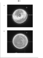
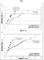
- (A) is an image showing the intensity distribution of laser light in the structure obtained as a result of performing the heat treatment step shown in FIG. 2 with the second clamp holding the glass block.
- (B) is an image showing the intensity distribution of laser light in the structure obtained as a result of performing the heat treatment step shown in FIG. 2 in a state where the glass block is free.
- 5A is a graph showing the distribution of eccentricity in each structure group shown in FIGS. 5A and 5B.
- FIG. 5B is a graph showing the distribution of the optical axis angles in each structure group shown in FIGS. 5A and 5B.
- (A) And (b) is a longitudinal cross-sectional view of the 1st modification and 2nd modification of the structure shown to (a) of FIG. 1, respectively.
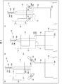
- FIG. 1A is a vertical cross-sectional view of the structure 1.
- FIG. 1B is an arrow view of the one end face 30 ⁇ /b>A that is the emission surface of the glass block 30 included in the structure 1 in a plan view.
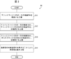
- FIG. 2 is a flowchart of the manufacturing method M1.
- FIG. 3A is a schematic diagram showing a state where the glass block 30 is heated by the burner in the second fusion bonding step S13 included in the manufacturing method M1.
- FIG. 3A is a schematic diagram showing a state where the glass block 30 is heated by the burner in the second fusion bonding step S13 included in the manufacturing method M1.
- FIG. 3B is a schematic view showing how one end face 20A of the bridge fiber 20 is pushed into the other end face 30B of the glass block 30 in the second fusion bonding step S13.
- FIG. 3C is a schematic diagram showing a state of the heat treatment step S14 included in the manufacturing method M1.
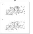
- FIG. 4A is a vertical cross-sectional view of the bridge fiber 20 and the glass block 30 after the second fusion bonding step S13.
- FIG. 4B is a vertical cross-sectional view of the bridge fiber 20 and the glass block 30 after the heat treatment step S14.
- the structure of the structure 1 will be described with reference to FIG. 1, and then the manufacturing method M1 will be described with reference to FIGS. 2 to 4.
- the structure 1 includes a delivery fiber 10, a bridge fiber 20, and a glass block 30.
- the delivery fiber 10 and the bridge fiber 20 are an aspect of the optical fiber described in the claims.
- the structure 1 is used, for example, as an output unit of a laser device (for example, a laser processing machine).
- the laser light L F generated by the laser light source for example, a fiber laser
- the laser light source for example, a fiber laser
- the glass block 30 functions as an output head (for example, a processing head) of the laser device.
- One end surface 10A of the delivery fiber 10 is joined (for example, fused) to the other end surface 20B of the bridge fiber 20.
- the other end surface 10B of the delivery fiber 10, which is the other end surface of the optical fiber, can be joined (for example, fused) to the output port of the laser light source.
- the delivery fiber 10 includes a core 10a, a clad 10b, and a coating 10c.
- the core 10a is a columnar (for example, columnar) structure body made of glass (for example, quartz glass).
- the clad 10b is a tubular (for example, circular tubular) structure made of glass (for example, quartz glass).
- the coating 10c is a tubular (for example, circular tubular) structure made of a resin (for example, an ultraviolet curable resin). The coating 10c is removed in the vicinity of both end surfaces 10A and 10B of the delivery fiber 10.
- the core 10a and the clad 10b are integrated so that the inner surface of the clad 10b covers the outer surface of the core 10a.
- One or both of the core 10a and the clad 10b is added with a dopant for making the refractive index of the core 10a higher than that of the cladding 10b, or making the refractive index of the clad 10b lower than that of the core 10a.
- the diameter ⁇ D of the delivery fiber 10 is approximately constant in the entire section and is, for example, 360 ⁇ m.
- the bridge fiber 20 is a large-diameter fiber inserted between the delivery fiber 10 and the glass block 30.
- the bridge fiber 20 includes a core 20a and a clad 20b.
- the core 20a is a columnar (for example, cylindrical) structure made of glass (for example, quartz glass).
- the clad 20b is a tubular (for example, circular tubular) structure made of glass (for example, quartz glass).
- the core 20a and the clad 20b are integrated so that the inner surface of the clad 20b covers the outer surface of the core 20a.
- One or both of the core 20a and the clad 20b is added with a dopant for making the refractive index of the core 20a higher than that of the clad 20b, or for making the refractive index of the clad 20b lower than that of the core 20a. Has been done.
- the refractive index of the core 20a is preferably the same as or similar to the refractive index of the core 10a (the same in the present embodiment), and the refractive index of the clad 20b is the same as or similar to the refractive index of the clad 10b. It is preferable (the same in the present embodiment).
- the diameter of the core 20a is preferably the same as or about the same as the diameter of the core 10a (the same in the present embodiment).
- the diameter of the bridge fiber 20 is increased by making the thickness of the clad 20b thicker than that of an ordinary optical fiber.
- the bridge fiber 20 is composed of an inclined section 21 including the other end face 20B and a same diameter portion 22 including one end face 20A.
- the inclined section 21 is configured such that its diameter ⁇ BR1 increases as it goes away from the other end surface 20B.
- the shape of the inclined section 21 is a truncated cone whose diameter ⁇ BR1 increases from the other end surface 20B toward the one end surface 20A.
- the diameter ⁇ BR1 changes within the range of ⁇ D ⁇ BR1 ⁇ BR2 according to the distance from the other end surface 20B (or the distance from the one end surface 20A).
- the diameter ⁇ BR1 at the other end surface is configured to be equal to the diameter ⁇ D
- the diameter ⁇ BR1 changes within the range of ⁇ D ⁇ BR1 ⁇ BR2 .
- the diameter ⁇ BR1 at the other end face 20B is configured to be equal to or larger than the diameter ⁇ D of the delivery fiber 10.
- the diameter ⁇ BR1 at the other end face 20B is configured to exceed the diameter ⁇ D of the delivery fiber 10, and the diameter ⁇ BR1 (that is, the minimum value of the diameter ⁇ BR1 ) at the other end face 20B is For example, it is 700 ⁇ m.
- the diameter ⁇ BR1 (that is, the maximum value of the diameter ⁇ BR1 ) at the boundary surface between the inclined section 21 and the same diameter portion 22 is, for example, 4 mm.
- the diameter ⁇ BR1 at the other end surface 20B is configured to exceed the diameter ⁇ D of the delivery fiber 10, so that one end surface 10A of the delivery fiber 10 becomes the other end surface 20B of the bridge fiber 20.
- the delivery fiber 10 and the bridge fiber 20 can be fused.
- the entire surface of the one end surface 10A can be fused to the other end surface 20B, so that the structure 1 can increase the strength of the joint portion between the delivery fiber 10 and the bridge fiber 20.
- the bridge fiber 20 can be manufactured, for example, by subjecting the vicinity of the other end of the originally cylindrical bridge fiber to a conical grinding process.
- the central axis of the inclined section 21 having a truncated cone shape that is, the central axis of the bridge fiber 20
- the central axis of the core 10a coincide with each other.
- the central axis of the inclined section 21 having a truncated cone shape that is, the central axis of the bridge fiber 20
- the central axis of the core 10a do not coincide with each other due to machining deviation at the time.
- the diameter ⁇ BR1 at the other end face 20B can be fused using the optical fiber fusion splicer. It is required to be included within a predetermined range.
- the predetermined range that can be fused using the optical fiber fusion splicer is a unique range defined for each optical fiber fusion splicer, and one example thereof is 50 ⁇ m or more and 1000 ⁇ m or less.
- the diameter ⁇ BR1 of 700 ⁇ m used in this embodiment is included in a predetermined range that can be fused by using this optical fiber fusion splicer .
- the diameter ⁇ BR1 at the other end face 20B exceeds the diameter ⁇ D of the delivery fiber 10 and is included in a predetermined range that can be fused using the optical fiber fusion splicer. Can be appropriately determined within.
- the same-diameter portion 22 is configured such that the diameter ⁇ BR2 thereof is approximately constant over the entire section from the boundary surface between the inclined section 21 and the same-diameter portion 22 to the one end surface 20A.
- the shape of the same diameter portion 22 is a column shape.
- the diameter ⁇ BR2 of the same diameter portion 22 is, for example, 4 mm.
- a section of the bridge fiber 20 in which the diameter ⁇ BR2 exceeds the diameter ⁇ D of the delivery fiber 10 is one mode of the large-diameter section described in the claims.
- the entire section of the bridge fiber 20 excluding the other end surface 20B corresponds to the large diameter section.
- the inclined section 21 is configured such that the angle formed between the inclined surface 21a and the optical axis of the bridge fiber 20 is more than 0° and less than 90°.
- the one end face 10A of the delivery fiber 10 and the other end face 20B of the bridge fiber 20 are preferably fused by using an optical fiber fusion splicer as described later.
- the maximum power of the optical fiber fusion splicer is predetermined according to the specifications of the optical fiber fusion splicer. Therefore, when the heat capacity of the other end surface 20B exceeds the allowable value corresponding to the maximum power, the optical fiber fusion splicer cannot melt the other end surface 20B, and the delivery fiber 10 and the bridge fiber 20 Cannot be fused.
- the delivery fiber 10 and the bridge fiber 20 are fused to each other by appropriately setting the heat capacity of the other end face 20B within a range below the allowable value of the heat capacity corresponding to the maximum power of the optical fiber fusion splicer. It can be fused using a connecting device. In the present embodiment, 15° is adopted as an example of the angle formed by the slope 21a that can use the optical fiber fusion splicer and the optical axis of the bridge fiber 20. In addition, in this embodiment, the delivery fiber 10 and the bridge fiber 20 are joined so that the optical axis of the bridge fiber 20 and the optical axis of the delivery fiber 10 coincide with each other. Therefore, the optical axis of the bridge fiber 20 is an example of the optical axis of the optical fiber described in the claims.
- the bridge fiber 20 having an inclined section 21 having a truncated cone shape is obtained by grinding the vicinity of the other end of the originally cylindrical bridge fiber into a conical shape.
- the sloped surface 21a of the sloped section 21 can be roughened like the surface of ground glass, for example.
- the glass block 30 is a block-shaped (for example, columnar) structure made of glass (for example, quartz glass).
- the diameter ⁇ BL of the glass block 30 is set to exceed the diameter ⁇ BR2 of the same diameter portion 22 of the bridge fiber 20 (see FIG. 1).
- the refractive index of the glass block 30 is the same as or similar to the refractive index of the core 10a of the delivery fiber 10 and the refractive index of the core 20a of the bridge fiber 20, and the refractive index of the cladding 10b of the delivery fiber 10 and the cladding of the bridge fiber 20. It is higher than the refractive index of 20b.
- One end surface 20A of the bridge fiber 20 and the other end surface 30B of the glass block 30 are joined (for example, fused).
- the optical fiber described in the claims has been described as including the delivery fiber 10 and the bridge fiber 20 joined to one end face 10A of the delivery fiber 10.
- the optical fiber described in the claims may be composed of one optical fiber in which the delivery fiber 10 and the bridge fiber 20 are integrally molded.
- the thickness of the cladding 10b is made thicker than the thickness of the cladding 10b in the other section of the delivery fiber 10, so that the delivery fiber 10 and the bridge fiber 20 are integrally molded.
- One optical fiber can be realized.
- the manufacturing method M1 for manufacturing the structure 1 as described above includes a polishing step S11, a first fusing step S12, a second fusing step S13, and a heat treatment step S14. Including.
- the polishing step S11 is a step of smoothing by polishing one end surface 20A of the bridge fiber 20, which is one end surface of the optical fiber described in the claims.
- the polishing step S11 is mechanical polishing using a rotating grindstone, and is performed by pressing one end surface 20A against the surface of the rotating grindstone.
- the polishing conditions are set so that the contoured portion (outer edge portion) of the one end face 20A is as little as possible, but a minute crack may occur in the contoured portion of the one end face 20A.
- the first fusion step S12 is a step of fusing one end surface 10A of the delivery fiber 10 and the other end surface 20B of the bridge fiber 20.
- the bridge fiber 20 includes the inclined section 21 and is configured such that the diameter ⁇ BR1 of the other end surface 20B is approximately the same as the diameter ⁇ D of the delivery fiber 10.
- the diameter ⁇ BR1 of the end face 20B of the bridge fiber 20 on the delivery fiber 10 side is sufficiently smaller than the diameter ⁇ BR2 of the end face 20A of the bridge fiber 20 on the glass block 30 side.
- the heat capacity of the end surface 20B on the fiber 10 side can be suppressed. Therefore, an optical fiber fusion splicer can be used in the first fusion step S12.
- the optical fiber fusion splicer can bond the delivery fiber 10 and the bridge fiber 20 while suppressing the deformation of the beam profile of the laser light L F. Therefore, the first fusion step S12 can suppress the deformation of the beam profile that may occur when the delivery fiber 10 and the bridge fiber 20 are joined.
- the second fusing step S13 which is an example of the fusing step described in the claims, is a step of fusing one end face 20A of the bridge fiber 20 to the other end face 30B of the glass block 30.
- the first clamp C1 shown in FIG. 3(a) is a cylindrical block-shaped member.
- a through hole (not shown in FIG. 3) that penetrates from the upper bottom surface toward the lower bottom surface is provided near the central axis of the first clamp C1.
- the diameter of this through hole is determined so that the same diameter portion 22 of the bridge fiber 20 can be housed inside the through hole.
- the first clamp C1 is an example of the first fixing portion described in the claims.
- each of the three protrusions is configured so that the amount of protrusion can be controlled from the inner wall surface.
- the first clamp C1 can fix the position of the bridge fiber 20 by projecting each of the three projecting portions in a state where the same diameter portion 22 is accommodated in the through hole. Further, the first clamp C1 frees the position of the bridge fiber 20 by reducing the protrusion amount of each of the three protrusions from the state where the bridge fiber 20 is fixed (in other words, the bridge fiber 20). Can be opened). Therefore, a part of the same diameter portion 22 of the bridge fiber 20 is fixed in position by the first clamp C1.
- the second clamp C2 shown in FIG. 3(a) has the same structure as the first clamp C1 except for the outer diameter and the diameter of the through hole provided in the vicinity of the central axis.
- the diameter of the through hole of the second clamp C2 is determined so that the glass block 30 can be housed inside the through hole.
- the second clamp C2 is an example of the second fixing portion described in the claims.
- the second clamp C2 has three protrusions like the first clamp C1.
- the second clamp C2 fixes the position of the glass block 30 or makes it free by controlling the amount of protrusion of each of the three protrusions in a state where the glass block 30 is housed inside the through hole. can do.
- the second clamp C2 is fixed on the surface of the table T.
- the fixing method for fixing the second clamp C2 on the surface of the table T is not limited.
- the second clamp C2 may be fixed to the table T using a fixing member such as a bolt, or when the weight of the second clamp C2 is sufficiently heavy, the lower bottom surface of the second clamp C2 may be fixed.
- the second clamp C2 may be fixed to the table T by a frictional force between the surface of the table T and the second clamp C2.
- the relative positions of the bridge fiber 20 and the glass block 30 are fixed.
- the first clamp C1 and the second clamp C2 described above are used to fix the relative position.
- a part of the same diameter portion 22 of the bridge fiber 20 which is a part of the optical fiber is fixed in position by the first clamp C1 and the glass block 30
- the vicinity of the lower end of the glass block 30, which is a part, is fixed in position by a second clamp C2 different from the first clamp C1 (see (a) of FIG. 3).
- the central axes of the bridge fiber 20 and the glass block 30 are arranged along the vertical direction, and their positions are fixed. It does not matter which of the bridge fiber 20 and the glass block 30 is arranged on the upper side, but in the present embodiment, the bridge fiber 20 is arranged on the upper side and the glass block 30 is arranged on the lower side.
- one end face 20A of the bridge fiber 20 and the other end face 30B of the glass block 30 are separated from each other by four It is preferable to use the burners B1 to B4 to heat the other end surface 30B so that the vicinity of the center of the other end surface 30B is slightly melted. At this time, the burners B1 to B4 are arranged isotropically with respect to the central axis of the glass block 30. Further, the bridge fiber 20 is separated from the glass block 30 so as not to be affected by the heat of the burner that heats the other end surface 30B. In addition, in the present embodiment, only the burners B1 and B3 among the burners B1 to B4 are illustrated in FIG. Further, in the present embodiment, the number of the plurality of burners B1 to B4 is four, but may be three, or may be five or more.
- oxyhydrogen gas burners are used as the burners B1 to B4.
- the oxyhydrogen gas burner uses oxyhydrogen gas, which is a mixed gas of oxygen gas and hydrogen gas, as fuel.
- the thermal power of the oxyhydrogen gas burner depends on the respective flow rates of oxygen gas and hydrogen gas.
- the thermal power of the oxyhydrogen gas burner increases as the flow rates of oxygen gas and hydrogen gas increase.
- the heating condition of the second fusion bonding step S13 is determined by the heating power of the oxyhydrogen gas burner determined by the respective flow rates of oxygen gas and hydrogen gas, and the heating time, and the vicinity of the center of the other end surface 30B is It can be appropriately determined so that it slightly melts.
- the second fusion step S13 next, in a state where the vicinity of the center of the other end face 30B is slightly melted, one end face of the bridge fiber 20 is translated by translating the first clamp C1 downward. 20A is slightly pushed into the other end surface 30B of the glass block 30 (see FIG. 3B). As a result, the one end surface 20A and the vicinity of the center of the other end surface 30B are fused, and the fusion surface S f is formed at the boundary between the one end surface 20A and the other end surface 30B.
- the heat treatment step S14 is a step performed after the second fusion bonding step S13.
- the heat treatment is performed by heating the vicinity of the outer edge of the fusion surface under a heating condition in which either one of the heat power and the heating time is lower than the heat power and the heating time set in the second fusion step S13. This is the process of applying.
- the four burners B1 to B4 are used to slightly melt the vicinity of the outer edge of the fusion-bonded surface S f of the other end surface 30B of the glass block 30. First, it is preferable to heat the other end surface 30B.
- the relative position between the bridge fiber 20 and the glass block 30 is free.
- the glass block 30 is opened by reducing the protrusion amount of each of the three protrusions of the second clamp C2, and the first clamp C1 is moved upward.
- one end face 30A of the glass block 30 is separated from the surface of the table T to free the relative position (see (c) of FIG. 3).
- the position of the glass block 30 is held by the bridge fiber 20 via the fusion-bonding surface S f . That is, the gravity acting vertically downward on the glass block 30 and the holding force acting vertically upward on the glass block 30 and the holding force by the bridge fiber 20 balance each other, whereby the glass block 30 is The position of is fixed.
- the glass block 30 is not fixed by either the second clamp C2 or the surface of the table T, and an external force other than the gravity and the holding force by the bridge fiber 20 acts. Not in a state.
- the central axes of the bridge fiber 20 and the glass block 30 are arranged along the vertical direction, and are members arranged above the bridge fiber 20 and the glass block 30.
- the position of the bridge fiber 20 is fixed, and the position of the lower member of the bridge fiber 20 and the glass block 30 is free.
- the burners B1 to B4 used in the second fusing step S13 are used.
- the heating conditions of the heat treatment step S14 are appropriately set within a range in which either one of the heating power and the heating time is lower than the heating power and the heating time set in the second fusing step S13. can do.
- the heating conditions of the heat treatment step S14 are set so that both the heating power and the heating time are lower than the heating power and the heating time set in the second fusion bonding step S13.
- the first clamp C1 and the second clamp C2 are respectively adopted as an example of each of the first fixing portion and the second fixing portion.
- the first fixing portion and the second fixing portion are not limited to these.
- the first fixing portion may have any structure as long as the position of the bridge fiber 20 can be fixed.
- the second fixing portion may have any structure as long as the position of the glass block 30 can be fixed.
- the load applied when slightly pushing one end face 20A of the bridge fiber 20 into the other end face 30B of the glass block 30 is, for example, about 1 kgf.
- the fixing force for fixing the bridge fiber 20 by the first fixing portion and the force for fixing the glass block 30 by the second fixing portion are both the bridge fiber 20 and the glass block 30 to which the above-mentioned load is applied. It can be appropriately set within a range that does not move.
- a vacuum chuck that sucks the glass block 30 by sucking air can be used.
- a vacuum chuck may be adopted instead of the first clamp C1.
- the manufacturing method M1 illustrated in FIG. 2 is the manufacturing method M1 of the structure 1 including the optical fiber (the delivery fiber 10 and the bridge fiber 20) and the glass block 30, and the optical fiber ( After the fusing step (second fusing step S13) of fusing one end surface 20A of the delivery fiber 10 and the bridge fiber 20) to the glass block 30 and the fusing step (second fusing step S13).
- the heat treatment step S14 that is performed, by heating the vicinity of the outer edge of the fusion surface under heating conditions in which one of the thermal power and the heating time is lower than the thermal power and the heating time set in the fusion step.
- a heat treatment step S14 of performing heat treatment by heating the vicinity of the outer edge of the fusion surface under heating conditions in which one of the thermal power and the heating time is lower than the thermal power and the heating time set in the fusion step.
- One end face 20A of the bridge fiber 20 is smoothed by polishing as described above. However, in the contour portion of the one end face 20A, a minute chip may occur when polished. Such a chip causes an angle where stress is likely to concentrate on the contour portion which is originally circular and is composed only of curves.
- the depression 30B1 in which stress is likely to be concentrated in the contour portion R 1 of the fusing surface S f of the other end surface 30B. May occur (see (a) of FIG. 4). It is preferable that the surface from the outer surface of the bridge fiber 20 near the one end surface 20A of the bridge fiber 20 to the other end surface 30B of the glass block 30 is smoothly continuous. However, the recess 30B1 described above causes a discontinuous portion in a part of the surface, and consequently causes a portion where stress is likely to concentrate.
- the manufacturing method M1 by including the heat treatment step S14 of performing the heat treatment on the vicinity of the outer edge of the fusion surface S f under the heating condition lower than the condition set in the second fusion step S13, the fusion surface S f It is possible to make the shape of the recess 30B1 which is a portion where the above-mentioned stress is likely to concentrate, smooth while suppressing the influence on the vicinity of the center. Further, by appropriately setting the heating conditions, as shown in FIG. 4B, the shape of the recess 30B1 is made smooth, and then the contour portion R 1 of the fusion surface S f of the other end surface 30B is The fillet 30B2 can be formed.
- the section including one end surface (one end surface 20A of the bridge fiber 20) (that is, the section of the bridge fiber 20) is larger than the section other than the section (that is, the section of the delivery fiber 10).
- the strength of the fusion surface S f Can be increased.
- a position of a part of the same diameter portion 22 of the bridge fiber 20 which is a part of the optical fiber is fixed by the first clamp C1
- a part of the glass block 30 is fixed in position by a second clamp C2 different from the first clamp C1
- the heat treatment step S14 either the first clamp C1 or the second clamp C2 is processed.
- One of them is preferably open.
- the positions of the bridge fiber 20 and the glass block 30 forming the optical fiber in the second fusion bonding step S13 are fixed by the first clamp C1 and the second clamp C2, respectively.
- the relative position can be reliably fixed.
- the manufacturing method M1 since either one of the first clamp C1 and the second clamp C2 is opened in the heat treatment step S14, the relative position can be surely freed.
- the bridge fiber 20 and the glass block 30 forming the optical fiber are arranged along the vertical direction.
- the bridge fiber 20 and the glass block 30 constituting the optical fiber are arranged along the vertical direction in the heat treatment step S14, gravity acts along the normal direction of the fusion surface S f. Works. Therefore, as compared with the case where the bridge fiber 20 and the glass block 30 forming the optical fiber are arranged along the horizontal direction, it is possible to suppress distortion of the fusion surface S f that may occur in the heat treatment step S14.
- the bridge fiber 20 constituting a part of the optical fiber is arranged on the upper side
- the glass block 30 is arranged on the lower side
- the glass block 30 The position is preferably unfixed and free.
- the delivery fiber 10 forming a part of the optical fiber is longer than the glass block 30. Therefore, when the optical fiber (delivery fiber 10 and bridge fiber 20) is arranged on the lower side in the heat treatment step S14 and the position of the optical fiber (delivery fiber 10 and bridge fiber 20) is set freely, the optical fiber ( It is difficult to suspend all of the delivery fiber 10 and the bridge fiber 20, especially the delivery fiber 10) in the air in a completely free state.
- the rest of the delivery fiber 10 needs to be placed on the ground, or the rest of the delivery fiber 10 needs to be held by some gripping mechanism.
- a force acting in a direction intersecting with the normal direction acts.
- the glass block 30 is arranged on the lower side in the heat treatment step S14, and the position of the glass block 30 is freed without being fixed. Therefore, the glass block 30 having a short length can be easily floated in the air in a completely free state. As a result, gravity acting on the fusion surface between the bridge fiber 20 and the glass block 30 acts along the direction normal to the fusion surface.
- the manufacturing method M1 as compared with the case where the optical fibers (delivery fiber 10 and bridge fiber 20) are arranged on the lower side in the heat treatment step S14, and the position of the optical fiber is free without being fixed.
- the distortion of the fused surface that may occur in the heat treatment step S14 can be suppressed.
- the bridge fiber 20 and the glass block 30 constituting the optical fiber are arranged along the vertical direction.
- the gravitational force is the method of the fusing surface S f . Operates along the line direction. Therefore, as compared with the case where the bridge fiber 20 and the glass block forming the optical fiber are arranged along the horizontal direction, the distortion of the fusion surface S f that can occur in the second fusion step S13 is suppressed.
- Example ⁇ The structure 1 manufactured using the example of the manufacturing method M1 and the structure 1 manufactured using the comparative example of the manufacturing method M1 will be described with reference to FIGS. 5 and 6.
- a plurality of structures 1 were manufactured using the example of the manufacturing method M1, and a plurality of structures 1 were manufactured using the comparative example of the manufacturing method M1.
- the plurality of structures 1 will be referred to as a structure group.
- FIG. 5A shows the laser beam L F in the structure 1 obtained as a result of performing the heat treatment step S14 shown in FIG. 2 with the second clamp C2 keeping the glass block 30 fixed. It is an image which shows intensity distribution.
- the intensity distribution shown in FIG. 5A is measured at a spot obtained by condensing the laser light emitted from one end face 20A of the bridge fiber 20. That is, the near-field pattern (NFP) of the laser beam L F in the structure 1 manufactured using the comparative example of the manufacturing method M1 has the same shape as the intensity distribution shown in FIG.
- FIG. 5B is an image showing the intensity distribution of the laser light L F in the structure 1 obtained as a result of performing the heat treatment step S14 with the glass block 30 being free. Similar to (a) in FIG.
- FIG. 5 is a graph showing the distribution of the eccentricity in each structure group shown in FIGS. 5A and 5B.
- FIG. 6B is a graph showing the distribution of optical axis angles in each structure group shown in FIGS. 5A and 5B.
- the center of gravity of the intensity distribution of the laser light L F in the structure 1 manufactured using the comparative example of the manufacturing method M1 is from the center of the bridge fiber 20 (that is, the center of the core 20a).
- Eccentricity also referred to as eccentricity).
- the eccentricity shown on the horizontal axis of (a) of FIG. 6 is a quantification of the degree of deviation of the center of gravity of the intensity distribution of the laser light L F from the center of the bridge fiber 20.
- the vertical axis in (a) of FIG. 6 represents the multiple ⁇ of the standard deviation of the eccentricity measured for each structure 1 included in the structure group.
- the optical axis angle shown on the horizontal axis of FIG. 6B represents the angle formed by the central axis of the glass block 30 and the optical axis of the laser light L F.
- the vertical axis in (b) of FIG. 6 indicates the multiple ⁇ of the standard deviation of the optical axis angle measured for each structure 1 included in each structure group.
- the larger the standard deviation multiple ⁇ the larger the variance in the structure group.
- the x-intercept of a straight line approximating the multiple ⁇ of the standard deviation represents the average value in the structure group.
- the average eccentricity is 1.18%, and the multiple ⁇ of the standard deviation is It was 0.7%.
- the average eccentricity was 2.6%, and the standard deviation multiple ⁇ was 1.53%. From the above results, it was found that the eccentricity can be suppressed by using the example of the manufacturing method M1 as compared with the case of using the comparative example of the manufacturing method M1. As described above, the manufacturing method M1 can increase the strength of the fusion bonding surface S f in the structure 1 and can suppress the eccentricity.
- the average optical axis angle is 4.2 mrad. And the multiple ⁇ of the standard deviation is 1.4 mrad. Met.
- the average optical axis angle is 9.9 mrad. And the multiple ⁇ of the standard deviation is 5.5 mrad. Met. From the above results, it was found that the optical axis angle can be suppressed by using the example of the manufacturing method M1 as compared with the case of using the comparative example of the manufacturing method M1. As described above, the manufacturing method M1 can increase the strength of the fusion bonding surface S f in the structure 1 and can suppress the optical axis angle.
- FIG. 7A is a vertical sectional view of the structure 101.
- the manufacturing method M1 according to the embodiment of the present invention can be used for manufacturing the structure 101 as well as for manufacturing the structure 1.
- the structure 101 includes a delivery fiber 110, a glass capillary tube 120, and a glass block 130.
- the delivery fiber 110 and the glass capillary tube 120 are an aspect of the optical fiber described in the claims.
- the structure 101 functions as an output head of the laser device.
- the other end surface 130B of the glass block 130 is joined (for example, fused) with one end surface 110A of the delivery fiber 110, which is one end surface of the optical fiber, and one end surface 120A of the glass capillary 120.
- the other end surface 110B of the delivery fiber 110, which is the other end surface of the optical fiber, can be joined (for example, fused) to the output port of the laser light source.
- the delivery fiber 110 is configured similarly to the delivery fiber 10 shown in FIG. That is, the delivery fiber 110 includes a core 110a, a clad 110b, and a coating 110c. Each of the core 110a, the clad 110b, and the coating 110c corresponds to the core 10a, the clad 10b, and the coating 10c of the delivery fiber 10, respectively.
- one end face 10A of the delivery fiber 10 is joined to the other end face 20B of the bridge fiber 20.
- one end surface 110A is inserted through the pores of the glass thin tube 120 described later, and the outer surface near the one end surface 110A is inside the one end surface 120A of the glass thin tube 120. It is joined (for example, fused) to the side surface.
- one end face 110A of the delivery fiber 110 is joined (for example, fused) to the other end face 130B of the glass block 130 together with the one end face 120A of the glass capillary 120.
- the delivery fiber 110 differs from the delivery fiber 10 in these points.
- the glass capillary 120 is a member corresponding to the clad 20b having the large diameter of the bridge fiber 20 shown in FIG.
- the glass thin tube 120 is a tubular (for example, circular tube) structure made of glass (for example, quartz glass).
- pores are formed near the central axis of the glass capillary 120.
- the inner diameter of the pore is configured to slightly exceed the diameter ⁇ D of the delivery fiber 110. That is, the inner diameter of the pore is small. Therefore, the glass capillary tube 120 may be called a capillary tube (capillary).
- a dopant is added to the glass capillary tube 120 to make the refractive index of the core 110a higher than that of the glass capillary tube 120 or to make the refractive index of the glass capillary tube 120 lower than that of the core 110a.
- the refractive index of the glass capillary 120 is preferably the same as or about the same as the refractive index of the cladding 110b (the same in the present embodiment).
- the glass thin tube 120 is heated in the vicinity of one end face 120A in a state where the delivery fiber 110 is inserted into its pores. By this heating, the inner surface of the section 1221 near the one end surface 120A of the glass capillary 120 is fused to the outer surface of the delivery fiber 110 near the one end surface 110A. In other words, at least a part of the inner side surface of the glass capillary 120 and at least a part of the outer side surface of the delivery fiber 110 that is inserted into the pores of the glass capillary 120 are fixed to each other by fusion bonding. Has been done. Therefore, the glass capillary tube 120 covers the delivery fiber 110.
- the optical fiber described in the claims can be obtained.
- the diameter of the optical fiber is increased by mounting the glass thin tube 120 on the delivery fiber 110.
- the glass thin tube 120 is composed of an inclined section 121 including the other end surface 120B and a same diameter portion 122 including one end surface 120A.
- the inclined section 121 is configured such that its diameter ⁇ CP1 increases as it goes away from the other end surface 120B.
- the outer shape of the inclined section 121 is a truncated cone whose diameter ⁇ CP1 increases from the other end surface 120B toward the one end surface 120A.
- the diameter ⁇ CP1 at the other end surface 120B is configured to be approximately the same as the diameter ⁇ D of the delivery fiber 10.
- the diameter ⁇ CP1 at the other end surface 120B is, for example, 400 ⁇ m.
- the diameter ⁇ CP1 (that is, the maximum value of the diameter ⁇ BR1 ) at the boundary surface between the inclined section 121 and the same diameter portion 122 is, for example, 4 mm.
- the same-diameter portion 122 is configured such that the diameter ⁇ CP2 thereof is approximately constant over the entire section from the boundary surface between the inclined section 121 and the same-diameter portion 122 to the one end surface 120A.
- the shape of the same diameter portion 122 is a circular tube.
- the diameter ⁇ CP2 of the same diameter portion 122 is, for example, 4 mm.
- the section of the delivery fiber 110 in which the glass thin tube 120 is mounted is one mode of the large-diameter section described in the claims.
- the inclined section 121 is configured such that the angle formed between the inclined surface 121a and the optical axis of the delivery fiber 110 is more than 0° and less than 90°.
- the glass thin tube 120 has the delivery fiber 110 inserted through its pores. Therefore, unlike the case of the bridge fiber 20 shown in FIG. 1, the delivery fiber 110 and the glass capillary tube 120 cannot be fused by using the optical fiber fusion splicer. Therefore, the angle formed between the inclined surface 121a and the optical axis of the delivery fiber 110 can be appropriately determined without assuming the use of the optical fiber fusion splicer. In this embodiment, as in the case of the first embodiment, 15° is adopted as an example of the angle formed by the slope 121a and the optical axis of the delivery fiber 110.
- the glass tube 120 having an outer shape of the inclined section 121 is a truncated cone is obtained by grinding the vicinity of the other end of the glass tube, which is originally a circular tube, into a conical shape.
- the sloped surface 121a of the sloped section 121 can be roughened like the surface of frosted glass, for example.
- the glass block 130 has the same structure as the glass block 30 shown in FIG. Therefore, in this embodiment, the description of the glass block 130 is omitted.
- FIG. 7B is a vertical sectional view of the structure 201.
- the manufacturing method M1 according to the embodiment of the present invention can be used for manufacturing the structure 201 as well as for manufacturing the structures 1 and 101. It can be said that the structure 201 is a modification of the structure 101 that is the first modification. Therefore, in this modification, only the structure 201 different from the structure 101 will be described.
- the delivery fiber and the glass block are denoted by the same reference numerals 110 and 130 as those of the structure 101.
- the glass thin tube 120 included in the structure 101 is replaced with the glass thin tube 220 based on the structure 101, and the glass block 240 is further added. It is obtained by doing.
- the glass block 240 is a block-shaped (cylindrical in the present modification) structure made of the same glass as the glass block 130.
- the diameter of the glass block 240 is approximately constant in all sections, and is configured to be approximately the same as (preferably the same) as the diameter ⁇ D of the delivery fiber 110. That is, the diameter of the glass block 240 is smaller than the diameter ⁇ BL of the glass block 130.
- the glass block 240 has a diameter of 360 ⁇ m, for example. Further, the length of the glass block 240 is shorter than the length of the glass block 130.
- one end surface 110A of the delivery fiber 110 is bonded (for example, fused) to the other end surface 240B of the glass block 240.
- the one end surface 110A and the glass block 240 thus joined are inserted through the pores of the glass capillary tube 220, and the outer surface of the glass block 240 and the outer surface near the one end surface 110A are the glass capillary tube. It is joined (for example, fused) to the inner side surface near one end surface 220A of 220.
- one end face 240A of the glass block 240 is joined (for example, fused) to the other end face 130B of the glass block 130 together with the one end face 220A of the glass capillary tube 220.
- the glass capillary 220 is obtained by omitting the inclined section 121 from the glass capillary 120.
- the glass thin tube 220 is composed of only the same diameter portion 122 of the glass thin tube 120. Therefore, the glass thin tube 220 is a circular tubular glass member configured such that its diameter ⁇ CP is approximately constant over the entire section from the one end surface 220A to the other end surface 220B.
- the diameter ⁇ CP of the glass capillary 220 is, for example, 4 mm.
- the glass thin tube 220 is heated in the vicinity of one end face 220A in a state where the delivery fiber 110 and the glass block 240 are inserted into the pores thereof.
- the inner surface of the section 2201 near the one end surface 220A of the glass capillary 220 is fused to the outer surface of the delivery fiber 110 near the one end surface 110A and the outer surface of the glass block 240.
- at least a part of the inner surface of the glass thin tube 220 and at least a part of the outer surface of the section of the delivery fiber 110 inserted into the pores of the glass thin tube 120 are fixed to each other by fusion bonding.
- at least a part of the inner surface of the glass thin tube 220 and the outer surface of the glass block 240 are fixed to each other by fusion bonding. Therefore, the glass thin tube 220 covers the delivery fiber 110 and the glass block 240.
- the optical fiber described in the claims can be obtained.
- the diameter of the optical fiber is increased by mounting the glass thin tube 120 on the delivery fiber 110 to which the glass block 240 is joined.
- the structure 201 includes the glass block 240 that is the first glass block and the glass block 130 that is the second glass block.
- the glass block 240 has a smaller volume than the glass block 130. Therefore, the heat capacity of the glass block 240 is smaller than that of the glass block 130.
- the amount of heat required to melt a part of the glass block 240 is lower than the amount of heat required to melt the glass block 130.
- the influence of the heat applied to the vicinity of the one end surface 110A is the case when it is assumed that the one end surface 110A is directly fused to the glass block 130. In addition, it is smaller than the influence of heat on the vicinity of one end surface 110A. Therefore, as compared with the case where the delivery fiber 110 is fused to the glass block 130 by fusing the delivery fiber 110 to the glass block 240, for example, the boundary surface between the core 110a and the clad 110b of the delivery fiber 110 is deformed. It is possible to prevent the optical axis of the core 110a from deviating from a predetermined direction.
- one end surface 240A of the glass block 240 is fused to the glass block 130 having a large heat capacity, the vicinity of the one end surface 240A is more affected by heat than the vicinity of the one end surface 110A.
- the glass block 240 is a simple glass block in which the core and the clad are not formed, even if the glass block 240 is greatly affected by heat, for example, the boundary surface between the core and the clad is deformed or the core is clad. The optical axis of does not deviate from a predetermined direction.
- the structure 201 can reduce the strain generated in the fiber, the deformation generated in the beam profile can be reduced.
- a manufacturing method is a method of manufacturing a structure including an optical fiber and a glass block, and a fusion step of fusing one end face of the optical fiber to the glass block.
- a heat treatment step carried out after the fusing step, as compared with the heating power and heating time set in the fusing step, one of the heating power and the heating time A heat treatment step of performing heat treatment by heating the vicinity of the outer edge.
- -A small chip may occur on one end face of the optical fiber. Such a chip causes an angle where stress is likely to concentrate on the contour portion which is originally circular and is composed only of curves.
- the optical fiber and the glass block are simply fused by the fusion process, there is a possibility that a dent easily concentrates stress on the contour of the fusion surface. It is preferable that the surface from the outer surface of the optical fiber near the one end surface of the optical fiber to the other end surface of the glass block is smoothly continuous. However, the above-mentioned depression causes a discontinuous portion on a part of the surface, and as a result, causes a portion where stress is likely to concentrate.
- the present manufacturing method by performing the heat treatment process on the vicinity of the outer edge of the fusion surface under the conditions below the conditions set in the fusion process, while suppressing the influence on the vicinity of the center of the fusion surface, the stress It is possible to make the shape of the area where is easily concentrated smooth.
- the present manufacturing method is a structure including an optical fiber in which a section including one end face has a large diameter, and a glass block fused to one end face of the optical fiber, and a fused surface. The strength of can be increased.
- the manufacturing method in the fusion bonding step, a part of the optical fiber, the position is fixed by the first fixing portion, and a part of the glass block, The position is fixed by a second fixing part different from the first fixing part, and in the heat treatment step, one of the first fixing part and the second fixing part is opened. , Is preferred.
- the relative position is reliably fixed. can do. Further, according to the present manufacturing method, since either one of the first fixing portion and the second fixing portion is opened in the heat treatment step, the relative position can be surely made free.
- the optical fiber and the glass block are arranged along a vertical direction.
- the optical fiber is arranged on the upper side
- the glass block is arranged on the lower side
- the position of the glass block is fixed. It is preferred that it is not, that is, free.
- the length of the optical fiber is longer than that of the glass block. Therefore, when the optical fiber is arranged on the lower side in the heat treatment step and the position of the optical fiber is free, it is difficult to float all the optical fibers in a completely free state.
- An optical fiber longer than the height at which the heat treatment process is performed needs to rest the rest portion on the ground, or to grip the rest portion by some gripping mechanism. As a result, a force acting in a direction intersecting the normal direction acts on the fusion surface between the optical fiber and the glass block, in addition to gravity acting along the normal direction of the fusion surface.
- the glass block is arranged on the lower side in the heat treatment step, and the position of the glass block is free. Therefore, the glass block having a short length can be easily floated in the air in a completely free state. As a result, gravity acting on the fusion surface between the optical fiber and the glass block acts along the normal direction of the fusion surface.
- the present manufacturing method suppresses the distortion of the fusion surface that may occur in the heat treatment step as compared with the case where the optical fiber is arranged on the lower side in the heat treatment step and the position of the optical fiber is set freely.
- the optical fiber and the glass block are arranged along a vertical direction.
Landscapes
- Physics & Mathematics (AREA)
- General Physics & Mathematics (AREA)
- Optics & Photonics (AREA)
- Chemical & Material Sciences (AREA)
- Engineering & Computer Science (AREA)
- Geochemistry & Mineralogy (AREA)
- General Life Sciences & Earth Sciences (AREA)
- Manufacturing & Machinery (AREA)
- Life Sciences & Earth Sciences (AREA)
- Materials Engineering (AREA)
- Organic Chemistry (AREA)
- Optical Fibers, Optical Fiber Cores, And Optical Fiber Bundles (AREA)
- Optical Couplings Of Light Guides (AREA)
- Mechanical Coupling Of Light Guides (AREA)
Abstract
光ファイバと、ガラスブロックと、を備えた構造体において、融着面の強度を高めることができる製造方法を提供する。製造方法(M1)は、光ファイバと、ガラスブロックと、を備えた構造体の製造方法(M1)であって、上記光ファイバの一方の端面を上記ガラスブロックに融着する融着工程(第2の融着工程S13)と、融着面の外縁近傍を加熱することにより熱処理を施す熱処理工程(S14)と、を含む。
Description
本発明は、光ファイバと、該光ファイバの一方の端面に融着されたガラスブロックと、を備えた構造体の製造方法に関する。
近年、レーザ光源が生成した大出力なレーザ光を加工対象物に照射することによって、加工対象物を加工するレーザ加工装置が広く利用されている。
このようなレーザ加工装置は、レーザ光源と、デリバリファイバと、ガラスブロックと、光学系とを備えている。例えば、デリバリファイバは、石英ガラス系の光ファイバであり、ガラスブロックは、石英ガラス製である。
デリバリファイバは、上述したように、レーザ光源が生成したレーザ光を加工対象物の近傍まで導波する。ガラスブロックは、上記デリバリファイバにより導波されたレーザ光を、該ガラスブロックの一方の端面から加工対象物に対して出射する。ガラスブロックは、デリバリファイバの一方の端面に接続されているので、デリバリファイバのエンドキャップとも呼ばれる。光学系は、ガラスブロックから出射されたレーザ光を加工対象物の表面において合焦させる。
特許文献1の図3には、光ファイバとガラスブロックとを備え、光ファイバの一方の端面にガラスブロックが融着された構造体が記載されている。
しかしながら、特許文献1の図3に記載されたような構造体では、光ファイバとして直径が全区間において略一定である光ファイバを用いているため、光ファイバとガラスブロックとの融着面の強度が不足する場合がある。
融着面の強度を高めるためには、光ファイバの一方の端面を含む区間において、クラッドの厚みをそれ以外の区間より厚くし(すなわち大径化し)、大径化された光ファイバの一方の端面をガラスブロックに融着することが考えられる。
このように一方の端面を含む区間が大径化された光ファイバと、ガラスブロックとを融着する場合、以下のような製造方法が考えられる。
まず、光ファイバの一方の端面を含む区間を大径化する。具体的には、以下の何れかの方法を用いて光ファイバの一方の端面を含む区間を大径化する。
(1)全区間に亘って直径が略一定であるデリバリファイバの一方の端面に、クラッドの厚さを厚くすることによって大径化されたブリッジファイバを接合する。
(2)中心軸近傍にデリバリファイバを挿通可能な細孔が形成されたガラス細管を用意し、上記細孔にデリバリファイバを挿通した状態で、デリバリファイバの外側面と、ガラス細管の内側面とを融着する。
このようにして、光ファイバの一方の端面を含み、且つ、大径化された大径区間が形成される。光ファイバの一方の端面でもある大径区間の一方の端面は、研磨されることによって平滑化される。
次に、該光ファイバの一方の端面と、該ガラスブロックの他方の端面とが離間するように、光ファイバ及びガラスブロックの各々を保持する。このとき、光ファイバは、第1のクランプにより把持されており、且つ、ガラスブロックは、第1のクランプとは異なる第2のクランプにより把持されている。
ガラスブロックの他方の端面をバーナーで加熱することにより該他方の端面を溶融させ、光ファイバの一方の端面をガラスブロックの他方の端面にわずかに押し込むことにより、両端面同士を融着する。これにより、光ファイバとガラスブロックとの境界面には、融着面が形成される。
以上のようにして、光ファイバの一方の端面と、ガラスブロックの他方の端面とを接合することができる。
しかしながら、光ファイバの一方の端面とガラスブロックの他方の端面とを融着しただけでは、融着面の外縁に応力が集中しやすい箇所が生じる場合があり、応力が集中しやすい箇所に起因して融着面の強度が不足する場合がある。応力が集中しやすい箇所は、光ファイバの一方の端面をガラスブロックの他方の端面に押し込んだときに融着面の外縁に生じる凹みに起因する場合もあるし、光ファイバの一方の端面を研磨する工程に起因する場合もある。
本発明の一態様に係る製造方法は、上述した課題に鑑みてなされたものであり、その目的は、光ファイバと、ガラスブロックと、を備えた構造体において、融着面の強度を高めることができる製造方法を提供することである。
上記の課題を解決するために、本発明の一態様に係る製造方法は、光ファイバと、ガラスブロックと、を備えた構造体の製造方法であって、上記光ファイバの一方の端面を上記ガラスブロックに融着する融着工程と、上記融着工程のあとに実施される熱処理工程であって、上記融着工程において設定した火力及び加熱時間と比較して、火力及び加熱時間の何れか一方が下回る加熱条件で融着面の外縁近傍を加熱することにより熱処理を施す熱処理工程と、を含む。
本発明の一態様によれば、光ファイバと、ガラスブロックと、を備えた構造体において、融着面の強度を高めることができる製造方法を提供することができる。
本発明の一実施形態に係る製造方法M1と、製造方法M1を用いて製造する構造体1について、図1~図4を参照して説明する。図1の(a)は、構造体1の縦断面図である。図1の(b)は、構造体1が備えているガラスブロック30の出射面である一方の端面30Aを平面視した場合の矢視図である。図2は、製造方法M1のフローチャートである。図3の(a)は、製造方法M1に含まれる第2の融着工程S13において、バーナーでガラスブロック30を加熱している様子を示す概略図である。図3の(b)は、第2の融着工程S13において、ブリッジファイバ20の一方の端面20Aをガラスブロック30の他方の端面30Bに押し込んだ様子を示す概略図である。図3の(c)は、製造方法M1に含まれる熱処理工程S14の様子を示す概略図である。図4の(a)は、第2の融着工程S13後のブリッジファイバ20及びガラスブロック30の縦断面図である。図4の(b)は、熱処理工程S14後のブリッジファイバ20及びガラスブロック30の縦断面図である。
本実施形態では、構造体1の構成について、図1を参照して説明したあとに、製造方法M1について、図2~図4を参照して説明する。
〔構造体1〕
図1の(a)に示すように、構造体1は、デリバリファイバ10と、ブリッジファイバ20と、ガラスブロック30と、を備えている。デリバリファイバ10とブリッジファイバ20とは、特許請求の範囲に記載の光ファイバの一態様である。
図1の(a)に示すように、構造体1は、デリバリファイバ10と、ブリッジファイバ20と、ガラスブロック30と、を備えている。デリバリファイバ10とブリッジファイバ20とは、特許請求の範囲に記載の光ファイバの一態様である。
構造体1は、例えば、レーザ装置(例えば、レーザ加工機)の出力部として利用される。この場合、レーザ光源(例えば、ファイバレーザ)にて生成されたレーザ光LFは、(1)デリバリファイバ10及びブリッジファイバ20を導波され、(2)ガラスブロック30を透過し、(3)ガラスブロック30の一方の端面30Aから外部(例えば、加工対象物)に出力される。すなわち、ガラスブロック30は、レーザ装置の出力ヘッド(例えば、加工ヘッド)として機能する。
ガラスブロック30の他方の端面30Bには、光ファイバの一方の端面であるブリッジファイバ20の一方の端面20Aが接合(例えば、融着)されている。ブリッジファイバ20の他方の端面20Bには、デリバリファイバ10の一方の端面10Aが接合(例えば、融着)されている。光ファイバの他方の端面であるデリバリファイバ10の他方の端面10Bは、レーザ光源の出力ポートに接合(例えば、融着)可能である。
デリバリファイバ10は、コア10aと、クラッド10bと、被覆10cとを備えている。コア10aは、ガラス(例えば、石英ガラス)により構成された、柱状(例えば、円柱状)の構造体である。クラッド10bは、ガラス(例えば、石英ガラス)により構成された、管状(例えば、円管状)の構造体である。被覆10cは、樹脂(例えば、紫外線硬化型樹脂)により構成された、管状(例えば、円管状)の構造体である。なお、被覆10cは、デリバリファイバ10の両端面10A,10Bの近傍において除去されている。
コア10a及びクラッド10bは、クラッド10bの内側面がコア10aの外側面を覆うように、一体化されている。コア10a及びクラッド10bの一方又は両方には、コア10aの屈折率をクラッド10bの屈折率よりも高くする、又は、クラッド10bの屈折率をコア10aの屈折率よりも低くするためのドーパントが添加されている。デリバリファイバ10の直径φDは、全区間においておよそ一定であり、例えば、360μmである。
ブリッジファイバ20は、デリバリファイバ10とガラスブロック30との間に挿入された大径ファイバである。ブリッジファイバ20は、コア20aと、クラッド20bとを備えている。コア20aは、ガラス(例えば、石英ガラス)により構成された、柱状(例えば、円柱状)の構造体である。クラッド20bは、ガラス(例えば、石英ガラス)により構成された、管状(例えば、円管状)の構造体である。コア20a及びクラッド20bは、クラッド20bの内側面がコア20aの外側面を覆うように、一体化されている。コア20a及びクラッド20bの一方又は両方には、コア20aの屈折率をクラッド20bの屈折率よりも高くする、又は、クラッド20bの屈折率をコア20aの屈折率よりも低くするためのドーパントが添加されている。
コア20aの屈折率は、コア10aの屈折率と同一又は同程度であることが好ましく(本実施形態においては同一)、クラッド20bの屈折率は、クラッド10bの屈折率と同一又は同程度であることが好ましい(本実施形態においては同一)。
また、コア20aの直径は、コア10aの直径と同一又は同程度であることが好ましい(本実施形態においては同一)。本実施形態においては、クラッド20bの厚みを通常の光ファイバよりも厚くすることによって、ブリッジファイバ20の大径化を実現している。
ブリッジファイバ20は、他方の端面20Bを含む傾斜区間21と、一方の端面20Aを含む同径部22とからなる。
傾斜区間21は、その直径φBR1が他方の端面20Bから遠ざかるにしたがって大きくなるように構成されている。本実施形態において、傾斜区間21の形状は、その直径φBR1が他方の端面20Bから一方の端面20Aに近づくにしたがって拡大する円錐台である。このように、直径φBR1は、他方の端面20Bからの距離(あるいは一方の端面20Aからの距離)に応じて、φD<φBR1≦φBR2の範囲内で変化する。他方の端面における直径φBR1が直径φDと等しく構成されている場合には、直径φBR1は、φD≦φBR1≦φBR2の範囲内で変化する。
他方の端面20Bにおける直径φBR1は、デリバリファイバ10の直径φD以上となるように構成されている。本実施形態において、他方の端面20Bにおける直径φBR1は、デリバリファイバ10の直径φDを上回るように構成されており、他方の端面20Bにおける直径φBR1(すなわち直径φBR1の最小値)は、例えば、700μmである。一方、傾斜区間21と同径部22との境界面における直径φBR1(すなわち直径φBR1の最大値)は、例えば、4mmである。
上述したように、他方の端面20Bにおける直径φBR1がデリバリファイバ10の直径φDを上回るように構成されていることにより、デリバリファイバ10の一方の端面10Aがブリッジファイバ20の他方の端面20Bに包含された状態で、デリバリファイバ10とブリッジファイバ20とを融着することができる。この構成によれば、一方の端面10Aの全面を他方の端面20Bに融着することができるので、構造体1は、デリバリファイバ10とブリッジファイバ20との接合部の強度を高めることができる。
なお、ブリッジファイバ20は、例えば、もともと円柱状であるブリッジファイバの他方の端部近傍を円錐状に研削加工を施すことによって製造することができる。この研削加工後のブリッジファイバ20において、円錐台形状である傾斜区間21の中心軸(すなわちブリッジファイバ20の中心軸)と、コア10aの中心軸とが一致していることが望ましいが、研削加工時の加工ずれに起因して、円錐台形状である傾斜区間21の中心軸(すなわちブリッジファイバ20の中心軸)と、コア10aの中心軸とが一致しない場合も生じ得る。傾斜区間21の中心軸とコア10aの中心軸とが一致していない場合であっても、他方の端面20Bにおける直径φBR1をデリバリファイバ10の直径φDよりも大きくしておくことによって、一方の端面10Aが他方の端面20Bからはみ出し、デリバリファイバ10とブリッジファイバ20との接合部の接合面積が小さくなること(換言すれば接合部の強度が低下すること)を防ぐことができる。
ただし、一方の端面10Aと他方の端面20Bとを光ファイバ融着接続機を用いて融着する場合には、他方の端面20Bにおける直径φBR1が光ファイバ融着接続機を用いて融着可能な所定の範囲内に含まれていることが求められる。光ファイバ融着接続機を用いて融着可能な所定の範囲は、光ファイバ融着接続機ごとに定められた固有の範囲であるが、その一例としては、50μm以上1000μm以下が挙げられる。本実施形態において採用している700μmという直径φBR1は、この光ファイバ融着接続機を用いて融着可能な所定の範囲内に含まれている。
以上のように、他方の端面20Bにおける直径φBR1は、デリバリファイバ10の直径φDを上回り、且つ、光ファイバ融着接続機を用いて融着可能な所定の範囲内に含まれている範囲内において適宜定めることができる。
同径部22は、傾斜区間21と同径部22との境界面から一方の端面20Aまでの全区間に亘って、その直径φBR2がおよそ一定になるように構成されている。本実施形態において、同径部22の形状は、円柱状である。同径部22の直径φBR2は、例えば、4mmである。
ブリッジファイバ20のうち、その直径φBR2がデリバリファイバ10の直径φDを上回る区間は、特許請求の範囲に記載の大径区間の一態様である。本実施形態においては、ブリッジファイバ20のうち、他方の端面20Bを除いた全区間が大径区間に相当する。
傾斜区間21は、その斜面21aとブリッジファイバ20の光軸との成す角が0°を上回り且つ90°未満となるように構成されている。斜面21aとブリッジファイバ20の光軸との成す角を小さくすればするほど、他方の端面20Bの熱容量を抑制することができる。一方、斜面21aとブリッジファイバ20の光軸との成す角を大きくすればするほど傾斜区間21の全長(ブリッジファイバ20の中心軸に沿った方向の長さ)を短くすることができる。
デリバリファイバ10の一方の端面10Aと、ブリッジファイバ20の他方の端面20Bとは、後述するように、光ファイバ融着接続機を利用して融着することが好ましい。光ファイバ融着接続機の最大パワーは、該光ファイバ融着接続機の仕様に応じて予め定められている。そのため、他方の端面20Bの熱容量が上記最大パワーに対応する許容値を上回る場合、該光ファイバ融着接続機は、他方の端面20Bを溶融させることができず、デリバリファイバ10とブリッジファイバ20とを融着することができない。
上記光ファイバ融着接続機の上記最大パワーに対応する熱容量の許容値を下回る範囲内において、他方の端面20Bの熱容量を適宜設定することにより、デリバリファイバ10とブリッジファイバ20とを光ファイバ融着接続機を利用して融着することができる。本実施形態では、光ファイバ融着接続機を利用可能な斜面21aとブリッジファイバ20の光軸との成す角の一例として15°を採用している。なお、本実施形態においては、ブリッジファイバ20の光軸とデリバリファイバ10の光軸とが一致するように、デリバリファイバ10とブリッジファイバ20とが接合されている。したがって、ブリッジファイバ20の光軸は、特許請求の範囲に記載の光ファイバの光軸の一例である。
本実施形態においては、もともと円柱状であるブリッジファイバの他方の端部近傍を円錐状に研削することによって、傾斜区間21の形状が円錐台であるブリッジファイバ20を得ている。研削に用いる砥石の粒度を適宜選択することによって、傾斜区間21の斜面21aを、例えばすりガラスの表面のように粗面化することができる。
ガラスブロック30は、ガラス(例えば、石英ガラス)により構成された、塊状(例えば、円柱状)の構造体である。ガラスブロック30の直径φBLは、ブリッジファイバ20の同径部22の直径φBR2を上回るように設定されている(図1参照)。ガラスブロック30の屈折率は、デリバリファイバ10のコア10aの屈折率及びブリッジファイバ20のコア20aの屈折率と同一又は同程度であり、デリバリファイバ10のクラッド10bの屈折率及びブリッジファイバ20のクラッド20bの屈折率よりも高い。ブリッジファイバ20の一方の端面20Aとガラスブロック30の他方の端面30Bとは、接合(例えば、融着)されている。
なお、本実施形態において、特許請求の範囲に記載の光ファイバは、デリバリファイバ10と、デリバリファイバ10の一方の端面10Aに接合されたブリッジファイバ20とからなるものとして説明した。しかし、特許請求の範囲に記載の光ファイバは、デリバリファイバ10とブリッジファイバ20とが一体成形された1本の光ファイバにより構成されていてもよい。この場合、デリバリファイバ10の一方の端面10A近傍において、クラッド10bの厚みを、デリバリファイバ10の他の区間におけるクラッド10bの厚みよりも厚くすることによって、デリバリファイバ10とブリッジファイバ20とが一体成形された1本の光ファイバを実現することができる。
〔製造方法M1〕
上述したような構造体1を製造する製造方法M1は、図2に示すように、研磨工程S11と、第1の融着工程S12と、第2の融着工程S13と、熱処理工程S14とを含む。
上述したような構造体1を製造する製造方法M1は、図2に示すように、研磨工程S11と、第1の融着工程S12と、第2の融着工程S13と、熱処理工程S14とを含む。
(研磨工程S11)
研磨工程S11は、特許請求の範囲に記載の光ファイバの一方の端面であるブリッジファイバ20の一方の端面20Aを研磨することによって平滑化する工程である。研磨工程S11は、回転する砥石を用いた機械研磨であり、回転している砥石の表面に一方の端面20Aを押し当てることによって実施される。研磨工程S11においては、一方の端面20Aの輪郭部分(外縁部分)にできるだけ欠けが生じないよう研磨条件を設定するものの、一方の端面20Aの輪郭部分には、微小な欠けが生じる場合がある。
研磨工程S11は、特許請求の範囲に記載の光ファイバの一方の端面であるブリッジファイバ20の一方の端面20Aを研磨することによって平滑化する工程である。研磨工程S11は、回転する砥石を用いた機械研磨であり、回転している砥石の表面に一方の端面20Aを押し当てることによって実施される。研磨工程S11においては、一方の端面20Aの輪郭部分(外縁部分)にできるだけ欠けが生じないよう研磨条件を設定するものの、一方の端面20Aの輪郭部分には、微小な欠けが生じる場合がある。
(第1の融着工程S12)
第1の融着工程S12は、デリバリファイバ10の一方の端面10Aと、ブリッジファイバ20の他方の端面20Bとを融着する工程である。本実施形態において、ブリッジファイバ20は、傾斜区間21を含み、他方の端面20Bの直径φBR1がデリバリファイバ10の直径φDと同程度になるように構成されている。
第1の融着工程S12は、デリバリファイバ10の一方の端面10Aと、ブリッジファイバ20の他方の端面20Bとを融着する工程である。本実施形態において、ブリッジファイバ20は、傾斜区間21を含み、他方の端面20Bの直径φBR1がデリバリファイバ10の直径φDと同程度になるように構成されている。
この構成によれば、ブリッジファイバ20のデリバリファイバ10側の端面20Bの直径φBR1がブリッジファイバ20のガラスブロック30側の端面20Aの直径φBR2と比べて十分に小さいため、ブリッジファイバ20のデリバリファイバ10側の端面20Bの熱容量を抑制することができる。そのため、第1の融着工程S12において、光ファイバ融着接続機を用いることができる。光ファイバ融着接続機は、レーザ光LFのビームプロファイルが変形することを抑制しつつ、デリバリファイバ10とブリッジファイバ20とを接合することができる。したがって、第1の融着工程S12は、デリバリファイバ10とブリッジファイバ20とを接合する場合に生じ得るビームプロファイルの変形を抑制することができる。
(第2の融着工程S13)
特許請求の範囲に記載の融着工程の一例である第2の融着工程S13は、ブリッジファイバ20の一方の端面20Aをガラスブロック30の他方の端面30Bに融着する工程である。
特許請求の範囲に記載の融着工程の一例である第2の融着工程S13は、ブリッジファイバ20の一方の端面20Aをガラスブロック30の他方の端面30Bに融着する工程である。
図3の(a)に示す第1のクランプC1は、円筒形のブロック状部材である。第1のクランプC1の中心軸の近傍には、上底面から下底面に向かって貫通する貫通孔(図3には不図示)が設けられている。この貫通孔の直径は、ブリッジファイバ20の同径部22を該貫通孔の内部に収容可能なように定められている。なお、第1のクランプC1は、特許請求の範囲に記載の第1の固定部の一例である。
この貫通孔の内壁面には、該内壁面から中心軸に向かって突出した3つの突出部であって、隣接する2つの突出部同士の中心角が何れも120°となる3つの突出部が配置されている。3つの突出部の各々は、上記内壁面から突出量を制御可能なように構成されている。
第1のクランプC1は、上記貫通孔の内部に同径部22を収容した状態において、3つの突出部の各々を突出させることによって、ブリッジファイバ20の位置を固定することができる。また、第1のクランプC1は、ブリッジファイバ20を固定している状態から3つの突出部の各々の突出量を減らすことによって、ブリッジファイバ20の位置を自由にする(換言すれば、ブリッジファイバ20を開放する)ことができる。したがって、ブリッジファイバ20の同径部22の一部は、第1のクランプC1により位置が固定されている。
図3の(a)に示す第2のクランプC2は、外径と、中心軸の近傍に設けられた貫通孔の直径とを除いて、第1のクランプC1と同様に構成されている。第2のクランプC2の貫通孔の直径は、ガラスブロック30を該貫通孔の内部に収容可能なように定められている。なお、第2のクランプC2は、特許請求の範囲に記載の第2の固定部の一例である。
第2のクランプC2は、第1のクランプC1と同様に3つの突出部を有している。第2のクランプC2は、上記貫通孔の内部にガラスブロック30を収容した状態において、3つの突出部の各々の突出量を制御することによって、ガラスブロック30の位置を固定したり、自由にしたりすることができる。
本実施形態において、第2のクランプC2は、テーブルTの表面上に固定されている。テーブルTの表面上に第2のクランプC2を固定する固定方法は、限定されるものではない。例えば、ボルトのような固定部材を用いて第2のクランプC2をテーブルTに固定してもよいし、第2のクランプC2の重量が十分に重い場合には、第2のクランプC2の下底面とテーブルTの表面との摩擦力によって第2のクランプC2をテーブルTに固定してもよい。
第2の融着工程S13において、ブリッジファイバ20とガラスブロック30との相対位置は、固定されている。本実施形態では、該相対位置を固定するために、上述した第1のクランプC1及び第2のクランプC2を用いている。
すなわち、第2の融着工程S13において、光ファイバの一部であるブリッジファイバ20の同径部22の一部は、第1のクランプC1により位置が固定されており、且つ、ガラスブロック30の一部であるガラスブロック30の下端部近傍は、第1のクランプC1とは異なる第2のクランプC2により位置が固定されている(図3の(a)参照)。
また、ブリッジファイバ20及びガラスブロック30の各々は、それぞれの中心軸が鉛直方向沿って配置されており、且つ、それぞれの位置が固定されている。ブリッジファイバ20及びガラスブロック30の何れを上側に配置するかは問わないが、本実施形態においては、ブリッジファイバ20を上側に、ガラスブロック30を下側に配置している。
第2の融着工程S13では、まず、図3の(a)に示すように、ブリッジファイバ20の一方の端面20Aと、ガラスブロック30の他方の端面30Bとを離間させた状態で、4つのバーナーB1~B4を用いて他方の端面30Bの中心近傍がわずかに溶融する程度に、他方の端面30Bを加熱することが好ましい。このとき、各バーナーB1~B4は、ガラスブロック30の中心軸に対して等方的に配置されている。また、ブリッジファイバ20は、他方の端面30Bを加熱するバーナーの熱の影響を受けないように、ガラスブロック30から離間されている。なお、本実施形態では、バーナーB1~B4のうちバーナーB1,B3のみを図3の(a)に図示している。また、本実施形態では、複数のバーナーB1~B4の数を4つにしているが、3つであってもよいし、5つ以上であってもよい。
本実施形態では、バーナーB1~B4として、酸水素ガスバーナーを採用している。酸水素ガスバーナーは、酸素ガスと水素ガスとの混合ガスである酸水素ガスを燃料とする。酸水素ガスバーナーの火力は、酸素ガス及び水素ガスの各々の流量に依存する。酸水素ガスバーナーの火力は、酸素ガス及び水素ガスの各々の流量を増やせば増やすほど増す。
第2の融着工程S13の加熱条件は、酸素ガス及び水素ガスの各々の流量によって定まる酸水素ガスバーナーの火力と、加熱時間とにより定められるものであって、他方の端面30Bの中心近傍がわずかに溶融する程度に適宜定めることができる。
第2の融着工程S13では、次に、他方の端面30Bの中心近傍がわずかに溶融した状態において、第1のクランプC1を下方向に向かって並進させることによって、ブリッジファイバ20の一方の端面20Aを、ガラスブロック30の他方の端面30Bにわずかに押し込む(図3の(b)参照)。これにより、一方の端面20Aと、他方の端面30Bの中心近傍とが融着され、一方の端面20Aと他方の端面30Bとの境界に融着面Sfが形成される。
(熱処理工程S14)
熱処理工程S14は、第2の融着工程S13のあとに実施される工程である。熱処理工程S14は、第2の融着工程S13において設定した火力及び加熱時間と比較して、火力及び加熱時間の何れか一方が下回る加熱条件で融着面の外縁近傍を加熱することにより熱処理を施す工程である。
熱処理工程S14は、第2の融着工程S13のあとに実施される工程である。熱処理工程S14は、第2の融着工程S13において設定した火力及び加熱時間と比較して、火力及び加熱時間の何れか一方が下回る加熱条件で融着面の外縁近傍を加熱することにより熱処理を施す工程である。
熱処理工程S14では、図3の(c)に示すように、4つのバーナーB1~B4を用いて、ガラスブロック30の他方の端面30Bのうち融着面Sfの外縁近傍がわずかに溶融する程度に、他方の端面30Bを加熱することが好ましい。
熱処理工程S14において、ブリッジファイバ20とガラスブロック30との相対位置は、自由である。該相対位置を自由にするために、本実施形態では、第2のクランプC2の3つの突出部の各々の突出量を減らすことによってガラスブロック30を開放し、且つ、第1のクランプC1を上方向に向かって並進させることによって、該相対位置を自由にするために、ガラスブロック30の一方の端面30AをテーブルTの表面から離間させている(図3の(c)参照)。
図3の(c)に示す状態では、ガラスブロック30の位置は、融着面Sfを介してブリッジファイバ20により保持されている。すなわち、ガラスブロック30に対して鉛直方向下向きに作用する重力と、ガラスブロック30に対して鉛直方向上向きに作用する保持力であって、ブリッジファイバ20による保持力とが釣り合うことによって、ガラスブロック30の位置は、固定されている。図3の(c)に示す状態において、ガラスブロック30は、第2のクランプC2及びテーブルTの表面の何れによっても固定されておらず、重力及びブリッジファイバ20による保持力以外の外力が作用していない状態である。
熱処理工程S14において、ブリッジファイバ20及びガラスブロック30の各々は、それぞれの中心軸が鉛直方向に沿って配置されており、且つ、ブリッジファイバ20及びガラスブロック30のうち上側に配置された部材であるブリッジファイバ20の位置が固定されており、ブリッジファイバ20及びガラスブロック30のうち下側に配置された部材の位置が自由である。
熱処理工程S14においても、第2の融着工程S13において用いたバーナーB1~B4を用いる。ただし、熱処理工程S14の加熱条件は、上述したように、第2の融着工程S13において設定した火力及び加熱時間と比較して、火力及び加熱時間の何れか一方が下回る範囲内において、適宜設定することができる。本実施形態では、熱処理工程S14の加熱条件は、第2の融着工程S13において設定した火力及び加熱時間と比較して、火力及び加熱時間の両方が下回るように設定している。
熱処理工程S14の加熱条件は、ガラスブロック30の他方の端面30Bのうち、融着面Sfの外縁近傍がわずかに溶融する程度に適宜定めることができる。
(第1の固定部及び第2の固定部のバリエーション)
本実施形態では、図3に示したように、第1の固定部及び第2の固定部の各々の一例として、それぞれ、第1のクランプC1及び第2のクランプC2を採用している。しかし、第1の固定部及び第2の固定部は、これらに限定されるものではない。第1の固定部は、ブリッジファイバ20の位置を固定可能であれば、如何なる構造を採用していてもよい。同様に、第2の固定部は、ガラスブロック30の位置を固定可能であれば、如何なる構造を採用していてもよい。
本実施形態では、図3に示したように、第1の固定部及び第2の固定部の各々の一例として、それぞれ、第1のクランプC1及び第2のクランプC2を採用している。しかし、第1の固定部及び第2の固定部は、これらに限定されるものではない。第1の固定部は、ブリッジファイバ20の位置を固定可能であれば、如何なる構造を採用していてもよい。同様に、第2の固定部は、ガラスブロック30の位置を固定可能であれば、如何なる構造を採用していてもよい。
第2の融着工程S13において、ブリッジファイバ20の一方の端面20Aを、ガラスブロック30の他方の端面30Bにわずかに押し込むときに加える荷重は、例えば、1kgf程度である。第1の固定部がブリッジファイバ20を固定する固定力、及び、第2の固定部がガラスブロック30を固定する力は、何れも、上述した荷重を加えられたブリッジファイバ20及びガラスブロック30が動かない範囲内で適宜定めることができる。
例えば、第2の固定部として、第2のクランプC2以外の構成を採用する場合、エアーを吸引することによって、ガラスブロック30を吸着する真空チャックを採用することができる。第1の固定部としても同様に、第1のクランプC1の代わりに真空チャックを採用してもよい。
〔製造方法M1のまとめ〕
以上のように、図2に示した製造方法M1は、光ファイバ(デリバリファイバ10及びブリッジファイバ20)と、ガラスブロック30と、を備えた構造体1の製造方法M1であって、光ファイバ(デリバリファイバ10及びブリッジファイバ20)の一方の端面20Aをガラスブロック30に融着する融着工程(第2の融着工程S13)と、融着工程(第2の融着工程S13)のあとに実施される熱処理工程S14であって、上記融着工程において設定した火力及び加熱時間と比較して、火力及び加熱時間の何れか一方が下回る加熱条件で融着面の外縁近傍を加熱することにより熱処理を施す熱処理工程S14と、を含む。
以上のように、図2に示した製造方法M1は、光ファイバ(デリバリファイバ10及びブリッジファイバ20)と、ガラスブロック30と、を備えた構造体1の製造方法M1であって、光ファイバ(デリバリファイバ10及びブリッジファイバ20)の一方の端面20Aをガラスブロック30に融着する融着工程(第2の融着工程S13)と、融着工程(第2の融着工程S13)のあとに実施される熱処理工程S14であって、上記融着工程において設定した火力及び加熱時間と比較して、火力及び加熱時間の何れか一方が下回る加熱条件で融着面の外縁近傍を加熱することにより熱処理を施す熱処理工程S14と、を含む。
ブリッジファイバ20の一方の端面20Aは、上述したように研磨されることによって平滑化されている。しかし、一方の端面20Aの輪郭部分には、研磨したときに微小な欠けが生じる場合がある。このような欠けは、本来円形であり曲線のみで構成されている輪郭部分に対して、応力が集中しやすい角を生じさせる。
また、第2の融着工程S13によりブリッジファイバ20とガラスブロック30とを融着しただけでは、他方の端面30Bのうち融着面Sfの輪郭部分R1に、応力が集中しやすい凹み30B1が生じる可能性がある(図4の(a)参照)。ブリッジファイバ20の一方の端面20A近傍におけるブリッジファイバの外側面から、ガラスブロック30の他方の端面30Bにかけての表面は、滑らかに連続していることが好ましい。しかし、上述した凹み30B1は、上記表面の一部に不連続な部分を生じさせるので、結果として、応力が集中しやすい部分を生じさせる。
製造方法M1によれば、第2の融着工程S13において設定した条件を下回る加熱条件で融着面Sfの外縁近傍に対して熱処理を施す熱処理工程S14を含むことによって、融着面Sfの中心近傍に与える影響を抑えつつ、上述した応力が集中しやすい箇所である凹み30B1の形状をなめらかにすることができる。また、加熱条件を適宜定めることによって、図4の(b)に示すように、凹み30B1の形状をなめらかにしたうえで、他方の端面30Bのうち融着面Sfの輪郭部分R1に、フィレット30B2を形成することができる。
その結果として、製造方法M1は、一方の端面(ブリッジファイバ20の一方の端面20A)を含む区間(すなわちブリッジファイバ20の区間)が該区間以外の区間(すなわちデリバリファイバ10の区間)よりも大径化された光ファイバ(デリバリファイバ10及びブリッジファイバ20)と、該光ファイバの上記一方の端面に融着されたガラスブロック30と、を備えた構造体1において、融着面Sfの強度を高めることができる。
また、製造方法M1は、第2の融着工程S13において、上記光ファイバの一部であるブリッジファイバ20の同径部22の一部は、第1のクランプC1により位置が固定されており、且つ、上記ガラスブロック30の一部は、第1のクランプC1とは異なる第2のクランプC2により位置が固定されており、熱処理工程S14において、第1のクランプC1及び第2のクランプC2の何れか一方は、開放されている、ことが好ましい。
製造方法M1によれば、第2の融着工程S13において光ファイバを構成するブリッジファイバ20及びガラスブロック30の各々の位置が、それぞれ、第1のクランプC1及び第2のクランプC2により固定されていることにより、上記相対位置を確実に固定することができる。また、製造方法M1によれば、熱処理工程S14において第1のクランプC1及び第2のクランプC2の何れか一方が開放されていることにより、上記相対位置を確実に自由にすることができる。
また、製造方法M1は、熱処理工程S14において、上記光ファイバを構成するブリッジファイバ20及びガラスブロック30は、鉛直方向に沿って配置されている、ことが好ましい。
製造方法M1によれば、熱処理工程S14において上記光ファイバを構成するブリッジファイバ20及びガラスブロック30が鉛直方向に沿って配置されているので、重力は、融着面Sfの法線方向に沿って作用する。したがって、上記光ファイバを構成するブリッジファイバ20及びガラスブロック30が水平方向に沿って配置されている場合と比較して、熱処理工程S14において生じ得る融着面Sfの歪みを抑えることができる。
また、製造方法M1は、熱処理工程S14において、上側に上記光ファイバの一部を構成するブリッジファイバ20が配置され、且つ、下側にガラスブロック30が配置されており、且つ、ガラスブロック30の位置は、固定されておらず且つ自由である、ことが好ましい。
光ファイバの一部を構成するデリバリファイバ10は、その長さがガラスブロック30と比較して長い。そのため、熱処理工程S14において下側に光ファイバ(デリバリファイバ10及びブリッジファイバ20)が配置されており、且つ、光ファイバ(デリバリファイバ10及びブリッジファイバ20)の位置を自由にした場合、光ファイバ(デリバリファイバ10及びブリッジファイバ20のうち特にデリバリファイバ10)の全てを完全に自由な状態で宙に浮かせることが困難である。熱処理工程S14が実施される高さよりも長いデリバリファイバ10は、その残りの部分を地面上に載置するか、あるいは、その残りの部分を何らかの把持機構により把持する必要がある。その結果、ブリッジファイバ20とガラスブロック30との融着面には、該融着面の法線方向に沿って作用する重力に加えて、該法線方向に交わる方向に作用する力が働く。
一方、製造方法M1においては、熱処理工程S14において下側にガラスブロック30が配置されており、且つ、ガラスブロック30の位置を固定することなく自由にする。そのため、長さが短いガラスブロック30を完全に自由な状態で宙に浮かせることが容易にできる。その結果、ブリッジファイバ20とガラスブロック30との融着面には、該融着面の法線方向に沿って作用する重力が働く。
したがって、製造方法M1は、熱処理工程S14において下側に光ファイバ(デリバリファイバ10及びブリッジファイバ20)が配置されており、且つ、光ファイバの位置を固定することなく自由にした場合と比較して、熱処理工程S14において生じ得る上記融着面の歪みを抑えることができる。
また、製造方法M1は、第2の融着工程S13において、上記光ファイバを構成するブリッジファイバ20及びガラスブロック30は、鉛直方向に沿って配置されている、ことが好ましい。
製造方法M1によれば、第2の融着工程S13において上記光ファイバを構成するブリッジファイバ20及びガラスブロック30が鉛直方向に沿って配置されているので、重力は、融着面Sfの法線方向に沿って作用する。したがって、光ファイバを構成するブリッジファイバ20及び上記ガラスブロックが水平方向に沿って配置されている場合と比較して、第2の融着工程S13において生じ得る融着面Sfの歪みを抑えることができる。
〔実施例〕
製造方法M1の実施例を用いて製造した構造体1と、製造方法M1の比較例を用いて製造した構造体1とについて、図5及び図6を参照して説明する。本実施例では、製造方法M1の実施例を用いて複数の構造体1を製造し、また、製造方法M1の比較例を用いて複数の構造体1を製造した。以下において、これらの複数の構造体1のことを構造体群と称する。
製造方法M1の実施例を用いて製造した構造体1と、製造方法M1の比較例を用いて製造した構造体1とについて、図5及び図6を参照して説明する。本実施例では、製造方法M1の実施例を用いて複数の構造体1を製造し、また、製造方法M1の比較例を用いて複数の構造体1を製造した。以下において、これらの複数の構造体1のことを構造体群と称する。
図5の(a)は、第2のクランプC2がガラスブロック30を固定したままの状態で、図2に示した熱処理工程S14を実施した結果として得られた構造体1におけるレーザ光LFの強度分布を示す画像である。図5の(a)に示した強度分布は、ブリッジファイバ20の一方の端面20Aから出射されたレーザ光を集光することによって得られたスポットにおいて測定したものである。すなわち、製造方法M1の比較例を用いて製造した構造体1におけるレーザ光LFのニアフィールドパターン(NFP)は、図5の(a)に示した強度分布と同様の形状を有する。図5の(b)は、ガラスブロック30を自由にした状態で、熱処理工程S14を実施した結果として得られた構造体1におけるレーザ光LFの強度分布を示す画像である。図5の(a)と同様に、図5の(b)に示した強度分布は、ブリッジファイバ20の一方の端面20Aから出射されたレーザ光を集光することによって得られたスポットにおいて測定したものである。すなわち、製造方法M1の実施例を用いて製造した構造体1におけるレーザ光LFのNFPは、図5の(b)に示した強度分布と同様の形状を有する。図6の(a)は、図5の(a)及び(b)に示した各構造体群における離心率の分布を示すグラフである。図6の(b)は、図5の(a)及び(b)に示した各構造体群における光軸角度の分布を示すグラフである。
図5の(a)に示すように、製造方法M1の比較例を用いて製造した構造体1におけるレーザ光LFの強度分布の重心は、ブリッジファイバ20の中心(すなわちコア20aの中心)から離心(偏心とも表現できる)している。
図6の(a)の横軸に示した離心率は、レーザ光LFの強度分布の重心の、ブリッジファイバ20の中心からの偏り具合を定量化したものである。図6の(a)の縦軸は、構造体群に含まれる各構造体1について測定した離心率の標準偏差の倍数σを示す。
また、図6の(b)の横軸に示した光軸角度は、ガラスブロック30の中心軸と、レーザ光LFの光軸との成す角を表す。図6の(b)の縦軸は、各構造体群に含まれる各構造体1について測定した光軸角度の標準偏差の倍数σを示す。
図6の(a)及び(b)において、標準偏差の倍数σは、大きければ大きいほど、構造体群における分散が大きいことを示す。また、標準偏差の倍数σを近似した直線のx切片は、構造体群における平均値を表す。
図6の(a)を参照すれば、製造方法M1の実施例を用いて製造した構造体1の構造体群については、平均の離心率が1.18%であり、標準偏差の倍数σが0.7%であった。一方、製造方法M1の比較例を用いて製造した構造体1の構造体群については、平均の離心率が2.6%であり、標準偏差の倍数σが1.53%であった。以上の結果より、製造方法M1の実施例を用いることによって、製造方法M1の比較例を用いた場合と比較して、離心率を抑制可能であることが分かった。以上のように、製造方法M1は、構造体1において、融着面Sfの強度を高めることができるとともに、離心率を抑制することができる。
図6の(b)を参照すれば、製造方法M1の実施例を用いて製造した構造体1の構造体群については、平均の光軸角度が4.2mrad.であり、標準偏差の倍数σが1.4mrad.であった。一方、製造方法M1の比較例を用いて製造した構造体1の構造体群については、平均の光軸角度が9.9mrad.であり、標準偏差の倍数σが5.5mrad.であった。以上の結果より、製造方法M1の実施例を用いることによって、製造方法M1の比較例を用いた場合と比較して、光軸角度を抑制可能であることが分かった。以上のように、製造方法M1は、構造体1において、融着面Sfの強度を高めることができるとともに、光軸角度を抑制することができる。
また、製造方法M1の実施例を用いることによって、製造方法M1の比較例を用いた場合と比較して、離心率及び光軸角度の何れにおいても、構造体群に含まれる各構造体1の個体差に起因する分散を抑制できることが分かった。したがって、製造方法M1の実施例を用いることによって、各構造体1の公差を抑制することができる。
〔構造体1の変形例〕
(第1の変形例)
図1に示した構造体1の第1の変形例である構造体101について、図7の(a)を参照して説明する。図7の(a)は、構造体101の縦断面図である。本発明の一実施形態に係る製造方法M1は、構造体1の製造と同様に、構造体101の製造にも用いることができる。
(第1の変形例)
図1に示した構造体1の第1の変形例である構造体101について、図7の(a)を参照して説明する。図7の(a)は、構造体101の縦断面図である。本発明の一実施形態に係る製造方法M1は、構造体1の製造と同様に、構造体101の製造にも用いることができる。
図7の(a)に示すように、構造体101は、デリバリファイバ110と、ガラス細管120と、ガラスブロック130と、を備えている。デリバリファイバ110とガラス細管120とは、特許請求の範囲に記載の光ファイバの一態様である。構造体101は、構造体1と同様に、レーザ装置の出力ヘッドとして機能する。
ガラスブロック130の他方の端面130Bには、光ファイバの一方の端面であるデリバリファイバ110の一方の端面110A及びガラス細管120の一方の端面120Aが接合(例えば、融着)されている。光ファイバの他方の端面であるデリバリファイバ110の他方の端面110Bは、レーザ光源の出力ポートに接合(例えば、融着)可能である。
デリバリファイバ110は、図1に図示したデリバリファイバ10と同様に構成されている。すなわち、デリバリファイバ110は、コア110aと、クラッド110bと、被覆110cとを備えている。コア110a、クラッド110b、及び、被覆110cの各々は、それぞれ、デリバリファイバ10のコア10a、クラッド10b、及び、被覆10cに対応する。
ただし、デリバリファイバ10は、一方の端面10Aがブリッジファイバ20の他方の端面20Bに接合されている。それに対して、デリバリファイバ110は、一方の端面110Aが後述するガラス細管120の細孔中を挿通し、且つ、一方の端面110A近傍の外側面が、ガラス細管120の一方の端面120A近傍の内側面に接合(例えば、融着)されている。そのうえで、デリバリファイバ110の一方の端面110Aは、ガラス細管120の一方の端面120Aとともにガラスブロック130の他方の端面130Bに接合(例えば、融着)されている。デリバリファイバ110は、デリバリファイバ10と比較して、これらの点が異なる。
ガラス細管120は、図1に示したブリッジファイバ20の大径化されたクラッド20bに対応する部材である。ガラス細管120は、ガラス(例えば、石英ガラス)により構成された、管状(例えば、円管状)の構造体である。本実施形態においては、ガラス細管120の中心軸近傍に細孔が形成されている。該細孔の内径は、デリバリファイバ110の直径φDをわずかに上回るように構成されている。すなわち、上記細孔の上記内径は、細い。したがって、ガラス細管120は、毛細管(キャピラリ)と称されることもある。ガラス細管120には、コア110aの屈折率をガラス細管120の屈折率よりも高くする、又は、ガラス細管120の屈折率をコア110aの屈折率よりも低くするためのドーパントが添加されている。ガラス細管120の屈折率は、クラッド110bの屈折率と同一又は同程度であることが好ましい(本実施形態においては同一)。
ガラス細管120は、その細孔中にデリバリファイバ110を挿通した状態で、一方の端面120Aの近傍を加熱される。この加熱により、ガラス細管120の一方の端面120Aの近傍区間1221の内側面は、デリバリファイバ110の一方の端面110A近傍の外側面に融着される。言い換えれば、ガラス細管120の内側面の少なくとも一部と、デリバリファイバ110のうちガラス細管120の細孔中に挿通された区間の外側面の少なくとも一部とは、融着されることによって互いに固定されている。したがって、ガラス細管120は、デリバリファイバ110を覆っている。
このように融着された一方の端面110A及び一方の端面120Aをともに研磨されることによって、特許請求の範囲に記載の光ファイバが得られる。本実施形態では、以上のように、デリバリファイバ110に対してガラス細管120を装着することによって、光ファイバの大径化を実現している。
ガラス細管120は、他方の端面120Bを含む傾斜区間121と、一方の端面120Aを含む同径部122とからなる。
傾斜区間121は、その直径φCP1が他方の端面120Bから遠ざかるにしたがって大きくなるように構成されている。本実施形態において、傾斜区間121の外形の形状は、その直径φCP1が他方の端面120Bから一方の端面120Aに近づくにしたがって拡大する円錐台である。
他方の端面120Bにおける直径φCP1は、デリバリファイバ10の直径φDと同程度になるように構成されている。他方の端面120Bにおける直径φCP1は、例えば、400μmである。傾斜区間121と同径部122との境界面における直径φCP1(すなわち直径φBR1の最大値)は、例えば、4mmである。
同径部122は、傾斜区間121と同径部122との境界面から一方の端面120Aまでの全区間に亘って、その直径φCP2がおよそ一定になるように構成されている。本実施形態において、同径部122の形状は、円管状である。同径部122の直径φCP2は、例えば、4mmである。
デリバリファイバ110のうち、ガラス細管120が装着されている区間は、特許請求の範囲に記載の大径区間の一態様である。
傾斜区間121は、その斜面121aとデリバリファイバ110の光軸との成す角が0°を上回り且つ90°未満となるように構成されている。ガラス細管120は、その細孔中にデリバリファイバ110を挿通されている。そのため、図1に示したブリッジファイバ20の場合とは異なり、光ファイバ融着接続機を用いてデリバリファイバ110とガラス細管120とを融着することはできない。したがって、斜面121aとデリバリファイバ110の光軸との成す角は、光ファイバ融着接続機の利用を想定することなく、適宜定めることができる。本実施形態では、第1の実施形態の場合と同様に、斜面121aとデリバリファイバ110の光軸との成す角の一例として15°を採用している。
本実施形態においては、もともと円管状であるガラス管の他方の端部近傍を円錐状に研削することによって、傾斜区間121の外形の形状が円錐台であるガラス細管120を得ている。研削に用いる砥石の粒度を適宜選択することによって、傾斜区間121の斜面121aを、例えばすりガラスの表面のように粗面化することができる。
ガラスブロック130は、図1に示したガラスブロック30と同一に構成されている。したがって、本実施形態では、ガラスブロック130の説明を省略する。
(第2の変形例)
図1に示した構造体1の第2の変形例である構造体201について、図7の(b)を参照して説明する。図7の(b)は、構造体201の縦断面図である。本発明の一実施形態に係る製造方法M1は、構造体1及び構造体101の製造と同様に、構造体201の製造にも用いることができる。なお、構造体201は、第1の変形例である構造体101の変形例であるとも言える。そこで、本変形例では、構造体201について、構造体101と異なっている点についてのみ説明する。なお、構造体201においても、デリバリファイバ及びガラスブロックの各々には、構造体101と同じ符号110及び130を付している。
図1に示した構造体1の第2の変形例である構造体201について、図7の(b)を参照して説明する。図7の(b)は、構造体201の縦断面図である。本発明の一実施形態に係る製造方法M1は、構造体1及び構造体101の製造と同様に、構造体201の製造にも用いることができる。なお、構造体201は、第1の変形例である構造体101の変形例であるとも言える。そこで、本変形例では、構造体201について、構造体101と異なっている点についてのみ説明する。なお、構造体201においても、デリバリファイバ及びガラスブロックの各々には、構造体101と同じ符号110及び130を付している。
図7の(b)に示すように、構造体201は、構造体101をベースにして、構造体101が備えていたガラス細管120をガラス細管220に置換し、且つ、ガラスブロック240を更に追加することによって得られる。
ガラスブロック240は、ガラスブロック130と同じガラスにより構成された、塊状(本変形例においては、円柱状)の構造体である。ガラスブロック240の直径は、全区間においておよそ一定であり、デリバリファイバ110の直径φDと同程度(好ましくは同じ)になるように構成されている。すなわち、ガラスブロック240の直径は、ガラスブロック130の直径φBLよりも小さい。ガラスブロック240の直径は、例えば、360μmである。また、ガラスブロック240の長さは、ガラスブロック130の長さよりも短い。
構造体201において、デリバリファイバ110の一方の端面110Aは、ガラスブロック240の他方の端面240Bに接合(例えば、融着)されている。このように接合された一方の端面110A及びガラスブロック240は、ガラス細管220の細孔中を挿通し、且つ、ガラスブロック240の外側面と、一方の端面110A近傍の外側面とが、ガラス細管220の一方の端面220A近傍の内側面に接合(例えば、融着)されている。そのうえで、ガラスブロック240の一方の端面240Aは、ガラス細管220の一方の端面220Aとともにガラスブロック130の他方の端面130Bに接合(例えば、融着)されている。
ガラス細管220は、ガラス細管120から傾斜区間121を省略することによって得られる。別の言い方をすれば、ガラス細管220は、ガラス細管120の同径部122のみにより構成されている。したがって、ガラス細管220は、一方の端面220Aから他方の端面220Bまでの全区間に亘って、その直径φCPがおよそ一定になるように構成された、円管状のガラス部材である。ガラス細管220の直径φCPは、例えば4mmである。
ガラス細管220は、その細孔中にデリバリファイバ110及びガラスブロック240を挿通した状態で、一方の端面220Aの近傍を加熱される。この加熱により、ガラス細管220の一方の端面220Aの近傍区間2201の内側面は、デリバリファイバ110の一方の端面110A近傍の外側面及びガラスブロック240の外側面に融着される。言い換えれば、ガラス細管220の内側面の少なくとも一部と、デリバリファイバ110のうちガラス細管120の細孔中に挿通された区間の外側面の少なくとも一部とは、融着されることによって互いに固定されており、且つ、ガラス細管220の内側面の少なくとも一部と、ガラスブロック240の外側面とは、融着されることによって互いに固定されている。したがって、ガラス細管220は、デリバリファイバ110及びガラスブロック240を覆っている。
一方の端面240A及び一方の端面220Aをともに研磨されることによって、特許請求の範囲に記載の光ファイバが得られる。本実施形態では、以上のように、ガラスブロック240を接合したデリバリファイバ110に対してガラス細管120を装着することによって、光ファイバの大径化を実現している。
以上のように、構造体201は、第1のガラスブロックであるガラスブロック240と、第2のガラスブロックであるガラスブロック130とを備えている。ガラスブロック240は、ガラスブロック130と比較して、体積が小さい。したがって、ガラスブロック240の熱容量は、ガラスブロック130の熱容量より小さい。
したがって、ガラスブロック240の一部を溶融させるために要する熱量は、ガラスブロック130を溶融させるために要する熱量より低い。
そのため、デリバリファイバ110の一方の端面110Aをガラスブロック240に融着するときに一方の端面110A近傍が受ける熱の影響は、一方の端面110Aを直接ガラスブロック130に融着すると仮定した場合におけるときに一方の端面110A近傍が受ける熱の影響より小さい。したがって、デリバリファイバ110をガラスブロック240に融着することによって、デリバリファイバ110をガラスブロック130に融着する場合と比較して、例えば、デリバリファイバ110のコア110aとクラッド110bとの境界面が変形したり、コア110aの光軸が所定の方向から逸れたりすることを抑制することができる。
また、ガラスブロック240の一方の端面240Aは、熱容量が大きなガラスブロック130に融着されるため、一方の端面240A近傍は、一方の端面110A近傍よりも熱の影響を大きく受ける。しかし、ガラスブロック240は、コア及びクラッドが形成されていない単なるガラスブロックであるため、熱の影響を大きく受けた場合であっても、例えば、コアとクラッドとの境界面が変形したり、コアの光軸が所定の方向から逸れたりすることがない。
したがって、構造体201は、ファイバに生じる歪みを低減することができるため、ビームプロファイルに生じる変形を低減できる。
〔まとめ〕
本発明の一態様に係る製造方法は、光ファイバと、ガラスブロックと、を備えた構造体の製造方法であって、上記光ファイバの一方の端面を上記ガラスブロックに融着する融着工程と、上記融着工程のあとに実施される熱処理工程であって、上記融着工程において設定した火力及び加熱時間と比較して、火力及び加熱時間の何れか一方が下回る加熱条件で融着面の外縁近傍を加熱することにより熱処理を施す熱処理工程と、を含む。
本発明の一態様に係る製造方法は、光ファイバと、ガラスブロックと、を備えた構造体の製造方法であって、上記光ファイバの一方の端面を上記ガラスブロックに融着する融着工程と、上記融着工程のあとに実施される熱処理工程であって、上記融着工程において設定した火力及び加熱時間と比較して、火力及び加熱時間の何れか一方が下回る加熱条件で融着面の外縁近傍を加熱することにより熱処理を施す熱処理工程と、を含む。
光ファイバの一方の端面には、微小な欠けが生じる場合がある。このような欠けは、本来円形であり曲線のみで構成されている輪郭部分に対して、応力が集中しやすい角を生じさせる。
また、融着工程により光ファイバとガラスブロックとを融着しただけでは、融着面の輪郭部分に応力が集中しやすい凹みが生じる可能性がある。光ファイバの一方の端面近傍における該光ファイバの外側面から、ガラスブロックの他方の端面にかけての表面は、滑らかに連続していることが好ましい。しかし、上述した凹みは、上記表面の一部に不連続な部分を生じさせるので、結果として、応力が集中しやすい部分を生じさせる。
本製造方法によれば、融着工程において設定した条件を下回る条件で融着面の外縁近傍に対して熱処理工程を施すことによって、融着面の中心近傍に与える影響を抑えつつ、上述した応力が集中しやすい箇所の形状をなめらかにすることができる。結果として、本製造方法は、一方の端面を含む区間が大径化された光ファイバと、該光ファイバの一方の端面に融着されたガラスブロックと、を備えた構造体において、融着面の強度を高めることができる。
また、本発明の一態様に係る製造方法は、上記融着工程において、上記光ファイバの一部は、第1の固定部により位置が固定されており、且つ、上記ガラスブロックの一部は、上記第1の固定部とは異なる第2の固定部により位置が固定されており、上記熱処理工程において、上記第1の固定部及び上記第2の固定部の何れか一方は、開放されている、ことが好ましい。
本製造方法によれば、融着工程において光ファイバ及びガラスブロックの各々の位置が、それぞれ、第1の固定部及び第2の固定部により固定されていることにより、上記相対位置を確実に固定することができる。また、本製造方法によれば、熱処理工程において第1の固定部及び第2の固定部の何れか一方が開放されていることにより、上記相対位置を確実に自由にすることができる。
また、本発明の一態様に係る製造方法は、上記熱処理工程において、上記光ファイバ及び上記ガラスブロックは、鉛直方向に沿って配置されている、ことが好ましい。
本製造方法によれば、熱処理工程において光ファイバ及びガラスブロックが鉛直方向に沿って配置されているので、重力は、融着面の法線方向に沿って作用する。したがって、光ファイバ及びガラスブロックが水平方向に沿って配置されている場合と比較して、熱処理工程において生じ得る融着面の歪みを抑えることができる。
また、本発明の一態様に係る製造方法は、上記熱処理工程において、上側に上記光ファイバが配置され、且つ、下側に上記ガラスブロックが配置されており、且つ、当該ガラスブロックの位置は固定されていない、すなわち自由である、ことが好ましい。
光ファイバは、その長さがガラスブロックと比較して長い。そのため、熱処理工程において下側に光ファイバが配置されており、且つ、光ファイバの位置を自由にした場合、光ファイバの全てを完全に自由な状態で宙に浮かせることが困難である。熱処理工程が実施される高さよりも長い光ファイバは、その残りの部分を地面上に載置するか、あるいは、その残りの部分を何らかの把持機構により把持する必要がある。その結果、光ファイバとガラスブロックとの融着面には、該融着面の法線方向に沿って作用する重力に加えて、該法線方向に交わる方向に作用する力が働く。
一方、本製造方法においては、熱処理工程において下側にガラスブロックが配置されており、且つ、ガラスブロックの位置を自由にする。そのため、長さが短いガラスブロックを完全に自由な状態で宙に浮かせることが容易にできる。その結果、光ファイバとガラスブロックとの融着面には、該融着面の法線方向に沿って作用する重力が働く。
したがって、本製造方法は、熱処理工程において下側に光ファイバが配置されており、且つ、光ファイバの位置を自由にした場合と比較して、熱処理工程において生じ得る融着面の歪みを抑えることができる。
また、本発明の一態様に係る製造方法は、上記融着工程において、上記光ファイバ及び上記ガラスブロックは、鉛直方向に沿って配置されている、ことが好ましい。
本製造方法によれば、融着工程において上記光ファイバ及び上記ガラスブロックが鉛直方向に沿って配置されているので、重力は、融着面の法線方向に沿って作用する。したがって、上記光ファイバ及び上記ガラスブロックが水平方向に沿って配置されている場合と比較して、融着工程において生じ得る融着面の歪みを抑えることができる。
〔付記事項〕
本発明は上述した各実施形態に限定されるものではなく、請求項に示した範囲で種々の変更が可能であり、異なる実施形態にそれぞれ開示された技術的手段を適宜組み合わせて得られる実施形態についても本発明の技術的範囲に含まれる。
本発明は上述した各実施形態に限定されるものではなく、請求項に示した範囲で種々の変更が可能であり、異なる実施形態にそれぞれ開示された技術的手段を適宜組み合わせて得られる実施形態についても本発明の技術的範囲に含まれる。
1,101 構造体
10,110 デリバリファイバ(光ファイバの一部)
20 ブリッジファイバ(光ファイバの一部)
120 ガラス細管(光ファイバの一部)
21,121 傾斜区間
22,122 同径部
30,130 ガラスブロック
C1,C2 クランプ(第1の固定部,第2の固定部)
M1 製造方法
S11 研磨工程
S12 第1の融着工程
S13 第2の融着工程(融着工程)
S14 熱処理工程
10,110 デリバリファイバ(光ファイバの一部)
20 ブリッジファイバ(光ファイバの一部)
120 ガラス細管(光ファイバの一部)
21,121 傾斜区間
22,122 同径部
30,130 ガラスブロック
C1,C2 クランプ(第1の固定部,第2の固定部)
M1 製造方法
S11 研磨工程
S12 第1の融着工程
S13 第2の融着工程(融着工程)
S14 熱処理工程
Claims (5)
- 光ファイバと、ガラスブロックと、を備えた構造体の製造方法であって、
上記光ファイバの一方の端面を上記ガラスブロックに融着する融着工程と、
上記融着工程のあとに実施される熱処理工程であって、上記融着工程において設定した火力及び加熱時間と比較して、火力及び加熱時間の何れか一方が下回る加熱条件で融着面の外縁近傍を加熱することにより熱処理を施す熱処理工程と、を含む、
ことを特徴とする製造方法。 - 上記融着工程において、上記光ファイバの一部は、第1の固定部により位置が固定されており、且つ、上記ガラスブロックの一部は、上記第1の固定部とは異なる第2の固定部により位置が固定されており、
上記熱処理工程において、上記第1の固定部及び上記第2の固定部の何れか一方は、開放されている、
ことを特徴とする請求項1に記載の製造方法。 - 上記熱処理工程において、上記光ファイバ及び上記ガラスブロックは、鉛直方向に沿って配置されている、
ことを特徴とする請求項1または2に記載の製造方法。 - 上記熱処理工程において、上側に上記光ファイバが配置され、且つ、下側に上記ガラスブロックが配置されており、且つ、当該ガラスブロックの位置は固定されていない、
ことを特徴とする請求項3に記載の製造方法。 - 上記融着工程において、上記光ファイバ及び上記ガラスブロックは、鉛直方向に沿って配置されている、
ことを特徴とする請求項1~4の何れか1項に記載の製造方法。
Applications Claiming Priority (2)
| Application Number | Priority Date | Filing Date | Title |
|---|---|---|---|
| JP2019-018935 | 2019-02-05 | ||
| JP2019018935A JP6788696B2 (ja) | 2019-02-05 | 2019-02-05 | 製造方法 |
Publications (1)
| Publication Number | Publication Date |
|---|---|
| WO2020162058A1 true WO2020162058A1 (ja) | 2020-08-13 |
Family
ID=71947860
Family Applications (1)
| Application Number | Title | Priority Date | Filing Date |
|---|---|---|---|
| PCT/JP2019/049735 Ceased WO2020162058A1 (ja) | 2019-02-05 | 2019-12-19 | 製造方法 |
Country Status (2)
| Country | Link |
|---|---|
| JP (1) | JP6788696B2 (ja) |
| WO (1) | WO2020162058A1 (ja) |
Citations (9)
| Publication number | Priority date | Publication date | Assignee | Title |
|---|---|---|---|---|
| US4962988A (en) * | 1989-07-10 | 1990-10-16 | Optomec Design Company | Termination interface structure and method for joining an optical fiber to a graded index rod lens |
| JP2000321470A (ja) * | 1999-05-17 | 2000-11-24 | Nec Corp | 光ファイバおよびレーザ加工機 |
| US6424765B1 (en) * | 1993-12-24 | 2002-07-23 | Agilent Technologies, Inc. | Optical device and method of making the same |
| JP2005241822A (ja) * | 2004-02-25 | 2005-09-08 | Fujikura Ltd | 融着光部品、融着光部品製造方法及び融着光部品製造装置 |
| JP2006209085A (ja) * | 2004-12-28 | 2006-08-10 | Precise Gauges Co Ltd | 光部品の製造方法及び製造装置、並びに、光部品 |
| JP2013007959A (ja) * | 2011-06-27 | 2013-01-10 | Sumitomo Electric Ind Ltd | 光ファイバの端面処理方法及び光ファイバの端末構造 |
| CN203480079U (zh) * | 2013-09-27 | 2014-03-12 | 武汉锐科光纤激光器技术有限责任公司 | 一种减少反馈光进入光纤的端帽结构 |
| JP2014191276A (ja) * | 2013-03-28 | 2014-10-06 | Sumitomo Electric Ind Ltd | レーザ伝送用ファイバ及びレーザ伝送用ファイバの製造方法 |
| JP2017191194A (ja) * | 2016-04-13 | 2017-10-19 | 三菱電線工業株式会社 | 光ファイバ・石英ブロック接合構造及びその製造方法 |
-
2019
- 2019-02-05 JP JP2019018935A patent/JP6788696B2/ja active Active
- 2019-12-19 WO PCT/JP2019/049735 patent/WO2020162058A1/ja not_active Ceased
Patent Citations (9)
| Publication number | Priority date | Publication date | Assignee | Title |
|---|---|---|---|---|
| US4962988A (en) * | 1989-07-10 | 1990-10-16 | Optomec Design Company | Termination interface structure and method for joining an optical fiber to a graded index rod lens |
| US6424765B1 (en) * | 1993-12-24 | 2002-07-23 | Agilent Technologies, Inc. | Optical device and method of making the same |
| JP2000321470A (ja) * | 1999-05-17 | 2000-11-24 | Nec Corp | 光ファイバおよびレーザ加工機 |
| JP2005241822A (ja) * | 2004-02-25 | 2005-09-08 | Fujikura Ltd | 融着光部品、融着光部品製造方法及び融着光部品製造装置 |
| JP2006209085A (ja) * | 2004-12-28 | 2006-08-10 | Precise Gauges Co Ltd | 光部品の製造方法及び製造装置、並びに、光部品 |
| JP2013007959A (ja) * | 2011-06-27 | 2013-01-10 | Sumitomo Electric Ind Ltd | 光ファイバの端面処理方法及び光ファイバの端末構造 |
| JP2014191276A (ja) * | 2013-03-28 | 2014-10-06 | Sumitomo Electric Ind Ltd | レーザ伝送用ファイバ及びレーザ伝送用ファイバの製造方法 |
| CN203480079U (zh) * | 2013-09-27 | 2014-03-12 | 武汉锐科光纤激光器技术有限责任公司 | 一种减少反馈光进入光纤的端帽结构 |
| JP2017191194A (ja) * | 2016-04-13 | 2017-10-19 | 三菱電線工業株式会社 | 光ファイバ・石英ブロック接合構造及びその製造方法 |
Also Published As
| Publication number | Publication date |
|---|---|
| JP6788696B2 (ja) | 2020-11-25 |
| JP2020126161A (ja) | 2020-08-20 |
Similar Documents
| Publication | Publication Date | Title |
|---|---|---|
| US9784930B2 (en) | Optical interface device having a curved waveguide using laser writing and methods of forming | |
| EP3171206B1 (en) | Optical interface devices and methods employing optical fibers and a support member having a bend section | |
| US10422961B2 (en) | Fiber array formed using laser bonded optical fibers | |
| CN1429349A (zh) | 光波导透镜和制造方法 | |
| WO2019152455A1 (en) | Optical couplers for evanescent coupling of polymer clad fibers to optical waveguides using alignment features | |
| JP2022521754A (ja) | ケーン・ベースガラス光ファイバ予備成形品を形成する真空ベースの方法 | |
| US9915791B2 (en) | Method of laser polishing a connectorized optical fiber and a connectorized optical fiber formed in accordance therewith | |
| CN103140784A (zh) | 光纤的熔接方法 | |
| JPH08136772A (ja) | 光源結合用光ファイバインターフェイスおよびその製造方法 | |
| CN206684346U (zh) | 提升耦光效率的光通讯模组 | |
| US20070274631A1 (en) | Conical-wedge-shaped lensed fiber and the method of making the same | |
| CN108508545B (zh) | 光学器件的耦合结构及耦合方法 | |
| JP5636377B2 (ja) | 電磁線伝送用の光導波路及びその製造方法 | |
| CN102053305A (zh) | 光纤、光纤的端部加工方法以及光纤的端部加工装置 | |
| TWI222540B (en) | Optical signal altering lensed apparatus and method of manufacture | |
| JP6788696B2 (ja) | 製造方法 | |
| US20230124283A1 (en) | Assembly and method for cleaving a glass body with a laser | |
| JP4146196B2 (ja) | 複合光学装置およびその製造方法 | |
| JP7066533B2 (ja) | ガラスレンズ成形型 | |
| JP7698977B2 (ja) | 光ファイバ接続構造の製造方法 | |
| JP5728375B2 (ja) | ダミー棒が接続された光ファイバ母材の製造方法、および、ダミー棒の製造方法 | |
| JP2007279291A (ja) | 光ファイバ構造体及びその製造装置、並びに、それに用いられるブロック状チップ | |
| JP2018165814A (ja) | 光コネクタの製造方法 | |
| US6476973B1 (en) | Compound surface to aid in the fabrication of a lens with a plano surface | |
| JP2008299303A (ja) | レンズ付き光ファイバとその製造方法 |
Legal Events
| Date | Code | Title | Description |
|---|---|---|---|
| 121 | Ep: the epo has been informed by wipo that ep was designated in this application |
Ref document number: 19914509 Country of ref document: EP Kind code of ref document: A1 |
|
| NENP | Non-entry into the national phase |
Ref country code: DE |
|
| 122 | Ep: pct application non-entry in european phase |
Ref document number: 19914509 Country of ref document: EP Kind code of ref document: A1 |