WO2020159323A1 - 전기차량 및 산업용 장비의 주행 중 무선충전 급전 시스템 - Google Patents
전기차량 및 산업용 장비의 주행 중 무선충전 급전 시스템 Download PDFInfo
- Publication number
- WO2020159323A1 WO2020159323A1 PCT/KR2020/001548 KR2020001548W WO2020159323A1 WO 2020159323 A1 WO2020159323 A1 WO 2020159323A1 KR 2020001548 W KR2020001548 W KR 2020001548W WO 2020159323 A1 WO2020159323 A1 WO 2020159323A1
- Authority
- WO
- WIPO (PCT)
- Prior art keywords
- electric vehicle
- wireless charging
- inverter
- feeding
- power supply
- Prior art date
Links
- 239000003990 capacitor Substances 0.000 claims abstract description 46
- 238000000034 method Methods 0.000 claims abstract description 33
- 230000005291 magnetic effect Effects 0.000 claims abstract description 11
- 239000003302 ferromagnetic material Substances 0.000 claims description 12
- 238000000926 separation method Methods 0.000 claims description 8
- 230000000694 effects Effects 0.000 abstract description 6
- 238000007796 conventional method Methods 0.000 abstract 1
- 238000010586 diagram Methods 0.000 description 5
- 230000015556 catabolic process Effects 0.000 description 4
- 230000008859 change Effects 0.000 description 3
- 230000005294 ferromagnetic effect Effects 0.000 description 3
- 230000004907 flux Effects 0.000 description 3
- 230000008901 benefit Effects 0.000 description 2
- 230000005611 electricity Effects 0.000 description 2
- 238000009434 installation Methods 0.000 description 2
- 230000005540 biological transmission Effects 0.000 description 1
- 238000001514 detection method Methods 0.000 description 1
- 230000005284 excitation Effects 0.000 description 1
- 238000012986 modification Methods 0.000 description 1
- 230000004048 modification Effects 0.000 description 1
- 239000003208 petroleum Substances 0.000 description 1
- 238000010248 power generation Methods 0.000 description 1
- 238000004904 shortening Methods 0.000 description 1
- 238000010792 warming Methods 0.000 description 1
- 229910000859 α-Fe Inorganic materials 0.000 description 1
Images


Classifications
-
- B—PERFORMING OPERATIONS; TRANSPORTING
- B60—VEHICLES IN GENERAL
- B60L—PROPULSION OF ELECTRICALLY-PROPELLED VEHICLES; SUPPLYING ELECTRIC POWER FOR AUXILIARY EQUIPMENT OF ELECTRICALLY-PROPELLED VEHICLES; ELECTRODYNAMIC BRAKE SYSTEMS FOR VEHICLES IN GENERAL; MAGNETIC SUSPENSION OR LEVITATION FOR VEHICLES; MONITORING OPERATING VARIABLES OF ELECTRICALLY-PROPELLED VEHICLES; ELECTRIC SAFETY DEVICES FOR ELECTRICALLY-PROPELLED VEHICLES
- B60L53/00—Methods of charging batteries, specially adapted for electric vehicles; Charging stations or on-board charging equipment therefor; Exchange of energy storage elements in electric vehicles
- B60L53/30—Constructional details of charging stations
- B60L53/35—Means for automatic or assisted adjustment of the relative position of charging devices and vehicles
- B60L53/38—Means for automatic or assisted adjustment of the relative position of charging devices and vehicles specially adapted for charging by inductive energy transfer
- B60L53/39—Means for automatic or assisted adjustment of the relative position of charging devices and vehicles specially adapted for charging by inductive energy transfer with position-responsive activation of primary coils
-
- B—PERFORMING OPERATIONS; TRANSPORTING
- B60—VEHICLES IN GENERAL
- B60L—PROPULSION OF ELECTRICALLY-PROPELLED VEHICLES; SUPPLYING ELECTRIC POWER FOR AUXILIARY EQUIPMENT OF ELECTRICALLY-PROPELLED VEHICLES; ELECTRODYNAMIC BRAKE SYSTEMS FOR VEHICLES IN GENERAL; MAGNETIC SUSPENSION OR LEVITATION FOR VEHICLES; MONITORING OPERATING VARIABLES OF ELECTRICALLY-PROPELLED VEHICLES; ELECTRIC SAFETY DEVICES FOR ELECTRICALLY-PROPELLED VEHICLES
- B60L53/00—Methods of charging batteries, specially adapted for electric vehicles; Charging stations or on-board charging equipment therefor; Exchange of energy storage elements in electric vehicles
- B60L53/10—Methods of charging batteries, specially adapted for electric vehicles; Charging stations or on-board charging equipment therefor; Exchange of energy storage elements in electric vehicles characterised by the energy transfer between the charging station and the vehicle
- B60L53/12—Inductive energy transfer
- B60L53/122—Circuits or methods for driving the primary coil, e.g. supplying electric power to the coil
-
- B—PERFORMING OPERATIONS; TRANSPORTING
- B60—VEHICLES IN GENERAL
- B60L—PROPULSION OF ELECTRICALLY-PROPELLED VEHICLES; SUPPLYING ELECTRIC POWER FOR AUXILIARY EQUIPMENT OF ELECTRICALLY-PROPELLED VEHICLES; ELECTRODYNAMIC BRAKE SYSTEMS FOR VEHICLES IN GENERAL; MAGNETIC SUSPENSION OR LEVITATION FOR VEHICLES; MONITORING OPERATING VARIABLES OF ELECTRICALLY-PROPELLED VEHICLES; ELECTRIC SAFETY DEVICES FOR ELECTRICALLY-PROPELLED VEHICLES
- B60L53/00—Methods of charging batteries, specially adapted for electric vehicles; Charging stations or on-board charging equipment therefor; Exchange of energy storage elements in electric vehicles
- B60L53/30—Constructional details of charging stations
- B60L53/32—Constructional details of charging stations by charging in short intervals along the itinerary, e.g. during short stops
-
- B—PERFORMING OPERATIONS; TRANSPORTING
- B60—VEHICLES IN GENERAL
- B60L—PROPULSION OF ELECTRICALLY-PROPELLED VEHICLES; SUPPLYING ELECTRIC POWER FOR AUXILIARY EQUIPMENT OF ELECTRICALLY-PROPELLED VEHICLES; ELECTRODYNAMIC BRAKE SYSTEMS FOR VEHICLES IN GENERAL; MAGNETIC SUSPENSION OR LEVITATION FOR VEHICLES; MONITORING OPERATING VARIABLES OF ELECTRICALLY-PROPELLED VEHICLES; ELECTRIC SAFETY DEVICES FOR ELECTRICALLY-PROPELLED VEHICLES
- B60L53/00—Methods of charging batteries, specially adapted for electric vehicles; Charging stations or on-board charging equipment therefor; Exchange of energy storage elements in electric vehicles
- B60L53/60—Monitoring or controlling charging stations
-
- H—ELECTRICITY
- H02—GENERATION; CONVERSION OR DISTRIBUTION OF ELECTRIC POWER
- H02J—CIRCUIT ARRANGEMENTS OR SYSTEMS FOR SUPPLYING OR DISTRIBUTING ELECTRIC POWER; SYSTEMS FOR STORING ELECTRIC ENERGY
- H02J50/00—Circuit arrangements or systems for wireless supply or distribution of electric power
- H02J50/40—Circuit arrangements or systems for wireless supply or distribution of electric power using two or more transmitting or receiving devices
-
- B—PERFORMING OPERATIONS; TRANSPORTING
- B60—VEHICLES IN GENERAL
- B60L—PROPULSION OF ELECTRICALLY-PROPELLED VEHICLES; SUPPLYING ELECTRIC POWER FOR AUXILIARY EQUIPMENT OF ELECTRICALLY-PROPELLED VEHICLES; ELECTRODYNAMIC BRAKE SYSTEMS FOR VEHICLES IN GENERAL; MAGNETIC SUSPENSION OR LEVITATION FOR VEHICLES; MONITORING OPERATING VARIABLES OF ELECTRICALLY-PROPELLED VEHICLES; ELECTRIC SAFETY DEVICES FOR ELECTRICALLY-PROPELLED VEHICLES
- B60L2200/00—Type of vehicles
- B60L2200/40—Working vehicles
- B60L2200/44—Industrial trucks or floor conveyors
-
- B—PERFORMING OPERATIONS; TRANSPORTING
- B60—VEHICLES IN GENERAL
- B60L—PROPULSION OF ELECTRICALLY-PROPELLED VEHICLES; SUPPLYING ELECTRIC POWER FOR AUXILIARY EQUIPMENT OF ELECTRICALLY-PROPELLED VEHICLES; ELECTRODYNAMIC BRAKE SYSTEMS FOR VEHICLES IN GENERAL; MAGNETIC SUSPENSION OR LEVITATION FOR VEHICLES; MONITORING OPERATING VARIABLES OF ELECTRICALLY-PROPELLED VEHICLES; ELECTRIC SAFETY DEVICES FOR ELECTRICALLY-PROPELLED VEHICLES
- B60L2210/00—Converter types
- B60L2210/40—DC to AC converters
-
- B—PERFORMING OPERATIONS; TRANSPORTING
- B60—VEHICLES IN GENERAL
- B60L—PROPULSION OF ELECTRICALLY-PROPELLED VEHICLES; SUPPLYING ELECTRIC POWER FOR AUXILIARY EQUIPMENT OF ELECTRICALLY-PROPELLED VEHICLES; ELECTRODYNAMIC BRAKE SYSTEMS FOR VEHICLES IN GENERAL; MAGNETIC SUSPENSION OR LEVITATION FOR VEHICLES; MONITORING OPERATING VARIABLES OF ELECTRICALLY-PROPELLED VEHICLES; ELECTRIC SAFETY DEVICES FOR ELECTRICALLY-PROPELLED VEHICLES
- B60L2270/00—Problem solutions or means not otherwise provided for
- B60L2270/10—Emission reduction
- B60L2270/14—Emission reduction of noise
- B60L2270/147—Emission reduction of noise electro magnetic [EMI]
-
- H—ELECTRICITY
- H02—GENERATION; CONVERSION OR DISTRIBUTION OF ELECTRIC POWER
- H02J—CIRCUIT ARRANGEMENTS OR SYSTEMS FOR SUPPLYING OR DISTRIBUTING ELECTRIC POWER; SYSTEMS FOR STORING ELECTRIC ENERGY
- H02J50/00—Circuit arrangements or systems for wireless supply or distribution of electric power
- H02J50/10—Circuit arrangements or systems for wireless supply or distribution of electric power using inductive coupling
-
- Y—GENERAL TAGGING OF NEW TECHNOLOGICAL DEVELOPMENTS; GENERAL TAGGING OF CROSS-SECTIONAL TECHNOLOGIES SPANNING OVER SEVERAL SECTIONS OF THE IPC; TECHNICAL SUBJECTS COVERED BY FORMER USPC CROSS-REFERENCE ART COLLECTIONS [XRACs] AND DIGESTS
- Y02—TECHNOLOGIES OR APPLICATIONS FOR MITIGATION OR ADAPTATION AGAINST CLIMATE CHANGE
- Y02P—CLIMATE CHANGE MITIGATION TECHNOLOGIES IN THE PRODUCTION OR PROCESSING OF GOODS
- Y02P90/00—Enabling technologies with a potential contribution to greenhouse gas [GHG] emissions mitigation
- Y02P90/60—Electric or hybrid propulsion means for production processes
-
- Y—GENERAL TAGGING OF NEW TECHNOLOGICAL DEVELOPMENTS; GENERAL TAGGING OF CROSS-SECTIONAL TECHNOLOGIES SPANNING OVER SEVERAL SECTIONS OF THE IPC; TECHNICAL SUBJECTS COVERED BY FORMER USPC CROSS-REFERENCE ART COLLECTIONS [XRACs] AND DIGESTS
- Y02—TECHNOLOGIES OR APPLICATIONS FOR MITIGATION OR ADAPTATION AGAINST CLIMATE CHANGE
- Y02T—CLIMATE CHANGE MITIGATION TECHNOLOGIES RELATED TO TRANSPORTATION
- Y02T10/00—Road transport of goods or passengers
- Y02T10/60—Other road transportation technologies with climate change mitigation effect
- Y02T10/70—Energy storage systems for electromobility, e.g. batteries
-
- Y—GENERAL TAGGING OF NEW TECHNOLOGICAL DEVELOPMENTS; GENERAL TAGGING OF CROSS-SECTIONAL TECHNOLOGIES SPANNING OVER SEVERAL SECTIONS OF THE IPC; TECHNICAL SUBJECTS COVERED BY FORMER USPC CROSS-REFERENCE ART COLLECTIONS [XRACs] AND DIGESTS
- Y02—TECHNOLOGIES OR APPLICATIONS FOR MITIGATION OR ADAPTATION AGAINST CLIMATE CHANGE
- Y02T—CLIMATE CHANGE MITIGATION TECHNOLOGIES RELATED TO TRANSPORTATION
- Y02T10/00—Road transport of goods or passengers
- Y02T10/60—Other road transportation technologies with climate change mitigation effect
- Y02T10/7072—Electromobility specific charging systems or methods for batteries, ultracapacitors, supercapacitors or double-layer capacitors
-
- Y—GENERAL TAGGING OF NEW TECHNOLOGICAL DEVELOPMENTS; GENERAL TAGGING OF CROSS-SECTIONAL TECHNOLOGIES SPANNING OVER SEVERAL SECTIONS OF THE IPC; TECHNICAL SUBJECTS COVERED BY FORMER USPC CROSS-REFERENCE ART COLLECTIONS [XRACs] AND DIGESTS
- Y02—TECHNOLOGIES OR APPLICATIONS FOR MITIGATION OR ADAPTATION AGAINST CLIMATE CHANGE
- Y02T—CLIMATE CHANGE MITIGATION TECHNOLOGIES RELATED TO TRANSPORTATION
- Y02T10/00—Road transport of goods or passengers
- Y02T10/60—Other road transportation technologies with climate change mitigation effect
- Y02T10/72—Electric energy management in electromobility
-
- Y—GENERAL TAGGING OF NEW TECHNOLOGICAL DEVELOPMENTS; GENERAL TAGGING OF CROSS-SECTIONAL TECHNOLOGIES SPANNING OVER SEVERAL SECTIONS OF THE IPC; TECHNICAL SUBJECTS COVERED BY FORMER USPC CROSS-REFERENCE ART COLLECTIONS [XRACs] AND DIGESTS
- Y02—TECHNOLOGIES OR APPLICATIONS FOR MITIGATION OR ADAPTATION AGAINST CLIMATE CHANGE
- Y02T—CLIMATE CHANGE MITIGATION TECHNOLOGIES RELATED TO TRANSPORTATION
- Y02T90/00—Enabling technologies or technologies with a potential or indirect contribution to GHG emissions mitigation
- Y02T90/10—Technologies relating to charging of electric vehicles
- Y02T90/12—Electric charging stations
-
- Y—GENERAL TAGGING OF NEW TECHNOLOGICAL DEVELOPMENTS; GENERAL TAGGING OF CROSS-SECTIONAL TECHNOLOGIES SPANNING OVER SEVERAL SECTIONS OF THE IPC; TECHNICAL SUBJECTS COVERED BY FORMER USPC CROSS-REFERENCE ART COLLECTIONS [XRACs] AND DIGESTS
- Y02—TECHNOLOGIES OR APPLICATIONS FOR MITIGATION OR ADAPTATION AGAINST CLIMATE CHANGE
- Y02T—CLIMATE CHANGE MITIGATION TECHNOLOGIES RELATED TO TRANSPORTATION
- Y02T90/00—Enabling technologies or technologies with a potential or indirect contribution to GHG emissions mitigation
- Y02T90/10—Technologies relating to charging of electric vehicles
- Y02T90/14—Plug-in electric vehicles
Definitions
- the present invention relates to a wireless charging and feeding system, and more specifically, to an electric bus, an electric passenger car, a tram, a light rail train, an electric vehicle such as a subway, and an RTGC (Rubber Tyred Gantry Crane). It is about.
- a power supply system is installed to enable wireless charging on the road.
- FIG. 1 is a view showing a feeding line of the wireless charging system 100 while driving a conventional wireless charging electric vehicle, the feeding line is placed on the left and right sides of the inverter 101 and is composed of a single coil.
- the inverter 110 applies a sinusoidal current to the feed line composed of the common line part 130 and the feed area 140, and the applied current is returned to the inverter 110.
- Such a configuration mainly consists of a power supply line in a low frequency band (20-40 kHz), so that electric vehicles and industrial equipment can be wirelessly charged.
- a low frequency band (20-40 kHz)
- the breakdown voltage between both ends of the same feed line increases by about 4.25 times, which may cause problems such as discharge and leakage current.
- a method of shortening the teeth of the feeder line or reducing the current used may be proposed, but if the length is shortened, the charging time of the charging electric vehicle during driving is shortened, resulting in a problem that the charging amount is significantly reduced.
- Reducing the current may be one method, but when reducing the current, a voltage lower than the battery voltage is formed as an excitation electromotive force, which may cause a problem that the battery is not easily charged.
- the present invention was devised to solve this problem, more effectively reduce the breakdown voltage of the feeder line, and improve the compatibility with various wireless charging current collector pads installed in the vehicle in a manner that further reduces the cost, and also of the feeder line.
- the purpose of the present invention is to provide a wireless charging and feeding system that reduces electromagnetic interference (EMI).
- EMI electromagnetic interference
- a system for wirelessly controlling charging power during driving of an electric vehicle and industrial equipment (hereinafter referred to as ⁇ electric vehicle'') equipped with a current collector according to the present invention is wireless by alternating current flow.
- a feeding cable that generates electric power for charging An inverter having a relay for controlling the supply of the alternating current flowing through the feeder cable and adjusting the phase of the alternating current to 0 degrees or 180 degrees;
- a capacitor unit having a relay for adjusting the phase of the alternating current to 0 or 180 degrees under the control of the inverter, and a capacitor to offset the inductance of the feed line, and the other end of the feed cable connected to one end of the inverter. Is configured to be connected to the next capacitor unit without returning to the inverter.
- the other end of the feeding cable connected to one end of the nth capacitor unit is connected to the n+1th capacitor unit without returning to the nth capacitor unit.
- the coil constituting the feeder cable may be composed of a pair, or may be composed of two or more pairs.
- a feeding core which is a ferromagnetic material may be further included.
- each coil can independently adjust the phase of the current independently by a relay, so that all of the phases of 0 or 180 degrees can be adjusted for the n pairs of coils. Combination is possible, and it is possible to control the wireless power supplied through the feeder cable by controlling the current phase combination.
- each coil When the feeding cable is composed of n (n ⁇ 2) pairs of coils, each coil may be arranged to be contacted without a separation distance, or may be arranged at a predetermined distance.
- the coil constituting the feeding cable and the feeding core may be disposed to be contacted without a separation distance or may be disposed at a predetermined distance.
- Each coil of the section (hereinafter referred to as a'common line') where each coil constituting the feeder cable is collected may be set to have a current direction so as to cancel a magnetic field above a predetermined criterion.
- the wireless charging and feeding system for the electric vehicle may further include a shielding tube surrounding the entire coil for shielding a magnetic field in a section where each coil constituting the feeding cable is collected (hereinafter referred to as a'common line'). .
- the inverter detects the location of the electric vehicle that has entered, detects current collector information mounted on the electric vehicle, and locates the electric vehicle according to the detected current collector information. It is possible to control the power of the branch and to cut off the power of the location when the corresponding electric vehicle leaves the location.
- the location of the electric vehicle may be a feeding segment in which the electric vehicle is located.
- the information of the current collector may be the type of the current collector or the height from the ground of the current collector.
- the method for controlling the power supply by the wireless charging power supply system includes: (a) When an electric vehicle equipped with a current collecting device enters a power supply section controlled by the inverter, the corresponding electricity Detecting the position of the vehicle; (B) the inverter, grasping the information of the current collector mounted on the electric vehicle; (c) the inverter converting a point where the electric vehicle is located into a charging mode according to the identified current collector information, and controlling power to be supplied to the location; And, (d) when the electric vehicle is out of the position, the inverter may include the step of switching the position to the off mode, to cut off the power of the position.
- the location of the electric vehicle may be a feeding segment in which the electric vehicle is located.
- the information of the current collector may be the type of the current collector or the height from the ground of the current collector.
- each coil can independently adjust the phase of the current independently by a relay, and all combinations of phases of 0 or 180 degrees for the n pairs of coils This is possible, and the inverter can control the wireless power supplied through the feeding cable by controlling the current phase combination.
- the present invention it is possible to expand the wireless feeder line while driving by solving the problems of internal pressure on the conventional feeder line with a capacitor provided in a'hammer' or'inverter' existing outside the road, and a design method of a feeder line and a common line arrangement design. And, according to the scalability, there is an effect of greatly improving the economic problem of the wireless charging system.
- FIG. 1 is a view showing a feeding line of a conventional wireless charging power supply system.
- Figure 2 is a schematic diagram showing a wireless charging and feeding system including an electric vehicle on the road according to the present invention.
- Figure 3 is a view showing the coil structure of the feed line of the wireless charging power supply system according to the present invention.
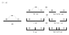
- FIG. 4 is a view showing the shape and structure of the ferromagnetic material forming the feeding core of the wireless charging power supply system according to the present invention.
- FIG. 5 is a view showing a distance between a coil and a ferromagnetic material that is a coil and a feeding core, which are design variables of a wireless charging and feeding system according to the present invention.
- FIG. 6 is a graph showing a change in inductance per unit distance of a power supply line according to the design variable shown in FIG. 5.
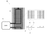
- FIG. 7 is a diagram illustrating a method of processing a common line portion in a wireless charging and feeding system according to the present invention.
- FIG. 8 is a flow chart showing a power supply control method in the wireless charging power supply system according to the present invention.
- FIG. 2 is a schematic diagram showing a wireless charging and feeding system including an electric vehicle on a road according to the present invention.
- the feeder line in the wireless power transmission of an electric vehicle (bus, tram, train, passenger car, etc.) 10, the feeder line includes a feeding part composed of a plurality of feeding pads, and a feeding part It includes an inverter 210 for supplying AC power, and a common line 230 connecting the inverter 210 and the power supply unit.
- the feeding part includes a feeding core made of a ferromagnetic material and a feeding cable 240.
- the configuration of the inverter 210 or the box 220 of the wireless charging power supply system 200 of the present invention is not limited to the inverter or the box, but may include a switch or other power device, and these devices are also through the inverter or box Since the device implements the same functions as the one to be implemented, in the following description, these will be referred to collectively as the inverter 210 and other boxes 220.
- the term'ham' refers to a circuit part including a capacitor and a relay, and hereinafter referred to as a'capacitor part 220' by distinguishing it from the inverter 210.
- a relay is also provided in the inverter 210.
- the common line connecting the power supply unit and the inverter does not return, and as shown in FIG. 2, it has a structure to expand and connect to the next inverter or capacitor unit 220.
- the other end of the feed cable having one end connected to the nth capacitor part returns to the nth capacitor part. It is not connected to the n+1th capacitor portion.
- the wireless charging power supply system 200 of the present invention of FIG. 2 includes a feeding line having compatibility so that charging can be performed even when various types of wireless charging pads are attached to various types of vehicles.
- the breakdown voltage of the power supply line can be more effectively reduced through a capacitor provided in the inverter 210 or a capacitor provided in the capacitor unit 220.
- the reason why the breakdown voltage of the power supply line can be reduced is that the capacitor cancels out the inductance generated in the power supply line.
- the advantage of the present invention is that a plurality of inverters are not used to implement the compatibility as described above. That is, if a plurality of inverters are used, as much of the installation cost is incurred, which lowers economic efficiency.
- the present invention sufficiently secures such compatibility through one inverter 210 and one or more capacitors 220 connected as shown in FIG. 2 with the inverter 210, that is, the inverter 210 or the capacitor. It is possible to ensure compatibility by changing the current phase through the relay disposed in the unit 220. The implementation method of such compatibility will be described later in detail with reference to FIG. 3.
- the shape of the power supply line of the wireless charging power supply system 200 may be various shapes including an elliptical or circular structure, and may not include a ferromagnetic material such as a ferrite core as a power supply core, or a ferromagnetic material as a power supply core.
- a ferromagnetic material such as a ferrite core as a power supply core
- a ferromagnetic material as a power supply core
- the coil structure of the feed line may be composed of a pair of coils or two or more pairs, an example of this is illustrated in FIG. 3.
- the current direction of each coil of the feeder line may be made of any possible combination in the coil, and the interval between a pair of coils or two or more pairs of coils may be variously spaced including equal intervals It may include but will be described later with reference to FIGS. 3 and 5.
- FIG. 3 is a view showing a coil structure of a power supply line of the wireless charging power feeding system 200 according to the present invention
- FIG. 4 is a shape and structure of a ferromagnetic material forming a feeding core of the wireless charging power feeding system 200 according to the present invention.
- the shape and structure of the ferromagnetic material may include all of the modified shapes including the bar-type, L-type, and W-type.
- FIG. 3 an embodiment 300 of a cross-section of a feed cable 240 constituting a feed line, that is, a cross section showing a current direction flowing through the feed cable 240 is illustrated.
- the feed line may be composed of a single number of coils 301 or a plurality of coils 302, 303, 304.
- the direction in which the current flows is indicated by' ⁇ '
- the direction in which the current flows is indicated by'X'.
- only three examples of 301, 302, and 303 are shown for the case of using two coils, but any combination of two' ⁇ ' and two'X' is possible.
- the direction of the current in each coil can be controlled to' ⁇ ' or'X'. That is, according to the control of the relay of the inverter 210 and the relay of the capacitor unit 220, it is possible to control the phase of the current in each coil to 0 or 180 degrees.
- wireless power is generated by the magnetic flux transmitted from the corresponding power supply line section to the charging mode, or the magnetic flux is blocked to cut off the power (off mode).
- the phase of each coil wireless power is generated by the magnetic flux transmitted from the corresponding power supply line section to the charging mode, or the magnetic flux is blocked to cut off the power (off mode).
- wireless power is generated by magnetic flux from the current of the power supply cable 240, and the charging mode is generated.
- the pair of coils on the left side are canceled each other as currents of opposite phases, so that power for charging is not generated.
- the pair of coils on the right does not generate electricity as well.
- the phase control of the current can be variously controlled in addition to switching to the charging mode or the off mode.
- some power may be generated at the receiving side according to the distance 20 between the two coils. That is, if the two coils are arranged very close, little power will be generated at the receiving side, but as the distance between the two coils is farther than a predetermined interval, the generated power at the receiving side will increase.
- the distance between the coils 20 and the distance between the coil 240 and the lower feeding core 250 (refer to FIG. 5), occurrence of a case where currents of the same phase flow through a pair of coils on both sides The power and the generated power when the current in the opposite phase flows are changed.
- Inverter 210 that controls the magnitude and phase of the generated current, as well as controlling the wireless power generation of the corresponding section on or off according to the case where the vehicle is present or non-existent in a specific segment of the feeder line section, the section By detecting the type of the pick-up device mounted on the vehicle passing through, and the height of the current collecting device from the ground of the feeder line, which differs depending on a large vehicle or a passenger car, so that appropriate wireless power is supplied to the current collecting device It is possible to control the phase of the current flowing through the power supply cable 240 of the power supply line, that is, the coil 240 as shown in the embodiment 300 of FIG. 3.
- the control of the phase of the current by the inverter 210 is performed by controlling the relay provided in the inverter 210 and the relay provided in the capacitor 220 of each section.
- each coil can independently adjust the phase of the current by a relay under the control of the inverter 210, so that n pairs of Any combination of phases of 0 degrees or 180 degrees with respect to the coil is possible, and the wireless power supplied through the feeding cable is controlled by controlling the current phase combination of the inverter 210.
- FIG. 5 is a diagram illustrating a distance 20 between coils 240 which are design variables of a wireless charging and feeding system 200 according to the present invention, and a distance 30 between coils 240 and ferromagnetic material 250 which is a feeding core.
- FIG. 6 is a graph showing a change in inductance per unit distance of a power supply line according to the design variable shown in FIG. 5.
- each coil may be arranged to be contacted without a separation distance, or may be arranged to be spaced apart at a certain distance, and the coils and the power supply core constituting the power supply cable may also be arranged to be contacted without a separation distance, or may be arranged to be spaced at a certain distance. have.
- F15 graph 61 means that the separation distance 30 between the ferromagnetic body and the coil is 15 mm
- F25 means that the separation distance 30 between the ferromagnetic body and the coil is 25 mm (62).
- the value of the x-axis (horizontal axis) of the graph represents the distance 20 between the coils
- the y-axis (vertical axis) means inductance per unit length.
- the graph shows an example of a total of 66 designs for the design variables (20, 30) at intervals, and the appropriate design variable values are set according to the environment and various conditions in which the power supply line is installed. Can be set.
- FIG. 7 is a diagram illustrating a method of processing a portion of the common line 230 in the wireless charging and feeding system 200 according to the present invention.
- the common line refers to a portion where the feeding cable 240 is collected, that is, a portion 230 of which the feeding cable is collected from the inverter 210 or the capacitor unit 220 (see FIG. 2 ).
- the common line 230 is not only shielded by a magnetic field wrapped by the shield tube 260, but also can maximize the magnetic field canceling effect by reducing the direction of the current as shown in FIG. 7(b), thereby reducing inductance.
- FIG. 8 is a flow chart showing a power supply control method in the wireless charging power supply system 200 according to the present invention.
- the control of Figure 8 is performed by the inverter 210.
- the power-supply section controlled by the inverter means all the capacitor parts 220 connected to the corresponding inverter 210 and the power-supply cable section connected thereto.
- the position of the corresponding vehicle to be sensed means that which power supply segment is in the power supply section.
- the power supply segment is a power supply line between the inverter 210 and the next capacitor part 221 (see FIG. 2), and a power supply line between the next capacitor part 221 (see FIG. 2) and the next capacitor part 222 (see FIG. 2). Etc. Referring to FIG.
- the feed line between the inverter 210 and the next capacitor unit 221 (refer to FIG. 2) is referred to as a first feed segment, and the next capacitor unit 221 (see FIG. 2) and the next capacitor unit 222 , See FIG. 2 ), when the second power supply segment is referred to as a second power supply segment, the current vehicle has entered the second power supply segment.
- the position detection (S801) may be performed in various ways, but as an embodiment, GPS information of the corresponding vehicle 10 is received to determine a feeding segment in a feeding section of the current inverter 210 of the corresponding vehicle. Can.
- the inverter 210 connected to the power supply segment in which the corresponding vehicle 10 is located directly detects the vehicle entry, or the capacitor units 221 and 222 connected to the power supply segment detects the vehicle entrance and sends a signal to the inverter 210. can send.
- the inverter 210 connected to the power supply segment in which the corresponding vehicle 10 is located directly detects current collector information mounted in the corresponding vehicle 10, or the capacitor units 221 and 222 connected to the power supply segment are connected to the corresponding vehicle ( 10) by detecting the current collector information mounted on the sensor, and sending the information to the inverter 210, whereby the inverter 210 can grasp the current collector information (S802).
- the current collector information may include the type of current collector, the height of the current collector from the ground, and the like.
- Inverter 210 switches the power supply segment in which the vehicle is located to the charging mode and controls the power to be fed (S803). As described above with reference to FIG. 3, the control of the power is controlled by controlling the relay of the inverter 210 and the capacitor unit 221 or 222 of the corresponding feeding segment to control the phase of the current of each coil 240. You can do it the way
- the inverter 210 switches the power supply segment to the off mode to cut off the power of the power supply segment (S804).
- power cut-off may also be performed by controlling the relay of the capacitor part 221 or 222 of the power supply segment to control the phase of the current in each coil 240.
Abstract
본 발명은 무선충전 급전 시스템에 관한 것으로서, 더욱 상세하게는 전기 버스, 전기 승용차, 트램, 경전철, 지하철 등의 전기차량 및 RTGC(Rubber Tyred Gantry Crane)를 포함한 산업용 장비의 운행 중 무선충전 급전 시스템에 관한 것이다. 본 발명에 의하면, 종래 급전선로 상의 내압 문제를 도로 밖에 존재하는 '함' 또는 '인버터'에 구비된 캐패시터와, 급전선로 설계 방안 및 공통선 배치 설계로 해결함으로써 주행중 무선 급전선로의 확장을 가능하게 하며, 이러한 확장성에 따라 무선 충전 시스템의 경제성 문제를 크게 개선한다. 이와 함께 종래 다수의 인버터를 사용하는 방식에 의해 주행중 차량에 설치된 다양한 무선 충전 집전 패드와 호환성을 유지시키는 방식과 대비하여, '함'과 '인버터'내에 존재하는 릴레이를 활용함으로써 더욱 저렴한 비용으로 그와 같은 호환성을 충분히 만족시키는 무선 충전 급전 시스템을 제공하며, 나아가, 공통선의 구조 및 차폐관을 이용하여 자기장 상쇄 효과를 극대화함으로써 급전선로의 EMI(ElectroMagnetic Interference)를 저감시킨다.
Description
본 발명은 무선충전 급전 시스템에 관한 것으로서, 더욱 상세하게는 전기 버스, 전기 승용차, 트램, 경전철, 지하철 등의 전기차량 및 RTGC(Rubber Tyred Gantry Crane)를 포함한 산업용 장비의 운행 중 무선충전 급전 시스템에 관한 것이다.
지구 온난화로 인해 자동차, 철도 등의 교통수단에 대해, 석유 에너지를 대체하기 위해 에너지 공급원으로서 배터리를 이용한 전기력의 사용이 증가하고 있다. 그러나 현재는 배터리의 용량이 충분치 않아 주행거리가 짧고 잦은 충전이 요구될 뿐만 아니라, 충전소 등의 인프라 부족 또한 충전 시간 소요 등의 원인으로 인해 전기차가 더욱 일반적으로 보급되기에는 한계가 있어 왔으나, 주행 중에 도로 상에서 무선충전이 가능하도록 급전 시스템이 설치되고 있기도 하다.
도 1은 종래의 무선충전 전기차의 주행 중 무선충전 시스템(100)의 급전선로를 나타낸 도면으로서, 급전선로가 인버터(101)를 중심으로 좌우측에 놓이게 되고 단일 코일로 구성되어 있다.
인버터(110)에서 정현파 전류를 공통선 부분(130)과 급전 영역(140)으로 구성된 급전선로로 인가하고, 인가된 전류는 다시 그 인버터(110)로 회귀하는 구조로 되어 있다.
이러한 구성은 주로 주파수가 낮은 영역대(20~40kHz)에서는 큰 무리 없이 급전선로를 구성하여 전기차량 및 산업용 장비에 무선으로 충전이 가능하다. 그러나 차량에 장착되는 무선충전 패드의 무게와 크기 EMF 그리고 유선 충전 대비 상대적으로 비싼 무선 충전의 한계성으로 인하여 많은 연구 등으로 무선 충전의 주파수를 기존 20~40kHz에서 85kHz로 변경하고 있는 실정이다. 그러나 변경된 주파수에 따라 이점들도 확보할 수 있지만 주파수 상승에 대한 내압 문제가 상존하게 되는 단점을 지닌다
즉, 현 전기차량용 무선충전 추세에 따라 주파수가 20~40kHz에서 85kHz로 상향된다면, 동일한 급전선로에서 양단간의 내압은 약 4.25배 상승하게 되어 방전, 누설전류 등의 문제를 야기시킬 수 있다. 이를 억제하기 위해서는 급전선로의 이를 짧게 하거나 사용되는 전류를 줄이는 방안 등이 제안될 수 있으나, 길이를 짧게 할 경우 주행중 충전 전기차의 충전 시간이 짧아지게 되어 충전량이 현저히 떨어지는 문제가 발생한다. 전류를 줄이는 것도 하나의 방안이 될 수 있으나, 전류를 줄일 경우 배터리 전압보다 낮은 전압이 여기 기전력으로 형성됨으로 배터리 충전이 용이치 않게 되는 문제를 야기할 수 있는 문제점이 있다.
또한 주파수 문제와 더불어, 기존의 전기차 주행중 무선충전 급전 시스템(100)의 경우 단일 코일이 차량진행 방향으로 한 턴으로 감겨 있어, 다른 차량에 부착된 무선충전 패드와의 호환성이 결여될 수 있는 단점을 가진다.
본 발명은 이와 같은 문제점을 해결하기 위해 창안된 것으로서, 급전선로의 내압을 더욱 효과적으로 저감하고, 비용을 더욱 저감시킨 방식으로 차량에 설치된 다양한 무선 충전 집전 패드와의 호환성을 향상시키며, 또한 급전선로의 EMI(ElectroMagnetic Interference)를 저감시키는 무선충전 급전 시스템을 제공하는데 그 목적이 있다.
이와 같은 목적을 달성하기 위하여 본 발명에 따른 집전장치가 장착된 전기차량 및 산업용 장비(이하 '전기차량'이라 통칭한다)의 주행 중 무선으로 충전 전력을 제어하는 시스템은, 교류 전류가 흐름으로써 무선 충전을 위한 전력을 발생시키는 급전케이블; 상기 급전케이블에 흐르는 교류 전류의 공급을 제어하고, 교류 전류의 위상을 0도 또는 180도로 조정하는 릴레이(relay)를 구비하는 인버터; 및, 상기 인버터의 제어를 받아 교류 전류의 위상을 0도 또는 180도로 조정하는 릴레이 및, 급전선로의 인덕턴스를 상쇄시키는 캐패시터를 구비하는 캐패시터부를 포함하고, 상기 인버터에 일단이 연결된 상기 급전 케이블의 타단은, 인버터로 회귀하지 않고 다음 캐패시터부로 연결되도록 구성된다.
상기 캐패시터부는 하나 이상 구비되며, 상기 캐패시터부가 2개 이상 구비되는 경우, 제 n번째 캐패시터부에 일단이 연결된 상기 급전 케이블의 타단은, 제 n번째 캐패시터부로 회귀하지 않고 제 n+1번째 캐패시터부로 연결될 수 있다.
상기 급전케이블을 구성하는 코일은, 1쌍으로 구성되거나, 또는 2쌍 이상으로 구성될 수 있다.
상기 급전케이블 하부에, 강자성체인 급전코어를 더 포함할 수 있다.
상기 급전케이블이 n(n≥2)쌍의 코일로 구성될 경우, 각 코일은 릴레이에 의해 각각 독립적으로 전류의 위상 조정이 가능하여, 상기 n쌍의 코일에 대하여 0도 또는 180도 위상의 모든 조합이 가능하고, 상기 전류 위상 조합의 제어에 의해 급전케이블을 통하여 공급되는 무선 전력을 제어할 수 있다.
상기 급전케이블이 n(n≥2)쌍의 코일로 구성될 경우, 각 코일은 이격 거리 없이 접촉되도록 배치되거나, 또는 일정 거리 이격되어 배치될 수 있다.
상기 급전케이블을 구성하는 코일과 급전코어는, 이격 거리 없이 접촉되도록 배치되거나, 또는 일정 거리 이격되어 배치될 수 있다.
상기 급전케이블을 구성하는 각 코일이 모아지는 구간(이하 '공통선'이라 한다)의 각 코일은, 기 설정된 기준 이상으로 자기장 상쇄가 되도록 전류 방향이 설정될 수 있다.
상기 전기차량에 대한 무선충전 급전 시스템은, 상기 급전케이블을 구성하는 각 코일이 모아지는 구간(이하 '공통선'이라 한다)에는, 자기장 차폐를 위해 전체 코일을 감싸는 차폐관을 더 구비할 수 있다.
상기 인버터는, 상기 전기차량이 급전 구간에 진입한 경우, 진입한 전기차량의 위치를 감지하고, 상기 전기차량에 장착된 집전장치 정보를 감지하여, 감지된 집전장치 정보에 따라 해당 전기차량이 위치한 지점의 전력을 제어하고, 해당 전기차량이 그 위치에서 나간 경우, 그 위치의 전력을 차단하도록 제어할 수 있다.
상기 전기차량의 위치는, 상기 전기차량이 위치한 급전 세그먼트일 수 있다.
상기 집전장치의 정보는, 상기 집전장치의 종류 또는 상기 집전장치의 지면으로부터의 높이일 수 있다.
본 발명의 다른 측면에 따르면, 상기 무선충전 급전 시스템이, 급전을 제어하는 방법은, (a) 인버터가, 상기 인버터가 제어하는 급전 구간에 집전장치를 장착한 전기차량이 진입한 경우, 해당 전기차량의 위치를 감지하는 단계; (b) 상기 인버터가, 상기 전기차량에 장착된 집전장치의 정보를 파악하는 단계; (c) 상기 인버터가, 파악된 집전장치 정보에 따라, 전기차량이 위치한 지점을 충전 모드로 전환하고, 그 위치에 급전할 전력을 제어하는 단계; 및, (d) 상기 인버터가, 상기 전기차량이 상기 위치를 빠져나간 경우, 해당 위치를 오프 모드로 전환하여, 해당 위치의 전력을 차단하는 단계를 포함할 수 있다.
상기 전기차량의 위치는, 상기 전기차량이 위치한 급전 세그먼트일 수 있다.
상기 집전장치의 정보는, 상기 집전장치의 종류 또는 상기 집전장치의 지면으로부터의 높이일 수 있다.
급전케이블이 n(n≥2)쌍의 코일로 구성될 경우, 각 코일은 릴레이에 의해 각각 독립적으로 전류의 위상 조정이 가능하여, 상기 n쌍의 코일에 대하여 0도 또는 180도 위상의 모든 조합이 가능하고, 상기 인버터는 상기 전류 위상 조합의 제어에 의해 급전케이블을 통하여 공급되는 무선 전력을 제어할 수 있다.
본 발명에 의하면, 종래 급전선로 상의 내압 문제를 도로 밖에 존재하는 '함' 또는 '인버터'에 구비된 캐패시터와, 급전선로 설계 방안 및 공통선 배치 설계로 해결함으로써 주행중 무선 급전선로의 확장을 가능하게 하며, 이러한 확장성에 따라 무선 충전 시스템의 경제성 문제를 크게 개선하는 효과가 있다.
이와 함께 종래 다수의 인버터를 사용하는 방식에 의해 주행중 차량에 설치된 다양한 무선 충전 집전 패드와 호환성을 유지시키는 방식과 대비하여, '함'과 '인버터'내에 존재하는 릴레이를 활용함으로써 더욱 저렴한 비용으로 그와 같은 호환성을 충분히 만족시키는 무선 충전 급전 시스템을 제공하는 효과가 있다.
나아가, 공통선의 구조 및 차폐관을 이용하여 자기장 상쇄 효과를 극대화함으로써 급전선로의 EMI(ElectroMagnetic Interference)를 저감시키는 효과가 있다.
도 1은 종래의 무선충전 급전 시스템의 급전 선로를 나타낸 도면.
도 2는 본 발명에 따른 도로상에 전기차량을 포함한 무선 충전 급전 시스템이 도시된 개략도.
도 3은 본 발명에 따른 무선 충전 급전 시스템의 급전선로의 코일 구조를 나타낸 도면.
도 4는 본 발명에 따른 무선 충전 급전 시스템의 급전코어를 형성하는 강자성체의 형상과 구조를 나타낸 도면.
도 5는 본 발명에 따른 무선 충전 급전 시스템의 설계 변수인 코일 간의 거리 및 코일과 급전코어인 강자성체 간의 거리를 도시한 도면.
도 6은 도 5에서 도시한 설계 변수에 따른 급전선로의 단위거리당 인덕턴스의 변화를 나타내는 그래프.
도 7은 본 발명에 따른 무선 충전 급전 시스템에서 공통선 부분의 처리 방법을 예시한 도면.
도 8은 본 발명에 따른 무선 충전 급전 시스템에서 급전 제어 방법을 나타내는 순서도.
이하 첨부된 도면을 참조로 본 발명의 바람직한 실시예를 상세히 설명하기로 한다. 이에 앞서, 본 명세서 및 청구범위에 사용된 용어나 단어는 통상적이거나 사전적인 의미로 한정해서 해석되어서는 아니되며, 발명자는 그 자신의 발명을 가장 최선의 방법으로 설명하기 위해 용어의 개념을 적절하게 정의할 수 있다는 원칙에 입각하여 본 발명의 기술적 사상에 부합하는 의미와 개념으로 해석되어야만 한다. 따라서, 본 명세서에 기재된 실시예와 도면에 도시된 구성은 본 발명의 가장 바람직한 일 실시예에 불과할 뿐이고 본 발명의 기술적 사상을 모두 대변하는 것은 아니므로, 본 출원시점에 있어서 이들을 대체할 수 있는 다양한 균등물과 변형예들이 있을 수 있음을 이해하여야 한다.
도 2는 본 발명에 따른 도로상에 전기차량을 포함한 무선 충전 급전 시스템이 도시된 개략도이다.
본 발명에 따른 무선 충전 급전 시스템(200)은 전기차량(버스, 트램, 전철, 승용차 등)(10)의 무선전력전달에 있어서, 급전선로는 복수개의 급전패드로 구성된 급전부와, 급전부에 교류전력을 공급하는 인버터(210)와, 인버터(210)와 급전부를 연결하는 공통선(230)을 포함한다. 급전부는 강자성체로 구성되는 급전코어와 급전케이블(240)을 구비한다.
본 발명의 무선충전 급전 시스템(200)의 인버터(210) 또는 함(220)의 구성은, 인버터 또는 함으로 국한되지 않고 스위치 또는 다른 전력장치를 수반할 수 있는데, 이러한 장치들 역시 인버터 또는 함을 통하여 구현하는 것과 동일한 기능을 구현하는 장치이므로, 이하의 설명에서는 이들을 인버터(210) 및 그 외의 함(220)으로 통칭하여 부르기로 한다. 여기서 '함'이라함은 캐패시터(capacitor)와 릴레이(relay)를 포함하는 회로부가 포함된 함을 말하는 것으로서, 이하에서는 이를 인버터(210)와 구분하여 '캐패시터부(220)'라 칭하기로 한다. 이와 같은 릴레이는 인버터(210)에도 구비된다.
또한 본 발명에서는 급전부와 인버터를 연결하는 공통선이 회귀되지 않고, 도 2에 도시된 바와 같이 다음 인버터 또는 캐패시터부(220)로 확장 연결하는 구조를 가진다. 마찬가지로, 캐패시터부(220)가 2개 이상 구비(221,222...) 되는 경우에도, 도 2에 도시된 바와 같이 제 n번째 캐패시터부에 일단이 연결된 급전 케이블의 타단은, 제 n번째 캐패시터부로 회귀하지 않고 제 n+1번째 캐패시터부로 연결된다.
도 2의 본 발명의 무선충전 급전 시스템(200)은, 다양한 종류의 차량에 다양한 종류의 무선충전 패드가 부착되더라도 충전이 가능하도록, 호환성을 구비한 급전 선로를 포함한다. 도 2와 같이 급전선로를 구성할 경우, 인버터(210) 내에 구비된 캐패시터, 또는 캐패시터부(220)에 구비된 캐패시터를 통해 급전선로의 내압을 보다 효과적으로 저감할 수 있다. 급전선로의 내압을 저감시킬 수 있는 이유는, 급전선로에서 발생하는 인덕턴스를, 캐패시터가 상쇄하게 되기 때문이다.
나아가, 본 발명의 장점은, 전술한 바와 같은 호환성을 구현하기 위해 복수개의 인버터를 이용하지 않는다는 점이다. 즉, 복수개의 인버터를 사용할 경우 그만큼 많은 설치 비용이 들어가게 되어 경제성을 저하시킨다. 본 발명은 하나의 인버터(210)와 함께, 그 인버터(210)와 도 2와 같이 연결된 하나 이상의 커패시터부(220)를 통하여 그와 같은 호환성을 충분히 확보하게 되는데, 즉, 인버터(210) 또는 캐패시터부(220)에 배치된 릴레이를 통해 전류 위상을 바꿈으로써 호환성을 확보할 수 있게 되는 것이다. 이와 같은 호환성의 구현 방법에 대하여는 도 3을 참조하여 상세히 후술하기로 한다.
또한 무선충전 급전 시스템(200)의 급전선로의 형상은 타원형 또는 원형 구조를 비롯하여 다양한 형상일 수 있으며, 급전코어로서 페라이트 코어와 같은 강자성체를 수반하거나, 또는 급전코어로서의 강자성체를 수반하지 않을 수도 있는데, 급전코어로서의 강자성체를 구비하는 경우 그러한 강자성체의 형상의 실시예에 대하여는 도 4를 참조하여 후술하기로 한다.
그리고 급전선로의 코일 구조는 하나의 코일이 한 쌍으로 구성되거나 2쌍 이상으로 구성될 수 있으며, 이에 대한 예시는 도 3에 도시되어 있다.
2쌍 이상의 코일로 구성된 급전선로의 경우, 급전선로의 각 코일의 전류 방향은, 코일에서 가능한 모든 조합으로 이루어질 수 있으며, 한 쌍의 코일 또는 2쌍 이상의 코일들의 간격은 등간격을 포함하여 다양한 간격을 포함할 수 있는데 이에 대하여는 도 3 및 도 5를 참조하여 후술하기로 한다.
도 3은 본 발명에 따른 무선 충전 급전 시스템(200)의 급전선로의 코일 구조를 나타낸 도면이며, 도 4는 본 발명에 따른 무선 충전 급전 시스템(200)의 급전코어를 형성하는 강자성체의 형상과 구조를 나타낸 도면으로 강자성체의 형상과 구조는 bar-타입과, L-타입, W-타입 등을 포함하여 이를 변형한 형상들을 모두 포함할 수 있다.
도 3에서 급전선로를 구성하는 급전케이블(240)의 단면, 즉, 급전케이블(240)에서 흐르는 전류 방향을 나타내는 단면의 실시예(300)가 도시되어 있다.
단면의 실시예(300)와 같이 급전선로는 단수개의 코일(301) 또는 복수개의 코일(302,303,304)로 구성될 수 있다. 본 도면에서는 전류가 나오는 방향을 '·', 전류가 들어가는 방향을 'X'로 표시하였다. 본 도면에서는 2개의 코일을 사용하는 경우에 대하여 301, 302, 303의 3가지 예에 대하여만 도시하였으나, '·'가 2개이고 'X'가 2개인 어떠한 조합도 가능함은 물론이다.
인버터(210)의 릴레이와 캐패시터부(220)의 릴레이의 제어에 따라 각 코일에서의 전류의 방향을 '·' 또는 'X'로 제어 가능하다. 즉, 인버터(210)의 릴레이와 캐패시터부(220)의 릴레이의 제어에 따라 각 코일에서의 전류의 위상을 0 또는 180도로 제어할 수 있는 것이다.
이와 같이 각 코일의 위상을 제어함에 의해 해당 급전선로 구간에서 상부로 전달되는 자속에 의한 무선 전력을 발생시켜 충전 모드로 하거나 또는 자속을 차단하여 전력을 차단(오프 모드)시킬 수 있다. 예를 들어 도 3에서 302의 경우는 급전케이블(240)의 전류로부터 자속에 의한 무선 전력이 발생하여 충전모드가 된다. 그러나 303의 경우는 좌측의 코일 1쌍은 반대의 위상의 전류로서 서로 상쇄되어 충전을 위한 전력이 발생하지 않게 된다. 우측의 코일 1쌍도 마찬가지로 전력이 발생하지 않는다.
이와 같이 전류의 위상 제어는, 충전 모드 또는 오프 모드로 전환시키는 것 이외에도 다양한 제어를 할 수 있다. 예를 들어, 도 3의 303 또는 304의 경우에, 좌측의 코일 1쌍이 전류의 위상이 서로 반대라도, 그 2개의 코일간의 거리(20)에 따라 수신측에 전력이 어느 정도 발생할 수도 있다. 즉, 2개의 코일이 매우 가깝게 배치되어 있다면 수신측에 전력은 거의 발생하지 않을 것이지만, 그 2개의 코일의 거리가 떨어진 거리가 일정 간격 이상으로 멀수록 발생하는 수신측의 전력은 증가하게 된다. 이와 같이 코일 간의 거리(20), 또한 코일(240)과 하부의 급전코어(250)간의 거리(30, 도 5 참조)에 따라, 양측의 1쌍의 코일에 동일 위상의 전류가 흐를 경우의 발생 전력, 그리고 반대 위상의 전류가 흐를 경우의 발생 전력은 변화하게 된다.
발생 전류의 크기 및 위상을 제어하는 인버터(210)는, 급전선로 구간의 특정 세그먼트에 차량이 존재 또는 비존재의 경우에 따라 해당 구간의 무선 전력 발생을 온 또는 오프로 제어할 뿐 아니라, 해당 구간을 지나는 차량에 장착된 집전장치(pick-up device)의 종류 및, 대형차량 또는 승용차 등에 따라 차이가 나는 급전선로 지면으로부터의 집전장치의 높이 등을 감지하여 해당 집전장치에 적절한 무선 전력이 공급되도록 급전선로의 급전케이블(240), 즉, 도 3의 실시예(300)에 나타난 바와 같은 코일(240)에 흐르는 전류의 위상을 제어할 수 있는 것이다.
이와 같은 인버터(210)에 의한 전류의 위상의 제어는, 인버터(210)에 구비된 릴레이 및, 각 구간의 캐패시터부(220)에 구비된 릴레이를 제어함에 의해 수행된다.
즉, 급전케이블(240)이 n(n≥2)쌍의 코일로 구성될 경우, 각 코일은 인버터(210)의 제어에 따라 릴레이에 의해 각각 독립적으로 전류의 위상 조정이 가능하여, n쌍의 코일에 대하여 0도 또는 180도 위상의 모든 조합이 가능하고, 이와 같은 인버터(210)의 전류 위상 조합의 제어에 의해 급전케이블을 통하여 공급되는 무선 전력을 제어하는 것이다.
이와 같이 다양한 집전장치의 종류 및 다양한 집전장치의 설치 높이 등에 대하여도 전술한 바와 같이 충전을 위한 적절한 무선 전력량을 자동으로 제어하여 공급해주는 것이 전술한 바와 같은 '호환성'인 것이다.
또한 이러한 위상의 제어에 따라 급전선로의 인덕턴스를 저감시킬 수 있다.
도 5는 본 발명에 따른 무선 충전 급전 시스템(200)의 설계 변수인 코일(240) 간의 거리(20) 및 코일(240)과 급전코어인 강자성체(250) 간의 거리(30)를 도시한 도면이고, 도 6은 도 5에서 도시한 설계 변수에 따른 급전선로의 단위거리당 인덕턴스의 변화를 나타내는 그래프이다.
도 5는 급전선로를 구성하는 코일 사이 간격에 따른 호환성 확보 및 인덕턴스 저감으로 인한 구간 확장에 대한 방안을 나타낸다. 코일 사이 간격(20), 코일과 강자성체 사이 거리(30)의 변화에 따른 인덕턴스 값을 단위거리로 환산하여 유리한 조건을 판단할 수 있다. 즉, 각 코일은 이격 거리 없이 접촉되도록 배치되거나, 또는 일정 거리 이격되어 배치될 수 있고, 급전케이블을 구성하는 코일과 급전코어 역시, 이격 거리 없이 접촉되도록 배치되거나, 또는 일정 거리 이격되어 배치될 수 있다.
도 6에서 F15 그래프(61)는 강자성체와 코일의 이격 거리(30)가 15mm, F25는 강자성체와 코일의 이격 거리(30)가 25mm(62)을 의미한다. 또한 그래프의 x축(가로축)의 값은 코일 간의 거리(20)를 나타내며, y축(세로축)은 단위길이당 인덕턴스를 의미한다.
그래프에서 각 그래프에 찍힌 66개의 점들은, 그래프는 간격의 설계변수(20,30)에 대해서 총 66가지 설계의 예시를 나타낸 것으로서, 급전선로가 설치되는 환경 및 여러 조건에 따라 적절한 설계변수 값을 설정할 수 있다.
도 7은 본 발명에 따른 무선 충전 급전 시스템(200)에서 공통선(230) 부분의 처리 방법을 예시한 도면이다.
공통선이란, 급전케이블(240)이 모아지는 부분, 즉, 예를 들어 인버터(210) 또는 캐패시터부(220)에서 급전케이블이 모아져서 나오는 부분(230, 도 2 참조)을 말한다. 이러한 공통선(230)은 차폐관(260)에 의해 감싸져서 자기장 차폐가 될 뿐 아니라, 도 7(b)와 같이 전류의 방향 조절에 의해서도 자기장 상쇄 효과를 극대화하여 인덕턴스를 저감시킬 수 있다.
도 8은 본 발명에 따른 무선 충전 급전 시스템(200)에서 급전 제어 방법을 나타내는 순서도이다.
도 8의 제어는 인버터(210)에서 수행한다. 인버터(210)가 제어하는 급전 구간에 집전장치를 장착한 전기차량(10)이 진입한 경우, 해당 차량의 위치를 감지한다(S801). 인버터가 제어하는 급전 구간이라 함은 해당 인버터(210)와 연결되어 있는 모든 커패시터부(220) 및 그에 연결되어 있는 급전케이블 구간을 의미한다. 감지하는 해당 차량의 위치란, 해당 급전 구간 내에서 어느 급전 세그먼트에 있는지를 파악한다는 의미이다. 급전 세그먼트란, 인버터(210)와 다음 캐패시터부(221, 도 2참조) 사이의 급전선로, 다음 캐패시터부(221, 도 2참조)와 그 다음 캐패시터부(222, 도 2참조) 사이의 급전선로 등을 말한다. 도 2를 참조하면, 인버터(210)와 다음 캐패시터부(221, 도 2참조) 사이의 급전선로를 제1 급전 세그먼트라 하고, 다음 캐패시터부(221, 도 2참조)와 그 다음 캐패시터부(222, 도 2참조) 사이의 급전선로를 제2 급전 세그먼트라 할 경우, 현재 차량이 제2 급전 세그먼트에 진입한 상태이다.
그와 같은 위치 감지(S801)는 다양한 방법으로 이루어질 수 있으나, 일 실시예로서 해당 차량(10)의 GPS 정보를 수신하여 해당 차량 현재 인버터(210)의 급전 구간 내의 급전 세그먼트를 파악하는 방법으로 할 수 있다. 또는, 해당 차량(10)이 위치한 급전 세그먼트에 연결된 인버터(210)가 직접 차량 진입을 감지하거나, 또는 그 급전 세그먼트에 연결된 캐패시터부(221,222) 등이 차량 진입을 감지하여 인버터(210)로 신호를 보낼 수 있다.
이후, 해당 차량(10)이 위치한 급전 세그먼트에 연결된 인버터(210)가 직접 해당 차량(10)에 장착된 집전장치 정보를 감지하거나, 또는 그 급전 세그먼트에 연결된 캐패시터부(221,222) 등이 해당 차량(10)에 장착된 집전장치 정보를 감지하여 인버터(210)로 그 정보를 보내주어, 이로써 인버터(210)가 집전장치 정보를 파악할 수 있다(S802). 집전장치 정보란, 집전장치의 종류, 집전장치의 지면으로부터의 높이 등을 포함할 수 있다.
*인버터(210)는, 이와 같이 파악된 집전장치 정보에 따라, 차량이 위치한 급전 세그먼트를 충전 모드로 전환하고 급전할 전력을 제어한다(S803). 이와 같은 전력의 제어는, 도 3을 참조하여 전술한 바와 같이 인버터(210)와 해당 급전 세그먼트의 캐패시터부(221 또는 222 등)의 릴레이를 제어하여 각 코일(240)의 전류의 위상을 제어하는 방식으로 할 수 있다.
이후 주행중인 해당 차량(10)이 그 급전 세그먼트를 빠져나간 경우에는, 인버터(210)는 해당 급전 세그먼트를 오프 모드로 전환하여, 해당 급전 세그먼트의 전력을 차단하게 된다(S804). 이와 같은 급전 세그먼트이 전력 차단 역시 해당 급전 세그먼트의 캐패시터부(221 또는 222 등)의 릴레이를 제어하여 각 코일(240)의 전류의 위상을 제어하는 방식으로 할 수 있다.
이상과 같이, 본 발명은 비록 한정된 실시예와 도면에 의해 설명되었으나, 본 발명은 이것에 의해 한정되지 않으며 본 발명이 속하는 기술분야에서 통상의 지식을 가진 자에 의해 본 발명의 기술사상과 아래에 기재될 특허청구범위의 균등범위 내에서 다양한 수정 및 변형이 가능함은 물론이다.
Claims (16)
- 집전장치가 장착된 전기차량 및 산업용 장비(이하 '전기차량'이라 통칭한다)의 주행 중 무선으로 충전 전력을 제어하는 시스템으로서,교류 전류가 흐름으로써 무선 충전을 위한 전력을 발생시키는 급전케이블;상기 급전케이블에 흐르는 교류 전류의 공급을 제어하고, 교류 전류의 위상을 0도 또는 180도로 조정하는 릴레이(relay)를 구비하는 인버터; 및,상기 인버터의 제어를 받아 교류 전류의 위상을 0도 또는 180도로 조정하는 릴레이 및, 급전선로의 인덕턴스를 상쇄시키는 캐패시터를 구비하는 캐패시터부를 포함하고,상기 인버터에 일단이 연결된 상기 급전 케이블의 타단은, 인버터로 회귀하지 않고 다음 캐패시터부로 연결되도록 구성된,를 포함하는 전기차량에 대한 무선충전 급전 시스템.
- 청구항 1에 있어서,상기 캐패시터부는 하나 이상 구비되며,상기 캐패시터부가 2개 이상 구비되는 경우,제 n번째 캐패시터부에 일단이 연결된 상기 급전 케이블의 타단은, 제 n번째 캐패시터부로 회귀하지 않고 제 n+1번째 캐패시터부로 연결되는,을 특징으로 하는 전기차량에 대한 무선충전 급전 시스템.
- 청구항 2에 있어서,상기 급전케이블을 구성하는 코일은,1쌍으로 구성되거나, 또는 2쌍 이상으로 구성되는 것을 특징으로 하는 전기차량에 대한 무선충전 급전 시스템.
- 청구항 3에 있어서,상기 급전케이블 하부에, 강자성체인 급전코어를 더 포함하는 것을 특징으로 하는 전기차량에 대한 무선충전 급전 시스템.
- 청구항 3 또는 청구항 4에 있어서,상기 급전케이블이 n(n≥2)쌍의 코일로 구성될 경우,각 코일은 릴레이에 의해 각각 독립적으로 전류의 위상 조정이 가능하여,상기 n쌍의 코일에 대하여 0도 또는 180도 위상의 모든 조합이 가능하고,상기 전류 위상 조합의 제어에 의해 급전케이블을 통하여 공급되는 무선 전력을 제어하는 것을 특징으로 하는 전기차량에 대한 무선충전 급전 시스템.
- 청구항 3 또는 청구항 4에 있어서,상기 급전케이블이 n(n≥2)쌍의 코일로 구성될 경우,각 코일은 이격 거리 없이 접촉되도록 배치되거나, 또는 일정 거리 이격되어 배치되는 것을 특징으로 하는 전기차량에 대한 무선충전 급전 시스템.
- 청구항 4에 있어서,상기 급전케이블을 구성하는 코일과 급전코어는,이격 거리 없이 접촉되도록 배치되거나, 또는 일정 거리 이격되어 배치되는 것을 특징으로 하는 전기차량에 대한 무선충전 급전 시스템.
- 청구항 2에 있어서,상기 급전케이블을 구성하는 각 코일이 모아지는 구간(이하 '공통선'이라 한다)의 각 코일은, 기 설정된 기준 이상으로 자기장 상쇄가 되도록 전류 방향이 설정되는 것을 특징으로 하는 전기차량에 대한 무선충전 급전 시스템.
- 청구항 2에 있어서,상기 급전케이블을 구성하는 각 코일이 모아지는 구간(이하 '공통선'이라 한다)에는, 자기장 차폐를 위해 전체 코일을 감싸는 차폐관을 더 구비하는 것을 특징으로 하는 전기차량에 대한 무선충전 급전 시스템.
- 청구항 5에 있어서,상기 인버터는,상기 전기차량이 급전 구간에 진입한 경우, 진입한 전기차량의 위치를 감지하고, 상기 전기차량에 장착된 집전장치 정보를 감지하여, 감지된 집전장치 정보에 따라 해당 전기차량이 위치한 지점의 전력을 제어하고, 해당 전기차량이 그 위치에서 나간 경우, 그 위치의 전력을 차단하도록 제어하는 것을 특징으로 하는 전기차량에 대한 무선충전 급전 시스템.
- 청구항 10에 있어서,상기 전기차량의 위치는,상기 전기차량이 위치한 급전 세그먼트인 것을 특징으로 하는 전기차량에 대한 무선충전 급전 시스템.
- 청구항 10에 있어서,상기 집전장치의 정보는,상기 집전장치의 종류 또는 상기 집전장치의 지면으로부터의 높이인 것을 특징으로 하는 전기차량에 대한 무선충전 급전 시스템.
- 청구항 1의 무선충전 급전 시스템이, 급전을 제어하는 방법으로서,(a) 인버터가, 상기 인버터가 제어하는 급전 구간에 집전장치를 장착한 전기차량이 진입한 경우, 해당 전기차량의 위치를 감지하는 단계;(b) 상기 인버터가, 상기 전기차량에 장착된 집전장치의 정보를 파악하는 단계;(c) 상기 인버터가, 파악된 집전장치 정보에 따라, 전기차량이 위치한 지점을 충전 모드로 전환하고, 그 위치에 급전할 전력을 제어하는 단계; 및,(d) 상기 인버터가, 상기 전기차량이 상기 위치를 빠져나간 경우, 해당 위치를 오프 모드로 전환하여, 해당 위치의 전력을 차단하는 단계를 포함하는, 무선충전 급전 시스템의 급전 제어 방법.
- 청구항 13에 있어서,상기 전기차량의 위치는,상기 전기차량이 위치한 급전 세그먼트인 것을 특징으로 하는 무선충전 급전 시스템의 급전 제어 방법.
- 청구항 13에 있어서,상기 집전장치의 정보는,상기 집전장치의 종류 또는 상기 집전장치의 지면으로부터의 높이인 것을 특징으로 하는 무선충전 급전 시스템의 급전 제어 방법.
- 청구항 13에 있어서,급전케이블이 n(n≥2)쌍의 코일로 구성될 경우,각 코일은 릴레이에 의해 각각 독립적으로 전류의 위상 조정이 가능하여,상기 n쌍의 코일에 대하여 0도 또는 180도 위상의 모든 조합이 가능하고,상기 인버터는 상기 전류 위상 조합의 제어에 의해 급전케이블을 통하여 공급되는 무선 전력을 제어하는 것을 특징으로 하는 무선충전 급전 시스템의 급전 제어 방법.
Priority Applications (2)
| Application Number | Priority Date | Filing Date | Title |
|---|---|---|---|
| EP20748306.6A EP3919315A4 (en) | 2019-02-01 | 2020-01-31 | WIRELESS CHARGING AND POWER SYSTEM WHILE DRIVING AN ELECTRIC VEHICLE AND INDUSTRIAL EQUIPMENT |
| US17/391,273 US20220024329A1 (en) | 2019-02-01 | 2021-08-02 | Wireless charging power supply system during running of electric vehicles and industrial equipment |
Applications Claiming Priority (4)
| Application Number | Priority Date | Filing Date | Title |
|---|---|---|---|
| KR20190013372 | 2019-02-01 | ||
| KR10-2019-0013372 | 2019-02-01 | ||
| KR1020190137602A KR102249722B1 (ko) | 2019-02-01 | 2019-10-31 | 전기차량 및 산업용 장비의 주행 중 무선충전 급전 시스템 |
| KR10-2019-0137602 | 2019-10-31 |
Related Child Applications (1)
| Application Number | Title | Priority Date | Filing Date |
|---|---|---|---|
| US17/391,273 Continuation US20220024329A1 (en) | 2019-02-01 | 2021-08-02 | Wireless charging power supply system during running of electric vehicles and industrial equipment |
Publications (1)
| Publication Number | Publication Date |
|---|---|
| WO2020159323A1 true WO2020159323A1 (ko) | 2020-08-06 |
Family
ID=71840219
Family Applications (1)
| Application Number | Title | Priority Date | Filing Date |
|---|---|---|---|
| PCT/KR2020/001548 WO2020159323A1 (ko) | 2019-02-01 | 2020-01-31 | 전기차량 및 산업용 장비의 주행 중 무선충전 급전 시스템 |
Country Status (2)
| Country | Link |
|---|---|
| US (1) | US20220024329A1 (ko) |
| WO (1) | WO2020159323A1 (ko) |
Citations (5)
| Publication number | Priority date | Publication date | Assignee | Title |
|---|---|---|---|---|
| KR20120091965A (ko) * | 2011-02-10 | 2012-08-20 | 한국과학기술원 | 온라인 전기자동차용 급전 인버터의 동작 제어장치 및 그 제어방법 |
| US20120217111A1 (en) * | 2009-08-07 | 2012-08-30 | John Talbot Boys | Roadway powered electric vehicle system |
| US20130119774A1 (en) * | 2010-01-18 | 2013-05-16 | Toyota Jidosha Kabushiki Kaisha | Contactless electric power receiving apparatus, contactless electric power transmitting apparatus, contactless electric power feeding system, and vehicle |
| US20140320090A1 (en) * | 2013-04-29 | 2014-10-30 | Qualcomm Incorporated | Induction power transfer system with coupling and reactance selection |
| US20170072807A1 (en) * | 2014-04-16 | 2017-03-16 | Mitsubishi Electric Corporation | Charging device for electric vehicle |
Family Cites Families (17)
| Publication number | Priority date | Publication date | Assignee | Title |
|---|---|---|---|---|
| NZ545664A (en) * | 2006-02-28 | 2008-07-31 | Auckland Uniservices Ltd | Single phase power supply for inductively coupled power transfer systems |
| US9620281B2 (en) * | 2010-08-06 | 2017-04-11 | Auckland Uniservices Limited | Inductive power receiver apparatus |
| US8669677B2 (en) * | 2010-12-28 | 2014-03-11 | Tdk Corporation | Wireless power feeder, wireless power receiver, and wireless power transmission system |
| WO2012116054A2 (en) * | 2011-02-22 | 2012-08-30 | Steele Daniel W | Wireless automated vehicle energizing system |
| CN103782356B (zh) * | 2011-07-19 | 2017-11-14 | 奥克兰联合服务有限公司 | 双导体单相感应功率传输轨道 |
| EP2815484B1 (en) * | 2012-02-16 | 2022-11-30 | Auckland UniServices Limited | Multiple coil flux pad |
| US9666357B2 (en) * | 2012-09-11 | 2017-05-30 | Qualcomm Incorporated | Apparatus system, and method for wirelessly receiving power using conductive structures |
| US9511674B2 (en) * | 2014-04-18 | 2016-12-06 | Qualcomm Incorporated | Base distribution network for dynamic wireless charging |
| US9533590B2 (en) * | 2014-04-18 | 2017-01-03 | Qualcomm Incorporated | Base array network design for multiple vehicle pads |
| US9469207B2 (en) * | 2014-04-18 | 2016-10-18 | Qualcomm Incorporated | Base magnetics and sequence design for dynamic systems |
| EP3167466A4 (en) * | 2014-07-09 | 2018-03-14 | Auckland Uniservices Limited | Inductive power system suitable for electric vehicles |
| US9680312B2 (en) * | 2014-09-10 | 2017-06-13 | Qualcomm Incorporated | System and method for reactive power control in dynamic inductive power transfer systems |
| US10027147B2 (en) * | 2015-01-23 | 2018-07-17 | Qualcomm Incorporated | Methods and apparatus for a modular coil holder for an extended wireless charging roadway assembly |
| US10566839B2 (en) * | 2015-06-30 | 2020-02-18 | WiTricinity Corporation | Systems, methods and apparatus for guidance and alignment between electric vehicles and wireless charging systems |
| US10131238B2 (en) * | 2015-11-13 | 2018-11-20 | Nio Usa, Inc. | Charging transmission line under roadway for moving electric vehicle |
| US10377255B2 (en) * | 2016-05-13 | 2019-08-13 | Witricity Corporation | Methods and apparatus for reducing flux cancellation in ferrite of double couple inductive power transfer systems |
| US10239415B2 (en) * | 2016-06-24 | 2019-03-26 | Qualcomm Incorporated | Base side vehicle identification using vehicle controller switching frequency |
-
2020
- 2020-01-31 WO PCT/KR2020/001548 patent/WO2020159323A1/ko unknown
-
2021
- 2021-08-02 US US17/391,273 patent/US20220024329A1/en active Pending
Patent Citations (5)
| Publication number | Priority date | Publication date | Assignee | Title |
|---|---|---|---|---|
| US20120217111A1 (en) * | 2009-08-07 | 2012-08-30 | John Talbot Boys | Roadway powered electric vehicle system |
| US20130119774A1 (en) * | 2010-01-18 | 2013-05-16 | Toyota Jidosha Kabushiki Kaisha | Contactless electric power receiving apparatus, contactless electric power transmitting apparatus, contactless electric power feeding system, and vehicle |
| KR20120091965A (ko) * | 2011-02-10 | 2012-08-20 | 한국과학기술원 | 온라인 전기자동차용 급전 인버터의 동작 제어장치 및 그 제어방법 |
| US20140320090A1 (en) * | 2013-04-29 | 2014-10-30 | Qualcomm Incorporated | Induction power transfer system with coupling and reactance selection |
| US20170072807A1 (en) * | 2014-04-16 | 2017-03-16 | Mitsubishi Electric Corporation | Charging device for electric vehicle |
Non-Patent Citations (1)
| Title |
|---|
| See also references of EP3919315A4 * |
Also Published As
| Publication number | Publication date |
|---|---|
| US20220024329A1 (en) | 2022-01-27 |
Similar Documents
| Publication | Publication Date | Title |
|---|---|---|
| KR102249722B1 (ko) | 전기차량 및 산업용 장비의 주행 중 무선충전 급전 시스템 | |
| EP2494677B1 (en) | Transferring electric energy to a vehicle, using a system which comprises consecutive segments for energy transfer | |
| US8827058B2 (en) | Inductively receiving electric energy for a vehicle | |
| WO2011034393A9 (en) | Power supply and acquisition apparatus for on-line electric vehicle | |
| KR101172715B1 (ko) | 가선 없는 교통 시스템의 충전 시스템 | |
| WO2011078552A2 (ko) | 이엠에프 능동차폐 기능을 포함하는 온라인 전기자동차용 집전장치 | |
| WO2010076976A4 (en) | Electric vehicle transportation system | |
| KR101606152B1 (ko) | 무선충전 림 방식의 자기부상 하이브리드 차량에 전력 및 추진력을 제공하기 위한 장치 및 방법 | |
| WO2020159323A1 (ko) | 전기차량 및 산업용 장비의 주행 중 무선충전 급전 시스템 | |
| WO2010137802A2 (ko) | 철도 차량의 발전 장치 | |
| WO2020159324A1 (ko) | 전기차량 및 산업용 장비의 주행 중 무선충전 급전 및 집전 시스템 | |
| US20120326498A1 (en) | Providing a plurality of vehicles, in particular track bound vehicles, with electric energy | |
| WO2016027982A1 (ko) | 무선 전력공급장치 | |
| EP3919314A1 (en) | Power feeding and current collecting system for on-road wireless charging of electric vehicle and industrial machine | |
| WO2011046374A2 (en) | Power supply device for on-line electric vehicle having emf cancellation capability | |
| KR101135209B1 (ko) | 전자유도를 이용한 온라인 전기자동차의 자기장 통신장치 | |
| KR101356030B1 (ko) | 집전 및 급전 시스템과 그를 위한 집전 장치, 급전 구조물 | |
| WO2013108976A1 (ko) | 분리배선을 위한 급전모듈 | |
| WO2022005250A1 (ko) | 전기 차량 및 산업용 장비의 무선충전을 위한 멀티 집전코일 및 이를 구비한 집전장치 | |
| US20230110224A1 (en) | Contactless power supply system and coil unit thereof | |
| WO2013100314A1 (ko) | 분리배선 급전장치 | |
| KR101457198B1 (ko) | 자장 단속을 이용한 비접촉 열차 급전 시스템 | |
| KR101386669B1 (ko) | 고출력 집전 및 급전 시스템과 그를 위한 고출력 집전 장치 | |
| KR20120130680A (ko) | 급전선로를 세그먼트화하여 전력을 공급하는 급전장치, 그 구동방법 및 급집전장치 | |
| WO2012026763A2 (ko) | 집전장치 |
Legal Events
| Date | Code | Title | Description |
|---|---|---|---|
| 121 | Ep: the epo has been informed by wipo that ep was designated in this application |
Ref document number: 20748306 Country of ref document: EP Kind code of ref document: A1 |
|
| NENP | Non-entry into the national phase |
Ref country code: DE |
|
| ENP | Entry into the national phase |
Ref document number: 2020748306 Country of ref document: EP Effective date: 20210901 |