WO2020158848A1 - Optical fiber alignment tool, and method for setting optical fiber in fiber holder - Google Patents
Optical fiber alignment tool, and method for setting optical fiber in fiber holder Download PDFInfo
- Publication number
- WO2020158848A1 WO2020158848A1 PCT/JP2020/003365 JP2020003365W WO2020158848A1 WO 2020158848 A1 WO2020158848 A1 WO 2020158848A1 JP 2020003365 W JP2020003365 W JP 2020003365W WO 2020158848 A1 WO2020158848 A1 WO 2020158848A1
- Authority
- WO
- WIPO (PCT)
- Prior art keywords
- optical fibers
- fiber
- optical
- optical fiber
- aligning
- Prior art date
Links
Images


Classifications
-
- G—PHYSICS
- G02—OPTICS
- G02B—OPTICAL ELEMENTS, SYSTEMS OR APPARATUS
- G02B6/00—Light guides; Structural details of arrangements comprising light guides and other optical elements, e.g. couplings
- G02B6/24—Coupling light guides
- G02B6/255—Splicing of light guides, e.g. by fusion or bonding
- G02B6/2555—Alignment or adjustment devices for aligning prior to splicing
-
- G—PHYSICS
- G02—OPTICS
- G02B—OPTICAL ELEMENTS, SYSTEMS OR APPARATUS
- G02B6/00—Light guides; Structural details of arrangements comprising light guides and other optical elements, e.g. couplings
- G02B6/24—Coupling light guides
- G02B6/36—Mechanical coupling means
- G02B6/38—Mechanical coupling means having fibre to fibre mating means
- G02B6/3807—Dismountable connectors, i.e. comprising plugs
- G02B6/3898—Tools, e.g. handheld; Tuning wrenches; Jigs used with connectors, e.g. for extracting, removing or inserting in a panel, for engaging or coupling connectors, for assembling or disassembling components within the connector, for applying clips to hold two connectors together or for crimping
-
- G—PHYSICS
- G02—OPTICS
- G02B—OPTICAL ELEMENTS, SYSTEMS OR APPARATUS
- G02B6/00—Light guides; Structural details of arrangements comprising light guides and other optical elements, e.g. couplings
- G02B6/24—Coupling light guides
- G02B6/36—Mechanical coupling means
- G02B6/38—Mechanical coupling means having fibre to fibre mating means
- G02B6/3807—Dismountable connectors, i.e. comprising plugs
- G02B6/3873—Connectors using guide surfaces for aligning ferrule ends, e.g. tubes, sleeves, V-grooves, rods, pins, balls
- G02B6/3885—Multicore or multichannel optical connectors, i.e. one single ferrule containing more than one fibre, e.g. ribbon type
Definitions
- the present invention relates to an optical fiber alignment tool and a method for setting an optical fiber in a fiber holder.
- field assembly type optical connectors have been proposed that can be easily assembled to optical fiber cord terminals at optical fiber installation sites.
- the built-in optical fiber is preliminarily inserted and fixed in the ferrule at the factory, and the end of the built-in optical fiber and the end of the optical fiber in the optical fiber cord are fused together.
- Patent Document 1 a ferrule having a plurality of built-in optical fibers is assembled by fusion-splicing the ends of the plurality of built-in optical fibers and the ends of the plurality of optical fibers in an optical fiber cord.
- a fusion splicing type field assembly type optical connector is disclosed (see FIGS. 41 and 42 of Patent Document 1).
- the present invention aims to improve the workability of the work of aligning and holding a plurality of optical fibers in a predetermined order.
- Some embodiments of the present invention are an optical fiber alignment tool for aligning a plurality of optical fibers, the fiber aligning unit aligning the plurality of optical fibers in a predetermined order, and maintaining the predetermined order.
- the optical fiber aligning tool further comprising: a fiber holding portion that holds the plurality of optical fibers in a line in a direction in which the plurality of optical fibers are arranged.
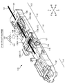
- FIG. 1A and 1B are perspective views of the optical fiber alignment tool 10 according to the first embodiment in an initial state.
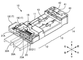
- FIG. 2 is a perspective view of the optical fiber alignment tool 10 according to the first embodiment in an assembled state.
- FIG. 3 is an exploded perspective view of the main body 12 in an initial state.
- 4A to 4D are explanatory views showing the states before and after assembling a plurality of optical fibers 1 by the optical fiber alignment tool 10 of the first embodiment.
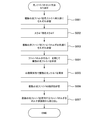
- FIG. 5 is a flowchart of a method (setting procedure) for setting the plurality of optical fibers 1 on the fiber holder 6 by the optical fiber alignment tool 10 of the first embodiment.
- FIG. 6A is a perspective view showing a state where the optical fiber 1 is inserted into the fiber insertion portion 22.
- FIG. 6B is a perspective view showing a state in which a plurality of optical fibers 1 are assembled.
- 7A to 7C are explanatory views showing a state in which a plurality of optical fibers 1 are inserted into the fiber insertion portion 22 of the optical fiber alignment tool 10 of the first comparative example.
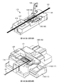
- FIG. 8 is a perspective view of the optical fiber alignment tool 110 according to the second embodiment in an initial state.
- FIG. 9 is a perspective view of the optical fiber alignment tool 110 according to the second embodiment in an assembled state.
- FIG. 10 is an exploded perspective view of the main body 111 in the initial state.
- FIG. 11 is an exploded perspective view of the main body 111 in the assembled state.
- FIG. 12A to 12D are explanatory views showing a state before and after assembling a plurality of optical fibers 101 by the optical fiber alignment tool 110 of the second embodiment.
- FIG. 13A is a schematic explanatory diagram of the main body 111 in an initial state.
- FIG. 13B is a schematic explanatory diagram of the main body 111 in the assembled state.
- FIG. 14A is an explanatory diagram showing the main body 111 in the assembled state, with the main body side cover 119 closed.
- FIG. 14B is an explanatory diagram showing the main body 111 in the assembled state with the main body side cover 119 opened.
- FIG. 15A is a perspective view showing a state where the optical fiber 101 is inserted into the fiber insertion portion 122.
- FIG. 15B is a perspective view showing a state in which a plurality of optical fibers 101 are assembled.
- FIG. 16A is a perspective view showing a state in which a plurality of optical fibers 101 are accommodated in the V groove 107 of the fiber holder 106.
- FIG. 16B is a perspective view showing how the lid 108 of the fiber holder 106 is closed.
- 17A to 17C are explanatory views showing a state in which a plurality of optical fibers 101 are inserted into the fiber insertion portion 122 in the optical fiber alignment tool 110 of the second comparative example.
- FIG. 18A is a perspective view of the optical fiber alignment tool 110 of the first modified example.
- FIG. 18B is a perspective view of the main body 111 of the optical fiber alignment tool 110 of the second modification.
- An optical fiber aligning tool for aligning a plurality of optical fibers, the fiber aligning unit aligning the plurality of optical fibers in a predetermined order, and the plurality of optical fibers while maintaining the predetermined order. It becomes clear that the optical fiber aligning tool is characterized by having a fiber holding portion that holds the plurality of optical fibers in a direction in which the optical fibers are arranged. According to such an optical fiber alignment tool, it is possible to improve the workability of the work of aligning and holding a plurality of optical fibers in a predetermined order.
- the fiber alignment section includes a plurality of separation sections provided in a direction in which the plurality of optical fibers are arranged. Thereby, the plurality of optical fibers can be aligned in a predetermined order.
- the fiber aligning section includes a plurality of fiber inserting sections provided between the two separating sections, and that the optical fibers are inserted one by one into the plurality of fiber inserting sections. Thereby, the plurality of optical fibers can be aligned in a predetermined order.
- a taper portion is formed on the side of the fiber insertion portion where the optical fiber is inserted.
- the optical fiber can be easily inserted into the fiber insertion portion.
- the fiber holding section includes a mounting section on which the plurality of optical fibers are mounted when the fiber holding section sandwiches and holds the plurality of optical fibers in a direction in which the plurality of optical fibers are arranged. Accordingly, it is possible to hold the plurality of optical fibers by sandwiching the plurality of optical fibers in the direction in which the plurality of optical fibers are arranged while maintaining the predetermined order of the plurality of optical fibers.
- the fiber holding unit When the fiber holding unit holds the plurality of optical fibers in a direction in which the plurality of optical fibers are arranged, the fiber holding unit is arranged in a direction perpendicular to an optical axis direction of the optical fibers and a direction in which the plurality of optical fibers are arranged. It is desirable to sandwich a plurality of optical fibers. Accordingly, it is possible to hold the plurality of optical fibers by sandwiching the plurality of optical fibers in the direction in which the plurality of optical fibers are arranged while maintaining the predetermined order of the plurality of optical fibers.
- the plurality of optical fibers is preferably movable in the direction in which the plurality of optical fibers are arranged. .. Accordingly, it is possible to hold the plurality of optical fibers by sandwiching the plurality of optical fibers in the direction in which the plurality of optical fibers are arranged while maintaining the predetermined order of the plurality of optical fibers.
- the plurality of optical fibers be movable in a direction in which the plurality of optical fibers are arranged, by the separation portion not protruding from the mounting surfaces of the plurality of optical fibers in the mounting portion. .. Accordingly, it is possible to hold the plurality of optical fibers by sandwiching the plurality of optical fibers in the direction in which the plurality of optical fibers are arranged while maintaining the predetermined order of the plurality of optical fibers.
- a holder holder is further provided, and a fiber holder that holds the plurality of optical fibers in the predetermined order is installed in the holder holder.
- a fiber holder that holds the plurality of optical fibers in the predetermined order is installed in the holder holder.
- a front side holding section for holding the plurality of optical fibers
- the holder holding section is preferably provided so as to be sandwiched between the fiber alignment section and the front side holding section.
- optical fiber alignment tools for solving these problems. That is, it is an optical fiber alignment tool for aligning a plurality of optical fibers, the fiber aligning unit for aligning the plurality of optical fibers in a predetermined order, and the optical fiber alignment tool while maintaining the predetermined order of the plurality of optical fibers. And a fiber holding unit that collects and holds a plurality of optical fibers, wherein the fiber alignment unit includes a separation unit that separates the optical fibers aligned in the predetermined order from each other, and the separation unit is the An optical fiber aligning tool characterized by being retractable from between optical fibers becomes clear. According to such an optical fiber alignment tool, it is possible to improve the workability of the work of aligning and holding a plurality of optical fibers in a predetermined order and a predetermined pitch.
- the separating section retracts from between the optical fibers so that the fiber holding section can hold the plurality of optical fibers in a direction in which the plurality of optical fibers are aligned. Thereby, a plurality of optical fibers can be held at a predetermined pitch.
- the fiber alignment section includes a plurality of fiber insertion sections provided between the two separation sections, and the optical fiber is inserted into the fiber insertion section. Thereby, the plurality of optical fibers can be aligned in a predetermined order.
- the fiber insertion part is formed so as to widen toward the side where the optical fiber is inserted. Thereby, the optical fiber can be easily inserted into the fiber insertion portion.
- the fiber holding section includes an arm section, and the arm section is provided both before the separation section retracts from between the optical fibers and after the separation section retracts from between the optical fibers. It is desirable that the plurality of optical fibers be mounted. This allows the plurality of optical fibers to move in the direction in which the plurality of optical fibers are aligned while maintaining the predetermined order of the plurality of optical fibers.
- the fiber holding unit When the fiber holding unit holds the plurality of optical fibers in a direction in which the plurality of optical fibers are aligned, the fiber holding unit is perpendicular to both the optical axis direction of the optical fibers and the direction in which the plurality of optical fibers are aligned. It is desirable that the plurality of optical fibers be sandwiched in different directions. This allows the plurality of optical fibers to move in the direction in which the plurality of optical fibers are aligned while maintaining the predetermined order of the plurality of optical fibers.
- the plurality of optical fibers are movable in the direction in which the plurality of optical fibers are aligned. Is desirable.
- the plurality of optical fibers can be gathered in the direction in which the plurality of optical fibers are aligned while maintaining the predetermined order of the plurality of optical fibers.
- the plurality of optical fibers can be moved in a direction in which the plurality of optical fibers are aligned after the separating unit is retracted from between the optical fibers.
- the plurality of optical fibers can be gathered in the direction in which the plurality of optical fibers are aligned while maintaining the predetermined order of the plurality of optical fibers.
- a holder holder is further provided, and a fiber holder that holds the plurality of optical fibers in the predetermined order and a predetermined pitch is installed in the holder holder.
- a fiber holder that holds the plurality of optical fibers in the predetermined order and a predetermined pitch is installed in the holder holder.
- a front side holding section for holding the plurality of optical fibers
- the holder mounting section is preferably provided so as to be sandwiched between the fiber alignment section and the front side holding section.
- a method for setting an optical fiber in a fiber holder using an optical fiber alignment tool for aligning a plurality of optical fibers wherein the optical fiber alignment tool comprises: A fiber aligning unit that aligns the fibers in a predetermined order; and a fiber holding unit that collects and holds the plurality of optical fibers while maintaining the predetermined order of the plurality of optical fibers, and the fiber aligning unit is A separation unit that separates the optical fibers arranged in the predetermined order from each other, and the plurality of optical fibers are arranged in the predetermined order, and the separation unit retracts from between the optical fibers.
- the method of setting the optical fiber in the fiber holder is characterized by According to such a method of setting the optical fibers in the fiber holder, it is possible to improve the workability of the work of aligning and holding the plurality of optical fibers in a predetermined order and a predetermined pitch.
- An optical fiber aligning tool for aligning a plurality of optical fibers, the fiber aligning unit aligning the plurality of optical fibers in a predetermined order, and maintaining the predetermined order of the plurality of optical fibers.
- a fiber holding unit that collects and holds the plurality of optical fibers, and the fiber alignment unit includes a separation unit that separates the optical fibers arranged in the predetermined order from each other. Is retractable from between the optical fibers, and the fiber holding portion is a position where the separating portion separates the optical fibers again after the separating portion retracts from between the optical fibers.
- the optical fiber aligning tool which is characterized in that it has a stopper portion for restricting the return to the above, becomes clear. According to such an optical fiber alignment tool, it is possible to prevent the optical fiber from being damaged by the separating section sandwiching the optical fiber.
- the fiber holding unit collects and holds the plurality of optical fibers in a direction in which the plurality of optical fibers are aligned, it is perpendicular to both the optical axis direction of the optical fibers and the direction in which the plurality of optical fibers are aligned. It is preferable that the plurality of optical fibers are sandwiched in different directions, and the stopper portion regulates movement of the separation portion in a direction in which the plurality of optical fibers are sandwiched. As a result, it is possible to prevent the optical fiber from being sandwiched by the separating section and damaging the optical fiber.
- the fiber holding unit includes a slide unit that collects and holds the plurality of optical fibers after the separation unit is retracted from between the optical fibers, and the stopper unit includes a slide unit in which the slide unit includes the separation unit. It is desirable to regulate returning to a position separating the optical fibers from each other again. As a result, it is possible to prevent the optical fiber from being sandwiched by the separating section and damaging the optical fiber.
- the fiber holding portion includes a lid portion that sandwiches the plurality of optical fibers in a direction perpendicular to both an optical axis direction of the optical fiber and a direction in which the plurality of optical fibers are aligned, and the lid portion is a convex portion.
- the slide part includes a locking part, and the locking part locks with the convex part when the separation part moves in a direction in which the plurality of optical fibers are sandwiched. ..
- the slide part includes a locking part, and the locking part locks with the convex part when the separation part moves in a direction in which the plurality of optical fibers are sandwiched. ..
- FIG. 2 is a perspective view of the optical fiber alignment tool 10 according to the first embodiment in an assembled state. 1B and 2, part of the housing 11 of the optical fiber alignment tool 10 is omitted.
- the optical axis direction of the optical fiber 1 held by the optical fiber alignment tool 10 is the front-back direction.
- the main body portion 12, the holder holding portion 13, and the front holding portion 14 are provided in this order in the front-rear direction, and the holder holding portion 13 is provided.
- the side of the front side holding portion 14 with respect to is referred to as “front”, and the side of the main body portion 12 with respect to the holder holding portion 13 is referred to as “rear”.
- the direction perpendicular to the bottom surface of the accommodating portion 43 of the holder holding portion 13 is referred to as “vertical direction”, and the fiber holder 6 (not shown in FIGS. 1A to 2; 6B) is defined as “upper” and the opposite side is “lower”.
- a direction perpendicular to the front-rear direction and the up-down direction is referred to as “left-right direction”.
- the slide portion 18 is provided so as to be slidable in the left-right direction with respect to the housing 11. Therefore, the left-right direction may be referred to as the “sliding direction”.
- the plurality of optical fibers 1 are arranged in the left-right direction. Therefore, the left-right direction may be referred to as the “fiber alignment direction” or simply the “alignment direction”. Furthermore, the right side when the front side is viewed from the rear side is defined as “right”, and the left side is defined as “left”. The hinge side of the main body side lid portion 19 (or the hinge side of the front side lid portion 40) is “left” and the opening/closing side is “right”.
- the optical fiber alignment tool 10 is a tool for aligning a plurality of optical fibers 1 in a predetermined order and assembling the plurality of optical fibers 1. Further, the optical fiber alignment tool 10 is also a tool for holding a plurality of optical fibers 1 in an assembled state. By aligning the plurality of optical fibers 1 in a predetermined order with the optical fiber aligning tool 10, collecting the plurality of optical fibers 1, and holding the plurality of optical fibers 1 in the assembled state, the plurality of optical fibers 1 1 can be easily set in the fiber holder 6.
- the fiber holder 6 (not shown in FIGS. 1A to 2; see FIGS. 6A and 6B described later) used in the first embodiment is a member for holding a plurality of optical fibers 1 in a state of being aligned in a predetermined order. Is. By holding the plurality of optical fibers 1 in the optical fiber cord in a predetermined order by the fiber holder 6, processing such as coating removal and cutting can be performed collectively by the plurality of optical fibers 1. You can Further, by holding the plurality of optical fibers 1 in the optical fiber cord in a predetermined order by the fiber holder 6, the plurality of optical fibers 1 and the plurality of built-in optical fibers inserted and fixed in the ferrule are held. The fusion splicing can also be performed collectively.
- the plurality of optical fibers 1 can be held and set in the fiber holder 6 in a state where the optical fibers 1 are arranged at a predetermined pitch.
- the plurality of optical fibers 1 in a state in which the optical fibers 1 are arranged at a predetermined pitch may be referred to as “an aggregated optical fiber 1”.
- the plurality of optical fibers 1 in the aggregated state are arranged in one direction (here, in the left-right direction) while adjacent optical fibers 1 are in contact with each other. It is in a state of being.
- the pitch of the optical fibers 1 in the assembled state is the same as the pitch of the built-in optical fibers to be fusion-spliced (that is, the pitch of a plurality of grooves formed in the fiber holder 6 described later)
- the adjacent optical fibers 1 do not have to be in contact with each other.
- the plurality of optical fibers 1 in the aggregated state may be arranged in a line in one direction (here, the left-right direction) even if adjacent optical fibers 1 are not in contact with each other.
- the “aggregate state” may also refer to the state of the optical fiber alignment tool 10 that holds a plurality of optical fibers 1 with the optical fibers 1 arranged at a predetermined pitch.
- the position of each component (for example, the fiber alignment part 16 and the slide part 18 described later) of the optical fiber alignment tool 10 in the assembled state may be referred to as a “assembly position”.
- FIG. 2 shows the assembled state of the optical fiber alignment tool 10 of the first embodiment, in which the fiber alignment section 16 and the slide section 18 are located at the assembly position.
- the initial state of the optical fiber alignment tool 10 in the work of setting the plurality of optical fibers 1 in the fiber holder 6 may be referred to as the “initial state”.
- the position of each component (for example, the fiber alignment part 16 and the slide part 18 described later) of the optical fiber alignment tool 10 in the initial state may be referred to as an “initial position”.
- 1A and 1B show an initial state of the optical fiber alignment tool 10 according to the first embodiment, in which the fiber alignment section 16 and the slide section 18 are located at the initial positions.
- the optical fiber alignment tool 10 has a main body portion 12, a holder holding portion 13, and a front holding portion 14.
- the main body portion 12, the holder holding portion 13, and the front side holding portion 14 are portions provided in the housing 11 of the optical fiber alignment tool 10, and the main body portion 12, the holder holding portion 13, and the front side portion, respectively.
- the holding portion 14 is provided in this order in the front-rear direction. That is, the main body portion 12, the holder holding portion 13, and the front side holding portion 14 are provided along the optical axis direction of the optical fiber 1 held by the optical fiber alignment tool 10.
- the main body 12 is a part that aligns the plurality of optical fibers 1 in a predetermined order and collects the plurality of optical fibers 1.
- the main body 12 is also a part that holds the plurality of optical fibers 1 in an assembled state.
- the body portion 12 is provided on the rear side of the holder holding portion 13.
- the main body portion 12 has a fiber alignment portion 16 and a fiber holding portion 17.
- the fiber alignment section 16 is a part that aligns the plurality of optical fibers 1 in a predetermined order.
- the fiber alignment unit 16 is housed inside the housing 11.
- the fiber alignment unit 16 is provided so as to be vertically movable with respect to the housing 11. Further, the fiber alignment section 16 is provided so as to be sandwiched by the slide section 18 (the arm section 31A and the arm section 31B) of the fiber holding section 17. The detailed configuration and operation of the fiber alignment unit 16 will be described later.
- the fiber holding unit 17 is a part that collects a plurality of optical fibers 1.
- the fiber holding unit 17 is also a part that holds a plurality of optical fibers 1 in an assembled state. The detailed configuration and operation of the fiber holding unit 17 will be described later.
- the holder holding portion 13 is a portion that holds the fiber holder 6 (not shown in FIGS. 1A to 2; see FIGS. 6A and 6B described later).
- the holder holding portion 13 is provided on the front side of the main body portion 12 and is provided on the rear side of the front holding portion 14.
- the holder holding portion 13 is provided with a housing portion 43 for housing the fiber holder 6.
- the fiber holder 6 is positioned with respect to the optical fiber alignment tool 10.
- the plurality of optical fibers 1 held by the optical fiber alignment tool 10 are housed in the plurality of grooves formed in the fiber holder 6, respectively. Therefore, by positioning the fiber holder 6 with respect to the optical fiber alignment tool 10, the plurality of optical fibers 1 can be easily accommodated in the plurality of grooves formed in the fiber holder 6, respectively.
- the front holding section 14 is a section that holds a plurality of optical fibers 1.
- the front holding portion 14 is provided on the front side of the holder holding portion 13.
- the front holding portion 14 is provided with a front lid portion 40 and a front groove portion 41.
- the front lid portion 40 is a portion that sandwiches the plurality of optical fibers 1 from above.
- the front groove portion 41 is a portion on which the plurality of optical fibers 1 are placed. By sandwiching the plurality of optical fibers 1 placed in the front groove portion 41 by the front lid portion 40, the plurality of optical fibers 1 can be held.
- the front lid portion 40 is formed of a transparent resin that transmits an optical signal. Further, a lens 42 is formed on the front lid portion 40. Since the front lid portion 40 is formed of a transparent resin that transmits an optical signal, an operator can visually check the aligned state (order) of the plurality of optical fibers 1 through the front lid portion 40. Further, since the lens 42 is formed, the visual observation of the aligned state of the plurality of optical fibers 1 is enlarged, and the aligned state (order) of the plurality of optical fibers 1 can be easily confirmed.
- FIG. 3 is an exploded perspective view of the main body 12 in an initial state.
- 4A to 4D are explanatory views showing the states before and after assembling a plurality of optical fibers 1 by the optical fiber alignment tool 10 of the first embodiment.
- the main body 12 has the fiber alignment part 16 and the fiber holding part 17.
- the fiber alignment section 16 is a part that aligns the plurality of optical fibers 1 in a predetermined order.
- the fiber holding unit 17 is also a part that collects a plurality of optical fibers 1 and holds the plurality of optical fibers 1 in a collected state.
- the fiber alignment unit 16 is provided with an identification unit 20, a separation unit 21, and a pin 23 (pin 23A and pin 23B).
- the identification section 20 is a section for identifying each of the plurality of optical fibers 1 when inserting the plurality of optical fibers 1 into the fiber alignment section 16.
- a plurality of identification units 20 are provided in the left-right direction, and are colored corresponding to the identification colors of the plurality of optical fibers 1.
- a plurality of fiber insertion portions 22 are provided in the left-right direction so as to correspond to the plurality of identification portions 20.
- the plurality of identification portions 20 are provided on the rear side of the plurality of fiber insertion portions 22.
- the identification color of the optical fiber 1 and the identification part 20 can be easily associated with each other.
- the identification unit 20 is provided in the vicinity of the fiber insertion unit 22 to the extent that the identification color of the optical fiber 1 and the color of the identification unit 20 can be associated with each other, the plurality of identification units 20 will not operate in the plurality of fibers. It may not be provided on the rear side of the insertion portion 22.
- the separating unit 21 is a unit that sorts the plurality of optical fibers 1 one by one.
- the separation part 21 is provided as a wall extending in the front-rear direction.
- a plurality (here, 11) of separation units 21 are provided to sort the plurality (here, 12) of the optical fibers 1 output from the optical fiber cord into each one.
- the plurality of separation parts 21 are arranged in the left-right direction, and the space between the separation parts 21 is a fiber insertion part 22. However, at the left and right ends of the fiber alignment section 16, the fiber insertion section 22 is between the separation section 21 and the housing 11.
- the plurality of optical fibers 1 are inserted into the plurality (here, 12) of fiber insertion portions 22 formed in this way, so that the plurality of optical fibers 1 are sorted into each one.
- a groove 24 extending in the left-right direction is formed in the separating portion 21 when the main body side lid portion 19 described later is closed.
- the wall 24 is a portion for accommodating the convex portion 33 of the main body side lid portion 19 described later.
- the identification unit 20 allows the plurality of optical fibers 1 to be inserted into each fiber insertion unit 22 in a predetermined order.
- the fiber insertion portions 22 are separated from each other by the separation portion 21. That is, when the plurality of optical fibers 1 are inserted in the fiber insertion portion 22, the optical fibers 1 are separated from each other by the separation portion 21. Thereby, the plurality of optical fibers 1 can be aligned in a predetermined order.
- a taper portion is formed on the rear side of the separation portion 21. Specifically, the tapered portion is formed such that the width in the left-right direction decreases from the front side to the rear side. Then, the fiber insertion portion 22 is formed so as to widen toward the side (rear side) into which the optical fiber 1 is inserted. Thereby, the optical fiber 1 can be easily inserted into the fiber insertion portion 22.
- the pin 23 is a portion protruding from the fiber alignment portion 16.
- two pins 23 (pins 23A and 23B) are provided.
- the pin 23A is provided on the rear side of the fiber alignment section 16, and the pin 23B is provided on the front side of the fiber alignment section 16.
- the pin 23B is not shown in FIG.
- the pins 23 (pins 23A and 23B) are inserted in rail portions 30 (30A and 30B) provided on a slide portion 18 described later.
- the pin 23 is provided so as to be movable with respect to the rail portion 30. When the pin 23 moves along the rail portion 30, the entire fiber alignment portion 16 moves.
- the fiber holding portion 17 has a slide portion 18 and a main body side lid portion 19.
- the slide part 18 is a part that switches between the initial state and the collective state.
- the slide portion 18 is provided so as to be movable in the left-right direction with respect to the housing 11.
- the slide portion 18 is provided with a rail portion 30 (rail portion 30A and rail portion 30B), an arm portion 31 (arm portion 31A and arm portion 31B), and a shoulder portion 32 (shoulder portion 32A and shoulder portion 32B). ing.
- the rail part 30 is a part into which the pin 23 of the fiber alignment part 16 is inserted.
- two rail portions 30 (rail portion 30A and rail portion 30B) are provided.
- the rail portion 30A is provided on the rear side of the slide portion 18, and the rail portion 30B is provided on the rear side of the slide portion 18.
- the pin 23A is inserted into the rail portion 30A, and the pin 23B is inserted into the rail portion 30B.
- the pin 23A and the pin 23B are provided so as to be movable with respect to the rail portion 30A and the rail portion 30B, respectively.
- the rail portion 30 includes an upper rail portion 44, an inclined portion 45, and a lower rail portion 46.
- the upper rail portion 44A in the rail portion 30A, the inclined portion 45A, and the lower rail portion 46A are illustrated, and the upper rail portion 44B in the rail portion 30B, the inclined portion 45B, and the lower portion 45B.
- the side rail portion 46B is not shown.
- the upper rail portion 44, the inclined portion 45, and the lower rail portion 46 are integrally formed openings, and the upper rail portion 44, the inclined portion 45, and the lower rail portion 46 are The pin 23 can freely move between them.
- the upper rail portion 44 is a portion of the rail portion 30 on which the pin 23 is located when the fiber alignment portion 16 reaches the initial position.
- the upper rail portion 44 is located above the lower rail portion 46.
- the fiber alignment section 16 when the pin 23 is positioned on the upper rail portion 44 is in the initial position, and is in a state in which the plurality of optical fibers 1 can be inserted into the plurality of fiber insertion sections 22, respectively. Is.
- the separation portions 21 separate the optical fibers 1 from each other, and the predetermined order of the plurality of optical fibers 1 is maintained.
- the inclined portion 45 is a portion of the rail portion 30 on which the pin 23 is located when the fiber alignment portion 16 moves between the initial position and the assembly position.
- the inclined portion 45 is a portion that connects the upper rail portion 44 and the lower rail portion 46. As described above, the upper rail portion 44 is located above the lower rail portion 46. Therefore, the inclined portion 45 is a portion inclined from the upper rail portion 44 to the lower rail portion 46.
- the lower rail portion 46 is a portion of the rail portion 30 on which the pin 23 is located when the fiber alignment portion 16 is at the gathering position.
- the lower rail portion 46 is located below the upper rail portion 44.
- the fiber alignment portion 16 when the pins 23 are positioned on the lower rail portion 46 is in the gathering position, and the separation portion 21 moves downward and the optical fibers 1 are not separated from each other.
- the plurality of optical fibers 1 are in a state of being sandwiched between the bridge portion 15 and the convex portion 33 of the main body side cover portion 19, which will be described later, and the predetermined order of the plurality of optical fibers 1 is maintained. It is in a state.
- the arm 31 is a place where a plurality of optical fibers 1 are placed.
- the plurality of optical fibers 1 are placed on the arm 31 at both the initial position and the gathering position.
- the arm portion 31 may be referred to as the placing portion 31. That is, as will be described later, even after the separating section 21 moves downward in the assembled state, the plurality of optical fibers 1 are still mounted on the arm section 31.
- two arm portions 31 (arm portion 31A and arm portion 31B) are provided. Each arm portion 31 is formed so as to extend to the left at the upper end portion of the slide portion 18.
- the optical fiber 1 is placed on the upper surfaces of the arm portions 31A and 31B (hereinafter may be referred to as "mounting surfaces").
- the shoulder 32 is a part that holds the plurality of optical fibers 1 together with the housing 11.
- the shoulder portion 32 is a portion that protrudes upward at the right end portion of the arm portion 31.
- two shoulders 32 are provided.
- the shoulder portion 32A projects from the arm portion 31A
- the shoulder portion 32B projects from the arm portion 31B.
- the shoulder portion 32 holds the plurality of optical fibers 1 with the housing 11 in a sandwiched state.
- the main body side lid portion 19 is a portion that sandwiches the plurality of optical fibers 1 from above and below together with the bridge portion 15 of the housing 11. As shown in FIGS. 4B and 4D, a plurality of light beams are provided between the convex portion 33 provided on the main body side lid portion 19 and the bridge portion 15 provided on the housing 11 at both the initial position and the gathering position. The fiber 1 is sandwiched and held. As a result, since the plurality of optical fibers 1 are sandwiched and held from the initial state to the assembled state, the predetermined order of the plurality of optical fibers 1 is maintained. However, as will be described later, it is possible for the plurality of optical fibers 1 to move in the left-right direction while maintaining a predetermined order after the separating unit 21 moves downward and then to the assembled state.
- FIGS. 4A and 4B show the optical fiber alignment tool 10 when the plurality of optical fibers 1 are inserted into the fiber insertion portion 22 (fiber alignment portion 16) in the initial state.
- FIG. 4A shows a side view of the optical fiber alignment tool 10 when the optical fiber alignment tool 10 is viewed from the rear side to the front side.
- FIG. 4B shows a sectional view of the optical fiber alignment tool 10 when cut along a plane perpendicular to the left-right direction.
- the slide section 18 in the initial state is located on the right side.
- the pin 23 is located at the left end of the upper rail portion 44.
- the bottom surface of the fiber aligning portion 16 is located above the mounting surface of the optical fiber 1 of the arm portion 31, and the separating portion 21 can sort the plurality of optical fibers 1 one by one. It is in a state. That is, the worker can insert the plurality of optical fibers 1 into the fiber insertion portion 22 one by one. In other words, the worker can randomly insert the plurality of optical fibers 1 into the respective fiber insertion portions 22.
- the pin 23 moves from the upper rail portion 44 to the inclined portion 45.
- the inclined portion 45 is a portion that connects the upper rail portion 44 and the lower rail portion 46 and that is inclined from the upper rail portion 44 to the lower rail portion 46. Therefore, the pin 23 advances along the inclined portion 45 along with the slide of the slide portion 18. Therefore, when the pin 23 advances in the inclined portion 45, the pin 23 (fiber alignment portion 16) moves downward with respect to the slide portion 18. That is, as the pin 23 advances along the inclined portion 45, the separating portion 21 moves downward.
- FIG. 4C and 4D show the optical fiber alignment tool 10 in the assembled state.
- FIG. 4C shows a side view of the optical fiber alignment tool 10 when the optical fiber alignment tool 10 is viewed from the rear side to the front side.
- FIG. 4D shows a sectional view of the optical fiber alignment tool 10 when cut along a plane perpendicular to the left-right direction.
- the pin 23 moves from the inclined portion 45 to the lower rail portion 46.
- the bottom surface of the fiber alignment portion 16 is located below the mounting surface of the optical fiber 1 of the arm portion 31, and the sorting of the plurality of optical fibers 1 by the separating portion 21 is released. ing. That is, it becomes possible for the plurality of optical fibers 1 to move in the left-right direction.
- the predetermined order of the plurality of optical fibers 1 is maintained. It remains dripping.
- the slide unit 18 in the assembled state is located on the left side.
- the pin 23 is located at the right end of the lower rail portion 46.
- the shoulder portion 32 and the housing 11 are in a state of holding the plurality of optical fibers 1 in between. That is, while maintaining the predetermined order of the plurality of optical fibers 1, the plurality of optical fibers 1 are sandwiched and held in the direction (horizontal direction) in which they are arranged.
- FIG. 5 is a flowchart of a method (setting procedure) for setting the plurality of optical fibers 1 on the fiber holder 6 by the optical fiber alignment tool 10 of the first embodiment.
- the worker stores a plurality of optical fibers 1 in the respective fiber insertion portions 22 (S101).
- the operator confirms that the optical fiber alignment tool 10 is in the initial state before accommodating the plurality of optical fibers 1 in the respective fiber insertion portions 22. That is, as shown in FIG. 4A, it is confirmed that the slide portion 18 is located on the right side.
- the bottom surface of the fiber alignment section 16 is located above the mounting surface of the optical fiber 1 of the arm section 31, and the separation section 21 can sort the plurality of optical fibers 1 into each one.
- the worker can randomly insert the plurality of optical fibers 1 into the respective fiber insertion portions 22.
- FIG. 6A is a perspective view showing a state where the optical fiber 1 is inserted into the fiber insertion portion 22.
- a plurality (here, 12) of fiber insertion portions 22 are provided.
- the fiber insertion portions 22 are separated from each other by the separation portion 21. Therefore, the worker can randomly insert the plurality of optical fibers 1 into the respective fiber insertion portions 22. That is, it is not necessary to sequentially insert the optical fibers 1 from the right side among the plurality of fiber insertion portions 22.
- the optical fiber 1 can be inserted into any fiber insertion portion 22.
- the identification color of the optical fiber 1 and the identification section 20 are made to correspond to each other, and the optical fiber 1 is inserted into the predetermined fiber insertion section 22. Thereby, the plurality of optical fibers 1 can be easily aligned in a predetermined order.
- the operator slides the slide portion 18 (S102).
- the operator slides the slide portion 18 located on the right side in the initial state to the left side.
- This causes the pin 23 to move from the upper rail portion 44 to the inclined portion 45.
- the pins 23 (the fiber alignment section 16) move downward with respect to the slide section 18 as the pins 23 move along the inclined portions 45. That is, as the pin 23 advances along the inclined portion 45, the separating portion 21 moves downward.
- the pin 23 moves from the inclined portion 45 to the lower rail portion 46.
- the bottom surface of the fiber alignment section 16 is located below the mounting surface of the optical fiber 1 of the arm section 31.
- the plurality of optical fibers 1 can be moved in the left-right direction while maintaining a predetermined order.
- the plurality of optical fibers 1 can be sandwiched and held in the direction in which the plurality of optical fibers 1 are arranged while maintaining the predetermined order of the plurality of optical fibers 1.
- the worker stores the plurality of optical fibers 1 in the respective grooves of the fiber holder 6 (S103).
- FIG. 6B is a perspective view showing a state in which a plurality of optical fibers 1 are assembled. As described above, in the assembled state, the plurality of optical fibers 1 are held with the optical fibers 1 arranged at a predetermined pitch. Therefore, the worker can easily store the plurality of optical fibers 1 in the grooves of the fiber holder 6 by holding the plurality of optical fibers 1 on the fiber holder 6 by stroking them in the front-back direction.
- the worker closes the cover of the fiber holder 6 and holds the plurality of optical fibers 1 (S104). As a result, the plurality of optical fibers 1 are held by the fiber holder 6.
- the worker holds the plurality of optical fibers 1 in the front holding unit 14 (S105) and confirms the order of the plurality of optical fibers 1 (S106).
- the front holding unit 14 is formed of a transparent resin that transmits an optical signal, and the lens 42 is formed, so that the operator can keep the plurality of optical fibers 1 aligned (sequential).
- the visual observation is enlarged, and the aligned state (order) of the plurality of optical fibers 1 can be easily confirmed.
- the fiber alignment unit 16 is not provided with the separation unit 21. Therefore, as shown in FIG. 7B, in the optical fiber alignment tool 10 of the first comparative example, all of the plurality of optical fibers 1 should be inserted into one fiber insertion portion 22 provided in the fiber alignment portion 16. become.
- the vertical width of the fiber insertion portion 22 is formed to be substantially the same as the outer diameter of the optical fiber 1. Therefore, as shown in FIG. 7B, by filling the optical fibers 1 from the right side and inserting them, it is possible to align them in a predetermined order when all the plurality of optical fibers 1 are inserted.
- the inserted optical fibers 1 packed on the right side can be moved in the left and right directions, respectively. Therefore, as shown in FIG. 7C, the optical fiber 1 to be packed on the right side may move to the left side, and a space may be left between the optical fibers 1.
- the optical fibers 1 to be inserted may be mistakenly inserted into this empty space and may be aligned in the wrong order. This problem is particularly remarkable in the field assembly type optical connector in which a plurality of optical fibers are manually arranged in a predetermined order.
- the fiber insertion portions 22 are separated by the separation portion 21. That is, when the plurality of optical fibers 1 are inserted in the fiber insertion portion 22, the optical fibers 1 are separated from each other by the separation portion 21. Therefore, it is possible to prevent a space from being formed between the optical fibers 1 and the optical fibers 1 to be inserted can be mistakenly inserted into the empty space and be aligned in an incorrect order. .. As a result, the workability of the work of aligning and holding the plurality of optical fibers 1 in a predetermined order can be improved.
- FIG. 8 is a perspective view of the optical fiber alignment tool 110 according to the second embodiment in an initial state.
- FIG. 9 is a perspective view of the optical fiber alignment tool 110 according to the second embodiment in an assembled state.
- the fiber holder 106 and the optical fiber 101 are not shown in FIG. 8, the fiber holder 106 and the plurality of optical fibers 101 in the assembled state are shown in FIG. 9.
- the “aggregated state” of the plurality of optical fibers 101 is a state in which the plurality of optical fibers 101 are aligned in a predetermined order and a state in which the plurality of optical fibers 101 are gathered and held.
- “assembling” the plurality of optical fibers 101 means bringing the plurality of optical fibers 101 into an assembled state.
- the optical axis direction of the optical fiber 101 held by the optical fiber alignment tool 110 is the front-back direction.
- the main body 111, the holder mounting portion 112, and the front holding portion 113 are provided in this order in the front-rear direction.
- the side of the front holding part 113 with respect to the holder mounting part 112 is defined as “front”, and the side of the main body part 111 with respect to the holder mounting part 112 is defined as “rear”.
- the direction perpendicular to the bottom surface of the holder mounting portion 112 is referred to as “vertical direction”, and the side (see FIG. 9) in which the fiber holder 106 is accommodated when viewed from the bottom surface of the holder mounting portion 112 is referred to as “upper”. The other side is "bottom”.
- a direction perpendicular to the front-rear direction and the up-down direction is referred to as “left-right direction”.
- the slide portion 118 of the fiber holding portion 117 is provided so as to be slidable in the left-right direction with respect to the main body housing 111A. Therefore, the left-right direction may be referred to as the “sliding direction”.
- the plurality of optical fibers 101 in the assembled state are aligned in the left-right direction. Therefore, the left-right direction may be referred to as the “fiber alignment direction” or simply the “alignment direction”. Furthermore, the right side when the front side is viewed from the rear side is defined as “right”, and the left side is defined as “left”. The hinge side of the main body side cover portion 119 is “left” and the opening/closing side is “right”.
- the optical fiber alignment tool 110 is a tool for assembling a plurality of optical fibers 101.
- the plurality of optical fibers 101 can be collected.
- 101 can be easily set on the fiber holder 106 for aligning the 101 in a predetermined order and a predetermined pitch (described later). That is, it is possible to improve the workability of the work of aligning and holding the plurality of optical fibers 101 in a predetermined order and a predetermined pitch (setting work of the plurality of optical fibers 101 to the fiber holder 106).
- the fiber holder 106 (see FIG. 9) used in the second embodiment is a member that holds a plurality of optical fibers 101 in a state of being aligned in a predetermined order and a predetermined pitch.
- processing such as coating removal and cutting (cutting) is collectively performed by the plurality of optical fibers 101. You can do it.
- the plurality of optical fibers 101 in the optical fiber cord in a predetermined order and a predetermined pitch by the fiber holder 106, the plurality of optical fibers 101 and the plurality of optical fibers inserted and fixed in the ferrule are held.
- the fusion splicing with the built-in optical fiber can also be performed collectively.
- the plurality of optical fibers 101 in the aggregated state held by the optical fiber alignment tool 110 of the second embodiment are in a state of being aligned in a predetermined order, and while the adjacent optical fibers 101 are in contact with each other, It is in a state of being aligned in the direction (here, the left-right direction) (see the right side diagram of FIG. 12C described later).
- the adjacent optical fibers 101 may not be in contact with each other.
- the plurality of optical fibers 101 in the aggregated state may be in a state where they are gathered and aligned in one direction (here, the left-right direction) even if the adjacent optical fibers 101 are not in contact with each other.
- the plurality of V grooves 107 formed at a predetermined pitch in the fiber holder 106 are provided. Each can be easily accommodated.
- the “aggregate state” may also refer to the state of the optical fiber alignment tool 110 that holds a plurality of optical fibers 101 that are gathered and aligned in a predetermined order.
- the position of each component (for example, the fiber alignment part 116 and the slide part 118) of the optical fiber alignment tool 110 in the assembled state may be referred to as a “assembly position”.
- FIG. 9, FIG. 11, FIG. 12C, and FIG. 12D show the assembled state of the optical fiber alignment tool 110 of the second embodiment, and the fiber alignment section 116 and the slide section 118 are located at the assembled position.
- FIGS. 8, 10, 12A, and 12B show the initial state of the optical fiber alignment tool 110 of the second embodiment, in which the fiber alignment section 116 and the slide section 118 are located at the initial positions.
- the optical fiber aligning tool 110 has a main body 111, a holder placement part 112, a front side holding part 113, and a fiber clamp 114.
- the main body portion 111, the holder mounting portion 112, and the front holding portion 113 are provided in this order in the front-rear direction. That is, the main body portion 111, the holder mounting portion 112, and the front holding portion 113 are provided along the optical axis direction of the optical fiber 101 held by the optical fiber alignment tool 110.
- the main body portion 111 is a portion where a plurality of optical fibers 101 are assembled (the plurality of optical fibers 101 are arranged in a predetermined order and the plurality of optical fibers 101 are collected and held).
- the main body portion 111 is provided on the rear side of the holder mounting portion 112.
- the main body section 111 has a main body section housing 111A, a fiber alignment section 116, and a fiber holding section 117.
- the main body housing 111A is a portion that houses the fiber alignment portion 116 and the fiber holding portion 117.
- the main body housing 111A is a portion that supports the fiber alignment portion 116 so as to be vertically movable. Further, the main body housing 111A is a portion that supports the slide portion 118 of the fiber holding portion 117 so as to be movable in the left-right direction.
- a bridge 115 is provided on the main body housing 111A.
- the bridge portion 115 is a place where the plurality of optical fibers 101 are placed in both the initial state and the collective state.
- the bridge portion 115 is a portion that extends in the left-right direction.
- the fiber alignment unit 116 is a part that aligns the plurality of optical fibers 101 in a predetermined order.
- the fiber alignment unit 116 is housed inside the main body housing 111A.
- the fiber alignment unit 116 is provided so as to be vertically movable with respect to the main body housing 111A. Further, the fiber aligning portion 116 is provided so as to be sandwiched by the slide portion 118 (arm portion 131A and arm portion 131B) of the fiber holding portion 117 from the front-rear direction.
- the detailed configuration and operation of the fiber alignment unit 116 will be described later.
- the fiber holding unit 117 is a part that collects and holds a plurality of optical fibers 101.
- “collecting and holding” means that the plurality of optical fibers 101 to be held by the fiber holder 106 have the same pitch as the V groove 107 of the fiber holder 106, or the V grooves 107 of the fiber holder 106. It is to hold them in a state where they are aligned at almost the same pitch as the pitch.
- the detailed configuration and operation of the fiber holding unit 117 will be described later.
- the holder mounting part 112 is a part for holding the fiber holder 106 (see FIG. 9).
- the holder mounting part 112 is provided on the front side of the main body part 111 and on the rear side of the front holding part 113.
- the fiber holder 106 is positioned (held) with respect to the optical fiber alignment tool 110.
- the plurality of optical fibers 101 held by the main body 111 are housed in the plurality of V grooves 107 formed in the fiber holder 106 (described later). Therefore, by positioning the fiber holder 106 with respect to the optical fiber alignment tool 110, the plurality of optical fibers 101 can be easily housed in the plurality of V grooves 107 formed in the fiber holder 106, respectively.
- the front holding section 113 is a section that holds a plurality of optical fibers 101 on the front side of the fiber holder 106.
- the front holding portion 113 is provided on the front side of the holder mounting portion 112.
- the front holding portion 113 has a front cover 140 and a front groove portion 141.
- the front cover 140 is a portion that sandwiches the plurality of optical fibers 101 from above.
- the front groove portion 141 is a portion where a plurality of optical fibers 101 are placed. By sandwiching the plurality of optical fibers 101 placed in the front groove portion 141 with the front cover 140, the plurality of optical fibers 101 can be held.
- the front holding portion 113 may not be provided.
- the fiber clamp 114 is a part that clamps a plurality of optical fibers 101.
- the fiber clamp 114 is provided on the rearmost side of the optical fiber alignment tool 110. By clamping the plurality of optical fibers 101 with the fiber clamp 114, the rear side (root side) of the plurality of optical fibers 101 can be collectively fixed to the optical fiber alignment tool 110.
- the fiber clamp 114 has a clamp cover 142 that sandwiches the plurality of optical fibers 101 from above.
- FIG. 10 is an exploded perspective view of the main body 111 in the initial state.
- FIG. 11 is an exploded perspective view of the main body 111 in the assembled state.
- 12A to 12D are explanatory views showing a state before and after assembling a plurality of optical fibers 101 by the optical fiber alignment tool 110 of the second embodiment.
- FIG. 13A is a schematic explanatory diagram of the main body 111 in an initial state.
- FIG. 13B is a schematic explanatory diagram of the main body 111 in the assembled state.
- FIG. 10 illustrates a plurality of optical fibers 101 before being assembled, which are inserted into the fiber insertion portion 122 (described later).
- FIG. 10 illustrates a plurality of optical fibers 101 before being assembled, which are inserted into the fiber insertion portion 122 (described later).
- FIG. 10 illustrates a plurality of optical fibers 101 before being assembled, which are inserted into the fiber insertion portion 122 (described later).
- the main body 111 includes the main body casing 111A, and the fiber alignment portion 116 that aligns the plurality of optical fibers 101 in a predetermined order.
- a fiber holding unit 117 that collects and holds a plurality of optical fibers 101.
- the fiber alignment section 116 has an identification section 120, a separation section 121, a groove 124, and a pin 123 (pin 123A and pin 123B).
- the identification unit 120 is a part for identifying each of the plurality of optical fibers 101 when inserting the plurality of optical fibers 101 into the fiber insertion unit 122 (described later). As shown in FIGS. 10 and 11, a plurality of identification units 120 are provided in the left-right direction, and each identification unit 120 is colored corresponding to the identification color of the optical fiber 101. Since the plurality of fiber insertion portions 122 are provided in the left-right direction so as to correspond to the plurality of identification portions 120, the operator installs so as to correspond to the identification portions 120 of the same color as the identification color of the optical fiber 101.
- the plurality of identification units 120 are arranged behind the plurality of fiber insertion units 122 (front side when inserting the plurality of optical fibers 101). Side). Accordingly, when the optical fiber 101 is inserted from the rear side to the front side, the identification color of the optical fiber 101 and the identification section 120 can be easily associated with each other.
- the identification unit 120 is provided in the vicinity of the fiber insertion unit 122 to the extent that the identification color of the optical fiber 101 and the color of the identification unit 120 can be made to correspond to each other, the plurality of identification units 120 will not be included in the plurality of fibers. It may not be provided on the rear side of the insertion portion 122. Moreover, the identification unit 120 may not be provided.
- the separating part 121 is a part that separates the plurality of aligned optical fibers 101 from each other.
- the separating portion 121 is provided as a wall extending in the front-rear direction. Note that, as shown in FIGS. 10 and 11, the separating portion 121 is not provided in the portion where the groove 124 is formed.
- a plurality of (here, 11) separating units 121 are provided in order to separate the plurality (here, 12) of the optical fibers 101 output from the optical fiber cord into each one. ing.
- the plurality of separation parts 121 are arranged in the left-right direction, and the fiber insertion part 122 is formed between the separation parts 121.
- fiber insertion portions 122 are formed between the separation portion 121 and the main body housing 111A at the left and right ends of the fiber alignment portion 116.
- the fiber insertion portion 122 is a portion into which the optical fiber 101 is inserted.
- a plurality of (here, 12) optical fibers 101 are inserted into the plurality (here, 12) of fiber insertion portions 122 formed in this way. It is possible to separate the optical fiber 101 of the present invention one by one.
- the number of the fiber insertion portions 122 (separation portions 121) can be changed according to the number of the optical fibers 101 output from the optical fiber cord.
- the optical fibers 101 are not always inserted into the fiber insertion portion 122 one by one. For example, like the optical fiber alignment tool 110 (see FIG. 18B) of the second modification described later, two optical fibers 101 may be inserted into the fiber insertion portion 122.
- the plurality of optical fibers 101 are arranged in a predetermined manner by the identification section 120 provided corresponding to the identification color of the optical fiber 101 and the fiber insertion section 122 provided corresponding to the identification section 120.
- the fibers can be inserted into the fiber insertion portions 122 in order.
- the fiber insertion portions 122 are separated from each other by the separation portion 121. That is, when the plurality of optical fibers 101 are inserted in the fiber insertion portion 122, the optical fibers 101 are separated from each other by the separation portion 121.
- the separating section 121 does not have to be provided as a wall extending in the front-rear direction (a space between the optical fibers 101 is It does not have to be separated by a wall).
- the plurality of optical fibers 101 are adhered by the adhesive section 147 so that the positions of the optical fibers 101 in the left-right direction are changed. You may suppress exchanging.
- the tapered portion 125 is formed on the rear side of the separation portion 121. Specifically, the tapered portion 125 is formed such that the width in the left-right direction decreases from the front side to the rear side. Then, the fiber insertion portion 122 is formed so as to widen toward the side (rear side) into which the optical fiber 101 is inserted. Thereby, the optical fiber 101 can be easily inserted into the fiber insertion portion 122.
- the groove 124 is a portion in which the bridge 115 is accommodated. Note that, as shown in FIGS. 10 and 11, the groove 124 is formed as a groove extending in the left-right direction on the upper surface of the fiber alignment portion 116 (the surface on which the separation portion 121 is provided).
- the pin 123 is a portion protruding from the fiber alignment portion 116.
- a pair of pins 123 pins 123A and 123B that project to the front side and the rear side are provided.
- the pin 123A is provided on the rear side of the fiber alignment section 116
- the pin 123B is provided on the front side of the fiber alignment section 116.
- the pin 123B is not shown in FIGS. 10 to 13B.
- the pins 123 (pins 123A and 123B) are inserted in rail portions 130 (30A and 30B) provided on a slide portion 118 described later.
- the pin 123 is provided so as to be movable with respect to the rail portion 130.
- the fiber holding part 117 has a slide part 118 and a main body side cover part 119.
- the slide part 118 is a part that switches between the initial state and the collective state.
- the slide portion 118 is provided so as to be movable in the left-right direction with respect to the main body housing 111A.
- the slide part 118 includes a rail part 130 (rail part 130A and rail part 130B), an arm part 131 (arm part 131A and arm part 131B), a shoulder part 132 (shoulder part 132A and shoulder part 132B), and a stopper part 134. Have and.
- the rail part 130 is a part into which the pin 123 of the fiber alignment part 116 is inserted.
- a pair of rail portions 130 (a rail portion 130A and a rail portion 130B) are formed on the front side and the rear side.
- the rail portion 130A is formed on the rear side of the slide portion 118, and the rail portion 130B is formed on the rear side of the slide portion 118.
- the rail portion 130B is not shown in FIGS. 10 to 13B.
- the pin 123A is inserted in the rail portion 130A, and the pin 123B is inserted in the rail portion 130B (however, in FIGS. 10 to 13B, the rail portion 130B and the pin 123B are not shown).
- Rails 130A and 130B movably support pins 123A and 123B, respectively.
- the rail portion 130A and the rail portion 130B each include an upper rail portion 144, an inclined portion 145, and a lower rail portion 146.
- the upper rail portion 144A, the inclined portion 145A, and the lower rail portion 146A in the rail portion 130A are illustrated, and the upper rail portion 144B, the inclined portion 145B, and the lower portion in the rail portion 130B are illustrated.
- Side rail portion 146B is not shown.
- the upper rail portion 144, the inclined portion 145, and the lower rail portion 146 are integrally formed openings, and the upper rail portion 144, the inclined portion 145, and the lower rail portion 146 are connected to each other.
- the pin 123 can freely move between them.
- the upper rail portion 144 is a portion of the rail portion 130 where the pin 123 is located when the fiber alignment portion 116 is in the initial position.
- the upper rail portion 144 is located above the lower rail portion 146.
- the fiber alignment portion 116 when the pin 123 is positioned on the upper rail portion 144 is in the initial position, and the plurality of optical fibers 101 are respectively inserted into the plurality of fiber insertion portions 122. It is ready for insertion.
- FIGS. 12A and 12B when the plurality of optical fibers 101 are inserted into the plurality of fiber insertion portions 122, the separation portions 121 separate the optical fibers 101 from each other, and the predetermined order of the plurality of optical fibers 101 is changed. It is maintained.
- the inclined part 145 is a part of the rail part 130 where the pin 123 is located when the fiber alignment part 116 moves between the initial position and the assembly position.
- the inclined portion 145 is a portion that connects the upper rail portion 144 and the lower rail portion 146. As described above, the upper rail portion 144 is located above the lower rail portion 146. Therefore, the inclined portion 145 is a portion inclined from the upper rail portion 144 to the lower rail portion 146.
- the lower rail portion 146 is a portion of the rail portion 130 on which the pin 123 is located when assembling a plurality of optical fibers 101.
- the lower rail portion 146 is located below the upper rail portion 144.
- the fiber alignment portion 116 when the pin 123 is located at the right end of the lower rail portion 146 is in the gathering position. While the pins 123 are located on the lower rail portion 146, the plurality of optical fibers 101 are sandwiched between the bridge portion 115 and the main body side lid portion 119, and the plurality of optical fibers 101 are kept. The predetermined order of the fibers 101 is maintained.
- the arm 131 is a part on which a plurality of optical fibers 101 are placed.
- the plurality of optical fibers 101 are placed on the arm 131 at both the initial position and the gathering position.
- the arm portion 131 may be referred to as the mounting portion 31.
- the plurality of optical fibers 101 remain mounted on the arm 131.
- two arm portions 131 are provided in the second embodiment. Each arm 131 (arm 131A and arm 131B) is formed so as to extend to the left above the slide 118.
- the optical fiber 101 is placed on the upper surfaces of the arm portions 131A and 131B (hereinafter, sometimes referred to as "mounting surfaces").
- the placement surface is a surface parallel to the left-right direction and the front-back direction (in other words, a surface perpendicular to the up-down direction).
- the shoulder portion 132 is a portion that holds the plurality of optical fibers 101 together with the main body housing 111A.
- the shoulder portion 132 is a portion that protrudes upward at the right end portion of the arm portion 131.
- two shoulders 132 (shoulder 132A and shoulder 132B) are provided.
- the shoulder portion 132A projects from the arm portion 131A
- the shoulder portion 132B projects from the arm portion 131B.
- the shoulder portion 132 holds the plurality of optical fibers 101 together with the main body housing 111A in the assembled state (that is, collects and holds the plurality of optical fibers 101). ).
- FIG. 12A and 12B show the optical fiber alignment tool 110 when a plurality of optical fibers 101 are inserted into the fiber insertion portion 122 (fiber alignment portion 116) in the initial state.
- FIG. 12A shows a side view of the optical fiber alignment tool 110 when the optical fiber alignment tool 110 is viewed from the rear side to the front side.
- FIG. 12B shows a cross-sectional view of the optical fiber alignment tool 110 when cut along a plane perpendicular to the left-right direction.
- the slide unit 118 in the initial state is located on the right side.
- the pin 123 is located at the left end of the upper rail portion 144.
- the plurality of optical fibers 101 can be sorted one by one by being separated by the separating unit 121. That is, the worker can insert the plurality of optical fibers 101 into the fiber insertion portion 122 one by one. In other words, the worker can randomly insert the plurality of optical fibers 101 into the respective fiber insertion portions 122.
- the pin 123 moves from the upper rail portion 144 to the inclined portion 145.
- the inclined portion 145 is a portion that connects the upper rail portion 144 and the lower rail portion 146 and is inclined from the upper rail portion 144 to the lower rail portion 146. Therefore, the pin 123 advances along the inclined portion 145 along the slide of the slide portion 118. Therefore, when the pin 123 advances in the inclined portion 145, the pin 123 (fiber alignment portion 116) moves downward with respect to the slide portion 118. That is, as the pin 123 moves along the inclined portion 145, the separating portion 121 moves downward.
- FIG. 12C and 12D show the optical fiber alignment tool 110 in the assembled state.
- FIG. 12C shows a side view of the optical fiber alignment tool 110 when the optical fiber alignment tool 110 is viewed from the rear side to the front side.
- FIG. 12D shows a cross-sectional view of the optical fiber alignment tool 110 when cut along a plane perpendicular to the left-right direction.
- the pin 123 moves from the inclined portion 145 to the lower rail portion 146.
- the separating unit 121 is retracted from between the optical fibers 101, and the sorting of the plurality of optical fibers 101 by the separating unit 121 is released. That is, it becomes possible for the plurality of optical fibers 101 to move in the left-right direction.
- the predetermined order of the plurality of optical fibers 101 is maintained. Remains maintained.
- the slide unit 118 in the assembled state is located on the left side.
- the pin 123 is located at the right end of the lower rail portion 146.
- the shoulder portion 132 and the housing 11 are in a state of holding the plurality of optical fibers 101 in between. That is, while maintaining the predetermined order of the plurality of optical fibers 101, the plurality of optical fibers 101 are sandwiched and held in the direction (horizontal direction) in which the plurality of optical fibers 101 are arranged (that is, the plurality of optical fibers 101 are held). It is in a state of collecting and holding the fibers 101).
- the stopper portion 134 is a portion that regulates the return of the slide portion 118 from the assembled state to the initial state while the main body side lid portion 119 is closed. As shown in FIG. 10, FIG. 11, FIG. 12A, and FIG. 12C, the stopper portion 134 projects obliquely upward to the right with respect to the bottom surface of the slide portion 118.
- the stopper part 134 has a locking part 136 and an elastically deforming part 137.
- the locking part 136 is a part that locks with the convex part 135 of the main body side cover part 119.
- the locking portion 136 is provided at the end of the stopper portion 134 on the protruding side.
- the locking portion 136 is formed as a convex portion protruding upward, and locks with the convex portion 135 of the main body side lid portion 119 which projects downward when the main body side lid portion 119 is closed (see a later-described figure 14A).
- the elastically deformable portion 137 is a portion that allows the locking portion 136 to be pushed down by elastically deforming.
- the elastically deformable portion 137 constitutes the base side of the stopper portion 134.
- the main body side cover portion 119 is a portion that sandwiches the plurality of optical fibers 101 from above and below together with the bridge portion 115 of the main body housing 111A. As shown in FIGS. 12B and 12D, between the main body side lid portion 119 and the bridge portion 115 and the arm portion 131 of the slide portion 118 provided on the main body portion housing 111A at both the initial position and the gathering position. A plurality of optical fibers 101 are sandwiched and held. As a result, since the plurality of optical fibers 101 are sandwiched and held from the initial state to the assembled state, the predetermined order of the plurality of optical fibers 101 is maintained. However, it is possible to move the plurality of optical fibers 101 in the left-right direction while keeping the predetermined order after the separating unit 121 is retracted downward (from between the optical fibers 101).
- the main body side lid portion 119 has a convex portion 135.
- the convex portion 135 is a portion that is locked by the locking portion 136 of the stopper portion 134 when the slide portion 118 is returned from the assembled state to the initial state while the main body side lid portion 119 is closed.
- the convex portion 135 is provided on the hinge side of the main body side lid portion 119. As shown in FIGS. 12A and 12C, when the main body side cover portion 119 is closed, the convex portion 135 protrudes downward, and the locking portion 136 of the stopper portion 134 formed as a convex portion protruding upward is formed. It is locked (see FIG. 14A described later).
- FIG. 14A is an explanatory diagram showing a state in which the main body 111 in the assembled state and the main body side cover 119 are closed.
- the separating unit 121 In the assembled state shown in FIG. 14A, as described above, the separating unit 121 is in a state of being retracted from between the optical fibers 101. The upper side of the plurality of optical fibers 101 in the assembled state is sandwiched by the main body side cover 119.
- the locking portion 136 provided on the stopper portion 134 engages with the convex portion 135 provided on the main body side lid portion 119.
- the slide portion 118 By stopping, it is regulated to return the slide portion 118 from the assembled state (the state located on the left side) to the initial state (the state located on the right side). If the operator does not have the stopper portion 134 and the operator tries to move the slide portion 118 to the right side (initial position side), the separating portion 121 moves up and the optical fiber 101 is sandwiched between the optical fiber 101 and the main body side lid portion 119. There is a risk of getting out. That is, the optical fiber 101 may be sandwiched between the separating part 121 and the main body side cover part 119, and the optical fiber 101 may be damaged.
- the optical fiber alignment tool 110 of the second embodiment has the stopper portion 134, the slide portion 118 in the assembled state suddenly returns to the initial position side, so that the separation portion 121 and the main body side lid portion 119 are formed. It is possible to prevent the optical fiber 101 from being damaged by sandwiching the optical fiber 101 between them.
- FIG. 14B is an explanatory diagram showing a state in which the main body part 111 in the assembled state and the main body side cover part 119 are opened.
- the convex portion 135 provided on the hinge side of the main body side cover portion 119 moves upward.
- the locking portion 136 can move below the convex portion 135 without contacting the convex portion 135. That is, it becomes possible to move the slide portion 118 to the right side (the initial position side) without the stopper portion 134 being locked to the locking portion 136.
- the locking portion 136 is provided with a slope 136A.
- the inclined surface 136A is a surface on the left side of the locking portion 136. That is, the inclined surface 136A is a surface that comes into contact with the convex portion 135 when the slide portion 118 is moved from the right side (initial position side) to the left side (collection position side).
- the slope 136A is formed as a slope facing diagonally upward to the left. Note that, in FIG. 12C described above, the state of the stopper portion 134 when the convex portion 135 contacts the slope 136A is indicated by a broken line.
- the locking portion 136 receives the downward force from the projection 135 by the convex portion 135 coming into contact with the slope 136A, and the elastically deforming portion 137 elastically deforms, so that the locking portion 136. Is pushed down. This allows the locking portion 136 to move below the convex portion 135. That is, when the slide part 118 is moved from the right side (initial position side) to the left side (collection position side), the locking part 136 is not locked to the convex part 135 and the slide part 118 is changed from the initial state to the collection state. Transition is not regulated.
- FIG. 15A is a perspective view showing a state where the optical fiber 101 is inserted into the fiber insertion portion 122.
- FIG. 15B is a perspective view showing a state in which a plurality of optical fibers 101 are assembled.
- FIG. 16A is a perspective view showing a state in which a plurality of optical fibers 101 are accommodated in the V groove 107 of the fiber holder 106.
- FIG. 16B is a perspective view showing how the lid 108 of the fiber holder 106 is closed. Note that FIG. 9 is referred to for the shape of the V groove 107 of the fiber holder 106 described in FIG. 16A.
- the operator stores the plurality of optical fibers 101 in the respective fiber insertion portions 122.
- the operator confirms that the optical fiber alignment tool 110 is in the initial state before accommodating the plurality of optical fibers 101 in the respective fiber insertion portions 122. That is, as shown in FIG. 15A, it is confirmed that the slide portion 118 is located on the right side.
- the separating unit 121 separates the plurality of optical fibers 101 one by one, and the worker can randomly insert the plurality of optical fibers 101 into the respective fiber inserting units 122. Has become.
- a plurality of (here, seven) optical fibers 101 are randomly inserted into the fiber insertion portion 122.
- FIG. 15A is a perspective view showing a state where a plurality of optical fibers 101 are inserted into the fiber insertion portion 122.
- a plurality (here, 12) of fiber insertion portions 122 are provided.
- the fiber insertion portions 122 are separated from each other by the separation portion 121. Therefore, the worker can randomly insert the plurality of optical fibers 101 into the respective fiber insertion portions 122. That is, it is not necessary to sequentially insert the optical fibers 101 from the right side among the plurality of fiber insertion portions 122.
- the optical fiber 101 can be inserted into an arbitrary fiber insertion portion 122.
- the identification color of the optical fiber 101 and the identification section 120 are associated with each other, and the optical fiber 101 is inserted into the predetermined fiber insertion section 122. Thereby, the plurality of optical fibers 101 can be easily aligned in a predetermined order.
- the operator slides the slide portion 118.
- the operator slides the slide portion 118 located on the right side in the initial state to the left side. This causes the pin 123 to move from the upper rail portion 144 to the sloped portion 145.
- the pin 123 (fiber alignment portion 116) moves downward with respect to the slide portion 118. That is, as the pin 123 advances along the inclined portion 145, the separating portion 121 retracts downward.
- the separating unit 121 is located below the mounting surface of the optical fiber 101 of the arm 131.
- the plurality of optical fibers 101 can be moved in the left-right direction while maintaining the predetermined order (that is, it is possible to collect the plurality of optical fibers 101).
- the slide portion 118 By sliding the slide portion 118 to the gathering position, the plurality of optical fibers 101 can be sandwiched and held in the direction in which the plurality of optical fibers 101 are arranged while maintaining the predetermined order of the plurality of optical fibers 101.
- the mounting surface of the arm 131 can be moved in the left-right direction while the optical fiber 101 is mounted.
- the worker accommodates the plurality of optical fibers 101 in the respective V grooves 107 of the fiber holder 106 (for the V groove 107, see FIG. 9).
- FIG. 15B shows a state in which a plurality of optical fibers 101 are assembled.
- the plurality of optical fibers 101 are held in a state where the optical fibers 101 are arranged at a predetermined pitch.
- the operator can easily press the plurality of optical fibers 101 from above on the fiber holder 106 by stroking the plurality of optical fibers 101 in the front-back direction. Can be housed in
- the worker closes the cover of the fiber holder 106 and holds the plurality of optical fibers 101.
- the plurality of optical fibers 101 are held by the fiber holder 106 in a predetermined order and a predetermined pitch.
- the worker takes out the fiber holder 106 holding the plurality of optical fibers 101 from the holder holding portion.
- 17A to 17C are explanatory views showing a state in which a plurality of optical fibers 101 are inserted into the fiber insertion portion 122 in the optical fiber alignment tool 110 of the second comparative example. Note that in FIGS. 17A to 17C, only the fiber alignment section 116 is shown for ease of explanation.
- the fiber alignment unit 116 is not provided with the separation unit 121. Therefore, as shown in FIG. 17B, in the optical fiber alignment tool 110 of the second comparative example, all of the plurality of optical fibers 101 are inserted into one fiber insertion portion 122 provided in the fiber alignment portion 116. become.
- the plurality of optical fibers 101 can be aligned in a predetermined order. That is, the vertical width of the fiber insertion portion 122 is formed to be substantially the same as the outer diameter of the optical fiber 101. Therefore, as shown in FIG. 17B, by packing the optical fibers 101 from the right side, it is possible to align them in a predetermined order when all the plurality of optical fibers 101 are inserted.
- the inserted optical fibers 101 packed on the right side can be moved in the left and right directions, respectively. Therefore, as shown in FIG. 17C, the optical fiber 101 to be packed on the right side may move to the left side, and a space may be left between the optical fibers 101.
- the optical fiber 101 to be inserted may be mistakenly inserted into this empty space and may be aligned in the wrong order. This problem is particularly remarkable in the field assembly type optical connector in which a plurality of optical fibers are manually arranged in a predetermined order.
- the fiber insertion portions 122 are separated by the separation portion 121. That is, when the plurality of optical fibers 101 are inserted in the fiber insertion portion 122, the optical fibers 101 are separated from each other by the separation portion 121. Therefore, it is possible to prevent a space from being formed between the optical fibers 101, and the optical fiber 101 to be inserted can be mistakenly inserted into the empty space and be aligned in an incorrect order. .. As a result, the workability of the work of aligning and holding the plurality of optical fibers 101 in a predetermined order and a predetermined pitch can be improved.
- FIG. 18A is a perspective view of an optical fiber alignment tool 110 of a first modified example.
- the fiber alignment section 116 has the adhesive section 147 as the separation section 121.
- the adhesive portion 147 is a portion that separates the plurality of aligned optical fibers 101 by adhering the plurality of optical fibers 101.
- the fiber alignment portion 116 is vertically movable with respect to the main body housing 111A, and the pin 123 is positioned on the lower rail portion 146. In the interval, the adhesive portion 147 is in a state of being retracted from between the optical fibers 101.
- FIG. 18B is a perspective view of the main body portion 111 of the optical fiber alignment tool 110 of the second modified example.
- the optical fiber alignment tool 110 of the second modified example two optical fibers 101 are inserted into one fiber insertion portion 122.
- another optical fiber 101 is provided between the optical fibers 101 as in the second comparative example described above. Do not insert it by mistake. That is, there is little risk that the plurality of optical fibers 101 will be aligned in the wrong order.
- the optical fiber alignment tool 110 may not have the stopper portion 134.
Abstract
[Problem] To improve workability of an operation to align and hold a plurality of optical fibers in a prescribed order. [Solution] This optical fiber alignment tool for aligning a plurality of optical fibers is characterized by including: a fiber aligning unit for aligning the plurality of optical fibers in a prescribed order; and a fiber holding unit for sandwiching the plurality of optical fibers in the direction in which the plurality of optical fibers are arranged, to hold the same while maintaining the prescribed order.
Description
本発明は、光ファイバ整列用工具及び光ファイバのファイバホルダへのセット方法に関する。
The present invention relates to an optical fiber alignment tool and a method for setting an optical fiber in a fiber holder.
近年、光ファイバ敷設現場において光ファイバコードの端末に容易に組み立てることができる現場組立型光コネクタが提案されている。このような現場組立型光コネクタの一例として、工場にてあらかじめ内蔵光ファイバがフェルールに内挿固定されると共に、内蔵光ファイバの端部と光ファイバコード内の光ファイバの端部とを融着接続することで組み立てられる融着接続型の現場組立型光コネクタがある。
In recent years, field assembly type optical connectors have been proposed that can be easily assembled to optical fiber cord terminals at optical fiber installation sites. As an example of such a field-assembled optical connector, the built-in optical fiber is preliminarily inserted and fixed in the ferrule at the factory, and the end of the built-in optical fiber and the end of the optical fiber in the optical fiber cord are fused together. There is a fusion splicing type field assembly type optical connector which is assembled by connecting.
例えば、特許文献1には、複数の内蔵光ファイバを有するフェルールに関して、複数の内蔵光ファイバの端部と、光ファイバコード内の複数の光ファイバの端部とを融着接続することで組み立てられる融着接続型の現場組立型光コネクタが開示されている(特許文献1の図41及び図42を参照)。
For example, in Patent Document 1, a ferrule having a plurality of built-in optical fibers is assembled by fusion-splicing the ends of the plurality of built-in optical fibers and the ends of the plurality of optical fibers in an optical fiber cord. A fusion splicing type field assembly type optical connector is disclosed (see FIGS. 41 and 42 of Patent Document 1).
光ファイバコードの端末に融着接続型の現場組立型光コネクタを組み立てる際、光ファイバコードから口出しされた複数の光ファイバを所定の順序で整列させ、保持する必要がある。しかし、光ファイバ敷設現場において複数の光ファイバを所定の順序で整列させ、保持することを手作業で行うことは困難であり、作業性が低下してしまうことが問題であった。
When assembling a fusion splicing type field assembly type optical connector to the end of the optical fiber cord, it is necessary to align and hold a plurality of optical fibers ejected from the optical fiber cord in a predetermined order. However, it is difficult to manually align and hold a plurality of optical fibers in a predetermined order at an optical fiber installation site, and workability is deteriorated.
本発明は、複数の光ファイバを所定の順序で整列させ、保持する作業の作業性を向上させることを目的とする。
The present invention aims to improve the workability of the work of aligning and holding a plurality of optical fibers in a predetermined order.
本発明の幾つかの実施形態は、複数の光ファイバを整列させる光ファイバ整列用工具であって、前記複数の光ファイバを所定の順序で整列させるファイバ整列部と、前記所定の順序を維持したまま、前記複数の光ファイバが並ぶ方向に前記複数の光ファイバを挟んで保持するファイバ保持部とを有することを特徴とする光ファイバ整列用工具である。
Some embodiments of the present invention are an optical fiber alignment tool for aligning a plurality of optical fibers, the fiber aligning unit aligning the plurality of optical fibers in a predetermined order, and maintaining the predetermined order. The optical fiber aligning tool, further comprising: a fiber holding portion that holds the plurality of optical fibers in a line in a direction in which the plurality of optical fibers are arranged.
本発明の他の特徴については、後述する明細書及び図面の記載により明らかにする。
Other features of the present invention will be clarified in the description and drawings described below.
本発明の幾つかの実施形態によれば、複数の光ファイバを所定の順序で整列させ、保持する作業の作業性を向上させることができる。
According to some embodiments of the present invention, it is possible to improve the workability of the work of aligning and holding a plurality of optical fibers in a predetermined order.
後述する明細書及び図面の記載から、少なくとも以下の事項が明らかとなる。
At least the following matters will be clarified from the description and drawings described below.
(1)複数の光ファイバを整列させる光ファイバ整列用工具であって、前記複数の光ファイバを所定の順序で整列させるファイバ整列部と、前記所定の順序を維持したまま、前記複数の光ファイバが並ぶ方向に前記複数の光ファイバを挟んで保持するファイバ保持部とを有することを特徴とする光ファイバ整列用工具が明らかとなる。このような光ファイバ整列用工具によれば、複数の光ファイバを所定の順序で整列させ、保持する作業の作業性を向上させることができる。
(1) An optical fiber aligning tool for aligning a plurality of optical fibers, the fiber aligning unit aligning the plurality of optical fibers in a predetermined order, and the plurality of optical fibers while maintaining the predetermined order. It becomes clear that the optical fiber aligning tool is characterized by having a fiber holding portion that holds the plurality of optical fibers in a direction in which the optical fibers are arranged. According to such an optical fiber alignment tool, it is possible to improve the workability of the work of aligning and holding a plurality of optical fibers in a predetermined order.
前記ファイバ整列部は、前記複数の光ファイバが並ぶ方向に設けられた複数の分離部を備えることが望ましい。これにより、複数の光ファイバを所定の順序で整列させることができる。
It is desirable that the fiber alignment section includes a plurality of separation sections provided in a direction in which the plurality of optical fibers are arranged. Thereby, the plurality of optical fibers can be aligned in a predetermined order.
前記ファイバ整列部は、2つの前記分離部の間に設けられたファイバ挿入部を複数備え、前記複数のファイバ挿入部に、前記光ファイバが1本ずつ挿入されることが望ましい。これにより、複数の光ファイバを所定の順序で整列させることができる。
It is desirable that the fiber aligning section includes a plurality of fiber inserting sections provided between the two separating sections, and that the optical fibers are inserted one by one into the plurality of fiber inserting sections. Thereby, the plurality of optical fibers can be aligned in a predetermined order.
前記ファイバ挿入部の前記光ファイバが挿入される側にテーパ部が形成されていることが望ましい。これにより、光ファイバをファイバ挿入部に容易に挿入することができる。
Desirably, a taper portion is formed on the side of the fiber insertion portion where the optical fiber is inserted. Thereby, the optical fiber can be easily inserted into the fiber insertion portion.
前記ファイバ保持部が前記複数の光ファイバが並ぶ方向に前記複数の光ファイバを挟んで保持する際に、前記複数の光ファイバが載置される載置部を備えることが望ましい。これにより、複数の光ファイバの所定の順序を維持したまま、複数の光ファイバが並ぶ方向に複数の光ファイバを挟んで保持することができる。
It is desirable that the fiber holding section includes a mounting section on which the plurality of optical fibers are mounted when the fiber holding section sandwiches and holds the plurality of optical fibers in a direction in which the plurality of optical fibers are arranged. Accordingly, it is possible to hold the plurality of optical fibers by sandwiching the plurality of optical fibers in the direction in which the plurality of optical fibers are arranged while maintaining the predetermined order of the plurality of optical fibers.
前記ファイバ保持部が前記複数の光ファイバが並ぶ方向に前記複数の光ファイバを挟んで保持する際に、前記光ファイバの光軸方向と前記複数の光ファイバが並ぶ方向とに垂直な方向に前記複数の光ファイバを挟むことが望ましい。これにより、複数の光ファイバの所定の順序を維持したまま、複数の光ファイバが並ぶ方向に複数の光ファイバを挟んで保持することができる。
When the fiber holding unit holds the plurality of optical fibers in a direction in which the plurality of optical fibers are arranged, the fiber holding unit is arranged in a direction perpendicular to an optical axis direction of the optical fibers and a direction in which the plurality of optical fibers are arranged. It is desirable to sandwich a plurality of optical fibers. Accordingly, it is possible to hold the plurality of optical fibers by sandwiching the plurality of optical fibers in the direction in which the plurality of optical fibers are arranged while maintaining the predetermined order of the plurality of optical fibers.
前記ファイバ保持部が前記複数の光ファイバが並ぶ方向に前記複数の光ファイバを挟んで保持する際に、前記複数の光ファイバは、前記複数の光ファイバが並ぶ方向に移動可能となることが望ましい。これにより、複数の光ファイバの所定の順序を維持したまま、複数の光ファイバが並ぶ方向に複数の光ファイバを挟んで保持することができる。
When the fiber holding unit holds the plurality of optical fibers in the direction in which the plurality of optical fibers are arranged, the plurality of optical fibers is preferably movable in the direction in which the plurality of optical fibers are arranged. .. Accordingly, it is possible to hold the plurality of optical fibers by sandwiching the plurality of optical fibers in the direction in which the plurality of optical fibers are arranged while maintaining the predetermined order of the plurality of optical fibers.
前記分離部が、前記載置部における前記複数の光ファイバの載置面に対して突出しないことで、前記複数の光ファイバは、前記複数の光ファイバが並ぶ方向に移動可能となることが望ましい。これにより、複数の光ファイバの所定の順序を維持したまま、複数の光ファイバが並ぶ方向に複数の光ファイバを挟んで保持することができる。
It is desirable that the plurality of optical fibers be movable in a direction in which the plurality of optical fibers are arranged, by the separation portion not protruding from the mounting surfaces of the plurality of optical fibers in the mounting portion. .. Accordingly, it is possible to hold the plurality of optical fibers by sandwiching the plurality of optical fibers in the direction in which the plurality of optical fibers are arranged while maintaining the predetermined order of the plurality of optical fibers.
ホルダ保持部をさらに有し、前記ホルダ保持部には、前記複数の光ファイバを前記所定の順序で保持するファイバホルダが設置されることが望ましい。これにより、複数の光ファイバを所定の順序で整列させ、保持する作業の作業性を向上させることができる。
It is preferable that a holder holder is further provided, and a fiber holder that holds the plurality of optical fibers in the predetermined order is installed in the holder holder. As a result, the workability of aligning and holding the plurality of optical fibers in a predetermined order can be improved.
前記複数の光ファイバを保持する前側保持部をさらに有し、前記ホルダ保持部は、前記ファイバ整列部と前記前側保持部との間に挟まれるように設けられることが望ましい。これにより、複数の光ファイバを所定の順序で整列させ、保持する作業の作業性を向上させることができる。
It is desirable to further have a front side holding section for holding the plurality of optical fibers, and the holder holding section is preferably provided so as to be sandwiched between the fiber alignment section and the front side holding section. As a result, the workability of aligning and holding the plurality of optical fibers in a predetermined order can be improved.
(2)ところで、光ファイバコードの端末に融着接続型の現場組立型光コネクタを組み立てる際、光ファイバコードから口出しされた複数の光ファイバを所定の順序及び所定のピッチで整列させ、さらに複数の光ファイバの所定の順序及び所定のピッチを保持する必要がある。しかし、光ファイバ敷設現場において複数の光ファイバを所定の順序及び所定のピッチで整列させ、保持することを手作業で行うことは困難であり、作業性が低下してしまうことが問題であった。
(2) By the way, when assembling a fusion splicing type field assembly type optical connector to an end of an optical fiber cord, a plurality of optical fibers output from the optical fiber cord are aligned in a predetermined order and a predetermined pitch, and further a plurality of optical fibers are arranged. It is necessary to maintain a predetermined order and a predetermined pitch of the optical fibers. However, it is difficult to manually arrange and hold a plurality of optical fibers in a predetermined order and at a predetermined pitch at an optical fiber installation site, and workability is deteriorated. ..
このような課題を解決するための光ファイバ整列用工具として、次の光ファイバ整列用工具が明らかとなる。すなわち、複数の光ファイバを整列させる光ファイバ整列用工具であって、前記複数の光ファイバを所定の順序で整列させるファイバ整列部と、前記複数の光ファイバの前記所定の順序を維持したまま前記複数の光ファイバを集めて保持するファイバ保持部とを有し、前記ファイバ整列部は、前記所定の順序で整列した前記光ファイバ同士の間を隔離する分離部を備え、前記分離部は、前記光ファイバ同士の間から退避可能であることを特徴とする光ファイバ整列用工具が明らかとなる。このような光ファイバ整列用工具によれば、複数の光ファイバを所定の順序及び所定のピッチで整列させ、保持する作業の作業性を向上させることができる。
The following optical fiber alignment tools will be clarified as optical fiber alignment tools for solving these problems. That is, it is an optical fiber alignment tool for aligning a plurality of optical fibers, the fiber aligning unit for aligning the plurality of optical fibers in a predetermined order, and the optical fiber alignment tool while maintaining the predetermined order of the plurality of optical fibers. And a fiber holding unit that collects and holds a plurality of optical fibers, wherein the fiber alignment unit includes a separation unit that separates the optical fibers aligned in the predetermined order from each other, and the separation unit is the An optical fiber aligning tool characterized by being retractable from between optical fibers becomes clear. According to such an optical fiber alignment tool, it is possible to improve the workability of the work of aligning and holding a plurality of optical fibers in a predetermined order and a predetermined pitch.
前記分離部が前記光ファイバ同士の間から退避することで、前記ファイバ保持部が前記複数の光ファイバが整列する方向に前記複数の光ファイバを挟んで保持することが可能となることが望ましい。これにより、複数の光ファイバを所定のピッチで保持することができる。
It is preferable that the separating section retracts from between the optical fibers so that the fiber holding section can hold the plurality of optical fibers in a direction in which the plurality of optical fibers are aligned. Thereby, a plurality of optical fibers can be held at a predetermined pitch.
前記ファイバ整列部は、2つの前記分離部の間に設けられたファイバ挿入部を複数備え、前記ファイバ挿入部に前記光ファイバが挿入されることが望ましい。これにより、複数の光ファイバを所定の順序で整列させることができる。
It is preferable that the fiber alignment section includes a plurality of fiber insertion sections provided between the two separation sections, and the optical fiber is inserted into the fiber insertion section. Thereby, the plurality of optical fibers can be aligned in a predetermined order.
前記ファイバ挿入部は、前記光ファイバが挿入される側ほど広がるように形成されていることが望ましい。これにより、光ファイバをファイバ挿入部に容易に挿入することができる。
It is desirable that the fiber insertion part is formed so as to widen toward the side where the optical fiber is inserted. Thereby, the optical fiber can be easily inserted into the fiber insertion portion.
前記ファイバ保持部は、腕部を備え、前記腕部は、前記分離部が前記光ファイバ同士の間から退避する前と、前記分離部が前記光ファイバ同士の間から退避した後との両方において前記複数の光ファイバが載置されることが望ましい。これにより、複数の光ファイバの所定の順序を維持したまま、複数の光ファイバが整列する方向に複数の光ファイバが移動することができる。
The fiber holding section includes an arm section, and the arm section is provided both before the separation section retracts from between the optical fibers and after the separation section retracts from between the optical fibers. It is desirable that the plurality of optical fibers be mounted. This allows the plurality of optical fibers to move in the direction in which the plurality of optical fibers are aligned while maintaining the predetermined order of the plurality of optical fibers.
前記ファイバ保持部が前記複数の光ファイバが整列する方向に前記複数の光ファイバを挟んで保持する際に、前記光ファイバの光軸方向と前記複数の光ファイバが整列する方向との両方に垂直な方向に前記複数の光ファイバが挟まれていることが望ましい。これにより、複数の光ファイバの所定の順序を維持したまま、複数の光ファイバが整列する方向に複数の光ファイバが移動することができる。
When the fiber holding unit holds the plurality of optical fibers in a direction in which the plurality of optical fibers are aligned, the fiber holding unit is perpendicular to both the optical axis direction of the optical fibers and the direction in which the plurality of optical fibers are aligned. It is desirable that the plurality of optical fibers be sandwiched in different directions. This allows the plurality of optical fibers to move in the direction in which the plurality of optical fibers are aligned while maintaining the predetermined order of the plurality of optical fibers.
前記ファイバ保持部が前記複数の光ファイバが整列する方向に前記複数の光ファイバを挟んで保持する際に、前記複数の光ファイバは、前記複数の光ファイバが整列する方向に移動可能であることが望ましい。これにより、複数の光ファイバの所定の順序を維持したまま、複数の光ファイバが整列する方向に複数の光ファイバを集めることができる。
When the fiber holding unit holds the plurality of optical fibers in a direction in which the plurality of optical fibers are aligned, the plurality of optical fibers are movable in the direction in which the plurality of optical fibers are aligned. Is desirable. Thus, the plurality of optical fibers can be gathered in the direction in which the plurality of optical fibers are aligned while maintaining the predetermined order of the plurality of optical fibers.
前記分離部が前記光ファイバ同士の間から退避した後に、前記複数の光ファイバは、前記複数の光ファイバが整列する方向に移動可能となることが望ましい。これにより、複数の光ファイバの所定の順序を維持したまま、複数の光ファイバが整列する方向に複数の光ファイバを集めることができる。
It is desirable that the plurality of optical fibers can be moved in a direction in which the plurality of optical fibers are aligned after the separating unit is retracted from between the optical fibers. Thus, the plurality of optical fibers can be gathered in the direction in which the plurality of optical fibers are aligned while maintaining the predetermined order of the plurality of optical fibers.
ホルダ載置部をさらに有し、前記ホルダ載置部には、前記複数の光ファイバを前記所定の順序及び所定のピッチで保持するファイバホルダが設置されることが望ましい。これにより、複数の光ファイバを所定の順序及び所定のピッチで整列させ、保持する作業の作業性を向上させることができる。
It is preferable that a holder holder is further provided, and a fiber holder that holds the plurality of optical fibers in the predetermined order and a predetermined pitch is installed in the holder holder. As a result, the workability of aligning and holding the plurality of optical fibers in a predetermined order and a predetermined pitch can be improved.
前記複数の光ファイバを保持する前側保持部をさらに有し、前記ホルダ載置部は、前記ファイバ整列部と前記前側保持部との間に挟まれるように設けられることが望ましい。これにより、複数の光ファイバを所定の順序及び所定のピッチで整列させ、保持する作業の作業性を向上させることができる。
It is desirable to further have a front side holding section for holding the plurality of optical fibers, and the holder mounting section is preferably provided so as to be sandwiched between the fiber alignment section and the front side holding section. As a result, the workability of aligning and holding the plurality of optical fibers in a predetermined order and a predetermined pitch can be improved.
複数の光ファイバを整列させる光ファイバ整列用工具を使用して光ファイバをファイバホルダへセットする、光ファイバのファイバホルダへのセット方法であって、前記光ファイバ整列用工具は、前記複数の光ファイバを所定の順序で整列させるファイバ整列部と、前記複数の光ファイバの前記所定の順序を維持したまま前記複数の光ファイバを集めて保持するファイバ保持部とを有し、前記ファイバ整列部は、前記所定の順序で整列した前記光ファイバ同士の間を隔離する分離部を備え、前記複数の光ファイバを前記所定の順序で整列すること、前記分離部が、前記光ファイバ同士の間から退避することを特徴とする光ファイバのファイバホルダへのセット方法が明らかとなる。このような光ファイバのファイバホルダへのセット方法によれば、複数の光ファイバを所定の順序及び所定のピッチで整列させ、保持する作業の作業性を向上させることができる。
A method for setting an optical fiber in a fiber holder using an optical fiber alignment tool for aligning a plurality of optical fibers, wherein the optical fiber alignment tool comprises: A fiber aligning unit that aligns the fibers in a predetermined order; and a fiber holding unit that collects and holds the plurality of optical fibers while maintaining the predetermined order of the plurality of optical fibers, and the fiber aligning unit is A separation unit that separates the optical fibers arranged in the predetermined order from each other, and the plurality of optical fibers are arranged in the predetermined order, and the separation unit retracts from between the optical fibers. The method of setting the optical fiber in the fiber holder is characterized by According to such a method of setting the optical fibers in the fiber holder, it is possible to improve the workability of the work of aligning and holding the plurality of optical fibers in a predetermined order and a predetermined pitch.
(3)また、複数の光ファイバを整列させる光ファイバ整列用工具であって、前記複数の光ファイバを所定の順序で整列させるファイバ整列部と、前記複数の光ファイバの前記所定の順序を維持したまま前記複数の光ファイバを集めて保持するファイバ保持部とを有し、前記ファイバ整列部は、前記所定の順序で整列した前記光ファイバ同士の間を隔離する分離部を備え、前記分離部は、前記光ファイバ同士の間から退避可能であり、前記ファイバ保持部は、前記分離部が前記光ファイバ同士の間から退避した後に、前記分離部が再び前記光ファイバ同士の間を隔離する位置に戻ることを規制するストッパー部を備えることを特徴とする光ファイバ整列用工具が明らかとなる。このような光ファイバ整列用工具によれば、分離部が光ファイバを挟み込み、光ファイバを損傷させてしまうことを抑制することができる。
(3) An optical fiber aligning tool for aligning a plurality of optical fibers, the fiber aligning unit aligning the plurality of optical fibers in a predetermined order, and maintaining the predetermined order of the plurality of optical fibers. And a fiber holding unit that collects and holds the plurality of optical fibers, and the fiber alignment unit includes a separation unit that separates the optical fibers arranged in the predetermined order from each other. Is retractable from between the optical fibers, and the fiber holding portion is a position where the separating portion separates the optical fibers again after the separating portion retracts from between the optical fibers. The optical fiber aligning tool, which is characterized in that it has a stopper portion for restricting the return to the above, becomes clear. According to such an optical fiber alignment tool, it is possible to prevent the optical fiber from being damaged by the separating section sandwiching the optical fiber.
前記ファイバ保持部が前記複数の光ファイバが整列する方向に前記複数の光ファイバを集めて保持する際に、前記光ファイバの光軸方向と前記複数の光ファイバが整列する方向との両方に垂直な方向に前記複数の光ファイバが挟まれており、前記ストッパー部は、前記複数の光ファイバが挟まれる方向に前記分離部が移動することを規制することが望ましい。これにより、分離部が光ファイバを挟み込み、光ファイバを損傷させてしまうことを抑制することができる。
When the fiber holding unit collects and holds the plurality of optical fibers in a direction in which the plurality of optical fibers are aligned, it is perpendicular to both the optical axis direction of the optical fibers and the direction in which the plurality of optical fibers are aligned. It is preferable that the plurality of optical fibers are sandwiched in different directions, and the stopper portion regulates movement of the separation portion in a direction in which the plurality of optical fibers are sandwiched. As a result, it is possible to prevent the optical fiber from being sandwiched by the separating section and damaging the optical fiber.
前記ファイバ保持部は、前記分離部を前記光ファイバ同士の間から退避させた後に、前記複数の光ファイバを集めて保持するスライド部を備え、前記ストッパー部は、前記スライド部が前記分離部を再び前記光ファイバ同士の間を隔離する位置に戻すことを規制する
ことが望ましい。これにより、分離部が光ファイバを挟み込み、光ファイバを損傷させてしまうことを抑制することができる。 The fiber holding unit includes a slide unit that collects and holds the plurality of optical fibers after the separation unit is retracted from between the optical fibers, and the stopper unit includes a slide unit in which the slide unit includes the separation unit. It is desirable to regulate returning to a position separating the optical fibers from each other again. As a result, it is possible to prevent the optical fiber from being sandwiched by the separating section and damaging the optical fiber.
ことが望ましい。これにより、分離部が光ファイバを挟み込み、光ファイバを損傷させてしまうことを抑制することができる。 The fiber holding unit includes a slide unit that collects and holds the plurality of optical fibers after the separation unit is retracted from between the optical fibers, and the stopper unit includes a slide unit in which the slide unit includes the separation unit. It is desirable to regulate returning to a position separating the optical fibers from each other again. As a result, it is possible to prevent the optical fiber from being sandwiched by the separating section and damaging the optical fiber.
前記ファイバ保持部は、前記光ファイバの光軸方向と前記複数の光ファイバが整列する方向との両方に垂直な方向に前記複数の光ファイバを挟む蓋部を備え、前記蓋部は、凸部を備えており、前記スライド部は、係止部を備え、前記複数の光ファイバが挟まれる方向に前記分離部が移動する際に、前記係止部が前記凸部に係止することが望ましい。これにより、分離部が光ファイバを挟み込み、光ファイバを損傷させてしまうことを抑制することができる。
The fiber holding portion includes a lid portion that sandwiches the plurality of optical fibers in a direction perpendicular to both an optical axis direction of the optical fiber and a direction in which the plurality of optical fibers are aligned, and the lid portion is a convex portion. It is preferable that the slide part includes a locking part, and the locking part locks with the convex part when the separation part moves in a direction in which the plurality of optical fibers are sandwiched. .. As a result, it is possible to prevent the optical fiber from being sandwiched by the separating section and damaging the optical fiber.
前記蓋部を開けると、前記ストッパー部による前記分離部の移動の規制が解除されることが望ましい。これにより、スライド部を初期位置に戻すことが可能となる。
▽ It is desirable that the restriction on the movement of the separation section by the stopper section be released when the lid section is opened. As a result, the slide portion can be returned to the initial position.
===第1実施形態===
<光ファイバ整列用工具10の全体構成>
図1A及び図1Bは、第1実施形態の光ファイバ整列用工具10の初期状態における斜視図である。図2は、第1実施形態の光ファイバ整列用工具10の集合状態における斜視図である。なお、図1B及び図2では、光ファイバ整列用工具10の筐体11の一部の図示を省略している。 === First Embodiment ===
<Overall structure of the opticalfiber alignment tool 10>
1A and 1B are perspective views of the opticalfiber alignment tool 10 according to the first embodiment in an initial state. FIG. 2 is a perspective view of the optical fiber alignment tool 10 according to the first embodiment in an assembled state. 1B and 2, part of the housing 11 of the optical fiber alignment tool 10 is omitted.
<光ファイバ整列用工具10の全体構成>
図1A及び図1Bは、第1実施形態の光ファイバ整列用工具10の初期状態における斜視図である。図2は、第1実施形態の光ファイバ整列用工具10の集合状態における斜視図である。なお、図1B及び図2では、光ファイバ整列用工具10の筐体11の一部の図示を省略している。 === First Embodiment ===
<Overall structure of the optical
1A and 1B are perspective views of the optical
以下では、図1A~図2に示す方向に従って説明を行うことがある。すなわち、光ファイバ整列用工具10により保持される光ファイバ1の光軸方向を前後方向とする。後述するように、第1実施形態の光ファイバ整列用工具10では、本体部12と、ホルダ保持部13と、前側保持部14とが前後方向にこの順で設けられており、ホルダ保持部13に対する前側保持部14の側を「前」とし、ホルダ保持部13に対する本体部12の側を「後」とする。また、ホルダ保持部13の収容部43の底面に垂直な方向を「上下方向」とし、収容部43の底面から見てファイバホルダ6(図1A~図2では不図示、後述する図6A及び図6Bを参照)が収容される側を「上」とし、逆側を「下」とする。また、前後方向及び上下方向に垂直な方向を「左右方向」とする。後述するように、第1実施形態の光ファイバ整列用工具10では、スライド部18が筐体11に対して左右方向にスライド可能に設けられている。このため、左右方向のことを「スライド方向」と呼ぶことがある。また、後述するように、第1実施形態の光ファイバ整列用工具10では、複数の光ファイバ1が左右方向に並ぶことになる。このため、左右方向のことを「ファイバ整列方向」、又は単に「整列方向」と呼ぶこともある。さらに、後側から前側を見たときの右側を「右」とし、左側を「左」とする。なお、本体側蓋部19のヒンジ側(又は前側蓋部40のヒンジ側)が「左」であり、開閉側が「右」である。
In the following, explanations may be given according to the directions shown in FIGS. 1A and 2. That is, the optical axis direction of the optical fiber 1 held by the optical fiber alignment tool 10 is the front-back direction. As will be described later, in the optical fiber alignment tool 10 of the first embodiment, the main body portion 12, the holder holding portion 13, and the front holding portion 14 are provided in this order in the front-rear direction, and the holder holding portion 13 is provided. The side of the front side holding portion 14 with respect to is referred to as “front”, and the side of the main body portion 12 with respect to the holder holding portion 13 is referred to as “rear”. Further, the direction perpendicular to the bottom surface of the accommodating portion 43 of the holder holding portion 13 is referred to as “vertical direction”, and the fiber holder 6 (not shown in FIGS. 1A to 2; 6B) is defined as "upper" and the opposite side is "lower". Further, a direction perpendicular to the front-rear direction and the up-down direction is referred to as “left-right direction”. As will be described later, in the optical fiber alignment tool 10 of the first embodiment, the slide portion 18 is provided so as to be slidable in the left-right direction with respect to the housing 11. Therefore, the left-right direction may be referred to as the “sliding direction”. Moreover, as will be described later, in the optical fiber alignment tool 10 of the first embodiment, the plurality of optical fibers 1 are arranged in the left-right direction. Therefore, the left-right direction may be referred to as the “fiber alignment direction” or simply the “alignment direction”. Furthermore, the right side when the front side is viewed from the rear side is defined as “right”, and the left side is defined as “left”. The hinge side of the main body side lid portion 19 (or the hinge side of the front side lid portion 40) is “left” and the opening/closing side is “right”.
光ファイバ整列用工具10は、複数の光ファイバ1を所定の順序で整列させると共に、複数の光ファイバ1を集合させる工具である。また、光ファイバ整列用工具10は、複数の光ファイバ1を集合させた状態で保持する工具でもある。光ファイバ整列用工具10で複数の光ファイバ1を所定の順序で整列させると共に、複数の光ファイバ1を集合させ、複数の光ファイバ1を集合させた状態で保持することにより、複数の光ファイバ1をファイバホルダ6に容易にセットすることができる。
The optical fiber alignment tool 10 is a tool for aligning a plurality of optical fibers 1 in a predetermined order and assembling the plurality of optical fibers 1. Further, the optical fiber alignment tool 10 is also a tool for holding a plurality of optical fibers 1 in an assembled state. By aligning the plurality of optical fibers 1 in a predetermined order with the optical fiber aligning tool 10, collecting the plurality of optical fibers 1, and holding the plurality of optical fibers 1 in the assembled state, the plurality of optical fibers 1 1 can be easily set in the fiber holder 6.
第1実施形態で使用されるファイバホルダ6(図1A~図2では不図示、後述する図6A及び図6Bを参照)は、複数の光ファイバ1を所定の順序で整列した状態で保持する部材である。ファイバホルダ6によって光ファイバコード内の複数の光ファイバ1を所定の順序で整列した状態で保持することにより、被覆除去、切断(カット)などの加工を複数の光ファイバ1で一括して行うことができる。さらに、ファイバホルダ6によって光ファイバコード内の複数の光ファイバ1を所定の順序で整列した状態で保持することにより、複数の光ファイバ1と、フェルールに内挿固定された複数の内蔵光ファイバとの融着接続も一括して行うことができる。
The fiber holder 6 (not shown in FIGS. 1A to 2; see FIGS. 6A and 6B described later) used in the first embodiment is a member for holding a plurality of optical fibers 1 in a state of being aligned in a predetermined order. Is. By holding the plurality of optical fibers 1 in the optical fiber cord in a predetermined order by the fiber holder 6, processing such as coating removal and cutting can be performed collectively by the plurality of optical fibers 1. You can Further, by holding the plurality of optical fibers 1 in the optical fiber cord in a predetermined order by the fiber holder 6, the plurality of optical fibers 1 and the plurality of built-in optical fibers inserted and fixed in the ferrule are held. The fusion splicing can also be performed collectively.
複数の光ファイバ1と、複数の内蔵光ファイバとの融着接続を一括して行うためには、複数の光ファイバ1が所定の順序で整列した状態で保持されるだけでなく、ファイバホルダ6によって、光ファイバ1同士が所定のピッチで配置された状態で保持されることが必要である。第1実施形態の光ファイバ整列用工具10では、光ファイバ1同士が所定のピッチで配置された状態で複数の光ファイバ1を保持し、ファイバホルダ6にセットすることができる。以下の説明では、光ファイバ1同士が所定のピッチで配置された状態の複数の光ファイバ1を「集合状態(の光ファイバ1)」と呼ぶことがある。第1実施形態において、後述する図4C及び図6Bに示すように、集合状態の複数の光ファイバ1は、隣り合う光ファイバ1同士が互いに接しつつ、一方向(ここでは左右方向)に並んでいる状態である。但し、集合状態の光ファイバ1同士のピッチが、融着接続の対象となる内蔵光ファイバ同士のピッチ(すなわち、後述するファイバホルダ6に形成された複数の溝のピッチ)と同じであれば、隣り合う光ファイバ1同士が互いに接している状態でなくても良い。例えば、集合状態の複数の光ファイバ1は、隣り合う光ファイバ1同士が互いに接していなくても、一方向(ここでは左右方向)に集まって並んだ状態であれば良い。
In order to collectively perform the fusion splicing of the plurality of optical fibers 1 and the plurality of built-in optical fibers, not only the plurality of optical fibers 1 are held in an aligned state in a predetermined order but also the fiber holder 6 Therefore, it is necessary to hold the optical fibers 1 in a state in which they are arranged at a predetermined pitch. In the optical fiber alignment tool 10 of the first embodiment, the plurality of optical fibers 1 can be held and set in the fiber holder 6 in a state where the optical fibers 1 are arranged at a predetermined pitch. In the following description, the plurality of optical fibers 1 in a state in which the optical fibers 1 are arranged at a predetermined pitch may be referred to as “an aggregated optical fiber 1”. In the first embodiment, as shown in FIGS. 4C and 6B described later, the plurality of optical fibers 1 in the aggregated state are arranged in one direction (here, in the left-right direction) while adjacent optical fibers 1 are in contact with each other. It is in a state of being. However, if the pitch of the optical fibers 1 in the assembled state is the same as the pitch of the built-in optical fibers to be fusion-spliced (that is, the pitch of a plurality of grooves formed in the fiber holder 6 described later), The adjacent optical fibers 1 do not have to be in contact with each other. For example, the plurality of optical fibers 1 in the aggregated state may be arranged in a line in one direction (here, the left-right direction) even if adjacent optical fibers 1 are not in contact with each other.
なお、「集合状態」とは、光ファイバ1同士が所定のピッチで配置された状態で複数の光ファイバ1を保持している光ファイバ整列用工具10の状態を呼ぶこともある。また、集合状態の際の光ファイバ整列用工具10の各構成(例えば、後述するファイバ整列部16やスライド部18)の位置を「集合位置」と呼ぶことがある。図2は、第1実施形態の光ファイバ整列用工具10の集合状態を示しており、ファイバ整列部16及びスライド部18は集合位置に位置している。
The “aggregate state” may also refer to the state of the optical fiber alignment tool 10 that holds a plurality of optical fibers 1 with the optical fibers 1 arranged at a predetermined pitch. The position of each component (for example, the fiber alignment part 16 and the slide part 18 described later) of the optical fiber alignment tool 10 in the assembled state may be referred to as a “assembly position”. FIG. 2 shows the assembled state of the optical fiber alignment tool 10 of the first embodiment, in which the fiber alignment section 16 and the slide section 18 are located at the assembly position.
また、複数の光ファイバ1をファイバホルダ6へセットする作業における光ファイバ整列用工具10の初めの状態を「初期状態」と呼ぶことがある。また、初期状態の際の光ファイバ整列用工具10の各構成(例えば、後述するファイバ整列部16やスライド部18)の位置を「初期位置」と呼ぶことがある。図1A及び図1Bは、第1実施形態の光ファイバ整列用工具10の初期状態を示しており、ファイバ整列部16及びスライド部18は初期位置に位置している。
Also, the initial state of the optical fiber alignment tool 10 in the work of setting the plurality of optical fibers 1 in the fiber holder 6 may be referred to as the “initial state”. The position of each component (for example, the fiber alignment part 16 and the slide part 18 described later) of the optical fiber alignment tool 10 in the initial state may be referred to as an “initial position”. 1A and 1B show an initial state of the optical fiber alignment tool 10 according to the first embodiment, in which the fiber alignment section 16 and the slide section 18 are located at the initial positions.
光ファイバ整列用工具10は、本体部12と、ホルダ保持部13と、前側保持部14とを有する。本体部12と、ホルダ保持部13と、前側保持部14とは、それぞれ光ファイバ整列用工具10の筐体11に設けられている部位であり、本体部12と、ホルダ保持部13と、前側保持部14とが前後方向にこの順で設けられている。すなわち、本体部12と、ホルダ保持部13と、前側保持部14とは、光ファイバ整列用工具10により保持される光ファイバ1の光軸方向に沿って設けられている。
The optical fiber alignment tool 10 has a main body portion 12, a holder holding portion 13, and a front holding portion 14. The main body portion 12, the holder holding portion 13, and the front side holding portion 14 are portions provided in the housing 11 of the optical fiber alignment tool 10, and the main body portion 12, the holder holding portion 13, and the front side portion, respectively. The holding portion 14 is provided in this order in the front-rear direction. That is, the main body portion 12, the holder holding portion 13, and the front side holding portion 14 are provided along the optical axis direction of the optical fiber 1 held by the optical fiber alignment tool 10.
本体部12は、複数の光ファイバ1を所定の順序で整列させると共に、複数の光ファイバ1を集合させる部位である。また、本体部12は、複数の光ファイバ1を集合させた状態で保持する部位でもある。本体部12は、ホルダ保持部13の後側に設けられている。
The main body 12 is a part that aligns the plurality of optical fibers 1 in a predetermined order and collects the plurality of optical fibers 1. The main body 12 is also a part that holds the plurality of optical fibers 1 in an assembled state. The body portion 12 is provided on the rear side of the holder holding portion 13.
本体部12は、ファイバ整列部16と、ファイバ保持部17とを有する。
The main body portion 12 has a fiber alignment portion 16 and a fiber holding portion 17.
ファイバ整列部16は、複数の光ファイバ1を所定の順序で整列させる部位である。ファイバ整列部16は筐体11の内部に収容されている。なお、ファイバ整列部16は、筐体11に対して上下方向に移動可能に設けられている。また、ファイバ整列部16は、ファイバ保持部17のスライド部18(腕部31A及び腕部31B)に挟まれるように設けられている。ファイバ整列部16の詳細な構成と動作については、後述する。
The fiber alignment section 16 is a part that aligns the plurality of optical fibers 1 in a predetermined order. The fiber alignment unit 16 is housed inside the housing 11. The fiber alignment unit 16 is provided so as to be vertically movable with respect to the housing 11. Further, the fiber alignment section 16 is provided so as to be sandwiched by the slide section 18 (the arm section 31A and the arm section 31B) of the fiber holding section 17. The detailed configuration and operation of the fiber alignment unit 16 will be described later.
ファイバ保持部17は、複数の光ファイバ1を集合させる部位である。また、ファイバ保持部17は、複数の光ファイバ1を集合させた状態で保持する部位でもある。ファイバ保持部17の詳細な構成と動作については、後述する。
The fiber holding unit 17 is a part that collects a plurality of optical fibers 1. The fiber holding unit 17 is also a part that holds a plurality of optical fibers 1 in an assembled state. The detailed configuration and operation of the fiber holding unit 17 will be described later.
ホルダ保持部13は、ファイバホルダ6(図1A~図2では不図示、後述する図6A及び図6Bを参照)を保持する部位である。ホルダ保持部13は、本体部12の前側に設けられ、前側保持部14の後側に設けられている。図1A~図2に示すように、ホルダ保持部13には、ファイバホルダ6が収容される収容部43が設けられている。収容部43にファイバホルダ6が収容されることにより、ファイバホルダ6の光ファイバ整列用工具10に対する位置決めがなされる。第1実施形態では、光ファイバ整列用工具10により保持される複数の光ファイバ1が、ファイバホルダ6に形成された複数の溝にそれぞれ収容される。このため、ファイバホルダ6の光ファイバ整列用工具10に対する位置決めがなされることで、複数の光ファイバ1をファイバホルダ6に形成された複数の溝にそれぞれ容易に収容することができる。
The holder holding portion 13 is a portion that holds the fiber holder 6 (not shown in FIGS. 1A to 2; see FIGS. 6A and 6B described later). The holder holding portion 13 is provided on the front side of the main body portion 12 and is provided on the rear side of the front holding portion 14. As shown in FIGS. 1A and 2, the holder holding portion 13 is provided with a housing portion 43 for housing the fiber holder 6. By accommodating the fiber holder 6 in the accommodating portion 43, the fiber holder 6 is positioned with respect to the optical fiber alignment tool 10. In the first embodiment, the plurality of optical fibers 1 held by the optical fiber alignment tool 10 are housed in the plurality of grooves formed in the fiber holder 6, respectively. Therefore, by positioning the fiber holder 6 with respect to the optical fiber alignment tool 10, the plurality of optical fibers 1 can be easily accommodated in the plurality of grooves formed in the fiber holder 6, respectively.
前側保持部14は、複数の光ファイバ1を保持する部位である。前側保持部14は、ホルダ保持部13の前側に設けられている。前側保持部14には、前側蓋部40と、前側溝部41とが設けられている。前側蓋部40は、複数の光ファイバ1を上側から挟む部位である。前側溝部41は、複数の光ファイバ1が載置される部位である。前側溝部41に載置された複数の光ファイバ1を前側蓋部40が挟むことにより、複数の光ファイバ1を保持することができる。
The front holding section 14 is a section that holds a plurality of optical fibers 1. The front holding portion 14 is provided on the front side of the holder holding portion 13. The front holding portion 14 is provided with a front lid portion 40 and a front groove portion 41. The front lid portion 40 is a portion that sandwiches the plurality of optical fibers 1 from above. The front groove portion 41 is a portion on which the plurality of optical fibers 1 are placed. By sandwiching the plurality of optical fibers 1 placed in the front groove portion 41 by the front lid portion 40, the plurality of optical fibers 1 can be held.
なお、第1実施形態では、前側蓋部40は、光信号を透過させる透明樹脂によって成形されている。さらに、前側蓋部40にはレンズ42が形成されている。前側蓋部40が光信号を透過させる透明樹脂によって成形されていることにより、作業者は前側蓋部40を介して複数の光ファイバ1の整列状態(順序)を目視することができる。また、レンズ42が形成されていることにより、複数の光ファイバ1の整列状態の目視が拡大され、複数の光ファイバ1の整列状態(順序)を容易に確認することができる。
Note that, in the first embodiment, the front lid portion 40 is formed of a transparent resin that transmits an optical signal. Further, a lens 42 is formed on the front lid portion 40. Since the front lid portion 40 is formed of a transparent resin that transmits an optical signal, an operator can visually check the aligned state (order) of the plurality of optical fibers 1 through the front lid portion 40. Further, since the lens 42 is formed, the visual observation of the aligned state of the plurality of optical fibers 1 is enlarged, and the aligned state (order) of the plurality of optical fibers 1 can be easily confirmed.
<本体部12>
図3は、本体部12の初期状態における分解斜視図である。図4A~図4Dは、第1実施形態の光ファイバ整列用工具10で複数の光ファイバ1を集合させる前後の様子を示す説明図である。 <Main body 12>
FIG. 3 is an exploded perspective view of themain body 12 in an initial state. 4A to 4D are explanatory views showing the states before and after assembling a plurality of optical fibers 1 by the optical fiber alignment tool 10 of the first embodiment.
図3は、本体部12の初期状態における分解斜視図である。図4A~図4Dは、第1実施形態の光ファイバ整列用工具10で複数の光ファイバ1を集合させる前後の様子を示す説明図である。 <
FIG. 3 is an exploded perspective view of the
前述したように、第1実施形態の光ファイバ整列用工具10では、本体部12は、ファイバ整列部16と、ファイバ保持部17とを有する。また、前述したように、ファイバ整列部16は、複数の光ファイバ1を所定の順序で整列させる部位である。また、前述したように、ファイバ保持部17は、複数の光ファイバ1を集合させ、複数の光ファイバ1を集合させた状態で保持する部位でもある。
As described above, in the optical fiber alignment tool 10 of the first embodiment, the main body 12 has the fiber alignment part 16 and the fiber holding part 17. Further, as described above, the fiber alignment section 16 is a part that aligns the plurality of optical fibers 1 in a predetermined order. Further, as described above, the fiber holding unit 17 is also a part that collects a plurality of optical fibers 1 and holds the plurality of optical fibers 1 in a collected state.
・ファイバ整列部16
ファイバ整列部16には、識別部20と、分離部21と、ピン23(ピン23A及びピン23B)とが設けられている。 ・Fiber alignment part 16
Thefiber alignment unit 16 is provided with an identification unit 20, a separation unit 21, and a pin 23 (pin 23A and pin 23B).
ファイバ整列部16には、識別部20と、分離部21と、ピン23(ピン23A及びピン23B)とが設けられている。 ・
The
識別部20は、複数の光ファイバ1をファイバ整列部16に挿入する際に、複数の光ファイバ1をそれぞれ識別するため部位である。識別部20は、左右方向に複数設けられており、複数の光ファイバ1の識別色に対応してそれぞれ着色が施されている。後述するように、複数の識別部20に対応するように、左右方向に複数のファイバ挿入部22が設けられている。作業者は、光ファイバ1の識別色と同じ色の識別部20の近傍に設けられたファイバ挿入部22に光ファイバ1を挿入することで、容易に複数の光ファイバ1を所定の順序で各ファイバ挿入部22に挿入することができる。なお、図3に示すように、第1実施形態の本体部12では、複数の識別部20は、複数のファイバ挿入部22の後側に設けられている。これにより、光ファイバ1を後側から前側の方向に光ファイバ1を挿入する際に、光ファイバ1の識別色と識別部20の色とを容易に対応させることができる。但し、光ファイバ1の識別色と識別部20の色とを対応させることができる程度に識別部20がファイバ挿入部22の近傍に設けられていれば、複数の識別部20は、複数のファイバ挿入部22の後側に設けられていなくても良い。
The identification section 20 is a section for identifying each of the plurality of optical fibers 1 when inserting the plurality of optical fibers 1 into the fiber alignment section 16. A plurality of identification units 20 are provided in the left-right direction, and are colored corresponding to the identification colors of the plurality of optical fibers 1. As will be described later, a plurality of fiber insertion portions 22 are provided in the left-right direction so as to correspond to the plurality of identification portions 20. By inserting the optical fiber 1 into the fiber insertion portion 22 provided in the vicinity of the identification portion 20 having the same color as the identification color of the optical fiber 1, the worker can easily install the plurality of optical fibers 1 in a predetermined order. It can be inserted into the fiber insertion portion 22. As shown in FIG. 3, in the main body portion 12 of the first embodiment, the plurality of identification portions 20 are provided on the rear side of the plurality of fiber insertion portions 22. Thereby, when the optical fiber 1 is inserted from the rear side to the front side, the identification color of the optical fiber 1 and the identification part 20 can be easily associated with each other. However, if the identification unit 20 is provided in the vicinity of the fiber insertion unit 22 to the extent that the identification color of the optical fiber 1 and the color of the identification unit 20 can be associated with each other, the plurality of identification units 20 will not operate in the plurality of fibers. It may not be provided on the rear side of the insertion portion 22.
分離部21は、複数の光ファイバ1を1本ずつに仕分ける部位である。分離部21は、前後方向に延在する壁として設けられている。第1実施形態では、光ファイバコードから口出しされた複数(ここでは、12本)の光ファイバ1を1本ずつに仕分けるために、複数(ここでは、11個)の分離部21が設けられている。複数の分離部21は、左右方向に並んでおり、分離部21同士の間がファイバ挿入部22となる。但し、ファイバ整列部16の左右方向の端部では、分離部21と筐体11との間がファイバ挿入部22となる。このように形成された複数(ここでは、12個)のファイバ挿入部22に対して、複数の光ファイバ1をそれぞれ1本ずつ挿入することで、複数の光ファイバ1を1本ずつに仕分けることができる。なお、ファイバ挿入部22(分離部21)の個数は光ファイバコードから口出しされた光ファイバ1の本数に応じて変更して設けることができる。なお、図3に示すように、第1実施形態では、後述する本体側蓋部19を閉じる際に、分離部21には左右方向に延在する溝24が形成されている。壁24は後述する本体側蓋部19の凸部33が収容される部位である。
The separating unit 21 is a unit that sorts the plurality of optical fibers 1 one by one. The separation part 21 is provided as a wall extending in the front-rear direction. In the first embodiment, a plurality (here, 11) of separation units 21 are provided to sort the plurality (here, 12) of the optical fibers 1 output from the optical fiber cord into each one. There is. The plurality of separation parts 21 are arranged in the left-right direction, and the space between the separation parts 21 is a fiber insertion part 22. However, at the left and right ends of the fiber alignment section 16, the fiber insertion section 22 is between the separation section 21 and the housing 11. The plurality of optical fibers 1 are inserted into the plurality (here, 12) of fiber insertion portions 22 formed in this way, so that the plurality of optical fibers 1 are sorted into each one. You can The number of the fiber insertion portions 22 (separation portions 21) can be changed and provided according to the number of the optical fibers 1 output from the optical fiber cord. In addition, as shown in FIG. 3, in the first embodiment, a groove 24 extending in the left-right direction is formed in the separating portion 21 when the main body side lid portion 19 described later is closed. The wall 24 is a portion for accommodating the convex portion 33 of the main body side lid portion 19 described later.
前述したように、識別部20により、複数の光ファイバ1を所定の順序で各ファイバ挿入部22に挿入することができる。ファイバ挿入部22同士の間は、分離部21によって隔てられている。つまり、複数の光ファイバ1がファイバ挿入部22に挿入された状態では、光ファイバ1同士の間は分離部21によって隔てられている。これにより、複数の光ファイバ1を所定の順序で整列させることができる。
As described above, the identification unit 20 allows the plurality of optical fibers 1 to be inserted into each fiber insertion unit 22 in a predetermined order. The fiber insertion portions 22 are separated from each other by the separation portion 21. That is, when the plurality of optical fibers 1 are inserted in the fiber insertion portion 22, the optical fibers 1 are separated from each other by the separation portion 21. Thereby, the plurality of optical fibers 1 can be aligned in a predetermined order.
なお、図3に示すように、第1実施形態では、分離部21の後側にテーパ部が形成されている。具体的には、テーパ部は前側から後側に向かって左右方向の幅が小さくなるように形成されている。そうすると、ファイバ挿入部22は、光ファイバ1を挿入する側(後側)に行くほど広がって形成されていることになる。これにより、ファイバ挿入部22に光ファイバ1を容易に挿入させることができる。
Incidentally, as shown in FIG. 3, in the first embodiment, a taper portion is formed on the rear side of the separation portion 21. Specifically, the tapered portion is formed such that the width in the left-right direction decreases from the front side to the rear side. Then, the fiber insertion portion 22 is formed so as to widen toward the side (rear side) into which the optical fiber 1 is inserted. Thereby, the optical fiber 1 can be easily inserted into the fiber insertion portion 22.
ピン23は、ファイバ整列部16から突出する部位である。第1実施形態では、2つのピン23(ピン23A及びピン23B)が設けられている。ピン23Aがファイバ整列部16の後側に設けられ、ピン23Bがファイバ整列部16の前側に設けられている。但し、図3では、ピン23Bは図示していない。ピン23(ピン23A及びピン23B)は、後述するスライド部18に設けられたレール部30(30A及び30B)に挿入されている。なお、ピン23は、レール部30に対して移動可能に設けられている。ピン23がレール部30を移動することで、ファイバ整列部16全体が移動することになる。
The pin 23 is a portion protruding from the fiber alignment portion 16. In the first embodiment, two pins 23 (pins 23A and 23B) are provided. The pin 23A is provided on the rear side of the fiber alignment section 16, and the pin 23B is provided on the front side of the fiber alignment section 16. However, the pin 23B is not shown in FIG. The pins 23 (pins 23A and 23B) are inserted in rail portions 30 (30A and 30B) provided on a slide portion 18 described later. The pin 23 is provided so as to be movable with respect to the rail portion 30. When the pin 23 moves along the rail portion 30, the entire fiber alignment portion 16 moves.
・ファイバ保持部17
ファイバ保持部17は、スライド部18と、本体側蓋部19とを有する。 ・Fiber holding part 17
Thefiber holding portion 17 has a slide portion 18 and a main body side lid portion 19.
ファイバ保持部17は、スライド部18と、本体側蓋部19とを有する。 ・
The
スライド部18は、初期状態と集合状態とを切り替える部位である。スライド部18は、筐体11に対して左右方向に移動可能に設けられている。
The slide part 18 is a part that switches between the initial state and the collective state. The slide portion 18 is provided so as to be movable in the left-right direction with respect to the housing 11.
スライド部18には、レール部30(レール部30A及びレール部30B)と、腕部31(腕部31A及び腕部31B)と、肩部32(肩部32A及び肩部32B)とが設けられている。
The slide portion 18 is provided with a rail portion 30 (rail portion 30A and rail portion 30B), an arm portion 31 (arm portion 31A and arm portion 31B), and a shoulder portion 32 (shoulder portion 32A and shoulder portion 32B). ing.
レール部30は、ファイバ整列部16のピン23が挿入される部位である。第1実施形態では、2つのレール部30(レール部30A及びレール部30B)が設けられている。レール部30Aがスライド部18の後側に設けられ、レール部30Bがスライド部18の後側に設けられている。そして、レール部30Aにピン23Aが挿入され、レール部30Bにピン23Bが挿入されている。前述したように、ピン23Aとピン23Bとは、レール部30Aとレール部30Bとに対してそれぞれ移動可能に設けられている。
The rail part 30 is a part into which the pin 23 of the fiber alignment part 16 is inserted. In the first embodiment, two rail portions 30 (rail portion 30A and rail portion 30B) are provided. The rail portion 30A is provided on the rear side of the slide portion 18, and the rail portion 30B is provided on the rear side of the slide portion 18. Then, the pin 23A is inserted into the rail portion 30A, and the pin 23B is inserted into the rail portion 30B. As described above, the pin 23A and the pin 23B are provided so as to be movable with respect to the rail portion 30A and the rail portion 30B, respectively.
図4A及び図4Cに示すように、レール部30は、上側レール部分44と、傾斜部分45と、下側レール部分46とからなる。但し、図4A及び図4Cでは、レール部30Aにおける上側レール部分44Aと、傾斜部分45Aと、下側レール部分46Aとを図示し、レール部30Bにおける上側レール部分44Bと、傾斜部分45Bと、下側レール部分46Bとを図示していない。上側レール部分44と、傾斜部分45と、下側レール部分46とは、一体的に形成された開口部となっており、上側レール部分44と、傾斜部分45と、下側レール部分46との間をピン23が自在に移動できるようになっている。
As shown in FIGS. 4A and 4C, the rail portion 30 includes an upper rail portion 44, an inclined portion 45, and a lower rail portion 46. However, in FIGS. 4A and 4C, the upper rail portion 44A in the rail portion 30A, the inclined portion 45A, and the lower rail portion 46A are illustrated, and the upper rail portion 44B in the rail portion 30B, the inclined portion 45B, and the lower portion 45B. The side rail portion 46B is not shown. The upper rail portion 44, the inclined portion 45, and the lower rail portion 46 are integrally formed openings, and the upper rail portion 44, the inclined portion 45, and the lower rail portion 46 are The pin 23 can freely move between them.
上側レール部分44は、ファイバ整列部16が初期位置となる際にピン23が位置するレール部30の部分である。上側レール部分44は、下側レール部分46よりも上側に位置している。上側レール部分44にピン23が位置している際のファイバ整列部16は、初期位置となっており、複数のファイバ挿入部22に対して複数の光ファイバ1をそれぞれ挿入することが可能な状態である。複数のファイバ挿入部22に複数の光ファイバ1が挿入されると、分離部21によって光ファイバ1同士が隔てられ、複数の光ファイバ1の所定の順序が維持された状態となっている。
The upper rail portion 44 is a portion of the rail portion 30 on which the pin 23 is located when the fiber alignment portion 16 reaches the initial position. The upper rail portion 44 is located above the lower rail portion 46. The fiber alignment section 16 when the pin 23 is positioned on the upper rail portion 44 is in the initial position, and is in a state in which the plurality of optical fibers 1 can be inserted into the plurality of fiber insertion sections 22, respectively. Is. When the plurality of optical fibers 1 are inserted into the plurality of fiber insertion portions 22, the separation portions 21 separate the optical fibers 1 from each other, and the predetermined order of the plurality of optical fibers 1 is maintained.
傾斜部分45は、ファイバ整列部16が初期位置と集合位置との間を移動する際にピン23が位置するレール部30の部分である。傾斜部分45は、上側レール部分44と下側レール部分46とを接続する部分である。前述したように、上側レール部分44は、下側レール部分46よりも上側に位置している。このため、傾斜部分45は、上側レール部分44から下側レール部分46にかけて傾斜した部分となっている。
The inclined portion 45 is a portion of the rail portion 30 on which the pin 23 is located when the fiber alignment portion 16 moves between the initial position and the assembly position. The inclined portion 45 is a portion that connects the upper rail portion 44 and the lower rail portion 46. As described above, the upper rail portion 44 is located above the lower rail portion 46. Therefore, the inclined portion 45 is a portion inclined from the upper rail portion 44 to the lower rail portion 46.
下側レール部分46は、ファイバ整列部16が集合位置となる際にピン23が位置するレール部30の部分である。下側レール部分46は、上側レール部分44よりも下側に位置している。下側レール部分46にピン23が位置している際のファイバ整列部16は、集合位置となっており、分離部21が下方へ移動し光ファイバ1同士が隔てられていない状態である。しかし、複数の光ファイバ1は、後述する橋部15と本体側蓋部19の凸部33との間に挟まれた状態になっており、複数の光ファイバ1の所定の順序が維持された状態である。
The lower rail portion 46 is a portion of the rail portion 30 on which the pin 23 is located when the fiber alignment portion 16 is at the gathering position. The lower rail portion 46 is located below the upper rail portion 44. The fiber alignment portion 16 when the pins 23 are positioned on the lower rail portion 46 is in the gathering position, and the separation portion 21 moves downward and the optical fibers 1 are not separated from each other. However, the plurality of optical fibers 1 are in a state of being sandwiched between the bridge portion 15 and the convex portion 33 of the main body side cover portion 19, which will be described later, and the predetermined order of the plurality of optical fibers 1 is maintained. It is in a state.
腕部31は、複数の光ファイバ1が載置される場所である。第1実施形態では、初期位置と集合位置との両方で複数の光ファイバ1が腕部31に載置される。なお、腕部31のことを載置部31と呼ぶことがある。つまり、後述するように、集合状態において分離部21が下方へ移動した後でも、複数の光ファイバ1は腕部31に載置されたままである。図3に示すように、第1実施形態では、2つの腕部31(腕部31A及び腕部31B)が設けられている。それぞれの腕部31は、スライド部18の上側端部において左側に延び出るように形成されている。腕部31A及び腕部31Bのそれぞれの上面(以下、「載置面」と呼ぶことがある)に光ファイバ1が載置されることになる。
The arm 31 is a place where a plurality of optical fibers 1 are placed. In the first embodiment, the plurality of optical fibers 1 are placed on the arm 31 at both the initial position and the gathering position. The arm portion 31 may be referred to as the placing portion 31. That is, as will be described later, even after the separating section 21 moves downward in the assembled state, the plurality of optical fibers 1 are still mounted on the arm section 31. As shown in FIG. 3, in the first embodiment, two arm portions 31 (arm portion 31A and arm portion 31B) are provided. Each arm portion 31 is formed so as to extend to the left at the upper end portion of the slide portion 18. The optical fiber 1 is placed on the upper surfaces of the arm portions 31A and 31B (hereinafter may be referred to as "mounting surfaces").
肩部32は、筐体11と共に複数の光ファイバ1を挟んで保持する部位である。肩部32は、腕部31の右側端部において上側に突出する部位である。第1実施形態では、2つの肩部32(肩部32A及び肩部32B)が設けられている。肩部32Aが腕部31Aから突出し、肩部32Bが腕部31Bから突出している。図4Cに示すように、第1実施形態では、肩部32は、集合状態において筐体11と共に複数の光ファイバ1を挟んで保持する。
The shoulder 32 is a part that holds the plurality of optical fibers 1 together with the housing 11. The shoulder portion 32 is a portion that protrudes upward at the right end portion of the arm portion 31. In the first embodiment, two shoulders 32 (shoulder 32A and shoulder 32B) are provided. The shoulder portion 32A projects from the arm portion 31A, and the shoulder portion 32B projects from the arm portion 31B. As shown in FIG. 4C, in the first embodiment, the shoulder portion 32 holds the plurality of optical fibers 1 with the housing 11 in a sandwiched state.
本体側蓋部19は、筐体11の橋部15と共に、複数の光ファイバ1を上下方向から挟む部位である。図4B及び図4Dに示すように、初期位置と集合位置との両方で本体側蓋部19に設けられた凸部33と、筐体11に設けられた橋部15との間で複数の光ファイバ1が挟んで保持されている。これにより、初期状態から集合状態にかけて複数の光ファイバ1は挟んで保持されているので、複数の光ファイバ1の所定の順序が維持された状態となっている。但し、後述するように、分離部21が下方へ移動してから集合状態にかけて、複数の光ファイバ1が所定の順序を保ったまま左右方向の移動をすることは可能である。
The main body side lid portion 19 is a portion that sandwiches the plurality of optical fibers 1 from above and below together with the bridge portion 15 of the housing 11. As shown in FIGS. 4B and 4D, a plurality of light beams are provided between the convex portion 33 provided on the main body side lid portion 19 and the bridge portion 15 provided on the housing 11 at both the initial position and the gathering position. The fiber 1 is sandwiched and held. As a result, since the plurality of optical fibers 1 are sandwiched and held from the initial state to the assembled state, the predetermined order of the plurality of optical fibers 1 is maintained. However, as will be described later, it is possible for the plurality of optical fibers 1 to move in the left-right direction while maintaining a predetermined order after the separating unit 21 moves downward and then to the assembled state.
<本体部12の動作>
図4A及び図4Bは、初期状態において複数の光ファイバ1をファイバ挿入部22(ファイバ整列部16)に挿入したときの光ファイバ整列用工具10を示している。図4Aは、光ファイバ整列用工具10を後側から前側を見たときの光ファイバ整列用工具10の側面図を示している。また、図4Bは、左右方向に垂直な面で切ったときの光ファイバ整列用工具10の断面図を示している。 <Operation ofmain body 12>
FIGS. 4A and 4B show the opticalfiber alignment tool 10 when the plurality of optical fibers 1 are inserted into the fiber insertion portion 22 (fiber alignment portion 16) in the initial state. FIG. 4A shows a side view of the optical fiber alignment tool 10 when the optical fiber alignment tool 10 is viewed from the rear side to the front side. Further, FIG. 4B shows a sectional view of the optical fiber alignment tool 10 when cut along a plane perpendicular to the left-right direction.
図4A及び図4Bは、初期状態において複数の光ファイバ1をファイバ挿入部22(ファイバ整列部16)に挿入したときの光ファイバ整列用工具10を示している。図4Aは、光ファイバ整列用工具10を後側から前側を見たときの光ファイバ整列用工具10の側面図を示している。また、図4Bは、左右方向に垂直な面で切ったときの光ファイバ整列用工具10の断面図を示している。 <Operation of
FIGS. 4A and 4B show the optical
図4Aに示すように、初期状態のスライド部18は、右側に位置している。このとき、ピン23は上側レール部分44の左端に位置している。これにより、ファイバ整列部16の底面が腕部31の光ファイバ1の載置面よりも上側に位置することになり、分離部21が複数の光ファイバ1を1本ずつに仕分けることが可能な状態となっている。つまり、作業者が複数の光ファイバ1を1本ずつファイバ挿入部22に挿入可能となる。言い換えれば、作業者は、複数の光ファイバ1を各ファイバ挿入部22に対してランダムに挿入していくことができる。
As shown in FIG. 4A, the slide section 18 in the initial state is located on the right side. At this time, the pin 23 is located at the left end of the upper rail portion 44. As a result, the bottom surface of the fiber aligning portion 16 is located above the mounting surface of the optical fiber 1 of the arm portion 31, and the separating portion 21 can sort the plurality of optical fibers 1 one by one. It is in a state. That is, the worker can insert the plurality of optical fibers 1 into the fiber insertion portion 22 one by one. In other words, the worker can randomly insert the plurality of optical fibers 1 into the respective fiber insertion portions 22.
図4A及び図4Bに示す初期状態から、作業者がスライド部18を左側にスライドさせると、ピン23は上側レール部分44から傾斜部分45に移動する。前述したように、傾斜部分45は、上側レール部分44と下側レール部分46とを接続し、上側レール部分44から下側レール部分46にかけて傾斜した部分である。このため、スライド部18のスライドに沿ってピン23は傾斜部分45を進むことになる。したがって、ピン23が傾斜部分45を進むことにより、ピン23(ファイバ整列部16)がスライド部18に対して下方へ移動することになる。すなわち、ピン23が傾斜部分45を進むことにより、分離部21が下方へ移動することになる。
When the operator slides the slide portion 18 to the left from the initial state shown in FIGS. 4A and 4B, the pin 23 moves from the upper rail portion 44 to the inclined portion 45. As described above, the inclined portion 45 is a portion that connects the upper rail portion 44 and the lower rail portion 46 and that is inclined from the upper rail portion 44 to the lower rail portion 46. Therefore, the pin 23 advances along the inclined portion 45 along with the slide of the slide portion 18. Therefore, when the pin 23 advances in the inclined portion 45, the pin 23 (fiber alignment portion 16) moves downward with respect to the slide portion 18. That is, as the pin 23 advances along the inclined portion 45, the separating portion 21 moves downward.
図4C及び図4Dは、集合状態の光ファイバ整列用工具10を示している。図4Cは、光ファイバ整列用工具10を後側から前側を見たときの光ファイバ整列用工具10の側面図を示している。また、図4Dは、左右方向に垂直な面で切ったときの光ファイバ整列用工具10の断面図を示している。
4C and 4D show the optical fiber alignment tool 10 in the assembled state. FIG. 4C shows a side view of the optical fiber alignment tool 10 when the optical fiber alignment tool 10 is viewed from the rear side to the front side. Further, FIG. 4D shows a sectional view of the optical fiber alignment tool 10 when cut along a plane perpendicular to the left-right direction.
前述した状態からさらに作業者がスライド部18を左側にスライドさせると、ピン23は傾斜部分45から下側レール部分46に移動する。これにより、ファイバ整列部16の底面が腕部31の光ファイバ1の載置面よりも下側に位置することになり、分離部21による複数の光ファイバ1の仕分けが解除された状態となっている。つまり、複数の光ファイバ1が左右方向の移動をすることが可能になる。但し、前述したように、複数の光ファイバ1は、凸部33と、橋部15との間で上下方向から挟まれて保持されている状態なので、複数の光ファイバ1の所定の順序は保たれたままである。
When the operator further slides the slide portion 18 to the left from the above-mentioned state, the pin 23 moves from the inclined portion 45 to the lower rail portion 46. As a result, the bottom surface of the fiber alignment portion 16 is located below the mounting surface of the optical fiber 1 of the arm portion 31, and the sorting of the plurality of optical fibers 1 by the separating portion 21 is released. ing. That is, it becomes possible for the plurality of optical fibers 1 to move in the left-right direction. However, as described above, since the plurality of optical fibers 1 are held by being sandwiched between the convex portion 33 and the bridge portion 15 from the vertical direction, the predetermined order of the plurality of optical fibers 1 is maintained. It remains dripping.
図4Dに示すように、集合状態のスライド部18は、左側に位置している。このとき、ピン23は下側レール部分46の右端に位置している。これにより、肩部32と筐体11とが複数の光ファイバ1を挟んで保持する状態となっている。つまり、複数の光ファイバ1の所定の順序を維持したまま、複数の光ファイバ1が並ぶ方向(左右方向)に複数の光ファイバ1を挟んで保持する状態となっている。
As shown in FIG. 4D, the slide unit 18 in the assembled state is located on the left side. At this time, the pin 23 is located at the right end of the lower rail portion 46. As a result, the shoulder portion 32 and the housing 11 are in a state of holding the plurality of optical fibers 1 in between. That is, while maintaining the predetermined order of the plurality of optical fibers 1, the plurality of optical fibers 1 are sandwiched and held in the direction (horizontal direction) in which they are arranged.
<複数の光ファイバ1のファイバホルダ6へのセット方法(セット手順)>
図5は、第1実施形態の光ファイバ整列用工具10による複数の光ファイバ1のファイバホルダ6へのセット方法(セット手順)のフロー図である。 <Method of setting a plurality ofoptical fibers 1 on the fiber holder 6 (setting procedure)>
FIG. 5 is a flowchart of a method (setting procedure) for setting the plurality ofoptical fibers 1 on the fiber holder 6 by the optical fiber alignment tool 10 of the first embodiment.
図5は、第1実施形態の光ファイバ整列用工具10による複数の光ファイバ1のファイバホルダ6へのセット方法(セット手順)のフロー図である。 <Method of setting a plurality of
FIG. 5 is a flowchart of a method (setting procedure) for setting the plurality of
まず、作業者は、複数の光ファイバ1を各ファイバ挿入部22にそれぞれ収容する(S101)。作業者は、複数の光ファイバ1を各ファイバ挿入部22にそれぞれ収容する前に、光ファイバ整列用工具10が初期状態であることを確認する。すなわち、前述の図4Aに示すように、スライド部18が右側に位置していることを確認する。初期状態では、ファイバ整列部16の底面が腕部31の光ファイバ1の載置面よりも上側に位置することになり、分離部21が複数の光ファイバ1を1本ずつに仕分けることが可能な状態となっており、作業者が複数の光ファイバ1を各ファイバ挿入部22に対してランダムに挿入可能な状態となっている。
First, the worker stores a plurality of optical fibers 1 in the respective fiber insertion portions 22 (S101). The operator confirms that the optical fiber alignment tool 10 is in the initial state before accommodating the plurality of optical fibers 1 in the respective fiber insertion portions 22. That is, as shown in FIG. 4A, it is confirmed that the slide portion 18 is located on the right side. In the initial state, the bottom surface of the fiber alignment section 16 is located above the mounting surface of the optical fiber 1 of the arm section 31, and the separation section 21 can sort the plurality of optical fibers 1 into each one. In this state, the worker can randomly insert the plurality of optical fibers 1 into the respective fiber insertion portions 22.
図6Aは、光ファイバ1をファイバ挿入部22に挿入した様子を示す斜視図である。前述したように、第1実施形態では、複数(ここでは、12個)のファイバ挿入部22が設けられている。ファイバ挿入部22同士の間は、分離部21によって隔てられている。このため、作業者は、複数の光ファイバ1を各ファイバ挿入部22に対してランダムに挿入していくことができる。すなわち、複数のファイバ挿入部22の内、右側から順番に光ファイバ1を挿入していく必要がない。図6Aに示すように、任意のファイバ挿入部22に対して光ファイバ1を挿入することができる。このとき、前述したように、光ファイバ1の識別色と識別部20の色とを対応させて、所定のファイバ挿入部22に光ファイバ1を挿入する。これにより、複数の光ファイバ1を所定の順序で容易に整列させることができる。
FIG. 6A is a perspective view showing a state where the optical fiber 1 is inserted into the fiber insertion portion 22. As described above, in the first embodiment, a plurality (here, 12) of fiber insertion portions 22 are provided. The fiber insertion portions 22 are separated from each other by the separation portion 21. Therefore, the worker can randomly insert the plurality of optical fibers 1 into the respective fiber insertion portions 22. That is, it is not necessary to sequentially insert the optical fibers 1 from the right side among the plurality of fiber insertion portions 22. As shown in FIG. 6A, the optical fiber 1 can be inserted into any fiber insertion portion 22. At this time, as described above, the identification color of the optical fiber 1 and the identification section 20 are made to correspond to each other, and the optical fiber 1 is inserted into the predetermined fiber insertion section 22. Thereby, the plurality of optical fibers 1 can be easily aligned in a predetermined order.
次に、作業者は、スライド部18をスライドする(S102)。作業者は初期状態において右側に位置していたスライド部18を左側にスライドすることになる。これにより、ピン23は上側レール部分44から傾斜部分45に移動する。そうすると、ピン23が傾斜部分45を進むことにより、ピン23(ファイバ整列部16)がスライド部18に対して下方へ移動することになる。すなわち、ピン23が傾斜部分45を進むことにより、分離部21が下方へ移動することになる。作業者がさらにスライド部18を左側にスライドすると、ピン23は傾斜部分45から下側レール部分46に移動する。これにより、ファイバ整列部16の底面が腕部31の光ファイバ1の載置面よりも下側に位置することになる。すなわち、複数の光ファイバ1の所定の順序を保ったまま左右方向の移動をすることが可能となっている。集合位置までスライド部18をスライドさせることにより、複数の光ファイバ1の所定の順序を維持したまま、複数の光ファイバ1が並ぶ方向に複数の光ファイバ1を挟んで保持することができる。
Next, the operator slides the slide portion 18 (S102). The operator slides the slide portion 18 located on the right side in the initial state to the left side. This causes the pin 23 to move from the upper rail portion 44 to the inclined portion 45. Then, the pins 23 (the fiber alignment section 16) move downward with respect to the slide section 18 as the pins 23 move along the inclined portions 45. That is, as the pin 23 advances along the inclined portion 45, the separating portion 21 moves downward. When the operator further slides the slide portion 18 to the left, the pin 23 moves from the inclined portion 45 to the lower rail portion 46. As a result, the bottom surface of the fiber alignment section 16 is located below the mounting surface of the optical fiber 1 of the arm section 31. That is, it is possible to move the plurality of optical fibers 1 in the left-right direction while maintaining a predetermined order. By sliding the slide portion 18 to the gathering position, the plurality of optical fibers 1 can be sandwiched and held in the direction in which the plurality of optical fibers 1 are arranged while maintaining the predetermined order of the plurality of optical fibers 1.
次に、作業者は、複数の光ファイバ1をファイバホルダ6の各溝にそれぞれ収容する(S103)。
Next, the worker stores the plurality of optical fibers 1 in the respective grooves of the fiber holder 6 (S103).
図6Bは、複数の光ファイバ1を集合させた様子を示す斜視図である。前述したように、集合状態では、光ファイバ1同士が所定のピッチで配置された状態で複数の光ファイバ1が保持されている。このため、作業者は、ファイバホルダ6の上から複数の光ファイバ1を前後方向に撫でるように抑えることで、容易に複数の光ファイバ1をファイバホルダ6の各溝に収容することができる。
FIG. 6B is a perspective view showing a state in which a plurality of optical fibers 1 are assembled. As described above, in the assembled state, the plurality of optical fibers 1 are held with the optical fibers 1 arranged at a predetermined pitch. Therefore, the worker can easily store the plurality of optical fibers 1 in the grooves of the fiber holder 6 by holding the plurality of optical fibers 1 on the fiber holder 6 by stroking them in the front-back direction.
次に、作業者は、ファイバホルダ6のカバーを閉じて複数の光ファイバ1を保持する(S104)。これにより、複数の光ファイバ1がファイバホルダ6によって保持されることになる。
Next, the worker closes the cover of the fiber holder 6 and holds the plurality of optical fibers 1 (S104). As a result, the plurality of optical fibers 1 are held by the fiber holder 6.
次に、作業者は、前側保持部14で複数の光ファイバ1を保持し(S105)、複数の光ファイバ1の順序を確認する(S106)。前述したように、前側保持部14は、光信号を透過させる透明樹脂によって成形されており、レンズ42が形成されていることにより、作業者は、複数の光ファイバ1の整列状態(順序)の目視が拡大され、複数の光ファイバ1の整列状態(順序)を容易に確認することができる。
Next, the worker holds the plurality of optical fibers 1 in the front holding unit 14 (S105) and confirms the order of the plurality of optical fibers 1 (S106). As described above, the front holding unit 14 is formed of a transparent resin that transmits an optical signal, and the lens 42 is formed, so that the operator can keep the plurality of optical fibers 1 aligned (sequential). The visual observation is enlarged, and the aligned state (order) of the plurality of optical fibers 1 can be easily confirmed.
最後に、作業者は、複数の光ファイバ1を保持するファイバホルダ6をホルダ保持部13から取り出す(S107)。
Finally, the worker takes out the fiber holder 6 holding the plurality of optical fibers 1 from the holder holding portion 13 (S107).
<第1比較例>
図7A~図7Cは、第1比較例の光ファイバ整列用工具10におけるファイバ挿入部22に複数の光ファイバ1を挿入する様子を示す説明図である。なお、図7A~図7Cでは、説明を容易にするために、ファイバ整列部16のみ図示している。 <First Comparative Example>
7A to 7C are explanatory views showing a state in which a plurality ofoptical fibers 1 are inserted into the fiber insertion portion 22 of the optical fiber alignment tool 10 of the first comparative example. 7A to 7C, only the fiber alignment section 16 is shown for ease of explanation.
図7A~図7Cは、第1比較例の光ファイバ整列用工具10におけるファイバ挿入部22に複数の光ファイバ1を挿入する様子を示す説明図である。なお、図7A~図7Cでは、説明を容易にするために、ファイバ整列部16のみ図示している。 <First Comparative Example>
7A to 7C are explanatory views showing a state in which a plurality of
図7Aに示すように、第1比較例の光ファイバ整列用工具10では、ファイバ整列部16に分離部21が設けられていない。このため、図7Bに示すように、第1比較例の光ファイバ整列用工具10では、ファイバ整列部16に設けられた一つのファイバ挿入部22に全ての複数の光ファイバ1が挿入されることになる。
As shown in FIG. 7A, in the optical fiber alignment tool 10 of the first comparative example, the fiber alignment unit 16 is not provided with the separation unit 21. Therefore, as shown in FIG. 7B, in the optical fiber alignment tool 10 of the first comparative example, all of the plurality of optical fibers 1 should be inserted into one fiber insertion portion 22 provided in the fiber alignment portion 16. become.
ところで、第1比較例の光ファイバ整列用工具10においても、複数の光ファイバ1を所定の順序で整列させることができる。すなわち、ファイバ挿入部22の上下方向の幅は、光ファイバ1の外径とほぼ同じ大きさで形成されている。したがって、図7Bに示すように、右側から詰めて光ファイバ1を挿入していくことで、全ての複数の光ファイバ1を挿入したときに、所定の順序で整列させることができる。
By the way, also in the optical fiber alignment tool 10 of the first comparative example, it is possible to align a plurality of optical fibers 1 in a predetermined order. That is, the vertical width of the fiber insertion portion 22 is formed to be substantially the same as the outer diameter of the optical fiber 1. Therefore, as shown in FIG. 7B, by filling the optical fibers 1 from the right side and inserting them, it is possible to align them in a predetermined order when all the plurality of optical fibers 1 are inserted.
ところが、右側に詰められた挿入済の光ファイバ1は、それぞれ左右方向に移動可能である。このため、図7Cに示すように、右側に詰められるべき光ファイバ1が左側に移動してしまい、光ファイバ1同士の間に空間が空いてしまうことがある。この空いた空間に挿入対象の光ファイバ1を誤って挿入してしまい、誤った順序で整列してしまうことがある。この問題は、複数の光ファイバを所定の順序で整列させることを手作業で行う現場組立型光コネクタでは特に顕著であった。
However, the inserted optical fibers 1 packed on the right side can be moved in the left and right directions, respectively. Therefore, as shown in FIG. 7C, the optical fiber 1 to be packed on the right side may move to the left side, and a space may be left between the optical fibers 1. The optical fibers 1 to be inserted may be mistakenly inserted into this empty space and may be aligned in the wrong order. This problem is particularly remarkable in the field assembly type optical connector in which a plurality of optical fibers are manually arranged in a predetermined order.
しかし、第1実施形態の光ファイバ整列用工具10では、ファイバ挿入部22同士の間は、分離部21によって隔てられている。つまり、複数の光ファイバ1がファイバ挿入部22に挿入された状態では、光ファイバ1同士の間は分離部21によって隔てられている。このため、光ファイバ1同士の間に空間が空いてしまい、この空いた空間に挿入対象の光ファイバ1を誤って挿入してしまい、誤った順序で整列してしまうことを抑制することができる。これにより、複数の光ファイバ1を所定の順序で整列させ、保持する作業の作業性を向上させることができる。
However, in the optical fiber alignment tool 10 of the first embodiment, the fiber insertion portions 22 are separated by the separation portion 21. That is, when the plurality of optical fibers 1 are inserted in the fiber insertion portion 22, the optical fibers 1 are separated from each other by the separation portion 21. Therefore, it is possible to prevent a space from being formed between the optical fibers 1 and the optical fibers 1 to be inserted can be mistakenly inserted into the empty space and be aligned in an incorrect order. .. As a result, the workability of the work of aligning and holding the plurality of optical fibers 1 in a predetermined order can be improved.
===第2実施形態===
<光ファイバ整列用工具110の全体構成>
図8は、第2実施形態の光ファイバ整列用工具110の初期状態における斜視図である。図9は、第2実施形態の光ファイバ整列用工具110の集合状態における斜視図である。なお、図8では、ファイバホルダ106及び光ファイバ101を図示していないが、図9では、ファイバホルダ106及び集合状態の複数の光ファイバ101を図示している。ここで、複数の光ファイバ101における「集合状態」とは、複数の光ファイバ101が所定の順序で整列した状態であると共に、複数の光ファイバ101が集まって保持された状態である。そして、複数の光ファイバ101を「集合させる」とは、複数の光ファイバ101を集合状態にすることである。 === Second Embodiment ===
<Overall Configuration of OpticalFiber Alignment Tool 110>
FIG. 8 is a perspective view of the opticalfiber alignment tool 110 according to the second embodiment in an initial state. FIG. 9 is a perspective view of the optical fiber alignment tool 110 according to the second embodiment in an assembled state. Although the fiber holder 106 and the optical fiber 101 are not shown in FIG. 8, the fiber holder 106 and the plurality of optical fibers 101 in the assembled state are shown in FIG. 9. Here, the “aggregated state” of the plurality of optical fibers 101 is a state in which the plurality of optical fibers 101 are aligned in a predetermined order and a state in which the plurality of optical fibers 101 are gathered and held. Then, “assembling” the plurality of optical fibers 101 means bringing the plurality of optical fibers 101 into an assembled state.
<光ファイバ整列用工具110の全体構成>
図8は、第2実施形態の光ファイバ整列用工具110の初期状態における斜視図である。図9は、第2実施形態の光ファイバ整列用工具110の集合状態における斜視図である。なお、図8では、ファイバホルダ106及び光ファイバ101を図示していないが、図9では、ファイバホルダ106及び集合状態の複数の光ファイバ101を図示している。ここで、複数の光ファイバ101における「集合状態」とは、複数の光ファイバ101が所定の順序で整列した状態であると共に、複数の光ファイバ101が集まって保持された状態である。そして、複数の光ファイバ101を「集合させる」とは、複数の光ファイバ101を集合状態にすることである。 === Second Embodiment ===
<Overall Configuration of Optical
FIG. 8 is a perspective view of the optical
以下では、図8及び図9に示す方向に従って説明を行うことがある。すなわち、光ファイバ整列用工具110により保持される光ファイバ101の光軸方向を前後方向とする。図8及び図9に示すように、第2実施形態の光ファイバ整列用工具110では、本体部111と、ホルダ載置部112と、前側保持部113とが前後方向にこの順で設けられており、ホルダ載置部112に対する前側保持部113の側を「前」とし、ホルダ載置部112に対する本体部111の側を「後」とする。また、ホルダ載置部112の底面に垂直な方向を「上下方向」とし、ホルダ載置部112の底面から見てファイバホルダ106が収容される側(図9を参照)を「上」とし、逆側を「下」とする。また、前後方向及び上下方向に垂直な方向を「左右方向」とする。後述するように、第2実施形態の光ファイバ整列用工具110では、ファイバ保持部117のスライド部118が本体部筐体111Aに対して左右方向にスライド可能に設けられている。このため、左右方向のことを「スライド方向」と呼ぶことがある。また、後述するように、第2実施形態の光ファイバ整列用工具110では、集合状態の複数の光ファイバ101は左右方向に整列している。このため、左右方向のことを「ファイバ整列方向」、又は単に「整列方向」と呼ぶこともある。さらに、後側から前側を見たときの右側を「右」とし、左側を「左」とする。なお、本体側蓋部119のヒンジ側が「左」であり、開閉側が「右」である。
In the following, explanations may be given according to the directions shown in FIGS. 8 and 9. That is, the optical axis direction of the optical fiber 101 held by the optical fiber alignment tool 110 is the front-back direction. As shown in FIGS. 8 and 9, in the optical fiber alignment tool 110 according to the second embodiment, the main body 111, the holder mounting portion 112, and the front holding portion 113 are provided in this order in the front-rear direction. The side of the front holding part 113 with respect to the holder mounting part 112 is defined as “front”, and the side of the main body part 111 with respect to the holder mounting part 112 is defined as “rear”. In addition, the direction perpendicular to the bottom surface of the holder mounting portion 112 is referred to as “vertical direction”, and the side (see FIG. 9) in which the fiber holder 106 is accommodated when viewed from the bottom surface of the holder mounting portion 112 is referred to as “upper”. The other side is "bottom". Further, a direction perpendicular to the front-rear direction and the up-down direction is referred to as “left-right direction”. As will be described later, in the optical fiber alignment tool 110 of the second embodiment, the slide portion 118 of the fiber holding portion 117 is provided so as to be slidable in the left-right direction with respect to the main body housing 111A. Therefore, the left-right direction may be referred to as the “sliding direction”. Moreover, as will be described later, in the optical fiber alignment tool 110 of the second embodiment, the plurality of optical fibers 101 in the assembled state are aligned in the left-right direction. Therefore, the left-right direction may be referred to as the “fiber alignment direction” or simply the “alignment direction”. Furthermore, the right side when the front side is viewed from the rear side is defined as “right”, and the left side is defined as “left”. The hinge side of the main body side cover portion 119 is “left” and the opening/closing side is “right”.
光ファイバ整列用工具110は、複数の光ファイバ101を集合させる工具である。第2実施形態の光ファイバ整列用工具110で複数の光ファイバ101を集合させる(すなわち、所定の順序で整列させ、さらに複数の光ファイバ101を集めて保持する)ことにより、当該複数の光ファイバ101を所定の順序及び所定のピッチで整列させるためのファイバホルダ106に容易にセットすることができる(後述)。すなわち、複数の光ファイバ101を所定の順序及び所定のピッチで整列させ、保持する作業(複数の光ファイバ101のファイバホルダ106へのセット作業)の作業性を向上させることができる。
The optical fiber alignment tool 110 is a tool for assembling a plurality of optical fibers 101. By assembling the plurality of optical fibers 101 with the optical fiber aligning tool 110 of the second embodiment (that is, aligning the plurality of optical fibers 101 in a predetermined order and further collecting and holding the plurality of optical fibers 101), the plurality of optical fibers 101 can be collected. 101 can be easily set on the fiber holder 106 for aligning the 101 in a predetermined order and a predetermined pitch (described later). That is, it is possible to improve the workability of the work of aligning and holding the plurality of optical fibers 101 in a predetermined order and a predetermined pitch (setting work of the plurality of optical fibers 101 to the fiber holder 106).
第2実施形態で使用されるファイバホルダ106(図9を参照)は、複数の光ファイバ101を所定の順序及び所定のピッチで整列した状態で保持する部材である。ファイバホルダ106によって光ファイバコード内の複数の光ファイバ101を所定の順序及び所定のピッチで整列した状態で保持することにより、被覆除去、切断(カット)などの加工を複数の光ファイバ101で一括して行うことができる。また、ファイバホルダ106によって光ファイバコード内の複数の光ファイバ101を所定の順序及び所定のピッチで整列した状態で保持することにより、複数の光ファイバ101と、フェルールに内挿固定された複数の内蔵光ファイバとの融着接続も一括して行うことができる。
The fiber holder 106 (see FIG. 9) used in the second embodiment is a member that holds a plurality of optical fibers 101 in a state of being aligned in a predetermined order and a predetermined pitch. By holding a plurality of optical fibers 101 in the optical fiber cord in a state of being aligned in a predetermined order and a predetermined pitch by the fiber holder 106, processing such as coating removal and cutting (cutting) is collectively performed by the plurality of optical fibers 101. You can do it. Further, by holding the plurality of optical fibers 101 in the optical fiber cord in a predetermined order and a predetermined pitch by the fiber holder 106, the plurality of optical fibers 101 and the plurality of optical fibers inserted and fixed in the ferrule are held. The fusion splicing with the built-in optical fiber can also be performed collectively.
第2実施形態の光ファイバ整列用工具110で保持される集合状態の複数の光ファイバ101は、所定の順序で整列している状態であると共に、隣り合う光ファイバ101同士が互いに接しつつ、一方向(ここでは左右方向)に整列している状態である(後述する図12Cの右側の図を参照)。但し、集合状態の複数の光ファイバ101は、隣り合う光ファイバ101同士が互いに接していなくても良い。例えば、集合状態の複数の光ファイバ101は、隣り合う光ファイバ101同士が互いに接していなくても、一方向(ここでは左右方向)に集まって整列している状態であれば良い。複数の光ファイバ101が所定の順序で整列している状態であると共に、一方向に集まって整列している状態であれば、ファイバホルダ106に所定のピッチで形成された複数のV溝107にそれぞれ容易に収容することができる。
The plurality of optical fibers 101 in the aggregated state held by the optical fiber alignment tool 110 of the second embodiment are in a state of being aligned in a predetermined order, and while the adjacent optical fibers 101 are in contact with each other, It is in a state of being aligned in the direction (here, the left-right direction) (see the right side diagram of FIG. 12C described later). However, regarding the plurality of optical fibers 101 in the aggregated state, the adjacent optical fibers 101 may not be in contact with each other. For example, the plurality of optical fibers 101 in the aggregated state may be in a state where they are gathered and aligned in one direction (here, the left-right direction) even if the adjacent optical fibers 101 are not in contact with each other. When the plurality of optical fibers 101 are aligned in a predetermined order and are gathered and aligned in one direction, the plurality of V grooves 107 formed at a predetermined pitch in the fiber holder 106 are provided. Each can be easily accommodated.
なお、「集合状態」とは、所定の順序で、集まって整列した状態の複数の光ファイバ101を保持している光ファイバ整列用工具110の状態を呼ぶこともある。また、集合状態の際の光ファイバ整列用工具110の各構成(例えば、ファイバ整列部116やスライド部118)の位置を「集合位置」と呼ぶことがある。図9、図11、図12C及び図12Dは、第2実施形態の光ファイバ整列用工具110の集合状態を示しており、ファイバ整列部116及びスライド部118は集合位置に位置している。
The “aggregate state” may also refer to the state of the optical fiber alignment tool 110 that holds a plurality of optical fibers 101 that are gathered and aligned in a predetermined order. The position of each component (for example, the fiber alignment part 116 and the slide part 118) of the optical fiber alignment tool 110 in the assembled state may be referred to as a “assembly position”. FIG. 9, FIG. 11, FIG. 12C, and FIG. 12D show the assembled state of the optical fiber alignment tool 110 of the second embodiment, and the fiber alignment section 116 and the slide section 118 are located at the assembled position.
また、集合状態となる前であり、複数の光ファイバ101を光ファイバ整列用工具110にセット可能な状態(具体的に言うと、複数の光ファイバ101をファイバ整列部116のファイバ挿入部122に挿入可能な状態)を「初期状態」と呼ぶことがある。また、初期状態の際の光ファイバ整列用工具110の各構成(例えば、後述するファイバ整列部116やスライド部118)の位置を「初期位置」と呼ぶことがある。図8、図10、図12A及び図12Bは、第2実施形態の光ファイバ整列用工具110の初期状態を示しており、ファイバ整列部116及びスライド部118は初期位置に位置している。
In addition, it is in a state in which the plurality of optical fibers 101 can be set in the optical fiber alignment tool 110 before the state of being assembled (specifically, the plurality of optical fibers 101 are placed in the fiber insertion portion 122 of the fiber alignment portion 116). The insertable state) is sometimes called the “initial state”. Further, the position of each component of the optical fiber alignment tool 110 in the initial state (for example, the fiber alignment part 116 and the slide part 118 described later) may be referred to as an “initial position”. FIGS. 8, 10, 12A, and 12B show the initial state of the optical fiber alignment tool 110 of the second embodiment, in which the fiber alignment section 116 and the slide section 118 are located at the initial positions.
光ファイバ整列用工具110は、本体部111と、ホルダ載置部112と、前側保持部113と、ファイバクランプ114とを有する。本体部111と、ホルダ載置部112と、前側保持部113とは、前後方向にこの順で設けられている。すなわち、本体部111と、ホルダ載置部112と、前側保持部113とは、光ファイバ整列用工具110により保持される光ファイバ101の光軸方向に沿って設けられている。
The optical fiber aligning tool 110 has a main body 111, a holder placement part 112, a front side holding part 113, and a fiber clamp 114. The main body portion 111, the holder mounting portion 112, and the front holding portion 113 are provided in this order in the front-rear direction. That is, the main body portion 111, the holder mounting portion 112, and the front holding portion 113 are provided along the optical axis direction of the optical fiber 101 held by the optical fiber alignment tool 110.
本体部111は、複数の光ファイバ101を集合させる(複数の光ファイバ101を所定の順序で整列させると共に、複数の光ファイバ101を集めて保持する)部位である。本体部111は、ホルダ載置部112の後側に設けられている。
The main body portion 111 is a portion where a plurality of optical fibers 101 are assembled (the plurality of optical fibers 101 are arranged in a predetermined order and the plurality of optical fibers 101 are collected and held). The main body portion 111 is provided on the rear side of the holder mounting portion 112.
本体部111は、本体部筐体111Aと、ファイバ整列部116と、ファイバ保持部117とを有する。
The main body section 111 has a main body section housing 111A, a fiber alignment section 116, and a fiber holding section 117.
本体部筐体111Aは、ファイバ整列部116とファイバ保持部117とを収容する部位である。また、本体部筐体111Aは、ファイバ整列部116を上下方向に移動可能に支持する部位である。さらに、本体部筐体111Aは、ファイバ保持部117のスライド部118を左右方向に移動可能に支持する部位である。図8に示すように、本体部筐体111Aには、橋部115が設けられている。橋部115は、初期状態と集合状態との両方の状態で複数の光ファイバ101が載置される場所である。橋部115は、左右方向に延在する部位である。
The main body housing 111A is a portion that houses the fiber alignment portion 116 and the fiber holding portion 117. The main body housing 111A is a portion that supports the fiber alignment portion 116 so as to be vertically movable. Further, the main body housing 111A is a portion that supports the slide portion 118 of the fiber holding portion 117 so as to be movable in the left-right direction. As shown in FIG. 8, a bridge 115 is provided on the main body housing 111A. The bridge portion 115 is a place where the plurality of optical fibers 101 are placed in both the initial state and the collective state. The bridge portion 115 is a portion that extends in the left-right direction.
ファイバ整列部116は、複数の光ファイバ101を所定の順序で整列させる部位である。ファイバ整列部116は本体部筐体111Aの内部に収容されている。なお、ファイバ整列部116は、本体部筐体111Aに対して上下方向に移動可能に設けられている。また、ファイバ整列部116は、ファイバ保持部117のスライド部118(腕部131A及び腕部131B)に前後方向から挟まれるように設けられている。ファイバ整列部116の詳細な構成と動作については、後述する。
The fiber alignment unit 116 is a part that aligns the plurality of optical fibers 101 in a predetermined order. The fiber alignment unit 116 is housed inside the main body housing 111A. The fiber alignment unit 116 is provided so as to be vertically movable with respect to the main body housing 111A. Further, the fiber aligning portion 116 is provided so as to be sandwiched by the slide portion 118 (arm portion 131A and arm portion 131B) of the fiber holding portion 117 from the front-rear direction. The detailed configuration and operation of the fiber alignment unit 116 will be described later.
ファイバ保持部117は、複数の光ファイバ101を集めて保持する部位である。ここで、「集めて保持する」とは、ファイバホルダ106によって保持される対象の複数の光ファイバ101を、ファイバホルダ106のV溝107のピッチと同じか、又はファイバホルダ106のV溝107のピッチとほぼ同じピッチに整列した状態で保持することである。ファイバ保持部117の詳細な構成と動作については、後述する。
The fiber holding unit 117 is a part that collects and holds a plurality of optical fibers 101. Here, “collecting and holding” means that the plurality of optical fibers 101 to be held by the fiber holder 106 have the same pitch as the V groove 107 of the fiber holder 106, or the V grooves 107 of the fiber holder 106. It is to hold them in a state where they are aligned at almost the same pitch as the pitch. The detailed configuration and operation of the fiber holding unit 117 will be described later.
ホルダ載置部112は、ファイバホルダ106(図9を参照)を保持する部位である。ホルダ載置部112は、本体部111の前側に設けられ、前側保持部113の後側に設けられている。ホルダ載置部112にファイバホルダ106が載置(収容)されることにより、ファイバホルダ106が光ファイバ整列用工具110に対して位置決めされる(保持される)。第2実施形態では、本体部111により保持される複数の光ファイバ101が、ファイバホルダ106に形成された複数のV溝107にそれぞれ収容される(後述)。このため、ファイバホルダ106が光ファイバ整列用工具110に対して位置決めされることで、複数の光ファイバ101をファイバホルダ106に形成された複数のV溝107にそれぞれ容易に収容することができる。
The holder mounting part 112 is a part for holding the fiber holder 106 (see FIG. 9). The holder mounting part 112 is provided on the front side of the main body part 111 and on the rear side of the front holding part 113. By mounting (accommodating) the fiber holder 106 on the holder mounting part 112, the fiber holder 106 is positioned (held) with respect to the optical fiber alignment tool 110. In the second embodiment, the plurality of optical fibers 101 held by the main body 111 are housed in the plurality of V grooves 107 formed in the fiber holder 106 (described later). Therefore, by positioning the fiber holder 106 with respect to the optical fiber alignment tool 110, the plurality of optical fibers 101 can be easily housed in the plurality of V grooves 107 formed in the fiber holder 106, respectively.
前側保持部113は、複数の光ファイバ101をファイバホルダ106よりも前側で保持する部位である。前側保持部113は、ホルダ載置部112の前側に設けられている。前側保持部113には、前側カバー140と、前側溝部141とを有する。前側カバー140は、複数の光ファイバ101を上側から挟む部位である。前側溝部141は、複数の光ファイバ101が載置される部位である。前側溝部141に載置された複数の光ファイバ101を前側カバー140が挟むことにより、複数の光ファイバ101を保持することができる。但し、前側保持部113が設けられなくても良い。
The front holding section 113 is a section that holds a plurality of optical fibers 101 on the front side of the fiber holder 106. The front holding portion 113 is provided on the front side of the holder mounting portion 112. The front holding portion 113 has a front cover 140 and a front groove portion 141. The front cover 140 is a portion that sandwiches the plurality of optical fibers 101 from above. The front groove portion 141 is a portion where a plurality of optical fibers 101 are placed. By sandwiching the plurality of optical fibers 101 placed in the front groove portion 141 with the front cover 140, the plurality of optical fibers 101 can be held. However, the front holding portion 113 may not be provided.
ファイバクランプ114は、複数の光ファイバ101をクランプする部位である。ファイバクランプ114は、光ファイバ整列用工具110の最も後側に設けられている。ファイバクランプ114により複数の光ファイバ101をクランプすることにより、複数の光ファイバ101の後側(根元側)をまとめて光ファイバ整列用工具110に固定することができる。なお、ファイバクランプ114は、複数の光ファイバ101を上から挟むクランプカバー142を有する。
The fiber clamp 114 is a part that clamps a plurality of optical fibers 101. The fiber clamp 114 is provided on the rearmost side of the optical fiber alignment tool 110. By clamping the plurality of optical fibers 101 with the fiber clamp 114, the rear side (root side) of the plurality of optical fibers 101 can be collectively fixed to the optical fiber alignment tool 110. The fiber clamp 114 has a clamp cover 142 that sandwiches the plurality of optical fibers 101 from above.
<本体部111の詳細構成>
図10は、本体部111の初期状態における分解斜視図である。図11は、本体部111の集合状態における分解斜視図である。図12A~図12Dは、第2実施形態の光ファイバ整列用工具110で複数の光ファイバ101を集合させる前後の様子を示す説明図である。図13Aは、本体部111の初期状態における概要説明図である。図13Bは、本体部111の集合状態における概要説明図である。なお、図10では、ファイバ挿入部122(後述)に挿入された、集合する前の複数の光ファイバ101を図示している。また、図11では、集合状態の複数の光ファイバ101を図示している。前述したように、第2実施形態の光ファイバ整列用工具110では、本体部111は、本体部筐体111Aのほかに、複数の光ファイバ101を所定の順序で整列させるファイバ整列部116と、複数の光ファイバ101を集めて保持するファイバ保持部117とを有する。 <Detailed configuration ofmain body 111>
FIG. 10 is an exploded perspective view of themain body 111 in the initial state. FIG. 11 is an exploded perspective view of the main body 111 in the assembled state. 12A to 12D are explanatory views showing a state before and after assembling a plurality of optical fibers 101 by the optical fiber alignment tool 110 of the second embodiment. FIG. 13A is a schematic explanatory diagram of the main body 111 in an initial state. FIG. 13B is a schematic explanatory diagram of the main body 111 in the assembled state. Note that FIG. 10 illustrates a plurality of optical fibers 101 before being assembled, which are inserted into the fiber insertion portion 122 (described later). In addition, FIG. 11 illustrates a plurality of optical fibers 101 in an assembled state. As described above, in the optical fiber alignment tool 110 according to the second embodiment, the main body 111 includes the main body casing 111A, and the fiber alignment portion 116 that aligns the plurality of optical fibers 101 in a predetermined order. A fiber holding unit 117 that collects and holds a plurality of optical fibers 101.
図10は、本体部111の初期状態における分解斜視図である。図11は、本体部111の集合状態における分解斜視図である。図12A~図12Dは、第2実施形態の光ファイバ整列用工具110で複数の光ファイバ101を集合させる前後の様子を示す説明図である。図13Aは、本体部111の初期状態における概要説明図である。図13Bは、本体部111の集合状態における概要説明図である。なお、図10では、ファイバ挿入部122(後述)に挿入された、集合する前の複数の光ファイバ101を図示している。また、図11では、集合状態の複数の光ファイバ101を図示している。前述したように、第2実施形態の光ファイバ整列用工具110では、本体部111は、本体部筐体111Aのほかに、複数の光ファイバ101を所定の順序で整列させるファイバ整列部116と、複数の光ファイバ101を集めて保持するファイバ保持部117とを有する。 <Detailed configuration of
FIG. 10 is an exploded perspective view of the
・ファイバ整列部116
ファイバ整列部116には、識別部120と、分離部121と、溝124と、ピン123(ピン123A及びピン123B)とを有する。 -Fiber alignment section 116
Thefiber alignment section 116 has an identification section 120, a separation section 121, a groove 124, and a pin 123 (pin 123A and pin 123B).
ファイバ整列部116には、識別部120と、分離部121と、溝124と、ピン123(ピン123A及びピン123B)とを有する。 -
The
識別部120は、複数の光ファイバ101をファイバ挿入部122(後述)に挿入する際に、複数の光ファイバ101をそれぞれ識別するため部位である。図10及び図11に示すように、識別部120は、左右方向に複数設けられており、光ファイバ101の識別色に対応してそれぞれ着色が施されている。複数の識別部120に対応するように、左右方向に複数のファイバ挿入部122が設けられているので、作業者は、光ファイバ101の識別色と同じ色の識別部120に対応するように設けられたファイバ挿入部122に光ファイバ101を挿入することで、容易に複数の光ファイバ101を所定の順序で各ファイバ挿入部122に挿入することができる。なお、図10及び図11に示すように、第2実施形態の本体部111では、複数の識別部120は、複数のファイバ挿入部122の後側(複数の光ファイバ101を挿入する際の手前側)に設けられている。これにより、光ファイバ101を後側から前側の方向に光ファイバ101を挿入する際に、光ファイバ101の識別色と識別部120の色とを容易に対応させることができる。但し、光ファイバ101の識別色と識別部120の色とを対応させることができる程度に識別部120がファイバ挿入部122の近傍に設けられていれば、複数の識別部120は、複数のファイバ挿入部122の後側に設けられていなくても良い。また、識別部120が設けられなくても良い。
The identification unit 120 is a part for identifying each of the plurality of optical fibers 101 when inserting the plurality of optical fibers 101 into the fiber insertion unit 122 (described later). As shown in FIGS. 10 and 11, a plurality of identification units 120 are provided in the left-right direction, and each identification unit 120 is colored corresponding to the identification color of the optical fiber 101. Since the plurality of fiber insertion portions 122 are provided in the left-right direction so as to correspond to the plurality of identification portions 120, the operator installs so as to correspond to the identification portions 120 of the same color as the identification color of the optical fiber 101. By inserting the optical fibers 101 into the formed fiber insertion portions 122, it is possible to easily insert the plurality of optical fibers 101 into the respective fiber insertion portions 122 in a predetermined order. As shown in FIGS. 10 and 11, in the main body 111 of the second embodiment, the plurality of identification units 120 are arranged behind the plurality of fiber insertion units 122 (front side when inserting the plurality of optical fibers 101). Side). Accordingly, when the optical fiber 101 is inserted from the rear side to the front side, the identification color of the optical fiber 101 and the identification section 120 can be easily associated with each other. However, if the identification unit 120 is provided in the vicinity of the fiber insertion unit 122 to the extent that the identification color of the optical fiber 101 and the color of the identification unit 120 can be made to correspond to each other, the plurality of identification units 120 will not be included in the plurality of fibers. It may not be provided on the rear side of the insertion portion 122. Moreover, the identification unit 120 may not be provided.
分離部121は、整列した複数の光ファイバ101の間を隔離する部位である。第2実施形態では、分離部121は、前後方向に延在する壁として設けられている。なお、図10及び図11に示すように、溝124が形成されている部分では、分離部121が設けられていない。第2実施形態では、光ファイバコードから口出しされた複数(ここでは、12本)の光ファイバ101を1本ずつに隔離するために、複数(ここでは、11個)の分離部121が設けられている。複数の分離部121は、左右方向に並んでおり、分離部121同士の間にファイバ挿入部122が形成されている。但し、ファイバ整列部116の左右両端では、分離部121と本体部筐体111Aとの間にファイバ挿入部122が形成されている。ファイバ挿入部122は、光ファイバ101が挿入される部位である。第2実施形態では、このように形成された複数(ここでは、12個)のファイバ挿入部122に対して、複数の光ファイバ101をそれぞれ1本ずつ挿入することで、複数(ここでは、12本)の光ファイバ101を1本ずつに分離することができる。なお、ファイバ挿入部122(分離部121)の個数は光ファイバコードから口出しされた光ファイバ101の本数に応じて変更することができる。また、ファイバ挿入部122には、光ファイバ101を1本ずつ挿入するとは限らない。例えば、後述する第2変形例の光ファイバ整列用工具110(図18Bを参照)のように、ファイバ挿入部122に対して光ファイバ101が2本ずつ挿入されても良い。
The separating part 121 is a part that separates the plurality of aligned optical fibers 101 from each other. In the second embodiment, the separating portion 121 is provided as a wall extending in the front-rear direction. Note that, as shown in FIGS. 10 and 11, the separating portion 121 is not provided in the portion where the groove 124 is formed. In the second embodiment, a plurality of (here, 11) separating units 121 are provided in order to separate the plurality (here, 12) of the optical fibers 101 output from the optical fiber cord into each one. ing. The plurality of separation parts 121 are arranged in the left-right direction, and the fiber insertion part 122 is formed between the separation parts 121. However, fiber insertion portions 122 are formed between the separation portion 121 and the main body housing 111A at the left and right ends of the fiber alignment portion 116. The fiber insertion portion 122 is a portion into which the optical fiber 101 is inserted. In the second embodiment, a plurality of (here, 12) optical fibers 101 are inserted into the plurality (here, 12) of fiber insertion portions 122 formed in this way. It is possible to separate the optical fiber 101 of the present invention one by one. The number of the fiber insertion portions 122 (separation portions 121) can be changed according to the number of the optical fibers 101 output from the optical fiber cord. In addition, the optical fibers 101 are not always inserted into the fiber insertion portion 122 one by one. For example, like the optical fiber alignment tool 110 (see FIG. 18B) of the second modification described later, two optical fibers 101 may be inserted into the fiber insertion portion 122.
第2実施形態では、光ファイバ101の識別色に対応して設けられている識別部120と、識別部120に対応して設けられているファイバ挿入部122により、複数の光ファイバ101を所定の順序でファイバ挿入部122にそれぞれ挿入することができる。ファイバ挿入部122同士の間は、分離部121によって隔離されている。つまり、複数の光ファイバ101がファイバ挿入部122に挿入された状態では、光ファイバ101同士の間は分離部121によって隔離されている。これにより、光ファイバ101同士の左右方向の位置が入れ替わることを抑制できるので、所定の順序で整列した複数の光ファイバ101の順序を維持することができる。また、所定の順序で整列した複数の光ファイバ101の順序を維持することができれば、分離部121は、前後方向に延在する壁として設けられていなくても良い(光ファイバ101同士の間が壁で隔離されていなくても良い)。例えば、後述する第1変形例の光ファイバ整列用工具110(図18Aを参照)のように、粘着部147によって複数の光ファイバ101を粘着させることで、光ファイバ101同士の左右方向の位置が入れ替わることを抑制しても良い。
In the second embodiment, the plurality of optical fibers 101 are arranged in a predetermined manner by the identification section 120 provided corresponding to the identification color of the optical fiber 101 and the fiber insertion section 122 provided corresponding to the identification section 120. The fibers can be inserted into the fiber insertion portions 122 in order. The fiber insertion portions 122 are separated from each other by the separation portion 121. That is, when the plurality of optical fibers 101 are inserted in the fiber insertion portion 122, the optical fibers 101 are separated from each other by the separation portion 121. As a result, it is possible to prevent the positions of the optical fibers 101 in the left-right direction from being interchanged, so that it is possible to maintain the order of the plurality of optical fibers 101 arranged in a predetermined order. Further, if the order of the plurality of optical fibers 101 arranged in a predetermined order can be maintained, the separating section 121 does not have to be provided as a wall extending in the front-rear direction (a space between the optical fibers 101 is It does not have to be separated by a wall). For example, as in the optical fiber alignment tool 110 (see FIG. 18A) of the first modified example described later, the plurality of optical fibers 101 are adhered by the adhesive section 147 so that the positions of the optical fibers 101 in the left-right direction are changed. You may suppress exchanging.
なお、図10及び図11に示すように、第2実施形態では、分離部121の後側にテーパ部125が形成されている。具体的には、テーパ部125は前側から後側に向かって左右方向の幅が小さくなるように形成されている。そうすると、ファイバ挿入部122は、光ファイバ101を挿入する側(後側)に行くほど広がるように形成されていることになる。これにより、ファイバ挿入部122に光ファイバ101を容易に挿入させることができる。
Note that, as shown in FIGS. 10 and 11, in the second embodiment, the tapered portion 125 is formed on the rear side of the separation portion 121. Specifically, the tapered portion 125 is formed such that the width in the left-right direction decreases from the front side to the rear side. Then, the fiber insertion portion 122 is formed so as to widen toward the side (rear side) into which the optical fiber 101 is inserted. Thereby, the optical fiber 101 can be easily inserted into the fiber insertion portion 122.
溝124は、橋部115が収容される部位である。なお、図10及び図11に示すように、溝124はファイバ整列部116の上面(分離部121が設けられている面)において左右方向に延在する溝として形成されている。
The groove 124 is a portion in which the bridge 115 is accommodated. Note that, as shown in FIGS. 10 and 11, the groove 124 is formed as a groove extending in the left-right direction on the upper surface of the fiber alignment portion 116 (the surface on which the separation portion 121 is provided).
ピン123は、ファイバ整列部116から突出する部位である。第2実施形態では、前側及び後側に突出した一対のピン123(ピン123A及びピン123B)が設けられている。ピン123Aがファイバ整列部116の後側に設けられ、ピン123Bがファイバ整列部116の前側に設けられている。但し、図10~図13Bでは、ピン123Bは図示していない。ピン123(ピン123A及びピン123B)は、後述するスライド部118に設けられたレール部130(30A及び30B)に挿入されている。また、ピン123は、レール部130に対して移動可能に設けられている。ピン123がレール部130を移動することで、ファイバ整列部116全体がスライド部118に対して移動する。逆に言えば、スライド部118を移動させることで、ファイバ整列部116全体が移動する。
The pin 123 is a portion protruding from the fiber alignment portion 116. In the second embodiment, a pair of pins 123 (pins 123A and 123B) that project to the front side and the rear side are provided. The pin 123A is provided on the rear side of the fiber alignment section 116, and the pin 123B is provided on the front side of the fiber alignment section 116. However, the pin 123B is not shown in FIGS. 10 to 13B. The pins 123 (pins 123A and 123B) are inserted in rail portions 130 (30A and 30B) provided on a slide portion 118 described later. Moreover, the pin 123 is provided so as to be movable with respect to the rail portion 130. When the pin 123 moves along the rail portion 130, the entire fiber alignment portion 116 moves relative to the slide portion 118. Conversely, by moving the slide part 118, the entire fiber alignment part 116 moves.
・ファイバ保持部117
ファイバ保持部117は、スライド部118と、本体側蓋部119とを有する。 ・Fiber holding part 117
Thefiber holding part 117 has a slide part 118 and a main body side cover part 119.
ファイバ保持部117は、スライド部118と、本体側蓋部119とを有する。 ・
The
スライド部118は、初期状態と集合状態とを切り替える部位である。スライド部118は、本体部筐体111Aに対して左右方向に移動可能に設けられている。スライド部118は、レール部130(レール部130A及びレール部130B)と、腕部131(腕部131A及び腕部131B)と、肩部132(肩部132A及び肩部132B)と、ストッパー部134とを有する。
The slide part 118 is a part that switches between the initial state and the collective state. The slide portion 118 is provided so as to be movable in the left-right direction with respect to the main body housing 111A. The slide part 118 includes a rail part 130 (rail part 130A and rail part 130B), an arm part 131 (arm part 131A and arm part 131B), a shoulder part 132 (shoulder part 132A and shoulder part 132B), and a stopper part 134. Have and.
レール部130は、ファイバ整列部116のピン123が挿入される部位である。第2実施形態では、前側及び後側に一対のレール部130(レール部130A及びレール部130B)が形成されている。レール部130Aがスライド部118の後側に形成され、レール部130Bがスライド部118の後側に形成されている。但し、図10~図13Bでは、レール部130Bは図示していない。なお、レール部130Aにピン123Aが挿入され、レール部130Bにピン123Bが挿入されている(但し、図10~図13Bでは、レール部130B及びピン123Bは不図示)。レール部130Aとレール部130Bとは、ピン123Aとピン123Bとをそれぞれ移動可能に支持している。
The rail part 130 is a part into which the pin 123 of the fiber alignment part 116 is inserted. In the second embodiment, a pair of rail portions 130 (a rail portion 130A and a rail portion 130B) are formed on the front side and the rear side. The rail portion 130A is formed on the rear side of the slide portion 118, and the rail portion 130B is formed on the rear side of the slide portion 118. However, the rail portion 130B is not shown in FIGS. 10 to 13B. The pin 123A is inserted in the rail portion 130A, and the pin 123B is inserted in the rail portion 130B (however, in FIGS. 10 to 13B, the rail portion 130B and the pin 123B are not shown). Rails 130A and 130B movably support pins 123A and 123B, respectively.
図12A及び図12Cに示すように、レール部130Aとレール部130Bとは、それぞれ上側レール部分144と、傾斜部分145と、下側レール部分146とからなる。但し、図12A及び図12Cでは、レール部130Aにおける上側レール部分144Aと、傾斜部分145Aと、下側レール部分146Aとを図示し、レール部130Bにおける上側レール部分144Bと、傾斜部分145Bと、下側レール部分146Bとを図示していない。上側レール部分144と、傾斜部分145と、下側レール部分146とは、一体的に形成された開口部となっており、上側レール部分144と、傾斜部分145と、下側レール部分146との間をピン123が自在に移動できるようになっている。
As shown in FIGS. 12A and 12C, the rail portion 130A and the rail portion 130B each include an upper rail portion 144, an inclined portion 145, and a lower rail portion 146. However, in FIGS. 12A and 12C, the upper rail portion 144A, the inclined portion 145A, and the lower rail portion 146A in the rail portion 130A are illustrated, and the upper rail portion 144B, the inclined portion 145B, and the lower portion in the rail portion 130B are illustrated. Side rail portion 146B is not shown. The upper rail portion 144, the inclined portion 145, and the lower rail portion 146 are integrally formed openings, and the upper rail portion 144, the inclined portion 145, and the lower rail portion 146 are connected to each other. The pin 123 can freely move between them.
上側レール部分144は、ファイバ整列部116が初期位置となる際にピン123が位置するレール部130の部分である。上側レール部分144は、下側レール部分146よりも上側に位置している。図12Aに示すように、上側レール部分144にピン123が位置している際のファイバ整列部116は、初期位置となっており、複数のファイバ挿入部122に対して複数の光ファイバ101をそれぞれ挿入することが可能な状態である。図12A及び図12Bに示すように、複数のファイバ挿入部122に複数の光ファイバ101が挿入されると、分離部121によって光ファイバ101同士が隔てられ、複数の光ファイバ101の所定の順序が維持された状態となっている。
The upper rail portion 144 is a portion of the rail portion 130 where the pin 123 is located when the fiber alignment portion 116 is in the initial position. The upper rail portion 144 is located above the lower rail portion 146. As shown in FIG. 12A, the fiber alignment portion 116 when the pin 123 is positioned on the upper rail portion 144 is in the initial position, and the plurality of optical fibers 101 are respectively inserted into the plurality of fiber insertion portions 122. It is ready for insertion. As shown in FIGS. 12A and 12B, when the plurality of optical fibers 101 are inserted into the plurality of fiber insertion portions 122, the separation portions 121 separate the optical fibers 101 from each other, and the predetermined order of the plurality of optical fibers 101 is changed. It is maintained.
傾斜部分145は、ファイバ整列部116が初期位置と集合位置との間を移動する際にピン123が位置するレール部130の部分である。傾斜部分145は、上側レール部分144と下側レール部分146とを接続する部分である。前述したように、上側レール部分144は、下側レール部分146よりも上側に位置している。このため、傾斜部分145は、上側レール部分144から下側レール部分146にかけて傾斜した部分となっている。
The inclined part 145 is a part of the rail part 130 where the pin 123 is located when the fiber alignment part 116 moves between the initial position and the assembly position. The inclined portion 145 is a portion that connects the upper rail portion 144 and the lower rail portion 146. As described above, the upper rail portion 144 is located above the lower rail portion 146. Therefore, the inclined portion 145 is a portion inclined from the upper rail portion 144 to the lower rail portion 146.
下側レール部分146は、複数の光ファイバ101を集合させる際にピン123が位置するレール部130の部分である。下側レール部分146は、上側レール部分144よりも下側に位置している。傾斜部分145をピン123が通過し、ピン123が下側レール部分146の左端に達するまでスライド部118を移動させると、分離部121が本体部筐体111Aに対して下方へ移動し光ファイバ101同士が隔離されていない状態となる。すなわち、下側レール部分146にピン123が位置している間は、分離部121が光ファイバ101同士の間から退避した状態となる。図12Cに示すように、下側レール部分146の右端にピン123が位置している際のファイバ整列部116は、集合位置となっている。なお、下側レール部分146にピン123が位置している間は、複数の光ファイバ101は、橋部115と本体側蓋部119との間に挟まれた状態になっており、複数の光ファイバ101の所定の順序が維持された状態である。
The lower rail portion 146 is a portion of the rail portion 130 on which the pin 123 is located when assembling a plurality of optical fibers 101. The lower rail portion 146 is located below the upper rail portion 144. When the pin 123 passes through the inclined portion 145 and the slide portion 118 is moved until the pin 123 reaches the left end of the lower rail portion 146, the separating portion 121 moves downward with respect to the main body housing 111A, and the optical fiber 101. The two are not isolated from each other. That is, while the pin 123 is positioned on the lower rail portion 146, the separation section 121 is retracted from between the optical fibers 101. As shown in FIG. 12C, the fiber alignment portion 116 when the pin 123 is located at the right end of the lower rail portion 146 is in the gathering position. While the pins 123 are located on the lower rail portion 146, the plurality of optical fibers 101 are sandwiched between the bridge portion 115 and the main body side lid portion 119, and the plurality of optical fibers 101 are kept. The predetermined order of the fibers 101 is maintained.
腕部131は、複数の光ファイバ101が載置される部位である。第2実施形態では、初期位置と集合位置との両方で複数の光ファイバ101が腕部131に載置される。なお、腕部131のことを載置部31と呼ぶことがある。後述するように、集合状態において分離部121が下方へ退避した後でも、複数の光ファイバ101は腕部131に載置されたままである。図10及び図11に示すように、第2実施形態では、2つの腕部131(腕部131A及び腕部131B)が設けられている。それぞれの腕部131(腕部131A及び腕部131B)は、スライド部118の上側において左側に延び出るように形成されている。腕部131A及び腕部131Bのそれぞれの上面(以下、「載置面」と呼ぶことがある)に光ファイバ101が載置されることになる。なお、載置面は、左右方向及び前後方向に平行な面(言い換えると、上下方向に垂直な面)である。
The arm 131 is a part on which a plurality of optical fibers 101 are placed. In the second embodiment, the plurality of optical fibers 101 are placed on the arm 131 at both the initial position and the gathering position. The arm portion 131 may be referred to as the mounting portion 31. As will be described later, even after the separating unit 121 has retracted downward in the assembled state, the plurality of optical fibers 101 remain mounted on the arm 131. As shown in FIGS. 10 and 11, in the second embodiment, two arm portions 131 (arm portion 131A and arm portion 131B) are provided. Each arm 131 (arm 131A and arm 131B) is formed so as to extend to the left above the slide 118. The optical fiber 101 is placed on the upper surfaces of the arm portions 131A and 131B (hereinafter, sometimes referred to as "mounting surfaces"). The placement surface is a surface parallel to the left-right direction and the front-back direction (in other words, a surface perpendicular to the up-down direction).
肩部132は、本体部筐体111Aと共に複数の光ファイバ101を挟んで保持する部位である。肩部132は、腕部131の右側端部において上側に突出する部位である。第2実施形態では、2つの肩部132(肩部132A及び肩部132B)が設けられている。肩部132Aが腕部131Aから突出し、肩部132Bが腕部131Bから突出している。図11に示すように、第2実施形態では、肩部132は、集合状態において本体部筐体111Aと共に複数の光ファイバ101を挟んで保持する(すなわち、複数の光ファイバ101を集めて保持する)。
The shoulder portion 132 is a portion that holds the plurality of optical fibers 101 together with the main body housing 111A. The shoulder portion 132 is a portion that protrudes upward at the right end portion of the arm portion 131. In the second embodiment, two shoulders 132 (shoulder 132A and shoulder 132B) are provided. The shoulder portion 132A projects from the arm portion 131A, and the shoulder portion 132B projects from the arm portion 131B. As shown in FIG. 11, in the second embodiment, the shoulder portion 132 holds the plurality of optical fibers 101 together with the main body housing 111A in the assembled state (that is, collects and holds the plurality of optical fibers 101). ).
以下では、スライド部118を初期位置から集合位置まで移動させる時の、ファイバ整列部116とファイバ保持部117との動作を説明する。図12A及び図12Bは、初期状態において複数の光ファイバ101をファイバ挿入部122(ファイバ整列部116)に挿入したときの光ファイバ整列用工具110を示している。図12Aは、光ファイバ整列用工具110を後側から前側を見たときの光ファイバ整列用工具110の側面図を示している。また、図12Bは、左右方向に垂直な面で切ったときの光ファイバ整列用工具110の断面図を示している。
The operation of the fiber alignment unit 116 and the fiber holding unit 117 when moving the slide unit 118 from the initial position to the gathering position will be described below. 12A and 12B show the optical fiber alignment tool 110 when a plurality of optical fibers 101 are inserted into the fiber insertion portion 122 (fiber alignment portion 116) in the initial state. FIG. 12A shows a side view of the optical fiber alignment tool 110 when the optical fiber alignment tool 110 is viewed from the rear side to the front side. Further, FIG. 12B shows a cross-sectional view of the optical fiber alignment tool 110 when cut along a plane perpendicular to the left-right direction.
図12Aに示すように、初期状態のスライド部118は、右側に位置している。このとき、ピン123は上側レール部分144の左端に位置している。このとき、分離部121によって隔てられることで、複数の光ファイバ101を1本ずつに仕分けることが可能な状態となっている。つまり、作業者が複数の光ファイバ101を1本ずつファイバ挿入部122に挿入可能となる。言い換えれば、作業者は、複数の光ファイバ101を各ファイバ挿入部122に対してランダムに挿入していくことができる。
As shown in FIG. 12A, the slide unit 118 in the initial state is located on the right side. At this time, the pin 123 is located at the left end of the upper rail portion 144. At this time, the plurality of optical fibers 101 can be sorted one by one by being separated by the separating unit 121. That is, the worker can insert the plurality of optical fibers 101 into the fiber insertion portion 122 one by one. In other words, the worker can randomly insert the plurality of optical fibers 101 into the respective fiber insertion portions 122.
図12A及び図12Bに示す初期状態から、作業者がスライド部118を左側にスライドさせると、ピン123は上側レール部分144から傾斜部分145に移動する。前述したように、傾斜部分145は、上側レール部分144と下側レール部分146とを接続し、上側レール部分144から下側レール部分146にかけて傾斜した部分である。このため、スライド部118のスライドに沿ってピン123は傾斜部分145を進むことになる。したがって、ピン123が傾斜部分145を進むことにより、ピン123(ファイバ整列部116)がスライド部118に対して下方へ移動することになる。すなわち、ピン123が傾斜部分145を進むことにより、分離部121が下方へ移動することになる。
When the operator slides the slide portion 118 to the left from the initial state shown in FIGS. 12A and 12B, the pin 123 moves from the upper rail portion 144 to the inclined portion 145. As described above, the inclined portion 145 is a portion that connects the upper rail portion 144 and the lower rail portion 146 and is inclined from the upper rail portion 144 to the lower rail portion 146. Therefore, the pin 123 advances along the inclined portion 145 along the slide of the slide portion 118. Therefore, when the pin 123 advances in the inclined portion 145, the pin 123 (fiber alignment portion 116) moves downward with respect to the slide portion 118. That is, as the pin 123 moves along the inclined portion 145, the separating portion 121 moves downward.
図12C及び図12Dは、集合状態の光ファイバ整列用工具110を示している。図12Cは、光ファイバ整列用工具110を後側から前側を見たときの光ファイバ整列用工具110の側面図を示している。また、図12Dは、左右方向に垂直な面で切ったときの光ファイバ整列用工具110の断面図を示している。
12C and 12D show the optical fiber alignment tool 110 in the assembled state. FIG. 12C shows a side view of the optical fiber alignment tool 110 when the optical fiber alignment tool 110 is viewed from the rear side to the front side. Further, FIG. 12D shows a cross-sectional view of the optical fiber alignment tool 110 when cut along a plane perpendicular to the left-right direction.
前述した状態からさらに作業者がスライド部118を左側にスライドさせると、ピン123は傾斜部分145から下側レール部分146に移動する。これにより、分離部121が光ファイバ101同士の間から退避した状態になり、分離部121による複数の光ファイバ101の仕分けが解除された状態となっている。つまり、複数の光ファイバ101が左右方向の移動をすることが可能になる。但し、前述したように、複数の光ファイバ101は、本体側蓋部119と、橋部115との間で上下方向から挟まれて保持されている状態なので、複数の光ファイバ101の所定の順序は維持されたままである。
When the operator further slides the slide portion 118 to the left from the above-described state, the pin 123 moves from the inclined portion 145 to the lower rail portion 146. As a result, the separating unit 121 is retracted from between the optical fibers 101, and the sorting of the plurality of optical fibers 101 by the separating unit 121 is released. That is, it becomes possible for the plurality of optical fibers 101 to move in the left-right direction. However, as described above, since the plurality of optical fibers 101 are in a state of being sandwiched and held between the main body side cover portion 119 and the bridge portion 115 from the vertical direction, the predetermined order of the plurality of optical fibers 101 is maintained. Remains maintained.
図12Dに示すように、集合状態のスライド部118は、左側に位置している。このとき、ピン123は下側レール部分146の右端に位置している。これにより、肩部132と筐体11とが複数の光ファイバ101を挟んで保持する状態となっている。つまり、複数の光ファイバ101の所定の順序を維持したまま、複数の光ファイバ101が並ぶ方向(左右方向)に複数の光ファイバ101を挟んで保持する状態となっている(すなわち、複数の光ファイバ101を集めて保持する状態となっている)。
As shown in FIG. 12D, the slide unit 118 in the assembled state is located on the left side. At this time, the pin 123 is located at the right end of the lower rail portion 146. As a result, the shoulder portion 132 and the housing 11 are in a state of holding the plurality of optical fibers 101 in between. That is, while maintaining the predetermined order of the plurality of optical fibers 101, the plurality of optical fibers 101 are sandwiched and held in the direction (horizontal direction) in which the plurality of optical fibers 101 are arranged (that is, the plurality of optical fibers 101 are held). It is in a state of collecting and holding the fibers 101).
ストッパー部134は、本体側蓋部119を閉じたままスライド部118を集合状態から初期状態に戻すことを規制する部位である。図10、図11、図12A及び図12Cに示すように、ストッパー部134は、スライド部118の底面に対して、右斜め上方向に突出している。ストッパー部134は、係止部136と、弾性変形部137とを有する。
The stopper portion 134 is a portion that regulates the return of the slide portion 118 from the assembled state to the initial state while the main body side lid portion 119 is closed. As shown in FIG. 10, FIG. 11, FIG. 12A, and FIG. 12C, the stopper portion 134 projects obliquely upward to the right with respect to the bottom surface of the slide portion 118. The stopper part 134 has a locking part 136 and an elastically deforming part 137.
係止部136は、本体側蓋部119の凸部135と係止する部位である。係止部136は、ストッパー部134の突出側の端部に設けられている。係止部136は、上側に突出する凸部分として形成されており、本体側蓋部119を閉じた際に下側に突出する本体側蓋部119の凸部135と係止する(後述する図14Aを参照)。
The locking part 136 is a part that locks with the convex part 135 of the main body side cover part 119. The locking portion 136 is provided at the end of the stopper portion 134 on the protruding side. The locking portion 136 is formed as a convex portion protruding upward, and locks with the convex portion 135 of the main body side lid portion 119 which projects downward when the main body side lid portion 119 is closed (see a later-described figure 14A).
弾性変形部137は、弾性変形することで係止部136を押し下げることを可能にする部位である。弾性変形部137は、ストッパー部134の根元側を構成する。
The elastically deformable portion 137 is a portion that allows the locking portion 136 to be pushed down by elastically deforming. The elastically deformable portion 137 constitutes the base side of the stopper portion 134.
本体側蓋部119は、本体部筐体111Aの橋部115と共に、複数の光ファイバ101を上下方向から挟む部位である。図12B及び図12Dに示すように、初期位置と集合位置との両方で本体側蓋部119と、本体部筐体111Aに設けられた橋部115及びスライド部118の腕部131との間で複数の光ファイバ101が挟んで保持されている。これにより、初期状態から集合状態にかけて複数の光ファイバ101は挟んで保持されているので、複数の光ファイバ101の所定の順序が維持された状態となっている。但し、分離部121が下方へ(光ファイバ101同士の間から)退避してから、複数の光ファイバ101が所定の順序を保ったまま左右方向の移動をすることは可能である。
The main body side cover portion 119 is a portion that sandwiches the plurality of optical fibers 101 from above and below together with the bridge portion 115 of the main body housing 111A. As shown in FIGS. 12B and 12D, between the main body side lid portion 119 and the bridge portion 115 and the arm portion 131 of the slide portion 118 provided on the main body portion housing 111A at both the initial position and the gathering position. A plurality of optical fibers 101 are sandwiched and held. As a result, since the plurality of optical fibers 101 are sandwiched and held from the initial state to the assembled state, the predetermined order of the plurality of optical fibers 101 is maintained. However, it is possible to move the plurality of optical fibers 101 in the left-right direction while keeping the predetermined order after the separating unit 121 is retracted downward (from between the optical fibers 101).
なお、本体側蓋部119は、凸部135を有する。凸部135は、本体側蓋部119を閉じたままスライド部118を集合状態から初期状態に戻す際に、ストッパー部134の係止部136が係止する部位である。凸部135は、本体側蓋部119のヒンジ側に設けられている。図12A及び図12Cに示すように、本体側蓋部119を閉じた際、凸部135は下側に突出しており、上側に突出する凸部分として形成されたストッパー部134の係止部136が係止する(後述する図14Aを参照)。
Note that the main body side lid portion 119 has a convex portion 135. The convex portion 135 is a portion that is locked by the locking portion 136 of the stopper portion 134 when the slide portion 118 is returned from the assembled state to the initial state while the main body side lid portion 119 is closed. The convex portion 135 is provided on the hinge side of the main body side lid portion 119. As shown in FIGS. 12A and 12C, when the main body side cover portion 119 is closed, the convex portion 135 protrudes downward, and the locking portion 136 of the stopper portion 134 formed as a convex portion protruding upward is formed. It is locked (see FIG. 14A described later).
図14Aは、集合状態の本体部111で、本体側蓋部119を閉じた状態を示す説明図である。図14Aに示す集合状態では、前述したように、分離部121が光ファイバ101同士の間から退避した状態となっている。なお、集合状態の複数の光ファイバ101の上側は、本体側蓋部119によって挟まれた状態となっている。この状態で、作業者がスライド部118を右側(初期位置側)に移動させようとすると、ストッパー部134に設けられた係止部136が本体側蓋部119に設けられた凸部135に係止することによって、スライド部118を集合状態(左側に位置している状態)から初期状態(右側に位置している状態)に戻すことが規制される。仮に、ストッパー部134が無い場合、作業者がスライド部118を右側(初期位置側)に移動させようとすると、分離部121が上昇して本体側蓋部119との間で光ファイバ101を挟み込んでしまうおそれがある。つまり、分離部121と本体側蓋部119との間で光ファイバ101を挟み込み、光ファイバ101を損傷させてしまうおそれがある。したがって、第2実施形態の光ファイバ整列用工具110は、ストッパー部134を有することで、集合状態のスライド部118が不意に初期位置側に戻ることにより、分離部121と本体側蓋部119との間で光ファイバ101を挟み込み、光ファイバ101を損傷させてしまうことを抑制することができる。
FIG. 14A is an explanatory diagram showing a state in which the main body 111 in the assembled state and the main body side cover 119 are closed. In the assembled state shown in FIG. 14A, as described above, the separating unit 121 is in a state of being retracted from between the optical fibers 101. The upper side of the plurality of optical fibers 101 in the assembled state is sandwiched by the main body side cover 119. In this state, when the operator tries to move the slide portion 118 to the right (the initial position side), the locking portion 136 provided on the stopper portion 134 engages with the convex portion 135 provided on the main body side lid portion 119. By stopping, it is regulated to return the slide portion 118 from the assembled state (the state located on the left side) to the initial state (the state located on the right side). If the operator does not have the stopper portion 134 and the operator tries to move the slide portion 118 to the right side (initial position side), the separating portion 121 moves up and the optical fiber 101 is sandwiched between the optical fiber 101 and the main body side lid portion 119. There is a risk of getting out. That is, the optical fiber 101 may be sandwiched between the separating part 121 and the main body side cover part 119, and the optical fiber 101 may be damaged. Therefore, since the optical fiber alignment tool 110 of the second embodiment has the stopper portion 134, the slide portion 118 in the assembled state suddenly returns to the initial position side, so that the separation portion 121 and the main body side lid portion 119 are formed. It is possible to prevent the optical fiber 101 from being damaged by sandwiching the optical fiber 101 between them.
図14Bは、集合状態の本体部111で、本体側蓋部119を開けた状態を示す説明図である。図14Bに示すように、本体側蓋部119を開けると、本体側蓋部119のヒンジ側に設けられた凸部135が上側に移動する。これにより、作業者がスライド部118を右側(初期位置側)に移動させると、係止部136が凸部135に接触することなく凸部135の下側を移動することが可能となる。すなわち、ストッパー部134が係止部136に係止することなく、スライド部118を右側(初期位置側)に移動させることが可能となる。仮に、光ファイバ101が載置面に残置されている場合でも、本体側蓋部119を開けた状態であるので、分離部121と本体側蓋部119との間で光ファイバ101を挟み込んでしまうことがない。
FIG. 14B is an explanatory diagram showing a state in which the main body part 111 in the assembled state and the main body side cover part 119 are opened. As shown in FIG. 14B, when the main body side cover portion 119 is opened, the convex portion 135 provided on the hinge side of the main body side cover portion 119 moves upward. Accordingly, when the operator moves the slide portion 118 to the right (the initial position side), the locking portion 136 can move below the convex portion 135 without contacting the convex portion 135. That is, it becomes possible to move the slide portion 118 to the right side (the initial position side) without the stopper portion 134 being locked to the locking portion 136. Even if the optical fiber 101 is left on the mounting surface, since the main body side cover 119 is in the opened state, the optical fiber 101 is sandwiched between the separating part 121 and the main body side cover 119. Never.
前述の図14A及び図14Bでは、スライド部118を左側(集合位置側)から右側(初期位置側)に移動させる場合について説明した。ところで、第2実施形態では、スライド部118を右側(初期位置側)から左側(集合位置側)に移動させる場合にも、本体側蓋部119を閉じたままである。すなわち、この場合でも、ストッパー部134に設けられた係止部136が本体側蓋部119に設けられた凸部135に接触することになる。
In FIGS. 14A and 14B described above, the case where the slide unit 118 is moved from the left side (collection position side) to the right side (initial position side) has been described. By the way, in the second embodiment, even when the slide portion 118 is moved from the right side (initial position side) to the left side (collection position side), the main body side cover portion 119 remains closed. That is, even in this case, the locking portion 136 provided on the stopper portion 134 contacts the convex portion 135 provided on the main body side lid portion 119.
第2実施形態では、係止部136には、斜面136Aが設けられている。斜面136Aは、係止部136の左側の面である。すなわち、斜面136Aは、右側(初期位置側)から左側(集合位置側)にスライド部118を移動させる際に、凸部135に接触する面である。斜面136Aは、左斜め上方向を向く斜面として形成されている。なお、前述の図12Cにおいて、凸部135が斜面136Aに接触した際のストッパー部134の様子を破線で示している。第2実施形態では、凸部135が斜面136Aに接触することで、係止部136は、凸部135から下方向の力を受け、弾性変形部137が弾性変形することで、係止部136が押し下げられる。これにより、係止部136が凸部135の下側を移動することが可能となる。つまり、スライド部118を右側(初期位置側)から左側(集合位置側)に移動させる場合には、係止部136が凸部135に係止せずに、スライド部118が初期状態から集合状態に移行することは規制されない。
In the second embodiment, the locking portion 136 is provided with a slope 136A. The inclined surface 136A is a surface on the left side of the locking portion 136. That is, the inclined surface 136A is a surface that comes into contact with the convex portion 135 when the slide portion 118 is moved from the right side (initial position side) to the left side (collection position side). The slope 136A is formed as a slope facing diagonally upward to the left. Note that, in FIG. 12C described above, the state of the stopper portion 134 when the convex portion 135 contacts the slope 136A is indicated by a broken line. In the second embodiment, the locking portion 136 receives the downward force from the projection 135 by the convex portion 135 coming into contact with the slope 136A, and the elastically deforming portion 137 elastically deforms, so that the locking portion 136. Is pushed down. This allows the locking portion 136 to move below the convex portion 135. That is, when the slide part 118 is moved from the right side (initial position side) to the left side (collection position side), the locking part 136 is not locked to the convex part 135 and the slide part 118 is changed from the initial state to the collection state. Transition is not regulated.
<複数の光ファイバ101のファイバホルダ106へのセット方法(セット手順)>
図15Aは、光ファイバ101をファイバ挿入部122に挿入した様子を示す斜視図である。図15Bは、複数の光ファイバ101を集合させた様子を示す斜視図である。図16Aは、複数の光ファイバ101をファイバホルダ106のV溝107に収容する様子を示す斜視図である。図16Bは、ファイバホルダ106の蓋部108を閉じる様子を示す斜視図である。なお、図16Aで説明するファイバホルダ106のV溝107の形状については、図9を参照する。 <Method of setting a plurality ofoptical fibers 101 on the fiber holder 106 (setting procedure)>
FIG. 15A is a perspective view showing a state where theoptical fiber 101 is inserted into the fiber insertion portion 122. FIG. 15B is a perspective view showing a state in which a plurality of optical fibers 101 are assembled. FIG. 16A is a perspective view showing a state in which a plurality of optical fibers 101 are accommodated in the V groove 107 of the fiber holder 106. FIG. 16B is a perspective view showing how the lid 108 of the fiber holder 106 is closed. Note that FIG. 9 is referred to for the shape of the V groove 107 of the fiber holder 106 described in FIG. 16A.
図15Aは、光ファイバ101をファイバ挿入部122に挿入した様子を示す斜視図である。図15Bは、複数の光ファイバ101を集合させた様子を示す斜視図である。図16Aは、複数の光ファイバ101をファイバホルダ106のV溝107に収容する様子を示す斜視図である。図16Bは、ファイバホルダ106の蓋部108を閉じる様子を示す斜視図である。なお、図16Aで説明するファイバホルダ106のV溝107の形状については、図9を参照する。 <Method of setting a plurality of
FIG. 15A is a perspective view showing a state where the
まず、図15Aに示すように、作業者は、複数の光ファイバ101を各ファイバ挿入部122にそれぞれ収容する。作業者は、複数の光ファイバ101を各ファイバ挿入部122にそれぞれ収容する前に、光ファイバ整列用工具110が初期状態であることを確認する。すなわち、図15Aに示すように、スライド部118が右側に位置していることを確認する。初期状態では、分離部121が複数の光ファイバ101を1本ずつに隔離する状態となっており、作業者が複数の光ファイバ101を各ファイバ挿入部122に対してランダムに挿入可能な状態となっている。図15Aに示すように、複数(ここでは、7本)の光ファイバ101がファイバ挿入部122にランダムに挿入されている。
First, as shown in FIG. 15A, the operator stores the plurality of optical fibers 101 in the respective fiber insertion portions 122. The operator confirms that the optical fiber alignment tool 110 is in the initial state before accommodating the plurality of optical fibers 101 in the respective fiber insertion portions 122. That is, as shown in FIG. 15A, it is confirmed that the slide portion 118 is located on the right side. In the initial state, the separating unit 121 separates the plurality of optical fibers 101 one by one, and the worker can randomly insert the plurality of optical fibers 101 into the respective fiber inserting units 122. Has become. As shown in FIG. 15A, a plurality of (here, seven) optical fibers 101 are randomly inserted into the fiber insertion portion 122.
図15Aは、複数の光ファイバ101をファイバ挿入部122に挿入した様子を示す斜視図である。前述したように、第2実施形態では、複数(ここでは、12個)のファイバ挿入部122が設けられている。ファイバ挿入部122同士の間は、分離部121によって隔離されている。このため、作業者は、複数の光ファイバ101を各ファイバ挿入部122に対してランダムに挿入していくことができる。すなわち、複数のファイバ挿入部122の内、右側から順番に光ファイバ101を挿入していく必要がない。図15Aに示すように、任意のファイバ挿入部122に対して光ファイバ101を挿入することができる。このとき、前述したように、光ファイバ101の識別色と識別部120の色とを対応させて、所定のファイバ挿入部122に光ファイバ101を挿入する。これにより、複数の光ファイバ101を所定の順序で容易に整列させることができる。
FIG. 15A is a perspective view showing a state where a plurality of optical fibers 101 are inserted into the fiber insertion portion 122. As described above, in the second embodiment, a plurality (here, 12) of fiber insertion portions 122 are provided. The fiber insertion portions 122 are separated from each other by the separation portion 121. Therefore, the worker can randomly insert the plurality of optical fibers 101 into the respective fiber insertion portions 122. That is, it is not necessary to sequentially insert the optical fibers 101 from the right side among the plurality of fiber insertion portions 122. As shown in FIG. 15A, the optical fiber 101 can be inserted into an arbitrary fiber insertion portion 122. At this time, as described above, the identification color of the optical fiber 101 and the identification section 120 are associated with each other, and the optical fiber 101 is inserted into the predetermined fiber insertion section 122. Thereby, the plurality of optical fibers 101 can be easily aligned in a predetermined order.
次に、図15Bに示すように、作業者は、スライド部118をスライドする。作業者は初期状態において右側に位置していたスライド部118を左側にスライドすることになる。これにより、ピン123は上側レール部分144から傾斜部分145に移動する。そうすると、ピン123が傾斜部分145を進むことにより、ピン123(ファイバ整列部116)がスライド部118に対して下方へ移動することになる。すなわち、ピン123が傾斜部分145を進むことにより、分離部121が下方へ退避することになる。作業者がさらにスライド部118を左側にスライドすると、ピン123は傾斜部分145から下側レール部分146に移動する。これにより、分離部121が腕部131の光ファイバ101の載置面よりも下側に位置することになる。すなわち、複数の光ファイバ101の所定の順序を保ったまま左右方向の移動をすることが可能となっている(すなわち、複数の光ファイバ101を集合させることが可能となっている)。集合位置までスライド部118をスライドさせることにより、複数の光ファイバ101の所定の順序を維持したまま、複数の光ファイバ101が並ぶ方向に複数の光ファイバ101を挟んで保持することができる。なお、腕部131の載置面は、光ファイバ101を載置した状態で左右方向に移動させることが可能である。
Next, as shown in FIG. 15B, the operator slides the slide portion 118. The operator slides the slide portion 118 located on the right side in the initial state to the left side. This causes the pin 123 to move from the upper rail portion 144 to the sloped portion 145. Then, as the pin 123 moves along the inclined portion 145, the pin 123 (fiber alignment portion 116) moves downward with respect to the slide portion 118. That is, as the pin 123 advances along the inclined portion 145, the separating portion 121 retracts downward. When the operator further slides the slide portion 118 to the left, the pin 123 moves from the inclined portion 145 to the lower rail portion 146. As a result, the separating unit 121 is located below the mounting surface of the optical fiber 101 of the arm 131. That is, it is possible to move the plurality of optical fibers 101 in the left-right direction while maintaining the predetermined order (that is, it is possible to collect the plurality of optical fibers 101). By sliding the slide portion 118 to the gathering position, the plurality of optical fibers 101 can be sandwiched and held in the direction in which the plurality of optical fibers 101 are arranged while maintaining the predetermined order of the plurality of optical fibers 101. The mounting surface of the arm 131 can be moved in the left-right direction while the optical fiber 101 is mounted.
次に、図16Aに示すように、作業者は、複数の光ファイバ101をファイバホルダ106の各V溝107(V溝107については、図9を参照)にそれぞれ収容する。
Next, as shown in FIG. 16A, the worker accommodates the plurality of optical fibers 101 in the respective V grooves 107 of the fiber holder 106 (for the V groove 107, see FIG. 9).
前述した図15Bでは、複数の光ファイバ101を集合させた様子を示していた。集合状態では、光ファイバ101同士が所定のピッチで配置された状態で複数の光ファイバ101が保持されている。このため、図16Aに示すように、作業者は、ファイバホルダ106の上から複数の光ファイバ101を前後方向に撫でるように抑えることで、容易に複数の光ファイバ101をファイバホルダ106の各溝に収容することができる。
The above-mentioned FIG. 15B shows a state in which a plurality of optical fibers 101 are assembled. In the assembled state, the plurality of optical fibers 101 are held in a state where the optical fibers 101 are arranged at a predetermined pitch. For this reason, as shown in FIG. 16A, the operator can easily press the plurality of optical fibers 101 from above on the fiber holder 106 by stroking the plurality of optical fibers 101 in the front-back direction. Can be housed in
次に、図16Bに示すように、作業者は、ファイバホルダ106のカバーを閉じて複数の光ファイバ101を保持する。これにより、複数の光ファイバ101がファイバホルダ106によって所定の順序及び所定のピッチで保持されることになる。最後に、作業者は、複数の光ファイバ101を保持するファイバホルダ106をホルダ保持部から取り出す。
Next, as shown in FIG. 16B, the worker closes the cover of the fiber holder 106 and holds the plurality of optical fibers 101. As a result, the plurality of optical fibers 101 are held by the fiber holder 106 in a predetermined order and a predetermined pitch. Finally, the worker takes out the fiber holder 106 holding the plurality of optical fibers 101 from the holder holding portion.
<第2比較例>
図17A~図17Cは、第2比較例の光ファイバ整列用工具110におけるファイバ挿入部122に複数の光ファイバ101を挿入する様子を示す説明図である。なお、図17A~図17Cでは、説明を容易にするために、ファイバ整列部116のみ図示している。 <Second Comparative Example>
17A to 17C are explanatory views showing a state in which a plurality ofoptical fibers 101 are inserted into the fiber insertion portion 122 in the optical fiber alignment tool 110 of the second comparative example. Note that in FIGS. 17A to 17C, only the fiber alignment section 116 is shown for ease of explanation.
図17A~図17Cは、第2比較例の光ファイバ整列用工具110におけるファイバ挿入部122に複数の光ファイバ101を挿入する様子を示す説明図である。なお、図17A~図17Cでは、説明を容易にするために、ファイバ整列部116のみ図示している。 <Second Comparative Example>
17A to 17C are explanatory views showing a state in which a plurality of
図17Aに示すように、第2比較例の光ファイバ整列用工具110では、ファイバ整列部116に分離部121が設けられていない。このため、図17Bに示すように、第2比較例の光ファイバ整列用工具110では、ファイバ整列部116に設けられた一つのファイバ挿入部122に全ての複数の光ファイバ101が挿入されることになる。
As shown in FIG. 17A, in the optical fiber alignment tool 110 of the second comparative example, the fiber alignment unit 116 is not provided with the separation unit 121. Therefore, as shown in FIG. 17B, in the optical fiber alignment tool 110 of the second comparative example, all of the plurality of optical fibers 101 are inserted into one fiber insertion portion 122 provided in the fiber alignment portion 116. become.
ところで、第2比較例の光ファイバ整列用工具110においても、複数の光ファイバ101を所定の順序で整列させることができる。すなわち、ファイバ挿入部122の上下方向の幅は、光ファイバ101の外径とほぼ同じ大きさで形成されている。したがって、図17Bに示すように、右側から詰めて光ファイバ101を挿入していくことで、全ての複数の光ファイバ101を挿入したときに、所定の順序で整列させることができる。
By the way, also in the optical fiber alignment tool 110 of the second comparative example, the plurality of optical fibers 101 can be aligned in a predetermined order. That is, the vertical width of the fiber insertion portion 122 is formed to be substantially the same as the outer diameter of the optical fiber 101. Therefore, as shown in FIG. 17B, by packing the optical fibers 101 from the right side, it is possible to align them in a predetermined order when all the plurality of optical fibers 101 are inserted.
ところが、右側に詰められた挿入済の光ファイバ101は、それぞれ左右方向に移動可能である。このため、図17Cに示すように、右側に詰められるべき光ファイバ101が左側に移動してしまい、光ファイバ101同士の間に空間が空いてしまうことがある。この空いた空間に挿入対象の光ファイバ101を誤って挿入してしまい、誤った順序で整列してしまうことがある。この問題は、複数の光ファイバを所定の順序で整列させることを手作業で行う現場組立型光コネクタでは特に顕著であった。
However, the inserted optical fibers 101 packed on the right side can be moved in the left and right directions, respectively. Therefore, as shown in FIG. 17C, the optical fiber 101 to be packed on the right side may move to the left side, and a space may be left between the optical fibers 101. The optical fiber 101 to be inserted may be mistakenly inserted into this empty space and may be aligned in the wrong order. This problem is particularly remarkable in the field assembly type optical connector in which a plurality of optical fibers are manually arranged in a predetermined order.
しかし、第2実施形態の光ファイバ整列用工具110では、ファイバ挿入部122同士の間は、分離部121によって隔離されている。つまり、複数の光ファイバ101がファイバ挿入部122に挿入された状態では、光ファイバ101同士の間は分離部121によって隔離されている。このため、光ファイバ101同士の間に空間が空いてしまい、この空いた空間に挿入対象の光ファイバ101を誤って挿入してしまい、誤った順序で整列してしまうことを抑制することができる。これにより、複数の光ファイバ101を所定の順序及び所定のピッチで整列させ、保持する作業の作業性を向上させることができる。
However, in the optical fiber alignment tool 110 of the second embodiment, the fiber insertion portions 122 are separated by the separation portion 121. That is, when the plurality of optical fibers 101 are inserted in the fiber insertion portion 122, the optical fibers 101 are separated from each other by the separation portion 121. Therefore, it is possible to prevent a space from being formed between the optical fibers 101, and the optical fiber 101 to be inserted can be mistakenly inserted into the empty space and be aligned in an incorrect order. .. As a result, the workability of the work of aligning and holding the plurality of optical fibers 101 in a predetermined order and a predetermined pitch can be improved.
<変形例>
・第1変形例
図18Aは、第1変形例の光ファイバ整列用工具110の斜視図である。第1変形例の光ファイバ整列用工具110では、ファイバ整列部116は、分離部121として、粘着部147を有する。粘着部147は、複数の光ファイバ101を粘着させることで、整列した複数の光ファイバ101の間を隔離する部位である。なお、第1変形例の光ファイバ整列用工具110でも、ファイバ整列部116は、本体部筐体111Aに対して上下方向に移動可能であり、下側レール部分146にピン123が位置している間は、粘着部147が光ファイバ101同士の間から退避した状態となる。 <Modification>
First Modified Example FIG. 18A is a perspective view of an opticalfiber alignment tool 110 of a first modified example. In the optical fiber alignment tool 110 of the first modified example, the fiber alignment section 116 has the adhesive section 147 as the separation section 121. The adhesive portion 147 is a portion that separates the plurality of aligned optical fibers 101 by adhering the plurality of optical fibers 101. Also in the optical fiber alignment tool 110 of the first modified example, the fiber alignment portion 116 is vertically movable with respect to the main body housing 111A, and the pin 123 is positioned on the lower rail portion 146. In the interval, the adhesive portion 147 is in a state of being retracted from between the optical fibers 101.
・第1変形例
図18Aは、第1変形例の光ファイバ整列用工具110の斜視図である。第1変形例の光ファイバ整列用工具110では、ファイバ整列部116は、分離部121として、粘着部147を有する。粘着部147は、複数の光ファイバ101を粘着させることで、整列した複数の光ファイバ101の間を隔離する部位である。なお、第1変形例の光ファイバ整列用工具110でも、ファイバ整列部116は、本体部筐体111Aに対して上下方向に移動可能であり、下側レール部分146にピン123が位置している間は、粘着部147が光ファイバ101同士の間から退避した状態となる。 <Modification>
First Modified Example FIG. 18A is a perspective view of an optical
・第2変形例
図18Bは、第2変形例の光ファイバ整列用工具110の本体部111の斜視図である。第2変形例の光ファイバ整列用工具110では、1つのファイバ挿入部122に対して光ファイバ101を2本ずつ挿入する。このように、1つのファイバ挿入部122に対して光ファイバ101を2本ずつ挿入する場合であれば、前述の第2比較例のように、光ファイバ101同士の間に別の光ファイバ101を誤って挿入することがない。すなわち、複数の光ファイバ101を誤った順序で整列してしまうおそれが小さい。 Second Modified Example FIG. 18B is a perspective view of themain body portion 111 of the optical fiber alignment tool 110 of the second modified example. In the optical fiber alignment tool 110 of the second modified example, two optical fibers 101 are inserted into one fiber insertion portion 122. In this way, when two optical fibers 101 are inserted into one fiber insertion portion 122, another optical fiber 101 is provided between the optical fibers 101 as in the second comparative example described above. Do not insert it by mistake. That is, there is little risk that the plurality of optical fibers 101 will be aligned in the wrong order.
図18Bは、第2変形例の光ファイバ整列用工具110の本体部111の斜視図である。第2変形例の光ファイバ整列用工具110では、1つのファイバ挿入部122に対して光ファイバ101を2本ずつ挿入する。このように、1つのファイバ挿入部122に対して光ファイバ101を2本ずつ挿入する場合であれば、前述の第2比較例のように、光ファイバ101同士の間に別の光ファイバ101を誤って挿入することがない。すなわち、複数の光ファイバ101を誤った順序で整列してしまうおそれが小さい。 Second Modified Example FIG. 18B is a perspective view of the
===その他===
光ファイバ整列用工具110では、ストッパー部134を有さなくてもよい。 === Others ===
The opticalfiber alignment tool 110 may not have the stopper portion 134.
光ファイバ整列用工具110では、ストッパー部134を有さなくてもよい。 === Others ===
The optical
前述の実施形態は、本発明の理解を容易にするためのものであり、本発明を限定して解釈するためのものではない。本発明は、その趣旨を逸脱することなく、変更・改良され得ると共に、本発明には、その等価物が含まれることは言うまでもない。
The above-described embodiment is for facilitating the understanding of the present invention, and is not for limiting the interpretation of the present invention. It goes without saying that the present invention can be modified and improved without departing from the spirit thereof and that the present invention includes equivalents thereof.
1 光ファイバ、6 ファイバホルダ、10 光ファイバ整列用工具、
11 筐体、12 本体部、13 ホルダ保持部、
14 前側保持部、15 橋部、16 ファイバ整列部、
17 ファイバ保持部、18 スライド部、19 本体側蓋部、
20 識別部、21 分離部、22 ファイバ挿入部、
23A・23B ピン、24 溝、30A・30B レール部、
31A・31B 腕部、32A・32B 肩部、33 凸部、
40 前側蓋部、41 前側溝部、42 レンズ、
43 収容部、44A・44B 上側レール部分、
45A・45B 傾斜部分、46A・46B 下側レール部分
101 光ファイバ10106 ファイバホルダ、107 V溝、108 蓋部、
109 ホルダ本体、110 光ファイバ整列用工具、111 本体部、
111A 本体部筐体、112 ホルダ載置部、113 前側保持部、
114 ファイバクランプ、115 橋部、116 ファイバ整列部、
117 ファイバ保持部、118 スライド部、119 本体側蓋部、
120 識別部、121 分離部、122 ファイバ挿入部、
123A・123B ピン、124 溝、125 テーパ部、
130A・130B レール部、131A・131B 腕部、
132A・132B 肩部、134 ストッパー部、135 凸部、
136 係止部、136A 斜面、137 弾性変形部、
140 前側カバー、141 前側溝部、142 クランプカバー、
144A・144B 上側レール部分、145A・145B 傾斜部分、
146A・146B 下側レール部分、147 粘着部 1 optical fiber, 6 fiber holder, 10 optical fiber alignment tool,
11 housing, 12 main body section, 13 holder holding section,
14 front holding part, 15 bridge part, 16 fiber alignment part,
17 fiber holding part, 18 slide part, 19 main body side cover part,
20 identification unit, 21 separation unit, 22 fiber insertion unit,
23A/23B pin, 24 groove, 30A/30B rail part,
31A/31B arm portion, 32A/32B shoulder portion, 33 convex portion,
40 front lid part, 41 front groove part, 42 lens,
43 storage portion, 44A/44B upper rail portion,
45A/45B inclined portion, 46A/46Blower rail portion 101 optical fiber 10106 fiber holder, 107 V groove, 108 lid portion,
109 holder body, 110 optical fiber alignment tool, 111 body part,
111A main body housing, 112 holder mounting portion, 113 front holding portion,
114 fiber clamp, 115 bridge part, 116 fiber alignment part,
117 fiber holding portion, 118 sliding portion, 119 main body side lid portion,
120 identification part, 121 separation part, 122 fiber insertion part,
123A/123B pin, 124 groove, 125 taper part,
130A/130B rails, 131A/131B arms,
132A/132B shoulder part, 134 stopper part, 135 convex part,
136 locking part, 136A slope, 137 elastically deformable part,
140 front cover, 141 front groove, 142 clamp cover,
144A/144B upper rail part, 145A/145B inclined part,
146A/146B Lower rail part, 147 Adhesive part
11 筐体、12 本体部、13 ホルダ保持部、
14 前側保持部、15 橋部、16 ファイバ整列部、
17 ファイバ保持部、18 スライド部、19 本体側蓋部、
20 識別部、21 分離部、22 ファイバ挿入部、
23A・23B ピン、24 溝、30A・30B レール部、
31A・31B 腕部、32A・32B 肩部、33 凸部、
40 前側蓋部、41 前側溝部、42 レンズ、
43 収容部、44A・44B 上側レール部分、
45A・45B 傾斜部分、46A・46B 下側レール部分
101 光ファイバ10106 ファイバホルダ、107 V溝、108 蓋部、
109 ホルダ本体、110 光ファイバ整列用工具、111 本体部、
111A 本体部筐体、112 ホルダ載置部、113 前側保持部、
114 ファイバクランプ、115 橋部、116 ファイバ整列部、
117 ファイバ保持部、118 スライド部、119 本体側蓋部、
120 識別部、121 分離部、122 ファイバ挿入部、
123A・123B ピン、124 溝、125 テーパ部、
130A・130B レール部、131A・131B 腕部、
132A・132B 肩部、134 ストッパー部、135 凸部、
136 係止部、136A 斜面、137 弾性変形部、
140 前側カバー、141 前側溝部、142 クランプカバー、
144A・144B 上側レール部分、145A・145B 傾斜部分、
146A・146B 下側レール部分、147 粘着部 1 optical fiber, 6 fiber holder, 10 optical fiber alignment tool,
11 housing, 12 main body section, 13 holder holding section,
14 front holding part, 15 bridge part, 16 fiber alignment part,
17 fiber holding part, 18 slide part, 19 main body side cover part,
20 identification unit, 21 separation unit, 22 fiber insertion unit,
23A/23B pin, 24 groove, 30A/30B rail part,
31A/31B arm portion, 32A/32B shoulder portion, 33 convex portion,
40 front lid part, 41 front groove part, 42 lens,
43 storage portion, 44A/44B upper rail portion,
45A/45B inclined portion, 46A/46B
109 holder body, 110 optical fiber alignment tool, 111 body part,
111A main body housing, 112 holder mounting portion, 113 front holding portion,
114 fiber clamp, 115 bridge part, 116 fiber alignment part,
117 fiber holding portion, 118 sliding portion, 119 main body side lid portion,
120 identification part, 121 separation part, 122 fiber insertion part,
123A/123B pin, 124 groove, 125 taper part,
130A/130B rails, 131A/131B arms,
132A/132B shoulder part, 134 stopper part, 135 convex part,
136 locking part, 136A slope, 137 elastically deformable part,
140 front cover, 141 front groove, 142 clamp cover,
144A/144B upper rail part, 145A/145B inclined part,
146A/146B Lower rail part, 147 Adhesive part
Claims (26)
- 複数の光ファイバを仕分ける複数の分離部と、前記複数の分離部の間に設けられ前記光ファイバが挿入されることで前記複数の光ファイバを所定の順序で整列させるファイバ挿入部と、を有するファイバ整列部と、
前記複数の光ファイバが載置される載置面を有するファイバ保持部と、
を備え、
前記ファイバ整列部と前記ファイバ保持部とは、前記複数の光ファイバが並ぶ方向に相対的に移動可能である
ことを特徴とする光ファイバ整列用工具。 A plurality of separating sections for sorting the plurality of optical fibers; and a fiber inserting section provided between the plurality of separating sections for aligning the plurality of optical fibers in a predetermined order by inserting the optical fibers. A fiber alignment section,
A fiber holding portion having a mounting surface on which the plurality of optical fibers are mounted,
Equipped with
The optical fiber aligning tool, wherein the fiber aligning portion and the fiber holding portion are relatively movable in a direction in which the plurality of optical fibers are aligned. - 請求項1に記載の光ファイバ整列用工具であって、
前記ファイバ整列部に対して、前記ファイバ保持部が移動する
ことを特徴とする光ファイバ整列用工具。 The optical fiber alignment tool according to claim 1, wherein
The optical fiber aligning tool, wherein the fiber holding part moves with respect to the fiber aligning part. - 請求項1又は2に記載の光ファイバ整列用工具であって、
前記ファイバ保持部は、前記所定の順序を維持したまま、前記複数の光ファイバが並ぶ方向に前記複数の光ファイバを挟んで保持する
ことを特徴とする光ファイバ整列用工具。 The optical fiber alignment tool according to claim 1 or 2, wherein
The optical fiber aligning tool, wherein the fiber holding unit holds the plurality of optical fibers in a direction in which the plurality of optical fibers are arranged while holding the predetermined order. - 請求項1~3のいずれかに記載の光ファイバ整列用工具であって、
前記ファイバ挿入部の前記光ファイバが挿入される側にテーパ部が形成されている
ことを特徴とする光ファイバ整列用工具。 The optical fiber alignment tool according to any one of claims 1 to 3,
An optical fiber alignment tool, wherein a taper portion is formed on a side of the fiber insertion portion where the optical fiber is inserted. - 請求項1~4のいずれかに記載の光ファイバ整列用工具であって、
複数の前記ファイバ挿入部に、前記光ファイバが1本ずつ挿入される
を有することを特徴とする光ファイバ整列用工具。 The optical fiber aligning tool according to any one of claims 1 to 4,
An optical fiber aligning tool, wherein each of the optical fibers is inserted into each of the plurality of fiber insertion portions. - 請求項3に記載の光ファイバ整列用工具であって、
前記ファイバ保持部が前記複数の光ファイバが並ぶ方向に前記複数の光ファイバを挟んで保持する際に、前記光ファイバの光軸方向と前記複数の光ファイバが並ぶ方向とに垂直な方向に前記複数の光ファイバを挟む
ことを特徴とする光ファイバ整列用工具。 The optical fiber alignment tool according to claim 3,
When the fiber holding unit holds the plurality of optical fibers in a direction in which the plurality of optical fibers are arranged, the fiber holding unit is arranged in a direction perpendicular to an optical axis direction of the optical fibers and a direction in which the plurality of optical fibers are arranged. An optical fiber alignment tool characterized by sandwiching multiple optical fibers. - 請求項3に記載の光ファイバ整列用工具であって、
前記ファイバ保持部が前記複数の光ファイバが並ぶ方向に前記複数の光ファイバを挟んで保持する際に、前記複数の光ファイバは、前記複数の光ファイバが並ぶ方向に移動可能となる
ことを特徴とする光ファイバ整列用工具。 The optical fiber alignment tool according to claim 3,
When the fiber holding unit holds the plurality of optical fibers in a direction in which the plurality of optical fibers are arranged, the plurality of optical fibers can be moved in a direction in which the plurality of optical fibers are arranged. A tool for aligning optical fibers. - 請求項7に記載の光ファイバ整列用工具であって、
前記分離部が、前記載置部における前記複数の光ファイバの載置面に対して突出しないことで、前記複数の光ファイバは、前記複数の光ファイバが並ぶ方向に移動可能となる
ことを特徴とする光ファイバ整列用工具。 The optical fiber alignment tool according to claim 7, wherein
Since the separation unit does not protrude from the mounting surface of the plurality of optical fibers in the mounting unit, the plurality of optical fibers can be moved in the direction in which the plurality of optical fibers are arranged. A tool for aligning optical fibers. - 請求項1~8のいずれかに記載の光ファイバ整列用工具であって、
ホルダ保持部をさらに有し、
前記ホルダ保持部には、前記複数の光ファイバを前記所定の順序で保持するファイバホルダが設置される
ことを特徴とする光ファイバ整列用工具。 The optical fiber alignment tool according to any one of claims 1 to 8,
Further having a holder holding portion,
An optical fiber alignment tool, wherein a fiber holder that holds the plurality of optical fibers in the predetermined order is installed in the holder holding section. - 請求項9に記載の光ファイバ整列用工具であって、
前記複数の光ファイバを保持する前側保持部をさらに有し、
前記ホルダ保持部は、前記ファイバ整列部と前記前側保持部との間に挟まれるように設けられる
ことを特徴とする光ファイバ整列用工具。 The optical fiber alignment tool according to claim 9,
Further having a front side holding portion for holding the plurality of optical fibers,
The optical fiber aligning tool, wherein the holder holding portion is provided so as to be sandwiched between the fiber aligning portion and the front side holding portion. - 複数の光ファイバを整列させる光ファイバ整列用工具であって、
前記複数の光ファイバを所定の順序で整列させるファイバ整列部と、
前記複数の光ファイバの前記所定の順序を維持したまま前記複数の光ファイバを集めて保持するファイバ保持部と
を有し、
前記ファイバ整列部は、前記所定の順序で整列した前記光ファイバ同士の間を隔離する分離部を備え、
前記分離部は、前記光ファイバ同士の間から退避可能である
ことを特徴とする光ファイバ整列用工具。 An optical fiber alignment tool for aligning a plurality of optical fibers,
A fiber alignment unit for aligning the plurality of optical fibers in a predetermined order,
A fiber holding unit that collects and holds the plurality of optical fibers while maintaining the predetermined order of the plurality of optical fibers,
The fiber alignment unit includes a separation unit that separates the optical fibers aligned in the predetermined order from each other,
The optical fiber aligning tool, wherein the separating portion can be retracted from between the optical fibers. - 請求項11に記載の光ファイバ整列用工具であって、
前記分離部が前記光ファイバ同士の間から退避することで、前記ファイバ保持部が前記複数の光ファイバが整列する方向に前記複数の光ファイバを挟んで保持することが可能となる
ことを特徴とする光ファイバ整列用工具。 The optical fiber alignment tool according to claim 11,
By retracting the separating unit from between the optical fibers, the fiber holding unit can hold the plurality of optical fibers by sandwiching the plurality of optical fibers in a direction in which the plurality of optical fibers are aligned. Optical fiber alignment tool. - 請求項11又は12に記載の光ファイバ整列用工具であって、
前記ファイバ整列部は、2つの前記分離部の間に設けられたファイバ挿入部を複数備え、前記ファイバ挿入部に前記光ファイバが挿入される
ことを特徴とする光ファイバ整列用工具。 The optical fiber alignment tool according to claim 11 or 12,
The optical fiber aligning tool, wherein the fiber aligning section includes a plurality of fiber inserting sections provided between the two separating sections, and the optical fiber is inserted into the fiber inserting section. - 請求項13に記載の光ファイバ整列用工具であって、
前記ファイバ挿入部は、前記光ファイバが挿入される側ほど広がるように形成されている
ことを特徴とする光ファイバ整列用工具。 The optical fiber alignment tool according to claim 13, wherein
The optical fiber alignment tool is characterized in that the fiber insertion portion is formed so as to expand toward a side where the optical fiber is inserted. - 請求項11~14のいずれかに記載の光ファイバ整列用工具であって、
前記ファイバ保持部は、腕部を備え、
前記腕部は、前記分離部が前記光ファイバ同士の間から退避する前と、前記分離部が前記光ファイバ同士の間から退避した後との両方において前記複数の光ファイバが載置される
ことを特徴とする光ファイバ整列用工具。 The optical fiber alignment tool according to any one of claims 11 to 14,
The fiber holding portion includes an arm portion,
The plurality of optical fibers are placed on the arm portion both before the separation portion retracts from between the optical fibers and after the separation portion retracts from between the optical fibers. A tool for aligning optical fibers. - 請求項15に記載の光ファイバ整列用工具であって、
前記ファイバ保持部が前記複数の光ファイバが整列する方向に前記複数の光ファイバを挟んで保持する際に、前記光ファイバの光軸方向と前記複数の光ファイバが整列する方向との両方に垂直な方向に前記複数の光ファイバが挟まれている
ことを特徴とする光ファイバ整列用工具。 The optical fiber alignment tool according to claim 15, wherein
When the fiber holding unit holds the plurality of optical fibers in a direction in which the plurality of optical fibers are aligned, the fiber holding unit is perpendicular to both the optical axis direction of the optical fibers and the direction in which the plurality of optical fibers are aligned. An optical fiber alignment tool, wherein the plurality of optical fibers are sandwiched in different directions. - 請求項15又は16に記載の光ファイバ整列用工具であって、
前記ファイバ保持部が前記複数の光ファイバが整列する方向に前記複数の光ファイバを挟んで保持する際に、前記複数の光ファイバは、前記複数の光ファイバが整列する方向に移動可能である
ことを特徴とする光ファイバ整列用工具。 The optical fiber alignment tool according to claim 15 or 16, wherein
When the fiber holding unit holds the plurality of optical fibers in a direction in which the plurality of optical fibers are aligned, the plurality of optical fibers are movable in a direction in which the plurality of optical fibers are aligned. A tool for aligning optical fibers. - 請求項17に記載の光ファイバ整列用工具であって、
前記分離部が前記光ファイバ同士の間から退避した後に、前記複数の光ファイバは、前記複数の光ファイバが整列する方向に移動可能となる
ことを特徴とする光ファイバ整列用工具。 The optical fiber alignment tool according to claim 17, wherein
The optical fiber aligning tool, wherein the plurality of optical fibers are movable in a direction in which the plurality of optical fibers are aligned after the separating section is retracted from between the optical fibers. - 請求項11~18のいずれかに記載の光ファイバ整列用工具であって、
ホルダ載置部をさらに有し、
前記ホルダ載置部には、前記複数の光ファイバを前記所定の順序及び所定のピッチで保持するファイバホルダが設置される
ことを特徴とする光ファイバ整列用工具。 The optical fiber alignment tool according to any one of claims 11 to 18,
Further having a holder mounting portion,
An optical fiber alignment tool, wherein a fiber holder that holds the plurality of optical fibers in the predetermined order and a predetermined pitch is installed in the holder mounting portion. - 請求項19に記載の光ファイバ整列用工具であって、
前記複数の光ファイバを保持する前側保持部をさらに有し、
前記ホルダ載置部は、前記ファイバ整列部と前記前側保持部との間に挟まれるように設けられる
ことを特徴とする光ファイバ整列用工具。 The optical fiber alignment tool according to claim 19, wherein
Further having a front side holding portion for holding the plurality of optical fibers,
The optical fiber aligning tool, wherein the holder placing part is provided so as to be sandwiched between the fiber aligning part and the front holding part. - 複数の光ファイバを整列させる光ファイバ整列用工具を使用して光ファイバをファイバホルダへセットする、光ファイバのファイバホルダへのセット方法であって、
前記光ファイバ整列用工具は、
前記複数の光ファイバを所定の順序で整列させるファイバ整列部と、
前記複数の光ファイバの前記所定の順序を維持したまま前記複数の光ファイバを集めて保持するファイバ保持部と
を有し、
前記ファイバ整列部は、前記所定の順序で整列した前記光ファイバ同士の間を隔離する分離部を備え、
前記複数の光ファイバを前記所定の順序で整列すること、
前記分離部が、前記光ファイバ同士の間から退避すること
を特徴とする光ファイバのファイバホルダへのセット方法。 A method for setting an optical fiber to a fiber holder, using an optical fiber alignment tool for aligning a plurality of optical fibers, the method comprising:
The optical fiber alignment tool,
A fiber alignment unit for aligning the plurality of optical fibers in a predetermined order,
A fiber holding unit that collects and holds the plurality of optical fibers while maintaining the predetermined order of the plurality of optical fibers,
The fiber alignment unit includes a separation unit that separates the optical fibers aligned in the predetermined order from each other,
Aligning the plurality of optical fibers in the predetermined order,
The method of setting an optical fiber in a fiber holder, wherein the separating unit is retracted from between the optical fibers. - 複数の光ファイバを整列させる光ファイバ整列用工具であって、
前記複数の光ファイバを所定の順序で整列させるファイバ整列部と、
前記複数の光ファイバの前記所定の順序を維持したまま前記複数の光ファイバを集めて保持するファイバ保持部と
を有し、
前記ファイバ整列部は、前記所定の順序で整列した前記光ファイバ同士の間を隔離する分離部を備え、前記分離部は、前記光ファイバ同士の間から退避可能であり、
前記ファイバ保持部は、
前記分離部が前記光ファイバ同士の間から退避した後に、前記分離部が再び前記光ファイバ同士の間を隔離する位置に戻ることを規制するストッパー部を備える
ことを特徴とする光ファイバ整列用工具。 An optical fiber alignment tool for aligning a plurality of optical fibers,
A fiber alignment unit for aligning the plurality of optical fibers in a predetermined order,
A fiber holding unit that collects and holds the plurality of optical fibers while maintaining the predetermined order of the plurality of optical fibers,
The fiber alignment unit includes a separation unit that separates the optical fibers arranged in the predetermined order from each other, and the separation unit is retractable from between the optical fibers.
The fiber holding unit,
An optical fiber aligning tool, comprising a stopper part that restricts the separation part from returning to a position separating the optical fibers from each other after the separation part retracts from between the optical fibers. .. - 請求項22に記載の光ファイバ整列用工具であって、
前記ファイバ保持部が前記複数の光ファイバが整列する方向に前記複数の光ファイバを集めて保持する際に、前記光ファイバの光軸方向と前記複数の光ファイバが整列する方向との両方に垂直な方向に前記複数の光ファイバが挟まれており、
前記ストッパー部は、前記複数の光ファイバが挟まれる方向に前記分離部が移動することを規制する
ことを特徴とする光ファイバ整列用工具。 The optical fiber alignment tool according to claim 22, wherein:
When the fiber holding unit collects and holds the plurality of optical fibers in a direction in which the plurality of optical fibers are aligned, it is perpendicular to both the optical axis direction of the optical fibers and the direction in which the plurality of optical fibers are aligned. The plurality of optical fibers are sandwiched in various directions,
The stopper part regulates movement of the separation part in a direction in which the plurality of optical fibers are sandwiched. - 請求項23に記載の光ファイバ整列用工具であって、
前記ファイバ保持部は、前記分離部を前記光ファイバ同士の間から退避させた後に、前記複数の光ファイバを集めて保持するスライド部を備え、
前記ストッパー部は、前記スライド部が前記分離部を再び前記光ファイバ同士の間を隔離する位置に戻すことを規制する
ことを特徴とする光ファイバ整列用工具。 The optical fiber alignment tool according to claim 23, wherein:
The fiber holding unit includes a slide unit that collects and holds the plurality of optical fibers after the separating unit is retracted from between the optical fibers.
The stopper part regulates that the slide part returns the separating part to a position for separating the optical fibers from each other again. - 請求項24に記載の光ファイバ整列用工具であって、
前記ファイバ保持部は、前記光ファイバの光軸方向と前記複数の光ファイバが整列する方向との両方に垂直な方向に前記複数の光ファイバを挟む蓋部を備え、前記蓋部は、凸部を備えており、
前記スライド部は、係止部を備え、
前記蓋部を閉じた状態で、前記複数の光ファイバが挟まれる方向に前記分離部が移動する際に、前記係止部が前記凸部に係止する
ことを特徴とする光ファイバ整列用工具。 The optical fiber alignment tool according to claim 24, wherein
The fiber holding portion includes a lid portion that sandwiches the plurality of optical fibers in a direction perpendicular to both an optical axis direction of the optical fiber and a direction in which the plurality of optical fibers are aligned, and the lid portion is a convex portion. Is equipped with
The slide portion includes a locking portion,
An optical fiber alignment tool, wherein the locking portion locks on the convex portion when the separation portion moves in a direction in which the plurality of optical fibers are sandwiched with the lid portion closed. .. - 請求項25に記載の光ファイバ整列用工具であって、
前記蓋部を開けると、前記ストッパー部による前記分離部の移動の規制が解除される
ことを特徴とする光ファイバ整列用工具。 The optical fiber aligning tool according to claim 25,
The optical fiber aligning tool, wherein the restriction of movement of the separating portion by the stopper portion is released when the lid portion is opened.
Priority Applications (1)
| Application Number | Priority Date | Filing Date | Title |
|---|---|---|---|
| US17/424,022 US11719884B2 (en) | 2019-01-30 | 2020-01-30 | Optical fiber alignment tool and method of setting optical fibers in fiber holder |
Applications Claiming Priority (6)
| Application Number | Priority Date | Filing Date | Title |
|---|---|---|---|
| JP2019-014608 | 2019-01-30 | ||
| JP2019014608A JP6648320B1 (en) | 2019-01-30 | 2019-01-30 | Optical fiber alignment tool |
| JP2019-155923 | 2019-08-28 | ||
| JP2019155935A JP6876107B2 (en) | 2019-08-28 | 2019-08-28 | Optical fiber alignment tool |
| JP2019-155935 | 2019-08-28 | ||
| JP2019155923A JP6932750B2 (en) | 2019-08-28 | 2019-08-28 | Optical fiber alignment tool and optical fiber setting method in fiber holder |
Publications (1)
| Publication Number | Publication Date |
|---|---|
| WO2020158848A1 true WO2020158848A1 (en) | 2020-08-06 |
Family
ID=71841417
Family Applications (1)
| Application Number | Title | Priority Date | Filing Date |
|---|---|---|---|
| PCT/JP2020/003365 WO2020158848A1 (en) | 2019-01-30 | 2020-01-30 | Optical fiber alignment tool, and method for setting optical fiber in fiber holder |
Country Status (2)
| Country | Link |
|---|---|
| US (1) | US11719884B2 (en) |
| WO (1) | WO2020158848A1 (en) |
Families Citing this family (1)
| Publication number | Priority date | Publication date | Assignee | Title |
|---|---|---|---|---|
| JPWO2021166084A1 (en) * | 2020-02-18 | 2021-08-26 |
Citations (9)
| Publication number | Priority date | Publication date | Assignee | Title |
|---|---|---|---|---|
| US4830646A (en) * | 1986-11-18 | 1989-05-16 | Alcatel N.V. | Method and device for releasably fixing bare glass fibers in a splicing device |
| JPH04139407A (en) * | 1990-10-01 | 1992-05-13 | Sumitomo Electric Ind Ltd | Arraying jig for coated optical fiber |
| JPH0527143A (en) * | 1991-07-23 | 1993-02-05 | Fujitsu Ltd | Manufacture of multiple optical connector |
| JPH08122558A (en) * | 1994-10-19 | 1996-05-17 | Sumitomo Electric Ind Ltd | Optical fiber coupler producing device |
| JP2006350210A (en) * | 2005-06-20 | 2006-12-28 | Fujitsu Ltd | Optical fiber arraying tool |
| JP2007316474A (en) * | 2006-05-29 | 2007-12-06 | Nippon Telegr & Teleph Corp <Ntt> | Method and equipment of manufacturing optical fiber array |
| JP2008225006A (en) * | 2007-03-12 | 2008-09-25 | Sony Corp | Fiber pitch conversion apparatus |
| JP2011013635A (en) * | 2009-07-06 | 2011-01-20 | Fujikura Ltd | Ferrule, method of manufacturing multiple core optical connector and boot |
| WO2014060883A1 (en) * | 2012-10-19 | 2014-04-24 | Tyco Electronics (Shanghai) Co. Ltd. | System and method for stripping optical cables |
Family Cites Families (4)
| Publication number | Priority date | Publication date | Assignee | Title |
|---|---|---|---|---|
| JP5395616B2 (en) | 2009-10-28 | 2014-01-22 | Seiオプティフロンティア株式会社 | Ferrule holder |
| US9360633B2 (en) | 2011-01-06 | 2016-06-07 | Sei Optifrontier Co., Ltd. | Method for assembling optical connector |
| MX357669B (en) | 2012-02-20 | 2018-07-18 | Adc Telecommunications Inc | Fiber optic connector, fiber optic connector and cable assembly, and methods for manufacturing. |
| US9575272B2 (en) | 2012-09-07 | 2017-02-21 | Commscope Technologies Llc | Manufacturing and using ferrule-less multi-fiber connectors |
-
2020
- 2020-01-30 US US17/424,022 patent/US11719884B2/en active Active
- 2020-01-30 WO PCT/JP2020/003365 patent/WO2020158848A1/en active Application Filing
Patent Citations (9)
| Publication number | Priority date | Publication date | Assignee | Title |
|---|---|---|---|---|
| US4830646A (en) * | 1986-11-18 | 1989-05-16 | Alcatel N.V. | Method and device for releasably fixing bare glass fibers in a splicing device |
| JPH04139407A (en) * | 1990-10-01 | 1992-05-13 | Sumitomo Electric Ind Ltd | Arraying jig for coated optical fiber |
| JPH0527143A (en) * | 1991-07-23 | 1993-02-05 | Fujitsu Ltd | Manufacture of multiple optical connector |
| JPH08122558A (en) * | 1994-10-19 | 1996-05-17 | Sumitomo Electric Ind Ltd | Optical fiber coupler producing device |
| JP2006350210A (en) * | 2005-06-20 | 2006-12-28 | Fujitsu Ltd | Optical fiber arraying tool |
| JP2007316474A (en) * | 2006-05-29 | 2007-12-06 | Nippon Telegr & Teleph Corp <Ntt> | Method and equipment of manufacturing optical fiber array |
| JP2008225006A (en) * | 2007-03-12 | 2008-09-25 | Sony Corp | Fiber pitch conversion apparatus |
| JP2011013635A (en) * | 2009-07-06 | 2011-01-20 | Fujikura Ltd | Ferrule, method of manufacturing multiple core optical connector and boot |
| WO2014060883A1 (en) * | 2012-10-19 | 2014-04-24 | Tyco Electronics (Shanghai) Co. Ltd. | System and method for stripping optical cables |
Also Published As
| Publication number | Publication date |
|---|---|
| US20220082758A1 (en) | 2022-03-17 |
| US11719884B2 (en) | 2023-08-08 |
Similar Documents
| Publication | Publication Date | Title |
|---|---|---|
| CN101846774B (en) | Fiber optic adapter module | |
| JP4184329B2 (en) | Alignment element, alignment board, optical distribution board | |
| US10012799B2 (en) | Shuttered LC adapter | |
| EP2138875B1 (en) | Optical fiber connector and optical cable | |
| EP2776877B1 (en) | Shuttered duplex adapter | |
| EP1655627B1 (en) | An optical LC connector assembly and cam termination tool | |
| US9459412B2 (en) | Optical connector receptacle, receptacle housing, optical connector adapter, and adapter housing | |
| US8052334B2 (en) | Field installable ferrule and tool and method for installing optical fibers in the ferrule using the tool | |
| US5682450A (en) | Fiber optic connector element | |
| US10802226B2 (en) | Cleaning tool | |
| WO2020158848A1 (en) | Optical fiber alignment tool, and method for setting optical fiber in fiber holder | |
| JP4208256B1 (en) | Floating mechanical splice | |
| CN103364883A (en) | Optical fiber connector | |
| JP6876107B2 (en) | Optical fiber alignment tool | |
| JP6932750B2 (en) | Optical fiber alignment tool and optical fiber setting method in fiber holder | |
| JP6648320B1 (en) | Optical fiber alignment tool | |
| WO2004051319A2 (en) | Receptacle for receiving a ferrule | |
| WO2018179679A1 (en) | Optical fiber connecting tool and optical connector provided with optical fiber connecting tool | |
| JP2020148834A (en) | Optical fiber rowing tool and method for setting optical fibers in fiber folder | |
| KR101203170B1 (en) | Optical connector for assembling in the field | |
| US11487062B2 (en) | Field assembly optical connector configured to prevent optical fiber bending | |
| WO2020013059A1 (en) | Optical connector, method for manufacturing optical fiber cable provided with optical connector, and optical fiber connection tool | |
| JP2020012914A (en) | Jig for optical fiber connection | |
| JP2020012915A (en) | Method for manufacturing optical fiber cable with optical connector attached thereto | |
| RU2179733C2 (en) | Socket with electrooptical device |
Legal Events
| Date | Code | Title | Description |
|---|---|---|---|
| 121 | Ep: the epo has been informed by wipo that ep was designated in this application |
Ref document number: 20748300 Country of ref document: EP Kind code of ref document: A1 |
|
| NENP | Non-entry into the national phase |
Ref country code: DE |
|
| 122 | Ep: pct application non-entry in european phase |
Ref document number: 20748300 Country of ref document: EP Kind code of ref document: A1 |