WO2020158201A1 - Machining condition analysis device, laser machining device, laser machining system, and machining condition analysis method - Google Patents
Machining condition analysis device, laser machining device, laser machining system, and machining condition analysis method Download PDFInfo
- Publication number
- WO2020158201A1 WO2020158201A1 PCT/JP2019/048498 JP2019048498W WO2020158201A1 WO 2020158201 A1 WO2020158201 A1 WO 2020158201A1 JP 2019048498 W JP2019048498 W JP 2019048498W WO 2020158201 A1 WO2020158201 A1 WO 2020158201A1
- Authority
- WO
- WIPO (PCT)
- Prior art keywords
- processing
- correction amount
- unit
- evaluation
- laser
- Prior art date
Links
Images


Classifications
-
- B—PERFORMING OPERATIONS; TRANSPORTING
- B23—MACHINE TOOLS; METAL-WORKING NOT OTHERWISE PROVIDED FOR
- B23K—SOLDERING OR UNSOLDERING; WELDING; CLADDING OR PLATING BY SOLDERING OR WELDING; CUTTING BY APPLYING HEAT LOCALLY, e.g. FLAME CUTTING; WORKING BY LASER BEAM
- B23K26/00—Working by laser beam, e.g. welding, cutting or boring
- B23K26/02—Positioning or observing the workpiece, e.g. with respect to the point of impact; Aligning, aiming or focusing the laser beam
- B23K26/03—Observing, e.g. monitoring, the workpiece
-
- B—PERFORMING OPERATIONS; TRANSPORTING
- B23—MACHINE TOOLS; METAL-WORKING NOT OTHERWISE PROVIDED FOR
- B23K—SOLDERING OR UNSOLDERING; WELDING; CLADDING OR PLATING BY SOLDERING OR WELDING; CUTTING BY APPLYING HEAT LOCALLY, e.g. FLAME CUTTING; WORKING BY LASER BEAM
- B23K26/00—Working by laser beam, e.g. welding, cutting or boring
- B23K26/36—Removing material
- B23K26/38—Removing material by boring or cutting
Landscapes
- Engineering & Computer Science (AREA)
- Physics & Mathematics (AREA)
- Optics & Photonics (AREA)
- Plasma & Fusion (AREA)
- Mechanical Engineering (AREA)
- Laser Beam Processing (AREA)
Abstract
An objective of the present invention is to obtain a machining condition analysis device that can adjust machining conditions for laser machining such that, regardless of the skill level of an operator, an adjustment time is suppressed and machining quality of at least a certain level can be achieved. A machining condition analysis device (10) of the present invention is provided with: an evaluation unit (13) that uses a feature amount, based on an image obtained by imaging a cut surface that has been cut by laser cutting, to generate an evaluation value indicating a machining quality corresponding to each of a plurality of machining defect modes, and outputs a combination pattern, which is a plurality of evaluation values corresponding to each of the plurality of machining defect modes; and a correction amount calculation unit (14) that calculates a correction amount, for a machining parameter of the laser cutting, on the basis of the combination pattern.
Description
本発明は、レーザ加工における加工条件を解析する加工条件解析装置、レーザ加工装置、レーザ加工システムおよび加工条件解析方法に関する。
The present invention relates to a processing condition analysis device, a laser processing device, a laser processing system and a processing condition analysis method for analyzing processing conditions in laser processing.
従来、レーザ切断加工において、作業者は、切断面を観察してキズ、酸化膜の剥れ、荒れ、ドロス等複数の加工不良の要因を判別し、判別結果に応じて、レーザ出力、焦点位置、ガス圧、加工速度、集光径等の加工パラメータを設定する作業を行う必要があった。ドロスとは、被加工物の下面に溶融した金属等が付着する現象である。そのため、加工を行う前に長時間の調整が必要であった。また、切断面から複数の加工不良の要因を判別して適切な複数の加工パラメータを設定することは複雑な作業であるため、作業者が熟練した作業者である必要がある。したがって、作業者の熟練度が低いと適切な加工パラメータを設定することが困難な可能性がある。
Conventionally, in laser cutting, an operator observes a cut surface to determine a plurality of causes of processing defects such as scratches, peeling of an oxide film, roughness, and dross, and a laser output and a focus position are determined according to the determination result. It was necessary to perform the work of setting the processing parameters such as the gas pressure, the processing speed, and the focused diameter. Dross is a phenomenon in which molten metal or the like adheres to the lower surface of a work piece. Therefore, it was necessary to adjust for a long time before performing the processing. Further, it is a complicated work to determine a plurality of factors of processing defects from the cut surface and set a plurality of appropriate processing parameters, and therefore the worker needs to be a skilled worker. Therefore, it may be difficult to set appropriate processing parameters if the skill level of the operator is low.
特許文献1には、レーザ加工条件データを機械学習する機械学習装置が開示されている。特許文献1に記載の機械学習装置は、レーザ加工システムの状態量を観測する状態量観測部とレーザ加工システムによる加工結果を取得する動作結果取得部とを備え、レーザ加工条件データを、レーザ加工システムの状態量および加工結果に関連付けて学習する。そして、特許文献1に記載の機械学習装置は、学習したレーザ加工条件データを参照してレーザ加工条件データを出力することにより、最適な加工結果が得られるレーザ加工条件データを決定している。
Patent Document 1 discloses a machine learning device for machine learning laser processing condition data. The machine learning device described in Patent Document 1 includes a state quantity observing section for observing a state quantity of a laser processing system and an operation result acquiring section for acquiring a processing result by the laser processing system. Learn by associating with system state quantities and processing results. Then, the machine learning device described in Patent Document 1 refers to the learned laser processing condition data and outputs the laser processing condition data to determine the laser processing condition data with which the optimum processing result is obtained.
しかしながら、特許文献1に記載の機械学習装置では、加工結果の誤差が小さくなるように学習モデルを更新する。加工結果の誤差を小さくする加工条件の修正方法は様々なものが考えられるが、特許文献1では、加工結果と加工条件の修正方法との対応が詳細に示されていない。このため、特許文献1に記載の機械学習装置が、適切な加工条件を学習して、一定以上の水準の加工品質が得られるまでには、様々な加工条件で試行を行う必要があり、多くの試行回数を要する。この結果、特許文献1に記載の機械学習装置は、加工条件の調整に時間を要することになる。
However, in the machine learning device described in Patent Document 1, the learning model is updated so that the error in the processing result becomes small. Although various methods of modifying the processing conditions that reduce the error in the processing result are conceivable, Patent Document 1 does not show the correspondence between the processing results and the method of modifying the processing conditions in detail. For this reason, the machine learning device described in Patent Document 1 needs to perform trials under various processing conditions before learning appropriate processing conditions and obtaining a processing quality of a certain level or higher. It takes a number of trials. As a result, the machine learning device described in Patent Document 1 requires time to adjust the processing conditions.
本発明は、上記に鑑みてなされたものであって、レーザ加工における加工条件を、作業者の熟練度によらず、調整時間を抑制して一定以上の水準の加工品質が得られるように調整することが可能な加工条件解析装置を得ることを目的とする。
The present invention has been made in view of the above, and adjusts the processing conditions in laser processing so as to suppress the adjustment time and obtain a processing quality of a certain level or higher regardless of the skill level of the operator. It is an object of the present invention to obtain a processing condition analysis device capable of performing.
上述した課題を解決し、目的を達成するために、本発明にかかる加工条件解析装置は、レーザ切断加工によって切断された切断面を撮影した画像に基づく切断面情報を用いて、複数の加工不良モードのそれぞれに対応する加工品質を示す評価値を生成し、複数の加工不良モードのそれぞれに対応する複数の評価値である組み合わせパターンを出力する評価部を備える。また、加工条件解析装置は、組み合わせパターンに基づいて、レーザ切断加工の加工条件を示す加工パラメータの補正量を算出する補正量算出部、を備える。
In order to solve the above-mentioned problems and to achieve the object, the processing condition analyzing apparatus according to the present invention uses a plurality of processing defects by using cutting surface information based on an image obtained by photographing a cutting surface cut by laser cutting processing. An evaluation unit that generates an evaluation value indicating the processing quality corresponding to each of the modes and outputs a combination pattern that is a plurality of evaluation values corresponding to each of the plurality of processing failure modes is provided. In addition, the processing condition analysis device includes a correction amount calculation unit that calculates a correction amount of a processing parameter indicating a processing condition of laser cutting processing based on the combination pattern.
本発明にかかる加工条件解析装置は、レーザ加工における加工条件を、作業者の熟練度によらず、調整時間を抑制して一定以上の水準の加工品質が得られるように調整することができるという効果を奏する。
The processing condition analyzing apparatus according to the present invention can adjust the processing conditions in laser processing so as to suppress the adjustment time and obtain a processing quality of a certain level or higher regardless of the skill level of the operator. Produce an effect.
以下に、本発明の実施の形態にかかる加工条件解析装置、レーザ加工装置、レーザ加工システムおよび加工条件解析方法を図面に基づいて詳細に説明する。なお、この実施の形態によりこの発明が限定されるものではない。
A processing condition analysis device, a laser processing device, a laser processing system, and a processing condition analysis method according to an embodiment of the present invention will be described below in detail with reference to the drawings. The present invention is not limited to the embodiments.
実施の形態1.
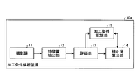
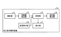
図1は、本発明の実施の形態1にかかる加工条件解析装置を含む、レーザ加工システムの構成例を示す図である。レーザ加工システムは、本発明にかかる加工条件解析装置10と、レーザ加工装置20とを備える。本実施の形態のレーザ加工装置20は、レーザ光を集光することにより被加工物であるワーク30を切断するレーザ切断加工を行う。加工条件解析装置10は、レーザ加工装置20が行う加工、すなわちレーザ切断加工における加工条件を調整する。 Embodiment 1.
FIG. 1 is a diagram showing a configuration example of a laser processing system including a processing condition analyzing apparatus according to the first embodiment of the present invention. The laser processing system includes a processing condition analysis device 10 according to the present invention and alaser processing device 20. The laser processing apparatus 20 of the present embodiment performs laser cutting processing for cutting the work 30 that is the workpiece by focusing the laser light. The processing condition analysis device 10 adjusts the processing conditions of the laser processing device 20, that is, the laser cutting process.
図1は、本発明の実施の形態1にかかる加工条件解析装置を含む、レーザ加工システムの構成例を示す図である。レーザ加工システムは、本発明にかかる加工条件解析装置10と、レーザ加工装置20とを備える。本実施の形態のレーザ加工装置20は、レーザ光を集光することにより被加工物であるワーク30を切断するレーザ切断加工を行う。加工条件解析装置10は、レーザ加工装置20が行う加工、すなわちレーザ切断加工における加工条件を調整する。 Embodiment 1.
FIG. 1 is a diagram showing a configuration example of a laser processing system including a processing condition analyzing apparatus according to the first embodiment of the present invention. The laser processing system includes a processing condition analysis device 10 according to the present invention and a
レーザ加工装置20は、図1に示すように、制御部21、レーザ発振器22および加工ヘッド23を備える。レーザ発振器22はレーザ光を発振して射出する。加工に使用するレーザ加工装置20のレーザ光の波長は、レーザ光の加工対象への吸収率、反射率等を考慮して適宜選択することができる。例えば、0.193μm~11μmとすることができる。レーザ発振器22から射出されたレーザ光は光路を介して、加工ヘッド23へ供給される。加工ヘッド23内部には、加工ガスが供給され、レーザ光がワーク30へ照射される際に、加工ガスがワーク30へ供給される。加工ヘッド23は、レーザ光をワーク30へ集光する不図示の集光レンズを有している。加工ヘッド23は、レーザ光を集光してワーク30へ照射することによりワーク30を切断する。加工ヘッド23は不図示のノズルを有する。ノズルは、集光レンズとワーク30との間のレーザビーム光路上に開口部を有し、この開口部をレーザ光および加工ガスが通過する。一般には、図示しない、モータ及びモータ駆動装置が、加工ヘッド23が設置される軸、あるいは、ワーク30を配置する加工テーブル、あるいは、加工ヘッド23が設置される軸およびワーク30を配置する加工テーブル、に備えられ、制御部21の制御の元でモータ駆動装置がモータを制御することにより加工ヘッド23とワーク30との相対位置を変更することが可能である。
The laser processing device 20 includes a control unit 21, a laser oscillator 22, and a processing head 23, as shown in FIG. The laser oscillator 22 oscillates and emits laser light. The wavelength of the laser light of the laser processing device 20 used for the processing can be appropriately selected in consideration of the absorptance of the laser light to the processing target, the reflectance, and the like. For example, it can be set to 0.193 μm to 11 μm. The laser light emitted from the laser oscillator 22 is supplied to the processing head 23 via the optical path. The processing gas is supplied to the inside of the processing head 23, and the processing gas is supplied to the work 30 when the work 30 is irradiated with the laser light. The processing head 23 has a condensing lens (not shown) that condenses the laser light onto the work 30. The processing head 23 cuts the work 30 by focusing the laser light and irradiating the work 30 with the laser light. The processing head 23 has a nozzle (not shown). The nozzle has an opening on the optical path of the laser beam between the condenser lens and the work 30, and the laser light and the processing gas pass through this opening. Generally, a motor and a motor drive device (not shown) are a shaft on which the machining head 23 is installed, a machining table on which the work 30 is arranged, or a shaft on which the machining head 23 is arranged and a machining table on which the work 30 is arranged. , And the relative position between the processing head 23 and the work 30 can be changed by controlling the motor by the motor drive device under the control of the control unit 21.
レーザ発振器22の種類は限定されない。レーザ発振器22の一例は、ファイバレーザ発振器であるが、炭酸ガスレーザや銅蒸気レーザや各種イオンレーザ、YAG結晶等を励起媒体とする固体レーザであってもよいし、レーザダイオードの光をそのまま利用するダイレクトダイオードレーザ等であってもよい。また、上記レーザ発振器22から発生したレーザ光を波長変換する波長変換部を備えても良い。
The type of laser oscillator 22 is not limited. An example of the laser oscillator 22 is a fiber laser oscillator, but a carbon dioxide gas laser, a copper vapor laser, various ion lasers, a solid-state laser having a YAG crystal or the like as an excitation medium may be used, or light from a laser diode may be used as it is. It may be a direct diode laser or the like. Further, a wavelength conversion unit for converting the wavelength of the laser light generated from the laser oscillator 22 may be provided.
制御部21は、加工プログラムと加工条件を示す加工パラメータとに従って、レーザ光がワーク30上の加工経路を走査するように、レーザ発振器22およびモータ駆動装置を制御する。制御部21は、加工パラメータとしては、レーザ出力、加工ガス圧、加工速度、集光光学系の焦点位置、集光径、レーザのパルス周波数、レーザのパルスのデューティ比、ノズル径、ワーク30とノズルとの距離、レーザビームモードの種類、ノズル穴の中心とレーザビームの位置関係等が挙げられる。加工パラメータは、上述した例に限定されない。使用するレーザの種別、レーザ加工装置20が備える機能などに応じて、加工パラメータとしてどのようなものを用いるかが適宜決定される。
The control unit 21 controls the laser oscillator 22 and the motor drive device so that the laser beam scans the machining path on the work 30 according to the machining program and the machining parameters indicating the machining conditions. The control unit 21 uses the laser output, the processing gas pressure, the processing speed, the focus position of the converging optical system, the condensing diameter, the pulse frequency of the laser, the duty ratio of the laser pulse, the nozzle diameter, and the work 30 as the processing parameters. The distance to the nozzle, the type of laser beam mode, the positional relationship between the center of the nozzle hole and the laser beam, and the like can be mentioned. The processing parameter is not limited to the above example. What is used as a processing parameter is appropriately determined depending on the type of laser used, the function of the laser processing apparatus 20, and the like.
制御部21が用いる加工パラメータは、後述するように加工条件解析装置10により算出される補正量に応じて変更可能である。すなわち、加工パラメータは加工条件解析装置10により補正可能である。加工条件解析装置10により補正される前の加工パラメータは、例えば、加工内容に応じて予め定められている。また、レーザ加工装置20が、作業者からの入力を受ける入力手段を備え、加工条件解析装置10により補正される前の加工パラメータが作業者からの入力により変更可能であってもよい。また、図示しない他のコンピュータなどの装置から、加工条件解析装置10により補正される前の加工パラメータがレーザ加工装置20へ送信されてもよい。
The processing parameters used by the control unit 21 can be changed according to the correction amount calculated by the processing condition analysis device 10 as described later. That is, the processing parameters can be corrected by the processing condition analysis device 10. The processing parameters before being corrected by the processing condition analysis device 10 are predetermined according to the processing content, for example. Further, the laser processing device 20 may include an input means for receiving an input from an operator, and the processing parameters before being corrected by the processing condition analysis device 10 may be changeable by the input from the operator. Further, the processing parameters before being corrected by the processing condition analyzing apparatus 10 may be transmitted to the laser processing apparatus 20 from another device such as a computer (not shown).
加工条件解析装置10は、図1に示すように、撮影器11、特徴量抽出部12、評価部13および補正量算出部14を備える。撮影器11は、レーザ加工装置20により加工されたワーク30の切断面31を撮影し、撮影した画像を特徴量抽出部12へ出力する。ここで、撮影した画像とは静止画像に限定されず、動画として撮影された画像も含む。特徴量抽出部12は、撮影器11から出力された画像から特徴量を抽出し、抽出した特徴量を評価部13へ出力する。特徴量は、レーザ切断加工によって切断された切断面を撮影した画像に基づく切断面情報の一例である。加工条件解析装置10による加工の評価と加工パラメータの補正量の算出は、例えば、製品の生産用の加工である生産加工へ移行する前に行われる。
As shown in FIG. 1, the processing condition analysis device 10 includes a photographing device 11, a feature amount extraction unit 12, an evaluation unit 13, and a correction amount calculation unit 14. The photographing device 11 photographs the cut surface 31 of the work 30 processed by the laser processing device 20, and outputs the photographed image to the feature amount extraction unit 12. Here, the captured image is not limited to a still image, and includes an image captured as a moving image. The feature amount extraction unit 12 extracts the feature amount from the image output from the imager 11, and outputs the extracted feature amount to the evaluation unit 13. The feature amount is an example of cutting plane information based on an image obtained by photographing a cutting plane cut by laser cutting processing. The evaluation of the processing by the processing condition analysis device 10 and the calculation of the correction amount of the processing parameter are performed, for example, before shifting to the production processing which is the processing for producing the product.
評価部13は、特徴量抽出部12から出力された特徴量を用いて切断面31の加工良否を判定し、判定結果を補正量算出部14へ出力する。詳細には、評価部13は、レーザ切断加工によって切断された切断面31を撮影した画像に基づく切断面情報を用いて、複数の加工不良モードのそれぞれに対応する加工品質を示す評価値を生成する。切断面情報は、特徴量抽出部12から出力された特徴量であってもよく、画像自体であってもよい。そして、評価部13は、複数の加工不良モードのそれぞれに対応する複数の評価値である組み合わせパターンを判定結果として出力する。補正量算出部14は、評価部13から出力された判定結果が否すなわち加工不良であることを示す値であった場合、所望の加工品質を得るため加工パラメータの補正量をレーザ加工装置20へ出力する。所望の加工品質とは、一定以上の水準の加工品質であり、具体例については後述する。補正量算出部14は、評価部13から出力された判定結果が良を示す値であった場合、補正量は算出せず、判定結果が良であることをレーザ加工装置20へ通知する。
The evaluation unit 13 determines the quality of processing of the cut surface 31 using the feature amount output from the feature amount extraction unit 12, and outputs the determination result to the correction amount calculation unit 14. Specifically, the evaluation unit 13 uses the cutting surface information based on the image of the cut surface 31 cut by the laser cutting processing to generate the evaluation value indicating the processing quality corresponding to each of the plurality of processing failure modes. To do. The cutting plane information may be the feature amount output from the feature amount extraction unit 12 or the image itself. Then, the evaluation unit 13 outputs a combination pattern, which is a plurality of evaluation values corresponding to each of the plurality of processing failure modes, as a determination result. If the determination result output from the evaluation unit 13 is negative, that is, a value indicating that the processing is defective, the correction amount calculation unit 14 sends the correction amount of the processing parameter to the laser processing apparatus 20 to obtain desired processing quality. Output. The desired processing quality is a processing quality of a certain level or higher, and a specific example will be described later. When the determination result output from the evaluation unit 13 is a value indicating good, the correction amount calculation unit 14 does not calculate the correction amount and notifies the laser processing device 20 that the determination result is good.
レーザ加工装置20では、補正量算出部14から補正量が出力されると、補正後の加工パラメータを用いた切断加工を実施する。詳細には、制御部21が、補正量算出部14から補正量の分だけ加工パラメータを補正した後に、切断加工を実行するよう加工ヘッド23およびレーザ発振器22を制御する。また、レーザ加工装置20は、判定結果が良であることを補正量算出部14から通知されると、生産加工へ移行する。
In the laser processing device 20, when the correction amount is output from the correction amount calculation unit 14, the cutting process is performed using the corrected processing parameters. Specifically, the control unit 21 controls the processing head 23 and the laser oscillator 22 to execute the cutting processing after correcting the processing parameters by the correction amount calculation unit 14 by the correction amount. When the correction amount calculation unit 14 notifies the laser processing device 20 that the determination result is good, the laser processing device 20 shifts to production processing.
加工条件解析装置10とレーザ加工装置20とは、有線または無線で接続されていてもよく、ネットワークを介して接続されていてもよい。なお、図1に示した例では、加工条件解析装置10とレーザ加工装置20とを別の装置としているが、加工条件解析装置10がレーザ加工装置20に含まれていてもよい。すなわち、レーザ加工装置20が、撮影器11、特徴量抽出部12、評価部13および補正量算出部14を備えていてもよい。
The processing condition analysis device 10 and the laser processing device 20 may be connected by wire or wirelessly, or may be connected via a network. In the example shown in FIG. 1, the processing condition analysis device 10 and the laser processing device 20 are separate devices, but the processing condition analysis device 10 may be included in the laser processing device 20. That is, the laser processing device 20 may include the imaging device 11, the feature amount extraction unit 12, the evaluation unit 13, and the correction amount calculation unit 14.
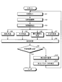
次に、本実施の形態の動作について説明する。図2は、本実施の形態のレーザ加工システムにおける加工パラメータ調整の動作の一例を示すフローチャートである。レーザ加工システムは、例えば、生産加工の実施前に、加工パラメータ調整のために図2に示す動作を実行する。なお、図2に示す動作を実行するタイミングは生産加工の実施前に限定されず、例えば、生産加工の途中などに実行されてもよい。
Next, the operation of this embodiment will be described. FIG. 2 is a flow chart showing an example of the operation of adjusting the processing parameters in the laser processing system according to the present embodiment. The laser processing system executes, for example, the operation shown in FIG. 2 for adjusting processing parameters before performing production processing. Note that the timing of executing the operation illustrated in FIG. 2 is not limited to before the production processing is performed, and may be performed during the production processing, for example.
図2のステップS1は、図1に示したレーザ加工装置20により実施され、ステップS2は、図1に示した撮影器11により実施される。図2のステップS3は、図1に示した特徴量抽出部12により実施され、図2のステップS4~S8は、図1に示した評価部13により実施される。また、図2のステップS9,S11は、図1に示した補正量算出部14により実施され、図2のステップS10は、レーザ加工装置20により実施される。以下、各ステップの詳細について説明する。
Step S1 in FIG. 2 is performed by the laser processing apparatus 20 shown in FIG. 1, and step S2 is performed by the imager 11 shown in FIG. Step S3 of FIG. 2 is performed by the feature amount extraction unit 12 shown in FIG. 1, and steps S4 to S8 of FIG. 2 are performed by the evaluation unit 13 shown in FIG. Further, steps S9 and S11 of FIG. 2 are executed by the correction amount calculation unit 14 shown in FIG. 1, and step S10 of FIG. 2 is executed by the laser processing device 20. The details of each step will be described below.
図2に示すように、まず、レーザ加工装置20が切断加工を行う(ステップS1)。次に、加工条件解析装置10の撮影器11が、切断加工により形成された切断面31を撮影する(ステップS2)。切断面31の画像取得は、レーザ加工の実施中に、切断が完了した部分の切断面31を撮影してもよく、切断完了後の加工対象の切断面31を撮影してもよい。撮影器11は、デジタルカメラでもよいしビデオカメラでもよい。特徴量を抽出するのに用いる画像は、特徴量を抽出することができる画像であれば、静止画像を用いてもよく動画像を用いてもよい。また、画像を取得するカメラに代えて、3次元形状測定機で切断面31の凹凸の面内分布を計測したデータを取得する装置を用いてもよい。
As shown in FIG. 2, first, the laser processing device 20 performs cutting processing (step S1). Next, the image capturing device 11 of the processing condition analyzing apparatus 10 captures an image of the cut surface 31 formed by the cutting processing (step S2). The image acquisition of the cut surface 31 may be performed by shooting the cut surface 31 of the portion where the cutting is completed during the laser processing, or the cut surface 31 of the processing target after the cutting is completed. The photographing device 11 may be a digital camera or a video camera. The image used for extracting the feature amount may be a still image or a moving image as long as the image can extract the feature amount. Further, instead of the camera that acquires the image, a device that acquires data obtained by measuring the in-plane distribution of the unevenness of the cut surface 31 with a three-dimensional shape measuring machine may be used.
次に、特徴量抽出部12が、撮影器11によって撮影された画像から特徴量を抽出する(ステップS3)。
Next, the feature quantity extraction unit 12 extracts the feature quantity from the image photographed by the photographing device 11 (step S3).
特徴量抽出部12は、例えば、特徴量として、画像処理技術を用いて、切断面31の色相、彩度、明度、各画素間の明度相関、高次局所自己相関(HLAC:Higher order Local AutoCorrelation)を算出する。また、特徴量抽出部12は、特徴量として、画像処理技術を用いて、ガウシアン(Gaussian)平滑化処理(Sobelフィルタを用いた処理)により得られる処理結果、アフィン変換により得られる結果、局所領域の明度の勾配方向のヒストグラム(HoG特徴量)、SIFT(Scale Invariant Feature Transform:位置不変量)、位相限定相関法を用いた解析結果、フーリエ変換を用いた解析結果などで算出してもよい。また、特徴量抽出部12は、前処理として、画像の露出補正、色温度やホワイトバランス等の色調補正、軸上色収差補正、倍率色収差補正等の収差補正、平滑化フィルタであるGaussianフィルタ、Medianフィルタ、バイラテラルフィルタ、Guidedフィルタ、ヒストグラム平坦化処理であるコントラスト制限付適応ヒストグラム平坦化(Contrast Limited Histogram Enhancement: CLAHE)、微分フィルタであるSobelフィルタ、Laplarcianフィルタ、色空間変換方法である、RGB、輝度、HSV(Hue、Saturation、Value)、HLS(Hue、Lightness、Saturation)、CIE(Commission Internationale de l'Eclairage) L*a*b*(CIELAB)、CIE L*u*v*(CIELUV)、アフィン変換等を用いてもよい。また、特徴量抽出部12は、画素値情報としてヒストグラム、平均、分散を特徴量として算出してもよいし、フーリエ変換、ウェーブレット変換などにより得られる周波数情報を特徴量として算出してもよい。また、特徴量抽出部12は、高次局所自己相関特徴、CILAC(Color Indel Local AutoCorrelation)、NLAC(Normal Local AutoCorrelations)、GLAC(Gradient Local AutoCorrelations)、SIFT、HOG(Histograms of Oriented Gradients)、SURF(Speeded Up Robust Features)、LBP(Local Binary Pattern)を利用した特徴量、ガボール フィルタ(Gabor Filter)を利用した特徴量、GLCM(Gray-Level Co-occurrence Matrix)に基づく特徴量、Haralick's texture features、深層ニューラルネットワークにおけるボトルネック特徴量、バギング(Bag of Visual Words)、KAZE、AKAZE(Accelerated-KAZE)、BRIEF(Binary Robust Independent Elementary Features)、ORB (Oriented FAST and Rotated BRIEF)、MSER(Maximally Stable Extremal Regions)、GBTT(Good Features to Track)、AGAST(Adaptive and Generic Accelerated Segment Test)等を特徴量として算出してもよい。また、これらの画像処理技術は一般的なものを用いることができるため、特徴量の抽出の詳細な説明は省略する。特徴量はこれらに限定されず、どのようなものを用いてもよい。また、特徴量抽出部12は、画像そのものを、特徴量としてもよい。また、特徴量抽出部12が抽出する特徴量の数は、1つでもよく複数でもよい。
The feature amount extraction unit 12 uses, for example, the image processing technique as the feature amount, the hue, the saturation, the lightness of the cut surface 31, the lightness correlation between the pixels, and the high-order local autocorrelation (HLAC). ) Is calculated. In addition, the feature amount extraction unit 12 uses, as the feature amount, a processing result obtained by a Gaussian smoothing process (a process using a Sobel filter), a result obtained by an affine transformation, and a local region, using an image processing technique. The brightness may be calculated using a histogram in the gradient direction (HoG feature amount), SIFT (Scale Invariant Feature Transform), an analysis result using the phase-only correlation method, an analysis result using the Fourier transform, and the like. Further, the feature amount extraction unit 12 performs pre-processing such as image exposure correction, color tone correction such as color temperature and white balance correction, axial chromatic aberration correction, aberration correction such as magnification chromatic aberration correction, smoothing filter Gaussian filter, Median Filter, bilateral filter, Guided filter, adaptive histogram flattening (Contrast Limited Histogram Enhancement: CLAHE) which is a histogram flattening process, Sobel filter which is a differential filter, Laplarcian filter, RGB which is a color space conversion method, Luminance, HSV (Hue, Saturation, Value), HLS (Hue, Lightness, Saturation), CIE (Commission Internationale de l'Eclairage) L*a*b* (CIELAB), CIE L*u*v* (CIEUV), Affine transformation or the like may be used. Further, the feature amount extraction unit 12 may calculate a histogram, an average, and a variance as the feature amount as the pixel value information, or may calculate frequency information obtained by Fourier transform, wavelet transform, or the like as the feature amount. In addition, the feature amount extraction unit 12 includes higher-order local autocorrelation features, CILAC (Color Indel Local AutoCorrelation), NLAC (Normal Local AutoCorrelations), GLAC (Gradient Local AutoCorrelations), SIFT, HOG (Histograms of Oriented Gradients), SURF (Surf). Speeded Up Robust Features), features using LBP (Local Binary Pattern), features using a Gabor Filter, features based on GLCM (Gray-Level Co-occurrence Matrix), Haralick's texture features, deep layers Bottleneck feature amount, bagging (Bag of Visual Words), KAZE, AKAZE (Accelerated-KAZE), BRIEF (Binary Robust Independent Elementary Features), ORB (Oriented FAST and Rotated Brief), MSER (Maximally Stable Extreme) , GBTT (Good Features to Track), AGAST (Adaptive and Generic Accelerated Segment Test), etc. may be calculated as features. Further, since general image processing techniques can be used, detailed description of the extraction of the feature amount will be omitted. The feature amount is not limited to these, and any kind may be used. The feature amount extraction unit 12 may use the image itself as the feature amount. Further, the number of feature quantities extracted by the feature quantity extraction unit 12 may be one or more.
図2の説明に戻る。評価部13は、特徴量抽出部12から出力された特徴量を用いて、加工不良モードごとの良否判定を行う。図2では、加工不良モードとして、荒れの発生、キズの発生、酸化膜剥れの発生、ドロスの発生を考慮した例を示している。したがって、図2に示すように、評価部13は、これらの加工不良モードにそれぞれ対応する良否判定として、荒れ判定(ステップS4)、キズ判定(ステップS5)、酸化膜剥れ判定(ステップS6)、ドロス判定(ステップS7)を行う。なお、図2では、荒れ判定、キズ判定、酸化膜剥れ判定、ドロス判定を並列に示しているが、評価部13は、これらの判定を並行して実施しても良いし、時系列で順に実施してもよい。
Return to the explanation of FIG. The evaluation unit 13 uses the feature amount output from the feature amount extraction unit 12 to make a pass/fail determination for each processing failure mode. FIG. 2 shows an example in which occurrence of roughness, occurrence of scratches, occurrence of oxide film peeling, and occurrence of dross are taken into consideration as the processing failure mode. Therefore, as shown in FIG. 2, the evaluation unit 13 determines roughness (step S4), scratches (step S5), and oxide film peeling (step S6) as quality judgments corresponding to these processing failure modes. , Dross determination (step S7) is performed. In addition, in FIG. 2, the roughness determination, the flaw determination, the oxide film peeling determination, and the dross determination are shown in parallel, but the evaluation unit 13 may perform these determinations in parallel, or in a time series. You may implement in order.
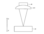
ここで、各加工不良モードについて詳細に説明する。図3は、本実施の形態におけるワーク30の上下方向の定義を示す図である。図3に示すように、ワーク30が加工される際に、加工ヘッド23の一部である集光レンズ231によりレーザビーム40が集光される。図3は、切断面31におけるワーク30および集光レンズ231の断面を模式的に示すものである。本実施の形態では、図3に示すように、ワーク30からみて、加工ヘッド23の存在する方向を上と定義、その反対側を下と定義する。
Here, each processing failure mode will be described in detail. FIG. 3 is a diagram showing the vertical definition of the work 30 in the present embodiment. As shown in FIG. 3, when the work 30 is processed, the laser beam 40 is condensed by the condenser lens 231 which is a part of the processing head 23. FIG. 3 schematically shows a cross section of the work 30 and the condenser lens 231 on the cut surface 31. In the present embodiment, as shown in FIG. 3, the direction in which the processing head 23 is present is defined as the upper side and the opposite side is defined as the lower side as viewed from the work 30.
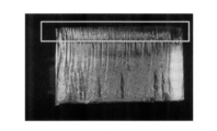
図4は、荒れが発生した状態で撮影された切断面31の画像の一例を示す図である。点線で囲まれた部分が荒れの特徴的な部分である。切断面31の上部に周期的に荒れが発生している。荒れが発生すると、荒れが発生していない場合に比べ、条痕の凹凸の深さが深くなる。荒れの発生の有無を判断する基準として、例えば、切断面31の面粗度が一定の値以上であるか否かを用いることができる。したがって、評価部13は、荒れ判定として、ステレオ撮影により凹凸の深さを測定したり、荒れの周期方向から照明をあてることで、山部は明るくその影の谷部は暗くなるので、明暗の度合いや影の長さや暗部の幅等により凹凸の深さを推測すること等で切断面31の面粗度を求め、面粗度が一定の値以上である場合に、荒れがあると判断することができる。
FIG. 4 is a diagram showing an example of an image of the cut surface 31 taken in a state where the roughness occurs. The part surrounded by the dotted line is the characteristic part of the roughness. Roughness is periodically generated in the upper part of the cut surface 31. When the roughness occurs, the depth of the unevenness of the streaks becomes deeper than when the roughness does not occur. As a criterion for determining the occurrence of roughness, for example, whether the surface roughness of the cut surface 31 is a certain value or more can be used. Therefore, as the roughness determination, the evaluation unit 13 measures the depth of the unevenness by stereo photography or illuminates from the cycle direction of the roughness, so that the peaks are bright and the valleys of the shadow are dark. The surface roughness of the cut surface 31 is obtained by estimating the depth of the unevenness based on the degree, the length of the shadow, the width of the dark portion, etc., and when the surface roughness is a certain value or more, it is determined that the surface is rough. be able to.
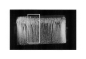
図5は、キズが発生した状態で撮影された切断面31の画像の一例を示す図である。点線で囲まれた部分がキズの特徴的な部分である。キズは、切断面31において局所的に上面から下面にかけて発生する。キズの発生の有無を判断する基準として、実作業では、例えば切断面31を複数の区間に分け、区間内の明度に基づいて凹凸のPV(Peak to Valley)値を求め、ある区間のPVの値が一定の値以上であるか否かを用いることができる。この区間としては、切断面31を左右方向に複数に分割した区間を用いてもよい。本実施の形態においては、評価部13は、画像を上下および左右に複数の区間に分割し、区間内の他の画素の平均値と明度が閾値以上異なる部分をキズ候補部分とし、キズ候補部分の長さを求め、キズ候補部分の長さが一定以上の値の場合にキズの発生と判定してもよい。キズ候補部分の求め方はこの例に限定されない。
FIG. 5 is a diagram showing an example of an image of the cut surface 31 taken in a state where a scratch has occurred. The part surrounded by the dotted line is the characteristic part of the scratch. The scratch is locally generated on the cut surface 31 from the upper surface to the lower surface. In the actual work, for example, the cut surface 31 is divided into a plurality of sections, and a PV (Peak to Valley) value of unevenness is calculated based on the brightness in the section as a criterion for determining the presence or absence of a scratch, and the PV of a section is calculated. Whether or not the value is a certain value or more can be used. As this section, a section obtained by dividing the cut surface 31 in the left-right direction may be used. In the present embodiment, the evaluation unit 13 divides the image into a plurality of sections vertically and horizontally, and defines a portion whose brightness differs from the average value of other pixels in the section by a threshold value or more as a flaw candidate portion, and the flaw candidate portion. May be determined, and it may be determined that a flaw has occurred when the length of the flaw candidate portion is a value equal to or greater than a certain value. The method for obtaining the defect candidate portion is not limited to this example.
図6は、酸化膜剥れが発生した状態で撮影された切断面31の画像の一例を示す図である。点線で囲まれた部分が酸化膜剥れの特徴的な部分である。酸化膜剥れは、切断に用いる加工ガスが酸素である場合に生じ、切断面31に生じている酸化膜が剥れてしまう症状であり、切断面31の下部に発生する。評価部13は、例えば、画素の明度等の特徴量に基づいて、酸化膜が剥れた箇所と想定される部分の面積を求め、この面積が一定の値以上である場合に、酸化膜剥れが生じていると判定してもよい。酸化膜が剥れた箇所は、例えば、画素の明度の平均値との差が閾値以上ある部分を酸化膜剥れが生じている部分とすることができるが、酸化膜が剥れた箇所の算出方法はこれに限定されない。
FIG. 6 is a diagram showing an example of an image of the cut surface 31 taken in a state where the oxide film is peeled off. The part surrounded by the dotted line is the characteristic part of the oxide film peeling. The oxide film peeling is a symptom that occurs when the processing gas used for cutting is oxygen, and the oxide film generated on the cutting surface 31 peels off, and occurs at the lower part of the cutting surface 31. The evaluation unit 13 obtains the area of the portion where the oxide film is supposed to be peeled based on the characteristic amount such as the brightness of the pixel, and when the area is a certain value or more, the oxide film peeling is performed. It may be determined that this has occurred. The location where the oxide film is peeled off can be defined as, for example, the portion where the difference between the average value of the brightness of the pixel and the threshold value is greater than or equal to the portion where the oxide film peeling has occurred. The calculation method is not limited to this.
図7は、ドロスが発生した状態で撮影された切断面31の画像の一例を示す図である。点線で囲まれた部分がドロスの特徴的な部分である。ドロスは、レーザ切断中に溶融した金属等が切断面31に付着する症状であり、切断面31の下端から発生する。評価部13は、画素の明度等の特徴量に基づいて、切断面31の下部においてドロス候補と想定される部分の長さを求め、この長さが一定の値以上である場合にドロスが生じていると判定してもよい。ドロス箇所の算出方法はこれに限定されない。
FIG. 7 is a diagram showing an example of an image of the cut surface 31 taken in a state where dross has occurred. The part surrounded by the dotted line is the characteristic part of the dross. Dross is a symptom that metal or the like melted during laser cutting adheres to the cutting surface 31, and is generated from the lower end of the cutting surface 31. The evaluation unit 13 obtains the length of a portion assumed to be a dross candidate in the lower part of the cut surface 31 based on the feature amount such as the brightness of the pixel, and the dross is generated when this length is a certain value or more. May be determined to be present. The method for calculating the dross location is not limited to this.
加工不良モードはこれらに限定されない。例えば、ワーク30の変色、振動面の有無等、他の加工不良モードも含めて判定を行ってもよいし、上述した加工不良モードのうちの一部に替えて他の加工不良モードの判定を行ってもよい。また、評価部13は、レーザ出力、加工速度、加工板厚の組み合わせ、加工ガスの種類等の加工パラメータによって、判定する加工不良モードを変更してもよい。
The processing failure mode is not limited to these. For example, the determination may be performed by including other processing failure modes such as the discoloration of the workpiece 30 and the presence or absence of a vibrating surface. Alternatively, a part of the processing failure modes described above may be replaced with another processing failure mode. You can go. Further, the evaluation unit 13 may change the processing failure mode to be determined according to the processing parameters such as the combination of the laser output, the processing speed, the processing plate thickness, the type of processing gas, and the like.
例えば、加工ガスの種類が酸素である場合は、切断面31に酸化膜が発生するため、酸化膜剥れの有無の判定が必要である。しかし、加工ガスの種類が窒素である場合は、切断面31に酸化膜が発生することがないため、酸化膜剥れの有無の判定は不要である。したがって、評価部13は、加工ガスの種類が窒素である場合は、酸化膜剥れ判定を省いてもよい。
For example, when the type of processing gas is oxygen, an oxide film is generated on the cut surface 31, so it is necessary to determine whether or not the oxide film is peeled off. However, when the type of processing gas is nitrogen, an oxide film is not generated on the cut surface 31, and therefore it is not necessary to determine whether the oxide film is peeled off. Therefore, the evaluation unit 13 may omit the oxide film peeling determination when the type of processing gas is nitrogen.
図2の説明に戻る。評価部13は、荒れ判定(ステップS4)、キズ判定(ステップS5)、酸化膜剥れ判定(ステップS6)、ドロス判定(ステップS7)の後、これらの判定結果を用いて、切断加工の良否を判定する(ステップS8)。切断加工の良否の判定結果である評価値としては、良または否(不良)の度合いすなわち加工品質を2段階以上のあらかじめ定められた複数の段階的な値で表すものであってもよいし、連続的な値であってもよい。評価値は、換言する加工品質を示す値である。評価値が段階で表される場合、良または不良の2値のうちのいずれかを示す2段階の値であってもよいし、3段階以上の不良の度合いを示すものであってもよい。また、段階的な値のそれぞれについて確率と組み合わせてもよい。例えば、評価部13は、良である確率が90%、不良である確率が10%といった評価値を算出してもよい。評価部13は、加工不良モードごとの判定結果を、評価値として出力してもよい。例えば、加工不良モードごとの判定が、上述した荒れ判定、キズ判定、酸化膜剥れ判定、ドロス判定の4つであり、評価部13がこれらにそれぞれ対応する評価値として良または不良の2値のいずれかを出力するとする。評価値が1の場合を良、評価値が0の場合を不良とし、評価部13から、例えば、荒れ判定、キズ判定、酸化膜剥れ判定、ドロス判定にそれぞれ対応する評価値として、0,1,0,0が出力されるとする。この場合、キズ判定では不良すなわちキズが発生していると判定され、荒れ判定、酸化膜剥れ判定およびドロス判定では良と判定されたことを意味する。
Return to the explanation of FIG. The evaluation unit 13 uses the judgment results after the roughness judgment (step S4), the scratch judgment (step S5), the oxide film peeling judgment (step S6), and the dross judgment (step S7), and determines whether the cutting process is good or bad. Is determined (step S8). As the evaluation value which is the determination result of the quality of the cutting process, the degree of good or bad (defective), that is, the processing quality may be represented by a plurality of predetermined stepwise values of two or more steps, It may be a continuous value. The evaluation value is a value indicating the processing quality in other words. When the evaluation value is expressed in stages, it may be a two-stage value indicating either one of two values, good or bad, or may indicate a degree of failure of three or more steps. Also, each stepwise value may be combined with a probability. For example, the evaluation unit 13 may calculate evaluation values such that the probability of being good is 90% and the probability of being bad is 10%. The evaluation unit 13 may output the determination result for each processing failure mode as an evaluation value. For example, the determination for each processing failure mode is the above-described four determinations of roughness determination, scratch determination, oxide film peeling determination, and dross determination, and the evaluation unit 13 has two values of good or bad as evaluation values corresponding to these respectively. Suppose you want to output either of When the evaluation value is 1, the evaluation value is 0, and when the evaluation value is 0, the evaluation value is 0. From the evaluation unit 13, for example, 0, It is assumed that 1,0,0 is output. In this case, it means that the defect determination determines that a defect, that is, a defect has occurred, and that the roughness determination, the oxide film peeling determination, and the dross determination determine that the defect is good.
また、評価部13は、各加工不良モードに対応する判定の評価値の合計によって、切断加工の良否を判定してもよい。また、評価部13は、加工不良モードごとに判定結果に重み付けをして、重み付け後の合計に基づいて切断加工の良否を判定してもよい。例えば、評価部13は、加工不良モードに対応する判定結果のうち否と判定された数が閾値以上である場合に、切断加工の良否判定結果が否であると判定してもよい。または、各加工不良モードに対応する判定のうち1つでも否と判断された加工不良モードがある場合は、評価部13は、切断面31の良否判定結果を否としてもよい。
Further, the evaluation unit 13 may determine the quality of the cutting process based on the sum of the evaluation values of the determination corresponding to each process failure mode. Further, the evaluation unit 13 may weight the determination result for each processing failure mode and determine the quality of the cutting processing based on the weighted total. For example, the evaluation unit 13 may determine that the cut processing quality determination result is negative when the number of determination results corresponding to the processing failure mode determined to be negative is equal to or greater than a threshold value. Alternatively, if at least one of the determinations corresponding to each of the processing failure modes is determined to be defective, the evaluation unit 13 may determine the quality of the cut surface 31 as negative.
また、評価部13は、各加工不良モードに対応する判定において、良否の2値の判定でなく、良の可能性が高いと0に近づき不良の可能性が高いと1に近づくといった連続した値を求めるようにしてもよい。また、評価部13は、加工条件解析装置10の内部または外部の表示部に判定結果を表示するようにしてもよい。または、評価部13は、切断加工の良否判定結果が否の場合のみ、加工条件解析装置10の内部または外部の表示部に判定結果を表示するようにしてもよい。
Further, the evaluation unit 13 does not make a binary decision of good or bad in the determination corresponding to each processing failure mode, but a continuous value that approaches 0 when the possibility of good is high and approaches 1 when the possibility of defective is high. May be requested. In addition, the evaluation unit 13 may display the determination result on a display unit inside or outside the processing condition analysis apparatus 10. Alternatively, the evaluation unit 13 may display the determination result on the display unit inside or outside the processing condition analysis device 10 only when the quality determination result of the cutting process is NO.
また、評価部13は、特徴量抽出部12から出力された特徴量だけでなく、他の情報も用いて、良否判定を行ってもよい。図8は、他の情報を用いる場合の本実施の形態の評価部13への入力を示す図である。図8では、撮影器11の図示を省略して記載している。図8に示した例では、他の情報として、加工板厚、加工材料を用いている。加工板厚は、加工対象のワーク30のレーザ光入射方向の厚みであり、加工材料は加工対象のワーク30の材質である。これらの他の情報は、加工条件解析装置10が入力手段を備えることにより、作業者から加工条件解析装置10へ入力されていてもよいし、加工条件解析装置10がレーザ加工装置20から取得してもよい。
Further, the evaluation unit 13 may make a pass/fail judgment by using not only the feature amount output from the feature amount extraction unit 12 but also other information. FIG. 8 is a diagram showing input to the evaluation unit 13 in the present embodiment when other information is used. In FIG. 8, the imaging device 11 is omitted in the illustration. In the example shown in FIG. 8, the processed plate thickness and the processed material are used as other information. The processing plate thickness is the thickness of the workpiece 30 to be processed in the laser beam incident direction, and the processing material is the material of the workpiece 30 to be processed. The other information may be input to the processing condition analyzing apparatus 10 from an operator by providing the processing condition analyzing apparatus 10 with an input unit, or the processing condition analyzing apparatus 10 acquires it from the laser processing apparatus 20. May be.
図2の説明に戻る。補正量算出部14は、評価部13から出力される判定結果が良であるか否かを判断し(ステップS9)、判定結果が良である場合(ステップS9 Yes)には、加工パラメータの調整を終了する。加工パラメータの調整が終了すると、生産加工が実行される。なお、評価部13が判定結果すなわち評価値として3段階以上の値または連続値を出力する場合、補正量算出部14は、ステップS9では、この評価値が定められた基準を満たすか否かにより、良否を判定する。例えば、評価値がレベル1からレベル5までの5段階であり、レベル1が加工の状態が最も良くレベル5が加工の状態が最も悪い場合、評価部13は、レベル3以下の場合に良であると判定する。なお、このように複数の段階で評価値を定義する場合には、例えば、キズ判定では、キズ候補の長さに応じて複数段階の評価値を定義するといった方法が考えられる。
Return to the explanation of FIG. The correction amount calculation unit 14 determines whether or not the determination result output from the evaluation unit 13 is good (step S9), and when the determination result is good (step S9 Yes), the adjustment of the processing parameter is performed. To finish. When the adjustment of the processing parameters is completed, production processing is executed. When the evaluation unit 13 outputs a determination result, that is, a value of three or more stages or a continuous value as the evaluation value, the correction amount calculation unit 14 determines whether the evaluation value satisfies the predetermined criterion in step S9. , Judge pass/fail. For example, when the evaluation value has five levels from level 1 to level 5, the level 1 is the best processing state, and the level 5 is the worst processing state, the evaluation unit 13 is good when the level 3 or lower. Judge that there is. When defining the evaluation values in a plurality of stages in this way, for example, in the scratch determination, a method of defining the evaluation values in a plurality of stages according to the length of the scratch candidate can be considered.
補正量算出部14は、評価部13から出力される判定結果が良でない場合(ステップS9 No)、評価部13から出力される判定結果に基づいて加工パラメータの補正量を算出する(ステップS10)。補正量算出部14は、算出した補正量をレーザ加工装置20へ出力する。なお、補正量算出部14は、レーザ加工装置20から、レーザ加工装置20に設定されている加工パラメータを取得可能であり、評価部13から出力される判定結果と現在設定されている加工パラメータとに基づいて補正量を算出してもよい。レーザ加工装置20の制御部21は、補正量算出部14から受け取った補正量に基づいて加工パラメータを補正し(ステップS11)、再度、ステップS1を実行する。このように、評価部13による判定結果が否である場合には、加工パラメータが補正された後に再び切断加工が行われる。加工条件解析装置10は、切断加工が行われると、再度、ステップS2以降の処理を実行する。以上の処理により、評価部13から出力される判定結果が良となるまで、加工パラメータの補正と切断加工が繰り返される。なお、加工の安定性を確認したい場合は、同じ加工パラメータを用いた切断加工を複数回行い、その複数回の切断加工に関してそれぞれステップS2~ステップS9を実行して、これらの切断加工に対応するステップS9の判定で全て良と判定された場合、加工パラメータ補正を終了するようにしてもよい。
When the determination result output from the evaluation unit 13 is not good (No in step S9), the correction amount calculation unit 14 calculates the processing parameter correction amount based on the determination result output from the evaluation unit 13 (step S10). .. The correction amount calculation unit 14 outputs the calculated correction amount to the laser processing device 20. The correction amount calculation unit 14 can acquire the processing parameters set in the laser processing device 20 from the laser processing device 20, and determines the determination result output from the evaluation unit 13 and the currently set processing parameters. The correction amount may be calculated based on The control unit 21 of the laser processing apparatus 20 corrects the processing parameters based on the correction amount received from the correction amount calculation unit 14 (step S11), and executes step S1 again. As described above, when the determination result by the evaluation unit 13 is negative, the cutting process is performed again after the processing parameters are corrected. When the cutting processing is performed, the processing condition analysis device 10 again executes the processing from step S2. Through the above processing, the correction of the processing parameters and the cutting processing are repeated until the determination result output from the evaluation unit 13 becomes good. If it is desired to confirm the stability of the processing, the cutting processing using the same processing parameter is performed a plurality of times, and the steps S2 to S9 are executed for each of the plurality of cutting processings to correspond to the cutting processing. When it is determined that all are good in the determination of step S9, the processing parameter correction may be ended.
ここで、ステップS10の加工パラメータの補正量の算出について詳細に説明する。補正すべき加工パラメータの例としては、レーザ出力、加工ガス圧、加工速度、集光光学系の焦点位置、集光径、レーザのパルス周波数、レーザのパルスのデューティ比、ノズル径、ワーク30とノズルとの距離、レーザビームモードの種類、ノズル穴の中心とレーザビームの位置関係等を挙げることができる。
Here, the calculation of the correction amount of the processing parameter in step S10 will be described in detail. Examples of processing parameters to be corrected include laser output, processing gas pressure, processing speed, focus position of converging optical system, converging diameter, laser pulse frequency, laser pulse duty ratio, nozzle diameter, and work 30. The distance to the nozzle, the type of laser beam mode, the positional relationship between the center of the nozzle hole and the laser beam, and the like can be mentioned.
補正量算出部14は、評価部13から評価値として加工不良モードごとの判定結果が出力される場合、各加工不良モードについての良否判定結果の組み合わせパターンに基づいて、補正する加工パラメータと該加工パラメータの補正量を決定してもよい。組み合わせパターンとは、例えば、評価値が1の場合を良、評価値が0の場合を不良とし、荒れ判定、キズ判定、酸化膜剥れ判定、ドロス判定にそれぞれ対応する評価値を評価部13が出力する場合、0,0,0,1などといった4つのデータの値の組み合わせのことである。例えば、ドロス判定に対応する値のみが1で他の値が0である場合には、加工パラメータのうちレーザ出力および加工ガス圧を補正量の算出対象とし、レーザ出力を増加させ加工ガス圧を低下させるように補正量を決定する。このように、組み合わせパターンごとに補正する加工パラメータと該加工パラメータの補正量を定めておくことができる。
When the evaluation result is output from the evaluation unit 13 as a determination result for each processing failure mode, the correction amount calculation unit 14 corrects the processing parameter to be corrected and the processing parameter based on the combination pattern of the quality determination results for each processing failure mode. You may decide the correction amount of a parameter. The combination pattern is, for example, good when the evaluation value is 1 and bad when the evaluation value is 0, and the evaluation values corresponding to the roughness judgment, the scratch judgment, the oxide film peeling judgment, and the dross judgment are evaluated by the evaluation unit 13 respectively. Is a combination of four data values such as 0, 0, 0, 1 and so on. For example, when only the value corresponding to the dross determination is 1 and the other values are 0, the laser output and the processing gas pressure among the processing parameters are the calculation targets of the correction amount, and the laser output is increased to increase the processing gas pressure. The correction amount is determined so as to decrease. In this way, the processing parameter to be corrected and the correction amount of the processing parameter can be set for each combination pattern.
また、評価部13から評価値として加工不良モードごとの判定結果が出力され、かつ各加工不良モードの良否判定結果が不良の度合いを示す値として出力される場合は、加工不良モードごとに補正すべき加工パラメータの補正量に重みをつけて変更してもよいし、補正を行う加工パラメータ自体を各加工不良モードの評価値に応じて変更してもよい。
In addition, when the evaluation unit 13 outputs a determination result for each processing failure mode as an evaluation value and a quality determination result for each processing failure mode is output as a value indicating the degree of failure, correction is performed for each processing failure mode. The correction amount of the processing parameter to be corrected may be weighted and changed, or the processing parameter itself to be corrected may be changed according to the evaluation value of each processing failure mode.
例えば、評価部13が、各加工不良モードについて評価値として、0から1までの数値で3段階以上の値として出力するとする。例えば、ドロス判定の評価値としては、0,0.3,0.6,1.0の4段階で定義され、ドロス判定の評価値に応じて、レーザ出力および加工ガス圧の補正量を定めておく。例えば、ドロスの評価値が0.3である場合は、レーザ出力の補正量を+0.2[kW]とし、加工ガス圧の補正量を-0.01[MPa]とし、評価値が0.6の場合は補正量を+0.5[kW]とし、加工ガス圧の補正量を-0.02[MPa]とする。補正量算出部14は、このように定められた評価値と補正量との対応にしたがって補正量を求める。これにより、ドロスの評価値が0.3である場合は、レーザ出力を0.2[kW]上げ、加工ガス圧を0.01[MPa]下げ、評価値が0.6の場合は、レーザ出力を0.5[kW]上げ、加工ガス圧を0.02[MPa]下げることになる。なお、以上述べた補正量は一例であり、補正量は評価値に応じて定められていればよく、補正量をさらに補正前の加工パラメータの値に依存する値として定めておいてもよく、補正量の決定方法は上述した例に限定されない。
For example, it is assumed that the evaluation unit 13 outputs an evaluation value for each processing failure mode as a numerical value from 0 to 1 in three or more levels. For example, the evaluation value of the dross determination is defined in four stages of 0, 0.3, 0.6, and 1.0, and the correction amount of the laser output and the processing gas pressure is determined according to the evaluation value of the dross determination. Keep it. For example, when the evaluation value of the dross is 0.3, the correction amount of the laser output is +0.2 [kW], the correction amount of the processing gas pressure is −0.01 [MPa], and the evaluation value is 0. In the case of 6, the correction amount is +0.5 [kW] and the processing gas pressure correction amount is −0.02 [MPa]. The correction amount calculation unit 14 calculates the correction amount according to the correspondence between the evaluation value and the correction amount thus determined. As a result, when the evaluation value of the dross is 0.3, the laser output is increased by 0.2 [kW] and the processing gas pressure is decreased by 0.01 [MPa]. When the evaluation value is 0.6, the laser output is increased. The output is increased by 0.5 [kW] and the processing gas pressure is decreased by 0.02 [MPa]. Note that the correction amount described above is an example, and the correction amount may be set according to the evaluation value, and the correction amount may be set as a value depending on the value of the processing parameter before correction. The method of determining the correction amount is not limited to the above example.
また、各加工不良モードについて評価値として連続した値が評価部13から出力される場合、評価値と補正量との対応をテーブルとして保持しておき、補正量算出部14が、テーブルを用いて、各加工パラメータの補正量を外挿または内挿により算出してもよい。外挿または内挿方法は、スプライン補間やラグランジュ補間等の多項式曲線を用いてもよいし、三角関数、円錐曲線等の各種関数を用いてもよい。
When a continuous evaluation value is output from the evaluation unit 13 for each processing failure mode, the correspondence between the evaluation value and the correction amount is held as a table, and the correction amount calculation unit 14 uses the table. The correction amount of each processing parameter may be calculated by extrapolation or interpolation. As the extrapolation or interpolation method, a polynomial curve such as spline interpolation or Lagrange interpolation may be used, or various functions such as a trigonometric function and a conic curve may be used.
なお、以上述べた例では、評価部13は、加工不良モードとして切断面31の品質にかかわる不良の例を説明したが、作業者によって、切断面31の品質、生産性、加工の安定性など、優先度の高い改善項目が異なる場合がある。生産性、すなわち加工速度が極めて遅い場合は、切断面31の品質が良かったとしても、適切でない場合がある。このため、加工条件解析装置10が入力手段を設け、作業者からの改善項目ごとの優先度の入力を受け付けるようにしてもよい。補正量算出部14は、改善項目ごとの優先度に基づいて、加工パラメータの補正量を算出する。すなわち、補正量算出部14は、生産性、組み合わせパターン、加工安定性を含む複数の改善項目の優先度に基づいて加工パラメータの補正量を決定してもよい。例えば、改善項目によって、同じ加工パラメータの補正量の正負が逆になることが考えられる。このような場合には、補正量算出部14は、優先される作業項目に対応する補正量を選択する。
In the example described above, the evaluation unit 13 has described an example of a defect related to the quality of the cut surface 31 as the processing failure mode. However, depending on the operator, the quality of the cut surface 31, productivity, processing stability, etc. , High-priority improvement items may differ. If the productivity, that is, the processing speed is extremely low, even if the quality of the cut surface 31 is good, it may not be appropriate. For this reason, the processing condition analysis device 10 may be provided with an input means so as to receive the input of the priority for each improvement item from the operator. The correction amount calculation unit 14 calculates the correction amount of the processing parameter based on the priority of each improvement item. That is, the correction amount calculation unit 14 may determine the correction amount of the processing parameter based on the priority of the plurality of improvement items including the productivity, the combination pattern, and the processing stability. For example, depending on the improvement item, the positive and negative signs of the correction amount of the same processing parameter may be reversed. In such a case, the correction amount calculation unit 14 selects the correction amount corresponding to the work item to be prioritized.
また、補正量算出部14は、優先度に応じた重み付けを行って補正量を求めてもよい。例えば、改善項目ごとに、各加工パラメータの補正量を予め定めておき、補正量算出部14は、改善項目の優先度に応じた重みを予め定めた補正量にそれぞれ乗算し、重みが乗算された後の補正量の合計を求めることで、出力する補正量を決定する。優先する項目ほど重みの値が大きくなるように重みを決定しておくと、優先度が高いほど出力される補正量への寄与度が大きくなる。このように、補正量算出部14は、優先度に応じた重み付けを行って、各項目のバランスをとって補正量を算出してもよい。
The correction amount calculation unit 14 may obtain the correction amount by weighting according to the priority. For example, the correction amount of each processing parameter is predetermined for each improvement item, and the correction amount calculation unit 14 multiplies the predetermined correction amount by the weight corresponding to the priority of the improvement item, and the weight is multiplied. The correction amount to be output is determined by obtaining the total correction amount after the correction. If the weight is determined such that the weight of the item having a higher priority becomes larger, the contribution to the output correction amount becomes larger as the priority becomes higher. As described above, the correction amount calculation unit 14 may perform the weighting according to the priority and calculate the correction amount by balancing each item.
なお、加工条件解析装置10は、過去の試行結果を反映して、補正量を決定するようにしてもよい。この場合、加工条件解析装置10は、1組以上の加工パラメータと評価値の組を記憶しておく必要がある。図9は、複数回の試行結果を反映して、補正量を決定する場合の本実施の形態の加工条件解析装置の構成例を示す図である。図9に示す加工条件解析装置10aは、図1に示した加工条件解析装置10に加工条件記憶部15が追加されている。
Note that the processing condition analysis device 10 may determine the correction amount by reflecting the past trial results. In this case, the processing condition analysis device 10 needs to store one or more sets of processing parameters and evaluation values. FIG. 9 is a diagram showing a configuration example of the processing condition analyzing apparatus of the present embodiment when the correction amount is determined by reflecting the results of a plurality of trials. A machining condition analyzing apparatus 10a shown in FIG. 9 has a machining condition storage unit 15 added to the machining condition analyzing apparatus 10 shown in FIG.
加工条件解析装置10aでは、1つ前または過去の複数回の試行における、評価部13から出力される評価結果と該評価結果に対応する加工パラメータとの組の1組以上が加工条件記憶部15に記憶される。補正量算出部14は、評価部13から出力される評価結果と、加工条件記憶部15に記憶された過去の評価結果と加工パラメータとに基づいて、加工パラメータの補正量を算出する。このように、現在の情報だけでなく過去の情報に基づいて補正量を算出することで、補正量の算出精度を向上させることができる。一例としては、複数回分の評価結果と加工パラメータとの組を用いて補正量を算出することができる。実際の加工条件の調整においては、一般的に、同一の不具合パターンが、未観察あるいは観察不可能な状態量などの影響により、複数の加工条件で発生することが有りえる。そして、これらの補正条件の組み合わせも複数考えられる。このうちの1つの組み合わせが選択され次の試行加工において不具合パターンがどのように変化するかも考慮して補正量を決定することで、より正しい補正条件を見つけることが可能になる。例えば、加工条件解析装置10aが、加工パラメータである焦点位置を下げるように補正量を算出して、切断加工が行われる。加工条件記憶部15には、この加工において設定された加工パラメータと切断加工による結果に対応する評価結果とが記憶される。補正量算出部14は、評価部13から出力された評価結果が良でなかった場合、さらにもう一回、焦点位置を下げてレーザ加工の試行が実施される。補正量算出部14は、この2回の試行で、加工不良モードの一つであるドロスの判定が改善されなかった場合、加工条件記憶部15に記憶された加工パラメータと評価値の組に基づき、焦点位置を2回の試行で下げた量以上に焦点位置を上げるように補正量を算出してもよい。
In the processing condition analysis device 10a, one or more sets of the evaluation result output from the evaluation unit 13 and the processing parameter corresponding to the evaluation result in one or more previous trials are stored in the processing condition storage unit 15 as a set. Memorized in. The correction amount calculation unit 14 calculates the correction amount of the processing parameter based on the evaluation result output from the evaluation unit 13, the past evaluation result and the processing parameter stored in the processing condition storage unit 15. In this way, by calculating the correction amount based not only on the current information but also on the past information, it is possible to improve the calculation accuracy of the correction amount. As an example, the correction amount can be calculated using a set of evaluation results and processing parameters for a plurality of times. In the actual adjustment of the processing conditions, generally, the same defective pattern may occur under a plurality of processing conditions due to the influence of unobserved or unobservable state quantities. A plurality of combinations of these correction conditions are possible. A more correct correction condition can be found by selecting one of the combinations and determining the correction amount in consideration of how the defective pattern changes in the next trial machining. For example, the processing condition analysis device 10a calculates the correction amount so as to lower the focus position which is the processing parameter, and the cutting processing is performed. The processing condition storage unit 15 stores the processing parameters set in this processing and the evaluation result corresponding to the result of the cutting processing. When the evaluation result output from the evaluation unit 13 is not good, the correction amount calculation unit 14 lowers the focus position once more and performs a laser processing trial. If the determination of the dross, which is one of the processing failure modes, is not improved by the two trials, the correction amount calculation unit 14 determines based on the set of the processing parameter and the evaluation value stored in the processing condition storage unit 15. Alternatively, the correction amount may be calculated so as to raise the focal position by an amount equal to or more than the amount of lowering the focal position by two trials.
また、加工条件解析装置10aは、入力手段を備え、作業者から、各加工不良モードに対応する段階的な評価値、または良否2つの判定結果で構成される評価値を出力する際に用いる各段階を決めるための閾値の入力を受け付けるようにしてもよい。そして、評価部13は、入力された閾値を用いて評価値を決定する。作業者ごとに、作業者の要望に応じた閾値を決定し各加工不良モードに評価の段階を細かくまたは粗く設定することができる。また、これにより、作業者は評価値の基準を厳しくまたは甘くする設定を行うことができる。
Further, the processing condition analyzing apparatus 10a includes an input unit, and is used when the operator outputs a stepwise evaluation value corresponding to each processing failure mode or an evaluation value configured by two judgment results. You may make it accept the input of the threshold value for determining a step. Then, the evaluation unit 13 determines the evaluation value using the input threshold value. For each worker, a threshold value according to the worker's request can be determined, and the evaluation stage can be set finely or roughly for each processing failure mode. In addition, this allows the operator to set the evaluation value standard to be strict or loose.
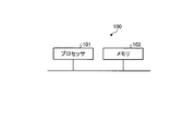
次に、本実施の形態の加工条件解析装置10のハードウェア構成について説明する。加工条件解析装置10の特徴量抽出部12、評価部13および補正量算出部14は、処理回路により実現される。処理回路は、プロセッサを備える回路であってもよいし、専用ハードウェアであってもよい。加工条件記憶部15は、メモリにより実現される。
Next, the hardware configuration of the processing condition analysis device 10 of the present embodiment will be described. The feature amount extraction unit 12, the evaluation unit 13, and the correction amount calculation unit 14 of the processing condition analysis device 10 are realized by a processing circuit. The processing circuit may be a circuit including a processor or may be dedicated hardware. The processing condition storage unit 15 is realized by a memory.
処理回路がプロセッサを備える回路である場合、処理回路は例えば図10に示した構成の処理回路である。図10は、本実施の形態の処理回路の構成例を示す図である。図10に示す処理回路100は、プロセッサ101およびメモリ102を備える。特徴量抽出部12、評価部13および補正量算出部14が図10に示した処理回路100によって実現される場合、プロセッサ101が、メモリ102に格納されたプログラムを読み出して実行することにより、これらが実現される。すなわち、特徴量抽出部12、評価部13および補正量算出部14が図10に示した処理回路100によって実現される場合、これらの機能は、ソフトウェアであるプログラムを用いて実現される。メモリ102はプロセッサ101の作業領域としても使用される。プロセッサ101は、CPU(Central Processing Unit)等である。メモリ102は、例えば、RAM(Random Access Memory)、ROM(Read Only Memory)、フラッシュメモリー等の不揮発性または揮発性の半導体メモリ、磁気ディスク等が該当する。
When the processing circuit is a circuit including a processor, the processing circuit has the configuration shown in FIG. 10, for example. FIG. 10 is a diagram showing a configuration example of the processing circuit according to the present embodiment. The processing circuit 100 shown in FIG. 10 includes a processor 101 and a memory 102. When the feature amount extraction unit 12, the evaluation unit 13, and the correction amount calculation unit 14 are implemented by the processing circuit 100 illustrated in FIG. 10, the processor 101 reads out and executes the program stored in the memory 102, thereby Is realized. That is, when the feature amount extraction unit 12, the evaluation unit 13, and the correction amount calculation unit 14 are realized by the processing circuit 100 shown in FIG. 10, these functions are realized by using a program that is software. The memory 102 is also used as a work area of the processor 101. The processor 101 is a CPU (Central Processing Unit) or the like. The memory 102 corresponds to, for example, a RAM (Random Access Memory), a ROM (Read Only Memory), a nonvolatile or volatile semiconductor memory such as a flash memory, or a magnetic disk.
特徴量抽出部12、評価部13および補正量算出部14が専用ハードウェアである場合、処理回路は、例えば、FPGA(Field Programmable Gate Array)、ASIC(Application Specific Integrated Circuit)である。なお、特徴量抽出部12、評価部13および補正量算出部14は、プロセッサを備える処理回路および専用ハードウェアを組み合わせて実現されてもよい。特徴量抽出部12、評価部13および補正量算出部14は、複数の処理回路により実現されてもよい。
When the feature amount extraction unit 12, the evaluation unit 13, and the correction amount calculation unit 14 are dedicated hardware, the processing circuits are, for example, FPGA (Field Programmable Gate Array) and ASIC (Application Specific Integrated Circuit). The feature amount extraction unit 12, the evaluation unit 13, and the correction amount calculation unit 14 may be realized by combining a processing circuit including a processor and dedicated hardware. The feature amount extraction unit 12, the evaluation unit 13, and the correction amount calculation unit 14 may be realized by a plurality of processing circuits.
レーザ加工の加工条件調整は、多次元のパラメータ探索となり、所望の水準以上の加工品質を得るための加工条件を探索するには非常に多くの試行回数を必要とする。本実施の形態の加工条件解析装置10,10aによれば、切断面の特徴量を抽出し、切断面の複数の加工不良モードの良否判定を行い、複数の加工不良モードごとの良否の組み合わせパターンと関連付けられた加工パラメータの補正量を決定することによって少ない試行回数で加工条件の補正を行うことが可能になる。
▽ Adjusting the processing conditions for laser processing is a multi-dimensional parameter search, and it takes an extremely large number of trials to search for the processing conditions to obtain the processing quality above the desired level. According to the processing condition analyzers 10 and 10a of the present embodiment, the feature amount of the cut surface is extracted, the quality of the plurality of processing failure modes of the cutting surface is determined, and the combination pattern of the quality of each of the plurality of processing failure modes is determined. By determining the correction amount of the processing parameter associated with, it becomes possible to correct the processing condition with a small number of trials.
また、作業者が熟練者である場合には、経験とノウハウにより加工条件の調整を行うことができるが、本実施の形態の加工条件解析装置10,10aによれば、熟練者の知識およびノウハウを必要とせずに、加工条件の調整を行うことが可能である。また、本実施の形態の加工条件解析装置10,10aを用いて調整された加工条件を用いて、レーザ加工装置20の加工条件の生成を行い、レーザ加工装置20における生産のための製造を行ってもよい。特許文献1に記載の技術では、レーザ切断面の状態量観測部において観測データとして切断面の平滑度あるいは面粗度等の測定値が用いられるため、測定に時間がかかる。このため、1回の切断加工の試行に時間を要する。本実施の形態の加工条件解析装置10,10aによれば、切断面31を撮影した画像から特徴量を抽出し、特徴量を用いて、切断面31の加工不良モードごとの良否判定を行うため1回の試行に要する時間を削減することができる。このように、本実施の形態では、作業者の熟練度によらず、加工条件の調整時間を抑制して一定以上の水準の加工品質が得られるように調整することができる。
Further, when the worker is a skilled person, the working conditions can be adjusted by experience and know-how. However, according to the working condition analyzing apparatus 10 or 10a of the present embodiment, the knowledge and know-how of the skilled person can be obtained. It is possible to adjust the processing conditions without requiring. Further, the processing conditions of the laser processing apparatus 20 are generated by using the processing conditions adjusted by using the processing condition analysis apparatuses 10 and 10a of the present embodiment, and the manufacturing for production in the laser processing apparatus 20 is performed. May be. In the technique described in Patent Document 1, a measurement value such as the smoothness or surface roughness of the cut surface is used as the observation data in the state quantity observing unit of the laser cut surface, so that the measurement takes time. Therefore, it takes a long time to perform one cutting process trial. According to the processing condition analysis devices 10 and 10a of the present embodiment, the feature amount is extracted from the image of the cut surface 31, and the quality determination is performed using the feature amount for each processing failure mode of the cut surface 31. The time required for one trial can be reduced. As described above, in the present embodiment, it is possible to suppress the adjustment time of the processing condition and perform the adjustment so that the processing quality of a certain level or more can be obtained regardless of the skill level of the operator.
実施の形態2.
図11は、本発明の実施の形態2にかかる加工条件解析装置の構成例を示す図である。本実施の形態のレーザ加工システムは、加工条件解析装置10の替わりに図11に示す加工条件解析装置10bを備える以外は、実施の形態1のレーザ加工システムと同様である。実施の形態1と同様の機能を有する構成要素は実施の形態1と同一の符号を付して重複する説明を省略する。以下、実施の形態1と異なる点を主に説明する。 Embodiment 2.
FIG. 11 is a diagram showing a configuration example of a processing condition analysis device according to the second exemplary embodiment of the present invention. The laser processing system according to the present embodiment is the same as the laser processing system according to the first embodiment except that a processingcondition analyzing apparatus 10b shown in FIG. 11 is provided instead of the processing condition analyzing apparatus 10. The constituent elements having the same functions as those in the first embodiment are designated by the same reference numerals as those in the first embodiment, and the duplicated description will be omitted. Hereinafter, differences from the first embodiment will be mainly described.
図11は、本発明の実施の形態2にかかる加工条件解析装置の構成例を示す図である。本実施の形態のレーザ加工システムは、加工条件解析装置10の替わりに図11に示す加工条件解析装置10bを備える以外は、実施の形態1のレーザ加工システムと同様である。実施の形態1と同様の機能を有する構成要素は実施の形態1と同一の符号を付して重複する説明を省略する。以下、実施の形態1と異なる点を主に説明する。 Embodiment 2.
FIG. 11 is a diagram showing a configuration example of a processing condition analysis device according to the second exemplary embodiment of the present invention. The laser processing system according to the present embodiment is the same as the laser processing system according to the first embodiment except that a processing
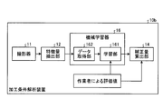
本実施の形態の加工条件解析装置10bでは、実施の形態1の加工条件解析装置10に機械学習器16が追加され、評価部13が削除されている。機械学習器16は、特徴量抽出部12により抽出された特徴量と、作業者が作成した評価値(作業者による評価値)とを関連付けて学習する。作業者による評価値は、例えば、図示しない入力手段から入力されてもよいし、他の装置から受信されてもよい。なお、機械学習器16は、実施の形態1の特徴量抽出部12、評価部13および補正量算出部14と同様に処理回路により実現される。
In the machining condition analysis device 10b of the present embodiment, the machine learning device 16 is added to the machining condition analysis device 10 of the first embodiment, and the evaluation unit 13 is deleted. The machine learning device 16 learns by associating the feature amount extracted by the feature amount extraction unit 12 with the evaluation value created by the worker (evaluation value by the worker). The evaluation value by the operator may be input, for example, from an input unit (not shown) or may be received from another device. The machine learning device 16 is realized by a processing circuit like the feature amount extraction unit 12, the evaluation unit 13, and the correction amount calculation unit 14 of the first embodiment.
機械学習器16は、学習部161およびデータ取得部162を備える。学習部161は、機械学習により、入力と結果のデータの組を学習する。学習部161の機械学習のアルゴリズムとしてはどのようなものを用いてもよいが、例えば、教師あり学習のアルゴリズムを用いることができる。データ取得部162は、学習部161における入力として、特徴量抽出部12から特徴量を取得し、取得した特徴量を学習部161へ入力する。また、学習部161には、作業者による評価値も入力される。作業者による評価値は、切断面31の良否を各加工不良モードに関して判断した結果であり、実施の形態1で述べた評価部13における判定結果における評価値と同様に、段階的にレベルを示す値であってもよいし連続した数値であってもよい。すなわち、作業者による評価値は、実施の形態1で述べた組み合わせパターンに相当するものを作業者が決定したものである。なお、データ取得部162は、撮影器11から出力される画像を学習部161への入力として取得してもよい。このように、データ取得部162は、撮影器11から出力される画像または特徴量抽出部12から出力される特徴量を、状態変数として取得し、学習部161へ与える。学習部161は、状態変数と評価値で構成されるデータセットを用いて、切断面31の良否を機械学習することができる。データセットは、状態変数および評価データを互いに関連付けたデータである。
The machine learning device 16 includes a learning unit 161 and a data acquisition unit 162. The learning unit 161 learns a set of input and result data by machine learning. Although any machine learning algorithm of the learning unit 161 may be used, for example, a supervised learning algorithm may be used. The data acquisition unit 162 acquires the feature amount from the feature amount extraction unit 12 as an input to the learning unit 161, and inputs the acquired feature amount to the learning unit 161. Further, the evaluation value by the worker is also input to the learning unit 161. The evaluation value by the operator is the result of judging the quality of the cut surface 31 with respect to each processing failure mode, and indicates the level stepwise like the evaluation value in the judgment result by the evaluation unit 13 described in the first embodiment. It may be a value or a continuous numerical value. That is, the evaluation value by the operator is determined by the operator to correspond to the combination pattern described in the first embodiment. The data acquisition unit 162 may acquire the image output from the image capturing device 11 as an input to the learning unit 161. In this way, the data acquisition unit 162 acquires the image output from the image capturing device 11 or the feature amount output from the feature amount extraction unit 12 as a state variable and supplies the state variable to the learning unit 161. The learning unit 161 can machine-learn whether the cut surface 31 is good or bad by using a data set including state variables and evaluation values. The data set is data in which state variables and evaluation data are associated with each other.
そして、機械学習による学習済みモデルを用いて、学習部161が、特徴量に応じた評価値を出力することで、より高精度に加工パラメータを補正することが可能である。なお、ここでは、学習部161が切断面31の良否を機械学習する機能と学習済モデルとしての機能の両方を有するようにしたが、学習済モデルを用いて評価値を出力する推論部を学習部161とは別に設けてもよい。すなわち、加工条件解析装置10bは、学習部161により学習が行われた学習済モデルを用いて切断面情報に基づいて組み合わせパターンを算出する推論部を備えてもよい。
Then, the learning unit 161 outputs the evaluation value according to the feature amount by using the learned model by machine learning, so that the processing parameter can be corrected with higher accuracy. Here, the learning unit 161 has both the function of machine learning the quality of the cut surface 31 and the function as the learned model, but the inference unit that outputs the evaluation value is learned using the learned model. It may be provided separately from the portion 161. That is, the processing condition analysis device 10b may include an inference unit that calculates a combination pattern based on the cut surface information by using the learned model learned by the learning unit 161.
なお、図11に示した例では、機械学習器16は加工条件解析装置10b内に設けられるが、加工条件解析装置10bとは別の装置であってもよい。例えば、加工条件解析装置10bと機械学習器16がネットワークを介して接続されていてもよい。また、機械学習器16は、クラウドサーバ上に存在していてもよい。
In addition, in the example shown in FIG. 11, the machine learning device 16 is provided in the processing condition analysis device 10b, but may be a device different from the processing condition analysis device 10b. For example, the processing condition analysis device 10b and the machine learning device 16 may be connected via a network. Further, the machine learning device 16 may exist on the cloud server.
また、加工条件解析装置10bが実施の形態1で述べた評価部13を備え、実施の形態1と同様の動作により評価部13が判定した判定結果を用いて学習する機能を有していてもよい。例えば、上述したデータセットを用いてある程度学習が進んだ後に、評価部13による判定結果を修正し、その結果を学習部161が学習するようにしてもよい。図12は、評価部13を備える本実施の形態の加工条件解析装置10bの構成例を示す図である。評価部13は、例えば、実施の形態1で述べた、複数の加工不良モードのそれぞれに対応する複数の評価値である組み合わせパターンを算出し作業者がその評価値を修正し、修正した結果を機械学習器16へ入力する。このとき、評価部13における評価値を決定するためのアルゴリズム、判定のための閾値は作業者により適宜変更可能であってもよい。
Further, even if the processing condition analyzing apparatus 10b includes the evaluation unit 13 described in the first embodiment and has a function of learning using the determination result determined by the evaluation unit 13 by the same operation as in the first embodiment. Good. For example, the learning result may be learned by the evaluation unit 13 after the learning has progressed to some extent using the above-described data set, and the learning unit 161 may learn the result. FIG. 12 is a diagram showing a configuration example of the processing condition analysis device 10b of the present embodiment including the evaluation unit 13. The evaluation unit 13 calculates, for example, a combination pattern, which is a plurality of evaluation values corresponding to each of the plurality of processing failure modes described in the first embodiment, the operator corrects the evaluation values, and the corrected result is displayed. Input to the machine learning device 16. At this time, the algorithm for determining the evaluation value in the evaluation unit 13 and the threshold value for the determination may be appropriately changeable by the operator.
学習部161は、例えば、ニューラルネットワークモデルを用いて、いわゆる教師あり学習により、切断面31の良否評価結果を学習する。ここで、教師あり学習とは、ある入力と結果(ラベル)とのデータの組であるデータセットを大量に学習器に与えることで、それらのデータセットにある特徴を学習し、入力から結果を推定する機械学習である。
The learning unit 161 learns the pass/fail evaluation result of the cut surface 31 by so-called supervised learning using, for example, a neural network model. Here, the supervised learning is to give a large amount of data sets, which are data sets of a certain input and a result (label), to a learner to learn the characteristics of those data sets and obtain the results from the input. This is machine learning to estimate.
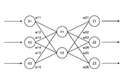
ニューラルネットワークは、複数のニューロンからなる入力層、複数のニューロンからなり隠れ層とも呼ばれる中間層、および複数のニューロンからなる出力層で構成される。中間層は、1層でもよく2層以上であってもよい。
A neural network is composed of an input layer composed of multiple neurons, an intermediate layer composed of multiple neurons, also called a hidden layer, and an output layer composed of multiple neurons. The intermediate layer may be one layer or two or more layers.
図13は、実施の形態2にかかるニューラルネットワークモデルの構成例を示す図である。X1,X2,X3は入力層のニューロンであり、Y1,Y2は中間層のニューロンであり、Z1,Z2,Z3は出力層のニューロンである。例えば、図13に示すような3層のニューラルネットワークモデルであれば、3つの入力値のそれぞれに対応するX1,X2,X3にそれぞれ入力されると、各入力値は、対応する重みw11~w16が乗算されて中間層のニューロンであるY1,Y2に入力される。そして、Y1,Y2からの出力値は、対応する重みw21~w26が乗算されて、出力層のニューロンであるZ1,Z2,Z3に入力される。出力層は、入力された値を加算し、出力結果として出力する。例えば、Z1,Z2,Z3からそれぞれ出力される結果を各加工不良モードに対応する評価結果に対応させることができる。この出力結果は、重みw11~w16と重みw21~w26の値によって変わる。
FIG. 13 is a diagram showing a configuration example of the neural network model according to the second embodiment. X1, X2 and X3 are neurons in the input layer, Y1 and Y2 are neurons in the intermediate layer, and Z1, Z2 and Z3 are neurons in the output layer. For example, in the case of a three-layer neural network model as shown in FIG. 13, when input to X1, X2, and X3 respectively corresponding to three input values, each input value corresponds to a corresponding weight w11 to w16. Are multiplied and input to Y1 and Y2 which are neurons in the intermediate layer. Then, the output values from Y1 and Y2 are multiplied by the corresponding weights w21 to w26 and input to the neurons Z1, Z2 and Z3 which are neurons in the output layer. The output layer adds the input values and outputs the result as an output result. For example, the results output from Z1, Z2, and Z3 can be associated with the evaluation results corresponding to each processing failure mode. This output result changes depending on the values of the weights w11 to w16 and the weights w21 to w26.
本実施の形態では、上述したデータセットを用いて、上記ニューラルネットワークの出力結果が、正解である切断面31の良否の評価結果に近づくように、重みw11~w16と重みw21~w26が調整されることにより、学習が行われる。なお、図13は、一例であり、ニューラルネットワークモデルの層数、および各層に属するニューロンの数は、図13の例に限定されない。
In the present embodiment, the weights w11 to w16 and the weights w21 to w26 are adjusted by using the above-mentioned data set so that the output result of the neural network approaches the evaluation result of the quality of the cut surface 31, which is the correct answer. By doing so, learning is performed. Note that FIG. 13 is an example, and the number of layers of the neural network model and the number of neurons belonging to each layer are not limited to the example of FIG. 13.
また、学習部161は、ニューラルネットワークモデルを用いて、いわゆる教師なし学習によって、切断面31の良否の評価結果を学習することもできる。教師なし学習とは、入力データのみを大量に学習部161に与えることで、入力データがどのような分布をしているか学習し、対応する教師出力データを与えなくても、入力データに対して圧縮、分類、整形等を行う方法を学習する手法である。例えば、教師なし学習では、入力データのセットが有する特徴が似ているもの同士をクラスタリングすること等ができる。何らかの基準を設けてクラスタリング等の結果を最適にするように、クラスタリング等の結果に対して評価結果の割り当てを行うことで、評価結果の予測を実現することできる。また、教師なし学習と教師あり学習の中間的な問題設定として、半教師あり学習と呼ばれるものもあり、これは一部のみ入力と出力のデータの組が存在し、それ以外は入力のみのデータである場合がこれに当たる。本実施の形態の学習部161は、半教師あり学習により機械学習を実現してもよい。
The learning unit 161 can also learn the evaluation result of the quality of the cut surface 31 by so-called unsupervised learning using the neural network model. Unsupervised learning means learning a distribution of input data by giving a large amount of input data only to the learning unit 161, and learning the input data without inputting corresponding teacher output data. This is a method for learning how to perform compression, classification, shaping, and the like. For example, in unsupervised learning, it is possible to cluster those having similar features in the set of input data. Prediction of the evaluation result can be realized by assigning the evaluation result to the result of the clustering so that the result of the clustering or the like is optimized by setting some standard. In addition, as an intermediate problem setting between unsupervised learning and supervised learning, there is also what is called semi-supervised learning, in which only a part of the input and output data sets exists, and the others only have input-only data. This is the case. The learning unit 161 of the present embodiment may realize machine learning by semi-supervised learning.
また、機械学習器16は、複数の加工条件解析装置からデータセットを取得し、切断面31の良否の評価結果を学習するようにしてもよい。複数の加工条件解析装置は、本実施の形態の加工条件解析装置10bであっても良いし実施の形態1の加工条件解析装置10,10aであってもよく、これらの組み合わせであってもよい。なお、機械学習器16は、同一の現場で使用される複数の加工条件解析装置からデータセットを取得してもよいし、異なる現場でそれぞれ稼動する複数の加工条件解析装置からデータセットを取得してもよい。さらに、データセットの取得元の加工条件解析装置を途中で追加し、または、取得元の加工条件解析装置を途中で除去することも可能である。また、加工条件解析装置10bとは別に機械学習器16を設け、機械学習器16が、ある加工条件解析装置10bから取得したデータセットにより学習した後、別の加工条件解析装置10bと接続してさらにこの加工条件解析装置10bからデータセットを取得して再学習してもよい。
Alternatively, the machine learning device 16 may acquire data sets from a plurality of processing condition analysis devices and learn the evaluation result of the quality of the cut surface 31. The plurality of processing condition analysis devices may be the processing condition analysis device 10b of the present embodiment, the processing condition analysis devices 10 and 10a of the first embodiment, or a combination thereof. .. The machine learning device 16 may acquire the data sets from a plurality of processing condition analyzing devices used at the same site, or may acquire the data sets from a plurality of processing condition analyzing devices operating at different sites. May be. Furthermore, it is also possible to add the processing condition analysis device from which the data set is acquired, or remove the processing condition analysis device from which the data set is acquired. Further, a machine learning device 16 is provided separately from the processing condition analysis device 10b, and after the machine learning device 16 learns from a data set acquired from a certain processing condition analysis device 10b, it is connected to another processing condition analysis device 10b. Further, a data set may be acquired from the processing condition analysis device 10b and re-learned.
また、以上の説明では、撮影器11から出力される画像または特徴量抽出部12から特徴量と、切断面31の良否の評価結果との関係を学習する例を説明したが、撮影器11から出力される画像または特徴量抽出部12から出力される特徴量と、加工パラメータの補正量との関係を学習してもよい。この場合、データ取得部162は、撮影器11から出力される画像または特徴量抽出部12から出力される特徴量と、補正量算出部14から出力される補正量とを取得することになる。この場合、学習を行った後は、機械学習器16は、撮影器11から出力される画像または特徴量抽出部12から出力される特徴量に基づいて、各加工パラメータの補正量を算出して出力することができる。学習済モデルを機械学習器16と別に備える場合には、加工条件解析装置10bは、学習部161により学習が行われた学習済モデルを用いて切断面情報に基づいて加工パラメータの補正量を算出する推論部を備える。
Further, in the above description, an example in which the relationship between the feature amount and the evaluation result of the quality of the cut surface 31 is learned from the image output from the image capturing device 11 or the feature amount extracting unit 12 has been described. The relationship between the output image or the feature amount output from the feature amount extraction unit 12 and the correction amount of the processing parameter may be learned. In this case, the data acquisition unit 162 acquires the image output from the imaging device 11 or the feature amount output from the feature amount extraction unit 12 and the correction amount output from the correction amount calculation unit 14. In this case, after learning, the machine learning device 16 calculates the correction amount of each processing parameter based on the image output from the image capturing device 11 or the feature amount output from the feature amount extraction unit 12. Can be output. When the learned model is provided separately from the machine learning device 16, the processing condition analysis device 10b calculates the correction amount of the processing parameter based on the cut surface information using the learned model learned by the learning unit 161. It has an inference unit to perform.
また、データ取得部162は、学習部161の入力として、撮影器11から出力される画像または特徴量抽出部12から出力される特徴量だけでなく、さらに、切断面31の板厚、ワーク30の材質等も入力としてよい。また、学習部161で用いられる学習アルゴリズムとしては、特徴量そのものの抽出を学習する、深層学習(Deep Learning)などのニューラルネットワークを用いることもでき、他の公知の方法、例えば遺伝的プログラミング、機能論理プログラミング、サポートベクターマシン、フィッシャー判別法、部分空間法、マハラノビス空間を用いた判別分析などに従って機械学習を実行してもよい。また、学習部161で用いられる学習アルゴリズムとして、決定木、ランダムフォレスト(Random Forest)、ロジスティック回帰、k近傍法(kNN)、部分空間法、CLAFIC(CLAss-Featuring Information Compression method)、Isolation Forest、LOF(Local Outlier Factor)、ブースティング、AdaBoost、LogitBoost、One-Class SVM(Support Vector Machine)、Gaussian Mixture Model、判別分析法(Discriminant Analysis)、単純ベイズ分類器(Naive Bayes classifier)等を用いてもよい。また、深層学習、畳み込みニューラルネットワーク(Convolution Neural Network)などのように、画像から自動的に特徴量を抽出する学習を行う場合は、特徴量抽出部12を設けなくてもよい。また、加工不良モードごとに機械学習器16を設けてもよいし、1つの機械学習器16を複数の加工不良モードに対応させてもよい。以上述べた以外の本実施の形態の動作は実施の形態1と同様である。
Further, the data acquisition unit 162 receives, as input to the learning unit 161, not only the image output from the imaging device 11 or the feature amount output from the feature amount extraction unit 12, but also the plate thickness of the cut surface 31, the work 30. The material and the like may be input. Further, as the learning algorithm used in the learning unit 161, a neural network such as deep learning that learns the extraction of the feature amount itself can be used, and other known methods such as genetic programming and function can be used. Machine learning may be executed according to logic programming, support vector machine, Fisher discriminant method, subspace method, discriminant analysis using Mahalanobis space, and the like. As learning algorithms used in the learning unit 161, decision trees, random forests, logistic regression, k-nearest neighbors (kNN), subspace methods, CLAFIC (CLAss-Featuring Information Compression method), Isolation Forest, LOF. (Local Outlier Factor), boosting, AdaBoost, LogitBoost, One-Class SVM (Support Vector Machine), Gaussian Mixture Model, Discriminant Analysis, Naive Bayes classifier, etc. may be used. .. Further, when performing learning for automatically extracting a feature amount from an image, such as deep learning and convolutional neural network (Convolution Neural Network), the feature amount extraction unit 12 may not be provided. Further, the machine learning device 16 may be provided for each machining failure mode, or one machine learning device 16 may correspond to a plurality of machining failure modes. The operation of this embodiment other than that described above is the same as that of the first embodiment.
以上のように、本実施の形態では、撮影器11から出力される画像または特徴量抽出部12から出力される特徴量と、切断面31の良否の評価結果とを用いて、切断面31の良否の判定結果を機械学習する。これにより、実施の形態1と同様の効果を奏するとともに、実施の形態1より精度よく加工パラメータの補正量を求めることができる。
As described above, in the present embodiment, the image output from the image capturing device 11 or the feature amount output from the feature amount extraction unit 12 and the evaluation result of the quality of the cut face 31 are used to determine the cut face 31. Machine learning of the judgment result of pass/fail. As a result, the same effect as that of the first embodiment can be obtained, and the correction amount of the processing parameter can be obtained more accurately than in the first embodiment.
実施の形態3.
図14は、本発明の実施の形態3にかかる加工条件解析装置の構成例を示す図である。本実施の形態のレーザ加工システムは、加工条件解析装置10の替わりに図14に示す加工条件解析装置10cを備える以外は、実施の形態1のレーザ加工システムと同様である。実施の形態1と同様の機能を有する構成要素は実施の形態1と同一の符号を付して重複する説明を省略する。以下、実施の形態1と異なる点を主に説明する。 Embodiment 3.
FIG. 14 is a diagram showing a configuration example of a processing condition analyzing apparatus according to the third embodiment of the present invention. The laser processing system according to the present embodiment is the same as the laser processing system according to the first embodiment, except that a processing condition analyzing apparatus 10c shown in FIG. 14 is provided instead of the processing condition analyzing apparatus 10. The constituent elements having the same functions as those in the first embodiment are designated by the same reference numerals as those in the first embodiment, and the duplicated description will be omitted. Hereinafter, differences from the first embodiment will be mainly described.
本実施の形態の加工条件解析装置10cは、実施の形態1の加工条件解析装置10に表示部17および変更受付部18が追加されている。表示部17は、ディスプレイ、モニタ、タッチパネルなどにより実現される。変更受付部18は入力手段であり、キーボード、マウス、ボタン、タッチパネルなどにより実現される。
The machining condition analyzing apparatus 10c of the present embodiment has a display unit 17 and a change accepting unit 18 added to the machining condition analyzing apparatus 10 of the first embodiment. The display unit 17 is realized by a display, a monitor, a touch panel, or the like. The change receiving unit 18 is an input means, and is realized by a keyboard, a mouse, buttons, a touch panel, or the like.
本実施の形態では、評価部13が、切断面31の加工品質が不良であると判定した場合、表示部17が、切断面31の画像を表示する。すなわち、表示部17は、評価部13により算出された評価値のうち不良であることを示すものがある場合、該評価値に対応する加工不良モードの判定の根拠となる画像における部分を表示する。これにより、作業者は、加工品質が不良であると判定された切断面31を画像により把握することができる。また、加工不良モードごとに、不良と判定された根拠となる部分がわかるように表示することで、作業者は、どの部分に問題があるかを把握することができる。
In the present embodiment, when the evaluation unit 13 determines that the processing quality of the cut surface 31 is poor, the display unit 17 displays the image of the cut surface 31. That is, when there is an evaluation value calculated by the evaluation unit 13 that indicates a defect, the display unit 17 displays the part in the image that is the basis of the determination of the processing failure mode corresponding to the evaluation value. .. Thereby, the operator can grasp the cut surface 31 whose processing quality is determined to be poor from the image. In addition, by displaying such that the part that is the basis for determining a defect is displayed for each processing defect mode, the operator can know which part has a problem.
作業者は、表示部17に表示された切断面31を画像で確認し、変更受付部18を用いて、評価部13における判定結果を変更したり、評価部13における判定に用いられる閾値などを変更したりするための入力を行うことができる。加工良否の評価基準に関しては、使用する作業者によって良否判断が異なることがある。表示部17に表示された切断面31を作業者が確認することによって、作業者自身が判定結果を変更することが可能である。評価部13は、作業者から入力された判定結果を反映した評価値を補正量算出部14へ出力する。
The operator confirms the cut surface 31 displayed on the display unit 17 with an image, and uses the change reception unit 18 to change the determination result in the evaluation unit 13 and to set the threshold value used in the determination in the evaluation unit 13 and the like. Input can be made to make changes. Regarding the evaluation criteria of processing quality, the quality judgment may differ depending on the operator who uses it. The operator himself/herself can change the determination result by confirming the cut surface 31 displayed on the display unit 17. The evaluation unit 13 outputs an evaluation value that reflects the determination result input by the worker to the correction amount calculation unit 14.
図15は、本実施の形態の表示部17に表示される表示画面の一例を示す図である。図15に示した表示画面200には、加工不良モードごとの判定結果を示す評価値と画像が上部に表示されている。下部には、該判定結果に対応する加工パラメータの補正量が補正条件として示されている。図15に示した例では、ドロス、キズおよび荒れが発生していると評価部13により判定された例を示しており、画像内の対応する部分が点線で囲まれて示されている。また、各画像の下部には、数値として表現された評価値がレベル1.0などとして示されている。例えば、作業者が考えるキズのレベルと、評価部13により判定された評価値とが異なっている場合には、作業者は、変更受付部18を介して評価値を変更する。または、作業者は、評価値自体を変更する替わりに、評価値の各レベルを判定のための閾値を変更してもよい。これにより作業者の所望の加工品質に近づくように加工パラメータの補正量が変更されるようになる。
FIG. 15 is a diagram showing an example of a display screen displayed on the display unit 17 according to the present embodiment. On the display screen 200 shown in FIG. 15, an evaluation value and an image showing the determination result for each processing failure mode are displayed at the top. In the lower part, the correction amount of the processing parameter corresponding to the determination result is shown as the correction condition. In the example shown in FIG. 15, an example in which the evaluation unit 13 determines that dross, scratches, and roughness have occurred is shown, and the corresponding portion in the image is surrounded by a dotted line. Also, the evaluation value expressed as a numerical value is shown as a level 1.0 or the like at the bottom of each image. For example, when the level of scratches considered by the worker and the evaluation value determined by the evaluation unit 13 are different, the worker changes the evaluation value via the change reception unit 18. Alternatively, the worker may change the threshold value for determining each level of the evaluation value, instead of changing the evaluation value itself. As a result, the correction amount of the processing parameter is changed so as to approach the processing quality desired by the operator.
なお、加工条件解析装置10cに機械学習器16を設け、機械学習器16が、撮影器11から出力される画像または特徴量抽出部12から出力される特徴量と、作業者により施された変更内容を学習するようにしてもよい。また、実施の形態2の加工条件解析装置10bに、表示部17および変更受付部18を追加し、作業者により変更された後の評価結果を機械学習器16が学習するようにしてもよい。
A machine learning device 16 is provided in the processing condition analysis device 10c, and the machine learning device 16 changes the image output from the image capturing device 11 or the feature amount output from the feature amount extraction unit 12 and the change made by the operator. You may make it learn the content. Further, the display unit 17 and the change receiving unit 18 may be added to the machining condition analyzing apparatus 10b of the second embodiment so that the machine learning device 16 learns the evaluation result after the change by the operator.
以上のように、本実施の形態によれば、切断面31の加工品質が不良であると判定した場合、表示部17が、切断面31の画像を表示し、作業者からの評価結果への変更を受け付けるようにした。これにより、実施の形態1と同様の効果が得られるとともに、作業者の要望に応じた加工状態を実現することができる。
As described above, according to the present embodiment, when it is determined that the processing quality of the cut surface 31 is poor, the display unit 17 displays the image of the cut surface 31 and displays the evaluation result from the operator. I accept changes. As a result, the same effect as that of the first embodiment can be obtained, and the processing state according to the operator's request can be realized.
以上の実施の形態に示した構成は、本発明の内容の一例を示すものであり、別の公知の技術と組み合わせることも可能であるし、本発明の要旨を逸脱しない範囲で、構成の一部を省略、変更することも可能である。
The configurations described in the above embodiments are examples of the content of the present invention, and can be combined with other known techniques, and the configurations of the configurations are not departing from the scope of the present invention. It is also possible to omit or change parts.
10 加工条件解析装置、11 撮影器、12 特徴量抽出部、13 評価部、14 補正量算出部、15 加工条件記憶部、16 機械学習器、17 表示部、18 変更受付部、20 レーザ加工装置、21 制御部、22 レーザ発振器、23 加工ヘッド、30 ワーク、161 学習部、162 データ取得部。
10 processing condition analysis device, 11 camera device, 12 feature amount extraction unit, 13 evaluation unit, 14 correction amount calculation unit, 15 processing condition storage unit, 16 machine learning device, 17 display unit, 18 change acceptance unit, 20 laser processing device , 21 control unit, 22 laser oscillator, 23 processing head, 30 workpiece, 161, learning unit, 162 data acquisition unit.
Claims (14)
- レーザ切断加工によって切断された切断面を撮影した画像に基づく切断面情報を用いて、複数の加工不良モードのそれぞれに対応する加工品質を示す評価値を生成し、前記複数の加工不良モードのそれぞれに対応する複数の前記評価値である組み合わせパターンを出力する評価部と、
前記組み合わせパターンに基づいて、前記レーザ切断加工の加工条件を示す加工パラメータの補正量を算出する補正量算出部と、
を備えることを特徴とする加工条件解析装置。 Using the cutting surface information based on the image obtained by photographing the cutting surface cut by the laser cutting processing, an evaluation value indicating the processing quality corresponding to each of the plurality of processing failure modes is generated, and each of the plurality of processing failure modes is generated. An evaluation unit that outputs a combination pattern that is a plurality of the evaluation values corresponding to
A correction amount calculation unit that calculates a correction amount of a processing parameter indicating a processing condition of the laser cutting processing based on the combination pattern;
A processing condition analysis device comprising: - 前記切断面情報は、前記画像であることを特徴とする請求項1に記載の加工条件解析装置。 The processing condition analysis device according to claim 1, wherein the cutting surface information is the image.
- 前記切断面情報は、前記画像から抽出された特徴量であることを特徴とする請求項1に記載の加工条件解析装置。 The processing condition analysis device according to claim 1, wherein the cutting plane information is a feature amount extracted from the image.
- 前記評価部は、前記評価値として、あらかじめ定められた複数の段階的な値のうちのいずれか1つを出力することを特徴とする請求項1から3のいずれか1つに記載の加工条件解析装置。 The processing condition according to claim 1, wherein the evaluation unit outputs any one of a plurality of predetermined stepwise values as the evaluation value. Analyzer.
- 前記切断面情報と前記組み合わせパターンとの関係を学習する学習部を備えることを特徴とする請求項1から3のいずれか1つに記載の加工条件解析装置。 The processing condition analysis device according to any one of claims 1 to 3, further comprising a learning unit that learns a relationship between the cutting surface information and the combination pattern.
- 前記学習部により学習が行われた学習済モデルを用いて前記切断面情報に基づいて前記組み合わせパターンを算出する推論部を備えることを特徴とする請求項5に記載の加工条件解析装置。 The processing condition analyzing apparatus according to claim 5, further comprising: an inference unit that calculates the combination pattern based on the cut surface information by using a learned model learned by the learning unit.
- 前記切断面情報と前記加工パラメータの補正量との関係を学習する学習部を備えることを特徴とする請求項1から3のいずれか1つに記載の加工条件解析装置。 The processing condition analyzing apparatus according to any one of claims 1 to 3, further comprising a learning unit that learns a relationship between the cutting surface information and a correction amount of the processing parameter.
- 前記学習部により学習が行われた学習済モデルを用いて前記切断面情報に基づいて前記加工パラメータの補正量を算出する推論部を備えることを特徴とする請求項7に記載の加工条件解析装置。 The processing condition analyzing apparatus according to claim 7, further comprising: an inference unit that calculates a correction amount of the processing parameter based on the cutting surface information by using a learned model learned by the learning unit. ..
- 前記加工パラメータの補正量と前記組み合わせパターンとの組を1組以上記憶する加工条件記憶部、
を備え、
前記補正量算出部は、前記加工条件記憶部に記憶されている、前記加工パラメータの補正量と前記組み合わせパターンとの組に基づいて前記加工パラメータの補正量を決定することを特徴とする請求項1から8のいずれか1つに記載の加工条件解析装置。 A processing condition storage unit that stores at least one set of the correction amount of the processing parameter and the combination pattern;
Equipped with
The correction amount calculation unit determines the correction amount of the processing parameter based on a set of the correction amount of the processing parameter and the combination pattern stored in the processing condition storage unit. The processing condition analysis device according to any one of 1 to 8. - 前記補正量算出部は、生産性、前記組み合わせパターン、加工安定性を含む複数の改善項目の優先度に基づいて前記加工パラメータの補正量を決定することを特徴とする請求項1から9のいずれか1つに記載の加工条件解析装置。 10. The correction amount calculation unit determines the correction amount of the processing parameter based on priorities of a plurality of improvement items including productivity, the combination pattern, and processing stability. The processing condition analysis device according to one.
- 前記評価部により算出された前記評価値のうち不良であることを示すものがある場合、該評価値に対応する前記加工不良モードの判定の根拠となる前記画像における部分を表示する表示部、
を備えることを特徴とする請求項1から10のいずれか1つに記載の加工条件解析装置。 If there is something that indicates a defect among the evaluation values calculated by the evaluation unit, a display unit that displays a portion in the image that is the basis of the determination of the processing failure mode corresponding to the evaluation value,
The processing condition analysis device according to claim 1, further comprising: - 請求項1から11のいずれか1つに記載の加工条件解析装置、
を備え、
前記加工条件解析装置により算出された、加工パラメータの補正量に基づいてレーザ切断加工を行うことを特徴とするレーザ加工装置。 A processing condition analysis device according to any one of claims 1 to 11,
Equipped with
A laser processing apparatus which performs laser cutting processing based on a correction amount of a processing parameter calculated by the processing condition analysis apparatus. - 請求項1から11のいずれか1つに記載の加工条件解析装置と、
前記加工条件解析装置により算出された、加工パラメータの補正量に基づいてレーザ切断加工を行うレーザ加工装置と、
を備えることを特徴とするレーザ加工システム。 A processing condition analyzing apparatus according to any one of claims 1 to 11,
A laser processing device that performs laser cutting processing based on a correction amount of a processing parameter calculated by the processing condition analysis device,
A laser processing system comprising: - 加工条件解析装置が、
レーザ切断加工によって切断された切断面を撮影した画像に基づく切断面情報を用いて、複数の加工不良モードのそれぞれに対応する加工不良の度合いを示す評価値を生成し、前記複数の加工不良モードのそれぞれに対応する複数の前記評価値である組み合わせパターンを出力する評価ステップと、
前記組み合わせパターンに基づいて、前記レーザ切断加工の加工条件を示す加工パラメータの補正量を算出する補正量算出ステップと、
を含むことを特徴とする加工条件解析方法。 The processing condition analysis device
Using the cutting surface information based on the image obtained by photographing the cutting surface cut by the laser cutting processing, an evaluation value indicating the degree of processing failure corresponding to each of the plurality of processing failure modes is generated, and the plurality of processing failure modes are generated. An evaluation step of outputting a combination pattern that is a plurality of the evaluation values corresponding to each of the
A correction amount calculating step of calculating a correction amount of a processing parameter indicating a processing condition of the laser cutting processing based on the combination pattern,
A processing condition analysis method comprising:
Applications Claiming Priority (2)
| Application Number | Priority Date | Filing Date | Title |
|---|---|---|---|
| JP2019-016102 | 2019-01-31 | ||
| JP2019016102A JP6972047B2 (en) | 2019-01-31 | 2019-01-31 | Machining condition analysis device, laser machining device, laser machining system and machining condition analysis method |
Publications (1)
| Publication Number | Publication Date |
|---|---|
| WO2020158201A1 true WO2020158201A1 (en) | 2020-08-06 |
Family
ID=71841336
Family Applications (1)
| Application Number | Title | Priority Date | Filing Date |
|---|---|---|---|
| PCT/JP2019/048498 WO2020158201A1 (en) | 2019-01-31 | 2019-12-11 | Machining condition analysis device, laser machining device, laser machining system, and machining condition analysis method |
Country Status (2)
| Country | Link |
|---|---|
| JP (1) | JP6972047B2 (en) |
| WO (1) | WO2020158201A1 (en) |
Cited By (2)
| Publication number | Priority date | Publication date | Assignee | Title |
|---|---|---|---|---|
| CN114769898A (en) * | 2022-03-11 | 2022-07-22 | 大族激光科技产业集团股份有限公司 | Laser processing control method, device and readable storage medium |
| WO2022263207A1 (en) * | 2021-06-18 | 2022-12-22 | Trumpf Werkzeugmaschinen Gmbh + Co. Kg | Laser machining method and laser machining system and control apparatus therefor |
Families Citing this family (4)
| Publication number | Priority date | Publication date | Assignee | Title |
|---|---|---|---|---|
| DE102020212510A1 (en) | 2020-10-02 | 2022-04-07 | Trumpf Werkzeugmaschinen Gmbh + Co. Kg | Method and device for showing the influence of cutting parameters on a cut edge |
| WO2022080215A1 (en) | 2020-10-13 | 2022-04-21 | ファナック株式会社 | Machine-learning device, control device, and machine-learning method |
| CN112894126B (en) * | 2021-02-26 | 2023-01-06 | 广州德擎光学科技有限公司 | Method and system for adjusting detection parameters in laser processing process |
| CN116670600A (en) * | 2021-03-02 | 2023-08-29 | 三菱电机株式会社 | Debugging support program, debugging support device, debugging support method, and machine learning device |
Citations (5)
| Publication number | Priority date | Publication date | Assignee | Title |
|---|---|---|---|---|
| JP2002239760A (en) * | 2001-02-13 | 2002-08-28 | Amada Eng Center Co Ltd | Method and device for determing machining condition of laser beam machining device |
| JP2015027681A (en) * | 2013-07-30 | 2015-02-12 | ブラザー工業株式会社 | Laser processing system, laser processing device, and program |
| JP2016135492A (en) * | 2015-01-23 | 2016-07-28 | パナソニックIpマネジメント株式会社 | Observation device and method of laser cut part |
| JP2017164801A (en) * | 2016-03-17 | 2017-09-21 | ファナック株式会社 | Mechanical learning device, laser processing system and mechanical learning method |
| JP2018190241A (en) * | 2017-05-09 | 2018-11-29 | オムロン株式会社 | Task execution system, task execution method, and learning device and learning method thereof |
-
2019
- 2019-01-31 JP JP2019016102A patent/JP6972047B2/en active Active
- 2019-12-11 WO PCT/JP2019/048498 patent/WO2020158201A1/en active Application Filing
Patent Citations (5)
| Publication number | Priority date | Publication date | Assignee | Title |
|---|---|---|---|---|
| JP2002239760A (en) * | 2001-02-13 | 2002-08-28 | Amada Eng Center Co Ltd | Method and device for determing machining condition of laser beam machining device |
| JP2015027681A (en) * | 2013-07-30 | 2015-02-12 | ブラザー工業株式会社 | Laser processing system, laser processing device, and program |
| JP2016135492A (en) * | 2015-01-23 | 2016-07-28 | パナソニックIpマネジメント株式会社 | Observation device and method of laser cut part |
| JP2017164801A (en) * | 2016-03-17 | 2017-09-21 | ファナック株式会社 | Mechanical learning device, laser processing system and mechanical learning method |
| JP2018190241A (en) * | 2017-05-09 | 2018-11-29 | オムロン株式会社 | Task execution system, task execution method, and learning device and learning method thereof |
Cited By (2)
| Publication number | Priority date | Publication date | Assignee | Title |
|---|---|---|---|---|
| WO2022263207A1 (en) * | 2021-06-18 | 2022-12-22 | Trumpf Werkzeugmaschinen Gmbh + Co. Kg | Laser machining method and laser machining system and control apparatus therefor |
| CN114769898A (en) * | 2022-03-11 | 2022-07-22 | 大族激光科技产业集团股份有限公司 | Laser processing control method, device and readable storage medium |
Also Published As
| Publication number | Publication date |
|---|---|
| JP2020121338A (en) | 2020-08-13 |
| JP6972047B2 (en) | 2021-11-24 |
Similar Documents
| Publication | Publication Date | Title |
|---|---|---|
| WO2020158201A1 (en) | Machining condition analysis device, laser machining device, laser machining system, and machining condition analysis method | |
| US10726539B2 (en) | Image processing apparatus, image processing method and storage medium | |
| WO2020137222A1 (en) | Defect inspecting device, defect inspecting method, and program for same | |
| US10891508B2 (en) | Image processing apparatus, method, and non-transitory computer-readable storage medium | |
| JP2011214903A (en) | Appearance inspection apparatus, and apparatus, method and program for generating appearance inspection discriminator | |
| JP2010220197A (en) | Device and method for detecting shadow in image | |
| JP6731370B2 (en) | Image processing system and computer program for performing image processing | |
| US11501517B2 (en) | Individual identifying device | |
| US11367225B2 (en) | Image inspection apparatus | |
| JP2016114592A (en) | Information processing device, information processing method, and program | |
| WO2021153633A1 (en) | Metal structure phase classification method, metal structure phase classification device, metal structure phase learning method, metal structure phase learning device, material property prediction method for metal material, and material property prediction device for metal material | |
| KR102388831B1 (en) | Apparatus and Method for Fusing Intelligent Multi Focus Image | |
| WO2016203922A1 (en) | Imaging device and image processing method | |
| JP7393313B2 (en) | Defect classification device, defect classification method and program | |
| JP2022091270A (en) | Method, system, and computer program | |
| JP2001188906A (en) | Method and device for automatic image calssification | |
| JP2010071826A (en) | Teacher data preparation method, and image sorting method and image sorter | |
| CN113642479B (en) | Human face image evaluation method and device, electronic equipment and storage medium | |
| JP7377159B2 (en) | Individual identification system, individual identification program, and recording medium | |
| US20100091125A1 (en) | Template matching device, camera with template matching device, and program for allowing computer to carry out template matching | |
| JP2021092887A (en) | Visual inspection device, visual inspection system, feature quantity estimation device, and visual inspection program | |
| WO2022124224A1 (en) | Method, system, and computer program | |
| JP2011112810A (en) | Image processing method and apparatus | |
| JP2003065969A (en) | Apparatus and method for inspecting pattern | |
| JP2009064100A (en) | Image processor and gain adjustment method |
Legal Events
| Date | Code | Title | Description |
|---|---|---|---|
| 121 | Ep: the epo has been informed by wipo that ep was designated in this application |
Ref document number: 19912853 Country of ref document: EP Kind code of ref document: A1 |
|
| NENP | Non-entry into the national phase |
Ref country code: DE |
|
| 122 | Ep: pct application non-entry in european phase |
Ref document number: 19912853 Country of ref document: EP Kind code of ref document: A1 |