WO2020158144A1 - Laser marker - Google Patents
Laser marker Download PDFInfo
- Publication number
- WO2020158144A1 WO2020158144A1 PCT/JP2019/046542 JP2019046542W WO2020158144A1 WO 2020158144 A1 WO2020158144 A1 WO 2020158144A1 JP 2019046542 W JP2019046542 W JP 2019046542W WO 2020158144 A1 WO2020158144 A1 WO 2020158144A1
- Authority
- WO
- WIPO (PCT)
- Prior art keywords
- oscillation unit
- laser oscillation
- base
- guide portion
- laser
- Prior art date
Links
- 239000003550 marker Substances 0.000 title claims abstract description 43
- 230000010355 oscillation Effects 0.000 claims abstract description 162
- 238000003780 insertion Methods 0.000 claims abstract description 22
- 230000037431 insertion Effects 0.000 claims abstract description 22
- 238000011144 upstream manufacturing Methods 0.000 claims description 84
- 230000002093 peripheral effect Effects 0.000 claims description 4
- 239000000758 substrate Substances 0.000 description 5
- 230000001276 controlling effect Effects 0.000 description 2
- 230000003287 optical effect Effects 0.000 description 2
- 238000010586 diagram Methods 0.000 description 1
- 238000005516 engineering process Methods 0.000 description 1
- 238000010330 laser marking Methods 0.000 description 1
- 238000012986 modification Methods 0.000 description 1
- 230000004048 modification Effects 0.000 description 1
- 230000000149 penetrating effect Effects 0.000 description 1
- 230000001105 regulatory effect Effects 0.000 description 1
- 239000011347 resin Substances 0.000 description 1
- 229920005989 resin Polymers 0.000 description 1
Images


Classifications
-
- B—PERFORMING OPERATIONS; TRANSPORTING
- B23—MACHINE TOOLS; METAL-WORKING NOT OTHERWISE PROVIDED FOR
- B23K—SOLDERING OR UNSOLDERING; WELDING; CLADDING OR PLATING BY SOLDERING OR WELDING; CUTTING BY APPLYING HEAT LOCALLY, e.g. FLAME CUTTING; WORKING BY LASER BEAM
- B23K26/00—Working by laser beam, e.g. welding, cutting or boring
- B23K26/08—Devices involving relative movement between laser beam and workpiece
- B23K26/082—Scanning systems, i.e. devices involving movement of the laser beam relative to the laser head
-
- B—PERFORMING OPERATIONS; TRANSPORTING
- B23—MACHINE TOOLS; METAL-WORKING NOT OTHERWISE PROVIDED FOR
- B23K—SOLDERING OR UNSOLDERING; WELDING; CLADDING OR PLATING BY SOLDERING OR WELDING; CUTTING BY APPLYING HEAT LOCALLY, e.g. FLAME CUTTING; WORKING BY LASER BEAM
- B23K26/00—Working by laser beam, e.g. welding, cutting or boring
- B23K26/70—Auxiliary operations or equipment
- B23K26/702—Auxiliary equipment
-
- B—PERFORMING OPERATIONS; TRANSPORTING
- B23—MACHINE TOOLS; METAL-WORKING NOT OTHERWISE PROVIDED FOR
- B23K—SOLDERING OR UNSOLDERING; WELDING; CLADDING OR PLATING BY SOLDERING OR WELDING; CUTTING BY APPLYING HEAT LOCALLY, e.g. FLAME CUTTING; WORKING BY LASER BEAM
- B23K26/00—Working by laser beam, e.g. welding, cutting or boring
- B23K26/02—Positioning or observing the workpiece, e.g. with respect to the point of impact; Aligning, aiming or focusing the laser beam
- B23K26/06—Shaping the laser beam, e.g. by masks or multi-focusing
- B23K26/064—Shaping the laser beam, e.g. by masks or multi-focusing by means of optical elements, e.g. lenses, mirrors or prisms
-
- B—PERFORMING OPERATIONS; TRANSPORTING
- B23—MACHINE TOOLS; METAL-WORKING NOT OTHERWISE PROVIDED FOR
- B23K—SOLDERING OR UNSOLDERING; WELDING; CLADDING OR PLATING BY SOLDERING OR WELDING; CUTTING BY APPLYING HEAT LOCALLY, e.g. FLAME CUTTING; WORKING BY LASER BEAM
- B23K26/00—Working by laser beam, e.g. welding, cutting or boring
- B23K26/08—Devices involving relative movement between laser beam and workpiece
-
- B—PERFORMING OPERATIONS; TRANSPORTING
- B23—MACHINE TOOLS; METAL-WORKING NOT OTHERWISE PROVIDED FOR
- B23K—SOLDERING OR UNSOLDERING; WELDING; CLADDING OR PLATING BY SOLDERING OR WELDING; CUTTING BY APPLYING HEAT LOCALLY, e.g. FLAME CUTTING; WORKING BY LASER BEAM
- B23K26/00—Working by laser beam, e.g. welding, cutting or boring
- B23K26/18—Working by laser beam, e.g. welding, cutting or boring using absorbing layers on the workpiece, e.g. for marking or protecting purposes
-
- B—PERFORMING OPERATIONS; TRANSPORTING
- B23—MACHINE TOOLS; METAL-WORKING NOT OTHERWISE PROVIDED FOR
- B23K—SOLDERING OR UNSOLDERING; WELDING; CLADDING OR PLATING BY SOLDERING OR WELDING; CUTTING BY APPLYING HEAT LOCALLY, e.g. FLAME CUTTING; WORKING BY LASER BEAM
- B23K37/00—Auxiliary devices or processes, not specially adapted to a procedure covered by only one of the preceding main groups
- B23K37/02—Carriages for supporting the welding or cutting element
-
- B—PERFORMING OPERATIONS; TRANSPORTING
- B41—PRINTING; LINING MACHINES; TYPEWRITERS; STAMPS
- B41J—TYPEWRITERS; SELECTIVE PRINTING MECHANISMS, i.e. MECHANISMS PRINTING OTHERWISE THAN FROM A FORME; CORRECTION OF TYPOGRAPHICAL ERRORS
- B41J2/00—Typewriters or selective printing mechanisms characterised by the printing or marking process for which they are designed
- B41J2/435—Typewriters or selective printing mechanisms characterised by the printing or marking process for which they are designed characterised by selective application of radiation to a printing material or impression-transfer material
- B41J2/47—Typewriters or selective printing mechanisms characterised by the printing or marking process for which they are designed characterised by selective application of radiation to a printing material or impression-transfer material using the combination of scanning and modulation of light
Landscapes
- Engineering & Computer Science (AREA)
- Physics & Mathematics (AREA)
- Optics & Photonics (AREA)
- Mechanical Engineering (AREA)
- Plasma & Fusion (AREA)
- Laser Beam Processing (AREA)
- Mechanical Optical Scanning Systems (AREA)
- Lasers (AREA)
Abstract
Provided is a laser marker where positioning of a laser oscillation unit is carried out with high precision relative to a scanning unit into which an expander of the laser oscillation unit is inserted. A laser marker 1 comprises; a laser oscillation unit 12; a scanning unit which scans laser light of the laser oscillation unit 12; and a base 10 which is provided to the scanning unit and has an insertion part into which an expander 82 of the laser oscillation unit 12 is inserted when the laser oscillation unit 12 is mounted. The base 10 has a downstream-side first guide section 58, and a restricting section 62 which restricts sliding of the laser oscillation unit 12 on the base 10. The laser oscillation unit 12 has: a downstream-side second guide section 92 which defines a mounting direction MD of the laser oscillation unit 12 by engaging the downstream-side first guide section 58 of the base 10; and an abutting section 94 which abuts against the restricting section 62 of the base 10 when the laser oscillation unit 12 is mounted to the scanning unit.
Description
本開示は、レーザマーカに関するものである。
The present disclosure relates to a laser marker.
従来より、レーザ光を出射するレーザマーカに関し、種々の技術が提案されている。例えば、下記特許文献1に記載のレーザマーキング装置は、レーザビームを発振するレーザ発振器を備える発振部と、スキャナ及びfθレンズの如きレンズを備える走査部とを単一のベース上に設けている。レーザ発振器の組付けでは、レーザ発振器を、その保持台の底面がベースの上面の第1及び第2フレームの間となるように配置する。この際、ベースの上面に突設された2つの位置決めピンが、保持台の位置決め孔とスリットとへ夫々嵌合されるとともに、レーザチャンバから発振されるレーザビームの光軸がピンホールの中央を通過するように、レーザ発振器を位置決めする。この位置決めは、ベースの幅方向中央線上に配置された位置決めピンによって水平方向に、またベースの上面によって垂直方向に夫々作用している。
Conventionally, various technologies have been proposed for laser markers that emit laser light. For example, a laser marking device described in Patent Document 1 below includes an oscillating unit including a laser oscillator that oscillates a laser beam and a scanning unit including a scanner and a lens such as an fθ lens on a single base. In assembling the laser oscillator, the laser oscillator is arranged such that the bottom surface of the holding table is between the first and second frames on the top surface of the base. At this time, the two positioning pins protruding from the upper surface of the base are fitted into the positioning hole and the slit of the holding table, respectively, and the optical axis of the laser beam emitted from the laser chamber is located at the center of the pinhole. Position the laser oscillator to pass. This positioning is effected in the horizontal direction by the positioning pins arranged on the center line in the width direction of the base, and in the vertical direction by the upper surface of the base.
故障や使用寿命等の要因でレーザ発振器の交換が行われる場合がある。この場合、レーザ発振器の一部が走査部に挿入されて構成されるレーザマーカでは、交換時に当該一部が走査部に接触し破損することを防止するため、より好適なレーザ発振器の位置決めが望まれていた。
-The laser oscillator may be replaced due to factors such as failure and service life. In this case, in the laser marker configured by inserting a part of the laser oscillator into the scanning part, more suitable positioning of the laser oscillator is desired in order to prevent the part from contacting the scanning part and being damaged during replacement. Was there.
そこで、本開示は、上述した点を鑑みてなされたものであり、レーザ発振ユニットのエキスパンダが差し込まれる走査部に対して、レーザ発振ユニットの位置決めが精度良く行われるレーザマーカを提供する。
Therefore, the present disclosure has been made in view of the above points, and provides a laser marker in which the laser oscillation unit is accurately positioned with respect to the scanning unit into which the expander of the laser oscillation unit is inserted.
本明細書は、レーザ光を出射するエキスパンダが設けられたレーザ発振ユニットと、レーザ発振ユニットが載置された状態でスライドすることによって着脱自在に装着されると共に、レーザ発振ユニットから出射されたレーザ光を走査する走査部と、走査部に設けられ、レーザ発振ユニットが装着される際にレーザ発振ユニットのエキスパンダが差し込まれる挿入部とを有するベースとを備え、ベースは、第1案内部と、レーザ発振ユニットが突き当たることによって、レーザ発振ユニットがベース上をスライドすることを規制する規制部とを有し、レーザ発振ユニットは、ベースの第1案内部と係合することによって、レーザ発振ユニットの装着方向を規定する第2案内部と、走査部に装着された際にベースの規制部に当接した状態になる当接部とを有することを特徴とするレーザマーカを開示する。
This specification describes that a laser oscillation unit provided with an expander that emits laser light and a laser oscillation unit are detachably mounted by sliding in a mounted state and emitted from the laser oscillation unit. A base having a scanning unit that scans the laser light and an insertion unit that is provided in the scanning unit and into which the expander of the laser oscillation unit is inserted when the laser oscillation unit is mounted is provided, and the base is the first guide unit. And a restriction portion that restricts the laser oscillation unit from sliding on the base when the laser oscillation unit hits the laser oscillation unit. The laser oscillation unit engages with the first guide portion of the base to generate the laser oscillation. Disclosed is a laser marker having a second guide portion that defines a mounting direction of a unit, and a contact portion that comes into contact with a restriction portion of a base when mounted on a scanning portion.
本開示によれば、レーザマーカでは、レーザ発振ユニットのエキスパンダが差し込まれる走査部に対して、レーザ発振ユニットの位置決めが精度良く行われる。
According to the present disclosure, in the laser marker, the laser oscillation unit is accurately positioned with respect to the scanning unit into which the expander of the laser oscillation unit is inserted.
以下、本開示のレーザマーカについて、具体化した実施形態に基づき、図面を参照しつつ説明する。以下の説明に用いる図1、及び図10乃至図12では、基本的構成の一部が省略されて描かれている。
Hereinafter, the laser marker of the present disclosure will be described based on a specific embodiment with reference to the drawings. In FIG. 1 and FIGS. 10 to 12 used in the following description, a part of the basic structure is omitted.
[1.レーザマーカの概要]
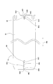
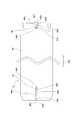
図1に表されたように、本実施形態のレーザマーカ1は、ベース10を備えている。ベース10上には、レーザ発振ユニット12、走査ユニット14、メイン基板16、ガルバノ基板18、フレーム20、リア基板22、及び電源供給ユニット(以下、「PSU」という。)24等が設けられている。 [1. Outline of laser marker]
As shown in FIG. 1, the laser marker 1 of this embodiment includes abase 10. A laser oscillation unit 12, a scanning unit 14, a main board 16, a galvano board 18, a frame 20, a rear board 22, a power supply unit (hereinafter referred to as “PSU”) 24, and the like are provided on the base 10. ..
図1に表されたように、本実施形態のレーザマーカ1は、ベース10を備えている。ベース10上には、レーザ発振ユニット12、走査ユニット14、メイン基板16、ガルバノ基板18、フレーム20、リア基板22、及び電源供給ユニット(以下、「PSU」という。)24等が設けられている。 [1. Outline of laser marker]
As shown in FIG. 1, the laser marker 1 of this embodiment includes a
レーザ発振ユニット12は、レーザ光を出射するものであって、CO2レーザ、YAGレーザ等で構成されている。走査ユニット14は、不図示のガルバノスキャナ、及び後述のfθレンズ(図11の符号102)等が収められたものである。レーザ発振ユニット12から出射されたレーザ光は、走査ユニット14内の上記ガルバノスキャナ及び上記fθレンズ等によって、加工対象物上で走査される。これにより、加工対象物には、文字又は図形等の像がマーキング(印字)加工される。
The laser oscillation unit 12 emits a laser beam and is composed of a CO2 laser, a YAG laser, or the like. The scanning unit 14 includes a galvano scanner (not shown), an fθ lens (reference numeral 102 in FIG. 11) described later, and the like. The laser beam emitted from the laser oscillation unit 12 is scanned on the object to be processed by the galvano scanner and the fθ lens in the scanning unit 14. As a result, an image such as a character or a graphic is marked on the object to be processed.
メイン基板16及びリア基板22は、本実施形態のレーザマーカ1を制御するための基板である。ガルバノ基板18は、走査ユニット14内の上記ガルバノスキャナを制御するための基板である。フレーム20は、その内側に不図示のファンが備え付けられる。上記ファンは、本実施形態のレーザマーカ1の排気を行うものである。更に、フレーム20の上部には、リア基板22が固定されている。PSU24は、本実施形態のレーザマーカ1に対して電力を供給するものである。
The main board 16 and the rear board 22 are boards for controlling the laser marker 1 of the present embodiment. The galvano board 18 is a board for controlling the galvano scanner in the scanning unit 14. The frame 20 is provided with a fan (not shown) inside thereof. The fan exhausts the laser marker 1 of this embodiment. Further, a rear substrate 22 is fixed on the upper portion of the frame 20. The PSU 24 supplies power to the laser marker 1 of this embodiment.
メイン基板16、ガルバノ基板18、フレーム20、及びPSU24等は、ベース10に設けられた後述の固定孔(図3の符号52)に固定ネジ26がねじ込まれることによって、ベース10に固定される。走査ユニット14も、同様にして、ベース10に設けられた後述の固定孔(図3の符号68)に固定ネジ26がねじ込まれることによって、ベース10に固定される。これに対して、レーザ発振ユニット12は、後述するようにして、ベース10上を装着方向MDへスライドさせられることで位置決めが行われ、その後に、ベース10に固定される。
The main board 16, the galvano board 18, the frame 20, the PSU 24, and the like are fixed to the base 10 by screwing the fixing screws 26 into fixing holes (reference numeral 52 in FIG. 3) described later provided in the base 10. Similarly, the scanning unit 14 is also fixed to the base 10 by screwing the fixing screw 26 into a fixing hole (reference numeral 68 in FIG. 3) described later provided in the base 10. On the other hand, the laser oscillation unit 12 is positioned by being slid on the base 10 in the mounting direction MD as described later, and then fixed to the base 10.
尚、ベース10及びフレーム20には、取付ねじ28によって、不図示の筐体カバーが取り付けられる。上記筐体カバーによって、レーザ発振ユニット12、走査ユニット14、メイン基板16、ガルバノ基板18、フレーム20、リア基板22、及び電源供給ユニット24等は、ベース10上で覆われる。
A housing cover (not shown) is attached to the base 10 and the frame 20 with a mounting screw 28. The laser oscillation unit 12, the scanning unit 14, the main substrate 16, the galvano substrate 18, the frame 20, the rear substrate 22, the power supply unit 24, and the like are covered on the base 10 by the housing cover.
[2.ベースの詳細]
図2及び図3に表されたように、ベース10は、略矩形状である。ベース10には、複数のザグリ加工面40乃至48、貫通穴50、複数の固定孔52、及び複数の取付穴54等が設けられている。複数のザグリ加工面40乃至48は、ベース10の表面よりも低い水平面であって、ベース10の表面がザグリ加工されることによって形成されたものである。ザグリ加工面40は、ベース10が備える一対の長辺及び一対の短辺のうち、一方の長辺及び一方の短辺まで達している。これに対して、その他のザグリ加工面42乃至48は、それぞれの縁から上方へ延出した壁面に囲まれている。 [2. Base details]
As shown in FIGS. 2 and 3, thebase 10 has a substantially rectangular shape. The base 10 is provided with a plurality of counterbored surfaces 40 to 48, a through hole 50, a plurality of fixing holes 52, a plurality of mounting holes 54, and the like. The plurality of counterbored surfaces 40 to 48 are horizontal planes lower than the surface of the base 10 and are formed by counterboring the surface of the base 10. The counterbored surface 40 reaches one long side and one short side of the pair of long sides and the pair of short sides included in the base 10. On the other hand, the other counterbored surfaces 42 to 48 are surrounded by the wall surfaces extending upward from their respective edges.
図2及び図3に表されたように、ベース10は、略矩形状である。ベース10には、複数のザグリ加工面40乃至48、貫通穴50、複数の固定孔52、及び複数の取付穴54等が設けられている。複数のザグリ加工面40乃至48は、ベース10の表面よりも低い水平面であって、ベース10の表面がザグリ加工されることによって形成されたものである。ザグリ加工面40は、ベース10が備える一対の長辺及び一対の短辺のうち、一方の長辺及び一方の短辺まで達している。これに対して、その他のザグリ加工面42乃至48は、それぞれの縁から上方へ延出した壁面に囲まれている。 [2. Base details]
As shown in FIGS. 2 and 3, the
ザグリ加工面40には、レーザ発振ユニット12が載置される。ザグリ加工面42には、不図示のセーフティリレーユニットが載置される。上記セーフティリレーユニットは、本実施形態のレーザマーカ1の非常停止回路及び再起動回路等が備えられたものである。ザグリ加工面44には、ガルバノ基板18が載置される。ザグリ加工面46には、上記ガルバノスキャナが載置される。ザグリ加工面48には、上記ガルバノスキャナにレーザ光を導く不図示のミラーユニットが載置される。貫通穴50には、上述したfθレンズ102(図11参照)が嵌装される穴である。固定孔52は、上述した固定ネジ26がねじ込まれる孔である。取付穴54は、上述した取付ねじ28がねじ込まれる孔である。
The laser oscillation unit 12 is placed on the countersunk surface 40. A safety relay unit (not shown) is placed on the counterbored surface 42. The safety relay unit is provided with an emergency stop circuit and a restart circuit of the laser marker 1 of this embodiment. The galvano substrate 18 is placed on the counterbored surface 44. The galvano scanner is mounted on the countersink surface 46. On the countersink surface 48, a mirror unit (not shown) that guides the laser beam to the galvano scanner is placed. The through hole 50 is a hole into which the above-described fθ lens 102 (see FIG. 11) is fitted. The fixing hole 52 is a hole into which the fixing screw 26 described above is screwed. The mounting hole 54 is a hole into which the above-described mounting screw 28 is screwed.
ザグリ加工面40には、上流側第1案内部56、下流側第1案内部58、側壁部60、一対の規制部62、4つの固定孔64、及び突出部66が設けられている。
The counterbored surface 40 is provided with an upstream first guide portion 56, a downstream first guide portion 58, a side wall portion 60, a pair of restriction portions 62, four fixing holes 64, and a protruding portion 66.
上流側第1案内部56及び下流側第1案内部58は、ザグリ加工面40から突き出して設けられたピンであって、ベース10の長辺方向に並んで設けられている。尚、本実施形態では、ベース10の長辺方向は、装着方向MDと平行であるので、以下では、装着方向MDを使用して、ベース10等を説明する。
The upstream first guide portion 56 and the downstream first guide portion 58 are pins provided so as to project from the countersunk surface 40, and are provided side by side in the long side direction of the base 10. In the present embodiment, the long side direction of the base 10 is parallel to the mounting direction MD, so the base 10 and the like will be described below using the mounting direction MD.
つまり、上流側第1案内部56は、装着方向MDの上流側に設けられている。下流側第1案内部58は、上流側第1案内部56よりも装着方向MDの下流側に設けられている。尚、以下の説明において、上流側第1案内部56及び下流側第1案内部58を区別せずに総称する場合には、第1案内部56,58と表記する。
That is, the upstream first guide portion 56 is provided on the upstream side in the mounting direction MD. The downstream first guide portion 58 is provided downstream of the upstream first guide portion 56 in the mounting direction MD. In the following description, the upstream first guide portion 56 and the downstream first guide portion 58 are collectively referred to as the first guide portions 56 and 58 without being distinguished.
側壁部60は、ベース10の短辺方向の中央付近において、ザグリ加工面40の縁から上方へ延出し、装着方向MDに沿って形成された壁面である。一対の規制部62は、下流側第1案内部58よりも装着方向MDの下流側において、ザグリ加工面40の縁から上方へ延出した壁面の一部が装着方向MDの上流側へ張り出したものであって、装着方向MDとは直交する方向(以下、「装着方向MDの直交方向」という。)に沿って形成された壁面である。一対の規制部62は、装着方向MDの直交方向における下流側第1案内部58の両側において、下流側第1案内部58よりも装着方向MDの下流側に位置している。尚、本実施形態では、装着方向MDの直交方向は、図2等の平面視において、ベース10の短辺方向と平行である。
The side wall portion 60 is a wall surface that extends upward from the edge of the countersunk surface 40 near the center in the short side direction of the base 10 and is formed along the mounting direction MD. A part of the wall surface of the pair of restricting portions 62 extending upward from the edge of the countersunk surface 40 protrudes upstream in the mounting direction MD on the downstream side in the mounting direction MD with respect to the downstream first guide portion 58. The wall surface is formed along a direction orthogonal to the mounting direction MD (hereinafter, referred to as "a direction orthogonal to the mounting direction MD"). The pair of restricting portions 62 are located on the both sides of the downstream first guide portion 58 in the direction orthogonal to the mounting direction MD and on the downstream side in the mounting direction MD with respect to the downstream first guide portion 58. In the present embodiment, the direction orthogonal to the mounting direction MD is parallel to the short side direction of the base 10 in the plan view of FIG.
4つの固定孔64は、装着方向MDの直交方向において、第1案内部56,58の両側に設けられている。突出部66は、上流側第1案内部56よりも装着方向MDの上流側に設けられており、上記のファンが載置される。
The four fixing holes 64 are provided on both sides of the first guide portions 56 and 58 in the direction orthogonal to the mounting direction MD. The protruding portion 66 is provided on the upstream side in the mounting direction MD with respect to the upstream first guide portion 56, and the fan is placed on the protruding portion 66.
ベース10には、装着方向MDの下流側にあるザグリ加工面46,48付近において、4つの固定孔68が設けられている。固定孔68は、上述した固定ネジ26がねじ込まれる孔である。
The base 10 is provided with four fixing holes 68 near the counterbored surfaces 46 and 48 on the downstream side in the mounting direction MD. The fixing hole 68 is a hole into which the fixing screw 26 described above is screwed.
[3.走査ユニットの詳細]
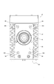
図4に表されたように、走査ユニット14(の筐体)は、固定ネジ26が上述した固定孔68にねじ込まれることによって、ベース10に固定される。これにより、走査ユニット14(の筐体)は、その装着方向MDの上流側の側面が、一対の規制部62よりも装着方向MDの下流側に位置すると共に、ベース10に対して垂直に設けられている。また、走査ユニット14(の筐体)には、その装着方向MDの上流側の側面において、円形状の挿入部70が貫いて設けられている。挿入部70には、円環状の弾性体72が設けられている。弾性体72には、例えば、樹脂製のスポンジが使用され、円形の貫通孔74が形成されている。 [3. Details of scanning unit]
As shown in FIG. 4, the scanning unit 14 (the housing thereof) is fixed to thebase 10 by screwing the fixing screw 26 into the fixing hole 68 described above. As a result, the scanning unit 14 (the housing thereof) is provided such that the side surface on the upstream side in the mounting direction MD is located on the downstream side in the mounting direction MD with respect to the pair of restricting portions 62 and is provided perpendicular to the base 10. Has been. Further, the scanning unit 14 (the housing thereof) is provided with a circular insertion portion 70 penetrating the side surface on the upstream side in the mounting direction MD. The insertion portion 70 is provided with an annular elastic body 72. For the elastic body 72, for example, a resin sponge is used, and a circular through hole 74 is formed.
図4に表されたように、走査ユニット14(の筐体)は、固定ネジ26が上述した固定孔68にねじ込まれることによって、ベース10に固定される。これにより、走査ユニット14(の筐体)は、その装着方向MDの上流側の側面が、一対の規制部62よりも装着方向MDの下流側に位置すると共に、ベース10に対して垂直に設けられている。また、走査ユニット14(の筐体)には、その装着方向MDの上流側の側面において、円形状の挿入部70が貫いて設けられている。挿入部70には、円環状の弾性体72が設けられている。弾性体72には、例えば、樹脂製のスポンジが使用され、円形の貫通孔74が形成されている。 [3. Details of scanning unit]
As shown in FIG. 4, the scanning unit 14 (the housing thereof) is fixed to the
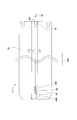
[4.レーザ発振ユニットの詳細]
図5及び図6に表されたように、レーザ発振ユニット12は、本体80、エキスパンダ82、及びプレート84等を有している。本体80は、略直方体状のケースであって、上記のCO2レーザ、YAGレーザ等が収められたものである。エキスパンダ82は、上記のCO2レーザ、YAGレーザ等から出射されたレーザ光の光径を調整するものである。エキスパンダ82は、本体80を構成する側面から突出している。プレート84は、略矩形状であって、その四隅が切り欠けられており、本体80を構成する底面に固定されている。 [4. Details of laser oscillator unit]
As shown in FIGS. 5 and 6, thelaser oscillation unit 12 has a main body 80, an expander 82, a plate 84, and the like. The main body 80 is a case having a substantially rectangular parallelepiped shape, and contains the above-mentioned CO 2 laser, YAG laser, and the like. The expander 82 is for adjusting the optical diameter of the laser light emitted from the CO2 laser, the YAG laser, or the like. The expander 82 projects from the side surface of the main body 80. The plate 84 has a substantially rectangular shape and has four corners cut out, and is fixed to the bottom surface of the main body 80.
図5及び図6に表されたように、レーザ発振ユニット12は、本体80、エキスパンダ82、及びプレート84等を有している。本体80は、略直方体状のケースであって、上記のCO2レーザ、YAGレーザ等が収められたものである。エキスパンダ82は、上記のCO2レーザ、YAGレーザ等から出射されたレーザ光の光径を調整するものである。エキスパンダ82は、本体80を構成する側面から突出している。プレート84は、略矩形状であって、その四隅が切り欠けられており、本体80を構成する底面に固定されている。 [4. Details of laser oscillator unit]
As shown in FIGS. 5 and 6, the
尚、本実施形態では、レーザ発振ユニット12がベース10に固定された場合、本体80及びプレート84の長手方向が装着方向MDに相当するので、以下では、装着方向MDを使用して、レーザ発振ユニット12を説明する。
In the present embodiment, when the laser oscillation unit 12 is fixed to the base 10, the longitudinal direction of the main body 80 and the plate 84 corresponds to the mounting direction MD. Therefore, in the following, the mounting direction MD is used for laser oscillation. The unit 12 will be described.
プレート84は、装着方向MDの上流側及び下流側において、本体80から突出している。プレート84を構成する装着方向MDの上流側端部には、一対の固定孔88が形成されている。これに対して、プレート84を構成する装着方向MDの下流側端部には、一対の固定スリット86が装着方向MDに沿って形成されている。一対の固定スリット86は、その装着方向MDの下流側がプレート84の側面にまで達することによって開かれている。
The plate 84 projects from the main body 80 on the upstream side and the downstream side in the mounting direction MD. A pair of fixing holes 88 are formed at the upstream end of the plate 84 in the mounting direction MD. On the other hand, a pair of fixed slits 86 are formed along the mounting direction MD at the downstream end of the plate 84 in the mounting direction MD. The pair of fixed slits 86 are opened when the downstream side of the mounting direction MD reaches the side surface of the plate 84.
プレート84を構成する装着方向MDの上流側端部には、上流側第2案内部90が設けられている。プレート84を構成する装着方向MDの下流側端部には、下流側第2案内部92が設けられている。つまり、上流側第2案内部90は、装着方向MDの上流側に設けられている。下流側第2案内部92は、上流側第2案内部90よりも装着方向MDの下流側に設けられている。
An upstream second guide portion 90 is provided at the upstream end of the plate 84 in the mounting direction MD. A downstream second guide portion 92 is provided at the downstream end of the plate 84 in the mounting direction MD. That is, the upstream second guide portion 90 is provided on the upstream side in the mounting direction MD. The downstream second guide portion 92 is provided downstream of the upstream second guide portion 90 in the mounting direction MD.
上流側第2案内部90及び下流側第2案内部92は、装着方向MDの直交方向において、プレート84の中央に位置し、装着方向MDに沿って形成されたスリットである。よって、プレート84を構成する装着方向MDの上流側端部では、上流側第2案内部90が、装着方向MDの直交方向において、一対の固定孔88間の中央に位置する。また、プレート84を構成する装着方向MDの下流側端部では、下流側第2案内部92が、装着方向MDの直交方向において、一対の固定スリット86間の中央に位置する。尚、以下の説明において、上流側第2案内部90及び下流側第2案内部92を区別せずに総称する場合には、第2案内部90,92と表記する。
The upstream second guide portion 90 and the downstream second guide portion 92 are slits formed in the center of the plate 84 in the direction orthogonal to the mounting direction MD and formed along the mounting direction MD. Therefore, at the upstream end of the plate 84 in the mounting direction MD, the second upstream guide portion 90 is located at the center between the pair of fixing holes 88 in the direction orthogonal to the mounting direction MD. Further, at the downstream end portion of the plate 84 in the mounting direction MD, the downstream second guide portion 92 is located at the center between the pair of fixed slits 86 in the direction orthogonal to the mounting direction MD. In the following description, the upstream second guide portion 90 and the downstream second guide portion 92 are collectively referred to as the second guide portions 90 and 92 without being distinguished from each other.
プレート84を構成する装着方向MDの下流側端部では、一対の固定スリット86と下流側第2案内部92との間において、一対の当接部94が設けられている。つまり、装着方向MDの直交方向において、下流側第2案内部92は、一対の当接部94の間に位置する。一対の当接部94は、プレート84を構成する装着方向MDの下流側の側面の一部であって、装着方向MDの直交方向に沿って形成された壁面である。
At the downstream end of the plate 84 in the mounting direction MD, a pair of contact portions 94 are provided between the pair of fixed slits 86 and the downstream second guide portion 92. That is, in the direction orthogonal to the mounting direction MD, the downstream second guide portion 92 is located between the pair of contact portions 94. The pair of abutting portions 94 are wall surfaces that are part of the side surfaces on the downstream side of the mounting direction MD that configure the plate 84 and that are formed along the direction orthogonal to the mounting direction MD.
[5.第2案内部の詳細]
図7に表されたように、レーザ発振ユニット12では、プレート84を構成する装着方向MDの上流側端部において、上流側第2案内部90が形成されている。上流側第2案内部90は、スリットであって、一対の長壁90A等で構成されている。一対の長壁90Aは、装着方向MDに沿って形成されることによって、装着方向MDの直交方向で対向している。一対の長壁90Aは、開口端90B及び閉口端90Cを有している。開口端90Bは、一対の長壁90Aの装着方向MDの上流側(つまりレーザ発振ユニット12の外方側)がプレート84の側面にまで達することによって開かれている。開口端90Bには、一対の長壁90Aとプレート84の側面とを連ねる角部が面取りされることによって、切欠部90Dが形成されている。これに対して、閉口端90Cは、一対の長壁90Aの装着方向MDの下流側(つまりレーザ発振ユニット12の内方側)が連なることによって閉じられている。 [5. Details of the 2nd guidance section]
As shown in FIG. 7, in thelaser oscillation unit 12, the upstream second guide portion 90 is formed at the upstream end of the plate 84 in the mounting direction MD. The upstream second guide portion 90 is a slit, and is composed of a pair of long walls 90A and the like. The pair of long walls 90A are formed along the mounting direction MD so as to face each other in the direction orthogonal to the mounting direction MD. The pair of long walls 90A has an open end 90B and a closed end 90C. The open end 90B is opened by the upstream side of the pair of long walls 90A in the mounting direction MD (that is, the outer side of the laser oscillation unit 12) reaching the side surface of the plate 84. A notch 90D is formed in the opening end 90B by chamfering a corner connecting the pair of long walls 90A and the side surface of the plate 84. On the other hand, the closed end 90C is closed by connecting the pair of long walls 90A on the downstream side in the mounting direction MD (that is, on the inner side of the laser oscillation unit 12).
図7に表されたように、レーザ発振ユニット12では、プレート84を構成する装着方向MDの上流側端部において、上流側第2案内部90が形成されている。上流側第2案内部90は、スリットであって、一対の長壁90A等で構成されている。一対の長壁90Aは、装着方向MDに沿って形成されることによって、装着方向MDの直交方向で対向している。一対の長壁90Aは、開口端90B及び閉口端90Cを有している。開口端90Bは、一対の長壁90Aの装着方向MDの上流側(つまりレーザ発振ユニット12の外方側)がプレート84の側面にまで達することによって開かれている。開口端90Bには、一対の長壁90Aとプレート84の側面とを連ねる角部が面取りされることによって、切欠部90Dが形成されている。これに対して、閉口端90Cは、一対の長壁90Aの装着方向MDの下流側(つまりレーザ発振ユニット12の内方側)が連なることによって閉じられている。 [5. Details of the 2nd guidance section]
As shown in FIG. 7, in the
また、レーザ発振ユニット12には、プレート84を構成する装着方向MDの下流側端部において、下流側第2案内部92が形成されている。下流側第2案内部92は、スリットであって、一対の長壁92A等で構成されている。一対の長壁92Aは、装着方向MDに沿って形成されることによって、装着方向MDの直交方向で対向している。一対の長壁92Aは、開口端92B及び閉口端92Cを有している。開口端92Bは、一対の長壁92Aの装着方向MDの下流側(つまりレーザ発振ユニット12の外方側)がプレート84の側面にまで達することによって開かれている。開口端92Bには、一対の長壁92Aとプレート84の側面とを連ねる角部が面取りされることによって、切欠部92Dが形成されている。これに対して、閉口端92Cは、一対の長壁90Aの装着方向MDの上流側(つまりレーザ発振ユニット12の内方側)が連なることによって閉じられている。
Further, the laser oscillation unit 12 is provided with a downstream second guide portion 92 at the downstream end of the plate 84 in the mounting direction MD. The downstream side second guide portion 92 is a slit and is composed of a pair of long walls 92A and the like. The pair of long walls 92A are formed along the mounting direction MD and thus face each other in the direction orthogonal to the mounting direction MD. The pair of long walls 92A has an open end 92B and a closed end 92C. The open end 92B is opened by the downstream side of the pair of long walls 92A in the mounting direction MD (that is, the outer side of the laser oscillation unit 12) reaching the side surface of the plate 84. A notch 92D is formed in the opening end 92B by chamfering a corner connecting the pair of long walls 92A and the side surface of the plate 84. On the other hand, the closed end 92C is closed by the upstream side (that is, the inner side of the laser oscillation unit 12) of the pair of long walls 90A in the mounting direction MD being continuous.
レーザ発振ユニット12の第2案内部90,92、及び上述したベース10の第1案内部56,58は、図8に表された寸法関係が満たされるようにして設けられている。図8に表された寸法関係には、第1寸法関係と第2寸法関係とがある。第1寸法関係とは、ベース10における上流側第1案内部56と下流側第1案内部58とが互いに対向する側の間の距離L1が、レーザ発振ユニット12における上流側第2案内部90の閉口端90Cと下流側第2案内部92の開口端92Bとの間の距離L2以上であることをいう。第2寸法関係とは、上述した距離L1が、レーザ発振ユニット12における上流側第2案内部90の開口端90Bと下流側第2案内部92の開口端92Bとの間の距離L3よりも短いことをいう。
The second guide portions 90 and 92 of the laser oscillation unit 12 and the above-described first guide portions 56 and 58 of the base 10 are provided so that the dimensional relationship shown in FIG. 8 is satisfied. The dimensional relationship shown in FIG. 8 includes a first dimensional relationship and a second dimensional relationship. The first dimensional relationship means that the distance L1 between the sides of the base 10 where the upstream first guide portion 56 and the downstream first guide portion 58 face each other is the upstream second guide portion 90 in the laser oscillation unit 12. The distance L2 between the closed end 90C and the opening end 92B of the downstream second guide portion 92 is equal to or greater than L2. The second dimension relationship means that the distance L1 described above is shorter than the distance L3 between the opening end 90B of the upstream second guide portion 90 and the opening end 92B of the downstream second guide portion 92 in the laser oscillation unit 12. Say that.
更に、レーザ発振ユニット12の下流側第2案内部92の開口端92B、及びベース10の下流側第1案内部58は、図9に表された寸法関係が満たされるようにして設けられている。図9に表された寸法関係とは、装着方向MDの距離に関し、ベース10における走査ユニット14の挿入部70の装着方向上流側と、下流側第1案内部58の装着方向上流側との間の距離L4が、レーザ発振ユニット12におけるエキスパンダ82の先端と下流側第2案内部92の開口端92Bとの間の距離L5よりも長いことをいう。
Further, the opening end 92B of the downstream second guide portion 92 of the laser oscillation unit 12 and the downstream first guide portion 58 of the base 10 are provided so as to satisfy the dimensional relationship shown in FIG. .. The dimensional relationship shown in FIG. 9 relates to the distance in the mounting direction MD between the upstream side in the mounting direction of the insertion portion 70 of the scanning unit 14 in the base 10 and the upstream side in the mounting direction of the downstream first guide portion 58. L4 is longer than the distance L5 between the tip of the expander 82 in the laser oscillation unit 12 and the opening end 92B of the downstream second guide portion 92.
[6.走査ユニットの挿入部等の詳細]
図9に表されたように、走査ユニット14(の筐体)の挿入部70には、その内周面70Aの全域に亘って、上述した弾性体72が設けられている。弾性体72の貫通孔74は、上述したように円形であって、レーザ発振ユニット12のエキスパンダ82の外径D1よりも小さな径D2を有するものである。 [6. Details of scanning unit insertion section, etc.]
As shown in FIG. 9, the above-mentionedelastic body 72 is provided in the insertion portion 70 of (the casing of) the scanning unit 14 over the entire inner peripheral surface 70A thereof. The through hole 74 of the elastic body 72 is circular as described above and has a diameter D2 smaller than the outer diameter D1 of the expander 82 of the laser oscillation unit 12.
図9に表されたように、走査ユニット14(の筐体)の挿入部70には、その内周面70Aの全域に亘って、上述した弾性体72が設けられている。弾性体72の貫通孔74は、上述したように円形であって、レーザ発振ユニット12のエキスパンダ82の外径D1よりも小さな径D2を有するものである。 [6. Details of scanning unit insertion section, etc.]
As shown in FIG. 9, the above-mentioned
エキスパンダ82の位置は、レーザ発振ユニット12に備えられた調整機構によって変更することが可能である。後述するようにして、レーザ発振ユニット12の位置決めが行われた状態では、上述した調整機構によって、エキスパンダ82の位置は、装着方向MDの直交方向において、所定領域DA内で変更されることが可能である。所定領域DAは、走査ユニット14(の筐体)の挿入部70よりも小さい。
The position of the expander 82 can be changed by the adjusting mechanism provided in the laser oscillation unit 12. As will be described later, when the laser oscillation unit 12 is positioned, the position of the expander 82 may be changed within the predetermined area DA in the direction orthogonal to the mounting direction MD by the adjustment mechanism described above. It is possible. The predetermined area DA is smaller than the insertion portion 70 of (the housing of) the scanning unit 14.
図10に表されたように、レーザ発振ユニット12では、プレート84の上方において、本体80に対して、エキスパンダ82が固定されている。その固定は、エキスパンダ82から張り出したフランジ96の固定孔98を介して、不図示の固定ネジが本体80側の固定孔100にねじ込まれることによって行われる。フランジ96の固定孔98は、本体80側の固定孔100よりも大きな馬鹿穴になっており、エキスパンダ82の固定位置を調整可能にする。このようにして、レーザ発振ユニット12では、上述した調整機構が構成されている。
As shown in FIG. 10, in the laser oscillation unit 12, the expander 82 is fixed to the main body 80 above the plate 84. The fixing is performed by screwing a fixing screw (not shown) into the fixing hole 100 on the main body 80 side through the fixing hole 98 of the flange 96 protruding from the expander 82. The fixing hole 98 of the flange 96 is a stupid hole larger than the fixing hole 100 on the main body 80 side, and allows the fixing position of the expander 82 to be adjusted. In this way, in the laser oscillation unit 12, the adjusting mechanism described above is configured.
[7.レーザ発振ユニットの位置決め]
以下、ベース10の走査ユニット14に対するレーザ発振ユニット12の位置決めについて説明する。作業者は、ベース10において、走査ユニット14に対するレーザ発振ユニット12の位置決めを行う際は、レーザ発振ユニット12を、そのエキスパンダ82がベース10の走査ユニット14へ向かう状態にした後、レーザ発振ユニット12のプレート84の側面をベース10の側壁部60(図4参照)に当接させる。 [7. Positioning of laser oscillation unit]
Hereinafter, positioning of thelaser oscillation unit 12 with respect to the scanning unit 14 of the base 10 will be described. When positioning the laser oscillation unit 12 with respect to the scanning unit 14 in the base 10, the operator sets the laser oscillation unit 12 so that the expander 82 faces the scanning unit 14 of the base 10 and then the laser oscillation unit 12 is moved. The side surface of the plate 84 of 12 is brought into contact with the side wall portion 60 (see FIG. 4) of the base 10.
以下、ベース10の走査ユニット14に対するレーザ発振ユニット12の位置決めについて説明する。作業者は、ベース10において、走査ユニット14に対するレーザ発振ユニット12の位置決めを行う際は、レーザ発振ユニット12を、そのエキスパンダ82がベース10の走査ユニット14へ向かう状態にした後、レーザ発振ユニット12のプレート84の側面をベース10の側壁部60(図4参照)に当接させる。 [7. Positioning of laser oscillation unit]
Hereinafter, positioning of the
その後、作業者は、レーザ発振ユニット12のプレート84の側面をベース10の側壁部60に当接させながら、レーザ発振ユニット12のプレート84の底面をベース10のザグリ加工面40に近接させる。更に、作業者は、レーザ発振ユニット12のプレート84の側面とベース10の側壁部60とを僅かに離間させながら、レーザ発振ユニット12のプレート84の底面をベース10のザグリ加工面40に載置させる。その際、作業者は、例えば、図8に表されたようにして、レーザ発振ユニット12の上流側第2案内部(スリット)90にベース10の上流側第1案内部(ピン)56を嵌入させる一方、レーザ発振ユニット12の下流側第2案内部(スリット)92の開口端92Bを、ベース10の下流側第1案内部(ピン)58よりも装着方向MDの下流側に配置させる。
Thereafter, the worker brings the bottom surface of the plate 84 of the laser oscillation unit 12 close to the counterbored surface 40 of the base 10 while bringing the side surface of the plate 84 of the laser oscillation unit 12 into contact with the side wall portion 60 of the base 10. Further, the worker places the bottom surface of the plate 84 of the laser oscillation unit 12 on the counterbored surface 40 of the base 10 while slightly separating the side surface of the plate 84 of the laser oscillation unit 12 and the side wall portion 60 of the base 10. Let At that time, the worker fits the upstream first guide portion (pin) 56 of the base 10 into the upstream second guide portion (slit) 90 of the laser oscillation unit 12 as shown in FIG. 8, for example. On the other hand, the opening end 92B of the downstream second guide portion (slit) 92 of the laser oscillation unit 12 is arranged downstream of the downstream first guide portion (pin) 58 of the base 10 in the mounting direction MD.
その後、作業者は、ベース10に載置されているレーザ発振ユニット12を、ベース10の走査ユニット14へ向けてスライドさせることによって、レーザ発振ユニット12の下流側第2案内部(スリット)92に、その開口端92Bを介して、ベース10の下流側第1案内部(ピン)58を嵌入させる。そのような状態で、作業者は、ベース10に載置されているレーザ発振ユニット12を、ベース10の走査ユニット14へ向けてスライドさせると、レーザ発振ユニット12の第2案内部(スリット)90,92とベース10の第1案内部(ピン)56,58とが係わり合うことによって、レーザ発振ユニット12がベース10上を装着方向MDへ移動する。これにより、装着方向MDが規定される。
After that, the worker slides the laser oscillation unit 12 mounted on the base 10 toward the scanning unit 14 of the base 10 so that the laser oscillation unit 12 is moved to the second guide portion (slit) 92 on the downstream side of the laser oscillation unit 12. The downstream first guide portion (pin) 58 of the base 10 is fitted through the open end 92B. In such a state, when the worker slides the laser oscillation unit 12 mounted on the base 10 toward the scanning unit 14 of the base 10, the second guide portion (slit) 90 of the laser oscillation unit 12 is slid. , 92 and the first guide portions (pins) 56, 58 of the base 10 are engaged with each other, so that the laser oscillation unit 12 moves on the base 10 in the mounting direction MD. This defines the mounting direction MD.
その際、エキスパンダ82の所定領域DAは、装着方向MDから視ると、走査ユニット14(の筐体)の挿入部70に含まれる。
At that time, the predetermined area DA of the expander 82 is included in the insertion portion 70 of (the housing of) the scanning unit 14 when viewed from the mounting direction MD.
更に、作業者は、ベース10に載置されているレーザ発振ユニット12を装着方向MDへ移動させると、図11に表されたようにして、レーザ発振ユニット12の当接部94がベース10の規制部62に突き当たることによって、レーザ発振ユニット12が装着方向MDへ移動することが規制される。その際、レーザ発振ユニット12のエキスパンダ82は、走査ユニット14(の筐体)の挿入部70において、弾性体72を圧縮させながら、弾性体72の貫通孔74に差し込まれる。
Further, when the worker moves the laser oscillation unit 12 mounted on the base 10 in the mounting direction MD, the contact portion 94 of the laser oscillation unit 12 is moved to the base 10 as shown in FIG. The laser oscillation unit 12 is restricted from moving in the mounting direction MD by hitting the restriction portion 62. At that time, the expander 82 of the laser oscillation unit 12 is inserted into the through hole 74 of the elastic body 72 while compressing the elastic body 72 in the insertion portion 70 of (the casing of) the scanning unit 14.
上述したようにして、レーザ発振ユニット12が装着方向MDへ移動することが規制されると、作業者は、レーザ発振ユニット12の当接部94をベース10の規制部62に当接させた状態にすることによって、ベース10の走査ユニット14に対するレーザ発振ユニット12の位置決めを完了させる。
As described above, when the movement of the laser oscillation unit 12 in the mounting direction MD is restricted, the operator brings the contact portion 94 of the laser oscillation unit 12 into contact with the restriction portion 62 of the base 10. By doing so, the positioning of the laser oscillation unit 12 with respect to the scanning unit 14 of the base 10 is completed.
その後、作業者は、レーザ発振ユニット12の装着方向MDの下流側において、レーザ発振ユニット12の固定スリット86を介して、固定ネジ104をベース10の固定孔64にねじ込む。更に、作業者は、図12に表された固定ネジ104を、レーザ発振ユニット12の装着方向MDの上流側において、レーザ発振ユニット12の固定孔88を介して、ベース10の固定孔64にねじ込む。これにより、レーザ発振ユニット12は、そのエキスパンダ82を走査ユニット14(の筐体)の挿入部70に装着させた状態で、ベース10に取り付けられる。
After that, the worker screws the fixing screw 104 into the fixing hole 64 of the base 10 on the downstream side in the mounting direction MD of the laser oscillation unit 12 via the fixing slit 86 of the laser oscillation unit 12. Further, the worker screws the fixing screw 104 shown in FIG. 12 into the fixing hole 64 of the base 10 through the fixing hole 88 of the laser oscillation unit 12 on the upstream side in the mounting direction MD of the laser oscillation unit 12. .. As a result, the laser oscillation unit 12 is attached to the base 10 in a state where the expander 82 is attached to the insertion portion 70 of (the housing of) the scanning unit 14.
尚、作業者は、上述した作業を記載順とは逆の順で行えば、レーザ発振ユニット12のエキスパンダ82を走査ユニット14(の筐体)の挿入部70から抜き出しながら、レーザ発振ユニット12をベース10から取り外すことが可能である。
If the worker performs the above-described operations in the reverse order of the description order, the worker can pull out the expander 82 of the laser oscillation unit 12 from the insertion portion 70 of (the housing of) the scanning unit 14 while the laser oscillation unit 12 is being extracted. Can be removed from the base 10.
[8.まとめ]
以上詳細に説明したように、本実施の形態のレーザマーカ1では、レーザ発振ユニット12がベース10に載置された状態でスライドさせられる。これにより、レーザ発振ユニット12のエキスパンダ82が走査ユニット14の挿入部70に差し込まれながら、レーザ発振ユニット12が走査ユニット14に着脱自在に装着される。その際、ベース10の第1案内部56,58とレーザ発振ユニット12の第2案内部90,92とが係合することによって、レーザ発振ユニット12の装着方向MDが規定される。また、レーザ発振ユニット12の当接部94がベース10の規制部62に突き当たることによって、レーザ発振ユニット12がベース10上をスライドすることが規制される。更に、レーザ発振ユニット12の当接部94がベース10の規制部62に当接した状態にされることによって、ベース10におけるレーザ発振ユニット12の位置決めが完了する。このようにして、本実施の形態のレーザマーカ1では、レーザ発振ユニット12のエキスパンダ82が差し込まれる走査ユニット14に対して、レーザ発振ユニット12の位置決めが精度良く行われる。 [8. Summary]
As described above in detail, in the laser marker 1 according to the present embodiment, thelaser oscillation unit 12 is slid while being mounted on the base 10. As a result, the laser oscillation unit 12 is detachably attached to the scanning unit 14 while the expander 82 of the laser oscillation unit 12 is inserted into the insertion portion 70 of the scanning unit 14. At that time, the mounting direction MD of the laser oscillation unit 12 is defined by the engagement between the first guide portions 56 and 58 of the base 10 and the second guide portions 90 and 92 of the laser oscillation unit 12. Further, the abutting portion 94 of the laser oscillation unit 12 abuts against the regulation portion 62 of the base 10, whereby the laser oscillation unit 12 is regulated to slide on the base 10. Further, the contact portion 94 of the laser oscillation unit 12 is brought into contact with the restriction portion 62 of the base 10, whereby the positioning of the laser oscillation unit 12 on the base 10 is completed. In this way, in the laser marker 1 according to the present embodiment, the laser oscillation unit 12 is accurately positioned with respect to the scanning unit 14 into which the expander 82 of the laser oscillation unit 12 is inserted.
以上詳細に説明したように、本実施の形態のレーザマーカ1では、レーザ発振ユニット12がベース10に載置された状態でスライドさせられる。これにより、レーザ発振ユニット12のエキスパンダ82が走査ユニット14の挿入部70に差し込まれながら、レーザ発振ユニット12が走査ユニット14に着脱自在に装着される。その際、ベース10の第1案内部56,58とレーザ発振ユニット12の第2案内部90,92とが係合することによって、レーザ発振ユニット12の装着方向MDが規定される。また、レーザ発振ユニット12の当接部94がベース10の規制部62に突き当たることによって、レーザ発振ユニット12がベース10上をスライドすることが規制される。更に、レーザ発振ユニット12の当接部94がベース10の規制部62に当接した状態にされることによって、ベース10におけるレーザ発振ユニット12の位置決めが完了する。このようにして、本実施の形態のレーザマーカ1では、レーザ発振ユニット12のエキスパンダ82が差し込まれる走査ユニット14に対して、レーザ発振ユニット12の位置決めが精度良く行われる。 [8. Summary]
As described above in detail, in the laser marker 1 according to the present embodiment, the
また、第1案内部56,58は、ベース10に突設されたピンである。第2案内部90,92は、レーザ発振ユニット12において対向して設けられた一対の長壁90A,92Aで構成されている。よって、本実施の形態のレーザマーカ1では、上述した位置決めを行うための第1案内部56,58及び第2案内部90,92が、簡単な構成で実現されている。
Moreover, the first guide portions 56 and 58 are pins protruding from the base 10. The second guide portions 90 and 92 are composed of a pair of long walls 90A and 92A provided to face each other in the laser oscillation unit 12. Therefore, in the laser marker 1 of the present embodiment, the first guide portions 56, 58 and the second guide portions 90, 92 for performing the above-described positioning are realized with a simple configuration.
また、レーザ発振ユニット12の下流側第2案内部92では、閉口端92Cに切欠部92Dが設けられている。これにより、レーザ発振ユニット12の下流側第2案内部92では、その中央部における一対の長壁92Aの間隔よりも、閉口端92Cにおける一対の長壁92Aの間隔が大きくなる。よって、レーザ発振ユニット12の下流側第2案内部92に、その開口端92Bを介して、ベース10の下流側第1案内部58を嵌入させ易い。そのため、本実施の形態のレーザマーカ1では、下流側第1案内部58が、レーザ発振ユニット12のプレート84で潰され難い。
Further, in the second guide portion 92 on the downstream side of the laser oscillation unit 12, a cutout portion 92D is provided at the closed end 92C. As a result, in the downstream second guide portion 92 of the laser oscillation unit 12, the gap between the pair of long walls 92A at the closed end 92C is larger than the gap between the pair of long walls 92A at the center thereof. Therefore, the downstream first guide portion 58 of the base 10 can be easily fitted into the downstream second guide portion 92 of the laser oscillation unit 12 via the opening end 92B. Therefore, in the laser marker 1 of the present embodiment, the downstream first guide portion 58 is unlikely to be crushed by the plate 84 of the laser oscillation unit 12.
また、第1案内部56,58は、ベース10において、装着方向MDの上流側に配設された上流側第1案内部56と、上流側第1案内部56よりも装着方向MDの下流側に配設された下流側第1案内部58とで構成されている。更に、第2案内部90,92は、ベース10上を装着方向MDへスライドするレーザ発振ユニット12において、装着方向MDの上流側に位置する上流側第2案内部90と、上流側第2案内部90よりも装着方向MDの下流側に位置する下流側第2案内部92とで構成されている。そのため、本実施の形態のレーザマーカ1では、装着方向MDの両側において、ベース10の第1案内部56,58とレーザ発振ユニット12の第2案内部90,92とが係合することから、走査ユニット14に対するレーザ発振ユニット12の位置決めの精度が高い。
In addition, the first guide portions 56 and 58 are the upstream first guide portion 56 disposed on the upstream side in the mounting direction MD and the downstream side in the mounting direction MD with respect to the upstream first guide portion 56 in the base 10. And a downstream side first guide portion 58 disposed in the. Further, in the laser oscillation unit 12 that slides on the base 10 in the mounting direction MD, the second guide portions 90 and 92 are the upstream second guide portion 90 located upstream of the mounting direction MD and the upstream second guide portion. It is composed of a downstream second guide portion 92 located downstream of the portion 90 in the mounting direction MD. Therefore, in the laser marker 1 of the present embodiment, the first guide portions 56, 58 of the base 10 and the second guide portions 90, 92 of the laser oscillation unit 12 are engaged with each other on both sides in the mounting direction MD, so that scanning is performed. The positioning accuracy of the laser oscillation unit 12 with respect to the unit 14 is high.
また、ベース10における上流側第1案内部(ピン)56と下流側第1案内部(ピン)58とが互いに対向する側の間の距離L1は、レーザ発振ユニット12における上流側第2案内部(スリット)90の閉口端90Cと下流側第2案内部(スリット)92の開口端92Bとの間の距離L2以上である一方、レーザ発振ユニット12における上流側第2案内部(スリット)90の開口端90Bと下流側第2案内部(スリット)92の開口端92Bとの間の距離L3よりも短い。
Further, the distance L1 between the sides of the base 10 where the upstream first guide portion (pin) 56 and the downstream first guide portion (pin) 58 face each other is determined by the distance between the upstream second guide portion of the laser oscillation unit 12. The distance L2 between the closed end 90C of the (slit) 90 and the open end 92B of the downstream second guide portion (slit) 92 is equal to or more than the distance L2, while the upstream second guide portion (slit) 90 of the laser oscillation unit 12 is It is shorter than the distance L3 between the opening end 90B and the opening end 92B of the downstream second guide portion (slit) 92.
そのため、ベース10の上流側第1案内部(ピン)56がレーザ発振ユニット12の上流側第2案内部(スリット)90に係合された状態でも、ベース10の下流側第1案内部(ピン)58は、レーザ発振ユニット12の下流側第2案内部(スリット)92よりも、装着方向MDの下流側に位置させることが可能である。更に、レーザ発振ユニット12がベース10に載置された状態でスライドすることによって、ベース10の下流側第1案内部(ピン)58とレーザ発振ユニット12の下流側第2案内部(スリット)92とが係合された状態になっても、ベース10の上流側第1案内部(ピン)56がレーザ発振ユニット12の上流側第2案内部(スリット)90に係合された状態は維持される。
Therefore, even when the upstream first guide portion (pin) 56 of the base 10 is engaged with the upstream second guide portion (slit) 90 of the laser oscillation unit 12, the downstream first guide portion (pin) of the base 10 is )58 can be located downstream of the downstream second guide portion (slit) 92 of the laser oscillation unit 12 in the mounting direction MD. Further, by sliding the laser oscillation unit 12 while being mounted on the base 10, the downstream first guide portion (pin) 58 of the base 10 and the downstream second guide portion (slit) 92 of the laser oscillation unit 12 are provided. Even when and are engaged, the state where the upstream first guide portion (pin) 56 of the base 10 is engaged with the upstream second guide portion (slit) 90 of the laser oscillation unit 12 is maintained. It
そのため、本実施の形態のレーザマーカ1では、ベース10の上流側第1案内部(ピン)56とレーザ発振ユニット12の上流側第2案内部(スリット)90との係合が先行され維持されることによって、ベース10の下流側第1案内部(ピン)58とレーザ発振ユニット12の下流側第2案内部(スリット)92との係合を後行で容易に行うことが可能である。
Therefore, in the laser marker 1 of the present embodiment, engagement between the upstream first guide portion (pin) 56 of the base 10 and the upstream second guide portion (slit) 90 of the laser oscillation unit 12 is preceded and maintained. As a result, the downstream first guide portion (pin) 58 of the base 10 and the downstream second guide portion (slit) 92 of the laser oscillation unit 12 can be easily engaged in a subsequent step.
また、装着方向MDの距離に関し、ベース10における走査ユニット14の挿入部70の装着方向上流側と、下流側第1案内部(ピン)58の装着方向上流側との間の距離L4は、レーザ発振ユニット12におけるエキスパンダ82の先端と下流側第2案内部(スリット)92の開口端92Bとの間の距離L5よりも長い。そのため、本実施の形態のレーザマーカ1では、レーザ発振ユニット12のエキスパンダ82がベース10の走査ユニット14の挿入部70に差し込まれる前において、ベース10の下流側第1案内部(ピン)58とレーザ発振ユニット12の下流側第2案内部(スリット)92との係合が行われることによって、装着方向MDの直交方向の位置決めを行うことが可能である。
Regarding the distance in the mounting direction MD, the distance L4 between the upstream side in the mounting direction of the insertion portion 70 of the scanning unit 14 in the base 10 and the upstream side in the mounting direction of the downstream first guide portion (pin) 58 is the laser. It is longer than the distance L5 between the tip of the expander 82 in the oscillation unit 12 and the opening end 92B of the downstream second guide portion (slit) 92. Therefore, in the laser marker 1 of the present embodiment, before the expander 82 of the laser oscillation unit 12 is inserted into the insertion portion 70 of the scanning unit 14 of the base 10, the expander 82 and the first guide portion (pin) 58 on the downstream side of the base 10 are connected. By engaging with the downstream second guide portion (slit) 92 of the laser oscillation unit 12, it is possible to perform positioning in the direction orthogonal to the mounting direction MD.
また、ベース10は、装着方向MDに沿って設けられた側壁部60を有する。側壁部60は、ベース10の第1案内部56,58とレーザ発振ユニット12の第2案内部90,92とが係合状態にある場合に、レーザ発振ユニット12に対し装着方向の直交方向に位置する。そのため、本実施の形態のレーザマーカ1では、レーザ発振ユニット12がベース10に載置される際において、レーザ発振ユニット12が側壁部60に当接させた状態にすれば、装着方向MDの直交方向において、レーザ発振ユニット12の位置が概ね決められる。よって、ベース10の第1案内部56,58とレーザ発振ユニット12の第2案内部90,92との係合が容易に行われる。
Also, the base 10 has a side wall portion 60 provided along the mounting direction MD. When the first guide portions 56 and 58 of the base 10 and the second guide portions 90 and 92 of the laser oscillation unit 12 are engaged with each other, the side wall portion 60 is in a direction orthogonal to the mounting direction with respect to the laser oscillation unit 12. To position. Therefore, in the laser marker 1 according to the present embodiment, when the laser oscillation unit 12 is placed on the base 10, if the laser oscillation unit 12 is brought into contact with the side wall portion 60, a direction orthogonal to the mounting direction MD is obtained. In, the position of the laser oscillation unit 12 is roughly determined. Therefore, the first guide portions 56 and 58 of the base 10 and the second guide portions 90 and 92 of the laser oscillation unit 12 are easily engaged with each other.
また、レーザ発振ユニット12は、エキスパンダ82の位置を装着方向MDの直交方向における所定領域DA内で変更させることが可能な調整機構を有している。ベース10における走査ユニット14の挿入部70は、装着方向MDから視て、レーザ発振ユニット12がベース10に装着される際の所定領域DAを含んでいる。よって、本実施の形態のレーザマーカ1では、レーザ発振ユニット12におけるエキスパンダ82の位置に関する個体差を受容することが可能である。
Further, the laser oscillation unit 12 has an adjusting mechanism capable of changing the position of the expander 82 within a predetermined area DA in the direction orthogonal to the mounting direction MD. The insertion portion 70 of the scanning unit 14 in the base 10 includes a predetermined area DA when the laser oscillation unit 12 is mounted on the base 10 when viewed from the mounting direction MD. Therefore, the laser marker 1 of the present embodiment can accept individual differences regarding the position of the expander 82 in the laser oscillation unit 12.
また、ベース10は、走査ユニット14の挿入部70の内周面70Aに周設された弾性体72を有している。弾性体72には、レーザ発振ユニット12のエキスパンダ82の外径D1よりも小さな径D2の貫通孔74が形成されている。このような構成によって、エキスパンダ82は、レーザ発振ユニット12が走査ユニット14に装着される際において、弾性体72を圧縮しながら貫通孔74に差し込まれる。これにより、本実施の形態のレーザマーカ1は、走査ユニット14内の防塵性を向上させている。
The base 10 also has an elastic body 72 that is provided around the inner peripheral surface 70A of the insertion portion 70 of the scanning unit 14. A through hole 74 having a diameter D2 smaller than the outer diameter D1 of the expander 82 of the laser oscillation unit 12 is formed in the elastic body 72. With such a configuration, the expander 82 is inserted into the through hole 74 while compressing the elastic body 72 when the laser oscillation unit 12 is mounted on the scanning unit 14. As a result, the laser marker 1 of the present embodiment improves the dustproof property in the scanning unit 14.
ちなみに、本実施形態において、走査ユニット14は、「走査部」の一例である。距離L3は、「前記レーザ発振ユニットにおける前記上流側第2案内部及び前記下流側第2案内部の開口端間の距離」の一例である。
Incidentally, in the present embodiment, the scanning unit 14 is an example of a “scanning unit”. The distance L3 is an example of "a distance between the opening ends of the upstream second guide portion and the downstream second guide portion in the laser oscillation unit".
[9.変更例]
尚、本開示は、本実施形態に限定されるものでなく、その趣旨を逸脱しない範囲で様々な変更が可能である。 [9. Example of change]
The present disclosure is not limited to this embodiment, and various modifications can be made without departing from the spirit of the present disclosure.
尚、本開示は、本実施形態に限定されるものでなく、その趣旨を逸脱しない範囲で様々な変更が可能である。 [9. Example of change]
The present disclosure is not limited to this embodiment, and various modifications can be made without departing from the spirit of the present disclosure.
例えば、走査ユニット14(の筐体)は、ベース10と一体的に設けられてもよい。規制部62は、走査ユニット14(の筐体)に設けられてもよい。第1案内部(ピン)56,58及び第2案内部90,92(スリット)については、上流側第1案内部(ピン)56及び上流側第2案内部90(スリット)が省略されてもよい。
For example, (the housing of) the scanning unit 14 may be provided integrally with the base 10. The regulation unit 62 may be provided in (the casing of) the scanning unit 14. Regarding the first guide portions (pins) 56, 58 and the second guide portions 90, 92 (slits), the upstream first guide portion (pins) 56 and the upstream second guide portion 90 (slits) may be omitted. Good.
また、図13に表されたように、レーザ発振ユニット12の上流側第2案内部90において、その中央部における一対の長壁90Aの間隔よりも大きな径を有する円形穴90Eが、装着方向MDの上流側の端部に連設されてもよい。これにより、レーザ発振ユニット12の上流側第2案内部90では、その中央部における一対の長壁90Aの間隔よりも、閉口端90Cにおける一対の長壁90Aの間隔が大きくなる。
Further, as shown in FIG. 13, in the upstream second guide portion 90 of the laser oscillation unit 12, a circular hole 90E having a diameter larger than the distance between the pair of long walls 90A in the central portion thereof is located in the mounting direction MD. It may be connected to the upstream end. As a result, in the upstream second guide portion 90 of the laser oscillation unit 12, the gap between the pair of long walls 90A at the closed end 90C is larger than the gap between the pair of long walls 90A at the center thereof.
そのような変更例では、レーザ発振ユニット12のプレート84の底面がベース10のザグリ加工面40に載置される際において、レーザ発振ユニット12の上流側第2案内部90(の円形穴90E)にベース10の上流側第1案内部(ピン)56を嵌入させ易い。そのため、上流側第1案内部(ピン)56は、レーザ発振ユニット12のプレート84で潰され難い。
In such a modified example, when the bottom surface of the plate 84 of the laser oscillation unit 12 is placed on the countersunk surface 40 of the base 10, the upstream second guide portion 90 (the circular hole 90E) of the laser oscillation unit 12 is placed. It is easy to fit the upstream first guide portion (pin) 56 of the base 10 into the. Therefore, the upstream first guide portion (pin) 56 is unlikely to be crushed by the plate 84 of the laser oscillation unit 12.
尚、同様にして、レーザ発振ユニット12の下流側第2案内部92において、その中央部における一対の長壁92Aの間隔よりも大きな径を有する円形穴92Eが、装着方向MDの上流側の端部に連設されてもよい。これにより、レーザ発振ユニット12の下流側第2案内部92では、その中央部における一対の長壁92Aの間隔よりも、閉口端92Cにおける一対の長壁92Aの間隔が大きくなる。
In the same manner, in the downstream second guide portion 92 of the laser oscillation unit 12, a circular hole 92E having a diameter larger than the distance between the pair of long walls 92A in the central portion is provided at the upstream end portion in the mounting direction MD. May be serially installed. As a result, in the downstream second guide portion 92 of the laser oscillation unit 12, the gap between the pair of long walls 92A at the closed end 92C is larger than the gap between the pair of long walls 92A at the center thereof.
また、第2案内部90,92は、その両端部が閉じられた溝であってもよい。そのような場合には、作業者は、レーザ発振ユニット12のプレート84の底面をベース10のザグリ加工面40に載置させる際に、レーザ発振ユニット12の上流側第2案内部90にベース10の上流側第1案内部(ピン)56を嵌入させると共に、レーザ発振ユニット12の下流側第2案内部92にベース10の下流側第1案内部(ピン)58を嵌入させる。
Also, the second guide portions 90 and 92 may be grooves whose both ends are closed. In such a case, when the operator mounts the bottom surface of the plate 84 of the laser oscillation unit 12 on the countersunk surface 40 of the base 10, the worker uses the second guide portion 90 on the upstream side of the laser oscillation unit 12 for the base 10. The upstream first guide portion (pin) 56 is fitted and the downstream first guide portion (pin) 58 of the base 10 is fitted into the downstream second guide portion 92 of the laser oscillation unit 12.
1:レーザマーカ、10:ベース、12:レーザ発振ユニット、14:走査ユニット、56:上流側第1案内部(ピン)、58:下流側第1案内部(ピン)、60:側壁部、62:規制部、70:挿入部、70A:内周面、72:弾性体、74:貫通孔、82:エキスパンダ、90:上流側第2案内部(スリット)、90A:一対の長壁、90B:開口端、90C:閉口端、92:下流側第2案内部(スリット)、92A:一対の長壁、92B:開口端、92C:閉口端、94:当接部、D1:エキスパンダの外径、D2:貫通孔の径、DA:所定領域、L1:上流側第1案内部と下流側第1案内部とが互いに対向する側の間の距離、L2:上流側第2案内部の閉口端と下流側第2案内部の開口端との間の距離、L3:上流側第2案内部の開口端と下流側第2案内部の開口端との間の距離、L4:装着方向における走査部の挿入部の装着方向上流側と下流側第1案内部の装着方向上流側との間の距離、L5:装着方向におけるエキスパンダの先端と下流側第2案内部の開口端との間の距離、MD:装着方向
1: laser marker, 10: base, 12: laser oscillation unit, 14: scanning unit, 56: upstream first guide portion (pin), 58: downstream first guide portion (pin), 60: side wall portion, 62: Restriction part, 70: insertion part, 70A: inner peripheral surface, 72: elastic body, 74: through hole, 82: expander, 90: second upstream guide part (slit), 90A: pair of long walls, 90B: opening. End, 90C: closed end, 92: downstream second guide portion (slit), 92A: pair of long walls, 92B: open end, 92C: closed end, 94: contact portion, D1: expander outer diameter, D2 : Diameter of through-hole, DA: predetermined area, L1: distance between sides where upstream first guide portion and downstream first guide portion face each other, L2: closed end of upstream second guide portion and downstream Distance between the open end of the second side guide portion, L3: distance between the open end of the upstream second guide portion and the open end of the downstream second guide portion, L4: insertion of the scanning portion in the mounting direction Between the upstream side in the mounting direction of the section and the upstream side in the mounting direction of the downstream first guide section, L5: the distance between the tip of the expander and the open end of the downstream second guide section in the mounting direction, MD : Mounting direction
Claims (9)
- レーザ光を出射するエキスパンダが設けられたレーザ発振ユニットと、
前記レーザ発振ユニットが載置された状態でスライドすることによって着脱自在に装着されると共に、前記レーザ発振ユニットから出射されたレーザ光を走査する走査部と、前記走査部に設けられ、前記レーザ発振ユニットが装着される際に前記レーザ発振ユニットの前記エキスパンダが差し込まれる挿入部とを有するベースとを備え、
前記ベースは、
第1案内部と、
前記レーザ発振ユニットが突き当たることによって、前記レーザ発振ユニットが前記ベース上をスライドすることを規制する規制部とを有し、
前記レーザ発振ユニットは、
前記ベースの前記第1案内部と係合することによって、前記レーザ発振ユニットの装着方向を規定する第2案内部と、
前記走査部に装着された際に前記ベースの規制部に当接した状態になる当接部とを有することを特徴とするレーザマーカ。 A laser oscillation unit provided with an expander that emits laser light,
The laser oscillation unit is detachably mounted by sliding in a mounted state, and a scanning unit that scans the laser light emitted from the laser oscillation unit and the laser oscillation unit is provided in the scanning unit. A base having an insert portion into which the expander of the laser oscillation unit is inserted when the unit is mounted,
The base is
The first guidance section,
By abutting the laser oscillation unit, the laser oscillation unit has a restricting portion that restricts sliding on the base,
The laser oscillation unit,
A second guide portion that defines a mounting direction of the laser oscillation unit by engaging with the first guide portion of the base;
A laser marker having an abutting portion that comes into a state of abutting against the restricting portion of the base when mounted on the scanning portion. - 前記第1案内部は、前記ベースに突設されたピンであり、
前記第2案内部は、前記レーザ発振ユニットにおいて対向して設けられた一対の長壁であることを特徴とする請求項1に記載のレーザマーカ。 The first guide portion is a pin protruding from the base,
The laser marker according to claim 1, wherein the second guide portion is a pair of long walls provided to face each other in the laser oscillation unit. - 前記一対の長壁は、両端部の少なくとも一方の間隔が中央部の間隔よりも大きいことを特徴とする請求項2に記載のレーザマーカ。 The laser marker according to claim 2, wherein at least one of both ends of the pair of long walls has an interval larger than an interval of the central part.
- 前記第1案内部は、前記ベースにおいて、前記装着方向の上流側に配設された上流側第1案内部と、前記上流側第1案内部よりも前記装着方向の下流側に配設された下流側第1案内部とで構成され、
前記第2案内部は、前記ベース上を前記装着方向へスライドする前記レーザ発振ユニットにおいて、前記装着方向の上流側に位置する上流側第2案内部と、前記上流側第2案内部よりも前記装着方向の下流側に位置する下流側第2案内部とで構成されることを特徴とする請求項1乃至請求項3のいずれか一つに記載のレーザマーカ。 The first guide part is arranged on the base in the upstream side in the mounting direction and on the upstream side in the mounting direction, and on the downstream side in the mounting direction with respect to the upstream side first guide part. It is composed of the first guide part on the downstream side,
In the laser oscillation unit that slides on the base in the mounting direction, the second guide portion is an upstream second guide portion located upstream in the mounting direction, and the upstream second guide portion is more than the upstream second guide portion. The laser marker according to any one of claims 1 to 3, wherein the laser marker is configured with a downstream second guide portion located on the downstream side in the mounting direction. - 前記上流側第2案内部及び前記下流側第2案内部は、スリットであって、前記レーザ発振ユニットの内方側が閉じられた閉口端と、前記レーザ発振ユニットの外方側が開けられた開口端とを有し、
前記ベースにおける前記上流側第1案内部と前記下流側第1案内部とが互いに対向する側の間の距離は、前記レーザ発振ユニットにおける前記上流側第2案内部の閉口端と前記下流側第2案内部の開口端との間の距離以上である一方、前記レーザ発振ユニットにおける前記上流側第2案内部及び前記下流側第2案内部の開口端間の距離よりも短いことを特徴とする請求項4に記載のレーザマーカ。 The upstream side second guide portion and the downstream side second guide portion are slits, and a closed end where the inner side of the laser oscillation unit is closed and an open end where the outer side of the laser oscillation unit is opened. Has and
The distance between the upstream first guide portion and the downstream first guide portion of the base facing each other is determined by the closed end of the upstream second guide portion and the downstream first guide portion of the laser oscillation unit. The distance is equal to or more than the distance between the two guide portions and the open end, and is shorter than the distance between the open ends of the upstream second guide portion and the downstream second guide portion in the laser oscillation unit. The laser marker according to claim 4. - 前記装着方向の距離に関し、前記ベースにおける前記走査部の前記挿入部の前記装着方向上流側と、前記下流側第1案内部の前記装着方向上流側との間の距離は、前記レーザ発振ユニットにおける前記エキスパンダの先端と前記下流側第2案内部の開口端との間の距離よりも長いことを特徴とする請求項5に記載のレーザマーカ。 Regarding the distance in the mounting direction, the distance between the mounting direction upstream side of the insertion part of the scanning part in the base and the mounting direction upstream side of the downstream side first guide part in the laser oscillation unit is The laser marker according to claim 5, wherein the laser marker is longer than the distance between the tip of the expander and the opening end of the downstream second guide portion.
- 前記ベースは、
前記装着方向に沿って設けられ、前記ベースの前記第1案内部と前記レーザ発振ユニットの前記第2案内部とが係合状態にある場合に、前記レーザ発振ユニットに対し前記装着方向とは直交する方向に位置する側壁部を有することを特徴とする請求項1乃至請求項6のいずれか一つに記載のレーザマーカ。 The base is
When the first guide part of the base and the second guide part of the laser oscillation unit are provided along the mounting direction and are in an engaged state, the mounting direction is orthogonal to the laser oscillation unit. The laser marker according to any one of claims 1 to 6, wherein the laser marker has a side wall portion located in a direction in which the laser marker is formed. - 前記レーザ発振ユニットは、
前記エキスパンダの位置を前記装着方向と直交する方向における所定領域内で変更させることが可能な調整機構を有し、
前記ベースにおける前記走査部の前記挿入部は、前記装着方向から視て、前記レーザ発振ユニットが前記ベースに装着される際の前記所定領域を含むことを特徴とする請求項1乃至請求項7のいずれか一つに記載のレーザマーカ。 The laser oscillation unit,
An adjusting mechanism capable of changing the position of the expander within a predetermined region in a direction orthogonal to the mounting direction,
8. The insertion part of the scanning part in the base includes the predetermined region when the laser oscillation unit is mounted on the base when viewed from the mounting direction. The laser marker described in any one. - 前記ベースは、
前記走査部の前記挿入部の内周面に周設されると共に、前記レーザ発振ユニットの前記エキスパンダの外径よりも小さな径の貫通孔が形成された弾性体を有し、
前記レーザ発振ユニットが前記走査部に装着された場合、前記エキスパンダは前記弾性体を圧縮して前記貫通孔に差し込まれることを特徴とする請求項1乃至請求項8のいずれか一つに記載のレーザマーカ。 The base is
Along with the inner peripheral surface of the insertion portion of the scanning unit, an elastic body having a through hole having a diameter smaller than the outer diameter of the expander of the laser oscillation unit is formed,
The expander compresses the elastic body and inserts the elastic body into the through hole when the laser oscillation unit is mounted on the scanning unit. Laser marker.
Priority Applications (2)
| Application Number | Priority Date | Filing Date | Title |
|---|---|---|---|
| EP19914149.0A EP3919217B1 (en) | 2019-01-30 | 2019-11-28 | Laser marker |
| US17/207,213 US11890695B2 (en) | 2019-01-30 | 2021-03-19 | Laser marker |
Applications Claiming Priority (2)
| Application Number | Priority Date | Filing Date | Title |
|---|---|---|---|
| JP2019014495A JP6848990B2 (en) | 2019-01-30 | 2019-01-30 | Laser marker |
| JP2019-014495 | 2019-01-30 |
Related Child Applications (1)
| Application Number | Title | Priority Date | Filing Date |
|---|---|---|---|
| US17/207,213 Continuation US11890695B2 (en) | 2019-01-30 | 2021-03-19 | Laser marker |
Publications (1)
| Publication Number | Publication Date |
|---|---|
| WO2020158144A1 true WO2020158144A1 (en) | 2020-08-06 |
Family
ID=71840557
Family Applications (1)
| Application Number | Title | Priority Date | Filing Date |
|---|---|---|---|
| PCT/JP2019/046542 WO2020158144A1 (en) | 2019-01-30 | 2019-11-28 | Laser marker |
Country Status (4)
| Country | Link |
|---|---|
| US (1) | US11890695B2 (en) |
| EP (1) | EP3919217B1 (en) |
| JP (1) | JP6848990B2 (en) |
| WO (1) | WO2020158144A1 (en) |
Citations (4)
| Publication number | Priority date | Publication date | Assignee | Title |
|---|---|---|---|---|
| JPH07191246A (en) * | 1993-12-27 | 1995-07-28 | Sigma Koki Kk | Optical member holder |
| JP2000015466A (en) | 1998-07-02 | 2000-01-18 | Keyence Corp | Device for laser marking and laser oscillator |
| JP2012222242A (en) * | 2011-04-12 | 2012-11-12 | Panasonic Industrial Devices Sunx Co Ltd | Laser processing device, and laser processing system |
| JP2017042820A (en) * | 2015-08-28 | 2017-03-02 | マクサ・アイディ・エセ・アー | Method of manufacturing laser marking device corresponding to request, and laser marking device obtained by the method |
Family Cites Families (5)
| Publication number | Priority date | Publication date | Assignee | Title |
|---|---|---|---|---|
| US6881925B1 (en) * | 1997-12-09 | 2005-04-19 | Kabushiki Kaisha Toshiba | Laser emission head, laser beam transmission device, laser beam transmission device adjustment method and preventive maintenance/repair device of structure in nuclear reactor |
| US9225148B2 (en) * | 2010-09-23 | 2015-12-29 | Daylight Solutions, Inc. | Laser source assembly with thermal control and mechanically stable mounting |
| US9358639B2 (en) * | 2013-09-16 | 2016-06-07 | Markem-Imaje Corporation | Connector for adjustable configurations |
| KR20180050878A (en) * | 2016-11-07 | 2018-05-16 | 위즈테크 주식회사 | A laser marking device |
| JP6970000B2 (en) * | 2017-12-14 | 2021-11-24 | 株式会社キーエンス | Laser processing equipment and laser processing method |
-
2019
- 2019-01-30 JP JP2019014495A patent/JP6848990B2/en active Active
- 2019-11-28 WO PCT/JP2019/046542 patent/WO2020158144A1/en unknown
- 2019-11-28 EP EP19914149.0A patent/EP3919217B1/en active Active
-
2021
- 2021-03-19 US US17/207,213 patent/US11890695B2/en active Active
Patent Citations (4)
| Publication number | Priority date | Publication date | Assignee | Title |
|---|---|---|---|---|
| JPH07191246A (en) * | 1993-12-27 | 1995-07-28 | Sigma Koki Kk | Optical member holder |
| JP2000015466A (en) | 1998-07-02 | 2000-01-18 | Keyence Corp | Device for laser marking and laser oscillator |
| JP2012222242A (en) * | 2011-04-12 | 2012-11-12 | Panasonic Industrial Devices Sunx Co Ltd | Laser processing device, and laser processing system |
| JP2017042820A (en) * | 2015-08-28 | 2017-03-02 | マクサ・アイディ・エセ・アー | Method of manufacturing laser marking device corresponding to request, and laser marking device obtained by the method |
Non-Patent Citations (1)
| Title |
|---|
| See also references of EP3919217A4 |
Also Published As
| Publication number | Publication date |
|---|---|
| EP3919217A4 (en) | 2022-12-14 |
| JP6848990B2 (en) | 2021-03-24 |
| US11890695B2 (en) | 2024-02-06 |
| US20210205921A1 (en) | 2021-07-08 |
| EP3919217A1 (en) | 2021-12-08 |
| JP2020121323A (en) | 2020-08-13 |
| EP3919217B1 (en) | 2023-12-27 |
Similar Documents
| Publication | Publication Date | Title |
|---|---|---|
| JP5707079B2 (en) | Laser processing equipment | |
| US6285548B1 (en) | Face plate for a chassis for high frequency components | |
| US6508556B1 (en) | Projection display apparatus | |
| EP1847861A3 (en) | Optical waveguide having specular surface formed by laser beam machining | |
| JP2019188455A (en) | Jig unit for laser beam axis confirmation and jig | |
| WO2020158144A1 (en) | Laser marker | |
| JP5289743B2 (en) | Laser processing equipment | |
| JP2001267670A (en) | Laser device | |
| JP5707092B2 (en) | Laser processing equipment | |
| US20070109786A1 (en) | Lamp assembly of a projection apparatus | |
| US20050105978A1 (en) | Laser positioning device for drilling machine | |
| JP2000015466A (en) | Device for laser marking and laser oscillator | |
| CN112809166A (en) | Double-galvanometer square head and calibration method thereof | |
| KR100523814B1 (en) | Method and apparatus for laser beam machining making a minute three-dimensional part | |
| JP2004136351A (en) | Device for laser beam marking, head unit of laser beam marking device and method for changing specifications in laser beam marking device | |
| JPH05210284A (en) | Optical scanner | |
| JP2009157083A (en) | Image forming apparatus | |
| JP2564131Y2 (en) | Lead frame magazine | |
| US20020141186A1 (en) | Light source apparatus | |
| JP2003338647A (en) | Laser oscillator | |
| CN211438602U (en) | Laser marking machine | |
| JPH04215611A (en) | Photo-scanning device | |
| JP3214518B2 (en) | Reference pin positioning mechanism | |
| JP3253570B2 (en) | Optical path correction method for liquid crystal projector | |
| JP2002372014A (en) | Tightening mechanism for exterior member of image forming device |
Legal Events
| Date | Code | Title | Description |
|---|---|---|---|
| 121 | Ep: the epo has been informed by wipo that ep was designated in this application |
Ref document number: 19914149 Country of ref document: EP Kind code of ref document: A1 |
|
| NENP | Non-entry into the national phase |
Ref country code: DE |
|
| ENP | Entry into the national phase |
Ref document number: 2019914149 Country of ref document: EP Effective date: 20210830 |