WO2020155621A1 - Motor control method and device - Google Patents
Motor control method and device Download PDFInfo
- Publication number
- WO2020155621A1 WO2020155621A1 PCT/CN2019/103641 CN2019103641W WO2020155621A1 WO 2020155621 A1 WO2020155621 A1 WO 2020155621A1 CN 2019103641 W CN2019103641 W CN 2019103641W WO 2020155621 A1 WO2020155621 A1 WO 2020155621A1
- Authority
- WO
- WIPO (PCT)
- Prior art keywords
- control
- motor
- model
- sub
- function
- Prior art date
Links
Images


Classifications
-
- H—ELECTRICITY
- H02—GENERATION; CONVERSION OR DISTRIBUTION OF ELECTRIC POWER
- H02P—CONTROL OR REGULATION OF ELECTRIC MOTORS, ELECTRIC GENERATORS OR DYNAMO-ELECTRIC CONVERTERS; CONTROLLING TRANSFORMERS, REACTORS OR CHOKE COILS
- H02P5/00—Arrangements specially adapted for regulating or controlling the speed or torque of two or more electric motors
- H02P5/46—Arrangements specially adapted for regulating or controlling the speed or torque of two or more electric motors for speed regulation of two or more dynamo-electric motors in relation to one another
- H02P5/48—Arrangements specially adapted for regulating or controlling the speed or torque of two or more electric motors for speed regulation of two or more dynamo-electric motors in relation to one another by comparing mechanical values representing the speeds
-
- H—ELECTRICITY
- H02—GENERATION; CONVERSION OR DISTRIBUTION OF ELECTRIC POWER
- H02P—CONTROL OR REGULATION OF ELECTRIC MOTORS, ELECTRIC GENERATORS OR DYNAMO-ELECTRIC CONVERTERS; CONTROLLING TRANSFORMERS, REACTORS OR CHOKE COILS
- H02P5/00—Arrangements specially adapted for regulating or controlling the speed or torque of two or more electric motors
- H02P5/46—Arrangements specially adapted for regulating or controlling the speed or torque of two or more electric motors for speed regulation of two or more dynamo-electric motors in relation to one another
- H02P5/50—Arrangements specially adapted for regulating or controlling the speed or torque of two or more electric motors for speed regulation of two or more dynamo-electric motors in relation to one another by comparing electrical values representing the speeds
-
- B—PERFORMING OPERATIONS; TRANSPORTING
- B60—VEHICLES IN GENERAL
- B60L—PROPULSION OF ELECTRICALLY-PROPELLED VEHICLES; SUPPLYING ELECTRIC POWER FOR AUXILIARY EQUIPMENT OF ELECTRICALLY-PROPELLED VEHICLES; ELECTRODYNAMIC BRAKE SYSTEMS FOR VEHICLES IN GENERAL; MAGNETIC SUSPENSION OR LEVITATION FOR VEHICLES; MONITORING OPERATING VARIABLES OF ELECTRICALLY-PROPELLED VEHICLES; ELECTRIC SAFETY DEVICES FOR ELECTRICALLY-PROPELLED VEHICLES
- B60L15/00—Methods, circuits, or devices for controlling the traction-motor speed of electrically-propelled vehicles
- B60L15/20—Methods, circuits, or devices for controlling the traction-motor speed of electrically-propelled vehicles for control of the vehicle or its driving motor to achieve a desired performance, e.g. speed, torque, programmed variation of speed
- B60L15/2045—Methods, circuits, or devices for controlling the traction-motor speed of electrically-propelled vehicles for control of the vehicle or its driving motor to achieve a desired performance, e.g. speed, torque, programmed variation of speed for optimising the use of energy
-
- G—PHYSICS
- G05—CONTROLLING; REGULATING
- G05B—CONTROL OR REGULATING SYSTEMS IN GENERAL; FUNCTIONAL ELEMENTS OF SUCH SYSTEMS; MONITORING OR TESTING ARRANGEMENTS FOR SUCH SYSTEMS OR ELEMENTS
- G05B17/00—Systems involving the use of models or simulators of said systems
- G05B17/02—Systems involving the use of models or simulators of said systems electric
-
- B—PERFORMING OPERATIONS; TRANSPORTING
- B60—VEHICLES IN GENERAL
- B60L—PROPULSION OF ELECTRICALLY-PROPELLED VEHICLES; SUPPLYING ELECTRIC POWER FOR AUXILIARY EQUIPMENT OF ELECTRICALLY-PROPELLED VEHICLES; ELECTRODYNAMIC BRAKE SYSTEMS FOR VEHICLES IN GENERAL; MAGNETIC SUSPENSION OR LEVITATION FOR VEHICLES; MONITORING OPERATING VARIABLES OF ELECTRICALLY-PROPELLED VEHICLES; ELECTRIC SAFETY DEVICES FOR ELECTRICALLY-PROPELLED VEHICLES
- B60L2220/00—Electrical machine types; Structures or applications thereof
- B60L2220/40—Electrical machine applications
- B60L2220/42—Electrical machine applications with use of more than one motor
-
- B—PERFORMING OPERATIONS; TRANSPORTING
- B60—VEHICLES IN GENERAL
- B60L—PROPULSION OF ELECTRICALLY-PROPELLED VEHICLES; SUPPLYING ELECTRIC POWER FOR AUXILIARY EQUIPMENT OF ELECTRICALLY-PROPELLED VEHICLES; ELECTRODYNAMIC BRAKE SYSTEMS FOR VEHICLES IN GENERAL; MAGNETIC SUSPENSION OR LEVITATION FOR VEHICLES; MONITORING OPERATING VARIABLES OF ELECTRICALLY-PROPELLED VEHICLES; ELECTRIC SAFETY DEVICES FOR ELECTRICALLY-PROPELLED VEHICLES
- B60L2240/00—Control parameters of input or output; Target parameters
- B60L2240/40—Drive Train control parameters
- B60L2240/42—Drive Train control parameters related to electric machines
- B60L2240/421—Speed
-
- B—PERFORMING OPERATIONS; TRANSPORTING
- B60—VEHICLES IN GENERAL
- B60L—PROPULSION OF ELECTRICALLY-PROPELLED VEHICLES; SUPPLYING ELECTRIC POWER FOR AUXILIARY EQUIPMENT OF ELECTRICALLY-PROPELLED VEHICLES; ELECTRODYNAMIC BRAKE SYSTEMS FOR VEHICLES IN GENERAL; MAGNETIC SUSPENSION OR LEVITATION FOR VEHICLES; MONITORING OPERATING VARIABLES OF ELECTRICALLY-PROPELLED VEHICLES; ELECTRIC SAFETY DEVICES FOR ELECTRICALLY-PROPELLED VEHICLES
- B60L2240/00—Control parameters of input or output; Target parameters
- B60L2240/40—Drive Train control parameters
- B60L2240/42—Drive Train control parameters related to electric machines
- B60L2240/423—Torque
-
- B—PERFORMING OPERATIONS; TRANSPORTING
- B60—VEHICLES IN GENERAL
- B60L—PROPULSION OF ELECTRICALLY-PROPELLED VEHICLES; SUPPLYING ELECTRIC POWER FOR AUXILIARY EQUIPMENT OF ELECTRICALLY-PROPELLED VEHICLES; ELECTRODYNAMIC BRAKE SYSTEMS FOR VEHICLES IN GENERAL; MAGNETIC SUSPENSION OR LEVITATION FOR VEHICLES; MONITORING OPERATING VARIABLES OF ELECTRICALLY-PROPELLED VEHICLES; ELECTRIC SAFETY DEVICES FOR ELECTRICALLY-PROPELLED VEHICLES
- B60L2260/00—Operating Modes
- B60L2260/20—Drive modes; Transition between modes
- B60L2260/26—Transition between different drive modes
-
- Y—GENERAL TAGGING OF NEW TECHNOLOGICAL DEVELOPMENTS; GENERAL TAGGING OF CROSS-SECTIONAL TECHNOLOGIES SPANNING OVER SEVERAL SECTIONS OF THE IPC; TECHNICAL SUBJECTS COVERED BY FORMER USPC CROSS-REFERENCE ART COLLECTIONS [XRACs] AND DIGESTS
- Y02—TECHNOLOGIES OR APPLICATIONS FOR MITIGATION OR ADAPTATION AGAINST CLIMATE CHANGE
- Y02T—CLIMATE CHANGE MITIGATION TECHNOLOGIES RELATED TO TRANSPORTATION
- Y02T10/00—Road transport of goods or passengers
- Y02T10/60—Other road transportation technologies with climate change mitigation effect
- Y02T10/64—Electric machine technologies in electromobility
-
- Y—GENERAL TAGGING OF NEW TECHNOLOGICAL DEVELOPMENTS; GENERAL TAGGING OF CROSS-SECTIONAL TECHNOLOGIES SPANNING OVER SEVERAL SECTIONS OF THE IPC; TECHNICAL SUBJECTS COVERED BY FORMER USPC CROSS-REFERENCE ART COLLECTIONS [XRACs] AND DIGESTS
- Y02—TECHNOLOGIES OR APPLICATIONS FOR MITIGATION OR ADAPTATION AGAINST CLIMATE CHANGE
- Y02T—CLIMATE CHANGE MITIGATION TECHNOLOGIES RELATED TO TRANSPORTATION
- Y02T10/00—Road transport of goods or passengers
- Y02T10/60—Other road transportation technologies with climate change mitigation effect
- Y02T10/72—Electric energy management in electromobility
Definitions
- the motor control method provided in the first aspect of the present invention further includes:
- connection method there is one controller and multiple motors.
- the specific number of settings depends on the motor control system of the specific application.
- the embodiment shown in Figure 2 also exemplarily shows the connection between the controller and other components.
- the controller taking the window control system as an example, the controller is shown as the connection between the Master and the vehicle, and Master controller and each motor (shown as Slave1-SlaveN in the figure) connection status.
Abstract
Provided are a motor control method and a device, applicable in the technical field of motor control, and particularly applicable to a controller in a motor control system. The system comprises one controller and at least two motors, and each of the motors drives one drive entity. The method comprises: acquiring a control instruction at a current time, a positional relationship of drive entities, and a system state after a previous program cycle has ended; on the basis of the acquired information, and in combination with a pre-established mapping of transition relationships and transition conditions between all system states, determining, from the control instruction at the current time, a target system state corresponding to the system state after the previous program cycle has ended, determining, according to the target system state, a target control instruction, and controlling actions of all of the motors. The present invention achieves control of all motors via one controller, thereby reducing the number of controllers used, eliminating the need to design a control program for each motor, and reducing hardware costs and software development costs of control systems.
Description
本申请要求于2019年1月28日提交中国专利局、申请号为201910079629.2、发明名称为“一种电机控制方法及装置”的中国专利申请的优先权,其全部内容通过引用结合在本申请中。This application claims the priority of a Chinese patent application filed with the Chinese Patent Office on January 28, 2019, the application number is 201910079629.2, and the invention title is "a motor control method and device", the entire content of which is incorporated into this application by reference .
本发明属于电机控制技术领域,尤其涉及一种电机控制方法及装置。The invention belongs to the technical field of motor control, and in particular relates to a motor control method and device.
目前的电机控制一般是由控制器按照预设的控制逻辑控制电机运转,比如汽车电动天窗控制系统中,需要控制天窗玻璃和遮阳帘的运动时,需要在汽车电动天窗控制系统中设置两个控制器,分别向天窗玻璃和遮阳帘输出控制命令,实现天窗玻璃和遮阳帘的运动控制。The current motor control is generally controlled by the controller according to the preset control logic to control the operation of the motor. For example, in the automobile electric sunroof control system, when the movement of the sunroof glass and sunshade needs to be controlled, two controls need to be set in the automobile electric sunroof control system It outputs control commands to the sunroof glass and sunshade curtain to realize the movement control of the sunroof glass and sunshade curtain.
然而,目前的电机控制过程中,一个控制器往往对应控制一电机,如果有多个电机需要控制,就需要提供相应数量的控制器,同时,还需要为每一控制器设计独立的控制逻辑,使得控制系统的硬件成本以及软件开发成本较高。However, in the current motor control process, one controller often controls one motor. If multiple motors need to be controlled, a corresponding number of controllers need to be provided. At the same time, it is also necessary to design independent control logic for each controller. This makes the hardware cost and software development cost of the control system higher.
发明内容Summary of the invention
有鉴于此,本发明的目的在于提供一种电机控制方法及装置,通过一个控制器实现对多个电机的控制,降低控制系统的硬件成本以及软件开发成本,具体方案如下:In view of this, the purpose of the present invention is to provide a motor control method and device, which realizes the control of multiple motors through a controller and reduces the hardware cost and software development cost of the control system. The specific solutions are as follows:
第一方面,本发明提供的电机控制方法,应用于电机控制系统中的控制器,所述电机控制系统包括一个控制器和至少两个电机,且每一所述电机驱动一驱动实体,所述方法包括:In the first aspect, the motor control method provided by the present invention is applied to a controller in a motor control system. The motor control system includes a controller and at least two motors, and each of the motors drives a driving entity. Methods include:
获取当前时间的控制命令、各所述驱动实体的位置关系以及上一程序周期结束后的系统状态,其中,所述上一程序周期结束后的系统状态用于表征上一程序周期结束后各所述电机的运动状态;Acquire the current time control command, the positional relationship of each of the driving entities, and the system status after the end of the previous program cycle, where the system status after the end of the previous program cycle is used to characterize the system status after the end of the previous program cycle. State the motion state of the motor;
根据预设映射关系和所述各所述驱动实体的位置关系,确定在所述控制命令下,所述上一程序周期结束后的系统状态对应的目标系统状态,其中,所述预设映射关系用于表征各系统状态之间的跳转关系和跳转条件;According to the preset mapping relationship and the position relationship of each of the driving entities, the target system state corresponding to the system state after the last program cycle is determined under the control command, wherein the preset mapping relationship Used to characterize the jump relationship and jump conditions between the various system states;
根据所述目标系统状态,确定目标控制指令;Determine a target control instruction according to the target system state;
根据所述目标控制指令控制各所述电机动作。The action of each of the motors is controlled according to the target control instruction.
可选的,本发明第一方面提供的电机控制方法,还包括:Optionally, the motor control method provided in the first aspect of the present invention further includes:
调用预设的主控制模型;Call the preset master control model;
获取所述主控制模型中预设输入参量的参量值;Acquiring parameter values of preset input parameters in the main control model;
将所述参量值赋予对应的所述预设输入参量,以使所述主控制模型输出与各所述电机对应的功能控制指令;Assigning the parameter value to the corresponding preset input parameter, so that the main control model outputs a function control command corresponding to each of the motors;
根据所述功能控制指令和所述目标控制指令得到总控制指令,利用所述总控制指令控制各所述电机动作。A general control command is obtained according to the function control command and the target control command, and the general control command is used to control the actions of each of the motors.
可选的,所述主控制模型中包括与各所述电机一一对应设置的参考模型,所述预设输入参量为各所述参考模型的输入参量的集合,Optionally, the main control model includes reference models set in one-to-one correspondence with each of the motors, and the preset input parameters are a collection of input parameters of each of the reference models,
且每一所述参考模型均与子控制模型相关联,所述主控制模型调用所述子控制模型,以结合赋值后的所述预设输入参量输出所述功能控制指令,所述子控制模型包括得到所述功能控制指令所需的子功能模型。And each of the reference models is associated with a sub-control model, and the main control model calls the sub-control model to output the function control instruction in combination with the assigned preset input parameters, the sub-control model It includes the sub-function model required to obtain the function control instruction.
可选的,所述子控制模型还设置有多个关联接口,所述关联接口用于调用所述子功能模型,且一所述关联接口对应一所述子功能模型。Optionally, the sub-control model is further provided with multiple associated interfaces, the associated interfaces are used to call the sub-function models, and one of the associated interfaces corresponds to one of the sub-function models.
可选的,本发明第一方面提供的电机控制方法,在所述根据所述目标控制指令控制各所述电机动作之前,还包括:Optionally, the motor control method provided in the first aspect of the present invention, before the controlling the actions of each of the motors according to the target control instruction, further includes:
调用目标功能模型,对所述目标控制指令进行过滤,得到过滤后的所述目标控制指令并控制各所述电机动作,所述目标功能模型用于执行部分所述电机需要执行的功能。The target function model is called, the target control instruction is filtered, the filtered target control instruction is obtained and the actions of each motor are controlled, and the target function model is used to perform part of the functions that the motor needs to perform.
第二方面,本发明提供一种电机控制装置,应用于电机控制系统中的控制器,所述电机控制系统包括一个控制器和至少两个电机,且每一所述电机驱动一驱动实体,所述装置包括:In a second aspect, the present invention provides a motor control device that is applied to a controller in a motor control system. The motor control system includes a controller and at least two motors, and each of the motors drives a driving entity, so The device includes:
第一获取单元,用于获取当前时间的控制命令、各所述驱动实体的位置关系以及上一程序周期结束后的系统状态,其中,所述上一程序周期结束后的系统状态用于表征上一程序周期结束后各所述电机的运动状态;The first acquiring unit is used to acquire the control command at the current time, the positional relationship of each of the driving entities, and the system state after the end of the previous program cycle, wherein the system state after the end of the previous program cycle is used to characterize the upper The motion state of each of the motors after the end of a program cycle;
第一确定单元,用于根据预设映射关系和所述各所述驱动实体的位置关系,确定在所述控制命令下,所述上一程序周期结束后的系统状态对应的目标系统状态,其中,所述预设映射关系用于表征各系统状态之间的跳转关系和跳转条件;The first determining unit is configured to determine, under the control command, the target system state corresponding to the system state after the end of the previous program cycle according to the preset mapping relationship and the position relationship of each of the driving entities, where , The preset mapping relationship is used to characterize the jump relationship and jump conditions between the system states;
第二确定单元,用于根据所述目标系统状态,确定目标控制指令;The second determining unit is configured to determine a target control instruction according to the target system state;
第一控制单元,用于根据所述目标控制指令控制各所述电机动作。The first control unit is configured to control the actions of each of the motors according to the target control instruction.
可选的,本发明第二方面提供的电机控制装置,还包括:Optionally, the motor control device provided by the second aspect of the present invention further includes:
第一调用单元,用于调用预设的主控制模型;The first calling unit is used to call the preset main control model;
第二获取单元,用于获取所述主控制模型中预设输入参量的参量值;The second acquiring unit is used to acquire the parameter value of the preset input parameter in the main control model;
赋值单元,用于将所述参量值赋予对应的所述预设输入参量,以使所述主控制模型输出与各所述电机对应的功能控制指令;An assignment unit, configured to assign the parameter value to the corresponding preset input parameter, so that the main control model outputs a function control instruction corresponding to each of the motors;
第二控制单元,用于根据所述功能控制指令和所述目标控制指令得到总控制指令,利用所述总控制指令控制各所述电机动作。The second control unit is configured to obtain a general control instruction according to the function control instruction and the target control instruction, and use the general control instruction to control the actions of each of the motors.
可选的,所述主控制模型中包括与各所述电机一一对应设置的参考模型,所述预设输入参量为各所述参考模型的输入参量的集合,Optionally, the main control model includes reference models set in one-to-one correspondence with each of the motors, and the preset input parameters are a collection of input parameters of each of the reference models,
且每一所述参考模型均与子控制模型相关联,所述主控制模型调用所述子控制模型,以结合赋值后的所述预设输入参量输出所述功能控制指令,所述子控制模型包括得到所述功能控制指令所需的子功能模型。And each of the reference models is associated with a sub-control model, and the main control model calls the sub-control model to output the function control instruction in combination with the assigned preset input parameters, the sub-control model It includes the sub-function model required to obtain the function control instruction.
可选的,所述子控制模型还设置有多个关联接口,所述关联接口用于调用所述子功能模型,且一所述关联接口对应一所述子功能模型。Optionally, the sub-control model is further provided with multiple associated interfaces, the associated interfaces are used to call the sub-function models, and one of the associated interfaces corresponds to one of the sub-function models.
可选的,本发明第二方面提供的电机控制装置,还包括:Optionally, the motor control device provided by the second aspect of the present invention further includes:
第二调用单元,用于调用目标功能模型,对所述目标控制指令进行过滤,得到过滤后的所述目标控制指令并控制各所述电机动作,所述目标功能模型用于执行部分所述电机需要执行的功能。The second calling unit is used to call the target function model, filter the target control instructions, obtain the filtered target control instructions and control the actions of each motor, and the target function model is used to execute part of the motors The function that needs to be performed.
第三方面,本发明提供一种电机控制装置,包括:存储器和处理器;所述存储器存储有适于所述处理器执行的程序,以实现本发明第一方面任一项所述的电机控制方法。In a third aspect, the present invention provides a motor control device, including: a memory and a processor; the memory stores a program suitable for execution by the processor to implement the motor control according to any one of the first aspects of the present invention method.
第四方面,本发明提供一种存储介质,其上存储有程序,该程序被处理器执行时实现本发明第一方面任一项所述的电机控制方法。In a fourth aspect, the present invention provides a storage medium on which a program is stored, and when the program is executed by a processor, the motor control method according to any one of the first aspects of the present invention is implemented.
第五方面,本发明提供一种计算机程序产品,所述计算机程序产品包括存储在非暂态计算机可读存储介质上的计算机程序,所述计算机程序包括程序指令,当所述程序指令被计算机执行时,使所述计算机执行本发明第一方面任一项所述的电机控制方法。In a fifth aspect, the present invention provides a computer program product, the computer program product includes a computer program stored on a non-transitory computer-readable storage medium, the computer program includes program instructions, when the program instructions are executed by a computer At this time, the computer is made to execute the motor control method according to any one of the first aspects of the present invention.
基于上述技术方案,本发明提供的电机控制方法及装置,方法应用于电机控制系统中的控制器,该电机控制系统包括一个控制器和至少两个电机,且每一电机驱动一驱动实体,本方法首先获取当前时间的控制指令、各驱动实体的位置关系以及上一程序周期结束后的系统状态,其中,上一程序周期结束后的系统状态用于表征上一程序周期结束后各电机的运动状态,根据上述所得信息,结合预先建立的表征各系统状态之间的跳转关系和跳转条件的预设映射关系,确定在当前时间的控制命令下,上一程序周期结束后的系统状态对应的目标系统状态,并进一步根据得到的目标系统状态确定目标控制指令,最终根据目标控制指令控制各电机动作。本发明提供的电机控制方法及装置,一个控制器对应多个电机,同时通过用系统状态来表征所有电机的运动状态,且预先建立了表征各系统状态之间的跳转关系和跳转条件的预设映射关系的方式实现控制器对所有电机的控制,与现有技术相比,在硬件方面,通过一个控制器就可以实现对各电机的控制,减少了控制器的使用数量,在软件方面,由于用系统状态来表征所有电机的运动状态,用预设映射关系来表征各系统状态之间的跳转关系和跳转条件,不需要针对每一个电机设计控制程序,进而实现降低控制系统的硬件成本以及软件开发成本。Based on the above technical solutions, the motor control method and device provided by the present invention are applied to a controller in a motor control system. The motor control system includes a controller and at least two motors, and each motor drives a driving entity. The method first obtains the current time control command, the position relationship of each drive entity, and the system state after the previous program cycle ends. The system state after the previous program cycle ends is used to characterize the movement of each motor after the previous program cycle ends. State, according to the above information, combined with the pre-established mapping relationship that characterizes the jump relationship between the system states and the jump condition, it is determined that the system state after the end of the previous program cycle corresponds to the control command at the current time According to the target system state, and further determine the target control command according to the obtained target system state, and finally control the action of each motor according to the target control command. In the motor control method and device provided by the present invention, one controller corresponds to multiple motors, and at the same time, the state of the system is used to characterize the motion states of all motors, and the jump relationship and jump conditions between the states of each system are pre-established The preset mapping relationship is used to realize the controller's control of all motors. Compared with the prior art, in terms of hardware, one controller can realize the control of each motor, which reduces the number of controllers used. In terms of software Because the system state is used to characterize the motion state of all motors, and the preset mapping relationship is used to characterize the jump relationship and jump conditions between the system states, it is not necessary to design a control program for each motor, thereby reducing the control system Hardware cost and software development cost.
为了更清楚地说明本发明实施例或现有技术中的技术方案,下面将对实施例或现有技术描述中所需要使用的附图作简单地介绍,显而易见地,下面描述中的附图是本发明的一些实施例,对于本领域普通技术人员来讲,在不付出创造性劳动的前提下,还可以根据这些附图获得其他的附图。In order to explain the embodiments of the present invention or the technical solutions in the prior art more clearly, the following will briefly introduce the drawings that need to be used in the description of the embodiments or the prior art. Obviously, the drawings in the following description are For some of the embodiments of the present invention, for those of ordinary skill in the art, other drawings may be obtained based on these drawings without creative work.
图1是本发明实施例提供的一种电机控制方法的流程图;Figure 1 is a flowchart of a motor control method provided by an embodiment of the present invention;
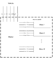
图2是本发明实施例提供的一种车辆应用场景下电机控制系统的系统框图;2 is a system block diagram of a motor control system in a vehicle application scenario provided by an embodiment of the present invention;
图3是实现本发明实施例提供的电机控制方法时对应的硬件电路框图;3 is a block diagram of the corresponding hardware circuit when implementing the motor control method provided by the embodiment of the present invention;
图4是本发明实施例提供的电机控制方法的一种应用场景中系统状态跳转示意图;4 is a schematic diagram of system state transition in an application scenario of the motor control method provided by an embodiment of the present invention;
图5是本发明实施例提供的电机控制方法中主控制模型的架构图;FIG. 5 is an architecture diagram of a main control model in a motor control method provided by an embodiment of the present invention;
图6是本发明实施例提供的电机控制方法中子控制模型的架构图;Fig. 6 is an architecture diagram of a neutron control model of a motor control method provided by an embodiment of the present invention;
图7是本发明实施例提供的电机控制方法中主控制模型的输入-输出示意图;FIG. 7 is a schematic diagram of the input-output of the main control model in the motor control method provided by the embodiment of the present invention;
图8是本发明实施例提供的一种电机控制装置的结构框图;Figure 8 is a structural block diagram of a motor control device provided by an embodiment of the present invention;
图9是本发明实施例提供的另一种电机控制装置的结构框图;9 is a structural block diagram of another motor control device provided by an embodiment of the present invention;
图10是本发明实施例提供的再一种电机控制装置的结构框图。Fig. 10 is a structural block diagram of still another motor control device provided by an embodiment of the present invention.
为使本发明实施例的目的、技术方案和优点更加清楚,下面将结合本发明实施例中的附图,对本发明实施例中的技术方案进行清楚、完整地描述,显然,所描述的实施例是本发明一部分实施例,而不是全部的实施例。基于本发明中的实施例,本领域普通技术人员在没有做出创造性劳动前提下所获得的所有其他实施例,都属于本发明保护的范围。In order to make the objectives, technical solutions, and advantages of the embodiments of the present invention clearer, the technical solutions in the embodiments of the present invention will be described clearly and completely in conjunction with the accompanying drawings in the embodiments of the present invention. Obviously, the described embodiments It is a part of the embodiments of the present invention, not all the embodiments. Based on the embodiments of the present invention, all other embodiments obtained by those of ordinary skill in the art without creative work shall fall within the protection scope of the present invention.
本发明实施例提供的电机控制方法,应用于电机控制系统中的控制器,该电机控制系统包括一个控制器、至少两个电机,且每一电机对应一驱动实体。该电机控制系统可以根据具体应用的场景不同而做出相应的调整,比如,应用在汽车天窗控制系统或车窗控制系统中时,各个电机即为汽车天窗控制系统或车窗控制系统中所设置的驱动电机,相应的,与电机对应的驱动实体即为天窗/车窗玻璃或遮阳帘,当然,还包括其他为实现控制功能所必需设置的机构,比如用于发出操作指令的控制开关等。The motor control method provided by the embodiment of the present invention is applied to a controller in a motor control system. The motor control system includes a controller and at least two motors, and each motor corresponds to a driving entity. The motor control system can be adjusted according to the specific application scenarios. For example, when it is used in a car sunroof control system or a car window control system, each motor is set in the car sunroof control system or car window control system Correspondingly, the driving entity corresponding to the motor is the sunroof/window glass or sunshade. Of course, it also includes other mechanisms necessary to achieve control functions, such as control switches for issuing operating instructions.
参见图1,图1是本发明实施例提供的一种电机控制方法的流程图,结合图1所示,该流程可以包括:Referring to Fig. 1, Fig. 1 is a flowchart of a motor control method provided by an embodiment of the present invention. As shown in conjunction with Fig. 1, the process may include:
步骤S100,获取当前时间的控制命令、各驱动实体的位置关系以及上一程序周期结束后的系统状态。Step S100: Obtain the current time control command, the position relationship of each driving entity, and the system state after the previous program cycle ends.
可选的,为实现本发明实施例提供的电机控制方法,需要对电机控制系统的硬件控制线路进行针对性的改进。这里以本发明实施例提供的电机控制方法在应用场景为车辆时的电机控制系统为例进行说明,参见图2,图2是本发明实施例提供的一种车辆应用场景下电机控制系统的系统框图,可以看出,在本系统框中,控制器是唯一的,与控制器相连的电机有多个。为便于表述,在本发明实施例中,对图2所示的硬件连接关系,称之为Master-Slave模式(主-从模式)。Optionally, in order to implement the motor control method provided by the embodiment of the present invention, the hardware control circuit of the motor control system needs to be improved in a targeted manner. Here, the motor control method provided by the embodiment of the present invention is described as an example of a motor control system when the application scenario is a vehicle. Refer to FIG. 2, which is a system of a motor control system in a vehicle application scenario provided by an embodiment of the present invention. From the block diagram, it can be seen that in this system frame, the controller is unique, and there are multiple motors connected to the controller. For ease of presentation, in the embodiment of the present invention, the hardware connection relationship shown in FIG. 2 is referred to as the Master-Slave mode (master-slave mode).
具体的,如果控制器直接与多个电机中的任一电机安装在一起,则与控制器相连的电机和控制器一并作为Master,并且该与控制器相连的电机称为Master电机,其他电机通过线束与控制器相连,则称为Slave电机,这种设置方式可以称为集成式连接。Specifically, if the controller is directly installed with any one of the multiple motors, the motor connected to the controller and the controller together serve as the Master, and the motor connected to the controller is called the Master motor, and the other motors Connected to the controller through a wire harness is called a Slave motor, and this setting can be called an integrated connection.
如果控制器独立设置,不与任一电机直接相连,则控制器即为Master,各个电机均通过线束连接至控制器,作为Slave电机,这种设置方式称为主控式连接。If the controller is set independently and not directly connected to any motor, the controller is the Master, and each motor is connected to the controller through a wire harness as a slave motor. This setting method is called master connection.
无论采用何种连接方式,控制器均设置有一个,电机则设置有多个,具体的设置数量因具体应用的电机控制系统而定。此外,图2所示实施例中还示例性的给出控制器与其他构成部分的连接情况,图中以车窗控制系统为例,给出控制器作为Master与车辆Vehicle之间的连接,以及Master控制器与各电机(图中以Slave1-SlaveN示出)的连接情况。需要说明的是,图2中示出的连接线路,如电源线Battery、地线GND、车辆信号Vehicle Signal、局域互联网络Lin总线以及和Slave电机相连的驱动线路Drive Wire、供电线路Power Wire、信号线路Signal Wire等,均是示例性给出连接关系,具体连接情况应视具体应用场景而定。需要着重说明的是,图中控制器与车辆之间仅设置一个开关Switch连接,但在实际设置中,必然会存在多个开关分别与控制器相连,用于分别控制不同的电机动作。No matter which connection method is adopted, there is one controller and multiple motors. The specific number of settings depends on the motor control system of the specific application. In addition, the embodiment shown in Figure 2 also exemplarily shows the connection between the controller and other components. In the figure, taking the window control system as an example, the controller is shown as the connection between the Master and the vehicle, and Master controller and each motor (shown as Slave1-SlaveN in the figure) connection status. It should be noted that the connection lines shown in Figure 2, such as the power line Battery, ground line GND, vehicle signal Vehicle Signal, local interconnection network Lin bus, and the drive line Drive Wire connected to the Slave motor, power supply line Power Wire, Signal lines, Signal, Wire, etc., are all examples of connection relationships, and the specific connection conditions should depend on the specific application scenarios. It should be emphasized that, in the figure, there is only one switch connection between the controller and the vehicle, but in the actual setting, there are bound to be multiple switches connected to the controller respectively to control different motor actions.
可选的,参见图3,图3是实现本发明实施例提供的电机控制方法时对应的硬件电路框图。图3给出了以车窗控制系统为例,采用集成式连接方式时,电机控制系统各组成部分之间的连接关系。Optionally, refer to FIG. 3, which is a block diagram of the corresponding hardware circuit when implementing the motor control method provided by the embodiment of the present invention. Figure 3 shows the connection relationship between the various components of the motor control system when the integrated connection mode is adopted for the car window control system.
具体的,硬件电路设计包括但不限于下述构成部分:电源电路、控制器(图3中以MCU电路为例)及其周边电路、外部信号采集电路、Slave驱动电路以及 Slave信号处理电路,其中,如前所述,Slave1-SlaveN用于表示各电机,以及与各电机相连的各类电路。比如,Slave1信号处理电路则表示电机1的所对应的信号处理电路,以此类推,其余电路此处不再赘述。Master电机表示与控制器直接相连的电机,相应的,Master驱动电路和Master信号处理电路用于实现Master电机与控制器之间的具体连接。Specifically, the hardware circuit design includes but is not limited to the following components: a power supply circuit, a controller (in Figure 3, the MCU circuit is taken as an example) and its peripheral circuits, an external signal acquisition circuit, a Slave drive circuit, and a Slave signal processing circuit. , As mentioned earlier, Slave1-SlaveN is used to represent each motor and various circuits connected to each motor. For example, the Slave1 signal processing circuit represents the corresponding signal processing circuit of the motor 1, and so on, and the rest of the circuits will not be repeated here. Master motor refers to the motor directly connected to the controller. Correspondingly, the Master drive circuit and the Master signal processing circuit are used to realize the specific connection between the Master motor and the controller.
电源电路与车辆Vehicle之间示例性的通过电源线Battery以及地线GND连接,电源电路主要用于从外部获取电能,比如车辆设置的蓄电池等,并将获取得到的电能转换为控制器可用的电压等级,保证控制器的正常工作。同时,检测供电电压是否满足预设的使用要求,防止控制器被异常的输入电压烧毁,当然,电源电路还应该能够实现其他必须的功能,此处不再赘述。The power circuit and the vehicle are exemplarily connected by the power line Battery and the ground line GND. The power circuit is mainly used to obtain electrical energy from the outside, such as the battery installed in the vehicle, and convert the obtained electrical energy into the voltage available to the controller Level to ensure the normal operation of the controller. At the same time, it detects whether the power supply voltage meets the preset usage requirements to prevent the controller from being burned by the abnormal input voltage. Of course, the power supply circuit should also be able to implement other necessary functions, which will not be repeated here.
控制器用于在获取的各种信号后,根据预设控制逻辑向Master电机及各Slave电机输出驱动控制指令,控制Master电机和各Slave电机动作。The controller is used to output drive control instructions to the Master motor and each Slave motor according to the preset control logic after acquiring various signals, and control the actions of the Master motor and each Slave motor.
外部信号采集电路与车辆Vehicle之间设置有开关Switch连接线路、局域互联网络Lin总线、以及实现车速信息采集、远程控制等功能的连接线路。外部信号采集电路是用于获取来自车辆(Vehicle)的电信号的处理电路。该电路可以将来自整车部分的电信号进行处理,成为控制器可接收的信号并传输给控制器电路。需要说明的是,任何控制器以外的信号采集电路都是外部信号采集电路。Between the external signal acquisition circuit and the vehicle, a switch connection line, a local interconnection network Lin bus, and a connection line for realizing vehicle speed information collection, remote control and other functions are provided. The external signal acquisition circuit is a processing circuit used to acquire electrical signals from a vehicle. This circuit can process the electrical signal from the whole vehicle part and turn it into a signal that the controller can receive and transmit it to the controller circuit. It should be noted that any signal acquisition circuit other than the controller is an external signal acquisition circuit.
Slave驱动电路(图3中示例性的给出Slave 1和Slave N的驱动电路)是用于实现驱动Slave电机运动的相关电路。该电路可以通过功率器件将控制器输出的控制信号(即驱动控制指令)转换成大功率电能输出并通过线束驱动Slave电机运行。每个Slave电机在控制器上都有一套独立的Slave驱动电路。The Slave driving circuit (the driving circuit of Slave 1 and Slave N is shown as an example in FIG. 3) is a related circuit used to drive the motion of the Slave motor. The circuit can convert the control signal (ie, drive control command) output by the controller into a high-power electric energy output through the power device and drive the Slave motor to run through the wire harness. Each Slave motor has an independent Slave drive circuit on the controller.
Slave信号处理电路(图3中示例性的给出Slave1和Slave N对应的信号处理电路)是用于采集并处理电机反馈信号的相关电路。该电路可以采集Slave电机的反馈信号并处理成控制器可接收的信号类型并传送给控制器用于逻辑控制。每个Slave电机在控制器上都有一套独立的Slave信号处理电路。The Slave signal processing circuit (the signal processing circuit corresponding to Slave1 and Slave N is shown as an example in FIG. 3) is a related circuit used to collect and process motor feedback signals. The circuit can collect the feedback signal of the Slave motor and process it into a signal type that the controller can receive and send it to the controller for logic control. Each Slave motor has an independent Slave signal processing circuit on the controller.
Master电机的驱动电路和信号处理电路与Slave电机的驱动电路及信号处理电路的功能相同,此处不再赘述。The drive circuit and signal processing circuit of the Master motor have the same functions as the drive circuit and signal processing circuit of the Slave motor, and will not be repeated here.
在建立上述硬件连接关系后,控制器可以在同一程序周期内,采集各开关的状态信息,比如开关是否处于被按下,以及开关被按下的时间,按下的先后 顺序等信息,并进一步根据预设的开关状态与控制命令之间的对应关系,结合具体获取得到的开关状态,确定控制命令。同时,还可获取各驱动实体之间的位置关系,具体的,可以是通过相对于预设坐标原点的距离表征的前后关系,或者是各驱动实体与预设坐标原点之间的实际距离等,当应用于车辆的车窗控制系统时,各驱动实体的位置关系,还可以通过各驱动实体的开度表示。After establishing the above-mentioned hardware connection relationship, the controller can collect the status information of each switch in the same program cycle, such as whether the switch is being pressed, the time when the switch is pressed, the sequence of pressing, etc., and further According to the corresponding relationship between the preset switch state and the control command, the control command is determined in combination with the specifically obtained switch state. At the same time, the positional relationship between the driving entities can also be obtained. Specifically, it can be the front-to-back relationship characterized by the distance from the origin of the preset coordinates, or the actual distance between the driving entities and the origin of the preset coordinates, etc. When applied to a vehicle window control system, the positional relationship of each driving entity can also be expressed by the opening degree of each driving entity.
进一步的,控制器还需要获取上一程序周期结束后的系统状态,该上一程序周期结束后的系统状态中记录了上一程序周期结束后各电机的运动状态,比如各电机是否处于运转状态,运转的方向是正转还是反转等。需要说明的是,在任一程序周期中,对于任一电机而言,其运动状态可以发生变化,也可能不发生变化,但只有在该程序周期结束时各电机的运动状态才能够作为该程序周期的系统状态。在进入新的程序周期时,上一程序周期的系统状态将作为当前程序周期的初始系统状态,因此,在获取当前时间的控制命令、各驱动实体的位置关系的同时,还需要获取在上一程序周期结束后的系统状态。Further, the controller also needs to obtain the system status after the end of the previous program cycle. The system status after the end of the previous program cycle records the movement status of each motor after the end of the previous program cycle, such as whether each motor is running , Whether the direction of rotation is forward or reverse, etc. It should be noted that in any program cycle, for any motor, its motion state may or may not change, but only at the end of the program cycle can the motion state of each motor be regarded as the program cycle System status. When entering a new program cycle, the system state of the previous program cycle will be used as the initial system state of the current program cycle. Therefore, while obtaining the control commands at the current time and the positional relationship of each driving entity, you also need to obtain the previous The state of the system after the end of the program cycle.
步骤S110,根据预设映射关系和各驱动实体的位置关系,确定在控制命令下,上一程序周期结束后的系统状态对应的目标系统状态。Step S110: Determine the target system state corresponding to the system state after the end of the previous program cycle under the control command according to the preset mapping relationship and the position relationship of each driving entity.
本发明实施例提供的电机控制方法,设置有预设映射关系,该预设映射关系用于表征各系统状态之间的跳转关系和跳转条件。对于同一种当前的系统状态,跳转条件的不同,会使系统状态发生不同的跳转。The motor control method provided by the embodiment of the present invention is provided with a preset mapping relationship, and the preset mapping relationship is used to characterize the jump relationship and jump conditions between the states of the various systems. For the same current system state, different jump conditions will cause different jumps to the system state.
如前所述,系统状态用于表征各电机的运动状态。可选的,可以通过构建状态机的方式定义各电机不同运动状态的组合,得到多个系统状态,即状态机中的状态。同时,用状态机体现各系统状态之间的跳转关系和跳转条件,即用状态机具体表示前述预设映射关系。As mentioned earlier, the system status is used to characterize the motion status of each motor. Optionally, a combination of different motion states of each motor can be defined by constructing a state machine to obtain multiple system states, that is, the states in the state machine. At the same time, the state machine is used to reflect the jump relationship and jump conditions between the states of the systems, that is, the state machine is used to specifically express the aforementioned preset mapping relationship.
可选的,以车辆天窗控制系统(设置有天窗玻璃和遮阳帘,且二者均为电控部件)为例,说明本发明实施例中设置系统状态的核心思想。Optionally, take the vehicle sunroof control system (with sunroof glass and sunshade curtain, and both are electronic control components) as an example to illustrate the core idea of setting the system state in the embodiment of the present invention.
由于现有设计中,遮阳帘大都采用软性材料,为保证遮阳帘不受风阻等因素的影响,往往要求遮阳帘的开度永远大于天窗玻璃的开度。因此,在控制逻辑的设计中,需要考虑二者的联动控制关系。在对天窗玻璃和遮阳帘进行联动控制时,可以分为两种主要的控制类型:Since most of the sun blinds in existing designs are made of soft materials, in order to ensure that the sun blind is not affected by wind resistance and other factors, it is often required that the opening of the sun blind is always greater than the opening of the skylight glass. Therefore, in the design of control logic, the linkage control relationship between the two needs to be considered. In the linkage control of skylight glass and sun shade, it can be divided into two main types of control:
A类型:天窗玻璃打开之前,遮阳帘先打开到与天窗玻璃完全打开时对应的位置(一般为车顶中部位置);遮阳帘关闭之前,天窗玻璃先完全关闭,待天窗玻璃完全关闭之后,再控制遮阳帘关闭。Type A: Before the sunroof glass is opened, the sunshade is opened to the position corresponding to when the sunroof glass is fully opened (usually the middle position of the roof); before the sunshade is closed, the sunroof glass is completely closed first, and then the sunroof glass is completely closed. Control the sunshade to close.
B类型:需要首先比较天窗玻璃和遮阳帘之间的位置关系。天窗玻璃打开之前,如果遮阳帘的开度小于(天窗玻璃开度+预设裕量),其中,预设裕量是指控制逻辑制定时,天窗玻璃与遮阳帘之间的间隔距离,则遮阳帘先运动到(天窗玻璃开度+预设裕量)所对应的位置,然后天窗玻璃开始与遮阳帘一同打开。如果遮阳帘开度大于(天窗玻璃开度+预设裕量),特别是遮阳帘开度远大于(天窗玻璃开度+预设裕量)时(此种工况对应于:天窗控制系统先执行遮阳帘打开命令,遮阳帘移动一段距离后停止,此时遮阳帘并未完全打开,然后天窗控制系统收到并执行天窗玻璃完全打开指令),如前所述,天窗玻璃的开度不能大于遮阳帘开度,因此,天窗玻璃先运动到(遮阳帘开度-预设裕量)所对应的位置,然后遮阳帘与天窗玻璃一同打开。相应的,遮阳帘关闭或者遮阳帘和天窗玻璃联动关闭时,也有类似的对称逻辑。比如,关闭遮阳帘时,如果遮阳帘开度小于(天窗玻璃开度+预设裕量),则天窗玻璃先运动到(遮阳帘开度-预设裕量)对应的位置,然后天窗玻璃开始与遮阳帘一同关闭。如果遮阳帘开度大于(天窗玻璃开度+预设裕量),则遮阳帘先运动到(天窗玻璃开度+预设裕量)所对应位置,然后天窗玻璃开始与遮阳帘一同关闭。Type B: It is necessary to first compare the positional relationship between the sunroof glass and the sunshade. Before the sunroof glass is opened, if the opening of the sunshade is less than (sunroof glass opening + preset margin), the preset margin refers to the separation distance between the sunroof glass and the sunshade when the control logic is formulated, then the sunshade The curtain moves to the position corresponding to (opening degree of sunroof glass + preset margin), and then the sunroof glass starts to open together with the sun shade. If the sunshade opening is greater than (sunroof glass opening + preset margin), especially when the sunshade opening is much greater than (sunroof glass opening + preset margin) (this working condition corresponds to: sunroof control system first Execute the sunshade opening command, and the sunshade will stop after moving for a certain distance. At this time, the sunshade is not fully opened, and then the sunroof control system receives and executes the sunroof glass fully open instruction). As mentioned above, the opening of the sunroof cannot be greater than The opening degree of the sunshade, therefore, the sunroof glass first moves to the position corresponding to (sunshade opening-preset margin), and then the sunshade and sunroof glass are opened together. Correspondingly, when the sun shade is closed or the sun shade and skylight glass are closed in conjunction, there is a similar symmetrical logic. For example, when closing the sunshade, if the sunshade opening is smaller than (sunroof glass opening + preset margin), the sunroof glass will first move to the position corresponding to (sunshade opening-preset margin), and then the sunroof glass will start Close together with the sunshade. If the sunshade opening is greater than (sunroof glass opening + preset margin), the sunshade first moves to the position corresponding to (sunroof glass opening + preset margin), and then the sunroof glass starts to close together with the sunshade.
可以想到的是,在B类型的控制逻辑设计中,前提是保证遮阳帘的开度永远大于天窗玻璃开度,不论是在打开过程还是关闭过程,如果二者之间的距离不满足该前提,则控制二者之一先移动一段距离,直至满足该前提。It is conceivable that in the B-type control logic design, the premise is to ensure that the opening of the sunshade is always greater than the opening of the sunroof glass, whether in the opening process or the closing process, if the distance between the two does not meet the premise, Then control one of the two to move a certain distance until the premise is met.
需要说明的是,由于电机与驱动实体之间具有一一对应的关系,在上述构建系统状态的过程中,为便于表述,均以驱动实体之间具体的位置关系、以及驱动实体的运动过程,对各系统状态的定义加以区分,但可以想到的是,各系统状态在实质上还是结合各驱动实体的位置关系,对各电机的运动状态所做的定义。It should be noted that since there is a one-to-one correspondence between the motor and the driving entity, in the above process of constructing the system state, in order to facilitate the expression, the specific positional relationship between the driving entities and the movement process of the driving entities are used. The definition of each system state is distinguished, but it is conceivable that each system state is actually a definition of the motion state of each motor in combination with the position relationship of each driving entity.
基于上述内容,在本发明实施例应用于车辆的天窗/车窗控制系统时,可以得出多种由各电机的运动状态定义的系统状态。Based on the foregoing, when the embodiment of the present invention is applied to a sunroof/window control system of a vehicle, a variety of system states defined by the motion states of each motor can be obtained.
具体的,参见图4,图4是本发明实施例提供的电机控制方法的一种应用场景中系统状态跳转示意图,图中示出以前述B控制类型中打开天窗玻璃和/或遮 阳帘为例,可以定义出的几种系统状态,以及各系统状态之间的跳转关系及跳转条件(包括但不限于此)。其中,G-Cmd表示天窗玻璃的控制指令,R-Cmd表示遮阳帘的控制指令,Freeze表示对应的控制指令无效或为空指令,Open表示对应的控制指令有效。Specifically, referring to Fig. 4, Fig. 4 is a schematic diagram of system state jump in an application scenario of the motor control method provided by an embodiment of the present invention. The figure shows that opening the sunroof glass and/or sunshade in the aforementioned B control type is For example, several system states that can be defined, as well as the jump relationships and jump conditions between the system states (including but not limited to this). Among them, G-Cmd represents the control command of the sunroof glass, R-Cmd represents the control command of the sunshade, Freeze represents the corresponding control command is invalid or empty, and Open represents the corresponding control command is valid.
Idle(静止,天窗玻璃和遮阳帘都处于静止状态);Idle (stationary, the sunroof glass and sunshade are in a stationary state);
G-Opening(天窗玻璃打开);G-Opening (open skylight glass);
R-Opening(遮阳帘打开,天窗玻璃不处于等待遮阳帘运动的状态);R-Opening (the sunshade is open, and the sunroof glass is not in a state of waiting for the sunshade to move);
G-R-Opening(天窗玻璃和遮阳帘都打开,A类型中没有此状态);G-R-Opening (sunroof glass and sun blinds are both open, there is no such state in Type A);
R-Opening-G-Holding(遮阳帘打开,天窗玻璃等待遮阳帘运动到指定位置);R-Opening-G-Holding (the sunshade is opened, and the sunroof glass waits for the sunshade to move to the designated position);
G-Opening-R-Holding(天窗玻璃打开,遮阳帘等待天窗玻璃运动到指定位置,A类型中没有此状态)。G-Opening-R-Holding (the sunroof glass is opened, the sunshade waits for the sunroof glass to move to the specified position, there is no such state in Type A).
进一步的,根据预设映射关系,具体由图4所示的系统状态跳转示意图表示,以及各驱动实体的位置关系,确定在控制命令下,上一程序周期结束后的系统状态对应的目标系统状态。如前所述,上一程序周期结束后的系统状态可以直接获取得到,各驱动实体的位置关系可以在当前程序周期开始时获取得到,结合图4示出的跳转关系,即可确定在当前时间的控制命令下,与上一程序周期结束后的系统状态相对应的目标系统状态。Further, according to the preset mapping relationship, specifically represented by the system state jump schematic diagram shown in Figure 4, and the positional relationship of each driving entity, the target system corresponding to the system state after the previous program cycle is determined under the control command status. As mentioned earlier, the system status after the last program cycle can be obtained directly, and the positional relationship of each driving entity can be obtained at the beginning of the current program cycle. Combined with the jump relationship shown in Figure 4, it can be determined that the current Under the time control command, the target system status corresponding to the system status after the end of the previous program cycle.
具体的,图4中的每一个箭头代表一种状态跳转,都需要满足相应的条件才能触发。比如,根据前述步骤,确定上一程序周期结束后的系统状态处于Idle状态,同时,在当前程序周期内,获取到遮阳帘打开的命令,那么根据图4所示的预设映射关系中定义的系统状态跳转关系,目标系统状态应为R-Opening;再比如,当前时刻的控制命令为打开玻璃,根据各天窗玻璃和遮阳帘的位置关系确定遮阳帘的开度达到(天窗玻璃开度+预设裕量),且在上一程序周期结束后,遮阳帘的开度小于(天窗玻璃开度+预设裕量),即系统状态为R-Opening-G-Holding,结合预设映射关系,即可确定目标系统状态为G-R-Opening。Specifically, each arrow in FIG. 4 represents a state transition, which needs to meet corresponding conditions to trigger. For example, according to the foregoing steps, it is determined that the system state after the end of the previous program cycle is in the Idle state. At the same time, in the current program cycle, the command to open the sunshade is obtained, then according to the preset mapping relationship defined in Figure 4 The system status jump relationship, the target system status should be R-Opening; for another example, the control command at the current moment is to open the glass, according to the position relationship between the sunroof glass and the sunshade, the opening degree of the sunshade is determined to reach (sunroof glass opening + Preset margin), and after the last program cycle, the opening of the sunshade is less than (sunroof glass opening + preset margin), that is, the system state is R-Opening-G-Holding, combined with the preset mapping relationship , You can determine that the target system status is GR-Opening.
通过上述示例可以看出,预设映射关系同样是基于前述两种控制类型(即A类型和B类型)制定的,同样能够满足遮阳帘的开度永远大于天窗玻璃开度这一前提条件。It can be seen from the above example that the preset mapping relationship is also based on the aforementioned two control types (namely, type A and type B), which can also meet the precondition that the opening of the sunshade is always greater than the opening of the sunroof glass.
对于A类型来说,其预设映射关系的架构与B类型基本类似,其不同之处在于,A类型不存在G-Opening-R-Holding和G-R-Opening两种系统状态,同时,R-Opening-G-Holding状态和G-Opening状态之间存在状态跳转关系。具体的,处于R-Opening-G-Holding状态的系统,收到“遮阳帘已经到达车顶中部位置”的跳转条件时,目标系统状态即确定为G-Opening。其他状态跳转A类型与B类型类似,此处不再赘述。For Type A, the architecture of its preset mapping relationship is basically similar to Type B. The difference is that Type A does not have two system states: G-Opening-R-Holding and GR-Opening. At the same time, R-Opening -There is a state jump relationship between the G-Holding state and the G-Opening state. Specifically, when the system in the R-Opening-G-Holding state receives the jump condition of "the sunshade has reached the middle position of the roof", the target system state is determined to be G-Opening. The other state transition type A is similar to type B, and will not be described here.
根据实际情况来看,多电机控制系统的关键问题往往发生在状态跳转的时刻。与现有技术中的控制方法相比,在每个程序执行周期,系统状态只会存在一次跳转(或者不发生跳转,不发生跳转的情况也可以理解为当前时间的系统状态与目标系统状态为同一系统状态),而确定当前时间的系统状态所需参量与确定目标系统状态所需参量,都是在同一程序周期内获得的,不同的控制目标(如天窗玻璃和遮阳帘)之间是完全平等的,任一目标的控制不依赖于前一程序周期的执行结果,任一目标的运动状态和位置信息都可以在当前程序周期内对系统状态产生影响,没有滞后性,因此更容易进行调试分析。According to the actual situation, the key problem of the multi-motor control system often occurs at the moment of state transition. Compared with the control method in the prior art, in each program execution cycle, the system state only has one jump (or no jump occurs, and the situation that no jump occurs can also be understood as the current time system state and target The system status is the same system status), and the parameters required to determine the current time system status and the parameters required to determine the target system status are obtained in the same program cycle. Different control targets (such as sunroof glass and sunshade) The control of any target does not depend on the execution result of the previous program cycle. The motion state and position information of any target can affect the system state in the current program cycle without hysteresis. Easy to debug and analyze.
步骤S120,根据目标系统状态,确定目标控制指令。Step S120: Determine the target control instruction according to the target system state.
由前述内容可知,系统状态是由电机的运动状态定义的,因此,在确定目标系统状态之后,即可确定目标系统状态之中各电机的目标运动状态,亦即得知具体需要动作的电机以及相应电机的具体转动方向、与电机对应的驱动实体,不需要动作的电机,从而得到针对每一个电机的目标控制指令。It can be seen from the foregoing that the system state is defined by the motor's motion state. Therefore, after the target system state is determined, the target motion state of each motor in the target system state can be determined, that is, the specific motor that needs to be actuated and Corresponding to the specific rotation direction of the motor, the driving entity corresponding to the motor, and the motor that does not need to act, the target control instruction for each motor is obtained.
步骤S130,根据目标控制指令控制各电机动作。Step S130, controlling the actions of each motor according to the target control command.
在得到目标控制指令之后,即可控制各电机动作。可以想到的是,目标控制指令中可以包括空指令,收到空指令的电机则不需要动作。After obtaining the target control instruction, the actions of each motor can be controlled. It is conceivable that the target control command can include a null command, and the motor that receives the null command does not need to act.
本发明实施例提供的电机控制方法,一个控制器对应多个电机,同时通过用系统状态来表征所有电机的运动状态,且预先建立了表征各系统状态之间的跳转关系和跳转条件的预设映射关系的方式实现控制器对所有电机的控制,与现有技术相比,在硬件方面,通过一个控制器就可以实现对各电机的控制,减少了控制器的使用数量,在软件方面,由于用系统状态来表征所有电机的运动状态,用预设映射关系来表征各系统状态之间的跳转关系和跳转条件,不需要针对每一个电机设计控制程序,进而实现可以降低控制系统的硬件成本以及软件开发成本。In the motor control method provided by the embodiment of the present invention, one controller corresponds to multiple motors, and at the same time, the system states are used to characterize the motion states of all motors, and the jump relationship and jump conditions between the system states are established in advance. The preset mapping relationship is used to realize the controller's control of all motors. Compared with the prior art, in terms of hardware, one controller can realize the control of each motor, which reduces the number of controllers used. In terms of software , Because the system state is used to characterize the motion state of all motors, and the preset mapping relationship is used to characterize the jump relationship and jump conditions between the system states, there is no need to design a control program for each motor, which can reduce the control system The cost of hardware and software development.
需要说明的是,上述各步骤都是在同一程序周期内执行的,这意味着,在实际控制驱动实体达到某一指定位置工程中,比如控制车窗玻璃由闭合至完全打开,需要经历多个程序周期才能完成,通过循环的执行上述步骤,最终达到预期的控制目的。It should be noted that the above steps are executed in the same program cycle, which means that in the actual control of the drive entity to reach a specified position, for example, the control of the window glass from closed to fully opened requires multiple The program cycle can only be completed, and the expected control purpose is finally achieved by cyclically executing the above steps.
进一步需要说明的是,在接收到新的控制命令之前,为保证当前时间的控制命令能够有效的执行,需要对当前时间的控制命令的时效性进行限定,具体的限定方法可以采用现有技术中的方法实现,本发明对此不做限定。It should be further explained that before receiving a new control command, in order to ensure that the control command at the current time can be effectively executed, the timeliness of the control command at the current time needs to be limited. The specific limitation method can be adopted in the prior art. The method is not limited in the present invention.
在电机控制系统的应用场景中,大都有人的参与,为保证参与者的人身安全以及电机控制系统中相关设备的安全,电机控制系统往往都设置有高优先级的控制功能,比如,可以控制电机急停的功能,控制电机减速的功能等。In the application scenarios of motor control systems, most people are involved. In order to ensure the personal safety of participants and the safety of related equipment in the motor control system, the motor control system is often set with high priority control functions, for example, it can control the motor Emergency stop function, control motor deceleration function, etc.
具体的,在汽车的天窗控制系统中,天窗防夹功能和电机的热保护功能,即为高优先级的控制功能。以天窗防夹功能为例,在天窗玻璃和/或遮阳帘执行关闭命令时,如果根据预设控制逻辑检测到有障碍物存在,比如人手,或者其他预设触发条件时,即执行高优先级的天窗防夹功能,防止天窗玻璃和/或遮阳帘对障碍物造成伤害,而正在执行的关闭命令则不会再执行。Specifically, in the sunroof control system of an automobile, the sunroof anti-pinch function and the thermal protection function of the motor are high-priority control functions. Take the sunroof anti-pinch function as an example. When the sunroof glass and/or sunshade are closed, if an obstacle is detected according to the preset control logic, such as human hands, or other preset trigger conditions, high priority will be executed The sunroof anti-pinch function prevents the sunroof glass and/or sunshade from causing damage to obstacles, and the closing command being executed will not be executed again.
为实现上述功能,现有技术中大都为每一电机设计对应的、独立的控制逻辑,即为每一个电机设置对应的控制模型。如果在此基础上,通过一个控制器控制多个电机的运转,就需要在控制器中加载每一个电机所对应的控制模型,这无疑会使得控制器中的控制算法复杂化,大量的代码将占用控制器大量的存储空间及其他资源,为保证控制功能的正常工作,必然要提高对控制器性能的要求,造成设计成本的增加,这显然是本领域技术人员不希望看到的。同时,控制模型中的部分子功能可能会遇到问题而进行升级改动,由于整个控制模型的代码是整体编辑的,部分功能的改进将导致整个控制模型随之改动,这样不仅不利于模型升级维护和平台化,而且工作量巨大。In order to realize the above functions, most of the prior art designs corresponding and independent control logic for each motor, that is, sets a corresponding control model for each motor. If on this basis, a controller controls the operation of multiple motors, it is necessary to load the control model corresponding to each motor in the controller, which will undoubtedly complicate the control algorithm in the controller, and a large amount of code will Occupying a large amount of storage space and other resources of the controller, in order to ensure the normal operation of the control function, the performance requirements of the controller must be increased, resulting in an increase in design cost, which is obviously undesirable for those skilled in the art. At the same time, some sub-functions in the control model may encounter problems and be upgraded and changed. Since the code of the entire control model is edited as a whole, the improvement of some functions will cause the entire control model to be changed, which is not conducive to model upgrade and maintenance. And platformization, and the workload is huge.
发明人研究发现,对于车窗防夹、热保护这类高优先级的控制功能,虽然应用于每个独立的电机,但控制模型的控制逻辑和最终实现的控制功能都是相同的,只是需要配置的参数不同(即具体的控制对象不同)。基于此发现,本发明实施例提供另一种电机控制方法。The inventor’s research found that, although high-priority control functions such as car window anti-trapping and thermal protection are applied to each independent motor, the control logic of the control model and the final control function are the same, but only need The configured parameters are different (that is, the specific control objects are different). Based on this finding, the embodiment of the present invention provides another motor control method.
在前述实施例的基础上,按预设周期调用预设的主控制模型,然后获取主 控制模型中预设输入参量的参量值,在得到对应的参量值之后,将所得参量值赋予对应的预设输入参量,主控制模型根据得到的参量值输出对应的功能控制指令,根据所得功能控制指令和前述目标控制指令得到总控制指令,进而根据总控制指令控制各电机动作。On the basis of the foregoing embodiment, the preset main control model is called according to the preset cycle, and then the parameter value of the preset input parameter in the main control model is obtained. After the corresponding parameter value is obtained, the obtained parameter value is assigned to the corresponding preset Assuming input parameters, the main control model outputs corresponding function control commands according to the obtained parameter values, obtains the overall control commands according to the obtained function control commands and the aforementioned target control commands, and then controls the actions of the motors according to the overall control commands.
可选的,在根据所得功能控制指令和前述目标控制指令得到总控制指令时,可以预设各指令的优先级,根据预设的优先级,将筛选得到优先级较高的指令作为总控制指令。Optionally, when the general control command is obtained according to the obtained function control command and the aforementioned target control command, the priority of each command can be preset, and the command with higher priority can be selected as the general control command according to the preset priority. .
需要说明的是,考虑到主控制模型所实现的控制功能多是优先级较高的,因此,调用主控制模型的预设周期可以长于前述实施例中给出的控制方法的执行周期,保证能够定期调用主控制模型,并执行对应控制功能即可。并且,本发明实施例提供的主控制模型为控制系统中,每一个电机都具有的控制功能所对应的控制模型,即针对每个电机,都会用到该主控制模型以实现对应的控制功能。It should be noted that, considering that most of the control functions implemented by the main control model are of higher priority, the preset period for calling the main control model can be longer than the execution period of the control method given in the foregoing embodiment to ensure that Call the main control model regularly and execute the corresponding control functions. Moreover, the main control model provided by the embodiment of the present invention is a control model corresponding to the control function of each motor in the control system, that is, for each motor, the main control model is used to realize the corresponding control function.
可选的,参见图5,图5是本发明实施例提供的电机控制方法中主控制模型的架构图。图5展示了主控制模型的总体架构,可以看出,主控制模型包括多个参考模型,且每一参考模型对应一个电机。同时,本发明实施例还设置一子控制模型,每一个参考模型都通过调用的方式与该子控制模型相关联。子控制模型包括多个关联接口,每一关联接口均通过调用的方式与一个对应的子功能模块相关联,而子功能模块具体用于实现该功能控制指令。基于该总体架构,在调用主控制模型后,遍历主控制模型中的每一个参考模型,并且,每一个参考模型都会调用子控制模型。主控制模型的预设输入参量是各参考模型的输入参量的集合,对主控制模型中的预设输入参量进行赋值,即是对每一参考模型所调用的子控制模型中对应的输入参量进行赋值,子控制模型调用子功能模型,进而得到相应的功能控制指令。其中,图5中的目标A、目标B、...、目标M,关联接口1、关联接口2、...、关联接口L,以及子功能模型1、子功能模型2、...、子功能模型L是示例性的,在实际应用中目标的数量及标识、关联接口的数量及标识和子功能模型的数量及标识根据实际需求确定。Optionally, refer to FIG. 5, which is an architecture diagram of a main control model in a motor control method provided by an embodiment of the present invention. Figure 5 shows the overall architecture of the main control model. It can be seen that the main control model includes multiple reference models, and each reference model corresponds to a motor. At the same time, the embodiment of the present invention also sets a sub-control model, and each reference model is associated with the sub-control model by calling. The sub-control model includes multiple associated interfaces, and each associated interface is associated with a corresponding sub-function module by calling, and the sub-function module is specifically used to implement the function control instruction. Based on this overall architecture, after calling the main control model, each reference model in the main control model is traversed, and each reference model calls the sub-control model. The preset input parameters of the main control model are the set of input parameters of each reference model. Assigning values to the preset input parameters in the main control model means to perform the corresponding input parameters in the sub-control model called by each reference model. Assignment, the sub-control model calls the sub-function model, and then obtains the corresponding function control instruction. Among them, target A, target B,..., target M in Figure 5, associated interface 1, associated interface 2,..., associated interface L, and sub-function model 1, sub-function model 2, ..., The sub-function model L is exemplary. In actual applications, the number and identification of targets, the number and identification of associated interfaces, and the number and identification of sub-function models are determined according to actual requirements.
进一步的,从主控制模型搭建的过程来看,在主控制模型搭建开始前,设计人员必然清楚的知道主控模型需要实现的控制功能具体包括的内容,因此,在搭建开始后,首先需要根据主控制器模型预期实现的功能建立各个子功能模 型。以车窗控制系统中的车窗防夹功能为例,为实现该车窗防夹功能,至少需要包括防夹区判断,位置提取,电压波动检测,学习和初始化,阈值选择,防夹力计算等子功能模型,即各子功能模型可以理解为系统中最基本的功能单元,执行子功能模型内具体的程序代码,即可实现对应的功能。Furthermore, from the perspective of the main control model construction process, before the main control model construction starts, the designer must clearly know the specific content of the control functions that the main control model needs to implement. Therefore, after the construction starts, first need to follow The functions expected to be realized by the main controller model establish various sub-function models. Take the window anti-pinch function in the window control system as an example. In order to realize the window anti-pinch function, at least it needs to include the anti-pinch area judgment, position extraction, voltage fluctuation detection, learning and initialization, threshold selection, and anti-pinch force calculation. Sub-function model, that is, each sub-function model can be understood as the most basic functional unit in the system, and the corresponding function can be realized by executing the specific program code in the sub-function model.
在编制所需的子功能模型之后,需要建立一个子控制模型,子控制模型可以理解为单个控制目标(即电机)的控制模型,与现有技术不同的是,不需要为每一个控制目标设置对应的子控制模型,而是在子控制模型中集成各控制目标共同的控制功能,每一控制目标都可以调用子控制模型,即子控制模型是可以共用的。进一步的,子控制模型中包括多个关联接口,每个关联接口关联相应的子功能模型。After compiling the required sub-function model, a sub-control model needs to be established. The sub-control model can be understood as a control model of a single control target (ie motor). Unlike the prior art, it is not necessary to set each control target. The corresponding sub-control model integrates the common control functions of each control target in the sub-control model. Each control target can call the sub-control model, that is, the sub-control model can be shared. Further, the sub-control model includes multiple associated interfaces, and each associated interface is associated with a corresponding sub-function model.
需要说明的是,关联接口实际的设置数量可以多于实际关联的子功能模型,在后续程序升级、出现新的子功能模型时,直接建立关联接口与子功能模型的调用关系即可,无需再配置相应的关联接口。关联接口的设置,可以使各子功能模型与子控制模型之间呈调用关系,子控制模型中并不真正的含有各子功能模型中的代码内容,这样,如果某一子功能模型需要升级或调整代码时,只需通过关联接口解除子控制模型与相应子功能模型的调用关系即可,其他子功能模型则无需变更,方便子功能模型的升级与调整。It should be noted that the actual setting number of the associated interface can be more than the actual associated sub-function model. When subsequent program upgrades and new sub-function models appear, the call relationship between the associated interface and the sub-function model can be directly established, and there is no need to Configure the corresponding associated interface. The setting of the associated interface can make each sub-function model and the sub-control model have a calling relationship. The sub-control model does not really contain the code content in each sub-function model. In this way, if a sub-function model needs to be upgraded or When adjusting the code, you only need to release the calling relationship between the sub-control model and the corresponding sub-function model through the associated interface, and other sub-function models do not need to be changed, which facilitates the upgrade and adjustment of the sub-function models.
当然,也可以不设置关联接口,子控制模型直接引用各子功能模型,同样可以实现子功能模型对应的功能。Of course, the associated interface may not be set, and the sub-control model directly references each sub-function model, and the corresponding function of the sub-function model can also be realized.
在得到子控制模型之后,即可构建主控制模型。主控制模型可以理解为多个参考模型的集合,根据电机的数量,在主控制模型中建立相应数量的参考模型,每个参考模型关联同一个子控制模型。至此,即完成主控制模型的构建。After the sub-control model is obtained, the main control model can be constructed. The main control model can be understood as a collection of multiple reference models. According to the number of motors, a corresponding number of reference models are established in the main control model, and each reference model is associated with the same sub-control model. At this point, the construction of the main control model is completed.
可以想到的是,主控制模型中各参考模型与子控制模型的关系,与子控制模型和各子功能模型的关系是类似的,此处不再赘述。It is conceivable that the relationship between the reference models and the sub-control models in the main control model is similar to the relationship between the sub-control models and the sub-function models, and will not be repeated here.
可选的,参见图6,图6是本发明实施例提供的电机控制方法中子控制模型的架构图(以车窗的防夹控制功能为例)。子控制模型中设置有N个输入参量和N个输出参量,N个输入参量对应为实现相应控制功能而需要接收的参量值;N个输出参量,用于与外部其他模型进行接口(在程序实现中,输出参量可以作为其他控制模型的输入参量,从而实现模型间的调用),比如电机的驱动模 型。因此,子控制模型的输出参量即可理解为相应的功能控制指令,具体的,子控制模型的输出参量可以是可执行的、直接输出至相应驱动电路的指令,当然,也可以是中间参量,将该输出参量赋予其他相关的控制模型,进而实现对其他控制模型的调用或触发。Optionally, refer to FIG. 6, which is an architecture diagram of a sub-control model of the motor control method provided by an embodiment of the present invention (taking the anti-pinch control function of a car window as an example). There are N input parameters and N output parameters in the sub-control model. The N input parameters correspond to the parameter values that need to be received to realize the corresponding control function; the N output parameters are used to interface with other external models (implemented in the program Among them, the output parameter can be used as the input parameter of other control models, so as to realize the call between models), such as the drive model of the motor. Therefore, the output parameters of the sub-control model can be understood as corresponding functional control instructions. Specifically, the output parameters of the sub-control model can be executable instructions that are directly output to the corresponding drive circuit. Of course, they can also be intermediate parameters. Assign the output parameter to other related control models, and then realize the call or trigger to other control models.
根据图6所示内容,构建子控制模型所需预先设置的输入参量由相应的子功能模型决定,各子功能模型的输入参量的集合构成了子控制模型的输入参量,且各子功能模型之间具有预设的参量调用关系,这些调用关系是设计人员在设计初期即已经明确的,现有技术中也已存在相应的调用关系,在此不再赘述。相应的,各子功能模型具有与自身相应的输出参量,不同的是,部分子功能模型的输出参量只在子控制模型内部调用,部分子功能模型的输出参量会最终予以输出。According to the content shown in Figure 6, the preset input parameters required to construct the sub-control model are determined by the corresponding sub-function model. The set of input parameters of each sub-function model constitutes the input parameters of the sub-control model, and the input parameters of each sub-function model There are preset parameter calling relationships between them, and these calling relationships are already clear by the designer at the initial stage of design. Corresponding calling relationships already exist in the prior art, and will not be repeated here. Correspondingly, each sub-function model has its own corresponding output parameters. The difference is that the output parameters of some sub-function models are only called inside the sub-control model, and the output parameters of some sub-function models will eventually be output.
需要说明的是,图6中示出的子控制模型中,各关联接口之间显示出预设的调用关系(也可以理解为信息传递关系),实际上是各关联接口所关联的各子功能模型之间的调用关系。各关联接口之间实际上并不存在直接的调用关系,彼此之间是相互独立的,关联接口仅仅是用于实现子控制模型对各子功能模型的调用。图6中示出的各关联接口之间的调用关系,仅仅是为了便于展示各子功能模型之间的调用关系。It should be noted that in the sub-control model shown in Figure 6, the preset calling relationships (also understood as information transfer relationships) are displayed between the associated interfaces, which are actually the sub-functions associated with each associated interface. The calling relationship between models. In fact, there is no direct calling relationship between the associated interfaces, and they are independent of each other. The associated interfaces are only used to implement the call of the sub-control model to the sub-function models. The calling relationship between the associated interfaces shown in FIG. 6 is only for the convenience of showing the calling relationship between the sub-function models.
可选的,对于不同的电机,配置的输入参量和输出参量可能会不同,建模时可采用数组的方式进行参量区别,数组维数与电机的数量相同:Optionally, for different motors, the configured input parameters and output parameters may be different, and the parameters can be distinguished by means of arrays when modeling, and the array dimensions are the same as the number of motors:
Parameter[N]={Parameter A,Parameter C,...,Parameter N}Parameter[N]={ParameterA,ParameterC,...,ParameterN}
可选的,为便于区分具体调用子控制模型的参考模型,子控制模型的输入参量中的至少包括一输入参量用于表示不同的电机,如目标A、目标B、目标M等,用于在子控制模型内部选择不同的配置参量。Optionally, in order to facilitate the differentiation of the reference model that specifically calls the sub-control model, the input parameters of the sub-control model include at least one input parameter for representing different motors, such as target A, target B, target M, etc. Different configuration parameters are selected within the sub-control model.
可选的,参见图7,图7是本发明实施例提供的电机控制方法中主控制模型的输入-输出示意图。图中Input用于表示输入参量,相应的,Input1-InputN表示N个输入参量;Output用于表示输出参量,Output1-OutputN表示N个输出参量,A-M表示设置有M个参考模型,将前述内容组合起来,可以具体表示任一参考模型的任一输入参量或任一输出参量。比如,A_Input_1表示参考模型A的输入参量1,A_Output_1表示参考模型A的输出参量1。由前述内容可知,各参考模型调用子控制模型,各参考模型的输入参量与子控制模型设置的输入参 量是对应设置的,子控制模型中通过预设的一路输入参量区分具体的参考模型。结合图5和图7,主控制模型是多个参考模型的结合,因此,主控制模型的预设输入参量即为多个参考模型对应的输入参量的集合。而主控制模型预设的输出参量即为各参考模型对应的输出参量(在实际执行过程中,即为多个子功能模型的输出参量)。Optionally, refer to FIG. 7, which is a schematic diagram of input-output of the main control model in the motor control method provided by the embodiment of the present invention. In the figure, Input is used to indicate input parameters. Correspondingly, Input1-InputN indicates N input parameters; Output is used to indicate output parameters, Output1-OutputN indicates N output parameters, AM indicates that M reference models are set, and the foregoing content is combined Together, it can specifically represent any input parameter or any output parameter of any reference model. For example, A_Input_1 represents the input parameter 1 of the reference model A, and A_Output_1 represents the output parameter 1 of the reference model A. It can be seen from the foregoing that each reference model calls a sub-control model, and the input parameters of each reference model and the input parameters set by the sub-control model are set correspondingly. The sub-control model distinguishes specific reference models through a preset input parameter. With reference to Figures 5 and 7, the main control model is a combination of multiple reference models. Therefore, the preset input parameters of the main control model are the set of input parameters corresponding to the multiple reference models. The preset output parameters of the main control model are the output parameters corresponding to each reference model (in the actual execution process, they are the output parameters of multiple sub-function models).
结合图7所示,构建图5所示的主控制模型后,子控制模型可整体成为一个大的子函数,函数形参为子控制模型的输入参量,函数实参为图7中实际的输入参量值,函数的运行结果为图7所示的输出参量值。Combined with Figure 7, after constructing the main control model shown in Figure 5, the sub-control model can be integrated into a large sub-function. The function parameter is the input parameter of the sub-control model, and the actual function parameter is the actual input in Figure 7. Parameter value, the running result of the function is the output parameter value shown in Figure 7.
通过本发明实施例提供的电机控制方法,将各个电机相同的控制功能进行模块化设计,每一控制功能对应一子功能模型,多个子功能模型构成一子控制模型,与每一个电机对应设置的参考模型调用该子控制模型,实现对应的控制功能。但并未针对每一电机设置对应的子控制模型,以及子功能模型,在调用某一参考模型时,即将与参考模型对应的输入参量赋予子控制模型中的子功能模型,从而实现相应的控制功能。因此,控制程序的整体代码量整体上得到大幅减少,降低对控制器的性能要求,进而降低设计成本。Through the motor control method provided by the embodiment of the present invention, the same control function of each motor is modularized. Each control function corresponds to a sub-function model, and multiple sub-function models form a sub-control model, which is set corresponding to each motor. The reference model calls the sub-control model to realize the corresponding control function. However, the corresponding sub-control model and sub-function model are not set for each motor. When a reference model is called, the input parameters corresponding to the reference model will be assigned to the sub-function model in the sub-control model to achieve corresponding control. Features. Therefore, the overall code amount of the control program is greatly reduced as a whole, which reduces the performance requirements of the controller, thereby reducing the design cost.
进一步的,由于子功能模型能够实现相应的控制功能,当需要升级、修改某一控制功能时,只需针对对应的子功能模型进行,而其他不相关的子功能模型不涉及相应的操作。因此,可以简化控制算法维护与管理,减少维护人员的工作量。Further, since the sub-function model can realize the corresponding control function, when a certain control function needs to be upgraded or modified, only the corresponding sub-function model needs to be performed, while other unrelated sub-function models do not involve corresponding operations. Therefore, the control algorithm maintenance and management can be simplified, and the workload of maintenance personnel can be reduced.
可选的,电机控制系统中包括至少两个电机,每一个电机都对应着一个驱动实体,由于各驱动实体之间可能存在区别,因此,还需要根据各驱动实体的特点,设置不同的逻辑分支,通过各电机或各驱动实体预设的标识号(比如序列号或预设的编码等)对逻辑分支进行选择,在得到具体作用于各电机的目标控制命令之后,选择对应的逻辑分支,执行该目标控制指令。Optionally, the motor control system includes at least two motors, and each motor corresponds to a drive entity. Since there may be differences between the drive entities, different logic branches need to be set according to the characteristics of each drive entity. , Select the logic branch through the identification number preset by each motor or each drive entity (such as serial number or preset code, etc.), after obtaining the target control command specifically acting on each motor, select the corresponding logic branch and execute The target control instruction.
可选的,本发明实施例提供的电机控制方法,在得到目标控制指令之后,调用执行部分电机需要执行的功能的目标功能模型,对目标控制指令进行过滤,得到过滤后的目标控制指令并控制各电机动作。比如,在汽车天窗控制系统中,针对各电机都会调用诊断功能模型,但其中的Hall Power故障诊断则仅针对前述的Slave电机。Optionally, in the motor control method provided by the embodiment of the present invention, after obtaining the target control instruction, it calls the target function model that performs part of the functions that the motor needs to perform, filters the target control instructions, and obtains the filtered target control instructions and controls Each motor moves. For example, in the automotive sunroof control system, the diagnostic function model is called for each motor, but the Hall Power fault diagnosis is only for the aforementioned Slave motor.
需要说明的是,调用目标功能模型对控制指令进行过滤,不仅仅用于前述得到的目标控制指令,同样还可以用于将功能控制指令与目标控制指令进行比对后得到的总控制指令。It should be noted that calling the target function model to filter the control commands is not only used for the target control commands obtained above, but can also be used for the total control commands obtained after comparing the function control commands with the target control commands.
下面对本发明实施例提供的电机控制装置进行介绍,下文描述的电机控制装置可以认为是为实现本发明实施例提供的电机控制方法,在控制器中需设置的功能模块架构;下文描述内容可与上文相互参照。The following describes the motor control device provided by the embodiment of the present invention. The motor control device described below can be considered as a functional module architecture that needs to be set in the controller to implement the motor control method provided by the embodiment of the present invention; the following description can be related to Cross reference above.
可选的,参见图8,图8是本发明实施例提供的一种电机控制装置的结构框图,该装置可以包括:Optionally, refer to FIG. 8. FIG. 8 is a structural block diagram of a motor control device provided by an embodiment of the present invention. The device may include:
第一获取单元10,用于获取当前时间的控制命令、各驱动实体的位置关系以及上一程序周期结束后的系统状态,其中,上一程序周期结束后的系统状态用于表征上一程序周期结束后各电机的运动状态;The first acquiring unit 10 is used to acquire the current time control command, the position relationship of each driving entity, and the system state after the end of the previous program cycle, where the system state after the end of the previous program cycle is used to represent the previous program cycle The movement state of each motor after the end;
第一确定单元20,用于根据预设映射关系和各驱动实体的位置关系,确定在控制命令下,上一程序周期结束后的系统状态对应的目标系统状态,其中,预设映射关系用于表征各系统状态之间的跳转关系和跳转条件;The first determining unit 20 is configured to determine the target system state corresponding to the system state after the end of the previous program cycle under the control command according to the preset mapping relationship and the positional relationship of each driving entity, wherein the preset mapping relationship is used for Characterize the jump relationship and jump conditions between the various system states;
第二确定单元30,用于根据目标系统状态,确定目标控制指令;The second determining unit 30 is configured to determine the target control instruction according to the target system state;
第一控制单元40,用于根据目标控制指令控制各电机动作。The first control unit 40 is used to control the actions of each motor according to the target control instruction.
可选的,参见图9,图9是本发明实施例提供的另一种电机控制装置的结构框图,该装置在图8所示实施例基础上,还包括:Optionally, refer to Fig. 9, which is a structural block diagram of another motor control device provided by an embodiment of the present invention. Based on the embodiment shown in Fig. 8, the device further includes:
第一调用单元50,用于调用预设的主控制模型;The first calling unit 50 is used for calling a preset master control model;
第二获取单元60,用于获取主控制模型中预设输入参量的参量值;The second acquiring unit 60 is used to acquire the parameter value of the preset input parameter in the main control model;
赋值单元70,用于将参量值赋予对应的预设输入参量,以使主控制模型输出与各电机对应的功能控制指令;The assignment unit 70 is configured to assign parameter values to corresponding preset input parameters so that the main control model outputs function control instructions corresponding to each motor;
第二控制单元80,用于根据功能控制指令和目标控制指令得到总控制指令,利用总控制指令控制各电机动作。The second control unit 80 is configured to obtain a general control command according to the function control command and the target control command, and use the general control command to control the actions of each motor.
可选的,主控制模型中包括与各电机一一对应设置的参考模型,预设输入参量为各参考模型的输入参量的集合,Optionally, the main control model includes reference models set in one-to-one correspondence with each motor, and the preset input parameters are a collection of input parameters of each reference model.
且每一参考模型均与子控制模型相关联,主控制模型调用子控制模型,以结合赋值后的预设输入参量输出功能控制指令,子控制模型包括得到功能控制指令所需的子功能模型。And each reference model is associated with a sub-control model. The main control model calls the sub-control model to combine the assigned preset input parameters to output function control commands. The sub-control models include sub-function models required to obtain the function control commands.
可选的,子控制模型还设置有多个关联接口,关联接口用于调用子功能模型,且一关联接口对应一子功能模型。Optionally, the sub-control model is further provided with multiple associated interfaces, the associated interfaces are used to call the sub-function models, and one associated interface corresponds to one sub-function model.
可选的,参见图10,图10是本发明实施例提供的再一种电机控制装置的结构框图,该装置在图8所示实施例基础上,还包括:Optionally, refer to FIG. 10, which is a structural block diagram of yet another motor control device provided by an embodiment of the present invention. Based on the embodiment shown in FIG. 8, the device further includes:
第二调用单元90,用于调用目标功能模型,对目标控制指令进行过滤,得到过滤后的目标控制指令并控制各电机动作,目标功能模型用于执行部分电机需要执行的功能。The second calling unit 90 is used to call the target function model, filter the target control instructions, obtain the filtered target control instructions and control the actions of each motor, and the target function model is used to perform some functions that the motors need to perform.
可选的,本发明提供一种电机控制装置,包括:存储器和处理器;所述存储器存储有适于所述处理器执行的程序,以实现本发明前述实施例中任一项所述的电机控制方法。Optionally, the present invention provides a motor control device, including: a memory and a processor; the memory stores a program suitable for execution by the processor to implement the motor according to any one of the foregoing embodiments of the present invention Control Method.
可选的,本发明提供一种存储介质,其上存储有程序,该程序被处理器执行时实现本发明前述实施例中任一项所述的电机控制方法。Optionally, the present invention provides a storage medium on which a program is stored, and when the program is executed by a processor, the motor control method according to any one of the foregoing embodiments of the present invention is implemented.
可选的,本发明提供一种计算机程序产品,该计算机程序产品包括存储在非暂态计算机可读存储介质上的计算机程序,该计算机程序包括程序指令,当程序指令被计算机执行时,使计算机执行本发明前述实施例中任一项所述的电机控制方法。Optionally, the present invention provides a computer program product. The computer program product includes a computer program stored on a non-transitory computer-readable storage medium. The computer program includes program instructions. When the program instructions are executed by a computer, the computer Perform the motor control method described in any one of the foregoing embodiments of the present invention.
本说明书中各个实施例采用递进的方式描述,每个实施例重点说明的都是与其他实施例的不同之处,各个实施例之间相同相似部分互相参见即可。对于实施例公开的装置而言,由于其与实施例公开的方法相对应,所以描述的比较简单,相关之处参见方法部分说明即可。The various embodiments in this specification are described in a progressive manner, and each embodiment focuses on the differences from other embodiments, and the same or similar parts between the various embodiments can be referred to each other. For the device disclosed in the embodiment, since it corresponds to the method disclosed in the embodiment, the description is relatively simple, and the relevant parts can be referred to the description of the method part.
专业人员还可以进一步意识到,结合本文中所公开的实施例描述的各示例的单元及算法步骤,能够以电子硬件、计算机软件或者二者的结合来实现,为了清楚地说明硬件和软件的可互换性,在上述说明中已经按照功能一般性地描述了各示例的组成及步骤。这些功能究竟以硬件还是软件方式来执行,取决于技术方案的特定应用和设计约束条件。专业技术人员可以对每个特定的应用来使用不同方法来实现所描述的功能,但是这种实现不应认为超出本发明的范围。Professionals may further realize that the units and algorithm steps of the examples described in the embodiments disclosed in this article can be implemented by electronic hardware, computer software, or a combination of both, in order to clearly illustrate the possibilities of hardware and software. Interchangeability, in the above description, the composition and steps of each example have been generally described in accordance with the function. Whether these functions are performed by hardware or software depends on the specific application and design constraint conditions of the technical solution. Professionals and technicians can use different methods for each specific application to implement the described functions, but such implementation should not be considered as going beyond the scope of the present invention.
结合本文中所公开的实施例描述的方法或算法的步骤可以直接用硬件、处理器执行的软件模块,或者二者的结合来实施。软件模块可以置于随机存储器 (RAM)、内存、只读存储器(ROM)、电可编程ROM、电可擦除可编程ROM、寄存器、硬盘、可移动磁盘、CD-ROM、或技术领域内所公知的任意其它形式的存储介质中。The steps of the method or algorithm described in combination with the embodiments disclosed herein can be directly implemented by hardware, a software module executed by a processor, or a combination of the two. The software module can be placed in random access memory (RAM), internal memory, read-only memory (ROM), electrically programmable ROM, electrically erasable programmable ROM, registers, hard disks, removable disks, CD-ROMs, or all in the technical field. Any other known storage media.
对所公开的实施例的上述说明,使本领域专业技术人员能够实现或使用本发明。对这些实施例的多种修改对本领域的专业技术人员来说将是显而易见的,本文中所定义的一般原理可以在不脱离本发明的核心思想或范围的情况下,在其它实施例中实现。因此,本发明将不会被限制于本文所示的这些实施例,而是要符合与本文所公开的原理和新颖特点相一致的最宽的范围。The above description of the disclosed embodiments enables those skilled in the art to implement or use the present invention. Various modifications to these embodiments will be obvious to those skilled in the art, and the general principles defined in this document can be implemented in other embodiments without departing from the core idea or scope of the present invention. Therefore, the present invention will not be limited to the embodiments shown in this text, but should conform to the widest scope consistent with the principles and novel features disclosed in this text.
Claims (10)
- 一种电机控制方法,其特征在于,应用于电机控制系统中的控制器,所述电机控制系统包括一个控制器和至少两个电机,且每一所述电机驱动一驱动实体,所述方法包括:A motor control method, characterized in that it is applied to a controller in a motor control system, the motor control system includes a controller and at least two motors, and each of the motors drives a driving entity, the method includes :获取当前时间的控制命令、各所述驱动实体的位置关系以及上一程序周期结束后的系统状态,其中,所述上一程序周期结束后的系统状态用于表征上一程序周期结束后各所述电机的运动状态;Acquire the current time control command, the positional relationship of each of the driving entities, and the system status after the end of the previous program cycle, where the system status after the end of the previous program cycle is used to characterize the system status after the end of the previous program cycle. State the motion state of the motor;根据预设映射关系和所述各所述驱动实体的位置关系,确定在所述控制命令下,所述上一程序周期结束后的系统状态对应的目标系统状态,其中,所述预设映射关系用于表征各系统状态之间的跳转关系和跳转条件;According to the preset mapping relationship and the position relationship of each of the driving entities, the target system state corresponding to the system state after the last program cycle is determined under the control command, wherein the preset mapping relationship Used to characterize the jump relationship and jump conditions between the various system states;根据所述目标系统状态,确定目标控制指令;Determine a target control instruction according to the target system state;根据所述目标控制指令控制各所述电机动作。The action of each of the motors is controlled according to the target control instruction.
- 根据权利要求1所述的电机控制方法,其特征在于,还包括:The motor control method according to claim 1, further comprising:调用预设的主控制模型;Call the preset master control model;获取所述主控制模型中预设输入参量的参量值;Acquiring parameter values of preset input parameters in the main control model;将所述参量值赋予对应的所述预设输入参量,以使所述主控制模型输出与各所述电机对应的功能控制指令;Assigning the parameter value to the corresponding preset input parameter, so that the main control model outputs a function control command corresponding to each of the motors;根据所述功能控制指令和所述目标控制指令得到总控制指令,利用所述总控制指令控制各所述电机动作。A general control command is obtained according to the function control command and the target control command, and the general control command is used to control the actions of each of the motors.
- 根据权利要求2所述的电机控制方法,其特征在于,所述主控制模型中包括与各所述电机一一对应设置的参考模型,所述预设输入参量为各所述参考模型的输入参量的集合,The motor control method according to claim 2, wherein the main control model includes reference models set in a one-to-one correspondence with each of the motors, and the preset input parameters are input parameters of each of the reference models Collection,且每一所述参考模型均与子控制模型相关联,所述主控制模型调用所述子控制模型,以结合赋值后的所述预设输入参量输出所述功能控制指令,所述子控制模型包括得到所述功能控制指令所需的子功能模型。And each of the reference models is associated with a sub-control model, and the main control model calls the sub-control model to output the function control instruction in combination with the assigned preset input parameters, the sub-control model It includes the sub-function model required to obtain the function control instruction.
- 根据权利要求3所述的电机控制方法,其特征在于,所述子控制模型还设置有多个关联接口,所述关联接口用于调用所述子功能模型,且一所述关联接口对应一所述子功能模型。The motor control method according to claim 3, wherein the sub-control model is further provided with a plurality of associated interfaces, the associated interfaces are used to call the sub-function models, and one associated interface corresponds to one Describe the sub-function model.
- 根据权利要求1所述的电机控制方法,其特征在于,在所述根据所述目标控制指令控制各所述电机动作之前,还包括:The motor control method according to claim 1, wherein before said controlling the actions of each of said motors according to said target control instruction, the method further comprises:调用目标功能模型,对所述目标控制指令进行过滤,得到过滤后的所述目标控制指令并控制各所述电机动作,所述目标功能模型用于执行部分所述电机需要执行的功能。The target function model is called, the target control instruction is filtered, the filtered target control instruction is obtained and the actions of each motor are controlled, and the target function model is used to perform part of the functions that the motor needs to perform.
- 一种电机控制装置,其特征在于,应用于电机控制系统中的控制器,所述电机控制系统包括一个控制器和至少两个电机,且每一所述电机驱动一驱动实体,所述装置包括:A motor control device, characterized in that it is applied to a controller in a motor control system, the motor control system includes a controller and at least two motors, and each of the motors drives a driving entity, and the device includes :第一获取单元,用于获取当前时间的控制命令、各所述驱动实体的位置关系以及上一程序周期结束后的系统状态,其中,所述上一程序周期结束后的系统状态用于表征上一程序周期结束后各所述电机的运动状态;The first acquiring unit is used to acquire the control command at the current time, the positional relationship of each of the driving entities, and the system state after the end of the previous program cycle, wherein the system state after the end of the previous program cycle is used to characterize the upper The motion state of each of the motors after the end of a program cycle;第一确定单元,用于根据预设映射关系和所述各所述驱动实体的位置关系,确定在所述控制命令下,所述上一程序周期结束后的系统状态对应的目标系统状态,其中,所述预设映射关系用于表征各系统状态之间的跳转关系和跳转条件;The first determining unit is configured to determine, under the control command, the target system state corresponding to the system state after the end of the previous program cycle according to the preset mapping relationship and the position relationship of each of the driving entities, where , The preset mapping relationship is used to characterize the jump relationship and jump conditions between the system states;第二确定单元,用于根据所述目标系统状态,确定目标控制指令;The second determining unit is configured to determine a target control instruction according to the target system state;第一控制单元,用于根据所述目标控制指令控制各所述电机动作。The first control unit is configured to control the actions of each of the motors according to the target control instruction.
- 根据权利要求6所述的电机控制装置,其特征在于,还包括:The motor control device according to claim 6, further comprising:第一调用单元,用于调用预设的主控制模型;The first calling unit is used to call the preset main control model;第二获取单元,用于获取所述主控制模型中预设输入参量的参量值;The second acquiring unit is used to acquire the parameter value of the preset input parameter in the main control model;赋值单元,用于将所述参量值赋予对应的所述预设输入参量,以使所述主控制模型输出与各所述电机对应的功能控制指令;An assignment unit, configured to assign the parameter value to the corresponding preset input parameter, so that the main control model outputs a function control instruction corresponding to each of the motors;第二控制单元,用于根据所述功能控制指令和所述目标控制指令得到总控制指令,利用所述总控制指令控制各所述电机动作。The second control unit is configured to obtain a general control instruction according to the function control instruction and the target control instruction, and use the general control instruction to control the actions of each of the motors.
- 根据权利要求7所述的电机控制装置,其特征在于,所述主控制模型中包括与各所述电机一一对应设置的参考模型,所述预设输入参量为各所述参考模型的输入参量的集合,8. The motor control device according to claim 7, wherein the main control model includes reference models set in one-to-one correspondence with each of the motors, and the preset input parameters are input parameters of each of the reference models Collection,且每一所述参考模型均与子控制模型相关联,所述主控制模型调用所述子控制模型,以结合赋值后的所述预设输入参量输出所述功能控制指令,所述子控制模型包括得到所述功能控制指令所需的子功能模型。And each of the reference models is associated with a sub-control model, and the main control model calls the sub-control model to output the function control instruction in combination with the assigned preset input parameters, the sub-control model It includes the sub-function model required to obtain the function control instruction.
- 根据权利要求8所述的电机控制装置,其特征在于,所述子控制模型还设置有多个关联接口,所述关联接口用于调用所述子功能模型,且一所述关联接口对应一所述子功能模型。The motor control device according to claim 8, wherein the sub-control model is further provided with a plurality of associated interfaces, the associated interfaces are used to call the sub-function models, and one associated interface corresponds to one Describe the sub-function model.
- 根据权利要求6所述的电机控制装置,其特征在于,还包括:The motor control device according to claim 6, further comprising:第二调用单元,用于调用目标功能模型,对所述目标控制指令进行过滤,得到过滤后的所述目标控制指令并控制各所述电机动作,所述目标功能模型用于执行部分所述电机需要执行的功能。The second calling unit is used to call the target function model, filter the target control instructions, obtain the filtered target control instructions and control the actions of each motor, and the target function model is used to execute part of the motors The function that needs to be performed.
Priority Applications (3)
| Application Number | Priority Date | Filing Date | Title |
|---|---|---|---|
| EP19913897.5A EP3920404A4 (en) | 2019-01-28 | 2019-08-30 | Motor control method and device |
| KR1020217017358A KR102544829B1 (en) | 2019-01-28 | 2019-08-30 | Motor control method and device |
| US17/295,097 US11563391B2 (en) | 2019-01-28 | 2019-08-30 | Motor control method and device |
Applications Claiming Priority (2)
| Application Number | Priority Date | Filing Date | Title |
|---|---|---|---|
| CN201910079629.2A CN109889106B (en) | 2019-01-28 | 2019-01-28 | Motor control method and device |
| CN201910079629.2 | 2019-01-28 |
Publications (1)
| Publication Number | Publication Date |
|---|---|
| WO2020155621A1 true WO2020155621A1 (en) | 2020-08-06 |
Family
ID=66926962
Family Applications (1)
| Application Number | Title | Priority Date | Filing Date |
|---|---|---|---|
| PCT/CN2019/103641 WO2020155621A1 (en) | 2019-01-28 | 2019-08-30 | Motor control method and device |
Country Status (5)
| Country | Link |
|---|---|
| US (1) | US11563391B2 (en) |
| EP (1) | EP3920404A4 (en) |
| KR (1) | KR102544829B1 (en) |
| CN (1) | CN109889106B (en) |
| WO (1) | WO2020155621A1 (en) |
Families Citing this family (4)
| Publication number | Priority date | Publication date | Assignee | Title |
|---|---|---|---|---|
| CN109889106B (en) | 2019-01-28 | 2021-11-23 | 北京经纬恒润科技股份有限公司 | Motor control method and device |
| CN113176736A (en) * | 2021-04-13 | 2021-07-27 | 宁波奥克斯电气股份有限公司 | Centralized driving device sharing control method and centralized driving device |
| CN115113554A (en) * | 2021-12-06 | 2022-09-27 | 长城汽车股份有限公司 | Linkage control method, linkage control device and vehicle |
| CN116880340B (en) * | 2023-09-07 | 2023-12-29 | 深圳金亚太科技有限公司 | Control terminal based on industrial Internet of things |
Citations (4)
| Publication number | Priority date | Publication date | Assignee | Title |
|---|---|---|---|---|
| US20040257010A1 (en) * | 2003-06-20 | 2004-12-23 | Asmo Co., Ltd. | Open-and-close control system for openable apparatus |
| CN202280346U (en) * | 2011-09-29 | 2012-06-20 | 鲁文杰 | Synchronous control system for electric window openers |
| CN207884519U (en) * | 2018-03-01 | 2018-09-18 | 弘允新能源(上海)有限公司 | A kind of pure electric automobile four-in-one body electric machine controller |
| CN109889106A (en) * | 2019-01-28 | 2019-06-14 | 北京经纬恒润科技有限公司 | A kind of motor control method and device |
Family Cites Families (8)
| Publication number | Priority date | Publication date | Assignee | Title |
|---|---|---|---|---|
| US5239247A (en) * | 1992-06-17 | 1993-08-24 | Cincinnati Milacron | Reconfigurable master-slave control |
| CN103953245B (en) * | 2014-04-25 | 2016-01-20 | 上海大众汽车有限公司 | The control method of vehicle dormer window |
| CN106411186B (en) * | 2015-08-13 | 2018-11-20 | 中山大洋电机股份有限公司 | Its refrigerator-freezer and control method of a kind of multi-machine system and its control method and application |
| CN105730389B (en) * | 2016-03-16 | 2018-11-20 | 江苏日盈电子股份有限公司 | The adaptive anti-clamping method of power sunroof based on velocity measuring |
| CN106627064A (en) * | 2016-12-13 | 2017-05-10 | 大陆汽车电子(长春)有限公司 | Device and method for controlling skylight of vehicle |
| CN108032718A (en) * | 2017-07-18 | 2018-05-15 | 北京经纬恒润科技有限公司 | A kind of day window control method and system |
| CN206983690U (en) * | 2017-07-18 | 2018-02-09 | 北京经纬恒润科技有限公司 | A kind of scuttle control device and full-vehicle control device |
| CN108288928B (en) * | 2018-02-12 | 2019-11-19 | 北京经纬恒润科技有限公司 | A kind of method of motor control, apparatus and system |
-
2019
- 2019-01-28 CN CN201910079629.2A patent/CN109889106B/en active Active
- 2019-08-30 EP EP19913897.5A patent/EP3920404A4/en active Pending
- 2019-08-30 KR KR1020217017358A patent/KR102544829B1/en active IP Right Grant
- 2019-08-30 US US17/295,097 patent/US11563391B2/en active Active
- 2019-08-30 WO PCT/CN2019/103641 patent/WO2020155621A1/en unknown
Patent Citations (4)
| Publication number | Priority date | Publication date | Assignee | Title |
|---|---|---|---|---|
| US20040257010A1 (en) * | 2003-06-20 | 2004-12-23 | Asmo Co., Ltd. | Open-and-close control system for openable apparatus |
| CN202280346U (en) * | 2011-09-29 | 2012-06-20 | 鲁文杰 | Synchronous control system for electric window openers |
| CN207884519U (en) * | 2018-03-01 | 2018-09-18 | 弘允新能源(上海)有限公司 | A kind of pure electric automobile four-in-one body electric machine controller |
| CN109889106A (en) * | 2019-01-28 | 2019-06-14 | 北京经纬恒润科技有限公司 | A kind of motor control method and device |
Non-Patent Citations (1)
| Title |
|---|
| See also references of EP3920404A4 |
Also Published As
| Publication number | Publication date |
|---|---|
| CN109889106B (en) | 2021-11-23 |
| CN109889106A (en) | 2019-06-14 |
| KR20210090662A (en) | 2021-07-20 |
| KR102544829B1 (en) | 2023-06-16 |
| US20220021316A1 (en) | 2022-01-20 |
| US11563391B2 (en) | 2023-01-24 |
| EP3920404A1 (en) | 2021-12-08 |
| EP3920404A4 (en) | 2022-11-02 |
Similar Documents
| Publication | Publication Date | Title |
|---|---|---|
| WO2020155621A1 (en) | Motor control method and device | |
| CN108412364B (en) | Electric tail gate stay bar control method and electric tail gate system | |
| CN110356250B (en) | Motor control method and system for unmanned vehicle | |
| CN101474957B (en) | Vehicle dormer window movement control system and method | |
| CN114809855A (en) | Vehicle window control system based on SOA framework | |
| CN110821315B (en) | Automobile electric back door opening and closing driving system based on gesture control and control method | |
| CN103220200A (en) | CAN (Controller Area Network/LIN (Local Interconnect Network) bus hybrid network topology structure of vehicle | |
| CN114428602A (en) | Anti-pinch functional service system based on SOA architecture | |
| CN107380028B (en) | A kind of control method and system of car seat heating ventilation limping mode | |
| CN111845596A (en) | New energy vehicle power system integrated control method and device and central control panel | |
| CN115617018A (en) | Vehicle sunroof control method, device, equipment and medium | |
| WO2023103896A1 (en) | Linkage control method, linkage control device, and vehicle | |
| CN114253182A (en) | Vehicle control method and system and vehicle | |
| CN104656496A (en) | Controller and automotive skylight control system as well as control method using controller | |
| CN112406492A (en) | Multifunctional intelligent skylight control system | |
| CN216580412U (en) | Control system | |
| CN111391625A (en) | New energy automobile and electric curtain, charging method and charging system applied to new energy automobile | |
| CN218577672U (en) | T-BOX control system and vehicle | |
| CN108032718A (en) | A kind of day window control method and system | |
| CN209880150U (en) | Intelligent motor control system with voice recognition function | |
| CN117170281A (en) | Component control system, method and medium | |
| CN207764579U (en) | A kind of sunroof control system with blue tooth communication function | |
| CN215264435U (en) | Novel T-BOX device with big data acquisition and pickup truck | |
| CN115320516A (en) | Integrated controller, system and method for vehicle door and vehicle window | |
| CN201687331U (en) | Self-help opening-closing device of rear door of bus |
Legal Events
| Date | Code | Title | Description |
|---|---|---|---|
| 121 | Ep: the epo has been informed by wipo that ep was designated in this application |
Ref document number: 19913897 Country of ref document: EP Kind code of ref document: A1 |
|
| ENP | Entry into the national phase |
Ref document number: 20217017358 Country of ref document: KR Kind code of ref document: A |
|
| NENP | Non-entry into the national phase |
Ref country code: DE |
|
| ENP | Entry into the national phase |
Ref document number: 2019913897 Country of ref document: EP Effective date: 20210830 |