WO2020153410A1 - Surgical procedure assistance system, treatment device, and plate - Google Patents
Surgical procedure assistance system, treatment device, and plate Download PDFInfo
- Publication number
- WO2020153410A1 WO2020153410A1 PCT/JP2020/002160 JP2020002160W WO2020153410A1 WO 2020153410 A1 WO2020153410 A1 WO 2020153410A1 JP 2020002160 W JP2020002160 W JP 2020002160W WO 2020153410 A1 WO2020153410 A1 WO 2020153410A1
- Authority
- WO
- WIPO (PCT)
- Prior art keywords
- markers
- reconstructed image
- unit
- drill
- dimensional reconstructed
- Prior art date
Links
- 238000011282 treatment Methods 0.000 title claims description 108
- 238000001356 surgical procedure Methods 0.000 title description 2
- 238000005259 measurement Methods 0.000 claims abstract description 10
- 238000002591 computed tomography Methods 0.000 claims description 141
- 239000003550 marker Substances 0.000 claims description 111
- 238000012545 processing Methods 0.000 claims description 94
- 239000007943 implant Substances 0.000 claims description 85
- 239000011159 matrix material Substances 0.000 claims description 38
- 238000013461 design Methods 0.000 claims description 31
- 238000006243 chemical reaction Methods 0.000 claims description 29
- 210000000988 bone and bone Anatomy 0.000 claims description 27
- 238000002513 implantation Methods 0.000 claims description 27
- 239000004053 dental implant Substances 0.000 claims description 26
- 238000004364 calculation method Methods 0.000 claims description 25
- 230000005540 biological transmission Effects 0.000 claims description 17
- 239000011505 plaster Substances 0.000 claims description 17
- 229910052602 gypsum Inorganic materials 0.000 claims description 8
- 239000010440 gypsum Substances 0.000 claims description 8
- 238000012937 correction Methods 0.000 claims description 6
- 230000009466 transformation Effects 0.000 claims description 6
- 238000003384 imaging method Methods 0.000 claims description 5
- 238000004891 communication Methods 0.000 claims description 2
- 239000003814 drug Substances 0.000 claims description 2
- 229940079593 drug Drugs 0.000 claims description 2
- 210000004513 dentition Anatomy 0.000 abstract description 2
- 230000036346 tooth eruption Effects 0.000 abstract description 2
- 210000000515 tooth Anatomy 0.000 description 42
- 238000007726 management method Methods 0.000 description 37
- 238000000034 method Methods 0.000 description 25
- 230000008569 process Effects 0.000 description 18
- 210000000214 mouth Anatomy 0.000 description 13
- 238000013170 computed tomography imaging Methods 0.000 description 10
- 238000005520 cutting process Methods 0.000 description 10
- 238000010586 diagram Methods 0.000 description 10
- 210000005036 nerve Anatomy 0.000 description 10
- 238000003331 infrared imaging Methods 0.000 description 8
- 230000011218 segmentation Effects 0.000 description 7
- 238000013459 approach Methods 0.000 description 6
- 210000001847 jaw Anatomy 0.000 description 5
- 210000001519 tissue Anatomy 0.000 description 5
- 230000008859 change Effects 0.000 description 3
- 238000004040 coloring Methods 0.000 description 3
- 239000000463 material Substances 0.000 description 3
- 239000003086 colorant Substances 0.000 description 2
- 238000012790 confirmation Methods 0.000 description 2
- 238000012938 design process Methods 0.000 description 2
- 238000003780 insertion Methods 0.000 description 2
- 230000037431 insertion Effects 0.000 description 2
- 210000004086 maxillary sinus Anatomy 0.000 description 2
- RTAQQCXQSZGOHL-UHFFFAOYSA-N Titanium Chemical compound [Ti] RTAQQCXQSZGOHL-UHFFFAOYSA-N 0.000 description 1
- 238000004590 computer program Methods 0.000 description 1
- 239000000470 constituent Substances 0.000 description 1
- 210000002455 dental arch Anatomy 0.000 description 1
- 238000005516 engineering process Methods 0.000 description 1
- 230000006872 improvement Effects 0.000 description 1
- 210000004373 mandible Anatomy 0.000 description 1
- 230000007246 mechanism Effects 0.000 description 1
- 229910052751 metal Inorganic materials 0.000 description 1
- 239000002184 metal Substances 0.000 description 1
- 239000011806 microball Substances 0.000 description 1
- 238000012986 modification Methods 0.000 description 1
- 230000004048 modification Effects 0.000 description 1
- 238000002203 pretreatment Methods 0.000 description 1
- 239000011347 resin Substances 0.000 description 1
- 229920005989 resin Polymers 0.000 description 1
- 239000010936 titanium Substances 0.000 description 1
- 229910052719 titanium Inorganic materials 0.000 description 1
- 238000003325 tomography Methods 0.000 description 1
- 238000013519 translation Methods 0.000 description 1
Images


Classifications
-
- A—HUMAN NECESSITIES
- A61—MEDICAL OR VETERINARY SCIENCE; HYGIENE
- A61B—DIAGNOSIS; SURGERY; IDENTIFICATION
- A61B90/00—Instruments, implements or accessories specially adapted for surgery or diagnosis and not covered by any of the groups A61B1/00 - A61B50/00, e.g. for luxation treatment or for protecting wound edges
- A61B90/39—Markers, e.g. radio-opaque or breast lesions markers
-
- A—HUMAN NECESSITIES
- A61—MEDICAL OR VETERINARY SCIENCE; HYGIENE
- A61C—DENTISTRY; APPARATUS OR METHODS FOR ORAL OR DENTAL HYGIENE
- A61C8/00—Means to be fixed to the jaw-bone for consolidating natural teeth or for fixing dental prostheses thereon; Dental implants; Implanting tools
-
- A—HUMAN NECESSITIES
- A61—MEDICAL OR VETERINARY SCIENCE; HYGIENE
- A61C—DENTISTRY; APPARATUS OR METHODS FOR ORAL OR DENTAL HYGIENE
- A61C1/00—Dental machines for boring or cutting ; General features of dental machines or apparatus, e.g. hand-piece design
- A61C1/08—Machine parts specially adapted for dentistry
- A61C1/082—Positioning or guiding, e.g. of drills
- A61C1/084—Positioning or guiding, e.g. of drills of implanting tools
-
- A—HUMAN NECESSITIES
- A61—MEDICAL OR VETERINARY SCIENCE; HYGIENE
- A61B—DIAGNOSIS; SURGERY; IDENTIFICATION
- A61B34/00—Computer-aided surgery; Manipulators or robots specially adapted for use in surgery
- A61B34/10—Computer-aided planning, simulation or modelling of surgical operations
-
- A—HUMAN NECESSITIES
- A61—MEDICAL OR VETERINARY SCIENCE; HYGIENE
- A61B—DIAGNOSIS; SURGERY; IDENTIFICATION
- A61B34/00—Computer-aided surgery; Manipulators or robots specially adapted for use in surgery
- A61B34/20—Surgical navigation systems; Devices for tracking or guiding surgical instruments, e.g. for frameless stereotaxis
-
- A—HUMAN NECESSITIES
- A61—MEDICAL OR VETERINARY SCIENCE; HYGIENE
- A61B—DIAGNOSIS; SURGERY; IDENTIFICATION
- A61B6/00—Apparatus for radiation diagnosis, e.g. combined with radiation therapy equipment
- A61B6/02—Devices for diagnosis sequentially in different planes; Stereoscopic radiation diagnosis
- A61B6/03—Computerised tomographs
- A61B6/032—Transmission computed tomography [CT]
-
- A61B6/51—
-
- A—HUMAN NECESSITIES
- A61—MEDICAL OR VETERINARY SCIENCE; HYGIENE
- A61C—DENTISTRY; APPARATUS OR METHODS FOR ORAL OR DENTAL HYGIENE
- A61C1/00—Dental machines for boring or cutting ; General features of dental machines or apparatus, e.g. hand-piece design
- A61C1/0007—Control devices or systems
-
- A—HUMAN NECESSITIES
- A61—MEDICAL OR VETERINARY SCIENCE; HYGIENE
- A61C—DENTISTRY; APPARATUS OR METHODS FOR ORAL OR DENTAL HYGIENE
- A61C1/00—Dental machines for boring or cutting ; General features of dental machines or apparatus, e.g. hand-piece design
- A61C1/08—Machine parts specially adapted for dentistry
- A61C1/082—Positioning or guiding, e.g. of drills
-
- A—HUMAN NECESSITIES
- A61—MEDICAL OR VETERINARY SCIENCE; HYGIENE
- A61C—DENTISTRY; APPARATUS OR METHODS FOR ORAL OR DENTAL HYGIENE
- A61C19/00—Dental auxiliary appliances
- A61C19/04—Measuring instruments specially adapted for dentistry
-
- A—HUMAN NECESSITIES
- A61—MEDICAL OR VETERINARY SCIENCE; HYGIENE
- A61C—DENTISTRY; APPARATUS OR METHODS FOR ORAL OR DENTAL HYGIENE
- A61C3/00—Dental tools or instruments
- A61C3/02—Tooth drilling or cutting instruments; Instruments acting like a sandblast machine
-
- A—HUMAN NECESSITIES
- A61—MEDICAL OR VETERINARY SCIENCE; HYGIENE
- A61C—DENTISTRY; APPARATUS OR METHODS FOR ORAL OR DENTAL HYGIENE
- A61C8/00—Means to be fixed to the jaw-bone for consolidating natural teeth or for fixing dental prostheses thereon; Dental implants; Implanting tools
- A61C8/0089—Implanting tools or instruments
-
- A—HUMAN NECESSITIES
- A61—MEDICAL OR VETERINARY SCIENCE; HYGIENE
- A61C—DENTISTRY; APPARATUS OR METHODS FOR ORAL OR DENTAL HYGIENE
- A61C9/00—Impression cups, i.e. impression trays; Impression methods
- A61C9/004—Means or methods for taking digitized impressions
- A61C9/0046—Data acquisition means or methods
-
- G—PHYSICS
- G06—COMPUTING; CALCULATING OR COUNTING
- G06T—IMAGE DATA PROCESSING OR GENERATION, IN GENERAL
- G06T17/00—Three dimensional [3D] modelling, e.g. data description of 3D objects
-
- G—PHYSICS
- G06—COMPUTING; CALCULATING OR COUNTING
- G06T—IMAGE DATA PROCESSING OR GENERATION, IN GENERAL
- G06T19/00—Manipulating 3D models or images for computer graphics
- G06T19/20—Editing of 3D images, e.g. changing shapes or colours, aligning objects or positioning parts
-
- G—PHYSICS
- G16—INFORMATION AND COMMUNICATION TECHNOLOGY [ICT] SPECIALLY ADAPTED FOR SPECIFIC APPLICATION FIELDS
- G16H—HEALTHCARE INFORMATICS, i.e. INFORMATION AND COMMUNICATION TECHNOLOGY [ICT] SPECIALLY ADAPTED FOR THE HANDLING OR PROCESSING OF MEDICAL OR HEALTHCARE DATA
- G16H20/00—ICT specially adapted for therapies or health-improving plans, e.g. for handling prescriptions, for steering therapy or for monitoring patient compliance
- G16H20/30—ICT specially adapted for therapies or health-improving plans, e.g. for handling prescriptions, for steering therapy or for monitoring patient compliance relating to physical therapies or activities, e.g. physiotherapy, acupressure or exercising
-
- G—PHYSICS
- G16—INFORMATION AND COMMUNICATION TECHNOLOGY [ICT] SPECIALLY ADAPTED FOR SPECIFIC APPLICATION FIELDS
- G16H—HEALTHCARE INFORMATICS, i.e. INFORMATION AND COMMUNICATION TECHNOLOGY [ICT] SPECIALLY ADAPTED FOR THE HANDLING OR PROCESSING OF MEDICAL OR HEALTHCARE DATA
- G16H20/00—ICT specially adapted for therapies or health-improving plans, e.g. for handling prescriptions, for steering therapy or for monitoring patient compliance
- G16H20/40—ICT specially adapted for therapies or health-improving plans, e.g. for handling prescriptions, for steering therapy or for monitoring patient compliance relating to mechanical, radiation or invasive therapies, e.g. surgery, laser therapy, dialysis or acupuncture
-
- G—PHYSICS
- G16—INFORMATION AND COMMUNICATION TECHNOLOGY [ICT] SPECIALLY ADAPTED FOR SPECIFIC APPLICATION FIELDS
- G16H—HEALTHCARE INFORMATICS, i.e. INFORMATION AND COMMUNICATION TECHNOLOGY [ICT] SPECIALLY ADAPTED FOR THE HANDLING OR PROCESSING OF MEDICAL OR HEALTHCARE DATA
- G16H30/00—ICT specially adapted for the handling or processing of medical images
-
- G—PHYSICS
- G16—INFORMATION AND COMMUNICATION TECHNOLOGY [ICT] SPECIALLY ADAPTED FOR SPECIFIC APPLICATION FIELDS
- G16H—HEALTHCARE INFORMATICS, i.e. INFORMATION AND COMMUNICATION TECHNOLOGY [ICT] SPECIALLY ADAPTED FOR THE HANDLING OR PROCESSING OF MEDICAL OR HEALTHCARE DATA
- G16H50/00—ICT specially adapted for medical diagnosis, medical simulation or medical data mining; ICT specially adapted for detecting, monitoring or modelling epidemics or pandemics
- G16H50/50—ICT specially adapted for medical diagnosis, medical simulation or medical data mining; ICT specially adapted for detecting, monitoring or modelling epidemics or pandemics for simulation or modelling of medical disorders
-
- A—HUMAN NECESSITIES
- A61—MEDICAL OR VETERINARY SCIENCE; HYGIENE
- A61B—DIAGNOSIS; SURGERY; IDENTIFICATION
- A61B34/00—Computer-aided surgery; Manipulators or robots specially adapted for use in surgery
- A61B34/10—Computer-aided planning, simulation or modelling of surgical operations
- A61B2034/101—Computer-aided simulation of surgical operations
- A61B2034/105—Modelling of the patient, e.g. for ligaments or bones
-
- A—HUMAN NECESSITIES
- A61—MEDICAL OR VETERINARY SCIENCE; HYGIENE
- A61B—DIAGNOSIS; SURGERY; IDENTIFICATION
- A61B34/00—Computer-aided surgery; Manipulators or robots specially adapted for use in surgery
- A61B34/20—Surgical navigation systems; Devices for tracking or guiding surgical instruments, e.g. for frameless stereotaxis
- A61B2034/2046—Tracking techniques
- A61B2034/2055—Optical tracking systems
-
- A—HUMAN NECESSITIES
- A61—MEDICAL OR VETERINARY SCIENCE; HYGIENE
- A61B—DIAGNOSIS; SURGERY; IDENTIFICATION
- A61B34/00—Computer-aided surgery; Manipulators or robots specially adapted for use in surgery
- A61B34/20—Surgical navigation systems; Devices for tracking or guiding surgical instruments, e.g. for frameless stereotaxis
- A61B2034/2068—Surgical navigation systems; Devices for tracking or guiding surgical instruments, e.g. for frameless stereotaxis using pointers, e.g. pointers having reference marks for determining coordinates of body points
-
- A—HUMAN NECESSITIES
- A61—MEDICAL OR VETERINARY SCIENCE; HYGIENE
- A61B—DIAGNOSIS; SURGERY; IDENTIFICATION
- A61B90/00—Instruments, implements or accessories specially adapted for surgery or diagnosis and not covered by any of the groups A61B1/00 - A61B50/00, e.g. for luxation treatment or for protecting wound edges
- A61B90/36—Image-producing devices or illumination devices not otherwise provided for
- A61B2090/363—Use of fiducial points
-
- A—HUMAN NECESSITIES
- A61—MEDICAL OR VETERINARY SCIENCE; HYGIENE
- A61B—DIAGNOSIS; SURGERY; IDENTIFICATION
- A61B90/00—Instruments, implements or accessories specially adapted for surgery or diagnosis and not covered by any of the groups A61B1/00 - A61B50/00, e.g. for luxation treatment or for protecting wound edges
- A61B90/36—Image-producing devices or illumination devices not otherwise provided for
- A61B90/37—Surgical systems with images on a monitor during operation
- A61B2090/376—Surgical systems with images on a monitor during operation using X-rays, e.g. fluoroscopy
- A61B2090/3762—Surgical systems with images on a monitor during operation using X-rays, e.g. fluoroscopy using computed tomography systems [CT]
-
- A—HUMAN NECESSITIES
- A61—MEDICAL OR VETERINARY SCIENCE; HYGIENE
- A61B—DIAGNOSIS; SURGERY; IDENTIFICATION
- A61B90/00—Instruments, implements or accessories specially adapted for surgery or diagnosis and not covered by any of the groups A61B1/00 - A61B50/00, e.g. for luxation treatment or for protecting wound edges
- A61B90/39—Markers, e.g. radio-opaque or breast lesions markers
- A61B2090/3966—Radiopaque markers visible in an X-ray image
-
- A—HUMAN NECESSITIES
- A61—MEDICAL OR VETERINARY SCIENCE; HYGIENE
- A61B—DIAGNOSIS; SURGERY; IDENTIFICATION
- A61B90/00—Instruments, implements or accessories specially adapted for surgery or diagnosis and not covered by any of the groups A61B1/00 - A61B50/00, e.g. for luxation treatment or for protecting wound edges
- A61B90/39—Markers, e.g. radio-opaque or breast lesions markers
- A61B2090/397—Markers, e.g. radio-opaque or breast lesions markers electromagnetic other than visible, e.g. microwave
- A61B2090/3975—Markers, e.g. radio-opaque or breast lesions markers electromagnetic other than visible, e.g. microwave active
- A61B2090/3979—Markers, e.g. radio-opaque or breast lesions markers electromagnetic other than visible, e.g. microwave active infrared
-
- A—HUMAN NECESSITIES
- A61—MEDICAL OR VETERINARY SCIENCE; HYGIENE
- A61B—DIAGNOSIS; SURGERY; IDENTIFICATION
- A61B90/00—Instruments, implements or accessories specially adapted for surgery or diagnosis and not covered by any of the groups A61B1/00 - A61B50/00, e.g. for luxation treatment or for protecting wound edges
- A61B90/39—Markers, e.g. radio-opaque or breast lesions markers
- A61B2090/3983—Reference marker arrangements for use with image guided surgery
-
- A—HUMAN NECESSITIES
- A61—MEDICAL OR VETERINARY SCIENCE; HYGIENE
- A61B—DIAGNOSIS; SURGERY; IDENTIFICATION
- A61B90/00—Instruments, implements or accessories specially adapted for surgery or diagnosis and not covered by any of the groups A61B1/00 - A61B50/00, e.g. for luxation treatment or for protecting wound edges
- A61B90/10—Instruments, implements or accessories specially adapted for surgery or diagnosis and not covered by any of the groups A61B1/00 - A61B50/00, e.g. for luxation treatment or for protecting wound edges for stereotaxic surgery, e.g. frame-based stereotaxis
- A61B90/14—Fixators for body parts, e.g. skull clamps; Constructional details of fixators, e.g. pins
- A61B90/16—Bite blocks
-
- G—PHYSICS
- G06—COMPUTING; CALCULATING OR COUNTING
- G06T—IMAGE DATA PROCESSING OR GENERATION, IN GENERAL
- G06T2207/00—Indexing scheme for image analysis or image enhancement
- G06T2207/30—Subject of image; Context of image processing
- G06T2207/30004—Biomedical image processing
- G06T2207/30036—Dental; Teeth
-
- G—PHYSICS
- G09—EDUCATION; CRYPTOGRAPHY; DISPLAY; ADVERTISING; SEALS
- G09B—EDUCATIONAL OR DEMONSTRATION APPLIANCES; APPLIANCES FOR TEACHING, OR COMMUNICATING WITH, THE BLIND, DEAF OR MUTE; MODELS; PLANETARIA; GLOBES; MAPS; DIAGRAMS
- G09B23/00—Models for scientific, medical, or mathematical purposes, e.g. full-sized devices for demonstration purposes
- G09B23/28—Models for scientific, medical, or mathematical purposes, e.g. full-sized devices for demonstration purposes for medicine
- G09B23/283—Models for scientific, medical, or mathematical purposes, e.g. full-sized devices for demonstration purposes for medicine for dentistry or oral hygiene
Definitions
- the present invention relates to a treatment support system for dental implants, a processing device and a plate used in the treatment support system.
- Patent Document 1 is an operation support system that intuitively and in real time grasps an appropriate position for implanting an implant and creates design information, and CT imaging in which a CT image is taken together with a reference marker indicating a tooth reference position.
- the device a first position marker whose relative position to the reference marker is fixed, a second position marker that specifies the position and direction of the operation unit, three-dimensional model information based on the CT image, and the operation unit
- a three-dimensional model storage unit that stores three-dimensional model information of a virtual implant that is mounted in a direction perpendicular to the longitudinal direction, and a three-dimensional model information that is aligned from the position information of three markers and the operation unit and
- a display control unit that displays according to the movement of the subject, and a capture that stores the position and angle as design information when the virtual implant three-dimensional model is displayed at the desired position and angle.
- a system a system.
- Patent Document 2 discloses a dental navigation system, which is a system for registering a human jaw using CT images.
- an object of the present invention is to provide a technique for reducing the work load on the practitioner in performing a dental implant treatment.
- the first aspect of the present invention is a plate that is used by being fixed to a stent to be mounted on the dentition of a subject.
- This plate connects a plurality of CT (Computed Tomography) markers and a reference frame having a plurality of infrared markers whose relative positional relationship with each of the plurality of CT markers is known when connected to the plate. Attached/detached part, position coordinates of the plurality of CT markers in a three-dimensional reconstructed image of CT including the plate as an object, and position coordinates of the CT markers in a real space in which the plate exists, and the plurality of infrared rays. And a recess for use in measuring the accuracy of alignment with the position coordinates calculated based on the position coordinates of the marker.
- CT Computer Tomography
- the second aspect of the present invention is a processing device.
- This device is DICOM (Digital Imaging and COmmunications in Medicine) data related to CT images taken with the above-mentioned stent fixed to the tooth of the subject, and the DICOM data acquired via the network.
- a storage unit for storing the 3D model, a 3D model generation unit for generating a 3D reconstructed image of CT based on the DICOM data, and a plurality of CT markers in the 3D reconstructed image from a user of the processing device.
- the position acquisition unit that accepts the designation of the position and the stent to which the plate to which the reference frame is connected are fixed are attached to the tooth gypsum model of the subject
- the position coordinates of the plurality of infrared markers are measured.
- a three-dimensional measurement unit, and a coordinate calculation unit that calculates the position coordinates of the plurality of CT markers provided on the plate based on the relative positional relationship between the position coordinates of the plurality of infrared markers and the plurality of CT markers.
- the position of the plurality of CT markers specified by the user and the position coordinates calculated by the coordinate calculation unit the position adjustment for executing the position adjustment between the three-dimensional reconstructed image and the tooth-shaped plaster model. And a section.
- the reference frame may rotate at a plurality of predetermined angles with respect to a plate fixed to a stent mounted on the toothed plaster model, and the alignment portion is provided in the reference frame.
- the processing device uses the three-dimensional reconstructed image, the positions of the plurality of CT markers in the three-dimensional reconstructed image, and the conversion matrix for each predetermined angle as the transmission source of the DICOM data via the network.
- the device may further include a transmitting unit for transmitting to the device.
- the three-dimensional measurement unit may be detachably attached to a drill having a drill blade, and may further image a drill frame having a plurality of drill markers whose relative positional relationship with the drill blade is known,
- the alignment unit, the position coordinates of the plurality of drill markers measured by the three-dimensional measurement unit, the relative positional relationship between the plurality of drill markers and the drill blade, the position coordinates of the plurality of infrared markers, And the position of the drill blade in the three-dimensional reconstructed image may be calculated based on the relative positional relationship between the position coordinates of the plurality of infrared markers and the plurality of CT markers, and the processing device further An accuracy calculation unit that calculates an error between the position of the recess and the position of the drill blade in the three-dimensional reconstructed image as the accuracy of the alignment when the user inserts the drill blade into the recess.
- the transmission unit may further transmit the alignment accuracy to the device that is the transmission source of the DICOM data via the network.
- a third aspect of the present invention is a treatment support device in a first facility for treating a dental implant and a device in a second facility different from the first facility, which is connected to the treatment support device via a network. It is a support system for dental implant surgery, including the above-mentioned processing device connected to each other.
- the operation support device transmits DICOM data regarding the CT image captured in a state where the stent having the plate fixed thereto is attached to the tooth of the subject to the processing device via the network.
- a display control unit for displaying the three-dimensional reconstructed image on the display unit.
- the treatment assisting device is for position coordinates of the plurality of infrared markers included in the reference frame, for a plurality of drills that are attachable to and detachable from a drill having a drill blade, and a relative positional relationship with the drill blade is known.
- a position information acquisition unit for measuring the position coordinates of the plurality of drill markers provided in the drill reference frame having the marker, the three-dimensional reconstructed image, the position coordinates of the plurality of infrared markers, and the plurality of drills.
- a position calculation unit that calculates the position of the drill blade in the three-dimensional reconstructed image based on the position coordinates of the marker, the relative positional relationship between the plurality of drill markers and the drill blade, and the conversion matrix.
- the display control unit may superimpose the drill blade on the three-dimensional reconstructed image and display the image on the display unit.
- the display control unit (1) an image including bone in which the implant of the subject is extracted, which is extracted from the three-dimensional reconstructed image, (2) a predetermined implantation completion position of the implant, and (3) ) A predicted implantation completion position of the implant calculated based on the current position of the drill blade calculated by the position calculation unit, and (4) a current position of the implant corresponding to the current position of the drill blade, respectively.
- the display may be displayed in different modes.
- the indicator marker in the indicator tool frame having a plurality of indicator markers that are attachable to and detachable from the indicator for indicating a point in the real space and have a relative positional relationship with the indicator.
- the part is a plane parallel to a plane whose normal line is the longitudinal direction of the implant at the predetermined implantation completion position of the implant in the three-dimensional reconstructed image, and the indication part in the three-dimensional reconstructed image
- the display unit by superimposing an imaginary plane whose distance from the position is a predetermined distance on the image including the bone in which the implant of the subject is implanted and the predetermined implantation completion position of the implant. It may be displayed.
- the position information acquisition unit is attachable to and detachable from a driver for use in embedding a straightening anchor screw, and the driver frame has a plurality of driver markers whose relative positional relationship with the driver is known.
- the position coordinates of the driver marker may be further acquired, and the position calculation unit may be configured such that the three-dimensional reconstructed image, the position coordinates of the plurality of infrared markers, the position coordinates of the plurality of driver markers, and the plurality of drivers.
- the position of the driver in the three-dimensional reconstructed image may be further calculated based on the relative positional relationship between the display marker and the driver, and the conversion matrix.
- a virtual image when the driver is advanced along the axial direction may be displayed on the display unit by being superimposed on the image including the bone in which the correction anchor screw of the subject is embedded.
- FIG. 3 is a schematic diagram of a plate 10 and a reference frame 20.
- FIG. 3 is a schematic diagram of a plate 10 and a reference frame 20.
- FIG. It is a figure which shows the example of description of conversion matrix generation. It is a figure which shows the example of known design information.
- It is a schematic diagram of the operating tool 30.
- It is a treatment flowchart of the dental implant using the treatment support system 1. It is a figure showing an example of a plaster model and a stent, and an example of plate 10. It is a figure which shows the example of a CT image.
- FIG. 6 is a schematic view of a tool for assisting in vertical position design of an implant.
- FIG. 6 is a schematic view of a tool for orthodontic anchor screw navigation.
- the treatment support system 1 supports a practitioner (particularly a dentist) in the treatment of a dental implant, and performs various types of processing of CT image data conventionally performed in a dental clinic. It is possible to reduce the work load on the practitioner by allowing the operation to be performed in a facility different from the clinic (for example, a dental laboratory, etc., hereinafter referred to as “remote support facility”).
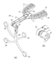
- FIG. 1A is a schematic diagram of an operation support system 1 for dental implant operation according to the present embodiment.
- the treatment support system 1 includes a treatment support device 100 in a dental clinic (first facility) that performs dental implants, a management server 200 (for example, a cloud server) in a second facility different from the dental clinic, and the dental clinic. And a processing device 300 in one or more different third facilities (remote support facilities). Note that one of the processing devices 300 may be provided in the second facility including the management server 200.
- the treatment support apparatus 100 and the processing apparatus 300 are connected to the management server 200 via a network (for example, the Internet), and exchange data with each other via the management server 200.
- a network for example, the Internet
- the dental clinic is provided with an infrared photographing device 40, a CT photographing device 50, a display device such as a display 60, and a treatment supporting device 100.
- the infrared photographing device 40 photographs the infrared marker 25 using infrared rays in order to measure the position coordinates of the infrared marker 25 in the real space.
- the CT imaging apparatus 50 takes a tomographic image of all or part of the upper jaw and the lower jaw of the subject who is wearing the plate 10.
- the plate 10 is embedded with a CT marker 11 serving as a reference position for identifying the relationship with the tooth of the subject.
- the plate 10 is fixed to the stent to be mounted on the dental arch of the practitioner when the CT imaging apparatus 50 is imaged. Therefore, the CT marker 11 can serve as a reference position for specifying the relationship with the tooth of the subject when the CT imaging apparatus 50 takes an image.
- the plate 10 includes a reference frame including an infrared marker 25 whose relative positional relationship with the CT marker 11 is known in order to specify the relative position with the CT marker 11. 20 can be connected. If the relative positional relationship between the CT marker 11 and the infrared marker 25 is fixed, the position coordinates of the CT marker 11 and the infrared marker 25 in the real space can be converted to each other by a predetermined conversion matrix. .. Therefore, once the position coordinates of the infrared marker 25 in the real space can be specified, the position coordinates of the CT marker 11 can also be specified, and by extension, the living tissue (tooth, bone, nerve, etc.) including the tooth of the subject. The position coordinates in the real space can be specified.
- the position coordinates of the living tissue including the tooth of the subject can be specified by calculation.
- the operation tool 30 is a drill having a drill blade.
- the marker for a drill which is the infrared marker 39, is attachable to and detachable from the drill, and is provided on the drill reference frame.
- the plurality of drill markers provided on the drill reference frame have a known relative positional relationship with the drill blade.
- the treatment support apparatus 100 acquires, from the CT imaging apparatus 50, CT image data (DICOM data) of the subject obtained by tomography with the plate 10 fixed to the teeth of the subject, and stores it in the storage unit 110. To do. Since CT image data of the reference frame 20 is unnecessary when performing CT imaging of the subject, the reference frame 20 is removed from the plate 10.
- CT image data of the reference frame 20 is unnecessary when performing CT imaging of the subject, the reference frame 20 is removed from the plate 10.
- the treatment support apparatus 100 transmits DICOM data relating to the subject to the management server 200 via the network according to instructions from the practitioner or the like received through the input unit 130.
- the management server 200 transmits the DICOM data received from the treatment support apparatus 100 to the processing apparatus 300 in the remote support facility designated by the practitioner from one or a plurality of options.
- the processing device 300 generates a three-dimensional CT reconstructed image including the plate 10 as an object based on the DICOM data received from the treatment support device 100.
- the three-dimensional reconstructed image is, so to speak, a three-dimensional model of the subject including the plate 10.
- the processing device 300 segmentates the living tissue of the subject included in the generated three-dimensional reconstructed image for each type of tissue.
- the processing device 300 receives the designation of the position of the CT marker 11 in the three-dimensional reconstructed image from the operator of the processing device 300 (for example, a dental technician), and thereby the CT marker 11 included in the plate 10 in the real space and the virtual It is possible to perform registration (registration) with the CT marker 11 in a typical three-dimensional reconstructed image.
- a gypsum model which is a tooth profile design model showing the tooth profile of the subject, is delivered to the remote support facility where the processing device 300 is installed from the dental clinic by mail or the like.
- the operator of the processing device 300 mounts the stent, to which the plate 10 to which the reference frame 20 is connected, is fixed, on the plaster model, so that the CT marker 11 of the plate 10 in the real space and the three-dimensional reconstructed image can be obtained. It can be aligned with the CT marker 11.
- the plate 10 is used to measure the accuracy of alignment between the position coordinates of the CT markers 11 in the three-dimensional reconstructed image and the position coordinates of the CT markers 11 in the real space in which the plate 10 exists. It includes a registration confirmation part for use.
- the alignment confirmation unit is a recess provided in the plate 10 and has a size such that a drill blade of a drill, which is an example of the operation tool 30, can be inserted therein.
- the processing device 300 is based on the relative positional relationship between the recess and the infrared marker 39 in the three-dimensional reconstructed image. From the calculated positional relationship with the virtual drill tooth in the three-dimensional reconstructed image, the accuracy of alignment between the CT marker 11 of the plate 10 in the real space and the CT marker 11 in the three-dimensional reconstructed image is calculated. To do.
- the fact that the operator of the processing apparatus 300 inserts the drill blade into the concave portion of the plate 10 in the real space means that the concave portion and the drill blade in the real space have the same position.
- the positions of the recessed portion and the drill blade in the three-dimensional reconstructed image match, it indicates that the alignment accuracy is high.
- the size of the distance between the recess and the drill tooth in the three-dimensional reconstructed image depends on the accuracy of alignment between the CT marker 11 of the plate 10 in the real space and the CT marker 11 in the three-dimensional reconstructed image. Corresponding to goodness.
- the operator of the processing device 300 positions the CT marker 11 of the plate 10 in the real space and the CT marker 11 of the three-dimensional reconstructed image so that the positioning accuracy is the position accuracy required by the practitioner or the like.
- the operation support apparatus 100 uses the management server 200 to check the data regarding one or more three-dimensional reconstructed images and the transformation matrix generated after the segmentation processing and the registration processing by the processing apparatus 300 in the remote support facility, and the registration accuracy with the management server 200. To receive through.
- the practitioner or the like instructs the treatment support apparatus 100 through the input unit 130 to the facility requesting the processing of the DICOM data or the like according to his/her preference or in consideration of the congestion status of the remote support facility, the processing cost, and the like. May be.
- the treatment support device 100 displays the three-dimensional reconstructed image of the mouth (lower jaw, upper jaw, or both) of the subject and the plate 10 based on the data of the three-dimensional reconstructed image received from the management server 200. To display. Of course, a slice image can be displayed from the image of the three-dimensional reconstructed image.
- the subject When performing a dental implant, the subject receives the treatment while fixing the plate 10 on which the reference frame 20 is attached to the teeth.
- the treatment support apparatus 100 obtains a relative positional relationship between the infrared markers 25 and 39 based on the image data of the infrared markers 25 and 39 photographed by the infrared photographing device 40 (position information acquisition unit 140), An image of a three-dimensional reconstructed image of at least the tip portion of the operation tool 30 and a surgical part such as a drill is displayed on the image of the three-dimensional reconstructed image of the subject's mouth and plate 10 based on the processed DICOM data. 60 is displayed. The display is performed in real time, and in real time (for example, a refresh rate of 30 to 60 Hz) in accordance with the movement of the operation tool 30 of the practitioner in the actual implant treatment.
- the processing device 300 guarantees the accuracy of alignment between the CT marker 11 of the plate 10 in the real space and the CT marker 11 in the three-dimensional reconstructed image, the operation tool 30 to be superimposed on the three-dimensional reconstructed image is guaranteed.
- the positional accuracy of the image is the positional accuracy required by the practitioner or the like. For this reason, by omitting the alignment work that is conventionally performed by a practitioner or the like before performing an operation, and only by confirming the alignment accuracy using the recessed portion of the plate 10, the practitioner can display on the display 60. It is possible to start the operation of the dental implant on the subject while observing the image of the three-dimensional reconstructed image that is displayed, and it is possible to perform a three-dimensional intuitive operation. As described above, the treatment support system 1 according to the embodiment can reduce the work load of the practitioner in the treatment of the dental implant.
- FIG. 1B shows an outline of functional blocks of the treatment support apparatus 100, the management server 200, and the processing apparatus 300, which are realized by the operation of hardware according to software.
- the hardware of the treatment support apparatus 100 and the processing apparatus 300 may be a general computer, and the hardware of the management server 200 may be a general server type computer.
- the treatment support device 100 and the processing device 300 may be configured to have the same function, and by doing so, it is easy to collectively update the software of the devices added to the treatment support system 1.
- the three-dimensional measuring unit such as the infrared imaging device 40 and the display device such as the display 60 are installed as in the dental clinic where the treatment support device 100 is installed.
- the treatment support apparatus 100 includes a storage unit 110 that stores various information such as CT image data (referred to as “DICOM data”); an anonymization processing unit 120 that anonymizes CT image information; various information such as information regarding a subject.
- An input unit 130 that receives an input of; a position information acquisition unit 140 that specifies the spatial position of the infrared marker based on the image data of the infrared imaging device 40 (see Patent Document 1, etc.); implant information designed by the practitioner (position for implanting Implant design information generation unit 150 that generates (information such as type); display control unit 160 that displays various information including a three-dimensional reconstructed image on display 60, transmission unit 170 that transmits DICOM data regarding CT images to processing device 300.
- a receiving unit 180 that receives various kinds of information from the processing device 300; and a position calculating unit 190 that calculates the position of the operation tool 30 in the three-dimensional reconstructed image.
- the infrared markers 25 and 39 are made of a material that reflects infrared rays and/or have a light source that emits infrared rays (for example, an infrared emitting diode).
- the treatment support system 1 may include a light source that irradiates the infrared markers 25 and 39 with infrared rays.
- the infrared photographing device 40 is composed of, for example, a stereo infrared camera, and can photograph the infrared markers 25 and 39 from a plurality of different angles.
- the position information acquisition unit 140 displays the position coordinates of the plurality of infrared markers 25 included in the reference frame 20 and the plurality of drill markers.
- the position coordinates of a plurality of drill markers included in the drill reference frame are acquired.
- the position calculation unit 190 includes a three-dimensional reconstructed image, position coordinates of a plurality of infrared markers 25, position coordinates of a plurality of drill markers, relative positional relationship between a plurality of drill markers and drill blades, and conversion.
- the position of the drill blade in the three-dimensional reconstructed image is calculated based on the matrix. Accordingly, the display control unit 160 can superimpose the drill blade on the three-dimensional reconstructed image and display it on the display 60.
- the management server 200 stores a backup database 210 for storing various received data for backup; a log data database 220 for backing up log data such as a miracle of the position of the operation tool 30 during the operation; and the operation support apparatus 100 and A software update unit 230 that keeps the software of the processing device 300 up to date is provided.
- the processing device 300 stores a variety of information including DICOM data received from the treatment support device 100; a segmentation that performs coloring/correction processing of CT image data received from the treatment support device 100 via the management server 200.
- Processing unit 320 three-dimensional model generation unit 330 that generates data of one or more three-dimensional reconstructed images based on the data subjected to the segmentation processing; from the user of the processing device 300, a plurality of CT markers in the three-dimensional reconstructed images
- Position acquisition unit 340 that accepts the designation of the position of; the implant design information generation unit 350 that arbitrarily generates implant information designed by a dental technician (position and type of implant, etc.); measures the position coordinates of a plurality of infrared markers 25
- a three-dimensional measuring unit 360 a coordinate calculating unit 370 for calculating the position coordinates of a plurality of CT markers 11 provided on the plate 10; a position adjusting unit 380 for executing the position adjustment between the three-dimensional reconstructed image and the tooth-shaped plaster model
- the storage unit 310 acquires DICOM data relating to a CT image captured in a state where the stent to which the plate 10 is fixed is attached to the tooth of the subject from the treatment support apparatus 100 and stores the DICOM data.
- the three-dimensional model generation unit 330 generates a CT three-dimensional reconstructed image based on the DICOM data.
- the position acquisition unit 340 processes the designation of the positions of the plurality of CT markers 11 in the three-dimensional reconstructed image generated by the three-dimensional model generation unit 330 via a pointing device included in the processing device 300 (not shown) such as a mouse. Accepted from 300 users.
- the three-dimensional measuring unit 360 determines the position coordinates of the plurality of infrared markers 25 provided on the reference frame 20 in a state where the stent, to which the plate 10 to which the reference frame 20 is connected is fixed, is attached to the tooth gypsum model of the subject. taking measurement.
- the three-dimensional measuring unit 360 measures each position coordinate, for example, based on the image captured by the infrared imaging device 40.
- the coordinate calculation unit 370 calculates the position coordinates of the plurality of CT markers 11 provided on the plate 10 based on the relative position relationship between the plurality of infrared markers 25 and the plurality of CT markers 11.
- the alignment unit 380 performs three-dimensional reconstruction based on the positions of the plurality of CT markers 11 in the three-dimensional reconstructed image specified by the user and the position coordinates of the CT markers 11 in the real space calculated by the coordinate calculation unit 370. Align the image with the tooth-shaped gypsum model. As a result, even a user existing in the remote support facility can accurately align the three-dimensional reconstructed image and the tooth-shaped plaster model.
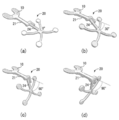
- FIG. 2 illustrates the plate 10 mounted on a stent 15 (a mouthpiece-shaped object made of transparent resin) manufactured from a tooth-shaped gypsum model of a subject. That is, the plate 10 according to the embodiment is used by being fixed to the stent 15 to be mounted on the tooth row of the subject.
- a stent 15 a mouthpiece-shaped object made of transparent resin
- the plate 10 is embedded with a plurality of CT markers 11 made of metal (for example, titanium microballs) so that they can be clearly identified on the CT image.
- the plate 10 also includes an attaching/detaching part 12 for connecting a reference frame 20 having a plurality of infrared markers 25 whose relative positional relationship with each of the plurality of CT markers 11 is known when connected to the plate 10. ing.
- the plate 10 has the first frame 21 of the reference frame 20 attached to the attachment/detachment portion 12.
- the number of CT markers 11 is at least three. In the present specification, a preferred embodiment in which the number of CT markers 11 is 7 will be described, but the present invention is not limited to this.
- the plate 10 further includes position coordinates of a plurality of CT markers 11 in a three-dimensional reconstructed image of CT including the plate 10 as an object and position coordinates of the CT markers 11 in the real space where the plate 10 is present, which is the reference frame 20. Also provided is a recess 16 for use in measuring the accuracy of alignment with the position coordinates calculated based on the position coordinates of the plurality of infrared markers 25 included in.
- the user of the processing apparatus 300 uses the plaster model of the tooth shape of the subject and the recess 16 of the plate 10 so that even in a place where the practitioner does not exist, the user can use the plaster model in a real space.
- the user in the remote support facility can ensure the accuracy of the alignment by repeatedly performing the alignment until the position precision required by the practitioner or the like is achieved.
- the reference frame 20 includes a first frame 21 and a second frame 24 that is connected to the first frame 21 at the connecting portion 22 and that has a plurality of infrared markers 25.
- the number of the infrared markers 25 may be three or more. As the number increases, the accuracy of position measurement improves, but the amount of data to be processed increases.
- the reference frame 20 including the four infrared markers 25 is described as a preferred embodiment, but the present invention is not limited to this.
- the connecting portion 22 limits the rotational position of the second frame 24 with respect to the first frame 21 (and the plate 10) to a plurality of predetermined angles, and locks the first and second frames 21 and 24 by the lock mechanism 23. It is configured so that it can be performed (FIG. 2B).
- the reference frame 20 is configured such that it cannot be fixed between the first and second frames 21 and 24 at any angle other than the predetermined angle, and the reference frame 20 includes the stent 15 (the stent mounted on the tooth-shaped plaster model). The plate fixed to 15) is rotated only at a plurality of predetermined angles. For example, as shown in FIG.
- the predetermined angles are in four stages, and the angles between the first and second frames 21 and 24 are 0°, 30°, 60°, and 90°. It is configured to be It should be noted that although a preferred embodiment in which the predetermined angles between the first and second frames 21 and 24 are 0°, 30°, 60°, and 90° will be described in the present specification, the present invention is not limited to this. It is not something that will be done.
- the reference frame 20 is removed from the plate 10, and the plate 10 attached to the stent is fixed to the tooth of the subject.
- the design of the dental implant by the operator and/or the dental technician and the operation of the dental implant by the operator are performed with the reference frame 20 attached to the plate 10.
- the alignment unit 380 of the processing device 300 has known design information about the relative positional relationship between the infrared markers 25 provided on the reference frame 20 and the CT markers 11 provided on the plate 10, and three-dimensional information. Based on the positions of the plurality of CT markers 11 in the reconstructed image, a plurality of reference frames 20 are provided for each predetermined angle that is a possible angle between the first frame 21 and the second frame 24. A conversion matrix for converting the position of the infrared marker 25 into the position of the plurality of CT markers 11 in the three-dimensional reconstructed image is generated.
- the reference frame 20 interferes with the practitioner during the operation of the implant, it can be eliminated by changing the angle, and by using the conversion matrix corresponding to the changed angle,
- the positional relationship between the position/direction of the operation tool 30 on the display 60 and the three-dimensional reconstructed image of the plate 10, the tooth of the subject, the mandible and the like can be normally maintained.
- Known design information regarding the relative positional relationship between the plurality of infrared markers 25 provided on the reference frame 20 and the plurality of CT markers 11 provided on the plate 10 is stored in the storage unit 310 in advance.
- FIG. 4 is a diagram showing an example of explaining conversion matrix generation.
- the positions (X, Y, Z) of 11 to (7) can be determined in advance at the design stage of the plate 10 and the reference frame 20. Further, the positions (X, Y, Z) of the seven CT markers 11(1) to 11(7) are determined by a predetermined angle (0 between the first frame 21 and the second frame 24 of the reference frame 20). °, 30°, 60°, and 90°), but they can also be predetermined.
- FIG. 5 is a diagram showing an example of known design information. Specifically, FIG. 5 shows that the seven CT markers 11(1) to 11( of the plate 10 with respect to a predetermined center O at predetermined angles (0°, 30°, 60°, and 90°). It is an example of the position (X, Y, Z) of 7). Such information (CAD data) on the relative position of the CT marker 11 with respect to the center O is stored in advance in the treatment support device 100 and the processing device 300.
- CAD data CAD data
- the transmission unit 395 is a device that is a transmission source device of the DICOM data via the network for the conversion matrix for each position of the plurality of CT markers 11 in the three-dimensional reconstructed image, the three-dimensional reconstructed image, and the predetermined angle. It transmits to the support device 100. Accordingly, the dentist or the like who is the user of the treatment support apparatus 100 can quickly start the treatment based on the information received from the transmission unit 395.
- processing such as segmentation processing and alignment processing that has conventionally been performed in a dental clinic can be performed by a professional dentist using a remote system that uses the same system. It becomes possible for a technician or the like to perform the processing, so that the work efficiency of the practitioner can be improved and the work load on the practitioner can be reduced.
- the practitioner can easily select a remote support facility or the like to request various processings in consideration of the favorite remote support facility and the congestion status or cost of the remote support facility.
- various data passing through the management server 200 is stored for backup, it is possible to reduce a risk when the practitioner accidentally loses or deletes the data.
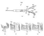
- FIG. 6 is a schematic view of an operating tool 30 used by a practitioner when performing or designing a dental implant, and shows a drill 450 having a drill blade 451 as an example of various operating tools 30.
- the drill 450 is a dental drill having a drill blade 451 attached to its tip, and a drill frame 460 is detachably attached to its end.
- the drill frame 460 includes an arm extending in three directions from the tip, and a disk-shaped drill marker 461 is attached to the tip of the arm.
- the drill marker 461 is composed of a material that reflects infrared light and an infrared light emitting diode (IR LED).
- the drill blade 451 cuts the gums and bones of the practitioner while rotating about a direction substantially perpendicular to the longitudinal direction of the drill 450.
- the drill 450 is attached, but when embedding the artificial tooth root in the cut hole, the artificial tooth root is attached instead of the drill 450.
- the drill marker 461 is provided at a fixed position with respect to the drill 450, and when the position of the drill marker 461 is specified, the tip of the drill 450 and the drill blade 451 (or artificial tooth root) attached thereto are provided. It is also possible to specify the positions of parts such as. Therefore, when the relative positional relationship between the drill marker 461 of the drill 450 and the infrared marker 25 of the reference frame 20 is specified, the positions of parts such as the drill 450 and the positions of the practitioner's teeth, jaws, etc. are positioned. It is possible to match.
- a plaster model imitating the tooth jaw of the subject may be used, or the tooth jaw itself of the subject may be used.
- a design component for example, the component shown in FIG. 6 of Patent Document 1 described above
- the three-dimensional measuring unit 360 images the drill frame 460 having the plurality of drill markers 461 using the infrared imaging device 40 and the like.
- the drill frame 460 is attachable to and detachable from the drill 450 having the drill blade 451 and the relative positional relationship with the drill blade 451 is known.
- the alignment unit 380 includes position coordinates of the plurality of drill markers 461 measured by the three-dimensional measurement unit 360, a relative positional relationship between the plurality of drill markers 461 and the drill blade 451, and position coordinates of the plurality of infrared markers 25. , And the position of the drill blade 451 in the three-dimensional reconstructed image based on the relative positional relationship between the position coordinates of the plurality of infrared markers 25 and the plurality of CT markers 11.
- the accuracy calculation unit 390 registers the error between the position of the recess 16 and the position of the drill blade 451 in the three-dimensional reconstructed image. Calculate as accuracy.
- the transmission unit 395 further transmits the alignment accuracy calculated by the accuracy calculation unit 390 to the treatment support device 100, which is the transmission source device of the DICOM data, via the network.
- the user of the treatment support apparatus 100 such as a dentist can at a glance grasp the alignment accuracy of the CT marker 11 received from the processing apparatus 300 without having to check it himself.
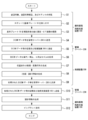
- step S1 in a dental clinic, a practitioner (dentist) who has received an implant request takes a tooth impression of the recipient, creates a plaster model 17 that is a dental plaster model, and a stent from the plaster model 17. 15 (mouthpiece) is prepared.
- FIG. 8A shows an example of the plaster model 17 and an example of the stent 15. It should be noted that these treatments are pretreatments for the conventional implant treatment.
- step S2 the practitioner prepares the plate 10 and attaches the plate 10 to the stent 15 (FIG. 8(b)).
- the plate 10 is firmly fixed to the stent 15 so as not to shift.
- step S3 the practitioner fixes the plate 10 attached to the stent 15 to the teeth of the practitioner, and takes a CT image (hundreds of slice images) using the CT imaging device 50.
- FIG. 9A is an example of a CT image (one slice image) of the subject, and the seven CT markers 11(1) to 11(7) are clearly shown in a form distinguishable from other parts such as bones. You can see what is shown in the image.
- FIG. 9B is an example of a plate 10 generated from a CT image and a three-dimensional reconstructed image of the subject.
- the treatment support apparatus 100 receives the DICOM data of the CT image of the subject from the CT imaging apparatus 50, stores it as original data (storage unit 110), and stores the DICOM data in the management server 200 via the network.
- the DICOM data may be anonymized by the treatment support apparatus 100 (anonymization processing unit 120) so that the third party does not understand the relationship between the subject and the DICOM data.
- the ID information of the remote support facility that the management server 200 specifies so that the destination can be specified, the ID information of the dental clinic of the practitioner, the patient ID number, and any implant information (insert implant)
- the information such as the part) is transmitted from the treatment support apparatus 100 to the management server 200 (referred to as “DICOM data”).
- step S5 the management server 200 stores the received DICOM data and the like (backup database 210) and transmits the DICOM data and the like to the processing device 300 such as the designated remote support facility.
- the management server 200 may store DICOM data and the like in the backup database 210 for backup and provide the DICOM data and the like according to the request of the practitioner.
- step S6 the dental technician or the like of the remote support facility uses the processing device 300 to perform segmentation processing, that is, to color each portion of the received DICOM data and appropriately correct the unclear portion (segmentation processing unit 320). ).
- the processing device 300 generates one or a plurality of three-dimensional reconstructed images using the processed data (three-dimensional model generation unit 330).
- the dental technician colors the bones, nerves, and the parts on the image data corresponding to the CT markers 11 with different colors (especially, the nerves should not be damaged, so it is good to color them well), halation, etc.
- the area that becomes unclear due to is corrected to data as appropriate.
- the position information (x, y, z) of the CT marker 11 on the three-dimensional reconstructed image is specified and stored in the processing device 300 in association with the data of the three-dimensional reconstructed image (storage unit 310). Note that these operations may be automatically performed by the processing apparatus 300, or may be manually performed visually by a dental technician or the like.
- step S7 the processing device 300 determines the position of the CT marker 11 on the three-dimensional reconstructed image based on the infrared marker 25 for each of the predetermined angles between the first and second frames 21 and 24 of the reference frame 20.
- a conversion matrix for obtaining is generated (positioning unit 380).
- step S8 optionally, the dental technician considers the recommended design of the dental implant and generates information about the recommended design (information such as implant position and type).
- step S9 the processing device 300 transmits the three-dimensional reconstructed image, the information of the conversion matrix, the ID information of the dental clinic, etc. to the management server 200 via the network.
- the management server 200 stores information such as a three-dimensional reconstructed image and a conversion matrix (backup database 210), and sends the information to the operation support device 100 of the original dental clinic.
- the management server 200 may store the three-dimensional reconstructed image, the information of the conversion matrix, and the like for backup, and provide the information according to the request of the practitioner.
- step S11 the practitioner uses the treatment support apparatus 100 to design the implant (determine the position and type of the implant) on the three-dimensional reconstructed image based on the information of the three-dimensional reconstructed image and the transformation matrix. Is performed (implant design information generation unit 150), and design information is stored (storage unit 110).
- FIG. 10 is an example showing the design position of the implant in the three-dimensional reconstructed image.
- step S12 the practitioner fixes the plate 10 on which the reference frame 20 is attached to the teeth of the subject and sets the angle between the plate 10 and the reference frame 20 to a predetermined angle (0°, 30°, 60°). Or 90°).
- a transformation matrix corresponding to the angle is selected, and while viewing the three-dimensional reconstructed image displayed on the display 60, the drill blade 451 at the tip of the drill 450 comes to the designed implant position on the display 60.
- the implant operation can be accurately performed at the actual design position. Since the relative positional relationship between the CT marker 11 and the infrared marker 25 and the relative positional relationship between the infrared marker 25 and the drill marker 461 are accurately reflected on the display 60 in real time, the practitioner displays The implant operation can be performed while watching 60.
- the display control unit 160 (1) an image including bone in which the implant of the subject is extracted and extracted from the three-dimensional reconstructed image, (2) a predetermined implantation completion position of the implant, and (3) position calculation.
- the implantation completion predicted position of the implant calculated based on the current position of the drill blade 451 calculated by the unit 190, and (4) the current position of the implant corresponding to the current position of the drill blade 451 are in different modes. , Is displayed on the display 60 that functions as the display unit of the treatment support apparatus 100.
- the display control unit 160 displays the bone and tooth in which the implant obtained from the CT data is to be embedded according to the signal received from the processing device 300, and the implantation completion position of the implant determined in advance is the first attribute, for example, red.
- the estimated completion position of embedding is displayed in a second attribute, for example, yellow, and the current position is displayed in a third attribute, for example, blue.
- the implant insertion support screen will be described with reference to FIG.
- the image is divided into 6 areas.
- Three multi-section reconstruction images (MPR image, multi-planar reconstruction, multi planar reconstruction) by CT data are in the left area 31-33, and in the right area 34-36.
- Three 3D rendered images of CT data are displayed.
- images viewed from three different directions such as the upper side, the outer side, the inner side, and the lower side can be appropriately displayed according to the practitioner's request.
- the cross section specified by the substantially horizontal line of the cross lines shown in the areas 32 and 33 is displayed, and in the area 32, the substantially vertical line of the cross lines shown in the areas 31 and 33 is displayed.
- the cross section specified by is displayed, and the cross section specified by the substantially horizontal line shown in the region 31 and the substantially vertical line shown in the region 32 is displayed in the region 33.
- These substantially horizontal lines and substantially vertical lines are given the same color corresponding to each cross section.
- a distance 37 between the tip of the drill blade 451 and the bottom portion at the implantation completion position and a distance 38 between the tip of the drill blade 451 and the nerve are displayed. As a result, the practitioner can grasp the specific numerical value and perform the work precisely.
- the treatment process includes a design process, an approach process, and a cutting process.
- the design process is the process of deciding the implant position based on CT data.
- the practitioner determines the position of the nerve 54 existing inside the bone based on the CT data.
- the position of the implant is determined so as not to overlap the position of the nerve 54 and taking various circumstances into consideration.
- the data on the positions of the nerve 54 and the implant are input to the treatment support device 100.
- the approach process is a process of determining the approach angle of the drill blade 451 with respect to the bone.
- the treatment assisting apparatus 100 calculates the bones and teeth in which the implant is to be embedded, the positions of the implant completion position 51 and the nerve 54 which are determined in advance, and creates an image in which these are combined.
- the display 60 displays this image (see FIG. 12A).
- the embedding completion position 51 is displayed in red.
- the practitioner refers to the image displayed on the display 60, advances the drill blade 451 into the oral cavity of the practitioner, and temporarily applies the drill blade 451 to the position where the implant is to be provided.
- the infrared photographing device 40 continuously transmits the images obtained by photographing the infrared marker 25 and the drill marker 461 provided on the reference frame 20 to the treatment assistance device 100.
- the treatment assistance apparatus 100 calculates the position of the drill blade 451 in the oral cavity using the image, and based on the obtained position, the position of the drill blade 451 with respect to the bone is virtually displayed on the display 60 at the tip of the drill blade 451.
- the virtual implants 500 added are continuously displayed (see FIG. 12B).
- the virtual implant 500 indicates the implantation completion predicted position that predicts the position where the implant will be embedded, and is displayed in yellow.
- the position and angle of the drill blade 451 and the virtual implant 500 displayed on the display 60 also change according to the change ( See FIGS. 12C and 12D).
- the practitioner confirms that the position and angle of the virtual implant 500 coincide with the implantation completion position 51 the cutting process is started.
- the cutting process is the process of actually making a hole in the bone of the subject.
- the practitioner operates the drill blade 451 and starts cutting while maintaining the position and angle of the virtual implant 500 in agreement with the implantation completion position 51 (see FIG. 12(E)). ).
- the infrared imaging device 40, the operation support device 100, and the display 60 continuously operate, and the position of the drill blade 451 that has entered the inside of the bone is blue as the current position 52. It is continuously displayed on the display 60. Since each position is continuously updated and displayed, when the current position 52 deviates from the position and angle determined by the approach process, the virtual implant 500 is displaced from the implantation completion position 51 on the display 60.
- the drill blade 451 projects from the bottom of the embedding completion position 51 (see FIG. 12G). As a result, the practitioner can easily recognize that the current position 52 is beyond the embedding completion position 51, and can stop cutting. According to the above, the practitioner can perform cutting while grasping the position and angle of the drill blade 451 and appropriately correcting the position and angle while looking at the image displayed on the display 60.
- [Depth marker] 13(a) to 13(e) are schematic views of tools for assisting the vertical position design of the implant.
- the vertical position of the implant is one of the factors that greatly affects the aesthetics of the implant superstructure. It is indispensable to control this vertical position together with the buccolingual position to obtain an aesthetic treatment result, and the display screen relating to the depth marker displayed on the display 60 by the display control unit 160 supports this position. To do.
- FIG. 13A is a diagram schematically showing an instruction tool 550, which is a kind of the operation tool 30 for supporting a vertical position.
- the pointing tool 550 is a pointing section 551 for pointing a point in the real space, and a plurality of pointing section markers 561 that are detachable from the pointing section 551 and have a known relative positional relationship with the pointing section 551.
- a tool frame 560 having a.
- the practitioner points out the gingival margin line desired to be restored with the pointing unit 551 of the pointing tool 550 when designing the position in the oral cavity of the plaster model 17 or the subject.
- the position information acquisition unit 140 acquires the position coordinates of the plurality of indicator marker 561 included in the tool frame 560 in addition to the infrared marker 25 included in the reference frame 20.
- the position calculation unit 190 includes a three-dimensional reconstructed image, position coordinates of the plurality of infrared markers 25, position coordinates of the plurality of indicator unit markers 561, and a relative positional relationship between the plurality of indicator unit markers 561 and the instruction unit 551. , And the conversion matrix, the position of the instruction unit 551 in the three-dimensional reconstructed image is calculated.
- the display control unit 160 is a plane parallel to a plane whose normal is the longitudinal direction of the implant at the predetermined implant completion position 51 in the three-dimensional reconstructed image, and is an instruction unit in the three-dimensional reconstructed image.
- a virtual plane 570 (see FIGS. 13B to 13E) having a predetermined distance from the position of 551 is an image including a bone in which the implant of the subject is embedded and a predetermined implant The display 60 is displayed so as to be superimposed on the embedding completion position 51 of.
- FIGS. 13B and 13C there is a gap between the virtual plane 570 and the front surface of the embedding completion position 51.
- the practitioner moves the embedding completion position 51 so that the front surface of the embedding completion position 51 coincides with the virtual plane 570, as shown in FIG. Accordingly, the practitioner can set the vertical position of the implant at an appropriate position in the planning stage before inserting the implant.
- the distance between the position of the instruction unit 551 and the plane 570 in the three-dimensional reconstructed image is 3 mm by default.
- Orthodontic anchor screw navigation enables the operator to see the anatomical positional relationship between the orthodontic anchor screw and the natural tooth root, maxillary sinus, etc. in real time when the orthodontic anchor screw is implanted in the subject's oral cavity. It is a display screen for the purpose of presenting and making it easy to embed and install the orthodontic anchor screw at a safe site.
- FIG. 14A is a diagram schematically showing a driver tool 650 for embedding an orthodontic anchor screw, which is a kind of the operation tool 30.
- the driver tool 650 has a driver 651 for use in embedding an orthodontic anchor screw, and a driver 651 that is attachable to and detachable from the driver 651 and that has a known relative positional relationship with the driver 651.
- the frame 660 for use.
- the practitioner uses a driver 651 to which a driver frame 660 is connected when implanting and installing the correction anchor screw in the oral cavity of the practitioner.
- the position information acquisition unit 140 acquires the position coordinates of the plurality of driver markers 661 included in the driver frame 660 in addition to the infrared marker 25 included in the reference frame 20.
- the position calculation unit 190 includes a three-dimensional reconstructed image, position coordinates of the plurality of infrared markers 25, position coordinates of the plurality of driver markers 661, relative positional relationship between the plurality of driver markers 661 and the driver 651, and conversion.
- the position of the driver 651 in the three-dimensional reconstructed image is calculated based on the matrix.
- the display control unit 160 displays a virtual image 670 (see FIG. 14B) when the driver 651 is advanced along the long axis direction of the driver 651 in which the correction anchor screw of the subject is embedded. It is displayed on the display 60 so as to be superimposed on the image including the.
- the treatment assisting apparatus 100 can assist the practitioner to implant and install the correction anchor screw in a safe site in the subject's oral cavity.
- the present invention may be specified by the following items.
- An operation support device (100) in a first facility for operating a dental implant A management server (200) in a second facility different from the first facility, the management server (200) being connected to the treatment support apparatus (100) via a network;
- the treatment support device (100) stores DICOM data regarding a CT image obtained in a state where a plate (10) having a plurality of CT markers (11) embedded therein is attached to a tooth of a subject, the management server ( 200) and then
- the management server (200) transmits the DICOM data to the processing device (300),
- the processing device (300) processes the DICOM data, generates one or more three-dimensional reconstructed images of the CT image, and transmits the three-dimensional reconstructed image data to the management server (200).
- the treatment support system (200) transmits the data of the three-dimensional reconstructed image to the treatment support apparatus (100).
- the reference frame (20, 24) attached to the plate (10) is rotated at a plurality of predetermined angles with respect to the plate (10),
- the processing device (300) includes known design information regarding a relative positional relationship between the plurality of infrared markers (25) provided on the reference frame (20) and the CT marker (11), and the three-dimensional reconstruction information. Based on the position information of the CT marker (11) on the constituent image, the position information of the CT marker (11) on the three-dimensional reconstructed image from the position of the infrared marker (25) at every predetermined angle.
- An operation support device (100) in a first facility for operating a dental implant A management server (200) in a second facility different from the first facility, the management server (200) being connected to the treatment support apparatus via a network; A processing device (300) in the second facility or in a third facility different from the first and second facilities, which is connected to the management server (200) via a network ( 300) and a dental implant treatment support system (1) including:
- the treatment support device (100) stores DICOM data regarding a CT image obtained in a state where a plate (10) having a plurality of CT markers (11) embedded therein is attached to a tooth of a subject, the management server ( 200) sending to The management server (200) transmitting the DICOM data to the processing device (300);
- the processing device (300) processes the DICOM data, generates one or more three-dimensional reconstructed images of the CT image, and transmits the three-dimensional reconstructed image data to the management server (200).
- the management server (200) transmits the data of the three-dimensional reconstructed image to the treatment support apparatus (100), the treatment support method.
- the reference frame (20, 24) attached to the plate (10) is rotated at a plurality of predetermined angles with respect to the plate (10),
- the processing device (300) known design information regarding the relative positional relationship between the plurality of infrared markers (25) provided in the reference frame (20) and the CT marker (11), Based on the position information of the CT marker (11) on the three-dimensional reconstructed image, the CT marker (11 on the three-dimensional reconstructed image from the position of the infrared marker (25) at every predetermined angle.
- the treatment support display device according to [2-2] which displays a distance between the nerve and the current tip position of the drill blade.
- [2-5] The operation support according to any one of [2-1] to [2-4], which displays images of the bone, the implantation completion position, the implantation completion predicted position, and the current position viewed from three different directions.
- Display device. [2-6] A frame for a drill that is removable from a drill having a drill blade and has a marker for a drill, A fixed frame having a marker for a fixed frame, which is attached so as to extend outside the oral cavity from a fixed portion mounted on a tooth in the oral cavity, An imaging device for photographing the drill marker and the fixed frame marker, Based on the data from the imaging device, a predicted implantation completion position of the implant corresponding to the current position of the drill blade, and a processing device that calculates the current position of the implant corresponding to the current position of the drill blade, The bones and teeth in which the implant is embedded are displayed, the predetermined implantation completion position of the implant is displayed with a first attribute, the predicted implantation completion position is displayed with a second attribute, and the current position is a third attribute.
- a fixed part attached to the tooth and having a fixed part marker A fixed frame attached to the fixed portion so as to extend outside the oral cavity from the fixed portion, and a fixed frame having a fixed frame marker, A frame for a drill that is removable from a drill having a drill blade and has a marker for a drill, An imaging device for photographing the drill marker and the fixed frame marker, A processing device that stores in advance the positional relationship between the fixed portion marker and the fixed frame marker, A display device that displays bones and teeth in which the implant is embedded, The processing device includes data obtained by photographing with the fixed part attached to the teeth, a positional relationship between the fixed part marker and the fixed frame marker, the drill marker and the fixed frame.
- the display device Based on the positional relationship between the tooth and the marker for the fixed frame, and the predicted implantation completion position of the implant corresponding to the current position of the drill blade, and the current drill blade Calculate the current position of the implant corresponding to the position of
- the display device displays bones and teeth in which implants are embedded, displays a predetermined implantation completion position of an implant with a first attribute, displays the implantation completion predicted position with a second attribute, and displays the current position. Is displayed with the third attribute, Treatment support system.
- Coordinate calculation unit 380 Positioning unit 390... Accuracy calculation unit 395... Transmission unit 450... Drill 451... Drill blade 460... Drill frame 461... Drill marker 500... Virtual implant 550... Instruction tool 551... Instruction section 560... Tool frame 561... Instruction section marker 650... Driver tool 651... Driver 660... ⁇ Driver frame 661 ⁇ Driver marker
Abstract
Description
図1Aは、本実施形態に係る歯科インプラント施術のための施術支援システム1の概要図である。 <Outline of treatment support system>
FIG. 1A is a schematic diagram of an
図1Bに、ソフトウェアに応じたハードウェアの動作により実現される、施術支援装置100、管理サーバー200、及び処理装置300の機能ブロックの概要を示す。施術支援装置100及び処理装置300のハードウェアとしては一般的なコンピュータであってもよく、管理サーバー200のハードウェアとしては一般的なサーバー型コンピュータであってもよい。施術支援装置100と処理装置300は互いに同じ機能を有するように構成してもよく、そうすることで施術支援システム1に加わる装置のソフトウェアの一括更新が容易となる。この場合、遠隔サポート施設においても、施術支援装置100が設置されている歯科医院と同様に、赤外線撮影装置40等の3次元測定部及びディスプレイ60等の表示装置も設置される。 <Functional configuration of each device included in the
FIG. 1B shows an outline of functional blocks of the
より具体的に、記憶部310は、プレート10を固定したステントを被施術者の歯に装着させた状態で撮像されたCT画像に関するDICOMデータを施術支援装置100から取得して記憶している。3次元モデル生成部330は、DICOMデータに基づいてCTの3次元再構成画像を生成する。位置取得部340は、3次元モデル生成部330が生成した3次元再構成画像中の複数のCTマーカー11の位置の指定を、マウス等の図示しない処理装置300が備えるポインティングデバイスを介して処理装置300のユーザから受け付ける。 [Alignment at remote support facility]
More specifically, the
図2及び図3は、プレート10及び基準フレーム20の模式図である。以下、実施の形態に係る施術支援システム1で利用されるプレート10及び基準フレーム20についてより詳細に説明する。なお、図2では被施術者の歯形石膏模型から作製するステント15(透明な樹脂で形成されたマウスピース状のもの)に装着された状態のプレート10が描かれている。すなわち、実施の形態に係るプレート10は、被施術者の歯列に装着させるステント15に固定して用いられる。 [Details of
2 and 3 are schematic views of the
図1Bの説明に戻る。処理装置300の位置合わせ部380は、基準フレーム20に備えられた複数の赤外線マーカー25とプレート10に備えられた複数のCTマーカー11との相対的な位置関係に関する既知の設計情報と、3次元再構成画像中の複数のCTマーカー11の位置とに基づいて、第1のフレーム21と第2のフレーム24とが取り得る角度である所定の角度毎に、基準フレーム20に備えられた複数の赤外線マーカー25の位置を3次元再構成画像中の複数のCTマーカー11の位置に変換するための変換行列を生成する。 [Generation and transmission of conversion matrix]
Returning to the description of FIG. 1B. The
A=R*B+t
式中、Aは3次元再構成画像上のCTマーカー11の位置(x, y, z)の行列であり、BはCTマーカー11のCADデータ(中心Oに対するCTマーカー11の位置(X、Y、Z))の行列であり、Rは回転行列、tは平行移動行列である。所定の角度毎にBの値は異なることから、位置合わせ部380記憶は所定の角度毎に変換行列[R,t]を求める。 The
A=R*B+t
In the formula, A is a matrix of positions (x, y, z) of the
図6は、施術者が歯科インプラントの施術や設計をする際に用いる操作器具30の模式図であり、種々存在する操作器具30の一例として、ドリル刃451を有するドリル450を示している。ドリル450は先端部にドリル刃451が取り付けられた歯科用ドリルであって、末端部にドリル用フレーム460が着脱可能に取り付けられる。ドリル用フレーム460は、先端から三方に延びるアームを備え、アームの先端に円盤形状のドリル用マーカー461が取り付けられる。ドリル用マーカー461は、赤外線を反射する素材及び赤外線発光ダイオード(IR・LED)から成る。ドリル刃451は、ドリル450の長手方向に略垂直な方向を軸として回転しながら、施術者の歯茎や骨を切削する。なお、歯茎や骨を切削する際には、ドリル450が装着されるが、人工歯根を切削した穴に埋め込む際には、ドリル450に代えてその人口歯根が装着される。 [Example of operating device 30]
FIG. 6 is a schematic view of an
再び図1Bの説明に戻る。3次元測定部360は、赤外線撮影装置40等を使って、複数のドリル用マーカー461を有するドリル用フレーム460を撮像する。ドリル用フレーム460はドリル刃451を有するドリル450に着脱可能であり、ドリル刃451との相対的な位置関係が既知である。 [Check alignment accuracy]
Returning to the explanation of FIG. 1B again. The three-
次に、図7~10を用いて、本実施形態における施術支援システム1を用いた歯科インプラントの施術フローの概要について具体例を適宜用いながら説明する。 <Processing flow>
Next, an outline of a treatment flow of a dental implant using the
続いて、実施の形態に係る施術支援装置100の表示制御部160が表示装置であるディスプレイ60に表示させる表示画面について説明する。 <Display screen example>
Next, a display screen displayed on the
表示制御部160は、(1)3次元再構成画像から抽出され被施術者のインプラントが埋め込まれる骨を含む画像と、(2)予め決定されたインプラントの埋め込み完了位置と、(3)位置算出部190が算出したドリル刃451の現在の位置に基づいて算出されるインプラントの埋め込み完了予測位置と、(4)ドリル刃451の現在の位置に対応するインプラントの現在位置と、をそれぞれ異なる態様で、施術支援装置100の表示部として機能するディスプレイ60に表示させる。 [Implant implantation support screen]
The display control unit 160 (1) an image including bone in which the implant of the subject is extracted and extracted from the three-dimensional reconstructed image, (2) a predetermined implantation completion position of the implant, and (3) position calculation. The implantation completion predicted position of the implant calculated based on the current position of the
表示制御部160は、処理装置300から受信した信号に応じて、CTデータから得られたインプラントが埋め込まれる骨及び歯を表示し、予め決定したインプラントの埋め込み完了位置を第1の属性、例えば赤色で表示し、埋め込み完了予測位置を第2の属性、例えば黄色で表示し、現在位置を第3の属性、例えば青色で表示する。 Hereinafter, it will be described more specifically.
The
図13(a)~(e)は、インプラントの垂直的ポジション設計の支援をするためのツールを概略的に示す図である。インプラントの垂直的ポジションは、インプラント上部構造の審美性に非常に影響を与える要素の一つである。この垂直的ポジションを頬舌的ポジションとともにコントロールすることは審美的な治療結果を得るために必要不可欠であり、表示制御部160がディスプレイ60に表示させる深度マーカーに係る表示画面は、このポジションをサポートする。 [Depth marker]
13(a) to 13(e) are schematic views of tools for assisting the vertical position design of the implant. The vertical position of the implant is one of the factors that greatly affects the aesthetics of the implant superstructure. It is indispensable to control this vertical position together with the buccolingual position to obtain an aesthetic treatment result, and the display screen relating to the depth marker displayed on the
図14(a)~(b)は、矯正用アンカースクリューナビゲーションをするためのツールを概略的に示す図である。矯正用アンカースクリューナビゲーションは、矯正用アンカースクリューを被施術者の口腔内に埋入する際に、矯正用アンカースクリューと天然歯歯根や上顎洞等との解剖学的位置関係をリアルタイムで施術者に提示し、矯正用アンカースクリューを安全な部位に埋入設置しやすくすることを目的とした表示画面である。 [Orthodontic anchor screw navigation]
14(a) and 14(b) are schematic views of a tool for performing orthodontic anchor screw navigation. Orthodontic anchor screw navigation enables the operator to see the anatomical positional relationship between the orthodontic anchor screw and the natural tooth root, maxillary sinus, etc. in real time when the orthodontic anchor screw is implanted in the subject's oral cavity. It is a display screen for the purpose of presenting and making it easy to embed and install the orthodontic anchor screw at a safe site.
〔1-1〕
歯科インプラントを施術する第1の施設における施術支援装置(100)と、
前記第1の施設とは異なる第2の施設における管理サーバー(200)であって、前記施術支援装置(100)とネットワークを介して接続される前記管理サーバー(200)と、
前記第2の施設における又は前記第1及び第2の施設とは異なる第3の施設における処理装置(300)であって、前記管理サーバー(200)とネットワークを介して接続される前記処理装置(300)とを含む、歯科インプラントの施術支援システム(1)であって、
前記施術支援装置(100)は、複数のCTマーカー(11)が埋め込まれたプレート(10)を被施術者の歯に装着させた状態で得られたCT画像に関するDICOMデータを、前記管理サーバー(200)に送信し、
前記管理サーバー(200)は、前記DICOMデータを前記処理装置(300)に送信し、
前記処理装置(300)は、前記DICOMデータを処理し、前記CT画像の1つ以上の3次元再構成画像を生成し、前記3次元再構成画像のデータを前記管理サーバー(200)に送信し、
前記管理サーバー(200)は、前記3次元再構成画像のデータを前記施術支援装置(100)に送信する、前記施術支援システム。
〔1-2〕
前記プレート(10)に装着される基準フレーム(20, 24)は、前記プレート(10)に対して複数の所定の角度毎に回転するものであり、
前記処理装置(300)は、前記基準フレーム(20)に備え付けられた複数の赤外線マーカー(25)と前記CTマーカー(11)との相対的な位置関係に関する既知の設計情報と、前記3次元再構成画像上における前記CTマーカー(11)の位置情報とに基づき、前記所定の角度毎に、前記赤外線マーカー(25)の位置から前記3次元再構成画像上における前記CTマーカー(11)の位置情報を生成するための変換行列を生成し、前記3次元再構成画像のデータとともに前記管理サーバーに送信する、〔1-1〕に記載の施術支援システム。
〔1-3〕
前記処理装置(300)による前記DICOMデータの処理は、前記CT画像データの着色処理を含む、〔1-1〕又は〔1-2〕に記載の施術支援システム。
〔1-4〕
歯科インプラントを施術する第1の施設における施術支援装置(100)と、
前記第1の施設とは異なる第2の施設における管理サーバー(200)であって、前記施術支援装置にネットワークを介して接続される前記管理サーバー(200)と、
前記第2の施設における又は前記第1及び第2の施設とは異なる第3の施設における処理装置(300)であって、前記管理サーバー(200)にネットワークを介して接続される前記処理装置(300)とを含む歯科インプラントの施術支援システム(1)における施術支援方法であって、
前記施術支援装置(100)が、複数のCTマーカー(11)が埋め込まれたプレート(10)を被施術者の歯に装着させた状態で得られたCT画像に関するDICOMデータを、前記管理サーバー(200)に送信するステップと、
前記管理サーバー(200)が、前記DICOMデータを前記処理装置(300)に送信するステップと、
前記処理装置(300)が、前記DICOMデータを処理し、前記CT画像の1つ以上の3次元再構成画像を生成し、前記3次元再構成画像のデータを前記管理サーバー(200)に送信するステップと、
前記管理サーバー(200)が、前記3次元再構成画像のデータを前記施術支援装置(100)に送信するステップと、を含む前記施術支援方法。
〔1-5〕
前記プレート(10)に装着される基準フレーム(20, 24)は、前記プレート(10)に対して複数の所定の角度毎に回転するものであり、
前記処理装置(300)は、前記基準フレーム(20)に備え付けられた複数の赤外線マーカー(25)と前記CTマーカー(11)との相対的な位置関係に関する既知の設計情報と、
前記3次元再構成画像上における前記CTマーカー(11)の位置情報とに基づき、前記所定の角度毎に、前記赤外線マーカー(25)の位置から前記3次元再構成画像上における前記CTマーカー(11)の位置情報を生成するための変換行列を生成し、前記3次元再構成画像のデータとともに前記管理サーバーに送信する、〔1-4〕に記載の施術支援方法。
〔1-6〕
前記処理装置(300)による前記DICOMデータの処理は、前記CT画像データの着色処理を含む、〔1-4〕又は〔1-5〕に記載の施術支援方法。 The present invention may be specified by the following items.
[1-1]
An operation support device (100) in a first facility for operating a dental implant,
A management server (200) in a second facility different from the first facility, the management server (200) being connected to the treatment support apparatus (100) via a network;
A processing device (300) in the second facility or in a third facility different from the first and second facilities, which is connected to the management server (200) via a network ( 300) and a dental implant treatment support system (1),
The treatment support device (100) stores DICOM data regarding a CT image obtained in a state where a plate (10) having a plurality of CT markers (11) embedded therein is attached to a tooth of a subject, the management server ( 200) and then
The management server (200) transmits the DICOM data to the processing device (300),
The processing device (300) processes the DICOM data, generates one or more three-dimensional reconstructed images of the CT image, and transmits the three-dimensional reconstructed image data to the management server (200). ,
The treatment support system (200) transmits the data of the three-dimensional reconstructed image to the treatment support apparatus (100).
[1-2]
The reference frame (20, 24) attached to the plate (10) is rotated at a plurality of predetermined angles with respect to the plate (10),
The processing device (300) includes known design information regarding a relative positional relationship between the plurality of infrared markers (25) provided on the reference frame (20) and the CT marker (11), and the three-dimensional reconstruction information. Based on the position information of the CT marker (11) on the constituent image, the position information of the CT marker (11) on the three-dimensional reconstructed image from the position of the infrared marker (25) at every predetermined angle. The operation support system according to [1-1], which generates a conversion matrix for generating the image, and transmits the conversion matrix to the management server together with the data of the three-dimensional reconstructed image.
[1-3]
The treatment support system according to [1-1] or [1-2], wherein the processing of the DICOM data by the processing device (300) includes coloring of the CT image data.
[1-4]
An operation support device (100) in a first facility for operating a dental implant,
A management server (200) in a second facility different from the first facility, the management server (200) being connected to the treatment support apparatus via a network;
A processing device (300) in the second facility or in a third facility different from the first and second facilities, which is connected to the management server (200) via a network ( 300) and a dental implant treatment support system (1) including:
The treatment support device (100) stores DICOM data regarding a CT image obtained in a state where a plate (10) having a plurality of CT markers (11) embedded therein is attached to a tooth of a subject, the management server ( 200) sending to
The management server (200) transmitting the DICOM data to the processing device (300);
The processing device (300) processes the DICOM data, generates one or more three-dimensional reconstructed images of the CT image, and transmits the three-dimensional reconstructed image data to the management server (200). Steps,
The management server (200) transmits the data of the three-dimensional reconstructed image to the treatment support apparatus (100), the treatment support method.
[1-5]
The reference frame (20, 24) attached to the plate (10) is rotated at a plurality of predetermined angles with respect to the plate (10),
The processing device (300), known design information regarding the relative positional relationship between the plurality of infrared markers (25) provided in the reference frame (20) and the CT marker (11),
Based on the position information of the CT marker (11) on the three-dimensional reconstructed image, the CT marker (11 on the three-dimensional reconstructed image from the position of the infrared marker (25) at every predetermined angle. ) The operation support method according to [1-4], wherein a conversion matrix for generating the position information of (1) is generated and is transmitted to the management server together with the data of the three-dimensional reconstructed image.
[1-6]
The treatment support method according to [1-4] or [1-5], wherein the processing of the DICOM data by the processing device (300) includes coloring of the CT image data.
インプラントが埋め込まれる骨を表示し、
予め決定したインプラントの埋め込み完了位置を第1の属性で表示し、
現在のドリル刃の位置に基づいて算出されるインプラントの埋め込み完了予測位置を第2の属性で表示し、
現在のドリル刃の位置に対応するインプラントの現在位置を第3の属性で表示する、
施術支援表示装置。
〔2-2〕
前記骨の内部に存在する神経を表示する〔2-1〕に記載の施術支援表示装置。
〔2-3〕
前記神経と、現在のドリル刃の先端位置との距離を表示する〔2-2〕に記載の施術支援表示装置。
〔2-4〕
前記埋め込み完了位置における最深部と、現在のドリル刃の先端位置との距離を表示する〔2-1〕から〔2-3〕のいずれかに記載の施術支援表示装置。
〔2-5〕
前記骨、前記埋め込み完了位置、前記埋め込み完了予測位置、及び前記現在位置を、3つの異なる方向から見た画像を表示する〔2-1〕から〔2-4〕のいずれかに記載の施術支援表示装置。
〔2-6〕
ドリル刃を有するドリルに着脱可能であって、ドリル用マーカーを有するドリル用フレームと、
口腔内の歯に装着される固定部から口腔外に延びるように取り付けられ、固定フレーム用マーカーを有する固定フレームと、
前記ドリル用マーカー及び前記固定フレーム用マーカーを撮影する撮像装置と、
前記撮像装置からのデータに基づいて、現在の前記ドリル刃の位置に対応するインプラントの埋め込み完了予測位置と、現在の前記ドリル刃の位置に対応するインプラントの現在位置を算出する処理装置と、
インプラントが埋め込まれる骨及び歯を表示し、予め決定したインプラントの埋め込み完了位置を第1の属性で表示し、前記埋め込み完了予測位置を第2の属性で表示し、前記現在位置を第3の属性で表示する表示装置と、
を備える施術支援システム。
〔2-7〕
歯に装着され、固定部用マーカーを有する固定部と、
前記固定部から口腔外に延びるように前記固定部に取り付けられ、固定フレーム用マーカーを有する固定フレームと、
ドリル刃を有するドリルに着脱可能であって、ドリル用マーカーを有するドリル用フレームと、
前記ドリル用マーカー及び前記固定フレーム用マーカーとを撮影する撮像装置と、
前記固定部用マーカーと前記固定フレーム用マーカーとの位置関係を予め記憶する処理装置と、
インプラントが埋め込まれる骨及び歯を表示する表示装置とを備え、
前記処理装置は、前記固定部を前記歯に装着した状態で撮影して得られたデータと、前記固定部用マーカーと前記固定フレーム用マーカーとの位置関係と、前記ドリル用マーカー及び前記固定フレーム用マーカーとの位置関係に基づいて、前記歯と前記固定フレーム用マーカーとの位置関係を算出し、かつ現在の前記ドリル刃の位置に対応するインプラントの埋め込み完了予測位置と、現在の前記ドリル刃の位置に対応するインプラントの現在位置を算出し、
前記表示装置は、インプラントが埋め込まれる骨及び歯を表示し、予め決定したインプラントの埋め込み完了位置を第1の属性で表示し、前記埋め込み完了予測位置を第2の属性で表示し、前記現在位置を第3の属性で表示する、
施術支援システム。
〔2-8〕
歯に装着され、固定部用マーカーを有する固定部と、
前記固定部から口腔外に延びるように前記固定部に取り付けられ、固定フレーム用マーカーを有する固定フレームと、
前記固定フレーム用マーカーを撮影する撮像装置と、
前記固定部用マーカーと前記固定フレーム用マーカーとの位置関係を予め記憶する処理装置とを備え、
前記処理装置は、前記固定部を前記歯に装着した状態で撮影して得られたデータと、前記固定部用マーカーと前記固定フレーム用マーカーとの位置関係とに基づいて、前記歯と前記固定フレーム用マーカーとの位置関係を算出する位置合わせ装置。
〔2-9〕
前記固定フレーム用マーカーは、前記固定部に対して複数の角度を取りうる〔2-8〕に記載の位置合わせ装置。 [2-1]
Display the bone where the implant will be embedded,
The implantation completion position of the implant determined in advance is displayed with the first attribute,
The estimated implantation completion position of the implant calculated based on the current position of the drill blade is displayed with the second attribute,
Display the current position of the implant corresponding to the current position of the drill blade with the third attribute,
Treatment support display device.
[2-2]
The treatment support display device according to [2-1], which displays nerves existing inside the bone.
[2-3]
The treatment support display device according to [2-2], which displays a distance between the nerve and the current tip position of the drill blade.
[2-4]
The treatment support display device according to any one of [2-1] to [2-3], which displays the distance between the deepest portion at the embedding completion position and the current tip position of the drill blade.
[2-5]
The operation support according to any one of [2-1] to [2-4], which displays images of the bone, the implantation completion position, the implantation completion predicted position, and the current position viewed from three different directions. Display device.
[2-6]
A frame for a drill that is removable from a drill having a drill blade and has a marker for a drill,
A fixed frame having a marker for a fixed frame, which is attached so as to extend outside the oral cavity from a fixed portion mounted on a tooth in the oral cavity,
An imaging device for photographing the drill marker and the fixed frame marker,
Based on the data from the imaging device, a predicted implantation completion position of the implant corresponding to the current position of the drill blade, and a processing device that calculates the current position of the implant corresponding to the current position of the drill blade,
The bones and teeth in which the implant is embedded are displayed, the predetermined implantation completion position of the implant is displayed with a first attribute, the predicted implantation completion position is displayed with a second attribute, and the current position is a third attribute. And a display device that displays
Treatment support system.
[2-7]
A fixed part attached to the tooth and having a fixed part marker;
A fixed frame attached to the fixed portion so as to extend outside the oral cavity from the fixed portion, and a fixed frame having a fixed frame marker,
A frame for a drill that is removable from a drill having a drill blade and has a marker for a drill,
An imaging device for photographing the drill marker and the fixed frame marker,
A processing device that stores in advance the positional relationship between the fixed portion marker and the fixed frame marker,
A display device that displays bones and teeth in which the implant is embedded,
The processing device includes data obtained by photographing with the fixed part attached to the teeth, a positional relationship between the fixed part marker and the fixed frame marker, the drill marker and the fixed frame. Based on the positional relationship between the tooth and the marker for the fixed frame, and the predicted implantation completion position of the implant corresponding to the current position of the drill blade, and the current drill blade Calculate the current position of the implant corresponding to the position of
The display device displays bones and teeth in which implants are embedded, displays a predetermined implantation completion position of an implant with a first attribute, displays the implantation completion predicted position with a second attribute, and displays the current position. Is displayed with the third attribute,
Treatment support system.
[2-8]
A fixed part attached to the tooth and having a fixed part marker;
A fixed frame attached to the fixed portion so as to extend outside the oral cavity from the fixed portion, and a fixed frame having a fixed frame marker,
An image pickup device for photographing the fixed frame marker;
A processing device that stores in advance the positional relationship between the fixed portion marker and the fixed frame marker,
The processing device is configured such that the teeth and the fixed portions are fixed on the basis of data obtained by photographing with the fixed portion attached to the teeth and a positional relationship between the fixed portion markers and the fixed frame markers. A positioning device that calculates a positional relationship with a frame marker.
[2-9]
The positioning device according to [2-8], wherein the fixed frame marker can take a plurality of angles with respect to the fixed portion.
10・・・プレート
11・・・CTマーカー
12・・・着脱部
15・・・ステント
16・・・凹部
17・・・石膏モデル
20・・・基準フレーム
25、39・・・赤外線マーカー
30・・・操作器具
40・・・赤外線撮影装置
50・・・CT撮影装置
60・・・ディスプレイ
100・・・施術支援装置
110・・・記憶部
120・・・匿名化処理部
130・・・入力部
140・・・位置情報取得部
150・・・インプラント設計情報生成部
160・・・表示制御部
170・・・送信部
180・・・受信部
190・・・位置算出部
300・・・処理装置
310・・・記憶部
320・・・セグメンテーション処理部
330・・・3次元モデル生成部
340・・・位置取得部
350・・・インプラント設計情報生成部
360・・・3次元測定部
370・・・座標算出部
380・・・位置合わせ部
390・・・精度算出部
395・・・送信部
450・・・ドリル
451・・・ドリル刃
460・・・ドリル用フレーム
461・・・ドリル用マーカー
500・・・仮想インプラント
550・・・指示ツール
551・・・指示部
560・・・ツール用フレーム
561・・・指示部用マーカー
650・・・ドライバツール
651・・・ドライバ
660・・・ドライバ用フレーム
661・・・ドライバ用マーカー 1...
Claims (10)
- 被施術者の歯列に装着させるステントに固定して用いられるプレートであって、
複数のCT(Computed Tomography)マーカーと、
前記プレートに接続したときに前記複数のCTマーカーそれぞれとの相対的な位置関係が既知である複数の赤外線マーカーを備える基準フレームを接続するための着脱部と、
前記プレートを被写体に含むCTの3次元再構成画像における前記複数のCTマーカーの位置座標と、前記プレートが存在する実空間における前記CTマーカーの位置座標であって前記複数の赤外線マーカーの位置座標に基づいて算出された位置座標との位置合わせの精度の測定に用いるための凹部と、
を備えるプレート。 A plate which is used by being fixed to a stent to be mounted on a tooth row of a subject,
Multiple CT (Computed Tomography) markers,
An attachment/detachment portion for connecting a reference frame including a plurality of infrared markers whose relative positional relationship with each of the plurality of CT markers is known when connected to the plate,
The position coordinates of the plurality of CT markers in the three-dimensional reconstructed image of CT including the plate as an object and the position coordinates of the CT markers in the real space in which the plate exists, which are the position coordinates of the plurality of infrared markers. A recess for use in measuring the accuracy of alignment with the position coordinates calculated based on
With a plate. - 処理装置であって、
請求項1に記載のプレートを固定したステントを被施術者の歯に装着させた状態で撮像されたCT画像に関するDICOM(Digital Imaging and COmmunications in Medicine)データであってネットワークを介して取得したDICOMデータを記憶する記憶部と、
前記DICOMデータに基づいてCTの3次元再構成画像を生成する3次元モデル生成部と、
前記処理装置のユーザから、前記3次元再構成画像中の前記複数のCTマーカーの位置の指定を受け付ける位置取得部と、
前記基準フレームが接続された前記プレートを固定したステントを前記被施術者の歯形石膏模型に装着した状態で、前記複数の赤外線マーカーの位置座標を測定する3次元測定部と、
前記複数の赤外線マーカーの位置座標と前記複数のCTマーカーとの相対的な位置関係に基づいて、前記プレートに設けられた複数のCTマーカーの位置座標を算出する座標算出部と、
前記ユーザが指定した前記複数のCTマーカーの位置と、前記座標算出部が算出した位置座標とに基づいて、前記3次元再構成画像と前記歯形石膏模型との位置合わせを実行する位置合わせ部と、
を備える処理装置。 A processing device,
DICOM (Digital Imaging and COmmunications in Medicine) data relating to a CT image taken in a state in which the stent having the plate according to claim 1 mounted on the tooth of the subject is DICOM data acquired via a network. A storage unit for storing
A three-dimensional model generation unit that generates a three-dimensional CT reconstructed image based on the DICOM data;
A position acquisition unit that receives designation of positions of the plurality of CT markers in the three-dimensional reconstructed image from a user of the processing device;
A three-dimensional measuring unit that measures the position coordinates of the plurality of infrared markers in a state where the stent to which the plate to which the reference frame is connected is fixed is attached to the tooth gypsum model of the subject,
Based on the relative positional relationship between the position coordinates of the plurality of infrared markers and the plurality of CT markers, a coordinate calculation unit that calculates the position coordinates of the plurality of CT markers provided on the plate,
A positioning unit that performs positioning of the three-dimensional reconstructed image and the tooth-shaped gypsum model based on the positions of the plurality of CT markers designated by the user and the position coordinates calculated by the coordinate calculation unit. ,
A processing device comprising: - 前記基準フレームは、前記歯形石膏模型に装着されたステントに固定されたプレートに対して複数の所定の角度毎に回転するものであり、
前記位置合わせ部は、前記基準フレームに備えられた前記複数の赤外線マーカーと前記プレートに備えられた前記複数のCTマーカーとの相対的な位置関係に関する既知の設計情報と、前記3次元再構成画像中の前記複数のCTマーカーの位置とに基づいて、前記所定の角度毎に、前記基準フレームに備えられた前記複数の赤外線マーカーの位置を前記3次元再構成画像中の前記複数のCTマーカーの位置に変換するための変換行列を生成する、
請求項2に記載の処理装置。 The reference frame is for rotating at a plurality of predetermined angles with respect to a plate fixed to a stent mounted on the tooth-shaped plaster model,
The alignment unit includes known design information regarding a relative positional relationship between the plurality of infrared markers provided on the reference frame and the plurality of CT markers provided on the plate, and the three-dimensional reconstructed image. Based on the positions of the plurality of CT markers in the inside, the positions of the plurality of infrared markers provided in the reference frame are determined for each of the predetermined angles with respect to the positions of the plurality of CT markers in the three-dimensional reconstructed image. Generate a transformation matrix for converting to position,
The processing device according to claim 2. - 前記3次元再構成画像、前記3次元再構成画像中の前記複数のCTマーカーの位置、及び前記所定の角度毎の変換行列を、前記ネットワークを介して前記DICOMデータの送信元の装置に送信する送信部をさらに備える、
請求項3に記載の処理装置。 The three-dimensional reconstructed image, the positions of the plurality of CT markers in the three-dimensional reconstructed image, and the conversion matrix for each predetermined angle are transmitted to the device that is the transmission source of the DICOM data via the network. A transmitter is further provided,
The processing device according to claim 3. - 前記3次元測定部は、ドリル刃を有するドリルに着脱可能であって前記ドリル刃との相対的な位置関係が既知である複数のドリル用マーカーを有するドリル用フレームをさらに撮像し、
前記位置合わせ部は、前記3次元測定部が測定した複数のドリル用マーカーの位置座標、前記複数のドリル用マーカーと前記ドリル刃との相対的な位置関係、前記複数の赤外線マーカーの位置座標、及び前記複数の赤外線マーカーの位置座標と前記複数のCTマーカーとの相対的な位置関係に基づいて、前記3次元再構成画像における前記ドリル刃の位置を算出し、
前記処理装置はさらに、前記ユーザが前記ドリル刃を前記凹部に挿入したときに、前記3次元再構成画像における前記凹部の位置と前記ドリル刃の位置との誤差を前記位置合わせの精度として算出する精度算出部を備え、
前記送信部は、前記位置合わせの精度を、前記ネットワークを介して前記DICOMデータの送信元の装置にさらに送信する、
請求項4に記載の処理装置。 The three-dimensional measurement unit is further attachable to and detachable from a drill having a drill blade, and further images a drill frame having a plurality of drill markers whose relative positional relationship with the drill blade is known,
The alignment unit, the position coordinates of the plurality of drill markers measured by the three-dimensional measurement unit, the relative positional relationship between the plurality of drill markers and the drill blade, the position coordinates of the plurality of infrared markers, And, based on the relative positional relationship between the position coordinates of the plurality of infrared markers and the plurality of CT markers, calculate the position of the drill blade in the three-dimensional reconstructed image,
The processing device further calculates an error between the position of the recess and the position of the drill blade in the three-dimensional reconstructed image as the alignment accuracy when the user inserts the drill blade into the recess. Equipped with a precision calculator,
The transmission unit further transmits the alignment accuracy to a device that is a transmission source of the DICOM data via the network,
The processing device according to claim 4. - 歯科インプラントを施術する第1の施設における施術支援装置と、前記第1の施設とは異なる第2の施設における装置であって、前記施術支援装置とネットワークを介して接続される請求項4又は5に記載の処理装置とを含む、歯科インプラント施術の施術支援システムであって、
前記施術支援装置は、
請求項1に記載のプレートを固定したステントを被施術者の歯に装着させた状態で撮像した前記CT画像に関するDICOMデータを、前記ネットワークを介して前記処理装置に送信する送信部と、
前記処理装置から、前記ネットワークを介して前記3次元再構成画像、前記3次元再構成画像中の前記複数のCTマーカーの位置、及び前記所定の角度毎の変換行列を受信する受信部と、
前記3次元再構成画像を表示部に表示させる表示制御部と、
を備える施術支援システム。 The treatment support device in a first facility for treating a dental implant, and a device in a second facility different from the first facility, which is connected to the treatment support device via a network. A treatment support system for a dental implant treatment, including the treatment device according to
The treatment support device,
A transmitting unit configured to transmit DICOM data regarding the CT image captured in a state in which the stent having the plate according to claim 1 attached to a tooth of a subject is transmitted to the processing device via the network.
A receiving unit that receives, from the processing device, the three-dimensional reconstructed image, the positions of the plurality of CT markers in the three-dimensional reconstructed image, and the conversion matrix for each predetermined angle via the network;
A display control unit for displaying the three-dimensional reconstructed image on a display unit;
Treatment support system. - 前記施術支援装置は、
前記基準フレームが備える前記複数の赤外線マーカーの位置座標と、ドリル刃を有するドリルに着脱可能であって前記ドリル刃との相対的な位置関係が既知である複数のドリル用マーカーを有するドリル用基準フレームが備える前記複数のドリル用マーカーの位置座標と、を測定する位置情報取得部と、
前記3次元再構成画像、前記複数の赤外線マーカーの位置座標、前記複数のドリル用マーカーの位置座標、前記複数のドリル用マーカーと前記ドリル刃との相対的な位置関係、及び前記変換行列に基づいて、前記3次元再構成画像における前記ドリル刃の位置を算出する位置算出部と、をさらに備え、
前記表示制御部は、前記3次元再構成画像に前記ドリル刃を重畳して前記表示部に表示させる、
請求項6に記載の施術支援システム。 The treatment support device,
Positional coordinates of the plurality of infrared markers included in the reference frame, a drill reference having a plurality of drill markers that are attachable to and detachable from a drill having a drill blade and whose relative positional relationship with the drill blade is known. Positional coordinates of the plurality of drill markers provided in the frame, and a position information acquisition unit for measuring the position coordinates,
Based on the three-dimensional reconstructed image, the position coordinates of the plurality of infrared markers, the position coordinates of the plurality of drill markers, the relative positional relationship between the plurality of drill markers and the drill blade, and the conversion matrix And a position calculation unit that calculates the position of the drill blade in the three-dimensional reconstructed image,
The display control unit superimposes the drill blade on the three-dimensional reconstructed image and causes the display unit to display the image.
The treatment support system according to claim 6. - 前記表示制御部は、(1)前記3次元再構成画像から抽出された前記被施術者のインプラントが埋め込まれる骨を含む画像と、(2)予め決定されたインプラントの埋め込み完了位置と、(3)前記位置算出部が算出した前記ドリル刃の現在の位置に基づいて算出されるインプラントの埋め込み完了予測位置と、(4)前記ドリル刃の現在の位置に対応するインプラントの現在位置と、をそれぞれ異なる態様で前記表示部に表示させる、
請求項7に記載の施術支援システム。 The display control unit (1) an image including bone in which the implant of the subject is extracted, which is extracted from the three-dimensional reconstructed image, (2) a predetermined implantation completion position of the implant, and (3) ) A predicted implantation completion position of the implant calculated based on the current position of the drill blade calculated by the position calculation unit, and (4) a current position of the implant corresponding to the current position of the drill blade, respectively. Display on the display unit in a different mode,
The treatment support system according to claim 7. - 実空間上の点を指示するための指示部に着脱可能であって前記指示部との相対的な位置関係が既知である複数の指示部用マーカーを有する指示ツール用フレームにおける前記指示部用マーカーの位置座標を取得する位置情報取得部さらに備え、
前記位置算出部は、前記3次元再構成画像、前記複数の赤外線マーカーの位置座標、前記複数の指示部用マーカーの位置座標、前記複数の指示部用マーカーと前記指示部との相対的な位置関係、及び前記変換行列に基づいて、前記3次元再構成画像における前記指示部の位置をさらに算出し、
前記表示制御部は、前記3次元再構成画像中における前記予め決定されたインプラントの埋め込み完了位置におけるインプラントの長手方向を法線とする平面と平行な平面であって、前記3次元再構成画像における前記指示部の位置との距離が所定の距離となる仮想的な平面を、前記被施術者のインプラントが埋め込まれる骨を含む画像と前記予め決定されたインプラントの埋め込み完了位置とに重畳させて前記表示部に表示させる、
請求項8に記載の施術支援システム。 The indicator marker in the indicator tool frame having a plurality of indicator markers that are attachable to and detachable from the indicator for indicating a point in the real space and have a relative positional relationship with the indicator. A position information acquisition unit for acquiring position coordinates of
The position calculation unit includes the three-dimensional reconstructed image, position coordinates of the plurality of infrared markers, position coordinates of the plurality of pointing unit markers, and relative positions of the plurality of pointing unit markers and the pointing unit. Further calculating the position of the pointing unit in the three-dimensional reconstructed image based on the relationship and the transformation matrix,
In the three-dimensional reconstructed image, the display control unit is a plane parallel to a plane whose normal line is the longitudinal direction of the implant at the predetermined implantation completion position of the implant in the three-dimensional reconstructed image. The virtual plane having a predetermined distance from the position of the pointing unit is superimposed on the image including the bone in which the implant of the subject is implanted and the predetermined implantation completion position of the implant, and Display on the display,
The treatment support system according to claim 8. - 前記位置情報取得部は、矯正用アンカースクリューの埋入に用いるためのドライバに着脱可能であって前記ドライバとの相対的な位置関係が既知である複数のドライバ用マーカーを有するドライバ用フレームにおける前記ドライバ用マーカーの位置座標をさらに取得し、
前記位置算出部は、前記3次元再構成画像、前記複数の赤外線マーカーの位置座標、前記複数のドライバ用マーカーの位置座標、前記複数のドライバ用マーカーと前記ドライバとの相対的な位置関係、及び前記変換行列に基づいて、前記3次元再構成画像における前記ドライバの位置をさらに算出し、
前記表示制御部は、前記ドライバの長軸の方向に沿って前記ドライバを進行させた場合の仮想的な画像を前記被施術者の矯正用アンカースクリューが埋め込まれる骨を含む画像に重畳させて前記表示部に表示させる、
請求項9に記載の施術支援システム。 The position information acquisition unit is attachable to and detachable from a driver for use in embedding a straightening anchor screw, and the driver frame has a plurality of driver markers whose relative positional relationship with the driver is known. Further obtain the position coordinates of the driver marker,
The position calculation unit, the three-dimensional reconstructed image, the position coordinates of the plurality of infrared markers, the position coordinates of the plurality of driver markers, the relative positional relationship between the plurality of driver markers and the driver, and Further calculating the position of the driver in the three-dimensional reconstructed image based on the transformation matrix,
The display control unit superimposes a virtual image when the driver is advanced along the long axis direction of the driver on an image including a bone in which the correction anchor screw of the subject is embedded, and Display on the display,
The treatment support system according to claim 9.
Priority Applications (4)
| Application Number | Priority Date | Filing Date | Title |
|---|---|---|---|
| KR1020217025953A KR20210121093A (en) | 2019-01-22 | 2020-01-22 | Procedure support system, processing device and plate |
| JP2020568189A JP7414286B2 (en) | 2019-01-22 | 2020-01-22 | Treatment support system and processing equipment |
| EP20745910.8A EP3925568A4 (en) | 2019-01-22 | 2020-01-22 | Surgical procedure assistance system, treatment device, and plate |
| US17/382,258 US20220008159A1 (en) | 2019-01-22 | 2021-07-21 | Surgical procedure assistance system, treatment device, and plate |
Applications Claiming Priority (4)
| Application Number | Priority Date | Filing Date | Title |
|---|---|---|---|
| JP2019-008579 | 2019-01-22 | ||
| JP2019008578 | 2019-01-22 | ||
| JP2019008579 | 2019-01-22 | ||
| JP2019-008578 | 2019-01-22 |
Related Child Applications (1)
| Application Number | Title | Priority Date | Filing Date |
|---|---|---|---|
| US17/382,258 Continuation US20220008159A1 (en) | 2019-01-22 | 2021-07-21 | Surgical procedure assistance system, treatment device, and plate |
Publications (1)
| Publication Number | Publication Date |
|---|---|
| WO2020153410A1 true WO2020153410A1 (en) | 2020-07-30 |
Family
ID=71736915
Family Applications (1)
| Application Number | Title | Priority Date | Filing Date |
|---|---|---|---|
| PCT/JP2020/002160 WO2020153410A1 (en) | 2019-01-22 | 2020-01-22 | Surgical procedure assistance system, treatment device, and plate |
Country Status (5)
| Country | Link |
|---|---|
| US (1) | US20220008159A1 (en) |
| EP (1) | EP3925568A4 (en) |
| JP (1) | JP7414286B2 (en) |
| KR (1) | KR20210121093A (en) |
| WO (1) | WO2020153410A1 (en) |
Cited By (2)
| Publication number | Priority date | Publication date | Assignee | Title |
|---|---|---|---|---|
| CN113925633A (en) * | 2021-12-17 | 2022-01-14 | 极限人工智能有限公司 | Needle-turning auxiliary navigation and early warning method and device and surgical robot |
| CN114795540A (en) * | 2022-04-27 | 2022-07-29 | 杭州键嘉机器人有限公司 | Mobile phone drill bit calibration device and method |
Families Citing this family (2)
| Publication number | Priority date | Publication date | Assignee | Title |
|---|---|---|---|---|
| KR102434755B1 (en) * | 2022-05-27 | 2022-08-22 | 주식회사 임솔 | Marker integrally formed with the stent |
| CN117379179B (en) * | 2023-12-07 | 2024-02-06 | 深圳卡尔文科技有限公司 | External physical point navigation registration method, system and storage medium |
Citations (7)
| Publication number | Priority date | Publication date | Assignee | Title |
|---|---|---|---|---|
| US20130122463A1 (en) * | 2011-11-15 | 2013-05-16 | Raphael Yitz CSILLAG | Method and system for facilitating the placement of a dental implant |
| US20150140505A1 (en) * | 2012-11-27 | 2015-05-21 | National Chung Cheng University | Computer-aided positioning and navigation system for dental implant |
| US20170196521A1 (en) * | 2016-01-08 | 2017-07-13 | Eped Inc. | Bite Tray Having Fiducial Markers for Head Scan Registration and Method of Use |
| WO2018066765A1 (en) * | 2016-10-06 | 2018-04-12 | 주식회사 메가젠임플란트 | Mobile apparatus-linked implant evaluation system |
| WO2018088146A1 (en) | 2016-11-08 | 2018-05-17 | 国立大学法人九州大学 | Operation assistance system, operation assistance method, and operation assistance program |
| WO2018143497A1 (en) * | 2017-02-03 | 2018-08-09 | 김도현 | Implant surgery guiding method |
| US20180279975A1 (en) | 2014-12-08 | 2018-10-04 | Claronav Inc. | Appliance for dental navigation |
Family Cites Families (4)
| Publication number | Priority date | Publication date | Assignee | Title |
|---|---|---|---|---|
| US8366442B2 (en) | 2006-02-15 | 2013-02-05 | Bankruptcy Estate Of Voxelogix Corporation | Dental apparatus for radiographic and non-radiographic imaging |
| JP5476036B2 (en) | 2009-04-30 | 2014-04-23 | 国立大学法人大阪大学 | Surgical navigation system using retinal projection type head mounted display device and simulation image superimposing method |
| JP2018088146A (en) | 2016-11-29 | 2018-06-07 | 富士通株式会社 | Drawing program, drawing method and drawing apparatus |
| US10695150B2 (en) * | 2016-12-16 | 2020-06-30 | Align Technology, Inc. | Augmented reality enhancements for intraoral scanning |
-
2020
- 2020-01-22 EP EP20745910.8A patent/EP3925568A4/en not_active Withdrawn
- 2020-01-22 KR KR1020217025953A patent/KR20210121093A/en unknown
- 2020-01-22 WO PCT/JP2020/002160 patent/WO2020153410A1/en unknown
- 2020-01-22 JP JP2020568189A patent/JP7414286B2/en active Active
-
2021
- 2021-07-21 US US17/382,258 patent/US20220008159A1/en active Pending
Patent Citations (7)
| Publication number | Priority date | Publication date | Assignee | Title |
|---|---|---|---|---|
| US20130122463A1 (en) * | 2011-11-15 | 2013-05-16 | Raphael Yitz CSILLAG | Method and system for facilitating the placement of a dental implant |
| US20150140505A1 (en) * | 2012-11-27 | 2015-05-21 | National Chung Cheng University | Computer-aided positioning and navigation system for dental implant |
| US20180279975A1 (en) | 2014-12-08 | 2018-10-04 | Claronav Inc. | Appliance for dental navigation |
| US20170196521A1 (en) * | 2016-01-08 | 2017-07-13 | Eped Inc. | Bite Tray Having Fiducial Markers for Head Scan Registration and Method of Use |
| WO2018066765A1 (en) * | 2016-10-06 | 2018-04-12 | 주식회사 메가젠임플란트 | Mobile apparatus-linked implant evaluation system |
| WO2018088146A1 (en) | 2016-11-08 | 2018-05-17 | 国立大学法人九州大学 | Operation assistance system, operation assistance method, and operation assistance program |
| WO2018143497A1 (en) * | 2017-02-03 | 2018-08-09 | 김도현 | Implant surgery guiding method |
Non-Patent Citations (1)
| Title |
|---|
| See also references of EP3925568A4 |
Cited By (4)
| Publication number | Priority date | Publication date | Assignee | Title |
|---|---|---|---|---|
| CN113925633A (en) * | 2021-12-17 | 2022-01-14 | 极限人工智能有限公司 | Needle-turning auxiliary navigation and early warning method and device and surgical robot |
| CN113925633B (en) * | 2021-12-17 | 2022-02-25 | 极限人工智能有限公司 | Needle-turning auxiliary navigation and early warning method and device and surgical robot |
| CN114795540A (en) * | 2022-04-27 | 2022-07-29 | 杭州键嘉机器人有限公司 | Mobile phone drill bit calibration device and method |
| CN114795540B (en) * | 2022-04-27 | 2023-08-29 | 杭州键嘉医疗科技股份有限公司 | Mobile phone drill bit calibration device and method |
Also Published As
| Publication number | Publication date |
|---|---|
| JP7414286B2 (en) | 2024-01-16 |
| EP3925568A4 (en) | 2022-08-10 |
| US20220008159A1 (en) | 2022-01-13 |
| KR20210121093A (en) | 2021-10-07 |
| EP3925568A1 (en) | 2021-12-22 |
| JPWO2020153410A1 (en) | 2020-07-30 |
Similar Documents
| Publication | Publication Date | Title |
|---|---|---|
| WO2020153410A1 (en) | Surgical procedure assistance system, treatment device, and plate | |
| Panchal et al. | Dynamic navigation for dental implant surgery | |
| Stefanelli et al. | Accuracy of a Dynamic Dental Implant Navigation System in a Private Practice. | |
| Brief et al. | Accuracy of image‐guided implantology | |
| US9283055B2 (en) | Method for establishing drill trajectory for dental implants | |
| US20130172731A1 (en) | Image-overlay medical evaluation devices and techniques | |
| US7585172B2 (en) | Orthodontic treatment planning with user-specified simulation of tooth movement | |
| JP7005105B2 (en) | Implant surgery guide method | |
| KR101252277B1 (en) | Imaginary overlay apparatus and method for dental treatment | |
| US20080280247A1 (en) | Method and system for integrated orthodontic treatment planning using unified workstation | |
| Widmann et al. | Use of a surgical navigation system for CT-guided template production. | |
| KR102424096B1 (en) | Service Apparatus for Coordinating of Images for Dental Implant Procedure and Method for Coordinating of Images for thereof | |
| US20150359479A1 (en) | Methods for Obtaining Information Relative to a Specific Linear Trajectory | |
| WO2022116929A1 (en) | Axial and depth verification guide plate for implanting, and method for fabrication thereof | |
| Pozzi et al. | Clinical and radiological outcomes of novel digital workflow and dynamic navigation for single‐implant immediate loading in aesthetic zone: 1‐year prospective case series | |
| WO2021045062A1 (en) | Treatment support system and alignment device | |
| Spille et al. | Comparison of implant placement accuracy in two different preoperative digital workflows: navigated vs. pilot-drill-guided surgery | |
| CN210784765U (en) | Digital planting guide plate with optical navigation function and planting system | |
| Li et al. | Accuracy of autonomous robotic surgery for dental implant placement in fully edentulous patients: A retrospective case series study | |
| Ewers et al. | Planning implants crown down—a systematic quality control for proof of concept | |
| KR102419010B1 (en) | System for Providing of Procedure Information of Dental Implant, Doctor Apparatus thereof, and Method for Providing of Procedure Information of Dental Implant of using thereof | |
| WO2016073053A1 (en) | Dental instrument alignment systems | |
| US20120225409A1 (en) | Method For Producing Individual Drilling Templates For Dental Implant Surgery In A Patient's Jawbone | |
| EP2644156A1 (en) | Method and device for comparison of a pre- and post-operative position of a dental implant | |
| Widmann et al. | Multipurpose navigation system-based concept for surgical template production |
Legal Events
| Date | Code | Title | Description |
|---|---|---|---|
| 121 | Ep: the epo has been informed by wipo that ep was designated in this application |
Ref document number: 20745910 Country of ref document: EP Kind code of ref document: A1 |
|
| NENP | Non-entry into the national phase |
Ref country code: DE |
|
| ENP | Entry into the national phase |
Ref document number: 20217025953 Country of ref document: KR Kind code of ref document: A |
|
| ENP | Entry into the national phase |
Ref document number: 2020745910 Country of ref document: EP Effective date: 20210823 |
|
| ENP | Entry into the national phase |
Ref document number: 2020568189 Country of ref document: JP Kind code of ref document: A |