WO2020153295A1 - 追尾ずれ検出方法及び追尾ずれ検出システム - Google Patents
追尾ずれ検出方法及び追尾ずれ検出システム Download PDFInfo
- Publication number
- WO2020153295A1 WO2020153295A1 PCT/JP2020/001712 JP2020001712W WO2020153295A1 WO 2020153295 A1 WO2020153295 A1 WO 2020153295A1 JP 2020001712 W JP2020001712 W JP 2020001712W WO 2020153295 A1 WO2020153295 A1 WO 2020153295A1
- Authority
- WO
- WIPO (PCT)
- Prior art keywords
- array
- image
- tracking
- virtual image
- shadow
- Prior art date
- Legal status (The legal status is an assumption and is not a legal conclusion. Google has not performed a legal analysis and makes no representation as to the accuracy of the status listed.)
- Ceased
Links
Images







Classifications
-
- H—ELECTRICITY
- H02—GENERATION; CONVERSION OR DISTRIBUTION OF ELECTRIC POWER
- H02S—GENERATION OF ELECTRIC POWER BY CONVERSION OF INFRARED RADIATION, VISIBLE LIGHT OR ULTRAVIOLET LIGHT, e.g. USING PHOTOVOLTAIC [PV] MODULES
- H02S20/00—Supporting structures for PV modules
- H02S20/30—Supporting structures being movable or adjustable, e.g. for angle adjustment
- H02S20/32—Supporting structures being movable or adjustable, e.g. for angle adjustment specially adapted for solar tracking
-
- H—ELECTRICITY
- H02—GENERATION; CONVERSION OR DISTRIBUTION OF ELECTRIC POWER
- H02S—GENERATION OF ELECTRIC POWER BY CONVERSION OF INFRARED RADIATION, VISIBLE LIGHT OR ULTRAVIOLET LIGHT, e.g. USING PHOTOVOLTAIC [PV] MODULES
- H02S50/00—Monitoring or testing of PV systems, e.g. load balancing or fault identification
-
- Y—GENERAL TAGGING OF NEW TECHNOLOGICAL DEVELOPMENTS; GENERAL TAGGING OF CROSS-SECTIONAL TECHNOLOGIES SPANNING OVER SEVERAL SECTIONS OF THE IPC; TECHNICAL SUBJECTS COVERED BY FORMER USPC CROSS-REFERENCE ART COLLECTIONS [XRACs] AND DIGESTS
- Y02—TECHNOLOGIES OR APPLICATIONS FOR MITIGATION OR ADAPTATION AGAINST CLIMATE CHANGE
- Y02E—REDUCTION OF GREENHOUSE GAS [GHG] EMISSIONS, RELATED TO ENERGY GENERATION, TRANSMISSION OR DISTRIBUTION
- Y02E10/00—Energy generation through renewable energy sources
- Y02E10/50—Photovoltaic [PV] energy
Definitions
- the present disclosure relates to a tracking shift detection method and a tracking shift detection system.
- This application claims the priority based on Japanese application No. 2019-010313 filed on January 24, 2019, and incorporates all the contents described in the Japanese application.
- the concentrating solar power generation device is a group of optical system basic units that collect sunlight through a condenser lens and make it enter a small cell for power generation.
- a module is formed by arranging the basic units in a matrix in one housing, and an array (panel) is formed by arranging a large number of the modules.
- the array is supported by a tracking mount. Further, the tracking mount changes the attitude of the array so as to track the sun.
- a method according to one expression of the present invention is a method for detecting tracking deviation of an array in a solar tracking type solar power generation device, comprising: (a) inserting a flying object between the sun and the array, (B) The surface of the array is imaged from a direction perpendicular to the surface by the imaging device mounted on the flying object by projecting onto the array, and (c) the light receiving portion including the cell is enlarged through the light collecting portion.
- the image in which the shadow projected by the flying object is reflected in the image reflected in the array as a composite virtual image of the whole of the light receiving unit, in which a collection of pixels of the virtual image is formed. This is a tracking deviation detection method to be acquired.
- a tracking shift detection system supports an array formed by assembling basic units of an optical system that collects sunlight by a light collecting unit and makes it enter a light receiving unit including a cell, and supports the array. And a tracking platform that changes the attitude of the array so as to track the sun, a flying body that can enter between the sun and the array and project itself on the array, and mounted on the flying body And an imaging device capable of imaging the surface of the array from a direction perpendicular to the surface.
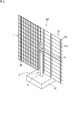
- FIG. 1 is a perspective view of one example of a concentrating solar power generation device viewed from the light receiving surface side, and shows the solar power generation device in a completed state.
- FIG. 2 is a perspective view of an example of a concentrating solar power generation device for one unit as seen from the light receiving surface side. The right half shows a state where the skeleton of the pedestal part of the tracking cradle can be seen. The attached state is shown in the left half.
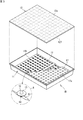
- FIG. 3 is a perspective view showing an example of the configuration of the module.
- FIG. 4 is an example of a sectional view showing a minimum basic unit of the optical system.
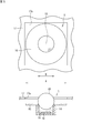
- FIG. 5 is a plan view (upper) and a cross-sectional view (lower) of the light receiving portion.
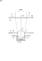
- FIG. 6 is a side view showing an example of a state in which the array is imaged.
- FIG. 7 is a diagram showing an example of how the secondary lens and the protective plate of the light receiving unit look from the image pickup apparatus.
- FIG. 8 is an example of a diagram showing a state in which the light receiving unit is reflected as a normal composite virtual image in the image captured by the array.
- FIG. 9 is a diagram illustrating an example of the tracking deviation detection system.
- FIG. 10 is a schematic plan view in which the shape of an air vehicle appears most characteristically.
- FIG. 11 is a diagram showing a composite virtual image and a cross-shaped shadow of a flying object.
- FIG. 12 is another diagram showing the composite virtual image and the cross-shaped shadow of the flying object.
- FIG. 11 is a diagram showing a composite virtual image and a cross-shaped shadow of a flying object.
- FIG. 13 is another view showing the synthetic virtual image and the cross-shaped shadow of the flying object.
- FIG. 14 is a block diagram showing an example of a configuration for automating tracking deviation detection.
- FIG. 15 is a flowchart showing an example of processing of the information processing device.
- FIG. 16 is a side view (or front view) of an aircraft having another configuration.
- FIG. 17 is a diagram showing the positional relationship between the array for tracking the sun and the imaging device.
- FIG. 18 is a schematic view of a main part of an image appearing on the surface of the array in the state of FIG.
- FIG. 19 is a diagram showing a positional relationship between an array for tracking the sun and an imaging device in a state where there is a tracking shift.
- FIG. 20 is a diagram showing a positional relationship between the array for tracking the sun and the image pickup device before and after the midday time.
- FIG. 21 is a plan view of an aircraft having another configuration.
- FIG. 22 is an example of a block diagram relating to the image pickup apparatus.
- FIG. 23 is a diagram of the image pickup apparatus viewed from the front side on the image pickup side.
- FIG. 24 is a schematic diagram of a main part of an image appearing on the surface of the array when there is no tracking shift.
- the tracking deviation of the array with respect to the sun can be detected quickly and easily by imaging the array.
- the gist of the embodiment of the present disclosure includes at least the following.
- This is a method of detecting tracking deviation of an array in a solar tracking type solar power generation device, wherein (a) an aircraft is inserted between the sun and the array, and the aircraft is projected on the array. Then, (b) the imaging device mounted on the flying object images the surface of the array from a direction perpendicular to the surface, and (c) the light receiving portion including the cell becomes a virtual image enlarged through the light collecting portion. , A collection of pixels of the virtual image becomes a composite virtual image of the whole of the light receiving unit and is captured in the array, and an image in which a shadow of the flying object is projected is obtained, tracking This is a deviation detection method.
- the light receiving section becomes a virtual image magnified through the light collecting section, and a group of pixels of the virtual image becomes a combined virtual image of the entire light receiving section. Reflected in the array. Furthermore, the shadow of the flying object is projected so as to overlap with the synthetic virtual image reflected in the array. Therefore, an image in which the shadow of the flying object is reflected in the composite virtual image reflected in the array is acquired by the imaging device. The presence or absence of tracking deviation can be detected based on the acquired image. That is, when there is no tracking deviation, the shadow of the flying object appears at the center of the composite virtual image reflected in the array. When there is a tracking shift, the shadow of the aircraft deviates from the center of the composite virtual image.
- a component of a relative shift amount between the center position of the composite virtual image and the center position of the shadow in the acquired image, and The angle of tracking deviation can be determined based on the distance to the surface of the array. In this case, it is possible to detect how much the azimuth angle or the elevation angle is deviated as an angle based on the component of the relative deviation amount.
- the shadow may be a shadow of the imaging device mounted on the flying object.
- the shadow of the image pickup device directly looking at the array in the normal direction can be projected on the array, the shadow originally desired to be seen can be seen in a better form.
- the shadow may be a shadow of a mark member attached to the imaging device mounted on the flying object.
- the shadow of the mark member attached to the image pickup device directly looking at the array in the normal direction can be projected on the array, the shadow originally desired to be seen can be seen in a better form. If the mark member has a cross shape, for example, it is easy to confirm.
- the imaging device may capture an image while moving the flying object so as to scan the entire surface of the array. Good. In this way, it is possible to detect the presence or absence of tracking deviation within the surface due to local distortion of the array or the like.
- a tracking deviation detection system an array formed by assembling basic units of an optical system that collects sunlight by a light collecting unit and makes it enter a light receiving unit including a cell, and supports the array. And a tracking platform that changes the attitude of the array so as to track the sun, a flying body that can enter between the sun and the array and project itself on the array, and mounted on the flying body And an imaging device capable of imaging the surface of the array from a direction perpendicular to the surface.
- the light receiving section becomes a virtual image magnified through the light collecting section, and a group of pixels of the virtual image becomes a combined virtual image of the entire light receiving section. Reflected in the array. Furthermore, the shadow of the flying object is projected so as to overlap with the synthetic virtual image reflected in the array. Therefore, an image in which the shadow of the flying object is reflected in the composite virtual image reflected in the array is acquired by the imaging device. The presence or absence of tracking deviation can be detected based on the acquired image. That is, when there is no tracking deviation, the shadow of the flying object appears at the center of the composite virtual image reflected in the array. When there is a tracking shift, the shadow of the aircraft deviates from the center of the composite virtual image.
- the flying body has a central portion, a plurality of rotary blades extending outward from the central portion with an equal length, and a tip of each of the rotary blades. It may be provided with a propeller provided to obtain lift. In this case, it is easy to find the center of the shadow in the image when the air vehicle is projected on the array.
- the light receiving unit includes a ball lens.
- the contour of the ball lens clearly appears in the synthetic virtual image. Therefore, it is easy to find the center position of the composite virtual image.
- the light receiving unit including the cell is a virtual image enlarged through the condensing unit, and An image in which a shadow projected by the imaging device is reflected in an image reflected in the array by a collection of pixels of the virtual image becoming a combined virtual image of the entire light receiving unit.
- the light receiving section becomes a virtual image magnified through the light collecting section, and a group of pixels of the virtual image is combined as a whole of the light receiving section. It becomes a virtual image and is reflected in the array. Further, the shadow of the image pickup device is projected so as to overlap with the composite virtual image reflected on the array. Therefore, an image in which the shadow of the image pickup device is reflected in the composite virtual image reflected in the array is acquired by the image pickup device. The presence or absence of tracking deviation can be detected based on the acquired image. That is, when there is no tracking shift, the shadow of the image pickup device appears at the center of the composite virtual image reflected on the array. When there is a tracking shift, the shadow of the image pickup device deviates from the center of the combined virtual image.
- the image pickup apparatus for example, a mark member serving as a mark to be projected is attached to the image pickup apparatus, and the image pickup is performed.
- the light receiving section including the cell is a virtual image enlarged through the light collecting section, and a collection of pixels of the virtual image is reflected in the array as a combined virtual image of the entire light receiving section. An image is obtained in which the shadow of the mark member is reflected in the image.
- the light receiving section becomes a virtual image magnified through the light collecting section, and a group of pixels of the virtual image is combined as a whole of the light receiving section. It becomes a virtual image and is reflected in the array. Furthermore, the shadow of the mark member is projected so as to overlap the composite virtual image reflected in the array. Therefore, an image in which the shadow of the mark member is reflected in the composite virtual image reflected in the array is acquired by the image pickup device. The presence or absence of tracking deviation can be detected based on the acquired image. That is, when there is no tracking deviation, the shadow of the mark member appears in the center of the composite virtual image reflected in the array. When there is tracking deviation, the shadow of the mark member deviates from the center of the composite virtual image.
- the flying body includes a linear guide, and the linear guide supports the imaging device so as to be movable within a predetermined range. It may be configured to do.
- the interposition of the linear guide allows the imaging device or the marking member attached thereto to be moved to a position away from the main body for flying the flying body. Therefore, it is possible to prevent the imaging device or the marking member attached thereto from entering the shadow of the main body portion, and to project the shadow of the imaging device or the marking member attached thereto onto the array.
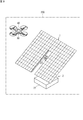
- FIG. 1 and FIG. 2 are perspective views of an example of a solar tracking and concentrating solar power generation device for one unit, as viewed from the light receiving surface side.
- FIG. 1 shows the solar power generation device 100 in a completed state
- FIG. 2 shows the solar power generation device 100 in a state of being assembled.
- FIG. 2 shows a state in which the skeleton of the gantry unit 25 of the tracking gantry 2 is visible in the right half, and shows a state in which the module 1M is attached in the left half. When the module 1M is actually attached to the tracking pedestal 2, it is attached with the pedestal portion 25 lying on the ground.
- this solar power generation device 100 is provided with an array (entire solar power generation panel) 1 that is continuous on the upper side and divided into left and right sides on the lower side, and a tracking mount 2.
- the array 1 is configured by aligning the modules 1M on the pedestal portion 25 (FIG. 2) on the back side.
- the tracking stand 2 supports the array 1 and changes the attitude of the array 1 so as to track the sun.
- the tracking mount 2 includes a column 21, a foundation 22, a biaxial drive unit 23, a horizontal shaft 24 (FIG. 2) serving as a drive shaft, and a mount unit 25.
- the column 21 has a lower end fixed to the foundation 22 and an upper end provided with a biaxial drive unit 23.
- the foundation 22 is firmly buried in the ground so that only the upper surface can be seen.
- the pillar 21 is vertical and the horizontal axis 24 (FIG. 2) is horizontal.
- the biaxial drive unit 23 can rotate the horizontal shaft 24 in two directions of an azimuth angle (an angle with the column 21 as a central axis) and an elevation angle (an angle with the horizontal shaft 24 as a central axis).
- a reinforcing member 25a is attached to the horizontal shaft 24.
- a plurality of horizontal rails 25b are attached to the reinforcing member 25a. Therefore, when the horizontal axis 24 rotates in the azimuth or elevation direction, the array 1 also rotates in that direction.
- FIGS. 1 and 2 show the tracking mount 2 that supports the array 1 with one column 21, the configuration of the tracking mount 2 is not limited to this. In short, it is sufficient that the array 1 can be supported so as to be movable in two axes (azimuth and elevation).
- FIG. 3 is a perspective view showing an example of the configuration of the module 1M.
- the module 1M includes, as an external physical form, for example, a metal-made rectangular flat-bottomed container-like casing 11 and a light-collecting member 12 mounted thereon like a lid. There is.
- the light collecting member 12 is configured, for example, by attaching a resin light collecting portion 12f (Fresnel lens) to the back surface of one transparent glass plate 12a.
- a resin light collecting portion 12f Resnel lens
- each of the illustrated square (10 ⁇ 14) sections is the light converging unit 12f and can condense sunlight to the focal position.
- a flexible printed wiring board 13 is arranged on the bottom surface 11b of the housing 11.
- a cell package 14 holding a cell (power generation element) is mounted at a predetermined position on the flexible printed wiring board 13.
- a portion surrounded by a chain double-dashed line “ ⁇ ” is an enlarged view of the light receiving unit R.
- the secondary lens 15 is provided on the cell package 14, and the protective plate 16 is provided around the secondary lens.
- the secondary lens 15 is, for example, a ball lens.
- the protection plate 16 is, for example, an annular metal body, and a commercially available washer can be used.
- the protective plate 16 prevents the convergent light from thermally damaging the periphery of the cell when the convergent light of the sunlight is deviated from the secondary lens 15. Further, the protective plate 16 receives the scattered light in the housing 11 and reflects it even if all the converged light enters the secondary lens 15.
- the light receiving sections R are provided in the same number and at the same intervals corresponding to each of the light collecting sections 12f.
- a shielding plate 17 is provided between the light receiving unit R and the light collecting member 12.
- the shielding plate 17 is provided with a square opening 17a similar to the outer diameter of one condensing part 12f at a position corresponding to each condensing part 12f.
- the light converged by the condensing unit 12f passes through the opening 17a.
- FIG. 4 is an example of a sectional view showing the minimum basic unit 1U of the optical system.
- the incident direction of sunlight is perpendicular to the condensing part 12f of the condensing member 12 and the incident direction and the optical axis Ax are parallel to each other, the light converged by the condensing part 12f is , Passes through the opening 17 a of the shielding plate 17 and enters the secondary lens 15.
- the secondary lens 15 guides the incident light to the cell 18.
- the cell 18 is held in the cell package 14.
- the protective plate 16 is attached so as to ride on the upper end of the cell package 14.
- a light-transmissive resin 19 is enclosed between the secondary lens 15 and the cell 18.
- FIG. 5 is a plan view (top) and a cross-sectional view (bottom) of the light receiving unit R.
- the outer diameter A (for example, 15 mm) of the protective plate 16 is slightly smaller than the inner dimension (for example, 18 mm) of the opening 17a.
- the inner diameter B of the protective plate 16 is approximately the outer diameter (for example, 5 mm) of the secondary lens 15. In the plan view, the protective plate 16 and the secondary lens 15 are visible in the opening 17a.
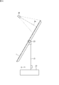
- FIG. 6 is a side view showing an example of a state in which the array 1 is imaged. As illustrated, the array 1 is imaged using the imaging device 30. The imaging device 30 images the array 1 so that its optical axis Ac is perpendicular to the array 1. The array 1 may be imaged at only one place, or the entire array 1 may be imaged while moving the imaging device 30 vertically and horizontally.
- FIG. 7 is a diagram showing an example of what the secondary lens 15 and the protective plate 16 of the light receiving section R look like from the imaging device 30.
- many light receiving units R are centered on the light receiving unit R on the optical axis Ac.
- the secondary lens 15 and the protective plate 16 appear as a virtual image magnified through a “magnifying glass” called the light condensing unit 12f.
- the light receiving part R on the optical axis Ac of the imaging device 30 will appear as a virtual image V0 in which the center of the secondary lens 15 is enlarged.
- the virtual image V0 looks black because the light reflected from the surface of the secondary lens 15 is small. Even if the light receiving portion R is not strictly on the optical axis Ac, the light receiving portion R in the vicinity of the light receiving portion R also appears as a blackish virtual image.
- the light receiving unit R slightly to the right with respect to the optical axis Ac when viewed from the imaging device 30 is to be seen from the left rather than in the middle of the corresponding light condensing unit 12f, and thus becomes a virtual image V1, for example.
- the boundary between the secondary lens 15 and the protective plate 16 can be seen. Since the protective plate 16 reflects scattered light and looks brighter than the secondary lens 15, the light contrast at the boundary becomes clear.
- the light receiving unit R further to the right of the optical axis Ac is viewed from the left end of the corresponding light collecting unit 12f, so that it becomes, for example, a virtual image V2, and the boundary between the protective plate 16 and its periphery (that is, the protective plate 16). 16 outer contours) are visible. Since the surrounding area reflects less light than the protective plate 16, the light contrast at the boundary becomes clear.
- the light receiving portion R slightly left of the optical axis Ac as viewed from the image pickup device 30 is not seen in the middle of the corresponding light collecting portion 12f but slightly from the right, for example, the virtual image V3 is obtained. Then, the boundary between the secondary lens 15 and the protective plate 16 can be seen. Since the light receiving portion R further left to the optical axis Ac is seen from the right end of the corresponding light collecting portion 12f, it becomes a virtual image V4, for example, and the outer contour of the protective plate 16 can be seen.
- the light receiving unit R slightly above the optical axis Ac as viewed from the imaging device 30 is not seen in the middle of the corresponding light condensing unit 12f but rather slightly below, and therefore, for example, the virtual image V5. Therefore, the boundary between the secondary lens 15 and the protective plate 16 can be seen. Since the light receiving portion R located further above the optical axis Ac is seen from the lower end of the corresponding light collecting portion 12f, for example, it becomes a virtual image V6, and the outer contour of the protective plate 16 can be seen.
- the light receiving unit R slightly below the optical axis Ac when viewed from the imaging device 30 is not seen in the middle of the corresponding light converging unit 12f, but slightly above, it is, for example, a virtual image V7. Then, the boundary between the secondary lens 15 and the protective plate 16 can be seen. Since the light receiving unit R further below the optical axis Ac is viewed from the upper end of the corresponding light collecting unit 12f, for example, it becomes a virtual image V8, and the outer contour of the protective plate 16 can be seen.
- the light receiving portions R located diagonally upper right, diagonally lower right, diagonally lower left, and diagonally upper left with respect to the optical axis Ac are also like virtual images V9, V10, V11, and V12, respectively. appear.
- the light receiving unit R becomes a virtual image enlarged through the light converging unit 12f, and the collection of pixels of the virtual image. It is possible to acquire an image reflected in a plurality of modules 1M as a combined virtual image of the entire light receiving unit R.
- the composite virtual image of the light receiving part R reflected in the image of the array 1 reflects the actual shape. To do. In particular, the shapes of the secondary lens 15 and the protective plate 16 are reflected.
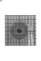
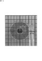
- FIG. 8 is an example of a diagram showing a state in which the light receiving unit R is reflected as a normal composite virtual image in the image captured by the array 1. As shown by the two concentric circles in the figure, the shapes of the secondary lens 15 and the protective plate 16 that form the light receiving unit R appear as an enlarged composite virtual image. Since the ball lens is used as the secondary lens, the inner circle has a high contrast.
- FIG. 9 is a diagram showing an example of the tracking deviation detection system 200.
- the tracking deviation detection system 200 includes an array 1, a tracking mount 2, a flying object 40, and an imaging device 30.
- the flying body 40 is a drone that can be automatically piloted by a built-in computer, a small multicopter, or the like.
- the imaging device 30 is mounted on the flying body 40.
- the imaging device 30 mounted on the flying object 40 can image the surface of the array 1 during solar power generation from an arbitrary position and distance.
- the flying body 40 is preferably small, but a large and manned flying body (for example, a helicopter) is theoretically possible. However, in that case, it is necessary to set a distance such that the shadow of the flying object itself becomes relatively smaller than the entire surface of the array 1.
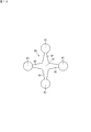
- FIG. 10 is a schematic plan view in which the shape of the air vehicle 40 appears most characteristically.
- the flying body 40 has a cross shape, and has a structural central portion 41, a plurality of (in this case, four) rotary blades 42 extending outward from the central portion 41 with the same length, and at the tip of the rotary blade 42. And a propeller 43 for obtaining lift. Since the center of such a cross shape can be easily confirmed, it is suitable for projection described later. However, in addition to this, a shape of the flying body 40 is suitable if the shape is such that the center position can be easily understood when projected.
- FIG. 9 ⁇ Projection of flight object to array ⁇
- an air vehicle 40 for example hovering near array 1 enters between the sun and array 1.
- the flying object 40 is projected onto the array 1, and the shadow of the flying object 40 is projected on the surface of the array 1.
- this line segment is parallel to the sunlight.
- the line segment is a normal line perpendicular to the surface of the array 1.
- FIG. 11 is a diagram showing a composite virtual image and a cross-shaped shadow of the flying object 40.
- the center of the composite virtual image that is, the center of the double circle in FIG. 11 and the center of the shadow are at the same position.
- the center of the shadow is the cross point of the cross.
- the shadow is shown as white for the sake of explanation, but actually it is darker than the inner circle of the composite virtual image. When such an image is obtained, it can be said that tracking is normal and there is substantially no tracking deviation.
- FIG. 12 is another diagram showing the composite virtual image and the cross-shaped shadow of the flying object 40.
- the center of the shadow is displaced upward from the center of the composite virtual image by a distance d1.
- the reason for such an image is that there is a tracking shift of the elevation angle.
- ⁇ E Arctan (d1/L).
- FIG. 13 is another view showing the composite virtual image and the cross-shaped shadow of the flying object 40.
- the center of the shadow is displaced rightward from the center of the composite virtual image by a distance d2.
- the reason for such an image is that there is a tracking shift in azimuth.
- ⁇ A Arctan (d2/L).
- the shift component is divided into the vertical direction (elevation angle) and the horizontal direction (azimuth angle), and the respective shifts are made. The angle can be calculated.
- the flying body 40 is inserted between the sun and the array 1 to project the flying body 40 on the array 1, and (b) the flying body 40 is mounted on the flying body 40.
- the imaging device 30 images the surface of the array 1 from a direction perpendicular to the array 1, and (c) the light receiving unit R including the cell 18 becomes a virtual image enlarged through the light collecting unit 12f, and a collection of pixels of the virtual image is formed. An image in which a shadow is reflected is acquired in the image reflected in the array 1 as a combined virtual image of the light receiving unit R as a whole.
- the light receiving unit R When the array 1 is viewed from a direction perpendicular to an arbitrary position on its surface, the light receiving unit R becomes a virtual image magnified through the light collecting unit 12f, and a collection of pixels of the virtual image as a whole of the light receiving unit R. It is reflected in the array as a synthetic virtual image. Further, the shadow of the flying object 40 is projected so as to overlap with the synthetic virtual image reflected on the array 1. Therefore, the image in which the shadow of the flying object 40 is reflected in the composite virtual image reflected in the array 1 is acquired by the image pickup device 30. The presence or absence of tracking deviation can be detected based on the acquired image. That is, when there is no tracking deviation, the shadow of the flying object 40 appears in the center of the composite virtual image reflected in the array 1. When there is a tracking shift, the shadow of the flying object 40 deviates from the center of the composite virtual image.
- the angle of tracking deviation can be obtained. That is, it is possible to detect how much the azimuth angle or the elevation angle is deviated as an angle based on the component of the relative deviation amount.
- the array 1 has been described as one unit from the viewpoint of tracking deviation, if the imaging device 30 captures an image while moving the flying body 40 so as to scan the entire surface of the array 1, the local distortion of the array 1 will occur. It is also possible to detect a tracking shift that may occur in the surface due to the above.
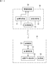
- FIG. 14 is a block diagram showing an example of a configuration for automating tracking deviation detection.
- the imaging device 30 includes an image acquisition unit 31, a distance measurement unit 32, a transmission/reception unit 33, and a drive control unit 34.
- the drive control unit 34 has a function of directing the imaging device 30 in an arbitrary direction within its movable range.
- the drive control unit 34 causes the imaging direction of the imaging device 30 to face the array 1 vertically, that is, perpendicular to the surface of the array 1. Adjust to.
- the image acquisition unit 31 acquires an image in which the composite virtual image of the light receiving unit R and the shadow of the flying object 40 are reflected.
- the distance measuring unit 32 is, for example, a laser rangefinder, and measures the distance L between the imaging device 30 and the surface of the array 1.
- the information of the acquired image and the information of the distance L are wirelessly transmitted by the transmitting/receiving unit 33.
- the information processing unit 50 using a personal computer on the ground side includes a transmission/reception unit 51, an image analysis unit 52, a tracking deviation detection unit 53, and a storage unit 54.
- the transceiver 51 receives the information transmitted from the transceiver 33.
- the image analysis unit 52 extracts the image data of the combined virtual image and the shadow based on the received information.
- the tracking deviation detection unit 53 detects the center position of each of the extracted combined virtual image and shadow image data, and detects the presence or absence of tracking deviation. When there is a tracking shift, the azimuth angle or the elevation angle is determined based on the component of the relative shift amount between the center position of the composite virtual image and the center position of the shadow, and the distance from the imaging device 30 to the surface of the array 1. It is possible to detect how much is shifted as an angle. Further, the information regarding the tracking deviation can be stored and accumulated in the storage unit 54.
- the function of the information processing unit 50 may be mounted on the flying body 40. In that case, the transmission/reception units 33 and 51 are unnecessary.
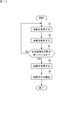
- FIG. 15 is a flowchart showing an example of processing of the imaging device 30 and the information processing unit 50.
- the information processing unit 50 acquires an image from the image acquisition unit 31 via the transmission/reception units 33 and 51 (step S1) and analyzes the image (step S2).
- the information processing unit 50 determines whether or not the combined virtual image and the shadow of the flying object 40 are reflected in the analyzed image (step S3). If the imaging is performed from the direction perpendicular to an arbitrary position on the surface of the array 1, the synthetic virtual image and the shadow should be reflected.
- the image analysis unit 52 sends a signal for changing the image pickup direction to the drive control unit 34 via the transmission/reception units 51, 33, and while adjusting the direction of the image pickup device 30, the image acquisition and analysis are performed. Repeat (steps S1, S2, S3).
- the information processing unit 50 acquires the distance information (step S4) and detects the tracking deviation (step S5). If there is tracking deviation, the deviation angle ( ⁇ A , ⁇ E ) is obtained (step S5).
- the tracking deviation angle calculated as above exceeds the allowable value, correct the tracking operation. Further, even if the tracking deviation is within the allowable value, by periodically detecting the tracking deviation and accumulating the data of the tracking deviation, for example, how the tracking deviation changes according to the time of morning, daytime, and evening can be determined. You can figure it out. Further, by detecting the tracking deviation regularly throughout the year, it is possible to understand how the tracking deviation changes according to the temperature and the sun altitude.
- the flying body 40 which is a drone, can only hover in a horizontal state.
- the shape of the flying object 40 is projected without substantially changing, but when the array 1 is not in a horizontal attitude, an ideal cross-shaped shadow is not formed. Therefore, it is considered that the portion of the flying body 40 that is not the main body for flying is used as the projection target.
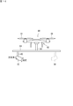
- FIG. 16 is a side view (or front view) of an air vehicle 60 having another configuration.
- the flying body 60 is a schematic diagram as an example.
- an air vehicle 60 has a main body 62 for flight, which includes four (only two are shown) propellers 61.
- a linear guide 64 as a support member that supports the imaging device 30 is attached to the lower end of the pillar 63 at the center of the main body 62. If the main body 62 is horizontal, the linear guide 64 is also horizontal. The linear guide 64 can move the imaging device 30 in the lateral direction.
- the image pickup device 30 is supported by the linear guide 64 via a suspension member 65.
- a gimbal connector (not shown), for example, is used to connect the hanging member 65 and the imaging device 30.
- the gimbal connector and the drive controller 34 (FIG. 14) allow the imaging device 30 to move in both directions of azimuth and elevation with respect to the suspension member 65. Further, the imaging device 30 can be laterally moved together with the suspending member 65 by being guided by the linear guide 64 as illustrated. However, what is significant as the position of the imaging device 30 is the position near both ends of the linear guide 64.
- the linear guide 64 has a built-in small motor, for example, and is capable of laterally moving the imaging device 30 freely. For example, if the motor is driven by the drive control unit 34 (FIG. 14), the imaging device 30 can be moved laterally. However, before the takeoff of the flying body 60, it is also possible to laterally move it by an operator's manual operation.
- FIG. 17 is a diagram showing a positional relationship between the array 1 for tracking the sun and the image pickup device 30.
- the array 1 faces the sun at an elevation angle ⁇ (for example, 20 degrees), and the incident angle of sunlight on the surface of the array 1 is 0 degree.
- the flying body 60 is in the hovering state, and the imaging direction of the imaging device 30 is on the normal line NL of the array 1.
- the imager 30 that falls between the sun and the array 1 is projected onto the surface of the array 1 on the normal NL.
- the flying body 60 except the image pickup device 30 also casts a shadow on the surface of the array 1, but the shadow is not on the intersection of the normal NL and the surface of the array 1.
- FIG. 18 is a schematic view of a main part of an image appearing on the surface of the array 1 in the state of FIG.
- the image includes an inner circle C1 formed by a combined virtual image of the secondary lens 15 (FIG. 5) and an outer circle C2 formed by a combined virtual image of the protective plate 16 (FIG. 5).
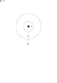
- An image of the containing double circle appears. Then, the shadow S projected by the imaging device 30 can be seen at the center of the inner circle C1. If such an image is obtained, it can be said that tracking is normal and there is substantially no tracking deviation.
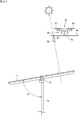
- FIG. 19 is a diagram showing a positional relationship between the array 1 for tracking the sun and the imaging device 30 in a state where there is a tracking shift.
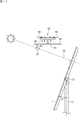
- the imaging device 30 is adjusted in posture so that a double circle image is obtained, and the imaging direction is on the normal line NL to the surface of the array 1.
- the shadow of the image capturing apparatus 30 itself does not exist at the center of the double circle, and the point P has a shadow.
- the displacement angle ⁇ E can be known from the distance that the shadow is displaced from the center of the double circle.
- the shift component is divided into the vertical direction (elevation angle) and the horizontal direction (azimuth angle), and the respective shifts are made. The angle can be calculated.
- FIG. 20 is a diagram showing a positional relationship between the array 1 for tracking the sun and the imaging device 30 before and after the midday time.
- the elevation angle ⁇ is 80 degrees.
- the shadow of the entire flying object 60 (excluding the image pickup device 30) and the shadow of the image pickup device 30 are likely to overlap with each other, but the image pickup device 30 moves near the end of the linear guide 64. , It is possible to suppress overlapping of shadows.
- FIG. 21 is a plan view of an air vehicle 60 having another configuration.
- the flying body 60 includes four propellers 61 and a main body portion 62. Below the main body 62, cross-shaped linear guides 64a and 64b in two orthogonal directions are provided.
- the imaging device 30 is slidably supported along the linear guides 64a and 64b, and can be moved to, for example, not only the position indicated by the solid line but also the three positions indicated by the dotted line.
- FIG. 22 is an example of a block diagram regarding the imaging device 30.
- the difference from FIG. 14 is that the information processing unit 50 is mounted on the flying body 60 together with the imaging device 30, and that the imaging device 30 is equipped with a GPS (Global Positioning System) receiver 35 (FIG. 14). Is omitted.)
- the drive control unit 34 calculates the position of the sun based on the information such as the time, latitude, and longitude acquired by the GPS receiver 35, and the shadow of the flying object 60 and the shadow of the imaging device 30 are on the surface of the array 1.
- the positions of the image pickup device 30 shown in FIG. 21 it is determined which position of the linear guides 64a and 64b is best to support the image pickup device 30 for projection so as not to overlap.
- the imaging device 30 is supported by the linear guides 64a and 64b at the best position.
- FIG. 23 is a diagram of the image pickup apparatus 30 viewed from the front side on the image pickup side.
- a cross-shaped mark member 70 is attached to the lower portion of the imaging device 30.
- FIG. 24 is a schematic diagram of a main part of an image appearing on the surface of the array 1 when there is no tracking shift.
- the image includes an inner circle C1 formed by the combined virtual image of the secondary lens 15 (FIG. 5) and an outer circle C2 formed by the combined virtual image of the protective plate 16 (FIG. 5).
- An image of the containing double circle appears. Then, the shadow S on which the mark member 70 is projected can be seen at the center of the inner circle C1. If such an image is obtained, it can be said that tracking is normal and there is substantially no tracking deviation.
- the shadow of the cross-shaped mark member 70 has an advantage that its center is easy to see.
- the concentrating solar power generation device 100 that uses the condensing unit 12f that is a Fresnel lens has been described.
- a reflective sun that reflects sunlight by a concave mirror and guides the condensed light to a cell
- the same tracking deviation detection method can be applied to the photovoltaic device. This is because the concave mirror can also project a virtual image like the Fresnel lens.
Landscapes
- Life Sciences & Earth Sciences (AREA)
- Sustainable Development (AREA)
- Length Measuring Devices By Optical Means (AREA)
Abstract
太陽追尾型の太陽光発電装置におけるアレイの追尾ずれ検出方法であって、飛行体を太陽と前記アレイとの間に入らせて当該飛行体を前記アレイに投影し、前記飛行体に搭載された撮像装置により、前記アレイの表面を、当該表面に垂直な方向から撮像し、セルを含む受光部が集光部を通して拡大された虚像となり、当該虚像の画素の集まりが前記受光部の全体としての合成虚像となって前記アレイに映り込んでいる画像の中に、前記飛行体が投影された影が映っている画像を取得する、追尾ずれ検出方法である。
Description
本開示は、追尾ずれ検出方法及び追尾ずれ検出システムに関する。
本出願は、2019年1月24日出願の日本出願第2019-010313号に基づく優先権を主張し、前記日本出願に記載された全ての記載内容を援用するものである。
本出願は、2019年1月24日出願の日本出願第2019-010313号に基づく優先権を主張し、前記日本出願に記載された全ての記載内容を援用するものである。
集光型太陽光発電装置は、集光レンズにより太陽光を集めて発電用の小さなセルに入射させる光学系の基本ユニットの集合体である。基本ユニットを1つの筐体内にマトリクス状に並べたものがモジュールであり、このモジュールを多数整列させたものがアレイ(パネル)である。アレイは、追尾架台により支持される。また、追尾架台は、太陽を追尾するようにアレイの姿勢を変化させる。
集光型太陽光発電装置では、太陽に対するアレイの追尾動作がずれると集光位置がずれて発電できなくなる。そのため、常に正確な追尾が求められる。目視点検では追尾ずれが生じているかどうかを検出することは困難であるため、発電電力の変化に基づいて追尾ずれを検出する方法が提案されている(例えば、特許文献1参照。)。
本開示は、以下の発明を含む。但し、本発明は、請求の範囲によって定められるものである。
本発明の一表現に係る方法は、太陽追尾型の太陽光発電装置におけるアレイの追尾ずれ検出方法であって、(a)飛行体を太陽と前記アレイとの間に入らせて当該飛行体を前記アレイに投影し、(b)前記飛行体に搭載された撮像装置により、前記アレイの表面を、当該表面に垂直な方向から撮像し、(c)セルを含む受光部が集光部を通して拡大された虚像となり、当該虚像の画素の集まりが前記受光部の全体としての合成虚像となって前記アレイに映り込んでいる画像の中に、前記飛行体が投影された影が映っている画像を取得する、追尾ずれ検出方法である。
本発明の一表現による追尾ずれ検出システムは、太陽光を集光部により集光し、セルを含む受光部に入射させる光学系の基本ユニットが集合して構成されたアレイと、前記アレイを支持し、かつ、太陽を追尾するように前記アレイの姿勢を変化させる追尾架台と、太陽と前記アレイとの間に入って前記アレイに自己を投影することができる飛行体と、前記飛行体に搭載され、前記アレイの表面を、当該表面に垂直な方向から撮像可能な撮像装置と、を有する。
[発明が解決しようとする課題]
発電電力の変化に基づいて追尾ずれを検出するには、変化を継続的に観察する必要がある。もっと迅速に且つ簡単に追尾ずれを検出できればさらに好ましい。
かかる課題に鑑み、本開示は、アレイの追尾ずれを、迅速に且つ簡単に検出することを目的とする。
発電電力の変化に基づいて追尾ずれを検出するには、変化を継続的に観察する必要がある。もっと迅速に且つ簡単に追尾ずれを検出できればさらに好ましい。
かかる課題に鑑み、本開示は、アレイの追尾ずれを、迅速に且つ簡単に検出することを目的とする。
[本開示の効果]
本開示によれば、太陽に対するアレイの追尾ずれを、アレイを撮像することによって迅速に且つ簡単に検出することができる。
本開示によれば、太陽に対するアレイの追尾ずれを、アレイを撮像することによって迅速に且つ簡単に検出することができる。
[実施形態の要旨]
本開示の実施形態の要旨としては、少なくとも以下のものが含まれる。
本開示の実施形態の要旨としては、少なくとも以下のものが含まれる。
(1)これは、太陽追尾型の太陽光発電装置におけるアレイの追尾ずれ検出方法であって、(a)飛行体を太陽と前記アレイとの間に入らせて当該飛行体を前記アレイに投影し、(b)前記飛行体に搭載された撮像装置により、前記アレイの表面を、当該表面に垂直な方向から撮像し、(c)セルを含む受光部が集光部を通して拡大された虚像となり、当該虚像の画素の集まりが前記受光部の全体としての合成虚像となって前記アレイに映り込んでいる画像の中に、前記飛行体が投影された影が映っている画像を取得する、追尾ずれ検出方法である。
アレイを、その表面の任意の位置に対して垂直な方向から見ると、受光部が集光部を通して拡大された虚像となり、当該虚像の画素の集まりが、受光部の全体としての合成虚像となってアレイに映り込む。さらに、アレイに映り込んだ合成虚像と重なるように飛行体の影が映る。そこで、アレイに映り込んだ合成虚像の中に飛行体の影が映っている画像を、撮像装置により取得する。この取得した画像に基づいて、追尾ずれの有無を検出することができる。すなわち、追尾ずれがない場合は、アレイに映り込んだ合成虚像の中心に、飛行体の影が映る。追尾ずれがある場合は、飛行体の影は合成虚像の中心から外れる。
(2)前記(1)の追尾ずれ検出方法において、例えば、取得した画像における前記合成虚像の中心位置と、前記影の中心位置との相対的なずれ量の成分、及び、前記撮像装置から前記アレイの表面までの距離に基づいて、追尾ずれの角度を求めることができる。
この場合、相対的なずれ量の成分に基づいて方位角又は仰角が角度としてどれだけずれているかを検出することができる。
この場合、相対的なずれ量の成分に基づいて方位角又は仰角が角度としてどれだけずれているかを検出することができる。
(3)前記(1)又は(2)の追尾ずれ検出方法において、前記影は、前記飛行体に搭載された前記撮像装置の影であってもよい。
この場合、アレイを法線方向に直視している撮像装置の影をアレイに投影することができるので、本来見たい影を、よりよい形で見ることができる。
この場合、アレイを法線方向に直視している撮像装置の影をアレイに投影することができるので、本来見たい影を、よりよい形で見ることができる。
(4)前記(1)又は(2)の追尾ずれ検出方法において、前記影は、前記飛行体に搭載された前記撮像装置に取り付けられた目印部材の影であってもよい。
この場合、アレイを法線方向に直視している撮像装置に取り付けられた目印部材の影をアレイに投影することができるので、本来見たい影を、よりよい形で見ることができる。目印部材の形態を例えば十字状にすれば確認が容易である。
この場合、アレイを法線方向に直視している撮像装置に取り付けられた目印部材の影をアレイに投影することができるので、本来見たい影を、よりよい形で見ることができる。目印部材の形態を例えば十字状にすれば確認が容易である。
(5)前記(1)から(4)までのいずれかの追尾ずれ検出方法において、前記アレイの表面全体をスキャンするように前記飛行体を移動させつつ、前記撮像装置により撮像するようにしてもよい。
このようにして、アレイの局部的なゆがみ等による表面内での追尾ずれの有無を検出することができる。
このようにして、アレイの局部的なゆがみ等による表面内での追尾ずれの有無を検出することができる。
(6)一方、追尾ずれ検出システムとしては、太陽光を集光部により集光し、セルを含む受光部に入射させる光学系の基本ユニットが集合して構成されたアレイと、前記アレイを支持し、かつ、太陽を追尾するように前記アレイの姿勢を変化させる追尾架台と、太陽と前記アレイとの間に入って前記アレイに自己を投影することができる飛行体と、前記飛行体に搭載され、前記アレイの表面を、当該表面に垂直な方向から撮像可能な撮像装置と、を有する。
アレイを、その表面の任意の位置に対して垂直な方向から見ると、受光部が集光部を通して拡大された虚像となり、当該虚像の画素の集まりが、受光部の全体としての合成虚像となってアレイに映り込む。さらに、アレイに映り込んだ合成虚像と重なるように飛行体の影が映る。そこで、アレイに映り込んだ合成虚像の中に飛行体の影が映っている画像を、撮像装置により取得する。この取得した画像に基づいて、追尾ずれの有無を検出することができる。すなわち、追尾ずれがない場合は、アレイに映り込んだ合成虚像の中心に、飛行体の影が映る。追尾ずれがある場合は、飛行体の影は合成虚像の中心から外れる。
(7)前記(6)の追尾ずれ検出システムにおいて、前記飛行体は、中心部と、当該中心部から均等な長さで外方へ延びる複数の回転翼と、当該回転翼の各々の先端に設けられ、揚力を得るプロペラと、を備えたものであってもよい。
この場合、飛行体がアレイに投影された場合に、画像の中の影の中心を発見することが容易である。
この場合、飛行体がアレイに投影された場合に、画像の中の影の中心を発見することが容易である。
(8)前記(6)又は(7)の追尾ずれ検出システムにおいて、前記受光部はボールレンズを含むことが好ましい。
この場合、ボールレンズの輪郭が合成虚像の中に明瞭に現れる。従って、合成虚像の中心位置を発見するのが容易である。
この場合、ボールレンズの輪郭が合成虚像の中に明瞭に現れる。従って、合成虚像の中心位置を発見するのが容易である。
(9)前記(6)から(8)までのいずれかの追尾ずれ検出システムにおいて、前記撮像装置は、例えば、前記セルを含む前記受光部が前記集光部を通して拡大された虚像となり、かつ、当該虚像の画素の集まりが前記受光部の全体としての合成虚像となって前記アレイに映り込んでいる画像の中に、前記撮像装置が投影された影が映っている画像を取得する。
この場合、アレイを、その表面の任意の位置に対して垂直な方向から見ると、受光部が集光部を通して拡大された虚像となり、当該虚像の画素の集まりが、受光部の全体としての合成虚像となってアレイに映り込む。さらに、アレイに映り込んだ合成虚像と重なるように撮像装置の影が映る。そこで、アレイに映り込んだ合成虚像の中に撮像装置の影が映っている画像を、撮像装置により取得する。この取得した画像に基づいて、追尾ずれの有無を検出することができる。すなわち、追尾ずれがない場合は、アレイに映り込んだ合成虚像の中心に、撮像装置の影が映る。追尾ずれがある場合は、撮像装置の影は合成虚像の中心から外れる。
(10)前記(6)から(8)までのいずれかの追尾ずれ検出システムにおいて、前記撮像装置は、例えば、投影されるべき目印となる目印部材が前記撮像装置に取り付けられており、前記撮像装置は、前記セルを含む前記受光部が前記集光部を通して拡大された虚像となり、かつ、当該虚像の画素の集まりが前記受光部の全体としての合成虚像となって前記アレイに映り込んでいる画像の中に、前記目印部材が投影された影が映っている画像を取得する。
この場合、アレイを、その表面の任意の位置に対して垂直な方向から見ると、受光部が集光部を通して拡大された虚像となり、当該虚像の画素の集まりが、受光部の全体としての合成虚像となってアレイに映り込む。さらに、アレイに映り込んだ合成虚像と重なるように目印部材の影が映る。そこで、アレイに映り込んだ合成虚像の中に目印部材の影が映っている画像を、撮像装置により取得する。この取得した画像に基づいて、追尾ずれの有無を検出することができる。すなわち、追尾ずれがない場合は、アレイに映り込んだ合成虚像の中心に、目印部材の影が映る。追尾ずれがある場合は、目印部材の影は合成虚像の中心から外れる。
(11)前記(6)から(10)までのいずれかの追尾ずれ検出システムにおいて、前記飛行体はリニアガイドを備えており、前記リニアガイドは、前記撮像装置を所定範囲内で移動可能に支持する、という構成であってもよい。
この場合、リニアガイドの介在によって、飛行体の飛行ための本体部から離れた位置へ撮像装置又はこれに取り付けられた目印部材を移動させることができる。従って、撮像装置又はこれに取り付けられた目印部材が、本体部の影に入ることを回避し、撮像装置又はこれに取り付けられた目印部材の影をアレイに投影することができる。
この場合、リニアガイドの介在によって、飛行体の飛行ための本体部から離れた位置へ撮像装置又はこれに取り付けられた目印部材を移動させることができる。従って、撮像装置又はこれに取り付けられた目印部材が、本体部の影に入ることを回避し、撮像装置又はこれに取り付けられた目印部材の影をアレイに投影することができる。
[実施形態の詳細]
以下、本発明の一実施形態について、図面を参照して説明する。
以下、本発明の一実施形態について、図面を参照して説明する。
《太陽光発電装置》
図1及び図2はそれぞれ、1基分の、太陽追尾型で集光型の太陽光発電装置の一例を、受光面側から見た斜視図である。図1は、完成した状態での太陽光発電装置100を示し、図2は、組立途中の状態での太陽光発電装置100を示している。図2は、追尾架台2の架台部25の骨組みが見える状態を右半分に示し、モジュール1Mが取り付けられた状態を左半分に示している。なお、実際にモジュール1Mを追尾架台2に取り付ける際は、架台部25を地面に寝かせた状態で取り付けを行う。
図1及び図2はそれぞれ、1基分の、太陽追尾型で集光型の太陽光発電装置の一例を、受光面側から見た斜視図である。図1は、完成した状態での太陽光発電装置100を示し、図2は、組立途中の状態での太陽光発電装置100を示している。図2は、追尾架台2の架台部25の骨組みが見える状態を右半分に示し、モジュール1Mが取り付けられた状態を左半分に示している。なお、実際にモジュール1Mを追尾架台2に取り付ける際は、架台部25を地面に寝かせた状態で取り付けを行う。
図1において、この太陽光発電装置100は、上部側で連続し、下部側で左右に分かれた形状のアレイ(太陽光発電パネル全体)1と、追尾架台2とを備えている。アレイ1は、背面側の架台部25(図2)上にモジュール1Mを整列させて構成されている。図1の例では、左右のウイングを構成する(96(=12×8)×2)個と、中央の渡り部分の8個との、合計200個のモジュール1Mの集合体として、アレイ1が構成されている。
追尾架台2は、アレイ1を支持するとともに、太陽を追尾するようにアレイ1の姿勢を変化させる。追尾架台2は、支柱21と、基礎22と、2軸駆動部23と、駆動軸となる水平軸24(図2)と、架台部25を備えている。支柱21は、下端が基礎22に固定され、上端に2軸駆動部23を備えている。
図1において、基礎22は、上面のみが見える程度に地中に堅固に埋設される。基礎22を地中に埋設した状態で、支柱21は鉛直となり、水平軸24(図2)は水平となる。2軸駆動部23は、水平軸24を、方位角(支柱21を中心軸とした角度)及び仰角(水平軸24を中心軸とした角度)の2方向に回動させることができる。図2において、水平軸24には、補強材25aが取り付けられている。また、補強材25aには、複数本の水平方向へのレール25bが取り付けられている。従って、水平軸24が方位角又は仰角の方向に回動すれば、アレイ1もその方向に回動する。
なお、図1,図2では1本の支柱21でアレイ1を支える追尾架台2を示したが、追尾架台2の構成は、これに限られるものではない。要するに、アレイ1を、2軸(方位角、仰角)で可動なように支持できる構成であればよい。
《モジュールの構成例》
図3は、モジュール1Mの構成の一例を示す斜視図である。図において、モジュール1Mは、外観上の物理的な形態としては、例えば金属製で長方形の平底容器状の筐体11と、その上に蓋のように取り付けられる集光部材12と、を備えている。集光部材12は、例えば1枚の透明なガラス板12aの裏面に樹脂製の集光部12f(フレネルレンズ)が貼り付けられて構成されている。例えば図示の正方形(10個×14個)の区画の1つ1つが、集光部12fであり、太陽光を焦点位置に収束させることができる。
図3は、モジュール1Mの構成の一例を示す斜視図である。図において、モジュール1Mは、外観上の物理的な形態としては、例えば金属製で長方形の平底容器状の筐体11と、その上に蓋のように取り付けられる集光部材12と、を備えている。集光部材12は、例えば1枚の透明なガラス板12aの裏面に樹脂製の集光部12f(フレネルレンズ)が貼り付けられて構成されている。例えば図示の正方形(10個×14個)の区画の1つ1つが、集光部12fであり、太陽光を焦点位置に収束させることができる。
筐体11の底面11b上には、フレキシブルプリント配線板13が配置されている。フレキシブルプリント配線板13上の所定位置にはセル(発電素子)を保持するセルパッケージ14が搭載されている。図中の、二点鎖線の「○」で囲んでいる部位は、受光部Rの拡大図である。受光部Rにおいて、セルパッケージ14上には2次レンズ15があり、二次レンズの周りには保護板16がある。2次レンズ15は例えばボールレンズである。保護板16は、例えば、円環状の金属体であり、市販のワッシャを用いることができる。保護板16は2次レンズ15から太陽光の収束光が外れた場合に、収束光がセル周辺に熱的なダメージを与えることを防止している。また、保護板16は、収束光が全て2次レンズ15に入っている場合であっても、筐体11内での散乱光を受けてこれを反射する。
受光部Rは、集光部12fの各々に対応して同数、同一間隔で、設けられている。受光部Rと集光部材12との間には、遮蔽板17が設けられている。遮蔽板17には、個々の集光部12fに対応した位置に、1つの集光部12fの外径と相似な正方形の開口17aが形成されている。集光部12fによって収束する光は、開口17aを通過する。太陽光の入射方向と受光部Rの光軸とが大きくずれた場合には、ずれた位置に集光しようとする光は遮蔽板17に当たるようになっている。
図4は、光学系の最小の基本ユニット1Uを現す断面図の一例である。図において、太陽光の入射方向が集光部材12の集光部12fに対して垂直であり、入射方向と光軸Axとが互いに平行であるとき、集光部12fによって収束させられた光は、遮蔽板17の開口17aを通り抜け、2次レンズ15に入射する。2次レンズ15は、入射した光をセル18に導く。セル18は、セルパッケージ14の中に保持されている。保護板16は、セルパッケージ14の上端に乗るように取り付けられている。2次レンズ15とセル18との間には、光透過性の樹脂19が封入されている。
図5は、受光部Rの平面図(上)及び断面図(下)である。保護板16の外径A(例えば15mm)は、開口17aの内寸法(例えば18mm)より若干小さい。保護板16の内径Bは、ほぼ、2次レンズ15の外径(例えば5mm)である。平面図では、開口17aの中に、保護板16と2次レンズ15とが見えている状態となる。
《アレイの撮像》
図6は、アレイ1を撮像する状態の一例を示す側面図である。図示のように、撮像装置30を用いてアレイ1を撮像する。撮像装置30は、その光軸Acがアレイ1に対して垂直になるように向けてアレイ1を撮像する。アレイ1の撮像は、一箇所のみであってもよいし、また、撮像装置30を上下左右に動かしながら、アレイ1全体を撮像してもよい。
図6は、アレイ1を撮像する状態の一例を示す側面図である。図示のように、撮像装置30を用いてアレイ1を撮像する。撮像装置30は、その光軸Acがアレイ1に対して垂直になるように向けてアレイ1を撮像する。アレイ1の撮像は、一箇所のみであってもよいし、また、撮像装置30を上下左右に動かしながら、アレイ1全体を撮像してもよい。
図7は、受光部Rの2次レンズ15及び保護板16が、撮像装置30からどのように見えるかの一例を示す図である。撮像装置30の視野内には、光軸Ac上にある受光部Rを中心として多くの受光部Rが映る。2次レンズ15及び保護板16は、撮像装置30側から見ると、集光部12fという「虫眼鏡」を通して拡大された虚像として見える。撮像装置30の光軸Ac上にある受光部Rは、2次レンズ15の中心が拡大された虚像V0となって見えることになる。虚像V0は、2次レンズ15の表面からの光反射が少ないので、黒っぽく見える。また、厳密に光軸Ac上になくても、その近傍にある受光部Rも同様の黒っぽい虚像として見える。
撮像装置30から見て、光軸Acに対して少し右にある受光部Rは、対応する集光部12fのど真ん中で見るのではなく少し左から見ることになるので、例えば虚像V1となって、2次レンズ15と保護板16との境界が見える。保護板16は散乱光を反射していて2次レンズ15よりも明るく見えるので、境界での光のコントラストが明確になる。光軸Acに対してさらに右にある受光部Rは、対応する集光部12fの左端から見ることになるので、例えば虚像V2となって、保護板16とその周辺との境界(すなわち保護板16の外側輪郭)が見える。周辺は保護板16に比べて光の反射が少ないので境界での光のコントラストが明確になる。
また、撮像装置30から見て、光軸Acに対して少し左にある受光部Rは、対応する集光部12fのど真ん中で見るのではなく少し右から見ることになるので、例えば虚像V3となって、2次レンズ15と保護板16との境界が見える。光軸Acに対してさらに左にある受光部Rは、対応する集光部12fの右端から見ることになるので、例えば虚像V4となって、保護板16の外側輪郭が見える。
同様に、撮像装置30から見て、光軸Acに対して少し上にある受光部Rは、対応する集光部12fのど真ん中で見るのではなく少し下から見ることになるので、例えば虚像V5となって、2次レンズ15と保護板16との境界が見える。光軸Acに対してさらに上にある受光部Rは、対応する集光部12fの下端から見ることになるので、例えば虚像V6となって、保護板16の外側輪郭が見える。
また、撮像装置30から見て、光軸Acに対して少し下にある受光部Rは、対応する集光部12fのど真ん中で見るのではなく少し上から見ることになるので、例えば虚像V7となって、2次レンズ15と保護板16との境界が見える。光軸Acに対してさらに下にある受光部Rは、対応する集光部12fの上端から見ることになるので、例えば虚像V8となって、保護板16の外側輪郭が見える。
さらに、撮像装置30から見て、光軸Acに対して斜め右上、斜め右下、斜め左下、斜め左上にある受光部Rについても同様に、それぞれ、虚像V9,V10,V11,V12のように見える。
以上のように、アレイ1の表面に対して垂直な方向から、撮像装置30によりアレイ1を撮像すれば、受光部Rが集光部12fを通して拡大された虚像となり、当該虚像の画素の集まりが、受光部Rの全体としての合成虚像となって複数のモジュール1Mにわたって映り込んでいる画像を取得することができる。
上記のアレイ1において、架台部25へのモジュール1Mの取り付け状態が正常であり、平面度が維持されていれば、アレイ1の画像に写り込む受光部Rの合成虚像は、実物の形状を反映する。特に、2次レンズ15と保護版16の形状が反映される。
上記のアレイ1において、架台部25へのモジュール1Mの取り付け状態が正常であり、平面度が維持されていれば、アレイ1の画像に写り込む受光部Rの合成虚像は、実物の形状を反映する。特に、2次レンズ15と保護版16の形状が反映される。
《実例》
図8は、アレイ1を撮像した画像に受光部Rが正常な合成虚像として写り込んでいる状態を示す図の一例である。図中の2つの同心円で示すように、受光部Rを構成する2次レンズ15及び保護板16の形状が、拡大された合成虚像として現れている。2次レンズとしてボールレンズを用いていることで、特に、内円がコントラストの高い状態となっている。
図8は、アレイ1を撮像した画像に受光部Rが正常な合成虚像として写り込んでいる状態を示す図の一例である。図中の2つの同心円で示すように、受光部Rを構成する2次レンズ15及び保護板16の形状が、拡大された合成虚像として現れている。2次レンズとしてボールレンズを用いていることで、特に、内円がコントラストの高い状態となっている。
《追尾ずれ検出システム》
図9は、追尾ずれ検出システム200の一例を示す図である。追尾ずれ検出システム200は、アレイ1と、追尾架台2と、飛行体40と、撮像装置30とによって構成される。飛行体40は、内蔵するコンピュータにより自動操縦が可能なドローンや、小型のマルチコプター等である。撮像装置30は、飛行体40に搭載される。飛行体40に搭載された撮像装置30は、太陽光発電中のアレイ1の表面を、任意の位置及び距離から撮像することができる。
なお、飛行体40は小型のものが好ましいが、大型で有人の飛行体(例えばヘリコプター)でも理論的には可能である。但し、その場合は、飛行体自身の影がアレイ1の全面に比べて相対的に小さくなるような距離をとる必要がある。
図9は、追尾ずれ検出システム200の一例を示す図である。追尾ずれ検出システム200は、アレイ1と、追尾架台2と、飛行体40と、撮像装置30とによって構成される。飛行体40は、内蔵するコンピュータにより自動操縦が可能なドローンや、小型のマルチコプター等である。撮像装置30は、飛行体40に搭載される。飛行体40に搭載された撮像装置30は、太陽光発電中のアレイ1の表面を、任意の位置及び距離から撮像することができる。
なお、飛行体40は小型のものが好ましいが、大型で有人の飛行体(例えばヘリコプター)でも理論的には可能である。但し、その場合は、飛行体自身の影がアレイ1の全面に比べて相対的に小さくなるような距離をとる必要がある。
図10は、飛行体40の形状が最も特徴的に現れる平面図での略図である。飛行体40は、十字状であり、構造上の中心部41と、中心部41から互いに同じ長さで外方へ延びる複数(ここでは4本)の回転翼42と、回転翼42の先端に設けられ、揚力を得るためのプロペラ43とを備えている。このような十字状の形状は中心が確認しやすいので、後述の投影に適している。但し、これ以外にも、投影したときに中心位置がわかりやすい形状であれば飛行体40の形状には好適である。
《飛行体の、アレイへの投影》
図9において、飛行体40が例えばアレイ1の近くでホバリングし、太陽とアレイ1との間に入る。これにより、飛行体40がアレイ1に投影され、アレイ1の表面に飛行体40の影が映る。このとき、飛行体40とその影とを結ぶ線分を想定すると、この線分は太陽光と平行である。アレイ1が正確に太陽を追尾している状態では、上記線分はアレイ1の表面に対して垂直な法線となる。
図9において、飛行体40が例えばアレイ1の近くでホバリングし、太陽とアレイ1との間に入る。これにより、飛行体40がアレイ1に投影され、アレイ1の表面に飛行体40の影が映る。このとき、飛行体40とその影とを結ぶ線分を想定すると、この線分は太陽光と平行である。アレイ1が正確に太陽を追尾している状態では、上記線分はアレイ1の表面に対して垂直な法線となる。
図11は、合成虚像と、飛行体40の十字状の影とを表した図である。アレイ1が正確に太陽を追尾している状態では、合成虚像の中心すなわち図11の二重円の中心と、影の中心とは同じ位置になる。影の中心とは十字のクロス点である。なお、図11では説明上、影を白く表しているが、実際は合成虚像の内円より黒い。このような画像が得られた場合は、追尾は正常であり、追尾ずれは実質的にない、と言える状態である。
図12は、合成虚像と、飛行体40の十字状の影とを表した他の図である。この場合、影の中心は、合成虚像の中心から上方向に距離d1だけずれている。このような画像になるのは、仰角の追尾ずれがあるからである。ずれ角度をθE、撮像装置30とアレイ1の表面との距離をLとすると、θE=Arctan(d1/L)である。
図13は、合成虚像と、飛行体40の十字状の影とを表したさらに他の図である。この場合、影の中心は、合成虚像の中心から右方向に距離d2だけずれている。このような画像になるのは、方位角の追尾ずれがあるからである。ずれ角度をθA、撮像装置30とアレイ1の表面との距離をLとすると、θA=Arctan(d2/L)である。
方位角及び仰角のどちらにも追尾ずれがあれば、影の中心は斜めにずれることになるので、ずれの成分を上下方向(仰角)と横方向(方位角)とに分けて、それぞれのずれ角度を求めることができる。
《ここまでのまとめ》
以上のように、この追尾ずれ検出方法は、(a)飛行体40を太陽とアレイ1との間に入らせて飛行体40をアレイ1に投影し、(b)飛行体40に搭載された撮像装置30により、アレイ1の表面を、アレイ1に垂直な方向から撮像し、(c)セル18を含む受光部Rが集光部12fを通して拡大された虚像となり、当該虚像の画素の集まりが受光部Rの全体としての合成虚像となってアレイ1に映り込んでいる画像の中に、影が映っている画像を取得する。
以上のように、この追尾ずれ検出方法は、(a)飛行体40を太陽とアレイ1との間に入らせて飛行体40をアレイ1に投影し、(b)飛行体40に搭載された撮像装置30により、アレイ1の表面を、アレイ1に垂直な方向から撮像し、(c)セル18を含む受光部Rが集光部12fを通して拡大された虚像となり、当該虚像の画素の集まりが受光部Rの全体としての合成虚像となってアレイ1に映り込んでいる画像の中に、影が映っている画像を取得する。
アレイ1を、その表面の任意の位置に対して垂直な方向から見ると、受光部Rが集光部12fを通して拡大された虚像となり、当該虚像の画素の集まりが、受光部Rの全体としての合成虚像となってアレイに映り込む。さらに、アレイ1に映り込んだ合成虚像と重なるように飛行体40の影が映る。そこで、アレイ1に映り込んだ合成虚像の中に飛行体40の影が映っている画像を、撮像装置30により取得する。この取得した画像に基づいて、追尾ずれの有無を検出することができる。すなわち、追尾ずれがない場合は、アレイ1に映り込んだ合成虚像の中心に、飛行体40の影が映る。追尾ずれがある場合は、飛行体40の影は合成虚像の中心から外れる。
また、取得した画像における受光部Rの合成虚像の中心位置と、飛行体40の影の中心位置との相対的なずれ量の成分、及び、撮像装置30からアレイ1の表面までの距離に基づいて、追尾ずれの角度を求めることができる。すなわち、相対的なずれ量の成分に基づいて方位角又は仰角が角度としてどれだけずれているかを検出することができる。
《その他の応用》
なお、アレイ1を1単位として追尾ずれの観点から説明したが、アレイ1の表面全体をスキャンするように飛行体40を移動させつつ、撮像装置30により撮像すれば、アレイ1の局部的なゆがみ等による表面内で生じる可能性のある追尾ずれを検出することもできる。
なお、アレイ1を1単位として追尾ずれの観点から説明したが、アレイ1の表面全体をスキャンするように飛行体40を移動させつつ、撮像装置30により撮像すれば、アレイ1の局部的なゆがみ等による表面内で生じる可能性のある追尾ずれを検出することもできる。
《追尾ずれ検出の自動化》
図14は、追尾ずれ検出を自動化する構成の一例を示すブロック図である。図において、撮像装置30は、画像取得部31と、距離測定部32と、送受信部33と、駆動制御部34とを備えている。駆動制御部34は、撮像装置30を、その可動範囲内で任意の方向に向ける機能を有する。画像取得部31又は情報処理部50の画像解析部52と連携して、駆動制御部34は、撮像装置30の撮像方向がアレイ1に正対すなわち、アレイ1の表面に対して垂直になるように調節する。画像取得部31は、受光部Rの合成虚像及び飛行体40の影が映り込んでいる画像を取得する。距離測定部32は例えばレーザ測距計であり、撮像装置30とアレイ1の表面との距離Lを測定する。取得した画像の情報及び距離Lの情報は、送受信部33により無線送信される。
図14は、追尾ずれ検出を自動化する構成の一例を示すブロック図である。図において、撮像装置30は、画像取得部31と、距離測定部32と、送受信部33と、駆動制御部34とを備えている。駆動制御部34は、撮像装置30を、その可動範囲内で任意の方向に向ける機能を有する。画像取得部31又は情報処理部50の画像解析部52と連携して、駆動制御部34は、撮像装置30の撮像方向がアレイ1に正対すなわち、アレイ1の表面に対して垂直になるように調節する。画像取得部31は、受光部Rの合成虚像及び飛行体40の影が映り込んでいる画像を取得する。距離測定部32は例えばレーザ測距計であり、撮像装置30とアレイ1の表面との距離Lを測定する。取得した画像の情報及び距離Lの情報は、送受信部33により無線送信される。
例えば地上側にあるパソコン等を用いた情報処理部50は、送受信部51と、画像解析部52と、追尾ずれ検出部53と、記憶部54とを備えている。送受信部51は、送受信部33から送信された情報を受信する。受信した情報に基づいて、画像解析部52は合成虚像及び影の画像データを抽出する。追尾ずれ検出部53は、抽出された合成虚像及び影の画像データからそれぞれの中心位置を検出し、追尾ずれの有無を検出する。追尾ずれがある場合には、合成虚像の中心位置と、影の中心位置との相対的なずれ量の成分、及び、撮像装置30からアレイ1の表面までの距離に基づいて、方位角又は仰角が角度としてどれだけずれているかを検出することができる。また、追尾ずれに関する情報は記憶部54に記憶し、蓄積することができる。
なお、情報処理部50の機能を飛行体40に搭載することも可能である。その場合には送受信部33,51は不要である。
図15は、撮像装置30及び情報処理部50の処理の一例を示すフローチャートである。情報処理部50は、画像取得部31から送受信部33,51を介して画像を取得し(ステップS1)、画像を解析する(ステップS2)。情報処理部50は、解析した画像に、合成虚像及び飛行体40の影が映っているかどうかを判定する(ステップS3)。アレイ1の表面の任意の位置に対して垂直な方向から撮像が行われていれば、合成虚像及び影が映っているはずである。映っていなければ、画像解析部52から送受信部51,33を介して駆動制御部34に対して撮像の向きを変える信号を送り、撮像装置30の向きを調整しながら、画像の取得及び解析を繰り返す(ステップS1,S2,S3)。
ステップS3において合成虚像及び影が映っている画像を取得すれば、情報処理部50は、距離の情報を取得し(ステップS4)、追尾ずれの検出を行う(ステップS5)。追尾ずれがある場合には、ずれの角度(θA,θE)を求める(ステップS5)。
以上のようにして求めた追尾ずれの角度が許容値を超える場合は、追尾動作の修正を行う。また、許容値以内であっても、追尾ずれを定期的に検出し、追尾ずれのデータを累積することで、例えば朝、昼、夕方の時刻に応じて追尾ずれがどのように変化するかを把握することができる。さらに、年間を通して追尾ずれを定期的に検出することで、気温や太陽高度に応じて追尾ずれがどのように変化するかを把握することができる。
《その他の投影対象物について》
以上の説明では、飛行体40(ドローン)の形態をアレイ1に投影することを考えたが、さらに好ましい投影対象物という観点から、以下、補足する。
以上の説明では、飛行体40(ドローン)の形態をアレイ1に投影することを考えたが、さらに好ましい投影対象物という観点から、以下、補足する。
(撮像装置が投影対象物になる場合)
現状、ドローンである飛行体40は、水平状態でしかホバリングできない。アレイ1が水平な姿勢であれば、飛行体40の形態が概ね変化せずに投影されるが、アレイ1が水平な姿勢でないときは、理想的な十字状の影にはならない。そこで、飛行体40の、飛行のための本体部ではない部分を、投影対象物とすることを考える。
現状、ドローンである飛行体40は、水平状態でしかホバリングできない。アレイ1が水平な姿勢であれば、飛行体40の形態が概ね変化せずに投影されるが、アレイ1が水平な姿勢でないときは、理想的な十字状の影にはならない。そこで、飛行体40の、飛行のための本体部ではない部分を、投影対象物とすることを考える。
図16は、他の構成による飛行体60の側面図(又は正面図)である。なお、飛行体60は一例としての概略図である。図において、飛行体60は、4個(2個のみ図示している。)のプロペラ61を含む、飛行のための本体部62を有している。本体部62の中心にある柱63の下端には、撮像装置30を支持する支持部材としてのリニアガイド64が取り付けられている。本体部62が水平であれば、リニアガイド64も水平である。リニアガイド64は、撮像装置30を、横方向に移動させることができる。
撮像装置30は、吊り下げ部材65を介してリニアガイド64に支持されている。吊り下げ部材65と撮像装置30との接続には例えばジンバルコネクタ(図示せず。)が使用されている。このジンバルコネクタと駆動制御部34(図14)とにより、撮像装置30は、吊り下げ部材65に対して方位角及び仰角の双方向に動くことができる。また、撮像装置30は、吊り下げ部材65と共に、リニアガイド64に案内されて図示のように横移動することができる。但し、撮像装置30の位置として意義があるのは、リニアガイド64の両端近傍の位置である。
リニアガイド64は、例えば小型のモータを内蔵し、撮像装置30を自在に横移動させることができるものである。例えば、駆動制御部34(図14)から上記モータを駆動すれば、撮像装置30を横移動させることができる。但し、飛行体60の離陸前に、操作者の手動操作によって横移動させることも可能である。
図17は、太陽を追尾するアレイ1と撮像装置30との位置関係を示す図である。図において、アレイ1は仰角θ(例えば20度)で太陽に正対し、アレイ1の表面に対する太陽光の入射角は0度である。飛行体60はホバリング状態であり、撮像装置30の撮像方向は、アレイ1の法線NL上にある。太陽とアレイ1との間に入る撮像装置30は、法線NL上のアレイ1の表面に投影される。撮像装置30を除く飛行体60もアレイ1の表面上に影を落とすが、その影は法線NLとアレイ1の表面との交差点上にはない。
図18は、図17の状態でアレイ1の表面に現れる画像の要部の略図である。図18において、画像には、図8にも示したように、2次レンズ15(図5)の合成虚像による内円C1と、保護板16(図5)の合成虚像による外円C2とを含む二重円の画像が現れる。そして、内円C1の中心に、撮像装置30が投影された影Sが見える。このような画像が得られれば、追尾は正常であり、追尾ずれは実質的にない、といえる状態である。
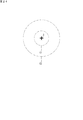
次に、図19は、追尾ずれがある状態での、太陽を追尾するアレイ1と撮像装置30との位置関係を示す図である。図において、撮像装置30は二重円の画像が得られるように姿勢を調節し、撮像方向がアレイ1の表面に対する法線NL上にあるようにする。一方、アレイ1は例えば仰角θであるが、追尾ずれを生じていて、例えば、本来θ=20度であるべきところが、30度になっている。これにより、仰角の追尾ずれの、ずれ角度θE(=10度)が生じる。この場合、撮像装置30が撮像する画像において、二重円の中心に撮像装置30自身の影は無く、点Pに影がある状態となる。二重円の中心から上方へずれた距離d3は、撮像装置30からアレイ1の表面までの法線NL上の距離をLとすると、d3=L・tanθEである。従って、ずれ角度θEは、θE=Arctan(d3/L)である。
このように、撮像装置30が二重円の中心に投影されていなければ、追尾ずれがある。また、影が二重円の中心からずれている距離により、ずれ角度θEがわかる。方位角のずれに関しては、二重円の中心から左右へずれた位置に撮像装置30の影ができる。この場合、距離d4だけずれているとすると、方位角のずれ角度θAは、θA=Arctan(d4/L)である。
方位角及び仰角のどちらにも追尾ずれがあれば、影の中心は斜めにずれることになるので、ずれの成分を上下方向(仰角)と横方向(方位角)とに分けて、それぞれのずれ角度を求めることができる。
図20は、正中時刻前後における、太陽を追尾するアレイ1と撮像装置30との位置関係を示す図である。例えば仰角θは80度である。この場合、飛行体60全体(撮像装置30を除く。)の影と、撮像装置30の影とが、互いに重なりやすいが、撮像装置30がリニアガイド64の端部近傍に移動していることで、影の重なりを抑制することができる。
図21は、他の構成による飛行体60の平面図である。飛行体60は、4個のプロペラ61と、本体部62とを備えている。本体部62の下方には、クロス状に直交2方向のリニアガイド64a,64bが設けられている。撮像装置30は、リニアガイド64a,64bに沿ってスライド可能に支持されており、例えば、実線で示す位置のほか、点線で示す3つの位置にも移動できる。
図22は、撮像装置30に関するブロック図の一例である。図14との違いは、情報処理部50を撮像装置30と共に飛行体60に搭載した点と、撮像装置30がGPS(Global Positioning System)受信機35を搭載していることを明示した(図14では省略している。)点とである。駆動制御部34は、GPS受信機35が取得した時刻、緯度、経度等の情報に基づいて太陽の位置を計算し、飛行体60の影と撮像装置30の影とがアレイ1の表面上で重ならないように、図21に示した撮像装置30の位置のうち、リニアガイド64a,64bのどの位置に撮像装置30を支持するのが投影のために最も良いかを判断する。そして、最も良い位置で、撮像装置30がリニアガイド64a,64bに支持されるようにする。
(目印部材が投影対象物になる場合)
次に、撮像装置30ではなく、他の目印部材が投影対象物になる場合について説明する。
図23は、撮像装置30を、撮像側の正面から見た図である。撮像装置30の下部には、クロス状の目印部材70が取り付けられている。
次に、撮像装置30ではなく、他の目印部材が投影対象物になる場合について説明する。
図23は、撮像装置30を、撮像側の正面から見た図である。撮像装置30の下部には、クロス状の目印部材70が取り付けられている。
図24は、追尾ずれが無い場合に、アレイ1の表面に現れる画像の要部の略図である。図24において、画像には、図8にも示したように、2次レンズ15(図5)の合成虚像による内円C1と、保護板16(図5)の合成虚像による外円C2とを含む二重円の画像が現れる。そして、内円C1の中心に、目印部材70が投影された影Sが見える。このような画像が得られれば、追尾は正常であり、追尾ずれは実質的にない、といえる状態である。クロス状の目印部材70の影は、その中心がわかり易いという利点がある。
《その他》
なお、上記実施形態では、フレネルレンズである集光部12fを用いる集光型の太陽光発電装置100について説明したが、太陽光を凹面鏡で反射させ集光した光をセルに導く反射型の太陽光発電装置についても、同様な追尾ずれ検出方法を適用することができる。凹面鏡もフレネルレンズと同様に、虚像を映し出すことができるからである。
なお、上記実施形態では、フレネルレンズである集光部12fを用いる集光型の太陽光発電装置100について説明したが、太陽光を凹面鏡で反射させ集光した光をセルに導く反射型の太陽光発電装置についても、同様な追尾ずれ検出方法を適用することができる。凹面鏡もフレネルレンズと同様に、虚像を映し出すことができるからである。
《補記》
なお、今回開示された実施の形態はすべての点で例示であって制限的なものではないと考えられるべきである。本発明の範囲は請求の範囲によって示され、請求の範囲と均等の意味及び範囲内での全ての変更が含まれることが意図される。
なお、今回開示された実施の形態はすべての点で例示であって制限的なものではないと考えられるべきである。本発明の範囲は請求の範囲によって示され、請求の範囲と均等の意味及び範囲内での全ての変更が含まれることが意図される。
1 アレイ
1M モジュール
1U 基本ユニット
2 追尾架台
11 筐体
11b 底面
12 集光部材
12a ガラス板
12f 集光部
13 フレキシブルプリント配線板
14 セルパッケージ
15 2次レンズ
16 保護板
17 遮蔽板
17a 開口
18 セル
19 樹脂
21 支柱
22 基礎
23 2軸駆動部
24 水平軸
25 架台部
25a 補強材
25b レール
30 撮像装置
31 画像取得部
32 距離測定部
33 送受信部
34 駆動制御部
35 GPS受信機
40 飛行体
41 中心部
42 回転翼
43 プロペラ
50 情報処理部
51 送受信部
52 画像解析部
53 追尾ずれ検出部
54 記憶部
60 飛行体
61 プロペラ
62 本体部
63 柱
64,64a,64b リニアガイド
65 吊り下げ部材
70 目印部材
100 太陽光発電装置
200 追尾ずれ検出システム
A 外径
Ac 光軸
Ax 光軸
B 内径
C1 内円
C2 外円
d1,d2,d3,d4 距離
L 距離
NL 法線
R 受光部
S 影
θ 仰角
θA ずれ角度(方位角)
θE ずれ角度(仰角)
1M モジュール
1U 基本ユニット
2 追尾架台
11 筐体
11b 底面
12 集光部材
12a ガラス板
12f 集光部
13 フレキシブルプリント配線板
14 セルパッケージ
15 2次レンズ
16 保護板
17 遮蔽板
17a 開口
18 セル
19 樹脂
21 支柱
22 基礎
23 2軸駆動部
24 水平軸
25 架台部
25a 補強材
25b レール
30 撮像装置
31 画像取得部
32 距離測定部
33 送受信部
34 駆動制御部
35 GPS受信機
40 飛行体
41 中心部
42 回転翼
43 プロペラ
50 情報処理部
51 送受信部
52 画像解析部
53 追尾ずれ検出部
54 記憶部
60 飛行体
61 プロペラ
62 本体部
63 柱
64,64a,64b リニアガイド
65 吊り下げ部材
70 目印部材
100 太陽光発電装置
200 追尾ずれ検出システム
A 外径
Ac 光軸
Ax 光軸
B 内径
C1 内円
C2 外円
d1,d2,d3,d4 距離
L 距離
NL 法線
R 受光部
S 影
θ 仰角
θA ずれ角度(方位角)
θE ずれ角度(仰角)
Claims (11)
- 太陽追尾型の太陽光発電装置におけるアレイの追尾ずれ検出方法であって、
飛行体を太陽と前記アレイとの間に入らせて当該飛行体を前記アレイに投影し、
前記飛行体に搭載された撮像装置により、前記アレイの表面を、当該表面に垂直な方向から撮像し、
セルを含む受光部が集光部を通して拡大された虚像となり、当該虚像の画素の集まりが前記受光部の全体としての合成虚像となって前記アレイに映り込んでいる画像の中に、前記飛行体が投影された影が映っている画像を取得する、
追尾ずれ検出方法。 - 取得した画像における前記合成虚像の中心位置と、前記影の中心位置との相対的なずれ量の成分、及び、前記撮像装置から前記アレイの表面までの距離に基づいて、追尾ずれの角度を求める請求項1に記載の追尾ずれ検出方法。
- 前記影は、前記飛行体に搭載された前記撮像装置の影である請求項1又は請求項2に記載の追尾ずれ検出方法。
- 前記影は、前記飛行体に搭載された前記撮像装置に取り付けられた目印部材の影である請求項1又は請求項2に記載の追尾ずれ検出方法。
- 前記アレイの表面全体をスキャンするように前記飛行体を移動させつつ、前記撮像装置により撮像する請求項1から請求項4のいずれか1項に記載の追尾ずれ検出方法。
- 太陽光を集光部により集光し、セルを含む受光部に入射させる光学系の基本ユニットが集合して構成されたアレイと、
前記アレイを支持し、かつ、太陽を追尾するように前記アレイの姿勢を変化させる追尾架台と、
太陽と前記アレイとの間に入って前記アレイに自己を投影することができる飛行体と、
前記飛行体に搭載され、前記アレイの表面を、当該表面に垂直な方向から撮像可能な撮像装置と、
を有する追尾ずれ検出システム。 - 前記飛行体は、中心部と、当該中心部から均等な長さで外方へ延びる複数の回転翼と、当該回転翼の各々の先端に設けられ、揚力を得るプロペラと、を備えたものである請求項6に記載の追尾ずれ検出システム。
- 前記受光部はボールレンズを含む請求項6又は請求項7に記載の追尾ずれ検出システム。
- 前記撮像装置は、
前記セルを含む前記受光部が前記集光部を通して拡大された虚像となり、かつ、当該虚像の画素の集まりが前記受光部の全体としての合成虚像となって前記アレイに映り込んでいる画像の中に、前記撮像装置が投影された影が映っている画像を取得する、請求項6から請求項8のいずれか1項に記載の追尾ずれ検出システム。 - 投影されるべき目印となる目印部材が前記撮像装置に取り付けられており、前記撮像装置は、
前記セルを含む前記受光部が前記集光部を通して拡大された虚像となり、かつ、当該虚像の画素の集まりが前記受光部の全体としての合成虚像となって前記アレイに映り込んでいる画像の中に、前記目印部材が投影された影が映っている画像を取得する、請求項6から請求項8のいずれか1項に記載の追尾ずれ検出システム。 - 前記飛行体はリニアガイドを備えており、
前記リニアガイドは、前記撮像装置を所定範囲内で移動可能に支持する、請求項6から請求項10のいずれか1項に記載の追尾ずれ検出システム。
Applications Claiming Priority (2)
| Application Number | Priority Date | Filing Date | Title |
|---|---|---|---|
| JP2019010313 | 2019-01-24 | ||
| JP2019-010313 | 2019-01-24 |
Publications (1)
| Publication Number | Publication Date |
|---|---|
| WO2020153295A1 true WO2020153295A1 (ja) | 2020-07-30 |
Family
ID=71735662
Family Applications (1)
| Application Number | Title | Priority Date | Filing Date |
|---|---|---|---|
| PCT/JP2020/001712 Ceased WO2020153295A1 (ja) | 2019-01-24 | 2020-01-20 | 追尾ずれ検出方法及び追尾ずれ検出システム |
Country Status (1)
| Country | Link |
|---|---|
| WO (1) | WO2020153295A1 (ja) |
Citations (4)
| Publication number | Priority date | Publication date | Assignee | Title |
|---|---|---|---|---|
| JPS5526578A (en) * | 1978-08-16 | 1980-02-26 | Sharp Corp | Concave mirror and condenser |
| US20110036345A1 (en) * | 2009-05-26 | 2011-02-17 | Cogenra Solar, Inc. | Concentrating Solar Photovoltaic-Thermal System |
| US8327838B1 (en) * | 2008-10-16 | 2012-12-11 | Lockheed Martin Corporation | Solar parabolic trough mirror/receiver alignment |
| WO2019117189A1 (ja) * | 2017-12-14 | 2019-06-20 | 住友電気工業株式会社 | モジュール取り付け状態の不良検出方法及びアレイ |
-
2020
- 2020-01-20 WO PCT/JP2020/001712 patent/WO2020153295A1/ja not_active Ceased
Patent Citations (4)
| Publication number | Priority date | Publication date | Assignee | Title |
|---|---|---|---|---|
| JPS5526578A (en) * | 1978-08-16 | 1980-02-26 | Sharp Corp | Concave mirror and condenser |
| US8327838B1 (en) * | 2008-10-16 | 2012-12-11 | Lockheed Martin Corporation | Solar parabolic trough mirror/receiver alignment |
| US20110036345A1 (en) * | 2009-05-26 | 2011-02-17 | Cogenra Solar, Inc. | Concentrating Solar Photovoltaic-Thermal System |
| WO2019117189A1 (ja) * | 2017-12-14 | 2019-06-20 | 住友電気工業株式会社 | モジュール取り付け状態の不良検出方法及びアレイ |
Similar Documents
| Publication | Publication Date | Title |
|---|---|---|
| CA2977832C (en) | Modular lidar system | |
| US10324183B2 (en) | UAV measuring apparatus and UAV measuring system | |
| JP7188832B1 (ja) | 無人飛行体、および、風力発電設備の点検システム、並びに、風力発電設備の点検方法 | |
| AU2012320745B2 (en) | Method and system for positioning an apparatus for monitoring a parabolic reflector aerially | |
| US10656096B2 (en) | Method and system for inspecting a surface area for material defects | |
| AU2003231341B2 (en) | Airborne reconnaissance system | |
| US9409656B2 (en) | Aerial photographing system | |
| CN101103248B (zh) | 用于测量至少一个目标的方法和测地装置 | |
| CN104730539B (zh) | 一种低空轻小型红外与激光雷达集成系统 | |
| CN110171565B (zh) | 一种用于光伏电站故障检测的无人机及其检测方法 | |
| KR101550780B1 (ko) | 무인 항공기를 이용한 영상 데이터 수집 시스템 및 방법 | |
| CN108413987A (zh) | 一种定日镜的校准方法、装置及系统 | |
| CN110220533A (zh) | 一种基于传递对准的机载光电吊舱设备失准角标定方法 | |
| JP2021085812A (ja) | 状態判定システムおよび状態判定方法。 | |
| US20230091829A1 (en) | Heliostat optical assessment | |
| CN212156432U (zh) | 一种光电、雷达一体式指向器 | |
| Matsuoka et al. | Measurement of large-scale solar power plant by using images acquired by non-metric digital camera on board UAV | |
| WO2021145141A1 (ja) | 検査システム及び検査方法 | |
| ES2796964B2 (es) | Vehiculo aereo, procedimiento y sistema para la inspeccion de palas de aerogeneradores en movimiento | |
| JP6799635B2 (ja) | 空撮画像位置特定システムおよび空撮画像位置特定方法。 | |
| CN109639389B (zh) | 一种车载并联组网式反无人机防御系统 | |
| WO2020153295A1 (ja) | 追尾ずれ検出方法及び追尾ずれ検出システム | |
| CN207258000U (zh) | 一种惯导数据共享无人机巡检多平台吊舱 | |
| CN212623088U (zh) | 一种基于图像识别和激光测距的铁塔姿态预警装置 | |
| CN212695608U (zh) | 一种架空输电线路巡检作业系统及飞行作业平台 |
Legal Events
| Date | Code | Title | Description |
|---|---|---|---|
| 121 | Ep: the epo has been informed by wipo that ep was designated in this application |
Ref document number: 20744233 Country of ref document: EP Kind code of ref document: A1 |
|
| NENP | Non-entry into the national phase |
Ref country code: DE |
|
| 122 | Ep: pct application non-entry in european phase |
Ref document number: 20744233 Country of ref document: EP Kind code of ref document: A1 |
|
| NENP | Non-entry into the national phase |
Ref country code: JP |