WO2020149261A1 - 内視鏡用可撓管、内視鏡型医療機器、及びこれらの製造方法 - Google Patents
内視鏡用可撓管、内視鏡型医療機器、及びこれらの製造方法 Download PDFInfo
- Publication number
- WO2020149261A1 WO2020149261A1 PCT/JP2020/000877 JP2020000877W WO2020149261A1 WO 2020149261 A1 WO2020149261 A1 WO 2020149261A1 JP 2020000877 W JP2020000877 W JP 2020000877W WO 2020149261 A1 WO2020149261 A1 WO 2020149261A1
- Authority
- WO
- WIPO (PCT)
- Prior art keywords
- flexible tube
- layer
- endoscope
- group
- base material
- Prior art date
- Legal status (The legal status is an assumption and is not a legal conclusion. Google has not performed a legal analysis and makes no representation as to the accuracy of the status listed.)
- Ceased
Links
- ODFOEIMQHAWVNP-WITZSUAWSA-N CC(/C=C(\C)/O[N](O/C(/C)=C/C(C)=O)(O/C(/C)=C/C(C)=O)O/C(/C)=C/C(C)=O)=O Chemical compound CC(/C=C(\C)/O[N](O/C(/C)=C/C(C)=O)(O/C(/C)=C/C(C)=O)O/C(/C)=C/C(C)=O)=O ODFOEIMQHAWVNP-WITZSUAWSA-N 0.000 description 1
- QOYAKUWNTXUIPA-UHFFFAOYSA-K CCCCCCCCOP(OCCCCCCCC)(OP(O)(O[Tl](OP(O)(O)=O)(OC1)OC1=O)=O)=O Chemical compound CCCCCCCCOP(OCCCCCCCC)(OP(O)(O[Tl](OP(O)(O)=O)(OC1)OC1=O)=O)=O QOYAKUWNTXUIPA-UHFFFAOYSA-K 0.000 description 1
Images

Classifications
-
- B—PERFORMING OPERATIONS; TRANSPORTING
- B05—SPRAYING OR ATOMISING IN GENERAL; APPLYING FLUENT MATERIALS TO SURFACES, IN GENERAL
- B05D—PROCESSES FOR APPLYING FLUENT MATERIALS TO SURFACES, IN GENERAL
- B05D7/00—Processes, other than flocking, specially adapted for applying liquids or other fluent materials to particular surfaces or for applying particular liquids or other fluent materials
- B05D7/50—Multilayers
- B05D7/52—Two layers
-
- A—HUMAN NECESSITIES
- A61—MEDICAL OR VETERINARY SCIENCE; HYGIENE
- A61B—DIAGNOSIS; SURGERY; IDENTIFICATION
- A61B1/00—Instruments for performing medical examinations of the interior of cavities or tubes of the body by visual or photographical inspection, e.g. endoscopes; Illuminating arrangements therefor
- A61B1/00064—Constructional details of the endoscope body
- A61B1/0011—Manufacturing of endoscope parts
-
- A—HUMAN NECESSITIES
- A61—MEDICAL OR VETERINARY SCIENCE; HYGIENE
- A61B—DIAGNOSIS; SURGERY; IDENTIFICATION
- A61B1/00—Instruments for performing medical examinations of the interior of cavities or tubes of the body by visual or photographical inspection, e.g. endoscopes; Illuminating arrangements therefor
- A61B1/00131—Accessories for endoscopes
- A61B1/00135—Oversleeves mounted on the endoscope prior to insertion
-
- B—PERFORMING OPERATIONS; TRANSPORTING
- B05—SPRAYING OR ATOMISING IN GENERAL; APPLYING FLUENT MATERIALS TO SURFACES, IN GENERAL
- B05D—PROCESSES FOR APPLYING FLUENT MATERIALS TO SURFACES, IN GENERAL
- B05D1/00—Processes for applying liquids or other fluent materials
- B05D1/18—Processes for applying liquids or other fluent materials performed by dipping
-
- B—PERFORMING OPERATIONS; TRANSPORTING
- B05—SPRAYING OR ATOMISING IN GENERAL; APPLYING FLUENT MATERIALS TO SURFACES, IN GENERAL
- B05D—PROCESSES FOR APPLYING FLUENT MATERIALS TO SURFACES, IN GENERAL
- B05D1/00—Processes for applying liquids or other fluent materials
- B05D1/26—Processes for applying liquids or other fluent materials performed by applying the liquid or other fluent material from an outlet device in contact with, or almost in contact with, the surface
- B05D1/265—Extrusion coatings
-
- B—PERFORMING OPERATIONS; TRANSPORTING
- B05—SPRAYING OR ATOMISING IN GENERAL; APPLYING FLUENT MATERIALS TO SURFACES, IN GENERAL
- B05D—PROCESSES FOR APPLYING FLUENT MATERIALS TO SURFACES, IN GENERAL
- B05D7/00—Processes, other than flocking, specially adapted for applying liquids or other fluent materials to particular surfaces or for applying particular liquids or other fluent materials
- B05D7/14—Processes, other than flocking, specially adapted for applying liquids or other fluent materials to particular surfaces or for applying particular liquids or other fluent materials to metal, e.g. car bodies
- B05D7/146—Processes, other than flocking, specially adapted for applying liquids or other fluent materials to particular surfaces or for applying particular liquids or other fluent materials to metal, e.g. car bodies to metallic pipes or tubes
-
- B—PERFORMING OPERATIONS; TRANSPORTING
- B05—SPRAYING OR ATOMISING IN GENERAL; APPLYING FLUENT MATERIALS TO SURFACES, IN GENERAL
- B05D—PROCESSES FOR APPLYING FLUENT MATERIALS TO SURFACES, IN GENERAL
- B05D7/00—Processes, other than flocking, specially adapted for applying liquids or other fluent materials to particular surfaces or for applying particular liquids or other fluent materials
- B05D7/50—Multilayers
- B05D7/52—Two layers
- B05D7/54—No clear coat specified
- B05D7/548—No curing step for the last layer
- B05D7/5483—No curing step for any layer
-
- B—PERFORMING OPERATIONS; TRANSPORTING
- B05—SPRAYING OR ATOMISING IN GENERAL; APPLYING FLUENT MATERIALS TO SURFACES, IN GENERAL
- B05D—PROCESSES FOR APPLYING FLUENT MATERIALS TO SURFACES, IN GENERAL
- B05D7/00—Processes, other than flocking, specially adapted for applying liquids or other fluent materials to particular surfaces or for applying particular liquids or other fluent materials
- B05D7/50—Multilayers
- B05D7/56—Three layers or more
- B05D7/58—No clear coat specified
- B05D7/588—No curing step for the last layer
- B05D7/5883—No curing step for any layer
-
- B—PERFORMING OPERATIONS; TRANSPORTING
- B32—LAYERED PRODUCTS
- B32B—LAYERED PRODUCTS, i.e. PRODUCTS BUILT-UP OF STRATA OF FLAT OR NON-FLAT, e.g. CELLULAR OR HONEYCOMB, FORM
- B32B15/00—Layered products comprising a layer of metal
- B32B15/04—Layered products comprising a layer of metal comprising metal as the main or only constituent of a layer, which is next to another layer of the same or of a different material
- B32B15/08—Layered products comprising a layer of metal comprising metal as the main or only constituent of a layer, which is next to another layer of the same or of a different material of synthetic resin
-
- B—PERFORMING OPERATIONS; TRANSPORTING
- B32—LAYERED PRODUCTS
- B32B—LAYERED PRODUCTS, i.e. PRODUCTS BUILT-UP OF STRATA OF FLAT OR NON-FLAT, e.g. CELLULAR OR HONEYCOMB, FORM
- B32B15/00—Layered products comprising a layer of metal
- B32B15/04—Layered products comprising a layer of metal comprising metal as the main or only constituent of a layer, which is next to another layer of the same or of a different material
- B32B15/08—Layered products comprising a layer of metal comprising metal as the main or only constituent of a layer, which is next to another layer of the same or of a different material of synthetic resin
- B32B15/085—Layered products comprising a layer of metal comprising metal as the main or only constituent of a layer, which is next to another layer of the same or of a different material of synthetic resin comprising polyolefins
-
- B—PERFORMING OPERATIONS; TRANSPORTING
- B32—LAYERED PRODUCTS
- B32B—LAYERED PRODUCTS, i.e. PRODUCTS BUILT-UP OF STRATA OF FLAT OR NON-FLAT, e.g. CELLULAR OR HONEYCOMB, FORM
- B32B15/00—Layered products comprising a layer of metal
- B32B15/04—Layered products comprising a layer of metal comprising metal as the main or only constituent of a layer, which is next to another layer of the same or of a different material
- B32B15/08—Layered products comprising a layer of metal comprising metal as the main or only constituent of a layer, which is next to another layer of the same or of a different material of synthetic resin
- B32B15/088—Layered products comprising a layer of metal comprising metal as the main or only constituent of a layer, which is next to another layer of the same or of a different material of synthetic resin comprising polyamides
-
- B—PERFORMING OPERATIONS; TRANSPORTING
- B32—LAYERED PRODUCTS
- B32B—LAYERED PRODUCTS, i.e. PRODUCTS BUILT-UP OF STRATA OF FLAT OR NON-FLAT, e.g. CELLULAR OR HONEYCOMB, FORM
- B32B15/00—Layered products comprising a layer of metal
- B32B15/04—Layered products comprising a layer of metal comprising metal as the main or only constituent of a layer, which is next to another layer of the same or of a different material
- B32B15/08—Layered products comprising a layer of metal comprising metal as the main or only constituent of a layer, which is next to another layer of the same or of a different material of synthetic resin
- B32B15/09—Layered products comprising a layer of metal comprising metal as the main or only constituent of a layer, which is next to another layer of the same or of a different material of synthetic resin comprising polyesters
-
- B—PERFORMING OPERATIONS; TRANSPORTING
- B32—LAYERED PRODUCTS
- B32B—LAYERED PRODUCTS, i.e. PRODUCTS BUILT-UP OF STRATA OF FLAT OR NON-FLAT, e.g. CELLULAR OR HONEYCOMB, FORM
- B32B3/00—Layered products comprising a layer with external or internal discontinuities or unevennesses, or a layer of non-planar shape; Layered products comprising a layer having particular features of form
- B32B3/26—Layered products comprising a layer with external or internal discontinuities or unevennesses, or a layer of non-planar shape; Layered products comprising a layer having particular features of form characterised by a particular shape of the outline of the cross-section of a continuous layer; characterised by a layer with cavities or internal voids ; characterised by an apertured layer
- B32B3/263—Layered products comprising a layer with external or internal discontinuities or unevennesses, or a layer of non-planar shape; Layered products comprising a layer having particular features of form characterised by a particular shape of the outline of the cross-section of a continuous layer; characterised by a layer with cavities or internal voids ; characterised by an apertured layer characterised by a layer having non-uniform thickness
-
- B—PERFORMING OPERATIONS; TRANSPORTING
- B32—LAYERED PRODUCTS
- B32B—LAYERED PRODUCTS, i.e. PRODUCTS BUILT-UP OF STRATA OF FLAT OR NON-FLAT, e.g. CELLULAR OR HONEYCOMB, FORM
- B32B7/00—Layered products characterised by the relation between layers; Layered products characterised by the relative orientation of features between layers, or by the relative values of a measurable parameter between layers, i.e. products comprising layers having different physical, chemical or physicochemical properties; Layered products characterised by the interconnection of layers
- B32B7/02—Physical, chemical or physicochemical properties
-
- G—PHYSICS
- G02—OPTICS
- G02B—OPTICAL ELEMENTS, SYSTEMS OR APPARATUS
- G02B23/00—Telescopes, e.g. binoculars; Periscopes; Instruments for viewing the inside of hollow bodies; Viewfinders; Optical aiming or sighting devices
- G02B23/24—Instruments or systems for viewing the inside of hollow bodies, e.g. fibrescopes
-
- B—PERFORMING OPERATIONS; TRANSPORTING
- B05—SPRAYING OR ATOMISING IN GENERAL; APPLYING FLUENT MATERIALS TO SURFACES, IN GENERAL
- B05D—PROCESSES FOR APPLYING FLUENT MATERIALS TO SURFACES, IN GENERAL
- B05D2202/00—Metallic substrate
- B05D2202/10—Metallic substrate based on Fe
- B05D2202/15—Stainless steel
-
- B—PERFORMING OPERATIONS; TRANSPORTING
- B05—SPRAYING OR ATOMISING IN GENERAL; APPLYING FLUENT MATERIALS TO SURFACES, IN GENERAL
- B05D—PROCESSES FOR APPLYING FLUENT MATERIALS TO SURFACES, IN GENERAL
- B05D2350/00—Pretreatment of the substrate
- B05D2350/60—Adding a layer before coating
-
- B—PERFORMING OPERATIONS; TRANSPORTING
- B05—SPRAYING OR ATOMISING IN GENERAL; APPLYING FLUENT MATERIALS TO SURFACES, IN GENERAL
- B05D—PROCESSES FOR APPLYING FLUENT MATERIALS TO SURFACES, IN GENERAL
- B05D2505/00—Polyamides
-
- B—PERFORMING OPERATIONS; TRANSPORTING
- B05—SPRAYING OR ATOMISING IN GENERAL; APPLYING FLUENT MATERIALS TO SURFACES, IN GENERAL
- B05D—PROCESSES FOR APPLYING FLUENT MATERIALS TO SURFACES, IN GENERAL
- B05D2530/00—Rubber or the like
-
- B—PERFORMING OPERATIONS; TRANSPORTING
- B05—SPRAYING OR ATOMISING IN GENERAL; APPLYING FLUENT MATERIALS TO SURFACES, IN GENERAL
- B05D—PROCESSES FOR APPLYING FLUENT MATERIALS TO SURFACES, IN GENERAL
- B05D2701/00—Coatings being able to withstand changes in the shape of the substrate or to withstand welding
- B05D2701/30—Coatings being able to withstand changes in the shape of the substrate or to withstand welding withstanding bending
-
- B—PERFORMING OPERATIONS; TRANSPORTING
- B32—LAYERED PRODUCTS
- B32B—LAYERED PRODUCTS, i.e. PRODUCTS BUILT-UP OF STRATA OF FLAT OR NON-FLAT, e.g. CELLULAR OR HONEYCOMB, FORM
- B32B2307/00—Properties of the layers or laminate
- B32B2307/70—Other properties
- B32B2307/732—Dimensional properties
- B32B2307/737—Dimensions, e.g. volume or area
- B32B2307/7375—Linear, e.g. length, distance or width
- B32B2307/7376—Thickness
-
- B—PERFORMING OPERATIONS; TRANSPORTING
- B32—LAYERED PRODUCTS
- B32B—LAYERED PRODUCTS, i.e. PRODUCTS BUILT-UP OF STRATA OF FLAT OR NON-FLAT, e.g. CELLULAR OR HONEYCOMB, FORM
- B32B2311/00—Metals, their alloys or their compounds
- B32B2311/30—Iron, e.g. steel
-
- B—PERFORMING OPERATIONS; TRANSPORTING
- B32—LAYERED PRODUCTS
- B32B—LAYERED PRODUCTS, i.e. PRODUCTS BUILT-UP OF STRATA OF FLAT OR NON-FLAT, e.g. CELLULAR OR HONEYCOMB, FORM
- B32B2367/00—Polyesters, e.g. PET, i.e. polyethylene terephthalate
-
- B—PERFORMING OPERATIONS; TRANSPORTING
- B32—LAYERED PRODUCTS
- B32B—LAYERED PRODUCTS, i.e. PRODUCTS BUILT-UP OF STRATA OF FLAT OR NON-FLAT, e.g. CELLULAR OR HONEYCOMB, FORM
- B32B2375/00—Polyureas; Polyurethanes
-
- B—PERFORMING OPERATIONS; TRANSPORTING
- B32—LAYERED PRODUCTS
- B32B—LAYERED PRODUCTS, i.e. PRODUCTS BUILT-UP OF STRATA OF FLAT OR NON-FLAT, e.g. CELLULAR OR HONEYCOMB, FORM
- B32B2377/00—Polyamides
Definitions
- the present invention relates to a flexible tube for an endoscope, an endoscope type medical device, and manufacturing methods thereof.
- An endoscope is a medical device for observing a patient's body cavity, digestive tract, esophagus, etc. Since it is inserted into the body and used, it is desired that it does not damage the organs and does not cause pain or discomfort to the patient. Due to such a demand, a spiral tube formed by spirally winding a softly bending metal strip is adopted as the flexible tube forming the insertion part (structure part to be inserted into the body cavity) of the endoscope. Has been done. Furthermore, the circumference of the spiral tube is coated with a soft resin, and this resin coating layer is optionally covered with a topcoat layer so that the inner surface of the esophagus, digestive tract, body cavity, etc. is not irritated or damaged. There is.
- the above resin coating layer can be formed, for example, by extruding a resin on the outer peripheral surface of a flexible tube base material in which a spiral tube is covered with a tubular mesh body. At this time, it is preferable that the front end side is soft for easy insertion into the body and the rear end side is hard for easy operation. In consideration of this point, it has been proposed to adopt a two-layer structure of an inner layer and an outer layer having different hardness as the resin coating layer, and change the ratio of the thickness of the inner layer and the outer layer in the axial direction of the flexible tube.
- the flexible tube base material In order to improve the operability and durability of the endoscope, it is important to enhance the adhesion between the flexible tube base material and the resin coating layer that covers it. If this adhesion is not sufficient, when the flexible tube is inserted into the body, the flexible tube is likely to be wrinkled, floated, torn, or peeled off due to the bending of the flexible tube. When the tube is rotated, the resin coating layer tends to be twisted. If the resin coating layer is wrinkled, floated, torn, does not come off, or is twisted, the surface of the flexible tube inserted into the body may be caught by surrounding tissues, which may cause pain to the subject.
- a primer layer between the flexible tube base material and the resin coating layer in order to enhance the adhesion.
- a primer is applied to the surface of a metal core material (flexible tube base material), and then an outer skin layer is coated and molded.
- a silane coupling agent, a titanate coupling agent, or a zirconate is used as the primer. It is described that a system coupling agent or the like can be used.
- the present invention can sufficiently maintain the adhesiveness between the flexible tube base material and the resin coating layer covering the flexible tube base material even if the bending operation is repeated, and can also be performed by a strong sterilization treatment using ethylene oxide gas.
- An object of the present invention is to provide a flexible tube for an endoscope in which adhesion between a flexible tube base material and a resin coating layer is unlikely to occur, and an endoscope-type medical device including the flexible tube for an endoscope.
- Another object of the present invention is to provide a method for manufacturing the flexible tube for an endoscope and a method for manufacturing the endoscope medical device.
- the present inventors have repeatedly studied the formation of a resin coating layer in a flexible tube for an endoscope, and as a result, on the surface of a flexible tube substrate made of a metal material, a specific structure such as a metal alkoxide is formed. It was found that the above problems can be solved by forming a primer layer containing the compound of 1) and further applying a specific type of resin as a constituent material of the resin coating layer in contact with the primer layer. The present invention has been completed through further studies based on these findings.
- a flexible tube for an endoscope having a flexible tube base material made of metal as a constituent material, and a resin coating layer covering an outer periphery of the flexible tube base material, A primer layer containing at least one compound represented by the following general formula (1) or (2) is provided between the flexible tube base material and the resin coating layer, and the resin coating layer contains at least a primer.
- a flexible tube for an endoscope which comprises at least one compound of polyamide, polyester, polyurethane, and polyolefin on the side in contact with the layer.
- General formula (2) O-[M-(OR 2 ) n-1 ] 2
- M represents Al, B, Ba, Bi, Ca, Ga, Ge, Hf, In, La, Mg, Nb, P, Sr, Sn, Ta, Ti, V, Y, or Zr.
- R 1 represents a hydrogen atom, an alkyl group, a cycloalkyl group, an acyl group, an aryl group, or an unsaturated aliphatic group.
- R 2 represents a hydrogen atom, an alkyl group, a cycloalkyl group, an acyl group, an alkenyl group, an aryl group, a phosphonate group, or —SO 2 R S.
- R S represents a substituent.
- m is an integer of 0 to 3
- n is a valence of M. n>m is satisfied.
- the flexible tube for an endoscope according to [4], wherein at least one of OR 2 has an acetonato structure.
- the flexible tube for an endoscope according to [7], wherein at least one of OR 2 has an acetonato structure.
- An endoscope type medical device including the flexible tube for an endoscope according to any one of [1] to [15].
- a step of forming a primer layer containing at least one compound represented by the following general formula (1) or (2) on at least the outer periphery of a flexible tube base material composed of a metal, and the flexible tube substrate for an endoscope, including a step of forming a resin coating layer including coating a resin containing at least one compound of polyamide, polyester, polyurethane, and polyolefin in contact with the primer layer formed on the outer periphery of the material Manufacturing method of flexible tube.
- General formula (2) O-[M-(OR 2 ) n-1 ] 2
- M represents Al, B, Ba, Bi, Ca, Ga, Ge, Hf, In, La, Mg, Nb, P, Sr, Sn, Ta, Ti, V, Y, or Zr.
- R 1 represents a hydrogen atom, an alkyl group, a cycloalkyl group, an acyl group, an aryl group, or an unsaturated aliphatic group.
- R 2 represents a hydrogen atom, an alkyl group, a cycloalkyl group, an acyl group, an alkenyl group, an aryl group, a phosphonate group, or —SO 2 R S.
- R S represents a substituent.
- m is an integer of 0 to 3
- n is a valence of M. n>m is satisfied.
- the resin coating layer has a two-layer structure, at least the inner layer of the two-layer structure contains at least one compound of polyamide, polyester, polyurethane, and polyolefin, the ratio of the thickness of the inner layer and the outer layer of the two-layer structure,
- [19] [17] A step of obtaining a flexible tube for an endoscope by the method for manufacturing a flexible tube for an endoscope according to [18], and A method for manufacturing an endoscopic medical device, comprising a step of incorporating the obtained flexible tube for an endoscope into an insertion portion of the endoscopic medical device.
- a method for manufacturing an endoscopic medical device comprising incorporating the flexible tube for an endoscope according to any one of [1] to [15] into an insertion portion of the endoscopic medical device.
- substituents when there are a plurality of substituents, linking groups, etc. (hereinafter referred to as substituents) indicated by a specific code, or when a plurality of substituents, etc. are defined simultaneously or alternatively, It means that the substituents and the like may be the same or different from each other. Further, even when not otherwise specified, when a plurality of substituents and the like are adjacent to each other, they may be linked to each other or condensed to form a ring.
- a substituent which is not specified to be substituted or unsubstituted means that the group may have any substituent as long as the desired effect can be obtained. ..
- this carbon number means the carbon number of the entire group. That is, when this group is in the form of further having a substituent, it means the total number of carbon atoms including this substituent.
- the flexible tube for an endoscope of the present invention can sufficiently maintain the adhesiveness between the flexible tube base material and the resin coating layer covering the flexible tube base material even if the bending operation is repeated, and the flexible tube can be sterilized. It is unlikely that the adhesiveness between the flexible tube base material and the resin coating layer decreases.
- the flexible tube which is a structural part to be inserted into the body, has sufficient adhesion between the flexible tube base material and the resin coating layer covering the flexible tube base material even if the bending operation is repeated. It can be maintained, and the adhesiveness between the flexible tube base material and the resin coating layer does not easily decrease even by sterilization treatment.
- the endoscopic medical device of the present invention is excellent in durability and can further reduce the burden on the subject during use.
- the method for manufacturing an endoscope flexible tube of the present invention it is possible to sufficiently maintain the adhesion between the flexible tube base material and the resin coating layer that covers the flexible tube base material even if the bending operation is repeated, It is possible to obtain a flexible tube for an endoscope in which the adhesiveness between the flexible tube base material and the resin coating layer does not easily decrease even by sterilization treatment.
- the flexible tube forming the device has sufficient adhesion between the flexible tube base material and the resin coating layer that covers the flexible tube base material even if the bending operation is repeated.
- a preferred embodiment of the endoscopic medical device of the present invention will be described by taking an electronic endoscope as an example.
- a flexible tube for an endoscope is incorporated in an electronic endoscope (hereinafter, the flexible tube for an endoscope may be simply referred to as “flexible tube”), and the flexible tube is used in a body cavity or a digestive tract. It is used as a medical device for observing the inside of the body by inserting it into the esophagus, etc.
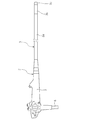
- the electronic endoscope 2 is connected to an insertion portion 3 to be inserted into the body, a main body operation portion 5 connected to a proximal end portion of the insertion portion 3, a processor device and a light source device. And a universal cord 6 to be used.
- the insertion portion 3 is provided with a flexible tube 3a continuously provided with the main body operation portion 5, an angle portion 3b continuously provided therewith, and a distal end thereof continuously provided with an imaging device (not shown) for in-vivo imaging. It is composed of a built-in tip portion 3c.
- the flexible tube 3a which occupies most of the length of the insertion portion 3, has flexibility over almost the entire length thereof, and in particular, the portion to be inserted inside the body cavity or the like has a structure with more flexibility.
- the flexible tube has a flexible tube base material composed of metal as an innermost layer.
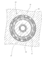
- the flexible tube base material 14 is a tubular net body formed by braiding a metal wire on the spiral tube 11 formed by spirally winding the metal strip 11a on the innermost side. It is preferable that 12 is covered and caps 13 are fitted at both ends.
- the metal constituting the flexible tube base material 14 is preferably subjected to passivation treatment on its surface in order to prevent corrosion. That is, it is preferable that the flexible tube base material 14 has a passivation film on the outer periphery thereof. This passivation treatment can be performed by a conventional method.
- the metal forming the flexible tube base material 14 is preferably stainless steel.
- the stainless steel surface is usually in a state in which chromium and oxygen are combined to form a passive film.
- the passivation treatment described above is performed on the stainless steel. Is preferably applied.
- a primer layer (not shown) is provided on the outer circumference of the flexible tube base material.
- this primer layer contains at least one compound represented by the following general formula (1) or (2). That is, the primer layer in the present invention includes the following forms (i) to (iii).
- M is Al, B, Ba, Bi, Ca, Ga, Ge, Hf, In, La, Mg, Nb, P, Sr, Sn, Ta, Ti, V, Y. , Or Zr.
- M is preferably Ti, Al, or Zr.
- R 1 represents a hydrogen atom, an alkyl group, a cycloalkyl group, an acyl group, an aryl group, or an unsaturated aliphatic group.
- the alkyl group which can be adopted as R 1 includes a linear alkyl group, a branched alkyl group and an aralkyl group.
- the alkyl group has preferably 1 to 20 carbon atoms, more preferably 1 to 15 carbon atoms, further preferably 1 to 10 carbon atoms, particularly preferably 1 to 8 carbon atoms, but 7 to 30 carbon atoms is preferable in the case of an aralkyl group.
- alkyl group examples include, for example, methyl, ethyl, propyl, isopropyl, n-butyl, s-butyl, isobutyl, t-butyl, n-pentyl, n-hexyl, n-heptyl, n-octyl, n. -Decyl, n-tridecyl, n-octadecyl, benzyl, and phenethyl.
- the cycloalkyl group that can be used as R 1 is preferably an integer having 3 to 20 carbon atoms, more preferably 3 to 15, further preferably 3 to 10, and particularly preferably 3 to 8.
- Specific preferred examples of the cycloalkyl group include cyclopropyl, cyclopentyl, and cyclohexyl.
- the acyl group that can be used as R 1 is preferably an integer having 2 to 40 carbon atoms, more preferably 2 to 30, still more preferably 2 to 20 and particularly preferably 2 to 18.
- the aryl group that can be used as R 1 is preferably an integer having 6 to 20 carbon atoms, more preferably 6 to 15, further preferably 6 to 12, and particularly preferably 6 to 10. Specific preferred examples of this aryl group include, for example, phenyl and naphthyl, with phenyl being more preferred.
- the unsaturated aliphatic group that can be used as R 1 has preferably 1 to 5 carbon-carbon unsaturated bonds, more preferably 1 to 3, further preferably 1 or 2, and particularly 1. preferable.
- the unsaturated aliphatic group may contain a hetero atom and is preferably a hydrocarbon group.
- the unsaturated aliphatic group is a hydrocarbon group, it preferably has 2 to 20 carbon atoms, more preferably has 2 to 15 carbon atoms, further preferably has 2 to 10 carbon atoms, and particularly preferably has 2 to 8 carbon atoms.
- the unsaturated aliphatic group is more preferably an alkenyl group or an alkynyl group.
- R 1 is preferably a hydrogen atom, an alkyl group, a cycloalkyl group or an aryl group, more preferably an alkyl group or a cycloalkyl group.
- two R 1 may be linked to each other to form a ring.
- R 2 represents a hydrogen atom, an alkyl group, a cycloalkyl group, an acyl group, an alkenyl group, an aryl group, a phosphonate group (phosphonic acid group), or —SO 2 R S.
- R S represents a substituent.
- the alkyl group, cycloalkyl group, acyl group, and aryl group that can be adopted as R 2 have the same meanings as the alkyl group, cycloalkyl group, acyl group, and aryl group that can be adopted as R 1 , respectively, and preferred forms of each group Is also the same.
- the alkyl group that can be used as R 2 also preferably has an amino group as a substituent.
- the alkenyl group that can be adopted as R 2 includes a linear alkenyl group and a branched alkenyl group.
- the carbon number of this alkenyl group is preferably an integer of 2 to 18, more preferably 2 to 7, and further preferably 2 to 5.
- Preferred specific examples of the alkenyl group include, for example, vinyl, allyl, butenyl, pentenyl and hexenyl.
- the alkenyl group is preferably a substituted alkenyl group.
- the phosphonate group that can be adopted as R 2 is a group represented by —P( ⁇ O)(—OR P1 )OR P2 .
- R P1 and R P2 represent a hydrogen atom or a substituent, and the substituent is preferably an alkyl group or a phosphonate group.
- the alkyl group that can be taken as R P1 and R P2 has the same meaning as the alkyl group that can be taken as R 1 described above, and the preferred form of the alkyl group is also the same.
- the phosphonate group that can be taken as R P1 and R P2 has the same meaning as the phosphonate group that can be taken as R 2 , and the preferred forms are also the same.
- R P1 or R P2 is a phosphonate group
- R P1 and R P2 constituting the phosphonate group are preferably alkyl groups.
- the phosphonate group that can be adopted as R 2 it is preferable that both R P1 and R P2 are alkyl groups, or that R P1 is a hydrogen atom and R P2 is a phosphonate group. Since the phosphonate group is tautomeric with the phosphite group (phosphorous acid group), the phosphonate group in the present invention is meant to include the phosphite group.
- R S is preferably an alkyl group or an aryl group.
- Preferable forms of the alkyl group and the aryl group that can be taken as R S include the preferable forms of the alkyl group and the aryl group that can be taken as R 1 described above, respectively.
- R S is preferably phenyl having an alkyl group as a substituent.
- the preferred form of this alkyl group is the same as the preferred form of the alkyl group that can be adopted as R 1 described above.
- R 2 When the compound of the general formula (1) or the compound of the general formula (2) has two or more R 2 , two R 2 may be linked to each other to form a ring.
- ⁇ m is an integer from 0 to 3, and n is the valence of M. Also, n>m is satisfied.
- m is preferably 0 or 1, and more preferably 0.
- the compound represented by the general formula (1) or (2) preferably contains at least one atom of N, P and S.
- N it is preferable to have this N as an amino group.
- P it is preferable to have P as a phosphate group (phosphoric acid group) or a phosphonate group (phosphonic acid group).
- S a sulfonyl group (—SO 2 —).
- Ti is usually tetravalent.
- OR 2 has an acetonato structure.
- the acetonato structure means a structure in which one hydrogen ion is removed from acetone or a compound having a structure in which acetone has a substituent to coordinate with M.
- the coordinating atom coordinating to M is usually an oxygen atom.
- This acetonato structure has an acetylacetone structure (“CH 3 —C( ⁇ O)—CH 2 —C( ⁇ O)—CH 3 ”) as a basic structure from which one hydrogen ion is removed to remove an oxygen atom.
- a structure in which M is coordinated as a coordinating atom is preferable.
- the above-mentioned "having an acetylacetone structure as a basic structure” is meant to include, in addition to the acetylacetone structure, a structure in which a hydrogen atom of the acetylacetone structure is replaced with a substituent.
- Examples of the form in which M is Al and OR 2 has an acetonato structure include compounds A-2 and A-3 described later. Further, when M is Al, in the above general formula (1) or (2), it is preferable that at least one of OR 2 has an acetato structure.
- the acetato structure means a structure in which one hydrogen ion is removed from the acetic acid ester or a compound having a structure in which the acetic acid ester has a substituent (including an alkyl group) to coordinate with M.
- the coordinating atom coordinating to M is usually an oxygen atom.
- This acetato structure has an alkylacetoacetate structure (“CH 3 —C( ⁇ O)—CH 2 —C( ⁇ O)—O—R alk (R alk represents an alkyl group)”) as a basic structure.
- a structure in which one hydrogen ion is removed therefrom and an oxygen atom is coordinated to M as a coordination atom is preferable.
- the above-mentioned "having an alkyl acetoacetate structure as a basic structure” is meant to include, in addition to the above alkyl acetoacetate structure, a structure in which a hydrogen atom of the above alkyl acetoacetate structure is substituted with a substituent.
- Examples of the form in which M is Al and OR 2 has an acetato structure include compounds A-3, A-4, and A-5 described later. Al is usually trivalent.
- OR 2 has an acetonato structure.
- This acetonato structure is synonymous with the acetonato structure described in the form where M is Al. Examples of the form in which M is Zr and OR 2 has an acetonato structure include compounds Z-3 and Z-6 described later.
- at least one of OR 2 in the above general formula (1) or (2) preferably has an acetato structure.
- This acetato structure is synonymous with the acetato structure described in the form where M is Al. Examples of the form in which M is Zr and OR 2 has an acetato structure include compound Z-7 described later.
- OR 2 has a lactate structure in the general formula (1) or (2).
- This lactate structure means a structure in which lactate ion (lactate) is a basic structure, and one hydrogen ion is removed from the lactate ion to coordinate with M.
- lactate lactate
- the above-mentioned “having a lactate ion as a basic structure” is meant to include, in addition to the lactate ion, a structure in which a hydrogen atom of the lactate ion is substituted with a substituent.
- the coordinating atom coordinating to M is usually an oxygen atom.
- compound Z-4 described later can be mentioned.
- M is Zr
- R 2 in the general formula (1) or (2) is an acyl group.
- examples of the form of M as Zr and R 2 as an acyl group include compound Z-5 described later.
- Zr is usually tetravalent.
- Each group that can be adopted as R 1 or R 2 may have an anionic group (salt type substituent) having a counter cation as a substituent.
- the anionic group means a group capable of forming an anion.
- Examples of the anionic group having a counter cation include a carboxylate ion group having an ammonium ion as a counter cation.
- the counter cation may be present in the compound represented by the general formula (1) or (2) so that the charge of the entire compound becomes zero.
- M Tetra-n-propoxyzirconium (also known as zirconium tetra-n-propoxide), Tetra-n-butoxyzirconium (also known as zirconium tetra-n-butoxide), Zirconium tetraacetylacetonate, Zirconium tributoxy monoacetylacetonate, Zirconium dibutoxy bis(acetylacetonate), Zirconium dibutoxy bis (ethyl acetoacetate), Zirconium tributoxyethyl acetoacetate, Zirconium monobutoxy acetylacetonate bis (ethyl acetoacetate), Zirconium tributoxy monostearate (also known as zirconium stearate tri-n-butoxide), Zirconium stearate, Zirconium lactate ammonium salt, Zirconium monoacetylacetonate.
- zirconium stearate also known as zi
- triethyl borate is an example of M being B
- barium acetylacetonate hydrate is an example of M being Ba
- bismuth tritert-amyloxide is an example of M being Bi
- calcium tert-butoxide is an example of M being Ca
- M is Ca.
- Ga gallium triisopropoxide
- examples of M of Ge are germanium tetraethoxide
- examples of M of Hf are hafnium tetra-n-butoxide
- examples of M of In are indium tritriisopropoxide
- examples of M of La examples of M of La.
- M is Mg as an example of magnesium bis(2-methyl-2-propanolate)
- M is Nb as an example of niobium penta n-butoxide
- M is P as an example of trimethyl phosphate
- M is Sr.
- strontium isopropoxide as an example, tin n-butoxide as an example of Sn
- tantalum penta-n-butoxide as an example of M
- vanadium tri-n-butoxide oxide as an example of M
- Y examples thereof include yttrium n-butoxide.
- the primer layer contains at least one compound represented by the general formula (1) or (2)
- the compound represented by the general formula (1) or (2) is a flexible tube group. It is meant to include the form contained in the state of reacting with the material and the form contained in the state of reacting the compound represented by the general formula (1) or (2) with the resin coating layer. That is, at least a part of the compound represented by the general formula (1) or (2) is hydrolyzed to expose the hydroxy group, which reacts with the constituent metal of the flexible tube base material or the resin coating layer. It may exist by reacting with a group on the surface of.
- the flexible tube of the present invention has a resin coating layer on the outer periphery of a flexible tube base material provided with a primer layer.
- the outer surface of the resin coating layer 15 is coated with a top coat layer 16 containing fluorine or the like, which contributes to chemical resistance and the like.
- a top coat layer 16 containing fluorine or the like, which contributes to chemical resistance and the like.
- the resin coating layer 15 and the top coat layer 16 are drawn thicker than the diameter of the flexible tube base material 14 in order to clearly show the layer structure.
- the resin coating layer covers the outer peripheral surface of the flexible tube base material having the primer layer described above.
- the resin coating layer 15 is formed by laminating an inner layer 17 that covers the entire circumferential surface around the axis of the flexible tube base material 14 and an outer layer 18 that covers the entire circumferential surface around the axis of the inner layer 17. It has a two-layer structure. Usually, a soft resin is used for the material of the inner layer 17 and a hard resin is used for the material of the outer layer 18, but the present invention is not limited to these forms.
- the resin coating layer has a multilayer structure of two or more layers, at least one compound of polyamide, polyester, polyurethane, and polyolefin is present in at least the innermost layer (layer in contact with the primer layer). Is included.
- the single resin coating layer contains at least one compound of polyamide, polyester, polyurethane and polyolefin. That is, in the present invention, the resin coating layer contains at least one compound of polyamide, polyester, polyurethane, and polyolefin on at least the side in contact with the primer layer.
- polyamide As the polyamide, a general polyamide that can be applied as a resin coating layer of a flexible tube for an endoscope can be widely adopted.
- crystalline polyamide, amorphous polyamide, and polyamide elastomer can be mentioned.
- the crystalline polyamide is not particularly limited, and examples thereof include aliphatic polyamide and aromatic polyamide. Examples of the aliphatic polyamide include poly ⁇ -caproamide (polyamide 6), polytetramethylene adipamide (polyamide 46), polyhexamethylene adipamide (polyamide 66), polycaproamide/polyhexamethylene adipamide copolymer.
- Polyamide 6/66 polyundecamide (polyamide 11), polycaproamide/polyundecamide copolymer (polyamide 6/11), polydodecamide (polyamide 12), polycaproamide/polydodecamide copolymer (polyamide 6/12), Polyhexamethylene sebacamide (polyamide 610), polydecamethylene sebacamide (polyamide 1010), polyhexamethylene dodecamide (polyamide 612), polydecamethylene dodecamide (polyamide 1012), polyundecamethylene adipamide ( Polyamide 116) and mixtures or copolymers thereof.
- aromatic polyamides examples include polyhexamethylene isophthalamide (polyamide 6I), polyhexamethylene terephthalamide (polyamide 6T), polyhexamethylene terephthalamide/polyhexamethylene isophthalamide copolymer (polyamide 6T/6I), polycaproamide.
- polyamide 6/6T Polycaproamide/polyhexamethylene isophthalamide copolymer
- polyamide 6/6I polyhexamethylene adipamide/polyhexamethylene terephthalamide copolymer
- polyamide 66/6T Polyhexamethylene adipamide/polyhexamethylene isophthalamide copolymer
- polyamide TMDT polytrimethylhexamethylene terephthalamide
- PACM12 polybis(4-aminocyclohexyl)methandodecamide
- PACM12 polybis(3 -Methyl-4-aminocyclohexyl)methandodecamide
- polymethaxylylene adipamide polyamide MXD6
- polydecamethylene terephthalamide polyamide 10T
- polyundecamethylene terephthalamide polyundecamethylene terephthalamide
- amorphous polyamides include polycondensates of isophthalic acid/terephthalic acid/1,6-hexanediamine/bis(3-methyl-4-aminocyclohexyl)methane, terephthalic acid/2,2,4-trimethyl- 1,6-hexanediamine/2,4,4-trimethyl-1,6-hexanediamine polycondensate, isophthalic acid/bis(3-methyl-4-aminocyclohexyl)methane/ ⁇ -laurolactam polycondensate , Polycondensate of isophthalic acid/terephthalic acid/1,6-hexanediamine, isophthalic acid/2,2,4-trimethyl-1,6-hexanediamine/2,4,4-trimethyl-1,6-hexanediamine Polycondensate of isophthalic acid/terephthalic acid/2,2,4-trimethyl-1,6-hexanediamine/2,4,4-trimethyl-1,6-hexanediamine
- polyamide elastomer for example, an elastomer having a hard segment of polyamide, which is called an amide-based thermoplastic elastomer, can be mentioned.
- a hard segment is a polyamide
- a soft segment is a multi-block copolymer using polyether or polyester
- a hard segment is a polyamide
- a soft segment is a multi-block copolymer having both ether bond and ester bond bonding modes.
- the hard segment include polyamide 6,66,610,11,12 and the like.
- Polyether in the soft segment includes polyethylene glycol, diol poly(oxytetramethylene) glycol, poly(oxypropylene) glycol, and the like, and polyester includes poly(ethylene adipate) glycol, poly(butylene-1,4-adipate) glycol. Etc.
- polyamide 11 manufactured by Arkema, trade name "Rilsan BMN O”
- polyamide 12 manufactured by Daicel-Evonik, trade name "Daiamide L1940”
- Polyamide 1010 manufactured by Daicel-Evonik, trade name "Vestamide Terra DDS16”
- polyamide 1012 manufactured by Evonik, trade name "Vestamide Terra D16”
- amorphous polyamide manufactured by Daicel-Evonik, trade name "Trogamide CX7323
- Polyamide elastomer trade name “Pebax 7233” and “Pebax Rnew80R53” manufactured by Arkema Co., Ltd.
- the polyamide may be used alone or in combination of two or more.
- polyester As the polyester, general polyester that can be applied as a resin coating layer of a flexible tube for an endoscope can be widely adopted.
- thermoplastic polyester and polyester elastomer can be mentioned.
- thermoplastic polyester include polyester resins composed of a dicarboxylic acid component and a diol component, polyester resins composed of a hydroxycarboxylic acid component, and the like.
- dicarboxylic acid component examples include terephthalic acid, isophthalic acid, phthalic acid, 2,6-naphthalenedicarboxylic acid, 4,4'-biphenyldicarboxylic acid, 5-sodium sulfoisophthalic acid, oxalic acid, succinic acid, adipic acid, sebacic acid. , Azelaic acid, dodecanedioic acid, dimer acid, maleic anhydride, maleic acid, fumaric acid, itaconic acid, citraconic acid, mesaconic acid, cyclohexanedicarboxylic acid and the like.
- ethylene glycol diethylene glycol, 1,3-propanediol, 1,4-butanediol, neopentyl glycol, 1,6-hexanediol, cyclohexanedimethanol, triethylene glycol, polyethylene glycol, polypropylene glycol. , Polytetramethylene glycol, ethylene oxide adducts of bisphenol A and bisphenol S, and the like.
- hydroxycarboxylic acid component examples include ⁇ -caprolactone, lactic acid, 4-hydroxybenzoic acid and the like.
- the thermoplastic polyester resin may be a homopolymer composed of the above dicarboxylic acid component and a diol component or a homopolymer composed of the above hydroxycarboxylic acid component, may be a copolymer, and further, trimellitic acid, trimesic acid, It may contain a small amount of trifunctional compound components such as pyromellitic acid, trimethylolpropane, glycerin and pentaerythritol.
- polyester elastomer examples include an elastomer in which the hard segment is polyester, which is referred to as an ester-based thermoplastic elastomer.
- the hard segment include polybutylene terephthalate and polyethylene terephthalate.
- the soft segment examples include polyalkylene glycols such as polytetramethylene glycol and polypropylene glycol, bisphenol A ethylene oxide adducts, bisphenol A propylene oxide adducts, and polyesters such as polycaprolactone.
- the polyester elastomer for example, a block copolymer composed of a high-melting point polyester segment (hard segment) and a low-melting point polymer segment (soft segment) having a molecular weight of 400 to 6,000 as described in JP-A No. 11-92636 is used. You can
- polyesters used in the present invention include polyester elastomers (trade names “Perprene P-70B” and “Perprene S-3001” manufactured by Toyobo Co., Ltd., and “Primalloy B1942” manufactured by Mitsubishi Chemical Corporation). )) and polybutylene terephthalate (manufactured by Mitsubishi Engineering Plastics, trade name “Novaduran 5505S”).
- the polyesters may be used alone or in combination of two or more.
- polyurethane As the polyurethane, a general polyurethane that can be applied as a resin coating layer of a flexible tube for an endoscope can be widely adopted. For example, carbonate-based, ether-based or ester-based polyurethane or a mixture thereof may be used. Polyurethane elastomers are also preferred. Examples of the polyurethane elastomer include a block polymer having a hard segment which is a polyurethane and a soft segment having an ether, ester or carbonate bond or a mixed mode of these bonds, which is referred to as a urethane-based thermoplastic elastomer, depending on the purpose. It can be appropriately prepared.
- a block polymer including a hard segment composed of a low molecular weight glycol component and a diisocyanate component and a soft segment composed of a high molecular (long chain) diol component and a diisocyanate component can be mentioned.
- the polymer (long chain) diol component include polyether diol, polyester diol, and lactone polyester diol.
- the number average molecular weight of the polymeric (long-chain) diol is preferably 500 to 10,000.
- a short chain diol such as ethylene glycol, propylene glycol, 1,4-butanediol or bisphenol A can be used.
- the number average molecular weight of the short chain diol is preferably 48 to 500.
- the diisocyanate component include diphenylmethane diisocyanate, hexamethylene diisocyanate, tolidine diisocyanate, 1,5-naphthalene diisocyanate, isophorone diisocyanate and xylylene diisocyanate.
- Examples of commercially available polyurethanes that can be used in the present invention include PANDEX T-2185, T-2983N (above, manufactured by DIC Co., Ltd.), miractolane (manufactured by Nippon Miractolan Co., Ltd.), and elastran (BASF Japan. Resamine (manufactured by Dainichiseika Kogyo Co., Ltd.), Peresen (manufactured by Dow Chemical Japan Co., Ltd.), Iron Rubber (manufactured by NOK Co., Ltd.), Mobilon (manufactured by Nisshinbo Chemical Co., Ltd.), etc. Are listed.
- Isoplast manufactured by Lubrizol
- Tecoflex manufactured by Lubrizol
- Superflex 830, 460, 870, 420, or 420NS polyurethane manufactured by Dai-ichi Kogyo Seiyaku Co., Ltd.
- Hydran AP-40F Polyurethane manufactured by DIC
- Orestar UD500 Polyurethane manufactured by Mitsui Chemicals
- W-615, W-6010, W-6020, W-6061, W-405, W-5030 , W-5661, W-512A-6, W-635, WPB-6601 manufactured by DIC Corporation
- the polyurethane may be used alone or in combination of two or more.
- polyolefin As the polyolefin, a general polyolefin that can be applied as a resin coating layer of a flexible tube for an endoscope can be widely adopted. For example, polyolefins and olefin elastomers may be mentioned.
- polystyrene resin examples include homopolymers or copolymers of ⁇ -olefins having 2 to 20 carbon atoms such as ethylene, propylene, 1-butene, 1-hexene and 4-methyl-pentene.
- a copolymer of an ⁇ -olefin with a non-conjugated diene having 2 to 20 carbon atoms such as dicyclopentadiene, 1,4-hexadiene, cyclooctadiene, methylene norbornene, ethylidene norbornene, butadiene and isoprene can be given.
- ethylene- ⁇ -olefin copolymer rubber ethylene- ⁇ -olefin-non-conjugated diene copolymer rubber, propylene- ⁇ -olefin copolymer rubber, butene- ⁇ -olefin copolymer rubber and the like can be mentioned. be able to.
- ethylene-(meth)acrylic acid copolymer ethylene-(meth)acrylic acid ester-(meth)acrylic acid copolymer, ethylene-vinyl acetate copolymer, ethylene-vinyl acetate-(meth)acrylic acid copolymer Polymer, ethylene-propylene-(meth)acrylic acid copolymer, ethylene-propylene-(meth)acrylic acid ester-(meth)acrylic acid copolymer, ethylene-maleic anhydride copolymer, ethylene-(meth) Acrylic ester-maleic anhydride copolymer, ethylene-butene-maleic anhydride and/or (meth)acrylic acid copolymer, propylene-butene-maleic anhydride and/or (meth)acrylic acid copolymer, ethylene -Vinyl chloride copolymer, ethylene-vinyl chloride copolymer, ethylene-(meth)acrylic acid
- polyolefin in the olefin elastomer examples include ethylene-propylene copolymer, ethylene-1-butene copolymer, ethylene- ⁇ -olefin copolymer, propylene-1-butene copolymer, propylene- ⁇ -olefin copolymer.
- Examples of the rubber component in the olefin elastomer include propylene rubber (PP), ethylene-propylene rubber (EPM) and ethylene-propylene-diene rubber (EPDM), polyisoprene, polybutadiene, polychloroprene, isobutylene-isoprene copolymer.
- PP propylene rubber
- EPM ethylene-propylene rubber
- EPDM ethylene-propylene-diene rubber
- polyisoprene polybutadiene
- polychloroprene isobutylene-isoprene copolymer.
- the polyolefin and the rubber component in the olefin elastomer may be contained singly or in combination of two or more.
- polyolefin resins used in the present invention examples include olefin elastomers (trade name “Cerlink 3145D” manufactured by Toyobo Co., Ltd.).
- the polyolefin may be used alone or in combination of two or more.
- the resin coating layer is a single layer, in the resin coating layer, polyamide, polyester, polyurethane, and the total content of compounds selected from polyolefin, and the polyamide in the innermost layer when the resin coating layer is a multilayer,
- the total content of compounds selected from polyester, polyurethane, and polyolefin is preferably 50% by mass or more, more preferably 70% by mass or more, further preferably 80% by mass or more, and further preferably 90% by mass or more.
- the resin coating layer may be a layer made of at least one of polyamide resin, polyester resin, polyurethane resin and polyolefin resin, and when the resin coating layer is a multi-layer.
- the innermost layer in may be a layer made of at least one of polyamide resin, polyester resin, polyurethane resin, and polyolefin resin.
- the resin coating layer is a single layer resin coating layer, and, when the resin coating layer is a multilayer, the innermost layer contains a polymer other than the polymer selected from polyamide, polyester, polyurethane, and polyolefin, the polymer is There is no particular limitation as long as the effects of the present invention are not impaired.
- the resin coating layer may appropriately contain various commonly used additives as long as the effects of the present invention are not impaired. Examples of such additives include heat resistance stabilizers, inorganic fillers, impact improvers, plasticizers, lubricants, metal soaps, light resistance assistants, and colorants.
- the content of the above additives in the resin coating layer can also be adjusted appropriately.
- Such an additive may be derived from the resin material used, or may be added separately from the resin.
- the layers other than the innermost layer also contain at least one compound of polyamide, polyester, polyurethane and polyolefin.
- a layer having desired physical properties can be formed by appropriately combining these polymers.
- the above-mentioned polymers usable in the resin coating layer of the present invention preferably have a molecular weight of 10,000 to 1,000,000, more preferably a molecular weight of 20,000 to 500,000, and particularly preferably a molecular weight of 30,000 to 300,000.
- the molecular weight of the polymer constituting the resin coating layer means the weight average molecular weight unless otherwise specified.
- the weight average molecular weight can be measured as a molecular weight in terms of polystyrene by gel permeation chromatography (GPC).
- the resin coating layer 15 is preferably formed with a substantially uniform thickness in the longitudinal direction (axial direction) of the flexible tube base material 14.
- the thickness of the resin coating layer 15 is, for example, 0.2 mm to 1.0 mm.
- the outer diameter D of the flexible tube 3a is appropriately set according to the purpose. For example, it is 11 to 14 mm.
- the inner layer 17 and the outer layer 18 are formed so that the ratio of the thickness of each layer 17, 18 to the total thickness of the resin coating layer 15 changes in the axial direction of the flexible tube base material 14. ing.
- the thickness of the inner layer 17 is larger than that of the outer layer 18 with respect to the total thickness of the resin coating layer 15. Is also big. Then, the thickness of the inner layer 17 gradually decreases from the one end 14a to the other end 14b side (base end side) attached to the main body operating portion 5, and the outer layer 18 has a smaller thickness on the other end 14b side. Is larger than the thickness of.
- the ratio of the thickness of the inner layer 17 at the one end 14a is the maximum, and the ratio of the thickness of the outer layer 18 at the other end 14b is the maximum.
- the thickness of the inner layer 17: the thickness of the outer layer 18 can be 9:1 at the one end 14a and 1:9 at the other end 14b.
- the thicknesses of both layers are changed so that the ratio of the thicknesses of the inner layer 17 and the outer layer 18 is reversed from both ends 14a to 14b.
- the flexible tube 3a has a difference in hardness between the one end 14a side and the other end 14b side, and the flexibility can be changed in the axial direction such that the one end 14a side is soft and the other end 14b side is hard.
- the inner layer and the outer layer preferably have a thickness ratio at one end of 95:5 to 60:40 (inner layer:outer layer) and a thickness ratio at the other end of 5:95 to 40:60 (inner layer:outer layer).
- the thickness ratio of the inner layer 17 and the outer layer 18 within the range of 95:5 to 5:95, the extrusion amount of the thinner resin can be precisely controlled.
- the soft resin and the hard resin used for the inner layer 17 and the outer layer 18 preferably have a difference in 100% modulus value, which is an index of hardness after molding, of 1 MPa or more, and more preferably 3 MPa or more.
- the difference in melt viscosity at the molding temperature of 150° C. to 300° C., which is an index showing the fluidity of the molten resin, is preferably 2500 Pa ⁇ s or less.
- the compound in which M in the general formulas (1) and (2) is Ti when a compound in which M in the general formulas (1) and (2) is Ti is used for the primer layer, it is preferable to use polyamide or polyester for the resin coating layer in contact with the primer layer.
- the compound in which M is Ti in the general formulas (1) and (2) preferably contains at least one atom of N, P and S.
- the compound in which M in the general formulas (1) and (2) is Al when used for the primer layer, it is preferable to use polyolefin for the resin coating layer in contact with the primer layer.
- the compound in which M is Al in the general formulas (1) and (2) preferably has at least one structure of an acetonato structure and an acetato structure.
- polyurethane is preferably used for the resin coating layer in contact with the primer layer.
- the compound in which M is Zr in the general formulas (1) and (2) preferably has at least one structure of an acetonato structure, an acetato structure and a lactate structure.
- top coat layer 16 is arranged on the outer periphery of the resin coating layer 15 if necessary.
- the material of the top coat layer is not particularly limited, and urethane paint, acrylic paint, fluorine paint, silicone paint, epoxy paint, polyester paint and the like are applied.
- the main purpose of using the top coat layer is to protect and polish the surface of the flexible tube, impart slipperiness, and impart chemical resistance. Therefore, as the top coat layer, one having a high elastic modulus, a smooth surface and excellent chemical resistance is preferable.
- a primer layer is first formed on the flexible tube base material.
- the primer layer is prepared by dissolving at least one compound represented by the general formula (1) or (2) in a solvent to prepare a coating solution, and coating the coating solution on the outer periphery of the flexible tube base material.
- the coating film is dried by a conventional method (for example, 100° C.). It can be formed by high-temperature drying (for example).
- an alcohol solvent such as methanol or ethanol, a ketone solvent such as acetone or methyl ethyl ketone, an ester solvent such as ethyl acetate, a hydrocarbon solvent such as toluene, or a mixture thereof is used.
- an acid catalyst such as water or acetic acid with these solvents in order to accelerate the hydrolysis of the compound represented by the general formula (1) or (2).
- the coating liquid may be adjusted to be acidic (eg pH 1 to 4 at 25° C.) or alkaline (eg pH 9 to 11 at 25° C.).
- the content of the compound represented by the general formula (1) in the coating liquid is not particularly limited, and can be, for example, 0.01 to 2% by mass, and 0.05% by mass or more and less than 1.5% by mass. Is preferable, and it is more preferable to set it to 0.1 mass% or more and less than 1.0 mass %.
- the coating liquid may contain a surfactant, a catalyst and the like in addition to the compound represented by the general formula (1) or (2), the solvent and the pH adjusting agent.
- the coating liquid is more preferably composed of the compound represented by the general formula (1) or (2) and a solvent. In the present invention, as long as the effect of the present invention is not impaired, a part of the outer circumference of the flexible tube substrate may have a portion not covered with the primer layer (that is, a part of the primer layer is defective. May have occurred.)
- the formation of the resin coating layer will be described by taking the case where the resin coating layer has a two-layer structure as an example.
- the flexible tube having a two-layer structure in which the resin coating layer is composed of an inner layer and an outer layer is, for example, a resin material containing at least one of a first resin material (polyamide resin, polyester resin, polyurethane resin, and polyolefin resin) forming the inner layer.
- the second resin material constituting the outer layer are melt-kneaded around the flexible tube base material on which the primer layer is formed and extrusion-molded to obtain the flexible tube base material by coating.
- a mode in which the resin coating layer is one layer or three or more layers can also be obtained by appropriately changing the layer structure by referring to the following method.
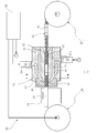
- a continuous molding machine is used to mold the resin coating layer 15.
- the continuous molding machine 20 includes a known extruding section 21 and 22 including a hopper and screws 21a and 22a, a head section 23 for covering and molding the resin coating layer 15 on the outer peripheral surface of the flexible tube base material 14, and a cooling unit. It is preferable to use a unit including a unit 24, a transport unit 25 (the supply drum 28 and the winding drum 29) that transports the connected flexible tube base material 31 to the head unit 23, and a control unit 26 that controls these. ..
- the head portion 23 preferably includes a nipple 32, a die 33, and a support 34 that fixedly supports these.
- a configuration example of such an apparatus for example, the apparatus described in FIGS. 3 to 5 of JP2011-72391A can be used.
- the molding temperature is preferably set in the range of 150°C to 300°C.
- the temperatures of the first resin material 39 and the second resin material 40 can be raised to high temperatures by controlling the heating temperature of the heating unit in the apparatus. In addition to this, the higher the rotational speeds of the screws 21a and 22a, the higher The temperatures of the first resin material 39 and the second resin material 40 can be further increased, and the fluidity of each can be increased.
- the molding speed of the inner layer 17 and the outer layer 18 is changed by changing the discharge rate of the molten first resin material 39 and the second resin material 40 while keeping the transport speed of the connected flexible tube base material 31 constant. Can be adjusted.
- a process of molding the resin coating layer 15 on the flexible tube base material 31 by the continuous molding machine 20 will be described.
- the continuous molding machine 20 performs a molding process
- the first extruded portions 21 and 22 are in a molten state.
- the resin material 39 and the second resin material 40 are extruded to the head portion 23.
- the transport unit 25 operates to transport the connected flexible tube base material 31 to the head unit 23.
- the push-out portions 21 and 22 are in a state of always pushing out the first resin material 39 and the second resin material 40 and supplying the same to the head portion 23, and the push-out portions 21 and 22 are pushed out to the gates 35 and 36.
- the 1st resin material 39 and the 2nd resin material 40 pass through the edge, merge, and are supplied to the molding passage 37 through the resin passage 38 in the overlapping state.
- the two-layer molded resin coating layer 15 in which the inner layer 17 using the first resin material 39 and the outer layer 18 using the second resin material 40 overlap each other is formed.
- the connected flexible tube base material 31 is formed by connecting a plurality of flexible tube base materials 14 (a primer layer is formed on the outer periphery of the flexible tube base material 14), and During the transportation, the resin coating layer 15 is continuously formed on the plurality of flexible tube base materials 14.
- a primer layer is formed on the outer periphery of the flexible tube base material 14
- the resin coating layer 15 is continuously formed on the plurality of flexible tube base materials 14.
- the control unit 26 is used to switch the discharge amounts of the pushing units 21 and 22. Specifically, the control unit 26 determines, based on the ratio of the thickness on the other end 14b side (base end side) of one flexible tube base material 14, the next flexible tube base material 14 on the one end 14a side (tip side). It is preferable to switch the discharge amounts of the extruding portions 21 and 22 so that the thickness ratio of (1) is satisfied.
- the control unit 26 determines, based on the ratio of the thickness on the other end 14b side (base end side) of one flexible tube base material 14, the next flexible tube base material 14 on the one end 14a side (tip side). It is preferable to switch the discharge amounts of the extruding portions 21 and 22 so that the thickness ratio of (1) is satisfied.
- the thickness of the outer layer gradually increases from one end side to the other end side,
- the pushers 21 and 22 are preferably controlled.
- the connected flexible tube base material 31 on which the resin coating layer 15 has been molded to the last end is removed from the continuous molding machine 20, and then the joint member 30 is removed from the flexible tube base material 14 to obtain each flexible tube base material. It is separated into 14. Next, the separated flexible tube base material 14 is coated with the top coat layer 16 on the resin coating layer 15 to complete the flexible tube 3a. The completed flexible tube 3a is transported to the assembly process of the electronic endoscope.
- the resin coating layer is a multi-layer
- a functional layer may be interposed between the layers forming the multi-layer.
- the electronic endoscope for observing an image obtained by imaging the state of the subject using the imaging device is described as an example, but the present invention is not limited to this. Instead, it can also be applied to an endoscope that employs an optical image guide to observe the state of a subject.
- the flexible tube of the present invention can be widely applied to endoscopic medical devices.
- the present invention can be applied to an endoscope equipped with a clip or wire at the tip thereof, or a device equipped with a basket or a brush.
- the endoscope type medical device in addition to the above-mentioned medical device having a basic structure of the endoscope, such as a remote control type medical device, the insertion portion has flexibility, and is used by being introduced into the body. It is meant to include a wide range of medical and medical equipment.
- the endoscope type medical device of the present invention has the flexible tube for an endoscope of the present invention incorporated in its insertion portion. That is, the method for manufacturing an endoscope type medical device of the present invention includes incorporating the flexible tube for an endoscope of the present invention into the insertion portion of the endoscope type medical device.
- a solution having a water/ethanol mass ratio of 5/75 was prepared.
- the compounds shown in the table below were dissolved in this solution to a concentration of 8.9 g/kg to prepare a coating solution for forming a primer layer.
- a spiral tube 11 was formed by using the metal strip 11a made of stainless steel, and a flexible tube base material in which the spiral tube 11 was covered with a tubular net 12 in which stainless steel fibers were woven was prepared.
- This flexible tube substrate has a length of 80 cm and a diameter of 12 mm.
- This stainless flexible tube has a passivation layer formed on its surface by an annealing treatment (heating treatment) at the time of forming the spiral tube and the cylindrical net body.
- the above flexible tube substrate was washed by immersing it in a 7.5% aqueous sodium hydroxide solution at 60°C for 1 minute. Then, it was rinsed with distilled water and dried in an oven at 100° C. for 10 minutes. The washed flexible tube substrate was dipped in the primer layer-forming coating solution prepared above at room temperature for 1 minute, and then dried in an oven at 160° C. for 10 minutes. In this way, a flexible tube base material having a primer layer on the outer periphery (the surface coated with the resin) was prepared.
- a flexible tube base material provided with a primer layer or an adhesive layer is extrusion-coated with a resin as shown in Table 1 below (molding temperature: 200° C.) to have a resin coating layer for an endoscope.
- a flexible tube was produced.
- the thickness of the resin coating layer was 0.4 mm.
- the resin coating layer was two layers (Examples 83 to 92), two layers were simultaneously coated and molded by two-layer extrusion molding to form a resin coating layer having a thickness of 0.4 mm.
- the length is 5 cm and the width is 1 cm along the axial direction of the flexible tube so that the cut reaches the flexible tube base material with respect to the resin coating layer of the flexible tube for endoscope after the EOG sterilization.
- a vertical cut was made to the resin coating layer.
- one end of this notch was also made in the width direction to form a grip portion for a peeling test.
- the formed notch has the same length direction as the axial direction of the flexible tube and has a width of 1 cm on the outer peripheral surface of the resin coating layer.
- the flexible tube base material and the resin coating layer are peeled off at a constant speed in the axial direction along a notch having a width of 1 cm while keeping the angle between the flexible tube base material and the peeled resin coating layer at 90°.
- the 90° peel strength was measured (measurement value X).
- the peel strength was measured with a force gauge (unit: N/cm).
- the 90° peel strength was measured in the same manner by using each flexible tube for endoscopes that was not subjected to EOG sterilization treatment (flexible tube for endoscopes not subjected to EOG sterilization treatment).
- Value Y 90° peel strength was measured under the same conditions for all flexible tubes.
- the ratio (%, 100 ⁇ X/Y) of the measured value X to the measured value Y was obtained, and the result was fitted and evaluated according to the following criteria.
- the results are shown in the table below.
- Titanium di-2-ethylhexoxybis(2-ethyl-3-hydroxyhexoxide) (“Organix TC-201" manufactured by Matsumoto Fine Chemical Co., Ltd.)
- the resulting flexible tube is subjected to repeated bending loads, and the flexible tube is subjected to EOG sterilization treatment. It was found that the adhesiveness between the flexible tube base material and the resin coating layer could be sufficiently maintained even after the application (Examples 1 to 92).
Landscapes
- Life Sciences & Earth Sciences (AREA)
- Engineering & Computer Science (AREA)
- Health & Medical Sciences (AREA)
- Surgery (AREA)
- Wood Science & Technology (AREA)
- Physics & Mathematics (AREA)
- Optics & Photonics (AREA)
- Medical Informatics (AREA)
- Veterinary Medicine (AREA)
- Nuclear Medicine, Radiotherapy & Molecular Imaging (AREA)
- Pathology (AREA)
- Radiology & Medical Imaging (AREA)
- Public Health (AREA)
- Biomedical Technology (AREA)
- Heart & Thoracic Surgery (AREA)
- Biophysics (AREA)
- Animal Behavior & Ethology (AREA)
- Molecular Biology (AREA)
- General Health & Medical Sciences (AREA)
- Manufacturing & Machinery (AREA)
- Astronomy & Astrophysics (AREA)
- General Physics & Mathematics (AREA)
- Endoscopes (AREA)
- Instruments For Viewing The Inside Of Hollow Bodies (AREA)
- Laminated Bodies (AREA)
Abstract
金属製の可撓管基材と、その外周を覆う樹脂被覆層とを有する内視鏡用可撓管であって、 可撓管基材と樹脂被覆層との間に一般式(1)又は(2)の化合物の少なくとも1種を含むプライマー層を有し、樹脂被覆層がプライマー層と接する側にポリアミド、ポリエステル、ポリウレタン及びポリオレフィンの少なくとも1種を含む内視鏡用可撓管、この内視鏡用可撓管を備えた内視鏡型医療機器、これらの製造方法。 一般式(1): R1
m-M-(OR2)n-m 一般式(2): O-[M-(OR2)n-1]2 MはAl、Ti、Zr等を示す。 R1及びR2は水素原子又は特定の基を示す。 mは0~3、nはMの価数であり、n>mである。
Description
本発明は、内視鏡用可撓管、内視鏡型医療機器、及びこれらの製造方法に関する。
内視鏡は、患者の体腔内、消化管内、食道等を観察するための医療用機器である。体内に挿入して用いるため、臓器に傷をつけず、患者に痛みないし違和感を与えないものが望まれる。そのような要請から、内視鏡の挿入部(体腔内に挿入される構造部)を構成する可撓管には、柔らかく屈曲する金属帯片を螺旋状に巻いて形成された螺旋管が採用されている。さらに、螺旋管の周囲は柔軟な樹脂で被覆され、この樹脂被覆層が必要によりトップコート層で被覆されて、食道、消化管、体腔等の内表面に刺激ないし傷を与えない工夫がなされている。
上記の樹脂被覆層は、例えば、螺旋管を筒状網体で覆った可撓管基材の外周面に、樹脂を押し出し成形することにより形成することができる。このとき、先端側は体内に挿入しやすくするために軟らかく、後端側は操作しやすくするために硬くすることが好ましい。この点を考慮し、樹脂被覆層として互いに硬さが異なる内層及び外層の二層構造を採用し、内層と外層の厚みの割合を可撓管の軸方向で変化させることが提案されている。
内視鏡の操作性、耐久性等の向上には、可撓管基材とそれを覆う樹脂被覆層との密着性を高めることが重要である。この密着性が十分でないと、可撓管を体内に挿入した際に、可撓管の屈曲により樹脂被覆層に皺、浮き、裂け、剥がれ等が生じやすくなり、また、挿入した状態で可撓管を回転させた際に樹脂被覆層に捩れが生じやすくなる。樹脂被覆層に皺、浮き、裂け、剥がれないし捩れが生じると、体内に挿入された可撓管の表面が周囲の組織に引っ掛かるなどして被検者に苦痛を与えるおそれがある。可撓管基材と樹脂被覆層との密着性は、可撓管の滅菌処理等によっても低下することが知られている。
上記の密着性を高めるために、可撓管基材と樹脂被覆層との間にプライマー層を介在させることが知られている。例えば特許文献1には、金属製芯材(可撓管基材)表面にプライマーを塗布した後、外皮層を被覆成形すること、このプライマーとして、シランカップリング剤、チタネート系カップリング剤、ジルコネート系カップリング剤などを用い得ることが記載されている。
上記の密着性を高めるために、可撓管基材と樹脂被覆層との間にプライマー層を介在させることが知られている。例えば特許文献1には、金属製芯材(可撓管基材)表面にプライマーを塗布した後、外皮層を被覆成形すること、このプライマーとして、シランカップリング剤、チタネート系カップリング剤、ジルコネート系カップリング剤などを用い得ることが記載されている。
本発明は、曲げ動作を繰り返しても可撓管基材とそれを覆う樹脂被覆層との密着性を十分に維持することができ、また、エチレンオキサイドガスを用いた強力な滅菌処理によっても可撓管基材と樹脂被覆層との密着性の低下を生じにくい内視鏡用可撓管、及び、この内視鏡用可撓管を備えた内視鏡型医療機器を提供することを課題とする。また本発明は、上記内視鏡用可撓管の製造方法、及び上記内視鏡型医療機器の製造方法を提供することを課題とする。
本発明者らは上記課題に鑑み内視鏡用可撓管における樹脂被覆層の形成について検討を重ねた結果、金属材料で構成される可撓管基材の表面に、金属アルコキシド等の特定構造の化合物を含むプライマー層を形成し、さらに、このプライマー層に接する樹脂被覆層の構成材料として特定種の樹脂を適用することにより、上記課題を解決できることを見出した。本発明は、これらの知見に基づきさらに検討を重ね、完成させるに至ったものである。
本発明の上記課題は下記の手段により解決された。
〔1〕
金属を構成材料とする可撓管基材と、この可撓管基材の外周を覆う樹脂被覆層とを有する内視鏡用可撓管であって、
上記可撓管基材と上記樹脂被覆層との間に下記一般式(1)又は(2)で表される化合物の少なくとも1種を含むプライマー層を有し、上記樹脂被覆層が、少なくともプライマー層と接する側にポリアミド、ポリエステル、ポリウレタン、及びポリオレフィンの少なくとも1種の化合物を含む、内視鏡用可撓管。
一般式(1): R1 m-M-(OR2)n-m
一般式(2): O-[M-(OR2)n-1]2
式中、MはAl、B、Ba、Bi、Ca、Ga、Ge、Hf、In、La、Mg、Nb、P、Sr、Sn、Ta、Ti、V、Y、又はZrを示す。
R1は水素原子、アルキル基、シクロアルキル基、アシル基、アリール基、又は不飽和脂肪族基を示す。
R2は水素原子、アルキル基、シクロアルキル基、アシル基、アルケニル基、アリール基、ホスホネート基、又は-SO2RSを示す。RSは置換基を示す。
mは0~3の整数であり、nはMの価数である。n>mを満たす。
〔2〕
上記MがTiである、〔1〕に記載の内視鏡用可撓管。
〔3〕
上記の一般式(1)又は(2)で表される化合物が、N、P及びSの少なくとも1種の原子を含む、〔2〕に記載の内視鏡用可撓管。
〔4〕
上記MがAlである、〔1〕に記載の内視鏡用可撓管。
〔5〕
上記一般式(1)及び(2)において、OR2の少なくとも1つがアセトナト構造を有する、〔4〕に記載の内視鏡用可撓管。
〔6〕
上記一般式(1)及び(2)において、OR2の少なくとも1つがアセタト構造を有する、〔4〕又は〔5〕に記載の内視鏡用可撓管。
〔7〕
上記MがZrである、〔1〕に記載の内視鏡用可撓管。
〔8〕
上記一般式(1)及び(2)において、OR2の少なくとも1つがアセトナト構造を有する、〔7〕に記載の内視鏡用可撓管。
〔9〕
上記一般式(1)及び(2)において、OR2の少なくとも1つがアセタト構造を有する、〔7〕又は〔8〕に記載の内視鏡用可撓管。
〔10〕
上記一般式(1)及び(2)において、OR2の少なくとも1つがラクタト構造を有する、〔7〕~〔9〕のいずれかに記載の内視鏡用可撓管。
〔11〕
上記可撓管基材を構成する金属がステンレスである、〔1〕~〔10〕のいずれかに記載の内視鏡用可撓管。
〔12〕
上記可撓管基材を構成する金属が表面に不動態皮膜を有する、〔1〕~〔11〕のいずれかに記載の内視鏡用可撓管。
〔13〕
上記樹脂被覆層が単層構造又は複層構造であり、上記プライマー層と接する層中にポリアミド、ポリエステル、ポリウレタン、及びポリオレフィンの少なくとも1種の化合物を含む、〔1〕~〔12〕のいずれかに記載の内視鏡用可撓管。
〔14〕
上記樹脂被覆層が2層構造であり、この2層構造の内層及び外層の厚みの割合が、上記可撓管基材の軸方向において傾斜的に変化している、〔1〕~〔13〕のいずれかに記載の内視鏡用可撓管。
〔15〕
上記の内層及び外層の厚みの割合が、上記内視鏡用可撓管の一端において内層:外層=95:5~60:40であって、他端において内層:外層=5:95~40:60である、〔14〕に記載の内視鏡用可撓管。
〔16〕
〔1〕~〔15〕のいずれかに記載の内視鏡用可撓管を有する内視鏡型医療機器。
〔17〕
金属を構成材料とする可撓管基材の少なくとも外周に、下記一般式(1)又は(2)で表される化合物の少なくとも1種を含むプライマー層を形成する工程、及び
上記可撓管基材の外周に形成された上記プライマー層に接して、ポリアミド、ポリエステル、ポリウレタン、及びポリオレフィンの少なくとも1種の化合物を含む樹脂を被覆することを含む樹脂被覆層の形成工程
を含む、内視鏡用可撓管の製造方法。
一般式(1): R1 m-M-(OR2)n-m
一般式(2): O-[M-(OR2)n-1]2
式中、MはAl、B、Ba、Bi、Ca、Ga、Ge、Hf、In、La、Mg、Nb、P、Sr、Sn、Ta、Ti、V、Y、又はZrを示す。
R1は水素原子、アルキル基、シクロアルキル基、アシル基、アリール基、又は不飽和脂肪族基を示す。
R2は水素原子、アルキル基、シクロアルキル基、アシル基、アルケニル基、アリール基、ホスホネート基、又は-SO2RSを示す。RSは置換基を示す。
mは0~3の整数であり、nはMの価数である。n>mを満たす。
〔18〕
上記樹脂被覆層が2層構造であり、この2層構造の少なくとも内層がポリアミド、ポリエステル、ポリウレタン、及びポリオレフィンの少なくとも1種の化合物を含み、上記2層構造の内層及び外層の厚みの割合が、上記可撓管基材の軸方向において傾斜的に変化している、〔17〕に記載の内視鏡用可撓管の製造方法。
〔19〕
〔17〕又は〔18〕に記載の内視鏡用可撓管の製造方法により内視鏡用可撓管を得る工程、及び、
得られた内視鏡用可撓管を内視鏡型医療機器の挿入部に組み込む工程
を含む、内視鏡型医療機器の製造方法。
〔20〕
〔1〕~〔15〕のいずれかに記載の内視鏡用可撓管を内視鏡型医療機器の挿入部に組み込むことを含む、内視鏡型医療機器の製造方法。
〔1〕
金属を構成材料とする可撓管基材と、この可撓管基材の外周を覆う樹脂被覆層とを有する内視鏡用可撓管であって、
上記可撓管基材と上記樹脂被覆層との間に下記一般式(1)又は(2)で表される化合物の少なくとも1種を含むプライマー層を有し、上記樹脂被覆層が、少なくともプライマー層と接する側にポリアミド、ポリエステル、ポリウレタン、及びポリオレフィンの少なくとも1種の化合物を含む、内視鏡用可撓管。
一般式(1): R1 m-M-(OR2)n-m
一般式(2): O-[M-(OR2)n-1]2
式中、MはAl、B、Ba、Bi、Ca、Ga、Ge、Hf、In、La、Mg、Nb、P、Sr、Sn、Ta、Ti、V、Y、又はZrを示す。
R1は水素原子、アルキル基、シクロアルキル基、アシル基、アリール基、又は不飽和脂肪族基を示す。
R2は水素原子、アルキル基、シクロアルキル基、アシル基、アルケニル基、アリール基、ホスホネート基、又は-SO2RSを示す。RSは置換基を示す。
mは0~3の整数であり、nはMの価数である。n>mを満たす。
〔2〕
上記MがTiである、〔1〕に記載の内視鏡用可撓管。
〔3〕
上記の一般式(1)又は(2)で表される化合物が、N、P及びSの少なくとも1種の原子を含む、〔2〕に記載の内視鏡用可撓管。
〔4〕
上記MがAlである、〔1〕に記載の内視鏡用可撓管。
〔5〕
上記一般式(1)及び(2)において、OR2の少なくとも1つがアセトナト構造を有する、〔4〕に記載の内視鏡用可撓管。
〔6〕
上記一般式(1)及び(2)において、OR2の少なくとも1つがアセタト構造を有する、〔4〕又は〔5〕に記載の内視鏡用可撓管。
〔7〕
上記MがZrである、〔1〕に記載の内視鏡用可撓管。
〔8〕
上記一般式(1)及び(2)において、OR2の少なくとも1つがアセトナト構造を有する、〔7〕に記載の内視鏡用可撓管。
〔9〕
上記一般式(1)及び(2)において、OR2の少なくとも1つがアセタト構造を有する、〔7〕又は〔8〕に記載の内視鏡用可撓管。
〔10〕
上記一般式(1)及び(2)において、OR2の少なくとも1つがラクタト構造を有する、〔7〕~〔9〕のいずれかに記載の内視鏡用可撓管。
〔11〕
上記可撓管基材を構成する金属がステンレスである、〔1〕~〔10〕のいずれかに記載の内視鏡用可撓管。
〔12〕
上記可撓管基材を構成する金属が表面に不動態皮膜を有する、〔1〕~〔11〕のいずれかに記載の内視鏡用可撓管。
〔13〕
上記樹脂被覆層が単層構造又は複層構造であり、上記プライマー層と接する層中にポリアミド、ポリエステル、ポリウレタン、及びポリオレフィンの少なくとも1種の化合物を含む、〔1〕~〔12〕のいずれかに記載の内視鏡用可撓管。
〔14〕
上記樹脂被覆層が2層構造であり、この2層構造の内層及び外層の厚みの割合が、上記可撓管基材の軸方向において傾斜的に変化している、〔1〕~〔13〕のいずれかに記載の内視鏡用可撓管。
〔15〕
上記の内層及び外層の厚みの割合が、上記内視鏡用可撓管の一端において内層:外層=95:5~60:40であって、他端において内層:外層=5:95~40:60である、〔14〕に記載の内視鏡用可撓管。
〔16〕
〔1〕~〔15〕のいずれかに記載の内視鏡用可撓管を有する内視鏡型医療機器。
〔17〕
金属を構成材料とする可撓管基材の少なくとも外周に、下記一般式(1)又は(2)で表される化合物の少なくとも1種を含むプライマー層を形成する工程、及び
上記可撓管基材の外周に形成された上記プライマー層に接して、ポリアミド、ポリエステル、ポリウレタン、及びポリオレフィンの少なくとも1種の化合物を含む樹脂を被覆することを含む樹脂被覆層の形成工程
を含む、内視鏡用可撓管の製造方法。
一般式(1): R1 m-M-(OR2)n-m
一般式(2): O-[M-(OR2)n-1]2
式中、MはAl、B、Ba、Bi、Ca、Ga、Ge、Hf、In、La、Mg、Nb、P、Sr、Sn、Ta、Ti、V、Y、又はZrを示す。
R1は水素原子、アルキル基、シクロアルキル基、アシル基、アリール基、又は不飽和脂肪族基を示す。
R2は水素原子、アルキル基、シクロアルキル基、アシル基、アルケニル基、アリール基、ホスホネート基、又は-SO2RSを示す。RSは置換基を示す。
mは0~3の整数であり、nはMの価数である。n>mを満たす。
〔18〕
上記樹脂被覆層が2層構造であり、この2層構造の少なくとも内層がポリアミド、ポリエステル、ポリウレタン、及びポリオレフィンの少なくとも1種の化合物を含み、上記2層構造の内層及び外層の厚みの割合が、上記可撓管基材の軸方向において傾斜的に変化している、〔17〕に記載の内視鏡用可撓管の製造方法。
〔19〕
〔17〕又は〔18〕に記載の内視鏡用可撓管の製造方法により内視鏡用可撓管を得る工程、及び、
得られた内視鏡用可撓管を内視鏡型医療機器の挿入部に組み込む工程
を含む、内視鏡型医療機器の製造方法。
〔20〕
〔1〕~〔15〕のいずれかに記載の内視鏡用可撓管を内視鏡型医療機器の挿入部に組み込むことを含む、内視鏡型医療機器の製造方法。
本明細書において、特定の符号で示された置換基や連結基等(以下、置換基等という)が複数あるとき、あるいは複数の置換基等を同時もしくは択一的に規定するときには、それぞれの置換基等は互いに同一でも異なっていてもよいことを意味する。また、特に断らない場合であっても、複数の置換基等が隣接するときにはそれらが互いに連結したり縮環したりして環を形成していてもよい意味である。
本明細書において置換ないし無置換を明記していない置換基(連結基についても同様)については、所望の効果を奏する範囲で、その基に任意の置換基を有していてもよい意味である。これは置換ないし無置換を明記していない化合物についても同義である。
本明細書において、ある基の炭素数を規定する場合、この炭素数は、基全体の炭素数を意味する。つまり、この基がさらに置換基を有する形態である場合、この置換基を含めた全体の炭素数を意味する。
本明細書において置換ないし無置換を明記していない置換基(連結基についても同様)については、所望の効果を奏する範囲で、その基に任意の置換基を有していてもよい意味である。これは置換ないし無置換を明記していない化合物についても同義である。
本明細書において、ある基の炭素数を規定する場合、この炭素数は、基全体の炭素数を意味する。つまり、この基がさらに置換基を有する形態である場合、この置換基を含めた全体の炭素数を意味する。
本発明の内視鏡用可撓管は、曲げ動作を繰り返しても可撓管基材とそれを覆う樹脂被覆層との密着性を十分に維持することができ、また、滅菌処理によっても可撓管基材と樹脂被覆層との密着性の低下を生じにくい。
本発明の内視鏡型医療機器は、体内に挿入される構造部である可撓管が、曲げ動作を繰り返しても可撓管基材とそれを覆う樹脂被覆層との密着性を十分に維持することができ、また、滅菌処理によっても可撓管基材と樹脂被覆層との密着性の低下を生じにくい。したがって、本発明の内視鏡型医療機器は耐久性に優れ、使用時における被検者の負担をより軽減することができる。
本発明の内視鏡用可撓管の製造方法によれば、曲げ動作を繰り返しても可撓管基材とそれを覆う樹脂被覆層との密着性を十分に維持することができ、また、滅菌処理によっても可撓管基材と樹脂被覆層との密着性の低下を生じにくい内視鏡用可撓管を得ることができる。
本発明の内視鏡型医療機器の製造方法によれば、この機器を構成する可撓管を、曲げ動作を繰り返しても可撓管基材とそれを覆う樹脂被覆層との密着性を十分に維持することができ、また、滅菌処理によっても可撓管基材と樹脂被覆層との密着性の低下を生じにくい特性とすることができる。したがって、本発明の内視鏡型医療機器の製造方法により、耐久性に優れ、使用時における被検者の負担がより軽減された内視鏡型医療機器を得ることができる。
本発明の内視鏡型医療機器は、体内に挿入される構造部である可撓管が、曲げ動作を繰り返しても可撓管基材とそれを覆う樹脂被覆層との密着性を十分に維持することができ、また、滅菌処理によっても可撓管基材と樹脂被覆層との密着性の低下を生じにくい。したがって、本発明の内視鏡型医療機器は耐久性に優れ、使用時における被検者の負担をより軽減することができる。
本発明の内視鏡用可撓管の製造方法によれば、曲げ動作を繰り返しても可撓管基材とそれを覆う樹脂被覆層との密着性を十分に維持することができ、また、滅菌処理によっても可撓管基材と樹脂被覆層との密着性の低下を生じにくい内視鏡用可撓管を得ることができる。
本発明の内視鏡型医療機器の製造方法によれば、この機器を構成する可撓管を、曲げ動作を繰り返しても可撓管基材とそれを覆う樹脂被覆層との密着性を十分に維持することができ、また、滅菌処理によっても可撓管基材と樹脂被覆層との密着性の低下を生じにくい特性とすることができる。したがって、本発明の内視鏡型医療機器の製造方法により、耐久性に優れ、使用時における被検者の負担がより軽減された内視鏡型医療機器を得ることができる。
本発明の内視鏡型医療機器の好ましい実施形態について、電子内視鏡を例に説明する。電子内視鏡は、内視鏡用可撓管が組み込まれ(以下、内視鏡用可撓管を単に「可撓管」と称することがある)、この可撓管を体腔内、消化管内、食道等に挿入して体内を観察等する医療機器として用いられる。図1に示した例において、電子内視鏡2は、体内に挿入される挿入部3と、挿入部3の基端部分に連設された本体操作部5と、プロセッサ装置や光源装置に接続されるユニバーサルコード6とを備えている。挿入部3は、本体操作部5に連設される可撓管3aと、そこに連設されるアングル部3bと、その先端に連設され、体内撮影用の撮像装置(図示せず)が内蔵された先端部3cとから構成される。挿入部3の大半の長さを占める可撓管3aは、そのほぼ全長にわたって可撓性を有し、特に体腔等の内部に挿入される部位はより可撓性に富む構造となっている。
<可撓管基材>
可撓管は、最内層として金属を構成材料とする可撓管基材を有する。
図2に示すように、可撓管基材14は、最内側に金属帯片11aを螺旋状に巻回することにより形成される螺旋管11に、金属線を編組してなる筒状網体12を被覆して両端に口金13をそれぞれ嵌合した形態とすることが好ましい。可撓管基材14を構成する金属は、腐蝕を防ぐために、その表面に不動態化処理が施されていることが好ましい。すなわち、可撓管基材14はその外周に不動態皮膜を有することが好ましい。この不動態化処理は常法により行うことができる。例えば、硝酸などの強力な酸化剤を含む溶液に浸漬したり、空気(酸素)中もしくは水(水蒸気)中で加熱したり、酸化剤を含む溶液中で陽極酸化したりすることにより、金属表面に不動態皮膜を形成することができる。
可撓管基材14を構成する金属は、ステンレスが好ましい。ステンレス表面は通常、クロムと酸素が結合して不動態皮膜が形成された状態にある。しかし、可撓管基材14の構成材料としてステンレスを使用する場合であっても、ステンレス表面全体に、より均一な不動態皮膜をより確実に形成させるために、ステンレスに上述した不動態化処理を施すことが好ましい。
可撓管は、最内層として金属を構成材料とする可撓管基材を有する。
図2に示すように、可撓管基材14は、最内側に金属帯片11aを螺旋状に巻回することにより形成される螺旋管11に、金属線を編組してなる筒状網体12を被覆して両端に口金13をそれぞれ嵌合した形態とすることが好ましい。可撓管基材14を構成する金属は、腐蝕を防ぐために、その表面に不動態化処理が施されていることが好ましい。すなわち、可撓管基材14はその外周に不動態皮膜を有することが好ましい。この不動態化処理は常法により行うことができる。例えば、硝酸などの強力な酸化剤を含む溶液に浸漬したり、空気(酸素)中もしくは水(水蒸気)中で加熱したり、酸化剤を含む溶液中で陽極酸化したりすることにより、金属表面に不動態皮膜を形成することができる。
可撓管基材14を構成する金属は、ステンレスが好ましい。ステンレス表面は通常、クロムと酸素が結合して不動態皮膜が形成された状態にある。しかし、可撓管基材14の構成材料としてステンレスを使用する場合であっても、ステンレス表面全体に、より均一な不動態皮膜をより確実に形成させるために、ステンレスに上述した不動態化処理を施すことが好ましい。
<プライマー層>
本発明において、可撓管基材の外周には、プライマー層(図示せず)が設けられている。このプライマー層を設けることにより、可撓管基材と、その外周を覆って設けられる後述する樹脂被覆層との密着性を効果的に高めることができる。本発明において、このプライマー層は下記一般式(1)又は(2)で表される化合物の少なくとも1種を含む。すなわち本発明におけるプライマー層には次の(i)~(iii)の形態が含まれる。
(i)一般式(1)で表される化合物の少なくとも1種を含み、一般式(2)で表される化合物を含まない形態;
(ii)一般式(1)で表される化合物を含まず、一般式(2)で表される化合物の少なくとも1種を含む形態;
(iii)一般式(1)で表される化合物の少なくとも1種を含み、かつ一般式(2)で表される化合物の少なくとも1種を含む形態。
本発明において、可撓管基材の外周には、プライマー層(図示せず)が設けられている。このプライマー層を設けることにより、可撓管基材と、その外周を覆って設けられる後述する樹脂被覆層との密着性を効果的に高めることができる。本発明において、このプライマー層は下記一般式(1)又は(2)で表される化合物の少なくとも1種を含む。すなわち本発明におけるプライマー層には次の(i)~(iii)の形態が含まれる。
(i)一般式(1)で表される化合物の少なくとも1種を含み、一般式(2)で表される化合物を含まない形態;
(ii)一般式(1)で表される化合物を含まず、一般式(2)で表される化合物の少なくとも1種を含む形態;
(iii)一般式(1)で表される化合物の少なくとも1種を含み、かつ一般式(2)で表される化合物の少なくとも1種を含む形態。
一般式(1): R1
m-M-(OR2)n-m
一般式(2): O-[M-(OR2)n-1]2
一般式(2): O-[M-(OR2)n-1]2
一般式(1)及び(2)中、MはAl、B、Ba、Bi、Ca、Ga、Ge、Hf、In、La、Mg、Nb、P、Sr、Sn、Ta、Ti、V、Y、又はZrを示す。MはTi、Al、又はZrであることが好ましい。
R1は水素原子、アルキル基、シクロアルキル基、アシル基、アリール基、又は不飽和脂肪族基を示す。
R1として採り得るアルキル基は、直鎖アルキル基及び分岐アルキル基並びにアラルキル基を含む。このアルキル基の炭素数は1~20の整数が好ましく、1~15がより好ましく、1~10がさらに好ましく、1~8が特に好ましいが、アラルキル基の場合は7~30が好ましい。このアルキル基の好ましい具体例として、例えば、メチル、エチル、プロピル、イソプロピル、n-ブチル、s-ブチル、イソブチル、t-ブチル、n-ペンチル、n-ヘキシル、n-ヘプチル、n-オクチル、n-デシル、n-トリデシル、n-オクタデシル、ベンジル、及びフェネチルが挙げられる。
R1として採り得るアルキル基は、直鎖アルキル基及び分岐アルキル基並びにアラルキル基を含む。このアルキル基の炭素数は1~20の整数が好ましく、1~15がより好ましく、1~10がさらに好ましく、1~8が特に好ましいが、アラルキル基の場合は7~30が好ましい。このアルキル基の好ましい具体例として、例えば、メチル、エチル、プロピル、イソプロピル、n-ブチル、s-ブチル、イソブチル、t-ブチル、n-ペンチル、n-ヘキシル、n-ヘプチル、n-オクチル、n-デシル、n-トリデシル、n-オクタデシル、ベンジル、及びフェネチルが挙げられる。
R1として採り得るシクロアルキル基は、炭素数が3~20の整数が好ましく、3~15がより好ましく、3~10がさらに好ましく、3~8が特に好ましい。このシクロアルキル基の好ましい具体例としては、例えば、シクロプロピル、シクロペンチル、及びシクロヘキシルが挙げられる。
R1として採り得るアシル基は、炭素数が2~40の整数が好ましく、2~30がより好ましく、2~20がさらに好ましく、2~18が特に好ましい。
R1として採り得るアリール基は、炭素数が6~20の整数が好ましく、6~15がより好ましく、6~12がさらに好ましく、6~10が特に好ましい。このアリール基の好ましい具体例としては、例えば、フェニル及びナフチルが挙げられ、フェニルがさらに好ましい。
R1として採り得る不飽和脂肪族基は、炭素-炭素不飽和結合の数が1~5であることが好ましく、1~3がより好ましく、1又は2がさらに好ましく、1であることが特に好ましい。不飽和脂肪族基はヘテロ原子を含んでもよく、炭化水素基であることも好ましい。不飽和脂肪族基が炭化水素基の場合、炭素数は2~20が好ましく、2~15がより好ましく、2~10がさらに好ましく、2~8が特に好ましい。不飽和脂肪族基はより好ましくはアルケニル基又はアルキニル基である。
R1は水素原子、アルキル基、シクロアルキル基、又はアリール基が好ましく、アルキル基、又はシクロアルキル基がより好ましい。
一般式(1)の化合物がR1を2つ以上有する場合、2つのR1は互いに連結して環を形成していてもよい。
一般式(1)の化合物がR1を2つ以上有する場合、2つのR1は互いに連結して環を形成していてもよい。
R2は水素原子、アルキル基、シクロアルキル基、アシル基、アルケニル基、アリール基、ホスホネート基(ホスホン酸基)、又は-SO2RSを示す。RSは置換基を示す。
R2として採り得るアルキル基、シクロアルキル基、アシル基、及びアリール基は、それぞれ、R1として採り得るアルキル基、シクロアルキル基、アシル基、及びアリール基と同義であり、各基の好ましい形態も同じである。また、R2として採り得るアルキル基は、置換基としてアミノ基を有することも好ましい。
R2として採り得るアルキル基、シクロアルキル基、アシル基、及びアリール基は、それぞれ、R1として採り得るアルキル基、シクロアルキル基、アシル基、及びアリール基と同義であり、各基の好ましい形態も同じである。また、R2として採り得るアルキル基は、置換基としてアミノ基を有することも好ましい。
R2として採り得るアルケニル基は、直鎖アルケニル基及び分岐アルケニル基を含む。このアルケニル基の炭素数は好ましくは2~18の整数であり、より好ましくは2~7、さらに好ましくは2~5である。このアルケニル基の好ましい具体例として、例えば、ビニル、アリル、ブテニル、ペンテニル及びヘキセニルが挙げられる。このアルケニル基は置換アルケニル基が好ましい。
R2として採り得るホスホネート基は、-P(=O)(-ORP1)ORP2で表される基である。RP1及びRP2は水素原子又は置換基を示し、この置換基はアルキル基、又はホスホネート基が好ましい。RP1及びRP2として採り得るアルキル基は上述したR1として採り得るアルキル基と同義であり、アルキル基の好ましい形態も同じである。RP1及びRP2として採り得るホスホネート基は、R2として採り得るホスホネート基と同義であり、好ましい形態も同じである。RP1又はRP2がホスホネート基の場合、このホスホネート基を構成するRP1及びRP2はアルキル基が好ましい。
R2として採り得るホスホネート基は、RP1及びRP2がともにアルキル基であるか、又は、RP1が水素原子で、RP2がホスホネート基であることが好ましい。
なお、ホスホネート基はホスファイト基(亜リン酸基)と互変異性であるため、本発明においてホスホネート基は、ホスファイト基を含む意味である。
R2として採り得るホスホネート基は、RP1及びRP2がともにアルキル基であるか、又は、RP1が水素原子で、RP2がホスホネート基であることが好ましい。
なお、ホスホネート基はホスファイト基(亜リン酸基)と互変異性であるため、本発明においてホスホネート基は、ホスファイト基を含む意味である。
R2として採り得る-SO2RSにおいて、置換基RSとしてはアルキル基又はアリール基が好ましい。RSとして採り得るアルキル基及びアリール基の好ましい形態として、それぞれ、上述したR1として採り得るアルキル基及びアリール基の好ましい形態を挙げることができる。なかでもRSはアルキル基を置換基として有するフェニルが好ましい。このアルキル基の好ましい形態は、上述したR1として採り得るアルキル基の好ましい形態と同じである。
一般式(1)の化合物又は一般式(2)の化合物がR2を2つ以上有する場合、2つのR2は互いに連結して環を形成していてもよい。
mは0~3の整数であり、nはMの価数である。また、n>mを満たす。mは0又は1が好ましく、より好ましくは0である。
MがTiの場合、上記の一般式(1)又は(2)で表される化合物は、N、P及びSの少なくとも1種の原子を含むことが好ましい。一般式(1)又は(2)で表される化合物がNを有する場合、このNをアミノ基として有することが好ましい。
一般式(1)又は(2)で表される化合物がPを有する場合、このPをホスフェート基(リン酸基)ないしホスホネート基(ホスホン酸基)として有することが好ましい。
一般式(1)又は(2)で表される化合物がSを有する場合、このSをスルホニル基(-SO2-)として有することが好ましい。
Tiは通常は4価である。
一般式(1)又は(2)で表される化合物がPを有する場合、このPをホスフェート基(リン酸基)ないしホスホネート基(ホスホン酸基)として有することが好ましい。
一般式(1)又は(2)で表される化合物がSを有する場合、このSをスルホニル基(-SO2-)として有することが好ましい。
Tiは通常は4価である。
MがAlの場合、上記の一般式(1)又は(2)において、OR2の少なくとも1つがアセトナト構造を有することが好ましい。このアセトナト構造は、アセトン又はアセトンが置換基を有した構造の化合物から水素イオンが1つ除かれてMに配位している構造を意味する。このMに配位する配位原子は通常は酸素原子である。このアセトナト構造は、アセチルアセトン構造(「CH3-C(=O)-CH2-C(=O)-CH3」)を基本構造とし、そこから水素イオンが1つ除かれて、酸素原子を配位原子としてMに配位している構造が好ましい。上記の「アセチルアセトン構造を基本構造とする」とは、上記アセチルアセトン構造の他、上記アセチルアセトン構造の水素原子が置換基で置換された構造を含む意味である。MがAlで、かつOR2がアセトナト構造を有する形態として、例えば、後述する化合物A-2及びA-3が挙げられる。
また、MがAlの場合、上記の一般式(1)又は(2)において、OR2の少なくとも1つがアセタト構造を有することが好ましい。このアセタト構造は、酢酸エステル又は酢酸エステルが置換基(アルキル基を含む)を有した構造の化合物から水素イオンが1つ除かれてMに配位している構造を意味する。このMに配位する配位原子は通常は酸素原子である。このアセタト構造は、アルキルアセトアセタート構造(「CH3-C(=O)-CH2-C(=O)-O-Ralk(Ralkはアルキル基を示す。)」)を基本構造とし、そこから水素イオンが1つ除かれて、酸素原子を配位原子としてMに配位している構造が好ましい。上記の「アルキルアセトアセタート構造を基本構造とする」とは、上記アルキルアセトアセタート構造の他、上記アルキルアセトアセタート構造の水素原子が置換基で置換された構造を含む意味である。MがAlで、かつOR2がアセタト構造を有する形態として、例えば、後述する化合物A-3、A-4、及びA-5が挙げられる。
Alは通常は3価である。
また、MがAlの場合、上記の一般式(1)又は(2)において、OR2の少なくとも1つがアセタト構造を有することが好ましい。このアセタト構造は、酢酸エステル又は酢酸エステルが置換基(アルキル基を含む)を有した構造の化合物から水素イオンが1つ除かれてMに配位している構造を意味する。このMに配位する配位原子は通常は酸素原子である。このアセタト構造は、アルキルアセトアセタート構造(「CH3-C(=O)-CH2-C(=O)-O-Ralk(Ralkはアルキル基を示す。)」)を基本構造とし、そこから水素イオンが1つ除かれて、酸素原子を配位原子としてMに配位している構造が好ましい。上記の「アルキルアセトアセタート構造を基本構造とする」とは、上記アルキルアセトアセタート構造の他、上記アルキルアセトアセタート構造の水素原子が置換基で置換された構造を含む意味である。MがAlで、かつOR2がアセタト構造を有する形態として、例えば、後述する化合物A-3、A-4、及びA-5が挙げられる。
Alは通常は3価である。
MがZrの場合、上記の一般式(1)又は(2)において、OR2の少なくとも1つがアセトナト構造を有することが好ましい。このアセトナト構造は、MがAlの形態で説明したアセトナト構造と同義である。MがZrで、かつOR2がアセトナト構造を有する形態として、例えば、後述する化合物Z-3及びZ-6が挙げられる。
また、MがZrの場合、上記の一般式(1)又は(2)において、OR2の少なくとも1つがアセタト構造を有することが好ましい。このアセタト構造は、MがAlの形態で説明したアセタト構造と同義である。MがZrで、かつOR2がアセタト構造を有する形態として、例えば、後述する化合物Z-7が挙げられる。
また、MがZrの場合、上記の一般式(1)又は(2)において、OR2の少なくとも1つがラクタト構造を有することが好ましい。このラクタト構造は、乳酸イオン(ラクタート)を基本構造とし、そこから水素イオンが1つ除かれてMに配位している構造を意味する。上記の「乳酸イオンを基本構造とする」とは、上記乳酸イオンの他、上記乳酸イオンの水素原子が置換基で置換された構造を含む意味である。このMに配位する配位原子は通常は酸素原子である。MがZrで、かつOR2がラクタト構造を有する形態として、例えば、後述する化合物Z-4が挙げられる。
また、MがZrの場合、上記の一般式(1)又は(2)において、R2の少なくとも1つがアシル基であることも好ましい。MがZrで、かつR2がアシル基の形態として、例えば、後述する化合物Z-5が挙げられる。
Zrは通常は4価である。
また、MがZrの場合、上記の一般式(1)又は(2)において、OR2の少なくとも1つがアセタト構造を有することが好ましい。このアセタト構造は、MがAlの形態で説明したアセタト構造と同義である。MがZrで、かつOR2がアセタト構造を有する形態として、例えば、後述する化合物Z-7が挙げられる。
また、MがZrの場合、上記の一般式(1)又は(2)において、OR2の少なくとも1つがラクタト構造を有することが好ましい。このラクタト構造は、乳酸イオン(ラクタート)を基本構造とし、そこから水素イオンが1つ除かれてMに配位している構造を意味する。上記の「乳酸イオンを基本構造とする」とは、上記乳酸イオンの他、上記乳酸イオンの水素原子が置換基で置換された構造を含む意味である。このMに配位する配位原子は通常は酸素原子である。MがZrで、かつOR2がラクタト構造を有する形態として、例えば、後述する化合物Z-4が挙げられる。
また、MがZrの場合、上記の一般式(1)又は(2)において、R2の少なくとも1つがアシル基であることも好ましい。MがZrで、かつR2がアシル基の形態として、例えば、後述する化合物Z-5が挙げられる。
Zrは通常は4価である。
上記R1又はR2として採り得る各基は、対カチオンを有するアニオン性基(塩型の置換基)を置換基として有していてもよい。アニオン性基とは、アニオンを形成し得る基を意味する。上記対カチオンを有するアニオン性基としては、例えば、アンモニウムイオンを対カチオンとするカルボン酸イオンの基が挙げられる。この場合、上記対カチオンは、上記の一般式(1)又は(2)で表される化合物中において、化合物全体の電荷が0となるように存在していればよい。
一般式(1)で表される化合物の具体例を以下に示すが、本発明はこれらに限定されるものではない。
(MがTiの例)
イソプロピルトリイソステアロイルチタネート、
イソプロピルトリドデシルベンゼンスルホニルチタネート、
イソプロピルトリオクタノイルチタネート、
イソプロピルトリ(ジオクチルホスファイト)チタネート、
イソプロピルトリス(ジオクチルピロホスフェート)チタネート、
イソプロピルトリ(ジオクチルスルフェート)チタネート、
イソプロピルトリクミルフェニルチタネート、
イソプロピルトリ(N-アミノエチル-アミノエチル)チタネート、
イソプロピルジメタクリルイソステアロイルチタネート、
イソプロピルイソステアロイルジアクリルチタネート、
イソブチルトリメチルチタネート、
ジイソステアロイルエチレンチタネート、
ジイソプロピルビス(ジオクチルピロホスフェート)チタネート、
ジオクチルビス(ジトリデシルホスファイト)チタネート、
ジクミルフェニルオキシアセテートチタネート、
ビス(ジオクチルピロホスフェート)オキシアセテートチタネート、
ビス(ジオクチルピロホスフェート)エチレンチタネート、
ビス(ジオクチルピロホスフェート)オキシアセテートチタネート、
テトライソプロピルチタネート、
テトラn-ブチルチタネート、
テトラオクチルチタネート、
テトラステアリルチタネート、
テトライソプロピルビス(ジオクチルホスファイト)チタネート、
テトラオクチルビス(ジ-トリデシルホスファイト)チタネート、
テトラ(2,2-ジアリルオキシメチル-1-ブチル)ビス(ジ-トリデシル)ホスファイトチタネート、
ブチルチタネートダイマー、
チタンテトラアセチルアセトネート、
チタンエチルアセトアセテート、
チタンオクチレングリコレート、
チタニウムジ-2-エチルヘキソキシビス(2-エチル-3-ヒドロキシヘキソキシド)。
イソプロピルトリイソステアロイルチタネート、
イソプロピルトリドデシルベンゼンスルホニルチタネート、
イソプロピルトリオクタノイルチタネート、
イソプロピルトリ(ジオクチルホスファイト)チタネート、
イソプロピルトリス(ジオクチルピロホスフェート)チタネート、
イソプロピルトリ(ジオクチルスルフェート)チタネート、
イソプロピルトリクミルフェニルチタネート、
イソプロピルトリ(N-アミノエチル-アミノエチル)チタネート、
イソプロピルジメタクリルイソステアロイルチタネート、
イソプロピルイソステアロイルジアクリルチタネート、
イソブチルトリメチルチタネート、
ジイソステアロイルエチレンチタネート、
ジイソプロピルビス(ジオクチルピロホスフェート)チタネート、
ジオクチルビス(ジトリデシルホスファイト)チタネート、
ジクミルフェニルオキシアセテートチタネート、
ビス(ジオクチルピロホスフェート)オキシアセテートチタネート、
ビス(ジオクチルピロホスフェート)エチレンチタネート、
ビス(ジオクチルピロホスフェート)オキシアセテートチタネート、
テトライソプロピルチタネート、
テトラn-ブチルチタネート、
テトラオクチルチタネート、
テトラステアリルチタネート、
テトライソプロピルビス(ジオクチルホスファイト)チタネート、
テトラオクチルビス(ジ-トリデシルホスファイト)チタネート、
テトラ(2,2-ジアリルオキシメチル-1-ブチル)ビス(ジ-トリデシル)ホスファイトチタネート、
ブチルチタネートダイマー、
チタンテトラアセチルアセトネート、
チタンエチルアセトアセテート、
チタンオクチレングリコレート、
チタニウムジ-2-エチルヘキソキシビス(2-エチル-3-ヒドロキシヘキソキシド)。
(MがAlの例)
アルミニウムトリエチレート、
アルミニウムトリイソプロピレート、
アルミニウムトリsec-ブチレート、
アルミニウムトリス(エチルアセトアセテート)、
エチルアセトアセテートアルミニウムジイソプロピレート、
アルミニウムモノアセチルアセトネートビス(エチルアセトアセテート)、
アルミニウムトリス(アセチルアセトネート)
ジイソプロポキシアルミニウム-9-オクタデセニルアセトアセテート、
アルミニウムジイソプロボキシモノエチルアセトアセテート、
アルミニウムトリスエチルアセトアセテート、
アルミニウムトリスアセチルアセトネート、
モノsec-ブトキシアルミニウムジイソプロピレート、
エチルアセトアセテエートアルミニウムジイソプロピレート、
ジエチルアセトアセテートアルミニウムイソプロピレート、
アルミニウムビスエチルアセトアセテートモノアセチルアセトネート、
アルミニウムトリスエチルアセトアセテート、
アルミニウムオクタデシルアセトアセテートジイソプロピレート。
アルミニウムトリエチレート、
アルミニウムトリイソプロピレート、
アルミニウムトリsec-ブチレート、
アルミニウムトリス(エチルアセトアセテート)、
エチルアセトアセテートアルミニウムジイソプロピレート、
アルミニウムモノアセチルアセトネートビス(エチルアセトアセテート)、
アルミニウムトリス(アセチルアセトネート)
ジイソプロポキシアルミニウム-9-オクタデセニルアセトアセテート、
アルミニウムジイソプロボキシモノエチルアセトアセテート、
アルミニウムトリスエチルアセトアセテート、
アルミニウムトリスアセチルアセトネート、
モノsec-ブトキシアルミニウムジイソプロピレート、
エチルアセトアセテエートアルミニウムジイソプロピレート、
ジエチルアセトアセテートアルミニウムイソプロピレート、
アルミニウムビスエチルアセトアセテートモノアセチルアセトネート、
アルミニウムトリスエチルアセトアセテート、
アルミニウムオクタデシルアセトアセテートジイソプロピレート。
(MがZrの例)
テトラ-n-プロポキシジルコニウム(別名 ジルコニウムテトラn-プロポキシド)、
テトラ-n-ブトキシジルコニウム(別名 ジルコニウムテトラn-ブトキシド)、
ジルコニウムテトラアセチルアセトネート、
ジルコニウムトリブトキシモノアセチルアセトネート、
ジルコニウムジブトキシビス(アセチルアセトネート)、
ジルコニウムジブトキシビス(エチルアセトアセテート)、
ジルコニウムトリブトキシエチルアセトアセテート、
ジルコニウムモノブトキシアセチルアセトネートビス(エチルアセトアセテート)、
ジルコニウムトリブトキシモノステアレート(別名 ステアリン酸ジルコニウムトリn-ブトキシド)、
ステアリン酸ジルコニウム、
ジルコニウムラクテートアンモニウム塩、
ジルコニウムモノアセチルアセトネート。
テトラ-n-プロポキシジルコニウム(別名 ジルコニウムテトラn-プロポキシド)、
テトラ-n-ブトキシジルコニウム(別名 ジルコニウムテトラn-ブトキシド)、
ジルコニウムテトラアセチルアセトネート、
ジルコニウムトリブトキシモノアセチルアセトネート、
ジルコニウムジブトキシビス(アセチルアセトネート)、
ジルコニウムジブトキシビス(エチルアセトアセテート)、
ジルコニウムトリブトキシエチルアセトアセテート、
ジルコニウムモノブトキシアセチルアセトネートビス(エチルアセトアセテート)、
ジルコニウムトリブトキシモノステアレート(別名 ステアリン酸ジルコニウムトリn-ブトキシド)、
ステアリン酸ジルコニウム、
ジルコニウムラクテートアンモニウム塩、
ジルコニウムモノアセチルアセトネート。
また、MがBの例としてホウ酸トリエチル、MがBaの例としてバリウムアセチルアセトネート水和物、MがBiの例としてビスマストリtert-アミロキシド、MがCaの例としてカルシウムtert-ブトキシド、MがGaの例としてガリウムトリイソプロポキシド、MがGeの例としてゲルマニウムテトラエトキシド、MがHfの例としてハフニウムテトラn-ブトキシド、MがInの例としてインジウムトリトリイソプロポキシド、MがLaの例としてランタリウムトリイソプロポキシド、MがMgの例としてマグネシウムビス(2-メチル-2-プロパノラート)、MがNbの例としてニオブペンタn-ブトキシド、MがPの例としてリン酸トリメチル、MがSrの例としてストロンチウムイソプロポキシド、MがSnの例としてスズn-ブトキシド、MがTaの例としてタンタルペンタn-ブトキシド、MがVの例としてバナジウムトリ-n-ブトキシドオキシド、MがYの例としてイットリウムn-ブトキシドを挙げることができる。
本発明において「プライマー層が一般式(1)又は(2)で表される化合物の少なくとも1種を含む」とは、一般式(1)又は(2)で表される化合物が可撓管基材と反応した状態で含まれている形態、及び、一般式(1)又は(2)で表される化合物が樹脂被覆層と反応した状態で含まれている形態を包含する意味である。すなわち、一般式(1)又は(2)で表される化合物は少なくとも一部が加水分解してヒドロキシ基が露出した状態となり、これが可撓管基材の構成金属と反応したり、樹脂被覆層の表面の基と反応したりして存在し得るものである。
<樹脂被覆層>
本発明の可撓管は、プライマー層が設けられた可撓管基材の外周に樹脂被覆層を有する。
図2の形態では、樹脂被覆層15の外面に、耐薬品性等に寄与する、フッ素等を含有したトップコート層16をコーティングしている。図2において、螺旋管11は1層だけ図示されているが、同軸に2層以上重ねて構成してもよい。なお、図面において、樹脂被覆層15及びトップコート層16は、層構造を明確に図示するため、可撓管基材14の径に比して厚く描いている。
本発明の可撓管は、プライマー層が設けられた可撓管基材の外周に樹脂被覆層を有する。
図2の形態では、樹脂被覆層15の外面に、耐薬品性等に寄与する、フッ素等を含有したトップコート層16をコーティングしている。図2において、螺旋管11は1層だけ図示されているが、同軸に2層以上重ねて構成してもよい。なお、図面において、樹脂被覆層15及びトップコート層16は、層構造を明確に図示するため、可撓管基材14の径に比して厚く描いている。
本発明において樹脂被覆層は、上述したプライマー層を有する可撓管基材の外周面を被覆する。図2の形態では、樹脂被覆層15は、可撓管基材14の軸回りの全周面を被覆する内層17と、内層17の軸回りの全周面を被覆する外層18とを積層した二層構成である。通常、内層17の材料には、軟質樹脂が使用され、外層18の材料には、硬質樹脂が使用されるが、本発明はこれらの形態に限定されるものではない。
本発明においては後述するように、樹脂被覆層が2層以上の複層構造の場合には、少なくとも最内層(プライマー層と接する層)にポリアミド、ポリエステル、ポリウレタン、及びポリオレフィンの少なくとも1種の化合物が含まれる。また、本発明において樹脂被覆層が単層の場合には、この単層の樹脂被覆層にはポリアミド、ポリエステル、ポリウレタン、及びポリオレフィンの少なくとも1種の化合物が含まれる。すなわち、本発明において樹脂被覆層は、少なくともプライマー層と接する側にポリアミド、ポリエステル、ポリウレタン、及びポリオレフィンの少なくとも1種の化合物を含む。
本発明においては後述するように、樹脂被覆層が2層以上の複層構造の場合には、少なくとも最内層(プライマー層と接する層)にポリアミド、ポリエステル、ポリウレタン、及びポリオレフィンの少なくとも1種の化合物が含まれる。また、本発明において樹脂被覆層が単層の場合には、この単層の樹脂被覆層にはポリアミド、ポリエステル、ポリウレタン、及びポリオレフィンの少なくとも1種の化合物が含まれる。すなわち、本発明において樹脂被覆層は、少なくともプライマー層と接する側にポリアミド、ポリエステル、ポリウレタン、及びポリオレフィンの少なくとも1種の化合物を含む。
(ポリアミド)
ポリアミドとしては、内視鏡用可撓管の樹脂被覆層として適用可能な通常のポリアミドを広く採用することができる。例えば、結晶性ポリアミド、非晶性ポリアミド、及びポリアミドエラストマーを挙げることができる。
結晶性ポリアミドに特に制限はなく、例えば脂肪族ポリアミド及び芳香族ポリアミドを挙げることができる。
脂肪族ポリアミドとしては、例えば、ポリε-カプロアミド(ポリアミド6)、ポリテトラメチレンアジパミド(ポリアミド46)、ポリヘキサメチレンアジパミド(ポリアミド66)、ポリカプロアミド/ポリヘキサメチレンアジパミドコポリマー(ポリアミド6/66)、ポリウンデカミド(ポリアミド11)、ポリカプロアミド/ポリウンデカミドコポリマー(ポリアミド6/11)、ポリドデカミド(ポリアミド12)、ポリカプロアミド/ポリドデカミドコポリマー(ポリアミド6/12)、ポリヘキサメチレンセバカミド(ポリアミド610)、ポリデカメチレンセバカミド(ポリアミド1010)、ポリヘキサメチレンドデカミド(ポリアミド612)、ポリデカメチレンドデカミド(ポリアミド1012)、ポリウンデカメチレンアジパミド(ポリアミド116)およびこれらの混合物又は共重合体等が挙げられる。
ポリアミドとしては、内視鏡用可撓管の樹脂被覆層として適用可能な通常のポリアミドを広く採用することができる。例えば、結晶性ポリアミド、非晶性ポリアミド、及びポリアミドエラストマーを挙げることができる。
結晶性ポリアミドに特に制限はなく、例えば脂肪族ポリアミド及び芳香族ポリアミドを挙げることができる。
脂肪族ポリアミドとしては、例えば、ポリε-カプロアミド(ポリアミド6)、ポリテトラメチレンアジパミド(ポリアミド46)、ポリヘキサメチレンアジパミド(ポリアミド66)、ポリカプロアミド/ポリヘキサメチレンアジパミドコポリマー(ポリアミド6/66)、ポリウンデカミド(ポリアミド11)、ポリカプロアミド/ポリウンデカミドコポリマー(ポリアミド6/11)、ポリドデカミド(ポリアミド12)、ポリカプロアミド/ポリドデカミドコポリマー(ポリアミド6/12)、ポリヘキサメチレンセバカミド(ポリアミド610)、ポリデカメチレンセバカミド(ポリアミド1010)、ポリヘキサメチレンドデカミド(ポリアミド612)、ポリデカメチレンドデカミド(ポリアミド1012)、ポリウンデカメチレンアジパミド(ポリアミド116)およびこれらの混合物又は共重合体等が挙げられる。
芳香族ポリアミドとしては、例えば、ポリヘキサメチレンイソフタルアミド(ポリアミド6I)、ポリヘキサメチレンテレフタルアミド(ポリアミド6T)、ポリヘキサメチレンテレフタルアミド/ポリヘキサメチレンイソフタルアミドコポリマー(ポリアミド6T/6I)、ポリカプロアミド/ポリヘキサメチレンテレフタルアミドコポリマー(ポリアミド6/6T)、ポリカプロアミド/ポリヘキサメチレンイソフタルアミドコポリマー(ポリアミド6/6I)、ポリヘキサメチレンアジパミド/ポリヘキサメチレンテレフタルアミドコポリマー(ポリアミド66/6T)、ポリヘキサメチレンアジパミド/ポリヘキサメチレンイソフタルアミドコポリマー(ポリアミド66/6I)、ポリトリメチルヘキサメチレンテレフタルアミド(ポリアミドTMDT)、ポリビス(4-アミノシクロヘキシル)メタンドデカミド(ポリアミドPACM12)、ポリビス(3-メチル-4-アミノシクロヘキシル)メタンドデカミド(ナイロンジメチルPACM12)、ポリメタキシリレンアジパミド(ポリアミドMXD6)、ポリデカメチレンテレフタルアミド(ポリアミド10T)、ポリウンデカメチレンテレフタルアミド(ポリアミド11T)、およびこれらの混合物又は共重合体等が挙げられる。
非晶性ポリアミドとしては、例えば、イソフタル酸/テレフタル酸/1,6-ヘキサンジアミン/ビス(3-メチル-4-アミノシクロヘキシル)メタンの重縮合体、テレフタル酸/2,2,4-トリメチル-1,6-ヘキサンジアミン/2,4,4-トリメチル-1,6-ヘキサンジアミンの重縮合体、イソフタル酸/ビス(3-メチル-4-アミノシクロヘキシル)メタン/ω-ラウロラクタムの重縮合体、イソフタル酸/テレフタル酸/1,6-ヘキサンジアミンの重縮合体、イソフタル酸/2,2,4-トリメチル-1,6-ヘキサンジアミン/2,4,4-トリメチル-1,6-ヘキサンジアミンの重縮合体、イソフタル酸/テレフタル酸/2,2,4-トリメチル-1,6-ヘキサンジアミン/2,4,4-トリメチル-1,6-ヘキサンジアミンの重縮合体、イソフタル酸/ビス(3-メチル-4-アミノシクロヘキシル)メタン/ω-ラウロラクタムの重縮合体、イソフタル酸/テレフタル酸/その他ジアミン成分の重縮合体等が挙げられる。
ポリアミドエラストマーとしては、例えば、アミド系熱可塑性エラストマーと称される、ハードセグメントがポリアミドであるエラストマーを挙げることができる。例えば、ハードセグメントがポリアミドであり、ソフトセグメントがポリエーテルやポリエステルを用いたマルチブロックコポリマー、及び、ハードセグメントがポリアミドであり、ソフトセグメントがエーテル結合及びエステル結合の両方の結合様式をもつマルチブロックコポリマーを挙げることができる。ハードセグメントとしては、例えば、ポリアミド6,66,610,11,12等が挙げられる。ソフトセグメントにおけるポリエーテルは、ポリエチレングリコール、ジオールポリ(オキシテトラメチレン)グリコール、ポリ(オキシプロピレン)グリコール等が挙げられ、ポリエステルは、ポリ(エチレンアジペート)グリコール、ポリ(ブチレン-1,4-アジペート)グリコール等が挙げられる。
商業的に入手できる、本発明に用い得るポリアミドとしては、例えば、ポリアミド11(アルケマ社製、商品名「リルサンBMN O」)、ポリアミド12(ダイセル・エボニック社製、商品名「ダイアミドL1940」)、ポリアミド1010(ダイセル・エボニック社製、商品名「ベスタミドTerraDS16」)、ポリアミド1012(エボニック社製、商品名「ベスタミドTerraDD16」)、非晶性ポリアミド(ダイセル・エボニック社製、商品名「トロガミドCX7323」)、ポリアミドエラストマー(アルケマ社製、商品名「ペバックス7233」及び「ペバックスRnew80R53」)が挙げられる。
ポリアミドは1種を単独で用いてもよく、2種以上を組み合わせて用いてもよい。
(ポリエステル)
ポリエステルとしては、内視鏡用可撓管の樹脂被覆層として適用可能な通常のポリエステルを広く採用することができる。例えば、熱可塑性ポリエステル及びポリエステルエラストマーを挙げることができる。
熱可塑性ポリエステルは、ジカルボン酸成分とジオール成分とから構成されるポリエステル樹脂、ヒドロキシカルボン酸成分から構成されるポリエステル樹脂等が挙げられる。
ジカルボン酸成分としては、テレフタル酸、イソフタル酸、フタル酸、2,6-ナフタレンジカルボン酸、4,4’-ビフェニルジカルボン酸、5-ナトリウムスルホイソフタル酸、シュウ酸、コハク酸、アジピン酸、セバシン酸、アゼライン酸、ドデカン二酸、ダイマー酸、無水マレイン酸、マレイン酸、フマール酸、イタコン酸、シトラコン酸、メサコン酸、シクロヘキサンジカルボン酸等が挙げられる。
ポリエステルとしては、内視鏡用可撓管の樹脂被覆層として適用可能な通常のポリエステルを広く採用することができる。例えば、熱可塑性ポリエステル及びポリエステルエラストマーを挙げることができる。
熱可塑性ポリエステルは、ジカルボン酸成分とジオール成分とから構成されるポリエステル樹脂、ヒドロキシカルボン酸成分から構成されるポリエステル樹脂等が挙げられる。
ジカルボン酸成分としては、テレフタル酸、イソフタル酸、フタル酸、2,6-ナフタレンジカルボン酸、4,4’-ビフェニルジカルボン酸、5-ナトリウムスルホイソフタル酸、シュウ酸、コハク酸、アジピン酸、セバシン酸、アゼライン酸、ドデカン二酸、ダイマー酸、無水マレイン酸、マレイン酸、フマール酸、イタコン酸、シトラコン酸、メサコン酸、シクロヘキサンジカルボン酸等が挙げられる。
また、ジオール成分としては、エチレングリコール、ジエチレングリコール、1,3-プロパンジオール、1,4-ブタンジオール、ネオペンチルグリコール、1,6-ヘキサンジオール、シクロヘキサンジメタノール、トリエチレングリコール、ポリエチレングリコール、ポリプロピレングリコール、ポリテトラメチレングリコール、ビスフェノールAやビスフェノールSのエチレンオキシド付加体等が挙げられる。
ヒドロキシカルボン酸成分としては、ε-カプロラクトン、乳酸、4-ヒドロキシ安息香酸などが挙げられる。
熱可塑性ポリエステル樹脂は、上記のジカルボン酸成分とジオール成分とから構成されるホモポリマー又は上記のヒドロキシカルボン酸成分から構成されるホモポリマーでもよく、コポリマーでもよく、さらに、トリメリット酸、トリメシン酸、ピロメリット酸、トリメチロールプロパン、グリセリン、ペンタエリスリトール等の3官能化合物成分を少量含有していてもよい。
ポリエステルエラストマーとしては、例えば、エステル系熱可塑性エラストマーと称される、ハードセグメントがポリエステルであるエラストマーを挙げることができる。例えば、ハードセグメントが結晶性ポリエステルであり、ソフトセグメントがポリエーテル又はポリエステルであるマルチブロックコポリマー、及び、ハードセグメントが結晶性ポリエステルであり、ソフトセグメントがエーテル結合及びエステル結合の両方の結合様式をもつマルチブロックコポリマーを挙げることができる。
ハードセグメントとしては、ポリブチレンテレフタラート及びポリエチレンテレフタラート等が挙げられる。
ソフトセグメントとしては、ポリテトラメチレングリコール及びポリプロピレングリコール等のポリアルキレングリコール、ビスフェノールAエチレンオキサイド付加物、ビスフェノールAプロピレンオキサイド付加物、並びに、ポリカプロラクトン等のポリエステル等が挙げられる。
ポリエステルエラストマーとして、例えば、特開平11-92636号公報などに記載のごとく高融点ポリエステルセグメント(ハードセグメント)と分子量400~6,000の低融点ポリマーセグメント(ソフトセグメント)とからなるブロックコポリマーを用いることができる。
ハードセグメントとしては、ポリブチレンテレフタラート及びポリエチレンテレフタラート等が挙げられる。
ソフトセグメントとしては、ポリテトラメチレングリコール及びポリプロピレングリコール等のポリアルキレングリコール、ビスフェノールAエチレンオキサイド付加物、ビスフェノールAプロピレンオキサイド付加物、並びに、ポリカプロラクトン等のポリエステル等が挙げられる。
ポリエステルエラストマーとして、例えば、特開平11-92636号公報などに記載のごとく高融点ポリエステルセグメント(ハードセグメント)と分子量400~6,000の低融点ポリマーセグメント(ソフトセグメント)とからなるブロックコポリマーを用いることができる。
商業的に入手できる、本発明に用いられるポリエステルとしては、例えば、ポリエステルエラストマー(東洋紡社製の商品名「ペルプレン P-70B」及び「ペルプレン S-3001」、三菱ケミカル社製の商品名「プリマロイ B1942」)並びにポリブチレンテレフタラート(三菱エンジニアリングプラスチックス社製、商品名「ノバデュラン 5505S」)を挙げることができる。
ポリエステルは1種を単独で用いてもよく、2種以上を組み合わせて用いてもよい。
(ポリウレタン)
ポリウレタンとしては、内視鏡用可撓管の樹脂被覆層として適用可能な通常のポリウレタンを広く採用することができる。例えば、カーボネート系、エーテル系もしくはエステル系又はこれらの混合系のポリウレタンを用いることができる。また、ポリウレタンエラストマーも好ましい。ポリウレタンエラストマーとしては、ウレタン系熱可塑性エラストマーと称される、ハードセグメントがポリウレタンであり、ソフトセグメントがエーテル、エステルもしくはカーボネート結合又はこれらの結合の混合様式をもつブロックポリマーが挙げられ、目的に応じて適宜調製することができる。例えば、低分子のグリコール成分およびジイソシアネート成分からなるハードセグメントと、高分子(長鎖)ジオール成分およびジイソシアネート成分からなるソフトセグメントとを含むブロックポリマーが挙げられる。
高分子(長鎖)ジオール成分としては、ポリエーテルジオール、ポリエステルジオール及びラクトン系ポリエステルジオール等が挙げられる。例えば、ポリプロピレングリコール、ポリテトラメチレンオキサイド、ポリ(1,4-ブチレンアジペート)、ポリ(エチレンアジペート-co-1,4-ブチレンアジペート)、ポリカプロラクトン系ジオール、ポリ(1,6-ヘキシレンカーボネート)、ポリ(1,6-ヘキシレンアジペート-co-ネオペンチレンアジペート)などが挙げられる。高分子(長鎖)ジオールの数平均分子量は、500~10,000が好ましい。
低分子のグリコール成分としては、エチレングリコール、プロピレングリコール、1,4-ブタンジオール、ビスフェノールA等の短鎖ジオールを用いることができる。短鎖ジオールの数平均分子量は、48~500が好ましい。
上記ジイソシアネート成分としては、例えばジフェニルメタンジイソシアネート、ヘキサメチレンジイソシアネート、トリジンジイソシアネート、1,5-ナフタレンジイソシアネート、イソホロンジイソシアネート、キシリレンジイソシアネート等が挙げられる。
ポリウレタンとしては、内視鏡用可撓管の樹脂被覆層として適用可能な通常のポリウレタンを広く採用することができる。例えば、カーボネート系、エーテル系もしくはエステル系又はこれらの混合系のポリウレタンを用いることができる。また、ポリウレタンエラストマーも好ましい。ポリウレタンエラストマーとしては、ウレタン系熱可塑性エラストマーと称される、ハードセグメントがポリウレタンであり、ソフトセグメントがエーテル、エステルもしくはカーボネート結合又はこれらの結合の混合様式をもつブロックポリマーが挙げられ、目的に応じて適宜調製することができる。例えば、低分子のグリコール成分およびジイソシアネート成分からなるハードセグメントと、高分子(長鎖)ジオール成分およびジイソシアネート成分からなるソフトセグメントとを含むブロックポリマーが挙げられる。
高分子(長鎖)ジオール成分としては、ポリエーテルジオール、ポリエステルジオール及びラクトン系ポリエステルジオール等が挙げられる。例えば、ポリプロピレングリコール、ポリテトラメチレンオキサイド、ポリ(1,4-ブチレンアジペート)、ポリ(エチレンアジペート-co-1,4-ブチレンアジペート)、ポリカプロラクトン系ジオール、ポリ(1,6-ヘキシレンカーボネート)、ポリ(1,6-ヘキシレンアジペート-co-ネオペンチレンアジペート)などが挙げられる。高分子(長鎖)ジオールの数平均分子量は、500~10,000が好ましい。
低分子のグリコール成分としては、エチレングリコール、プロピレングリコール、1,4-ブタンジオール、ビスフェノールA等の短鎖ジオールを用いることができる。短鎖ジオールの数平均分子量は、48~500が好ましい。
上記ジイソシアネート成分としては、例えばジフェニルメタンジイソシアネート、ヘキサメチレンジイソシアネート、トリジンジイソシアネート、1,5-ナフタレンジイソシアネート、イソホロンジイソシアネート、キシリレンジイソシアネート等が挙げられる。
上記の実施形態に係るポリウレタンエラストマーとしては、例えば、特開2005-015643号公報の開示を参照することができる。
商業的に入手できる、本発明に用い得るポリウレタンとしては、例えば、PANDEX T-2185、T-2983N(以上、DIC(株)製)、ミラクトラン(日本ミラクトラン(株)製)、エラストラン(BASFジャパン(株)製)、レザミン(大日精化工業(株)製)、ペレセン(ダウ・ケミカル日本(株)製)、アイアンラバー(NOK(株)製)、モビロン(日清紡ケミカル(株)製)などが挙げられる。アイソプラスト(ルーブリゾール社製)、テコフレックス(ルーブリゾール社製)、スーパフレックス830、460、870、420、又は420NS(第一工業製薬社製ポリウレタン)、ハイドランAP-40F、WLS-202、又はHW-140SF(DIC社製ポリウレタン)、オレスターUD500、又はUD350(三井化学社製ポリウレタン)、並びに、タケラックW-615、W-6010、W-6020、W-6061、W-405、W-5030、W-5661、W-512A-6、W-635、又はWPB-6601(DIC(株)製)等を挙げることができる。
ポリウレタンは、1種単独で用いてもよく、2種以上を組合せて用いてもよい。
(ポリオレフィン)
ポリオレフィンとしては、内視鏡用可撓管の樹脂被覆層として適用可能な通常のポリオレフィンを広く採用することができる。例えば、ポリオレフィン及びオレフィン系エラストマーが挙げられる。
ポリオレフィンとしては、内視鏡用可撓管の樹脂被覆層として適用可能な通常のポリオレフィンを広く採用することができる。例えば、ポリオレフィン及びオレフィン系エラストマーが挙げられる。
ポリオレフィンとしては、例えば、エチレン、プロピレン、1-ブテン、1-ヘキセン及び4-メチル-ペンテン等の炭素数2~20のα-オレフィンの単独重合体又は共重合体が挙げられる。また、ジシクロペンタジエン、1,4-ヘキサジエン、シクロオクタジエン、メチレンノルボルネン、エチリデンノルボルネン、ブタジエン及びイソプレンなどの炭素数2~20の非共役ジエンとα-オレフィンとの共重合体等が挙げられる。また、エチレン-α-オレフィン共重合体ゴム、エチレン-α-オレフィン-非共役ジエン共重合体ゴム、プロピレン-α-オレフィン共重合体ゴム、及び、ブテン-α-オレフィン共重合体ゴムなどを挙げることができる。また、エチレン-(メタ)アクリル酸共重合体、エチレン-(メタ)アクリル酸エステル-(メタ)アクリル酸共重合体、エチレン-酢酸ビニル共重合体、エチレン-酢酸ビニル-(メタ)アクリル酸共重合体、エチレン-プロピレン-(メタ)アクリル酸共重合体、エチレン-プロピレン-(メタ)アクリル酸エステル-(メタ)アクリル酸共重合体、エチレン-無水マレイン酸共重合体、エチレン-(メタ)アクリル酸エステル-無水マレイン酸共重合体、エチレン-ブテン-無水マレイン酸及び/又は(メタ)アクリル酸共重合体、プロピレン-ブテン-無水マレイン酸及び/又は(メタ)アクリル酸共重合体、エチレン-塩化ビニル共重合体、エチレン-塩化ビニル共重合体、及び、エチレン-(メタ)アクリル酸共重合体等を用いることもできる。
オレフィン系エラストマーにおけるポリオレフィンとしては、例えば、エチレン-プロピレン共重合体、エチレン-1-ブテン共重合体、エチレン-α-オレフィン共重合体、プロピレン-1-ブテン共重合体、プロピレン-α-オレフィン共重合体、1-ブテン-α-オレフィン共重合体、プロピレン-1-ブテン-エチレン共重合体、プロピレン-α-オレフィン-エチレン共重合体、プロピレン-α-オレフィン-1-ブテン共重合体、1-ブテン-α-オレフィン-エチレン共重合体及びポリプロピレンが挙げられる。
オレフィン系エラストマーにおけるゴム成分としては、例えば、プロピレンゴム(PP)、エチレン-プロピレンゴム(EPM)及びエチレン-プロピレン-ジエンゴム(EPDM)、ポリイソプレン、ポリブタジエン、ポリクロロプレン、イソブチレン-イソプレン共重合体が挙げられる。
オレフィン系エラストマー中におけるポリオレフィン及びゴム成分は、それぞれ、1種単独で含有されていてもよく、2種以上が含有されていてもよい。
オレフィン系エラストマーにおけるゴム成分としては、例えば、プロピレンゴム(PP)、エチレン-プロピレンゴム(EPM)及びエチレン-プロピレン-ジエンゴム(EPDM)、ポリイソプレン、ポリブタジエン、ポリクロロプレン、イソブチレン-イソプレン共重合体が挙げられる。
オレフィン系エラストマー中におけるポリオレフィン及びゴム成分は、それぞれ、1種単独で含有されていてもよく、2種以上が含有されていてもよい。
商業的に入手できる、本発明に用いられるポリオレフィン樹脂としては、例えば、オレフィン系エラストマー(東洋紡社製の商品名「サーリンク 3145D」)を挙げることができる。
ポリオレフィンは1種を単独で用いてもよく、2種以上を組み合わせて用いてもよい。
樹脂被覆層が単層の場合の樹脂被覆層中の、ポリアミド、ポリエステル、ポリウレタン、及びポリオレフィンから選ばれる化合物の含有量の合計、及び、樹脂被覆層が複層の場合における最内層中のポリアミド、ポリエステル、ポリウレタン、及びポリオレフィンから選ばれる化合物の含有量の合計は、50質量%以上であることが好ましく、より好ましくは70質量%以上、さらに好ましくは80質量%以上、さらに好ましくは90質量%以上である。また、樹脂被覆層が単層の場合の樹脂被覆層はポリアミド樹脂、ポリエステル樹脂、ポリウレタン樹脂、及びポリオレフィン樹脂の少なくとも1種からなる層であってもよく、また、樹脂被覆層が複層の場合における最内層は、ポリアミド樹脂、ポリエステル樹脂、ポリウレタン樹脂、及びポリオレフィン樹脂の少なくとも1種からなる層であってもよい。
樹脂被覆層が単層の場合の樹脂被覆層、及び、樹脂被覆層が複層の場合における最内層が、ポリアミド、ポリエステル、ポリウレタン、及びポリオレフィンから選ばれるポリマー以外のポリマーを含む場合、このポリマーは本発明の効果を損なわない限り特に制限はない。
なお、樹脂被覆層は、本発明の効果を損なわない範囲で常用の各種添加剤を、適宜含有させることができる。このような添加剤としては、例えば、耐熱安定剤、無機フィラー、衝撃向上剤、可塑剤、滑剤、金属石鹸、耐光助剤、着色剤が挙げられる。樹脂被覆層中での上記添加剤の含有量も、適宜調整することができる。このような添加剤は用いる樹脂材料に由来してもよく、また、樹脂とは別に添加することもできる。
樹脂被覆層が単層の場合の樹脂被覆層、及び、樹脂被覆層が複層の場合における最内層が、ポリアミド、ポリエステル、ポリウレタン、及びポリオレフィンから選ばれるポリマー以外のポリマーを含む場合、このポリマーは本発明の効果を損なわない限り特に制限はない。
なお、樹脂被覆層は、本発明の効果を損なわない範囲で常用の各種添加剤を、適宜含有させることができる。このような添加剤としては、例えば、耐熱安定剤、無機フィラー、衝撃向上剤、可塑剤、滑剤、金属石鹸、耐光助剤、着色剤が挙げられる。樹脂被覆層中での上記添加剤の含有量も、適宜調整することができる。このような添加剤は用いる樹脂材料に由来してもよく、また、樹脂とは別に添加することもできる。
樹脂被覆層が複層の場合における最内層以外の層もまた、ポリアミド、ポリエステル、ポリウレタン、及びポリオレフィンの少なくとも1種の化合物を含むことが好ましい。これらのポリマーを適宜に組み合わせて所望の物性を有する層を形成することができる。
本発明の樹脂被覆層に用い得る上記各ポリマーは、分子量1万~100万が好ましく、分子量2万~50万がより好ましく、分子量3万~30万が特に好ましい。
本発明において、樹脂被覆層を構成するポリマーの分子量は、特に断らない限り、重量平均分子量を意味する。重量平均分子量は、ゲル浸透クロマトグラフィー(GPC)によってポリスチレン換算の分子量として計測することができる。
本発明において、樹脂被覆層を構成するポリマーの分子量は、特に断らない限り、重量平均分子量を意味する。重量平均分子量は、ゲル浸透クロマトグラフィー(GPC)によってポリスチレン換算の分子量として計測することができる。
図2に示すように、本発明において樹脂被覆層15は、可撓管基材14の長手方向(軸方向)においてほぼ均一な厚みで形成されることが好ましい。樹脂被覆層15の厚みは、例えば、0.2mm~1.0mmである。可撓管3aの外径Dは目的に応じて適宜に設定される。例えば、11~14mmである。図2において内層17及び外層18の厚みは、可撓管基材14の軸方向において、樹脂被覆層15の全体の厚みに対して、各層17、18の厚みの割合が変化するように形成されている。具体的には、アングル部3bに取り付けられる可撓管基材14の一端14a側(先端側)は、樹脂被覆層15の全厚みに対して、内層17の厚みの方が外層18の厚みよりも大きい。そして、一端14aから本体操作部5に取り付けられる他端14b側(基端側)に向かって、徐々に内層17の厚みが漸減し、他端14b側では、外層18の厚みの方が内層17の厚みよりも大きくなっている。
図2において、一端14aにおける内層17の厚みの割合が最大であり、他端14bにおいて、外層18の厚み割合が最大である。内層17の厚み:外層18の厚みは、一端14aにおいて、例えば9:1とし、他端14bにおいて、例えば1:9とすることができる。両端14aから14bにかけて、内層17と外層18の厚みの割合が逆転するように、両層の厚みを変化させている。これにより、可撓管3aは、一端14a側と、他端14b側の硬度に差が生じ、一端14a側が軟らかく、他端14b側が硬くなるように軸方向において柔軟性を変化させることができる。上記内層及び外層は、一端における厚みの割合を95:5~60:40(内層:外層)とすることが好ましく、他端における厚みの割合を5:95~40:60(内層:外層)とすることが好ましい。
なお、内層17と外層18との厚みの割合を95:5~5:95の範囲内とすることにより、薄い方の樹脂の押し出し量についても、精密に制御することが可能である。
なお、内層17と外層18との厚みの割合を95:5~5:95の範囲内とすることにより、薄い方の樹脂の押し出し量についても、精密に制御することが可能である。
内層17及び外層18に用いる軟質樹脂及び硬質樹脂は、成形後の硬度を表す指標である100%モジュラス値の差が1MPa以上であることが好ましく、3MPa以上であることがより好ましい。溶融状態の樹脂の流動性を表す指標である150℃~300℃の成形温度における溶融粘度の差は、2500Pa・s以下であることが好ましい。これにより、内層17及び外層18からなる樹脂被覆層15は、良好な成形精度と、先端側と基端側において必要な硬度差の両方が確保される。
本発明において、可撓管基材と樹脂被覆層との密着性をより高める観点から、プライマー層に、一般式(1)及び(2)におけるMがTiの化合物を用いた場合には、このプライマー層に接する樹脂被覆層にはポリアミド又はポリエステルを用いることが好ましい。この場合、一般式(1)及び(2)におけるMがTiの化合物は、N、P及びSの少なくとも1種の原子を含むことが好ましい。
同様の観点から、プライマー層に、一般式(1)及び(2)におけるMがAlの化合物を用いた場合には、このプライマー層に接する樹脂被覆層にはポリオレフィンを用いることが好ましい。この場合、一般式(1)及び(2)におけるMがAlの化合物は、アセトナト構造及びアセタト構造の少なくとも1種の構造を有することが好ましい。
同様の観点で、プライマー層に、一般式(1)及び(2)におけるMがZrの化合物を用いた場合には、このプライマー層に接する樹脂被覆層にはポリウレタンを用いることが好ましい。この場合、一般式(1)及び(2)におけるMがZrの化合物は、アセトナト構造、アセタト構造及びラクタト構造の少なくとも1種の構造を有することが好ましい。
同様の観点から、プライマー層に、一般式(1)及び(2)におけるMがAlの化合物を用いた場合には、このプライマー層に接する樹脂被覆層にはポリオレフィンを用いることが好ましい。この場合、一般式(1)及び(2)におけるMがAlの化合物は、アセトナト構造及びアセタト構造の少なくとも1種の構造を有することが好ましい。
同様の観点で、プライマー層に、一般式(1)及び(2)におけるMがZrの化合物を用いた場合には、このプライマー層に接する樹脂被覆層にはポリウレタンを用いることが好ましい。この場合、一般式(1)及び(2)におけるMがZrの化合物は、アセトナト構造、アセタト構造及びラクタト構造の少なくとも1種の構造を有することが好ましい。
[トップコート層]
本発明の可撓管には、樹脂被覆層15の外周には、必要によりトップコート層16が配される。トップコート層の材料は特に制限されず、ウレタン塗料、アクリル塗料、フッ素塗料、シリコーン塗料、エポキシ塗料、ポリエステル塗料などが適用される。
トップコート層を使用する主な目的は、可撓管表面の保護や艶出し、滑り性の付与、そして耐薬品性の付与である。そのため、トップコート層としては弾性率が高く、かつ表面が平滑になり、耐薬品性に優れるものが好ましい。
本発明の可撓管には、樹脂被覆層15の外周には、必要によりトップコート層16が配される。トップコート層の材料は特に制限されず、ウレタン塗料、アクリル塗料、フッ素塗料、シリコーン塗料、エポキシ塗料、ポリエステル塗料などが適用される。
トップコート層を使用する主な目的は、可撓管表面の保護や艶出し、滑り性の付与、そして耐薬品性の付与である。そのため、トップコート層としては弾性率が高く、かつ表面が平滑になり、耐薬品性に優れるものが好ましい。
<可撓管の製造方法>
(プライマー層の形成)
本発明の可撓管基材の製造において、可撓管基材にはまず、プライマー層が形成される。プライマー層は、上記一般式(1)又は(2)で表される化合物の少なくとも1種を溶媒に溶解して塗布液を調製し、この塗布液を可撓管基材の外周に塗ったり、スプレーしたり、あるいはこの塗布液中に可撓管基材を浸漬したりするなどして可撓管基材の少なくとも外周に塗布膜を形成した後、塗布膜を常法により乾燥(例えば100℃程度の高温乾燥等)することによって形成することができる。
塗布液に用いる溶媒としては、メタノール、エタノールなどのアルコール系溶媒、アセトン、メチルエチルケトンなどのケトン系溶媒、酢酸エチルなどのエステル系溶媒、トルエンなどの炭化水素系溶媒又はこれらの混合液を用いることができ、さらにこれらの溶剤に対して一般式(1)又は(2)で表される化合物の加水分解を促進させるために水や酢酸等の酸触媒を混合することが好ましい。また、塗布液は酸性(例えば25℃におけるpH1~4)又はアルカリ性(例えば25℃におけるpH9~11)に調製してもよい。
塗布液中の一般式(1)で表される化合物の含有量は特に制限されず、例えば、0.01~2質量%とすることができ、0.05質量%以上1.5質量%未満が好ましく、0.1質量%以上1.0質量%未満とすることがより好ましい。
塗布液中には、一般式(1)又は(2)で表される化合物、溶媒、pH調整剤の他にも、界面活性剤、触媒等を含んでもよい。塗布液はより好ましくは、一般式(1)又は(2)で表される化合物と溶媒とにより構成される。
本発明においては、本発明の効果を損なわない範囲で、可撓管基材の外周の一部に、プライマー層で覆われていない部分があってもよい(すなわち、プライマー層の一部に欠陥が生じていてもよい。)。
(プライマー層の形成)
本発明の可撓管基材の製造において、可撓管基材にはまず、プライマー層が形成される。プライマー層は、上記一般式(1)又は(2)で表される化合物の少なくとも1種を溶媒に溶解して塗布液を調製し、この塗布液を可撓管基材の外周に塗ったり、スプレーしたり、あるいはこの塗布液中に可撓管基材を浸漬したりするなどして可撓管基材の少なくとも外周に塗布膜を形成した後、塗布膜を常法により乾燥(例えば100℃程度の高温乾燥等)することによって形成することができる。
塗布液に用いる溶媒としては、メタノール、エタノールなどのアルコール系溶媒、アセトン、メチルエチルケトンなどのケトン系溶媒、酢酸エチルなどのエステル系溶媒、トルエンなどの炭化水素系溶媒又はこれらの混合液を用いることができ、さらにこれらの溶剤に対して一般式(1)又は(2)で表される化合物の加水分解を促進させるために水や酢酸等の酸触媒を混合することが好ましい。また、塗布液は酸性(例えば25℃におけるpH1~4)又はアルカリ性(例えば25℃におけるpH9~11)に調製してもよい。
塗布液中の一般式(1)で表される化合物の含有量は特に制限されず、例えば、0.01~2質量%とすることができ、0.05質量%以上1.5質量%未満が好ましく、0.1質量%以上1.0質量%未満とすることがより好ましい。
塗布液中には、一般式(1)又は(2)で表される化合物、溶媒、pH調整剤の他にも、界面活性剤、触媒等を含んでもよい。塗布液はより好ましくは、一般式(1)又は(2)で表される化合物と溶媒とにより構成される。
本発明においては、本発明の効果を損なわない範囲で、可撓管基材の外周の一部に、プライマー層で覆われていない部分があってもよい(すなわち、プライマー層の一部に欠陥が生じていてもよい。)。
プライマー層の形成の前に、可撓管基材は酸溶液やアルカリ溶液、界面活性剤水溶液、有機溶剤等により脱脂洗浄しておくことが好ましい。また、上記洗浄後、さらに水ないし温水を用いて酸やアルカリ、界面活性剤等が基材表面から少なくなる様に洗浄しておくことが好ましい。
(樹脂被覆層の形成)
樹脂被覆層の形成について、樹脂被覆層が2層構造の場合を例にして説明する。
樹脂被覆層が内層と外層からなる2層構造の可撓管は、例えば、上記内層を構成する第1樹脂材料(ポリアミド樹脂、ポリエステル樹脂、ポリウレタン樹脂、及びポリオレフィン樹脂の少なくとも1種を含む樹脂材料)と、上記外層を構成する第2樹脂材料とを、上記のプライマー層を形成した可撓管基材の周囲に溶融混練して押し出し成形し、上記可撓管基材を被覆することにより得ることができる。
なお、樹脂被覆層が1層あるいは3層以上の態様も、下記方法を参照し、適宜に層構成を変えることによる得ることができる。
樹脂被覆層の形成について、樹脂被覆層が2層構造の場合を例にして説明する。
樹脂被覆層が内層と外層からなる2層構造の可撓管は、例えば、上記内層を構成する第1樹脂材料(ポリアミド樹脂、ポリエステル樹脂、ポリウレタン樹脂、及びポリオレフィン樹脂の少なくとも1種を含む樹脂材料)と、上記外層を構成する第2樹脂材料とを、上記のプライマー層を形成した可撓管基材の周囲に溶融混練して押し出し成形し、上記可撓管基材を被覆することにより得ることができる。
なお、樹脂被覆層が1層あるいは3層以上の態様も、下記方法を参照し、適宜に層構成を変えることによる得ることができる。
図3、図4に基づき可撓管3a(図1、図2)の樹脂被覆層の形成方法の一例について説明する。この形態では、樹脂被覆層15を成形するために連続成形機を用いる。連続成形機20は、ホッパ、スクリュー21a及び22aなどからなる周知の押し出し部21及び22と、可撓管基材14の外周面に樹脂被覆層15を被覆成形するためのヘッド部23と、冷却部24と、連結可撓管基材31をヘッド部23へ搬送する搬送部25(供給ドラム28と、巻取ドラム29)と、これらを制御する制御部26とからなるものを用いることが好ましい。ヘッド部23は、ニップル32、ダイス33、及びこれらを固定的に支持する支持体34からなるものが好ましい。このような装置の構成例としては、例えば、特開2011-72391号公報の図3~5に記載の装置を使用することができる。
ダイス33の内部を所定の成形温度に加熱することが好ましい。成形温度は、150℃~300℃の範囲に設定されることが好ましい。装置内の加熱部を加熱温調することにより第1樹脂材料39及び第2樹脂材料40の各温度を高温にすることができるが、これに加え、スクリュー21a及び22aの各回転数が高いほど、第1樹脂材料39及び第2樹脂材料40の各温度をさらに高くすることができ、それぞれの流動性を高めることができる。このとき、連結可撓管基材31の搬送速度を一定とし、溶融状態の第1樹脂材料39及び第2樹脂材料40の各吐出量を変更することにより、内層17及び外層18の各成形厚みを調整することができる。
連続成形機20で連結可撓管基材31に樹脂被覆層15を成形するときのプロセスについて説明すると、連続成形機20が成形工程を行うときは、押し出し部21及び22から溶融状態の第1樹脂材料39及び第2樹脂材料40がヘッド部23へと押し出される。これとともに、搬送部25が動作して連結可撓管基材31がヘッド部23へと搬送される。このとき、押し出し部21及び22は、第1樹脂材料39及び第2樹脂材料40を常時押し出してヘッド部23へ供給する状態であり、押し出し部21及び22からゲート35及び36へ押し出された第1樹脂材料39及び第2樹脂材料40は、エッジを通過して合流し、重なった状態で樹脂通路38を通って成形通路37へ供給される。これにより、第1樹脂材料39を使用した内層17と第2樹脂材料40を使用した外層18が重なった二層成形の樹脂被覆層15が形成される。
連結可撓管基材31は、複数の可撓管基材14(この可撓管基材14の外周にはプライマー層が形成されている)が連結されたものであり、成形通路37内を搬送中に、複数の可撓管基材14に対して連続的に樹脂被覆層15が成形される。1つの可撓管基材の一端14a側(先端側)から他端14b側(基端側)まで樹脂被覆層15を成形するとき、押し出し部21及び22による樹脂の吐出を開始した直後は、内層17の厚みを厚くとる。そして、他端14b側へ向かう中間部分で徐々に外層18の厚みの割合を漸増させる。これにより、上記の傾斜的な樹脂被覆層15の厚み割合となるように樹脂の吐出量を制御することが好ましい。
ジョイント部材30は、2つの可撓管基材14の連結部であるので、制御部26は押し出し部21及び22の吐出量の切り替えに利用される。具体的には、制御部26は、1本の可撓管基材14の他端14b側(基端側)における厚みの割合から、次の可撓管基材14の一端14a側(先端側)の厚みの割合になるように、押し出し部21及び22の吐出量を切り替えることが好ましい。次の可撓管基材14の一端14a側から他端14b側まで樹脂被覆層15を成形するときは、同様に一端側から他端側へ向かって徐々に外層の厚みが大きくなるように、押し出し部21及び22が制御されることが好ましい。
最後端まで樹脂被覆層15が成形された連結可撓管基材31は、連続成形機20から取り外された後、可撓管基材14からジョイント部材30が取り外され、各可撓管基材14に分離される。次に、分離された可撓管基材14に対して、樹脂被覆層15の上にトップコート層16がコーティングされて、可撓管3aが完成する。完成した可撓管3aは、電子内視鏡の組立工程へ搬送される。
本発明において、樹脂被覆層は複層である場合、複層を構成する各層の間には、機能層が介在していてもよい。
上記の説明は、図面を参照して、撮像装置を用いて被検体の状態を撮像した画像を観察する電子内視鏡を例に上げて説明しているが、本発明はこれに限るものではなく、光学的イメージガイドを採用して被検体の状態を観察する内視鏡にも適用することができる。
上記の説明は、図面を参照して、撮像装置を用いて被検体の状態を撮像した画像を観察する電子内視鏡を例に上げて説明しているが、本発明はこれに限るものではなく、光学的イメージガイドを採用して被検体の状態を観察する内視鏡にも適用することができる。
本発明の可撓管は、内視鏡型医療機器に対して広く適用することができる。例えば、内視鏡の先端にクリップやワイヤーを装備したもの、あるいはバスケットやブラシを装備した器具に適用することもできる。なお、内視鏡型医療機器とは、上述した内視鏡を基本構造とする医療機器のほか、遠隔操作型の医療機器など、挿入部が可撓性を有し、体内に導入して用いられる医療ないし診療機器を広く含む意味である。
本発明の内視鏡型医療機器は、その挿入部に本発明の内視鏡用可撓管が組み込まれている。すなわち、本発明の内視鏡型医療機器の製造方法は、本発明の内視鏡用可撓管を、内視鏡型医療機器の挿入部に組み込むことを含むものである。
本発明の内視鏡型医療機器は、その挿入部に本発明の内視鏡用可撓管が組み込まれている。すなわち、本発明の内視鏡型医療機器の製造方法は、本発明の内視鏡用可撓管を、内視鏡型医療機器の挿入部に組み込むことを含むものである。
以下に、本発明について実施例を通じてさらに詳細に説明するが、本発明がこれらにより限定して解釈されるものではない。
[プライマー層形成用塗布液の調製]
水/エタノールの質量比を5/75とした溶液を調製した。この溶液に、下表に示す化合物を8.9g/kgの濃度となるように溶解し、プライマー層形成用塗布液とした。
水/エタノールの質量比を5/75とした溶液を調製した。この溶液に、下表に示す化合物を8.9g/kgの濃度となるように溶解し、プライマー層形成用塗布液とした。
[内視鏡用可撓管の作製]
図2に示す構造の可撓管を作製した。樹脂被覆層は、下表に示す樹脂材料を用いて単層構造とした。
図2に示す構造の可撓管を作製した。樹脂被覆層は、下表に示す樹脂材料を用いて単層構造とした。
<可撓管基材>
ステンレス製の金属帯片11aを用いて螺旋管11を形成し、この螺旋管11を、ステンレス製の繊維を織り込んだ筒状網体12で被覆した形態の可撓管基材を用意した。この可撓管基材は、長さ80cm、直径12mmである。このステンレス製可撓管は、螺旋管及び筒状網体の形成時におけるアニール処理(加熱処理)により、表面に不動態層が形成されている。
ステンレス製の金属帯片11aを用いて螺旋管11を形成し、この螺旋管11を、ステンレス製の繊維を織り込んだ筒状網体12で被覆した形態の可撓管基材を用意した。この可撓管基材は、長さ80cm、直径12mmである。このステンレス製可撓管は、螺旋管及び筒状網体の形成時におけるアニール処理(加熱処理)により、表面に不動態層が形成されている。
<プライマー層の形成>
上記の可撓管基材を、7.5%水酸化ナトリウム水溶液中に、60℃で1分間浸漬することにより洗浄した。次いで蒸留水ですすいだ後、100℃のオーブンで10分間乾燥した。洗浄された可撓管基材を、上記で調製したプライマー層形成用塗布液中に、常温で1分間浸漬し、次いで160℃のオーブン中で10分間乾燥した。こうして、外周(樹脂により被覆される面)にプライマー層を有する可撓管基材を調製した。
上記の可撓管基材を、7.5%水酸化ナトリウム水溶液中に、60℃で1分間浸漬することにより洗浄した。次いで蒸留水ですすいだ後、100℃のオーブンで10分間乾燥した。洗浄された可撓管基材を、上記で調製したプライマー層形成用塗布液中に、常温で1分間浸漬し、次いで160℃のオーブン中で10分間乾燥した。こうして、外周(樹脂により被覆される面)にプライマー層を有する可撓管基材を調製した。
<樹脂被覆層の形成>
プライマー層又は接着剤層を設けた可撓管基材の外周に、下記表1に記載される通りの樹脂を押出被覆し(成形温度:200℃)、樹脂被覆層を有する内視鏡用可撓管を作製した。樹脂被覆層の厚さは0.4mmであった。
なお、樹脂被覆層を2層とした場合(実施例83~92)には、2層押出成形により2層を同時に被覆成形して厚さ0.4mmの樹脂被覆層を形成した。この場合、先端と後端の内外層比率を、先端で、内層:外層=80:20とし、後端で、内層:外層=20:80とした。
プライマー層又は接着剤層を設けた可撓管基材の外周に、下記表1に記載される通りの樹脂を押出被覆し(成形温度:200℃)、樹脂被覆層を有する内視鏡用可撓管を作製した。樹脂被覆層の厚さは0.4mmであった。
なお、樹脂被覆層を2層とした場合(実施例83~92)には、2層押出成形により2層を同時に被覆成形して厚さ0.4mmの樹脂被覆層を形成した。この場合、先端と後端の内外層比率を、先端で、内層:外層=80:20とし、後端で、内層:外層=20:80とした。
[試験例1] 曲げ耐久性の評価
上記で作製した内視鏡用可撓管(長さ80cm)を、直径10cmのプーリーの半周部分に、U字状に接触させ、U字状の内視鏡用可撓管の一端と他端とを交互に引っ張って往復運動させた。この往復運動において、内視鏡用可撓管の両端から各17.85cmを除いた長さ44.3cmの部分が、プーリーに接触した状態で順次U字の頂点を形成するようにした。樹脂の皺、浮き、裂け、又は剥がれが発生する往復回数を下記評価基準に当てはめ評価した。
<曲げ耐久性評価基準>
A:10000回以上
B:1000回以上10000回未満
C:100回以上1000回未満
D:100回未満
結果を下表に示す。
上記で作製した内視鏡用可撓管(長さ80cm)を、直径10cmのプーリーの半周部分に、U字状に接触させ、U字状の内視鏡用可撓管の一端と他端とを交互に引っ張って往復運動させた。この往復運動において、内視鏡用可撓管の両端から各17.85cmを除いた長さ44.3cmの部分が、プーリーに接触した状態で順次U字の頂点を形成するようにした。樹脂の皺、浮き、裂け、又は剥がれが発生する往復回数を下記評価基準に当てはめ評価した。
<曲げ耐久性評価基準>
A:10000回以上
B:1000回以上10000回未満
C:100回以上1000回未満
D:100回未満
結果を下表に示す。
[試験例2] エチレンオキサイドガス(EOG)滅菌耐性の評価
上記で作製した内視鏡用可撓管の両端をテフロン(登録商標)栓でキャッピングし、エチレンオキサイドガス滅菌装置(三浦工業社製EQ-150型)を用いて滅菌した。滅菌条件を以下に示す。
上記で作製した内視鏡用可撓管の両端をテフロン(登録商標)栓でキャッピングし、エチレンオキサイドガス滅菌装置(三浦工業社製EQ-150型)を用いて滅菌した。滅菌条件を以下に示す。
<滅菌条件>
酸化エチレンガス:二酸化炭素=20:80
55℃
50%RH
減圧71kPa
加圧69kPa
ガス濃度450mg/L
前処理1時間
滅菌処理5時間
滅菌後の換気(55℃)を12時間
酸化エチレンガス:二酸化炭素=20:80
55℃
50%RH
減圧71kPa
加圧69kPa
ガス濃度450mg/L
前処理1時間
滅菌処理5時間
滅菌後の換気(55℃)を12時間
上記EOG滅菌後の内視鏡用可撓管の樹脂被覆層に対し、可撓管基材に切れ込みが到達するようにして、可撓管の軸方向に沿って長さ5cm、幅1cmであって、樹脂被覆層に対して垂直な切り込みを入れた。また、この切れ込みの一端については、幅方向にも切れ込みを入れ、ピーリング試験用の掴み部を形成した。形成された切れ込みは、長さ方向が可撓管の軸方向と同じであって、樹脂被覆層の外周面上で1cm幅を有する。可撓管基材と樹脂被覆層との間で、1cm幅の切れ込みに沿って軸方向に一定速度で、可撓管基材と剥離した樹脂被覆層との角度を90°に保ちながら引き剥がすことにより、90°剥離強度を測定した(測定値X)。剥離強度はフォースゲージにより測定した(単位:N/cm)。
各内視鏡用可撓管の、EOG滅菌処理に付していないもの(EOG滅菌処理を行わない内視鏡用可撓管)を用いて、同様にして90°剥離強度を測定した(測定値Y)。すべての可撓管について、同じ条件で90°剥離強度を測定した。
測定値Yに対する測定値Xの割合(%、100×X/Y)を求めて、下記基準で当てはめ評価した。
<EOG滅菌耐性評価基準>
A:80%以上
B:60%以上80%未満
C:40%以上60%未満
D:40%未満
結果を下表に示す。
各内視鏡用可撓管の、EOG滅菌処理に付していないもの(EOG滅菌処理を行わない内視鏡用可撓管)を用いて、同様にして90°剥離強度を測定した(測定値Y)。すべての可撓管について、同じ条件で90°剥離強度を測定した。
測定値Yに対する測定値Xの割合(%、100×X/Y)を求めて、下記基準で当てはめ評価した。
<EOG滅菌耐性評価基準>
A:80%以上
B:60%以上80%未満
C:40%以上60%未満
D:40%未満
結果を下表に示す。

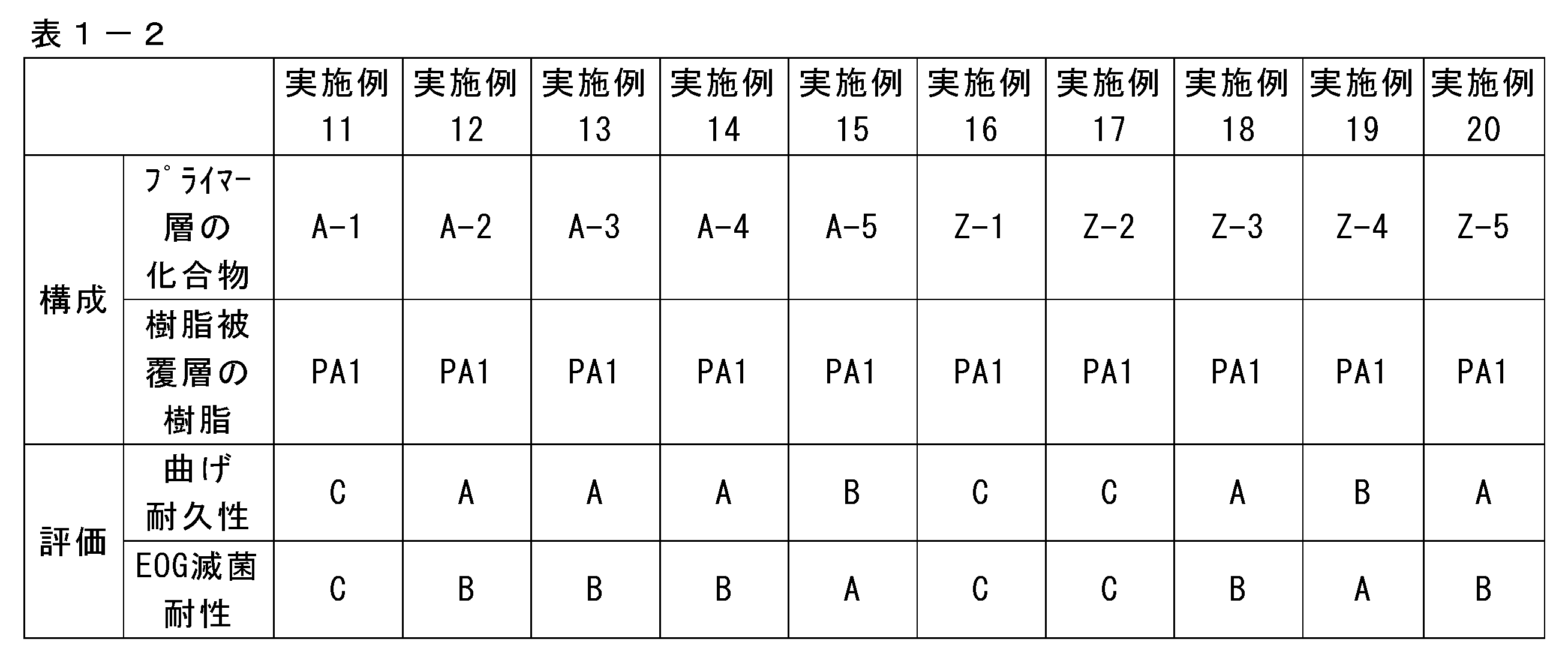
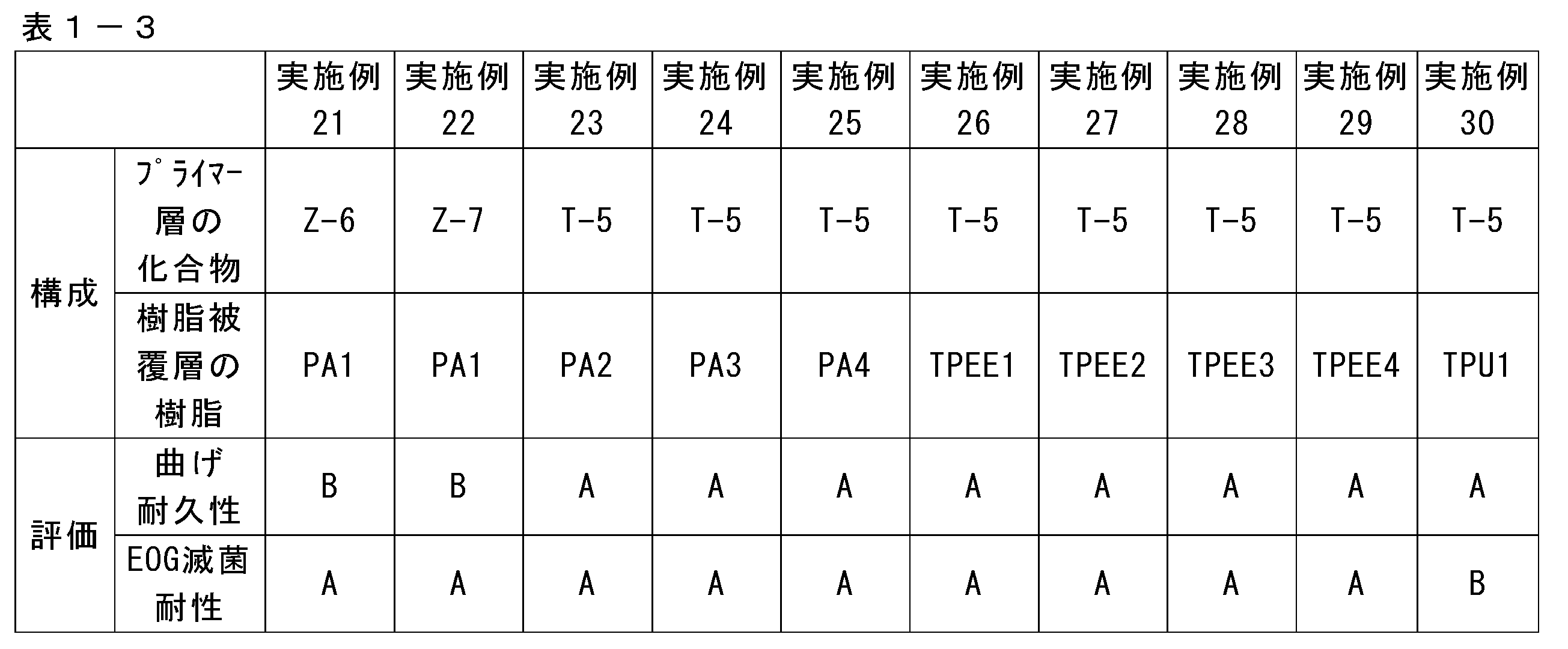
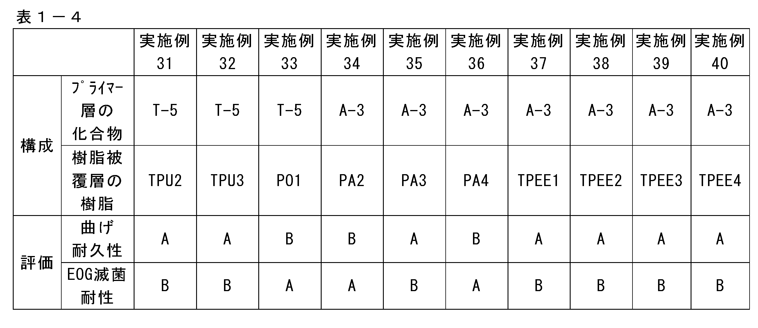
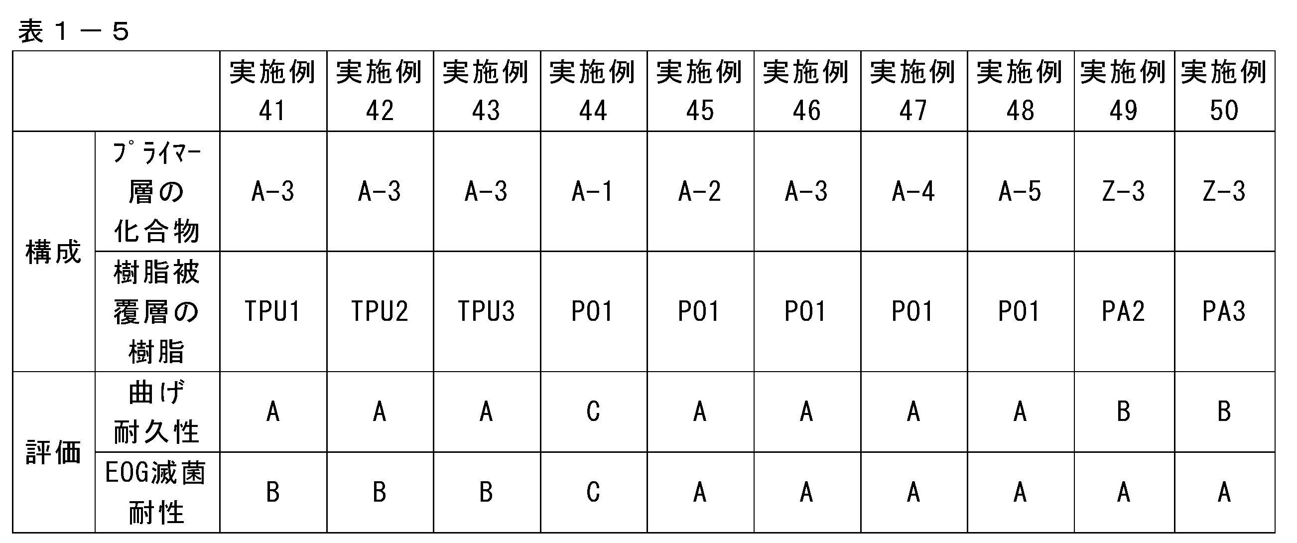
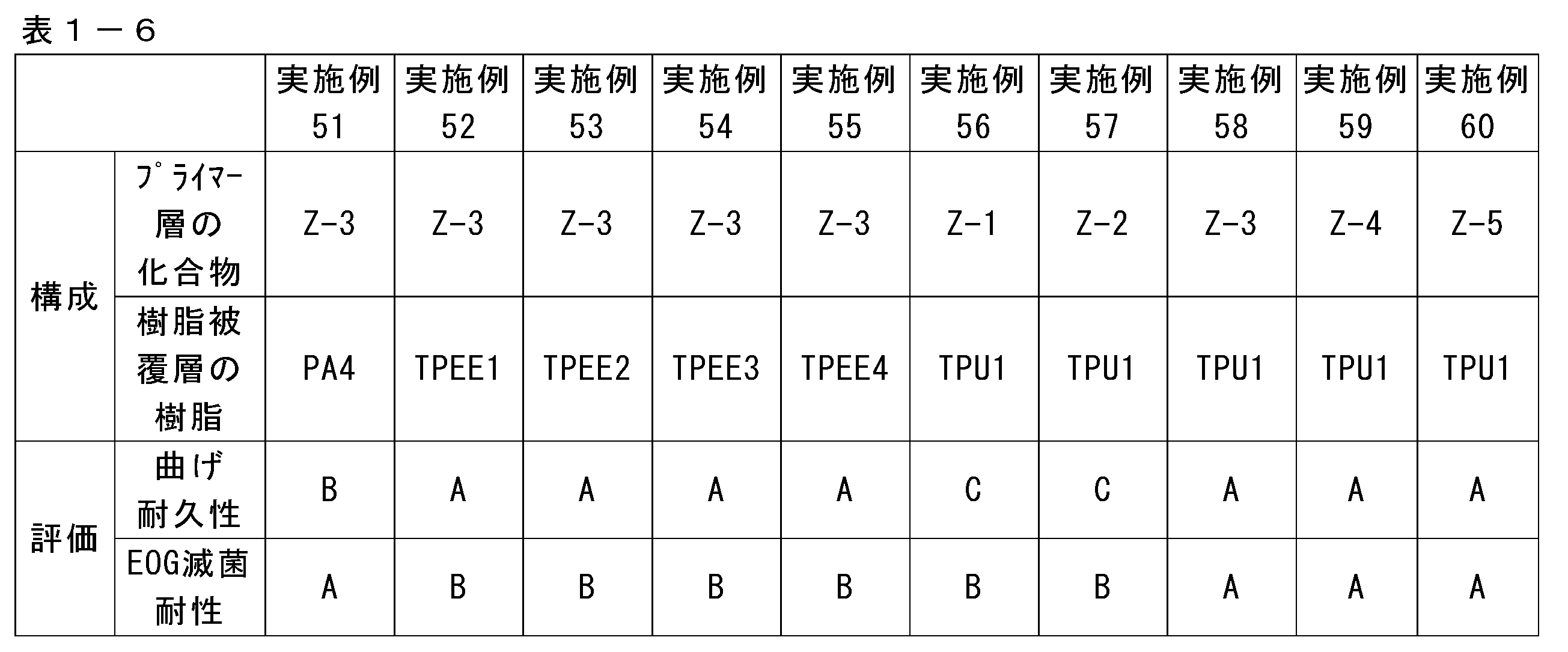
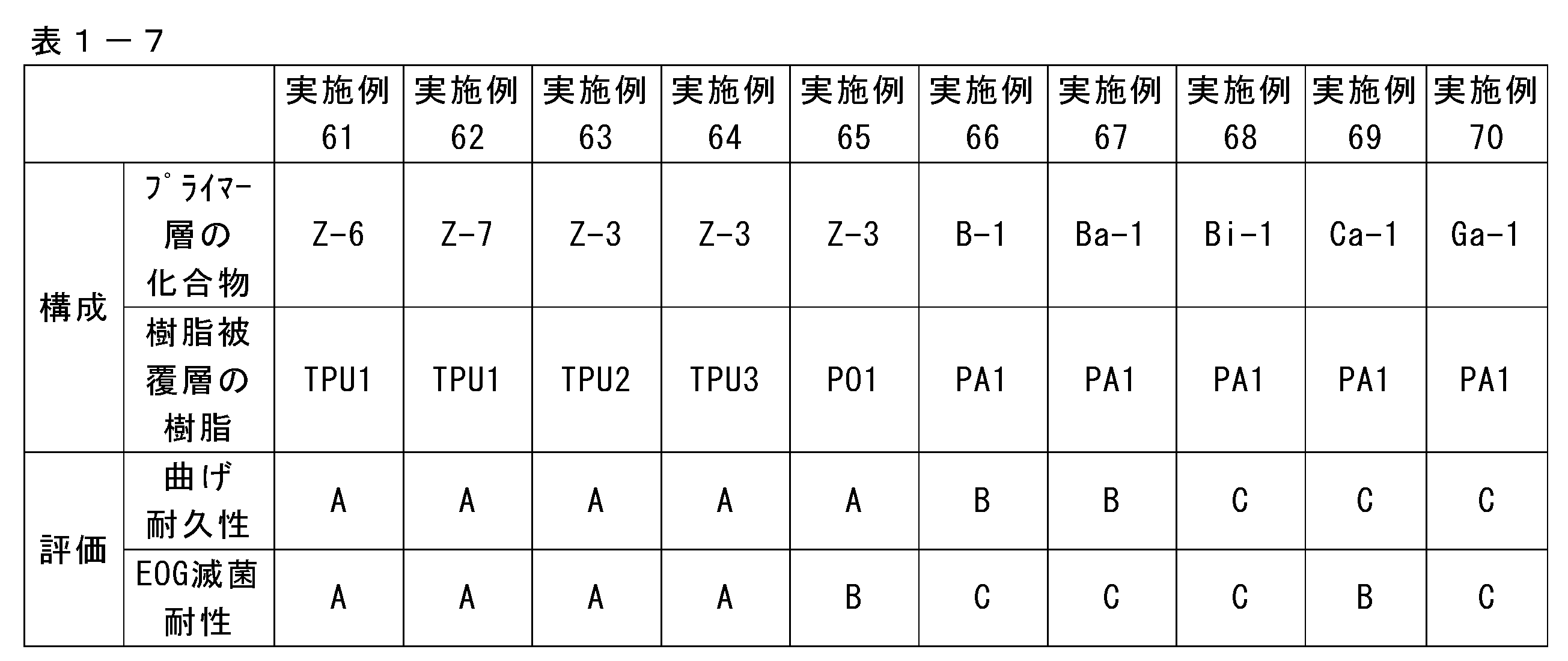
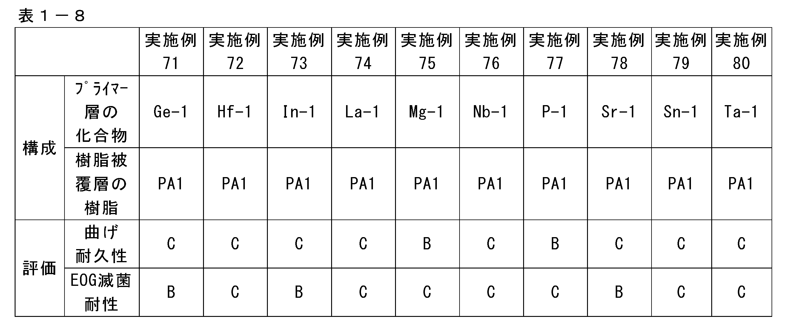
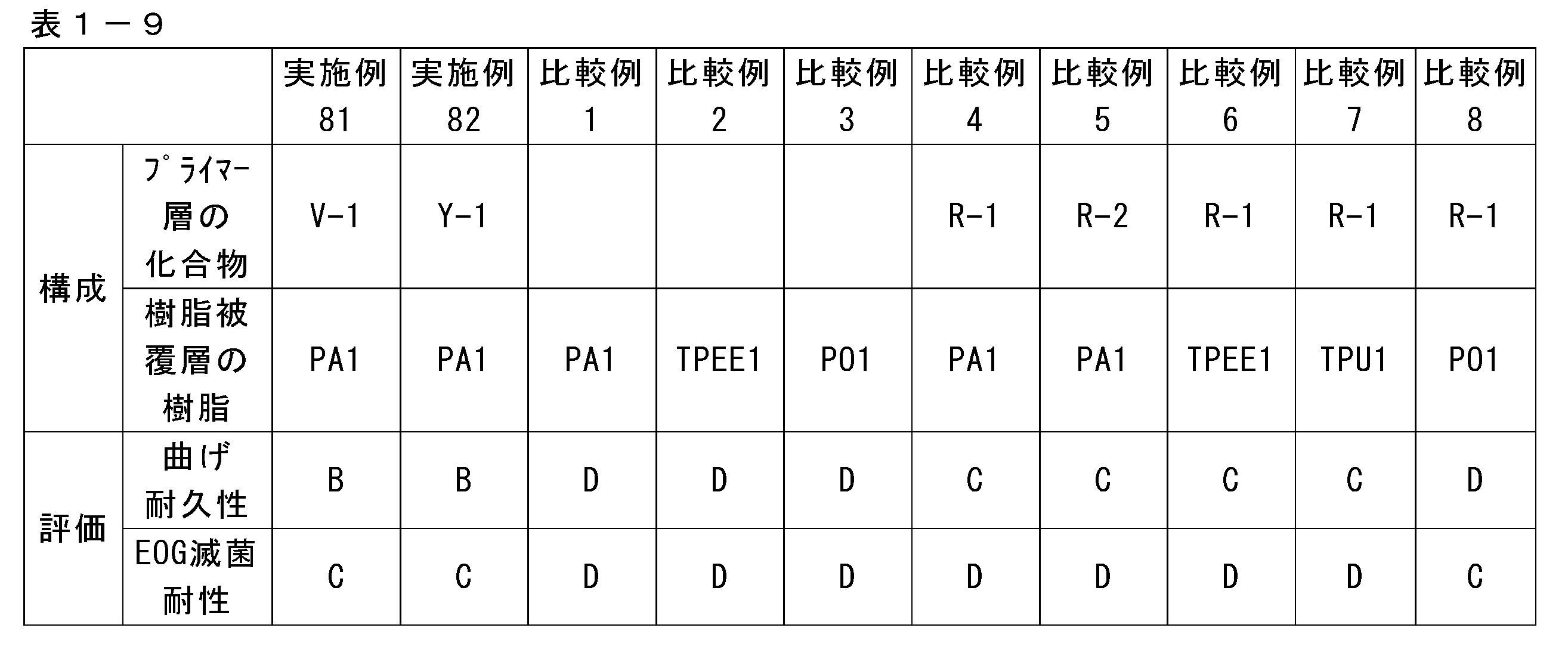
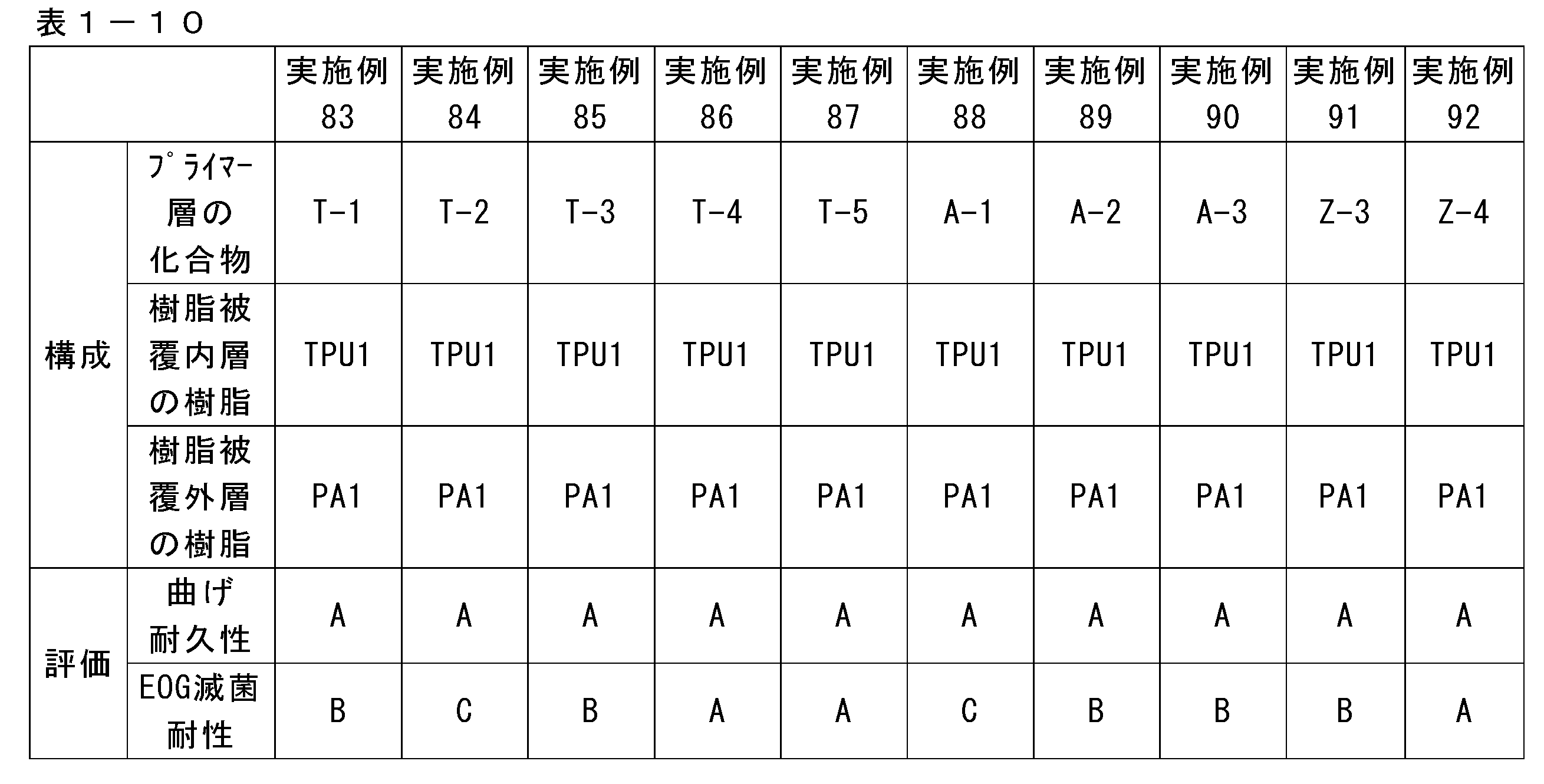
上記表に記載した略称は次の通りである。
<T-1>
テトラn-ブチルチタネート(マツモトファインケミカル社製「オルガチックスTA-21」)

<T-1>
テトラn-ブチルチタネート(マツモトファインケミカル社製「オルガチックスTA-21」)
<T-2>
n-ブチルチタネートダイマー(マツモトファインケミカル社製「オルガチックスTA-23」)
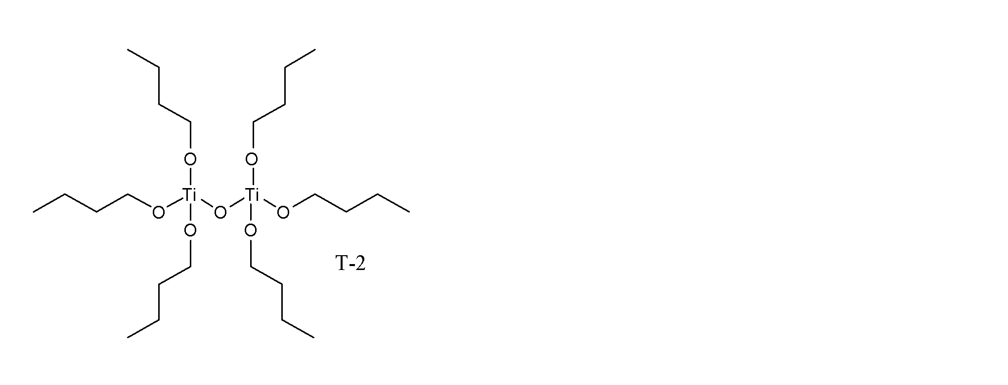
n-ブチルチタネートダイマー(マツモトファインケミカル社製「オルガチックスTA-23」)
<T-3>
イソプロピルトリイソステアロイルチタネート(味の素ファインテクノ社製「プレンアクトTTS」)

イソプロピルトリイソステアロイルチタネート(味の素ファインテクノ社製「プレンアクトTTS」)
<T-4>
ジオクチルビス(ジトリデシル)ホスフェートチタネート(味の素ファインテクノ社製「プレンアクト46B」)
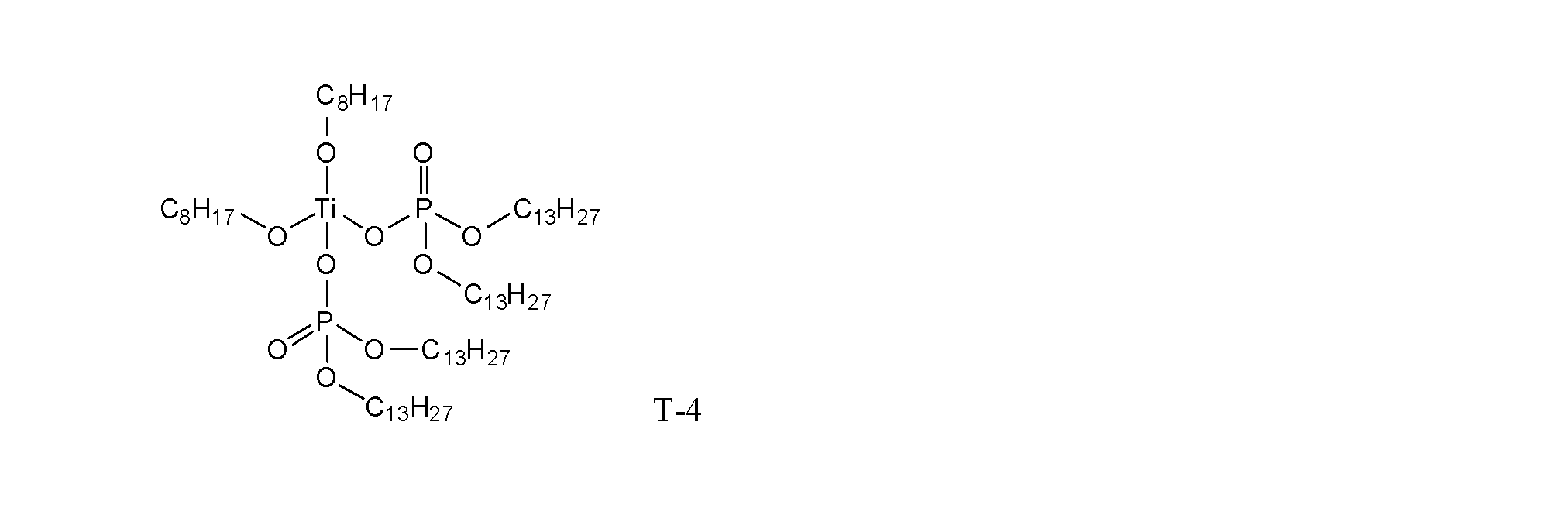
ジオクチルビス(ジトリデシル)ホスフェートチタネート(味の素ファインテクノ社製「プレンアクト46B」)
<T-5>
ジイソプロピルビス(ジオクチルピロホスフェート)チタネート(味の素ファインテクノ社製「プレンアクト38S」)
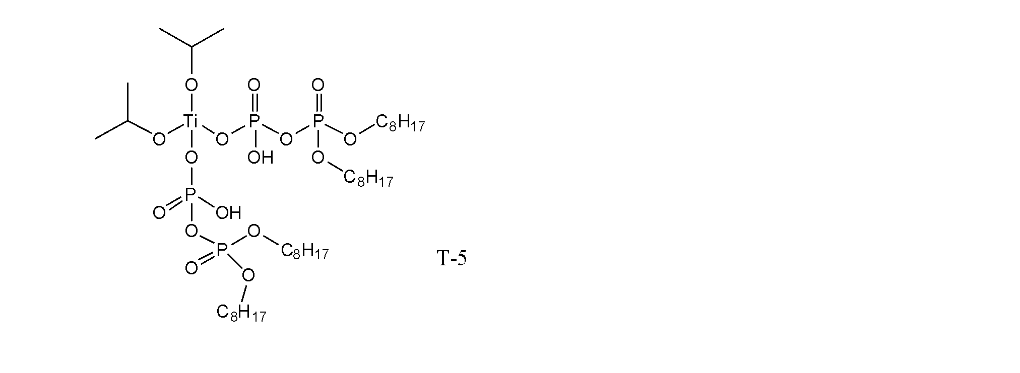
ジイソプロピルビス(ジオクチルピロホスフェート)チタネート(味の素ファインテクノ社製「プレンアクト38S」)
<T-6>
ビス(ジオクチルピロホスフェート)オキシアセテートチタネート(味の素ファインテクノ社製「プレンアクト138S」)
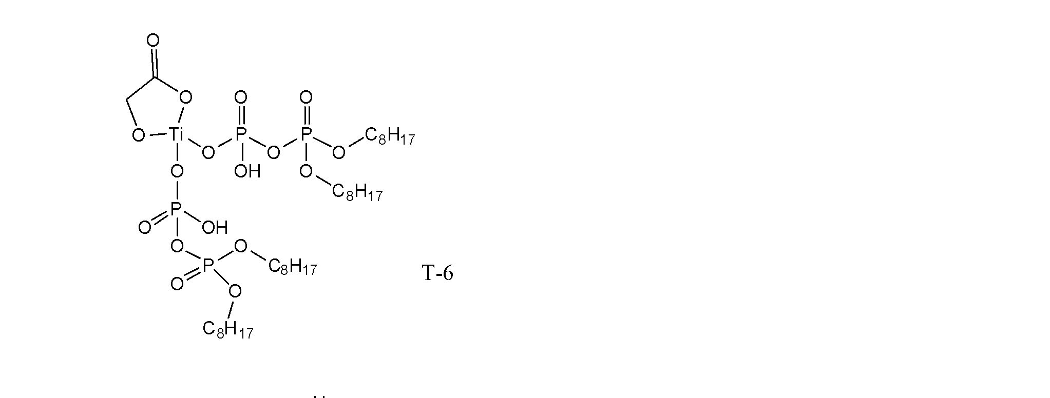
ビス(ジオクチルピロホスフェート)オキシアセテートチタネート(味の素ファインテクノ社製「プレンアクト138S」)
<T-7>
ビス(ジオクチルピロホスフェート)エチレンチタネート(味の素ファインテクノ社製「プレンアクト238S」)

ビス(ジオクチルピロホスフェート)エチレンチタネート(味の素ファインテクノ社製「プレンアクト238S」)
<T-8>
イソプロピルトリ(N-アミノエチル-アミノエチル)チタネート(味の素ファインテクノ社製「プレンアクト44」)
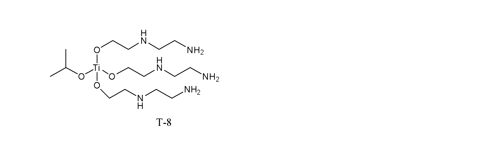
イソプロピルトリ(N-アミノエチル-アミノエチル)チタネート(味の素ファインテクノ社製「プレンアクト44」)
<T-9>
イソプロピルトリドデシルベンゼンスルホニルチタネート(味の素ファインテクノ社製「プレンアクト9SA」)

イソプロピルトリドデシルベンゼンスルホニルチタネート(味の素ファインテクノ社製「プレンアクト9SA」)
<T-10>
チタニウムジ-2-エチルヘキソキシビス(2-エチル-3-ヒドロキシヘキソキシド)(マツモトファインケミカル社製「オルガチックスTC-201」)
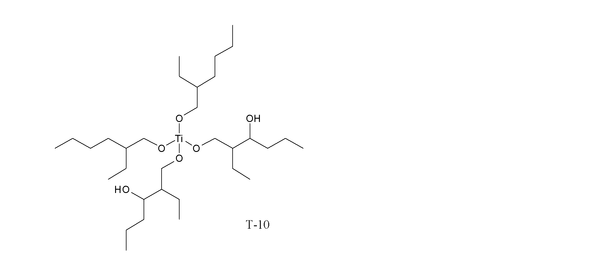
チタニウムジ-2-エチルヘキソキシビス(2-エチル-3-ヒドロキシヘキソキシド)(マツモトファインケミカル社製「オルガチックスTC-201」)
<A-1>
アルミニウムsec-ブトキシド(川研ファインケミカル社製「ASBD」)

アルミニウムsec-ブトキシド(川研ファインケミカル社製「ASBD」)
<A-2>
アルミニウムトリスアセチルアセトネート(マツモトファインケミカル社製「オルガチックスAL-3100」)
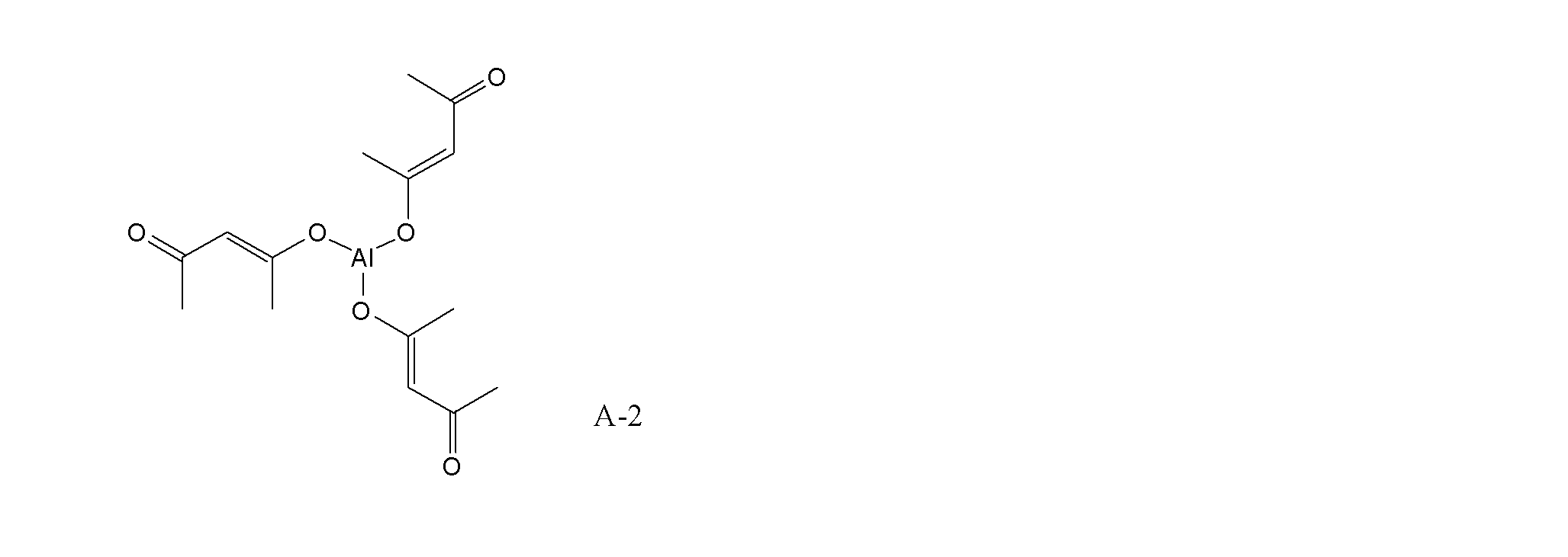
アルミニウムトリスアセチルアセトネート(マツモトファインケミカル社製「オルガチックスAL-3100」)
<A-3>
アルミニウムビスエチルアセトアセテートモノアセチルアセトネート(マツモトファインケミカル社製「オルガチックスAL-3200)
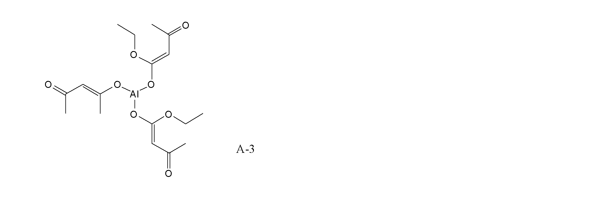
アルミニウムビスエチルアセトアセテートモノアセチルアセトネート(マツモトファインケミカル社製「オルガチックスAL-3200)
<A-4>
アルミニウムトリスエチルアセトアセテート(マツモトファインケミカル社製「オルガチックスAL-3215)
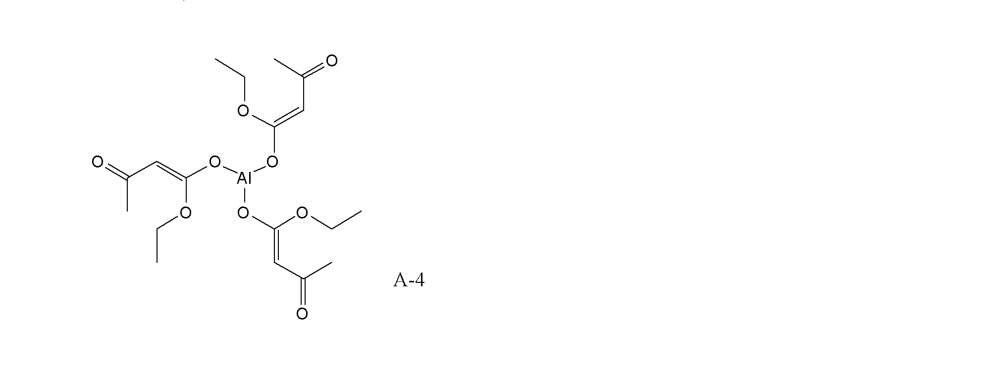
アルミニウムトリスエチルアセトアセテート(マツモトファインケミカル社製「オルガチックスAL-3215)
<A-5>
アルミニウムオクタデシルアセトアセテートジイソプロピレート(味の素ファインテクノ社製「プレンアクトAL-M」)

アルミニウムオクタデシルアセトアセテートジイソプロピレート(味の素ファインテクノ社製「プレンアクトAL-M」)
<Z-1>
ジルコニウムテトラn-プロポキシド(マツモトファインケミカル社製「オルガチックスZA-45」)
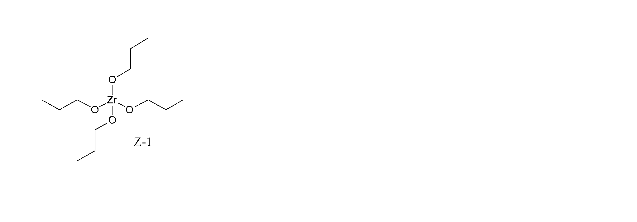
ジルコニウムテトラn-プロポキシド(マツモトファインケミカル社製「オルガチックスZA-45」)
<Z-2>
ジルコニウムテトラn-ブトキシド(マツモトファインケミカル社製「オルガチックスZA-65」)
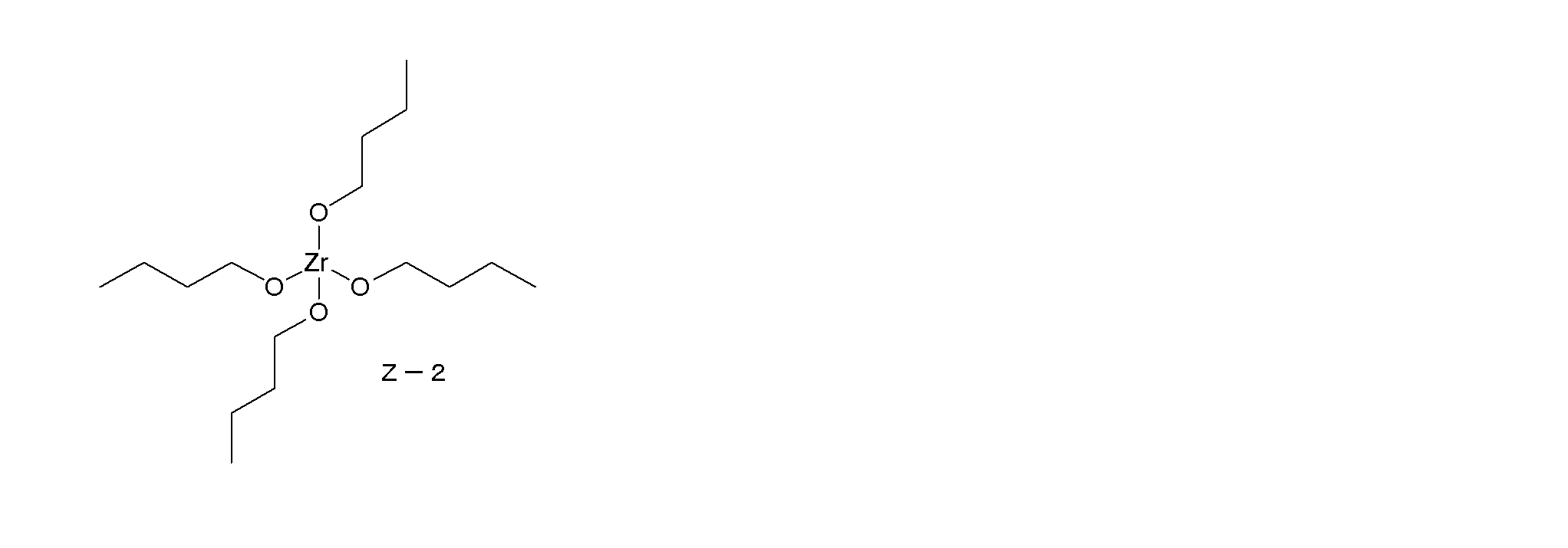
ジルコニウムテトラn-ブトキシド(マツモトファインケミカル社製「オルガチックスZA-65」)
<Z-3>
ジルコニウムテトラアセチルアセトネート(マツモトファインケミカル社製「オルガチックスZC-150」)
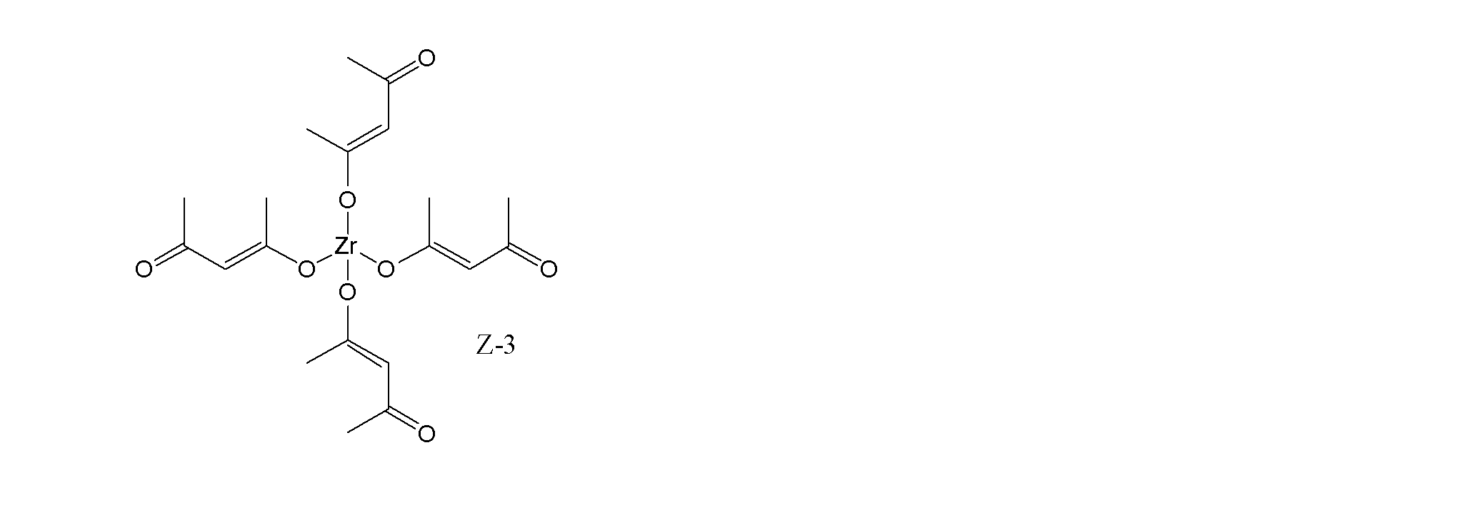
ジルコニウムテトラアセチルアセトネート(マツモトファインケミカル社製「オルガチックスZC-150」)
<Z-4>
ジルコニウムラクテートアンモニウム塩(マツモトファインケミカル社製「オルガチックスZC-300」)

ジルコニウムラクテートアンモニウム塩(マツモトファインケミカル社製「オルガチックスZC-300」)
<Z-5>
ステアリン酸ジルコニウムトリn-ブトキシド(マツモトファインケミカル社製「オルガチックスZC-320」)

ステアリン酸ジルコニウムトリn-ブトキシド(マツモトファインケミカル社製「オルガチックスZC-320」)
<Z-6>
ジルコニウムトリn-ブトキシモノアセチルアセトネート(マツモトファインケミカル社製「オルガチックスZC-540」)
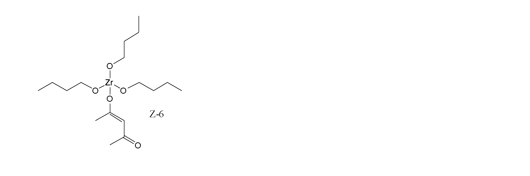
ジルコニウムトリn-ブトキシモノアセチルアセトネート(マツモトファインケミカル社製「オルガチックスZC-540」)
<Z-7>
ジルコニウムジn-ブトキシビス(エチルアセトアセテート)(マツモトファインケミカル社製「オルガチックスZC-580」)

ジルコニウムジn-ブトキシビス(エチルアセトアセテート)(マツモトファインケミカル社製「オルガチックスZC-580」)
<B-1>
ホウ酸トリエチル(富士フイルム和光純薬社製)
<Ba-1>
バリウムアセチルアセトネート水和物(富士フイルム和光純薬社製)
<Bi-1>
ビスマストリtert-アミロキシド(高純度化学研究所社製)
<Ca-1>
カルシウムtert-ブトキシド(東京化成工業社製)
<Ga-1>
ガリウムトリイソプロポキシド(高純度化学研究所社製)
<Ge-1>
ゲルマニウムテトラエトキシド(北興化学工業社製)
<Hf-1>
ハフニウムテトラn-ブトキシド(北興化学工業社製)
<In-1>
インジウムトリトリイソプロポキシド(高純度化学研究所社製)
<La-1>
ランタリウムトリイソプロポキシド(北興化学工業社製)
<Mg-1>
マグネシウムビス(2-メチル-2-プロパノラート)(Capotchemical社製)
<Nb-1>
ニオブペンタn-ブトキシド(北興化学工業社製)
<P-1>
リン酸トリメチル(高純度化学研究所社製)
<Sr-1>
ストロンチウムイソプロポキシド(北興化学工業社製)
<Sn-1>
スズn-ブトキシド(北興化学工業社製)
<Ta-1>
タンタルペンタn-ブトキシド(北興化学工業社製)
<V-1>
バナジウムトリ-n-ブトキシドオキシド(高純度化学研究所社製)
<Y-1>
イットリウムn-ブトキシド(北興化学工業社製「HY-OB」)
<R-1>
ビニルトリメトキシシラン
<R-2>
テトラエトキシシラン
ホウ酸トリエチル(富士フイルム和光純薬社製)
<Ba-1>
バリウムアセチルアセトネート水和物(富士フイルム和光純薬社製)
<Bi-1>
ビスマストリtert-アミロキシド(高純度化学研究所社製)
<Ca-1>
カルシウムtert-ブトキシド(東京化成工業社製)
<Ga-1>
ガリウムトリイソプロポキシド(高純度化学研究所社製)
<Ge-1>
ゲルマニウムテトラエトキシド(北興化学工業社製)
<Hf-1>
ハフニウムテトラn-ブトキシド(北興化学工業社製)
<In-1>
インジウムトリトリイソプロポキシド(高純度化学研究所社製)
<La-1>
ランタリウムトリイソプロポキシド(北興化学工業社製)
<Mg-1>
マグネシウムビス(2-メチル-2-プロパノラート)(Capotchemical社製)
<Nb-1>
ニオブペンタn-ブトキシド(北興化学工業社製)
<P-1>
リン酸トリメチル(高純度化学研究所社製)
<Sr-1>
ストロンチウムイソプロポキシド(北興化学工業社製)
<Sn-1>
スズn-ブトキシド(北興化学工業社製)
<Ta-1>
タンタルペンタn-ブトキシド(北興化学工業社製)
<V-1>
バナジウムトリ-n-ブトキシドオキシド(高純度化学研究所社製)
<Y-1>
イットリウムn-ブトキシド(北興化学工業社製「HY-OB」)
<R-1>
ビニルトリメトキシシラン
<R-2>
テトラエトキシシラン
[ポリアミド樹脂]
<PA1>
ダイセル・エボニック社製「ダイアミド L1940」(ポリアミド12、メルトボリュームレイト(MVR)=8cm3/10分)
<PA2>
ダイセル・エボニック社製「ベスタミド DS16」(ポリアミド1010、MVR=20cm3/10分)
<PA3>
アルケマ社製「リルサン BMN O」(ポリアミド11、MVR=36cm3/10分)
<PA4>
アルケマ社製「ペバックス 7233」(ポリエーテルブロックアミド、MVR=4cm3/10分)
<PA1>
ダイセル・エボニック社製「ダイアミド L1940」(ポリアミド12、メルトボリュームレイト(MVR)=8cm3/10分)
<PA2>
ダイセル・エボニック社製「ベスタミド DS16」(ポリアミド1010、MVR=20cm3/10分)
<PA3>
アルケマ社製「リルサン BMN O」(ポリアミド11、MVR=36cm3/10分)
<PA4>
アルケマ社製「ペバックス 7233」(ポリエーテルブロックアミド、MVR=4cm3/10分)
[ポリエステル樹脂]
<TPEE1>
東洋紡社製「ペルプレン P-70B」(MVR=20cm3/10分)
<TPEE2>
東洋紡社製「ペルプレン S-3001」(MVR=16cm3/10分)
<TPEE3>
三菱ケミカル社製「プリマロイ B1942」(MVR=59cm3/10分)
<TPEE4>
三菱エンジニアリングプラスチックス社製「ノバデュラン 5505S」(MVR=25cm3/10分)
<TPEE1>
東洋紡社製「ペルプレン P-70B」(MVR=20cm3/10分)
<TPEE2>
東洋紡社製「ペルプレン S-3001」(MVR=16cm3/10分)
<TPEE3>
三菱ケミカル社製「プリマロイ B1942」(MVR=59cm3/10分)
<TPEE4>
三菱エンジニアリングプラスチックス社製「ノバデュラン 5505S」(MVR=25cm3/10分)
[ポリウレタン樹脂]
<TPU1>
日本ミラクトラン社製「ミラクトランE675」
<TPU2>
ディーアイシーコベストロポリマー社製「パンデックスT-8185」(MVR=18cm3/10分)
<TPU3>
ディーアイシーコベストロポリマー社製「パンデックスT-2190」(MVR=12cm3/10分)
<TPU1>
日本ミラクトラン社製「ミラクトランE675」
<TPU2>
ディーアイシーコベストロポリマー社製「パンデックスT-8185」(MVR=18cm3/10分)
<TPU3>
ディーアイシーコベストロポリマー社製「パンデックスT-2190」(MVR=12cm3/10分)
[ポリオレフィン樹脂]
<PO1>
東洋紡社製「サーリンク 3145D」(MVR=54cm3/10分)
<PO1>
東洋紡社製「サーリンク 3145D」(MVR=54cm3/10分)
上記表に示されるように、可撓管基材の外周にプライマー層を設けずに樹脂被覆層を形成した場合には、可撓管に曲げの負荷を繰り返しかけると、樹脂被覆層に皺、浮き、裂けないし剥がれが生じやすく、また、EOG滅菌処理により可撓管基材と樹脂被覆層との間の密着性が低下しやすいことがわかった(比較例1~3)。
また、プライマー層に一般式(1)又は(2)に包含されない化合物を用いた場合も、可撓管に曲げの負荷を繰り返しかけたり、可撓管をEOG滅菌処理に付したりすると、可撓管基材と樹脂被覆層との未着性が損なわれやすい傾向を示した(比較例4~8)。
これに対し、プライマー層に一般式(1)又は(2)の化合物を用いた場合には、得られる可撓管は曲げの負荷を繰り返しかけても、また、可撓管をEOG滅菌処理に付しても、可撓管基材と樹脂被覆層との密着性を十分に維持できることがわかった(実施例1~92)。
また、プライマー層に一般式(1)又は(2)に包含されない化合物を用いた場合も、可撓管に曲げの負荷を繰り返しかけたり、可撓管をEOG滅菌処理に付したりすると、可撓管基材と樹脂被覆層との未着性が損なわれやすい傾向を示した(比較例4~8)。
これに対し、プライマー層に一般式(1)又は(2)の化合物を用いた場合には、得られる可撓管は曲げの負荷を繰り返しかけても、また、可撓管をEOG滅菌処理に付しても、可撓管基材と樹脂被覆層との密着性を十分に維持できることがわかった(実施例1~92)。
本発明をその実施態様とともに説明したが、我々は特に指定しない限り我々の発明を説明のどの細部においても限定しようとするものではなく、添付の請求の範囲に示した発明の精神と範囲に反することなく幅広く解釈されるべきであると考える。
本願は、2019年1月16日に日本国で特許出願された特願2019-005385に基づく優先権を主張するものであり、これはここに参照してその内容を本明細書の記載の一部として取り込む。
2 電子内視鏡(内視鏡)
3 挿入部
3a 可撓管
3b アングル部
3c 先端部
5 本体操作部
6 ユニバーサルコード
11 螺旋管
11a 金属帯片
12 筒状網体
13 口金
14 可撓管基材
14a 先端側
14b 基端側
15 樹脂被覆層
16 トップコート層
17 内層
18 外層
X アングル部3b側(軟)
Y 本体操作部5側(硬)
20 連続成形機(製造装置)
21、22 押し出し部
21a スクリュー
22a スクリュー
23 ヘッド部
24 冷却部
25 搬送部
26 制御部
28 供給ドラム
29 巻取ドラム
30 ジョイント部材
31 連結可撓管基材
32 ニップル
33 ダイス
34 支持体
35、36 ゲート
37 成形通路
38 樹脂通路
39 第1樹脂材料(軟質樹脂)
40 第2樹脂材料(硬質樹脂)
3 挿入部
3a 可撓管
3b アングル部
3c 先端部
5 本体操作部
6 ユニバーサルコード
11 螺旋管
11a 金属帯片
12 筒状網体
13 口金
14 可撓管基材
14a 先端側
14b 基端側
15 樹脂被覆層
16 トップコート層
17 内層
18 外層
X アングル部3b側(軟)
Y 本体操作部5側(硬)
20 連続成形機(製造装置)
21、22 押し出し部
21a スクリュー
22a スクリュー
23 ヘッド部
24 冷却部
25 搬送部
26 制御部
28 供給ドラム
29 巻取ドラム
30 ジョイント部材
31 連結可撓管基材
32 ニップル
33 ダイス
34 支持体
35、36 ゲート
37 成形通路
38 樹脂通路
39 第1樹脂材料(軟質樹脂)
40 第2樹脂材料(硬質樹脂)
Claims (20)
- 金属を構成材料とする可撓管基材と、該可撓管基材の外周を覆う樹脂被覆層とを有する内視鏡用可撓管であって、
前記可撓管基材と前記樹脂被覆層との間に下記一般式(1)又は(2)で表される化合物の少なくとも1種を含むプライマー層を有し、前記樹脂被覆層が、少なくともプライマー層と接する側にポリアミド、ポリエステル、ポリウレタン、及びポリオレフィンの少なくとも1種の化合物を含む、内視鏡用可撓管。
一般式(1): R1 m-M-(OR2)n-m
一般式(2): O-[M-(OR2)n-1]2
式中、MはAl、B、Ba、Bi、Ca、Ga、Ge、Hf、In、La、Mg、Nb、P、Sr、Sn、Ta、Ti、V、Y、又はZrを示す。
R1は水素原子、アルキル基、シクロアルキル基、アシル基、アリール基、又は不飽和脂肪族基を示す。
R2は水素原子、アルキル基、シクロアルキル基、アシル基、アルケニル基、アリール基、ホスホネート基、又は-SO2RSを示す。RSは置換基を示す。
mは0~3の整数であり、nはMの価数である。n>mを満たす。 - 前記MがTiである、請求項1に記載の内視鏡用可撓管。
- 前記の一般式(1)又は(2)で表される化合物が、N、P及びSの少なくとも1種の原子を含む、請求項2に記載の内視鏡用可撓管。
- 前記MがAlである、請求項1に記載の内視鏡用可撓管。
- 前記一般式(1)及び(2)において、OR2の少なくとも1つがアセトナト構造を有する、請求項4に記載の内視鏡用可撓管。
- 前記一般式(1)及び(2)において、OR2の少なくとも1つがアセタト構造を有する、請求項4又は5に記載の内視鏡用可撓管。
- 前記MがZrである、請求項1に記載の内視鏡用可撓管。
- 前記一般式(1)及び(2)において、OR2の少なくとも1つがアセトナト構造を有する、請求項7に記載の内視鏡用可撓管。
- 前記一般式(1)及び(2)において、OR2の少なくとも1つがアセタト構造を有する、請求項7又は8に記載の内視鏡用可撓管。
- 前記一般式(1)及び(2)において、OR2の少なくとも1つがラクタト構造を有する、請求項7~9のいずれか1項に記載の内視鏡用可撓管。
- 前記可撓管基材を構成する金属がステンレスである、請求項1~10のいずれか1項に記載の内視鏡用可撓管。
- 前記可撓管基材を構成する金属が表面に不動態皮膜を有する、請求項1~11のいずれか1項に記載の内視鏡用可撓管。
- 前記樹脂被覆層が単層構造又は複層構造であり、前記プライマー層と接する層中にポリアミド、ポリエステル、ポリウレタン、及びポリオレフィンの少なくとも1種の化合物を含む、請求項1~12のいずれか1項に記載の内視鏡用可撓管。
- 前記樹脂被覆層が2層構造であり、該2層構造の内層及び外層の厚みの割合が、前記可撓管基材の軸方向において傾斜的に変化している、請求項1~13のいずれか1項に記載の内視鏡用可撓管。
- 前記の内層及び外層の厚みの割合が、前記内視鏡用可撓管の一端において内層:外層=95:5~60:40であって、他端において内層:外層=5:95~40:60である、請求項14に記載の内視鏡用可撓管。
- 請求項1~15のいずれか1項に記載の内視鏡用可撓管を有する内視鏡型医療機器。
- 金属を構成材料とする可撓管基材の少なくとも外周に、下記一般式(1)又は(2)で表される化合物の少なくとも1種を含むプライマー層を形成する工程、及び
前記可撓管基材の外周に形成された前記プライマー層に接して、ポリアミド、ポリエステル、ポリウレタン、及びポリオレフィンの少なくとも1種の化合物を含む樹脂を被覆することを含む樹脂被覆層の形成工程
を含む、内視鏡用可撓管の製造方法。
一般式(1): R1 m-M-(OR2)n-m
一般式(2): O-[M-(OR2)n-1]2
式中、MはAl、B、Ba、Bi、Ca、Ga、Ge、Hf、In、La、Mg、Nb、P、Sr、Sn、Ta、Ti、V、Y、又はZrを示す。
R1は水素原子、アルキル基、シクロアルキル基、アシル基、アリール基、又は不飽和脂肪族基を示す。
R2は水素原子、アルキル基、シクロアルキル基、アシル基、アルケニル基、アリール基、ホスホネート基、又は-SO2RSを示す。RSは置換基を示す。
mは0~3の整数であり、nはMの価数である。n>mを満たす。 - 前記樹脂被覆層が2層構造であり、該2層構造の少なくとも内層がポリアミド、ポリエステル、ポリウレタン、及びポリオレフィンの少なくとも1種の化合物を含み、該2層構造の内層及び外層の厚みの割合が、前記可撓管基材の軸方向において傾斜的に変化している、請求項17に記載の内視鏡用可撓管の製造方法。
- 請求項17又は18に記載の内視鏡用可撓管の製造方法により内視鏡用可撓管を得る工程、及び、
得られた内視鏡用可撓管を内視鏡型医療機器の挿入部に組み込む工程
を含む、内視鏡型医療機器の製造方法。 - 請求項1~15のいずれか1項に記載の内視鏡用可撓管を内視鏡型医療機器の挿入部に組み込むことを含む、内視鏡型医療機器の製造方法。
Priority Applications (3)
| Application Number | Priority Date | Filing Date | Title |
|---|---|---|---|
| CN202080007415.5A CN113302540B (zh) | 2019-01-16 | 2020-01-14 | 内窥镜用挠性管、内窥镜型医疗器械、及其制造方法 |
| JP2020566413A JP7112524B2 (ja) | 2019-01-16 | 2020-01-14 | 内視鏡用可撓管、内視鏡型医療機器、及びこれらの製造方法 |
| US17/344,359 US20210298565A1 (en) | 2019-01-16 | 2021-06-10 | Flexible tube for endoscope, endoscopic medical device, and methods for producing the same |
Applications Claiming Priority (2)
| Application Number | Priority Date | Filing Date | Title |
|---|---|---|---|
| JP2019005385 | 2019-01-16 | ||
| JP2019-005385 | 2019-01-16 |
Related Child Applications (1)
| Application Number | Title | Priority Date | Filing Date |
|---|---|---|---|
| US17/344,359 Continuation US20210298565A1 (en) | 2019-01-16 | 2021-06-10 | Flexible tube for endoscope, endoscopic medical device, and methods for producing the same |
Publications (1)
| Publication Number | Publication Date |
|---|---|
| WO2020149261A1 true WO2020149261A1 (ja) | 2020-07-23 |
Family
ID=71613888
Family Applications (1)
| Application Number | Title | Priority Date | Filing Date |
|---|---|---|---|
| PCT/JP2020/000877 Ceased WO2020149261A1 (ja) | 2019-01-16 | 2020-01-14 | 内視鏡用可撓管、内視鏡型医療機器、及びこれらの製造方法 |
Country Status (4)
| Country | Link |
|---|---|
| US (1) | US20210298565A1 (ja) |
| JP (1) | JP7112524B2 (ja) |
| CN (1) | CN113302540B (ja) |
| WO (1) | WO2020149261A1 (ja) |
Citations (5)
| Publication number | Priority date | Publication date | Assignee | Title |
|---|---|---|---|---|
| JPH1142205A (ja) * | 1997-07-25 | 1999-02-16 | Olympus Optical Co Ltd | 内視鏡可撓管 |
| US20030135197A1 (en) * | 2002-01-15 | 2003-07-17 | Scimed Life Systems, Inc. | Bonds between metals and polymers for medical devices |
| JP2010035923A (ja) * | 2008-08-07 | 2010-02-18 | Olympus Medical Systems Corp | 内視鏡用可撓管およびその製造方法 |
| JP2016067566A (ja) * | 2014-09-29 | 2016-05-09 | 富士フイルム株式会社 | 内視鏡用可撓管、内視鏡用接着剤、内視鏡型医療機器、ならびに内視鏡用可撓管および内視鏡型医療機器の製造方法 |
| WO2019013243A1 (ja) * | 2017-07-12 | 2019-01-17 | 富士フイルム株式会社 | 内視鏡用可撓管、内視鏡型医療機器、及びこれらの製造方法 |
Family Cites Families (6)
| Publication number | Priority date | Publication date | Assignee | Title |
|---|---|---|---|---|
| US6511752B1 (en) * | 2000-06-01 | 2003-01-28 | Sika Corporation | Water-based primer for promoting adhesion of polyurethane-based sealants and adhesives |
| US20050288545A1 (en) * | 2004-03-31 | 2005-12-29 | Jun Matsumoto | Flexible tube for endoscope and method for manufacturing the same |
| US9506159B2 (en) * | 2013-05-15 | 2016-11-29 | Srg Global, Inc. | Organometallic adhesion promoters for paint-over-chrome plated polymers |
| EP3646900B1 (en) * | 2017-06-30 | 2025-05-21 | FUJIFILM Corporation | Endoscope flexible tube, endoscope-type medical device, resin composition for coating endoscope flexible tube substrate, and resin composition set for coating endoscope flexible tube substrate |
| CN115996830B (zh) * | 2020-06-29 | 2025-05-13 | 富士胶片株式会社 | 内窥镜用挠性管、内窥镜型医疗器材及它们的制造方法 |
| WO2022070722A1 (ja) * | 2020-09-29 | 2022-04-07 | 富士フイルム株式会社 | 内視鏡用可撓管、内視鏡型医療機器、及びこれらの製造方法 |
-
2020
- 2020-01-14 JP JP2020566413A patent/JP7112524B2/ja active Active
- 2020-01-14 CN CN202080007415.5A patent/CN113302540B/zh active Active
- 2020-01-14 WO PCT/JP2020/000877 patent/WO2020149261A1/ja not_active Ceased
-
2021
- 2021-06-10 US US17/344,359 patent/US20210298565A1/en not_active Abandoned
Patent Citations (5)
| Publication number | Priority date | Publication date | Assignee | Title |
|---|---|---|---|---|
| JPH1142205A (ja) * | 1997-07-25 | 1999-02-16 | Olympus Optical Co Ltd | 内視鏡可撓管 |
| US20030135197A1 (en) * | 2002-01-15 | 2003-07-17 | Scimed Life Systems, Inc. | Bonds between metals and polymers for medical devices |
| JP2010035923A (ja) * | 2008-08-07 | 2010-02-18 | Olympus Medical Systems Corp | 内視鏡用可撓管およびその製造方法 |
| JP2016067566A (ja) * | 2014-09-29 | 2016-05-09 | 富士フイルム株式会社 | 内視鏡用可撓管、内視鏡用接着剤、内視鏡型医療機器、ならびに内視鏡用可撓管および内視鏡型医療機器の製造方法 |
| WO2019013243A1 (ja) * | 2017-07-12 | 2019-01-17 | 富士フイルム株式会社 | 内視鏡用可撓管、内視鏡型医療機器、及びこれらの製造方法 |
Also Published As
| Publication number | Publication date |
|---|---|
| JPWO2020149261A1 (ja) | 2021-11-18 |
| JP7112524B2 (ja) | 2022-08-03 |
| CN113302540B (zh) | 2023-12-01 |
| CN113302540A (zh) | 2021-08-24 |
| US20210298565A1 (en) | 2021-09-30 |
Similar Documents
| Publication | Publication Date | Title |
|---|---|---|
| JP7112524B2 (ja) | 内視鏡用可撓管、内視鏡型医療機器、及びこれらの製造方法 | |
| US20230135925A1 (en) | Flexible tube for endoscope, endoscopic medical device, and methods for producing the same | |
| JP7425850B2 (ja) | 内視鏡用可撓管、内視鏡型医療機器、及びこれらの製造方法 | |
| US12575715B2 (en) | Flexible tube for endoscope, endoscopic medical device, and methods for producing the same | |
| JP7697976B2 (ja) | 内視鏡用可撓管、内視鏡型医療機器、及びこれらの製造方法 | |
| JP7461493B2 (ja) | 内視鏡用可撓管、内視鏡型医療機器、及びこれらの製造方法 | |
| JP7038234B2 (ja) | 内視鏡用可撓管、内視鏡型医療機器、及びこれらの製造方法 | |
| CN115996661B (zh) | 内窥镜用挠性管、内窥镜型医疗器材及内窥镜用挠性管基材被覆材料 | |
| JP7411088B2 (ja) | 内視鏡用可撓管、内視鏡型医療機器、内視鏡用可撓管を構成する被覆材料の製造方法、及び内視鏡用可撓管の製造方法 |
Legal Events
| Date | Code | Title | Description |
|---|---|---|---|
| 121 | Ep: the epo has been informed by wipo that ep was designated in this application |
Ref document number: 20741288 Country of ref document: EP Kind code of ref document: A1 |
|
| ENP | Entry into the national phase |
Ref document number: 2020566413 Country of ref document: JP Kind code of ref document: A |
|
| NENP | Non-entry into the national phase |
Ref country code: DE |
|
| 122 | Ep: pct application non-entry in european phase |
Ref document number: 20741288 Country of ref document: EP Kind code of ref document: A1 |