WO2020145372A1 - Base station device, terminal device, and communication method - Google Patents
Base station device, terminal device, and communication method Download PDFInfo
- Publication number
- WO2020145372A1 WO2020145372A1 PCT/JP2020/000589 JP2020000589W WO2020145372A1 WO 2020145372 A1 WO2020145372 A1 WO 2020145372A1 JP 2020000589 W JP2020000589 W JP 2020000589W WO 2020145372 A1 WO2020145372 A1 WO 2020145372A1
- Authority
- WO
- WIPO (PCT)
- Prior art keywords
- transmission
- pusch
- terminal device
- slot
- transport block
- Prior art date
Links
Images


Classifications
-
- H—ELECTRICITY
- H04—ELECTRIC COMMUNICATION TECHNIQUE
- H04L—TRANSMISSION OF DIGITAL INFORMATION, e.g. TELEGRAPHIC COMMUNICATION
- H04L1/00—Arrangements for detecting or preventing errors in the information received
- H04L1/08—Arrangements for detecting or preventing errors in the information received by repeating transmission, e.g. Verdan system
-
- H—ELECTRICITY
- H04—ELECTRIC COMMUNICATION TECHNIQUE
- H04W—WIRELESS COMMUNICATION NETWORKS
- H04W72/00—Local resource management
- H04W72/20—Control channels or signalling for resource management
- H04W72/23—Control channels or signalling for resource management in the downlink direction of a wireless link, i.e. towards a terminal
-
- H—ELECTRICITY
- H04—ELECTRIC COMMUNICATION TECHNIQUE
- H04L—TRANSMISSION OF DIGITAL INFORMATION, e.g. TELEGRAPHIC COMMUNICATION
- H04L1/00—Arrangements for detecting or preventing errors in the information received
- H04L1/12—Arrangements for detecting or preventing errors in the information received by using return channel
- H04L1/16—Arrangements for detecting or preventing errors in the information received by using return channel in which the return channel carries supervisory signals, e.g. repetition request signals
- H04L1/18—Automatic repetition systems, e.g. Van Duuren systems
- H04L1/1829—Arrangements specially adapted for the receiver end
- H04L1/1864—ARQ related signaling
-
- H—ELECTRICITY
- H04—ELECTRIC COMMUNICATION TECHNIQUE
- H04L—TRANSMISSION OF DIGITAL INFORMATION, e.g. TELEGRAPHIC COMMUNICATION
- H04L1/00—Arrangements for detecting or preventing errors in the information received
- H04L1/12—Arrangements for detecting or preventing errors in the information received by using return channel
- H04L1/16—Arrangements for detecting or preventing errors in the information received by using return channel in which the return channel carries supervisory signals, e.g. repetition request signals
- H04L1/1607—Details of the supervisory signal
- H04L1/1671—Details of the supervisory signal the supervisory signal being transmitted together with control information
-
- H—ELECTRICITY
- H04—ELECTRIC COMMUNICATION TECHNIQUE
- H04L—TRANSMISSION OF DIGITAL INFORMATION, e.g. TELEGRAPHIC COMMUNICATION
- H04L1/00—Arrangements for detecting or preventing errors in the information received
- H04L1/12—Arrangements for detecting or preventing errors in the information received by using return channel
- H04L1/16—Arrangements for detecting or preventing errors in the information received by using return channel in which the return channel carries supervisory signals, e.g. repetition request signals
- H04L1/18—Automatic repetition systems, e.g. Van Duuren systems
- H04L1/1867—Arrangements specially adapted for the transmitter end
- H04L1/189—Transmission or retransmission of more than one copy of a message
Definitions
- the present invention relates to a base station device, a terminal device, and a communication method.
- the present application claims priority based on Japanese Patent Application No. 2019-2866 filed in Japan on January 10, 2019, the contents of which are incorporated herein by reference.
- Non-Patent Document 1 LTE (Long Term Evolution)-Advanced Pro and NR (New Radio) are being used in the 3rd Generation Partnership Project (3GPP) as a wireless access method and wireless network technology for the 5th generation cellular system. technology) and standard development are being conducted (Non-Patent Document 1).
- 3GPP 3rd Generation Partnership Project
- eMBB enhanced Mobile BroadBand
- URLLC Ultra-Reliable and Low Latency Communication
- IoT Internet of Things
- An object of one aspect of the present invention is to provide a base station device, a terminal device, and a communication method that enable efficient communication in the above wireless communication system.
- a terminal device includes a receiving unit that receives a first radio resource control (RRC) parameter that sets one of a first repeat transmission type and a second repeat transmission type, and a DCI. And a transmitter for transmitting the transport block scheduled by the format on the PUSCH, the transmitter applying the repeat transmission type set in the first RRC parameter to the repeat transmission of the transport block. It is characterized by performing.
- RRC radio resource control
- the base station apparatus is a transmission for transmitting a first radio resource control (RRC) parameter that sets one of a first repetitive transmission type and a second repetitive transmission type.
- RRC radio resource control
- a receiving unit for receiving a transport block scheduled by the DCI format on the PUSCH, the receiving unit applying the repeat transmission type set in the first RRC parameter to the transport block. Is repeatedly received.
- a communication method is a communication method for a terminal device, wherein the first radio resource control sets either the first repeat transmission type or the second repeat transmission type. (RCC) parameter is received, a transport block scheduled by a DCI format is transmitted on PUSCH, and the iterative transmission type set in the first RRC parameter is applied to repeatedly transmit the transport block. Is characterized by.
- RRC repeat transmission type
- a communication method is a communication method for a base station apparatus, wherein a first radio resource for setting one of a first repeat transmission type and a second repeat transmission type.
- Receiving control block (RRC) parameters receiving a transport block scheduled by DCI format on PUSCH, applying a repeat transmission type set in the first RRC parameter, and receiving repeat transmission of the transport block; It is characterized by performing.
- the base station device and the terminal device can efficiently communicate with each other.
- FIG. 5 is a diagram showing a relationship in the time domain of subframes, slots, and minislots according to the embodiment of the present invention. It is a figure which shows an example of the slot or sub-frame which concerns on embodiment of this invention. It is a figure showing an example of beamforming concerning an embodiment of the present invention. It is a figure which shows an example of the PDSCH mapping type which concerns on embodiment of this invention.
- FIG. 9 is a diagram defining which resource allocation table according to an embodiment of the present invention is applied to PDSCH time domain resource allocation. It is a figure which shows an example of the default table A which concerns on embodiment of this invention. It is a figure which shows an example of the default table B which concerns on embodiment of this invention. It is a figure which shows an example of the default table C which concerns on embodiment of this invention. It is a figure which shows an example which calculates SLIV which concerns on embodiment of this invention.
- FIG. 7 is a diagram showing another example of the number of repeated transmissions and frequency hopping in the present embodiment. It is a figure which shows an example of the slot aggregation transmission which concerns on embodiment of this invention. It is a schematic block diagram which shows the structure of the terminal device 1 which concerns on embodiment of this invention. It is a schematic block diagram which shows the structure of the base station apparatus 3 which concerns on embodiment of this invention.
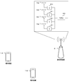
- FIG. 1 is a conceptual diagram of a wireless communication system according to this embodiment.
- the wireless communication system includes a terminal device 1A, a terminal device 1B, and a base station device 3.
- the terminal device 1A and the terminal device 1B are also referred to as the terminal device 1.
- the terminal device 1 is also called a user terminal, mobile station device, communication terminal, mobile device, terminal, UE (User Equipment), MS (Mobile Station).
- the base station device 3 includes a radio base station device, a base station, a radio base station, a fixed station, an NB (Node B), an eNB (evolved Node B), a BTS (Base Transceiver Station), a BS (Base Station), and an NR NB ( It is also called NR Node B), NNB, TRP (Transmission and Reception Point), and gNB.
- the base station device 3 may include a core network device.
- the base station device 3 may include one or a plurality of transmission/reception points 4 (transmission reception point).
- the base station device 3 may serve the terminal device 1 with the communicable range (communication area) controlled by the base station device 3 as one or a plurality of cells.
- the base station device 3 may serve the terminal device 1 by setting the communicable range (communication area) controlled by the one or more transmission/reception points 4 as one or more cells.
- one cell may be divided into a plurality of partial areas (Beamed area), and the terminal device 1 may be served in each partial area.
- the partial region may be identified based on a beam index used in beam forming or a precoding index.
- a wireless communication link from the base station device 3 to the terminal device 1 is called a downlink.
- a wireless communication link from the terminal device 1 to the base station device 3 is called an uplink.
- orthogonal frequency division multiplexing OFDM: Orthogonal Frequency Division Multiplexing
- CP Cyclic Prefix
- SC- FDM Single-Carrier Frequency Division Multiplexing
- DFT-S-OFDM Discrete Fourier Transform Spread OFDM
- MC-CDM Multi-Carrier Code Division Multiplexing
- a universal filter multi-carrier (UFMC), a filter OFDM (F-OFDM: Filtered OFDM), and a window function are used.
- Multiplied OFDM (Windowed OFDM) and filter bank multi-carrier (FBMC: Filter-Bank Multi-Carrier) may be used.
- OFDM is explained as a transmission method using OFDM symbols, but the case of using other transmission methods described above is also included in the present invention.
- the CP in the wireless communication between the terminal device 1 and the base station device 3, the CP may not be used, or the above-mentioned transmission method with zero padding may be used instead of the CP. Also, CP and zero padding may be added to both the front and the rear.
- One aspect of the present embodiment may be operated in carrier aggregation or dual connectivity with a radio access technology (RAT: Radio Access Technology) such as LTE or LTE-A/LTE-A Pro.
- RAT Radio Access Technology
- some or all cells or cell groups, carriers or carrier groups for example, primary cell (PCell: Primary Cell), secondary cell (SCell: Secondary Cell), primary secondary cell (PSCell), MCG (Master Cell Group) ), SCG (Secondary Cell Group), etc.
- PCell Primary Cell
- SCell Secondary Cell
- PSCell primary secondary cell
- MCG Master Cell Group
- SCG Secondary Cell Group
- the SpCell (Special Cell) is a PCell of the MCG or a PSCell of the SCG depending on whether the MAC (MAC: Medium Access Control) entity is associated with the MCG or the SCG, respectively. Called. Unless it is a dual connectivity operation, SpCell (Special Cell) is called PCell. SpCell (Special Cell) supports PUCCH transmission and contention-based random access.
- MAC Medium Access Control
- one or more serving cells may be set for the terminal device 1.
- the plurality of configured serving cells may include one primary cell and one or more secondary cells.
- the primary cell may be a serving cell that has undergone the initial connection establishment procedure, a serving cell that has initiated the connection re-establishment procedure, or a cell designated as the primary cell in the handover procedure. Good.
- One or a plurality of secondary cells may be set when or after the RRC (Radio Resource Control) connection is established.
- the plurality of configured serving cells may include one primary secondary cell.
- the primary secondary cell may be a secondary cell capable of transmitting control information in the uplink among one or a plurality of secondary cells in which the terminal device 1 is set.
- the master cell group may include one primary cell and zero or more secondary cells.
- the secondary cell group may be composed of one primary secondary cell and zero or more secondary cells.
- TDD Time Division Duplex
- FDD Frequency Division Duplex
- the TDD (Time Division Duplex) method or the FDD (Frequency Division Duplex) method may be applied to all of the plurality of cells.
- cells to which the TDD scheme is applied and cells to which the FDD scheme is applied may be aggregated.
- the TDD method may be referred to as an unpaired spectrum operation.
- the FDD method may be referred to as a paired spectrum operation.
- the carrier corresponding to the serving cell is called the downlink component carrier (or downlink carrier).
- the carrier corresponding to the serving cell is called an uplink component carrier (or uplink carrier).
- the carrier corresponding to the serving cell is called a side link component carrier (or side link carrier).
- the downlink component carrier, the uplink component carrier, and/or the side link component carrier are collectively referred to as a component carrier (or carrier).
- the following physical channels are used in the wireless communication between the terminal device 1 and the base station device 3.
- PBCH Physical Broadcast CHannel
- PDCCH Physical Downlink Control CHannel
- PDSCH Physical Downlink Shared CHannel
- PUCCH Physical Uplink Control CHannel
- PRACH Physical Random Access CHannel
- MIB Master Information Block
- EIB Essential Information Block
- BCH Broadcast Channel
- the PBCH may be used to broadcast a time index within a cycle of a block of a synchronization signal (also referred to as an SS/PBCH block).
- the time index is information indicating the index of the synchronization signal and PBCH in the cell.
- the SS/PBCH block is transmitted using the assumption of three transmission beams (transmission filter setting, pseudo co-location (QCL: Quasi Co-Location) regarding the reception spatial parameter)
- the SS/PBCH block is set within a predetermined cycle or set. It may indicate the time order within the cycle.
- the terminal device may recognize the difference in the time index as the difference in the transmission beams.
- the PDCCH is used to transmit (or carry) downlink control information (Downlink Control Information: DCI) in downlink wireless communication (wireless communication from the base station device 3 to the terminal device 1).
- DCI Downlink Control Information
- one or more DCIs (which may be referred to as DCI formats) are defined for transmission of downlink control information. That is, a field for downlink control information is defined as DCI and is mapped to information bits.
- the PDCCH is transmitted in PDCCH candidates.
- the terminal device 1 monitors a set of PDCCH candidates (candidate) in the serving cell. Monitoring means trying to decode the PDCCH according to a certain DCI format.
- DCI format For example, the following DCI format may be defined.
- DCI format 0_0 may be used for PUSCH scheduling in a serving cell.
- the DCI format 0_0 may include information indicating PUSCH scheduling information (frequency domain resource allocation and time domain resource allocation).
- the DCI format 0_0 may have a CRC scrambled by any one of C-RNTI, CS-RNTI, MCS-C-RNTI, and/or TC-RNTI.
- DCI format 0_0 may be monitored in the common search space or the UE-specific search space.
- DCI format 0_1 may be used for PUSCH scheduling in a serving cell.
- DCI format 0_1 refers to information indicating PUSCH scheduling information (frequency domain resource allocation and time domain resource allocation), information indicating a band part (BWP: BandWidth Part), channel state information (CSI: Channel State Information) request, sounding reference A signal (SRS: Sounding Reference Signal) request and information about the antenna port may be included.
- the DCI format 0_1 may include a CRC scrambled by any one of C-RNTI, CS-RNTI, SP-CSI-RNTI, and/or MCS-C-RNTI. DCI format 0_1 may be monitored in the UE-specific search space.
- DCI format 1_0 may be used for PDSCH scheduling in a serving cell.
- the DCI format 1_0 may include information indicating PDSCH scheduling information (frequency domain resource allocation and time domain resource allocation).
- the DCI format 1_0 is added with a CRC that is scrambled by any one of C-RNTI, CS-RNTI, MCS-C-RNTI, P-RNTI, SI-RNTI, RA-RNTI, and/or TC-RNTI. May be.
- DCI format 1_0 may be monitored in the common search space or the UE-specific search space.
- the DCI format 1_1 may be used for PDSCH scheduling in a serving cell.
- the DCI format 1_1 includes information indicating PDSCH scheduling information (frequency domain resource allocation and time domain resource allocation), information indicating a band portion (BWP), a transmission setting instruction (TCI: Transmission Configuration Indication), and information related to an antenna port. Good.
- the DCI format 1_1 may include a CRC scrambled by any one of C-RNTI, CS-RNTI, and/or MCS-C-RNTI. DCI format 1_1 may be monitored in the UE-specific search space.
- DCI format 2_0 is used to notify the slot format of one or more slots.
- the slot format is defined as each OFDM symbol in the slot being classified as one of downlink, flexible, and uplink.
- the slot format is 28
- the DDDDDDDDDDDDFU is applied to 14 OFDM symbols in the slot for which the slot format 28 is designated.
- D is a downlink symbol
- F is a flexible symbol
- U is an uplink symbol.
- the DCI format 2_1 is used to notify the terminal device 1 of a physical resource block and an OFDM symbol that may be assumed not to be transmitted. This information may be referred to as a preemption instruction (intermittent transmission instruction).
- DCI format 2_2 is used for transmitting the transmission power control (TPC: Transmit Power Control) command for PUSCH and PUSCH.
- TPC Transmit Power Control
- DCI format 2_3 is used to transmit a group of TPC commands for transmitting a sounding reference signal (SRS) by one or more terminal devices 1. Also, the SRS request may be transmitted together with the TPC command. Further, in the DCI format 2_3, the SRS request and the TPC command may be defined for the uplink without PUSCH and PUCCH, or for the uplink in which the transmission power control of SRS is not tied to the transmission power control of PUSCH.
- SRS sounding reference signal
- DCI for the downlink is also called downlink grant or downlink assignment.
- the DCI for the uplink is also referred to as an uplink grant or an uplink assignment.
- DCI may also be referred to as DCI format.
- the CRC (Cyclic Redundancy Check) parity bit added to the DCI format transmitted by one PDCCH is SI-RNTI (System Information-Radio Network Temporary Identifier), P-RNTI (Paging-Radio Network Temporary Identifier), C- It is scrambled by RNTI (Cell-Radio Network Temporary Identifier), CS-RNTI (Configured Scheduling-Radio Network Temporary Identifier), RA-RNTI (Random Access-Radio Network Temporary Identity), or Temporary C-RNTI.
- SI-RNTI may be an identifier used for broadcasting system information.
- the P-RNTI may be an identifier used for notification of paging and system information change.
- C-RNTI, MCS-C-RNTI, and CS-RNTI are identifiers for identifying a terminal device in a cell.
- the Temporary C-RNTI is an identifier for identifying the terminal device 1 that has transmitted the random access preamble during the contention based random access procedure.
- C-RNTI terminal device identifier (identification information)
- CS-RNTI is used to periodically allocate PDSCH or PUSCH resources.
- MCS-C-RNTI is used to indicate the use of a given MCS table for grant-based transmission.
- Temporary C-RNTI (TC-RNTI) is used to control PDSCH transmission or PUSCH transmission in one or more slots. The Temporary C-RNTI is used to schedule the retransmission of the random access message 3 and the transmission of the random access message 4.
- RA-RNTI random access response identification information
- the PUCCH is used to transmit uplink control information (Uplink Control Information: UCI) in uplink wireless communication (wireless communication from the terminal device 1 to the base station device 3).
- the uplink control information may include channel state information (CSI: Channel State Information) used to indicate the state of the downlink channel.
- the uplink control information may include a scheduling request (SR: Scheduling Request) used to request the UL-SCH resource.
- the uplink control information may include HARQ-ACK (Hybrid Automatic Repeat request ACKnowledgement).
- HARQ-ACK may indicate HARQ-ACK for downlink data (Transport block, Medium Access Control Protocol Data Unit: MAC PDU, Downlink-Shared Channel: DL-SCH).
- PDSCH Downlink Shared CHannel
- MAC Medium Access Control
- SI System Information
- RAR Random Access Response
- PUSCH may be used to transmit HARQ-ACK and/or CSI together with uplink data (UL-SCH: Uplink Shared Channel) from the MAC layer or uplink data. It may also be used to send CSI only or HARQ-ACK and CSI only. That is, it may be used to transmit only UCI.
- UL-SCH Uplink Shared Channel
- the base station device 3 and the terminal device 1 exchange (transmit/receive) signals in an upper layer (upper layer: higher layer).
- the base station apparatus 3 and the terminal apparatus 1 transmit and receive RRC signaling (RRC message: Radio Resource Control message, also called RRC information: Radio Resource Control information) in the radio resource control (RRC:Radio Resource Control) layer.
- RRC Radio Resource Control
- the base station device 3 and the terminal device 1 may transmit and receive a MAC control element in a MAC (Medium Access Control) layer.
- the RRC layer of the terminal device 1 acquires the system information reported from the base station device 3.
- the RRC signaling, the system information, and/or the MAC control element are also referred to as an upper layer signal (upper layer signalling) or an upper layer parameter.
- the upper layer here means an upper layer viewed from the physical layer, and thus may include one or more of a MAC layer, an RRC layer, an RLC layer, a PDCP layer, a NAS (Non Access Stratum) layer, and the like.
- the upper layer may include one or more of the RRC layer, the RLC layer, the PDCP layer, the NAS layer, and the like.
- the meaning of “A is given by the upper layer” or “A is given by the upper layer” means that the upper layer (mainly the RRC layer, the MAC layer, etc.) of the terminal device 1 is transmitted from the base station device 3. It may mean that A is received and that the received A is given from the upper layer of the terminal device 1 to the physical layer of the terminal device 1. Setting the upper layer parameters in the terminal device 1 may mean that the upper layer parameters are provided to the terminal device.
- PDSCH or PUSCH may be used for transmitting RRC signaling and MAC control elements.
- the RRC signaling transmitted from the base station apparatus 3 may be common signaling to the plurality of terminal apparatuses 1 in the cell.
- the RRC signaling transmitted from the base station device 3 may be dedicated signaling (also referred to as dedicated signaling) for a certain terminal device 1. That is, the terminal device specific (UE-specific) information may be transmitted to a certain terminal device 1 by using dedicated signaling.
- PUSCH may be used for transmission of UE capability (UE Capability) in the uplink.
- the following downlink physical signals are used in downlink wireless communication.
- the downlink physical signal is not used for transmitting the information output from the upper layer, but is used by the physical layer.
- SS Synchronization signal
- RS Reference Signal
- the synchronization signal may include a primary synchronization signal (PSS) and a secondary synchronization signal (SSS).
- PSS primary synchronization signal
- SSS secondary synchronization signal
- the cell ID may be detected using PSS and SSS.
- the synchronization signal is used by the terminal device 1 to synchronize the downlink frequency domain and time domain.
- the synchronization signal may be used by the terminal device 1 for precoding by the base station device 3 or for precoding or beam selection in beamforming.
- the beam may also be called a transmission or reception filter setting, or a spatial domain transmission filter or a spatial domain reception filter.
- the reference signal is used by the terminal device 1 to perform propagation path compensation on the physical channel.
- the reference signal may also be used for the terminal device 1 to calculate downlink CSI.
- the reference signal may be used for fine synchronization so that numerology such as radio parameters and subcarrier intervals and window synchronization of FFT can be performed.
- one or more of the following downlink reference signals are used.
- DMRS Demodulation Reference Signal
- CSI-RS Channel State Information Reference Signal
- PTRS Phase Tracking Reference Signal
- TRS Tracking Reference Signal
- CSI-RS is used to demodulate the modulated signal.
- the CSI-RS is used for measuring channel state information (CSI) and beam management, and a periodic or semi-persistent or aperiodic CSI reference signal transmission method is applied.
- the CSI-RS may be defined as a non-zero power (NZP) CSI-RS and a zero-power (ZP: Zero Power) CSI-RS having zero transmission power (or reception power).
- the ZP CSI-RS may be defined as a CSI-RS resource with zero transmission power or not transmitted.
- the TRS is used to guarantee the Doppler shift when moving at a high speed, and the TRS may be used as one setting of the CSI-RS, for example, one-port CSI-RS is used as the TRS. Radio resources may be configured.
- uplink reference signals are used.
- DMRS Demodulation Reference Signal
- PTRS Phase Tracking Reference Signal
- SRS Sounding Reference Signal
- SRS uplink channel state information
- the downlink physical channel and/or the downlink physical signal are collectively referred to as the downlink signal.
- the uplink physical channel and/or the uplink physical signal are collectively referred to as an uplink signal.
- the downlink physical channel and/or the uplink physical channel are generically called a physical channel.
- the downlink physical signal and/or the uplink physical signal are collectively referred to as a physical signal.
- BCH, UL-SCH and DL-SCH are transport channels.
- a channel used in a medium access control (MAC) layer is called a transport channel.
- the unit of the transport channel used in the MAC layer is also called a transport block (TB) and/or a MAC PDU (Protocol Data Unit).
- HARQ Hybrid Automatic Repeat reQuest
- the transport block is a unit of data delivered by the MAC layer to the physical layer. In the physical layer, transport blocks are mapped to codewords, and an encoding process is performed for each codeword.
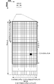
- FIG. 2 is a diagram showing an example of an SS/PBCH block (also referred to as a synchronization signal block, an SS block, an SSB) and an SS burst set (also referred to as a synchronization signal burst set) according to the present embodiment.
- FIG. 2 shows an example in which two SS/PBCH blocks are included in an SS burst set that is periodically transmitted, and the SS/PBCH block is composed of 4 consecutive OFDM symbols.
- the SS/PBCH block is a unit block including at least a synchronization signal (PSS, SSS) and/or PBCH. Transmitting the signal/channel included in the SS/PBCH block is expressed as transmitting the SS/PBCH block.
- the base station device 3 may use an independent downlink transmission beam for each SS/PBCH block. Good.
- PSS, SSS, and PBCH are time/frequency multiplexed in one SS/PBCH block.
- the order in which PSS, SSS and/or PBCH are multiplexed in the time domain may be different from the example shown in FIG.
- SS burst set may be sent periodically.
- a cycle to be used for initial access and a cycle to be set for the connected (Connected or RRC_Connected) terminal device may be defined.
- the cycle to be set for the connected (Connected or RRC_Connected) terminal device may be set in the RRC layer.
- the period set for the connected (Connected or RRC_Connected) terminal is the period of the radio resource in the time domain that may potentially be transmitted, and whether the base station device 3 actually transmits You may decide.
- the cycle used for the initial access may be defined in advance in a specification or the like.
- the SS burst set may be determined based on the system frame number (SFN: System Frame Number). Also, the start position (boundary) of the SS burst set may be determined based on the SFN and the cycle.
- SFN System Frame Number
- An SS/PBCH block is assigned an SSB index (may be referred to as an SSB/PBCH block index) according to the temporal position in the SS burst set.
- the terminal device 1 calculates the SSB index based on the PBCH information and/or the reference signal information included in the detected SS/PBCH block.
- -SS/PBCH blocks having the same relative time within each SS burst set in a plurality of SS burst sets are assigned the same SSB index.
- SS/PBCH blocks with the same relative time within each SS burst set in multiple SS burst sets may be assumed to be QCL (or have the same downlink transmit beam applied).
- antenna ports in SS/PBCH blocks with the same relative time within each SS burst set in multiple SS burst sets may be assumed to be QCL with respect to average delay, Doppler shift, and spatial correlation.
- SS/PBCH blocks assigned the same SSB index may be assumed to be QCL with respect to average delay, average gain, Doppler spread, Doppler shift, and spatial correlation.
- the setting corresponding to one or more SS/PBCH blocks that may be QCL (or may be reference signals) may be referred to as QCL setting.
- the number of SS/PBCH blocks (which may be referred to as the number of SS blocks or the number of SSBs) is, for example, as the number of SS/PBCH blocks (number) in an SS burst, an SS burst set, or a cycle of SS/PBCH blocks. May be defined. Further, the number of SS/PBCH blocks may indicate the number of beam groups for cell selection in the SS burst, the SS burst set, or the period of the SS/PBCH block. Here, the beam group may be defined as the number of different SS/PBCH blocks or the number of different beams included in the SS burst, or the set of SS bursts, or the period of the SS/PBCH block.
- the reference signals described in this embodiment are downlink reference signals, synchronization signals, SS/PBCH blocks, downlink DM-RSs, CSI-RSs, uplink reference signals, SRSs, and/or uplink DM-. Including RS.
- the downlink reference signal, the synchronization signal and/or the SS/PBCH block may be referred to as a reference signal.
- Reference signals used in the downlink include downlink reference signals, synchronization signals, SS/PBCH blocks, downlink DM-RSs, CSI-RSs, and the like.
- the reference signal used in the uplink includes an uplink reference signal, SRS, and/or uplink DM-RS.
- the reference signal may be used for radio resource measurement (RRM: Radio Resource Measurement). Further, the reference signal may be used for beam management.
- RRM Radio Resource Measurement
- the beam management includes analog and/or digital beams in a transmitting device (the base station device 3 in the case of downlink and the terminal device 1 in the case of uplink) and a receiving device (the terminal device 1 in the case of downlink).
- the base station apparatus 3 in the case of the uplink may be a procedure of the base station apparatus 3 and/or the terminal apparatus 1 for obtaining the beam gain by matching the directivity of the analog and/or digital beams.
- the following procedure may be included as a procedure for configuring, setting, or establishing a beam pair link.
- the beam selection may be a procedure for selecting a beam in communication between the base station device 3 and the terminal device 1.
- the beam improvement may be a procedure of selecting a beam having a higher gain or changing the beam between the base station apparatus 3 and the terminal apparatus 1 optimally by moving the terminal apparatus 1.
- the beam recovery may be a procedure for reselecting the beam when the quality of the communication link is deteriorated due to the blockage caused by the passage of a shield or a person in the communication between the base station device 3 and the terminal device 1.
- Beam management may include beam selection and beam refinement.
- Beam recovery may include the following procedures. -Detection of beam failure-Discoverment of new beam-Transmission of beam recovery request-Monitoring response to beam recovery request
- CSI-RS or RSRP Reference Signal Received Power
- CSI-RS resource index CRI: CSI-RS Resource Index
- DMRS reference signal
- the base station apparatus 3 instructs the CRI or SS/PBCH time index when instructing the beam to the terminal apparatus 1, and the terminal apparatus 1 receives based on the instructed CRI or SS/PBCH time index.
- the terminal device 1 may set and receive the spatial filter based on the instructed CRI or the time index of the SS/PBCH.
- the terminal device 1 may receive using the assumption of a pseudo co-location (QCL).
- a signal (antenna port, synchronization signal, reference signal, etc.) and another signal (antenna port, synchronization signal, reference signal, etc.) “QCL” or “the assumption of QCL is used” means that a signal is Can be interpreted as being associated with another signal.
- Two antenna ports are said to be QCL if the Long Term Property of the channel carrying a symbol at one antenna port can be inferred from the channel carrying a symbol at the other antenna port. ..
- the long-term characteristics of the channel include one or more of delay spread, Doppler spread, Doppler shift, average gain, and average delay. For example, when the antenna port 1 and the antenna port 2 are QCL with respect to the average delay, it means that the reception timing of the antenna port 2 can be inferred from the reception timing of the antenna port 1.
- the QCL extended to the space may be newly defined.
- the arrival angle AoA (Angle of Arrival), ZoA (Zenith angle of Arrival), etc.
- Angle Spread such as ASA (Angle Spread Arrival) or ZSA (Zenith angle Spread of Arrival)
- sending angle AoD, ZoD, etc.
- Angle Spread such as ASD (Angle Spread of Departure) or ZSD ( Zenithangle Spread of Departure)
- spatial correlation SpatialCorrelation
- reception spatial parameters reception spatial parameters.
- the reception beam (reception spatial filter) that receives the signal from the antenna port 1 receives the signal from the antenna port 2 from the reception beam. It means that the beam can be inferred.
- QCL type a combination of long-term characteristics that may be regarded as QCL may be defined.
- the following types may be defined.
- the above QCL type is RRC and/or
- the assumption of QCL between one or two reference signals and PDCCH or PDSCH DMRS may be set and/or instructed as a transmission configuration indication (TCI) in the MAC layer and/or DCI.
- TCI transmission configuration indication
- the terminal #1 when the terminal #1 is set and/or instructed to have the index #2 of the SS/PBCH block and the QCL type A+QCL type B as one state of the TCI when the terminal device 1 receives the PDCCH, the terminal device 1 may use the PDCCH DMRS.
- the Doppler shift, the Doppler spread, the average delay, the delay spread, the reception spatial parameter and the long-term characteristics of the channel are regarded as the DMRS of the PDCCH to receive the synchronization and the propagation path. You may make an estimate.
- the reference signal (SS/PBCH block in the above example) designated by the TCI is the source reference signal, and the reference is influenced by the long-term characteristic inferred from the long-term characteristic of the channel when the source reference signal is received.
- the signal (PDCCH DMRS in the above example) may be referred to as the target reference signal.
- the TCI may have one or more TCI states in RRC and a combination of a source reference signal and a QCL type for each state, and may be instructed to the terminal device 1 by the MAC layer or DCI.
- subframe Although referred to as a subframe in this embodiment, it may be referred to as a resource unit, a radio frame, a time section, a time interval, or the like.
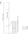
- FIG. 3 is a diagram showing an example of a schematic configuration of an uplink and a downlink slot according to the first embodiment of the present invention.
- Each radio frame is 10 ms long.
- Each radio frame is composed of 10 subframes and W slots.
- one slot is composed of X OFDM symbols. That is, the length of one subframe is 1 ms.
- NCP Normal Cyclic Prefix
- W 10 when the subcarrier spacing is 15 kHz
- W 40 when the subcarrier spacing is 60 kHz.
- the uplink slot is defined similarly, and the downlink slot and the uplink slot may be defined separately.
- BWP BandWidth Part
- the slot may be defined as a transmission time interval (TTI: Transmission Time Interval). Slots may not be defined as TTIs.
- the TTI may be the transport block transmission period.
- the signal or physical channel transmitted in each of the slots may be represented by a resource grid.
- the resource grid is defined by a plurality of subcarriers and a plurality of OFDM symbols for each numerology (subcarrier spacing and cyclic prefix length) and each carrier.
- the number of subcarriers forming one slot depends on the downlink and uplink bandwidths of the cell.
- Each of the elements in the resource grid is called a resource element. Resource elements may be identified using subcarrier numbers and OFDM symbol numbers.
- one physical resource block is, for example, 12 (the number of OFDM symbols included in one slot)*4 (included in one subframe in the time domain).
- Number of slots) 48 consecutive OFDM symbols and 12*Nmax, ⁇ consecutive subcarriers in the frequency domain. That is, the resource grid is composed of (48*12*Nmax, ⁇ ) resource elements.
- Reference resource blocks, common resource blocks, physical resource blocks, and virtual resource blocks are defined as resource blocks.
- One resource block is defined as 12 consecutive subcarriers in the frequency domain.
- the reference resource block is common to all subcarriers, and for example, the resource blocks may be configured at subcarrier intervals of 15 kHz and may be numbered in ascending order.
- the subcarrier index 0 in the reference resource block index 0 may be referred to as a reference point A (point A) (may be simply referred to as “reference point”).
- the common resource block is a resource block numbered in ascending order from 0 in each subcarrier interval setting ⁇ from the reference point A.
- the resource grid described above is defined by this common resource block.
- the physical resource blocks are resource blocks numbered in ascending order from 0 included in the band portion (BWP) described later, and the physical resource blocks are in ascending order from 0 included in the band portion (BWP). It is a numbered resource block.
- a physical uplink channel is first mapped to a virtual resource block.
- the virtual resource block is then mapped to the physical resource block.
- the resource block may be a virtual resource block, a physical resource block, a common resource block, or a reference resource block.
- the subcarrier interval setting ⁇ As mentioned above, NR supports one or more OFDM numerologies.
- slots are counted in ascending order from 0 to N ⁇ subframe, ⁇ _ ⁇ slot ⁇ -1 in a subframe, and 0 to N ⁇ frame, ⁇ _ ⁇ slot in a frame.
- ⁇ -1 are counted in ascending order.
- N ⁇ slot ⁇ _ ⁇ symb ⁇ consecutive OFDM symbols in the slot based on the slot settings and the cyclic prefix.
- N ⁇ slot ⁇ _ ⁇ symb ⁇ is 14.
- the start of slot n ⁇ _ ⁇ s ⁇ in the subframe is the start and time of the n ⁇ _ ⁇ s ⁇ N ⁇ slot ⁇ _ ⁇ symb ⁇ th OFDM symbol in the same subframe. It is aligned.
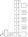
- FIG. 4 is a diagram showing the relationship between subframes, slots, and minislots in the time domain. As shown in the figure, three types of time units are defined.
- the subframe is 1 ms regardless of the subcarrier interval, the number of OFDM symbols included in the slot is 7 or 14, and the slot length differs depending on the subcarrier interval.
- the subcarrier interval is 15 kHz, one subframe includes 14 OFDM symbols.
- the downlink slot may be referred to as PDSCH mapping type A.
- the uplink slot may be referred to as PUSCH mapping type A.
- a minislot (may be referred to as a subslot) is a time unit composed of fewer OFDM symbols than the number of OFDM symbols included in the slot.
- the figure shows the case where the minislot is composed of two OFDM symbols as an example.
- the OFDM symbols in a minislot may match the OFDM symbol timing that makes up the slot.
- the minimum unit of scheduling may be a slot or a minislot.
- assigning minislots may be referred to as non-slot based scheduling.
- scheduling a minislot may be expressed as scheduling a resource in which the relative time positions of the reference signal and the start position of data are fixed.
- the downlink minislot may be referred to as PDSCH mapping type B.
- the uplink minislot may be referred to as PUSCH mapping type B.
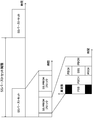
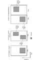
- FIG. 5 is a diagram showing an example of the slot format.
- the slot length is 1 ms at a subcarrier interval of 15 kHz is shown as an example.
- D indicates a downlink and U indicates an uplink.
- U indicates an uplink.
- a certain time period for example, the minimum time period that must be assigned to one UE in the system
- It may include one or more of downlink symbols, flexible symbols, and uplink symbols. Note that these ratios may be predetermined as a slot format. Further, it may be defined by the number of downlink OFDM symbols included in the slot or the start position and end position in the slot.
- scheduling a slot may be expressed as scheduling a resource in which a relative time position between a reference signal and a slot boundary is fixed.
- the terminal device 1 may receive a downlink signal or a downlink channel with a downlink symbol or a flexible symbol.
- the terminal device 1 may transmit an uplink signal or a downlink channel with an uplink symbol or a flexible symbol.
- 5A may also be referred to as a certain time period (for example, a minimum unit of time resources that can be assigned to one UE, a time unit, or the like. Further, a plurality of minimum units of time resources are bundled and referred to as a time unit. 5B, all are used for downlink transmission.
- uplink scheduling is performed via, for example, the PDCCH in the first time resource, processing delay of the PDCCH and downlink are performed.
- the uplink signal is transmitted via the flexible symbol including the uplink switching time and the generation of the transmission signal.
- the uplink signal may be used for transmitting HARQ-ACK and/or CSI, that is, UCI.
- FIG. 5(d) is used for transmission of PDCCH and/or PDSCH in the first time resource, and has processing delay, downlink to uplink switching time, and uplink PUSCH and/or via a gap for generation of a transmission signal. Alternatively, it is used for transmitting PUCCH.
- the uplink signal may be used for transmission of uplink data, that is, UL-SCH.
- FIG. 5(e) is an example where all are used for uplink transmission (PUSCH or PUCCH).
- the downlink part and the uplink part described above may be composed of a plurality of OFDM symbols as in LTE.
- FIG. 6 is a diagram showing an example of beamforming.
- a plurality of antenna elements are connected to one transmission unit (TXRU: Transceiver unit) 50, the phase is controlled by the phase shifter 51 for each antenna element, and by transmitting from the antenna element 52, the transmission signal can be transmitted in any direction.
- the beam can be aimed.
- TXRU may be defined as an antenna port, and in the terminal device 1, only the antenna port may be defined.
- directivity can be directed in an arbitrary direction, so that the base station device 3 can communicate with the terminal device 1 using a beam having a high gain.
- BWP Bandwidth part
- BWP is also referred to as carrier BWP.
- BWP may be set for each of the downlink and the uplink.
- BWP is defined as a set of contiguous physical resources selected from a contiguous subset of common resource blocks.
- the terminal device 1 can set up to four BWPs in which one downlink carrier BWP (DL BWP) is activated at a certain time.
- DL BWP downlink carrier BWP
- UL BWP uplink carrier BWP
- BWP may be set in each serving cell.
- the fact that one BWP is set in a certain serving cell may be expressed as the fact that no BWP is set. Further, the setting of two or more BWPs may be expressed as the BWP being set.
- BWP switching for a serving cell may also be controlled by the BWP inactivity timer, RRC signaling, or by the MAC entity itself at the start of the random access procedure.
- one BWP is first active without receiving PDCCH indicating downlink allocation or uplink grant.
- the first active DL BWP (first active DL BWP) and the UL BWP (first active UL BWP) may be specified in the RRC message sent from the base station device 3 to the terminal device 1.
- the active BWP for a certain serving cell is designated by the RRC or PDCCH sent from the base station device 3 to the terminal device 1.
- the first active DL BWP (first active DL BWP) and the UL BWP (first active UL BWP) may be included in the message 4.
- first active DL BWP (first active DL BWP)
- UL BWP (first active UL BWP)
- the MAC entity of the terminal device 1 applies the normal process. Normal processing includes transmitting UL-SCH, transmitting RACH, monitoring PDCCH, transmitting PUCCH, transmitting SRS, and receiving DL-SCH.
- the MAC entity of the terminal device 1 does not transmit the UL-SCH, does not transmit the RACH, does not monitor the PDCCH, does not transmit the PUCCH, Does not transmit SRS and does not receive DL-SCH. If a serving cell is deactivated, there may be no active BWPs (eg, active BWPs are deactivated).
- the BWP information element (IE) included in the RRC message (system information to be broadcast or information sent in the dedicated RRC message) is used to set the BWP.
- the RRC message transmitted from the base station device 3 is received by the terminal device 1.
- the network For each serving cell, the network (such as the base station device 3) has at least one downlink BWP and one (if the serving cell is configured for uplink) or two (supplementary uplink in the appendix). Is set to the terminal device 1, at least an initial BWP (initial BWP) including an uplink BWP (for example, is used). Further, the network may configure additional uplink BWP or downlink BWP for a serving cell.
- the BWP setting is divided into an uplink parameter and a downlink parameter.
- the BWP setting is divided into a common parameter and a dedicated parameter. Common parameters (such as BWP uplink common IE and BWP downlink common IE) are cell-specific.
- the common parameters of the initial BWP of the primary cell are also provided in the system information.
- the network provides common parameters on dedicated signals.
- the BWP is identified by the BWP ID.
- the initial BWP has a BWP ID of 0.
- BWP IDs of other BWPs take values from 1 to 4.
- the initial DL BWP (initial active DL BWP, initial active DL BWP) is the control resource set (CORESET) for the type 0 PDCCH common search space. It may be defined by the position and number of consecutive PRBs, subcarrier spacing, and cyclic prefix for PDCCH reception in. The positions of the consecutive PRBs start from the PRB with the smallest index and end with the PRB with the largest index among the PRBs of the control resource set for the type 0 PDCCH common search space.
- the initial DL BWP may be indicated by the upper layer parameter initialDownlinkBWP.
- the upper layer parameter initialDownlinkBWP may be included in SIB1 (systemInformationBlockType1, ServingCellConfigCommonSIB) or ServingCellConfigCommon.
- SIB1 systemInformationBlockType1, ServingCellConfigCommonSIB
- ServingCellConfigCommon SIB is used to set the cell-specific parameter of the serving cell for the terminal device 1 in the SIB1.
- the size of the initial DL BWP is the number of resource blocks of the control resource set (CORESET#0) for the type 0 PDCCH common search space. It may be.
- the size of the initial DL BWP may be given by the locationAndBandwidth included in the upper layer parameter initialDownlinkBWP.
- the upper layer parameter locationAndBandwidth may indicate the position and bandwidth in the frequency domain of the initial DL BWP.
- multiple DL BWPs may be set for the terminal device 1. Then, of the DL BWPs set for the terminal device 1, the default DL BWP can be set by the parameter defaultDownlinkBWP-Id of the upper layer. If the upper layer parameter defaultDownlinkBWP-Id is not provided to the terminal device 1, the default DL BWP is the initial DL BWP.
- An initial UL BWP may be provided to the terminal device 1 by SIB1 (systemInformationBlockType1) or initialUplinkBWP.
- the information element initialUplinkBWP is used to set the initial UL BWP.
- the terminal device 1 may be set (provided) with an initial UL BWP (initial active UL BWP) by the upper layer parameter initialUplinkBWP.
- a supplemental uplink carrier (supplementary UL carrier) is set for the terminal device 1
- the terminal device 1 uses the initialUplinkBWP included in the parameter supplementaryUplink of the upper layer to set the initial UL on the supplemental uplink carrier. BWP may be set.
- Control resource set (CORESET) in this embodiment will be described below.
- Control resource set is a time and frequency resource for searching downlink control information.
- the setting information of CORESET includes information for identifying the CORESET identifier (ControlResourceSetId, CORESET-ID) and the frequency resource of CORESET.
- the information element ControlResourceSetId (identifier of CORESET) is used to specify a control resource set in a certain serving cell.
- the CORESET identifier is used between BWPs in a serving cell.
- the CORESET identifier is unique between BWPs in the serving cell.
- the number of CORESETs for each BWP is limited to 3, including the initial CORESET. In a certain serving cell, the value of the identifier of CORESET takes a value from 0 to 11.
- CORESET#0 The control resource set specified by the CORESET identifier 0 (ControlResourceSetId 0) is called CORESET#0.
- CORESET#0 may be set by pdchch-ConfigSIB1 included in MIB or PDCCH-ConfigCommon included in ServingCellConfigCommon. That is, the setting information of CORESET#0 may be pdcch-ConfigSIB1 included in MIB or PDCCH-ConfigCommon included in ServingCellConfigCommon.
- the setting information of CORESET#0 may be set by controlResourceSetZero included in PDCCH-ConfigSIB1 or PDCCH-ConfigCommon.
- the information element controlResourceSetZero is used to indicate CORESET#0 (common CORESET) of the initial DL BWP.
- CORESET indicated by pdcch-ConfigSIB1 is CORESET#0.
- the information element pdcch-ConfigSIB1 in the MIB or the dedicated configuration is used to set the initial DL BWP.
- the CORESET setting information pdcch-ConfigSIB1 for CORESET#0 the CORESET identifier, the CORESET frequency resource (for example, the number of consecutive resource blocks), and the time resource (the number of consecutive symbols) are explicitly specified.
- the frequency resource (for example, the number of consecutive resource blocks) and the time resource (the number of consecutive symbols) of CORESET with respect to CORESET#0 are implicitly indicated by the information included in pdcch-ConfigSIB1. Can be specified.
- the information element PDCCH-ConfigCommon is used to set cell-specific PDCCH parameters provided in the SIB.
- the PDCCH-ConfigCommon may be provided at the time of handover and addition of PSCell and/or SCell.
- the setting information of CORESET#0 is included in the setting of the initial BWP. That is, the setting information of CORESET#0 does not need to be included in the setting of BWP other than the initial BWP.
- the controlResourceSetZero corresponds to 4 bits (eg, 4 bits of MSB and 4 bits of most significant bit) of pdchch-ConfigSIB1.
- CORESET#0 is a control resource set for the type 0 PDCCH common search space.
- the setting information of the additional common CORESET may be set by the commonControlResourceSet included in the PDCCH-ConfigCommon. Also, the additional common CORESET configuration information may be used to specify additional common CORESET for system information and/or paging procedures. The setting information of the additional common CORESET may be used to specify the additional common CORESET used in the random access procedure. The setting information of the additional common CORESET may be included in the setting of each BWP. The identifier of CORESET shown in commonControlResourceSet takes a value other than 0.
- the common CORESET may be CORESET used in the random access procedure (for example, additional common CORESET). Further, in the present embodiment, the common CORESET may include CORESET#0 and/or CORESET set by the additional common CORESET setting information. That is, common CORESET may include CORESET#0 and/or additional common CORESET. CORESET#0 may be referred to as common CORESET#0.
- the terminal device 1 and the BWP other than the BWP to which the common CORESET is set may also refer to (acquire) the setting information of the common CORESET.
- the setting information of one or more CORESETs may be set by PDCCH-Config.
- the information element PDCCH-Config is used to set UE-specific PDCCH parameters (eg, CORSET, search space, etc.) for a certain BWP.
- PDCCH-Config may be included in the settings of each BWP.
- the common RESET setting information indicated by MIB is pdcch-ConfigSIB1
- the common RESET setting information indicated by PDCCH-ConfigCommon is controlResourceSetZero
- the additional common COREset indicated by PDCCH-ConfigCommon is commonCOREset.
- the setting information of (Common CORESET) is commonControlResourceSet.
- the setting information of one or a plurality of CORESETs (UE-specifically configured Control Resource Sets, UE-specific CORESET) indicated by PDCCH-Config is controlResourceSetToAddModList.
- the search space is defined to search for PDCCH candidates (PDCCH candidates).
- the searchSpaceType included in the search space setting information indicates whether the search space is a common search space (Common Search Space, CSS) or a UE-specific search space (UE-specific Search Space, USS).
- the UE-specific search space is at least derived from the value of C-RNTI set by the terminal device 1. That is, the UE-specific search space is individually derived for each terminal device 1.
- the common search space is a common search space among a plurality of terminal devices 1, and is composed of CCEs (Control Channel Elements) having a predetermined index.
- the CCE is composed of a plurality of resource elements.
- the search space setting information includes information on the DCI format monitored in the search space.
- the search space setting information includes the CORESET identifier specified by the CORESET setting information.
- the CORESET specified by the CORESET identifier included in the search space setting information is associated with the search space.
- CORESET associated with the search space is CORESET specified by the identifier of CORESET included in the search space.
- the DCI format indicated by the setting information of the search space is monitored by the associated CORESET.
- Each search space is associated with one CORESET.
- the search space setting information for the random access procedure may be set by ra-SearchSpace. That is, the DCI format to which the CRC scrambled by RA-RNTI or TC-RNTI is added in CORESET associated with ra-SearchSpace is monitored.
- the terminal device 1 monitors the set of PDCCH candidates in one or more CORESETs arranged in each active serving cell configured to monitor the PDCCH.
- the set of PDCCH candidates corresponds to one or more search space sets. Monitoring refers to decoding each PDCCH candidate depending on the monitored DCI format or formats.
- a set of PDCCH candidates monitored by the terminal device 1 is defined by a PDCCH search space set).
- One search space set is a common search space set or a UE-specific search space set. In the above, the search space set is called a search space, the common search space set is called a common search space, and the UE-specific search space set is called a UE-specific search space.
- the terminal device 1 monitors PDCCH candidates with one or more of the following search space sets.
- -Type 0 PDCCH common search space set (a Type0-PDCCH common search space set): This search space set is indicated by pdcch-ConfigSIB1 or PDCCH-ConfigCommon indicated by MIB, which is a parameter of the upper layer.
- Search space SIB1 searchSpaceSIB1
- searchSpaceZero search space zero included in PDCCH-ConfigCommon. This search space is for monitoring the DCI format of the CRC scrambled with SI-RNRI in the primary cell.
- -Type 0A PDCCH common search space set (a Type 0A-PDCCH common search space set): This search space set is set by the search space (searchSpaceOtherSystemInformation) indicated by PDCCH-ConfigCommon, which is a parameter of the upper layer. To be done. This search space is for monitoring the DCI format of the CRC scrambled with SI-RNRI in the primary cell.
- -Type 1 PDCCH common search space set (a Type1-PDCCH common search space set): This search space set is a search for a random access procedure indicated by PDCCH-ConfigCommon, which is an upper layer parameter. Set by space (ra-SearchSpace ).
- This search space is for monitoring the DCI format of the CRC scrambled with RA-RNRI or TC-RNTI in the primary cell.
- the Type 1 PDCCH common search space set is a search space set for a random access procedure.
- -Type 2 PDCCH common search space set This search space set is a search space for the paging procedure indicated by PDCCH-ConfigCommon, which is a parameter of the upper layer. Set by (pagingSearchSpace). This search space is for monitoring the DCI format of the P-RNTI scrambled CRC in the primary cell.
- This search space set is a search space whose search space type indicated by PDCCH-Config, which is an upper layer parameter, is common. Set by (SearchSpace).
- This search space is for monitoring the DCI format of the INT-RNTI, SFI-RNTI, TPC-PUSCH-RNTI, TPC-PUCCH-RNTI, or TPC-SRS-RNTI scrambled CRC.
- the primary cell it is for monitoring the DCI format of the C-RNTI, CS-RNTI(s), or MSC-C-RNTI scrambled CRC.
- aUE-specific search space set In this search space set, the search space type indicated by PDCCH-Config, which is an upper layer parameter, is set by the UE-specific search space (SearchSpace) ..
- This search space is for monitoring DCI format of C-RNTI, CS-RNTI(s), or MSC-C-RNTI scrambled CRC.
- the terminal device 1 If the terminal device 1 is provided with one or more search space sets by the corresponding upper layer parameters (searchSpaceZero, searchSpaceSIB1, searchSpaceOtherSystemInformation, pagingSearchSpace, ra-SearchSpace, etc.), the terminal device 1 will receive C-RNTI or When CS-RNTI is provided, the terminal device 1 monitors PDCCH candidates for DCI format0_0 and DCI format1_0 having C-RNTI or CS-RNTI in the one or more search space sets. May be.
- searchSpaceZero searchSpaceSIB1, searchSpaceOtherSystemInformation, pagingSearchSpace, ra-SearchSpace, etc.
- the BWP setting information is divided into DL BWP setting information and UL BWP setting information.
- the BWP setting information includes an information element bwp-Id (BWP identifier).
- the BWP identifier included in the DL BWP setting information is used to identify (reference) the DL BWP in a certain serving cell.
- the BWP identifier included in the UL BWP setting information is used to identify (reference) the UL BWP in a certain serving cell.
- the BWP identifier is assigned to each of the DL BWP and UL BWP. For example, the identifier of the BWP corresponding to the DL BWP may be referred to as the DL BWP index.
- the BWP identifier corresponding to the UL BWP may be referred to as the UL BWP index (ULBWP index).
- the initial DL BWP is referenced by the DL BWP identifier 0.
- the initial UL BWP is referenced by the UL BWP identifier 0.
- maxNrfBWPs is the maximum number of BWPs per serving cell and is 4.
- the values of the other BWP identifiers take values from 1 to 4.
- the setting information of the other upper layer is associated with a specific BWP by using the identifier of the BWP. Having DL BWP and UL BWP having the same BWP identifier may mean that DL BWP and UL BWP are paired.
- the terminal device 1 may be configured with one primary cell and up to 15 secondary cells.
- the following describes the procedure for receiving PDSCH.
- the terminal device 1 may decode (receive) the corresponding PDSCH by detecting the PDCCH including the DCI format 1_0 or the DCI format 1_1.
- the corresponding PDSCH is scheduled (shown) by its DCI format (DCI).
- the start position (start symbol) of the scheduled PDSCH is called S.
- the starting symbol S of the PDSCH may be the first symbol in which the PDSCH is transmitted (mapped) in a certain slot.
- the start symbol S corresponds to the start of the slot. For example, when the value of S is 0, the terminal device 1 may receive the PDSCH from the first symbol in a certain slot. Further, for example, when the value of S is 2, the terminal device 1 may receive the PDSCH from the third symbol of a certain slot.
- the number of consecutive symbols of the PDSCH scheduled is called L. The number L of consecutive symbols is counted from the start symbol S. The determination of S and L assigned to PDSCH will be described later.
- the types of PDSCH mapping have PDSCH mapping type A and PDSCH mapping type B.
- S takes values from 0 to 3.
- L takes a value from 3 to 14.
- the sum of S and L takes values from 3 to 14.
- S takes values from 0 to 12.
- L takes one value from ⁇ 2, 4, 7 ⁇ .
- the sum of S and L takes a value from 2 to 14.
- the location of the DMRS symbol for PDSCH depends on the type of PDSCH mapping.
- the location of the first DM-RS symbol for PDSCH depends on the type of PDSCH mapping.
- the position of the first DMRS symbol may be indicated in the upper layer parameter dmrs-TypeA-Position. That is, the upper layer parameter dmrs-TypeA-Position is used to indicate the position of the first DMRS for PDSCH or PUSCH.
- dmrs-TypeA-Position may be set to either'pos2' or'pos3'.
- the position of the first DMRS symbol for PDSCH may be the third symbol in the slot.
- the position of the first DMRS symbol for PDSCH may be the fourth symbol in the slot.
- S can take a value of 3 only when dmrs-TypeA-Position is set to'pos3'. That is, if dmrs-TypeA-Position is set to'pos2', S takes a value from 0 to 2.
- the position of the first DMRS symbol is the first symbol of the PDSCH assigned.
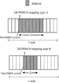
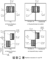
- FIG. 7 is a diagram showing an example of the PDSCH mapping type according to the present embodiment.
- FIG. 7A is a diagram showing an example of PDSCH mapping type A.
- the S of PDSCH to be assigned is 3.
- the L of PDSCH allocated is 7.
- the position of the first DMRS symbol for PDSCH is the fourth symbol in the slot. That is, dmrs-TypeA-Position is set to “pos3”.
- FIG. 7B is a diagram showing an example of PDSCH mapping type A.
- the S of PDSCH assigned is 4.
- the L of PDSCH allocated is 4.
- the position of the first DMRS symbol for PDSCH is the first symbol to which PDSCH is assigned.
- the base station device 3 may schedule the terminal device 1 to receive the PDSCH by DCI. Then, the terminal device 1 may receive the PDSCH by detecting the DCI addressed to itself. When identifying the PDSCH time domain resource allocation, the terminal device 1 first determines the resource allocation table to be applied to the PDSCH. The resource allocation table includes one or more PDSCH time domain resource allocation configurations. Next, the terminal device 1 may select one PDSCH time domain resource allocation configuration in the determined resource allocation table based on the value indicated in the'Time domain resource assignment' field included in the DCI that schedules the PDSCH. Good.
- the base station device 3 determines the PDSCH resource allocation to the terminal device 1, generates the value of the'Time domain resource resource assignment' field, and transmits the DCI including the'Time domain resource resource assignment' field to the terminal device 1. To do.
- the terminal device 1 identifies the resource allocation in the time direction of PDSCH based on the value set in the'Time domain resource assignment' field.
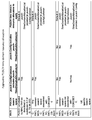
- FIG. 10 is a diagram defining which resource allocation table is applied to PDSCH time domain resource allocation.
- the terminal device 1 may determine the resource allocation table applied to the PDSCH time domain resource allocation with reference to FIG. 10.
- the resource allocation table includes one or more PDSCH time domain resource allocation configurations.
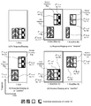
- the resource allocation table is classified into (I) a resource allocation table defined in advance and (II) a resource allocation table set from an RRC signal of an upper layer.
- the predefined resource allocation table is defined as a default PDSCH time domain resource allocation A, a default PDSCH time domain resource allocation B, and a default PDSCH time domain resource allocation C.
- the default PDSCH time domain resource allocation A will be referred to as the default table A.
- the default PDSCH time domain resource allocation B is called default table B.
- the default PDSCH time domain resource allocation C is referred to as the default table C.
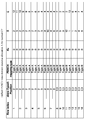
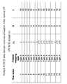
- FIG. 11 is a diagram showing an example of the default table A according to this embodiment.
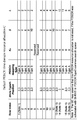
- FIG. 12 is a diagram showing an example of the default table B according to this embodiment.
- FIG. 13 is a diagram showing an example of the default table C according to this embodiment.
- the default table A includes 16 rows. Each row in the default table A indicates a PDSCH time domain resource allocation configuration. Specifically, in FIG. 11, the indexed row is a PDSCH mapping type, a PDCCH including DCI and a slot offset K 0 between the PDSCH, a start symbol S of the PDSCH in the slot, and The number of consecutively assigned symbols L is defined.
- the resource allocation table set from the RRC signal of the upper layer is given by the signal pdsch-TimeDomainAllocationList of the upper layer.
- the information element PDSCH-TimeDomainResourceAllocation indicates the configuration of PDSCH time domain resource allocation.
- PDSCH-TimeDomainResourceAllocation may be used to set up a time domain relationship between PDCCH and PDSCH including DCI.
- the pdsch-TimeDomainAllocationList contains one or more information elements PDSCH-TimeDomainResourceAllocation. That is, pdsch-TimeDomainAllocationList is a list including one or more elements (information elements).
- One information element PDSCH-TimeDomainResourceAllocation may also be referred to as one entry (or one row).
- the pdsch-TimeDomainAllocationList may contain up to 16 entries. Each entry may be defined by K 0 , mappingType, and startSymbolAndLength.
- K 0 indicates a slot offset between the PDCCH including the DCI and the PDSCH.
- mappingType indicates either PDSCH mapping type A or PDSCH mapping type A.
- startSymbolAndLength is an index that gives a valid combination of the PDSCH start symbol S and the number of consecutively allocated symbols L.
- the startSymbolAndLength may be referred to as a start and length indicator (SLIV).
- the start symbol S and the continuous symbol L are given based on SLIV.
- the base station apparatus 3 can set the value of SLIV so that the time domain resource allocation of PDSCH does not exceed the slot boundary.
- the slot offset K 0 and SLIV will be described later.
- the upper layer signal pdsch-TimeDomainAllocationList may be included in pdsch-ConfigCommon and/or pdsch-Config.
- the information element pdsch-ConfigCommon is used to set the cell specific parameters for PDSCH for a certain BWP.
- Information element pdsch-Config is used to set UE specific parameters for PDSCH for a certain BWP.
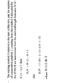
- FIG. 14 is a diagram showing an example of calculating SLIV.
- FIG. 14 is the number of symbols included in the slot.
- FIG. 14 shows an example of calculating SLIV in the case of NCP (Normal Cyclic Prefix).
- the value of SLIV is calculated based on the number of symbols included in the slot, the start symbol S, and the number L of consecutive symbols.
- the value of L is equal to or greater than 1 and does not exceed (14-S).
- 6 and 12 are used for 7 and 14 in FIG. 14 when calculating SLIV.
- the slot offset K 0 will be described below.
- K 0 is the number of slots based on the PDSCH subcarrier spacing. K 0 can take values from 0 to 32. In a subframe or frame, slot numbers are counted in ascending order from 0.
- the slot number n of the subcarrier interval setting of 15 kHz corresponds to the slot numbers 2n and 2n+1 of the subcarrier interval setting of 30 kHz.
- the terminal device 1 detects the DCI that schedules the PDSCH.
- the slot assigned to the PDSCH is given by (Equation 1) Floor(n*2 ⁇ PDSCH /2 ⁇ PDCCH )+K 0 .
- the function Floor(A) outputs the largest integer that does not exceed A.
- n is a slot in which the PDCCH that schedules the PDSCH is detected.
- ⁇ PDSCH is a subcarrier interval setting for PDSCH .
- ⁇ PDCCH is a subcarrier interval setting for the PDCCH .
- the terminal device 1 may determine which one of the resource allocation tables is applied to PDSCH time domain resource allocation with reference to FIG. 10. That is, the terminal device 1 may determine the resource allocation table to be applied to the PDSCH scheduled by DCI, based on at least some or all of the following elements (A) to (F).
- Element A Type of RNTI that scrambles CRC added to DCI
- B Type of search space in which DCI is detected
- C Whether CORESET associated with that search space is CORESET#0
- D pdsch- Whether ConfigCommon contains pdsch-TimeDomainAllocationList
- E Whether pdsch-Config contains pdsch-TimeDomainAllocationList
- F SS/PBCH and CORESET multiple pattern
- the type of RNTI that scrambles the CRC attached to DCI is , SI-RNTI, RA-RNTI, TC-RNTI, P-RNTI, C-RNTI, MCS-C-RNTI, or CS-RNTI.
- the type of search space in which DCI is detected is a common search space or a UE-specific search space.
- the common search space includes a type 0 common search space, a type 1 common search space, and a type 2 common search space.
- the terminal device 1 may detect the DCI in any common search space associated with CORESET#0. A CRC scrambled by any one of C-RNTI, MCS-C-RNTI, and CS-RNTI is added to the detected DCI. Then, the terminal device 1 may determine the resource allocation table to be applied to the PDSCH scheduled by the DCI.
- pdsch-ConfigCommon includes pdsch-TimeDomainAllocationList for the terminal device 1
- the terminal device 1 may determine the resource allocation table set from the RRC signal of the upper layer. The resource allocation table is given by pdsch-TimeDomainAllocationList included in pdsch-ConfigCommon.
- the terminal device 1 may determine the default table A. That is, the terminal device 1 may apply the determination of PDSCH time domain resource allocation using the default table A indicating the configuration of PDSCH time domain resource allocation.
- the terminal device 1 may detect the DCI in an arbitrary common search space that is not associated with CORESET#0. A CRC scrambled by any one of C-RNTI, MCS-C-RNTI, and CS-RNTI is added to the detected DCI. Then, the terminal device 1 may determine the resource allocation table to be applied to the PDSCH scheduled by the DCI.
- pdsch-Config includes pdsch-TimeDomainAllocationList for the terminal device 1
- the terminal device 1 assigns the resource allocation table applied to the PDSCH time domain resource allocation to the resource allocation given from the pdsch-TimeDomainAllocationList provided in pdsch-Config. You may decide on the table.
- the terminal device 1 uses the pdsch-TimeDomainAllocationList provided by pdsch-Config regardless of whether pdsch-ConfigCommon includes pdsch-TimeDomainAllocationList or not. It may be applied to the determination of area resource allocation.
- pdsch-Config does not include pdsch-TimeDomainAllocationList and pdsch-ConfigCommon includes pdsch-TimeDomainAllocationList
- the terminal device 1 uses the pdsch-ConfigCommon to allocate the resource allocation table applied to the PDSCH time domain resource allocation.
- the terminal device 1 uses the pdsch-TimeDomainAllocationList provided by pdsch-ConfigCommon to apply the PDSCH time domain resource allocation determination.
- the terminal device 1 sets the resource allocation table applied to PDSCH time domain resource allocation in the default table A. You may decide.
- the terminal device 1 may detect DCI in the UE-specific search space. A CRC scrambled by any one of C-RNTI, MCS-C-RNTI, and CS-RNTI is added to the detected DCI. Then, the terminal device 1 may determine the resource allocation table to be applied to the PDSCH scheduled by the DCI.
- pdsch-Config includes pdsch-TimeDomainAllocationList for the terminal device 1
- the terminal device 1 assigns the resource allocation table applied to the PDSCH time domain resource allocation to the resource allocation given from the pdsch-TimeDomainAllocationList provided in pdsch-Config. You may decide on the table.
- the terminal device 1 uses the pdsch-TimeDomainAllocationList provided by pdsch-Config regardless of whether pdsch-ConfigCommon includes pdsch-TimeDomainAllocationList or not. It may be applied to the determination of area resource allocation.
- pdsch-Config does not include pdsch-TimeDomainAllocationList and pdsch-ConfigCommon includes pdsch-TimeDomainAllocationList
- the terminal device 1 uses the pdsch-ConfigCommon to allocate the resource allocation table applied to the PDSCH time domain resource allocation.
- the terminal device 1 uses the pdsch-TimeDomainAllocationList provided by pdsch-ConfigCommon to apply the PDSCH time domain resource allocation determination.
- the terminal device 1 sets the resource allocation table applied to PDSCH time domain resource allocation in the default table A. You may decide.
- the method of determining the resource allocation table applied to the PDSCH detected in the UE-specific search space is as follows: the resource applied to the PDSCH detected in any common search space not associated with CORESET#0 This is the same as the method of determining the allocation table.
- the terminal device 1 may select one PDSCH time domain resource allocation configuration in the determined resource allocation table based on the value indicated in the'Time domain resource assignment' field included in the DCI that schedules the PDSCH. Good.
- the resource allocation table applied to PDSCH time domain resource allocation is the default table A
- the value m indicated in the'Time domain resource assignment' field may be the row index m+1 of the default table A.
- the PDSCH time domain resource allocation is a configuration of the time domain resource allocation indicated by the row index m+1.
- the terminal device 1 assumes the configuration of time domain resource allocation indicated by the row index m+1 and receives the PDSCH.
- the terminal device 1 is scheduled by its DCI using the PDSCH time domain resource allocation configuration of the row index 1 of the default table A.
- the resource allocation of the PDSCH in the time direction is specified.
- the value m shown in the'Time domain resource allocation' field is (m+1)th in the list pdsch-TimeDomainAllocationList.
- the terminal device 1 may refer to the first element (entry) in the list pdsch-TimeDomainAllocationList.
- the terminal device 1 may refer to the second element (entry) in the list pdsch-TimeDomainAllocationList.
- the terminal device 1 may decode (receive) the corresponding PDSCH by detecting the PDCCH including the DCI format 1_0 or the DCI format 1_1.
- the number of bits of the'Time domain resource assignment' field included in the DCI format 1_0 may be a fixed number of bits. For example, this fixed number of bits may be four. That is, the size of the'Time domain resource assignment' field included in the DCI format 1_0 is 4 bits. Further, the size of the'Time domain resource assignment' field included in the DCI format 1_1 may be a variable number of bits. For example, the number of bits of the'Time domain resource assignment' field included in the DCI format 1_1 may be any one of 0, 1, 2, 3, 4.
- the number of bits of the'Time domain resource assignment' field included in DCI format 1_1 is (I) whether pdsch-ConfigCommon includes pdsch-TimeDomainAllocationList and/or (II) whether pdsch-Config includes pdsch-TimeDomainAllocationList And/or (III) may be provided based at least on the number of rows included in the predefined default table.
- the DCI format 1_1 is added with a CRC scrambled by any one of C-RNTI, MCS-C-RNTI, and CS-RNTI. DCI format 1_1 may be detected in the UE-specific search space.
- the meaning of “pdsch-Config includes pdsch-TimeDomainAllocationList” may mean that “pdsch-Config provides pdsch-TimeDomainAllocationList”.
- the meaning of'pdsch-ConfigCommon includes pdsch-TimeDomainAllocationList' may mean'provided by pdsch-ConfigCommon in pdsch-TimeDomainAllocationList'.
- the number of bits in the'Time domain resource assignment' field may be given as ceiling(log 2 (I)).
- the function Ceiling(A) outputs the smallest integer not less than A.
- the number of bits of the Time domain resource assignment' field may be given based on the number of entries included in pdsch-TimeDomainAllocationList.
- the number of bits in the Time domain resource assignment' field may be given based on the number of rows in the default table (default table A).
- the value of I may be the number of entries included in pdsch-TimeDomainAllocationList provided in pdsch-Config.
- the value of I is the number of entries included in pdsch-TimeDomainAllocationList provided by pdsch-ConfigCommon. May be. If pdsch-Config does not contain pdsch-TimeDomainAllocationList and pdsch-ConfigCommon does not contain pdsch-TimeDomainAllocationList, the value of I is the number of rows contained in the default table (eg default table A). May be.
- the number of bits in the'Time domain resource assignment' field is given as ceiling(log 2 (I)). May be.
- the number of bits of the'Time domain resource assignment' field may be a fixed number of bits.
- the fixed number of bits may be 4 bits.
- I may be the number of entries included in the pdsch-TimeDomainAllocationList.
- the value of I may be the number of entries included in pdsch-TimeDomainAllocationList provided in pdsch-Config.
- the value of I is the number of entries included in pdsch-TimeDomainAllocationList provided by pdsch-ConfigCommon. May be.
- the terminal device 1 can specify the number of bits of the'Time domain resource assignment' field generated by the base station device 3. That is, the terminal device 1 can correctly receive the PDSCH destined for the terminal device 1 scheduled by the base station device 3.
- the terminal device 1 may transmit the corresponding PUSCH by detecting the DCI format 0_0 or the PDCCH including the DCI format 0_1. That is, the corresponding PUSCH may be scheduled (shown) by its DCI format (DCI). Further, the PUSCH may be scheduled by the RAR UL grant included in the RAR message.
- the start position (start symbol) of the scheduled PUSCH is called S.
- the starting symbol S of the PUSCH may be the first symbol in which the PUSCH is transmitted (mapped) in a certain slot.
- the start symbol S corresponds to the start of the slot. For example, when the value of S is 0, the terminal device 1 may transmit the PUSCH from the first symbol in a certain slot.
- the terminal device 1 may transmit the PUSCH from the third symbol of a certain slot.
- the number of consecutive symbols on the scheduled PUSCH is called L.
- the number L of consecutive symbols is counted from the start symbol S. The determination of S and L assigned to PUSCH will be described later.
- PUSCH mapping types include PUSCH mapping type A and PUSCH mapping type B.
- PUSCH mapping type A the value of S is 0.
- L takes a value from 4 to 14.
- the sum of S and L takes values from 4 to 14.
- PUSCH mapping type B S takes values from 0 to 13.
- L takes a value from 1 to 14.
- the sum of S and L takes a value from 1 to 14.
- the location of the DMRS symbol for PUSCH depends on the type of PUSCH mapping.
- the position of the first DMRS symbol for the PUSCH depends on the type of PUSCH mapping.
- the position of the first DMRS symbol may be indicated in the upper layer parameter dmrs-TypeA-Position.
- dmrs-TypeA-Position is set to either'pos2' or'pos3'. For example, if dmrs-TypeA-Position is set to'pos2', the position of the first DMRS symbol for PUSCH may be the third symbol in the slot.
- the position of the first DMRS symbol for PUSCH may be the fourth symbol in the slot.
- the position of the first DMRS symbol may be the first symbol of the assigned PUSCH.
- the following describes the method of identifying PUSCH time domain resource allocation.
- the base station device 3 may schedule the terminal device 1 to transmit the PUSCH by DCI. Then, the terminal device 1 may transmit the PUSCH by detecting the DCI addressed to itself.
- the terminal device 1 first determines the resource allocation table to be applied to the PUSCH.
- the resource allocation table includes one or more PUSCH time domain resource allocation configurations. Next, the terminal device 1 may select one PUSCH time domain resource allocation configuration in the determined resource allocation table based on the value indicated in the'Time domain resource allocation' field included in the DCI that schedules the PUSCH. Good.
- the base station device 3 determines PUSCH resource allocation to the terminal device 1, generates a value of the'Time domain resource resource assignment' field, and transmits DCI including the'Time domain resource resource assignment' field to the terminal device 1. To do.
- the terminal device 1 identifies the resource allocation in the time direction of PUSCH based on the value set in the'Time domain resource assignment' field.
- FIG. 16 is a diagram defining which resource allocation table is applied to PUSCH time domain resource allocation.
- the terminal device 1 may determine the resource allocation table applied to PUSCH time domain resource allocation with reference to FIG. 16.
- the resource allocation table includes configurations of one or more PUSCH time domain resource allocations.
- the resource allocation table is classified into (I) a resource allocation table defined in advance and (II) a resource allocation table set from an RRC signal of an upper layer.
- the predefined resource allocation table is defined as the default PUSCH time domain resource allocation A.
- the default PUSCH time domain resource allocation A will be referred to as the PUSCH default table A.
- FIG. 17 is a diagram showing an example of the PUSCH default table A for NCP (Normal Cyclic Prefix).
- PUSCH default table A includes 16 rows. Each row in the PUSCH default table A indicates a PUSCH time domain resource allocation configuration. Specifically, in FIG. 17, an indexed row is a PUSCH mapping type, a slot offset K 2 between the PDCCH including DCI and the PUSCH, a start symbol S of the PUSCH in the slot, and The number of consecutively allocated symbols L is defined.
- the resource allocation table set from the RRC signal of the upper layer is given by the signal push-TimeDomainAllocationList of the upper layer.
- the information element PUSCH-TimeDomainResourceAllocation indicates the configuration of PUSCH time domain resource allocation.
- PUSCH-TimeDomainResourceAllocation may be used to set the time domain relationship between the PDCCH including the DCI and the PUSCH.
- the pusch-TimeDomainAllocationList contains one or more information elements PUSCH-TimeDomainResourceAllocation. That is, push-TimeDomainAllocationList is a list including one or more elements (information elements).
- One information element PDSCH-TimeDomainResourceAllocation may also be referred to as one entry (or one row).
- the pusch-TimeDomainAllocationList may contain up to 16 entries. Each entry may be defined by K 2 , mappingType, and startSymbolAndLength.
- K 2 denotes the slot offset between the PUSCH to be PDCCH and its schedule including the DCI. If PUSCH-TimeDomainResourceAllocation does not indicate K 2 , the terminal device 1 assumes that the value of K 2 is 1 when the subcarrier spacing of PUSCH is 15 kHz or 30 kHz, and the subcarrier spacing of PUSCH is If it is 60 kHz, it assumes that the value of K 2 is 2, when the sub-carrier interval of the PUSCH is 120 kHz, may be assumed that the value of K 2 is 3.
- mappingType indicates either PUSCH mapping type A or PUSCH mapping type A.
- startSymbolAndLength is an index that gives a valid combination of the start symbol S of PUSCH and the number of consecutively allocated symbols L.
- the startSymbolAndLength may be referred to as a start and length indicator (SLIV). That is, unlike the default table that directly defines the start symbol S and the continuous symbol L, the start symbol S and the continuous symbol L are given based on SLIV.
- the base station apparatus 3 can set the value of SLIV so that the time domain resource allocation of PUSCH does not exceed the slot boundary.
- the value of SLIV is calculated based on the number of symbols included in the slot, the start symbol S, and the number L of consecutive symbols, as in the formula in FIG.
- the upper layer signal push-TimeDomainAllocationList may be included in push-ConfigCommon and/or push-Config.
- the information element push-ConfigCommon is used to set the cell-specific parameters for PUSCH for a certain BWP.
- the information element push-Config is used to set UE-specific parameters for the PUSCH for a certain BWP.
- the terminal device 1 detects DCI which schedules PUSCH.
- the slot in which the PUSCH is transmitted is given by (Equation 4) Floor(n*2 ⁇ PUSCH /2 ⁇ PDCCH )+K 2 .
- n is a slot in which the PDCCH that schedules the PUSCH is detected.
- ⁇ PUSCH is a subcarrier interval setting for PUSCH .
- ⁇ PDCCH is a subcarrier interval setting for the PDCCH .
- the value of K 2 is one of j, j+1, j+2, or j+3.
- the value of j is a value specified for the PUSCH subcarrier interval. For example, if the subcarrier spacing to which PUSCH is applied is 15 kHz or 30 kHz, the value of j may be 1 slot. For example, if the subcarrier spacing to which PUSCH is applied is 60 kHz, the value of j may be 2 slots. For example, if the subcarrier spacing to which PUSCH is applied is 120 kHz, the value of j may be 3 slots.
- the terminal device 1 may determine which of the resource allocation tables to apply to PUSCH time domain resource allocation with reference to FIG.
- the terminal device 1 may determine the resource allocation table to be applied to the PUSCH scheduled by the RAR UL grant.
- the terminal device 1 may determine the resource allocation table set from the RRC signal of the upper layer. The resource allocation table is given by push-TimeDomainAllocationList included in push-ConfigCommon.
- the terminal device 1 may determine the PUSCH default table A. That is, the terminal device 1 may apply the PUSCH time domain resource allocation determination using the default table A indicating the configuration of the PUSCH time domain resource allocation.
- the terminal device 1 may detect DCI in an arbitrary common search space associated with CORESET#0. A CRC scrambled by any of C-RNTI, MCS-C-RNTI, TC-RNTI, or CS-RNTI is added to the detected DCI. Then, the terminal device 1 may determine the resource allocation table applied to the PUSCH scheduled by the DCI.
- push-ConfigCommon includes push-TimeDomainAllocationList for the terminal device 1
- the terminal device 1 assigns the resource allocation table applied to the PUSCH time domain resource allocation to the resource allocation given from the push-TimeDomainAllocationList provided by push-ConfigCommon. You may decide on the table.
- push-ConfigCommon does not include push-TimeDomainAllocationList, the terminal device 1 may determine the PUSCH default table A as the resource allocation table to be applied to PUSCH time domain resource allocation.
- the terminal device 1 may detect DCI in any common search space associated with (I) CORESET#0 or (II) UE-specific search space. A CRC scrambled by any of C-RNTI, MCS-C-RNTI, TC-RNTI, or CS-RNTI is added to the detected DCI. Then, the terminal device 1 may determine the resource allocation table applied to the PUSCH scheduled by the DCI. When push-Config includes push-TimeDomainAllocationList for the terminal device 1, the terminal device 1 assigns the resource allocation table applied to PUSCH time domain resource allocation to the resource allocation given from the push-TimeDomainAllocationList provided in push-Config. You may decide on the table.
- the terminal device 1 uses the push-TimeDomainAllocationList provided by push-Config regardless of whether push-ConfigCommon includes push-TimeDomainAllocationList. It may be applied to the determination of area resource allocation.
- push-Config does not include push-TimeDomainAllocationList and push-ConfigCommon includes push-TimeDomainAllocationList
- the terminal device 1 uses the push-ConfigCommon to assign the resource allocation table applied to PUSCH time domain resource allocation. It may be determined in the resource allocation table given from the provided push-TimeDomainAllocationList.
- the terminal device 1 uses the push-TimeDomainAllocationList provided by push-ConfigCommon to apply the PUSCH time domain resource allocation determination.
- push-Config does not include push-TimeDomainAllocationList
- push-ConfigCommon does not include push-TimeDomainAllocationList
- the terminal device 1 uses the PUSCH default table A as the resource allocation table to be applied to PUSCH time domain resource allocation. May be determined.
- the terminal device 1 selects one PUSCH time domain resource allocation configuration in the determined resource allocation table based on the value indicated in the'Time domain resource assignment' field included in the DCI that schedules the PUSCH. Good.
- the resource allocation table applied to PUSCH time domain resource allocation is the PUSCH default table A
- the value m shown in the'Time domain resource assignment' field indicates the row index m+1 of the default table A.
- the PUSCH time domain resource allocation is a configuration of the time domain resource allocation indicated by the row index m+1.
- the terminal device 1 transmits the PUSCH, assuming a configuration of time domain resource allocation indicated by the row index m+1.
- the terminal device 1 uses the PUSCH time domain resource allocation configuration of the row index 1 of the PUSCH default table A to schedule by the DCI.
- the resource allocation in the time direction of the PUSCH to be specified is specified.
- the value m shown in the'Time domain resource assignment' field is the (m+1)th position in the list pushch-TimeDomainAllocationList.
- the terminal device 1 may refer to the first element (entry) in the list push-TimeDomainAllocationList.
- the terminal device 1 may refer to the second element (entry) in the list pushch-TimeDomainAllocationList.
- the terminal device 1 may transmit the corresponding PUSCH by detecting the PDCCH including the DCI format 0_0 or the DCI format 0_1.
- the number of bits of the'Time domain resource assignment' field included in the DCI format 0_0 may be a fixed number of bits. For example, this fixed number of bits may be four. That is, the size of the'Time domain resource assignment' field included in the DCI format 0_0 is 4 bits.
- the size of the'Time domain resource assignment' field included in the DCI format 0_1 may be a variable number of bits. For example, the number of bits of the'Time domain resource assignment' field included in the DCI format 0_1 may be any one of 0, 1, 2, 3, 4.
- the number of bits in the'Time domain resource assignment' field may be given as ceiling(log 2 (I)).
- the value of I may be the number of entries included in push-TimeDomainAllocationList.
- the value of I may be the number of rows of the PUSCH default table A. That is, when push-TimeDomainAllocationList is set for the terminal device 1, the number of bits of the Time domain resource assignment' field may be given based on the number of entries included in push-TimeDomainAllocationList.
- the number of bits of the Time domain resource assignment' field may be given based on the number of rows of the default table (default table A).
- the value of I may be the number of entries included in push-TimeDomainAllocationList provided in push-Config. If push-Config does not include push-TimeDomainAllocationList and push-ConfigCommon does include push-TimeDomainAllocationList, the value of I is the number of entries included in push-TimeDomainAllocationList provided by push-ConfigCommon. May be. If push-Config does not include push-TimeDomainAllocationList and push-ConfigCommon does not include push-TimeDomainAllocationList, the value of I may be the number of rows included in PUSCH default table A.
- slot aggregation transmission slot aggregation transmission, multi-slot transmission
- the upper layer parameter pushch-AggregationFactor is used to indicate the number of times of repeated transmission of data (transport block).
- the upper layer parameter pushch-AggregationFactor indicates any one of 2, 4, and 8.
- the base station apparatus 3 may transmit an upper layer parameter push-AggregationFactor indicating the number of times of data transmission repetition to the terminal apparatus 1.
- the base station apparatus 3 can use the pushch-AggregationFactor to cause the terminal apparatus 1 to repeat the transmission of the transport block a predetermined number of times.
- the terminal device 1 may receive the upper layer parameter pushch-AggregationFactor from the base station device 3 and repeat transmission of the transport block using the number of repetitions indicated by the pushch-AggregationFactor.
- the terminal device 1 when the terminal device 1 does not receive the pushch-AggregationFactor from the base station device, the number of repeated transmissions of the transport block may be regarded as one. That is, in this case, the terminal device 1 may transmit the transport block scheduled by the PDCCH once. That is, when the terminal device 1 does not receive the pushch-AggregationFactor from the base station device, the terminal device 1 does not have to perform the slot aggregation transmission (multi-slot transmission) for the transport block scheduled by the PDCCH.
- the terminal device 1 receives the PDCCH including the DCI format to which the CRC scrambled by the C-RNTI and the MCS-C-RNTI is added and transmits the PUSCH scheduled by the PDCCH. Good.
- the terminal device 1 may transmit the PUSCH N times in consecutive N slots from the slot in which the PUSCH is transmitted first.
- PUSCH transmission transmission of a transport block
- PUSCH transmission may be performed once for each slot. That is, transmission of the same transport block (repeated transmission) is performed only once within one slot.
- the value of N is shown from pushch-AggregationFactor.
- N may be 1.
- the slot in which the PUSCH is first transmitted may be given by (Equation 4) as described above.
- the PUSCH time domain resource allocation given based on the PDCCH scheduling the PUSCH may be applied to N consecutive slots. That is, the same symbol allocation (the same start symbol S and the same number of consecutively allocated symbols L) may be applied to N consecutive slots.
- the terminal device 1 may repeatedly transmit the transport block over N consecutive slots from the slot in which the PUSCH is transmitted first.
- the terminal device 1 may repeatedly transmit the transport block by using the same symbol allocation (symbol allocation) in each slot.
- the slot aggregation transmission performed by the terminal device 1 when the upper layer parameter push-AggregationFactor is set may be referred to as first aggregation transmission. That is, the upper layer parameter pushch-AggregationFactor is used to indicate the number of repetition transmissions (repetition transmission) for the first aggregation transmission.
- the upper layer parameter pushch-AggregationFactor is also referred to as a first aggregation transmission parameter.
- the first transmission occasion (0th transmission occasion, transmission opportunity) may be in the slot in which the PUSCH is transmitted first.
- the second transmission occasion (1st transmission occasion) may be in the next slot from the slot in which the PUSCH is first transmitted.
- the Nth transmission occasion ((N-1)th transmission occasion) may be in the Nth slot from the slot in which the PUSCH is first transmitted.
- the redundancy version applied to the transmission of the transport block is indicated by rv indicated by the nth transmission occasion ((n-1)th transmission occasion) of the transport block and the DCI scheduling the PUSCH. It may be determined based on the id .
- the sequence of redundant versions is ⁇ 0,2,3,1 ⁇ .
- the variable rv id is an index into the sequence of redundant versions.
- the variable is updated modulo by 4.
- the redundant version is used for coding (rate matching) of transport blocks transmitted on PUSCH.
- the redundant version may be incremented in the order 0, 2, 3, 1.
- the repeated transmission of the transport block may be performed in order of the redundancy version (Redundancy Version).
- FIG. 15 is a diagram showing an example of a redundant version applied to a transmission occasion.
- the redundancy version rv id applied to the first transmission occasion is a value indicated by the DCI that schedules the PUSCH (transport block). For example, when the DCI that schedules the PUSCH indicates the value of rv id as 0, the terminal device 1 refers to the first line of FIG. 15 and determines the redundant version rv id provided for the transmission occasion. Good.
- the redundancy version applied to the transmission occasion may be incremented in the order 0, 2, 3, 1. For example, if the DCI that schedules the PUSCH indicates the value of rv id to be 2, the terminal device 1 refers to the second line of FIG. 15 and determines the redundant version rv id provided to the transmission occasion. Good.
- the redundant version applied to the transmission occasion may be incremented in the order 2, 3, 1, 0.
- the terminal device 1 When at least one symbol in the symbol allocation for a certain transmission occasion is indicated in the downlink symbol from the parameter of the higher layer, the terminal device 1 does not have to transmit the transport block in the slot in the transmission occasion. ..
- the base station device 3 may transmit the upper layer parameter pushch-AggregationFactor-r16 to the terminal device 1.
- the upper layer parameter pushch-AggregationFactor-r16 may be used to indicate the number of times of repeated transmission (repetition transmission) of data (transport block).
- the upper layer parameter push-AggregationFactor-r16 may be used to indicate the number of repeated transmissions for slot aggregation transmissions and/or minislot aggregation transmissions. The slot aggregation transmission and the minislot aggregation transmission will be described later.
- pushch-AggregationFactor-r16 is set to any one of n1, n2, and n3, for example.
- the values of n1, n2, and n3 may be 2, 4, and 8, or may be other values.
- n1, n2, and n3 indicate the number of repeated transmissions of the transport block. That is, pushch-AggregationFactor-r16 may indicate the value of the number of times of one repeat transmission.
- the number of repeated transmissions of the transport block may be the number of repeated transmissions within a slot (N rep, etc.), the number of repeated transmissions within the slot and between slots (N total, etc.), or the number of repeated transmissions between slots. It may be the number of times (N total etc.).
- the base station device 3 may transmit the pushch-AggregationFactor-r16 including more than one element to the terminal device 1 so that the number of repeated transmissions can be set to the terminal device 1 more flexibly.
- Each element (information element, entry) may be used to indicate the number of repeated transmissions of the transport block. That is, pushch-AggregationFactor-r16 may indicate the value of the number of repeated transmissions more than one.
- the slot aggregation transmission performed by the terminal device 1 when the higher layer parameter pushch-AggregationFactor-r16 is set may be referred to as second aggregation transmission.
- the upper layer parameter pushch-AggregationFactor-r16 may be used to indicate the number of repetition transmissions (repetition transmissions) for at least the second aggregation transmission.
- the upper layer parameter pushch-AggregationFactor-r16 is also referred to as a second aggregation transmission parameter.
- the base station device 3 may indicate any element via a field included in the DCI that schedules the transport block, and notify the terminal device 1 of the number of repeated transmissions of the transport block. The specific procedure will be described later. Further, the base station device 3 may indicate any element via a MAC CE (MAC Control Element) and notify the terminal device 1 of the number of repeated transmissions of the transport block.
- MAC CE MAC Control Element
- the base station device 3 may indicate any element via the field included in the DCI and/or the MAC CE, and dynamically notify the terminal device 1 of the number of times of repeated transmission. Applying the function of the dynamic repeat count to the terminal device 1 may mean that the base station device 3 notifies the terminal device 1 of the dynamic repeat count dynamically.
- the base station device 3 does not have to transmit the pushch-AggregationFactor and pushch-AggregationFactor-r16 to the terminal device 1. That is, the push-AggregationFactor and push-AggregationFactor-r16 may not be set in the terminal device 1.
- the terminal device 1 may receive from the base station device 3 an RRC message that does not include (do not set) push-AggregationFactor and push-AggregationFactor-r16.
- the terminal device 1 may transmit the PUSCH in the slot given by (Equation 4) as described above.
- the number of repeated transmissions of the transport block may be 1. That is, the terminal device 1 does not have to perform the slot aggregation transmission and/or the minislot aggregation transmission.
- the base station device 3 may transmit pushch-AggregationFactor to the terminal device 1 and may not transmit pushch-AggregationFactor-r16. That is, push-AggregationFactor may be set in the terminal device 1 and push-AggregationFactor-r16 may not be set.
- the terminal device 1 may receive from the base station device 3 an RRC message that includes (sets) push-AggregationFactor and does not include (does not set) push-AggregationFactor-r16.
- the terminal device 1 may transmit the PUSCH N times in N consecutive slots from the slots given by (Equation 4) as described above.
- the number of repeated transmissions of the transport block may be N indicated by pushch-AggregationFactor.
- the terminal device 1 may perform the first aggregation transmission with respect to the PUSCH scheduled by DCI.
- PDCCH including DCI which schedules this PUSCH may be transmitted by CSS and may be transmitted by USS.
- the same symbol allocation may be applied to consecutive N slots.
- the base station device 3 may transmit pushch-AggregationFactor-r16 to the terminal device 1 instead of transmitting pushch-AggregationFactor-r16. That is, push-AggregationFactor may not be set in the terminal device 1, but push-AggregationFactor-r16 may be set.
- the terminal device 1 may receive from the base station device 3 an RRC message that does not include (sets) push-AggregationFactor but includes (sets) push-AggregationFactor-r16. In this case, the terminal device 1 may transmit the PUSCH M times in one or more slots from the slots given by (Equation 4) as described above.
- the plurality of slots may be continuous or non-continuous. That is, the number M of repeated transmissions of the transport block may be indicated by pushch-AggregationFactor-r16.
- the PDCCH including DCI that schedules the PUSCH may be transmitted in CSS or USS.
- the same symbol allocation may not apply to multiple slots. That is, the PUSCH time domain resource allocation (symbol allocation) applied to the first repeated transmission of the transport block may be given based on the DCI that schedules the transport block. However, the PUSCH symbol allocation applied to the repeated transmission of the transport block from the second time may be different from the symbol allocation given based on the PDCCH (such as DCI) that schedules the PUSCH. This is called symbol allocation extension.
- the start symbol S applied to the repeated transmission of the transport block from the second time may be different from the start symbol S given based on the PDCCH (start symbol extension).
- the start symbol S applied to the repeated transmission of the transport block from the second time may be the 0th symbol that is the head of the slot.
- the start symbol S applied to the repeated transmission of the transport block from the second time may be the same as the start symbol S given based on the PDCCH.
- the start symbol S applied to the repeated transmission of the transport block from the second time may be the first available symbol from the beginning of the slot.
- the number L of consecutively allocated symbols of PUSCH applied to the repeated transmission of transport blocks from the second time may be different from the number L of continuously allocated symbols given based on the PDCCH ( Number of symbols expanded). Further, the number L of continuously allocated symbols of PUSCH applied to the repeated transmission of the transport block from the second time may be the same as the number L of continuously allocated symbols given based on the PDCCH. The start symbol and/or number of symbols in each repeat transmission may be determined based on the available symbols.
- the number of symbols L of the X-th PUSCH is the start symbol S given based on the PDCCH, the number of symbols L given based on the PDCCH, the number of symbols of the slot, the available symbols in the slot, N total , N rep and N It may be determined based on one, a plurality, or all of the slots .
- the terminal device 1 uses the'Repetition Number' field included in the DCI to detect a plurality of elements. One may be selected from among (the number of dynamic repetitions).
- The'Repetition Number' field included in DCI may be present if pushch-AggregationFactor-r16 contains one and/or more than one element, and may be absent otherwise.
- The'Repetition Number' field included in the DCI may not exist if pushch-AggregationFactor-r16 is not set. Then, the value indicated in the selected element is the number of repeated transmissions of the transport block scheduled by DCI.
- the terminal device 1 may repeatedly transmit the transport block as many times as notified.
- the number of bits in the'Repetition Number' field may be given as ceiling(log 2 (X+1)) or ceiling(log 2 (X)).
- X is the number of elements contained in pushch-AggregationFactor-r16.
- the value m shown in the'Repetition Number' field is the (m+1)th element contained in pushch-AggregationFactor-r16. May be supported.
- the number of repeated transmissions of the transport block may be a value indicated by the (m+1)th element.
- the terminal device 1 may refer to the first element included in pushch-AggregationFactor-r16.
- the value indicated by the element may be greater than one.
- the value indicated by the element may be equal to 1.
- the value m shown in the'Repetition Number' field is the m-th element included in pushch-AggregationFactor-r16. May correspond to.
- the value of m is a non-zero value.
- the terminal device 1 may regard the number of repeated transmissions as 1.
- the value indicated by each element may be greater than one.
- pusch-AggregationFactor-r16 When pusch-AggregationFactor-r16 is set, symbol allocation extension (start symbol extension and/or symbol number extension), dynamic repetition count, and/or for aggregation transmission (second aggregation transmission) The function of minislot aggregation transmission is applied.
- the base station device 3 may transmit pushch-AggregationFactor and pushch-AggregationFactor-r16 to the terminal device 1. That is, pushch-AggregationFactor and pushch-AggregationFactor-r16 may be set in the terminal device 1.
- the terminal device 1 may receive from the base station device 3 an RRC message including (setting) push-AggregationFactor and push-AggregationFactor-r16.
- the operation when the pushch-AggregationFactor-r16 described as the third example is set that is, symbol allocation extension (start symbol extension and/or symbol number extension), dynamic repeat count, and/or Alternatively, the function of minislot aggregation transmission is applied.
- a'Repetition Number' field exists in a certain DCI based on at least some or all of the following elements (A) to (D) (present ) You may decide whether or not to do it.
- Element A Type of RNTI that scrambles CRC added to DCI
- Element B Type of search space in which DCI is detected
- C Type of DCI format
- D Information indicated in field of DCI
- the type of RNTI that scrambles the added CRC is one of SI-RNTI, RA-RNTI, TC-RNTI, P-RNTI, C-RNTI, MCS-C-RNTI, or CS-RNTI. In this case, the'Repetition Number' field may not exist in the DCI.
- the type of RNTI that scrambles the CRC added to DCI is NEW-RNTI
- the'Repetition Number' field included in the DCI may be present.
- the type of search space in which the terminal device 1 monitors the DCI is a common search space or a UE-specific search space.
- the common search space includes a type 0 common search space, a type 1 common search space, and a type 2 common search space.
- the'Repetition Number' field may not exist in the DCI. If the search space in which the DCI is monitored is a UE-specific search space, a'Repetition Number' field may be present in the DCI.
- the types of DCI format are DCI format 0_0, DCI format 0_1, and DCI format 0_2.
- the DCI has the DCI format 0_0 and the DCI format 0_1, the'Repetition Number' field may not exist in the DCI.
- the DCI has the DCI format 0_2
- the'Repetition Number' field may be present in the DCI.
- the DCI is the DCI format 0_1 or the DCI format 0_2, the'Repetition Number' field may be present in the DCI.
- the DCI format when the DCI format 0_0 is monitored in the common search space, the DCI format may not include the'Repetition Number' field.
- the DCI format 0_0 when the DCI format 0_0 is monitored in the UE-specific search space, the'Repetition Number' field may be present in the DCI.
- the DCI format 0_1 when the DCI format 0_1 is scrambled by NEW-RNTI, the'Repetition Number' field may be present in the DCI.
- the DCI format 0_1 is scrambled by an RNTI other than NEW-RNTI, the'Repetition Number' field may not exist in the DCI.
- the terminal device 1 to which pushch-AggregationFactor-r16 is set is based on at least some or all of the following elements (A) to (C), and the PUSCH transmission explained by the DCI is described above.
- -AggregationFactor- may determine if the feature when r16 is set is applied.
- Element A RNTI type that scrambles CRC attached to DCI
- Element B Type of search space in which DCI is detected
- Element C Type of DCI format
- type of RNTI that scrambles CRC attached to DCI Is any one of SI-RNTI, RA-RNTI, TC-RNTI, P-RNTI, C-RNTI, MCS-C-RNTI, or CS-RNTI
- the PUSCH transmission scheduled by the DCI is performed.
- the function when pusch-AggregationFactor-r16 is set may not be applied.
- the type of the RNTI that scrambles the CRC added to the DCI is NEW-RNTI
- the function when the push-AggregationFactor-r16 is set for PUSCH transmission scheduled by the DCI may be applied.
- the type of search space in which the terminal device 1 monitors the DCI is a common search space or a UE-specific search space.
- the common search space includes a type 0 common search space, a type 1 common search space, and a type 2 common search space.
- the function when push-AggregationFactor-r16 is set for PUSCH transmission scheduled by the DCI may not be applied.
- the function when push-AggregationFactor-r16 is set for PUSCH transmission scheduled by the DCI may be applied.
- the types of DCI format are DCI format 0_0, DCI format 0_1, and DCI format 0_2.
- DCI is DCI format 0_0 and DCI format 0_1
- the function when push-AggregationFactor-r16 is set to PUSCH transmission which this DCI schedules does not need to be applied.
- the DCI has the DCI format 0_2
- the function when push-AggregationFactor-r16 is set for PUSCH transmission scheduled by the DCI may be applied.
- the function when the push-AggregationFactor-r16 is set for the PUSCH transmission scheduled by the DCI may not be applied.
- the function when push-AggregationFactor-r16 is set for PUSCH transmission scheduled by the DCI may be applied.
- the function when push-AggregationFactor-r16 is set for PUSCH transmission scheduled by the DCI may not be applied.
- the function when push-AggregationFactor-r16 is set for PUSCH transmission scheduled by the DCI may be applied.
- the terminal device 1 may repeatedly transmit the transport block N times in N consecutive slots.
- the value of N may be given by pushch-AggregationFactor.
- the same symbol allocation may be applied to N slots.
- the function when push-AggregationFactor-r16 is set is not applied, if push-AggregationFactor is not set, PUSCH transmission scheduled by the DCI may be performed once. That is, the terminal device 1 may transmit the transport block once.
- minislot aggregation transmission (mini-slot aggregation transmission, subslot aggregation transmission, multi-subslot transmission, intra-slot aggregation transmission) in this embodiment will be described below.
- one uplink grant may schedule two or more PUSCH repeated transmissions. Each repetitive transmission takes place in each successive slot (or each available slot). In other words, in slot aggregation, the same transport block can be repeatedly transmitted only once within one slot (one available slot).
- the available slot may be a slot in which the transport block is actually repeatedly transmitted.
- one uplink grant may schedule two or more PUSCH repeated transmissions. Repeated transmissions may occur within the same slot or over consecutive available slots. For the scheduled PUSCH repeat transmission, the number of repeat transmissions performed in each slot may be different based on the symbols available for PUSCH repeat transmission in a slot (available slot). That is, in minislot aggregation transmission, the number of repeated transmissions of the same transport block may be one or more than one in one slot (one available slot). That is, in the minislot aggregation transmission, the terminal device 1 can transmit one or more repeated transmissions of the same transport block to the base station device 3 within one slot.
- the minislot aggregation transmission means a mode that supports intra-slot aggregation.
- the symbol allocation extension (start symbol extension and/or symbol number extension) and/or the number of dynamic repetitions described above may be applied to the minislot aggregation transmission.
- the terminal device 1 performs aggregation transmission for PUSCH transmission in which the uplink grant is scheduled based on at least (I) upper layer parameters and/or (II) fields included in the uplink grant. May be applied, or if any aggregation transmission type is applied.
- the type of aggregation transmission may include a first aggregation transmission and a second aggregation transmission.
- the type of the second aggregation transmission may be divided into a slot aggregation transmission and a minislot aggregation transmission.
- the type of aggregation transmission may include the first slot aggregation transmission (first aggregation transmission), the second slot aggregation transmission (slot aggregation in the second aggregation transmission), and the minislot aggregation transmission.
- the base station device 3 may notify the terminal device 1 of which of the slot aggregation transmission and the minislot aggregation transmission is to be set, by a higher layer parameter.
- Which of the slot aggregation transmission and the minislot aggregation transmission is set may mean which of the slot aggregation transmission and the minislot aggregation transmission is applied.
- pushch-AggregationFactor may be used to indicate the number of repeated transmissions of the first aggregation transmission (first slot aggregation transmission).
- pusch-AggregationFactor-r16 may be used to indicate the number of repeated transmissions of the second slot aggregation transmission and/or the minislot aggregation transmission.
- pusch-AggregationFactor-r16 may be a common parameter for the second slot aggregation transmission and/or the minislot aggregation transmission.
- the upper layer parameter repTxWithinSlot-r16 may be used to indicate minislot aggregation transmissions.
- the terminal device 1 may consider that the minislot aggregation transmission is applied to the transport block transmission, and may execute the minislot aggregation transmission. That is, when pushch-AggregationFactor-r16 is set in the terminal device 1 and repTxWithinSlot-r16 is set (enabled), the terminal device 1 is applied with the minislot aggregation transmission. You may regard it.
- the number of repeated transmissions for minislot aggregation transmissions may be indicated by pushch-AggregationFactor-r16.
- the terminal device 1 may be considered to apply the second slot aggregation transmission.
- the number of repeated transmissions for the second slot aggregation transmission may be indicated by pushch-AggregationFactor-r16.
- the terminal device 1 may be considered to apply the first slot aggregation transmission.
- the terminal device 1 when pushch-AggregationFactor and pushch-AggregationFactor-r16 are not set in the terminal device 1, the terminal device 1 considers that the aggregation transmission is not applied, and may transmit the PUSCH in which the uplink grant is scheduled once. ..
- setting the parameter of the upper layer may mean that the parameter of the upper layer (for example, repTxWithinSlot-r16) is effectively set. It may mean that a layer parameter (for example, repTxWithinSlot-r16) is transmitted from the base station device 3.
- the fact that the upper layer parameter (for example, repTxWithinSlot-r16) is not set may mean that the upper layer parameter (for example, repTxWithinSlot-r16) is set to be invalid, or the upper layer It may mean that the parameter (for example, repTxWithinSlot-r16) is not transmitted from the base station device 3.
- the base station device 3 may notify the terminal device 1 of which of the slot aggregation transmission and the minislot aggregation transmission is to be set, by the parameter of the upper layer.
- pusch-AggregationFactor may be used to indicate the number of repeated transmissions of the first slot aggregation transmission.
- pusch-AggregationFactor-r16 may be used to indicate the number of repeated transmissions of the second slot aggregation transmission and/or the minislot aggregation transmission.
- pusch-AggregationFactor-r16 may be a common parameter for the second slot aggregation transmission and/or the minislot aggregation transmission.
- pushch-AggregationFactor-r16 When pushch-AggregationFactor-r16 is set in the terminal device 1, the second slot aggregation transmission and/or the minislot aggregation transmission may be applied to the terminal device 1.
- the terminal device 1 further determines which of the slot aggregation transmission and the minislot aggregation transmission is to be applied, based on the field included in the uplink grant that schedules the PUSCH transmission (PUSCH repetitive transmission). Good.
- a certain field included in the uplink grant may be used to indicate whether slot aggregation transmission or minislot aggregation transmission is applied.
- the field may be 1 bit.
- the terminal device 1 may determine which of the slot aggregation transmission and the minislot aggregation transmission is applied, based on the field included in the uplink grant transmitted from the base station device 3.
- the terminal device 1 may determine that the slot aggregation transmission is applied when the field indicates 0, and may determine that the minislot aggregation transmission is applied when the field indicates 1. ..
- the terminal device 1 applies either slot aggregation transmission or minislot aggregation transmission based on the'Time domain resource assignment' field included in the uplink grant transmitted from the base station apparatus 3. May be determined.
- the'Time domain resource assignment' field is used to indicate the PUSCH time domain resource assignment.
- the terminal device 1 determines whether the slot aggregation transmission or the minislot aggregation transmission is performed based on whether or not the number of consecutively assigned symbols L obtained based on the'Time domain resource assignment' field exceeds a predetermined value. It may be determined whether it applies.
- the terminal device 1 may determine that the slot aggregation transmission is applied when the number of symbols L exceeds a predetermined value.
- the terminal device 1 may determine that the minislot aggregation transmission is applied when the number of symbols L does not exceed a predetermined value.
- the predetermined value may be a value indicated by the parameters of the upper layer.
- the predetermined value may be a value defined in advance in a specification or the like. For example, the predetermined value may be 7 symbols.
- the base station device 3 may notify the terminal device 1 of which of the slot aggregation transmission and the minislot aggregation transmission is to be set, by a higher layer parameter.
- the base station device 3 may individually set an upper layer parameter indicating the number of repeated transmissions for each of the second slot aggregation transmission and the minislot aggregation transmission.
- pushch-AggregationFactor-r16 may be used to indicate the number of repeated transmissions of the second slot aggregation transmission.
- pusch-MiniAggregationFactor-r16 may be used to indicate the number of repeated transmissions of minislot aggregation transmissions.
- the base station apparatus 3 may transmit the corresponding upper layer parameter when setting either the second slot aggregation transmission or the minislot aggregation transmission to the terminal apparatus 1. That is, when the base station device 3 transmits pushch-AggregationFactor-r16 to the terminal device 1, the terminal device 1 may consider that the first slot aggregation transmission is applied. When the base station device 3 transmits push-MiniAggregationFactor-r16 to the terminal device 1, the terminal device 1 may consider that the minislot aggregation transmission is applied.
- the terminal device 1 uses the slot aggregation based on the PUSCH mapping type obtained based on the'Time domain resource assignment' field included in the uplink grant. It may be decided which of transmissions or minislot aggregation transmissions applies. Specifically, when the second slot aggregation transmission and/or the minislot aggregation transmission is applied, the terminal device 1 determines that the PUSCH mapping type obtained based on the'Time domain resource assignment' field is the PUSCH mapping type. If it is A, it may be considered that the second slot aggregation transmission and/or the minislot aggregation transmission is not applied.
- the terminal apparatus 1 may determine that the first slot aggregation transmission is applied to the PUSCH transmission scheduled by the uplink grant. ..
- the number of repeated transmissions of the slot aggregation transmission is indicated by pushch-AggregationFactor. If push-AggregationFactor is not transmitted from the base station device 3, the terminal device 1 may transmit PUSCH scheduled by the uplink grant once.
- the terminal device 1 and the base station device 3 apply the same symbol allocation (symbol allocation) to each slot when push-AggregationFactor is set when the first condition is satisfied, If the transport block is repeatedly transmitted N times in consecutive N slots and the pushch-AggregationFactor is not set, the transport block is transmitted once and the second condition is satisfied, as described above.
- the transport block may be transmitted by applying the second aggregation transmission.
- the first condition is DCI that schedules PUSCH transmission, and at least includes that the PUSCH mapping type is indicated by type A.
- the second condition is DCI that schedules PUSCH transmission, and includes at least that the PUSCH mapping type is indicated in type B.
- the value of N is given to pushch-AggregationFactor.
- the mapping type of the PUSCH to which the second slot aggregation transmission and/or the minislot aggregation transmission is applied may be the type B.
- the PUSCH mapping type to which the first slot aggregation transmission is applied may be type A or type B.
- the terminal device 1 may determine N total .
- N total is the total number of times the same transport block scheduled in one uplink grant is repeatedly transmitted (total number of PUSCH repeatedly transmitted). In other words, N total is the number of one or more PUSCHs scheduled in one uplink grant.
- the terminal device 1 may determine N rep .
- N rep is the number of times the same transport block is repeatedly transmitted within a slot (the number of PUSCHs that are repeatedly transmitted). In other words, N rep is the number of one or more PUSCHs arranged in a slot that is for one or more PUSCHs scheduled in one uplink grant.
- the terminal device 1 may determine N slots .
- N slots is the number of slots in which the same transport block scheduled in one uplink grant is repeatedly transmitted.
- N slots is the number of slots used for one or more PUSCH scheduled in one uplink grant.
- the terminal device 1 may derive N total from N rep and N slots .
- the terminal device 1 may derive N rep from N total and N slots .
- the terminal device 1 may derive N slots from N rep and N total .
- N slots may be 1 or 2.
- N rep may have different values between slots.
- N rep may be the same value between slots.
- An upper layer parameter frequencyHopping may be set (provided) in the terminal device 1.
- the upper layer parameter frequencyHopping may be set to either'intraSlot'or'interSlot'. When frequencyHopping is set to'intraSlot', the terminal device 1 may perform PUSCH transmission with intra-slot frequency hopping.
- in-slot frequency hopping is set in the terminal device 1, frequencyHopping is set to'intraSlot', and the value of the'Frequency hopping flag' field included in the DCI that schedules the PUSCH is set to 1.
- frequencyHopping is set to'interSlot'
- the terminal device 1 may perform PUSCH transmission with inter-slot frequency hopping. That is, when frequency hopping between slots is set in the terminal device 1, frequencyHopping is set to'interSlot' and the value of the'Frequency hopping flag' field included in the DCI that schedules the PUSCH is set to 1.
- the terminal apparatus 1 may perform PUSCH transmission without frequency hopping.
- the fact that frequency hopping is not set in the terminal device 1 may include that frequency hopping is not transmitted. Further, the fact that frequency hopping is not set in the terminal device 1 may include that the value of the'Frequency hopping flag' field included in the DCI that schedules the PUSCH is set to 0 even if frequency hopping is transmitted. ..
- FIG. 8 is a diagram showing an example of frequency hopping in the present embodiment.
- FIG. 8A shows an example of PUSCH transmission without frequency hopping.
- FIG. 8B is an example of PUSCH transmission accompanied by intra-slot frequency hopping.
- FIG. 8C is an example of PUSCH transmission accompanied by inter-slot frequency hopping.
- FIG. 8 may be applied to slot aggregation transmission.
- FIG. 8 may be applied to minislot aggregation transmission in which the number of repeated transmissions is 1 in one slot.
- PUSCH transmission with intra-slot frequency hopping is performed in a slot with a first frequency hop (first frequency hop, first hop, first frequency unit) and a second frequency hop (second frequency hop). hop, first hop, second frequency unit).
- the number of symbols for the first frequency hop may be given by Floor(N PUSCH,s symb /2).
- the number of symbols for the second frequency hop may be given by N PUSCH,s symb- Floor(N PUSCH,s symb /2).
- N PUSCH,s symb is the length of one PUSCH transmission in an OFDM symbol in one slot.
- N PUSCH,s symb may be the number of OFDM symbols used for one scheduled PUSCH in one slot.
- the value of N PUSCH,s symb may be indicated in a field included in the DCI format or RAR UL grant.
- N PUSCH,s symb may be the number of consecutively allocated symbols obtained based on the'Time domain resource assignment' field included in the uplink grant that schedules the transmission of the transport block.
- the resource block difference RB offset between the starting RB (starting RB) of the first frequency hop and the starting RB of the first frequency hop may be referred to as a frequency offset of the resource block. That is, RB offset is the frequency offset of RB between two frequency hops.
- the RB offset may be referred to as a frequency offset for the second frequency hop.
- the start RB of the first frequency hop is called RB start .
- the starting RB of the second frequency hop may be given by (Equation 5) (RB start + RB offset ) mod N size BWP .
- RB start may be given by the frequency resource allocation field included in the DCI that schedules the PUSCH.
- N size BWP is the size (number of physical resource blocks) of the activated BWP .
- the function (A) mod (B) divides A and B, and outputs the undivisible remainder.
- the value of the frequency offset RB offset is set by an upper layer parameter frequencyHoppingOffsetLists included in PUSCH-Config.
- the upper layer parameter frequencyHoppingOffsetLists is used to indicate the set of frequency offset (frequency hopping offset) values when frequency hopping is applied.
- intra-slot frequency hopping may be applied to single-slot PUSCH transmission and/or multi-slot (slot aggregation) PUSCH transmission.
- frequency hopping between slots may be applied to multi-slot PUSCH transmission.
- RB offset is the frequency offset of RB between two frequency hops.
- the starting RB of the PUSCH transmitted in a slot may be determined based on the slot number n u s .
- the start RB of PUSCH in the slot is RB start .
- the starting RB of PUSCH in the slot may be given by (Equation 5) (RB start+ RB offset ) mod N size BWP .
- RB start may be given by the frequency resource allocation field included in the DCI that schedules the PUSCH.
- the terminal device 1 repeatedly transmits the same transport block in two consecutive slots.
- -In-slot frequency hopping may be applied to single slot transmission or slot aggregation transmission.
- Inter-slot frequency hopping may be applied to slot aggregation transmissions.
- FIG. 9 is a diagram showing another example of determination of the number of repeated transmissions and frequency hopping in the present embodiment.
- FIG. 9A is an example of PUSCH transmission without frequency hopping.
- FIG. 9B is an example of PUSCH transmission accompanied by intra-slot frequency hopping.
- FIG. 9C is another example of PUSCH transmission with intra-slot frequency hopping.
- FIG. 9D is an example of PUSCH transmission with inter-slot frequency hopping.
- FIG. 9 may be applied to slot aggregation transmission. Frequency hopping as shown in FIG. 9 may be applied to minislot aggregation transmissions. Alternatively, frequency hopping as shown in FIG. 9 may be applied to minislot aggregation transmissions in which the number of repetitive transmissions in one slot is more than one.
- FIG. 9A is an example of PUSCH transmission without frequency hopping.
- FIG. 9B is an example of PUSCH transmission accompanied by intra-slot frequency hopping.
- FIG. 9C is another example of
- a minislot aggregation transmission in a slot consists of a first frequency hop and a second frequency hop in that slot.
- the number of repeated transmissions included in the first frequency hop may be given by Floor(N rep /2).
- the number of repeated transmissions included in the second frequency hop may be given by N rep -Floor(N rep /2).
- N rep is the number of times the same transport block is repeatedly transmitted in the slot.
- the resource block difference RB offset between the starting RB (starting RB) of the first frequency hop and the starting RB of the first frequency hop may be referred to as a frequency offset of the resource block. That is, RB offset is the frequency offset of RB between two frequency hops.
- the RB offset may be referred to as a frequency offset for the second frequency hop.
- the start RB of the first frequency hop is called RB start .
- the starting RB of the second frequency hop may be given by (Equation 5) (RB start + RB offset ) mod N size BWP .
- the RB start may be given by the frequency resource allocation field.
- the function (A) mod (B) divides A and B, and outputs the undivisible remainder. If N rep is 1, the number of frequency hops may be 1. That is, when frequencyHopping is set to'intraSlot', the terminal device 1 may perform PUSCH transmission without intra-slot frequency hopping.
- the starting RB for PUSCH transmission without intra-slot frequency hopping may be given by (Equation 5) (RB start + RB offset ) mod N size BWP . Further, even when N rep is 1, the number of frequency hops may be regarded as 2. That is, the number of symbols in the first frequency hop may be zero. The number of symbols in the second frequency hop may be N rep *N PUSCH,s symb .
- the total number of repeated transmissions of the transport block, N total is 4.
- the total number of repeated transmissions N total may be notified by an upper layer parameter and/or a field in the DCI that schedules the transport block transmission.
- N total number of repeated transport block transmissions (N total PUSCH transmissions) are performed in one slot.
- the first frequency hop contains symbols corresponding to the first two repeated transmissions.
- the second frequency hop contains symbols corresponding to the last two repeated transmissions.
- N total the total number of repeated transmissions of the transport block, N total, is 7.
- N total may be signaled by higher layer parameters and/or fields in the DCI that schedule its transport block transmissions.
- N total times of transport block repeated transmissions are performed in two slots.
- the terminal device 1 may perform intra-slot frequency hopping on each of the slots in which the transport block is repeatedly transmitted.
- the first frequency hop contains symbols corresponding to the first two repeated transmissions in the slot.
- the second frequency hop contains symbols corresponding to the last two repeated transmissions in the slot.
- the first frequency hop contains symbols corresponding to the first one repeat transmission in the slot.
- the second frequency hop contains symbols corresponding to the last two repeated transmissions in the slot.
- the symbol corresponding to one repetitive transmission in slot A may be the same as or different from the symbol corresponding to one repetitive transmission in slot B.
- the symbols corresponding to each of the repeated transmissions in slot A or slot B may be the same or different.
- the total number of repeated transmissions of the transport block, N total is 7.
- N total transport block repeated transmissions are performed in two slots.
- the terminal device 1 may perform inter-slot frequency hopping in which the transport block is repeatedly transmitted.
- RB offset is the frequency offset of RB between two frequency hops.
- the starting RB of the PUSCH transmitted in a slot may be determined based on the slot number n u s .
- the start RB of PUSCH in the slot is RB start .
- the starting RB of PUSCH in the slot may be given by (Equation 5) (RB start+ RB offset ) mod N size BWP .
- RB start may be given by the frequency resource allocation field included in the DCI that schedules the PUSCH.
- the terminal device 1 repeats transmission all times within one slot (slot A). That is, in slot B, the terminal device 1 does not have to repeatedly transmit the same transport block.
- the terminal device 1 may regard that inter-slot frequency hopping is not applied. That is, the terminal device 1 may assume that frequency hopping is not set and perform PUSCH transmission without frequency hopping. That is, the RB start transmitted in the slot may be given by the frequency resource allocation field included in the DCI, not based on the slot number. Further, in this case, it may be considered that in-slot frequency hopping is applied, and in-slot frequency hopping as shown in FIG. 9B may be performed.
- N rep 4 in slot A
- N rep 0 in slot B
- N total 4
- N slots 1.
- the terminal device 1 to which intra-slot frequency hopping is set may determine the first frequency hop and the second frequency hop based on the number of repeated transmissions of the same transport block in one slot.
- the terminal device 1 determines the number of symbols of the first frequency hop as Floor(N PUSCH,s symb /2),
- the number of symbols of two frequency hops may be determined as N PUSCH,s symb -Floor(N PUSCH,s symb /2). That is, when the number of repeated transmissions of the same transport block in one slot is 1, the number of symbols in the first frequency hop is given by Floor(N PUSCH,s symb /2) and the number of symbols in the second frequency hop is The number of symbols may be given by N PUSCH,s symb -Floor(N PUSCH,s symb /2).
- N PUSCH,s symb may be the length of PUSCH transmission in the OFDM symbol in one slot.
- N PUSCH,s symb may be the number of consecutively allocated symbols obtained based on the'Time domain resource assignment' field included in the uplink grant that schedules the transmission of the transport block. That is, N PUSCH,s symb may be the number of symbols corresponding to one repeated transmission of the transport block in one slot.
- the terminal device 1 determines the number of repeated transmissions included in the first frequency hop as Floor(N rep /2) when the number of repeated transmissions of the same transport block in one slot is greater than 1.
- the number of repeated transmissions included in the second frequency hop may be determined as N rep -Floor(N rep /2).
- N rep may be the number of times the same transport block was repeatedly transmitted in the slot. That is, when the number of repeated transmissions of the same transport block in one slot is greater than 1, the number of repeated transmissions included in the first frequency hop is given by Floor(N rep /2) and the second frequency the number of repeated transmission contained in hops may be given by N rep -Floor (N rep / 2 ).
- the number of symbols of the first frequency hop may be a symbol corresponding to the repeated transmission included in the first frequency hop.
- the number of symbols of the second frequency hop may be the symbol corresponding to the repeated transmission included in the second frequency hop.
- the number of symbols for the first frequency hop may be given by Floor(N rep /2)*L.
- the number of symbols of the second frequency hops may be given by (N rep -Floor (N rep / 2)) * L.
- L may be the number of consecutively allocated symbols obtained based on the'Time domain resource assignment' field included in the uplink grant that schedules repeated transmission of transport blocks. That is, L may be the number of symbols corresponding to one repeat transmission of the transport block in one slot. That is, L may be N PUSCH,s symb as described above. That is, when the number of repeated transmissions of the same transport block in one slot is 1, the number of frequency hops in the slot may be 2.
- the terminal device 1 determines the number of frequency hops in the slot as N rep when the number of repeated transmissions of the same transport block in one slot is more than 1.
- N rep may be the number of times the same transport block was repeatedly transmitted in the slot. That is, when the number of repeated transmissions of the same transport block in one slot is more than 1, the number of frequency hops in the slot may be the value of Nrep.
- the first frequency hop may correspond to the first repeated transmission of the transport block.
- the second frequency hop may correspond to the second repeated transmission of the transport block.
- the i-th frequency hop may correspond to the i-th repeated transmission of the transport block.
- the N rep frequency hop may correspond to the Nrep th transport block repeat transmission.
- RBstart may be provided by the frequency resource allocation field included in the DCI scheduling the PUSCH.
- RBoffset is the frequency offset of RB between two frequency hops indicated by the upper layer parameters. That is, RBoffset is the frequency offset of RB between the first frequency hop and the second frequency hop. That is, RBoffset is the frequency offset of RB between the i-th frequency hop and the (i+1)th frequency hop.
- FIG. 20 is a diagram showing another example of the number of repeated transmissions and frequency hopping in the present embodiment.
- Frequency hopping as shown in FIG. 20 may be applied to minislot aggregation transmissions.
- FIG. 20 is an example of PUSCH transmission to which intra-slot minislot transmission with intra-slot frequency hopping is applied.
- frequency hopping as shown in FIG. 20 may be applied to minislot aggregation transmissions in which the number of repeated transmissions in one slot is more than one.
- the terminal device 1 may perform intra-slot frequency hopping in which the transport block is repeatedly transmitted.
- the first frequency hop may correspond to the first repeated transmission of the transport block.
- the second frequency hop may correspond to the second repeated transmission of the transport block.
- the third frequency hop may correspond to the third repeated transmission of the transport block.
- the fourth frequency hop may correspond to the fourth repeated transmission of the transport block.
- the starting RB of the first frequency hop and the third frequency hop may be RBstart.
- the starting RBs for the second and fourth frequency hops may be given by (Equation 5) as described above.
- FIG. 18 is a diagram showing another example of determination of the number of repeated transmissions and frequency hopping in the present embodiment.
- FIG. 18A is an example of PUSCH transmission to which intra-slot minislot transmission is applied without frequency hopping.
- FIG. 18B is an example of PUSCH transmission to which inter-slot minislot transmission is applied without frequency hopping.
- FIG. 18C is an example of PUSCH transmission to which intra-slot minislot transmission with intra-slot frequency hopping is applied.
- FIG. 18D is an example of PUSCH transmission to which inter-slot minislot transmission with inter-slot frequency hopping is applied.
- FIG. 18 may be applied when the second aggregation transmission is set. Frequency hopping as shown in FIG.
- the terminal device 1 may receive N total by an upper layer parameter and/or a field in the DCI that schedules its transport block transmission.
- the terminal device 1 may receive N rep by upper layer parameters and/or fields in the DCI that schedule its transport block transmissions.
- the start symbol S of the first PUSCH is given based on the PDCCH transmitted from the base station device 3 to the terminal device 1.
- the number of symbols L to which the first PUSCH is continuously assigned is given based on the PDCCH transmitted from the base station device 3 to the terminal device 1.
- the start symbol S of the second PUSCH may be the first available symbol after the first PUSCH.
- the start symbol S of the second PUSCH may be the first symbol following the first PUSCH.
- the number of symbols L to which the second PUSCH is continuously assigned is given based on the PDCCH transmitted from the base station device 3 to the terminal device 1.
- consecutively assigned symbols of the second PUSCH are symbols from the start symbol S of the second PUSCH to the last symbol of the slot and do not extend to the next slot.
- L is the number of symbols from the start symbol S of the second PUSCH to the last symbol number of the slot. .. That is, the terminal device 1 and the base station device 3 set the number L of symbols of the second PUSCH to one of the start symbol S given based on the PDCCH, the number L of symbols given based on the PDCCH, and the number of symbols of the slot. , Plural, or all may be used for the determination. That is, it can be said that minislot aggregation, start symbol extension, and symbol number extension are applied to the second PUSCH.
- the terminal device 1 may receive N total by an upper layer parameter and/or a field in the DCI that schedules its transport block transmission.
- the terminal device 1 may receive N rep by upper layer parameters and/or fields in the DCI that schedule its transport block transmissions.
- the start symbol S of the first PUSCH is given based on the PDCCH transmitted from the base station device 3 to the terminal device 1.
- the number of symbols L to which the first PUSCH is continuously assigned is given based on the PDCCH transmitted from the base station device 3 to the terminal device 1.
- consecutively assigned symbols of the first PUSCH are symbols from the start symbol S of the first PUSCH given based on the PDCCH to the last symbol of the slot and do not extend to the next slot.
- L is the number of symbols from the start symbol S of the first PUSCH to the last symbol number of the slot. .. That is, the terminal device 1 and the base station device 3 set the first PUSCH symbol number L to one of the start symbol S given based on the PDCCH, the symbol number L given based on the PDCCH, and the symbol number of the slot. , Plural, or all may be used for the determination.
- the base station device usually notifies the number of symbols L having a value that does not extend across slots, and no special processing is required, but FIG.
- L given based on the PDCCH may be a value considering two slots, and therefore the above processing is effective.
- the start symbol S of the second PUSCH may be the first available symbol of slot B.
- the start symbol S of the second PUSCH may be the first symbol following the first PUSCH.
- the number of symbols L to which the second PUSCH is continuously assigned is given based on the PDCCH transmitted from the base station device 3 to the terminal device 1.
- the consecutively allocated symbols of the second PUSCH may be the number of remaining symbols used for the first PUSCH transmission. That is, the number of symbols L of the second PUSCH may be obtained by subtracting the number L of first PUSCH symbols from L given based on the PDCCH.
- the terminal device 1 and the base station device 3 set the symbol number L of the second PUSCH to the start symbol S given based on the PDCCH, the symbol number L given based on the PDCCH, the symbol number of the slot, and the first number. May be determined based on one, a plurality, or all of the number of symbols used in the PUSCH. That is, it can be said that the start symbol extension and the symbol number extension are applied to the second PUSCH.
- N rep -Floor (N rep / 2) 1) iterations transmission.
- FIG. 18D frequency hopping between slots is applied to FIG. 18B.
- FIG. 19 is a diagram showing another example of determination of the number of repeated transmissions and frequency hopping in the present embodiment.
- FIG. 19A is an example of PUSCH transmission to which intra-slot minislot transmission is applied without frequency hopping.
- FIG. 19B is an example of PUSCH transmission to which inter-slot minislot transmission is applied without frequency hopping.
- FIG. 19(c) is an example of PUSCH transmission to which intra-slot minislot transmission with intra-slot frequency hopping is applied.
- FIG. 19D is an example of PUSCH transmission to which inter-slot minislot transmission accompanied by inter-slot frequency hopping is applied.
- FIG. 19 may be applied when the second aggregation transmission is set. Frequency hopping as shown in FIG.
- the terminal device 1 may receive N total by an upper layer parameter and/or a field in the DCI that schedules its transport block transmission.
- the terminal device 1 may receive N rep by upper layer parameters and/or fields in the DCI that schedule its transport block transmissions.
- the start symbol S of the first PUSCH is given based on the PDCCH transmitted from the base station device 3 to the terminal device 1.
- the number of symbols L to which the first PUSCH is continuously assigned is given based on the PDCCH transmitted from the base station device 3 to the terminal device 1.
- the start symbol S of the second PUSCH may be the first available symbol after the first PUSCH.
- the start symbol S of the second PUSCH may be the first symbol following the first PUSCH.
- the number of symbols L to which the second PUSCH is continuously assigned is given based on the PDCCH transmitted from the base station device 3 to the terminal device 1.
- the start symbol S of the Xth PUSCH may be the first available symbol after the X ⁇ 1th PUSCH.
- the start symbol S of the Xth PUSCH may be the first symbol consecutive to the X ⁇ 1th PUSCH.
- the number L of consecutively allocated symbols of the X-th PUSCH is given based on the PDCCH transmitted from the base station device 3 to the terminal device 1.
- consecutively allocated symbols of the Xth PUSCH are symbols from the start symbol S of the Xth PUSCH to the last symbol of the slot and do not extend to the next slot. Therefore, when the L symbols from the start symbol S of the Xth PUSCH exceed the last symbol number of the slot, L is the number of symbols from the start symbol S of the second PUSCH to the last symbol number of the slot. .. Further, the X+1th PUSCH transmission is performed in the next slot. Alternatively, the X+1th PUSCH transmission is not performed in the next slot.
- the terminal device 1 and the base station device 3 the symbol number L of the X-th PUSCH, the start symbol S given based on the PDCCH, the symbol number L given based on the PDCCH, the symbol number of the slot, N total .
- the determination may be based on one, more, or all of N rep and N slots .
- whether or not the X+1th PUSCH transmission is performed may be determined based on one, a plurality, or all of N total , N rep, and N slots . That is, it can be said that minislot aggregation, start symbol extension, and symbol number extension are applied to the PUSCH transmission in FIG.
- the start symbol S of the first transmission occasion is given based on the PDCCH transmitted from the base station device 3 to the terminal device 1.
- the number L of symbols to be continuously allocated in the first transmission occasion is given based on the PDCCH transmitted from the base station device 3 to the terminal device 1. That is, the first transmission occasion is used for transmitting the first PUSCH.
- the terminal device 1 may transmit the first PUSCH to the base station device 3 with the first transmission occasion.
- the first PUSCH is the first repeat transmission of the transport block. When the PUSCH is transmitted once, the number of repeated transmissions of the transport block may be incremented by one. That is, the X-th PUSCH (X-th PUSCH) is the X-th repeated transmission of the transport block repeated transmission.
- the start symbol S of the second transmission occasion may be the first available symbol after the first transmission occasion.
- the start symbol S of the second transmission occasion may be the first symbol following the first transmission occasion.
- the start symbol S of the second transmission occasion may be the first available symbol after the closest transmitted PUSCH.
- the start symbol S of the second transmission occasion may be the first symbol consecutive to the closest transmitted PUSCH.
- the closest transmitted PUSCH is the first PUSCH.
- the number L of symbols to be continuously allocated in the second transmission occasion is given based on the PDCCH transmitted from the base station device 3 to the terminal device 1.
- the second PUSCH transmitted in the second transmission occasion is the second repeated transmission of the transport block.
- the start symbol S of the Xth transmission occasion may be the first available symbol after the X-1th transmission occasion.
- the start symbol S of the Xth transmission occasion may be the first symbol following the X ⁇ 1th transmission occasion.
- the start symbol S of the Xth transmission occasion may be the first available symbol after the closest transmitted PUSCH.
- the start symbol S of the Xth transmission occasion may be the first symbol consecutive to the closest transmitted PUSCH.
- the number L of consecutively allocated symbols in the Xth transmission occasion is given based on the PDCCH transmitted from the base station device 3 to the terminal device 1.
- the symbols of the Xth transmission occasion may be available symbols. Also, some or all symbols in the Xth transmission occasion may not be available symbols. That is, all the symbols included in the transmission occasion cannot be used for transmitting the PUSCH.
- the terminal device 1 bases the PUSCH on the continuous available symbols. It may be transmitted to the station device 3. If the number of consecutive available symbols (maximum number) in the transmission occasion is less than the first value, the terminal device 1 does not have to transmit the PUSCH to the base station device 3 in the transmission occasion. ..
- the first value may be indicated from a parameter of an upper layer. The first value may be determined based at least on the symbol L provided based on the PDCCH. For example, the first value may be given by ceiling(L*F). F may be a value smaller than 1. Also, the first value may be given by (LT). T may be a value greater than or equal to 1. The value of F or T may be indicated from higher layer parameters. The values of F or T may correspond to different values for each of the different L.
- consecutively assigned symbols of the Xth transmission occasion are symbols from the start symbol S of the Xth transmission occasion to the last symbol of the slot and do not extend to the next slot. Therefore, the number of symbols from the start symbol S to the L symbol of the Xth transmission occasion is the number up to the last symbol number of the slot. Also, the X+1th transmission occasion may be in the next slot. At this time, the start symbol S of the X+1th transmission occasion may be the first available symbol of the slot. The start symbol S of the (X+1)th transmission occasion may be the first symbol of the slot.
- the number L of consecutively allocated symbols in the X+1th transmission occasion is given based on the PDCCH transmitted from the base station device 3 to the terminal device 1.
- FIG. 21 is a diagram showing an example of slot aggregation transmission (second aggregation transmission) in the present embodiment.
- the start symbol S of the first transmission occasion is given based on the PDCCH transmitted from the base station device 3 to the terminal device 1.
- the number L of symbols to which the first transmission occasion (slot) is continuously assigned is given based on the PDCCH transmitted from the base station device 3 to the terminal device 1. That is, the first transmission occasion (slot) is used for transmitting the first PUSCH.
- the terminal device 1 may transmit the first PUSCH to the base station device 3 in the first transmission occasion (slot).
- the first PUSCH is the first repeat transmission of the transport block.
- the number of repeated transmissions of the transport block may be incremented by one. That is, the X-th PUSCH (X-th PUSCH) is the X-th repeated transmission of the transport block repeated transmission.
- the start symbol S of the second transmission occasion (slot) may be the first available symbol of the next slot of the first transmission occasion (slot).
- the number L of symbols that are continuously allocated in the second transmission occasion (slot) is given based on the PDCCH transmitted from the base station device 3 to the terminal device 1.
- the second PUSCH transmitted in the second transmission occasion is the second repeated transmission of the transport block.
- the start symbol S of the Xth transmission occasion (slot) may be the first available symbol of the next slot of the X ⁇ 1th transmission occasion (slot).
- the number L of symbols to be continuously allocated in the Xth transmission occasion (slot) is given based on the PDCCH transmitted from the base station device 3 to the terminal device 1.
- the symbols of the Xth transmission occasion (slot) may be available symbols. Also, some or all symbols in the Xth transmission occasion (slot) may not be available symbols. That is, all the symbols included in the transmission occasion (slot) cannot be used for PUSCH transmission.
- the terminal device 1 uses the continuous available symbols.
- the PUSCH may be transmitted to the base station device 3. If the number (maximum number) of consecutive available symbols in the transmission occasion (slot) is smaller than the first value, the terminal device 1 transmits the PUSCH to the base station device 3 in the transmission occasion (slot). You don't have to send it.
- the first value may be indicated from a parameter of an upper layer. The first value may be determined based at least on the symbol L provided based on the PDCCH. For example, the first value may be given by ceiling(L*F). F may be a value smaller than 1.
- the first value may be given by (LT).
- T may be a value greater than or equal to 1.
- the value of F or T may be indicated from higher layer parameters.
- the values of F or T may correspond to different values for each of the different L.
- slots in which slot aggregation transmissions occur may include two or more than two bursts of available symbols. For example, in FIG. 21B, slot B has burst 201 of available symbols and burst 202 of available symbols.
- the burst of available symbols consists of consecutive available symbols in a slot. Between burst 201 and burst 202, there are unusable symbols.
- the terminal device 1 may transmit the PUSCH (second) to the base station device 3 in slot B using either the burst 201 or the burst 202.
- the number of symbols included in the burst 202 is larger than the number of symbols included in the burst 201.
- the terminal device 1 may transmit the PUSCH to the base station device 3 by using the burst having the maximum length (the maximum number of available symbols) among the plurality of bursts. That is, the terminal device 1 may transmit the PUSCH to the base station device 3 in the burst 202. Also, the terminal device 1 may transmit the PUSCH to the base station device 3 using the earliest burst of the plurality of bursts. That is, the terminal device 1 may transmit the PUSCH to the base station device 3 in the burst 201.
- the terminal device 1 may transmit the PUSCH to the base station device 3 by using the earliest burst among a plurality of bursts having the same length. That is, when the number of symbols included in burst 201 and the number of symbols included in burst 202 are the same, terminal device 1 may transmit PUSCH to base station device 3 in burst 201. Also, the terminal device 1 may transmit the PUSCH to the base station device 3 using the earliest burst that is equal to or larger than the first value as described above among the plurality of bursts. That is, the PUSCH start symbol S transmitted in slot B may be the first symbol (first available symbol) of the burst used for transmission.
- the number of continuously assigned symbols of PUSCH transmitted in slot B may be the number of consecutively assigned symbols L given based on the PDCCH transmitted from base station apparatus 3 to terminal apparatus 1. Thus, if the L symbols from the first symbol of the burst used for transmission exceed the last symbol number of the burst, L is the symbol from the first symbol of the burst used for transmission to the last symbol number of the burst. Becomes a number.
- the number of consecutively allocated symbols of PUSCH transmitted in slot B may be the length of the burst used for transmission. That is, the number of consecutively allocated symbols of PUSCH transmitted in slot B is the symbols from the first symbol of the burst used for transmission to the last symbol of the burst, and does not span the burst.
- the terminal device 1 and the base station device 3 set the number of symbols L of the PUSCH to be transmitted to the start symbol S given based on the PDCCH, the number of symbols L given based on the PDCCH, the number of symbols of slots, the number of bursts, and the number of bursts. May be based on one, more, or all of the number of symbols in N total , N rep, and N slots .
- This method may be generalized and used for slot A, slot B, and/or slot C.
- N rep 2 in slot A
- N rep 2 in slot A
- the terminal device 1 and the base station device 3 set the symbol number L of the Xth PUSCH to the start symbol S given based on the PDCCH, the symbol number L given based on the PDCCH, It may be determined based on the number of symbols in a slot, one, a plurality, or all of N total , N rep, and N slots . Further, whether or not the X+1th PUSCH transmission is performed may be determined based on one, a plurality, or all of N total , N rep, and N slots .
- inter-slot frequency hopping is applied to FIG. 19B.
- the ceiling function may be used instead of the Floor function in the calculation formula related to the intra-slot frequency hopping.
- a ceiling function may be used instead of the Floor function, and Floor(N rep /2) may be changed to ceiling(N rep /2).
- available symbols are at least symbols indicated as lexical and/or uplink by the higher layer parameters TDD-UL-DL-ConfigurationCommon and/or TDD-UL-DL-ConfigDedicated. May be. That is, the available symbols are not the symbols indicated as downlink by the upper layer parameters TDD-UL-DL-ConfigurationCommon and/or TDD-UL-DL-ConfigDedicated.
- the upper layer parameters TDD-UL-DL-ConfigurationCommon and/or TDD-UL-DL-ConfigDedicated are used to determine the uplink/downlink TDD configuration.
- Unavailable symbols may be symbols that are not available symbols. However, the available symbols are not at least the symbols indicated by the upper layer parameter ssb-PositionsInBurst.
- ssb-PositionsInBurst is used to indicate the time domain position of the SS/PBCH block transmitted to the base station apparatus 3. That is, the terminal device 1 knows the position of the symbol in which the SS/PBCH block is transmitted by ssb-PositionsInBurst.
- the symbols in which SS/PBCH blocks are transmitted may be referred to as SS/PBCH block symbols. That is, the available symbols are not SS/PBCH block symbols. However, the available symbols are not at least the symbols indicated by pdcch-ConfigSIB1. That is, the available symbols are not the symbols indicated by pdcch-ConfigSIB1 for CORESET of the Type 0 PDCCH common search space set.
- pdcch-ConfigSIB1 may be included in MIB or ServingCellConfigCommon.
- the terminal device 1 can perform uplink data transmission to the base station device 3.
- FIG. 22 is a schematic block diagram showing the configuration of the terminal device 1 of this embodiment.
- the terminal device 1 is configured to include a wireless transmission/reception unit 10 and an upper layer processing unit 14.
- the wireless transmission/reception unit 10 includes an antenna unit 11, an RF (Radio Frequency) unit 12, and a baseband unit 13.
- the upper layer processing unit 14 includes a medium access control layer processing unit 15 and a radio resource control layer processing unit 16.
- the wireless transmission/reception unit 10 is also referred to as a transmission unit, a reception unit, a monitor unit, or a physical layer processing unit.
- the upper layer processing unit 14 is also referred to as a measurement unit, a selection unit or a control unit 14.
- the upper layer processing unit 14 outputs the uplink data (which may be referred to as a transport block) generated by a user's operation or the like to the wireless transmission/reception unit 10.
- the upper layer processing unit 14 is a medium access control (MAC: Medium Access Control) layer, a packet data integration protocol (Packet Data Convergence Protocol: PDCP) layer, a radio link control (Radio Link Control: RLC) layer, and a radio resource control (Radio). (Resource Control:RRC) Performs part or all of the layer.
- the upper layer processing unit 14 has a function of determining whether or not to repeatedly transmit the transport block based on the upper layer signal received from the base station device 3.
- the upper layer processing unit 14 determines whether to perform the first aggregation transmission and/or the second aggregation transmission based on the upper layer signal received from the base station device 3.
- the upper layer processing unit 14 performs symbol allocation extension (start symbol extension and/or symbol number extension) for aggregation transmission (second aggregation transmission) based on the upper layer signal received from the base station device 3, It has the function of controlling the number of dynamic repetitions and/or minislot aggregation transmissions.
- the upper layer processing unit 14 determines whether to perform frequency hopping transmission of the transport block based on the upper layer signal received from the base station device 3.
- the upper layer processing unit 14 has a function of controlling the setting of the first frequency hop and the second frequency hop based on the number of repeated transmissions of the same transport block in one slot.
- the upper layer processing unit 14 outputs frequency hopping information, aggregation transmission information and the like to the wireless transmission/reception unit 10.
- the upper layer processing unit 14 has a function of controlling the second number based on the upper layer signal including the first number of repeated transmissions and/or the DCI field including the first number.
- the first number may be the number of repeated transmissions of the same transport block including within and between slots.
- the second number may be the number of repeated transmissions of the same transport block within the slot.
- the medium access control layer processing unit 15 included in the upper layer processing unit 14 performs processing of the MAC layer (medium access control layer).
- the medium access control layer processing unit 15 controls transmission of the scheduling request based on various setting information/parameters managed by the radio resource control layer processing unit 16.
- the radio resource control layer processing unit 16 included in the upper layer processing unit 14 performs processing of the RRC layer (radio resource control layer).
- the radio resource control layer processing unit 16 manages various setting information/parameters of its own device.
- the radio resource control layer processing unit 16 sets various setting information/parameters based on the upper layer signal received from the base station device 3. That is, the radio resource control layer processing unit 16 sets various setting information/parameters based on the information indicating various setting information/parameters received from the base station device 3.
- the radio resource control layer processing unit 16 controls (specifies) resource allocation based on the downlink control information received from the base station device 3.
- the wireless transmission/reception unit 10 performs physical layer processing such as modulation, demodulation, encoding, and decoding.
- the wireless transmission/reception unit 10 separates, demodulates, and decodes the signal received from the base station device 3, and outputs the decoded information to the upper layer processing unit 14.
- the wireless transmission/reception unit 10 generates a transmission signal by modulating and encoding data and transmits it to the base station device 3.
- the wireless transmission/reception unit 10 outputs the upper layer signal (RRC message), DCI, etc. received from the base station device 3 to the upper layer processing unit 14. Further, the wireless transmission/reception unit 10 generates and transmits an uplink signal based on an instruction from the upper layer processing unit 14.
- the wireless transmission/reception unit 10 can repeatedly transmit the transport block to the base station device 3 based on the instruction from the upper layer processing unit 14.
- the wireless transmission/reception unit 10 repeatedly transmits the same transport block when the repeated transmission of the transport block is set.
- the number of repeated transmissions is given based on an instruction from the upper layer processing unit 14.
- the wireless transmission/reception unit 10 is characterized by transmitting the PUSCH by aggregation transmission based on the information about the first number of repetitions, the first number, and the second number instructed by the upper layer processing unit 14.
- the wireless transmission/reception unit 10 can control aggregation transmission based on a predetermined condition.
- the radio transmitter/receiver unit 10 applies the same symbol allocation to each slot to consecutively transport blocks. It has a function of repeatedly transmitting N times with N slots, and transmitting the transport block once when the second aggregation transmission parameter is not set.
- the value of N is indicated in the second aggregation transmission parameter.
- the wireless transmission/reception unit 10 has a function of applying minislot aggregation transmission and transmitting a transport block.
- the first condition includes at least that the PUSCH mapping type is indicated by type A in the DCI received from the base station device 3.
- the second condition includes at least that the PUSCH mapping type is indicated by type B in the DCI received from the base station device 3.
- the RF unit 12 converts a signal received via the antenna unit 11 into a baseband signal by quadrature demodulation (down conversion: downcovert) and removes unnecessary frequency components.
- the RF unit 12 outputs the processed analog signal to the baseband unit.
- the baseband unit 13 converts the analog signal input from the RF unit 12 into a digital signal.
- the baseband unit 13 removes a part corresponding to CP (Cyclic Prefix) from the converted digital signal, performs a fast Fourier transform (FFT) on the signal from which the CP is removed, and outputs a signal in the frequency domain. Extract.
- CP Cyclic Prefix
- FFT fast Fourier transform
- the baseband unit 13 performs an Inverse Fast Fourier Transform (IFFT) on the data to generate an OFDM symbol, adds a CP to the generated OFDM symbol, and generates a baseband digital signal to generate a baseband signal. Converts band digital signals to analog signals. The baseband unit 13 outputs the converted analog signal to the RF unit 12.
- IFFT Inverse Fast Fourier Transform
- the RF unit 12 removes extra frequency components from the analog signal input from the baseband unit 13 using a low-pass filter, up-converts the analog signal to a carrier frequency, and transmits it via the antenna unit 11. To do.
- the RF unit 12 also amplifies the power. Further, the RF unit 12 may have a function of determining the transmission power of the uplink signal and/or the uplink channel transmitted in the serving cell.
- the RF unit 12 is also referred to as a transmission power control unit.
- FIG. 23 is a schematic block diagram showing the configuration of the base station device 3 of this embodiment.
- the base station device 3 is configured to include a wireless transmission/reception unit 30 and an upper layer processing unit 34.
- the wireless transmission/reception unit 30 includes an antenna unit 31, an RF unit 32, and a baseband unit 33.
- the upper layer processing unit 34 includes a medium access control layer processing unit 35 and a radio resource control layer processing unit 36.
- the wireless transceiver 30 is also referred to as a transmitter, a receiver, a monitor, or a physical layer processor.
- a control unit that controls the operation of each unit based on various conditions may be separately provided.
- the upper layer processing unit 34 is also referred to as the control unit 34.
- the upper layer processing unit 34 includes a medium access control (MAC: Medium Access Control) layer, a packet data integration protocol (Packet Data Convergence Protocol: PDCP) layer, a radio link control (Radio Link Control: RLC) layer, and a radio resource control (Radio). (Resource Control:RRC) Performs part or all of the layer.
- the upper layer processing unit 34 has a function of determining whether or not to repeatedly transmit the transport block, based on the upper layer signal transmitted to the terminal device 1.
- the upper layer processing unit 34 determines whether to perform the first aggregation transmission and/or the second aggregation transmission based on the upper layer signal transmitted to the terminal device 1.
- the upper layer processing unit 34 performs symbol allocation extension (start symbol extension and/or symbol number extension) for the aggregation transmission (second aggregation transmission) based on the higher layer signal transmitted to the terminal device 1, It has a function of controlling the number of target repetitions and/or the minislot aggregation transmission.
- the upper layer processing unit 34 determines whether to perform frequency hopping transmission of the transport block based on the upper layer signal transmitted to the terminal device 1.
- the upper layer processing unit 34 has a function of controlling the settings of the first frequency hop and the second frequency hop based on the number of repeated transmissions of the same transport block in one slot.
- the upper layer processing unit 34 outputs the frequency hopping information, the aggregation transmission information, and the like to the wireless transmission/reception unit 30.
- the upper layer processing unit 34 has a function of controlling the second number based on the upper layer signal including the first number of repeated transmissions and/or the DCI field including the first number.
- the first number may be the number of repeated transmissions of the same transport block including within and between slots.
- the second number may be the number of repeated transmissions of the same transport block within the slot.
- the medium access control layer processing unit 35 included in the upper layer processing unit 34 performs processing of the MAC layer.
- the medium access control layer processing unit 35 performs processing relating to a scheduling request based on various setting information/parameters managed by the wireless resource control layer processing unit 36.
- the radio resource control layer processing unit 36 included in the upper layer processing unit 34 performs processing of the RRC layer.
- the radio resource control layer processing unit 36 generates downlink control information (uplink grant, downlink grant) including resource allocation information for the terminal device 1.
- the radio resource control layer processing unit 36 receives downlink control information, downlink data (transport block, random access response) arranged in the physical downlink shared channel, system information, RRC message, MAC CE (Control Element), etc. It is generated or acquired from an upper node and output to the wireless transmission/reception unit 30.
- the wireless resource control layer processing unit 36 also manages various setting information/parameters of each terminal device 1.
- the radio resource control layer processing unit 36 may set various setting information/parameters for each terminal device 1 via a signal of an upper layer. That is, the radio resource control layer processing unit 36 transmits/notifies information indicating various setting information/parameters.
- the radio resource control layer processing unit 36 may transmit/notify information for specifying the setting of one or more reference signals in a certain cell.
- the base station device 3 When an RRC message, a MAC CE, and/or a PDCCH are transmitted from the base station device 3 to the terminal device 1 and the terminal device 1 performs processing based on the reception, the base station device 3 performs the processing.
- the processing (control of the terminal device 1 and the system) is performed assuming that it is being performed. That is, the base station device 3 sends the terminal device 1 an RRC message, a MAC CE, and/or a PDCCH that causes the terminal device to perform processing based on the reception.
- the wireless transmission/reception unit 30 transmits an upper layer signal (RRC message), DCI, etc. to the terminal device 1. Further, the wireless transmission/reception unit 30 receives the uplink signal transmitted from the terminal device 1 based on the instruction from the upper layer processing unit 34. The wireless transmission/reception unit 30 can receive the repeated transmission of the transport block from the terminal device 1 based on the instruction from the upper layer processing unit 34. When the repeated transmission of the transport block is set, the wireless transmission/reception unit 30 receives the repeated transmission of the same transport block. The number of repeated transmissions is given based on an instruction from the upper layer processing unit 34.
- the wireless transmission/reception unit 30 is characterized by receiving the PUSCH by aggregation transmission based on the information about the first number of repetitions, the first number, and the second number instructed by the upper layer processing unit 34.
- the wireless transmission/reception unit 30 can control aggregation transmission based on a predetermined condition. Specifically, if the first condition is satisfied and if the second aggregation transmission parameter is set, the radio transmitter/receiver unit 30 applies the same symbol allocation in each slot to continuously transport blocks. It has a function of receiving the transport block once when the second aggregation transmission parameter is not set by repeatedly receiving N times in N different slots. Here, the value of N is indicated in the second aggregation transmission parameter.
- the wireless transmission/reception unit 30 has a function of applying minislot aggregation transmission and receiving a transport block.
- the first condition includes at least that the PUSCH mapping type is indicated by type A in the DCI transmitted to the terminal device 1.
- the second condition includes at least that the PUSCH mapping type is indicated by type B in the DCI transmitted to the terminal device 1.
- a part of the function of the wireless transmission/reception unit 30 is the same as that of the wireless transmission/reception unit 10, and the description thereof is omitted.
- some or all of the functions of the wireless transmission/reception unit 30 may be included in each transmission/reception point 4.
- the upper layer processing unit 34 transmits (transfers) a control message or user data between the base station devices 3 or between the base network devices 3 (MME, S-GW (Serving-GW)) and the base station device 3. ) Or receive.
- MME base network devices 3
- S-GW Serving-GW
- FIG. 23 other components of the base station device 3 and transmission paths of data (control information) between the components are omitted, but other functions necessary for operating as the base station device 3 are omitted. It is clear that it has a plurality of blocks that it has as a component.
- the upper layer processing unit 34 includes a radio resource management (Radio Resource Management) layer processing unit and an application layer processing unit.
- Parts in the figure are elements that realize the functions of the terminal device 1 and the base station device 3 and each procedure, which are also expressed by terms such as sections, circuits, constituent devices, devices, and units.
- Each of the units 10 to 16 provided in the terminal device 1 may be configured as a circuit.
- Each of the units denoted by reference numerals 30 to 36 included in the base station device 3 may be configured as a circuit.
- the terminal device 1 receives the RRC message including the first aggregation transmission parameter and receives the DCI, and the receiving unit receiving unit 10 and the DCI.
- a transmission unit 10 for transmitting the scheduled PUSCH and when the first aggregation condition is set and the second aggregation transmission parameter is set, the same symbol allocation is applied to each slot,
- the port block is repeatedly transmitted N times in consecutive N slots, the value of N is indicated in the second aggregation transmission parameter, and the transport is performed if the second aggregation transmission parameter is not set.
- the minislot aggregation transmission is applied to transmit the transport block.
- the base station device 3 in the second aspect of the present invention transmits the RRC message including the first aggregation transmission parameter, receives the DCI, and the transmitting unit 30 that receives the PUSCH scheduled by the DCI.
- the receiving unit 30 is provided, and when the first condition is satisfied and the second aggregation transmission parameter is set, the same symbol allocation is applied to each slot, and transport blocks are consecutive N times. Repeatedly received N times in a number of slots, the value of N is indicated in the second aggregation transmission parameter, and the transport block is received once when the second aggregation transmission parameter is not set, If the second condition is met, the minislot aggregation transmission is applied to receive the transport block.
- the first condition includes at least that the PUSCH mapping type is indicated by type A in the DCI.
- the second condition includes at least that the PUSCH mapping type is indicated by type B in the DCI.
- the terminal device 1 includes a reception unit 10 that receives an uplink grant, and a transmission unit 10 that transmits PUSCH with frequency hopping for which the uplink grant is scheduled.
- the PUSCH includes repeated transmissions of the same transport block N rep times in one slot, the PUSCH consists of a first frequency hop and a second frequency hop in one slot, and the N rep is 1.
- the first frequency hop has a Floor(L/2) symbol
- the second frequency hop has an L-Floor(L/2) symbol
- the L is one of the repeated transmissions.
- the number of symbols corresponding to N rep is greater than 1, the first frequency hop has symbols corresponding to the first Floor (N rep /2) repeated transmissions, and Frequency hops of N rep -Floor(N rep /2) have symbols corresponding to the repeated transmissions.
- the base station device 3 includes a transmission unit 30 that transmits an uplink grant and a reception unit 30 that receives a PUSCH with frequency hopping for which the uplink grant is scheduled.
- the PUSCH comprises repeated transmissions of the same transport block N rep times in one slot, the PUSCH consists of a first frequency hop and a second frequency hop in one slot, and the N rep is If 1, the first frequency hop has a Floor(L/2) symbol, the second frequency hop has an L-Floor(L/2) symbol, and the L is the one repetition.
- the first frequency hop has symbols corresponding to the first Floor (N rep /2) number of repeated transmissions, and Two frequency hops have symbols corresponding to N rep -Floor(N rep /2) times of the repeated transmission.
- the number of symbols corresponding to each repeated transmission of the same transport block in one slot may be the same or different.
- the N rep times of the repeated transmission are continuously transmitted or discontinuously transmitted in one slot.
- the terminal device 1 receives the RRC message including the first aggregation transmission parameter, receives the DCI, and the transmission unit that transmits the PUSCH scheduled by the DCI.
- the first aggregation transmission parameter includes information about a first number of repetitions
- the DCI field includes a first number, and a second number based on the first number. Is calculated, and the transmitting unit transmits the PUSCH by aggregation transmission based on the information regarding the first number of repetitions, the first number, and the second number.
- the base station device 3 in the sixth aspect of the present invention transmits the RRC message including the first aggregation transmission parameter, receives the DCI, and the transmitting unit 30 that receives the PUSCH scheduled by the DCI.
- the first number is the number of repeated transmissions of the same transport block including within slots and between slots
- the second number is The number of repeated transmissions of the same transport block within a slot.
- the first number is the number of repeated transmissions of the same transport block in the slot
- the second number is in the slot and in the slot. This is the number of repeated transmissions of the same transport block including the interval.
- the terminal device 1 can efficiently communicate with the base station device 3.
- the program that operates on the device related to the present invention may be a program that controls a Central Processing Unit (CPU) or the like to cause a computer to function so as to realize the functions of the embodiments related to the present invention.
- the program or information handled by the program is temporarily stored in a volatile memory such as Random Access Memory (RAM) or a non-volatile memory such as a flash memory, a Hard Disk Drive (HDD), or other storage device system.
- RAM Random Access Memory
- HDD Hard Disk Drive
- the program for realizing the functions of the embodiments according to the present invention may be recorded in a computer-readable recording medium. It may be realized by causing a computer system to read and execute the program recorded in this recording medium.
- the “computer system” here is a computer system built in the apparatus and includes an operating system and hardware such as peripheral devices.
- the “computer-readable recording medium” is a semiconductor recording medium, an optical recording medium, a magnetic recording medium, a medium that dynamically holds a program for a short time, or another computer-readable recording medium. Is also good.
- each functional block or various features of the device used in the above-described embodiments may be implemented or executed by an electric circuit, for example, an integrated circuit or a plurality of integrated circuits.
- An electrical circuit designed to perform the functions described herein may be a general purpose processor, a digital signal processor (DSP), an application specific integrated circuit (ASIC), a field programmable gate array (FPGA), or others. Programmable logic devices, discrete gate or transistor logic, discrete hardware components, or combinations thereof.
- a general purpose processor may be a microprocessor, conventional processor, controller, microcontroller, or state machine.
- the electric circuit described above may be formed of a digital circuit or an analog circuit. Further, in the event that an integrated circuit technology that replaces the current integrated circuit has emerged due to the progress of semiconductor technology, one or more aspects of the present invention can use a new integrated circuit according to the technology.
- the example applied to the communication system including the base station device and the terminal device has been described. Is also applicable.
- the present invention is not limited to the above embodiment. Although an example of the apparatus is described in the embodiment, the present invention is not limited to this, and a stationary or non-movable electronic device installed indoors or outdoors, for example, an AV device, a kitchen device, It can be applied to terminal devices or communication devices such as cleaning/laundry equipment, air conditioning equipment, office equipment, vending machines, and other household appliances.
Abstract
Description
・PBCH(Physical Broadcast CHannel)
・PDCCH(Physical Downlink Control CHannel)
・PDSCH(Physical Downlink Shared CHannel)
・PUCCH(Physical Uplink Control CHannel)
・PUSCH(Physical Uplink Shared CHannel)
・PRACH(Physical Random Access CHannel)
PBCHは、端末装置1が必要な重要なシステム情報を含む重要情報ブロック(MIB: Master Information Block、EIB: Essential Information Block、BCH:Broadcast Channel)を報知するために用いられる。 In FIG. 1, the following physical channels are used in the wireless communication between the
・PBCH (Physical Broadcast CHannel)
・PDCCH (Physical Downlink Control CHannel)
・PDSCH (Physical Downlink Shared CHannel)
・PUCCH (Physical Uplink Control CHannel)
・PUSCH (Physical Uplink Shared CHannel)
・PRACH (Physical Random Access CHannel)
The PBCH is used to notify an important information block (MIB: Master Information Block, EIB: Essential Information Block, BCH: Broadcast Channel) including important system information required by the
・DCIフォーマット0_1
・DCIフォーマット1_0
・DCIフォーマット1_1
・DCIフォーマット2_0
・DCIフォーマット2_1
・DCIフォーマット2_2
・DCIフォーマット2_3
DCIフォーマット0_0は、あるサービングセルにおけるPUSCHのスケジューリングのために用いられてもよい。DCIフォーマット0_0は、PUSCHのスケジューリング情報(周波数領域リソース割り当て及び時間領域リソース割り当て)を示す情報を含んでよい。DCIフォーマット0_0は、C-RNTI、CS-RNTI、MCS―C-RNTI、および/または、TC-RNTIの内何れかによってスクランブルされるCRCが付加されてもよい。DCIフォーマット0_0は、コモンサーチスペースまたはUE固有サーチスペースにおいてモニタされてもよい。 ・DCI format 0_0
・DCI format 0_1
・DCI format 1_0
・DCI format 1_1
・DCI format 2_0
・DCI format 2_1
・DCI format 2_2
・DCI format 2_3
DCI format 0_0 may be used for PUSCH scheduling in a serving cell. The DCI format 0_0 may include information indicating PUSCH scheduling information (frequency domain resource allocation and time domain resource allocation). The DCI format 0_0 may have a CRC scrambled by any one of C-RNTI, CS-RNTI, MCS-C-RNTI, and/or TC-RNTI. DCI format 0_0 may be monitored in the common search space or the UE-specific search space.
・同期信号(Synchronization signal: SS)
・参照信号(Reference Signal: RS)
同期信号は、プライマリ同期信号(PSS:Primary Synchronization Signal)およびセカンダリ同期信号(SSS)を含んでよい。PSSとSSSを用いてセルIDが検出されてよい。 In FIG. 1, the following downlink physical signals are used in downlink wireless communication. Here, the downlink physical signal is not used for transmitting the information output from the upper layer, but is used by the physical layer.
・Synchronization signal (SS)
・Reference Signal (RS)
The synchronization signal may include a primary synchronization signal (PSS) and a secondary synchronization signal (SSS). The cell ID may be detected using PSS and SSS.
・CSI-RS(Channel State Information Reference Signal)
・PTRS(Phase Tracking Reference Signal)
・TRS(Tracking Reference Signal)
DMRSは、変調信号を復調するために使用される。なお、DMRSには、PBCHを復調するための参照信号と、PDSCHを復調するための参照信号の2種類が定義されてもよいし、両方をDMRSと称してもよい。CSI-RSは、チャネル状態情報(CSI:Channel State Information)の測定およびビームマネジメントに使用され、周期的またはセミパーシステントまたは非周期のCSI参照信号の送信方法が適用される。CSI-RSには、ノンゼロパワー(NZP:Non-Zero Power)CSI-RSと、送信電力(または受信電力)がゼロである(ゼロパワー(ZP:Zero Power)CSI-RSが定義されてよい。ここで、ZP CSI-RSは送信電力がゼロまたは送信されないCSI-RSリソースと定義されてよい。PTRSは、位相雑音に起因する周波数オフセットを保証する目的で、時間軸で位相をトラックするために使用される。TRSは、高速移動時におけるドップラーシフトを保証するために使用される。なお、TRSはCSI-RSの1つの設定として用いられてよい。例えば、1ポートのCSI-RSがTRSとして無線リソースが設定されてもよい。 ・DMRS (Demodulation Reference Signal)
・CSI-RS (Channel State Information Reference Signal)
・PTRS (Phase Tracking Reference Signal)
・TRS (Tracking Reference Signal)
DMRS is used to demodulate the modulated signal. Note that the DMRS may be defined with two types of reference signals for demodulating the PBCH and PDSCH, or both may be referred to as DMRS. The CSI-RS is used for measuring channel state information (CSI) and beam management, and a periodic or semi-persistent or aperiodic CSI reference signal transmission method is applied. The CSI-RS may be defined as a non-zero power (NZP) CSI-RS and a zero-power (ZP: Zero Power) CSI-RS having zero transmission power (or reception power). Here, the ZP CSI-RS may be defined as a CSI-RS resource with zero transmission power or not transmitted. The TRS is used to guarantee the Doppler shift when moving at a high speed, and the TRS may be used as one setting of the CSI-RS, for example, one-port CSI-RS is used as the TRS. Radio resources may be configured.
・PTRS(Phase Tracking Reference Signal)
・SRS(Sounding Reference Signal)
DMRSは、変調信号を復調するために使用される。なお、DMRSには、PUCCHを復調するための参照信号と、PUSCHを復調するための参照信号の2種類が定義されてもよいし、両方をDMRSと称してもよい。SRSは、上りリンクチャネル状態情報(CSI)の測定、チャネルサウンディング、およびビームマネジメントに使用される。PTRSは、位相雑音に起因する周波数オフセットを保証する目的で、時間軸で位相をトラックするために使用される。 ・DMRS (Demodulation Reference Signal)
・PTRS (Phase Tracking Reference Signal)
・SRS (Sounding Reference Signal)
DMRS is used to demodulate the modulated signal. Two types of reference signals for demodulating PUCCH and PUSCH may be defined in DMRS, or both may be referred to as DMRS. SRS is used for uplink channel state information (CSI) measurement, channel sounding, and beam management. The PTRS is used to track the phase on the time axis in order to guarantee the frequency offset due to the phase noise.
・ビーム選択(Beam selection)
・ビーム改善(Beam refinement)
・ビームリカバリ(Beam recovery)
例えば、ビーム選択は、基地局装置3と端末装置1の間の通信においてビームを選択する手続きであってよい。また、ビーム改善は、さらに利得の高いビームの選択、あるいは端末装置1の移動によって最適な基地局装置3と端末装置1の間のビームの変更をする手続きであってよい。ビームリカバリは、基地局装置3と端末装置1の間の通信において遮蔽物や人の通過などにより生じるブロッケージにより通信リンクの品質が低下した際にビームを再選択する手続きであってよい。 The following procedure may be included as a procedure for configuring, setting, or establishing a beam pair link.
・Beam selection
・Beam refinement
・Beam recovery
For example, the beam selection may be a procedure for selecting a beam in communication between the
・ビーム失敗(beam failure)の検出
・新しいビームの発見
・ビームリカバリリクエストの送信
・ビームリカバリリクエストに対する応答のモニタ
例えば、端末装置1における基地局装置3の送信ビームを選択する際にCSI-RSまたはSS/PBCHブロックに含まれるSSSのRSRP(Reference Signal Received Power)を用いてもよいし、CSIを用いてもよい。また、基地局装置3への報告としてCSI-RSリソースインデックス(CRI:CSI-RS Resource Index)を用いてもよいし、SS/PBCHブロックに含まれるPBCHおよび/またはPBCHの復調に用いられる復調用参照信号(DMRS)の系列で指示されるインデックスを用いてもよい。 Beam management may include beam selection and beam refinement. Beam recovery may include the following procedures.
-Detection of beam failure-Discoverment of new beam-Transmission of beam recovery request-Monitoring response to beam recovery request For example, when selecting the transmission beam of the
・タイプB:ドップラーシフト、ドップラースプレッド
・タイプC:平均遅延、ドップラーシフト
・タイプD:受信空間パラメータ
上述のQCLタイプは、RRCおよび/またはMAC層および/またはDCIで1つまたは2つの参照信号とPDCCHやPDSCH DMRSとのQCLの想定を送信設定指示(TCI:Transmission Configuration Indication)として設定および/または指示してもよい。例えば、端末装置1がPDCCHを受信する際のTCIの1つの状態として、SS/PBCHブロックのインデックス#2とQCLタイプA+QCLタイプBが設定および/または指示された場合、端末装置1は、PDCCH DMRSを受信する際、SS/PBCHブロックインデックス#2の受信におけるドップラーシフト、ドップラースプレッド、平均遅延、遅延スプレッド、受信空間パラメータとチャネルの長区間特性とみなしてPDCCHのDMRSを受信して同期や伝搬路推定をしてもよい。このとき、TCIにより指示される参照信号(上述の例ではSS/PBCHブロック)をソース参照信号、ソース参照信号を受信する際のチャネルの長区間特性から推論される長区間特性の影響を受ける参照信号(上述の例ではPDCCH DMRS)をターゲット参照信号と称してよい。また、TCIは、RRCで1つまたは複数のTCI状態と各状態に対してソース参照信号とQCLタイプの組み合わせが設定され、MAC層またはDCIにより端末装置1に指示されてよい。 -Type A: Doppler shift, Doppler spread, average delay, delay spread-Type B: Doppler shift, Doppler spread-Type C: Average delay, Doppler shift-Type D: Reception spatial parameter The above QCL type is RRC and/or The assumption of QCL between one or two reference signals and PDCCH or PDSCH DMRS may be set and/or instructed as a transmission configuration indication (TCI) in the MAC layer and/or DCI. For example, when the
・下りリンクシンボル
・フレキシブルシンボル
・上りリンクシンボル
のうち1つまたは複数を含んでよい。なお、これらの割合はスロットフォーマットとして予め定められてもよい。また、スロット内に含まれる下りリンクのOFDMシンボル数またはスロット内のスタート位置および終了位置で定義されてもよい。また、スロット内に含まれる上りリンクのOFDMシンボルまたはDFT-S-OFDMシンボル数またはスロット内のスタート位置および終了位置で定義されてよい。なお、スロットをスケジューリングされることを参照信号とスロット境界の相対的な時間位置が固定であるリソースがスケジュールされたと表現されてもよい。 FIG. 5 is a diagram showing an example of the slot format. Here, the case where the slot length is 1 ms at a subcarrier interval of 15 kHz is shown as an example. In the figure, D indicates a downlink and U indicates an uplink. As shown in the figure, within a certain time period (for example, the minimum time period that must be assigned to one UE in the system),
It may include one or more of downlink symbols, flexible symbols, and uplink symbols. Note that these ratios may be predetermined as a slot format. Further, it may be defined by the number of downlink OFDM symbols included in the slot or the start position and end position in the slot. Further, it may be defined by the number of uplink OFDM symbols or DFT-S-OFDM symbols included in the slot or the start position and end position in the slot. It should be noted that scheduling a slot may be expressed as scheduling a resource in which a relative time position between a reference signal and a slot boundary is fixed.
<MAC entity動作>
活性化されたサービングセルにおいて、常に一つのアクティブな(活性化された)BWPがある。あるサービングセルに対するBWP切り替え(BWP switching)は、インアクティブな(非活性化された)BWPを活性化(activate)し、アクティブな(活性化された)BWPを非活性化(deactivate)するために使用される。あるサービングセルに対するBWP切り替え(BWP switching)は、下りリンク割り当てまたは上りリンクグラントを示すPDCCHによって制御される。あるサービングセルに対するBWP切り替え(BWP switching)は、さらに、BWPインアクティブタイマー(BWP inactivity timer)や、RRCシグナリングによってや、ランダムアクセスプロシージャの開始時にMACエンティティ自身によって制御されてもよい。SpCell(PCellまたはPSCell)の追加または、SCellの活性化において、一つのBWPが、下りリンク割り当てまたは上りリンクグラントを示すPDCCHを受信することなしに第一にアクティブである。第一にアクティブなDL BWP (first active DL BWP) およびUL BWP(first active UL BWP)は、基地局装置3から端末装置1に送られるRRCメッセージで指定されるかもしれない。あるサービングセルに対するアクティブなBWPは、基地局装置3から端末装置1に送られるRRCまたはPDCCHで指定される。また、第一にアクティブなDL BWP (first active DL BWP) およびUL BWP(first active UL BWP)は、メッセージ4に含まれてもよい。アンペアードスペクトラム(Unpaired spectrum)(TDDバンドなど)では、DL BWPとUL BWPはペアされていて、BWP切り替えは、ULとDLに対して共通である。BWPが設定されているアクティベートされたサービングセルのそれぞれに対する、アクティブなBWPにおいて、端末装置1のMACエンティティは、ノーマル処理を適用する。ノーマル処理には、UL-SCHを送信する、RACHを送信する、PDCCHをモニタする、PUCCHを送信する、SRSを送信する、およびDL-SCHを受信することを含む。BWPが設定されているアクティベートされたサービングセルのそれぞれに対する、インアクティブなBWPにおいて、端末装置1のMACエンティティは、UL-SCHを送信しない、RACHを送信しない、PDCCHをモニタしない、PUCCHを送信しない、SRSを送信しない、およびDL-SCHを受信しない。あるサービングセルが非活性化された場合、アクティブなBWPは、存在しないようにしてもよい(例えば、アクティブなBWPは非活性化される)。
<RRC動作>
RRCメッセージ(報知されるシステム情報や、専用RRCメッセージで送られる情報)に含まれるBWPインフォメーションエレメント(IE)は、BWPを設定するために使われる。基地局装置3から送信されたRRCメッセージは、端末装置1によって受信される。それぞれのサービングセルに対して、ネットワーク(基地局装置3など)は、少なくとも下りリンクのBWPと1つ(もしサービングセルが上りリンクの設定された場合など)または2つ(付録のアップリンク(supplementary uplink)が使われる場合など)の上りリンクBWPを含む少なくとも初期BWP(initial BWP)を、端末装置1に対して、設定する。さらに、ネットワークは、追加の上りリンクBWPや下りリンクBWPをあるサービングセルに対して設定するかもしれない。BWP設定は、上りリンクパラメータと下りリンクパラメータに分けられる。また、BWP設定は、共通(common)パラメータと専用(dedicated)パラメータに分けられる。共通パラメータ(BWP上りリンク共通IEやBWP下りリンク共通IEなど)は、セル特有である。プライマリセルの初期BWPの共通パラメータは、システム情報でも提供される。他のすべてのサービングセルに対しては、ネットワークは専用信号で共通パラメータを提供する。BWPは、BWP IDで識別される。初期BWPは、BWP IDが0である。他のBWPのBWP IDは、1から4までの値を取る。 Hereinafter, the band part (BWP, Bandwidth part) will be described. BWP is also referred to as carrier BWP. BWP may be set for each of the downlink and the uplink. BWP is defined as a set of contiguous physical resources selected from a contiguous subset of common resource blocks. The
<MAC entity operation>
In an activated serving cell, there is always one active (activated) BWP. BWP switching for a serving cell is used to activate an inactive (deactivated) BWP and deactivate an active (activated) BWP. To be done. BWP switching for a certain serving cell is controlled by PDCCH indicating downlink allocation or uplink grant. BWP switching for a serving cell may also be controlled by the BWP inactivity timer, RRC signaling, or by the MAC entity itself at the start of the random access procedure. Upon addition of SpCell (PCell or PSCell) or activation of SCell, one BWP is first active without receiving PDCCH indicating downlink allocation or uplink grant. The first active DL BWP (first active DL BWP) and the UL BWP (first active UL BWP) may be specified in the RRC message sent from the
<RRC operation>
The BWP information element (IE) included in the RRC message (system information to be broadcast or information sent in the dedicated RRC message) is used to set the BWP. The RRC message transmitted from the
- タイプ0PDCCHコモンサーチスペースセット(a Type0-PDCCH common search space set、タイプ0コモンサーチスペース): このサーチスペースセットは、上位層のパラメータである、MIBで示されるpdcch-ConfigSIB1またはPDCCH-ConfigCommonで示されるサーチスペースSIB1(searchSpaceSIB1)またはPDCCH-ConfigCommonに含まれるサーチスペースゼロ(searchSpaceZero)によって設定される。このサーチスペースは、プライマリセルにおけるSI-RNRIでスクランブルされたCRCのDCIフォーマットのモニタリングのためのものである。
- タイプ0APDCCHコモンサーチスペースセット(a Type0A-PDCCH common search space set、タイプ0Aコモンサーチスペース): このサーチスペースセットは、上位層のパラメータである、PDCCH-ConfigCommonで示されるサーチスペース(searchSpaceOtherSystemInformation)によって設定される。このサーチスペースは、プライマリセルにおけるSI-RNRIでスクランブルされたCRCのDCIフォーマットのモニタリングのためのものである。
- タイプ1PDCCHコモンサーチスペースセット(a Type1-PDCCH common search space set、タイプ1コモンサーチスペース): このサーチスペースセットは、上位層のパラメータである、PDCCH-ConfigCommonで示されるランダムアクセス手順のためのサーチスペース(ra-SearchSpace)によって設定される。このサーチスペースは、プライマリセルにおけるRA-RNRIまたはTC-RNTIでスクランブルされたCRCのDCIフォーマットのモニタリングのためのものである。タイプ1PDCCHコモンサーチスペースセットはランダムアクセス手順のためのサーチスペースセットである。
- タイプ2PDCCHコモンサーチスペースセット(a Type2-PDCCH common search space set、タイプ2コモンサーチスペース): このサーチスペースセットは、上位層のパラメータである、PDCCH-ConfigCommonで示されるページング手順のためのサーチスペース(pagingSearchSpace)によって設定される。このサーチスペースは、プライマリセルにおけるP-RNTIでスクランブルされたCRCのDCIフォーマットのモニタリングのためのものである。
- タイプ3PDCCHコモンサーチスペースセット(a Type3-PDCCH common search space set、タイプ3コモンサーチスペース): このサーチスペースセットは、上位層のパラメータである、PDCCH-Configで示されるサーチスペースタイプがコモンのサーチスペース(SearchSpace)によって設定される。このサーチスペースは、INT-RNTI、SFI-RNTI、TPC-PUSCH-RNTI、TPC-PUCCH-RNTI、またはTPC-SRS-RNTIでスクランブルされたCRCのDCIフォーマットのモニタリングのためのものである。プライマリライセルに対しては、C-RNTI、CS-RNTI(s)、またはMSC-C-RNTIでスクランブルされたCRCのDCIフォーマットのモニタリングのためのものである。 The
-
-Type 0A PDCCH common search space set (a Type 0A-PDCCH common search space set): This search space set is set by the search space (searchSpaceOtherSystemInformation) indicated by PDCCH-ConfigCommon, which is a parameter of the upper layer. To be done. This search space is for monitoring the DCI format of the CRC scrambled with SI-RNRI in the primary cell.
-
-
-
要素B:DCIが検出されるサーチスペースのタイプ
要素C:そのサーチスペースと関連付けられるCORESETがCORESET#0であるかどうか
要素D:pdsch-ConfigCommonがpdsch-TimeDomainAllocationListを含むかどうか
要素E:pdsch-Configがpdsch-TimeDomainAllocationListを含むかどうか
要素F:SS/PBCHとCORESET多重パータン
要素Aにおいて、DCIに付加されるCRCをスクランブルするRNTIのタイプは、SI-RNTI、RA-RNTI、TC-RNTI、P-RNTI、C-RNTI、MCS-C-RNTI、または、CS-RNTIの内、何れかである。 Element A: Type of RNTI that scrambles CRC added to DCI Element B: Type of search space in which DCI is detected Element C: Whether CORESET associated with that search space is
ここで、Iはpdsch-TimeDomainAllocationListに含まれるエントリの数であってもよい。具体的に言うと、pdsch-Configがpdsch-TimeDomainAllocationListを含む場合、Iの値はpdsch-Configで提供されるpdsch-TimeDomainAllocationListに含まれるエントリの数であってもよい。また、pdsch-Configがpdsch-TimeDomainAllocationListを含んでおらず、且つ、pdsch-ConfigCommonがpdsch-TimeDomainAllocationListを含む場合、Iの値はpdsch-ConfigCommonで提供されるpdsch-TimeDomainAllocationListに含まれるエントリの数であってもよい。 In other words, when pdsch-TimeDomainAllocationList is set (provided) for the
Here, I may be the number of entries included in the pdsch-TimeDomainAllocationList. Specifically, when pdsch-Config includes pdsch-TimeDomainAllocationList, the value of I may be the number of entries included in pdsch-TimeDomainAllocationList provided in pdsch-Config. When pdsch-Config does not include pdsch-TimeDomainAllocationList and pdsch-ConfigCommon includes pdsch-TimeDomainAllocationList, the value of I is the number of entries included in pdsch-TimeDomainAllocationList provided by pdsch-ConfigCommon. May be.
要素B:DCIが検出されるサーチスペースのタイプ
要素C:DCIフォーマットのタイプ
要素D:DCIのフィールドで示される情報
要素Aにおいて、DCIに付加されるCRCをスクランブルするRNTIのタイプが、SI-RNTI、RA-RNTI、TC-RNTI、P-RNTI、C-RNTI、MCS-C-RNTI、または、CS-RNTIの内、何れかである場合、該DCIに‘Repetition Number’フィールドが存在しないようにしてもよい。また、DCIに付加されるCRCをスクランブルするRNTIのタイプがNEW-RNTIである場合、該DCIに含まれる‘Repetition Number’フィールドは、存在するようにしてもよい。 Element A: Type of RNTI that scrambles CRC added to DCI Element B: Type of search space in which DCI is detected Element C: Type of DCI format Element D: Information indicated in field of DCI The type of RNTI that scrambles the added CRC is one of SI-RNTI, RA-RNTI, TC-RNTI, P-RNTI, C-RNTI, MCS-C-RNTI, or CS-RNTI. In this case, the'Repetition Number' field may not exist in the DCI. When the type of RNTI that scrambles the CRC added to DCI is NEW-RNTI, the'Repetition Number' field included in the DCI may be present.
要素B:DCIが検出されるサーチスペースのタイプ
要素C:DCIフォーマットのタイプ
要素Aにおいて、DCIに付加されるCRCをスクランブルするRNTIのタイプが、SI-RNTI、RA-RNTI、TC-RNTI、P-RNTI、C-RNTI、MCS-C-RNTI、または、CS-RNTIの内、何れかである場合、該DCIがスケジュールするPUSCH送信にpusch-AggregationFactor-r16が設定されている際の機能が適用されなくてもよい。また、DCIに付加されるCRCをスクランブルするRNTIのタイプがNEW-RNTIである場合、該DCIがスケジュールするPUSCH送信にpusch-AggregationFactor-r16が設定されている際の機能が適用されてもよい。 Element A: RNTI type that scrambles CRC attached to DCI Element B: Type of search space in which DCI is detected Element C: Type of DCI format In element A, type of RNTI that scrambles CRC attached to DCI Is any one of SI-RNTI, RA-RNTI, TC-RNTI, P-RNTI, C-RNTI, MCS-C-RNTI, or CS-RNTI, the PUSCH transmission scheduled by the DCI is performed. The function when pusch-AggregationFactor-r16 is set may not be applied. When the type of the RNTI that scrambles the CRC added to the DCI is NEW-RNTI, the function when the push-AggregationFactor-r16 is set for PUSCH transmission scheduled by the DCI may be applied.
図18(a)は、Nrep=2、Ntotal=2、Nslots=1である。例えば、端末装置1は、Ntotalを、上位層のパラメータ、および/または、そのトランスポートブロック送信をスケジュールするDCI内のフィールドによって受信してもよい。端末装置1は、Nrepを、上位層のパラメータ、および/または、そのトランスポートブロック送信をスケジュールするDCI内のフィールドによって受信してもよい。第1のPUSCHのスタートシンボルSは、基地局装置3から端末装置1に送信されるPDCCHに基づいて与えられる。第1のPUSCHの連続的な割り当てられるシンボル数Lは、基地局装置3から端末装置1に送信されるPDCCHに基づいて与えられる。第2のPUSCHのスタートシンボルSは、第1のPUSCHの後の最初の利用可能なシンボルであってもよい。第2のPUSCHのスタートシンボルSは、第1のPUSCHに連続した最初のシンボルであってもよい。第2のPUSCHの連続的な割り当てられるシンボル数Lは、基地局装置3から端末装置1に送信されるPDCCHに基づいて与えられる。ただし、第2のPUSCHの連続的な割り当てられるシンボルは、第2のPUSCHのスタートシンボルSからスロットの最後のシンボルまでのシンボルであって、次のスロットまでまたがらない。よって、第2のPUSCHのスタートシンボルSからLシンボルがスロットの最後のシンボル番号を超える場合は、Lは、第2のPUSCHのスタートシンボルSからそのスロットの最後のシンボル番号までのシンボル数となる。すなわち、端末装置1および基地局装置3は、第2のPUSCHのシンボル数Lを、PDCCHに基づいて与えられるスタートシンボルS、PDCCHに基づいて与えられるシンボル数L、およびスロットのシンボル数の1つ、複数、または全部に基づいて決定してもよい。すなわち、第2のPUSCHに対しては、ミニスロットアグリゲーション、スタートシンボル拡張およびシンボル数拡張が適用されていると言える。端末装置1および基地局装置3は、Nslots=1であることを、Nrep、Ntotal、PDCCHに基づいて与えられるスタートシンボルS、PDCCHに基づいて与えられるシンボル数L、およびスロットのシンボル数の1つ、複数、または全部に基づいて決定してもよい。別の方法として、端末装置1は、基地局装置3からNslots=1であることを示す情報を受信してもよい。図18(b)は、スロットAでのNrep=1、スロットBでのNrep=1、Ntotal=2、Nslots=2である。例えば、端末装置1は、Ntotalを、上位層のパラメータ、および/または、そのトランスポートブロック送信をスケジュールするDCI内のフィールドによって受信してもよい。端末装置1は、Nrepを、上位層のパラメータ、および/または、そのトランスポートブロック送信をスケジュールするDCI内のフィールドによって受信してもよい。第1のPUSCHのスタートシンボルSは、基地局装置3から端末装置1に送信されるPDCCHに基づいて与えられる。第1のPUSCHの連続的な割り当てられるシンボル数Lは、基地局装置3から端末装置1に送信されるPDCCHに基づいて与えられる。ただし、第1のPUSCHの連続的な割り当てられるシンボルは、PDCCHに基づいて与えられる第1のPUSCHのスタートシンボルSからスロットの最後のシンボルまでのシンボルであって、次のスロットまでまたがらない。よって、第1のPUSCHのスタートシンボルSからLシンボルがスロットの最後のシンボル番号を超える場合は、Lは、第1のPUSCHのスタートシンボルSからそのスロットの最後のシンボル番号までのシンボル数となる。すなわち、端末装置1および基地局装置3は、第1のPUSCHのシンボル数Lを、PDCCHに基づいて与えられるスタートシンボルS、PDCCHに基づいて与えられるシンボル数L、およびスロットのシンボル数の1つ、複数、または全部に基づいて決定してもよい。ミニスロットアグリゲーションを適用しない場合は通常、基地局装置は、スロットをまたがらないような値のシンボル数Lを、通知するようにしておけば、特別な処理は必要ないが、図18(b)の場合、PDCCHに基づいて与えられるLは、2スロットを考慮した値であるかもしれないため上記のような処理が有効になる。第2のPUSCHのスタートシンボルSは、スロットBの最初の利用可能なシンボルであってもよい。第2のPUSCHのスタートシンボルSは、第1のPUSCHに連続した最初のシンボルであってもよい。第2のPUSCHの連続的な割り当てられるシンボル数Lは、基地局装置3から端末装置1に送信されるPDCCHに基づいて与えられる。ただし、第2のPUSCHの連続的な割り当てられるシンボルは、第1のPUSCH送信に使用された残りのシンボル数であってもよい。すなわち、PDCCHに基づいて与えられるLから、第1のPUSCHシンボル数Lを引いたものを、第2のPUSCHのシンボル数Lとしてもよい。すなわち、端末装置1および基地局装置3は、第2のPUSCHのシンボル数Lを、PDCCHに基づいて与えられるスタートシンボルS、PDCCHに基づいて与えられるシンボル数L、スロットのシンボル数、および第1のPUSCHで使用されるシンボル数の1つ、複数、または全部に基づいて決定してもよい。すなわち、第2のPUSCHに対しては、スタートシンボル拡張およびシンボル数拡張が適用されていると言える。端末装置1および基地局装置3は、Nslots=2であることを、Nrep、Ntotal、PDCCHに基づいて与えられるスタートシンボルS、PDCCHに基づいて与えられるシンボル数L、およびスロットのシンボル数の1つ、複数、または全部に基づいて決定してもよい。別の方法として、端末装置1は、基地局装置3からNslots=2であることを示す情報を受信してもよい。
図18(b)は、スロットAでのNrep=1、スロットBでのNrep=1、であるため、スロットアグリゲーションとしても考えられる。すなわち、図18(b)は、第2のアグリゲーションにおけるシンボル割り当て拡張(スタートシンボル拡張および/またはシンボル数拡張)であってもよい。
図18(c)は、図18(a)に対して、スロット内周波数ホッピングを適用している。Nrep=2、Ntotal=2、Nslots=1であるから、第1の周波数ホップは最初の(Floor(Nrep/2)=1)回の繰り返し送信を含む。第2の周波数ホップは(Nrep―Floor(Nrep/2)=1)回の繰り返し送信を含む。
図18(d)は、図18(b)に対して、スロット間周波数ホッピングを適用している。端末装置1および基地局装置3は、スロット間周波数ホッピングを適用するか、スロット内周波数ホッピングを適用するかは、Nslotsに基づいて決定してもよい。例えば、Nslot=1の場合は、スロット内周波数ホッピングを適用し、Nslots=2の場合は、スロット内周波数ホッピングを適用する。 FIG. 18 is a diagram showing another example of determination of the number of repeated transmissions and frequency hopping in the present embodiment. FIG. 18 assumes N total =2. FIG. 18A is an example of PUSCH transmission to which intra-slot minislot transmission is applied without frequency hopping. FIG. 18B is an example of PUSCH transmission to which inter-slot minislot transmission is applied without frequency hopping. FIG. 18C is an example of PUSCH transmission to which intra-slot minislot transmission with intra-slot frequency hopping is applied. FIG. 18D is an example of PUSCH transmission to which inter-slot minislot transmission with inter-slot frequency hopping is applied. FIG. 18 may be applied when the second aggregation transmission is set. Frequency hopping as shown in FIG. 18 may be applied to minislot aggregation transmissions. Alternatively, frequency hopping as shown in FIG. 18 may be applied to minislot aggregation transmissions in which the number of repeated transmissions within one slot is more than one.
In FIG. 18A, N rep =2, N total =2, and N slots =1. For example, the
FIG. 18 (b), N rep = 1 in slot A, since it is N rep = 1, the slot B, is also considered as a slot aggregation. That is, FIG. 18B may be symbol allocation extension (start symbol extension and/or symbol number extension) in the second aggregation.
In FIG. 18C, in-slot frequency hopping is applied to FIG. 18A. Since N rep =2, N total =2, and N slots =1 the first frequency hop includes the first (Floor(N rep /2)=1) repeated transmissions. Second frequency hops comprises (N rep -Floor (N rep / 2) = 1) iterations transmission.
In FIG. 18D, frequency hopping between slots is applied to FIG. 18B. The
図19(a)は、Nrep=4、Ntotal=4、Nslots=1である。例えば、端末装置1は、Ntotalを、上位層のパラメータ、および/または、そのトランスポートブロック送信をスケジュールするDCI内のフィールドによって受信してもよい。端末装置1は、Nrepを、上位層のパラメータ、および/または、そのトランスポートブロック送信をスケジュールするDCI内のフィールドによって受信してもよい。第1のPUSCHのスタートシンボルSは、基地局装置3から端末装置1に送信されるPDCCHに基づいて与えられる。第1のPUSCHの連続的な割り当てられるシンボル数Lは、基地局装置3から端末装置1に送信されるPDCCHに基づいて与えられる。第2のPUSCHのスタートシンボルSは、第1のPUSCHの後の最初の利用可能なシンボルであってもよい。第2のPUSCHのスタートシンボルSは、第1のPUSCHに連続した最初のシンボルであってもよい。第2のPUSCHの連続的な割り当てられるシンボル数Lは、基地局装置3から端末装置1に送信されるPDCCHに基づいて与えられる。同様に、X番目のPUSCHのスタートシンボルSは、X-1番目のPUSCHの後の最初の利用可能なシンボルであってもよい。X番目のPUSCHのスタートシンボルSは、X-1番目のPUSCHに連続した最初のシンボルであってもよい。X番目のPUSCHの連続的な割り当てられるシンボル数Lは、基地局装置3から端末装置1に送信されるPDCCHに基づいて与えられる。
ただし、X番目のPUSCHの連続的な割り当てられるシンボルは、X番目のPUSCHのスタートシンボルSからスロットの最後のシンボルまでのシンボルであって、次のスロットまでまたがらない。よって、X番目のPUSCHのスタートシンボルSからLシンボルがスロットの最後のシンボル番号を超える場合は、Lは、第2のPUSCHのスタートシンボルSからそのスロットの最後のシンボル番号までのシンボル数となる。また、X+1番目のPUSCH送信は、次のスロットで行われる。または、X+1番目のPUSCH送信は、次のスロットで行われない。X+1番目のPUSCH送信が、行われるかどうかは、Nslotsに基づいて決定してもよい。例えば、Nslots=1の場合は、X+1番目のPUSCH送信は、行われない。Nslots=2の場合は、X+1番目のPUSCHは、次のスロットで行われる。別の方法として、X+1番目のPUSCH送信が、行われるかどうかは、Nrepに基づいて決定してもよい。即ち、Nrep+1番目のPUSCH送信は行われない。別の方法として、X+1番目のPUSCH送信が、行われるかどうかは、Ntotal基づいて決定してもよい。即ち、Ntotal+1番目のPUSCH送信は行われない。すなわち、端末装置1および基地局装置3は、X番目のPUSCHのシンボル数Lを、PDCCHに基づいて与えられるスタートシンボルS、PDCCHに基づいて与えられるシンボル数L、スロットのシンボル数、Ntotal、NrepおよびNslotsの1つ、複数、または全部に基づいて決定してもよい。また、X+1番目のPUSCH送信が、行われるかどうかは、Ntotal、NrepおよびNslotsの1つ、複数、または全部に基づいて決定してもよい。すなわち、図19(a)のPUSCH送信に対しては、ミニスロットアグリゲーション、スタートシンボル拡張およびシンボル数拡張が適用されていると言える。端末装置1および基地局装置3は、Nslots=1であることを、Nrep、Ntotal、PDCCHに基づいて与えられるスタートシンボルS、PDCCHに基づいて与えられるシンボル数L、およびスロットのシンボル数の1つ、複数、または全部に基づいて決定してもよい。別の方法として、端末装置1は、基地局装置3からNslots=1であることを示す情報を受信してもよい。 FIG. 19 is a diagram showing another example of determination of the number of repeated transmissions and frequency hopping in the present embodiment. FIG. 19 assumes N total =4. FIG. 19A is an example of PUSCH transmission to which intra-slot minislot transmission is applied without frequency hopping. FIG. 19B is an example of PUSCH transmission to which inter-slot minislot transmission is applied without frequency hopping. FIG. 19(c) is an example of PUSCH transmission to which intra-slot minislot transmission with intra-slot frequency hopping is applied. FIG. 19D is an example of PUSCH transmission to which inter-slot minislot transmission accompanied by inter-slot frequency hopping is applied. FIG. 19 may be applied when the second aggregation transmission is set. Frequency hopping as shown in FIG. 19 may be applied to minislot aggregation transmissions. Alternatively, frequency hopping as shown in FIG. 19 may be applied to minislot aggregation transmission in which the number of repeated transmissions within one slot is more than one.
In FIG. 19A, N rep =4, N total =4, and N slots =1. For example, the
However, consecutively allocated symbols of the Xth PUSCH are symbols from the start symbol S of the Xth PUSCH to the last symbol of the slot and do not extend to the next slot. Therefore, when the L symbols from the start symbol S of the Xth PUSCH exceed the last symbol number of the slot, L is the number of symbols from the start symbol S of the second PUSCH to the last symbol number of the slot. .. Further, the X+1th PUSCH transmission is performed in the next slot. Alternatively, the X+1th PUSCH transmission is not performed in the next slot. Whether the X+1th PUSCH transmission is performed may be determined based on N slots . For example, when N slots =1, the X+1th PUSCH transmission is not performed. If N slots =2, the X+1th PUSCH is performed in the next slot. Alternatively, whether or not the (X+1)th PUSCH transmission is performed may be determined based on N rep . That is, N rep +1st PUSCH transmission is not performed. Alternatively, whether or not the (X+1)th PUSCH transmission is performed may be determined based on N total . That is, N total +1st PUSCH transmission is not performed. That is, the
同様に、X番目のトランスミッションオケージョンのスタートシンボルSは、X-1番目のトランスミッションオケージョンの後の最初の利用可能なシンボルであってもよい。X番目のトランスミッションオケージョンのスタートシンボルSは、X-1番目のトランスミッションオケージョンに連続した最初のシンボルであってもよい。X番目のトランスミッションオケージョンのスタートシンボルSは、最も近く送信されたPUSCHの後の最初の利用可能なシンボルであってもよい。X番目のトランスミッションオケージョンのスタートシンボルSは、最も近く送信されたPUSCHに連続した最初のシンボルであってもよい。X番目のトランスミッションオケージョンの連続的な割り当てられるシンボル数Lは、基地局装置3から端末装置1に送信されるPDCCHに基づいて与えられる。X番目のトランスミッションオケージョンのシンボルは、利用可能なシンボルであってもよい。また、X番目のトランスミッションオケージョンの一部または全部のシンボルは、利用可能なシンボルではないかもしれない。すなわち、そのトランスミッションオケージョンに含まれる全部のシンボルは、PUSCHの送信に用いられることができない。このとき、もしそのトランスミッションオケージョンにおける連続的な利用可能なシンボルの数(最大の数)が第1の値より等しいまたは多い場合、端末装置1は、該連続的な利用可能なシンボルでPUSCHを基地局装置3へ送信してもよい。もしそのトランスミッションオケージョンにおける連続的な利用可能なシンボルの数(最大の数)が第1の値より少ない場合、端末装置1は、該トランスミッションオケージョンでPUSCHを基地局装置3へ送信しなくてもよい。ここで、第1の値は、上位層のパラメータから示されてもよい。第1の値は、PDCCHに基づいて与えられるシンボルLに少なくとも基づいて決定されてもよい。例えば、第1の値は、ceiling(L*F)によって与えられてもよい。Fは1より小さい値であってもよい。また、第1の値は、(L-T)によって与えられてもよい。Tは1より等しいまたは大きい値であってもよい。FまたはTの値は、上位層のパラメータから示されてもよい。FまたはTの値は、異なるLのそれぞれに対して異なる値に対応してもよい。 Further, in FIG. 19A, the start symbol S of the first transmission occasion is given based on the PDCCH transmitted from the
Similarly, the start symbol S of the Xth transmission occasion may be the first available symbol after the X-1th transmission occasion. The start symbol S of the Xth transmission occasion may be the first symbol following the X−1th transmission occasion. The start symbol S of the Xth transmission occasion may be the first available symbol after the closest transmitted PUSCH. The start symbol S of the Xth transmission occasion may be the first symbol consecutive to the closest transmitted PUSCH. The number L of consecutively allocated symbols in the Xth transmission occasion is given based on the PDCCH transmitted from the
上述の各PUSCHのスタートシンボルおよびシンボル数の決定方法は、スロットアグリゲーションにおいても使用されてもよい。図21は本実施形態におけるスロットアグリゲーション送信(第2のアグリゲーション送信)の一例を示す図である。例えば、図21(A)は、Nrep=1、Ntotal=3、Nslot=3の場合を示している。第1のトランスミッションオケージョンのスタートシンボルSは、基地局装置3から端末装置1に送信されるPDCCHに基づいて与えられる。第1のトランスミッションオケージョン(スロット)の連続的な割り当てられるシンボル数Lは、基地局装置3から端末装置1に送信されるPDCCHに基づいて与えられる。すなわち、第1のトランスミッションオケージョン(スロット)は第1のPUSCHの送信に用いられる。端末装置1は第1のトランスミッションオケージョン(スロット)で第1のPUSCHを基地局装置3へ送信してもよい。第1のPUSCHがトランスポートブロックの1回目の繰り返し送信である。PUSCHが1回送信されると、トランスポートブロックの繰り返し送信の回数が1つインクリメントされてもよい。すなわち、第XのPUSCH(X番目のPUSCH)がトランスポートブロックの繰り返し送信のX回目の繰り返し送信である。第2のトランスミッションオケージョン(スロット)のスタートシンボルSは、第1のトランスミッションオケージョン(スロット)の次のスロットの最初の利用可能なシンボルであってもよい。第2のトランスミッションオケージョン(スロット)の連続的な割り当てられるシンボル数Lは、基地局装置3から端末装置1に送信されるPDCCHに基づいて与えられる。第2のトランスミッションオケージョンで送信された第2のPUSCHはトランスポートブロックの2回目の繰り返し送信である。同様に、X番目のトランスミッションオケージョン(スロット)のスタートシンボルSは、X-1番目のトランスミッションオケージョン(スロット)の次のスロットの最初の利用可能なシンボルであってもよい。X番目のトランスミッションオケージョン(スロット)の連続的な割り当てられるシンボル数Lは、基地局装置3から端末装置1に送信されるPDCCHに基づいて与えられる。X番目のトランスミッションオケージョン(スロット)のシンボルは、利用可能なシンボルであってもよい。また、X番目のトランスミッションオケージョン(スロット)の一部または全部のシンボルは、利用可能なシンボルではないかもしれない。すなわち、そのトランスミッションオケージョン(スロット)に含まれる全部のシンボルは、PUSCHの送信に用いられることができない。このとき、もしそのトランスミッションオケージョン(スロット)における連続的な利用可能なシンボルの数(最大の数)が第1の値より等しいまたは多い場合、端末装置1は、該連続的な利用可能なシンボルでPUSCHを基地局装置3へ送信してもよい。もしそのトランスミッションオケージョン(スロット)における連続的な利用可能なシンボルの数(最大の数)が第1の値より少ない場合、端末装置1は、該トランスミッションオケージョン(スロット)でPUSCHを基地局装置3へ送信しなくてもよい。ここで、第1の値は、上位層のパラメータから示されてもよい。第1の値は、PDCCHに基づいて与えられるシンボルLに少なくとも基づいて決定されてもよい。例えば、第1の値は、ceiling(L*F)によって与えられてもよい。Fは1より小さい値であってもよい。また、第1の値は、(L-T)によって与えられてもよい。Tは1より等しいまたは大きい値であってもよい。FまたはTの値は、上位層のパラメータから示されてもよい。FまたはTの値は、異なるLのそれぞれに対して異なる値に対応してもよい。
また、スロットアグリゲーション送信が行われるスロットでは、2つまたは2つより多い利用可能なシンボルのバーストを含んでもよい。例えば、図21(B)において、スロットBは利用可能なシンボルのバースト201と利用可能なシンボルのバースト202を有する。利用可能なシンボルのバーストは、スロット内の連続的な利用可能なシンボルからなる。バースト201とバースト202の間では、利用不可能なシンボルが存在する。端末装置1は、バースト201とバースト202の何れかを用いて、スロットBでPUSCH(第2の)を基地局装置3へ送信してもよい。バースト202に含まれるシンボルの数は、バースト201に含まれるシンボルの数より多い。端末装置1は、複数のバーストの内、最大の長さ(最大の利用可能なシンボルの数)を持つバーストを用いて、PUSCHを基地局装置3へ送信してもよい。すなわち、端末装置1は、バースト202でPUSCHを基地局装置3へ送信してもよい。また、端末装置1は、複数のバーストの内、一番早いバーストを用いて、PUSCHを基地局装置3へ送信してもよい。すなわち、端末装置1は、バースト201でPUSCHを基地局装置3へ送信してもよい。また、端末装置1は、同じ長さの複数のバーストの内、一番早いバーストを用いて、PUSCHを基地局装置3へ送信してもよい。すなわち、バースト201に含まれるシンボルの数とバースト202に含まれるシンボルの数が同一である場合、端末装置1は、バースト201でPUSCHを基地局装置3へ送信してもよい。また、端末装置1は、複数のバーストの内、前述のような第1の値より等しいまたは多い一番早いバーストを用いて、PUSCHを基地局装置3へ送信してもよい。つまり、スロットBで送信されるPUSCHのスタートシンボルSは、送信に用いられるバーストの最初のシンボル(最初の利用可能なシンボル)であってもよい。スロットBで送信されるPUSCHの連続的な割り当てられるシンボル数は、基地局装置3から端末装置1に送信されるPDCCHに基づいて与えられる連続的な割り当てられるシンボル数Lであってもよい。
よって、送信に用いられるバーストの最初のシンボルからLシンボルがそのバーストの最後のシンボル番号を超える場合は、Lは、送信に用いられるバーストの最初のシンボルからそのバーストの最後のシンボル番号までのシンボル数となる。または、スロットBで送信されるPUSCHの連続的な割り当てられるシンボル数は、送信に用いられるバーストの長さであってもよい。即ち、スロットBで送信されるPUSCHの連続的な割り当てられるシンボル数は、送信に用いられるバーストの最初のシンボルからバースト最後のシンボルまでのシンボルであって、該バーストをまたがらない。端末装置1および基地局装置3は、送信されるPUSCHのシンボル数Lを、PDCCHに基づいて与えられるスタートシンボルS、PDCCHに基づいて与えられるシンボル数L、スロットのシンボル数、バーストの数、バースト内のシンボルの数、Ntotal、NrepおよびNslotsの1つ、複数、または全部に基づいて決定してもよい。この方法は、一般化して、スロットA、スロットB,および/またはスロットCに使われてもよい。
図19(b)は、スロットAでのNrep=2、スロットBでのNrep=2、Ntotal=4、Nslots=2である。図19(a)と同様にして、端末装置1および基地局装置3は、X番目のPUSCHのシンボル数Lを、PDCCHに基づいて与えられるスタートシンボルS、PDCCHに基づいて与えられるシンボル数L、スロットのシンボル数、Ntotal、NrepおよびNslotsの1つ、複数、または全部に基づいて決定してもよい。また、X+1番目のPUSCH送信が、行われるかどうかは、Ntotal、NrepおよびNslotsの1つ、複数、または全部に基づいて決定してもよい。
図19(c)は、図19(a)に対して、スロット内周波数ホッピングを適用している。Nrep=4、Ntotal=4、Nslots=1であるから、第1の周波数ホップは最初の(Floor(Nrep/2)=2)回の繰り返し送信を含む。第2の周波数ホップは(Nrep―Floor(Nrep/2)=2)回の繰り返し送信を含む。
図19(d)は、図19(b)に対して、スロット間周波数ホッピングを適用している。端末装置1および基地局装置3は、スロット間周波数ホッピングを適用するか、スロット内周波数ホッピングを適用するかは、Nslotsに基づいて決定してもよい。例えば、Nslot=1の場合は、スロット内周波数ホッピングを適用し、Nslots=2の場合は、スロット内周波数ホッピングを適用する。 However, consecutively assigned symbols of the Xth transmission occasion are symbols from the start symbol S of the Xth transmission occasion to the last symbol of the slot and do not extend to the next slot. Therefore, the number of symbols from the start symbol S to the L symbol of the Xth transmission occasion is the number up to the last symbol number of the slot. Also, the X+1th transmission occasion may be in the next slot. At this time, the start symbol S of the X+1th transmission occasion may be the first available symbol of the slot. The start symbol S of the (X+1)th transmission occasion may be the first symbol of the slot. The number L of consecutively allocated symbols in the X+1th transmission occasion is given based on the PDCCH transmitted from the
The method of determining the start symbol and the number of symbols of each PUSCH described above may also be used in slot aggregation. FIG. 21 is a diagram showing an example of slot aggregation transmission (second aggregation transmission) in the present embodiment. For example, FIG. 21A shows a case where N rep =1, N total =3, and N slot =3. The start symbol S of the first transmission occasion is given based on the PDCCH transmitted from the
Also, slots in which slot aggregation transmissions occur may include two or more than two bursts of available symbols. For example, in FIG. 21B, slot B has burst 201 of available symbols and burst 202 of available symbols. The burst of available symbols consists of consecutive available symbols in a slot. Between burst 201 and burst 202, there are unusable symbols. The
Thus, if the L symbols from the first symbol of the burst used for transmission exceed the last symbol number of the burst, L is the symbol from the first symbol of the burst used for transmission to the last symbol number of the burst. Becomes a number. Alternatively, the number of consecutively allocated symbols of PUSCH transmitted in slot B may be the length of the burst used for transmission. That is, the number of consecutively allocated symbols of PUSCH transmitted in slot B is the symbols from the first symbol of the burst used for transmission to the last symbol of the burst, and does not span the burst. The
FIG. 19 (b), N rep = 2 in slot A, is N rep = 2, N total = 4, N slots = 2 in slot B. Similarly to FIG. 19A, the
In FIG. 19C, in-slot frequency hopping is applied to FIG. 19A. Since N rep =4, N total =4, and N slots =1 the first frequency hop includes the first (Floor(N rep /2)=2) repeated transmissions. Second frequency hops comprises a repeated transmission of the (N rep -Floor (N rep / 2) = 2) times.
In FIG. 19D, inter-slot frequency hopping is applied to FIG. 19B. The
ただし、利用可能なシンボルは、少なくとも上位層のパラメータssb-PositionsInBurstによって示されるシンボルではない。ssb-PositionsInBurstは、基地局装置3に送信されるSS/PBCHブロックの時間領域位置を示すために用いられる。すなわち、端末装置1は、ssb-PositionsInBurstによってSS/PBCHブロックが送信されるシンボルの位置を知る。SS/PBCHブロックが送信されるシンボルは、SS/PBCHブロックシンボルと称してもよい。すなわち、利用可能なシンボルは、SS/PBCHブロックシンボルではない。
ただし、利用可能なシンボルは、少なくともpdcch-ConfigSIB1によって示されるシンボルではない。すなわち、利用可能なシンボルは、タイプ0PDCCHコモンサーチスペースセットのCORESETのためのpdcch-ConfigSIB1によって示されるシンボルではない。pdcch-ConfigSIB1はMIBまたはServingCellConfigCommonに含まれてもよい。 In the uplink transmission of this embodiment, available symbols are at least symbols indicated as lexical and/or uplink by the higher layer parameters TDD-UL-DL-ConfigurationCommon and/or TDD-UL-DL-ConfigDedicated. May be. That is, the available symbols are not the symbols indicated as downlink by the upper layer parameters TDD-UL-DL-ConfigurationCommon and/or TDD-UL-DL-ConfigDedicated. The upper layer parameters TDD-UL-DL-ConfigurationCommon and/or TDD-UL-DL-ConfigDedicated are used to determine the uplink/downlink TDD configuration. Unavailable symbols may be symbols that are not available symbols.
However, the available symbols are not at least the symbols indicated by the upper layer parameter ssb-PositionsInBurst. ssb-PositionsInBurst is used to indicate the time domain position of the SS/PBCH block transmitted to the
However, the available symbols are not at least the symbols indicated by pdcch-ConfigSIB1. That is, the available symbols are not the symbols indicated by pdcch-ConfigSIB1 for CORESET of the
Claims (10)
- 端末装置であって、
第1の繰り返し送信タイプと第2の繰り返し送信タイプのうちいずれかを設定する第1の無線リソース制御(RRC)パラメータを受信する受信部と、
DCIフォーマットによってスケジュールされるトランスポートブロックをPUSCHで送信する送信部と、を備え、
前記送信部は、前記第1のRRCパラメータに設定される繰り返し送信タイプを適用して前記トランスポートブロックの繰り返し送信を行うことを特徴とする端末装置。 A terminal device,
A receiving unit for receiving a first radio resource control (RRC) parameter for setting either the first repeat transmission type or the second repeat transmission type;
A transmission unit for transmitting the transport block scheduled by the DCI format on the PUSCH,
The terminal device is characterized in that the transmitting unit performs repeated transmission of the transport block by applying a repeated transmission type set in the first RRC parameter. - 前記第1の繰り返し送信タイプでは、前記トランスポートブロックのN回繰り返し送信が連続的なN個のスロットで行われ、
前記第2の繰り返し送信タイプでは、前記トランスポートブロックのX番目の繰り返し送信のスタートシンボルは、X-1番目の繰り返し送信に連続した最初のシンボルである、
請求項1の端末装置。 In the first iterative transmission type, the transport block is repeatedly transmitted N times in N consecutive slots,
In the second iterative transmission type, the start symbol of the Xth iterative transmission of the transport block is the first symbol consecutive to the (X-1)th iterative transmission.
The terminal device according to claim 1. - 前記第1の繰り返し送信タイプでは、前記トランスポートブロックの繰り返し送信が1つのスロット内で1回だけ行われ、
前記第2の繰り返し送信タイプでは、前記トランスポートブロックの繰り返し送信が1つのスロット内で1回または1回より多く行われ、
請求項1の端末装置。 In the first repetitive transmission type, repetitive transmission of the transport block is performed only once in one slot,
In the second repetitive transmission type, repetitive transmission of the transport block is performed once or more than once in one slot,
The terminal device according to claim 1. - 前記第1の繰り返し送信タイプでは、前記トランスポートブロックの繰り返し送信間で同じシンボル割り当てが適用され、
前記第2の繰り返し送信タイプでは、前記トランスポートブロックの繰り返し送信間で異なるシンボル割り当てが適用可能、
前記シンボル割り当ては、前記トランスポートブロックが繰り返し送信されるPUSCHのスタートシンボルのシンボル番号と連続的なシンボルの数を含む、
請求項1の端末装置。 In the first repeat transmission type, the same symbol allocation is applied between repeat transmissions of the transport block,
In the second iterative transmission type, different symbol allocation may be applied between iterative transmissions of the transport block,
The symbol allocation includes a symbol number of a PUSCH start symbol and the number of consecutive symbols in which the transport block is repeatedly transmitted,
The terminal device according to claim 1. - 基地局装置であって、
第1の繰り返し送信タイプと第2の繰り返し送信タイプのうちいずれかを設定する第1の無線リソース制御(RRC)パラメータを送信する送信部と、
DCIフォーマットによってスケジュールされるトランスポートブロックをPUSCHで受信する受信部と、を備え、
前記受信部は、前記第1のRRCパラメータに設定される繰り返し送信タイプを適用して前記トランスポートブロックの繰り返し送信の受信を行うことを特徴とする基地局装置。 A base station device,
A transmitter for transmitting a first radio resource control (RRC) parameter for setting one of a first repeat transmission type and a second repeat transmission type;
A receiving unit for receiving a transport block scheduled by the DCI format on the PUSCH,
The base station apparatus, wherein the receiving unit receives the repeated transmission of the transport block by applying the repeated transmission type set in the first RRC parameter. - 前記第1の繰り返し送信タイプでは、前記トランスポートブロックのN回繰り返し送信が連続的なN個のスロットで行われ、
前記第2の繰り返し送信タイプでは、前記トランスポートブロックのX番目の繰り返し送信のスタートシンボルは、X-1番目の繰り返し送信に連続した最初のシンボルである、
請求項5の基地局装置。 In the first iterative transmission type, the transport block is repeatedly transmitted N times in N consecutive slots,
In the second iterative transmission type, the start symbol of the Xth iterative transmission of the transport block is the first symbol consecutive to the (X-1)th iterative transmission.
The base station device according to claim 5. - 前記第1の繰り返し送信タイプでは、前記トランスポートブロックの繰り返し送信が1つのスロット内で1回だけ行われ、
前記第2の繰り返し送信タイプでは、前記トランスポートブロックの繰り返し送信が1つのスロット内で1回または1回より多く行われ、
請求項5の基地局装置。 In the first repetitive transmission type, repetitive transmission of the transport block is performed only once in one slot,
In the second repetitive transmission type, repetitive transmission of the transport block is performed once or more than once in one slot,
The base station device according to claim 5. - 前記第1の繰り返し送信タイプでは、前記トランスポートブロックの繰り返し送信間で同じシンボル割り当てが適用され、
前記第2の繰り返し送信タイプでは、前記トランスポートブロックの繰り返し送信間で異なるシンボル割り当てが適用可能、
前記シンボル割り当ては、前記トランスポートブロックが繰り返し送信されるPUSCHのスタートシンボルのシンボル番号と連続的なシンボルの数を含む、
請求項5の基地局装置。 In the first repeat transmission type, the same symbol allocation is applied between repeat transmissions of the transport block,
In the second iterative transmission type, different symbol allocation may be applied between iterative transmissions of the transport block,
The symbol allocation includes a symbol number of a PUSCH start symbol and the number of consecutive symbols in which the transport block is repeatedly transmitted,
The base station device according to claim 5. - 端末装置の通信方法であって、
第1の繰り返し送信タイプと第2の繰り返し送信タイプのうちいずれかを設定する第1の無線リソース制御(RRC)パラメータを受信し、
DCIフォーマットによってスケジュールされるトランスポートブロックをPUSCHで送信し、
前記第1のRRCパラメータに設定される繰り返し送信タイプを適用して前記トランスポートブロックの繰り返し送信を行うことを特徴とする通信方法。 A communication method of a terminal device, comprising:
Receiving a first radio resource control (RRC) parameter that sets one of a first repeat transmission type and a second repeat transmission type;
Send transport block scheduled by DCI format on PUSCH,
A communication method, characterized in that repetitive transmission of the transport block is performed by applying a repetitive transmission type set in the first RRC parameter. - 基地局装置の通信方法であって、
第1の繰り返し送信タイプと第2の繰り返し送信タイプのうちいずれかを設定する第1の無線リソース制御(RRC)パラメータを送信し、
DCIフォーマットによってスケジュールされるトランスポートブロックをPUSCHで受信し、
前記第1のRRCパラメータに設定される繰り返し送信タイプを適用して前記トランスポートブロックの繰り返し送信の受信を行うことを特徴とする通信方法。 A communication method of a base station device, comprising:
Transmitting a first radio resource control (RRC) parameter that sets one of a first repeat transmission type and a second repeat transmission type,
Receive the transport block scheduled by DCI format on PUSCH,
A communication method, wherein the repeated transmission type set in the first RRC parameter is applied to receive the repeated transmission of the transport block.
Priority Applications (4)
| Application Number | Priority Date | Filing Date | Title |
|---|---|---|---|
| EP20738804.2A EP3911077A4 (en) | 2019-01-10 | 2020-01-10 | Base station device, terminal device, and communication method |
| CN202080008539.5A CN113273284A (en) | 2019-01-10 | 2020-01-10 | Base station device, terminal device, and communication method |
| AU2020206541A AU2020206541A1 (en) | 2019-01-10 | 2020-01-10 | Base station apparatus, terminal apparatus, and communication method |
| US17/421,750 US20220095353A1 (en) | 2019-01-10 | 2020-01-10 | Base station apparatus, terminal apparatus, and communication method |
Applications Claiming Priority (2)
| Application Number | Priority Date | Filing Date | Title |
|---|---|---|---|
| JP2019002866A JP7249785B2 (en) | 2019-01-10 | 2019-01-10 | TERMINAL DEVICE, BASE STATION DEVICE, AND COMMUNICATION METHOD |
| JP2019-002866 | 2019-01-10 |
Publications (1)
| Publication Number | Publication Date |
|---|---|
| WO2020145372A1 true WO2020145372A1 (en) | 2020-07-16 |
Family
ID=71521036
Family Applications (1)
| Application Number | Title | Priority Date | Filing Date |
|---|---|---|---|
| PCT/JP2020/000589 WO2020145372A1 (en) | 2019-01-10 | 2020-01-10 | Base station device, terminal device, and communication method |
Country Status (6)
| Country | Link |
|---|---|
| US (1) | US20220095353A1 (en) |
| EP (1) | EP3911077A4 (en) |
| JP (1) | JP7249785B2 (en) |
| CN (1) | CN113273284A (en) |
| AU (1) | AU2020206541A1 (en) |
| WO (1) | WO2020145372A1 (en) |
Cited By (1)
| Publication number | Priority date | Publication date | Assignee | Title |
|---|---|---|---|---|
| EP4096142A1 (en) * | 2021-05-27 | 2022-11-30 | KT Corporation | Method and apparatus of frequency hopping for uplink transmission and reception |
Families Citing this family (8)
| Publication number | Priority date | Publication date | Assignee | Title |
|---|---|---|---|---|
| US11032001B2 (en) | 2018-04-05 | 2021-06-08 | Qualcomm Incorporated | Timing parameter management for bandwidth part switching |
| AU2020205855A1 (en) * | 2019-01-10 | 2021-09-02 | FG Innovation Company Limited | User equipment and base stations that achieve mini-slot-based repetitions |
| US20210218437A1 (en) * | 2020-01-14 | 2021-07-15 | Qualcomm Incorporated | Physical uplink shared channel repetition with frequency hopping |
| CA3114817A1 (en) * | 2020-04-09 | 2021-10-09 | Comcast Cable Communications, Llc | Transmission and reception configuration and signaling |
| JP7264217B2 (en) * | 2020-07-01 | 2023-04-25 | ブラザー工業株式会社 | Display program and display device |
| WO2022029972A1 (en) * | 2020-08-06 | 2022-02-10 | 株式会社Nttドコモ | Terminal |
| WO2022065464A1 (en) * | 2020-09-28 | 2022-03-31 | シャープ株式会社 | Terminal device, base station device, and communication method |
| KR20240047976A (en) * | 2021-08-20 | 2024-04-12 | 퀄컴 인코포레이티드 | Frequency hopping for multiple uplink repetitions |
Citations (1)
| Publication number | Priority date | Publication date | Assignee | Title |
|---|---|---|---|---|
| JP2019002866A (en) | 2017-06-19 | 2019-01-10 | 日本特殊陶業株式会社 | Sensor element and gas sensor |
Family Cites Families (2)
| Publication number | Priority date | Publication date | Assignee | Title |
|---|---|---|---|---|
| US10341998B2 (en) * | 2017-03-23 | 2019-07-02 | Sharp Laboratories Of America, Inc. | User equipments, base stations and methods |
| US11184892B2 (en) * | 2018-11-05 | 2021-11-23 | Mediatek Singapore Pte. Ltd. | Enhancement of new radio PUSCH for URLLC in mobile communications |
-
2019
- 2019-01-10 JP JP2019002866A patent/JP7249785B2/en active Active
-
2020
- 2020-01-10 EP EP20738804.2A patent/EP3911077A4/en active Pending
- 2020-01-10 US US17/421,750 patent/US20220095353A1/en active Pending
- 2020-01-10 WO PCT/JP2020/000589 patent/WO2020145372A1/en unknown
- 2020-01-10 AU AU2020206541A patent/AU2020206541A1/en active Pending
- 2020-01-10 CN CN202080008539.5A patent/CN113273284A/en active Pending
Patent Citations (1)
| Publication number | Priority date | Publication date | Assignee | Title |
|---|---|---|---|---|
| JP2019002866A (en) | 2017-06-19 | 2019-01-10 | 日本特殊陶業株式会社 | Sensor element and gas sensor |
Non-Patent Citations (4)
| Title |
|---|
| MEDIATEK INC: "Enhancements of NR PUSCH for URLLC", 3GPP TSC RAN WG1 #95 R1-1812376, 3 November 2018 (2018-11-03), XP051478569, Retrieved from the Internet <URL:http://www.3gpp.org/ftp/tsg_ran/WG1_RL1/TSGR1_95/Docs/R1-1812376.zip> * |
| NOKIA: "Combined CR of all essential corrections to 38.214 from RANI #94bis and RAN1 #95", 3GPP TSG RAN WG1 #95 RL-1814395, 30 November 2018 (2018-11-30), XP051494852, Retrieved from the Internet <URL:http://www.3gpp.org/ftp/tsg_ran/WGl_RLl/TSGRl_95/Docs/R1-1814395.zip> * |
| NTT DOCOMO: "Revision of SI: Study on New Radio Access Technology", RP-161214, June 2016 (2016-06-01) |
| See also references of EP3911077A4 |
Cited By (1)
| Publication number | Priority date | Publication date | Assignee | Title |
|---|---|---|---|---|
| EP4096142A1 (en) * | 2021-05-27 | 2022-11-30 | KT Corporation | Method and apparatus of frequency hopping for uplink transmission and reception |
Also Published As
| Publication number | Publication date |
|---|---|
| JP2020113881A (en) | 2020-07-27 |
| JP7249785B2 (en) | 2023-03-31 |
| EP3911077A4 (en) | 2022-10-12 |
| US20220095353A1 (en) | 2022-03-24 |
| CN113273284A (en) | 2021-08-17 |
| EP3911077A1 (en) | 2021-11-17 |
| AU2020206541A1 (en) | 2021-07-29 |
Similar Documents
| Publication | Publication Date | Title |
|---|---|---|
| WO2020145372A1 (en) | Base station device, terminal device, and communication method | |
| WO2020145368A1 (en) | Base station device, terminal device, and communication method | |
| WO2020166696A1 (en) | Base station device, terminal device, and communication method | |
| WO2020166624A1 (en) | Base station device, terminal device, communication method, and integrated circuit | |
| WO2020166625A1 (en) | Communication method, terminal device, base station device, and integrated circuit | |
| WO2020166672A1 (en) | Base station device, terminal device, and communication method | |
| WO2020170972A1 (en) | Base station device, terminal device, communication method, and integrated circuit | |
| JP7390111B2 (en) | Base station device, terminal device, and communication method | |
| WO2020203427A1 (en) | Base station device, terminal device, and communication method | |
| JP6963586B2 (en) | Base station equipment, terminal equipment, and communication methods | |
| WO2020218254A1 (en) | Base station device, terminal device, communication method, and integrated circuit | |
| WO2020091046A1 (en) | Base station device, terminal device, and communication method | |
| WO2021029367A1 (en) | Base station device, terminal device, and communication method | |
| WO2020218348A1 (en) | Base station device, terminal device, communication method, and integrated circuit | |
| WO2020195531A1 (en) | Base station device, terminal device, and communication method | |
| WO2021029402A1 (en) | Base station device, terminal device, and communication method |
Legal Events
| Date | Code | Title | Description |
|---|---|---|---|
| 121 | Ep: the epo has been informed by wipo that ep was designated in this application |
Ref document number: 20738804 Country of ref document: EP Kind code of ref document: A1 |
|
| NENP | Non-entry into the national phase |
Ref country code: DE |
|
| ENP | Entry into the national phase |
Ref document number: 2020206541 Country of ref document: AU Date of ref document: 20200110 Kind code of ref document: A |
|
| ENP | Entry into the national phase |
Ref document number: 2020738804 Country of ref document: EP Effective date: 20210810 |