WO2020145256A1 - Steel sheet and method for manufacturing same - Google Patents
Steel sheet and method for manufacturing same Download PDFInfo
- Publication number
- WO2020145256A1 WO2020145256A1 PCT/JP2020/000134 JP2020000134W WO2020145256A1 WO 2020145256 A1 WO2020145256 A1 WO 2020145256A1 JP 2020000134 W JP2020000134 W JP 2020000134W WO 2020145256 A1 WO2020145256 A1 WO 2020145256A1
- Authority
- WO
- WIPO (PCT)
- Prior art keywords
- steel sheet
- phase
- less
- rolling
- plate thickness
- Prior art date
Links
Images

Classifications
-
- C—CHEMISTRY; METALLURGY
- C21—METALLURGY OF IRON
- C21D—MODIFYING THE PHYSICAL STRUCTURE OF FERROUS METALS; GENERAL DEVICES FOR HEAT TREATMENT OF FERROUS OR NON-FERROUS METALS OR ALLOYS; MAKING METAL MALLEABLE, e.g. BY DECARBURISATION OR TEMPERING
- C21D8/00—Modifying the physical properties by deformation combined with, or followed by, heat treatment
- C21D8/02—Modifying the physical properties by deformation combined with, or followed by, heat treatment during manufacturing of plates or strips
- C21D8/0205—Modifying the physical properties by deformation combined with, or followed by, heat treatment during manufacturing of plates or strips of ferrous alloys
-
- C—CHEMISTRY; METALLURGY
- C21—METALLURGY OF IRON
- C21D—MODIFYING THE PHYSICAL STRUCTURE OF FERROUS METALS; GENERAL DEVICES FOR HEAT TREATMENT OF FERROUS OR NON-FERROUS METALS OR ALLOYS; MAKING METAL MALLEABLE, e.g. BY DECARBURISATION OR TEMPERING
- C21D9/00—Heat treatment, e.g. annealing, hardening, quenching or tempering, adapted for particular articles; Furnaces therefor
- C21D9/46—Heat treatment, e.g. annealing, hardening, quenching or tempering, adapted for particular articles; Furnaces therefor for sheet metals
-
- C—CHEMISTRY; METALLURGY
- C22—METALLURGY; FERROUS OR NON-FERROUS ALLOYS; TREATMENT OF ALLOYS OR NON-FERROUS METALS
- C22C—ALLOYS
- C22C38/00—Ferrous alloys, e.g. steel alloys
- C22C38/18—Ferrous alloys, e.g. steel alloys containing chromium
- C22C38/40—Ferrous alloys, e.g. steel alloys containing chromium with nickel
- C22C38/58—Ferrous alloys, e.g. steel alloys containing chromium with nickel with more than 1.5% by weight of manganese
-
- B—PERFORMING OPERATIONS; TRANSPORTING
- B32—LAYERED PRODUCTS
- B32B—LAYERED PRODUCTS, i.e. PRODUCTS BUILT-UP OF STRATA OF FLAT OR NON-FLAT, e.g. CELLULAR OR HONEYCOMB, FORM
- B32B15/00—Layered products comprising a layer of metal
- B32B15/01—Layered products comprising a layer of metal all layers being exclusively metallic
-
- C—CHEMISTRY; METALLURGY
- C21—METALLURGY OF IRON
- C21D—MODIFYING THE PHYSICAL STRUCTURE OF FERROUS METALS; GENERAL DEVICES FOR HEAT TREATMENT OF FERROUS OR NON-FERROUS METALS OR ALLOYS; MAKING METAL MALLEABLE, e.g. BY DECARBURISATION OR TEMPERING
- C21D1/00—General methods or devices for heat treatment, e.g. annealing, hardening, quenching or tempering
- C21D1/18—Hardening; Quenching with or without subsequent tempering
- C21D1/185—Hardening; Quenching with or without subsequent tempering from an intercritical temperature
-
- C—CHEMISTRY; METALLURGY
- C21—METALLURGY OF IRON
- C21D—MODIFYING THE PHYSICAL STRUCTURE OF FERROUS METALS; GENERAL DEVICES FOR HEAT TREATMENT OF FERROUS OR NON-FERROUS METALS OR ALLOYS; MAKING METAL MALLEABLE, e.g. BY DECARBURISATION OR TEMPERING
- C21D1/00—General methods or devices for heat treatment, e.g. annealing, hardening, quenching or tempering
- C21D1/18—Hardening; Quenching with or without subsequent tempering
- C21D1/19—Hardening; Quenching with or without subsequent tempering by interrupted quenching
-
- C—CHEMISTRY; METALLURGY
- C21—METALLURGY OF IRON
- C21D—MODIFYING THE PHYSICAL STRUCTURE OF FERROUS METALS; GENERAL DEVICES FOR HEAT TREATMENT OF FERROUS OR NON-FERROUS METALS OR ALLOYS; MAKING METAL MALLEABLE, e.g. BY DECARBURISATION OR TEMPERING
- C21D1/00—General methods or devices for heat treatment, e.g. annealing, hardening, quenching or tempering
- C21D1/26—Methods of annealing
-
- C—CHEMISTRY; METALLURGY
- C21—METALLURGY OF IRON
- C21D—MODIFYING THE PHYSICAL STRUCTURE OF FERROUS METALS; GENERAL DEVICES FOR HEAT TREATMENT OF FERROUS OR NON-FERROUS METALS OR ALLOYS; MAKING METAL MALLEABLE, e.g. BY DECARBURISATION OR TEMPERING
- C21D8/00—Modifying the physical properties by deformation combined with, or followed by, heat treatment
- C21D8/005—Modifying the physical properties by deformation combined with, or followed by, heat treatment of ferrous alloys
-
- C—CHEMISTRY; METALLURGY
- C21—METALLURGY OF IRON
- C21D—MODIFYING THE PHYSICAL STRUCTURE OF FERROUS METALS; GENERAL DEVICES FOR HEAT TREATMENT OF FERROUS OR NON-FERROUS METALS OR ALLOYS; MAKING METAL MALLEABLE, e.g. BY DECARBURISATION OR TEMPERING
- C21D8/00—Modifying the physical properties by deformation combined with, or followed by, heat treatment
- C21D8/02—Modifying the physical properties by deformation combined with, or followed by, heat treatment during manufacturing of plates or strips
- C21D8/0221—Modifying the physical properties by deformation combined with, or followed by, heat treatment during manufacturing of plates or strips characterised by the working steps
- C21D8/0226—Hot rolling
-
- C—CHEMISTRY; METALLURGY
- C21—METALLURGY OF IRON
- C21D—MODIFYING THE PHYSICAL STRUCTURE OF FERROUS METALS; GENERAL DEVICES FOR HEAT TREATMENT OF FERROUS OR NON-FERROUS METALS OR ALLOYS; MAKING METAL MALLEABLE, e.g. BY DECARBURISATION OR TEMPERING
- C21D8/00—Modifying the physical properties by deformation combined with, or followed by, heat treatment
- C21D8/02—Modifying the physical properties by deformation combined with, or followed by, heat treatment during manufacturing of plates or strips
- C21D8/0221—Modifying the physical properties by deformation combined with, or followed by, heat treatment during manufacturing of plates or strips characterised by the working steps
- C21D8/0231—Warm rolling
-
- C—CHEMISTRY; METALLURGY
- C21—METALLURGY OF IRON
- C21D—MODIFYING THE PHYSICAL STRUCTURE OF FERROUS METALS; GENERAL DEVICES FOR HEAT TREATMENT OF FERROUS OR NON-FERROUS METALS OR ALLOYS; MAKING METAL MALLEABLE, e.g. BY DECARBURISATION OR TEMPERING
- C21D8/00—Modifying the physical properties by deformation combined with, or followed by, heat treatment
- C21D8/02—Modifying the physical properties by deformation combined with, or followed by, heat treatment during manufacturing of plates or strips
- C21D8/0221—Modifying the physical properties by deformation combined with, or followed by, heat treatment during manufacturing of plates or strips characterised by the working steps
- C21D8/0236—Cold rolling
-
- C—CHEMISTRY; METALLURGY
- C21—METALLURGY OF IRON
- C21D—MODIFYING THE PHYSICAL STRUCTURE OF FERROUS METALS; GENERAL DEVICES FOR HEAT TREATMENT OF FERROUS OR NON-FERROUS METALS OR ALLOYS; MAKING METAL MALLEABLE, e.g. BY DECARBURISATION OR TEMPERING
- C21D8/00—Modifying the physical properties by deformation combined with, or followed by, heat treatment
- C21D8/02—Modifying the physical properties by deformation combined with, or followed by, heat treatment during manufacturing of plates or strips
- C21D8/0221—Modifying the physical properties by deformation combined with, or followed by, heat treatment during manufacturing of plates or strips characterised by the working steps
- C21D8/0242—Flattening; Dressing; Flexing
-
- C—CHEMISTRY; METALLURGY
- C21—METALLURGY OF IRON
- C21D—MODIFYING THE PHYSICAL STRUCTURE OF FERROUS METALS; GENERAL DEVICES FOR HEAT TREATMENT OF FERROUS OR NON-FERROUS METALS OR ALLOYS; MAKING METAL MALLEABLE, e.g. BY DECARBURISATION OR TEMPERING
- C21D8/00—Modifying the physical properties by deformation combined with, or followed by, heat treatment
- C21D8/02—Modifying the physical properties by deformation combined with, or followed by, heat treatment during manufacturing of plates or strips
- C21D8/0247—Modifying the physical properties by deformation combined with, or followed by, heat treatment during manufacturing of plates or strips characterised by the heat treatment
- C21D8/0263—Modifying the physical properties by deformation combined with, or followed by, heat treatment during manufacturing of plates or strips characterised by the heat treatment following hot rolling
-
- C—CHEMISTRY; METALLURGY
- C21—METALLURGY OF IRON
- C21D—MODIFYING THE PHYSICAL STRUCTURE OF FERROUS METALS; GENERAL DEVICES FOR HEAT TREATMENT OF FERROUS OR NON-FERROUS METALS OR ALLOYS; MAKING METAL MALLEABLE, e.g. BY DECARBURISATION OR TEMPERING
- C21D8/00—Modifying the physical properties by deformation combined with, or followed by, heat treatment
- C21D8/02—Modifying the physical properties by deformation combined with, or followed by, heat treatment during manufacturing of plates or strips
- C21D8/0247—Modifying the physical properties by deformation combined with, or followed by, heat treatment during manufacturing of plates or strips characterised by the heat treatment
- C21D8/0273—Final recrystallisation annealing
-
- C—CHEMISTRY; METALLURGY
- C22—METALLURGY; FERROUS OR NON-FERROUS ALLOYS; TREATMENT OF ALLOYS OR NON-FERROUS METALS
- C22C—ALLOYS
- C22C38/00—Ferrous alloys, e.g. steel alloys
- C22C38/001—Ferrous alloys, e.g. steel alloys containing N
-
- C—CHEMISTRY; METALLURGY
- C22—METALLURGY; FERROUS OR NON-FERROUS ALLOYS; TREATMENT OF ALLOYS OR NON-FERROUS METALS
- C22C—ALLOYS
- C22C38/00—Ferrous alloys, e.g. steel alloys
- C22C38/04—Ferrous alloys, e.g. steel alloys containing manganese
-
- C—CHEMISTRY; METALLURGY
- C22—METALLURGY; FERROUS OR NON-FERROUS ALLOYS; TREATMENT OF ALLOYS OR NON-FERROUS METALS
- C22C—ALLOYS
- C22C38/00—Ferrous alloys, e.g. steel alloys
- C22C38/12—Ferrous alloys, e.g. steel alloys containing tungsten, tantalum, molybdenum, vanadium, or niobium
-
- C—CHEMISTRY; METALLURGY
- C22—METALLURGY; FERROUS OR NON-FERROUS ALLOYS; TREATMENT OF ALLOYS OR NON-FERROUS METALS
- C22C—ALLOYS
- C22C38/00—Ferrous alloys, e.g. steel alloys
- C22C38/14—Ferrous alloys, e.g. steel alloys containing titanium or zirconium
-
- C—CHEMISTRY; METALLURGY
- C22—METALLURGY; FERROUS OR NON-FERROUS ALLOYS; TREATMENT OF ALLOYS OR NON-FERROUS METALS
- C22C—ALLOYS
- C22C38/00—Ferrous alloys, e.g. steel alloys
- C22C38/18—Ferrous alloys, e.g. steel alloys containing chromium
- C22C38/40—Ferrous alloys, e.g. steel alloys containing chromium with nickel
- C22C38/44—Ferrous alloys, e.g. steel alloys containing chromium with nickel with molybdenum or tungsten
-
- C—CHEMISTRY; METALLURGY
- C22—METALLURGY; FERROUS OR NON-FERROUS ALLOYS; TREATMENT OF ALLOYS OR NON-FERROUS METALS
- C22C—ALLOYS
- C22C38/00—Ferrous alloys, e.g. steel alloys
- C22C38/18—Ferrous alloys, e.g. steel alloys containing chromium
- C22C38/40—Ferrous alloys, e.g. steel alloys containing chromium with nickel
- C22C38/48—Ferrous alloys, e.g. steel alloys containing chromium with nickel with niobium or tantalum
-
- C—CHEMISTRY; METALLURGY
- C22—METALLURGY; FERROUS OR NON-FERROUS ALLOYS; TREATMENT OF ALLOYS OR NON-FERROUS METALS
- C22C—ALLOYS
- C22C38/00—Ferrous alloys, e.g. steel alloys
- C22C38/18—Ferrous alloys, e.g. steel alloys containing chromium
- C22C38/40—Ferrous alloys, e.g. steel alloys containing chromium with nickel
- C22C38/50—Ferrous alloys, e.g. steel alloys containing chromium with nickel with titanium or zirconium
-
- C—CHEMISTRY; METALLURGY
- C22—METALLURGY; FERROUS OR NON-FERROUS ALLOYS; TREATMENT OF ALLOYS OR NON-FERROUS METALS
- C22C—ALLOYS
- C22C38/00—Ferrous alloys, e.g. steel alloys
- C22C38/18—Ferrous alloys, e.g. steel alloys containing chromium
- C22C38/40—Ferrous alloys, e.g. steel alloys containing chromium with nickel
- C22C38/54—Ferrous alloys, e.g. steel alloys containing chromium with nickel with boron
-
- C—CHEMISTRY; METALLURGY
- C21—METALLURGY OF IRON
- C21D—MODIFYING THE PHYSICAL STRUCTURE OF FERROUS METALS; GENERAL DEVICES FOR HEAT TREATMENT OF FERROUS OR NON-FERROUS METALS OR ALLOYS; MAKING METAL MALLEABLE, e.g. BY DECARBURISATION OR TEMPERING
- C21D2201/00—Treatment for obtaining particular effects
- C21D2201/05—Grain orientation
-
- C—CHEMISTRY; METALLURGY
- C21—METALLURGY OF IRON
- C21D—MODIFYING THE PHYSICAL STRUCTURE OF FERROUS METALS; GENERAL DEVICES FOR HEAT TREATMENT OF FERROUS OR NON-FERROUS METALS OR ALLOYS; MAKING METAL MALLEABLE, e.g. BY DECARBURISATION OR TEMPERING
- C21D2211/00—Microstructure comprising significant phases
- C21D2211/002—Bainite
-
- C—CHEMISTRY; METALLURGY
- C21—METALLURGY OF IRON
- C21D—MODIFYING THE PHYSICAL STRUCTURE OF FERROUS METALS; GENERAL DEVICES FOR HEAT TREATMENT OF FERROUS OR NON-FERROUS METALS OR ALLOYS; MAKING METAL MALLEABLE, e.g. BY DECARBURISATION OR TEMPERING
- C21D2211/00—Microstructure comprising significant phases
- C21D2211/005—Ferrite
-
- C—CHEMISTRY; METALLURGY
- C21—METALLURGY OF IRON
- C21D—MODIFYING THE PHYSICAL STRUCTURE OF FERROUS METALS; GENERAL DEVICES FOR HEAT TREATMENT OF FERROUS OR NON-FERROUS METALS OR ALLOYS; MAKING METAL MALLEABLE, e.g. BY DECARBURISATION OR TEMPERING
- C21D2211/00—Microstructure comprising significant phases
- C21D2211/008—Martensite
-
- C—CHEMISTRY; METALLURGY
- C22—METALLURGY; FERROUS OR NON-FERROUS ALLOYS; TREATMENT OF ALLOYS OR NON-FERROUS METALS
- C22C—ALLOYS
- C22C38/00—Ferrous alloys, e.g. steel alloys
- C22C38/02—Ferrous alloys, e.g. steel alloys containing silicon
-
- C—CHEMISTRY; METALLURGY
- C22—METALLURGY; FERROUS OR NON-FERROUS ALLOYS; TREATMENT OF ALLOYS OR NON-FERROUS METALS
- C22C—ALLOYS
- C22C38/00—Ferrous alloys, e.g. steel alloys
- C22C38/06—Ferrous alloys, e.g. steel alloys containing aluminium
-
- C—CHEMISTRY; METALLURGY
- C22—METALLURGY; FERROUS OR NON-FERROUS ALLOYS; TREATMENT OF ALLOYS OR NON-FERROUS METALS
- C22C—ALLOYS
- C22C38/00—Ferrous alloys, e.g. steel alloys
- C22C38/08—Ferrous alloys, e.g. steel alloys containing nickel
-
- C—CHEMISTRY; METALLURGY
- C22—METALLURGY; FERROUS OR NON-FERROUS ALLOYS; TREATMENT OF ALLOYS OR NON-FERROUS METALS
- C22C—ALLOYS
- C22C38/00—Ferrous alloys, e.g. steel alloys
- C22C38/18—Ferrous alloys, e.g. steel alloys containing chromium
-
- C—CHEMISTRY; METALLURGY
- C22—METALLURGY; FERROUS OR NON-FERROUS ALLOYS; TREATMENT OF ALLOYS OR NON-FERROUS METALS
- C22C—ALLOYS
- C22C38/00—Ferrous alloys, e.g. steel alloys
- C22C38/18—Ferrous alloys, e.g. steel alloys containing chromium
- C22C38/32—Ferrous alloys, e.g. steel alloys containing chromium with boron
-
- C—CHEMISTRY; METALLURGY
- C22—METALLURGY; FERROUS OR NON-FERROUS ALLOYS; TREATMENT OF ALLOYS OR NON-FERROUS METALS
- C22C—ALLOYS
- C22C38/00—Ferrous alloys, e.g. steel alloys
- C22C38/18—Ferrous alloys, e.g. steel alloys containing chromium
- C22C38/38—Ferrous alloys, e.g. steel alloys containing chromium with more than 1.5% by weight of manganese
Definitions
- the present invention relates to a steel plate and a method for manufacturing the steel plate.
- the present application claims priority based on Japanese Patent Application No. 2019-000672 filed in Japan on January 07, 2019, and the content thereof is incorporated herein.
- Patent Document 1 in order to improve the surface texture after the overhanging process, from the ⁇ 001 ⁇ plane parallel to the steel sheet surface, A ferrite thin steel sheet is disclosed in which the area fraction of crystals having a crystal orientation within ⁇ 15° is 0.25 or less and the average grain size of the crystals is 25 ⁇ m or less.
- Patent Document 1 relates to a ferritic thin steel sheet having a C content of 0.0060% or less. In order to increase the strength of the steel sheet, it is effective to increase the C content and make the structure a multi-phase structure composed of ferrite and a hard phase.
- Patent Document 1 When the C content is increased in order to obtain it, the area fraction of crystals having a crystal orientation within ⁇ 15° from the ⁇ 001 ⁇ plane parallel to the steel sheet surface as described in Patent Document 1 cannot be reduced. I found out. That is, the method of Patent Document 1 cannot simultaneously achieve high strength and improvement of surface properties after processing (suppression of occurrence of irregularities).
- Patent Document 2 discloses a multi-phase structure steel having ferrite and a second phase, and describes that lowering the yield point is effective as a measure against surface strain during forming.
- Patent Document 2 does not disclose the relationship between the appearance after molding and the structure from the viewpoint of measures against surface roughness and patterns.
- An object of the present invention is to provide a high-strength steel sheet in which the occurrence of surface irregularities during forming is suppressed and a manufacturing method thereof.
- the present inventors have studied a method for solving the above problems.
- Occurs ii) unevenness of the surface after forming occurs due to uneven deformation in the range from the steel plate surface to the position of 20 ⁇ m in the plate thickness direction, iii) uneven deformation is caused by uneven hard structure It was found that the cause was dispersion and the development of specific textures.
- DP steel composed of ferrite and a second phase in order to achieve both strength and formability in a range of 0 to 20 ⁇ m in the plate thickness direction from the surface.
- the fraction of the second phase, the average grain size of the second phase, and the texture of the ferrite phase are made different from the metal structure inside the steel sheet to secure strength and It has been found that a steel sheet having excellent appearance (surface quality) after forming can be obtained by suppressing the occurrence of surface irregularities.
- strain is applied after hot rolling, not after cold rolling, and depending on the processing amount, subsequent cold rolling rate and heat treatment. We found that setting the conditions is effective.
- the present invention was made based on the above findings, and the summary thereof is as follows.
- the steel sheet according to one aspect of the present invention has a chemical composition, in mass %, of C: 0.020% or more, 0.090% or less, Si: 0.200% or less, Mn: 0.45% or more. , 2.10% or less, P: 0.030% or less, S: 0.020% or less, sol.
- the metallographic structure of the region is composed of ferrite and a second phase having a volume fraction of 0.01 to 5.0%, and a position of more than 20 ⁇ m in the plate thickness direction from the surface to the plate thickness direction from the surface.
- the metallographic structure of the inner region which is a range up to 1/4 of the plate thickness, is composed of ferrite and the second phase having a volume fraction of 2.0 to 10.0%, and the second region of the surface layer region is formed.
- the volume fraction of the phase is smaller than the volume fraction of the second phase in the internal region, and the average crystal grain size of the second phase in the surface region is 0.01 to 4.0 ⁇ m, Included is a texture in which X ODF ⁇ 001 ⁇ / ⁇ 111 ⁇ , which is the strength ratio between the ⁇ 001 ⁇ orientation and the ⁇ 111 ⁇ orientation, of the ferrite is 0.60 or more and less than 2.00.
- the average crystal grain size of the second phase in the inner region is 1.0 ⁇ m or more and 5.0 ⁇ m or less, and the average grain size of the second phase in the surface region is It may be larger than the average crystal grain size.
- the steel sheet according to the above (1) or (2) has a cross section perpendicular to the rolling direction of the steel sheet in the range of 0 to 50 ⁇ m in the plate thickness direction from the surface, and 100 ⁇ m in the plate width direction and the plate.
- the average number density of the second phase per observation visual field of 50 ⁇ m in the thickness direction is 130 or less, and the minimum number density of the second phase per observation visual field is the average number density of the second phase ⁇ It may be 20 or more.
- the chemical composition is% by mass, B: 0.0001% or more, 0.0050% or less, Mo: 0.001% or more.
- the second phase in the surface layer region may be made of any one or more of martensite, bainite, and tempered martensite. .. (6)
- the steel sheet according to any one of (1) to (5) above may have a plating layer on the surface.
- the steel sheet according to any one of (1) to (6) above may have a tensile strength of 400 MPa or more.
- a method of manufacturing a steel sheet according to another aspect of the present invention includes a heating step of heating a steel slab having the chemical composition according to (1) to 1000° C. or higher, and a rolling end temperature of the steel slab of 950.
- the stress-applying step of applying a stress to 350 MPa, and the hot-rolled steel sheet after the stress-applying step is subjected to cold rolling with a cumulative reduction R CR of 70 to 90% to obtain a cold-rolled steel sheet. So that the average heating rate from 300° C.
- the annealing step of performing annealing for holding at the soaking temperature T1° C. for 30 to 150 seconds and the cold-rolled steel sheet after the annealing step have an average cooling rate from T1° C. to 650° C. of 1.0.
- the stress applying step may be performed at 40 to 500°C.
- the finish rolling start temperature may be 900° C. or lower in the hot rolling step.
- a holding step of holding the cold rolled steel sheet after the cooling step in a temperature range of 200 to 490° C. for 30 to 600 seconds May be further provided.
- the steel sheet of the above aspect of the present invention the occurrence of surface irregularities is suppressed even after various deformations caused by press deformation, as compared with conventional materials. Therefore, the steel sheet according to the above aspect of the present invention is excellent in the beauty of the surface and can contribute to the improvement of the sharpness of the coating and the design. Further, the steel sheet of the present invention has high strength and can contribute to further weight reduction of automobiles. In the present invention, high strength means having a tensile strength of 400 MPa or more. Further, according to the method for manufacturing a steel plate of the above aspect of the present invention, it is possible to manufacture a high-strength steel plate in which the occurrence of surface irregularities is suppressed even after various deformations caused by press deformation.
- FIG. 1 It is a figure which shows the influence of the texture parameter on the surface quality after shaping
- the plot of ⁇ is an example of a range in which the second phase fraction of the surface layer is not preferable.
- a steel sheet according to an embodiment of the present invention (a steel sheet according to the present embodiment) has a chemical composition of, in mass%, C: 0.020% or more, 0.090% or less, Si: 0.200% or less, Mn. : 0.45% or more, 2.10% or less, P: 0.030% or less, S: 0.020% or less, sol. Al: 0.50% or less, N: 0.0100% or less, optionally B: 0.0050% or less, Mo: 0.40% or less, Ti: 0.10% or less, Nb: 0.10. % Or less, Cr: 0.55% or less, Ni: 0.25% or less, and the balance is Fe and impurities.
- the metal structure of the surface layer region which is the range from the surface to the position of 20 ⁇ m in the plate thickness direction from the surface, is ferrite and 0.01 to 5.0% in volume fraction.
- a second phase, and the metallographic structure of the internal region in the range from a position of more than 20 ⁇ m in the plate thickness direction from the surface to a position of 1 ⁇ 4 of the plate thickness in the plate thickness direction from the surface is ferrite
- the average crystal grain size of the second phase in the surface layer region, is 0.01 to 4.0 ⁇ m, and the ⁇ 001 ⁇ orientation and the ⁇ 111 ⁇ orientation of the ferrite are X ODF ⁇ 001 ⁇ / ⁇ 111 ⁇ which is the intensity ratio of 0.60 or more and less than 2.00 is included.
- the average crystal grain size of the second phase in the internal region is 1.0 ⁇ m or more and 5.0 ⁇ m or less, and from the average crystal grain size of the second phase in the surface layer region. Is also preferably large.
- the average number density of the second phase per observation field of 100 ⁇ m in the sheet width direction ⁇ 50 ⁇ m in the sheet thickness direction is 130 pieces. It is preferable that the minimum number density of the second phase per the observation visual field of 100 ⁇ m ⁇ 50 ⁇ m is equal to or more than the average number density of the second phase ⁇ 20.
- C 0.020% or more, 0.090% or less
- C (carbon) is an element that enhances the strength of the steel plate, and is an essential element for ensuring the volume fraction of the second phase.
- the C content is set to 0.020% or more. It is preferably 0.030% or more.
- the C content exceeds 0.090%, the number of hard phase (second phase) particles increases, and the hard phase is easily connected.
- the C content is set to 0.090% or less.
- the C content is 0.070% or less, more preferably 0.060% or less.
- Si silicon
- Si is a deoxidizing element of steel and is an element effective for increasing the mechanical strength of a steel sheet.
- the Si content exceeds 0.200%, the scale releasability at the time of production decreases, and the surface defects are likely to occur in the product. Further, the cold rolling load at the time of cold rolling at a high pressure reduction rate increases, and the productivity decreases. Furthermore, the weldability and the deformability of the steel sheet are reduced. Therefore, the Si content is set to 0.200% or less.
- the Si content is 0.150% or less, more preferably 0.100% or less.
- Mn 0.45% or more, 2.10% or less
- Mn manganese
- MnS manganese
- the Mn content is 0.45% or more.
- the Mn content is set to 2.10% or less. It is preferably 2.00% or less.
- P phosphorus
- the P content is limited to 0.030% or less.
- the P content is limited to 0.020% or less. Since it is preferable that the P content is small, the P content may be 0%, but considering the current general refining (including secondary refining), the P content may be 0.0005% or more.
- S sulfur
- S is an impurity. If S is contained in steel excessively, MnS stretched by hot rolling is generated, and the deformability of the steel sheet is reduced. Therefore, the S content is limited to 0.020% or less. Since it is preferable that the S content is small, the S content may be 0%, but the S content may be 0.0005% or more in consideration of the current general refining (including secondary refining).
- Al 0.50% or less
- Al aluminum
- Al is a deoxidizing element for steel and is an element effective for increasing the mechanical strength of a steel sheet.
- sol. You may make it contain so that Al may be 0.10% or more.
- sol. It may not contain Al.
- sol. If the Al content exceeds 0.50%, the castability deteriorates and the productivity decreases. Therefore, sol.
- the Al content is 0.50% or less.
- N nitrogen
- nitrogen is an impurity and an element that reduces the deformability of the steel sheet. Therefore, the N content is limited to 0.0100% or less. Since the N content is preferably small, it may be 0%. However, considering the current general refining (including secondary refining), the N content may be 0.0005% or more.
- the steel sheet according to the present embodiment may contain the above elements, and the balance may be Fe and impurities. However, in order to improve various characteristics, the following elements (arbitrary elements) may be contained instead of part of Fe. Since it is not necessary to intentionally add these optional elements to the steel in order to reduce the alloy cost, the lower limits of the contents of these optional elements are all 0%. Impurities refer to components that are unintentionally included from raw materials or other manufacturing processes in the process of manufacturing a steel sheet.
- B boron
- B is an element that fixes carbon and nitrogen in steel to form fine carbonitrides.
- the fine carbonitrides contribute to precipitation strengthening, structural control, fine grain strengthening, etc. of steel. Therefore, you may contain as needed.
- the B content is preferably 0.0001% or more.
- the B content exceeds 0.0050%, not only the above effect is saturated, but also the workability (deformability) of the steel sheet may be deteriorated. Therefore, even if it is contained, the B content is set to 0.0050% or less.
- the B content is preferably 0.0005% or less.
- Mo mobdenum
- Mo mobdenum
- the Mo content is preferably 0.001% or more.
- Mo is an expensive element, and an increase in Mo content causes an increase in alloy cost. From this viewpoint, the Mo content is preferably 0.15% or less.
- Ti titanium
- Ti titanium
- the fine carbonitrides contribute to precipitation strengthening, structural control, fine grain strengthening, etc. of steel. Therefore, you may contain as needed.
- the Ti content is preferably 0.001% or more.
- the Ti content exceeds 0.10%, not only the above effect is saturated, but also the strength of the cold-rolled original sheet (steel sheet used for cold rolling) increases, and when performing cold rolling at a high pressure reduction rate. The cold rolling load of is increased. Therefore, the Ti content is 0.10% or less even when it is contained.
- Nb 0 to 0.10%
- Nb niobium
- the fine Nb carbonitride contributes to precipitation strengthening, structure control, fine grain strengthening and the like of steel. Therefore, you may contain as needed.
- the Nb content is preferably 0.001% or more.
- the Nb content exceeds 0.10%, not only the above effects are saturated, but also the strength of the cold-rolled base plate increases, and the cold-rolling load when cold rolling at a high pressure reduction ratio increases. Therefore, even if it is contained, the Nb content is set to 0.10% or less.
- Cr 0 to 0.55%
- Cr Cr
- the Cr content is preferably 0.001% or more.
- the Cr content becomes excessive, the strength of the cold-rolled raw sheet increases, and the cold-rolling load when cold rolling at a high pressure reduction rate increases.
- excessive inclusion of Cr causes an increase in alloy cost. Therefore, the Cr content is 0.55% or less even when it is contained.
- Ni nickel
- the Ni content is preferably 0.001% or more.
- the Ni content becomes excessive, the strength of the cold-rolled raw sheet increases, and the cold-rolling load when cold rolling at a high pressure reduction rate increases. Further, excessive Ni content causes an increase in alloy cost. Therefore, the Ni content is 0.25% or less even when it is contained.
- the depth range from the surface to the plate thickness direction to t/4 is divided into two regions, and the surface is used as a starting point and a depth position of 20 ⁇ m in the depth direction.
- the depth range ending with is the surface layer region, and the range closer to the center of the steel sheet than the surface layer region is the internal region.
- the influence of the metallographic structure of the surface layer region which is in the range of 0 to 20 ⁇ m in the plate thickness direction from the surface (the range from the surface to the position of 20 ⁇ m in the plate thickness direction), is large. Do you get it. Therefore, in the steel sheet according to this embodiment, the metallographic structure of the surface layer region is controlled as follows.
- the volume fraction of the second phase in the surface region is less than 0.01%, the strength of the steel sheet will not be sufficiently improved. Therefore, the volume fraction of the second phase is set to 0.01% or more. On the other hand, when the volume fraction of the second phase exceeds 5.0%, the hard phase is likely to be unevenly dispersed, so that surface irregularities occur during molding and the appearance after molding deteriorates. Further, the volume fraction of the second phase in the metal structure of the surface layer region is set to be smaller than the volume fraction of the second phase in the inner region. Suppressing the occurrence of surface irregularities and achieving both material strength for the first time by making the volume fraction of the second phase in the surface layer smaller than the volume fraction of the second phase in the inner region and further increasing the volume fraction in the inner region. Can be made.
- the second phase is a hard structure other than ferrite, and is, for example, one or more of pearlite, martensite, retained austenite, bainite, and tempered martensite. From the viewpoint of improving strength, one or more of martensite, bainite, and tempered martensite are preferable, and martensite is more preferable.
- the volume fraction of the second phase in the surface layer region can be obtained by the following method. For observing the metal structure (microstructure) from the W/4 position or the 3W/4 position of the plate width W of the obtained steel plate (that is, the W/4 position in the width direction from any width direction end of the steel plate). A sample (generally, the size is 20 mm in the rolling direction ⁇ 20 mm in the width direction ⁇ the thickness of the steel plate) is taken, and the metal structure (microstructure) is observed from the surface layer to 1/4 of the thickness using an optical microscope. The area fraction of the second phase from the surface of the steel sheet (the surface excluding the plating layer when plating is present) to 20 ⁇ m is calculated.
- the plate thickness cross section in the direction perpendicular to the rolling direction is polished as an observation surface and etched with a Repeller reagent.
- the "microstructure" is classified from an optical micrograph with a magnification of 500 times etched with a Repeller reagent.
- bainite is black
- martensite including tempered martensite
- ferrite is gray.
- the region other than gray showing ferrite is the second phase.
- the area having the pixels of Lmin+0.3 ⁇ (Lmax ⁇ Lmin) is defined as a black area and the other areas are defined as gray areas, and the area fraction of the second phase, which is the area other than gray, is calculated.
- the image analysis is performed in the same manner as above for the visual fields of 10 places in total, and the area fraction of the second phase is measured. Assuming that the area fraction is equal to the volume fraction, these are further averaged and calculated as the volume fraction of the second phase in the surface layer region.
- the average crystal grain size of the second phase is 0.01 to 4.0 ⁇ m
- the average crystal grain size of the second phase exceeds 4.0 ⁇ m, the appearance after molding deteriorates. Therefore, the average particle diameter of the second phase in the surface layer region is set to 4.0 ⁇ m or less.
- the average crystal grain size of the second phase is less than 0.01 ⁇ m, the particles of the second phase tend to aggregate and be generated. Even if the individual particles of the second phase are small, if they are aggregated and formed, the appearance after molding is degraded. Therefore, the average particle size of the second phase is set to 0.01 ⁇ m or more. It is preferably 0.10 ⁇ m or more.
- the average crystal grain size of the second phase in the surface layer region can be obtained by the following method. Similarly to the above, 10 fields of view were observed at a magnification of 500 times at a 1/4 thickness position from the surface layer of the steel plate etched with the Repeller reagent, and a region of 20 ⁇ m ⁇ 200 ⁇ m was selected from the surface layer of the steel plate of the microstructure photograph by Adobe Corporation. Image analysis is performed in the same manner as described above using the image analysis software “Photoshop CS5” manufactured by the company, and the area occupied by the second phase and the number of particles in the second phase are calculated. The average area per particle of the second phase is calculated by summing them and dividing the area occupied by the second phase by the number of particles of the second phase. The circle-equivalent diameter is calculated from this area and the number of particles to obtain the average crystal grain size of the second phase.
- a texture is included, in which X ODF ⁇ 001 ⁇ / ⁇ 111 ⁇ , which is the strength ratio of ⁇ 001 ⁇ orientation to ⁇ 111 ⁇ orientation, of ferrite is 0.60 or more and less than 2.00]
- the ferrite phase has X ODF ⁇ 001 ⁇ / ⁇ 111 ⁇ which is an intensity ratio (ratio of the maximum value of the X-ray random intensity ratio) of ⁇ 001 ⁇ orientation and ⁇ 111 ⁇ orientation of 0.60 or more,
- the appearance after molding is improved. The reason for this is not clear, but it is considered that the non-uniform deformation on the surface is suppressed by the interaction between the existence form of the second phase and the crystal orientation distribution of ferrite.
- the unevenness of the surface of the ferrite phase easily develops due to the non-uniform deformation to the boundary between the crystal grains in the vicinity of ⁇ 111 ⁇ of the ferrite phase and the crystal grains in other directions.
- the difference between X ODF ⁇ 001 ⁇ / ⁇ 111 ⁇ of the ferrite surface area and X ODF ferrite in the internal region ⁇ 001 ⁇ / ⁇ 111 ⁇ is at -0.40 to 0.40, the thickness direction This is more preferable because it is considered that the deformation nonuniformity in the ferrite phase is suppressed and it contributes to the improvement of the work hardening characteristics of the material.
- ferrite in the surface layer region contains a texture of X ODF ⁇ 001 ⁇ / ⁇ 111 ⁇ of 0.60 to 2.00 can be obtained by the following procedure using the EBSD (Electron Backscattering Diffraction) method. it can.
- EBSD Electro Backscattering Diffraction
- a steel plate is polished by mechanical grinding, and then strain is removed by chemical polishing or electrolytic polishing, and at the same time, the cross section in the plate thickness direction including the range from the surface to 1/4 of the plate thickness becomes the measurement surface.
- the sample is adjusted so that Regarding the sampling position in the plate width direction, it is desirable to collect the sample in the vicinity of the plate width position of W/4 or 3W/4 (the position separated from the end surface of the steel plate by a distance of 1 ⁇ 4 of the plate width of the steel plate). ..
- the crystal orientation distribution is measured by the EBSD method in a region of the sample up to 20 ⁇ m in the plate thickness direction from the surface of the steel plate at a pitch of 0.5 ⁇ m or less.
- the ferrite phase is extracted using an IQ (Image Quality) value map that can be analyzed by EBSP-OIM (registered trademark, Electron Back Scatter Diffraction Pattern-Orientation Image Microscopy).
- the IQ value threshold value is set so that the ferrite area fraction calculated by observing the microstructure due to the Repeller corrosion described above and the ferrite area fraction calculated based on the IQ value are the same.
- the maximum value of the X-ray random intensity ratio of the ⁇ 001 ⁇ orientation group and ⁇ 111 ⁇ in the ⁇ 2 45° cross section of the three-dimensional texture (ODF: Orientation Distribution Functions) display calculated using the crystal orientation of the extracted ferrite phase.
- Ratio of the maximum value of the X-ray random intensity ratio of the azimuth group ( ⁇ -fiber) to the maximum value of the X-ray random intensity ratio of the ⁇ 001 ⁇ azimuth group/ ⁇ 111 ⁇ X-ray random of the azimuth group ( ⁇ -fiber) X ODF ⁇ 001 ⁇ / ⁇ 111 ⁇ which is the maximum intensity ratio) is obtained.
- the X-ray random intensity ratio is obtained by measuring the diffraction intensity of a standard sample having no accumulation in a specific direction and the diffraction intensity of the test material by the X-ray diffraction method under the same conditions. It is a numerical value obtained by dividing the diffraction intensity by the diffraction intensity of the standard sample.
- ⁇ 111 ⁇ orientation group ⁇ -fiber
- ⁇ hkl ⁇ indicates that the normal direction of the plate surface is parallel to ⁇ hkl> when the sample is taken by the above method.
- the crystal orientation is usually expressed by (hkl) or ⁇ hkl ⁇ which is perpendicular to the plate surface.
- ⁇ Hkl ⁇ is a generic term for equivalent planes, and (hkl) refers to individual crystal planes.
- the body-centered cubic structure (bcc structure) is targeted, for example, (111), (-111), (1-11), (11-1), (-1-11) ), (-11-1), (1-1-1), and (-1-1-1) planes are equivalent and indistinguishable. In such a case, these orientations are collectively referred to as a ⁇ 111 ⁇ orientation group. Since the ODF display is also used to display the orientation of other crystal structures having low symmetry, the ODF display generally displays each orientation as (hkl)[uvw], but in the present embodiment, Attention was paid to the normal direction azimuth ⁇ hkl ⁇ for which it was found that the normal direction azimuth of the plate surface had a great influence on the development of irregularities after molding. Note that ⁇ hkl ⁇ and (hkl) are synonymous. When the product is a steel sheet having a plating layer, the surface of the steel sheet excluding the plating layer is defined as the starting point of the surface layer region.
- volume fraction of the second phase in the internal region is less than 2.0%, the strength of the steel sheet cannot be sufficiently improved. Therefore, the volume fraction of the second phase is set to 2.0% or more.
- the volume fraction of the second phase exceeds 10.0%, the volume fraction of ferrite becomes too small and workability such as elongation and hole expandability deteriorates. Therefore, the volume fraction of the second phase is set to 10.0% or less.
- the average crystal grain size of the second phase is 1.0 ⁇ m or more and 5.0 ⁇ m or less, and is larger than the average crystal grain size of the second phase in the surface layer region.
- the average grain size in the inner region is 1.0 ⁇ m to 5.0 ⁇ m and is larger than the average grain size of the second phase in the surface region
- the average grain size of the second phase in the surface region is smaller than that in the inner region. It is preferable that the non-uniform deformation is suppressed in the surface layer region by making the size smaller. Therefore, the average particle size in the internal region may be controlled within the above range.
- the inner region is preferably in the range of more than 20 ⁇ m to 100 ⁇ m from the surface in the plate thickness direction.
- the number density of the particles of the second phase and the variation in the number density are controlled within the following range in the range of 0 to 50 ⁇ m from the surface in the section perpendicular to the rolling direction of the steel sheet, the It is preferable because the appearance is improved.
- the uniform dispersibility of the hard phase has a wider area in the thickness direction than the surface orientation (from the surface to the surface orientation) as compared to the crystal orientation and the microstructure fraction because the uneven pattern caused by the uneven deformation during molding is generated. .About.20 ⁇ m), it is controlled in the range of 0 to 50 ⁇ m from the surface, which is wider in the plate thickness direction.
- the average number density of the second phase per observation visual field of 100 ⁇ m (plate width direction) ⁇ 50 ⁇ m (plate thickness direction) is 130 or less]
- the minimum number density of the second phase per observation visual field of 100 ⁇ m (plate width direction) ⁇ 50 ⁇ m (plate thickness direction) is the average number density of the second phase ⁇ 20 or more]
- the minimum number density of the second phase is less than the average number density of the second phase minus 20 (the number density varies), non-uniform deformation in which the deformation concentrates on the place where the particles of the hard phase are few occurs. As a result, the appearance after molding may deteriorate. Therefore, it is preferable that the average number density in the observation visual field is 130 or less and the difference between the minimum number density and the average number density is 20 or less (the minimum number density is the average number density ⁇ 20 or more).
- the number density of the particles of the second phase and the variation in the number density in the range of 0 to 50 ⁇ m in the plate thickness direction from the surface are measured by using a steel plate etched with a Repeller reagent, and measuring the surface of the sample in the plate thickness direction from the surface to the plate thickness direction by 50 ⁇ m. In this range, 10 or more observation visual fields of 100 ⁇ m (plate width direction) ⁇ 50 ⁇ m (plate thickness direction) are designated, and the number of particles of the second phase can be counted.
- the average number density of the second phase is a value obtained by averaging the number of particles of the second phase measured in 10 fields or more.
- the minimum number density of the second phase is a value of the minimum number density in the measured number of particles, and when the average number density in the observation visual field (100 ⁇ m ⁇ 50 ⁇ m) of the second phase is 20 or less, The minimum number density may be 0 or more.
- the steel sheet according to the present embodiment may have a plating layer on the surface (on the surface of the steel sheet). It is preferable to have a plating layer on the surface because corrosion resistance is improved.
- the plating to be applied is not particularly limited, but hot dip galvanizing, alloy hot dip galvanizing, electrogalvanizing, Zn-Ni plating (electric galvanizing zinc), Sn plating, Al-Si plating, alloy electrogalvanizing, Examples include hot-dip zinc-aluminum alloy plating, hot-dip zinc-aluminum-magnesium alloy plating, hot-dip zinc-aluminum-magnesium alloy-Si plated steel sheets, zinc vapor deposition Al plating and the like.
- the plate thickness of the steel plate according to the present embodiment is not particularly limited. However, when applied to the outer plate member, if the plate thickness exceeds 0.55 mm, the contribution to weight reduction of the member is small. If the plate thickness is less than 0.15 mm, the rigidity may become a problem. Therefore, the plate thickness is preferably 0.15 mm to 0.55 mm.
- the steel sheet according to this embodiment can be manufactured by a manufacturing method including the following steps (i) to (vi). (I) a heating step of heating a steel slab having the above chemical composition to 1000° C. or higher; (Ii) a hot rolling step of hot rolling a billet to obtain a hot rolled steel sheet so that the rolling end temperature is 950° C.
- a cold rolling step for obtaining a cold rolled steel sheet by performing cold rolling with a cumulative reduction ratio R CR of 70 to 90% on the hot rolled steel sheet after the stress applying step (V) Heating the cold-rolled steel sheet so that the average heating rate from 300° C. to a soaking temperature T1° C. that satisfies the following formula (1) is 1.5 to 10.0° C./sec, and then soaking An annealing step in which annealing is performed at a temperature of T1° C.
- the manufacturing method may further include the following steps.
- heating process In the heating step, a slab having a predetermined chemical composition is heated to 1000° C. or higher prior to rolling. If the heating temperature is less than 1000° C., the rolling reaction force increases in the subsequent hot rolling, and sufficient hot rolling cannot be performed, so that the desired product thickness may not be obtained. Alternatively, the plate shape may be deteriorated, and the plate may not be wound. Although there is no need to limit the upper limit of the heating temperature, it is economically unfavorable to raise the heating temperature excessively high. From this, it is desirable that the upper limit of the slab heating temperature be less than 1300°C. Moreover, the slab to be subjected to the heating step is not limited. For example, a slab manufactured by a continuous casting method by melting molten steel having the above chemical composition using a converter or an electric furnace can be used. Instead of the continuous casting method, an ingot making method, a thin slab casting method or the like may be adopted.
- the slab heated to 1000° C. or higher in the heating step is hot rolled and wound to obtain a hot rolled steel sheet.
- the rolling end temperature is higher than 950°C, the average grain size becomes too large. In this case, the average crystal grain size of the final product plate also becomes large, and the yield strength decreases and the surface quality after molding deteriorates, which is not preferable. Therefore, the finish rolling temperature (finishing rolling end temperature) is set to 950°C or lower.
- the finish rolling start temperature is set to 900°C or lower.
- the winding temperature is preferably 750°C or lower, and more preferably 650°C or lower in order to make the crystal grains fine.
- the winding temperature is preferably 450°C or higher, more preferably 500°C or higher, from the viewpoint of reducing the strength of the cold rolled sheet.
- stress application process stress is applied to the hot-rolled steel sheet after hot rolling such that the residual stress ⁇ s on the surface is 150 MPa to 350 MPa in absolute value.
- stress can be applied by grinding the hot-rolled steel sheet using a surface-layer grinding brush after hot rolling or pickling. At that time, the contact pressure of the grinding brush on the steel plate surface may be changed, and the surface residual stress may be measured online by using a portable X-ray residual stress measuring device so as to be controlled within the above range.
- a steel sheet having a ferrite having a predetermined texture and a predetermined hard phase distribution is obtained. can get.
- the residual stress is less than 150 MPa or more than 350 MPa, a predetermined ferrite texture cannot be obtained after the subsequent cold rolling, annealing and cooling. Further, when the residual stress is applied after the cold rolling, not after the hot rolling, the residual stress is widely distributed in the plate thickness direction, so that a predetermined hard phase distribution and texture can be obtained only in the surface layer of the material. Can not.
- the method of applying residual stress to the surface of the hot-rolled steel sheet is not limited to the above-mentioned grinding brush, and for example, there is a method of performing shot blasting.
- the stress applying step is preferably performed at a steel plate temperature of 40 to 500°C. By performing in this temperature range, residual stress can be efficiently applied to the surface layer region, and cracking due to residual stress of the hot rolled steel sheet can be suppressed.
- a cold rolled steel sheet is obtained by performing cold rolling with a cumulative reduction R CR of 70 to 90%.
- R CR cumulative reduction rate
- the annealing step at the average heating rate according to the residual stress applied in the stress applying step and the cumulative rolling reduction in the cold rolling step, after heating the cold rolled steel sheet to the soaking temperature, the residual applied in the stress applying step Hold at a soaking temperature according to the stress and the cumulative reduction in the cold rolling process.
- the cold-rolled steel sheet should have an average heating rate of 1.5 to 10.0° C./sec from 300° C. to a soaking temperature T1° C. that satisfies the following formula (1).
- annealing is performed at a soaking temperature T1° C. for 30 to 150 seconds.
- the difference in strength between the non-recrystallized grains and the recrystallized grains promotes non-uniform deformation during molding, which is not preferable.
- the soaking temperature is higher than 1275-27 ⁇ ln( ⁇ s )-4 ⁇ R CR , the recrystallization of ferrite and the reverse transformation of ferrite to austenite proceed sufficiently, but the crystal grains become coarse and It is not preferable because a texture cannot be obtained.
- the average heating rate is calculated by (heating end temperature-heating start temperature)/(heating time).
- the cold-rolled steel sheet after soaking in the annealing step is cooled.
- the average cooling rate is further from 5.0 to 500. Cool to 200-490° C. so that 0° C./sec. If the average cooling rate from T1° C. to 650° C. is less than 1.0° C./sec, the ferrite transformation is excessively promoted, and a predetermined second phase volume fraction cannot be obtained.
- the ferrite transformation does not proceed sufficiently and the concentration of carbon into austenite does not proceed sufficiently, so that a predetermined volume fraction of the second phase cannot be obtained. .. Further, if the average cooling rate from the temperature range of 200 to 490° C. after cooling to the temperature range of 550 to 650° C. is less than 5.0° C./sec, ferrite transformation is excessively promoted. Therefore, the predetermined volume fraction of the second phase cannot be obtained. On the other hand, since it is difficult to set the temperature to more than 500.0° C./second due to equipment restrictions, the upper limit may be set to 500.0° C./second.
- the average cooling rate is calculated by (cooling start temperature-cooling end temperature)/(cooling time).
- the cold-rolled steel sheet after being cooled to 200 to 490° C. may be held in the temperature range of 200 to 490° C. for 30 to 600 seconds. By maintaining the temperature range for a predetermined time, it is possible to obtain the effect of improving the ductility by tempering martensite, which is preferable.
- the cold rolled steel sheet after being cooled to 200 to 490° C. or the cold rolled steel sheet after the holding step may be cooled to room temperature at 10° C./sec or more.
- the cold-rolled steel sheet obtained by the above method may be further subjected to a plating step of forming a plating layer on the surface.
- a plating step of forming a plating layer on the surface examples include the following processes.
- the cold rolled steel sheet after the cooling step or the holding step may be electroplated to form an electroplated layer on the surface.
- the electroplating method is not particularly limited. The conditions may be determined according to the required characteristics (corrosion resistance, adhesion, etc.). Further, the cold-rolled steel sheet after electroplating may be heated to alloy the plated metal.
- the cold-rolled steel sheet after the cooling step or the holding step may be hot dip galvanized to form a hot dip galvanized layer on the surface.
- the hot dip galvanizing method is not particularly limited. The conditions may be determined according to the required characteristics (corrosion resistance, adhesion, etc.). Further, the cold-rolled steel sheet after hot dip galvanizing may be heat-treated to alloy the plated layer. When alloying, it is preferable that the cold-rolled steel sheet is heat-treated at a temperature range of 400 to 550° C. for 3 to 60 seconds.
- the steel sheet according to this embodiment can be obtained.
- the conditions in the examples are one condition example adopted to confirm the feasibility and effects of the present invention, and the present invention is not limited to this one condition example.
- the present invention can employ various conditions as long as the object of the present invention is achieved without departing from the gist of the present invention.
- annealing was performed under the conditions shown in Tables 3A to 3F, cooling to 500 to 650°C at the cooling rate in the table, and then cooling to the temperature in the table.
- Some of the steel sheets were further subjected to a holding step of holding at 200 to 490° C. for 30 to 600 seconds. After cooling or holding, it was left to cool to room temperature.
- various platings were performed on some of the steel plates to form a plating layer on the surface.
- CR is not plated
- GI hot-dip galvanized
- GA hot-dip galvanized
- EG electroplated
- EGA galvannealed
- Zn-Al-Mg is plating containing these elements. It shows that you went.
- the volume fraction of the second phase in the surface layer region was determined by the following method.
- a sample (20 mm in the rolling direction ⁇ 20 mm in the width direction ⁇ the thickness of the steel sheet) for observing the metal structure (microstructure) was taken from the W/4 position of the sheet width W of the obtained steel sheet, and the surface layer was obtained using an optical microscope. From the above, the metal structure was observed at a plate thickness of 1/4, and the area fraction of the second phase from the surface of the steel plate (the surface excluding the plating layer when plating is present) to 20 ⁇ m was calculated.
- the cross section of the plate thickness in the direction perpendicular to the rolling was polished as an observation surface and etched with a Repeller reagent.
- the "microstructure" was classified from optical micrographs with a magnification of 500 times etched with a Repeller reagent. From the surface layer of the steel sheet etched with the Repeller reagent, 10 fields of view were observed at a 1/4 thickness position at a magnification of 500 times, and a region portion of 20 ⁇ m from the surface layer of the steel sheet of the micrograph was designated, and “Photoshop CS5” manufactured by Adobe Image analysis was performed using image analysis software to determine the area fraction of the second phase. Image analysis was performed in the same manner as above for the visual fields at 10 places in total, the area fraction of the second phase was measured, and these were averaged to calculate the volume fraction of the second phase in the surface layer region.
- the average crystal grain size of the second phase in the surface layer region was determined by the following method. Similarly to the case of obtaining the volume fraction of the second phase, 10 fields of view were observed at a magnification of 500 at a 1/4 thickness position from the surface layer of the steel sheet etched with the Repeller reagent, and 20 ⁇ m from the surface layer of the steel sheet in the micrograph. A region of ⁇ 200 ⁇ m was selected, image analysis was performed using image analysis software “Photoshop CS5” manufactured by Adobe Systems Incorporated, and the area occupied by the second phase and the number of particles in the second phase were calculated. The average area per particle of the second phase was calculated by summing them and dividing the area occupied by the second phase by the number of particles of the second phase. The equivalent circle diameter was calculated from this area and the number of particles to obtain the average crystal grain size of the second phase.
- a steel plate etched with a Repeller reagent was used, and the range from the surface of the sample to more than 20 ⁇ m in the plate thickness direction to a position of 1 ⁇ 4 of the plate thickness. was selected and analyzed by the same method as for the surface area.
- the X ODF ⁇ 001 ⁇ / ⁇ 111 ⁇ of the ferrite in the surface layer region was determined by the following procedure using the EBSD (Electron Backscattering Diffraction) method.
- EBSD Electro Backscattering Diffraction
- a steel plate is polished by mechanical grinding, and then strain is removed by chemical polishing, electrolytic polishing, etc., and at the same time, the cross section in the plate thickness direction including the range from the surface to 1/4 of the plate thickness becomes the measurement surface.
- the sample is adjusted so that the texture is measured.
- the sampling position in the plate width direction a sample was sampled at a plate width position of W/4 (a position separated from the end surface of the steel plate by a distance of 1 ⁇ 4 of the plate width of the steel plate).
- the crystal orientation distribution of the region of the sample up to 20 ⁇ m in the plate thickness direction from the surface of the steel plate was measured by the EBSD method at a pitch of 0.5 ⁇ m or less.
- the ferrite phase was extracted using an IQ (Image Quality) value map that can be analyzed by EBSP-OIM (registered trademark, Electron Back Scatter Diffraction Pattern-Orientation Image Microscopy).
- the threshold value of the IQ value was set so that the area fraction of ferrite calculated by observing the microstructure due to the Repeller corrosion described above and the area fraction of ferrite calculated based on the IQ value were the same.
- ODF Orientation Distribution Functions
- X ODF ⁇ 001 ⁇ / ⁇ 111 ⁇ which is the ratio of the maximum value of the X-ray random intensity ratio of the azimuth group ( ⁇ -fiber)
- a range from more than 20 ⁇ m to a position of 1 ⁇ 4 of the plate thickness in the plate thickness direction is designated by using the above-mentioned EBSD method, and is set as the surface layer region. It was obtained by analyzing by the same method.
- the number density of the particles of the second phase and the variation in the number density in the range of 0 to 50 ⁇ m in the plate thickness direction from the surface are obtained by using a steel plate etched with a Repeller reagent, It was obtained by designating 10 or more observation visual fields of 100 ⁇ m (plate width direction) ⁇ 50 ⁇ m (plate thickness direction) in a range of 50 ⁇ m, and counting the number of particles of the second phase.
- the results are shown in Tables 4A, 4B and 4C.
- the tensile strength was determined by a tensile test conducted in accordance with JIS Z 2241 using a JIS No. 5 test piece cut out in a direction perpendicular to the rolling direction. The results are shown in Tables 3A to 3F.
- the surface quality of the steel plate was evaluated for the manufactured product plate. Specifically, the surface of the manufactured steel sheet was visually observed to evaluate the surface condition.
- the evaluation criteria of the surface quality of the steel sheet were as follows. A: No pattern was generated (more desirable, it can be used as an exterior material). B: Acceptable minute pattern generation (can be used as an exterior material) C: Unacceptable pattern generation (not possible as an exterior material) D: Marked pattern defect (cannot be used as a part) The results are shown in Tables 3A to 3F.
- Step sheet forming test A material having a surface quality evaluation of C or D was not subjected to a forming test, and a material having a surface evaluation of A or B was subjected to a forming test.
- a deep drawing tester, a ⁇ 50 mm cylindrical punch, and a ⁇ 54 mm cylindrical die were used to perform a 10% rolling width direction in a cylindrical drawing forming test by the Marciniac method. A plastic strain was applied.
- a test piece of 100 mm in the rolling width ⁇ 50 mm in the rolling direction is created from the deformed portion, and the arithmetic mean height Pa of the cross-sectional curve prescribed in JIS B0601 (2001) is rolled according to JIS B0633 (2001) standard. Measured in the direction perpendicular to the direction. The evaluation was performed on the part that is deformed by molding, and the evaluation length was 30 mm. In addition, in the flat portion of the molded product, a test piece of 100 mm in width direction ⁇ 50 mm in rolling direction was prepared, and the arithmetic mean height of the cross-sectional curve specified in JIS B0601 (2001) was determined according to JIS B0633 (2001) standard.
- the evaluation criteria are as follows.
Abstract
Description
本願は、2019年01月07日に、日本に出願された特願2019-000672号に基づき優先権を主張し、その内容をここに援用する。 The present invention relates to a steel plate and a method for manufacturing the steel plate.
The present application claims priority based on Japanese Patent Application No. 2019-000672 filed in Japan on January 07, 2019, and the content thereof is incorporated herein.
しかしながら、特許文献1は、C含有量が0.0060%以下のフェライト系薄鋼板に関する。鋼板を高強度化するためには、C含有量を高め、組織をフェライトと硬質相とからなる複相組織とすることが有効であるものの、本発明者らが検討した結果、複相組織を得るためにC含有量を高めた場合、特許文献1に記載されるような鋼板表面に平行な{001}面から±15°以内の結晶方位を持つ結晶の面積分率を低減することはできないことが分かった。すなわち、特許文献1の方法では、高強度化と加工後の表面性状の改善(凹凸の発生の抑制)とを同時に達成することはできない。 Regarding the relationship between the appearance after forming and the material properties of the steel sheet applied to the outer panel, for example, in Patent Document 1, in order to improve the surface texture after the overhanging process, from the {001} plane parallel to the steel sheet surface, A ferrite thin steel sheet is disclosed in which the area fraction of crystals having a crystal orientation within ±15° is 0.25 or less and the average grain size of the crystals is 25 μm or less.
However, Patent Document 1 relates to a ferritic thin steel sheet having a C content of 0.0060% or less. In order to increase the strength of the steel sheet, it is effective to increase the C content and make the structure a multi-phase structure composed of ferrite and a hard phase. When the C content is increased in order to obtain it, the area fraction of crystals having a crystal orientation within ±15° from the {001} plane parallel to the steel sheet surface as described in Patent Document 1 cannot be reduced. I found out. That is, the method of Patent Document 1 cannot simultaneously achieve high strength and improvement of surface properties after processing (suppression of occurrence of irregularities).
また、本発明者らがさらに検討を行った結果、強度と成形性との両立にはフェライトと第2相とからなるDP鋼とすることが好ましく、表面から板厚方向に0~20μmの範囲である表層領域の金属組織において、第2相の分率、第2相の平均粒径、フェライト相の集合組織を鋼板内部と異なる金属組織にすることで、強度を確保しつつ、成形時の表面凹凸の発生を抑えて成形後外観(表面品位)に優れる鋼板が得られることを見出した。 The present inventors have studied a method for solving the above problems. In particular, we focused our attention on the relationship between the microstructure and texture of the steel sheet that affects the surface irregularities of the manufactured steel sheet and the surface irregularities after forming, and conducted a diligent investigation. Occurs, ii) unevenness of the surface after forming occurs due to uneven deformation in the range from the steel plate surface to the position of 20 μm in the plate thickness direction, iii) uneven deformation is caused by uneven hard structure It was found that the cause was dispersion and the development of specific textures.
Further, as a result of further study by the present inventors, it is preferable to use DP steel composed of ferrite and a second phase in order to achieve both strength and formability in a range of 0 to 20 μm in the plate thickness direction from the surface. In the metal structure of the surface layer region, the fraction of the second phase, the average grain size of the second phase, and the texture of the ferrite phase are made different from the metal structure inside the steel sheet to secure strength and It has been found that a steel sheet having excellent appearance (surface quality) after forming can be obtained by suppressing the occurrence of surface irregularities.
(1)本発明の一態様に係る鋼板は、化学組成が、質量%で、C:0.020%以上、0.090%以下、Si:0.200%以下、Mn:0.45%以上、2.10%以下、P:0.030%以下、S:0.020%以下、sol.Al:0.50%以下、N:0.0100%以下、B:0~0.0050%、Mo:0~0.40%、Ti:0~0.10%、Nb:0~0.10%、Cr:0~0.55%、Ni:0~0.25%、を含有し、残部がFeおよび不純物からなり、表面~前記表面から板厚方向に20μmの位置までの範囲である表層領域の金属組織が、フェライトと、体積分率で0.01~5.0%の第2相とからなり、前記表面から前記板厚方向に20μm超の位置~前記表面から前記板厚方向に板厚の1/4の位置までの範囲である内部領域の金属組織が、フェライトと、体積分率で2.0~10.0%の第2相とからなり、前記表層領域の前記第2相の体積分率が、前記内部領域の前記第2相の体積分率よりも小さく、前記表層領域において、前記第2相の平均結晶粒径が、0.01~4.0μmであり、前記フェライトの、{001}方位と{111}方位との強度比であるXODF{001}/{111}が0.60以上2.00未満である集合組織が含まれる。
(2)上記(1)に記載の鋼板は、前記内部領域における前記第2相の平均結晶粒径が、1.0μm以上5.0μm以下であり、かつ、前記表層領域における前記第2相の前記平均結晶粒径よりも大きくてもよい。
(3)上記(1)または(2)に記載の鋼板は、鋼板の圧延方向に直角な断面の、前記表面から前記板厚方向に0~50μmの範囲において、板幅方向に100μmかつ前記板厚方向に50μmの観察視野あたりの前記第2相の平均個数密度が、130個以下であり、前記観察視野あたりの前記第2相の最小個数密度が、前記第2相の前記平均個数密度-20個以上であってもよい。
(4)上記(1)~(3)のいずれかに記載の鋼板は、前記化学組成が、質量%で、B:0.0001%以上、0.0050%以下、Mo:0.001%以上、0.40%以下、Ti:0.001%以上、0.10%以下、Nb:0.001%以上、0.10%以下、Cr:0.001%以上、0.55%以下、および、Ni:0.001%以上、0.25%以下のいずれか1種以上を含んでもよい。
(5)上記(1)~(4)のいずれかに記載の鋼板は、前記表層領域における前記第2相が、マルテンサイト、ベイナイト、焼き戻しマルテンサイトのいずれか1種以上からなってもよい。
(6)上記(1)~(5)のいずれかに記載の鋼板は、前記表面にめっき層を有してもよい。
(7)上記(1)~(6)のいずれかに記載の鋼板は、引張強度が400MPa以上であってもよい。
(8)本発明の別の態様に係る鋼板の製造方法は、(1)に記載の化学組成を有する鋼片を1000℃以上に加熱する加熱工程と、前記鋼片を、圧延終了温度が950℃以下となるように熱間圧延して熱延鋼板を得る熱間圧延工程と、前記熱間圧延工程後の、前記熱延鋼板に、表面における残留応力であるσsが絶対値で150MPa~350MPaとなるように、応力を付与する応力付与工程と、前記応力付与工程後の前記熱延鋼板に、累積圧下率であるRCRが70~90%である冷間圧延を行って冷延鋼板を得る冷間圧延工程と、前記冷延鋼板に、300℃~下記(i)式を満足する均熱温度T1℃までの平均加熱速度が1.5~10.0℃/秒となるように加熱した後、前記均熱温度T1℃で30~150秒保持する焼鈍を行う焼鈍工程と、前記焼鈍工程後の前記冷延鋼板を、前記T1℃~650℃までの平均冷却速度が1.0~10.0℃/秒となるように550~650℃まで冷却した後、平均冷却速度が5.0~500.0℃/秒となるように200~490℃まで冷却する冷却工程と、を備える。
1275-27×ln(σs)-4.5×RCR ≦ T1 ≦ 1275-27×ln(σs)-4×RCR ・・・ (i)
(9)上記(8)に記載の鋼板の製造方法は、前記応力付与工程を、40~500℃で行ってもよい。
(10)上記(8)または(9)に記載の鋼板の製造方法は、前記熱間圧延工程において、仕上げ圧延開始温度が900℃以下であってもよい。
(11)上記(8)~(10)のいずれかに記載の鋼板の製造方法は、前記冷却工程後の前記冷延鋼板を、200~490℃の温度域で30~600秒保持する保持工程をさらに備えてもよい。 The present invention was made based on the above findings, and the summary thereof is as follows.
(1) The steel sheet according to one aspect of the present invention has a chemical composition, in mass %, of C: 0.020% or more, 0.090% or less, Si: 0.200% or less, Mn: 0.45% or more. , 2.10% or less, P: 0.030% or less, S: 0.020% or less, sol. Al: 0.50% or less, N: 0.0100% or less, B: 0 to 0.0050%, Mo: 0 to 0.40%, Ti: 0 to 0.10%, Nb: 0 to 0.10. %, Cr: 0 to 0.55%, Ni: 0 to 0.25%, the balance consisting of Fe and impurities, and the surface layer ranging from the surface to a position of 20 μm in the plate thickness direction from the surface. The metallographic structure of the region is composed of ferrite and a second phase having a volume fraction of 0.01 to 5.0%, and a position of more than 20 μm in the plate thickness direction from the surface to the plate thickness direction from the surface. The metallographic structure of the inner region, which is a range up to 1/4 of the plate thickness, is composed of ferrite and the second phase having a volume fraction of 2.0 to 10.0%, and the second region of the surface layer region is formed. The volume fraction of the phase is smaller than the volume fraction of the second phase in the internal region, and the average crystal grain size of the second phase in the surface region is 0.01 to 4.0 μm, Included is a texture in which X ODF {001}/{111}, which is the strength ratio between the {001} orientation and the {111} orientation, of the ferrite is 0.60 or more and less than 2.00.
(2) In the steel sheet according to (1), the average crystal grain size of the second phase in the inner region is 1.0 μm or more and 5.0 μm or less, and the average grain size of the second phase in the surface region is It may be larger than the average crystal grain size.
(3) The steel sheet according to the above (1) or (2) has a cross section perpendicular to the rolling direction of the steel sheet in the range of 0 to 50 μm in the plate thickness direction from the surface, and 100 μm in the plate width direction and the plate. The average number density of the second phase per observation visual field of 50 μm in the thickness direction is 130 or less, and the minimum number density of the second phase per observation visual field is the average number density of the second phase − It may be 20 or more.
(4) In the steel sheet according to any one of (1) to (3), the chemical composition is% by mass, B: 0.0001% or more, 0.0050% or less, Mo: 0.001% or more. , 0.40% or less, Ti: 0.001% or more, 0.10% or less, Nb: 0.001% or more, 0.10% or less, Cr: 0.001% or more, 0.55% or less, and , Ni: 0.001% or more and 0.25% or less.
(5) In the steel sheet according to any one of (1) to (4), the second phase in the surface layer region may be made of any one or more of martensite, bainite, and tempered martensite. ..
(6) The steel sheet according to any one of (1) to (5) above may have a plating layer on the surface.
(7) The steel sheet according to any one of (1) to (6) above may have a tensile strength of 400 MPa or more.
(8) A method of manufacturing a steel sheet according to another aspect of the present invention includes a heating step of heating a steel slab having the chemical composition according to (1) to 1000° C. or higher, and a rolling end temperature of the steel slab of 950. A hot rolling step of hot rolling to obtain a hot rolled steel sheet at a temperature of ℃ or less, and the residual stress σ s on the surface of the hot rolled steel sheet after the hot rolling step is 150 MPa in absolute value The stress-applying step of applying a stress to 350 MPa, and the hot-rolled steel sheet after the stress-applying step is subjected to cold rolling with a cumulative reduction R CR of 70 to 90% to obtain a cold-rolled steel sheet. So that the average heating rate from 300° C. to a soaking temperature T1° C. that satisfies the following formula (i) is 1.5 to 10.0° C./sec. After heating, the annealing step of performing annealing for holding at the soaking temperature T1° C. for 30 to 150 seconds and the cold-rolled steel sheet after the annealing step have an average cooling rate from T1° C. to 650° C. of 1.0. A cooling step of cooling to 550 to 650° C. at a rate of up to 10.0° C./second, and then cooling to 200 to 490° C. at an average cooling rate of 5.0 to 500.0° C./second. Prepare
1275-27×ln(σ s )-4.5×R CR ≦ T1 ≦ 1275-27×ln(σ s )-4×R CR ... (i)
(9) In the method for manufacturing a steel sheet according to (8) above, the stress applying step may be performed at 40 to 500°C.
(10) In the method for manufacturing a steel sheet according to (8) or (9), the finish rolling start temperature may be 900° C. or lower in the hot rolling step.
(11) In the method for manufacturing a steel sheet according to any one of (8) to (10), a holding step of holding the cold rolled steel sheet after the cooling step in a temperature range of 200 to 490° C. for 30 to 600 seconds May be further provided.
また、本発明の上記態様の鋼板の製造方法によれば、プレス変形で生じる様々な変形後にも表面凹凸の発生が抑制される、高強度鋼板を製造することができる。 In the steel sheet of the above aspect of the present invention, the occurrence of surface irregularities is suppressed even after various deformations caused by press deformation, as compared with conventional materials. Therefore, the steel sheet according to the above aspect of the present invention is excellent in the beauty of the surface and can contribute to the improvement of the sharpness of the coating and the design. Further, the steel sheet of the present invention has high strength and can contribute to further weight reduction of automobiles. In the present invention, high strength means having a tensile strength of 400 MPa or more.
Further, according to the method for manufacturing a steel plate of the above aspect of the present invention, it is possible to manufacture a high-strength steel plate in which the occurrence of surface irregularities is suppressed even after various deformations caused by press deformation.
また、本実施形態に係る鋼板は、表面~前記表面から板厚方向に20μmの位置までの範囲である表層領域の金属組織が、フェライトと、体積分率で0.01~5.0%の第2相とからなり、前記表面から前記板厚方向に20μm超の位置~前記表面から前記板厚方向に板厚の1/4の位置までの範囲である内部領域の金属組織が、フェライトと、体積分率で2.0~10.0%の第2相とからなり、前記表層領域の前記第2相の体積分率が、前記内部領域の前記第2相の体積分率よりも小さい。
また、本実施形態に係る鋼板では、前記表層領域において、前記第2相の平均結晶粒径が、0.01~4.0μmであり、前記フェライトの、{001}方位と{111}方位との強度比であるXODF{001}/{111}が0.60以上2.00未満である集合組織が含まれる。
本実施形態に係る鋼板では、内部領域における前記第2相の平均結晶粒径が、1.0μm以上5.0μm以下であり、かつ、前記表層領域における前記第2相の前記平均結晶粒径よりも大きいことが好ましい。また、鋼板の圧延方向に直角な断面、表面から板厚方向に0~50μmの範囲において、板幅方向100μm×板厚方向50μmの観察視野あたりの前記第2相の平均個数密度が、130個以下であり、100μm×50μmの前記観察視野あたりの前記第2相の最小個数密度が、前記第2相の平均個数密度-20個以上であることが好ましい。 A steel sheet according to an embodiment of the present invention (a steel sheet according to the present embodiment) has a chemical composition of, in mass%, C: 0.020% or more, 0.090% or less, Si: 0.200% or less, Mn. : 0.45% or more, 2.10% or less, P: 0.030% or less, S: 0.020% or less, sol. Al: 0.50% or less, N: 0.0100% or less, optionally B: 0.0050% or less, Mo: 0.40% or less, Ti: 0.10% or less, Nb: 0.10. % Or less, Cr: 0.55% or less, Ni: 0.25% or less, and the balance is Fe and impurities.
Further, in the steel sheet according to this embodiment, the metal structure of the surface layer region, which is the range from the surface to the position of 20 μm in the plate thickness direction from the surface, is ferrite and 0.01 to 5.0% in volume fraction. A second phase, and the metallographic structure of the internal region in the range from a position of more than 20 μm in the plate thickness direction from the surface to a position of ¼ of the plate thickness in the plate thickness direction from the surface is ferrite And a second phase having a volume fraction of 2.0 to 10.0%, and a volume fraction of the second phase in the surface layer region is smaller than a volume fraction of the second phase in the inner region. ..
Further, in the steel sheet according to this embodiment, in the surface layer region, the average crystal grain size of the second phase is 0.01 to 4.0 μm, and the {001} orientation and the {111} orientation of the ferrite are X ODF {001}/{111} which is the intensity ratio of 0.60 or more and less than 2.00 is included.
In the steel sheet according to the present embodiment, the average crystal grain size of the second phase in the internal region is 1.0 μm or more and 5.0 μm or less, and from the average crystal grain size of the second phase in the surface layer region. Is also preferably large. Further, in the section perpendicular to the rolling direction of the steel sheet, in the range of 0 to 50 μm from the surface in the sheet thickness direction, the average number density of the second phase per observation field of 100 μm in the sheet width direction×50 μm in the sheet thickness direction is 130 pieces. It is preferable that the minimum number density of the second phase per the observation visual field of 100 μm×50 μm is equal to or more than the average number density of the second phase−20.
まず、本実施形態に係る鋼板の化学組成の限定理由について説明する。
[C:0.020%以上、0.090%以下]
C(炭素)は、鋼板の強度を高める元素であり、第2相の体積分率を確保するために必須の元素である。所定の第2相体積分率を確保するため、C含有量を0.020%以上とする。好ましくは0.030%以上である。
一方、C含有量が0.090%超になると、硬質相(第2相)粒子数が増大して、硬質相が連結しやすくなる。連結した硬質相以外の部分は、成形時には変形が促進されるので、硬質相の粒子が不均一に分散している場合には、成形後の表面の模様欠陥が生じやすくなる。また、C含有量が0.090%超になると、高圧下率で冷間圧延を行う際の冷延荷重が増大し、生産性が低下する上、鋼板の成形性や溶接性が悪化する。そのため、C含有量を0.090%以下とする。好ましくは、C含有量は0.070%以下、より好ましくは0.060%以下である。 <About chemical composition>
First, the reasons for limiting the chemical composition of the steel sheet according to this embodiment will be described.
[C: 0.020% or more, 0.090% or less]
C (carbon) is an element that enhances the strength of the steel plate, and is an essential element for ensuring the volume fraction of the second phase. In order to secure a predetermined second phase volume fraction, the C content is set to 0.020% or more. It is preferably 0.030% or more.
On the other hand, when the C content exceeds 0.090%, the number of hard phase (second phase) particles increases, and the hard phase is easily connected. Deformation is promoted at the portion other than the connected hard phase during molding, and therefore, when the particles of the hard phase are dispersed nonuniformly, pattern defects on the surface after molding are likely to occur. Further, if the C content exceeds 0.090%, the cold rolling load at the time of cold rolling at a high pressure reduction ratio increases, the productivity decreases, and the formability and weldability of the steel sheet deteriorate. Therefore, the C content is set to 0.090% or less. Preferably, the C content is 0.070% or less, more preferably 0.060% or less.
Si(ケイ素)は、鋼の脱酸元素であり、鋼板の機械的強度を高めるのに有効な元素である。しかしながら、Si含有量が、0.200%超となると、生産時におけるスケール剥離性が低下し、製品に表面欠陥が発生しやすくなる。また、高圧下率で冷間圧延を行う際の冷延荷重が増大し、生産性が低下する。さらに、溶接性や鋼板の変形能が低下する。そのため、Si含有量を0.200%以下とする。好ましくは、Si含有量は0.150%以下、より好ましくは0.100%以下である。 [Si: 0.200% or less]
Si (silicon) is a deoxidizing element of steel and is an element effective for increasing the mechanical strength of a steel sheet. However, if the Si content exceeds 0.200%, the scale releasability at the time of production decreases, and the surface defects are likely to occur in the product. Further, the cold rolling load at the time of cold rolling at a high pressure reduction rate increases, and the productivity decreases. Furthermore, the weldability and the deformability of the steel sheet are reduced. Therefore, the Si content is set to 0.200% or less. Preferably, the Si content is 0.150% or less, more preferably 0.100% or less.
Mn(マンガン)は、鋼板の機械的強度を高めるのに有効な元素である。また、Mnは、鋼中のS(硫黄)をMnS等として固定することにより、熱間圧延時の割れを防ぐ元素でもある。これらの効果を得るため、Mn含有量を0.45%以上とする。
一方、Mn含有量が、2.10%を超えると、高圧下率で冷間圧延を行う際の冷延荷重が増大し、生産性が低下する。また、Mnの偏析が生じやすくなるので、焼鈍後に硬質相が凝集して成形後の表面の模様欠陥が生じやすくなる。そのため、Mn含有量を2.10%以下とする。好ましくは、2.00%以下である。 [Mn: 0.45% or more, 2.10% or less]
Mn (manganese) is an element effective in increasing the mechanical strength of the steel sheet. Mn is also an element that prevents cracks during hot rolling by fixing S (sulfur) in steel as MnS or the like. In order to obtain these effects, the Mn content is 0.45% or more.
On the other hand, when the Mn content exceeds 2.10%, the cold rolling load at the time of cold rolling at a high pressure reduction ratio increases, and the productivity decreases. In addition, segregation of Mn is likely to occur, so that the hard phase aggregates after annealing and pattern defects on the surface after forming are likely to occur. Therefore, the Mn content is set to 2.10% or less. It is preferably 2.00% or less.
P(リン)は不純物である。Pを過剰に鋼中に含有すると、熱間圧延または冷間圧延時の割れが助長される上、鋼板の延性や溶接性が低下する。そのため、P含有量を0.030%以下に制限する。好ましくは、P含有量を0.020%以下に制限する。P含有量は少ない方が好ましいので、0%でもよいが、現行の一般的な精錬(二次精錬を含む)を考慮すると、P含有量を0.0005%以上としてもよい。 [P: 0.030% or less]
P (phosphorus) is an impurity. If P is contained in steel excessively, cracking during hot rolling or cold rolling is promoted, and the ductility and weldability of the steel sheet deteriorate. Therefore, the P content is limited to 0.030% or less. Preferably, the P content is limited to 0.020% or less. Since it is preferable that the P content is small, the P content may be 0%, but considering the current general refining (including secondary refining), the P content may be 0.0005% or more.
S(硫黄)は、不純物である。Sを過剰に鋼中に含有すると、熱間圧延によって伸張したMnSが生成され、鋼板の変形能が低下する。そのため、S含有量を0.020%以下に制限する。S含有量は少ない方が好ましいので、0%でもよいが、現行の一般的な精錬(二次精錬を含む)を考慮すると、S含有量を0.0005%以上としてもよい。 [S: 0.020% or less]
S (sulfur) is an impurity. If S is contained in steel excessively, MnS stretched by hot rolling is generated, and the deformability of the steel sheet is reduced. Therefore, the S content is limited to 0.020% or less. Since it is preferable that the S content is small, the S content may be 0%, but the S content may be 0.0005% or more in consideration of the current general refining (including secondary refining).
Al(アルミニウム)は、鋼の脱酸元素であり、鋼板の機械的強度を高めるのに有効な元素である。この効果を得るため、sol.Alが0.10%以上となるように含有させてもよい。ただし、Siによって脱酸を行う場合には、sol.Alを含有しなくてもよい。
一方で、sol.Al含有量が0.50%を超えると、鋳造性が悪化し、生産性が低下する。そのため、sol.Al含有量を0.50%以下とする。 [Sol. Al: 0.50% or less]
Al (aluminum) is a deoxidizing element for steel and is an element effective for increasing the mechanical strength of a steel sheet. To obtain this effect, sol. You may make it contain so that Al may be 0.10% or more. However, when deoxidizing with Si, sol. It may not contain Al.
On the other hand, sol. If the Al content exceeds 0.50%, the castability deteriorates and the productivity decreases. Therefore, sol. The Al content is 0.50% or less.
N(窒素)は、不純物であり、鋼板の変形能を低下させる元素である。したがって、N含有量を0.0100%以下に制限する。N含有量は少ない方が好ましいので、0%でもよい。しかしながら、現行の一般的な精錬(二次精錬を含む)を考慮すると、N含有量を0.0005%以上としてもよい。 [N: 0.0100% or less]
N (nitrogen) is an impurity and an element that reduces the deformability of the steel sheet. Therefore, the N content is limited to 0.0100% or less. Since the N content is preferably small, it may be 0%. However, considering the current general refining (including secondary refining), the N content may be 0.0005% or more.
不純物とは、鋼板の製造過程において、原料から、またはその他の製造工程から、意図せず含まれる成分をいう。 The steel sheet according to the present embodiment may contain the above elements, and the balance may be Fe and impurities. However, in order to improve various characteristics, the following elements (arbitrary elements) may be contained instead of part of Fe. Since it is not necessary to intentionally add these optional elements to the steel in order to reduce the alloy cost, the lower limits of the contents of these optional elements are all 0%.
Impurities refer to components that are unintentionally included from raw materials or other manufacturing processes in the process of manufacturing a steel sheet.
B(ホウ素)、は、鋼中の炭素及び窒素を固定して微細な炭窒化物を生成する元素である。微細な炭窒化物は、鋼の析出強化、組織制御、細粒強化などに寄与する。そのため、必要に応じて、含有させてもよい。上記効果を得る場合、B含有量を0.0001%以上とすることが好ましい。
一方、B含有量が0.0050%を超えると、上記効果が飽和するだけでなく、鋼板の加工性(変形能)が低下するおそれがある。そのため、含有させる場合でも、B含有量を0.0050%以下とする。また、B含有により冷延原板の強度が増加するので、高圧下率で冷間圧延を行う際の冷延荷重が増大する。このため、生産性の観点からは、B含有量を0.0005%以下とすることが好ましい。 [B: 0 to 0.0050%]
B (boron) is an element that fixes carbon and nitrogen in steel to form fine carbonitrides. The fine carbonitrides contribute to precipitation strengthening, structural control, fine grain strengthening, etc. of steel. Therefore, you may contain as needed. When obtaining the above effect, the B content is preferably 0.0001% or more.
On the other hand, when the B content exceeds 0.0050%, not only the above effect is saturated, but also the workability (deformability) of the steel sheet may be deteriorated. Therefore, even if it is contained, the B content is set to 0.0050% or less. In addition, since the strength of the cold-rolled original sheet increases due to the inclusion of B, the cold-rolling load when cold rolling at a high pressure reduction rate increases. Therefore, from the viewpoint of productivity, the B content is preferably 0.0005% or less.
Mo(モリブデン)は、鋼板の機械的強度の向上に寄与する元素である。また、Mnよりも含有量が少ない場合、Mnにくらべて偏析しにくい元素であり、硬質相の均一な分散に寄与する。そのため、必要に応じて、含有させてもよい。上記効果を得る場合、Mo含有量を0.001%以上とすることが好ましい。
一方、Mo含有量が過剰になると、鋼板の変形能が低下する虞がある。そのため、含有させる場合でも、Mo含有量を0.40%以下とする。また、Moは高価な元素であり、Mo含有量の増加は合金コストの増大を招く。この観点から、Mo含有量を0.15%以下とすることが好ましい。 [Mo: 0 to 0.40%]
Mo (molybdenum) is an element that contributes to improving the mechanical strength of the steel sheet. When the content is smaller than Mn, it is an element that is less likely to segregate than Mn and contributes to uniform dispersion of the hard phase. Therefore, you may contain as needed. When obtaining the above effect, the Mo content is preferably 0.001% or more.
On the other hand, if the Mo content is excessive, the deformability of the steel sheet may decrease. Therefore, even if it is contained, the Mo content is set to 0.40% or less. Further, Mo is an expensive element, and an increase in Mo content causes an increase in alloy cost. From this viewpoint, the Mo content is preferably 0.15% or less.
Ti(チタニウム)、は、鋼中の炭素及び窒素を固定して微細な炭窒化物を生成する元素である。微細な炭窒化物は、鋼の析出強化、組織制御、細粒強化などに寄与する。そのため、必要に応じて、含有させてもよい。上記効果を得る場合、Ti含有量を0.001%以上とすることが好ましい。
一方、Ti含有量が0.10%を超えると、上記効果が飽和するだけでなく、冷延原板(冷間圧延に供する鋼板)の強度が増加し、高圧下率で冷間圧延を行う際の冷延荷重が増大する。このため、含有させる場合でも、Ti含有量を0.10%以下とする。 [Ti: 0 to 0.10%]
Ti (titanium) is an element that fixes carbon and nitrogen in steel to form fine carbonitrides. The fine carbonitrides contribute to precipitation strengthening, structural control, fine grain strengthening, etc. of steel. Therefore, you may contain as needed. When obtaining the above effect, the Ti content is preferably 0.001% or more.
On the other hand, when the Ti content exceeds 0.10%, not only the above effect is saturated, but also the strength of the cold-rolled original sheet (steel sheet used for cold rolling) increases, and when performing cold rolling at a high pressure reduction rate. The cold rolling load of is increased. Therefore, the Ti content is 0.10% or less even when it is contained.
Nb(ニオブ)は、鋼中の炭素及び窒素を固定して微細な炭窒化物を生成する元素である。微細なNbの炭窒化物は、鋼の析出強化、組織制御、細粒強化などに寄与する。そのため、必要に応じて、含有させてもよい。上記効果を得る場合、Nb含有量を0.001%以上とすることが好ましい。
一方、Nb含有量が0.10%を超えると、上記効果が飽和するだけでなく、冷延原板の強度が増加し、高圧下率で冷間圧延を行う際の冷延荷重が増大する。このため、含有させる場合でも、Nb含有量を0.10%以下とする。 [Nb: 0 to 0.10%]
Nb (niobium) is an element that fixes carbon and nitrogen in steel and forms fine carbonitrides. The fine Nb carbonitride contributes to precipitation strengthening, structure control, fine grain strengthening and the like of steel. Therefore, you may contain as needed. When obtaining the above effect, the Nb content is preferably 0.001% or more.
On the other hand, when the Nb content exceeds 0.10%, not only the above effects are saturated, but also the strength of the cold-rolled base plate increases, and the cold-rolling load when cold rolling at a high pressure reduction ratio increases. Therefore, even if it is contained, the Nb content is set to 0.10% or less.
Cr(クロミウム)は、鋼板の機械的強度の向上に寄与する元素である。そのため、必要に応じて、含有させてもよい。上記効果を得る場合、Cr含有量を0.001%以上とすることが好ましい。
一方、Cr含有量が過剰になると、冷延原板の強度が増加し、高圧下率で冷間圧延を行う際の冷延荷重が増大する。また、Crを過剰に含有させることは合金コストの増大を招く。このため、含有させる場合でもCr含有量を0.55%以下とする。 [Cr: 0 to 0.55%]
Cr (chromium) is an element that contributes to improving the mechanical strength of the steel sheet. Therefore, you may contain as needed. When obtaining the above effect, the Cr content is preferably 0.001% or more.
On the other hand, when the Cr content becomes excessive, the strength of the cold-rolled raw sheet increases, and the cold-rolling load when cold rolling at a high pressure reduction rate increases. In addition, excessive inclusion of Cr causes an increase in alloy cost. Therefore, the Cr content is 0.55% or less even when it is contained.
Ni(ニッケル)は、鋼板の機械的強度の向上に寄与する元素である。そのため、必要に応じて、含有させてもよい。上記効果を得る場合、Ni含有量を0.001%以上とすることが好ましい。
一方、Ni含有量が過剰になると、冷延原板の強度が増加し、高圧下率で冷間圧延を行う際の冷延荷重が増大する。また、Niを過剰に含有させることは合金コストの増大を招く。このため、含有させる場合でもNi含有量を0.25%以下とする。 [Ni: 0 to 0.25%]
Ni (nickel) is an element that contributes to improving the mechanical strength of the steel sheet. Therefore, you may contain as needed. To obtain the above effect, the Ni content is preferably 0.001% or more.
On the other hand, when the Ni content becomes excessive, the strength of the cold-rolled raw sheet increases, and the cold-rolling load when cold rolling at a high pressure reduction rate increases. Further, excessive Ni content causes an increase in alloy cost. Therefore, the Ni content is 0.25% or less even when it is contained.
本実施形態に係る鋼板では、板厚をtとしたとき、表面から板厚方向にt/4までの深さ範囲を2つの領域に分け、表面を始点として深さ方向に20μmの深さ位置を終点とする深さ範囲を表層領域、表層領域よりも鋼板の中心側の範囲を内部領域とする。
本発明者らが検討した結果、成形時の表面凹凸の発生は、ミクロな領域内での強度の不均一に起因する成形時の不均一変形によって生じることが分かった。特に、表面の凹凸の発生に関しては、表面から板厚方向に0~20μmの範囲(表面~表面から板厚方向に20μmの位置までの範囲)である表層領域の金属組織の影響が大きいことが分かった。そのため、本実施形態に係る鋼板では、表層領域の金属組織を以下のように制御する。 <About the metal structure of the surface area>
In the steel plate according to the present embodiment, when the plate thickness is t, the depth range from the surface to the plate thickness direction to t/4 is divided into two regions, and the surface is used as a starting point and a depth position of 20 μm in the depth direction. The depth range ending with is the surface layer region, and the range closer to the center of the steel sheet than the surface layer region is the internal region.
As a result of studies by the present inventors, it was found that the occurrence of surface irregularities during molding is caused by non-uniform deformation during molding due to non-uniform strength in the microscopic region. In particular, regarding the occurrence of surface irregularities, the influence of the metallographic structure of the surface layer region, which is in the range of 0 to 20 μm in the plate thickness direction from the surface (the range from the surface to the position of 20 μm in the plate thickness direction), is large. Do you get it. Therefore, in the steel sheet according to this embodiment, the metallographic structure of the surface layer region is controlled as follows.
表層領域における第2相の体積分率が0.01%未満では、鋼板の強度が十分に向上しない。そのため、第2相の体積分率を0.01%以上とする。
一方、第2相の体積分率が5.0%を超えると、硬質相が不均一に分散しやすくなるので、成形時に表面凹凸が発生し、成形後の外観が低下する。
また、表層領域の金属組織における第2相の体積分率は、内部領域における第2相の体積分率よりも小さくする。表層における第2相の体積分率を内部領域における第2相の体積分率よりも小さくし、さらに内部領域における体積分率を大きくすることによってはじめて、表面凹凸の発生抑制と材料強度とを両立させることができる。 [Composed of ferrite and a second phase having a volume fraction of 0.01 to 5.0%, and the volume fraction of the second phase is smaller than the volume fraction of the second phase in the internal region]
If the volume fraction of the second phase in the surface region is less than 0.01%, the strength of the steel sheet will not be sufficiently improved. Therefore, the volume fraction of the second phase is set to 0.01% or more.
On the other hand, when the volume fraction of the second phase exceeds 5.0%, the hard phase is likely to be unevenly dispersed, so that surface irregularities occur during molding and the appearance after molding deteriorates.
Further, the volume fraction of the second phase in the metal structure of the surface layer region is set to be smaller than the volume fraction of the second phase in the inner region. Suppressing the occurrence of surface irregularities and achieving both material strength for the first time by making the volume fraction of the second phase in the surface layer smaller than the volume fraction of the second phase in the inner region and further increasing the volume fraction in the inner region. Can be made.
得られた鋼板の板幅WのW/4位置もしくは3W/4位置(すなわち、鋼板のいずれかの幅方向端部から幅方向にW/4の位置)から金属組織(ミクロ組織)観察用の試料(サイズは、おおむね、圧延方向に20mm×幅方向に20mm×鋼板の厚さ)を採取し、光学顕微鏡を用いて表層から板厚1/4厚における金属組織(ミクロ組織)の観察を行い、鋼板の表面(めっきが存在する場合はめっき層を除く表面)から20μmまでの第2相の面積分率を算出する。試料の調整として、圧延方向に直角方向の板厚断面を観察面として研磨し、レペラー試薬にてエッチングする。
レペラー試薬にてエッチングした倍率500倍の光学顕微鏡写真から「ミクロ組織」を分類する。レペラー腐食後に光学顕微鏡観察を行なうと、例えばベイナイトは黒、マルテンサイト(焼戻しマルテンサイトを含む)は白、フェライトは灰色と、各組織が色分けして観察されるので、フェライトとそれ以外の硬質組織の判別を容易に行うことができる。組織写真で、フェライトを示す灰色以外の領域が第2相である。
レペラー試薬にてエッチングした鋼板の表層から1/4厚位置において500倍の倍率にて10視野観察し、組織写真の鋼板の表層から20μmの領域部分を指定し、Adobe社製「Photoshop CS5」の画像解析ソフトを用いて画像解析を行い、第2相の面積分率を求める。画像解析手法として、例えば、画像の最大明度値Lmaxと最小明度値Lminを画像から取得し、明度がLmax-0.3×(Lmax-Lmin)からLmaxまでの画素を持つ部分を白色領域、LminからLmin+0.3×(Lmax-Lmin)の画素を持つ部分を黒色領域、それ以外の部分を灰色領域として、灰色以外の領域である第2相の面積分率を算出する。合計10箇所の視野について、上記と同様に画像解析を行って第2相の面積分率を測定する。面積分率は体積分率と等しいとして、さらにこれらを平均し、表層領域における第2相の体積分率として算出する。 The volume fraction of the second phase in the surface layer region can be obtained by the following method.
For observing the metal structure (microstructure) from the W/4 position or the 3W/4 position of the plate width W of the obtained steel plate (that is, the W/4 position in the width direction from any width direction end of the steel plate). A sample (generally, the size is 20 mm in the rolling direction × 20 mm in the width direction × the thickness of the steel plate) is taken, and the metal structure (microstructure) is observed from the surface layer to 1/4 of the thickness using an optical microscope. The area fraction of the second phase from the surface of the steel sheet (the surface excluding the plating layer when plating is present) to 20 μm is calculated. As the adjustment of the sample, the plate thickness cross section in the direction perpendicular to the rolling direction is polished as an observation surface and etched with a Repeller reagent.
The "microstructure" is classified from an optical micrograph with a magnification of 500 times etched with a Repeller reagent. When optical microscopy is performed after repeller corrosion, for example, bainite is black, martensite (including tempered martensite) is white, and ferrite is gray. Can be easily discriminated. In the micrograph of the structure, the region other than gray showing ferrite is the second phase.
From the surface layer of the steel sheet etched with the Repeller reagent, 10 fields of view were observed at a 1/4 thickness position at a magnification of 500 times, and a region portion of 20 μm from the surface layer of the steel sheet of the micrograph was designated, and “Photoshop CS5” manufactured by Adobe Image analysis is performed using image analysis software to determine the area fraction of the second phase. As an image analysis method, for example, a maximum lightness value Lmax and a minimum lightness value Lmin of the image are acquired from the image, and a portion having pixels with lightness from Lmax−0.3×(Lmax−Lmin) to Lmax is a white region, Lmin. From the above, the area having the pixels of Lmin+0.3×(Lmax−Lmin) is defined as a black area and the other areas are defined as gray areas, and the area fraction of the second phase, which is the area other than gray, is calculated. The image analysis is performed in the same manner as above for the visual fields of 10 places in total, and the area fraction of the second phase is measured. Assuming that the area fraction is equal to the volume fraction, these are further averaged and calculated as the volume fraction of the second phase in the surface layer region.
第2相の平均結晶粒径が4.0μmを超えると、成形後の外観が低下する。そのため、表層領域における第2相の平均粒径を4.0μm以下とする。
一方、第2相の平均結晶粒径が、0.01μm未満では、第2相の粒子が凝集して生成されやすくなる。第2相の個々の粒子が小さくても凝集して生成すると成形後の外観が低下する。そのため、第2相の平均粒径を0.01μm以上とする。好ましくは0.10μm以上である。 [The average crystal grain size of the second phase is 0.01 to 4.0 μm]
If the average crystal grain size of the second phase exceeds 4.0 μm, the appearance after molding deteriorates. Therefore, the average particle diameter of the second phase in the surface layer region is set to 4.0 μm or less.
On the other hand, if the average crystal grain size of the second phase is less than 0.01 μm, the particles of the second phase tend to aggregate and be generated. Even if the individual particles of the second phase are small, if they are aggregated and formed, the appearance after molding is degraded. Therefore, the average particle size of the second phase is set to 0.01 μm or more. It is preferably 0.10 μm or more.
上記と同様に、レペラー試薬にてエッチングした鋼板の表層から1/4厚位置において500倍の倍率にて10視野観察し、組織写真の鋼板の表層から20μm×200μmの領域を選択し、Adobe社製「Photoshop CS5」の画像解析ソフトを用いて上記と同様に画像解析を行い、第2相が占める面積と第2相の粒子数とをそれぞれ算出する。それらを合算し、第2相が占める面積を第2相の粒子数で除すことにより、第2相の粒子あたりの平均面積を計算する。この面積と粒子数とから、円相当直径を算出し、第2相の平均結晶粒径とする。 The average crystal grain size of the second phase in the surface layer region can be obtained by the following method.
Similarly to the above, 10 fields of view were observed at a magnification of 500 times at a 1/4 thickness position from the surface layer of the steel plate etched with the Repeller reagent, and a region of 20 μm×200 μm was selected from the surface layer of the steel plate of the microstructure photograph by Adobe Corporation. Image analysis is performed in the same manner as described above using the image analysis software “Photoshop CS5” manufactured by the company, and the area occupied by the second phase and the number of particles in the second phase are calculated. The average area per particle of the second phase is calculated by summing them and dividing the area occupied by the second phase by the number of particles of the second phase. The circle-equivalent diameter is calculated from this area and the number of particles to obtain the average crystal grain size of the second phase.
表層領域において、フェライト相が、{001}方位と{111}方位との強度比(X線ランダム強度比の最大値の比)であるXODF{001}/{111}が0.60以上、2.00未満となる集合組織を有することで、成形後の外観が向上する。この理由は明らかではないが、第2相の存在形態とフェライトの結晶方位分布との相互作用によって表面における不均一変形が抑制されるためと考えられる。
XODF{001}/{111}が0.60未満であると、材料(鋼板)の結晶毎の方位分布と強度差とに起因した不均一変形が生じやすく、フェライト相の{001}近傍方位への変形集中が顕著となる。
一方、XODF{001}/{111}が2.00以上となっても材料の結晶毎の方位分布と強度差とに起因した不均一変形が生じやすく、フェライト相と第2相との境界、およびフェライト相の{111}近傍方位の結晶粒と他の方位の結晶粒の境界への不均一変形とが生じやすく、表面の凹凸が発達しやすくなると考えられる。
また、表層領域のフェライトのXODF{001}/{111}と内部領域のフェライトのXODF{001}/{111}との差が-0.40~0.40であると、板厚方向のフェライト相における変形不均一が抑制され、材料の加工硬化特性の向上に寄与する考えられるためより好ましい。 [In the surface layer region, a texture is included, in which X ODF {001}/{111}, which is the strength ratio of {001} orientation to {111} orientation, of ferrite is 0.60 or more and less than 2.00]
In the surface layer region, the ferrite phase has X ODF {001}/{111} which is an intensity ratio (ratio of the maximum value of the X-ray random intensity ratio) of {001} orientation and {111} orientation of 0.60 or more, By having a texture of less than 2.00, the appearance after molding is improved. The reason for this is not clear, but it is considered that the non-uniform deformation on the surface is suppressed by the interaction between the existence form of the second phase and the crystal orientation distribution of ferrite.
When X ODF {001}/{111} is less than 0.60, non-uniform deformation due to the orientation distribution and strength difference for each crystal of the material (steel sheet) is likely to occur, and the {001} orientation of the ferrite phase is close to Concentration of deformation on
On the other hand, even if X ODF {001}/{111} is 2.00 or more, non-uniform deformation easily occurs due to the orientation distribution and strength difference of each crystal of the material, and the boundary between the ferrite phase and the second phase is likely to occur. It is considered that the unevenness of the surface of the ferrite phase easily develops due to the non-uniform deformation to the boundary between the crystal grains in the vicinity of {111} of the ferrite phase and the crystal grains in other directions.
Further, when the difference between X ODF {001} / {111} of the ferrite surface area and X ODF ferrite in the internal region {001} / {111} is at -0.40 to 0.40, the thickness direction This is more preferable because it is considered that the deformation nonuniformity in the ferrite phase is suppressed and it contributes to the improvement of the work hardening characteristics of the material.
EBSD法に供する試料については、鋼板を機械研削により研磨し、次いで、化学研磨や電解研磨などによって歪みを除去すると同時に表面~板厚の1/4の範囲を含む板厚方向断面が測定面となるように試料を調整し、集合組織を測定する。板幅方向の試料採取位置については、W/4もしくは3W/4の板幅位置(鋼板の端面から鋼板の板幅の1/4の距離だけ離れた位置)近傍で試料を採取することが望ましい。
試料の、鋼板の表面から板厚方向に20μmまでの領域を、0.5μm以下のピッチでEBSD法により結晶方位分布を測定する。EBSP-OIM(登録商標、Electron Back Scatter Diffraction Pattern-Orientation Image Microscopy)で分析可能なIQ(Image Quality)値マップを用いてフェライト相を抽出する。フェライト相はIQ値が大きい特徴があるので、この方法により簡易に分別が可能である。前述のレペラー腐食によるミクロ組織観察によって算出したフェライトの面積分率と、IQ値を基準に算出したフェライトの面積分率が一致するように、IQ値の閾値を設定する。
抽出したフェライト相の結晶方位を用いて計算した3次元集合組織(ODF:Orientation Distribution Functions)表示のφ2=45°断面における{001}方位群のX線ランダム強度比の最大値と、{111}方位群(γ-fiber)のX線ランダム強度比の最大値と、の比({001}方位群のX線ランダム強度比の最大値/{111}方位群(γ-fiber)のX線ランダム強度比の最大値)であるXODF{001}/{111}を得る。X線ランダム強度比は、特定の方位への集積を持たない標準試料の回折強度と、供試材の回折強度とを同条件でX線回折法等により測定し、得られた供試材の回折強度を標準試料の回折強度で除した数値である。例えば、70%以上の高圧下率で鋼板を圧延し、焼鈍した場合、集合組織が発達し、{111}方位群(γ-fiber)のX線ランダム強度が大きくなる。
ここで、{hkl}は、上述の方法で試料を採取した時、板面の法線方向が<hkl>に平行であることを示している。結晶の方位は、通常板面に垂直な方位を(hkl)または{hkl}で表示する。{hkl}は、等価な面の総称であり、(hkl)は、個々の結晶面を指す。すなわち、本実施形態においては、体心立方構造(bcc構造)を対象としているため、例えば、(111)、(-111)、(1-11)、(11-1)、(-1-11)、(-11-1)、(1-1-1)、(-1-1-1)の各面は、等価であり区別できない。このような場合、これらの方位を総称して{111}方位群と称する。ODF表示は、他の対称性の低い結晶構造の方位表示にも用いられるため、ODF表示では個々の方位を(hkl)[uvw]で表示するのが一般的であるが、本実施形態においては、板面の法線方向方位が成形後の凹凸の発達へ大きな影響を与える知見が得られた、法線方向方位{hkl}に着目した。なお、{hkl}と(hkl)とは同義である。
製品がめっき層を有する鋼板の場合は、めっき層を除いた鋼板の表面を表層領域の起点として定義する。 Whether or not the ferrite in the surface layer region contains a texture of X ODF {001}/{111} of 0.60 to 2.00 can be obtained by the following procedure using the EBSD (Electron Backscattering Diffraction) method. it can.
For the sample to be subjected to the EBSD method, a steel plate is polished by mechanical grinding, and then strain is removed by chemical polishing or electrolytic polishing, and at the same time, the cross section in the plate thickness direction including the range from the surface to 1/4 of the plate thickness becomes the measurement surface. The sample is adjusted so that Regarding the sampling position in the plate width direction, it is desirable to collect the sample in the vicinity of the plate width position of W/4 or 3W/4 (the position separated from the end surface of the steel plate by a distance of ¼ of the plate width of the steel plate). ..
The crystal orientation distribution is measured by the EBSD method in a region of the sample up to 20 μm in the plate thickness direction from the surface of the steel plate at a pitch of 0.5 μm or less. The ferrite phase is extracted using an IQ (Image Quality) value map that can be analyzed by EBSP-OIM (registered trademark, Electron Back Scatter Diffraction Pattern-Orientation Image Microscopy). Since the ferrite phase has a large IQ value, it can be easily separated by this method. The IQ value threshold value is set so that the ferrite area fraction calculated by observing the microstructure due to the Repeller corrosion described above and the ferrite area fraction calculated based on the IQ value are the same.
The maximum value of the X-ray random intensity ratio of the {001} orientation group and {111} in the φ2=45° cross section of the three-dimensional texture (ODF: Orientation Distribution Functions) display calculated using the crystal orientation of the extracted ferrite phase. Ratio of the maximum value of the X-ray random intensity ratio of the azimuth group (γ-fiber) to the maximum value of the X-ray random intensity ratio of the {001} azimuth group/{111} X-ray random of the azimuth group (γ-fiber) X ODF {001}/{111} which is the maximum intensity ratio) is obtained. The X-ray random intensity ratio is obtained by measuring the diffraction intensity of a standard sample having no accumulation in a specific direction and the diffraction intensity of the test material by the X-ray diffraction method under the same conditions. It is a numerical value obtained by dividing the diffraction intensity by the diffraction intensity of the standard sample. For example, when a steel sheet is rolled at a high pressure reduction rate of 70% or more and annealed, a texture develops and the X-ray random intensity of the {111} orientation group (γ-fiber) increases.
Here, {hkl} indicates that the normal direction of the plate surface is parallel to <hkl> when the sample is taken by the above method. The crystal orientation is usually expressed by (hkl) or {hkl} which is perpendicular to the plate surface. {Hkl} is a generic term for equivalent planes, and (hkl) refers to individual crystal planes. That is, in the present embodiment, since the body-centered cubic structure (bcc structure) is targeted, for example, (111), (-111), (1-11), (11-1), (-1-11) ), (-11-1), (1-1-1), and (-1-1-1) planes are equivalent and indistinguishable. In such a case, these orientations are collectively referred to as a {111} orientation group. Since the ODF display is also used to display the orientation of other crystal structures having low symmetry, the ODF display generally displays each orientation as (hkl)[uvw], but in the present embodiment, Attention was paid to the normal direction azimuth {hkl} for which it was found that the normal direction azimuth of the plate surface had a great influence on the development of irregularities after molding. Note that {hkl} and (hkl) are synonymous.
When the product is a steel sheet having a plating layer, the surface of the steel sheet excluding the plating layer is defined as the starting point of the surface layer region.
本実施形態に係る鋼板では、上記の通り表層領域の金属組織を制御した上で、表面から板厚方向に20μm超の位置~表面から板厚方向に板厚の1/4の位置(板厚をtとした場合:t/4)までの範囲である内部領域の金属組織についても制御する必要がある。 <About the metal structure of the internal area>
In the steel sheet according to the present embodiment, after controlling the metallographic structure in the surface layer region as described above, the position from the surface to more than 20 μm in the plate thickness direction to the position ¼ of the plate thickness in the plate thickness direction from the surface (plate thickness Where t is t: It is also necessary to control the metallographic structure of the internal region, which is the range up to t/4).
内部領域における第2相の体積分率が2.0%未満では、鋼板の強度を十分に向上させることができない。そのため、第2相の体積分率を2.0%以上とする。
一方、第2相の体積分率が10.0%を超えると、フェライトの体積分率が小さくなりすぎて、伸びや穴広げ性などの加工性が低下する。そのため、第2相の体積分率を10.0%以下とする。 [Composed of ferrite and a second phase with a volume fraction of 2.0 to 10.0%]
If the volume fraction of the second phase in the internal region is less than 2.0%, the strength of the steel sheet cannot be sufficiently improved. Therefore, the volume fraction of the second phase is set to 2.0% or more.
On the other hand, when the volume fraction of the second phase exceeds 10.0%, the volume fraction of ferrite becomes too small and workability such as elongation and hole expandability deteriorates. Therefore, the volume fraction of the second phase is set to 10.0% or less.
内部領域における平均粒径が1.0μm~5.0μmであり、かつ表層領域における第2相の平均結晶粒径よりも大きいと、表層領域における第2相の平均結晶粒径が内部領域に対して小さくなることで、表層領域において不均一変形が抑制されるので、好ましい。
そのため、内部領域における平均粒径を上記の範囲に制御してもよい。 [The average crystal grain size of the second phase is 1.0 μm or more and 5.0 μm or less, and is larger than the average crystal grain size of the second phase in the surface layer region]
When the average grain size in the inner region is 1.0 μm to 5.0 μm and is larger than the average grain size of the second phase in the surface region, the average grain size of the second phase in the surface region is smaller than that in the inner region. It is preferable that the non-uniform deformation is suppressed in the surface layer region by making the size smaller.
Therefore, the average particle size in the internal region may be controlled within the above range.
また、内部領域におけるフェライト相の集合組織についても、上述のEBSD法を用いて、試料の表面から板厚方向に20μm超~板厚の1/4の位置までの範囲を指定し、表層領域と同様の手法で解析することによって得ることができる。
製品の板厚が0.4mm超の場合は、内部領域は板厚方向に表面から20μm超~100μmまでの範囲とすることが好ましい。 Regarding the volume fraction and average crystal grain size of the second phase in the internal region, a steel plate etched with a Repeller reagent was used, and the range from the surface of the sample to more than 20 μm in the plate thickness direction to a position of ¼ of the plate thickness. Can be obtained and analyzed by the same method as for the surface area.
Also, regarding the texture of the ferrite phase in the internal region, a range from more than 20 μm to a position of ¼ of the plate thickness in the plate thickness direction is designated by using the above-mentioned EBSD method, and is set as the surface layer region. It can be obtained by analyzing in the same manner.
When the plate thickness of the product is more than 0.4 mm, the inner region is preferably in the range of more than 20 μm to 100 μm from the surface in the plate thickness direction.
鋼板の圧延方向に直角な断面の、表面から板厚方向に0~50μmの範囲において、第2相の粒子の個数密度とその個数密度のばらつきとを以下の範囲に制御すると、さらに成形後の外観が向上するので好ましい。硬質相の均一分散性は、結晶方位や組織分率に比べ、成形時の不均一変形の発生による凹凸模様の発生に対し、板厚方向により広い領域が影響するため、表層領域(表面から0~20μm)に対して、板厚方向により広い、表面から0~50μmの範囲で制御する。 <Other organizations>
When the number density of the particles of the second phase and the variation in the number density are controlled within the following range in the range of 0 to 50 μm from the surface in the section perpendicular to the rolling direction of the steel sheet, the It is preferable because the appearance is improved. The uniform dispersibility of the hard phase has a wider area in the thickness direction than the surface orientation (from the surface to the surface orientation) as compared to the crystal orientation and the microstructure fraction because the uneven pattern caused by the uneven deformation during molding is generated. .About.20 μm), it is controlled in the range of 0 to 50 μm from the surface, which is wider in the plate thickness direction.
[100μm(板幅方向)×50μm(板厚方向)の観察視野あたりの第2相の最小個数密度が、第2相の平均個数密度-20個以上]
鋼板の圧延方向に直角な断面の、100μm(板幅方向)×50μm(板厚方向)を10視野以上観察した際の第2相の平均個数密度が130個超/視野であると、硬質粒子が不均一に分散しやすくなり、成形後の外観が低下する場合がある。また、第2相の最小個数密度が、第2相の平均個数密度-20個未満である(個数密度にばらつきがある)と、硬質相の粒子が少ない場所に変形が集中する不均一変形が発生するので、成形後の外観が低下する場合がある。そのため、上記観察視野における平均個数密度を130個以下、かつ最小個数密度と平均個数密度との差が20個以内(最小個数密度が平均個数密度-20個以上)であることが好ましい。
表面から板厚方向に0~50μmの範囲における、第2相の粒子の個数密度とその個数密度のばらつきは、レペラー試薬にてエッチングした鋼板を用い、試料の表面から板厚方向に表面~50μmの範囲において、100μm(板幅方向)×50μm(板厚方向)の観察視野を10視野以上指定し、第2相の粒子の個数をカウントすることによって得ることができる。
第2相の平均個数密度は、10視野以上で測定した第2相の粒子数を平均した値である。第2相の最小個数密度は、上記測定した粒子数の中で、最小の個数密度の値であり、第2相の観察視野(100μm×50μm)における平均個数密度が20個以下の場合は、最小個数密度は0個以上であればよい。 [The average number density of the second phase per observation visual field of 100 μm (plate width direction)×50 μm (plate thickness direction) is 130 or less]
[The minimum number density of the second phase per observation visual field of 100 μm (plate width direction)×50 μm (plate thickness direction) is the average number density of the second phase −20 or more]
When the average number density of the second phase is more than 130/field of view when observing 10 fields or more of 100 μm (plate width direction)×50 μm (plate thickness direction) in a cross section perpendicular to the rolling direction of the steel plate, hard particles May become unevenly dispersed and the appearance after molding may deteriorate. In addition, when the minimum number density of the second phase is less than the average number density of the second phase minus 20 (the number density varies), non-uniform deformation in which the deformation concentrates on the place where the particles of the hard phase are few occurs. As a result, the appearance after molding may deteriorate. Therefore, it is preferable that the average number density in the observation visual field is 130 or less and the difference between the minimum number density and the average number density is 20 or less (the minimum number density is the average number density−20 or more).
The number density of the particles of the second phase and the variation in the number density in the range of 0 to 50 μm in the plate thickness direction from the surface are measured by using a steel plate etched with a Repeller reagent, and measuring the surface of the sample in the plate thickness direction from the surface to the plate thickness direction by 50 μm. In this range, 10 or more observation visual fields of 100 μm (plate width direction)×50 μm (plate thickness direction) are designated, and the number of particles of the second phase can be counted.
The average number density of the second phase is a value obtained by averaging the number of particles of the second phase measured in 10 fields or more. The minimum number density of the second phase is a value of the minimum number density in the measured number of particles, and when the average number density in the observation visual field (100 μm×50 μm) of the second phase is 20 or less, The minimum number density may be 0 or more.
本実施形態に係る鋼板では、表面(鋼板の表面上)にめっき層を有していてもよい。表面にめっき層を有することで、耐食性が向上するので好ましい。
適用するめっきとしては、特に限定されないが、溶融亜鉛めっき、合金化溶融亜鉛めっき、電気亜鉛めっき、Zn-Niめっき(電気合金亜鉛めっき)、Snめっき、Al-Siめっき、合金化電気亜鉛めっき、溶融亜鉛-アルミニウム合金めっき、溶融亜鉛-アルミニウム-マグネシウム合金めっき、溶融亜鉛-アルミニウム-マグネシウム合金-Siめっき鋼板、亜鉛蒸着Alめっきなどが例示される。 <About plating layer>
The steel sheet according to the present embodiment may have a plating layer on the surface (on the surface of the steel sheet). It is preferable to have a plating layer on the surface because corrosion resistance is improved.
The plating to be applied is not particularly limited, but hot dip galvanizing, alloy hot dip galvanizing, electrogalvanizing, Zn-Ni plating (electric galvanizing zinc), Sn plating, Al-Si plating, alloy electrogalvanizing, Examples include hot-dip zinc-aluminum alloy plating, hot-dip zinc-aluminum-magnesium alloy plating, hot-dip zinc-aluminum-magnesium alloy-Si plated steel sheets, zinc vapor deposition Al plating and the like.
本実施形態に係る鋼板の板厚は特に限定されない。しかしながら、外板部材に適用する場合、板厚が0.55mm超では、部材の軽量化への貢献が小さい。また、板厚が0.15mm未満では剛性が問題となる場合がある。そのため、板厚は、0.15mm~0.55mmであることが好ましい。 <About board thickness>
The plate thickness of the steel plate according to the present embodiment is not particularly limited. However, when applied to the outer plate member, if the plate thickness exceeds 0.55 mm, the contribution to weight reduction of the member is small. If the plate thickness is less than 0.15 mm, the rigidity may become a problem. Therefore, the plate thickness is preferably 0.15 mm to 0.55 mm.
次に、本実施形態に係る鋼板の好ましい製造方法について説明する。本実施形態に係る鋼板は、製造方法に関わらず上記の特徴を有していればその効果が得られる。しかしながら、以下の方法によれば安定して製造できるので好ましい。 <About manufacturing method>
Next, a preferable method for manufacturing the steel sheet according to this embodiment will be described. If the steel sheet according to this embodiment has the above characteristics regardless of the manufacturing method, the effect can be obtained. However, the following method is preferable because stable production is possible.
(i)上記の化学組成を有する鋼片を1000℃以上に加熱する加熱工程、
(ii)鋼片を、圧延終了温度が950℃以下となるように熱間圧延して熱延鋼板を得る熱間圧延工程、
(iii)熱間圧延工程後の熱延鋼板に、表面における残留応力であるσsが絶対値で150MPa~350MPaとなるように、応力を付与する応力付与工程、
(iv)応力付与工程後の熱延鋼板に、累積圧下率であるRCRが70~90%である冷間圧延を行って冷延鋼板を得る冷間圧延工程、
(v)冷延鋼板に、300℃~下記(1)式を満足する均熱温度T1℃までの平均加熱速度が1.5~10.0℃/秒となるように加熱した後、均熱温度T1℃で30~150秒保持する焼鈍を行う焼鈍工程、
1275-27×ln(σs)-4.5×RCR ≦ T1 ≦ 1275-27×ln(σs)-4×RCR ・・・ (1)
(vi)焼鈍工程後の冷延鋼板を、T1℃~650℃までの平均冷却速度が1.0~10.0℃/秒となるように550~650℃の温度域まで冷却した後、平均冷却速度が5.0~500.0℃/秒となるように200~490℃の温度域まで冷却する冷却工程。
また、マルテンサイトの焼き戻しによる延性の向上によって、より成形性に優れた冷延鋼板またはめっき鋼板とする場合には、さらに以下の工程を含む製造方法としてもよい。
(vii)冷却工程後の前記冷延鋼板を、200~490℃の温度域で30~600秒保持する保持工程。 Specifically, the steel sheet according to this embodiment can be manufactured by a manufacturing method including the following steps (i) to (vi).
(I) a heating step of heating a steel slab having the above chemical composition to 1000° C. or higher;
(Ii) a hot rolling step of hot rolling a billet to obtain a hot rolled steel sheet so that the rolling end temperature is 950° C. or lower,
(Iii) a stress applying step of applying stress to the hot-rolled steel sheet after the hot rolling step so that σ s, which is the residual stress on the surface, becomes 150 MPa to 350 MPa in absolute value,
(Iv) a cold rolling step for obtaining a cold rolled steel sheet by performing cold rolling with a cumulative reduction ratio R CR of 70 to 90% on the hot rolled steel sheet after the stress applying step,
(V) Heating the cold-rolled steel sheet so that the average heating rate from 300° C. to a soaking temperature T1° C. that satisfies the following formula (1) is 1.5 to 10.0° C./sec, and then soaking An annealing step in which annealing is performed at a temperature of T1° C. for 30 to 150 seconds,
1275-27×ln(σs)-4.5×R CR ≦ T1 ≦ 1275-27×ln(σs)-4×R CR (1)
(Vi) After cooling the cold-rolled steel sheet after the annealing step to a temperature range of 550 to 650°C so that the average cooling rate from T1°C to 650°C is 1.0 to 10.0°C/sec, the average A cooling step of cooling to a temperature range of 200 to 490°C so that the cooling rate becomes 5.0 to 500.0°C/sec.
Further, when a cold rolled steel sheet or a plated steel sheet having more excellent formability is obtained by improving the ductility by tempering martensite, the manufacturing method may further include the following steps.
(Vii) A holding step of holding the cold rolled steel sheet after the cooling step in a temperature range of 200 to 490° C. for 30 to 600 seconds.
[加熱工程]
加熱工程では、所定の化学組成を有するスラブを、圧延に先立って、1000℃以上に加熱する。加熱温度が1000℃未満であると、続く熱間圧延において圧延反力が増加して、十分な熱間圧延が行えず、目的とする製品厚が得られない場合がある。または、板形状が悪化することにより巻き取ることができなくなる虞がある。
加熱温度の上限については限定する必要はないが、加熱温度を過度に高温にすることは、経済上好ましくない。このことから、スラブ加熱温度の上限は1300℃未満とすることが望ましい。
また、加熱工程に供するスラブについては限定されない。例えば、転炉又は電気炉等を用いて上記化学組成の溶鋼を溶製し、連続鋳造法により製造したスラブを用いることができる。連続鋳造法に代えて、造塊法、薄スラブ鋳造法等を採用してもよい。 Each step will be described.
[Heating process]
In the heating step, a slab having a predetermined chemical composition is heated to 1000° C. or higher prior to rolling. If the heating temperature is less than 1000° C., the rolling reaction force increases in the subsequent hot rolling, and sufficient hot rolling cannot be performed, so that the desired product thickness may not be obtained. Alternatively, the plate shape may be deteriorated, and the plate may not be wound.
Although there is no need to limit the upper limit of the heating temperature, it is economically unfavorable to raise the heating temperature excessively high. From this, it is desirable that the upper limit of the slab heating temperature be less than 1300°C.
Moreover, the slab to be subjected to the heating step is not limited. For example, a slab manufactured by a continuous casting method by melting molten steel having the above chemical composition using a converter or an electric furnace can be used. Instead of the continuous casting method, an ingot making method, a thin slab casting method or the like may be adopted.
熱間圧延工程では、加熱工程によって1000℃以上に加熱されたスラブを熱間圧延し、巻き取って熱延鋼板を得る。
圧延終了温度が950℃超であると、平均粒径が大きくなりすぎる。この場合、最終の製品板の平均結晶粒径も大きくなり、降伏強度の低下と成形後の表面品位が劣化の原因となるので、好ましくない。そのため、仕上げ圧延温度(仕上圧延終了温度)を950℃以下とする。好ましくは仕上げ圧延開始温度を900℃以下とする。 [Hot rolling process]
In the hot rolling step, the slab heated to 1000° C. or higher in the heating step is hot rolled and wound to obtain a hot rolled steel sheet.
If the rolling end temperature is higher than 950°C, the average grain size becomes too large. In this case, the average crystal grain size of the final product plate also becomes large, and the yield strength decreases and the surface quality after molding deteriorates, which is not preferable. Therefore, the finish rolling temperature (finishing rolling end temperature) is set to 950°C or lower. Preferably, the finish rolling start temperature is set to 900°C or lower.
また、巻取り温度は結晶粒を微細化させるために、750℃以下が好ましく、650℃以下がより好ましい。また、冷延原板の強度を低減する点で、巻取り温度は450℃以上が好ましく、500℃以上がより好ましい。 When the temperature change (finishing rolling end temperature-finishing rolling start temperature) in the hot rolling step is +5° C. or more, recrystallization is promoted by the heat generation in the hot rolling step and the crystal grains are made finer, which is preferable.
In addition, the winding temperature is preferably 750°C or lower, and more preferably 650°C or lower in order to make the crystal grains fine. The winding temperature is preferably 450°C or higher, more preferably 500°C or higher, from the viewpoint of reducing the strength of the cold rolled sheet.
応力付与工程では、熱間圧延後の熱延鋼板に対し、表面における残留応力であるσsが絶対値で150MPa~350MPaとなるように、応力を付与する。例えば熱延、または酸洗後に表層研削ブラシを用いて熱延鋼板を研削することで応力を付与できる。その際、研削ブラシの鋼板表面への接触圧を変化させ、ポータブル型X線残留応力測定装置を用い、表層残留応力をオンライン計測して、上記範囲内となるように制御すればよい。
表面に上記範囲内となるように残留応力が付与された状態で、所定の冷間圧延、焼鈍、冷却を行うことで、所定の集合組織を有するフェライトと所定の硬質相分布とを有する鋼板が得られる。
残留応力が150MPa未満、または350MPa超であると、引き続いて行われる冷間圧延、焼鈍及び冷却の後に所定のフェライトの集合組織を得ることができない。また、熱間圧延後ではなく冷間圧延後に残留応力を付与する場合、残留応力が板厚方向に広く分布するため、材料の表層のみに、所定の硬質相分布と集合組織とを得ることができない。
熱延鋼板の表面に残留応力を付与する方法については上記の研削ブラシに限定されず、例えばショットブラストを行う方法等もある。ただし、ショットブラストの場合、投射材の衝突によって表面に微細な凹凸が生じたり、投射材のかみこみによって続く冷間圧延等で疵が生じたりする虞がある。そのため、ブラシによる研削によって応力を付与する方が好ましい。
また、スキンパスのようなロールによる圧下では、鋼板の厚み方向全体に応力が付与されることになり、材料の表層のみに、所望の硬質相分布と集合組織とを得ることができない。 [Stress application process]
In the stress applying step, stress is applied to the hot-rolled steel sheet after hot rolling such that the residual stress σ s on the surface is 150 MPa to 350 MPa in absolute value. For example, stress can be applied by grinding the hot-rolled steel sheet using a surface-layer grinding brush after hot rolling or pickling. At that time, the contact pressure of the grinding brush on the steel plate surface may be changed, and the surface residual stress may be measured online by using a portable X-ray residual stress measuring device so as to be controlled within the above range.
In the state where residual stress is applied to the surface within the above range, by performing predetermined cold rolling, annealing, and cooling, a steel sheet having a ferrite having a predetermined texture and a predetermined hard phase distribution is obtained. can get.
If the residual stress is less than 150 MPa or more than 350 MPa, a predetermined ferrite texture cannot be obtained after the subsequent cold rolling, annealing and cooling. Further, when the residual stress is applied after the cold rolling, not after the hot rolling, the residual stress is widely distributed in the plate thickness direction, so that a predetermined hard phase distribution and texture can be obtained only in the surface layer of the material. Can not.
The method of applying residual stress to the surface of the hot-rolled steel sheet is not limited to the above-mentioned grinding brush, and for example, there is a method of performing shot blasting. However, in the case of shot blasting, there is a possibility that fine unevenness may occur on the surface due to the collision of the shot material, or flaws may occur due to subsequent cold rolling or the like due to the bite of the shot material. Therefore, it is preferable to apply stress by grinding with a brush.
In addition, when rolled by a roll such as a skin pass, stress is applied to the entire thickness of the steel sheet, and a desired hard phase distribution and texture cannot be obtained only in the surface layer of the material.
冷間圧延工程では、累積圧下率であるRCRが70~90%である冷間圧延を行って冷延鋼板を得る。所定の残留応力が付与された熱延鋼板を上記の累積圧下率で冷間圧延することで、焼鈍、冷却後に、所定の集合組織を有するフェライトが得られる。
累積圧下率が70%未満では、冷延板(冷延鋼板)の集合組織が十分に発達しないので、焼鈍後に所定の集合組織を得ることができない。また、累積圧下率が90%超では、冷延板の集合組織が過度に発達し、焼鈍後に所定の集合組織を得ることができない。また、圧延荷重が増大し、板幅方向の材質の均一性が低下する。さらに、生産の安定性も低下する。そのため、冷間圧延における累積圧下率RCRを70~90%とする。 [Cold rolling process]
In the cold rolling step, a cold rolled steel sheet is obtained by performing cold rolling with a cumulative reduction R CR of 70 to 90%. By carrying out cold rolling of the hot rolled steel sheet to which a predetermined residual stress has been applied at the above-mentioned cumulative reduction rate, ferrite having a predetermined texture can be obtained after annealing and cooling.
If the cumulative rolling reduction is less than 70%, the texture of the cold-rolled sheet (cold-rolled steel sheet) does not sufficiently develop, so that a predetermined texture cannot be obtained after annealing. On the other hand, if the cumulative reduction ratio exceeds 90%, the texture of the cold-rolled sheet excessively develops and a predetermined texture cannot be obtained after annealing. Further, the rolling load increases, and the uniformity of the material in the strip width direction deteriorates. Furthermore, the stability of production is also reduced. Therefore, the cumulative rolling reduction R CR in cold rolling is set to 70 to 90%.
焼鈍工程では、応力付与工程で付与された残留応力及び冷間圧延工程における累積圧下率に応じた平均加熱速度で、均熱温度まで冷延鋼板を加熱した後、応力付与工程で付与された残留応力及び冷間圧延工程における累積圧下率に応じた均熱温度で、保持を行う。
具体的には、焼鈍工程では、冷延鋼板に、300℃~下記(1)式を満足する均熱温度T1℃までの平均加熱速度が1.5~10.0℃/秒となるように加熱した後、均熱温度T1℃で30~150秒保持する焼鈍を行う。
1275-27×ln(σs)-4.5×RCR ≦ T1 ≦ 1275-27×ln(σs)-4×RCR ・・・ (1)
平均加熱速度が1.5℃/秒未満では、加熱に時間を要し、生産性が低下するので好ましくない。また、平均加熱速度が10.0℃/秒超では、板幅方向の温度の均一性が低下するので好ましくない。
また、均熱温度T1が1275-27×ln(σs)-4.5×RCRよりも低いと、フェライトの再結晶およびフェライトからオーステナイトへの逆変態が十分進まず、所定の集合組織を得ることができない。また、未再結晶粒と再結晶粒との強度差により成形時の不均一変形が助長されるため好ましくない。一方、均熱温度が1275-27×ln(σs)-4×RCRよりも高いと、フェライトの再結晶およびフェライトからオーステナイトへの逆変態が十分進むが、結晶粒が粗大化し、所定の集合組織を得ることができないので好ましくない。
平均加熱速度とは、(加熱終了温度‐加熱開始温度)/(加熱時間)で求められる。 [Annealing process]
In the annealing step, at the average heating rate according to the residual stress applied in the stress applying step and the cumulative rolling reduction in the cold rolling step, after heating the cold rolled steel sheet to the soaking temperature, the residual applied in the stress applying step Hold at a soaking temperature according to the stress and the cumulative reduction in the cold rolling process.
Specifically, in the annealing step, the cold-rolled steel sheet should have an average heating rate of 1.5 to 10.0° C./sec from 300° C. to a soaking temperature T1° C. that satisfies the following formula (1). After heating, annealing is performed at a soaking temperature T1° C. for 30 to 150 seconds.
1275-27×ln(σ s )-4.5×R CR ≦ T1 ≦ 1275-27×ln(σ s )-4×R CR (1)
If the average heating rate is less than 1.5° C./sec, it takes time to heat and the productivity is lowered, which is not preferable. Further, if the average heating rate exceeds 10.0° C./sec, the uniformity of the temperature in the plate width direction deteriorates, which is not preferable.
When the soaking temperature T1 is lower than 1275-27×ln(σ s )-4.5×R CR, recrystallization of ferrite and reverse transformation of ferrite to austenite do not proceed sufficiently and a predetermined texture is formed. Can't get In addition, the difference in strength between the non-recrystallized grains and the recrystallized grains promotes non-uniform deformation during molding, which is not preferable. On the other hand, if the soaking temperature is higher than 1275-27×ln(σ s )-4×R CR , the recrystallization of ferrite and the reverse transformation of ferrite to austenite proceed sufficiently, but the crystal grains become coarse and It is not preferable because a texture cannot be obtained.
The average heating rate is calculated by (heating end temperature-heating start temperature)/(heating time).
冷却工程では、焼鈍工程での均熱後の冷延鋼板を、冷却する。冷却に際しては、T1℃~650℃までの平均冷却速度が1.0~10.0℃/秒となるように550~650℃まで冷却した後、さらに、平均冷却速度が5.0~500.0℃/秒となるように200~490℃まで冷却する。
T1℃~650℃までの平均冷却速度が1.0℃/秒未満であると、フェライト変態が過剰に促進され、所定の第2相の体積分率を得ることができない。一方、10.0℃/秒超であると、フェライト変態が十分に進行せず、オーステナイトへの炭素の濃化が十分に進行しないので、所定の第2相の体積分率を得ることができない。
また、550~650℃の温度域まで冷却した後の、該温度域から200~490℃の温度域までの平均冷却速度が5.0℃/秒未満であると、フェライト変態が過剰に促進されるので、所定の第2相の体積分率を得ることができない。一方、500.0℃/秒超とすることは設備制約上困難であるので、上限を500.0℃/秒としてもよい。
平均冷却速度とは、(冷却開始温度‐冷却終了温度)/(冷却時間)で求められる。 [Cooling process]
In the cooling step, the cold-rolled steel sheet after soaking in the annealing step is cooled. Upon cooling, after cooling to 550 to 650°C so that the average cooling rate from T1°C to 650°C is 1.0 to 10.0°C/sec, the average cooling rate is further from 5.0 to 500. Cool to 200-490° C. so that 0° C./sec.
If the average cooling rate from T1° C. to 650° C. is less than 1.0° C./sec, the ferrite transformation is excessively promoted, and a predetermined second phase volume fraction cannot be obtained. On the other hand, if it is higher than 10.0° C./sec, the ferrite transformation does not proceed sufficiently and the concentration of carbon into austenite does not proceed sufficiently, so that a predetermined volume fraction of the second phase cannot be obtained. ..
Further, if the average cooling rate from the temperature range of 200 to 490° C. after cooling to the temperature range of 550 to 650° C. is less than 5.0° C./sec, ferrite transformation is excessively promoted. Therefore, the predetermined volume fraction of the second phase cannot be obtained. On the other hand, since it is difficult to set the temperature to more than 500.0° C./second due to equipment restrictions, the upper limit may be set to 500.0° C./second.
The average cooling rate is calculated by (cooling start temperature-cooling end temperature)/(cooling time).
200~490℃まで冷却した後の冷延鋼板については、200~490℃の当該温度域で30~600秒保持してもよい。
当該温度域で所定時間保持することで、マルテンサイトの焼き戻しによる延性の向上という効果が得られるので、好ましい。
200~490℃まで冷却した後の冷延鋼板、または保持工程後の冷延鋼板は、10℃/秒以上で室温まで冷却すればよい。 [Holding process]
The cold-rolled steel sheet after being cooled to 200 to 490° C. may be held in the temperature range of 200 to 490° C. for 30 to 600 seconds.
By maintaining the temperature range for a predetermined time, it is possible to obtain the effect of improving the ductility by tempering martensite, which is preferable.
The cold rolled steel sheet after being cooled to 200 to 490° C. or the cold rolled steel sheet after the holding step may be cooled to room temperature at 10° C./sec or more.
[合金化工程]
冷却工程後または保持工程後の冷延鋼板については、電気めっきを行って表面に電気めっき層を形成してもよい。電気めっき方法については特に限定されない。要求される特性(耐食性や密着性等)に応じて条件を決定すればよい。
また、電気めっき後の冷延鋼板を加熱し、めっき金属を合金化してもよい。 [Electroplating process]
[Alloying process]
The cold rolled steel sheet after the cooling step or the holding step may be electroplated to form an electroplated layer on the surface. The electroplating method is not particularly limited. The conditions may be determined according to the required characteristics (corrosion resistance, adhesion, etc.).
Further, the cold-rolled steel sheet after electroplating may be heated to alloy the plated metal.
[合金化工程]
冷却工程後または保持工程後の冷延鋼板に対し、溶融亜鉛めっきを行って表面に溶融亜鉛めっき層を形成してもよい。溶融亜鉛めっき法については特に限定されない。要求される特性(耐食性や密着性等)に応じて条件を決定すればよい。
また、溶融亜鉛めっき後の冷延鋼板に熱処理を行って、めっき層を合金化してもよい。合金化を行う場合、冷延鋼板を400~550℃の温度範囲で3~60秒の熱処理を行うことが好ましい。 [Hot dip galvanizing process]
[Alloying process]
The cold-rolled steel sheet after the cooling step or the holding step may be hot dip galvanized to form a hot dip galvanized layer on the surface. The hot dip galvanizing method is not particularly limited. The conditions may be determined according to the required characteristics (corrosion resistance, adhesion, etc.).
Further, the cold-rolled steel sheet after hot dip galvanizing may be heat-treated to alloy the plated layer. When alloying, it is preferable that the cold-rolled steel sheet is heat-treated at a temperature range of 400 to 550° C. for 3 to 60 seconds.
その後、コイルを巻き戻して、熱延鋼板に応力付与を行った。その際、表2A~表2Cに示す加工温度(鋼板温度)ポータブル型X線残留応力測定装置を用い、表層残留応力をオンライン計測しながら、表2A~表2Cに示す残留応力となるように、研削ブラシの鋼板表面への接触圧を変化させた。
その後、表2A~表2Cに示す圧下率(累積圧下率)で冷間圧延を行って鋼板A1~Z1を得た。 Steel bill No. of Table 1 Steel having the chemical composition shown in A to Z was melted, and a slab having a thickness of 240 to 300 mm was manufactured by continuous casting. The obtained slab was heated to the temperatures shown in Tables 2A to 2C. The heated slab was hot-rolled under the conditions shown in Tables 2A to 2C and wound up.
Then, the coil was rewound to apply stress to the hot rolled steel sheet. At that time, while using the processing temperature (steel plate temperature) portable X-ray residual stress measuring device shown in Tables 2A to 2C to measure the surface layer residual stress online, the residual stress shown in Tables 2A to 2C was obtained. The contact pressure of the grinding brush on the steel plate surface was changed.
Then, cold rolling was performed at the rolling reductions (cumulative rolling reductions) shown in Tables 2A to 2C to obtain steel sheets A1 to Z1.
また、表面から前記板厚方向に0~50μmの範囲において、板幅方向に100μmかつ板厚方向に50μmの観察視野あたりの第2相の平均個数密度、最小個数密度を求めた。 The obtained product plate No. For A1a to Z1a, the metal structure of the surface layer region and the inner region was observed, and the X ODF {001}/{111} was measured.
Further, in the range of 0 to 50 μm in the plate thickness direction from the surface, the average number density and the minimum number density of the second phase per observation visual field of 100 μm in the plate width direction and 50 μm in the plate thickness direction were obtained.
得られた鋼板の板幅WのW/4位置から金属組織(ミクロ組織)観察用の試料(圧延方向に20mm×幅方向に20mm×鋼板の厚さ)を採取し、光学顕微鏡を用いて表層から板厚1/4厚における金属組織の観察を行い、鋼板の表面(めっきが存在する場合はめっき層を除く表面)から20μmまでの第2相の面積分率を算出した。試料の調整として、圧延直角方向の板厚断面を観察面として研磨し、レペラー試薬にてエッチングした。
レペラー試薬にてエッチングした倍率500倍の光学顕微鏡写真から「ミクロ組織」を分類した。レペラー試薬にてエッチングした鋼板の表層から1/4厚位置において500倍の倍率にて10視野観察し、組織写真の鋼板の表層から20μmの領域部分を指定し、Adobe社製「Photoshop CS5」の画像解析ソフトを用いて画像解析を行い、第2相の面積分率を求めた。合計10箇所の視野について、上記と同様に画像解析を行って第2相の面積分率を測定し、さらにこれらを平均し、表層領域における第2相の体積分率として算出した。 The volume fraction of the second phase in the surface layer region was determined by the following method.
A sample (20 mm in the rolling direction×20 mm in the width direction×the thickness of the steel sheet) for observing the metal structure (microstructure) was taken from the W/4 position of the sheet width W of the obtained steel sheet, and the surface layer was obtained using an optical microscope. From the above, the metal structure was observed at a plate thickness of 1/4, and the area fraction of the second phase from the surface of the steel plate (the surface excluding the plating layer when plating is present) to 20 μm was calculated. As a sample adjustment, the cross section of the plate thickness in the direction perpendicular to the rolling was polished as an observation surface and etched with a Repeller reagent.
The "microstructure" was classified from optical micrographs with a magnification of 500 times etched with a Repeller reagent. From the surface layer of the steel sheet etched with the Repeller reagent, 10 fields of view were observed at a 1/4 thickness position at a magnification of 500 times, and a region portion of 20 μm from the surface layer of the steel sheet of the micrograph was designated, and “Photoshop CS5” manufactured by Adobe Image analysis was performed using image analysis software to determine the area fraction of the second phase. Image analysis was performed in the same manner as above for the visual fields at 10 places in total, the area fraction of the second phase was measured, and these were averaged to calculate the volume fraction of the second phase in the surface layer region.
第2相の体積分率を求めたのと同様に、レペラー試薬にてエッチングした鋼板の表層から1/4厚位置において500倍の倍率にて10視野観察し、組織写真の鋼板の表層から20μm×200μmの領域を選択し、Adobe社製「Photoshop CS5」の画像解析ソフトを用いて画像解析を行い、第2相が占める面積と第2相の粒子数とをそれぞれ算出した。それらを合算し、第2相が占める面積を第2相の粒子数で除すことにより、第2相の粒子あたりの平均面積を計算した。この面積と粒子数とから、円相当直径を算出し、第2相の平均結晶粒径とした。 The average crystal grain size of the second phase in the surface layer region was determined by the following method.
Similarly to the case of obtaining the volume fraction of the second phase, 10 fields of view were observed at a magnification of 500 at a 1/4 thickness position from the surface layer of the steel sheet etched with the Repeller reagent, and 20 μm from the surface layer of the steel sheet in the micrograph. A region of ×200 μm was selected, image analysis was performed using image analysis software “Photoshop CS5” manufactured by Adobe Systems Incorporated, and the area occupied by the second phase and the number of particles in the second phase were calculated. The average area per particle of the second phase was calculated by summing them and dividing the area occupied by the second phase by the number of particles of the second phase. The equivalent circle diameter was calculated from this area and the number of particles to obtain the average crystal grain size of the second phase.
EBSD法に供する試料については、鋼板を機械研削により研磨し、次いで、化学研磨や電解研磨などによって歪みを除去すると同時に表面~板厚の1/4の範囲を含む板厚方向断面が測定面となるように試料を調整し、集合組織を測定する。板幅方向の試料採取位置については、W/4の板幅位置(鋼板の端面から鋼板の板幅の1/4の距離だけ離れた位置)で試料を採取した。
試料の、鋼板の表面から板厚方向に20μmまでの領域を、0.5μm以下のピッチでEBSD法により結晶方位分布を測定した。EBSP-OIM(登録商標、Electron Back Scatter Diffraction Pattern-Orientation Image Microscopy)で分析可能なIQ(Image Quality)値マップを用いてフェライト相を抽出した。前述のレペラー腐食によるミクロ組織観察によって算出したフェライトの面積分率と、IQ値を基準に算出したフェライトの面積分率が一致するように、IQ値の閾値を設定した。抽出したフェライト相の結晶方位を用いて計算した3次元集合組織(ODF:Orientation Distribution Functions)表示のφ2=45°断面における{001}方
位群のX線ランダム強度比の最大値と、{111}方位群(γ-fiber)のX線ランダム強度比の最大値と、の比であるXODF{001}/{111}を得た。
また、内部領域におけるフェライト相の集合組織についても、上述のEBSD法を用いて、試料の表面から板厚方向に20μm超~板厚の1/4の位置までの範囲を指定し、表層領域と同様の手法で解析することによって得た。 The X ODF {001}/{111} of the ferrite in the surface layer region was determined by the following procedure using the EBSD (Electron Backscattering Diffraction) method.
Regarding the sample to be subjected to the EBSD method, a steel plate is polished by mechanical grinding, and then strain is removed by chemical polishing, electrolytic polishing, etc., and at the same time, the cross section in the plate thickness direction including the range from the surface to 1/4 of the plate thickness becomes the measurement surface. The sample is adjusted so that the texture is measured. Regarding the sampling position in the plate width direction, a sample was sampled at a plate width position of W/4 (a position separated from the end surface of the steel plate by a distance of ¼ of the plate width of the steel plate).
The crystal orientation distribution of the region of the sample up to 20 μm in the plate thickness direction from the surface of the steel plate was measured by the EBSD method at a pitch of 0.5 μm or less. The ferrite phase was extracted using an IQ (Image Quality) value map that can be analyzed by EBSP-OIM (registered trademark, Electron Back Scatter Diffraction Pattern-Orientation Image Microscopy). The threshold value of the IQ value was set so that the area fraction of ferrite calculated by observing the microstructure due to the Repeller corrosion described above and the area fraction of ferrite calculated based on the IQ value were the same. The maximum value of the X-ray random intensity ratio of {001} orientation group and {111} in the φ2=45° cross section of the three-dimensional texture (ODF: Orientation Distribution Functions) display calculated using the crystal orientation of the extracted ferrite phase. X ODF {001}/{111} , which is the ratio of the maximum value of the X-ray random intensity ratio of the azimuth group (γ-fiber), was obtained.
Also, regarding the texture of the ferrite phase in the internal region, a range from more than 20 μm to a position of ¼ of the plate thickness in the plate thickness direction is designated by using the above-mentioned EBSD method, and is set as the surface layer region. It was obtained by analyzing by the same method.
また、製造された製品板に対し、鋼板の表面品位の評価を行った。
具体的には、製造した鋼板の表面を目視で観察し、表面状態を評価した。鋼板の表面品位の評価基準は、以下の通りとした。
A:模様発生なし(より望ましく、外装材として利用できる。)
B:許容できる微小な模様発生(外装材として利用できる。)
C:許容できない模様発生(外装材として不可。)
D:顕著な模様欠陥(部品として利用できない。)
結果を表3A~表3Fに示す。 [Evaluation of steel sheet surface quality]
Further, the surface quality of the steel plate was evaluated for the manufactured product plate.
Specifically, the surface of the manufactured steel sheet was visually observed to evaluate the surface condition. The evaluation criteria of the surface quality of the steel sheet were as follows.
A: No pattern was generated (more desirable, it can be used as an exterior material).
B: Acceptable minute pattern generation (can be used as an exterior material)
C: Unacceptable pattern generation (not possible as an exterior material)
D: Marked pattern defect (cannot be used as a part)
The results are shown in Tables 3A to 3F.
鋼板の表面品位の評価がCまたはDの材料は成形試験を実施せず、鋼板の表面評価がAまたはBの材料のみに対し、成形試験を行った。
成形に関しては、上記の表面性状を測定した鋼板に対して、深絞り試験機、φ50mmの円筒パンチ、およびφ54mmの円筒ダイを用いて、マルシニアック法による円筒絞り成形試験で圧延幅方向に10%の塑性ひずみを与えた。
成形により変形した部分から圧延幅方向100mm×圧延方向50mmの試験片を作成し、JIS B0633(2001)規格に準じて、JIS B0601(2001)に規定される断面曲線の算術平均高さPaを圧延方向と直角方向に計測した。なお、評価は成形により変形する部分で行い、評価長さは30mmとした。
また、成形した成形品の平坦部において、幅方向100mm×圧延方向50mmの試験片を作成し、JIS B0633(2001)規格に準じて、JIS B0601(2001)に規定される断面曲線の算術平均高さPaを圧延方向と直角方向に計測した。評価長さは30mmとした。
成形品のPa、上記測定試験で得られた鋼板のPaを用いて粗さ増加量ΔPaを算出した。
粗さ増加量ΔPa=成形品のPa-鋼板のPa [Steel sheet forming test]
A material having a surface quality evaluation of C or D was not subjected to a forming test, and a material having a surface evaluation of A or B was subjected to a forming test.
Regarding forming, for the steel sheet whose surface texture was measured, a deep drawing tester, a φ50 mm cylindrical punch, and a φ54 mm cylindrical die were used to perform a 10% rolling width direction in a cylindrical drawing forming test by the Marciniac method. A plastic strain was applied.
A test piece of 100 mm in the rolling width×50 mm in the rolling direction is created from the deformed portion, and the arithmetic mean height Pa of the cross-sectional curve prescribed in JIS B0601 (2001) is rolled according to JIS B0633 (2001) standard. Measured in the direction perpendicular to the direction. The evaluation was performed on the part that is deformed by molding, and the evaluation length was 30 mm.
In addition, in the flat portion of the molded product, a test piece of 100 mm in width direction×50 mm in rolling direction was prepared, and the arithmetic mean height of the cross-sectional curve specified in JIS B0601 (2001) was determined according to JIS B0633 (2001) standard. Sa was measured in the direction perpendicular to the rolling direction. The evaluation length was 30 mm.
The roughness increase amount ΔPa was calculated using Pa of the molded product and Pa of the steel plate obtained in the above measurement test.
Roughness increase ΔPa=Pa of molded product−Pa of steel plate
A:ΔPa≦0.25μm(より望ましく、外装材として利用できる。)
B:0.25μm<ΔPa≦0.35μm(外装材として利用できる。)
C:0.35μm<ΔPa≦0.55μm(部品として利用できるが、外装材として不可。)
D:0.55μm<ΔPa(部品として利用できない。) Based on this ΔPa, the surface properties of the steel sheet after forming were evaluated. The evaluation criteria are as follows.
A: ΔPa≦0.25 μm (more desirably, it can be used as an exterior material)
B: 0.25 μm<ΔPa≦0.35 μm (can be used as an exterior material)
C: 0.35 μm<ΔPa≦0.55 μm (can be used as a part but not as an exterior material)
D: 0.55 μm<ΔPa (cannot be used as a part)
表面性状の総合評価基準は、上記2つの評価(鋼板の評価、成形後の評価)において評点が低い側を総合評価とした。結果を表4A~表4Cに示す。
A:より望ましく、外装材として利用できる。
B:外装材として利用できる。
C:外装材として不可。
D:部品として利用できない。 [Comprehensive evaluation]
As the comprehensive evaluation standard of the surface properties, the side having a lower score in the above two evaluations (evaluation of steel sheet and evaluation after forming) was taken as the comprehensive evaluation. The results are shown in Tables 4A to 4C.
A: More desirable and can be used as an exterior material.
B: Can be used as an exterior material.
C: Not applicable as an exterior material.
D: Cannot be used as a part.
一方で、化学組成、表層領域の金属組織、内部領域の金属組織が、XODF{001}/{111}のいずれか一つ以上が本発明範囲を外れた例(比較例)については、鋼板の段階、または成形後において、模様が発生するか、凹凸が生じ、外装材として使用できない状態であった。 Based on Tables 1 to 4C, in the examples (invention examples) in which the chemical composition, the metal structure of the surface layer region, and the metal structure of the inner region are in the preferable range of X ODF{001}/{111} , the comprehensive evaluation is A Or, it became B, and the formation of surface irregularities after processing was suppressed.
On the other hand, for the examples (comparative examples) in which the chemical composition, the metal structure of the surface layer region, and the metal structure of the inner region are one or more of X ODF {001}/{111} outside the scope of the present invention, At the stage of, or after molding, a pattern was generated or irregularities were generated, and it could not be used as an exterior material.


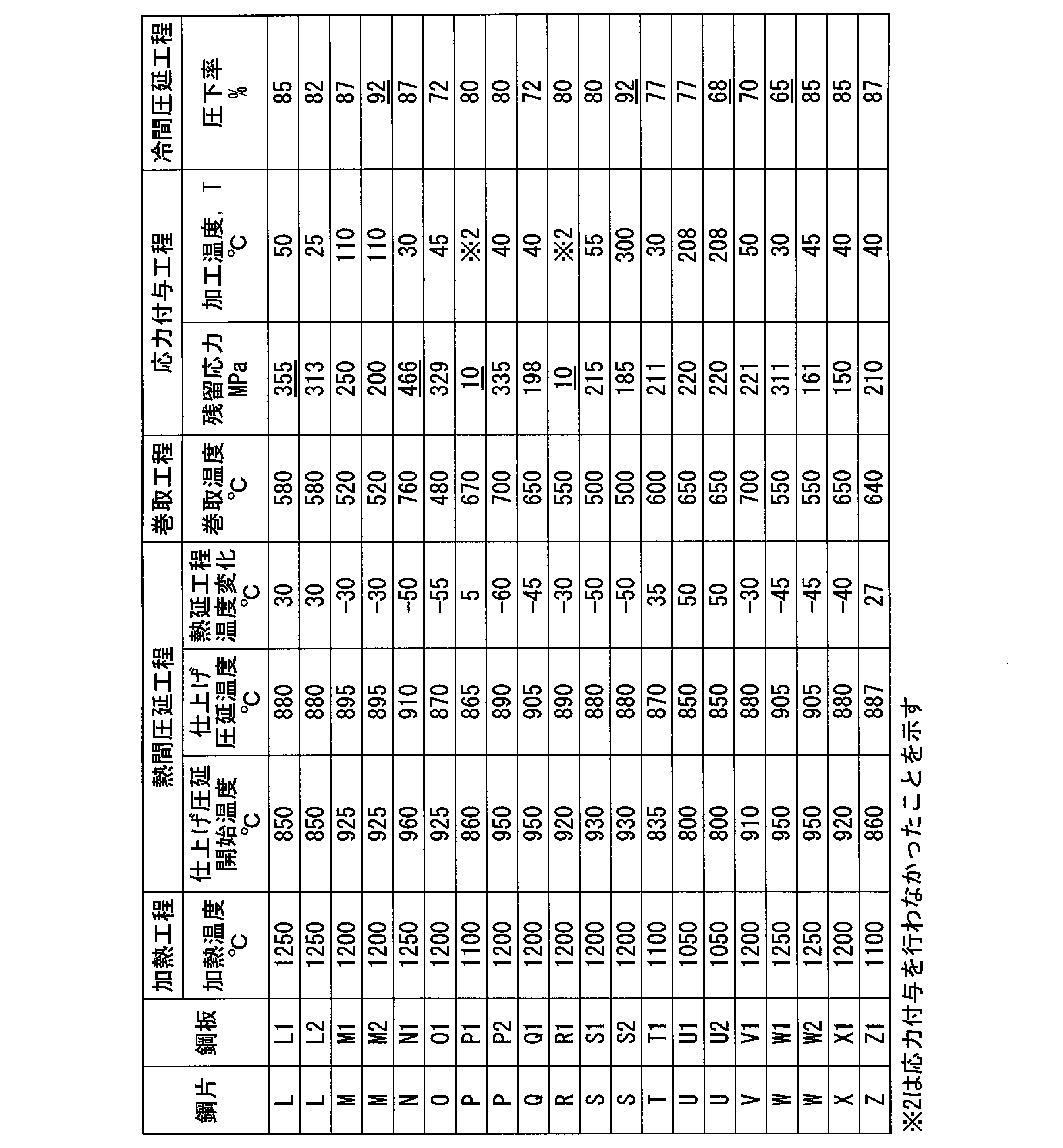


Claims (11)
- 化学組成が、質量%で、
C:0.020%以上、0.090%以下、
Si:0.200%以下、
Mn:0.45%以上、2.10%以下、
P:0.030%以下、
S:0.020%以下、
sol.Al:0.50%以下、
N:0.0100%以下、
B:0~0.0050%、
Mo:0~0.40%、
Ti:0~0.10%、
Nb:0~0.10%、
Cr:0~0.55%、
Ni:0~0.25%、
を含有し、残部がFeおよび不純物からなり、
表面~前記表面から板厚方向に20μmの位置までの範囲である表層領域の金属組織が、フェライトと、体積分率で0.01~5.0%の第2相とからなり、
前記表面から前記板厚方向に20μm超の位置~前記表面から前記板厚方向に板厚の1/4の位置までの範囲である内部領域の金属組織が、フェライトと、体積分率で2.0~10.0%の第2相とからなり、
前記表層領域の前記第2相の体積分率が、前記内部領域の前記第2相の体積分率よりも小さく、
前記表層領域において、
前記第2相の平均結晶粒径が、0.01~4.0μmであり、
前記フェライトの、{001}方位と{111}方位との強度比であるXODF{001}/{111}が0.60以上2.00未満である集合組織が含まれる
ことを特徴とする鋼板。 The chemical composition is% by mass,
C: 0.020% or more, 0.090% or less,
Si: 0.200% or less,
Mn: 0.45% or more, 2.10% or less,
P: 0.030% or less,
S: 0.020% or less,
sol. Al: 0.50% or less,
N: 0.0100% or less,
B: 0 to 0.0050%,
Mo: 0 to 0.40%,
Ti: 0 to 0.10%,
Nb: 0 to 0.10%,
Cr: 0 to 0.55%,
Ni: 0 to 0.25%,
And the balance consists of Fe and impurities,
The metal structure of the surface layer region, which is a range from the surface to the position of 20 μm in the plate thickness direction from the surface, is composed of ferrite and a second phase having a volume fraction of 0.01 to 5.0%,
1. The metallographic structure of the internal region, which is in the range from the position of more than 20 μm in the plate thickness direction to the position of 1/4 of the plate thickness in the plate thickness direction from the surface, is ferrite and 2. It consists of 0 to 10.0% of the second phase,
A volume fraction of the second phase in the surface layer region is smaller than a volume fraction of the second phase in the inner region,
In the surface area,
The average crystal grain size of the second phase is 0.01 to 4.0 μm,
A steel sheet containing a texture in which X ODF {001}/{111}, which is the strength ratio between the {001} orientation and the {111} orientation, of the ferrite is 0.60 or more and less than 2.00. .. - 前記内部領域における前記第2相の平均結晶粒径が、1.0μm以上5.0μm以下であり、かつ、前記表層領域における前記第2相の前記平均結晶粒径よりも大きい
ことを特徴とする請求項1に記載の鋼板。 The average crystal grain size of the second phase in the internal region is 1.0 μm or more and 5.0 μm or less, and is larger than the average crystal grain size of the second phase in the surface layer region. The steel plate according to claim 1. - 鋼板の圧延方向に直角な断面の、前記表面から前記板厚方向に0~50μmの範囲において、
板幅方向に100μmかつ前記板厚方向に50μmの観察視野あたりの前記第2相の平均個数密度が、130個以下であり、
前記観察視野あたりの前記第2相の最小個数密度が、前記第2相の前記平均個数密度-20個以上である
ことを特徴とする請求項1または2に記載の鋼板。 In the range of 0 to 50 μm from the surface to the plate thickness direction of the cross section perpendicular to the rolling direction of the steel plate,
The average number density of the second phase per observation visual field of 100 μm in the plate width direction and 50 μm in the plate thickness direction is 130 or less,
The steel sheet according to claim 1 or 2, wherein the minimum number density of the second phase per the observation visual field is the average number density of the second phase minus 20 or more. - 前記化学組成が、質量%で、
B:0.0001%以上、0.0050%以下、
Mo:0.001%以上、0.40%以下、
Ti:0.001%以上、0.10%以下、
Nb:0.001%以上、0.10%以下、
Cr:0.001%以上、0.55%以下、および、
Ni:0.001%以上、0.25%以下
のいずれか1種以上を含む
ことを特徴とする請求項1~3のいずれか一項に記載の鋼板。 The chemical composition is% by mass,
B: 0.0001% or more, 0.0050% or less,
Mo: 0.001% or more, 0.40% or less,
Ti: 0.001% or more, 0.10% or less,
Nb: 0.001% or more, 0.10% or less,
Cr: 0.001% or more, 0.55% or less, and
The steel sheet according to any one of claims 1 to 3, characterized in that it contains at least one of Ni: 0.001% or more and 0.25% or less. - 前記表層領域における前記第2相が、マルテンサイト、ベイナイト、焼き戻しマルテンサイトのいずれか1種以上からなる
ことを特徴とする請求項1~4のいずれか一項に記載の鋼板。 The steel sheet according to any one of claims 1 to 4, wherein the second phase in the surface layer region is made of one or more of martensite, bainite, and tempered martensite. - 前記表面にめっき層を有することを特徴とする請求項1~5のいずれか一項に記載の鋼板。 The steel sheet according to any one of claims 1 to 5, which has a plating layer on the surface.
- 引張強度が400MPa以上であることを特徴とする請求項1~6のいずれか一項に記載の鋼板。 The steel sheet according to any one of claims 1 to 6, which has a tensile strength of 400 MPa or more.
- 請求項1に記載の化学組成を有する鋼片を1000℃以上に加熱する加熱工程と、
前記鋼片を、圧延終了温度が950℃以下となるように熱間圧延して熱延鋼板を得る熱間圧延工程と、
前記熱間圧延工程後の、前記熱延鋼板に、表面における残留応力であるσsが絶対値で150MPa~350MPaとなるように、応力を付与する応力付与工程と、
前記応力付与工程後の前記熱延鋼板に、累積圧下率であるRCRが70~90%である冷間圧延を行って冷延鋼板を得る冷間圧延工程と、
前記冷延鋼板に、300℃~下記(1)式を満足する均熱温度T1℃までの平均加熱速度が1.5~10.0℃/秒となるように加熱した後、前記均熱温度T1℃で30~150秒保持する焼鈍を行う焼鈍工程と、
前記焼鈍工程後の前記冷延鋼板を、前記T1℃~650℃までの平均冷却速度が1.0~10.0℃/秒となるように550~650℃まで冷却した後、平均冷却速度が5.0~500.0℃/秒となるように200~490℃まで冷却する冷却工程と、
を備える、ことを特徴とする鋼板の製造方法。
1275-27×ln(σs)-4.5×RCR ≦ T1 ≦ 1275-27×ln(σs)-4×RCR ・・・ (1) A heating step of heating a steel slab having the chemical composition according to claim 1 to 1000° C. or higher;
A hot rolling step of hot rolling the steel slab so that the rolling end temperature is 950° C. or lower to obtain a hot rolled steel sheet;
A stress applying step of applying stress to the hot-rolled steel sheet after the hot rolling step so that σ s, which is the residual stress on the surface, becomes 150 MPa to 350 MPa in absolute value;
A cold rolling step in which the hot rolled steel sheet after the stress application step is subjected to cold rolling in which the cumulative reduction ratio R CR is 70 to 90% to obtain a cold rolled steel sheet;
The cold-rolled steel sheet is heated so that the average heating rate from 300° C. to a soaking temperature T1° C. that satisfies the following formula (1) is 1.5 to 10.0° C./sec. An annealing step of annealing at T1° C. for 30 to 150 seconds,
After cooling the cold-rolled steel sheet after the annealing step to 550 to 650°C so that the average cooling rate from T1°C to 650°C is 1.0 to 10.0°C/sec, the average cooling rate is A cooling step of cooling to 200 to 490° C. at a rate of 5.0 to 500.0° C./sec;
A method of manufacturing a steel sheet, comprising:
1275-27×ln(σ s )-4.5×R CR ≦ T1 ≦ 1275-27×ln(σ s )-4×R CR (1) - 前記応力付与工程を、40~500℃で行う
ことを特徴とする請求項8に記載の鋼板の製造方法。 The method for producing a steel sheet according to claim 8, wherein the stress applying step is performed at 40 to 500°C. - 前記熱間圧延工程において、
仕上げ圧延開始温度が900℃以下であることを特徴とする請求項8または9に記載の鋼板の製造方法。 In the hot rolling step,
The finish rolling starting temperature is 900° C. or lower, and the method for producing a steel sheet according to claim 8 or 9, wherein: - 前記冷却工程後の前記冷延鋼板を、200~490℃の温度域で30~600秒保持する保持工程をさらに備えることを特徴とする請求項8~10のいずれか一項に記載の鋼板の製造方法。 11. The steel sheet according to claim 8, further comprising a holding step of holding the cold rolled steel sheet after the cooling step in a temperature range of 200 to 490° C. for 30 to 600 seconds. Production method.
Priority Applications (6)
| Application Number | Priority Date | Filing Date | Title |
|---|---|---|---|
| US17/420,088 US20220316020A1 (en) | 2019-01-07 | 2020-01-07 | Steel sheet and method for manufacturing same |
| EP20738298.7A EP3910083B1 (en) | 2019-01-07 | 2020-01-07 | Steel sheet and method for manufacturing same |
| CN202080008029.8A CN113302322B (en) | 2019-01-07 | 2020-01-07 | Steel sheet and method for producing same |
| MX2021008065A MX2021008065A (en) | 2019-01-07 | 2020-01-07 | Steel sheet and method for manufacturing same. |
| JP2020530539A JP6809652B2 (en) | 2019-01-07 | 2020-01-07 | Steel plate and its manufacturing method |
| KR1020217019474A KR102485637B1 (en) | 2019-01-07 | 2020-01-07 | Steel plate and its manufacturing method |
Applications Claiming Priority (2)
| Application Number | Priority Date | Filing Date | Title |
|---|---|---|---|
| JP2019-000672 | 2019-01-07 | ||
| JP2019000672 | 2019-01-07 |
Publications (1)
| Publication Number | Publication Date |
|---|---|
| WO2020145256A1 true WO2020145256A1 (en) | 2020-07-16 |
Family
ID=71520487
Family Applications (1)
| Application Number | Title | Priority Date | Filing Date |
|---|---|---|---|
| PCT/JP2020/000134 WO2020145256A1 (en) | 2019-01-07 | 2020-01-07 | Steel sheet and method for manufacturing same |
Country Status (7)
| Country | Link |
|---|---|
| US (1) | US20220316020A1 (en) |
| EP (1) | EP3910083B1 (en) |
| JP (1) | JP6809652B2 (en) |
| KR (1) | KR102485637B1 (en) |
| CN (1) | CN113302322B (en) |
| MX (1) | MX2021008065A (en) |
| WO (1) | WO2020145256A1 (en) |
Cited By (2)
| Publication number | Priority date | Publication date | Assignee | Title |
|---|---|---|---|---|
| WO2023100424A1 (en) * | 2021-12-03 | 2023-06-08 | 日本製鉄株式会社 | Steel sheet |
| WO2023149002A1 (en) * | 2022-02-01 | 2023-08-10 | 日本製鉄株式会社 | Steel sheet |
Families Citing this family (1)
| Publication number | Priority date | Publication date | Assignee | Title |
|---|---|---|---|---|
| KR102562003B1 (en) * | 2019-02-15 | 2023-08-02 | 닛폰세이테츠 가부시키가이샤 | Steel plate and its manufacturing method |
Citations (5)
| Publication number | Priority date | Publication date | Assignee | Title |
|---|---|---|---|---|
| JP2007291514A (en) * | 2006-03-28 | 2007-11-08 | Jfe Steel Kk | Hot-rolled steel sheet with small in-plane anisotropy after cold rolling and recrystallization annealing, cold-rolled steel sheet with small in-plane anisotropy and production method therefor |
| JP2009132981A (en) * | 2007-11-30 | 2009-06-18 | Jfe Steel Corp | High-strength cold-rolled steel sheet having small in-plane anisotropy of elongation, and manufacturing method therefor |
| WO2013046476A1 (en) | 2011-09-28 | 2013-04-04 | Jfeスチール株式会社 | High strength steel plate and manufacturing method thereof |
| JP2016156079A (en) | 2015-02-26 | 2016-09-01 | 新日鐵住金株式会社 | Ferritic thin steel sheet |
| JP2019000672A (en) | 2017-02-02 | 2019-01-10 | オリンパス株式会社 | Endoscope |
Family Cites Families (4)
| Publication number | Priority date | Publication date | Assignee | Title |
|---|---|---|---|---|
| MX2010010116A (en) * | 2008-03-27 | 2010-10-04 | Nippon Steel Corp | High-strength galvanized steel sheet, high-strength alloyed hot-dip galvanized sheet, and high-strength cold-rolled steel sheet which excel in moldability and weldability, and manufacturing method for the same. |
| WO2011055844A1 (en) * | 2009-11-09 | 2011-05-12 | 新日本製鐵株式会社 | High-strength steel sheet having excellent processability and paint bake hardenability, and method for producing same |
| MX360332B (en) * | 2011-07-29 | 2018-10-29 | Nippon Steel & Sumitomo Metal Corp | High-strength galvanized steel sheet having superior bendability and method for producing same. |
| MX2014003714A (en) * | 2011-09-30 | 2014-07-09 | Nippon Steel & Sumitomo Metal Corp | High-strength hot dip galvanized steel plate having excellent moldability, weak material anisotropy and ultimate tensile strength of 980 mpa or more, high-strength alloyed hot dip galvanized steel plate and manufacturing method therefor. |
-
2020
- 2020-01-07 CN CN202080008029.8A patent/CN113302322B/en active Active
- 2020-01-07 KR KR1020217019474A patent/KR102485637B1/en active IP Right Grant
- 2020-01-07 EP EP20738298.7A patent/EP3910083B1/en active Active
- 2020-01-07 MX MX2021008065A patent/MX2021008065A/en unknown
- 2020-01-07 WO PCT/JP2020/000134 patent/WO2020145256A1/en unknown
- 2020-01-07 US US17/420,088 patent/US20220316020A1/en active Pending
- 2020-01-07 JP JP2020530539A patent/JP6809652B2/en active Active
Patent Citations (5)
| Publication number | Priority date | Publication date | Assignee | Title |
|---|---|---|---|---|
| JP2007291514A (en) * | 2006-03-28 | 2007-11-08 | Jfe Steel Kk | Hot-rolled steel sheet with small in-plane anisotropy after cold rolling and recrystallization annealing, cold-rolled steel sheet with small in-plane anisotropy and production method therefor |
| JP2009132981A (en) * | 2007-11-30 | 2009-06-18 | Jfe Steel Corp | High-strength cold-rolled steel sheet having small in-plane anisotropy of elongation, and manufacturing method therefor |
| WO2013046476A1 (en) | 2011-09-28 | 2013-04-04 | Jfeスチール株式会社 | High strength steel plate and manufacturing method thereof |
| JP2016156079A (en) | 2015-02-26 | 2016-09-01 | 新日鐵住金株式会社 | Ferritic thin steel sheet |
| JP2019000672A (en) | 2017-02-02 | 2019-01-10 | オリンパス株式会社 | Endoscope |
Cited By (2)
| Publication number | Priority date | Publication date | Assignee | Title |
|---|---|---|---|---|
| WO2023100424A1 (en) * | 2021-12-03 | 2023-06-08 | 日本製鉄株式会社 | Steel sheet |
| WO2023149002A1 (en) * | 2022-02-01 | 2023-08-10 | 日本製鉄株式会社 | Steel sheet |
Also Published As
| Publication number | Publication date |
|---|---|
| EP3910083B1 (en) | 2023-09-06 |
| MX2021008065A (en) | 2021-08-05 |
| CN113302322B (en) | 2023-07-21 |
| KR20210094031A (en) | 2021-07-28 |
| JPWO2020145256A1 (en) | 2021-02-18 |
| CN113302322A (en) | 2021-08-24 |
| EP3910083A4 (en) | 2022-06-01 |
| EP3910083A1 (en) | 2021-11-17 |
| US20220316020A1 (en) | 2022-10-06 |
| JP6809652B2 (en) | 2021-01-06 |
| KR102485637B1 (en) | 2023-01-06 |
Similar Documents
| Publication | Publication Date | Title |
|---|---|---|
| KR101949628B1 (en) | High-strength steel sheet and method for manufacturing same | |
| EP2762582B1 (en) | High-strength galvannealed steel sheet of high bake hardenability, high-strength alloyed galvannealed steel sheet, and method for manufacturing same | |
| JP5983895B2 (en) | High strength steel plate and method for producing the same, and method for producing high strength galvanized steel plate | |
| KR101479391B1 (en) | Cold rolled steel sheet having excellent shape fixability and method for manufacturing the same | |
| JP5699764B2 (en) | Alloyed hot-dip galvanized steel sheet and method for producing the same | |
| KR20170072322A (en) | High-strength steel sheet and method for manufacturing same | |
| MX2014000125A (en) | Method for producing cold-rolled steel sheet. | |
| US11274355B2 (en) | Hot rolled steel sheet and method for producing same | |
| JP5071173B2 (en) | Hot-dip galvanized steel sheet and manufacturing method thereof | |
| WO2020145256A1 (en) | Steel sheet and method for manufacturing same | |
| US11332804B2 (en) | High-strength cold-rolled steel sheet, high-strength coated steel sheet, and method for producing the same | |
| WO2020145259A1 (en) | Steel plate and manufacturing method thereof | |
| WO2020166231A1 (en) | Steel sheet and method for producing same | |
| WO2022210396A1 (en) | Steel plate, method for producing steel plate, and method for producing intermediate steel plate | |
| JP7216933B2 (en) | Steel plate and its manufacturing method | |
| KR20190063413A (en) | Method for manufacturing high strength steel strip | |
| JP5825204B2 (en) | Cold rolled steel sheet | |
| JP5708320B2 (en) | Cold rolled steel sheet | |
| CN115003835A (en) | Hot rolled steel plate | |
| JP5644703B2 (en) | Cold rolled steel sheet manufacturing method | |
| WO2023032225A1 (en) | Hot-rolled steel sheet |
Legal Events
| Date | Code | Title | Description |
|---|---|---|---|
| ENP | Entry into the national phase |
Ref document number: 2020530539 Country of ref document: JP Kind code of ref document: A |
|
| 121 | Ep: the epo has been informed by wipo that ep was designated in this application |
Ref document number: 20738298 Country of ref document: EP Kind code of ref document: A1 |
|
| ENP | Entry into the national phase |
Ref document number: 20217019474 Country of ref document: KR Kind code of ref document: A |
|
| NENP | Non-entry into the national phase |
Ref country code: DE |
|
| ENP | Entry into the national phase |
Ref document number: 2020738298 Country of ref document: EP Effective date: 20210809 |