WO2020144968A1 - Drive mechanism capable of dealing with gas sterilization - Google Patents
Drive mechanism capable of dealing with gas sterilization Download PDFInfo
- Publication number
- WO2020144968A1 WO2020144968A1 PCT/JP2019/046623 JP2019046623W WO2020144968A1 WO 2020144968 A1 WO2020144968 A1 WO 2020144968A1 JP 2019046623 W JP2019046623 W JP 2019046623W WO 2020144968 A1 WO2020144968 A1 WO 2020144968A1
- Authority
- WO
- WIPO (PCT)
- Prior art keywords
- unit
- moving block
- moving
- partition wall
- magnet
- Prior art date
Links
Images


Classifications
-
- B—PERFORMING OPERATIONS; TRANSPORTING
- B65—CONVEYING; PACKING; STORING; HANDLING THIN OR FILAMENTARY MATERIAL
- B65G—TRANSPORT OR STORAGE DEVICES, e.g. CONVEYORS FOR LOADING OR TIPPING, SHOP CONVEYOR SYSTEMS OR PNEUMATIC TUBE CONVEYORS
- B65G54/00—Non-mechanical conveyors not otherwise provided for
- B65G54/02—Non-mechanical conveyors not otherwise provided for electrostatic, electric, or magnetic
-
- C—CHEMISTRY; METALLURGY
- C12—BIOCHEMISTRY; BEER; SPIRITS; WINE; VINEGAR; MICROBIOLOGY; ENZYMOLOGY; MUTATION OR GENETIC ENGINEERING
- C12M—APPARATUS FOR ENZYMOLOGY OR MICROBIOLOGY; APPARATUS FOR CULTURING MICROORGANISMS FOR PRODUCING BIOMASS, FOR GROWING CELLS OR FOR OBTAINING FERMENTATION OR METABOLIC PRODUCTS, i.e. BIOREACTORS OR FERMENTERS
- C12M33/00—Means for introduction, transport, positioning, extraction, harvesting, peeling or sampling of biological material in or from the apparatus
- C12M33/04—Means for introduction, transport, positioning, extraction, harvesting, peeling or sampling of biological material in or from the apparatus by injection or suction, e.g. using pipettes, syringes, needles
-
- C—CHEMISTRY; METALLURGY
- C12—BIOCHEMISTRY; BEER; SPIRITS; WINE; VINEGAR; MICROBIOLOGY; ENZYMOLOGY; MUTATION OR GENETIC ENGINEERING
- C12M—APPARATUS FOR ENZYMOLOGY OR MICROBIOLOGY; APPARATUS FOR CULTURING MICROORGANISMS FOR PRODUCING BIOMASS, FOR GROWING CELLS OR FOR OBTAINING FERMENTATION OR METABOLIC PRODUCTS, i.e. BIOREACTORS OR FERMENTERS
- C12M1/00—Apparatus for enzymology or microbiology
-
- C—CHEMISTRY; METALLURGY
- C12—BIOCHEMISTRY; BEER; SPIRITS; WINE; VINEGAR; MICROBIOLOGY; ENZYMOLOGY; MUTATION OR GENETIC ENGINEERING
- C12M—APPARATUS FOR ENZYMOLOGY OR MICROBIOLOGY; APPARATUS FOR CULTURING MICROORGANISMS FOR PRODUCING BIOMASS, FOR GROWING CELLS OR FOR OBTAINING FERMENTATION OR METABOLIC PRODUCTS, i.e. BIOREACTORS OR FERMENTERS
- C12M23/00—Constructional details, e.g. recesses, hinges
- C12M23/50—Means for positioning or orientating the apparatus
-
- C—CHEMISTRY; METALLURGY
- C12—BIOCHEMISTRY; BEER; SPIRITS; WINE; VINEGAR; MICROBIOLOGY; ENZYMOLOGY; MUTATION OR GENETIC ENGINEERING
- C12M—APPARATUS FOR ENZYMOLOGY OR MICROBIOLOGY; APPARATUS FOR CULTURING MICROORGANISMS FOR PRODUCING BIOMASS, FOR GROWING CELLS OR FOR OBTAINING FERMENTATION OR METABOLIC PRODUCTS, i.e. BIOREACTORS OR FERMENTERS
- C12M3/00—Tissue, human, animal or plant cell, or virus culture apparatus
-
- C—CHEMISTRY; METALLURGY
- C12—BIOCHEMISTRY; BEER; SPIRITS; WINE; VINEGAR; MICROBIOLOGY; ENZYMOLOGY; MUTATION OR GENETIC ENGINEERING
- C12M—APPARATUS FOR ENZYMOLOGY OR MICROBIOLOGY; APPARATUS FOR CULTURING MICROORGANISMS FOR PRODUCING BIOMASS, FOR GROWING CELLS OR FOR OBTAINING FERMENTATION OR METABOLIC PRODUCTS, i.e. BIOREACTORS OR FERMENTERS
- C12M37/00—Means for sterilizing, maintaining sterile conditions or avoiding chemical or biological contamination
Definitions
- the present invention relates to a direct-acting mechanism that can operate with high accuracy without causing a failure even when exposed to a highly corrosive gas atmosphere such as hydrogen peroxide gas.
- Aseptic work devices such as safety cabinets and isolators are used in the fields of drug discovery and regenerative medicine as devices used for cell culture and various tests.
- a series of operations such as cell seeding, medium replacement, and observation require high cleanliness without contamination.
- Cultivation and tests are continuously performed for a long time, and in that process, it is indispensable to grasp the state of the sample at a predetermined timing and to exchange the medium.
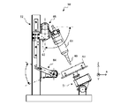
- Patent Document 1 discloses a dispensing device 50 arranged in an internal space of an isolator as shown in FIG.
- the dispensing device 50 disclosed in Patent Document 1 includes a slide device 64 that slides and drives the syringe 61 in the vertical direction, and a rotating device 65 that rotates the syringe 61 in the X-axis direction and the Y-axis direction.
- the drive device itself is miniaturized by arranging the rotating shafts orthogonally to each other. Further, by reducing the size of the driving device, it is possible to improve the degree of freedom in the arrangement position of the mounting table 51 and the storage container A1, so that the storage container A1 is arranged at a position where particles generated by the operation of the driving device are not mixed. doing. As a result, it is possible to prevent particle contamination of the culture and the culture solution due to the operation of the driving device.
- the drive mechanism for driving the syringe 61 and the storage container A1 is installed in an exposed state, and when sterilized with a sterilizing gas such as hydrogen peroxide gas, the exposed mechanism part is sterilized.
- a sterilizing gas such as hydrogen peroxide gas
- the present invention has been made in view of the above problems, and it is an object of the present invention to provide a drive mechanism that can withstand sterilization treatment with a sterilizing gas such as hydrogen peroxide and can perform a more accurate positioning operation. Has an aim.
- a drive mechanism of the present invention includes a moving block, a driving unit that moves the moving block, a guide mechanism that guides the moving block in a predetermined direction, the moving block, the driving unit, and A partition wall that isolates the guide mechanism from the external environment, and a position that is outside the partition wall and faces the moving block through the partition wall, covers at least a part of the partition wall, and is movable along the partition wall.
- a moving table provided, a first magnet coupling mechanism having magnets attracting each other on respective surfaces (first surfaces) of the moving block and the moving table that face each other through the partition wall, and the first magnet coupling mechanism.
- a second magnet coupling mechanism that is orthogonal to the surface and is provided on each surface (second surface) of the moving block and the moving base that face each other via the partition wall and that includes magnets that attract each other. It is characterized in that the moving table follows a movement of the moving block and moves along a track guided by the partition wall.
- each surface is provided with an urging magnet unit provided with magnetic poles that repel each other in a direction that reinforces the attraction force of the first and/or second magnet coupling mechanism.
- the moving table can move more accurately along the track guided by the partition wall.
- the magnets that compose the first magnet coupling mechanism and the second magnet coupling mechanism are permanent magnets. Further, the magnets forming the first magnet coupling mechanism and the second magnet coupling mechanism may include electromagnets.
- the surfaces of the moving block and the moving base on which the biasing magnet unit is arranged may be arranged at a predetermined angle with respect to the surface on which the second magnet coupling is arranged. good.
- the drive mechanism of the present invention can be used for a moving part of a distribution device, a medium exchange device, and a cultured cell handling device and has corrosion resistance, the entire device is gas-sterilized with an oxidizing gas. However, the device can be operated stably without corrosion.
- the configuration of the present invention by enhancing the sealing property of the movable part, it is possible to use gas sterilization with an oxidizing gas, so that the effect of preventing contamination by miscellaneous bacteria is high, and the device can be stably used for a long period of time. It can be moved. Further, since the accurate positioning operation of the movable table is possible, it is possible to stably perform the accurate forward/backward movement, which was impossible with the conventional apparatus, for a long period of time.
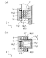
- FIG. 3 is a cross-sectional view taken along the XY plane of the drive mechanism that is an embodiment of the present invention.
- FIG. 3 is a cross-sectional view on the YZ plane of the drive mechanism that is an embodiment of the present invention.
- FIG. 2 is a perspective view showing a drive mechanism 1 according to an embodiment of the present invention
- FIG. 3 is a view showing a transverse cross section of a moving table 5 portion of the drive mechanism 1 in an XY plane
- FIG. 4 is a drive mechanism 1 It is a figure which shows the center vertical cross section in a YZ plane.
- the drive mechanism 1 of the present invention includes a moving block 2 that moves by rotation of an internal screw shaft 8, a guide mechanism 3 that guides the moving block 2 in a predetermined direction, and a moving block 2 that drives the screw shaft 8 to rotate. And a moving table 5 that moves together with the moving block 2.
- the moving block 2, the guide mechanism 3, and the drive source 4 are isolated from the external environment (the external environment inside the device such as a distributor: hereinafter referred to as “work space”: corresponding to the work space 36 described later) by the partition wall 6.
- the movable table 5 is arranged outside the partition wall 6 (work space).
- the first drive magnet unit Mg1 and the first driven magnet unit Mg2, the second drive magnet unit Mg3, and the second drive magnet unit Mg2 which are arranged on the moving block 2 and the moving table 5 so as to attract each other by magnetic force via the partition wall 6
- the driven magnet unit Mg4 is provided.
- the moving base 5 follows the movement of the moving block 2 and moves along the partition wall 6 by the magnet coupling by the attraction force of these magnet units Mg1 to Mg4.
- the surfaces of the moving block 2 and the moving table 5 opposite to the surface on which the second drive magnet unit Mg3 and the second driven magnet unit Mg4 are arranged are repulsed by mutual magnetic forces.
- a first biasing magnet unit Mg5 and a second biasing magnet unit Mg6 that are arranged are provided.
- the repulsive force generated by the biasing magnet units Mg5 and Mg6 arranged so as to repel each other is urged in the same direction as the attraction force by the magnetic coupling between the moving block 2 and the moving base 5 to reinforce.
- the distance between the moving table 5 and the partition wall 6 can be kept constant.
- the guide mechanism 3 included in the drive mechanism 1 of the present embodiment is arranged so as to be parallel to the guide rail 3b that guides the moving element 3a fixed to the moving block 2 in a predetermined direction.
- a screw shaft 8 screwed into a ball nut 7 fixed to the moving block 2 and a motor 4 which is a drive source connected to the screw shaft 8 and rotationally driving the screw shaft 8 are provided.
- the guide rail 3b is fixed to one surface of the internal space of the casing 9 that is the base of the drive mechanism 1, and the screw shaft 8 is rotatably fixed to the casing 9.
- the casing 9 including the guide mechanism 3 of the present embodiment has a vertically long substantially rectangular parallelepiped shape, and the motor 4 is fixed to one end of the casing 4 via a bracket 12.
- the rotating shaft 10 is concentrically connected to the screw shaft 8 via the coupling 4a, and the rotating shaft 10 of the motor 4 rotates to rotate the screw shaft 10. 8 also rotates.
- Position detection sensors S1 and S2 that detect the position of the moving block 2 are provided on the longitudinal wall surface of the casing 9.
- An optical rotation detection sensor S3 that detects the rotation angle of the rotation shaft 10 of the motor 4 is provided near the motor 4, and a sensor dog 11 fixed to the rotation shaft 10 is an optical axis of the rotation detection sensor S3.
- the rotation position of the rotary shaft 10 is detected by shutting off.
- These sensors S1, S2, S3 are connected to a control unit 70 that controls the rotation of the motor 4.
- the motor 4 included in the drive mechanism 1 of the present embodiment is a stepping motor that allows easy control of the rotation angle of the rotary shaft 10, and rotation control of the rotary shaft 10 is performed by a control signal from the control unit 70.
- a transmitted light type sensor, a reflected light type sensor, a magnetic sensor or the like can be applied, but a sensor according to another detection method may be used.
- the moving block 2 included in the drive mechanism 1 has a substantially rectangular parallelepiped shape, and the mover 3a of the guide rail 3b is fixed to the surface F1 facing the guide rail 3b. ing. Further, a hole 13 through which the screw shaft 8 penetrates is formed in the moving block 2, and a ball nut 7 screwed with the screw shaft 8 is fixed to the moving block 2 while being inserted into the hole 13. .. With this configuration, the moving block 2 can move in the plane guided by the guide rail 3b in conjunction with the rotation of the screw shaft 8.
- the first drive magnet unit Mg1 is fixed to the surface F2 (front surface) opposite to the surface F1 to which the moving element 3a of the moving block 2 is fixed. Further, the first driven magnet unit Mg2 is fixed in parallel to the first drive magnet unit Mg1 on the face F2′ of the moving table 5 facing the front face F2 of the moving block 2.
- the first drive magnet unit Mg1 and the first driven magnet unit Mg2 constitute a first magnet coupling mechanism by an attractive force generated by mutually opposing magnetic poles.
- the second drive magnet unit Mg3 is fixed to the left side surface (first side surface) F3 which is formed substantially at right angles to the front surface F2 of the moving block 2. Further, the second driven magnet unit Mg4 is parallel to the second drive magnet unit Mg3 on the left side surface (first side surface) F3′ of the moving table 5 facing the first side surface F3 of the moving block 2 via the partition wall 6. It is fixed to be.
- the second drive magnet unit Mg3 and the second driven magnet unit Mg4 constitute a second magnet coupling mechanism by an attractive force generated by mutually opposing magnetic poles.
- a first biasing magnet unit Mg5 is arranged on the right side surface (second side surface) F4 formed on the opposite side of the first side surface F3 of the moving block 2.
- the second biasing magnet unit Mg6 is connected to the first biasing magnet unit Mg5. They are fixed so that they are parallel to each other. The same magnetic poles of the first biasing magnet unit Mg5 and the second biasing magnet unit Mg6 are opposed to each other to form a magnetic field that repels each other.
- the repulsive force generated by the first biasing magnet unit Mg5 and the second biasing magnet unit Mg6 is the attraction force by the second magnet coupling (the moving table 5 is a partition wall that is close to the first side face F3 of the moving block 2).
- the second side face F4′ of the moving table 5 is urged in a direction away from the second side face F4 of the moving block 2 so as to reinforce the suction force acting so as to closely adhere to the 6 side.
- the first biasing magnet unit Mg5 and the second biasing magnet unit Mg6 can be selectively added when it is desired to reinforce the attraction force of the first and/or second magnet coupling mechanism.
- the partition wall 6 included in the drive mechanism 1 of the present embodiment is a box-shaped member that hermetically isolates the moving block 2, the guide mechanism 3, and the motor 4 from the working space, and is fixed to the casing 9.
- the inside of the space defined by the partition wall 6 is maintained in a general atmospheric atmosphere, and even if the working space is filled with an oxidizing gas atmosphere such as hydrogen peroxide gas, the guide is arranged in the internal space of the partition wall 6.
- the mechanism 3 can operate normally without being affected by the corrosive action due to the oxidizing gas atmosphere.
- the moving table 5 included in the drive mechanism 1 exemplified in the present embodiment is a member having a substantially U-shaped cross section, and is arranged so as to cover the partition wall 6 in an external environment outside the space defined by the partition wall 6. ing. Further, a plurality of rolling elements 14 are attached to the front face F2′, the first side face F3′, and the second side face F4′, which are the faces facing the partition wall 6 of the moving table 5 of the present embodiment.
- the rolling element 14 of this embodiment is a member that supports the movable table 5 against the magnetic attraction force generated by the magnet units Mg1 to Mg4, and keeps the distance between the partition wall 6 and the movable table 5 constant. It is a member.
- the moving base 5 can move on the partition wall 6 following the movement of the moving block 2 without the main body of the moving base 5 contacting the partition wall 6. Can be done.
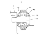
- FIG. 5 is a cross-sectional view illustrating the rolling element 14 included in the drive mechanism 1 of this embodiment.
- the rolling element 14 of the present embodiment includes a wheel member 14a formed of a resin material in an annular shape, a bearing 14b inserted into the wheel member 14a, and a stainless steel shaft 14c inserted into an inner ring of the bearing 14b. It comprises a collar 14d arranged between the inner ring of the bearing 14b and the movable table 5 and a seal packing 14e having a substantially funnel shape.
- the seal packing 14e is arranged on both side surfaces of the wheel member 14a, and the peripheral edge of the lip portion of the tip of the seal packing 14e is in airtight contact with the wheel member 14a.
- the space in which the bearing 14b is arranged becomes a space isolated from the working space by the wheel member 14a and the seal packing 14e, and particles of the oxidizing gas are prevented from coming into contact with the bearing 14b.
- the annular wheel member 14a is formed of an engineering plastic having high wear resistance and chemical resistance, such as PEEK (polyether ether ketone), PPS (polyphenylene sulfide), or Vespel (registered trademark). Is desirable.
- the seal packing 14e may be formed of a flexible material having excellent heat resistance and chemical resistance, such as fluororubber, acrylic rubber, hydrogenated nitrile rubber, silicone resin, vinyl acetate ethylene resin, and ethylene propylene rubber. desirable.
- 6A and 6B are schematic cross-sectional views showing the arrangement of the permanent magnets of the magnet units Mg1 to Mg4 included in the drive mechanism 1 of this embodiment.
- 6A is a vertical partial cross-sectional view showing the polar arrangement of the permanent magnets of the moving block 2 and the moving table 5 of the drive mechanism 1, and FIG.
- a plurality of rectangular permanent magnets are arranged in a lattice so that adjacent permanent magnets have different polarities.
- the magnet units Mg1 to Mg4 arranged to face each other are arranged such that magnetic poles that exert an attractive force on the magnetic poles of the magnets that face each other.
- the moving base 5 is biased in the direction indicated by the arrow in the figure by the attraction force between the magnets having different magnetic poles facing each other, and the positions of the moving block 2 and the moving base 5 are increased. Can be effectively maintained in place. Further, even if the positional relationship between the drive magnet units Mg1 and Mg3 and the driven magnet units Mg2 and Mg4 is about to shift due to some load being applied to the moving table 5, the respective magnets have the same poles arranged next to each other. Since the two magnets repel each other, they function to return the position of the movable table 5 to a predetermined position.
- FIGS. 7A to 7C are diagrams illustrating polarities of the driving magnet units Mg1 and Mg3 and the driven magnet units Mg2 and Mg4 when viewed from the partition wall 6 side, respectively.
- the shape and arrangement of the magnets used in the magnet units Mg1 to Mg4 are not limited to the embodiment in which the permanent magnets are arranged in two rows as shown in FIG. 7(a). It is also possible to arrange the permanent magnets in three rows as described above, or to arrange the magnets having a circular cross-sectional shape in a zigzag pattern as shown in FIG. 7(c). It is also possible that the cross-sectional shape of the magnet is not rectangular or circular. Further, a yoke may be attached to each magnet to increase the attraction force.
- a magnet having a strong magnetic force such as a neodymium magnet or a samarium cobalt magnet as the magnet used in the magnet units Mg1 to Mg4.
- magnets such as neodymium magnets and samarium-cobalt magnets are easily corroded, surface treatment of the magnet surface with nickel or the like, which has resistance to highly corrosive gases such as hydrogen peroxide gas, or a resistant material such as silicone. It is desirable to apply a coating process.
- the biasing magnet units Mg5 and Mg6 of the present embodiment are arranged in a grid so that a plurality of rectangular magnets are adjacent to each other and have different polarities.
- the biasing magnet units Mg5 and Mg6 arranged to face each other are arranged such that magnetic poles that exert repulsive force on the magnetic poles of the magnets that face each other are arranged. See FIG. 6(b).
- the shape and arrangement of the magnets used for the biasing magnet units Mg5 and Mg6 are not limited to those in the above embodiment.
- the magnets having a circular cross-sectional shape in a staggered pattern, and it is also sufficiently possible to make the cross-sectional shape of the magnets a shape other than rectangular or circular.
- a yoke may be attached to each magnet to increase the repulsive force.
- a permanent magnet having a strong magnetic force such as a neodymium magnet or a samarium cobalt magnet for the magnets used for the biasing magnet units Mg5 and Mg6.
- the surface of the magnet is surface-treated with nickel or the like having resistance to highly corrosive gas such as hydrogen peroxide gas, or coated with a resistant material such as silicone.
- the moving block 2 is configured to move in the plane guided by the guide mechanism 3, and no displacement occurs in the direction orthogonal to the traveling direction.
- the drive mechanism 1 of the present embodiment urges the repulsive force generated by the first urging magnet unit Mg5 and the second urging magnet unit Mg6 in the direction of pressing the moving table 5 against the partition wall 6. It is configured.
- the direction of the biasing force that presses the moving table 5 against the partition wall 6 is configured to be the same as the direction of the attraction force that attracts the moving table 5 to the partition wall 6 by the magnet units Mg3 and Mg4.
- the moving table 5 is urged in the direction in which the surface F3′ is pressed toward the partition wall 6 in addition to the magnetic attraction force of the magnet coupling mechanism of the magnet unit Mg3 and the magnet unit Mg4. Can move accurately on the track guided by the partition wall 6.
- the partition wall 6 of the present embodiment has a function of housing the moving block 2 having low resistance to sterilization gas, the guide mechanism 3, and the drive source 4 and isolating it from the working space filled with sterilization gas during the sterilization process. It has a function of accurately guiding the moving direction of the moving table 5. Further, in addition to the function of supporting the movable table 5 against the attraction force generated by the magnet units Mg1 and Mg2 and Mg3 and Mg4, the movable table 5 is supported against the repulsive force generated by the magnet units Mg5 and Mg6. It also has the function of supporting. Therefore, it is desirable to use a sturdy member for the partition wall 6 in order to counter the suction force and the repulsive force.
- the partition wall 6 of this embodiment is formed of stainless steel having high corrosion resistance and relatively high strength. Further, since a large load is applied to the portion of the moving table 5 with which the rolling elements 14 are in contact, the thickness of the member of the partition wall 6 is increased along the track along which the rolling elements 14 pass so that the structure can withstand the load. May be. Further, a strong member is arranged along the track through which the rolling elements 14 pass, and a member having high magnetic permeability is arranged along the track through which the magnet units Mg1 to 6 pass, and the members are airtightly connected. It may be configured to match.
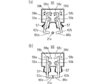
- FIG. 8 is a view showing a cross section of the drive mechanism 15 of the present embodiment on the XY plane. It should be noted that common reference numerals are given to the same configurations as the drive mechanism 1 according to the first embodiment.
- the moving block 16 included in the drive mechanism 15 of the present embodiment includes a front face F2 parallel to the X axis and a first parallel to the Y axis direction orthogonal to the front face F2, similarly to the moving block 2 of the first embodiment. It has a side surface F3.
- the movable table 17 included in the drive mechanism 15 of the present embodiment has a front surface F2′ parallel to the X axis and a Y axis direction perpendicular to the front surface F2′, like the movable table 5 of the first embodiment. It has a parallel first side face F3'.
- magnet units Mg1, Mg2, Mg3, Mg4 are fixed to the moving block 16 and the moving base 17 front faces F2, F2', first side faces F3, F3' as in the first embodiment, and the first driving is performed.
- the magnet unit Mg1 and the first driven magnet unit Mg2, and the second drive magnet unit Mg3 and the second driven magnet unit Mg4 are coupled by a magnetic coupling having magnetic poles having different polarities.
- a partition wall 18 having a wall surface parallel to F3' is arranged. Similar to the drive mechanism 1 of the first embodiment, the partition wall 18 houses the moving block 16, the guide mechanism 3, the ball screw mechanism 8, the drive source 4 and the like in an internal space hermetically isolated from the working space.
- the second side face F5 formed on the moving block 16 of the present embodiment is inclined by ⁇ degrees compared to the moving block 2 of the first embodiment formed parallel to the Y-axis direction when viewed from above. Has been formed. Further, the second side face F5′ formed on the moving table 17 of the present embodiment has a ⁇ compared to the moving table 5 of the first embodiment formed parallel to the Y-axis direction when viewed from above. It is formed with a tilt. Corresponding to this, the surface of the partition wall 18 of the present embodiment, which is disposed between the moving block 16 and the moving base 17, is also formed with an inclination of ⁇ degrees compared to the partition wall 6 of the first embodiment. ing.
- the first urging magnet unit Mg5 is fixed to the second side face F5 formed on the moving block 16 of the present embodiment, and the second side face F5' of the moving table 17 facing the moving block 16 has a second attaching side.
- the bias magnet unit Mg6 is fixedly arranged so as to face the first bias magnet unit Mg5.
- the first biasing magnet unit Mg5 and the second biasing magnet unit Mg6 are fixed to the second side faces F5 and F5′, respectively, in a state of being inclined by ⁇ degrees with respect to the Y-axis direction when viewed from above.
- the urging forces generated by the first urging magnet unit Mg5 and the second urging unit Mg6 are both the component for urging the moving table 17 in the X-axis direction and the component for urging the moving table 17 in the Y-axis direction. Since it has a component, the movable table 17 is pressed not only in the X-axis direction but also in the Y-axis direction. As a result, the moving table 17 can move along the track defined by the partition wall 18 without displacement.
- FIG. 9 is a front view showing the distribution device 20 of the present embodiment
- FIG. 10 is a side view thereof.
- the distribution device 20 of the present embodiment is a device for automatically distributing a medium (culture solution) filled in a large capacity container 19 into a plurality of subdivision containers 21.
- the distribution device 20 of the present embodiment includes a container holding unit 22 that holds a large-capacity container 19 in an inverted state with the discharge port 19a facing downward, a container rack 23 that stores a plurality of subdivided containers 21, and a container rack 23 that is horizontal.
- a rack moving unit 24 for moving in the direction, a pump unit 26 for sucking the medium (culture solution) filled in the container 19 and discharging it from the nozzle 25, and a nozzle elevating unit 27 for vertically moving the nozzle 25. It is composed of.
- the container holding unit 22 of this embodiment includes a tray unit 28 that holds a large capacity container 19, and a drive source 29 that rotates the tray unit 28 around a rotation axis L1 that extends in the horizontal direction as a rotation center.
- a tray unit 28 that holds a large capacity container 19
- a drive source 29 that rotates the tray unit 28 around a rotation axis L1 that extends in the horizontal direction as a rotation center.
- the pump unit 26 has a pump (not shown) inside, and the pump sucks the medium (culture liquid) filled in the container 19 through the suction tube 30 and the nozzle through the discharge tube 31.
- the medium (culture solution) is discharged from 25.
- the pump (not shown) is a known pump, and it is preferable to use a pump such as a peristaltic pump or a piezoelectric pump that is relatively easy to decontaminate and that is unlikely to contaminate the sample.
- the drive mechanism 1 of the present invention is used for the rack moving unit 24 and the nozzle elevating unit 27 of the distribution device 20.
- the rack moving unit 24 is arranged in a state in which the drive mechanism 1 of the present invention is laid down horizontally so that the front of the moving table 5 faces upward.
- a rack mounting table 32 is fixed to the upper surface of the moving table 5, and the container rack 23 is detachably attached to a predetermined position of the rack mounting table 32.
- a plurality of subdivided containers 21 are arranged side by side in the left-right direction in a posture with the inlet 21a facing upward, and the container racks 23 are fixed at predetermined positions on the rack mounting table 32. To be done.
- FIG. 9A is a view showing that the injection port 21a of the subdivided container 21 arranged at the right end of the container rack 23 is located immediately below the nozzle 25 as viewed in the drawing
- FIG. 6 is a view showing a place where an injection port 21 a of the subdivision container 21 arranged at the left end of the rack 23 is located immediately below a nozzle 25.
- the rack moving unit 24 has a stroke sufficient to move all the subdivided containers 21 accommodated in the container rack 23 to just below the nozzle 25 by moving the moving table 5 in the horizontal direction.
- the position information of the motor 4 for moving each of the subdivided containers 21 to directly below the nozzle 25 is previously taught by the operator, and the position information is stored in the control unit 70.
- a nozzle elevating unit 27 for moving the nozzle 25 up and down in the vertical direction is provided with the drive mechanism 1 of the present invention in an upright state.
- a nozzle bracket 33 for fixing the nozzles 25 is fixed to the movable table 5.
- the nozzle elevating unit 27 is arranged at a position where the nozzle 25 can be inserted into the injection port 21a of the subdivided container 21 housed in the container rack 23 when the nozzle 25 descends. Further, in the drive mechanism 1 provided in the nozzle elevating unit 27, when the nozzle 25 descends, the tip of the nozzle 25 reaches near the center of the subdivision container 21, and the upper end of the subdivision container 21 and the tip of the nozzle 25. Has a stroke that allows it to move up to a position where it does not interfere.
- the tip of a discharge tube 31 is connected to the base end of the nozzle 25, and the culture medium (culture liquid) supplied from the pump unit 26 is supplied to the nozzle 25 and injected into the subdivision container 21.
- Position information of the motor 4'for moving the nozzle 25 to the raised position and the lowered position is previously taught by the operator, and the position information is stored in the control unit 70.
- the operation of the motors 4 and 4 ′ of the rack moving unit 24 and the nozzle lifting unit 27, the drive source 29 of the container holding unit 22, and the pump of the pump unit 26 are controlled by a distributor control unit (not shown).
- the distribution device control unit is composed of at least a known computer, a storage unit that stores an operation program and various data taught in advance, and a communication unit that communicates with a host computer on the upper side, An input signal from each sensor is received, an operation command is transmitted to a control unit included in each unit according to an operation program stored in advance, and each drive mechanism is operated.
- the distribution device 20 of the present embodiment can automatically and sequentially distribute the medium (culture solution) filled in the large capacity container 19 to the plurality of subdivision containers 21 housed in the container rack 23. I can.
- the control unit 70 of the drive mechanism 1 may be included in the distributor control unit.
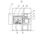
- each unit constituting the distribution device 20 of this embodiment is fixed on the base plate 34. Further, the distribution device 20 of the present embodiment is arranged in the work space 36 of the aseptic work device 35 capable of performing hydrogen peroxide gas sterilization as illustrated in FIGS.
- FIG. 11 is a front view illustrating a sterile work device 35 including the distribution device 20 of the present embodiment
- FIG. 12 is a side view schematically showing an internal configuration of a work space 36 of the sterile work device.
- the aseptic working apparatus 35 is also called an isolator, and a clean working space 36 isolated from the external atmosphere is formed inside the aseptic working apparatus 35.
- a sterile storage device 44 is connected next to the aseptic working device 35, and a passage for connecting the storage of the sterile storage device 44 and the working space 36 is partitioned by a door 45 (FIG. 12). ..
- the work space 36 is maintained at a predetermined cleanliness level by circulating clean air that has flowed in through a HEPA filter (High Efficiency Particulate Air Filter) (not shown) disposed above and below the aseptic work device 35. Has been done.
- HEPA filter High Efficiency Particulate Air Filter
- a front door 37 that can hermetically close the work space 36 is attached to the front side of the work space 36, and the distribution device 20 of the present embodiment is installed inside the work space 36 by opening the front door 37.
- the front door 37 is provided with a window 38 formed of transparent glass or resin so that an operator can observe the inside of the work space 36. Further, a circular opening is formed at a predetermined position of the window 38, and a globe 39 is airtightly fixed to this opening. By wearing the gloves 39 on both arms, the worker in the external environment can perform a predetermined treatment on the article carried into the work space 36 while viewing the inside of the work space 36 through the window 38.
- the aseptic work device 35 of the present embodiment is connected to a sterilizer (not shown) that supplies a sterilizing gas such as hydrogen peroxide vapor.
- a sterilizer (not shown) that supplies a sterilizing gas such as hydrogen peroxide vapor.
- the control unit that controls the operation of the distribution apparatus 20 of the present embodiment, the power supply unit that supplies power to the distribution apparatus 20, and the control unit that controls the operation of each unit are provided with a sterilizing gas filling the working space 36. In order not to be affected, it is arranged in a space isolated from the work space 36 inside the aseptic work device 35.
- the aseptic work device 35 is provided with a pass box 40 adjacent to the work space 36.
- the pass box 40 is a box-shaped device with a sterilizing function for exchanging articles between the work space 36 and the external environment. Samples such as a medium and a medium having a relatively small volume necessary for work in the work space 36 are brought into the work space 36 via the pass box 40.
- a sterilizing means for sterilizing articles brought into the internal space of the pass box 40 with ultraviolet rays or a sterilizing gas, a door 41 for partitioning the external environment from the internal space of the pass box 40, and the inside of the pass box 40 A door (not shown) that partitions the space and the work space 36 is provided.
- the operator When carrying the article into the work space 36, the operator opens the door 41 arranged in front of the aseptic work device 35 to carry the article into the internal space of the pass box, and then closes the door 41. Sterilization of the internal space of the pass box 40 is performed. When this sterilization process is completed, the worker wears the glove 39, opens the door that partitions the work space 36 and the internal space of the pass box 40 from the work space 36 side, and carries the article into the work space 36. Later, this door is closed. By the above procedure, the articles carried into the work space 36 are sterilized, so that the work space 36 is maintained in a clean state.
- the container 19, the subdivided container 21, and the container rack 23 set in the distribution device 20 of the present embodiment are carried into the work space 36 via the pass box 40.
- the worker sets the subdivided container 21 on the container rack 23 while wearing the gloves 39, and then fixes the container rack 23 on the rack mounting table 32 of the rack moving unit 24.
- the operator connects the discharge tube 19a of the container 19 to the suction tube 30 and then fixes the container 19 to the tray portion 28.
- the touch panel 42 and the operation panel 43 of the aseptic work device 35 are operated to start the automatic distribution operation of the distribution device 20.
- the control unit When the operation start signal is received, the control unit operates the drive source 29 of the container holding unit 22 to rotate and move the tray section 28 until the container 19 is in the inverted posture, and then operates the motor 4 of the rack moving unit 24. Then, the container rack 23 is moved to a predetermined position.
- the predetermined position means that, of the subdivision containers 21 accommodated in the container rack 23, the injection port 21 a of the subdivision container 21 arranged at the end of the container rack 23 is directly below the nozzle 25 of the nozzle lifting unit 27.
- the location information is stored in the control unit 70 in advance.
- control unit operates the motor 4 of the nozzle elevating unit 27 to lower the nozzle 25 until the nozzle 25 is inserted into the injection port 21a of the subdivision container 21 located immediately below the nozzle 25.
- control unit operates the pump unit 26 to inject the medium (culture solution) filled in the container 19 into the subdivided container 21.
- the control unit stops the operation of the pump unit 26 and then moves the nozzle 25 upward to a position away from the subdivision container 21.
- the motor 4 of the rack moving unit 24 is operated to move the container rack 23 so that the subdivision container 21 next to the subdivision container 21 that has been filled with the culture medium (culture solution) is located immediately below the nozzle 25.
- the operator opens the door 45 to carry out the container rack 23 and the filled subdivision containers 21 to the storage of the storage device 44, and the pass box 40. Then, the next container rack 23 and the subdivided container 21 are carried into the distributor 20. Further, the inside of the work space 36 and the distribution device 20 are sterilized with a sterilizing gas, if necessary.
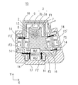
- FIG. 13 and 14 are front views showing the distribution sealing device 46 of the present embodiment
- FIG. 15 shows the distribution sealing device 46 between the first and second container elevating units 47a and 47b in FIG. It is a side view which shows the state which looked at the 1st container raising/lowering unit 47a and the 1st injection auxiliary unit 52 side from the position between the 2nd injection port holding units 49a and 49b.
- the distribution sealing device 46 of the present embodiment in addition to the distribution device 20 of the first embodiment of the present invention, holds the injection port 21a of the flexible subdivision container 21 to ensure the supply of the medium.
- the inlet holding units 49a and 49b and a welding unit 60 for welding and sealing the inlet 21a of the subdivision container 21 by heat are provided.
- the distribution sealing device 46 of this embodiment includes two container elevating units 47a and 47b for individually lifting the subdivided containers 21 housed in the container rack 23.
- the container lifting units 47a and 47b are composed of a container support member 48 that supports the subdivided container 21 from below, and a drive mechanism 1 that moves the container support member 48 up and down in the vertical direction.
- the container elevating units 47a and 47b are fixed to the lower surface of the base plate 34, and support the subdivision containers 21 from below through the base plate 34 and the openings formed in the bottom of the container rack 23 to move them up and down.
- the inlet 21a is sealed by the method. The following is a sequential description.
- the first container elevating unit 47a operates to move the subdivision container 21 (first subdivision container 21-1) accommodated at the right end of the container rack 23 upward. ..
- the first subdivision container 21-1 moved up to a predetermined position by the first container elevating unit 47a is held by the first injection port holding unit 49a at a position where the injection port 21a has a predetermined height. ..
- the nozzle elevating unit 27 operates and the nozzle 25 is inserted into the inlet 21a, so that the medium is supplied into the first subdivision container 21-1. ..
- the nozzle 25 is taken out from the inlet 21a, and the holding of the inlet 21a by the inlet holding unit 49 is released. Thereafter, the first subdivision container 21-1 is returned to the container rack 23 by the container elevating unit 47a descending.
- the rack moving unit 24 is moved to the right while viewing the container rack 23 until the next subdivided container 21 is located directly below the nozzle 25. Then, each unit sequentially performs the medium supply operation described above. In this way, the medium is sequentially supplied to the subdivision containers 21 housed in the container rack 23. Then, when the first subdivision container 21-1 has moved to just above the second container lifting/lowering unit 47b, the first subdivision container 21-1 is lifted to a predetermined position by the second container lifting/lowering unit 47b. Then, the sealing operation of the inlet 21a is started (see FIGS. 14 and 15).
- the first subdivision container 21-1 moved up to a predetermined position by the second container elevating unit 47b is held by the second injection port holding unit 49b so that the injection port 21a is located at a predetermined position. It When the inlet 21a is held by the inlet holding unit 49, the inlet 21a is pressed by the heating member 66 included in the welding unit 60, and is welded and sealed.
- FIG. 16 is a diagram showing the operation of the injection assisting unit 52. All the subdivided containers 21 are manufactured by laminating resin sheets face to face, and a large injection pressure is required to supply the medium inside. Therefore, the infusion assisting unit 52 separates the side surfaces of the container in a direction in which they are separated from each other, so that a space is formed inside the subdivision container 21 and the medium can be easily injected.
- Two suction cups 53a and 53b are provided so as to face each other in a portion of the injection auxiliary unit 52 that abuts the side surface of the subdivision container 21.
- the suction cups 53a and 53b are fixed to the respective tip portions of the pair of shafts 63a and 63b.
- the pair of shafts 63a and 63b are clamped and clamped by a drive source provided in the injection assisting unit 52.
- the injection assisting unit 52 holds the side surface of the subdivision container 21 from the left and right sides when the subdivision container 21 has finished the upward movement by the first container lifting unit 47a. See FIG. 16(a).
- the injection auxiliary unit 52 sucks and holds both side surfaces of the subdivision container 21 with suction cups 53a and 53b by a vacuum pressure from a vacuum source (not shown), and the opening and closing mechanism provided in the injection auxiliary unit 52 causes the subdivided subdivisions to be in close contact Both walls of the container 21 are separated from each other to create a space inside the subdivided container 21. See FIG. 16(b).
- a bellows member 57 that hermetically closes the internal space of the casing 52a is arranged between the main body casing 52a of the injection auxiliary unit 52 and the shafts 63a and 63b. With the above configuration, the inside of the casing 52a is prevented from entering the sterilizing gas.
- FIG. 17 is a sectional view showing the structure and operation of the inlet holding unit 49.
- the inlet holding unit 49 is provided with a pair of inlet holding members 54a and 54b which are symmetrically arranged, and the inlet holding members 54a and 54b are opened and closed to hold and release the inlet 21a. I do.
- the holding unit 49 of this embodiment includes stepping motors 55a and 55b known as drive sources for opening and closing the inlet holding members 54a and 54b.
- the stepping motors 55a and 55b are arranged inside a casing 56 included in the inlet holding unit 49.
- a bellows member 57 that hermetically closes the internal space of the casing 56 is arranged between each of the inlet holding members 54a and 54b and the casing 56.
- the casing 56 itself is also formed airtight, and with the above configuration, the inside of the casing 56 can be prevented from entering the sterilizing gas.
- transmitted light sensors 58a to 58d are arranged inside the casing 56, and sensor dogs 59a and 59b are arranged so that the optical axes of the transmitted light sensors 58a to 58d are arranged at the base end portions of the injection port holding members 54a and 54b.
- the control unit of the welding unit 60 can recognize whether each of the inlet holding members 54a and 54b is in the open state or the closed state.
- the drive mechanism for moving the suction cups 53a and 53b of the injection auxiliary unit 52 to the open position and the closed position is also the same as the above-mentioned mechanism.
- FIG. 18 is a sectional view showing the structure and operation of the welding unit 60.
- the welding unit 60 of the present embodiment is a device that seals the inside of the subdivision container 21 by welding the inlet 21a of the subdivision container 21 with heat.
- the injection port 21a of the subdivision container 21 is made of a thermoplastic resin such as nylon or polypropylene, and can be easily sealed by applying heat.
- heating members 66a and 66b are fixed to the tips of a pair of shafts 62a and 62b that move forward and backward with respect to the inlet 21a.
- the heating members 66a and 66b included in the welding unit 60 of the present embodiment are formed of aluminum, and a heater is provided inside, so that the heating members 66a and 66b have a temperature at which the inlet 21a can be welded. Be heated.
- the surfaces of the heating members 66a and 66b are coated with fluororesin. This prevents the heated resin material of the inlet 21a from adhering to the heating members 66a and 66b.
- the drive mechanism for moving the pair of shafts 62a, 62b back and forth is the same as the drive mechanism of the inlet holding unit 49.
- the welding unit 60 can seal the inlet 21a by pressing the tip of the inlet 21a while heating.
- the injection port 21a can be held at a predetermined position before the injection port 21a is welded, so that reliable welding is possible.
- a second container elevating unit 47b that supports the subdivided container 21 from below is arranged, and the welding unit 60 is positioned at a predetermined position by the second container elevating unit 47b.
- the tip portion of the injection port 21a is welded and sealed to the subdivided container 21 into which the medium has been injected, which has been raised up to.
- the rack 23 accommodating the subdivided containers 21 is sequentially moved by the rack moving unit 24, similarly to the distribution device 20 of the first embodiment.
- the distance between the nozzle elevating unit 27 and the welding unit 60 included in the distribution sealing device 46 of the present embodiment is an integral multiple of the distance in which the subdivided containers 21 of the rack 23 are stored.
- the storage interval of the subdivision container 21 is an integral multiple, another subdivision container 21 in which the medium has already been injected while the medium is being injected into the subdivision container 21 stored in the rack 23 at the predetermined position.
- the injection port 21a can be sealed by the welding unit 60.
- the device using the drive mechanism 1 of the present invention is not limited to the above-mentioned distribution device 20 and distribution sealing device 46.
- a dispensing device for seeding cells or dispensing reagents, or during culture is suitable for an apparatus such as a medium exchanging device for exchanging the medium (culture solution) of cells, which has a direct-acting mechanism for moving an object in a linear direction and which needs sterilization treatment with corrosive gas.
- the present invention is not limited to an apparatus directly related to cell culture, and can be applied to, for example, a cultured cell handling apparatus for observing cells in culture with a microscope and dividing cultured cells.
- permanent magnets are used for the moving side magnet units Mg1, Mg3 and the first biasing magnet unit Mg5 included in the moving blocks 2, 16, but the present invention is not limited to this.
- an electromagnet may be provided instead of the permanent magnet.
- the ball nut 7 and the screw shaft 8 are provided as means for transmitting the driving force of the driving source 4 to the moving blocks 2 and 16, but the present invention is not limited to this, and for example, A drive transmission means such as a belt or a chain may be provided. Further, a linear motor may be provided instead of the drive source 4.
Abstract
Provided is a drive mechanism capable of withstanding sterilization treatment using a sterilization gas such as hydrogen peroxide and capable of performing positioning operation with heightened accuracy. In a drive mechanism according to the present invention, a movable block disposed in the internal space of a partition wall for blocking a sterilization gas is coupled to a movable platform disposed in the external space of the partition wall by means of a magnet coupling mechanism. Further, biasing magnet units are arranged on surfaces, of the movable block and the movable platform, on which no magnetic coupling mechanism is disposed, such that the biasing magnetic units serve as magnetic poles repelling each other. Repelling force generated by the biasing magnet units serves as biasing force that biases the movable platform toward the partition wall.
Description
本発明は、過酸化水素ガス等の腐食性の高いガス雰囲気に曝されても故障すること無く、且つ精度良く動作することが可能な直動機構に関する。
The present invention relates to a direct-acting mechanism that can operate with high accuracy without causing a failure even when exposed to a highly corrosive gas atmosphere such as hydrogen peroxide gas.
創薬分野や再生医療分野において、細胞の培養や各種試験等に用いられる装置として安全キャビネットやアイソレータといった無菌作業装置が利用されている。再生医療分野に代表されるように、細胞の播種や培地の交換、観察といった一連の作業は汚染が発生しない高い清浄度を必要とする。また、こういった一連の作業は無菌作業装置内の滅菌処理された清浄な環境で行われる。培養や試験は長時間継続して行われるものであり、その過程において、所定のタイミングで試料の状態を把握したり、培地の交換を行ったりといった作業が不可欠なものとなっている。
Aseptic work devices such as safety cabinets and isolators are used in the fields of drug discovery and regenerative medicine as devices used for cell culture and various tests. As represented by the field of regenerative medicine, a series of operations such as cell seeding, medium replacement, and observation require high cleanliness without contamination. In addition, such a series of operations is performed in a sterilized and clean environment inside the aseptic operation device. Cultivation and tests are continuously performed for a long time, and in that process, it is indispensable to grasp the state of the sample at a predetermined timing and to exchange the medium.
また、従来無菌作業装置内で行われる細胞の播種や培地の交換は、作業者が手作業で行っていたが、近年、作業の効率を上げるためにこういった作業を自動化する装置を無菌作業装置内に配置するようになってきた。特許文献1には、図1に示すようなアイソレータの内部空間に配置される分注装置50が開示されている。
Further, in the past, the seeding of cells and the exchange of the medium performed in the aseptic work device were manually performed by the worker, but recently, in order to improve the efficiency of the work, a device for automating such work has been provided aseptic work. It has come to be placed in the device. Patent Document 1 discloses a dispensing device 50 arranged in an internal space of an isolator as shown in FIG.
特許文献1に開示される分注装置50は、シリンジ61を上下方向にスライド駆動させるスライド装置64とシリンジ61をX軸方向とY軸方向に回転させる回転装置65を備え、この回転装置65の各回動軸を直交させて配置することにより駆動装置自体を小型化している。さらに、駆動装置を小型化することで、載置台51や貯留容器A1の配置位置の自由度を向上させることが出来るので、貯留容器A1を駆動装置の動作により発生するパーティクルが混入しない位置に配置している。これにより、駆動装置の動作による培養物や培養液のパーティクル汚染は防止できるようになった。
The dispensing device 50 disclosed in Patent Document 1 includes a slide device 64 that slides and drives the syringe 61 in the vertical direction, and a rotating device 65 that rotates the syringe 61 in the X-axis direction and the Y-axis direction. The drive device itself is miniaturized by arranging the rotating shafts orthogonally to each other. Further, by reducing the size of the driving device, it is possible to improve the degree of freedom in the arrangement position of the mounting table 51 and the storage container A1, so that the storage container A1 is arranged at a position where particles generated by the operation of the driving device are not mixed. doing. As a result, it is possible to prevent particle contamination of the culture and the culture solution due to the operation of the driving device.
ところで、近年、無菌作業装置の作業空間に酸化性ガスを充満させることで除染を行うガス滅菌法による処理が行われており、特に過酸化水素ガス滅菌は滅菌時間が比較的短く、さらに滅菌後は酸素と水素に分解されるため安全であることから広く実施されている。無菌作業装置においては、外部環境から侵入してきた雑菌や汚染物質の除去に加えて、交叉汚染を防止するために、種類の異なる細胞を扱う場合には作業終了ごとに実施されている。ただし、過酸化水素は強力な腐食作用を有しているので、滅菌処理される被処理物は耐腐食性を有する材質に限定される。特許文献1の分注装置50では、シリンジ61や貯留容器A1を駆動させる駆動機構がむき出しの状態で設置されており、過酸化水素ガス等の滅菌ガスで滅菌した場合、むき出しの機構部分に滅菌ガスの成分が付着して腐食してしまい、作業が継続出来なくなってしまうのである。
By the way, in recent years, a process by a gas sterilization method for decontaminating by filling an oxidizing gas into the work space of the aseptic work apparatus has been performed. After that, it is widely used because it is safe because it is decomposed into oxygen and hydrogen. In the aseptic work apparatus, in addition to the removal of bacteria and contaminants that have entered from the external environment, in order to prevent cross-contamination, when different types of cells are handled, they are performed after each work. However, since hydrogen peroxide has a strong corrosive action, the object to be sterilized is limited to a material having corrosion resistance. In the dispensing device 50 of Patent Document 1, the drive mechanism for driving the syringe 61 and the storage container A1 is installed in an exposed state, and when sterilized with a sterilizing gas such as hydrogen peroxide gas, the exposed mechanism part is sterilized. The gas components adhere and corrode, making it impossible to continue working.
本発明は上記問題点に鑑みてなされたものであり、過酸化水素等の滅菌ガスによる滅菌処理に耐えることが可能で、さらに正確な位置決め動作を行うことが可能な駆動機構を提供することを目的としている。
The present invention has been made in view of the above problems, and it is an object of the present invention to provide a drive mechanism that can withstand sterilization treatment with a sterilizing gas such as hydrogen peroxide and can perform a more accurate positioning operation. Has an aim.
上記目的を達成するため、本発明の駆動機構は、移動ブロックと、前記移動ブロックを移動させる駆動部と、前記移動ブロックを所定の方向に案内する案内機構と、前記移動ブロック、前記駆動部及び前記案内機構を外部環境から隔絶する隔壁と、前記隔壁の外側であって該隔壁を介して前記移動ブロックと対向する位置に、前記隔壁の少なくとも一部を覆い、前記隔壁に沿って移動可能に設けられた移動台と、前記移動ブロックと前記移動台は前記隔壁を介して互いに対向する各面(第一の面)に互いに引き合う磁石を備える第一のマグネットカップリング機構と、前記第一の面と直交しており、前記隔壁を介して互いに対向する前記移動ブロックと前記移動台の各面(第二の面)に設けられ、それぞれ互いに引き合う磁石を備える第二のマグネットカップリング機構とを備え、前記移動台は、前記移動ブロックの移動に追従して前記隔壁が案内する軌道を移動することを特徴としている。
To achieve the above object, a drive mechanism of the present invention includes a moving block, a driving unit that moves the moving block, a guide mechanism that guides the moving block in a predetermined direction, the moving block, the driving unit, and A partition wall that isolates the guide mechanism from the external environment, and a position that is outside the partition wall and faces the moving block through the partition wall, covers at least a part of the partition wall, and is movable along the partition wall. A moving table provided, a first magnet coupling mechanism having magnets attracting each other on respective surfaces (first surfaces) of the moving block and the moving table that face each other through the partition wall, and the first magnet coupling mechanism. A second magnet coupling mechanism that is orthogonal to the surface and is provided on each surface (second surface) of the moving block and the moving base that face each other via the partition wall and that includes magnets that attract each other. It is characterized in that the moving table follows a movement of the moving block and moves along a track guided by the partition wall.
前記移動台の前記隔壁に対向する面に転動可能に取り付けられた転動体を備える構成としても良い。また、前記移動ブロックと前記移動台の前記第一の面及び前記第二の面とは異なる面(第三の面)であって、前記移動ブロックと前記移動台の前記隔壁を介して互いに対向する各面に、前記第一及び/または第二のマグネットカップリング機構の吸着力を補強する方向に互いに反発する磁極を設けた付勢磁石ユニットを備える構成を付加することもできる。これにより、移動台は隔壁が案内する軌道をより正確に移動することが出来る。
It may be configured to include a rolling element rotatably attached to a surface of the moving base that faces the partition wall. In addition, the moving block and the moving base are different surfaces (third surface) from the first surface and the second surface, and face each other through the partition wall of the moving block and the moving base. It is also possible to add a configuration in which each surface is provided with an urging magnet unit provided with magnetic poles that repel each other in a direction that reinforces the attraction force of the first and/or second magnet coupling mechanism. As a result, the moving table can move more accurately along the track guided by the partition wall.
また、前記第一のマグネットカップリング機構と前記第二のマグネットカップリング機構を構成する磁石は永久磁石であることを特徴としている。さらに、前記第一のマグネットカップリング機構と前記第二のマグネットカップリング機構を構成する磁石には電磁石が含まれる構成としても良い。
Also, the magnets that compose the first magnet coupling mechanism and the second magnet coupling mechanism are permanent magnets. Further, the magnets forming the first magnet coupling mechanism and the second magnet coupling mechanism may include electromagnets.
また、前記移動ブロックと前記移動台の前記付勢磁石ユニットが配置される面は、前記第二のマグネットカップリングが配置される面に対して所定の角度をもって傾いて配置されていることとしても良い。上記構成とすることで付勢磁石ユニットにより発生する付勢力は第一のマグネットカップリング機構と第二のマグネットカップリング機構の両方に作用することが出来るので、移動台を隔壁が案内する軌道をより正確に移動させることが出来る。
Further, the surfaces of the moving block and the moving base on which the biasing magnet unit is arranged may be arranged at a predetermined angle with respect to the surface on which the second magnet coupling is arranged. good. With the above structure, the biasing force generated by the biasing magnet unit can act on both the first magnet coupling mechanism and the second magnet coupling mechanism. It can be moved more accurately.
また、本発明の駆動機構は、分配装置や培地交換装置、培養細胞取扱装置の移動部分に使用することが出き、耐腐食性を有するため、これらの装置全体を酸化性ガスによりガス滅菌しても腐食することなく装置を安定して稼働することが出来る。
Further, since the drive mechanism of the present invention can be used for a moving part of a distribution device, a medium exchange device, and a cultured cell handling device and has corrosion resistance, the entire device is gas-sterilized with an oxidizing gas. However, the device can be operated stably without corrosion.
本発明の構成によれば、可動部分の密封性を高めることにより、酸化性ガスによるガス滅菌の利用が可能になるので、雑菌等の汚染を防止効果が高く、且つ長期間安定して装置を可動させることが出来る。また、移動台の正確な位置決め動作が可能になるので、従来の装置では不可能であった正確な進退動作を長期間安定して行うことが出来る。
According to the configuration of the present invention, by enhancing the sealing property of the movable part, it is possible to use gas sterilization with an oxidizing gas, so that the effect of preventing contamination by miscellaneous bacteria is high, and the device can be stably used for a long period of time. It can be moved. Further, since the accurate positioning operation of the movable table is possible, it is possible to stably perform the accurate forward/backward movement, which was impossible with the conventional apparatus, for a long period of time.
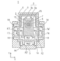
以下に本発明の詳細を、図面を参照して詳細に説明する。図2は本発明の一実施形態である駆動機構1を示す斜視図であり、図3は駆動機構1の移動台5部分のXY平面における横断面を示す図であり、図4は駆動機構1のYZ平面における中央縦断面を示す図である。本発明の駆動機構1は、内部のネジ軸8の回転により移動する移動ブロック2と、移動ブロック2を所定の方向に案内する案内機構3と、ねじ軸8を回転駆動させることにより移動ブロック2を移動させる駆動源4と、移動ブロック2とともに移動する移動台5とを備えている。また、移動ブロック2と案内機構3と駆動源4とは、隔壁6により外部環境(分配装置等の装置内外部環境:以下「作業空間」と称する:後述する作業空間36に相当する)から隔絶された空間に配置されていて、移動台5は隔壁6の外側(作業空間)に配置されている。
The details of the present invention will be described below in detail with reference to the drawings. FIG. 2 is a perspective view showing a drive mechanism 1 according to an embodiment of the present invention, FIG. 3 is a view showing a transverse cross section of a moving table 5 portion of the drive mechanism 1 in an XY plane, and FIG. 4 is a drive mechanism 1 It is a figure which shows the center vertical cross section in a YZ plane. The drive mechanism 1 of the present invention includes a moving block 2 that moves by rotation of an internal screw shaft 8, a guide mechanism 3 that guides the moving block 2 in a predetermined direction, and a moving block 2 that drives the screw shaft 8 to rotate. And a moving table 5 that moves together with the moving block 2. In addition, the moving block 2, the guide mechanism 3, and the drive source 4 are isolated from the external environment (the external environment inside the device such as a distributor: hereinafter referred to as “work space”: corresponding to the work space 36 described later) by the partition wall 6. The movable table 5 is arranged outside the partition wall 6 (work space).
また、移動ブロック2と移動台5には、隔壁6を介して互いに磁力によって引き付け合うように配置される第一駆動磁石ユニットMg1と第一従動磁石ユニットMg2、第二駆動磁石ユニットMg3と第二従動磁石ユニットMg4を備えている。これら磁石ユニットMg1~Mg4の吸着力によるマグネットカップリングによって、移動台5は移動ブロック2の移動に追従して隔壁6に沿って移動する。
The first drive magnet unit Mg1 and the first driven magnet unit Mg2, the second drive magnet unit Mg3, and the second drive magnet unit Mg2 which are arranged on the moving block 2 and the moving table 5 so as to attract each other by magnetic force via the partition wall 6 The driven magnet unit Mg4 is provided. The moving base 5 follows the movement of the moving block 2 and moves along the partition wall 6 by the magnet coupling by the attraction force of these magnet units Mg1 to Mg4.
さらに、移動ブロック2と移動台5の第二駆動磁石ユニットMg3と第二従動磁石ユニットMg4が配置されている面の反対側(図3における右側)面には、互いの磁力により反発するように配置された第一付勢磁石ユニットMg5と第二付勢磁石ユニットMg6が備えられている。この互いに反発するように配置された付勢磁石ユニットMg5、Mg6が発生させる反発力が、移動ブロック2と移動台5との間のマグネットカップリングによる吸着力と同一方向に付勢し補強する付勢力となり、移動台5の隔壁6に対する距離を一定に保つことが出来る。
Further, the surfaces of the moving block 2 and the moving table 5 opposite to the surface on which the second drive magnet unit Mg3 and the second driven magnet unit Mg4 are arranged (on the right side in FIG. 3) are repulsed by mutual magnetic forces. A first biasing magnet unit Mg5 and a second biasing magnet unit Mg6 that are arranged are provided. The repulsive force generated by the biasing magnet units Mg5 and Mg6 arranged so as to repel each other is urged in the same direction as the attraction force by the magnetic coupling between the moving block 2 and the moving base 5 to reinforce. As a result, the distance between the moving table 5 and the partition wall 6 can be kept constant.
本実施形態の駆動機構1が備える案内機構3は、移動ブロック2に固定された移動子3aを所定の方向に案内するガイドレール3bと、ガイドレール3bに対して平行になるように配置されて移動ブロック2に固定されたボールナット7に螺合するネジ軸8と、ネジ軸8に連結されてネジ軸8を回転駆動する駆動源であるモータ4とを備えている。ガイドレール3bは駆動機構1のベースとなるケーシング9の内部空間の一面に固定されており、ネジ軸8はケーシング9に回転可能に固定されている。また、本実施形態の案内機構3を備えるケーシング9は縦長の略直方体形状を有しており、その一端部にはモータ4がブラケット12を介して固定されている。本実施形態の案内機構3が備えるモータ4は、回転軸10がカップリング4aを介してネジ軸8に同心軸状に連結されていて、モータ4の回転軸10が回転動作することによりネジ軸8も回転動作を行う。
The guide mechanism 3 included in the drive mechanism 1 of the present embodiment is arranged so as to be parallel to the guide rail 3b that guides the moving element 3a fixed to the moving block 2 in a predetermined direction. A screw shaft 8 screwed into a ball nut 7 fixed to the moving block 2 and a motor 4 which is a drive source connected to the screw shaft 8 and rotationally driving the screw shaft 8 are provided. The guide rail 3b is fixed to one surface of the internal space of the casing 9 that is the base of the drive mechanism 1, and the screw shaft 8 is rotatably fixed to the casing 9. Further, the casing 9 including the guide mechanism 3 of the present embodiment has a vertically long substantially rectangular parallelepiped shape, and the motor 4 is fixed to one end of the casing 4 via a bracket 12. In the motor 4 included in the guide mechanism 3 of the present embodiment, the rotating shaft 10 is concentrically connected to the screw shaft 8 via the coupling 4a, and the rotating shaft 10 of the motor 4 rotates to rotate the screw shaft 10. 8 also rotates.
ケーシング9の長手方向の壁面には移動ブロック2の位置を検出する位置検出センサS1、S2が設けられている。また、モータ4付近にはモータ4の回転軸10の回転角度を検出する光学式の回転検出センサS3が設けられていて、回転軸10に固定されたセンサドグ11がこの回転検出センサS3の光軸を遮断することで回転軸10の回転位置を検出する。これらのセンサS1、S2、S3はモータ4の回転を制御する制御部70に接続されている。なお、本実施形態の駆動機構1が備えるモータ4は、回転軸10の回転角度制御が容易なステッピングモータであり、制御部70からの制御信号により回転軸10の回転制御が行われる。また、移動ブロック2を検出する位置検出センサS1、S2は、透過光式センサ、反射光式センサ、磁気センサ等が適用可能であるが、それ以外の検出方法によるセンサを使用してもよい。
Position detection sensors S1 and S2 that detect the position of the moving block 2 are provided on the longitudinal wall surface of the casing 9. An optical rotation detection sensor S3 that detects the rotation angle of the rotation shaft 10 of the motor 4 is provided near the motor 4, and a sensor dog 11 fixed to the rotation shaft 10 is an optical axis of the rotation detection sensor S3. The rotation position of the rotary shaft 10 is detected by shutting off. These sensors S1, S2, S3 are connected to a control unit 70 that controls the rotation of the motor 4. The motor 4 included in the drive mechanism 1 of the present embodiment is a stepping motor that allows easy control of the rotation angle of the rotary shaft 10, and rotation control of the rotary shaft 10 is performed by a control signal from the control unit 70. Further, as the position detection sensors S1 and S2 for detecting the moving block 2, a transmitted light type sensor, a reflected light type sensor, a magnetic sensor or the like can be applied, but a sensor according to another detection method may be used.
図1乃至6に例示する実施形態では、駆動機構1が備える移動ブロック2は、略直方体の形状をしており、ガイドレール3bに対向する面F1にはガイドレール3bの移動子3aが固定されている。また、移動ブロック2にはネジ軸8が貫通する孔13が形成されていて、このネジ軸8と螺合するボールナット7が、孔13に挿入された状態で移動ブロック2に固定されている。この構成により、移動ブロック2は、ネジ軸8の回転に連動してガイドレール3bが案内する面内を移動することが出来る。
In the embodiment illustrated in FIGS. 1 to 6, the moving block 2 included in the drive mechanism 1 has a substantially rectangular parallelepiped shape, and the mover 3a of the guide rail 3b is fixed to the surface F1 facing the guide rail 3b. ing. Further, a hole 13 through which the screw shaft 8 penetrates is formed in the moving block 2, and a ball nut 7 screwed with the screw shaft 8 is fixed to the moving block 2 while being inserted into the hole 13. .. With this configuration, the moving block 2 can move in the plane guided by the guide rail 3b in conjunction with the rotation of the screw shaft 8.
また、移動ブロック2の移動子3aが固定された面F1の反対側の面F2(正面)には、第一駆動磁石ユニットMg1が固定されている。さらに、移動ブロック2の正面F2に対向する移動台の5の面F2´には、第一従動磁石ユニットMg2が第一駆動磁石ユニットMg1に対して平行になるように固定されている。この第一駆動磁石ユニットMg1と第一従動磁石ユニットMg2とは互いに異なる磁極が相対することで発生する吸着力による第一のマグネットカップリング機構が構成されている。
The first drive magnet unit Mg1 is fixed to the surface F2 (front surface) opposite to the surface F1 to which the moving element 3a of the moving block 2 is fixed. Further, the first driven magnet unit Mg2 is fixed in parallel to the first drive magnet unit Mg1 on the face F2′ of the moving table 5 facing the front face F2 of the moving block 2. The first drive magnet unit Mg1 and the first driven magnet unit Mg2 constitute a first magnet coupling mechanism by an attractive force generated by mutually opposing magnetic poles.
また、移動ブロック2の正面F2に対してほぼ直角に形成されている左側面(第一側面)F3には、第二駆動磁石ユニットMg3が固定されている。さらに移動ブロック2の第一側面F3に隔壁6を介して対向する移動台5の左側面(第一側面)F3´には、第二従動磁石ユニットMg4が第二駆動磁石ユニットMg3に対して平行になるように固定されている。この第二駆動磁石ユニットMg3と第二従動磁石ユニットMg4とは互いに異なる磁極が相対することで発生する吸着力による第二のマグネットカップリング機構が構成されている。
The second drive magnet unit Mg3 is fixed to the left side surface (first side surface) F3 which is formed substantially at right angles to the front surface F2 of the moving block 2. Further, the second driven magnet unit Mg4 is parallel to the second drive magnet unit Mg3 on the left side surface (first side surface) F3′ of the moving table 5 facing the first side surface F3 of the moving block 2 via the partition wall 6. It is fixed to be. The second drive magnet unit Mg3 and the second driven magnet unit Mg4 constitute a second magnet coupling mechanism by an attractive force generated by mutually opposing magnetic poles.
さらに、移動ブロック2の第一側面F3の反対側に形成されている右側面(第二側面)F4には、第一付勢磁石ユニットMg5が配置されている。また、移動ブロック2の第二側面F4に隔壁2を介して対向する移動台5の右側面(第二側面)F4´には、第二付勢磁石ユニットMg6が第一付勢磁石ユニットMg5に対して平行になるように固定されている。この第一付勢磁石ユニットMg5と第二付勢磁石ユニットMg6とは互いに同じ磁極が相対することで、互いに反発する磁界が形成されている。この第一付勢磁石ユニットMg5と第二付勢磁石ユニットMg6とが発生させる反発力が、第二のマグネットカップリングによる吸着力(移動台5を移動ブロック2の第一側面F3に近接する隔壁6側に密着させるよう作用する吸着力)を補強するように、移動台5の第二側面F4‘が移動ブロック2の第二側面F4から離れる方向に付勢する。この第一付勢磁石ユニットMg5及び第二付勢磁石ユニットMg6は、第一及び/又は第二のマグネットカップリング機構の吸着力を補強することが望ましい場合に選択的に付加することができる。
Further, a first biasing magnet unit Mg5 is arranged on the right side surface (second side surface) F4 formed on the opposite side of the first side surface F3 of the moving block 2. On the right side surface (second side surface) F4′ of the moving table 5 facing the second side surface F4 of the moving block 2 via the partition wall 2, the second biasing magnet unit Mg6 is connected to the first biasing magnet unit Mg5. They are fixed so that they are parallel to each other. The same magnetic poles of the first biasing magnet unit Mg5 and the second biasing magnet unit Mg6 are opposed to each other to form a magnetic field that repels each other. The repulsive force generated by the first biasing magnet unit Mg5 and the second biasing magnet unit Mg6 is the attraction force by the second magnet coupling (the moving table 5 is a partition wall that is close to the first side face F3 of the moving block 2). The second side face F4′ of the moving table 5 is urged in a direction away from the second side face F4 of the moving block 2 so as to reinforce the suction force acting so as to closely adhere to the 6 side. The first biasing magnet unit Mg5 and the second biasing magnet unit Mg6 can be selectively added when it is desired to reinforce the attraction force of the first and/or second magnet coupling mechanism.
本実施形態の駆動機構1が備える隔壁6は、移動ブロック2と案内機構3とモータ4とを作業空間から気密に隔絶する箱状の部材であり、ケーシング9に固定されている。隔壁6により画定される空間の内部は一般大気雰囲気に維持されており、作業空間が過酸化水素ガス等の酸化性ガス雰囲気で充満されたとしても、隔壁6の内部空間に配置されている案内機構3は酸化性ガス雰囲気による腐食作用の影響を受けることがなく、正常に動作することが出来る。
The partition wall 6 included in the drive mechanism 1 of the present embodiment is a box-shaped member that hermetically isolates the moving block 2, the guide mechanism 3, and the motor 4 from the working space, and is fixed to the casing 9. The inside of the space defined by the partition wall 6 is maintained in a general atmospheric atmosphere, and even if the working space is filled with an oxidizing gas atmosphere such as hydrogen peroxide gas, the guide is arranged in the internal space of the partition wall 6. The mechanism 3 can operate normally without being affected by the corrosive action due to the oxidizing gas atmosphere.
本実施形態に例示する駆動機構1が備える移動台5は、略コの字状の断面を有する部材であり、隔壁6が画定する空間の外側の外部環境に、隔壁6を覆うように配置されている。また、本実施形態の移動台5の隔壁6に対向する面である正面F2´、第一側面F3´、第二側面F4´には、それぞれ複数の転動体14が取り付けられている。本実施形態の転動体14は磁石ユニットMg1~Mg4によって発生する磁気吸着力に対抗して移動台5を支持する部材であり、また、隔壁6と移動台5との間の距離を一定に保つ部材である。さらに、隔壁6上を摺動移動する移動台5の摺動抵抗を低減する部材である。転動体14を隔壁6に対抗する面に備えることにより、移動台5は、移動台5の本体が隔壁6に接触することなく、移動ブロック2の移動に追従して隔壁6上を移動することが出来る。
The moving table 5 included in the drive mechanism 1 exemplified in the present embodiment is a member having a substantially U-shaped cross section, and is arranged so as to cover the partition wall 6 in an external environment outside the space defined by the partition wall 6. ing. Further, a plurality of rolling elements 14 are attached to the front face F2′, the first side face F3′, and the second side face F4′, which are the faces facing the partition wall 6 of the moving table 5 of the present embodiment. The rolling element 14 of this embodiment is a member that supports the movable table 5 against the magnetic attraction force generated by the magnet units Mg1 to Mg4, and keeps the distance between the partition wall 6 and the movable table 5 constant. It is a member. Further, it is a member that reduces the sliding resistance of the moving table 5 that slides on the partition wall 6. By providing the rolling element 14 on the surface facing the partition wall 6, the moving base 5 can move on the partition wall 6 following the movement of the moving block 2 without the main body of the moving base 5 contacting the partition wall 6. Can be done.
図5は本実施形態の駆動機構1が備える転動体14を例示する断面図である。本実施形態の転動体14は、樹脂材で円環状に形成された車輪部材14aと、車輪部材14aに挿入される軸受け14bと、軸受け14bの内輪に挿入されるステンレススチール製のシャフト14cと、軸受け14bの内輪と移動台5との間に配置されるカラー14dと略漏斗状の形状を有するシールパッキン14eとで構成されている。シールパッキン14eは車輪部材14aの両側面に配置されていて、さらに、シールパッキン14e先端のリップ部分周縁は車輪部材14aと気密に接触している。これにより、軸受け14bが配置される空間は車輪部材14aとシールパッキン14eとにより作業空間から隔絶された空間となり、酸化性ガスの粒子が軸受け14bに接触することを防止している。
FIG. 5 is a cross-sectional view illustrating the rolling element 14 included in the drive mechanism 1 of this embodiment. The rolling element 14 of the present embodiment includes a wheel member 14a formed of a resin material in an annular shape, a bearing 14b inserted into the wheel member 14a, and a stainless steel shaft 14c inserted into an inner ring of the bearing 14b. It comprises a collar 14d arranged between the inner ring of the bearing 14b and the movable table 5 and a seal packing 14e having a substantially funnel shape. The seal packing 14e is arranged on both side surfaces of the wheel member 14a, and the peripheral edge of the lip portion of the tip of the seal packing 14e is in airtight contact with the wheel member 14a. As a result, the space in which the bearing 14b is arranged becomes a space isolated from the working space by the wheel member 14a and the seal packing 14e, and particles of the oxidizing gas are prevented from coming into contact with the bearing 14b.
なお、円環状の車輪部材14aは、耐摩耗性や耐薬品性の高いエンジニアリングプラスチック、例えばPEEK(ポリエーテルエーテルケトン)やPPS(ポリフェニレンサルファイド)、べスペル(登録商標)といった素材で形成されることが望ましい。また、シールパッキン14eは、フッ素ゴム、アクリルゴムや水素化ニトリルゴム、シリコーン樹脂、酢酸ビニルエチレン樹脂、エチレンプロピレンゴムといった耐熱性や耐薬品性に優れ、柔軟性を有する素材で形成されることが望ましい。
The annular wheel member 14a is formed of an engineering plastic having high wear resistance and chemical resistance, such as PEEK (polyether ether ketone), PPS (polyphenylene sulfide), or Vespel (registered trademark). Is desirable. The seal packing 14e may be formed of a flexible material having excellent heat resistance and chemical resistance, such as fluororubber, acrylic rubber, hydrogenated nitrile rubber, silicone resin, vinyl acetate ethylene resin, and ethylene propylene rubber. desirable.
次に、本実施形態の磁石ユニットMg1~Mg4について説明する。図6(a)、(b)は本実施形態の駆動機構1が備える磁石ユニットMg1~Mg4の永久磁石の配置を示す概略断面図である。図6(a)は駆動機構1の移動ブロック2及び移動台5の永久磁石の極性の配置を示す縦方向部分断面図であり、図6(b)は横断面図である。本実施形態の磁石ユニットMg1~Mg4は、矩形に形成された複数の永久磁石が隣どうしで極性が異なるように格子状に配置されている。また、互いに対向して配置される磁石ユニットMg1~Mg4は、対向する磁石の磁極に対して吸着力が働く磁極を配置するように構成されている。このように構成することで、対向して配置される磁極が異なる磁石どうしの吸着力により図中の矢印が示す方向に移動台5を付勢することとなり、移動ブロック2と移動台5の位置を所定の位置に効果的に維持することが出来る。また、何らかの負荷が移動台5に掛かることにより駆動磁石ユニットMg1、Mg3と従動磁石ユニットMg2、Mg4の位置関係がずれそうになった場合でも、それぞれの磁石は、その隣に配置される同極の磁石どうしで反発し合うので、移動台5の位置を所定の位置に戻す働きをする。
Next, the magnet units Mg1 to Mg4 of this embodiment will be described. 6A and 6B are schematic cross-sectional views showing the arrangement of the permanent magnets of the magnet units Mg1 to Mg4 included in the drive mechanism 1 of this embodiment. 6A is a vertical partial cross-sectional view showing the polar arrangement of the permanent magnets of the moving block 2 and the moving table 5 of the drive mechanism 1, and FIG. In the magnet units Mg1 to Mg4 of the present embodiment, a plurality of rectangular permanent magnets are arranged in a lattice so that adjacent permanent magnets have different polarities. Further, the magnet units Mg1 to Mg4 arranged to face each other are arranged such that magnetic poles that exert an attractive force on the magnetic poles of the magnets that face each other. With such a configuration, the moving base 5 is biased in the direction indicated by the arrow in the figure by the attraction force between the magnets having different magnetic poles facing each other, and the positions of the moving block 2 and the moving base 5 are increased. Can be effectively maintained in place. Further, even if the positional relationship between the drive magnet units Mg1 and Mg3 and the driven magnet units Mg2 and Mg4 is about to shift due to some load being applied to the moving table 5, the respective magnets have the same poles arranged next to each other. Since the two magnets repel each other, they function to return the position of the movable table 5 to a predetermined position.
図7(a)~(c)は駆動磁石ユニットMg1、Mg3と従動磁石ユニットMg2、Mg4の配置をそれぞれ隔壁6側から見たときの極性を例示する図である。磁石ユニットMg1~Mg4に使用される磁石の形状と配置は、図7(a)に示すようなそれぞれ永久磁石を二列に配置する実施形態に限定されることはなく、例えば図7(b)のように永久磁石を三列に配置することも可能であるし、図7(c)のように断面形状が円形の磁石を千鳥格子状に配置する形態とすることも可能である。また、磁石の断面形状を矩形や円形以外の形状とすることも十分可能である。さらに、各磁石に吸着力を増加させるヨークを取付ける構成としてもよい。なお、磁石ユニットMg1~Mg4に使用される磁石には、ネオジム磁石やサマリウムコバルト磁石といった磁力の強い磁石を使用することが望ましい。また、ネオジム磁石やサマリウムコバルト磁石といった磁石は腐食しやすいので、磁石表面を過酸化水素ガス等の腐食性の高いガスに対して耐性を有するニッケル等での表面処理や、シリコーン等の耐性材料でコーティング処理を施しておくことが望ましい。
7A to 7C are diagrams illustrating polarities of the driving magnet units Mg1 and Mg3 and the driven magnet units Mg2 and Mg4 when viewed from the partition wall 6 side, respectively. The shape and arrangement of the magnets used in the magnet units Mg1 to Mg4 are not limited to the embodiment in which the permanent magnets are arranged in two rows as shown in FIG. 7(a). It is also possible to arrange the permanent magnets in three rows as described above, or to arrange the magnets having a circular cross-sectional shape in a zigzag pattern as shown in FIG. 7(c). It is also possible that the cross-sectional shape of the magnet is not rectangular or circular. Further, a yoke may be attached to each magnet to increase the attraction force. It is desirable to use a magnet having a strong magnetic force such as a neodymium magnet or a samarium cobalt magnet as the magnet used in the magnet units Mg1 to Mg4. Also, since magnets such as neodymium magnets and samarium-cobalt magnets are easily corroded, surface treatment of the magnet surface with nickel or the like, which has resistance to highly corrosive gases such as hydrogen peroxide gas, or a resistant material such as silicone. It is desirable to apply a coating process.
次に、本実施形態の第一と第二の付勢磁石ユニットMg5、Mg6について説明する。本実施形態の付勢磁石ユニットMg5、Mg6は、矩形に形成された複数の磁石が隣どうしで極性が異なるように格子状に配置されている。また、互いに対向して配置される付勢磁石ユニットMg5、Mg6は、対向する磁石の磁極に対して反発力が働く磁極を配置するように構成されている。図6(b)を参照。なお、付勢磁石ユニットMg5、Mg6に使用される磁石の形状と配置は、上記実施形態に限定されることはない。例えば、上記説明したように、断面形状が円形の磁石を千鳥格子状に配置する形態とすることも十分可能であるし、磁石の断面形状を矩形や円形以外の形状とすることも十分可能である。また、各磁石に反発力を増加させるヨークを取付ける構成としてもよい。また、付勢磁石ユニットMg5、Mg6に使用される磁石には、ネオジム磁石やサマリウムコバルト磁石といった磁力の強い永久磁石を使用することが望ましい。また、磁石表面を過酸化水素ガス等の腐食性の高いガスに対して耐性を有するニッケル等での表面処理や、シリコーン等の耐性材料でコーティング処理を施しておくことが望ましい。
Next, the first and second biasing magnet units Mg5 and Mg6 of this embodiment will be described. The biasing magnet units Mg5 and Mg6 of the present embodiment are arranged in a grid so that a plurality of rectangular magnets are adjacent to each other and have different polarities. The biasing magnet units Mg5 and Mg6 arranged to face each other are arranged such that magnetic poles that exert repulsive force on the magnetic poles of the magnets that face each other are arranged. See FIG. 6(b). The shape and arrangement of the magnets used for the biasing magnet units Mg5 and Mg6 are not limited to those in the above embodiment. For example, as described above, it is sufficiently possible to arrange the magnets having a circular cross-sectional shape in a staggered pattern, and it is also sufficiently possible to make the cross-sectional shape of the magnets a shape other than rectangular or circular. Is. In addition, a yoke may be attached to each magnet to increase the repulsive force. Further, it is desirable to use a permanent magnet having a strong magnetic force such as a neodymium magnet or a samarium cobalt magnet for the magnets used for the biasing magnet units Mg5 and Mg6. Further, it is desirable that the surface of the magnet is surface-treated with nickel or the like having resistance to highly corrosive gas such as hydrogen peroxide gas, or coated with a resistant material such as silicone.
ところで、移動ブロック2は案内機構3が案内する面内を移動するよう構成されており、進行方向に対して直交する方向の位置ずれは発生しない。しかしながら、移動台5を案内する機構は無く、移動台5は磁石ユニットMg1~Mg4が発生させる磁気的な吸着力によって隔壁6に押さえ付けられているだけなので、移動台5の移動に伴う進行方向に対して直交する方向の位置ずれが発生しやすい。そこで、本実施形態の駆動機構1は、第一付勢磁石ユニットMg5と第二付勢磁石ユニットMg6とで発生させる反発力を、移動台5を隔壁6に押さえ付ける方向に付勢するように構成されている。この移動台5を隔壁6に押さえ付ける付勢力の方向は、磁石ユニットMg3と磁石ユニットMg4とによる移動台5を隔壁6に引き付ける吸着力の方向と同じになるように構成される。これにより移動台5は、磁石ユニットMg3と磁石ユニットMg4とのマグネットカップリング機構の磁気吸着力に加えて、面F3´が隔壁6に向かって押さえつけられる方向に付勢されるので、移動台5は隔壁6が案内する軌道を正確に移動することが可能になる。
By the way, the moving block 2 is configured to move in the plane guided by the guide mechanism 3, and no displacement occurs in the direction orthogonal to the traveling direction. However, there is no mechanism for guiding the moving table 5, and the moving table 5 is only pressed against the partition wall 6 by the magnetic attraction force generated by the magnet units Mg1 to Mg4. A position shift in a direction orthogonal to is likely to occur. Therefore, the drive mechanism 1 of the present embodiment urges the repulsive force generated by the first urging magnet unit Mg5 and the second urging magnet unit Mg6 in the direction of pressing the moving table 5 against the partition wall 6. It is configured. The direction of the biasing force that presses the moving table 5 against the partition wall 6 is configured to be the same as the direction of the attraction force that attracts the moving table 5 to the partition wall 6 by the magnet units Mg3 and Mg4. As a result, the moving table 5 is urged in the direction in which the surface F3′ is pressed toward the partition wall 6 in addition to the magnetic attraction force of the magnet coupling mechanism of the magnet unit Mg3 and the magnet unit Mg4. Can move accurately on the track guided by the partition wall 6.
本実施形態の隔壁6は、滅菌ガスに耐性の低い移動ブロック2や案内機構3、駆動源4を収納して滅菌処理の際に滅菌ガスの充満する作業空間から隔絶するという機能に加えて、移動台5の移動方向を正確に案内するという機能を有している。さらに、磁石ユニットMg1とMg2、Mg3とMg4とで発生させる吸着力に対抗して移動台5を支持する機能に加えて、磁石ユニットMg5とMg6とで発生させる反発力に対抗して移動台5を支持する機能も有している。そこで、こういった吸着力や反発力に対抗するために隔壁6は頑丈な部材を使用することが望ましい。なお、本実施形態の隔壁6は耐腐食性が高く比較的強靭なステンレススチールで形成されている。また、移動台5が備える転動体14が当接する部分には大きな荷重がかかるので、転動体14が通過する軌道に沿って隔壁6の部材の厚みを厚くして荷重に耐える構造とするようにしても良い。さらに、転動体14が通過する軌道に沿って強靭な部材を配置して、磁石ユニットMg1~6が通過する軌道に沿って磁力透過性の高い部材を配置して、それぞれの部材を気密に繋ぎ合わせる構成としてもよい。
The partition wall 6 of the present embodiment has a function of housing the moving block 2 having low resistance to sterilization gas, the guide mechanism 3, and the drive source 4 and isolating it from the working space filled with sterilization gas during the sterilization process. It has a function of accurately guiding the moving direction of the moving table 5. Further, in addition to the function of supporting the movable table 5 against the attraction force generated by the magnet units Mg1 and Mg2 and Mg3 and Mg4, the movable table 5 is supported against the repulsive force generated by the magnet units Mg5 and Mg6. It also has the function of supporting. Therefore, it is desirable to use a sturdy member for the partition wall 6 in order to counter the suction force and the repulsive force. The partition wall 6 of this embodiment is formed of stainless steel having high corrosion resistance and relatively high strength. Further, since a large load is applied to the portion of the moving table 5 with which the rolling elements 14 are in contact, the thickness of the member of the partition wall 6 is increased along the track along which the rolling elements 14 pass so that the structure can withstand the load. May be. Further, a strong member is arranged along the track through which the rolling elements 14 pass, and a member having high magnetic permeability is arranged along the track through which the magnet units Mg1 to 6 pass, and the members are airtightly connected. It may be configured to match.
次に本発明の第二の実施形態である駆動機構15について説明する。図8は本実施形態の駆動機構15のXY平面における断面を示す図である。なお、第一の実施形態である駆動機構1と同じ構成には共通の参照番号を付与している。本実施形態の駆動機構15が備える移動ブロック16は、第一の実施形態の移動ブロック2と同様にX軸と平行な正面F2と、正面F2に対して直角なY軸方向と平行な第一側面F3とを有している。また、本実施形態の駆動機構15が備える移動台17は、第一の実施形態の移動台5と同様にX軸と平行な正面F2´と、正面F2´に対して直角なY軸方向と平行な第一側面F3´とを有している。また、移動ブロック16と移動台17正面F2、F2´、第一側面F3、F3´には第一の実施形態と同様に磁石ユニットMg1、Mg2、Mg3、Mg4が固定されていて、第一駆動磁石ユニットMg1と第一従動磁石ユニットMg2、及び第二駆動磁石ユニットMg3と第二従動磁石ユニットMg4のそれぞれの間は極性の異なる磁極によるマグネットカップリングによって結合している。さらに、第一駆動磁石ユニットMg1と第一従動磁石ユニットMg2、及び第二駆動磁石ユニットMg3と第二従動磁石ユニットMg4との間の空間には、それぞれ正面F2、F2´と第一側面F3、F3´に平行な壁面が形成された隔壁18が配置されている。隔壁18は第一の実施形態の駆動機構1と同様に、移動ブロック16と案内機構3、ボールネジ機構8、駆動源4等を作業空間から気密に隔絶された内部空間に収納している。
Next, the drive mechanism 15 according to the second embodiment of the present invention will be described. FIG. 8 is a view showing a cross section of the drive mechanism 15 of the present embodiment on the XY plane. It should be noted that common reference numerals are given to the same configurations as the drive mechanism 1 according to the first embodiment. The moving block 16 included in the drive mechanism 15 of the present embodiment includes a front face F2 parallel to the X axis and a first parallel to the Y axis direction orthogonal to the front face F2, similarly to the moving block 2 of the first embodiment. It has a side surface F3. Further, the movable table 17 included in the drive mechanism 15 of the present embodiment has a front surface F2′ parallel to the X axis and a Y axis direction perpendicular to the front surface F2′, like the movable table 5 of the first embodiment. It has a parallel first side face F3'. Further, magnet units Mg1, Mg2, Mg3, Mg4 are fixed to the moving block 16 and the moving base 17 front faces F2, F2', first side faces F3, F3' as in the first embodiment, and the first driving is performed. The magnet unit Mg1 and the first driven magnet unit Mg2, and the second drive magnet unit Mg3 and the second driven magnet unit Mg4 are coupled by a magnetic coupling having magnetic poles having different polarities. Further, in the spaces between the first drive magnet unit Mg1 and the first driven magnet unit Mg2, and between the second drive magnet unit Mg3 and the second driven magnet unit Mg4, front faces F2, F2' and a first side face F3, respectively. A partition wall 18 having a wall surface parallel to F3' is arranged. Similar to the drive mechanism 1 of the first embodiment, the partition wall 18 houses the moving block 16, the guide mechanism 3, the ball screw mechanism 8, the drive source 4 and the like in an internal space hermetically isolated from the working space.
本実施形態の移動ブロック16に形成される第二側面F5は、上面視してY軸方向に対して平行に形成された第一の実施形態の移動ブロック2と比較して、θ度傾けて形成されている。また、本実施形態の移動台17に形成される第二側面F5´は、上面視してY軸方向に対して平行に形成された第一の実施形態の移動台5と比較して、θ度傾けて形成されている。また、これに対応して本実施形態の隔壁18の移動ブロック16と移動台17との間に配置される面もまた、第一の実施形態の隔壁6と比較してθ度傾けて形成されている。
The second side face F5 formed on the moving block 16 of the present embodiment is inclined by θ degrees compared to the moving block 2 of the first embodiment formed parallel to the Y-axis direction when viewed from above. Has been formed. Further, the second side face F5′ formed on the moving table 17 of the present embodiment has a θ compared to the moving table 5 of the first embodiment formed parallel to the Y-axis direction when viewed from above. It is formed with a tilt. Corresponding to this, the surface of the partition wall 18 of the present embodiment, which is disposed between the moving block 16 and the moving base 17, is also formed with an inclination of θ degrees compared to the partition wall 6 of the first embodiment. ing.
本実施形態の移動ブロック16に形成される第二側面F5には、第一付勢磁石ユニットMg5が固定され、移動台17の移動ブロック16に対向する第二側面F5´には、第二付勢磁石ユニットMg6が第一付勢磁石ユニットMg5に対向する固定に配置されている。第一付勢磁石ユニットMg5と第二付勢磁石ユニットMg6は、上面視してY軸方向に対してθ度傾けられた状態で第二側面F5、F5´にそれぞれ固定されている。
The first urging magnet unit Mg5 is fixed to the second side face F5 formed on the moving block 16 of the present embodiment, and the second side face F5' of the moving table 17 facing the moving block 16 has a second attaching side. The bias magnet unit Mg6 is fixedly arranged so as to face the first bias magnet unit Mg5. The first biasing magnet unit Mg5 and the second biasing magnet unit Mg6 are fixed to the second side faces F5 and F5′, respectively, in a state of being inclined by θ degrees with respect to the Y-axis direction when viewed from above.
上記構成とすることで、第一付勢磁石ユニットMg5と第二付勢ユニットMg6とが反発することにより発生する付勢力の作用する方向は、X軸方向及びY軸方向のいずれに対しても平行にはなっていない。言い換えると、第一付勢磁石ユニットMg5と第二付勢ユニットMg6とによって生成される付勢力は、移動台17をX軸方向に付勢する成分とY軸方向に付勢する成分の両方の成分を有しているので、移動台17をX軸方向のみならずY軸方向にも押さえ付けることとなる。これにより、移動台17は隔壁18が規定する平面内の軌道を位置ずれすることなく移動することが出来る。
With the above configuration, the direction in which the urging force generated by the repulsion of the first urging magnet unit Mg5 and the second urging unit Mg6 acts in both the X-axis direction and the Y-axis direction. It is not parallel. In other words, the urging forces generated by the first urging magnet unit Mg5 and the second urging unit Mg6 are both the component for urging the moving table 17 in the X-axis direction and the component for urging the moving table 17 in the Y-axis direction. Since it has a component, the movable table 17 is pressed not only in the X-axis direction but also in the Y-axis direction. As a result, the moving table 17 can move along the track defined by the partition wall 18 without displacement.
次に、本発明の駆動機構1を使用した一実施形態である分配装置20について説明する。図9は本実施形態の分配装置20を示す正面図であり、図10はその側面図である。本実施形態の分配装置20は、大容量の容器19に充填されている培地(培養液)を複数の小分け容器21に自動で分配するための装置である。本実施形態の分配装置20は、大容量の容器19を吐出口19aが下になる倒立状態で保持する容器保持ユニット22と、小分け容器21を複数収容する容器ラック23と、容器ラック23を水平方向に移動させるラック移動ユニット24と、容器19に充填されている培地(培養液)を吸引してノズル25から吐出するポンプユニット26と、ノズル25を鉛直方向に昇降移動させるノズル昇降ユニット27とで構成されている。
Next, a distribution device 20 which is an embodiment using the drive mechanism 1 of the present invention will be described. FIG. 9 is a front view showing the distribution device 20 of the present embodiment, and FIG. 10 is a side view thereof. The distribution device 20 of the present embodiment is a device for automatically distributing a medium (culture solution) filled in a large capacity container 19 into a plurality of subdivision containers 21. The distribution device 20 of the present embodiment includes a container holding unit 22 that holds a large-capacity container 19 in an inverted state with the discharge port 19a facing downward, a container rack 23 that stores a plurality of subdivided containers 21, and a container rack 23 that is horizontal. A rack moving unit 24 for moving in the direction, a pump unit 26 for sucking the medium (culture solution) filled in the container 19 and discharging it from the nozzle 25, and a nozzle elevating unit 27 for vertically moving the nozzle 25. It is composed of.
本実施形態の容器保持ユニット22は、大容量の容器19を保持するトレー部28と、トレー部28を水平方向に延在する回転軸L1を回転中心として回転させる駆動源29を備えている。大容量の容器19をトレー部28に固定する際にはトレー部28を寝かせた状態にしておき、容器19をトレー部28に固定して容器19の吐出口19aに吸引用チューブ30を接続した後に、駆動源29を回転動作させて、トレー部28を直立させる。その後、容器19は吐出口19aを下にした倒立状態に維持される。
The container holding unit 22 of this embodiment includes a tray unit 28 that holds a large capacity container 19, and a drive source 29 that rotates the tray unit 28 around a rotation axis L1 that extends in the horizontal direction as a rotation center. When fixing the large-capacity container 19 to the tray part 28, the tray part 28 is left in a lying state, the container 19 is fixed to the tray part 28, and the suction tube 30 is connected to the discharge port 19a of the container 19. After that, the drive source 29 is rotatably operated to erect the tray unit 28. Then, the container 19 is maintained in the inverted state with the discharge port 19a facing down.
ポンプユニット26は、内部に不図示のポンプを備えるものであり、ポンプは吸引用チューブ30を介して容器19に充填された培地(培養液)を吸引して、吐出用チューブ31を介してノズル25から培地(培養液)を吐出する。なお、不図示のポンプは公知のポンプであり、ペリスタルティックポンプや圧電ポンプといった除染が比較的容易であり、且つ試料を汚染する可能性が少ないポンプを使用することが好ましい。
The pump unit 26 has a pump (not shown) inside, and the pump sucks the medium (culture liquid) filled in the container 19 through the suction tube 30 and the nozzle through the discharge tube 31. The medium (culture solution) is discharged from 25. The pump (not shown) is a known pump, and it is preferable to use a pump such as a peristaltic pump or a piezoelectric pump that is relatively easy to decontaminate and that is unlikely to contaminate the sample.
本発明の駆動機構1は、分配装置20のラック移動ユニット24とノズル昇降ユニット27とに使用されている。ラック移動ユニット24は、本発明の駆動機構1を移動台5の正面が上になるように水平方向に寝かせた状態で配置されている。移動台5の上面にはラック載置台32が固定されていて、このラック載置台32の所定の位置に容器ラック23が着脱可能に取り付けられる。容器ラック23には複数の小分け容器21が注入口21aを上にした姿勢で、図面視して左右方向に並べて配置されていて、この容器ラック23はラック載置台32上の所定の位置に固定される。なお、小分け容器21には円筒状の口が3つ備えられており、注入口21a以外の2つの口は小分け容器21の内部に注入された培地の取り出し等に使用されるものであり、注入口21aから培地を注入する際には、これら2つの口は気密に閉じられている。図9(a)は、図面視して容器ラック23の右端に配置された小分け容器21の注入口21aがノズル25の直下に位置するところを示す図であり、図9(b)は、容器ラック23の左端に配置された小分け容器21の注入口21aがノズル25の直下に位置するところを示す図である。ラック移動ユニット24は、移動台5を水平方向に移動させることで、容器ラック23に収容された全ての小分け容器21をノズル25の直下まで移動させるに十分なストロークを有している。これら各小分け容器21をノズル25の直下に移動させるためのモータ4の位置情報は作業者により予め教示されていて、その位置情報は制御部70に記憶されている。
The drive mechanism 1 of the present invention is used for the rack moving unit 24 and the nozzle elevating unit 27 of the distribution device 20. The rack moving unit 24 is arranged in a state in which the drive mechanism 1 of the present invention is laid down horizontally so that the front of the moving table 5 faces upward. A rack mounting table 32 is fixed to the upper surface of the moving table 5, and the container rack 23 is detachably attached to a predetermined position of the rack mounting table 32. In the container rack 23, a plurality of subdivided containers 21 are arranged side by side in the left-right direction in a posture with the inlet 21a facing upward, and the container racks 23 are fixed at predetermined positions on the rack mounting table 32. To be done. Note that the subdivision container 21 is provided with three cylindrical ports, and the two ports other than the injection port 21a are used for taking out the medium injected into the subdivision container 21. When injecting the medium from the inlet 21a, these two ports are airtightly closed. FIG. 9A is a view showing that the injection port 21a of the subdivided container 21 arranged at the right end of the container rack 23 is located immediately below the nozzle 25 as viewed in the drawing, and FIG. FIG. 6 is a view showing a place where an injection port 21 a of the subdivision container 21 arranged at the left end of the rack 23 is located immediately below a nozzle 25. The rack moving unit 24 has a stroke sufficient to move all the subdivided containers 21 accommodated in the container rack 23 to just below the nozzle 25 by moving the moving table 5 in the horizontal direction. The position information of the motor 4 for moving each of the subdivided containers 21 to directly below the nozzle 25 is previously taught by the operator, and the position information is stored in the control unit 70.
ノズル25を鉛直方向に昇降移動させるノズル昇降ユニット27は、本発明の駆動機構1を鉛直方向に立設した状態で備えている。移動台5にはノズル25を固定するノズルブラケット33が固定されている。ノズル昇降ユニット27は、ノズル25が下降した時に、ノズル25が容器ラック23に収容された小分け容器21の注入口21aに挿通出来る位置に配置されている。また、ノズル昇降ユニット27に備えられる駆動機構1は、ノズル25が下降した時にはノズル25の先端が小分け容器21の中央部付近まで到達し、また、小分け容器21の上端部とノズル25の先端部が干渉しない位置まで上昇移動することが可能なストロークを有している。ノズル25の基端部には吐出用チューブ31の先端が接続されていて、ポンプユニット26から供給される培地(培養液)がノズル25へと供給され、小分け容器21に注入される。ノズル25の上昇位置と降下位置に移動させるためのモータ4´の位置情報は作業者により予め教示されていて、その位置情報は制御部70に記憶されている。
A nozzle elevating unit 27 for moving the nozzle 25 up and down in the vertical direction is provided with the drive mechanism 1 of the present invention in an upright state. A nozzle bracket 33 for fixing the nozzles 25 is fixed to the movable table 5. The nozzle elevating unit 27 is arranged at a position where the nozzle 25 can be inserted into the injection port 21a of the subdivided container 21 housed in the container rack 23 when the nozzle 25 descends. Further, in the drive mechanism 1 provided in the nozzle elevating unit 27, when the nozzle 25 descends, the tip of the nozzle 25 reaches near the center of the subdivision container 21, and the upper end of the subdivision container 21 and the tip of the nozzle 25. Has a stroke that allows it to move up to a position where it does not interfere. The tip of a discharge tube 31 is connected to the base end of the nozzle 25, and the culture medium (culture liquid) supplied from the pump unit 26 is supplied to the nozzle 25 and injected into the subdivision container 21. Position information of the motor 4'for moving the nozzle 25 to the raised position and the lowered position is previously taught by the operator, and the position information is stored in the control unit 70.
ラック移動ユニット24とノズル昇降ユニット27の各モータ4、4´と容器保持ユニット22の駆動源29、及びポンプユニット26のポンプの作動は、不図示の分配装置制御ユニットによって制御される。分配装置制御ユニットは、少なくとも、公知のコンピュータと、動作プログラムや予め教示された各種データを保存する記憶部と、上位側のホストコンピュータとの間で通信を行う通信部とで構成されていて、各センサからの入力信号を受信して予め記憶した動作プログラムに沿って各ユニットが備える制御部に動作指令を送信して各駆動機構を動作させる。上記構成により、本実施形態の分配装置20は、大容量容器19に充填されている培地(培養液)を容器ラック23に収納されている複数の小分け容器21に順次、自動で分配することが出来る。分配装置制御ユニット内に駆動機構1の制御部70を包含させることもできる。
The operation of the motors 4 and 4 ′ of the rack moving unit 24 and the nozzle lifting unit 27, the drive source 29 of the container holding unit 22, and the pump of the pump unit 26 are controlled by a distributor control unit (not shown). The distribution device control unit is composed of at least a known computer, a storage unit that stores an operation program and various data taught in advance, and a communication unit that communicates with a host computer on the upper side, An input signal from each sensor is received, an operation command is transmitted to a control unit included in each unit according to an operation program stored in advance, and each drive mechanism is operated. With the above configuration, the distribution device 20 of the present embodiment can automatically and sequentially distribute the medium (culture solution) filled in the large capacity container 19 to the plurality of subdivision containers 21 housed in the container rack 23. I can. The control unit 70 of the drive mechanism 1 may be included in the distributor control unit.
なお、本実施形態の分配装置20を構成する各ユニットはベース板34上に固定されている。また、本実施形態の分配装置20は、図11,12に例示するような過酸化水素ガス滅菌が可能な無菌作業装置35の作業空間36内に配置される。図11は本実施形態の分配装置20を備える無菌作業装置35を例示する正面図であり、図12は無菌作業装置の作業空間36の内部構成の概略を示す側面図である。無菌作業装置35はアイソレータとも呼ばれるものであり、無菌作業装置35の内部には、外部雰囲気から隔離された清浄な作業空間36が形成されている。また、無菌作業装置35の隣には、無菌保管装置44が連結されていて、この無菌保管装置44の保管庫と作業空間36とを連通させる通路は扉45(図12)によって仕切られている。作業空間36は、無菌作業装置35の上部及び下部に配置される不図示のHEPAフィルタ(High Efficiency Particulate Air Filter)を通過して流入させた清浄空気を循環させることにより、所定の清浄度に維持されている。
Note that each unit constituting the distribution device 20 of this embodiment is fixed on the base plate 34. Further, the distribution device 20 of the present embodiment is arranged in the work space 36 of the aseptic work device 35 capable of performing hydrogen peroxide gas sterilization as illustrated in FIGS. FIG. 11 is a front view illustrating a sterile work device 35 including the distribution device 20 of the present embodiment, and FIG. 12 is a side view schematically showing an internal configuration of a work space 36 of the sterile work device. The aseptic working apparatus 35 is also called an isolator, and a clean working space 36 isolated from the external atmosphere is formed inside the aseptic working apparatus 35. A sterile storage device 44 is connected next to the aseptic working device 35, and a passage for connecting the storage of the sterile storage device 44 and the working space 36 is partitioned by a door 45 (FIG. 12). .. The work space 36 is maintained at a predetermined cleanliness level by circulating clean air that has flowed in through a HEPA filter (High Efficiency Particulate Air Filter) (not shown) disposed above and below the aseptic work device 35. Has been done.
作業空間36の正面側には作業空間36を気密に閉鎖可能な正面扉37が取り付けられていて、本実施形態の分配装置20はこの正面扉37を開けて作業空間36内部に設置される。正面扉37には、作業者が作業空間36内部を観察できるように透明なガラスや樹脂で成型された窓38が備えられている。また、窓38の所定の位置には円形の開口が形成されていて、この開口にはグローブ39が気密に固定されている。外部環境に居る作業者はこのグローブ39を両腕に装着することで、窓38から作業空間36内部を目視しながら作業空間36に搬入された物品に対して所定の処置を施すことが出来る。また、本実施形態の無菌作業装置35には、過酸化水素蒸気等の滅菌ガスを供給する不図示の滅菌装置が接続されている。この滅菌装置から供給される滅菌ガスを作業空間36に充満させることで、作業空間36と作業空間36に配置される分配装置20とは滅菌処理される。なお、本実施形態の分配装置20の動作を制御する制御ユニットと分配装置20に電源を供給する電源ユニット、及び各ユニットの動作を制御する制御部は、作業空間36に充満される滅菌ガスの影響を受けないようにするため、無菌作業装置35内部の作業空間36から隔絶された空間に配置されている。
A front door 37 that can hermetically close the work space 36 is attached to the front side of the work space 36, and the distribution device 20 of the present embodiment is installed inside the work space 36 by opening the front door 37. The front door 37 is provided with a window 38 formed of transparent glass or resin so that an operator can observe the inside of the work space 36. Further, a circular opening is formed at a predetermined position of the window 38, and a globe 39 is airtightly fixed to this opening. By wearing the gloves 39 on both arms, the worker in the external environment can perform a predetermined treatment on the article carried into the work space 36 while viewing the inside of the work space 36 through the window 38. Further, the aseptic work device 35 of the present embodiment is connected to a sterilizer (not shown) that supplies a sterilizing gas such as hydrogen peroxide vapor. By filling the sterilizing gas supplied from the sterilizer into the work space 36, the work space 36 and the distribution device 20 arranged in the work space 36 are sterilized. The control unit that controls the operation of the distribution apparatus 20 of the present embodiment, the power supply unit that supplies power to the distribution apparatus 20, and the control unit that controls the operation of each unit are provided with a sterilizing gas filling the working space 36. In order not to be affected, it is arranged in a space isolated from the work space 36 inside the aseptic work device 35.
また、無菌作業装置35には作業空間36に隣接してパスボックス40が備えられている。パスボックス40は作業空間36と外部環境との間で物品を遣り取りするための箱状の滅菌機能付き装置である。作業空間36内の作業に必要な比較的容積の小さい機器や培地等の試料は、このパスボックス40を介して作業空間36内に持ち込まれる。パスボックス40には、パスボックス40の内部空間に持ち込まれた物品を紫外線や滅菌ガスで滅菌する滅菌手段と、外部環境とパスボックス40の内部空間とを仕切る扉41と、パスボックス40の内部空間と作業空間36とを仕切る不図示の扉とが備えられている。
Further, the aseptic work device 35 is provided with a pass box 40 adjacent to the work space 36. The pass box 40 is a box-shaped device with a sterilizing function for exchanging articles between the work space 36 and the external environment. Samples such as a medium and a medium having a relatively small volume necessary for work in the work space 36 are brought into the work space 36 via the pass box 40. In the pass box 40, a sterilizing means for sterilizing articles brought into the internal space of the pass box 40 with ultraviolet rays or a sterilizing gas, a door 41 for partitioning the external environment from the internal space of the pass box 40, and the inside of the pass box 40 A door (not shown) that partitions the space and the work space 36 is provided.
物品を作業空間36内に搬入する際には、作業者は無菌作業装置35の正面に配置される扉41を開けて物品をパスボックスの内部空間に搬入した後、扉41を閉鎖して、パスボックス40の内部空間の滅菌処理を行う。この滅菌処理が完了したら、作業者はグローブ39を装着して、作業空間36とパスボックス40の内部空間とを仕切る扉を作業空間36側から開扉して物品を作業空間36内に搬入した後、この扉を閉鎖する。上記手順により、作業空間36内に搬入される物品は無菌化されるので、作業空間36は清浄な状態に維持される。
When carrying the article into the work space 36, the operator opens the door 41 arranged in front of the aseptic work device 35 to carry the article into the internal space of the pass box, and then closes the door 41. Sterilization of the internal space of the pass box 40 is performed. When this sterilization process is completed, the worker wears the glove 39, opens the door that partitions the work space 36 and the internal space of the pass box 40 from the work space 36 side, and carries the article into the work space 36. Later, this door is closed. By the above procedure, the articles carried into the work space 36 are sterilized, so that the work space 36 is maintained in a clean state.
次に、無菌作業装置35に設置された本実施形態の分配装置20の動作について説明する。本実施形態の分配装置20にセットされる容器19、小分け容器21、容器ラック23は、パスボックス40を介して作業空間36に搬入される。作業者はグローブ39を装着した状態で、小分け容器21を容器ラック23にセットした後、ラック移動ユニット24のラック載置台32上に容器ラック23を固定する。次に作業者は、容器19の吐出口19aに吸引用チューブ30を接続した後、容器19をトレー部28に固定する。その後無菌作業装置35のタッチパネル42や操作パネル43を操作して、分配装置20の自動分配動作を開始する。
Next, the operation of the distribution device 20 of the present embodiment installed in the aseptic work device 35 will be described. The container 19, the subdivided container 21, and the container rack 23 set in the distribution device 20 of the present embodiment are carried into the work space 36 via the pass box 40. The worker sets the subdivided container 21 on the container rack 23 while wearing the gloves 39, and then fixes the container rack 23 on the rack mounting table 32 of the rack moving unit 24. Next, the operator connects the discharge tube 19a of the container 19 to the suction tube 30 and then fixes the container 19 to the tray portion 28. After that, the touch panel 42 and the operation panel 43 of the aseptic work device 35 are operated to start the automatic distribution operation of the distribution device 20.
動作開始の信号を受信すると、制御ユニットは容器保持ユニット22の駆動源29を作動させて容器19が倒立姿勢となるまでトレー部28を回転移動させ、次にラック移動ユニット24のモータ4を作動させて容器ラック23を所定の位置まで移動させる。ここで、所定の位置とは、容器ラック23に収容されている小分け容器21のうち、容器ラック23の端部に配置される小分け容器21の注入口21aがノズル昇降ユニット27のノズル25の直下に位置する地点であり、この位置情報は予め制御部70に記憶されている。
When the operation start signal is received, the control unit operates the drive source 29 of the container holding unit 22 to rotate and move the tray section 28 until the container 19 is in the inverted posture, and then operates the motor 4 of the rack moving unit 24. Then, the container rack 23 is moved to a predetermined position. Here, the predetermined position means that, of the subdivision containers 21 accommodated in the container rack 23, the injection port 21 a of the subdivision container 21 arranged at the end of the container rack 23 is directly below the nozzle 25 of the nozzle lifting unit 27. The location information is stored in the control unit 70 in advance.
次に制御ユニットは、ノズル昇降ユニット27のモータ4を作動させて、ノズル25の直下に位置する小分け容器21の注入口21aにノズル25が挿通されるまでノズル25を下降させる。その後制御ユニットはポンプユニット26を作動させて、容器19に充填されている培地(培養液)を小分け容器21に注入する。所定の量の培地(培養液)が注入されると、制御ユニットはポンプユニット26の作動を停止した後ノズル25を小分け容器21から離間する位置まで上昇移動させる。その後、ラック移動ユニット24のモータ4を作動させて、培地(培養液)を充填し終えた小分け容器21の隣の小分け容器21がノズル25の直下に位置するように容器ラック23を移動させる。上記手順を繰り返すことで容器ラック23に収容される小分け容器21に順次培地(培養液)を自動で注入していく。
Next, the control unit operates the motor 4 of the nozzle elevating unit 27 to lower the nozzle 25 until the nozzle 25 is inserted into the injection port 21a of the subdivision container 21 located immediately below the nozzle 25. After that, the control unit operates the pump unit 26 to inject the medium (culture solution) filled in the container 19 into the subdivided container 21. When a predetermined amount of culture medium (culture liquid) is injected, the control unit stops the operation of the pump unit 26 and then moves the nozzle 25 upward to a position away from the subdivision container 21. After that, the motor 4 of the rack moving unit 24 is operated to move the container rack 23 so that the subdivision container 21 next to the subdivision container 21 that has been filled with the culture medium (culture solution) is located immediately below the nozzle 25. By repeating the above procedure, the medium (culture solution) is automatically and sequentially injected into the subdivided containers 21 housed in the container rack 23.
培地(培養液)の小分け容器21への分配が終了すると、作業者は扉45を開けて保管装置44の保管庫に容器ラック23と充填が完了した小分け容器21とを運び出して、パスボックス40から次の容器ラック23と小分け容器21とを分配装置20へと運び入れる。また、必要に応じて、作業空間36内と分配装置20とを滅菌ガスにより滅菌処理する。
When the distribution of the medium (culture solution) to the subdivision containers 21 is completed, the operator opens the door 45 to carry out the container rack 23 and the filled subdivision containers 21 to the storage of the storage device 44, and the pass box 40. Then, the next container rack 23 and the subdivided container 21 are carried into the distributor 20. Further, the inside of the work space 36 and the distribution device 20 are sterilized with a sterilizing gas, if necessary.
次に、本発明の他の実施形態である分配密封装置46について説明する。図13、14は本実施形態の分配密封装置46を示す正面図であり、図15は分配密封装置46を、図13における第一及び第二の容器昇降ユニット47a、47bの間及び第一及び第二の注入口保持ユニット49aと49bの間の位置から、第一の容器昇降ユニット47a及び第一の注入補助ユニット52側を見た状態を示す側面図である。本実施形態の分配密封装置46は、本発明の第一の実施形態である分配装置20に加えて、柔軟な小分け容器21の注入口21aを保持して確実に培地の供給を行うための注入口保持ユニット49a、49bと、更に、小分け容器21の注入口21aを熱により溶着させて密封するための溶着ユニット60を備えている。さらに、本実施形態の分配密封装置46は、容器ラック23に収納された小分け容器21を個別に持ち上げる二つの容器昇降ユニット47a、47bを備えている。容器昇降ユニット47a、47bは、小分け容器21を下方から支持する容器支持部材48と、この容器支持部材48を鉛直方向に昇降移動させる駆動機構1とで構成されている。容器昇降ユニット47a、47bはベース板34の下面に固定されていて、ベース板34と容器ラック23の底部に形成された開口部を介して小分け容器21を下方から支持して昇降移動させる。
Next, a distribution sealing device 46 which is another embodiment of the present invention will be described. 13 and 14 are front views showing the distribution sealing device 46 of the present embodiment, and FIG. 15 shows the distribution sealing device 46 between the first and second container elevating units 47a and 47b in FIG. It is a side view which shows the state which looked at the 1st container raising/lowering unit 47a and the 1st injection auxiliary unit 52 side from the position between the 2nd injection port holding units 49a and 49b. The distribution sealing device 46 of the present embodiment, in addition to the distribution device 20 of the first embodiment of the present invention, holds the injection port 21a of the flexible subdivision container 21 to ensure the supply of the medium. The inlet holding units 49a and 49b and a welding unit 60 for welding and sealing the inlet 21a of the subdivision container 21 by heat are provided. Further, the distribution sealing device 46 of this embodiment includes two container elevating units 47a and 47b for individually lifting the subdivided containers 21 housed in the container rack 23. The container lifting units 47a and 47b are composed of a container support member 48 that supports the subdivided container 21 from below, and a drive mechanism 1 that moves the container support member 48 up and down in the vertical direction. The container elevating units 47a and 47b are fixed to the lower surface of the base plate 34, and support the subdivision containers 21 from below through the base plate 34 and the openings formed in the bottom of the container rack 23 to move them up and down.
複数の小分け容器21が並べて収容された容器ラック23がラック移動ユニット24によって図面視して左から右へと移動することで、右端の小分け容器21から順次培地を注入され、その後、溶着ユニット60によって注入口21aを密閉処理される。以下順次説明する。
容器ラック23が所定の位置まで達すると、第一の容器昇降ユニット47aが作動して、容器ラック23の右端に収容されている小分け容器21(第一の小分け容器21-1)を上昇移動させる。第一の容器昇降ユニット47aによって所定の位置まで上昇移動させられた第一の小分け容器21-1は、第一の注入口保持ユニット49aによって注入口21aが所定の高さとなる位置に保持される。注入口21aが注入口保持ユニット49によって保持されると、ノズル昇降ユニット27が作動してノズル25が注入口21aに挿入されて、第一の小分け容器21-1の内部に培地が供給される。培地の供給が終了すると、ノズル25が注入口21aから取り出されて、注入口保持ユニット49による注入口21aの保持が解除される。その後、第一の小分け容器21-1は容器昇降ユニット47aが下降することによって容器ラック23へと戻される。 Acontainer rack 23, which accommodates a plurality of subdivided containers 21 side by side, is moved from the left to the right by the rack moving unit 24 as viewed in the drawing, whereby the medium is sequentially injected from the subdivided containers 21 at the right end, and then the welding unit 60. The inlet 21a is sealed by the method. The following is a sequential description.
When thecontainer rack 23 reaches a predetermined position, the first container elevating unit 47a operates to move the subdivision container 21 (first subdivision container 21-1) accommodated at the right end of the container rack 23 upward. .. The first subdivision container 21-1 moved up to a predetermined position by the first container elevating unit 47a is held by the first injection port holding unit 49a at a position where the injection port 21a has a predetermined height. .. When the inlet 21a is held by the inlet holding unit 49, the nozzle elevating unit 27 operates and the nozzle 25 is inserted into the inlet 21a, so that the medium is supplied into the first subdivision container 21-1. .. When the supply of the medium is completed, the nozzle 25 is taken out from the inlet 21a, and the holding of the inlet 21a by the inlet holding unit 49 is released. Thereafter, the first subdivision container 21-1 is returned to the container rack 23 by the container elevating unit 47a descending.
容器ラック23が所定の位置まで達すると、第一の容器昇降ユニット47aが作動して、容器ラック23の右端に収容されている小分け容器21(第一の小分け容器21-1)を上昇移動させる。第一の容器昇降ユニット47aによって所定の位置まで上昇移動させられた第一の小分け容器21-1は、第一の注入口保持ユニット49aによって注入口21aが所定の高さとなる位置に保持される。注入口21aが注入口保持ユニット49によって保持されると、ノズル昇降ユニット27が作動してノズル25が注入口21aに挿入されて、第一の小分け容器21-1の内部に培地が供給される。培地の供給が終了すると、ノズル25が注入口21aから取り出されて、注入口保持ユニット49による注入口21aの保持が解除される。その後、第一の小分け容器21-1は容器昇降ユニット47aが下降することによって容器ラック23へと戻される。 A
When the
次に、ラック移動ユニット24を次の小分け容器21がノズル25の真下に位置するまで容器ラック23を図面視して右方向へ移動させる。そして、各ユニットは順次上述した培地供給動作を行う。こうして容器ラック23に収容された小分け容器21に順次培地を供給していく。そして、第一の小分け容器21-1が第二の容器昇降ユニット47bの真上まで移動したところで、第一の小分け容器21-1は第二の容器昇降ユニット47bによって所定の位置まで上昇させられて、注入口21aの密閉動作が開始される(図14、図15を参照)。第二の容器昇降ユニット47bによって所定の位置まで上昇移動させられた第一の小分け容器21-1は、第二の注入口保持ユニット49bによって注入口21aを所定に位置に位置するように保持される。注入口21aが注入口保持ユニット49によって保持されると注入口21aは溶着ユニット60が備える加熱部材66によって押圧され、且つ溶着されて密封される。
Next, the rack moving unit 24 is moved to the right while viewing the container rack 23 until the next subdivided container 21 is located directly below the nozzle 25. Then, each unit sequentially performs the medium supply operation described above. In this way, the medium is sequentially supplied to the subdivision containers 21 housed in the container rack 23. Then, when the first subdivision container 21-1 has moved to just above the second container lifting/lowering unit 47b, the first subdivision container 21-1 is lifted to a predetermined position by the second container lifting/lowering unit 47b. Then, the sealing operation of the inlet 21a is started (see FIGS. 14 and 15). The first subdivision container 21-1 moved up to a predetermined position by the second container elevating unit 47b is held by the second injection port holding unit 49b so that the injection port 21a is located at a predetermined position. It When the inlet 21a is held by the inlet holding unit 49, the inlet 21a is pressed by the heating member 66 included in the welding unit 60, and is welded and sealed.
また、小分け容器21は、ノズル25から培地を注入される際に第一の注入口保持ユニット49aの下側に設けられている注入補助ユニット52によって、向かい合う容器壁面を吸引保持され、互いに離間する方向に引き離される。図16は注入補助ユニット52の動作を示す図である。全ての小分け容器21は樹脂製のシートを向い合せに貼り合せて製作されており、内部に培地を供給するには大きな注入圧が必要になる。そのため、この注入補助ユニット52によって容器側面を互いに離間する方向に引き離されることで小分け容器21内部に空間が形成されて、培地の注入が容易になる。注入補助ユニット52の小分け容器21の側面に当接する部分には向かい合うように二つの吸盤53a、53bが備えられている。この各吸盤53a、53bは一対のシャフト63a、63bのそれぞれの先端部に固定されている。一対のシャフト63a、63bは、注入補助ユニット52内に備えられる駆動源によって挟持および挟持解除動作を行う。注入補助ユニット52は、小分け容器21が第一の容器昇降ユニット47aによる上昇移動が終了すると、小分け容器21の側面を左右両側から挟持する。図16(a)を参照。次に注入補助ユニット52は、不図示の真空源からの真空圧により小分け容器21の両側面を吸盤53a、53bで吸着保持して、注入補助ユニット52が備える開閉機構によって、密着していた小分け容器21の両壁面を離間させて、小分け容器21の内部に空間を生じさせる。図16(b)を参照。注入補助ユニット52の本体ケーシング52aと各シャフト63a、63bとの間には、ケーシング52aの内部空間を気密に閉鎖するベローズ部材57が配置されている。上記構成により、ケーシング52a内部は滅菌ガスの侵入を防止している。
In addition, the subdivided container 21 is suction-held on the opposing container wall surfaces by the injection auxiliary unit 52 provided below the first injection port holding unit 49a when the medium is injected from the nozzle 25, and is separated from each other. Pulled away in the direction. FIG. 16 is a diagram showing the operation of the injection assisting unit 52. All the subdivided containers 21 are manufactured by laminating resin sheets face to face, and a large injection pressure is required to supply the medium inside. Therefore, the infusion assisting unit 52 separates the side surfaces of the container in a direction in which they are separated from each other, so that a space is formed inside the subdivision container 21 and the medium can be easily injected. Two suction cups 53a and 53b are provided so as to face each other in a portion of the injection auxiliary unit 52 that abuts the side surface of the subdivision container 21. The suction cups 53a and 53b are fixed to the respective tip portions of the pair of shafts 63a and 63b. The pair of shafts 63a and 63b are clamped and clamped by a drive source provided in the injection assisting unit 52. The injection assisting unit 52 holds the side surface of the subdivision container 21 from the left and right sides when the subdivision container 21 has finished the upward movement by the first container lifting unit 47a. See FIG. 16(a). Next, the injection auxiliary unit 52 sucks and holds both side surfaces of the subdivision container 21 with suction cups 53a and 53b by a vacuum pressure from a vacuum source (not shown), and the opening and closing mechanism provided in the injection auxiliary unit 52 causes the subdivided subdivisions to be in close contact Both walls of the container 21 are separated from each other to create a space inside the subdivided container 21. See FIG. 16(b). A bellows member 57 that hermetically closes the internal space of the casing 52a is arranged between the main body casing 52a of the injection auxiliary unit 52 and the shafts 63a and 63b. With the above configuration, the inside of the casing 52a is prevented from entering the sterilizing gas.
次に第1及び第2の注入口保持ユニット49a、49b(以下特に必要がない限り、単に「注入口保持ユニット49」と称する)について説明する。図17は注入口保持ユニット49の構成と動作を示す断面図である。注入口保持ユニット49には左右対称に配置される一対の注入口保持部材54a、54bが備えられていて、この注入口保持部材54a、54bが開閉動作することで注入口21aの保持および保持解除を行う。本実施形態の保持ユニット49は、各注入口保持部材54a、54bを開閉動作させる駆動源として公知のステッピングモータ55a、55bを備えている。ステッピングモータ55a、55bは注入口保持ユニット49が備えるケーシング56の内部に配置されている。また、各注入口保持部材54a、54bとケーシング56との間にはケーシング56の内部空間を気密に閉鎖するベローズ部材57が配置されている。ケーシング56自体も気密に形成されており、上記構成により、ケーシング56内部は滅菌ガスの侵入を防止することが出来る。また、ケーシング56内部には透過光センサ58a~58dが配置されていて、この透過光センサ58a~58dの光軸を各注入口保持部材54a、54bの基端部に配置されるセンサドグ59a、59bが開閉動作により遮光することで、溶着ユニット60の制御部は各注入口保持部材54a、54bが開状態にあるか閉状態にあるかを認識することが出来る。なお、注入補助ユニット52の吸盤53a、53bを開位置と閉位置に移動させる駆動機構も上記した機構と同様のものが備えられている。
Next, the first and second inlet holding units 49a and 49b (hereinafter simply referred to as "inlet holding unit 49" unless otherwise necessary) will be described. FIG. 17 is a sectional view showing the structure and operation of the inlet holding unit 49. The inlet holding unit 49 is provided with a pair of inlet holding members 54a and 54b which are symmetrically arranged, and the inlet holding members 54a and 54b are opened and closed to hold and release the inlet 21a. I do. The holding unit 49 of this embodiment includes stepping motors 55a and 55b known as drive sources for opening and closing the inlet holding members 54a and 54b. The stepping motors 55a and 55b are arranged inside a casing 56 included in the inlet holding unit 49. In addition, a bellows member 57 that hermetically closes the internal space of the casing 56 is arranged between each of the inlet holding members 54a and 54b and the casing 56. The casing 56 itself is also formed airtight, and with the above configuration, the inside of the casing 56 can be prevented from entering the sterilizing gas. Further, transmitted light sensors 58a to 58d are arranged inside the casing 56, and sensor dogs 59a and 59b are arranged so that the optical axes of the transmitted light sensors 58a to 58d are arranged at the base end portions of the injection port holding members 54a and 54b. By blocking the light by the opening/closing operation, the control unit of the welding unit 60 can recognize whether each of the inlet holding members 54a and 54b is in the open state or the closed state. The drive mechanism for moving the suction cups 53a and 53b of the injection auxiliary unit 52 to the open position and the closed position is also the same as the above-mentioned mechanism.
次に、溶着ユニット60について説明する。図18は溶着ユニット60の構成と動作を示す断面図である。本実施形態の溶着ユニット60は、小分け容器21の注入口21aを熱により溶着させて小分け容器21の内部を密封する装置である。小分け容器21の注入口21aはナイロンやポリプロピレンといった熱可塑性樹脂で形成されていて、熱を加えることにより容易に密封することが出来る。本実施形態の溶着ユニット60には、注入口21aに対して進退移動する一対のシャフト62a、62bのそれぞれの先端に加熱部材66a、66bが固定されている。本実施形態の溶着ユニット60が備える加熱部材66a、66bはアルミニウムで形成されており、内部にはヒータが備えられていて、これにより、加熱部材66a、66bは注入口21aを溶着可能な温度に加熱される。また、加熱部材66a、66bの表面はフッ素樹脂でコーティングされている。これにより、加熱された注入口21aの樹脂材料が加熱部材66a、66bに付着することが防止される。また、一対のシャフト62a、62bを進退移動させる駆動機構は、注入口保持ユニット49が備える駆動機構と同様のものが備えられている。上記構成により、溶着ユニット60は注入口21aの先端部を加熱しながら押圧することで、注入口21aを密閉することが出来る。なお、溶着ユニット60の下方に注入口保持ユニット49を備えることで、注入口21aを溶着する前に注入口21aを所定の位置に保持することができるので、確実な溶着が可能となる。
Next, the welding unit 60 will be described. FIG. 18 is a sectional view showing the structure and operation of the welding unit 60. The welding unit 60 of the present embodiment is a device that seals the inside of the subdivision container 21 by welding the inlet 21a of the subdivision container 21 with heat. The injection port 21a of the subdivision container 21 is made of a thermoplastic resin such as nylon or polypropylene, and can be easily sealed by applying heat. In the welding unit 60 of the present embodiment, heating members 66a and 66b are fixed to the tips of a pair of shafts 62a and 62b that move forward and backward with respect to the inlet 21a. The heating members 66a and 66b included in the welding unit 60 of the present embodiment are formed of aluminum, and a heater is provided inside, so that the heating members 66a and 66b have a temperature at which the inlet 21a can be welded. Be heated. The surfaces of the heating members 66a and 66b are coated with fluororesin. This prevents the heated resin material of the inlet 21a from adhering to the heating members 66a and 66b. The drive mechanism for moving the pair of shafts 62a, 62b back and forth is the same as the drive mechanism of the inlet holding unit 49. With the above structure, the welding unit 60 can seal the inlet 21a by pressing the tip of the inlet 21a while heating. By providing the injection port holding unit 49 below the welding unit 60, the injection port 21a can be held at a predetermined position before the injection port 21a is welded, so that reliable welding is possible.
また、本実施形態の溶着ユニット60の下方には、小分け容器21を下方から支持する第二の容器昇降ユニット47bが配置されていて、溶着ユニット60は第二の容器昇降ユニット47bによって所定の位置まで上昇させられた培地注入済み小分け容器21に対して注入口21aの先端部を溶着して密封する。本実施形態の分配密封装置46では、小分け容器21を収納したラック23は、第一の実施形態である分配装置20と同様に、ラック移動ユニット24によって順次移動させられる。また、本実施形態の分配密封装置46が備えるノズル昇降ユニット27と溶着ユニット60との離間距離はラック23の小分け容器21を収納する間隔の整数倍とすることが望ましい。小分け容器21の収納間隔の整数倍とすることで、所定の位置にあるラック23に収納された小分け容器21に培地を注入している最中に、既に培地注入を終えた別の小分け容器21の注入口21aを溶着ユニット60によって密封することが出来る。
In addition, below the welding unit 60 of the present embodiment, a second container elevating unit 47b that supports the subdivided container 21 from below is arranged, and the welding unit 60 is positioned at a predetermined position by the second container elevating unit 47b. The tip portion of the injection port 21a is welded and sealed to the subdivided container 21 into which the medium has been injected, which has been raised up to. In the distribution and sealing device 46 of the present embodiment, the rack 23 accommodating the subdivided containers 21 is sequentially moved by the rack moving unit 24, similarly to the distribution device 20 of the first embodiment. Further, it is desirable that the distance between the nozzle elevating unit 27 and the welding unit 60 included in the distribution sealing device 46 of the present embodiment is an integral multiple of the distance in which the subdivided containers 21 of the rack 23 are stored. By setting the storage interval of the subdivision container 21 to be an integral multiple, another subdivision container 21 in which the medium has already been injected while the medium is being injected into the subdivision container 21 stored in the rack 23 at the predetermined position. The injection port 21a can be sealed by the welding unit 60.
なお、本発明の駆動機構1を利用した装置は上記の分配装置20や分配密封装置46に限定されることは無く、例えば、細胞の播種や試薬の分注を行う分注装置や、培養中の細胞の培地(培養液)を交換する培地交換装置といった、対象物を直線方向に移動させる直動機構を備え、且つ腐食性ガスによる滅菌処理が必要な装置には好適である。また、細胞培養に直接関係する装置に限らず、例えば、培養中の細胞を顕微鏡で観察したり、培養した細胞の株分けを行ったりする培養細胞取扱装置に適用することも出来る。
The device using the drive mechanism 1 of the present invention is not limited to the above-mentioned distribution device 20 and distribution sealing device 46. For example, a dispensing device for seeding cells or dispensing reagents, or during culture. It is suitable for an apparatus such as a medium exchanging device for exchanging the medium (culture solution) of cells, which has a direct-acting mechanism for moving an object in a linear direction and which needs sterilization treatment with corrosive gas. Further, the present invention is not limited to an apparatus directly related to cell culture, and can be applied to, for example, a cultured cell handling apparatus for observing cells in culture with a microscope and dividing cultured cells.
また、本発明の実施形態では、移動ブロック2、16が備える動側磁石ユニットMg1、Mg3、及び第一付勢磁石ユニットMg5には永久磁石を使用しているが、本発明はこれに限定されることはなく、永久磁石の代わりに電磁石を備える形態としても良い。さらに、本実施形態では、駆動源4の駆動力を移動ブロック2、16に伝達する手段としてボールナット7とネジ軸8を備えているが、本発明はこれに限定されることはなく、例えば、ベルトやチェーンといった駆動伝達手段を備えることとしてもよい。さらに、駆動源4に代えて、リニアモータを備えることとしてもよい。
Further, in the embodiment of the present invention, permanent magnets are used for the moving side magnet units Mg1, Mg3 and the first biasing magnet unit Mg5 included in the moving blocks 2, 16, but the present invention is not limited to this. However, instead of the permanent magnet, an electromagnet may be provided. Furthermore, in the present embodiment, the ball nut 7 and the screw shaft 8 are provided as means for transmitting the driving force of the driving source 4 to the moving blocks 2 and 16, but the present invention is not limited to this, and for example, A drive transmission means such as a belt or a chain may be provided. Further, a linear motor may be provided instead of the drive source 4.
以上本発明の駆動機構1、15について実施形態を参照して説明してきたが、本発明はこれに限定されるものでは無く、本発明の要旨を逸脱しない範囲での設計変更等も含まれる。
The drive mechanisms 1 and 15 of the present invention have been described above with reference to the embodiments, but the present invention is not limited to this, and includes design changes and the like without departing from the scope of the present invention.
Claims (11)
- 移動ブロックと、
前記移動ブロックを移動させる駆動部と、
前記移動ブロックを所定の方向に案内する案内機構と、
前記移動ブロック、前記駆動部及び前記案内機構を外部環境から隔絶する隔壁と、
前記隔壁の外側であって前記隔壁を介して前記移動ブロックと対向する位置に、前記隔壁の少なくとも一部を覆い、前記隔壁に沿って移動可能に設けられた移動台と、
前記移動ブロックと前記移動台と前記隔壁を介して互いに対向する各面(第一の面)に互いに引き合う磁石を備える第一のマグネットカップリング機構と、
前記第一の面と直交しており、前記隔壁を介して互いに対向する前記移動ブロックと前記移動台の各面(第二の面)に設けられ、それぞれ互いに引き合う磁石を備える第二のマグネットカップリング機構と、
を備え、
前記移動台は、前記移動ブロックの移動に追従して前記隔壁が案内する軌道を移動する、
ことを特徴とする駆動機構。 A moving block,
A drive unit for moving the moving block,
A guide mechanism for guiding the moving block in a predetermined direction,
A partition for isolating the moving block, the drive unit and the guide mechanism from the external environment,
At a position outside the partition wall and facing the moving block via the partition wall, at least a part of the partition wall is covered, and a movable table provided movably along the partition wall,
A first magnet coupling mechanism including magnets attracting to each other (first surface) facing each other through the moving block, the moving table, and the partition wall;
A second magnet cup that is orthogonal to the first surface and is provided on each surface (second surface) of the moving block and the moving base that face each other with the partition wall interposed therebetween, and that includes magnets attracting each other. A ring mechanism,
Equipped with
The moving table follows a movement of the moving block and moves on a track guided by the partition wall.
A drive mechanism characterized by the above. - 前記移動台の前記隔壁に対向する面に転動可能に取り付けられた転動体を備えることを特徴とする請求項1に記載の駆動機構。 The drive mechanism according to claim 1, further comprising a rolling element that is rotatably attached to a surface of the moving base that faces the partition wall.
- 前記移動ブロックと前記移動台の前記第一の面及び前記第二の面とは異なる面(第三の面)であって、前記移動ブロックと前記移動台の前記隔壁を介して互いに対向する各面に、前記第一及び/または第二のマグネットカップリング機構の吸着力を補強する方向に互いに反発する磁極を設けた付勢磁石ユニットを備えることを特徴とする請求項1または2に記載の駆動機構。 Each of the moving block and the moving base is a surface (third surface) different from the first surface and the second surface, and is opposed to each other through the partition wall of the moving block and the moving base. 3. The urging magnet unit provided with magnetic poles that repel each other in a direction that reinforces the attraction force of the first and/or second magnet coupling mechanism, on the surface thereof. Drive mechanism.
- 前記第一のマグネットカップリング機構と前記第二のマグネットカップリング機構を構成する磁石は永久磁石であることを特徴とする請求項1から3のいずれか1項に記載の駆動機構。 4. The drive mechanism according to claim 1, wherein magnets forming the first magnet coupling mechanism and the second magnet coupling mechanism are permanent magnets.
- 前記第一のマグネットカップリング機構と前記第二のマグネットカップリング機構を構成する磁石には電磁石が含まれることを特徴とする請求項4に記載の駆動機構。 The drive mechanism according to claim 4, wherein the magnets forming the first magnet coupling mechanism and the second magnet coupling mechanism include electromagnets.
- 前記移動ブロックと前記移動台の前記付勢磁石ユニットが配置される面は、前記第二のマグネットカップリングが配置される面に対して所定の角度をもって傾いて配置されていることを特徴とする、請求項1から請求項5のいずれか1項に記載の駆動機構。 A surface of the moving block and the moving base on which the biasing magnet unit is arranged is inclined with respect to a surface on which the second magnet coupling is arranged at a predetermined angle. The drive mechanism according to any one of claims 1 to 5.
- 請求項1から請求項6のいずれか1項に記載の駆動機構を備える分配装置。 A distribution device comprising the drive mechanism according to any one of claims 1 to 6.
- 請求項1から請求項6のいずれか1項に記載の駆動機構を備える分注装置。 A dispensing device comprising the drive mechanism according to any one of claims 1 to 6.
- 請求項1から請求項6のいずれか1項に記載の駆動機構を備える培地交換装置。 A medium exchange device comprising the drive mechanism according to claim 1.
- 請求項1から請求項6のいずれか一項に記載の駆動機構を備える培養細胞取扱装置。 A cultured cell handling device comprising the drive mechanism according to any one of claims 1 to 6.
- 移動ブロックと、
前記移動ブロックを移動させる駆動部と、
前記移動ブロックを所定の方向に案内する案内機構と、
前記移動ブロック、前記駆動部及び前記案内機構を外部環境から隔絶する隔壁と、
前記隔壁によって規定される前記外部環境であって、前記移動ブロックの対向する位置には、略コの字状の移動台が前記隔壁を覆うように配置され、
前記移動ブロックの第一の面には第一の駆動磁石ユニットが備えられ、
前記移動ブロックの前記第一の面に直交する第二の面には第二の駆動磁石ユニットが備えられ、
前記移動ブロックの前記第二の駆動磁石が配置される面に対向する面には、第一の付勢磁石ユニットが配置され、
前記移動台の前記第一の駆動磁石ユニットに対向する面には第一の従動磁石ユニットが配置され、
前記移動台の前記第二の駆動磁石ユニットに対向する面には第二の従動磁石ユニットが配置され、
前記移動台の前記第二の従動磁石ユニットが配置される面の対向する面であり、且つ前記移動ブロックの前記第一の付勢磁石ユニットに対向する面には第二の付勢磁石ユニットが配置され、
前記移動台の前記第一の従動磁石ユニットが配置される面と前記第二の従動磁石ユニットが配置される面には転動体が転動可能に取り付けられ、
前記第一の駆動磁石ユニットと前記第一の従動磁石ユニット、及び前記第二の駆動磁石ユニットと前記第二の従動磁石ユニットとは、互いに異なる磁極を有しており、
前記第一の付勢磁石ユニットと前記第二の付勢磁石ユニットとは、互いに同じ磁極を有し、
前記移動台は、前記移動ブロックの移動に追従して前記隔壁が規定する面内を移動する、
ことを特徴とする駆動機構。 A moving block,
A drive unit for moving the moving block,
A guide mechanism for guiding the moving block in a predetermined direction,
A partition for isolating the moving block, the drive unit and the guide mechanism from the external environment,
In the external environment defined by the partition wall, at a position facing the moving block, a substantially U-shaped moving base is arranged so as to cover the partition wall,
A first drive magnet unit is provided on the first surface of the moving block,
A second drive magnet unit is provided on a second surface of the moving block which is orthogonal to the first surface,
A first biasing magnet unit is disposed on a surface of the moving block that faces the surface on which the second drive magnet is disposed,
A first driven magnet unit is arranged on a surface of the movable table facing the first drive magnet unit,
A second driven magnet unit is arranged on a surface of the movable table facing the second drive magnet unit,
A second urging magnet unit is provided on a surface of the moving base that is opposite to a surface on which the second driven magnet unit is arranged, and on a surface of the moving block that faces the first urging magnet unit. Placed,
Rolling bodies are rotatably attached to the surface of the moving base on which the first driven magnet unit is arranged and the surface on which the second driven magnet unit is arranged,
The first drive magnet unit and the first driven magnet unit, and the second drive magnet unit and the second driven magnet unit have different magnetic poles,
The first biasing magnet unit and the second biasing magnet unit have the same magnetic poles,
The movable table moves in a plane defined by the partition wall following the movement of the movable block,
A drive mechanism characterized by the above.
Priority Applications (3)
| Application Number | Priority Date | Filing Date | Title |
|---|---|---|---|
| JP2020565616A JP7366935B2 (en) | 2019-01-11 | 2019-11-28 | Drive mechanism compatible with gas sterilization |
| CN201980077835.8A CN113166693A (en) | 2019-01-11 | 2019-11-28 | Driving mechanism capable of corresponding to gas sterilization |
| US17/369,907 US11634287B2 (en) | 2019-01-11 | 2021-07-07 | Drive mechanism capable of dealing with gas sterilization |
Applications Claiming Priority (2)
| Application Number | Priority Date | Filing Date | Title |
|---|---|---|---|
| JP2019003801 | 2019-01-11 | ||
| JP2019-003801 | 2019-01-11 |
Related Child Applications (1)
| Application Number | Title | Priority Date | Filing Date |
|---|---|---|---|
| US17/369,907 Continuation US11634287B2 (en) | 2019-01-11 | 2021-07-07 | Drive mechanism capable of dealing with gas sterilization |
Publications (1)
| Publication Number | Publication Date |
|---|---|
| WO2020144968A1 true WO2020144968A1 (en) | 2020-07-16 |
Family
ID=71521126
Family Applications (1)
| Application Number | Title | Priority Date | Filing Date |
|---|---|---|---|
| PCT/JP2019/046623 WO2020144968A1 (en) | 2019-01-11 | 2019-11-28 | Drive mechanism capable of dealing with gas sterilization |
Country Status (4)
| Country | Link |
|---|---|
| US (1) | US11634287B2 (en) |
| JP (1) | JP7366935B2 (en) |
| CN (1) | CN113166693A (en) |
| WO (1) | WO2020144968A1 (en) |
Families Citing this family (1)
| Publication number | Priority date | Publication date | Assignee | Title |
|---|---|---|---|---|
| EP4108610A1 (en) * | 2021-06-24 | 2022-12-28 | Schneider Electric Industries SAS | Linear motor system and method for operating same |
Citations (5)
| Publication number | Priority date | Publication date | Assignee | Title |
|---|---|---|---|---|
| WO2010001873A1 (en) * | 2008-07-01 | 2010-01-07 | ローツェ株式会社 | Constant-temperature equipment |
| WO2012173074A2 (en) * | 2011-06-14 | 2012-12-20 | ローツェ株式会社 | Constant-temperature device provided with rotating specimen table |
| JP2013128462A (en) * | 2011-12-22 | 2013-07-04 | Sanyo Electric Co Ltd | Dispensing system, isolator |
| JP2016533189A (en) * | 2013-09-20 | 2016-10-27 | アジエンダ オスペダリエロ−ウニベルシタリア ピサーナ | Apparatus and process for preparing tympanic membrane biomimetic tissue prosthesis |
| WO2017126535A1 (en) * | 2016-01-18 | 2017-07-27 | 株式会社ExH | Transport equipment and connector |
Family Cites Families (15)
| Publication number | Priority date | Publication date | Assignee | Title |
|---|---|---|---|---|
| JPH06191635A (en) * | 1992-04-28 | 1994-07-12 | Sandvik Kk | Article sorting device |
| JP3351240B2 (en) * | 1996-05-30 | 2002-11-25 | 松下電工株式会社 | Linear motor |
| JP3372434B2 (en) * | 1996-11-19 | 2003-02-04 | 三菱重工業株式会社 | Wall adsorption type moving device |
| CN1246424A (en) * | 1998-08-28 | 2000-03-08 | 乔占领 | Full-suspended magnetic-pneumatic train |
| CN101018949A (en) * | 2004-09-15 | 2007-08-15 | 托马斯工业公司 | Orbiting valve for a reciprocating pump |
| US7131528B1 (en) * | 2005-08-30 | 2006-11-07 | Homag Holzbearbeitungssysteme Ag | Chain guide for a continuous running transport chain |
| JPWO2008075616A1 (en) * | 2006-12-20 | 2010-04-08 | 株式会社相模化学金属 | Traveling device using permanent magnets |
| JP5376982B2 (en) * | 2008-06-30 | 2013-12-25 | キヤノン株式会社 | Electromechanical transducer, electromechanical transducer, and method for producing electromechanical transducer |
| KR20110073968A (en) * | 2009-12-24 | 2011-06-30 | 강윤진 | Guide apparatus using magnetic levitation |
| JP5940797B2 (en) * | 2011-11-09 | 2016-06-29 | ローム株式会社 | Semiconductor wafer inspection equipment |
| JP6156716B2 (en) * | 2012-08-21 | 2017-07-05 | シンフォニアテクノロジー株式会社 | Transport device |
| CN103305412A (en) * | 2013-05-31 | 2013-09-18 | 广州安必平自动化检测设备有限公司 | Full-automatic nucleic acid extraction machine |
| US10975345B2 (en) * | 2015-05-25 | 2021-04-13 | Nipro Corporation | Culturing device |
| JP2021016206A (en) * | 2018-02-19 | 2021-02-12 | 株式会社ExH | Power supply system, arrangement method |
| US20210016206A1 (en) * | 2019-07-18 | 2021-01-21 | Casey William Field | Modular filtration system |
-
2019
- 2019-11-28 WO PCT/JP2019/046623 patent/WO2020144968A1/en active Application Filing
- 2019-11-28 JP JP2020565616A patent/JP7366935B2/en active Active
- 2019-11-28 CN CN201980077835.8A patent/CN113166693A/en active Pending
-
2021
- 2021-07-07 US US17/369,907 patent/US11634287B2/en active Active
Patent Citations (5)
| Publication number | Priority date | Publication date | Assignee | Title |
|---|---|---|---|---|
| WO2010001873A1 (en) * | 2008-07-01 | 2010-01-07 | ローツェ株式会社 | Constant-temperature equipment |
| WO2012173074A2 (en) * | 2011-06-14 | 2012-12-20 | ローツェ株式会社 | Constant-temperature device provided with rotating specimen table |
| JP2013128462A (en) * | 2011-12-22 | 2013-07-04 | Sanyo Electric Co Ltd | Dispensing system, isolator |
| JP2016533189A (en) * | 2013-09-20 | 2016-10-27 | アジエンダ オスペダリエロ−ウニベルシタリア ピサーナ | Apparatus and process for preparing tympanic membrane biomimetic tissue prosthesis |
| WO2017126535A1 (en) * | 2016-01-18 | 2017-07-27 | 株式会社ExH | Transport equipment and connector |
Also Published As
| Publication number | Publication date |
|---|---|
| US20220033201A1 (en) | 2022-02-03 |
| JP7366935B2 (en) | 2023-10-23 |
| CN113166693A (en) | 2021-07-23 |
| JPWO2020144968A1 (en) | 2021-11-25 |
| US11634287B2 (en) | 2023-04-25 |
Similar Documents
| Publication | Publication Date | Title |
|---|---|---|
| US9279099B2 (en) | Processing system for cell cultures and module connecting method of processing system for cell cultures | |
| CN102533548B (en) | Cell culture apparatus | |
| KR101589356B1 (en) | Cell culture device and transport device | |
| US20190054459A1 (en) | Method for protecting and unprotecting the fluid path in a controlled environment enclosure | |
| US20200223573A1 (en) | Apparatus and method for asepticaly filling pharmaceutical containers with a pharmaceutical fluid using rotary stage | |
| KR20150130546A (en) | Controlled non-classified filling device and method | |
| US11624048B2 (en) | Switching valve and suction-discharge device including the same | |
| US10647955B2 (en) | Cell culture system | |
| WO2019071339A1 (en) | Apparatus and method for monitoring and controlling the filling of a container with a pharmaceutical fluid in an aseptic environment | |
| US10723497B2 (en) | Apparatus and method for monitoring and controlling the filling of a container with a pharmaceutical fluid in an aseptic environment | |
| WO2020144968A1 (en) | Drive mechanism capable of dealing with gas sterilization | |
| JP2012147685A (en) | Cell culture treatment system | |
| JP5814594B2 (en) | Cell culture equipment | |
| JP2022540091A (en) | Isolator fluid transfer system | |
| KR20210027451A (en) | Modular storage units and storage assemblies for perfusion and/or cultivation of one or more samples | |
| JP2012147693A (en) | Dispensation device and cell culture treatment system | |
| JP2003093040A (en) | Device and method for biospecimen observation | |
| JP2008048644A (en) | Culturing tool and culturing apparatus | |
| JP2017099622A (en) | Sterile material transfer method | |
| JPWO2017069149A1 (en) | Cell processing equipment | |
| KR20210020552A (en) | Apparatus for manufacturing artificail skin and micro plate |
Legal Events
| Date | Code | Title | Description |
|---|---|---|---|
| 121 | Ep: the epo has been informed by wipo that ep was designated in this application |
Ref document number: 19909229 Country of ref document: EP Kind code of ref document: A1 |
|
| ENP | Entry into the national phase |
Ref document number: 2020565616 Country of ref document: JP Kind code of ref document: A |
|
| NENP | Non-entry into the national phase |
Ref country code: DE |
|
| 122 | Ep: pct application non-entry in european phase |
Ref document number: 19909229 Country of ref document: EP Kind code of ref document: A1 |