WO2020144834A1 - ユーザ装置及び通信方法 - Google Patents
ユーザ装置及び通信方法 Download PDFInfo
- Publication number
- WO2020144834A1 WO2020144834A1 PCT/JP2019/000608 JP2019000608W WO2020144834A1 WO 2020144834 A1 WO2020144834 A1 WO 2020144834A1 JP 2019000608 W JP2019000608 W JP 2019000608W WO 2020144834 A1 WO2020144834 A1 WO 2020144834A1
- Authority
- WO
- WIPO (PCT)
- Prior art keywords
- pdcch monitoring
- monitoring
- pdcch
- component carrier
- information
- Prior art date
Links
Images


Classifications
-
- H—ELECTRICITY
- H04—ELECTRIC COMMUNICATION TECHNIQUE
- H04L—TRANSMISSION OF DIGITAL INFORMATION, e.g. TELEGRAPHIC COMMUNICATION
- H04L5/00—Arrangements affording multiple use of the transmission path
- H04L5/0001—Arrangements for dividing the transmission path
- H04L5/0003—Two-dimensional division
- H04L5/0005—Time-frequency
- H04L5/0007—Time-frequency the frequencies being orthogonal, e.g. OFDM(A), DMT
- H04L5/001—Time-frequency the frequencies being orthogonal, e.g. OFDM(A), DMT the frequencies being arranged in component carriers
-
- H—ELECTRICITY
- H04—ELECTRIC COMMUNICATION TECHNIQUE
- H04W—WIRELESS COMMUNICATION NETWORKS
- H04W72/00—Local resource management
- H04W72/04—Wireless resource allocation
- H04W72/044—Wireless resource allocation based on the type of the allocated resource
-
- H—ELECTRICITY
- H04—ELECTRIC COMMUNICATION TECHNIQUE
- H04L—TRANSMISSION OF DIGITAL INFORMATION, e.g. TELEGRAPHIC COMMUNICATION
- H04L5/00—Arrangements affording multiple use of the transmission path
- H04L5/003—Arrangements for allocating sub-channels of the transmission path
- H04L5/0053—Allocation of signaling, i.e. of overhead other than pilot signals
-
- H—ELECTRICITY
- H04—ELECTRIC COMMUNICATION TECHNIQUE
- H04L—TRANSMISSION OF DIGITAL INFORMATION, e.g. TELEGRAPHIC COMMUNICATION
- H04L5/00—Arrangements affording multiple use of the transmission path
- H04L5/0091—Signaling for the administration of the divided path
- H04L5/0096—Indication of changes in allocation
- H04L5/0098—Signalling of the activation or deactivation of component carriers, subcarriers or frequency bands
-
- H—ELECTRICITY
- H04—ELECTRIC COMMUNICATION TECHNIQUE
- H04W—WIRELESS COMMUNICATION NETWORKS
- H04W72/00—Local resource management
- H04W72/20—Control channels or signalling for resource management
- H04W72/23—Control channels or signalling for resource management in the downlink direction of a wireless link, i.e. towards a terminal
-
- H—ELECTRICITY
- H04—ELECTRIC COMMUNICATION TECHNIQUE
- H04W—WIRELESS COMMUNICATION NETWORKS
- H04W76/00—Connection management
- H04W76/20—Manipulation of established connections
- H04W76/27—Transitions between radio resource control [RRC] states
-
- H—ELECTRICITY
- H04—ELECTRIC COMMUNICATION TECHNIQUE
- H04W—WIRELESS COMMUNICATION NETWORKS
- H04W76/00—Connection management
- H04W76/30—Connection release
- H04W76/34—Selective release of ongoing connections
Definitions
- the present invention relates to a user equipment device and a communication method in a wireless communication system.
- a Physical Downlink Control Channel (PDCCH) is monitored by a certain CC of a plurality of component carriers (CC), and the Downlink Control Information (DCI).
- DCI Downlink Control Information
- PDSCH Physical Downlink Shared Channel
- PUSCH Physical Uplink Shared Channel
- the user equipment performs PDCCH monitoring with one CC, receives DCI, and schedules PDSCH/PUSCH or the like for a plurality of CCs based on the received DCI. It can be carried out. As a result, it is possible to reduce the number of CCs that perform PDCCH monitoring, and thus it is possible to reduce the power consumption of the user apparatus. That is, the user apparatus can reduce power consumption by performing cross carrier scheduling.
- one CC performing the PDCCH monitoring is deactivated.
- the user apparatus cannot perform PDCCH monitoring using the one CC.
- a receiving unit that receives a downlink signal, and a plurality of component carriers, in response to deactivation of a first component carrier in an active state
- a user apparatus including a control unit that selects a second component carrier in an active state for monitoring a downlink control channel among the component carriers.
- the embodiment it is possible to quickly switch the CC for PDCCH monitoring while reducing the power consumption in the user equipment.
- FIG. 1 is a diagram showing a configuration example of a wireless communication system according to the present embodiment.
- the wireless communication system according to this embodiment includes a base station 10 and a user apparatus 20.
- FIG. 1 shows the base station 10 and the user equipment 20 as an example.
- the user equipment 20 has a function of cellular communication as a UE in LTE or NR. Further, the user device 20 has a function of communicating with the base station 10 by simultaneously using a plurality of component carriers (CC). That is, the user apparatus 20 has a function of performing carrier aggregation (CA) with the base station 10.
- CC component carriers
- CA carrier aggregation
- the base station 10 also has a cellular communication function as the base station 10 in LTE or NR. Further, the base station 10 has a function of communicating with the user apparatus 20 by simultaneously using a plurality of component carriers (CC). That is, the base station 10 has a function of performing carrier aggregation (CA) with the user apparatus 20.
- CC component carriers
- CA carrier aggregation
- a Physical Downlink Control Channel (PDCCH) is monitored by a CC of a plurality of component carriers (CC), and the Downlink Control Information (DCI). ) Is received, and it is possible to schedule Physical Downlink Shared Channel (PDSCH)/Physical Uplink Shared Channel (PUSCH) and the like via CC other than the CC that received the DCI.
- PDSCH Physical Downlink Shared Channel
- PUSCH Physical Uplink Shared Channel
- the above scheduling is called cross carrier scheduling.
- the term “PDCCH monitoring” may mean “PDCCH configuration” or “a series of PDCCH monitoring set by PDCCH configuration”.
- the user apparatus 20 performs PDCCH monitoring on one CC, receives DCI, and schedules PDSCH/PUSCH or the like for a plurality of CCs based on the received DCI. It can be performed. As a result, it is possible to reduce the number of CCs that perform PDCCH monitoring, and thus it is possible to reduce the power consumption of the user apparatus 20. That is, the user device 20 can reduce power consumption by performing cross-carrier scheduling.
- RRC Radio Resource Control
- the CC to be deactivated will be dynamically determined by the congestion state and channel state of each CC. Therefore, it is difficult to predict in advance which CC should be deactivated.
- PDCCH monitoring is performed with two or more CCs used when performing CA, the number of CCs that perform PDCCH monitoring increases, so that power consumption of the user apparatus 20 increases.
- the user apparatus 20 when CA is performed using a plurality of CCs between the user apparatus 20 and the base station 10, the user apparatus 20 is triggered by activation of a CC of the plurality of CCs. May stop PDCCH monitoring in another active CC of the plurality of CCs. Stopping PDCCH monitoring in CCs in other active states in this manner may be referred to as deactivating PDCCH monitoring (deactivation, transition to deactivate state).
- CA is performed between the user apparatus 20 and the base station 10 using CC#1, CC#2, and CC#3, for example.
- the user apparatus 20 starts PDCCH monitoring in CC#2, triggered by the deactivation of the active CC#1 of CC#1, CC#2, and CC#3. May be.
- the user apparatus 20 activates CC#3, which is inactive, of CC#1, CC#2, and CC#3, and triggers activation of CC# in the active state.
- the PDCCH monitoring in 2 may be stopped.
- the user apparatus 20 may use CC#2 as a trigger when CC#1, which is active among CC#1, CC#2, and CC#3, is deactivated. After starting the PDCCH monitoring in CC#1, the PDCCH monitoring in CC#1 may be stopped and the PDCCH monitoring in CC#1 may be started in response to the CC#1 being reactivated.
- the CC may be activated and deactivated, for example, by the network using MAC Control Element (MAC CE).
- MAC CE MAC Control Element
- the user device 20 detects that any CC has been activated or deactivated by receiving the MAC CE from the network side, and in response to this, stops PDCCH monitoring in other CCs or Will start.
- CC activation and deactivation may be performed using the physical layer from the network, for example.
- DCI or power saving signal/channel (power reduction signal/channel) or the like may be used to notify the user apparatus 20 that any CC is activated or deactivated. In response to this, PDCCH monitoring in other CCs will be stopped or started.
- the power saving signal/channel includes PDCCH based power saving signal/channel, TRS, CSI-RS, DMRS based power saving signal/channel, SS base based, etc.
- the user apparatus 20 activates PDCCH monitoring, before activating the PDCCH monitoring, for example, (1) information necessary for PDCCH monitoring and (2) activation of PDCCH monitoring by RRC signaling. Information regarding the trigger, and/or (3) information regarding the trigger for deactivating PDCCH monitoring may be notified.
- information necessary for PDCCH monitoring information necessary for normal PDCCH monitoring, for example, information related to search space (Searchspace), information related to control resource set (CORESET), and the like are considered.
- the information necessary for PDCCH monitoring may be the existing PDCCH configuration.
- the user equipment 20 is notified that the activation of the PDCCH monitoring is triggered by the deactivation of a specific CC among a plurality of CCs forming the CA. May be done.
- the information indicating CC#1 may be notified to the user apparatus 20 as the information regarding the activation trigger of the PDCCH monitoring.
- the user equipment 20 may start the configured PDCCH monitoring.
- the above-mentioned specific CC not only one CC but a plurality of CCs may be designated.
- the user device 20 activates the configured PDCCH monitoring upon the deactivation of the CC corresponding to the specific PDCCH monitoring (may be a specific search space or a specific CORESET) May be done.
- the information indicating the search space ID1 may be notified to the user device 20, and in this case, the user device 20 is set in response to the CC to which the search space ID1 belongs being deactivated.
- PDCCH monitoring may be started.
- a plurality of PDCCH monitoring may be designated as the above-mentioned specific PDCCH monitoring.
- a plurality of search spaces may be designated as the specific search space described above.
- a plurality of CORESETs may be designated as the specific CORESET described above.
- the user device 20 when the PDCCH monitoring is set by RRC or the like, the user device 20 is informed that the default PDCCH monitoring immediately after the setting is in the active state or in the inactive state. You may be notified.
- deactivation of PDCCH monitoring is triggered by activation of a specific CC among a plurality of CCs forming the CA, and the user equipment 20 is notified of the fact. You may be notified.
- the information indicating CC#1 may be notified to the user apparatus 20 as information regarding the trigger for deactivating PDCCH monitoring.
- the user apparatus 20 may stop the configured PDCCH monitoring in response to the activation of CC#1.
- the above-mentioned specific CC not only one CC but a plurality of CCs may be designated.
- the activation of the PDCCH monitoring may be triggered by the deactivation of a specific CC among a plurality of CCs forming the CA. If it is notified to the PDCCH monitoring, the PDCCH monitoring deactivation is triggered by the activation of the specific CC described above without explicitly notifying the information regarding the trigger of the PDCCH monitoring deactivation. May be set to.
- Notifying that the user equipment 20 deactivates the configured PDCCH monitoring upon activation of the CC corresponding to the specific PDCCH monitoring may be a specific search space or a specific CORESET
- the information indicating the search space ID1 may be notified to the user device 20, and in this case, the user device 20 responds to the activation of the CC to which the search space ID1 belongs, and sets the configured PDCCH. Monitoring may be stopped.
- a plurality of PDCCH monitoring may be designated as the above-mentioned specific PDCCH monitoring.
- a plurality of search spaces may be designated as the specific search space described above.
- a plurality of CORESETs may be designated as the specific CORESET described above.
- the user apparatus 20 activates the set PDCCH monitoring upon the deactivation of the CC corresponding to the specific PDCCH monitoring (which may be a specific search space or a specific CORESET). Is notified, the above-mentioned specific PDCCH monitoring (which may be a specific search space or a specific CORESET) is performed without explicitly notifying the information regarding the trigger for the deactivation of the PDCCH monitoring. Deactivation of PDCCH monitoring may be set to be triggered by activation of the corresponding CC.
- the above-mentioned (2) information regarding the activation trigger of PDCCH monitoring and/or (3) information regarding the activation trigger of PDCCH monitoring may be added to the normal PDCCH configuration. Then, the PDCCH configuration to which the information of (2) and/or the information of (3) is added may be notified to the user apparatus 20 by RRC signaling. Alternatively, a new RRC configuration including (1) information necessary for PDCCH monitoring, (2) information regarding activation triggers of PDCCH monitoring, and/or (3) information regarding activation triggers of PDCCH monitoring is newly added. The specified RRC configuration may be notified to the user apparatus 20 by RRC signaling.
- the set of (1) information necessary for PDCCH monitoring, (2) information regarding activation trigger of PDCCH monitoring, and/or (3) information regarding activation trigger of PDCCH monitoring is one CC.
- One set may be set in the user device 20. Alternatively, multiple sets may be configured in the user equipment 20 for one CC.
- the information of (1) and the information of (2) and/or the information of (3) described above may be notified to the user device 20 separately.
- the above-mentioned information of (2) and/or information of (3) may be notified to the user apparatus 20 for each PDCCH configuration.
- the above-mentioned information of (1) and information of (2) and/or information of (3) may be notified to the user apparatus 20 separately for each CC.
- three pieces of PDCCH configuration may be notified to the user apparatus 20 as information corresponding to the above (1), and activation is performed as the information of (2) and the information of (3).
- the user device 20 may be notified of only one set of information regarding the trigger of the above and information regarding the trigger of the deactivation. In this case, the user apparatus 20 may apply the same activation trigger and deactivation trigger to the three PDCCH configurations.
- FIG. 2 shows setting information (configuration) notified to the user apparatus 20 by RRC signaling or the like.
- the normal PDCCH configuration is set in the user device 20.
- the trigger for activating PDCCH monitoring is not particularly set, the user equipment 20 activates PDCCH monitoring in CC#1 when CC#1 is activated according to the normal PDCCH configuration, and CC If #1 is deactivated, deactivate PDCCH monitoring in CC #1.
- PDCCH configuration is set in the user device 20 in consideration of the activation trigger of PDCCH monitoring. Specifically, deactivating CC#1 is set as a trigger for activating PDCCH monitoring in CC#2.
- PDCCH configuration is set in the user device 20 in consideration of the activation trigger of PDCCH monitoring.
- deactivating CC#1 and CC#2 is set as a trigger for activating PDCCH monitoring in CC#3.
- the trigger for deactivation is not explicitly set and is implicitly determined in response to the trigger for activation is described.
- the setting corresponding to the trigger of activation may be explicitly set as the trigger of deactivation.
- step S101 shown in FIG. 3 the user apparatus 20 detects that CC#1 is activated, CC#2 is activated, and CC#3 is activated. Therefore, the user equipment 20 activates the PDCCH monitoring in CC#1 according to the normal PDCCH configuration set for CC#1. In addition, the user apparatus 20 deactivates the PDCCH monitoring in CC#2 according to the PDCCH configuration set for CC#2 in response to detecting that CC#1 is activated. (Do not activate PDCCH monitoring on CC#2). In addition, in response to detecting that CC#1 has been activated and CC#2 has been activated, the user equipment 20 follows CC## according to the PDCCH configuration set for CC#3. Deactivate PDCCH monitoring in 3 (do not activate PDCCH monitoring in CC #3).
- step S102 shown in FIG. 3 the user apparatus 20 detects that CC#1 is deactivated, CC#2 is activated, and CC#3 is activated. Therefore, the user apparatus 20 deactivates the PDCCH monitoring in CC#1 according to the normal PDCCH configuration set for CC#1. Also, the user apparatus 20 activates the PDCCH monitoring in CC#2 according to the PDCCH configuration set for CC#2 in response to detecting that CC#1 has been deactivated. ..
- the user equipment 20 in response to detecting that CC#1 is deactivated and CC#2 is activated, the user equipment 20 follows the PDCCH configuration set for CC#3, according to CC Deactivate PDCCH monitoring in #3 (do not activate PDCCH monitoring in CC #3).
- step S103 shown in FIG. 3 the user apparatus 20 detects that CC#1 is deactivated, CC#2 is deactivated, and CC#3 is activated. Therefore, the user apparatus 20 deactivates the PDCCH monitoring in CC#1 according to the normal PDCCH configuration set for CC#1 (does not activate PDCCH monitoring in CC#1). In addition, the user apparatus 20 detects that CC#1 is deactivated, but responds to the detection that CC#2 is deactivated, in response to the PDCCH in CC#2. Deactivate monitoring. Also, the user apparatus 20 responds to the detection that CC#1 is deactivated and CC#2 is deactivated, in accordance with the PDCCH configuration set for CC#3, Activate PDCCH monitoring in CC#3.
- step S104 shown in FIG. 3 the user apparatus 20 detects that CC#1 is activated, CC#2 is deactivated, and CC#3 is activated. Therefore, the user equipment 20 activates the PDCCH monitoring in CC#1 according to the normal PDCCH configuration set for CC#1. In addition, the user apparatus 20 deactivates PDCCH monitoring in CC#2 in response to detecting that CC#1 is activated and detecting that CC#2 is deactivated. Activate (do not activate PDCCH monitoring in CC#2). In addition, in response to detecting that CC#1 is activated and CC#2 is deactivated, the user equipment 20 follows the PDCCH configuration set for CC#3, according to CC Deactivate PDCCH monitoring in #3.
- the user apparatus 20 starts PDCCH monitoring in another active CC upon the deactivation of a specific CC. Moreover, the user apparatus 20 stops PDCCH monitoring in the CC in another active state, triggered by the activation of the specific CC.
- FIG. 4 shows setting information (configuration) notified to the user apparatus 20 by RRC signaling or the like.
- the normal PDCCH configuration#1 is set in the user apparatus 20.
- the trigger for activating PDCCH monitoring is not particularly set, the user equipment 20 activates PDCCH monitoring in CC#1 when CC#1 is activated according to normal PDCCH configuration#1.
- CC#1 is deactivated, PDCCH monitoring in CC#1 is deactivated.
- the normal PDCCH configuration#2 is set in the user device 20.
- the trigger for activating PDCCH monitoring is not particularly set, the user device 20 activates PDCCH monitoring in CC#2 when CC#2 is activated according to normal PDCCH configuration#2.
- CC#2 is deactivated, PDCCH monitoring in CC#2 is deactivated.
- PDCCH configuration#3 and PDCCH configuration#4 are set in the user device 20 in consideration of the activation trigger of PDCCH monitoring. Specifically, deactivating CC#1 is set as a trigger for activating PDCCH monitoring according to PDCCH configuration#3 in CC#3. Additionally, deactivating CC#2 is set as a trigger for activating PDCCH monitoring according to PDCCH configuration#4 in CC#3.
- the trigger for deactivation is not explicitly set and is implicitly determined in response to the trigger for activation is described.
- the setting corresponding to the trigger of activation may be explicitly set as the trigger of deactivation.
- step S201 shown in FIG. 5 the user apparatus 20 detects that CC#1 is activated, CC#2 is activated, and CC#3 is activated. Therefore, the user equipment 20 activates the PDCCH monitoring in CC#1 according to the normal PDCCH configuration#1 set for CC#1. Further, in response to detecting that CC#2 is activated, the user equipment 20 performs PDCCH monitoring in CC#2 according to the normal PDCCH configuration#2 set for CC#2. Activate. In addition, the user apparatus 20 deactivates the PDCCH monitoring according to the PDCCH configuration #3 in CC#3 in response to detecting that CC#1 is activated and CC#2 is activated.
- PDCCH monitoring according to PDCCH configuration #3 in CC#3 is not activated and PDCCH monitoring according to PDCCH configuration #4 in CC#3 is deactivated (PDCCH monitoring according to PDCCH configuration #4 in CC#3 is performed). Do not activate).
- step S202 shown in FIG. 5 the user apparatus 20 detects that CC#1 is deactivated, CC#2 is activated, and CC#3 is activated. Therefore, the user apparatus 20 deactivates the PDCCH monitoring in CC#1 according to the normal PDCCH configuration#1 set for CC#1.
- the user equipment 20 activates PDCCH monitoring in CC#2 according to the PDCCH configuration#2 set for CC#2. Yes (do not deactivate PDCCH monitoring in CC#2).
- the user equipment 20 activates the PDCCH monitoring according to the PDCCH configuration #3 in CC#3 in response to detecting that CC#1 is deactivated and CC#2 is activated. And deactivate PDCCH monitoring according to PDCCH configuration #4 in CC #3 (do not activate PDCCH monitoring according to PDCCH configuration #4 in CC #3).
- step S203 shown in FIG. 5 the user apparatus 20 detects that CC#1 is deactivated, CC#2 is deactivated, and CC#3 is activated. Therefore, the user apparatus 20 deactivates PDCCH monitoring in CC#1 (does not activate PDCCH monitoring in CC#1). Moreover, the user apparatus 20 deactivates PDCCH monitoring in CC#2 in response to having detected that CC#2 is deactivated. In addition, the user apparatus 20 responds to the detection that CC#1 is deactivated and CC#2 is deactivated, and then performs PDCCH monitoring according to PDCCH configuration#3 in CC#3. Activate (do not deactivate PDCCH monitoring according to PDCCH configuration #3 in CC #3) and activate PDCCH monitoring according to PDCCH configuration #4 in CC #3.
- step S204 shown in FIG. 5 the user apparatus 20 detects that CC#1 is activated, CC#2 is deactivated, and CC#3 is activated. Therefore, the user apparatus 20 activates PDCCH monitoring in CC#1. Also, the user apparatus 20 deactivates the PDCCH monitoring in CC#2 (does not activate the PDCCH monitoring in CC#2). Also, the user apparatus 20 deactivates the PDCCH monitoring according to the PDCCH configuration #3 in CC#3 in response to detecting that CC#1 is activated and CC#2 is deactivated. Activate and activate PDCCH monitoring according to PDCCH configuration #4 in CC #3 (do not deactivate PDCCH monitoring according to PDCCH configuration #4 in CC #3).
- the user apparatus 20 starts PDCCH monitoring in another active CC upon the deactivation of a specific CC. Moreover, the user apparatus 20 stops PDCCH monitoring in the CC in another active state, triggered by the activation of the specific CC. Also, a plurality of PDCCH configurations may be set for a specific CC, and different PDCCH monitoring activation/deactivation triggers may be set for a plurality of PDCCH configurations.
- the activation trigger and the deactivation trigger of the PDCCH monitoring may be specified by the specifications, for example.
- the user equipment 20 automatically starts the PDCCH monitoring in the CC in the active state so that the PDCCH monitoring is performed.
- the activation trigger of may be defined.
- CC corresponding to a particular PDCCH monitoring (which may be a particular search space or a particular CORESET) is active, and other PDCCH monitoring (other search spaces or other CORESET).
- User equipment 20 is automatically triggered to activate its specific PDCCH monitoring when the CC corresponding to the PDCCH monitoring is inactive. Good.
- a trigger for deactivation of PDCCH monitoring may be defined so as to be activated.
- a specific CC corresponding to a specific PDCCH monitoring (which may be a specific search space or a specific CORESET) is in an active state
- other PDCCH monitoring in other search spaces or other CORESET
- User device 20 may automatically stop the specific PDCCH monitoring when there is even one PDCCH monitoring in which the corresponding CC is active.
- the trigger for activation may be specified.
- the numerical value x may be notified to the user device 20.
- PDCCH monitoring may be x search spaces or x CORESET
- the number x of PDCCH monitoring in which the CCs to be activated are active may be defined as a trigger, and the numerical value x may be notified to the user apparatus 20.
- the user device 20 may be notified of such a numerical value x for each PDCCH configuration.
- the user device 20 may be notified of such a numerical value x for each CC.
- the user device 20 may be notified of such a numerical value x for each user device 20.
- prioritization is performed on a plurality of CCs, and among the active CCs, the CCs from the highest priority to the xth CC. It is stipulated to activate/deactivate PDCCH monitoring in, and the user apparatus 20 uses the activation/deactivation of the CC having the highest priority among the active CCs as a trigger.
- the activation/deactivation of PDCCH monitoring may be performed in the x+1th priority CC.
- the prioritization is performed for a plurality of CCs, but the target for prioritization is not limited to a plurality of CCs.
- priority may be given to a plurality of PDCCH configurations (may be a plurality of search space configurations or a plurality of CORESET configurations), and among the active PDCCH configurations, from the highest priority to the xth. It is stipulated that PDCCH monitoring for PDCCH configuration is activated/deactivated, and activation/deactivation of PDCCH monitoring for the highest priority PDCCH configuration among active PDCCH configurations is triggered.
- the user apparatus 20 may activate/deactivate the PDCCH monitoring for the x+1-th priority PDCCH configuration among the active PDCCH configurations.
- the numerical value x corresponding to the number of PDCCH monitoring described above may be notified to the user apparatus 20 or may be defined by the specifications.
- the transition of activation/deactivation of PDCCH monitoring in the user device 20 may be directly notified from the network side to the user device 20.
- This notification may be performed by a signal of any layer. That is, it may be a physical layer signal (for example, a signal including DCI), a MAC layer signal, or an RRC layer signal. Further, this notification may be notified by a signal of any channel. For example, it may be notified by a PBCH signal, a PDCCH signal, a PDSCH signal, or the like. For example, the notification may be made using a power saving signal/channel (power reduction signal/channel) or the like.
- the power saving signal/channel includes PDCCH based power saving signal/channel, TRS, CSI-RS, DMRS based power saving signal/channel, SS base based, etc.
- a dormant state may be specified as the CC state in addition to the active state and inactive state. In this Dormant state, uplink and downlink grants are not transmitted, and only CSI measurement and reporting are executed. In Release 15 of 3GPP, the Dormant state was not introduced, but in Release 16 of 3GPP, there is discussion about whether or not to introduce the Dormant state. Therefore, activation/deactivation may be read as “deactivation or Dormant state” throughout the present specification, in particular, deactivation.
- notifying may mean notifying by any layer/channel/signal information, notifying by DCI, notifying by MAC, notifying by RRC, It may have any meaning such as notification with a PBCH signal, notification with a PDCCH signal, notification with a PDSCH signal, or the like.
- FIG. 6 is a diagram showing an example of the functional configuration of the base station 10.
- the base station 10 includes a transmitter 101, a receiver 102, a setting information manager 103, and a controller 104.
- the functional configuration shown in FIG. 6 is merely an example. As long as the operation according to the present embodiment can be executed, the function classification and the names of the function units may be any names.
- the transmitter 101 may be referred to as a transmitter and the receiver 102 may be referred to as a receiver.
- the transmitting unit 101 includes a function of generating a signal to be transmitted to the user device 20 side and wirelessly transmitting the signal.
- the reception unit 102 includes a function of receiving various signals transmitted from the user device 20 and acquiring, for example, information of a higher layer from the received signals. Further, the receiving unit 102 includes a function of measuring a received signal and acquiring a quality value.
- the setting information management unit 103 stores preset setting information, setting information received from the user device 20, and the like.
- the setting information related to transmission may be stored in the transmission unit 101, and the setting information related to reception may be stored in the reception unit 102.
- the control unit 104 controls the base station 10.
- the function of the control unit 104 related to transmission may be included in the transmission unit 101, and the function of the control unit 104 related to reception may be included in the reception unit 102.
- FIG. 7 is a diagram illustrating an example of a functional configuration of the user device 20.
- the user device 20 includes a transmission unit 201, a reception unit 202, a setting information management unit 203, and a control unit 204.
- the functional configuration shown in FIG. 7 is merely an example. As long as the operation according to the present embodiment can be executed, the function classification and the names of the function units may be any names.
- the transmitter 201 may be called a transmitter and the receiver 202 may be called a receiver.
- the user device 20 may be the user device 20A on the transmitting side or the user device 20B on the receiving side.
- the transmitting unit 201 creates a transmission signal from transmission data and wirelessly transmits the transmission signal.
- the reception unit 202 wirelessly receives various signals and acquires higher-layer signal from the received physical-layer signal. Further, the receiving unit 202 includes a function of measuring a received signal and acquiring a quality value.
- the setting information management unit 203 stores preset setting information, setting information received from the base station 10, and the like.
- the setting information management unit 203 may store information related to carrier aggregation settings.
- the setting information related to transmission may be stored in the transmission unit 201, and the setting information related to reception may be stored in the reception unit 202.
- the control unit 204 controls the user device 20.
- the function of the control unit 204 related to transmission may be included in the transmission unit 201, and the function of the control unit 204 related to reception may be included in the reception unit 202.
- control unit 204 may activate/deactivate PDCCH monitoring based on the information indicating activation/deactivation of the CC received by the receiving unit 202 from the base station 10.
- each functional block may be realized by using one device physically or logically coupled, or directly or indirectly (for example, two or more devices physically or logically separated). , Wired, wireless, etc.) and may be implemented using these multiple devices.
- the functional blocks may be realized by combining the one device or the plurality of devices with software.
- Functions include judgment, decision, judgment, calculation, calculation, processing, derivation, investigation, search, confirmation, reception, transmission, output, access, resolution, selection, selection, establishment, comparison, assumption, expectation, observation, Broadcasting, notifying, communicating, forwarding, configuring, reconfiguring, allocating, mapping, assigning, etc., but not limited to these.
- a functional block (component) that causes transmission to function is called a transmitting unit or a transmitter.
- the implementation method is not particularly limited.
- both the user device 20 and the base station 10 according to the embodiment of the present invention may function as a computer that performs the processing according to the present embodiment.
- FIG. 8 is a diagram showing an example of a hardware configuration of the user equipment 20 and the base station 10 according to the present embodiment.
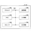
- Each of the user device 20 and the base station 10 described above may be physically configured as a computer device including a processor 1001, a memory 1002, a storage 1003, a communication device 1004, an input device 1005, an output device 1006, a bus 1007, and the like. Good.
- the word “device” can be read as a circuit, device, unit, or the like.
- the hardware configurations of the user device 20 and the base station 10 may be configured to include one or a plurality of each of the devices 1001 to 1006 shown in the figure, or may be configured without including some devices. May be.
- Each function in the user device 20 and the base station 10 causes a predetermined software (program) to be loaded on hardware such as the processor 1001 and the memory 1002, so that the processor 1001 performs an operation and controls communication by the communication device 1004. Alternatively, it is realized by controlling at least one of reading and writing of data in the memory 1002 and the storage 1003.
- the processor 1001 operates an operating system to control the entire computer, for example.
- the processor 1001 may be configured by a central processing unit (CPU) including an interface with peripheral devices, a control device, an arithmetic device, a register, and the like.
- CPU central processing unit
- the baseband signal processing unit 104 and the call processing unit 105 described above may be realized by the processor 1001.
- the processor 1001 reads a program (program code), software module, data, and the like from at least one of the storage 1003 and the communication device 1004 into the memory 1002, and executes various processes according to these.
- a program program that causes a computer to execute at least part of the operations described in the above-described embodiments is used.
- the control unit 401 of the user device 20 may be implemented by a control program stored in the memory 1002 and operating in the processor 1001, and may be implemented similarly for other functional blocks.
- the various processes described above are executed by one processor 1001, they may be executed simultaneously or sequentially by two or more processors 1001.
- the processor 1001 may be implemented by one or more chips.
- the program may be transmitted from the network via an electric communication line.
- the memory 1002 is a computer-readable recording medium, and is composed of at least one of, for example, ROM (Read Only Memory), EPROM (Erasable Programmable ROM), EEPROM (Electrically Erasable Programmable ROM), RAM (Random Access Memory), and the like. May be done.
- the memory 1002 may be called a register, a cache, a main memory (main storage device), or the like.
- the memory 1002 can store an executable program (program code), a software module, or the like for implementing the wireless communication method according to the embodiment of the present disclosure.
- the storage 1003 is a computer-readable recording medium, for example, an optical disc such as a CD-ROM (Compact Disc ROM), a hard disc drive, a flexible disc, a magneto-optical disc (for example, a compact disc, a digital versatile disc, a Blu-ray disc). At least one of a (registered trademark) disk, a smart card, a flash memory (for example, a card, a stick, and a key drive), a floppy (registered trademark) disk, a magnetic strip, or the like.
- the storage 1003 may be called an auxiliary storage device.
- the storage medium described above may be, for example, a database including at least one of the memory 1002 and the storage 1003, a server, or another appropriate medium.
- the communication device 1004 is hardware (transmission/reception device) for performing communication between computers via at least one of a wired network and a wireless network, and is also called, for example, a network device, a network controller, a network card, a communication module, or the like.
- the communication device 1004 includes, for example, a high frequency switch, a duplexer, a filter, a frequency synthesizer, etc. in order to realize at least one of frequency division duplex (FDD: Frequency Division Duplex) and time division duplex (TDD: Time Division Duplex). May be composed of
- FDD Frequency Division Duplex
- TDD Time Division Duplex
- the transmitter/receiver 103 may be physically or logically separated from the transmitter 103a and the receiver 103b.
- the input device 1005 is an input device (eg, keyboard, mouse, microphone, switch, button, sensor, etc.) that receives an input from the outside.
- the output device 1006 is an output device (for example, a display, a speaker, an LED lamp, etc.) that performs output to the outside.
- the input device 1005 and the output device 1006 may be integrated (for example, a touch panel).
- Each device such as the processor 1001 and the memory 1002 is connected by a bus 1007 for communicating information.
- the bus 1007 may be configured by using a single bus, or may be configured by using a different bus for each device.
- the user device 20 and the base station 10 respectively include a microprocessor, a digital signal processor (DSP: Digital Signal Processor), an ASIC (Application Specific Integrated Circuit), a PLD (Programmable Logic Device), an FPGA (Field Programmable Gate Array), etc. It may be configured to include hardware, and the hardware may implement some or all of the functional blocks. For example, the processor 1001 may be implemented using at least one of these hardware.
- DSP Digital Signal Processor
- ASIC Application Specific Integrated Circuit
- PLD Programmable Logic Device
- FPGA Field Programmable Gate Array
- the PDCCH monitoring is performed.
- one CC is deactivated, it is possible to quickly switch CCs for PDCCH monitoring.
- the control unit sets, in advance, a plurality of monitoring configurations for monitoring the downlink control channel for the second component carrier in an active state for monitoring the downlink control channel, Responsive to deactivating the first component carrier in the active state, activating a monitoring configuration that is activated when the first component carrier is deactivated in the plurality of monitoring configurations
- the downlink control channel may be monitored in the second component carrier based on the monitoring configuration.
- the plurality of monitoring configurations may specify different time and frequency resources as resources for monitoring the downlink control channel.
- the control unit in response to the deactivation of the first component carrier, starts monitoring the downlink control channel in the second component carrier, and then starts the first component carrier. In response to being reactivated, monitoring of the downlink control channel in the second component carrier is stopped and monitoring of the downlink control channel in the first component carrier is started. May be.
- the PDCCH monitoring is performed.
- one CC is deactivated, it becomes possible to quickly switch CCs for PDCCH monitoring.
- the operation of a plurality of functional units may be physically performed by one component, or the operation of one functional unit may be physically performed by a plurality of components.
- the order of processing may be changed as long as there is no contradiction.
- the user equipment 20 and the base station 10 have been described using functional block diagrams, but such equipment may be implemented in hardware, software, or a combination thereof.
- the software operated by the processor included in the user equipment 20 according to the embodiment of the present invention and the software operated by the processor included in the base station 10 according to the embodiment of the present invention are random access memory (RAM), flash memory, and read-only, respectively. It may be stored in a memory (ROM), EPROM, EEPROM, register, hard disk (HDD), removable disk, CD-ROM, database, server, or any other suitable storage medium.
- the notification of information is not limited to the aspect/embodiment described in the present disclosure, and may be performed using another method.
- information is notified by physical layer signaling (eg, DCI (Downlink Control Information), UCI (Uplink Control Information)), upper layer signaling (eg, RRC (Radio Resource Control) signaling, MAC (Medium Access Control) signaling, Notification information (MIB (Master Information Block), SIB (System Information Block))), other signals, or a combination thereof may be used.
- the RRC signaling may be called an RRC message, and may be, for example, an RRC connection setup (RRC Connection Setup) message, an RRC connection reconfiguration message, or the like.
- LTE Long Term Evolution
- LTE-A Long Term Evolution-Advanced
- SUPER 3G IMT-Advanced
- 4G 4th generation mobile communication system
- 5G 5th generation mobile communication
- FRA Full Radio Access
- NR new Radio
- W-CDMA registered trademark
- GSM registered trademark
- CDMA2000 Code Division Multiple Access 2000
- UMB Universal Mobile Broadband
- IEEE 802.11 Wi-Fi (registered trademark)
- IEEE 802.16 WiMAX (registered trademark)
- IEEE 802.20 UWB (Ultra-WideBand
- Bluetooth registered trademark
- It may be applied to at least one of the next-generation systems. Further, a plurality of systems may be combined and applied (for example, a combination of at least one of LTE and LTE-A and 5G).
- the specific operation that is performed by the base station 10 in the present disclosure may be performed by its upper node in some cases.
- various operations performed for communication with a terminal are performed by the base station 10 and other network nodes other than the base station 10 (for example, , MME or S-GW, etc., but not limited thereto).
- other network nodes other than the base station 10 for example, MME or S-GW, etc., but not limited thereto.
- a combination of a plurality of other network nodes for example, MME and S-GW may be used.
- Information that has been input and output may be stored in a specific location (for example, memory), or may be managed using a management table. Information that is input/output may be overwritten, updated, or added. The output information and the like may be deleted. The input information and the like may be transmitted to another device.
- the determination may be performed based on a value represented by 1 bit (whether 0 or 1), may be performed based on a Boolean value (Boolean: true or false), or may be compared by numerical values (for example, a predetermined value). (Comparison with the value).
- the notification of the predetermined information (for example, the notification of “being X”) is not limited to the explicit notification, and is performed implicitly (for example, the notification of the predetermined information is not performed). Good.
- software, instructions, information, etc. may be sent and received via a transmission medium.
- the software uses a website using at least one of wired technology (coaxial cable, optical fiber cable, twisted pair, digital subscriber line (DSL), etc.) and wireless technology (infrared, microwave, etc.), When sent from a server, or other remote source, at least one of these wired and wireless technologies are included within the definition of transmission medium.
- wired technology coaxial cable, optical fiber cable, twisted pair, digital subscriber line (DSL), etc.
- wireless technology infrared, microwave, etc.
- data, instructions, commands, information, signals, bits, symbols, chips, etc. that may be referred to throughout the above description include voltage, current, electromagnetic waves, magnetic fields or magnetic particles, optical fields or photons, or any of these. May be represented by a combination of
- At least one of the channel and the symbol may be a signal (signaling).
- the signal may also be a message.
- a component carrier CC:Component Carrier
- CC Component Carrier
- system and “network” used in this disclosure are used interchangeably.
- information, parameters, etc. described in the present disclosure may be represented by using an absolute value, may be represented by using a relative value from a predetermined value, or by using corresponding other information. May be represented.
- the radio resources may be those indicated by the index.
- base station Base Station
- wireless base station fixed station
- NodeB NodeB
- eNodeB eNodeB
- gNodeB gNodeB
- a base station can accommodate one or more (eg, three) cells.
- the entire coverage area of the base station can be divided into multiple smaller areas, each smaller area being a base station subsystem (eg, a small indoor base station (RRH: It is also possible to provide communication services by Remote Radio Head).
- RRH small indoor base station
- the term "cell” or “sector” refers to a part or the whole of the coverage area of at least one of the base station and the base station subsystem that perform communication services in this coverage. Refers to.
- MS Mobile Station
- UE User Equipment
- Mobile stations are defined by those skilled in the art as subscriber stations, mobile units, subscriber units, wireless units, remote units, mobile devices, wireless devices, wireless communication devices, remote devices, mobile subscriber stations, access terminals, mobile terminals, wireless. It may also be referred to as a terminal, remote terminal, handset, user agent, mobile client, client, or some other suitable term.
- At least one of the base station and the mobile station may be called a transmission device, a reception device, a communication device, or the like.
- the base station and the mobile station may be a device mounted on a mobile body, the mobile body itself, or the like.
- the moving body may be a vehicle (eg, car, airplane, etc.), an unmanned moving body (eg, drone, self-driving car, etc.), or a robot (manned or unmanned).
- At least one of the base station and the mobile station also includes a device that does not necessarily move during a communication operation.
- at least one of the base station and the mobile station may be an IoT (Internet of Things) device such as a sensor.
- IoT Internet of Things
- the base station in the present disclosure may be replaced by the user terminal.
- the communication between the base station and the user terminal is replaced with communication between a plurality of user terminals (for example, D2D (Device-to-Device), V2X (Vehicle-to-Everything) may be called).
- a plurality of user terminals for example, D2D (Device-to-Device), V2X (Vehicle-to-Everything) may be called).
- each aspect/embodiment of the present disclosure may be applied.
- the user terminal 20 may have the function of the base station 10 described above.
- the words such as “up” and “down” may be replaced with the words corresponding to the communication between terminals (for example, “side”).
- the uplink channel and the downlink channel may be replaced with the side channel.
- the user equipment in the present disclosure may be replaced by the base station.
- the base station 10 may have the function of the user device 20 described above.
- connection means any direct or indirect connection or coupling between two or more elements, and It may include the presence of one or more intermediate elements between two elements that are “connected” or “coupled”.
- the connections or connections between the elements may be physical, logical, or a combination thereof.
- connection may be read as “access”.
- two elements are in the radio frequency domain, with at least one of one or more wires, cables and printed electrical connections, and as some non-limiting and non-exhaustive examples. , Can be considered to be “connected” or “coupled” to each other, such as with electromagnetic energy having wavelengths in the microwave and light (both visible and invisible) regions.
- the reference signal may be abbreviated as RS (Reference Signal) or may be referred to as a pilot (Pilot) depending on the applied standard.
- RS Reference Signal
- Pilot pilot
- the phrase “based on” does not mean “based only on,” unless expressly specified otherwise. In other words, the phrase “based on” means both "based only on” and “based at least on.”
- the term “A and B are different” may mean “A and B are different from each other”.
- the term may mean that “A and B are different from C”.
- the terms “remove”, “coupled” and the like may be construed as “different” as well.
Abstract
下りリンクの信号を受信する受信部と、複数のコンポーネントキャリアのうち、アクティブ状態の第1のコンポーネントキャリアが非アクティブ化されたことに応答して、前記複数のコンポーネントキャリアのうち、下りリンクの制御チャネルを監視するためのアクティブ状態の第2のコンポーネントキャリアを選択する制御部とを備えるユーザ装置が提供される。
Description
本発明は、無線通信システムにおけるユーザ装置装置及び通信方法に関連する。
現在、3GPPのRAN1、Release 16において、Study on UE Power Saving for NRのStudy Item(SI)が立ち上がり、ユーザ装置の消費電力を抑制することが検討されている。
Release 15のNRでは、例えば、キャリアアグリゲーション(CA)を行っている時に、複数のコンポーネントキャリア(CC)のうちの、あるCCでPhysical Downlink Control Channel(PDCCH)をモニタリングして、Downlink Control Information(DCI)を受信し、受信したDCIにより、そのDCIを受信したCC以外のCCを介してのPhysical Downlink Shared Channel(PDSCH)/Physical Uplink Shared Channel(PUSCH)等をスケジューリングすることが可能となっている。上述のようなスケジューリングのことをクロスキャリアスケジューリングという。
3GPP TS 38.331 V15.3.0 (2018-09)
PDCCHのモニタリングを行うCCの数が多いと、ユーザ装置の消費電力は増大する。上述のクロスキャリアスケジューリングを用いて、ユーザ装置は、例えば、1つのCCで、PDCCHモニタリングを行い、DCIの受信を行って、受信したDCIに基づいて、複数のCCに対するPDSCH/PUSCH等のスケジューリングを行うことができる。その結果、PDCCHモニタリングを行うCCの数を減らすことができるので、ユーザ装置の消費電力を低減することが可能である。すなわち、クロスキャリアスケジューリングを行うことで、ユーザ装置は、消費電力を低減することが可能である。ユーザ装置が、1つのCCを使用して、PDCCHモニタリングを行い、DCIの受信を行い、他のCCに対するPDSCH/PUSCH等のスケジューリングを行う場合において、当該PDCCHモニタリングを行う1つのCCが非アクティブ化(deactivate)されると、ユーザ装置は、当該1つのCCを使用してPDCCHモニタリングを行うことができなくなる。
従って、ユーザ装置における消費電力を低減しつつ、PDCCHモニタリングを行うためのCCを迅速に切り替える技術が必要とされている。
本発明の一態様によれば、下りリンクの信号を受信する受信部と、複数のコンポーネントキャリアのうち、アクティブ状態の第1のコンポーネントキャリアが非アクティブ化されたことに応答して、前記複数のコンポーネントキャリアのうち、下りリンクの制御チャネルを監視するためのアクティブ状態の第2のコンポーネントキャリアを選択する制御部とを備えるユーザ装置が提供される。
実施例によれば、ユーザ装置における消費電力を低減しつつ、PDCCHモニタリングを行うためのCCを迅速に切り替えることが可能となる
以下、図面を参照して本発明の実施の形態(本実施の形態)を説明する。なお、以下で説明する実施の形態は一例に過ぎず、本発明が適用される実施の形態は、以下の実施の形態に限られるわけではない。
(システム構成)
図1は、本実施の形態に係る無線通信システムの構成例を示す図である。図1に示すように、本実施の形態に係る無線通信システムは、基地局10及びユーザ装置20を有する。なお、実際には多数の基地局及びユーザ装置が存在し得るが、図1は例として基地局10及びユーザ装置20を示している。
図1は、本実施の形態に係る無線通信システムの構成例を示す図である。図1に示すように、本実施の形態に係る無線通信システムは、基地局10及びユーザ装置20を有する。なお、実際には多数の基地局及びユーザ装置が存在し得るが、図1は例として基地局10及びユーザ装置20を示している。
本実施の形態において、ユーザ装置20は、LTEあるいはNRにおけるUEとしてのセルラ通信の機能を有している。また、ユーザ装置20は基地局10との間で複数のコンポーネントキャリア(CC)を同時に使用して通信を行う機能を有している。すなわち、ユーザ装置20は、基地局10との間でキャリアアグリゲーション(CA)を行う機能を有している。なお、図1において、コンポーネントキャリアとしてCC1、CC2、及びCC3の3つのコンポーネントキャリアが示されているが、コンポーネントキャリアの数は、3つには限定されない。
また、基地局10については、LTEあるいはNRにおける基地局10としてのセルラ通信の機能を有している。また、基地局10は、ユーザ装置20との間で複数のコンポーネントキャリア(CC)を同時に使用して通信を行う機能を有している。すなわち、基地局10は、ユーザ装置20との間でキャリアアグリゲーション(CA)を行う機能を有している。
Release 15のNRでは、例えば、キャリアアグリゲーション(CA)を行っている時に、複数のコンポーネントキャリア(CC)のうちの、あるCCでPhysical Downlink Conrol Channel(PDCCH)をモニタリングして、Downlink Control Information(DCI)を受信し、受信したDCIにより、そのDCIを受信したCC以外のCCを介してのPhysical Downlink Shared Channel(PDSCH)/Physical Uplink Shared Channel(PUSCH)等をスケジューリングすることが可能となっている。上述のようなスケジューリングのことをクロスキャリアスケジューリングという。なお、本開示において、「PDCCHモニタリング」という用語は、「PDCCH configuration」もしくは「PDCCH configurationにより設定された一連のPDCCHモニタリング」ことを意味してもよい。
PDCCHのモニタリングを行うCCの数が多いと、ユーザ装置20の消費電力は増大する。上述のクロスキャリアスケジューリングを用いて、ユーザ装置20は、例えば、1つのCCで、PDCCHモニタリングを行い、DCIの受信を行って、受信したDCIに基づいて、複数のCCに対するPDSCH/PUSCH等のスケジューリングを行うことができる。その結果、PDCCHモニタリングを行うCCの数を減らすことができるので、ユーザ装置20の消費電力を低減することが可能である。すなわち、クロスキャリアスケジューリングを行うことで、ユーザ装置20は、消費電力を低減することが可能である。
(課題について)
ここで、前述のように、ユーザ装置20が、1つのCCを使用して、PDCCHモニタリングを行い、DCIの受信を行い、他のCCに対するPDSCH/PUSCH等のスケジューリングを行う場合において、当該PDCCHモニタリングを行う1つのCCが非アクティブ化(deactivate)されると、ユーザ装置20は、当該1つのCCを使用してPDCCHモニタリングを行うことができなくなる。
ここで、前述のように、ユーザ装置20が、1つのCCを使用して、PDCCHモニタリングを行い、DCIの受信を行い、他のCCに対するPDSCH/PUSCH等のスケジューリングを行う場合において、当該PDCCHモニタリングを行う1つのCCが非アクティブ化(deactivate)されると、ユーザ装置20は、当該1つのCCを使用してPDCCHモニタリングを行うことができなくなる。
ここで、Radio Resource Control(RRC)シグナリングにより、PDCCHモニタリングを行うためのCCを切り替えることは可能である。しかしながら、RRCによる通知及び動作は上位レイヤの動作であるため、物理レイヤにおける動作又はMedium Access Control(MAC)レイヤの動作と比較して、時間がかかる。
従って、RRCシグナリングによりPDCCHモニタリングを行うためのCCを切り替える方法によれば、CCを非アクティブ化するまでに比較的長い時間を要するため、不必要にCCがアクティブ(active)状態となる時間が長くなる。或いは、ユーザ装置20において、PDCCHモニタリングが可能となるまでの時間がより長くなり、その後のデータの送受信にも時間がかかるため、ユーザ装置20がデータの送受信を完了し、スリープ状態に遷移するまでの時間が長くなる。その結果、ユーザ装置20の消費電力が増大することになる。
ここで、CAを行う場合に使用される複数のCCのうち、非アクティブ化するCCは、各CCの混雑状態及びチャネル状態により動的に決定されることになる。このため、非アクティブ化すべきCCを事前に想定することは困難である。また、CAを行う場合に使用される2以上のCCでPDCCHモニタリングを行うようにすると、PDCCHモニタリングを行うCC数が増加するため、ユーザ装置20の消費電力が増大することになる。
(解決方法の提案)
ユーザ装置20と基地局10との間で、複数のCCを用いてCAが行われている場合において、複数のCCのうちのあるCCが非アクティブ化されたことを契機として、ユーザ装置20は、当該複数のCCのうちの他のアクティブ状態のCCにおけるPDCCHモニタリングを開始してもよい。このように、他のアクティブ状態のCCにおけるPDCCHモニタリングを開始することを、PDCCHモニタリングのアクティブ化(activation、active状態への遷移)と呼んでもよい。
ユーザ装置20と基地局10との間で、複数のCCを用いてCAが行われている場合において、複数のCCのうちのあるCCが非アクティブ化されたことを契機として、ユーザ装置20は、当該複数のCCのうちの他のアクティブ状態のCCにおけるPDCCHモニタリングを開始してもよい。このように、他のアクティブ状態のCCにおけるPDCCHモニタリングを開始することを、PDCCHモニタリングのアクティブ化(activation、active状態への遷移)と呼んでもよい。
また、ユーザ装置20と基地局10との間で、複数のCCを用いてCAが行われている場合において、複数のCCのうちのあるCCがアクティブ化されたことを契機として、ユーザ装置20は、当該複数のCCのうちの他のアクティブ状態のCCにおけるPDCCHモニタリングを停止してもよい。このように、他のアクティブ状態のCCにおけるPDCCHモニタリングを停止することを、PDCCHモニタリングの非アクティブ化(deactivation、deactivate状態への遷移)と呼んでもよい。
ここで、説明を単純化するために、例えば、ユーザ装置20と基地局10との間で、CC#1、CC#2、及びCC#3を用いてCAが行われていると仮定する。例えば、ユーザ装置20は、CC#1、CC#2、及びCC#3のうちの、アクティブであったCC#1が非アクティブ化されたことを契機として、CC#2におけるPDCCHモニタリングを開始してもよい。
また、例えば、ユーザ装置20は、CC#1、CC#2、及びCC#3のうちの、非アクティブ状態であったCC#3がアクティブ化されたことを契機として、アクティブ状態であるCC#2におけるPDCCHモニタリングを停止してもよい。
また、別の例として、例えば、ユーザ装置20は、CC#1、CC#2、及びCC#3のうちのアクティブであったCC#1が非アクティブ化されたことを契機として、CC#2におけるPDCCHモニタリングを開始した後、CC#1が再度アクティブ化されたことに応答して、CC#2におけるPDCCHモニタリングを停止すると共に、CC#1におけるPDCCHモニタリングを開始してもよい。
CCのアクティブ化及び非アクティブ化は、例えば、ネットワークが、MAC Control Element(MAC CE)を用いて行ってもよい。ユーザ装置20は、ネットワーク側からのMAC CEを受信することで、いずれかのCCがアクティブ化又は非アクティブ化されたことを検出し、これに応答して、他のCCにおけるPDCCHモニタリングを停止又は開始することになる。また、CCのアクティブ化及び非アクティブ化は、例えば、ネットワークから物理レイヤを用いて行ってもよい。例えばDCIもしくはpower saving signal/channel(電力削減の信号/チャネル)等を用いてユーザ装置20にいずれかのCCがアクティブ化又は非アクティブ化することが通知されてもよい。これに応答して、他のCCにおけるPDCCHモニタリングを停止又は開始することになる。該power saving signal/channelには、PDCCH basedのpower saving signal/channel、TRS、CSI-RS、DMRS basedのpower saving signal/channel、SS basedのpower saving signal/channel、等が含まれる。
ユーザ装置20がPDCCHモニタリングをアクティブ化する場合において、当該PDCCHモニタリングのアクティブ化を行う前に、例えば、RRCシグナリングで、(1)PDCCHモニタリングに必要な情報や、(2)PDCCHモニタリングのアクティブ化の契機に関する情報、及び/又は(3)PDCCHモニタリングの非アクティブ化の契機に関する情報が通知されてもよい。
ここで、PDCCHモニタリングに必要な情報としては、通常のPDCCHモニタリングに必要な情報、例えば、サーチスペース(Searchspace)に関連する情報、control resource set (CORESET)に関連する情報等が考えられる。PDCCHモニタリングに必要な情報は、既存のPDCCH configurationであってもよい。
PDCCHモニタリングのアクティブ化の契機に関する情報として、例えば、CAを構成する複数のCCのうちの、特定のCCの非アクティブ化を契機として、PDCCHモニタリングのアクティブ化を行うことが、ユーザ装置20に通知されてもよい。例えば、PDCCHモニタリングのアクティブ化の契機に関する情報として、CC#1を示す情報がユーザ装置20に通知されてもよい。この場合、CC#1が非アクティブ化されたことに応答して、ユーザ装置20は、設定されているPDCCHモニタリングを開始してもよい。また、上述の特定のCCとして、1つのCCだけではなく、複数のCCが指定されてもよい。
特定のPDCCHモニタリング(特定のサーチスペース又は特定のCORESETであってもよい)に対応するCCの非アクティブ化を契機として、ユーザ装置20が、設定されているPDCCHモニタリングのアクティブ化を行うことが通知されてもよい。例えば、サーチスペースID1を示す情報がユーザ装置20に通知されてもよく、この場合において、ユーザ装置20は、サーチスペースID1が属するCCが非アクティブ化されたことに応答して、設定されているPDCCHモニタリングを開始してもよい。また、上述の特定のPDCCHモニタリングとして、複数のPDCCHモニタリングが指定されてもよい。上述の特定のサーチスペースとして、複数のサーチスペースが指定されてもよい。上述の特定のCORESETとして、複数のCORESETが指定されてもよい。
また、例えば、RRC等で、PDCCHモニタリングの設定が行われた場合において、その設定が行われた直後のデフォルトのPDCCHモニタリングがアクティブ状態であるか、又は非アクティブ状態であることがユーザ装置20に対して通知されてもよい。
PDCCHモニタリングの非アクティブ化の契機に関する情報として、例えば、CAを構成する複数のCCのうちの、特定のCCのアクティブ化を契機として、PDCCHモニタリングの非アクティブ化を行うことが、ユーザ装置20に通知されてもよい。例えば、PDCCHモニタリングの非アクティブ化の契機に関する情報として、CC#1を示す情報がユーザ装置20に通知されてもよい。この場合、CC#1がアクティブ化されたことに応答して、ユーザ装置20は、設定されているPDCCHモニタリングを停止してもよい。また、上述の特定のCCとして、1つのCCだけではなく、複数のCCが指定されてもよい。なお、PDCCHモニタリングのアクティブ化の契機に関する情報として、例えば、CAを構成する複数のCCのうちの、特定のCCの非アクティブ化を契機として、PDCCHモニタリングのアクティブ化を行うことが、ユーザ装置20に通知されている場合には、PDCCHモニタリングの非アクティブ化の契機に関する情報を明示的に通知することなく、上述の特定のCCのアクティブ化を契機として、PDCCHモニタリングの非アクティブ化が行われるように設定されてもよい。
特定のPDCCHモニタリング(特定のサーチスペース又は特定のCORESETであってもよい)に対応するCCのアクティブ化を契機として、ユーザ装置20が、設定されているPDCCHモニタリングの非アクティブ化を行うことが通知されてもよい。例えば、サーチスペースID1を示す情報がユーザ装置20に通知されてもよく、この場合において、ユーザ装置20は、サーチスペースID1が属するCCがアクティブ化されたことに応答して、設定されているPDCCHモニタリングを停止してもよい。また、上述の特定のPDCCHモニタリングとして、複数のPDCCHモニタリングが指定されてもよい。上述の特定のサーチスペースとして、複数のサーチスペースが指定されてもよい。上述の特定のCORESETとして、複数のCORESETが指定されてもよい。なお、特定のPDCCHモニタリング(特定のサーチスペース又は特定のCORESETであってもよい)に対応するCCの非アクティブ化を契機として、ユーザ装置20が、設定されているPDCCHモニタリングのアクティブ化を行うことが通知されている場合には、PDCCHモニタリングの非アクティブ化の契機に関する情報を明示的に通知することなく、上述の特定のPDCCHモニタリング(特定のサーチスペース又は特定のCORESETであってもよい)に対応するCCのアクティブ化を契機として、PDCCHモニタリングの非アクティブ化が行われるように設定されてもよい。
なお、上述の(2)PDCCHモニタリングのアクティブ化の契機に関する情報、及び/又は(3)PDCCHモニタリングの非アクティブ化の契機に関する情報は、通常のPDCCH configurationに追加されてもよい。その上で、(2)の情報及び/又は(3)の情報が追加されたPDCCH configurationがRRCシグナリングにより、ユーザ装置20に通知されてもよい。代替的に、(1)PDCCHモニタリングに必要な情報、(2)PDCCHモニタリングのアクティブ化の契機に関する情報、及び/又は(3)PDCCHモニタリングの非アクティブ化の契機に関する情報を含むRRC configurationが新たに規定され、当該RRC configurationがRRCシグナリングにより、ユーザ装置20に通知されてもよい。
上述の(2)の情報及び/又は(3)の情報を通常のPDCCH configurationに追加する場合において、ユーザ装置20に対してPDCCH configurationを設定する際に、PDCCHモニタリングが常にアクティブ状態であることを示す情報(つまり、設定されるPDCCHモニタリングが通常のPDCCHモニタリングであることを示す情報)、又はPDCCHモニタリングのアクティブ状態/非アクティブ状態が遷移することを示す情報が、ユーザ装置20に対して通知されてもよい。
また、上述の(1)PDCCHモニタリングに必要な情報、(2)PDCCHモニタリングのアクティブ化の契機に関する情報、及び/又は(3)PDCCHモニタリングの非アクティブ化の契機に関する情報のセットは、1つのCCに対して1セットがユーザ装置20において設定されてもよい。或いは、1つのCCに対して複数のセットがユーザ装置20において設定されてもよい。
また、上述の(1)の情報と、(2)の情報及び/又は(3)の情報とは、ユーザ装置20に、別々に通知されてもよい。上述の(2)の情報及び/又は(3)の情報は、PDCCH configurationごとに、ユーザ装置20に通知されてもよい。また、上述の(1)の情報と、(2)の情報及び/又は(3)の情報とは、CCごとに、別々に、ユーザ装置20に通知されてもよい。例えば、1つのCCに対して、上述の(1)に対応する情報として、3つのPDCCH configurationがユーザ装置20に通知されてもよく、(2)の情報及び(3)の情報として、アクティブ化の契機に関する情報及び非アクティブ化の契機に関する情報が1セットだけユーザ装置20に通知されてもよい。この場合において、ユーザ装置20は、3つのPDCCH configurationに対して、同じアクティブ化の契機及び非アクティブ化の契機を適用してもよい。
(動作例1)
次に、図2及び図3を参照して、ユーザ装置20の動作例1を説明する。説明の前提として、基地局10とユーザ装置20とは、CC#1、CC#2、及びCC#3を同時に用いて通信を行っているものとする。すなわち、基地局10とユーザ装置20とはキャリアアグリゲーションを行っているものとする。
次に、図2及び図3を参照して、ユーザ装置20の動作例1を説明する。説明の前提として、基地局10とユーザ装置20とは、CC#1、CC#2、及びCC#3を同時に用いて通信を行っているものとする。すなわち、基地局10とユーザ装置20とはキャリアアグリゲーションを行っているものとする。
図2は、ユーザ装置20に対して、RRCシグナリング等により通知される設定情報(configuration)を示している。
図2に示されるように、CC#1に関して、ユーザ装置20には、通常のPDCCH configurationが設定されている。PDCCHモニタリングのアクティブ化の契機は特に設定されていないが、通常のPDCCH configurationに従い、ユーザ装置20は、CC#1がアクティブ化されている場合には、CC#1におけるPDCCHモニタリングをアクティブ化し、CC#1が非アクティブ化されている場合には、CC#1におけるPDCCHモニタリングを非アクティブ化する。
また、CC#2に関して、ユーザ装置20には、PDCCHモニタリングのアクティブ化の契機を考慮したPDCCH configurationが設定されている。具体的には、CC#1が非アクティブ化されることが、CC#2におけるPDCCHモニタリングのアクティブ化の契機として設定されている。
また、CC#3についても、ユーザ装置20には、PDCCHモニタリングのアクティブ化の契機を考慮したPDCCH configurationが設定されている。具体的には、CC#1及びCC#2が非アクティブ化されることが、CC#3におけるPDCCHモニタリングのアクティブ化の契機として設定されている。ここでは、非アクティブ化の契機は明示的に設定されずアクティブ化の契機に対応して暗示的に判断される例を記載している。非アクティブ化の契機としてアクティブ化の契機に対応した設定が明示的に設定されてもよい。
次に図3を参照して、動作例1の詳細を説明する。
まず、図3に示されるステップS101において、ユーザ装置20は、CC#1がアクティブ化され、CC#2がアクティブ化され、かつCC#3がアクティブ化されていることを検出する。従って、ユーザ装置20は、CC#1に関して設定されている、通常のPDCCH configurationに従い、CC#1におけるPDCCHモニタリングをアクティブ化する。また、ユーザ装置20は、CC#1がアクティブ化されていることを検出したことに応答して、CC#2に関して設定されている、PDCCH configurationに従い、CC#2におけるPDCCHモニタリングを非アクティブ化する(CC#2におけるPDCCHモニタリングをアクティブ化しない)。また、ユーザ装置20は、CC#1がアクティブ化され、かつCC#2がアクティブ化されていることを検出したことに応答して、CC#3に関して設定されている、PDCCH configurationに従い、CC#3におけるPDCCHモニタリングを非アクティブ化する(CC#3におけるPDCCHモニタリングをアクティブ化しない)。
次に、図3に示されるステップS102において、ユーザ装置20は、CC#1が非アクティブ化され、CC#2がアクティブ化され、かつCC#3がアクティブ化されていることを検出する。従って、ユーザ装置20は、CC#1に関して設定されている、通常のPDCCH configurationに従い、CC#1におけるPDCCHモニタリングを非アクティブ化する。また、ユーザ装置20は、CC#1が非アクティブ化されていることを検出したことに応答して、CC#2に関して設定されている、PDCCH configurationに従い、CC#2におけるPDCCHモニタリングをアクティブ化する。また、ユーザ装置20は、CC#1が非アクティブ化され、かつCC#2がアクティブ化されていることを検出したことに応答して、CC#3に関して設定されている、PDCCH configurationに従い、CC#3におけるPDCCHモニタリングを非アクティブ化する(CC#3におけるPDCCHモニタリングをアクティブ化しない)。
次に、図3に示されるステップS103において、ユーザ装置20は、CC#1が非アクティブ化され、CC#2が非アクティブ化され、かつCC#3がアクティブ化されていることを検出する。従って、ユーザ装置20は、CC#1に関して設定されている、通常のPDCCH configurationに従い、CC#1におけるPDCCHモニタリングを非アクティブ化する(CC#1におけるPDCCHモニタリングをアクティブ化しない)。また、ユーザ装置20は、CC#1が非アクティブ化されていることを検出しているが、CC#2が非アクティブ化されていることを検出したことに応答して、CC#2におけるPDCCHモニタリングを非アクティブ化する。また、ユーザ装置20は、CC#1が非アクティブ化され、かつCC#2が非アクティブ化されていることを検出したことに応答して、CC#3に関して設定されている、PDCCH configurationに従い、CC#3におけるPDCCHモニタリングをアクティブ化する。
次に、図3に示されるステップS104において、ユーザ装置20は、CC#1がアクティブ化され、CC#2が非アクティブ化され、かつCC#3がアクティブ化されていることを検出する。従って、ユーザ装置20は、CC#1に関して設定されている、通常のPDCCH configurationに従い、CC#1におけるPDCCHモニタリングをアクティブ化する。また、ユーザ装置20は、CC#1がアクティブ化されていることを検出し、かつCC#2が非アクティブ化されていることを検出したことに応答して、CC#2におけるPDCCHモニタリングを非アクティブ化する(CC#2におけるPDCCHモニタリングをアクティブ化しない)。また、ユーザ装置20は、CC#1がアクティブ化され、かつCC#2が非アクティブ化されていることを検出したことに応答して、CC#3に関して設定されている、PDCCH configurationに従い、CC#3におけるPDCCHモニタリングを非アクティブ化する。
このように、ユーザ装置20は、特定のCCの非アクティブ化を契機として、他のアクティブ状態のCCにおけるPDCCHモニタリングを開始する。また、ユーザ装置20は、特定のCCのアクティブ化を契機として、他のアクティブ状態のCCにおけるPDCCHモニタリングを停止する。
(動作例2)
次に、図4及び図5を参照して、ユーザ装置20の動作例2を説明する。説明の前提として、基地局10とユーザ装置20とは、CC#1、CC#2、及びCC#3を同時に用いて通信を行っているものとする。すなわち、基地局10とユーザ装置20とはキャリアアグリゲーションを行っているものとする。
次に、図4及び図5を参照して、ユーザ装置20の動作例2を説明する。説明の前提として、基地局10とユーザ装置20とは、CC#1、CC#2、及びCC#3を同時に用いて通信を行っているものとする。すなわち、基地局10とユーザ装置20とはキャリアアグリゲーションを行っているものとする。
図4は、ユーザ装置20に対して、RRCシグナリング等により通知される設定情報(configuration)を示している。
図4に示されるように、CC#1に関して、ユーザ装置20には、通常のPDCCH configuration#1が設定されている。PDCCHモニタリングのアクティブ化の契機は特に設定されていないが、通常のPDCCH configuration#1に従い、ユーザ装置20は、CC#1がアクティブ化されている場合には、CC#1におけるPDCCHモニタリングをアクティブ化し、CC#1が非アクティブ化されている場合には、CC#1におけるPDCCHモニタリングを非アクティブ化する。
また、CC#2に関して、ユーザ装置20には、通常のPDCCH configuration#2が設定されている。PDCCHモニタリングのアクティブ化の契機は特に設定されていないが、通常のPDCCH configuration#2に従い、ユーザ装置20は、CC#2がアクティブ化されている場合には、CC#2におけるPDCCHモニタリングをアクティブ化し、CC#2が非アクティブ化されている場合には、CC#2におけるPDCCHモニタリングを非アクティブ化する。
また、CC#3関して、ユーザ装置20には、PDCCHモニタリングのアクティブ化の契機を考慮したPDCCH configuration#3及びPDCCH configuration#4が設定されている。具体的には、CC#1が非アクティブ化されることが、CC#3におけるPDCCH configuration#3に従うPDCCHモニタリングのアクティブ化の契機として設定されている。追加的に、CC#2が非アクティブ化されることが、CC#3におけるPDCCH configuration#4に従うPDCCHモニタリングのアクティブ化の契機として設定されている。ここでは、非アクティブ化の契機は明示的に設定されずアクティブ化の契機に対応して暗示的に判断される例を記載している。非アクティブ化の契機としてアクティブ化の契機に対応した設定が明示的に設定されてもよい。
次に図5を参照して、動作例2の詳細を説明する。
まず、図5に示されるステップS201において、ユーザ装置20は、CC#1がアクティブ化され、CC#2がアクティブ化され、かつCC#3がアクティブ化されていることを検出する。従って、ユーザ装置20は、CC#1に関して設定されている、通常のPDCCH configuration#1に従い、CC#1におけるPDCCHモニタリングをアクティブ化する。また、ユーザ装置20は、CC#2がアクティブ化されていることを検出したことに応答して、CC#2に関して設定されている、通常のPDCCH configuration#2に従い、CC#2におけるPDCCHモニタリングをアクティブ化する。また、ユーザ装置20は、CC#1がアクティブ化され、かつCC#2がアクティブ化されていることを検出したことに応答して、CC#3における、PDCCH configuration#3に従うPDCCHモニタリングを非アクティブ化し(CC#3におけるPDCCH configuration#3に従うPDCCHモニタリングをアクティブ化しない)、かつCC#3における、PDCCH configuration#4に従うPDCCHモニタリングを非アクティブ化する(CC#3におけるPDCCH configuration#4に従うPDCCHモニタリングをアクティブ化しない)。
次に、図5に示されるステップS202において、ユーザ装置20は、CC#1が非アクティブ化され、CC#2がアクティブ化され、かつCC#3がアクティブ化されていることを検出する。従って、ユーザ装置20は、CC#1に関して設定されている、通常のPDCCH configuration#1に従い、CC#1におけるPDCCHモニタリングを非アクティブ化する。また、ユーザ装置20は、CC#2がアクティブ化されていることを検出したことに応答して、CC#2に関して設定されている、PDCCH configuration#2に従い、CC#2におけるPDCCHモニタリングをアクティブ化する(CC#2におけるPDCCHモニタリングを非アクティブ化しない)。また、ユーザ装置20は、CC#1が非アクティブ化され、かつCC#2がアクティブ化されていることを検出したことに応答して、CC#3における、PDCCH configuration#3に従うPDCCHモニタリングをアクティブ化し、かつCC#3における、PDCCH configuration#4に従うPDCCHモニタリングを非アクティブ化する(CC#3におけるPDCCH configuration#4に従うPDCCHモニタリングをアクティブ化しない)。
次に、図5に示されるステップS203において、ユーザ装置20は、CC#1が非アクティブ化され、CC#2が非アクティブ化され、かつCC#3がアクティブ化されていることを検出する。従って、ユーザ装置20は、CC#1におけるPDCCHモニタリングを非アクティブ化する(CC#1におけるPDCCHモニタリングをアクティブ化しない)。また、ユーザ装置20は、CC#2が非アクティブ化されていることを検出したことに応答して、CC#2におけるPDCCHモニタリングを非アクティブ化する。また、ユーザ装置20は、CC#1が非アクティブ化され、かつCC#2が非アクティブ化されていることを検出したことに応答して、CC#3における、PDCCH configuration#3に従うPDCCHモニタリングをアクティブ化し(CC#3におけるPDCCH configuration#3に従うPDCCHモニタリングを非アクティブ化しない)、かつCC#3における、PDCCH configuration#4に従うPDCCHモニタリングをアクティブ化する。
次に、図5に示されるステップS204において、ユーザ装置20は、CC#1がアクティブ化され、CC#2が非アクティブ化され、かつCC#3がアクティブ化されていることを検出する。従って、ユーザ装置20は、CC#1におけるPDCCHモニタリングをアクティブ化する。また、ユーザ装置20は、CC#2におけるPDCCHモニタリングを非アクティブ化する(CC#2におけるPDCCHモニタリングをアクティブ化しない)。また、ユーザ装置20は、CC#1がアクティブ化され、かつCC#2が非アクティブ化されていることを検出したことに応答して、CC#3における、PDCCH configuration#3に従うPDCCHモニタリングを非アクティブ化し、かつCC#3における、PDCCH configuration#4に従うPDCCHモニタリングをアクティブ化する(CC#3におけるPDCCH configuration#4に従うPDCCHモニタリングを非アクティブ化しない)。
このように、ユーザ装置20は、特定のCCの非アクティブ化を契機として、他のアクティブ状態のCCにおけるPDCCHモニタリングを開始する。また、ユーザ装置20は、特定のCCのアクティブ化を契機として、他のアクティブ状態のCCにおけるPDCCHモニタリングを停止する。また、特定のCCに対して、複数のPDCCH configurationを設定してもよく、複数のPDCCH configurationに対して、それぞれ異なるPDCCHモニタリングのアクティブ化/非アクティブ化の契機が設定されてもよい。
(PDCCHモニタリングのアクティブ化/非アクティブ化の契機)
PDCCHモニタリングのアクティブ化の契機及び非アクティブ化の契機について、例えば、仕様により規定されていてもよい。
PDCCHモニタリングのアクティブ化の契機及び非アクティブ化の契機について、例えば、仕様により規定されていてもよい。
例えば、1つのCCだけがアクティブな状態であり、その他にアクティブなCCが存在しない場合において、ユーザ装置20は、自動的に、そのアクティブな状態のCCにおけるPDCCHモニタリングを開始するように、PDCCHモニタリングのアクティブ化の契機が規定されていてもよい。
また、例えば、特定のPDCCHモニタリング(特定のサーチスペース又は特定のCORESETであってもよい)に対応する1つのCCだけがアクティブな状態であり、その他のPDCCHモニタリング(その他のサーチスペース又はその他のCORESETであってもよい)に対応するCCが非アクティブである場合に、ユーザ装置20は、自動的に、その特定のPDCCHモニタリングを開始するように、PDCCHモニタリングのアクティブ化の契機が規定されていてもよい。
また、例えば、特定のCCがアクティブな状態であり、そのCCにおけるPDCCHモニタリングがアクティブ状態である場合において、その他に一つでもアクティブなCCが存在する場合に、その特定のCCにおけるPDCCHモニタリングが非アクティブ化されるように、PDCCHモニタリングの非アクティブ化の契機が規定されていてもよい。
また、例えば、特定のPDCCHモニタリング(特定のサーチスペース又は特定のCORESETであってもよい)に対応する特定のCCがアクティブな状態であり、その他のPDCCHモニタリング(その他のサーチスペース又はその他のCORESETであってもよい)のうち、対応するCCがアクティブな状態であるPDCCHモニタリングが一つでもある場合、ユーザ装置20は、自動的に、その特定のPDCCHモニタリングを停止するように、PDCCHモニタリングの非アクティブ化の契機が規定されていてもよい。
また、上記の変形例として、例えば、PDCCHモニタリングのアクティブ化の契機/非アクティブ化の契機として、他にx個のアクティブ状態/非アクティブ状態のCCが存在することを契機として規定した上で、その数値xをユーザ装置20に通知するようにしてもよい。また、例えば、PDCCHモニタリングのアクティブ化の契機/非アクティブ化の契機として、特定のPDCCHモニタリング以外に、PDCCHモニタリング(x個のサーチスペース又はx個のCORESETであってもよい)であって、対応するCCがアクティブな状態である、PDCCHモニタリング、がx個存在することを契機として規定した上で、その数値xをユーザ装置20に通知するようにしてもよい。このような数値xについては、PDCCH configration毎に、ユーザ装置20に通知されてもよい。代替的に、このような数値xについては、CC毎に、ユーザ装置20に通知されてもよい。代替的に、このような数値xについては、ユーザ装置20毎に、ユーザ装置20に通知されてもよい。
また、PDCCHモニタリングのアクティブ化/非アクティブ化の契機の別の例として、例えば、複数のCCに対して優先順位付けを行い、アクティブなCCのうち、優先順位の高い方からx番目までのCCにおけるPDCCHモニタリングをアクティブ化/非アクティブ化することを規定しておき、アクティブなCCのうち、優先順位の最も高いCCのアクティブ化/非アクティブ化を契機として、ユーザ装置20は、アクティブなCCのうちx+1番目の優先順位のCCにおけるPDCCHモニタリングのアクティブ化/非アクティブ化を行ってもよい。上述の例では複数のCCに対する優先順位付けを行っているが、優先順位付けを行う対象は、複数のCCには、限定されない。例えば、複数のPDCCH configuration(複数のsearchspace configuration、又は或いは複数のCORESET configurationでもよい)に対して優先順位付けを行ってもよく、アクティブなPDCCH configurationのうち、優先順位の高い方からx番目までのPDCCH configurationについてのPDCCHモニタリングをアクティブ化/非アクティブ化することを規定しておき、アクティブなPDCCH configurationのうち、優先順位の最も高いPDCCH configurationについてのPDCCHモニタリングのアクティブ化/非アクティブ化を契機として、ユーザ装置20は、アクティブなPDCCH configurationのうちx+1番目の優先順位のPDCCH configurationについてのPDCCHモニタリングのアクティブ化/非アクティブ化を行ってもよい。上記のPDCCHモニタリングを行う数に対応する数値xは、ユーザ装置20に通知されてもよく、或いは仕様により規定されていてもよい。
なお、ユーザ装置20におけるPDCCHモニタリングのアクティブ化/非アクティブ化の遷移については、ネットワーク側からユーザ装置20に対して直接通知されてもよい。この通知は、いずれのレイヤの信号で行われてもよい。つまり、物理レイヤの信号(例えばDCIを含む信号)であってもよく、MACレイヤの信号であってもよく、RRCレイヤの信号であってもよい。また、この通知は、いずれのチャネルの信号で通知されてもよい。例えば、PBCHの信号、PDCCHの信号、PDSCHの信号などで通知されてもよい。例えば、power saving signal/channel(電力削減の信号/チャネル)等を用いて通知されてもよい。該power saving signal/channelには、PDCCH basedのpower saving signal/channel、TRS、CSI-RS、DMRS basedのpower saving signal/channel、SS basedのpower saving signal/channel、等が含まれる。
3GPPのリリース16以降のNRにおいて、CCの状態として、アクティブ状態、非アクティブ状態に加えて、休止状態(Dormant状態)が規定される可能性がある。このDormant状態においては、上りリンク及び下りリンクのグラント(grant)は送信されず、CSI measurement及びreportingのみが実行される。3GPPのリリース15では、Dormant状態は導入されなかったが、3GPPのリリース16では、Dormant状態を導入するか否かについて議論が行われている。従って、本明細書全体において、アクティブ化/非アクティブ化(activation/deactivation)について、特に、非アクティブ化(deactivation)を、「非アクティブ化又はDormant状態化」と読み替えてもよい。
また、本明細書全体において、「通知する」とは、いずれのレイヤ/チャネル/信号の情報で通知することを意味してもよく、DCIで通知する、MACで通知する、RRCで通知する、PBCHの信号で通知する、PDCCHの信号で通知する、PDSCHの信号で通知するなどのいずれの意味であってもよい。
(装置構成)
次に、これまでに説明した処理動作を実行する基地局10及びユーザ装置20の機能構成例を説明する。
次に、これまでに説明した処理動作を実行する基地局10及びユーザ装置20の機能構成例を説明する。
<基地局10>
図6は、基地局10の機能構成の一例を示す図である。図6に示すように、基地局10は、送信部101と、受信部102と、設定情報管理部103と、制御部104とを有する。図6に示す機能構成は一例に過ぎない。本実施の形態に係る動作を実行できるのであれば、機能区分及び機能部の名称はどのようなものでもよい。なお、送信部101を送信機と称し、受信部102を受信機と称してもよい。
図6は、基地局10の機能構成の一例を示す図である。図6に示すように、基地局10は、送信部101と、受信部102と、設定情報管理部103と、制御部104とを有する。図6に示す機能構成は一例に過ぎない。本実施の形態に係る動作を実行できるのであれば、機能区分及び機能部の名称はどのようなものでもよい。なお、送信部101を送信機と称し、受信部102を受信機と称してもよい。
送信部101は、ユーザ装置20側に送信する信号を生成し、当該信号を無線で送信する機能を含む。受信部102は、ユーザ装置20から送信された各種の信号を受信し、受信した信号から、例えば、より上位のレイヤの情報を取得する機能を含む。また、受信部102は受信する信号の測定を行って、品質値を取得する機能を含む。
設定情報管理部103には、予め設定した設定情報、ユーザ装置20から受信する設定情報等が格納される。なお、送信に関わる設定情報が送信部101に格納され、受信に関わる設定情報が受信部102に格納されることとしてもよい。制御部104は、基地局10の制御を行う。なお、送信に関わる制御部104の機能が送信部101に含まれ、受信に関わる制御部104の機能が受信部102に含まれてもよい。
<ユーザ装置20>
図7は、ユーザ装置20の機能構成の一例を示す図である。図7に示されるように、ユーザ装置20は、送信部201と、受信部202と、設定情報管理部203と、制御部204とを有する。図7に示す機能構成は一例に過ぎない。本実施の形態に係る動作を実行できるのであれば、機能区分及び機能部の名称はどのようなものでもよい。なお、送信部201を送信機と称し、受信部202を受信機と称してもよい。また、ユーザ装置20は、送信側のユーザ装置20Aであってもよいし、受信側のユーザ装置20Bであってもよい。
図7は、ユーザ装置20の機能構成の一例を示す図である。図7に示されるように、ユーザ装置20は、送信部201と、受信部202と、設定情報管理部203と、制御部204とを有する。図7に示す機能構成は一例に過ぎない。本実施の形態に係る動作を実行できるのであれば、機能区分及び機能部の名称はどのようなものでもよい。なお、送信部201を送信機と称し、受信部202を受信機と称してもよい。また、ユーザ装置20は、送信側のユーザ装置20Aであってもよいし、受信側のユーザ装置20Bであってもよい。
送信部201は、送信データから送信信号を作成し、当該送信信号を無線で送信する。受信部202は、各種の信号を無線受信し、受信した物理レイヤの信号からより上位のレイヤの信号を取得する。また、受信部202は受信する信号の測定を行って、品質値を取得する機能を含む。設定情報管理部203には、予め設定された設定情報、基地局10から受信する設定情報等が格納される。設定情報管理部203は、キャリアアグリゲーションの設定に関する情報を格納してもよい。なお、送信に関わる設定情報が送信部201に格納され、受信に関わる設定情報が受信部202に格納されることとしてもよい。制御部204は、ユーザ装置20の制御を行う。なお、送信に関わる制御部204の機能が送信部201に含まれ、受信に関わる制御部204の機能が受信部202に含まれてもよい。
例えば、制御部204は、受信部202が基地局10から受信したCCのアクティブ化/非アクティブ化を示す情報に基づいて、PDCCHモニタリングのアクティブ化/非アクティブ化を行ってもよい。
<ハードウェア構成>
上記実施の形態の説明に用いたブロック図(図6~図7)は、機能単位のブロックを示している。これらの機能ブロック(構成部)は、ハードウェア及びソフトウェアの少なくとも一方の任意の組み合わせによって実現される。また、各機能ブロックの実現方法は特に限定されない。すなわち、各機能ブロックは、物理的又は論理的に結合した1つの装置を用いて実現されてもよいし、物理的又は論理的に分離した2つ以上の装置を直接的又は間接的に(例えば、有線、無線などを用いて)接続し、これら複数の装置を用いて実現されてもよい。機能ブロックは、上記1つの装置又は上記複数の装置にソフトウェアを組み合わせて実現されてもよい。機能には、判断、決定、判定、計算、算出、処理、導出、調査、探索、確認、受信、送信、出力、アクセス、解決、選択、選定、確立、比較、想定、期待、見做し、報知(broadcasting)、通知(notifying)、通信(communicating)、転送(forwarding)、構成(configuring)、再構成(reconfiguring)、割り当て(allocating、mapping)、割り振り(assigning)などがあるが、これらに限られない。たとえば、送信を機能させる機能ブロック(構成部)は、送信部(transmitting unit)や送信機(transmitter)と呼称される。いずれも、上述したとおり、実現方法は特に限定されない。
上記実施の形態の説明に用いたブロック図(図6~図7)は、機能単位のブロックを示している。これらの機能ブロック(構成部)は、ハードウェア及びソフトウェアの少なくとも一方の任意の組み合わせによって実現される。また、各機能ブロックの実現方法は特に限定されない。すなわち、各機能ブロックは、物理的又は論理的に結合した1つの装置を用いて実現されてもよいし、物理的又は論理的に分離した2つ以上の装置を直接的又は間接的に(例えば、有線、無線などを用いて)接続し、これら複数の装置を用いて実現されてもよい。機能ブロックは、上記1つの装置又は上記複数の装置にソフトウェアを組み合わせて実現されてもよい。機能には、判断、決定、判定、計算、算出、処理、導出、調査、探索、確認、受信、送信、出力、アクセス、解決、選択、選定、確立、比較、想定、期待、見做し、報知(broadcasting)、通知(notifying)、通信(communicating)、転送(forwarding)、構成(configuring)、再構成(reconfiguring)、割り当て(allocating、mapping)、割り振り(assigning)などがあるが、これらに限られない。たとえば、送信を機能させる機能ブロック(構成部)は、送信部(transmitting unit)や送信機(transmitter)と呼称される。いずれも、上述したとおり、実現方法は特に限定されない。
また、例えば、本発明の一実施の形態におけるユーザ装置20と基地局10はいずれも、本実施の形態に係る処理を行うコンピュータとして機能してもよい。図8は、本実施の形態に係るユーザ装置20と基地局10のハードウェア構成の一例を示す図である。上述のユーザ装置20と基地局10はそれぞれ、物理的には、プロセッサ1001、メモリ1002、ストレージ1003、通信装置1004、入力装置1005、出力装置1006、バス1007などを含むコンピュータ装置として構成されてもよい。
なお、以下の説明では、「装置」という文言は、回路、デバイス、ユニットなどに読み替えることができる。ユーザ装置20と基地局10のハードウェア構成は、図に示した1001~1006で示される各装置を1つ又は複数含むように構成されてもよいし、一部の装置を含まずに構成されてもよい。
ユーザ装置20と基地局10における各機能は、プロセッサ1001、メモリ1002などのハードウェア上に所定のソフトウェア(プログラム)を読み込ませることによって、プロセッサ1001が演算を行い、通信装置1004による通信を制御したり、メモリ1002及びストレージ1003におけるデータの読み出し及び書き込みの少なくとも一方を制御したりすることによって実現される。
プロセッサ1001は、例えば、オペレーティングシステムを動作させてコンピュータ全体を制御する。プロセッサ1001は、周辺装置とのインターフェース、制御装置、演算装置、レジスタなどを含む中央処理装置(CPU:Central Processing Unit)によって構成されてもよい。例えば、上述のベースバンド信号処理部104、呼処理部105などは、プロセッサ1001によって実現されてもよい。
また、プロセッサ1001は、プログラム(プログラムコード)、ソフトウェアモジュール、データなどを、ストレージ1003及び通信装置1004の少なくとも一方からメモリ1002に読み出し、これらに従って各種の処理を実行する。プログラムとしては、上述の実施の形態において説明した動作の少なくとも一部をコンピュータに実行させるプログラムが用いられる。例えば、ユーザ装置20の制御部401は、メモリ1002に格納され、プロセッサ1001において動作する制御プログラムによって実現されてもよく、他の機能ブロックについても同様に実現されてもよい。上述の各種処理は、1つのプロセッサ1001によって実行される旨を説明してきたが、2以上のプロセッサ1001により同時又は逐次に実行されてもよい。プロセッサ1001は、1以上のチップによって実装されてもよい。なお、プログラムは、電気通信回線を介してネットワークから送信されても良い。
メモリ1002は、コンピュータ読み取り可能な記録媒体であり、例えば、ROM(Read Only Memory)、EPROM(Erasable Programmable ROM)、EEPROM(Electrically Erasable Programmable ROM)、RAM(Random Access Memory)などの少なくとも1つによって構成されてもよい。メモリ1002は、レジスタ、キャッシュ、メインメモリ(主記憶装置)などと呼ばれてもよい。メモリ1002は、本開示の一実施の形態に係る無線通信方法を実施するために実行可能なプログラム(プログラムコード)、ソフトウェアモジュールなどを保存することができる。
ストレージ1003は、コンピュータ読み取り可能な記録媒体であり、例えば、CD-ROM(Compact Disc ROM)などの光ディスク、ハードディスクドライブ、フレキシブルディスク、光磁気ディスク(例えば、コンパクトディスク、デジタル多用途ディスク、Blu-ray(登録商標)ディスク)、スマートカード、フラッシュメモリ(例えば、カード、スティック、キードライブ)、フロッピー(登録商標)ディスク、磁気ストリップなどの少なくとも1つによって構成されてもよい。ストレージ1003は、補助記憶装置と呼ばれてもよい。上述の記憶媒体は、例えば、メモリ1002及びストレージ1003の少なくとも一方を含むデータベース、サーバその他の適切な媒体であってもよい。
通信装置1004は、有線ネットワーク及び無線ネットワークの少なくとも一方を介してコンピュータ間の通信を行うためのハードウェア(送受信デバイス)であり、例えばネットワークデバイス、ネットワークコントローラ、ネットワークカード、通信モジュールなどともいう。通信装置1004は、例えば周波数分割複信(FDD:Frequency Division Duplex)及び時分割複信(TDD:Time Division Duplex)の少なくとも一方を実現するために、高周波スイッチ、デュプレクサ、フィルタ、周波数シンセサイザなどを含んで構成されてもよい。例えば、上述の送受信アンテナ101、アンプ部102、送受信部103、伝送路インターフェース106などは、通信装置1004によって実現されてもよい。送受信部103は、送信部103aと受信部103bとで、物理的に、または論理的に分離された実装がなされてもよい。
入力装置1005は、外部からの入力を受け付ける入力デバイス(例えば、キーボード、マウス、マイクロフォン、スイッチ、ボタン、センサなど)である。出力装置1006は、外部への出力を実施する出力デバイス(例えば、ディスプレイ、スピーカー、LEDランプなど)である。なお、入力装置1005及び出力装置1006は、一体となった構成(例えば、タッチパネル)であってもよい。
また、プロセッサ1001、メモリ1002などの各装置は、情報を通信するためのバス1007によって接続される。バス1007は、単一のバスを用いて構成されてもよいし、装置間ごとに異なるバスを用いて構成されてもよい。
また、ユーザ装置20と基地局10はそれぞれ、マイクロプロセッサ、デジタル信号プロセッサ(DSP:Digital Signal Processor)、ASIC(Application Specific Integrated Circuit)、PLD(Programmable Logic Device)、FPGA(Field Programmable Gate Array)などのハードウェアを含んで構成されてもよく、当該ハードウェアにより、各機能ブロックの一部又は全てが実現されてもよい。例えば、プロセッサ1001は、これらのハードウェアの少なくとも1つを用いて実装されてもよい。
(実施の形態のまとめ)
本明細書には、少なくとも下記の通信装置及びチャネル状態情報測定方法が開示されている。
本明細書には、少なくとも下記の通信装置及びチャネル状態情報測定方法が開示されている。
下りリンクの信号を受信する受信部と、複数のコンポーネントキャリアのうち、アクティブ状態の第1のコンポーネントキャリアが非アクティブ化されたことに応答して、前記複数のコンポーネントキャリアのうち、下りリンクの制御チャネルを監視するためのアクティブ状態の第2のコンポーネントキャリアを選択する制御部とを備えるユーザ装置。
上記の構成によれば、ユーザ装置が、1つのCCを使用して、PDCCHモニタリングを行い、DCIの受信を行い、他のCCに対するPDSCH/PUSCH等のスケジューリングを行う場合において、当該PDCCHモニタリングを行う1つのCCが非アクティブ化された場合において、PDCCHモニタリングを行うためのCCを迅速に切り替えることが可能となる。
前記制御部は、前記下りリンクの制御チャネルを監視するためのアクティブ状態の第2のコンポーネントキャリアに対して、事前に、前記下りリンクの制御チャネルを監視するための複数の監視構成を設定し、前記アクティブ状態の第1のコンポーネントキャリアが非アクティブ化されたことに応答して、前記複数の監視構成のうち、第1のコンポーネントキャリアが非アクティブ化された場合にアクティブ化される監視構成をアクティブ化し、該監視構成に基づき、前記第2のコンポーネントキャリアにおいて、前記下りリンクの制御チャネルを監視してもよい。
前記複数の監視構成は、前記下りリンクの制御チャネルを監視するためのリソースとして、それぞれ異なる時間及び周波数リソースを指定してもよい。
前記制御部は、前記第1のコンポーネントキャリアが非アクティブ化されたことに応答して、前記第2のコンポーネントキャリアにおいて、前記下りリンクの制御チャネルの監視を開始した後、前記第1のコンポーネントキャリアが再度アクティブ化されたことに応答して、前記第2のコンポーネントキャリアにおける前記下りリンクの制御チャネルの監視を停止すると共に、前記第1のコンポーネントキャリアにおける前記下りリンクの制御チャネルの監視を開始してもよい。
下りリンクの信号を受信するステップと、複数のコンポーネントキャリアのうち、アクティブ状態の第1のコンポーネントキャリアが非アクティブ化されたことに応答して、前記複数のコンポーネントキャリアのうち、下りリンクの制御チャネルを監視するためのアクティブ状態の第2のコンポーネントキャリアを選択するステップとを備えるユーザ装置による通信方法。
上記の構成によれば、ユーザ装置が、1つのCCを使用して、PDCCHモニタリングを行い、DCIの受信を行い、他のCCに対するPDSCH/PUSCH等のスケジューリングを行う場合において、当該PDCCHモニタリングを行う1つのCCが非アクティブ化された場合において、PDCCHモニタリングを行うためのCCを迅速に切り替えることが可能となる。
(実施形態の補足)
以上、本発明の実施の形態を説明してきたが、開示される発明はそのような実施形態に限定されず、当業者は様々な変形例、修正例、代替例、置換例等を理解するであろう。発明の理解を促すため具体的な数値例を用いて説明がなされたが、特に断りのない限り、それらの数値は単なる一例に過ぎず適切な如何なる値が使用されてもよい。上記の説明における項目の区分けは本発明に本質的ではなく、2以上の項目に記載された事項が必要に応じて組み合わせて使用されてよいし、ある項目に記載された事項が、別の項目に記載された事項に(矛盾しない限り)適用されてよい。機能ブロック図における機能部又は処理部の境界は必ずしも物理的な部品の境界に対応するとは限らない。複数の機能部の動作が物理的には1つの部品で行われてもよいし、あるいは1つの機能部の動作が物理的には複数の部品により行われてもよい。実施の形態で述べた処理手順については、矛盾の無い限り処理の順序を入れ替えてもよい。処理説明の便宜上、ユーザ装置20と基地局10は機能的なブロック図を用いて説明されたが、そのような装置はハードウェアで、ソフトウェアで又はそれらの組み合わせで実現されてもよい。本発明の実施の形態に従ってユーザ装置20が有するプロセッサにより動作するソフトウェア及び本発明の実施の形態に従って基地局10が有するプロセッサにより動作するソフトウェアはそれぞれ、ランダムアクセスメモリ(RAM)、フラッシュメモリ、読み取り専用メモリ(ROM)、EPROM、EEPROM、レジスタ、ハードディスク(HDD)、リムーバブルディスク、CD-ROM、データベース、サーバその他の適切な如何なる記憶媒体に保存されてもよい。
以上、本発明の実施の形態を説明してきたが、開示される発明はそのような実施形態に限定されず、当業者は様々な変形例、修正例、代替例、置換例等を理解するであろう。発明の理解を促すため具体的な数値例を用いて説明がなされたが、特に断りのない限り、それらの数値は単なる一例に過ぎず適切な如何なる値が使用されてもよい。上記の説明における項目の区分けは本発明に本質的ではなく、2以上の項目に記載された事項が必要に応じて組み合わせて使用されてよいし、ある項目に記載された事項が、別の項目に記載された事項に(矛盾しない限り)適用されてよい。機能ブロック図における機能部又は処理部の境界は必ずしも物理的な部品の境界に対応するとは限らない。複数の機能部の動作が物理的には1つの部品で行われてもよいし、あるいは1つの機能部の動作が物理的には複数の部品により行われてもよい。実施の形態で述べた処理手順については、矛盾の無い限り処理の順序を入れ替えてもよい。処理説明の便宜上、ユーザ装置20と基地局10は機能的なブロック図を用いて説明されたが、そのような装置はハードウェアで、ソフトウェアで又はそれらの組み合わせで実現されてもよい。本発明の実施の形態に従ってユーザ装置20が有するプロセッサにより動作するソフトウェア及び本発明の実施の形態に従って基地局10が有するプロセッサにより動作するソフトウェアはそれぞれ、ランダムアクセスメモリ(RAM)、フラッシュメモリ、読み取り専用メモリ(ROM)、EPROM、EEPROM、レジスタ、ハードディスク(HDD)、リムーバブルディスク、CD-ROM、データベース、サーバその他の適切な如何なる記憶媒体に保存されてもよい。
情報の通知は、本開示において説明した態様/実施形態に限られず、他の方法を用いて行われてもよい。例えば、情報の通知は、物理レイヤシグナリング(例えば、DCI(Downlink Control Information)、UCI(Uplink Control Information))、上位レイヤシグナリング(例えば、RRC(Radio Resource Control)シグナリング、MAC(Medium Access Control)シグナリング、報知情報(MIB(Master Information Block)、SIB(System Information Block)))、その他の信号又はこれらの組み合わせによって実施されてもよい。また、RRCシグナリングは、RRCメッセージと呼ばれてもよく、例えば、RRC接続セットアップ(RRC Connection Setup)メッセージ、RRC接続再構成(RRC Connection Reconfiguration)メッセージなどであってもよい。
本開示において説明した各態様/実施形態は、LTE(Long Term Evolution)、LTE-A(LTE-Advanced)、SUPER 3G、IMT-Advanced、4G(4th generation mobile communication system)、5G(5th generation mobile communication system)、FRA(Future Radio Access)、NR(new Radio)、W-CDMA(登録商標)、GSM(登録商標)、CDMA2000、UMB(Ultra Mobile Broadband)、IEEE 802.11(Wi-Fi(登録商標))、IEEE 802.16(WiMAX(登録商標))、IEEE 802.20、UWB(Ultra-WideBand)、Bluetooth(登録商標)、その他の適切なシステムを利用するシステム及びこれらに基づいて拡張された次世代システムの少なくとも一つに適用されてもよい。また、複数のシステムが組み合わされて(例えば、LTE及びLTE-Aの少なくとも一方と5Gとの組み合わせ等)適用されてもよい。
本開示において説明した各態様/実施形態の処理手順、シーケンス、フローチャートなどは、矛盾の無い限り、順序を入れ替えてもよい。例えば、本開示において説明した方法については、例示的な順序を用いて様々なステップの要素を提示しており、提示した特定の順序に限定されない。
本開示において基地局10によって行われるとした特定動作は、場合によってはその上位ノード(upper node)によって行われることもある。基地局10を有する1つ又は複数のネットワークノード(network nodes)からなるネットワークにおいて、端末との通信のために行われる様々な動作は、基地局10及び基地局10以外の他のネットワークノード(例えば、MME又はS-GWなどが考えられるが、これらに限られない)の少なくとも1つによって行われ得ることは明らかである。上記において基地局10以外の他のネットワークノードが1つである場合を例示したが、複数の他のネットワークノードの組み合わせ(例えば、MME及びS-GW)であってもよい。
入出力された情報等は特定の場所(例えば、メモリ)に保存されてもよいし、管理テーブルを用いて管理してもよい。入出力される情報等は、上書き、更新、又は追記され得る。出力された情報等は削除されてもよい。入力された情報等は他の装置へ送信されてもよい。
判定は、1ビットで表される値(0か1か)によって行われてもよいし、真偽値(Boolean:true又はfalse)によって行われてもよいし、数値の比較(例えば、所定の値との比較)によって行われてもよい。
本開示において説明した各態様/実施形態は単独で用いてもよいし、組み合わせて用いてもよいし、実行に伴って切り替えて用いてもよい。また、所定の情報の通知(例えば、「Xであること」の通知)は、明示的に行うものに限られず、暗黙的(例えば、当該所定の情報の通知を行わない)ことによって行われてもよい。
ソフトウェアは、ソフトウェア、ファームウェア、ミドルウェア、マイクロコード、ハードウェア記述言語と呼ばれるか、他の名称で呼ばれるかを問わず、命令、命令セット、コード、コードセグメント、プログラムコード、プログラム、サブプログラム、ソフトウェアモジュール、アプリケーション、ソフトウェアアプリケーション、ソフトウェアパッケージ、ルーチン、サブルーチン、オブジェクト、実行可能ファイル、実行スレッド、手順、機能などを意味するよう広く解釈されるべきである。
また、ソフトウェア、命令、情報などは、伝送媒体を介して送受信されてもよい。例えば、ソフトウェアが、有線技術(同軸ケーブル、光ファイバケーブル、ツイストペア、デジタル加入者回線(DSL:Digital Subscriber Line)など)及び無線技術(赤外線、マイクロ波など)の少なくとも一方を使用してウェブサイト、サーバ、又は他のリモートソースから送信される場合、これらの有線技術及び無線技術の少なくとも一方は、伝送媒体の定義内に含まれる。
本開示において説明した情報、信号などは、様々な異なる技術のいずれかを使用して表されてもよい。例えば、上記の説明全体に渡って言及され得るデータ、命令、コマンド、情報、信号、ビット、シンボル、チップなどは、電圧、電流、電磁波、磁界若しくは磁性粒子、光場若しくは光子、又はこれらの任意の組み合わせによって表されてもよい。
なお、本開示において説明した用語及び本開示の理解に必要な用語については、同一の又は類似する意味を有する用語と置き換えてもよい。例えば、チャネル及びシンボルの少なくとも一方は信号(シグナリング)であってもよい。また、信号はメッセージであってもよい。また、コンポーネントキャリア(CC:Component Carrier)は、キャリア周波数、セル、周波数キャリアなどと呼ばれてもよい。
本開示において使用する「システム」及び「ネットワーク」という用語は、互換的に使用される。また、本開示において説明した情報、パラメータなどは、絶対値を用いて表されてもよいし、所定の値からの相対値を用いて表されてもよいし、対応する別の情報を用いて表されてもよい。例えば、無線リソースはインデックスによって指示されるものであってもよい。
上述したパラメータに使用する名称はいかなる点においても限定的な名称ではない。さらに、これらのパラメータを使用する数式等は、本開示で明示的に開示したものと異なる場合もある。様々なチャネル(例えば、PUCCH、PDCCHなど)及び情報要素は、あらゆる好適な名称によって識別できるので、これらの様々なチャネル及び情報要素に割り当てている様々な名称は、いかなる点においても限定的な名称ではない。
本開示においては、「基地局(BS:Base Station)」、「無線基地局」、「固定局(fixed station)」、「NodeB」、「eNodeB(eNB)」、「gNodeB(gNB)」、「アクセスポイント(access point)」、「送信ポイント(transmission point)」、「受信ポイント(reception point)、「送受信ポイント(transmission/reception point)」、「セル」、「セクタ」、「セルグループ」、「キャリア」、「コンポーネントキャリア」などの用語は、互換的に使用され得る。基地局は、マクロセル、スモールセル、フェムトセル、ピコセルなどの用語で呼ばれる場合もある。
基地局は、1つ又は複数(例えば、3つ)のセルを収容することができる。基地局が複数のセルを収容する場合、基地局のカバレッジエリア全体は複数のより小さいエリアに区分でき、各々のより小さいエリアは、基地局サブシステム(例えば、屋内用の小型基地局(RRH:Remote Radio Head)によって通信サービスを提供することもできる。「セル」又は「セクタ」という用語は、このカバレッジにおいて通信サービスを行う基地局及び基地局サブシステムの少なくとも一方のカバレッジエリアの一部又は全体を指す。
本開示においては、「移動局(MS:Mobile Station)」、「ユーザ端末(user terminal)」、「ユーザ装置(UE:User Equipment)」、「端末」などの用語は、互換的に使用され得る。
移動局は、当業者によって、加入者局、モバイルユニット、加入者ユニット、ワイヤレスユニット、リモートユニット、モバイルデバイス、ワイヤレスデバイス、ワイヤレス通信デバイス、リモートデバイス、モバイル加入者局、アクセス端末、モバイル端末、ワイヤレス端末、リモート端末、ハンドセット、ユーザエージェント、モバイルクライアント、クライアント、又はいくつかの他の適切な用語で呼ばれる場合もある。
基地局及び移動局の少なくとも一方は、送信装置、受信装置、通信装置などと呼ばれてもよい。なお、基地局及び移動局の少なくとも一方は、移動体に搭載されたデバイス、移動体自体などであってもよい。当該移動体は、乗り物(例えば、車、飛行機など)であってもよいし、無人で動く移動体(例えば、ドローン、自動運転車など)であってもよいし、ロボット(有人型又は無人型)であってもよい。なお、基地局及び移動局の少なくとも一方は、必ずしも通信動作時に移動しない装置も含む。例えば、基地局及び移動局の少なくとも一方は、センサなどのIoT(Internet of Things)機器であってもよい。
また、本開示における基地局は、ユーザ端末で読み替えてもよい。例えば、基地局及びユーザ端末間の通信を、複数のユーザ端末間の通信(例えば、D2D(Device-to-Device)、V2X(Vehicle-to-Everything)などと呼ばれてもよい)に置き換えた構成について、本開示の各態様/実施形態を適用してもよい。この場合、上述の基地局10が有する機能をユーザ端末20が有する構成としてもよい。また、「上り」及び「下り」などの文言は、端末間通信に対応する文言(例えば、「サイド(side)」)で読み替えられてもよい。例えば、上りチャネル、下りチャネルなどは、サイドチャネルで読み替えられてもよい。
同様に、本開示におけるユーザ装置は、基地局で読み替えてもよい。この場合、上述のユーザ装置20が有する機能を基地局10が有する構成としてもよい。
「接続された(connected)」、「結合された(coupled)」という用語、又はこれらのあらゆる変形は、2又はそれ以上の要素間の直接的又は間接的なあらゆる接続又は結合を意味し、互いに「接続」又は「結合」された2つの要素間に1又はそれ以上の中間要素が存在することを含むことができる。要素間の結合又は接続は、物理的なものであっても、論理的なものであっても、或いはこれらの組み合わせであってもよい。例えば、「接続」は「アクセス」で読み替えられてもよい。本開示で使用する場合、2つの要素は、1又はそれ以上の電線、ケーブル及びプリント電気接続の少なくとも一つを用いて、並びにいくつかの非限定的かつ非包括的な例として、無線周波数領域、マイクロ波領域及び光(可視及び不可視の両方)領域の波長を有する電磁エネルギーなどを用いて、互いに「接続」又は「結合」されると考えることができる。
参照信号は、RS(Reference Signal)と略称することもでき、適用される標準によってパイロット(Pilot)と呼ばれてもよい。
本開示において使用する「に基づいて」という記載は、別段に明記されていない限り、「のみに基づいて」を意味しない。言い換えれば、「に基づいて」という記載は、「のみに基づいて」と「に少なくとも基づいて」の両方を意味する。
本開示において、「含む(include)」、「含んでいる(including)」及びそれらの変形が使用されている場合、これらの用語は、用語「備える(comprising)」と同様に、包括的であることが意図される。さらに、本開示において使用されている用語「又は(or)」は、排他的論理和ではないことが意図される。
本開示において、例えば、英語でのa、an及びtheのように、翻訳により冠詞が追加された場合、本開示は、これらの冠詞の後に続く名詞が複数形であることを含んでもよい。
本開示において、「AとBが異なる」という用語は、「AとBが互いに異なる」ことを意味してもよい。なお、当該用語は、「AとBがそれぞれCと異なる」ことを意味してもよい。「離れる」、「結合される」などの用語も、「異なる」と同様に解釈されてもよい。
以上、本発明について詳細に説明したが、当業者にとっては、本発明が本明細書中に説明した実施形態に限定されるものではないということは明らかである。本発明は、特許請求の範囲の記載により定まる本発明の趣旨及び範囲を逸脱することなく修正及び変更態様として実施することができる。したがって、本明細書の記載は、例示説明を目的とするものであり、本発明に対して何ら制限的な意味を有するものではない。
101 送信部
102 受信部
103 設定情報管理部
104 制御部
201 送信部
202 受信部
203 設定情報管理部
204 制御部
1001 プロセッサ
1002 メモリ
1003 ストレージ
1004 通信装置
1005 入力装置
1006 出力装置
102 受信部
103 設定情報管理部
104 制御部
201 送信部
202 受信部
203 設定情報管理部
204 制御部
1001 プロセッサ
1002 メモリ
1003 ストレージ
1004 通信装置
1005 入力装置
1006 出力装置
Claims (6)
- 下りリンクの信号を受信する受信部と、
複数のコンポーネントキャリアのうち、アクティブ状態の第1のコンポーネントキャリアが非アクティブ化されたことに応答して、前記複数のコンポーネントキャリアのうち、下りリンクの制御チャネルを監視するためのアクティブ状態の第2のコンポーネントキャリアを選択する制御部と
を備えるユーザ装置。 - 前記制御部は、前記下りリンクの制御チャネルを監視するためのアクティブ状態の第2のコンポーネントキャリアに対して、事前に、前記下りリンクの制御チャネルを監視するための複数の監視構成を設定し、前記アクティブ状態の第1のコンポーネントキャリアが非アクティブ化されたことに応答して、前記複数の監視構成のうち、第1のコンポーネントキャリアが非アクティブ化された場合にアクティブ化される監視構成をアクティブ化し、該監視構成に基づき、前記第2のコンポーネントキャリアにおいて、前記下りリンクの制御チャネルを監視する、
請求項1に記載のユーザ装置。 - 前記複数の監視構成は、前記下りリンクの制御チャネルを監視するためのリソースとして、それぞれ異なる時間及び周波数リソースを指定する、
請求項1に記載のユーザ装置。 - 前記制御部は、前記第1のコンポーネントキャリアが非アクティブ化されたことに応答して、前記第2のコンポーネントキャリアにおいて、前記下りリンクの制御チャネルの監視を開始した後、前記第1のコンポーネントキャリアが再度アクティブ化されたことに応答して、前記第2のコンポーネントキャリアにおける前記下りリンクの制御チャネルの監視を停止すると共に、前記第1のコンポーネントキャリアにおける前記下りリンクの制御チャネルの監視を開始する、
請求項1に記載のユーザ装置。 - 前記受信部は、前記下りリンクの制御チャネルを監視をアクティブ化する契機を示す情報及び前記下りリンクの制御チャネルを監視を非アクティブ化する契機を示す情報のうちの少なくとも1つを含む信号を受信する、
請求項1に記載のユーザ装置。 - 下りリンクの信号を受信するステップと、
複数のコンポーネントキャリアのうち、アクティブ状態の第1のコンポーネントキャリアが非アクティブ化されたことに応答して、前記複数のコンポーネントキャリアのうち、下りリンクの制御チャネルを監視するためのアクティブ状態の第2のコンポーネントキャリアを選択するステップと
を備えるユーザ装置による通信方法。
Priority Applications (3)
| Application Number | Priority Date | Filing Date | Title |
|---|---|---|---|
| EP19908816.2A EP3911056A1 (en) | 2019-01-10 | 2019-01-10 | User device and communication method |
| US17/420,847 US20220095291A1 (en) | 2019-01-10 | 2019-01-10 | User equipment and communication method |
| PCT/JP2019/000608 WO2020144834A1 (ja) | 2019-01-10 | 2019-01-10 | ユーザ装置及び通信方法 |
Applications Claiming Priority (1)
| Application Number | Priority Date | Filing Date | Title |
|---|---|---|---|
| PCT/JP2019/000608 WO2020144834A1 (ja) | 2019-01-10 | 2019-01-10 | ユーザ装置及び通信方法 |
Publications (1)
| Publication Number | Publication Date |
|---|---|
| WO2020144834A1 true WO2020144834A1 (ja) | 2020-07-16 |
Family
ID=71521064
Family Applications (1)
| Application Number | Title | Priority Date | Filing Date |
|---|---|---|---|
| PCT/JP2019/000608 WO2020144834A1 (ja) | 2019-01-10 | 2019-01-10 | ユーザ装置及び通信方法 |
Country Status (3)
| Country | Link |
|---|---|
| US (1) | US20220095291A1 (ja) |
| EP (1) | EP3911056A1 (ja) |
| WO (1) | WO2020144834A1 (ja) |
Citations (2)
| Publication number | Priority date | Publication date | Assignee | Title |
|---|---|---|---|---|
| WO2011035420A1 (en) * | 2009-09-25 | 2011-03-31 | Research In Motion Limited | System and method for multi-carrier network operation |
| JP2018506927A (ja) * | 2015-02-27 | 2018-03-08 | クゥアルコム・インコーポレイテッドQualcomm Incorporated | 高速拡張コンポーネントキャリアアクティベーション |
Family Cites Families (28)
| Publication number | Priority date | Publication date | Assignee | Title |
|---|---|---|---|---|
| US8514793B2 (en) * | 2008-10-31 | 2013-08-20 | Interdigital Patent Holdings, Inc. | Method and apparatus for monitoring and processing component carriers |
| US20100302951A1 (en) * | 2009-05-26 | 2010-12-02 | Ou Meng-Hui | Method and Apparatus for Handling Radio Link Failure |
| KR101785997B1 (ko) * | 2009-10-30 | 2017-10-17 | 주식회사 골드피크이노베이션즈 | 무선통신 시스템에서 요소 반송파 집합 정보 전송방법 및 그 기지국, 단말의 수신방법 |
| JP5395641B2 (ja) * | 2009-11-30 | 2014-01-22 | シャープ株式会社 | 通信システム及び移動局装置及び基地局装置及び処理方法 |
| EP2518919A4 (en) * | 2009-12-22 | 2016-12-28 | Lg Electronics Inc | METHOD AND APPARATUS FOR EFFICIENT CHANNEL MEASUREMENT IN A MULTI-CARRIER WIRELESS COMMUNICATION SYSTEM |
| CN101959249B (zh) * | 2010-01-30 | 2012-09-26 | 华为技术有限公司 | 组成载波管理方法与设备 |
| US9306723B2 (en) * | 2010-02-20 | 2016-04-05 | Google Technology Holdings LLC | Multi-carrier control signaling in wireless communication system |
| WO2011102686A2 (en) * | 2010-02-21 | 2011-08-25 | Lg Electronics Inc. | Method for managing carrier aggregation sets,and related devices |
| KR101617350B1 (ko) * | 2010-03-30 | 2016-05-02 | 삼성전자주식회사 | 셀룰러 무선 통신시스템에서 단말의 구성 반송파를 활성화하는 방법 및 장치 |
| WO2011120432A1 (en) * | 2010-03-31 | 2011-10-06 | Huawei Technologies Co., Ltd. | Method and apparatus of communication |
| US9332537B2 (en) * | 2010-04-01 | 2016-05-03 | Jung-Fu Cheng | System and method for signaling control information in a mobile communication network |
| BR112012033103A2 (pt) * | 2010-06-21 | 2016-11-22 | Fujitsu Ltd | método de comunicação radio e aparelhos de comunicação rádio |
| US9100972B2 (en) * | 2010-12-07 | 2015-08-04 | Lg Electronics Inc. | Method for controlling inter-cell interference in a wireless communication system that supports a plurality of component carriers, and base station apparatus for same |
| US9603126B2 (en) * | 2010-12-16 | 2017-03-21 | Nokia Solutions And Networks Oy | Common control deactivation in carrier aggregation |
| WO2012086883A1 (ko) * | 2010-12-20 | 2012-06-28 | 엘지전자 주식회사 | 캐리어 접합 시스템에서, 컴포넌트 캐리어 할당 방법 및 장치 |
| EP2501057A1 (en) * | 2011-03-17 | 2012-09-19 | Panasonic Corporation | Dynamic PUSCH deactivation/activation for component carriers of a relay node |
| US20130010641A1 (en) * | 2011-07-05 | 2013-01-10 | Esmael Dinan | Carrier Activation Employing RRC messages |
| JP7197367B2 (ja) * | 2017-01-12 | 2022-12-27 | 株式会社Nttドコモ | 端末、無線通信方法、基地局及びシステム |
| US10785013B2 (en) * | 2017-08-11 | 2020-09-22 | Qualcomm Incorporated | Priority-based carrier selection in distributed wireless networks |
| US11153862B2 (en) * | 2018-03-22 | 2021-10-19 | Apple Inc. | Physical downlink control channel (PDCCH) blind decoding in fifth generation (5G) new radio (NR) systems |
| US11284428B2 (en) * | 2018-08-10 | 2022-03-22 | Apple Inc. | Dynamic C-DRX configuration for balance between power savings and communication efficiency, and use of DCI for activating carrier components |
| US11218963B2 (en) * | 2018-10-05 | 2022-01-04 | Qualcomm Incorporated | Discontinuous reception wakeup operation with multiple component carriers |
| US11425705B2 (en) * | 2019-02-28 | 2022-08-23 | Electronics And Telecommunication Research Institute | Method and apparatus for transmitting and receiving control information in communication system supporting unlicensed band |
| CN113785646A (zh) * | 2019-04-02 | 2021-12-10 | 中兴通讯股份有限公司 | 无线通信中的下行控制信令 |
| US11044621B2 (en) * | 2019-04-09 | 2021-06-22 | Qualcomm Incorporated | Control channel monitoring capability for low latency communications |
| WO2021066198A1 (en) * | 2019-10-03 | 2021-04-08 | Sharp Kabushiki Kaisha | User equipment, base station, and method |
| US20230048970A1 (en) * | 2021-08-05 | 2023-02-16 | Qualcomm Incorporated | Complexity handling for physical downlink control channel repetition |
| US20230141557A1 (en) * | 2021-11-05 | 2023-05-11 | Qualcomm Incorporated | Group-based pdcch overbooking and dropping |
-
2019
- 2019-01-10 US US17/420,847 patent/US20220095291A1/en active Pending
- 2019-01-10 WO PCT/JP2019/000608 patent/WO2020144834A1/ja unknown
- 2019-01-10 EP EP19908816.2A patent/EP3911056A1/en not_active Withdrawn
Patent Citations (2)
| Publication number | Priority date | Publication date | Assignee | Title |
|---|---|---|---|---|
| WO2011035420A1 (en) * | 2009-09-25 | 2011-03-31 | Research In Motion Limited | System and method for multi-carrier network operation |
| JP2018506927A (ja) * | 2015-02-27 | 2018-03-08 | クゥアルコム・インコーポレイテッドQualcomm Incorporated | 高速拡張コンポーネントキャリアアクティベーション |
Non-Patent Citations (3)
| Title |
|---|
| 3GPP TS 38.331 V15.3.0, September 2018 (2018-09-01) |
| NTT DOCOMO: "Discussion on UE adaptation to the traffic and UE power consumption characteristics", 3GPP TSG RAN WG1 AD-HOC MEETING 1901 R1-1900980, 11 January 2019 (2019-01-11), XP051576515, Retrieved from the Internet <URL:http://www.3gpp.org/ftp/tsg_ran/WG1_RL1/TSGR1_AH/NR_AH_1901/Docs/R1-1900980.zip> * |
| OPPO: "UE Adaptation to the Traffic and UE Power Consumption", 3GPP TSG RAN WG1 MEETING #95 R1-1812824, 16 November 2018 (2018-11-16), XP051479069, Retrieved from the Internet <URL:http://www.3gpp.org/ftp/tsg_ran/WG1_RL1/TSGRl_95/Docs/Rl-1812824.zip> * |
Also Published As
| Publication number | Publication date |
|---|---|
| EP3911056A1 (en) | 2021-11-17 |
| US20220095291A1 (en) | 2022-03-24 |
Similar Documents
| Publication | Publication Date | Title |
|---|---|---|
| WO2020090098A1 (ja) | ユーザ装置及び基地局装置 | |
| WO2020166017A1 (ja) | ユーザ装置、基地局及び通信方法 | |
| WO2020255424A1 (ja) | 端末 | |
| WO2020217539A1 (ja) | ユーザ装置 | |
| WO2020166027A1 (ja) | ユーザ装置及び通信方法 | |
| JPWO2020166018A1 (ja) | ユーザ装置 | |
| WO2020174549A1 (ja) | ユーザ装置及び通信方法 | |
| WO2020100559A1 (ja) | ユーザ装置及び基地局装置 | |
| CA3087617C (en) | User equipment | |
| WO2020255422A1 (ja) | 端末 | |
| WO2020222271A1 (ja) | ユーザ装置及び通信方法 | |
| JP7203199B2 (ja) | 端末、基地局及び通信方法 | |
| WO2021161489A1 (ja) | 端末、基地局及び通信方法 | |
| CN114009085B (zh) | 终端 | |
| WO2020144834A1 (ja) | ユーザ装置及び通信方法 | |
| US20220393844A1 (en) | Terminal and communication method | |
| JP2023046416A (ja) | 端末及び通信方法 | |
| JPWO2020170404A1 (ja) | ユーザ装置 | |
| WO2022030024A1 (ja) | 端末及び通信方法 | |
| WO2022030023A1 (ja) | 端末及び通信方法 | |
| WO2022074749A1 (ja) | 端末及び通信方法 | |
| WO2022085094A1 (ja) | 端末及び通信方法 | |
| WO2022070431A1 (ja) | 端末、基地局及び通信方法 | |
| WO2022029985A1 (ja) | 端末及び通信方法 | |
| WO2021161490A1 (ja) | 端末、基地局及び通信方法 |
Legal Events
| Date | Code | Title | Description |
|---|---|---|---|
| 121 | Ep: the epo has been informed by wipo that ep was designated in this application |
Ref document number: 19908816 Country of ref document: EP Kind code of ref document: A1 |
|
| NENP | Non-entry into the national phase |
Ref country code: DE |
|
| ENP | Entry into the national phase |
Ref document number: 2019908816 Country of ref document: EP Effective date: 20210810 |
|
| NENP | Non-entry into the national phase |
Ref country code: JP |