WO2020144760A1 - Image processing device, image processing method, and image processing program - Google Patents
Image processing device, image processing method, and image processing program Download PDFInfo
- Publication number
- WO2020144760A1 WO2020144760A1 PCT/JP2019/000311 JP2019000311W WO2020144760A1 WO 2020144760 A1 WO2020144760 A1 WO 2020144760A1 JP 2019000311 W JP2019000311 W JP 2019000311W WO 2020144760 A1 WO2020144760 A1 WO 2020144760A1
- Authority
- WO
- WIPO (PCT)
- Prior art keywords
- motion vector
- attention area
- unit
- image
- matrix
- Prior art date
Links
Images


Classifications
-
- G—PHYSICS
- G06—COMPUTING; CALCULATING OR COUNTING
- G06T—IMAGE DATA PROCESSING OR GENERATION, IN GENERAL
- G06T7/00—Image analysis
- G06T7/70—Determining position or orientation of objects or cameras
- G06T7/73—Determining position or orientation of objects or cameras using feature-based methods
-
- G—PHYSICS
- G06—COMPUTING; CALCULATING OR COUNTING
- G06T—IMAGE DATA PROCESSING OR GENERATION, IN GENERAL
- G06T7/00—Image analysis
- G06T7/30—Determination of transform parameters for the alignment of images, i.e. image registration
- G06T7/33—Determination of transform parameters for the alignment of images, i.e. image registration using feature-based methods
-
- G—PHYSICS
- G06—COMPUTING; CALCULATING OR COUNTING
- G06T—IMAGE DATA PROCESSING OR GENERATION, IN GENERAL
- G06T7/00—Image analysis
- G06T7/10—Segmentation; Edge detection
- G06T7/11—Region-based segmentation
-
- G—PHYSICS
- G06—COMPUTING; CALCULATING OR COUNTING
- G06T—IMAGE DATA PROCESSING OR GENERATION, IN GENERAL
- G06T7/00—Image analysis
- G06T7/20—Analysis of motion
- G06T7/223—Analysis of motion using block-matching
-
- G—PHYSICS
- G06—COMPUTING; CALCULATING OR COUNTING
- G06T—IMAGE DATA PROCESSING OR GENERATION, IN GENERAL
- G06T2207/00—Indexing scheme for image analysis or image enhancement
- G06T2207/10—Image acquisition modality
- G06T2207/10016—Video; Image sequence
-
- G—PHYSICS
- G06—COMPUTING; CALCULATING OR COUNTING
- G06T—IMAGE DATA PROCESSING OR GENERATION, IN GENERAL
- G06T2207/00—Indexing scheme for image analysis or image enhancement
- G06T2207/20—Special algorithmic details
- G06T2207/20021—Dividing image into blocks, subimages or windows
-
- G—PHYSICS
- G06—COMPUTING; CALCULATING OR COUNTING
- G06T—IMAGE DATA PROCESSING OR GENERATION, IN GENERAL
- G06T2207/00—Indexing scheme for image analysis or image enhancement
- G06T2207/20—Special algorithmic details
- G06T2207/20212—Image combination
- G06T2207/20221—Image fusion; Image merging
Definitions
- the present invention relates to an image processing device, an image processing method, and an image processing program.
- Calculating the amount of misalignment using the projective transformation matrix can correctly calculate in what direction and in what direction the entire image has moved if a subject with depth is not included.
- the amount of positional deviation between images on the imaging surface varies depending on the distance from the imaging device to the subject.
- Patent Document 1 A technique for setting a motion vector selection rule for performing motion estimation of the entire image in order to perform appropriate alignment is known (for example, see Patent Document 1). There is also known a technique for appropriately aligning the main subject by weighting the motion vector using the information of the main subject region (for example, refer to Patent Document 2).
- the present invention provides an image processing device, an image processing method, and an image processing program that can perform alignment correctly by a method suitable for each subject regardless of the depth difference between the main subject and the background subject. It is an object.
- One aspect of the present invention is a motion for setting a plurality of discrete measurement regions with respect to a standard image and a reference image selected from a plurality of images acquired in time series, and calculating a motion vector in each measurement region.
- a vector calculation unit, a attention region setting unit that sets a attention region with respect to the reference image, and the attention region set by the attention region setting unit from the plurality of motion vectors calculated by the motion vector calculation unit A motion vector selection unit that selects the motion vector in the matrix, a matrix estimation unit that estimates a projective transformation matrix that represents the motion of the region of interest using the motion vector selected by the motion vector selection unit, and the matrix estimation unit.
- a matrix evaluation unit that evaluates the error of the projective conversion matrix based on the plurality of motion vectors calculated by the motion vector calculation unit.
- the motion vector calculation unit sets a plurality of discrete measurement regions, and the motion vector in each measurement region is calculated. Then, the attention area setting unit sets the first attention area with respect to the reference image. Then, the motion vector selection unit uses the calculated plurality of motion vectors to select the motion vector in the first region of interest, and the matrix estimation unit estimates the projective transformation matrix using the selected motion vectors. To be done. The error of the estimated projective transformation matrix is evaluated by the matrix evaluation unit based on the motion vector.
- the second attention area wider than the first attention area is set based on the evaluation result of the projective transformation matrix estimated based on the first attention area, and the set second attention area is set.
- the matrix evaluation unit an error calculation unit that calculates an error between the result of applying the projective transformation matrix to the position coordinates of each of the plurality of measurement regions and the motion vector, and the error calculation unit.
- An error determination unit may be provided for each of the measurement regions to determine whether or not the error calculated by the above is greater than or equal to a predetermined threshold value.
- the matrix evaluation unit may include a matrix estimation mode selection unit that selects a matrix estimation mode based on a determination result by the error determination unit.
- the matrix estimation mode selection unit is a first mode in which the region of interest is reset based on the determination result by the error determination unit to re-estimate the projective transformation matrix, or the matrix estimation unit.
- the second mode for estimating at least one other projective transformation matrix different from the projective transformation matrix estimated by
- the size of the area to be widened may be determined based on the photographing information of the images acquired in time series.
- the shooting information of the image may be an aperture value
- the attention area setting unit may increase the size of the area to be expanded as the aperture value is larger.
- the shooting information of the image is a distance to the subject
- the attention area setting unit may increase the size of the area to be expanded as the distance is increased.
- the motion vector selection unit further calculates a reliability of the motion vector, and sets a threshold value for the calculated reliability, a motion vector reliability threshold setting unit, and the motion vector
- a motion vector extraction unit that extracts only the motion vector in which the measurement region is within the region of interest and the reliability of the motion vector is greater than or equal to a threshold value may be provided.
- the reliability of the motion vector becomes small when the motion estimation with sub-pixel accuracy is likely to fail, for example, when the measurement region has low contrast or has a high-frequency striped pattern.
- the matrix estimation unit divides the attention area into four based on a result of analysis of a distribution of position coordinates of the motion vector, and the motion vector used for matrix estimation from the four divided areas. May be determined. With this configuration, it is possible to estimate the projective transformation matrix that appropriately aligns the entire region of interest.
- the attention area setting unit may set an area set by the user as the attention area. Further, in the above aspect, the attention area setting unit may set an area including at least a part of a focus position of the image acquired in time series as the attention area. Further, in the above aspect, an image synthesizing unit that aligns and synthesizes the standard image and the reference image by using the projective transformation matrix estimated by the matrix estimating unit may be provided.
- a plurality of discrete measurement regions are set with respect to a standard image and a reference image selected from a plurality of images acquired in time series, and a motion vector in each measurement region is set.
- the attention area is calculated and set to the reference image, the motion vector in the set attention area is selected from the plurality of calculated motion vectors, and the movement vector is selected using the selected movement vector.
- Estimating a projective transformation matrix that represents the movement of the region of interest based on the estimated projective transformation matrix and the calculated plurality of motion vectors, evaluate the projective transformation matrix, and based on the evaluation result, set
- This is an image processing method for resetting a new attention area that is wider than the above-mentioned attention area.
- a plurality of discrete measurement regions are set with respect to a standard image and a reference image selected from a plurality of images acquired in time series, and a motion vector in each measurement region is set.
- the present invention regardless of the difference in depth between the main subject and the background subject, it is possible to perform the alignment correctly by a method suitable for each subject.
- FIG. 1 It is a block diagram showing an imaging device provided with an image processing device concerning one embodiment of the present invention. It is a figure which shows an example of the reference
- FIG. 6 is a diagram showing a motion vector similar to that shown in FIG. 5 with reliability superimposed. It is the figure which extracted only the attention area of FIG. FIG. 16 is a diagram in which only the motion vectors with high reliability in FIG. 15 are extracted, and the dividing lines for dividing the barycentric position and the attention area into four are overlapped and shown.
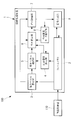
- the image processing apparatus 1 is provided in the image pickup apparatus 100, as shown in FIG.
- the imaging device 100 includes an image acquisition unit 110 that acquires a plurality of images of a subject in time series.
- the image acquisition unit 110 is a camera.
- the image processing apparatus 1 includes a frame memory 2, a motion vector calculation unit 3, an attention area setting unit 4, a motion vector selection unit 5, a matrix estimation unit 6, a matrix evaluation unit 7, a matrix estimation mode selection unit 8, and an image synthesis unit 9. I have it.
- the image processing device 1 is composed of a processor and a memory.
- the frame memory 2 sequentially stores the images and the like acquired by the image acquisition unit 110.
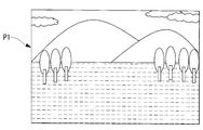
- the motion vector calculation unit 3 selects the standard image P1 shown in FIG. 2 and the reference image P2 shown in FIG. 3 from among the images stored in the frame memory 2, and selects the selected standard image P1 and reference image.
- a plurality of discrete measurement areas A1 are set for P2, and the motion vector in each set area is calculated.
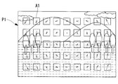
- the motion vector calculation unit 3 sets a plurality of discrete areas in the standard image P1 and the reference image P2 with 32 ⁇ 32 pixels as one measurement area A1, and uses the block matching method. As shown in FIG. 5, the motion vector values in the horizontal direction and the vertical direction on the image are acquired using a known method such as. Further, the motion vector calculation unit 3 estimates motion information with sub-pixel accuracy from the distribution of evaluation values by using equiangular straight line fitting or parabola fitting.
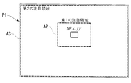
- the attention area setting unit 4 sets the attention area A2 for the images P1 and P2 stored in the frame memory 2. As shown in FIG. 6, the attention area setting unit 4 sets a first attention area (attention area) A2, which is larger than the first attention area A2 based on an evaluation result in a matrix evaluation unit 7 described later. The second attention area (attention area) A3 having the wider width is reset.
- the focus position at the time of acquiring the reference image P1 may be used.
- the reference image P1 is acquired and an autofocus (AF) area is set as shown in FIG. 6 and the image is taken, the area including the AF area is set as the first attention area A2.
- the first attention area A2 may be set to a position and size including at least a part of the AF area. The user may arbitrarily set the first attention area A2.
- the motion vector selection unit 5 includes a motion vector reliability threshold setting unit 51 and a motion vector extraction unit 52.
- the motion vector reliability threshold setting unit 51 sets a motion vector reliability threshold. The reliability of the motion vector becomes small when the motion estimation with sub-pixel accuracy is likely to fail, for example, when the measurement area A1 has a low contrast or has a high frequency stripe pattern.
- the motion vector extraction unit 52 uses the threshold set by the motion vector reliability threshold setting unit 51, is the motion vector of the measurement area A1 in which it is considered that the correct motion can be estimated, and exists in the attention area A2. Extract only motion vectors.
- the two images P1 5 shows an example of the motion vector calculated between P2 and P2.
- the motion vector extraction unit 52 extracts the motion vector in the first attention area A2 indicated by the broken line in FIG.
- the matrix estimation unit 6 calculates a projective transformation matrix from the motion vector selected by the motion vector selection unit 5.
- the matrix evaluation unit 7 includes an error calculation unit 71, an error threshold value setting unit 72, and an error determination unit 73.
- the error calculation unit 71 calculates the error between the result of applying the projective transformation matrix to the position coordinates of each measurement area A1 and the motion vector. The coordinates of the measurement area A1 on the reference image P1 for which the motion vector has been calculated. If the position (x, y) and the estimated projective transformation matrix H1 are given by equation 1, the coordinate position (x′, y′) after projective transformation is given by equation 2.
- Equation 3 the error e of the projective transformation matrix H1 is given by Equation 3.
- the error determination unit 73 compares the threshold e_TH set by the error threshold setting unit 72 with the error e calculated by the error calculation unit 71. When the error e is less than the threshold value e_TH, it is determined that the measurement area A1 can be appropriately aligned by the estimated projective transformation matrix H1. If the error e is greater than or equal to the threshold value e_TH, misalignment may occur when the images are aligned with the estimated projective transformation matrix H1, so it is determined to be an inappropriate projective transformation matrix. The error is evaluated for all the position coordinates of the measurement area A1 of the motion vector in the reference image P1.
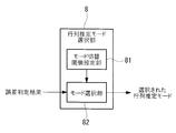
- Matrix estimation mode selection unit 8 selects a matrix estimation mode based on the evaluation result by matrix evaluation unit 7. As shown in FIG. 10, the matrix estimation mode selection unit 8 includes a mode switching threshold setting unit 81 and a mode selection unit 82, and with respect to the number of motion vectors of the entire screen for which an error is determined by the matrix evaluation unit 7, Then, the matrix estimation mode is selected based on the ratio of the number of motion vectors (inlier number) determined to be appropriate for alignment.
- the first mode is a mode for resetting the attention area A3 and re-estimating the projective transformation matrix
- the second mode is a mode for estimating at least one projective transformation matrix different from the first projective transformation matrix. ..
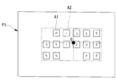
- the attention area The attention area A3 is reset by the setting unit 4. As an example of resetting, as shown in FIG. 11, a second attention area A3 having a larger area size than the first first attention area A2 is set. Then, the second projective transformation matrix H2 is estimated using the set second attention area A3.
- the projective transformation matrix H2 can be estimated using the motion vector around the reference image P1 as compared with the case where the projective transformation matrix H1 is estimated in the first attention area A2, and the projective transformation matrix H2 around the reference image P1 can be estimated. It becomes easy to find a projective transformation matrix that takes motion into consideration.
- the image synthesizing unit 9 uses the second projective transformation matrix H2 estimated using the reset second attention area A3 to compare the standard image P1 and the reference image P2 stored in the frame memory 2. To synthesize. As a result, it is possible to generate a composite image with less displacement even in the periphery of the image.
- the method of setting the second attention area A3 may reset the entire image as the second attention area A3 as shown in FIG. This makes it possible to calculate an appropriate projective transformation matrix H2 that further considers the movement around the image.
- the size of the area to be expanded may be determined based on the shooting information of the shot images P1 and P2. For example, it is conceivable that the larger the aperture value at the time of capturing the image, the larger the area. When the subject is flat, it is considered that the larger the aperture value is, the more focused the image is on every corner of the image, and the motion vector between the images P1 and P2 is also estimated with high accuracy. Increase the size of A3. On the other hand, as the aperture value is smaller, the focus around the image may be weakened even for a flat subject, and the estimation accuracy of the motion vector may be reduced. Therefore, the size of the second attention area A3 is reduced. To do.
- the size of the second attention area A3 may be increased as the subject distance at the time of shooting the images P1 and P2 increases. Since the amount of movement itself between the images P1 and P2 decreases as the distance to the subject increases, it is possible that a small rotation component of the image cannot be estimated well in the small attention area A3. Therefore, an appropriate projective transformation matrix H2 can be estimated by setting an area having a size closer to the whole of the images P1 and P2 as the distance of the subject is increased to the second attention area A3.
- the second region of interest A3 may be expanded as the focal length of the lens is shorter.
- a different projective transformation matrix H2 is estimated using the motion vector of the area A1. For example, as shown in FIG. 13, as a result of evaluating the projective transformation matrix H1 by the matrix evaluation unit 7 using the projective transformation matrix H1 calculated from the first attention area A2, the measurement area in which the error is less than the threshold value. When the area A1 is surrounded by a thick line and the measurement area A1 whose error is equal to or larger than the threshold is a shaded area, another projective transformation matrix H2 is obtained using the shaded area.
- the image synthesizing unit 9 has an advantage that it is possible to perform alignment while selecting the appropriate projective transformation matrixes H1 and H2 for each pixel or each region using the two projective transformation matrices H1 and H2. is there.
- the projective transformation matrix H2 is obtained by the matrix estimation unit 6, and as a result of the evaluation of the projective transformation matrix H2 by the matrix evaluation unit 7, if the ratio in which the error is greater than or equal to the threshold value is greater than the threshold value hTH, the third The projective transformation matrix H3 is obtained.
- the matrix estimation process may be terminated when the ratio of the error being equal to or larger than the threshold is smaller than the threshold hTH.
- the image composition unit 9 aligns and composes the standard image P1 and the reference image P2 using the calculated one or more projective transformation matrices. By doing so, it is possible to perform alignment while selecting an appropriate projective transformation matrix for each pixel or each region using the n number of projective transformation matrices.
- the combined image combined by the image combining unit 9 is stored in the frame memory 2.
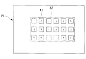
- the matrix estimation part 6 you may determine the motion vector used when performing matrix estimation by the following methods. That is, after the motion vector selection unit 5 extracts a motion vector in the first attention area A2 that is highly reliable, the matrix estimation unit 6 calculates the barycentric position coordinates of the extracted motion vector. Then, the first attention area A2 is divided into four with the calculated center of gravity as the center, and a motion vector used for matrix estimation is determined from each of the four divided areas.
- the measurement area A1 shown in FIG. 14 when the motion vector between the images P1 and P2 is calculated, the measurement area A1 with a high motion vector reliability is indicated by a solid line, and the measurement area with a low motion vector reliability is measured. A1 is indicated by a broken line. Further, in FIG. 14, the first attention area A2 is an area surrounded by a chain line.
- the motion vector is highly reliable, and the motion vector in the first attention area A2 is extracted as shown in FIG. Further, when the center of gravity position G of these extracted motion vectors is calculated, the result is as shown in FIG.
- the area Centering the calculated center-of-gravity position G, the area is divided into four by a horizontal line passing through the center-of-gravity position G and a vertical line orthogonal to the horizontal line, and one arbitrary motion vector is selected from each of the divided areas. Then, using the selected four motion vectors, a projective transformation matrix is obtained by the RANSAC algorithm or the like. This makes it possible to estimate the projective transformation matrix that appropriately aligns the entire first attention area A2.
- the center coordinates of the first attention area A2 may be simply divided into four.
- the present method can be applied to the case of setting the second attention area A3.
- the four images P1 and P2 are Matrix estimation can be performed using the motion vectors located in the regions near the corners or the four corners, respectively, and the projective transformation matrix that appropriately aligns the entire images P1 and P2 can be estimated.
- the resolution of the composite image is not particularly limited, and a composite image having the same resolution as the image acquired by shooting may be generated, or the resolution higher than the image acquired by shooting. You may generate a synthetic image.
- the pixels When synthesizing a high resolution image having twice the resolution in each of the horizontal direction and the vertical direction with respect to the images P1 and P2 acquired by photographing, the pixels may be aligned with sub-pixel accuracy.
Abstract
An image processing device (1) provided with: a motion vector calculation unit (3) which sets a plurality of discrete measurement regions in a reference image and a comparison image selected from among a plurality of images that were acquired in time series, and calculates a motion vector for each measurement region; a target region setting unit (4) which sets a target region in the reference image; a motion vector selection unit (5) which selects a motion vector for the interior of the set target region from among the plurality of calculated motion vectors; a matrix estimation unit (6) which uses the selected motion vector to estimate a projective transformation matrix representing a motion of the target region; and a matrix evaluation unit (7) which, on the basis of the estimated projective transformation matrix and the plurality of motion vectors, evaluates an error in the projective transformation matrix. The target region setting unit (4) sets a second target region larger than and including a first target region on the basis of results of evaluation, by the matrix evaluation unit, of a projective transformation matrix estimated on the basis of the first target region.
Description
本発明は、画像処理装置、画像処理方法および画像処理プログラムに関するものである。
The present invention relates to an image processing device, an image processing method, and an image processing program.
複数枚の画像を位置合わせする技術として、位置ずれ量を射影変換行列によってモデル化する手法がある。これは、複数枚の撮像画像の中から任意に選択された基準画像および参照画像に対して、オプティカルフローあるいは特徴点マッチング等により特徴的な領域の画像間における位置ずれ量を求め、位置ずれ量の情報を用いて画像全体の幾何学的な変化を推定することにより、各画素位置の位置合わせ量を算出するものである。
As a technique for aligning multiple images, there is a method of modeling the amount of positional shift using a projective transformation matrix. This is the amount of positional deviation between the images of the characteristic region obtained by optical flow or characteristic point matching for the standard image and the reference image arbitrarily selected from the plurality of captured images. By estimating the geometrical change of the entire image using the information of (3), the alignment amount of each pixel position is calculated.
射影変換行列を用いた位置ずれ量の算出は、奥行きのある被写体が含まれなければ、画像全体のどの方向にどれだけ移動したかを正しく算出できる。しかしながら、近距離平面と遠距離平面とが混在する奥行きのある被写体の場合には、撮像装置から被写体までの距離に応じて撮像面上での画像間の位置ずれ量が異なる。
Calculating the amount of misalignment using the projective transformation matrix can correctly calculate in what direction and in what direction the entire image has moved if a subject with depth is not included. However, in the case of a subject having a depth in which a short-distance plane and a long-distance plane are mixed, the amount of positional deviation between images on the imaging surface varies depending on the distance from the imaging device to the subject.
被写体距離が近い物体ほど撮像面上での位置ずれ量は大きく、被写体距離が遠いほど撮像面上での位置ずれ量は小さくなる。そのため、距離平面ごとに適切な射影変換行列を推定する必要がある。領域ごとに適切な射影変換行列を適用できない場合には、正しい位置合わせができず、位置合わせ誤差によるアーティファクトが発生する。
The closer the object distance is, the greater the amount of positional deviation on the imaging surface, and the farther the object distance, the smaller the amount of positional deviation on the imaging surface. Therefore, it is necessary to estimate an appropriate projective transformation matrix for each distance plane. If an appropriate projective transformation matrix cannot be applied to each area, correct alignment cannot be performed, and an artifact due to the alignment error occurs.
適切な位置合わせを行うために、画像全体の動き推定を行うための動きベクトルの選択規則を設定する技術が知られている(例えば、特許文献1参照。)。また、主要被写体領域の情報を利用して動きベクトルの重みづけを行うことにより主要被写体を適切に位置合わせする技術も知られている(例えば、特許文献2参照。)。
A technique for setting a motion vector selection rule for performing motion estimation of the entire image in order to perform appropriate alignment is known (for example, see Patent Document 1). There is also known a technique for appropriately aligning the main subject by weighting the motion vector using the information of the main subject region (for example, refer to Patent Document 2).
しかしながら、特許文献1の技術では、画像全体から動きベクトルを選択するので、被写体によらず、画像全体の動き推定を行うため、主要被写体と背景被写体の間の奥行き差が大きい場合には主要被写体と背景被写体の両方を適切に位置合わせすることができず、主要被写体と背景被写体のいずれか、もしくは、どちらも位置ずれが生ずるリスクがある。
However, in the technique of Patent Document 1, since a motion vector is selected from the entire image, motion estimation of the entire image is performed regardless of the subject. Therefore, when the depth difference between the main subject and the background subject is large, the main subject It is not possible to properly align both the background subject and the background subject, and there is a risk that the main subject and the background subject or both of them will be displaced.
また、特許文献2の技術では、奥行き差がない平面的な被写体である場合に、画像全体を主要被写体領域として認識できなければ問題が発生する。すなわち、画像の一部が主要被写体領域であると認識されてしまうと、その領域の動きベクトルを重要視して優先的に位置合わせが行われるため、主要被写体領域から空間的に離れた領域における位置合わせ精度が低下して位置ずれが発生するという問題がある。そのため、画像全体を適切に位置合わせするには主要被写体の認識精度を向上する必要があり、動き推定の前処理における処理コストが大きくなるという不都合がある。
Also, in the technique of Patent Document 2, if the subject is a plane subject with no depth difference, a problem will occur if the entire image cannot be recognized as the main subject region. That is, when a part of the image is recognized as the main subject region, the motion vector of the region is regarded as important and the alignment is performed preferentially. Therefore, in a region spatially separated from the main subject region. There is a problem that the alignment accuracy is lowered and the position shift occurs. Therefore, in order to properly position the entire image, it is necessary to improve the recognition accuracy of the main subject, which results in an inconvenience that the processing cost in the preprocessing for motion estimation increases.
本発明は、主要被写体と背景被写体との奥行き差の大小にかかわらず、それぞれの被写体に適した方法で位置合わせを正しく行うことができる画像処理装置、画像処理方法および画像処理プログラムを提供することを目的としている。
The present invention provides an image processing device, an image processing method, and an image processing program that can perform alignment correctly by a method suitable for each subject regardless of the depth difference between the main subject and the background subject. It is an object.
本発明の一態様は、時系列に取得された複数の画像から選択された基準画像および参照画像に対して離散的な複数の測定領域を設定し、各該測定領域における動きベクトルを算出する動きベクトル算出部と、前記基準画像に対して注目領域を設定する注目領域設定部と、前記動きベクトル算出部により算出された複数の前記動きベクトルから、前記注目領域設定部により設定された前記注目領域内の前記動きベクトルを選択する動きベクトル選択部と、該動きベクトル選択部により選択された前記動きベクトルを用いて前記注目領域の動きを表す射影変換行列を推定する行列推定部と、該行列推定部により推定された前記射影変換行列と、前記動きベクトル算出部により算出された複数の前記動きベクトルとに基づいて、前記射影変換行列の誤差を評価する行列評価部とを備え、前記注目領域設定部が、第1の注目領域に基づいて推定された前記射影変換行列の前記行列評価部における評価結果に基づいて、前記第1の注目領域よりも広げた第2の注目領域を設定する画像処理装置である。
One aspect of the present invention is a motion for setting a plurality of discrete measurement regions with respect to a standard image and a reference image selected from a plurality of images acquired in time series, and calculating a motion vector in each measurement region. A vector calculation unit, a attention region setting unit that sets a attention region with respect to the reference image, and the attention region set by the attention region setting unit from the plurality of motion vectors calculated by the motion vector calculation unit A motion vector selection unit that selects the motion vector in the matrix, a matrix estimation unit that estimates a projective transformation matrix that represents the motion of the region of interest using the motion vector selected by the motion vector selection unit, and the matrix estimation unit. And a matrix evaluation unit that evaluates the error of the projective conversion matrix based on the plurality of motion vectors calculated by the motion vector calculation unit. Image processing for setting a second attention area wider than the first attention area based on an evaluation result of the projective transformation matrix estimated by the matrix evaluation unit based on the first attention area. It is a device.
本態様によれば、時系列に取得された複数の画像から選択された基準画像と参照画像について、動きベクトル算出部により離散的な複数の測定領域が設定され、各測定領域における動きベクトルが算出され、注目領域設定部により基準画像に対して第1の注目領域が設定される。そして、動きベクトル選択部において、算出された複数の動きベクトルを用いて、第1の注目領域内の動きベクトルが選択され、行列推定部により、選択された動きベクトルを用いて射影変換行列が推定される。推定された射影変換行列の誤差が、行列評価部において、動きベクトルに基づいて評価される。
According to this aspect, with respect to the standard image and the reference image selected from the plurality of images acquired in time series, the motion vector calculation unit sets a plurality of discrete measurement regions, and the motion vector in each measurement region is calculated. Then, the attention area setting unit sets the first attention area with respect to the reference image. Then, the motion vector selection unit uses the calculated plurality of motion vectors to select the motion vector in the first region of interest, and the matrix estimation unit estimates the projective transformation matrix using the selected motion vectors. To be done. The error of the estimated projective transformation matrix is evaluated by the matrix evaluation unit based on the motion vector.
この場合において、第1の注目領域に基づいて推定された射影変換行列の評価結果に基づいて第1の注目領域よりも広げた第2の注目領域が設定され、設定された第2の注目領域を用いて動きベクトルの選択、射影変換行列の推定が行われる。すなわち、第1の注目領域で推定された射影変換行列よりも、領域を広げた第2の注目領域で推定された射影変換行列の方が、画像の周辺の動きを考慮したものとなるので、推定された射影変換行列を用いて画像の周辺まで位置ずれの少ない合成画像を生成することができる。
In this case, the second attention area wider than the first attention area is set based on the evaluation result of the projective transformation matrix estimated based on the first attention area, and the set second attention area is set. Is used to select the motion vector and estimate the projective transformation matrix. That is, since the projective transformation matrix estimated in the second region of interest, which is a wider region, takes into consideration the movement around the image than the projective transformation matrix estimated in the first region of interest, By using the estimated projective transformation matrix, it is possible to generate a composite image with less displacement even in the periphery of the image.
上記態様においては、前記行列評価部が、複数の前記測定領域それぞれの位置座標に対して前記射影変換行列を適用した結果と前記動きベクトルとの誤差を算出する誤差算出部と、該誤差算出部により算出された前記誤差が所定の閾値以上であるか否かを前記測定領域ごとに判定する誤差判定部とを備えていてもよい。
この構成により、行列評価部により射影変換行列の誤差を容易に評価することができる。 In the above aspect, the matrix evaluation unit, an error calculation unit that calculates an error between the result of applying the projective transformation matrix to the position coordinates of each of the plurality of measurement regions and the motion vector, and the error calculation unit. An error determination unit may be provided for each of the measurement regions to determine whether or not the error calculated by the above is greater than or equal to a predetermined threshold value.
With this configuration, the matrix evaluation unit can easily evaluate the error of the projective transformation matrix.
また、上記態様においては、前記行列評価部が、前記誤差判定部による判定結果に基づいて行列推定モードを選択する行列推定モード選択部を備えていてもよい。
この構成により、被写体における奥行きの有無に合わせて、適正な行列推定モードを切り替えて適用することができる。 Further, in the above aspect, the matrix evaluation unit may include a matrix estimation mode selection unit that selects a matrix estimation mode based on a determination result by the error determination unit.
With this configuration, an appropriate matrix estimation mode can be switched and applied according to the presence or absence of depth in the subject.
また、上記態様においては、前記行列推定モード選択部が、前記誤差判定部による判定結果に基づいて前記注目領域を再設定して前記射影変換行列を推定し直す第1モードか、前記行列推定部により推定された前記射影変換行列とは異なる少なくとも1以上の他の射影変換行列を推定する第2モードかを選択してもよい。
この構成により、奥行きが少ない平面的な被写体を撮影した画像については、第1モードにより注目領域を再設定して射影変換行列を推定し、奥行きの大きな被写体を撮影した画像については、第2モードにより領域ごとに異なる射影変換行列を適用して、領域ごとに適正な位置合わせを行うことができる。 Further, in the above aspect, the matrix estimation mode selection unit is a first mode in which the region of interest is reset based on the determination result by the error determination unit to re-estimate the projective transformation matrix, or the matrix estimation unit. The second mode for estimating at least one other projective transformation matrix different from the projective transformation matrix estimated by
With this configuration, for an image of a flat subject with a small depth, the region of interest is reset in the first mode to estimate the projective transformation matrix, and for an image of a subject with a large depth, the second mode is used. Thus, it is possible to apply different projective transformation matrices for each region and perform proper alignment for each region.
また、上記態様においては、前記注目領域設定部が、前記注目領域を再設定するとき、時系列に取得された前記画像の撮影情報に基づいて広げる領域の大きさを決定してもよい。
この構成により、画像の撮影情報に基づいて簡易に注目領域を適正に広げることができる。 Further, in the above aspect, when the attention area setting unit resets the attention area, the size of the area to be widened may be determined based on the photographing information of the images acquired in time series.
With this configuration, it is possible to easily and appropriately expand the attention area based on the shooting information of the image.
また、上記態様においては、前記画像の撮影情報が絞り値であり、前記注目領域設定部は、前記絞り値が大きいほど、広げる領域の大きさを大きくしてもよい。
この構成により、絞り値が大きいほど画像の隅々まで合焦しているため、より広い注目領域を用いて推定された射影変換行列により、画像の周辺まで位置ずれの少ない合成画像を生成することができる。 Further, in the above aspect, the shooting information of the image may be an aperture value, and the attention area setting unit may increase the size of the area to be expanded as the aperture value is larger.
With this configuration, the larger the aperture value is, the more focused the image is on every corner. Therefore, by using the projective transformation matrix estimated using a wider attention area, it is possible to generate a composite image with less displacement to the periphery of the image. You can
また、上記態様においては、前記画像の撮影情報が被写体までの距離であり、前記注目領域設定部は、前記距離が大きいほど、広げる領域の大きさを大きくしてもよい。
この構成により、被写体までの距離が大きいほど画像間の動き量自体が小さくなるため、より広い注目領域を用いて推定された射影変換行列により、画像の周辺まで位置ずれの少ない合成画像を生成することができる。 Further, in the above aspect, the shooting information of the image is a distance to the subject, and the attention area setting unit may increase the size of the area to be expanded as the distance is increased.
With this configuration, the larger the distance to the subject, the smaller the amount of movement itself between the images. Therefore, a projective transformation matrix estimated using a wider attention area is used to generate a composite image with less displacement to the periphery of the image. be able to.
また、上記態様においては、前記動きベクトル選択部が、前記動きベクトルの信頼度をさらに算出し、算出された前記信頼度に対する閾値を設定する動きベクトル信頼度閾値設定部と、前記動きベクトルの前記測定領域が前記注目領域内であり、かつ、前記動きベクトルの前記信頼度が閾値以上である前記動きベクトルのみを抽出する動きベクトル抽出部とを備えていてもよい。
Further, in the above aspect, the motion vector selection unit further calculates a reliability of the motion vector, and sets a threshold value for the calculated reliability, a motion vector reliability threshold setting unit, and the motion vector A motion vector extraction unit that extracts only the motion vector in which the measurement region is within the region of interest and the reliability of the motion vector is greater than or equal to a threshold value may be provided.
動きベクトルの信頼度は、例えば、測定領域が低コントラストである場合、あるいは高周波の縞模様である場合等、サブピクセル精度での動き推定が失敗しそうなときに小さくなる。
この構成により、動きベクトルの信頼度が閾値以上であり、正しい動きが推定できたと考えられる測定領域の動きベクトルのみが抽出されるので、位置ずれの少ない合成画像を生成することができる。 The reliability of the motion vector becomes small when the motion estimation with sub-pixel accuracy is likely to fail, for example, when the measurement region has low contrast or has a high-frequency striped pattern.
With this configuration, only the motion vector of the measurement region in which the reliability of the motion vector is equal to or higher than the threshold value and the correct motion can be estimated, and thus a composite image with less displacement can be generated.
また、上記態様においては、前記行列推定部が、前記動きベクトルの位置座標の分布を解析した結果に基づいて前記注目領域を4分割し、分割された4つの領域から行列推定に用いる前記動きベクトルを決定してもよい。
この構成により、注目領域内全体を適切に位置合わせする射影変換行列を推定することができる。 Further, in the above aspect, the matrix estimation unit divides the attention area into four based on a result of analysis of a distribution of position coordinates of the motion vector, and the motion vector used for matrix estimation from the four divided areas. May be determined.
With this configuration, it is possible to estimate the projective transformation matrix that appropriately aligns the entire region of interest.
また、上記態様においては、前記注目領域設定部が、ユーザが設定した領域を前記注目領域として設定してもよい。
また、上記態様においては、前記注目領域設定部が、時系列に取得された前記画像の合焦位置の少なくとも一部を含む領域を前記注目領域として設定してもよい。
また、上記態様においては、前記行列推定部により推定された前記射影変換行列を用いて、前記基準画像と前記参照画像とを位置合わせして合成する画像合成部を備えていてもよい。 Further, in the above aspect, the attention area setting unit may set an area set by the user as the attention area.
Further, in the above aspect, the attention area setting unit may set an area including at least a part of a focus position of the image acquired in time series as the attention area.
Further, in the above aspect, an image synthesizing unit that aligns and synthesizes the standard image and the reference image by using the projective transformation matrix estimated by the matrix estimating unit may be provided.
また、本発明の他の態様は、時系列に取得された複数の画像から選択された基準画像および参照画像に対して離散的な複数の測定領域を設定し、各該測定領域における動きベクトルを算出し、前記基準画像に対して注目領域を設定し、算出された複数の前記動きベクトルから、設定された前記注目領域内の前記動きベクトルを選択し、選択された該動きベクトルを用いて前記注目領域の動きを表す射影変換行列を推定し、推定された該射影変換行列と、算出された複数の前記動きベクトルとに基づいて、前記射影変換行列を評価し、評価結果に基づいて、設定された前記注目領域よりも広げたあらたな注目領域を再設定する画像処理方法である。
Further, according to another aspect of the present invention, a plurality of discrete measurement regions are set with respect to a standard image and a reference image selected from a plurality of images acquired in time series, and a motion vector in each measurement region is set. The attention area is calculated and set to the reference image, the motion vector in the set attention area is selected from the plurality of calculated motion vectors, and the movement vector is selected using the selected movement vector. Estimating a projective transformation matrix that represents the movement of the region of interest, based on the estimated projective transformation matrix and the calculated plurality of motion vectors, evaluate the projective transformation matrix, and based on the evaluation result, set This is an image processing method for resetting a new attention area that is wider than the above-mentioned attention area.
また、本発明の他の態様は、時系列に取得された複数の画像から選択された基準画像および参照画像に対して離散的な複数の測定領域を設定し、各該測定領域における動きベクトルを算出するステップと、前記基準画像に対して注目領域を設定するステップと、算出された複数の前記動きベクトルから、設定された前記注目領域内の前記動きベクトルを選択するステップと、選択された前記動きベクトルを用いて前記注目領域の動きを表す射影変換行列を推定するステップと、推定された前記射影変換行列と、算出された複数の前記動きベクトルとに基づいて、前記射影変換行列を評価するステップと、評価結果に基づいて、設定された前記注目領域よりも広げたあらたな注目領域を再設定するステップとを実行する画像処理プログラムである。
Further, according to another aspect of the present invention, a plurality of discrete measurement regions are set with respect to a standard image and a reference image selected from a plurality of images acquired in time series, and a motion vector in each measurement region is set. A step of calculating, a step of setting an attention area with respect to the reference image, a step of selecting the motion vector in the set attention area from the plurality of calculated motion vectors, the selected Estimating the projective transformation matrix that represents the motion of the region of interest using a motion vector, and evaluating the projective transformation matrix based on the estimated projective transformation matrix and the calculated plurality of motion vectors. It is an image processing program that executes a step and a step of resetting a new attention area wider than the set attention area based on an evaluation result.
本発明によれば、主要被写体と背景被写体との奥行き差の大小にかかわらず、それぞれの被写体に適した方法で位置合わせを正しく行うことができるという効果を奏する。
According to the present invention, regardless of the difference in depth between the main subject and the background subject, it is possible to perform the alignment correctly by a method suitable for each subject.
本発明の一実施形態に係る画像処理装置1について、図面を参照して以下に説明する。
本実施形態に係る画像処理装置1は、図1に示されるように、撮像装置100に備えられている。撮像装置100は、被写体の画像を時系列に複数取得する画像取得部110を備えている。画像取得部110はカメラである。 Animage processing apparatus 1 according to an embodiment of the present invention will be described below with reference to the drawings.
Theimage processing apparatus 1 according to the present embodiment is provided in the image pickup apparatus 100, as shown in FIG. The imaging device 100 includes an image acquisition unit 110 that acquires a plurality of images of a subject in time series. The image acquisition unit 110 is a camera.
本実施形態に係る画像処理装置1は、図1に示されるように、撮像装置100に備えられている。撮像装置100は、被写体の画像を時系列に複数取得する画像取得部110を備えている。画像取得部110はカメラである。 An
The
画像処理装置1は、フレームメモリ2、動きベクトル算出部3、注目領域設定部4、動きベクトル選択部5、行列推定部6、行列評価部7、行列推定モード選択部8および画像合成部9を備えている。画像処理装置1は、プロセッサおよびメモリにより構成されている。
The image processing apparatus 1 includes a frame memory 2, a motion vector calculation unit 3, an attention area setting unit 4, a motion vector selection unit 5, a matrix estimation unit 6, a matrix evaluation unit 7, a matrix estimation mode selection unit 8, and an image synthesis unit 9. I have it. The image processing device 1 is composed of a processor and a memory.
フレームメモリ2は、画像取得部110により取得された画像等を逐次記憶する。
動きベクトル算出部3は、フレームメモリ2に記憶された画像内から、図2に示される基準画像P1と、図3に示される参照画像P2とを選択し、選択された基準画像P1および参照画像P2に対して離散的な複数の測定領域A1を設定して、各設定領域における動きベクトルを算出する。 Theframe memory 2 sequentially stores the images and the like acquired by the image acquisition unit 110.
The motionvector calculation unit 3 selects the standard image P1 shown in FIG. 2 and the reference image P2 shown in FIG. 3 from among the images stored in the frame memory 2, and selects the selected standard image P1 and reference image. A plurality of discrete measurement areas A1 are set for P2, and the motion vector in each set area is calculated.
動きベクトル算出部3は、フレームメモリ2に記憶された画像内から、図2に示される基準画像P1と、図3に示される参照画像P2とを選択し、選択された基準画像P1および参照画像P2に対して離散的な複数の測定領域A1を設定して、各設定領域における動きベクトルを算出する。 The
The motion
動きベクトル算出部3は、例えば、図4に示されるように、基準画像P1および参照画像P2において、32×32画素を1つの測定領域A1として複数の離散的な領域を設定し、ブロックマッチング法等の公知の手法を用いて、図5に示されるように、画像上の水平方向と垂直方向の動きベクトル値を取得する。さらに、動きベクトル算出部3は、評価値の分布から等角直線フィッティングあるいはパラボラフィッティングを用いてサブピクセル精度の動き情報を推定する。
For example, as shown in FIG. 4, the motion vector calculation unit 3 sets a plurality of discrete areas in the standard image P1 and the reference image P2 with 32×32 pixels as one measurement area A1, and uses the block matching method. As shown in FIG. 5, the motion vector values in the horizontal direction and the vertical direction on the image are acquired using a known method such as. Further, the motion vector calculation unit 3 estimates motion information with sub-pixel accuracy from the distribution of evaluation values by using equiangular straight line fitting or parabola fitting.
注目領域設定部4は、フレームメモリ2に記憶されている画像P1,P2に対して注目領域A2を設定する。図6に示されるように、注目領域設定部4は、第1の注目領域(注目領域)A2を設定し、後述する行列評価部7における評価結果に基づいて第1の注目領域A2よりも大きさを広げた第2の注目領域(注目領域)A3を再設定する。
The attention area setting unit 4 sets the attention area A2 for the images P1 and P2 stored in the frame memory 2. As shown in FIG. 6, the attention area setting unit 4 sets a first attention area (attention area) A2, which is larger than the first attention area A2 based on an evaluation result in a matrix evaluation unit 7 described later. The second attention area (attention area) A3 having the wider width is reset.
第1の注目領域A2の設定方法としては、例えば、基準画像P1取得時の合焦位置を利用すればよい。基準画像P1取得時に図6に示されるようにオートフォーカス(AF)エリアを設定して撮影されたとき、AFエリアを含む領域を第1の注目領域A2として設定する。第1の注目領域A2はAFエリアの少なくとも一部を含む位置および大きさに設定されればよい。なお、第1の注目領域A2は、ユーザが任意に設定してもよい。
As a method of setting the first attention area A2, for example, the focus position at the time of acquiring the reference image P1 may be used. When the reference image P1 is acquired and an autofocus (AF) area is set as shown in FIG. 6 and the image is taken, the area including the AF area is set as the first attention area A2. The first attention area A2 may be set to a position and size including at least a part of the AF area. The user may arbitrarily set the first attention area A2.
動きベクトル選択部5は、図7に示されるように、動きベクトル信頼度閾値設定部51と、動きベクトル抽出部52とを備えている。動きベクトル信頼度閾値設定部51は、動きベクトルの信頼度の閾値を設定する。動きベクトルの信頼度は、例えば、測定領域A1が低コントラストである場合、あるいは、高周波の縞模様である場合など、サブピクセル精度での動き推定が失敗しそうな場合に小さくなる。
As shown in FIG. 7, the motion vector selection unit 5 includes a motion vector reliability threshold setting unit 51 and a motion vector extraction unit 52. The motion vector reliability threshold setting unit 51 sets a motion vector reliability threshold. The reliability of the motion vector becomes small when the motion estimation with sub-pixel accuracy is likely to fail, for example, when the measurement area A1 has a low contrast or has a high frequency stripe pattern.
動きベクトル抽出部52は、動きベクトル信頼度閾値設定部51により設定された閾値を用いて、正しい動きが推定できたと考えられる測定領域A1の動きベクトルであり、かつ、注目領域A2内に存在する動きベクトルのみを抽出する。
The motion vector extraction unit 52 uses the threshold set by the motion vector reliability threshold setting unit 51, is the motion vector of the measurement area A1 in which it is considered that the correct motion can be estimated, and exists in the attention area A2. Extract only motion vectors.
あるシーンにおいて、図2に示される1枚目に撮影された画像を基準画像P1とし、図3に示される2枚目に撮影された画像を参照画像P2としたときに、2枚の画像P1、P2間で算出された動きベクトルの一例を図5に示す。
動きベクトル抽出部52により、図8に破線で示される第1の注目領域A2内の動きベクトルが抽出される。 In a certain scene, when the first captured image shown in FIG. 2 is the reference image P1 and the second captured image shown in FIG. 3 is the reference image P2, the twoimages P1 5 shows an example of the motion vector calculated between P2 and P2.
The motionvector extraction unit 52 extracts the motion vector in the first attention area A2 indicated by the broken line in FIG.
動きベクトル抽出部52により、図8に破線で示される第1の注目領域A2内の動きベクトルが抽出される。 In a certain scene, when the first captured image shown in FIG. 2 is the reference image P1 and the second captured image shown in FIG. 3 is the reference image P2, the two
The motion
行列推定部6は、動きベクトル選択部5において選択された動きベクトルから射影変換行列を算出する。射影変換行列は、4点の動きベクトル情報、すなわち、動きベクトルの測定領域の位置座標(x_n,y_n)とその位置における動きベクトル(mvx_n,mvy_n)(n=1,2,3,4)とがあれば推定できる。多数の動きベクトルがある場合には、例えば、公知のRANSACアルゴリズム等を用いて最適な射影変換行列を推定することができる。
The matrix estimation unit 6 calculates a projective transformation matrix from the motion vector selected by the motion vector selection unit 5. The projective transformation matrix includes the motion vector information of four points, that is, the position coordinates (x_n, y_n) of the measurement region of the motion vector and the motion vector (mvx_n, mvy_n) (n=1, 2, 3, 4) at that position. Can be estimated if there is. When there are a large number of motion vectors, the optimum projective transformation matrix can be estimated by using, for example, a well-known RANSAC algorithm.
行列評価部7は、図9に示されるように、誤差算出部71、誤差閾値設定部72および誤差判定部73を備えている。
誤差算出部71は、測定領域A1それぞれの位置座標に対して射影変換行列を適用した結果と、動きベクトルとの誤差を算出する、動きベクトルが算出された基準画像P1上の測定領域A1の座標位置(x,y)、推定された射影変換行列H1を数1とすると、射影変換後の座標位置(x´,y´)は数2となる。 As shown in FIG. 9, thematrix evaluation unit 7 includes an error calculation unit 71, an error threshold value setting unit 72, and an error determination unit 73.
Theerror calculation unit 71 calculates the error between the result of applying the projective transformation matrix to the position coordinates of each measurement area A1 and the motion vector. The coordinates of the measurement area A1 on the reference image P1 for which the motion vector has been calculated. If the position (x, y) and the estimated projective transformation matrix H1 are given by equation 1, the coordinate position (x′, y′) after projective transformation is given by equation 2.
誤差算出部71は、測定領域A1それぞれの位置座標に対して射影変換行列を適用した結果と、動きベクトルとの誤差を算出する、動きベクトルが算出された基準画像P1上の測定領域A1の座標位置(x,y)、推定された射影変換行列H1を数1とすると、射影変換後の座標位置(x´,y´)は数2となる。 As shown in FIG. 9, the
The


また、座標位置(x,y)における動きベクトルを(mvx,mvy)とすると、射影変換行列H1の誤差eは数3となる。

Further, assuming that the motion vector at the coordinate position (x, y) is (mvx, mvy), the error e of the projective transformation matrix H1 is given by Equation 3.
誤差判定部73は、誤差閾値設定部72により設定された閾値e_THと誤差算出部71により算出された誤差eとを比較する。誤差eが閾値e_TH未満である場合には、推定された射影変換行列H1によって適切に位置合わせ可能な測定領域A1であると判断する。誤差eが閾値e_TH以上である場合には、推定された射影変換行列H1で画像の位置合わせを行うと位置ずれが生ずる可能性があるため不適切な射影変換行列であると判断する。基準画像P1中の動きベクトルの測定領域A1の全ての位置座標に対して誤差を評価する。
The error determination unit 73 compares the threshold e_TH set by the error threshold setting unit 72 with the error e calculated by the error calculation unit 71. When the error e is less than the threshold value e_TH, it is determined that the measurement area A1 can be appropriately aligned by the estimated projective transformation matrix H1. If the error e is greater than or equal to the threshold value e_TH, misalignment may occur when the images are aligned with the estimated projective transformation matrix H1, so it is determined to be an inappropriate projective transformation matrix. The error is evaluated for all the position coordinates of the measurement area A1 of the motion vector in the reference image P1.
行列推定モード選択部8は、行列評価部7による評価結果に基づいて行列推定モードを選択する。行列推定モード選択部8は、図10に示されるように、モード切替閾値設定部81とモード選択部82とを備え、行列評価部7において誤差が判定された画面全体の動きベクトルの数に対して、位置合わせに適切と判定された動きベクトルの数(インライア数)の割合に基づいて行列推定モードを選択する。
Matrix estimation mode selection unit 8 selects a matrix estimation mode based on the evaluation result by matrix evaluation unit 7. As shown in FIG. 10, the matrix estimation mode selection unit 8 includes a mode switching threshold setting unit 81 and a mode selection unit 82, and with respect to the number of motion vectors of the entire screen for which an error is determined by the matrix evaluation unit 7, Then, the matrix estimation mode is selected based on the ratio of the number of motion vectors (inlier number) determined to be appropriate for alignment.
モード切替のための閾値modeTHは予め設定されており、例えば、modeTH=0.8(80%)である。この場合には、インライア数が80%以上であれば第1モード、80%未満であれば第2モードのように切り替える。第1モードは注目領域A3を再設定して射影変換行列を推定し直すモードであり、第2モードは第1の射影変換行列とは異なる少なくとも1つ以上の射影変換行列を推定するモードである。
Threshold value modeTH for mode switching is set in advance, for example, modeTH=0.8 (80%). In this case, when the number of inliers is 80% or more, the first mode is selected, and when the number of inliers is less than 80%, the second mode is selected. The first mode is a mode for resetting the attention area A3 and re-estimating the projective transformation matrix, and the second mode is a mode for estimating at least one projective transformation matrix different from the first projective transformation matrix. ..
具体的には、モード選択部82により第1モードが選択された場合には、被写体に奥行きがなく平面的であると考えられるので、基準画像P1全体を適切に位置合わせするために、注目領域設定部4により注目領域A3を再設定する。再設定の例としては、図11に示されるように、最初の第1の注目領域A2よりも領域サイズを広げた第2の注目領域A3を設定する。そして、設定された第2の注目領域A3を用いて第2の射影変換行列H2が推定される。
Specifically, when the first mode is selected by the mode selection unit 82, it is considered that the subject has no depth and is planar, so that the entire reference image P1 is properly aligned, the attention area The attention area A3 is reset by the setting unit 4. As an example of resetting, as shown in FIG. 11, a second attention area A3 having a larger area size than the first first attention area A2 is set. Then, the second projective transformation matrix H2 is estimated using the set second attention area A3.
これによれば、第1の注目領域A2で射影変換行列H1を推定する場合よりも基準画像P1の周辺の動きベクトルを用いて射影変換行列H2を推定することができ、基準画像P1の周辺の動きを考慮した射影変換行列が求まり易くなる。
画像合成部9は、再設定された第2の注目領域A3を用いて推定された第2の射影変換行列H2を用いて、フレームメモリ2に記憶されている基準画像P1と参照画像P2とを合成する。これにより、画像の周辺まで位置ずれの少ない合成画像を生成することができる。 According to this, the projective transformation matrix H2 can be estimated using the motion vector around the reference image P1 as compared with the case where the projective transformation matrix H1 is estimated in the first attention area A2, and the projective transformation matrix H2 around the reference image P1 can be estimated. It becomes easy to find a projective transformation matrix that takes motion into consideration.
Theimage synthesizing unit 9 uses the second projective transformation matrix H2 estimated using the reset second attention area A3 to compare the standard image P1 and the reference image P2 stored in the frame memory 2. To synthesize. As a result, it is possible to generate a composite image with less displacement even in the periphery of the image.
画像合成部9は、再設定された第2の注目領域A3を用いて推定された第2の射影変換行列H2を用いて、フレームメモリ2に記憶されている基準画像P1と参照画像P2とを合成する。これにより、画像の周辺まで位置ずれの少ない合成画像を生成することができる。 According to this, the projective transformation matrix H2 can be estimated using the motion vector around the reference image P1 as compared with the case where the projective transformation matrix H1 is estimated in the first attention area A2, and the projective transformation matrix H2 around the reference image P1 can be estimated. It becomes easy to find a projective transformation matrix that takes motion into consideration.
The
なお、第2の注目領域A3の設定方法は、図12に示されるように、全体画像を第2の注目領域A3として再設定してもよい。これにより、さらに画像周辺の動きを考慮した適切な射影変換行列H2を算出することができる。
Note that the method of setting the second attention area A3 may reset the entire image as the second attention area A3 as shown in FIG. This makes it possible to calculate an appropriate projective transformation matrix H2 that further considers the movement around the image.
また、その他の設定方法として、撮影された画像P1,P2の撮影情報に基づいて広げる領域の大きさを決めることにしてもよい。
例えば、画像を撮影した際の絞り値が大きいほど、領域を大きく広げることが考えられる。被写体が平面的である場合には、絞り値が大きいほど画像の隅々まで合焦しており、画像P1,P2間の動きベクトルも精度よく推定されると考えられるため、第2の注目領域A3の大きさを大きくする。逆に、絞り値が小さいほど、平面的な被写体であっても画像周辺のピントが甘くなり、動きベクトルの推定精度が低下する可能性があるため、第2の注目領域A3の大きさを小さくする。 Further, as another setting method, the size of the area to be expanded may be determined based on the shooting information of the shot images P1 and P2.
For example, it is conceivable that the larger the aperture value at the time of capturing the image, the larger the area. When the subject is flat, it is considered that the larger the aperture value is, the more focused the image is on every corner of the image, and the motion vector between the images P1 and P2 is also estimated with high accuracy. Increase the size of A3. On the other hand, as the aperture value is smaller, the focus around the image may be weakened even for a flat subject, and the estimation accuracy of the motion vector may be reduced. Therefore, the size of the second attention area A3 is reduced. To do.
また、画像P1,P2の撮影時の被写体距離が遠いほど第2の注目領域A3の大きさを広げてもよい。被写体の距離が遠いほど画像P1,P2間の動き量自体が小さくなるため、小さな注目領域A3では画像の微小な回転成分がうまく推定できない可能性がある。そこで、被写体の距離が遠いほど画像P1,P2全体に近い大きさの領域を第2の注目領域A3に設定することにより、適切な射影変換行列H2を推定することができる。また、レンズの焦点距離が短いほど第2の注目領域A3を広げることにしてもよい。
The size of the second attention area A3 may be increased as the subject distance at the time of shooting the images P1 and P2 increases. Since the amount of movement itself between the images P1 and P2 decreases as the distance to the subject increases, it is possible that a small rotation component of the image cannot be estimated well in the small attention area A3. Therefore, an appropriate projective transformation matrix H2 can be estimated by setting an area having a size closer to the whole of the images P1 and P2 as the distance of the subject is increased to the second attention area A3. The second region of interest A3 may be expanded as the focal length of the lens is shorter.
また、行列推定モード選択部8により第2モードが選択された場合には、推定した射影変換行列H1では適切に位置合わせできない領域が多いことになるので、誤差が閾値以上であった複数の測定領域A1の動きベクトルを用いて異なる射影変換行列H2を推定する。
例えば、図13に示されるように、第1の注目領域A2から算出された射影変換行列H1を用いて行列評価部7により射影変換行列H1を評価した結果、誤差が閾値未満であった測定領域A1が太線枠で囲まれた領域、誤差が閾値以上であった測定領域A1が網掛け領域となった場合に、網掛け領域を用いて別の射影変換行列H2を求める。 In addition, when the second mode is selected by the matrix estimationmode selection unit 8, there are many regions in which the estimated projective transformation matrix H1 cannot be properly aligned. A different projective transformation matrix H2 is estimated using the motion vector of the area A1.
For example, as shown in FIG. 13, as a result of evaluating the projective transformation matrix H1 by thematrix evaluation unit 7 using the projective transformation matrix H1 calculated from the first attention area A2, the measurement area in which the error is less than the threshold value. When the area A1 is surrounded by a thick line and the measurement area A1 whose error is equal to or larger than the threshold is a shaded area, another projective transformation matrix H2 is obtained using the shaded area.
例えば、図13に示されるように、第1の注目領域A2から算出された射影変換行列H1を用いて行列評価部7により射影変換行列H1を評価した結果、誤差が閾値未満であった測定領域A1が太線枠で囲まれた領域、誤差が閾値以上であった測定領域A1が網掛け領域となった場合に、網掛け領域を用いて別の射影変換行列H2を求める。 In addition, when the second mode is selected by the matrix estimation
For example, as shown in FIG. 13, as a result of evaluating the projective transformation matrix H1 by the
これにより、画像合成部9においては、2つの射影変換行列H1,H2を用いて画素ごと、もしくは領域ごとに適切な射影変換行列H1,H2を選択しながら位置合わせを行うことができるという利点がある。
Thereby, the image synthesizing unit 9 has an advantage that it is possible to perform alignment while selecting the appropriate projective transformation matrixes H1 and H2 for each pixel or each region using the two projective transformation matrices H1 and H2. is there.
なお、第2モードが選択された場合には、異なる射影変換行列を1つだけ算出して射影変換行列の推定を終了してもよいし、異なる射影変換行列を2つ以上算出してもよい。算出手順としては、行列推定部6により射影変換行列H2が求められ、行列評価部7における射影変換行列H2の評価の結果、誤差が閾値以上である割合が閾値hTHより大きい場合には3つめの射影変換行列H3を求める。誤差が閾値以上である割合が閾値hTH未満となった時点で行列の推定処理を終了すればよい。
In addition, when the second mode is selected, only one different projective transformation matrix may be calculated to finish the estimation of the projective transformation matrix, or two or more different projective transformation matrices may be calculated. .. As the calculation procedure, the projective transformation matrix H2 is obtained by the matrix estimation unit 6, and as a result of the evaluation of the projective transformation matrix H2 by the matrix evaluation unit 7, if the ratio in which the error is greater than or equal to the threshold value is greater than the threshold value hTH, the third The projective transformation matrix H3 is obtained. The matrix estimation process may be terminated when the ratio of the error being equal to or larger than the threshold is smaller than the threshold hTH.
画像合成部9は、算出された1以上の射影変換行列を用いて基準画像P1と参照画像P2とを位置合わせして合成する。このようにすることで、n個の射影変換行列を用いて画素ごと、もしくは領域ごとに適切な射影変換行列を選択しながら位置合わせを行うことができる。画像合成部9において合成された合成画像はフレームメモリ2に記憶される。
The image composition unit 9 aligns and composes the standard image P1 and the reference image P2 using the calculated one or more projective transformation matrices. By doing so, it is possible to perform alignment while selecting an appropriate projective transformation matrix for each pixel or each region using the n number of projective transformation matrices. The combined image combined by the image combining unit 9 is stored in the frame memory 2.
なお、行列推定部6においては、以下の方法により行列推定を行う際に用いる動きベクトルを決定してもよい。
すなわち、動きベクトル選択部5において、信頼性が高くかつ第1の注目領域A2内の動きベクトルが抽出された後に、行列推定部6において、抽出された動きベクトルの重心位置座標を算出する。そして、算出された重心位置を中心として第1の注目領域A2を4つに分割し、分割された4つの領域のそれぞれから行列推定に用いる動きベクトルを決定する。 In addition, in thematrix estimation part 6, you may determine the motion vector used when performing matrix estimation by the following methods.
That is, after the motionvector selection unit 5 extracts a motion vector in the first attention area A2 that is highly reliable, the matrix estimation unit 6 calculates the barycentric position coordinates of the extracted motion vector. Then, the first attention area A2 is divided into four with the calculated center of gravity as the center, and a motion vector used for matrix estimation is determined from each of the four divided areas.
すなわち、動きベクトル選択部5において、信頼性が高くかつ第1の注目領域A2内の動きベクトルが抽出された後に、行列推定部6において、抽出された動きベクトルの重心位置座標を算出する。そして、算出された重心位置を中心として第1の注目領域A2を4つに分割し、分割された4つの領域のそれぞれから行列推定に用いる動きベクトルを決定する。 In addition, in the
That is, after the motion
例えば、図14に示される測定領域A1において、画像P1,P2間の動きベクトルが算出された場合に、動きベクトルの信頼性が高い測定領域A1を実線で、動きベクトルの信頼性が低い測定領域A1を破線で示す。また、図14において、第1の注目領域A2を一転鎖線で囲まれた領域とする。
For example, in the measurement area A1 shown in FIG. 14, when the motion vector between the images P1 and P2 is calculated, the measurement area A1 with a high motion vector reliability is indicated by a solid line, and the measurement area with a low motion vector reliability is measured. A1 is indicated by a broken line. Further, in FIG. 14, the first attention area A2 is an area surrounded by a chain line.
この場合、動きベクトルの信頼性が高く、かつ、第1の注目領域A2内の動きベクトルは、図15に示されるように抽出される。
また、これらの抽出された動きベクトルの重心位置Gを算出すると、図16の通りとなる。 In this case, the motion vector is highly reliable, and the motion vector in the first attention area A2 is extracted as shown in FIG.
Further, when the center of gravity position G of these extracted motion vectors is calculated, the result is as shown in FIG.
算出された重心位置Gを中心として、重心位置Gを通過する水平線および水平線に直交する垂直線により領域を4つに分割し、分割された各領域から、任意の動きベクトルを1つずつ選ぶ。そして、選ばれた4つの動きベクトルを用いて、RANSACアルゴリズム等により射影変換行列を求める。これにより、第1の注目領域A2内全体を適切に位置合わせする射影変換行列を推定することができる。
Centering the calculated center-of-gravity position G, the area is divided into four by a horizontal line passing through the center-of-gravity position G and a vertical line orthogonal to the horizontal line, and one arbitrary motion vector is selected from each of the divided areas. Then, using the selected four motion vectors, a projective transformation matrix is obtained by the RANSAC algorithm or the like. This makes it possible to estimate the projective transformation matrix that appropriately aligns the entire first attention area A2.
なお、信頼性の高いベクトルの重心座標を用いて4分割する方法に代えて、単純に第1の注目領域A2の中心座標を用いて4分割してもよい。また、第2の注目領域A3を設定する場合にも本手法を適用することができ、特に、画像P1,P2全体を第2の注目領域A3として設定した場合には、画像P1,P2の4隅あるいは4隅に近い領域に位置する動きベクトルをそれぞれ用いて行列推定を行うことができ、画像P1,P2全体を適切に位置合わせする射影変換行列を推定することができる。
Note that, instead of the method of dividing into four using the centroid coordinates of a highly reliable vector, the center coordinates of the first attention area A2 may be simply divided into four. In addition, the present method can be applied to the case of setting the second attention area A3. In particular, when the entire images P1 and P2 are set as the second attention area A3, the four images P1 and P2 are Matrix estimation can be performed using the motion vectors located in the regions near the corners or the four corners, respectively, and the projective transformation matrix that appropriately aligns the entire images P1 and P2 can be estimated.
また、本発明においては、合成画像の解像度について特に限定するものではなく、撮影により取得された画像と同じ解像度の合成画像を生成してもよいし、撮影により取得された画像よりも解像度の高い合成画像を生成してもよい。撮影により取得された画像P1,P2に対して水平方向および垂直方向にそれぞれ2倍の解像度を有する高解像度画像を合成する場合には、画素毎にサブピクセル精度で位置合わせすればよい。
Further, in the present invention, the resolution of the composite image is not particularly limited, and a composite image having the same resolution as the image acquired by shooting may be generated, or the resolution higher than the image acquired by shooting. You may generate a synthetic image. When synthesizing a high resolution image having twice the resolution in each of the horizontal direction and the vertical direction with respect to the images P1 and P2 acquired by photographing, the pixels may be aligned with sub-pixel accuracy.
1 画像処理装置
3 動きベクトル算出部
4 注目領域設定部
5 動きベクトル選択部
6 行列推定部
7 行列評価部
8 行列推定モード選択部
9 画像合成部
51 動きベクトル信頼度閾値設定部
52 動きベクトル抽出部
71 誤差算出部
73 誤差判定部
A1 測定領域
A2 第1の注目領域(注目領域)
A3 第2の注目領域(注目領域)
H1,H2,H3 射影変換行列
P1 基準画像(画像)
P2 参照画像(画像) 1image processing device 3 motion vector calculation unit 4 attention area setting unit 5 motion vector selection unit 6 matrix estimation unit 7 matrix evaluation unit 8 matrix estimation mode selection unit 9 image synthesis unit 51 motion vector reliability threshold setting unit 52 motion vector extraction unit 71 error calculation unit 73 error determination unit A1 measurement region A2 first region of interest (region of interest)
A3 Second area of interest (area of interest)
H1, H2, H3 Projective transformation matrix P1 Reference image (image)
P2 reference image (image)
3 動きベクトル算出部
4 注目領域設定部
5 動きベクトル選択部
6 行列推定部
7 行列評価部
8 行列推定モード選択部
9 画像合成部
51 動きベクトル信頼度閾値設定部
52 動きベクトル抽出部
71 誤差算出部
73 誤差判定部
A1 測定領域
A2 第1の注目領域(注目領域)
A3 第2の注目領域(注目領域)
H1,H2,H3 射影変換行列
P1 基準画像(画像)
P2 参照画像(画像) 1
A3 Second area of interest (area of interest)
H1, H2, H3 Projective transformation matrix P1 Reference image (image)
P2 reference image (image)
Claims (14)
- 時系列に取得された複数の画像から選択された基準画像および参照画像に対して離散的な複数の測定領域を設定し、各該測定領域における動きベクトルを算出する動きベクトル算出部と、
前記基準画像に対して注目領域を設定する注目領域設定部と、
前記動きベクトル算出部により算出された複数の前記動きベクトルから、前記注目領域設定部により設定された前記注目領域内の前記動きベクトルを選択する動きベクトル選択部と、
該動きベクトル選択部により選択された前記動きベクトルを用いて前記注目領域の動きを表す射影変換行列を推定する行列推定部と、
該行列推定部により推定された前記射影変換行列と、前記動きベクトル算出部により算出された複数の前記動きベクトルとに基づいて、前記射影変換行列の誤差を評価する行列評価部とを備え、
前記注目領域設定部が、第1の注目領域に基づいて推定された前記射影変換行列の前記行列評価部における評価結果に基づいて、前記第1の注目領域よりも広げた第2の注目領域を設定する画像処理装置。 A motion vector calculation unit that sets a plurality of discrete measurement regions for a standard image and a reference image selected from a plurality of images acquired in time series, and calculates a motion vector in each measurement region,
An attention area setting unit that sets an attention area with respect to the reference image,
A motion vector selection unit that selects the motion vector in the attention area set by the attention area setting unit from the plurality of motion vectors calculated by the motion vector calculation unit;
A matrix estimator that estimates a projective transformation matrix representing the motion of the region of interest using the motion vector selected by the motion vector selector,
The projection transformation matrix estimated by the matrix estimation unit, and a matrix evaluation unit that evaluates an error of the projection transformation matrix based on the plurality of motion vectors calculated by the motion vector calculation unit,
The attention area setting unit determines a second attention area that is wider than the first attention area based on an evaluation result of the projective transformation matrix estimated by the matrix evaluation unit based on the first attention area. Image processing device to set. - 前記行列評価部が、
複数の前記測定領域それぞれの位置座標に対して前記射影変換行列を適用した結果と前記動きベクトルとの誤差を算出する誤差算出部と、
該誤差算出部により算出された前記誤差が所定の閾値以上であるか否かを前記測定領域ごとに判定する誤差判定部とを備える請求項1に記載の画像処理装置。 The matrix evaluation unit,
An error calculation unit that calculates an error between the result and the motion vector of applying the projective transformation matrix to the position coordinates of each of the plurality of measurement regions,
The image processing apparatus according to claim 1, further comprising: an error determination unit that determines, for each of the measurement regions, whether or not the error calculated by the error calculation unit is equal to or greater than a predetermined threshold value. - 前記行列評価部が、
前記誤差判定部による判定結果に基づいて行列推定モードを選択する行列推定モード選択部を備える請求項2に記載の画像処理装置。 The matrix evaluation unit,
The image processing device according to claim 2, further comprising a matrix estimation mode selection unit that selects a matrix estimation mode based on a determination result by the error determination unit. - 前記行列推定モード選択部が、
前記誤差判定部による判定結果に基づいて前記注目領域を再設定して前記射影変換行列を推定し直す第1モードか、前記行列推定部により推定された前記射影変換行列とは異なる少なくとも1以上の他の射影変換行列を推定する第2モードかを選択する請求項3に記載の画像処理装置。 The matrix estimation mode selection unit,
At least one or more different from the projective transformation matrix estimated by the matrix estimating section, or the first mode for resetting the attention area based on the determination result by the error determining section and re-estimating the projective transformation matrix The image processing apparatus according to claim 3, wherein the second mode for estimating another projective transformation matrix is selected. - 前記注目領域設定部が、前記注目領域を再設定するとき、時系列に取得された前記画像の撮影情報に基づいて広げる領域の大きさを決定する請求項1から請求項4のいずれかに記載の画像処理装置。 The said attention area setting part determines the size of the area to expand based on the imaging information of the said image acquired in time series, when resetting the said attention area. Image processing device.
- 前記画像の撮影情報が絞り値であり、
前記注目領域設定部は、前記絞り値が大きいほど、広げる領域の大きさを大きくする請求項5に記載の画像処理装置。 The shooting information of the image is an aperture value,
The image processing apparatus according to claim 5, wherein the attention area setting unit increases the size of the area to be expanded as the aperture value is increased. - 前記画像の撮影情報が被写体までの距離であり、
前記注目領域設定部は、前記距離が大きいほど、広げる領域の大きさを大きくする請求項5に記載の画像処理装置。 The shooting information of the image is the distance to the subject,
The image processing apparatus according to claim 5, wherein the attention area setting unit increases the size of the area to be expanded as the distance is increased. - 前記動きベクトル選択部が、
前記動きベクトルの信頼度をさらに算出し、算出された前記信頼度に対する閾値を設定する動きベクトル信頼度閾値設定部と、
前記動きベクトルの前記測定領域が前記注目領域内であり、かつ、前記動きベクトルの前記信頼度が閾値以上である前記動きベクトルのみを抽出する動きベクトル抽出部とを備える請求項1から請求項7のいずれかに記載の画像処理装置。 The motion vector selection unit,
A motion vector reliability threshold setting unit that further calculates the reliability of the motion vector and sets a threshold for the calculated reliability.
The motion vector extraction unit that extracts only the motion vector in which the measurement region of the motion vector is within the region of interest and the reliability of the motion vector is equal to or more than a threshold value. The image processing device according to any one of 1. - 前記行列推定部が、
前記動きベクトルの位置座標の分布を解析した結果に基づいて前記注目領域を4分割し、分割された4つの領域から行列推定に用いる前記動きベクトルを決定する請求項1から請求項8のいずれかに記載の画像処理装置。 The matrix estimation unit,
9. The motion vector used in matrix estimation is determined from the four divided regions based on a result of analyzing the distribution of position coordinates of the motion vector, and the divided motion vector is determined from the four divided regions. The image processing device according to 1. - 前記注目領域設定部が、
ユーザが設定した領域を前記注目領域として設定する請求項1から請求項9のいずれかに記載の画像処理装置。 The attention area setting unit,
The image processing apparatus according to claim 1, wherein an area set by a user is set as the attention area. - 前記注目領域設定部が、
時系列に取得された前記画像の合焦位置の少なくとも一部を含む領域を前記注目領域として設定する請求項1から請求項9のいずれかに記載の画像処理装置。 The attention area setting unit,
The image processing apparatus according to claim 1, wherein an area including at least a part of a focus position of the image acquired in time series is set as the attention area. - 前記行列推定部により推定された前記射影変換行列を用いて、前記基準画像と前記参照画像とを位置合わせして合成する画像合成部を備える請求項1から請求項11のいずれかに記載の画像処理装置。 The image according to any one of claims 1 to 11, further comprising an image synthesizing unit that aligns and synthesizes the standard image and the reference image using the projective transformation matrix estimated by the matrix estimating unit. Processing equipment.
- 時系列に取得された複数の画像から選択された基準画像および参照画像に対して離散的な複数の測定領域を設定し、各該測定領域における動きベクトルを算出し、
前記基準画像に対して注目領域を設定し、
算出された複数の前記動きベクトルから、設定された前記注目領域内の前記動きベクトルを選択し、
選択された該動きベクトルを用いて前記注目領域の動きを表す射影変換行列を推定し、
推定された該射影変換行列と、算出された複数の前記動きベクトルとに基づいて、前記射影変換行列を評価し、
評価結果に基づいて、設定された前記注目領域よりも広げたあらたな注目領域を再設定する画像処理方法。 Set a plurality of discrete measurement regions for the standard image and the reference image selected from the plurality of images acquired in time series, and calculate the motion vector in each of the measurement regions,
Set the attention area for the reference image,
From the plurality of calculated motion vectors, select the motion vector in the set attention area,
Estimating a projective transformation matrix representing the motion of the region of interest using the selected motion vector,
Based on the estimated projective transformation matrix and the calculated plurality of motion vectors, evaluate the projective transformation matrix,
An image processing method for resetting a new attention area that is wider than the set attention area based on an evaluation result. - 時系列に取得された複数の画像から選択された基準画像および参照画像に対して離散的な複数の測定領域を設定し、各該測定領域における動きベクトルを算出するステップと、
前記基準画像に対して注目領域を設定するステップと、
算出された複数の前記動きベクトルから、設定された前記注目領域内の前記動きベクトルを選択するステップと、
選択された前記動きベクトルを用いて前記注目領域の動きを表す射影変換行列を推定するステップと、
推定された前記射影変換行列と、算出された複数の前記動きベクトルとに基づいて、前記射影変換行列を評価するステップと、
評価結果に基づいて、設定された前記注目領域よりも広げたあらたな注目領域を再設定するステップとを実行する画像処理プログラム。 Setting a plurality of discrete measurement regions for the standard image and the reference image selected from the plurality of images acquired in time series, and calculating a motion vector in each of the measurement regions,
Setting a region of interest for the reference image,
Selecting the motion vector in the set attention area from the plurality of calculated motion vectors;
Estimating a projective transformation matrix representing the motion of the region of interest using the selected motion vector;
Evaluating the projective transformation matrix based on the estimated projective transformation matrix and the plurality of calculated motion vectors;
And a step of resetting a new attention area expanded from the set attention area based on an evaluation result.
Priority Applications (4)
| Application Number | Priority Date | Filing Date | Title |
|---|---|---|---|
| JP2020565065A JP7110397B2 (en) | 2019-01-09 | 2019-01-09 | Image processing device, image processing method and image processing program |
| PCT/JP2019/000311 WO2020144760A1 (en) | 2019-01-09 | 2019-01-09 | Image processing device, image processing method, and image processing program |
| CN201980086760.XA CN113228102A (en) | 2019-01-09 | 2019-01-09 | Image processing apparatus, image processing method, and image processing program |
| US17/366,162 US11948328B2 (en) | 2019-01-09 | 2021-07-02 | Image-processing device, image-processing method, and image-processing program |
Applications Claiming Priority (1)
| Application Number | Priority Date | Filing Date | Title |
|---|---|---|---|
| PCT/JP2019/000311 WO2020144760A1 (en) | 2019-01-09 | 2019-01-09 | Image processing device, image processing method, and image processing program |
Related Child Applications (1)
| Application Number | Title | Priority Date | Filing Date |
|---|---|---|---|
| US17/366,162 Continuation US11948328B2 (en) | 2019-01-09 | 2021-07-02 | Image-processing device, image-processing method, and image-processing program |
Publications (1)
| Publication Number | Publication Date |
|---|---|
| WO2020144760A1 true WO2020144760A1 (en) | 2020-07-16 |
Family
ID=71521583
Family Applications (1)
| Application Number | Title | Priority Date | Filing Date |
|---|---|---|---|
| PCT/JP2019/000311 WO2020144760A1 (en) | 2019-01-09 | 2019-01-09 | Image processing device, image processing method, and image processing program |
Country Status (4)
| Country | Link |
|---|---|
| US (1) | US11948328B2 (en) |
| JP (1) | JP7110397B2 (en) |
| CN (1) | CN113228102A (en) |
| WO (1) | WO2020144760A1 (en) |
Cited By (1)
| Publication number | Priority date | Publication date | Assignee | Title |
|---|---|---|---|---|
| CN114088088A (en) * | 2021-11-15 | 2022-02-25 | 贵州大学 | Angular rate and angular acceleration measuring method based on monocular vision |
Citations (4)
| Publication number | Priority date | Publication date | Assignee | Title |
|---|---|---|---|---|
| JP2007257287A (en) * | 2006-03-23 | 2007-10-04 | Tokyo Institute Of Technology | Image registration method |
| JP2010193058A (en) * | 2009-02-17 | 2010-09-02 | Casio Computer Co Ltd | Image capture device, image capturing method, and image capturing program |
| JP2016126576A (en) * | 2015-01-05 | 2016-07-11 | キヤノン株式会社 | Image processing apparatus and image processing method |
| WO2018221224A1 (en) * | 2017-05-29 | 2018-12-06 | オリンパス株式会社 | Image processing device, image processing method, and image processing program |
Family Cites Families (8)
| Publication number | Priority date | Publication date | Assignee | Title |
|---|---|---|---|---|
| JPH09212649A (en) | 1996-02-06 | 1997-08-15 | Nippon Telegr & Teleph Corp <Ntt> | Movement estimation method |
| JP4807194B2 (en) | 2006-09-06 | 2011-11-02 | カシオ計算機株式会社 | Image processing apparatus and program |
| JP4212109B2 (en) | 2007-03-20 | 2009-01-21 | パナソニック株式会社 | Imaging apparatus and imaging method |
| JP4940164B2 (en) | 2008-02-07 | 2012-05-30 | オリンパス株式会社 | Imaging apparatus and imaging method |
| JP4720859B2 (en) | 2008-07-09 | 2011-07-13 | カシオ計算機株式会社 | Image processing apparatus, image processing method, and program |
| JP2011171991A (en) | 2010-02-18 | 2011-09-01 | Olympus Corp | Image processing apparatus, electronic device, image processing method and image processing program |
| TWI571828B (en) * | 2013-01-02 | 2017-02-21 | 奇高電子股份有限公司 | Optical navigation method and device using same |
| US10051274B2 (en) * | 2013-10-25 | 2018-08-14 | Canon Kabushiki Kaisha | Image processing apparatus, method of calculating information according to motion of frame, and storage medium |
-
2019
- 2019-01-09 JP JP2020565065A patent/JP7110397B2/en active Active
- 2019-01-09 CN CN201980086760.XA patent/CN113228102A/en active Pending
- 2019-01-09 WO PCT/JP2019/000311 patent/WO2020144760A1/en active Application Filing
-
2021
- 2021-07-02 US US17/366,162 patent/US11948328B2/en active Active
Patent Citations (4)
| Publication number | Priority date | Publication date | Assignee | Title |
|---|---|---|---|---|
| JP2007257287A (en) * | 2006-03-23 | 2007-10-04 | Tokyo Institute Of Technology | Image registration method |
| JP2010193058A (en) * | 2009-02-17 | 2010-09-02 | Casio Computer Co Ltd | Image capture device, image capturing method, and image capturing program |
| JP2016126576A (en) * | 2015-01-05 | 2016-07-11 | キヤノン株式会社 | Image processing apparatus and image processing method |
| WO2018221224A1 (en) * | 2017-05-29 | 2018-12-06 | オリンパス株式会社 | Image processing device, image processing method, and image processing program |
Cited By (2)
| Publication number | Priority date | Publication date | Assignee | Title |
|---|---|---|---|---|
| CN114088088A (en) * | 2021-11-15 | 2022-02-25 | 贵州大学 | Angular rate and angular acceleration measuring method based on monocular vision |
| CN114088088B (en) * | 2021-11-15 | 2023-08-04 | 贵州大学 | Angular velocity and angular acceleration measuring method based on monocular vision |
Also Published As
| Publication number | Publication date |
|---|---|
| US20210335001A1 (en) | 2021-10-28 |
| JP7110397B2 (en) | 2022-08-01 |
| US11948328B2 (en) | 2024-04-02 |
| JPWO2020144760A1 (en) | 2021-11-18 |
| CN113228102A (en) | 2021-08-06 |
Similar Documents
| Publication | Publication Date | Title |
|---|---|---|
| CN104685513B (en) | According to the high-resolution estimation of the feature based of the low-resolution image caught using array source | |
| US9019426B2 (en) | Method of generating image data by an image device including a plurality of lenses and apparatus for generating image data | |
| US8928736B2 (en) | Three-dimensional modeling apparatus, three-dimensional modeling method and computer-readable recording medium storing three-dimensional modeling program | |
| JP5074322B2 (en) | Image processing apparatus, image processing method, image processing program, and imaging apparatus | |
| CN107851321B (en) | Image processing method and dual-camera system | |
| US11568516B2 (en) | Depth-based image stitching for handling parallax | |
| JP2017531976A (en) | System and method for dynamically calibrating an array camera | |
| US10872396B2 (en) | Image stitching method and device | |
| JP2013539273A (en) | Autofocus for stereoscopic cameras | |
| KR20080016605A (en) | Image processing apparatus and image processing program | |
| US9224212B2 (en) | Image processing apparatus and image processing method | |
| US8531505B2 (en) | Imaging parameter acquisition apparatus, imaging parameter acquisition method and storage medium | |
| JP6515039B2 (en) | Program, apparatus and method for calculating a normal vector of a planar object to be reflected in a continuous captured image | |
| US10529092B2 (en) | Method for reducing matching error in disparity image by information in zoom image | |
| JP4887376B2 (en) | A method for obtaining a dense parallax field in stereo vision | |
| JP7378219B2 (en) | Imaging device, image processing device, control method, and program | |
| JP6061770B2 (en) | Camera posture estimation apparatus and program thereof | |
| US9031355B2 (en) | Method of system for image stabilization through image processing, and zoom camera including image stabilization function | |
| CN109496326B (en) | Image processing method, device and system | |
| KR101938067B1 (en) | Method and Apparatus for Stereo Matching of Wide-Angle Images using SIFT Flow | |
| WO2020144760A1 (en) | Image processing device, image processing method, and image processing program | |
| JP2009186287A (en) | Plane parameter estimating device, plane parameter estimating method, and plane parameter estimating program | |
| US20120038785A1 (en) | Method for producing high resolution image | |
| CN112669355B (en) | Method and system for splicing and fusing focusing stack data based on RGB-D super pixel segmentation | |
| JP2016156702A (en) | Imaging device and imaging method |
Legal Events
| Date | Code | Title | Description |
|---|---|---|---|
| 121 | Ep: the epo has been informed by wipo that ep was designated in this application |
Ref document number: 19909507 Country of ref document: EP Kind code of ref document: A1 |
|
| ENP | Entry into the national phase |
Ref document number: 2020565065 Country of ref document: JP Kind code of ref document: A |
|
| NENP | Non-entry into the national phase |
Ref country code: DE |
|
| 122 | Ep: pct application non-entry in european phase |
Ref document number: 19909507 Country of ref document: EP Kind code of ref document: A1 |