WO2020141904A1 - Image signal encoding/decoding method and device for same - Google Patents
Image signal encoding/decoding method and device for same Download PDFInfo
- Publication number
- WO2020141904A1 WO2020141904A1 PCT/KR2020/000055 KR2020000055W WO2020141904A1 WO 2020141904 A1 WO2020141904 A1 WO 2020141904A1 KR 2020000055 W KR2020000055 W KR 2020000055W WO 2020141904 A1 WO2020141904 A1 WO 2020141904A1
- Authority
- WO
- WIPO (PCT)
- Prior art keywords
- tile
- block
- picture
- tiles
- information
- Prior art date
Links
Images


Classifications
-
- H—ELECTRICITY
- H04—ELECTRIC COMMUNICATION TECHNIQUE
- H04N—PICTORIAL COMMUNICATION, e.g. TELEVISION
- H04N19/00—Methods or arrangements for coding, decoding, compressing or decompressing digital video signals
- H04N19/10—Methods or arrangements for coding, decoding, compressing or decompressing digital video signals using adaptive coding
- H04N19/169—Methods or arrangements for coding, decoding, compressing or decompressing digital video signals using adaptive coding characterised by the coding unit, i.e. the structural portion or semantic portion of the video signal being the object or the subject of the adaptive coding
- H04N19/17—Methods or arrangements for coding, decoding, compressing or decompressing digital video signals using adaptive coding characterised by the coding unit, i.e. the structural portion or semantic portion of the video signal being the object or the subject of the adaptive coding the unit being an image region, e.g. an object
- H04N19/172—Methods or arrangements for coding, decoding, compressing or decompressing digital video signals using adaptive coding characterised by the coding unit, i.e. the structural portion or semantic portion of the video signal being the object or the subject of the adaptive coding the unit being an image region, e.g. an object the region being a picture, frame or field
-
- H—ELECTRICITY
- H04—ELECTRIC COMMUNICATION TECHNIQUE
- H04N—PICTORIAL COMMUNICATION, e.g. TELEVISION
- H04N19/00—Methods or arrangements for coding, decoding, compressing or decompressing digital video signals
- H04N19/10—Methods or arrangements for coding, decoding, compressing or decompressing digital video signals using adaptive coding
- H04N19/102—Methods or arrangements for coding, decoding, compressing or decompressing digital video signals using adaptive coding characterised by the element, parameter or selection affected or controlled by the adaptive coding
- H04N19/119—Adaptive subdivision aspects, e.g. subdivision of a picture into rectangular or non-rectangular coding blocks
-
- H—ELECTRICITY
- H04—ELECTRIC COMMUNICATION TECHNIQUE
- H04N—PICTORIAL COMMUNICATION, e.g. TELEVISION
- H04N19/00—Methods or arrangements for coding, decoding, compressing or decompressing digital video signals
- H04N19/10—Methods or arrangements for coding, decoding, compressing or decompressing digital video signals using adaptive coding
- H04N19/102—Methods or arrangements for coding, decoding, compressing or decompressing digital video signals using adaptive coding characterised by the element, parameter or selection affected or controlled by the adaptive coding
- H04N19/103—Selection of coding mode or of prediction mode
-
- H—ELECTRICITY
- H04—ELECTRIC COMMUNICATION TECHNIQUE
- H04N—PICTORIAL COMMUNICATION, e.g. TELEVISION
- H04N19/00—Methods or arrangements for coding, decoding, compressing or decompressing digital video signals
- H04N19/10—Methods or arrangements for coding, decoding, compressing or decompressing digital video signals using adaptive coding
- H04N19/102—Methods or arrangements for coding, decoding, compressing or decompressing digital video signals using adaptive coding characterised by the element, parameter or selection affected or controlled by the adaptive coding
- H04N19/12—Selection from among a plurality of transforms or standards, e.g. selection between discrete cosine transform [DCT] and sub-band transform or selection between H.263 and H.264
- H04N19/122—Selection of transform size, e.g. 8x8 or 2x4x8 DCT; Selection of sub-band transforms of varying structure or type
-
- H—ELECTRICITY
- H04—ELECTRIC COMMUNICATION TECHNIQUE
- H04N—PICTORIAL COMMUNICATION, e.g. TELEVISION
- H04N19/00—Methods or arrangements for coding, decoding, compressing or decompressing digital video signals
- H04N19/10—Methods or arrangements for coding, decoding, compressing or decompressing digital video signals using adaptive coding
- H04N19/169—Methods or arrangements for coding, decoding, compressing or decompressing digital video signals using adaptive coding characterised by the coding unit, i.e. the structural portion or semantic portion of the video signal being the object or the subject of the adaptive coding
- H04N19/17—Methods or arrangements for coding, decoding, compressing or decompressing digital video signals using adaptive coding characterised by the coding unit, i.e. the structural portion or semantic portion of the video signal being the object or the subject of the adaptive coding the unit being an image region, e.g. an object
- H04N19/174—Methods or arrangements for coding, decoding, compressing or decompressing digital video signals using adaptive coding characterised by the coding unit, i.e. the structural portion or semantic portion of the video signal being the object or the subject of the adaptive coding the unit being an image region, e.g. an object the region being a slice, e.g. a line of blocks or a group of blocks
-
- H—ELECTRICITY
- H04—ELECTRIC COMMUNICATION TECHNIQUE
- H04N—PICTORIAL COMMUNICATION, e.g. TELEVISION
- H04N19/00—Methods or arrangements for coding, decoding, compressing or decompressing digital video signals
- H04N19/10—Methods or arrangements for coding, decoding, compressing or decompressing digital video signals using adaptive coding
- H04N19/169—Methods or arrangements for coding, decoding, compressing or decompressing digital video signals using adaptive coding characterised by the coding unit, i.e. the structural portion or semantic portion of the video signal being the object or the subject of the adaptive coding
- H04N19/17—Methods or arrangements for coding, decoding, compressing or decompressing digital video signals using adaptive coding characterised by the coding unit, i.e. the structural portion or semantic portion of the video signal being the object or the subject of the adaptive coding the unit being an image region, e.g. an object
- H04N19/176—Methods or arrangements for coding, decoding, compressing or decompressing digital video signals using adaptive coding characterised by the coding unit, i.e. the structural portion or semantic portion of the video signal being the object or the subject of the adaptive coding the unit being an image region, e.g. an object the region being a block, e.g. a macroblock
-
- H—ELECTRICITY
- H04—ELECTRIC COMMUNICATION TECHNIQUE
- H04N—PICTORIAL COMMUNICATION, e.g. TELEVISION
- H04N19/00—Methods or arrangements for coding, decoding, compressing or decompressing digital video signals
- H04N19/70—Methods or arrangements for coding, decoding, compressing or decompressing digital video signals characterised by syntax aspects related to video coding, e.g. related to compression standards
-
- H—ELECTRICITY
- H04—ELECTRIC COMMUNICATION TECHNIQUE
- H04N—PICTORIAL COMMUNICATION, e.g. TELEVISION
- H04N19/00—Methods or arrangements for coding, decoding, compressing or decompressing digital video signals
- H04N19/10—Methods or arrangements for coding, decoding, compressing or decompressing digital video signals using adaptive coding
- H04N19/134—Methods or arrangements for coding, decoding, compressing or decompressing digital video signals using adaptive coding characterised by the element, parameter or criterion affecting or controlling the adaptive coding
- H04N19/157—Assigned coding mode, i.e. the coding mode being predefined or preselected to be further used for selection of another element or parameter
- H04N19/159—Prediction type, e.g. intra-frame, inter-frame or bidirectional frame prediction
Definitions
- the present invention relates to a video signal encoding/decoding method and an apparatus therefor.
- JCT-VC High Efficiency Video Coding
- An object of the present invention is to provide a method for dividing a picture into a plurality of tiles or a plurality of slices and an apparatus for performing the method in encoding/decoding a video signal.
- a method of selectively encoding/decoding size information of a tile column/tile row according to whether a width/height of a neighboring tile column/tile row is the same and the above It is an object to provide an apparatus for performing the method.
- An object of the present invention is to provide a method for determining a slice based on the number of tiles included in a slice or an index of a tile in a slice, and an apparatus for performing the method in dividing a picture into a plurality of slices. .
- the video signal decoding method may include dividing a picture into a plurality of tiles, and determining at least one slice based on the plurality of tiles.
- dividing the picture into a plurality of tiles includes: determining a width of a first tile column in the picture; And determining a width of a second tile row adjacent to the first tile row.
- the width of the first tile column is determined by a syntax indicating the width of the first tile column, and when the width of the second tile column is equal to the width of the first tile column, the syntax indicating the width of the second tile column Decoding is omitted, and the width of the second tile column may be set equal to the width of the first tile column.
- the second tile column may be the rightmost tile column in the picture.
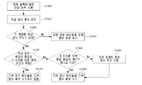
- the step of determining the slice includes: decoding information indicating a method of determining the slice, and decoding information for determining tiles included in the slice can do.
- the information indicating the determination method of the slice may indicate whether the slice is defined based on a raster scan order or whether the slice is defined in a square shape.
- the information for determining the tiles is information indicating the number of tiles included in the slice, and when the slice is defined in a square shape, for determining the tiles
- the information may be information for determining an index of at least one of tiles included in the slice.
- the information for determining the index may indicate an index difference between a tile at a predetermined position included in the slice and a tile at a predetermined position included in the previous slice.
- decoding of information for determining the tiles may be omitted.
- coding/decoding efficiency can be improved by dividing a picture into a plurality of tiles or slices.
- encoding/decoding efficiency can be improved by selectively encoding/decoding size information of a tile column/tile row according to whether the width/height of a neighboring tile column/tile row is the same.
- encoding/decoding efficiency can be improved by determining a slice based on the number of tiles included in the slice or the index of the tile in the slice.
- FIG. 1 is a block diagram of an image encoder (encoder) according to an embodiment of the present invention.
- FIG. 2 is a block diagram of an image decoder (decoder) according to an embodiment of the present invention.
- FIG. 3 is a diagram illustrating a basic coding tree unit according to an embodiment of the present invention.
- FIG. 4 is a diagram showing various division types of a coding block.
- FIG. 5 is a diagram illustrating a splitting aspect of a coding tree unit.
- FIG. 6 is a flowchart of an inter prediction method according to an embodiment of the present invention.
- FIG. 7 is a flowchart of a process for deriving motion information of a current block under merge mode.
- FIG. 8 is a diagram illustrating candidate blocks used to derive merge candidates.
- 9 is a view for explaining an example of determining a motion vector for each sub-block.
- FIG. 10 is a view for explaining an update aspect of a motion information table.
- FIG. 11 is a diagram showing an update aspect of a motion information table.
- FIG. 12 is a diagram illustrating an example in which an index of a pre-stored motion information candidate is updated.
- 13 is a view showing the location of a representative sub-block.
- FIG. 14 shows an example in which a motion information table is generated for each inter prediction mode.
- 15 is a diagram illustrating an example in which redundancy check is performed on only some of the merge candidates.
- 16 is a diagram illustrating an example in which redundancy check with a specific merge candidate is omitted.
- 17 is a flowchart of an intra prediction method according to an embodiment of the present invention.
- FIG. 18 is a diagram illustrating intra prediction modes.
- 19 and 20 are views illustrating an example of a one-dimensional array in which reference samples are arranged in a line.
- FIG. 21 is a diagram illustrating an angle in which directional intra prediction modes form a straight line parallel to the x-axis.
- 22 is a diagram illustrating an aspect in which a prediction sample is obtained when the current block is in a non-square form.
- FIG. 23 is a diagram illustrating wide angle intra prediction modes.
- 24 is a flowchart illustrating a process for determining block strength.
- 26 is a diagram illustrating a picture division method according to an embodiment of the present invention.
- FIG. 27 shows an example in which a picture is divided into a plurality of tiles.
- FIG. 28 is a diagram illustrating a split mode of a picture according to the flexible tile technique.
- 29 is a diagram illustrating an example in which a scan order of tiles is determined according to a tile group index.
- FIG. 30 is a diagram illustrating an example in which tile IDs are assigned to each coding tree unit.
- 31 and 32 are diagrams illustrating an example in which tile groups are defined based on raster order.
- 33 is a view showing an example in which only a rectangular tile group is allowed.
- 34 is a diagram illustrating an example of defining a tile group under a flexible tile segmentation technique.
- 35 illustrates an example in which the in-loop filter is selectively applied for each tile.
- the encoding and decoding of an image is performed in block units.
- encoding/decoding processing such as transformation, quantization, prediction, in-loop filtering, or reconstruction may be performed on a coding block, a transform block, or a prediction block.
- the current block may represent a coding block, a transform block, or a prediction block according to the current encoding/decoding process step.
- the term'unit' as used herein may be understood to indicate a basic unit for performing a specific encoding/decoding process, and'block' indicating a sample array of a predetermined size. Unless otherwise specified,'block' and'unit' may be used interchangeably. For example, in the embodiments described below, it may be understood that the coding block and the coding unit have mutually equivalent meanings.
- FIG. 1 is a block diagram of an image encoder (encoder) according to an embodiment of the present invention.
- the image encoding apparatus 100 includes a picture splitter 110, a prediction unit 120, 125, a transform unit 130, a quantization unit 135, a reordering unit 160, and an entropy coding unit ( 165), an inverse quantization unit 140, an inverse conversion unit 145, a filter unit 150, and a memory 155.
- each component shown in FIG. 1 is independently illustrated to represent different characteristic functions in the image encoding apparatus, and does not mean that each component is composed of separate hardware or one software component unit. That is, for convenience of description, each component is listed and included as each component, and at least two components of each component are combined to form one component, or one component is divided into a plurality of components to perform functions. The integrated and separated embodiments of the components are also included in the scope of the present invention without departing from the essence of the present invention.
- the components are not essential components for performing essential functions in the present invention, but may be optional components for improving performance.
- the present invention can be implemented by including only components necessary for realizing the essence of the present invention, except components used for performance improvement, and structures including only essential components excluding optional components used for performance improvement. Also included in the scope of the present invention.
- the picture division unit 110 may divide the input picture into at least one processing unit.
- the processing unit may be a prediction unit (PU), a transformation unit (TU), or a coding unit (CU).
- the picture dividing unit 110 divides a single picture into a combination of a plurality of coding units, prediction units, and transformation units, and combines one coding unit, prediction unit, and transformation unit with a predetermined criterion (for example, a cost function). You can code a picture by selecting.
- a predetermined criterion for example, a cost function
- one picture may be divided into a plurality of coding units.
- a recursive tree structure such as a quad tree structure can be used.
- One image or a largest coding unit is used as a root and is split into other coding units.
- the unit may be divided into as many child nodes as the number of divided coding units.
- a coding unit that is no longer split is a leaf node. That is, when it is assumed that only square division is possible for one coding unit, one coding unit may be divided into up to four different coding units.
- the coding unit may be used as a meaning of a unit that performs coding or may be used as a meaning of a unit that performs decoding.
- the prediction unit may be divided into at least one square or rectangular shape having the same size within one coding unit, and one prediction unit among the prediction units split within one coding unit may be another prediction unit. It may be divided into units having different shapes and/or sizes.
- intra prediction may be performed without dividing into a plurality of prediction units NxN.
- the prediction units 120 and 125 may include an inter prediction unit 120 performing inter prediction and an intra prediction unit 125 performing intra prediction. It is determined whether to use inter prediction or intra prediction for a prediction unit, and specific information (eg, intra prediction mode, motion vector, reference picture, etc.) according to each prediction method can be determined. At this time, the processing unit for which prediction is performed and the processing unit for which the prediction method and specific content are determined may be different. For example, a method of prediction and a prediction mode are determined in a prediction unit, and prediction may be performed in a transformation unit. The residual value (residual block) between the generated prediction block and the original block may be input to the transform unit 130.
- specific information eg, intra prediction mode, motion vector, reference picture, etc.
- prediction mode information, motion vector information, and the like used for prediction may be encoded by the entropy encoding unit 165 together with the residual value and transmitted to the decoder.
- a specific encoding mode it is also possible to encode the original block as it is and transmit it to the decoding unit without generating a prediction block through the prediction units 120 and 125.
- the inter-prediction unit 120 may predict a prediction unit based on information of at least one of a previous picture or a subsequent picture of the current picture, and in some cases, prediction based on information of some regions in which encoding in the current picture is completed. Units can be predicted.
- the inter prediction unit 120 may include a reference picture interpolation unit, a motion prediction unit, and a motion compensation unit.
- the reference picture interpolator may receive reference picture information from the memory 155 and generate pixel information of integer pixels or less in the reference picture.
- a DCT-based 8-tap interpolation filter (DCT-based interpolation filter) having different filter coefficients may be used to generate pixel information of integer pixels or less in units of 1/4 pixels.
- a DCT-based interpolation filter (DCT-based interpolation filter) having different filter coefficients may be used to generate pixel information of an integer pixel or less in units of 1/8 pixels.
- the motion prediction unit may perform motion prediction based on the reference picture interpolated by the reference picture interpolation unit.
- various methods such as Full Search-based Block Matching Algorithm (FBMA), Three Step Search (TSS), and New Three-Step Search Algorithm (NTS) can be used.
- the motion vector may have a motion vector value in units of 1/2 or 1/4 pixels based on the interpolated pixels.
- the motion prediction unit may predict a current prediction unit by differently using a motion prediction method.
- various methods such as a skip method, a merge method, an advanced motion vector prediction (AMVP) method, and an intra block copy method may be used.
- AMVP advanced motion vector prediction
- the intra prediction unit 125 may generate a prediction unit based on reference pixel information around a current block, which is pixel information in a current picture. If the neighboring block of the current prediction unit is a block that has undergone inter prediction, and the reference pixel is a pixel that has undergone inter prediction, the reference pixel included in the block that has undergone inter prediction is a reference pixel of the block that has performed intra prediction around it. It can be used as a substitute for information. That is, when the reference pixel is not available, the available reference pixel information may be replaced with at least one reference pixel among the available reference pixels.
- the prediction mode may have a directional prediction mode that uses reference pixel information according to a prediction direction and a non-directional mode that does not use directional information when performing prediction.
- a mode for predicting luminance information and a mode for predicting color difference information may be different, and intra prediction mode information or predicted luminance signal information used to predict luminance information may be utilized to predict color difference information.
- intra prediction when performing the intra prediction, if the size of the prediction unit and the size of the transformation unit are the same, intra prediction for the prediction unit based on a pixel located at the left of the prediction unit, a pixel at the top left, and a pixel at the top of the prediction unit You can do However, when the size of the prediction unit and the size of the transformation unit are different when performing intra prediction, intra prediction may be performed using a reference pixel based on the transformation unit. In addition, intra prediction using NxN splitting can be used only for a minimum coding unit.
- the intra prediction method may generate a prediction block after applying an adaptive intra smoothing (AIS) filter to a reference pixel according to a prediction mode.
- AIS adaptive intra smoothing
- the type of AIS filter applied to the reference pixel may be different.
- the intra prediction mode of the current prediction unit may be predicted from the intra prediction mode of the prediction unit existing around the current prediction unit.
- the prediction mode of the current prediction unit is predicted by using the mode information predicted from the neighboring prediction unit, if the intra prediction mode of the current prediction unit and the neighboring prediction unit are the same, the current prediction unit and the neighbor prediction unit using predetermined flag information It is possible to transmit the information that the prediction mode is the same, and if the prediction mode of the current prediction unit and the neighboring prediction unit are different, entropy encoding may be performed to encode prediction mode information of the current block.
- a residual block including prediction unit that performs prediction based on the prediction units generated by the prediction units 120 and 125 and residual information that is a difference value from the original block of the prediction unit may be generated.
- the generated residual block may be input to the conversion unit 130.
- the transform unit 130 transforms a residual block including residual information of a prediction unit generated by the original block and the prediction units 120 and 125, such as a DCT (Discrete Cosine Transform) or a DST (Discrete Sine Transform). Can be converted using methods.
- the DCT conversion core includes at least one of DCT2 or DCT8, and the DST conversion core includes DST7. Whether DCT or DST is applied to transform the residual block may be determined based on intra prediction mode information of a prediction unit used to generate the residual block.
- the transform for the residual block may be skipped.
- a flag indicating whether or not to transform the residual block can be encoded. Transform skip can be allowed for residual blocks of size less than or equal to a threshold, luma component, or chroma component under 4:4:4 format.
- the quantization unit 135 may quantize values converted from the conversion unit 130 to the frequency domain.
- the quantization coefficient may vary depending on the block or the importance of the image.
- the value calculated by the quantization unit 135 may be provided to the inverse quantization unit 140 and the rearrangement unit 160.
- the rearrangement unit 160 may rearrange the coefficient values with respect to the quantized residual value.
- the reordering unit 160 may change a block shape coefficient of 2D into a vector form of 1D through a coefficient scanning method.
- the rearrangement unit 160 may scan a DC coefficient to a coefficient in a high frequency region using a Zig-Zag Scan method and change it into a one-dimensional vector form.
- a vertical scan in which two-dimensional block shape coefficients are scanned in a column direction and a horizontal scan in which two-dimensional block shape coefficients are scanned in a row direction may be used instead of a zig-zag scan. That is, depending on the size of the transform unit and the intra prediction mode, it is possible to determine whether a scan method is used among zigzag scan, vertical scan, and horizontal scan.
- the entropy encoding unit 165 may perform entropy encoding based on values calculated by the reordering unit 160.
- various encoding methods such as exponential Golomb, CAVLC (Context-Adaptive Variable Length Coding), and CABAC (Context-Adaptive Binary Arithmetic Coding) can be used.
- the entropy encoding unit 165 includes residual value coefficient information and block type information, prediction mode information, split unit information, prediction unit information, and transmission unit information, motion of the coding unit from the reordering unit 160 and the prediction units 120 and 125 Various information such as vector information, reference frame information, block interpolation information, and filtering information can be encoded.
- the entropy encoding unit 165 may entropy encode the coefficient value of the coding unit input from the reordering unit 160.
- the inverse quantization unit 140 and the inverse transformation unit 145 inverse quantize the values quantized by the quantization unit 135 and inversely transform the values converted by the conversion unit 130.
- the residual values generated by the inverse quantization unit 140 and the inverse transformation unit 145 are restored by being combined with the prediction units predicted through the motion estimation unit, the motion compensation unit, and the intra prediction unit included in the prediction units 120 and 125 You can create a Reconstructed Block.
- the filter unit 150 may include at least one of a deblocking filter, an offset correction unit, and an adaptive loop filter (ALF).
- a deblocking filter may include at least one of a deblocking filter, an offset correction unit, and an adaptive loop filter (ALF).
- ALF adaptive loop filter
- the deblocking filter can remove block distortion caused by boundary between blocks in the reconstructed picture.
- it may be determined whether to apply a deblocking filter to the current block based on pixels included in a few columns or rows included in the block.
- a strong filter or a weak filter may be applied according to the required deblocking filtering strength.
- horizontal filtering and vertical filtering may be processed in parallel.
- the offset correction unit may correct an offset from the original image in units of pixels for the deblocking image.
- the offset correction unit may correct an offset from the original image in units of pixels for the deblocking image. In order to perform offset correction for a specific picture, after dividing the pixels included in the image into a certain number of regions, determining the region to perform the offset and applying the offset to the region, or offset by considering the edge information of each pixel You can use the method of applying.
- ALF Adaptive Loop Filtering
- one filter to be applied to the group may be determined to perform filtering differently for each group.
- the luminance signal may be transmitted for each coding unit (CU), and the shape and filter coefficient of the ALF filter to be applied may be changed according to each block.
- the ALF filter of the same form may be applied regardless of the characteristics of the block to be applied.
- the memory 155 may store reconstructed blocks or pictures calculated through the filter unit 150, and the stored reconstructed blocks or pictures may be provided to the predictors 120 and 125 when performing inter prediction.
- FIG. 2 is a block diagram of an image decoder (decoder) according to an embodiment of the present invention.
- the image decoder 200 includes an entropy decoding unit 210, a reordering unit 215, an inverse quantization unit 220, an inverse transform unit 225, a prediction unit 230, 235, and a filter unit ( 240), a memory 245 may be included.
- the input bitstream may be decoded in a procedure opposite to that of the image encoder.
- the entropy decoding unit 210 may perform entropy decoding in a procedure opposite to that performed by entropy encoding in the entropy encoding unit of the image encoder. For example, various methods such as Exponential Golomb (CAVLC), Context-Adaptive Variable Length Coding (CAVLC), and Context-Adaptive Binary Arithmetic Coding (CABAC) may be applied to the method performed in the image encoder.
- CAVLC Exponential Golomb
- CAVLC Context-Adaptive Variable Length Coding
- CABAC Context-Adaptive Binary Arithmetic Coding
- the entropy decoding unit 210 may decode information related to intra prediction and inter prediction performed by the encoder.
- the reordering unit 215 may perform reordering based on a method of reordering the bitstream entropy-decoded by the entropy decoding unit 210 in the encoding unit.
- the coefficients expressed in the form of a one-dimensional vector can be reconstructed into coefficients in the form of a two-dimensional block again and rearranged.
- the reordering unit 215 may receive information related to coefficient scanning performed by the encoding unit and perform reordering through a reverse scanning method based on a scanning order performed by the encoding unit.
- the inverse quantization unit 220 may perform inverse quantization based on the quantization parameter provided by the encoder and the coefficient values of the rearranged blocks.
- the inverse transform unit 225 may perform inverse transform, that is, inverse DCT or inverse DST, on the transform performed by the transform unit on the quantization result performed by the image encoder, that is, DCT or DST.
- the DCT conversion core may include at least one of DCT2 or DCT8, and the DST conversion core may include DST7.
- the inverse transform unit 225 may not perform the inverse transform.
- the inverse transform may be performed based on the transmission unit determined by the image encoder.
- a transform method for example, DCT or DST
- a plurality of information such as a prediction method, a current block size, and a prediction direction.
- the prediction units 230 and 235 may generate prediction blocks based on prediction block generation related information provided by the entropy decoding unit 210 and previously decoded block or picture information provided by the memory 245.
- intra prediction when intra prediction is performed in the same manner as in the image encoder, when the size of the prediction unit and the size of the transformation unit are the same, the pixel located on the left side of the prediction unit, the pixel located on the upper left side, and the top level of the prediction unit Intra prediction of the prediction unit is performed based on the pixel to be performed, but when the size of the prediction unit and the size of the transformation unit are different when performing the intra prediction, intra prediction is performed using the reference pixel based on the transformation unit. Can.
- intra prediction using NxN splitting may be used only for the smallest coding unit.
- the prediction units 230 and 235 may include a prediction unit determination unit, an inter prediction unit, and an intra prediction unit.
- the prediction unit determining unit receives various information such as prediction unit information input from the entropy decoding unit 210, prediction mode information of an intra prediction method, and motion prediction related information of an inter prediction method, classifies the prediction unit from the current coding unit, and predicts the prediction unit. It is possible to determine whether the unit performs inter prediction or intra prediction.
- the inter predictor 230 predicts the current prediction based on information included in at least one of a previous picture or a subsequent picture of the current picture including the current prediction unit, using information required for inter prediction of the current prediction unit provided by the image encoder. Inter prediction for a unit may be performed. Alternatively, inter-prediction may be performed based on information of some regions pre-restored in the current picture including the current prediction unit.
- a motion prediction method of a prediction unit included in a coding unit based on a coding unit is a skip mode, a merge mode, a motion vector prediction mode (AMVP mode), and an intra block copy It can be determined whether it is any of the modes.
- the intra prediction unit 235 may generate a prediction block based on pixel information in the current picture.
- intra prediction may be performed based on intra prediction mode information of a prediction unit provided by an image encoder.
- the intra prediction unit 235 may include an adaptive intra smoothing (AIS) filter, a reference pixel interpolation unit, and a DC filter.
- the AIS filter is a part that performs filtering on the reference pixel of the current block and can be applied by determining whether to apply the filter according to the prediction mode of the current prediction unit.
- AIS filtering may be performed on a reference pixel of a current block by using prediction mode and AIS filter information of a prediction unit provided by an image encoder. When the prediction mode of the current block is a mode that does not perform AIS filtering, the AIS filter may not be applied.
- the reference pixel interpolation unit may interpolate the reference pixel to generate a reference pixel in an integer value or less. If the prediction mode of the current prediction unit is a prediction mode in which a prediction block is generated without interpolating a reference pixel, the reference pixel may not be interpolated.
- the DC filter may generate a prediction block through filtering when the prediction mode of the current block is the DC mode.
- the reconstructed block or picture may be provided to the filter unit 240.
- the filter unit 240 may include a deblocking filter, an offset correction unit, and an ALF.
- Information about whether a deblocking filter is applied to a corresponding block or picture and information about whether a strong filter is applied or a weak filter is applied may be provided from the image encoder.
- information related to the deblocking filter provided by the video encoder may be provided, and the video decoder may perform deblocking filtering on the corresponding block.
- the offset correction unit may perform offset correction on the reconstructed image based on the type of offset correction and offset value information applied to the image during encoding.
- ALF may be applied to a coding unit based on ALF application information provided by an encoder, ALF coefficient information, and the like. This ALF information may be provided by being included in a specific parameter set.
- the memory 245 may store the restored picture or block so that it can be used as a reference picture or a reference block, and also provide the restored picture to an output unit.
- FIG. 3 is a diagram illustrating a basic coding tree unit according to an embodiment of the present invention.
- the largest sized coding block can be defined as a coding tree block.
- One picture is divided into a plurality of coding tree units (CTUs).
- the coding tree unit is a largest coding unit, and may be referred to as a large coding unit (LCU).
- LCU large coding unit
- 3 shows an example in which one picture is divided into a plurality of coding tree units.
- the size of the coding tree unit can be defined at a picture level or a sequence level. To this end, information indicating the size of the coding tree unit may be signaled through a picture parameter set or a sequence parameter set.
- the size of a coding tree unit for all pictures in a sequence may be set to 128x128.
- one of 128x128 or 256x256 may be determined as a size of a coding tree unit at a picture level.
- the size of the coding tree unit may be set to 128x128 in the first picture, and the size of the coding tree unit may be set to 256x256 in the second picture.
- the coding block represents a basic unit for encoding/decoding processing. For example, prediction or transformation may be performed for each coding block, or a prediction coding mode may be determined for each coding block.
- the prediction encoding mode represents a method for generating a prediction image.
- the prediction encoding mode includes intra prediction (Intra Prediction), inter prediction (Inter Prediction), current picture reference (Current Picture Referencing, CPR, or Intra Block Copy (IBC)).
- IBC Intra Block Copy
- a prediction block for a coding block may be generated using at least one prediction coding mode among intra prediction, inter prediction, current picture reference, or complex prediction.
- Information indicating a prediction encoding mode of a current block may be signaled through a bitstream.
- the information may be a 1-bit flag indicating whether the prediction encoding mode is intra mode or inter mode. As long as the prediction encoding mode of the current block is determined as the inter mode, the current picture reference or composite prediction may be available.
- the current picture reference is for setting a current picture as a reference picture and obtaining a prediction block of a current block from an area in which encoding/decoding has already been completed in the current picture.
- the current picture means a picture including the current block.
- Information indicating whether a current picture reference is applied to a current block may be signaled through a bitstream.
- the information may be a flag of 1 bit. When the flag is true, the prediction encoding mode of the current block is determined as a reference to the current picture, and when the flag is false, the prediction mode of the current block can be determined as inter prediction.
- the prediction coding mode of the current block may be determined based on the reference picture index. For example, when the reference picture index indicates the current picture, the prediction encoding mode of the current block may be determined as the current picture reference. When the reference picture index indicates a picture other than the current picture, the prediction coding mode of the current block may be determined as inter prediction. That is, the current picture reference is a prediction method using information of a region in which encoding/decoding is completed in the current picture, and inter prediction is a prediction method using information of another picture in which encoding/decoding is completed.
- the composite prediction represents a coding mode in which two or more of intra prediction, inter prediction, and current picture reference are combined.
- a first prediction block may be generated based on one of intra prediction, inter prediction, or a current picture reference
- a second prediction block may be generated based on the other.
- a final prediction block may be generated through an average operation or a weighted sum operation of the first prediction block and the second prediction block.
- Information indicating whether the composite prediction is applied may be signaled through the bitstream. The information may be a flag of 1 bit.
- FIG. 4 is a diagram showing various division types of a coding block.
- the coding block may be divided into a plurality of coding blocks based on quad tree splitting, binary tree splitting, or triple tree splitting.
- the divided coding block may also be divided into a plurality of coding blocks based on quad tree splitting, battery tree splitting, or triple tree splitting.
- Quad tree splitting represents a splitting technique that splits a current block into four blocks.
- the current block can be divided into four square partitions (see (a)'SPLIT_QT' in FIG. 4).
- Binary tree splitting represents a splitting technique that splits the current block into two blocks. Dividing the current block into two blocks along a vertical direction (ie, using a vertical line across the current block) may be referred to as a vertical binary tree partition, and along a horizontal direction (ie, traversing the current block). Splitting the current block into two blocks using a horizontal line can be referred to as horizontal binary tree splitting. As a result of dividing the binary tree, the current block can be divided into two non-square partitions.
- FIG. 4(b)'SPLIT_BT_VER' shows the vertical binary tree splitting result
- FIG. 4(c)'SPLIT_BT_HOR' shows the horizontal binary tree splitting result.
- Triple tree splitting represents a splitting technique that splits the current block into three blocks. Dividing the current block into three blocks along a vertical direction (ie, using two vertical lines across the current block) may be referred to as a vertical triple tree split, and along a horizontal direction (ie, the current block) Splitting the current block into three blocks using two horizontal horizontal lines) can be referred to as horizontal triple tree splitting.
- the current block may be divided into three non-square partitions. At this time, the width/height of the partition located in the center of the current block may be twice the width/height of the other partitions.
- FIG. 4(d)'SPLIT_TT_VER' shows the vertical triple tree splitting result
- FIG. 4(e)'SPLIT_TT_HOR' shows the horizontal triple tree splitting result.
- the number of splitting of the coding tree unit may be defined as a partitioning depth.
- the maximum division depth of the coding tree unit may be determined at the sequence or picture level. Accordingly, the maximum splitting depth of the coding tree unit may be different for each sequence or filler.
- the maximum splitting depth for each of the splitting techniques can be individually determined.
- the maximum splitting depth allowed for quad tree splitting may be different from the maximum splitting depth allowed for binary tree splitting and/or triple tree splitting.
- the encoder may signal information indicating at least one of a split type or a split depth of a current block through a bitstream.
- the decoder can determine the division type and division depth of the coding tree unit based on the information parsed from the bitstream.
- FIG. 5 is a diagram illustrating a splitting aspect of a coding tree unit.
- Splitting a coding block using a splitting technique such as quad tree splitting, binary tree splitting and/or triple tree splitting may be referred to as multi-tree partitioning.
- Coding blocks generated by applying multi-tree splitting to a coding block may be referred to as lower coding blocks.
- the division depth of the coding block is k
- the division depth of the lower coding blocks is set to k+1.
- a coding block having a split depth of k may be referred to as an upper coding block.
- the division type of the current coding block may be determined based on at least one of a division type of an upper coding block or a division type of a neighboring coding block.
- the neighboring coding block is adjacent to the current coding block, and may include at least one of an upper neighboring block, a left neighboring block, or a neighboring block adjacent to the upper left corner of the current coding block.
- the split type may include at least one of quad tree splitting, binary tree splitting, binary tree splitting, triple tree splitting, or triple tree splitting.
- information indicating whether a coding block is divided or not may be signaled through a bitstream.
- the information is a 1-bit flag'split_cu_flag', and the flag is true indicates that the coding block is split by the head tree splitting technique.
- split_cu_flag When split_cu_flag is true, information indicating whether a coding block is quad-tree split may be signaled through a bitstream.
- the information is a 1-bit flag split_qt_flag. If the flag is true, the coding block may be divided into 4 blocks.
- the coding tree unit is quad-tree split
- four coding blocks having a split depth of 1 are shown.
- quad-tree splitting is again applied to the first coding block and the fourth coding block among the four coding blocks generated as a result of quad-tree splitting.
- four coding blocks having a split depth of 2 can be generated.
- a coding block having a split depth of 3 may be generated.
- quad-tree splitting is not applied to a coding block
- binary tree splitting is performed on the coding block by considering at least one of a size of a coding block, whether a coding block is located at a picture boundary, a maximum splitting depth, or a partitioning form of a neighboring block.
- information indicating a split direction may be signaled through a bitstream.
- the information may be a 1-bit flag mtt_split_cu_vertical_flag. Based on the flag, it may be determined whether the dividing direction is a vertical direction or a horizontal direction.
- information indicating whether binary tree splitting or triple tree splitting is applied to the coding block may be signaled through a bitstream.
- the information may be a 1-bit flag mtt_split_cu_binary_flag. Based on the flag, it may be determined whether binary tree splitting or triple tree splitting is applied to the coding block.
- vertical binary tree splitting is applied to a coding block having a split depth of 1
- vertical triple tree splitting is applied to a left coding block among coding blocks generated as a result of the splitting
- the right coding block is illustrated with vertical binary tree partitioning applied.
- Inter prediction is a prediction encoding mode that predicts a current block using information of a previous picture.
- a block (hereinafter, a collocated block) having the same position as the current block in the previous picture may be set as a prediction block of the current block.
- the prediction block generated based on the block at the same position as the current block will be referred to as a collocated prediction block.
- the current block can be effectively predicted using the motion of the object.
- a prediction block (or prediction image) of the current block may be generated in consideration of the motion information of the object.
- a prediction block generated using motion information may be referred to as a motion prediction block.
- a residual block may be generated by differentiating a prediction block from the current block. At this time, if the motion of the object exists, by using the motion prediction block instead of the collocated prediction block, the energy of the residual block can be reduced, and accordingly, the compression performance of the residual block can be improved.
- generating a prediction block using motion information may be referred to as motion compensation prediction.
- a prediction block can be generated based on motion compensation prediction.
- the motion information may include at least one of a motion vector, a reference picture index, a prediction direction, or a bidirectional weight index.
- the motion vector indicates the moving direction and size of the object.
- the reference picture index specifies a reference picture of the current block among reference pictures included in the reference picture list.
- the prediction direction indicates one of unidirectional L0 prediction, unidirectional L1 prediction, or bidirectional prediction (L0 prediction and L1 prediction). According to the prediction direction of the current block, at least one of motion information in the L0 direction or motion information in the L1 direction may be used.
- the bidirectional weight index specifies the weight applied to the L0 prediction block and the weight applied to the L1 prediction block.
- FIG. 6 is a flowchart of an inter prediction method according to an embodiment of the present invention.
- the inter prediction method is based on determining an inter prediction mode of the current block (S601), obtaining motion information of a current block according to the determined inter prediction mode (S602), and obtained motion information In step S603, motion compensation prediction for the current block is performed.
- the inter prediction mode represents various techniques for determining motion information of a current block, and may include an inter prediction mode using translation motion information and an inter prediction mode using affine motion information.
- the inter prediction mode using translational motion information includes a merge mode and a motion vector prediction mode
- the inter prediction mode using affine motion information includes an affine merge mode and affine motion vector prediction mode.
- Motion information of the current block may be determined based on information parsed from a neighboring block or a bitstream neighboring the current block according to the inter prediction mode.
- the motion information of the current block may be derived from motion information of another block of the current block.
- the other block may be a block encoded/decoded by inter prediction ahead of the current block.
- Setting the motion information of the current block to be the same as the motion information of another block may be defined as a merge mode.
- a motion vector prediction mode may be defined as setting a motion vector of another block as a prediction value of a motion vector of the current block.
- FIG. 7 is a flowchart of a process for deriving motion information of a current block under merge mode.
- the merge candidate of the current block may be derived (S701).
- the merge candidate of the current block may be derived from a block encoded/decoded by inter prediction ahead of the current block.
- FIG. 8 is a diagram illustrating candidate blocks used to derive merge candidates.
- the candidate blocks may include at least one of neighboring blocks including samples adjacent to the current block or non-neighboring blocks containing samples not adjacent to the current block.
- samples for determining candidate blocks are defined as reference samples.
- a reference sample adjacent to the current block will be referred to as a neighbor reference sample
- a reference sample not adjacent to the current block will be referred to as a non-neighbor reference sample.
- the neighbor reference sample may be included in a neighboring column of the leftmost column of the current block or a neighboring row of the top row of the current block. For example, when the coordinates of the upper left sample of the current block are (0, 0), a block including a reference sample at the (-1, H-1) position, a reference sample at the (W-1, -1) position A block including a, a block including a reference sample at the (W, -1) position, a block including a reference sample at the (-1, H) position, or a block including a reference sample at the (-1, -1) position At least one of them may be used as a candidate block. Referring to the drawing, neighboring blocks of index 0 to index 4 may be used as candidate blocks.
- the non-neighbor reference sample represents a sample in which at least one of an x-axis distance or a y-axis distance from a reference sample adjacent to the current block has a predefined value.
- At least one of blocks including a non-neighbor sample whose x-axis distance and y-axis distance are predefined values may be used as candidate blocks.
- the predefined value may be a natural number such as 4, 8, 12 or 16. Referring to the drawings, at least one of the blocks of indexes 5 to 26 may be used as a candidate block.
- candidate blocks that do not belong to the same coding tree unit as the current block may be set as unavailable as merge candidates.
- a candidate block including the reference sample may be set as unavailable as a merge candidate.
- Merge candidates may be derived from temporal neighboring blocks included in a picture different from the current block.
- a merge candidate may be derived from a collocated block included in a collocated picture.
- Any one of the reference pictures included in the reference picture list may be set as a collocated picture.
- Index information identifying a collocated picture among reference pictures may be signaled through a bitstream.
- a reference picture having a predefined index among reference pictures may be determined as a collocated picture.
- the motion information of the merge candidate may be set to be the same as the motion information of the candidate block.
- at least one of a motion vector, a reference picture index, a prediction direction, or a bidirectional weight index of a candidate block may be set as motion information of a merge candidate.
- a merge candidate list including merge candidates may be generated (S702).
- the index of merge candidates in the merge candidate list may be allocated according to a predetermined order. For example, merge candidates derived from a left neighboring block, merge candidates derived from a top neighboring block, merge candidates derived from a top right neighboring block, merge candidates derived from a bottom left neighboring block, and merge candidates derived from a top left neighboring block And an index in order of merge candidates derived from temporal neighboring blocks.
- At least one of the plurality of merge candidates may be selected (S703).
- information for specifying any one of a plurality of merge candidates may be signaled through a bitstream.
- information merge_idx indicating an index of any one of merge candidates included in the merge candidate list may be signaled through a bitstream.
- a motion vector may be derived for each sub-block.
- 9 is a view for explaining an example of determining a motion vector for each sub-block.
- One motion vector among a plurality of merge candidates included in the merge candidate list may be set as an initial motion vector of the current block.
- the merge candidate used to derive the initial motion vector may be determined by syntax merge_idx.
- an initial motion vector may be derived from the first available merge candidate.
- the predetermined scan order includes a neighboring block (A1) adjacent to the left side of the current block, a neighboring block (B1) adjacent to the top of the current block, a neighboring block (B0) adjacent to the upper right corner of the current block, and the current block. It may be an order of neighboring blocks A0 adjacent to the lower left corner of the.
- a predetermined scan order may be defined in the order of B1, B0, A1 and A0, or may be determined in the order of B1, A1, B0 and A0.
- a collocated picture of the current block can be determined.
- the call picture may be set as a reference picture having a predefined index among reference pictures included in the reference picture list.
- the predefined index may be 0 or the largest index.
- information for determining a call picture may be signaled through a bitstream.
- a syntax collocated_ref_idx that specifies a call picture in a reference picture list may be signaled through a bitstream.
- a block separated by an initial motion vector from a collocated block having the same position and size as the current block in the call picture may be determined.
- the block specified by the initial motion vector may be referred to as a call picture corresponding block.
- the initial motion vector motion vector of the A1 block in FIG. 9
- the initial motion vector spaced apart from the block (collocated block) at the same position as the current block in the call picture (x1, y1)
- a block may be determined as a call picture-corresponding block.
- a motion vector of sub blocks in the call picture corresponding block may be set as a motion vector of sub blocks in the current block.
- motion vectors for 4x4 sized subblocks in a call picture corresponding block may be set as motion vectors of each subblock in the current block.
- the bi-directional motion vector of a sub-block in the call picture corresponding block can be taken as a bi-directional motion vector of a sub-block in the current block have.
- the L0 motion vector may be taken from the sub-block in the call picture corresponding block or only the L1 motion vector may be taken.
- a motion vector of a sub block in a call picture corresponding block may be scaled to derive a motion vector of a sub block in the current block.
- the reference picture and bidirectional prediction of the current block may be set to be the same as the merge candidate used to derive the initial motion vector.
- information for specifying a reference picture of a current block and/or information indicating whether to perform bidirectional prediction may be signaled through a bitstream.
- Information indicating whether to derive a motion vector for each sub-block may be signaled through a bitstream.
- the information may be a flag of 1 bit, but is not limited thereto.
- it may be determined whether to derive a motion vector for each sub-block, based on whether bidirectional prediction is applied to the current block or at least one of the number of available merge candidates.
- the threshold value may be a value obtained by subtracting an offset from the maximum number of merge candidates or the maximum number of merge candidates that may be included in the merge candidate list.
- the offset may be a natural number such as 1 or 2.
- the motion information table includes motion information candidates derived from coded/decoded blocks based on inter prediction in the current picture.
- motion information of a motion information candidate included in a motion information table may be set to be the same as motion information of a coded/decoded block based on inter prediction.
- the motion information may include at least one of a motion vector, a reference picture index, a prediction direction, or a bidirectional weight index.
- the motion information candidate included in the motion information table may also be referred to as an inter-region merge candidate or a prediction region merge candidate.
- the maximum number of motion information candidates that may be included in the motion information table may be predefined in the encoder and decoder.
- the maximum number of motion information candidates that the motion information table may include may be 1, 2, 3, 4, 5, 6, 7, 8 or more (eg, 16).
- information indicating the maximum number of motion information candidates that may be included in the motion information table may be signaled through a bitstream.
- the information can be signaled at the sequence, picture, or slice level.
- the information may indicate the maximum number of motion information candidates that may be included in the motion information table.
- the information may indicate a difference between the maximum number of motion information candidates that the motion information table may include and the maximum number of merge candidates that the merge candidate list may include.
- the maximum number of motion information candidates that the motion information table may include may be determined according to the size of a picture, the size of a slice, or the size of a coding tree unit.
- the motion information table may be initialized in units of pictures, slices, tiles, bricks, coding tree units, or coding tree unit lines (rows or columns). For example, when the slice is initialized, the motion information table is also initialized, and the motion information table may not include any motion information candidates.
- information indicating whether to initialize the motion information table may be signaled through a bitstream.
- the information can be signaled at the slice, tile, brick or block level.
- a preconfigured motion information table may be used before the information instructs to initialize the motion information table.
- an initial motion information candidate may be signaled through a picture parameter set or slice header. Even if the slice is initialized, the motion information table may include initial motion information candidates. Accordingly, an initial motion information candidate can be used for a block that is the first encoding/decoding target in a slice.
- the motion information candidate included in the motion information table of the previous coding tree unit may be set as the initial motion information candidate.
- a motion information candidate having the smallest index or a motion information candidate having the largest index may be set as an initial motion information candidate.
- Blocks are encoded/decoded according to the encoding/decoding order, but blocks encoded/decoded based on inter prediction may be sequentially set as motion information candidates according to the encoding/decoding order.
- FIG. 10 is a view for explaining an update aspect of a motion information table.
- motion information candidates may be derived based on the current block (S1002).
- the motion information of the motion information candidate may be set to be the same as the motion information of the current block.
- motion information candidates derived based on the current block may be added to the motion information table (S1004).
- a redundancy check may be performed on motion information (or a motion information candidate derived based on this) of the current block (S1005).
- the redundancy check is to determine whether motion information of a motion information candidate previously stored in a motion information table is identical to motion information of a current block.
- the redundancy check may be performed on all motion information candidates previously stored in the motion information table.
- redundancy check may be performed on motion information candidates whose index is greater than or equal to a threshold value among motion information candidates previously stored in the motion information table.
- a redundancy check may be performed on a predefined number of motion information candidates. For example, two motion information candidates having a small index or two motion information candidates having a large index may be determined as a target for redundancy check.
- a motion information candidate derived based on the current block may be added to the motion information table (S1008). Whether motion information candidates are the same may be determined based on whether motion information of motion information candidates (eg, a motion vector and/or a reference picture index) is the same.
- the oldest motion information candidate is deleted (S1007), and the motion information candidate derived based on the current block is added to the motion information table It can be done (S1008).
- the oldest motion information candidate may be a motion information candidate having the largest index or a motion information candidate having the smallest index.
- the motion information candidates can be identified by indexes.
- the lowest index eg, 0
- the index of pre-stored motion information candidates can be increased by one. At this time, if the maximum number of motion information candidates has already been stored in the motion information table, the motion information candidate having the largest index is removed.
- the largest index can be assigned to the motion information candidate. For example, when the number of motion information candidates pre-stored in the motion information table is smaller than the maximum value, an index having the same value as the number of pre-stored motion information candidates may be assigned to the motion information candidate. Alternatively, if the number of motion information candidates previously stored in the motion information table is equal to the maximum value, an index obtained by subtracting 1 from the maximum value may be assigned to the motion information candidate. Also, the motion information candidate having the smallest index is removed, and the indexes of the remaining pre-stored motion information candidates are decreased by one.
- FIG. 11 is a diagram showing an update aspect of a motion information table.
- the largest index is assigned to the motion information candidate while the motion information candidate derived from the current block is added to the motion information table.
- the maximum number of motion information candidates is already stored in the motion information table.
- the motion information candidate HmvpCand[n+1] derived from the current block is added to the motion information table HmvpCandList, the motion information candidate HmvpCand[0] with the smallest index among the previously stored motion information candidates is deleted, and the remaining motion information candidates
- the index can be decreased by one. Further, the index of the motion information candidate HmvpCand[n+1] derived from the current block may be set to a maximum value (n in the example shown in FIG. 11).
- the motion information candidate derived based on the current block may not be added to the motion information table (S1009).
- the pre-stored motion information candidate identical to the motion information candidate may be removed.
- the same effect is caused that the index of the pre-stored motion information candidate is newly updated.
- FIG. 12 is a diagram illustrating an example in which an index of a pre-stored motion information candidate is updated.
- the pre-stored motion information candidate is deleted and the index of motion information candidates whose index is greater than hIdx is decreased by one.
- HmvpCand[2] which is the same as mvCand, is deleted from the motion information table HvmpCandList, and the indexes from HmvpCand[3] to HmvpCand[n] are shown to decrease by one.
- a motion information candidate mvCand derived based on the current block may be added to the end of the motion information table.
- the index allocated to the pre-stored motion information candidate identical to the motion information candidate derived based on the current block may be updated.
- the index of the pre-stored motion information candidate may be changed to a minimum value or a maximum value.
- Motion information of blocks included in a predetermined area may be set so as not to be added to the motion information table.
- a motion information candidate derived based on motion information of a block included in a merge processing area may not be added to the motion information table. Since the coding/decoding order is not defined for blocks included in the merge processing region, it is inappropriate to use motion information of one of them in inter prediction of another block. Accordingly, motion information candidates derived based on blocks included in the merge processing area may not be added to the motion information table.
- motion information of a block smaller than a predetermined size may be set so as not to be added to the motion information table.
- motion information candidates derived based on motion information of a coding block having a width or height smaller than 4 or 8, or motion information of a 4x4 sized coding block may not be added to the motion information table.
- motion information candidates may be derived based on motion information of a representative sub-block among a plurality of sub-blocks included in the current block. For example, when a sub-block merge candidate is used for a current block, a motion information candidate can be derived based on motion information of a representative sub-block among sub-blocks.
- the motion vectors of the sub-blocks can be derived in the following order. First, one of the merge candidates included in the merge candidate list of the current block is selected, and an initial shift vector (shVector) may be derived based on the motion vector of the selected merge candidate. Then, an initial shift vector is added to the position (xSb, ySb) of the reference sample (eg, the upper left sample or the middle position sample) of each sub block in the coding block, and the shift sub block having the reference sample position (xColSb, yColSb) Can induce Equation 1 below represents an equation for deriving a shift sub-block.
- the motion vector of the collocated block corresponding to the center position of the sub-block including (xColSb, yColSb) can be set as the motion vector of the sub-block including (xSb, ySb).
- the representative sub-block may mean a sub-block including the top left sample or the center sample of the current block.
- 13 is a view showing the location of a representative sub-block.
- FIG. 13(a) shows an example in which a sub-block located in the upper left of the current block is set as a representative sub-block
- FIG. 13(b) shows an example in which a sub-block located in the center of the current block is set as a representative sub-block.
- motion information candidates of the current block may be derived based on a motion vector of the sub-block including the upper left sample of the current block or the central sample of the current block.
- the motion information table may not be updated based on the current block.
- motion information candidates may be derived based on at least one sub-block vector among sub-blocks included in the encoded/decoded block based on the affine motion model.
- a motion information candidate may be derived using a sub-block located at the upper left of the current block, a sub-block positioned at the center or a sub-block located at the upper right.
- an average value of sub-block vectors of a plurality of sub-blocks may be set as a motion vector of a motion information candidate.
- motion information candidates may be derived based on the average values of the affine seed vectors of the encoded/decoded block based on the affine motion model. For example, an average of at least one of a first affine seed vector, a second affine seed vector, or a third affine seed vector of the current block may be set as a motion vector of a motion information candidate.
- a motion information table may be configured for each inter prediction mode.
- motion information table for blocks encoded/decoded by intra block copy motion information table for blocks encoded/decoded based on a translational motion model, or motion for blocks encoded/decoded based on an affine motion model
- At least one of the information tables may be defined. According to the inter prediction mode of the current block, any one of a plurality of motion information tables can be selected.
- FIG. 14 shows an example in which a motion information table is generated for each inter prediction mode.
- the motion information candidate mvCand derived based on the block may be added to the non-affine motion information table HmvpCandList.
- the motion information candidate may be set to include additional information in addition to the motion information. For example, at least one of block size, shape, or partition information of a block may be additionally stored for a motion information candidate.
- block size, shape, or partition information of a block may be additionally stored for a motion information candidate.
- motion information candidates included in the motion information table may be added to the merge candidate list as merge candidates.
- the additional process is performed in the order when the indexes of motion information candidates are sorted in ascending or descending order. For example, a motion information candidate having the largest index may be added to the merge candidate list of the current block.
- the redundancy check may be performed only on some of the motion information candidates included in the motion information table. For example, the redundancy check may be performed only on candidate motion information whose index is greater than or equal to a threshold value. Alternatively, the redundancy check may be performed only on the N motion information candidates having the largest index or the N motion information candidates having the lowest index.
- the redundancy check may be performed only on some of the merge candidates previously stored in the merge candidate list.
- the redundancy check may be performed only on merge candidates whose index is greater than or equal to a threshold value or a merge candidate derived from a block at a specific location.
- the specific location may include at least one of a left neighboring block, a top neighboring block, a top right neighboring block, or a bottom left neighboring block of the current block.
- 15 is a diagram illustrating an example in which redundancy check is performed on only some of the merge candidates.
- redundancy check with up to two merge candidates having the smallest index may be performed on the motion information candidate. For example, it is possible to check whether mergeCandList[0] and mergeCandList[1] are the same as HmvpCand[j].
- the redundancy check may be performed only on merge candidates derived from a specific location.
- redundancy check may be performed on at least one of a merge candidate derived from a neighboring block located on the left side of the current block or a merge candidate derived from a neighboring block located on the top of the current block.
- motion information candidates may be added to the merge candidate list without redundancy check.
- Redundancy check with a merge candidate may be performed on only some of the motion information candidates. For example, redundancy check may be performed only on N motion information candidates having a large index or N indexes having a small index among motion information candidates included in the motion information table. For example, the redundancy check may be performed only on motion information candidates having an index in which the number and difference of motion information candidates included in the motion information table is less than or equal to a threshold. When the threshold is 2, redundancy check may be performed only on three motion information candidates having the largest index value among motion information candidates included in the motion information table. Redundancy check may be omitted for motion information candidates other than the three motion information candidates. When the redundancy check is omitted, the motion information candidate can be added to the merge candidate list regardless of whether the merge candidate has the same motion information.
- the number of motion information candidates included in the motion information table and the difference may be set to perform redundancy check only for motion information candidates having an index having a threshold value or higher.
- the number of motion information candidates for which redundancy check is performed may be predefined in the encoder and decoder.
- the threshold may be an integer such as 0, 1 or 2.
- the threshold may be determined based on at least one of the number of merge candidates included in the merge candidate list or the number of motion information candidates included in the motion information table.
- the redundancy check with the same merge candidate as the first motion information candidate may be omitted when checking the redundancy for the second motion information candidate.
- 16 is a diagram illustrating an example in which redundancy check with a specific merge candidate is omitted.
- HmvpCand[i] and mergeCandList[2] are the same. Accordingly, HmvpCand[i] is not added to the merge candidate list, and redundancy check for HmvpCand[i-1] can be performed. At this time, the redundancy check between HvmpCand[i-1] and mergeCandList[2] may be omitted.
- the pair-wise merge candidate refers to a merge candidate having a value obtained by averaging motion vectors of two or more merge candidates as a motion vector
- the zero merge candidate refers to a merge candidate having a motion vector of 0.
- the merge candidate list of the current block may be added with a merge candidate in the following order.
- the spatial merge candidate refers to a merge candidate derived from at least one of a neighboring block or a non-neighbor block
- the temporal merge candidate refers to a merge candidate derived from a previous reference picture.
- the affine motion information candidate represents a motion information candidate derived from a block encoded/decoded by the affine motion model.
- Intra prediction is to predict a current block by using a reconstructed sample that has been encoded/decoded around the current block. At this time, for intra prediction of the current block, a reconstructed sample before the in-loop filter is applied may be used.
- the intra prediction technique includes matrix-based intra prediction and general intra prediction considering directionality with a surrounding reconstructed sample.
- Information indicating the intra prediction technique of the current block may be signaled through a bitstream.
- the information may be a flag of 1 bit.
- the intra prediction technique of the current block may be determined based on at least one of the intra block prediction technique of the current block location, size, shape, or neighboring block. For example, when the current block exists across a picture boundary, it may be set so that no intra prediction based on a matrix is applied to the current block.
- Matrix-based intra prediction is a method of obtaining a prediction block of a current block based on a matrix product between a matrix previously stored in an encoder and a decoder and reconstructed samples around the current block.
- Information for specifying any one of a plurality of pre-stored matrices may be signaled through a bitstream.
- the decoder may determine a matrix for intra prediction of the current block based on the information and the size of the current block.
- General intra prediction is a method of obtaining a prediction block for a current block based on a non-directional intra prediction mode or a directional intra prediction mode.
- a process of performing intra prediction based on general intra prediction will be described in more detail with reference to the drawings.
- 17 is a flowchart of an intra prediction method according to an embodiment of the present invention.
- a reference sample line of the current block may be determined (S1701).
- the reference sample line means a set of reference samples included in a line k-th from the top and/or left of the current block.
- the reference sample may be derived from a reconstructed sample in which encoding/decoding of a current block is completed.
- Index information identifying a reference sample line of a current block among a plurality of reference sample lines may be signaled through a bitstream.
- index information intra_luma_ref_idx for specifying a reference sample line of the current block may be signaled through a bitstream.
- the index information may be signaled in units of coding blocks.
- the plurality of reference sample lines may include at least one of a top line and/or a left first line, a second line, and a third line in the current block.
- a reference sample line composed of a row adjacent to the top of the current block and a column adjacent to the left of the current block among the plurality of reference sample lines is referred to as an adjacent reference sample line, and other reference sample lines are referred to as non-contiguous reference sample lines. It can also be called.
- Table 1 shows an index assigned to each of the candidate reference sample lines.
- the reference sample line of the current block may be determined based on at least one of the current block position, size, shape, or prediction coding mode of the neighboring block. For example, when a current block touches a boundary of a picture, tile, slice, or coding tree unit, an adjacent reference sample line may be determined as a reference sample line of the current block.
- the reference sample line may include top reference samples located at the top of the current block and left reference samples located at the left of the current block.
- Upper reference samples and left reference samples may be derived from reconstructed samples around the current block. The reconstructed samples may be in a state before an in-loop filter is applied.
- the intra prediction mode of the current block may be determined (S1702).
- the intra prediction mode of the current block at least one of the non-directional intra prediction mode or the directional intra prediction mode may be determined as the intra prediction mode of the current block.
- the non-directional intra prediction mode includes a planner and DC, and the directional intra prediction mode includes 33 or 65 modes from the lower left diagonal direction to the upper right diagonal direction.
- FIG. 18 is a diagram illustrating intra prediction modes.
- FIG. 18(a) shows 35 intra prediction modes
- FIG. 18(b) shows 67 intra prediction modes.
- More or fewer intra prediction modes than those shown in FIG. 18 may be defined.
- a Most Probable Mode may be set.
- the neighboring block may include a left neighboring block adjacent to the left side of the current block and an upper neighboring block neighboring the top of the current block.
- the number of MPMs included in the MPM list may be preset in the encoder and decoder.
- the number of MPMs may be 3, 4, 5, or 6.
- information indicating the number of MPMs may be signaled through a bitstream.
- the number of MPMs may be determined based on at least one of a prediction coding mode of a neighboring block, a size, a shape of a current block, or a reference sample line index. For example, when the adjacent reference sample line is determined as the reference sample line of the current block, N MPMs are used, whereas when the non-contiguous reference sample line is determined as the reference sample line of the current block, M MPMs may be used. .
- M is a natural number smaller than N, for example, N is 6, and M may be 5, 4 or 3. Accordingly, when the index of the reference sample line of the current block is 0 and the MPM flag is true, the intra prediction mode of the current block is determined to be one of six candidate intra prediction modes, while the index of the reference sample line of the current block When is greater than 0 and the MPM flag is true, the intra prediction mode of the current block may be determined by any one of 5 candidate intra prediction modes.
- a fixed number eg, 6 or 5
- MPM candidates may be used regardless of the index of the reference sample line of the current block.
- An MPM list including a plurality of MPMs may be generated, and information indicating whether the same MPM as the intra prediction mode of the current block is included in the MPM list may be signaled through a bitstream.
- the information may be called an MPM flag with a flag of 1 bit.
- index information identifying one of the MPMs may be signaled through the bitstream. For example, index information mpm_idx specifying any one of a plurality of MPMs may be signaled through a bitstream.
- the MPM specified by the index information may be set as an intra prediction mode of the current block.
- residual mode information indicating any one of the remaining intra prediction modes excluding MPMs may be signaled through the bitstream.
- the residual mode information indicates an index value corresponding to the intra prediction mode of the current block when the index is reassigned to the remaining intra prediction modes excluding MPMs.
- the decoder can sort the MPMs in ascending order and compare the residual mode information with the MPMs to determine the intra prediction mode of the current block. For example, when the residual mode information is equal to or less than the MPM, the intra prediction mode of the current block may be derived by adding 1 to the residual mode information.
- comparison of some of the MPMs and residual mode information may be omitted.
- the non-directional intra prediction modes MPMs may be excluded from comparison.
- the non-directional intra prediction modes are set to MPMs, since it is clear that the residual mode information indicates a directional intra prediction mode, intra prediction of the current block through comparison of residual MPMs and residual mode information except for non-directional intra prediction modes The mode can be derived.
- the number of non-directional intra prediction modes may be added to the residual mode information, and the result value may be compared with the remaining MPMs.
- the default mode flag may be signaled only when the MPM flag indicates that the same MPM as the current block is included in the MPM list.
- the default mode may include at least one of a planner, DC, vertical direction mode, or horizontal direction mode.
- the default mode flag may indicate whether the intra prediction mode of the current block is the planner.
- the default mode flag indicates that the intra prediction mode of the current block is not the default mode, one of the MPMs indicated by the index information may be set as the intra prediction mode of the current block.
- the same intra prediction mode as the default mode may be set so as not to be set to MPM.
- the intra prediction mode of the current block may be derived using five MPMs except for the MPM corresponding to the planner.
- index information indicating one of the default modes may be further signaled.
- the intra prediction mode of the current block may be set as the default mode indicated by the index information.
- the index of the reference sample line of the current block is not 0, it can be set to not use the default mode.
- a non-directional intra prediction mode such as DC mode or planner mode may be set not to be used.
- the default mode flag may not be signaled, and the default mode flag value may be set to a predefined value (ie, false).
- prediction samples for the current block may be obtained based on the determined intra prediction mode (S1703).
- prediction samples for the current block are generated based on the average value of the reference samples. Specifically, the values of all samples in the prediction block may be generated based on the average value of the reference samples.
- the average value can be derived using at least one of the top reference samples located at the top of the current block and the left reference samples located at the left of the current block.
- the number or range of reference samples used to derive the average value may vary. For example, when the current block is a non-square block having a width greater than a height, the average value may be calculated using only the top reference samples. On the other hand, if the current block is a non-square block whose width is smaller than the height, the average value can be calculated using only the left reference samples. That is, when the width and height of the current block are different, the average value can be calculated using only reference samples adjacent to the longer side. Alternatively, based on the width and height ratio of the current block, it may be determined whether to calculate the average value using only the top reference samples or whether to calculate the average value using only the left reference samples.
- a prediction sample may be obtained using a horizontal prediction sample and a vertical prediction sample.
- the horizontal prediction sample is obtained based on the left reference sample and the right reference sample located on the same horizontal line as the prediction sample
- the vertical prediction sample is a top reference sample and a bottom positioned on the same vertical line as the prediction sample. It is obtained based on a reference sample.
- the right reference sample may be generated by copying a reference sample adjacent to the upper right corner of the current block
- the lower reference sample may be generated by copying a reference sample adjacent to the lower left corner of the current block.
- the horizontal prediction sample may be obtained based on the weighted sum operation of the left reference sample and the right reference sample, and the vertical prediction sample may be obtained based on the weighted sum operation of the upper reference sample and the lower reference sample.
- the weight assigned to each reference sample may be determined according to the location of the prediction sample.
- the prediction sample may be obtained based on an average operation or a weighted sum operation of the horizontal prediction sample and the vertical prediction sample. When a weighted sum operation is performed, a weight assigned to the horizontal prediction sample and the vertical prediction sample may be determined based on the position of the prediction sample.
- a parameter indicating a prediction direction (or prediction angle) of the selected directional prediction mode may be determined.
- Table 2 below shows the intra direction parameter intraPredAng for each intra prediction mode.
- PredModeIntra One 2 3 4 5 6 7 IntraPredAng - 32 26 21 17 13 9 PredModeIntra 8 9 10 11 12 13 14 IntraPredAng 5 2 0 -2 -5 -9 -13 PredModeIntra 15 16 17 18 19 20 21 IntraPredAng -17 -21 -26 -32 -26 -21 -17 PredModeIntra 22 23 24 25 26 27 28 IntraPredAng -13 -9 -5 -2 0 2 5 PredModeIntra 29 30 31 32 33 34 IntraPredAng 9 13 17 21 26 32
- Table 2 shows the intra direction parameters of each of the intra prediction modes in which the index is any one of 2 to 34 when 35 intra prediction modes are defined. When more than 33 directional intra prediction modes are defined, Table 2 may be further subdivided to set intra directional parameters of each of the directional intra prediction modes.
- a prediction sample may be obtained based on the value of the intra direction parameter.
- the value of the intra-direction parameter is negative, left reference samples and upper reference samples may be arranged in a line.
- 19 and 20 are views illustrating an example of a one-dimensional array in which reference samples are arranged in a line.
- FIG. 19 illustrates an example of a vertical one-dimensional array in which reference samples are arranged in a vertical direction
- FIG. 20 illustrates an example of a horizontal one-dimensional array in which reference samples are arranged in a horizontal direction. Assuming that 35 intra prediction modes are defined, the embodiments of FIGS. 19 and 20 will be described.
- the intra prediction mode index is any one of 11 to 18, a horizontal one-dimensional array in which the upper reference samples are rotated counterclockwise is applied, and when the intra prediction mode index is any of 19 to 25, the left reference samples are A vertical one-dimensional array rotated clockwise can be applied. In arranging the reference samples in a line, the intra prediction mode angle can be considered.
- the reference sample determination parameter may include a reference sample index for specifying a reference sample and a weight parameter for determining a weight applied to the reference sample.
- the reference sample index iIdx and the weight parameter ifact can be obtained through Equations 2 and 3 below, respectively.
- P ang represents an intra-direction parameter.
- the reference sample specified by the reference sample index iIdx corresponds to an integer pel.
- At least one reference sample can be specified. Specifically, considering the slope of the prediction mode, it is possible to specify the location of the reference sample used to derive the prediction sample.
- a reference sample used to derive a prediction sample may be specified using the reference sample index iIdx.
- a prediction sample may be generated by interpolating a plurality of reference samples.
- the slope of the intra prediction mode is a value between a slope between a prediction sample and a first reference sample and a slope between a prediction sample and a second reference sample
- the first reference sample and the second reference sample are interpolated to interpolate the prediction sample.
- the prediction sample can be obtained by interpolating reference samples located adjacent to the left or right or up and down of the position where the angular line passes. have.
- Equation 4 shows an example of obtaining a prediction sample based on reference samples.
- Equation 4 P denotes a prediction sample, and Ref_1D denotes one of one-dimensionally arranged reference samples.
- the location of the reference sample may be determined by the location of the prediction sample (x, y) and the reference sample index iIdx.
- Equation 4 may be simplified as Equation 5 below.
- intra prediction mode may be derived for each prediction sample, and a prediction sample may be derived based on the intra prediction mode allocated to each prediction sample.
- intra prediction modes may be derived for each region, and intra prediction may be performed for each region based on the intra prediction mode allocated to each region.
- the region may include at least one sample.
- At least one of the size or shape of the region may be adaptively determined based on at least one of the size, shape, or intra prediction mode of the current block.
- at least one of the size or shape of a region may be previously defined independently of the size or shape of the current block in the encoder and decoder.
- 21 is a diagram illustrating an angle in which directional intra prediction modes form a straight line parallel to the x-axis.
- the directional prediction modes may exist between the lower left diagonal direction and the upper right diagonal direction. Described by the angle formed by the x-axis and the directional prediction mode, the directional prediction modes may exist between 45 degrees (lower left diagonal direction) and -135 degrees (right upper diagonal direction).
- a reference sample farther to the prediction sample is used instead of the reference sample closer to the prediction sample among the reference samples located on the angular line along the intra prediction angle. Therefore, a case may be derived in which a predictive sample is derived.
- 22 is a diagram illustrating an aspect in which a prediction sample is obtained when the current block is in a non-square form.
- the current block is non-square with a width greater than a height, and the intra prediction mode of the current block has an angle between 0 and 45 degrees.
- the intra prediction mode of the current block has an angle between 0 and 45 degrees.
- the current block is a non-square with a height greater than a width
- the intra prediction mode of the current block is a directional intra prediction mode with a temperature between -90 and -135 degrees. Is assumed. In the above case, when deriving the prediction sample A near the bottom row of the current block, among the reference samples located on the angular mode along the angle, the prediction sample A and the top reference sample far from the prediction sample instead of the left reference sample L closest to the prediction sample The use of T may occur.
- the intra prediction mode of the current block may be replaced with the intra prediction mode in the opposite direction. Accordingly, directional prediction modes having a larger or smaller angle than the directional prediction modes illustrated in FIG. 18 may be used for a non-square block.
- Such a directional intra prediction mode can be defined as a wide angle intra prediction mode.
- the wide angle intra prediction mode represents a directional intra prediction mode that does not fall within a range of 45 degrees to -135 degrees.
- FIG. 23 is a diagram illustrating wide angle intra prediction modes.
- intra prediction modes having an index of -1 to -14 and intra prediction modes having an index of 67 to 80 represent wide angle intra prediction modes.
- 14 wide angle intra prediction modes having angles greater than 45 degrees (-1 to -14) and 14 wide angle intra prediction modes having angles smaller than -135 degrees are illustrated, but more than this More or fewer wide angle intra prediction modes may be defined.
- the length of the upper reference samples may be set to 2W+1, and the length of the left reference samples may be set to 2H+1.
- sample A shown in FIG. 23(a) is predicted using the reference sample T
- sample A shown in FIG. 23(b) is predicted using the reference sample L Can be.
- a total of 67 + N intra prediction modes can be used by adding the existing intra prediction modes and N wide angle intra prediction modes.
- Table 3 shows intra direction parameters of intra prediction modes when 20 wide angle intra prediction modes are defined.
- the intra prediction mode of the current block may be converted into a wide angle intra prediction mode.
- the conversion range may be determined based on at least one of the size, shape, or ratio of the current block.
- the ratio may indicate a ratio between the width and height of the current block.
- the transform range may be set from an index of the intra prediction mode in the upper right diagonal direction (for example, 66) (index of the intra prediction mode in the upper right diagonal direction-N). .
- N may be determined based on the ratio of the current block.
- the intra prediction mode of the current block falls within a transform range, the intra prediction mode may be converted into a wide angle intra prediction mode.
- the transform may be subtracting a predefined value for the intra prediction mode, and the predefined value may be a total number of intra prediction modes (eg, 67) excluding wide angle intra prediction modes.
- intra prediction modes 66 to 53 may be converted into wide angle intra prediction modes between -1 and -14, respectively.
- the transform range may be set from an index of the intra prediction mode in the lower left diagonal direction (eg, 2) to an index of the index of the intra prediction mode in the lower left diagonal direction (+M) .
- M may be determined based on the ratio of the current block.
- the intra prediction mode of the current block falls within a transform range, the intra prediction mode may be converted into a wide angle intra prediction mode.
- the transform may be to add a predefined value to the intra prediction mode, and the predefined value may be a total number (eg, 65) of directional intra prediction modes excluding wide angle intra prediction modes.
- each of the intra prediction modes 2 to 15 may be converted into wide angle intra prediction modes between 67 and 80 times.
- intra prediction modes belonging to the transform range will be referred to as wide angle intra alternative prediction modes.
- the conversion range can be determined based on the ratio of the current block.
- Table 4 and Table 5 show a transform range when 35 intra prediction modes and 67 intra prediction modes are defined except for the wide-angle intra prediction mode, respectively.
- the number of wide angle intra fallback prediction modes included in the transform range may be different.
- the conversion range may be set as shown in Table 6 below.
- a wide angle intra prediction mode is used Can be set not to. That is, even if the current block is non-square and the intra prediction mode of the current block falls within the transform range, the intra prediction mode of the current block may not be converted to the wide angle intra prediction mode.
- non-contiguous reference sample lines are set as not available as the reference sample lines of the current block, or one of a plurality of reference sample lines is selected.
- the multi-line intra prediction coding method described above can be set not to be used.
- an adjacent reference sample line may be determined as a reference sample line of the current block.
- refW and refH may be set as the sum of nTbW and nTbH. Accordingly, except for the top left reference sample, the non-contiguous reference sample having a distance from the current block is (nTbW + nTbH + offsetX[i]) top reference samples and (nTbW + nTbH + offsetY[i]) left references Samples may be included. That is, the non-contiguous reference sample having a distance from the current block i may include (2nTbW + 2nTbH + offsetX[i] + offsetY[i] + 1) reference samples.
- the value of offsetX when the value of whRatio is greater than 1, the value of offsetX can be set larger than the value of offsetY.
- the value of offsetX may be set to 1, and the value of offsetY may be set to 0.
- the value of whRatio when the value of whRatio is less than 1, the value of offsetY can be set larger than the value of offsetX.
- the value of offsetX may be set to 0, and the value of offsetY may be set to 1.
- encoding intra prediction modes for the wide angle intra prediction modes may be encoded to improve encoding efficiency.
- the 67 wide-angle alternative intra prediction mode #2 may be encoded as the current block's intra prediction mode.
- number -1 wide-angle alternative intra-prediction mode 66 may be encoded by the current block's intra prediction mode.
- the decoder can decode the intra prediction mode of the current block and determine whether the decoded intra prediction mode is included in the transform range.
- the decoded intra prediction mode is a wide angle alternative intra prediction mode
- the intra prediction mode may be converted into a wide angle intra prediction mode.
- the wide-angle intra prediction mode may be encoded as it is.
- the intra prediction mode may be encoded based on the MPM list described above. Specifically, when the neighboring block is encoded in the wide angle intra prediction mode, the MPM may be set based on the wide angle replacement intra prediction mode corresponding to the wide angle intra prediction mode.
- the current block can be transformed to decompose the residual image into two-dimensional frequency components.
- the transformation may be performed using a transform technique such as DCT (Discrete Cosine Transform) or DST (Discrete Sine Transform).
- the conversion technique can be determined on a block-by-block basis.
- the transform technique may be determined based on at least one of the prediction coding mode of the current block, the size of the current block, or the size of the current block. As an example, if the current block is coded in the intra prediction mode, and the size of the current block is smaller than NxN, transformation may be performed using a transform technique DST. On the other hand, if the above conditions are not satisfied, the conversion may be performed using the conversion technique DCT.
- a 2D image transformation may not be performed on some blocks of the residual image.
- the one that does not perform the 2D image transformation may be referred to as transform skip.
- transform skip When transform skip is applied, quantization may be applied to residual values for which transform is not performed.
- the converted current block may be converted again.
- a transform based on DCT or DST may be defined as a first transform
- a transform transforming a block to which the first transform is applied may be defined as a second transform.
- the first transform may be performed using any one of a plurality of transform core candidates.
- the first transformation may be performed using any one of DCT2, DCT8, or DCT7.
- Different conversion cores may be used for the horizontal and vertical directions.
- Information indicating a combination of a horizontal transform core and a vertical transform core may be signaled through a bitstream.
- the execution unit of the first transformation and the second transformation may be different.
- a first transform may be performed on an 8x8 block
- a second transform may be performed on a 4x4 subblock of the converted 8x8 blocks.
- the transform coefficients of the remaining regions where the second transform is not performed may be set to 0.
- a first transform may be performed on a 4x4 block, and a second transform may be performed on an 8x8-sized region including the transformed 4x4 block.
- Information indicating whether the second transform is performed may be signaled through a bitstream.
- whether the second transformation is performed may be determined based on whether the horizontal direction transformation core and the vertical direction transformation core are the same. For example, the second transformation may be performed only when the horizontal transformation core and the vertical transformation core are the same. Or, only when the horizontal direction conversion core and the vertical direction conversion core are different, the second conversion may be performed.
- the second transformation may be permitted only when a transformation core in which horizontal transformation and vertical transformation is defined is used.
- a transformation core in which horizontal transformation and vertical transformation is defined For example, when a DCT2 conversion core is used for horizontal conversion and vertical conversion, a second conversion may be allowed.
- whether to perform the second transform may be determined based on the number of non-zero transform coefficients of the current block. For example, if the non-zero transform coefficient of the current block is less than or equal to the threshold, the second transform is not used, and if the non-zero transform coefficient of the current block is greater than the threshold, the second transform is used. Can be. It may be set to use the second transform only when the current block is encoded with intra prediction.
- the decoder may perform an inverse transform (second inverse transform) of the second transform, and perform an inverse transform (first inverse transform) of the first transform on the execution result.
- second inverse transform an inverse transform
- first inverse transform an inverse transform of the first transform
- the decoder can obtain a residual block through inverse quantization and inverse transform.
- the decoder can obtain a reconstructed block for the current block by adding the prediction block and the residual block.
- the in-loop filter may include at least one of a deblocking filter, a sample adaptive offset filter (SAO), or an adaptive loop filter (ALF).
- SAO sample adaptive offset filter
- ALF adaptive loop filter
- a second reconstruction block may be obtained by applying at least one of a deblocking filter, SAO, or ALF to the first reconstruction block.
- SAO or ALF may be applied after the deblocking filter is applied.
- the deblocking filter is intended to alleviate image blocking deterioration (Blocking Artifact) at the boundary of a block that occurs as a result of performing quantization on a block-by-block basis.
- a blocking strength (BS) between a first reconstructed block and a neighbor reconstructed block may be determined.
- 24 is a flowchart illustrating a process for determining block strength.
- P denotes a first reconstruction block
- Q denotes a neighbor reconstruction block
- the neighbor reconstruction block may be a neighbor to the left or top of the current block.
- whether to apply a deblocking filter can be determined. For example, if the block strength is 0, filtering may not be performed.
- the SAO is intended to mitigate the ringing artifact that occurs when quantization is performed in the frequency domain.
- SAO may be performed by adding or subtracting an offset determined in consideration of the pattern of the first reconstructed image.
- the offset determination method includes an edge offset (EO) or a band offset (Band Offset).
- EO represents a method of determining an offset of a current sample according to a pattern of surrounding pixels.
- BO represents a method of applying a common offset to a set of pixels having similar brightness values in a region.
- the pixel brightness may be divided into 32 equal sections, and pixels having similar brightness values may be set as one set.
- four adjacent bands among 32 bands may be set as one group, and the same offset value may be applied to samples belonging to the four bands.
- ALF is a method of generating a second reconstructed image by applying a predefined size/shape filter to a first reconstructed image or a reconstructed image to which a deblocking filter is applied. Equation 6 below shows an application example of ALF.
- any one of predefined filter candidates may be selected.
- Each of the filter candidates may be different in size or shape.
- At least one of diamond shapes having a size of 5x5, 7x7, or 9x9 may be selected.
- chroma component only a 5x5 diamond shape can be used.
- a picture For real-time or low-latency encoding of high-resolution images such as panoramic video, 360-degree video, or 4K/8K Ultra High Definition (UHD) video, one picture is divided into multiple areas, and multiple areas are encoded/decoded in parallel. You can consider options. Specifically, a picture may be divided into tiles or slices (or tile groups) according to the purpose of processing.
- the tile represents a basic unit of parallel encoding/decoding. Each tile can be processed in parallel.
- the tile may have a rectangular shape.
- data of other tiles may be set not to be used.
- CABAC context adaptive binary arithmetic coding
- the image encoding/decoding information may be signaled through the slice header.
- Information signaled through the slice header may be commonly applied to coding tree units or tiles included in the slice.
- 26 is a diagram illustrating a picture division method according to an embodiment of the present invention.
- the processing unit may include at least one of tiles or slices.
- syntax no_pic_partition_flag indicating whether the current picture is divided into a plurality of tiles or slices may be signaled through a bitstream.
- a syntax no_pic_partition_flag having a value of 0 indicates that the current picture is divided into at least one tile or at least one slice.
- a syntax no_pic_partiton_flag having a value of 1 indicates that the current picture is not divided into a plurality of tiles or a plurality of slices.
- the process of dividing the current picture may be ended.
- the current picture is composed of one tile and one slice (or tile group).
- tile segmentation information may be signaled through a bitstream.
- a picture may be divided into at least one tile based on the signaled tile segmentation information (S2620).
- a plurality of tiles may be merged or one tile may be divided to determine a tile group (or slice) (S2630).
- FIG. 27 shows an example in which a picture is divided into a plurality of tiles.
- the tile may include at least one coding tree unit.
- the border of the tile may be set to match the border of the coding tree unit. That is, a split form in which one coding tree unit is divided into a plurality may not be allowed.
- Information indicating a split type of a picture may be signaled through a bitstream.
- the information may be encoded and signaled through a picture parameter set or a sequence parameter set.
- the information indicating the split type of the picture may include at least one of information indicating whether tiles are divided into equal sizes, information indicating the number of tile columns, or information indicating the number of tile rows.
- Information indicating whether tiles are divided into equal sizes may be a 1-bit flag uniform_spacing_flag. If it is determined that the picture is divided into tiles of equal size, the remaining tiles except the tile(s) adjacent to the right and/or bottom border of the picture may have an equal size.
- each of the tiles belongs to a different column and/or row.
- information indicating the number of tile columns and/or the number of tile rows may be signaled.
- information num_tile_row_minus1 indicating the number of rows formed by tiles generated by dividing a picture and information num_tile_column_minus1 indicating the number of columns formed by tiles may be signaled through a bitstream.
- the syntax num_tile_row_minus1 represents a value obtained by subtracting 1 from the number of tile rows
- the syntax num_tile_column_minus1 represents a value obtained by subtracting 1 from the number of tile rows.
- num_tile_columns_minus1 may represent 3
- num_tile_rows_minus1 may represent 2.
- a set of tiles belonging to one line may be referred to as a tile set.
- the horizontal tile set may mean a set of tiles belonging to one row
- the vertical tile set may mean a set of tiles belonging to one column.
- Tiles may have the same size in all regions except for the picture boundary, depending on the split type of the picture.
- the heights of adjacent tiles in the horizontal direction may be set to the same, or the widths of adjacent tiles in the vertical direction may be set to the same.
- the size of the tile column may be determined based on the number of coding tree unit rows included in the tile column, and the size of the tile row may be determined based on the number of coding tree unit rows included in the tile row.
- information indicating the width of each tile column may be signaled through a bitstream
- information indicating the height of each tile row Can be signaled through the bitstream.
- the syntax element column_width_minus1[i] indicating the size of a tile column may be a value obtained by subtracting 1 from the number of coding tree unit columns included in the i-th tile column.
- the syntax element row_height_minus1[i] indicating the size of a tile row may be a value obtained by subtracting 1 from the number of coding tree unit rows included in the i-th tile row.
- encoding of the syntax element column_width_minus1 indicating the size of the tile column may be omitted. Also, for the last tile row, encoding of the syntax element row_height_minus1 indicating the size of the tile row may be omitted.
- the width of the last tile column and the height of the last row can be derived by considering the picture size.
- Information indicating the size of a tile column and/or information indicating a size of a tile row may be signaled when it is determined that a picture is divided into tiles of non-uniform size. For example, when uniform_spacing_flag is 0, information indicating the size of a tile column and/or information indicating the size of a tile row may be signaled. When uniform_spacing_flag is 1, encoding of information indicating the size of a tile column and/or information indicating a size of a tile row may be omitted. In this case, based on the number of tile columns and/or the number of tile rows, the size of the tile rows and/or the number of tile columns may be derived.
- Table 7 shows a syntax table for determining a picture split type.
- the syntax element num_tile_columns_minus1 indicating the number of tile columns and the syntax element num_tile_rows_minus1 indicating the number of tile rows may be signaled.
- uniform_spacing_flag indicating whether a picture is divided into tiles of equal size may be signaled.
- uniform_spacing_flag indicating whether a picture is divided into tiles of equal size
- syntax element column_width_minus1 representing the width of each tile column and syntax element row_height_minus1 representing the height of each tile row may be signaled.
- loop_filter_across_tiles_enabled_flag indicates whether it is allowed to use the loop filter at the tile boundary.
- the picture may be split so that the heights of adjacent tiles are different from each other, or the picture may be split so that the widths of adjacent tiles are different from each other.
- the above picture segmentation method may be referred to as a flexible tile segmentation technique.
- tiles divided through the flexible tile splitting technique may be referred to as flexible tiles.
- the flexible tile splitting technique may be allowed only when it is determined that the tiles are not evenly divided (eg, when uniform_tile_spacing_flag is 0).
- FIG. 28 is a diagram illustrating a split mode of a picture according to the flexible tile technique.
- a search order between tiles generated by dividing a picture may follow a predetermined scan order. Also, an index may be assigned to each tile according to a predetermined scan order.
- the scan order of tiles may be any one of a raster scan, a diagonal scan, a vertical scan, or a horizontal scan.
- 28A to 28D show examples in which an index is assigned to each tile according to a raster scan, a diagonal scan, a vertical scan, and a horizontal scan, respectively.
- the next scan order may be determined according to the size or position of the current tile. For example, if the height of the current tile and the height of a neighboring tile to the right of the current tile are different (eg, when the height of the right neighboring tile is greater than the height of the current tile), the same as the neighboring tile at the bottom of the current tile.
- the leftmost of the tiles placed on the vertical line may be determined as a scan target after the current tile.
- the scan order of tiles may be determined on a picture or sequence basis.
- the scan order of tiles may be determined in consideration of the size of the first tile in the picture. For example, when the width of the first tile is greater than the height, the scan order of the tiles may be set as a horizontal scan. When the height of the first tile is greater than the width, the scan order of the tiles can be set to vertical scan. When the width of the first tile is the same as the height, the scan order of the tiles can be set to raster scan or diagonal scan.
- a scan order of tiles may be determined based on a tile index or an index of a tile group described later. Based on the index of the tile group, a scan order between the tile groups can be determined.
- 29 is a diagram illustrating an example in which a scan order of tiles is determined according to a tile group index.
- tiles included in a tile group having the lowest tile group index may be first scanned, and then tiles included in a tile group having a tile group index next order may be scanned.
- tiles included in tile group having a tile group index next order may be scanned.
- a scan order of tiles may be determined as follows.
- the scan order of coding tree units in a tile may be set to be the same as the scan order of tiles. For example, when the scan order of tiles follows the raster scan order, coding tree units included in the tile may also be encoded/decoded according to the raster scan order.
- a scan order of coding tree units in a tile and a scan order of tiles may be set differently.
- Information for determining the size of a tile may be encoded and signaled.
- the syntax element tile_width_minus1[i] indicating the width of the i-th tile column and the syntax element tile_height_minus1[i] indicating the height of the i-th tile row may be encoded in the bitstream.
- encoding of information indicating the width of the current tile column may be omitted, and the width of the current tile column may be derived from the width of the previous tile column.
- encoding of the syntax element tile_width_minus1 indicating the width of the current tile column may be omitted.
- encoding of the syntax element tile_width_minus1 indicating the width may be omitted for the rightmost tile column of the picture. The width of the rightmost tile column can be derived by subtracting the width of the remaining tile columns from the picture width.
- encoding of information indicating the height of the current tile row may be omitted, and the height of the current tile row may be derived from the height of the previous tile row.
- encoding of the syntax element tile_height_minus1 indicating the height of the current tile row may be omitted.
- encoding of the syntax element tile_height_minus1 indicating the height may be omitted for the lowest tile row of the picture.
- the height of the bottom tile row can be derived by subtracting the height of the remaining tile rows from the picture height.
- use_previous_tile_width_flag indicating whether the width of the current tile column is equal to the width of the previous tile column may be signaled.
- a use_previous_tile_width_flag of 1 indicates that the width of the current tile column is the same as the width of the previous tile column. In this case, encoding of the syntax element indicating the width of the current tile column may be omitted.
- a use_previous_tile_width_flag of 0 indicates that the width of the current tile column is not the same as the width of the previous tile column.
- a syntax element representing the width of the current tile column may be encoded.
- at least one tile column having the same width as the leftmost tile column or the leftmost tile column in the current picture is continuous to the left of the rightmost tile column or the leftmost tile column.
- a syntax element indicating the width can be encoded only for one of the tile columns having the same width.
- a tile column positioned to the left of the rightmost tile column or the rightmost tile column in the picture will be referred to as a first tile column.
- a syntax element indicating the width of the second tile column is encoded, and the width of the first tile column is determined. It is possible to omit the encoding of the indicated syntax element.
- the width of the first tile column may be set equal to the width of the second tile column.
- use_previous_tile_height_flag indicating whether the height of the current tile row is equal to the height of the previous tile row may be signaled.
- a use_previous_tile_height_flag of 1 indicates that the height of the current tile row is the same as the height of the previous tile row. In this case, encoding of the syntax element indicating the height of the current tile row may be omitted.
- a use_previous_tile_height_flag of 0 indicates that the height of the current tile row is not the same as the height of the previous tile row. In this case, a syntax element representing the height of the current tile row can be encoded.
- At least one tile row having the same height as the top row of the bottom tile row or the bottom row of tiles in the current picture is continuous to the top of the bottom row of tiles or the top of the bottom row of tile rows.
- a syntax element representing height can be encoded only for one of the tile rows having the same height.
- a tile row positioned at the top of the bottom tile row or the bottom tile row in the picture will be referred to as a first tile row.
- the first tile Encoding of the syntax element indicating the height of the row can be omitted.
- the height of the first tile row may be set equal to the height of the second tile row.
- information for specifying the number of tile columns in which the width of the tile columns in the current picture is signaled may be signaled through the bitstream.
- the syntax num_exp_tile_columns_minus1 for determining the number of tile columns in which the width of the tile columns is signaled may be signaled through the bitstream.
- the syntax num_exp_tile_columns_minus1 may be a value obtained by subtracting 1 from the number of tile columns in which the width of the tile columns is signaled.
- the width of the tile column may be determined based on syntax tile_width_minus1 signaled through the bitstream.
- the width of the tile column may be set to be the same as the last signaled syntax tile_width_minus1.
- information for specifying the number of tile rows in which the height of the tile rows in the current picture is signaled may be signaled through the bitstream.
- the syntax num_exp_tile_rows_minus1 for determining the number of tile rows in which the height of tile rows is signaled may be signaled through the bitstream.
- the syntax num_exp_tile_rows_minus1 may be a value obtained by subtracting 1 from the number of tile rows in which the height of the tile rows is signaled.
- the height of the tile row may be determined based on syntax tile_height_minus1 signaled through the bitstream.
- the height of the tile row may be set equal to the last signaled syntax tile_height_minus1.
- information indicating the height of the tile and the width of the tile may be signaled.
- information for determining the size of each tile may be encoded and signaled.
- the syntax element tile_width_minus1[i] indicating the width of the i-th tile and the syntax element tile_height_minus1[i] indicating the height of the i-th tile may be signaled through the bitstream.
- information indicating the total number of tiles in the picture may be encoded.
- information for determining information of each tile for each tile may be signaled.
- information indicating whether or not it has the same size as the previous tile may be encoded and signaled.
- the syntax element use_previous_tile_size_flag indicates whether the size of the current tile is the same as the size of the previous tile. If use_previous_tile_size_flag is true, it indicates that the size of the current tile is the same as that of the previous tile. In this case, encoding of information indicating the size of the current tile can be omitted. If use_previous_tile_size_flag is false, information indicating the size of the current tile may be encoded and signaled.
- encoding of use_previous_tile_size_flag may be omitted, and the value of the flag may be set to false.
- syntax tile_width_minus1[i] indicating the width of the i-th tile
- syntax tile_height_minus1[i] indicating the height of the i-th tile
- the size of the tile may be determined using information indicating whether the width of the tile is equal to the width of the previous tile and/or information indicating whether the height of the current tile is equal to the height of the previous tile.
- Table 8 shows a syntax table including information indicating whether the width of the tile is equal to the width of the previous tile.
- the syntax element use_previous_tile_width_flag indicates whether the width of the current tile is the same as the previous tile.
- use_previous_tile_width_flag is true, encoding of a syntax element indicating the width of the current tile can be omitted, and the width of the current tile can be set equal to the width of the previous tile.
- tile_width_minus1[i] may represent a value obtained by subtracting 1 from the number of coding tree unit rows included in the i-th tile.
- the syntax element use_previous_tile_width_flag may be encoded and signaled only when it is determined that the size of the current tile is different from that of the previous tile (eg, when the use_previous_tile_size_flag value is 0).
- tile_width_minus1[i] may be obtained by subtracting 1 from the number of coding tree unit columns included in the i-th tile. In the decoder, tile_width_minus1[i] is added to 1 to derive the number of coding tree unit columns belonging to the i-th tile, and a tile width may be calculated by multiplying the derived value by the width of the coding tree unit.
- Table 9 shows a syntax table further including information indicating whether the height of the current tile is equal to the height of the previous tile.
- the syntax element use_previous_tile_height_flag indicates whether the height of the current tile is the same as the previous tile.
- use_previous_tile_height_flag is true, encoding of information indicating the height of the current tile may be omitted, and the height of the current tile may be set equal to the height of the previous tile.
- tile_height_minus1[i] may represent a value obtained by subtracting 1 from the number of rows of the coding tree unit included in the i-th tile.
- syntax element use_previous_tile_height_flag may be encoded and signaled only when it is determined that the size of the current tile is different from that of the previous tile (eg, when the use_previous_tile_size_flag value is 0). Also, the syntax element use_previous_tile_height_flag can be signaled only when use_previous_tile_width_flag is false.
- Table 8 shows an example where use_previous_tile_width_flag is used
- Table 9 shows an example when use_previous_tile_width_flag and use_previous_tile_height_flag are used.
- Which of use_previous_tile_height_flag and use_previous_tile_size_flag to be used may be determined based on at least one of a tile scan order, a width/height of the first tile, or a width/height of the previous tile. For example, use_previous_tile_height_flag may be used when the tile scan order is vertical, while use_previous_tile_width_flag may be used when the tile scan order is horizontal.
- use_previous_tile_width_flag may be used when the first tile or the previous tile is non-square having a width greater than height
- use_previous_tile_height_flag may be used when the first tile or the previous tile is non-square having a height greater than the width
- Table 10 shows an example in which encoding of tile size information for the last tile is omitted.
- the remaining area in the picture may be set as the last tile.
- the decoder may determine a tile size based on the number of coding tree unit columns and/or the number of coding tree unit rows and the size of the coding tree unit derived based on the syntax elements.
- the width of the i-th tile is set to (tile_width_minus1[i]+1)*(width of the coding tree unit)
- the height of the i-th tile is (tile_height_minus1[i]+1)*(height of the coding tree unit) Can be set to
- information indicating the size of a coding tree unit may be signaled through a sequence parameter set or a picture parameter set.
- tile ID For each coding tree unit, an identifier (hereinafter referred to as tile ID, TileID) for identifying a tile to which the coding tree unit belongs may be assigned.
- FIG. 30 is a diagram illustrating an example in which tile IDs are assigned to each coding tree unit.
- the same tile ID may be assigned to coding tree units belonging to the same tile.
- N tileIDs may be allocated to coding tree units belonging to Tile N.
- variables x and y indicating the location of the coding tree unit in the picture may be determined.
- x represents a value obtained by dividing the x-axis coordinates by the width of the coding tree unit among the positions (x0, y0) of the upper left sample of the coding tree unit
- y is the location of the upper left sample of the coding tree unit (x0, y0).
- the y-axis coordinates are divided by the height of the coding tree unit.
- x and y can be derived by the following equations 7 and 8.
- Assigning tile IDs to each coding tree unit may be performed through the following process.
- the tile ID of each coding tree unit may be initialized to a value obtained by subtracting 1 from the number of tiles in the picture.
- a plurality of tiles may be defined as one processing unit.
- a plurality of tiles may be defined as one tile group.
- the tile group may also be referred to as a slice.
- one tile may be divided into a plurality of processing units.
- one tile may be divided into a plurality of slices.
- one slice may include at least one coding tree unit column.
- information indicating the height of each slice may be signaled through a bitstream.
- Information indicating the total number of tile groups in a sequence or picture may be signaled through a bitstream.
- a syntax numTotalTileGroup_minus1 indicating the total number of tile groups in a sequence or picture may be signaled.
- address information of the tile group may be signaled to identify each tile group.
- the syntax tile_group_index indicating an index of each tile group may be signaled for each tile group.
- the video encoding/decoding information may be signaled through the tile group header.
- the information signaled through the tile group header can be commonly applied to tiles belonging to the tile group.
- Information for determining a tile group included in a picture may be signaled through a bitstream.
- the information may include information indicating a method of dividing a tile group.
- a syntax rec_tile_group_flag indicating a tile group division method may be signaled through a bitstream.
- rec_tile_group_flag indicates whether a tile group is defined based on a raster scan order of tiles or whether a tile group is defined in a square shape. For example, when rec_tile_group_flag is 0, it indicates that a tile group is defined based on a raster scan order of tiles. On the other hand, when rec_tile_group_flag is 1, it indicates that a tile group is defined in a square shape.
- the tile group may be defined based on the raster scan order of tiles. For example, at least one tile is defined as one tile group, but tiles included in the tile group may be determined according to a raster scan order.
- 31 and 32 are diagrams illustrating an example in which tile groups are defined based on raster order.
- the first tile group tile group0 may be defined to include Tile0 to Tile2 according to a raster scan order.
- the second tile group tile group1 may be defined to include Tile3 to Tile 8 according to a raster scan order.
- the last tile group tile group2 may include residual tiles Tile 9 to Tile 11 according to a raster scan order.
- information indicating the number of tiles included in each tile group may be signaled to determine the tiles included in each tile group. For the last tile group, signaling of information indicating the number of tiles included in the tile group may be omitted.
- the width or height of tiles included in the tile group may be different.
- the height of Tile3 among the tiles included in the second tile group Tile group1 is shown to be different from the remaining tiles.
- tiles having different widths or heights may be set not to be included in one tile group.
- Tile3 having a height of 2 and Tile4 to Tile8 having a height of 3 are shown to constitute one tile group, but combinations of such tiles may be set to not be allowed. That is, as in the example shown in FIG. 32, one tile group may be set to not include tiles having different heights.
- a tile group including Tile3 to Tile 8 illustrated in FIG. 31 is illustrated as being divided into two tile groups tile group1 and tile group 2. Accordingly, the second tile group tile goup1 includes only Tile3 having a height of 2, and the third tile group tile group2 includes Tile4 to Tile8 having a height of 3.
- the tile group may be defined as a square shape. In this case, tiles located at the four corners of the tile group belong to the same row or column.
- 33 is a view showing an example in which only a rectangular tile group is allowed.
- the fourth tile group tile group tile group 3 includes Tile5, Tile6, Tile9, and Tile10.
- a rectangle having two vertices as an upper left tile and a lower right tile constituting the tile group may be defined as one tile group.
- 34 is a diagram illustrating an example of defining a tile group under a flexible tile segmentation technique.
- the tile group may be set to have a square shape. That is, as in the illustrated example, when a tile group includes a plurality of tiles, a rectangle having two vertices as a top left tile and a bottom right tile constituting a tile group may be defined as one tile group.
- the tile When the height of a predetermined tile is greater than the height of the previous tile group, the tile may be set to form one tile group.
- the height of Tile 8 is greater than the height of the previous tile group tile group1, and Tile 8 may be defined as a separate tile group.
- information for identifying tiles included in each tile group may be signaled to determine tiles included in each tile group.
- the information may be for identifying an index of a tile located at the top left of the tile group and an index of a tile located at the top right of the tile group.
- syntax top_left_tile_idx for identifying the index of the tile located at the upper left of the tile group and syntax bottom_right_tile_idx for identifying the index of the tile located at the lower right of the tile group may be signaled through a bitstream.
- encoding of at least one of a syntax for identifying an index of a tile located at the top left of the tile group or a syntax for identifying an index of a tile located at the bottom right of the tile group may be omitted.
- the index top_left_tile_idx of the tile located at the top left of each tile group and the bottom_right_tile_idx of the tile located at the bottom right of each tile group are signal. Can be ringed.
- encoding of top_left_tile_idx and bottom_right_tile idx may be omitted for tile group3, which is the last tile group in the picture.
- the index of the upper left tile of tile group3 is set as the index of the tile located at the upper left in the remaining area except tile group0, tile group1 and tile group2 in the picture, and the index of the lower right tile of tile group3 is at the lower right of the remaining area. It may be set as an index of a tile (or a tile located at the bottom right of the picture).
- information indicating a difference between the index of the tile located at the upper left of the tile group and the index of the tile located at the upper right of the tile group may be signaled through a bitstream.
- the syntax top_left_tile_idx for identifying the index of the tile located at the top left of the tile group and the syntax tile_delta_idx indicating the difference between the index of the tile located at the top left of the tile group and the index of the tile located at the bottom right of the tile group. Can be ringed.
- information indicating a difference between the index of the lower right tile of the previous tile group and the index of the lower right tile of the current tile group may be signaled through a bitstream.
- a syntax tile_delta_idx indicating a difference between an index of a tile located at the bottom right of the previous tile group and an index of a tile located at the bottom right of the current tile group may be signaled.
- the syntax tile_delta_idx may indicate a difference between an index of an upper left tile and an index of a lower right tile in the first tile group.
- encoding of a syntax indicating a difference between an index of a tile located at the bottom right of the previous tile group and an index of a tile located at the bottom right of the current tile group may be omitted.
- tile group index based on the index of a coding tree unit instead of the tile group index.
- a tile group is defined according to a raster scan order of tiles, but a tile group may be defined along a vertical scan, a horizontal scan, or a diagonal scan.
- Information indicating whether at least one tile group in a picture includes a plurality of tiles may be signaled.
- a syntax isMultipleTileInTileG_flag indicating whether a tile group including a plurality of tiles exists may be signaled.
- a syntax isMultipleTileInTileG_flag of 1 indicates that at least one tile group in the picture includes at least two tiles.
- a syntax isMultipleTileInTileG_flag equal to 0 indicates that all tile groups in the picture contain one tile. When isMultipleTileInTileG_flag is 0, each of the tiles may be defined as a tile group.
- information indicating whether the number of tiles constituting the tile group is plural for each tile group may be signaled.
- the syntax isMultipleTileInTileG_flag[i] indicates whether the i-th tile group includes a plurality of tiles.
- encoding of information eg, information on the number of tiles or information on the tile index
- determining tiles included in the tile group may be omitted.
- the syntax num_tile_inTG_minus2 indicating the number of tiles in the tile group may be signaled.
- the syntax num_tile_inTG_minus2 may be set to a value obtained by subtracting 2 from the number of tiles included in the tile group.
- the syntax num_tile_inTG_minus2 indicating the number of tiles in a tile group may be encoded only when it is determined that the tile group includes a plurality of tiles (eg, when the value of isMultipleTileInTileG_flag is 1).
- isMultipleTileInTileG_flag may be omitted, and syntax num_tile_inTG_minus1 indicating the number of tiles in the tile group may be encoded.
- the syntax num_tile_inTG_minus1 may be set to a value obtained by subtracting 1 from the number of tiles included in the tile group.
- the syntax num_tile_inTG_minus2 or num_tile_inTG_minus1 indicating the number of tile groups may be encoded only when a tile group is defined based on the raster scan order of tiles. For example, when defining a tile group based on a raster scan order of tiles, tile groups may be determined based on the number of tiles included in each tile group. For example, num_tile_inTG_minus1[i] indicates the number of tiles included in the i-th tile group. When the number of tiles included in the tile group is determined, tiles included in the tile group may be determined according to the raster scan order. For the last tile group, syntax encoding indicating the number of tiles included in the tile group may be omitted.
- the previous tile group may be determined according to an index of the tile group or a predetermined scan order.
- the previous tile group may be determined as a tile group having an index of 1 smaller than the current tile group.
- the previous tile group may be determined according to at least one of a raster scan order, a horizontal scan order, a vertical scan order, or a diagonal scan order.
- the information includes information indicating whether the size of the previous tile group and the current tile group are the same, information indicating whether the width of the previous tile group and the width of the current tile group are the same, or the height of the previous tile group and the height of the current tile group It may include at least one of information indicating whether the same.
- syntax use_previous_TG_size_flag indicating whether the size of the current tile group is the same as the size of the previous tile group may be signaled.
- a syntax use_previous_TG_size_flag[i] of 1 indicates that the size of the i-th tile group is the same as the size of the i-1-th tile group.
- syntax use_previous_TG_size_flag[i] is 1, encoding of information for determining tiles included in the i-th tile group may be omitted. For example, encoding of information indicating the number of tiles included in the tile group or index of tiles included in the tile group may be omitted.
- syntax use_previous_TG_size_flag[i] When syntax use_previous_TG_size_flag[i] is 0, it indicates that the size of the i-th tile group is different from the size of the i-1-th tile group. When the syntax use_previous_TG_size_flag[i] is 0, information for determining tiles included in the i-th tile group may be encoded and signaled.
- information indicating whether an in-loop filter is allowed for each tile may be encoded and signaled.
- 35 illustrates an example in which the in-loop filter is selectively applied for each tile.
- whether to allow an in-loop filter eg, deblocking filter, SAO and/or ALF
- SAO deblocking filter
- ALF ALF
- Table 13 shows an example in which information indicating whether an in-loop filter is allowed is encoded for each tile.
- loop_filter_across_tiles_flag[i] indicates whether it is allowed to apply an in-loop filter to the i-th tile.
- a value of 1 for loop_filter_across_tile_flag[i] indicates that an in-loop filter can be used in horizontal and vertical boundaries of a tile having a tile ID of i.
- a value of 0 for loop_filter_across_tiles_flag[i] indicates that an in-loop filter cannot be used in horizontal and vertical boundaries of a tile with tile ID i.
- Information indicating whether an in-loop filter is allowed may be encoded for each of the horizontal direction and the vertical direction.
- Table 14 shows an example in which information indicating whether an in-loop filter is allowed is individually coded in the horizontal direction and the vertical direction.
- the syntax element loop_filter_hor_across_tiles_flag[i] indicates whether it is allowed to apply an in-loop filter across the horizontal direction for the i-th tile.
- the syntax element loop_filter_ver_across_tiles_flag[i] indicates whether it is allowed to apply an in-loop filter across the vertical direction for the i-th tile.
- a value of loop_filter_hor_across_tile_flag[i] of 1 indicates that an in-loop filter can be used in a horizontal boundary of a tile having a tile ID of i.
- a value of 0 for loop_filter_hor_across_tile_flag[i] indicates that an in-loop filter cannot be used in a horizontal boundary of a tile having a tile ID of i.
- a value of 1 for loop_filter_ver_across_tile_flag[i] indicates that an in-loop filter can be used in a vertical boundary of a tile with an ID of i.
- a value of 0 for loop_filter_ver_across_tile_flag[i] is a vertical boundary of a tile with an ID of i. Indicates that the in-loop filter cannot be used.
- information indicating whether an in-loop filter is allowed may be signaled. Whether to allow the in-loop filter for a plurality of tiles included in the tile group may be determined by the above information.
- the encoding of information indicating whether the in-loop filter is allowed is omitted, and whether the in-loop filter is allowed may be determined based on at least one of the number of coding tree units included in the tile, the width of the tile, or the height of the tile. For example, when the tile width is smaller than the reference value, an in-loop filter for the horizontal direction is allowed, and when the tile height is smaller than the reference value, an in-loop filter for the vertical direction may be allowed.
- reconstruction data outside the tile may be generated based on data included in the tile.
- the reconstructed image outside the tile may be obtained by padding or interpolating data included in the tile.
- an in-loop filter may be applied using the reconstructed data outside the tile.
- each component (for example, unit, module, etc.) constituting a block diagram may be implemented as a hardware device or software, and a plurality of components are combined to form a single hardware device or software. It may be implemented.
- the above-described embodiments may be implemented in the form of program instructions that can be executed through various computer components and can be recorded in a computer-readable recording medium.
- the computer-readable recording medium may include program instructions, data files, data structures, or the like alone or in combination.
- Examples of computer-readable recording media include magnetic media such as hard disks, floppy disks and magnetic tapes, optical recording media such as CD-ROMs, DVDs, and magneto-optical media such as floptical disks. media), and hardware devices specifically configured to store and execute program instructions such as ROM, RAM, flash memory, and the like.
- the hardware device may be configured to operate as one or more software modules to perform processing according to the present invention, and vice versa.
- the present invention can be applied to an electronic device that encodes/decodes an image.
Abstract
An image decoding method according to the present invention may include: a step for dividing a picture into a plurality of tiles; and a step for determining at least one slice on the basis of the plurality of tiles. Here, the step for dividing a picture into a plurality of tiles may include: a step for determining the width of a first tile column in the picture; and a step for determining the width of a second tile column neighboring the first tile column.
Description
본 발명은 영상 신호 부호화/복호화 방법 및 이를 위한 장치에 관한 것이다.The present invention relates to a video signal encoding/decoding method and an apparatus therefor.
디스플레이 패널이 점점 더 대형화되는 추세에 따라 점점 더 높은 화질의 비디오 서비스가 요구되고 있다. 고화질 비디오 서비스의 가장 큰 문제는 데이터량이 크게 증가하는 것이며, 이러한 문제를 해결하기 위해, 비디오 압축율을 향상시키기 위한 연구가 활발하게 진행되고 있다. 대표적인 예로, 2009년에 MPEG(Motion Picture Experts Group)과 ITU-T(International Telecommunication Union-Telecommunication) 산하의 VCEG(Video Coding Experts Group)에서는 JCT-VC(Joint Collaborative Team on Video Coding)를 결성하였다. JCT-VC는 H.264/AVC에 비해 약 2배의 압축 성능을 갖는 비디오 압축 표준인 HEVC(High Efficiency Video Coding)를 제안하였으며, 2013년 1월 25일에 표준 승인되었다. 고화질 비디오 서비스의 급격한 발전에 따라 HEVC의 성능도 점차 적으로 그 한계를 드러내고 있다.With the trend of the display panel becoming larger and larger, a video service having a higher image quality is required. The biggest problem of the high-definition video service is that the amount of data increases significantly, and in order to solve this problem, research to improve the video compression rate has been actively conducted. As a representative example, in 2009, Video Colding Experts Group (VCEG) under Motion Picture Experts Group (MPEG) and International Telecommunication Union-Telecommunication (ITU-T) formed JCT-VC (Joint Collaborative Team on Video Coding). JCT-VC proposed HEVC (High Efficiency Video Coding), a video compression standard with a compression performance of about 2 times that of H.264/AVC, and was approved as a standard on January 25, 2013. With the rapid development of high-definition video services, HEVC's performance is gradually revealing its limitations.
본 발명은 비디오 신호를 부호화/복호화함에 있어서, 픽처를 복수의 타일들 또는 복수의 슬라이스들로 분할하는 방법 및 상기 방법을 수행하기 위한 장치를 제공하는 것을 목적으로 한다. An object of the present invention is to provide a method for dividing a picture into a plurality of tiles or a plurality of slices and an apparatus for performing the method in encoding/decoding a video signal.
본 발명은 픽처를 복수의 타일들로 분할함에 있어서, 이웃 타일 열/타일 행과의 너비/높이가 동일한지 여부에 따라, 선택적으로 타일 열/타일 행의 크기 정보를 부호화/복호화하는 방법 및 상기 방법을 수행하기 위한 장치를 제공하는 것을 목적으로 한다. In the present invention, in dividing a picture into a plurality of tiles, a method of selectively encoding/decoding size information of a tile column/tile row according to whether a width/height of a neighboring tile column/tile row is the same and the above It is an object to provide an apparatus for performing the method.
본 발명은 픽처를 복수의 슬라이스들로 분할함에 있어서, 슬라이스가 포함하는 타일들의 개수 또는 슬라이스 내 타일의 인덱스에 기초하여 슬라이스를 결정하는 방법 및 상기 방법을 수행하기 위한 장치를 제공하는 것을 목적으로 한다. An object of the present invention is to provide a method for determining a slice based on the number of tiles included in a slice or an index of a tile in a slice, and an apparatus for performing the method in dividing a picture into a plurality of slices. .
본 발명에서 이루고자 하는 기술적 과제들은 이상에서 언급한 기술적 과제들로 제한되지 않으며, 언급하지 않은 또 다른 기술적 과제들은 아래의 기재로부터 본 발명이 속하는 기술분야에서 통상의 지식을 가진 자에게 명확하게 이해될 수 있을 것이다.The technical problems to be achieved in the present invention are not limited to the technical problems mentioned above, and other technical problems not mentioned will be clearly understood by a person having ordinary knowledge in the technical field to which the present invention belongs from the following description. Will be able to.
본 발명에 따른 비디오 신호 복호화 방법은, 픽처를 복수의 타일들로 분할하는 단계, 및 상기 복수의 타일들을 기초로, 적어도 하나의 슬라이스를 결정하는 단계를 포함할 수 있다. 이때, 상기 픽처를 복수의 타일들로 분할하는 단계는, 상기 픽처 내 제1 타일 열의 너비를 결정하는 단계; 및 상기 제1 타일 열에 이웃하는 제2 타일 열의 너비를 결정하는 단계를 포함할 수 있다. 이때, , 상기 제1 타일 열의 너비는 상기 제1 타일 열의 너비를 나타내는 신택스에 의해 결정되고, 상기 제2 타일 열의 너비가 상기 제1 타일 열의 너비와 동일한 경우, 상기 제2 타일 열의 너비를 나타내는 신택스의 복호화가 생략되고, 상기 제2 타일 열의 너비는 상기 제1 타일 열의 너비와 동일하게 설정될 수 있다.The video signal decoding method according to the present invention may include dividing a picture into a plurality of tiles, and determining at least one slice based on the plurality of tiles. At this time, dividing the picture into a plurality of tiles includes: determining a width of a first tile column in the picture; And determining a width of a second tile row adjacent to the first tile row. At this time, the width of the first tile column is determined by a syntax indicating the width of the first tile column, and when the width of the second tile column is equal to the width of the first tile column, the syntax indicating the width of the second tile column Decoding is omitted, and the width of the second tile column may be set equal to the width of the first tile column.
본 발명에 따른 비디오 신호 복호화 방법에 있어서, 상기 제2 타일 열은 상기 픽처 내 최우측 타일 열일 수 있다.In the video signal decoding method according to the present invention, the second tile column may be the rightmost tile column in the picture.
본 발명에 따른 비디오 신호 복호화 방법에 있어서, 상기 슬라이스를 결정하는 단계는, 상기 슬라이스의 결정 방법을 나타내는 정보를 복호화하는 단계, 및 상기 슬라이스가 포함하는 타일들을 결정하기 위한 정보를 복호화하는 단계를 포함할 수 있다. 이때, 상기 슬라이스의 결정 방법을 나타내는 정보는 상기 슬라이스가 래스터 스캔 순서를 기초로 정의되는지 또는 상기 슬라이스가 사각 형태로 정의되는지 여부를 나타낼 수 있다. 상기 슬라이스가 래스터 스캔 순서를 기초로 정의되는 경우, 상기 타일들을 결정하기 위한 정보는 상기 슬라이스가 포함하는 타일들의 개수를 나타내는 정보이고, 상기 슬라이스가 사각 형태로 정의되는 경우, 상기 타일들을 결정하기 위한 정보는 상기 슬라이스가 포함하는 타일 중 적어도 하나의 인덱스를 결정하기 위한 정보일 수 있다.In the video signal decoding method according to the present invention, the step of determining the slice includes: decoding information indicating a method of determining the slice, and decoding information for determining tiles included in the slice can do. At this time, the information indicating the determination method of the slice may indicate whether the slice is defined based on a raster scan order or whether the slice is defined in a square shape. When the slice is defined based on a raster scan order, the information for determining the tiles is information indicating the number of tiles included in the slice, and when the slice is defined in a square shape, for determining the tiles The information may be information for determining an index of at least one of tiles included in the slice.
본 발명에 따른 비디오 신호 복호화 방법에 있어서, 상기 인덱스를 결정하기 위한 정보는 상기 슬라이스에 포함된 소정 위치의 타일과 이전 슬라이스에 포함된 소정 위치의 타일 사이의 인덱스 차분을 나타낼 수 있다.In the video signal decoding method according to the present invention, the information for determining the index may indicate an index difference between a tile at a predetermined position included in the slice and a tile at a predetermined position included in the previous slice.
본 발명에 따른 비디오 신호 복호화 방법에 있어서, 상기 픽처 내 마지막 슬라이스에 대해서는, 상기 타일들을 결정하기 위한 정보의 복호화가 생략될 수 있다.In the video signal decoding method according to the present invention, for the last slice in the picture, decoding of information for determining the tiles may be omitted.
본 발명에 대하여 위에서 간략하게 요약된 특징들은 후술하는 본 발명의 상세한 설명의 예시적인 양상일 뿐이며, 본 발명의 범위를 제한하는 것은 아니다.The features briefly summarized above with respect to the present invention are merely exemplary aspects of the detailed description of the present invention described below, and do not limit the scope of the present invention.
본 발명에 의하면, 픽처를 복수의 타일들 또는 슬라이스들로 분할함으로써, 부호화/복호화 효율을 향상시킬 수 있다. According to the present invention, coding/decoding efficiency can be improved by dividing a picture into a plurality of tiles or slices.
본 발명에 의하면, 이웃 타일 열/타일 행과의 너비/높이가 동일한지 여부에 따라, 선택적으로 타일 열/타일 행의 크기 정보를 부호화/복호화함으로써, 부호화/복호화 효율을 향상시킬 수 있다.According to the present invention, encoding/decoding efficiency can be improved by selectively encoding/decoding size information of a tile column/tile row according to whether the width/height of a neighboring tile column/tile row is the same.
본 발명에 의하면, 슬라이스가 포함하는 타일들의 개수 또는 슬라이스 내 타일의 인덱스에 기초하여 슬라이스를 결정함으로써, 부호화/복호화 효율을 향상시킬 수 있다. According to the present invention, encoding/decoding efficiency can be improved by determining a slice based on the number of tiles included in the slice or the index of the tile in the slice.
본 발명에서 얻을 수 있는 효과는 이상에서 언급한 효과들로 제한되지 않으며, 언급하지 않은 또 다른 효과들은 아래의 기재로부터 본 발명이 속하는 기술분야에서 통상의 지식을 가진 자에게 명확하게 이해될 수 있을 것이다.The effects obtainable in the present invention are not limited to the above-mentioned effects, and other effects not mentioned can be clearly understood by those skilled in the art from the following description. will be.
도 1은 본 발명의 일 실시예에 따른 영상 부호화기(인코더기)의 블록도이다.1 is a block diagram of an image encoder (encoder) according to an embodiment of the present invention.
도 2는 본 발명의 일 실시예에 따른 영상 복호화기(디코더기)의 블록도이다.2 is a block diagram of an image decoder (decoder) according to an embodiment of the present invention.
도 3은 본 발명의 일 실시예에 따른 기본 코딩 트리 유닛을 도시한 도면이다.3 is a diagram illustrating a basic coding tree unit according to an embodiment of the present invention.
도 4는 코딩 블록의 다양한 분할 형태를 나타낸 도면이다.4 is a diagram showing various division types of a coding block.
도 5는 코딩 트리 유닛의 분할 양상을 예시한 도면이다.5 is a diagram illustrating a splitting aspect of a coding tree unit.
도 6은 본 발명의 일 실시예에 따른 인터 예측 방법의 흐름도이다.6 is a flowchart of an inter prediction method according to an embodiment of the present invention.
도 7은 머지 모드 하에서 현재 블록의 움직임 정보를 유도하는 과정의 흐름도이다.7 is a flowchart of a process for deriving motion information of a current block under merge mode.
도 8은 머지 후보를 유도하기 위해 사용되는 후보 블록들을 예시한 도면이다.8 is a diagram illustrating candidate blocks used to derive merge candidates.
도 9는 서브 블록별로 움직임 벡터를 결정하는 예를 설명하기 위한 도면이다.9 is a view for explaining an example of determining a motion vector for each sub-block.
도 10은 모션 정보 테이블의 업데이트 양상을 설명하기 위한 도면이다.10 is a view for explaining an update aspect of a motion information table.
도 11은 모션 정보 테이블의 업데이트 양상을 나타낸 도면이다.11 is a diagram showing an update aspect of a motion information table.
도 12는 기 저장된 모션 정보 후보의 인덱스가 갱신되는 예를 나타낸 도면이다.12 is a diagram illustrating an example in which an index of a pre-stored motion information candidate is updated.
도 13는 대표 서브 블록의 위치를 나타낸 도면이다.13 is a view showing the location of a representative sub-block.
도 14는 인터 예측 모드 별로 모션 정보 테이블이 생성되는 예를 나타낸 것이다.14 shows an example in which a motion information table is generated for each inter prediction mode.
도 15는 머지 후보들 중 일부에 대해서만 중복성 검사가 수행되는 예를 도시한 도면이다.15 is a diagram illustrating an example in which redundancy check is performed on only some of the merge candidates.
도 16은 특정 머지 후보와의 중복성 검사가 생략되는 예를 나타낸 도면이다.16 is a diagram illustrating an example in which redundancy check with a specific merge candidate is omitted.
도 17은 본 발명의 일 실시예에 따른, 인트라 예측 방법의 흐름도이다.17 is a flowchart of an intra prediction method according to an embodiment of the present invention.
도 18은 인트라 예측 모드들을 나타낸 도면이다. 18 is a diagram illustrating intra prediction modes.
도 19 및 도 20은 참조 샘플들을 일렬로 배열하는 일차원 배열의 예시를 나타낸 도면이다.19 and 20 are views illustrating an example of a one-dimensional array in which reference samples are arranged in a line.
도 21는 방향성 인트라 예측 모드들이 x축과 평행한 직선과 형성하는 각도를 예시한 도면이다.FIG. 21 is a diagram illustrating an angle in which directional intra prediction modes form a straight line parallel to the x-axis.
도 22은 현재 블록이 비정방 형태인 경우, 예측 샘플이 획득되는 양상을 나타낸 도면이다.22 is a diagram illustrating an aspect in which a prediction sample is obtained when the current block is in a non-square form.
도 23은 와이드 앵글 인트라 예측 모드들을 나타낸 도면이다. 23 is a diagram illustrating wide angle intra prediction modes.
도 24는 블록 강도를 결정하는 과정을 나타낸 흐름도이다.24 is a flowchart illustrating a process for determining block strength.
도 25는 기 정의된 필터 후보들을 나타낸다.25 shows predefined filter candidates.
도 26은 본 발명의 일 실시예에 따른, 픽처 분할 방법을 나타낸 도면이다.26 is a diagram illustrating a picture division method according to an embodiment of the present invention.
도 27은 픽처가 복수의 타일들로 분할된 예를 나타낸다.27 shows an example in which a picture is divided into a plurality of tiles.
도 28은 플렉서블 타일 기법에 따른 픽처의 분할 양상을 나타낸 도면이다.28 is a diagram illustrating a split mode of a picture according to the flexible tile technique.
도 29는 타일 그룹 인덱스에 따라 타일들의 스캔 순서가 결정되는 예를 나타낸 도면이다.29 is a diagram illustrating an example in which a scan order of tiles is determined according to a tile group index.
도 30은 각 코딩 트리 유닛에 타일 아이디가 할당되는 예를 나타낸 도면이다.30 is a diagram illustrating an example in which tile IDs are assigned to each coding tree unit.
도 31 및 도 32는 래스터 순서에 기초하여 타일 그룹을 정의한 예를 나타낸 도면이다.31 and 32 are diagrams illustrating an example in which tile groups are defined based on raster order.
도 33은 사각 형태의 타일 그룹만이 허용되는 예를 나타낸 도면이다. 33 is a view showing an example in which only a rectangular tile group is allowed.
도 34는 플렉서블 타일 분할 기법 하에서 타일 그룹을 정의하는 예를 나타낸 도면이다.34 is a diagram illustrating an example of defining a tile group under a flexible tile segmentation technique.
도 35는 타일별로 인루프 필터의 적용 여부가 선택적으로 결정되는 예를 도시한 것이다. 35 illustrates an example in which the in-loop filter is selectively applied for each tile.
이하에서는 도면을 참조하여 본 발명의 실시예를 상세히 설명한다.Hereinafter, embodiments of the present invention will be described in detail with reference to the drawings.
영상의 부호화 및 복호화는 블록 단위로 수행된다. 일 예로, 코딩 블록, 변환 블록, 또는 예측 블록에 대해, 변환, 양자화, 예측, 인루프 필터링, 또는 복원 등의 부호화/복호화 처리가 수행될 수 있다. The encoding and decoding of an image is performed in block units. For example, encoding/decoding processing such as transformation, quantization, prediction, in-loop filtering, or reconstruction may be performed on a coding block, a transform block, or a prediction block.
이하, 부호화/복호화 대상인 블록을 '현재 블록'이라 호칭하기로 한다. 일 예로, 현재 블록은 현재 부호화/복호화 처리 단계에 따라, 코딩 블록, 변환 블록, 또는 예측 블록을 나타낼 수 있다.Hereinafter, a block to be encoded/decoded will be referred to as a'current block'. For example, the current block may represent a coding block, a transform block, or a prediction block according to the current encoding/decoding process step.
아울러, 본 명세서에서 사용되는 용어 '유닛'은 특정 부호화/복호화 프로세스를 수행하기 위한 기본 단위를 나타내고, '블록'은 소정 크기의 샘플 어레이를 나타내는 것으로 이해될 수 있다. 별도의 설명이 없는 한, '블록'과 '유닛'은 동등한 의미로 사용될 수 있다. 일 예로, 후술되는 실시예에서, 코딩 블록과 코딩 유닛은 상호 동등한 의미를 갖는 것으로 이해될 수 있다. In addition, the term'unit' as used herein may be understood to indicate a basic unit for performing a specific encoding/decoding process, and'block' indicating a sample array of a predetermined size. Unless otherwise specified,'block' and'unit' may be used interchangeably. For example, in the embodiments described below, it may be understood that the coding block and the coding unit have mutually equivalent meanings.
도 1은 본 발명의 일 실시예에 따른 영상 부호화기(인코더기)의 블록도이다.1 is a block diagram of an image encoder (encoder) according to an embodiment of the present invention.
도 1을 참조하면, 영상 부호화 장치(100)는 픽쳐 분할부(110), 예측부(120, 125), 변환부(130), 양자화부(135), 재정렬부(160), 엔트로피 부호화부(165), 역양자화부(140), 역변환부(145), 필터부(150) 및 메모리(155)를 포함할 수 있다.Referring to FIG. 1, the image encoding apparatus 100 includes a picture splitter 110, a prediction unit 120, 125, a transform unit 130, a quantization unit 135, a reordering unit 160, and an entropy coding unit ( 165), an inverse quantization unit 140, an inverse conversion unit 145, a filter unit 150, and a memory 155.
도 1에 나타난 각 구성부들은 영상 부호화 장치에서 서로 다른 특징적인 기능들을 나타내기 위해 독립적으로 도시한 것으로, 각 구성부들이 분리된 하드웨어나 하나의 소프트웨어 구성단위로 이루어짐을 의미하지 않는다. 즉, 각 구성부는 설명의 편의상 각각의 구성부로 나열하여 포함한 것으로 각 구성부 중 적어도 두 개의 구성부가 합쳐져 하나의 구성부로 이루어지거나, 하나의 구성부가 복수개의 구성부로 나뉘어져 기능을 수행할 수 있고 이러한 각 구성부의 통합된 실시예 및 분리된 실시예도 본 발명의 본질에서 벗어나지 않는 한 본 발명의 권리범위에 포함된다.Each component shown in FIG. 1 is independently illustrated to represent different characteristic functions in the image encoding apparatus, and does not mean that each component is composed of separate hardware or one software component unit. That is, for convenience of description, each component is listed and included as each component, and at least two components of each component are combined to form one component, or one component is divided into a plurality of components to perform functions. The integrated and separated embodiments of the components are also included in the scope of the present invention without departing from the essence of the present invention.
또한, 일부의 구성 요소는 본 발명에서 본질적인 기능을 수행하는 필수적인 구성 요소는 아니고 단지 성능을 향상시키기 위한 선택적 구성 요소일 수 있다. 본 발명은 단지 성능 향상을 위해 사용되는 구성 요소를 제외한 본 발명의 본질을 구현하는데 필수적인 구성부만을 포함하여 구현될 수 있고, 단지 성능 향상을 위해 사용되는 선택적 구성 요소를 제외한 필수 구성 요소만을 포함한 구조도 본 발명의 권리범위에 포함된다.Also, some of the components are not essential components for performing essential functions in the present invention, but may be optional components for improving performance. The present invention can be implemented by including only components necessary for realizing the essence of the present invention, except components used for performance improvement, and structures including only essential components excluding optional components used for performance improvement. Also included in the scope of the present invention.
픽쳐 분할부(110)는 입력된 픽쳐를 적어도 하나의 처리 단위로 분할할 수 있다. 이때, 처리 단위는 예측 단위(Prediction Unit: PU)일 수도 있고, 변환 단위(Transform Unit: TU)일 수도 있으며, 부호화 단위(Coding Unit: CU)일 수도 있다. 픽쳐 분할부(110)에서는 하나의 픽쳐에 대해 복수의 부호화 단위, 예측 단위 및 변환 단위의 조합으로 분할하고 소정의 기준(예를 들어, 비용 함수)으로 하나의 부호화 단위, 예측 단위 및 변환 단위 조합을 선택하여 픽쳐를 부호화 할 수 있다.The picture division unit 110 may divide the input picture into at least one processing unit. In this case, the processing unit may be a prediction unit (PU), a transformation unit (TU), or a coding unit (CU). The picture dividing unit 110 divides a single picture into a combination of a plurality of coding units, prediction units, and transformation units, and combines one coding unit, prediction unit, and transformation unit with a predetermined criterion (for example, a cost function). You can code a picture by selecting.
예를 들어, 하나의 픽쳐는 복수개의 부호화 단위로 분할될 수 있다. 픽쳐에서 부호화 단위를 분할하기 위해서는 쿼드 트리 구조(Quad Tree Structure)와 같은 재귀적인 트리 구조를 사용할 수 있는데 하나의 영상 또는 최대 크기 부호화 단위(largest coding unit)를 루트로 하여 다른 부호화 단위로 분할되는 부호화 유닛은 분할된 부호화 단위의 개수만큼의 자식 노드를 가지고 분할될 수 있다. 일정한 제한에 따라 더 이상 분할되지 않는 부호화 단위는 리프 노드가 된다. 즉, 하나의 코딩 유닛에 대하여 정방형 분할만이 가능하다고 가정하는 경우, 하나의 부호화 단위는 최대 4개의 다른 부호화 단위로 분할될 수 있다.For example, one picture may be divided into a plurality of coding units. In order to split a coding unit in a picture, a recursive tree structure such as a quad tree structure can be used. One image or a largest coding unit is used as a root and is split into other coding units. The unit may be divided into as many child nodes as the number of divided coding units. According to a certain restriction, a coding unit that is no longer split is a leaf node. That is, when it is assumed that only square division is possible for one coding unit, one coding unit may be divided into up to four different coding units.
이하, 본 발명의 실시예에서는 부호화 단위는 부호화를 수행하는 단위의 의미로 사용할 수도 있고, 복호화를 수행하는 단위의 의미로 사용할 수도 있다.Hereinafter, in an embodiment of the present invention, the coding unit may be used as a meaning of a unit that performs coding or may be used as a meaning of a unit that performs decoding.
예측 단위는 하나의 부호화 단위 내에서 동일한 크기의 적어도 하나의 정사각형 또는 직사각형 등의 형태를 가지고 분할된 것일 수도 있고, 하나의 부호화 단위 내에서 분할된 예측 단위 중 어느 하나의 예측 단위가 다른 하나의 예측 단위와 상이한 형태 및/또는 크기를 가지도록 분할된 것일 수도 있다.The prediction unit may be divided into at least one square or rectangular shape having the same size within one coding unit, and one prediction unit among the prediction units split within one coding unit may be another prediction unit. It may be divided into units having different shapes and/or sizes.
부호화 단위를 기초로 인트라 예측을 수행하는 예측 단위를 생성시 최소 부호화 단위가 아닌 경우, 복수의 예측 단위 NxN 으로 분할하지 않고 인트라 예측을 수행할 수 있다.When a prediction unit performing intra prediction based on a coding unit is not a minimum coding unit, intra prediction may be performed without dividing into a plurality of prediction units NxN.
예측부(120, 125)는 인터 예측을 수행하는 인터 예측부(120)와 인트라 예측을 수행하는 인트라 예측부(125)를 포함할 수 있다. 예측 단위에 대해 인터 예측을 사용할 것인지 또는 인트라 예측을 수행할 것인지를 결정하고, 각 예측 방법에 따른 구체적인 정보(예컨대, 인트라 예측 모드, 모션 벡터, 참조 픽쳐 등)를 결정할 수 있다. 이때, 예측이 수행되는 처리 단위와 예측 방법 및 구체적인 내용이 정해지는 처리 단위는 다를 수 있다. 예컨대, 예측의 방법과 예측 모드 등은 예측 단위로 결정되고, 예측의 수행은 변환 단위로 수행될 수도 있다. 생성된 예측 블록과 원본 블록 사이의 잔차값(잔차 블록)은 변환부(130)로 입력될 수 있다. 또한, 예측을 위해 사용한 예측 모드 정보, 모션 벡터 정보 등은 잔차값과 함께 엔트로피 부호화부(165)에서 부호화되어 복호화기에 전달될 수 있다. 특정한 부호화 모드를 사용할 경우, 예측부(120, 125)를 통해 예측 블록을 생성하지 않고, 원본 블록을 그대로 부호화하여 복호화부에 전송하는 것도 가능하다.The prediction units 120 and 125 may include an inter prediction unit 120 performing inter prediction and an intra prediction unit 125 performing intra prediction. It is determined whether to use inter prediction or intra prediction for a prediction unit, and specific information (eg, intra prediction mode, motion vector, reference picture, etc.) according to each prediction method can be determined. At this time, the processing unit for which prediction is performed and the processing unit for which the prediction method and specific content are determined may be different. For example, a method of prediction and a prediction mode are determined in a prediction unit, and prediction may be performed in a transformation unit. The residual value (residual block) between the generated prediction block and the original block may be input to the transform unit 130. In addition, prediction mode information, motion vector information, and the like used for prediction may be encoded by the entropy encoding unit 165 together with the residual value and transmitted to the decoder. When a specific encoding mode is used, it is also possible to encode the original block as it is and transmit it to the decoding unit without generating a prediction block through the prediction units 120 and 125.
인터 예측부(120)는 현재 픽쳐의 이전 픽쳐 또는 이후 픽쳐 중 적어도 하나의 픽쳐의 정보를 기초로 예측 단위를 예측할 수도 있고, 경우에 따라서는 현재 픽쳐 내의 부호화가 완료된 일부 영역의 정보를 기초로 예측 단위를 예측할 수도 있다. 인터 예측부(120)는 참조 픽쳐 보간부, 모션 예측부, 움직임 보상부를 포함할 수 있다. The inter-prediction unit 120 may predict a prediction unit based on information of at least one of a previous picture or a subsequent picture of the current picture, and in some cases, prediction based on information of some regions in which encoding in the current picture is completed. Units can be predicted. The inter prediction unit 120 may include a reference picture interpolation unit, a motion prediction unit, and a motion compensation unit.
참조 픽쳐 보간부에서는 메모리(155)로부터 참조 픽쳐 정보를 제공받고 참조 픽쳐에서 정수 화소 이하의 화소 정보를 생성할 수 있다. 휘도 화소의 경우, 1/4 화소 단위로 정수 화소 이하의 화소 정보를 생성하기 위해 필터 계수를 달리하는 DCT 기반의 8탭 보간 필터(DCT-based Interpolation Filter)가 사용될 수 있다. 색차 신호의 경우 1/8 화소 단위로 정수 화소 이하의 화소 정보를 생성하기 위해 필터 계수를 달리하는 DCT 기반의 4탭 보간 필터(DCT-based Interpolation Filter)가 사용될 수 있다.The reference picture interpolator may receive reference picture information from the memory 155 and generate pixel information of integer pixels or less in the reference picture. In the case of luminance pixels, a DCT-based 8-tap interpolation filter (DCT-based interpolation filter) having different filter coefficients may be used to generate pixel information of integer pixels or less in units of 1/4 pixels. For the color difference signal, a DCT-based interpolation filter (DCT-based interpolation filter) having different filter coefficients may be used to generate pixel information of an integer pixel or less in units of 1/8 pixels.
모션 예측부는 참조 픽쳐 보간부에 의해 보간된 참조 픽쳐를 기초로 모션 예측을 수행할 수 있다. 모션 벡터를 산출하기 위한 방법으로 FBMA(Full search-based Block Matching Algorithm), TSS(Three Step Search), NTS(New Three-Step Search Algorithm) 등 다양한 방법이 사용될 수 있다. 모션 벡터는 보간된 화소를 기초로 1/2 또는 1/4 화소 단위의 모션 벡터값을 가질 수 있다. 모션 예측부에서는 모션 예측 방법을 다르게 하여 현재 예측 단위를 예측할 수 있다. 모션 예측 방법으로 스킵(Skip) 방법, 머지(Merge) 방법, AMVP(Advanced Motion Vector Prediction) 방법, 인트라 블록 카피(Intra Block Copy) 방법 등 다양한 방법이 사용될 수 있다.The motion prediction unit may perform motion prediction based on the reference picture interpolated by the reference picture interpolation unit. As a method for calculating the motion vector, various methods such as Full Search-based Block Matching Algorithm (FBMA), Three Step Search (TSS), and New Three-Step Search Algorithm (NTS) can be used. The motion vector may have a motion vector value in units of 1/2 or 1/4 pixels based on the interpolated pixels. The motion prediction unit may predict a current prediction unit by differently using a motion prediction method. As a motion prediction method, various methods such as a skip method, a merge method, an advanced motion vector prediction (AMVP) method, and an intra block copy method may be used.
인트라 예측부(125)는 현재 픽쳐 내의 화소 정보인 현재 블록 주변의 참조 픽셀 정보를 기초로 예측 단위를 생성할 수 있다. 현재 예측 단위의 주변 블록이 인터 예측을 수행한 블록이어서, 참조 픽셀이 인터 예측을 수행한 픽셀일 경우, 인터 예측을 수행한 블록에 포함되는 참조 픽셀을 주변의 인트라 예측을 수행한 블록의 참조 픽셀 정보로 대체하여 사용할 수 있다. 즉, 참조 픽셀이 가용하지 않는 경우, 가용하지 않은 참조 픽셀 정보를 가용한 참조 픽셀 중 적어도 하나의 참조 픽셀로 대체하여 사용할 수 있다.The intra prediction unit 125 may generate a prediction unit based on reference pixel information around a current block, which is pixel information in a current picture. If the neighboring block of the current prediction unit is a block that has undergone inter prediction, and the reference pixel is a pixel that has undergone inter prediction, the reference pixel included in the block that has undergone inter prediction is a reference pixel of the block that has performed intra prediction around it. It can be used as a substitute for information. That is, when the reference pixel is not available, the available reference pixel information may be replaced with at least one reference pixel among the available reference pixels.
인트라 예측에서 예측 모드는 참조 픽셀 정보를 예측 방향에 따라 사용하는 방향성 예측 모드와 예측을 수행시 방향성 정보를 사용하지 않는 비방향성 모드를 가질 수 있다. 휘도 정보를 예측하기 위한 모드와 색차 정보를 예측하기 위한 모드가 상이할 수 있고, 색차 정보를 예측하기 위해 휘도 정보를 예측하기 위해 사용된 인트라 예측 모드 정보 또는 예측된 휘도 신호 정보를 활용할 수 있다.In intra prediction, the prediction mode may have a directional prediction mode that uses reference pixel information according to a prediction direction and a non-directional mode that does not use directional information when performing prediction. A mode for predicting luminance information and a mode for predicting color difference information may be different, and intra prediction mode information or predicted luminance signal information used to predict luminance information may be utilized to predict color difference information.
인트라 예측을 수행할 때 예측 단위의 크기와 변환 단위의 크기가 동일할 경우, 예측 단위의 좌측에 존재하는 픽셀, 좌측 상단에 존재하는 픽셀, 상단에 존재하는 픽셀을 기초로 예측 단위에 대한 인트라 예측을 수행할 수 있다. 그러나 인트라 예측을 수행할 때 예측 단위의 크기와 변환 단위의 크기가 상이할 경우, 변환 단위를 기초로 한 참조 픽셀을 이용하여 인트라 예측을 수행할 수 있다. 또한, 최소 부호화 단위에 대해서만 NxN 분할을 사용하는 인트라 예측을 사용할 수 있다.When performing the intra prediction, if the size of the prediction unit and the size of the transformation unit are the same, intra prediction for the prediction unit based on a pixel located at the left of the prediction unit, a pixel at the top left, and a pixel at the top of the prediction unit You can do However, when the size of the prediction unit and the size of the transformation unit are different when performing intra prediction, intra prediction may be performed using a reference pixel based on the transformation unit. In addition, intra prediction using NxN splitting can be used only for a minimum coding unit.
인트라 예측 방법은 예측 모드에 따라 참조 화소에 AIS(Adaptive Intra Smoothing) 필터를 적용한 후 예측 블록을 생성할 수 있다. 참조 화소에 적용되는 AIS 필터의 종류는 상이할 수 있다. 인트라 예측 방법을 수행하기 위해 현재 예측 단위의 인트라 예측 모드는 현재 예측 단위의 주변에 존재하는 예측 단위의 인트라 예측 모드로부터 예측할 수 있다. 주변 예측 단위로부터 예측된 모드 정보를 이용하여 현재 예측 단위의 예측 모드를 예측하는 경우, 현재 예측 단위와 주변 예측 단위의 인트라 예측 모드가 동일하면 소정의 플래그 정보를 이용하여 현재 예측 단위와 주변 예측 단위의 예측 모드가 동일하다는 정보를 전송할 수 있고, 만약 현재 예측 단위와 주변 예측 단위의 예측 모드가 상이하면 엔트로피 부호화를 수행하여 현재 블록의 예측 모드 정보를 부호화할 수 있다.The intra prediction method may generate a prediction block after applying an adaptive intra smoothing (AIS) filter to a reference pixel according to a prediction mode. The type of AIS filter applied to the reference pixel may be different. In order to perform the intra prediction method, the intra prediction mode of the current prediction unit may be predicted from the intra prediction mode of the prediction unit existing around the current prediction unit. When the prediction mode of the current prediction unit is predicted by using the mode information predicted from the neighboring prediction unit, if the intra prediction mode of the current prediction unit and the neighboring prediction unit are the same, the current prediction unit and the neighbor prediction unit using predetermined flag information It is possible to transmit the information that the prediction mode is the same, and if the prediction mode of the current prediction unit and the neighboring prediction unit are different, entropy encoding may be performed to encode prediction mode information of the current block.
또한, 예측부(120, 125)에서 생성된 예측 단위를 기초로 예측을 수행한 예측 단위와 예측 단위의 원본 블록과 차이값인 잔차값(Residual) 정보를 포함하는 잔차 블록이 생성될 수 있다. 생성된 잔차 블록은 변환부(130)로 입력될 수 있다. In addition, a residual block including prediction unit that performs prediction based on the prediction units generated by the prediction units 120 and 125 and residual information that is a difference value from the original block of the prediction unit may be generated. The generated residual block may be input to the conversion unit 130.
변환부(130)에서는 원본 블록과 예측부(120, 125)를 통해 생성된 예측 단위의 잔차값(residual)정보를 포함한 잔차 블록을 DCT(Discrete Cosine Transform) 또는 DST(Discrete Sine Transform)와 같은 변환 방법을 사용하여 변환시킬 수 있다. 여기서, DCT 변환 코어는 DCT2 또는 DCT8 중 적어도 하나를 포함하고, DST 변환 코어는 DST7을 포함한다. 잔차 블록을 변환하기 위해 DCT를 적용할지 또는 DST를 적용할지는 잔차 블록을 생성하기 위해 사용된 예측 단위의 인트라 예측 모드 정보를 기초로 결정할 수 있다. 잔차 블록에 대한 변환을 스킵할 수도 있다. 잔차 블록에 대한 변환을 스킵할 것인지 여부를 나타내는 플래그를 부호화할 수 있다. 변환 스킵은, 크기가 문턱값 이하인 잔차 블록, 루마 성분 또는 4:4:4 포맷 하에서의 크로마 성분에 대해 허용될 수 있다.The transform unit 130 transforms a residual block including residual information of a prediction unit generated by the original block and the prediction units 120 and 125, such as a DCT (Discrete Cosine Transform) or a DST (Discrete Sine Transform). Can be converted using methods. Here, the DCT conversion core includes at least one of DCT2 or DCT8, and the DST conversion core includes DST7. Whether DCT or DST is applied to transform the residual block may be determined based on intra prediction mode information of a prediction unit used to generate the residual block. The transform for the residual block may be skipped. A flag indicating whether or not to transform the residual block can be encoded. Transform skip can be allowed for residual blocks of size less than or equal to a threshold, luma component, or chroma component under 4:4:4 format.
양자화부(135)는 변환부(130)에서 주파수 영역으로 변환된 값들을 양자화할 수 있다. 블록에 따라 또는 영상의 중요도에 따라 양자화 계수는 변할 수 있다. 양자화부(135)에서 산출된 값은 역양자화부(140)와 재정렬부(160)에 제공될 수 있다.The quantization unit 135 may quantize values converted from the conversion unit 130 to the frequency domain. The quantization coefficient may vary depending on the block or the importance of the image. The value calculated by the quantization unit 135 may be provided to the inverse quantization unit 140 and the rearrangement unit 160.
재정렬부(160)는 양자화된 잔차값에 대해 계수값의 재정렬을 수행할 수 있다.The rearrangement unit 160 may rearrange the coefficient values with respect to the quantized residual value.
재정렬부(160)는 계수 스캐닝(Coefficient Scanning) 방법을 통해 2차원의 블록 형태 계수를 1차원의 벡터 형태로 변경할 수 있다. 예를 들어, 재정렬부(160)에서는 지그-재그 스캔(Zig-Zag Scan)방법을 이용하여 DC 계수부터 고주파수 영역의 계수까지 스캔하여 1차원 벡터 형태로 변경시킬 수 있다. 변환 단위의 크기 및 인트라 예측 모드에 따라 지그-재그 스캔 대신 2차원의 블록 형태 계수를 열 방향으로 스캔하는 수직 스캔, 2차원의 블록 형태 계수를 행 방향으로 스캔하는 수평 스캔이 사용될 수도 있다. 즉, 변환 단위의 크기 및 인트라 예측 모드에 따라 지그-재그 스캔, 수직 방향 스캔 및 수평 방향 스캔 중 어떠한 스캔 방법이 사용될지 여부를 결정할 수 있다.The reordering unit 160 may change a block shape coefficient of 2D into a vector form of 1D through a coefficient scanning method. For example, the rearrangement unit 160 may scan a DC coefficient to a coefficient in a high frequency region using a Zig-Zag Scan method and change it into a one-dimensional vector form. Depending on the size of the transform unit and the intra prediction mode, a vertical scan in which two-dimensional block shape coefficients are scanned in a column direction and a horizontal scan in which two-dimensional block shape coefficients are scanned in a row direction may be used instead of a zig-zag scan. That is, depending on the size of the transform unit and the intra prediction mode, it is possible to determine whether a scan method is used among zigzag scan, vertical scan, and horizontal scan.
엔트로피 부호화부(165)는 재정렬부(160)에 의해 산출된 값들을 기초로 엔트로피 부호화를 수행할 수 있다. 엔트로피 부호화는 예를 들어, 지수 골롬(Exponential Golomb), CAVLC(Context-Adaptive Variable Length Coding), CABAC(Context-Adaptive Binary Arithmetic Coding)과 같은 다양한 부호화 방법을 사용할 수 있다. The entropy encoding unit 165 may perform entropy encoding based on values calculated by the reordering unit 160. For entropy encoding, various encoding methods such as exponential Golomb, CAVLC (Context-Adaptive Variable Length Coding), and CABAC (Context-Adaptive Binary Arithmetic Coding) can be used.
엔트로피 부호화부(165)는 재정렬부(160) 및 예측부(120, 125)로부터 부호화 단위의 잔차값 계수 정보 및 블록 타입 정보, 예측 모드 정보, 분할 단위 정보, 예측 단위 정보 및 전송 단위 정보, 모션 벡터 정보, 참조 프레임 정보, 블록의 보간 정보, 필터링 정보 등 다양한 정보를 부호화할 수 있다. The entropy encoding unit 165 includes residual value coefficient information and block type information, prediction mode information, split unit information, prediction unit information, and transmission unit information, motion of the coding unit from the reordering unit 160 and the prediction units 120 and 125 Various information such as vector information, reference frame information, block interpolation information, and filtering information can be encoded.
엔트로피 부호화부(165)에서는 재정렬부(160)에서 입력된 부호화 단위의 계수값을 엔트로피 부호화할 수 있다.The entropy encoding unit 165 may entropy encode the coefficient value of the coding unit input from the reordering unit 160.
역양자화부(140) 및 역변환부(145)에서는 양자화부(135)에서 양자화된 값들을 역양자화하고 변환부(130)에서 변환된 값들을 역변환한다. 역양자화부(140) 및 역변환부(145)에서 생성된 잔차값(Residual)은 예측부(120, 125)에 포함된 움직임 추정부, 움직임 보상부 및 인트라 예측부를 통해서 예측된 예측 단위와 합쳐져 복원 블록(Reconstructed Block)을 생성할 수 있다. The inverse quantization unit 140 and the inverse transformation unit 145 inverse quantize the values quantized by the quantization unit 135 and inversely transform the values converted by the conversion unit 130. The residual values generated by the inverse quantization unit 140 and the inverse transformation unit 145 are restored by being combined with the prediction units predicted through the motion estimation unit, the motion compensation unit, and the intra prediction unit included in the prediction units 120 and 125 You can create a Reconstructed Block.
필터부(150)는 디블록킹 필터, 오프셋 보정부, ALF(Adaptive Loop Filter)중 적어도 하나를 포함할 수 있다.The filter unit 150 may include at least one of a deblocking filter, an offset correction unit, and an adaptive loop filter (ALF).
디블록킹 필터는 복원된 픽쳐에서 블록간의 경계로 인해 생긴 블록 왜곡을 제거할 수 있다. 디블록킹을 수행할지 여부를 판단하기 위해 블록에 포함된 몇 개의 열 또는 행에 포함된 픽셀을 기초로 현재 블록에 디블록킹 필터 적용할지 여부를 판단할 수 있다. 블록에 디블록킹 필터를 적용하는 경우 필요한 디블록킹 필터링 강도에 따라 강한 필터(Strong Filter) 또는 약한 필터(Weak Filter)를 적용할 수 있다. 또한 디블록킹 필터를 적용함에 있어 수직 필터링 및 수평 필터링 수행시 수평 방향 필터링 및 수직 방향 필터링이 병행 처리되도록 할 수 있다.The deblocking filter can remove block distortion caused by boundary between blocks in the reconstructed picture. In order to determine whether to perform deblocking, it may be determined whether to apply a deblocking filter to the current block based on pixels included in a few columns or rows included in the block. When a deblocking filter is applied to a block, a strong filter or a weak filter may be applied according to the required deblocking filtering strength. In addition, in applying the deblocking filter, when performing vertical filtering and horizontal filtering, horizontal filtering and vertical filtering may be processed in parallel.
오프셋 보정부는 디블록킹을 수행한 영상에 대해 픽셀 단위로 원본 영상과의 오프셋을 보정할 수 있다. 특정 픽쳐에 대한 오프셋 보정을 수행하기 위해 영상에 포함된 픽셀을 일정한 수의 영역으로 구분한 후 오프셋을 수행할 영역을 결정하고 해당 영역에 오프셋을 적용하는 방법 또는 각 픽셀의 에지 정보를 고려하여 오프셋을 적용하는 방법을 사용할 수 있다.The offset correction unit may correct an offset from the original image in units of pixels for the deblocking image. In order to perform offset correction for a specific picture, after dividing the pixels included in the image into a certain number of regions, determining the region to perform the offset and applying the offset to the region, or offset by considering the edge information of each pixel You can use the method of applying.
ALF(Adaptive Loop Filtering)는 필터링한 복원 영상과 원래의 영상을 비교한 값을 기초로 수행될 수 있다. 영상에 포함된 픽셀을 소정의 그룹으로 나눈 후 해당 그룹에 적용될 하나의 필터를 결정하여 그룹마다 차별적으로 필터링을 수행할 수 있다. ALF를 적용할지 여부에 관련된 정보는 휘도 신호는 부호화 단위(Coding Unit, CU) 별로 전송될 수 있고, 각각의 블록에 따라 적용될 ALF 필터의 모양 및 필터 계수는 달라질 수 있다. 또한, 적용 대상 블록의 특성에 상관없이 동일한 형태(고정된 형태)의 ALF 필터가 적용될 수도 있다. ALF (Adaptive Loop Filtering) may be performed based on a value obtained by comparing a filtered reconstructed image with an original image. After dividing the pixels included in the image into a predetermined group, one filter to be applied to the group may be determined to perform filtering differently for each group. For information related to whether to apply ALF, the luminance signal may be transmitted for each coding unit (CU), and the shape and filter coefficient of the ALF filter to be applied may be changed according to each block. Also, the ALF filter of the same form (fixed form) may be applied regardless of the characteristics of the block to be applied.
메모리(155)는 필터부(150)를 통해 산출된 복원 블록 또는 픽쳐를 저장할 수 있고, 저장된 복원 블록 또는 픽쳐는 인터 예측을 수행 시 예측부(120, 125)에 제공될 수 있다.The memory 155 may store reconstructed blocks or pictures calculated through the filter unit 150, and the stored reconstructed blocks or pictures may be provided to the predictors 120 and 125 when performing inter prediction.
도 2는 본 발명의 일 실시예에 따른 영상 복호화기(디코더기)의 블록도이다.2 is a block diagram of an image decoder (decoder) according to an embodiment of the present invention.
도 2를 참조하면, 영상 복호화기(200)는 엔트로피 복호화부(210), 재정렬부(215), 역양자화부(220), 역변환부(225), 예측부(230, 235), 필터부(240), 메모리(245)가 포함될 수 있다.Referring to FIG. 2, the image decoder 200 includes an entropy decoding unit 210, a reordering unit 215, an inverse quantization unit 220, an inverse transform unit 225, a prediction unit 230, 235, and a filter unit ( 240), a memory 245 may be included.
영상 부호화기에서 영상 비트스트림이 입력된 경우, 입력된 비트스트림은 영상 부호화기와 반대의 절차로 복호화될 수 있다.When an image bitstream is input from the image encoder, the input bitstream may be decoded in a procedure opposite to that of the image encoder.
엔트로피 복호화부(210)는 영상 부호화기의 엔트로피 부호화부에서 엔트로피 부호화를 수행한 것과 반대의 절차로 엔트로피 복호화를 수행할 수 있다. 예를 들어, 영상 부호화기에서 수행된 방법에 대응하여 지수 골롬(Exponential Golomb), CAVLC(Context-Adaptive Variable Length Coding), CABAC(Context-Adaptive Binary Arithmetic Coding)과 같은 다양한 방법이 적용될 수 있다. The entropy decoding unit 210 may perform entropy decoding in a procedure opposite to that performed by entropy encoding in the entropy encoding unit of the image encoder. For example, various methods such as Exponential Golomb (CAVLC), Context-Adaptive Variable Length Coding (CAVLC), and Context-Adaptive Binary Arithmetic Coding (CABAC) may be applied to the method performed in the image encoder.
엔트로피 복호화부(210)에서는 부호화기에서 수행된 인트라 예측 및 인터 예측에 관련된 정보를 복호화할 수 있다.The entropy decoding unit 210 may decode information related to intra prediction and inter prediction performed by the encoder.
재정렬부(215)는 엔트로피 복호화부(210)에서 엔트로피 복호화된 비트스트림을 부호화부에서 재정렬한 방법을 기초로 재정렬을 수행할 수 있다. 1차원 벡터 형태로 표현된 계수들을 다시 2차원의 블록 형태의 계수로 복원하여 재정렬할 수 있다. 재정렬부(215)에서는 부호화부에서 수행된 계수 스캐닝에 관련된 정보를 제공받고 해당 부호화부에서 수행된 스캐닝 순서에 기초하여 역으로 스캐닝하는 방법을 통해 재정렬을 수행할 수 있다.The reordering unit 215 may perform reordering based on a method of reordering the bitstream entropy-decoded by the entropy decoding unit 210 in the encoding unit. The coefficients expressed in the form of a one-dimensional vector can be reconstructed into coefficients in the form of a two-dimensional block again and rearranged. The reordering unit 215 may receive information related to coefficient scanning performed by the encoding unit and perform reordering through a reverse scanning method based on a scanning order performed by the encoding unit.
역양자화부(220)는 부호화기에서 제공된 양자화 파라미터와 재정렬된 블록의 계수값을 기초로 역양자화를 수행할 수 있다. The inverse quantization unit 220 may perform inverse quantization based on the quantization parameter provided by the encoder and the coefficient values of the rearranged blocks.
역변환부(225)는 영상 부호화기에서 수행한 양자화 결과에 대해 변환부에서 수행한 변환 즉, DCT 또는 DST에 대해 역변환 즉, 역 DCT 또는 역 DST를 수행할 수 있다. 여기서, DCT 변환 코어는 DCT2 또는 DCT8 중 적어도 하나를 포함하고, DST 변환 코어는 DST7을 포함할 수 있다. 또는, 영상 부호화기에서 변환이 스킵된 경우, 역변환부(225)에서도 역변환을 수행하지 않을 수 있다. 역변환은 영상 부호화기에서 결정된 전송 단위를 기초로 수행될 수 있다. 영상 복호화기의 역변환부(225)에서는 예측 방법, 현재 블록의 크기 및 예측 방향 등 복수의 정보에 따라 변환 기법(예를 들어, DCT 또는 DST)이 선택적으로 수행될 수 있다.The inverse transform unit 225 may perform inverse transform, that is, inverse DCT or inverse DST, on the transform performed by the transform unit on the quantization result performed by the image encoder, that is, DCT or DST. Here, the DCT conversion core may include at least one of DCT2 or DCT8, and the DST conversion core may include DST7. Alternatively, when the transform is skipped in the image encoder, the inverse transform unit 225 may not perform the inverse transform. The inverse transform may be performed based on the transmission unit determined by the image encoder. In the inverse transform unit 225 of the image decoder, a transform method (for example, DCT or DST) may be selectively performed according to a plurality of information such as a prediction method, a current block size, and a prediction direction.
예측부(230, 235)는 엔트로피 복호화부(210)에서 제공된 예측 블록 생성 관련 정보와 메모리(245)에서 제공된 이전에 복호화된 블록 또는 픽쳐 정보를 기초로 예측 블록을 생성할 수 있다. The prediction units 230 and 235 may generate prediction blocks based on prediction block generation related information provided by the entropy decoding unit 210 and previously decoded block or picture information provided by the memory 245.
전술한 바와 같이 영상 부호화기에서의 동작과 동일하게 인트라 예측을 수행시 예측 단위의 크기와 변환 단위의 크기가 동일할 경우, 예측 단위의 좌측에 존재하는 픽셀, 좌측 상단에 존재하는 픽셀, 상단에 존재하는 픽셀을 기초로 예측 단위에 대한 인트라 예측을 수행하지만, 인트라 예측을 수행시 예측 단위의 크기와 변환 단위의 크기가 상이할 경우, 변환 단위를 기초로 한 참조 픽셀을 이용하여 인트라 예측을 수행할 수 있다. 또한, 최소 부호화 단위에 대해서만 NxN 분할을 사용하는 인트라 예측을 사용할 수도 있다.As described above, when intra prediction is performed in the same manner as in the image encoder, when the size of the prediction unit and the size of the transformation unit are the same, the pixel located on the left side of the prediction unit, the pixel located on the upper left side, and the top level of the prediction unit Intra prediction of the prediction unit is performed based on the pixel to be performed, but when the size of the prediction unit and the size of the transformation unit are different when performing the intra prediction, intra prediction is performed using the reference pixel based on the transformation unit. Can. In addition, intra prediction using NxN splitting may be used only for the smallest coding unit.
예측부(230, 235)는 예측 단위 판별부, 인터 예측부 및 인트라 예측부를 포함할 수 있다. 예측 단위 판별부는 엔트로피 복호화부(210)에서 입력되는 예측 단위 정보, 인트라 예측 방법의 예측 모드 정보, 인터 예측 방법의 모션 예측 관련 정보 등 다양한 정보를 입력 받고 현재 부호화 단위에서 예측 단위를 구분하고, 예측 단위가 인터 예측을 수행하는지 아니면 인트라 예측을 수행하는지 여부를 판별할 수 있다. 인터 예측부(230)는 영상 부호화기에서 제공된 현재 예측 단위의 인터 예측에 필요한 정보를 이용해 현재 예측 단위가 포함된 현재 픽쳐의 이전 픽쳐 또는 이후 픽쳐 중 적어도 하나의 픽쳐에 포함된 정보를 기초로 현재 예측 단위에 대한 인터 예측을 수행할 수 있다. 또는, 현재 예측 단위가 포함된 현재 픽쳐 내에서 기-복원된 일부 영역의 정보를 기초로 인터 예측을 수행할 수도 있다.The prediction units 230 and 235 may include a prediction unit determination unit, an inter prediction unit, and an intra prediction unit. The prediction unit determining unit receives various information such as prediction unit information input from the entropy decoding unit 210, prediction mode information of an intra prediction method, and motion prediction related information of an inter prediction method, classifies the prediction unit from the current coding unit, and predicts the prediction unit. It is possible to determine whether the unit performs inter prediction or intra prediction. The inter predictor 230 predicts the current prediction based on information included in at least one of a previous picture or a subsequent picture of the current picture including the current prediction unit, using information required for inter prediction of the current prediction unit provided by the image encoder. Inter prediction for a unit may be performed. Alternatively, inter-prediction may be performed based on information of some regions pre-restored in the current picture including the current prediction unit.
인터 예측을 수행하기 위해 부호화 단위를 기준으로 해당 부호화 단위에 포함된 예측 단위의 모션 예측 방법이 스킵 모드(Skip Mode), 머지 모드(Merge 모드), 모션 벡터 예측 모드(AMVP Mode), 인트라 블록 카피 모드 중 어떠한 방법인지 여부를 판단할 수 있다.In order to perform inter prediction, a motion prediction method of a prediction unit included in a coding unit based on a coding unit is a skip mode, a merge mode, a motion vector prediction mode (AMVP mode), and an intra block copy It can be determined whether it is any of the modes.
인트라 예측부(235)는 현재 픽쳐 내의 화소 정보를 기초로 예측 블록을 생성할 수 있다. 예측 단위가 인트라 예측을 수행한 예측 단위인 경우, 영상 부호화기에서 제공된 예측 단위의 인트라 예측 모드 정보를 기초로 인트라 예측을 수행할 수 있다. 인트라 예측부(235)에는 AIS(Adaptive Intra Smoothing) 필터, 참조 화소 보간부, DC 필터를 포함할 수 있다. AIS 필터는 현재 블록의 참조 화소에 필터링을 수행하는 부분으로써 현재 예측 단위의 예측 모드에 따라 필터의 적용 여부를 결정하여 적용할 수 있다. 영상 부호화기에서 제공된 예측 단위의 예측 모드 및 AIS 필터 정보를 이용하여 현재 블록의 참조 화소에 AIS 필터링을 수행할 수 있다. 현재 블록의 예측 모드가 AIS 필터링을 수행하지 않는 모드일 경우, AIS 필터는 적용되지 않을 수 있다.The intra prediction unit 235 may generate a prediction block based on pixel information in the current picture. When the prediction unit is a prediction unit that has performed intra prediction, intra prediction may be performed based on intra prediction mode information of a prediction unit provided by an image encoder. The intra prediction unit 235 may include an adaptive intra smoothing (AIS) filter, a reference pixel interpolation unit, and a DC filter. The AIS filter is a part that performs filtering on the reference pixel of the current block and can be applied by determining whether to apply the filter according to the prediction mode of the current prediction unit. AIS filtering may be performed on a reference pixel of a current block by using prediction mode and AIS filter information of a prediction unit provided by an image encoder. When the prediction mode of the current block is a mode that does not perform AIS filtering, the AIS filter may not be applied.
참조 화소 보간부는 예측 단위의 예측 모드가 참조 화소를 보간한 화소값을 기초로 인트라 예측을 수행하는 예측 단위일 경우, 참조 화소를 보간하여 정수값 이하의 화소 단위의 참조 화소를 생성할 수 있다. 현재 예측 단위의 예측 모드가 참조 화소를 보간하지 않고 예측 블록을 생성하는 예측 모드일 경우 참조 화소는 보간되지 않을 수 있다. DC 필터는 현재 블록의 예측 모드가 DC 모드일 경우 필터링을 통해서 예측 블록을 생성할 수 있다.When the prediction mode of the prediction unit is the prediction unit that performs intra prediction based on the pixel value that interpolates the reference pixel, the reference pixel interpolation unit may interpolate the reference pixel to generate a reference pixel in an integer value or less. If the prediction mode of the current prediction unit is a prediction mode in which a prediction block is generated without interpolating a reference pixel, the reference pixel may not be interpolated. The DC filter may generate a prediction block through filtering when the prediction mode of the current block is the DC mode.
복원된 블록 또는 픽쳐는 필터부(240)로 제공될 수 있다. 필터부(240)는 디블록킹 필터, 오프셋 보정부, ALF를 포함할 수 있다.The reconstructed block or picture may be provided to the filter unit 240. The filter unit 240 may include a deblocking filter, an offset correction unit, and an ALF.
영상 부호화기로부터 해당 블록 또는 픽쳐에 디블록킹 필터를 적용하였는지 여부에 대한 정보 및 디블록킹 필터를 적용하였을 경우, 강한 필터를 적용하였는지 또는 약한 필터를 적용하였는지에 대한 정보를 제공받을 수 있다. 영상 복호화기의 디블록킹 필터에서는 영상 부호화기에서 제공된 디블록킹 필터 관련 정보를 제공받고 영상 복호화기에서 해당 블록에 대한 디블록킹 필터링을 수행할 수 있다. Information about whether a deblocking filter is applied to a corresponding block or picture and information about whether a strong filter is applied or a weak filter is applied may be provided from the image encoder. In the deblocking filter of the video decoder, information related to the deblocking filter provided by the video encoder may be provided, and the video decoder may perform deblocking filtering on the corresponding block.
오프셋 보정부는 부호화시 영상에 적용된 오프셋 보정의 종류 및 오프셋 값 정보 등을 기초로 복원된 영상에 오프셋 보정을 수행할 수 있다.The offset correction unit may perform offset correction on the reconstructed image based on the type of offset correction and offset value information applied to the image during encoding.
ALF는 부호화기로부터 제공된 ALF 적용 여부 정보, ALF 계수 정보 등을 기초로 부호화 단위에 적용될 수 있다. 이러한 ALF 정보는 특정한 파라메터 셋에 포함되어 제공될 수 있다.ALF may be applied to a coding unit based on ALF application information provided by an encoder, ALF coefficient information, and the like. This ALF information may be provided by being included in a specific parameter set.
메모리(245)는 복원된 픽쳐 또는 블록을 저장하여 참조 픽쳐 또는 참조 블록으로 사용할 수 있도록 할 수 있고 또한 복원된 픽쳐를 출력부로 제공할 수 있다. The memory 245 may store the restored picture or block so that it can be used as a reference picture or a reference block, and also provide the restored picture to an output unit.
도 3은 본 발명의 일 실시예에 따른 기본 코딩 트리 유닛을 도시한 도면이다.3 is a diagram illustrating a basic coding tree unit according to an embodiment of the present invention.
최대 크기의 코딩 블록을 코딩 트리 블록이라 정의할 수 있다. 하나의 픽처는 복수개의 코딩 트리 유닛(Coding Tree Unit, CTU)으로 분할된다. 코딩 트리 유닛은 최대 크기의 코딩 유닛으로, LCU (Largest Coding Unit)라 호칭될 수도 있다. 도 3은 하나의 픽처가 복수개의 코딩 트리 유닛으로 분할된 예를 나타낸 것이다.The largest sized coding block can be defined as a coding tree block. One picture is divided into a plurality of coding tree units (CTUs). The coding tree unit is a largest coding unit, and may be referred to as a large coding unit (LCU). 3 shows an example in which one picture is divided into a plurality of coding tree units.
코딩 트리 유닛의 크기는 픽처 레벨 또는 시퀀스 레벨에서 정의될 수 있다. 이를 위해, 코딩 트리 유닛의 크기를 나타내는 정보가 픽처 파라미터 세트 또는 시퀀스 파라미터 세트를 통해 시그날링될 수 있다. The size of the coding tree unit can be defined at a picture level or a sequence level. To this end, information indicating the size of the coding tree unit may be signaled through a picture parameter set or a sequence parameter set.
일 예로, 시퀀스 내 전체 픽처에 대한 코딩 트리 유닛의 크기가 128x128로 설정될 수 있다. 또는, 픽처 레벨에서 128x128 또는 256x256 중 어느 하나를 코딩 트리 유닛의 크기로 결정할 수 있다. 일 예로, 제1 픽처에서는 코딩 트리 유닛의 크기가 128x128로 설정되고, 제2 픽처에서는 코딩 트리 유닛의 크기가 256x256으로 설정될 수 있다. For example, the size of a coding tree unit for all pictures in a sequence may be set to 128x128. Alternatively, one of 128x128 or 256x256 may be determined as a size of a coding tree unit at a picture level. For example, the size of the coding tree unit may be set to 128x128 in the first picture, and the size of the coding tree unit may be set to 256x256 in the second picture.
코딩 트리 유닛을 분할하여, 코딩 블록을 생성할 수 있다. 코딩 블록은 부호화/복호화 처리를 위한 기본 단위를 나타낸다. 일 예로, 코딩 블록 별로 예측 또는 변환이 수행되거나, 코딩 블록 별로 예측 부호화 모드가 결정될 수 있다. 여기서, 예측 부호화 모드는 예측 영상을 생성하는 방법을 나타낸다. 일 예로, 예측 부호화 모드는 화면 내 예측(Intra Prediction, 인트라 예측), 화면 간 예측(Inter Prediction, 인터 예측), 현재 픽처 참조(Current Picture Referencing, CPR, 또는 인트라 블록 카피(Intra Block Copy, IBC)) 또는 복합 예측(Combined Prediction)을 포함할 수 있다. 코딩 블록에 대해, 인트라 예측, 인터 예측, 현재 픽처 참조 또는 복합 예측 중 적어도 하나의 예측 부호화 모드를 이용하여, 코딩 블록에 대한 예측 블록을 생성할 수 있다. By dividing the coding tree unit, a coding block can be generated. The coding block represents a basic unit for encoding/decoding processing. For example, prediction or transformation may be performed for each coding block, or a prediction coding mode may be determined for each coding block. Here, the prediction encoding mode represents a method for generating a prediction image. For example, the prediction encoding mode includes intra prediction (Intra Prediction), inter prediction (Inter Prediction), current picture reference (Current Picture Referencing, CPR, or Intra Block Copy (IBC)). ) Or a composite prediction. For a coding block, a prediction block for a coding block may be generated using at least one prediction coding mode among intra prediction, inter prediction, current picture reference, or complex prediction.
현재 블록의 예측 부호화 모드를 나타내는 정보가 비트스트림을 통해 시그날링될 수 있다. 일 예로, 상기 정보는 예측 부호화 모드가 인트라 모드인지 또는 인터 모드인지 여부를 나타내는 1비트 플래그일 수 있다. 현재 블록의 예측 부호화 모드가 인터 모드로 결정된 경우에 한하여, 현재 픽처 참조 또는 복합 예측이 이용 가능할 수 있다. Information indicating a prediction encoding mode of a current block may be signaled through a bitstream. For example, the information may be a 1-bit flag indicating whether the prediction encoding mode is intra mode or inter mode. As long as the prediction encoding mode of the current block is determined as the inter mode, the current picture reference or composite prediction may be available.
현재 픽처 참조는 현재 픽처를 참조 픽처로 설정하고, 현재 픽처 내 이미 부호화/복호화가 완료된 영역으로부터 현재 블록의 예측 블록을 획득하기 위한 것이다. 여기서, 현재 픽처는 현재 블록을 포함하는 픽처를 의미한다. 현재 블록에 현재 픽처 참조가 적용되는지 여부를 나타내는 정보가 비트스트림을 통해 시그날링될 수 있다. 일 예로, 상기 정보는 1비트의 플래그일 수 있다. 상기 플래그가 참인 경우, 현재 블록의 예측 부호화 모드는 현재 픽처 참조로 결정되고, 상기 플래그가 거짓인 경우, 현재 블록의 예측 모드는 인터 예측으로 결정될 수 있다.The current picture reference is for setting a current picture as a reference picture and obtaining a prediction block of a current block from an area in which encoding/decoding has already been completed in the current picture. Here, the current picture means a picture including the current block. Information indicating whether a current picture reference is applied to a current block may be signaled through a bitstream. For example, the information may be a flag of 1 bit. When the flag is true, the prediction encoding mode of the current block is determined as a reference to the current picture, and when the flag is false, the prediction mode of the current block can be determined as inter prediction.
또는, 참조 픽처 인덱스를 기초로, 현재 블록의 예측 부호화 모드가 결정될 수 있다. 일 예로, 참조 픽처 인덱스가 현재 픽처를 가리키는 경우, 현재 블록의 예측 부호화 모드는 현재 픽처 참조로 결정될 수 있다. 참조 픽처 인덱스가 현재 픽처가 아닌 다른 픽처를 가리키는 경우, 현재 블록의 예측 부호화 모드는 인터 예측으로 결정될 수 있다. 즉, 현재 픽처 참조는 현재 픽처 내 부호화/복호화가 완료된 영역의 정보를 이용한 예측 방법이고, 인터 예측은 부호화/복호화가 완료된 다른 픽처의 정보를 이용한 예측 방법이다.Alternatively, the prediction coding mode of the current block may be determined based on the reference picture index. For example, when the reference picture index indicates the current picture, the prediction encoding mode of the current block may be determined as the current picture reference. When the reference picture index indicates a picture other than the current picture, the prediction coding mode of the current block may be determined as inter prediction. That is, the current picture reference is a prediction method using information of a region in which encoding/decoding is completed in the current picture, and inter prediction is a prediction method using information of another picture in which encoding/decoding is completed.
복합 예측은 인트라 예측, 인터 예측 및 현재 픽처 참조 중 둘 이상을 조합된 부호화 모드를 나타낸다. 일 예로, 복합 예측이 적용되는 경우, 인트라 예측, 인터 예측 또는 현재 픽처 참조 중 어느 하나를 기초로 제1 예측 블록이 생성되고, 다른 하나를 기초로 제2 예측 블록이 생성될 수 있다. 제1 예측 블록 및 제2 예측 블록이 생성되면, 제1 예측 블록 및 제2 예측 블록의 평균 연산 또는 가중합 연산을 통해 최종 예측 블록이 생성될 수 있다. 복합 예측이 적용되는지 여부를 나타내는 정보가 비트스트림을 통해 시그날링될 수 있다. 상기 정보는 1비트의 플래그일 수 있다. The composite prediction represents a coding mode in which two or more of intra prediction, inter prediction, and current picture reference are combined. For example, when composite prediction is applied, a first prediction block may be generated based on one of intra prediction, inter prediction, or a current picture reference, and a second prediction block may be generated based on the other. When the first prediction block and the second prediction block are generated, a final prediction block may be generated through an average operation or a weighted sum operation of the first prediction block and the second prediction block. Information indicating whether the composite prediction is applied may be signaled through the bitstream. The information may be a flag of 1 bit.
도 4는 코딩 블록의 다양한 분할 형태를 나타낸 도면이다.4 is a diagram showing various division types of a coding block.
코딩 블록은 쿼드 트리 분할, 바이너리 트리 분할 또는 트리플 트리 분할을 기초로 복수의 코딩 블록들로 분할될 수 있다. 분할된 코딩 블록도 다시 쿼드 트리 분할, 바이터리 트리 분할 또는 트리플 트리 분할을 기초로 다시 복수의 코딩 블록들로 분할될 수 있다.The coding block may be divided into a plurality of coding blocks based on quad tree splitting, binary tree splitting, or triple tree splitting. The divided coding block may also be divided into a plurality of coding blocks based on quad tree splitting, battery tree splitting, or triple tree splitting.
쿼드 트리 분할은 현재 블록을 4개의 블록들로 분할하는 분할 기법을 나타낸다. 쿼드 트리 분할의 결과, 현재 블록은 4개의 정방 형태 파티션들로 분할될 수 있다 (도 4의 (a) 'SPLIT_QT' 참조).Quad tree splitting represents a splitting technique that splits a current block into four blocks. As a result of the quad tree partition, the current block can be divided into four square partitions (see (a)'SPLIT_QT' in FIG. 4).
바이너리 트리 분할은 현재 블록을 2개의 블록들로 분할하는 분할 기법을 나타낸다. 수직 방향을 따라(즉, 현재 블록을 가로지르는 수직선을 이용) 현재 블록을 두개의 블록들로 분할하는 것을 수직 방향 바이너리 트리 분할이라 호칭할 수 있고, 수평 방향을 따라(즉, 현재 블록을 가로지르는 수평선을 이용) 현재 블록을 두개의 블록들로 분할하는 것을 수평 방향 바이너리 트리 분할이라 호칭할 수 있다. 바이너리 트리 분할 결과, 현재 블록은 2개의 비정방 형태 파티션들로 분할될 수 있다. 도 4의 (b) 'SPLIT_BT_VER'는 수직 방향 바이너리 트리 분할 결과를 나타낸 것이고, 도 4의 (c) 'SPLIT_BT_HOR'는 수평 방향 바이너리 트리 분할 결과를 나타낸 것이다. Binary tree splitting represents a splitting technique that splits the current block into two blocks. Dividing the current block into two blocks along a vertical direction (ie, using a vertical line across the current block) may be referred to as a vertical binary tree partition, and along a horizontal direction (ie, traversing the current block). Splitting the current block into two blocks using a horizontal line can be referred to as horizontal binary tree splitting. As a result of dividing the binary tree, the current block can be divided into two non-square partitions. FIG. 4(b)'SPLIT_BT_VER' shows the vertical binary tree splitting result, and FIG. 4(c)'SPLIT_BT_HOR' shows the horizontal binary tree splitting result.
트리플 트리 분할은 현재 블록을 3개의 블록들로 분할하는 분할 기법을 나타낸다. 수직 방향을 따라(즉, 현재 블록을 가로지르는 두개의 수직선을 이용) 현재 블록을 세개의 블록들로 분할하는 것을 수직 방향 트리플 트리 분할이라 호칭할 수 있고, 수평 방향을 따라(즉, 현재 블록을 가로지르는 두개의 수평선을 이용) 현재 블록을 세개의 블록들로 분할하는 것을 수평 방향 트리플 트리 분할이라 호칭할 수 있다. 트리플 트리 분할 결과, 현재 블록은 3개의 비정방 형태 파티션들로 분할될 수 있다. 이때, 현재 블록의 중앙에 위치하는 파티션의 너비/높이는 다른 파티션들의 너비/높이 대비 2배일 수 있다. 도 4의 (d) 'SPLIT_TT_VER'는 수직 방향 트리플 트리 분할 결과를 나타낸 것이고, 도 4의 (e) 'SPLIT_TT_HOR'는 수평 방향 트리플 트리 분할 결과를 나타낸 것이다. Triple tree splitting represents a splitting technique that splits the current block into three blocks. Dividing the current block into three blocks along a vertical direction (ie, using two vertical lines across the current block) may be referred to as a vertical triple tree split, and along a horizontal direction (ie, the current block) Splitting the current block into three blocks using two horizontal horizontal lines) can be referred to as horizontal triple tree splitting. As a result of the triple tree partition, the current block may be divided into three non-square partitions. At this time, the width/height of the partition located in the center of the current block may be twice the width/height of the other partitions. FIG. 4(d)'SPLIT_TT_VER' shows the vertical triple tree splitting result, and FIG. 4(e)'SPLIT_TT_HOR' shows the horizontal triple tree splitting result.
코딩 트리 유닛의 분할 횟수를 분할 깊이(Partitioning Depth)라 정의할 수 있다. 시퀀스 또는 픽처 레벨에서 코딩 트리 유닛의 최대 분할 깊이가 결정될 수 있다. 이에 따라, 시퀀스 또는 필처별로 코딩 트리 유닛의 최대 분할 깊이가 상이할 수 있다. The number of splitting of the coding tree unit may be defined as a partitioning depth. The maximum division depth of the coding tree unit may be determined at the sequence or picture level. Accordingly, the maximum splitting depth of the coding tree unit may be different for each sequence or filler.
또는, 분할 기법들 각각에 대한 최대 분할 깊이를 개별적으로 결정할 수 있다. 일 예로, 쿼드 트리 분할이 허용되는 최대 분할 깊이는 바이너리 트리 분할 및/또는 트리플 트리 분할이 허용되는 최대 분할 깊이와 상이할 수 있다.Alternatively, the maximum splitting depth for each of the splitting techniques can be individually determined. For example, the maximum splitting depth allowed for quad tree splitting may be different from the maximum splitting depth allowed for binary tree splitting and/or triple tree splitting.
부호화기는 현재 블록의 분할 형태 또는 분할 깊이 중 적어도 하나를 나타내는 정보를 비트스트림을 통해 시그날링할 수 있다. 복호화기는 비트스트림으로부터 파싱되는 상기 정보에 기초하여 코딩 트리 유닛의 분할 형태 및 분할 깊이를 결정할 수 있다. The encoder may signal information indicating at least one of a split type or a split depth of a current block through a bitstream. The decoder can determine the division type and division depth of the coding tree unit based on the information parsed from the bitstream.
도 5는 코딩 트리 유닛의 분할 양상을 예시한 도면이다.5 is a diagram illustrating a splitting aspect of a coding tree unit.
쿼드 트리 분할, 바이너리 트리 분할 및/또는 트리플 트리 분할 등의 분할 기법을 이용하여 코딩 블록을 분할하는 것을 멀티 트리 분할(Multi Tree Partitioning)이라 호칭할 수 있다. Splitting a coding block using a splitting technique such as quad tree splitting, binary tree splitting and/or triple tree splitting may be referred to as multi-tree partitioning.
코딩 블록에 멀티 트리 분할을 적용하여 생성되는 코딩 블록들을 하위 코딩 블록들이라 호칭할 수 있다. 코딩 블록의 분할 깊이가 k인 경우, 하위 코딩 블록들의 분할 깊이는 k+1로 설정된다. Coding blocks generated by applying multi-tree splitting to a coding block may be referred to as lower coding blocks. When the division depth of the coding block is k, the division depth of the lower coding blocks is set to k+1.
반대로, 분할 깊이가 k+1인 코딩 블록들에 대해, 분할 깊이가 k인 코딩 블록을 상위 코딩 블록이라 호칭할 수 있다. Conversely, for coding blocks having a split depth of k+1, a coding block having a split depth of k may be referred to as an upper coding block.
현재 코딩 블록의 분할 타입은 상위 코딩 블록의 분할 형태 또는 이웃 코딩 블록의 분할 타입 중 적어도 하나를 기초로 결정될 수 있다. 여기서, 이웃 코딩 블록은 현재 코딩 블록에 인접하는 것으로, 현재 코딩 블록의 상단 이웃 블록, 좌측 이웃 블록, 또는 좌측 상단 코너에 인접하는 이웃 블록 중 적어도 하나를 포함할 수 있다. 여기서, 분할 타입은, 쿼드 트리 분할 여부, 바이너리 트리 분할 여부, 바이너리 트리 분할 방향, 트리플 트리 분할 여부, 또는 트리플 트리 분할 방향 중 적어도 하나를 포함할 수 있다.The division type of the current coding block may be determined based on at least one of a division type of an upper coding block or a division type of a neighboring coding block. Here, the neighboring coding block is adjacent to the current coding block, and may include at least one of an upper neighboring block, a left neighboring block, or a neighboring block adjacent to the upper left corner of the current coding block. Here, the split type may include at least one of quad tree splitting, binary tree splitting, binary tree splitting, triple tree splitting, or triple tree splitting.
코딩 블록의 분할 형태를 결정하기 위해, 코딩 블록이 분할되는지 여부를 나타내는 정보가 비트스트림을 통해 시그날링될 수 있다. 상기 정보는 1비트의 플래그 'split_cu_flag'로, 상기 플래그가 참인 것은, 머리 트리 분할 기법에 의해 코딩 블록이 분할됨을 나타낸다.In order to determine the division type of a coding block, information indicating whether a coding block is divided or not may be signaled through a bitstream. The information is a 1-bit flag'split_cu_flag', and the flag is true indicates that the coding block is split by the head tree splitting technique.
split_cu_flag가 참인 경우, 코딩 블록이 쿼드 트리 분할되는지 여부를 나타내는 정보가 비트스트림을 통해 시그날링될 수 있다. 상기 정보는 1비트의 플래그 split_qt_flag로, 상기 플래그가 참인 경우, 코딩 블록은 4개의 블록들로 분할될 수 있다.When split_cu_flag is true, information indicating whether a coding block is quad-tree split may be signaled through a bitstream. The information is a 1-bit flag split_qt_flag. If the flag is true, the coding block may be divided into 4 blocks.
일 예로, 도 5에 도시된 예에서는, 코딩 트리 유닛이 쿼드 트리 분할됨에 따라, 분할 깊이가 1인 4개의 코딩 블록들이 생성되는 것으로 도시되었다. 또한, 쿼드 트리 분할 결과로 생성된 4개의 코딩 블록들 중 첫번째 코딩 블록 및 네번째 코딩 블록에 다시 쿼드 트리 분할이 적용된 것으로 도시되었다. 그 결과, 분할 깊이가 2인 4개의 코딩 블록들이 생성될 수 있다. For example, in the example shown in FIG. 5, as the coding tree unit is quad-tree split, four coding blocks having a split depth of 1 are shown. Also, quad-tree splitting is again applied to the first coding block and the fourth coding block among the four coding blocks generated as a result of quad-tree splitting. As a result, four coding blocks having a split depth of 2 can be generated.
또한, 분할 깊이가 2인 코딩 블록에 다시 쿼드 트리 분할을 적용함으로써, 분할 깊이가 3인 코딩 블록을 생성할 수 있다. In addition, by applying quad tree splitting again to a coding block having a split depth of 2, a coding block having a split depth of 3 may be generated.
코딩 블록에 쿼드 트리 분할이 적용되지 않는 경우, 코딩 블록의 크기, 코딩 블록이 픽처 경계에 위치하는지 여부, 최대 분할 깊이 또는 이웃 블록의 분할 형태 중 적어도 하나를 고려하여, 상기 코딩 블록에 바이너리 트리 분할 또는 트리플 트리 분할을 수행할 것인지 여부를 결정할 수 있다. 상기 코딩 블록에 바이너리 트리 분할 또는 트리플 트리 분할이 수행되는 것으로 결정된 경우, 분할 방향을 나타내는 정보가 비트스트림을 통해 시그날링될 수 있다. 상기 정보는 1비트의 플래그 mtt_split_cu_vertical_flag일 수 있다. 상기 플래그에 기초하여, 분할 방향이 수직 방향인지 또는 수평 방향인지 여부가 결정될 수 있다. 추가로, 바이너리 트리 분할 또는 트리플 트리 분할 중 어느 것이 상기 코딩 블록에 적용되는지를 나타내는 정보가 비트스트림을 통해 시그날링될 수 있다. 상기 정보는 1비트의 플래그 mtt_split_cu_binary_flag일 수 있다. 상기 플래그에 기초하여, 상기 코딩 블록에 바이너리 트리 분할이 적용되는지 또는 트리플 트리 분할이 적용되는지 여부가 결정될 수 있다.When quad-tree splitting is not applied to a coding block, binary tree splitting is performed on the coding block by considering at least one of a size of a coding block, whether a coding block is located at a picture boundary, a maximum splitting depth, or a partitioning form of a neighboring block. Alternatively, it is possible to determine whether to perform triple tree splitting. When it is determined that the binary block or triple tree split is performed on the coding block, information indicating a split direction may be signaled through a bitstream. The information may be a 1-bit flag mtt_split_cu_vertical_flag. Based on the flag, it may be determined whether the dividing direction is a vertical direction or a horizontal direction. Additionally, information indicating whether binary tree splitting or triple tree splitting is applied to the coding block may be signaled through a bitstream. The information may be a 1-bit flag mtt_split_cu_binary_flag. Based on the flag, it may be determined whether binary tree splitting or triple tree splitting is applied to the coding block.
일 예로, 도 5에 도시된 예에서는, 분할 깊이 1인 코딩 블록에 수직 방향 바이너리 트리 분할이 적용되고, 상기 분할 결과로 생성된 코딩 블록들 중 좌측 코딩 블록에는 수직 방향 트리플 트리 분할이 적용되고, 우측 코딩 블록에는 수직 방향 바이너리 트리 분할이 적용된 것으로 도시되었다.For example, in the example illustrated in FIG. 5, vertical binary tree splitting is applied to a coding block having a split depth of 1, and vertical triple tree splitting is applied to a left coding block among coding blocks generated as a result of the splitting, The right coding block is illustrated with vertical binary tree partitioning applied.
인터 예측은 이전 픽처의 정보를 이용하여, 현재 블록을 예측하는 예측 부호화 모드이다. 일 예로, 이전 픽처 내 현재 블록과 동일한 위치의 블록(이하, 콜로케이티드 블록, Collocated block)을 현재 블록의 예측 블록으로 설정할 수 있다. 이하, 현재 블록과 동일한 위치의 블록을 기초로 생성된 예측 블록을 콜로케이티드 예측 블록(Collocated Prediction Block)이라 호칭하기로 한다. Inter prediction is a prediction encoding mode that predicts a current block using information of a previous picture. As an example, a block (hereinafter, a collocated block) having the same position as the current block in the previous picture may be set as a prediction block of the current block. Hereinafter, the prediction block generated based on the block at the same position as the current block will be referred to as a collocated prediction block.
반면, 이전 픽처에 존재한 오브젝트가 현재 픽처에서는 다른 위치로 이동하였다면, 오브젝트의 움직임을 이용하여 효과적으로 현재 블록을 예측할 수 있다. 예를 들어, 이전 픽처와 현재 픽처를 비교함으로써 오브젝트의 이동 방향 및 크기를 알 수 있다면, 오브젝트의 움직임 정보를 고려하여 현재 블록의 예측 블록(또는, 예측 영상)을 생성할 수 있다. 이하, 움직임 정보를 이용하여 생성된 예측 블록을 움직임 예측 블록이라 호칭할 수 있다.On the other hand, if the object existing in the previous picture is moved to a different location in the current picture, the current block can be effectively predicted using the motion of the object. For example, if the moving direction and the size of the object are known by comparing the previous picture and the current picture, a prediction block (or prediction image) of the current block may be generated in consideration of the motion information of the object. Hereinafter, a prediction block generated using motion information may be referred to as a motion prediction block.
현재 블록에서 예측 블록을 차분하여, 잔차 블록(residual block)을 생성할 수 있다. 이때, 오브젝트의 움직임이 존재하는 경우라면, 콜로케이티드 예측 블록 대신 움직임 예측 블록을 이용함으로써, 잔차 블록의 에너지를 줄이고, 이에 따라, 잔차 블록의 압축 성능을 향상시킬 수 있다.A residual block may be generated by differentiating a prediction block from the current block. At this time, if the motion of the object exists, by using the motion prediction block instead of the collocated prediction block, the energy of the residual block can be reduced, and accordingly, the compression performance of the residual block can be improved.
위처럼, 움직임 정보를 이용하여 예측 블록을 생성하는 것을 움직임 보상 예측이라 호칭할 수 있다. 대부분의 인터 예측에서는 움직임 보상 예측에 기초하여 예측 블록을 생성할 수 있다.As described above, generating a prediction block using motion information may be referred to as motion compensation prediction. In most inter predictions, a prediction block can be generated based on motion compensation prediction.
움직임 정보는 모션 벡터, 참조 픽처 인덱스, 예측 방향 또는 양방향 가중치 인덱스 중 적어도 하나를 포함할 수 있다. 모션 벡터는 오브젝트의 이동 방향 및 크기를 나타낸다. 참조 픽처 인덱스는 참조 픽처 리스트에 포함된 참조 픽처들 중 현재 블록의 참조 픽처를 특정한다. 예측 방향은 단방향 L0 예측, 단방향 L1 예측 또는 양방향 예측(L0 예측 및 L1 예측) 중 어느 하나를 가리킨다. 현재 블록의 예측 방향에 따라, L0 방향의 움직인 정보 또는 L1 방향의 움직임 정보 중 적어도 하나가 이용될 수 있다. 양방향 가중치 인덱스는 L0 예측 블록에 적용되는 가중치 및 L1 예측 블록에 적용되는 가중치를 특정한다.The motion information may include at least one of a motion vector, a reference picture index, a prediction direction, or a bidirectional weight index. The motion vector indicates the moving direction and size of the object. The reference picture index specifies a reference picture of the current block among reference pictures included in the reference picture list. The prediction direction indicates one of unidirectional L0 prediction, unidirectional L1 prediction, or bidirectional prediction (L0 prediction and L1 prediction). According to the prediction direction of the current block, at least one of motion information in the L0 direction or motion information in the L1 direction may be used. The bidirectional weight index specifies the weight applied to the L0 prediction block and the weight applied to the L1 prediction block.
도 6은 본 발명의 일 실시예에 따른 인터 예측 방법의 흐름도이다.6 is a flowchart of an inter prediction method according to an embodiment of the present invention.
도 6을 참조하면, 인터 예측 방법은, 현재 블록의 인터 예측 모드를 결정하는 단계(S601), 결정된 인터 예측 모드에 따라 현재 블록의 움직임 정보를 획득하는 단계(S602) 및 획득된 움직임 정보에 기초하여, 현재 블록에 대한 움직임 보상 예측을 수행하는 단계(S603)를 포함한다.Referring to FIG. 6, the inter prediction method is based on determining an inter prediction mode of the current block (S601), obtaining motion information of a current block according to the determined inter prediction mode (S602), and obtained motion information In step S603, motion compensation prediction for the current block is performed.
여기서, 인터 예측 모드는 현재 블록의 움직임 정보를 결정하기 위한 다양한 기법들을 나타내는 것으로, 병진(Translation) 움직임 정보를 이용하는 인터 예측 모드와, 어파인(Affine) 움직임 정보를 이용하는 인터 예측 모드를 포함할 수 있다. 일 예로, 병진 움직임 정보를 이용하는 인터 예측 모드는, 머지 모드 및 모션 벡터 예측 모드를 포함하고, 어파인 움직임 정보를 이용하는 인터 예측 모드는 어파인 머지 모드 및 어파인 모션 벡터 예측 모드를 포함할 수 있다. 현재 블록의 움직임 정보는, 인터 예측 모드에 따라, 현재 블록에 이웃하는 이웃 블록 또는 비트스트림으로부터 파싱되는 정보를 기초로 결정될 수 있다.Here, the inter prediction mode represents various techniques for determining motion information of a current block, and may include an inter prediction mode using translation motion information and an inter prediction mode using affine motion information. have. As an example, the inter prediction mode using translational motion information includes a merge mode and a motion vector prediction mode, and the inter prediction mode using affine motion information includes an affine merge mode and affine motion vector prediction mode. . Motion information of the current block may be determined based on information parsed from a neighboring block or a bitstream neighboring the current block according to the inter prediction mode.
현재 블록의 움직임 정보는 현재 블록 타 블록의 움직임 정보로부터 유도될 수 있다. 여기서, 타 블록은 현재 블록보다 앞서 인터 예측으로 부호화/복호화된 블록일 수 있다. 현재 블록의 움직임 정보를 타 블록의 움직임 정보와 동일하게 설정하는 것을 머지 모드라 정의할 수 있다. 또한, 타 블록의 움직임 벡터를 현재 블록의 움직임 벡터의 예측값으로 설정하는 것을 모션 벡터 예측 모드라 정의할 수 있다. The motion information of the current block may be derived from motion information of another block of the current block. Here, the other block may be a block encoded/decoded by inter prediction ahead of the current block. Setting the motion information of the current block to be the same as the motion information of another block may be defined as a merge mode. Also, a motion vector prediction mode may be defined as setting a motion vector of another block as a prediction value of a motion vector of the current block.
도 7은 머지 모드 하에서 현재 블록의 움직임 정보를 유도하는 과정의 흐름도이다.7 is a flowchart of a process for deriving motion information of a current block under merge mode.
현재 블록의 머지 후보를 유도할 수 있다(S701). 현재 블록의 머지 후보는 현재 블록보다 앞서 인터 예측으로 부호화/복호화된 블록으로부터 유도될 수 있다.The merge candidate of the current block may be derived (S701). The merge candidate of the current block may be derived from a block encoded/decoded by inter prediction ahead of the current block.
도 8은 머지 후보를 유도하기 위해 사용되는 후보 블록들을 예시한 도면이다.8 is a diagram illustrating candidate blocks used to derive merge candidates.
후보 블록들은, 현재 블록에 인접하는 샘플을 포함하는 이웃 블록들 또는 현재 블록에 인접하지 않는 샘플을 포함하는 비이웃 블록들 중 적어도 하나를 포함할 수 있다. 이하, 후보 블록들을 결정하는 샘플들을 기준 샘플들이라 정의한다. 또한, 현재 블록에 인접하는 기준 샘플을 이웃 기준 샘플이라 호칭하고, 현재 블록에 인접하지 않는 기준 샘플을 비이웃 기준 샘플이라 호칭하기로 한다.The candidate blocks may include at least one of neighboring blocks including samples adjacent to the current block or non-neighboring blocks containing samples not adjacent to the current block. Hereinafter, samples for determining candidate blocks are defined as reference samples. In addition, a reference sample adjacent to the current block will be referred to as a neighbor reference sample, and a reference sample not adjacent to the current block will be referred to as a non-neighbor reference sample.
이웃 기준 샘플은, 현재 블록의 최좌측 열의 이웃 열 또는 현재 블록의 최상단 행의 이웃 행에 포함될 수 있다. 일 예로, 현재 블록의 좌측 상단 샘플의 좌표를 (0, 0)이라 할 때, (-1, H-1) 위치의 기준 샘플을 포함하는 블록, (W-1, -1) 위치의 기준 샘플을 포함하는 블록, (W, -1) 위치의 기준 샘플을 포함하는 블록, (-1, H) 위치의 기준 샘플을 포함하는 블록 또는 (-1, -1) 위치의 기준 샘플을 포함하는 블록 중 적어도 하나가 후보 블록으로 이용될 수 있다. 도면을 참조하면, 인덱스 0 내지 인덱스 4의 이웃 블록들이 후보 블록들로 이용될 수 있다.The neighbor reference sample may be included in a neighboring column of the leftmost column of the current block or a neighboring row of the top row of the current block. For example, when the coordinates of the upper left sample of the current block are (0, 0), a block including a reference sample at the (-1, H-1) position, a reference sample at the (W-1, -1) position A block including a, a block including a reference sample at the (W, -1) position, a block including a reference sample at the (-1, H) position, or a block including a reference sample at the (-1, -1) position At least one of them may be used as a candidate block. Referring to the drawing, neighboring blocks of index 0 to index 4 may be used as candidate blocks.
비이웃 기준 샘플은, 현재 블록에 인접하는 기준 샘플과의 x축 거리 또는 y축 거리 중 적어도 하나가 기 정의된 값을 갖는 샘플을 나타낸다. 일 예로, 좌측 기준 샘플과의 x축 거리가 기 정의된 값인 기준 샘플을 포함하는 블록, 상단 기준 샘플과의 y축 거리가 기 정의된 값인 비이웃 샘플을 포함하는 블록 또는 좌측 상단 기준 샘플과의 x축 거리 및 y축 거리가 기 정의된 값인 비이웃 샘플을 포함하는 블록 중 적어도 하나가 후보 블록으로 이용될 수 있다. 기 정의된 값은, 4, 8, 12, 16 등의 자연수 일 수 있다. 도면을 참조하면, 인덱스 5 내지 26의 블록들 중 적어도 하나가 후보 블록으로 이용될 수 있다.The non-neighbor reference sample represents a sample in which at least one of an x-axis distance or a y-axis distance from a reference sample adjacent to the current block has a predefined value. For example, a block including a reference sample whose x-axis distance from a left reference sample is a predefined value, a block including a non-neighbor sample whose y-axis distance from a top reference sample is a predefined value, or a top left reference sample At least one of blocks including a non-neighbor sample whose x-axis distance and y-axis distance are predefined values may be used as candidate blocks. The predefined value may be a natural number such as 4, 8, 12 or 16. Referring to the drawings, at least one of the blocks of indexes 5 to 26 may be used as a candidate block.
또는, 현재 블록과 동일한 코딩 트리 유닛에 속하지 않는 후보 블록은 머지 후보로 이용 불가능한 것으로 설정될 수 있다. 일 예로, 기준 샘플이 현재 블록이 속하는 코딩 트리 유닛의 상단 경계를 벗어나는 경우, 상기 기준 샘플을 포함하는 후보 블록은 머지 후보로서 이용 불가능한 것으로 설정될 수 있다.Alternatively, candidate blocks that do not belong to the same coding tree unit as the current block may be set as unavailable as merge candidates. For example, when the reference sample is outside the upper boundary of the coding tree unit to which the current block belongs, a candidate block including the reference sample may be set as unavailable as a merge candidate.
현재 블록과 상이한 픽처에 포함된 시간적 이웃 블록으로부터 머지 후보를 유도할 수도 있다. 일 예로, 콜로케이티드 픽처에 포함된 콜로케이티드 블록으로부터 머지 후보를 유도할 수 있다. 참조 픽처 리스트에 포함된 참조 픽처들 중 어느 하나가 콜로케이티드 픽처로 설정될 수 있다. 참조 픽처들 중 콜로케이티드 픽처를 식별하는 인덱스 정보가 비트스트림을 통해 시그날링될 수 있다. 또는, 참조 픽처들 중 기 정의된 인덱스를 갖는 참조 픽처가 콜로케이티드 픽처로 결정될 수 있다. Merge candidates may be derived from temporal neighboring blocks included in a picture different from the current block. As an example, a merge candidate may be derived from a collocated block included in a collocated picture. Any one of the reference pictures included in the reference picture list may be set as a collocated picture. Index information identifying a collocated picture among reference pictures may be signaled through a bitstream. Alternatively, a reference picture having a predefined index among reference pictures may be determined as a collocated picture.
머지 후보의 움직임 정보는 후보 블록의 움직임 정보와 동일하게 설정될 수 있다. 일 예로, 후보 블록의 모션 벡터, 참조 픽처 인덱스, 예측 방향 또는 양방향 가중치 인덱스 중 적어도 하나를 머지 후보의 움직임 정보로 설정할 수 있다.The motion information of the merge candidate may be set to be the same as the motion information of the candidate block. For example, at least one of a motion vector, a reference picture index, a prediction direction, or a bidirectional weight index of a candidate block may be set as motion information of a merge candidate.
머지 후보를 포함하는 머지 후보 리스트를 생성할 수 있다(S702). A merge candidate list including merge candidates may be generated (S702).
머지 후보 리스트 내 머지 후보들의 인덱스는 소정 순서에 따라 할당될 수 있다. 일 예로, 좌측 이웃 블록으로부터 유도된 머지 후보, 상단 이웃 블록으로부터 유도된 머지 후보, 우측 상단 이웃 블록으로부터 유도된 머지 후보, 좌측 하단 이웃 블록으로부터 유도된 머지 후보, 좌측 상단 이웃 블록으로부터 유도된 머지 후보 및 시간적 이웃 블록으로부터 유도된 머지 후보 순으로 인덱스를 부여할 수 있다. The index of merge candidates in the merge candidate list may be allocated according to a predetermined order. For example, merge candidates derived from a left neighboring block, merge candidates derived from a top neighboring block, merge candidates derived from a top right neighboring block, merge candidates derived from a bottom left neighboring block, and merge candidates derived from a top left neighboring block And an index in order of merge candidates derived from temporal neighboring blocks.
머지 후보에 복수의 머지 후보들이 포함된 경우, 복수의 머지 후보들 중 적어도 하나를 선택할 수 있다(S703). 구체적으로, 복수의 머지 후보들 중 어느 하나를 특정하기 위한 정보가 비트스트림을 통해 시그날링될 수 있다. 일 예로, 머지 후보 리스트에 포함된 머지 후보들 중 어느 하나의 인덱스를 나타내는 정보 merge_idx가 비트스트림을 통해 시그날링될 수 있다. When a plurality of merge candidates are included in the merge candidate, at least one of the plurality of merge candidates may be selected (S703). Specifically, information for specifying any one of a plurality of merge candidates may be signaled through a bitstream. For example, information merge_idx indicating an index of any one of merge candidates included in the merge candidate list may be signaled through a bitstream.
서브 블록별로 움직임 벡터를 유도할 수도 있다.A motion vector may be derived for each sub-block.
도 9는 서브 블록별로 움직임 벡터를 결정하는 예를 설명하기 위한 도면이다.9 is a view for explaining an example of determining a motion vector for each sub-block.
머지 후보 리스트에 포함된 복수의 머지 후보들 중 어느 하나의 움직임 벡터를 현재 블록의 초기 움직임 벡터로 설정할 수 있다. 이때, 초기 움직임 벡터를 유도하는데 이용되는 머지 후보는 신택스 merge_idx에 의해 결정될 수 있다. 또는, 현재 블록에 이웃하는 이웃 블록들을 소정 스캔 순서에 따라 탐색하였을 때, 첫번째로 발견된 가용 머지 후보로부터 초기 움직임 벡터를 유도할 수 있다. 여기서, 소정 스캔 순서는, 현재 블록의 좌측에 인접하는 이웃 블록(A1), 현재 블록의 상단에 인접하는 이웃 블록(B1), 현재 블록의 우측 상단 코너에 인접하는 이웃 블록(B0) 및 현재 블록의 좌측 하단 코너에 인접하는 이웃 블록(A0)의 순서일 수 있다. 또는, 소정 스캔 순서를 B1, B0, A1 및 A0의 순으로 정의하거나, B1, A1, B0 및 A0의 순으로 결정할 수도 있다.One motion vector among a plurality of merge candidates included in the merge candidate list may be set as an initial motion vector of the current block. At this time, the merge candidate used to derive the initial motion vector may be determined by syntax merge_idx. Alternatively, when neighboring blocks neighboring the current block are searched according to a predetermined scan order, an initial motion vector may be derived from the first available merge candidate. Here, the predetermined scan order includes a neighboring block (A1) adjacent to the left side of the current block, a neighboring block (B1) adjacent to the top of the current block, a neighboring block (B0) adjacent to the upper right corner of the current block, and the current block. It may be an order of neighboring blocks A0 adjacent to the lower left corner of the. Alternatively, a predetermined scan order may be defined in the order of B1, B0, A1 and A0, or may be determined in the order of B1, A1, B0 and A0.
초기 움직임 벡터가 결정되면, 현재 블록의 콜 픽처(Collocated Picture)를 결정할 수 있다. 이때, 콜 픽처는 참조 픽처 리스트에 포함된 참조 픽처들 중 기 정의된 인덱스를 갖는 참조 픽처로 설정될 수 있다. 예컨대, 기 정의된 인덱스는 0 또는 가장 큰 인덱스일 수 있다. 또는, 콜 픽처를 결정하기 위한 정보가 비트스트림을 통해 시그날링될 수 있다. 일 예로, 참조 픽처 리스트 내 콜 픽처를 특정하는 신택스 collocated_ref_idx가 비트스트림을 통해 시그날링될 수 있다. When the initial motion vector is determined, a collocated picture of the current block can be determined. In this case, the call picture may be set as a reference picture having a predefined index among reference pictures included in the reference picture list. For example, the predefined index may be 0 or the largest index. Alternatively, information for determining a call picture may be signaled through a bitstream. For example, a syntax collocated_ref_idx that specifies a call picture in a reference picture list may be signaled through a bitstream.
콜 픽처가 결정되면, 콜 픽처 내 현재 블록과 동일한 위치 및 크기를 갖는 콜로케이티드 블록으로부터 초기 움직임 벡터 만큼 떨어진 블록을 결정할 수 있다. 초기 움직임 벡터에 의해 특정되는 블록을 콜 픽처 대응 블록이라 호칭할 수 있다. 일 예로, 초기 움직임 벡터(도 9에서는 A1 블록의 움직임 벡터)가 (x1, y1)인 경우, 콜 픽처 내 현재 블록과 동일한 위치의 블록(콜로케이티드 블록)으로부터 (x1, y1)만큼 이격된 블록을 콜 픽처 대응 블록으로 결정할 수 있다.When a call picture is determined, a block separated by an initial motion vector from a collocated block having the same position and size as the current block in the call picture may be determined. The block specified by the initial motion vector may be referred to as a call picture corresponding block. For example, when the initial motion vector (motion vector of the A1 block in FIG. 9) is (x1, y1), spaced apart from the block (collocated block) at the same position as the current block in the call picture (x1, y1) A block may be determined as a call picture-corresponding block.
콜 픽처 대응 블록이 결정되면, 콜 픽처 대응 블록 내 서브 블록들의 움직임 벡터를 현재 블록 내 서브 블록들의 움직임 벡터로 설정할 수 있다. 일 예로, 현재 블록이 4x4 크기의 서브 블록들로 분할된 경우, 콜 픽처 대응 블록 내 4x4 크기의 서브 블록들에 대한 움직임 벡터를, 현재 블록 내 각 서브 블록의 움직임 벡터로 설정할 수 있다.When a call picture corresponding block is determined, a motion vector of sub blocks in the call picture corresponding block may be set as a motion vector of sub blocks in the current block. For example, when the current block is divided into 4x4 sized subblocks, motion vectors for 4x4 sized subblocks in a call picture corresponding block may be set as motion vectors of each subblock in the current block.
콜 픽처 대응 블록 내 서브 블록이 양방향 움직임 벡터를 갖는 경우(예컨대, L0 움직임 벡터 및 L1 움직임 벡터), 콜 픽처 대응 블록 내 서브 블록의 양방향 움직임 벡터를 현재 블록 내 서브 블록의 양방향 움직임 벡터로 취할 수 있다. 또는, 현재 블록의 양방향 예측 여부에 기초하여, 콜 픽처 대응 블록 내 서브 블록으로부터 L0 움직임 벡터 만을 취하거나, L1 움직임 벡터 만을 취할 수도 있다. When a sub-block in a call picture corresponding block has a bi-directional motion vector (eg, L0 motion vector and L1 motion vector), the bi-directional motion vector of a sub-block in the call picture corresponding block can be taken as a bi-directional motion vector of a sub-block in the current block have. Alternatively, based on whether the current block is bi-directionally predicted, only the L0 motion vector may be taken from the sub-block in the call picture corresponding block or only the L1 motion vector may be taken.
또한, 현재 픽처와 콜 픽처 대응 블록의 참조 픽처가 상이한 경우, 콜 픽처 대응 블록 내 서브 블록의 움직임 벡터를 스케일링하여, 현재 블록 내 서브 블록의 움직임 벡터를 유도할 수 있다.In addition, when a reference picture of a current picture and a call picture corresponding block is different, a motion vector of a sub block in a call picture corresponding block may be scaled to derive a motion vector of a sub block in the current block.
현재 블록의 참조 픽처 및 양방향 예측 여부는 초기 움직임 벡터를 유도하는데 이용된 머지 후보와 동일하게 설정될 수 있다. 또는, 비트스트림을 통해 현재 블록의 참조 픽처를 특정하기 위한 정보 및/또는 양방향 예측 여부를 나타내는 정보가 시그날링될 수 있다.The reference picture and bidirectional prediction of the current block may be set to be the same as the merge candidate used to derive the initial motion vector. Alternatively, information for specifying a reference picture of a current block and/or information indicating whether to perform bidirectional prediction may be signaled through a bitstream.
서브 블록별로 움직임 벡터를 유도할 것인지 여부를 나타내는 정보가 비트스트림을 통해 시그날링될 수 있다. 상기 정보는 1비트의 플래그일 수 있으나, 이에 한정되지는 않는다. 또는, 현재 블록에 양방향 예측이 적용되었는지 여부 또는 이용 가능한 머지 후보의 개수 중 적어도 하나에 기초하여, 서브 블록별로 움직임 벡터를 유도할 것인지 여부가 결정될 수 있다.Information indicating whether to derive a motion vector for each sub-block may be signaled through a bitstream. The information may be a flag of 1 bit, but is not limited thereto. Alternatively, it may be determined whether to derive a motion vector for each sub-block, based on whether bidirectional prediction is applied to the current block or at least one of the number of available merge candidates.
머지 후보 리스트에 포함된 머지 후보들의 개수가 문턱값보다 작은 경우, 모션 정보 테이블에 포함된 모션 정보 후보를 머지 후보로서 머지 후보 리스트에 추가할 수 있다. 여기서, 문턱값은 머지 후보 리스트가 포함할 수 있는 최대 머지 후보의 개수 또는 최대 머지 후보의 개수에서 오프셋을 차감한 값일 수 있다. 오프셋은, 1 또는 2 등의 자연수일 수 있다. When the number of merge candidates included in the merge candidate list is smaller than a threshold, motion information candidates included in the motion information table may be added to the merge candidate list as merge candidates. Here, the threshold value may be a value obtained by subtracting an offset from the maximum number of merge candidates or the maximum number of merge candidates that may be included in the merge candidate list. The offset may be a natural number such as 1 or 2.
모션 정보 테이블은 현재 픽처 내 인터 예측을 기초로 부호화/복호화된 블록으로부터 유도되는 모션 정보 후보를 포함한다. 일 예로, 모션 정보 테이블에 포함된 모션 정보 후보의 움직임 정보는 인터 예측을 기초로 부호화/복호화된 블록의 움직임 정보와 동일하게 설정될 수 있다. 여기서, 움직임 정보는 모션 벡터, 참조 픽처 인덱스, 예측 방향 또는 양방향 가중치 인덱스 중 적어도 하나를 포함할 수 있다.The motion information table includes motion information candidates derived from coded/decoded blocks based on inter prediction in the current picture. For example, motion information of a motion information candidate included in a motion information table may be set to be the same as motion information of a coded/decoded block based on inter prediction. Here, the motion information may include at least one of a motion vector, a reference picture index, a prediction direction, or a bidirectional weight index.
모션 정보 테이블에 포함된 모션 정보 후보를 인터 영역 머지 후보 또는 예측 영역 머지 후보라 호칭할 수도 있다.The motion information candidate included in the motion information table may also be referred to as an inter-region merge candidate or a prediction region merge candidate.
모션 정보 테이블이 포함할 수 있는 모션 정보 후보의 최대 개수는 부호화기 및 복호화기에서 기 정의되어 있을 수 있다. 일 예로, 모션 정보 테이블이 포함할 수 있는 최대 모션 정보 후보의 개수는, 1, 2, 3, 4, 5, 6, 7, 8 또는 그 이상(예컨대, 16)일 수 있다.The maximum number of motion information candidates that may be included in the motion information table may be predefined in the encoder and decoder. For example, the maximum number of motion information candidates that the motion information table may include may be 1, 2, 3, 4, 5, 6, 7, 8 or more (eg, 16).
또는, 모션 정보 테이블이 포함할 수 있는 모션 정보 후보의 최대 개수를 나타내는 정보가 비트스트림을 통해 시그날링될 수 있다. 상기 정보는, 시퀀스, 픽처, 또는 슬라이스 레벨에서 시그날링될 수 있다. 상기 정보는 모션 정보 테이블이 포함할 수 있는 모션 정보 후보의 최대 개수를 나타낼 수 있다. 또는, 상기 정보는 모션 정보 테이블이 포함할 수 있는 모션 정보 후보의 최대 개수와 머지 후보 리스트가 포함할 수 있는 머지 후보의 최대 개수 사이의 차분을 나타낼 수 있다.Alternatively, information indicating the maximum number of motion information candidates that may be included in the motion information table may be signaled through a bitstream. The information can be signaled at the sequence, picture, or slice level. The information may indicate the maximum number of motion information candidates that may be included in the motion information table. Alternatively, the information may indicate a difference between the maximum number of motion information candidates that the motion information table may include and the maximum number of merge candidates that the merge candidate list may include.
또는, 픽처의 크기, 슬라이스의 크기 또는 코딩 트리 유닛의 크기에 따라, 모션 정보 테이블이 포함할 수 있는 모션 정보 후보의 최대 개수가 결정될 수 있다.Alternatively, the maximum number of motion information candidates that the motion information table may include may be determined according to the size of a picture, the size of a slice, or the size of a coding tree unit.
모션 정보 테이블은 픽처, 슬라이스, 타일, 브릭, 코딩 트리 유닛, 또는 코딩 트리 유닛 라인(행 또는 열) 단위로 초기화될 수 있다. 일 예로, 슬라이스가 초기화되는 경우, 모션 정보 테이블도 초기화되어, 모션 정보 테이블은 어떠한 모션 정보 후보도 포함하지 않을 수 있다. The motion information table may be initialized in units of pictures, slices, tiles, bricks, coding tree units, or coding tree unit lines (rows or columns). For example, when the slice is initialized, the motion information table is also initialized, and the motion information table may not include any motion information candidates.
또는, 모션 정보 테이블을 초기화할 것인지 여부를 나타내는 정보가 비트스트림을 통해 시그날링될 수도 있다. 상기 정보는 슬라이스, 타일, 브릭 또는 블록 레벨에서 시그날링될 수 있다. 상기 정보가 모션 정보 테이블을 초기화할 것을 지시하기 전까지, 기 구성된 모션 정보 테이블이 이용될 수 있다. Alternatively, information indicating whether to initialize the motion information table may be signaled through a bitstream. The information can be signaled at the slice, tile, brick or block level. Before the information instructs to initialize the motion information table, a preconfigured motion information table may be used.
또는, 픽처 파라미터 세트 또는 슬라이스 헤더를 통해 초기 모션 정보 후보에 대한 정보가 시그날링될 수 있다. 슬라이스가 초기화되더라도, 모션 정보 테이블은 초기 모션 정보 후보를 포함할 수 있다. 이에 따라, 슬라이스 내 첫번째 부호화/복호화 대상인 블록에 대해서도 초기 모션 정보 후보를 이용할 수 있다. Alternatively, information on an initial motion information candidate may be signaled through a picture parameter set or slice header. Even if the slice is initialized, the motion information table may include initial motion information candidates. Accordingly, an initial motion information candidate can be used for a block that is the first encoding/decoding target in a slice.
또는, 이전 코딩 트리 유닛의 모션 정보 테이블에 포함된 모션 정보 후보를 초기 모션 정보 후보로 설정할 수 있다. 일 예로, 이전 코딩 트리 유닛의 모션 정보 테이블에 포함된 모션 정보 후보들 중 인덱스가 가장 작은 모션 정보 후보 또는 인덱스가 가장 큰 모션 정보 후보가 초기 모션 정보 후보로 설정될 수 있다. Alternatively, the motion information candidate included in the motion information table of the previous coding tree unit may be set as the initial motion information candidate. For example, among motion information candidates included in the motion information table of the previous coding tree unit, a motion information candidate having the smallest index or a motion information candidate having the largest index may be set as an initial motion information candidate.
부호화/복호화 순서에 따라 블록들을 부호화/복호화하되, 인터 예측을 기초로 부호화/복호화된 블록들을 부호화/복호화 순서에 따라 순차적으로 모션 정보 후보로 설정할 수 있다.Blocks are encoded/decoded according to the encoding/decoding order, but blocks encoded/decoded based on inter prediction may be sequentially set as motion information candidates according to the encoding/decoding order.
도 10은 모션 정보 테이블의 업데이트 양상을 설명하기 위한 도면이다.10 is a view for explaining an update aspect of a motion information table.
현재 블록에 대해, 인터 예측이 수행된 경우(S1001), 현재 블록을 기초로 모션 정보 후보를 유도할 수 있다(S1002). 모션 정보 후보의 움직임 정보는 현재 블록의 움직임 정보와 동일하게 설정될 수 있다.When inter prediction is performed on the current block (S1001), motion information candidates may be derived based on the current block (S1002). The motion information of the motion information candidate may be set to be the same as the motion information of the current block.
모션 정보 테이블이 빈 상태인 경우(S1003), 현재 블록을 기초로 유도된 모션 정보 후보를 모션 정보 테이블에 추가할 수 있다(S1004).When the motion information table is empty (S1003), motion information candidates derived based on the current block may be added to the motion information table (S1004).
모션 정보 테이블이 이미 모션 정보 후보를 포함하고 있는 경우(S1003), 현재 블록의 움직임 정보(또는, 이를 기초로 유도된 모션 정보 후보)에 대한 중복성 검사를 실시할 수 있다(S1005). 중복성 검사는 모션 정보 테이블에 기 저장된 모션 정보 후보의 움직임 정보와 현재 블록의 움직임 정보가 동일한지 여부를 결정하기 위한 것이다. 중복성 검사는 모션 정보 테이블에 기 저장된 모든 모션 정보 후보들을 대상으로 수행될 수 있다. 또는, 모션 정보 테이블에 기 저장된 모션 정보 후보들 중 인덱스가 문턱값 이상 또는 문턱값 이하인 모션 정보 후보들을 대상으로 중복성 검사를 수행할 수 있다. 또는, 기 정의된 개수의 모션 정보 후보들을 대상으로 중복성 검사가 수행될 수 있다. 일 예로, 인덱스가 작은 2개의 모션 정보 후보들 또는 인덱스가 큰 2개읨 모션 정보 후보들이 중복성 검사 대상으로 결정될 수 있다.When the motion information table already includes a motion information candidate (S1003), a redundancy check may be performed on motion information (or a motion information candidate derived based on this) of the current block (S1005). The redundancy check is to determine whether motion information of a motion information candidate previously stored in a motion information table is identical to motion information of a current block. The redundancy check may be performed on all motion information candidates previously stored in the motion information table. Alternatively, redundancy check may be performed on motion information candidates whose index is greater than or equal to a threshold value among motion information candidates previously stored in the motion information table. Alternatively, a redundancy check may be performed on a predefined number of motion information candidates. For example, two motion information candidates having a small index or two motion information candidates having a large index may be determined as a target for redundancy check.
현재 블록의 움직임 정보와 동일한 움직임 정보를 갖는 모션 정보 후보가 포함되어 있지 않은 경우, 현재 블록을 기초로 유도된 모션 정보 후보를 모션 정보 테이블에 추가할 수 있다(S1008). 모션 정보 후보들이 동일한지 여부는, 모션 정보 후보들의 움직임 정보(예컨대, 모션 벡터 및/또는 참조 픽처 인덱스 등)가 동일한지 여부를 기초로 결정될 수 있다. If a motion information candidate having the same motion information as the motion information of the current block is not included, a motion information candidate derived based on the current block may be added to the motion information table (S1008). Whether motion information candidates are the same may be determined based on whether motion information of motion information candidates (eg, a motion vector and/or a reference picture index) is the same.
이때, 모션 정보 테이블에 이미 최대 개수의 모션 정보 후보들이 저장되어 있을 경우(S1006), 가장 오래된 모션 정보 후보를 삭제하고(S1007), 현재 블록을 기초로 유도된 모션 정보 후보를 모션 정보 테이블에 추가할 수 있다(S1008). 여기서, 가장 오래된 모션 정보 후보는 인덱스가 가장 큰 모션 정보 후보 또는 인덱스가 가장 작은 모션 정보 후보일 수 있다.At this time, if the maximum number of motion information candidates is already stored in the motion information table (S1006), the oldest motion information candidate is deleted (S1007), and the motion information candidate derived based on the current block is added to the motion information table It can be done (S1008). Here, the oldest motion information candidate may be a motion information candidate having the largest index or a motion information candidate having the smallest index.
모션 정보 후보들은 각기 인덱스에 의해 식별될 수 있다. 현재 블록으로부터 유도된 모션 정보 후보가 모션 정보 테이블에 추가되는 경우, 상기 모션 정보 후보에 가장 낮은 인덱스(예컨대, 0)를 할당하고, 기 저장된 모션 정보 후보들의 인덱스를 1씩 증가시킬 수 있다. 이때, 모션 정보 테이블에 이미 최대 개수의 모션 정보 후보들이 저장되었던 경우, 인덱스가 가장 큰 모션 정보 후보가 제거된다. The motion information candidates can be identified by indexes. When the motion information candidate derived from the current block is added to the motion information table, the lowest index (eg, 0) is assigned to the motion information candidate, and the index of pre-stored motion information candidates can be increased by one. At this time, if the maximum number of motion information candidates has already been stored in the motion information table, the motion information candidate having the largest index is removed.
또는, 현재 블록으로부터 유도된 모션 정보 후보가 모션 정보 테이블에 추가되는 경우, 상기 모션 정보 후보에 가장 큰 인덱스를 할당할 수 있다. 일 예로, 모션 정보 테이블에 기 저장된 모션 정보 후보들의 개수가 최대값보다 작은 경우, 상기 모션 정보 후보에는 기 저장된 모션 정보 후보들의 개수와 동일한 값의 인덱스가 할당될 수 있다. 또는, 모션 정보 테이블에 기 저장된 모션 정보 후보들의 개수가 최대값과 같은 경우, 상기 모션 정보 후보에는 최대값에서 1을 차감한 인덱스가 할당될 수 있다. 또한, 인덱스가 가장 작은 모션 정보 후보가 제거되고, 잔여 기 저장된 모션 정보 후보들의 인덱스들이 1씩 감소하게된다. Alternatively, when a motion information candidate derived from the current block is added to the motion information table, the largest index can be assigned to the motion information candidate. For example, when the number of motion information candidates pre-stored in the motion information table is smaller than the maximum value, an index having the same value as the number of pre-stored motion information candidates may be assigned to the motion information candidate. Alternatively, if the number of motion information candidates previously stored in the motion information table is equal to the maximum value, an index obtained by subtracting 1 from the maximum value may be assigned to the motion information candidate. Also, the motion information candidate having the smallest index is removed, and the indexes of the remaining pre-stored motion information candidates are decreased by one.
도 11은 모션 정보 테이블의 업데이트 양상을 나타낸 도면이다. 11 is a diagram showing an update aspect of a motion information table.
현재 블록으로부터 유도된 모션 정보 후보가 모션 정보 테이블에 추가되면서, 상기 모션 정보 후보에 가장 큰 인덱스가 할당되는 것으로 가정한다. 또한, 모션 정보 테이블에는 이미 최대 개수의 모션 정보 후보가 저장된 것으로 가정한다.It is assumed that the largest index is assigned to the motion information candidate while the motion information candidate derived from the current block is added to the motion information table. In addition, it is assumed that the maximum number of motion information candidates is already stored in the motion information table.
현재 블록으로부터 유도된 모션 정보 후보 HmvpCand[n+1]를 모션 정보 테이블 HmvpCandList에 추가하는 경우, 기 저장된 모션 정보 후보들 중 인덱스가 가장 작은 모션 정보 후보 HmvpCand[0]를 삭제하고, 잔여 모션 정보 후보들의 인덱스를 1씩 감소시킬 수 있다. 또한, 현재 블록으로부터 유도된 모션 정보 후보 HmvpCand[n+1]의 인덱스를 최대값(도 11에 도시된 예에서는 n)으로 설정할 수 있다.When the motion information candidate HmvpCand[n+1] derived from the current block is added to the motion information table HmvpCandList, the motion information candidate HmvpCand[0] with the smallest index among the previously stored motion information candidates is deleted, and the remaining motion information candidates The index can be decreased by one. Further, the index of the motion information candidate HmvpCand[n+1] derived from the current block may be set to a maximum value (n in the example shown in FIG. 11).
현재 블록을 기초로 유도된 모션 정보 후보와 동일한 모션 정보 후보가 기 저장되어 있을 경우(S1005), 현재 블록을 기초로 유도된 모션 정보 후보를 모션 정보 테이블에 추가하지 않을 수 있다(S1009).When a motion information candidate identical to the motion information candidate derived based on the current block is previously stored (S1005), the motion information candidate derived based on the current block may not be added to the motion information table (S1009).
또는, 현재 블록을 기초로 유도된 모션 정보 후보를 모션 정보 테이블에 추가하면서, 상기 모션 정보 후보와 동일한 기 저장된 모션 정보 후보를 제거할 수도 있다. 이 경우, 기 저장된 모션 정보 후보의 인덱스가 새롭게 갱신되는 것과 동일한 효과가 야기된다. Alternatively, while adding the motion information candidate derived based on the current block to the motion information table, the pre-stored motion information candidate identical to the motion information candidate may be removed. In this case, the same effect is caused that the index of the pre-stored motion information candidate is newly updated.
도 12는 기 저장된 모션 정보 후보의 인덱스가 갱신되는 예를 나타낸 도면이다.12 is a diagram illustrating an example in which an index of a pre-stored motion information candidate is updated.
현재 블록을 기초로 유도된 모션 정보 후보 mvCand와 동일한 기 저장된 모션 정보 후보의 인덱스가 hIdx인 경우, 상기 기 저장된 모션 정보 후보를 삭제하고, 인덱스가 hIdx보다 큰 모션 정보 후보들의 인덱스를 1만큼 감소시킬 수 있다. 일 예로, 도 12에 도시된 예에서는 mvCand와 동일한 HmvpCand[2]가 모션 정보 테이블 HvmpCandList에서 삭제되고, HmvpCand[3]부터 HmvpCand[n]까지의 인덱스가 1씩 감소하는 것으로 도시되었다.If the index of the pre-stored motion information candidate equal to the motion information candidate mvCand derived based on the current block is hIdx, the pre-stored motion information candidate is deleted and the index of motion information candidates whose index is greater than hIdx is decreased by one. Can. For example, in the example illustrated in FIG. 12, HmvpCand[2], which is the same as mvCand, is deleted from the motion information table HvmpCandList, and the indexes from HmvpCand[3] to HmvpCand[n] are shown to decrease by one.
그리고, 현재 블록을 기초로 유도된 모션 정보 후보 mvCand를 모션 정보 테이블의 마지막에 추가할 수 있다. Then, a motion information candidate mvCand derived based on the current block may be added to the end of the motion information table.
또는, 현재 블록을 기초로 유도된 모션 정보 후보와 동일한 기 저장된 모션 정보 후보에 할당된 인덱스를 갱신할 수 있다. 예컨대, 기 저장된 모션 정보 후보의 인덱스를 최소값 또는 최대값으로 변경할 수 있다. Alternatively, the index allocated to the pre-stored motion information candidate identical to the motion information candidate derived based on the current block may be updated. For example, the index of the pre-stored motion information candidate may be changed to a minimum value or a maximum value.
소정 영역에 포함된 블록들의 움직임 정보는 모션 정보 테이블에 추가되지 않도록 설정될 수 있다. 일 예로, 머지 처리 영역에 포함된 블록의 움직임 정보를 기초로 유도되는 모션 정보 후보는 모션 정보 테이블에 추가하지 않을 수 있다. 머지 처리 영역에 포함된 블록들에 대해서는 부호화/복호화 순서가 정의되어 있지 않은 바, 이들 중 어느 하나의 움직임 정보를 다른 블록의 인터 예측시에 이용하는 것은 부적절하다. 이에 따라, 머지 처리 영역에 포함된 블록들을 기초로 유도된 모션 정보 후보들은 모션 정보 테이블에 추가하지 않을 수 있다.Motion information of blocks included in a predetermined area may be set so as not to be added to the motion information table. For example, a motion information candidate derived based on motion information of a block included in a merge processing area may not be added to the motion information table. Since the coding/decoding order is not defined for blocks included in the merge processing region, it is inappropriate to use motion information of one of them in inter prediction of another block. Accordingly, motion information candidates derived based on blocks included in the merge processing area may not be added to the motion information table.
또는, 기 설정된 크기보다 작은 블록의 움직임 정보는 모션 정보 테이블에 추가되지 않도록 설정될 수 있다. 일 예로, 너비 또는 높이가 4 또는 8보다 작은 코딩 블록의 움직임 정보, 또는 4x4 크기의 코딩 블록의 움직임 정보를 기초로 유도되는 모션 정보 후보는 모션 정보 테이블에 추가하지 않을 수 있다.Alternatively, motion information of a block smaller than a predetermined size may be set so as not to be added to the motion information table. For example, motion information candidates derived based on motion information of a coding block having a width or height smaller than 4 or 8, or motion information of a 4x4 sized coding block may not be added to the motion information table.
서브 블록 단위로 움직임 보상 예측이 수행된 경우, 현재 블록에 포함된 복수의 서브 블록들 중 대표 서브 블록의 움직임 정보를 기초로 모션 정보 후보를 유도할 수 있다. 일 예로, 현재 블록에 대해 서브 블록 머지 후보가 사용된 경우, 서브 블록들 중 대표 서브 블록의 움직임 정보를 기초로 모션 정보 후보를 유도할 수 있다. When motion compensation prediction is performed in units of sub-blocks, motion information candidates may be derived based on motion information of a representative sub-block among a plurality of sub-blocks included in the current block. For example, when a sub-block merge candidate is used for a current block, a motion information candidate can be derived based on motion information of a representative sub-block among sub-blocks.
서브 블록들의 움직임 벡터는 다음의 순서로 유도될 수 있다. 먼저, 현재 블록의 머지 후보 리스트에 포함된 머지 후보들 중 어느 하나를 선택하고, 선택된 머지 후보의 움직임 벡터를 기초로, 초기 시프트 벡터(shVector)를 유도할 수 있다. 그리고, 코딩 블록 내 각 서브 블록의 기준 샘플(예컨대, 좌상단 샘플 또는 중간 위치 샘플)의 위치 (xSb, ySb)에 초기 시프트 벡터를 가산하여, 기준 샘플의 위치가 (xColSb, yColSb)인 시프트 서브 블록을 유도할 수 있다. 하기 수학식 1은 시프트 서브 블록을 유도하기 위한 수식을 나타낸다. The motion vectors of the sub-blocks can be derived in the following order. First, one of the merge candidates included in the merge candidate list of the current block is selected, and an initial shift vector (shVector) may be derived based on the motion vector of the selected merge candidate. Then, an initial shift vector is added to the position (xSb, ySb) of the reference sample (eg, the upper left sample or the middle position sample) of each sub block in the coding block, and the shift sub block having the reference sample position (xColSb, yColSb) Can induce Equation 1 below represents an equation for deriving a shift sub-block.
그리고 나서, (xColSb, yColSb)를 포함하는 서브 블록의 센터 포지션에 대응하는 콜로케이티드 블록의 모션 벡터를 (xSb, ySb)를 포함하는 서브 블록의 모션 벡터로 설정할 수 있다.Then, the motion vector of the collocated block corresponding to the center position of the sub-block including (xColSb, yColSb) can be set as the motion vector of the sub-block including (xSb, ySb).
대표 서브 블록은 현재 블록의 좌측 상단 샘플 또는 중앙 샘플을 포함하는 서브 블록을 의미할 수 있다. The representative sub-block may mean a sub-block including the top left sample or the center sample of the current block.
도 13은 대표 서브 블록의 위치를 나타낸 도면이다.13 is a view showing the location of a representative sub-block.
도 13의 (a)는 현재 블록의 좌측 상단에 위치한 서브 블록이 대표 서브 블록으로 설정된 예를 나타내고, 도 13의 (b)는 현재 블록의 중앙에 위치한 서브 블록이 대표 서브 블록으로 설정된 예를 나타낸다. 서브 블록 단위로 움직임 보상 예측이 수행된 경우, 현재 블록의 좌측 상단 샘플을 포함하는 서브 블록 또는 현재 블록의 중앙 샘플을 포함하는 서브 블록의 움직임 벡터를 기초로, 현재 블록의 모션 정보 후보를 유도할 수 있다. 13(a) shows an example in which a sub-block located in the upper left of the current block is set as a representative sub-block, and FIG. 13(b) shows an example in which a sub-block located in the center of the current block is set as a representative sub-block. . When motion compensation prediction is performed in units of sub-blocks, motion information candidates of the current block may be derived based on a motion vector of the sub-block including the upper left sample of the current block or the central sample of the current block. Can.
현재 블록의 인터 예측 모드를 기초로, 현재 블록을 모션 정보 후보로 이용할 것인지 여부를 결정할 수도 있다. 일 예로, 어파인 모션 모델을 기초로 부호화/복호화된 블록은 모션 정보 후보로 이용 불가능 한 것으로 설정될 수 있다. 이에 따라, 현재 블록이 인터 예측으로 부호화/복호화되었다 하더라도, 현재 블록의 인터 예측 모드가 어파인 예측 모드인 경우에는, 현재 블록을 기초로 모션 정보 테이블을 업데이트 하지 않을 수 있다.Based on the inter prediction mode of the current block, it may be determined whether to use the current block as a motion information candidate. For example, a block encoded/decoded based on an affine motion model may be set as unavailable as a motion information candidate. Accordingly, even if the current block is encoded/decoded by inter prediction, when the inter prediction mode of the current block is an affine prediction mode, the motion information table may not be updated based on the current block.
또는, 어파인 모션 모델을 기초로 부호화/복호화된 블록에 포함된 서브 블록 중 적어도 하나의 서브 블록 벡터를 기초로 모션 정보 후보를 유도할 수도 있다. 일 예로, 현재 블록의 좌측 상단에 위치하는 서브 블록, 중앙에 위치하는 서브 블록 또는 우측 상단에 위치하는 서브 블록을 이용하여 모션 정보 후보를 유도할 수 있다. 또는, 복수 서브 블록들의 서브 블록 벡터들의 평균값을 모션 정보 후보의 움직임 벡터로 설정할 수도 있다.Alternatively, motion information candidates may be derived based on at least one sub-block vector among sub-blocks included in the encoded/decoded block based on the affine motion model. For example, a motion information candidate may be derived using a sub-block located at the upper left of the current block, a sub-block positioned at the center or a sub-block located at the upper right. Alternatively, an average value of sub-block vectors of a plurality of sub-blocks may be set as a motion vector of a motion information candidate.
또는, 어파인 모션 모델을 기초로 부호화/복호화된 블록의 어파인 시드 벡터들의 평균값을 기초로 모션 정보 후보를 유도할 수도 있다. 일 예로, 현재 블록의 제1 어파인 시드 벡터, 제2 어파인 시드 벡터 또는 제3 어파인 시드 벡터 중 적어도 하나의 평균을 모션 정보 후보의 움직임 벡터로 설정할 수 있다.Alternatively, motion information candidates may be derived based on the average values of the affine seed vectors of the encoded/decoded block based on the affine motion model. For example, an average of at least one of a first affine seed vector, a second affine seed vector, or a third affine seed vector of the current block may be set as a motion vector of a motion information candidate.
또는, 인터 예측 모드 별로 모션 정보 테이블을 구성할 수 있다. 일 예로, 인트라 블록 카피로 부호화/복호화된 블록을 위한 모션 정보 테이블, 병진 모션 모델을 기초로 부호화/복호화된 블록을 위한 모션 정보 테이블 또는 어파인 모션 모델을 기초로 부호화/복호화된 블록을 위한 모션 정보 테이블 중 적어도 하나가 정의될 수 있다. 현재 블록의 인터 예측 모드에 따라, 복수의 모션 정보 테이블 중 어느 하나가 선택될 수 있다.Alternatively, a motion information table may be configured for each inter prediction mode. For example, motion information table for blocks encoded/decoded by intra block copy, motion information table for blocks encoded/decoded based on a translational motion model, or motion for blocks encoded/decoded based on an affine motion model At least one of the information tables may be defined. According to the inter prediction mode of the current block, any one of a plurality of motion information tables can be selected.
도 14는 인터 예측 모드 별로 모션 정보 테이블이 생성되는 예를 나타낸 것이다.14 shows an example in which a motion information table is generated for each inter prediction mode.
블록이 논어파인 모션 모델을 기초로 부호화/복호화된 경우, 상기 블록을 기초로 유도된 모션 정보 후보 mvCand는 논어파인 모션 정보 테이블 HmvpCandList에 추가될 수 있다. When a block is coded/decoded based on the non-affine motion model, the motion information candidate mvCand derived based on the block may be added to the non-affine motion information table HmvpCandList.
모션 정보 후보가 움직임 정보 이외에 추가 정보를 포함하도록 설정할 수 있다. 일 예로, 모션 정보 후보에 대해 블록의 크기, 형태 또는 블록의 파티션 정보 중 적어도 하나를 추가 저장할 수 있다. 현재 블록의 머지 후보 리스트 구성 시, 모션 정보 후보들 중 현재 블록과 크기, 형태 또는 파티션 정보가 동일 또는 유사한 모션 정보 후보만을 사용하거나, 현재 블록과 크기, 형태 또는 파티션 정보가 동일 또는 유사한 모션 정보 후보를 먼저 머지 후보 리스트에 추가할 수 있다.The motion information candidate may be set to include additional information in addition to the motion information. For example, at least one of block size, shape, or partition information of a block may be additionally stored for a motion information candidate. When configuring the merge candidate list of the current block, only motion information candidates having the same or similar size, shape, or partition information as the current block among motion information candidates are used, or motion information candidates having the same or similar size, shape, or partition information as the current block are selected. First, you can add it to the merge candidate list.
현재 블록의 머지 후보 리스트에 포함된 머지 후보의 개수가 문턱값보다 작은 경우, 모션 정보 테이블에 포함된 모션 정보 후보를 머지 후보로서 머지 후보 리스트에 추가할 수 있다. 상기 추가 과정은 모션 정보 후보들의 인덱스를 오름차순 또는 내림차순으로 정렬하였을 때의 순서를 따라 수행된다. 일 예로, 인덱스가 가장 큰 모션 정보 후보부터 현재 블록의 머지 후보 리스트에 추가할 수 있다.When the number of merge candidates included in the merge candidate list of the current block is smaller than a threshold, motion information candidates included in the motion information table may be added to the merge candidate list as merge candidates. The additional process is performed in the order when the indexes of motion information candidates are sorted in ascending or descending order. For example, a motion information candidate having the largest index may be added to the merge candidate list of the current block.
모션 정보 테이블에 포함된 모션 정보 후보를 머지 후보 리스트에 추가하고자 하는 경우, 모션 정보 후보와 머지 후보 리스트에 기 저장된 머지 후보들간의 중복성 검사가 수행될 수 있다. 중복성 검사 수행 결과, 기 저장된 머지 후보와 동일한 움직임 정보를 갖는 모션 정보 후보는 머지 후보 리스트에 추가되지 않을 수 있다.When the motion information candidate included in the motion information table is added to the merge candidate list, a redundancy check between the motion information candidate and merge candidates previously stored in the merge candidate list may be performed. As a result of performing the redundancy check, motion information candidates having the same motion information as the previously stored merge candidates may not be added to the merge candidate list.
중복성 검사는, 모션 정보 테이블에 포함된 모션 정보 후보들 중 일부에 대해서만 수행될 수도 있다. 일 예로, 인덱스가 문턱값 이상 또는 문턱값 이하인 모션 정보 후보에 대해서만 중복성 검사가 수행될 수 있다. 또는 인덱스가 가장 큰 N개의 모션 정보 후보 또는 인덱스가 가장 작은 N개의 모션 정보 후보에 대해서만 중복성 검사가 수행될 수 있다. The redundancy check may be performed only on some of the motion information candidates included in the motion information table. For example, the redundancy check may be performed only on candidate motion information whose index is greater than or equal to a threshold value. Alternatively, the redundancy check may be performed only on the N motion information candidates having the largest index or the N motion information candidates having the lowest index.
또는, 머지 후보 리스트에 기 저장된 머지 후보들 중 일부에 대해서만 중복성 검사를 수행할 수 있다. 일 예로, 인덱스가 문턱값 이상 또는 문턱값 이하인 머지 후보 또는 특정 위치의 블록으로부터 유도된 머지 후보에 대해서만 중복성 검사가 수행될 수 있다. 여기서, 특정 위치는, 현재 블록의 좌측 이웃 블록, 상단 이웃 블록, 우측 상단 이웃 블록 또는 좌측 하단 이웃 블록 중 적어도 하나를 포함할 수 있다. Alternatively, the redundancy check may be performed only on some of the merge candidates previously stored in the merge candidate list. For example, the redundancy check may be performed only on merge candidates whose index is greater than or equal to a threshold value or a merge candidate derived from a block at a specific location. Here, the specific location may include at least one of a left neighboring block, a top neighboring block, a top right neighboring block, or a bottom left neighboring block of the current block.
도 15는 머지 후보들 중 일부에 대해서만 중복성 검사가 수행되는 예를 도시한 도면이다.15 is a diagram illustrating an example in which redundancy check is performed on only some of the merge candidates.
모션 정보 후보 HmvpCand[j]를 머지 후보 리스트에에 추가하고자 하는 경우, 모션 정보 후보에 대해 인덱스가 가장 큰 2개의 머지 후보들 mergeCandList[NumMerge-2] 및 mergeCandList[NumMerge-1]과의 중복성 검사를 수행할 수 있다. 여기서, NumMerge는 가용한 공간적 머지 후보 및 시간적 머지 후보의 개수를 나타낼 수 있다.When the motion information candidate HmvpCand[j] is to be added to the merge candidate list, redundancy check is performed with the two merge candidates having the largest index, mergeCandList[NumMerge-2] and mergeCandList[NumMerge-1], for the motion information candidate can do. Here, NumMerge may indicate the number of available spatial merge candidates and temporal merge candidates.
도시된 예와 달리, 모션 정보 후보 HmvpCand[j]를 머지 후보 리스트에에 추가하고자 하는 경우, 모션 정보 후보에 대해 인덱스가 가장 작은 최대 2개의 머지 후보와의 중복성 검사를 수행할 수도 있다. 예컨대, mergeCandList[0] 및 mergeCandList[1]에 대해 HmvpCand[j]와의 동일 여부를 확인할 수 있다. Unlike the illustrated example, when the motion information candidate HmvpCand[j] is to be added to the merge candidate list, redundancy check with up to two merge candidates having the smallest index may be performed on the motion information candidate. For example, it is possible to check whether mergeCandList[0] and mergeCandList[1] are the same as HmvpCand[j].
또는 특정 위치에서 유도된 머지 후보에 대해서만 중복성 검사를 수행할 수 있다. 일 예로, 현재 블록의 좌측에 위치하는 주변 블록으로부터 유도된 머지 후보 또는 현재 블록의 상단에 위치하는 주변 블록으로부터 유도된 머지 후보 중 적어도 하나에 대해 중복성 검사를 수행할 수 있다. 머지 후보 리스트에 특정 위치에서 유도된 머지 후보가 존재하지 않는 경우, 중복성 검사 없이 모션 정보 후보를 머지 후보 리스트에 추가할 수 있다.Alternatively, the redundancy check may be performed only on merge candidates derived from a specific location. For example, redundancy check may be performed on at least one of a merge candidate derived from a neighboring block located on the left side of the current block or a merge candidate derived from a neighboring block located on the top of the current block. When there is no merge candidate derived from a specific location in the merge candidate list, motion information candidates may be added to the merge candidate list without redundancy check.
모션 정보 후보 HmvpCand[j]를 머지 후보 리스트에에 추가하고자 하는 경우, 모션 정보 후보에 대해 인덱스가 가장 큰 2개의 머지 후보들 mergeCandList[NumMerge-2] 및 mergeCandList[NumMerge-1]과의 중복성 검사를 수행할 수 있다. 여기서, NumMerge는 가용한 공간적 머지 후보 및 시간적 머지 후보의 개수를 나타낼 수 있다.When the motion information candidate HmvpCand[j] is to be added to the merge candidate list, redundancy check is performed with the two merge candidates having the largest index, mergeCandList[NumMerge-2] and mergeCandList[NumMerge-1], for the motion information candidate can do. Here, NumMerge may indicate the number of available spatial merge candidates and temporal merge candidates.
모션 정보 후보들 중 일부에 대해서만 머지 후보와의 중복성 검사를 수행할 수도 있다. 일 예로, 모션 정보 테이블에 포함된 모션 정보 후보들 중 인덱스가 큰 N개 또는 인덱스가 작은 N개의 모션 정보 후보에 대해서만 중복성 검사가 수행될 수 있다. 일 예로, 모션 정보 테이블에 포함된 모션 정보 후보들의 개수와 차분이 문턱값 이하인 인덱스를 갖는 모션 정보 후보들에 대해서만 중복성 검사가 수행될 수 있다. 문턱값이 2인 경우, 모션 정보 테이블에 포함된 모션 정보 후보들 중 인덱스 값이 가장 큰 3개의 모션 정보 후보들에 대해서만 중복성 검사가 수행될 수 있다. 상기 3개의 모션 정보 후보들을 제외한 모션 정보 후보들에 대해서는 중복성 검사가 생략될 수 있다. 중복성 검사가 생략되는 경우, 머지 후보와 동일한 움직임 정보를 갖는지 여부와 관계없이, 모션 정보 후보를 머지 후보 리스트에 추가할 수 있다. Redundancy check with a merge candidate may be performed on only some of the motion information candidates. For example, redundancy check may be performed only on N motion information candidates having a large index or N indexes having a small index among motion information candidates included in the motion information table. For example, the redundancy check may be performed only on motion information candidates having an index in which the number and difference of motion information candidates included in the motion information table is less than or equal to a threshold. When the threshold is 2, redundancy check may be performed only on three motion information candidates having the largest index value among motion information candidates included in the motion information table. Redundancy check may be omitted for motion information candidates other than the three motion information candidates. When the redundancy check is omitted, the motion information candidate can be added to the merge candidate list regardless of whether the merge candidate has the same motion information.
이와 반대로, 모션 정보 테이블에 포함된 모션 정보 후보들의 개수와 차분이 문턱값 이상인 인덱스를 갖는 모션 정보 후보들에 대해서만 중복성 검사가 수행되도록 설정할 수도 있다.Conversely, the number of motion information candidates included in the motion information table and the difference may be set to perform redundancy check only for motion information candidates having an index having a threshold value or higher.
중복성 검사가 수행되는 모션 정보 후보의 개수는 부호화기 및 복호화기에서 기 정의되어 있을 수 있다. 예컨대, 문턱값은 0, 1 또는 2와 같은 정수일 수 있다. The number of motion information candidates for which redundancy check is performed may be predefined in the encoder and decoder. For example, the threshold may be an integer such as 0, 1 or 2.
또는, 머지 후보 리스트에 포함된 머지 후보의 개수 또는 모션 정보 테이블에 포함된 모션 정보 후보들의 개수 중 적어도 하나를 기초로 문턱값을 결정할 수 있다. Alternatively, the threshold may be determined based on at least one of the number of merge candidates included in the merge candidate list or the number of motion information candidates included in the motion information table.
제1 모션 정보 후보와 동일한 머지 후보가 발견된 경우, 제2 모션 정보 후보에 대한 중복성 검사시 상기 제1 모션 정보 후보와 동일한 머지 후보와의 중복성 검사를 생략할 수 있다. When the same merge candidate as the first motion information candidate is found, the redundancy check with the same merge candidate as the first motion information candidate may be omitted when checking the redundancy for the second motion information candidate.
도 16은 특정 머지 후보와의 중복성 검사가 생략되는 예를 나타낸 도면이다. 16 is a diagram illustrating an example in which redundancy check with a specific merge candidate is omitted.
인덱스가 i인 모션 정보 후보 HmvpCand[i]를 머지 후보 리스트에 추가하고자 하는 경우, 상기 모션 정보 후보와 머지 후보 리스트에 기 저장된 머지 후보들 사이의 중복성 검사가 수행된 다. 이때, 모션 정보 후보 HmvpCand[i]와 동일한 머지 후보 mergeCandList[j]가 발견된 경우, 모션 정보 후보 HmvpCand[i]를 머지 후보 리스트에 추가하지 않고, 인덱스가 i-1인 모션 정보 후보 HmvpCand[i-1]와 머지 후보들 간의 중복성 검사를 수행할 수 있다. 이때, 모션 정보 후보 HmvpCand[i-1]과 머지 후보 mergeCandList[j] 사이의 중복성 검사는 생략할 수 있다.When the motion information candidate HmvpCand[i] having an index of i is to be added to the merge candidate list, a redundancy check between the motion information candidate and merge candidates previously stored in the merge candidate list is performed. At this time, if merge candidate mergeCandList[j] equal to motion information candidate HmvpCand[i] is found, motion information candidate HmvpCand[i] is not added to the merge candidate list, and motion information candidate HmvpCand[i with index i-1 -1] and redundancy check between merge candidates. At this time, the redundancy check between the motion information candidate HmvpCand[i-1] and the merge candidate mergeCandList[j] can be omitted.
일 예로, 도 16에 도시된 예에서는, HmvpCand[i]와 mergeCandList[2]가 동일한 것으로 결정되었다. 이에 따라, HmvpCand[i]는 머지 후보 리스트에 추가되지 않고, HmvpCand[i-1]에 대한 중복성 검사가 수행될 수 있다. 이때, HvmpCand[i-1]과 mergeCandList[2] 사이의 중복성 검사는 생략될 수 있다.For example, in the example shown in FIG. 16, it was determined that HmvpCand[i] and mergeCandList[2] are the same. Accordingly, HmvpCand[i] is not added to the merge candidate list, and redundancy check for HmvpCand[i-1] can be performed. At this time, the redundancy check between HvmpCand[i-1] and mergeCandList[2] may be omitted.
현재 블록의 머지 후보 리스트에 포함된 머지 후보의 개수가 문턱값보다 작은 경우, 모션 정보 후보 이외에도, 페어 와이즈 머지 후보 또는 제로 머지 후보 중 적어도 하나가 더 포함될 수도 있다. 페어 와이즈 머지 후보는 둘 이상의 머지 후보들의 움직임 벡터들을 평균한 값을 움직임 벡터로 갖는 머지 후보를 의미하고, 제로 머지 후보는 모션 벡터가 0인 머지 후보를 의미한다.When the number of merge candidates included in the merge candidate list of the current block is less than a threshold value, in addition to the motion information candidates, at least one of a pair-wise merge candidate or a zero merge candidate may be further included. The pair-wise merge candidate refers to a merge candidate having a value obtained by averaging motion vectors of two or more merge candidates as a motion vector, and the zero merge candidate refers to a merge candidate having a motion vector of 0.
현재 블록의 머지 후보 리스트는 다음의 순서를 따라, 머지 후보가 추가될 수 있다.The merge candidate list of the current block may be added with a merge candidate in the following order.
공간적 머지 후보 - 시간적 머지 후보 - 모션 정보 후보 - (어파인 모션 정보 후보) - 페어 와이즈 머지 후보 - 제로 머지 후보Spatial merge candidate-Temporary merge candidate-Motion information candidate-(Affine motion information candidate)-Pairwise merge candidate-Zero merge candidate
공간적 머지 후보는 이웃 블록 또는 비이웃 블록 중 적어도 하나로부터 유도되는 머지 후보를 의미하고, 시간적 머지 후보는 이전 참조 픽처에서 유도되는 머지 후보를 의미한다. 어파인 모션 정보 후보는 어파인 모션 모델로 부호화/복호화된 블록으로부터 유도된 모션 정보 후보를 나타낸다.The spatial merge candidate refers to a merge candidate derived from at least one of a neighboring block or a non-neighbor block, and the temporal merge candidate refers to a merge candidate derived from a previous reference picture. The affine motion information candidate represents a motion information candidate derived from a block encoded/decoded by the affine motion model.
인트라 예측은 현재 블록 주변에 부호화/복호화가 완료된 복원 샘플을 이용하여, 현재 블록을 예측하는 것이다. 이때, 현재 블록의 인트라 예측에는, 인루프 필터가 적용되기 전의 복원 샘플이 이용될 수 있다.Intra prediction is to predict a current block by using a reconstructed sample that has been encoded/decoded around the current block. At this time, for intra prediction of the current block, a reconstructed sample before the in-loop filter is applied may be used.
인트라 예측 기법은 매트릭스(Matrix)에 기반한 인트라 예측 및 주변 복원 샘플과의 방향성을 고려한 일반 인트라 예측을 포함한다. 현재 블록의 인트라 예측 기법을 지시하는 정보가 비트스트림을 통해 시그날링될 수 있다. 상기 정보는 1비트의 플래그일 수 있다. 또는, 현재 블록의 위치, 크기, 형태 또는 이웃 블록의 인트라 예측 기법 중 적어도 하나에 기초하여, 현재 블록의 인트라 예측 기법을 결정할 수 있다. 일 예로, 현재 블록이 픽처 바운더리를 걸쳐 존재하는 경우, 현재 블록에는 매트릭트에 기반한 인트라 예측이 적용되지 않도록 설정될 수 있다. The intra prediction technique includes matrix-based intra prediction and general intra prediction considering directionality with a surrounding reconstructed sample. Information indicating the intra prediction technique of the current block may be signaled through a bitstream. The information may be a flag of 1 bit. Alternatively, the intra prediction technique of the current block may be determined based on at least one of the intra block prediction technique of the current block location, size, shape, or neighboring block. For example, when the current block exists across a picture boundary, it may be set so that no intra prediction based on a matrix is applied to the current block.
매트릭스에 기반한 인트라 예측은, 부호화기 및 복호화기에서 기 저장된 매트릭스와, 현재 블록 주변의 복원 샘플 사이의 행렬 곱에 기반하여, 현재 블록의 예측 블록을 획득하는 방법이다. 기 저장된 복수개의 매트릭스들 중 어느 하나를 특정하기 위한 정보가 비트스트림을 통해 시그날링될 수 있다. 복호화기는 상기 정보 및 현재 블록의 크기에 기초하여, 현재 블록의 인트라 예측을 위한 매트릭스를 결정할 수 있다.Matrix-based intra prediction is a method of obtaining a prediction block of a current block based on a matrix product between a matrix previously stored in an encoder and a decoder and reconstructed samples around the current block. Information for specifying any one of a plurality of pre-stored matrices may be signaled through a bitstream. The decoder may determine a matrix for intra prediction of the current block based on the information and the size of the current block.
일반 인트라 예측은, 비방향성 인트라 예측 모드 또는 방향성 인트라 예측 모드에 기초하여, 현재 블록에 대한 예측 블록을 획득하는 방법이다. 이하, 도면을 참조하여, 일반 인트라 예측에 기초한 인트라 예측 수행 과정에 대해 보다 상세히 살펴보기로 한다.General intra prediction is a method of obtaining a prediction block for a current block based on a non-directional intra prediction mode or a directional intra prediction mode. Hereinafter, a process of performing intra prediction based on general intra prediction will be described in more detail with reference to the drawings.
도 17은 본 발명의 일 실시예에 따른, 인트라 예측 방법의 흐름도이다.17 is a flowchart of an intra prediction method according to an embodiment of the present invention.
현재 블록의 참조 샘플 라인을 결정할 수 있다(S1701). 참조 샘플 라인은 현재 블록의 상단 및/또는 좌측으로부터 k번째 떨어진 라인에 포함된 참조 샘플들의 집합을 의미한다. 참조 샘플은 현재 블록 주변 부호화/복호화가 완료된 복원 샘플로부터 유도될 수 있다. A reference sample line of the current block may be determined (S1701). The reference sample line means a set of reference samples included in a line k-th from the top and/or left of the current block. The reference sample may be derived from a reconstructed sample in which encoding/decoding of a current block is completed.
복수의 참조 샘플 라인들 중 현재 블록의 참조 샘플 라인을 식별하는 인덱스 정보가 비트스트림을 통해 시그날링될 수 있다. 일 예로, 현재 블록의 참조 샘플 라인을 특정하기 위한 인덱스 정보 intra_luma_ref_idx가 비트스트림을 통해 시그날링될 수 있다. 상기 인덱스 정보는 코딩 블록 단위로 시그날링될 수 있다. Index information identifying a reference sample line of a current block among a plurality of reference sample lines may be signaled through a bitstream. As an example, index information intra_luma_ref_idx for specifying a reference sample line of the current block may be signaled through a bitstream. The index information may be signaled in units of coding blocks.
복수의 참조 샘플 라인들은, 현재 블록에 상단 및/또는 좌측 1번째 라인, 2번째 라인, 3번째 라인 중 적어도 하나를 포함할 수 있다. 복수개의 참조 샘플 라인들 중 현재 블록의 상단에 인접하는 행 및 현재 블록의 좌측에 인접하는 열로 구성된 참조 샘플 라인을 인접 참조 샘플 라인이라 호칭하고, 그 이외의 참조 샘플 라인을 비인접 참조 샘플 라인이라 호칭할 수도 있다. The plurality of reference sample lines may include at least one of a top line and/or a left first line, a second line, and a third line in the current block. A reference sample line composed of a row adjacent to the top of the current block and a column adjacent to the left of the current block among the plurality of reference sample lines is referred to as an adjacent reference sample line, and other reference sample lines are referred to as non-contiguous reference sample lines. It can also be called.
표 1은 후보 참조 샘플 라인들 각각에 할당되는 인덱스를 나타낸 것이다. Table 1 shows an index assigned to each of the candidate reference sample lines.
| 인덱스 (intra_luma_ref_idx)Index (intra_luma_ref_idx) |
참조 샘플 라인 |
| 00 | 인접 참조 샘플 라인Adjacent reference sample line |
| 1One |
제1 비인접 참조 샘플 라인First non-contiguous |
| 22 | 제2 비인접 참조 샘플 라인Second non-contiguous reference sample line |
현재 블록의 위치, 크기, 형태 또는 이웃 블록의 예측 부호화 모드 중 적어도 하나에 기초하여, 현재 블록의 참조 샘플 라인을 결정할 수도 있다. 일 예로, 현재 블록이 픽처, 타일, 슬라이스 또는 코딩 트리 유닛의 경계에 접하는 경우, 인접 참조 샘플 라인을 현재 블록의 참조 샘플 라인으로 결정할 수 있다.The reference sample line of the current block may be determined based on at least one of the current block position, size, shape, or prediction coding mode of the neighboring block. For example, when a current block touches a boundary of a picture, tile, slice, or coding tree unit, an adjacent reference sample line may be determined as a reference sample line of the current block.
참조 샘플 라인은 현재 블록의 상단에 위치하는 상단 참조 샘플들 및 현재 블록의 좌측에 위치하는 좌측 참조 샘플들을 포함할 수 있다. 상단 참조 샘플들 및 좌측 참조 샘플들은 현재 블록 주변의 복원 샘플들로부터 유도될 수 있다. 상기 복원 샘플들은 인루프 필터가 적용되기 이전 상태일 수 있다.The reference sample line may include top reference samples located at the top of the current block and left reference samples located at the left of the current block. Upper reference samples and left reference samples may be derived from reconstructed samples around the current block. The reconstructed samples may be in a state before an in-loop filter is applied.
다음으로, 현재 블록의 인트라 예측 모드를 결정할 수 있다(S1702). 현재 블록의 인트라 예측 모드는 비방향성 인트라 예측 모드 또는 방향성 인트라 예측 모드 중 적어도 하나가 현재 블록의 인트라 예측 모드로 결정될 수 있다. 비방향성 인트라 예측 모드는, 플래너 및 DC를 포함하고, 방향성 인트라 예측 모드는 좌하단 대각 방향부터 우상단 대각 방향까지 33개 또는 65개의 모드들을 포함한다. Next, the intra prediction mode of the current block may be determined (S1702). As for the intra prediction mode of the current block, at least one of the non-directional intra prediction mode or the directional intra prediction mode may be determined as the intra prediction mode of the current block. The non-directional intra prediction mode includes a planner and DC, and the directional intra prediction mode includes 33 or 65 modes from the lower left diagonal direction to the upper right diagonal direction.
도 18은 인트라 예측 모드들을 나타낸 도면이다. 18 is a diagram illustrating intra prediction modes.
도 18의 (a)는 35개의 인트라 예측 모드를 나타낸 것이고, 도 18의 (b)는 67개의 인트라 예측 모드들을 나타낸 것이다.FIG. 18(a) shows 35 intra prediction modes, and FIG. 18(b) shows 67 intra prediction modes.
도 18에 도시된 것보다 더 많은 수 혹은 더 적은 수의 인트라 예측 모드들이 정의될 수도 있다. More or fewer intra prediction modes than those shown in FIG. 18 may be defined.
현재 블록에 인접하는 이웃 블록의 인트라 예측 모드를 기초로, MPM(Most Probable Mode)을 설정할 수 있다. 여기서, 이웃 블록은, 현재 블록의 좌측에 인접하는 좌측 이웃 블록 및 현재 블록의 상단에 이웃하는 상단 이웃 블록을 포함할 수 있다. Based on the intra prediction mode of the neighboring block adjacent to the current block, a Most Probable Mode (MPM) may be set. Here, the neighboring block may include a left neighboring block adjacent to the left side of the current block and an upper neighboring block neighboring the top of the current block.
MPM 리스트에 포함되는 MPM의 개수는 부호화기 및 복호화기에서 기 설정될 수 있다. 일 예로, MPM의 개수는, 3개, 4개, 5개 혹은 6개일 수 있다. 또는, MPM의 개수를 나타내는 정보가 비트스트림을 통해 시그날링될 수 있다. 또는, 이웃 블록의 예측 부호화 모드, 현재 블록의 크기, 형태 또는 참조 샘플 라인 인덱스 중 적어도 하나에 기초하여 MPM의 개수가 결정될 수 있다. 일 예로, 인접 참조 샘플 라인이 현재 블록의 참조 샘플 라인으로 결정된 경우에는 N개의 MPM들이 이용되는 반면, 비인접 참조 샘플 라인이 현재 블록의 참조 샘플 라인으로 결정된 경우에는 M개의 MPM들이 이용될 수 있다. M은 N보다 작은 자연수로, 일 예로, N은 6이고, M은 5, 4 또는 3일 수 있다. 이에 따라, 현재 블록의 참조 샘플 라인의 인덱스가 0이고, MPM 플래그가 참인 경우, 현재 블록의 인트라 예측 모드는 6개의 후보 인트라 예측 모드들 중 어느 하나로 결정되는 반면, 현재 블록의 참조 샘플 라인의 인덱스가 0보다 크고, MPM 플래그가 참인 경우, 현재 블록의 인트라 예측 모드는 5개의 후보 인트라 예측 모드들 중 어느 하나로 결정될 수 있다.The number of MPMs included in the MPM list may be preset in the encoder and decoder. For example, the number of MPMs may be 3, 4, 5, or 6. Alternatively, information indicating the number of MPMs may be signaled through a bitstream. Alternatively, the number of MPMs may be determined based on at least one of a prediction coding mode of a neighboring block, a size, a shape of a current block, or a reference sample line index. For example, when the adjacent reference sample line is determined as the reference sample line of the current block, N MPMs are used, whereas when the non-contiguous reference sample line is determined as the reference sample line of the current block, M MPMs may be used. . M is a natural number smaller than N, for example, N is 6, and M may be 5, 4 or 3. Accordingly, when the index of the reference sample line of the current block is 0 and the MPM flag is true, the intra prediction mode of the current block is determined to be one of six candidate intra prediction modes, while the index of the reference sample line of the current block When is greater than 0 and the MPM flag is true, the intra prediction mode of the current block may be determined by any one of 5 candidate intra prediction modes.
또는, 현재 블록의 참조 샘플 라인의 인덱스와 무관하게 고정된 개수(예컨대, 6개 또는 5개)의 MPM 후보를 사용할 수도 있다.Alternatively, a fixed number (eg, 6 or 5) of MPM candidates may be used regardless of the index of the reference sample line of the current block.
복수의 MPM을 포함하는 MPM 리스트를 생성하고, 현재 블록의 인트라 예측 모드와 동일한 MPM이 MPM 리스트에 포함되어 있는지 여부를 나타내는 정보를 비트스트림을 통해 시그날링할 수 있다. 상기 정보는 1비트의 플래그로 MPM 플래그라 호칭될 수 있다. 상기 MPM 플래그가 현재 블록과 동일한 MPM이 MPM 리스트에 포함되어 있음을 나타내는 경우, MPM들 중 하나를 식별하는 인덱스 정보가 비트스트림을 통해 시그날링될 수 있다. 일 예로, 복수의 MPM들 중 어느 하나를 특정하는 인덱스 정보 mpm_idx가 비트스트림을 통해 시그날링될 수 있다. 상기 인덱스 정보에 의해 특정된 MPM이 현재 블록의 인트라 예측 모드로 설정될 수 있다. 상기 MPM 플래그가 현재 블록과 동일한 MPM이 MPM 리스트에 포함되어 있지 않음을 나타내는 경우, MPM들을 제외한 잔여 인트라 예측 모드들 중 어느 하나를 지시하는 잔여 모드 정보가 비트스트림을 통해 시그날링될 수 있다. 잔여 모드 정보는 MPM들을 제외한 잔여 인트라 예측 모드들에 인덱스를 재할당하였을 때, 현재 블록의 인트라 예측 모드에 대응되는 인덱스 값을 가리킨다. 복호화기에서는 MPM들을 오름차순으로 정렬하고, 잔여 모드 정보를 MPM들과 비교하여 현재 블록의 인트라 예측 모드를 결정할 수 있다. 일 예로, 잔여 모드 정보가 MPM과 같거나 작은 경우, 잔여 모드 정보에 1을 가산하여 현재 블록의 인트라 예측 모드를 유도할 수 있다. An MPM list including a plurality of MPMs may be generated, and information indicating whether the same MPM as the intra prediction mode of the current block is included in the MPM list may be signaled through a bitstream. The information may be called an MPM flag with a flag of 1 bit. When the MPM flag indicates that the same MPM as the current block is included in the MPM list, index information identifying one of the MPMs may be signaled through the bitstream. For example, index information mpm_idx specifying any one of a plurality of MPMs may be signaled through a bitstream. The MPM specified by the index information may be set as an intra prediction mode of the current block. When the MPM flag indicates that the same MPM as the current block is not included in the MPM list, residual mode information indicating any one of the remaining intra prediction modes excluding MPMs may be signaled through the bitstream. The residual mode information indicates an index value corresponding to the intra prediction mode of the current block when the index is reassigned to the remaining intra prediction modes excluding MPMs. The decoder can sort the MPMs in ascending order and compare the residual mode information with the MPMs to determine the intra prediction mode of the current block. For example, when the residual mode information is equal to or less than the MPM, the intra prediction mode of the current block may be derived by adding 1 to the residual mode information.
현재 블록의 인트라 예측 모드 유도 시, MPM들 중 일부와 잔여 모드 정보에 대한 비교는 생략될 수 있다. 일 예로, MPM들 중 비방향성 인트라 예측 모드인 MPM 들은 비교 대상에서 제외될 수 있다. 비방향성 인트라 예측 모드들이 MPM들로 설정된 경우, 잔여 모드 정보는 방향성 인트라 예측 모드를 가리킴이 명확하므로, 비방향성 인트라 예측 모드들을 제외한 잔여 MPM들과 잔여 모드 정보와의 비교를 통해 현재 블록의 인트라 예측 모드를 유도할 수 있다. 비방향성 인트라 예측 모드들을 비교 대상으로 제외하는 대신, 잔여 모드 정보에 비방향성 인트라 예측 모드들의 개수를 가산한 뒤, 그 결과값을 잔여 MPM들과 비교할 수 있다. When inducing the intra prediction mode of the current block, comparison of some of the MPMs and residual mode information may be omitted. For example, among the MPMs, the non-directional intra prediction modes MPMs may be excluded from comparison. When the non-directional intra prediction modes are set to MPMs, since it is clear that the residual mode information indicates a directional intra prediction mode, intra prediction of the current block through comparison of residual MPMs and residual mode information except for non-directional intra prediction modes The mode can be derived. Instead of excluding non-directional intra prediction modes as a comparison object, the number of non-directional intra prediction modes may be added to the residual mode information, and the result value may be compared with the remaining MPMs.
디폴트 모드를 MPM으로 설정하는 대신, 현재 블록의 인트라 예측 모드가 디폴트 모드인지 여부를 나타내는 정보를 비트스트림을 통해 시그날링할 수 있다. 상기 정보는 1비트의 플래그이고, 상기 플래그를 디폴트 모드 플래그라 호칭할 수 있다. 상기 디폴트 모드 플래그는 MPM 플래그가 현재 블록과 동일한 MPM이 MPM 리스트에 포함되어 있음을 나타내는 경우에 한하여 시그날링될 수 있다. 상술한 바와 같이, 디폴트 모드는, 플래너, DC, 수직 방향 모드 또는 수평 방향 모드 중 적어도 하나를 포함할 수 있다. 일 예로, 플래너가 디폴트 모드로 설정된 경우, 디폴트 모드 플래그는 현재 블록의 인트라 예측 모드가 플래너인지 여부를 지시할 수 있다. 디폴트 모드 플래그가 현재 블록의 인트라 예측 모드가 디폴트 모드가 아님을 가리키는 경우, 인덱스 정보에 의해 지시되는 MPM들 중 하나를 현재 블록의 인트라 예측 모드로 설정할 수 있다. Instead of setting the default mode to MPM, information indicating whether the intra prediction mode of the current block is the default mode may be signaled through a bitstream. The information is a 1-bit flag, and the flag may be referred to as a default mode flag. The default mode flag may be signaled only when the MPM flag indicates that the same MPM as the current block is included in the MPM list. As described above, the default mode may include at least one of a planner, DC, vertical direction mode, or horizontal direction mode. For example, when the planner is set as the default mode, the default mode flag may indicate whether the intra prediction mode of the current block is the planner. When the default mode flag indicates that the intra prediction mode of the current block is not the default mode, one of the MPMs indicated by the index information may be set as the intra prediction mode of the current block.
디폴트 모드 플래그가 이용되는 경우, 디폴트 모드와 동일한 인트라 예측 모드는 MPM으로 설정되지 않도록 설정될 수 있다. 일 예로, 디폴트 모드 플래그가 현재 블록의 인트라 예측 모드가 플래너인지 여부를 지시하는 경우, 플래너에 해당하는 MPM을 제외한 5개의 MPM들을 이용하여, 현재 블록의 인트라 예측 모드를 유도할 수 있다.When the default mode flag is used, the same intra prediction mode as the default mode may be set so as not to be set to MPM. For example, when the default mode flag indicates whether the intra prediction mode of the current block is the planner, the intra prediction mode of the current block may be derived using five MPMs except for the MPM corresponding to the planner.
복수개의 인트라 예측 모드들이 디폴트 모드들로 설정된 경우, 디폴트 모드들 중 어느 하나를 지시하는 인덱스 정보가 더 시그날링될 수 있다. 현재 블록의 인트라 예측 모드는 상기 인덱스 정보가 가리키는 디폴트 모드로 설정될 수 있다.When a plurality of intra prediction modes are set as default modes, index information indicating one of the default modes may be further signaled. The intra prediction mode of the current block may be set as the default mode indicated by the index information.
현재 블록의 참조 샘플 라인의 인덱스가 0이 아닌 경우에는 디폴트 모드를 이용하지 못하도록 설정할 수 있다. 일 예로, 비인접 참조 샘플 라인이 현재 블록의 참조 샘플 라인으로 결정된 경우, DC 모드 또는 플래너 모드와 같은 비방향성 인트라 예측 모드를 사용하지 않도록 설정할 수 있다. 이에 따라, 참조 샘플 라인의 인덱스가 0이 아닌 경우에는 디폴트 모드 플래그를 시그날링하지 않고, 상기 디폴트 모드 플래그의 값을 기 정의된 값(즉, 거짓)으로 설정할 수 있다.If the index of the reference sample line of the current block is not 0, it can be set to not use the default mode. For example, when the non-contiguous reference sample line is determined as the reference sample line of the current block, a non-directional intra prediction mode such as DC mode or planner mode may be set not to be used. Accordingly, when the index of the reference sample line is not 0, the default mode flag may not be signaled, and the default mode flag value may be set to a predefined value (ie, false).
현재 블록의 인트라 예측 모드가 결정되면, 결정된 인트라 예측 모드를 기초로, 현재 블록에 대한 예측 샘플들을 획득할 수 있다(S1703).When the intra prediction mode of the current block is determined, prediction samples for the current block may be obtained based on the determined intra prediction mode (S1703).
DC 모드가 선택된 경우, 참조 샘플들의 평균값을 기초로, 현재 블록에 대한 예측 샘플들이 생성된다. 구체적으로, 예측 블록 내 전체 샘플들의 값은 참조 샘플들의 평균값을 기초로 생성될 수 있다. 평균값은, 현재 블록의 상단에 위치하는 상단 참조 샘플들 및 현재 블록의 좌측에 위치하는 좌측 참조 샘플들 중 적어도 하나를 이용하여 유도될 수 있다. When the DC mode is selected, prediction samples for the current block are generated based on the average value of the reference samples. Specifically, the values of all samples in the prediction block may be generated based on the average value of the reference samples. The average value can be derived using at least one of the top reference samples located at the top of the current block and the left reference samples located at the left of the current block.
현재 블록의 형태에 따라, 평균값을 유도하는데 이용되는 참조 샘플들의 개수 또는 범위가 달라질 수 있다. 일 예로, 현재 블록이 너비가 높이보다 큰 비정방형 블록인 경우, 상단 참조 샘플들만을 이용하여 평균값을 계산할 수 있다. 반면, 현재 블록이 너비가 높이보다 작은 비정방형 블록인 경우, 좌측 참조 샘플들만을 이용하여 평균값을 계산할 수 있다. 즉, 현재 블록의 너비 및 높이가 상이한 경우, 길이가 더 긴 쪽에 인접하는 참조 샘플들만을 이용하여 평균값을 계산할 수 있다. 또는, 현재 블록의 너비와 높이 비율에 기초하여, 상단 참조 샘플들만을 이용하여 평균값을 계산할 것인지 여부 또는 좌측 참조 샘플들만을 이용하여 평균값을 계산할 것인지 여부를 결정할 수 있다.Depending on the shape of the current block, the number or range of reference samples used to derive the average value may vary. For example, when the current block is a non-square block having a width greater than a height, the average value may be calculated using only the top reference samples. On the other hand, if the current block is a non-square block whose width is smaller than the height, the average value can be calculated using only the left reference samples. That is, when the width and height of the current block are different, the average value can be calculated using only reference samples adjacent to the longer side. Alternatively, based on the width and height ratio of the current block, it may be determined whether to calculate the average value using only the top reference samples or whether to calculate the average value using only the left reference samples.
플래너 모드가 선택된 경우, 수평 방향 예측 샘플과 수직 방향 예측 샘플을 이용하여, 예측 샘플을 획득할 수 있다. 여기서, 수평 방향 예측 샘플은, 예측 샘플과 동일한 수평선상에 위치하는 좌측 참조 샘플 및 우측 참조 샘플을 기초로 획득되고, 수직 방향 예측 샘플은, 예측 샘플과 동일한 수직선상에 위치하는 상단 참조 샘플 및 하단 참조 샘플을 기초로 획득된다. 여기서, 우측 참조 샘플은, 현재 블록의 우측 상단 코너에 인접하는 참조 샘플을 복사하여 생성되고, 하단 참조 샘플은, 현재 블록의 좌측 하단 코너에 인접하는 참조 샘플을 복사하여 생성될 수 있다. 수평 방향 예측 샘플은 좌측 참조 샘플 및 우측 참조 샘플의 가중합 연산을 기초로 획득되고, 수직 방향 예측 샘플은 상단 참조 샘플 및 하단 참조 샘플의 가중합 연산을 기초로 획득될 수 있다. 이때, 각 참조 샘플에 부여되는 가중치는 예측 샘플의 위치에 따라 결정될 수 있다. 예측 샘플은 수평 방향 예측 샘플 및 수직 방향 예측 샘플의 평균 연산 또는 가중합 연산을 기초로 획득될 수 있다. 가중합 연산이 수행되는 경우, 예측 샘플의 위치에 기초하여 수평 방향 예측 샘플 및 수직 방향 예측 샘플에 부여되는 가중치를 결정할 수 있다.When the planner mode is selected, a prediction sample may be obtained using a horizontal prediction sample and a vertical prediction sample. Here, the horizontal prediction sample is obtained based on the left reference sample and the right reference sample located on the same horizontal line as the prediction sample, and the vertical prediction sample is a top reference sample and a bottom positioned on the same vertical line as the prediction sample. It is obtained based on a reference sample. Here, the right reference sample may be generated by copying a reference sample adjacent to the upper right corner of the current block, and the lower reference sample may be generated by copying a reference sample adjacent to the lower left corner of the current block. The horizontal prediction sample may be obtained based on the weighted sum operation of the left reference sample and the right reference sample, and the vertical prediction sample may be obtained based on the weighted sum operation of the upper reference sample and the lower reference sample. At this time, the weight assigned to each reference sample may be determined according to the location of the prediction sample. The prediction sample may be obtained based on an average operation or a weighted sum operation of the horizontal prediction sample and the vertical prediction sample. When a weighted sum operation is performed, a weight assigned to the horizontal prediction sample and the vertical prediction sample may be determined based on the position of the prediction sample.
방향성 예측 모드가 선택되는 경우, 선택된 방향성 예측 모드의 예측 방향(또는 예측 각도)을 나타내는 파라미터를 결정할 수 있다. 하기 표 2는 인트라 예측 모드 별 인트라 방향 파라미터 intraPredAng를 나타낸 것이다.When the directional prediction mode is selected, a parameter indicating a prediction direction (or prediction angle) of the selected directional prediction mode may be determined. Table 2 below shows the intra direction parameter intraPredAng for each intra prediction mode.
| PredModeIntraPredModeIntra | 1One | 22 | 33 | 44 | 55 | 66 | 77 |
| IntraPredAngIntraPredAng | -- | 3232 | 2626 | 2121 | 1717 | 1313 | 99 |
|
PredModeIntra |
88 | 99 | 1010 | 1111 | 1212 | 1313 | 1414 |
|
IntraPredAng |
55 | 22 | 00 | -2-2 | -5-5 | -9-9 | -13-13 |
|
PredModeIntra |
1515 | 1616 | 1717 | 1818 | 1919 | 2020 | 2121 |
| IntraPredAngIntraPredAng | -17-17 | -21-21 | -26-26 | -32-32 | -26-26 | -21-21 | -17-17 |
|
PredModeIntra |
2222 | 2323 | 2424 | 2525 | 2626 | 2727 | 2828 |
| IntraPredAngIntraPredAng | -13-13 | -9-9 | -5-5 | -2-2 | 00 | 22 | 55 |
|
PredModeIntra |
2929 | 3030 | 3131 | 3232 | 3333 | 3434 | |
|
IntraPredAng |
99 | 1313 | 1717 | 2121 | 2626 | 3232 |
표 2는 35개의 인트라 예측 모드가 정의되어 있을 때, 인덱스가 2 내지 34 중 어느 하나인 인트라 예측 모드들 각각의 인트라 방향 파라미터를 나타낸다. 33개보다 더 많은 방향성 인트라 예측 모드가 정의되어 있는 경우, 표 2를 보다 세분화하여, 방향성 인트라 예측 모드 각각의 인트라 방향 파라미터를 설정할 수 있다.Table 2 shows the intra direction parameters of each of the intra prediction modes in which the index is any one of 2 to 34 when 35 intra prediction modes are defined. When more than 33 directional intra prediction modes are defined, Table 2 may be further subdivided to set intra directional parameters of each of the directional intra prediction modes.
현재 블록의 상단 참조 샘플들 및 좌측 참조 샘플들을 일렬로 배열한 뒤, 인트라 방향 파라미터의 값을 기초로, 예측 샘플을 획득할 수 있다. 이때, 인트라 방향 파라미터의 값이 음수인 경우, 좌측 참조 샘플들과 상단 참조 샘플들을 일렬로 배열할 수 있다. After arranging the top reference samples and the left reference samples in a row in the current block, a prediction sample may be obtained based on the value of the intra direction parameter. In this case, when the value of the intra-direction parameter is negative, left reference samples and upper reference samples may be arranged in a line.
도 19 및 도 20은 참조 샘플들을 일렬로 배열하는 일차원 배열의 예시를 나타낸 도면이다.19 and 20 are views illustrating an example of a one-dimensional array in which reference samples are arranged in a line.
도 19는 참조 샘플들을 수직 방향으로 배열하는 수직 방향 일차원 배열의 예시를 나타낸 것이고, 도 20은 참조 샘플들을 수평 방향으로 배열하는 수평 방향 일차원 배열의 예시를 나타낸 것이다. 35개의 인트라 예측 모드가 정의된 경우를 가정하여, 도 19 및 도 20의 실시예를 설명한다. 19 illustrates an example of a vertical one-dimensional array in which reference samples are arranged in a vertical direction, and FIG. 20 illustrates an example of a horizontal one-dimensional array in which reference samples are arranged in a horizontal direction. Assuming that 35 intra prediction modes are defined, the embodiments of FIGS. 19 and 20 will be described.
인트라 예측 모드 인덱스가 11 내지 18 중 어느 하나인 경우, 상단 참조 샘플들을 반시계 방향으로 회전한 수평 방향 일차원 배열을 적용하고, 인트라 예측 모드 인덱스가 19 내지 25 중 어느 하나인 경우, 좌측 참조 샘플들을 시계 방향으로 회전한 수직 방향 일차원 배열을 적용할 수 있다. 참조 샘플들을 일렬로 배열함에 있어서, 인트라 예측 모드 각도를 고려할 수 있다. When the intra prediction mode index is any one of 11 to 18, a horizontal one-dimensional array in which the upper reference samples are rotated counterclockwise is applied, and when the intra prediction mode index is any of 19 to 25, the left reference samples are A vertical one-dimensional array rotated clockwise can be applied. In arranging the reference samples in a line, the intra prediction mode angle can be considered.
인트라 방향 파라미터에 기초하여, 참조 샘플 결정 파라미터를 결정할 수 있다. 참조 샘플 결정 파라미터는 참조 샘플을 특정하기 위한 참조 샘플 인덱스 및 참조 샘플에 적용되는 가중치를 결정하기 위한 가중치 파라미터를 포함할 수 있다. Based on the intra-direction parameter, a reference sample determination parameter can be determined. The reference sample determination parameter may include a reference sample index for specifying a reference sample and a weight parameter for determining a weight applied to the reference sample.
참조 샘플 인덱스 iIdx 및 가중치 파라미터 ifact는 각각 다음의 수학식 2 및 3을 통해 획득될 수 있다.The reference sample index iIdx and the weight parameter ifact can be obtained through Equations 2 and 3 below, respectively.
수학식 2 및 3에서 Pang는 인트라 방향 파라미터를 나타낸다. 참조 샘플 인덱스 iIdx에 의해 특정되는 참조 샘플은 정수 펠(Integer pel)에 해당한다.In Equations 2 and 3, P ang represents an intra-direction parameter. The reference sample specified by the reference sample index iIdx corresponds to an integer pel.
예측 샘플을 유도하기 위해, 적어도 하나 이상의 참조 샘플을 특정할 수 있다. 구체적으로, 예측 모드의 기울기를 고려하여, 예측 샘플을 유도하는데 이용되는 참조 샘플의 위치를 특정할 수 있다. 일 예로, 참조 샘플 인덱스 iIdx를 이용하여, 예측 샘플을 유도하는데 이용되는 참조 샘플을 특정할 수 있다.To derive a predictive sample, at least one reference sample can be specified. Specifically, considering the slope of the prediction mode, it is possible to specify the location of the reference sample used to derive the prediction sample. As an example, a reference sample used to derive a prediction sample may be specified using the reference sample index iIdx.
이때, 인트라 예측 모드의 기울기가 하나의 참조 샘플로는 표현되지 않는 경우, 복수의 참조 샘플들을 보간하여 예측 샘플을 생성할 수 있다. 일 예로, 인트라 예측 모드의 기울기가 예측 샘플과 제1 참조 샘플 사이의 기울기 및 예측 샘플과 제2 참조 샘플 사이의 기울기 사이의 값인 경우, 제1 참조 샘플 및 제2 참조 샘플을 보간하여 예측 샘플을 획득할 수 있다. 즉, 인트라 예측 각도를 따르는 앵귤러 라인(Angular Line)이 정수 펠에 위치한 참조 샘플을 지나지 않는 경우, 상기 앵귤러 라인이 지나는 위치의 좌우 또는 상하에 인접 위치하는 참조 샘플들을 보간하여 예측 샘플을 획득할 수 있다.In this case, when the slope of the intra prediction mode is not represented by one reference sample, a prediction sample may be generated by interpolating a plurality of reference samples. For example, when the slope of the intra prediction mode is a value between a slope between a prediction sample and a first reference sample and a slope between a prediction sample and a second reference sample, the first reference sample and the second reference sample are interpolated to interpolate the prediction sample. Can be obtained. That is, when the angular line along the intra prediction angle does not pass the reference sample located in the integer pel, the prediction sample can be obtained by interpolating reference samples located adjacent to the left or right or up and down of the position where the angular line passes. have.
하기 수학식 4는 참조 샘플들을 기초로, 예측 샘플을 획득하는 예를 나타낸 것이다. Equation 4 below shows an example of obtaining a prediction sample based on reference samples.
수학식 4에서, P는 예측 샘플을 나타내고, Ref_1D은 일차원 배열된 참조 샘플들 중 어느 하나를 나타낸다. 이때, 참조 샘플의 위치는 예측 샘플의 위치 (x, y) 및 참조 샘플 인덱스 iIdx에 의해 결정될 수 있다.In Equation 4, P denotes a prediction sample, and Ref_1D denotes one of one-dimensionally arranged reference samples. At this time, the location of the reference sample may be determined by the location of the prediction sample (x, y) and the reference sample index iIdx.
인트라 예측 모드의 기울기가 하나의 참조 샘플로 표현 가능한 경우, 가중치 파라미터 ifact는 0으로 설정된다. 이에 따라, 수학식 4는 다음 수학식 5와 같이 간소화될 수 있다.When the slope of the intra prediction mode can be represented by one reference sample, the weight parameter i fact is set to 0. Accordingly, Equation 4 may be simplified as Equation 5 below.
복수의 인트라 예측 모드에 기초하여 현재 블록에 대한 인트라 예측을 수행할 수도 있다. 일 예로, 예측 샘플별로 인트라 예측 모드를 유도하고, 각각의 예측 샘플에 할당된 인트라 예측 모드에 기초하여 예측 샘플을 유도할 수 있다. It is also possible to perform intra prediction on the current block based on a plurality of intra prediction modes. For example, an intra prediction mode may be derived for each prediction sample, and a prediction sample may be derived based on the intra prediction mode allocated to each prediction sample.
또는, 영역 별로 인트라 예측 모드를 유도하고, 각각의 영역에 할당된 인트라 예측 모드에 기초하여 각 영역에 대한 인트라 예측을 수행할 수 있다. 여기서, 상기 영역은 적어도 하나의 샘플을 포함할 수 있다. 상기 영역의 크기 또는 형태 중 적어도 하나는 현재 블록의 크기, 형태 또는 인트라 예측 모드 중 적어도 하나에 기초하여 적응적으로 결정될 수 있다. 또는, 부호화기 및 복호화기에서 현재 블록의 크기 또는 형태와는 독립적으로 영역의 크기 또는 형태 중 적어도 하나가 기 정의되어 있을 수 있다.Alternatively, intra prediction modes may be derived for each region, and intra prediction may be performed for each region based on the intra prediction mode allocated to each region. Here, the region may include at least one sample. At least one of the size or shape of the region may be adaptively determined based on at least one of the size, shape, or intra prediction mode of the current block. Alternatively, at least one of the size or shape of a region may be previously defined independently of the size or shape of the current block in the encoder and decoder.
도 21은 방향성 인트라 예측 모드들이 x축과 평행한 직선과 형성하는 각도를 예시한 도면이다.21 is a diagram illustrating an angle in which directional intra prediction modes form a straight line parallel to the x-axis.
도 21에 나타난 예에서와 같이, 방향성 예측 모드들은 좌측 하단 대각 방향부터 우측 상단 대각 방향 사이에 존재할 수 있다. x축과 방향성 예측 모드가 형성하는 각도로 설명하면, 방향성 예측 모드들은, 45도 (좌측 하단 대각 방향) 부터, -135도 (우측 상단 대각 방향) 사이에 존재할 수 있다.As in the example shown in FIG. 21, the directional prediction modes may exist between the lower left diagonal direction and the upper right diagonal direction. Described by the angle formed by the x-axis and the directional prediction mode, the directional prediction modes may exist between 45 degrees (lower left diagonal direction) and -135 degrees (right upper diagonal direction).
현재 블록이 비정방 형태인 경우, 현재 블록의 인트라 예측 모드에 따라, 인트라 예측 각도를 따르는 앵귤러 라인 상에 위치하는 참조 샘플들 중 예측 샘플에 보다 가까운 참조 샘플 대신 예측 샘플에 보다 먼 참조 샘플을 이용하여 예측 샘플을 유도하는 경우가 발생할 수 있다. When the current block is non-square, according to the intra prediction mode of the current block, a reference sample farther to the prediction sample is used instead of the reference sample closer to the prediction sample among the reference samples located on the angular line along the intra prediction angle. Therefore, a case may be derived in which a predictive sample is derived.
도 22는 현재 블록이 비정방 형태인 경우, 예측 샘플이 획득되는 양상을 나타낸 도면이다.22 is a diagram illustrating an aspect in which a prediction sample is obtained when the current block is in a non-square form.
일 예로, 도 22의 (a)에 도시된 예에서와 같이, 현재 블록이 너비가 높이보다 큰 비정방형이고, 현재 블록의 인트라 예측 모드가 0도부터 45도 사이의 각도를 갖는 방향성 인트라 예측 모드인 것으로 가정한다. 위 경우, 현재 블록의 우측 열 부근의 예측 샘플 A를 유도할 때, 상기 각도를 따르는 앵귤러 모드 상에 위치하는 참조 샘플들 중 상기 예측 샘플과 가까운 상단 참조 샘플 T 대신 상기 예측 샘플과 먼 좌측 참조 샘플 L을 이용하는 경우가 발생할 수 있다. As an example, as in the example shown in (a) of FIG. 22, the current block is non-square with a width greater than a height, and the intra prediction mode of the current block has an angle between 0 and 45 degrees. Is assumed to be In the above case, when deriving the prediction sample A near the right column of the current block, among the reference samples located on the angular mode along the angle, the left reference sample far from the prediction sample instead of the top reference sample T close to the prediction sample The use of L may occur.
다른 예로, 도 22의 (b)에 도시된 예에서와 같이, 현재 블록이 높이가 너비보다 큰 비정방형이고, 현재 블록의 인트라 예측 모드가 -90 도부터 -135도 사이인 방향성 인트라 예측 모드인 것으로 가정한다. 위 경우, 현재 블록의 하단 행 부근의 예측 샘플 A를 유도할 때, 상기 각도를 따르는 앵귤러 모드 상에 위치하는 참조 샘플들 중 상기 예측 샘플과 가까운 좌측 참조 샘플 L 대신 상기 예측 샘플과 먼 상단 참조 샘플 T를 이용하는 경우가 발생할 수 있다. As another example, as in the example shown in (b) of FIG. 22, the current block is a non-square with a height greater than a width, and the intra prediction mode of the current block is a directional intra prediction mode with a temperature between -90 and -135 degrees. Is assumed. In the above case, when deriving the prediction sample A near the bottom row of the current block, among the reference samples located on the angular mode along the angle, the prediction sample A and the top reference sample far from the prediction sample instead of the left reference sample L closest to the prediction sample The use of T may occur.
위와 같은 문제점을 해소하기 위해, 현재 블록이 비정방형인 경우, 현재 블록의 인트라 예측 모드를 반대 방향의 인트라 예측 모드로 치환할 수 있다. 이에 따라, 비정방형 블록에 대해서는 도 18에 도시된 방향성 예측 모드들 보다 더 큰 혹은 더 작은 각도를 갖는 방향성 예측 모드들을 사용할 수 있다. 이와 같은, 방향성 인트라 예측 모드를 와이드 앵글 인트라 예측 모드라 정의할 수 있다. 와이드 앵글 인트라 예측 모드는 45도 내지 -135도 범위에 속하지 않는 방향성 인트라 예측 모드를 나타낸다.In order to solve the above problems, when the current block is non-square, the intra prediction mode of the current block may be replaced with the intra prediction mode in the opposite direction. Accordingly, directional prediction modes having a larger or smaller angle than the directional prediction modes illustrated in FIG. 18 may be used for a non-square block. Such a directional intra prediction mode can be defined as a wide angle intra prediction mode. The wide angle intra prediction mode represents a directional intra prediction mode that does not fall within a range of 45 degrees to -135 degrees.
도 23은 와이드 앵글 인트라 예측 모드들을 나타낸 도면이다. 23 is a diagram illustrating wide angle intra prediction modes.
도 23에 도시된 예에서, 인덱스가 -1 부터 -14인 인트라 예측 모드들 및 인덱스가 67 부터 80 사이인 인트라 예측 모드들이 와이드 앵글 인트라 예측 모드들을 나타낸다.In the example shown in FIG. 23, intra prediction modes having an index of -1 to -14 and intra prediction modes having an index of 67 to 80 represent wide angle intra prediction modes.
도 23에서는 각도가 45도 보다 큰 14개의 와이드 앵글 인트라 예측 모드들(-1 부터 -14) 및 각도가 -135도 보다 작은 14개의 와이드 앵글 인트라 예측 모드들(67 부터 80)을 예시하였으나, 이보다 더 많은 수 또는 더 적은 수의 와이드 앵글 인트라 예측 모드들이 정의될 수 있다.In FIG. 23, 14 wide angle intra prediction modes having angles greater than 45 degrees (-1 to -14) and 14 wide angle intra prediction modes having angles smaller than -135 degrees are illustrated, but more than this More or fewer wide angle intra prediction modes may be defined.
와이드 앵글 인트라 예측 모드가 사용되는 경우, 상단 참조 샘플들의 길이는 2W+1로 설정되고, 좌측 참조 샘플들의 길이는 2H+1로 설정될 수 있다.When the wide-angle intra prediction mode is used, the length of the upper reference samples may be set to 2W+1, and the length of the left reference samples may be set to 2H+1.
와이드 앵글 인트라 예측 모드를 사용함에 따라, 도 23의 (a)에 도시된 샘플 A는 참조 샘플 T를 이용하여 예측되고, 도 23의 (b)에 도시된 샘플 A는 참조 샘플 L을 이용하여 예측될 수 있다. Using the wide-angle intra prediction mode, sample A shown in FIG. 23(a) is predicted using the reference sample T, and sample A shown in FIG. 23(b) is predicted using the reference sample L Can be.
기존 인트라 예측 모드들과 N개의 와이드 앵글 인트라 예측 모드들을 더해, 총 67 + N개의 인트라 예측 모드들을 사용할 수 있다. 일 예로, 표 3은 20개의 와이드 앵글 인트라 예측 모드가 정의된 경우, 인트라 예측 모드들의 인트라 방향 파라미터를 나타낸 것이다.A total of 67 + N intra prediction modes can be used by adding the existing intra prediction modes and N wide angle intra prediction modes. For example, Table 3 shows intra direction parameters of intra prediction modes when 20 wide angle intra prediction modes are defined.
| PredModeIntraPredModeIntra | -10-10 | -9-9 | -8-8 | -7-7 | -6-6 | -5-5 | -4-4 | -3-3 | -2-2 |
| intraPredAngleintraPredAngle | 114114 | 9393 | 7979 | 6868 | 6060 | 5454 | 4949 | 4545 | 3939 |
| PredModeIntraPredModeIntra |
-1- |
22 | 33 | 44 | 55 | 66 | 77 | 88 | 99 |
| intraPredAngleintraPredAngle | 3535 | 3232 | 2929 | 2626 | 2323 | 2121 | 1919 | 1717 | 1515 |
|
PredModeIntra |
1010 | 1111 | 1212 | 1313 | 1414 | 1515 | 1616 | 1717 | 1818 |
|
intraPredAngle |
1313 | 1111 | 99 | 77 | 55 | 33 | 22 | 1One | 00 |
|
PredModeIntra |
1919 | 2020 | 2121 | 2222 | 2323 | 2424 | 2525 | 2626 | 2727 |
| intraPredAngleintraPredAngle | -1-One | -2-2 | -3-3 | -5-5 | -7-7 | -9-9 | -11-11 | -13-13 | -15-15 |
|
PredModeIntra |
2828 | 2929 | 3030 | 3131 | 3232 | 3333 | 3434 | 3535 | 3636 |
| intraPredAngleintraPredAngle | -17-17 | -19-19 | -21-21 | -23-23 | -26-26 | -29-29 | -32-32 | -29-29 | -26-26 |
| PredModeIntraPredModeIntra | 3737 | 3838 | 3939 | 4040 | 4141 | 4242 | 4343 | 4444 | 4545 |
| intraPredAngleintraPredAngle | -23-23 | -21-21 | -19-19 | -17-17 | -15-15 | -13-13 | -11-11 | -9-9 | -7-7 |
|
PredModeIntra |
4646 | 4747 | 4848 | 4949 | 5050 | 5151 | 5252 | 5353 | 5454 |
| intraPredAngleintraPredAngle | -5-5 | -3-3 | -2-2 |
-1- |
00 | 1One | 22 | 33 | 55 |
| PredModeIntraPredModeIntra | 5555 | 5656 | 5757 | 5858 | 5959 | 6060 | 6161 | 6262 | 6363 |
|
intraPredAngle |
77 | 99 | 1111 | 1313 | 1515 | 1717 | 1919 | 2121 | 2323 |
|
PredModeIntra |
6464 | 6565 | 6666 | 6767 | 6868 | 6969 | 7070 | 7171 | 7272 |
|
intraPredAngle |
2626 | 2929 | 3232 | 3535 | 3939 | 4545 | 4949 | 5454 | 6060 |
| PredModeIntraPredModeIntra | 7373 | 7474 | 7575 | 7676 | |||||
|
intraPredAngle |
6868 | 7979 | 9393 | 114114 |
현재 블록이 비정방형이고, S2502 단계에서 획득된 현재 블록의 인트라 예측 모드가 변환 범위에 속하는 경우, 현재 블록의 인트라 예측 모드를 와이드 앵글 인트라 예측 모드로 변환할 수 있다. 상기 변환 범위는 현재 블록의 크기, 형태 또는 비율 중 적어도 하나를 기초로 결정될 수 있다. 여기서, 상기 비율은 현재 블록의 너비 및 높이 사이의 비율을 나타낼 수 있다.When the current block is non-square, and the intra prediction mode of the current block obtained in step S2502 falls within a transform range, the intra prediction mode of the current block may be converted into a wide angle intra prediction mode. The conversion range may be determined based on at least one of the size, shape, or ratio of the current block. Here, the ratio may indicate a ratio between the width and height of the current block.
현재 블록이 너비가 높이보다 큰 비정방형인 경우, 변환 범위는 우측 상단 대각 방향의 인트라 예측 모드 인덱스(예컨대, 66)부터 (우측 상단 대각 방향인 인트라 예측 모드의 인덱스 - N)로 설정될 수 있다. 여기서, N은 현재 블록의 비율을 기초로 결정될 수 있다. 현재 블록의 인트라 예측 모드가 변환 범위에 속하는 경우, 상기 인트라 예측 모드를 와이드 앵글 인트라 예측 모드로 변환할 수 있다. 상기 변환은 상기 인트라 예측 모드에 기 정의된 값을 차감하는 것일 수 있고, 기 정의된 값은 와이드 앵글 인트라 예측 모드들을 제외한 인트라 예측 모드들의 총 개수 (예컨대, 67)일 수 있다.When the current block is non-square with a width greater than the height, the transform range may be set from an index of the intra prediction mode in the upper right diagonal direction (for example, 66) (index of the intra prediction mode in the upper right diagonal direction-N). . Here, N may be determined based on the ratio of the current block. When the intra prediction mode of the current block falls within a transform range, the intra prediction mode may be converted into a wide angle intra prediction mode. The transform may be subtracting a predefined value for the intra prediction mode, and the predefined value may be a total number of intra prediction modes (eg, 67) excluding wide angle intra prediction modes.
상기 실시예에 의해, 66번부터 53번 사이의 인트라 예측 모드들은, 각각 -1번부터 -14번 사이의 와이드 앵글 인트라 예측 모드들로 변환될 수 있다. According to the above embodiment, intra prediction modes 66 to 53 may be converted into wide angle intra prediction modes between -1 and -14, respectively.
현재 블록이 높이가 너비보다 큰 비정방형인 경우, 변환 범위는 좌측 하단 대각 방향의 인트라 예측 모드 인덱스(예컨대, 2) 부터 (좌측 하단 대각 방향의 인트라 예측 모드의 인덱스 + M)으로 설정될 수 있다. 여기서, M은 현재 블록의 비율을 기초로 결정될 수 있다. 현재 블록의 인트라 예측 모드가 변환 범위에 속하는 경우, 상기 인트라 예측 모드를 와이드 앵글 인트라 예측 모드로 변환할 수 있다. 상기 변환은 상기 인트라 예측 모드에 기 정의된 값을 가산하는 것일 수 있고, 기 정의된 값은 와이드 앵글 인트라 예측 모드들을 제외한 방향성 인트라 예측 모드들의 총 개수(예컨대, 65)일 수 있다.When the current block is non-square with a height greater than the width, the transform range may be set from an index of the intra prediction mode in the lower left diagonal direction (eg, 2) to an index of the index of the intra prediction mode in the lower left diagonal direction (+M) . Here, M may be determined based on the ratio of the current block. When the intra prediction mode of the current block falls within a transform range, the intra prediction mode may be converted into a wide angle intra prediction mode. The transform may be to add a predefined value to the intra prediction mode, and the predefined value may be a total number (eg, 65) of directional intra prediction modes excluding wide angle intra prediction modes.
상기 실시예에 의해, 2번부터 15번 사이의 인트라 예측 모드들 각각은 67번부터 80번 사이의 와이드 앵글 인트라 예측 모드들로 변환될 수 있다.According to the above embodiment, each of the intra prediction modes 2 to 15 may be converted into wide angle intra prediction modes between 67 and 80 times.
이하, 변환 범위에 속하는 인트라 예측 모드들을 와이드 앵글 인트라 대체 예측 모드로 호칭하기로 한다.Hereinafter, intra prediction modes belonging to the transform range will be referred to as wide angle intra alternative prediction modes.
변환 범위는 현재 블록의 비율에 기초하여 결정될 수 있다. 일 예로, 표 4 및 표 5는 각각 와이드 앵글 인트라 예측 모드 제외 35개의 인트라 예측 모드가 정의된 경우와 67개의 인트라 예측 모드가 정의된 경우, 변환 범위를 나타낸다. The conversion range can be determined based on the ratio of the current block. As an example, Table 4 and Table 5 show a transform range when 35 intra prediction modes and 67 intra prediction modes are defined except for the wide-angle intra prediction mode, respectively.
| ConditionCondition | Replaced Intra Prediction ModesReplaced Intra Prediction Modes |
| W/H = 2W/H = 2 |
Modes 2, 3, 4 |
| W/H > 2W/H> 2 |
Modes 2, 3, 4, 5, 6 |
| W/H = 1W/H = 1 | NoneNone |
| H/W = 1/2H/W = 1/2 |
Modes 32, 33, 34 |
| H/W < 1/2H/W <1/2 |
Modes 30, 31, 32, 33, 34 |
| ConditionCondition | Replaced Intra Prediction ModesReplaced Intra Prediction Modes |
| W/H = 2W/H = 2 |
Modes 2, 3, 4, 5, 6, 7 |
| W/H > 2W/H> 2 |
Modes 2, 3, 4, 5, 6, 7, 8, 9, 10, 11 |
| W/H = 1W/H = 1 | NoneNone |
| H/W = 1/2H/W = 1/2 |
Modes 61, 62, 63, 64, 65, 66 |
| H/W < 1/2H/W <1/2 |
Modes 57, 58, 59, 60, 61, 62, 63, 64, 65, 66 |
표 4 및 표 5에 나타난 예에서와 같이, 현재 블록의 비율에 따라, 변환 범위에 포함되는 와이드 앵글 인트라 대체 예측 모드들의 개수가 상이할 수 있다.As in the examples shown in Tables 4 and 5, according to the ratio of the current block, the number of wide angle intra fallback prediction modes included in the transform range may be different.
현재 블록의 비율을 보다 세분화하여, 다음 표 6과 같이 변환 범위를 설정할 수도 있다. By further subdividing the ratio of the current block, the conversion range may be set as shown in Table 6 below.
| ConditionCondition | Replaced Intra Prediction ModesReplaced Intra Prediction Modes |
| W/H = 16W/H = 16 |
Modes 12, 13, 14, 15 |
| W/H = 8W/H = 8 |
Modes 12, 13 |
| W/H = 4W/H = 4 |
Modes 2, 3, 4, 5, 6, 7, 8, 9, 10, 11 |
| H/W = 2H/W = 2 |
Modes 2, 3, 4, 5, 6, 7 |
| H/W = 1H/W = 1 | NoneNone |
| W/H = 1/2W/H = 1/2 |
Modes 61, 62, 63, 64, 65, 66 |
| W/H = 1/4W/H = 1/4 |
Modes 57, 58, 59, 60, 61, 62, 63, 64, 65, 66 |
| W/H = 1/8W/H = 1/8 | Modes 55, 56Modes 55, 56 |
| H/W = 1/16H/W = 1/16 |
Modes 53, 54, 55, 56 |
비인접 참조 샘플 라인이 현재 블록의 참조 샘플 라인으로 결정된 경우, 또는, 복수의 참조 샘플 라인들 중 어느 하나를 선택하는 멀티 라인 인트라 예측 부호화 방법이 사용된 경우에 있어서, 와이드 앵글 인트라 예측 모드가 사용되지 않도록 설정될 수 있다. 즉, 현재 블록이 비정방형이고, 현재 블록의 인트라 예측 모드가 변환 범위에 속하는 경우라 하더라도, 현재 블록의 인트라 예측 모드를 와이드 앵글 인트라 예측 모드로 변환하지 않을 수 있다.When a non-contiguous reference sample line is determined as a reference sample line of the current block, or when a multi-line intra prediction encoding method for selecting one of a plurality of reference sample lines is used, a wide angle intra prediction mode is used Can be set not to. That is, even if the current block is non-square and the intra prediction mode of the current block falls within the transform range, the intra prediction mode of the current block may not be converted to the wide angle intra prediction mode.
또는, 현재 블록의 인트라 예측 모드가 와이드 앵글 인트라 예측 모드로 결정된 경우, 비인접 참조 샘플 라인들을 현재 블록의 참조 샘플 라인으로 이용 가능하지 않은 것으로 설정하거나, 복수의 참조 샘플 라인들 중 어느 하나를 선택하는 멀티 라인 인트라 예측 부호화 방법이 사용되지 않도록 설정할 수 있다. 멀티 라인 인트라 예측 부호화 방법이 사용되지 않는 경우, 인접 참조 샘플 라인이 현재 블록의 참조 샘플 라인으로 결정될 수 있다.Alternatively, when the intra prediction mode of the current block is determined as the wide-angle intra prediction mode, non-contiguous reference sample lines are set as not available as the reference sample lines of the current block, or one of a plurality of reference sample lines is selected The multi-line intra prediction coding method described above can be set not to be used. When the multi-line intra prediction encoding method is not used, an adjacent reference sample line may be determined as a reference sample line of the current block.
와이드 앵글 인트라 예측 모드가 사용되지 않는 경우, refW 및 refH를 nTbW 와 nTbH의 합으로 설정할 수 있다. 이에 따라, 좌측 상단 참조 샘플 제외, 현재 블록과의 거리가 i인 비인접 레퍼런스 샘플은 (nTbW + nTbH + offsetX[i])개의 상단 참조 샘플과 (nTbW + nTbH + offsetY[i])개의 좌측 참조 샘플을 포함할 수 있다. 즉, 현재 블록과의 거리가 i인 비인접 레퍼런스 샘플은 (2nTbW + 2nTbH + offsetX[i] + offsetY[i] + 1)개의 참조 샘플들을 포함할 수 있다. 예를 들어, whRatio의 값이 1보다 큰 경우에는 offsetX의 값을 offsetY의 값보다 크게 설정할 수 있다. 일 예로, offsetX의 값은 1로 설정되고, offsetY의 값은 0으로 설정될 수 있다. 반면, whRatio의 값이 1보다 작은 경우에는 offsetX의 값보다 offsetY의 값을 더 크게 설정할 수 있다. 일 예로, offsetX의 값은 0으로 설정되고, offsetY의 값은 1로 설정될 수 있다.When the wide angle intra prediction mode is not used, refW and refH may be set as the sum of nTbW and nTbH. Accordingly, except for the top left reference sample, the non-contiguous reference sample having a distance from the current block is (nTbW + nTbH + offsetX[i]) top reference samples and (nTbW + nTbH + offsetY[i]) left references Samples may be included. That is, the non-contiguous reference sample having a distance from the current block i may include (2nTbW + 2nTbH + offsetX[i] + offsetY[i] + 1) reference samples. For example, when the value of whRatio is greater than 1, the value of offsetX can be set larger than the value of offsetY. For example, the value of offsetX may be set to 1, and the value of offsetY may be set to 0. On the other hand, when the value of whRatio is less than 1, the value of offsetY can be set larger than the value of offsetX. For example, the value of offsetX may be set to 0, and the value of offsetY may be set to 1.
기존의 인트라 예측 모드들에 추가로 와이드 앵글 인트라 예측 모드들이 사용됨에 따라, 와이드 앵글 인트라 예측 모드들을 부호화하는데 필요한 리소스가 증가하여, 부호화 효율이 낮아질 수 있다. 이에 따라, 와이드 앵글 인트라 예측 모드들을 그대로 부호화하는 대신, 와이드 앵글 인트라 예측 모드들에 대한 대체 인트라 예측 모드들을 부호화하여, 부호화 효율을 향상시킬 수 있다.As wide-angle intra-prediction modes are used in addition to the existing intra-prediction modes, a resource required for encoding the wide-angle intra-prediction modes increases, so that encoding efficiency may be lowered. Accordingly, instead of encoding the wide angle intra prediction modes as it is, encoding intra prediction modes for the wide angle intra prediction modes may be encoded to improve encoding efficiency.
일 예로, 현재 블록이 67번의 와이드 앵글 인트라 예측 모드를 이용하여 부호화된 경우, 67번의 와이드 앵글 대체 인트라 예측 모드인 2번을 현재 블록의 인트라 예측 모드로 부호화할 수 있다. 또한, 현재 블록이 -1번의 와이드 앵글 인트라 예측 모드로 부호화된 경우, -1번의 와이드 앵글 대체 인트라 예측 모드인 66번을 현재 블록의 인트라 예측 모드로 부호화할 수 있다.For example, when the current block is coded using the 67 wide-angle intra prediction mode, the 67 wide-angle alternative intra prediction mode # 2 may be encoded as the current block's intra prediction mode. In addition, when the current block is coded by the -1 wide-angle intra prediction mode, number -1 wide-angle alternative intra-prediction mode 66 may be encoded by the current block's intra prediction mode.
복호화기에서는 현재 블록의 인트라 예측 모드를 복호화하고, 복호화된 인트라 예측 모드가 변환 범위에 포함되는지 여부를 판단할 수 있다. 복호화된 인트라 예측 모드가 와이드 앵글 대체 인트라 예측 모드인 경우, 인트라 예측 모드를 와이드 앵글 인트라 예측 모드로 변환할 수 있다. The decoder can decode the intra prediction mode of the current block and determine whether the decoded intra prediction mode is included in the transform range. When the decoded intra prediction mode is a wide angle alternative intra prediction mode, the intra prediction mode may be converted into a wide angle intra prediction mode.
또는, 현재 블록이 와이드 앵글 인트라 예측 모드로 부호화된 경우, 와이드 앵글 인트라 예측 모드를 그대로 부호화할 수도 있다. Alternatively, when the current block is encoded in the wide-angle intra prediction mode, the wide-angle intra prediction mode may be encoded as it is.
인트라 예측 모드의 부호화는 상술한 MPM 리스트를 기초로 이루어질 수 있다. 구체적으로, 이웃 블록이 와이드 앵글 인트라 예측 모드로 부호화된 경우, 상기 와이드 앵글 인트라 예측 모드에 대응하는 와이드 앵글 대체 인트라 예측 모드를 기초로, MPM을 설정할 수 있다. The intra prediction mode may be encoded based on the MPM list described above. Specifically, when the neighboring block is encoded in the wide angle intra prediction mode, the MPM may be set based on the wide angle replacement intra prediction mode corresponding to the wide angle intra prediction mode.
원본 영상에서 예측 영상을 차분하여 유도된 잔차 영상을 유도할 수 있다. 이때, 잔차 영상을 주파수 도메인으로 변경하였을 때, 주파수 성분들 중 고주파 성분들을 제거하더라도, 영상의 주관적 화질은 크게 떨어지지 않는다. 이에 따라, 고주파 성분들의 값을 작게 변환하거나, 고주파 성분들의 값을 0으로 설정한다면, 시각적 왜곡이 크게 발생하지 않으면서도 압축 효율을 증가시킬 수 있는 효과가 있다. 위 특성을 반영하여, 잔차 영상을 2차원 주파수 성분들로 분해하기 위해 현재 블록을 변환할 수 있다. 상기 변환은 DCT(Discrete Cosine Transform) 또는 DST(Discrete Sine Transform) 등의 변환 기법을 이용하여 수행될 수 있다. It is possible to derive the residual image derived by differentiating the predicted image from the original image. At this time, when the residual image is changed to the frequency domain, even if high frequency components are removed from the frequency components, the subjective image quality of the image does not deteriorate significantly. Accordingly, if the value of the high-frequency components is converted to a small value, or if the value of the high-frequency components is set to 0, there is an effect that the compression efficiency can be increased without causing a large amount of visual distortion. Reflecting the above characteristics, the current block can be transformed to decompose the residual image into two-dimensional frequency components. The transformation may be performed using a transform technique such as DCT (Discrete Cosine Transform) or DST (Discrete Sine Transform).
변환 기법은 블록 단위로 결정될 수 있다. 변환 기법은 현재 블록의 예측 부호화 모드, 현재 블록의 크기 또는 현재 블록의 크기 중 적어도 하나를 기초로 결정될 수 있다. 일 예로, 현재 블록이 인트라 에측 모드로 부호화되고, 현재 블록의 크기가 NxN보다 작은 경우에는 변환 기법 DST를 사용하여 변환이 수행될 수 있다. 반면, 상기 조건을 만족하지 않는 경우, 변환 기법 DCT를 사용하여 변환이 수행될 수 있다.The conversion technique can be determined on a block-by-block basis. The transform technique may be determined based on at least one of the prediction coding mode of the current block, the size of the current block, or the size of the current block. As an example, if the current block is coded in the intra prediction mode, and the size of the current block is smaller than NxN, transformation may be performed using a transform technique DST. On the other hand, if the above conditions are not satisfied, the conversion may be performed using the conversion technique DCT.
잔차 영상 중 일부 블록에 대해서는 2차원 영상 변환이 수행되지 않을 수도 있다. 2차원 영상 변환을 수행하지 않는 것을 변환 스킵(Transform Skip)이라 호칭할 수 있다. 변환 스킵이 적용된 경우, 변환이 수행되지 않는 잔차값들을 대상으로 양자화가 적용될 수 있다.A 2D image transformation may not be performed on some blocks of the residual image. The one that does not perform the 2D image transformation may be referred to as transform skip. When transform skip is applied, quantization may be applied to residual values for which transform is not performed.
DCT 또는 DST를 이용하여 현재 블록을 변환한 뒤, 변환된 현재 블록을 다시 변환할 수 있다. 이때, DCT 또는 DST에 기초한 변환을 제1 변환이라 정의하고, 제1 변환이 적용된 블록을 다시 변환하는 것을 제2 변환이라 정의할 수 있다.After converting the current block using DCT or DST, the converted current block may be converted again. In this case, a transform based on DCT or DST may be defined as a first transform, and a transform transforming a block to which the first transform is applied may be defined as a second transform.
제1 변환은 복수개의 변환 코어 후보들 중 어느 하나를 이용하여 수행될 수 있다. 일 예로, DCT2, DCT8 또는 DCT7 중 어느 하나를 이용하여 제1 변환이 수행될 수 있다. The first transform may be performed using any one of a plurality of transform core candidates. For example, the first transformation may be performed using any one of DCT2, DCT8, or DCT7.
수평 방향 및 수직 방향에 대해 상이한 변환 코어가 사용될 수도 있다. 수평 방향의 변환 코어 및 수직 방향의 변환 코어의 조합을 나타내는 정보가 비트스트림을 통해 시그날링될 수도 있다.Different conversion cores may be used for the horizontal and vertical directions. Information indicating a combination of a horizontal transform core and a vertical transform core may be signaled through a bitstream.
제1 변환 및 제2 변환의 수행 단위가 상이할 수 있다. 일 예로, 8x8 블록에 대해 제1 변환을 수행하고, 변환된 8x8 블록 중 4x4 크기의 서브 블록에 대해 제2 변환을 수행할 수 있다. 이때, 제2 변환이 수행되지 않는 잔여 영역들의 변환 계수를 0으로 설정할 수도 있다. The execution unit of the first transformation and the second transformation may be different. For example, a first transform may be performed on an 8x8 block, and a second transform may be performed on a 4x4 subblock of the converted 8x8 blocks. At this time, the transform coefficients of the remaining regions where the second transform is not performed may be set to 0.
또는, 4x4 블록에 대해 제1 변환을 수행하고, 변환된 4x4 블록을 포함하는 8x8 크기의 영역에 대해 제2 변환을 수행할 수도 있다.Alternatively, a first transform may be performed on a 4x4 block, and a second transform may be performed on an 8x8-sized region including the transformed 4x4 block.
제2 변환의 수행 여부를 나타내는 정보가 비트스트림을 통해 시그날링될 수 있다.Information indicating whether the second transform is performed may be signaled through a bitstream.
또는, 수평 방향 변환 코어와 수직 방향 변환 코어가 동일한지 여부에 기초하여, 제2 변환의 수행여부가 결정될 수 있다. 일 예로, 수평 방향 변환 코어와 수직 방향 변환 코어가 동일한 경우에만, 제2 변환이 수행될 수 있다. 또는, 수평 방향 변환 코어와 수직 방향 변환 코어가 상이한 경우에만, 제2 변환이 수행될 수 있다.Alternatively, whether the second transformation is performed may be determined based on whether the horizontal direction transformation core and the vertical direction transformation core are the same. For example, the second transformation may be performed only when the horizontal transformation core and the vertical transformation core are the same. Or, only when the horizontal direction conversion core and the vertical direction conversion core are different, the second conversion may be performed.
또는, 수평 방향의 변환 및 수직 방향의 변환이 기 정의된 변환 코어를 이용된 경우에 한하여, 제2 변환이 허용될 수 있다. 일 예로, 수평 방향의 변환 및 수직 방향의 변환에 DCT2 변환 코어가 사용된 경우에, 제2 변환이 허용될 수 있다. Alternatively, the second transformation may be permitted only when a transformation core in which horizontal transformation and vertical transformation is defined is used. For example, when a DCT2 conversion core is used for horizontal conversion and vertical conversion, a second conversion may be allowed.
또는, 현재 블록의 논 제로 변환 계수의 개수를 기초로 제2 변환의 수행 여부를 결정할 수 있다. 일 예로, 현재 블록의 논 제로 변환 계수가 문턱값보다 작거나 같은 경우, 제2 변환을 사용하지 않도록 설정하고, 현재 블록의 논 제로 변환 계수가 문턱값보다 큰 경우, 제2 변환을 사용하도록 설정될 수 있다. 현재 블록이 인트라 예측으로 부호화된 경우에 한하여, 제2 변환을 사용하도록 설정될 수도 있다. Alternatively, whether to perform the second transform may be determined based on the number of non-zero transform coefficients of the current block. For example, if the non-zero transform coefficient of the current block is less than or equal to the threshold, the second transform is not used, and if the non-zero transform coefficient of the current block is greater than the threshold, the second transform is used. Can be. It may be set to use the second transform only when the current block is encoded with intra prediction.
복호화기에서는 제2 변환의 역변환(제2 역변환)을 수행하고, 그 수행 결과에 제1 변환의 역변환(제1 역변환)을 수행할 수 있다. 상기 제2 역변환 및 제1 역변환의 수행 결과, 현재 블록에 대한 잔차 신호들이 획득될 수 있다.The decoder may perform an inverse transform (second inverse transform) of the second transform, and perform an inverse transform (first inverse transform) of the first transform on the execution result. As a result of performing the second inverse transform and the first inverse transform, residual signals for the current block may be obtained.
부호화기에서 변환 및 양자화를 수행하면, 복호화기는 역양자화 및 역변환을 통해 잔차 블록을 획득할 수 있다. 복호화기에서는 예측 블록과 잔차 블록을 더하여, 현재 블록에 대한 복원 블록을 획득할 수 있다.When transform and quantization are performed in the encoder, the decoder can obtain a residual block through inverse quantization and inverse transform. The decoder can obtain a reconstructed block for the current block by adding the prediction block and the residual block.
현재 블록의 복원 블록이 획득되면, 인루프 필터링(In-loop filtering)을 통해 양자화 및 부호화 과정에서 발생하는 정보의 손실을 줄일 수 있다. 인루프 필터는 디블록킹 필터(Deblocking filter), 샘플 적응적 오프셋 필터(Sample Adaptive Offset filter, SAO) 또는 적응적 루프 필터(Adaptive Loop Filter, ALF) 중 적어도 하나를 포함할 수 있다. 이하, 인루프 필터가 적용되기 전의 복원 블록을 제1 복원 블록이라 호칭하고, 인루프 필터가 적용된 이후의 복원 블록을 제2 복원 블록이라 호칭하기로 한다.When the reconstructed block of the current block is obtained, loss of information generated in the quantization and encoding process can be reduced through in-loop filtering. The in-loop filter may include at least one of a deblocking filter, a sample adaptive offset filter (SAO), or an adaptive loop filter (ALF). Hereinafter, the reconstruction block before the in-loop filter is applied will be referred to as a first reconstruction block, and the reconstruction block after the in-loop filter is applied will be referred to as a second reconstruction block.
제1 복원 블록에 디블록킹 필터, SAO 또는 ALF 중 적어도 하나를 적용하여 제2 복원 블록을 획득할 수 있다. 이때, SAO 또는 ALF는 디블록킹 필터가 적용된 이후에 적용될 수 있다. A second reconstruction block may be obtained by applying at least one of a deblocking filter, SAO, or ALF to the first reconstruction block. At this time, SAO or ALF may be applied after the deblocking filter is applied.
디블록킹 필터는 블록 단위로 양자화를 수행함에 따라 발생하는 블록의 경계에서의 화질 열화(Blocking Artifact)를 완화시키기 위한 것이다. 디블록킹 필터를 적용하기 위해, 제1 복원 블록과 이웃 복원 블록 사이의 블록 강도(Blocking Strength, BS)를 결정할 수 있다.The deblocking filter is intended to alleviate image blocking deterioration (Blocking Artifact) at the boundary of a block that occurs as a result of performing quantization on a block-by-block basis. To apply a deblocking filter, a blocking strength (BS) between a first reconstructed block and a neighbor reconstructed block may be determined.
도 24는 블록 강도를 결정하는 과정을 나타낸 흐름도이다. 24 is a flowchart illustrating a process for determining block strength.
도 24에 도시된 예에서, P는 제1 복원 블록을 나타내고, Q는 이웃 복원 블록을 나타낸다. 여기서, 이웃 복원 블록은 현재 블록의 좌측 또는 상단에 이웃하는 것일 수 있다.In the example shown in FIG. 24, P denotes a first reconstruction block, and Q denotes a neighbor reconstruction block. Here, the neighbor reconstruction block may be a neighbor to the left or top of the current block.
도 24에 도시된 예에서는, P 및 Q의 예측 부호화 모드, 0이 아닌 변환 계수가 포함되어 있는지 여부, 동일한 참조 픽처를 이용하여 인터 예측되었는지 여부 또는 움직임 벡터들의 차분값이 문턱값 이상인지 여부를 고려하여 블록 강도가 결정되는 것으로 도시되었다. In the example illustrated in FIG. 24, the prediction encoding modes of P and Q, whether non-zero transform coefficients are included, whether inter prediction is performed using the same reference picture, or whether the difference values of motion vectors are greater than or equal to a threshold value It is shown that the block strength is determined in consideration.
블록 강도에 기초하여, 디블록킹 필터의 적용 여부가 결정될 수 있다. 일 예로, 블록 강도가 0인 경우에는 필터링이 수행되지 않을 수 있다.Based on the block strength, whether to apply a deblocking filter can be determined. For example, if the block strength is 0, filtering may not be performed.
SAO는 주파수 영역에서 양자화를 수행함에 따라 발생하는 링잉 현상(Ringing Artifact)를 완화시키기 위한 것이다. SAO는 제1 복원 영상의 패턴을 고려하여 결정되는 오프셋을 가산 또는 감산함으로써 수행될 수 있다. 오프셋의 결정 방법은 에지 오프셋(Edge Offset, EO) 또는 밴드 오프셋(Band Offset)을 포함한다. EO는 주변 화소들의 패턴에 따라, 현재 샘플의 오프셋을 결정하는 방법을 나타낸다. BO는 영역 내 비슷한 밝기 값을 갖는 화소들의 집합에 대해 공통의 오프셋을 적용하는 방법을 나타낸다. 구체적으로, 화소 밝기를 32개의 균등한 구간으로 나누고, 유사한 밝기 값을 갖는 화소들을 하나의 집합으로 설정할 수 있다. 일 예로, 32개의 밴드들 중 인접한 4개의 밴드를 하나의 그룹으로 설정하고, 4개 밴드에 속한 샘플들에는 동일한 오프셋 값을 적용할 수 있다. The SAO is intended to mitigate the ringing artifact that occurs when quantization is performed in the frequency domain. SAO may be performed by adding or subtracting an offset determined in consideration of the pattern of the first reconstructed image. The offset determination method includes an edge offset (EO) or a band offset (Band Offset). EO represents a method of determining an offset of a current sample according to a pattern of surrounding pixels. BO represents a method of applying a common offset to a set of pixels having similar brightness values in a region. Specifically, the pixel brightness may be divided into 32 equal sections, and pixels having similar brightness values may be set as one set. For example, four adjacent bands among 32 bands may be set as one group, and the same offset value may be applied to samples belonging to the four bands.
ALF는 제1 복원 영상 또는 디블록킹 필터가 적용된 복원 영상에 기 정의된 크기/모양의 필터를 적용하여 제2 복원 영상을 생성하는 방법이다. 하기 수학식 6은 ALF의 적용 예를 나타낸다.ALF is a method of generating a second reconstructed image by applying a predefined size/shape filter to a first reconstructed image or a reconstructed image to which a deblocking filter is applied. Equation 6 below shows an application example of ALF.

픽처, 코딩 트리 유닛, 코딩 블록, 예측 블록 또는 변환 블록 단위로, 기 정의된 필터 후보들 중 어느 하나를 선택할 수 있다. 각각의 필터 후보들은 크기 또는 모양 중 어느 하나가 상이할 수 있다.As a picture, a coding tree unit, a coding block, a prediction block, or a transform block unit, any one of predefined filter candidates may be selected. Each of the filter candidates may be different in size or shape.
도 25는 기 정의된 필터 후보들을 나타낸다.25 shows predefined filter candidates.
도 25에 도시된 예에서와 같이, 5x5, 7x7 또는 9x9 크기의 다이아몬드 형태 중 적어도 하나를 선택할 수 있다.As in the example shown in FIG. 25, at least one of diamond shapes having a size of 5x5, 7x7, or 9x9 may be selected.
크로마 성분에 대해서는 5x5 크기의 다이아몬드 형태만이 사용될 수 있다.For the chroma component, only a 5x5 diamond shape can be used.
파노라믹 비디오, 360도 비디오 또는 4K/8K UHD(Ultra High Definition) 영상 등 고해상도 영상의 실시간 또는 저지연 부호화를 위해 하나의 픽처를 복수개의 영역으로 나누고, 복수개의 영역을 병렬로 부호화/복호화하는 방안을 고려할 수 있다. 구체적으로, 처리 목적에 따라, 픽처를 타일 또는 슬라이스(또는 타일 그룹)으로 분할할 수 있다. For real-time or low-latency encoding of high-resolution images such as panoramic video, 360-degree video, or 4K/8K Ultra High Definition (UHD) video, one picture is divided into multiple areas, and multiple areas are encoded/decoded in parallel. You can consider options. Specifically, a picture may be divided into tiles or slices (or tile groups) according to the purpose of processing.
타일은 병렬 부호화/복호화의 기본 단위를 나타낸다. 각 타일은 병렬 처리될 수 있다. 타일은 직사각형 형태를 가질 수 있다. 타일의 부호화/복호화시, 다른 타일의 데이터는 이용하지 않도록 설정될 수 있다. 타일 간 부호화/복호화 종속성을 제거하여, 타일들의 병렬 처리를 지원할 수 있다. 구체적으로, 타일 단위로 CABAC(Context adaptive Binary Arithmetic Coding) 컨텍스트의 확률 테이블을 초기화 할 수 있으며, 타일들의 경계에서는 인루프 필터가 적용되지 않도록 설정할 수 있다.The tile represents a basic unit of parallel encoding/decoding. Each tile can be processed in parallel. The tile may have a rectangular shape. When encoding/decoding a tile, data of other tiles may be set not to be used. By removing the inter-tile encoding/decoding dependency, it is possible to support parallel processing of tiles. Specifically, the probability table of the context adaptive binary arithmetic coding (CABAC) context may be initialized in units of tiles, and an in-loop filter may not be applied to the boundary of tiles.
슬라이스 헤더를 통해서는 영상 부호화/복호화 정보가 시그날링될 수 있다. 슬라이스 헤더를 통해 시그날링되는 정보들은 슬라이스에 포함된 코딩 트리 유닛들 또는 타일들에 공통 적용될 수 있다. The image encoding/decoding information may be signaled through the slice header. Information signaled through the slice header may be commonly applied to coding tree units or tiles included in the slice.
도 26은 본 발명의 일 실시예에 따른, 픽처 분할 방법을 나타낸 도면이다.26 is a diagram illustrating a picture division method according to an embodiment of the present invention.
먼저, 현재 픽처를 복수의 처리 단위로 분할할 것인지 여부를 결정할 수 있다(S2610). 여기서, 처리 단위는 타일 또는 슬라이스 중 적어도 하나를 포함할 수 있다. 일 예로, 현재 픽처가 복수의 타일들 또는 슬라이스들로 분할되는지 여부를 나타내는 신택스 no_pic_partition_flag가 비트스트림을통해 시그날링될 수 있다. 신택스 no_pic_partition_flag의 값이 0인 것은, 현재 픽처가 적어도 하나의 타일 또는 적어도 하나의 슬라이스로 분할됨을 나타낸다. 반면, 신택스 no_pic_partiton_flag의 값이 1인 것은, 현재 픽처가 복수의 타일 또는 복수의 슬라이스로 분할되지 않음을 나타낸다.First, it may be determined whether to divide the current picture into a plurality of processing units (S2610). Here, the processing unit may include at least one of tiles or slices. As an example, syntax no_pic_partition_flag indicating whether the current picture is divided into a plurality of tiles or slices may be signaled through a bitstream. A syntax no_pic_partition_flag having a value of 0 indicates that the current picture is divided into at least one tile or at least one slice. On the other hand, a syntax no_pic_partiton_flag having a value of 1 indicates that the current picture is not divided into a plurality of tiles or a plurality of slices.
현재 픽처가 복수의 처리 단위들로 분할되지 않는 것으로 결정되는 경우, 현재 픽처의 분할 과정을 종료할 수 있다. 이 경우, 현재 픽처는 하나의 타일 및 하나의 슬라이스(또는 타일 그룹)로 구성된 것으로 이해될 수 있다.When it is determined that the current picture is not divided into a plurality of processing units, the process of dividing the current picture may be ended. In this case, it can be understood that the current picture is composed of one tile and one slice (or tile group).
현재 픽처가 복수의 처리 단위들로 분할되는 것으로 결정되는 경우, 비트스트림을 통해 타일 분할 정보를 시그날링할 수 있다. 상기 시그날링된 타일 분할 정보를 기초로, 픽처를 적어도 하나의 타일로 분할할 수 있다(S2620). When it is determined that the current picture is divided into a plurality of processing units, tile segmentation information may be signaled through a bitstream. A picture may be divided into at least one tile based on the signaled tile segmentation information (S2620).
현재 픽처가 복수의 타일들로 분할된 경우, 복수의 타일들을 병합하거나, 하나의 타일을 분할하여, 타일 그룹(또는 슬라이스)를 결정할 수 있다(S2630).When the current picture is divided into a plurality of tiles, a plurality of tiles may be merged or one tile may be divided to determine a tile group (or slice) (S2630).
이하, 본 발명에 따른, 타일 분할 방법 및 타일 그룹 결정 방법에 대해 상세히 살펴보기로 한다.Hereinafter, the tile division method and the tile group determination method according to the present invention will be described in detail.
도 27은 픽처가 복수의 타일들로 분할된 예를 나타낸다.27 shows an example in which a picture is divided into a plurality of tiles.
타일은 적어도 하나의 코딩 트리 유닛을 포함할 수 있다. 타일의 경계는 코딩 트리 유닛의 경계와 일치하도록 설정될 수 있다. 즉, 하나의 코딩 트리 유닛이 복수개로 분할되는 분할 형태는 허용되지 않을 수 있다. The tile may include at least one coding tree unit. The border of the tile may be set to match the border of the coding tree unit. That is, a split form in which one coding tree unit is divided into a plurality may not be allowed.
픽처의 분할 형태를 나타내는 정보가 비트스트림을 통해 시그날링될 수 있다. 상기 정보는 픽처 파라미터 세트 또는 시퀀스 파라미터 세트를 통해 부호화되어 시그날링될 수 있다. Information indicating a split type of a picture may be signaled through a bitstream. The information may be encoded and signaled through a picture parameter set or a sequence parameter set.
픽처의 분할 형태를 나타내는 정보는 정보는 타일들이 균등한 크기로 분할되는지 여부를 나타내는 정보, 타일 열의 개수를 나타낸 정보 또는 타일 행의 개수를 나타내는 정보 중 적어도 하나를 포함할 수 있다. The information indicating the split type of the picture may include at least one of information indicating whether tiles are divided into equal sizes, information indicating the number of tile columns, or information indicating the number of tile rows.
타일들이 균등한 크기로 분할되는지 여부를 나타내는 정보는 1비트의 플래그 uniform_spacing_flag일 수 있다. 픽처가 균등한 크기의 타일들로 분할되는 것으로 결정된 경우, 픽처의 우측 및/또는 하단 경계에 인접하는 타일(들)을 제외한 잔여 타일들은 동등한 크기를 가질 수 있다.Information indicating whether tiles are divided into equal sizes may be a 1-bit flag uniform_spacing_flag. If it is determined that the picture is divided into tiles of equal size, the remaining tiles except the tile(s) adjacent to the right and/or bottom border of the picture may have an equal size.
픽처를 가로지르는 수직선 또는 수평선 중 적어도 하나를 이용하여 픽처를 분할함에 따라, 타일들 각각은 상이한 열(Column) 및/또는 행(Row)에 속한다. 픽처의 분할 형태를 결정하기 위해, 타일 열의 개수 및/또는 타일 행의 개수를 나타내는 정보가 시그날링될 수 있다. 일 예로, 픽처를 분할함에 따라 생성되는 타일들이 형성하는 행의 개수를 나타내는 정보 num_tile_row_minus1 및 타일들이 형성하는 열의 개수를 나타내는 정보 num_tile_column_minus1가 비트스트림을 통해 시그날링될 수 있다. 신택스 num_tile_row_minus1은 타일 행의 개수에서 1을 차분한 값을 나타내고, 신택스 num_tile_column_minus1은 타일 열의 개수에서 1을 차분한 값을 나타낸다.As the picture is divided using at least one of a vertical line or a horizontal line across the picture, each of the tiles belongs to a different column and/or row. In order to determine a split type of a picture, information indicating the number of tile columns and/or the number of tile rows may be signaled. For example, information num_tile_row_minus1 indicating the number of rows formed by tiles generated by dividing a picture and information num_tile_column_minus1 indicating the number of columns formed by tiles may be signaled through a bitstream. The syntax num_tile_row_minus1 represents a value obtained by subtracting 1 from the number of tile rows, and the syntax num_tile_column_minus1 represents a value obtained by subtracting 1 from the number of tile rows.
도 27에 도시된 예에서, 타일 열의 개수는 4개이고, 타일 행의 개수는 3개 이다. 이에 따라, num_tile_columns_minus1은 3을 나타내고, num_tile_rows_minus1은 2를 나타낼 수 있다.In the example shown in FIG. 27, the number of tile columns is 4, and the number of tile rows is 3. Accordingly, num_tile_columns_minus1 may represent 3, and num_tile_rows_minus1 may represent 2.
하나의 라인(행 또는 열)에 속한 타일들의 집합을 타일 세트라 호칭할 수 있다. 일 예로, 가로 방향 타일 세트는 하나의 행에 속한 타일들의 집합을 의미할 수 있고, 세로 방향 타일 세트는 하나의 열에 속한 타일들의 집합을 의미할 수 있다.A set of tiles belonging to one line (row or column) may be referred to as a tile set. For example, the horizontal tile set may mean a set of tiles belonging to one row, and the vertical tile set may mean a set of tiles belonging to one column.
픽처의 분할 형태에 따라, 픽처 바운더리를 제외한 모든 영역에서 타일들이 동일한 크기를 가질 수 있다. 또는, 수평 방향으로 인접하는 타일들의 높이가 동일하게 설정되거나, 수직 방향으로 인접하는 타일들의 너비가 동일하게 설정될 수 있다. Tiles may have the same size in all regions except for the picture boundary, depending on the split type of the picture. Alternatively, the heights of adjacent tiles in the horizontal direction may be set to the same, or the widths of adjacent tiles in the vertical direction may be set to the same.
타일 열의 크기 및/또는 타일 행의 크기를 나타내는 정보가 비트스트림을 통해 시그날링될 수 있다. 타일 열의 크기는 타일 열에 포함된 코딩 트리 유닛 열의 개수를 기초로 결정될 수 있고, 타일 행의 크기는 타일 행에 포함된 코딩 트리 유닛 행의 개수를 기초로 결정될 수 있다. Information indicating the size of the tile column and/or the size of the tile row may be signaled through the bitstream. The size of the tile column may be determined based on the number of coding tree unit rows included in the tile column, and the size of the tile row may be determined based on the number of coding tree unit rows included in the tile row.
일 예로, 픽처가 복수의 타일 열로 분할되는 경우, 각 타일 열의 너비를 나타내는 정보가 비트스트림을 통해 시그날링될 수 있고, 픽처가 복수의 타일 행으로 분할되는 경우, 각 타일 행의 높이를 나타내는 정보가 비트스트림을 통해 시그날링될 수 있다. 타일 열의 크기를 나타내는 신택스 요소 column_width_minus1[i]는 i번째 타일 열에 포함된 코딩 트리 유닛 열의 개수에서 1을 차분한 값일 수 있다. 타일 행의 크기를 나타내는 신택스 요소 row_height_minus1[i]는 i번째 타일 행에 포함된 코딩 트리 유닛 행의 개수에서 1을 차분한 값일 수 있다. For example, when a picture is divided into a plurality of tile columns, information indicating the width of each tile column may be signaled through a bitstream, and when a picture is divided into a plurality of tile rows, information indicating the height of each tile row Can be signaled through the bitstream. The syntax element column_width_minus1[i] indicating the size of a tile column may be a value obtained by subtracting 1 from the number of coding tree unit columns included in the i-th tile column. The syntax element row_height_minus1[i] indicating the size of a tile row may be a value obtained by subtracting 1 from the number of coding tree unit rows included in the i-th tile row.
마지막 타일 열에 대해서는 타일 열의 크기를 나타내는 신택스 요소 column_width_minus1의 부호화가 생략될 수 있다. 또한, 마지막 타일 행에 대해서는 타일 행의 크기를 나타내는 신택스 요소 row_height_minus1의 부호화가 생략될 수 있다. 마지막 타일 열의 너비 및 마지막 행의 높이는 픽처 크기를 고려하여 유도될 수 있다. For the last tile column, encoding of the syntax element column_width_minus1 indicating the size of the tile column may be omitted. Also, for the last tile row, encoding of the syntax element row_height_minus1 indicating the size of the tile row may be omitted. The width of the last tile column and the height of the last row can be derived by considering the picture size.
타일 열의 크기를 나타내는 정보 및/또는 타일 행의 크기를 나타내는 정보는 픽처가 비균등 크기의 타일들로 분할되는 것으로 결정되는 경우에 시그날링될 수 있다. 일 예로, uniform_spacing_flag가 0인 경우, 타일 열의 크기를 나타내는 정보 및/또는 타일 행의 크기를 나타내는 정보가 시그날링될 수 있다. uniform_spacing_flag가 1인 경우, 타일 열의 크기를 나타내는 정보 및/또는 타일 행의 크기를 나타내는 정보의 부호화가 생략될 수 있다. 이 경우, 타일 열의 개수 및/또는 타일 행의 개수에 기초하여, 타일 행의 크기 및/또는 타일 열의 개수가 유도될 수 있다.Information indicating the size of a tile column and/or information indicating a size of a tile row may be signaled when it is determined that a picture is divided into tiles of non-uniform size. For example, when uniform_spacing_flag is 0, information indicating the size of a tile column and/or information indicating the size of a tile row may be signaled. When uniform_spacing_flag is 1, encoding of information indicating the size of a tile column and/or information indicating a size of a tile row may be omitted. In this case, based on the number of tile columns and/or the number of tile rows, the size of the tile rows and/or the number of tile columns may be derived.
표 7은 픽처의 분할 형태를 결정하기 위한 신택스 테이블을 나타낸 것이다.Table 7 shows a syntax table for determining a picture split type.
| …… | |
| if ( tile_enabled_flag ) {if (tile_enabled_flag) { | |
| num_tile_columns_minus1num_tile_columns_minus1 | ue(v)ue(v) |
| num_tile_rows_minus1num_tile_rows_minus1 | ue(v)ue(v) |
| uniform_spacing_flaguniform_spacing_flag | u(1)u(1) |
| if ( !uniform_spacing_flag ) { if (!uniform_spacing_flag) { | |
| for ( i=0; i < num_tile_columns_minus1: i++ ) for (i=0; i <num_tile_columns_minus1: i++) | |
| column_width_minus1[i] column_width_minus1 [i] | ue(v)ue(v) |
| for ( i=0; i < num_tile_rows_minus1: i++ ) for (i=0; i <num_tile_rows_minus1: i++) | |
| row_height_minus1[i] row_height_minus1 [i] | ue(v)ue(v) |
| } } | |
| loop_filter_across_tiles_enabled_flagloop_filter_across_tiles_enabled_flag | u(1)u(1) |
| }} | |
| …… |
표 7을 살펴보면, 타일 열의 개수를 나타내는 신택스 요소 num_tile_columns_minus1 및 타일 행의 개수를 나타내는 신택스 요소 num_tile_rows_minus1이 시그날링될 수 있다.Referring to Table 7, the syntax element num_tile_columns_minus1 indicating the number of tile columns and the syntax element num_tile_rows_minus1 indicating the number of tile rows may be signaled.
다음으로, 픽처가 균등한 크기의 타일들로 분할되는지 여부를 나타내는 신택스 요소 uniform_spacing_flag가 시그날링될 수 있다. uniform_spacing_flag가 참인 경우, 픽처 경계를 제외한 잔여 영역에서 타일들은 균등한 크기로 분할될 수 있다. Next, a syntax element uniform_spacing_flag indicating whether a picture is divided into tiles of equal size may be signaled. When uniform_spacing_flag is true, tiles can be divided into equal sizes in the remaining area except for the picture boundary.
uniform_spacing_flag가 거짓인 경우, 각 타일 열의 너비를 나타내는 신택스 요소 column_width_minus1 및 각 타일 행의 높이를 나타내는 신택스 요소 row_height_minus1이 시그날링될 수 있다.When uniform_spacing_flag is false, syntax element column_width_minus1 representing the width of each tile column and syntax element row_height_minus1 representing the height of each tile row may be signaled.
신택스 요소 loop_filter_across_tiles_enabled_flag는 타일 경계에서 루프 필터를 사용하는 것이 허용되는지 여부를 나타낸다.The syntax element loop_filter_across_tiles_enabled_flag indicates whether it is allowed to use the loop filter at the tile boundary.
좌우로 인접하는 타일들의 높이가 상이하도록 픽처를 분할하거나, 상하로 인접하는 타일들의 너비가 상이하도록 픽처를 분할할 수 있다. 위와 같은 픽처 분할 방식을 플렉서블 타일(Flexible Tile) 분할 기법이라 호칭할 수 있다. 또한, 플렉서블 타일 분할 기법을 통해 분할된 타일들을 플렉서블 타일이라 호칭할 수 있다. 플렉서블 타일 분할 기법은 타일들이 균등 분할되지 않는 것으로 결정된 경우(예컨대, uniform_tile_spacing_flag가 0인 경우)에 한하여, 허용될 수 있다.The picture may be split so that the heights of adjacent tiles are different from each other, or the picture may be split so that the widths of adjacent tiles are different from each other. The above picture segmentation method may be referred to as a flexible tile segmentation technique. In addition, tiles divided through the flexible tile splitting technique may be referred to as flexible tiles. The flexible tile splitting technique may be allowed only when it is determined that the tiles are not evenly divided (eg, when uniform_tile_spacing_flag is 0).
도 28은 플렉서블 타일 기법에 따른 픽처의 분할 양상을 나타낸 도면이다.28 is a diagram illustrating a split mode of a picture according to the flexible tile technique.
픽처를 분할하여 생성된 타일들 간의 탐색 순서는 소정의 스캔 순서를 따를 수 있다. 또한, 소정의 스캔 순서에 따라 타일들 각각에 인덱스가 할당될 수 있다. A search order between tiles generated by dividing a picture may follow a predetermined scan order. Also, an index may be assigned to each tile according to a predetermined scan order.
타일들의 스캔 순서는 래스터 스캔(Raster Scan), 대각 스캔(Diagonal Scan), 수직 방향 스캔 또는 수평 방향 스캔 중 어느 하나일 수 있다. 도 28의 (a) 내지 (d)는 각각 래스터 스캔, 대각 스캔, 수직 방향 스캔 및 수평 방향 스캔에 따라 타일들 각각에 인덱스가 할당된 예를 나타낸다. The scan order of tiles may be any one of a raster scan, a diagonal scan, a vertical scan, or a horizontal scan. 28A to 28D show examples in which an index is assigned to each tile according to a raster scan, a diagonal scan, a vertical scan, and a horizontal scan, respectively.
현재 타일의 크기 또는 위치에 따라, 다음 스캔 순서를 결정할 수도 있다. 일 예로, 현재 타일의 높이와 현재 타일의 우측에 이웃하는 타일의 높이가 상이한 경우(예컨대, 우측 이웃 타일의 높이가 현재 타일의 높이보다 더 큰 경우), 현재 타일의 하단에 이웃하는 타일과 동일한 수직 선상에 놓인 타일들 중 최좌측에 위치하는 것을 현재 타일 다음의 스캔 대상으로 결정할 수 있다.The next scan order may be determined according to the size or position of the current tile. For example, if the height of the current tile and the height of a neighboring tile to the right of the current tile are different (eg, when the height of the right neighboring tile is greater than the height of the current tile), the same as the neighboring tile at the bottom of the current tile The leftmost of the tiles placed on the vertical line may be determined as a scan target after the current tile.
타일들의 스캔 순서는 픽처 또는 시퀀스 단위로 결정될 수 있다.The scan order of tiles may be determined on a picture or sequence basis.
또는, 픽처 내 첫번째 타일의 크기를 고려하여 타일들의 스캔 순서를 결정할 수 있다. 일 예로, 첫번째 타일의 너비가 높이보다 큰 경우, 타일들의 스캔 순서를 수평 스캔으로 설정할 수 있다. 첫번째 타일의 높이가 너비보다 큰 경우, 타일들의 스캔 순서를 수직 스캔으로 설정할 수 있다. 첫번째 타일의 너비가 높이와 동일한 경우, 타일들의 스캔 순서를 래스터 스캔 또는 대각 스캔으로 설정할 수 있다. Alternatively, the scan order of tiles may be determined in consideration of the size of the first tile in the picture. For example, when the width of the first tile is greater than the height, the scan order of the tiles may be set as a horizontal scan. When the height of the first tile is greater than the width, the scan order of the tiles can be set to vertical scan. When the width of the first tile is the same as the height, the scan order of the tiles can be set to raster scan or diagonal scan.
또는, 타일 인덱스 또는 후술되는 타일 그룹의 인덱스를 기초로, 타일들의 스캔 순서를 결정할 수 있다. 타일 그룹의 인덱스를 기초로, 타일 그룹들 간의 스캔 순서가 결정될 수 있다. Alternatively, a scan order of tiles may be determined based on a tile index or an index of a tile group described later. Based on the index of the tile group, a scan order between the tile groups can be determined.
도 29는 타일 그룹 인덱스에 따라 타일들의 스캔 순서가 결정되는 예를 나타낸 도면이다.29 is a diagram illustrating an example in which a scan order of tiles is determined according to a tile group index.
픽처에 복수의 타일 그룹이 포함되어 있을 경우, 타일 그룹 인덱스가 가장 낮은 타일 그룹에 포함된 타일들을 먼저 스캔한 뒤, 타일 그룹 인덱스가 차순위인 타일 그룹에 포함된 타일들을 스캔할 수 있다. 일 예로, 도 29에 도시된 예에서와 같이, 첫번째 타일 그룹 tile group0는 tile0 내지 tile7을 포함하고, 두번째 타일 그룹 tile group1은 tile8만을 포함할 때, tile group0에 포함된 타일들을 모두 스캔한 뒤, tile group1에 포함된 타일을 스캔할 수 있다. 이에 따라, 타일들의 스캔 순서는 다음과 같이 결정될 수 있다.When a plurality of tile groups are included in a picture, tiles included in a tile group having the lowest tile group index may be first scanned, and then tiles included in a tile group having a tile group index next order may be scanned. As an example, as in the example shown in FIG. 29, when the first tile group tile group0 includes tile0 to tile7, and the second tile group tile group1 includes only tile8, after scanning all tiles included in tile group0, Tiles included in tile group1 may be scanned. Accordingly, a scan order of tiles may be determined as follows.
Tile0, Tile1, Tile2, Tile3, Tile4, Tile5, Tile6, Tile7, Tile8Tile0, Tile1, Tile2, Tile3, Tile4, Tile5, Tile6, Tile7, Tile8
타일 내 코딩 트리 유닛들의 스캔 순서는 타일들의 스캔 순서와 동일하게 설정될 수 있다. 일 예로, 타일들의 스캔 순서가 래스터 스캔 순서를 따르는 경우, 타일에 포함된 코딩 트리 유닛들도 래스터 스캔 순서에 따라 부호화/복호화될 수 있다.The scan order of coding tree units in a tile may be set to be the same as the scan order of tiles. For example, when the scan order of tiles follows the raster scan order, coding tree units included in the tile may also be encoded/decoded according to the raster scan order.
또는, 타일 내 코딩 트리 유닛들의 스캔 순서와 타일들의 스캔 순서를 상이하게 설정할 수도 있다.Alternatively, a scan order of coding tree units in a tile and a scan order of tiles may be set differently.
타일의 크기를 결정하기 위한 정보가 부호화되어 시그날링될 수 있다. 일 예로, i번째 타일 열의 너비를 나타내는 신택스 요소 tile_width_minus1[i] 및 i번째 타일 행의 높이를 나타내는 신택스 요소 tile_height_minus1[i]가 비트스트림에 부호화될 수 있다.Information for determining the size of a tile may be encoded and signaled. For example, the syntax element tile_width_minus1[i] indicating the width of the i-th tile column and the syntax element tile_height_minus1[i] indicating the height of the i-th tile row may be encoded in the bitstream.
현재 타일 열의 너비가 이전 타일 열의 너비와 동일한 경우, 현재 타일 열의 너비를 나타내는 정보의 부호화를 생략하고, 이전 타일 열의 너비로부터 현재 타일 열의 너비를 유도할 수 있다. 일 예로, 현재 타일 열의 너비가 이전 타일 열의 너비와 동일한 경우, 현재 타일 열의 너비를 나타내는 신택스 요소 tile_width_minus1의 부호화를 생략할 수 있다. 또한, 픽처의 최우측 타일 열에 대해서는 너비를 나타내는 신택스 요소 tile_width_minus1의 부호화를 생략할 수 있다. 최우측 타일 열의 너비는 픽처 너비에서 잔여 타일 열들의 너비를 차분하여 유도할 수 있다.When the width of the current tile column is the same as the width of the previous tile column, encoding of information indicating the width of the current tile column may be omitted, and the width of the current tile column may be derived from the width of the previous tile column. As an example, when the width of the current tile column is the same as the width of the previous tile column, encoding of the syntax element tile_width_minus1 indicating the width of the current tile column may be omitted. In addition, encoding of the syntax element tile_width_minus1 indicating the width may be omitted for the rightmost tile column of the picture. The width of the rightmost tile column can be derived by subtracting the width of the remaining tile columns from the picture width.
현재 타일 행의 높이가 이전 타일 행의 높이와 동일한 경우, 현재 타일 행의 높이를 나타내는 정보의 부호화를 생략하고, 이전 타일 행의 높이로부터 현재 타일 행의 높이를 유도할 수 있다. 일 예로, 현재 타일 행의 높이가 이전 타일 행의 높이와 동일한 경우, 현재 타일 행의 높이를 나타내는 신택스 요소 tile_height_minus1의 부호화를 생략할 수 있다. 또한, 픽처의 최하단 타일 행에 대해서는 높이를 나타내는 신택스 요소 tile_height_minus1의 부호화를 생략할 수 있다. 최하단 타일 행의 높이는 픽처 높이에서 잔여 타일 행들의 높이를 차분하여 유도할 수 있다.When the height of the current tile row is the same as the height of the previous tile row, encoding of information indicating the height of the current tile row may be omitted, and the height of the current tile row may be derived from the height of the previous tile row. For example, when the height of the current tile row is the same as the height of the previous tile row, encoding of the syntax element tile_height_minus1 indicating the height of the current tile row may be omitted. In addition, encoding of the syntax element tile_height_minus1 indicating the height may be omitted for the lowest tile row of the picture. The height of the bottom tile row can be derived by subtracting the height of the remaining tile rows from the picture height.
첫번째 타일 열/행을 제외한 잔여 타일 열/행에 대해, 이전 타일 열/행과의 크기가 동일한지 여부를 나타내는 정보를 부호화할 수 있다. 일 예로, 현재 타일 열의 너비가 이전 타일 열의 너비와 동일한지 여부를 나타내는 use_previous_tile_width_flag가 시그날링될 수 있다. use_previous_tile_width_flag가 1인 것은 현재 타일 열의 너비가 이전 타일 열의 너비와 동일함을 나타낸다. 이 경우, 현태 타일 열의 너비를 나타내는 신택스 요소의 부호화가 생략될 수 있다. use_previous_tile_width_flag가 0인 것은 현재 타일 열의 너비가 이전 타일 열의 너비와 동일하지 않음을 나타낸다. 이 경우, 현재 타일 열의 너비를 나타내는 신택스 요소가 부호화될 수 있다. 또는, 현재 픽처 내 최우측 타일 열 또는 최우측 타일 열의 좌측에 위치하는 타일 열과 동일한 너비를 갖는 적어도 하나의 타일 열이 상기 최우측 타일 열 또는 상기 최우측 타일 열의 좌측에 위치하는 타일 열의 좌측에 연속 배치된 경우, 동일한 너비를 갖는 타일 열들 중 하나에 대해서만 너비를 나타내는 신택스 요소를 부호화할 수 있다. 설명의 편의를 위해, 픽처 내 최우측 타일 열 또는 최우측 타일 열의 좌측에 위치하는 타일 열을 제1 타일 열이라 호칭하기로 한다. 일 예로, 상기 제1 타일 열의 좌측에 상기 제1 타일 열과 동일한 너비를 갖는 제2 타일 열이 존재하는 경우, 상기 제2 타일 열의 너비를 나타내는 신택스 요소를 부호화하는 한편, 상기 제1 타일 열의 너비를 나타내는 신택스 요소의 부호화를 생략할 수 있다. 상기 제1 타일 열의 너비는 상기 제2 타일 열의 너비와 동일하게 설정될 수 있다. For the remaining tile columns/rows except the first tile column/row, information indicating whether the size of the previous tile column/row is the same may be encoded. For example, use_previous_tile_width_flag indicating whether the width of the current tile column is equal to the width of the previous tile column may be signaled. A use_previous_tile_width_flag of 1 indicates that the width of the current tile column is the same as the width of the previous tile column. In this case, encoding of the syntax element indicating the width of the current tile column may be omitted. A use_previous_tile_width_flag of 0 indicates that the width of the current tile column is not the same as the width of the previous tile column. In this case, a syntax element representing the width of the current tile column may be encoded. Alternatively, at least one tile column having the same width as the leftmost tile column or the leftmost tile column in the current picture is continuous to the left of the rightmost tile column or the leftmost tile column. When arranged, a syntax element indicating the width can be encoded only for one of the tile columns having the same width. For convenience of description, a tile column positioned to the left of the rightmost tile column or the rightmost tile column in the picture will be referred to as a first tile column. For example, when a second tile column having the same width as the first tile column exists on the left side of the first tile column, a syntax element indicating the width of the second tile column is encoded, and the width of the first tile column is determined. It is possible to omit the encoding of the indicated syntax element. The width of the first tile column may be set equal to the width of the second tile column.
다른 예로, 현재 타일 행의 높이가 이전 타일 행의 높이와 동일한지 여부를 나타내는 use_previous_tile_height_flag가 시그날링될 수 있다. use_previous_tile_height_flag가 1인 것은 현재 타일 행의 높이가 이전 타일 행의 높이와 동일함을 나타낸다. 이 경우, 현태 타일 행의 높이를 나타내는 신택스 요소의 부호화가 생략될 수 있다. use_previous_tile_height_flag가 0인 것은 현재 타일 행의 높이가 이전 타일 행의 높이와 동일하지 않음을 나타낸다. 이 경우, 현재 타일 행의 높이를 나타내는 신택스 요소가 부호화될 수 있다. 또는, 현재 픽처 내 최하단 타일 행 또는 최하단 타일 행의 상단에 위치하는 타일 행과 동일한 높이를 갖는 적어도 하나의 타일 행이 상기 최하단 타일 행 또는 상기 최하단 타일 행의 상단에 위치하는 타일 행의 상단에 연속 배치된 경우, 동일한 높이를 갖는 타일 행들 중 하나에 대해서만 높이를 나타내는 신택스 요소를 부호화할 수 있다. 설명의 편의를 위해, 픽처 내 최하단 타일 행 또는 최하단 타일 행의 상단에 위치하는 타일 행을 제1 타일 행이라 호칭하기로 한다. 일 예로, 상기 제1 타일 행의 상단에 상기 제1 타일 행과 동일한 높이를 갖는 제2 타일 행이 존재하는 경우, 상기 제2 타일 행의 높이를 나타내는 신택스 요소를 부호화하는 한편, 상기 제1 타일 행의 높이를 나타내는 신택스 요소의 부호화를 생략할 수 있다. 상기 제1 타일 행의 높이는 상기 제2 타일 행의 높이와 동일하게 설정될 수 있다. As another example, use_previous_tile_height_flag indicating whether the height of the current tile row is equal to the height of the previous tile row may be signaled. A use_previous_tile_height_flag of 1 indicates that the height of the current tile row is the same as the height of the previous tile row. In this case, encoding of the syntax element indicating the height of the current tile row may be omitted. A use_previous_tile_height_flag of 0 indicates that the height of the current tile row is not the same as the height of the previous tile row. In this case, a syntax element representing the height of the current tile row can be encoded. Alternatively, at least one tile row having the same height as the top row of the bottom tile row or the bottom row of tiles in the current picture is continuous to the top of the bottom row of tiles or the top of the bottom row of tile rows. When arranged, a syntax element representing height can be encoded only for one of the tile rows having the same height. For convenience of description, a tile row positioned at the top of the bottom tile row or the bottom tile row in the picture will be referred to as a first tile row. For example, when a second tile row having the same height as the first tile row exists at the top of the first tile row, while encoding a syntax element indicating the height of the second tile row, the first tile Encoding of the syntax element indicating the height of the row can be omitted. The height of the first tile row may be set equal to the height of the second tile row.
다른 예로, 현재 픽처 내 타일 열의 너비가 시그날링되는 타일 열의 개수를 특정하기 위한 정보가 비트스트림을 통해 시그날링될 수 있다. 일 예로, 타일 열의 너비가 시그날링되는 타일 열의 개수를 결정하기 위한 신택스 num_exp_tile_columns_minus1이 비트스트림을 통해 시그날링될 수 있다. 신택스 num_exp_tile_columns_minus1은 타일 열의 너비가 시그날링되는 타일 열의 개수에서 1을 차분한 값일 수 있다. 타일 열의 인덱스가 타일 열의 너비가 시그날링되는 타일 열의 개수보다 작은 경우, 해당 타일 열의 너비는 비트스트림을 통해 시그날링되는 신택스 tile_width_minus1에 기초하여 결정될 수 있다. 반면, 타일 열의 인덱스가 타일 열의 너비가 시그날링되는 타일 열의 개수 이상인 경우, 해당 타일 열의 너비는 가장 마지막 시그날링된 신택스 tile_width_minus1과 동일하게 설정될 수 있다.As another example, information for specifying the number of tile columns in which the width of the tile columns in the current picture is signaled may be signaled through the bitstream. For example, the syntax num_exp_tile_columns_minus1 for determining the number of tile columns in which the width of the tile columns is signaled may be signaled through the bitstream. The syntax num_exp_tile_columns_minus1 may be a value obtained by subtracting 1 from the number of tile columns in which the width of the tile columns is signaled. When the index of the tile column is smaller than the number of tile columns in which the tile column width is signaled, the width of the tile column may be determined based on syntax tile_width_minus1 signaled through the bitstream. On the other hand, when the index of the tile column is greater than the number of tile columns in which the width of the tile column is signaled, the width of the tile column may be set to be the same as the last signaled syntax tile_width_minus1.
또는, 현재 픽처 내 타일 행의 높이가 시그날링되는 타일 행의 개수를 특정하기 위한 정보가 비트스트림을 통해 시그날링될 수 있다. 일 예로, 타일 행의 높이가 시그날링되는 타일 행의 개수를 결정하기 위한 신택스 num_exp_tile_rows_minus1이 비트스트림을 통해 시그날링될 수 있다. 신택스 num_exp_tile_rows_minus1은 타일 행의 높이가 시그날링되는 타일 행의 개수에서 1을 차분한 값일 수 있다. 타일 행의 인덱스가 타일 행의 높이가 시그날링되는 타일 행의 개수보다 작은 경우, 해당 타일 행의 높이는 비트스트림을 통해 시그날링되는 신택스 tile_height_minus1에 기초하여 결정될 수 있다. 반면, 타일 행의 인덱스가 타일 행의 높이가 시그날링되는 타일 행의 개수 이상인 경우, 해당 타일 행의 높이는 가장 마지막 시그날링된 신택스 tile_height_minus1과 동일하게 설정될 수 있다.Alternatively, information for specifying the number of tile rows in which the height of the tile rows in the current picture is signaled may be signaled through the bitstream. For example, the syntax num_exp_tile_rows_minus1 for determining the number of tile rows in which the height of tile rows is signaled may be signaled through the bitstream. The syntax num_exp_tile_rows_minus1 may be a value obtained by subtracting 1 from the number of tile rows in which the height of the tile rows is signaled. When the index of the tile row is smaller than the number of tile rows where the tile row height is signaled, the height of the tile row may be determined based on syntax tile_height_minus1 signaled through the bitstream. On the other hand, if the index of the tile row is higher than the number of tile rows where the height of the tile row is signaled, the height of the tile row may be set equal to the last signaled syntax tile_height_minus1.
다른 예로, 타일 별로, 타일의 높이 및 타일의 너비를 나타내는 정보를 시그날링할 수 있다. 일 예로, 타일의 개수가 결정되면, 각 타일의 크기를 결정하기 위한 정보가 부호화되어 시그날링될 수 있다. 일 예로, i번째 타일의 너비를 나타내는 신택스 요소 tile_width_minus1[i] 및 i번째 타일의 높이를 나타내는 신택스 요소 tile_height_minus1[i]가 비트스트림을 통해 시그날링될 수 있다. 이를 위해, 픽처 내 타일의 총 개수를 나타내는 정보가 부호화될 수 있다. As another example, for each tile, information indicating the height of the tile and the width of the tile may be signaled. For example, when the number of tiles is determined, information for determining the size of each tile may be encoded and signaled. For example, the syntax element tile_width_minus1[i] indicating the width of the i-th tile and the syntax element tile_height_minus1[i] indicating the height of the i-th tile may be signaled through the bitstream. To this end, information indicating the total number of tiles in the picture may be encoded.
타일들의 개수가 결정되면, 각 타일에 대해 각 타일의 정보를 결정하기 위한 정보를 시그날링할 수 있다. When the number of tiles is determined, information for determining information of each tile for each tile may be signaled.
먼저, 첫번째 타일을 제외한 잔여 타일에 대해, 이전 타일과 동일한 크기를 갖는지 여부를 나타내는 정보를 부호화하여 시그날링할 수 있다. 일 예로, 신택스 요소 use_previous_tile_size_flag는 현재 타일의 크기가 이전 타일의 크기와 동일한지 여부를 나타낸다. use_previous_tile_size_flag가 참인 것은 현재 타일의 크기가 이전 타일의 크기가 동일함을 나타낸다. 이 경우, 현재 타일의 크기를 나타내는 정보의 부호화를 생략할 수 있다. use_previous_tile_size_flag가 거짓인 경우, 현재 타일의 크기를 나타내는 정보를 부호화하여 시그날링할 수 있다. 첫번째 타일에 대해서는 use_previous_tile_size_flag의 부호화를 생략하고, 상기 플래그의 값을 거짓으로 설정할 수 있다. 일 예로, i번째 타일의 너비를 나타내는 신택스 tile_width_minus1[i] 및 i번째 타일의 높이를 나타내는 신택스 tile_height_minus1[i]를 부호화하여 시그날링할 수 있다.First, for the remaining tiles excluding the first tile, information indicating whether or not it has the same size as the previous tile may be encoded and signaled. For example, the syntax element use_previous_tile_size_flag indicates whether the size of the current tile is the same as the size of the previous tile. If use_previous_tile_size_flag is true, it indicates that the size of the current tile is the same as that of the previous tile. In this case, encoding of information indicating the size of the current tile can be omitted. If use_previous_tile_size_flag is false, information indicating the size of the current tile may be encoded and signaled. For the first tile, encoding of use_previous_tile_size_flag may be omitted, and the value of the flag may be set to false. For example, syntax tile_width_minus1[i] indicating the width of the i-th tile and syntax tile_height_minus1[i] indicating the height of the i-th tile may be encoded and signaled.
타일의 너비가 이전 타일의 너비와 동일한지 여부를 나타내는 정보 및/또는 현재 타일의 높이가 이전 타일의 높이와 동일한지 여부를 나타내는 정보를 이용하여, 타일의 크기를 결정할 수도 있다. The size of the tile may be determined using information indicating whether the width of the tile is equal to the width of the previous tile and/or information indicating whether the height of the current tile is equal to the height of the previous tile.
표 8은 타일의 너비가 이전 타일의 너비와 동일한지 여부를 나타내는 정보를 포함하는 신택스 테이블을 나타낸 것이다.Table 8 shows a syntax table including information indicating whether the width of the tile is equal to the width of the previous tile.
| pic_parameter_set_rbsp( ) {pic_parameter_set_rbsp() { | DescriptorDescriptor |
| ...... | |
| tiles_enabled_flagtiles_enabled_flag | u(1)u(1) |
| ...... | |
| CoveredWidthByTile = 0; CoveredWidthByTile = 0; | |
| CoveredHeightByTile = 0 ; CoveredHeightByTile = 0; | |
| PrevWidthByTile = 0; PrevWidthByTile = 0; | |
| PrevHeightByTile = 0 ; PrevHeightByTile = 0; | |
| if( tiles_enabled_flag ) { if( tiles_enabled_flag) { | |
| number_of_tiles_in_picture_minus2number_of_tiles_in_picture_minus2 | ue(v)ue(v) |
| for ( i=0; i < number_of_tiles_in_picture_minus2+2 ; i++ ) { for (i=0; i <number_of_tiles_in_picture_minus2+2; i++) { | |
| if ( i > 0 ) if (i> 0) | |
| use_previous_tile_size_flaguse_previous_tile_size_flag | u(1)u(1) |
| if ( use_previous_tile_size_flag == 0) {if (use_previous_tile_size_flag == 0) { | |
| use_previous_tile_width _flaguse_previous_tile_width _flag | ue(v)ue(v) |
| if ( use_previous_tile_width_flag == 0) { if (use_previous_tile_width_flag == 0) { | ue(v)ue(v) |
| tile_width_minus1[tile_width_minus1[ ii ]] | ue(v)ue(v) |
| tile_height_minus1[tile_height_minus1[ ii ]] | ue(v)ue(v) |
| } else {} else { | |
| tile_height_minus1[tile_height_minus1[ ii ]] | ue(v)ue(v) |
| } } | |
| } } | |
| loop_filter_across_tiles_enabled_flagloop_filter_across_tiles_enabled_flag | u(1)u(1) |
| }} | |
| ...... |
신택스 요소 use_previous_tile_width_flag는 현재 타일의 너비가 이전 타일과 동일한지 여부를 나타낸다. use_previous_tile_width_flag가 참인 경우, 현재 타일의 너비를 타나내는 신택스 요소의 부호화를 생략하고, 현재 타일의 너비를 이전 타일의 너비와 동일하게 설정할 수 있다. The syntax element use_previous_tile_width_flag indicates whether the width of the current tile is the same as the previous tile. When use_previous_tile_width_flag is true, encoding of a syntax element indicating the width of the current tile can be omitted, and the width of the current tile can be set equal to the width of the previous tile.
use_previous_tile_width_flag가 거짓인 경우, 현재 타일의 너비를 나타내는 정보를 시그날링할 수 있다. 일 예로, tile_width_minus1[i]는 i번째 타일에 포함된 코딩 트리 유닛 행의 개수에 1을 차감한 값을 나타낼 수 있다. When use_previous_tile_width_flag is false, information indicating the width of the current tile may be signaled. For example, tile_width_minus1[i] may represent a value obtained by subtracting 1 from the number of coding tree unit rows included in the i-th tile.
현재 타일의 크기가 이전 타일의 크기가 상이한 것으로 결정된 경우(예컨대, use_previous_tile_size_flag 값이 0인 경우)에 한하여, 신택스 요소 use_previous_tile_width_flag가 부호화되어 시그날링될 수도 있다. The syntax element use_previous_tile_width_flag may be encoded and signaled only when it is determined that the size of the current tile is different from that of the previous tile (eg, when the use_previous_tile_size_flag value is 0).
tile_width_minus1[i]는 i번째 타일에 포함된 코딩 트리 유닛 열의 개수에 1을 차분한 것일 수 있다. 복호화기에서는 tile_width_minus1[i]에 1을 더하여, i번째 타일에 속한 코딩 트리 유닛 열의 개수를 유도하고, 유도된 값에 코딩 트리 유닛의 너비를 곱하여 타일 너비를 계산할 수 있다. tile_width_minus1[i] may be obtained by subtracting 1 from the number of coding tree unit columns included in the i-th tile. In the decoder, tile_width_minus1[i] is added to 1 to derive the number of coding tree unit columns belonging to the i-th tile, and a tile width may be calculated by multiplying the derived value by the width of the coding tree unit.
표 9는 현재 타일의 높이가 이전 타일의 높이와 동일한지 여부를 나타내는 정보가 더 포함된 신택스 테이블을 나타낸 것이다.Table 9 shows a syntax table further including information indicating whether the height of the current tile is equal to the height of the previous tile.
| pic_parameter_set_rbsp( ) {pic_parameter_set_rbsp() { | DescriptorDescriptor |
| ...... | |
| tiles_enabled_flagtiles_enabled_flag | u(1)u(1) |
| ...... | |
| CoveredWidthByTile = 0; CoveredWidthByTile = 0; | |
| CoveredHeightByTile = 0 ; CoveredHeightByTile = 0; | |
| PrevWidthByTile = 0; PrevWidthByTile = 0; | |
| PrevHeightByTile = 0 ; PrevHeightByTile = 0; | |
| if( tiles_enabled_flag ) { if( tiles_enabled_flag) { | |
| number_of_tiles_in_picture_minus2number_of_tiles_in_picture_minus2 | ue(v)ue(v) |
| for ( i=0; i < number_of_tiles_in_picture_minus2+2 ; i++ ) { for (i=0; i <number_of_tiles_in_picture_minus2+2; i++) { | |
| if ( i > 0 ) if (i> 0) | |
| use_previous_tile_size_flaguse_previous_tile_size_flag | u(1)u(1) |
| if ( use_previous_tile_size_flag == 0) {if (use_previous_tile_size_flag == 0) { | |
| use_previous_tile_width _flaguse_previous_tile_width _flag | ue(v)ue(v) |
| if ( use_previous_tile_width_flag == 0) { if (use_previous_tile_width_flag == 0) { | ue(v)ue(v) |
| tile_width_minus1[tile_width_minus1[ ii ]] | ue(v)ue(v) |
| tile_width_minus1[i] +=1; tile_width_minus1[i] +=1; | |
| use_previous_tile_height _flaguse_previous_tile_height _flag | |
| if (use_previous_tile_height_flag ==0){ if (use_previous_tile_height_flag ==0){ | |
| tile_height_minus1[tile_height_minus1[ ii ]] | ue(v)ue(v) |
| tile_height_minus1[i] +=1; tile_height_minus1[i] +=1; | |
| } } | |
| } else { } else { | |
| use_previous_tile_height _flaguse_previous_tile_height _flag | |
| if (use_previous_tile_height_flag ==0){ if (use_previous_tile_height_flag ==0){ | |
| tile_height_minus1[tile_height_minus1[ ii ]] | ue(v)ue(v) |
| tile_height +=1; tile_height +=1; | |
| } } | |
| } } | |
| } } | |
| loop_filter_across_tiles_enabled_flagloop_filter_across_tiles_enabled_flag | u(1)u(1) |
| }} | |
| ...... |
신택스 요소 use_previous_tile_height_flag는 현재 타일의 높이가 이전 타일과 동일한지 여부를 나타낸다. use_previous_tile_height_flag가 참인 경우, 현재 타일의 높이를 나타내는 정보의 부호화를 생략하고, 현재 타일의 높이를 이전 타일의 높이와 동일하게 설정할 수 있다. The syntax element use_previous_tile_height_flag indicates whether the height of the current tile is the same as the previous tile. When use_previous_tile_height_flag is true, encoding of information indicating the height of the current tile may be omitted, and the height of the current tile may be set equal to the height of the previous tile.
use_previous_tile_height_flag가 거짓인 경우, 현재 타일의 높이를 나타내는 정보를 시그날링할 수 있다. 일 예로, tile_height_minus1[i]는 i번째 타일에 포함된 코딩 트리 유닛의 행의 개수에 1을 차감한 값을 나타낼 수 있다. When use_previous_tile_height_flag is false, information indicating the height of the current tile may be signaled. For example, tile_height_minus1[i] may represent a value obtained by subtracting 1 from the number of rows of the coding tree unit included in the i-th tile.
현재 타일의 크기가 이전 타일의 크기가 상이한 것으로 결정된 경우(예컨대, use_previous_tile_size_flag 값이 0인 경우)에 한하여, 신택스 요소 use_previous_tile_height_flag가 부호화되어 시그날링될 수도 있다. 또한, 신택스 요소 use_previous_tile_height_flag는 use_previous_tile_width_flag가 거짓인 경우에 한하여 시그날링될 수 있다.The syntax element use_previous_tile_height_flag may be encoded and signaled only when it is determined that the size of the current tile is different from that of the previous tile (eg, when the use_previous_tile_size_flag value is 0). Also, the syntax element use_previous_tile_height_flag can be signaled only when use_previous_tile_width_flag is false.
표 8은 use_previous_tile_width_flag가 이용되는 경우의 예를 나타내고, 표 9는 use_previous_tile_width_flag 및 use_previous_tile_height_flag가 이용되는 경우의 예를 나타낸다. 상기 표들에 나타나지는 않았지만, use_previous_tile_width_flag의 부호화를 생략하고, use_previous_tile_height_flag만을 사용할 수도 있다.Table 8 shows an example where use_previous_tile_width_flag is used, and Table 9 shows an example when use_previous_tile_width_flag and use_previous_tile_height_flag are used. Although not shown in the above tables, encoding of use_previous_tile_width_flag is omitted, and only use_previous_tile_height_flag may be used.
use_previous_tile_height_flag 및 use_previous_tile_size_flag 중 어느 것을 사용할 것인지는 타일 스캔 순서, 첫 번째 타일의 너비/높이 또는 이전 타일의 너비/높이 중 적어도 하나를 기초로 결정될 수 있다. 일 예로, 타일 스캔 순서가 수직 방향인 경우에는 use_previous_tile_height_flag를 사용하는 한편, 타일 스캔 순서가, 수평 방향인 경우에는 use_previous_tile_width_flag를 사용할 수 있다. 또는, 첫 번째 타일 또는 이전 타일이 너비가 높이보다 큰 비정방형인 경우, use_previous_tile_width_flag를 사용하는 한편, 첫번째 타일 또는 이전 타일이 높이가 너비보다 큰 비정방형인 경우, use_previous_tile_height_flag를 사용할 수 있다.Which of use_previous_tile_height_flag and use_previous_tile_size_flag to be used may be determined based on at least one of a tile scan order, a width/height of the first tile, or a width/height of the previous tile. For example, use_previous_tile_height_flag may be used when the tile scan order is vertical, while use_previous_tile_width_flag may be used when the tile scan order is horizontal. Alternatively, use_previous_tile_width_flag may be used when the first tile or the previous tile is non-square having a width greater than height, while use_previous_tile_height_flag may be used when the first tile or the previous tile is non-square having a height greater than the width.
픽처에 포함된 타일들의 개수를 시그날링하는 한편, 마지막 타일에 대해서는 타일 크기와 관련된 정보의 부호화를 생략할 수 있다.While the number of tiles included in the picture is signaled, encoding of information related to the tile size may be omitted for the last tile.
표 10은 지막 타일에 대한 타일 크기 정보의 부호화가 생략되는 예를 나타낸 것이다.Table 10 shows an example in which encoding of tile size information for the last tile is omitted.
| pic_parameter_set_rbsp( ) {pic_parameter_set_rbsp() { | DescriptorDescriptor |
| ...... | |
| tiles_enabled_flagtiles_enabled_flag | u(1)u(1) |
| ...... | |
| if( tiles_enabled_flag ) { if( tiles_enabled_flag) { | |
| number_of_tiles_in_picture_minus2number_of_tiles_in_picture_minus2 | ue(v)ue(v) |
| subtile_width_minus1subtile_width_minus1 | ue(v)ue(v) |
| subtile_height_minus1subtile_height_minus1 | ue(v)ue(v) |
| for ( i=0; i < number_of_tiles_in_picture_minus2+1 ; i++ ) { for (i=0; i <number_of_tiles_in_picture_minus2+1; i++) { | |
| if ( i > 0 ) if (i> 0) | |
| use_previous_tile_size_flaguse_previous_tile_size_flag | u(1)u(1) |
| if ( use_previous_tile_size_flag == 0) {if (use_previous_tile_size_flag == 0) { | |
| tile_width_minus1[tile_width_minus1[ ii ]] | ue(v)ue(v) |
| tile_height_minus1[tile_height_minus1[ ii ]] | ue(v)ue(v) |
| } } | |
| } } | |
| loop_filter_across_tiles_enabled_flagloop_filter_across_tiles_enabled_flag | u(1)u(1) |
| }} | |
| ...... |
마지막 타일을 제외한 타일들의 크기가 특정되면, 픽처 내 잔여 영역을 마지막 타일로 설정할 수 있다.When the sizes of tiles other than the last tile are specified, the remaining area in the picture may be set as the last tile.
복호화기는 상기 신택스 요소들을 기초로 유도된 코딩 트리 유닛 열의 개수 및/또는 코딩 트리 유닛 행의 개수와 코딩 트리 유닛의 크기를 기초로, 타일의 크기를 결정할 수 있다. 일 예로, i번째 타일의 너비는 (tile_width_minus1[i]+1)*(코딩 트리 유닛의 너비)로 설정되고, i번째 타일의 높이는 (tile_height_minus1[i]+1)*(코딩 트리 유닛의 높이)로 설정될 수 있다.The decoder may determine a tile size based on the number of coding tree unit columns and/or the number of coding tree unit rows and the size of the coding tree unit derived based on the syntax elements. As an example, the width of the i-th tile is set to (tile_width_minus1[i]+1)*(width of the coding tree unit), and the height of the i-th tile is (tile_height_minus1[i]+1)*(height of the coding tree unit) Can be set to
한편, 코딩 트리 유닛의 크기를 나타내는 정보는 시퀀스 파라미터 세트 또는 픽처 파라미터 세트를 통해 시그날링될 수 있다.Meanwhile, information indicating the size of a coding tree unit may be signaled through a sequence parameter set or a picture parameter set.
각각의 코딩 트리 유닛에 대해, 코딩 트리 유닛이 속하는 타일을 식별하기 위한 식별자(이하, 타일 아이디, TileID라 함)를 할당할 수 있다. For each coding tree unit, an identifier (hereinafter referred to as tile ID, TileID) for identifying a tile to which the coding tree unit belongs may be assigned.
도 30은 각 코딩 트리 유닛에 타일 아이디가 할당되는 예를 나타낸 도면이다.30 is a diagram illustrating an example in which tile IDs are assigned to each coding tree unit.
동일한 타일에 속하는 코딩 트리 유닛들에는 동일한 타일 아이디가 할당될 수 있다. 구체적으로, Tile N에 속한 코딩 트리 유닛 들에는 N번의 TileID가 할당될 수 있다.The same tile ID may be assigned to coding tree units belonging to the same tile. Specifically, N tileIDs may be allocated to coding tree units belonging to Tile N.
각 코딩 트리 유닛에 할당되는 타일 아이디를 결정하기 위해, 픽처 내 코딩 트리 유닛의 위치를 나타내는 변수 x와 y를 결정할 수 있다. 여기서, x는 코딩 트리 유닛의 좌측 상단 샘플의 위치 (x0, y0) 중 x축 좌표를 코딩 트리 유닛의 너비로 나눈 값을 나타내고, y는 코딩 트리 유닛의 좌측 상단 샘플의 위치 (x0, y0) 중 y축 좌표를 코딩 트리 유닛의 높이로 나눈 값을 나타낸다. 구체적으로, x 및 y는 다음의 수학식 7 및 8에 의해 유도될 수 있다. In order to determine the tile ID assigned to each coding tree unit, variables x and y indicating the location of the coding tree unit in the picture may be determined. Here, x represents a value obtained by dividing the x-axis coordinates by the width of the coding tree unit among the positions (x0, y0) of the upper left sample of the coding tree unit, and y is the location of the upper left sample of the coding tree unit (x0, y0). The y-axis coordinates are divided by the height of the coding tree unit. Specifically, x and y can be derived by the following equations 7 and 8.
각 코딩 트리 유닛에 타일 아이디를 할당하는 것은 다음의 과정을 거쳐 수행될 수 있다.Assigning tile IDs to each coding tree unit may be performed through the following process.
i) 타일 아이디 초기화 i) Tile ID initialization
각 코딩 트리 유닛의 타일 아이디를 픽처 내 타일들의 개수에 1을 차분한 값으로 초기화할 수 있다. The tile ID of each coding tree unit may be initialized to a value obtained by subtracting 1 from the number of tiles in the picture.
| If tiles_enabled_flag is equal to 1, the value of the variable tile_id and the value of the two-dimensional array TileId are specified as follows:tile_id = 0for (y=0; y<PicHeightInCtbsY; y++)- for (x=0; x<PicWidthInCtbsY; x++)→ TileId[x][y] = number_of_tiles_in_picture_minus2+1tile_height_minus1[number_of_tiles_in_picture_minus2+1] = 0tile_width_minus1[number_of_tiles_in_picture_minus2+1] = 0If tiles_enabled_flag is equal to 1, the value of the variable tile_id and the value of the two-dimensional array TileId are specified as follows:tile_id = 0for (y=0; y<PicHeightInCtbsY; y++)- for (x=0; x <PicWidthInCtbsY; x++)→ TileId[x][y] = number_of_tiles_in_picture_minus2+1tile_height_minus1[number_of_tiles_in_picture_minus2+1] = 0tile_width_minus1[number_of_tiles_in_picture_minus2+1] = 0 |
ii) 타일 아이디 유도ii) Derivation of tile ID
| The value of the variable tile_id and the value of the two-dimentional array CTU_tile assignment are derived as follows:for(ctu_y=0; ctu_y < (tile_height_minus1[i]+1)*(subtile_height_minus1+1) && (tile_coordinate_y+ctu_y) < PicHeightInCtbsY; ctu_y++)- for(ctu_x=0; ctu_x < (tile_width_minus1[i]+1)*(subtile_width_minus1+1) && (tile_coordinate_x+ctu_x) < PicWidthInCtbsY; ctu_x++)→ TileId[tile_coordinate_x + ctu_x] [tile_coordinate_y + ctu_y] = tile_idtile_id++The value of the variable tile_id and the value of the two-dimentional array CTU_tile assignment are derived as follows:for(ctu_y=0; ctu_y <(tile_height_minus1[i]+1)*(subtile_height_minus1+1) && (tile_coordinate_y+ctu_y) <PicHeightInCtbsY; ctu_y++)- for(ctu_x=0; ctu_x <(tile_width_minus1[i]+1)*(subtile_width_minus1+1) && (tile_coordinate_x+ctu_x) <PicWidthInCtbsY; ctu_x++)_ Tile_tile_tile_tile_tile_tile_tile ] = tile_idtile_id++ |
복수개의 타일들을 하나의 처리 단위로 정의할 수 있다. 일 예로, 복수개의 타일들을 하나의 타일 그룹으로 정의할 수 있다. 타일 그룹을 슬라이스라 호칭할 수도 있다. A plurality of tiles may be defined as one processing unit. For example, a plurality of tiles may be defined as one tile group. The tile group may also be referred to as a slice.
또는, 하나의 타일을 복수개의 처리 단위로 분할할 수도 있다. 일 예로, 하나의 타일을 복수개의 슬라이스로 분할할 수도 있다. 이 때, 하나의 슬라이스는 적어도 하나의 코딩 트리 유닛 열을 포함할 수 있다. 하나의 타일이 복수의 슬라이스로 분할되는 경우, 각 슬라이스의 높이를 나타내는 정보가 비트스트림을 통해 시그날링될 수 있다.Alternatively, one tile may be divided into a plurality of processing units. For example, one tile may be divided into a plurality of slices. At this time, one slice may include at least one coding tree unit column. When one tile is divided into a plurality of slices, information indicating the height of each slice may be signaled through a bitstream.
시퀀스 또는 픽처 내 타일 그룹들의 총 개수를 나타내는 정보가 비트스트림을 통해 시그날링될 수 있다. 일 예로, 시퀀스 또는 픽처 내 타일 그룹들의 총 개수를 나타내는 신택스 numTotalTileGroup_minus1이 시그날링될 수 있다. Information indicating the total number of tile groups in a sequence or picture may be signaled through a bitstream. For example, a syntax numTotalTileGroup_minus1 indicating the total number of tile groups in a sequence or picture may be signaled.
픽처에 복수의 타일 그룹들이 포함된 경우, 각 타일 그룹을 식별하기 위해 타일 그룹의 주소 정보를 시그날링할 수 있다. 일 예로, 각 타일 그룹마다 각 타일 그룹의 인덱스를 가리키는 신택스 tile_group_index가 시그날링될 수 있다. When a plurality of tile groups are included in a picture, address information of the tile group may be signaled to identify each tile group. For example, the syntax tile_group_index indicating an index of each tile group may be signaled for each tile group.
타일 그룹 헤더를 통해 영상 부호화/복호화 정보가 시그날링될 수 있다. 타일 그룹 헤더를 통해 시그날링되는 정보들은 타일 그룹에 속한 타일들에 공통적으로 적용될 수 있다. The video encoding/decoding information may be signaled through the tile group header. The information signaled through the tile group header can be commonly applied to tiles belonging to the tile group.
픽처가 포함하는 타일 그룹을 결정하기 위한 정보가 비트스트림을 통해 시그날링될 수 있다. 상기 정보는 타일 그룹의 분할 방법을 나타내는 정보를 포함할 수 있다. 일 예로, 타일 그룹의 분할 방법을 나타내는 신택스 rec_tile_group_flag가 비트스트림을 통해 시그날링될 수 있다. Information for determining a tile group included in a picture may be signaled through a bitstream. The information may include information indicating a method of dividing a tile group. For example, a syntax rec_tile_group_flag indicating a tile group division method may be signaled through a bitstream.
신택스 rec_tile_group_flag는 타일들의 래스터 스캔 순서에 기초하여 타일 그룹이 정의되는지 여부 또는 사각 형태로 타일 그룹이 정의되는지 여부를 나타낸다. 일 예로, rec_tile_group_flag가 0인 것은 타일들의 래스터 스캔 순서에 기초하여 타일 그룹이 정의됨을 나타낸다. 반면, rec_tile_group_flag가 1인 것은, 사각 형태로 타일 그룹이 정의됨을 나타낸다. The syntax rec_tile_group_flag indicates whether a tile group is defined based on a raster scan order of tiles or whether a tile group is defined in a square shape. For example, when rec_tile_group_flag is 0, it indicates that a tile group is defined based on a raster scan order of tiles. On the other hand, when rec_tile_group_flag is 1, it indicates that a tile group is defined in a square shape.
플렉서블 타일 분할 기법이 적용된 경우, 사각 형태로 타일 그룹을 정의하는 것만이 허용될 수 있다. 즉, 플렉서블 타일 분할 기법이 적용된 경우, rec_tile_group_flag의 부호화를 생략하고, 그 값이 1인 것으로 간주할 수 있다. When the flexible tile segmentation technique is applied, only defining a group of tiles in a square shape may be allowed. That is, when the flexible tile segmentation technique is applied, encoding of rec_tile_group_flag may be omitted, and the value may be regarded as 1.
이하, 타일 그룹을 결정하기 위한 위 두 방법에 대해 상세히 살펴보기로 한다.Hereinafter, the above two methods for determining the tile group will be described in detail.
타일 그룹은 타일들의 래스터 스캔 순서를 기초로 정의될 수 있다. 일 예로, 적어도 하나의 타일을 하나의 타일 그룹으로 정의하되, 타일 그룹이 포함하는 타일들은 래스터 스캔 순서에 따라 결정될 수 있다. The tile group may be defined based on the raster scan order of tiles. For example, at least one tile is defined as one tile group, but tiles included in the tile group may be determined according to a raster scan order.
도 31 및 도 32는 래스터 순서에 기초하여 타일 그룹을 정의한 예를 나타낸 도면이다.31 and 32 are diagrams illustrating an example in which tile groups are defined based on raster order.
일 예로, 도 31에 도시된 예에서, 첫번째 타일 그룹 tile group0이 3개의 타일들을 포함한다고 가정하였을 때, 첫번째 타일 그룹 tile group0은 래스터 스캔 순서에 따라, Tile0 내지 Tile2를 포함하는 것으로 정의될 수 있다. 두번째 타일 그룹 tile group1이 6개의 타일들을 포함한다고 가정하였을 때, 두번째 타일 그룹 tile group1은 래스터 스캔 순서에 따라, Tile3 내지 Tile 8을 포함하는 것으로 정의될 수 있다. 마지막 타일 그룹 tile group2은 래스터 스캔 순서에 따라, 잔여 타일들 Tile 9 내지 Tile11을 포함할 수 있다.For example, in the example shown in FIG. 31, assuming that the first tile group tile group0 includes 3 tiles, the first tile group tile group0 may be defined to include Tile0 to Tile2 according to a raster scan order. . When it is assumed that the second tile group tile group1 includes 6 tiles, the second tile group tile group1 may be defined to include Tile3 to Tile 8 according to a raster scan order. The last tile group tile group2 may include residual tiles Tile 9 to Tile 11 according to a raster scan order.
래스터 스캔 순서에 따라 타일 그룹이 정의되는 경우, 각 타일 그룹이 포함하는 타일들을 결정하기 위해, 각 타일 그룹이 포함하는 타일의 개수를 나타내는 정보가 시그날링될 수 있다. 마지막 타일 그룹에 대해서는 타일 그룹이 포함하는 타일의 개수를 나타내는 정보의 시그날링이 생략될 수 있다.When tile groups are defined according to a raster scan order, information indicating the number of tiles included in each tile group may be signaled to determine the tiles included in each tile group. For the last tile group, signaling of information indicating the number of tiles included in the tile group may be omitted.
타일 그룹이 포함하는 타일들의 너비 또는 높이는 상이할 수 있다. 일 예로, 두번째 타일 그룹 Tile group1이 포함하는 타일들 중 Tile3의 높이는 잔여 타일들과 상이한 것으로 도시되었다.The width or height of tiles included in the tile group may be different. For example, the height of Tile3 among the tiles included in the second tile group Tile group1 is shown to be different from the remaining tiles.
또는, 너비 또는 높이가 상이한 타일들이 하나의 타일 그룹에 포함되지 않도록 설정할 수 있다. 일 예로, 도 31에 도시된 예에서는, 높이가 2인 Tile3과 높이가 3인 Tile4 내지 Tile8이 하나의 타일 그룹을 구성하는 것으로 도시되었으나, 이와 같은 타일들의 조합은 허용하지 않도록 설정될 수 있다. 즉, 도 32에 도시된 예에서와 같이, 하나의 타일 그룹이 높이가 상이한 타일들을 포함하지 않도록 설정될 수 있다. 도 32에 도시된 예에서는, 도 31에 도시된 Tile3 내지 Tile 8을 포함하는 타일 그룹이 두개의 타일 그룹 tile group1 및 tile group 2로 분할된 것으로 도시되었다. 이에 따라, 두번째 타일 그룹 tile goup1은 높이가 2인 Tile3만을 포함하고, 세번째 타일 그룹 tile group2는 높이가 3인 Tile4 내지 Tile8을 포함한다.Alternatively, tiles having different widths or heights may be set not to be included in one tile group. For example, in the example illustrated in FIG. 31, Tile3 having a height of 2 and Tile4 to Tile8 having a height of 3 are shown to constitute one tile group, but combinations of such tiles may be set to not be allowed. That is, as in the example shown in FIG. 32, one tile group may be set to not include tiles having different heights. In the example illustrated in FIG. 32, a tile group including Tile3 to Tile 8 illustrated in FIG. 31 is illustrated as being divided into two tile groups tile group1 and tile group 2. Accordingly, the second tile group tile goup1 includes only Tile3 having a height of 2, and the third tile group tile group2 includes Tile4 to Tile8 having a height of 3.
타일 그룹은 사각 형태로 정의될 수도 있다. 이 경우, 타일 그룹의 네 모서리에 위치하는 타일들이 같은 행 또는 같은 열에 속하게 된다.The tile group may be defined as a square shape. In this case, tiles located at the four corners of the tile group belong to the same row or column.
도 33은 사각 형태의 타일 그룹만이 허용되는 예를 나타낸 도면이다. 33 is a view showing an example in which only a rectangular tile group is allowed.
도 33에 도시된 예에서와 같이, 네번째 타일 그룹 타일 그룹 tile group3는 Tile5, Tile6, Tile9 및 Tile10를 포함한다. 도시된 예에서와 같이, 타일 그룹이 복수의 타일들을 포함하는 경우, 타일 그룹을 구성하는 좌측 상단 타일 및 우측 하단 타일을 두 꼭지점으로 하는 직사각형을 하나의 타일 그룹으로 정의할 수 있다.As in the example shown in FIG. 33, the fourth tile group tile group tile group3 includes Tile5, Tile6, Tile9, and Tile10. As in the illustrated example, when the tile group includes a plurality of tiles, a rectangle having two vertices as an upper left tile and a lower right tile constituting the tile group may be defined as one tile group.
플렉서블 타일 분할 기법이 적용된 경우, 사각 형태로 타일 그룹을 정의하는 것 만이 허용될 수 있다.When the flexible tile segmentation technique is applied, only defining a group of tiles in a square shape may be allowed.
도 34는 플렉서블 타일 분할 기법 하에서 타일 그룹을 정의하는 예를 나타낸 도면이다.34 is a diagram illustrating an example of defining a tile group under a flexible tile segmentation technique.
도 34에 도시된 예에서와 같이, 타일 그룹은 사각 형태를 띠도록 설정될 수 있다. 즉, 도시된 예에서와 같이, 타일 그룹이 복수의 타일들을 포함하는 경우, 타일 그룹을 구성하는 좌측 상단 타일 및 우측 하단 타일을 두 꼭지점으로 하는 직사각형을 하나의 타일 그룹으로 정의할 수 있다.As in the example shown in FIG. 34, the tile group may be set to have a square shape. That is, as in the illustrated example, when a tile group includes a plurality of tiles, a rectangle having two vertices as a top left tile and a bottom right tile constituting a tile group may be defined as one tile group.
소정 타일의 높이가 이전 타일 그룹의 높이보다 큰 경우, 해당 타일은 하나의 타일 그룹을 형성하도록 설정될 수 있다. 일 예로, 도 34에 도시된 예에서, Tile 8의 높이가 이전 타일 그룹 tile group1의 높이보다 큰 바, Tile 8이 별개의 타일 그룹으로 정의될 수 있다.When the height of a predetermined tile is greater than the height of the previous tile group, the tile may be set to form one tile group. For example, in the example illustrated in FIG. 34, the height of Tile 8 is greater than the height of the previous tile group tile group1, and Tile 8 may be defined as a separate tile group.
사각 형태로 타일 그룹이 정의되는 경우, 각 타일 그룹이 포함하는 타일들을 결정하기 위해, 각 타일 그룹이 포함하는 타일들을 식별하기 위한 정보가 시그날링될 수 있다. 상기 정보는 타일 그룹의 좌상단에 위치하는 타일의 인덱스 및 타일 그룹의 우상단에 위치하는 타일의 인덱스를 식별하기 위한 것일 수 있다. 일 예로, 타일 그룹의 좌상단에 위치하는 타일의 인덱스를 식별하기 위한 신택스 top_left_tile_idx 및 타일 그룹의 우하단에 위치하는 타일의 인덱스를 식별하기 위한 신택스 bottom_right_tile_idx가 비트스트림을 통해 시그날링될 수 있다. 마지막 타일 그룹에 대해서는 타일 그룹의 좌상단에 위치하는 타일의 인덱스를 식별하기 위한 신택스 또는 타일 그룹의 우하단에 위치하는 타일의 인덱스를 식별하기 위한 신택스 중 적어도 하나의 부호화가 생략될 수 있다.When a tile group is defined in a square shape, information for identifying tiles included in each tile group may be signaled to determine tiles included in each tile group. The information may be for identifying an index of a tile located at the top left of the tile group and an index of a tile located at the top right of the tile group. For example, syntax top_left_tile_idx for identifying the index of the tile located at the upper left of the tile group and syntax bottom_right_tile_idx for identifying the index of the tile located at the lower right of the tile group may be signaled through a bitstream. For the last tile group, encoding of at least one of a syntax for identifying an index of a tile located at the top left of the tile group or a syntax for identifying an index of a tile located at the bottom right of the tile group may be omitted.
일 예로, 도 33에 도시된 예에서, tile group0, tile group1 및 tile group2에 대해서는, 각 타일 그룹의 좌상단에 위치하는 타일의 인덱스 top_left_tile_idx 및 각 타일 그룹의 우하단에 위치하는 타일의 인덱스 bottom_right_tile_idx가 시그날링될 수 있다. 반면, 픽처 내 마지막 타일 그룹인 tile group3에 대해서는 top_left_tile_idx 및 bottom_right_tile idx의 부호화가 생략될 수 있다. tile group3의 좌상단 타일의 인덱스는 픽처에서 tile group0, tile group1 및 tile group2를 제외한 잔여 영역 내 좌상단에 위치하는 타일의 인덱스로 설정되고, tile group3의 우하단 타일의 인덱스는 상기 잔여 영역 내 우하단에 위치하는 타일(또는, 픽처의 우하단에 위치하는 타일)의 인덱스로 설정될 수 있다. For example, in the example shown in FIG. 33, for tile group0, tile group1, and tile group2, the index top_left_tile_idx of the tile located at the top left of each tile group and the bottom_right_tile_idx of the tile located at the bottom right of each tile group are signal. Can be ringed. On the other hand, encoding of top_left_tile_idx and bottom_right_tile idx may be omitted for tile group3, which is the last tile group in the picture. The index of the upper left tile of tile group3 is set as the index of the tile located at the upper left in the remaining area except tile group0, tile group1 and tile group2 in the picture, and the index of the lower right tile of tile group3 is at the lower right of the remaining area. It may be set as an index of a tile (or a tile located at the bottom right of the picture).
또는, 타일 그룹의 좌상단에 위치하는 타일의 인덱스와 타일 그룹의 우상단에 위치하는 타일의 인덱스의 차분값을 나타내는 정보를 비트스트림을 통해 시그날링할 수 있다. 일 예로, 타일 그룹의 좌상단에 위치하는 타일의 인덱스를 식별하기 위한 신택스 top_left_tile_idx 및 타일 그룹의 좌상단에 위치하는 타일의 인덱스와 타일 그룹의 우하단에 위치하는 타일의 인덱스의 차분을 나타내는 신택스 tile_delta_idx가 시그날링될 수 있다. 마지막 타일 그룹에 대해서는 타일 그룹의 좌상단에 위치하는 타일의 인덱스를 나타내는 신택스 또는 타일 그룹의 좌상단에 위치하는 타일의 인덱스와 타일 그룹의 우하단에 위치하는 타일의 인덱스의 차분을 나타내는 신택스 중 적어도 하나의 부호화가 생략될 수 있다.Alternatively, information indicating a difference between the index of the tile located at the upper left of the tile group and the index of the tile located at the upper right of the tile group may be signaled through a bitstream. For example, the syntax top_left_tile_idx for identifying the index of the tile located at the top left of the tile group and the syntax tile_delta_idx indicating the difference between the index of the tile located at the top left of the tile group and the index of the tile located at the bottom right of the tile group. Can be ringed. For the last tile group, at least one of a syntax indicating an index of a tile located at the top left of the tile group or a index indicating a difference between an index of tiles located at the top left of the tile group and an index of tiles located at the bottom right of the tile group. Encoding can be omitted.
또는, 이전 타일 그룹의 우하단 타일의 인덱스와 현재 타일 그룹의 우하단 타일의 인덱스 사이의 차분을 나타내는 정보를 비트스트림을 통해 시그날링할 수 있다. 일 예로, 이전 타일 그룹의 우하단에 위치하는 타일의 인덱스와 현재 타일 그룹의 우하단에 위치하는 타일의 인덱스 사이의 차분을 나타내는 신택스 tile_delta_idx가 시그날링될 수 있다. 첫번째 타일 그룹에 대해, 신택스 tile_delta_idx는 첫번째 타일 그룹 내 좌상단 타일의 인덱스 및 우하단 타일의 인덱스의 차분을 나타낼 수 있다. 마지막 타일 그룹에 대해서는 이전 타일 그룹의 우하단에 위치하는 타일의 인덱스와 현재 타일 그룹의 우하단에 위치하는 타일의 인덱스 사이의 차분을 나타내는 신택스의 부호화가 생략될 수 있다. Alternatively, information indicating a difference between the index of the lower right tile of the previous tile group and the index of the lower right tile of the current tile group may be signaled through a bitstream. For example, a syntax tile_delta_idx indicating a difference between an index of a tile located at the bottom right of the previous tile group and an index of a tile located at the bottom right of the current tile group may be signaled. For the first tile group, the syntax tile_delta_idx may indicate a difference between an index of an upper left tile and an index of a lower right tile in the first tile group. For the last tile group, encoding of a syntax indicating a difference between an index of a tile located at the bottom right of the previous tile group and an index of a tile located at the bottom right of the current tile group may be omitted.
타일 그룹의 인덱스 대신 코딩 트리 유닛의 인덱스에 기초하여 타일 그룹을 정의하는 것도 가능하다.It is also possible to define a tile group based on the index of a coding tree unit instead of the tile group index.
상술한 예에서는 타일들의 래스터 스캔 순서를 따라 타일 그룹이 정의되는 것으로 설명하였으나, 수직 스캔, 수평 스캔 또는 대각 스캔을 따라 타일 그룹을 정의할 수도 있다.In the above-described example, it has been described that a tile group is defined according to a raster scan order of tiles, but a tile group may be defined along a vertical scan, a horizontal scan, or a diagonal scan.
픽처 내 적어도 하나의 타일 그룹이 복수의 타일들을 포함하는지 여부를 나타내는 정보를 시그날링할 수 있다. 일 예로, 복수의 타일들을 포함하는 타일 그룹이 존재하는지 여부를 나타내는 신택스 isMultipleTileInTileG_flag가 시그날링될 수 있다. 신택스 isMultipleTileInTileG_flag가 1인 것은 픽처 내 적어도 하나의 타일 그룹이 적어도 2개 이상의 타일들을 포함함을 나타낸다. 신택스 isMultipleTileInTileG_flag가 0인 것은 픽처 내 모든 타일 그룹이 1개의 타일을 포함함을 나타낸다. isMultipleTileInTileG_flag가 0인 경우, 타일들 각각을 타일 그룹으로 정의할 수 있다. Information indicating whether at least one tile group in a picture includes a plurality of tiles may be signaled. As an example, a syntax isMultipleTileInTileG_flag indicating whether a tile group including a plurality of tiles exists may be signaled. A syntax isMultipleTileInTileG_flag of 1 indicates that at least one tile group in the picture includes at least two tiles. A syntax isMultipleTileInTileG_flag equal to 0 indicates that all tile groups in the picture contain one tile. When isMultipleTileInTileG_flag is 0, each of the tiles may be defined as a tile group.
또는, 각 타일 그룹 마다 타일 그룹을 구성하는 타일들의 개수가 복수개인지 여부를 나타내는 정보를 시그날링할 수도 있다. 일 예로, 신택스 isMultipleTileInTileG_flag[i]는 i번째 타일 그룹이 복수의 타일들을 포함하는지 여부를 나타낸다. 타일 그룹이 포함하는 타일의 개수가 1개인 경우, 타일 그룹이 포함하는 타일들을 결정하기 위한 정보(예컨대, 타일 개수에 대한 정보 또는 타일 인덱스에 대한 정보)의 부호화가 생략될 수 있다.Alternatively, information indicating whether the number of tiles constituting the tile group is plural for each tile group may be signaled. As an example, the syntax isMultipleTileInTileG_flag[i] indicates whether the i-th tile group includes a plurality of tiles. When the number of tiles included in the tile group is 1, encoding of information (eg, information on the number of tiles or information on the tile index) for determining tiles included in the tile group may be omitted.
타일 그룹 내 타일들의 개수를 나타내는 신택스 num_tile_inTG_minus2가 시그날링될 수 있다. 신택스 num_tile_inTG_minus2는 타일 그룹이 포함하는 타일들의 개수에서 2를 차분한 값으로 설정될 수 있다. 타일 그룹 내 타일들의 개수를 나타내는 신택스 num_tile_inTG_minus2는 타일 그룹이 복수의 타일들을 포함하는 것으로 결정된 경우(예컨대, isMultipleTileInTileG_flag의 값이 1인 경우)에 한하여 부호화될 수 있다. The syntax num_tile_inTG_minus2 indicating the number of tiles in the tile group may be signaled. The syntax num_tile_inTG_minus2 may be set to a value obtained by subtracting 2 from the number of tiles included in the tile group. The syntax num_tile_inTG_minus2 indicating the number of tiles in a tile group may be encoded only when it is determined that the tile group includes a plurality of tiles (eg, when the value of isMultipleTileInTileG_flag is 1).
또는, isMultipleTileInTileG_flag의 부호화를 생략하고, 타일 그룹 내 타일들의 개수를 나타내는 신택스 num_tile_inTG_minus1를 부호화할 수 있다. 신택스 num_tile_inTG_minus1은 타일 그룹이 포함하는 타일들의 개수에서 1을 차분한 값으로 설정될 수 있다. Alternatively, the encoding of isMultipleTileInTileG_flag may be omitted, and syntax num_tile_inTG_minus1 indicating the number of tiles in the tile group may be encoded. The syntax num_tile_inTG_minus1 may be set to a value obtained by subtracting 1 from the number of tiles included in the tile group.
타일 그룹의 개수를 나타내는 신택스 num_tile_inTG_minus2 또는 num_tile_inTG_minus1은 타일들의 래스터 스캔 순서에 기초하여 타일 그룹이 정의된 경우에 한하여 부호화될 수 있다. 일 예로, 타일들의 래스터 스캔 순서에 기초하여 타일 그룹을 정의하는 경우, 각 타일 그룹이 포함하는 타일들의 개수를 기초로 타일 그룹들을 결정할 수 있다. 일 예로, num_tile_inTG_minus1[i]는 i번째 타일 그룹이 포함하는 타일들의 개수를 나타낸다. 타일 그룹이 포함하는 타일들의 개수가 결정되면, 래스터 스캔 순서에 따라 타일 그룹이 포함하는 타일들을 결정할 수 있다. 마지막 타일 그룹에 대해서는 타일 그룹이 포함하는 타일들의 개수를 나타내는 신택스의 부호화를 생략할 수 있다. The syntax num_tile_inTG_minus2 or num_tile_inTG_minus1 indicating the number of tile groups may be encoded only when a tile group is defined based on the raster scan order of tiles. For example, when defining a tile group based on a raster scan order of tiles, tile groups may be determined based on the number of tiles included in each tile group. For example, num_tile_inTG_minus1[i] indicates the number of tiles included in the i-th tile group. When the number of tiles included in the tile group is determined, tiles included in the tile group may be determined according to the raster scan order. For the last tile group, syntax encoding indicating the number of tiles included in the tile group may be omitted.
이전 타일 그룹과 현재 타일 그룹의 크기가 동일한지 여부를 나타내는 정보가 시그날링될 수 있다. 여기서, 이전 타일 그룹은 타일 그룹의 인덱스 또는 소정의 스캔 순서에 따라 결정될 수 있다. 일 예로, 이전 타일 그룹은 현재 타일 그룹보다 인덱스가 1이 작은 타일 그룹으로 결정될 수 있다. 또는, 이전 타일 그룹은 래스터 스캔 순서, 수평 스캔 순서, 수직 스캔 순서 또는 대각 스캔 순서 중 적어도 하나를 따라 결정될 수 있다. Information indicating whether the size of the previous tile group and the current tile group are the same may be signaled. Here, the previous tile group may be determined according to an index of the tile group or a predetermined scan order. For example, the previous tile group may be determined as a tile group having an index of 1 smaller than the current tile group. Alternatively, the previous tile group may be determined according to at least one of a raster scan order, a horizontal scan order, a vertical scan order, or a diagonal scan order.
상기 정보는 이전 타일 그룹과 현재 타일 그룹의 크기가 동일한지 여부를 나타내는 정보, 이전 타일 그룹의 너비와 현재 타일 그룹의 너비가 동일한지 여부를 나타내는 정보 또는 이전 타일 그룹의 높이와 현재 타일 그룹의 높이가 동일한지 여부를 나타내는 정보 중 적어도 하나를 포함할 수 있다.The information includes information indicating whether the size of the previous tile group and the current tile group are the same, information indicating whether the width of the previous tile group and the width of the current tile group are the same, or the height of the previous tile group and the height of the current tile group It may include at least one of information indicating whether the same.
일 예로, 현재 타일 그룹의 크기가 이전 타일 그룹의 크기와 동일한지 여부를 나타내는 신택스 use_previous_TG_size_flag가 시그날링될 수 있다. 신택스 use_previous_TG_size_flag[i]가 1인 것은 i번째 타일 그룹의 크기가 i-1번째 타일 그룹의 크기와 동일함을 나타낸다. 신택스 use_previous_TG_size_flag[i]가 1인 경우, i번째 타일 그룹이 포함하는 타일들을 결정하기 위한 정보의 부호화가 생략될 수 있다. 예컨대, 타일 그룹이 포함하는 타일들의 개수를 나타내는 정보 또는 타일 그룹이 포함하는 타일들의 인덱스를 나타내는 정보의 부호화가 생략될 수 있다.For example, the syntax use_previous_TG_size_flag indicating whether the size of the current tile group is the same as the size of the previous tile group may be signaled. A syntax use_previous_TG_size_flag[i] of 1 indicates that the size of the i-th tile group is the same as the size of the i-1-th tile group. When syntax use_previous_TG_size_flag[i] is 1, encoding of information for determining tiles included in the i-th tile group may be omitted. For example, encoding of information indicating the number of tiles included in the tile group or index of tiles included in the tile group may be omitted.
신택스 use_previous_TG_size_flag[i]가 0인 것은 i번째 타일 그룹의 크기와 i-1번째 타일 그룹의 크기가 상이함을 나타낸다. 신택스 use_previous_TG_size_flag[i]가 0인 경우, i번째 타일 그룹이 포함하는 타일들을 결정하기 위한 정보가 부호화되어 시그날링될 수 있다.When syntax use_previous_TG_size_flag[i] is 0, it indicates that the size of the i-th tile group is different from the size of the i-1-th tile group. When the syntax use_previous_TG_size_flag[i] is 0, information for determining tiles included in the i-th tile group may be encoded and signaled.
상술한 실시예에서는, 타일들의 경계에서 인루프 필터를 적용하는 것이 허용되는지 여부를 나타내는 플래그가 픽처 파라미터 세트를 통해 시그날링되는 것으로 설명하였다. 다만, 모든 타일 경계에서 인루프 필터를 사용하지 않도록 설정하는 경우, 주관적 화질이 감소하고 부호화 효율이 떨어지는 문제가 발생할 수 있다.In the above-described embodiment, it has been described that a flag indicating whether or not to apply an in-loop filter at the border of tiles is signaled through a picture parameter set. However, when the in-loop filter is not set to be used in all tile boundaries, subjective image quality may decrease and encoding efficiency may decrease.
이에, 타일별로 인루프 필터 허용 여부를 나타내는 정보를 부호화하여 시그날링할 수 있다. Accordingly, information indicating whether an in-loop filter is allowed for each tile may be encoded and signaled.
도 35는 타일별로 인루프 필터의 적용 여부가 선택적으로 결정되는 예를 도시한 것이다. 35 illustrates an example in which the in-loop filter is selectively applied for each tile.
도 35에 도시된 예에서와 같이, 수평 경계 또는 수직 경계에서 인루프 필터(예컨대, 디블록킹 필터, SAO 및/또는 ALF)를 허용할 것인지 여부가 타일별로 결정될 수 있다.As in the example illustrated in FIG. 35, whether to allow an in-loop filter (eg, deblocking filter, SAO and/or ALF) at a horizontal boundary or a vertical boundary may be determined on a tile-by-tile basis.
표 13은 인루프 필터의 허용 여부를 나타내는 정보가 타일 별로 부호화되는 예를 나타낸 것이다.Table 13 shows an example in which information indicating whether an in-loop filter is allowed is encoded for each tile.
| pic_parameter_set_rbsp( ) {pic_parameter_set_rbsp() { | DescriptorDescriptor |
| ...... | |
| tiles_enabled_flagtiles_enabled_flag | u(1)u(1) |
| ...... | |
| if( tiles_enabled_flag ) { if( tiles_enabled_flag) { | |
| number_of_tiles_in_picture_minus2number_of_tiles_in_picture_minus2 | ue(v)ue(v) |
| subtile_width_minus1subtile_width_minus1 | ue(v)ue(v) |
| subtile_height_minus1subtile_height_minus1 | ue(v)ue(v) |
| for ( i=0; i < number_of_tiles_in_picture_minus2+1 ; i++ ) { for (i=0; i <number_of_tiles_in_picture_minus2+1; i++) { | |
| if ( i > 0 ) if (i> 0) | |
| use_previous_tile_size_flaguse_previous_tile_size_flag | u(1)u(1) |
| if ( use_previous_tile_size_flag == 0) {if (use_previous_tile_size_flag == 0) { | |
| tile_width_minus1[tile_width_minus1[ ii ]] | ue(v)ue(v) |
| tile_height_minus1[tile_height_minus1[ ii ]] | ue(v)ue(v) |
| } } | |
| loop_filter_across_tiles_flag[i]loop_filter_across_tiles_flag[i] | u(1)u(1) |
| } } | |
| }} | |
| ...... |
표 13의 예에서, 신택스 요소 loop_filter_across_tiles_flag[i]는 i번째 타일에 대해 인루프 필터를 적용하는 것이 허용되는지 여부를 나타낸다. loop_filter_across_tile_flag[i]의 값이 1인 것은 타일 아이디가 i인 타일의 수평 및 수직 바운더리에서 인루프 필터를 사용할 수 있음을 나타낸다. loop_filter_across_tiles_flag[i]의 값이 0인 것은 타일 아이디가 i인 타일의 수평 및 수직 바운더리에서 인루프 필터를 사용할 수 없음을 나타낸다.In the example of Table 13, the syntax element loop_filter_across_tiles_flag[i] indicates whether it is allowed to apply an in-loop filter to the i-th tile. A value of 1 for loop_filter_across_tile_flag[i] indicates that an in-loop filter can be used in horizontal and vertical boundaries of a tile having a tile ID of i. A value of 0 for loop_filter_across_tiles_flag[i] indicates that an in-loop filter cannot be used in horizontal and vertical boundaries of a tile with tile ID i.
수평 방향 및 수직 방향 각각에 대해 인루프 필터의 허용 여부를 나타내는 정보를 부호화할 수도 있다.Information indicating whether an in-loop filter is allowed may be encoded for each of the horizontal direction and the vertical direction.
표 14는 인루프 필터의 허용 여부를 나타내는 정보가 수평 방향 및 수직 방향에 대해 개별적으로 부호화되는 예를 나타낸 것이다.Table 14 shows an example in which information indicating whether an in-loop filter is allowed is individually coded in the horizontal direction and the vertical direction.
| pic_parameter_set_rbsp( ) {pic_parameter_set_rbsp() { | DescriptorDescriptor |
| ...... | |
| tiles_enabled_flagtiles_enabled_flag | u(1)u(1) |
| ...... | |
| if( tiles_enabled_flag ) { if( tiles_enabled_flag) { | |
| number_of_tiles_in_picture_minus2number_of_tiles_in_picture_minus2 | ue(v)ue(v) |
| subtile_width_minus1subtile_width_minus1 | ue(v)ue(v) |
| subtile_height_minus1subtile_height_minus1 | ue(v)ue(v) |
| for ( i=0; i < number_of_tiles_in_picture_minus2+1 ; i++ ) { for (i=0; i <number_of_tiles_in_picture_minus2+1; i++) { | |
| if ( i > 0 ) if (i> 0) | |
| use_previous_tile_size_flaguse_previous_tile_size_flag | u(1)u(1) |
| if ( use_previous_tile_size_flag == 0) {if (use_previous_tile_size_flag == 0) { | |
| tile_width_minus1[tile_width_minus1[ ii ]] | ue(v)ue(v) |
| tile_height_minus1[tile_height_minus1[ ii ]] | ue(v)ue(v) |
| } } | |
| loop_filter_hor_across_tiles_flag[i]loop_filter_hor_across_tiles_flag[i] | u(1)u(1) |
| loop_filter_ver_across_tiles_flag[i]loop_filter_ver_across_tiles_flag[i] | u(1)u(1) |
| } } | |
| }} | |
| ...... |
표 14의 예에서, 신택스 요소 loop_filter_hor_across_tiles_flag[i]는 i번째 타일에 대해 수평 방향을 가로지르는 인루프 필터를 적용하는 것이 허용되는지 여부를 나타낸다. 신택스 요소 loop_filter_ver_across_tiles_flag[i]는 i번째 타일에 대해 수직 방향을 가로지르는 인루프 필터를 적용하는 것이 허용되는지 여부를 나타낸다. In the example of Table 14, the syntax element loop_filter_hor_across_tiles_flag[i] indicates whether it is allowed to apply an in-loop filter across the horizontal direction for the i-th tile. The syntax element loop_filter_ver_across_tiles_flag[i] indicates whether it is allowed to apply an in-loop filter across the vertical direction for the i-th tile.
loop_filter_hor_across_tile_flag[i]의 값이 1인 것은 타일 아이디가 i인 타일의 수평 바운더리에서 인루프 필터를 사용할 수 있음을 나타낸다. loop_filter_hor_across_tile_flag[i]의 값이 0인 것은 타일 아이디가 i인 타일의 수평 바운더리에서 인루프 필터를 사용할 수 없음을 나타낸다. A value of loop_filter_hor_across_tile_flag[i] of 1 indicates that an in-loop filter can be used in a horizontal boundary of a tile having a tile ID of i. A value of 0 for loop_filter_hor_across_tile_flag[i] indicates that an in-loop filter cannot be used in a horizontal boundary of a tile having a tile ID of i.
loop_filter_ver_across_tile_flag[i]의 값이 1인 것은 타일 아이디가 i인 타 일의 수직 바운더리에서 인루프 필터를 사용할 수 있음을 나타내고, loop_filter_ver_across_tile_flag[i]의 값이 0인 것은 타일 아이디가 i인 타일의 수직 바운더리에서 인루프 필터를 사용할 수 없음을 나타낸다.A value of 1 for loop_filter_ver_across_tile_flag[i] indicates that an in-loop filter can be used in a vertical boundary of a tile with an ID of i. A value of 0 for loop_filter_ver_across_tile_flag[i] is a vertical boundary of a tile with an ID of i. Indicates that the in-loop filter cannot be used.
또는, 타일 그룹 레벨에서, 인루프 필터가 허용되는지 여부를 나타내는 정보를 시그날링할 수도 있다. 타일 그룹에 포함된 복수의 타일들에 대한 인루프 필터의 허용 여부는 상기 정보에 의해 결정될 수 있다. Or, at the tile group level, information indicating whether an in-loop filter is allowed may be signaled. Whether to allow the in-loop filter for a plurality of tiles included in the tile group may be determined by the above information.
인루프 필터가 허용되는지 여부를 나타내는 정보의 부호화를 생략하고, 타일에 포함된 코딩 트리 유닛의 개수, 타일의 너비 또는 타일의 높이 중 적어도 하나를 기초로 인루프 필터의 허용 여부를 결정할 수 있다. 일 예로, 타일 너비가 기준값보다 작은 경우, 수평 방향에 대한 인루프 필터를 허용하고, 타일 높이가 기준값보다 작은 경우, 수직 방향에 대한 인루프 필터를 허용할 수 있다.The encoding of information indicating whether the in-loop filter is allowed is omitted, and whether the in-loop filter is allowed may be determined based on at least one of the number of coding tree units included in the tile, the width of the tile, or the height of the tile. For example, when the tile width is smaller than the reference value, an in-loop filter for the horizontal direction is allowed, and when the tile height is smaller than the reference value, an in-loop filter for the vertical direction may be allowed.
타일 경계에서 인루프 필터가 사용되는 경우, 타일에 포함된 데이터를 기초로 타일 외부의 복원 데이터를 생성할 수 있다. 이때, 타일 외부의 복원 영상은 타일에 포함된 데이터를 패딩 또는 보간하여 획득될 수 있다. 이후, 타일 외부의 복원 데이터를 이용하여, 인루프 필터를 적용할 수 있다.When an in-loop filter is used at a tile boundary, reconstruction data outside the tile may be generated based on data included in the tile. In this case, the reconstructed image outside the tile may be obtained by padding or interpolating data included in the tile. Thereafter, an in-loop filter may be applied using the reconstructed data outside the tile.
복호화 과정 또는 부호화 과정을 중심으로 설명된 실시예들을, 부호화 과정 또는 복호화 과정에 적용하는 것은, 본 발명의 범주에 포함되는 것이다. 소정의 순서로 설명된 실시예들을, 설명된 것과 상이한 순서로 변경하는 것 역시, 본 발명의 범주에 포함되는 것이다.It is within the scope of the present invention to apply the embodiments described around the decoding process or the encoding process to the encoding process or the decoding process. It is also included in the scope of the present invention to change the embodiments described in a certain order in a different order from that described.
상술한 실시예는 일련의 단계 또는 순서도를 기초로 설명되고 있으나, 이는 발명의 시계열적 순서를 한정한 것은 아니며, 필요에 따라 동시에 수행되거나 다른 순서로 수행될 수 있다. 또한, 상술한 실시예에서 블록도를 구성하는 구성요소(예를 들어, 유닛, 모듈 등) 각각은 하드웨어 장치 또는 소프트웨어로 구현될 수도 있고, 복수의 구성요소가 결합하여 하나의 하드웨어 장치 또는 소프트웨어로 구현될 수도 있다. 상술한 실시예는 다양한 컴퓨터 구성요소를 통하여 수행될 수 있는 프로그램 명령어의 형태로 구현되어 컴퓨터 판독 가능한 기록 매체에 기록될 수 있다. 상기 컴퓨터 판독 가능한 기록 매체는 프로그램 명령어, 데이터 파일, 데이터 구조 등을 단독으로 또는 조합하여 포함할 수 있다. 컴퓨터 판독 가능한 기록 매체의 예에는, 하드 디스크, 플로피 디스크 및 자기 테이프와 같은 자기 매체, CD-ROM, DVD와 같은 광기록 매체, 플롭티컬 디스크(floptical disk)와 같은 자기-광 매체(magneto-optical media), 및 ROM, RAM, 플래시 메모리 등과 같은 프로그램 명령어를 저장하고 수행하도록 특별히 구성된 하드웨어 장치가 포함된다. 상기 하드웨어 장치는 본 발명에 따른 처리를 수행하기 위해 하나 이상의 소프트웨어 모듈로서 작동하도록 구성될 수 있으며, 그 역도 마찬가지이다.Although the above-described embodiment is described based on a series of steps or flowcharts, it is not limited to the time-series order of the invention, and may be performed simultaneously or in a different order as necessary. In addition, in the above-described embodiment, each component (for example, unit, module, etc.) constituting a block diagram may be implemented as a hardware device or software, and a plurality of components are combined to form a single hardware device or software. It may be implemented. The above-described embodiments may be implemented in the form of program instructions that can be executed through various computer components and can be recorded in a computer-readable recording medium. The computer-readable recording medium may include program instructions, data files, data structures, or the like alone or in combination. Examples of computer-readable recording media include magnetic media such as hard disks, floppy disks and magnetic tapes, optical recording media such as CD-ROMs, DVDs, and magneto-optical media such as floptical disks. media), and hardware devices specifically configured to store and execute program instructions such as ROM, RAM, flash memory, and the like. The hardware device may be configured to operate as one or more software modules to perform processing according to the present invention, and vice versa.
본 발명은 영상을 부호화/복호화하는 전자 장치에 적용될 수 있다.The present invention can be applied to an electronic device that encodes/decodes an image.
Claims (10)
- 픽처를 복수의 타일들로 분할하는 단계; 및Dividing a picture into a plurality of tiles; And상기 복수의 타일들을 기초로, 적어도 하나의 슬라이스를 결정하는 단계를 포함하되,Determining, based on the plurality of tiles, at least one slice,상기 픽처를 복수의 타일들로 분할하는 단계는,The step of dividing the picture into a plurality of tiles,상기 픽처 내 제1 타일 열의 너비를 결정하는 단계, 상기 제1 타일 열의 너비는 상기 제1 타일 열의 너비를 나타내는 신택스에 의해 결정됨; 및Determining a width of the first tile column in the picture, wherein the width of the first tile column is determined by a syntax indicating the width of the first tile column; And상기 제1 타일 열에 이웃하는 제2 타일 열의 너비를 결정하는 단계를 포함하되,Determining a width of a second tile column adjacent to the first tile column,상기 제2 타일 열의 너비가 상기 제1 타일 열의 너비와 동일한 경우, 상기 제2 타일 열의 너비를 나타내는 신택스의 복호화가 생략되고, 상기 제2 타일 열의 너비는 상기 제1 타일 열의 너비와 동일하게 설정되는 것을 특징으로 하는, 영상 복호화 방법.When the width of the second tile column is equal to the width of the first tile column, decoding of a syntax indicating the width of the second tile column is omitted, and the width of the second tile column is set equal to the width of the first tile column. Characterized in that, the image decoding method.
- 제1 항에 있어서, According to claim 1,상기 제2 타일 열은 상기 픽처 내 최우측 타일 열인 것을 특징으로 하는, 영상 복호화 방법.The second tile column is a picture decoding method, characterized in that the right-most tile column in the picture.
- 제1 항에 있어서, According to claim 1,상기 슬라이스를 결정하는 단계는,Determining the slice,상기 슬라이스의 결정 방법을 나타내는 정보를 복호화하는 단계, 상기 슬라이스의 결정 방법을 나타내는 정보는 상기 슬라이스가 래스터 스캔 순서를 기초로 정의되는지 또는 상기 슬라이스가 사각 형태로 정의되는지 여부를 나타냄; 및Decoding information indicating a determination method of the slice, and information indicating a determination method of the slice indicates whether the slice is defined based on a raster scan order or whether the slice is defined in a square shape; And상기 슬라이스가 포함하는 타일들을 결정하기 위한 정보를 복호화하는 단계를 포함하되,Decoding the information for determining the tiles included in the slice,상기 슬라이스가 래스터 스캔 순서를 기초로 정의되는 경우, 상기 타일들을 결정하기 위한 정보는 상기 슬라이스가 포함하는 타일들의 개수를 나타내는 정보이고,When the slice is defined based on a raster scan order, information for determining the tiles is information indicating the number of tiles included in the slice,상기 슬라이스가 사각 형태로 정의되는 경우, 상기 타일들을 결정하기 위한 정보는 상기 슬라이스가 포함하는 타일 중 적어도 하나의 인덱스를 결정하기 위한 정보인 것을 특징으로 하는, 영상 복호화 방법.When the slice is defined in a quadrangular shape, the information for determining the tiles is information for determining an index of at least one of the tiles included in the slice.
- 제3 항에 있어서, According to claim 3,상기 인덱스를 결정하기 위한 정보는 상기 슬라이스에 포함된 소정 위치의 타일과 이전 슬라이스에 포함된 소정 위치의 타일 사이의 인덱스 차분을 나타내는 것을 특징으로 하는, 영상 복호화 방법.The information for determining the index is characterized by indicating an index difference between a tile at a predetermined position included in the slice and a tile at a predetermined position included in the previous slice.
- 제4 항에 있어서, According to claim 4,상기 픽처 내 마지막 슬라이스에 대해서는, 상기 타일들을 결정하기 위한 정보의 복호화가 생략되는 것을 특징으로 하는, 영상 복호화 방법.Decoding of information for determining the tiles is omitted for the last slice in the picture.
- 픽처를 복수의 타일들로 분할하는 단계; 및Dividing a picture into a plurality of tiles; And상기 복수의 타일들을 기초로, 적어도 하나의 슬라이스를 결정하는 단계를 포함하되,Determining, based on the plurality of tiles, at least one slice,상기 픽처를 복수의 타일들로 분할하는 단계는,The step of dividing the picture into a plurality of tiles,상기 픽처 내 제1 타일 열의 너비를 나타내는 정보를 부호화하는 단계; 및Encoding information indicating a width of a first tile column in the picture; And상기 제1 타일 열에 이웃하는 제2 타일 열의 너비를 부호화할 것인지 여부를 결정하는 단계를 포함하되,Determining whether to encode a width of a second tile column adjacent to the first tile column,상기 제2 타일 열의 너비가 상기 제1 타일 열의 너비와 동일한 경우, 상기 제2 타일 열의 너비를 나타내는 신택스의 부호화가 생략되는 것을 특징으로 하는, 영상 부호화 방법.When the width of the second tile column is the same as the width of the first tile column, encoding of a syntax indicating the width of the second tile column is omitted.
- 제6 항에 있어서, The method of claim 6,상기 제2 타일 열은 상기 픽처 내 최우측 타일 열인 것을 특징으로 하는, 영상 복호화 방법.The second tile column is a picture decoding method, characterized in that the right-most tile column in the picture.
- 제6 항에 있어서, The method of claim 6,상기 슬라이스를 결정하는 단계는,Determining the slice,상기 슬라이스의 결정 방법을 나타내는 정보를 부호화하는 단계, 상기 정보는 상기 슬라이스가 래스터 스캔 순서를 기초로 정의되는지 또는 상기 슬라이스가 사각 형태로 정의되는지 여부를 나타냄; 및Encoding information indicating a method of determining the slice, the information indicating whether the slice is defined based on a raster scan order or whether the slice is defined in a square shape; And상기 슬라이스가 포함하는 타일들을 결정하기 위한 정보를 부호화하는 단계를 포함하되,And encoding information for determining tiles included in the slice,상기 슬라이스가 래스터 스캔 순서를 기초로 정의되는 경우, 상기 타일들을 결정하기 위한 정보는 상기 슬라이스가 포함하는 타일들의 개수를 나타내는 정보이고,When the slice is defined based on a raster scan order, information for determining the tiles is information indicating the number of tiles included in the slice,상기 슬라이스가 사각 형태로 정의되는 경우, 상기 타일들을 결정하기 위한 정보는 상기 슬라이스가 포함하는 타일 중 적어도 하나의 인덱스를 결정하기 위한 정보인 것을 특징으로 하는, 영상 부호화 방법.When the slice is defined as a quadrangular shape, the information for determining the tiles is information for determining an index of at least one of the tiles included in the slice.
- 제8 항에 있어서, The method of claim 8,상기 인덱스를 결정하기 위한 정보는 상기 슬라이스에 포함된 소정 위치의 타일과 이전 슬라이스에 포함된 소정 위치의 타일 사이의 인덱스 차분을 나타내는 것을 특징으로 하는, 영상 부호화 방법.The information for determining the index is characterized by indicating an index difference between a tile at a predetermined position included in the slice and a tile at a predetermined position included in the previous slice.
- 제9 항에 있어서, The method of claim 9,상기 픽처 내 마지막 슬라이스에 대해서는, 상기 타일들을 결정하기 위한 정보의 부호화가 생략되는 것을 특징으로 하는, 영상 부호화 방법.For the last slice in the picture, encoding of information for determining the tiles is omitted.
Priority Applications (5)
| Application Number | Priority Date | Filing Date | Title |
|---|---|---|---|
| CN202080003179.XA CN112236998A (en) | 2019-01-02 | 2020-01-02 | Method for encoding/decoding video signal and apparatus therefor |
| EP20736045.4A EP3910943A4 (en) | 2019-01-02 | 2020-01-02 | Image signal encoding/decoding method and device for same |
| US16/950,536 US11012691B2 (en) | 2019-01-02 | 2020-11-17 | Image signal encoding/decoding method and device for same |
| US17/219,875 US11601646B2 (en) | 2019-01-02 | 2021-03-31 | Image signal encoding/decoding method and device for same |
| US18/116,554 US20230300331A1 (en) | 2019-01-02 | 2023-03-02 | Image signal encoding/decoding method and device for same |
Applications Claiming Priority (4)
| Application Number | Priority Date | Filing Date | Title |
|---|---|---|---|
| KR20190000468 | 2019-01-02 | ||
| KR10-2019-0000468 | 2019-01-02 | ||
| KR10-2019-0004996 | 2019-01-15 | ||
| KR20190004996 | 2019-01-15 |
Related Child Applications (1)
| Application Number | Title | Priority Date | Filing Date |
|---|---|---|---|
| US16/950,536 Continuation US11012691B2 (en) | 2019-01-02 | 2020-11-17 | Image signal encoding/decoding method and device for same |
Publications (1)
| Publication Number | Publication Date |
|---|---|
| WO2020141904A1 true WO2020141904A1 (en) | 2020-07-09 |
Family
ID=71407034
Family Applications (1)
| Application Number | Title | Priority Date | Filing Date |
|---|---|---|---|
| PCT/KR2020/000055 WO2020141904A1 (en) | 2019-01-02 | 2020-01-02 | Image signal encoding/decoding method and device for same |
Country Status (5)
| Country | Link |
|---|---|
| US (3) | US11012691B2 (en) |
| EP (1) | EP3910943A4 (en) |
| KR (1) | KR102619997B1 (en) |
| CN (1) | CN112236998A (en) |
| WO (1) | WO2020141904A1 (en) |
Cited By (1)
| Publication number | Priority date | Publication date | Assignee | Title |
|---|---|---|---|---|
| JPWO2020116630A1 (en) * | 2018-12-07 | 2021-10-07 | パナソニック インテレクチュアル プロパティ コーポレーション オブ アメリカPanasonic Intellectual Property Corporation of America | Decoding device and decoding method |
Families Citing this family (3)
| Publication number | Priority date | Publication date | Assignee | Title |
|---|---|---|---|---|
| KR20210103572A (en) * | 2018-12-31 | 2021-08-23 | 후아웨이 테크놀러지 컴퍼니 리미티드 | Encoders, decoders and corresponding methods for tile configuration signaling |
| KR102619997B1 (en) | 2019-01-02 | 2024-01-02 | 애플 인크. | Method for encodign/decodign video signal and apparatus therefor |
| US20200236377A1 (en) * | 2019-01-22 | 2020-07-23 | Tencent America LLC | Method for tile group identification |
Citations (5)
| Publication number | Priority date | Publication date | Assignee | Title |
|---|---|---|---|---|
| KR20150033194A (en) * | 2013-09-23 | 2015-04-01 | 삼성전자주식회사 | Parallel Encoding/Decoding Method and Apparatus |
| JP2017208846A (en) * | 2011-03-10 | 2017-11-24 | シャープ株式会社 | Decoding method, decoding device, encoding method, and encoding device |
| JP2018056686A (en) * | 2016-09-27 | 2018-04-05 | 株式会社ドワンゴ | Image encoder, image encoding method and image encoding program, and image decoder, image decoding method and image decoding program |
| KR20180098158A (en) * | 2017-02-24 | 2018-09-03 | 주식회사 케이티 | Method and apparatus for processing a video signal |
| KR20180111839A (en) * | 2016-02-11 | 2018-10-11 | 톰슨 라이센싱 | Method and device for encoding / decoding an image unit comprising image data represented by a luminance channel and at least one chrominance channel |
Family Cites Families (13)
| Publication number | Priority date | Publication date | Assignee | Title |
|---|---|---|---|---|
| JP5340091B2 (en) | 2008-12-19 | 2013-11-13 | キヤノン株式会社 | Image coding apparatus and control method thereof |
| US20120230399A1 (en) | 2011-03-10 | 2012-09-13 | Christopher Andrew Segall | Video decoder parallelization including a bitstream signal |
| US20120230398A1 (en) | 2011-03-10 | 2012-09-13 | Christopher Andrew Segall | Video decoder parallelization including slices |
| KR101782454B1 (en) * | 2013-12-06 | 2017-09-28 | 후아웨이 테크놀러지 컴퍼니 리미티드 | Image decoding apparatus, image coding apparatus, and coded data transformation apparatus |
| US10542258B2 (en) | 2016-01-25 | 2020-01-21 | Google Llc | Tile copying for video compression |
| KR101915037B1 (en) * | 2016-07-01 | 2018-11-06 | 에스케이 텔레콤주식회사 | Method and Apparatus for Generating Video Bit Stream for Streaming High Resolution Video |
| JP2018107500A (en) * | 2016-12-22 | 2018-07-05 | キヤノン株式会社 | Coding device, coding method, program, decoding device, decoding method, and program |
| JP2021016016A (en) * | 2017-10-20 | 2021-02-12 | シャープ株式会社 | Video encoding device and video decoding device |
| CN110035331B (en) * | 2018-01-12 | 2021-02-09 | 华为技术有限公司 | Media information processing method and device |
| US11509937B2 (en) * | 2018-04-09 | 2022-11-22 | Sk Telecom Co., Ltd. | Method and apparatus for encoding/decoding video |
| EP3840376B1 (en) * | 2018-09-21 | 2023-07-05 | Guangdong Oppo Mobile Telecommunications Corp., Ltd. | Image signal encoding/decoding method and device therefor |
| KR102619997B1 (en) | 2019-01-02 | 2024-01-02 | 애플 인크. | Method for encodign/decodign video signal and apparatus therefor |
| MX2021008348A (en) * | 2019-01-09 | 2021-10-13 | Huawei Tech Co Ltd | Temporal motion constrained sub-picture signaling in video coding. |
-
2020
- 2020-01-02 KR KR1020200000475A patent/KR102619997B1/en active IP Right Grant
- 2020-01-02 WO PCT/KR2020/000055 patent/WO2020141904A1/en unknown
- 2020-01-02 EP EP20736045.4A patent/EP3910943A4/en active Pending
- 2020-01-02 CN CN202080003179.XA patent/CN112236998A/en active Pending
- 2020-11-17 US US16/950,536 patent/US11012691B2/en active Active
-
2021
- 2021-03-31 US US17/219,875 patent/US11601646B2/en active Active
-
2023
- 2023-03-02 US US18/116,554 patent/US20230300331A1/en active Pending
Patent Citations (5)
| Publication number | Priority date | Publication date | Assignee | Title |
|---|---|---|---|---|
| JP2017208846A (en) * | 2011-03-10 | 2017-11-24 | シャープ株式会社 | Decoding method, decoding device, encoding method, and encoding device |
| KR20150033194A (en) * | 2013-09-23 | 2015-04-01 | 삼성전자주식회사 | Parallel Encoding/Decoding Method and Apparatus |
| KR20180111839A (en) * | 2016-02-11 | 2018-10-11 | 톰슨 라이센싱 | Method and device for encoding / decoding an image unit comprising image data represented by a luminance channel and at least one chrominance channel |
| JP2018056686A (en) * | 2016-09-27 | 2018-04-05 | 株式会社ドワンゴ | Image encoder, image encoding method and image encoding program, and image decoder, image decoding method and image decoding program |
| KR20180098158A (en) * | 2017-02-24 | 2018-09-03 | 주식회사 케이티 | Method and apparatus for processing a video signal |
Cited By (1)
| Publication number | Priority date | Publication date | Assignee | Title |
|---|---|---|---|---|
| JPWO2020116630A1 (en) * | 2018-12-07 | 2021-10-07 | パナソニック インテレクチュアル プロパティ コーポレーション オブ アメリカPanasonic Intellectual Property Corporation of America | Decoding device and decoding method |
Also Published As
| Publication number | Publication date |
|---|---|
| CN112236998A (en) | 2021-01-15 |
| EP3910943A1 (en) | 2021-11-17 |
| KR102619997B1 (en) | 2024-01-02 |
| US20230300331A1 (en) | 2023-09-21 |
| US20210067775A1 (en) | 2021-03-04 |
| KR20200084306A (en) | 2020-07-10 |
| US11601646B2 (en) | 2023-03-07 |
| EP3910943A4 (en) | 2022-11-16 |
| US11012691B2 (en) | 2021-05-18 |
| US20210235082A1 (en) | 2021-07-29 |
Similar Documents
| Publication | Publication Date | Title |
|---|---|---|
| WO2020185022A1 (en) | Method for encoding/decoding image signal, and device therefor | |
| WO2020159198A1 (en) | Video signal encoding/decoding method and device therefor | |
| WO2020096389A1 (en) | Image signal encoding/decoding method and apparatus therefor | |
| WO2020111785A1 (en) | Method for encoding/decoding video signal and apparatus therefor | |
| WO2020076125A1 (en) | Method for encoding/decoding image signal and device for same | |
| WO2017176030A1 (en) | Method and apparatus for processing video signal | |
| WO2018026219A1 (en) | Video signal processing method and device | |
| WO2020076116A1 (en) | Image encoding/decoding methods and apparatuses | |
| WO2019083334A1 (en) | Method and device for image encoding/decoding on basis of asymmetric sub-block | |
| WO2020222617A1 (en) | Method for encoding/decoding video signal and device therefor | |
| WO2019182292A1 (en) | Method and apparatus for video signal processing | |
| WO2020096388A1 (en) | Method for encoding/decoding image signal, and apparatus therefor | |
| WO2020060184A1 (en) | Image encoding/decoding method and apparatus, and recording medium storing bitstream | |
| WO2020256442A1 (en) | Method for encoding/decoding image signal and apparatus therefor | |
| WO2020213963A1 (en) | Method for encoding/decoding image signal, and device for same | |
| WO2020060328A1 (en) | Image signal encoding/decoding method and apparatus therefor | |
| WO2020096428A1 (en) | Method for encoding/decoding image signal and device therefor | |
| WO2020060327A1 (en) | Image signal encoding/decoding method and device therefor | |
| WO2020096426A1 (en) | Method for encoding/decoding image signal, and device for same | |
| WO2020060329A1 (en) | Method for encoding/decoding image signal and apparatus therefor | |
| WO2020060244A1 (en) | Method and device for encoding/decoding images, and recording medium for storing bitstream | |
| WO2020184979A1 (en) | Method for encoding/decoding image signal, and device therefor | |
| WO2020197290A1 (en) | Image encoding/decoding method and apparatus | |
| WO2020141904A1 (en) | Image signal encoding/decoding method and device for same | |
| WO2020004978A1 (en) | Method and apparatus for processing video signal |
Legal Events
| Date | Code | Title | Description |
|---|---|---|---|
| 121 | Ep: the epo has been informed by wipo that ep was designated in this application |
Ref document number: 20736045 Country of ref document: EP Kind code of ref document: A1 |
|
| NENP | Non-entry into the national phase |
Ref country code: DE |
|
| ENP | Entry into the national phase |
Ref document number: 2020736045 Country of ref document: EP Effective date: 20210802 |