WO2020137425A1 - Absorbent article - Google Patents
Absorbent article Download PDFInfo
- Publication number
- WO2020137425A1 WO2020137425A1 PCT/JP2019/047690 JP2019047690W WO2020137425A1 WO 2020137425 A1 WO2020137425 A1 WO 2020137425A1 JP 2019047690 W JP2019047690 W JP 2019047690W WO 2020137425 A1 WO2020137425 A1 WO 2020137425A1
- Authority
- WO
- WIPO (PCT)
- Prior art keywords
- longitudinal direction
- absorbent
- width direction
- absorber
- region
- Prior art date
Links
Images


Classifications
-
- A—HUMAN NECESSITIES
- A61—MEDICAL OR VETERINARY SCIENCE; HYGIENE
- A61F—FILTERS IMPLANTABLE INTO BLOOD VESSELS; PROSTHESES; DEVICES PROVIDING PATENCY TO, OR PREVENTING COLLAPSING OF, TUBULAR STRUCTURES OF THE BODY, e.g. STENTS; ORTHOPAEDIC, NURSING OR CONTRACEPTIVE DEVICES; FOMENTATION; TREATMENT OR PROTECTION OF EYES OR EARS; BANDAGES, DRESSINGS OR ABSORBENT PADS; FIRST-AID KITS
- A61F13/00—Bandages or dressings; Absorbent pads
- A61F13/15—Absorbent pads, e.g. sanitary towels, swabs or tampons for external or internal application to the body; Supporting or fastening means therefor; Tampon applicators
- A61F13/45—Absorbent pads, e.g. sanitary towels, swabs or tampons for external or internal application to the body; Supporting or fastening means therefor; Tampon applicators characterised by the shape
- A61F13/47—Sanitary towels, incontinence pads or napkins
- A61F13/475—Sanitary towels, incontinence pads or napkins characterised by edge leakage prevention means
- A61F13/4751—Sanitary towels, incontinence pads or napkins characterised by edge leakage prevention means the means preventing fluid flow in a transversal direction
- A61F13/4752—Sanitary towels, incontinence pads or napkins characterised by edge leakage prevention means the means preventing fluid flow in a transversal direction the means being an upstanding barrier
- A61F13/4753—Sanitary towels, incontinence pads or napkins characterised by edge leakage prevention means the means preventing fluid flow in a transversal direction the means being an upstanding barrier the barrier being not integral with the topsheet or backsheet
-
- A—HUMAN NECESSITIES
- A61—MEDICAL OR VETERINARY SCIENCE; HYGIENE
- A61F—FILTERS IMPLANTABLE INTO BLOOD VESSELS; PROSTHESES; DEVICES PROVIDING PATENCY TO, OR PREVENTING COLLAPSING OF, TUBULAR STRUCTURES OF THE BODY, e.g. STENTS; ORTHOPAEDIC, NURSING OR CONTRACEPTIVE DEVICES; FOMENTATION; TREATMENT OR PROTECTION OF EYES OR EARS; BANDAGES, DRESSINGS OR ABSORBENT PADS; FIRST-AID KITS
- A61F13/00—Bandages or dressings; Absorbent pads
- A61F13/15—Absorbent pads, e.g. sanitary towels, swabs or tampons for external or internal application to the body; Supporting or fastening means therefor; Tampon applicators
- A61F13/45—Absorbent pads, e.g. sanitary towels, swabs or tampons for external or internal application to the body; Supporting or fastening means therefor; Tampon applicators characterised by the shape
- A61F13/47—Sanitary towels, incontinence pads or napkins
- A61F13/475—Sanitary towels, incontinence pads or napkins characterised by edge leakage prevention means
-
- A—HUMAN NECESSITIES
- A61—MEDICAL OR VETERINARY SCIENCE; HYGIENE
- A61F—FILTERS IMPLANTABLE INTO BLOOD VESSELS; PROSTHESES; DEVICES PROVIDING PATENCY TO, OR PREVENTING COLLAPSING OF, TUBULAR STRUCTURES OF THE BODY, e.g. STENTS; ORTHOPAEDIC, NURSING OR CONTRACEPTIVE DEVICES; FOMENTATION; TREATMENT OR PROTECTION OF EYES OR EARS; BANDAGES, DRESSINGS OR ABSORBENT PADS; FIRST-AID KITS
- A61F13/00—Bandages or dressings; Absorbent pads
- A61F13/15—Absorbent pads, e.g. sanitary towels, swabs or tampons for external or internal application to the body; Supporting or fastening means therefor; Tampon applicators
- A61F13/45—Absorbent pads, e.g. sanitary towels, swabs or tampons for external or internal application to the body; Supporting or fastening means therefor; Tampon applicators characterised by the shape
- A61F13/49—Absorbent articles specially adapted to be worn around the waist, e.g. diapers
- A61F13/494—Absorbent articles specially adapted to be worn around the waist, e.g. diapers characterised by edge leakage prevention means
- A61F13/49406—Absorbent articles specially adapted to be worn around the waist, e.g. diapers characterised by edge leakage prevention means the edge leakage prevention means being at the crotch region
- A61F13/49413—Absorbent articles specially adapted to be worn around the waist, e.g. diapers characterised by edge leakage prevention means the edge leakage prevention means being at the crotch region the edge leakage prevention means being an upstanding barrier
- A61F13/4942—Absorbent articles specially adapted to be worn around the waist, e.g. diapers characterised by edge leakage prevention means the edge leakage prevention means being at the crotch region the edge leakage prevention means being an upstanding barrier the barrier not being integral with the top- or back-sheet
-
- A—HUMAN NECESSITIES
- A61—MEDICAL OR VETERINARY SCIENCE; HYGIENE
- A61F—FILTERS IMPLANTABLE INTO BLOOD VESSELS; PROSTHESES; DEVICES PROVIDING PATENCY TO, OR PREVENTING COLLAPSING OF, TUBULAR STRUCTURES OF THE BODY, e.g. STENTS; ORTHOPAEDIC, NURSING OR CONTRACEPTIVE DEVICES; FOMENTATION; TREATMENT OR PROTECTION OF EYES OR EARS; BANDAGES, DRESSINGS OR ABSORBENT PADS; FIRST-AID KITS
- A61F13/00—Bandages or dressings; Absorbent pads
- A61F13/15—Absorbent pads, e.g. sanitary towels, swabs or tampons for external or internal application to the body; Supporting or fastening means therefor; Tampon applicators
- A61F13/53—Absorbent pads, e.g. sanitary towels, swabs or tampons for external or internal application to the body; Supporting or fastening means therefor; Tampon applicators characterised by the absorbing medium
- A61F13/534—Absorbent pads, e.g. sanitary towels, swabs or tampons for external or internal application to the body; Supporting or fastening means therefor; Tampon applicators characterised by the absorbing medium having an inhomogeneous composition through the thickness of the pad
- A61F13/53409—Absorbent pads, e.g. sanitary towels, swabs or tampons for external or internal application to the body; Supporting or fastening means therefor; Tampon applicators characterised by the absorbing medium having an inhomogeneous composition through the thickness of the pad having a folded core
- A61F13/53436—Absorbent pads, e.g. sanitary towels, swabs or tampons for external or internal application to the body; Supporting or fastening means therefor; Tampon applicators characterised by the absorbing medium having an inhomogeneous composition through the thickness of the pad having a folded core having an undulated or corrugated cross-section
-
- A—HUMAN NECESSITIES
- A61—MEDICAL OR VETERINARY SCIENCE; HYGIENE
- A61F—FILTERS IMPLANTABLE INTO BLOOD VESSELS; PROSTHESES; DEVICES PROVIDING PATENCY TO, OR PREVENTING COLLAPSING OF, TUBULAR STRUCTURES OF THE BODY, e.g. STENTS; ORTHOPAEDIC, NURSING OR CONTRACEPTIVE DEVICES; FOMENTATION; TREATMENT OR PROTECTION OF EYES OR EARS; BANDAGES, DRESSINGS OR ABSORBENT PADS; FIRST-AID KITS
- A61F13/00—Bandages or dressings; Absorbent pads
- A61F13/15—Absorbent pads, e.g. sanitary towels, swabs or tampons for external or internal application to the body; Supporting or fastening means therefor; Tampon applicators
- A61F13/53—Absorbent pads, e.g. sanitary towels, swabs or tampons for external or internal application to the body; Supporting or fastening means therefor; Tampon applicators characterised by the absorbing medium
- A61F13/534—Absorbent pads, e.g. sanitary towels, swabs or tampons for external or internal application to the body; Supporting or fastening means therefor; Tampon applicators characterised by the absorbing medium having an inhomogeneous composition through the thickness of the pad
- A61F13/535—Absorbent pads, e.g. sanitary towels, swabs or tampons for external or internal application to the body; Supporting or fastening means therefor; Tampon applicators characterised by the absorbing medium having an inhomogeneous composition through the thickness of the pad inhomogeneous in the plane of the pad, e.g. core absorbent layers being of different sizes
- A61F13/536—Absorbent pads, e.g. sanitary towels, swabs or tampons for external or internal application to the body; Supporting or fastening means therefor; Tampon applicators characterised by the absorbing medium having an inhomogeneous composition through the thickness of the pad inhomogeneous in the plane of the pad, e.g. core absorbent layers being of different sizes having discontinuous areas of compression
-
- A—HUMAN NECESSITIES
- A61—MEDICAL OR VETERINARY SCIENCE; HYGIENE
- A61F—FILTERS IMPLANTABLE INTO BLOOD VESSELS; PROSTHESES; DEVICES PROVIDING PATENCY TO, OR PREVENTING COLLAPSING OF, TUBULAR STRUCTURES OF THE BODY, e.g. STENTS; ORTHOPAEDIC, NURSING OR CONTRACEPTIVE DEVICES; FOMENTATION; TREATMENT OR PROTECTION OF EYES OR EARS; BANDAGES, DRESSINGS OR ABSORBENT PADS; FIRST-AID KITS
- A61F13/00—Bandages or dressings; Absorbent pads
- A61F13/15—Absorbent pads, e.g. sanitary towels, swabs or tampons for external or internal application to the body; Supporting or fastening means therefor; Tampon applicators
- A61F13/53—Absorbent pads, e.g. sanitary towels, swabs or tampons for external or internal application to the body; Supporting or fastening means therefor; Tampon applicators characterised by the absorbing medium
- A61F13/534—Absorbent pads, e.g. sanitary towels, swabs or tampons for external or internal application to the body; Supporting or fastening means therefor; Tampon applicators characterised by the absorbing medium having an inhomogeneous composition through the thickness of the pad
- A61F13/537—Absorbent pads, e.g. sanitary towels, swabs or tampons for external or internal application to the body; Supporting or fastening means therefor; Tampon applicators characterised by the absorbing medium having an inhomogeneous composition through the thickness of the pad characterised by a layer facilitating or inhibiting flow in one direction or plane, e.g. a wicking layer
- A61F13/5376—Absorbent pads, e.g. sanitary towels, swabs or tampons for external or internal application to the body; Supporting or fastening means therefor; Tampon applicators characterised by the absorbing medium having an inhomogeneous composition through the thickness of the pad characterised by a layer facilitating or inhibiting flow in one direction or plane, e.g. a wicking layer characterised by the performance of the layer, e.g. acquisition rate, distribution time, transfer time
-
- A—HUMAN NECESSITIES
- A61—MEDICAL OR VETERINARY SCIENCE; HYGIENE
- A61F—FILTERS IMPLANTABLE INTO BLOOD VESSELS; PROSTHESES; DEVICES PROVIDING PATENCY TO, OR PREVENTING COLLAPSING OF, TUBULAR STRUCTURES OF THE BODY, e.g. STENTS; ORTHOPAEDIC, NURSING OR CONTRACEPTIVE DEVICES; FOMENTATION; TREATMENT OR PROTECTION OF EYES OR EARS; BANDAGES, DRESSINGS OR ABSORBENT PADS; FIRST-AID KITS
- A61F13/00—Bandages or dressings; Absorbent pads
- A61F13/15—Absorbent pads, e.g. sanitary towels, swabs or tampons for external or internal application to the body; Supporting or fastening means therefor; Tampon applicators
- A61F13/53—Absorbent pads, e.g. sanitary towels, swabs or tampons for external or internal application to the body; Supporting or fastening means therefor; Tampon applicators characterised by the absorbing medium
- A61F13/534—Absorbent pads, e.g. sanitary towels, swabs or tampons for external or internal application to the body; Supporting or fastening means therefor; Tampon applicators characterised by the absorbing medium having an inhomogeneous composition through the thickness of the pad
- A61F13/535—Absorbent pads, e.g. sanitary towels, swabs or tampons for external or internal application to the body; Supporting or fastening means therefor; Tampon applicators characterised by the absorbing medium having an inhomogeneous composition through the thickness of the pad inhomogeneous in the plane of the pad, e.g. core absorbent layers being of different sizes
- A61F2013/5355—Absorbent pads, e.g. sanitary towels, swabs or tampons for external or internal application to the body; Supporting or fastening means therefor; Tampon applicators characterised by the absorbing medium having an inhomogeneous composition through the thickness of the pad inhomogeneous in the plane of the pad, e.g. core absorbent layers being of different sizes with terraced core
-
- A—HUMAN NECESSITIES
- A61—MEDICAL OR VETERINARY SCIENCE; HYGIENE
- A61F—FILTERS IMPLANTABLE INTO BLOOD VESSELS; PROSTHESES; DEVICES PROVIDING PATENCY TO, OR PREVENTING COLLAPSING OF, TUBULAR STRUCTURES OF THE BODY, e.g. STENTS; ORTHOPAEDIC, NURSING OR CONTRACEPTIVE DEVICES; FOMENTATION; TREATMENT OR PROTECTION OF EYES OR EARS; BANDAGES, DRESSINGS OR ABSORBENT PADS; FIRST-AID KITS
- A61F13/00—Bandages or dressings; Absorbent pads
- A61F13/15—Absorbent pads, e.g. sanitary towels, swabs or tampons for external or internal application to the body; Supporting or fastening means therefor; Tampon applicators
- A61F13/53—Absorbent pads, e.g. sanitary towels, swabs or tampons for external or internal application to the body; Supporting or fastening means therefor; Tampon applicators characterised by the absorbing medium
- A61F13/534—Absorbent pads, e.g. sanitary towels, swabs or tampons for external or internal application to the body; Supporting or fastening means therefor; Tampon applicators characterised by the absorbing medium having an inhomogeneous composition through the thickness of the pad
- A61F13/537—Absorbent pads, e.g. sanitary towels, swabs or tampons for external or internal application to the body; Supporting or fastening means therefor; Tampon applicators characterised by the absorbing medium having an inhomogeneous composition through the thickness of the pad characterised by a layer facilitating or inhibiting flow in one direction or plane, e.g. a wicking layer
- A61F2013/53791—Absorbent pads, e.g. sanitary towels, swabs or tampons for external or internal application to the body; Supporting or fastening means therefor; Tampon applicators characterised by the absorbing medium having an inhomogeneous composition through the thickness of the pad characterised by a layer facilitating or inhibiting flow in one direction or plane, e.g. a wicking layer being resilient or elastic
Definitions
- the present invention relates to absorbent articles.
- Patent Document 1 discloses a water absorbent sheet structure.
- the water-absorbent sheet structure is used for absorbent articles, contains an absorbent resin as an absorbent material, and is a corrugated emboss extending in the longitudinal direction in the central region in the width direction, and the emboss at one or more locations is interrupted. Equipped with a corrugated embossment having a curved portion.
- An absorber containing a relatively large amount of super absorbent polymer has a small thickness and low rigidity. Therefore, when such an absorbent body is applied to an absorbent article, the absorbent body moves in the longitudinal direction by (a elastic member of) a pair of leak preventive walls extending in the longitudinal direction along the absorbent body on both sides in the width direction of the absorbent body. May contract. In that case, the entire absorbent article is contracted in the longitudinal direction due to the contraction of the absorbent body, and wrinkles occur in the absorbent article. As a result, there is a possibility that the fit property may be reduced or the absorption performance may be reduced.
- the absorbent body (water-absorbent sheet structure) of Patent Document 1 has a corrugated emboss (compressed portion) intermittently extending in the longitudinal direction in a central region in the width direction for improving liquid permeability. ing.
- the absorbent body is contracted in the longitudinal direction by (a elastic member of) the pair of leak preventive walls, and wrinkles may occur in the entire absorbent article.
- An object of the present invention is to provide an absorbent article containing a superabsorbent polymer, which can suppress the occurrence of wrinkles and can suppress the deterioration of fit and the deterioration of absorption performance.
- the absorbent article of the present invention is as follows. (1) Absorption that has a longitudinal direction, a width direction, and a thickness direction that are orthogonal to each other, is located between a ventral side portion, a back side portion, the abdominal side portion and the back side portion, and includes an absorber A absorbent body, wherein the absorbent body comprises a superabsorbent polymer and has a squeezing section extending in the longitudinal direction, wherein the absorbent body is a skin-side surface, It includes a pair of side sheets located on both sides in the width direction and extending in the longitudinal direction, each of the pair of side sheets is located at an end portion of the side sheet on the front side and the rear side in the longitudinal direction, and
- the absorbent main body which includes a fixing region fixed to the surface of the main body, and an elastic member extending along the longitudinal direction, and is located between the front and rear fixing regions in the longitudinal direction of the side seat.
- a leakage prevention wall having an outer edge in the width direction fixed to the surface of the inner wall and an inner edge in the width direction not fixed, and a front edge of the compressed portion in the longitudinal direction. Is located in front of the front edge of the leak-proof wall, and the rear edge of the compressed portion is located rearward of the rear edge of the leak-proof wall. ..
- the front edge of the compressed portion in the longitudinal direction, is located in front of the front edge of the leak preventive wall, and the rear edge of the compressed portion is the rear side of the leak preventive wall. It is located behind the edge of.
- the compressed portion is formed so as to extend in the longitudinal direction longer than the leak preventive wall and to exist outside the leak preventive wall in the longitudinal direction.
- the contraction force in the longitudinal direction of (the elastic member of) the leakproof wall can be opposed. This can prevent the absorbent body from contracting in the longitudinal direction, and can suppress the entire absorbent article from being contracted in the longitudinal direction due to the contraction of the absorbent body. Therefore, it is possible to suppress wrinkles from being generated in the absorbent article, and it is possible to suppress deterioration of fit and deterioration of absorption performance.
- the absorbent article according to the present invention is (2) described above in (1), in which the squeezing portion has a corrugated shape that extends in the longitudinal direction and is alternately convex toward one side and the other side in the width direction. It may be an absorbent article.
- a region formed by two straight lines parallel to the longitudinal direction sandwiching the compressed part from both sides in the width direction and extending in the longitudinal direction including the compressed part is defined as a compressed region.
- the area of the compression region should be increased in order to increase the rigidity of the absorber because it opposes the compression force in the longitudinal direction of the leak preventive wall.
- the area of the compressed portion in plan view may be increased.
- the compressed portion has a corrugated shape extending in the longitudinal direction.
- the area of the compressed region can be increased while suppressing the increase of the area of the compressed portion to a low level.
- the area ratio which is the ratio of the area of the compressed portion to the area of the compressed region, low. Therefore, it is possible to increase the rigidity of the absorber for opposing the compressive force in the longitudinal direction of the leak preventive wall.
- This can prevent the absorbent body from contracting in the longitudinal direction, and can prevent the entire absorbent article from being contracted in the longitudinal direction due to the contraction of the absorbent body. Therefore, it is possible to suppress wrinkles from being generated in the absorbent article, and it is possible to suppress deterioration of fit and deterioration of absorption performance.
- the absorbent section according to (1) or (2) above wherein the compressed section has a shape of an oblique lattice composed of a plurality of rhombus elongated in the longitudinal direction.
- the compressed portion has a shape of an oblique lattice formed by a plurality of rhombus elongated in the longitudinal direction. Therefore, even if a compressive force in the longitudinal direction of the leak-proof wall is applied to the absorber, the direction of the compressed portion is inclined with respect to the direction of the compressive force, so that the contractive force can be laterally released and weakened substantially. ..
- the direction of the compressed portion is inclined with respect to the direction of the compressive force, but is not at right angles to the direction of the compressed force, it is possible to prevent the absorber from being broken with the compressed portion as a broken line. By these, it is possible to further suppress the absorber from contracting in the longitudinal direction.
- a part of the compressed portion is located in a region between the fixed regions on the front side and the rear side in the longitudinal direction, (1) to (3) above.
- the absorbent article according to any one of (1) to (4) may be used.
- a part of the compressed portion is located in a region between the front-side fixed region and the rear-side fixed region in the longitudinal direction, that is, a region overlapping the leak preventive wall in the thickness direction. Therefore, the absorber can more strongly oppose the contraction force in the longitudinal direction of the leak preventive wall due to the rigidity of the compressed portion. Therefore, it is possible to further suppress the absorber from contracting in the longitudinal direction.
- a part of the squeezed portion is located outside an inner non-fixed edge of the leakproof wall, (1) to (4).
- the absorbent article according to any one of 1.
- a part of the compressed part is located in a region outside the inner non-fixed edge of the leak preventive wall, that is, in a region overlapping with the leak preventive wall in the thickness direction. ing. Therefore, the absorber can more strongly oppose the contraction force in the longitudinal direction of the leak preventive wall due to the rigidity of the compression unit. Thereby, it is possible to further suppress the absorber from contracting in the longitudinal direction.
- the absorbent article according to the present invention may be the absorbent article according to any one of (1) to (5) above, wherein the absorbent body has a rectangular shape in a plan view. .. If the absorber has an hourglass shape, that is, a shape having a portion constricted in the width direction at the center in the longitudinal direction, the contraction force in the longitudinal direction by the leak preventive wall is buffered, and the absorber is unlikely to contract in the longitudinal direction. However, in the present absorbent article, since the absorber has a rectangular shape in a plan view, the absorber is easily contracted in the longitudinal direction by the contracting force of the leak preventive wall in the longitudinal direction.
- wrinkles may occur in the absorbent article, which may cause a decrease in fit of the pants-type diaper 1 and a decrease in absorption performance.
- the absorber since the compressed portion is formed to extend at least longer in the longitudinal direction than the leakproof wall, the absorber can resist the contraction force in the longitudinal direction of the leakproof wall due to the rigidity of the compressed portion. Therefore, it is possible to prevent the absorber from being contracted in the longitudinal direction.
- the absorbent article of the present invention further comprises (7) a crotch portion located between the abdominal side portion and the back side portion, and the crotch portion is a leg portion at a portion around both leg portions of the wearer.
- the absorbent article according to any one of (1) to (6) above, which includes gathers and has a contraction force of the leak preventive wall lower than that of the leg gathers.
- the contraction force of the leak-proof wall is lower than the contraction force of the leg gather, so that the absorber can counteract the contraction force in the longitudinal direction of the leak-proof wall due to the rigidity of the squeezed part. Therefore, it is possible to further suppress the absorber from being contracted in the longitudinal direction.
- the absorbent article of the present invention includes (8) an absorbent core containing a superabsorbent polymer, a first core wrap that covers the skin-side surface of the absorbent core, and a non-skin-side surface of the absorbent core. And a second core wrap, wherein both ends of the first core wrap and the second core wrap in the width direction are joined at a joint portion extending along the longitudinal direction, and the joint portion is the absorbent core.
- the absorbent article according to any one of the above may also be used.
- the joint portion overlaps the compressed portion in the thickness direction. Therefore, the rigidity of the compression unit can be further increased. Therefore, the absorber can be opposed by the contraction force in the longitudinal direction of the leak preventive wall due to the rigidity of the compressed portion, and thereby the absorber can be further suppressed from contracting in the longitudinal direction.
- the absorbent main body includes a surface sheet located on the skin side of the absorbent body, the surface sheets extending along the longitudinal direction and arranged at intervals.
- the absorbent article according to any one of (1) to (9) above, comprising a plurality of convex portions and a plurality of concave portions positioned between adjacent convex portions of the plurality of convex portions. But it's okay.
- the topsheet includes a plurality of convex portions and a plurality of concave portions extending in the longitudinal direction. Therefore, the absorbent body can increase the rigidity in the longitudinal direction. Thereby, by adding the rigidity of the surface sheet, it is possible to further counter the contraction force of the leak preventive wall in the longitudinal direction, thereby further suppressing contraction of the absorbent body in the longitudinal direction.
- an absorbent article containing a superabsorbent polymer which can suppress the generation of wrinkles and can suppress the deterioration of fit and the deterioration of absorption performance.
- FIG. 2 is a sectional view taken along line II-II in FIG. 1. It is a top view and a sectional view showing an example of composition of an absorber concerning an embodiment. It is a top view which shows the structural example of the absorptive main body which concerns on embodiment. It is the top view which expanded a part of back side part of the pants type diaper which concerns on embodiment. It is the top view which expanded a part of ventral side part of the underpants type diaper which concerns on embodiment. It is a top view which shows the structural example of the absorptive main body which concerns on another embodiment.
- the absorbent article according to the embodiment will be described by taking a pants-type disposable diaper (hereinafter, simply referred to as “pants-type diaper”) as an example.
- the absorbent article is not limited to this example, and may be another type of absorbent article without departing from the scope of the present invention.
- Examples of such absorbent articles include a three-piece type disposable diaper and a tape type disposable diaper.
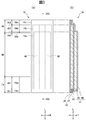
- FIG. 1 and 2 are diagrams showing a configuration example of a pants-type diaper 1 according to an embodiment.
- FIG. 1 is a plan view showing a state in which the pants-type diaper 1 is developed
- FIG. 2 is a sectional view taken along line II-II in FIG.
- the pants-type diaper 1 has a longitudinal direction L, a width direction W, and a thickness direction T that are orthogonal to each other, and a longitudinal center line CL that passes through the center of the width direction W and extends in the longitudinal direction L.
- a width direction center line CW extending in the width direction W through the center of the longitudinal direction L.
- the direction and the side approaching the longitudinal centerline CL are respectively inward and inward in the width direction W, and the direction and the side away are respectively outward and outward in the width direction W.
- the direction and the side approaching the width direction center line CW are defined as the inner direction and the inner side in the longitudinal direction L, and the direction and the side facing away are the outer direction and the outer side in the longitudinal direction L, respectively.
- the side of the pants-type diaper 1 corresponding to the abdomen of the wearer in the longitudinal direction L is referred to as the front side in the longitudinal direction L, which is the front side in the longitudinal direction L, and the pants-type diaper corresponding to the back of the wearer.
- the side toward the edge 1 is also referred to as the rear side of the longitudinal direction L.
- the "plan view” means that the pants-type diaper 1 in a state of being developed on a plane including the longitudinal direction L and the width direction W is viewed from above in the thickness direction T, and the "planar shape” is grasped in the plan view. Shape.
- the “planar direction” is an arbitrary direction parallel to the plane including the width direction W and the longitudinal direction L.
- “Skin side” and “non-skin side” respectively mean a side closer to the wearer's skin surface and a side farther away in the thickness direction T when the pants-type diaper 1 is worn by the wearer. To do. These definitions are commonly used not only for the pants-type diaper 1 but also for the absorber of the pants-type diaper 1 and each material arranged on them.
- a member or the like being parallel to the longitudinal direction L means that a member, a structure, a shape or the like is along the longitudinal direction L, but a component Dx of the member or the like in the longitudinal direction L is a component of the member or the like in the width direction W.
- Dy Dy
- the member and the like extending in the width direction W are not limited to the case where the member and the like are parallel to the width direction W, and the component Dy of the member and the like in the width direction W is greater than the component Dx of the member and the like in the longitudinal direction L. It also includes a large value (Dy>Dx).
- the member or the like is evaluated as described above with respect to the tangent line of each point on the curve or the like.
- the pants-type diaper 1 has a ventral side portion (ventral waist belt) 2, a back side portion (dorsal waist belt) 3, a ventral side portion 2 and a back side portion in the longitudinal direction L. 3 and the absorbent main body 10 located between 3 and 3.
- the pants-type diaper 1 further includes a crotch part 4 located between the abdominal part 2 and the back part 3.
- the abdominal part 2 is a part that comes into contact with the abdomen of the wearer.
- the back side portion 3 is a portion that contacts the wearer's hip or back.
- the absorbent main body 10 is a portion that comes into contact with the wearer's crotch, and one end portion in the longitudinal direction L is laminated on the abdominal side portion 2 and the other end portion is laminated on the back side portion 3.
- the crotch portion 4 is a portion that supports the absorbent main body 10 from the non-skin side. Both ends 2a, 2a of the abdominal part 2 in the width direction W and both ends 3a, 3a of the back part 3 in the width direction W overlap in the thickness direction T and are joined along the longitudinal direction L. As a result, the pants-type diaper 1 is formed.
- the waist opening through which the wearer's waist passes is defined by the outer end 2e of the abdomen 2 in the longitudinal direction L and the outer end 3e of the back 3 in the longitudinal direction L.
- the pair of leg openings through which the wearer's legs pass is defined by the side portions 5e and 5e on both sides of the crotch portion 4 in the width direction W.
- the abdominal part (abdominal waist belt) 2 and the dorsal part (dorsal waist belt) 3 are defined in the range of the longitudinal direction L where both ends 2a, 2a and both ends 3a, 3a are joined. Can be said.
- the abdominal part 2 and the dorsal part 3 each have a rectangular shape that extends substantially in the width direction W and are separated from each other in the longitudinal direction L.
- the crotch portion 4 is located between the ventral side portion 2 and the back side portion 3, and both side edges in the width direction W are recessed inward in the width direction W.
- the abdominal part 2, the crotch part 4, and the back part 3 are integrally formed with each other.
- the ventral portion 2, crotch portion 4 and dorsal portion 3 are formed separately from each other.
- the pants-type diaper 1 includes the abdomen 2 and the back 3 and does not include the crotch 4.
- the abdominal part 2, the dorsal part 3 and the crotch part 4 are provided with a liquid-impermeable cover sheet (sheet member) 5.
- the cover sheet 5 includes a cover sheet 5a located on the skin side and a cover sheet 5b located on the non-skin side.
- the cover sheet 5a and the cover sheet 5b are laminated in the thickness direction T and are bonded to each other with an adhesive or the like. Both ends in the longitudinal direction L of the cover sheet 5b are folded back to the skin side so as to cover both ends in the longitudinal direction L of the cover sheet 5a.
- the cover sheets 5b at the folding positions on the abdominal part 2 and the back part 3 form the end 2e of the abdominal part 2 and the end 3e of the back part 3, respectively.
- cover sheet 5 examples include any liquid-impermeable sheet such as a liquid-impermeable nonwoven fabric, a synthetic resin film, a composite sheet of these, an SB nonwoven fabric, and an SMS nonwoven fabric.
- material of the cover sheet 5 include polyolefin-based materials such as polypropylene and polyethylene.
- the basis weight of the cover sheet 5 is, for example, 5 to 100 g/m 2 , and preferably 10 to 50 g/m 2 .
- the dimension (thickness) of the cover sheet 5 in the thickness direction T is, for example, 0.1 to 5 mm, preferably 0.1 to 2 mm.
- the number of cover sheets 5 is one, or three or more (not shown).
- the cover sheet 5b is not folded back (not shown).
- the abdomen 2 and the back 3 are provided with a plurality of elastic members 6a and 6b for waist gather and a plurality of elastic members 7a and 7b between the cover sheet 5a and the cover sheet 5b, respectively. ..
- the plurality of elastic members 6a and 6b are arranged on the outside and inside of the abdominal side portion 2 in the longitudinal direction L, respectively.
- the plurality of elastic members 6a are arranged along the width direction W at intervals in the longitudinal direction L in the respective predetermined regions on both sides of the longitudinal center line CL.
- the predetermined region is a region from the end portion 2a to a portion inside the end edge of the absorbent main body 10 facing the end portion 2a in the width direction W.
- the plurality of elastic members 6b extend from one end 2a to the other end 2a along the width direction W, and are arranged at intervals in the longitudinal direction L.
- the plurality of elastic members 7 a and 7 b are arranged on the outer side and the inner side of the back side portion 3 in the longitudinal direction L, respectively.
- the plurality of elastic members 7a are arranged along the width direction W in the respective predetermined regions on both sides of the longitudinal centerline CL so as to be spaced from each other in the longitudinal direction L.
- the predetermined region is a region from the end portion 3a to a portion inside the end edge of the absorbent main body 10 facing the end portion 3a in the width direction W.
- the plurality of elastic members 7b extend from one end 3a to the other end 3a along the width direction W, and are arranged at intervals in the longitudinal direction L.
- the plurality of elastic members 6a, 6b, 7a, 7b expand and contract the waist opening, and are exemplified by rubber thread. It can be said that the abdominal part (abdominal waist belt) 2 and the dorsal part (dorsal waist belt) 3 are defined in the range of the longitudinal direction L in which the plurality of elastic members 6a, 6b, 7a, 7b are arranged. ..
- the pants-type diaper 1 includes a plurality of elastic members 8 for leg gathers (leg gathers) from the crotch portion 4 to the back side portion 3 and the abdominal side portion 2.
- the plurality of elastic members 8 mainly extend along both ends of the crotch portion 4 in the width direction W along the longitudinal direction L.
- the plurality of elastic members 8 respectively expand and contract the pair of leg openings, and are exemplified by a rubber thread.
- the contraction force of the leak preventive wall 16, that is, the contraction force of the plurality of elastic members 61 is lower than the contraction force of the leg gathers, that is, the contraction force of the plurality of elastic members 8. Therefore, even if the rigidity of the absorber 14 is relatively low, the absorber 14 can oppose the contracting force of the leak preventive wall 16 (the plurality of elastic members 61).
- the absorbent main body 10 has a substantially rectangular shape, and is positioned between the liquid-permeable topsheet 12, the liquid-impermeable backsheet 13, and the topsheet 12 and the backsheet 13. And an absorber 14 that absorbs and retains the liquid.
- the surface sheet 12 include a liquid-permeable nonwoven fabric or woven fabric, a synthetic resin film having liquid-permeable holes formed therein, and a composite sheet of these.
- the topsheet 12 includes a plurality of convex portions that extend along the longitudinal direction L and are arranged at intervals, and a plurality of concave portions that are located between adjacent convex portions of the plurality of convex portions. It may be a sheet having irregularities extending along the longitudinal direction L.
- the rigidity of the absorbent main body 10 in the longitudinal direction L can be increased.
- the back sheet 13 include liquid impermeable nonwoven fabrics, synthetic resin films, composite sheets of these, SMS nonwoven fabrics, and the like.
- the absorbent body 14 includes an absorbent core that absorbs and holds liquid, and a core wrap that contains the absorbent core. Details of the absorber 14 will be described later.
- the absorber 14 and the topsheet 12 and the backsheet 13 are bonded with an adhesive, respectively, and the topsheet 12 and the backsheet 13 are bonded with an adhesive at their peripheral portions.
- the adhesive may be a known material for pants-type diapers, for example, a hot melt adhesive.
- the shape of the absorbent main body 10 is not limited to the above example as long as it is a shape that is long in the longitudinal direction L, and may be, for example, a rectangle with rounded corners, a rectangle with a convex curve outward on the short side, or an hourglass shape.
- the back sheet 13 is omitted, and the non-skin side surface of the absorber 14 and the non-skin side surface of the peripheral portion of the top sheet 12 are joined to the cover sheet 5.
- the absorbent main body 10 includes a pair of side sheets 17, 17 located on both sides in the width direction W on the skin side surface and extending in the longitudinal direction L.
- Each side sheet 17 has a leak preventive wall 16 and fixing regions 15 and 15.
- the fixing regions 15 and 15 are located at the front and rear ends of the side seat 17 in the longitudinal direction L, and are fixed to the skin-side surface of the absorbent main body 10.
- the leak preventive wall 16 is located between and adjacent to the front and rear fixing regions 15 in the longitudinal direction L of the side sheet 17, is adjacent to the fixing regions 15, and is provided on the skin side surface of the absorbent main body 10 in the width direction W.
- the outer edge is fixed, and the inner edge in the width direction W is not fixed.
- the leak-proof wall 16 and the fixing regions 15 and 15 are formed, for example, at the inner side portion of the side seat 17 in the width direction W, and the outer side portion of the side seat 17 in the width direction W is fixed to the absorbent main body 10.
- the absorbent main body 10 includes the pair of leak-proof walls 16, 16.
- the pair of leak preventive walls 16 and 16 are arranged at both ends in the width direction W on the skin side of the absorbent main body 10 so as to face each other, and continuously extend along the longitudinal direction L.
- Each leak preventive wall 16 includes two elastic members 61 extending in the longitudinal direction L at the inner end in the width direction W.
- the elastic member 61 is exemplified by rubber thread.
- each of the pair of leak preventive walls 16 and 16 has an inner end in the width direction W folded back to the outer side in the width direction W (described later).
- the number of elastic members 61 is one or three or more.
- Each of the pair of leakproof walls 16 and 16 is formed of a hydrophobic sheet, for example, a hydrophobic nonwoven fabric. In another embodiment, it is formed of a hydrophilic sheet, such as a hydrophilic nonwoven.
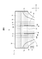
- FIG. 3 is a diagram showing a configuration example of the absorber 14 according to the embodiment, (a) is a plan view, and (b) is a cross-sectional view taken along line IIIb-IIIb in (a).
- the absorber 14 is a layer having a liquid absorption performance and a liquid retention performance, and in the present embodiment, the first absorption layer 41 located on the skin side, the second absorption layer 42 located on the non-skin side, and the first And an intermediate layer 43 located between the absorption layer 41 and the second absorption layer 42.
- the absorber 14 has a two-layer structure in which the first absorption layer 41, the intermediate layer 43, and the second absorption layer 42 are laminated in this order in the thickness direction T.
- the absorber 14 has a single-layer structure in which the intermediate layer 43 does not exist and the first absorption layer 41 and the second absorption layer 42 are integrated in the thickness direction.
- the absorber 14 has a multilayer structure of three or more layers in which another intermediate layer and another absorbing layer are further laminated between the first absorbing layer 41 and the second absorbing layer 42.
- the first absorbent layer 41 is located on the skin side and the second absorbent layer 42 is located on the non-skin side.
- the absorber 14 has a substantially rectangular planar shape extending in the longitudinal direction L.
- the absorber 14 can be regarded as having a first water absorbent material 45 and a second water absorbent material 47 as an absorbent core, and a first base material 44 and a second base material 46 as a core wrap.
- the shape is not particularly limited, and examples thereof include a rectangle with a short side protruding in an arc shape, a rounded rectangle, an ellipse, and an hourglass.
- the thickness of the absorber 14 is, for example, 0.5 to 20 mm, and preferably 1 to 10 mm.
- the basis weight of the absorbent body 14 can be appropriately adjusted depending on the absorption performance required for the pants-type diaper 1, and is, for example, 60 to 1600 g/m 2 .
- the first absorbent layer 41 is disposed on the intermediate layer 43 side of the first base material 44 and the first base material 44, which is formed of a sheet having liquid permeability, and absorbs water containing a water-absorbing polymer.
- the first absorbent layer 41 can be regarded as having the first water absorbent material 45 as the absorbent core and the first base material 44 (and the intermediate layer 43) as the core wrap.
- a core wrap sheet made of, for example, a tissue is provided that wraps the first water absorbing material 45 inside them.
- the first water-absorbing material 45 is formed by applying an adhesive to at least one of the surface of the first base material 44 on the side of the intermediate layer 43 and the surface of the intermediate layer 43 on the side of the first base material 44. It is fixed to at least one of the layers 43.
- the water absorbent material of the first water absorbent material 45 is arranged in the first absorbent layer 41 with a substantially uniform basis weight.
- the basis weight of the end portion in the longitudinal direction L and/or the width direction W may be gradually reduced toward the edge.
- the end portions are areas within 10% of the maximum dimension in the longitudinal direction L and/or the width direction W at both ends in the longitudinal direction L and/or the width direction W, for example.
- the water absorbent material of the first water absorbent material 45 is arranged in the first absorbent layer 41 in a predetermined distribution having a portion having a large basis weight and a portion having a small basis weight.
- the first water absorbent material 45 has a substantially rectangular planar shape.
- the first base material 44 has a substantially rectangular planar shape and covers the first water absorbent material 45 from the skin side in a plan view, and the peripheral portion of the first base material 44 is slightly around the first water absorbent material 45. Extend outwards.
- the outer dimension (outer edge) of the first absorbent layer 41 in the plane direction is, for example, the outer dimension (outer edge) of the first water absorbent material 45 in the plane direction.
- the outer dimension (outer edge) is measured, for example, at a half position in the thickness direction T of the first water absorbent material 45.
- the second absorbent layer 42 is disposed on the second base material 46 formed of a sheet having water retention and liquid diffusibility and on the intermediate layer 43 side with respect to the second base material 46, and the water absorbent polymer.
- the second absorbent layer 42 can be regarded as having the second water absorbent material 47 as the absorbent core and the second base material 46 (and the intermediate layer 43) as the core wrap.
- a core wrap sheet made of, for example, a tissue that wraps the second water absorbing material 47 inside them is provided.
- the second water-absorbing material 47 is formed on the intermediate layer 43 side of the second base material 46 and the adhesive applied to at least one of the surface of the intermediate layer 43 on the second base material 46 side. It is fixed to at least one of the layers 43.
- the water absorbing material of the second water absorbing material 47 is arranged in the second absorbing layer 42 with a substantially uniform basis weight except for the pair of channels 48, 48 (described later). However, the basis weight of the end portion in the longitudinal direction L and/or the width direction W may be gradually reduced toward the edge. In this case, the ends are as described above.
- the water absorbing materials of the second water absorbing material 47 are arranged in the second absorbing layer 42 in a predetermined distribution having a portion having a large basis weight and a portion having a small basis weight.
- the second water absorbent material 47 has a substantially rectangular planar shape that is slightly larger than the first water absorbent material 45 in the width direction W and the longitudinal direction L.
- the second base material 46 has a substantially rectangular planar shape and covers the second water absorbent material 47 from the non-skin side in a plan view, and the peripheral edge portion of the second base material 46 is surrounded by the second water absorbent material 47. It extends slightly outside.
- both ends of the second base material 46 in the width direction W cover both side surfaces of the second water absorbent material 47, and also cover the skin-side surface of both ends of the first base material 44 in the width direction W. That is, on the skin-side surface of the end portion of the first absorbent layer 41 in the width direction W, the end portion of the second base material 46 in the width direction W and the end portion of the first base material 44 in the width direction W overlap each other. Are joined together. Therefore, when the overlapping end P of the overlapped second base material 46 in the width direction W is defined as the overlapping portion P, the second base material 46 extends along the longitudinal direction L at both ends in the width direction W. Have overlapping portions P and P.
- the outer dimension (outer edge) of the second absorbent layer 42 in the plane direction is, for example, the outer dimension (outer edge) of the second water absorbent material 47 in the plane direction.
- the outer size (outer edge) is measured at, for example, a half position in the thickness direction T of the second water absorbent material 47.
- both ends of the second base material 46 in the width direction W cover the side surfaces of the second water absorbent material 47 in the width direction W, and further cover the side surfaces of the first base material 44 in the width direction W.
- the second water absorbent material 47 is sealed in the second absorbent layer 42 in the width direction W
- the first water absorbent material 45 is sealed in the first absorbent layer 41 in the width direction W.
- both ends of the first base material 44 in the width direction W cover both ends of the second base material 46 in the width direction W. That is, the first base material 44 has a pair of overlapping portions P, P extending along the longitudinal direction L at both ends in the width direction W.
- the first base material 44, the intermediate layer 43, and the second base material 46 are stacked in the thickness direction T and joined.
- the first base material 44, the intermediate layer 43, and the second base material 46 are laminated and joined in the thickness direction T at both ends in the longitudinal direction L of the absorber 14.
- the second water absorbent material 47 is enclosed in the second absorbent layer 42 by the first base material 44 and the intermediate layer 43 in the longitudinal direction L
- the first water absorbent material 45 is intermediate with the second base material 46 in the longitudinal direction L. It is enclosed by the layer 43 in the second absorption layer 42.
- both ends of the absorbent body 14 in the longitudinal direction L are not covered with the first base material 44 and the second base material 46.
- the intermediate layer 43 is a liquid-permeable sheet and has a substantially rectangular planar shape.
- the intermediate layer 43 includes an upper layer 43a and a pair of lower layers 43b and 43b adjacent to both sides in the width direction W on the non-skin side surface of the upper layer 43a.
- the intermediate layer 43 is formed by folding a pair of side portions located on both sides of the central portion in the width direction W back to the non-skin side of the central portion and stacking them on a sheet member having a substantially rectangular planar shape. At that time, the central portion of the sheet member becomes the upper layer 43a, and the pair of side portions of the sheet member becomes the pair of lower layers 43b, 43b.
- the portions on both sides of the intermediate layer 43 in the width direction W each have a two-layer structure in which the upper layer 43a and the lower layer 43b are stacked, and have a substantially rectangular shape extending in the longitudinal direction L.
- a portion 43d of the intermediate layer 43 near the center in the width direction W has a single-layer structure including only the upper layer 43a and has a substantially rectangular shape extending along the longitudinal direction L.
- the upper layer 43a and the lower layer 43b of the two-layer structure are joined by a pair of heat seal portions 43c, 43c extending along the longitudinal direction L on both sides in the width direction W of the portion 43d.
- the heat seal portion 43c is formed by squeezing while heating.
- the upper layer 43a and the lower layer 43b having a two-layer structure are joined by embossed portions extending along the longitudinal direction L on both sides in the width direction W of the portion 43d.
- the embossed portion is formed by pressing.
- the heat-sealing portion and the embossing portion have a plurality of points, a plurality of curved lines or a pattern.
- the intermediate layer 43 is sandwiched between both end edges in the width direction W by both end portions in the width direction W of the first base material 44 and the second base material 46, and both end edges in the longitudinal direction L are connected to the first base material 44 and the first base material 44.
- the two base materials 46 are sandwiched between both ends in the longitudinal direction L and are joined to each other.
- both end edges in the longitudinal direction L are not sandwiched between the ends of the first base material 44 and the second base material 46 in the longitudinal direction L, and are not joined.
- the absorber 14 has a pair of channels 48, 48 extending along the longitudinal direction L.
- the pair of channels 48, 48 are band-shaped regions that are located in the second absorption layer 42, extend in the longitudinal direction L, and are arranged at predetermined intervals on both sides in the width direction W with the longitudinal centerline CL interposed therebetween.
- the channel 48 is formed in at least the central portion in the longitudinal direction L so as to straddle the width-direction center line CW.
- the rigidity of the absorbent body 14 in the longitudinal direction L can be further increased by the channel 48 extending along the longitudinal direction L.
- the channel 48 is formed so as to reach at least one of both edges in the longitudinal direction L.
- the pattern of the pair of channels 48 in the plan view is, for example, a pattern formed such that the interval between the two is constant along the longitudinal direction L.
- the pattern of the pair of channels 48, 48 is, for example, a pattern formed to be narrow near the center in the longitudinal direction L and expand toward both outer sides in the longitudinal direction L.
- the channel 48 is an area in which the basis weight of the water absorbing material is smaller than the area around the channel in the absorber 14, and, for example, compared with the area around the channel 48 in the second absorbent layer 42. , A region where the basis weight of the water-absorbent material is small, including a case where the basis weight is zero.
- the channel 48 is formed such that the second base material 46 is recessed toward the intermediate layer 43 side, that is, the second water absorbing material 47 is recessed toward the intermediate layer 43 side. In another embodiment, the second water absorbing material 47 is formed so as to be recessed toward the second base material 46 side. Further, the pair of channels 48, 48 overlaps the pair of heat seal portions 43c, 43c in the thickness direction T. In another embodiment, at least a part of the channel 48 does not overlap the heat seal portion 43c in the thickness direction T. Note that, in another embodiment, the channel 48 extends not only in the longitudinal direction L but also in the width direction W as well as in the longitudinal direction L. In yet another embodiment, the channels 48 are one or more than two. In yet another embodiment, the channel 48 is formed in the first absorbent layer 41 instead of, or in addition to, the second absorbent layer 42. In yet another embodiment, the channel 48 is not formed.
- the first water absorbent material 45 and the second water absorbent material 47 include a super absorbent polymer (SAP).
- SAP super absorbent polymer
- the super absorbent polymer is not particularly limited as long as it is a polymer capable of absorbing and retaining water, and examples thereof include particulate or fibrous super absorbent polymers.
- the basis weight of the super absorbent polymer of the first water absorbent material 45 and the second water absorbent material 47 can be appropriately adjusted according to the absorption performance required for the pants-type diaper 1, and for example, each is 10 to 500 g/m 2. It is preferably 100 to 400 g/m 2 .
- One of the basis weights of the first water absorbent material 45 and the second water absorbent material 47 may be larger than the other, or may be the same.
- the first water absorbent material 45 and the second water absorbent material 47 may further include hydrophilic fibers such as pulp fibers and water absorbent fibers.
- the ratio of the super absorbent polymer to the first water absorbent material 45 and the second water absorbent material 47 is, for example, 80 to 100% by mass, preferably 90 to 100% by mass, and more preferably 95 to 100% by mass. .. Therefore, it can be said that the first water absorbent material 45 and the second water absorbent material 47 contain the super absorbent polymer as a main component, and the absorber 14 can be called a so-called SAP sheet.
- the first water absorbent material 45 and the second water absorbent material 47 are made of only a super absorbent polymer and do not contain hydrophilic fibers.
- the first water absorbent material 45 and the second water absorbent material 47 include pulp fibers and/or water absorbent fibers in addition to the super absorbent polymer.
- superabsorbent polymers examples include starch-based, cellulose-based, and synthetic polymer-based polymer absorbents.
- examples of the starch-based or cellulose-based superabsorbent polymer include starch-acrylic acid (salt) graft copolymer, saponified starch-acrylonitrile copolymer, and crosslinked sodium carboxymethyl cellulose.
- examples of synthetic polymer-based superabsorbent polymers include polyacrylic acid salt-based, polysulfonic acid salt-based, maleic acid anhydride-based, polyacrylamide-based, polyvinyl alcohol-based, polyethylene oxide-based, polyaspartate-based, polyglutamic acid.
- Examples thereof include salt-based, polyalginate-based, starch-based, cellulose-based and the like.
- a polyacrylic acid salt-based (particularly, sodium polyacrylate-based) superabsorbent polymer is preferable.
- 90 to 100% by mass of the superabsorbent polymer in the absorber 14 is composed of superabsorbent polymer particles having a particle diameter of 150 to 500 ⁇ m.
- the superabsorbent polymer particles having such a particle size distribution have a small particle size and are uniform, so that they are easily held by the adhesive.
- the particle size of the super absorbent polymer particles is measured according to the sieving test method described in JIS R 6002:1998.
- the adhesive is not particularly limited as long as it can fix the superabsorbent polymer, and examples thereof include hot melt adhesives.
- the application pattern of the adhesive is not particularly limited, and examples thereof include a continuous or intermittent omega pattern, a spiral pattern, and a line pattern.
- the basis weight of the adhesive can be appropriately adjusted so that the liquid absorbency of the absorbent body 14 is not significantly lowered, and for example, 3 to 50 g/m 2 for each layer can be mentioned.
- each layer means an adhesive layer between the first water absorbent material 45 and the first base material 44, an adhesive layer between the first water absorbent material 45 and the intermediate layer 43, and a second water absorbent material 47.
- the adhesive layer is between the second base material 46 and the second water absorbing material 47 and the intermediate layer 43.
- the first base material 44 is not particularly limited as long as it is a sheet having liquid permeability.
- the first base material 44 include liquid-permeable nonwoven fabrics, hydrophilic nonwoven fabrics, and laminated nonwoven fabrics thereof. Among them, nonwoven fabrics having high water permeability are preferable.
- it is formed from polyolefin fibers such as polyethylene (PE), polypropylene (PP), polyester fibers such as polyethylene terephthalate (PET), polytrimethylene terephthalate (PTT), polyethylene naphthalate (PEN), or a combination thereof. Spunbonded non-woven fabric and air-through non-woven fabric. These fibers are preferably hydrophilized by a known method.
- an air-laid nonwoven fabric in which hydrophilic fibers such as pulp fibers and rayon fibers are coated with a hydrophilic binder, and a spunlace nonwoven fabric in which the above hydrophilic fibers and the above synthetic fibers are combined are included.
- an air-laid non-woven fabric having liquid permeability and liquid retention property, in which pulp fibers are coated with a hydrophilic binder is used.
- the first base material 44 one or a plurality of types of non-woven fabrics may be laminated in multiple layers.
- the basis weight of the first base material 44 is, for example, 10 to 100 g/m 2 , and preferably 20 to 80 g/m 2 .
- the thickness of the first base material 44 is, for example, 0.1 to 5 mm, and preferably 0.15 to 3 mm.
- the second base material 46 is not particularly limited as long as it is a sheet having water retention and liquid diffusion properties.
- the second base material 46 include synthetic fibers such as polyamide fibers, recycled fibers such as rayon fibers and acetate fibers, natural fibers such as cotton, silk, hemp, and pulp (cellulose) fibers, or a combination thereof.
- the spunlace nonwoven fabric containing rayon fibers and/or pulp fibers may contain polyolefin fibers and/or polyester fibers.
- a spunlace nonwoven fabric containing rayon fibers and pulp fibers, which has liquid retaining properties and liquid diffusing properties is used.
- the second base material 46 one or a plurality of types of non-woven fabrics may be laminated in a plurality of layers.
- the basis weight of the second base material 46 is, for example, 10 to 200 g/m 2 , and preferably 35 to 150 g/m 2 .
- the thickness of the second base material 46 is, for example, 0.1 to 5 mm, and preferably 0.15 to 3 mm.
- the intermediate layer 43 is not particularly limited as long as it is a sheet having liquid permeability.
- As the intermediate layer 43 for example, a sheet similar to the first base material 44 can be used.
- the basis weight of the intermediate layer 43 is, for example, 10 to 100 g/m 2 , and preferably 15 to 80 g/m 2 .
- the thickness of the intermediate layer 43 is, for example, 0.1 to 5 mm, and preferably 0.15 to 3 mm.
- the absorbent body 14 includes a dorsal region BA, a ventral region FA, and a crotch region MA, which are arranged along the longitudinal direction L.
- the back side region BA is a region overlapping the back side portion 3 of the absorber 14 in the thickness direction T.
- the abdominal area FA is an area that overlaps the abdominal portion 2 of the absorber 14 in the thickness direction T.
- the crotch region MA is a region located between the back region BA and the abdominal region FA of the absorber 14, that is, a region overlapping the crotch portion 4 in the thickness direction T.
- the absorbent body 14 is divided along the longitudinal direction L into a dorsal region BA overlapping the dorsal part 3, an abdominal region FA overlapping the abdominal part 2, and a crotch region MA overlapping the crotch part 4. To be done.
- the absorber 14 also includes a high basis weight region 14a, a low basis weight region 14b, and a non-arrangement region 14c.
- the high basis weight region 14a is a region in which the basis weight of the superabsorbent polymer is high, and is a region in which the first absorbent layer 41 and the second absorbent layer 42 overlap in the thickness direction T.
- the boundary between the high grammage region 14a and the low grammage region 14b is, for example, the outer edge of the first absorption layer 41.
- the low basis weight region 14b is a region in which the basis weight of the superabsorbent polymer is low, and the first absorbent layer 41 does not exist in the thickness direction T and only the second absorbent layer 42 exists.
- the boundary between the low basis weight area 14b and the non-arranged area 14c is, for example, the outer edge of the second absorbent layer.
- the non-arranged region 14c is a region that does not contain the superabsorbent polymer, and is a region in which the first absorption layer 41 and the second absorption layer 42 do not exist in the thickness direction T.
- not including the super absorbent polymer includes a case where the super absorbent polymer exists but its basis weight is very small. “Very low” means that the basis weight of the superabsorbent polymer is 5% or less of the basis weight of the superabsorbent polymer in the high basis weight region 14a.
- the high basis weight area 14a, the low basis weight area 14b, and the non-arrangement area 14c have a substantially rectangular shape.
- the shape is not particularly limited, and examples thereof include a rectangle with a short side protruding in an arc shape, a rounded rectangle, an ellipse, and an hourglass.
- the low basis weight region 14b is a region that surrounds the high basis weight region 14a in a substantially frame shape (encloses at least three sides), and the low basis weight region 14b.
- the outer size is, for example, 5 to 25% larger than the outer size of the high basis weight region 14a.
- the non-arrangement area 14c is an area that surrounds the low basis weight area 14b in a substantially frame shape, and the outer dimension of the non-arrangement area 14c is, for example, 3 to 15% larger than the outer dimension of the low basis weight area 14b.
- the basic weight of the low basic weight area 14b is, for example, 40 to 60% of the basic weight of the high basic weight area 14a
- the basic weight of the non-arranged area 14c is, for example, 0% of the basic weight of the high basic weight area 14a. -5% is included.
- the high basis weight region is a water absorbing material (including an adhesive). Is the region of the maximum value to 50% of the maximum value.
- the low basis weight area is the area where the thickness of the water absorbing material (including adhesive) ranges from 50% to 5% of the maximum value, and the non-arrangement area is the thickness of the water absorbing material (including adhesive). Is the range of 5% to 0% of the maximum value.
- the thickness is the arithmetic average height (Ra: JIS B 0601-2001).
- the absorber 14 does not include at least one of the high basis weight area 14a, the low basis weight area 14b, and the non-arrangement area 14c.
- the back side area BA is the back side high basis weight area BAa as the high basis weight area 14a, the back side low basis weight area BAb as the low basis weight area 14b, and the non-arrangement area 14c.
- the abdominal area FA includes an abdominal high basis weight area FAa as the high grammage area 14a and an abdominal non-arrangement area FAc as the non-arrangement area 14c.
- the crotch region MA has only the high basis weight region 14a. Therefore, the basis weight of the super absorbent polymer in the back side high basis weight region BAa and the abdominal side high basis weight region FAa is equivalent to the basis weight of the super absorbent polymer in the crotch region MA.
- the abdominal area FA includes the abdominal low basis weight area FAb as the low basis weight area 14b in addition to the abdominal high basis weight area FAa and the abdominal non-arrangement area FAc.
- the second absorption layer 42 includes, at a rear end in the longitudinal direction L, a protrusion that protrudes outward from the edge of the first absorption layer 41 in a plan view.
- the protrusion includes the back side low basis weight region BAb, and in the present embodiment, the protrusion is the same as the back side low basis weight region BAb.
- the second absorbent layer 42 is covered with the intermediate layer 43, and thus the protruding portion, that is, the back side low basis weight region BAb is covered with the intermediate layer 43 and the first base material 44 on the skin side.
- the second absorbent layer 42 includes, in a plan view, the width-direction protrusions that protrude outward from the end edges of the first absorption layer 41 at both ends in the width direction W.
- the width direction protrusion is covered with the intermediate layer 43 and the first base material 44 on the skin side.
- the second absorbent layer 42 includes, at a front end in the longitudinal direction L, another protruding portion that protrudes outward from the edge of the first absorbent layer 41 in a plan view.
- Other protrusions include the ventral low basis weight area.
- the protruding portion that is, the back low-basis-weight area BAb is covered on the skin side by one of the intermediate layer 43 and the first base material 44 and not by the other.
- the second absorbent layer 42 does not include a widthwise protruding portion that protrudes outward from the end edge of the first absorbent layer 41 at both end portions in the width direction W in a plan view.
- the basis weight of the superabsorbent polymer in the crotch region MA is relatively high, and the low basis weight region of at least one of the back side region BA and the abdominal side region FA ( Example: The basis weight of the water absorbent polymer in the back low basis weight region BAb) is relatively low. Therefore, since a relatively large amount of the super absorbent polymer is arranged in the crotch region MA that needs to absorb the liquid, the absorber 14 ensures the absorption performance and does not leak the liquid (example: urine) without fail. Can be absorbed.
- the region becomes thin, so that it corresponds to the region.
- the absorber can be less likely to bite into the skin surface. This makes it difficult for the wearer to feel uncomfortable and improves the fit of the pants-type diaper 1. Therefore, in the pants-type diaper 1 containing the super absorbent polymer, it is possible to improve the fit while securing the absorption performance.
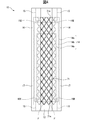
- FIG. 4 is a plan view showing a configuration example of the absorbent main body 10 according to the embodiment.
- the absorbent body 14 of the absorbent main body 10 has a compressed portion 71 extending in the longitudinal direction L.
- the planar shape of the compressed portion 71 is not particularly limited as long as it extends in the longitudinal direction L.
- the compressed portion 71 that “extends in the longitudinal direction” is not limited to the case where the compressed portion 71 is continuously extended in the longitudinal direction L, but is also intermittently extended in the longitudinal direction L, but overlaps in the width direction W. In addition, the case where it is continuous when viewed from the width direction W is included.
- the pressing part 71 exists in the range of at least 70% of the length of the absorber 14 in the longitudinal direction L, for example.
- the squeezing portion 71 exists in the range of 100% of the length of the absorber 14 in the longitudinal direction L, for example. Further, the compressed portion 71 exists in the width direction W, for example, in a range of at least 20% of the width of the absorber 14. It is preferably present in the range of 40% or more, more preferably in the range of 60% or more. In the present embodiment, the squeezing portion 71 exists in the width direction W, for example, in a range of about 70% of the length of the absorber 14 in the approximately central portion of the absorber 14 (each end portion has about 15%. Does not exist).
- the range in which the compressed portion 71 exists in the width direction W is two virtual straight lines parallel to the longitudinal direction L, from both sides in the width direction W. Is a region formed by sandwiching the compressed portions 71 extending in the width direction W and continuing in the width direction W, and extending in the longitudinal direction L including the compressed portions 71.
- the squeezing portion 71 is a squeezing groove formed by squeezing from both sides in the thickness direction T with or without heating a predetermined portion of the absorber 14 (example: embossing).
- the rigidity of the absorbent body 14 can be increased by the rigidity of the compressed portion 71. It should be noted that the compression unit 71 is omitted in FIGS. 1 to 3 and 5 to 6.
- the edge 71e on the front side (on the side of the end 2e of the abdominal side portion 2) of the compressed portion 71 is located on the front side of the front edge of the leak preventive wall 16. Furthermore, an end edge 71e on the rear side (on the side of the end portion 2e of the back side portion 3) of the compressed portion 71 is located rearward of an end edge on the rear side of the leak preventive wall 16. In other words, in the longitudinal direction L, the front end edge 71e of the compressed portion 71 is located on the front side of the rear end edge 15E in the front fixed region 15.
- the rear edge 71e of the squeezing portion 71 is located rearward of the front edge 15E of the rear fixed region 15 in the rear side. Therefore, since the compressed portion 71 is formed to extend longer in the longitudinal direction than the leak preventive wall 16, the absorber 14 has the rigidity of the compressed portion 71 so that the length of the leak preventive wall 16 (the elastic member 61 thereof) is longer. It is possible to counter the contracting force in the direction L.
- the absorber 14 has a plurality of compressed portions 71, and the plurality of compressed portions 71 are arranged side by side in the width direction W while extending along the longitudinal direction L.
- Each compressed portion 71 extends along the longitudinal direction L and has a corrugated shape that is alternately convex toward one side and the other side of the width direction W.
- the shape of the wave is not particularly limited, and examples thereof include a sine wave, a triangular wave, a sawtooth wave, a rectangular wave, a trapezoidal wave, a surface wave, and combinations thereof.
- the waves are rounded off.
- the pressing unit 71 may be one in which one or a plurality of types of patterns are arranged periodically or aperiodically along the longitudinal direction L.
- the compressed portion 71 is intermittently extended in the longitudinal direction L, but includes the case where the compressed portion 71 overlaps in the width direction W.
- the waves of each compressed portion 71 are separated from each other in the width direction W.
- the area of the compression region can be increased and the area of the compressed portion 71 itself (plan view) can be reduced.
- the waves of the compressed portions 71 are in contact with each other in the width direction W.
- a part of the compressed portion 71 in the width direction W, a part of the compressed portion 71 is located in a region between the fixed regions 15 on the front side and the rear side in the longitudinal direction L. That is, a part of the compressed portion 71 is located in a region overlapping the leak preventive wall 16 in the thickness direction T. Therefore, the rigidity of the region of the absorbent body 14 that overlaps the leak preventive wall 16 in the thickness direction T can be increased.
- a part of the compressed portion 71 is located outside the non-fixed inner edge (the innermost edge) of the leak preventive wall 16. Therefore, also in this case, the rigidity of the region of the absorber 14 that overlaps with the leak preventive wall 16 in the thickness direction T can be increased.
- both end portions of the second base material 46 in the width direction W that is, the pair of overlapping portions P, P are overlapped and joined to both end portions of the first base material 44 in the width direction W.
- the joint portion in which the overlapping portion P of the second base material 46 and the end portion of the first base material 44 in the width direction W are joined to the skin-side surface of the second water absorbent material 47 that is the absorbent core.
- the joint portion including the overlapping portion P overlaps a part of the compressed portion 71 in the thickness direction T.
- the first absorbent layer 41 is located on the non-skin side and the second absorbent layer 42 is located on the skin side, and the overlapping portion P of the second base material 46 and the first base material are opposite to each other.
- the joint portion where the end portion in the width direction W of 44 is joined is located on the non-skin side surface of the second water absorbent material 47 that is the absorbent core. Therefore, since the compressed portion 71 is further formed in the joint portion where the two base materials are laminated and the rigidity is increased, the rigidity of the region where the joint portion is located in the absorber 14 can be increased.
- FIG. 5 is an enlarged plan view of a part including the back side part 3 of the pants-type diaper according to the embodiment.
- the back portion 3 has a low back elastic region 31 having low elasticity in the width direction W and a pair of high elastic regions 32, 32 having high elasticity in the width direction W.
- the back side low expansion/contraction region 31 is located in the center portion of the back side portion 3 in the width direction W and extends from the front edge in the longitudinal direction L to the rear side.
- the pair of back side high expansion/contraction regions 32, 32 are adjacent to both sides of the back side low expansion/contraction region 31 in the width direction W.
- the elongation ratio ((length after expansion-original length)/(original length)) for a predetermined tensile force in the width direction W is the width of the back side high expansion/contraction region 32. It is a region of 1/3 or less of the elongation in the direction W, preferably 1/5 or less, and more preferably 1/10 or less.
- the back low expansion/contraction region 31 is a region in which there is no elastic member that expands/contracts in the width direction W, or a region in which an elastic member exists but the elastic member does not function as an elastic member (does not expand or contract much). ..
- the back side high expansion/contraction region 32 is a region where the elastic member 7a that expands/contracts in the width direction W exists. Therefore, the back high expansion/contraction area 32 and the back low expansion/contraction area 31 are defined by the area where the elastic member 7a that can function as the elastic member exists and the area where the elastic member that can function as the elastic member does not exist. ..
- the term “low elasticity” includes the case where elasticity does not occur. The elasticity of each elastic area is determined by the elasticity of the elastic member.
- the back side part 3 further has another back side high expansion/contraction region 34 that exhibits high elasticity in the width direction W.
- the other back high-elasticity region 34 is adjacent to the rear side of the pair of back high-elasticity regions 32, 32 and the back low-elasticity region 31 in the longitudinal direction L in plan view.
- the stretch ratio in the width direction W of the other back-side high stretch regions 34 is substantially the same as the stretch ratio in the width direction W of the back-side high stretch regions 32.
- Another back side high expansion/contraction region 34 is defined as a region where the elastic member 7b exists. Therefore, the rear end portion of the back side portion 3 in the longitudinal direction L is easily pressed against the wearer's back by the other back side high elasticity region 34.
- the elastic member 7b is located on the rear side (the back side 3 side) of the absorber 14 in the longitudinal direction L.
- the rear portion of the channel 48 in the longitudinal direction L overlaps with the back low-elasticity region 31 in the thickness direction T.
- the inner edge K1 in the width direction W of each of the pair of back side high-elasticity regions 32, 32 is an edge of the absorber 14 facing the back side high-elasticity region 32 in the width direction W. 14 EW and the channel 48 (the edge 48E in the width direction W thereof).
- the edge K1 is an inner edge in the width direction W of the elastic member 7a. Therefore, of the absorbent body 14 including the portion on the rear side of the longitudinal direction L of the channel 48, the central portion in the width direction W is hardly expanded in the width direction W by the back side low elastic region 31, and both end portions in the width direction W are formed. Is extended in the width direction W by the pair of back side high elastic regions 32, 32.
- FIG. 6 is an enlarged plan view of a part including the ventral side portion 2 of the pants-type diaper according to the embodiment.
- the ventral side portion 2 is substantially the same as the back side portion 3. That is, the abdominal part 2 has a low abdominal expansion/contraction region 36 in which the elasticity in the width direction W is low, and a pair of abdominal high expansion/contraction regions 37, 37 in which the elasticity in the width direction W is high.
- the belly-side low expansion/contraction region 36 is located at the center of the belly-side portion 2 in the width direction W, and extends from the rear edge of the longitudinal direction L to the front side.
- the pair of belly-side high stretch regions 37, 37 are adjacent to both sides of the belly-side low stretch region 36 in the width direction W.
- the abdominal side low expansion/contraction region 36 has an elongation rate ((length after expansion-original length)/(original length)) with respect to a predetermined tensile force in the width direction W, and is a width of the abdominal side high expansion/contraction region 37. It is a region of 1/3 or less of the elongation in the direction W, preferably 1/5 or less, and more preferably 1/10 or less.
- the belly-side low expansion/contraction region 36 is a region in which there is no elastic member that expands/contracts in the width direction W, or a region in which an elastic member exists but the elastic member does not function as an elastic member (does not expand or contract very much). ..
- the abdominal high expansion/contraction region 37 is a region where the elastic member 6a that expands/contracts in the width direction W exists. Therefore, the region in which the elastic member 6a that can function as the elastic member exists and the region in which the elastic member that can function as the elastic member does not exist define the belly-side high expansion/contraction region 37 and the belly-side low expansion/contraction region 36.
- the elasticity of each elastic area is determined by the elasticity of the elastic member.
- the abdominal side portion 2 further has another abdominal side high elastic region 39 that exhibits high elasticity in the width direction W.
- the other abdominal high-elasticity region 39 is adjacent to the front side in the longitudinal direction L of the pair of abdominal high-elasticity regions 37, 37 and the abdominal low-elasticity region 36.
- the expansion ratio in the width direction W of the other abdominal high expansion/contraction region 39 is substantially the same as the expansion ratio of the abdominal high expansion/contraction region 37 in the width direction W.
- the other high-side elastic region 39 is defined as a region where the elastic member 6b exists. Therefore, the front end of the abdominal part 2 in the longitudinal direction L is easily pressed against the abdomen of the wearer by the other abdominal high elastic region 39.
- the elastic member 6b is located on the front side (abdominal side 2 side) in the longitudinal direction L with respect to the absorber 14.
- the portion of the channel 48 on the front side in the longitudinal direction L overlaps with the abdominal low expansion/contraction region 36 in the thickness direction T.
- the inner edge K2 in the width direction W of each of the pair of ventral high-elasticity regions 37, 37 is an edge of the absorber 14 facing the ventral high-elasticity region 37 in the width direction W. 14 EW and the channel 48 (the edge 48E in the width direction W thereof).
- the edge K2 is an inner edge in the width direction W of the elastic member 6a.
- the central portion in the width direction W is hardly expanded or contracted in the width direction W by the belly-side low expansion/contraction region 36, and both end portions in the width direction W are It is extended in the width direction W by the pair of ventral high-stretch regions 37, 37.
- the channel 48 of the absorbent body 14 reaches at least one of the back side part 3 (back side waist belt) and the ventral side part 2 (abdominal side waist belt) in the longitudinal direction L. ing. Therefore, the liquid (example: urine) can be transported and distributed to the dorsal side (rear side of the longitudinal direction L) and/or the ventral side (front side of the longitudinal direction L) of the absorbent body 14. Thereby, the liquid can be absorbed by the superabsorbent polymer at the rear end or front end of the longitudinal direction L of the absorbent body 14 that hardly contributes to the absorption, and the superabsorbent polymer can be effectively utilized.
- the liquid example: urine
- the inner end in the width direction W in the high elastic region (dorsal high elastic region 32, abdominal high elastic region 37) of at least one of the back portion 3 and the abdominal portion 2 is It is located between the end edge 14WE and the channel 48 facing the high expansion/contraction region in the width direction W of the absorber 14. That is, the central portion of the absorbent body 14 in the width direction W overlaps with the low elasticity region (back low elasticity region 31, abdominal low elasticity region 36) in the thickness direction T. Therefore, the contraction force for contracting the absorbent body 14 in the width direction W is not too strong, so that the back-side end of the absorbent body 14 in the longitudinal direction L contracts in the width direction W and becomes a convex shape before mounting. Can be suppressed.
- the portions on both sides of the absorbent body 14 in the width direction W overlap the high elasticity region in the thickness direction T. Therefore, the absorber 14 can be pulled from both sides of the channel 48 in the width direction W by the contraction force in the high expansion/contraction region. As a result, it is possible to suppress the phenomenon that the end portion of the absorbent body 14 in the longitudinal direction L has a convex shape and the end portion of the absorbent main body 10 in the longitudinal direction L jumps out of the wearer's body. That is, the flatness of at least one of the back side portion 3 and the abdominal side portion 2 can be maintained before and after the attachment.
- the hot-melt adhesive is applied onto the sheet for the second base material 46 while moving the sheet for the second base material 46 in the longitudinal direction L.
- the super absorbent polymer is supplied from the super absorbent polymer supply device along the longitudinal direction L on both end portions and the central portion in the width direction W of the sheet for the second base material 46 coated with the hot melt adhesive. And spray. At this time, a small amount of superabsorbent polymer migrates to a region (corresponding to a channel) between both end portions and the central portion.
- the sheet for the intermediate layer 43, the hot melt adhesive of which is applied on both sides is laminated on the super absorbent polymer on the sheet for the second base material 46.
- a superabsorbent polymer is supplied from another superabsorbent polymer supply device to the central portion in the width direction W of the intermediate layer 43 sheet coated with the hot melt adhesive. Spray along the longitudinal direction L.
- the sheet for the first base material 44 in which the hot melt adhesive is applied is laminated on the super absorbent polymer on the sheet for the intermediate layer 43, with the hot melt adhesive being on the super absorbent polymer side.
- both sides of the sheet for the second base material 46 in the width direction W are folded back to both sides of the sheet for the first base material 44 in the width direction W to obtain a laminate.
- the laminate is passed through a pair of embossing rolls and a pair of press rolls, that is, embossing is performed, and the thickness of the laminate is adjusted by pressing to obtain the absorber 14.
- the order of the pair of embossing rolls and the pair of press rolls may be reversed. Moreover, you may use a pair of roll which integrated a pair of embossing roll and a pair of press roll.
- the liquid-permeable surface sheet 12 is attached to the upper surface (the surface of the first base material 44) of the absorbent body 14 manufactured as described above, and the liquid is not applied to the lower surface of the absorbent body 14 (the surface of the second base material 46).
- the transparent back sheet 13 is attached to obtain a laminated body.
- the side sheets 17 with the leak preventive wall 16 are attached to both sides of the laminate in the width direction W to obtain the absorbent main body 10.
- the absorptive main body 10 is pasted on the cover sheet 5 (including the elastic members 6, 7, and 8), and the abdominal portion 2 in the width direction W at both ends 2a, 2a and the back side portion 3 in the width direction W is attached.
- the both ends 3a, 3a are joined. Thereby, the pants-type diaper 1 is manufactured.
- the edge 71e on the front side (the end 2e side of the abdominal side 2) of the compressed portion 71 in the longitudinal direction L is the edge on the front side of the leak-proof wall 16 (the edge of the fixed region 15 on the front side).
- the edge located on the front side of the edge 15E) and on the rear side of the compressed portion (on the end 3e side of the back side portion 3) is the rear edge of the leak preventive wall 16 (the end of the fixed region 15 on the rear side). It is located behind the edge 15E).
- the compressed portion 71 is formed to extend longer in the longitudinal direction L than the leakproof wall 16 and to exist outside the leakproof wall 16 in the longitudinal direction L.
- the rigidity of the squeezing portion 71 can resist the contracting force of (the elastic member 61 of) the leak preventing wall 16 in the longitudinal direction L.
- the pressing portion 71 has a corrugated shape that extends in the longitudinal direction L and is alternately convex toward one side and the other side of the width direction W.
- the area of the compression region may be increased in order to increase the rigidity of the absorber 14 in order to face the compressive force of the leak preventive wall 16 in the longitudinal direction L.
- the area of the compressed portion 71 in plan view
- the rigidity of the absorber 14 becomes too high. That is, it may become too hard and the fit may be reduced, or the discomfort of the wearer may increase.
- the compressed portion 71 has a corrugated shape extending in the longitudinal direction L.
- the area of the compressed region can be increased while suppressing the increase of the area of the compressed portion 71 to a low level.
- the absorber 14 can be prevented from contracting in the longitudinal direction, and the entire pants-type diaper 1 can be prevented from being contracted in the longitudinal direction L due to the contraction of the absorber 14. Therefore, it is possible to suppress wrinkles from occurring in the pants-type diaper 1, and it is possible to suppress deterioration of the fit and absorption performance of the pants-type diaper 1.
- a part of the compressed portion 71 in the width direction W is located in a region between the front and rear fixed regions 15, 15 in the longitudinal direction L. That is, a part of the compressed portion 71 is located in a region overlapping the leak preventive wall 16 in the thickness direction T. Therefore, the absorber 14 can more strongly oppose the contracting force of the leak preventive wall 16 in the longitudinal direction L due to the rigidity of the compressed portion 71. Therefore, it is possible to further suppress the absorber 14 from contracting in the longitudinal direction L.
- a part of the squeezed portion 71 is located outside the inner non-fixed edge of the leak preventive wall 16. That is, a part of the compressed portion 71 is located in a region that overlaps with the leak preventive wall 16 in the thickness direction T. Therefore, the absorber 14 can more strongly oppose the contracting force of the leak preventive wall 16 in the longitudinal direction L due to the rigidity of the compressed portion 71. Thereby, it is possible to further suppress the absorber 14 from contracting in the longitudinal direction L.
- the absorber 14 has a rectangular shape in plan view.
- the absorber 14 has an hourglass shape, that is, a shape having a portion constricted in the width direction W at the center in the longitudinal direction L, the contraction force in the longitudinal direction L by the leak preventive wall 16 is buffered, and the absorber is absorbed. 14 is difficult to be contracted in the longitudinal direction L.
- the absorber 14 since the absorber 14 has a rectangular shape in a plan view, the absorber 14 is easily contracted in the longitudinal direction L by the contracting force of the leak preventive wall 16 in the longitudinal direction L. There is.
- the compressed portion 71 since the compressed portion 71 has at least the above-described configurations such that the compressed portion 71 extends in the longitudinal direction L at least longer than the leak-proof wall 16, the absorber has a leak-proof wall that is rigid due to the rigidity of the compressed portion. It is possible to counter the contraction force in the longitudinal direction, thereby suppressing the contraction of the absorbent body in the longitudinal direction.
- the contraction force of the leak preventive wall 16 that is, the contraction force of the elastic member 61 is lower than the contraction force of the leg gathers (leg gathers), that is, the elastic member 8. Therefore, the absorber 14 can more oppose the contracting force of the leak preventive wall 16 in the longitudinal direction L due to the rigidity of the compression portion 71, and thus the absorber 14 can be further suppressed from contracting in the longitudinal direction L. it can.
- the pair of overlapping portions P, P at both ends in the width direction W of the second base material 46 (second core wrap) is the first base material 44 (first core wrap).
- both end portions in the width direction W in the direction of thickness are joined at a pair of joint portions in the thickness direction T.
- the joint portion overlaps a part of the compressed portion 71 in the thickness direction T. Therefore, the rigidity of the compression unit 71 can be further increased. Therefore, the absorber 14 can be countered by the contraction force of the leak preventive wall 16 in the longitudinal direction L due to the rigidity of the compression portion 71, and thereby the absorber 14 can be further suppressed from contracting in the longitudinal direction L. ..
- the absorber 14 has at least one channel 48 extending along the longitudinal direction L. Therefore, the absorber 14 is likely to be slightly bent around the channel 48 along the longitudinal direction L, and the rigidity in the longitudinal direction L can be further increased. Thereby, the absorber 14 can further oppose the contraction force of the leak preventive wall 16 in the longitudinal direction L, and thus the absorber 14 can be further suppressed from contracting in the longitudinal direction L.
- the topsheet 12 includes a plurality of convex portions and a plurality of concave portions extending in the longitudinal direction L (not shown). Therefore, the absorbent main body 10 can increase the rigidity in the longitudinal direction L. Thereby, by adding the rigidity of the surface sheet 12, it is possible to further counter the contraction force of the leak preventive wall 16 in the longitudinal direction L, whereby the absorber 14 is contracted in the longitudinal direction L. It can be further suppressed.
- FIG. 7 is a top view which shows the structural example of the absorptive main body which concerns on another embodiment.
- the absorbent main body 10 has substantially the same configuration as that of FIG. 4, except that the compressed portion 71 has the shape of an oblique lattice composed of a plurality of rhombus elongated in the longitudinal direction L. 4 is different from the case of FIG. Therefore, even if a compressive force in the longitudinal direction L of the leak preventive wall 16 is applied to the absorber 14, the direction of the squeezing portion 71 is inclined with respect to the direction of the compressive force, that is, the substantially longitudinal direction L. You can let it escape and substantially weaken it.
- the direction of the compressed portion 71 is inclined with respect to the direction of the compressive force, it is not in the direction at right angles to the direction of the compressed force, that is, not in the substantially width direction W. Can be prevented from breaking. These can further suppress the absorber 14 from contracting in the longitudinal direction L.
- the disposable diaper 1 is a tape type diaper.
- the tape-type diaper includes a pair of locking members located on both outer sides in the width direction W of the back side portion of the absorbent main body 10.
- the tape-type diaper preferably further comprises an elastic member so as to straddle the longitudinal centerline CL at the center of the back side portion of the absorbent main body 10 in the width direction W, and more preferably between the pair of locking members.
- Prepare The structure of the absorbent main body 10 is as described above. Also in this case, the above-mentioned effects can be obtained.
- the absorbent article and the absorbent body of the present invention are not limited to the above-described embodiments, and the object and the purpose of the present invention are combined with each other and the known techniques are applied within a range not departing from the spirit of the present invention. It is possible to do so.
Abstract
Provided is an absorbent article in which the occurrence of wrinkles can be suppressed and the degradation of fitting property and absorption performance can be suppressed. This absorbent article is provided with an absorbent main body (10) including an abdomen-side section (2), a backside section (3), and an absorbent body (14). The absorbent body has a squeeze section (71) that includes a highly absorbent polymer and extends in the longitudinal direction. The absorbent main body includes, on both sides in the width direction, one pair of side sheets (17, 17) extending in the longitudinal direction. The side sheets each have: fixed regions (15, 15) that are positioned on an end section on the front side and rear side in the longitudinal direction and fixed to a surface of the absorbent main body; and a leak preventing wall (16) which includes an elastic member (61) extending in the longitudinal direction, is positioned between the fixed regions on the front side and the rear side, fixes the outer end edge in the width direction to the surface of the absorbent main body, and does not fix the inner end edge in the width direction. In the longitudinal direction, an end edge (71e) on the front side of the squeeze section is positioned closer to the front side in the leak preventing wall than the front end edge, and an end edge (71e) on the rear side of the squeeze section is positioned closer to the rear side in the leak preventing wall than the rear end edge.
Description
本発明は、吸収性物品に関する。
The present invention relates to absorbent articles.
吸収性材料として高吸水性ポリマー(Super Absorbent Polymer;SAP)を相対的に多く含む吸収体を用いた吸収性物品が知られている。高吸水性ポリマーを相対的に多く含む吸収体(いわゆるSAPシート)は、厚さが薄いので、装着性やフィット性などを向上することができ、好ましい吸収体といえる。そのような吸収体として、例えば、特許文献1に、吸水性シート構成体が開示されている。その吸水性シート構成体は、吸収性物品に用いられ、吸収性材料として吸収性樹脂を含有し、幅方向の中央領域に、長手方向に延びる波形エンボスであって、一箇所以上のエンボスが途切れた箇所を有する波形エンボスを備えている。
Absorbent articles using an absorbent containing a relatively large amount of super absorbent polymer (Super Absorber Polymer; SAP) are known as absorbent materials. Since the absorber (so-called SAP sheet) containing a relatively large amount of the superabsorbent polymer has a small thickness, it is possible to improve the wearability and fit, and can be said to be a preferable absorber. As such an absorber, for example, Patent Document 1 discloses a water absorbent sheet structure. The water-absorbent sheet structure is used for absorbent articles, contains an absorbent resin as an absorbent material, and is a corrugated emboss extending in the longitudinal direction in the central region in the width direction, and the emboss at one or more locations is interrupted. Equipped with a corrugated embossment having a curved portion.
高吸水性ポリマーを相対的に多く含む吸収体は、厚さが薄く剛性が低い。そのため、このような吸収体を吸収性物品に適用すると、吸収体の幅方向の両側において吸収体に沿って長手方向に延びる一対の防漏壁(の弾性部材)により、吸収体が長手方向に収縮されるおそれがある。そうなると、吸収体の収縮に引き摺られて、吸収性物品全体が長手方向に収縮されてしまい、吸収性物品に皺が生じてしまう。その結果、フィット性が低下したり、吸収性能が低下したりするおそれがある。
An absorber containing a relatively large amount of super absorbent polymer has a small thickness and low rigidity. Therefore, when such an absorbent body is applied to an absorbent article, the absorbent body moves in the longitudinal direction by (a elastic member of) a pair of leak preventive walls extending in the longitudinal direction along the absorbent body on both sides in the width direction of the absorbent body. May contract. In that case, the entire absorbent article is contracted in the longitudinal direction due to the contraction of the absorbent body, and wrinkles occur in the absorbent article. As a result, there is a possibility that the fit property may be reduced or the absorption performance may be reduced.
ここで、特許文献1の吸収体(吸水性シート構成体)は、液体浸透性の改善などのため、幅方向の中央領域に、長手方向に間欠的に延びる波形エンボス(圧搾部)を有している。しかし、吸収体が、一対の防漏壁(の弾性部材)で長手方向に収縮され、吸収性物品全体に皺が生じ得ることについては考慮されていない。
Here, the absorbent body (water-absorbent sheet structure) of Patent Document 1 has a corrugated emboss (compressed portion) intermittently extending in the longitudinal direction in a central region in the width direction for improving liquid permeability. ing. However, it is not taken into consideration that the absorbent body is contracted in the longitudinal direction by (a elastic member of) the pair of leak preventive walls, and wrinkles may occur in the entire absorbent article.
本発明の目的は、高吸水性ポリマーを含む吸収性物品において、皺の発生を抑制でき、フィット性の低下や吸収性能の低下を抑制可能な吸収性物品を提供することにある。
An object of the present invention is to provide an absorbent article containing a superabsorbent polymer, which can suppress the occurrence of wrinkles and can suppress the deterioration of fit and the deterioration of absorption performance.
本発明の吸収性物品は次のとおりである。(1)互いに直交する長手方向、幅方向及び厚さ方向を有し、腹側部と、背側部と、前記腹側部と前記背側部との間に位置し、吸収体を含む吸収性本体と、を備える、吸収性物品であって、前記吸収体は、高吸水性ポリマーを含み、前記長手方向に延びる圧搾部を有し、前記吸収性本体は、肌側の表面において、前記幅方向の両側に位置し、前記長手方向に延びる一対のサイドシートを含み、前記一対のサイドシートの各々は、前記サイドシートにおける前記長手方向の前側及び後側の端部に位置し、前記吸収性本体の表面に固定された固定領域と、前記長手方向に沿って延びる弾性部材を含み、前記サイドシートにおける前記長手方向の前側及び後側の前記固定領域の間に位置し、前記吸収性本体の表面に前記幅方向の外側の端縁を固定され、前記幅方向の内側の端縁を非固定とする防漏壁と、を有し、前記長手方向において、前記圧搾部の前側の端縁は、前記防漏壁における前側の端縁よりも前側に位置し、前記圧搾部の後側の端縁は、前記防漏壁における後側の端縁よりも後側に位置する、吸収性物品。
The absorbent article of the present invention is as follows. (1) Absorption that has a longitudinal direction, a width direction, and a thickness direction that are orthogonal to each other, is located between a ventral side portion, a back side portion, the abdominal side portion and the back side portion, and includes an absorber A absorbent body, wherein the absorbent body comprises a superabsorbent polymer and has a squeezing section extending in the longitudinal direction, wherein the absorbent body is a skin-side surface, It includes a pair of side sheets located on both sides in the width direction and extending in the longitudinal direction, each of the pair of side sheets is located at an end portion of the side sheet on the front side and the rear side in the longitudinal direction, and The absorbent main body, which includes a fixing region fixed to the surface of the main body, and an elastic member extending along the longitudinal direction, and is located between the front and rear fixing regions in the longitudinal direction of the side seat. A leakage prevention wall having an outer edge in the width direction fixed to the surface of the inner wall and an inner edge in the width direction not fixed, and a front edge of the compressed portion in the longitudinal direction. Is located in front of the front edge of the leak-proof wall, and the rear edge of the compressed portion is located rearward of the rear edge of the leak-proof wall. ..
本吸収性物品では、長手方向において、圧搾部の前側の端縁は、防漏壁における前側の端縁よりも前側に位置し、圧搾部の後側の端縁は、防漏壁における後側の端縁よりも後側に位置する。このように、圧搾部が防漏壁よりも長手方向に長く延び、かつ、防漏壁よりも長手方向の外側の位置まで存在するように形成されているので、吸収体は圧搾部の剛性により防漏壁(の弾性部材)の長手方向の収縮力に対抗することができる。それにより、吸収体が長手方向に収縮されることを抑制でき、吸収体の収縮に引き摺られて、吸収性物品全体が長手方向に収縮されることを抑制できる。したがって、吸収性物品に皺が生じることを抑制でき、フィット性の低下や吸収性能の低下を抑制できる。
In the absorbent article, in the longitudinal direction, the front edge of the compressed portion is located in front of the front edge of the leak preventive wall, and the rear edge of the compressed portion is the rear side of the leak preventive wall. It is located behind the edge of. In this way, the compressed portion is formed so as to extend in the longitudinal direction longer than the leak preventive wall and to exist outside the leak preventive wall in the longitudinal direction. The contraction force in the longitudinal direction of (the elastic member of) the leakproof wall can be opposed. This can prevent the absorbent body from contracting in the longitudinal direction, and can suppress the entire absorbent article from being contracted in the longitudinal direction due to the contraction of the absorbent body. Therefore, it is possible to suppress wrinkles from being generated in the absorbent article, and it is possible to suppress deterioration of fit and deterioration of absorption performance.
本発明の吸収性物品は、(2)前記圧搾部は、前記長手方向に延びつつ前記幅方向の一方側及び他方側に向かって交互に凸な波形の形状を有する、上記(1)に記載の吸収性物品、であってもよい。
長手方向に平行な二本の直線で幅方向の両側から圧搾部を挟んで形成される領域であって、圧搾部を含んで長手方向に延びる領域を圧搾領域とする。そのとき、防漏壁の長手方向の圧縮力に対向するために吸収体の剛性を高めるには、圧縮領域の面積を増加させればよいと考えられる。圧縮領域の面積を増加させるには、例えば、圧搾部の面積(平面視)を増加させればよいが、圧搾部の面積を増加させ過ぎると、吸収体の剛性が高くなり過ぎて、すなわち硬くなり過ぎて、フィット性が低下したり、着用者の不快感が増加したりするおそれがある。そこで、本吸収性物品では、圧搾部を長手方向に延びる波形の形状としている。それにより、圧搾部の面積の増加を低く抑えながら、圧搾領域の面積を増加させることができる。言い換えると、圧搾領域の面積に対する圧搾部の面積の割合である面積率を低く抑えつつ、圧搾領域の面積を増加させることができる。それゆえ、防漏壁の長手方向の圧縮力に対向するための吸収体の剛性を高めることができる。それにより、吸収体が長手方向に収縮されることを抑制でき、吸収体の収縮に引き摺られて、吸収性物品全体が長手方向に収縮されることを抑制できる。したがって、吸収性物品に皺が生じることを抑制でき、フィット性の低下や吸収性能の低下を抑制できる。 The absorbent article according to the present invention is (2) described above in (1), in which the squeezing portion has a corrugated shape that extends in the longitudinal direction and is alternately convex toward one side and the other side in the width direction. It may be an absorbent article.
A region formed by two straight lines parallel to the longitudinal direction sandwiching the compressed part from both sides in the width direction and extending in the longitudinal direction including the compressed part is defined as a compressed region. At this time, it is considered that the area of the compression region should be increased in order to increase the rigidity of the absorber because it opposes the compression force in the longitudinal direction of the leak preventive wall. In order to increase the area of the compression region, for example, the area of the compressed portion (in plan view) may be increased. However, if the area of the compressed portion is increased too much, the rigidity of the absorber becomes too high, that is, it becomes hard. If it becomes too much, the fit may be deteriorated or the wearer's discomfort may be increased. Therefore, in the present absorbent article, the compressed portion has a corrugated shape extending in the longitudinal direction. Thereby, the area of the compressed region can be increased while suppressing the increase of the area of the compressed portion to a low level. In other words, it is possible to increase the area of the compressed region while keeping the area ratio, which is the ratio of the area of the compressed portion to the area of the compressed region, low. Therefore, it is possible to increase the rigidity of the absorber for opposing the compressive force in the longitudinal direction of the leak preventive wall. This can prevent the absorbent body from contracting in the longitudinal direction, and can prevent the entire absorbent article from being contracted in the longitudinal direction due to the contraction of the absorbent body. Therefore, it is possible to suppress wrinkles from being generated in the absorbent article, and it is possible to suppress deterioration of fit and deterioration of absorption performance.
本発明の吸収性物品は、(3)圧搾部は、前記長手方向に細長い複数の菱形で構成された斜め格子の形状を有する、上記(1)又は(2)に記載の吸収性物品、でもよい。
本吸収性物品では、圧搾部が長手方向に細長い複数の菱形で構成された斜め格子の形状を有している。そのため、吸収体に防漏壁の長手方向の圧縮力が加わっても、圧搾部の方向が圧縮力の方向に対して傾いているので、収縮力を横に逃がして実質的に弱めることができる。また、圧搾部の方向が圧縮力の方向に対して傾いているが、圧縮力の方向に対して直角ではないのでので、圧搾部を折れ線として吸収体が折れることを抑制できる。それらにより、吸収体が長手方向に収縮されることをより抑制できる。 In the absorbent article of the present invention, (3) the absorbent section according to (1) or (2) above, wherein the compressed section has a shape of an oblique lattice composed of a plurality of rhombus elongated in the longitudinal direction. Good.
In the absorbent article, the compressed portion has a shape of an oblique lattice formed by a plurality of rhombus elongated in the longitudinal direction. Therefore, even if a compressive force in the longitudinal direction of the leak-proof wall is applied to the absorber, the direction of the compressed portion is inclined with respect to the direction of the compressive force, so that the contractive force can be laterally released and weakened substantially. .. Further, since the direction of the compressed portion is inclined with respect to the direction of the compressive force, but is not at right angles to the direction of the compressed force, it is possible to prevent the absorber from being broken with the compressed portion as a broken line. By these, it is possible to further suppress the absorber from contracting in the longitudinal direction.
本発明の吸収性物品は、(4)前記幅方向において、圧搾部の一部は、前記長手方向の前側及び後側の前記固定領域の間の領域に位置する、上記(1)乃至(3)のいずれか一項に記載の吸収性物品、でもよい。
本吸収性物品では、圧搾部の一部が、長手方向の前側の固定領域と後側の固定領域との間の領域、すなわち、厚さ方向に防漏壁と重なる領域に位置している。そのため、吸収体は、圧搾部の剛性により、防漏壁の長手方向の収縮力に対してより強く対抗することができる。したがって、吸収体が長手方向に収縮されることをより抑制できる。 In the absorbent article of the present invention, (4) in the width direction, a part of the compressed portion is located in a region between the fixed regions on the front side and the rear side in the longitudinal direction, (1) to (3) above. The absorbent article according to any one of (1) to (4) may be used.
In this absorbent article, a part of the compressed portion is located in a region between the front-side fixed region and the rear-side fixed region in the longitudinal direction, that is, a region overlapping the leak preventive wall in the thickness direction. Therefore, the absorber can more strongly oppose the contraction force in the longitudinal direction of the leak preventive wall due to the rigidity of the compressed portion. Therefore, it is possible to further suppress the absorber from contracting in the longitudinal direction.
本発明の吸収性物品は、(5)前記幅方向において、圧搾部の一部は、前記防漏壁における内側の非固定な端縁よりも外側に位置する、上記(1)乃至(4)のいずれか一項に記載の吸収性物品、であってもよい。
本吸収性物品では、圧搾部の一部が、防漏壁における内側の非固定な端縁よりも外側の領域、すなわち、厚さ方向に防漏壁と重なる領域の中でもより重なる領域に位置している。そのため、吸収体は、圧搾部の剛性により、防漏壁の長手方向の収縮力に、より強く対抗することができる。それにより、吸収体が長手方向に収縮されることをより抑制できる。 (5) In the absorbent article of the present invention, (5) in the width direction, a part of the squeezed portion is located outside an inner non-fixed edge of the leakproof wall, (1) to (4). The absorbent article according to any one of 1.
In the absorbent article, a part of the compressed part is located in a region outside the inner non-fixed edge of the leak preventive wall, that is, in a region overlapping with the leak preventive wall in the thickness direction. ing. Therefore, the absorber can more strongly oppose the contraction force in the longitudinal direction of the leak preventive wall due to the rigidity of the compression unit. Thereby, it is possible to further suppress the absorber from contracting in the longitudinal direction.
本発明の吸収性物品は、(6)前記吸収体は、平面視で、矩形形状を有する、上記(1)乃至(5)のいずれか一項に記載の吸収性物品、であってもよい。
吸収体が砂時計形状、すなわち長手方向の中央部に幅方向に括れた部分を有する形状であれば、防漏壁による長手方向の収縮力が緩衝されて、吸収体が長手方向に収縮され難い。ところが、本吸収性物品では、吸収体が平面視で矩形形状を有しているため、防漏壁の長手方向の収縮力で、吸収体が長手方向に収縮され易くなっている。すなわち、吸収性物品に皺が生じてしまい、パンツ型おむつ1のフィット性の低下や吸収性能の低下が生じるおそれがある。しかし、本吸収性物品では、圧搾部が少なくとも防漏壁よりも長手方向に長く延びるように形成されているので、吸収体は圧搾部の剛性により防漏壁の長手方向の収縮力に対抗でき、それにより、吸収体が長手方向に収縮されることを抑制できる。 (6) The absorbent article according to the present invention may be the absorbent article according to any one of (1) to (5) above, wherein the absorbent body has a rectangular shape in a plan view. ..
If the absorber has an hourglass shape, that is, a shape having a portion constricted in the width direction at the center in the longitudinal direction, the contraction force in the longitudinal direction by the leak preventive wall is buffered, and the absorber is unlikely to contract in the longitudinal direction. However, in the present absorbent article, since the absorber has a rectangular shape in a plan view, the absorber is easily contracted in the longitudinal direction by the contracting force of the leak preventive wall in the longitudinal direction. That is, wrinkles may occur in the absorbent article, which may cause a decrease in fit of the pants-type diaper 1 and a decrease in absorption performance. However, in the absorbent article, since the compressed portion is formed to extend at least longer in the longitudinal direction than the leakproof wall, the absorber can resist the contraction force in the longitudinal direction of the leakproof wall due to the rigidity of the compressed portion. Therefore, it is possible to prevent the absorber from being contracted in the longitudinal direction.
吸収体が砂時計形状、すなわち長手方向の中央部に幅方向に括れた部分を有する形状であれば、防漏壁による長手方向の収縮力が緩衝されて、吸収体が長手方向に収縮され難い。ところが、本吸収性物品では、吸収体が平面視で矩形形状を有しているため、防漏壁の長手方向の収縮力で、吸収体が長手方向に収縮され易くなっている。すなわち、吸収性物品に皺が生じてしまい、パンツ型おむつ1のフィット性の低下や吸収性能の低下が生じるおそれがある。しかし、本吸収性物品では、圧搾部が少なくとも防漏壁よりも長手方向に長く延びるように形成されているので、吸収体は圧搾部の剛性により防漏壁の長手方向の収縮力に対抗でき、それにより、吸収体が長手方向に収縮されることを抑制できる。 (6) The absorbent article according to the present invention may be the absorbent article according to any one of (1) to (5) above, wherein the absorbent body has a rectangular shape in a plan view. ..
If the absorber has an hourglass shape, that is, a shape having a portion constricted in the width direction at the center in the longitudinal direction, the contraction force in the longitudinal direction by the leak preventive wall is buffered, and the absorber is unlikely to contract in the longitudinal direction. However, in the present absorbent article, since the absorber has a rectangular shape in a plan view, the absorber is easily contracted in the longitudinal direction by the contracting force of the leak preventive wall in the longitudinal direction. That is, wrinkles may occur in the absorbent article, which may cause a decrease in fit of the pants-
本発明の吸収性物品は、(7)前記腹側部と前記背側部との間に位置する股間部を更に備え、前記股間部は、装着者の両脚部の周囲となる部分に脚部ギャザーを含み、前記防漏壁の収縮力は、前記脚部ギャザーの収縮力よりも低い、上記(1)乃至(6)のいずれか一項に記載の吸収性物品、でもよい。
本吸収性物品では、防漏壁の収縮力は脚部ギャザーの収縮力よりも低いので、吸収体は圧搾部の剛性により防漏壁の長手方向の収縮力により対抗することができ、それにより、吸収体が長手方向に収縮されることをより抑制できる。 The absorbent article of the present invention further comprises (7) a crotch portion located between the abdominal side portion and the back side portion, and the crotch portion is a leg portion at a portion around both leg portions of the wearer. The absorbent article according to any one of (1) to (6) above, which includes gathers and has a contraction force of the leak preventive wall lower than that of the leg gathers.
In this absorbent article, the contraction force of the leak-proof wall is lower than the contraction force of the leg gather, so that the absorber can counteract the contraction force in the longitudinal direction of the leak-proof wall due to the rigidity of the squeezed part. Therefore, it is possible to further suppress the absorber from being contracted in the longitudinal direction.
本発明の吸収性物品は、(8)高吸水性ポリマーを含む吸収性コアと、前記吸収性コアの肌側の表面を覆う第1コアラップと、前記吸収性コアの非肌側の表面を覆う第2コアラップと、を含み、前記第1コアラップ及び前記第2コアラップの前記幅方向の両端部の各々は、前記長手方向に沿って延びる接合部で接合されており、前記接合部は、前記吸収性コアの肌側及び非肌側のいずれか一方の表面に位置しており、前記接合部は、前記圧搾部の一部と前記厚さ方向に重なる、上記(1)乃至(7)のいずれか一項に記載の吸収性物品、でもよい。
本吸収性物品では、接合部が圧搾部と厚さ方向に重なる。したがって、圧搾部の剛性をより高めることができる。それゆえ、吸収体は圧搾部の剛性により防漏壁の長手方向の収縮力により対抗することができ、それにより、吸収体が長手方向に収縮されることをより抑制できる。 The absorbent article of the present invention includes (8) an absorbent core containing a superabsorbent polymer, a first core wrap that covers the skin-side surface of the absorbent core, and a non-skin-side surface of the absorbent core. And a second core wrap, wherein both ends of the first core wrap and the second core wrap in the width direction are joined at a joint portion extending along the longitudinal direction, and the joint portion is the absorbent core. Any of the above (1) to (7), which is located on one of the skin-side and non-skin-side surfaces of the elastic core, and the joint portion overlaps a part of the compressed portion in the thickness direction. The absorbent article according to any one of the above may also be used.
In the absorbent article, the joint portion overlaps the compressed portion in the thickness direction. Therefore, the rigidity of the compression unit can be further increased. Therefore, the absorber can be opposed by the contraction force in the longitudinal direction of the leak preventive wall due to the rigidity of the compressed portion, and thereby the absorber can be further suppressed from contracting in the longitudinal direction.
本発明の吸収性物品は、(9)前記吸収体は、前記長手方向に沿って延びる少なくとも一本のチャネルを有する、上記(1)乃至(8)のいずれか一項に記載の吸収性物品、でもよい。
本吸収性物品では、吸収体は長手方向に沿って延びる少なくとも一本のチャネルを有する。それゆえ、吸収体は長手方向の剛性をより高めることができる。それにより、吸収体は、防漏壁の長手方向の収縮力に更により対抗することができ、それにより、吸収体が長手方向に収縮されることを更により抑制できる。 (9) The absorbent article according to any one of the above (1) to (8), wherein the absorbent body has at least one channel extending along the longitudinal direction. , Can be.
In the absorbent article, the absorbent body has at least one channel extending along the longitudinal direction. Therefore, the absorber can further increase the rigidity in the longitudinal direction. Thereby, the absorber can further counter the contraction force in the longitudinal direction of the leak preventive wall, and thereby the absorber can be further suppressed from contracting in the longitudinal direction.
本発明の吸収性物品は、(10)前記吸収性本体は、前記吸収体の肌側に位置する表面シートを含み、前記表面シートは、前記長手方向に沿って延び、間隔を空けて並んだ複数の凸部と、前記複数の凸部のうちの隣接する凸部間に位置する複数の凹部と、を含む、上記(1)乃至(9)のいずれか一項に記載の吸収性物品、でもよい。
本吸収性物品では、表面シートが長手方向に延びる複数の凸部及び複数の凹部を含んでいる。それゆえ、吸収性本体は長手方向の剛性を高めることができる。それにより、表面シートの剛性を付加することで、防漏壁の長手方向の収縮力に更により対抗することができ、それにより、吸収体が長手方向に収縮されることを更により抑制できる。 In the absorbent article of the present invention, (10) the absorbent main body includes a surface sheet located on the skin side of the absorbent body, the surface sheets extending along the longitudinal direction and arranged at intervals. The absorbent article according to any one of (1) to (9) above, comprising a plurality of convex portions and a plurality of concave portions positioned between adjacent convex portions of the plurality of convex portions. But it's okay.
In the present absorbent article, the topsheet includes a plurality of convex portions and a plurality of concave portions extending in the longitudinal direction. Therefore, the absorbent body can increase the rigidity in the longitudinal direction. Thereby, by adding the rigidity of the surface sheet, it is possible to further counter the contraction force of the leak preventive wall in the longitudinal direction, thereby further suppressing contraction of the absorbent body in the longitudinal direction.
本発明によれば、高吸水性ポリマーを含む吸収性物品において、皺の発生を抑制でき、フィット性の低下や吸収性能の低下を抑制可能な吸収性物品を提供することができる。
According to the present invention, it is possible to provide an absorbent article containing a superabsorbent polymer, which can suppress the generation of wrinkles and can suppress the deterioration of fit and the deterioration of absorption performance.
以下、実施形態に係る吸収性物品を、パンツ型の使い捨ておむつ(以下、単に「パンツ型おむつ」ともいう。)を例に説明する。ただし、吸収性物品はこの例に限定されるものではなく、本発明の趣旨の範囲を逸脱しない限り、他の種類の吸収性物品でもよい。そのような吸収性物品としては、例えば3ピース型の使い捨ておむつ、テープ型の使い捨ておむつが挙げられる。
Hereinafter, the absorbent article according to the embodiment will be described by taking a pants-type disposable diaper (hereinafter, simply referred to as “pants-type diaper”) as an example. However, the absorbent article is not limited to this example, and may be another type of absorbent article without departing from the scope of the present invention. Examples of such absorbent articles include a three-piece type disposable diaper and a tape type disposable diaper.
図1及び図2は実施形態に係るパンツ型おむつ1の構成例を示す図である。図1はパンツ型おむつ1を展開した状態を示す平面図であり、図2は図1のII-II線に沿った断面図である。パンツ型おむつ1は、図1に示す状態において、互いに直交する長手方向L、幅方向W及び厚さ方向Tを有し、幅方向Wの中心を通り長手方向Lに延びる長手方向中心線CLと、長手方向Lの中心を通り幅方向Wに延びる幅方向中心線CWとを有する。長手方向中心線CLに近づく向き及び側をそれぞれ幅方向Wの内向き及び内側とし、遠ざかる向き及び側をそれぞれ幅方向Wの外向き及び外側とする。幅方向中心線CWに近づく向き及び側をそれぞれ長手方向Lの内向き及び内側とし、遠ざかる向き及び側をそれぞれ長手方向Lの外向き及び外側とする。また、長手方向Lにおける、装着者の腹部に対応するパンツ型おむつ1の端縁(腹側の端縁)に向かう側を長手方向Lの前側ともいい、装着者の背中に対応するパンツ型おむつ1の端縁(背側の端縁)に向かう側を長手方向Lの後側ともいう。「平面視」とは長手方向L及び幅方向Wを含む平面に展開した状態のパンツ型おむつ1を厚さ方向Tの上方側から見ることをいい、「平面形状」とは平面視で把握される形状をいう。「平面方向」とは幅方向W及び長手方向Lを含む面と平行な任意の方向である。「肌側」及び「非肌側」とはパンツ型おむつ1が装着者に装着されたときに、厚さ方向Tにおいて相対的に装着者の肌面に近くなる側及び遠くなる側をそれぞれ意味する。これら定義はパンツ型おむつ1だけでなく、パンツ型おむつ1の吸収体やそれらに配置された各資材にも共通に用いる。
1 and 2 are diagrams showing a configuration example of a pants-type diaper 1 according to an embodiment. FIG. 1 is a plan view showing a state in which the pants-type diaper 1 is developed, and FIG. 2 is a sectional view taken along line II-II in FIG. In the state shown in FIG. 1, the pants-type diaper 1 has a longitudinal direction L, a width direction W, and a thickness direction T that are orthogonal to each other, and a longitudinal center line CL that passes through the center of the width direction W and extends in the longitudinal direction L. , A width direction center line CW extending in the width direction W through the center of the longitudinal direction L. The direction and the side approaching the longitudinal centerline CL are respectively inward and inward in the width direction W, and the direction and the side away are respectively outward and outward in the width direction W. The direction and the side approaching the width direction center line CW are defined as the inner direction and the inner side in the longitudinal direction L, and the direction and the side facing away are the outer direction and the outer side in the longitudinal direction L, respectively. In addition, the side of the pants-type diaper 1 corresponding to the abdomen of the wearer in the longitudinal direction L is referred to as the front side in the longitudinal direction L, which is the front side in the longitudinal direction L, and the pants-type diaper corresponding to the back of the wearer. The side toward the edge 1 (the edge on the back side) is also referred to as the rear side of the longitudinal direction L. The "plan view" means that the pants-type diaper 1 in a state of being developed on a plane including the longitudinal direction L and the width direction W is viewed from above in the thickness direction T, and the "planar shape" is grasped in the plan view. Shape. The “planar direction” is an arbitrary direction parallel to the plane including the width direction W and the longitudinal direction L. "Skin side" and "non-skin side" respectively mean a side closer to the wearer's skin surface and a side farther away in the thickness direction T when the pants-type diaper 1 is worn by the wearer. To do. These definitions are commonly used not only for the pants-type diaper 1 but also for the absorber of the pants-type diaper 1 and each material arranged on them.
なお、部材や構造や形状などが長手方向Lに沿うとは、部材等が長手方向Lに平行な場合だけでなく、部材等の長手方向Lの成分Dxが、部材等の幅方向Wの成分Dyよりも大きい場合(Dx>Dy)も含んでいる。同様に、部材等が幅方向Wに沿うとは、部材等が幅方向Wに平行な場合だけでなく、部材等の幅方向Wの成分Dyが、部材等の長手方向Lの成分Dxよりも大きい場合(Dy>Dx)も含んでいる。曲線状や曲面状の部材等に関しては、曲線等上の各点の接線について、部材等を上記のように評価する。
It is to be noted that not only a member or the like being parallel to the longitudinal direction L means that a member, a structure, a shape or the like is along the longitudinal direction L, but a component Dx of the member or the like in the longitudinal direction L is a component of the member or the like in the width direction W. The case where it is larger than Dy (Dx>Dy) is also included. Similarly, the member and the like extending in the width direction W are not limited to the case where the member and the like are parallel to the width direction W, and the component Dy of the member and the like in the width direction W is greater than the component Dx of the member and the like in the longitudinal direction L. It also includes a large value (Dy>Dx). Regarding a curved or curved member, etc., the member or the like is evaluated as described above with respect to the tangent line of each point on the curve or the like.
図1に示すように、パンツ型おむつ1は、長手方向Lにおいて、腹側部(腹側ウエストベルト)2と、背側部(背側ウエストベルト)3と、腹側部2と背側部3との間に位置する吸収性本体10と、を備える。本実施形態では、パンツ型おむつ1は、腹側部2と背側部3との間に位置する股間部4を更に備える。腹側部2は、装着者の腹部に当接する部分である。背側部3は、装着者の尻部又は背部に当接する部分である。吸収性本体10は装着者の股間に当接する部分であり、長手方向Lの一端部が腹側部2に、他端部が背側部3にそれぞれ積層される。股間部4は、吸収性本体10を非肌側から支持する部分である。腹側部2の幅方向Wの両端部2a、2aと、背側部3の幅方向Wの両端部3a、3aとが、それぞれ厚さ方向Tに重なり、長手方向Lに沿って接合されることで、パンツ型おむつ1が形成される。この場合、パンツ型おむつ1では、腹側部2における長手方向Lの外側の端部2eと背側部3における長手方向Lの外側の端部3eとにより装着者の腰が通るウエスト開口部が画定される。また、パンツ型おむつ1では、股間部4における幅方向Wの両側の側部5e、5eにより装着者の脚が通る一対のレッグ開口部が画定される。なお、腹側部(腹側ウエストベルト)2及び背側部(背側ウエストベルト)3は、両端部2a、2aと両端部3a、3aとが接合する長手方向Lの範囲で画定される部分といえる。
As shown in FIG. 1, the pants-type diaper 1 has a ventral side portion (ventral waist belt) 2, a back side portion (dorsal waist belt) 3, a ventral side portion 2 and a back side portion in the longitudinal direction L. 3 and the absorbent main body 10 located between 3 and 3. In the present embodiment, the pants-type diaper 1 further includes a crotch part 4 located between the abdominal part 2 and the back part 3. The abdominal part 2 is a part that comes into contact with the abdomen of the wearer. The back side portion 3 is a portion that contacts the wearer's hip or back. The absorbent main body 10 is a portion that comes into contact with the wearer's crotch, and one end portion in the longitudinal direction L is laminated on the abdominal side portion 2 and the other end portion is laminated on the back side portion 3. The crotch portion 4 is a portion that supports the absorbent main body 10 from the non-skin side. Both ends 2a, 2a of the abdominal part 2 in the width direction W and both ends 3a, 3a of the back part 3 in the width direction W overlap in the thickness direction T and are joined along the longitudinal direction L. As a result, the pants-type diaper 1 is formed. In this case, in the pants-type diaper 1, the waist opening through which the wearer's waist passes is defined by the outer end 2e of the abdomen 2 in the longitudinal direction L and the outer end 3e of the back 3 in the longitudinal direction L. Defined. In the pants-type diaper 1, the pair of leg openings through which the wearer's legs pass is defined by the side portions 5e and 5e on both sides of the crotch portion 4 in the width direction W. In addition, the abdominal part (abdominal waist belt) 2 and the dorsal part (dorsal waist belt) 3 are defined in the range of the longitudinal direction L where both ends 2a, 2a and both ends 3a, 3a are joined. Can be said.
本実施形態では、図1に示す状態で、腹側部2及び背側部3はそれぞれ概ね幅方向Wに拡がる矩形形状を有し、長手方向Lに互いに離間している。股間部4は、腹側部2と背側部3との間に位置し、幅方向Wの両側縁が幅方向Wの内向きに窪んでいる。腹側部2、股間部4及び背側部3は互いに一体的に形成される。別の実施形態では、腹側部2、股間部4及び背側部3は互いに別個に形成される。更に、別の実施形態(図示されず)では、パンツ型おむつ1は、腹側部2及び背側部3を備え、股間部4を備えない。
In the present embodiment, in the state shown in FIG. 1, the abdominal part 2 and the dorsal part 3 each have a rectangular shape that extends substantially in the width direction W and are separated from each other in the longitudinal direction L. The crotch portion 4 is located between the ventral side portion 2 and the back side portion 3, and both side edges in the width direction W are recessed inward in the width direction W. The abdominal part 2, the crotch part 4, and the back part 3 are integrally formed with each other. In another embodiment, the ventral portion 2, crotch portion 4 and dorsal portion 3 are formed separately from each other. Further, in another embodiment (not shown), the pants-type diaper 1 includes the abdomen 2 and the back 3 and does not include the crotch 4.
本実施形態では、腹側部2、背側部3及び股間部4は、液不透過性のカバーシート(シート部材)5を備える。カバーシート5は、肌側に位置するカバーシート5aと非肌側に位置するカバーシート5bとを含む。カバーシート5aとカバーシート5bとは厚さ方向Tに積層され、接着剤等で互いに接合される。カバーシート5bの長手方向Lの両端部は、カバーシート5aの長手方向Lの両端部を覆うように、肌側に折り返される。その場合、腹側部2及び背側部3における折り返しの位置のカバーシート5bが、それぞれ腹側部2の端部2e及び背側部3の端部3eを構成する。
In the present embodiment, the abdominal part 2, the dorsal part 3 and the crotch part 4 are provided with a liquid-impermeable cover sheet (sheet member) 5. The cover sheet 5 includes a cover sheet 5a located on the skin side and a cover sheet 5b located on the non-skin side. The cover sheet 5a and the cover sheet 5b are laminated in the thickness direction T and are bonded to each other with an adhesive or the like. Both ends in the longitudinal direction L of the cover sheet 5b are folded back to the skin side so as to cover both ends in the longitudinal direction L of the cover sheet 5a. In that case, the cover sheets 5b at the folding positions on the abdominal part 2 and the back part 3 form the end 2e of the abdominal part 2 and the end 3e of the back part 3, respectively.
カバーシート5としては、例えば液不透過性の不織布や合成樹脂フィルム、これらの複合シート、SB不織布、SMS不織布など、任意の液不透過性シートが挙げられる。カバーシート5の材料としては、例えばポリプロピレンやポリエチレンなどのポリオレフィン系材料が挙げられる。カバーシート5の坪量は、例えば5~100g/m2であり、好ましくは10~50g/m2である。カバーシート5の厚さ方向Tの寸法(厚さ)としては、例えば0.1~5mmであり、好ましくは0.1~2mmである。別の実施形態ではカバーシート5は一枚、又は、三枚以上である(図示されず)。更に別の実施形態ではカバーシート5bは折り返されていない(図示されず)。
Examples of the cover sheet 5 include any liquid-impermeable sheet such as a liquid-impermeable nonwoven fabric, a synthetic resin film, a composite sheet of these, an SB nonwoven fabric, and an SMS nonwoven fabric. Examples of the material of the cover sheet 5 include polyolefin-based materials such as polypropylene and polyethylene. The basis weight of the cover sheet 5 is, for example, 5 to 100 g/m 2 , and preferably 10 to 50 g/m 2 . The dimension (thickness) of the cover sheet 5 in the thickness direction T is, for example, 0.1 to 5 mm, preferably 0.1 to 2 mm. In another embodiment, the number of cover sheets 5 is one, or three or more (not shown). In yet another embodiment, the cover sheet 5b is not folded back (not shown).
本実施形態では、腹側部2及び背側部3は、カバーシート5aとカバーシート5bとの間に、それぞれウェストギャザー用の複数の弾性部材6a、6b及び複数の弾性部材7a、7bを備える。複数の弾性部材6a、6bは、それぞれ腹側部2の長手方向Lの外側及び内側に配置される。複数の弾性部材6aは、長手方向中心線CLを挟んで両側のそれぞれの所定領域において、幅方向Wに沿って、長手方向Lに互いに間隔を空けて配置される。所定領域は、端部2aから吸収性本体10における端部2aに対向する幅方向Wの端縁の内側の部分までの領域である。複数の弾性部材6bは、幅方向Wに沿って、一方の端部2aから他方の端部2aまで延びており、長手方向Lに互いに間隔を空けて配置される。同様に、複数の弾性部材7a、7bは、それぞれ背側部3の長手方向Lの外側及び内側に配置される。複数の弾性部材7aは、長手方向中心線CLを挟んで両側のそれぞれの所定領域において、幅方向Wに沿って、長手方向Lに互いに間隔を空けて配置される。所定領域は、端部3aから吸収性本体10における端部3aに対向する幅方向Wの端縁の内側の部分までの領域である。複数の弾性部材7bは、幅方向Wに沿って、一方の端部3aから他方の端部3aまで延びており、長手方向Lに互いに間隔を空けて配置される。複数の弾性部材6a、6b、7a、7bは、ウエスト開口部を伸縮させるものであり、糸ゴムに例示される。腹側部(腹側ウエストベルト)2及び背側部(背側ウエストベルト)3は、複数の弾性部材6a、6b、7a、7bが配置された長手方向Lの範囲で画定される部分ともいえる。
In the present embodiment, the abdomen 2 and the back 3 are provided with a plurality of elastic members 6a and 6b for waist gather and a plurality of elastic members 7a and 7b between the cover sheet 5a and the cover sheet 5b, respectively. .. The plurality of elastic members 6a and 6b are arranged on the outside and inside of the abdominal side portion 2 in the longitudinal direction L, respectively. The plurality of elastic members 6a are arranged along the width direction W at intervals in the longitudinal direction L in the respective predetermined regions on both sides of the longitudinal center line CL. The predetermined region is a region from the end portion 2a to a portion inside the end edge of the absorbent main body 10 facing the end portion 2a in the width direction W. The plurality of elastic members 6b extend from one end 2a to the other end 2a along the width direction W, and are arranged at intervals in the longitudinal direction L. Similarly, the plurality of elastic members 7 a and 7 b are arranged on the outer side and the inner side of the back side portion 3 in the longitudinal direction L, respectively. The plurality of elastic members 7a are arranged along the width direction W in the respective predetermined regions on both sides of the longitudinal centerline CL so as to be spaced from each other in the longitudinal direction L. The predetermined region is a region from the end portion 3a to a portion inside the end edge of the absorbent main body 10 facing the end portion 3a in the width direction W. The plurality of elastic members 7b extend from one end 3a to the other end 3a along the width direction W, and are arranged at intervals in the longitudinal direction L. The plurality of elastic members 6a, 6b, 7a, 7b expand and contract the waist opening, and are exemplified by rubber thread. It can be said that the abdominal part (abdominal waist belt) 2 and the dorsal part (dorsal waist belt) 3 are defined in the range of the longitudinal direction L in which the plurality of elastic members 6a, 6b, 7a, 7b are arranged. ..
本実施形態では、パンツ型おむつ1は、股間部4から背側部3及び腹側部2にレッグギャザー(脚部ギャザー)用の複数の弾性部材8を備える。複数の弾性部材8は、主に股間部4における幅方向Wの両端部を長手方向Lに沿って延設されている。複数の弾性部材8は、一対のレッグ開口部をそれぞれ伸縮させるものであり、糸ゴムに例示される。防漏壁16の収縮力、すなわち複数の弾性部材61の収縮力は、レッグギャザーの収縮力、すなわち複数の弾性部材8の収縮力よりも低い。それゆえ、吸収体14の剛性が比較的低い場合でも、吸収体14は防漏壁16(複数の弾性部材61)の収縮力に対向し得る。
In the present embodiment, the pants-type diaper 1 includes a plurality of elastic members 8 for leg gathers (leg gathers) from the crotch portion 4 to the back side portion 3 and the abdominal side portion 2. The plurality of elastic members 8 mainly extend along both ends of the crotch portion 4 in the width direction W along the longitudinal direction L. The plurality of elastic members 8 respectively expand and contract the pair of leg openings, and are exemplified by a rubber thread. The contraction force of the leak preventive wall 16, that is, the contraction force of the plurality of elastic members 61 is lower than the contraction force of the leg gathers, that is, the contraction force of the plurality of elastic members 8. Therefore, even if the rigidity of the absorber 14 is relatively low, the absorber 14 can oppose the contracting force of the leak preventive wall 16 (the plurality of elastic members 61).
本実施形態では、吸収性本体10は、略矩形の形状を有し、液透過性の表面シート12と、液不透過性の裏面シート13と、表面シート12と裏面シート13との間に位置し、液を吸収・保持する吸収体14と、を含む。表面シート12として、例えば液透過性の不織布や織布、液透過孔が形成された合成樹脂フィルム、これらの複合シートなどが挙げられる。表面シート12は、長手方向Lに沿って延び、間隔を空けて並んだ複数の凸部と、複数の凸部のうちの隣接する凸部間に位置する複数の凹部と、を含む、表面に長手方向Lに沿って延びる凹凸を有するシートであって良い。その場合、吸収性本体10の長手方向Lの剛性を高めることができる。裏面シート13として、例えば液不透過性の不織布や合成樹脂フィルム、これらの複合シート、SMS不織布などが挙げられる。吸収体14は、本実施形態では液を吸収し保持する吸収性コアと吸収性コアを内包するコアラップとを含む。吸収体14の詳細は後述される。吸収体14と表面シート12及び裏面シート13とはそれぞれ接着剤により接合され、表面シート12と裏面シート13とはそれらの周縁部分において接着剤により接合される。接着剤はパンツ型おむつで公知の材料、例えばホットメルト接着剤が挙げられる。吸収性本体10の形状は、長手方向Lに長い形状ならば上記例に限定されず、例えば角が丸い矩形や、短辺が外側に凸曲線の矩形や砂時計型が挙げられる。また、別の実施形態では、裏面シート13が省略され、吸収体14の非肌側の面及び表面シート12の周縁部分の非肌側の面がカバーシート5に接合される。
In the present embodiment, the absorbent main body 10 has a substantially rectangular shape, and is positioned between the liquid-permeable topsheet 12, the liquid-impermeable backsheet 13, and the topsheet 12 and the backsheet 13. And an absorber 14 that absorbs and retains the liquid. Examples of the surface sheet 12 include a liquid-permeable nonwoven fabric or woven fabric, a synthetic resin film having liquid-permeable holes formed therein, and a composite sheet of these. The topsheet 12 includes a plurality of convex portions that extend along the longitudinal direction L and are arranged at intervals, and a plurality of concave portions that are located between adjacent convex portions of the plurality of convex portions. It may be a sheet having irregularities extending along the longitudinal direction L. In that case, the rigidity of the absorbent main body 10 in the longitudinal direction L can be increased. Examples of the back sheet 13 include liquid impermeable nonwoven fabrics, synthetic resin films, composite sheets of these, SMS nonwoven fabrics, and the like. In the present embodiment, the absorbent body 14 includes an absorbent core that absorbs and holds liquid, and a core wrap that contains the absorbent core. Details of the absorber 14 will be described later. The absorber 14 and the topsheet 12 and the backsheet 13 are bonded with an adhesive, respectively, and the topsheet 12 and the backsheet 13 are bonded with an adhesive at their peripheral portions. The adhesive may be a known material for pants-type diapers, for example, a hot melt adhesive. The shape of the absorbent main body 10 is not limited to the above example as long as it is a shape that is long in the longitudinal direction L, and may be, for example, a rectangle with rounded corners, a rectangle with a convex curve outward on the short side, or an hourglass shape. Further, in another embodiment, the back sheet 13 is omitted, and the non-skin side surface of the absorber 14 and the non-skin side surface of the peripheral portion of the top sheet 12 are joined to the cover sheet 5.
本実施形態では、吸収性本体10は、肌側の表面において、幅方向Wの両側に位置し、長手方向Lに延びる一対のサイドシート17、17を含む。各サイドシート17は、防漏壁16と、固定領域15、15とを有する。固定領域15、15は、サイドシート17における長手方向Lの前側及び後側の端部に位置し、吸収性本体10の肌側の表面に固定される。防漏壁16は、サイドシート17における長手方向Lの前側及び後側の固定領域15、15の間に位置し、それらに隣接しており、吸収性本体10の肌側の表面に幅方向Wの外側の端縁を固定され、幅方向Wの内側の端縁を非固定とされている。この場合、防漏壁16及び固定領域15、15は、例えばサイドシート17の幅方向Wの内側の部分で形成され、サイドシート17の幅方向Wの外側の部分は吸収性本体10に固定される。このように、吸収性本体10は、一対の防漏壁16、16を備える。一対の防漏壁16、16は、吸収性本体10における肌側の幅方向Wの両端部に、互いに向かい合うように配置され、長手方向Lに沿って連続的に延在する。各防漏壁16は、幅方向Wの内側の端部に、長手方向Lに沿って延びる二本の弾性部材61を含む。弾性部材61は糸ゴムに例示される。別の実施形態では、一対の防漏壁16、16の各々は、幅方向Wの内側の端部を、更に幅方向Wの外側へ折り返される(後述)。別の実施形態では弾性部材61は一本、又は、三本以上である。一対の防漏壁16、16の各々は疎水性シート、例えば疎水性不織布で形成される。別の実施形態では、親水性シート、例えば親水性不織布で形成される。
In the present embodiment, the absorbent main body 10 includes a pair of side sheets 17, 17 located on both sides in the width direction W on the skin side surface and extending in the longitudinal direction L. Each side sheet 17 has a leak preventive wall 16 and fixing regions 15 and 15. The fixing regions 15 and 15 are located at the front and rear ends of the side seat 17 in the longitudinal direction L, and are fixed to the skin-side surface of the absorbent main body 10. The leak preventive wall 16 is located between and adjacent to the front and rear fixing regions 15 in the longitudinal direction L of the side sheet 17, is adjacent to the fixing regions 15, and is provided on the skin side surface of the absorbent main body 10 in the width direction W. The outer edge is fixed, and the inner edge in the width direction W is not fixed. In this case, the leak-proof wall 16 and the fixing regions 15 and 15 are formed, for example, at the inner side portion of the side seat 17 in the width direction W, and the outer side portion of the side seat 17 in the width direction W is fixed to the absorbent main body 10. It Thus, the absorbent main body 10 includes the pair of leak- proof walls 16, 16. The pair of leak preventive walls 16 and 16 are arranged at both ends in the width direction W on the skin side of the absorbent main body 10 so as to face each other, and continuously extend along the longitudinal direction L. Each leak preventive wall 16 includes two elastic members 61 extending in the longitudinal direction L at the inner end in the width direction W. The elastic member 61 is exemplified by rubber thread. In another embodiment, each of the pair of leak preventive walls 16 and 16 has an inner end in the width direction W folded back to the outer side in the width direction W (described later). In another embodiment, the number of elastic members 61 is one or three or more. Each of the pair of leakproof walls 16 and 16 is formed of a hydrophobic sheet, for example, a hydrophobic nonwoven fabric. In another embodiment, it is formed of a hydrophilic sheet, such as a hydrophilic nonwoven.
次に、図1~図3を参照して、吸収体14について説明する。ただし、図3は実施形態に係る吸収体14の構成例を示す図であり、(a)は平面図であり、(b)は(a)におけるIIIb-IIIb線に沿った断面図である。吸収体14は、液吸収性能及び液保持性能を有する層であり、本実施形態では、肌側に位置する第1吸収層41と、非肌側に位置する第2吸収層42と、第1吸収層41と第2吸収層42との間に位置する中間層43と、を備える。吸収体14は、第1吸収層41と中間層43と第2吸収層42とが厚さ方向Tにこの順に積層された二層構造を有する。なお、別の実施形態では、吸収体14は、中間層43が存在せず、第1吸収層41と第2吸収層42とが厚さ方向に一体化した一層構造を有する。更に別の実施形態では、吸収体14は、第1吸収層41と第2吸収層42との間に他の中間層及び他の吸収層を更に積層した三層以上の多層構造である。別の実施形態では、第1吸収層41は肌側に位置し、第2吸収層42は非肌側に位置する。
Next, the absorber 14 will be described with reference to FIGS. 1 to 3. However, FIG. 3 is a diagram showing a configuration example of the absorber 14 according to the embodiment, (a) is a plan view, and (b) is a cross-sectional view taken along line IIIb-IIIb in (a). The absorber 14 is a layer having a liquid absorption performance and a liquid retention performance, and in the present embodiment, the first absorption layer 41 located on the skin side, the second absorption layer 42 located on the non-skin side, and the first And an intermediate layer 43 located between the absorption layer 41 and the second absorption layer 42. The absorber 14 has a two-layer structure in which the first absorption layer 41, the intermediate layer 43, and the second absorption layer 42 are laminated in this order in the thickness direction T. In addition, in another embodiment, the absorber 14 has a single-layer structure in which the intermediate layer 43 does not exist and the first absorption layer 41 and the second absorption layer 42 are integrated in the thickness direction. In still another embodiment, the absorber 14 has a multilayer structure of three or more layers in which another intermediate layer and another absorbing layer are further laminated between the first absorbing layer 41 and the second absorbing layer 42. In another embodiment, the first absorbent layer 41 is located on the skin side and the second absorbent layer 42 is located on the non-skin side.
本実施形態では、吸収体14は、長手方向Lに延びる略矩形の平面形状を有する。吸収体14は、吸収性コアとして第1吸水材45及び第2吸水材47を有し、コアラップとして第1基材44及び第2基材46を有すると見ることができる。ただし、その形状は特に限定されるものではなく、例えば、短辺が円弧状に突出した長方形、角丸長方形、楕円、砂時計が挙げられる。吸収体14の厚さは、例えば0.5~20mmが挙げられ、好ましくは1~10mmである。吸収体14の坪量は、パンツ型おむつ1に要求される吸収性能に応じて適宜調整され得るが、例えば60~1600g/m2が挙げられる。
In the present embodiment, the absorber 14 has a substantially rectangular planar shape extending in the longitudinal direction L. The absorber 14 can be regarded as having a first water absorbent material 45 and a second water absorbent material 47 as an absorbent core, and a first base material 44 and a second base material 46 as a core wrap. However, the shape is not particularly limited, and examples thereof include a rectangle with a short side protruding in an arc shape, a rounded rectangle, an ellipse, and an hourglass. The thickness of the absorber 14 is, for example, 0.5 to 20 mm, and preferably 1 to 10 mm. The basis weight of the absorbent body 14 can be appropriately adjusted depending on the absorption performance required for the pants-type diaper 1, and is, for example, 60 to 1600 g/m 2 .
本実施形態では、第1吸収層41は、液透過性を有するシートで形成された第1基材44と、第1基材44よりも中間層43側に配置され、吸水性ポリマーを含む吸水材を有する第1吸水材45と、を含む。第1吸収層41は、吸収性コアとして第1吸水材45を有し、コアラップとして第1基材44(及び中間層43)を有すると見ることができる。なお、別の実施形態では、コアラップとして、第1基材44(及び中間層43)とは別に、それらの内側に第1吸水材45を包み込む、例えばティッシュ製のコアラップシートを有する。第1吸水材45は、第1基材44の中間層43側の表面及び中間層43の第1基材44側の表面の少なくとも一方に塗布された接着剤により、第1基材44及び中間層43の少なくとも一方に固定される。第1吸水材45の吸水材は、第1吸収層41内に概ね均一の坪量で配置される。ただし、長手方向L及び/幅方向Wの端部の坪量は端縁に向かって緩やかに減少してもよい。この場合、端部は例えば長手方向L及び/幅方向Wの両端における、長手方向L及び/幅方向Wの最大寸法の10%以内の領域である。別の実施形態では、第1吸水材45の吸水材は、第1吸収層41内に坪量の多い箇所と少ない箇所を有する所定の分布で配置される。第1吸水材45は、略矩形の平面形状を有する。第1基材44は、略矩形の平面形状を有し、平面視で第1吸水材45を肌側から覆っており、第1基材44の周縁部分は第1吸水材45の周囲からやや外側に延在する。第1吸収層41の平面方向の外寸(外縁)は、例えば第1吸水材45の平面方向の外寸(外縁)とする。その外寸(外縁)は、例えば第1吸水材45の厚さ方向Tの半分の位置で測定される。
In the present embodiment, the first absorbent layer 41 is disposed on the intermediate layer 43 side of the first base material 44 and the first base material 44, which is formed of a sheet having liquid permeability, and absorbs water containing a water-absorbing polymer. A first water absorbing material 45 having a material. The first absorbent layer 41 can be regarded as having the first water absorbent material 45 as the absorbent core and the first base material 44 (and the intermediate layer 43) as the core wrap. In another embodiment, as the core wrap, in addition to the first base material 44 (and the intermediate layer 43 ), a core wrap sheet made of, for example, a tissue is provided that wraps the first water absorbing material 45 inside them. The first water-absorbing material 45 is formed by applying an adhesive to at least one of the surface of the first base material 44 on the side of the intermediate layer 43 and the surface of the intermediate layer 43 on the side of the first base material 44. It is fixed to at least one of the layers 43. The water absorbent material of the first water absorbent material 45 is arranged in the first absorbent layer 41 with a substantially uniform basis weight. However, the basis weight of the end portion in the longitudinal direction L and/or the width direction W may be gradually reduced toward the edge. In this case, the end portions are areas within 10% of the maximum dimension in the longitudinal direction L and/or the width direction W at both ends in the longitudinal direction L and/or the width direction W, for example. In another embodiment, the water absorbent material of the first water absorbent material 45 is arranged in the first absorbent layer 41 in a predetermined distribution having a portion having a large basis weight and a portion having a small basis weight. The first water absorbent material 45 has a substantially rectangular planar shape. The first base material 44 has a substantially rectangular planar shape and covers the first water absorbent material 45 from the skin side in a plan view, and the peripheral portion of the first base material 44 is slightly around the first water absorbent material 45. Extend outwards. The outer dimension (outer edge) of the first absorbent layer 41 in the plane direction is, for example, the outer dimension (outer edge) of the first water absorbent material 45 in the plane direction. The outer dimension (outer edge) is measured, for example, at a half position in the thickness direction T of the first water absorbent material 45.
本実施形態では、第2吸収層42は、保水性及び液拡散性を有するシートで形成された第2基材46と、第2基材46よりも中間層43側に配置され、吸水性ポリマーを含む吸水材を有する第2吸水材47と、を含む。第2吸収層42は、吸収性コアとして第2吸水材47を有し、コアラップとして第2基材46(及び中間層43)を有すると見ることができる。なお、別の実施形態では、コアラップとして、第2基材46(及び中間層43)とは別に、それらの内側に第2吸水材47を包み込む、例えばティッシュ製のコアラップシートを有する。第2吸水材47は、第2基材46の中間層43側の表面及び中間層43の第2基材46側の表面の少なくとも一方に塗布された接着剤により、第2基材46及び中間層43の少なくとも一方に固定される。第2吸水材47の吸水材は、一対のチャネル48、48(後述)を除き、第2吸収層42内に概ね均一の坪量で配置される。ただし、長手方向L及び/幅方向Wの端部の坪量は端縁に向かって緩やかに減少してもよい。この場合、端部は上記のとおりである。別の実施形態では、第2吸水材47の吸水材は、第2吸収層42内に坪量の多い箇所と少ない箇所を有する所定の分布で配置される。第2吸水材47は、第1吸水材45よりも幅方向W及び長手方向Lに一回り大きい略矩形の平面形状を有する。第2基材46は、略矩形の平面形状を有し、平面視で第2吸水材47を非肌側から覆っており、第2基材46の周縁部分は第2吸水材47の周囲からやや外側に延在する。そのとき、第2基材46の幅方向Wの両端部は、第2吸水材47の両側面を覆いつつ、第1基材44の幅方向Wの両端部における肌側の表面を覆う。すなわち、第1吸収層41の幅方向Wの端部における肌側の表面において、第2基材46の幅方向Wの端部と、第1基材44の幅方向Wの端部とが重ね合わされて接合される。したがって、この重ね合わされた第2基材46の幅方向Wの端部を重複部Pとすると、第2基材46は、幅方向Wの両端部に、長手方向Lに沿って延在する一対の重複部P、Pを有する。第2吸収層42の平面方向の外寸(外縁)は、例えば第2吸水材47の平面方向の外寸(外縁)とする。その外寸(外縁)は、例えば第2吸水材47の厚さ方向Tの半分の位置で測定される。
In the present embodiment, the second absorbent layer 42 is disposed on the second base material 46 formed of a sheet having water retention and liquid diffusibility and on the intermediate layer 43 side with respect to the second base material 46, and the water absorbent polymer. A second water absorbing material 47 having a water absorbing material including. The second absorbent layer 42 can be regarded as having the second water absorbent material 47 as the absorbent core and the second base material 46 (and the intermediate layer 43) as the core wrap. In another embodiment, as the core wrap, in addition to the second base material 46 (and the intermediate layer 43 ), a core wrap sheet made of, for example, a tissue that wraps the second water absorbing material 47 inside them is provided. The second water-absorbing material 47 is formed on the intermediate layer 43 side of the second base material 46 and the adhesive applied to at least one of the surface of the intermediate layer 43 on the second base material 46 side. It is fixed to at least one of the layers 43. The water absorbing material of the second water absorbing material 47 is arranged in the second absorbing layer 42 with a substantially uniform basis weight except for the pair of channels 48, 48 (described later). However, the basis weight of the end portion in the longitudinal direction L and/or the width direction W may be gradually reduced toward the edge. In this case, the ends are as described above. In another embodiment, the water absorbing materials of the second water absorbing material 47 are arranged in the second absorbing layer 42 in a predetermined distribution having a portion having a large basis weight and a portion having a small basis weight. The second water absorbent material 47 has a substantially rectangular planar shape that is slightly larger than the first water absorbent material 45 in the width direction W and the longitudinal direction L. The second base material 46 has a substantially rectangular planar shape and covers the second water absorbent material 47 from the non-skin side in a plan view, and the peripheral edge portion of the second base material 46 is surrounded by the second water absorbent material 47. It extends slightly outside. At that time, both ends of the second base material 46 in the width direction W cover both side surfaces of the second water absorbent material 47, and also cover the skin-side surface of both ends of the first base material 44 in the width direction W. That is, on the skin-side surface of the end portion of the first absorbent layer 41 in the width direction W, the end portion of the second base material 46 in the width direction W and the end portion of the first base material 44 in the width direction W overlap each other. Are joined together. Therefore, when the overlapping end P of the overlapped second base material 46 in the width direction W is defined as the overlapping portion P, the second base material 46 extends along the longitudinal direction L at both ends in the width direction W. Have overlapping portions P and P. The outer dimension (outer edge) of the second absorbent layer 42 in the plane direction is, for example, the outer dimension (outer edge) of the second water absorbent material 47 in the plane direction. The outer size (outer edge) is measured at, for example, a half position in the thickness direction T of the second water absorbent material 47.
このように、第2基材46の幅方向Wの両端部が、第2吸水材47の幅方向Wの側面を覆い、第1基材44の幅方向Wの側面を更に覆うことで、第2吸水材47が幅方向Wにおいて第2吸収層42に封入され、第1吸水材45が幅方向Wにおいて第1吸収層41に封入される。別の実施形態では、第1基材44の幅方向Wの両端部が、第2基材46の幅方向Wの両端部を覆う。すなわち、第1基材44は、幅方向Wの両端部に、長手方向Lに沿って延在する一対の重複部P、Pを有する。更に別の実施形態では、幅方向Wの両端部では、第1基材44、中間層43及び第2基材46が厚さ方向Tに積層され、接合される。
In this way, both ends of the second base material 46 in the width direction W cover the side surfaces of the second water absorbent material 47 in the width direction W, and further cover the side surfaces of the first base material 44 in the width direction W. The second water absorbent material 47 is sealed in the second absorbent layer 42 in the width direction W, and the first water absorbent material 45 is sealed in the first absorbent layer 41 in the width direction W. In another embodiment, both ends of the first base material 44 in the width direction W cover both ends of the second base material 46 in the width direction W. That is, the first base material 44 has a pair of overlapping portions P, P extending along the longitudinal direction L at both ends in the width direction W. In still another embodiment, at both ends in the width direction W, the first base material 44, the intermediate layer 43, and the second base material 46 are stacked in the thickness direction T and joined.
本実施形態では、吸収体14の長手方向Lの両端部では、第1基材44、中間層43及び第2基材46が厚さ方向Tに積層され、接合される。それにより、第2吸水材47が長手方向Lにおいて第1基材44と中間層43とにより第2吸収層42に封入され、第1吸水材45が長手方向Lにおいて第2基材46と中間層43とにより第2吸収層42に封入される。別の実施形態では、吸収体14の長手方向Lの両端部は第1基材44及び第2基材46では覆われない。
In the present embodiment, the first base material 44, the intermediate layer 43, and the second base material 46 are laminated and joined in the thickness direction T at both ends in the longitudinal direction L of the absorber 14. Thereby, the second water absorbent material 47 is enclosed in the second absorbent layer 42 by the first base material 44 and the intermediate layer 43 in the longitudinal direction L, and the first water absorbent material 45 is intermediate with the second base material 46 in the longitudinal direction L. It is enclosed by the layer 43 in the second absorption layer 42. In another embodiment, both ends of the absorbent body 14 in the longitudinal direction L are not covered with the first base material 44 and the second base material 46.
本実施形態では、中間層43は、液透過性を有するシートであり、略矩形の平面形状を有する。中間層43は、上部層43aと、上部層43aの非肌側の面における幅方向Wの両側に隣接する一対の下部層43b、43bと、を備える。中間層43は、略矩形の平面形状を有するシート部材において、幅方向Wの中央部分の両側に位置する一対の側部分を、中央部分の非肌側に折り返して重ね合わせることで形成される。そのとき、シート部材の中央部分が上部層43aとなり、シート部材の一対の側部分が一対の下部層43b、43bとなる。したがって、中間層43における幅方向Wの両側の部分は、いずれも、上部層43aと下部層43bとが積層された二層構造となり、長手方向Lに延びる略矩形の形状を有する。中間層43における幅方向Wの中心の近傍の部分43dは、上部層43aのみの一層構造となり、長手方向Lに沿って延びる略矩形を有する。二層構造の上部層43aと下部層43bとは、部分43dの幅方向Wの両側で長手方向Lに沿って延びる一対の熱シール部43c、43cにより接合される。加熱しつつ圧搾することにより熱シール部43cが形成される。別の実施形態では、二層構造の上部層43aと下部層43bとは、部分43dの幅方向Wの両側で長手方向Lに沿って延びるエンボス部により接合される。圧搾によりエンボス部が形成される。また、更に別の実施形態では、熱シール部やエンボス部は複数の点や複数の曲線や模様の形状を有する。中間層43は、幅方向Wの両端縁を、第1基材44及び第2基材46の幅方向Wの両端部に挟持され、長手方向Lの両端縁を、第1基材44及び第2基材46の長手方向Lの両端部に挟持されて、それぞれ接合される。別の実施形態では、長手方向Lの両端縁を、第1基材44及び第2基材46の長手方向Lの両端部に挟持されず、接合されない。二層構造にすることで液体を一時的に貯蔵でき、高吸水性ポリマーの吸収に要する時間を確保し易くできる。
In the present embodiment, the intermediate layer 43 is a liquid-permeable sheet and has a substantially rectangular planar shape. The intermediate layer 43 includes an upper layer 43a and a pair of lower layers 43b and 43b adjacent to both sides in the width direction W on the non-skin side surface of the upper layer 43a. The intermediate layer 43 is formed by folding a pair of side portions located on both sides of the central portion in the width direction W back to the non-skin side of the central portion and stacking them on a sheet member having a substantially rectangular planar shape. At that time, the central portion of the sheet member becomes the upper layer 43a, and the pair of side portions of the sheet member becomes the pair of lower layers 43b, 43b. Therefore, the portions on both sides of the intermediate layer 43 in the width direction W each have a two-layer structure in which the upper layer 43a and the lower layer 43b are stacked, and have a substantially rectangular shape extending in the longitudinal direction L. A portion 43d of the intermediate layer 43 near the center in the width direction W has a single-layer structure including only the upper layer 43a and has a substantially rectangular shape extending along the longitudinal direction L. The upper layer 43a and the lower layer 43b of the two-layer structure are joined by a pair of heat seal portions 43c, 43c extending along the longitudinal direction L on both sides in the width direction W of the portion 43d. The heat seal portion 43c is formed by squeezing while heating. In another embodiment, the upper layer 43a and the lower layer 43b having a two-layer structure are joined by embossed portions extending along the longitudinal direction L on both sides in the width direction W of the portion 43d. The embossed portion is formed by pressing. In still another embodiment, the heat-sealing portion and the embossing portion have a plurality of points, a plurality of curved lines or a pattern. The intermediate layer 43 is sandwiched between both end edges in the width direction W by both end portions in the width direction W of the first base material 44 and the second base material 46, and both end edges in the longitudinal direction L are connected to the first base material 44 and the first base material 44. The two base materials 46 are sandwiched between both ends in the longitudinal direction L and are joined to each other. In another embodiment, both end edges in the longitudinal direction L are not sandwiched between the ends of the first base material 44 and the second base material 46 in the longitudinal direction L, and are not joined. With the two-layer structure, the liquid can be temporarily stored, and the time required for absorbing the superabsorbent polymer can be easily secured.
本実施形態では、吸収体14は、長手方向Lに沿って延びる一対のチャネル48、48を有する。一対のチャネル48、48は、第2吸収層42に位置し、長手方向Lに延設され、長手方向中心線CLを挟んで幅方向Wの両側に所定間隔で並んだ帯状の領域である。チャネル48は、長手方向Lの少なくとも中央部に、幅方向中心線CWを跨ぐように形成される。長手方向Lに沿って延びるチャネル48により吸収体14の長手方向Lの剛性をより高めることができる。別の実施形態では、チャネル48は、長手方向Lの両端縁の少なくとも一方に達するように形成される。一対のチャネル48、48の平面視でのパターンは、例えば両者の間隔が、長手方向Lに沿って一定であるように形成されたパターンである。別の実施形態では、一対のチャネル48、48のパターンが、例えば長手方向Lの中央付近において狭く、長手方向Lの両外側に向かうに連れて拡がるように形成されたパターンである。ここで、チャネル48は、吸収体14におけるチャネルの周囲の領域と比較して、吸水材の坪量が少ない領域であり、例えば、第2吸収層42におけるチャネル48の周囲の領域と比較して、吸水材の坪量が少ない領域であり、坪量がゼロの場合を含む。チャネル48は、第2基材46が中間層43側へ窪むように、すなわち第2吸水材47が中間層43側へ窪むように形成される。別の実施形態では、第2吸水材47が第2基材46側へ窪むように形成される。また、一対のチャネル48、48は、一対の熱シール部43c、43cと厚さ方向Tに重なる。別の実施形態では、チャネル48の少なくとも一部は、熱シール部43cと厚さ方向Tに重ならない。なお、別の実施形態では、チャネル48は、長手方向Lではなく又は長手方向Lだけでなく、幅方向Wに沿って延びる。更に別の実施形態では、チャネル48は、一本又は三本以上の複数本である。更に別の実施形態では、チャネル48は、第2吸収層42ではなく、又は、第2吸収層42に加えて、第1吸収層41に形成される。更に別の実施形態では、チャネル48は、形成されない。
In the present embodiment, the absorber 14 has a pair of channels 48, 48 extending along the longitudinal direction L. The pair of channels 48, 48 are band-shaped regions that are located in the second absorption layer 42, extend in the longitudinal direction L, and are arranged at predetermined intervals on both sides in the width direction W with the longitudinal centerline CL interposed therebetween. The channel 48 is formed in at least the central portion in the longitudinal direction L so as to straddle the width-direction center line CW. The rigidity of the absorbent body 14 in the longitudinal direction L can be further increased by the channel 48 extending along the longitudinal direction L. In another embodiment, the channel 48 is formed so as to reach at least one of both edges in the longitudinal direction L. The pattern of the pair of channels 48 in the plan view is, for example, a pattern formed such that the interval between the two is constant along the longitudinal direction L. In another embodiment, the pattern of the pair of channels 48, 48 is, for example, a pattern formed to be narrow near the center in the longitudinal direction L and expand toward both outer sides in the longitudinal direction L. Here, the channel 48 is an area in which the basis weight of the water absorbing material is smaller than the area around the channel in the absorber 14, and, for example, compared with the area around the channel 48 in the second absorbent layer 42. , A region where the basis weight of the water-absorbent material is small, including a case where the basis weight is zero. The channel 48 is formed such that the second base material 46 is recessed toward the intermediate layer 43 side, that is, the second water absorbing material 47 is recessed toward the intermediate layer 43 side. In another embodiment, the second water absorbing material 47 is formed so as to be recessed toward the second base material 46 side. Further, the pair of channels 48, 48 overlaps the pair of heat seal portions 43c, 43c in the thickness direction T. In another embodiment, at least a part of the channel 48 does not overlap the heat seal portion 43c in the thickness direction T. Note that, in another embodiment, the channel 48 extends not only in the longitudinal direction L but also in the width direction W as well as in the longitudinal direction L. In yet another embodiment, the channels 48 are one or more than two. In yet another embodiment, the channel 48 is formed in the first absorbent layer 41 instead of, or in addition to, the second absorbent layer 42. In yet another embodiment, the channel 48 is not formed.
第1吸水材45及び第2吸水材47は、上記のように、高吸水性ポリマー(Super Absorbent Polymer;SAP)を含む。高吸水性ポリマーとしては、水分を吸収し保持できるポリマーであれば特に制限はなく、例えば粒子状又は繊維状の高吸水性ポリマーが挙げられる。第1吸水材45及び第2吸水材47の高吸水性ポリマーの坪量は、パンツ型おむつ1に要求される吸収性能に応じて適宜調整され得るが、例えばそれぞれ10~500g/m2が挙げられ、好ましくは100~400g/m2である。第1吸水材45及び第2吸水材47の坪量は、一方が他方よりも多くてもよく、同等でもよい。ただし、同等とは、一方が他方の±30%の範囲をいう。第1吸水材45及び第2吸水材47は、パルプ繊維や吸水性繊維のような親水性繊維を更に有してもよい。第1吸水材45及び第2吸水材47に対する高吸水性ポリマーの割合は、例えば80~100質量%が挙げられ、好ましくは90~100質量%であり、より好ましくは95~100質量%である。したがって、第1吸水材45及び第2吸水材47は高吸水性ポリマーを主成分として含むということができ、吸収体14はいわゆるSAPシートということができる。ただし、吸収体14(第1吸水材45及び第2吸水材47だけでなく、接着剤、第1基材44、中間層43及び第2基材46を含む)に対する高吸水性ポリマーの割合としては、例えば40~80質量%が挙げられ、好ましくは50~80質量%であり、より好ましくは60~80質量%である。本実施形態では、第1吸水材45及び第2吸水材47は、高吸水性ポリマーのみで構成され、親水性繊維を含まない。別の実施の形態では、第1吸水材45及び第2吸水材47は、高吸水性ポリマーの他に、パルプ繊維及び/又は吸水性繊維を含む。
As described above, the first water absorbent material 45 and the second water absorbent material 47 include a super absorbent polymer (SAP). The super absorbent polymer is not particularly limited as long as it is a polymer capable of absorbing and retaining water, and examples thereof include particulate or fibrous super absorbent polymers. The basis weight of the super absorbent polymer of the first water absorbent material 45 and the second water absorbent material 47 can be appropriately adjusted according to the absorption performance required for the pants-type diaper 1, and for example, each is 10 to 500 g/m 2. It is preferably 100 to 400 g/m 2 . One of the basis weights of the first water absorbent material 45 and the second water absorbent material 47 may be larger than the other, or may be the same. However, “equal” means a range where one is within ±30% of the other. The first water absorbent material 45 and the second water absorbent material 47 may further include hydrophilic fibers such as pulp fibers and water absorbent fibers. The ratio of the super absorbent polymer to the first water absorbent material 45 and the second water absorbent material 47 is, for example, 80 to 100% by mass, preferably 90 to 100% by mass, and more preferably 95 to 100% by mass. .. Therefore, it can be said that the first water absorbent material 45 and the second water absorbent material 47 contain the super absorbent polymer as a main component, and the absorber 14 can be called a so-called SAP sheet. However, as a ratio of the super absorbent polymer to the absorber 14 (including not only the first water absorbing material 45 and the second water absorbing material 47, but also the adhesive, the first base material 44, the intermediate layer 43, and the second base material 46). Is, for example, 40 to 80% by mass, preferably 50 to 80% by mass, and more preferably 60 to 80% by mass. In the present embodiment, the first water absorbent material 45 and the second water absorbent material 47 are made of only a super absorbent polymer and do not contain hydrophilic fibers. In another embodiment, the first water absorbent material 45 and the second water absorbent material 47 include pulp fibers and/or water absorbent fibers in addition to the super absorbent polymer.
高吸水性ポリマーとしては、例えば、デンプン系、セルロース系、合成ポリマー系の高分子吸収剤が挙げられる。デンプン系又はセルロース系の高吸水性ポリマーとしては、例えば、デンプン-アクリル酸(塩)グラフト共重合体、デンプン-アクリロニトリル共重合体のケン化物、ナトリウムカルボキシメチルセルロースの架橋物が挙げられる。合成ポリマー系の高吸水性ポリマーとしては、例えば、ポリアクリル酸塩系、ポリスルホン酸塩系、無水マレイン酸塩系、ポリアクリルアミド系、ポリビニルアルコール系、ポリエチレンオキシド系、ポリアスパラギン酸塩系、ポリグルタミン酸塩系、ポリアルギン酸塩系、デンプン系、セルロース系等が挙げられる。本実施の形態では、ポリアクリル酸塩系(特に、ポリアクリル酸ナトリウム系)の高吸水性ポリマーが好ましい。また、本実施の形態では、吸収体14において、高吸水性ポリマーの90~100質量%が150~500μmの粒径を有する高吸水性ポリマー粒子から構成されることが好ましい。このような粒径分布を有する高吸水性ポリマー粒子は、粒径が小さく均一であるので、接着剤に保持されやすい。高吸水性ポリマー粒子の粒径は、JIS R 6002:1998に記載のふるい分け試験方法に準拠して測定される。
Examples of superabsorbent polymers include starch-based, cellulose-based, and synthetic polymer-based polymer absorbents. Examples of the starch-based or cellulose-based superabsorbent polymer include starch-acrylic acid (salt) graft copolymer, saponified starch-acrylonitrile copolymer, and crosslinked sodium carboxymethyl cellulose. Examples of synthetic polymer-based superabsorbent polymers include polyacrylic acid salt-based, polysulfonic acid salt-based, maleic acid anhydride-based, polyacrylamide-based, polyvinyl alcohol-based, polyethylene oxide-based, polyaspartate-based, polyglutamic acid. Examples thereof include salt-based, polyalginate-based, starch-based, cellulose-based and the like. In the present embodiment, a polyacrylic acid salt-based (particularly, sodium polyacrylate-based) superabsorbent polymer is preferable. Further, in the present embodiment, it is preferable that 90 to 100% by mass of the superabsorbent polymer in the absorber 14 is composed of superabsorbent polymer particles having a particle diameter of 150 to 500 μm. The superabsorbent polymer particles having such a particle size distribution have a small particle size and are uniform, so that they are easily held by the adhesive. The particle size of the super absorbent polymer particles is measured according to the sieving test method described in JIS R 6002:1998.
接着剤としては、高吸水性ポリマーを固定できる接着剤であれば特に限定はなく、例えばホットメルト接着剤が挙げられる。接着剤の塗布のパターンとしては、特に制限はないが、例えば連続的又は間欠的なオメガパターン、スパイラルパターン、ラインパターンが挙げられる。接着剤の坪量は、吸収体14の液体吸収性が著しく低下しないように適宜調整され得るが、例えば各層ごとに3~50g/m2が挙げられる。ただし、各層とは、第1吸水材45と第1基材44との間の接着剤の層、第1吸水材45と中間層43との間の接着剤の層、第2吸水材47と第2基材46との間の接着剤の層、第2吸水材47と中間層43との間の接着剤の層である。
The adhesive is not particularly limited as long as it can fix the superabsorbent polymer, and examples thereof include hot melt adhesives. The application pattern of the adhesive is not particularly limited, and examples thereof include a continuous or intermittent omega pattern, a spiral pattern, and a line pattern. The basis weight of the adhesive can be appropriately adjusted so that the liquid absorbency of the absorbent body 14 is not significantly lowered, and for example, 3 to 50 g/m 2 for each layer can be mentioned. However, each layer means an adhesive layer between the first water absorbent material 45 and the first base material 44, an adhesive layer between the first water absorbent material 45 and the intermediate layer 43, and a second water absorbent material 47. The adhesive layer is between the second base material 46 and the second water absorbing material 47 and the intermediate layer 43.
第1基材44としては、液透過性を有するシートであれば特に制限はない。第1基材44としては、例えば液透過性の不織布、親水性の不織布、それらの積層不織布が挙げられ、中でも透水性が高い不織布が好ましい。例えば、ポリエチレン(PE)、ポリプロピレン(PP)のようなポリオレフィン繊維、ポリエチレンテレフタレート(PET)、ポリトリメチレンテレフタレート(PTT)、ポリエチレンナフタレート(PEN)のようなポリエステル繊維、又はそれらの組み合わせから形成されるスパンボンド不織布やエアスルー不織布が挙げられる。これらの繊維は公知の方法で親水化処理されていることが好ましい。あるいは、例えば、パルプ繊維やレーヨン繊維のような親水性繊維を親水性バインダで被覆したエアレイド不織布や、上記の親水性繊維と上記の合成繊維とを組み合わせたスパンレース不織布が挙げられる。本実施の形態では、液透過性、液保持性を有する、パルプ繊維を親水性バインダで被覆したエアレイド不織布を用いる。なお、第1基材44として、上記の不織布のうちの一種類又は複数の種類の不織布を複数層、積層してもよい。第1基材44の坪量は、例えば10~100g/m2が挙げられ、好ましくは20~80g/m2である。第1基材44の厚さは、例えば0.1~5mmが挙げられ、好ましくは0.15~3mmである。
The first base material 44 is not particularly limited as long as it is a sheet having liquid permeability. Examples of the first base material 44 include liquid-permeable nonwoven fabrics, hydrophilic nonwoven fabrics, and laminated nonwoven fabrics thereof. Among them, nonwoven fabrics having high water permeability are preferable. For example, it is formed from polyolefin fibers such as polyethylene (PE), polypropylene (PP), polyester fibers such as polyethylene terephthalate (PET), polytrimethylene terephthalate (PTT), polyethylene naphthalate (PEN), or a combination thereof. Spunbonded non-woven fabric and air-through non-woven fabric. These fibers are preferably hydrophilized by a known method. Alternatively, for example, an air-laid nonwoven fabric in which hydrophilic fibers such as pulp fibers and rayon fibers are coated with a hydrophilic binder, and a spunlace nonwoven fabric in which the above hydrophilic fibers and the above synthetic fibers are combined are included. In the present embodiment, an air-laid non-woven fabric having liquid permeability and liquid retention property, in which pulp fibers are coated with a hydrophilic binder, is used. As the first base material 44, one or a plurality of types of non-woven fabrics may be laminated in multiple layers. The basis weight of the first base material 44 is, for example, 10 to 100 g/m 2 , and preferably 20 to 80 g/m 2 . The thickness of the first base material 44 is, for example, 0.1 to 5 mm, and preferably 0.15 to 3 mm.
第2基材46としては、保水性及び液拡散性を有するシートであれば特に制限はない。第2基材46としては、例えば、ポリアミド繊維のような合成繊維、レーヨン繊維やアセテート繊維のような再生繊維、綿、絹、麻、パルプ(セルロース)繊維のような天然繊維、又はそれらの組み合わせから形成される不織布が挙げられる。具体的には、例えば、ナイロンを含むスパンボンド不織布や、レーヨン繊維及び/又はパルプ繊維を含むスパンレース不織布が挙げられる。レーヨン繊維及び/又はパルプ繊維を含むスパンレース不織布には、ポリオレフィン繊維及び/又はポリエステル繊維を含んでいてもよい。本実施の形態では、液保持性、液拡散性を有する、レーヨン繊維及びパルプ繊維を含むスパンレース不織布を用いる。なお、第2基材46として、上記の不織布のうちの一種類又は複数の種類の不織布を複数層、積層してもよい。第2基材46の坪量は、例えば10~200g/m2が挙げられ、好ましくは35~150g/m2である。第2基材46の厚さは、例えば0.1~5mmが挙げられ、好ましくは0.15~3mmである。
The second base material 46 is not particularly limited as long as it is a sheet having water retention and liquid diffusion properties. Examples of the second base material 46 include synthetic fibers such as polyamide fibers, recycled fibers such as rayon fibers and acetate fibers, natural fibers such as cotton, silk, hemp, and pulp (cellulose) fibers, or a combination thereof. A non-woven fabric formed from Specifically, for example, a spunbonded nonwoven fabric containing nylon and a spunlaced nonwoven fabric containing rayon fibers and/or pulp fibers can be mentioned. The spunlace nonwoven fabric containing rayon fibers and/or pulp fibers may contain polyolefin fibers and/or polyester fibers. In the present embodiment, a spunlace nonwoven fabric containing rayon fibers and pulp fibers, which has liquid retaining properties and liquid diffusing properties, is used. As the second base material 46, one or a plurality of types of non-woven fabrics may be laminated in a plurality of layers. The basis weight of the second base material 46 is, for example, 10 to 200 g/m 2 , and preferably 35 to 150 g/m 2 . The thickness of the second base material 46 is, for example, 0.1 to 5 mm, and preferably 0.15 to 3 mm.
中間層43としては液透過性を有するシートであれば特に制限はない。中間層43としては、例えば第1基材44と同様のシートを用いることができる。中間層43の坪量は、例えば10~100g/m2が挙げられ、好ましくは15~80g/m2である。中間層43の厚さは、例えば0.1~5mmが挙げられ、好ましくは0.15~3mmである。
The intermediate layer 43 is not particularly limited as long as it is a sheet having liquid permeability. As the intermediate layer 43, for example, a sheet similar to the first base material 44 can be used. The basis weight of the intermediate layer 43 is, for example, 10 to 100 g/m 2 , and preferably 15 to 80 g/m 2 . The thickness of the intermediate layer 43 is, for example, 0.1 to 5 mm, and preferably 0.15 to 3 mm.
本実施形態では、図3に示すように、吸収体14は、長手方向Lに沿って並んだ、背側領域BAと、腹側領域FAと、股間領域MAと、を備える。ただし、背側領域BAは、吸収体14における背側部3と厚さ方向Tに重なる領域である。また、腹側領域FAは、吸収体14における腹側部2と厚さ方向Tに重なる領域である。股間領域MAは、吸収体14における背側領域BAと腹側領域FAとの間に位置する領域、すなわち股間部4と厚さ方向Tに重なる領域である。したがって、吸収体14は、長手方向Lに沿って、背側部3と重なる背側領域BAと、腹側部2と重なる腹側領域FAと、股間部4と重なる股間領域MAと、に区画される。
In the present embodiment, as shown in FIG. 3, the absorbent body 14 includes a dorsal region BA, a ventral region FA, and a crotch region MA, which are arranged along the longitudinal direction L. However, the back side region BA is a region overlapping the back side portion 3 of the absorber 14 in the thickness direction T. The abdominal area FA is an area that overlaps the abdominal portion 2 of the absorber 14 in the thickness direction T. The crotch region MA is a region located between the back region BA and the abdominal region FA of the absorber 14, that is, a region overlapping the crotch portion 4 in the thickness direction T. Therefore, the absorbent body 14 is divided along the longitudinal direction L into a dorsal region BA overlapping the dorsal part 3, an abdominal region FA overlapping the abdominal part 2, and a crotch region MA overlapping the crotch part 4. To be done.
本実施形態では、また、吸収体14は、高坪量域14aと、低坪量域14bと、非配置域14cと、を含む。高坪量域14aは、高吸水性ポリマーの坪量が高い領域であり、第1吸収層41と第2吸収層42とが厚さ方向Tに重なった領域である。高坪量域14aと低坪量域14bとの境界は、例えば第1吸収層41の外縁とする。低坪量域14bは、高吸水性ポリマーの坪量が低い領域であり、厚さ方向Tに第1吸収層41が存在せず、第2吸収層42のみ存在する領域である。低坪量域14bと非配置域14cとの境界は、例えば第2吸収層の外縁とする。非配置域14cは、高吸水性ポリマーを含まない領域であり、厚さ方向Tに第1吸収層41及び第2吸収層42が存在しない領域である。ただし、高吸水性ポリマーを含まないとは、高吸水性ポリマーは存在するがその坪量が非常に少ない場合を含む。「非常に少ない」とは、高吸水性ポリマーの坪量が高坪量域14aの高吸水性ポリマーの坪量の5%以下の場合をいう。高坪量域14a、低坪量域14b及び非配置域14cは、略矩形形状を有する。ただし、その形状は特に限定されるものではなく、例えば、短辺が円弧状に突出した長方形、角丸長方形、楕円、砂時計が挙げられる。また、平面視で、長手方向L及び幅方向Wにおいて、低坪量域14bは高坪量域14aの周囲を略枠状に囲む(少なくとも三方を囲む)領域であり、低坪量域14bの外寸は例えば高坪量域14aの外寸より5~25%大きい。非配置域14cは低坪量域14bの周囲を略枠状に囲む領域であり、非配置域14cの外寸は例えば低坪量域14bの外寸のより3~15%大きい。また、低坪量域14bの坪量は高坪量域14aの坪量の、例えば40~60%が挙げられ、非配置域14cの坪量は高坪量域14aの坪量の、例えば0~5%が挙げられる。なお、吸収体14が第1吸収層41と第2吸収層42とを有さない一層の場合など、二つの領域に区別し難い場合、高坪量域は、吸水材(接着剤を含む)の厚さが、最高値から最高値の50%までの範囲の領域とする。低坪量域は、吸水材(接着剤を含む)の厚さが、最高値の50%から5%までの範囲の領域とし、非配置域は、吸水材(接着剤を含む)の厚さが、最高値の5%から0%までの範囲の領域とする。なお、厚さは、算術平均高さ(Ra:JIS B 0601-2001)とする。別の実施形態では、吸収体14は高坪量域14a、低坪量域14b及び非配置域14cの少なくとも一つを含まない。
In the present embodiment, the absorber 14 also includes a high basis weight region 14a, a low basis weight region 14b, and a non-arrangement region 14c. The high basis weight region 14a is a region in which the basis weight of the superabsorbent polymer is high, and is a region in which the first absorbent layer 41 and the second absorbent layer 42 overlap in the thickness direction T. The boundary between the high grammage region 14a and the low grammage region 14b is, for example, the outer edge of the first absorption layer 41. The low basis weight region 14b is a region in which the basis weight of the superabsorbent polymer is low, and the first absorbent layer 41 does not exist in the thickness direction T and only the second absorbent layer 42 exists. The boundary between the low basis weight area 14b and the non-arranged area 14c is, for example, the outer edge of the second absorbent layer. The non-arranged region 14c is a region that does not contain the superabsorbent polymer, and is a region in which the first absorption layer 41 and the second absorption layer 42 do not exist in the thickness direction T. However, not including the super absorbent polymer includes a case where the super absorbent polymer exists but its basis weight is very small. “Very low” means that the basis weight of the superabsorbent polymer is 5% or less of the basis weight of the superabsorbent polymer in the high basis weight region 14a. The high basis weight area 14a, the low basis weight area 14b, and the non-arrangement area 14c have a substantially rectangular shape. However, the shape is not particularly limited, and examples thereof include a rectangle with a short side protruding in an arc shape, a rounded rectangle, an ellipse, and an hourglass. Further, in a plan view, in the longitudinal direction L and the width direction W, the low basis weight region 14b is a region that surrounds the high basis weight region 14a in a substantially frame shape (encloses at least three sides), and the low basis weight region 14b. The outer size is, for example, 5 to 25% larger than the outer size of the high basis weight region 14a. The non-arrangement area 14c is an area that surrounds the low basis weight area 14b in a substantially frame shape, and the outer dimension of the non-arrangement area 14c is, for example, 3 to 15% larger than the outer dimension of the low basis weight area 14b. Further, the basic weight of the low basic weight area 14b is, for example, 40 to 60% of the basic weight of the high basic weight area 14a, and the basic weight of the non-arranged area 14c is, for example, 0% of the basic weight of the high basic weight area 14a. -5% is included. In addition, when it is difficult to distinguish into two regions, such as when the absorber 14 is a single layer that does not have the first absorbent layer 41 and the second absorbent layer 42, the high basis weight region is a water absorbing material (including an adhesive). Is the region of the maximum value to 50% of the maximum value. The low basis weight area is the area where the thickness of the water absorbing material (including adhesive) ranges from 50% to 5% of the maximum value, and the non-arrangement area is the thickness of the water absorbing material (including adhesive). Is the range of 5% to 0% of the maximum value. The thickness is the arithmetic average height (Ra: JIS B 0601-2001). In another embodiment, the absorber 14 does not include at least one of the high basis weight area 14a, the low basis weight area 14b, and the non-arrangement area 14c.
したがって、吸収体14では、背側領域BAは、高坪量域14aとしての背側高坪量域BAaと、低坪量域14bとしての背側低坪量域BAbと、非配置域14cとしての背側非配置域BAcと、を含む。また、吸収体14では、腹側領域FAは、高坪量域14aとしての腹側高坪量域FAaと、非配置域14cとしての腹側非配置域FAcと、を含む。なお、股間領域MAは、高坪量域14aのみを有している。したがって、背側高坪量域BAa及び腹側高坪量域FAaの高吸水性ポリマーの坪量は、股間領域MAの高吸水性ポリマーの坪量と同等である。なお、「同等」とは、一方が他方の0.7~1.3倍(±30%)の範囲にあることをいう。別の実施形態では、腹側領域FAは、腹側高坪量域FAa及び腹側非配置域FAcの他に、低坪量域14bとしての腹側低坪量域FAbを含む。
Therefore, in the absorber 14, the back side area BA is the back side high basis weight area BAa as the high basis weight area 14a, the back side low basis weight area BAb as the low basis weight area 14b, and the non-arrangement area 14c. Back non-arrangement area BAc of Further, in the absorber 14, the abdominal area FA includes an abdominal high basis weight area FAa as the high grammage area 14a and an abdominal non-arrangement area FAc as the non-arrangement area 14c. The crotch region MA has only the high basis weight region 14a. Therefore, the basis weight of the super absorbent polymer in the back side high basis weight region BAa and the abdominal side high basis weight region FAa is equivalent to the basis weight of the super absorbent polymer in the crotch region MA. The term “equivalent” means that one is in the range of 0.7 to 1.3 times (±30%) that of the other. In another embodiment, the abdominal area FA includes the abdominal low basis weight area FAb as the low basis weight area 14b in addition to the abdominal high basis weight area FAa and the abdominal non-arrangement area FAc.
ここで、第2吸収層42は、平面視で、長手方向Lの後側の端部に、第1吸収層41の端縁よりも外側に突出した突出部を含む。その突出部は背側低坪量域BAbを含んでおり、本実施形態では、突出部は背側低坪量域BAbと同じである。第2吸収層42は、中間層43に覆われており、したがって、突出部、すなわち背側低坪量域BAbは、肌側を中間層43及び第1基材44で覆われている。更に、本実施形態では、第2吸収層42は、平面視で、幅方向Wの両側の端部に、第1吸収層41の端縁よりも外側に突出した幅方向突出部を含む。その幅方向突出部は、肌側を中間層43及び第1基材44で覆われている。別の実施形態では、第2吸収層42は、平面視で、長手方向Lの前側の端部に、第1吸収層41の端縁よりも外側に突出した他の突出部を含む。その他の突出部は腹側低坪量域を含む。更に別の実施形態では、突出部、すなわち背側低坪量域BAbは、肌側を中間層43及び第1基材44のいずれか一方で覆われ、他方で覆われない。更に別の実施形態では、第2吸収層42は、平面視で、幅方向Wの両側の端部に、第1吸収層41の端縁よりも外側に突出した幅方向突出部を含まない。
Here, the second absorption layer 42 includes, at a rear end in the longitudinal direction L, a protrusion that protrudes outward from the edge of the first absorption layer 41 in a plan view. The protrusion includes the back side low basis weight region BAb, and in the present embodiment, the protrusion is the same as the back side low basis weight region BAb. The second absorbent layer 42 is covered with the intermediate layer 43, and thus the protruding portion, that is, the back side low basis weight region BAb is covered with the intermediate layer 43 and the first base material 44 on the skin side. Further, in the present embodiment, the second absorbent layer 42 includes, in a plan view, the width-direction protrusions that protrude outward from the end edges of the first absorption layer 41 at both ends in the width direction W. The width direction protrusion is covered with the intermediate layer 43 and the first base material 44 on the skin side. In another embodiment, the second absorbent layer 42 includes, at a front end in the longitudinal direction L, another protruding portion that protrudes outward from the edge of the first absorbent layer 41 in a plan view. Other protrusions include the ventral low basis weight area. In yet another embodiment, the protruding portion, that is, the back low-basis-weight area BAb is covered on the skin side by one of the intermediate layer 43 and the first base material 44 and not by the other. In yet another embodiment, the second absorbent layer 42 does not include a widthwise protruding portion that protrudes outward from the end edge of the first absorbent layer 41 at both end portions in the width direction W in a plan view.
本実施形態のパンツ型おむつ1では、吸収体14において、股間領域MAの高吸水性ポリマーの坪量が相対的に高く、背側領域BA及び腹側領域FAの少なくとも一方の低坪量域(例示:背側低坪量域BAb)の吸水性ポリマーの坪量が相対的に低い。したがって、液体の吸収が必要な股間領域MAには高吸水性ポリマーが相対的に多く配置されているので、吸収体14が吸収性能を確保して液体(例示:尿)を漏らすことなく確実に吸収することができる。一方、液体の吸収がそれほど必要でない背側領域BA及び腹側領域FAの少なくとも一方の低坪量域には高吸水性ポリマーを少なく配置することで、当該領域が薄くなるため、当該領域に対応する腹側部2又は背側部3が装着者の肌面に密着されるとき、吸収体が肌面に食い込み難くできる。それにより、装着者が違和感を覚え難くなり、パンツ型おむつ1のフィット性を改善することができる。したがって、高吸水性ポリマーを含むパンツ型おむつ1において、吸収性能を確保しながら、フィット性を改善することが可能となる。
In the pants-type diaper 1 of the present embodiment, in the absorber 14, the basis weight of the superabsorbent polymer in the crotch region MA is relatively high, and the low basis weight region of at least one of the back side region BA and the abdominal side region FA ( Example: The basis weight of the water absorbent polymer in the back low basis weight region BAb) is relatively low. Therefore, since a relatively large amount of the super absorbent polymer is arranged in the crotch region MA that needs to absorb the liquid, the absorber 14 ensures the absorption performance and does not leak the liquid (example: urine) without fail. Can be absorbed. On the other hand, by arranging a small amount of the super absorbent polymer in the low basis weight region of at least one of the back side region BA and the abdominal side region FA, which does not require so much absorption of the liquid, the region becomes thin, so that it corresponds to the region. When the abdominal side portion 2 or the back side portion 3 to be adhered is brought into close contact with the wearer's skin surface, the absorber can be less likely to bite into the skin surface. This makes it difficult for the wearer to feel uncomfortable and improves the fit of the pants-type diaper 1. Therefore, in the pants-type diaper 1 containing the super absorbent polymer, it is possible to improve the fit while securing the absorption performance.
図4は、実施形態に係る吸収性本体10の構成例を示す平面図である。図示されるように、吸収性本体10の吸収体14は、長手方向Lに延びる圧搾部71を有する。圧搾部71の平面形状は、長手方向Lに延びていれば、特に制限はない。ただし、「長手方向に延びる」圧搾部71とは、長手方向Lに連続的に延設される場合だけでなく、長手方向Lに間欠的に延設されているが、幅方向Wに重なることで、幅方向Wから見て連続している場合を含む。圧搾部71は、長手方向Lにおいて、例えば、吸収体14の長さの少なくとも70%の範囲に存在する。好ましくは80%以上の範囲に存在し、より好ましくは90%以上の範囲に存在する。本実施形態では、圧搾部71は、長手方向Lにおいて、例えば、吸収体14の長さの100%の範囲に存在する。また、圧搾部71は、幅方向Wにおいて、例えば、吸収体14の幅の少なくとも20%の範囲に存在する。好ましくは40%以上の範囲に存在し、より好ましくは60%以上の範囲に存在する。本実施形態では、圧搾部71は、幅方向Wにおいて、例えば、吸収体14の概ね中央部における、吸収体14の長さの約70%の範囲に存在する(両端部のそれぞれ約15%には非存在)。ただし、圧搾部71が幅方向Wに存在する範囲(以下、「圧搾領域」ともいう。)とは、長手方向Lに平行な二本の仮想的な直線で幅方向Wの両側から、長手方向に延び幅方向Wに連続する圧搾部71を挟んで形成される領域であって、圧搾部71を含んで長手方向Lに延びる領域である。圧搾部71は、吸収体14の所定箇所を加熱しつつ、又は、加熱せずに、厚さ方向Tの両側から圧搾して形成される圧搾溝である(例示:エンボス加工)。このように、長手方向Lに延びる圧搾部71が吸収体14に形成されることで、圧搾部71の剛性により、吸収体14の剛性を高めることができる。なお、図1~図3、図5~図6においては、圧搾部71の記載を省略している。
FIG. 4 is a plan view showing a configuration example of the absorbent main body 10 according to the embodiment. As illustrated, the absorbent body 14 of the absorbent main body 10 has a compressed portion 71 extending in the longitudinal direction L. The planar shape of the compressed portion 71 is not particularly limited as long as it extends in the longitudinal direction L. However, the compressed portion 71 that “extends in the longitudinal direction” is not limited to the case where the compressed portion 71 is continuously extended in the longitudinal direction L, but is also intermittently extended in the longitudinal direction L, but overlaps in the width direction W. In addition, the case where it is continuous when viewed from the width direction W is included. The pressing part 71 exists in the range of at least 70% of the length of the absorber 14 in the longitudinal direction L, for example. It is preferably present in the range of 80% or more, more preferably in the range of 90% or more. In the present embodiment, the squeezing portion 71 exists in the range of 100% of the length of the absorber 14 in the longitudinal direction L, for example. Further, the compressed portion 71 exists in the width direction W, for example, in a range of at least 20% of the width of the absorber 14. It is preferably present in the range of 40% or more, more preferably in the range of 60% or more. In the present embodiment, the squeezing portion 71 exists in the width direction W, for example, in a range of about 70% of the length of the absorber 14 in the approximately central portion of the absorber 14 (each end portion has about 15%. Does not exist). However, the range in which the compressed portion 71 exists in the width direction W (hereinafter, also referred to as “compressed region”) is two virtual straight lines parallel to the longitudinal direction L, from both sides in the width direction W. Is a region formed by sandwiching the compressed portions 71 extending in the width direction W and continuing in the width direction W, and extending in the longitudinal direction L including the compressed portions 71. The squeezing portion 71 is a squeezing groove formed by squeezing from both sides in the thickness direction T with or without heating a predetermined portion of the absorber 14 (example: embossing). By forming the compressed portion 71 extending in the longitudinal direction L on the absorbent body 14 in this manner, the rigidity of the absorbent body 14 can be increased by the rigidity of the compressed portion 71. It should be noted that the compression unit 71 is omitted in FIGS. 1 to 3 and 5 to 6.
本実施形態では、長手方向Lにおいて、圧搾部71の前側(腹側部2の端部2e側)の端縁71eは、防漏壁16における前側の端縁よりも前側に位置する。更に、圧搾部71の後側(背側部3の端部2e側)の端縁71eは、防漏壁16における後側の端縁よりも後側に位置する。言い換えると、長手方向Lにおいて、圧搾部71の前側の端縁71eは、前側の固定領域15における後側の端縁15Eよりも前側に位置する。更に、圧搾部71の後側の端縁71eは、後側の固定領域15における前側の端縁15Eよりも後側に位置する。したがって、圧搾部71は、防漏壁16よりも長手方向に長く延びているように形成されているので、吸収体14は圧搾部71の剛性により防漏壁16(の弾性部材61)の長手方向Lの収縮力に対抗することができる。
In the present embodiment, in the longitudinal direction L, the edge 71e on the front side (on the side of the end 2e of the abdominal side portion 2) of the compressed portion 71 is located on the front side of the front edge of the leak preventive wall 16. Furthermore, an end edge 71e on the rear side (on the side of the end portion 2e of the back side portion 3) of the compressed portion 71 is located rearward of an end edge on the rear side of the leak preventive wall 16. In other words, in the longitudinal direction L, the front end edge 71e of the compressed portion 71 is located on the front side of the rear end edge 15E in the front fixed region 15. Further, the rear edge 71e of the squeezing portion 71 is located rearward of the front edge 15E of the rear fixed region 15 in the rear side. Therefore, since the compressed portion 71 is formed to extend longer in the longitudinal direction than the leak preventive wall 16, the absorber 14 has the rigidity of the compressed portion 71 so that the length of the leak preventive wall 16 (the elastic member 61 thereof) is longer. It is possible to counter the contracting force in the direction L.
本実施形態では、吸収体14は複数の圧搾部71を有しており、複数の圧搾部71は長手方向Lに沿って延びつつ幅方向Wに並んで配置される。各圧搾部71は、長手方向Lに沿って延び、幅方向Wの一方側及び他方側に向かって交互に凸な波形の形状を有する。ただし、波の形状は特に制限されるものではなく、例えば、サイン波、三角波、ノコギリ波、矩形波、台形波、水面波やそれらの組み合わせが挙げられ、更に、それら波形に角がある場合には、それらを丸めた波が挙げられる。圧搾部71は一つ又は複数の種類の模様を周期的又は非周期的に長手方向Lに沿って並べたものでもよい。この場合、圧搾部71は、長手方向Lに間欠的に延設されているが、幅方向Wに重なっている場合を含む。各圧搾部71の波同士は、幅方向Wに互いに離間している。このような波型の形状を用いることで、圧縮領域の面積を増加させることができると共に、圧搾部71自体の面積(平面視)を減少させることができる。別の実施形態では、各圧搾部71の波同士は、幅方向Wに互いに接している。
In the present embodiment, the absorber 14 has a plurality of compressed portions 71, and the plurality of compressed portions 71 are arranged side by side in the width direction W while extending along the longitudinal direction L. Each compressed portion 71 extends along the longitudinal direction L and has a corrugated shape that is alternately convex toward one side and the other side of the width direction W. However, the shape of the wave is not particularly limited, and examples thereof include a sine wave, a triangular wave, a sawtooth wave, a rectangular wave, a trapezoidal wave, a surface wave, and combinations thereof. The waves are rounded off. The pressing unit 71 may be one in which one or a plurality of types of patterns are arranged periodically or aperiodically along the longitudinal direction L. In this case, the compressed portion 71 is intermittently extended in the longitudinal direction L, but includes the case where the compressed portion 71 overlaps in the width direction W. The waves of each compressed portion 71 are separated from each other in the width direction W. By using such a corrugated shape, the area of the compression region can be increased and the area of the compressed portion 71 itself (plan view) can be reduced. In another embodiment, the waves of the compressed portions 71 are in contact with each other in the width direction W.
本実施形態では、幅方向Wにおいて、圧搾部71の一部は、長手方向Lの前側及び後側の固定領域15の間の領域に位置する。すなわち、圧搾部71の一部は、厚さ方向Tに防漏壁16と重なる領域に位置している。そのため、吸収体14における厚さ方向Tに防漏壁16と重なる領域の剛性を高めることができる。
In the present embodiment, in the width direction W, a part of the compressed portion 71 is located in a region between the fixed regions 15 on the front side and the rear side in the longitudinal direction L. That is, a part of the compressed portion 71 is located in a region overlapping the leak preventive wall 16 in the thickness direction T. Therefore, the rigidity of the region of the absorbent body 14 that overlaps the leak preventive wall 16 in the thickness direction T can be increased.
本実施形態では、幅方向Wにおいて、圧搾部71の一部は、防漏壁16における内側の非固定な端縁(最も内側の端縁)よりも外側に位置する。そのため、この場合にも、吸収体14における厚さ方向Tに防漏壁16と重なる領域の剛性を高めることができる。
In the present embodiment, in the width direction W, a part of the compressed portion 71 is located outside the non-fixed inner edge (the innermost edge) of the leak preventive wall 16. Therefore, also in this case, the rigidity of the region of the absorber 14 that overlaps with the leak preventive wall 16 in the thickness direction T can be increased.
本実施形態では、第2基材46の幅方向Wの両端部、すなわち一対の重複部P、Pは、第1基材44の幅方向Wの両端部と重ね合わされて接合される。そのとき、第2基材46の重複部Pと第1基材44の幅方向Wの端部とが接合された接合部は、吸収性コアである第2吸水材47の肌側の表面に位置する。そして、その重複部Pを含む接合部は、圧搾部71の一部と厚さ方向Tに重なる。別の実施形態では、吸収体14において、逆に、第1吸収層41が非肌側で第2吸収層42が肌側に位置し、第2基材46の重複部Pと第1基材44の幅方向Wの端部とが接合された接合部は、吸収性コアである第2吸水材47の非肌側の表面に位置する。そのため、二枚の基材が積層されて剛性が増した接合部に、更に圧搾部71を形成するので、吸収体14におけるその接合部が位置する領域の剛性を高めることができる。
In the present embodiment, both end portions of the second base material 46 in the width direction W, that is, the pair of overlapping portions P, P are overlapped and joined to both end portions of the first base material 44 in the width direction W. At that time, the joint portion in which the overlapping portion P of the second base material 46 and the end portion of the first base material 44 in the width direction W are joined to the skin-side surface of the second water absorbent material 47 that is the absorbent core. To position. Then, the joint portion including the overlapping portion P overlaps a part of the compressed portion 71 in the thickness direction T. In another embodiment, in the absorber 14, conversely, the first absorbent layer 41 is located on the non-skin side and the second absorbent layer 42 is located on the skin side, and the overlapping portion P of the second base material 46 and the first base material are opposite to each other. The joint portion where the end portion in the width direction W of 44 is joined is located on the non-skin side surface of the second water absorbent material 47 that is the absorbent core. Therefore, since the compressed portion 71 is further formed in the joint portion where the two base materials are laminated and the rigidity is increased, the rigidity of the region where the joint portion is located in the absorber 14 can be increased.
図5は、実施形態に係るパンツ型おむつの背側部3を含む一部を拡大した平面図である。本実施形態では、背側部3は、幅方向Wの伸縮性が低い背側低伸縮域31と、幅方向Wの伸縮性が高い一対の背側高伸縮域32、32と、を有する。背側低伸縮域31は、背側部3における、幅方向Wの中央部に位置し、長手方向Lの前側の端縁から後側に延設される。一対の背側高伸縮域32、32は、背側低伸縮域31の幅方向Wの両側に隣接する。背側低伸縮域31は、幅方向Wの所定の引張力に対する伸び率((伸長後の長さ-元の長さ)/(元の長さ))が、背側高伸縮域32の幅方向Wの伸び率の1/3以下の領域であり、好ましくは1/5以下の領域であり、より好ましくは1/10以下の領域である。例えば、背側低伸縮域31は、幅方向Wに伸縮する弾性部材が存在しない領域、又は、弾性部材は存在するがその弾性部材は弾性部材としてあまり機能しない(あまり伸縮しない)領域、である。一方、背側高伸縮域32は、幅方向Wに伸縮する弾性部材7aが存在する領域である。したがって、弾性部材として機能し得る弾性部材7aが存在する領域と、弾性部材として機能し得る弾性部材が存在しない領域とにより、背側高伸縮域32と背側低伸縮域31とが画定される。なお、伸縮性が「低い」とは、伸縮しない場合を含む。なお、各伸縮域の伸縮性は、弾性部材の伸縮性により判断する。背側部3は、幅方向Wに高い伸縮性を示す他の背側高伸縮域34を更に有する。他の背側高伸縮域34は、平面視で、一対の背側高伸縮域32、32及び背側低伸縮域31の長手方向Lの後側に隣接する。他の背側高伸縮域34は、幅方向Wの伸び率が、背側高伸縮域32の幅方向Wの伸び率と概ね同じ領域である。他の背側高伸縮域34は、弾性部材7bが存在する領域として画定される。したがって、背側部3の長手方向Lの後側の端部は、他の背側高伸縮域34により装着者の背中に押し付けられ易くなる。弾性部材7bは、吸収体14よりも長手方向Lの後側(背側部3側)に位置している。
FIG. 5 is an enlarged plan view of a part including the back side part 3 of the pants-type diaper according to the embodiment. In the present embodiment, the back portion 3 has a low back elastic region 31 having low elasticity in the width direction W and a pair of high elastic regions 32, 32 having high elasticity in the width direction W. The back side low expansion/contraction region 31 is located in the center portion of the back side portion 3 in the width direction W and extends from the front edge in the longitudinal direction L to the rear side. The pair of back side high expansion/ contraction regions 32, 32 are adjacent to both sides of the back side low expansion/contraction region 31 in the width direction W. In the back low expansion/contraction region 31, the elongation ratio ((length after expansion-original length)/(original length)) for a predetermined tensile force in the width direction W is the width of the back side high expansion/contraction region 32. It is a region of 1/3 or less of the elongation in the direction W, preferably 1/5 or less, and more preferably 1/10 or less. For example, the back low expansion/contraction region 31 is a region in which there is no elastic member that expands/contracts in the width direction W, or a region in which an elastic member exists but the elastic member does not function as an elastic member (does not expand or contract much). .. On the other hand, the back side high expansion/contraction region 32 is a region where the elastic member 7a that expands/contracts in the width direction W exists. Therefore, the back high expansion/contraction area 32 and the back low expansion/contraction area 31 are defined by the area where the elastic member 7a that can function as the elastic member exists and the area where the elastic member that can function as the elastic member does not exist. .. The term “low elasticity” includes the case where elasticity does not occur. The elasticity of each elastic area is determined by the elasticity of the elastic member. The back side part 3 further has another back side high expansion/contraction region 34 that exhibits high elasticity in the width direction W. The other back high-elasticity region 34 is adjacent to the rear side of the pair of back high- elasticity regions 32, 32 and the back low-elasticity region 31 in the longitudinal direction L in plan view. The stretch ratio in the width direction W of the other back-side high stretch regions 34 is substantially the same as the stretch ratio in the width direction W of the back-side high stretch regions 32. Another back side high expansion/contraction region 34 is defined as a region where the elastic member 7b exists. Therefore, the rear end portion of the back side portion 3 in the longitudinal direction L is easily pressed against the wearer's back by the other back side high elasticity region 34. The elastic member 7b is located on the rear side (the back side 3 side) of the absorber 14 in the longitudinal direction L.
本実施形態では、チャネル48の長手方向Lの後側の部分は、背側低伸縮域31と厚さ方向Tに重なる。そして、平面視で、一対の背側高伸縮域32、32の各々における幅方向Wの内側の端縁K1は、吸収体14における幅方向Wの当該背側高伸縮域32に対向する端縁14EWとチャネル48(の幅方向Wの端縁48E)との間に位置する。端縁K1は、概ね弾性部材7aの幅方向Wの内側の端縁である。したがって、チャネル48の長手方向Lの後側の部分を含む吸収体14のうち、幅方向Wの中央部は背側低伸縮域31により幅方向Wにほとんど伸長されず、幅方向Wの両端部分は一対の背側高伸縮域32、32により幅方向Wに伸長される。
In the present embodiment, the rear portion of the channel 48 in the longitudinal direction L overlaps with the back low-elasticity region 31 in the thickness direction T. In plan view, the inner edge K1 in the width direction W of each of the pair of back side high- elasticity regions 32, 32 is an edge of the absorber 14 facing the back side high-elasticity region 32 in the width direction W. 14 EW and the channel 48 (the edge 48E in the width direction W thereof). The edge K1 is an inner edge in the width direction W of the elastic member 7a. Therefore, of the absorbent body 14 including the portion on the rear side of the longitudinal direction L of the channel 48, the central portion in the width direction W is hardly expanded in the width direction W by the back side low elastic region 31, and both end portions in the width direction W are formed. Is extended in the width direction W by the pair of back side high elastic regions 32, 32.
図6は、実施形態に係るパンツ型おむつの腹側部2を含む一部を拡大した平面図である。本実施形態では、腹側部2は背側部3と概ね同じである。すなわち、腹側部2は、幅方向Wの伸縮性が低い腹側低伸縮域36と、幅方向Wの伸縮性が高い一対の腹側高伸縮域37、37と、を有する。腹側低伸縮域36は、腹側部2における、幅方向Wの中央部に位置し、長手方向Lの後側の端縁から前側に延設される。一対の腹側高伸縮域37、37は、腹側低伸縮域36の幅方向Wの両側に隣接する。腹側低伸縮域36は、幅方向Wの所定の引張力に対する伸び率((伸長後の長さ-元の長さ)/(元の長さ))が、腹側高伸縮域37の幅方向Wの伸び率の1/3以下の領域であり、好ましくは1/5以下の領域であり、より好ましくは1/10以下の領域である。例えば、腹側低伸縮域36は、幅方向Wに伸縮する弾性部材が存在しない領域、又は、弾性部材は存在するがその弾性部材は弾性部材としてあまり機能しない(あまり伸縮しない)領域、である。一方、腹側高伸縮域37は、幅方向Wに伸縮する弾性部材6aが存在する領域である。したがって、弾性部材として機能し得る弾性部材6aが存在する領域と、弾性部材として機能し得る弾性部材が存在しない領域とにより、腹側高伸縮域37と腹側低伸縮域36とが画定される。なお、各伸縮域の伸縮性は、弾性部材の伸縮性により判断する。腹側部2は、幅方向Wに高い伸縮性を示す他の腹側高伸縮域39を更に有する。他の腹側高伸縮域39は、一対の腹側高伸縮域37、37及び腹側低伸縮域36の長手方向Lの前側に隣接する。他の腹側高伸縮域39は、幅方向Wの伸び率が、腹側高伸縮域37の幅方向Wの伸び率と概ね同じ領域である。他の腹側高伸縮域39は、弾性部材6bが存在する領域として画定される。したがって、腹側部2の長手方向Lの前側の端部は、他の腹側高伸縮域39により、装着者の腹部に押し付けられ易くなる。弾性部材6bは、吸収体14よりも長手方向Lの前側(腹側部2側)に位置している。
FIG. 6 is an enlarged plan view of a part including the ventral side portion 2 of the pants-type diaper according to the embodiment. In this embodiment, the ventral side portion 2 is substantially the same as the back side portion 3. That is, the abdominal part 2 has a low abdominal expansion/contraction region 36 in which the elasticity in the width direction W is low, and a pair of abdominal high expansion/ contraction regions 37, 37 in which the elasticity in the width direction W is high. The belly-side low expansion/contraction region 36 is located at the center of the belly-side portion 2 in the width direction W, and extends from the rear edge of the longitudinal direction L to the front side. The pair of belly-side high stretch regions 37, 37 are adjacent to both sides of the belly-side low stretch region 36 in the width direction W. The abdominal side low expansion/contraction region 36 has an elongation rate ((length after expansion-original length)/(original length)) with respect to a predetermined tensile force in the width direction W, and is a width of the abdominal side high expansion/contraction region 37. It is a region of 1/3 or less of the elongation in the direction W, preferably 1/5 or less, and more preferably 1/10 or less. For example, the belly-side low expansion/contraction region 36 is a region in which there is no elastic member that expands/contracts in the width direction W, or a region in which an elastic member exists but the elastic member does not function as an elastic member (does not expand or contract very much). .. On the other hand, the abdominal high expansion/contraction region 37 is a region where the elastic member 6a that expands/contracts in the width direction W exists. Therefore, the region in which the elastic member 6a that can function as the elastic member exists and the region in which the elastic member that can function as the elastic member does not exist define the belly-side high expansion/contraction region 37 and the belly-side low expansion/contraction region 36. The elasticity of each elastic area is determined by the elasticity of the elastic member. The abdominal side portion 2 further has another abdominal side high elastic region 39 that exhibits high elasticity in the width direction W. The other abdominal high-elasticity region 39 is adjacent to the front side in the longitudinal direction L of the pair of abdominal high- elasticity regions 37, 37 and the abdominal low-elasticity region 36. The expansion ratio in the width direction W of the other abdominal high expansion/contraction region 39 is substantially the same as the expansion ratio of the abdominal high expansion/contraction region 37 in the width direction W. The other high-side elastic region 39 is defined as a region where the elastic member 6b exists. Therefore, the front end of the abdominal part 2 in the longitudinal direction L is easily pressed against the abdomen of the wearer by the other abdominal high elastic region 39. The elastic member 6b is located on the front side (abdominal side 2 side) in the longitudinal direction L with respect to the absorber 14.
本実施形態では、チャネル48の長手方向Lの前側の部分は、腹側低伸縮域36と厚さ方向Tに重なる。そして、平面視で、一対の腹側高伸縮域37、37の各々における幅方向Wの内側の端縁K2は、吸収体14における幅方向Wの当該腹側高伸縮域37に対向する端縁14EWとチャネル48(の幅方向Wの端縁48E)との間に位置する。端縁K2は、概ね弾性部材6aの幅方向Wの内側の端縁である。したがって、チャネル48の長手方向Lの前側の部分を含む吸収体14のうち、幅方向Wの中央部は腹側低伸縮域36により幅方向Wにほとんど伸縮されず、幅方向Wの両端部分は一対の腹側高伸縮域37、37により幅方向Wに伸長される。
In this embodiment, the portion of the channel 48 on the front side in the longitudinal direction L overlaps with the abdominal low expansion/contraction region 36 in the thickness direction T. In plan view, the inner edge K2 in the width direction W of each of the pair of ventral high- elasticity regions 37, 37 is an edge of the absorber 14 facing the ventral high-elasticity region 37 in the width direction W. 14 EW and the channel 48 (the edge 48E in the width direction W thereof). The edge K2 is an inner edge in the width direction W of the elastic member 6a. Therefore, of the absorbent body 14 including the portion on the front side in the longitudinal direction L of the channel 48, the central portion in the width direction W is hardly expanded or contracted in the width direction W by the belly-side low expansion/contraction region 36, and both end portions in the width direction W are It is extended in the width direction W by the pair of ventral high- stretch regions 37, 37.
本実施形態のパンツ型おむつ1では、吸収体14のチャネル48が、長手方向Lにおいて、背側部3(背側ウエストベルト)及び腹側部2(腹側ウエストベルト)の少なくとも一方にまで達している。そのため、液体(例示:尿)を吸収体14の背側(長手方向Lの後側)及び/又は腹側(長手方向Lの前側)の端部へ輸送、分配できる。それにより、吸収に寄与し難い吸収体14における長手方向Lの後側や前側の端部の高吸水性ポリマーに液体を吸収させることができ、当該高吸水性ポリマーを有効に活用できる。そして、このパンツ型おむつ1は、背側部3及び腹側部2の少なくとも一方の高伸縮域(背側高伸縮域32、腹側高伸縮域37)における幅方向Wの内側の端部が、吸収体14における幅方向Wの当該高伸縮域に対向する端縁14WEとチャネル48との間に位置している。すなわち、吸収体14の幅方向Wの中央部は、低伸縮域(背側低伸縮域31、腹側低伸縮域36)と厚さ方向Tに重なっている。そのため、吸収体14を幅方向Wに収縮させる収縮力が強過ぎないため、装着前に吸収体14の長手方向Lの背側の端部が幅方向Wに収縮して凸な形状になる事象を抑制できる。また、吸収体14の幅方向Wの両側の部分は、高伸縮域と厚さ方向Tに重なっている。そのため、高伸縮域の収縮力により、吸収体14を幅方向Wにチャネル48の両側から引っ張ることができる。それにより、吸収体14の長手方向Lの端部が凸な形状となり吸収性本体10の長手方向Lの端部が装着者の身体から飛び出す、という事象を抑制できる。すなわち、装着前や装着後において、背側部3及び腹側部2の少なくとも一方における平面性を維持することができる。それにより、背側部3及び腹側部2の少なくとも一方と肌面との間に生じた隙間から液体が漏れる事態を抑制できる。これらにより、パンツ型おむつ1のフィット性の低下を抑制しつつ、液体の漏れを抑制することが可能となる。
In the pants-type diaper 1 of the present embodiment, the channel 48 of the absorbent body 14 reaches at least one of the back side part 3 (back side waist belt) and the ventral side part 2 (abdominal side waist belt) in the longitudinal direction L. ing. Therefore, the liquid (example: urine) can be transported and distributed to the dorsal side (rear side of the longitudinal direction L) and/or the ventral side (front side of the longitudinal direction L) of the absorbent body 14. Thereby, the liquid can be absorbed by the superabsorbent polymer at the rear end or front end of the longitudinal direction L of the absorbent body 14 that hardly contributes to the absorption, and the superabsorbent polymer can be effectively utilized. In this pants-type diaper 1, the inner end in the width direction W in the high elastic region (dorsal high elastic region 32, abdominal high elastic region 37) of at least one of the back portion 3 and the abdominal portion 2 is It is located between the end edge 14WE and the channel 48 facing the high expansion/contraction region in the width direction W of the absorber 14. That is, the central portion of the absorbent body 14 in the width direction W overlaps with the low elasticity region (back low elasticity region 31, abdominal low elasticity region 36) in the thickness direction T. Therefore, the contraction force for contracting the absorbent body 14 in the width direction W is not too strong, so that the back-side end of the absorbent body 14 in the longitudinal direction L contracts in the width direction W and becomes a convex shape before mounting. Can be suppressed. Further, the portions on both sides of the absorbent body 14 in the width direction W overlap the high elasticity region in the thickness direction T. Therefore, the absorber 14 can be pulled from both sides of the channel 48 in the width direction W by the contraction force in the high expansion/contraction region. As a result, it is possible to suppress the phenomenon that the end portion of the absorbent body 14 in the longitudinal direction L has a convex shape and the end portion of the absorbent main body 10 in the longitudinal direction L jumps out of the wearer's body. That is, the flatness of at least one of the back side portion 3 and the abdominal side portion 2 can be maintained before and after the attachment. As a result, it is possible to prevent the liquid from leaking from the gap between at least one of the back side portion 3 and the abdominal side portion 2 and the skin surface. With these, it becomes possible to suppress the leakage of the liquid while suppressing the deterioration of the fitting property of the pants-type diaper 1.
次に、吸収体14の製造方法について説明する。
まず、第2基材46用シートを長手方向Lに移動させつつ、ホットメルト接着剤を第2基材46用シートの上に塗布する。次いで、高吸水性ポリマー供給装置から高吸水性ポリマーを、ホットメルト接着剤を塗布された第2基材46用シートにおける幅方向Wの両端部分及び中央部分の上に、それぞれ長手方向Lに沿って散布する。このとき、両端部分と中央部分との間の領域(チャネルに相当)には少量の高吸水性ポリマーが移行する。次いで、両面にホットメルト接着剤が塗布された中間層43用シートを、第2基材46用シート上の高吸水性ポリマーの上に積層する。次いで、その積層物を長手方向Lに移動させつつ、他の高吸水性ポリマー供給装置から高吸水性ポリマーを、ホットメルト接着剤を塗布された中間層43用シートにおける幅方向Wの中央部分の上に長手方向Lに沿って散布する。次いで、中間層43用シート上の高吸水性ポリマーの上に、ホットメルト接着剤を塗布した第1基材44用シートを、ホットメルト接着剤を高吸水性ポリマー側にして積層する。そして、第2基材46用シートにおける幅方向Wの両側部を、第1基材44用シートにおける幅方向Wの両側部の上に折り返して、積層物を得る。その後、一対のエンボスロール及び一対のプレスロールに積層物を通過させる、すなわちエンボス加工を行い、プレスにより積層物の厚さを調整して、吸収体14を得る。一対のエンボスロール及び一対のプレスロールの順序は逆でもよい。また、一対のエンボスロール及び一対のプレスロールを一体化した一対のロールを用いてもよい。 Next, a method for manufacturing theabsorber 14 will be described.
First, the hot-melt adhesive is applied onto the sheet for thesecond base material 46 while moving the sheet for the second base material 46 in the longitudinal direction L. Then, the super absorbent polymer is supplied from the super absorbent polymer supply device along the longitudinal direction L on both end portions and the central portion in the width direction W of the sheet for the second base material 46 coated with the hot melt adhesive. And spray. At this time, a small amount of superabsorbent polymer migrates to a region (corresponding to a channel) between both end portions and the central portion. Next, the sheet for the intermediate layer 43, the hot melt adhesive of which is applied on both sides, is laminated on the super absorbent polymer on the sheet for the second base material 46. Next, while moving the laminate in the longitudinal direction L, a superabsorbent polymer is supplied from another superabsorbent polymer supply device to the central portion in the width direction W of the intermediate layer 43 sheet coated with the hot melt adhesive. Spray along the longitudinal direction L. Next, the sheet for the first base material 44 in which the hot melt adhesive is applied is laminated on the super absorbent polymer on the sheet for the intermediate layer 43, with the hot melt adhesive being on the super absorbent polymer side. Then, both sides of the sheet for the second base material 46 in the width direction W are folded back to both sides of the sheet for the first base material 44 in the width direction W to obtain a laminate. Then, the laminate is passed through a pair of embossing rolls and a pair of press rolls, that is, embossing is performed, and the thickness of the laminate is adjusted by pressing to obtain the absorber 14. The order of the pair of embossing rolls and the pair of press rolls may be reversed. Moreover, you may use a pair of roll which integrated a pair of embossing roll and a pair of press roll.
まず、第2基材46用シートを長手方向Lに移動させつつ、ホットメルト接着剤を第2基材46用シートの上に塗布する。次いで、高吸水性ポリマー供給装置から高吸水性ポリマーを、ホットメルト接着剤を塗布された第2基材46用シートにおける幅方向Wの両端部分及び中央部分の上に、それぞれ長手方向Lに沿って散布する。このとき、両端部分と中央部分との間の領域(チャネルに相当)には少量の高吸水性ポリマーが移行する。次いで、両面にホットメルト接着剤が塗布された中間層43用シートを、第2基材46用シート上の高吸水性ポリマーの上に積層する。次いで、その積層物を長手方向Lに移動させつつ、他の高吸水性ポリマー供給装置から高吸水性ポリマーを、ホットメルト接着剤を塗布された中間層43用シートにおける幅方向Wの中央部分の上に長手方向Lに沿って散布する。次いで、中間層43用シート上の高吸水性ポリマーの上に、ホットメルト接着剤を塗布した第1基材44用シートを、ホットメルト接着剤を高吸水性ポリマー側にして積層する。そして、第2基材46用シートにおける幅方向Wの両側部を、第1基材44用シートにおける幅方向Wの両側部の上に折り返して、積層物を得る。その後、一対のエンボスロール及び一対のプレスロールに積層物を通過させる、すなわちエンボス加工を行い、プレスにより積層物の厚さを調整して、吸収体14を得る。一対のエンボスロール及び一対のプレスロールの順序は逆でもよい。また、一対のエンボスロール及び一対のプレスロールを一体化した一対のロールを用いてもよい。 Next, a method for manufacturing the
First, the hot-melt adhesive is applied onto the sheet for the
次に、上記吸収体14を用いたパンツ型おむつ1の製造方法について説明する。
上記のように作製した吸収体14の上面(第1基材44の表面)に、液透過性の表面シート12を貼り付け、吸収体14の下面(第2基材46の表面)に液不透過性の裏面シート13を貼り付けて、積層体を得る。次いで、防漏壁16付きサイドシート17を、積層体の幅方向Wの両側に取り付け、吸収性本体10を得る。その後、吸収性本体10をカバーシート5(弾性部材6、7、8を含む)上に貼り付け、腹側部2の幅方向Wの両端部2a、2aと背側部3の幅方向Wの両端部3a、3aとを接合する。それにより、パンツ型おむつ1が製造される。 Next, a method of manufacturing the pants-type diaper 1 using the absorber 14 will be described.
The liquid-permeable surface sheet 12 is attached to the upper surface (the surface of the first base material 44) of the absorbent body 14 manufactured as described above, and the liquid is not applied to the lower surface of the absorbent body 14 (the surface of the second base material 46). The transparent back sheet 13 is attached to obtain a laminated body. Next, the side sheets 17 with the leak preventive wall 16 are attached to both sides of the laminate in the width direction W to obtain the absorbent main body 10. Then, the absorptive main body 10 is pasted on the cover sheet 5 (including the elastic members 6, 7, and 8), and the abdominal portion 2 in the width direction W at both ends 2a, 2a and the back side portion 3 in the width direction W is attached. The both ends 3a, 3a are joined. Thereby, the pants-type diaper 1 is manufactured.
上記のように作製した吸収体14の上面(第1基材44の表面)に、液透過性の表面シート12を貼り付け、吸収体14の下面(第2基材46の表面)に液不透過性の裏面シート13を貼り付けて、積層体を得る。次いで、防漏壁16付きサイドシート17を、積層体の幅方向Wの両側に取り付け、吸収性本体10を得る。その後、吸収性本体10をカバーシート5(弾性部材6、7、8を含む)上に貼り付け、腹側部2の幅方向Wの両端部2a、2aと背側部3の幅方向Wの両端部3a、3aとを接合する。それにより、パンツ型おむつ1が製造される。 Next, a method of manufacturing the pants-
The liquid-
次に、実施形態に係るパンツ型おむつ1(吸収性物品)の効果を説明する。パンツ型おむつ1では、長手方向Lにおいて、圧搾部71の前側(腹側部2の端部2e側)の端縁71eは、防漏壁16における前側の端縁(前側の固定領域15の端縁15E)よりも前側に位置し、圧搾部の後側(背側部3の端部3e側)の端縁は、防漏壁16における後側の端縁(後側の固定領域15の端縁15E)よりも後側に位置する。このように、圧搾部71が防漏壁16よりも長手方向Lに長く延び、かつ、防漏壁16よりも長手方向Lの外側の位置まで存在するように形成されているので、吸収体14は圧搾部71の剛性により防漏壁16(の弾性部材61)の長手方向Lの収縮力に対抗できる。それにより、吸収体14が長手方向Lに収縮されることを抑制でき、吸収体14の収縮に引き摺られて、パンツ型おむつ1全体が長手方向Lに収縮されることを抑制できる。したがって、パンツ型おむつ1に皺が生じることを抑制でき、パンツ型おむつ1のフィット性の低下や吸収性能の低下を抑制できる。
Next, the effect of the pants-type diaper 1 (absorbent article) according to the embodiment will be described. In the pants-type diaper 1, the edge 71e on the front side (the end 2e side of the abdominal side 2) of the compressed portion 71 in the longitudinal direction L is the edge on the front side of the leak-proof wall 16 (the edge of the fixed region 15 on the front side). The edge located on the front side of the edge 15E) and on the rear side of the compressed portion (on the end 3e side of the back side portion 3) is the rear edge of the leak preventive wall 16 (the end of the fixed region 15 on the rear side). It is located behind the edge 15E). As described above, the compressed portion 71 is formed to extend longer in the longitudinal direction L than the leakproof wall 16 and to exist outside the leakproof wall 16 in the longitudinal direction L. The rigidity of the squeezing portion 71 can resist the contracting force of (the elastic member 61 of) the leak preventing wall 16 in the longitudinal direction L. Thereby, it is possible to suppress the absorbent body 14 from contracting in the longitudinal direction L, and it is possible to prevent the entire pants-type diaper 1 from being contracted in the longitudinal direction L due to the contraction of the absorbent body 14. Therefore, it is possible to suppress wrinkles from occurring in the pants-type diaper 1, and it is possible to suppress deterioration of the fit and absorption performance of the pants-type diaper 1.
本実施形態では好ましい態様として、圧搾部71は、長手方向Lに延びつつ幅方向Wの一方側及び他方側に向かって交互に凸な波形の形状を有する。
ここで、防漏壁16の長手方向Lの圧縮力に対向するために吸収体14の剛性を高めるには、圧縮領域の面積を増加させればよいと考えられる。圧縮領域の面積を増加させるには、例えば、圧搾部71の面積(平面視)を増加させればよいが、圧搾部71の面積を増加させ過ぎると、吸収体14の剛性が高くなり過ぎて、すなわち硬くなり過ぎて、フィット性が低下したり、着用者の不快感が増加したりするおそれがある。そこで、パンツ型おむつ1(吸収性物品)では、圧搾部71を長手方向Lに延びる波形の形状としている。それにより、圧搾部71の面積の増加を低く抑えながら、圧搾領域の面積を増加させることができる。言い換えると、圧搾領域の面積に対する圧搾部71の面積の割合である面積率を低く抑えつつ、圧搾領域の面積を増加させることができる。それゆえ、防漏壁16の長手方向Lの圧縮力に対向するための吸収体14の剛性を高めることができる。それにより、吸収体14が長手方向に収縮されることを抑制でき、吸収体14の収縮に引き摺られて、パンツ型おむつ1全体が長手方向Lに収縮されることを抑制できる。したがって、パンツ型おむつ1に皺が生じることを抑制でき、パンツ型おむつ1のフィット性の低下や吸収性能の低下を抑制できる。 In a preferred mode of this embodiment, thepressing portion 71 has a corrugated shape that extends in the longitudinal direction L and is alternately convex toward one side and the other side of the width direction W.
Here, it is considered that the area of the compression region may be increased in order to increase the rigidity of theabsorber 14 in order to face the compressive force of the leak preventive wall 16 in the longitudinal direction L. In order to increase the area of the compression region, for example, the area of the compressed portion 71 (in plan view) may be increased, but if the area of the compressed portion 71 is increased too much, the rigidity of the absorber 14 becomes too high. That is, it may become too hard and the fit may be reduced, or the discomfort of the wearer may increase. Therefore, in the pants-type diaper 1 (absorbent article), the compressed portion 71 has a corrugated shape extending in the longitudinal direction L. Thereby, the area of the compressed region can be increased while suppressing the increase of the area of the compressed portion 71 to a low level. In other words, it is possible to increase the area of the compressed region while keeping the area ratio, which is the ratio of the area of the compressed portion 71 to the area of the compressed region, low. Therefore, it is possible to increase the rigidity of the absorber 14 that opposes the compressive force of the leak prevention wall 16 in the longitudinal direction L. Thereby, the absorber 14 can be prevented from contracting in the longitudinal direction, and the entire pants-type diaper 1 can be prevented from being contracted in the longitudinal direction L due to the contraction of the absorber 14. Therefore, it is possible to suppress wrinkles from occurring in the pants-type diaper 1, and it is possible to suppress deterioration of the fit and absorption performance of the pants-type diaper 1.
ここで、防漏壁16の長手方向Lの圧縮力に対向するために吸収体14の剛性を高めるには、圧縮領域の面積を増加させればよいと考えられる。圧縮領域の面積を増加させるには、例えば、圧搾部71の面積(平面視)を増加させればよいが、圧搾部71の面積を増加させ過ぎると、吸収体14の剛性が高くなり過ぎて、すなわち硬くなり過ぎて、フィット性が低下したり、着用者の不快感が増加したりするおそれがある。そこで、パンツ型おむつ1(吸収性物品)では、圧搾部71を長手方向Lに延びる波形の形状としている。それにより、圧搾部71の面積の増加を低く抑えながら、圧搾領域の面積を増加させることができる。言い換えると、圧搾領域の面積に対する圧搾部71の面積の割合である面積率を低く抑えつつ、圧搾領域の面積を増加させることができる。それゆえ、防漏壁16の長手方向Lの圧縮力に対向するための吸収体14の剛性を高めることができる。それにより、吸収体14が長手方向に収縮されることを抑制でき、吸収体14の収縮に引き摺られて、パンツ型おむつ1全体が長手方向Lに収縮されることを抑制できる。したがって、パンツ型おむつ1に皺が生じることを抑制でき、パンツ型おむつ1のフィット性の低下や吸収性能の低下を抑制できる。 In a preferred mode of this embodiment, the
Here, it is considered that the area of the compression region may be increased in order to increase the rigidity of the
本実施形態では好ましい態様として、幅方向Wにおいて、圧搾部71の一部は、長手方向Lの前側及び後側の固定領域15、15の間の領域に位置する。すなわち、圧搾部71の一部が、厚さ方向Tに防漏壁16と重なる領域に位置する。そのため、吸収体14は、圧搾部71の剛性により、防漏壁16の長手方向Lの収縮力に対してより強く対抗できる。したがって、吸収体14が長手方向Lに収縮されることをより抑制できる。
In a preferred embodiment of the present embodiment, a part of the compressed portion 71 in the width direction W is located in a region between the front and rear fixed regions 15, 15 in the longitudinal direction L. That is, a part of the compressed portion 71 is located in a region overlapping the leak preventive wall 16 in the thickness direction T. Therefore, the absorber 14 can more strongly oppose the contracting force of the leak preventive wall 16 in the longitudinal direction L due to the rigidity of the compressed portion 71. Therefore, it is possible to further suppress the absorber 14 from contracting in the longitudinal direction L.
本実施形態では好ましい態様として、幅方向Wにおいて、圧搾部71の一部は、防漏壁16における内側の非固定な端縁よりも外側に位置する。すなわち、圧搾部71の一部が、厚さ方向Tに防漏壁16と重なる領域の中でもより重なる領域に位置する。そのため、吸収体14は、圧搾部71の剛性により、防漏壁16の長手方向Lの収縮力に、より強く対抗できる。それにより、吸収体14が長手方向Lに収縮されることをより抑制できる。
In a preferred embodiment of the present embodiment, in the width direction W, a part of the squeezed portion 71 is located outside the inner non-fixed edge of the leak preventive wall 16. That is, a part of the compressed portion 71 is located in a region that overlaps with the leak preventive wall 16 in the thickness direction T. Therefore, the absorber 14 can more strongly oppose the contracting force of the leak preventive wall 16 in the longitudinal direction L due to the rigidity of the compressed portion 71. Thereby, it is possible to further suppress the absorber 14 from contracting in the longitudinal direction L.
本実施形態では好ましい態様として、吸収体14は、平面視で、矩形形状を有する。ここで、吸収体14が砂時計形状、すなわち長手方向Lの中央部に幅方向Wに括れた部分を有する形状であれば、防漏壁16による長手方向Lの収縮力が緩衝されて、吸収体14が長手方向Lに収縮され難い。ところが、パンツ型おむつ1では、吸収体14が平面視で矩形形状を有しているため、防漏壁16の長手方向Lの収縮力で、吸収体14が長手方向Lに収縮され易くなっている。すなわち、パンツ型おむつ1に皺が生じてしまい、パンツ型おむつ1のフィット性の低下や吸収性能の低下が生じるおそれがある。しかし、パンツ型おむつ1では、圧搾部71が少なくとも防漏壁16よりも長手方向Lに長く延びるなど、上記の各構成を有しているので、吸収体は圧搾部の剛性により防漏壁の長手方向の収縮力に対抗することができ、それにより、吸収体が長手方向に収縮されることを抑制できる。
In a preferred mode of this embodiment, the absorber 14 has a rectangular shape in plan view. Here, if the absorber 14 has an hourglass shape, that is, a shape having a portion constricted in the width direction W at the center in the longitudinal direction L, the contraction force in the longitudinal direction L by the leak preventive wall 16 is buffered, and the absorber is absorbed. 14 is difficult to be contracted in the longitudinal direction L. However, in the pants-type diaper 1, since the absorber 14 has a rectangular shape in a plan view, the absorber 14 is easily contracted in the longitudinal direction L by the contracting force of the leak preventive wall 16 in the longitudinal direction L. There is. That is, wrinkles may occur in the pants-type diaper 1, and the fit property and the absorption performance of the pants-type diaper 1 may be deteriorated. However, in the pants-type diaper 1, since the compressed portion 71 has at least the above-described configurations such that the compressed portion 71 extends in the longitudinal direction L at least longer than the leak-proof wall 16, the absorber has a leak-proof wall that is rigid due to the rigidity of the compressed portion. It is possible to counter the contraction force in the longitudinal direction, thereby suppressing the contraction of the absorbent body in the longitudinal direction.
本本実施形態では好ましい態様として、防漏壁16の収縮力、すなわち弾性部材61の収縮力は、レッグギャザー(脚部ギャザー)の収縮力、すなわち弾性部材8よりも低い。そのため、吸収体14は圧搾部71の剛性により防漏壁16の長手方向Lの収縮力に、より対抗することができ、それにより、吸収体14が長手方向Lに収縮されることをより抑制できる。
In a preferred mode of this embodiment, the contraction force of the leak preventive wall 16, that is, the contraction force of the elastic member 61 is lower than the contraction force of the leg gathers (leg gathers), that is, the elastic member 8. Therefore, the absorber 14 can more oppose the contracting force of the leak preventive wall 16 in the longitudinal direction L due to the rigidity of the compression portion 71, and thus the absorber 14 can be further suppressed from contracting in the longitudinal direction L. it can.
本実施形態では好ましい態様として、吸収体14では、第2基材46(第2コアラップ)における幅方向Wの両端部の一対の重複部P、Pが、第1基材44(第1コアラップ)における幅方向Wの両端部と、厚さ方向Tに一対の接合部で接合される。そして、接合部は、圧搾部71の一部と厚さ方向Tに重なる。したがって、圧搾部71の剛性をより高めることができる。それゆえ、吸収体14は圧搾部71の剛性により防漏壁16の長手方向Lの収縮力により対抗することができ、それにより、吸収体14が長手方向Lに収縮されることをより抑制できる。
As a preferred mode in the present embodiment, in the absorber 14, the pair of overlapping portions P, P at both ends in the width direction W of the second base material 46 (second core wrap) is the first base material 44 (first core wrap). And both end portions in the width direction W in the direction of thickness are joined at a pair of joint portions in the thickness direction T. Then, the joint portion overlaps a part of the compressed portion 71 in the thickness direction T. Therefore, the rigidity of the compression unit 71 can be further increased. Therefore, the absorber 14 can be countered by the contraction force of the leak preventive wall 16 in the longitudinal direction L due to the rigidity of the compression portion 71, and thereby the absorber 14 can be further suppressed from contracting in the longitudinal direction L. ..
本実施形態では好ましい態様として、吸収体14は、長手方向Lに沿って延びる少なくとも一本のチャネル48を有する。それゆえ、長手方向Lに沿ったチャネル48を基点に吸収体14に若干の曲がりが生じ易くなり、長手方向Lの剛性をより高めることができる。それにより、吸収体14は、防漏壁16の長手方向Lの収縮力に更により対抗することができ、それにより、吸収体14が長手方向Lに収縮されることを更により抑制できる。
In a preferred mode of this embodiment, the absorber 14 has at least one channel 48 extending along the longitudinal direction L. Therefore, the absorber 14 is likely to be slightly bent around the channel 48 along the longitudinal direction L, and the rigidity in the longitudinal direction L can be further increased. Thereby, the absorber 14 can further oppose the contraction force of the leak preventive wall 16 in the longitudinal direction L, and thus the absorber 14 can be further suppressed from contracting in the longitudinal direction L.
本実施形態では好ましい態様として、表面シート12が長手方向Lに延びる複数の凸部及び複数の凹部を含んでいる(図示されず)。それゆえ、吸収性本体10は長手方向Lの剛性を高めることができる。それにより、表面シート12の剛性を付加することで、防漏壁16の長手方向Lの収縮力に更により対抗することができ、それにより、吸収体14が長手方向Lに収縮されることを更により抑制できる。
In a preferred mode of this embodiment, the topsheet 12 includes a plurality of convex portions and a plurality of concave portions extending in the longitudinal direction L (not shown). Therefore, the absorbent main body 10 can increase the rigidity in the longitudinal direction L. Thereby, by adding the rigidity of the surface sheet 12, it is possible to further counter the contraction force of the leak preventive wall 16 in the longitudinal direction L, whereby the absorber 14 is contracted in the longitudinal direction L. It can be further suppressed.
別の実施形態について説明する。図7は、別の実施形態に係る吸収性本体の構成例を示す平面図である。図示されるように、吸収性本体10は、図4の場合と概ね同様の構成を有するが、圧搾部71が、長手方向Lに細長い複数の菱形で構成された斜め格子の形状を有する点で、図4の場合と相違する。そのため、吸収体14に防漏壁16の長手方向Lの圧縮力が加わっても、圧搾部71の方向が圧縮力の方向、すなわち略長手方向Lに対して傾いているので、収縮力を横に逃がして実質的に弱めることができる。また、圧搾部71の方向が圧縮力の方向に対して傾いているが、圧縮力の方向に対して直角の方向、すなわち略幅方向Wではないのでので、圧搾部71を折れ線として吸収体14が折れることを抑制できる。それらにより、吸収体14が長手方向Lに収縮されることをより抑制できる。
Another embodiment will be described. FIG. 7: is a top view which shows the structural example of the absorptive main body which concerns on another embodiment. As shown, the absorbent main body 10 has substantially the same configuration as that of FIG. 4, except that the compressed portion 71 has the shape of an oblique lattice composed of a plurality of rhombus elongated in the longitudinal direction L. 4 is different from the case of FIG. Therefore, even if a compressive force in the longitudinal direction L of the leak preventive wall 16 is applied to the absorber 14, the direction of the squeezing portion 71 is inclined with respect to the direction of the compressive force, that is, the substantially longitudinal direction L. You can let it escape and substantially weaken it. Further, although the direction of the compressed portion 71 is inclined with respect to the direction of the compressive force, it is not in the direction at right angles to the direction of the compressed force, that is, not in the substantially width direction W. Can be prevented from breaking. These can further suppress the absorber 14 from contracting in the longitudinal direction L.
別の実施形態として、図示しないが、使い捨ておむつ1は、テープ型おむつである。そのテープ型おむつは、吸収性本体10の背側の部分における幅方向Wの両外側に位置する一対の係止部材を備える。そのテープ型おむつは、好ましくは吸収性本体10の背側の部分の幅方向Wの中央に長手方向中心線CLを跨ぐように、より好ましくは一対の係止部材の間に、伸縮部材を更に備える。吸収性本体10の構成は上記のとおりである。この場合にも、上記した各効果を奏することができる。
As another embodiment, although not shown, the disposable diaper 1 is a tape type diaper. The tape-type diaper includes a pair of locking members located on both outer sides in the width direction W of the back side portion of the absorbent main body 10. The tape-type diaper preferably further comprises an elastic member so as to straddle the longitudinal centerline CL at the center of the back side portion of the absorbent main body 10 in the width direction W, and more preferably between the pair of locking members. Prepare The structure of the absorbent main body 10 is as described above. Also in this case, the above-mentioned effects can be obtained.
本発明の吸収性物品やその吸収体は、上述した各実施形態に制限されることなく、本発明の目的、趣旨を逸脱しない範囲内において、各実施形態同士を組合せることや公知技術を適用すること等が可能である。
The absorbent article and the absorbent body of the present invention are not limited to the above-described embodiments, and the object and the purpose of the present invention are combined with each other and the known techniques are applied within a range not departing from the spirit of the present invention. It is possible to do so.
1 パンツ型おむつ
2 腹側部
3 背側部
10 吸収性本体
14 吸収体
15 固定領域
17 サイドシート
61 弾性部材
16 防漏壁
71 圧搾部
71e 端縁 DESCRIPTION OFSYMBOLS 1 Pants type diaper 2 Ventral side part 3 Dorsal side part 10 Absorbent main body 14 Absorbent body 15 Fixing area 17 Side sheet 61 Elastic member 16 Leakage prevention wall 71 Compressed part 71e Edge
2 腹側部
3 背側部
10 吸収性本体
14 吸収体
15 固定領域
17 サイドシート
61 弾性部材
16 防漏壁
71 圧搾部
71e 端縁 DESCRIPTION OF
Claims (10)
- 互いに直交する長手方向、幅方向及び厚さ方向を有し、腹側部と、背側部と、前記腹側部と前記背側部との間に位置し、吸収体を含む吸収性本体と、を備える、吸収性物品であって、
前記吸収体は、
高吸水性ポリマーを含み、
前記長手方向に延びる圧搾部を有し、
前記吸収性本体は、肌側の表面において、前記幅方向の両側に位置し、前記長手方向に延びる一対のサイドシートを含み、
前記一対のサイドシートの各々は、
前記サイドシートにおける前記長手方向の前側及び後側の端部に位置し、前記吸収性本体の表面に固定された固定領域と、
前記長手方向に沿って延びる弾性部材を含み、前記サイドシートにおける前記長手方向の前側及び後側の前記固定領域の間に位置し、前記吸収性本体の表面に前記幅方向の外側の端縁を固定され、前記幅方向の内側の端縁を非固定とする防漏壁と、
を有し、
前記長手方向において、前記圧搾部の前側の端縁は、前記防漏壁における前側の端縁よりも前側に位置し、前記圧搾部の後側の端縁は、前記防漏壁における後側の端縁よりも後側に位置する、
吸収性物品。 An absorptive main body having a longitudinal direction, a width direction, and a thickness direction orthogonal to each other, located between the abdomen side portion, the back side portion, the abdomen side portion and the back side portion, and including an absorber; An absorbent article comprising:
The absorber is
Including super absorbent polymer,
Having a pressing portion extending in the longitudinal direction,
The absorbent main body is located on both sides in the width direction on the skin side surface, and includes a pair of side sheets extending in the longitudinal direction,
Each of the pair of side sheets,
A fixing region located at the front and rear ends of the side sheet in the longitudinal direction, and fixed to the surface of the absorbent main body,
An elastic member extending along the longitudinal direction, located between the front and rear fixing regions in the longitudinal direction of the side sheet, and an outer edge in the width direction on the surface of the absorbent main body. A leak-proof wall that is fixed and that does not fix the inner edge in the width direction,
Have
In the longitudinal direction, the front edge of the compression unit is located on the front side of the front edge of the leak prevention wall, and the rear edge of the compression unit is the rear edge of the leak prevention wall. Located behind the edge,
Absorbent article. - 前記圧搾部は、前記長手方向に延びつつ前記幅方向の一方側及び他方側に向かって交互に凸な波形の形状を有する、
請求項1に記載の吸収性物品。 The squeezing portion has a corrugated shape that is alternately convex toward the one side and the other side in the width direction while extending in the longitudinal direction.
The absorbent article according to claim 1. - 圧搾部は、前記長手方向に細長い複数の菱形で構成された斜め格子の形状を有する、
請求項1又は2に記載の吸収性物品。 The pressing unit has a shape of an oblique lattice formed of a plurality of rhombus elongated in the longitudinal direction,
The absorbent article according to claim 1 or 2. - 前記幅方向において、圧搾部の一部は、前記長手方向の前側及び後側の前記固定領域の間の領域に位置する、
請求項1乃至3のいずれか一項に記載の吸収性物品。 In the width direction, a part of the compressed portion is located in a region between the front and rear fixed regions in the longitudinal direction,
The absorbent article according to any one of claims 1 to 3. - 前記幅方向において、圧搾部の一部は、前記防漏壁における内側の非固定な端縁よりも外側に位置する、
請求項1乃至4のいずれか一項に記載の吸収性物品。 In the width direction, a part of the squeezed portion is located outside the non-fixed inner edge of the leak preventive wall,
The absorbent article according to any one of claims 1 to 4. - 前記吸収体は、平面視で、矩形形状を有する、
請求項1乃至5のいずれか一項に記載の吸収性物品。 The absorber has a rectangular shape in a plan view,
The absorbent article according to any one of claims 1 to 5. - 前記腹側部と前記背側部との間に位置する股間部を更に備え、
前記股間部は、装着者の両脚部の周囲となる部分に脚部ギャザーを含み、
前記防漏壁の収縮力は、前記脚部ギャザーの収縮力よりも低い、
請求項1乃至6のいずれか一項に記載の吸収性物品。 Further comprising a crotch portion located between the ventral side portion and the back side portion,
The crotch portion includes leg gathers in a portion around both legs of the wearer,
The contraction force of the leakage barrier is lower than the contraction force of the leg gathers,
The absorbent article according to any one of claims 1 to 6. - 前記吸収体は、
高吸水性ポリマーを含む吸収性コアと、
前記吸収性コアの肌側の表面を覆う第1コアラップと、
前記吸収性コアの非肌側の表面を覆う第2コアラップと、
を含み、
前記第1コアラップ及び前記第2コアラップの前記幅方向の両端部の各々は、前記長手方向に沿って延びる接合部で接合されており、
前記接合部は、前記吸収性コアの肌側及び非肌側のいずれか一方の表面に位置しており、
前記接合部は、前記圧搾部の一部と前記厚さ方向に重なる、
請求項1乃至7のいずれか一項に記載の吸収性物品。 The absorber is
An absorbent core containing a super absorbent polymer,
A first core wrap covering the skin-side surface of the absorbent core;
A second core wrap covering the non-skin side surface of the absorbent core;
Including,
Each of the widthwise end portions of the first core wrap and the second core wrap is joined at a joint portion extending along the longitudinal direction,
The joint is located on either the skin side or the non-skin side of the absorbent core,
The joint portion overlaps a part of the compressed portion in the thickness direction,
The absorbent article according to any one of claims 1 to 7. - 前記吸収体は、前記長手方向に沿って延びる少なくとも一本のチャネルを有する、
請求項1乃至8のいずれか一項に記載の吸収性物品。 The absorbent body has at least one channel extending along the longitudinal direction,
The absorbent article according to any one of claims 1 to 8. - 前記吸収性本体は、前記吸収体の肌側に位置する表面シートを含み、
前記表面シートは、
前記長手方向に沿って延び、間隔を空けて並んだ複数の凸部と、
前記複数の凸部のうちの隣接する凸部間に位置する複数の凹部と、
を含む、
請求項1乃至9のいずれか一項に記載の吸収性物品。 The absorbent main body includes a surface sheet located on the skin side of the absorber,
The surface sheet is
A plurality of convex portions extending along the longitudinal direction and arranged at intervals,
A plurality of concave portions located between adjacent convex portions of the plurality of convex portions,
including,
The absorbent article according to any one of claims 1 to 9.
Priority Applications (1)
| Application Number | Priority Date | Filing Date | Title |
|---|---|---|---|
| EP19902286.4A EP3884916A4 (en) | 2018-12-29 | 2019-12-05 | Absorbent article |
Applications Claiming Priority (2)
| Application Number | Priority Date | Filing Date | Title |
|---|---|---|---|
| CN201811634670 | 2018-12-29 | ||
| CN201811634670.3 | 2018-12-29 |
Publications (1)
| Publication Number | Publication Date |
|---|---|
| WO2020137425A1 true WO2020137425A1 (en) | 2020-07-02 |
Family
ID=71129120
Family Applications (1)
| Application Number | Title | Priority Date | Filing Date |
|---|---|---|---|
| PCT/JP2019/047690 WO2020137425A1 (en) | 2018-12-29 | 2019-12-05 | Absorbent article |
Country Status (4)
| Country | Link |
|---|---|
| EP (1) | EP3884916A4 (en) |
| JP (1) | JP7304800B2 (en) |
| CN (2) | CN212166016U (en) |
| WO (1) | WO2020137425A1 (en) |
Families Citing this family (2)
| Publication number | Priority date | Publication date | Assignee | Title |
|---|---|---|---|---|
| CN212166016U (en) * | 2018-12-29 | 2020-12-18 | 尤妮佳股份有限公司 | Absorbent article |
| JP7409996B2 (en) * | 2020-08-18 | 2024-01-09 | 花王株式会社 | absorbent articles |
Citations (8)
| Publication number | Priority date | Publication date | Assignee | Title |
|---|---|---|---|---|
| WO2007122938A1 (en) * | 2006-03-23 | 2007-11-01 | Kao Corporation | Absorbent article and process for production thereof |
| WO2011162069A1 (en) * | 2010-06-22 | 2011-12-29 | 花王株式会社 | Absorbent article and method for manufacturing same |
| WO2012043546A1 (en) | 2010-09-28 | 2012-04-05 | 住友精化株式会社 | Water absorbent sheet structure |
| JP2016502871A (en) * | 2012-12-10 | 2016-02-01 | ザ プロクター アンド ギャンブルカンパニー | Absorbent article with shaped capture-distribution system |
| JP2016077577A (en) * | 2014-10-17 | 2016-05-16 | 花王株式会社 | Absorbent article |
| JP2018000525A (en) * | 2016-06-30 | 2018-01-11 | ユニ・チャーム株式会社 | Absorbent article |
| JP2018047190A (en) * | 2016-09-23 | 2018-03-29 | 王子ホールディングス株式会社 | Absorber and absorbent article |
| JP3218599U (en) * | 2018-08-14 | 2018-10-25 | ユニ・チャーム株式会社 | Disposable diapers |
Family Cites Families (3)
| Publication number | Priority date | Publication date | Assignee | Title |
|---|---|---|---|---|
| WO2016104341A1 (en) * | 2014-12-26 | 2016-06-30 | ユニ・チャーム株式会社 | Absorbent article |
| JP6150357B2 (en) * | 2015-09-30 | 2017-06-21 | 大王製紙株式会社 | Absorbent article and manufacturing method thereof |
| CN212166016U (en) * | 2018-12-29 | 2020-12-18 | 尤妮佳股份有限公司 | Absorbent article |
-
2019
- 2019-12-02 CN CN201922124656.5U patent/CN212166016U/en active Active
- 2019-12-02 CN CN201911214940.XA patent/CN111374836A/en active Pending
- 2019-12-05 EP EP19902286.4A patent/EP3884916A4/en active Pending
- 2019-12-05 WO PCT/JP2019/047690 patent/WO2020137425A1/en unknown
- 2019-12-10 JP JP2019223235A patent/JP7304800B2/en active Active
Patent Citations (8)
| Publication number | Priority date | Publication date | Assignee | Title |
|---|---|---|---|---|
| WO2007122938A1 (en) * | 2006-03-23 | 2007-11-01 | Kao Corporation | Absorbent article and process for production thereof |
| WO2011162069A1 (en) * | 2010-06-22 | 2011-12-29 | 花王株式会社 | Absorbent article and method for manufacturing same |
| WO2012043546A1 (en) | 2010-09-28 | 2012-04-05 | 住友精化株式会社 | Water absorbent sheet structure |
| JP2016502871A (en) * | 2012-12-10 | 2016-02-01 | ザ プロクター アンド ギャンブルカンパニー | Absorbent article with shaped capture-distribution system |
| JP2016077577A (en) * | 2014-10-17 | 2016-05-16 | 花王株式会社 | Absorbent article |
| JP2018000525A (en) * | 2016-06-30 | 2018-01-11 | ユニ・チャーム株式会社 | Absorbent article |
| JP2018047190A (en) * | 2016-09-23 | 2018-03-29 | 王子ホールディングス株式会社 | Absorber and absorbent article |
| JP3218599U (en) * | 2018-08-14 | 2018-10-25 | ユニ・チャーム株式会社 | Disposable diapers |
Non-Patent Citations (1)
| Title |
|---|
| See also references of EP3884916A4 |
Also Published As
| Publication number | Publication date |
|---|---|
| EP3884916A1 (en) | 2021-09-29 |
| JP2020108744A (en) | 2020-07-16 |
| CN111374836A (en) | 2020-07-07 |
| EP3884916A4 (en) | 2022-03-02 |
| JP7304800B2 (en) | 2023-07-07 |
| CN212166016U (en) | 2020-12-18 |
Similar Documents
| Publication | Publication Date | Title |
|---|---|---|
| WO2020137424A1 (en) | Pants-type diaper | |
| WO2020137425A1 (en) | Absorbent article | |
| JP4082980B2 (en) | Disposable diapers | |
| WO2020137433A1 (en) | Disposable diaper | |
| WO2020137426A1 (en) | Tape-type diaper | |
| WO2020137427A1 (en) | Pants-type diaper | |
| WO2020137430A1 (en) | Pants-type diaper | |
| CN111374835B (en) | Absorbent body for absorbent article and absorbent article | |
| CN111374826B (en) | Absorbent article | |
| WO2020137423A1 (en) | Absorbent body for absorbent article, and absorbent article | |
| JP2017217257A (en) | Absorbent article | |
| JP6847188B2 (en) | Absorbent article | |
| JP7199339B2 (en) | absorbent article | |
| WO2020246161A1 (en) | Absorbent article | |
| JP2020108747A (en) | Absorber and absorbent article | |
| JP2019041875A (en) | Absorber and absorbent article |
Legal Events
| Date | Code | Title | Description |
|---|---|---|---|
| 121 | Ep: the epo has been informed by wipo that ep was designated in this application |
Ref document number: 19902286 Country of ref document: EP Kind code of ref document: A1 |
|
| NENP | Non-entry into the national phase |
Ref country code: DE |
|
| ENP | Entry into the national phase |
Ref document number: 2019902286 Country of ref document: EP Effective date: 20210624 |
|
| NENP | Non-entry into the national phase |
Ref country code: JP |