WO2020137126A1 - 画像復号装置、画像符号化装置、画像復号方法及びプログラム - Google Patents
画像復号装置、画像符号化装置、画像復号方法及びプログラム Download PDFInfo
- Publication number
- WO2020137126A1 WO2020137126A1 PCT/JP2019/041873 JP2019041873W WO2020137126A1 WO 2020137126 A1 WO2020137126 A1 WO 2020137126A1 JP 2019041873 W JP2019041873 W JP 2019041873W WO 2020137126 A1 WO2020137126 A1 WO 2020137126A1
- Authority
- WO
- WIPO (PCT)
- Prior art keywords
- prediction
- target block
- prediction target
- block
- motion compensation
- Prior art date
- Legal status (The legal status is an assumption and is not a legal conclusion. Google has not performed a legal analysis and makes no representation as to the accuracy of the status listed.)
- Ceased
Links
Images











Classifications
-
- H—ELECTRICITY
- H04—ELECTRIC COMMUNICATION TECHNIQUE
- H04N—PICTORIAL COMMUNICATION, e.g. TELEVISION
- H04N19/00—Methods or arrangements for coding, decoding, compressing or decompressing digital video signals
- H04N19/10—Methods or arrangements for coding, decoding, compressing or decompressing digital video signals using adaptive coding
- H04N19/134—Methods or arrangements for coding, decoding, compressing or decompressing digital video signals using adaptive coding characterised by the element, parameter or criterion affecting or controlling the adaptive coding
- H04N19/157—Assigned coding mode, i.e. the coding mode being predefined or preselected to be further used for selection of another element or parameter
- H04N19/159—Prediction type, e.g. intra-frame, inter-frame or bidirectional frame prediction
-
- H—ELECTRICITY
- H04—ELECTRIC COMMUNICATION TECHNIQUE
- H04N—PICTORIAL COMMUNICATION, e.g. TELEVISION
- H04N19/00—Methods or arrangements for coding, decoding, compressing or decompressing digital video signals
- H04N19/10—Methods or arrangements for coding, decoding, compressing or decompressing digital video signals using adaptive coding
- H04N19/102—Methods or arrangements for coding, decoding, compressing or decompressing digital video signals using adaptive coding characterised by the element, parameter or selection affected or controlled by the adaptive coding
- H04N19/103—Selection of coding mode or of prediction mode
- H04N19/105—Selection of the reference unit for prediction within a chosen coding or prediction mode, e.g. adaptive choice of position and number of pixels used for prediction
-
- H—ELECTRICITY
- H04—ELECTRIC COMMUNICATION TECHNIQUE
- H04N—PICTORIAL COMMUNICATION, e.g. TELEVISION
- H04N19/00—Methods or arrangements for coding, decoding, compressing or decompressing digital video signals
- H04N19/10—Methods or arrangements for coding, decoding, compressing or decompressing digital video signals using adaptive coding
- H04N19/102—Methods or arrangements for coding, decoding, compressing or decompressing digital video signals using adaptive coding characterised by the element, parameter or selection affected or controlled by the adaptive coding
- H04N19/103—Selection of coding mode or of prediction mode
- H04N19/109—Selection of coding mode or of prediction mode among a plurality of temporal predictive coding modes
-
- H—ELECTRICITY
- H04—ELECTRIC COMMUNICATION TECHNIQUE
- H04N—PICTORIAL COMMUNICATION, e.g. TELEVISION
- H04N19/00—Methods or arrangements for coding, decoding, compressing or decompressing digital video signals
- H04N19/10—Methods or arrangements for coding, decoding, compressing or decompressing digital video signals using adaptive coding
- H04N19/134—Methods or arrangements for coding, decoding, compressing or decompressing digital video signals using adaptive coding characterised by the element, parameter or criterion affecting or controlling the adaptive coding
- H04N19/136—Incoming video signal characteristics or properties
-
- H—ELECTRICITY
- H04—ELECTRIC COMMUNICATION TECHNIQUE
- H04N—PICTORIAL COMMUNICATION, e.g. TELEVISION
- H04N19/00—Methods or arrangements for coding, decoding, compressing or decompressing digital video signals
- H04N19/10—Methods or arrangements for coding, decoding, compressing or decompressing digital video signals using adaptive coding
- H04N19/134—Methods or arrangements for coding, decoding, compressing or decompressing digital video signals using adaptive coding characterised by the element, parameter or criterion affecting or controlling the adaptive coding
- H04N19/136—Incoming video signal characteristics or properties
- H04N19/137—Motion inside a coding unit, e.g. average field, frame or block difference
- H04N19/139—Analysis of motion vectors, e.g. their magnitude, direction, variance or reliability
-
- H—ELECTRICITY
- H04—ELECTRIC COMMUNICATION TECHNIQUE
- H04N—PICTORIAL COMMUNICATION, e.g. TELEVISION
- H04N19/00—Methods or arrangements for coding, decoding, compressing or decompressing digital video signals
- H04N19/10—Methods or arrangements for coding, decoding, compressing or decompressing digital video signals using adaptive coding
- H04N19/169—Methods or arrangements for coding, decoding, compressing or decompressing digital video signals using adaptive coding characterised by the coding unit, i.e. the structural portion or semantic portion of the video signal being the object or the subject of the adaptive coding
- H04N19/17—Methods or arrangements for coding, decoding, compressing or decompressing digital video signals using adaptive coding characterised by the coding unit, i.e. the structural portion or semantic portion of the video signal being the object or the subject of the adaptive coding the unit being an image region, e.g. an object
- H04N19/176—Methods or arrangements for coding, decoding, compressing or decompressing digital video signals using adaptive coding characterised by the coding unit, i.e. the structural portion or semantic portion of the video signal being the object or the subject of the adaptive coding the unit being an image region, e.g. an object the region being a block, e.g. a macroblock
-
- H—ELECTRICITY
- H04—ELECTRIC COMMUNICATION TECHNIQUE
- H04N—PICTORIAL COMMUNICATION, e.g. TELEVISION
- H04N19/00—Methods or arrangements for coding, decoding, compressing or decompressing digital video signals
- H04N19/50—Methods or arrangements for coding, decoding, compressing or decompressing digital video signals using predictive coding
- H04N19/503—Methods or arrangements for coding, decoding, compressing or decompressing digital video signals using predictive coding involving temporal prediction
- H04N19/51—Motion estimation or motion compensation
- H04N19/513—Processing of motion vectors
- H04N19/517—Processing of motion vectors by encoding
- H04N19/52—Processing of motion vectors by encoding by predictive encoding
-
- H—ELECTRICITY
- H04—ELECTRIC COMMUNICATION TECHNIQUE
- H04N—PICTORIAL COMMUNICATION, e.g. TELEVISION
- H04N19/00—Methods or arrangements for coding, decoding, compressing or decompressing digital video signals
- H04N19/50—Methods or arrangements for coding, decoding, compressing or decompressing digital video signals using predictive coding
- H04N19/503—Methods or arrangements for coding, decoding, compressing or decompressing digital video signals using predictive coding involving temporal prediction
- H04N19/51—Motion estimation or motion compensation
- H04N19/583—Motion compensation with overlapping blocks
-
- H—ELECTRICITY
- H04—ELECTRIC COMMUNICATION TECHNIQUE
- H04N—PICTORIAL COMMUNICATION, e.g. TELEVISION
- H04N19/00—Methods or arrangements for coding, decoding, compressing or decompressing digital video signals
- H04N19/85—Methods or arrangements for coding, decoding, compressing or decompressing digital video signals using pre-processing or post-processing specially adapted for video compression
- H04N19/86—Methods or arrangements for coding, decoding, compressing or decompressing digital video signals using pre-processing or post-processing specially adapted for video compression involving reduction of coding artifacts, e.g. of blockiness
Definitions
- the present invention relates to an image decoding device, an image encoding device, an image decoding method, and a program.
- Non-Patent Document 1 discloses a technique called overlap motion compensated prediction (OBMC: Overlapped Block Motion Compensation).
- OBMC Overlapped Block Motion Compensation
- the OBMC weights the reference pixel values pointed by the motion vectors of the prediction target block and the adjacent block, based on a preset weighting coefficient matrix, to generate a final prediction pixel. It is a technology to do.
- Patent Document 1 in order to reduce the memory bandwidth when OMBC is applied, based on the size of the prediction target block, the type of prediction direction (unidirectional prediction or bidirectional prediction), and the accuracy of the motion vector. , OBMC technology for determining suitability.
- Patent Literature 2 a technique of correcting a bS value that is a parameter for determining the strength of a deblocking filter when applying OBMC to a boundary between a plurality of prediction target blocks in a coding target block. Is written. According to such a technique, when the smoothing effect is already applied to the boundary between prediction target blocks by applying OBMC, it is possible to avoid an unnecessary filter effect by the deblocking filter.
- JEM 7 Joint Exploration Test Model 7
- Non-Patent Document 1 since the OBMC disclosed in Non-Patent Document 1 is configured to be applied regardless of the size of the prediction target block or the adjacent block or the type of the prediction direction, the memory bandwidth required when applying the OBMC. Also, there is a problem that the number of calculations increases.
- the memory bandwidth and the number of operations required when the OBMC is applied exceed the memory bandwidth and the number of operations required when the OBMC is not applied.
- the number of blocks to which OBMC is applied may be reduced by an unintended scale and the coding performance may be degraded.
- Patent Document 2 discloses that the bS value used for the strength determination of the deblocking filter is corrected when OBMC is applied, the target of application of OBMC is in the block to be encoded. There is a problem in that there are only a plurality of prediction target block boundaries.
- the present invention has been made in view of the above problems, and adds a determination (limitation) based on the size of the prediction target block, the type of the prediction direction, and the type of the prediction direction of the adjacent block to the application conditions of the OMBC.
- a determination limitation based on the size of the prediction target block, the type of the prediction direction, and the type of the prediction direction of the adjacent block to the application conditions of the OMBC.
- a first feature of the present invention is an image decoding device configured to decode an image signal composed of a plurality of blocks, and based on information on the block-by-block motion vector and reference frame,
- a motion compensation prediction unit configured to generate a prediction image signal of a prediction target block, a prediction image signal of the prediction target block, a motion vector of a block adjacent to the prediction target block, and information related to a reference frame
- An overlapping motion compensation unit configured to perform an overlapping motion compensation process for correcting the predicted image signal of the prediction target block by weighted averaging the predicted image signal generated by
- a determination unit configured to determine whether to apply the overlapping motion compensation process, the determination unit, when unidirectional prediction is applied to the adjacent block, for the prediction target block
- the gist is that it is configured to determine that the overlapping motion compensation process is applied.
- a second feature of the present invention is an image decoding device configured to decode an image signal composed of a plurality of blocks, and based on information on the block-by-block motion vector and reference frame,
- a motion compensation prediction unit configured to generate a prediction image signal of a prediction target block, a prediction image signal of the prediction target block, a motion vector of a block adjacent to the prediction target block, and information related to a reference frame
- a size of the prediction target block which is configured to perform a redundant motion compensation process for correcting the prediction image signal of the prediction target block by weighted averaging the prediction image signal generated by
- a determination unit configured to control the type of the prediction direction applied to the adjacent block and determine whether to apply the overlapping motion compensation process to the prediction target block. The point is to prepare.
- a third feature of the present invention is an image decoding device configured to decode an image signal composed of a plurality of blocks, and based on information on the block-by-block motion vector and reference frame,
- a motion compensation prediction unit configured to generate a prediction image signal of a prediction target block, a prediction image signal of the prediction target block, a motion vector of a block adjacent to the prediction target block, and information related to a reference frame
- An overlapping motion compensation unit configured to perform an overlapping motion compensation process for correcting the predicted image signal of the prediction target block by weighted averaging the predicted image signal generated by
- a determination unit configured to determine whether to apply the overlapping motion compensation process, the determination unit determines the number of overlapping motion compensation taps of the adjacent block based on the size of the prediction target block.
- the gist is that it is configured to control and determine whether to apply the overlapping motion compensation process to the prediction target block.
- a fourth feature of the present invention is an image decoding device configured to decode an image signal composed of a plurality of blocks, and based on the information on the block-by-block motion vector and reference frame,
- a motion compensation prediction unit configured to generate a prediction image signal of a prediction target block, a prediction image signal of the prediction target block, a motion vector of a block adjacent to the prediction target block, and information related to a reference frame
- An overlapping motion compensation unit configured to perform an overlapping motion compensation process for correcting the predicted image signal of the prediction target block by weighted averaging the predicted image signal generated by
- a determination unit configured to determine whether to apply the overlapping motion compensation process, the determination unit, when bidirectional prediction is applied to the adjacent block, determines whether The gist is that the prediction method applied to the block is configured to be converted from bidirectional prediction to unidirectional prediction.
- a fifth feature of the present invention is an image decoding device configured to decode an image signal composed of a plurality of blocks, wherein based on the information on the block-by-block motion vector and reference frame,
- a motion compensation prediction unit configured to generate a prediction image signal of a prediction target block, a prediction image signal of the prediction target block, a motion vector of a block adjacent to the prediction target block, and information related to a reference frame
- An overlapping motion compensation unit configured to perform an overlapping motion compensation process for correcting the predicted image signal of the prediction target block by weighted averaging the predicted image signal generated by
- a determination unit configured to determine whether to apply the overlapped motion compensation process, the overlapped motion compensation unit based on the number of the adjacent blocks or the size of the prediction target block.
- the gist is that it is configured to change the weight value of the weight coefficient matrix used in the average.
- a sixth feature of the present invention is an image decoding device configured to decode an image signal composed of a plurality of blocks, and based on information on the block-by-block motion vector and reference frame,
- a motion compensation prediction unit configured to generate a prediction image signal of a prediction target block, a prediction image signal of the prediction target block, a motion vector of a block adjacent to the prediction target block, and information related to a reference frame
- An overlapping motion compensation unit configured to perform an overlapping motion compensation process for correcting the predicted image signal of the prediction target block by weighted averaging the predicted image signal generated by
- a determination unit configured to determine whether to apply the overlapped motion compensation process, the overlapped motion compensation unit determines whether to apply the overlapped motion compensation prediction process based on whether or not the overlapped motion compensation prediction process is applied.
- the gist is that it is configured to change the application condition of the blocking filter.
- a seventh feature of the present invention is an image decoding device configured to decode an image signal composed of a plurality of blocks, and based on the information regarding the block-by-block motion vector and reference frame,
- a motion compensation prediction unit configured to generate a prediction image signal of a prediction target block, a prediction image signal of the prediction target block, a motion vector of a block adjacent to the prediction target block, and information related to a reference frame
- An overlapping motion compensation unit configured to perform an overlapping motion compensation process for correcting the predicted image signal of the prediction target block by weighted averaging the predicted image signal generated by
- a determination unit configured to determine whether to apply the overlapping motion compensation process, the motion compensation prediction unit, when the motion vector of the prediction target block and the motion vector of the adjacent block are different,
- the gist is that the number of motion vectors and reference frames required for the overlapping motion compensation prediction process is reduced by a predetermined reduction method.
- An eighth feature of the present invention is an image coding apparatus configured to code an image signal composed of a plurality of blocks to generate coded data, wherein the block-by-block motion vector and reference A motion compensation prediction unit configured to generate a prediction image signal of a prediction target block based on information about a frame, a prediction image signal of the prediction target block, and a motion vector of an adjacent block of the prediction target block And a motion compensation unit configured to perform a motion compensation process for correcting the prediction image signal of the prediction target block by performing weighted averaging on the prediction image signal generated based on the information about the reference frame. And a determination unit configured to determine whether to apply the overlapping motion compensation process to the prediction target block, wherein the determination unit applies unidirectional prediction to the adjacent block. In this case, the gist is that it is configured to determine that the overlapping motion compensation process is applied to the prediction target block.
- a ninth feature of the present invention is an image decoding method for decoding an image signal composed of a plurality of blocks, wherein a predicted image of a prediction target block is obtained based on the motion vector of the block unit and information related to a reference frame.
- a step of generating a signal, a predicted image signal of the prediction target block, and a predicted image signal generated based on information about a motion vector of a block adjacent to the prediction target block and information on a reference frame are weighted averaged.
- the gist is to determine that the overlapping motion compensation process is applied to the prediction target block.
- a tenth feature of the present invention is a program that causes a computer to function as an image decoding device configured to decode an image signal composed of a plurality of blocks, wherein the image decoding device is in block units.
- a motion compensation prediction unit configured to generate a prediction image signal of the prediction target block, a prediction image signal of the prediction target block, and the prediction target block It is configured to perform overlapping motion compensation processing for correcting the predicted image signal of the prediction target block by weighted averaging the motion vector of the adjacent block and the predicted image signal generated based on the information about the reference frame.
- a determination unit configured to determine whether to apply the overlapping motion compensation process to the prediction target block, wherein the determination unit performs unidirectional prediction on the adjacent block. Is applied, it is configured to determine that the overlapping motion compensation process is applied to the prediction target block.
- the determination (limitation) based on the size of the prediction target block, the type of the prediction direction, and the type of the prediction direction of the adjacent block is added to the application conditions of the OMBC, so that the memory bandwidth required when applying the OBMC Also, it is possible to provide an image decoding device, an image encoding device, an image decoding method, and a program that can suppress an increase in the number of calculations and realize an improvement in encoding performance.
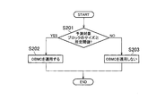
- FIG. 9 is a flowchart showing an example of the operation of the MC prediction unit 34b of the inter prediction unit 34 of the image decoding device 30 according to an embodiment.
- 9 is a flowchart showing an example of the operation of the MC prediction unit 34b of the inter prediction unit 34 of the image decoding device 30 according to an embodiment.
- 9 is a flowchart showing an example of the operation of the MC prediction unit 34b of the inter prediction unit 34 of the image decoding device 30 according to an embodiment.
- 14 is a flowchart showing an example of the operation of the MC prediction unit 34b of the inter prediction unit 34 of the image decoding device 30 according to a modification. It is a figure which shows an example of the table used in the example of a change. It is a figure which shows an example of the table used in the example of a change.
- 9 is a flowchart showing an example of the operation of the MC prediction unit 34b of the inter prediction unit 34 of the image decoding device 30 according to an embodiment. It is a figure which shows an example of the table used by one Embodiment.
- FIG. 9 is a flowchart showing an example of the operation of the MC prediction unit 34b of the inter prediction unit 34 of the image decoding device 30 according to an embodiment. It is a figure for explaining one embodiment. It is a figure for explaining one embodiment. It is a figure for explaining one embodiment. It is a figure for explaining one embodiment. It is a figure for explaining one embodiment. It is a figure for explaining one embodiment. It is a figure for explaining one embodiment.
- FIG. 1 is a diagram showing an image processing system 1 according to the present embodiment.
- the image processing system 1 includes an image encoding device 10 and an image decoding device 30.
- the image encoding device 10 is configured to generate encoded data by encoding an input image signal.
- the image decoding device 30 is configured to generate an output image signal by decoding encoded data.
- the encoded data may be transmitted from the image encoding device 10 to the image decoding device 30 via a transmission path.
- the encoded data may be stored in a storage medium and then provided from the image encoding device 10 to the image decoding device 30.
- FIG. 2 is a diagram showing the image encoding device according to the present embodiment.
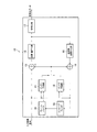
- the image encoding device 10 includes an inter prediction unit 11, an intra prediction unit 12, a subtractor 13, an adder 14, a transform/quantization unit 15, and an inverse transform/inverse quantization. It has a unit 16, an encoding unit 17, an in-loop filter 18, and a frame buffer 19.
- the inter prediction unit 11 is configured to generate a predicted image signal by inter prediction (interframe prediction).
- the inter prediction unit 11 identifies the reference unit included in the reference frame by comparing the encoding target frame (hereinafter, the target frame) with the reference frame stored in the frame buffer 19. It is configured to determine a motion vector of a prediction target block (prediction unit, for example, PU: Prediction Unit) with respect to the selected reference unit.
- a prediction target block for example, PU: Prediction Unit
- the reference frame is a frame different from the target frame.
- the reference unit is a block referred to for the prediction target block.
- the inter prediction unit 11 is also configured to generate a prediction image signal for each prediction target block based on the prediction target block and the motion vector.
- the inter prediction unit 11 is configured to output the predicted image signal to the subtractor 13 and the adder 14.
- the intra prediction unit 12 is configured to generate a prediction image signal by intra prediction (intra-frame prediction).
- the intra prediction unit 12 is configured to identify the reference unit included in the target frame and generate a prediction image signal for each prediction target block based on the identified reference unit. Further, the intra prediction unit 12 is configured to output the predicted image signal to the subtractor 13 and the adder 14.
- the reference unit is a block (adjacent block) adjacent to the prediction target block.
- the subtractor 13 is configured to subtract the prediction image signal from the input image signal, generate a prediction residual signal that is a difference between the input image signal and the prediction image signal, and output the prediction residual signal to the transform/quantization unit 15. There is.
- the adder 14 adds the prediction image signal output from the inter prediction unit 111 or the intra prediction unit 112 to the prediction residual signal output from the inverse transform/inverse quantization unit 16 to generate a pre-filter decoded signal,
- the pre-filter decoded signal is configured to be output to the intra prediction unit 12 and the in-loop filter 18.
- the pre-filter decoded signal constitutes a reference unit used in the intra prediction unit 12.
- the transform/quantization unit 15 is configured to perform a transform process on the input prediction residual signal and obtain a coefficient level value. Furthermore, the transform/quantization unit 15 may be configured to quantize such coefficient level values.
- the conversion process is a process of converting the above prediction residual signal into a frequency component signal.
- a base pattern (conversion matrix) corresponding to the discrete cosine transform (DCT: Discrete Cosine Transform) may be used, and a base pattern (conversion) corresponding to the discrete sine transform (DCT: Discrete Sine Transform). Matrix) may be used.
- the inverse transform/inverse quantization unit 16 is configured to perform an inverse transform process on the coefficient level value output from the transform/quantization unit 15.
- the inverse transform/inverse quantization unit 16 may be configured to perform inverse quantization of the coefficient level value prior to the inverse transform process.
- the inverse transform process and the inverse quantization are performed in the reverse procedure of the transform process and the quantization performed by the transform/quantization unit 15.
- the encoding unit 17 is configured to encode the coefficient level value output from the conversion/quantization unit 17, generate encoded data, and output the encoded data.
- such coding is entropy coding in which codes of different lengths are assigned based on the occurrence probability of such coefficient level values.
- the encoding unit 17 is configured to encode the control data used in the decoding process in the image decoding device 30, in addition to the coefficient level value.
- control data may include size data such as the size of the encoding target unit (CU: Coding Unit), the size of the prediction target block, and the size of the conversion unit (TU: Transform Unit).
- CU Coding Unit
- TU Transform Unit
- the in-loop filter 18 is configured to generate a post-filter decoded signal by filtering the pre-filter decoded signal output from the adder 14, and output the post-filter decoded signal to the frame buffer 19. ing.
- such a filter process is a deblocking filter process that reduces the distortion that occurs at the boundary of blocks (prediction target block or transform unit).
- the frame buffer 19 is configured to store the reference frame used by the inter prediction unit 11.
- the post-filter decoded signal constitutes a reference frame used in the inter prediction unit 11.
- FIG. 3 is a diagram showing the inter prediction unit 11 according to the present embodiment.
- the inter prediction unit 11 includes a motion search unit 11a, a merge unit 11b, and a motion compensation prediction unit (hereinafter, MC prediction unit) 11c.
- MC prediction unit motion compensation prediction unit
- the motion search unit 11a receives an input image signal (original image), a reference frame (reconstructed image) stored in the frame buffer 19 and a motion vector of a block adjacent to the prediction target block, and inputs the motion vector for each prediction target block. And a reference frame.
- the motion search unit 11a includes a motion compensation (MC) prediction unit 11a1 and a cost calculation unit 11a2.
- MC motion compensation
- the motion compensation (MC) prediction unit 11a1 is configured to generate a predicted image signal while changing the reference frame and the reference position in the reference frame with respect to the input image signal corresponding to the prediction target block.
- the cost calculation unit 11a2 minimizes the cost between the prediction image signal generated by the motion compensation prediction unit 11a1 and the input image signal, and minimizes the code amount difference between the motion vector of the adjacent block (ie, the reference position). Motion vector) and a reference frame.
- the cost calculation unit 11a2 for example, the sum of squared errors (SSE: Sum of Squared Error), the sum of absolute value errors (SAD: Sum of Absolute Difference), etc. are assumed, and the cost calculation unit 11a2 May be configured to appropriately select which cost function to use based on the calculation load.
- SSE Sum of Squared Error
- SAD Sum of Absolute Difference
- the image encoding device 10 is configured to superimpose the information related to the motion vector and the reference frame determined by the cost calculation unit 11a2 on the encoded data and transmit the information to the image decoding device 30.
- the merging unit 11b is configured to determine a merge candidate (motion vector) for the prediction target block from the input image signal, the reference frame stored in the hood buffer 19 and the motion vector of the adjacent block.
- the image encoding device 10 is configured to superimpose the information related to the merge candidate determined by the merging unit 11b on the encoded data and transmit the information to the image decoding device 30.
- FIG. 4 is a diagram showing the MC prediction unit 11c of the inter prediction unit 11 of the image coding device 10 according to the present embodiment.
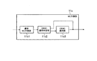
- the MC prediction unit 11c includes a standard motion compensation prediction unit (standard MC prediction unit) 11c1, an OBMC application determination unit 11c2, and an OBMC application unit 11c3.
- standard MC prediction unit standard MC prediction unit
- OBMC application determination unit 11c2 OBMC application determination unit
- OBMC application unit 11c3 OBMC application unit
- the MC prediction unit 11c based on the information about the motion vector and the reference frame from the motion search unit 11a (reference image list and reference image index) and the information about the merge candidate from the merge unit 11b, the predicted image. It is configured to output a signal (predicted pixel value). The output predicted image signal changes depending on whether or not OBMC is applied.
- the MC prediction unit 11c is configured to determine the suitability of the OBMC based on the OBMC application determination flag.
- the standard MC prediction unit 11c1 is configured to generate a predicted image signal of the prediction target block based on the block-by-block motion vector and the reference frame.
- the OBMC application determination unit 11c2 is configured to determine whether to apply OBMC to the prediction target block. Here, when it is determined that the OBMC is not applied, the OBMC application determination unit 11c2 is configured to output the predicted image signal generated by the standard MC prediction unit 11c1 as it is.
- the OBMC application unit 11c3 is configured to apply the OBMC to the prediction target block and output the generated prediction image signal.
- the image encoding device 10 is configured to superimpose the OBMC application determination flag on the encoded data and transmit it to the image decoding device 30.
- FIG. 5 is a diagram showing the image decoding device according to the present embodiment.
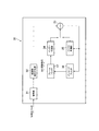
- the image decoding device 30 includes a decoding unit 31, an inverse transform/inverse quantization unit 32, an adder 33, an inter prediction unit 34, an intra prediction unit 35, and an in-loop filter 36. , Frame buffer 37.
- the decoding unit 31 is configured to decode the encoded data generated by the image encoding device 10 and the coefficient level value.
- the decoding is entropy decoding in a procedure opposite to the entropy coding performed in the coding unit 17 of the image coding device 10.
- the decoding unit 31 may be configured to acquire the control data by decoding the encoded data.
- control data may include size data such as the size of the coding unit, the size of the prediction target block, and the size of the conversion unit. Further, the control data may include an information element indicating an input source used to generate the second component prediction sample.
- the second component refers to, for example, a color difference signal other than the luminance signal forming the image signal.
- the inverse transform/inverse quantization unit 32 is configured to perform an inverse transform process on the coefficient level value output from the decoding unit 31.
- the inverse transform/inverse quantization unit 32 may be configured to perform the inverse quantization of the coefficient level value prior to the inverse transform process.
- the inverse transform process and the inverse quantization are performed in the reverse procedure of the transform process and the quantization performed by the transform/quantization unit 15.
- the adder 33 adds the prediction image signal to the prediction residual signal output from the inverse transform/inverse quantization unit 32 to generate a pre-filter decoded signal, and outputs the pre-filter decoded signal to the intra prediction unit 35 and the in-loop. It is configured to output to the filter 36.
- the pre-filter decoded signal constitutes a reference unit used in the intra prediction unit 35.
- the inter prediction unit 34 is configured to generate a predicted image signal by inter prediction (interframe prediction), like the inter prediction unit 11 of the image encoding device 10.
- the inter prediction unit 34 identifies the reference unit included in the reference frame by comparing the encoding target frame and the reference frame stored in the frame buffer 37, and predicts the prediction target for the identified reference unit. It is configured to determine the motion vector of the block.
- the inter prediction unit 34 is configured to generate a prediction image signal for each prediction target block based on the prediction target block and the motion vector.
- the inter prediction unit 34 is configured to output the predicted image signal to the adder 33.
- the intra prediction unit 35 is configured to generate a predicted image signal by intra prediction (intra-frame prediction), like the intra prediction unit 12 of the image encoding device 10.
- the intra prediction unit 35 is configured to specify a reference unit included in the encoding target frame and generate a prediction image signal for each prediction target block based on the specified reference unit. ..
- the intra prediction unit 35 is configured to output the predicted image signal to the adder 33.
- the in-loop filter 36 performs a filtering process on the pre-filter decoded signal output from the adder 33 to generate a post-filter decoded signal, and The post-decoded signal is output to the frame buffer 37.
- such a filter process is a deblocking filter process that reduces the distortion that occurs at the boundary of blocks (prediction target block or transform unit).
- the frame buffer 37 is configured to store the reference frame used by the inter prediction unit 34.
- the post-filter decoded signal constitutes a reference frame used in the inter prediction unit 11.
- FIG. 6 is a diagram showing the inter prediction unit 34 of the image decoding device 30 according to the present embodiment.
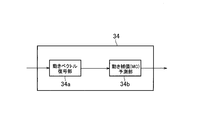
- the inter prediction unit 34 includes a motion vector decoding unit 34a and a motion compensation (MC) prediction unit 34b.
- MC motion compensation
- the motion vector decoding unit 34a decodes the information (reference image list and reference image index) related to the motion vector and reference frame of each block superimposed on the encoded data, the information related to the merge candidate, and the OBMC application determination flag. , MC prediction unit 34b.
- the MC prediction unit 34b is configured to receive the information about the motion vector and the reference frame decoded by the motion vector decoding unit 34a and the information about the merge candidate, and generate and output an output image signal (predicted pixel value). Has been done.
- FIG. 7 is a diagram showing the MC prediction unit 34b of the inter prediction unit 34 of the image decoding device 30 according to the present embodiment.
- the MC prediction unit 34b includes a standard motion compensation prediction unit (standard MC prediction unit) 34b1, an OBMC application determination unit 34b2, and an OBMC application unit 34b3.
- the MC prediction unit 34b based on the information (reference image list and reference image index) regarding the motion vector and the reference frame from the motion vector decoding unit 34a, the information regarding the merge candidate, and the OBMC application determination flag, It is configured to generate and output a pixel value).
- the output predicted image signal changes depending on whether or not OBMC is applied.
- the standard MC prediction unit 34b1 is configured to generate a predicted image signal of the prediction target block based on the information on the motion vector of the block unit and the reference frame.
- the OBMC application determination unit 34b2 is configured to determine whether to apply OBMC to the prediction target block. Here, when it is determined that the OBMC is not applied, the OBMC application determination unit 34b2 is configured to output the predicted image signal generated by the standard MC prediction unit 34b1 as it is.
- the OBMC application unit 34b3 is configured to apply the OBMC to the prediction target block and output the generated prediction image signal.
- the OBMC application unit 34b3 is configured to apply the OBMC to the prediction target block based on the determination result by the OBMC application determination unit 34b2, that is, when it is determined that the OBMC is applied.
- the OBMC calculates the weighted average of the prediction image signal of the prediction target block and the prediction image signal generated based on the information about the motion vector of the block adjacent to the prediction target block and the reference frame, thereby calculating This is an overlapping motion compensation process for correcting the predicted image signal of.
- the above determination method and application method are applied when the motion vector of the prediction target block and the motion vector of the adjacent block are different. If both motion vectors are considered equal or their difference is small, there is no point in applying OBMC to the boundary between the prediction target block and the adjacent block. Therefore, in the following description, it is assumed that the motion vector of the prediction target block and the motion vector of the adjacent block are different from each other.
- FIG. 8 is a flowchart showing an example of the operation of the MC prediction unit 34b of the inter prediction unit 34 in this embodiment.
- the OBMC application determination unit 34b2 of the MC prediction unit 34b determines whether to apply OBMC to the prediction target block based on the type of prediction direction of the prediction target block (unidirectional prediction or bidirectional prediction). Is configured to determine.
- step S101 the OBMC application determination unit 34b2 determines whether or not unidirectional prediction is applied to the prediction target block.
- step S102 If it is determined that the unidirectional prediction is applied to the prediction target block, the procedure proceeds to step S102. If it is determined that the unidirectional prediction is not applied to the prediction target block, the procedure is the step. It proceeds to S103.
- step S102 the OBMC application determination unit 34b2 determines to apply OBMC to the prediction target block, and the OBMC application unit 34b3 applies OBMC to the prediction target block.
- step S103 the OBMC application determination unit 34b2 determines not to apply OBMC to the prediction target block, and outputs the predicted image signal generated by the standard MC prediction unit 34b1 as it is.
- OBMC When bidirectional prediction is applied to the prediction target block, OBMC is applied to the prediction target block, and when unidirectional prediction is applied to the prediction target block, OBMC is applied to the prediction target block. Compared with the case where it is applied, the memory bandwidth and the number of operations that additionally need to be fetched increase. Therefore, according to the image encoding device 10 and the image decoding device 30 according to the present embodiment, by applying OBMC to a prediction target block only when unidirectional prediction is applied to the prediction target block, It is possible to prevent an increase in the memory bandwidth and the number of calculations.
- FIG. 9 is a flowchart showing an example of the operation of the MC prediction unit 34b of the inter prediction unit 34 in this embodiment.
- the OBMC application determination unit 34b2 of the MC prediction unit 34b is configured to determine that the OBMC is applied to the prediction target block when the size of the prediction target block is equal to or larger than the predetermined threshold.
- step S201 the OBMC application determination unit 34b2 determines whether or not the size of the prediction target block is equal to or larger than a predetermined threshold.
- step S202 When it is determined that the size of the prediction target block is equal to or larger than the predetermined threshold, the procedure proceeds to step S202. When it is determined that the size of the prediction target block is less than the predetermined threshold, the procedure proceeds to step S203. move on.
- step S202 the OBMC application determination unit 34b2 determines to apply the OBMC to the prediction target block, and the OBMC application unit 34b3 applies the OBMC to the prediction target block.
- step S203 the OBMC application determination unit 34b2 determines not to apply OBMC to the prediction target block, and outputs the predicted image signal generated by the standard MC prediction unit 34b1 as it is.
- the predetermined threshold value is, for example, a value such that the memory bandwidth and the number of operations required when applying OBMC are smaller than the memory bandwidth and the number of operations in bidirectional prediction when OBMC is not applied. It may be set to.
- the OBMC application determination unit 34b2 determines the size of the prediction target block using the number of pixels of the prediction target block, but as another method, the height and width of the prediction target block are used. It may be configured to determine the size of the prediction target block.
- the OBMC application determination unit 34b2 may be configured to determine that OBMC is applied to the prediction target block by using a table instead of the predetermined threshold value.
- OBMC OBMC is applied to a prediction target block that is relatively small in size
- the memory bandwidth and the number of operations that additionally need to be fetched will increase. Therefore, according to the image encoding device 10 and the image decoding device 30 according to the present embodiment, it is not intended by controlling whether or not to apply OBMC to the prediction target block based on the size of the prediction target block. It is possible to prevent an increase in the memory bandwidth and the number of calculations.
- FIG. 10 is a flowchart showing an example of the operation of the MC prediction unit 34b of the inter prediction unit 34 in this embodiment.
- the OBMC application determination unit 34b2 of the MC prediction unit 34b applies the OBMC to the prediction target block based on the type of prediction direction of the block adjacent to the prediction target block (unidirectional prediction or bidirectional prediction). It is configured to determine whether to do.
- step S301 the OBMC application determination unit 34b2 determines whether or not unidirectional prediction is applied to adjacent blocks.
- step S302 When it is determined that the unidirectional prediction is applied to the adjacent block, the procedure proceeds to step S302, and when it is determined that the unidirectional prediction is not applied to the adjacent block, the procedure proceeds to step S303. move on.
- step S302 the OBMC application determination unit 34b2 determines to apply OBMC to the prediction target block, and the OBMC application unit 34b3 applies OBMC to the prediction target block.
- step S303 the OBMC application determination unit 34b2 determines not to apply OBMC to the prediction target block, and outputs the predicted image signal generated by the standard MC prediction unit 34b1 as it is.
- OBMC when bidirectional prediction is applied to an adjacent block, OBMC is applied to a prediction target block, and when unidirectional prediction is applied to an adjacent block, OBMC is applied to a prediction target block.
- the OBMC is applied to the prediction target block only when the unidirectional prediction is applied to the adjacent block, which is not intended. It is possible to prevent an increase in the memory bandwidth and the number of calculations.
- FIG. 11 is a flowchart showing an example of the operation of the MC prediction unit 34b of the inter prediction unit 34 in Modification Example 1.
- step S401 the MC prediction unit 34b determines whether or not unidirectional prediction is applied to the prediction target block.
- step S403 When it is determined that the unidirectional prediction is applied to the prediction target block, the procedure proceeds to step S403, and when it is determined that the unidirectional prediction is not applied to the prediction target block, the procedure is the step Proceed to S402.
- step S402 the OBMC application determination unit 34b2 determines not to apply OBMC to the prediction target block, and outputs the predicted image signal generated by the standard MC prediction unit 34b1 as it is.
- step S403 the OBMC application determination unit 34b2 determines whether or not the size of the prediction target block is equal to or larger than a predetermined threshold.
- step S404 move on.
- step S404 the OBMC application determination unit 34b2 determines not to apply OBMC to the prediction target block, and outputs the predicted image signal generated by the standard MC prediction unit 34b1 as it is.
- step S405 the MC prediction unit 34b determines whether or not unidirectional prediction is applied to the adjacent block.
- step S406 When it is determined that the unidirectional prediction is applied to the adjacent block, the procedure proceeds to step S406, and when it is determined that the unidirectional prediction is not applied to the adjacent block, the procedure proceeds to step S407. move on.
- step S406 the OBMC application determination unit 34b2 determines to apply OBMC to the prediction target block, and the OBMC application unit 34b3 applies OBMC to the prediction target block.
- step S407 the OBMC application determination unit 34b2 determines not to apply OBMC to the prediction target block, and outputs the predicted image signal generated by the standard MC prediction unit 34b1 as it is.
- the OBMC application determination unit 34b2 when applying the OBMC to the prediction target block, the OBMC application determination unit 34b2 first determines whether or not unidirectional prediction is applied to the prediction target block. Secondly, it is determined whether or not the size of the prediction target block is equal to or larger than a predetermined threshold value, and thirdly, it is determined whether or not the unidirectional prediction is applied to the adjacent block.
- OBMC when unidirectional prediction is applied to the prediction target block, OBMC is applied uniformly, but unidirectional prediction is applied to the prediction target block. This is because the worst case at the time of applying OBMC can be avoided by introducing the constraint based on the size of the prediction target block after determining whether or not the OBMC is applied.
- the worst case may occur when the coding tree block is filled with the minimum coding target block or prediction target block, and at this time, the memory bandwidth and the number of operations required for applying OBMC are the maximum. Become. In other words, this worst case can be said to be the memory bandwidth and the number of calculations required when applying OBMC.
- the size of the prediction target block in the determination of suitability of OBMC for example, the memory bandwidth and the calculation required when unidirectional prediction is applied to the prediction target block and OBMC is applied.
- the number of times can be made smaller than the memory bandwidth and the number of operations required for the standard MC when OBMC is not applied and bidirectional prediction is applied to the prediction target block.
- OBMC when unidirectional prediction is applied to the prediction target block and the size of the prediction target block is equal to or larger than the predetermined threshold, OBMC is applied uniformly. However, if bidirectional prediction is applied to adjacent blocks, the required memory bandwidth and the number of operations may exceed the worst case.
- the OBMC when the bidirectional prediction is applied to the adjacent block, the OBMC is not applied so that the memory bandwidth and the number of operations required when the OBMC is applied are not applied by the OBMC. It can be made smaller than the memory bandwidth and the number of operations required for the standard MC when bidirectional prediction is applied to the prediction target block.
- the determination condition as to whether OBMC is applied is set as follows.
- the following predetermined thresholds are set so as not to exceed the memory bandwidth required for standard MC when OBMC is not applied and bidirectional prediction is applied to the prediction target block.
- S and L indicate the short side and the long side obtained by comparing the height and the width of the prediction target block (S ⁇ L).
- S ⁇ L the width of the prediction target block
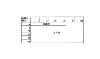
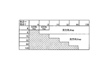
- the OBMC application determination unit 34b2 may be configured to determine the suitability of OBMC based on, for example, a table as shown in FIG. 12 instead of the predetermined threshold value.
- the “short side” and the “long side” in FIG. 12 indicate the short side and the long side obtained by comparing the height and the width of the prediction target block, and “not applied” in FIG. 12 indicates the OBMC. 12 indicates that the OBMC is not applied, and “unidirectional” in FIG. 12 indicates that the OBMC is applied when the unidirectional prediction is applied to the adjacent block.
- “bidirectional” means that OBMC is applied when unidirectional prediction or bidirectional prediction is applied to adjacent blocks.
- the predetermined threshold value or table (FIG. 12) that is set with a value that does not exceed the memory bandwidth is described.
- the setting method of the predetermined threshold value is the memory band.
- the size (height and width) of the prediction target block does not become a symmetrical threshold value.
- the table in which the number of calculations is used as a guide can have asymmetric values in size, as shown in FIG. 13, for example.
- the memory bandwidth and the number of operations are larger than the case where OBMC is not applied and bidirectional prediction is applied to the prediction target block, based on the parameters listed above. Is set to be smaller, but a stricter condition is set among the conditions obtained for the memory bandwidth and the number of calculations.
- FIG. 14 is a flowchart showing an example of the operation of the MC prediction unit 34b of the inter prediction unit 34 in this embodiment.
- step S501 the OBMC application determination unit 34b2 determines whether or not unidirectional prediction is applied to the prediction target block.
- step S503 If it is determined that the unidirectional prediction is applied to the prediction target block, the procedure proceeds to step S503. If it is determined that the unidirectional prediction is not applied to the prediction target block, the procedure is step It proceeds to S502.
- step S502 the OBMC application determination unit 34b2 determines not to apply OBMC to the prediction target block, and outputs the predicted image signal generated by the standard MC prediction unit 34b1 as it is.
- step S503 the OBMC application determination unit 34b2 determines the size of the prediction target block.
- step S504 When it is determined that the size of the prediction target block is less than the threshold TH1, the procedure proceeds to step S504, and when it is determined that the size of the prediction target block is greater than or equal to the threshold TH1 and less than the threshold TH2, the procedure is When it is determined that the size of the prediction target block is equal to or larger than the threshold value TH in step S506, the procedure proceeds to step S505.
- step S504 the OBMC application determination unit 34b2 determines not to apply OBMC to the prediction target block, and outputs the predicted image signal generated by the standard MC prediction unit 34b1 as it is.
- step S505 the OBMC application determination unit 34b2 determines to apply OBMC to the prediction target block, and the OBMC application unit 34b3 applies OBMC to the prediction target block.
- step S506 the OBMC application determination unit 34b2 determines whether or not the unidirectional prediction is applied to the adjacent block.
- step S507 If it is determined that the unidirectional prediction is applied to the adjacent block, the procedure proceeds to step S507, and if it is determined that the unidirectional prediction is not applied to the adjacent block, the procedure proceeds to step S5087. move on.
- step S507 the OBMC application determination unit 34b2 determines to apply OBMC to the prediction target block, and the OBMC application unit 34b3 applies OBMC to the prediction target block.
- step S508 the OBMC application determination unit 34b2 determines not to apply OBMC to the prediction target block, and outputs the predicted image signal generated by the standard MC prediction unit 34b1 as it is.
- the OBMC application determination unit 34b2 is configured to use two thresholds (where threshold TH1 ⁇ threshold TH2).
- the OBMC application determination unit 34b2 determines that OBMC is not applied to the prediction target block, and the size of the prediction target block is the threshold TH1 or more and the threshold TH2. If it is less than, it moves to the determination as to whether unidirectional prediction is applied to the adjacent block, and if the size of the prediction target block is equal to or greater than the threshold TH2, It is determined that OBMC is applied to the prediction target block regardless of whether or not the direction prediction is applied.
- the OBMC application determination unit 34b2 controls the type of the prediction direction (one-way prediction or bidirectional prediction) applied to the adjacent block based on the size of the prediction target block, and the OBMC for the prediction target block. Is configured to be applied.
- the determination condition as to whether or not OBMC is applied is set as follows.
- the following thresholds are set so as not to exceed the memory bandwidth required for the standard MC when OBMC is not applied and bidirectional prediction is applied to the prediction target block.
- S and L indicate the short side and the long side obtained by comparing the height and the width of the prediction target block (S ⁇ L).
- -(S ⁇ 16) ⁇ OBMC is applied even when bidirectional prediction is applied to adjacent blocks.
- OBMC is not applied.
- the OBMC application determination unit 34b2 may be configured to determine the suitability of OBMC based on, for example, a table as shown in FIG. 15 instead of the predetermined threshold value. Note that the grayed out portions in FIG. 15 need not be considered because they are the portions where S ⁇ L on the short side S and the long side L described above.
- the fifth embodiment of the present invention will be described below with reference to FIG.
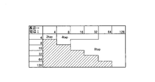
- the case where the number of OBMC taps (the number of overlapping motion compensation taps) is “8” has been described, but when the number of OBMC taps changes from “8” to “4”, When the number of taps is changed from “8” to “2”, the memory bandwidth and the number of operations required when applying OBMC are reduced, so that the constraint of applying OBMC is relaxed.
- the determination condition as to whether or not OBMC is applied when only the number of filter taps is changed is set as follows.
- the following threshold values are set so as not to exceed the memory bandwidth required for the standard MC when OBMC is not applied and bidirectional prediction is applied to the prediction target block, as in the case described above. ing.
- the OBMC application determination unit 34b2 may be configured to determine the suitability of OBMC based on, for example, a table as shown in FIG. 16 instead of the predetermined threshold value.
- the number of taps branched under the above conditions is backward compatible. For example, under the condition that OBMC with 8 taps can be used, OBMC with 4 taps or 2 taps may be used instead of 8 taps.
- the OBMC application constraint for the prediction target block having a small size may be relaxed. For example, in the above example, for the prediction target block (4 ⁇ 4) having a small size to which OBMC is not applied in FIG. 15, the number of taps is changed from 8 taps to 2 taps to predict the size.
- the OBMC can be applied to the target block.
- “2 tap” indicates that 2-tap OBMC is applied (provided that unidirectional prediction is applied to adjacent blocks), and “4 tap” applies 4-tap OBMC ( However, when unidirectional prediction is applied to adjacent blocks), “8 tap” applies OBMC of 8 taps (however, when unidirectional prediction is applied to adjacent blocks).
- the number of taps in FIG. 16 is backward compatible, and for example, in the case of “4 tap”, the OBMC of 2 taps may be applied, and in the case of “8 tap”, the number of taps is 2 taps or 4 taps. OBMC may be applied.
- a standard MC filter (4 taps) for color difference signals may be used.
- a bi-linear filter may be used. If the standard MC for color difference signals is used for 4 taps, an effect that an additional filter design is not required at the time of hardware implementation can be obtained.
- the OBMC application determining unit 34b2 controls the tap number of the OBMC based on the size of the prediction target block to determine whether to apply the OBMC to the prediction target block. Is configured.
- the threshold value or table is designed with the same idea as described above.
- the tap number of the OBMC branched under the above conditions is backward compatible. For example, under the condition that the OBMC of 8 taps can be used, even if the OBMC of 4 taps or 2 taps is used instead of 8 taps. Good.
- unidirectional prediction may be used if bidirectional prediction is allowed to be applied.
- the OBMC application constraint for the prediction target block having a small size may be relaxed. ..
- the number of taps is changed from 8 taps to 2 taps to predict the size.
- the OBMC can be applied to the target block.
- a 4 ⁇ 8 or 8 ⁇ 4 prediction target block by changing the number of taps from 8 taps to 2 taps, even if OBMC is applied to an adjacent block that is bidirectional prediction, Since OBMC is not applied and the memory bandwidth and the number of operations for the standard MC of the prediction target block that is bidirectional prediction are not exceeded, it is possible to perform 2-tap adjacent bidirectional prediction OBMC.
- the designer may freely set the conditions.
- the OBMC application determination unit 34b2 may be configured to determine the suitability of OBMC based on, for example, a table as shown in FIG. 17 instead of the predetermined threshold value.
- the OBMC application determination unit 34b2 determines the number of taps (“2”) of the OBMC of the adjacent block applied to the prediction target block of the first size (for example, 4 ⁇ 4). , And is smaller than the number of taps (“8”) of the OBMC of the adjacent block applied to the second size (for example, 128 ⁇ 128) prediction target block that is larger than the first size.
- the OBMC application determination unit 34b2 determines the type (unidirectional) of the prediction direction of the adjacent block applied to the prediction target block of the first size (for example, 4 ⁇ 4), It is configured to be smaller than the type (bidirectional) of the prediction direction of the adjacent block applied to the prediction target block of the second size (for example, 4 ⁇ 8 or 8 ⁇ 4) larger than the first size. There is.
- the precision of the motion vector is converted from a decimal number to an integer, and when the size of the prediction target block is larger than the predetermined threshold value.
- the motion vector accuracy may be set to a decimal.
- the number of OBMC applied lines is reduced.
- the size of the prediction target block is smaller than the predetermined threshold, the number of OBMC applied lines is reduced.
- the size of the prediction target block is larger than the predetermined threshold, the number of applied lines of OBMC is reduced. It may be configured to increase.
- FIG. 18 is a flowchart showing an example of the operation of the MC prediction unit 34b of the inter prediction unit 34 in the fourth modification.
- step S601 the OBMC application determination unit 34b2 determines whether or not unidirectional prediction is applied to adjacent blocks.
- step S603 If it is determined that the unidirectional prediction is applied to the adjacent block, the procedure proceeds to step S603, and if it is determined that the unidirectional prediction is not applied to the adjacent block, the procedure proceeds to step S602. move on.
- step S602 the OBMC application determination unit 34b2 converts the prediction method applied to the adjacent block from bidirectional prediction to unidirectional prediction by a predetermined method.
- step S603 the OBMC application determination unit 34b2 determines to apply OBMC to the prediction target block, and the OBMC application unit 34b3 applies OBMC to the prediction target block.
- the prediction method applied to adjacent blocks is converted from bidirectional prediction to unidirectional prediction by a predetermined method.
- the OBMC is applied.
- the predetermined method will be described later.
- the prediction method applied to the adjacent block is converted from bidirectional prediction to unidirectional prediction, thereby increasing the number of prediction target blocks to which OBMC is applied and necessary for OBMC.
- the memory bandwidth and the number of calculations can be reduced.
- the OBMC application determination unit 34b2 uses the predetermined method to determine the prediction method applied to the adjacent block from the bidirectional prediction to the unidirectional prediction. Is configured to convert to.
- L p0 ”and “L p1 ” are two reference frames of the prediction target block
- L n0 ”and “L n1 ” represent two reference frames of adjacent blocks, respectively.
- the table of FIG. 20 shows only one POC for each of “L p0 ”, “L p1 ”, “L n0 ”, and “L n1 ”, but this is superimposed on the encoded data.
- the POC indicated by the reference image list and the reference image index are not always the ones of “L p0 ”, “L p1 ”, “L n0 ”, and “L n1 ”. However, the designer can freely set the number of reference frames, but the POC is uniquely determined by the reference image list and the reference image index.
- the OBMC application determination unit 34b2 is configured to compare the absolute value of the difference in POC between the current frame C p of the prediction target block and each of the two reference frames L n0 /L n1 of the adjacent block. There is.
- the POC of the current frame C p of the prediction target block is “5”
- the POC of the reference frame L n0 of the adjacent block is “0”
- the reference of the adjacent block is performed.
- the POC of the frame L n1 is “8”
- 5
- 3. Therefore, the OBMC application determination unit 34 b 2 determines that the reference frame L n1 of the adjacent block is L n1. Select.
- the OBMC application determination unit 34b2 selects and selects one having a smaller absolute value of the POC difference between the current frame C p of the prediction target block and the reference frames L n0 /L n1 of the adjacent block. It is configured to determine that the unidirectional prediction using the reference frame L n1 of the adjacent block is applied to the adjacent block.
- the OBMC application determination unit 34b2 is configured to compare the absolute value of the difference in POC between the reference frame L p0 /L p1 of the prediction target block and the reference frame L n0 /L n1 of the adjacent block.
- the POC of the reference frame L p0 /L p1 of the prediction target block is “4”/“6”
- the POC of the reference frame L n0 /L n1 of the adjacent block is If “0”/“8”,
- 4,
- 4,
- 6,
- 2 Therefore, when the prediction target block has the reference frame L p1 , the OBMC application determination unit 34b2 selects the reference frame L n1 of the adjacent block having a small absolute value of the POC difference.
- the prediction target block has the reference frame L p0
- the absolute value of the difference in POC is equal in the reference frames L n0 /L n1 of the adjacent blocks
- the reference frames of the adjacent blocks are uniquely identified by the selection method described later. To decide.
- the OBMC application determination unit 34b2 selects the one having the smaller absolute value of the POC difference between the reference frame L p0 /L p1 of the prediction target block and the reference frames L n0 /L n1 of the adjacent blocks.
- the unidirectional prediction using the reference frame L n1 of the selected adjacent block is determined to be applied to the adjacent block.
- the OBMC application determination unit 34b2 selects by comparing the absolute value of the POC difference between the reference frame L p0 /L p1 of the prediction target block and the reference frames L n0 /L n1 of the adjacent blocks. It is configured.
- the POC of the reference frame L p0 /L p1 of the prediction target block is “4”/“6”
- the POC of the reference frame L n0 /L n1 of the adjacent block is If “0”/“8”,
- 4,
- 4,
- 6,
- 2 Therefore, when the prediction target block has the reference frame L p1 , the OBMC application determination unit 34b2 selects the reference frame L n0 of the adjacent block having the large absolute value of the POC difference.
- the prediction target block has the reference frame L p0
- the absolute value of the difference in POC is equal in the reference frames L n0 /L n1 of the adjacent blocks
- the reference frames of the adjacent blocks are uniquely identified by the selection method described later. It is based on the idea that a larger prediction error is likely to occur, and it is better to apply OBMC rather to such a block (block boundary).
- the OBMC application determination unit 34b2 selects the one having a larger absolute value of the POC difference between the reference frame L p0 /L p1 of the prediction target block and the reference frames L n0 /L n1 of the adjacent blocks.
- the unidirectional prediction using the reference frame L n1 of the selected adjacent block is determined to be applied to the adjacent block.
- the OBMC application determination unit 34b2 is configured to select the reference frame of the adjacent block having the same reference image index and the reference image index of the prediction target block.
- the OBMC application determination unit 34b2 selects the reference frame of the adjacent block that is equal to the reference frame of the prediction target block, and the unidirectional prediction using the reference frame of the selected adjacent block is applied to the adjacent block. It is configured to determine that there is.
- Such a method improves the prediction accuracy because the prediction directions of the prediction target block and the adjacent block are likely to be the same when the reference image list of the prediction target block and the reference frame having the same reference image index are selected in the adjacent block. It is based on the idea that it will be done.
- the OBMC application determination unit 34b2 is configured to select a reference frame of a neighboring block having a different reference image list and reference image index of the prediction target block.
- Method 6 the selection method when the absolute values are equal in the comparison of the absolute values of the POC differences between the current frame C p of the prediction target block and the reference frames L n0 /L n1 of the adjacent blocks will be described. ..
- the absolute value of the difference in POC between the current frame C p of the prediction target block and the reference frame L n0 /L n1 of the adjacent block is
- A
- the OBMC application determination unit 34b2 determines the difference in POC between the reference frame L p0 /L p1 of the new prediction target block and the reference frame L n0 /L n1 of the adjacent block.
- the reference frames of adjacent blocks are uniquely selected by comparing the absolute values.
- the OBMC application determination unit 34 b 2 L n0 having a small absolute value is selected as a reference frame of an adjacent block.
- Method 7 In the method 7, in the comparison of the absolute values of the POC differences between the reference frame L p0 /L p1 of the prediction target block and the reference frames L n0 /L n1 of the adjacent blocks, the selection method when the absolute values are equal to each other Will be described.
- the absolute value of the difference in POC between the reference current frame L p0 /L p1 of the prediction target block and the reference frame L n0 /L n1 of the adjacent block is
- X,
- X Y
- the OBMC application determination unit 34b2 newly determines the difference in POC between the current frame C p of the prediction target block and the reference frames L n0 /L n1 of the adjacent block.
- the reference frames of adjacent blocks are uniquely selected by comparing the absolute values of.
- the OBMC application determination unit 34 b 2 sets L n0 having a small absolute value to the reference frame of the adjacent block. Is configured to select as.
- the OBMC application determining unit 34b2 compares the absolute values of the POC differences between the reference frame of the prediction target block and the reference frames of the adjacent blocks, and when the absolute values are equal, the reference of the adjacent block is performed. It is configured to select a frame to a predetermined L n0 (or L n1 ).
- the OBMC application determining unit 34b2 determines the reference frame of the adjacent block in advance regardless of the result of the comparison of the absolute values of the POC differences between the reference frame of the prediction target block and the reference frame of the adjacent block. It may be configured to select a predetermined L n0 (or L n1 ).
- OBMC application determination unit 34b2 determines whether or not to apply OBMC not in the prediction target block unit but in the prediction target subblock unit obtained by dividing the prediction target block, as described in Non-Patent Document 1. May be configured to do so.
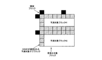
- 21 and 22 show an example in which a prediction target block is divided into prediction target sub-blocks as a processing unit when determining whether or not to apply OBMC and applying OBMC.
- two prediction target blocks #1/#2 (16 ⁇ 32 units) are included in the coding target block.
- the OBMC application determination unit 34b2 divides the boundary of the prediction target block #1/#2 into 4 ⁇ 4 units of prediction target subblocks, and determines whether to apply OBMC to the prediction target subblock. Or not.
- the suitability of OBMC is determined as described above, and when it is determined that the OBMC is applied, the boundary of the prediction target block is determined by the OBMC. Smoothing reduces the prediction error and consequently improves the objective performance.
- FIG. 22 shows a case where the prediction target block has different motion vectors in the coding target block.
- Non-Patent Document 1 When the prediction target block has different motion vectors in the coding target block, for example, an ATMVP (Alternative Temporal Motion Vector Prediction) mode, an AFFINE mode, and a FRUC (Frame-Rate-Up-Up) proposed in Non-Patent Document 1 are used. The case where the conversion mode is applied and the like can be mentioned.
- the OBMC application determination area for the prediction target block extends not only to the prediction target block boundary but also to the prediction target sub-block boundary.
- the required memory bandwidth and the calculation load increase as compared with the case where the OBMC is applied only to the boundary of the prediction target block. Therefore, as described above, the number of lines to which the OBMC is applied is reduced. be able to.
- the size of the weighting coefficient matrix is determined by the area where OBMC is applied to the prediction target block.
- the weighting coefficient matrix is 4 lines (4 ⁇ 4).
- the weight value of the weighting coefficient matrix for the reference pixel value of the prediction target block and the reference pixel value of the adjacent block is determined based on the ratio of the distance from the prediction target block boundary.
- the weighting value of the reference pixel value of the prediction target block becomes (3/4, 7/8, 15/16, 31/32) in ascending order from the prediction target block boundary, and the reference pixel of the adjacent block The value becomes (1/4, 1/8, 1/16, 1/32) in order from the boundary of the prediction target block.
- the weight value of the weight coefficient matrix may be changed based on the number of adjacent blocks.
- the weighting value of the reference pixel value of the prediction target block is (2/4, 6/8) in ascending order from the prediction target block boundary. , 14/16, 30/32), and the weighting value of the reference pixel value of the upper adjacent block becomes (1/4, 1/8, 1/16, 1/32) in the order closer to the prediction target block boundary, and The weight values of the reference pixel values of the adjacent blocks are (1/4, 1/8, 1/16, 1/32) in order from the boundary of the prediction target block.
- weighting average of the upper adjacent block and the left adjacent block separately for the prediction target block as weight values (1/4, 1/8, 1/16, 1/32) depends on the processing order. This is because the weight value is constant regardless of the processing order because the value changes.
- the weight value of the weight matrix is weighted based on the distance from the prediction target block boundary in the conventional method described in Non-Patent Document 1, when the size of the prediction target block is large, the image is a flat image. Since there is a high possibility that the weighting ratio between the prediction target block and the reference pixel value of the adjacent block at the time of weighted averaging by OBMC is better.
- the weighting ratio between the prediction target block and the adjacent block is increased to save the edge. It seems better.
- the OBMC application unit 34b3 is configured to change the weight value of the weight coefficient matrix used in the weighted average in OBMC based on the number of adjacent blocks or the size of the prediction target block.
- Non-Patent Document 2 The deblocking filter used in Non-Patent Document 2 is known to have a smoothing effect on block boundaries, but the boundary strength (BS value: Boundary Strength value) is used as one of the application judgments. ..
- the BS value is defined for each condition of two blocks that sandwich the block boundary, and when the BS value is “0”, the deblocking filter is applied to the block boundary.
- the deblocking filter is applied to the block boundary when the BS value is “1” or more.
- the OBMC smoothes the block boundary by weighting the reference pixel values pointed by the respective motion vectors in the reference frame when the prediction target block and the adjacent block have different motion vectors. Is configured to.
- the BS value is modified as shown in FIG. 23 in order to determine the suitability of the deblocking filter in order to prevent unintended double smoothing by the deblocking filter.
- the conditions 3 and 4 are that the cause of the block distortion occurring at the block boundary is that the motion vectors of the two blocks are different, that the reference images for motion compensation of the two blocks are different, and the number of motion vectors of the two blocks is different. It is supposed to be different.
- OBMC that is basically applied is already applied to the block boundary. Is based on the idea that the BS value may be set to "0" and double smoothing by a deblocking filter may be prohibited.
- the OBMC application unit 34b3 is configured to change the application condition of the deblocking filter based on whether or not OBMC is applied.
- the eighth embodiment of the present invention will be described below, focusing on the differences from the above-described embodiment and modifications.
- the present embodiment as a method of reducing the memory bandwidth and the number of calculations when OBMC is applied, when the motion vectors of adjacent blocks of the prediction target block are different, the number of motion vectors and reference frames required for OBMC by a predetermined reduction method.
- the MC predicting unit 34b configured to reduce? Will be described.
- the memory bandwidth and the number of operations required for applying the OBMC of the prediction target block increase by the number of adjacent blocks.
- a method of merging adjacent blocks having different motion vectors into a predetermined block size for example, a 4 ⁇ 4 adjacent block is merged into a 4 ⁇ 8 adjacent block or an 8 ⁇ 4 adjacent block.
- adjacent blocks having different motion vectors are arranged, adjacent blocks used when OBMC is applied are thinned out (for example, when four 4 ⁇ 4 adjacent blocks are arranged above the 16 ⁇ 16 prediction target block, OBMC is applied).
- the adjacent two blocks that are sometimes used are the leftmost and the third two counted from the leftmost, or the leftmost and rightmost adjacent blocks are used).
- the merging method and the thinning method of the adjacent blocks described above may be determined using a threshold value.
- the difference between the motion vectors of adjacent blocks having different motion vectors is less than 1 pixel, it is treated as an adjacent block having the same motion vector.
- the threshold value of the motion vector difference may be changed based on whether unidirectional prediction or bidirectional prediction is applied to adjacent blocks. (For example, less than 1.5 pixels when unidirectional prediction is applied, less than 1 pixel when bidirectional prediction is applied, etc.).
- the OBMC application unit 34b3 reduces the number of motion vectors and reference frames required for OBMC by a predetermined reduction method. It is configured.
- the image encoding device 10 and the image decoding device 30 described above may be realized by a program that causes a computer to execute each function (each step).
- the present invention has been described by taking the application to the image encoding device 10 and the image decoding device 30 as an example, but the present invention is not limited to this and the image encoding device is not limited to this. The same can be applied to an encoding/decoding system including the functions of the device 10 and the image decoding device 30.
Landscapes
- Engineering & Computer Science (AREA)
- Multimedia (AREA)
- Signal Processing (AREA)
- Compression Or Coding Systems Of Tv Signals (AREA)
Abstract
本発明に係る画像復号装置30は、ブロック単位の動きベクトル及び参照フレームに係る情報に基づいて、予測対象ブロックの予測画像信号を生成する動き補償予測部34b1と、予測対象ブロックの予測画像信号と、予測対象ブロックの隣接ブロックの動きベクトル及び参照フレームに係る情報に基づいて生成される予測画像信号とを加重平均することによって、予測対象ブロックの予測画像信号を補正する重複動き補償処理を行う重複動き補償部34b3と、予測対象ブロックに対して重複動き補償処理を適用するかについて判定する判定部34b2とを備え、判定部34b2は、隣接ブロックに片方向予測が適用されている場合、予測対象ブロックに対して重複動き補償処理を適用すると判定する。
Description
本発明は、画像復号装置、画像符号化装置、画像復号方法及びプログラムに関する。
非特許文献1に、重複動き補償予測(OBMC:Overlapped Block Motion Compensation)という技術が開示されている。OBMCは、動き補償予測の予測画素生成過程において、予測対象ブロック及び隣接ブロックの動きベクトルがそれぞれ指し示す参照画素値を、予め設定した重み係数マトリクスに基づいて加重平均し、最終的な予測画素を生成する技術である。
また、特許文献1には、OMBCを適用した場合のメモリバンド幅を低減させるために、予測対象ブロックのサイズや予測方向の種類(片方向予測又は双方向予測)や動きベクトルの精度に基づいて、OBMCの適否を判定する技術が記されている。
さらに、特許文献2には、符号化対象ブロック内にある複数の予測対象ブロック間の境界に対してOBMCを適用する際に、デブロッキングフィルタの強度を判定するパラメータであるbS値を修正する技術が記されている。かかる技術によれば、OBMCの適用により予測対象ブロック間の境界に対して平滑化効果が既に施されている場合に、デブロッキングフィルタによる不要なフィルタ効果を回避することができる。
Algorithm Description of Joint Exploration Test Model 7(JEM 7)
ITU-T H.265 High Efficiency Video Coding
しかしながら、非特許文献1に開示されているOBMCは、予測対象ブロック又は隣接ブロックのサイズや予測方向の種類に関係なく適用されるように構成されているため、OBMCの適用時に必要なメモリバンド幅及び演算回数が増大してしまうという問題点があった。
また、特許文献1に開示されているOBMCでは、かかるOBMCが適用されている場合に必要なメモリバンド幅及び演算回数が、OBMCが適用されていない場合に必要なメモリバンド幅及び演算回数を超えてしまう場合があり、また、OBMCが適用されているブロック数が意図しない規模で減少しまい、符号化性能が低下してしまうことが考えられるという問題点があった。
さらに、特許文献2では、OBMCが適用されている場合にデブロッキングフィルタの強度判定に用いるbS値を修正することが開示されているが、OBMCの適用対象としているのは符号化対象ブロック内の複数の予測対象ブロック境界のみであるという問題点があった。
そこで、本発明は、上述の課題に鑑みてなされたものであり、OMBCの適用条件に、予測対象ブロックのサイズや予測方向の種類や隣接ブロックの予測方向の種類に基づく判定(制限)を加えることで、OBMCの適用時に必要なメモリバンド幅及び演算回数の増大を抑制することができ、また、符号化性能の向上を実現することができる画像復号装置、画像符号化装置、画像復号方法及びプログラムを提供することを目的とする。
本発明の第1の特徴は、複数のブロックから構成された画像信号を復号するように構成されている画像復号装置であって、前記ブロック単位の動きベクトル及び参照フレームに係る情報に基づいて、予測対象ブロックの予測画像信号を生成するように構成されている動き補償予測部と、前記予測対象ブロックの予測画像信号と、前記予測対象ブロックの隣接ブロックの動きベクトル及び参照フレームに係る情報に基づいて生成される予測画像信号とを加重平均することによって、前記予測対象ブロックの予測画像信号を補正する重複動き補償処理を行うように構成されている重複動き補償部と、前記予測対象ブロックに対して前記重複動き補償処理を適用するかについて判定するように構成されている判定部とを備え、前記判定部は、前記隣接ブロックに片方向予測が適用されている場合、前記予測対象ブロックに対して前記重複動き補償処理を適用すると判定するように構成されていることを要旨とする。
本発明の第2の特徴は、複数のブロックから構成された画像信号を復号するように構成されている画像復号装置であって、前記ブロック単位の動きベクトル及び参照フレームに係る情報に基づいて、予測対象ブロックの予測画像信号を生成するように構成されている動き補償予測部と、前記予測対象ブロックの予測画像信号と、前記予測対象ブロックの隣接ブロックの動きベクトル及び参照フレームに係る情報に基づいて生成される予測画像信号とを加重平均することによって、前記予測対象ブロックの予測画像信号を補正する重複動き補償処理を行うように構成されている重複動き補償部と、前記予測対象ブロックのサイズに基づいて、前記隣接ブロックに適用されている予測方向の種類を制御して、前記予測対象ブロックに対して前記重複動き補償処理を適用するかについて判定するように構成されている判定部とを備えることを要旨とする。
本発明の第3の特徴は、複数のブロックから構成された画像信号を復号するように構成されている画像復号装置であって、前記ブロック単位の動きベクトル及び参照フレームに係る情報に基づいて、予測対象ブロックの予測画像信号を生成するように構成されている動き補償予測部と、前記予測対象ブロックの予測画像信号と、前記予測対象ブロックの隣接ブロックの動きベクトル及び参照フレームに係る情報に基づいて生成される予測画像信号とを加重平均することによって、前記予測対象ブロックの予測画像信号を補正する重複動き補償処理を行うように構成されている重複動き補償部と、前記予測対象ブロックに対して前記重複動き補償処理を適用するかについて判定するように構成されている判定部とを備え、前記判定部は、前記予測対象ブロックのサイズに基づいて、前記隣接ブロックの重複動き補償タップ数を制御して、前記予測対象ブロックに対して前記重複動き補償処理を適用するかについて判定するように構成されていることを要旨とする。
本発明の第4の特徴は、複数のブロックから構成された画像信号を復号するように構成されている画像復号装置であって、前記ブロック単位の動きベクトル及び参照フレームに係る情報に基づいて、予測対象ブロックの予測画像信号を生成するように構成されている動き補償予測部と、前記予測対象ブロックの予測画像信号と、前記予測対象ブロックの隣接ブロックの動きベクトル及び参照フレームに係る情報に基づいて生成される予測画像信号とを加重平均することによって、前記予測対象ブロックの予測画像信号を補正する重複動き補償処理を行うように構成されている重複動き補償部と、前記予測対象ブロックに対して前記重複動き補償処理を適用するかについて判定するように構成されている判定部とを備え、前記判定部は、前記隣接ブロックに双方向予測が適用されている場合、所定方法により、前記隣接ブロックに適用されている予測方法を双方向予測から片方向予測に変換するように構成されていることを要旨とする。
本発明の第5の特徴は、複数のブロックから構成された画像信号を復号するように構成されている画像復号装置であって、前記ブロック単位の動きベクトル及び参照フレームに係る情報に基づいて、予測対象ブロックの予測画像信号を生成するように構成されている動き補償予測部と、前記予測対象ブロックの予測画像信号と、前記予測対象ブロックの隣接ブロックの動きベクトル及び参照フレームに係る情報に基づいて生成される予測画像信号とを加重平均することによって、前記予測対象ブロックの予測画像信号を補正する重複動き補償処理を行うように構成されている重複動き補償部と、前記予測対象ブロックに対して前記重複動き補償処理を適用するかについて判定するように構成されている判定部とを備え、前記重複動き補償部は、前記隣接ブロックの数又は前記予測対象ブロックのサイズに基づいて、前記加重平均で用いる重み係数マトリクスの重み値を変更するように構成されていることを要旨とする。
本発明の第6の特徴は、複数のブロックから構成された画像信号を復号するように構成されている画像復号装置であって、前記ブロック単位の動きベクトル及び参照フレームに係る情報に基づいて、予測対象ブロックの予測画像信号を生成するように構成されている動き補償予測部と、前記予測対象ブロックの予測画像信号と、前記予測対象ブロックの隣接ブロックの動きベクトル及び参照フレームに係る情報に基づいて生成される予測画像信号とを加重平均することによって、前記予測対象ブロックの予測画像信号を補正する重複動き補償処理を行うように構成されている重複動き補償部と、前記予測対象ブロックに対して前記重複動き補償処理を適用するかについて判定するように構成されている判定部とを備え、前記重複動き補償部は、前記重複動き補償予測処理が適用されるか否かに基づいて、デブロッキングフィルタの適用条件を変更するように構成されていることを要旨とする。
本発明の第7の特徴は、複数のブロックから構成された画像信号を復号するように構成されている画像復号装置であって、前記ブロック単位の動きベクトル及び参照フレームに係る情報に基づいて、予測対象ブロックの予測画像信号を生成するように構成されている動き補償予測部と、前記予測対象ブロックの予測画像信号と、前記予測対象ブロックの隣接ブロックの動きベクトル及び参照フレームに係る情報に基づいて生成される予測画像信号とを加重平均することによって、前記予測対象ブロックの予測画像信号を補正する重複動き補償処理を行うように構成されている重複動き補償部と、前記予測対象ブロックに対して前記重複動き補償処理を適用するかについて判定するように構成されている判定部とを備え、前記動き補償予測部は、前記予測対象ブロックの動きベクトル及び前記隣接ブロックの動きベクトルが異なる場合、所定の削減手法により前記重複動き補償予測処理に必要な動きベクトル及び参照フレームの数を削減するように構成されていることを要旨とする。
本発明の第8の特徴は、複数のブロックから構成された画像信号を符号化して符号化データを生成するように構成されている画像符号化装置であって、前記ブロック単位の動きベクトル及び参照フレームに係る情報に基づいて、予測対象ブロックの予測画像信号を生成するように構成されている動き補償予測部と、前記予測対象ブロックの予測画像信号と、前記予測対象ブロックの隣接ブロックの動きベクトル及び参照フレームに係る情報に基づいて生成される予測画像信号とを加重平均することによって、前記予測対象ブロックの予測画像信号を補正する重複動き補償処理を行うように構成されている重複動き補償部と、前記予測対象ブロックに対して前記重複動き補償処理を適用するかについて判定するように構成されている判定部とを備え、前記判定部は、前記隣接ブロックに片方向予測が適用されている場合、前記予測対象ブロックに対して前記重複動き補償処理を適用すると判定するように構成されていることを要旨とする。
本発明の第9の特徴は、複数のブロックから構成された画像信号を復号する画像復号方法であって、前記ブロック単位の動きベクトル及び参照フレームに係る情報に基づいて、予測対象ブロックの予測画像信号を生成する工程Aと、前記予測対象ブロックの予測画像信号と、前記予測対象ブロックの隣接ブロックの動きベクトル及び参照フレームに係る情報に基づいて生成される予測画像信号とを加重平均することによって、前記予測対象ブロックの予測画像信号を補正する重複動き補償処理を行う工程Bと、前記予測対象ブロックに対して前記重複動き補償処理を適用するかについて判定する工程Cとを備え、前記工程Cにおいて、前記隣接ブロックに片方向予測が適用されている場合、前記予測対象ブロックに対して前記重複動き補償処理を適用すると判定することを要旨とする。
本発明の第10の特徴は、コンピュータを、複数のブロックから構成された画像信号を復号するように構成されている画像復号装置として機能させるプログラムであって、前記画像復号装置は、前記ブロック単位の動きベクトル及び参照フレームに係る情報に基づいて、予測対象ブロックの予測画像信号を生成するように構成されている動き補償予測部と、前記予測対象ブロックの予測画像信号と、前記予測対象ブロックの隣接ブロックの動きベクトル及び参照フレームに係る情報に基づいて生成される予測画像信号とを加重平均することによって、前記予測対象ブロックの予測画像信号を補正する重複動き補償処理を行うように構成されている重複動き補償部と、前記予測対象ブロックに対して前記重複動き補償処理を適用するかについて判定するように構成されている判定部とを備え、前記判定部は、前記隣接ブロックに片方向予測が適用されている場合、前記予測対象ブロックに対して前記重複動き補償処理を適用すると判定するように構成されていることを要旨とする。
本発明によれば、OMBCの適用条件に、予測対象ブロックのサイズや予測方向の種類や隣接ブロックの予測方向の種類に基づく判定(制限)を加えることで、OBMCの適用時に必要なメモリバンド幅及び演算回数の増大を抑制することができ、また、符号化性能の向上を実現することができる画像復号装置、画像符号化装置、画像復号方法及びプログラムを提供することができる。
以下、図1を参照して、本発明の実施形態に係る画像処理システム1について説明する。図1は、本実施形態に係る画像処理システム1について示す図である。
図1に示すように、本実施形態に係る画像処理システム1は、画像符号化装置10及び画像復号装置30を有する。
画像符号化装置10は、入力画像信号を符号化することによって符号化データを生成するように構成されている。画像復号装置30は、符号化データを復号することによって出力画像信号を生成するように構成されている。
符号化データは、画像符号化装置10から画像復号装置30に対して伝送路を介して送信されてもよい。符号化データは、記憶媒体に格納された上で、画像符号化装置10から画像復号装置30に提供されてもよい。
(画像符号化装置10について)
以下、図2を参照して、本実施形態に係る画像符号化装置10について説明する。図2は、本実施形態に係る画像符号化装置について示す図である。
以下、図2を参照して、本実施形態に係る画像符号化装置10について説明する。図2は、本実施形態に係る画像符号化装置について示す図である。
図2に示すように、画像符号化装置10は、インター予測部11と、イントラ予測部12と、減算器13と、加算器14と、変換・量子化部15と、逆変換・逆量子化部16と、符号化部17と、インループフィルタ18と、フレームバッファ19とを有する。
インター予測部11は、インター予測(フレーム間予測)によって予測画像信号を生成するように構成されている。
具体的には、インター予測部11は、符号化対象フレーム(以下、対象フレーム)とフレームバッファ19に格納されている参照フレームとの比較によって、かかる参照フレームに含まれる参照ユニットを特定し、特定された参照ユニットに対する予測対象ブロック(予測ユニット、例えば、PU:Prediction Unit)の動きベクトルを決定するように構成されている。
ここで、かかる参照フレームは、対象フレームとは異なるフレームである。また、かかる参照ユニットは、予測対象ブロックについて参照されるブロックである。
また、インター予測部11は、予測対象ブロック毎に、予測対象ブロック及び動きベクトルに基づいて、予測画像信号を生成するように構成されている。インター予測部11は、かかる予測画像信号を減算器13及び加算器14に出力するように構成されている。
イントラ予測部12は、イントラ予測(フレーム内予測)によって予測画像信号を生成するように構成されている。
具体的には、イントラ予測部12は、対象フレームに含まれる参照ユニットを特定し、特定された参照ユニットに基づいて、予測対象ブロック毎に予測画像信号を生成するように構成されている。また、イントラ予測部12は、かかる予測画像信号を減算器13及び加算器14に出力するように構成されている。
例えば、かかる参照ユニットは、予測対象ブロックに隣接するブロック(隣接ブロック)である。
減算器13は、入力画像信号から予測画像信号を減算し、入力画像信号と予測画像信号との差分である予測残差信号を生成して変換・量子化部15に出力するように構成されている。
加算器14は、逆変換・逆量子化部16から出力される予測残差信号にインター予測部111又はイントラ予測部112から出力される予測画像信号を加算してフィルタ前復号信号を生成し、かかるフィルタ前復号信号をイントラ予測部12及びインループフィルタ18に出力するように構成されている。
ここで、フィルタ前復号信号は、イントラ予測部12で用いられる参照ユニットを構成する。
変換・量子化部15は、入力された予測残差信号に対する変換処理を行い、係数レベル値を取得するように構成されている。さらに、変換・量子化部15は、かかる係数レベル値の量子化を行うように構成されていてもよい。
ここで、かかる変換処理は、上述の予測残差信号を周波数成分信号に変換する処理である。なお、かかる変換処理では、離散コサイン変換(DCT:Discrete Cosine Transform)に対応する基底パターン(変換行列)が用いられてもよく、離散サイン変換(DCT:Discrete Sine Transform)に対応する基底パターン(変換行列)が用いられてもよい。
逆変換・逆量子化部16は、変換・量子化部15から出力された係数レベル値に対する逆変換処理を行うように構成されている。ここで、逆変換・逆量子化部16は、かかる逆変換処理に先立って、かかる係数レベル値の逆量子化を行うように構成されていてもよい。
ここで、かかる逆変換処理及び逆量子化は、変換・量子化部15で行われる変換処理及び量子化とは逆の手順で行われる。
符号化部17は、変換・量子化部17から出力された係数レベル値を符号化し、符号化データを生成して出力するように構成されている。
例えば、かかる符号化は、かかる係数レベル値の発生確率に基づいて異なる長さの符号を割り当てるエントロピー符号化である。
また、符号化部17は、かかる係数レベル値に加えて、画像復号装置30における復号処理で用いられる制御データを符号化するように構成されている。
ここで、かかる制御データは、符号化対象ユニット(CU:Coding Unit)のサイズや、予測対象ブロックのサイズや、変換ユニット(TU:Transform Unit)のサイズ等のサイズデータを含んでもよい。
インループフィルタ18は、加算器14から出力されるフィルタ前復号信号に対してフィルタ処理を行うことでフィルタ後復号信号を生成し、かかるフィルタ後復号信号をフレームバッファ19に出力するように構成されている。
例えば、かかるフィルタ処理は、ブロック(予測対象ブロック又は変換ユニット)の境界部分で生じる歪みを減少するデブロッキングフィルタ処理である。
フレームバッファ19は、インター予測部11で用いられる参照フレームを蓄積するように構成されている。
ここで、かかるフィルタ後復号信号は、インター予測部11で用いられる参照フレームを構成する。
(インター予測部11について)
以下、図3を参照して、本実施形態に係る画像符号化装置10のインター予測部11について説明する。図3は、本実施形態に係るインター予測部11について示す図である。
以下、図3を参照して、本実施形態に係る画像符号化装置10のインター予測部11について説明する。図3は、本実施形態に係るインター予測部11について示す図である。
図3に示すように、インター予測部11は、動き探索部11aと、マージ部11bと、動き補償予測部(以下、MC予測部)11cとを有する。
動き探索部11aは、入力画像信号(原画像)やフレームバッファ19に格納されている参照フレーム(再構成画像)や予測対象ブロックの隣接ブロックの動きベクトルを入力とし、予測対象ブロック毎に動きベクトル及び参照フレームを決定するように構成されている。
例えば、具体的には、動き探索部11aは、動き補償(MC)予測部11a1と、コスト算出部11a2とを有する。
動き補償(MC)予測部11a1は、予測対象ブロックに対応する入力画像信号に対して、参照フレーム及び参照フレーム内の参照位置を変えながら予測画像信号を生成するように構成されている。
コスト算出部11a2は、動き補償予測部11a1によって生成された予測画像信号と入力画像信号とのコストが最小となり、かつ、隣接ブロックの動きベクトルとの符号量差が最小になる参照位置(すなわち、動きベクトル)及び参照フレームを決定するように構成されている。
ここで、コスト算出部に11a2において用いられるコスト関数として、例えば、二乗誤差和(SSE:Sum of Squared Error)や絶対値誤差和(SAD:Sum of Absolute Difference)等が想定され、コスト算出部11a2は、演算負荷に基づいて、適宜、どのコスト関数を用いるべきか選択するように構成されていてもよい。
画像符号化装置10は、コスト算出部11a2によって決定された動きベクトル及び参照フレームに係る情報を、符号化データに重畳して画像復号装置30に伝送するように構成されている。
マージ部11bは、入力画像信号とフームバッファ19に格納されている参照フレームと隣接ブロックの動きベクトルとから、予測対象ブロックに対するマージ候補(動きベクトル)を決定するように構成されている。
画像符号化装置10は、マージ部11bによって決定されたマージ候補に係る情報を、符号化データに重畳して画像復号装置30に伝送するように構成されている。
(MC予測部11cについて)
以下、図4を参照して、本実施形態に係る画像符号化装置10のインター予測部11のMC予測部11cについて説明する。図4は、本実施形態に係る画像符号化装置10のインター予測部11のMC予測部11cについて示す図である。
以下、図4を参照して、本実施形態に係る画像符号化装置10のインター予測部11のMC予測部11cについて説明する。図4は、本実施形態に係る画像符号化装置10のインター予測部11のMC予測部11cについて示す図である。
図4に示すように、MC予測部11cは、標準動き補償予測部(標準MC予測部)11c1と、OBMC適用判定部11c2と、OBMC適用部11c3とを有する。
ここで、MC予測部11cは、動き探索部11aからの動きベクトル及び参照フレームに係る情報(参照画像リスト及び参照画像インデックス)や、マージ部11bからのマージ候補に係る情報に基づいて、予測画像信号(予測画素値)を出力するように構成されている。なお、出力される予測画像信号は、OBMCが適用されるか否かによって変わる。
また、画像符号化装置10からOBMC適用判定フラグが送られる場合は、MC予測部11cは、かかるOBMC適用判定フラグに基づいて、OBMCの適否について判定するように構成されている。
具体的には、標準MC予測部11c1は、ブロック単位の動きベクトル及び参照フレームに基づいて、予測対象ブロックの予測画像信号を生成するように構成されている。
OBMC適用判定部11c2は、予測対象ブロックに対してOBMCを適用するか否かについて判定するように構成されている。ここで、OBMCを適用しないと判定された場合は、OBMC適用判定部11c2は、標準MC予測部11c1によって生成された予測画像信号をそのまま出力するように構成されている。
一方、OBMCを適用すると判定された場合は、OBMC適用部11c3は、予測対象ブロックに対してOBMCを適用し、生成された予測画像信号を出力するように構成されている。ここで、OBMCが適用される場合には、画像符号化装置10は、OBMC適用判定フラグを符号化データに重畳して画像復号装置30に伝送するように構成されている。
なお、具体的なOBMCを適用するか否かについての判定方法やOBMCの適用方法については後述する。
(画像復号装置30について)
以下、図5を参照して、本実施形態に係る画像復号装置30について説明する。図5は、本実施形態に係る画像復号装置について示す図である。
以下、図5を参照して、本実施形態に係る画像復号装置30について説明する。図5は、本実施形態に係る画像復号装置について示す図である。
図5に示すように、画像復号装置30は、復号部31と、逆変換・逆量子化部32と、加算器33と、インター予測部34と、イントラ予測部35と、インループフィルタ36と、フレームバッファ37とを有する。
復号部31は、画像符号化装置10によって生成された符号化データを復号し、係数レベル値を復号するように構成されている。
ここで、例えば、復号は、画像符号化装置10の符号化部17で行われるエントロピー符号化とは逆の手順のエントロピー復号である。
また、復号部31は、符号化データの復号処理によって制御データを取得するように構成されていてもよい。
上述したように、かかる制御データは、符号化ユニットのサイズや予測対象ブロックのサイズや変換ユニットのサイズ等のサイズデータを含んでもよい。また、かかる制御データは、第2成分の予測サンプルの生成に用いられる入力ソースを示す情報要素を含んでもよい。ここで、第2成分とは、例えば、画像信号を構成する輝度信号以外の色差信号を指す。
逆変換・逆量子化部32は、復号部31から出力された係数レベル値に対する逆変換処理を行うように構成されている。なお、逆変換・逆量子化部32は、かかる逆変換処理に先立って、かかる係数レベル値の逆量子化を行うように構成されていてもよい。
ここで、かかる逆変換処理及び逆量子化は、変換・量子化部15で行われる変換処理及び量子化とは逆の手順で行われる。
加算器33は、逆変換・逆量子化部32から出力された予測残差信号に予測画像信号を加算してフィルタ前復号信号を生成し、かかるフィルタ前復号信号をイントラ予測部35及びインループフィルタ36に出力するように構成されている。
ここで、かかるフィルタ前復号信号は、イントラ予測部35で用いられる参照ユニットを構成する。
インター予測部34は、画像符号化装置10のインター予測部11と同様に、インター予測(フレーム間予測)によって予測画像信号を生成するように構成されている。
具体的には、インター予測部34は、符号化対象フレームとフレームバッファ37に格納される参照フレームとの比較によって、かかる参照フレームに含まれる参照ユニットを特定し、特定された参照ユニットに対する予測対象ブロックの動きベクトルを決定するように構成されている。
ここで、インター予測部34は、予測対象ブロック及び動きベクトルに基づいて、予測対象ブロック毎に予測画像信号を生成するように構成されている。インター予測部34は、かかる予測画像信号を加算器33に出力するように構成されている。
イントラ予測部35は、画像符号化装置10のイントラ予測部12と同様に、イントラ予測(フレーム内予測)によって予測画像信号を生成するように構成されている。
具体的には、イントラ予測部35は、符号化対象フレームに含まれる参照ユニットを特定し、特定された参照ユニットに基づいて、予測対象ブロック毎に予測画像信号を生成するように構成されている。イントラ予測部35は、かかる予測画像信号を加算器33に出力するように構成されている。
インループフィルタ36は、画像符号化装置10のインループフィルタ18と同様に、加算器33から出力されたフィルタ前復号信号に対してフィルタ処理を行うことでフィルタ後復号信号を生成し、かかるフィルタ後復号信号をフレームバッファ37に出力するように構成されている。
例えば、かかるフィルタ処理は、ブロック(予測対象ブロック又は変換ユニット)の境界部分で生じる歪みを減少するデブロッキングフィルタ処理である。
フレームバッファ37は、画像符号化装置10のフレームバッファ19と同様に、インター予測部34で用いられる参照フレームを蓄積するように構成されている。
ここで、かかるフィルタ後復号信号は、インター予測部11で用いられる参照フレームを構成する。
(インター予測部34について)
以下、図6を参照して、本実施形態に係る画像復号装置30のインター予測部34について説明する。図6は、本実施形態に係る画像復号装置30のインター予測部34について示す図である。
以下、図6を参照して、本実施形態に係る画像復号装置30のインター予測部34について説明する。図6は、本実施形態に係る画像復号装置30のインター予測部34について示す図である。
図6に示すように、インター予測部34は、動きベクトル復号部34aと、動き補償(MC)予測部34bとを有する。
動きベクトル復号部34aは、符号化データに重畳されたブロック毎の動きベクトル及び参照フレームに係る情報(参照画像リスト及び参照画像インデックス)や、マージ候補に係る情報や、OBMC適用判定フラグを復号し、MC予測部34bに出力するように構成されている。
MC予測部34bは、動きベクトル復号部34aによって復号された動きベクトル及び参照フレームに係る情報やマージ候補に係る情報を入力とし、出力画像信号(予測画素値)を生成して出力するように構成されている。
(MC予測部34bについて)
以下、図7を参照して、本実施形態に係る画像復号装置30のインター予測部34のMC予測部34bについて説明する。図7は、本実施形態に係る画像復号装置30のインター予測部34のMC予測部34bについて示す図である。
以下、図7を参照して、本実施形態に係る画像復号装置30のインター予測部34のMC予測部34bについて説明する。図7は、本実施形態に係る画像復号装置30のインター予測部34のMC予測部34bについて示す図である。
図7に示すように、MC予測部34bは、標準動き補償予測部(標準MC予測部)34b1と、OBMC適用判定部34b2と、OBMC適用部34b3とを有する。
MC予測部34bは、動きベクトル復号部34aからの動きベクトル及び参照フレームに係る情報(参照画像リスト及び参照画像インデックス)やマージ候補に係る情報やOBMC適用判定フラグに基づいて、予測画像信号(予測画素値)を生成して出力するように構成されている。なお、出力される予測画像信号は、OBMCが適用されるか否かによって変わる。
具体的には、標準MC予測部34b1は、ブロック単位の動きベクトル及び参照フレームに係る情報に基づいて、予測対象ブロックの予測画像信号を生成するように構成されている。
OBMC適用判定部34b2は、予測対象ブロックに対してOBMCを適用するか否かについて判定するように構成されている。ここで、OBMCを適用しないと判定された場合は、OBMC適用判定部34b2は、標準MC予測部34b1によって生成された予測画像信号をそのまま出力するように構成されている。
一方、OBMCを適用すると判定された場合は、OBMC適用部34b3は、予測対象ブロックに対してOBMCを適用し、生成された予測画像信号を出力するように構成されている。
なお、具体的なOBMCを適用するか否かについての判定方法やOBMCの適用方法については後述する。
OBMC適用部34b3は、OBMC適用判定部34b2による判定結果に基づいて、すなわち、OBMCを適用すると判定された場合に、予測対象ブロックに対してOBMCを適用するように構成されている。
ここで、OBMCは、予測対象ブロックの予測画像信号と、予測対象ブロックの隣接ブロックの動きベクトル及び参照フレームに係る情報に基づいて生成される予測画像信号とを加重平均することによって、予測対象ブロックの予測画像信号を補正する重複動き補償処理である。
以下、図8~図23を参照して、具体的なOBMCを適用するか否かについての判定方法やOBMCの適用方法について説明する。以下の例では、画像復号装置30におけるMC予測部34bについて説明するが、画像符号化装置10におけるMC予測部11cについても同様の機能を有するものとする。
また、上述の判定方法及び適用方法は、予測対象ブロックの動きベクトルと隣接ブロックの動きベクトルがそれぞれ異なる場合に適用される。両者の動きベクトルが等しい又はその差分が小さいとみなされる場合には、予測対象ブロックと隣接ブロックとの境界にOBMCを適用する意味がない。したがって、以下、本明細書では、予測対象ブロックの動きベクトルと隣接ブロックの動きベクトルがそれぞれ異なることを前提として説明する。
なお、書面簡略化のために、上述の判定方法及び適用方法が予測対象ブロック単位で行われる場合について事例として挙げるが、上述の判定方法及び適用方法は、予測対象ブロックを分割したサブブロック単位で実施されてもよい。
(第1実施形態)
以下、図8を参照して、本発明の第1実施形態について説明する。図8は、本実施形態におけるインター予測部34のMC予測部34bの動作の一例を示すフローチャートである。
以下、図8を参照して、本発明の第1実施形態について説明する。図8は、本実施形態におけるインター予測部34のMC予測部34bの動作の一例を示すフローチャートである。
本実施形態において、MC予測部34bのOBMC適用判定部34b2は、予測対象ブロックの予測方向の種類(片方向予測又は双方向予測)に基づいて、予測対象ブロックに対してOBMCを適用するかについて判定するように構成されている。
図8に示すように、ステップS101において、OBMC適用判定部34b2は、予測対象ブロックに片方向予測が適用されているか否かについて判定する。
予測対象ブロックに片方向予測が適用されていると判定された場合、本手順は、ステップS102に進み、予測対象ブロックに片方向予測が適用されていないと判定された場合、本手順は、ステップS103に進む。
ステップS102において、OBMC適用判定部34b2は、予測対象ブロックに対してOBMCを適用すると判定し、OBMC適用部34b3は、予測対象ブロックに対してOBMCを適用する。
ステップS103において、OBMC適用判定部34b2は、予測対象ブロックに対してOBMCを適用しないと判定し、標準MC予測部34b1によって生成された予測画像信号をそのまま出力する。
なお、予測対象ブロックに双方向予測が適用されている場合に予測対象ブロックに対してOBMCを適用する場合、予測対象ブロックに片方向予測が適用されている場合に予測対象ブロックに対してOBMCを適用する場合と比べて、追加でフェッチが必要なメモリバンド幅と演算回数が増大する。したがって、本実施形態に係る画像符号化装置10及び画像復号装置30によれば、予測対象ブロックに片方向予測が適用されている場合に限り予測対象ブロックに対してOBMCを適用することによって、意図しないメモリバンド幅及び演算回数の増大を防ぐことができる。
(第2実施形態)
以下、図9を参照して、本発明の第2実施形態について説明する。図9は、本実施形態におけるインター予測部34のMC予測部34bの動作の一例を示すフローチャートである。
以下、図9を参照して、本発明の第2実施形態について説明する。図9は、本実施形態におけるインター予測部34のMC予測部34bの動作の一例を示すフローチャートである。
本実施形態において、MC予測部34bのOBMC適用判定部34b2は、予測対象ブロックのサイズが所定閾値以上である場合に、予測対象ブロックに対してOBMCを適用すると判定するように構成されている。
図9に示すように、ステップS201において、OBMC適用判定部34b2は、予測対象ブロックのサイズが所定閾値以上であるか否かについて判定する。
予測対象ブロックのサイズが所定閾値以上であると判定された場合、本手順は、ステップS202に進み、予測対象ブロックのサイズが所定閾値未満であると判定された場合、本手順は、ステップS203に進む。
ステップS202において、OBMC適用判定部34b2は、予測対象ブロックに対してOBMCを適用すると判定し、OBMC適用部34b3は、予測対象ブロックに対してOBMCを適用する。
ステップS203において、OBMC適用判定部34b2は、予測対象ブロックに対してOBMCを適用しないと判定し、標準MC予測部34b1によって生成された予測画像信号をそのまま出力する。
ここで、かかる所定閾値は、例えば、OBMCを適用する際に必要なメモリバンド幅及び演算回数が、OBMCを適用しない場合の双方向予測におけるメモリバンド幅及び演算回数と比較して、小さくなる値に設定してもよい。
また、上述の例では、OBMC適用判定部34b2は、予測対象ブロックの画素数を用いて予測対象ブロックのサイズを判定しているが、その他の手法として、予測対象ブロックの高さ及び幅を用いて予測対象ブロックのサイズを判定するように構成されていてもよい。
また、OBMC適用判定部34b2は、かかる所定閾値ではなく、テーブルを用いて、予測対象ブロックに対してOBMCを適用すると判定するように構成されていてもよい。
なお、サイズが比較的小さい予測対象ブロックに対してOBMCを適用する場合、追加でフェッチが必要なメモリバンド幅と演算回数が増大する。したがって、本実施形態に係る画像符号化装置10及び画像復号装置30によれば、予測対象ブロックのサイズに基づいて予測対象ブロックに対してOBMCを適用するか否かについて制御することによって、意図しないメモリバンド幅及び演算回数の増大を防ぐことができる。
(第3実施形態)
以下、図10を参照して、本発明の第1実施形態について説明する。図10は、本実施形態におけるインター予測部34のMC予測部34bの動作の一例を示すフローチャートである。
以下、図10を参照して、本発明の第1実施形態について説明する。図10は、本実施形態におけるインター予測部34のMC予測部34bの動作の一例を示すフローチャートである。
本実施形態において、MC予測部34bのOBMC適用判定部34b2は、予測対象ブロックの隣接ブロックの予測方向の種類(片方向予測又は双方向予測)に基づいて、予測対象ブロックに対してOBMCを適用するかについて判定するように構成されている。
図10に示すように、ステップS301において、OBMC適用判定部34b2は、隣接ブロックに片方向予測が適用されているか否かについて判定する。
隣接ブロックに片方向予測が適用されていると判定された場合、本手順は、ステップS302に進み、隣接ブロックに片方向予測が適用されていないと判定された場合、本手順は、ステップS303に進む。
ステップS302において、OBMC適用判定部34b2は、予測対象ブロックに対してOBMCを適用すると判定し、OBMC適用部34b3は、予測対象ブロックに対してOBMCを適用する。
ステップS303において、OBMC適用判定部34b2は、予測対象ブロックに対してOBMCを適用しないと判定し、標準MC予測部34b1によって生成された予測画像信号をそのまま出力する。
なお、隣接ブロックに双方向予測が適用されている場合に予測対象ブロックに対してOBMCを適用する場合、隣接ブロックに片方向予測が適用されている場合に予測対象ブロックに対してOBMCを適用する場合と比べて、追加でフェッチが必要なメモリバンド幅と演算回数が増大する。したがって、本実施形態に係る画像符号化装置10及び画像復号装置30によれば、隣接ブロックに片方向予測が適用されている場合に限り予測対象ブロックに対してOBMCを適用することによって、意図しないメモリバンド幅及び演算回数の増大を防ぐことができる。
(変更例1)
以下、図11を参照して、本発明の変更例1について、上述の第1~第3実施形態との相違点に着目して説明する。図11は、本変更例1におけるインター予測部34のMC予測部34bの動作の一例を示すフローチャートである。
以下、図11を参照して、本発明の変更例1について、上述の第1~第3実施形態との相違点に着目して説明する。図11は、本変更例1におけるインター予測部34のMC予測部34bの動作の一例を示すフローチャートである。
図11に示すように、ステップS401において、MC予測部34bは、予測対象ブロックに片方向予測が適用されているか否かについて判定する。
予測対象ブロックに片方向予測が適用されていると判定された場合、本手順は、ステップS403に進み、予測対象ブロックに片方向予測が適用されていないと判定された場合、本手順は、ステップS402に進む。
ステップS402において、OBMC適用判定部34b2は、予測対象ブロックに対してOBMCを適用しないと判定し、標準MC予測部34b1によって生成された予測画像信号をそのまま出力する。
ステップS403において、OBMC適用判定部34b2は、予測対象ブロックのサイズが所定閾値以上であるか否かについて判定する。
予測対象ブロックのサイズが所定閾値以上であると判定された場合、本手順は、ステップS405に進み、予測対象ブロックのサイズが所定閾値未満であると判定された場合、本手順は、ステップS404に進む。
ステップS404において、OBMC適用判定部34b2は、予測対象ブロックに対してOBMCを適用しないと判定し、標準MC予測部34b1によって生成された予測画像信号をそのまま出力する。
ステップS405おいて、MC予測部34bは、隣接ブロックに片方向予測が適用されているか否かについて判定する。
隣接ブロックに片方向予測が適用されていると判定された場合、本手順は、ステップS406に進み、隣接ブロックに片方向予測が適用されていないと判定された場合、本手順は、ステップS407に進む。
ステップS406において、OBMC適用判定部34b2は、予測対象ブロックに対してOBMCを適用すると判定し、OBMC適用部34b3は、予測対象ブロックに対してOBMCを適用する。
ステップS407において、OBMC適用判定部34b2は、予測対象ブロックに対してOBMCを適用しないと判定し、標準MC予測部34b1によって生成された予測画像信号をそのまま出力する。
上述のように、本変更例1では、OBMC適用判定部34b2は、予測対象ブロックに対してOBMCを適用するに際して、第1に、予測対象ブロックに対して片方向予測が適用されているか否かについて判定し、第2に、予測対象ブロックのサイズが所定閾値以上であるか否かについて判定し、第3に、隣接ブロックに対して片方向予測が適用されているか否かについて判定する。
本変更例1において、予測対象ブロックに対して片方向予測が適用されているか否かについての判定の後に、予測対象ブロックのサイズが所定閾値以上であるか否かについての判定が行われる効果は、以下の通りである。
上述の第1実施形態によれば、予測対象ブロックに対して片方向予測が適用されている場合には、一律にOBMCを適用するとしていたが、予測対象ブロックに対して片方向予測が適用されているか否かについての判定の後に予測対象ブロックのサイズに基づく制約を導入することで、OBMC適用時のワーストケースを回避することができるためである。
かかるワーストケースとは、符号化ツリーブロックが最小の符号化対象ブロック或いは予測対象ブロックで埋め尽くされる場合に発生し得るもので、このときにOBMC適用に必要なメモリバンド幅及び演算回数は最大となる。つまり、このワーストケースこそが、OBMC適用時に必要なメモリバンド幅及び演算回数といえる。
したがって、OBMCの適否の判定に予測対象ブロックのサイズを導入することで、例えば、予測対象ブロックに対して片方向予測が適用されており且つOBMCが適用される場合に必要なメモリバンド幅及び演算回数を、OBMCが適用されず且つ予測対象ブロックに対して双方向予測が適用される場合の標準MCに必要なメモリバンド幅及び演算回数と比較して、小さくすることができる。
また、本変更例1において、予測対象ブロックのサイズが所定閾値以上であるか否かについての判定の後に、隣接ブロックに対して片方向予測が適用されているか否かについての判定が行われる効果は、以下の通りである。
上述の構成によれば、予測対象ブロックに対して片方向予測が適用されており且つ予測対象ブロックのサイズが所定閾値以上である場合には、一律にOBMCを適用するとしていたが、かかる場合であっても、隣接ブロックに双方向予測が適用されている場合には、必要なメモリバンド幅及び演算回数がワーストケースを超える可能性がある。
これに対して、隣接ブロックに対して双方向予測が適用されている場合には、OBMCを非適用とすることで、OBMC適用時に必要なメモリバンド幅及び演算回数を、OBMCが適用されず且つ予測対象ブロックに対して双方向予測が適用される場合の標準MCに必要なメモリバンド幅及び演算回数と比較して、小さくすることができる。
ここで、例えば、予測対象ブロック及びOBMC関連のパラメータが以下のような値を持つ場合の条件分岐の具体例を示す。
・ 符号化ツリーブロック:128×128
・ 予測対象ブロックの最小サイズ:4×4
・ 輝度に対する標準動き補償タップ数:8
・ 色差に対する標準動き補償タップ数:4
・ 輝度に対するOBMCのタップ数:8
・ 色差に対するOBMCのタップ数:4
・ OBMCライン数:4ライン
・ 予測対象ブロックでの双方向予測禁止サイズ:4×4
・ 符号化ツリーブロック:128×128
・ 予測対象ブロックの最小サイズ:4×4
・ 輝度に対する標準動き補償タップ数:8
・ 色差に対する標準動き補償タップ数:4
・ 輝度に対するOBMCのタップ数:8
・ 色差に対するOBMCのタップ数:4
・ OBMCライン数:4ライン
・ 予測対象ブロックでの双方向予測禁止サイズ:4×4
ここで、図11の条件分岐に従えば、OBMCが適用されるか否かについての判定条件は、以下のように設定される。なお、以下の所定閾値は、OBMCが適用されず且つ予測対象ブロックに対して双方向予測が適用される場合の標準MCに必要なメモリバンド幅を超えないように設定されている。ここで、S及びLは、予測対象ブロックの高さと横幅とを比較して得られた短辺と長辺を示している(S≦L)。
・ 予測対象ブロックに対して片方向予測が適用されている場合で、
-(S=4且つL<64)又は(S=8且つL=8)⇒ OBMCを適用しない。
-(S=4且つL≧64)又は(S=8且つL≧16)又は(S≧16)⇒隣接ブロックに対して片方向予測が適用されている場合にOBMCを適用する。
・ 予測対象ブロックが双方向予測である場合、OBMCを適用しない。
・ 予測対象ブロックに対して片方向予測が適用されている場合で、
-(S=4且つL<64)又は(S=8且つL=8)⇒ OBMCを適用しない。
-(S=4且つL≧64)又は(S=8且つL≧16)又は(S≧16)⇒隣接ブロックに対して片方向予測が適用されている場合にOBMCを適用する。
・ 予測対象ブロックが双方向予測である場合、OBMCを適用しない。
一方で、OBMC適用判定部34b2は、所定閾値の代わりに、例えば、図12に示すようなテーブルに基づいて、OBMCの適否について判定するように構成されていてもよい。
図12の「短辺」及び「長辺」は、予測対象ブロックの高さと横幅とを比較して得られた短辺及び長辺を示しており、図12の「非適用」は、OBMCを適用しないことを示し、図12の「片方向」は、隣接ブロックに対して片方向予測が適用されている場合にOBMCを適用することを示す。また、図12において、図示されていないが、「双方向」は、隣接ブロックに対して片方向予測又は双方向予測が適用されている場合にOBMCを適用することを意味する。
上述の例では、メモリバンド幅を超えない値を目安に設定した所定閾値或いはテーブル(図12)について述べたが、演算回数を目安とした場合には、かかる所定閾値の設定方法が、メモリバンド幅で述べたように、予測対象ブロックのサイズ(高さと横幅)で対称な閾値にはならない。
何故なら、演算回数は、MCの処理順によって変わるためである。そのため、演算回数を目安としたテーブルは、例えば、図13に示すように、サイズで非対称な値となり得る。
実際の所定閾値の設定やテーブルの設計については、上記で挙げたパラメータより、OBMCが適用されず且つ予測対象ブロックに対して双方向予測が適用されている場合よりも、メモリバンド幅及び演算回数が小さくなるように設定するが、メモリバンド幅及び演算回数に対してそれぞれ求まる条件のうち、より厳しい条件を設定するようにする。
(第4実施形態)
以下、図14及び図15を参照して、本発明の第4実施形態について説明する。図14は、本実施形態におけるインター予測部34のMC予測部34bの動作の一例を示すフローチャートである。
以下、図14及び図15を参照して、本発明の第4実施形態について説明する。図14は、本実施形態におけるインター予測部34のMC予測部34bの動作の一例を示すフローチャートである。
上述の変更例1では、予測対象ブロックのサイズが所定閾値以上となる場合は、OBMCの適用対象となるが、実際に、OBMCが適用されるケースは、隣接ブロックに対して片方向予測が適用されている場合に制限されていた。
しかしながら、予測対象ブロックのサイズによっては、隣接ブロックに対して双方向予測が適用される場合であっても、OBMCの適用に必要なメモリバンド幅と演算回数が、OBMCが適用されず且つ予測対象ブロックに対して双方向予測が適用されている場合の標準MCに必要なメモリバンド幅及び演算回数よりも小さくできるケースがあり、その場合は、隣接ブロックに対して双方向予測が適用されている場合であっても、OBMCを適用した方が、符号化性能が向上する。
図14に示すように、ステップS501において、OBMC適用判定部34b2は、予測対象ブロックに片方向予測が適用されているか否かについて判定する。
予測対象ブロックに片方向予測が適用されていると判定された場合、本手順は、ステップS503に進み、予測対象ブロックに片方向予測が適用されていないと判定された場合、本手順は、ステップS502に進む。
ステップS502において、OBMC適用判定部34b2は、予測対象ブロックに対してOBMCを適用しないと判定し、標準MC予測部34b1によって生成された予測画像信号をそのまま出力する。
ステップS503において、OBMC適用判定部34b2は、予測対象ブロックのサイズについて判定する。
予測対象ブロックのサイズが閾値TH1未満であると判定された場合、本手順は、ステップS504に進み、予測対象ブロックのサイズが閾値TH1以上閾値TH2未満であると判定された場合、本手順は、ステップS506に進み、予測対象ブロックのサイズが閾値TH以上であると判定された場合、本手順は、ステップS505に進む。
ステップS504において、OBMC適用判定部34b2は、予測対象ブロックに対してOBMCを適用しないと判定し、標準MC予測部34b1によって生成された予測画像信号をそのまま出力する。
ステップS505において、OBMC適用判定部34b2は、予測対象ブロックに対してOBMCを適用すると判定し、OBMC適用部34b3は、予測対象ブロックに対してOBMCを適用する。
ステップS506において、OBMC適用判定部34b2は、隣接ブロックに片方向予測が適用されているか否かについて判定する。
隣接ブロックに片方向予測が適用されていると判定された場合、本手順は、ステップS507に進み、隣接ブロックに片方向予測が適用されていないと判定された場合、本手順は、ステップS5087に進む。
ステップS507において、OBMC適用判定部34b2は、予測対象ブロックに対してOBMCを適用すると判定し、OBMC適用部34b3は、予測対象ブロックに対してOBMCを適用する。
ステップS508において、OBMC適用判定部34b2は、予測対象ブロックに対してOBMCを適用しないと判定し、標準MC予測部34b1によって生成された予測画像信号をそのまま出力する。
本実施形態では、OBMC適用判定部34b2は、2つの閾値(ただし、閾値TH1≦閾値TH2)を用いるように構成されている。
そして、OBMC適用判定部34b2は、予測対象ブロックのサイズが閾値TH1未満である場合には、予測対象ブロックに対してOBMCを適用しないと判定し、予測対象ブロックのサイズが閾値TH1以上且つ閾値TH2未満である場合には、隣接ブロックに対して片方向予測が適用されているか否かについての判定に移行し、予測対象ブロックのサイズが閾値TH2以上である場合には、隣接ブロックに対して双方向予測が適用されているか否かに関わらず予測対象ブロックに対してOBMCを適用すると判定する。
すなわち、OBMC適用判定部34b2は、予測対象ブロックのサイズに基づいて、隣接ブロックに適用されている予測方向の種類(片方向予測或いは双方向予測)を制御して、予測対象ブロックに対してOBMCを適用するかについて判定するように構成されている。
ここで、例えば、予測対象ブロック及びOBMC関連のパラメータが以下のような値を持つ場合の条件分岐の具体例(閾値の設定方法)を示す。
・ 符号化ツリーブロック:128×128
・ 予測対象ブロックの最小サイズ:4×4
・ 輝度信号に対する標準動き補償タップ数:8
・ 色差信号に対する標準動き補償タップ数:4
・ 輝度信号に対するOBMCのタップ数:8
・ 色差信号に対するOBMCのタップ数:4
・ OBMCライン数:4ライン
・ 予測対象ブロックでの双方向予測禁止サイズ:4×4
なお、上記は画像信号が輝度信号(Y)と色差信号(CbCr)がそれぞれ4:2:0で構成される事例を示しており、これが他の構成(4:4:4や4:2:2)となる場合は適宜OBMCのタップ数などを変更してもよい。
・ 符号化ツリーブロック:128×128
・ 予測対象ブロックの最小サイズ:4×4
・ 輝度信号に対する標準動き補償タップ数:8
・ 色差信号に対する標準動き補償タップ数:4
・ 輝度信号に対するOBMCのタップ数:8
・ 色差信号に対するOBMCのタップ数:4
・ OBMCライン数:4ライン
・ 予測対象ブロックでの双方向予測禁止サイズ:4×4
なお、上記は画像信号が輝度信号(Y)と色差信号(CbCr)がそれぞれ4:2:0で構成される事例を示しており、これが他の構成(4:4:4や4:2:2)となる場合は適宜OBMCのタップ数などを変更してもよい。
ここで、OBMCが適用されるか否かについての判定条件は、以下のように設定される。なお、以下の閾値は、OBMCが適用されず且つ予測対象ブロックに対して双方向予測が適用される場合の標準MCに必要なメモリバンド幅を超えないように設定されている。ここで、S及びLは、予測対象ブロックの高さと横幅を比較して得られた短辺と長辺を示している(S≦L)。
・ 予測対象ブロックに対して片方向予測が適用されている場合で、
-(S=4且つL<64)又は(S=8且つL=8)⇒ OBMCを適用しない。
-(S=4且つ&L≧64)又は(S=8且つL≧16)又は(S≧16)⇒ 隣接ブロックに対して片方向予測が適用されている場合にOBMCを適用する。
-(S≧16)⇒ 隣接ブロックに対して双方向予測が適用されている場合であってもOBMCを適用する。
・ 予測対象ブロックが双方向予測である場合、OBMCを適用しない。
・ 予測対象ブロックに対して片方向予測が適用されている場合で、
-(S=4且つL<64)又は(S=8且つL=8)⇒ OBMCを適用しない。
-(S=4且つ&L≧64)又は(S=8且つL≧16)又は(S≧16)⇒ 隣接ブロックに対して片方向予測が適用されている場合にOBMCを適用する。
-(S≧16)⇒ 隣接ブロックに対して双方向予測が適用されている場合であってもOBMCを適用する。
・ 予測対象ブロックが双方向予測である場合、OBMCを適用しない。
一方で、OBMC適用判定部34b2は、所定閾値の代わりに、例えば、図15に示すようなテーブルに基づいて、OBMCの適否について判定するように構成されていてもよい。なお、図15のグレーアウトされた箇所は、上述の短辺Sと長辺LでS≧Lとなる個所のために、考慮不要である。
(第5実施形態)
以下、図16を参照して、本発明の第5実施形態について説明する。
上述の第4実施形態では、OBMCのタップ数(重複動き補償タップ数)が「8」であるケースについて説明したが、OBMCのタップ数が「8」から「4」になった場合及びOBMCのタップ数が「8」から「2」になった場合には、OBMC適用時に必要なメモリバンド幅及び演算回数が小さくなるため、OBMC適用の制約が緩和される。
以下、図16を参照して、本発明の第5実施形態について説明する。
上述の第4実施形態では、OBMCのタップ数(重複動き補償タップ数)が「8」であるケースについて説明したが、OBMCのタップ数が「8」から「4」になった場合及びOBMCのタップ数が「8」から「2」になった場合には、OBMC適用時に必要なメモリバンド幅及び演算回数が小さくなるため、OBMC適用の制約が緩和される。
例えば、上述の実施形態では、フィルタのタップ数のみを変更した場合に、OBMCが適用されるか否かについての判定条件は、以下のように設定される。ただし、以下の閾値は、上述のケースと同様に、OBMCが適用されず且つ予測対象ブロックに対して双方向予測が適用される場合の標準MCに必要なメモリバンド幅を超えないように設定されている。
・ 予測対象ブロックに対して片方向予測が適用されている場合で、
-(S=4且つL=4)⇒ 2タップのOBMCを適用する(ただし、隣接ブロックには片方向予測が適用されている場合)。
-(S=4且つL>4且つL<64)又は(S=8且つL=8)⇒ 4タップのOBMCを適用する(ただし、隣接ブロックには片方向予測が適用されている場合)。
-(S=4且つH≦64)又は(S=8且つL≧16)又は(S≧16)⇒ 8タップのOBMCを適用する(ただし、隣接ブロックには片方向予測が適用されている場合)。
・ 予測対象ブロックが双方向予測である場合、OBMCを適用しない。
・ 予測対象ブロックに対して片方向予測が適用されている場合で、
-(S=4且つL=4)⇒ 2タップのOBMCを適用する(ただし、隣接ブロックには片方向予測が適用されている場合)。
-(S=4且つL>4且つL<64)又は(S=8且つL=8)⇒ 4タップのOBMCを適用する(ただし、隣接ブロックには片方向予測が適用されている場合)。
-(S=4且つH≦64)又は(S=8且つL≧16)又は(S≧16)⇒ 8タップのOBMCを適用する(ただし、隣接ブロックには片方向予測が適用されている場合)。
・ 予測対象ブロックが双方向予測である場合、OBMCを適用しない。
一方で、OBMC適用判定部34b2は、所定閾値の代わりに、例えば、図16に示すようなテーブルに基づいて、OBMCの適否について判定するように構成されていてもよい。
ここで、上述の条件で分岐されるタップ数は、下位互換であり、例えば、8タップのOBMCが使用できる条件では、8タップの代わりに4タップ或いは2タップのOBMCを使用してもよい。
さらに、上述のように、予測対象ブロックのサイズに基づいて、隣接ブロックのOBMCタップ数を制御することにより、サイズの小さな予測対象ブロックに対するOBMCの適用制約を緩和させてもよい。例えば、上述の例では、図15でOBMCが非適用であったサイズの小さな予測対象ブロック(4×4)に対して、タップ数を8タップから2タップに変更することで、当該サイズの予測対象ブロックに対してもOBMCの適用を可能としている。
図16において、「2tap」は、2タップのOBMCを適用する(ただし、隣接ブロックには片方向予測が適用されている場合)ことを示し、「4tap」は、4タップのOBMCを適用する(ただし、隣接ブロックには片方向予測が適用されている場合)ことを示し、「8tap」は、8タップのOBMCを適用する(ただし、隣接ブロックには片方向予測が適用されている場合)ことを示す。ただし、図16中のタップ数は、下位互換であり、例えば、「4tap」の場合には、2タップのOBMCを適用してもよいし、「8tap」の場合には、2タップ又は4タップのOBMCを適用してもよい。
ここで、4タップについては、例えば、色差信号向けの標準MCフィルタ(4タップ)を流用してもよい。また、2タップについては、例えば、bi-linearフィルタを用いてもよい。なお、4タップにおいて、色差信号向けの標準MCを流用すれば、ハードウェア実装時に追加のフィルタ設計が不要となるという効果が得られる。
上述のように、本実施形態では、OBMC適用判定部34b2は、予測対象ブロックのサイズに基づいて、OBMCのタップ数を制御して、予測対象ブロックに対してOBMCを適用するかについて判定するように構成されている。
(変更例2)
ここまでは、予測対象ブロックのサイズに応じた隣接ブロックの予測方向の種類或いはOBMCのタップ数を制御する方法について述べたが、OBMCが適用されず且つ予測対象ブロックに対して双方向予測が適用されている場合の標準MCに必要なメモリバンド幅及び演算回数よりも、OBMC適用時に必要なメモリバンド幅と演算回数が下回り且つ符号化性能向上幅を最大限に狙うために、予測対象ブロックのサイズに応じた隣接ブロックの予測方向の種類及びOBMCのタップ数の双方を組み合わせて、OBMCの適用可否の条件を最大限緩和する手法が考えられる。
ここまでは、予測対象ブロックのサイズに応じた隣接ブロックの予測方向の種類或いはOBMCのタップ数を制御する方法について述べたが、OBMCが適用されず且つ予測対象ブロックに対して双方向予測が適用されている場合の標準MCに必要なメモリバンド幅及び演算回数よりも、OBMC適用時に必要なメモリバンド幅と演算回数が下回り且つ符号化性能向上幅を最大限に狙うために、予測対象ブロックのサイズに応じた隣接ブロックの予測方向の種類及びOBMCのタップ数の双方を組み合わせて、OBMCの適用可否の条件を最大限緩和する手法が考えられる。
かかる場合、閾値或いはテーブルは、上述と同じ思想で設計される。例えば、閾値については、
・ 予測対象ブロックに対して片方向予測が適用されている場合で、
-(S=4且つL=4)⇒ 2タップのOBMCを適用する(ただし、隣接ブロックには片方向予測が適用されている場合)。
-(S=4且つL=8)⇒ 2タップのOBMCを適用する(ただし、隣接ブロックに双方向予測が適用されている場合も許容)。
-(S=4且つL≧16)又は(S=8且つL≧8)⇒ 4タップのOBMCを適用する(ただし、隣接ブロックに双方向予測が適用されている場合も許容)。
-(S≧16)⇒ 8タップのOBMCを適用する(ただし、隣接ブロックに双方向予測が適用されている場合も許容)。
・ 予測対象ブロックが双方向予測である場合、OBMCを適用しない。
・ 予測対象ブロックに対して片方向予測が適用されている場合で、
-(S=4且つL=4)⇒ 2タップのOBMCを適用する(ただし、隣接ブロックには片方向予測が適用されている場合)。
-(S=4且つL=8)⇒ 2タップのOBMCを適用する(ただし、隣接ブロックに双方向予測が適用されている場合も許容)。
-(S=4且つL≧16)又は(S=8且つL≧8)⇒ 4タップのOBMCを適用する(ただし、隣接ブロックに双方向予測が適用されている場合も許容)。
-(S≧16)⇒ 8タップのOBMCを適用する(ただし、隣接ブロックに双方向予測が適用されている場合も許容)。
・ 予測対象ブロックが双方向予測である場合、OBMCを適用しない。
ここで、上述の条件で分岐されるOBMCのタップ数は、下位互換であり、例えば、8タップのOBMCが使用できる条件では、8タップの代わりに4タップ或いは2タップのOBMCを使用してもよい。
また、上述の条件で分岐される隣接ブロックの予測方向について、双方向予測の適用が許容されている条件は、片方向予測を使用してもよい。
さらに、上述のように、予測対象ブロックのサイズに基づいて、隣接ブロックのOBMCタップ数又は予測方向の種類を制御することにより、サイズの小さな予測対象ブロックに対するOBMCの適用制約を緩和させてもよい。
例えば、上述の例では、図15でOBMCが非適用であったサイズの小さな予測対象ブロック(4×4)に対して、タップ数を8タップから2タップに変更することで、当該サイズの予測対象ブロックに対してもOBMCの適用を可能としている。また、4×8又は8×4の予測対象ブロックに対しては、タップ数を8タップから2タップに変更することで、双方向予測である隣接ブロックに対してもOBMCを適用しても、OBMCを適用せず且つ双方向予測である予測対象ブロックの標準MCに対するメモリバンド幅と演算回数を超えないことから、2タップの隣接双方向予測のOBMCを可能としている。
フィルタのタップ数及び予測方向の種類の組み合わせについては、上述の通り、OBMCを適用せず且つ予測対象ブロックが双方向予測である場合の標準MCに必要なメモリバンド幅及び演算回数に対して、OBMC適用時に必要なメモリバンド幅及び演算回数が超えないような組み合わせ条件であれば、設計者の意思で自由に設定してもよい。
一方で、OBMC適用判定部34b2は、所定閾値の代わりに、例えば、図17に示すようなテーブルに基づいて、OBMCの適否について判定するように構成されていてもよい。
なお、図17のテーブルによれば、OBMC適用判定部34b2は、第1サイズ(例えば、4×4)の予測対象ブロックに対して適用される隣接ブロックのOBMCのタップ数(「2」)を、第1サイズよりも大きい第2サイズ(例えば、128×128)の予測対象ブロックに対して適用される隣接ブロックのOBMCのタップ数(「8」)よりも小さくするように構成されている。
或いは、図17のテーブルによれば、OBMC適用判定部34b2は、第1サイズ(例えば、4×4)の予測対象ブロックに対して適用される隣接ブロックの予測方向の種類(片方向)を、第1サイズよりも大きい第2サイズ(例えば、4×8または8×4)の予測対象ブロックに対して適用される隣接ブロックの予測方向の種類(双方向)よりも少なくするように構成されている。
ここで、上記隣接ブロックに対するOBMCフィルタタップ数または予測方向の種類を分岐させる閾値は、図17に示すように、複数あってもよい。
(変更例3)
ここまでは、予測対象ブロックのサイズに応じた隣接ブロックの予測方向の種類或いはOBMCのタップ数を制御する方法について述べたが、OBMC適用時のメモリバンド幅及び演算回数を低減させる同様な手段として、予測対象ブロックのサイズに応じたOBMC適用時の隣接ブロックの動きベクトルの精度の変更やOBMCの適用ライン数の変更が挙げられる。
ここまでは、予測対象ブロックのサイズに応じた隣接ブロックの予測方向の種類或いはOBMCのタップ数を制御する方法について述べたが、OBMC適用時のメモリバンド幅及び演算回数を低減させる同様な手段として、予測対象ブロックのサイズに応じたOBMC適用時の隣接ブロックの動きベクトルの精度の変更やOBMCの適用ライン数の変更が挙げられる。
動きベクトルの精度の変更に関しては、例えば、予測対象ブロックのサイズが所定閾値よりも小さい場合には、動きベクトルの精度を小数から整数化し、予測対象ブロックのサイズが所定閾値よりも大きい場合には、動きベクトルの精度を小数とするように構成されていてもよい。
また、予測対象ブロックのサイズが所定閾値よりも小さい場合には、OBMCの適用ライン数を減少させ、一方で、予測対象ブロックのサイズが所定閾値よりも大きい場合には、OBMCの適用ライン数を増大させるように構成されていてもよい。
かかる場合における閾値やテーブルの設定方法については、上述の実施形態や変更例のケースと同様であるため、説明を省略する。
(変更例4)
以下、図18及び図19を参照して、本発明の変更例4について、上述の実施形態或いは変更例との相違点に着目して説明する。図18は、本変更例4におけるインター予測部34のMC予測部34bの動作の一例を示すフローチャートである。
以下、図18及び図19を参照して、本発明の変更例4について、上述の実施形態或いは変更例との相違点に着目して説明する。図18は、本変更例4におけるインター予測部34のMC予測部34bの動作の一例を示すフローチャートである。
図18に示すように、ステップS601において、OBMC適用判定部34b2は、隣接ブロックに片方向予測が適用されているか否かについて判定する。
隣接ブロックに片方向予測が適用されていると判定された場合、本手順は、ステップS603に進み、隣接ブロックに片方向予測が適用されていないと判定された場合、本手順は、ステップS602に進む。
ステップS602において、OBMC適用判定部34b2は、所定方法により、隣接ブロックに適用されている予測方法を双方向予測から片方向予測に変換する。
ステップS603において、OBMC適用判定部34b2は、予測対象ブロックに対してOBMCを適用すると判定し、OBMC適用部34b3は、予測対象ブロックに対してOBMCを適用する。
本変更例4によれば、隣接ブロックに対して双方向予測が適用されている場合に、所定方法により、隣接ブロックに対して適用されている予測方法を双方向予測から片方向予測に変換することで、OBMCを適用するように構成されている。なお、かかる所定方法については後述する。
かかる変更例4によれば、隣接ブロックに対して適用されている予測方法を双方向予測から片方向予測に変換することで、OBMCが適用される予測対象ブロックの数を増やし且つOBMCに必要なメモリバンド幅及び演算回数を低減することができる。
上述のように、OBMC適用判定部34b2は、隣接ブロックに対して双方向予測が適用されている場合に、所定方法により、前記隣接ブロックに適用されている予測方法を双方向予測から片方向予測に変換するように構成されている。
以下、図19及び図20を参照して、隣接ブロックに対して適用されている予測方法を双方向予測から片方向予測に変換する際に用いられる所定方法について説明する。
図19において、「Cp」は、予測対象ブロックの現フレームであり、「Cn」は、隣接ブロックの現フレームであり、両者のPOC(Picture Order Count)は、同じ(「5」)である。
また、「Lp0」及び「Lp1」は、予測対象ブロックの2つの参照フレームであり、「Ln0」及び「Ln1」は、隣接ブロックの2つの参照フレームをそれぞれ示す。
なお、図20のテーブルには、「Lp0」、「Lp1」、「Ln0」及び「Ln1」は、それぞれ1つのPOCしか記載されていないが、これは、符号化データに重畳された参照画像リストと参照画像インデックスとが指し示すPOCであり、「Lp0」、「Lp1」、「Ln0」及び「Ln1」のPOCが、必ず1つであるとは限らない。ただし、設計者によって自由に参照フレームの枚数が設定できるが、参照画像リストと参照画像インデックスとによって一意にPOCは決まる。
ここで、隣接ブロックの予測方向を双方向予測から片方向予測に変換するには、隣接ブロックの参照フレームを一意に選択する必要があるが、以下では、予測対象ブロックの現フレームと予測対象ブロックの参照フレームと隣接ブロックの参照フレームとの相関に応じた手法について説明する。
(方法1)
方法1では、OBMC適用判定部34b2は、予測対象ブロックの現フレームCpと隣接ブロックの2つの参照フレームLn0/Ln1のそれぞれとのPOCの差の絶対値を比較するように構成されている。
方法1では、OBMC適用判定部34b2は、予測対象ブロックの現フレームCpと隣接ブロックの2つの参照フレームLn0/Ln1のそれぞれとのPOCの差の絶対値を比較するように構成されている。
例えば、図19及び図20の例のように、予測対象ブロックの現フレームCpのPOCが「5」であり、隣接ブロックの参照フレームLn0のPOCが「0」であり、隣接ブロックの参照フレームLn1のPOCが「8」である場合、|Cp-Ln0|=5、|Cp-Ln0|=3となるため、OBMC適用判定部34b2は、隣接ブロックの参照フレームLn1を選択する。
かかる方法は、POCの差の絶対値が小さい方が、予測精度が高くなりやすいという考えに基づいている。
すなわち、方法1では、OBMC適用判定部34b2は、予測対象ブロックの現フレームCpと隣接ブロックの参照フレームLn0/Ln1との間のPOC差の絶対値が小さい方を選択し、選択した隣接ブロックの参照フレームLn1を用いた片方向予測が隣接ブロックに適用されていると判定するように構成されている。
(方法2)
OBMC適用判定部34b2は、予測対象ブロックの参照フレームLp0/Lp1と隣接ブロックの参照フレームLn0/Ln1とのPOCの差の絶対値を比較するように構成されている。
OBMC適用判定部34b2は、予測対象ブロックの参照フレームLp0/Lp1と隣接ブロックの参照フレームLn0/Ln1とのPOCの差の絶対値を比較するように構成されている。
例えば、図19及び図20の例のように、予測対象ブロックの参照フレームLp0/Lp1のPOCが「4」/「6」であり、隣接ブロックの参照フレームLn0/Ln1のPOCが「0」/「8」である場合、|Lp0-Ln0|=4、|Lp0-Ln1|=4、|Lp1-Ln0|=6、|Lp1-Ln1|=2となるため、OBMC適用判定部34b2は、予測対象ブロックが参照フレームLp1を有する場合は、POCの差の絶対値が小さい隣接ブロックの参照フレームLn1を選択する。
ここで、予測対象ブロックが参照フレームLp0を有する場合は、POCの差の絶対値が隣接ブロックの参照フレームLn0/Ln1で等しいため、後述する選択手法で、隣接ブロックの参照フレームを一意に決定する。
かかる方法は、POCの差の絶対値が小さい方が、予測精度が高くなりやすいという考えに基づいている。
すなわち、方法2では、OBMC適用判定部34b2は、予測対象ブロックの参照フレームLp0/Lp1と隣接ブロックの参照フレームLn0/Ln1との間のPOC差の絶対値が小さい方を選択し、選択した隣接ブロックの参照フレームLn1を用いた片方向予測が隣接ブロックに適用されていると判定するように構成されている。
(方法3)
方法3では、OBMC適用判定部34b2は、予測対象ブロックの参照フレームLp0/Lp1と隣接ブロックの参照フレームLn0/Ln1とのPOCの差の絶対値を比較することで選択するように構成されている。
方法3では、OBMC適用判定部34b2は、予測対象ブロックの参照フレームLp0/Lp1と隣接ブロックの参照フレームLn0/Ln1とのPOCの差の絶対値を比較することで選択するように構成されている。
例えば、図19及び図20の例のように、予測対象ブロックの参照フレームLp0/Lp1のPOCが「4」/「6」であり、隣接ブロックの参照フレームLn0/Ln1のPOCが「0」/「8」である場合、|Lp0-Ln0|=4、|Lp0-Ln1|=4、|Lp1-Ln0|=6、|Lp1-Ln1|=2となるため、OBMC適用判定部34b2は、予測対象ブロックが参照フレームLp1を有する場合は、POCの差の絶対値が大きい隣接ブロックの参照フレームLn0を選択する。
ここで、予測対象ブロックが参照フレームLp0を有する場合は、POCの差の絶対値が隣接ブロックの参照フレームLn0/Ln1で等しいため、後述する選択手法で、隣接ブロックの参照フレームを一意に大きい方が、予測誤差が生じやすくなり、そのようなブロック(ブロック境界)に対してOBMCを寧ろ積極的に適用した方がよいという考えに基づいている。
すなわち、方法3では、OBMC適用判定部34b2は、予測対象ブロックの参照フレームLp0/Lp1と隣接ブロックの参照フレームLn0/Ln1との間のPOC差の絶対値が大きい方を選択し、選択した隣接ブロックの参照フレームLn1を用いた片方向予測が隣接ブロックに適用されていると判定するように構成されている。
(方法4)
方法4では、OBMC適用判定部34b2は、予測対象ブロックの参照画像リスト及び参照画像インデックスが等しい隣接ブロックの参照フレームを選択するように構成されている。
方法4では、OBMC適用判定部34b2は、予測対象ブロックの参照画像リスト及び参照画像インデックスが等しい隣接ブロックの参照フレームを選択するように構成されている。
すなわち、方法4では、OBMC適用判定部34b2は、予測対象ブロックの参照フレームと等しい隣接ブロックの参照フレームを選択し、選択した隣接ブロックの参照フレームを用いた片方向予測が接ブロックに適用されていると判定するように構成されている。
かかる方法は、予測対象ブロックの参照画像リスト及び参照画像インデックスが等しい方の参照フレームを隣接ブロックで選択した場合に、予測対象ブロック及び隣接ブロックの予測方向が等しくなりやすいため、予測精度を向上させられるという考えに基づいている。
(方法5)
方法5では、OBMC適用判定部34b2は、予測対象ブロックの参照画像リスト及び参照画像インデックスが異なる隣接ブロックの参照フレームを選択するように構成されている。
方法5では、OBMC適用判定部34b2は、予測対象ブロックの参照画像リスト及び参照画像インデックスが異なる隣接ブロックの参照フレームを選択するように構成されている。
かかる方法は、予測対象ブロックの参照画像リスト及び参照画像インデックスが異なる方の参照フレームを隣接ブロックで選択した場合に、予測対象ブロック及び隣接ブロックの予測方向が異なりやすいため、その影響で生じた予測誤差が生じやすくなり、予測誤差が生じやすくなり、そのようなブロック(ブロック境界)に対してはOBMCを積極的に適用した方がよいという考えに基づいている。
(方法6)
方法6では、予測対象ブロックの現フレームCpと隣接ブロックの参照フレームLn0/Ln1との間のPOCの差の絶対値の比較において、絶対値が等しくなった場合の選択方法について説明する。
方法6では、予測対象ブロックの現フレームCpと隣接ブロックの参照フレームLn0/Ln1との間のPOCの差の絶対値の比較において、絶対値が等しくなった場合の選択方法について説明する。
例えば、予測対象ブロックの現フレームCpと隣接ブロックの参照フレームLn0/Ln1との間のPOCの差の絶対値が、|Cp-Ln0|=A、|Cp-Ln1|=Bで、A=Bとなる場合、OBMC適用判定部34b2は、新たに予測対象ブロックの参照フレームLp0/Lp1と隣接ブロックの参照フレームLn0/Ln1との間のPOCの差の絶対値を比較することで、隣接ブロックの参照フレームを一意に選択するように構成されている。
例えば、予測対象ブロックが参照フレームLp0を有する場合に、|Lp0-Ln0|=C、|Lp0-Ln1|=Dで、C<Dとなる場合は、OBMC適用判定部34b2は、絶対値が小さいLn0を隣接ブロックの参照フレームとして選択するように構成されている。
(方法7)
方法7では、予測対象ブロックの参照フレームLp0/Lp1と隣接ブロックの参照フレームLn0/Ln1との間のPOCの差の絶対値の比較において、絶対値が等しくなった場合の選択方法について説明する。
方法7では、予測対象ブロックの参照フレームLp0/Lp1と隣接ブロックの参照フレームLn0/Ln1との間のPOCの差の絶対値の比較において、絶対値が等しくなった場合の選択方法について説明する。
例えば、予測対象ブロックの参照現フレームLp0/Lp1と隣接ブロックの参照フレームLn0/Ln1との間のPOCの差の絶対値が、|Lp0-Ln0|=X、|Lp0-Ln1|=Yで、X=Yとなる場合、OBMC適用判定部34b2は、新たに予測対象ブロックの現フレームCpと隣接ブロックの参照フレームLn0/Ln1との間のPOCの差の絶対値を比較することで、隣接ブロックの参照フレームを一意に選択するように構成されている。
例えば、|Cp-Ln0|=U、|Cp-Ln1|=Vで、U<Vとなる場合は、OBMC適用判定部34b2は、絶対値が小さいLn0を隣接ブロックの参照フレームとして選択するように構成されている。
(方法8)
方法8では、OBMC適用判定部34b2は、予測対象ブロックの参照フレームと隣接ブロックの参照フレームとの間のPOCの差の絶対値の比較で、絶対値が等しくなった場合に、隣接ブロックの参照フレームを予め定められたLn0(或いは、Ln1)に選択するように構成されている。
方法8では、OBMC適用判定部34b2は、予測対象ブロックの参照フレームと隣接ブロックの参照フレームとの間のPOCの差の絶対値の比較で、絶対値が等しくなった場合に、隣接ブロックの参照フレームを予め定められたLn0(或いは、Ln1)に選択するように構成されている。
また、方法8では、OBMC適用判定部34b2は、予測対象ブロックの参照フレームと隣接ブロックの参照フレームとの間のPOCの差の絶対値の比較の結果に関わらず、隣接ブロックの参照フレームを予め定められたLn0(或いは、Ln1)に選択するように構成されていてもよい。
(変更例5)
なお、OBMC適用判定部34b2は、予測対象ブロック単位ではなく、非特許文献1に記載されているように、予測対象ブロックを分割した予測対象サブブロック単位で、OBMCを適用するか否かについて判定するように構成されていてもよい。
なお、OBMC適用判定部34b2は、予測対象ブロック単位ではなく、非特許文献1に記載されているように、予測対象ブロックを分割した予測対象サブブロック単位で、OBMCを適用するか否かについて判定するように構成されていてもよい。
図21及び図22は、OBMCを適用するか否かについての判定及びOBMCを適用する際の処理単位として、予測対象ブロックを予測対象サブブロックに分割した事例を示している。
図21の例では、符号化対象ブロックに2つの予測対象ブロック#1/#2(16×32単位)が含まれている。ここで、OBMC適用判定部34b2は、かかる予測対象ブロック#1/#2の境界を4×4単位の予測対象サブブロックに分割して、かかる予測対象サブブロックに対してOBMCを適用するか否かについて判定する。
ここで、隣接ブロックが予測対象ブロックと異なる動きベクトルを持つ場合は、上述したように、OBMCの適否が判定され、OBMCが適用されると判定された場合は、予測対象ブロックの境界がOBMCによって平滑化され、予測誤差を低減し、結果的に、客観性能が向上する。
図22の例は、予測対象ブロックが符号化対象ブロック内で異なる動きベクトルを持つケースについて示す。
予測対象ブロックが符号化対象ブロック内で異なる動きベクトルを持つ場合とは、例えば、非特許文献1で提案されているATMVP(Alternative Temporal Motion Vector Prediction)モード、AFFINEモード、FRUC(Frame-Rate-Up Conversion)モードが適用された場合等が挙げられる。
かかる場合、予測対象ブロックに対するOBMCの適用判定領域は、予測対象ブロック境界のみならず、予測対象サブブロック境界にも及ぶことになる。この場合、予測対象ブロックの境界のみに対してOBMCを適用する場合に比べて、必要なメモリバンド幅や演算負荷が増大するため、上述の通り、OBMCの適用ライン数を減らす等の方法を取ることができる。
(第6実施形態)
以下、本発明の第6実施形態について、上述の実施形態及び変更例との相違点に着目して説明する。本実施形態では、OBMC適用時に使用する重み係数マトリクスの重み値の決定方法について説明する。
以下、本発明の第6実施形態について、上述の実施形態及び変更例との相違点に着目して説明する。本実施形態では、OBMC適用時に使用する重み係数マトリクスの重み値の決定方法について説明する。
第1に、重み係数マトリクスのサイズは、予測対象ブロックに対してOBMCを適用する領域によって決定される。
例えば、予測対象ブロック境界から4ライン分(4×4予測対象サブブロック単位)でOBMCが適用される場合は、重み係数マトリクスは、4ライン分(4×4)となる。
第2に、予測対象ブロックの参照画素値及び隣接ブロックの参照画素値についての重み係数マトリクスの重み値は、予測対象ブロック境界からの距離の比に基づいて決定される。OBMCが適用される場合、予測対象ブロックの参照画素値の重み値は、予測対象ブロック境界から近い順に(3/4、7/8、15/16、31/32)となり、隣接ブロックの参照画素値は、予測対象ブロック境界から近い順に(1/4、1/8、1/16、1/32)となる。
一方で、予測サブブロックの上左或いは上下左右の境界がOBMCの対象となる場合は、隣接ブロック数に基づいて、重み係数マトリクスの重み値を変えてもよい。
ただし、隣接ブロックが予測対象サブブロックと同じ動きベクトルと参照フレームをもつ場合はOBMCが適用されないため、隣接ブロック数にカウントするのは、予測対象サブブロックとは異なる動きベクトル又は参照フレームを持つ隣接ブロックに限定する。
例えば、予測対象サブブロックが上左に対してOBMCの対象となる隣接ブロックを持つ場合、予測対象ブロックの参照画素値の重み値は、予測対象ブロック境界から近い順に(2/4、6/8、14/16、30/32)となり、上隣接ブロックの参照画素値の重み値は、予測対象ブロック境界から近い順に(1/4、1/8、1/16、1/32)となり、左隣接ブロックの参照画素値の重み値は、予測対象ブロック境界から近い順に(1/4、1/8、1/16、1/32)となる。
これは、上隣接ブロックと左隣接ブロックをそれぞれ別々に予測対象ブロックに対して重み値(1/4、1/8、1/16、1/32)として加重平均すると、処理の順番によって掛かる重み値が変わってしまうため、処理順によらず、重み値を一定とするためである。
また、以下、かかる重み値を予測対象ブロックと隣接ブロックのサイズに基づいて決定する方法について説明する。
重みマトリクスの重み値は、非特許文献1に記載の従来手法では、予測対象ブロック境界からの距離に基づいて重み付けするとされているが、予測対象ブロックのサイズが大きい場合は、平坦な画像である可能性が高いため、OBMCで加重平均する際の予測対象ブロックと隣接ブロックの参照画素値との重み付け比は小さいほうが良いと考えられる。
一方で、予測対象ブロックのサイズが小さい場合は、複雑な模様やエッジを含む画像である可能性が高いため、予測対象ブロックと隣接ブロックとの重み付け比を大きくしてエッジを保存するようにしたほうが良いと考えられる。
本実施形態では、OBMC適用部34b3は、隣接ブロックの数又は予測対象ブロックのサイズに基づいて、OBMCにおける加重平均で用いる重み係数マトリクスの重み値を変更するように構成されている。
(第7実施形態)
以下、図23を参照して、本発明の第7実施形態について、上述の実施形態及び変更例との相違点に着目して説明する。本実施形態では、OBMC適用時にデブロッキングフィルタの適用条件を修正するMC予測部34bについて説明する。
以下、図23を参照して、本発明の第7実施形態について、上述の実施形態及び変更例との相違点に着目して説明する。本実施形態では、OBMC適用時にデブロッキングフィルタの適用条件を修正するMC予測部34bについて説明する。
非特許文献2で採用されているデブロッキングフィルタは、ブロック境界の平滑化効果があることが知られているが、その適用判定の1に、境界強度(BS値:Boundary Strength値)が用いられる。
例えば、HEVCでは、図23に示すように、BS値は、ブロック境界を挟む2つのブロックの条件ごとに規定されており、BS値が「0」の場合は、デブロッキングフィルタがブロック境界に適用されず、BS値が「1」以上のときにブロック境界に対してデブロッキングフィルタが適用されることが知られている。
ここで、OBMCは、上述の通り、予測対象ブロック及び隣接ブロックが異なる動きベクトルを持つ場合に、それぞれの動きベクトルが参照フレーム内で指す参照画素値を加重平均することで、ブロック境界を平滑化するように構成されている。
そのため、OBMCが適用された上で、デブロッキングフィルタを適用すると、ブロック境界が二重で平滑化されることとなるため、意図せず境界付近が平坦になりすぎてしまう可能性がある。
したがって、OBMCが適用された場合に、デブロッキングフィルタによる意図しない二重の平滑化を防ぐため、デブロッキングフィルタの適否を判定するために、図23に示すように、BS値を修正する。
図23では、OBMCが適用される場合において、条件3及び条件4におけるBS値を修正した。
条件3及び条件4は、ブロック境界に生じるブロック歪の発生起因を、2つのブロックの動きベクトルが異なること、2つのブロックの動き補償の参照画像が異なること、2つのブロックの動きベクトルの数が異なることとしている。
そのため、本実施形態は、ブロック境界を挟む2つのブロックが異なる動きベクトルを持つ場合に、基本的に適用されるOBMCが、ブロック境界に対して既に適用されている場合、条件3及び条件4についてはBS値を「0」として、デブロッキングフィルタによる二重の平滑化を禁止してもよいという考えに基づいている。
すなわち、本実施形態では、OBMC適用部34b3は、OBMCが適用されるか否かに基づいて、デブロッキングフィルタの適用条件を変更するように構成されている。
(第8実施形態)
以下、本発明の第8実施形態について、上述の実施形態及び変更例との相違点に着目して説明する。本実施形態では、OBMC適用時のメモリバンド幅や演算回数の削減方法として、予測対象ブロックの隣接ブロックが有する動きベクトルが異なる場合、所定の削減手法によりOBMCに必要な動きベクトル及び参照フレームの数を削減するように構成されているMC予測部34bについて説明する。
以下、本発明の第8実施形態について、上述の実施形態及び変更例との相違点に着目して説明する。本実施形態では、OBMC適用時のメモリバンド幅や演算回数の削減方法として、予測対象ブロックの隣接ブロックが有する動きベクトルが異なる場合、所定の削減手法によりOBMCに必要な動きベクトル及び参照フレームの数を削減するように構成されているMC予測部34bについて説明する。
予測対象ブロックの隣接ブロックが異なる動きベクトルを有する場合、予測対象ブロックのOBMC適用に必要なメモリバンド幅や演算回数は、隣接ブロックの数だけ増大する。
そのため、隣接ブロックが異なる動きクトルを有する場合に、OBMC適用に必要な動きベクトル及び参照フレームの数を削として、例えば、以下のような手法が考えられる。
・ 異なる動きベクトルを有する隣接ブロックについて所定のブロックサイズにマージする(例えば、4×4の隣接ブロックについては4×8の隣接ブロック又は8×4の隣接ブロックにマージする)方法。
・ 異なる動きベクトルを有する隣接ブロックが並ぶ場合、OBMC適用時に用いる隣接ブロックを間引く(例えば、16×16の予測対象ブロックの上部に対して、4×4の隣接ブロックが4つ並ぶ場合、OBMC適用時に用いる隣接ブロックとして左端及び左端から数えて3番目の2つを用いる、或いは、左端及び右端の隣接ブロックを用いる等)手法。
・ 異なる動きベクトルを有する隣接ブロックについて所定のブロックサイズにマージする(例えば、4×4の隣接ブロックについては4×8の隣接ブロック又は8×4の隣接ブロックにマージする)方法。
・ 異なる動きベクトルを有する隣接ブロックが並ぶ場合、OBMC適用時に用いる隣接ブロックを間引く(例えば、16×16の予測対象ブロックの上部に対して、4×4の隣接ブロックが4つ並ぶ場合、OBMC適用時に用いる隣接ブロックとして左端及び左端から数えて3番目の2つを用いる、或いは、左端及び右端の隣接ブロックを用いる等)手法。
また、上述した隣接ブロックのマージ方法や間引き方法は、閾値を用いて決定されてもよい。
例えば、異なる動きベクトルを有する隣接ブロックの動きベクトルの差が1画素未満の場合は、同じ動きベクトルを持つ隣接ブロックとして扱う。
また、かかる動きベクトルの差の閾値は、隣接ブロックに対して片方向予測又は双方向予測が適用されているかに基づいて変更されてもよい。例えば、片方向予測が適用されている場合は、1.5画素未満、双方向予測が適用されている場合は、1画素未満等)。
すなわち、本実施形態において、OBMC適用部34b3は、予測対象ブロックの動きベクトル及び隣接ブロックの動きベクトルが異なる場合、所定の削減手法によりOBMCに必要な動きベクトル及び参照フレームの数を削減するように構成されている。
また、上述の画像符号化装置10及び画像復号装置30は、コンピュータに各機能(各工程)を実行させるプログラムであって実現されていてもよい。
なお、上記の各実施形態では、本発明を画像符号化装置10及び画像復号装置30への適用を例にして説明したが、本発明は、これのみに限定されるものではなく、画像符号化装置10及び画像復号装置30の各機能を備えた符号化/復号システムにも同様に適用できる。
1…画像処理システム
10…画像符号化装置
11、34…インター予測部
11a…動き探索部
11a1、34b…動き補償(MC)予測部
11a2…コスト算出部
11b…マージ部
11c…MC予測部
11c1、34b1…標準動き補償予測部(標準MC予測部)
11c2、34b2…OBMC適用判定部
11c3、34b3…OBMC適用部
12、35…イントラ予測部
13…減算器
14、33…加算器
15…変換・量子化部
16、32…逆変換・逆量子化部
17…符号化部
18、36…インループフィルタ
19、37…フレームバッファ
30…画像復号装置
31…復号部
34a…動きベクトル復号部
10…画像符号化装置
11、34…インター予測部
11a…動き探索部
11a1、34b…動き補償(MC)予測部
11a2…コスト算出部
11b…マージ部
11c…MC予測部
11c1、34b1…標準動き補償予測部(標準MC予測部)
11c2、34b2…OBMC適用判定部
11c3、34b3…OBMC適用部
12、35…イントラ予測部
13…減算器
14、33…加算器
15…変換・量子化部
16、32…逆変換・逆量子化部
17…符号化部
18、36…インループフィルタ
19、37…フレームバッファ
30…画像復号装置
31…復号部
34a…動きベクトル復号部
Claims (20)
- 複数のブロックから構成された画像信号を復号するように構成されている画像復号装置であって、
前記ブロック単位の動きベクトル及び参照フレームに係る情報に基づいて、予測対象ブロックの予測画像信号を生成するように構成されている動き補償予測部と、
前記予測対象ブロックの予測画像信号と、前記予測対象ブロックの隣接ブロックの動きベクトル及び参照フレームに係る情報に基づいて生成される予測画像信号とを加重平均することによって、前記予測対象ブロックの予測画像信号を補正する重複動き補償処理を行うように構成されている重複動き補償部と、
前記予測対象ブロックに対して前記重複動き補償処理を適用するかについて判定するように構成されている判定部とを備え、
前記判定部は、前記隣接ブロックに片方向予測が適用されている場合、前記予測対象ブロックに対して前記重複動き補償処理を適用すると判定するように構成されていることを特徴とする画像復号装置。 - 複数のブロックから構成された画像信号を復号するように構成されている画像復号装置であって、
前記ブロック単位の動きベクトル及び参照フレームに係る情報に基づいて、予測対象ブロックの予測画像信号を生成するように構成されている動き補償予測部と、
前記予測対象ブロックの予測画像信号と、前記予測対象ブロックの隣接ブロックの動きベクトル及び参照フレームに係る情報に基づいて生成される予測画像信号とを加重平均することによって、前記予測対象ブロックの予測画像信号を補正する重複動き補償処理を行うように構成されている重複動き補償部と、
前記予測対象ブロックのサイズに基づいて、前記隣接ブロックに適用されている予測方向の種類を制御して、前記予測対象ブロックに対して前記重複動き補償処理を適用するかについて判定するように構成されている判定部とを備えることを特徴とする画像復号装置。 - 複数のブロックから構成された画像信号を復号するように構成されている画像復号装置であって、
前記ブロック単位の動きベクトル及び参照フレームに係る情報に基づいて、予測対象ブロックの予測画像信号を生成するように構成されている動き補償予測部と、
前記予測対象ブロックの予測画像信号と、前記予測対象ブロックの隣接ブロックの動きベクトル及び参照フレームに係る情報に基づいて生成される予測画像信号とを加重平均することによって、前記予測対象ブロックの予測画像信号を補正する重複動き補償処理を行うように構成されている重複動き補償部と、
前記予測対象ブロックに対して前記重複動き補償処理を適用するかについて判定するように構成されている判定部とを備え、
前記判定部は、前記予測対象ブロックのサイズに基づいて、前記隣接ブロックの重複動き補償タップ数又は予測方向の種類の数を制御して、前記予測対象ブロックに対して前記重複動き補償処理を適用するかについて判定するように構成されていることを特徴とする画像復号装置。 - 複数のブロックから構成された画像信号を復号するように構成されている画像復号装置であって、
前記ブロック単位の動きベクトル及び参照フレームに係る情報に基づいて、予測対象ブロックの予測画像信号を生成するように構成されている動き補償予測部と、
前記予測対象ブロックの予測画像信号と、前記予測対象ブロックの隣接ブロックの動きベクトル及び参照フレームに係る情報に基づいて生成される予測画像信号とを加重平均することによって、前記予測対象ブロックの予測画像信号を補正する重複動き補償処理を行うように構成されている重複動き補償部と、
前記予測対象ブロックに対して前記重複動き補償処理を適用するかについて判定するように構成されている判定部とを備え、
前記判定部は、前記隣接ブロックに双方向予測が適用されている場合、所定方法により、前記隣接ブロックに適用されている予測方法を双方向予測から片方向予測に変換するように構成されていることを特徴とする画像復号装置。 - 複数のブロックから構成された画像信号を復号するように構成されている画像復号装置であって、
前記ブロック単位の動きベクトル及び参照フレームに係る情報に基づいて、予測対象ブロックの予測画像信号を生成するように構成されている動き補償予測部と、
前記予測対象ブロックの予測画像信号と、前記予測対象ブロックの隣接ブロックの動きベクトル及び参照フレームに係る情報に基づいて生成される予測画像信号とを加重平均することによって、前記予測対象ブロックの予測画像信号を補正する重複動き補償処理を行うように構成されている重複動き補償部と、
前記予測対象ブロックに対して前記重複動き補償処理を適用するかについて判定するように構成されている判定部とを備え、
前記重複動き補償部は、前記隣接ブロックの数又は前記予測対象ブロックのサイズに基づいて、前記加重平均で用いる重み係数マトリクスの重み値を変更するように構成されていることを特徴とする画像復号装置。 - 複数のブロックから構成された画像信号を復号するように構成されている画像復号装置であって、
前記ブロック単位の動きベクトル及び参照フレームに係る情報に基づいて、予測対象ブロックの予測画像信号を生成するように構成されている動き補償予測部と、
前記予測対象ブロックの予測画像信号と、前記予測対象ブロックの隣接ブロックの動きベクトル及び参照フレームに係る情報に基づいて生成される予測画像信号とを加重平均することによって、前記予測対象ブロックの予測画像信号を補正する重複動き補償処理を行うように構成されている重複動き補償部と、
前記予測対象ブロックに対して前記重複動き補償処理を適用するかについて判定するように構成されている判定部とを備え、
前記重複動き補償部は、前記重複動き補償予測処理が適用されるか否かに基づいて、デブロッキングフィルタの適用条件を変更するように構成されていることを特徴とする画像復号装置。 - 複数のブロックから構成された画像信号を復号するように構成されている画像復号装置であって、
前記ブロック単位の動きベクトル及び参照フレームに係る情報に基づいて、予測対象ブロックの予測画像信号を生成するように構成されている動き補償予測部と、
前記予測対象ブロックの予測画像信号と、前記予測対象ブロックの隣接ブロックの動きベクトル及び参照フレームに係る情報に基づいて生成される予測画像信号とを加重平均することによって、前記予測対象ブロックの予測画像信号を補正する重複動き補償処理を行うように構成されている重複動き補償部と、
前記予測対象ブロックに対して前記重複動き補償処理を適用するかについて判定するように構成されている判定部とを備え、
前記動き補償予測部は、前記予測対象ブロックの動きベクトル及び前記隣接ブロックの動きベクトルが異なる場合、所定の削減手法により前記重複動き補償予測処理に必要な動きベクトル及び参照フレームの数を削減するように構成されていることを特徴とする画像復号装置。 - 前記判定部は、前記予測対象ブロックに片方向予測が適用されている場合に、前記予測対象ブロックに対して前記重複動き補償処理を適用すると判定するように構成されていることを特徴とする請求項1~7のいずれか一項に記載の画像復号装置。
- 前記判定部は、前記予測対象ブロックのサイズが所定閾値以上である場合に、前記予測対象ブロックに対して前記重複動き補償処理を適用すると判定するように構成されていることを特徴とする請求項1~7のいずれか一項に記載の画像復号装置。
- 前記判定部は、前記予測対象ブロックのサイズが第1閾値以上で且つ第2閾値未満である場合で且つ前記隣接ブロックに対して片方向予測が適用されている場合に、前記予測対象ブロックに対して前記重複動き補償処理を適用すると判定するように構成されていることを特徴とする請求項2に記載の画像復号装置。
- 前記判定部は、前記第1閾値未満である場合に、前記予測対象ブロックに対して前記重複動き補償処理を適用しないと判定するように構成されていることを特徴とする請求項10に記載の画像復号装置。
- 前記判定部は、前記第2閾値以上である場合に、前記予測対象ブロックに対して前記重複動き補償処理を適用すると判定するように構成されていることを特徴とする請求項10又は11に記載の画像復号装置。
- 前記判定部は、第1サイズの前記予測対象ブロックに対して適用される前記隣接ブロックの重複動き補償タップ数又は予測方向の種類の数を、前記第1サイズよりも大きい第2サイズの前記予測対象ブロックに対して適用される前記隣接ブロックの重複動き補償タップ数又は予測方向の種類の数よりも小さくするように構成されていることを特徴とする請求項3に記載の画像復号装置。
- 前記判定部は、前記予測対象ブロックの現フレームと前記隣接ブロックの参照フレームのとの間のPOC差の絶対値が小さい方を選択し、選択した前記隣接ブロックの参照フレームを用いた片方向予測が前記隣接ブロックに適用されていると判定するように構成されていることを特徴とする請求項4に記載の画像復号装置。
- 前記判定部は、前記予測対象ブロックの参照フレームと前記隣接ブロックの参照フレームのとの間のPOC差の絶対値が小さい方を選択し、選択した前記隣接ブロックの参照フレームを用いた片方向予測が前記隣接ブロックに適用されていると判定するように構成されていることを特徴とする請求項4に記載の画像復号装置。
- 前記判定部は、前記予測対象ブロックの参照フレームと等しい前記隣接ブロックの参照フレームを選択し、選択した前記隣接ブロックの参照フレームを用いた片方向予測が前記隣接ブロックに適用されていると判定するように構成されていることを特徴とする請求項4に記載の画像復号装置。
- 前記判定部は、前記予測対象ブロックのサイズに基づいて、更に前記隣接ブロックの予測方向の種類を制御して、前記予測対象ブロックに対して前記重複動き補償処理を適用するかについて判定するように構成されていることを特徴とする請求項3に記載の画像復号装置。
- 複数のブロックから構成された画像信号を符号化して符号化データを生成するように構成されている画像符号化装置であって、
前記ブロック単位の動きベクトル及び参照フレームに係る情報に基づいて、予測対象ブロックの予測画像信号を生成するように構成されている動き補償予測部と、
前記予測対象ブロックの予測画像信号と、前記予測対象ブロックの隣接ブロックの動きベクトル及び参照フレームに係る情報に基づいて生成される予測画像信号とを加重平均することによって、前記予測対象ブロックの予測画像信号を補正する重複動き補償処理を行うように構成されている重複動き補償部と、
前記予測対象ブロックに対して前記重複動き補償処理を適用するかについて判定するように構成されている判定部とを備え、
前記判定部は、前記隣接ブロックに片方向予測が適用されている場合、前記予測対象ブロックに対して前記重複動き補償処理を適用すると判定するように構成されていることを特徴とする画像符号化装置。 - 複数のブロックから構成された画像信号を復号する画像復号方法であって、
前記ブロック単位の動きベクトル及び参照フレームに係る情報に基づいて、予測対象ブロックの予測画像信号を生成する工程Aと、
前記予測対象ブロックの予測画像信号と、前記予測対象ブロックの隣接ブロックの動きベクトル及び参照フレームに係る情報に基づいて生成される予測画像信号とを加重平均することによって、前記予測対象ブロックの予測画像信号を補正する重複動き補償処理を行う工程Bと、
前記予測対象ブロックに対して前記重複動き補償処理を適用するかについて判定する工程Cとを備え、
前記工程Cにおいて、前記隣接ブロックに片方向予測が適用されている場合、前記予測対象ブロックに対して前記重複動き補償処理を適用すると判定することを特徴とする画像復号方法。 - コンピュータを、複数のブロックから構成された画像信号を復号するように構成されている画像復号装置として機能させるプログラムであって、
前記画像復号装置は、
前記ブロック単位の動きベクトル及び参照フレームに係る情報に基づいて、予測対象ブロックの予測画像信号を生成するように構成されている動き補償予測部と、
前記予測対象ブロックの予測画像信号と、前記予測対象ブロックの隣接ブロックの動きベクトル及び参照フレームに係る情報に基づいて生成される予測画像信号とを加重平均することによって、前記予測対象ブロックの予測画像信号を補正する重複動き補償処理を行うように構成されている重複動き補償部と、
前記予測対象ブロックに対して前記重複動き補償処理を適用するかについて判定するように構成されている判定部とを備え、
前記判定部は、前記隣接ブロックに片方向予測が適用されている場合、前記予測対象ブロックに対して前記重複動き補償処理を適用すると判定するように構成されていることを特徴とするプログラム。
Priority Applications (2)
| Application Number | Priority Date | Filing Date | Title |
|---|---|---|---|
| US17/183,788 US12022113B2 (en) | 2018-12-28 | 2021-02-24 | Image decoding device with block motion compensator and determination mechanism |
| US18/658,520 US12363340B2 (en) | 2018-12-28 | 2024-05-08 | Image decoding device with block motion compensator and determination mechanism |
Applications Claiming Priority (2)
| Application Number | Priority Date | Filing Date | Title |
|---|---|---|---|
| JP2018-246858 | 2018-12-28 | ||
| JP2018246858A JP7011571B2 (ja) | 2018-12-28 | 2018-12-28 | 画像復号装置、画像符号化装置、画像復号方法及びプログラム |
Related Child Applications (1)
| Application Number | Title | Priority Date | Filing Date |
|---|---|---|---|
| US17/183,788 Continuation US12022113B2 (en) | 2018-12-28 | 2021-02-24 | Image decoding device with block motion compensator and determination mechanism |
Publications (1)
| Publication Number | Publication Date |
|---|---|
| WO2020137126A1 true WO2020137126A1 (ja) | 2020-07-02 |
Family
ID=71127928
Family Applications (1)
| Application Number | Title | Priority Date | Filing Date |
|---|---|---|---|
| PCT/JP2019/041873 Ceased WO2020137126A1 (ja) | 2018-12-28 | 2019-10-25 | 画像復号装置、画像符号化装置、画像復号方法及びプログラム |
Country Status (3)
| Country | Link |
|---|---|
| US (2) | US12022113B2 (ja) |
| JP (1) | JP7011571B2 (ja) |
| WO (1) | WO2020137126A1 (ja) |
Families Citing this family (3)
| Publication number | Priority date | Publication date | Assignee | Title |
|---|---|---|---|---|
| TW202226836A (zh) * | 2020-12-22 | 2022-07-01 | 美商高通公司 | 重疊區塊運動補償 |
| JP2022162484A (ja) * | 2021-04-12 | 2022-10-24 | Kddi株式会社 | 画像復号装置、画像復号方法及びプログラム |
| JP7628484B2 (ja) * | 2021-11-18 | 2025-02-10 | Kddi株式会社 | 画像復号装置、画像復号方法及びプログラム |
Citations (1)
| Publication number | Priority date | Publication date | Assignee | Title |
|---|---|---|---|---|
| WO2016123068A1 (en) * | 2015-01-26 | 2016-08-04 | Qualcomm Incorporated | Overlapped motion compensation for video coding |
Family Cites Families (2)
| Publication number | Priority date | Publication date | Assignee | Title |
|---|---|---|---|---|
| DK2775711T3 (da) | 2011-11-04 | 2020-04-06 | Lg Electronics Inc | Fremgangsmåde og apparat til at indkode/afkode billedeinformation |
| US9883203B2 (en) | 2011-11-18 | 2018-01-30 | Qualcomm Incorporated | Adaptive overlapped block motion compensation |
-
2018
- 2018-12-28 JP JP2018246858A patent/JP7011571B2/ja active Active
-
2019
- 2019-10-25 WO PCT/JP2019/041873 patent/WO2020137126A1/ja not_active Ceased
-
2021
- 2021-02-24 US US17/183,788 patent/US12022113B2/en active Active
-
2024
- 2024-05-08 US US18/658,520 patent/US12363340B2/en active Active
Patent Citations (1)
| Publication number | Priority date | Publication date | Assignee | Title |
|---|---|---|---|---|
| WO2016123068A1 (en) * | 2015-01-26 | 2016-08-04 | Qualcomm Incorporated | Overlapped motion compensation for video coding |
Non-Patent Citations (3)
| Title |
|---|
| LIN, Z. Y. ET AL.: "CE10.2.1: Uni-prediction-based CU -boundary-only OBMC", JOINT VIDEO EXPERTS TEAM (JVET) OF ITU-T SG 16 WP 3 AND ISO/IEC JTC 1/SC 29/WG 11, JVET-M0178-V2, 13TH MEETING, January 2019 (2019-01-01), Marrakech, MA, pages 1 - 7, XP030200778 * |
| LIN, Z. Y. ET AL.: "CE10-related: OBMC bandwidth reduction and line buffer reduction", JOINT VIDEO EXPERTS TEAM (JVET) OF ITU-T SG 16 WP 3 AND ISO/IEC JTC 1/SC 29/WG 11, JVET-K0259-V2, 11TH MEETING, July 2018 (2018-07-01), Ljubljana, SI, pages 1 - 11, XP030198861 * |
| YOSHITAKA, KIDANI ET AL.: "CE10-related: Reduction of the worst-case memory bandwidth and operation number of OBMC", JOINT VIDEO EXPERTS TEAM (JVET) OF ITU-T SG 16 WP 3 AND ISO/IEC JTC 1/SC 29/WG 11, JVET-M0357-V4, 13TH MEETING, January 2019 (2019-01-01), Marrakech, MA, pages 1 - 10 * |
Also Published As
| Publication number | Publication date |
|---|---|
| US12363340B2 (en) | 2025-07-15 |
| US20240292023A1 (en) | 2024-08-29 |
| US12022113B2 (en) | 2024-06-25 |
| JP2020108055A (ja) | 2020-07-09 |
| JP7011571B2 (ja) | 2022-01-26 |
| US20210185354A1 (en) | 2021-06-17 |
Similar Documents
| Publication | Publication Date | Title |
|---|---|---|
| RU2696311C1 (ru) | Устройство и способ для компенсации движения видео с выбираемым интерполяционным фильтром | |
| KR101711688B1 (ko) | 움직임 벡터 예측 및 미세조정 | |
| US12363340B2 (en) | Image decoding device with block motion compensator and determination mechanism | |
| JP5594841B2 (ja) | 画像符号化装置及び画像復号装置 | |
| JP6961115B2 (ja) | 画像復号装置、画像復号方法及びプログラム | |
| WO2017056665A1 (ja) | 動画像の処理装置、処理方法及びコンピュータ可読記憶媒体 | |
| JP7772893B2 (ja) | 画像復号装置、画像復号方法及びプログラム | |
| JP2011147130A (ja) | 動き推定のための技術 | |
| US11290739B2 (en) | Video processing methods and apparatuses of determining motion vectors for storage in video coding systems | |
| KR102845645B1 (ko) | 부호화 장치, 복호 장치, 및 프로그램 | |
| US20250080765A1 (en) | Image decoding device, image decoding method, and program | |
| JP6273828B2 (ja) | 画像符号化装置、画像符号化方法、画像復号装置、及び画像復号方法 | |
| JP7299362B2 (ja) | 画像復号装置、画像符号化装置、画像復号方法及びプログラム | |
| JP7324899B2 (ja) | 画像復号装置、画像復号方法及びプログラム | |
| JP7549088B2 (ja) | 画像復号装置、画像符号化装置、画像復号方法及びプログラム | |
| JP5513333B2 (ja) | 動画像符号化装置、動画像符号化方法、およびプログラム | |
| JP7034363B2 (ja) | 画像復号装置、画像復号方法及びプログラム | |
| JP7061737B1 (ja) | 画像復号装置、画像復号方法及びプログラム | |
| JP7083971B1 (ja) | 画像復号装置、画像復号方法及びプログラム | |
| JP7134118B2 (ja) | 画像復号装置、画像復号方法及びプログラム | |
| JP2020053725A (ja) | 予測画像補正装置、画像符号化装置、画像復号装置、及びプログラム | |
| JP7267885B2 (ja) | 画像復号装置、画像復号方法及びプログラム | |
| JP6438376B2 (ja) | 映像符号化装置、映像復号装置、映像符号化方法、映像復号方法、映像符号化プログラム及び映像復号プログラム | |
| WO2011142221A1 (ja) | 符号化装置、および、復号装置 | |
| JP2017168955A (ja) | 画像復号装置、画像復号プログラム及びチップ |
Legal Events
| Date | Code | Title | Description |
|---|---|---|---|
| 121 | Ep: the epo has been informed by wipo that ep was designated in this application |
Ref document number: 19906238 Country of ref document: EP Kind code of ref document: A1 |
|
| NENP | Non-entry into the national phase |
Ref country code: DE |
|
| 122 | Ep: pct application non-entry in european phase |
Ref document number: 19906238 Country of ref document: EP Kind code of ref document: A1 |