WO2020136966A1 - スパッタ除去装置及びスパッタ除去方法 - Google Patents
スパッタ除去装置及びスパッタ除去方法 Download PDFInfo
- Publication number
- WO2020136966A1 WO2020136966A1 PCT/JP2019/029361 JP2019029361W WO2020136966A1 WO 2020136966 A1 WO2020136966 A1 WO 2020136966A1 JP 2019029361 W JP2019029361 W JP 2019029361W WO 2020136966 A1 WO2020136966 A1 WO 2020136966A1
- Authority
- WO
- WIPO (PCT)
- Prior art keywords
- nozzle
- spatter
- tip
- nozzle body
- tip portion
- Prior art date
- Legal status (The legal status is an assumption and is not a legal conclusion. Google has not performed a legal analysis and makes no representation as to the accuracy of the status listed.)
- Ceased
Links
Images



Classifications
-
- B—PERFORMING OPERATIONS; TRANSPORTING
- B23—MACHINE TOOLS; METAL-WORKING NOT OTHERWISE PROVIDED FOR
- B23K—SOLDERING OR UNSOLDERING; WELDING; CLADDING OR PLATING BY SOLDERING OR WELDING; CUTTING BY APPLYING HEAT LOCALLY, e.g. FLAME CUTTING; WORKING BY LASER BEAM
- B23K9/00—Arc welding or cutting
- B23K9/24—Features related to electrodes
- B23K9/28—Supporting devices for electrodes
- B23K9/29—Supporting devices adapted for making use of shielding means
-
- B—PERFORMING OPERATIONS; TRANSPORTING
- B23—MACHINE TOOLS; METAL-WORKING NOT OTHERWISE PROVIDED FOR
- B23K—SOLDERING OR UNSOLDERING; WELDING; CLADDING OR PLATING BY SOLDERING OR WELDING; CUTTING BY APPLYING HEAT LOCALLY, e.g. FLAME CUTTING; WORKING BY LASER BEAM
- B23K9/00—Arc welding or cutting
- B23K9/32—Accessories
Definitions
- the present invention relates to a spatter removing device and a spatter removing method for removing spatter attached to a nozzle of a welding device.
- Japanese Patent No. 3940302 discloses a spatter removing device that uses a cutter to remove spatter adhering to the inside of a nozzle attached to the tip of a welding torch of a welding device.
- the present invention has been made in consideration of such problems, and a spatter removing device and a spatter removing device that can economically scrape spatter attached to a nozzle of a welding device without making a complicated structure.
- the purpose is to provide a method.
- the aspect of the present invention relates to a spatter removing device and a spatter removing method for removing spatter attached to a nozzle of a welding device.
- the spatter removal device has a flexible portion that is elastically deformable, and a tip portion that is supported by the flexible portion and that can come into contact with the side wall of the nozzle.
- the relative movement of the nozzle by the welding device causes the side wall to come into contact with the tip portion, and the bending portion bends due to the pressing force from the side wall to the tip portion.
- the bending of the bending portion returns due to the relative movement of the nozzle in the direction of the base end side, the spatter adhered to the tip end side of the nozzle is scraped off from the nozzle by the tip end portion.
- a tip end portion supported by an elastically deformable bending portion is capable of abutting against a side wall of the nozzle, and a relative movement of the nozzle by the welding device is performed by the relative movement of the nozzle.
- the side wall is brought into contact with the tip portion, and the bending portion is bent by the pressing force from the side wall to the tip portion.
- the spatter adhered to the tip end side of the nozzle is transferred to the tip end. Part from the nozzle.
- the spatter adhering to the tip end side of the nozzle is removed by the tip end portion of the spatter removal device by the action of elastic deformation of the bending portion and the movement action of the nozzle by the welding device without separately installing a drive source. Cut off.
- the spatter adhered to the nozzle of the welding device can be scraped off economically and easily without complicating the device structure.
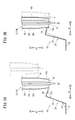
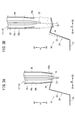
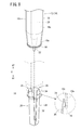
- FIG. 2A and 2B are explanatory views showing the operation (sputter removal method) of the sputter removal apparatus of FIG. 3A and 3B are explanatory views showing the operation of the spatter removal device of FIG.
- the spatter removing device 10 is a device for removing the spatter 16 adhering to the nozzle 12 in a welding device 14 using a nozzle 12 by a welding operation for an object to be welded. is there.
- the target nozzle 12 of the spatter removing device 10 is, for example, a nozzle of an arc welding device such as MAG (Metal Active Gas) welding or MIG (Metal Inert Gas) welding, or a nozzle of a laser welding device.
- the nozzle 12 extends in the A direction (vertical direction in FIG. 1) and has a cylindrical nozzle body 18 having an opening at a tip portion 18a in the A1 direction (downward direction in FIG. 1), and an A direction inside the nozzle body 18. And a contact chip 20 extending to the.
- the contact tip 20 guides the wire 22 as a welding electrode pulled out from a reel (not shown) in the A1 direction.
- FIGS. 2A to 3B as an example, a case is shown in which the tip of the contact tip 20 on the A1 direction side projects from the tip 18a of the nozzle body 18 in the A1 direction.
- the tip of the contact tip 20 may be substantially flush with the tip 18 a of the nozzle body 18, or the tip of the contact tip 20 may be recessed inward of the nozzle body 18.
- a workpiece for example, a frame of a vehicle body
- a tip portion 18a of the nozzle body 18 are opposed to each other, and the workpiece and the wire 22 are connected.
- the wire 22 is energized in the state of being in contact with.
- the work and the wire 22 are separated to generate an arc, and the work and the wire 22 are melted and joined by the heat of the arc.
- a part of the molten metal may scatter and adhere to the tip portion 18a of the nozzle body 18.
- the spatter 16 may adhere to the tip portion 18a of the nozzle body 18 as an annular deposit.
- the spatter 16 is deposited on the tip portion 18a of the nozzle body 18, it becomes difficult to inject the shield gas from the tip portion 18a.
- blowholes are generated in the weld beads formed on the work.
- the flow of the shield gas bends and the arc bends, which causes welding deviation.
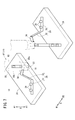
- the spatter removal device 10 includes a base plate 24 and a plurality of metal leaf springs 26 arranged on the base plate 24.
- the base plates 24 are respectively arranged on the B1 direction (rearward direction in FIG. 1) side and the B2 direction (frontward direction in FIG. 1) side, and each of the two base plates 24 includes two leaf springs.
- the case where 26 is arranged is illustrated.
- the A direction and the B direction may be directions that intersect with each other.
- the spatter removing device 10 is installed in an empty space in which the nozzle 12 can move.
- the two base plates 24 can be installed in any arrangement relationship (for example, diagonal arrangement) as long as the leaf spring 26 can contact the tip portion 18a of the nozzle body 18 when removing the spatter 16. is there.
- the case where the A direction is the up-down direction and the B direction is the front-rear direction will be described according to the illustration content of FIG. 1.
- the leaf spring 26 extends obliquely upward from the base end portion 30 fixed to the base plate 24 with a bolt 28, and has an elastically deformable bending portion 32, and an inclination obliquely downward from the tip of the bending portion 32. And a distal end portion 34 that extends in a vertical direction.
- the angle ⁇ 1 formed by the base end portion 30 and the bending portion 32 is a right angle or an obtuse angle
- the angle ⁇ 2 formed by the bending portion 32 and the tip end portion 34 is substantially a right angle.
- the two plate springs 26 are arranged on the base plate 24 arranged on the B1 direction side so that the tip ends 34 of the two plate springs 26 are close to each other toward the B2 direction. There is. Further, the two plate springs 26 are arranged on the base plate 24 arranged on the B2 direction side such that the tip ends 34 of the two plate springs 26 are close to each other in the B1 direction.
- the two leaf springs 26 of the base plate 24 on the B1 direction side and the two leaf springs 26 of the base plate 24 on the B2 direction side are arranged so that their tip portions 34 face each other.
- the tip ends 34 of the two leaf springs 26 of the one base plate 24 and the tip portions 34 of the two leaf springs 26 of the other base plate 24 face in different directions from each other. Should be placed. Therefore, the present embodiment is not limited to the facing arrangement configuration as shown in FIG. 1, but for example, two base plates 24 are arranged side by side, and the tip ends 34 of the two leaf springs 26 of each base plate 24 are arranged in opposite directions. It is also possible to arrange each leaf spring 26 so that it may face.
- the tip end portions 34 of the two leaf springs 26 arranged on each of the two base plates 24 of the nozzle body 18 contact. It extends from the tip of the bending portion 32 so as to be directed to the tip portion 18a. Further, the tip end portions 34 of the two leaf springs 26 extend from the flexure portion 32 so that the flexure portion 32 supporting the tip end portion 34 bends when abutting on the side wall of the nozzle 12. Further, the base end portions 30 of the two leaf springs 26 are positioned at predetermined positions on the upper surface of the base plate 24 by the plurality of pin members 36.
- the welding device 14 causes the nozzle 12 to approach the tip end portion 34 of the leaf spring 26, as shown in FIG. 2A, by using an unillustrated moving means such as a robot arm.
- the axial direction of the nozzle body 18 is the A direction
- the tip position of the nozzle body 18, more specifically, the position of the spatter 16 adhering to the tip portion 18 a of the nozzle body 18, is the tip portion 34 of the leaf spring 26.
- the nozzle 12 is brought close to the tip end portion 34 of the leaf spring 26 so as to be slightly on the A1 direction side (downward) from the tip end position.
- the moving means moves the nozzle 12 in the B1 direction so that the outer peripheral surface 18b (side wall of the nozzle 12) of the nozzle body 18 is attached to the tip end 34a of the leaf spring 26. Abut.
- the tip portion 34 of the leaf spring 26 is pushed by the pressing force from the tip portion 18a side of the outer peripheral surface 18b of the nozzle body 18 to the tip portion 34 of the leaf spring 26,
- the bending portion 32 bends in the B1 direction with a connection point between the base end portion 30 and the bending portion 32 as a fulcrum.
- the tip end portion 34 of the leaf spring 26 is displaced (retreated) obliquely rearward and upward in the B1 direction.
- the moving means moves the nozzle 12 in the A2 direction (upward, which is the direction of the base end side of the nozzle 12).
- the tip portion 18a of the nozzle body 18 has a shape that tapers gradually in the A1 direction. Therefore, as the nozzle 12 moves in the A2 direction, the bending portion 32 of the leaf spring 26 gradually returns in the B2 direction with the connection point between the base end portion 30 and the bending portion 32 as a fulcrum. As a result, the tip portion 34 of the leaf spring 26 is gradually displaced forward and obliquely downward in the B2 direction. After that, when the tip portion 34 of the leaf spring 26 reaches the tip position of the nozzle body 18, the tip portion 34 of the leaf spring 26 bites between the tip position of the nozzle body 18 and the spatter 16.
- the tip portion 34 of the leaf spring 26 is released from the pressed state from the nozzle body 18.
- the bending portion 32 of the leaf spring 26 returns to the B2 direction at once by the spring reaction force with the connection point between the base end portion 30 and the bending portion 32 as a fulcrum.
- a force directed obliquely downward and forward is applied to the sputter 16 from the tip portion 34 of the leaf spring 26, and the sputter 16 is caused by the force from the tip portion 34 of the leaf spring 26 and the movement of the nozzle 12 in the A2 direction.
- the tip end portion 18a of the nozzle body 18 is scraped off with the B2 direction side of the tip end position of the nozzle body 18 as a fulcrum.
- one leaf spring 26 arranged on the base plate 24 on the B1 direction side in FIG. 1 is used to act from the tip portion 34 of the leaf spring 26 to the portion of the sputter 16 on the B1 direction side.
- the case where the spatter 16 is scraped off from the tip portion 18a of the nozzle body 18 by force has been described. Since the two leaf springs 26 are arranged on the base plate 24 on the B1 direction side, the spatter 16 can be efficiently scraped off from the tip portion 18a of the nozzle body 18 by one removal work of the spatter 16.
- the force acting from the tip portion 34 of the leaf spring 26 disposed on the base plate 24 on the B1 direction side of FIG. 1 to the portion of the sputter 16 on the B1 direction side causes the tip portion 18a of the nozzle body 18 to move.
- the spatter 16 is scraped off. Therefore, the portion of the sputter 16 on the B2 direction side may remain on the tip portion 18a of the nozzle body 18.
- the two leaf springs 26 arranged on the base plate 24 on the B2 direction side shown in FIG. 1 may be used to scrape off the portion of the sputter 16 on the B2 direction side.
- "B1 direction” is replaced with “B2 direction”
- "B2 direction” is replaced with “B1 direction”
- "front” is replaced with “rear”
- "rear” is replaced with “rear”. If it is replaced with "front”, the operation of removing the spatter 16 by the two leaf springs 26 arranged on the base plate 24 on the B2 direction side will be described.
- the spatter 16 is scraped off by using the two leaf springs 26 arranged on the base plate 24 on the B2 direction side, and the sputter using the two leaf springs 26 arranged on the base plate 24 on the B1 direction side is cut off.
- the spatter 16 adhering to the tip portion 18a of the nozzle body 18 can be removed in a short time without unevenness. For example, when performing arc welding on a plurality of places of a work, every time the arc welding is performed a predetermined number of times, two leaf springs 26 on the B2 direction side and two leaf springs 26 on the B1 direction side are alternately sputtered. If the work of removing 16 is performed, the maintainability of the welding device 14 including the nozzle 12 is improved.
- the above description is about the removal work of the spatter 16 at an angle around the axis of the nozzle 12 where the tip end 18a side of the outer peripheral surface 18b of the nozzle body 18 and the leaf spring 26 face each other. Therefore, when the sputter 16 remains at another angle, the moving means may rotate the nozzle 12 around the axis to face the remaining sputter 16 and the leaf spring 26. As a result, the work of removing the remaining spatter 16 can be efficiently performed.
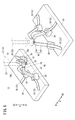
- the first modification shown in FIG. 4 is different from the embodiment of FIGS. 1 to 3B in that the number of leaf springs 26 that scrape off the sputter 16 is increased in one removal operation of the sputter 16.
- the tip end portions 34 of the leaf springs 26 are arranged close to each other so that the tip end portions 34 of the leaf springs 26 abut on the tip end portion 18a side of the outer peripheral surface 18b of the nozzle body 18.
- the tip end portion 34 of each leaf spring 26 can be caught and caught between the tip end position of the nozzle body 18 and the spatter 16 during the removal work of the spatter 16.
- the removal efficiency of the spatter 16 is further improved.
- a plurality of block-shaped base end portions 30 are arranged on the base plate 24, and each of the plurality of leaf springs 26 is fixed to the base end portion 30. Different from the case of 4. Therefore, the plurality of leaf springs 26 are configured by the bending portion 32 and the tip portion 34. In the second modified example, since the leaf spring 26 is bent at one location, the cost of the leaf spring 26 can be reduced.
- the bending portion 32 which is the leaf spring 26, and the claw member 40 having the tip portion 34 are connected via the connecting mechanism 38 arranged on the base plate 24.
- the bending portion 32 is a leaf spring 26, one end of which is in contact with the upper surface of the base plate 24 and the other end of which is curved upward by the connecting mechanism 38.
- the claw member 40 has a connecting portion 42 extending obliquely upward from the connecting mechanism 38, and a claw-shaped tip portion 34 extending obliquely downward from the connecting portion 42.
- the connecting portion 42 is supported by the connecting mechanism 38 at the other end of the bending portion 32.
- the tip portion 34 of the claw member 40 comes into contact with the tip portion 18a side of the outer peripheral surface 18b of the nozzle body 18 during the removal work of the spatter 16, the pressing force from the nozzle body 18 to the claw member 40 is transmitted to the bending portion 32.
- the other end of the bending portion 32 is further curved.
- the tip portion 34 of the claw member 40 bites between the tip position of the nozzle body 18 and the spatter 16.
- the spring reaction force of the bending portion 32 causes the claw member 40 to bend. It is displaced diagonally downward with the connection point between 32 and the connection portion 42 as a fulcrum. Thereby, the spatter 16 can be scraped off from the tip portion 18a of the nozzle body 18.
- the bending portion 32 and the claw member 40 are separate members.
- the claw member 40 can be made of a material having a high hardness, and the bending portion 32 can be made of a material having a large spring reaction force. This makes it possible to remove the spatter 16 reliably and efficiently. Further, the bending portion 32 or the claw member 40 can be appropriately replaced depending on wear such as wear.
- the leaf spring 26 is composed of a base end portion 30 and a bending portion 32, and a tip portion 34 which is a claw member is attached to the tip of the bending portion 32. It differs from the case of FIG. That is, in the fourth modified example, the leaf spring 26 and the tip portion 34 are separate members. In this case, for example, the leaf spring 26 is made of a material having a large spring reaction force, and the tip portion 34 is made of a material having a high hardness. As a result, the spatter 16 can be reliably removed, and only the tip portion 34 can be replaced.
- the plurality of leaf springs 26 have a bending portion 32 extending in the A direction and a claw-shaped tip portion 34 extending upward from the bending portion 32.
- the claw-shaped tip portions 34 and the inner peripheral surface 18 c (side wall of the nozzle 12) of the nozzle body 18 are located on the tip portion 18 a side.
- the nozzle bodies 18 are arranged so as to face each other at predetermined angular intervals (approximately 90° intervals in FIG. 8) around the axis of the nozzle body 18.
- the claw portion projects slightly outward (radially outside the nozzle body 18) from the tip end position of the nozzle body 18.
- the tip end portions 34 of the plurality of leaf springs 26 come into contact with the tip end positions of the nozzle body 18.
- the pressing force from the nozzle body 18 to the tip portions 34 of the plurality of leaf springs 26 is the force in the direction along the inclined surface of the claw portion of the tip portions 34 and the tip portions. It is decomposed into a force in a direction orthogonal to the inclined surface of the claw portion of the portion 34 (a force directed inward in the radial direction of the nozzle body 18).
- the tip end portion 34 and the bending portion 32 of the leaf spring 26 are bent inward in the radial direction. In this manner, the tip end portions 34 and the bending portions 32 of the plurality of leaf springs 26 are bent inward in the radial direction of the nozzle body 18, and the tip end portions 34 of the plurality of leaf springs 26 are located inside the nozzle body 18. Is inserted.
- the tip portions 34 of the plurality of leaf springs 26 bite between the tip position of the nozzle body 18 and the spatter 16 at the tip position of the nozzle body 18. After that, when the nozzle 12 further moves in the A2 direction and the plurality of leaf springs 26 are released from the pressing force of the nozzle body 18, the tip end portions 34 of the leaf springs 26 are directed outward in the radial direction of the nozzle body 18. The sputter 16 is scraped off from the tip portion 18 a of the nozzle body 18 by the spring reaction force of the bending portion 32.
- the spatter removing device 10 may be moved with respect to the nozzle 12. That is, in the spatter removing device 10, by moving the nozzle 12 relative to the tip portion 34, it is possible to scrape off the spatter 16 adhering to the tip portion 18 a of the nozzle body 18.
- the tip portion 18a side of the nozzle body 18 has a shape that tapers gradually in the A1 direction.
- the spatter 16 adhering to the tip portion 18a of the nozzle body 18 can be scraped off.
- a spring other than the leaf spring 26, for example, a torsion spring may be used to cause the tip portion 34 to bite between the tip position of the nozzle body 18 and the sputter 16.
- the spatter removal device 10 includes the elastically deformable bending portion 32 and the outer peripheral surface 18b or the inner peripheral surface 18c of the nozzle body 18 that is supported by the bending portion 32 and that constitutes the nozzle 12. (A side wall of the nozzle 12) has a tip portion 34 that can come into contact with the tip portion 18a side. In this case, the tip end portion 18a side of the outer peripheral surface 18b or the inner peripheral surface 18c of the nozzle body 18 abuts the tip portion 34 of the spatter removing device 10 due to the relative movement of the nozzle 12 by the welding device 14, and the outer peripheral surface 18b or the inner surface 18b.
- the bending portion 32 bends due to the pressing force applied from the peripheral surface 18c to the tip portion 34, and the bending of the bending portion 32 is caused by the relative movement of the nozzle 12 by the welding device 14 in the A2 direction (direction toward the base end side of the nozzle 12).
- the spatter 16 adhering to the tip end portion 18a of the nozzle body 18 is scraped off from the nozzle 12 by the tip end portion 34 of the spatter removing device 10.
- the tip portion 34 supported by the elastically deformable bending portion 32 can abut the tip portion 18a side of the outer peripheral surface 18b or the inner peripheral surface 18c of the nozzle body 18.
- the outer peripheral surface 18b or the inner peripheral surface 18c is brought into contact with the tip portion 34 of the spatter removing device 10 by the relative movement of the nozzle 12 by the welding device 14, and the outer peripheral surface 18b or the inner peripheral surface 18c.
- the bending portion 32 is bent by the pressing force from 18c to the tip portion 34 of the spatter removing device 10.
- the spatter 16 adhering to the tip portion 18a of the nozzle body 18 is removed by the spatter removing device by the action of elastic deformation of the bending portion 32 and the action of moving the nozzle 12 by the welding device 14 without separately installing a drive source.
- the tip portion 34 of 10 scrapes off.
- the spatter 16 adhering to the nozzle 12 of the welding device 14 can be scraped off economically and easily without complicating the device structure.
- the spatter removal device 10 can be configured at low cost.
- the tip portion 34 of the spatter removal device 10 extends from the bending portion 32 so as to be directed to the tip portion 18a of the nozzle body 18 when abutting on the tip portion 18a side of the outer peripheral surface 18b of the nozzle body 18.
- the tip end portion 34 of the spatter removal device 10 is likely to bite between the tip end portion 18 a of the nozzle body 18 and the spatter 16. Thereby, the spatter 16 can be easily scraped off, and the removal efficiency of the sputter 16 can be improved.
- the bending portion 32 and the tip portion 34 may be integrally formed, or at least one of the bending portion 32 and the tip portion 34 may be replaceable. If the flexible portion 32 and the tip portion 34 are integrally configured, the number of parts can be reduced and a simple configuration can be realized. Further, if at least one of the bending portion 32 and the tip end portion 34 is replaceable, it is only necessary to replace the component that is consumed due to wear or the like, so that the maintainability is improved.
Landscapes
- Engineering & Computer Science (AREA)
- Physics & Mathematics (AREA)
- Plasma & Fusion (AREA)
- Mechanical Engineering (AREA)
- Arc Welding In General (AREA)
Abstract
スパッタ除去装置(10)及びスパッタ除去方法において、溶接装置(14)によるノズル(12)の相対的な移動により、ノズル本体(18)の外周面(18b)を板ばね(26)の先端部(34)に当接させ、外周面(18b)から先端部(34)への押圧力で撓み部(32)を撓ませる。次に、溶接装置(14)によるノズル(12)のA2方向への相対的な移動により、撓み部(32)の撓みを戻した際に、ノズル本体(18)の先端位置に付着したスパッタ(16)を先端部(34)でノズル(12)から削ぎ落す。
Description
本発明は、溶接装置のノズルに付着したスパッタを除去するスパッタ除去装置及びスパッタ除去方法に関する。
例えば、特許第3940302号公報には、溶接装置の溶接トーチの先端部に取り付けたノズルの内部に付着するスパッタを、カッタを用いて除去するスパッタ除去装置が開示されている。
しかしながら、特許第3940302号公報の技術では、溶接装置とは別途の駆動源を用いてノズルを移動させることで、スパッタを除去するノズルの部位を移動させる必要がある。この結果、装置の構成が複雑になると共に、駆動源の設置費用がかかるので、経済的ではない。
本発明は、このような課題を考慮してなされたものであり、複雑な構成にすることなく、経済的に、溶接装置のノズルに付着したスパッタを削ぎ落すことができるスパッタ除去装置及びスパッタ除去方法を提供することを目的とする。
本発明の態様は、溶接装置のノズルに付着したスパッタを除去するスパッタ除去装置及びスパッタ除去方法に関する。
前記スパッタ除去装置は、弾性変形可能な撓み部と、前記撓み部に支持され、前記ノズルの側壁に当接可能な先端部とを有する。この場合、前記溶接装置による前記ノズルの相対的な移動により、前記側壁が前記先端部に当接して、前記側壁から前記先端部への押圧力で前記撓み部が撓み、前記溶接装置による前記ノズルの該ノズルの基端側の方向への相対的な移動により、前記撓み部の撓みが戻る際に、前記ノズルの先端側に付着した前記スパッタを前記先端部で前記ノズルから削ぎ落す。
前記スパッタ除去方法では、弾性変形可能な撓み部に支持される先端部が前記ノズルの側壁に当接可能であるスパッタ除去装置を用いて、前記溶接装置による前記ノズルの相対的な移動により、前記側壁を前記先端部に当接させ、前記側壁から前記先端部への押圧力で前記撓み部を撓ませる。次に、前記溶接装置による前記ノズルの該ノズルの基端側の方向への相対的な移動により、前記撓み部の撓みを戻した際に、前記ノズルの先端側に付着した前記スパッタを前記先端部で前記ノズルから削ぎ落す。
本発明によれば、駆動源を別途設置することなく、撓み部の弾性変形の作用と、溶接装置によるノズルの移動作用とによって、ノズルの先端側に付着したスパッタをスパッタ除去装置の先端部で削ぎ落す。これにより、装置構成を複雑にすることなく、経済的且つ容易に、溶接装置のノズルに付着したスパッタを削ぎ落すことができる。
以下、本発明に係るスパッタ除去装置及びスパッタ除去方法について好適な実施形態を例示し、添付の図面を参照しながら説明する。
[1.本実施形態の構成]
本実施形態に係るスパッタ除去装置10は、図1に示すように、ノズル12を用いた溶接装置14において、被溶接物に対する溶接作業によって該ノズル12に付着したスパッタ16を除去するための装置である。ここでは、スパッタ除去装置10の説明に先立ち、ノズル12の構成について説明する。なお、スパッタ除去装置10の対象となるノズル12としては、例えば、MAG(Metal Active Gas)溶接、MIG(Metal Inert Gas)溶接等のアーク溶接装置のノズルや、レーザ溶接装置のノズルがある。
本実施形態に係るスパッタ除去装置10は、図1に示すように、ノズル12を用いた溶接装置14において、被溶接物に対する溶接作業によって該ノズル12に付着したスパッタ16を除去するための装置である。ここでは、スパッタ除去装置10の説明に先立ち、ノズル12の構成について説明する。なお、スパッタ除去装置10の対象となるノズル12としては、例えば、MAG(Metal Active Gas)溶接、MIG(Metal Inert Gas)溶接等のアーク溶接装置のノズルや、レーザ溶接装置のノズルがある。
<1.1 ノズル12の構成>
ノズル12は、A方向(図1では上下方向)に延び、A1方向(図1では下方向)側の先端部18aが開口する筒状のノズル本体18と、ノズル本体18の内方でA方向に延びるコンタクトチップ20とを備える。コンタクトチップ20は、不図示のリールから引き出された溶接電極としてのワイヤ22をA1方向に導く。なお、本実施形態では、図2A~図3Bに示すように、一例として、コンタクトチップ20のA1方向側の先端部がノズル本体18の先端部18aからA1方向に突出している場合を図示している。本実施形態では、コンタクトチップ20の先端部がノズル本体18の先端部18aと略面一であったり、又は、コンタクトチップ20の先端部がノズル本体18の内方に引っ込んでいてもよい。
ノズル12は、A方向(図1では上下方向)に延び、A1方向(図1では下方向)側の先端部18aが開口する筒状のノズル本体18と、ノズル本体18の内方でA方向に延びるコンタクトチップ20とを備える。コンタクトチップ20は、不図示のリールから引き出された溶接電極としてのワイヤ22をA1方向に導く。なお、本実施形態では、図2A~図3Bに示すように、一例として、コンタクトチップ20のA1方向側の先端部がノズル本体18の先端部18aからA1方向に突出している場合を図示している。本実施形態では、コンタクトチップ20の先端部がノズル本体18の先端部18aと略面一であったり、又は、コンタクトチップ20の先端部がノズル本体18の内方に引っ込んでいてもよい。
ここで、例えば、MAG溶接、MIG溶接等のアーク溶接作業では、被溶接物である不図示のワーク(例えば、車体のフレーム)とノズル本体18の先端部18aとを向かい合わせ、ワークとワイヤ22とを接触させた状態でワイヤ22に通電する。次に、ワークとワイヤ22とを引き離してアークを発生させ、アークの熱によってワークとワイヤ22とを溶融させて接合する。その際、溶融金属(スパッタ16)の一部が飛び散ってノズル本体18の先端部18aに付着する場合がある。
特に、ワークの複数個所に対してアーク溶接を行った場合、スパッタ16が円環状の付着物としてノズル本体18の先端部18aに付着することがある。ノズル本体18の先端部18aにスパッタ16が堆積すると、該先端部18aからのシールドガスの噴射が困難となる。この結果、ワークに形成される溶接ビードにブローホールが発生する。また、シールドガスの流れが曲がり、アークが曲がることで、溶接ずれが発生する。
<1.2 スパッタ除去装置10の構成>
本実施形態に係るスパッタ除去装置10は、ベースプレート24と、ベースプレート24に配置された金属製の複数の板ばね26とを備える。図1では、一例として、B1方向(図1では後方向)側とB2方向(図1では前方向)側とにベースプレート24がそれぞれ配置され、2つのベースプレート24の各々には、2つの板ばね26が配置されている場合を図示している。
本実施形態に係るスパッタ除去装置10は、ベースプレート24と、ベースプレート24に配置された金属製の複数の板ばね26とを備える。図1では、一例として、B1方向(図1では後方向)側とB2方向(図1では前方向)側とにベースプレート24がそれぞれ配置され、2つのベースプレート24の各々には、2つの板ばね26が配置されている場合を図示している。
なお、本実施形態において、A方向及びB方向は、互いに交差する方向であればよい。後述するように、ロボットのアーム等の不図示の移動手段を用いて、溶接装置14がノズル12を移動させる場合、スパッタ除去装置10は、ノズル12が移動可能な空きスペースに設置される。この場合、2つのベースプレート24は、スパッタ16を除去する際、ノズル本体18の先端部18aに板ばね26が当接可能であれば、どのような配置関係(例えば、斜め配置)でも設置可能である。以下の説明では、図1の図示内容に従って、A方向が上下方向、B方向が前後方向である場合について説明する。
板ばね26は、ボルト28によってベースプレート24に固定された基端部30と、基端部30から斜め上方に延び、弾性変形可能な撓み部32と、撓み部32の先端から斜め下方に傾斜して延びる先端部34とを有する。図2Aに示すように、基端部30と撓み部32との成す角度θ1は直角又は鈍角であり、撓み部32と先端部34との成す角度θ2は略直角であることが望ましい。また、図1に示すように、B1方向側に配置されたベースプレート24には、2つの板ばね26の先端部34がB2方向に向かって互いに近接するように2つの板ばね26が配置されている。また、B2方向側に配置されたベースプレート24には、2つの板ばね26の先端部34がB1方向に向かって互いに近接するように2つの板ばね26が配置されている。
なお、図1において、B1方向側のベースプレート24の2つの板ばね26と、B2方向側のベースプレート24の2つの板ばね26とは、先端部34が互いに向かい合うように配置されている。本実施形態では、一方のベースプレート24の2つの板ばね26の先端部34と、他方のベースプレート24の2つの板ばね26の先端部34とが、互いに異なる方向を向くように、各板ばね26が配置されていればよい。従って、本実施形態では、図1のような向い合わせの配置構成に限らず、例えば、2つのベースプレート24を並べて配置し、各ベースプレート24の2つの板ばね26の先端部34が互いに逆方向に向くように各板ばね26を配置することも可能である。
2つのベースプレート24の各々に配置された2つの板ばね26の先端部34は、ノズル12が接近し、ノズル12の側壁(ノズル本体18の外周面18b)が当接する際に、ノズル本体18の先端部18aに指向するように、撓み部32の先端から延在している。また、2つの板ばね26の先端部34は、ノズル12の側壁に当接した際に、該先端部34を支持する撓み部32が撓むように、該撓み部32から延在している。さらに、2つの板ばね26の基端部30は、複数のピン部材36によってベースプレート24の上面の所定位置に位置決めされている。
[2.本実施形態の動作]
次に、本実施形態に係るスパッタ除去装置10の動作(スパッタ除去方法)について、図2A~図3Bを参照しながら説明する。なお、この動作説明では、必要に応じて、図1を参照しながら説明する。ここでは、代表的に、図1のB1方向側のベースプレート24に配置された2つの板ばね26のうち、一方の板ばね26によるスパッタ16の除去作業について説明する。
次に、本実施形態に係るスパッタ除去装置10の動作(スパッタ除去方法)について、図2A~図3Bを参照しながら説明する。なお、この動作説明では、必要に応じて、図1を参照しながら説明する。ここでは、代表的に、図1のB1方向側のベースプレート24に配置された2つの板ばね26のうち、一方の板ばね26によるスパッタ16の除去作業について説明する。
車体のフレーム等のワークの複数個所に対してアーク溶接を行うことで、ノズル本体18の先端部18aにスパッタ16が円環状に付着する。そこで、溶接装置14は、ロボットのアーム等の不図示の移動手段を用いて、図2Aに示すように、ノズル12を板ばね26の先端部34に接近させる。具体的に、ノズル本体18の軸方向がA方向で、ノズル本体18の先端位置、より詳しくは、ノズル本体18の先端部18aに付着したスパッタ16の位置が、板ばね26の先端部34の先端位置よりも僅かにA1方向側(下方)となるように、ノズル12を板ばね26の先端部34に接近させる。
次に、図2Bに示すように、移動手段は、ノズル12をB1方向に移動させ、ノズル本体18の外周面18b(ノズル12の側壁)の先端部18a側を板ばね26の先端部34に当接させる。そして、ノズル12をB1方向にさらに移動させると、ノズル本体18の外周面18bの先端部18a側から板ばね26の先端部34への押圧力によって、板ばね26の先端部34が押し込まれ、撓み部32は、基端部30と撓み部32との接続箇所を支点としてB1方向に撓む。この結果、板ばね26の先端部34は、B1方向に向かって、後方斜め上方に変位(後退)する。
次に、図3Aに示すように、移動手段は、ノズル12をA2方向(ノズル12の基端側の方向である上方)に移動させる。ノズル本体18の先端部18aは、A1方向に向かって徐々に先細りする形状である。そのため、ノズル12のA2方向への移動に伴って、板ばね26の撓み部32は、基端部30と撓み部32との接続箇所を支点としてB2方向に徐々に戻る。これにより、板ばね26の先端部34は、B2方向に向かって前方斜め下方に徐々に変位する。その後、板ばね26の先端部34がノズル本体18の先端位置に到達すると、板ばね26の先端部34がノズル本体18の先端位置とスパッタ16との間に喰い込む。
次に、図3Bに示すように、移動手段がノズル12をA2方向にさらに移動させると、板ばね26の先端部34は、ノズル本体18からの押圧状態から解放される。これにより、板ばね26の撓み部32は、基端部30と撓み部32との接続箇所を支点として、ばね反力により、B2方向に一気に戻る。この結果、板ばね26の先端部34からスパッタ16に前方斜め下方に向かう力が付与され、スパッタ16は、板ばね26の先端部34からの力と、ノズル12のA2方向への移動とによって、ノズル本体18の先端位置のB2方向側を支点として、ノズル本体18の先端部18aから削ぎ落される。
なお、上記の動作説明では、図1のB1方向側のベースプレート24に配置された1つの板ばね26を用いて、該板ばね26の先端部34からスパッタ16のB1方向側の部分に作用する力で、ノズル本体18の先端部18aからスパッタ16を削ぎ落す場合について説明した。B1方向側のベースプレート24には、2つの板ばね26が配置されているので、1回のスパッタ16の除去作業で、ノズル本体18の先端部18aからスパッタ16を効率よく削ぎ落すことができる。
また、上記の説明では、図1のB1方向側のベースプレート24に配置された板ばね26の先端部34からスパッタ16のB1方向側の部分に作用する力で、ノズル本体18の先端部18aからスパッタ16を削ぎ落す。そのため、スパッタ16のB2方向側の部分がノズル本体18の先端部18aに残存する可能性がある。
この場合、図1に示すB2方向側のベースプレート24に配置された2つの板ばね26を用いて、スパッタ16のB2方向側の部分を削ぎ落せばよい。この場合、前述した動作説明において、「B1方向」を「B2方向」に置換し、「B2方向」を「B1方向」に置換し、「前方」を「後方」に置換し、「後方」を「前方」に置換すれば、B2方向側のベースプレート24に配置された2つの板ばね26によるスパッタ16の除去作業の動作説明となる。
従って、図1において、B2方向側のベースプレート24に配置された2つの板ばね26を用いたスパッタ16の削ぎ落しと、B1方向側のベースプレート24に配置された2つの板ばね26を用いたスパッタ16の削ぎ落しとを交互に行えば、ノズル本体18の先端部18aに付着したスパッタ16を、偏りなく且つ短時間で除去することができる。例えば、ワークの複数個所に対してアーク溶接を行う場合、アーク溶接を所定回数実行する毎に、B2方向側の2つの板ばね26と、B1方向側の2つの板ばね26とで交互にスパッタ16の除去作業を行えば、ノズル12を含めた溶接装置14のメンテナンス性が向上する。
さらに、上記の説明は、ノズル12の軸回りのうち、ノズル本体18の外周面18bの先端部18a側と板ばね26とが向かい合う角度でのスパッタ16の除去作業である。従って、他の角度でスパッタ16が残存する場合、移動手段は、ノズル12を軸回りに回転させることで、残存するスパッタ16と板ばね26とを向かい合わせればよい。これにより、残存するスパッタ16に対する除去作業を効率よく行うことができる。
[3.変形例]
次に、本実施形態に係るスパッタ除去装置10の変形例(第1~第5変形例)について、図4~図8を参照しながら説明する。
次に、本実施形態に係るスパッタ除去装置10の変形例(第1~第5変形例)について、図4~図8を参照しながら説明する。
<3.1 第1変形例>
図4に示す第1変形例は、1回のスパッタ16の除去作業において、該スパッタ16を削ぎ落す板ばね26の数を増やした点で、図1~図3Bの実施形態とは異なる。この場合、各板ばね26の先端部34がノズル本体18の外周面18bの先端部18a側に当接するように、各板ばね26の先端部34が近接配置されている。これにより、第1変形例では、スパッタ16の除去作業の際、ノズル本体18の先端位置とスパッタ16との間に、各板ばね26の先端部34を引っ掛けて喰い込ませることができる。この結果、スパッタ16の除去効率がさらに向上する。
図4に示す第1変形例は、1回のスパッタ16の除去作業において、該スパッタ16を削ぎ落す板ばね26の数を増やした点で、図1~図3Bの実施形態とは異なる。この場合、各板ばね26の先端部34がノズル本体18の外周面18bの先端部18a側に当接するように、各板ばね26の先端部34が近接配置されている。これにより、第1変形例では、スパッタ16の除去作業の際、ノズル本体18の先端位置とスパッタ16との間に、各板ばね26の先端部34を引っ掛けて喰い込ませることができる。この結果、スパッタ16の除去効率がさらに向上する。
<3.2 第2変形例>
図5に示す第2変形例では、ベースプレート24に複数のブロック状の基端部30が配置され、複数の板ばね26の各々が基端部30に固定されている点で、図1~図4の場合とは異なる。従って、複数の板ばね26は、撓み部32及び先端部34によって構成される。第2変形例では、板ばね26の屈曲箇所が1箇所であるため、板ばね26のコストを削減することができる。
図5に示す第2変形例では、ベースプレート24に複数のブロック状の基端部30が配置され、複数の板ばね26の各々が基端部30に固定されている点で、図1~図4の場合とは異なる。従って、複数の板ばね26は、撓み部32及び先端部34によって構成される。第2変形例では、板ばね26の屈曲箇所が1箇所であるため、板ばね26のコストを削減することができる。
<3.3 第3変形例>
図6に示す第3変形例では、ベースプレート24に配置された連結機構38を介して、板ばね26である撓み部32と、先端部34を有する爪部材40とが連結されている。この場合、撓み部32は、一端がベースプレート24の上面に接触し、他端側が連結機構38によって上方に湾曲する板ばね26である。爪部材40は、連結機構38から斜め上方に延びる連結部42と、連結部42から斜め下方に延びる爪状の先端部34とを有する。連結部42は、連結機構38によって撓み部32の他端に支持されている。
図6に示す第3変形例では、ベースプレート24に配置された連結機構38を介して、板ばね26である撓み部32と、先端部34を有する爪部材40とが連結されている。この場合、撓み部32は、一端がベースプレート24の上面に接触し、他端側が連結機構38によって上方に湾曲する板ばね26である。爪部材40は、連結機構38から斜め上方に延びる連結部42と、連結部42から斜め下方に延びる爪状の先端部34とを有する。連結部42は、連結機構38によって撓み部32の他端に支持されている。
スパッタ16の除去作業の際、爪部材40の先端部34がノズル本体18の外周面18bの先端部18a側に当接すると、ノズル本体18から爪部材40への押圧力が撓み部32に伝わり、撓み部32の他端側がさらに湾曲する。その後、ノズル12のA2方向への移動によって、爪部材40の先端部34がノズル本体18の先端位置とスパッタ16との間に喰い込む。そして、ノズル12がA2方向にさらに移動して、爪部材40の先端部34がノズル本体18からの押圧力から解放されると、撓み部32のばね反力によって、爪部材40は、撓み部32と連結部42との連結箇所を支点として、斜め下方に変位する。これにより、ノズル本体18の先端部18aからスパッタ16を削ぎ落すことができる。
第3変形例では、撓み部32と爪部材40とが別部材である。これにより、爪部材40を硬度の高い材質とし、撓み部32をばね反力の大きな材質とすることができる。これにより、スパッタ16を確実に且つ効率よく除去することが可能となる。また、摩耗等の消耗に応じて、撓み部32又は爪部材40を適宜交換することが可能である。
<3.4 第4変形例>
図7に示す第4変形例では、板ばね26が基端部30及び撓み部32で構成され、撓み部32の先端に爪部材である先端部34が装着されている点で、図1~図6の場合とは異なる。すなわち、第4変形例では、板ばね26と先端部34とが別部材である。この場合、例えば、板ばね26をばね反力の大きな材質とし、先端部34を硬度の高い材質とする。これにより、スパッタ16を確実に除去することが可能になると共に、先端部34のみを交換することが可能となる。
図7に示す第4変形例では、板ばね26が基端部30及び撓み部32で構成され、撓み部32の先端に爪部材である先端部34が装着されている点で、図1~図6の場合とは異なる。すなわち、第4変形例では、板ばね26と先端部34とが別部材である。この場合、例えば、板ばね26をばね反力の大きな材質とし、先端部34を硬度の高い材質とする。これにより、スパッタ16を確実に除去することが可能になると共に、先端部34のみを交換することが可能となる。
<3.5 第5変形例>
図8に示す第5変形例では、A方向に延びる複数の板ばね26の先端部34をノズル本体18の内方に挿入し、ノズル12をA2方向に移動させた際、各板ばね26の先端部34によってノズル本体18の先端部18aに付着した円環状のスパッタ16を、ノズル本体18の内方から削ぎ落す点で、図1~図7の場合とは異なる。
図8に示す第5変形例では、A方向に延びる複数の板ばね26の先端部34をノズル本体18の内方に挿入し、ノズル12をA2方向に移動させた際、各板ばね26の先端部34によってノズル本体18の先端部18aに付着した円環状のスパッタ16を、ノズル本体18の内方から削ぎ落す点で、図1~図7の場合とは異なる。
第5変形例において、複数の板ばね26は、A方向に延びる撓み部32と、撓み部32から上方に延びる爪状の先端部34とを有する。具体的に、複数の板ばね26は、ノズル本体18の内方に挿入した際、爪状の各先端部34がノズル本体18の内周面18c(ノズル12の側壁)の先端部18a側と向かい合うように、ノズル本体18の軸回りに所定角度間隔(図8では、略90°間隔)で配置されている。また、複数の板ばね26の先端部34は、ノズル12から見たときに、爪部分がノズル本体18の先端位置よりも僅かに外方(ノズル本体18の径方向外側)に突出している。
この場合、移動手段によって、ノズル12をA1方向に移動させた際、複数の板ばね26の先端部34は、ノズル本体18の先端位置に当接する。ノズル12をA1方向にさらに移動させると、ノズル本体18から複数の板ばね26の先端部34への押圧力は、該先端部34の爪部分の傾斜面に沿った方向の力と、該先端部34の爪部分の傾斜面に直交する方向の力(ノズル本体18の径方向内側に向かう力)とに分解される。この径方向内側に向かう力によって、板ばね26の先端部34及び撓み部32は、該径方向内側に撓む。このように、複数の板ばね26の先端部34及び撓み部32がノズル本体18の径方向内側に撓んだ状態で、複数の板ばね26の先端部34は、ノズル本体18の内方に挿入される。
この状態で、ノズル12をA2方向に移動させると、ノズル本体18の先端位置において、複数の板ばね26の先端部34がノズル本体18の先端位置とスパッタ16との間に喰い込む。その後、ノズル12がA2方向にさらに移動して、複数の板ばね26がノズル本体18の押圧力から解放されると、各板ばね26の先端部34は、ノズル本体18の径方向外側に向かう撓み部32のばね反力によって、スパッタ16をノズル本体18の先端部18aから削ぎ落す。
第5変形例の場合でも、ノズル本体18の先端部18aに付着したスパッタ16を除去することが可能である。
<3.6 その他の変形例>
上記の説明では、スパッタ除去装置10に対してノズル12を移動させる場合について説明した。本実施形態では、ノズル12に対してスパッタ除去装置10を移動させてもよい。すなわち、スパッタ除去装置10では、先端部34に対してノズル12を相対的に移動させることにより、ノズル本体18の先端部18aに付着したスパッタ16を削ぎ落すことが可能である。
上記の説明では、スパッタ除去装置10に対してノズル12を移動させる場合について説明した。本実施形態では、ノズル12に対してスパッタ除去装置10を移動させてもよい。すなわち、スパッタ除去装置10では、先端部34に対してノズル12を相対的に移動させることにより、ノズル本体18の先端部18aに付着したスパッタ16を削ぎ落すことが可能である。
また、上記の説明では、ノズル本体18の先端部18a側がA1方向に向かって徐々に先細りする形状である場合について説明した。本実施形態では、ノズル本体18の先端部18a側がストレートな形状であっても、ノズル本体18の先端部18aに付着したスパッタ16を削ぎ落すことが可能である。
さらに、上記の説明では、主として、板ばね26の作用によって、ノズル本体18の先端位置とスパッタ16との間に先端部34を喰い込ませる場合について説明した。本実施形態では、板ばね26以外の他のばね、例えば、トーションばねを用いて先端部34をノズル本体18の先端位置とスパッタ16との間に喰い込ませることも可能である。
[4.本実施形態の効果]
以上説明したように、本実施形態に係るスパッタ除去装置10は、弾性変形可能な撓み部32と、撓み部32に支持され、ノズル12を構成するノズル本体18の外周面18b又は内周面18c(ノズル12の側壁)の先端部18a側に当接可能な先端部34とを有する。この場合、溶接装置14によるノズル12の相対的な移動により、ノズル本体18の外周面18b又は内周面18cの先端部18a側がスパッタ除去装置10の先端部34に当接し、外周面18b又は内周面18cから先端部34への押圧力で撓み部32が撓み、溶接装置14によるノズル12のA2方向(ノズル12の基端側の方向)への相対的な移動により、撓み部32の撓みが戻る際に、ノズル本体18の先端部18aに付着したスパッタ16をスパッタ除去装置10の先端部34でノズル12から削ぎ落す。
以上説明したように、本実施形態に係るスパッタ除去装置10は、弾性変形可能な撓み部32と、撓み部32に支持され、ノズル12を構成するノズル本体18の外周面18b又は内周面18c(ノズル12の側壁)の先端部18a側に当接可能な先端部34とを有する。この場合、溶接装置14によるノズル12の相対的な移動により、ノズル本体18の外周面18b又は内周面18cの先端部18a側がスパッタ除去装置10の先端部34に当接し、外周面18b又は内周面18cから先端部34への押圧力で撓み部32が撓み、溶接装置14によるノズル12のA2方向(ノズル12の基端側の方向)への相対的な移動により、撓み部32の撓みが戻る際に、ノズル本体18の先端部18aに付着したスパッタ16をスパッタ除去装置10の先端部34でノズル12から削ぎ落す。
また、本実施形態に係るスパッタ除去方法では、弾性変形可能な撓み部32に支持される先端部34がノズル本体18の外周面18b又は内周面18cの先端部18a側に当接可能であるスパッタ除去装置10を用いて、溶接装置14によるノズル12の相対的な移動により、外周面18b又は内周面18cをスパッタ除去装置10の先端部34に当接させ、外周面18b又は内周面18cからスパッタ除去装置10の先端部34への押圧力で撓み部32を撓ませる。次に、溶接装置14によるノズル12のA2方向への相対的な移動により、撓み部32の撓みを戻した際に、ノズル本体18の先端部18aに付着したスパッタ16をスパッタ除去装置10の先端部34でノズル12から削ぎ落す。
これにより、駆動源を別途設置することなく、撓み部32の弾性変形の作用と、溶接装置14によるノズル12の移動作用とによって、ノズル本体18の先端部18aに付着したスパッタ16をスパッタ除去装置10の先端部34で削ぎ落す。これにより、装置構成を複雑にすることなく、経済的且つ容易に、溶接装置14のノズル12に付着したスパッタ16を削ぎ落すことができる。
また、板ばね26の少なくとも一部を撓み部32として構成することにより、板ばね26のばね反力を利用して撓みを戻し、スパッタ16を削ぎ落すことが可能となる。これにより、低コストでスパッタ除去装置10を構成することができる。
また、スパッタ除去装置10の先端部34は、ノズル本体18の外周面18bの先端部18a側に当接する際に、ノズル本体18の先端部18aに指向するように、撓み部32から延びていれば、ノズル12を相対的に移動させた際に、ノズル本体18の先端部18aとスパッタ16との間にスパッタ除去装置10の先端部34が喰い込みやすくなる。これにより、スパッタ16を容易に削ぎ落すことができ、スパッタ16の除去効率を向上させることができる。
また、スパッタ除去装置10において、撓み部32及び先端部34が一体的に構成されているか、又は、撓み部32及び先端部34のうち、少なくとも1つが交換可能であればよい。撓み部32及び先端部34が一体的に構成されていれば、部品点数を削減して、簡素な構成を実現することができる。また、撓み部32及び先端部34のうち、少なくとも1つが交換可能とすれば、摩耗等で消耗した部品のみ交換すればよいので、メンテナンス性が向上する。
なお、本発明は、上述の実施形態に限らず、この明細書の記載内容に基づき、種々の構成を採り得ることは勿論である。
Claims (5)
- 溶接装置(14)のノズル(12)に付着したスパッタ(16)を除去するスパッタ除去装置(10)において、
弾性変形可能な撓み部(32)と、
前記撓み部に支持され、前記ノズルの側壁(18b、18c)に当接可能な先端部(34)と、
を有し、
前記溶接装置による前記ノズルの相対的な移動により、前記側壁が前記先端部に当接して、前記側壁から前記先端部への押圧力で前記撓み部が撓み、前記溶接装置による前記ノズルの該ノズルの基端側の方向への相対的な移動により、前記撓み部の撓みが戻る際に、前記ノズルの先端(18a)側に付着した前記スパッタを前記先端部で前記ノズルから削ぎ落す、スパッタ除去装置。 - 請求項1記載のスパッタ除去装置において、
板ばね(26)の少なくとも一部が前記撓み部として構成される、スパッタ除去装置。 - 請求項1又は2記載のスパッタ除去装置において、
前記先端部は、前記ノズルの側壁に当接する際に、前記ノズルの先端に指向するように、前記撓み部から延びている、スパッタ除去装置。 - 請求項1~3のいずれか1項に記載のスパッタ除去装置において、
前記撓み部及び前記先端部が一体的に構成されているか、又は、前記撓み部及び前記先端部のうち、少なくとも1つが交換可能である、スパッタ除去装置。 - 溶接装置のノズルに付着したスパッタを除去するスパッタ除去方法において、
弾性変形可能な撓み部に支持される先端部が前記ノズルの側壁に当接可能であるスパッタ除去装置を用いて、
前記溶接装置による前記ノズルの相対的な移動により、前記側壁を前記先端部に当接させ、前記側壁から前記先端部への押圧力で前記撓み部を撓ませ、
前記溶接装置による前記ノズルの該ノズルの基端側の方向への相対的な移動により、前記撓み部の撓みを戻した際に、前記ノズルの先端側に付着した前記スパッタを前記先端部で前記ノズルから削ぎ落す、スパッタ除去方法。
Priority Applications (1)
| Application Number | Priority Date | Filing Date | Title |
|---|---|---|---|
| JP2020562328A JP7012882B2 (ja) | 2018-12-28 | 2019-07-26 | スパッタ除去装置及びスパッタ除去方法 |
Applications Claiming Priority (2)
| Application Number | Priority Date | Filing Date | Title |
|---|---|---|---|
| JP2018247097 | 2018-12-28 | ||
| JP2018-247097 | 2018-12-28 |
Publications (1)
| Publication Number | Publication Date |
|---|---|
| WO2020136966A1 true WO2020136966A1 (ja) | 2020-07-02 |
Family
ID=71125781
Family Applications (1)
| Application Number | Title | Priority Date | Filing Date |
|---|---|---|---|
| PCT/JP2019/029361 Ceased WO2020136966A1 (ja) | 2018-12-28 | 2019-07-26 | スパッタ除去装置及びスパッタ除去方法 |
Country Status (2)
| Country | Link |
|---|---|
| JP (1) | JP7012882B2 (ja) |
| WO (1) | WO2020136966A1 (ja) |
Citations (4)
| Publication number | Priority date | Publication date | Assignee | Title |
|---|---|---|---|---|
| JPH0342153B2 (ja) * | 1984-11-05 | 1991-06-26 | ||
| JP2593953Y2 (ja) * | 1993-03-02 | 1999-04-19 | 義孝 藤井 | ガスシールドアーク溶接用トーチのスパッタ除去装置 |
| EP1772671A1 (de) * | 2005-10-08 | 2007-04-11 | INPRO Innovationsgesellschaft für fortgeschrittene Produktionssysteme in der Fahrzeugindustrie mbH | Reinigungsstation für einen robotergestützten oder automatisierten Brenner |
| US20180015562A1 (en) * | 2015-01-31 | 2018-01-18 | Audi Ag | Cleaning device for mechanically cleaning a gas nozzle of a gas-shielded welding torch |
-
2019
- 2019-07-26 JP JP2020562328A patent/JP7012882B2/ja active Active
- 2019-07-26 WO PCT/JP2019/029361 patent/WO2020136966A1/ja not_active Ceased
Patent Citations (4)
| Publication number | Priority date | Publication date | Assignee | Title |
|---|---|---|---|---|
| JPH0342153B2 (ja) * | 1984-11-05 | 1991-06-26 | ||
| JP2593953Y2 (ja) * | 1993-03-02 | 1999-04-19 | 義孝 藤井 | ガスシールドアーク溶接用トーチのスパッタ除去装置 |
| EP1772671A1 (de) * | 2005-10-08 | 2007-04-11 | INPRO Innovationsgesellschaft für fortgeschrittene Produktionssysteme in der Fahrzeugindustrie mbH | Reinigungsstation für einen robotergestützten oder automatisierten Brenner |
| US20180015562A1 (en) * | 2015-01-31 | 2018-01-18 | Audi Ag | Cleaning device for mechanically cleaning a gas nozzle of a gas-shielded welding torch |
Also Published As
| Publication number | Publication date |
|---|---|
| JP7012882B2 (ja) | 2022-01-28 |
| JPWO2020136966A1 (ja) | 2021-09-27 |
Similar Documents
| Publication | Publication Date | Title |
|---|---|---|
| US10058949B2 (en) | Resistance spot welding steel and aluminum workpieces using insertable cover | |
| CN102451954B (zh) | 工件支架清扫装置 | |
| US6380514B1 (en) | Automatic welding system for cylinder block recycling | |
| JP6480942B2 (ja) | 耐久性が改善された溶接トーチアセンブリおよび構成部品 | |
| EP1388389A1 (en) | A removable nozzle for a welding gun | |
| US20140158669A1 (en) | Dabbing pulsed welding system and method | |
| JP5499577B2 (ja) | レーザー溶接装置 | |
| KR102207831B1 (ko) | 점 접합 장치, 점 접합 방법 및 이음 구조 | |
| US20140131323A1 (en) | Head assembly for multi-wire submerged arc welding (saw) | |
| KR20200042855A (ko) | 용접 또는 적층 가공 이중 와이어 구동 시스템 | |
| JP2017530009A (ja) | 2つの入口と1つの出口を有する多消耗材送達トーチ用のマニホルド;消耗材送達トーチおよびシステム | |
| US20200306874A1 (en) | Friction stir welding tool | |
| JP7012882B2 (ja) | スパッタ除去装置及びスパッタ除去方法 | |
| JP2020082091A (ja) | 溶接用電極加工具および溶接用電極加工装置並びに溶接用電極加工方法 | |
| JP5061019B2 (ja) | アーク溶接方法 | |
| US11267070B2 (en) | Coupling device | |
| JP2011136359A (ja) | 溶接用棒状電極の自動交換用ホルダ | |
| KR20190121420A (ko) | 프론트 로더 퀵 조인트 및 이를 포함하는 프론트 로더 | |
| US7244911B2 (en) | Alignment mechanism for a welding torch | |
| JP4412654B2 (ja) | キャップチップ取外し装置 | |
| KR20220045770A (ko) | 용접용 토치 노즐 및 용접 로봇 | |
| US20200306875A1 (en) | Friction stir welding tool | |
| WO1983001919A1 (en) | Contact tip for a welding head | |
| JPH11347732A5 (ja) | 溶接ロボットの溶接開始点制御方法および溶接ロボット | |
| CN214382969U (zh) | 焊咀修复装置 |
Legal Events
| Date | Code | Title | Description |
|---|---|---|---|
| 121 | Ep: the epo has been informed by wipo that ep was designated in this application |
Ref document number: 19905908 Country of ref document: EP Kind code of ref document: A1 |
|
| ENP | Entry into the national phase |
Ref document number: 2020562328 Country of ref document: JP Kind code of ref document: A |
|
| NENP | Non-entry into the national phase |
Ref country code: DE |
|
| 122 | Ep: pct application non-entry in european phase |
Ref document number: 19905908 Country of ref document: EP Kind code of ref document: A1 |