WO2020136945A1 - 境界位置判定装置および方法 - Google Patents
境界位置判定装置および方法 Download PDFInfo
- Publication number
- WO2020136945A1 WO2020136945A1 PCT/JP2019/023876 JP2019023876W WO2020136945A1 WO 2020136945 A1 WO2020136945 A1 WO 2020136945A1 JP 2019023876 W JP2019023876 W JP 2019023876W WO 2020136945 A1 WO2020136945 A1 WO 2020136945A1
- Authority
- WO
- WIPO (PCT)
- Prior art keywords
- boundary
- layer
- liquid
- receiver
- deposition
- Prior art date
- Legal status (The legal status is an assumption and is not a legal conclusion. Google has not performed a legal analysis and makes no representation as to the accuracy of the status listed.)
- Ceased
Links
Images


Classifications
-
- G—PHYSICS
- G01—MEASURING; TESTING
- G01F—MEASURING VOLUME, VOLUME FLOW, MASS FLOW OR LIQUID LEVEL; METERING BY VOLUME
- G01F23/00—Indicating or measuring liquid level or level of fluent solid material, e.g. indicating in terms of volume or indicating by means of an alarm
- G01F23/22—Indicating or measuring liquid level or level of fluent solid material, e.g. indicating in terms of volume or indicating by means of an alarm by measuring physical variables, other than linear dimensions, pressure or weight, dependent on the level to be measured, e.g. by difference of heat transfer of steam or water
- G01F23/28—Indicating or measuring liquid level or level of fluent solid material, e.g. indicating in terms of volume or indicating by means of an alarm by measuring physical variables, other than linear dimensions, pressure or weight, dependent on the level to be measured, e.g. by difference of heat transfer of steam or water by measuring the variations of parameters of electromagnetic or acoustic waves applied directly to the liquid or fluent solid material
- G01F23/296—Acoustic waves
- G01F23/2961—Acoustic waves for discrete levels
-
- G—PHYSICS
- G01—MEASURING; TESTING
- G01F—MEASURING VOLUME, VOLUME FLOW, MASS FLOW OR LIQUID LEVEL; METERING BY VOLUME
- G01F23/00—Indicating or measuring liquid level or level of fluent solid material, e.g. indicating in terms of volume or indicating by means of an alarm
- G01F23/22—Indicating or measuring liquid level or level of fluent solid material, e.g. indicating in terms of volume or indicating by means of an alarm by measuring physical variables, other than linear dimensions, pressure or weight, dependent on the level to be measured, e.g. by difference of heat transfer of steam or water
- G01F23/28—Indicating or measuring liquid level or level of fluent solid material, e.g. indicating in terms of volume or indicating by means of an alarm by measuring physical variables, other than linear dimensions, pressure or weight, dependent on the level to be measured, e.g. by difference of heat transfer of steam or water by measuring the variations of parameters of electromagnetic or acoustic waves applied directly to the liquid or fluent solid material
- G01F23/296—Acoustic waves
- G01F23/2962—Measuring transit time of reflected waves
-
- G—PHYSICS
- G01—MEASURING; TESTING
- G01F—MEASURING VOLUME, VOLUME FLOW, MASS FLOW OR LIQUID LEVEL; METERING BY VOLUME
- G01F23/00—Indicating or measuring liquid level or level of fluent solid material, e.g. indicating in terms of volume or indicating by means of an alarm
- G01F23/22—Indicating or measuring liquid level or level of fluent solid material, e.g. indicating in terms of volume or indicating by means of an alarm by measuring physical variables, other than linear dimensions, pressure or weight, dependent on the level to be measured, e.g. by difference of heat transfer of steam or water
- G01F23/28—Indicating or measuring liquid level or level of fluent solid material, e.g. indicating in terms of volume or indicating by means of an alarm by measuring physical variables, other than linear dimensions, pressure or weight, dependent on the level to be measured, e.g. by difference of heat transfer of steam or water by measuring the variations of parameters of electromagnetic or acoustic waves applied directly to the liquid or fluent solid material
- G01F23/296—Acoustic waves
- G01F23/2965—Measuring attenuation of transmitted waves
Definitions
- the present invention relates to a boundary position determination device and method for determining the position of the boundary between a liquid layer and a deposited layer.
- crude oil extracted by drilling the seabed at an offshore oilfield is stored in a tank.
- the crude oil stored in the tank is heated and distilled by the refining equipment. That is, crude oil is separated into petroleum products such as petroleum gas, gasoline (naphtha), kerosene, light oil, heavy oil, and asphalt by utilizing the difference in boiling points.
- the liquid layer and the deposition layer do not have a clean boundary like the boundary between the liquid layer and the air layer, and the liquid and the impurities cannot be separated from each other between the liquid layer and the deposition layer. It was difficult to detect the position of the boundary between the liquid layer and the sedimentary layer with high accuracy because there was an intermediate layer in which was mixed.
- the present invention solves the above-mentioned problems, and an object of the present invention is to provide a boundary position determination device that can detect the position of the boundary between a liquid layer and a deposition layer with high accuracy.
- a boundary position determination device for achieving the above object is a transmitter that transmits a sound wave from the outside of a wall portion surrounding the liquid at a plurality of positions in the deposition direction of impurities contained in the liquid, and a transmitter that transmits the sound wave.
- a receiver that receives the sound waves at a plurality of positions, and a determination unit that determines the position of the boundary between the liquid layer and the deposition layer in the deposition direction based on the state of the sound waves received by the receiver. It is a feature.
- the receiver receives the sound waves transmitted from the transmitter at a plurality of positions, and the determination unit determines the state of the sound waves received by the receiver.
- the position of the boundary between the liquid layer and the deposition layer in the direction in which the impurities are deposited is determined based on. Therefore, the position of the boundary between the liquid layer and the deposition layer in the liquid inside the container or the pipe can be accurately detected from the outside.
- the determination unit compares the state of the sound wave received by the receiver with the state of the preset reference sound wave to determine the position of the boundary between the liquid layer and the deposition layer. It is characterized by making a judgment.
- the determination unit determines the position of the boundary between the liquid layer and the deposition layer by comparing the state of the received sound wave and the state of the reference sound wave, the position of the boundary can be easily determined.
- the determination unit detects a transition layer in which a liquid and impurities are mixed between the liquid layer and the deposition layer based on the state of the sound wave received by the receiver, The position of the boundary between the liquid layer and the deposition layer is defined by the transition layer.
- the determination unit detects the transition layer based on the state of the received sound wave and defines the position of the boundary between the liquid layer and the deposition layer by the transition layer, so that the transition layer is located between the liquid layer and the deposition layer. Even in the case where there exists, the position of the boundary between the liquid layer and the deposited layer can be detected with high accuracy.
- the determination unit compares the state of the sound wave received by the receiver and the state of the preset reference sound wave of the transition layer with the boundary between the liquid layer and the deposition layer. It is characterized by determining the position of.
- the determination unit determines the position of the boundary between the liquid layer and the deposition layer by comparing the state of the received sound wave and the state of the reference sound wave of the transition layer, it is possible to easily determine the position of the boundary. it can.
- the boundary position determination device of the present invention is characterized in that the determination unit defines the boundary position by dividing the transition layer into a plurality of layers in the impurity deposition direction.
- the determination unit divides the transition layer into a plurality of layers in the impurity deposition direction to define the position of the boundary, the position of the boundary can be determined with high accuracy.
- the determination unit determines the position of the boundary between the liquid layer and the deposition layer based on at least one of the interval and level of the sound waves received by the receiver. It is characterized by
- the determination unit determines the position of the boundary between the liquid layer and the deposition layer based on the interval and level of the received sound waves, the position of the boundary can be easily determined.
- the boundary position determination device of the present invention is characterized in that a plurality of the transmitters and the receivers are provided at predetermined intervals in the vertical direction on the outer surface of the container in which the liquid is stored.
- the boundary position can be easily determined in a short time.
- the boundary position determination device of the present invention is characterized in that the transmitter and the receiver are movably provided along the vertical direction on the outer surface of the container in which the liquid is stored.
- the transmitter and the receiver are provided movably along the vertical direction on the outer surface of the container, it is not necessary to provide a plurality of transmitters and receivers, and the cost can be reduced.
- the boundary position determination device of the present invention is characterized in that the liquid is crude oil and the container is a heat exchanger for refining the crude oil.
- the position of the boundary between the liquid layer and the sediment layer in the crude oil stored in the container of the heat exchanger can be detected with high accuracy from the outside.
- the boundary position determination device of the present invention is characterized in that a plurality of the transmitters and the receivers are provided at predetermined intervals in the circumferential direction on the outer surface of the pipe through which the liquid flows.
- the boundary position determination device of the present invention is characterized in that it is provided with a display unit for displaying that the position of the boundary determined by the determination unit has reached a preset upper limit position in the impurity deposition direction.
- the worker can confirm the impurity cleaning work at an early stage.
- the boundary position determination method of the present invention includes a step of transmitting a sound wave from the outside of a wall portion surrounding the liquid at a plurality of positions in the deposition direction of impurities contained in the liquid, and receiving the transmitted sound wave at the plurality of positions. And a step of determining the position of the boundary between the liquid layer and the deposition layer in the deposition direction based on the state of the received sound wave.
- the position of the boundary between the liquid layer and the deposited layer can be detected with high accuracy.
- FIG. 1 is a schematic configuration diagram showing the boundary position determination device of the first embodiment.
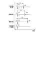
- FIG. 2 is a schematic diagram showing the received waves in the liquid layer, the transition layer, and the deposition layer.
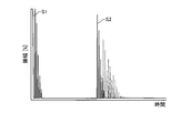
- FIG. 3 is a schematic diagram showing a received wave in a water-soluble deposition layer.
- FIG. 4 is a schematic diagram showing a received wave in a water-insoluble deposition layer.
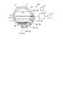
- FIG. 5 is a schematic configuration diagram showing the boundary position determination device of the second embodiment.
- FIG. 1 is a schematic configuration diagram showing the boundary position determination device of the first embodiment.
- crude oil is extracted by excavating the seabed at an offshore oilfield.
- This crude oil is heated and distilled in a refining facility to be separated into petroleum products such as petroleum gas, gasoline (naphtha), kerosene, light oil, heavy oil, and asphalt.
- crude oil is contaminated with impurities such as soil and gravel during the excavation process.
- the crude oil supplied to and stored in the tank is heated and distilled, while impurities are gradually accumulated inside the tank. Therefore, when a predetermined amount of impurities are accumulated inside the tank, the refining operation is stopped and a cleaning operation is performed to remove the impurities accumulated inside the tank.
- the boundary position determination device 10 includes impurities at the boundary between the liquid layer A and the deposition layer B in the crude oil (liquid) stored in the tank (container) 11. Is to determine the position in the direction in which is deposited. Then, the boundary position determination device 10 determines the position of the boundary between the liquid layer A of crude oil and the deposition layer B inside the tank 11, and when the position of the boundary becomes a predetermined position (height) set in advance, A display for performing the cleaning operation of the tank 11 is displayed.
- the tank 11 is a tank for constituting a heat exchanger in a crude oil refining facility, and the crude oil is supplied and heated to be distilled.
- the tank 11 has a bottom portion 11b provided at a lower portion of a cylindrical side portion 11a and a ceiling portion 11c provided at an upper portion thereof, and although not shown, a crude oil supply portion and a distillate discharge portion are provided.
- the boundary position determination device 10 includes a transmitter 12, a receiver 13, a determination unit 14, a storage unit 15, and a display unit 16.
- the transmitter 12 includes a plurality of (five in the present embodiment) transmitters 12a, 12b, 12c, 12d, and 12e.
- the transmitter 12 includes a plurality of transmitters 12a, 12b, 12c, 12d, and 12e. It is configured by being arranged in series on a line.
- the oscillator 12 is fixed to the outer surface of the tank 11. At this time, in the transmitter 12, the plurality of transmitters 12a, 12b, 12c, 12d, and 12e are arranged at a predetermined interval in the vertical direction, that is, in the impurity deposition direction.
- the receiver 13 is provided integrally with the transmitter 12. That is, the receiver 13 has a plurality of (five in the present embodiment) receivers 13a, 13b, 13c, 13d, and 13e, like the transmitter 12, and the receiver 13 has a plurality of receivers 13a, 13b, 13c, 13d, 13e are arranged in series on a straight line.
- the receiver 13 is fixed to the outer surface of the tank 11. At this time, in the receiver 13, the plurality of receivers 13a, 13b, 13c, 13d, 13e are arranged at a predetermined interval in the vertical direction, that is, the impurity deposition direction.
- the transmitter 12 transmits ultrasonic waves (sound waves) S at a plurality of positions in the accumulation direction of impurities contained in crude oil.
- the receiver 13 receives the ultrasonic wave (sound wave) S transmitted from the transmitter 12 at a plurality of positions. That is, the transmitter 12 transmits the ultrasonic waves S from the outer side to the inner side of the tank 11 in a plurality of positions in the horizontal direction orthogonal to the outer surface 11d of the side portion 11a. Then, a part of the ultrasonic wave S is reflected by the outer surface 11d of the side portion 11a, and the receiver 13 receives the ultrasonic wave S reflected by the outer surface 11d of the side portion 11a as a primary reflected wave S1.
- the ultrasonic wave S transmitted from the transmitter 12 passes through the side portion 11a, the rest travels straight inside the tank 11, and is reflected by the inner surface 11e of the opposite side portion 11a.
- the ultrasonic wave S reflected by the inner surface 11e of the portion 11a is received as the secondary reflected wave S2.
- the determination unit 14 determines the position of the boundary between the liquid layer A and the deposition layer B based on the state of the ultrasonic wave S received by the receiver 13.
- the determination unit 14 specifically determines the position of the boundary between the liquid layer A and the deposition layer B by comparing the state of the ultrasonic wave S received by the receiver 13 with the state of the preset reference ultrasonic wave Sa. To do.
- the position of the boundary between the liquid layer A and the gas layer above it may be determined.
- the state of the ultrasonic waves S is the interval between the ultrasonic waves S, that is, the interval (time) between the primary reflected wave S1 and the secondary reflected wave S2.
- the state of the ultrasonic wave S is the level of the ultrasonic wave S, that is, the level (magnitude) of the primary reflected wave S1 and the secondary reflected wave S2.
- the determination unit 14 may use either the interval of the ultrasonic waves S or the level of the ultrasonic waves S as the state of the ultrasonic waves S, but both may be used.
- the state of the reference ultrasonic wave Sa is the state of the ultrasonic wave S of the deposit layer B of the liquid layer A of crude oil in the tank 11 (the interval of the ultrasonic wave S, the level of the ultrasonic wave S), and is previously determined by experiments or the like. I ask for it.
- the storage unit 15 stores the reference state of the liquid layer A and the reference state of the deposition layer B.
- the determination unit 14 compares the state of the ultrasonic wave S received by the receiver 13 with the state of the reference ultrasonic wave Sa stored in the storage unit 15 to determine the position of the boundary between the liquid layer A and the deposition layer B. judge.
- the display unit 16 displays the determination result determined by the determination unit 14.
- the display unit 16 displays at which position (height) in the tank 11 the position of the boundary between the liquid layer A and the deposition layer B is located.
- the upper limit position of the boundary position where the cleaning operation is required in the tank 11, that is, the upper limit height of the deposition layer B is set, and the determination unit 14 determines that the liquid layer A and the deposition layer B in the current tank 11 are present. It is determined whether or not the position of the boundary between and reaches the upper limit position of the position of the boundary that requires cleaning work, and when the position of the boundary reaches the upper limit position, the display unit 16 displays.
- the determination unit 14 may issue an alarm when the boundary position reaches the upper limit position.
- the deposited layer B is gradually formed in the lower portion, but the intermediate layer (hereinafter, referred to as “the intermediate layer” in which the crude oil and the impurities are mixed between the liquid layer A and the deposited layer B) is formed.
- a transition layer) C is formed.
- the determination unit 14 detects the transition layer C between the liquid layer A and the deposition layer B based on the state of the ultrasonic wave S received by the receiver 13, and determines the position of the boundary between the liquid layer A and the deposition layer B. Is defined by the transition layer C.
- the determination unit 14 compares the position of the boundary between the liquid layer A and the deposition layer B by comparing the state of the ultrasonic wave S received by the receiver 13 and the state of the preset reference ultrasonic wave Sa of the transition layer C. judge. In this case, the determination unit 14 defines the boundary position by dividing the transition layer C into a plurality of layers in the impurity deposition direction.
- FIG. 2 is a schematic diagram showing received waves in the liquid layer A, the transition layer C, and the deposition layer B.
- Ultrasonic waves S are high-frequency elastic waves that propagate in elastic bodies such as gas, liquid, and solid, and the propagation speed varies depending on the gas, liquid, and solid.
- the interval (time) between the primary reflected wave S1 and the secondary reflected wave S2 of the ultrasonic wave S received by the receiver 13 in the liquid layer A of crude oil is defined as T1.
- the interval (time) between the primary reflected wave S1 and the secondary reflected wave S2 of the ultrasonic wave S received by the receiver 13 in the transition layer C1 of crude oil is set to T2, and the superposition received by the receiver 13 in the transition layer C2 is determined.
- the interval (time) between the primary reflected wave S1 and the secondary reflected wave S2 of the sound wave S is T3.
- the transition layer C1 is the upper layer of the transition layer C
- the transition layer C2 is the lower layer of the transition layer C
- more impurities are mixed in the transition layer C2. Therefore, the position of the boundary between the upper transition layer C1 and the lower transition layer C2 is defined as the position of the boundary between the liquid layer A and the deposition layer B.
- the deposition layer B cannot receive the secondary reflected wave S2 or has a minimum value.
- the transition layer C is set to the two transition layers C1 and C2, it may be set to three or more transition layers.
- the relationship between the intervals (time) T1, T2, T3 between the primary reflected wave S1 and the secondary reflected wave S2 of the ultrasonic wave S received by the receiver 13 is as follows. T1 ⁇ T2 ⁇ T3 That is, it can be seen that the propagation speed of the deposition layer B which is an impurity is slower than that of the liquid layer A which is a crude oil. Further, it can be seen that the lower transition layer C2 containing many impurities has a lower propagation speed than the upper transition layer C1.
- the intervals (time) T1, T2, T3 of the liquid layer A, the transition layer C1, and the transition layer C2 are obtained in advance and stored in the storage unit 15 as the intervals of the reference ultrasonic waves Sa.
- FIG. 3 is a schematic diagram showing the received wave in the water-soluble deposition layer
- FIG. 4 is a schematic diagram showing the received wave in the water-insoluble deposition layer.
- the water-soluble deposition layer in FIG. 3 is the upper deposition layer C1
- the water-insoluble deposition layer in FIG. 4 is the lower deposition layer C2.
- the position of the boundary between the liquid layer A and the deposited layer B depends on the level of the secondary reflected wave S2 of the ultrasonic wave S, not on the interval T between the primary reflected wave S1 and the secondary reflected wave S2 of the ultrasonic wave S. Can also be determined. As shown in FIG. 3, the level (magnitude, here, amplitude) of the secondary reflected wave S2 in the upper transition layer C1 gradually decreases. On the other hand, as shown in FIG. 4, the level (magnitude, in this case, amplitude) of the secondary reflected wave S2 in the lower transition layer C2 immediately becomes lower in a short time than in the upper transition layer C1.
- Changes in the levels of the transition layer C1 and the transition layer C2 are obtained in advance and stored in the storage unit 15 as the level of the reference ultrasonic wave Sa. Then, actually, the level of the secondary reflected wave S2 of the ultrasonic wave S received by the receiver 13 and the level of the reference ultrasonic wave Sa are compared to determine the position of the boundary position between the liquid layer A and the deposition layer B. judge.
- the ultrasonic waves S are transmitted from the outside of the tank 11 as a wall portion surrounding the crude oil at a plurality of positions in the accumulation direction of impurities contained in the crude oil (liquid).
- the liquid layer A and the deposition layer B based on the ultrasonic wave S state received by the receiver 13 and the receiver 12 that receives the ultrasonic wave S transmitted from the transmitter 12 at a plurality of positions.
- a determination unit that determines the position of the boundary in the deposition direction.
- the receiver 13 receives the ultrasonic waves S transmitted from the transmitter 12 at a plurality of positions, and the determination unit 14
- the position of the boundary between the liquid layer A and the deposition layer B in the direction in which impurities are deposited is determined based on the state of the ultrasonic wave S received by the receiver 13. Therefore, the position of the boundary between the liquid layer A and the deposition layer B in the crude oil inside the tank 11 can be accurately detected from the outside.
- the determination unit 14 compares the state of the ultrasonic wave S received by the receiver 13 with the state of the preset reference ultrasonic wave Sa to compare the liquid layer A and the deposited layer B. Determine the position of the boundary between and. Therefore, the position of the boundary can be easily determined.
- the determination unit 14 uses the transition layer in which the liquid and the impurities are mixed between the liquid layer A and the deposition layer B based on the state of the ultrasonic wave S received by the receiver 13. C is detected and the position of the boundary between the liquid layer A and the deposition layer B is defined by the transition layer C. Therefore, even if the transition layer C exists between the liquid layer A and the deposition layer B, the position of the boundary between the liquid layer A and the deposition layer B can be detected with high accuracy.
- the determination unit 14 compares the state of the ultrasonic wave S received by the receiver 13 with the state of the preset reference ultrasonic wave Sa of the transition layer C and determines that the liquid layer A is The position of the boundary with the deposition layer B is determined. Therefore, the position of the boundary can be easily determined.
- the determination unit 14 defines the boundary position by dividing the transition layer C into a plurality of layers in the impurity deposition direction. Therefore, the position of the boundary can be determined with high accuracy.
- the determination unit 14 determines the position of the boundary between the liquid layer A and the deposition layer B based on at least one of the interval and level of the sound waves received by the receiver 13. judge. Therefore, the position of the boundary can be easily determined.
- a plurality of transmitters 12 and receivers 13 are provided on the outer surface 11d of the tank 11 in which crude oil is stored, at predetermined intervals in the vertical direction. Therefore, the position of the boundary can be easily determined in a short time.
- a plurality of transmitters 12 and receivers 13 are provided on the outer surface of the tank 11 in which crude oil is stored, at predetermined intervals in the vertical direction. Therefore, the position of the boundary can be easily determined in a short time.
- the boundary position determination device of the first embodiment is provided with the display unit 16 that displays that the position of the boundary determined by the determination unit 14 reaches the preset upper limit position in the impurity deposition direction. Therefore, the operator can confirm the cleaning operation of impurities at an early stage.
- the boundary position determination method of the first embodiment includes a step of transmitting ultrasonic waves S from the outside of the tank 11 as a wall portion surrounding the crude oil at a plurality of positions in the accumulation direction of impurities contained in the crude oil (liquid),
- the method includes a step of receiving the transmitted ultrasonic waves S at a plurality of positions, and a step of determining the position in the deposition direction of the boundary between the liquid layer A and the deposition layer B based on the received ultrasonic waves S state. Therefore, the position of the boundary between the liquid layer A and the deposit layer B in the crude oil inside the tank 11 can be accurately detected from the outside.
- FIG. 5 is a schematic configuration diagram showing the boundary position determination device of the second embodiment. It should be noted that members having the same functions as those in the above-described embodiment are designated by the same reference numerals, and detailed description thereof will be omitted.
- the boundary position determination device 10A determines the position of the boundary between the liquid layer A and the deposition layer B in the liquid (eg, drainage) flowing inside the pipe 21. It is a thing. Then, the boundary position determination device 10A determines the position of the boundary between the liquid layer A and the accumulated layer B of the drainage inside the pipe 21, and when the position of the boundary becomes a predetermined position (height) set in advance, A display for performing the cleaning work of the pipe 21 is displayed.
- the pipe 21 has a cylindrical cross-sectional shape, and drainage flows along the direction orthogonal to the paper surface.
- the boundary position determination device 10A includes a transmitter 12A, a receiver 13A, a determination unit 14, a storage unit 15, and a display unit 16.
- the transmitter 12A is configured by arranging a plurality of transmitters 12a, 12b, 12c, 12d, 12e in series on one curve.
- the transmitter 12A is fixed to the curved outer surface of the pipe 21 along the circumferential direction. At this time, in the transmitter 12A, the plurality of transmitters 12a, 12b, 12c, 12d, and 12e are arranged at predetermined intervals in the impurity deposition direction.
- the receiver 13A is provided integrally with the transmitter 12A. That is, like the transmitter 12A, the receiver 13A is configured by a plurality of receiving units 13a, 13b, 13c, 13d, 13e arranged in series on one curve. The receiver 13A is fixed to the curved outer surface of the pipe 21 along the circumferential direction. At this time, in the receiver 13A, the plurality of receivers 13a, 13b, 13c, 13d, 13e are arranged at predetermined intervals in the impurity deposition direction.
- the transmitter 12A transmits ultrasonic waves (sound waves) S at a plurality of positions in the accumulation direction of impurities contained in the wastewater.
- the receiver 13A receives the ultrasonic wave S transmitted from the transmitter 12A at a plurality of positions. That is, the transmitter 12A transmits the ultrasonic waves S from the outside to the inside of the pipe 21 in a plurality of positions in a direction orthogonal to the outer surface 21a. Then, a part of the ultrasonic wave S is reflected by the outer surface 21a, and the receiver 13A receives the ultrasonic wave S reflected by the outer surface as a primary reflected wave.
- the rest of the ultrasonic wave S transmitted from the transmitter 12A passes through the pipe 21 and goes straight inside, and is reflected by the inner surface 21b on the opposite side, and the receiver 13A receives the ultrasonic wave S reflected by the inner surface 21b. Is received as a secondary reflected wave.
- the determination unit 14 determines the position of the boundary between the liquid layer A and the deposition layer B based on the state of the ultrasonic wave S received by the receiver 13A.
- the determination unit 14 specifically determines the position of the boundary between the liquid layer A and the deposition layer B by comparing the state of the ultrasonic wave S received by the receiver 13 with the state of the preset reference ultrasonic wave Sa.
- the state of the ultrasonic waves S is the interval of the ultrasonic waves S, that is, the interval (time) between the primary reflected wave and the secondary reflected wave.
- the state of the ultrasonic wave S is the level of the ultrasonic wave S, that is, the level (magnitude) of the primary reflected wave and the secondary reflected wave.
- the deposited layer B is gradually formed in the lower part, but an intermediate layer (hereinafter, referred to as a mixed layer) in which crude oil and impurities are mixed is present between the liquid layer A and the deposited layer B.
- a transition layer) C is formed.
- the determination unit 14 detects the transition layer C between the liquid layer A and the deposition layer B based on the state of the ultrasonic wave S received by the receiver 13A, and determines the position of the boundary between the liquid layer A and the deposition layer B. Is defined by the transition layer C.
- the determination unit 14 compares the state of the ultrasonic wave S received by the receiver 13A with the state of the preset reference ultrasonic waves Sa of the plurality of transition layers C to determine the boundary between the liquid layer A and the deposition layer B. Determine the position.
- the method of determining the position of the boundary between the liquid layer A and the deposition layer B by the determination unit 14 is the same as that in the first embodiment, and thus the description is omitted.
- the transmitter 12A that transmits the ultrasonic wave S from the outside of the pipe 21 at a plurality of positions in the accumulation direction of impurities contained in the drainage (liquid), and the transmitter 12A.
- the position of the boundary between the liquid layer A and the deposition layer B in the deposition direction is determined based on the ultrasonic wave S state received by the receiver 13A.
- the determination part 14 which determines.
- the receiver 13A receives the ultrasonic waves S transmitted from the transmitter 12A at a plurality of positions, and the determination unit 14
- the position of the boundary between the liquid layer A and the deposition layer B in the deposition direction is determined based on the state of the ultrasonic wave S received by the receiver 13. Therefore, the position of the boundary between the liquid layer A and the deposition layer B in the drainage inside the pipe 21 can be detected with high accuracy from the outside.
- the transmitter 12 and the receiver 13 are integrally provided, and the receiver 13 receives the ultrasonic wave S transmitted from the transmitter 12 and reflected. And the receiver 13 may be arranged to face each other, and the ultrasonic wave S transmitted from the transmitter 12 may be directly received by the receiver 13.
- the transmitter 12 is composed of a plurality of transmitters 12a, 12b, 12c, 12d, 12e
- the receiver 13 is composed of a plurality of receivers 13a, 13b, 13c, 13d, 13e.
- the configuration is not limited to this.
- one transmitting unit and one receiving unit may be provided so as to be movably supported in the impurity deposition direction. In this case, it is not necessary to provide a plurality of transmitters and receivers, and the cost can be reduced.
- the boundary position determination device of the present invention is applied to the crude oil tank 11 and the drainage pipe 21, but the invention is not limited to these, and a container for storing a liquid containing impurities or It can be applied to any pipe as long as a liquid containing impurities flows.
- the tank (container) 11 and the pipe 21 are applied as the wall portion surrounding the liquid, but the present invention is not limited to this configuration, and guides the container storing the liquid and the flowing liquid.
- the present invention can be applied to any pipe, and is not limited to the shape of the container or the pipe.
- Boundary position determination device 11d outer surface 11e inner surface 12,12A transmitter 12a, 12b, 12c, 12d, 12e transmitter 13, 13A receiver 13a, 13b, 13c, 13d, 13e receiver 14 determination unit 15 storage unit 16 display unit 21 pipe 21a outer surface 21b Inner surface A Liquid layer B Deposited layer C, C1, C2 Transition layer S Ultrasonic wave (sound wave) S1 Primary reflected wave S2 Secondary reflected wave Sa Reference ultrasonic wave T, T1, T2, T3 Interval
Landscapes
- Physics & Mathematics (AREA)
- Acoustics & Sound (AREA)
- Electromagnetism (AREA)
- Thermal Sciences (AREA)
- Fluid Mechanics (AREA)
- General Physics & Mathematics (AREA)
- Measurement Of Levels Of Liquids Or Fluent Solid Materials (AREA)
- Investigating Or Analyzing Materials By The Use Of Ultrasonic Waves (AREA)
- Length Measuring Devices Characterised By Use Of Acoustic Means (AREA)
Abstract
境界位置判定装置および方法において、原油(液体)に含まれる不純物の堆積方向における複数の位置で原油を囲う壁部としてのタンク(11)の外側から超音波(S)を発信する発信器(12)と、発信器(12)から発信された超音波(S)を複数の位置で受信する受信器(13)と、受信器(13)が受信した超音波(S)状態に基づいて液体層(A)と堆積層(B)との境界の堆積方向における位置を判定する判定部(14)とを備える。
Description
本発明は、液体層と堆積層との境界の位置を判定する境界位置判定装置および方法に関するものである。
例えば、海上油田にて、海底を掘削して取り出された原油は、タンクに貯留される。タンクに貯留された原油は、精製設備により加熱して蒸留される。即ち、原油は、沸点の差を利用することで、石油ガス、ガソリン(ナフサ)、灯油、軽油、重油、アスファルトなどの石油製品に分離される。
ところで、海底から取り出された原油は、その過程で土や砂利などの不純物が混入する。そのため、精製設備にて、タンクに原油を供給する一方で、タンクに貯留された原油を加熱して蒸留する間に、タンク内に不純物が堆積する。タンク内に多くの不純物が堆積すると、精製作業の妨げになってしまう。そのため、定期的に、精製作業を停止し、タンク内に堆積した不純物を除去する清掃作業を実施している。
タンクは、定期的に清掃作業が実施されるものの、内部に堆積している不純物の堆積量がわからず、堆積量が多くないときに内部の清掃作業を実施してしまうと、精製作業の作業効率が低下してしまう。そのため、外部からタンク内に堆積している不純物の堆積量を計測したいという要望がある。例えば、特許文献1に記載された音響による液位検出方法及び装置では、音波送受信器から容器内に向けて音波を送信し、容器内液相中の気相もしくは固相からの反射波を受信し、この反射波に基づいて液位を安定に検出するものである。ところが、不純物を含有する液体にて、液体層と堆積層は、液体層と空気層との境界のようにきれいに境界ができるものではなく、液体層と堆積層との間には、液体と不純物が混在した中間層があり、液体層と堆積層の境界の位置を高精度に検出することは困難であった。
本発明は、上述した課題を解決するものであり、液体層と堆積層との境界の位置を高精度に検出可能とする境界位置判定装置を提供することを目的とする。
上記の目的を達成するための境界位置判定装置は、液体に含まれる不純物の堆積方向における複数の位置で前記液体を囲う壁部の外側から音波を発信する発信器と、前記発信器から発信された音波を複数の位置で受信する受信器と、前記受信器が受信した音波の状態に基づいて液体層と堆積層との境界の前記堆積方向における位置を判定する判定部と、を備えることを特徴とするものである。
従って、発信器が不純物の堆積方向における複数の位置から音波を発信すると、受信器は、発信器から発信された音波を複数の位置で受信し、判定部は、受信器が受信した音波の状態に基づいて液体層と堆積層との境界の不純物が堆積する方向における位置を判定する。そのため、外部から容器や管などの内部にある液体における液体層と堆積層との境界の位置を高精度に検出することができる。
本発明の境界位置判定装置では、前記判定部は、前記受信器が受信した音波の状態と予め設定された基準音波の状態とを比較して前記液体層と前記堆積層との境界の位置を判定することを特徴としている。
従って、判定部は、受信した音波の状態と基準音波の状態とを比較して液体層と堆積層との境界の位置を判定することから、境界の位置の判定を容易に行うことができる。
本発明の境界位置判定装置では、前記判定部は、前記受信器が受信した音波の状態に基づいて前記液体層と前記堆積層との間にある液体と不純物が混在する遷移層を検出し、前記液体層と前記堆積層との境界の位置を前記遷移層で規定することを特徴としている。
従って、判定部は、受信した音波の状態に基づいて遷移層を検出し、液体層と堆積層との境界の位置を遷移層で規定することから、液体層と堆積層との間に遷移層が存在する場合であっても、液体層と堆積層との境界の位置を高精度に検出することができる。
本発明の境界位置判定装置では、前記判定部は、前記受信器が受信した音波の状態と予め設定された前記遷移層の基準音波の状態と比較して前記液体層と前記堆積層との境界の位置を判定することを特徴としている。
従って、判定部は、受信した音波の状態と遷移層の基準音波の状態と比較して液体層と堆積層との境界の位置を判定することから、境界の位置の判定を容易に行うことができる。
本発明の境界位置判定装置では、前記判定部は、前記遷移層を前記不純物の堆積方向に複数の層に分けて前記境界の位置を規定することを特徴としている。
従って、判定部は、遷移層を不純物の堆積方向に複数の層に分けて境界の位置を規定することから、境界の位置の判定を高精度に行うことができる。
本発明の境界位置判定装置では、前記判定部は、前記受信器が受信した音波の間隔とレベルの内の少なくともいずれか一方に基づいて前記液体層と前記堆積層との境界の位置を判定することを特徴としている。
従って、判定部は、受信した音波の間隔やレベルに基づいて液体層と堆積層との境界の位置を判定することから、境界の位置の判定を容易に行うことができる。
本発明の境界位置判定装置では、前記発信器および前記受信器は、前記液体が貯留される容器の外面に鉛直方向に所定間隔を空けて複数設けられることを特徴としている。
従って、発信器および受信器を容器の外面に鉛直方向に所定間隔を空けて複数設けることから、短時間で容易に境界の位置の判定を行うことができる。
本発明の境界位置判定装置では、前記発信器および前記受信器は、前記液体が貯留される容器の外面に鉛直方向に沿って移動自在に設けられることを特徴としている。
従って、発信器および受信器を容器の外面に鉛直方向に沿って移動自在に設けることから、複数の発信器および受信器を設ける必要がなく、コストを低減することができる。
本発明の境界位置判定装置では、前記液体は、原油であり、前記容器は、前記原油を精製する熱交換器であることを特徴としている。
従って、外部から熱交換器の容器に貯留される原油における液体層と堆積層との境界の位置を高精度に検出することができる。
本発明の境界位置判定装置では、前記発信器および前記受信器は、前記液体が流れる配管の外面に周方向に所定間隔を空けて複数設けられることを特徴としている。
従って、発信器および受信器を液体が流れる配管の外面に周方向に所定間隔を空けて複数設けることから、短時間で容易に境界の位置の判定を行うことができる。
本発明の境界位置判定装置では、前記判定部により判定された前記境界の位置が前記不純物の堆積方向において予め設定された上限位置に達することを表示する表示部が設けられることを特徴としている。
従って、境界の位置が上限位置に達することを表示部に表示することから、作業者は、不純物の清掃作業を早期に確認することができる。
また、本発明の境界位置判定方法は、液体に含まれる不純物の堆積方向における複数の位置で前記液体を囲う壁部の外側から音波を発信する工程と、発信された音波を複数の位置で受信する工程と、受信した音波の状態に基づいて液体層と堆積層との境界の前記堆積方向における位置を判定する工程と、を有するものである。
従って、外部から容器や管などの内部にある液体における液体層と堆積層との境界の位置を高精度に検出することができる。
本発明の境界位置判定装置および方法によれば、液体層と堆積層との境界の位置を高精度に検出することができる。
以下に添付図面を参照して、本発明の境界位置判定装置および方法の好適な実施形態を詳細に説明する。なお、この実施形態により本発明が限定されるものではなく、また、実施形態が複数ある場合には、各実施形態を組み合わせて構成するものも含むものである。
[第1実施形態]
図1は、第1実施形態の境界位置判定装置を表す概略構成図である。
図1は、第1実施形態の境界位置判定装置を表す概略構成図である。
例えば、原油は、海上油田にて、海底を掘削して取り出される。この原油は、精製設備により加熱して蒸留されることで、石油ガス、ガソリン(ナフサ)、灯油、軽油、重油、アスファルトなどの石油製品に分離される。しかし、原油は、掘削過程で土や砂利などの不純物が混入する。精製設備にて、タンクに供給されて貯留されている原油は、加熱して蒸留される一方、タンクの内部に徐々に不純物が堆積していく。そのため、タンクの内部に所定量の不純物が堆積すると、精製作業を停止し、タンクの内部に堆積した不純物を除去する清掃作業を実施する。
第1実施形態にて、図1に示すように、境界位置判定装置10は、タンク(容器)11の内部に貯留されている原油(液体)における液体層Aと堆積層Bとの境界の不純物が堆積する方向における位置を判定するものである。そして、境界位置判定装置10がタンク11の内部における原油の液体層Aと堆積層Bとの境界の位置を判定し、その境界の位置が予め設定された所定の位置(高さ)になると、タンク11の清掃作業を実施する表示を出す。なお、このタンク11は、原油の精製設備にて、熱交換器を構成するためのタンクであって、原油が供給されると共に、加熱して蒸留されるものである。
タンク11は、円筒形状の側部11aの下部に底部11bが設けられ、上部に天井部11cが設けられたものであり、図示しないが、原油の供給部と蒸留物の排出部が設けられる。
境界位置判定装置10は、発信器12と、受信器13と、判定部14と、記憶部15と、表示部16とを備える。発信器12は、複数(本実施形態では、5個)の発信部12a,12b,12c,12d,12eを有する、発信器12は、複数の発信部12a,12b,12c,12d,12eが一直線上に直列に配置されて構成される。発信器12は、タンク11の外面に固定される。このとき、発信器12は、複数の発信部12a,12b,12c,12d,12eが鉛直方向、つまり、不純物の堆積方向に所定間隔を空けて配置される。
受信器13は、発信器12と一体に設けられる。即ち、受信器13は、発信器12と同様に、複数(本実施形態では、5個)の受信部13a,13b,13c,13d,13eを有する、受信器13は、複数の受信部13a,13b,13c,13d,13eが一直線上に直列に配置されて構成される。受信器13は、タンク11の外面に固定される。このとき、受信器13は、複数の受信部13a,13b,13c,13d,13eが鉛直方向、つまり、不純物の堆積方向に所定間隔を空けて配置される。
発信器12は、原油に含まれる不純物の堆積方向における複数の位置で超音波(音波)Sを発信する。受信器13は、発信器12から発信された超音波(音波)Sを複数の位置で受信する。即ち、発信器12は、タンク11の外側から内部に向けて、側部11aの外面11dに直交する水平方向に向けて複数の位置で超音波Sを発信する。すると、この超音波Sは、一部が側部11aの外面11dで反射し、受信器13は、側部11aの外面11dで反射した超音波Sを1次反射波S1として受信する。また、発信器12から発信された超音波Sは、残りが側部11aを透過してタンク11の内部を直進し、反対側の側部11aの内面11eで反射し、受信器13は、側部11aの内面11eで反射した超音波Sを2次反射波S2として受信する。
判定部14は、受信器13が受信した超音波Sの状態に基づいて液体層Aと堆積層Bとの境界の位置を判定する。判定部14は、具体的に、受信器13が受信した超音波Sの状態と予め設定された基準超音波Saの状態とを比較して液体層Aと堆積層Bとの境界の位置を判定する。なお、液体層Aとその上方の気体層との境界の位置を判定してもよい。ここで、超音波Sの状態とは、超音波Sの間隔、つまり、1次反射波S1と2次反射波S2との間隔(時間)である。また、超音波Sの状態とは、超音波Sのレベル、つまり、1次反射波S1と2次反射波S2とのレベル(大きさ)である。この場合、判定部14は、超音波Sの状態として、超音波Sの間隔と超音波Sのレベルのいずれか一方を用いればよいものであるが、両方を用いてもよい。
また、基準超音波Saの状態とは、タンク11内における原油の液体層Aの堆積層Bの超音波Sの状態(超音波Sの間隔、超音波Sのレベル)であり、予め実験などにより求めておく。記憶部15は、この液体層Aの基準状態と堆積層Bの基準状態を記憶する。判定部14は、受信器13が受信した超音波Sの状態と、記憶部15に記憶されている基準超音波Saの状態とを比較して液体層Aと堆積層Bとの境界の位置を判定する。
表示部16は、判定部14が判定した判定結果を表示する。表示部16は、液体層Aと堆積層Bとの境界の位置がタンク11のどの位置(高さ)にあるかを表示する。ここで、タンク11における清掃作業が必要な境界の位置の上限位置、つまり、堆積層Bの上限高さを設定しておき、判定部14は、現在のタンク11における液体層Aと堆積層Bとの境界の位置が、清掃作業が必要な境界の位置の上限位置に到達したか否かを判定し、境界の位置が上限位置に到達したら表示部16に表示する。なお、判定部14は、境界の位置が上限位置に到達したら、警報を発したりするようにしてもよい。
また、タンク11内の原油は、不純物を有することから、下部に堆積層Bが徐々に形成されるものの、液体層Aと堆積層Bとの間に原油と不純物が混在した中間層(以下、遷移層)Cが形成される。判定部14は、受信器13が受信した超音波Sの状態に基づいて液体層Aと堆積層Bとの間にある遷移層Cを検出し、液体層Aと堆積層Bとの境界の位置を遷移層Cで規定する。即ち、判定部14は、受信器13が受信した超音波Sの状態と予め設定された遷移層Cの基準超音波Saの状態と比較して液体層Aと堆積層Bとの境界の位置を判定する。この場合、判定部14は、遷移層Cを不純物の堆積方向に複数の層に分けて境界の位置を規定する。
以下、境界位置判定装置10による液体層Aと堆積層Bとの境界の位置の判定方法について説明する。図2は、液体層Aと遷移層Cと堆積層Bにおける受信波を表す概略図である。
超音波Sは、気体、液体、固体などの弾性体を伝播する高い周波数の弾性波であり、伝搬する速度は、気体、液体、固体により変動する。図2に示すように、原油の液体層Aにおける受信器13が受信した超音波Sの1次反射波S1と2次反射波S2との間隔(時間)をT1とする。そして、原油の遷移層C1における受信器13が受信した超音波Sの1次反射波S1と2次反射波S2との間隔(時間)をT2とし、遷移層C2における受信器13が受信した超音波Sの1次反射波S1と2次反射波S2との間隔(時間)をT3とする。
ここで、遷移層C1は、遷移層Cの上層、遷移層C2は、遷移層Cの下層であり、遷移層C2の方が多くの不純物が混在している。そのため、上層の遷移層C1と下層の遷移層C2との境界の位置を液体層Aと堆積層Bとの境界の位置と規定する。また、堆積層Bは、2次反射波S2を受信することができないか、または、極小である。なお、遷移層Cを2つの遷移層C1,C2に設定したが、3つ以上の遷移層に設定してもよい。
すると、受信器13が受信した超音波Sの1次反射波S1と2次反射波S2との間隔(時間)T1,T2,T3との関係は、下記のようになる。
T1<T2<T3
即ち、原油である液体層Aよりも、不純物である堆積層Bの方が、伝搬速度が遅いことがわかる。また、上層の遷移層C1よりも、下層で不純物を多く含む遷移層C2の方が、伝搬速度が遅いことがわかる。この液体層A、遷移層C1、遷移層C2の間隔(時間)T1,T2,T3を予め求めておき、基準超音波Saの間隔として記憶部15に記憶させる。そして、実際に、受信器13が受信した超音波Sの1次反射波S1と2次反射波S2との間隔(時間)Tと、基準超音波Saの間隔(時間)T1,T2,T3とを比較して液体層Aと堆積層Bとの境界の位置の位置を判定する。
T1<T2<T3
即ち、原油である液体層Aよりも、不純物である堆積層Bの方が、伝搬速度が遅いことがわかる。また、上層の遷移層C1よりも、下層で不純物を多く含む遷移層C2の方が、伝搬速度が遅いことがわかる。この液体層A、遷移層C1、遷移層C2の間隔(時間)T1,T2,T3を予め求めておき、基準超音波Saの間隔として記憶部15に記憶させる。そして、実際に、受信器13が受信した超音波Sの1次反射波S1と2次反射波S2との間隔(時間)Tと、基準超音波Saの間隔(時間)T1,T2,T3とを比較して液体層Aと堆積層Bとの境界の位置の位置を判定する。
また、図3は、水溶性の堆積層における受信波を表す概略図、図4は、非水溶性の堆積層における受信波を表す概略図である。ここで、図3の水溶性の堆積層が上層の堆積層C1であり、図4の非水溶性の堆積層が下層の堆積層C2である。
また、液体層Aと堆積層Bとの境界の位置は、超音波Sの1次反射波S1と2次反射波S2との間隔Tではなく、超音波Sの2次反射波S2のレベルによっても判定することができる。図3に示すように、上層の遷移層C1における2次反射波S2は、そのレベル(大きさ、ここでは振幅)が徐々に低くなる。一方、図4に示すように、下層の遷移層C2における2次反射波S2は、そのレベル(大きさ、ここでは振幅)が上層の遷移層C1よりも短時間ですぐに低くなる。この遷移層C1、遷移層C2のレベルの変化を予め求めておき、基準超音波Saのレベルとして記憶部15に記憶させる。そして、実際に、受信器13が受信した超音波Sの2次反射波S2のレベルと、基準超音波Saのレベルとを比較して液体層Aと堆積層Bとの境界の位置の位置を判定する。
このように第1実施形態の境界位置判定装置にあっては、原油(液体)に含まれる不純物の堆積方向における複数の位置で原油を囲う壁部としてのタンク11の外側から超音波Sを発信する発信器12と、発信器12から発信された超音波Sを複数の位置で受信する受信器13と、受信器13が受信した超音波S状態に基づいて液体層Aと堆積層Bとの境界の堆積方向における位置を判定する判定部とを備える。
従って、発信器12が不純物の堆積方向における複数の位置から超音波Sを発信すると、受信器13は、発信器12から発信された超音波Sを複数の位置で受信し、判定部14は、受信器13が受信した超音波Sの状態に基づいて液体層Aと堆積層Bとの境界の不純物が堆積する方向における位置を判定する。そのため、外部からタンク11の内部にある原油における液体層Aと堆積層Bとの境界の位置を高精度に検出することができる。
第1実施形態の境界位置判定装置では、判定部14は、受信器13が受信した超音波Sの状態と予め設定された基準超音波Saの状態とを比較して液体層Aと堆積層Bとの境界の位置を判定する。従って、境界の位置の判定を容易に行うことができる。
第1実施形態の境界位置判定装置では、判定部14は、受信器13が受信した超音波Sの状態に基づいて液体層Aと堆積層Bとの間にある液体と不純物が混在する遷移層Cを検出し、液体層Aと堆積層Bとの境界の位置を遷移層Cで規定する。従って、液体層Aと堆積層Bとの間に遷移層Cが存在する場合であっても、液体層Aと堆積層Bとの境界の位置を高精度に検出することができる。
第1実施形態の境界位置判定装置では、判定部14は、受信器13が受信した超音波Sの状態と予め設定された遷移層Cの基準超音波Saの状態と比較して液体層Aと堆積層Bとの境界の位置を判定する。従って、境界の位置の判定を容易に行うことができる。
第1実施形態の境界位置判定装置では、判定部14は、遷移層Cを不純物の堆積方向に複数の層に分けて境界の位置を規定する。従って、境界の位置の判定を高精度に行うことができる。
第1実施形態の境界位置判定装置では、判定部14は、受信器13が受信した音波の間隔とレベルの内の少なくともいずれか一方に基づいて液体層Aと堆積層Bとの境界の位置を判定する。従って、境界の位置の判定を容易に行うことができる。
第1実施形態の境界位置判定装置では、発信器12および受信器13を原油が貯留されるタンク11の外面11dに鉛直方向に所定間隔を空けて複数設ける。従って、短時間で容易に境界の位置の判定を行うことができる。
第1実施形態の境界位置判定装置では、発信器12および受信器13を原油が貯留されるタンク11の外面に鉛直方向に所定間隔を空けて複数設けている。従って、短時間で容易に境界の位置の判定を行うことができる。
第1実施形態の境界位置判定装置では、判定部14により判定された境界の位置が不純物の堆積方向において予め設定された上限位置に達することを表示する表示部16を設ける。従って、作業者は、不純物の清掃作業を早期に確認することができる。
また、第1実施形態の境界位置判定方法は、原油(液体)に含まれる不純物の堆積方向における複数の位置で原油を囲う壁部としてのタンク11の外側から超音波Sを発信する工程と、発信された超音波Sを複数の位置で受信する工程と、受信した超音波S状態に基づいて液体層Aと堆積層Bとの境界の堆積方向における位置を判定する工程とを有する。従って、外部からタンク11の内部にある原油における液体層Aと堆積層Bとの境界の位置を高精度に検出することができる。
[第2実施形態]
図5は、第2実施形態の境界位置判定装置を表す概略構成図である。なお、上述した実施形態と同様の機能を有する部材には、同一の符号を付して詳細な説明は省略する。
図5は、第2実施形態の境界位置判定装置を表す概略構成図である。なお、上述した実施形態と同様の機能を有する部材には、同一の符号を付して詳細な説明は省略する。
第2実施形態にて、図5に示すように、境界位置判定装置10Aは、配管21の内部を流れる液体(例えば、排水など)における液体層Aと堆積層Bとの境界の位置を判定するものである。そして、境界位置判定装置10Aが配管21の内部における排水の液体層Aと堆積層Bとの境界の位置を判定し、その境界の位置が予め設定された所定の位置(高さ)になると、配管21の清掃作業を実施する表示を出す。
配管21は、円筒断面形状をなし、紙面の直交方向に沿って排水が流れる。境界位置判定装置10Aは、発信器12Aと、受信器13Aと、判定部14と、記憶部15と、表示部16とを備える。発信器12Aは、複数の発信部12a,12b,12c,12d,12eが一曲線上に直列に配置されて構成される。発信器12Aは、配管21の湾曲した外面に周方向に沿って固定される。このとき、発信器12Aは、複数の発信部12a,12b,12c,12d,12eが不純物の堆積方向に所定間隔を空けて配置される。
受信器13Aは、発信器12Aと一体に設けられる。即ち、受信器13Aは、発信器12Aと同様に、複数の受信部13a,13b,13c,13d,13eが一曲線上に直列に配置されて構成される。受信器13Aは、配管21の湾曲した外面に周方向に沿って固定される。このとき、受信器13Aは、複数の受信部13a,13b,13c,13d,13eが不純物の堆積方向に所定間隔を空けて配置される。
発信器12Aは、排水に含まれる不純物の堆積方向における複数の位置で超音波(音波)Sを発信する。受信器13Aは、発信器12Aから発信された超音波Sを複数の位置で受信する。即ち、発信器12Aは、配管21の外側から内部に向けて、外面21aに直交する方向に向けて複数の位置で超音波Sを発信する。すると、この超音波Sは、一部が外面21aで反射し、受信器13Aは、外面で反射した超音波Sを1次反射波として受信する。また、発信器12Aから発信された超音波Sは、残りが配管21を透過して内部を直進し、反対側の内面21bで反射し、受信器13Aは、この内面21bで反射した超音波Sを2次反射波として受信する。
判定部14は、受信器13Aが受信した超音波Sの状態に基づいて液体層Aと堆積層Bとの境界の位置を判定する。判定部14は、具体的に、受信器13が受信した超音波Sの状態と予め設定された基準超音波Saの状態とを比較して液体層Aと堆積層Bとの境界の位置を判定する。ここで、超音波Sの状態とは、超音波Sの間隔、つまり、1次反射波と2次反射波との間隔(時間)である。また、超音波Sの状態とは、超音波Sのレベル、つまり、1次反射波と2次反射波とのレベル(大きさ)である。
また、配管21内の排水は、不純物を有することから、下部に堆積層Bが徐々に形成されるものの、液体層Aと堆積層Bとの間に原油と不純物が混在した中間層(以下、遷移層)Cが形成される。判定部14は、受信器13Aが受信した超音波Sの状態に基づいて液体層Aと堆積層Bとの間にある遷移層Cを検出し、液体層Aと堆積層Bとの境界の位置を遷移層Cで規定する。即ち、判定部14は、受信器13Aが受信した超音波Sの状態と予め設定された複数の遷移層Cの基準超音波Saの状態と比較して液体層Aと堆積層Bとの境界の位置を判定する。
なお、判定部14による液体層Aと堆積層Bとの境界の位置の判定方法は、第1実施形態と同様であることから、説明は省略する。
このように第2実施形態の境界位置判定装置にあっては、排水(液体)に含まれる不純物の堆積方向における複数の位置で配管21の外側から超音波Sを発信する発信器12Aと、発信器12Aから発信された超音波Sを複数の位置で受信する受信器13Aと、受信器13Aが受信した超音波S状態に基づいて液体層Aと堆積層Bとの境界の堆積方向における位置を判定する判定部14とを備える。
従って、発信器12Aが不純物の堆積方向における複数の位置から超音波Sを発信すると、受信器13Aは、発信器12Aから発信された超音波Sを複数の位置で受信し、判定部14は、受信器13が受信した超音波Sの状態に基づいて液体層Aと堆積層Bとの境界の堆積方向における位置を判定する。そのため、外部から配管21の内部にある排水における液体層Aと堆積層Bとの境界の位置を高精度に検出することができる。
なお、上述した各実施形態にて、発信器12と受信器13を一体に設け、発信器12から発信されて反射した超音波Sを受信器13が受信するように構成したが、発信器12と受信器13を対向して配置し、発信器12から発信された超音波Sを受信器13が直接受信するように構成してもよい。
また、上述した各実施形態にて、発信器12を複数の発信部12a,12b,12c,12d,12eから構成し、受信器13を複数の受信部13a,13b,13c,13d,13eから構成したが、この構成に限定されるものではない。例えば、発信部と受信部をそれぞれ1個とし、不純物の堆積方向に移動自在に支持してもよい。この場合、複数の発信器および受信器を設ける必要がなく、コストを低減することができる。
また、上述した各実施形態にて、本発明の境界位置判定装置を原油のタンク11や排水の配管21に適用したが、これらに限定されるものではなく、不純物を含む液体を貯留する容器や不純物を含む液体が流れる管などであれば、いずれにも適用することができる。
また、上述した各実施形態にて、液体を囲う壁部として、タンク(容器)11や配管21を適用したが、この構成に限定されるものではなく、液体を貯留する容器や流れる液体を案内する配管に適用することができ、容器や配管の形状に限定されるものではない。
10 境界位置判定装置
11 タンク(容器)
11d 外面
11e 内面
12,12A 発信器
12a,12b,12c,12d,12e 発信部
13,13A 受信器
13a,13b,13c,13d,13e 受信部
14 判定部
15 記憶部
16 表示部
21 配管
21a 外面
21b 内面
A 液体層
B 堆積層
C,C1,C2 遷移層
S 超音波(音波)
S1 1次反射波
S2 2次反射波
Sa 基準超音波
T,T1,T2,T3 間隔
11 タンク(容器)
11d 外面
11e 内面
12,12A 発信器
12a,12b,12c,12d,12e 発信部
13,13A 受信器
13a,13b,13c,13d,13e 受信部
14 判定部
15 記憶部
16 表示部
21 配管
21a 外面
21b 内面
A 液体層
B 堆積層
C,C1,C2 遷移層
S 超音波(音波)
S1 1次反射波
S2 2次反射波
Sa 基準超音波
T,T1,T2,T3 間隔
Claims (12)
- 液体に含まれる不純物の堆積方向における複数の位置で前記液体を囲う壁部の外側から音波を発信する発信器と、
前記発信器から発信された音波を複数の位置で受信する受信器と、
前記受信器が受信した音波の状態に基づいて液体層と堆積層との境界の前記堆積方向における位置を判定する判定部と、
を備えることを特徴とする境界位置判定装置。 - 前記判定部は、前記受信器が受信した音波の状態と予め設定された基準音波の状態とを比較して前記液体層と前記堆積層との境界の位置を判定することを特徴とする請求項1に記載の境界位置判定装置。
- 前記判定部は、前記受信器が受信した音波の状態に基づいて前記液体層と前記堆積層との間にある液体と不純物が混在する遷移層を検出し、前記液体層と前記堆積層との境界の位置を前記遷移層で規定することを特徴とする請求項1または請求項2に記載の境界位置判定装置。
- 前記判定部は、前記受信器が受信した音波の状態と予め設定された前記遷移層の基準音波の状態と比較して前記液体層と前記堆積層との境界の位置を判定することを特徴とする請求項3に記載の境界位置判定装置。
- 前記判定部は、前記遷移層を前記不純物の堆積方向に複数の層に分けて前記境界の位置を規定することを特徴とする請求項4に記載の境界位置判定装置。
- 前記判定部は、前記受信器が受信した音波の間隔とレベルの内の少なくともいずれか一方に基づいて前記液体層と前記堆積層との境界の位置を判定することを特徴とする請求項1から請求項4のいずれか一項に記載の境界位置判定装置。
- 前記発信器および前記受信器は、前記液体が貯留される容器の外面に鉛直方向に所定間隔を空けて複数設けられることを特徴とする請求項1から請求項6のいずれか一項に記載の境界位置判定装置。
- 前記発信器および前記受信器は、前記液体が貯留される容器の外面に鉛直方向に沿って移動自在に設けられることを特徴とする請求項1から請求項6のいずれか一項に記載の境界位置判定装置。
- 前記液体は、原油であり、前記容器は、前記原油を精製する熱交換器であることを特徴とする請求項7または請求項8に記載の境界位置判定装置。
- 前記発信器および前記受信器は、前記液体が流れる配管の外面に周方向に所定間隔を空けて複数設けられることを特徴とする請求項1から請求項6のいずれか一項に記載の境界位置判定装置。
- 前記判定部により判定された前記境界の位置が前記不純物の堆積方向において予め設定された上限位置に達することを表示する表示部が設けられることを特徴とする請求項1から請求項10のいずれか一項に記載の境界位置判定装置。
- 液体に含まれる不純物の堆積方向における複数の位置で前記液体を囲う壁部の外側から音波を発信する工程と、
発信された音波を複数の位置で受信する工程と、
受信した音波の状態に基づいて液体層と堆積層との境界の前記堆積方向における位置を判定する工程と、
を有する境界位置判定方法。
Priority Applications (1)
| Application Number | Priority Date | Filing Date | Title |
|---|---|---|---|
| US17/281,381 US20220034703A1 (en) | 2018-12-28 | 2019-06-17 | Interface position determining apparatus and method |
Applications Claiming Priority (2)
| Application Number | Priority Date | Filing Date | Title |
|---|---|---|---|
| JP2018-247452 | 2018-12-28 | ||
| JP2018247452A JP2020106479A (ja) | 2018-12-28 | 2018-12-28 | 境界位置判定装置および方法 |
Publications (1)
| Publication Number | Publication Date |
|---|---|
| WO2020136945A1 true WO2020136945A1 (ja) | 2020-07-02 |
Family
ID=71127089
Family Applications (1)
| Application Number | Title | Priority Date | Filing Date |
|---|---|---|---|
| PCT/JP2019/023876 Ceased WO2020136945A1 (ja) | 2018-12-28 | 2019-06-17 | 境界位置判定装置および方法 |
Country Status (3)
| Country | Link |
|---|---|
| US (1) | US20220034703A1 (ja) |
| JP (1) | JP2020106479A (ja) |
| WO (1) | WO2020136945A1 (ja) |
Cited By (13)
| Publication number | Priority date | Publication date | Assignee | Title |
|---|---|---|---|---|
| WO2022120258A1 (en) * | 2020-12-04 | 2022-06-09 | Perceptive Sensor Technologies, Inc. | Multi-bounce acoustic signal material detection |
| US11525743B2 (en) | 2020-12-04 | 2022-12-13 | Perceptive Sensor Technologies, Inc. | Acoustic temperature measurement in layered environments |
| US11525809B2 (en) | 2020-12-04 | 2022-12-13 | Perceptive Sensor Technologies, Inc. | Apparatus, system, and method for the detection of objects and activity within a container |
| US11536696B2 (en) | 2020-12-04 | 2022-12-27 | Perceptive Sensor Technologies, Inc. | In-wall multi-bounce material property detection and acoustic signal amplification |
| US11549839B2 (en) | 2020-12-04 | 2023-01-10 | Perceptive Sensor Technologies, Inc. | Systems and methods for determining floating roof level tilt and characterizing runoff |
| US11585690B2 (en) | 2020-12-04 | 2023-02-21 | Perceptive Sensor Technologies, Inc. | Multi-path acoustic signal improvement for material detection |
| US11604294B2 (en) | 2020-12-04 | 2023-03-14 | Perceptive Sensor Technologies, Inc. | Determining layer characteristics in multi-layered environments |
| US11729537B2 (en) | 2020-12-02 | 2023-08-15 | Perceptive Sensor Technologies, Inc. | Variable angle transducer interface block |
| US11788904B2 (en) | 2020-12-04 | 2023-10-17 | Perceptive Sensor Technologies, Inc. | Acoustic temperature measurement in layered environments |
| US11846537B2 (en) | 2019-05-31 | 2023-12-19 | Perceptive Sensor Technologies, Inc. | Non-linear ultrasound method and apparatus for quantitative detection of materials |
| US11860014B2 (en) | 2022-02-11 | 2024-01-02 | Perceptive Sensor Technologies, Inc. | Acoustic signal detection of material composition in static and dynamic conditions |
| US11940420B2 (en) | 2022-07-19 | 2024-03-26 | Perceptive Sensor Technologies, Inc. | Acoustic signal material identification with nanotube couplant |
| US11946905B2 (en) | 2020-12-30 | 2024-04-02 | Perceptive Sensor Technologies, Inc. | Evaluation of fluid quality with signals |
Citations (5)
| Publication number | Priority date | Publication date | Assignee | Title |
|---|---|---|---|---|
| JPH0436620A (ja) * | 1990-02-19 | 1992-02-06 | Jgc Corp | 超音波を利用して二液層の境界面を検知する装置 |
| JPH08101058A (ja) * | 1994-09-30 | 1996-04-16 | Furuno Electric Co Ltd | 界面検出装置 |
| JPH109932A (ja) * | 1996-06-25 | 1998-01-16 | Kurita Water Ind Ltd | 固体粒子層の検出方法 |
| US20140008304A1 (en) * | 2010-11-10 | 2014-01-09 | Nederlandse Organisatie Voor Toegepast-Natuurweten Schappelijk Onderzoek Tno | Separation of liquid components from a mixture |
| US20160169839A1 (en) * | 2014-12-11 | 2016-06-16 | Cameron International Corporation | Ultrasonic Rag Layer Detection System And Method For Its Use |
Family Cites Families (8)
| Publication number | Priority date | Publication date | Assignee | Title |
|---|---|---|---|---|
| US3958451A (en) * | 1973-12-12 | 1976-05-25 | Inspection Technology Development, Inc. | Ultrasonic inspection apparatus |
| US4008603A (en) * | 1975-12-29 | 1977-02-22 | Shell Oil Company | Ultrasonic method and apparatus for measuring wall thickness of tubular members |
| US4144517A (en) * | 1977-08-05 | 1979-03-13 | Joseph Baumoel | Single transducer liquid level detector |
| US4320659A (en) * | 1978-02-27 | 1982-03-23 | Panametrics, Inc. | Ultrasonic system for measuring fluid impedance or liquid level |
| US4679430A (en) * | 1983-03-30 | 1987-07-14 | United Kingdom Atomic Energy Authority | Ultrasonic liquid interface detector |
| JP2000028421A (ja) * | 1998-07-09 | 2000-01-28 | Yonden Engineering Co Ltd | 樹脂計量装置 |
| GB0722256D0 (en) * | 2007-11-13 | 2007-12-27 | Johnson Matthey Plc | Level measurement system |
| US9052230B2 (en) * | 2011-05-13 | 2015-06-09 | Chevron U.S.A. Inc | Industrial process monitoring and imaging |
-
2018
- 2018-12-28 JP JP2018247452A patent/JP2020106479A/ja active Pending
-
2019
- 2019-06-17 WO PCT/JP2019/023876 patent/WO2020136945A1/ja not_active Ceased
- 2019-06-17 US US17/281,381 patent/US20220034703A1/en active Pending
Patent Citations (5)
| Publication number | Priority date | Publication date | Assignee | Title |
|---|---|---|---|---|
| JPH0436620A (ja) * | 1990-02-19 | 1992-02-06 | Jgc Corp | 超音波を利用して二液層の境界面を検知する装置 |
| JPH08101058A (ja) * | 1994-09-30 | 1996-04-16 | Furuno Electric Co Ltd | 界面検出装置 |
| JPH109932A (ja) * | 1996-06-25 | 1998-01-16 | Kurita Water Ind Ltd | 固体粒子層の検出方法 |
| US20140008304A1 (en) * | 2010-11-10 | 2014-01-09 | Nederlandse Organisatie Voor Toegepast-Natuurweten Schappelijk Onderzoek Tno | Separation of liquid components from a mixture |
| US20160169839A1 (en) * | 2014-12-11 | 2016-06-16 | Cameron International Corporation | Ultrasonic Rag Layer Detection System And Method For Its Use |
Cited By (15)
| Publication number | Priority date | Publication date | Assignee | Title |
|---|---|---|---|---|
| US11846537B2 (en) | 2019-05-31 | 2023-12-19 | Perceptive Sensor Technologies, Inc. | Non-linear ultrasound method and apparatus for quantitative detection of materials |
| US11729537B2 (en) | 2020-12-02 | 2023-08-15 | Perceptive Sensor Technologies, Inc. | Variable angle transducer interface block |
| US11536696B2 (en) | 2020-12-04 | 2022-12-27 | Perceptive Sensor Technologies, Inc. | In-wall multi-bounce material property detection and acoustic signal amplification |
| WO2022120258A1 (en) * | 2020-12-04 | 2022-06-09 | Perceptive Sensor Technologies, Inc. | Multi-bounce acoustic signal material detection |
| US11549839B2 (en) | 2020-12-04 | 2023-01-10 | Perceptive Sensor Technologies, Inc. | Systems and methods for determining floating roof level tilt and characterizing runoff |
| US11585690B2 (en) | 2020-12-04 | 2023-02-21 | Perceptive Sensor Technologies, Inc. | Multi-path acoustic signal improvement for material detection |
| US11604294B2 (en) | 2020-12-04 | 2023-03-14 | Perceptive Sensor Technologies, Inc. | Determining layer characteristics in multi-layered environments |
| US11525809B2 (en) | 2020-12-04 | 2022-12-13 | Perceptive Sensor Technologies, Inc. | Apparatus, system, and method for the detection of objects and activity within a container |
| US11788904B2 (en) | 2020-12-04 | 2023-10-17 | Perceptive Sensor Technologies, Inc. | Acoustic temperature measurement in layered environments |
| US11525743B2 (en) | 2020-12-04 | 2022-12-13 | Perceptive Sensor Technologies, Inc. | Acoustic temperature measurement in layered environments |
| US11994494B2 (en) | 2020-12-04 | 2024-05-28 | Perceptive Sensor Technologies, Inc. | Multi-bounce acoustic signal material detection |
| US11946905B2 (en) | 2020-12-30 | 2024-04-02 | Perceptive Sensor Technologies, Inc. | Evaluation of fluid quality with signals |
| US11860014B2 (en) | 2022-02-11 | 2024-01-02 | Perceptive Sensor Technologies, Inc. | Acoustic signal detection of material composition in static and dynamic conditions |
| US11940420B2 (en) | 2022-07-19 | 2024-03-26 | Perceptive Sensor Technologies, Inc. | Acoustic signal material identification with nanotube couplant |
| US12416605B2 (en) | 2022-07-19 | 2025-09-16 | Perceptive Sensor Technologies, Inc. | Acoustic signal material identification with nanotube couplant |
Also Published As
| Publication number | Publication date |
|---|---|
| US20220034703A1 (en) | 2022-02-03 |
| JP2020106479A (ja) | 2020-07-09 |
Similar Documents
| Publication | Publication Date | Title |
|---|---|---|
| WO2020136945A1 (ja) | 境界位置判定装置および方法 | |
| US8495913B2 (en) | Level measurement system | |
| EP3759453A1 (en) | Improvements in or relating to the monitoring of fluid pipes | |
| MX2011007904A (es) | Metodo y dispositivo para medir el espesor de cualquier deposito de material en una pared interna de una estructura. | |
| WO2016048457A1 (en) | Systems and methods for monitoring a condition of a tubular configured to convey a hydrocarbon fluid | |
| Selvakumar et al. | Demonstration and evaluation of state-of-the-art wastewater collection systems condition assessment technologies | |
| AU2014234934A1 (en) | Self-calibrating ultrasonic-based monitoring system | |
| EP2483656B1 (en) | System and method for the continuous detection of impacts on pipelines for the transportation of fluids, particularly suitable for underwater pipelines | |
| EP3710795A1 (en) | Device and method for detecting deposition layers in a conduit conducting a liquid or a soft medium and/or for level detection | |
| US10479945B2 (en) | Electric desalting and dehydration apparatus | |
| JP2000131179A (ja) | 導管漏洩位置検出方法およびその装置 | |
| US20190154479A1 (en) | Estimating flow velocity in pipes by correlating multi-frequency signals | |
| US20060211128A1 (en) | Crude unit desalter emulsion level detector | |
| JP4742675B2 (ja) | 筒状体内面付着層の厚さ測定方法 | |
| JP2014025821A (ja) | 検出装置 | |
| US11525719B2 (en) | Estimating flow velocity by harmonic excitation of injected microbubbles | |
| JPWO2014157539A1 (ja) | 欠陥分析装置、欠陥分析方法及びプログラム | |
| KR101517491B1 (ko) | 토양, 지하수오염 예방을 위한 유류 저장시설용 레벨 측정 시스템 및 이를 이용한 레벨 측정방법 | |
| CN115524392B (zh) | 地下工业管道完整性检测评价方法、系统、电子设备及存储介质 | |
| JP4252222B2 (ja) | 管種判別装置 | |
| CN111927438B (zh) | 一种随钻防溢管液位监测装置和监测方法 | |
| Burwell et al. | Internal corrosion direct assessment of dry gas transmission pipelines-validation | |
| US20170328865A1 (en) | System and method for fluid interface identification | |
| JP2821731B2 (ja) | 地中管内の土砂堆積量調査装置 | |
| EP4090444B1 (en) | Method for controlling the oil/water interface in an oil reservoir |
Legal Events
| Date | Code | Title | Description |
|---|---|---|---|
| 121 | Ep: the epo has been informed by wipo that ep was designated in this application |
Ref document number: 19902929 Country of ref document: EP Kind code of ref document: A1 |
|
| NENP | Non-entry into the national phase |
Ref country code: DE |
|
| 122 | Ep: pct application non-entry in european phase |
Ref document number: 19902929 Country of ref document: EP Kind code of ref document: A1 |