WO2020125534A1 - Channel measurement method and communication apparatus - Google Patents
Channel measurement method and communication apparatus Download PDFInfo
- Publication number
- WO2020125534A1 WO2020125534A1 PCT/CN2019/124792 CN2019124792W WO2020125534A1 WO 2020125534 A1 WO2020125534 A1 WO 2020125534A1 CN 2019124792 W CN2019124792 W CN 2019124792W WO 2020125534 A1 WO2020125534 A1 WO 2020125534A1
- Authority
- WO
- WIPO (PCT)
- Prior art keywords
- delay
- angle
- vectors
- vector
- indication information
- Prior art date
Links
Images


Classifications
-
- H—ELECTRICITY
- H04—ELECTRIC COMMUNICATION TECHNIQUE
- H04B—TRANSMISSION
- H04B7/00—Radio transmission systems, i.e. using radiation field
- H04B7/02—Diversity systems; Multi-antenna system, i.e. transmission or reception using multiple antennas
- H04B7/04—Diversity systems; Multi-antenna system, i.e. transmission or reception using multiple antennas using two or more spaced independent antennas
- H04B7/0413—MIMO systems
- H04B7/0456—Selection of precoding matrices or codebooks, e.g. using matrices antenna weighting
- H04B7/046—Selection of precoding matrices or codebooks, e.g. using matrices antenna weighting taking physical layer constraints into account
- H04B7/0469—Selection of precoding matrices or codebooks, e.g. using matrices antenna weighting taking physical layer constraints into account taking special antenna structures, e.g. cross polarized antennas into account
-
- H—ELECTRICITY
- H04—ELECTRIC COMMUNICATION TECHNIQUE
- H04B—TRANSMISSION
- H04B7/00—Radio transmission systems, i.e. using radiation field
- H04B7/02—Diversity systems; Multi-antenna system, i.e. transmission or reception using multiple antennas
- H04B7/04—Diversity systems; Multi-antenna system, i.e. transmission or reception using multiple antennas using two or more spaced independent antennas
- H04B7/0413—MIMO systems
- H04B7/0417—Feedback systems
-
- H—ELECTRICITY
- H04—ELECTRIC COMMUNICATION TECHNIQUE
- H04B—TRANSMISSION
- H04B7/00—Radio transmission systems, i.e. using radiation field
- H04B7/02—Diversity systems; Multi-antenna system, i.e. transmission or reception using multiple antennas
- H04B7/04—Diversity systems; Multi-antenna system, i.e. transmission or reception using multiple antennas using two or more spaced independent antennas
- H04B7/0413—MIMO systems
- H04B7/0456—Selection of precoding matrices or codebooks, e.g. using matrices antenna weighting
- H04B7/0478—Special codebook structures directed to feedback optimisation
Definitions
- the present application relates to the field of wireless communication, and more specifically, to a channel measurement method and a communication device.
- massive multiple-input multiple-input massive MIMO
- network equipment can reduce interference between multiple users and interference between multiple signal streams of the same user through precoding. It is beneficial to improve signal quality, realize space division multiplexing, and improve spectrum utilization.
- the terminal device may determine the precoding matrix based on downlink channel measurement, for example, and hopes that through feedback, the network device obtains a precoding matrix that is the same as or similar to the precoding matrix determined by the terminal device. Specifically, for example, the terminal device may indicate the precoding matrix by feeding back one or more beam vectors and their weighting coefficients.
- the feedback of the terminal device please refer to the type II (type II) codebook feedback method defined in the new radio (NR) protocol TS38.214.
- the present application provides a channel measurement method and a communication device, with a view to reducing feedback overhead.
- a channel measurement method is provided.
- the method may be executed by a terminal device, or may be executed by a chip configured in the terminal device.
- the method includes: receiving a precoding reference signal, which is obtained by precoding the reference signal based on K angle vectors; generating first indication information, where the first indication information is used to indicate at least one delay vector And P weighting coefficients corresponding to P angular delay pairs, the at least one delay vector and the P weighting coefficients are determined by the precoding reference signal; wherein, each angular delay in the P angular delay pairs For an angle vector including the K angle vectors and a delay vector in the at least one delay vector, the P angular delay pairs and their corresponding P weighting coefficients are used to determine the precoding matrix; P and K are all positive integers; send the first indication information.
- a channel measurement method is provided.
- the method may be executed by a network device, or may be executed by a chip configured in the network device.
- the method includes: sending a precoding reference signal, which is obtained by precoding the reference signal based on K angle vectors; receiving first indication information, where the first indication information is used to indicate at least one delay vector And P weighting coefficients corresponding to P angular delay pairs, the at least one delay vector and the P weighting coefficients are determined by the precoding reference signal; wherein, each angular delay in the P angular delay pairs For an angle vector including the K angle vectors and a delay vector in the at least one delay vector, the P angular delay pairs and their corresponding P weighting coefficients are used to determine the precoding matrix; P and K are all positive integers; the precoding matrix is determined according to the first indication information.
- the network device can pre-code the downlink reference signal based on the predetermined angle vector, so that the terminal device can perform downlink channel measurement according to the pre-coded reference signal. Since the network device pre-codes the reference signal based on the predetermined angle vector, the terminal device may not need to determine and feed back the spatial vector (such as the above angle vector), but only need to determine and feed back the delay vector corresponding to each angle vector and the Each angle delay pair corresponds to the weighting coefficient. Therefore, the downlink channel measurement process of the terminal device is simplified, the calculation complexity of the terminal device in the channel measurement process is reduced, and the feedback overhead of the terminal device is reduced.
- the precoding matrix is constructed based on a plurality of vectors in the spatial and frequency domains, so that the precoding matrix determined by the network device can be adapted to the downlink channel, thereby reducing feedback overhead while still providing feedback accuracy.
- pre-coding the downlink reference signal through the angle vector can reduce the number of ports of the reference signal, thereby reducing pilot overhead.
- the K angle vectors are determined based on uplink channel measurement.
- the network device By using the reciprocity of the uplink and downlink channels, the network device loads the reciprocal angle vector into the downlink reference signal to pre-compensate the downlink channel, so that the terminal device determines that it does not have a complete based on the received precoding reference signal Reciprocity of downlink channel information. Therefore, the measurement process of the downlink channel of the terminal device is simplified, and the calculation complexity of the terminal device in the channel measurement process is reduced; at the same time, the feedback accuracy can be ensured.
- the P weighting coefficients include one or more weighting coefficients fed back for each of the K angle vectors; wherein, for the K angle vectors The kth angle vector in, the first indication information is used to indicate L k weighting coefficients, the L k weighting coefficients correspond to the L k angle delay pairs of the P angle delay pairs, and the L each delay angle k of the delay angles to a vector comprising a delay angle of the k-th vector of L corresponding to the k and delay vectors; L k ⁇ 1, and L k is an integer.
- each of the P angle delay pairs may correspond to a weighting coefficient.
- the terminal device may determine one or more weighting coefficients corresponding to each angle vector according to the received precoding reference signal precoded based on each angle vector. When the delay vectors corresponding to the angle vectors are the same, the number of weighting coefficients corresponding to the angle vectors is the same.
- the L k weighting coefficients are obtained by performing channel estimation on multiple RBs based on the precoding reference signal obtained by precoding the kth angle vector.
- the channel estimate is determined.
- the precoding reference signal obtained based on one angle vector precoding may correspond to one port.
- the one or more weighting coefficients fed back by the terminal device to an angle vector may be obtained by performing channel estimation based on the precoding reference signal of one port. Therefore, the P weighting coefficients corresponding to the P angle delay pairs may be determined by multiple channel estimation values obtained by performing channel estimation on the precoding reference signals obtained by precoding the K angle vectors on multiple RBs.
- the at least one delay vector includes one or more delay vectors fed back for each of the K angle vectors; wherein, for the K The kth angle vector in the angle vectors, the first indication information is used to indicate L k delay vectors, the kth angle vector and the L k delay vectors are used to determine the P angle delay pairs L k angular delay pairs in; L k ⁇ 1, and L k is an integer.
- the terminal device may feed back one or more delay vectors for each of the K angle vectors.
- One or more delay vectors fed back for an angle vector may form one or more angular delay pairs for determining the precoding matrix with the angle vector.
- the method further includes: receiving second indication information, where the second indication information is used to indicate the number of delay vectors fed back for each of the K angle vectors.
- the method further includes: sending second indication information, where the second indication information is used to indicate the number of delay vectors fed back for each of the K angle vectors.
- the number of delay vectors fed back for each of the K angle vectors is a predefined value.
- the number of delay vectors fed back for each angle vector can be indicated by the network device to reduce the feedback overhead of the terminal device; it can also be determined and reported by the terminal device to the network device to better communicate with the downlink channel Adaptation; can also be pre-defined, such as protocol definition, to reduce signaling overhead.
- the L k delay vectors are obtained by performing channel estimation on a plurality of RBs based on a precoding reference signal obtained by precoding the kth angle vector.
- the channel estimates are determined.
- the precoding reference signal obtained based on one angle vector precoding may correspond to one port.
- the one or more delay vectors fed back by the terminal device for an angle vector may be obtained by performing channel estimation based on the precoding reference signal of one port.
- the delay vector fed back for the first angle vector of the K angle vectors is the same as the delay vector fed back by the second angle vector, and the first angle vector And the second angle vector is any two of the K angle vectors; the first indication information is used to indicate L delay vectors.
- the L delay vectors can be shared by K angle vectors, and the L delay vectors and K angle vectors can be combined in pairs to obtain K ⁇ L angle delay pairs that can be used to construct a precoding matrix.
- the method further includes: receiving second indication information, where the second indication information is used to indicate the value of L.
- the method further includes sending second indication information, where the second indication information is used to indicate the value of L.
- L is a predefined value.
- the value of L can be indicated by the network device to reduce the feedback overhead of the terminal device; it can also be determined by the terminal device and reported to the network device to better adapt to the downlink channel; it can also be pre-defined, such as a protocol Defined to reduce signaling overhead.
- the L delay vectors are multiple channels obtained by performing channel estimation on the precoding reference signals obtained by precoding the K angle vectors on multiple RBs The estimate is determined.
- the terminal device may determine L delay vectors that may be shared by K angle vectors based on the precoding reference signals of K ports.
- a channel measurement method is provided.
- the method may be executed by the terminal device, or may be executed by a chip configured in the terminal device.
- the method includes: receiving a precoding reference signal, which is obtained by precoding the reference signal based on K delay vectors; generating third indication information, where the third indication information is used to indicate at least one angle vector And P weighting coefficients corresponding to P angle delay pairs, the at least one angle vector and the P weighting coefficients are determined by the precoding reference signal; wherein, each angle delay in the P angle delay pairs For a delay vector including the K delay vectors and an angle vector in the at least one angle vector, the P angle delay pairs and their corresponding P weighting coefficients are used to determine the precoding matrix; P and K are all positive integers; send the third indication information.
- a channel measurement method is provided.
- the method may be executed by a network device, or may be executed by a chip configured in the network device.
- the method includes: sending a precoding reference signal, which is obtained by precoding the reference signal based on K delay vectors; receiving third indication information, where the third indication information is used to indicate at least one angle vector And P weighting coefficients corresponding to P angle delay pairs, the at least one angle vector and the P weighting coefficients are determined by the precoding reference signal; wherein, each angle delay in the P angle delay pairs For a delay vector including the K delay vectors and an angle vector in the at least one angle vector, the P angle delay pairs and their corresponding P weighting coefficients are used to determine the precoding matrix; P and K are all positive integers; the precoding matrix is determined according to the third indication information.
- the network device can pre-code the downlink reference signal based on the predetermined delay vector, so that the terminal device can perform downlink channel measurement according to the pre-coded reference signal. Since the network device pre-codes the reference signal based on the predetermined delay vector, the terminal device does not need to determine and feed back the vector in the frequency domain (such as the above delay vector), but only needs to determine and feed back the angle corresponding to each delay vector Vectors and weighting coefficients corresponding to each angle delay pair. Therefore, the downlink channel measurement process of the terminal device is simplified, the calculation complexity of the terminal device in the channel measurement process is reduced, and the feedback overhead of the terminal device is reduced. In addition, the precoding matrix is constructed based on a plurality of vectors in the spatial and frequency domains, so that the precoding matrix determined by the network device can be adapted to the downlink channel, thereby reducing feedback overhead while still providing feedback accuracy.
- the L delay vectors are determined based on uplink channel measurement.
- the network device By utilizing the reciprocity of the uplink and downlink channels, the network device loads the reciprocal delay vector into the downlink reference signal to precompensate the downlink channel, so that the terminal device determines that it does not have a precoding reference signal based on the received Downstream channel information for complete reciprocity. Therefore, the measurement process of the downlink channel of the terminal device is simplified, and the calculation complexity of the terminal device in the channel measurement process is reduced; at the same time, the feedback accuracy can be ensured.
- the P weighting coefficients include one or more weighting coefficients fed back for each of the L delay vectors; where, for the L The lth weighting coefficient in the delay vector, the first indication information is used to indicate K l weighting coefficients, the K l weighting coefficients corresponding to the K l angle delay pairs of the P angle delay pairs, and Each angular delay pair of the K l angular delay pairs includes the l-th delay vector and one of the corresponding K l angle vectors; K l ⁇ 1, K l and an integer.
- each angle delay pair in the P angle delay pairs may correspond to a weighting coefficient.
- the terminal device may determine one or more weighting coefficients corresponding to each delay vector according to the received precoding reference signal precoded based on each delay vector. When the angle vector corresponding to each delay vector is the same, the number of weighting coefficients corresponding to each delay vector is the same.
- the K l weighting coefficients are obtained by performing channel estimation on multiple RBs based on the precoding reference signal obtained by precoding the lth delay vector.
- the channel estimates are determined.
- the precoding reference signal obtained based on a delay vector precoding may correspond to a port.
- the one or more weighting coefficients fed back by the terminal device to a delay vector may be obtained by performing channel estimation based on the precoding reference signal of one port. Therefore, the P weighting coefficients corresponding to the P angular delay pairs may be determined by multiple channel estimation values obtained by performing channel estimation on the precoding reference signals obtained by L delay vector precoding on multiple RBs.
- the at least one angle vector includes one or more angle vectors fed back for each of the L delay vectors; wherein, for the L delay vector l th delay vectors, the third indication information for indicating the angular vectors K l, the l-th delay vectors and the vectors K l angles for determining the delay angle for the P K l angular delay pairs in; K l ⁇ 1, and K l is an integer.
- the terminal device may feed back one or more angle vectors for each angle vector in the L delay vectors.
- One or more angle vectors fed back for one angle vector may form one or more angle delay pairs for determining the precoding matrix with the delay vector.
- the method further includes: receiving fourth indication information, where the fourth indication information is used to indicate the number of angle vectors fed back for each of the L delay vectors.
- the method further includes: sending fourth indication information, where the fourth indication information is used to indicate the number of angle vectors fed back for each of the L delay vectors.
- the number of angle vectors fed back for each of the L delay vectors is a predefined value.
- the number of angle vectors fed back for each delay vector can be indicated by the network device to reduce the feedback overhead of the terminal device; or the terminal device can determine and report to the network device to better communicate with the downlink channel Adaptation; can also be pre-defined, such as protocol definition, to reduce signaling overhead.
- the angular vector K l is the channel estimate obtained based on multiple precoded reference signal of the l-th delay precoding vectors obtained in the plurality of RB The channel estimates are determined.
- the precoding reference signal obtained based on one delay vector precoding may correspond to a group of ports.
- the one or more angle vectors fed back by the terminal device to a delay vector may be obtained by performing channel estimation based on the precoding reference signals of a group of ports.
- the time delay vector fed back for the first angle vector of the K angle vectors is the same as the time delay vector fed back by the second angle vector, and the first angle vector And the second angle vector are any two angle vectors among the K angle vectors; the first indication information is used to indicate K angle vectors.
- the K angle vectors can be shared by L delay vectors, and the L delay vectors and K angle vectors can be combined in pairs to obtain K ⁇ L angle delay pairs that can be used to construct a precoding matrix.
- the method further includes: receiving fourth indication information, where the fourth indication information is used to indicate the value of K.
- the method further includes sending fourth indication information, where the fourth indication information is used to indicate the value of K.
- K is a predefined value.
- the value of K can be indicated by the network device to reduce the feedback overhead of the terminal device; it can also be determined by the terminal device and reported to the network device to better adapt to the downlink channel; it can also be pre-defined, such as a protocol Defined to reduce signaling overhead.
- the P angular delay pairs correspond to one receiving antenna.
- the above-mentioned first indication information and third indication information may be based on receiving antenna feedback.
- the terminal device may feed back P weighting coefficients corresponding to each receiving antenna based on the received precoding reference signal.
- the network device may reconstruct the downlink channel according to the weighting coefficient corresponding to each receiving antenna, and then determine the precoding matrix.
- the P angular delay pairs correspond to one transport layer one by one.
- the above-mentioned first indication information and third indication information may be feedback based on the transport layer.
- the terminal device may determine the number of transmission layers based on the received precoding reference signal, and feed back P weighting coefficients based on each transmission layer.
- the network device may directly determine the precoding matrix according to the weighting coefficient corresponding to each transmission layer.
- a communication device including various modules or units for performing the method in the first aspect or the third aspect and any possible implementation manner of the first aspect or the third aspect.
- a communication device including a processor.
- the processor is coupled to the memory and can be used to execute instructions in the memory to implement the first aspect or the third aspect and the method in any possible implementation manner of the first aspect or the third aspect.
- the communication device further includes a memory.
- the communication device further includes a communication interface, and the processor is coupled to the communication interface.
- the communication device is a terminal device.
- the communication interface may be a transceiver or an input/output interface.
- the communication device is a chip configured in the terminal device.
- the communication interface may be an input/output interface.
- the transceiver may be a transceiver circuit.
- the input/output interface may be an input/output circuit.
- a communication device including various modules or units for performing the method in any one of the second aspect or the fourth aspect and any possible implementation manner of the second aspect or the fourth aspect.
- a communication device including a processor.
- the processor is coupled to the memory, and may be used to execute instructions in the memory to implement the second aspect or the fourth aspect and the method in any possible implementation manner of the second aspect or the fourth aspect.
- the communication device further includes a memory.
- the communication device further includes a communication interface, and the processor is coupled to the communication interface.
- the communication device is a network device.
- the communication interface may be a transceiver or an input/output interface.
- the communication device is a chip configured in a network device.
- the communication interface may be an input/output interface.
- the transceiver may be a transceiver circuit.
- the input/output interface may be an input/output circuit.
- a processor including: an input circuit, an output circuit, and a processing circuit.
- the processing circuit is configured to receive a signal through the input circuit and transmit a signal through the output circuit, so that the processor executes any of the first aspect to the fourth aspect and any possible implementation manner of the first aspect to the fourth aspect The method.
- the processor may be a chip
- the input circuit may be an input pin
- the output circuit may be an output pin
- the processing circuit may be a transistor, a gate circuit, a flip-flop, and various logic circuits.
- the input signal received by the input circuit may be received and input by, for example, but not limited to a receiver
- the signal output by the output circuit may be, for example but not limited to, output to and transmitted by the transmitter
- the circuit may be the same circuit, which is used as an input circuit and an output circuit at different times, respectively.
- the embodiments of the present application do not limit the specific implementation manner of the processor and various circuits.
- a processing device including a processor and a memory.
- the processor is used to read instructions stored in the memory, and can receive signals through the receiver and transmit signals through the transmitter to perform any of the first aspect to the fourth aspect and any possible implementation manner of the first aspect to the fourth aspect Methods.
- processors there are one or more processors and one or more memories.
- the memory may be integrated with the processor, or the memory and the processor are provided separately.
- the memory may be non-transitory (non-transitory) memory, such as read-only memory (read only memory (ROM), which may be integrated with the processor on the same chip, or may be set in different On the chip, the embodiments of the present application do not limit the type of memory and the manner of setting the memory and the processor.
- ROM read only memory
- sending instruction information may be a process of outputting instruction information from the processor
- receiving capability information may be a process of receiving input capability information by the processor.
- the data output by the processor may be output to the transmitter, and the input data received by the processor may come from the receiver.
- the transmitter and the receiver may be collectively referred to as a transceiver.
- the processing device in the above tenth aspect may be one or more chips.
- the processor may be implemented by hardware or software.
- the processor When implemented by hardware, the processor may be a logic circuit, an integrated circuit, etc.; when implemented by software, the processor may be a general-purpose processor, This is achieved by reading the software code stored in the memory.
- the memory can be integrated in the processor or can be located outside the processor and exist independently.
- a computer program product includes: a computer program (also may be referred to as code or instructions), which, when the computer program is executed, causes the computer to perform the first aspect to The method in the fourth aspect and any possible implementation manner of the first aspect to the fourth aspect.
- a computer program also may be referred to as code or instructions
- a computer-readable medium that stores a computer program (also may be referred to as code or instructions) that when executed on a computer, causes the computer to perform the first aspect to The method in the fourth aspect and any possible implementation manner of the first aspect to the fourth aspect.
- a computer program also may be referred to as code or instructions
- a communication system including the aforementioned network device and terminal device.
- FIG. 1 is a schematic diagram of a communication system suitable for a channel measurement method according to an embodiment of the present application
- FIG. 2 is a schematic flowchart of a channel measurement method provided by an embodiment of the present application.
- FIG. 3 is a schematic diagram of multiple RBs carrying multiple ports of precoding reference signals provided by an embodiment of the present application
- FIG. 4 is a schematic diagram of a bitmap provided by an embodiment of the present application.
- FIG. 5 is a schematic flowchart of a channel measurement method according to another embodiment of the present application.
- FIG. 6 is another schematic diagram of multiple RBs carrying multiple ports of precoding reference signals provided by an embodiment of the present application.
- FIG. 7 is a schematic block diagram of a communication device provided by an embodiment of the present application.
- FIG. 8 is a schematic structural diagram of a terminal device provided by an embodiment of the present application.
- FIG. 9 is a schematic structural diagram of a network device provided by an embodiment of the present application.
- GSM global mobile communication
- CDMA code division multiple access
- WCDMA broadband code division multiple access
- general packet radio service general packet radio service, GPRS
- LTE long term evolution
- LTE frequency division duplex FDD
- TDD time division duplex
- UMTS universal mobile communication system
- WiMAX worldwide interoperability for microwave access
- 5G fifth generation
- 5G fifth generation
- NR new radio
- FIG. 1 is a schematic diagram of a communication system 100 suitable for a method of indicating a precoding vector according to an embodiment of the present application.
- the communication system 100 may include at least one network device, such as the network device 110 shown in FIG. 1; the communication system 100 may also include at least one terminal device, such as the terminal device 120 shown in FIG. 1.
- the network device 110 and the terminal device 120 can communicate through a wireless link.
- Each communication device, such as the network device 110 or the terminal device 120 may be configured with multiple antennas.
- the configured multiple antennas may include at least one transmit antenna for transmitting signals and at least one receive antenna for receiving signals. Therefore, the communication devices in the communication system 100, such as the network device 110 and the terminal device 120, can communicate through multi-antenna technology.
- the network device in the communication system may be any device with a wireless transceiver function or a chip that can be installed in the device.
- the device includes but is not limited to: evolved Node B (evolved Node B, eNB), wireless Network controller (radio network controller, RNC), Node B (Node B, NB), base station controller (BSC), base transceiver station (BTS), home base station (e.g., home evolved NodeB , Or Home Node B, HNB), baseband unit (BBU), access point (AP), wireless relay node, wireless backhaul node in wireless fidelity (WIFI) system, Transmission point (transmission point, TP) or transmission and reception point (transmission and reception point, TRP), etc., can also be 5G, such as NR, gNB in the system, or, transmission point (TRP or TP), base station in 5G system
- One or a group of antenna panels may be a network node that constitutes a gNB
- gNB may include a centralized unit (CU) and DU.
- the gNB may also include a radio unit (RU).
- CU implements some functions of gNB
- DU implements some functions of gNB, for example, CU implements radio resource control (RRC), packet data convergence layer protocol (packet data convergence protocol, PDCP) layer functions, DU implements wireless chain Road control (radio link control, RLC), media access control (media access control, MAC) and physical (physical, PHY) layer functions.
- RRC radio resource control
- PDCP packet data convergence layer protocol
- DU implements wireless chain Road control (radio link control, RLC), media access control (media access control, MAC) and physical (physical, PHY) layer functions.
- the network device may be a CU node, or a DU node, or a device including a CU node and a DU node.
- the CU may be divided into network devices in the access network RAN, or the CU may be divided into network devices in the core network (CN), which is not limited herein.
- terminal equipment in the communication system may also be referred to as user equipment (UE), access terminal, subscriber unit, user station, mobile station, mobile station, remote station, remote terminal, mobile device, user Terminal, terminal, wireless communication device, user agent or user device.
- UE user equipment
- the terminal device in the embodiment of the present application may be a mobile phone, a tablet computer, a computer with wireless transceiver function, a virtual reality (virtual reality, VR) terminal device, and an augmented reality (augmented reality, AR) terminal Wireless terminals in equipment, industrial control (industrial control), wireless terminals in self-driving (self-driving), wireless terminals in remote medical (remote medical), wireless terminals in smart grid (smart grid), transportation safety ( Wireless terminals in transportation, wireless terminals in smart cities, wireless terminals in smart homes, etc.
- the embodiments of the present application do not limit the application scenarios.
- FIG. 1 is only a simplified schematic diagram for ease of understanding and examples.
- the communication system 100 may also include other network devices or other terminal devices, which are not shown in FIG. 1.
- the processing procedure of the downlink signal at the physical layer before sending may be performed by a network device, or may be performed by a chip configured in the network device. For ease of explanation, they are collectively referred to as network devices below.
- Network devices can process codewords on physical channels.
- the codeword may be coded bits that have been coded (eg, including channel coding).
- the codeword is scrambling to generate scrambling bits.
- the scrambling bits undergo modulation mapping to obtain modulation symbols.
- the modulation symbols are mapped to multiple layers (layers) through layer mapping, or transmission layers.
- the modulation symbols after layer mapping are pre-coded to obtain pre-coded signals.
- the pre-encoded signal is mapped to multiple REs after being mapped to resource elements (RE). These REs are then orthogonally multiplexed (orthogonal frequency division multiplexing, OFDM) modulated and transmitted through the antenna port.
- OFDM orthogonally multiplexed
- the network device can process the signal to be transmitted by means of a precoding matrix matching the channel state when the channel state is known, so that the precoded signal to be transmitted is adapted to the channel, thereby Reduce the complexity of the receiving device to eliminate the impact of the channel. Therefore, through the precoding process of the signal to be transmitted, the quality of the received signal (such as signal to interference plus noise ratio (SINR), etc.) can be improved. Therefore, by using precoding technology, transmission devices and multiple receiving devices can be transmitted on the same time-frequency resources, that is, multiple users, multiple inputs, and multiple outputs (MU-MIMO).
- SINR signal to interference plus noise ratio
- the sending device may also perform precoding in other ways. For example, when channel information (such as, but not limited to, channel matrix) cannot be obtained, pre-coding is performed using a pre-coding matrix or a weighting method set in advance. For the sake of brevity, the specific content of this article will not be repeated here.
- channel information such as, but not limited to, channel matrix
- the uplink and downlink channels transmit signals on different time domain resources on the same frequency domain resources. Within a relatively short time (eg, the coherence time of channel propagation), it can be considered that the channel fading experienced by the signals on the upstream and downstream channels is the same. This is the reciprocity of the upstream and downstream channels.
- the network device can measure the uplink channel according to the uplink reference signal, such as a sounding reference signal (SRS). And the downlink channel can be estimated according to the uplink channel, so that the precoding matrix used for downlink transmission can be determined.
- the uplink reference signal such as a sounding reference signal (SRS).
- the upstream and downstream channels do not have complete reciprocity.
- the upstream channel is used to determine the downlink transmission.
- the precoding matrix may not be able to adapt to the downlink channel.
- the uplink and downlink channels in FDD mode still have partial reciprocity, for example, angle reciprocity and delay reciprocity. Therefore, angle and delay can also be called reciprocity parameters.
- the transmitting antenna can pass through multiple paths to reach the receiving antenna.
- Multipath delay causes frequency selective fading, which is the change of frequency domain channel.
- Time delay is the transmission time of a wireless signal on different transmission paths. It is determined by the distance and speed, and has no relationship with the frequency domain of the wireless signal. When signals are transmitted on different transmission paths, there are different transmission delays due to different distances. Therefore, the uplink and downlink channels in FDD mode can be considered to be the same, or reciprocal.
- the angle may refer to the angle of arrival (AOA) of the signal reaching the receiving antenna via the wireless channel, or the angle of departure (AOD) of the signal transmitted through the transmitting antenna.
- the angle may refer to the angle of arrival of the uplink signal to the network device, or the angle of departure of the network device to transmit the downlink signal.
- the arrival angle of the uplink reference signal and the departure angle of the downlink reference signal may be considered to be the same, or to say, reciprocal.
- each angle can be characterized by an angle vector.
- Each delay can be characterized by a delay vector.
- Reference signal reference signal
- RS reference signal
- pre-coded reference signal The reference signal may also be called a pilot, reference sequence, etc.
- the reference signal may be a reference signal used for channel measurement.
- the reference signal may be a channel state information reference signal (CSI-RS) for downlink channel measurement, or a sounding reference signal (SRS) for uplink channel measurement.
- CSI-RS channel state information reference signal
- SRS sounding reference signal
- the precoded reference signal may be a reference signal obtained by precoding the reference signal.
- the precoding may specifically include beamforming and/or phase rotation.
- the beamforming may be implemented by, for example, precoding the downlink reference signal based on one or more angle vectors
- the phase rotation may be implemented, for example, by precoding the downlink reference signal by one or more delay vectors.
- the reference signal obtained through precoding is called a precoding reference signal; the reference signal without precoding is simply referred to as a reference signal .
- pre-coding the downlink reference signal based on one or more angle vectors may also be referred to as loading one or more angle vectors onto the downlink reference signal to achieve beamforming.
- Precoding the downlink reference signal based on one or more delay vectors may also be referred to as loading one or more delay vectors onto the downlink reference signal to achieve phase rotation.
- a port may refer to a transmitting antenna port.
- the reference signal of each port may be a reference signal that has not been pre-encoded, or may be a pre-coded reference signal that is pre-encoded based on a delay vector.
- Coded reference signal; port can also refer to the reference signal port after beamforming, for example, the reference signal of each port can be a precoded reference signal obtained by precoding the reference signal based on an angle vector, or it can be based on A precoded reference signal obtained by precoding the reference signal with an angle vector and a delay vector.
- the signal of each port can be transmitted through one or more RBs.
- the transmitting antenna port may refer to an actual independent transmitting unit (TxRU). It can be understood that if the reference signal is pre-coded in the spatial domain, the number of ports may refer to the number of reference signal ports, and the number of reference signal ports may be smaller than the number of transmitting antenna ports.
- TxRU transmitting unit
- the transmit antenna port when referring to the transmit antenna port, it may refer to the number of ports that are not pre-coded in the spatial domain. That is, it is the actual number of independent transmission units.
- ports when referring to ports, in different embodiments, it may refer to a transmit antenna port or a reference signal port. The specific meaning expressed by the port may be determined according to specific embodiments.
- Angle vector It can be understood as a precoding vector used for beamforming the reference signal. Through beamforming, the transmitted reference signal can have a certain spatial directivity. Therefore, the process of precoding the reference signal based on the angle vector can also be regarded as a process of precoding in the spatial domain (or simply, spatial domain).
- the number of ports of the precoded reference signal obtained after precoding the reference signal based on one or more angle vectors is the same as the number of angle vectors.
- the number K of the angle vectors is smaller than the number T of the transmitting antennas, dimensionality reduction of the antenna ports can be achieved through spatial domain precoding, thereby reducing pilot overhead.
- the length of the angle vector can be T, T can represent the number of transmit antenna ports in one polarization direction, T ⁇ 1, and T is an integer.
- the angle vector is taken from a Discrete Fourier Transform (DFT) matrix.
- DFT Discrete Fourier Transform
- I 1 is the number of antenna ports in the same polarization direction included in each column (or row) in the antenna array
- I 2 is the number of antenna ports in the same polarization direction included in each row (or column) in the antenna array.
- T I 1 ⁇ I 2 .
- O 1 and O 2 are oversampling factors. i 1 and i 2 satisfy 0 ⁇ i 1 ⁇ (O 1 ⁇ I 1 -1), 0 ⁇ i 2 ⁇ (O 2 ⁇ I 2 -1).
- the angle vector is a uniform linear array (ULA) guide vector.
- ULA uniform linear array
- the steering vector can represent the phase difference of the angle of arrival of a path in the response of different antennas.
- the angle vector is a guiding vector of a uniform plane array (UPA).
- the steering vector may be, for example, a steering vector containing horizontal angle and pitch angle information.
- ⁇ k is the horizontal angle, Is the pitch angle;
- u k is the unit spherical base vector corresponding to the k-th angle:
- the transmitting antenna is a single-polarized antenna, and the number of transmitting antennas is T; the number of frequency domain units is N, N ⁇ 1, and N is an integer.
- the channel may be a matrix with a dimension of N ⁇ T. If the reference signal is spatially precoded based on an angle vector, for a receiving antenna, the dimension of the channel after precoding may be N ⁇ 1. That is, the received precoding reference signal may be expressed as a matrix of dimension N ⁇ 1.
- the channel may be a matrix with a dimension of 1 ⁇ T. If the reference signal is spatially precoded based on an angle vector, the angle vector can be loaded onto the reference signal separately. Since the dimension of the angle vector is T ⁇ 1, for a receiving antenna, the dimension of the channel after precoding may be N ⁇ 1. That is, the received precoding reference signal may be expressed as a matrix of dimension N ⁇ 1.
- the channel measured by the terminal device according to the received precoding reference signal can be equivalent to the channel loaded with the angle vector.
- loading the angle vector a( ⁇ k ) to the downstream channel V can be expressed as V(a( ⁇ k )) * .
- Delay vector The vector proposed in this application can be used to represent the changing law of the channel in the frequency domain. As mentioned earlier, multipath delay causes frequency selective fading. It can be known from the Fourier transform that the time delay of the signal in the time domain can be equivalent to the phase gradation in the frequency domain.
- the signal can be transformed into the frequency domain by Fourier transform:
- the signal can be transformed into the frequency domain by Fourier transform:
- ⁇ is the frequency variable, the phase rotation corresponding to different frequencies is different;
- t and tt 0 represent time delay.
- the law of the phase change of the channel in each frequency domain unit can be represented by a delay vector.
- the delay vector can be used to represent the delay characteristics of the channel.
- Precoding the reference signal based on the delay vector can essentially refer to the phase rotation of each frequency domain unit in the frequency domain based on the elements in the delay vector to pre-encode the frequency caused by the multipath delay by precoding the reference signal Select characteristics for pre-compensation. Therefore, the process of precoding the reference signal based on the delay vector can be regarded as the process of frequency domain precoding.
- Precoding the reference signal based on different delay vectors is equivalent to performing phase rotation on each frequency domain unit of the channel based on different delay vectors. Moreover, the angle of phase rotation of the same frequency domain unit may be different. In order to distinguish different delays, the network device may pre-code the reference signal based on each of the L delay vectors.
- each frequency domain unit includes only one RB for carrying a reference signal.
- each frequency domain unit may include one or more RBs for carrying reference signals.
- the network device may load the delay vector onto the multiple RBs for carrying reference signals in each frequency domain unit.
- the length of the delay vector is N, and N is the number of RBs used to carry reference signals (for example, the precoding reference signals in this embodiment) in the frequency domain occupied bandwidth of the CSI measurement resource, N ⁇ 1, and N is an integer.
- the delay vector is taken from the DFT matrix.
- Each vector in the DFT matrix may be called a DFT vector.
- O f is the over-sampling factor, O f ⁇ 1; k is the DFT vector index and satisfies 0 ⁇ k ⁇ O f ⁇ N-1 or 1-O f ⁇ N ⁇ k ⁇ 0.
- the vector u k in b( ⁇ l ) and the DFT matrix can satisfy:
- the delay vector is denoted as b( ⁇ l ).
- the bandwidth occupied by the CSI measurement resource in the frequency domain may be understood as a bandwidth used for transmitting a reference signal, and the reference signal may be a reference signal used for channel measurement, such as CSI-RS.
- the signaling for indicating the frequency domain occupied bandwidth of the CSI measurement resource may be, for example, a CSI occupied bandwidth range (CSI-Frequency Occupation).
- the bandwidth occupied by the CSI measurement resources in the frequency domain may also be referred to as measurement bandwidth, pilot transmission bandwidth, and so on. For convenience of description, the frequency domain occupied bandwidth of the CSI measurement resource is simply referred to as the measurement bandwidth.
- the length of the delay vector N is only a possible design, and should not constitute any limitation to this application.
- the lengths of different delay vectors will be defined below in combination with different embodiments. For the time being, detailed descriptions thereof will be omitted.
- the transmitting antenna is a single-polarized antenna
- the number of transmitting antennas is T; the number of RBs is N.
- the downlink channel may be a matrix with a dimension of N ⁇ T. If the reference signal is pre-coded in the frequency domain based on the delay vector, the N elements in the delay vector may be respectively loaded on the reference signals carried on the N RBs. The n-th element in the delay vector may be loaded onto the reference signal carried on the n-th RB among N RBs.
- the channel measured by the terminal device according to the received precoding reference signal can be equivalent to the channel loaded with the delay vector.
- loading the nth element in the delay vector onto the channel V (n) on the nth RB can be expressed as
- the frequency domain precoding of the reference signal based on the delay vector may be performed before resource mapping, or may be performed after resource mapping, which is not limited in this application.
- the delay vector is a form for expressing delay proposed in this application.
- the delay vector is only named for the convenience of distinguishing from the angle, and should not constitute any limitation to this application. This application does not exclude the possibility of defining other names to mean the same or similar meanings in future agreements.
- Frequency domain unit A unit of frequency domain resources, which can represent different frequency domain resource granularities.
- the frequency domain unit may include, for example but not limited to, a subband (subband), a resource block (RB), a resource block group (RBG), a precoding resource block group (precoding resource block (PRG), etc.).
- Angle delay pair can include an angle vector and a delay vector.
- the angle vector and/or delay vector included in any two angular delay pairs are different.
- each angular delay pair can be uniquely determined by an angle vector and a delay vector.
- the angular delay pair can be understood as the expression form of the basic unit of space frequency determined by an angle vector and a delay vector, but it is not necessarily the only expression form. For example, it can also be expressed as a space-frequency component matrix, a space-frequency component vector, etc. described below.
- Space frequency component matrix A space frequency component matrix can be determined by an angle delay pair. In other words, a space frequency component matrix can be uniquely determined by an angle vector and a delay vector. A space frequency component matrix and an angular delay pair can be converted to each other.
- a space-frequency component matrix can be determined by, for example, the product of the conjugate transpose of an angle vector and a delay vector, such as a( ⁇ k ) ⁇ b( ⁇ l ) H , and its dimension can be T ⁇ N.
- the space-frequency component matrix can be understood as another manifestation of the basic unit of space-frequency determined by an angle vector and a delay vector.
- the space-frequency basic unit can also be represented as a space-frequency component vector, which is determined by the Kronecker product of an angle vector and a delay vector, for example.
- the specific form of the space-time basic unit is not limited in this application. Based on the same conception, those skilled in the art should consider that all possible forms determined by an angle vector and a delay vector should fall within the scope of protection of the present application.
- the operation relationship between the space frequency component matrix and the angle vector and the delay vector, and the operation relationship between the space frequency component vector and the angle vector and the delay vector may also be possible different.
- the space-frequency component matrix can also be determined by the product of the conjugate of a delay vector and the transpose of an angle vector, such as b( ⁇ l ) * ⁇ a( ⁇ k ) T. This application does not limit the operation relationship between the space-frequency component matrix and the angle vector and the delay vector, and the operation relationship between the space-frequency component vector and the angle vector and the delay vector.
- the space frequency matrix is an intermediate quantity used to determine the precoding matrix.
- the precoding matrix may generally be a matrix of dimension T ⁇ Z.
- Z represents the number of transmission layers, Z ⁇ 1 and an integer.
- the space frequency matrix may be determined based on each receiving antenna, or may be determined based on each transmission layer.
- the space frequency matrix may be called a space frequency matrix corresponding to the receiving antenna.
- the space frequency matrix corresponding to the receiving antenna can be used to construct the downlink channel matrix of each RB, and then the precoding matrix corresponding to each RB can be determined.
- the channel matrix corresponding to a certain RB may be, for example, a transpose of a matrix constructed from column vectors corresponding to the same RB in the space-frequency matrix corresponding to each receiving antenna. For example, the nth column vector in the space-frequency matrix corresponding to each receiving antenna is extracted, and the matrix with dimensions T ⁇ R can be obtained from the left to the right according to the order of receiving antennas, R represents the number of receiving antennas, R ⁇ 1 and an integer.
- the transposition of the matrix can obtain the channel matrix V (n) of the n-th frequency domain unit.
- the relationship between the channel matrix and the space-frequency matrix will be described in detail below, and the detailed description of the relationship between the two will be omitted here for the time being.
- the space-frequency matrix may be called a space-frequency matrix corresponding to the transmission layer.
- the space frequency matrix corresponding to the transmission layer can be directly used to determine the precoding matrix corresponding to each RB.
- the precoding matrix corresponding to a certain RB may be, for example, a conjugate of a matrix constructed from column vectors corresponding to the same RB in the space-frequency matrix corresponding to each transmission layer. For example, the n-th column vector in the space-frequency matrix corresponding to each transmission layer is extracted, and arranged in the order of the transmission layer from left to right to obtain a matrix of dimension T ⁇ Z, Z represents the number of transmission layers, Z ⁇ 1 and an integer.
- the conjugate of this matrix can be used as the precoding matrix W (n) of the n-th frequency domain unit.
- the precoding matrix determined by the channel measurement method provided in the embodiment of the present application may be a precoding matrix directly used for downlink data transmission; it may also undergo some beamforming methods, for example, including zero forcing (ZF) ), regularized zero-forcing (RZF), minimum mean square error (MMSE), signal-to-leakage-and-noise (SLNR), etc.,
- ZF zero forcing
- RZF regularized zero-forcing
- MMSE minimum mean square error
- SLNR signal-to-leakage-and-noise
- the precoding matrix finally used for downlink data transmission is obtained.
- the precoding matrices involved in the following may all refer to the precoding matrix determined based on the channel measurement method provided in this application.
- the space-frequency matrix may be determined by one or more angular delay pairs.
- the space frequency matrix may be a weighted sum of one or more space frequency component matrices.
- the space-frequency matrix can also be converted into a space-frequency vector, and the space-frequency vector can also be a weighted sum of one or more space-frequency component vectors.
- the type II (type II) codebook feedback method is defined in NR protocol TS38.214.
- the following shows an example of feedback through the type II codebook feedback method when the rank is 1:
- W represents a transmission layer, a subband, and a precoding matrix to be fed back in two polarization directions.
- W 1 can be fed back through broadband
- W 2 can be fed back through subband.
- v 0 to v 3 are beam vectors included in W 1 , and the plurality of beam vectors may be indicated by an index of a combination of the plurality of beam vectors, for example.
- the precoding matrix shown above the beam vectors in the two polarization directions are the same, and the beam vectors v 0 to v 3 are used.
- a 0 to a 7 are the broadband amplitude coefficients included in W 1 , and can be indicated by the quantized value of the broadband amplitude coefficients.
- each sub-band coefficient may include a sub-band amplitude coefficient and a sub-band phase coefficient
- c 0 to c 7 may include sub-band amplitude coefficients ⁇ 0 to ⁇ 7 and sub-band With phase coefficient to And can respectively pass the quantized values of sub-band amplitude coefficients ⁇ 0 to ⁇ 7 and the sub-band phase coefficients to Quantized value to indicate.
- the delay vector can also be understood as a vector representing the delay characteristics of the channel.
- the above-mentioned space-frequency matrix is also an intermediate quantity proposed for constructing a precoding matrix based on the continuity in the frequency domain.
- H DL SC DL F H
- S H H DL C DL F H
- H DL T is the space frequency matrix determined by the real channel
- H DL T S * is the real channel after spatial precoding, that is, the channel observed by the terminal device when only the angle vector is loaded on the downlink reference signal .
- the terminal device may further determine the delay vector used to construct the downlink channel and the weighting coefficient of the delay pair at each angle based on the received precoding reference signal.
- H DL T is the space frequency matrix determined by the real channel;
- F T H DL T represents the sum of the channel estimation values measured by the terminal device when the delay vector is loaded on the downlink channel.
- the SC DL can be obtained by multiplying each row in the F T and each column in the H DL T.
- the number of elements included in each row vector in F T and the number of elements included in each column vector in H DL T may both be N.
- each element in the row vector such as the nth element, n traversing values in 1 to N
- the corresponding element in the column vector such as the nth element, n Iterate through the values from 1 to N
- the network device does not experience the downlink channel when loading the delay vector, and cannot obtain the correlation between the RBs of the downlink channel, the calculation of F T H DL T cannot be completed. Therefore, when the network device loads the delay vector onto each RB, it simply multiplies the elements in each row vector in F T with the elements in each column vector in H DL T , but does not complete the summing operation. .
- the terminal device performs channel estimation based on the received precoding reference signal to obtain the channel estimation value on each RB, and then sums the channel estimation values on the N RBs obtained from the precoding reference signal estimation based on the same delay vector, Then, F T H DL T can be obtained, that is, SC DL can be obtained, and then the angle vector used to construct the downlink channel and the weighting coefficient of each angle delay pair can be determined.
- the space frequency matrix H DL determined based on the weighting coefficients in the coefficient matrix C DL fed back by the terminal device may be obtained by transposing the real channel V.
- the channel matrix V may also be obtained by transposing the space frequency matrix H DL in the embodiment of the present application.
- the precoding matrix can be determined from the space frequency matrix H DL .
- the precoding matrix of the nth frequency domain unit may be the conjugate of the matrix constructed by the nth column vector in the space frequency matrix corresponding to each transmission layer.
- the SVD of the channel matrix V can obtain the conjugate transpose of the precoding matrix. If the channel matrix is transposed and then SVD is performed, that is, SVD is performed on V T , the conjugate of the precoding matrix can be obtained. Therefore, in the embodiment of the present application, the space frequency matrix H DL determined by the transposition of the real channel can be determined to obtain the conjugate of the precoding matrix corresponding to each frequency domain unit. On the contrary, the precoding matrix W may be obtained by conjugating the space frequency matrix H DL in the embodiment of the present application.
- Reference signal resources can be used to configure the transmission properties of the reference signal, such as time-frequency resource location, port mapping relationship, power factor, and scrambling code. For details, refer to the prior art.
- the transmitting end device may transmit the reference signal based on the reference signal resource, and the receiving end device may receive the reference signal based on the reference signal resource.
- One reference signal resource may include one or more RBs.
- the reference signal resource may be a CSI-RS resource, for example.
- the following points are made.
- P the number of angular delay pairs, P ⁇ 1 and an integer
- N the number of frequency domain units, N ⁇ 1 and an integer
- T the number of transmit antenna ports in one polarization direction, T ⁇ 1 and an integer
- K number of angle vectors, K ⁇ 1 and an integer
- L number of delay vectors, L ⁇ 1 and an integer
- R the number of receiving antennas, R ⁇ 1 and an integer
- Z the number of transmission layers, Z ⁇ 1 and an integer
- J the number of polarization directions of the transmitting antenna, J ⁇ 1 and an integer
- M the number of frequency domain groups, M>1 and an integer.
- serial numbering may start from 1.
- the L angle vectors may include the first angle vector to the Lth angle vector; the K delay vectors may include the first delay vector to the Kth delay vector.
- the specific implementation is not limited to this. For example, it may be consecutively numbered from 0.
- the angle vector and the delay vector are both column vectors as an example to illustrate the embodiment provided by this application, but this should not constitute any limitation to this application. Based on the same concept, those skilled in the art can also think of other possible expressions.
- for indicating may include both for direct indication and for indirect indication.
- the indication information may directly indicate A or indirectly indicate A, but does not mean that the indication information must carry A.
- the information indicated by the indication information is called information to be indicated.
- the information to be indicated can be directly indicated, such as the information to be indicated itself or the Indication index etc.
- the information to be indicated may also be indirectly indicated by indicating other information, where there is an association relationship between the other information and the information to be indicated. It is also possible to indicate only a part of the information to be indicated, while other parts of the information to be indicated are known or agreed in advance. For example, it is also possible to realize the indication of specific information by means of the arrangement order of various information pre-agreed (for example, stipulated in a protocol), thereby reducing the indication overhead to a certain extent.
- the precoding matrix is composed of precoding vectors, and each precoding vector in the precoding matrix may have the same part in terms of composition or other attributes.
- the specific indication method may also be various existing indication methods, such as, but not limited to, the above indication methods and various combinations thereof.
- the specific details of the various indication methods can refer to the prior art, and will not be repeated here. It can be seen from the foregoing that, for example, when multiple information of the same type needs to be indicated, situations in which different information may be indicated in different ways may occur.
- the required indication method can be selected according to specific needs. The embodiments of the present application do not limit the selected indication method. In this way, the indication methods involved in the embodiments of the present application should be understood as covering Fang learned various methods of the information to be indicated.
- row vectors can be expressed as column vectors
- a matrix can be represented by the transposed matrix of the matrix
- a matrix can also be expressed in the form of vectors or arrays
- the vectors or arrays It can be formed by connecting the row vectors or column vectors of the matrix to each other, etc.
- the information to be indicated may be sent together as a whole, or may be divided into multiple sub-information and sent separately, and the sending period and/or sending timing of these sub-information may be the same or different.
- the specific sending method is not limited in this application.
- the sending period and/or sending timing of these sub-information may be pre-defined, for example, pre-defined according to the protocol, or may be configured by the transmitting end device by sending configuration information to the receiving end device.
- the configuration information may include, for example but not limited to, radio resource control signaling, such as RRC signaling, MAC layer signaling, such as MAC-CE signaling, and physical layer signaling, such as downlink control information (downlink control information, DCI) One or a combination of at least two of them.
- pre-acquisition may include signaling indication or pre-defined by the network device, for example, protocol definition.
- pre-defined can be achieved by pre-storing corresponding codes, tables or other methods that can be used to indicate relevant information in the device (for example, including terminal devices and network devices), and this application does not do for its specific implementation limited.
- "save" involved in the embodiments of the present application may refer to being saved in one or more memories.
- the one or more memories may be set separately, or may be integrated in an encoder or decoder, a processor, or a communication device.
- the one or more memories may also be partly set separately and partly integrated in a decoder, processor, or communication device.
- the type of memory may be any form of storage medium, which is not limited in this application.
- the “protocol” referred to in the embodiments of the present application may refer to a standard protocol in the communication field, and may include, for example, the LTE protocol, the NR protocol, and related protocols applied in future communication systems, which are not limited in this application.
- At least one refers to one or more, and “multiple” refers to two or more.
- And/or describes the relationship of the related objects, indicating that there can be three relationships, for example, A and/or B, which can mean: A exists alone, A and B exist at the same time, B exists alone, where A, B can be singular or plural.
- the character "/” generally indicates that the related object is a "or” relationship.
- At least one of the following" or a similar expression refers to any combination of these items, including any combination of a single item or a plurality of items.
- At least one of a, b, and c may represent: a, or, b, or, c, or, a and b, or, a and c, or, b and c, or, a , B and c.
- a, b and c may be a single or multiple.
- the method provided by the embodiments of the present application may be applied to a system that communicates through multi-antenna technology, for example, the communication system 100 shown in FIG. 1.
- the communication system may include at least one network device and at least one terminal device.
- Multi-antenna technology can communicate between network equipment and terminal equipment.
- the embodiments shown below do not specifically limit the specific structure of the execution body of the method provided in the embodiments of the present application, as long as the program that records the code of the method provided in the embodiments of the present application can be executed to
- the method provided in the embodiment of the application may be used for communication.
- the execution body of the method provided in the embodiment of the present application may be a terminal device or a network device, or a functional module in the terminal device or network device that can call a program and execute the program.
- the interaction between the network device and the terminal device will be used as an example to describe in detail the channel measurement method provided by the embodiment of the present application.
- the network device may precode the downlink reference signal based on a predetermined angle, so that the terminal device estimates and feeds back the delay of the downlink channel and its corresponding weighting based on the received precoded reference signal coefficient.
- the network device may determine the precoding matrix adapted to the downlink channel according to the delay of the downlink channel fed back by the terminal device and its corresponding weighting coefficient, and a predetermined angle.
- the network device may also precode the downlink reference signal based on a predetermined delay, so that the terminal device estimates and feeds back the angle of the downlink channel and its correspondence based on the received precoded reference signal Weighting factor.
- the network device may determine the precoding matrix suitable for the downlink channel according to the angle of the downlink channel fed back by the terminal device and its corresponding weighting coefficient, and the predetermined time delay.
- the embodiment shown below first uses a polarization direction as an example to describe the detailed description of the channel measurement method 200 provided in the embodiment of the present application.
- the polarization direction may be any one of one or more polarization directions of the transmitting antenna configured by the network device.
- the terminal device can perform channel measurement based on the method 200 provided in the embodiment of the present application.
- the number of polarization directions of the transmitting antenna is not limited in this application, for example, it may be one, that is, a single polarization direction; it may also be multiple, such as a dual polarization direction.
- FIG. 2 is a schematic flowchart of a channel measurement method 200 provided by an embodiment of the present application from the perspective of device interaction. As shown, the method 200 may include steps 210 to 240. The steps of the method 200 are described in detail below.
- step 210 the terminal device receives a precoded reference signal, which is obtained by precoding the reference signal based on K angle vectors.
- the network device sends the precoding reference signal.
- K ⁇ 1, and K is an integer.
- the network device may pre-code the reference signal based on each of the K angle vectors to obtain pre-coded reference signals corresponding to the K ports.
- the precoded reference signal for each port is precoded based on one of the K angle vectors.
- the K angle vectors can be determined based on the upstream channel measurement. It should be understood that the K angle vectors are not necessarily determined based on uplink channel measurement. For example, the K angle vectors may be predefined, as defined by a protocol; or, the K angle vectors may be determined based on one or more downlink channel measurement statistics before. This application does not limit the determination method of the K angle vectors. Since there may be multiple delays at each angle, the multiple delays may correspond to multiple paths with the same angle but different delays. The network device can select K angles and determine the number of delays that the terminal device needs to estimate at each angle.
- the K angle vectors and the number of delay vectors corresponding to each angle vector may be determined based on uplink channel measurement.
- the network device may determine the strong K angles according to the uplink channel matrix obtained in advance.
- the K angles can be characterized by K angle vectors.
- the K angle vectors can be taken from a predefined set of angle vectors, for example.
- each angle vector in the set of angle vectors is taken from a DFT matrix.
- the K angle vectors can be determined by, for example, DFT the uplink channel matrix.
- each angle vector in the set of angle vectors is a steering vector.
- the network device may, for example, use the joint angle and delay estimation (JADE) algorithm in the prior art to determine the K angle vectors and the stronger one or more delays corresponding to each angle vector vector.
- the estimation algorithm may be, for example, multiple signal classification algorithm (MUSIC), Bartlett algorithm or rotation invariant subspace algorithm (estimation of signals, parameters, via rotation, variation in technology, ESPRIT), etc. .
- MUSIC multiple signal classification algorithm
- Bartlett algorithm or rotation invariant subspace algorithm (estimation of signals, parameters, via rotation, variation in technology, ESPRIT), etc.
- This application does not limit the specific method by which the network device determines the K angle vectors and the number of delays corresponding to each angle vector.
- the pre-defined angle vector set may be, for example, a vector set composed of multiple vectors in the spatial DFT matrix.
- the above-mentioned pre-defined delay vector set may be, for example, a vector set composed of multiple vectors in the frequency domain DFT matrix.
- the network device may perform the DFT transformation of the space domain and the frequency domain on the space frequency matrix H UL obtained by the uplink channel estimation to obtain the coefficient matrix C UL as follows:
- the dimension of the space frequency matrix H UL may be T ⁇ N.
- the network device may predefine the number K of angle vectors.
- the network device may determine K rows with a larger sum of squares of the modulus according to the square sum of the modulus of each row element in the coefficient matrix.
- the positions of the K rows in the coefficient matrix C UL can be used to determine K angle vectors.
- the positions of the K rows in the coefficient matrix C UL may be the positions of the K angle vectors in the set of space vectors described above.
- the network device may further determine the number of delay vectors corresponding to each angle vector according to the K squares of the modulus square in the coefficient matrix C UL and the larger K rows.
- the network device may determine the number of elements whose sum of squares of the modulus is greater than a preset value according to the magnitude of the square sum of the modulus of each element in the kth row (1 ⁇ k ⁇ K, and k is an integer) of the K rows .
- the preset value can be, for example, 80% of the sum of the squares of the modulus of the elements in this row.
- the number of elements whose sum of squares of modulus in the k-th row is greater than the preset value may be the number of delay vectors corresponding to the k-th angle vector L k (L k ⁇ 1, and L k is an integer).
- the network device may predefine the number P of angular delay pairs (P ⁇ 1, and P is an integer).
- the network device may determine P elements with a large modulus length according to the size of each element in the coefficient matrix C UL , and further determine the row where the P elements are located.
- the number of rows of the P elements with a large modulus length may be K.
- the rows of the P elements in the coefficient matrix C UL can be used to determine K angle vectors.
- the network device may further determine the number of delay vectors corresponding to each angle vector according to the number of P elements distributed in each of the K rows.
- the number of the P elements distributed in the k-th row may be the number of delay vectors L k corresponding to the k-th angle vector.
- the number of delay vectors corresponding to at least two angle vectors may be different. In other words, the number of delay vectors corresponding to some or all of the K angle vectors may be the same.
- Each angle vector and its corresponding one or more delay vectors can be combined to obtain one or more angle delay pairs.
- the angle delay pair obtained from the combination of K angle vectors and their corresponding delay vectors can be used to determine Precoding matrix.
- the specific process of determining the precoding matrix will be described in detail in step 240 below, and the detailed description of the specific process of determining the precoding matrix from the angle delay will be omitted here.
- the network device predefines the number K of angle vectors.
- the network device may determine K rows with a larger sum of squares of the modulus according to the square sum of the modulus of each row element in the coefficient matrix C UL .
- the positions of the K rows in the coefficient matrix C UL can be used to determine K angle vectors.
- the network device may further determine the number of delay vectors according to the magnitude of the square of the modulus of each element in the K rows. For example, the network device may determine that elements whose square whose modulus is greater than a preset value are distributed in several columns according to the square of the modulus of each row element in the K rows.
- the preset value can be, for example, 80% of the sum of the squares of the moduli of the K-line elements.
- the network device may use the number of columns distributed with elements whose modulus length is greater than a preset value as the number L of delay vectors.
- each angle vector may correspond to the same L delay vectors.
- the L delay vectors may be shared by K angle vectors.
- the L time delay vectors and any one of the K angle vectors may form L angle time delay pairs. Traversing the L delay vectors and K angle vectors, K ⁇ L angle delay pairs can be obtained, and the K ⁇ L angle delay pairs can be used to determine the precoding matrix. The specific process of determining the precoding matrix will be described in detail in step 240 below, and the detailed description of the specific process of determining the precoding matrix from the angle delay will be omitted here.
- the number of delay vectors corresponding to each angle vector may also be a predefined value, as defined by the protocol. This application does not limit the specific implementation manner in which the network device determines the number of the K angle vectors and the delay vector.
- the number of delay vectors corresponding to each angle vector may be determined by the network device based on uplink channel measurement, or may be determined by the terminal device based on downlink channel measurement, which is not limited in this application.
- the uplink channel matrix may be, for example, estimated by the network device according to the previously received uplink reference signal, such as SRS, or obtained from the data signal after correct decoding.
- SRS uplink reference signal
- This application does not limit this.
- the specific method for the network device to estimate the uplink channel matrix can refer to the prior art. For brevity, the detailed description of the specific method is omitted here.
- the K angle vectors obtained by the uplink channel measurement can be loaded into the downlink reference signal to facilitate the downlink channel measurement.
- the L delay vectors measured by the uplink channel can also be loaded into the downlink reference signal.
- This embodiment mainly describes the case of loading K angle vectors into the downlink reference signal in detail. This method can be applied to the FDD mode, and is particularly applicable to scenarios where the uplink and downlink reciprocity of the delay in the FDD mode is not very good.
- the network device may pre-code the downlink reference signal, such as CSI-RS, based on the K angle vectors to obtain a pre-coded reference signal, and may transmit the pre-coded reference signal through a pre-configured reference signal resource.
- the downlink reference signal such as CSI-RS
- the method 200 further includes: the terminal device receives fifth indication information, where the fifth indication information is used to configure a reference signal resource.
- the network device sends the fifth indication information.
- the reference signal resource configured by the fifth indication information can be used to carry the precoding reference signal.
- the precoded reference signal carried on the reference signal resource may correspond to the same one or more ports.
- the fifth indication information may be, for example, high-level signaling, such as RRC message. This application does not limit this.
- the fifth indication information may configure CSI-RS resources (CSI-RS resources, that is, an example of reference signal resources) through higher layer parameters.
- the high-level parameters may include, for example, CSI resource configuration (CSI-ResourceConfig) and non-zero power (NZP) CSI-RS resource set (NZP-CSI-RS-ResourceSet).
- the high-level parameters can configure the number of ports, time-frequency resources, and pilot density for each CSI-RS resource. Therefore, the terminal device can determine the number of ports corresponding to the precoding reference signal carried in each RB based on the high-layer parameters.
- the number of ports may refer to the number of ports corresponding to the precoded reference signals carried on one RB.
- the number of ports of the precoded reference signal obtained by precoding the downlink reference signal may be K.
- Each port can correspond to an angle vector.
- the precoded reference signal of each port is obtained by precoding the reference signal based on an angle vector.
- the network device sending the pre-coded reference signals of K ports may refer to that the network device may map the pre-coded reference signals of K ports on the same RB.
- the terminal device receiving the precoding reference signals of K ports may refer to that the precoding reference signals that the terminal device can receive on one RB correspond to K ports.
- the precoding reference signal carried on one RB may correspond to K ports, which does not mean that the reference signal is only carried on one RB.
- the network device may map the precoded reference signals of K ports to multiple RBs in the measurement bandwidth, and the precoded reference signals carried on each RB correspond to the K ports.
- the terminal device may receive the pre-coded reference signals of K ports on each RB of the multiple RBs measuring the bandwidth.
- the network device may precode the reference signal based on the kth angle vector of the K angle vectors to obtain the precoded reference signal of the kth port.
- k 1, 2, ..., K, and k is an integer. In other words, there can be a one-to-one correspondence between K ports and K angle vectors.
- FIG. 3 shows an example of precoding reference signals carrying multiple ports on multiple RBs.
- FIG. 3 and FIG. 5 shown hereinafter are only examples, and explain in detail the correspondence between the precoded reference signal carried on each RB and the port when the angle vector and the delay vector are respectively loaded on the reference signal.
- RB is only one possible form of frequency domain unit.
- the frequency domain unit may also be a subband, PRB, RBG, etc., for example. This application does not limit this. No matter what form the frequency domain unit is, it may include one or more RBs.
- the RB shown in FIG. 3 and FIG. 5 may be a frequency domain unit or an RB in a frequency domain unit used to carry a precoding reference signal, which is not limited in this application.
- the precoded reference signal is not necessarily carried on each RB of the measurement bandwidth, nor on multiple consecutive RBs.
- the terminal device may not necessarily receive the pre-coded reference signals of the multiple ports on each RB of the measurement bandwidth.
- the network device does not necessarily map the precoding reference signal to each RB of the measurement bandwidth.
- the RBs used to carry the downlink reference signal may be distributed discretely in the measurement bandwidth. For example, one RB carries a downlink reference signal every several RBs. This application does not limit this.
- RB#1, RB#2, RB#3, and RB#4 in FIG. 3 are not necessarily continuous in the frequency domain. For example, they can be located in four consecutive subbands to be measured, but between each other. , Such as between RB#1 and RB#2, between RB#2 and RB#3, and between RB#3 and RB#4, there may be one or more RBs apart.
- each frequency domain unit may have one RB for carrying a precoding reference signal, or there may be multiple RBs for carrying a precoding reference signal. No matter whether the number of RBs carrying the precoding reference signal in one frequency domain unit is one or more, the number of ports corresponding to the precoding reference signal carried by each RB is unchanged. It can be understood that when each frequency domain unit contains multiple RBs for carrying precoded reference signals, the angular delay pair corresponding to the precoded reference signals carried on each RB in the same frequency domain unit may be the same or different. In other words, the port numbers corresponding to the precoding reference signals carried on each RB in the same frequency domain unit may be the same or different, which is not limited in this application.
- RB can also be understood that each frequency domain unit contains only one RB for carrying the reference signal.
- FIG. 3 shows an example of multiple RBs carrying precoded reference signals of multiple ports.
- the figure shows an example where the number of RBs is 4.
- the pre-coded reference signals of the four ports may be pre-coded based on four different angle vectors.
- the precoded reference signal of port #1 may be obtained by precoding based on the angle vector a( ⁇ 1 ); the precoded reference signal of port #2 may be obtained by precoding based on the angle vector a( ⁇ 2 ); port #3 The precoding reference signal may be obtained by precoding based on the angle vector a( ⁇ 3 ); the precoding reference signal of port #4 may be obtained by precoding based on the angle vector a( ⁇ 4 ).
- the REs occupied by the precoding reference signals of the same port in each RB are the same, or the relative positions of the resources occupied by the precoding reference signals of the same port in the RBs are the same.
- the REs occupied by the precoded reference signals of different ports in the same RB can be different, for example, they can be distinguished by frequency division multiplexing (FDM) or time division multiplexing (TDM); different ports
- the REs occupied by the precoding reference signals in the same RB may also be the same, for example, they can be distinguished by code division multiplexing (code division multiplexing, CDM).
- CDM code division multiplexing
- FIG. 3 is only an example for ease of understanding, and does not completely show all REs in one RB.
- the present application does not limit the number of REs in each RB.
- the present application does not limit the number of ports corresponding to the precoded reference signals carried on each RB and the specific manner of multiplexing resources between the reference signals of each port.
- the four RBs shown in the figure may be an example of the reference signal resources described above.
- the 4 RBs may belong to the same reference signal resource. It should be understood that the figure is only an example, and shows four RBs as an example of reference signal resources. This should not constitute any limitation on this application.
- the reference signal resource may include more or fewer RBs, and the number of RBs included in the reference signal resource is not limited in this application.
- the precoded reference signal obtained by precoding the reference signal through K angle vectors, that is, beamforming makes the transmitted precoded reference signal have K different spatial directivities.
- the K different spatial directivities may be K different ports that can be recognized by the terminal device.
- the terminal device In step 220, the terminal device generates first indication information based on the received precoding reference signal.
- the first indication information may be used to indicate at least one delay vector and P weighting coefficients.
- the terminal device can detect the downlink channel information without complete reciprocity.
- the terminal device may determine a delay vector and corresponding weighting coefficients that can be used to construct a precoding matrix suitable for the downlink channel based on the received precoding reference signals of K ports.
- the terminal device may generate first indication information based on the determined delay vector and weighting coefficient.
- the dimension of H DL may be T ⁇ N; the angle vectors may be K, and the length of each angle vector may be T, then the dimension of S may be T ⁇ K; each delay vector may be L, the length of each delay vector can be N, then the dimension of F can be N ⁇ L.
- H DL T is a space frequency matrix determined by a real channel; H DL T S * is a real channel (or equivalent channel) after spatial domain precoding, and its dimension may be K ⁇ N.
- Each column in the matrix may represent a channel estimation value estimated based on the received precoding reference signal on one RB.
- Each row of the matrix can represent the channel estimates corresponding to one port received on N RBs.
- the terminal device may further determine the delay vector used to construct the downlink channel and the weighting coefficient of the delay pair at each angle based on the received precoding reference signal.
- the terminal device can estimate the downlink channel based on the pre-coded reference signals of K ports.
- the pre-coded reference signal for each of the K ports is obtained by pre-coding the reference signal based on one of the K angle vectors.
- K ports and K angle vectors can correspond one-to-one. Therefore, the terminal device estimates the downlink channel based on the pre-coded reference signals of K ports, that is, estimates the downlink channel based on the pre-coded reference signals obtained by precoding the K angle vectors.
- the dimension of the downlink channel may be N ⁇ T.
- the dimension of the downlink channel received on one receiving antenna and one RB may be 1 ⁇ T. Since the network device pre-codes the reference signal based on the angle vector, and the dimension of each angle vector may be T ⁇ 1, the terminal device is based on the pre-corresponding one port received on each receiving antenna and each RB.
- the dimension of the channel estimation value obtained by encoding the reference signal and performing channel estimation may be 1 ⁇ 1. Since the network device precodes the reference signal based on K angle vectors, the precoded reference signal carried by each RB may correspond to K ports.
- the precoding reference signal corresponding to the kth port among the K ports may be obtained by precoding the reference signal based on the kth angle vector among the K angle vectors.
- the precoded reference signal of the kth port may be used to determine one or more delay vectors and one or more weighting coefficients corresponding to the kth angle vector.
- the one or more weighting coefficients are weighting coefficients of one or more angular delay pairs determined by the k-th angle vector and the one or more delay vectors, respectively.
- the terminal device may estimate the corresponding downlink channel based on the precoding reference signal of each port. For example, taking the kth port among the K ports as an example, the terminal device may estimate the downlink channel corresponding to the kth port based on the precoding reference signal of the kth port. Since the precoding reference signals are carried in N frequency domain units, for the precoding reference signals of each port, the signal received by the terminal device on each receiving antenna can be expressed as a matrix with a dimension of 1 ⁇ N, or, A row vector of length N. Then , the dimension of the downlink channel y (k) estimated by the terminal device based on the precoding reference signal of the k-th port is also 1 ⁇ N.
- the 1 ⁇ N downlink channel y (k) is also a channel estimation value obtained by performing channel estimation based on the precoding reference signal obtained by precoding the k-th angle vector.
- the N elements in the channel estimation value correspond to the N RBs one-to-one. Each element can be obtained by performing channel estimation from the precoding reference signal received on the corresponding RB element.
- the specific method for the terminal device to estimate the channel matrix based on the precoding reference signal may refer to the channel estimation method in the prior art. For brevity, the detailed description of the specific method is omitted here.
- the terminal device may determine at least one delay vector used to form P angular delay pairs and P weighting coefficients corresponding to the P angular delay pairs according to the downlink channel estimation value.
- the at least one delay vector and P weighting coefficients may be fed back to the network device through the first indication information.
- the at least one delay vector and the P weighting coefficients may be determined by the terminal device based on the channel estimation value of the downlink channel, so it can also be said that the at least one delay vector and the P weighting coefficients may be based on the precoding reference signals of K ports determine.
- the terminal device may determine at least one delay vector based on the precoded reference signal of each port. In other words, the terminal device may determine at least one delay vector for each angle vector. The delay vectors determined for each angle vector may be different from each other. The delay vector determined for each angle vector may also be partially different. when. When the delay vectors determined for at least two angle vectors are different, the terminal device may determine the corresponding one or more delay vectors based on each angle vector.
- determining delay vector is a L k, L k ⁇ 1, and is an integer. Since the L k delay vectors are determined based on the precoding reference signal of the k-th port, it can be regarded as a delay vector corresponding to the k-th port.
- the angle vector and the delay vector corresponding to each of the K ports can be used to form P angular delay pairs, that is, the number of delay vectors determined by the terminal device is P, 1 ⁇ k ⁇ K, and k is an integer.
- the delay vectors determined for at least two angle vectors are different, it may mean that the delay vectors corresponding to at least two angle vectors are different, but the delay vectors corresponding to other angle vectors may be the same or different.
- This application There is no restriction on this. In other words, the experimental love determined for each angle vector can be partly or completely different from being sad.
- the delay vectors corresponding to the two angle vectors are different, which can mean that the delay vectors corresponding to the two angle vectors are completely different, that is, there is no repetition, or there is no intersection; it can also mean that the two angle vectors correspond
- the delay vector is partially different, that is, there are partial repetitions, but not the same, or that there are intersections, but not the same.
- the number of delay vectors corresponding to the two angle vectors may be the same or different, which is not limited in this application.
- the P delay vectors may include one or more repeated delay vectors.
- the P delay vectors are used to combine with different angle vectors to form different P angle delay pairs. The terminal device still needs to determine and feed back one or more delay vectors corresponding to each angle vector, that is, a total of P number.
- the terminal device determines one or more delay vectors based on the precoding reference signal of each port, or it can mean that the terminal device determines one for each angle vector Or multiple delay vectors.
- the P delay vectors may include one or more delay vectors determined for each of the K angle vectors.
- the L k delay vectors determined based on the k-th angle vector may be multiple channel estimation values determined by performing channel estimation on multiple RBs based on the precoding reference signal obtained by precoding the k-th angle vector.
- the number of delay vectors determined based on each angle vector may be indicated by the network device. Due to the reciprocity of the uplink and downlink channels, the network device may indicate to the terminal device the number of delays that need to be fed back for the downlink channel measurement according to the number of delays determined by the uplink channel measurement. Among them, each delay can be characterized by a delay vector.
- the method further includes: the terminal device receives second indication information, where the second indication information is used to indicate the number of delay vectors fed back for each angle vector.
- the network device sends the second indication information.
- the network device may carry the second indication information through physical layer signaling, such as DCI; the network device may also carry the second indication information through higher layer signaling, such as MAC CE or RRC message. This application does not limit this.
- the network device determines the number of delays corresponding to each angle vector based on the uplink channel measurement, fully utilizes the reciprocity of the uplink and downlink channels, and can reduce the feedback overhead of the terminal device.
- the number of delay vectors determined based on each angle vector can also be determined by the terminal device and reported to the network device.
- the terminal device may determine one or more delay vectors corresponding to each angle vector based on the received precoding reference signals of each port.
- the terminal device may determine the number of delay vectors corresponding to each angle vector while determining the delay vector.
- the method further includes: the terminal device sends second indication information, where the second indication information is used to indicate the number of delay vectors fed back for each angle vector.
- the network device receives the second indication information.
- the terminal device determines the number of delay vectors corresponding to each angle vector by itself, the terminal device can determine it according to the estimated value of the downlink channel, which will be explained in detail later in step 220 in which the terminal device determines each angle according to the estimated value of the downlink channel.
- step 220 the terminal device determines each angle according to the estimated value of the downlink channel.
- the terminal device may indicate the number of delay vectors corresponding to each angle vector in the first indication information described below. That is, the second instruction information and the first instruction information may be the same instruction information. Alternatively, the second indication information may also be independent of the first indication information, and the terminal device may carry the second indication information through CSI, for example.
- the terminal device determines the number of delays corresponding to each angle vector based on the downlink channel measurement, which can be more accurately fed back based on the status of the downlink channel, and is particularly suitable for scenarios where the uplink and downlink reciprocity of the delay is not very good.
- the number of delay vectors determined based on each angle vector may also be a predefined value.
- it can be predefined by the protocol.
- the present application does not limit the number of delay vectors fed back for each angle vector and the method of acquiring the number.
- the terminal device may determine Lk delay vectors corresponding to the kth port, or Lk corresponding to the kth angle vector, based on the estimated value of the downlink channel estimated based on the precoding reference signal of the kth port Delay vector.
- the terminal device upon determining a port corresponding to the k-th k-th delay vectors L, L the value of k may be determined according to the protocol defined in advance or the second indication information received, to determine the value of L may be self k And report to the network device through the second instruction information.
- This application does not limit this.
- L k does not mean that the terminal device has learned the value of L k in advance.
- the terminal device may determine the above L k delay vectors and L k weighting coefficients through DFT. Specifically, the terminal device can project the estimated value y (k) of the downlink channel based on the precoding reference signal of the kth port onto each delay vector in the set of predefined delay vectors to obtain multiple Projection values.
- the terminal device may determine strong L k delay vectors according to the magnitude of the projected value.
- the strong L k delay vectors may be the delay vectors corresponding to the L k projection values with a larger modulus among the multiple projection values.
- the terminal device may determine the number of elements whose modulus square is greater than a preset value, for example, according to the square of the modulus of the projection value.
- the number of elements whose squared modulus is greater than the preset value is the number of delay vectors L k corresponding to the k-th angle vector.
- the terminal device may further determine L k delay vectors from the set of delay vectors. Obtained by the delay of each delay vector projection vector set, the square norm is greater than a predetermined value L k projection values corresponding to the k delay vector L may be determined as a k-th delay corresponding to the angle of the vector vector.
- the larger the mold projection values L k L k may be weighting coefficients corresponding to the L k th delay vectors.
- the L k weighting coefficients may be determined by multiple channel estimation values obtained by the terminal device performing channel estimation on multiple RBs based on the precoding reference signal of the kth port.
- L k weighting coefficients corresponding to the k-th angle vector can be obtained by matrix operations shown below:
- the vector The L k projected values with larger mid-modulus are the above L k weighting coefficients corresponding to the k-th angle vector It can be understood that the L k weighting coefficients are all taken from the above N elements in. It is only for the sake of distinction, and is represented by different symbols.
- the weighting coefficients k L P may be a delay angle of the k-th vector angle (or k-th ports) L k corresponding to the delay angles of weighting coefficients.
- Each angular delay pair of the L k angular delay pairs may be determined by each of the k-th angle vectors and each of the L k delay vectors corresponding to the k-th angle vector. Therefore, the L k weighting coefficients may be referred to as weighting coefficients corresponding to L k delay vectors, or weighting coefficients corresponding to the k-th angle vector.
- the specific method in which the terminal device determines the number of delay vectors L k , L k delay vectors, and L k weighting coefficients based on the estimated value y (k) of the downlink channel is only an example for easy understanding, and should not be used for this.
- the application constitutes no limitation.
- the terminal device may use, for example, the JADE algorithm in the prior art, or through the above-mentioned DFT and other methods, based on the precoding reference signal of the k-th port to estimate the number of corresponding delay vectors L k and L k delay vectors And L k weighting coefficients.
- the terminal device may use, for example, the JADE algorithm in the prior art, or through the above-mentioned DFT and other methods, based on the precoding reference signal of the k-th port to estimate the number of corresponding delay vectors L k and L k delay vectors And L k weighting coefficients.
- the terminal device can simultaneously determine the delay vector and the weighting coefficient corresponding to the same angle vector through the same processing step, and can also determine the delay vector corresponding to the same angle vector through different processing steps. And weighting factors. This application does not limit this.
- the estimated value y (k) of the downlink channel can be approximated as: among them, L represents the first vector of the k th delay corresponding to the port k L k th delay vectors, Delay vector Weighting factor.
- the terminal device may obtain K sets of delay vectors and K sets of weighting coefficients based on the received precoding reference signals of the K ports based on the method described above.
- Each set of delay vectors can correspond to a set of weighting coefficients.
- the kth group delay vector may include L k delay vectors
- the kth group weighting coefficient may include L k weighting coefficients.
- the number of delay vectors included in at least two groups of delay vectors in the K groups of delay vectors may be different, or the number of delay vectors included in each group of delay vectors may be the same. Since the number of delay vectors included in each group of delay vectors may be the same or different, the number of weighting coefficients included in each group of weighting coefficients may also be the same or different. This application does not limit this.
- the terminal device may determine at least one delay vector based on the pre-coded reference signals of K ports, for example, denoted as L, L ⁇ 1, and an integer.
- the first indication information is used to indicate L delay vectors, and the L delay vectors are based on K angle vector feedback.
- the L delay vectors corresponding to any two angle vectors in the K angle vectors are the same. That is to say, among the K angle vectors, one or more delay vectors fed back for the first angle vector and at least one delay vector fed back for the second angle vector are the same.
- the first angle vector and the second angle vector are any two angle vectors among the K angle vectors.
- the L delay vectors can be shared by K angle vectors.
- the terminal device indicates the L delay vectors through the first indication information, it may generate only one piece of information for indicating the L delay vectors.
- the value of L may be indicated in advance by the network device through signaling. Due to the reciprocity of the uplink and downlink channels, the network device may indicate to the terminal device the number of delays that need to be fed back for the downlink channel measurement according to the number of delays determined by the uplink channel measurement. Among them, each delay can be characterized by a delay vector.
- the method further includes: the terminal device receives second indication information, where the second indication information is used to indicate the value of L.
- the network device sends the second indication information.
- the terminal device may carry the second indication information through physical layer signaling, such as DCI; the terminal device may also carry the second indication information through higher layer signaling, such as MAC CE or RRC message. This application does not limit this.
- the network device determines the number of delays corresponding to each angle vector based on the uplink channel measurement, fully utilizes the reciprocity of the uplink and downlink channels, and can reduce the feedback overhead of the terminal device.
- the above L numbers may also be determined by the terminal device and reported to the network device.
- the terminal device may determine the number of strong delay vectors based on the received precoding reference signal.
- the method further includes: the terminal device sends second indication information, where the second indication information is used to indicate the value of L.
- the network device receives the second indication information.
- the terminal device may indicate the value of L in the first indication information described below, for example. That is, the second instruction information and the first instruction information may be the same instruction information. Alternatively, the second indication information may also be independent of the first indication information, and the terminal device may carry the second indication information through CSI, for example.
- the terminal device determines the number of delays corresponding to each angle vector based on the downlink channel measurement, which can be more accurately fed back based on the status of the downlink channel, and is particularly suitable for scenarios where the uplink and downlink reciprocity of the delay is not very good.
- the above L may also be a predefined value.
- it can be predefined by the protocol.
- the L delay vectors may be determined based on the precoding reference signals of K ports, or may be determined based on the precoding reference signals of a certain port, which is not limited in this application.
- the terminal device may project the estimated values of the downlink channel based on the precoding reference signals of each of the K ports onto the delay vectors in the set of predefined delay vectors,
- the larger L projection values corresponding to each port are determined according to the modulus of the projection values. That is, based on the channel estimation values of K ports, K groups of projection values can be projected, and each group of projection values includes L projection values.
- the terminal device may further determine L delay vectors according to the magnitude of the sum of squares of the modulus of the L projection values in each group of projection values.
- the squares of the modulo of each group of projection values in the K groups of projection values can be separately summed, and the L delay vectors corresponding to the group of projection values corresponding to the group with the largest square of the modulo squares among the K groups of projection values can be determined as feedback L delay vectors.
- the L projection values in each group of projection values in the above-mentioned K groups of projection values may be L weighting coefficients respectively corresponding to the K ports.
- the L projection values in the k-th set of projection values are L weighting coefficients corresponding to the k-th port.
- L weighting coefficients corresponding to the kth port can be determined.
- the L weighting coefficients corresponding to the k-th port that is, the L weighting coefficients corresponding to the k-th angle vector.
- the L projection values in the k-th group of projection values may be weighting coefficients of L angular delay pairs composed of a combination of the k-th angle vector and the L delay vector, respectively. Therefore, the L weighting coefficients corresponding to the k-th angle vector may be determined by multiple channel estimation values obtained by the terminal device performing channel estimation on multiple RBs based on the precoding reference signal of the k-th port.
- the terminal device determines L delay vectors and P weighting coefficients based on the downlink channels of K ports is only an example for ease of understanding, and should not constitute any limitation to this application.
- the terminal device may use, for example, the JADE algorithm in the prior art or the above-mentioned DFT method to estimate the corresponding L k delay vectors and the weighting coefficients of the delay vectors based on the precoding reference signal of the k-th port.
- the terminal device may use, for example, the JADE algorithm in the prior art or the above-mentioned DFT method to estimate the corresponding L k delay vectors and the weighting coefficients of the delay vectors based on the precoding reference signal of the k-th port.
- the terminal device can simultaneously determine L delay vectors and L weighting coefficients corresponding to different ports (that is, a total of P weighting coefficients) through the same processing step, or through different 'S processing steps determine L delay vectors and P weighting coefficients, respectively. This application does not limit this.
- the terminal device may obtain a set of delay vectors and K sets of weighting coefficients based on the received precoding reference signals of the K ports based on the method described above.
- the group of delay vectors may include L delay vectors
- each group of weighting coefficients may include L weighting coefficients. It can be understood that, since L delay vectors in this group of delay vectors can be shared by K angle vectors, the number of weighting coefficients included in each group of weighting coefficients can be L.
- the terminal device may separately feed back one or more delay vectors for each angle vector, or may jointly feed back one or more delay vectors for K angle vectors.
- the terminal device can feedback based on each angle vector or based on multiple angle vectors. It can be pre-defined by the protocol, or can be indicated by the network device through signaling in advance. For example, it can be explicitly indicated by signaling, or it can be indicated by the second
- the indication information implicitly indicates, for example, if the number of delay vectors fed back for each angle vector is indicated, it indicates that each angle vector is fed back separately; if only the number of one delay vector is indicated, it is based on multiple Angle vector feedback. This application does not limit this.
- the precoding reference signals carried by each RB can also be precoded based on different angle vectors. That is, the angle vector corresponding to the precoding reference signal carried by each RB may be at least partially different.
- the number of ports corresponding to the precoding reference signals carried by each RB may be the same or different; the port numbers corresponding to the precoding reference signals carried by each RB may be the same or different.
- the network device may group multiple RBs within the measurement bandwidth to obtain multiple frequency domain groups.
- the precoding reference signals carried by each RB in the same frequency domain group may correspond to the same angle vector
- the precoding reference signals carried by RBs in different frequency domain groups may correspond to different angle vectors.
- the terminal device can still perform channel estimation on multiple RBs based on the precoding reference signals of each port based on the method described above to obtain multiple channel estimation values, Then, one or more delay vectors to be fed back and P weighting coefficients are determined.
- the terminal device may generate first indication information to indicate the at least one delay vector and the P weighting coefficients.
- the terminal device may generate a precoding reference signal based on the precoding reference signal of each angle vector, or the precoding reference signal for each port, to generate Information indicating the corresponding one or more delay vectors.
- the terminal device may be based on the weighting coefficient k L a delay vector and each vector of the estimated time delay to generate the k-th quantization information corresponding to the port to indicate a delay vector and each L k The weighting coefficient of the delay vector. It can be understood that the quantization information corresponding to the k-th port belongs to the first indication information, or that the quantization information corresponding to the k-th port may be at least part of the first indication information.
- the terminal device may indicate the delay vector by, for example, a bitmap or an index.
- a bitmap or an index.
- Manner 1 The terminal device indicates the selected one or more delay vectors in the delay vector set through a bitmap.
- the first indication information includes K bitmaps, and the kth bitmap in the K bitmaps is used to indicate L k delay vectors in the delay vector set.
- the number of bits included in each bitmap, or the length of each bitmap may be, for example, the number of delay vectors included in the delay vector set.
- the network device may indicate the corresponding one or more delay vectors based on each angle vector.
- the network device may respectively indicate one or more delay vectors corresponding to the K angle vectors through the K bitmaps.
- the K bitmaps may correspond to K angle vectors (or K ports) in one-to-one correspondence.
- Each bitmap can be used to indicate several delay vectors corresponding to one angle vector.
- Several delay vectors corresponding to each angle vector may be determined from a set of predefined delay vectors.
- the terminal device may indicate to the k-vector angles corresponding to the k L a k-th delay vector by bitmaps.
- Each bitmap may include multiple bits, each bit corresponding to a delay vector in a predefined set of delay vectors. When a bit indicates "0", the delay vector corresponding to the bit may not be selected; when the bit indicates "1", the delay vector corresponding to the bit may be selected, or In other words, the delay vector corresponding to the bit is the delay vector indicated by the terminal device to the network device, or one of the delay vectors indicated by the terminal device to the network device. It should be understood that the meanings expressed by the values of the indication bits listed here are only examples, and should not constitute any limitation to this application.
- the terminal device may further indicate the correspondence between each angle vector and the delay vector.
- the terminal device indicates one or more delay vectors corresponding to the K angle vectors to the terminal device through K bitmaps, they may be sequentially indicated in a predetermined order. Since the precoding reference signals obtained based on K angle vector precoding correspond to K ports, the terminal device may, for example, indicate the K bits corresponding to the K angle vectors in order according to the port number from large to small or from small to large Figure.
- the network device may also sequentially determine one or more delay vectors corresponding to each port in a predefined order. Alternatively, the terminal device may indicate the port number corresponding to each bitmap through additional indication bits when indicating the K bitmaps corresponding to the K angle vectors, respectively, so that the network device determines one or more corresponding to each port Delay vector.
- the terminal device may generate and indicate the indication information for the L delay vectors only once.
- the terminal device may indicate the L delay vectors through a bitmap.
- the bitmap can be used to indicate L delay vectors corresponding to K angle vectors in the set of delay vectors.
- the second indication information includes a bitmap, and the bitmap is used to indicate L k delay vectors corresponding to the kth angle vector in the K angle vectors in the delay vector set.
- the length of the bitmap may be K times the number of delay vectors included in the delay vector set.
- the bitmap is equivalent to stitching together the K bitmaps listed above with the length of the delay vector in the set of delay vectors.
- the bitmap may include K sets of indicator bits, and each set of indicator bits may be used to indicate one or more delay vectors corresponding to an angle vector.
- the terminal device may sequentially arrange the K groups of indication bits in a predefined order, so that the terminal device determines one or more delay vectors corresponding to each angle vector (or each port) based on the predefined order .
- FIG. 4 is a schematic diagram of a bitmap provided by an embodiment of the present application.
- the terminal device may indicate the delay vector corresponding to each angle vector through a 16-bit bitmap.
- the terminal device selects the first, fourth, and fifth delay vectors in the set of delay vectors, and for the angle vector corresponding to port #2,
- the network device selects the first, third, and eighth delay vectors in the set of delay vectors. Therefore, the network device can also determine the delay vector corresponding to each port in sequence according to the arrangement order of the port numbers.
- the bitmap can evolve into the above-mentioned bitmap whose length is the number of delay vectors in the set of delay vectors.
- the bitmap can be used to indicate L delay vectors corresponding to K angle vectors in the set of delay vectors.
- the terminal device may indicate the selected one or more delay vectors through the index of the combination of delay vectors.
- the first indication information includes K indexes, and the k-th index in the K indexes is used to indicate L k delay vectors in the delay vector set.
- the K indexes may correspond to the K ports one-to-one.
- Each index can be used to indicate the position of a combination of one or more delay vectors corresponding to a port in a set of predefined delay vectors.
- the network device and the terminal device may predefine a one-to-one correspondence between multiple combinations of delay vectors and multiple indexes, and each index may be used to indicate a combination of delay vectors.
- Each combination may include multiple delay vectors.
- the k-th index may be an index of the combination of the L k delay vectors.
- the one-to-one correspondence between the multiple combinations of the predefined delay vectors and the multiple indexes may be based on a combination of different numbers of delay vectors. For example, for a combination of 4 delay vectors, one-to-one correspondence between multiple combinations and multiple indexes can be predefined; for another example, for a combination of 8 delay vectors, multiple combinations and multiple indexes can be predefined One-to-one correspondence. For combinations of different numbers of delay vectors, the index can be reused.
- the terminal device can determine the index according to the delay vector and the number to be fed back, and the network device can determine L k delay vectors according to the number and index of the delay vector. For example, the terminal device may determine the index of the combination of the L k delay vectors in the set of delay vectors based on the L k delay vector to be fed back and the number L k . Since L k is indicated or a predefined value by the network device, the network device can know the value of L k in advance, and thus can determine L k delay vectors based on the index indicated by the terminal device.
- the terminal device may further indicate the correspondence between each angle vector and the delay vector.
- the terminal device indicates one or more delay vectors corresponding to the K angle vectors to the terminal device through K indexes, they may be sequentially indicated in a predetermined order. Since the precoding reference signals obtained based on K angle vector precoding correspond to K ports, the terminal device may, for example, indicate the K indexes corresponding to the K angle vectors in order according to the port number from large to small or from small to large .
- the network device may also sequentially determine one or more delay vectors corresponding to each port in a predefined order. Or, the terminal device may indicate the port number corresponding to each bitmap through additional indication bits when indicating the K indexes corresponding to the K angle vectors, respectively, so that the network device determines one or more corresponding to each port Extension vector.
- the terminal device may generate and indicate the indication information for the L delay vectors only once.
- the terminal device may indicate the L delay vectors through an index.
- the index may be an index of a combination of L delay vectors in a set of delay vectors.
- the terminal device may indicate the selected one or more delay vectors through the index of the delay vector.
- the first indication information includes K group indexes, and the kth group index in the K group indexes is used to indicate L k delay vectors in the delay vector set.
- the network device may indicate the corresponding one or more delay vectors based on each angle vector.
- the network device may respectively indicate one or more delay vectors corresponding to the K angle vectors through K sets of indexes.
- Each group of indexes may include one or more indexes, which are used to indicate one or more delay vectors in the set of delay vectors, respectively.
- the K group indexes can correspond to K ports one-to-one.
- Each set of indexes can be used to indicate the position of several delay vectors corresponding to a port in a set of predefined delay vectors.
- the network device and the terminal device may predefine the index of each delay vector in the set of delay vectors, and each index corresponds to one delay vector.
- the k-th group index may include the index of each delay vector in the L k delay vectors in the set of delay vectors.
- the terminal device may indicate the corresponding one or more delay vectors based on each angle vector.
- the terminal device may respectively indicate one or more delay vectors corresponding to the K angle vectors through K sets of indexes.
- Each group of indexes may include one or more indexes, which are used to indicate one or more delay vectors in the set of delay vectors, respectively. Therefore, the network device may also sequentially determine one or more delay vectors corresponding to each angle vector in a predetermined order.
- the network device may indicate one or more delay vectors corresponding to each angle vector through the index of the combination of angle vector pairs.
- the terminal device can set the K angle vectors corresponding to the K ports and the set of delay vectors respectively in a predefined order Combination, we can get a set of angle delay pairs.
- the combination of the K angle vectors and the delay vector set may be a logical combination, and the operation of combining the angle vector set and the delay vector set is not necessarily performed. Therefore, the set of angle delay pairs may be a logical set, and the network device and the terminal device do not necessarily save the set of angle delay pairs in advance.
- the terminal device When the terminal device reuses the set of delay vectors K times according to a pre-defined sequence, it can obtain K sets of delay vectors that correspond to K angle vectors one-to-one, and the set of K delay vectors are the same for each other. And each delay vector set includes multiple delay vectors.
- the K sets of delay vectors can be combined with K angle vectors to construct a set of K angle delay pairs. Each set of angular delay pairs may correspond to one of the K angle vectors and all delay vectors in the set of delay vectors.
- the terminal device may combine one or more delay vectors corresponding to each of the K angle vectors, and indicate the multiple delays corresponding to the K angle vectors through the first indication information
- the K delay vector sets may be obtained by repeatedly using the same delay vector set K times. Any two delay vector sets contain the same delay vector, and each delay vector set may include multiple delay vectors. It can be understood that, among the multiple delay vectors corresponding to the K angle vectors, some delay vectors may repeatedly appear, but the repeated delay vectors are used to form different angular delay pairs with different angle vectors. Therefore, the index implicitly indicates multiple angular delay pairs.
- the network device may indicate this through the index A combination of delay vectors.
- the terminal device may determine L k delay vectors from the set of delay vectors.
- the terminal device For the K angle vectors, it can be considered that the terminal device separately determines K groups of delay vectors from the set of delay vectors, where the number of the kth group of delay vectors is L k . Therefore, the terminal device can The combined indexes of the delay vectors in the K delay vector sets are fed back to the network device.
- the index can be used to indicate Position of delay vectors in the set of K delay vectors.
- the K groups of delay vectors may be arranged in a pre-defined order, for example, K groups of delay vectors corresponding to the K ports are arranged according to the port number from small to large or from large to small. Therefore, the index can implicitly indicate the correspondence between each port and the delay vector. That is equivalent to indicating the correspondence between each angle vector and the delay vector, and thus it is equivalent to implicitly indicating multiple angle delay pairs.
- the above index can be used, for example, to indicate the positions of the selected 6 delay vectors shown in FIG. 4 among 16 delay vectors (i.e., the delay vector set is reused twice).
- the terminal device can indicate that the L delay vectors are in the set of delay vectors through the combined index of the L delay vectors s position.
- the index is the same as the index described in the second way above.
- the terminal device indicates one or more delay vectors corresponding to each angle vector to the network device, it may indicate the correspondence between each angle vector and the delay vector in an implicit or explicit manner.
- the various implementations listed above show possible implementations that can be used to indicate the correspondence between each angle vector and the delay vector, but this should not constitute any limitation to this application. This application does not limit the specific implementation manner in which the terminal device indicates the correspondence between each angle vector and the delay vector.
- the terminal device may select a delay vector corresponding to each angle vector from one subset or multiple subsets.
- the terminal device may further indicate the subset to which the selected delay vector belongs through the first indication information or additional signaling. Since the specific method for the network device to select the delay vector corresponding to each angle vector from one or more subsets can be implemented by the method in the prior art, for brevity, a detailed description of the specific process is omitted here.
- the terminal device may be indicated by a normalized manner, for example.
- the terminal device may determine the weighting coefficient with the largest modulus from the P weighting coefficients (for example, referred to as the maximum weighting coefficient), and indicate the position of the maximum weighting coefficient among the P weighting coefficients.
- the terminal device may further indicate the relative value of the remaining P-1 weighting coefficients with respect to the maximum weighting coefficient.
- the terminal device may indicate the above P-1 weighting coefficients by the quantization index of each relative value.
- the network device and the terminal device may predefine a one-to-one correspondence between multiple quantization values and multiple indexes, and the terminal device may feedback the relative value of each weighting coefficient relative to the maximum weighting coefficient to the network based on the one-to-one correspondence equipment. Since the terminal device quantizes each weighting coefficient, the quantized value may be the same as or close to the real value, so it is called the quantized value of the weighting coefficient.
- the terminal device may sequentially indicate according to a predetermined order.
- the P weighting coefficients are divided into K groups according to K angle vectors, and the K group weighting coefficients are sequentially arranged into an ordered array in the order of K angle vectors.
- the first indication information can indicate the position of the normalization coefficient in the ordered array, and sequentially indicate the remaining P-1 according to the position of each weighting coefficient other than the normalization coefficient in the ordered array Weighting factors. Therefore, it is convenient for the network device to determine P weighting coefficients corresponding to P angle delay pairs.
- the terminal device may indicate the one or more time delays only once The delay vector, or in other words, the first indication information may only include indication information of a set of delay vectors.
- the terminal device may indicate the set of delay vectors by only one bitmap, an index, or a set of indexes, that is, the L delay vectors that can be shared above.
- the terminal device jointly determines one or more delay vectors based on the K ports. It can also mean that the terminal device determines one or more of the K angle vectors together. Delay vector.
- the first indication information includes a bitmap, and the bitmap is used to indicate L delay vectors in the delay vector set.
- the first indication information includes an index of a combination of L delay vectors in a set of delay vectors.
- the first indication information includes L indexes, and each index is used to indicate an index of one of the L delay vectors in the set of delay vectors.
- the terminal device can be indicated by a normalized manner, for example.
- the terminal device may determine the mold from which the largest weighting coefficient weighting coefficients L k (e.g., referred to as the maximum weighting factor), and indicate the position of the maximum weighting factor is located in L k weighting coefficients.
- the terminal device may further indicate the relative values of the remaining L k -1 weighting coefficients with respect to the maximum weighting coefficient.
- the terminal device may indicate the above L k -1 weighting coefficients through the quantized value indexes of the relative values.
- the network device and the terminal device may predefine a one-to-one correspondence between multiple quantization values and multiple indexes, and the terminal device may feedback the relative value of each weighting coefficient relative to the maximum weighting coefficient to the network based on the one-to-one correspondence equipment. Since the terminal device quantizes each weighting coefficient, the quantized value may be the same as or close to the real value, so it is called the quantized value of the weighting coefficient.
- the terminal device When the terminal device indicates P weighting coefficients through the first indication information, it may construct a matrix of dimension K ⁇ L according to K angle vectors and L delay vectors.
- the elements of the kth row and lth column in the matrix may be weighting coefficients corresponding to the kth angle vector and the lth delay vector, that is, the angle formed by the kth angle vector and the lth delay vector Weighting factor for delay pairs.
- the network device can recover the P weighting coefficients corresponding to the P angle delay pairs based on the same method.
- the terminal device may also construct a matrix of dimension L ⁇ K according to L delay vectors and K angle vectors.
- the corresponding relationship between each element in the matrix and the angle delay pair is similar to that described above.
- the elements in the lth row and kth column of the matrix may be weighting coefficients corresponding to the lth delay vector and the kth angle vector, that is, the angle formed by the lth delay vector and the kth angle vector Weighting factor for delay pairs.
- the network device can recover the P weighting coefficients corresponding to the P angle delay pairs based on the same method.
- the terminal device may also sequentially indicate P weighting coefficients in a predetermined order, for example, according to a method of traversing L delay vectors first and then traversing K angle vectors, or traversing K angle vectors first and then traversing L
- P angle delay pairs corresponding to the P weighting coefficients are arranged into an ordered array, so that the network device determines the position of each weighting coefficient in the ordered array.
- the network device can recover the P weighting coefficients corresponding to the P angle delay pairs based on the same method.
- the normalization mentioned above may determine the maximum weighting coefficient in units of each receiving antenna, so as to perform normalization within the range of quantization information corresponding to each receiving antenna.
- the terminal device may also determine the maximum weighting coefficient in units of multiple receiving antennas, one polarization direction, multiple polarization directions, or one port, so that Normalized within the range of quantization information corresponding to directions, multiple polarization directions, or a port.
- the first indication information when used to indicate P weighting coefficients, it may be indicated in a direct or indirect manner. For example, for the largest weighting coefficient, its position among P weighting coefficients may be indicated; for another example, for a weighting coefficient whose quantization value is zero, its position among P weighting coefficients may also be indicated. In other words, the first indication information does not necessarily indicate each of the P weighting coefficients. As long as the network device can recover P weighting coefficients according to the first indication information.
- the terminal device indicates the P weighting coefficients through the first indication information, for example, one or more weighting coefficients determined based on each of the K angle vectors may be sequentially indicated.
- L k weighting coefficients may be indicated in sequence according to the order in which one or more delay vectors corresponding to the angle vector are arranged in the delay vector set.
- the terminal device may also indicate L k delay vectors and L k weighting coefficients in a predefined order, as long as the network device can recover L k delay vectors and their corresponding L k according to the first indication information The weighting factor is sufficient.
- the terminal device when the terminal device indicates the K sets of delay vectors and the K sets of weighting coefficients through the first indication information, it may sequentially indicate a set of delay vectors corresponding to each port according to the predefined K port indication order And a set of weighting coefficients; alternatively, K groups of delay vectors can be indicated first, followed by K sets of weighting coefficients, or K sets of weighting coefficients can be indicated first, when K groups are indicated Extension vector.
- the network device can recover K sets of delay vectors and K sets of weighting coefficients corresponding to K ports according to the first indication information.
- the specific process of generating the first indication information by the terminal device is described in detail above by taking one polarization direction and one receiving antenna as examples.
- the above P weighting coefficients may be determined based on the precoding reference signal sent by one transmit antenna in the polarization direction and received on one receive antenna.
- the one receiving antenna described by way of example above may be any one of the multiple receiving antennas configured for the terminal device. That is to say, the terminal device can separately determine the delay vector and the weighting coefficient for each receiving antenna based on the method described above.
- the one polarization direction described by way of example above may be any one of the multiple polarization directions. That is, the terminal device may determine the delay vector and the weighting coefficient based on the precoding reference signal sent by the transmit antenna in each polarization direction based on the method described above.
- the first indication information may be used to indicate R group delay vectors and R group weighting coefficients corresponding to R receiving antennas.
- Each group of delay vectors may include one or more delay vectors determined based on K angle vectors, for example, may be P (that is, the delay vectors corresponding to the angle vectors are different from each other), or, L (That is, K angle vectors share the same L delay vectors).
- Each set of weighting coefficients may include P weighting coefficients.
- the R group delay vectors and R group weighting coefficients corresponding to the R receiving antennas that is, the R group delay vectors and sums determined based on the precoding reference signals received on each of the R receiving antennas, respectively Group R weighting coefficients.
- the first indication information includes R groups of indication information based on receiving antenna feedback, and each set of indication information based on receiving antenna feedback corresponds to one receiving antenna.
- Each set of indication information based on the feedback of the receiving antenna may be used to indicate one or more delay vectors corresponding to one receiving antenna and one or more weighting coefficients corresponding to one receiving antenna.
- the terminal device can generate the rth group based on receiving antenna feedback based on the estimated delay vector and weighting coefficient
- the indication information of the rth group based on the feedback of the receiving antenna may be used to indicate the delay vector and the weighting coefficient determined based on the precoding reference signal received by the rth receiving antenna. It can be understood that, since the indication information based on the reception antenna feedback corresponds to the reception antenna, the rth group of indication information based on the reception antenna feedback may belong to the first indication information, or the rth group of indication information based on the reception antenna feedback may be At least part of the first indication information. When the number of receiving antennas is 1, the indication information based on the feedback of the receiving antenna is also the first indication information.
- the information included in the first indication information is explained by taking a receiving antenna as an example.
- the information contained in the first indication information may be doubled accordingly, for example, the information used to indicate the weighting coefficient in the first indication information is doubled, or used to indicate the delay Both the vector and the weighting factor information are doubled.
- At least two receiving antennas have different delay vectors.
- the terminal device may separately determine and indicate the delay vector based on the precoding reference signal received on each receiving antenna. Therefore, when the terminal device indicates the delay vector corresponding to the R receiving antennas through the first indication information, it may indicate separately based on each receiving antenna.
- the specific indication manner may be, for example, the bitmap or index listed above.
- the first indication information may include, for example, a bitmap, which is used to sequentially indicate each receiving antenna, K based on R receiving antennas One or more delay vectors fed back by each angle vector of each angle vector; may also include R bitmaps, each bitmap is used to indicate one or more delays shared by K angle vectors on a receiving antenna Vector; may also include R ⁇ K bitmaps, each bitmap is used to indicate one or more delay vectors for each receiving antenna, each angle vector feedback.
- one or more delay vectors corresponding to the first receiving antenna and the one or more delay vectors corresponding to the second receiving antenna among the multiple receiving antennas are the same.
- multiple receiving antennas may also share the same one or more delay vectors, for example, L number.
- the L delay vectors may be determined, for example, based on the estimated value of the downlink channel estimated from the precoding reference signals received on one receiving antenna, or may be estimated based on the precoding reference signals received on multiple receiving antennas The estimated value of the downlink channel is determined. This application does not limit this.
- the specific method for the terminal device to determine the common L delay vectors based on the precoding reference signals received on the multiple receiving antennas and the terminal device described above determine the common L delays based on the precoding reference signals for multiple ports
- the specific methods of vectors are similar. For the sake of brevity, they are not repeated here.
- the terminal device when the terminal device indicates the delay vectors corresponding to the R receiving antennas through the first indication information, it may indicate only L delay vectors.
- the information for indicating the delay vector may be generated and indicated only once. That is, the R group information used to indicate the delay vector may be combined into one group.
- the first indication information when used to indicate the delay vector, it may include only a set of indication information of the delay vector.
- only one bitmap is used to indicate the delay vector shared by the R receiving antennas, or only one index (for example, the index of the combination of delay vectors or the index of the combination of angular delay pairs) or a group of indexes ( For example, each index of each delay vector is included) to indicate a delay vector common to R receiving antennas.
- each set of weighting coefficients may include P weighting coefficients corresponding to P angular delay pairs. That is, when the first indication information is used to indicate weighting coefficients, it may include indication information of R ⁇ P weighting coefficients.
- each receiving antenna may be used as a unit, and the P weighting coefficients corresponding to each receiving antenna may be normalized.
- One way instructions when the first indication information is used to indicate R ⁇ P weighting coefficients corresponding to R receiving antennas, each receiving antenna may be used as a unit, and the P weighting coefficients corresponding to each receiving antenna may be normalized.
- the first indication information when used to indicate the R ⁇ P weighting coefficients on the R receiving antennas, it may also be indicated in a normalized manner in units of multiple receiving antennas.
- a maximum weighting coefficient may be determined among R ⁇ P weighting coefficients corresponding to a plurality of receiving antennas, indicating the position of the maximum weighting coefficient.
- the terminal device may further determine the relative values of the remaining R ⁇ P-1 weighting coefficients with respect to the maximum weighting coefficient, and indicate the above R ⁇ P-1 weighting coefficients through the quantization index of each relative value.
- the specific method for the terminal device to perform normalization within the range of the quantization information of multiple receiving antennas is the same as the normalization within the range of the quantization information of one receiving antenna.
- the terminal device when the terminal device indicates the weighting coefficients of the multiple receiving antennas in a normalized manner, it may be sequentially indicated according to a predetermined order.
- the weighting coefficients other than the normalization coefficients may be sequentially indicated in accordance with the pre-defined indication sequence of R receiving antennas.
- This application does not limit the order in which the terminal device indicates the weighting coefficients, as long as the network device can recover R ⁇ P weighting coefficients corresponding to the R receiving antennas according to the first indication information.
- the number of weighting coefficients corresponding to the first receiving antenna is the same as the number of weighting coefficients corresponding to the second receiving antenna.
- the number of angular delay pairs corresponding to the first receiving antenna is the same as the number of angular delay pairs corresponding to the second receiving antenna.
- the number of weighting coefficients can be the same as the number of angular delay pairs. Therefore, the number of weighting coefficients corresponding to each receiving antenna is the same, that is, the number of angular delay pairs corresponding to each receiving antenna is the same.
- the number of weighting coefficients or angle delay pairs corresponding to each receiving antenna may be P listed above.
- the number of weighting coefficients corresponding to the first receiving antenna is different from the number of weighting coefficients corresponding to the second receiving antenna.
- the number of angular delay pairs corresponding to the first receiving antenna is different from the number of angular delay pairs corresponding to the second receiving antenna.
- the number of weighting coefficients can be the same as the number of angular delay pairs. Therefore, the number of weighting coefficients corresponding to each receiving antenna is different from each other, that is, the number of angle delay pairs corresponding to each receiving antenna is different from each other.
- the angle or the number of weighting coefficients may be a delay of the number of P r, P r ⁇ 1, and is an integer.
- the terminal device may determine and indicate the weighting coefficient based on the method described above.
- Pr can be understood as an example of P.
- the terminal device when the terminal device indicates the delay vector and the weighting coefficient corresponding to the multiple receiving antennas through the first indication information, it may sequentially indicate the K corresponding to each receiving antenna according to the predefined order of the multiple receiving antennas.
- the coefficients, or, first indicate the weighting coefficients corresponding to multiple receiving antennas in turn, and then sequentially indicate the delay vectors corresponding to multiple receiving antennas. As long as the network device can recover the delay vector and the weighting coefficient corresponding to the multiple receiving antennas according to the first indication information.
- the first indication information can be used to indicate J sets of delay vectors and J sets of weighting coefficients corresponding to the J polarization directions.
- Each group of delay vectors may include one or more delay vectors determined based on K angle vectors, for example, may be P (that is, the delay vectors corresponding to the angle vectors are different from each other), or, L (That is, K angle vectors share the same L delay vectors).
- Each set of weighting coefficients may include P weighting coefficients.
- J sets of delay vectors and J sets of weighting coefficients corresponding to J polarization directions that is, J determined based on the precoded reference signals transmitted by the transmitting antenna in each of the J polarization directions respectively Group delay vector and J group weighting coefficients.
- the first indication information includes J sets of indication information fed back based on polarization directions, and each set of indication information fed back based on polarization directions may correspond to one polarization direction.
- Each set of indication information fed back based on the polarization direction is used to indicate one or more delay vectors corresponding to one polarization direction and one or more weighting coefficients corresponding to one polarization direction.
- the terminal device can generate the jth group of polarization-based polarizations based on the estimated delay vector and weighting coefficient
- the indication information fed back by the polarization direction, the jth group of indication information fed back based on the polarization direction may be used to indicate the delay vector and the weighting coefficient determined by the precoding reference signal transmitted by the transmit antenna based on the jth polarization direction.
- the jth group of indication information based on the polarization direction feedback may belong to the first indication information, or that the jth group is based on the polarization direction feedback
- the indication information may be at least part of the first indication information.
- the indication information fed back based on the polarization direction is also the first indication information.
- one polarization direction is taken as an example to explain the information included in the first indication information.
- the information contained in the first indication information may be doubled accordingly.
- the information indicating the weighting coefficient in the first indication information is doubled, or the information indicating the delay vector and the weighting coefficient are both doubled.
- At least two polarization directions correspond to different delay vectors.
- the terminal device can separately determine and indicate the delay vector based on the precoding reference signal transmitted by the transmitting antenna of each polarization direction. Therefore, when the terminal device indicates the delay vector corresponding to the J polarization directions through the first indication information, it may indicate separately based on each polarization direction.
- the specific indication manner may be, for example, the bitmap or index listed above.
- the first indication information may include J bitmaps, and each bitmap is used to indicate a common one of the K angle vectors on a receiving antenna Or multiple delay vectors; J ⁇ K bitmaps may also be included, and each bitmap is used to indicate one or more delay vectors fed back for each polarization direction and each angle vector.
- the delay vector corresponding to the first polarization direction and the delay vector corresponding to the second polarization direction in the multiple polarization directions are the same.
- multiple polarization directions may share the same one or more delay vectors, for example, L number.
- the L time-delay vectors may be determined, for example, based on the estimated value of the downlink channel estimated from the precoding reference signal transmitted by the transmitting antenna in one polarization direction, or may be the precoding reference transmitted based on the transmitting antennas in multiple polarization directions
- the estimated value of the downlink channel obtained by signal estimation is determined. This application does not limit this.
- the specific method for the terminal device to determine the common L delay vectors based on the precoding reference signals transmitted by the transmit antennas in multiple polarization directions is the same as the terminal device described above for determining the common L number based on the precoding reference signals for multiple ports
- the specific methods of delay vectors are similar, and for the sake of brevity, they are not repeated here.
- the terminal device indicates the delay vectors corresponding to the J polarization directions through the first indication information
- only L delay vectors may be indicated.
- the information for indicating the delay vector in the first indication information may be generated and indicated only once. That is, the J sets of indication information used to indicate the delay vectors can be combined into one set.
- the first indication information when used to indicate the delay vector, it may include only a set of indication information of the delay vector.
- only one bitmap is used to indicate the delay vector shared by the J polarization directions, or only one index (for example, the index of the combination of delay vectors or the index of the combination of angular delay pairs) or a group of indexes ( For example, the index of each delay vector is included) to indicate the delay vector shared by the J polarization directions.
- each set of weighting coefficients may include P weighting coefficients corresponding to P angular delay pairs. That is, when the first indication information is used to indicate the weighting coefficient, it may include indication information of J ⁇ P weighting coefficients.
- each polarization direction may be used as a unit to weight P corresponding to each polarization direction
- the coefficient is indicated in a normalized manner.
- the specific implementation of the terminal device normalization within the quantization range of one polarization direction to indicate P weighting coefficients is the same as the specific implementation manner of normalization within the quantization range of a receiving antenna described above, in order to Introduction, detailed description of this specific implementation is omitted here.
- the first indication information when used to indicate J ⁇ P weighting coefficients in J polarization directions, it may also be indicated in a normalized manner using J polarization directions as a unit.
- a maximum weighting coefficient may be determined among J ⁇ P weighting coefficients corresponding to a plurality of polarization directions, indicating the position of the maximum weighting coefficient.
- the terminal device may further determine the relative values of the remaining J ⁇ P-1 weighting coefficients with respect to the maximum weighting coefficient, and indicate the above J ⁇ P-1 weighting coefficients by the quantization index of each relative value.
- the terminal device when the terminal device indicates the weighting coefficients of multiple polarization directions in a normalized manner, it may be sequentially indicated according to a predetermined order.
- the weighting coefficients other than the normalization coefficients may be sequentially indicated in accordance with the pre-defined indication order of the J polarization directions.
- This application does not limit the order in which the terminal device indicates the weighting coefficients, as long as the network device can recover J ⁇ P weighting coefficients corresponding to the J polarization directions according to the first indication information.
- the first indication information may be used to indicate J ⁇ R group delay vectors and J ⁇ R group weighting coefficients corresponding to J polarization directions and R receiving antennas.
- each group of delay vectors may include one or more delay vectors determined by precoding reference signals of K ports transmitted on one receiving antenna and received on one receiving antenna, for example, may be P (That is, the delay vectors corresponding to the angle vectors are different from each other), or L (that is, the K angle vectors share the same L delay vectors).
- Each set of weighting coefficients may include P weighting coefficients.
- the delay vector corresponding to one polarization direction and one receiving antenna may refer to a delay vector determined based on a precoding reference signal sent by a transmitting antenna in one polarization direction and received on one receiving antenna.
- the indication information used to indicate the delay vector in the first indication information may be J ⁇ corresponding to J polarization directions and R receiving antennas, respectively.
- R sets of indication information each set of indication information can be used to indicate one or more delay vectors corresponding to one polarization direction and one receiving antenna, the delay vectors corresponding to at least two polarization directions can be different, and at least two receive The delay vector corresponding to the antenna may also be different;
- the indication information used to indicate the delay vector in the first indication information may also be J sets of indication information corresponding to J polarization directions, and each set of indication information may be used to indicate One or more delay vectors corresponding to one polarization direction, the delay vectors corresponding to at least two polarization directions may be different, and each receiving antenna may share the same one or more delay vectors; used in the first indication information
- the indication information indicating the delay vector may also be one or more delay vectors corresponding to the R receiving antennas, and each set of indication information may be
- the first indication information is used to indicate the delay vector corresponding to the polarization direction and the delay vector corresponding to the receiving antenna have been described in detail above, and for the sake of brevity, they will not be repeated here.
- the first indication information is used to indicate the J ⁇ R ⁇ P weighting coefficients corresponding to the J polarization directions and the R receiving antennas, and may be taken in units of J polarization directions and the R receiving antennas. It can be indicated by normalization; it can also be indicated by one polarization direction and R receiving antennas, and it can also be indicated by J polarization directions and one receiving antenna. To indicate. This application does not limit this.
- the terminal device when the terminal device indicates the weighting coefficients of multiple polarization directions and multiple receiving antennas in a normalized manner, it may be sequentially indicated in a predetermined order.
- the weighting coefficients other than the normalization coefficients may be sequentially indicated in the order of the pre-defined J polarization directions and R receiving antennas.
- This application does not limit the order in which the terminal device indicates the weighting coefficient. As long as the network device can recover J ⁇ R ⁇ P weighting coefficients with J polarization directions and R receiving antennas according to the first instruction information.
- the terminal device may further indicate the number of receiving antennas.
- the method 200 further includes: the terminal device sends eighth indication information, where the eighth indication information is used to indicate the number of receiving antennas.
- the network device receives the eighth instruction information.
- the eighth indication information and the first indication information may be carried in the same signaling, such as PMI or CSI, or may be sent through different signaling, which is not limited in this application.
- the number of receiving antennas of the terminal device may also be defined in advance, such as the protocol definition. In this case, the terminal device may not indicate the number of receiving antennas through additional signaling.
- the feedback of the measurement results of the downlink channel by the terminal device is not limited to feedback based on each receiving antenna, and the terminal device may also feedback the measurement results of the downlink channel based on the transmission layer.
- the number of transmission layers may be one or more, which is not limited in this application.
- each transmission layer may share the same one or more delay vectors.
- each transmission layer and each polarization direction may share the same L delay vectors, or the delay vectors corresponding to the polarization directions are different from each other, and the delay vectors corresponding to the J polarization directions are J ⁇ L
- Each transmission layer can share the same J ⁇ L delay vectors.
- the terminal device indicates one or more delay vectors through the first indication information.
- the terminal device may further determine the weighting coefficient corresponding to each polarization direction and each receiving antenna based on the method described above, and may further process the weighting coefficient to obtain a weighting coefficient based on feedback of each transmission layer.
- the terminal device may construct a coefficient matrix based on J ⁇ R ⁇ P weighting coefficients corresponding to J polarization directions and R receiving antennas.
- the coefficient matrix may be a matrix of J ⁇ P rows and R columns, and the element of each column may be a J ⁇ P weighting coefficient corresponding to a receiving antenna.
- the first row to the Pth row in the coefficient matrix can be composed of weighting coefficients corresponding to one polarization direction, ⁇ p,r can represent the pth angular delay pair and the rth receiving antenna in the first polarization direction Corresponding weighting factor.
- the P+1th to 2Pth rows in the coefficient matrix can be composed of weighting coefficients corresponding to the other polarization direction, ⁇ P+p,r can represent the pth angular delay pair in the second polarization direction, The weighting coefficient corresponding to the r-th receiving antenna.
- the terminal device may perform singular value decomposition (SVD) on the coefficient matrix to obtain a weighting coefficient based on the feedback of the transmission layer.
- SVD singular value decomposition
- the weighting coefficients based on the transmission layer feedback may include Z ⁇ P weighting coefficients.
- the terminal device may indicate the above Z ⁇ P weighting coefficients in a normalized manner.
- the terminal device may use a normalization method to indicate the P weighting coefficients corresponding to each transmission layer in units of one transmission layer; the terminal device may also use the normalization method to indicate in Z transmission layers.
- the terminal device may further indicate the number of transmission layers.
- the method 200 further includes: the terminal device sends ninth indication information, where the ninth indication information is used to indicate the number of transmission layers. Accordingly, the network device receives the ninth instruction information.
- the ninth indication information is a rank indicator (RI).
- RI is only an example of the ninth instruction information, and should not constitute any limitation to this application. This application does not limit the specific form of the ninth instruction information.
- the ninth indication information and the first indication information may be carried in the same signaling, such as CSI, or may be sent through different signaling, which is not limited in this application.
- step 230 the terminal device sends the first indication information.
- the network device receives the first indication information.
- the first indication information may be, for example, CSI, or some information elements in the CSI, or other information. This application does not limit this.
- the first indication information may be carried in one or more messages in the prior art and sent by the terminal device to the network device, or may be carried in one or more newly designed messages and sent by the terminal device to the network device.
- the terminal device may send the first indication information to the network device through physical uplink resources, such as a physical uplink shared channel (physical uplink shared channel (PUSCH) or a physical uplink control channel (PUCCH), to facilitate the network device
- PUSCH physical uplink shared channel
- PUCCH physical uplink control channel
- the specific method for the terminal device to send the first indication information to the network device through the physical uplink resource may be the same as that in the prior art. For brevity, a detailed description of the specific process is omitted here.
- step 240 the network device determines the precoding matrix according to the first indication information.
- the terminal device may feedback the delay vector and the weighting coefficient based on the receiving antenna, and may also feed back the delay vector and the weighting coefficient based on the transmission layer.
- the network device may determine the precoding matrix based on the first indication information based on different feedback granularities.
- the delay vector indicated by the first indication information may include a delay vector corresponding to one or more receiving antennas, and the weighting coefficient indicated by the first indication information It may include weighting coefficients corresponding to one or more receiving antennas.
- the network device may determine the angle delay pair on each receiving antenna based on the delay vector and weighting coefficient corresponding to each receiving antenna and the K angle vectors determined in advance based on the uplink channel measurement, and reconstruct each RB.
- the corresponding downlink channel further determines the precoding matrix corresponding to each RB.
- the downlink channel corresponding to the RB may refer to a downlink channel determined based on the precoding reference signal received on the RB, and may be used to determine the precoding matrix corresponding to the RB.
- the precoding matrix corresponding to the RB may refer to the precoding matrix determined based on the channel matrix corresponding to the RB, or the precoding matrix determined based on the precoding reference signal received on the RB may be used to The data transmitted by RB is pre-coded.
- the network device may determine P weighting coefficients and weighting coefficients of each angle delay pair based on P weighting coefficients corresponding to each receiving antenna, one or more delay vectors, and K angle vectors, and then construct and The space-frequency matrix corresponding to the receiving antenna.
- the space-frequency matrix corresponding to the r-th receiving antenna can be determined by P angular delay pairs corresponding to the r-th receiving antenna and P weighting coefficients corresponding to the r-th receiving antenna.
- P angular delay pairs can be used to construct P space-frequency component matrices.
- Space frequency component matrix can be constructed Space-frequency matrix corresponding to the r-th receiving antenna It may be a weighted sum of the above P spatial frequency component matrices.
- the dimension of the space frequency matrix may be T ⁇ N.
- the specific process of determining the space-frequency matrix corresponding to the receiving antenna has been explained by taking one polarization direction of the transmitting antenna as an example. However, this should not constitute any limitation on this application.
- the network device can still determine the space-frequency matrix corresponding to each receiving antenna based on the method described above.
- the space-frequency matrix corresponding to the r-th receiving antenna can be determined by the following calculation formula:
- It represents a weighting coefficient based on the first polarization direction angle r th receiving antenna by the k-th feedback vector and an angle corresponding to the delay of the k-th vector of L configuration of the delay; Represents a weighting coefficient for an angular delay pair composed of the k-th angle vector and its corresponding lk- th delay vector in the second polarization direction based on the feedback of the r-th receiving antenna.
- the space-frequency matrix defined above for the two polarization directions The calculation formula of is only an example, and should not constitute any limitation to this application.
- the number of delay vectors and/or angle vectors loaded in different polarization directions may be the same or different, and the delay vectors and/or angle vectors loaded in different polarization directions may be the same or different .
- the network device may determine the space-frequency matrix based on the P weighting coefficients corresponding to each receiving antenna, respectively to Thus, the network device can determine the downlink channel matrix corresponding to each RB.
- the network device may determine the transpose (V (n) ) T of the downlink channel matrix corresponding to the nth RB.
- the matrix (V (n) ) T may be R space-frequency matrices respectively determined based on the R receiving antennas to The n-th column vector in each space-frequency matrix in is determined.
- the nth column in is the first column of the matrix (V (n) ) T
- the nth column in is used as the 2nd column of the matrix (V (n) ) T
- the nth column in is the rth column of the matrix (V (n) ) T.
- the matrix (V (n) ) T can be obtained, and further the downlink channel matrix V (n) corresponding to the n-th RB can be determined.
- a downlink channel matrix corresponding to each RB can be determined.
- the network device may further determine the precoding matrix according to the downlink channel matrix. For example, the network device can determine the precoding matrix by performing SVD on the downlink channel matrix or the covariance matrix of the channel matrix, or it can also perform eigenvalue decomposition (EVD) on the covariance matrix of the downlink channel matrix. The way is determined.
- the network device can determine the precoding matrix by performing SVD on the downlink channel matrix or the covariance matrix of the channel matrix, or it can also perform eigenvalue decomposition (EVD) on the covariance matrix of the downlink channel matrix. The way is determined.
- EVD eigenvalue decomposition
- the specific method for the network device to determine the precoding matrix according to the channel matrix may refer to the prior art, and this application does not limit the determination method of the precoding matrix.
- the network device can also directly determine the precoding matrix according to the space frequency matrix.
- the matrix V (n) can be determined based on the space-frequency matrix, and the network device can determine the precoding matrix by performing SVD on V (n) and then taking the right feature vector; for another example, the network device can directly determine the (V) (n) ) T performs SVD, and then takes the conjugate of the left feature vector to determine the precoding matrix.
- the delay vector indicated by the first indication information may be at least one delay vector common to multiple transmission layers, and the weighting coefficient indicated by the first indication information Weighting coefficients for one or more transport layers may be included.
- the network device may determine P angle delay pairs based on the at least one delay vector and K angle vectors determined based on the uplink channel measurement.
- the network device may determine the space-frequency matrix corresponding to each transmission layer based on the weighting coefficient corresponding to each transmission layer and the above P angular delay pairs, and then determine the precoding matrix corresponding to each RB.
- the network device may construct a space-frequency matrix corresponding to the transmission layer based on the P weighting coefficients corresponding to each transmission layer and the angle vector and the delay vector included in each angle delay pair in the P angle delay pairs.
- the space-frequency matrix corresponding to the z-th transmission layer It can be determined by P angular delay pairs and P weighting coefficients corresponding to the z-th transmission layer.
- P angular delay pairs can be used to construct P space-frequency component matrices.
- the space-frequency matrix a( ⁇ k ) ⁇ b( ⁇ l ) H can be constructed.
- the space-frequency matrix corresponding to the z-th transmission layer may be a weighted sum of P space-frequency component matrices. which is, Represents the weighting coefficient of the angular delay pair composed of the k-th angle vector and its corresponding lk-th delay vector based on the z-th transmission layer feedback.
- the dimension of the space frequency matrix may be T ⁇ N.
- the specific process of determining the space-frequency matrix corresponding to the receiving antenna has been described by taking one polarization direction of the transmitting antenna as an example. However, this should not constitute any limitation on this application.
- the network device can still determine the space-frequency matrix corresponding to each receiving antenna based on the method described above.
- the space-frequency matrix corresponding to the r-th receiving antenna can be determined by the following calculation formula:
- It represents a weighting coefficient based on the angle of the first polarization direction of the z-transport layer composed of a feedback k-vector angles and the corresponding delay of the k-th vector of L delay pair; Represents the weighting coefficient of the angular delay pair formed by the k-th angle vector and its corresponding lk- th delay vector in the second polarization direction based on the z-th transmission layer feedback.
- the space-frequency matrix defined above for the two polarization directions The calculation formula of is only an example, and should not constitute any limitation to this application.
- the number of delay vectors and/or angle vectors loaded in different polarization directions may be the same or different, and the delay vectors and/or angle vectors loaded in different polarization directions may be the same or different .
- the network device can determine the space-frequency matrix corresponding to each transmission layer based on the P weighting coefficients corresponding to each transmission layer to Thereby, the network device can determine the precoding matrix W (n) corresponding to each RB.
- the network device may first determine the conjugate (W (n) ) * of the precoding matrix W (n) corresponding to the nth RB. May be Z space-frequency matrices respectively determined based on the Z transmission layers described above to The n-th column vector in each space-frequency matrix is constructed.
- the nth column in is the first column of the downlink channel matrix (W (n) ) *
- the nth column in is used as the second column of the downlink channel matrix (W (n) ) *
- the The nth column in is the zth column of the downlink channel matrix (W (n) ) * . From this, the matrix (W (n) ) * can be obtained, and further the precoding matrix W (n) corresponding to the n-th RB can be determined.
- the precoding matrix corresponding to each RB can be determined.
- the network device may also determine P space-frequency component vectors based on P angular delay pairs, and then determine the precoding matrix.
- a person skilled in the art may construct P basic units of space frequency in different forms based on P angular delay pairs, and then determine a precoding matrix.
- the P space frequency basic units of different forms constructed based on P angle delay pairs, and the method of determining the precoding matrix based on the weighted sum of the P space frequency basic units should all fall within the protection scope required by the present application.
- the above is only an example and shows a possible implementation manner in which the network device determines the precoding matrix according to the first indication information, but this should not constitute any limitation to this application.
- This application does not limit the specific implementation manner of the network device determining the precoding matrix according to the first indication information. Based on the same concept, those skilled in the art transform or equivalently replace the matrix operations listed above, and the method for determining the precoding matrix should fall within the protection scope of the present application.
- the precoding matrix determined above is a precoding matrix corresponding to RB.
- RB is an example of a frequency domain unit.
- the precoding matrix corresponding to the RB may refer to the precoding matrix determined based on the channel matrix corresponding to the RB at the granularity of the RB, or the precoding matrix determined based on the precoding reference signal received on the RB, available Yu pre-codes the data transmitted through the RB.
- the downlink channel corresponding to the RB may refer to a downlink channel determined based on the precoding reference signal received on the RB, and may be used to determine the precoding matrix corresponding to the RB.
- the network device may determine the precoding matrix corresponding to the frequency domain unit according to the precoding matrix corresponding to each RB in each frequency domain unit.
- each frequency domain unit includes an RB for carrying a reference signal
- the network device may use the precoding matrix corresponding to the RB as the corresponding precoding matrix corresponding to the frequency domain unit.
- the network device may, for example, average the correlation matrices of the precoding matrices corresponding to multiple RBs in the same frequency domain unit and perform SVD to determine the frequency The precoding matrix corresponding to the domain unit; for example, the network device may use the average of the precoding matrix corresponding to multiple RBs in the same frequency domain unit as the precoding matrix corresponding to the frequency domain unit, and so on.
- the specific method for the network device to determine the precoding matrix of the frequency domain unit according to the precoding matrix corresponding to multiple RBs in the frequency domain unit may refer to the technology, and is not limited to the above. This application does not limit the specific method for determining the precoding matrix of the frequency domain unit by the precoding matrix corresponding to multiple RBs in the frequency domain unit of the network device.
- weighting coefficients corresponding to a certain angle vector and a certain delay vector mentioned in the description above that is, the angle delay pair formed by a certain angle vector and a certain delay vector
- Corresponding weighting factor For example, the weighting coefficient corresponding to the k-th angle vector and the l-th delay vector, that is, the weighting coefficient corresponding to the angular delay pair composed of the k-th angle vector and the l-th delay vector.
- the weighting coefficient corresponding to the k-th angle vector and the l-th delay vector that is, the weighting coefficient corresponding to the angular delay pair composed of the k-th angle vector and the l-th delay vector.
- the network device pre-codes the downlink reference signal based on the angle determined by the uplink channel measurement, so that the terminal device performs downlink channel measurement according to the pre-coded reference signal. Since the network device pre-codes the reference signal based on the reciprocal angle of the uplink and downlink channels, the terminal device may not need to feedback the vector in the spatial domain (such as the above-mentioned angle vector), but only the vector in the frequency domain (such as the above-mentioned delay vector) and each The weighting factor of the angle delay pair. Can greatly reduce the feedback overhead of the terminal device.
- the measurement process of the downlink channel by the terminal device is simplified, and the calculation complexity of the terminal device during the channel measurement process is reduced.
- the number of ports of the reference signal can be reduced, thereby reducing pilot overhead.
- the embodiments of the present application are for ease of understanding only, and show the specific process of measuring and determining the precoding matrix in the downlink channel when the space-frequency matrix is obtained by transposing the real channel.
- the relationship between the real channel and the space frequency matrix H DL is not fixed. Different definitions of the space-frequency matrix and the space-frequency component matrix may cause the relationship between the real channel and the space-frequency matrix H DL to change.
- the space frequency matrix H DL may be obtained by transposing the real channel, or may be obtained by conjugate transposing the real channel.
- the network device may also precode the reference signal based on the delay vector only, so that the terminal device performs downlink channel measurement based on the precoded reference signal.
- the following embodiment first uses a polarization direction of a transmitting antenna as an example to describe in detail the channel measurement method 400 provided by the embodiments of the present application.
- the polarization direction may be any one of one or more polarization directions of the transmitting antenna.
- any one of the one or more polarization directions can be used for channel measurement based on the method 400 provided in the embodiment of the present application.
- the number of polarization directions of the transmitting antenna is not limited in this application, for example, it may be one, that is, a single polarization direction; it may also be multiple, such as a dual polarization direction.
- FIG. 5 is a schematic flowchart of a channel measurement method 500 provided by an embodiment of the present application from the perspective of device interaction. As shown, the method 500 may include steps 510 to 540. The steps of method 500 are described in detail below.
- the terminal device receives a precoding reference signal, which is obtained by precoding the reference signal based on L delay vectors.
- the network device sends a precoding reference signal.
- L ⁇ 1, and L is an integer.
- the network device may pre-code the reference signal based on L delay vectors. Since the reference signal has not been precoded in the spatial domain, the precoded reference signal obtained after precoding based on a delay vector may correspond to at least part of the T antenna ports. Where T is the number of transmit antenna ports in one polarization direction, T ⁇ 1, and T is an integer.
- the network device may traverse L delay vectors, and based on each delay vector of the L delay vectors, precode the reference signal carried in each RB, and pass T The transmit antenna port sends the precoded reference signal.
- T ⁇ L different combinations, or T ⁇ L antenna delay pairs can be obtained. Since spatial precoding is not involved, each combination can correspond to a delay vector. In other words, by loading L delay vectors on the reference signals of different transmit antenna ports, T ⁇ L different combinations of the delay vector and the transmit antenna port can be obtained.
- the network device may precode the reference signal carried by each RB in the measurement bandwidth based on L delay vectors, and send the precoded reference signal through T transmit antenna ports.
- the precoding reference signals obtained based on different delay vector precoding can be mapped onto different RBs. That is, at least two RBs carry precoding reference signals corresponding to different delay vectors.
- L delay vectors on the reference signals of different transmit antenna ports, different combinations of delay vectors and transmit antenna ports can be obtained, totaling T ⁇ L′, 1 ⁇ L′ ⁇ L, L′ Is an integer.
- the L delay vectors can all be determined based on uplink channel measurements. Since the method 200 above has described in detail the specific method by which the network device determines the L strong delays based on the uplink channel measurement, for the sake of brevity, it will not be repeated here.
- the delays of the uplink and downlink channels are reciprocal, so the L delay vectors measured by the uplink channel can be loaded into the downlink reference signal, so that the terminal device can measure the downlink channel based on the received precoding reference signal .
- the network device may pre-code the downlink reference signal, such as CSI-RS, based on the L delay vectors to obtain a pre-coded reference signal.
- the network device may also transmit the pre-coded reference signal through a pre-configured reference signal resource.
- the method 500 further includes: the terminal device receives fifth indication information, where the fifth indication information is used to configure one or more reference signal resources.
- the network device sends the fifth indication information.
- One or more reference signal resources configured by the fifth indication information may be used to carry precoding reference signals.
- the precoding reference signal carried on the same reference signal resource may correspond to one or more ports.
- the delay vector and/or the transmit antenna port corresponding to the precoded reference signal carried on each reference signal resource may be different from each other, and each reference signal resource is The frequency domain and/or time domain do not overlap each other.
- the precoded reference signal of each port corresponds to one transmit antenna port and one delay vector.
- the network device may traverse each of the L delay vectors to precode the reference signal on each transmit antenna port to obtain a precoded reference signal.
- the reference signal resource used to transmit the precoded reference signal may be pre-configured by the network device through high-layer signaling, such as the above-mentioned fifth indication information.
- the reference signal resource may include one or more RBs, such as N. The precoding reference signal carried on each RB is obtained by precoding based on the same L delay vectors.
- the network device may configure a reference signal resource for the terminal device in advance.
- the precoding reference signal carried on each RB in the reference signal resource may correspond to P (that is, T ⁇ L) ports.
- the precoded reference signal of each port may be obtained by precoding a reference signal of one antenna port on T transmit antenna ports based on one delay vector of L delay vectors.
- the network device may configure a lower pilot density through higher layer signaling, such as the fifth indication information, to reduce pilot overhead.
- the correspondence between the precoding reference signal and the port carried on each RB of the reference signal resource As described above in detail in conjunction with FIG. 3 in the case where RBs are not grouped, the correspondence between the precoding reference signal and the port carried on each RB of the reference signal resource.
- the correspondence between the precoded reference signal carried on each RB and the port is similar, except that the angle vector in the above embodiment is replaced with the transmit antenna port.
- the angle vector in the above embodiment is replaced with the transmit antenna port.
- the precoded reference signal carried in each frequency domain group can be a partial combination of P combinations based on angle vectors and delay vectors, such as a delay vector and its corresponding
- the angle vector of, or, an angle vector and its corresponding delay vector, or, a delay vector and an angle vector, are obtained by precoding. This can greatly reduce the pilot overhead.
- the network device may pre-code the reference signal based on L delay vectors.
- the precoding reference signals obtained based on different delay vector precoding can be mapped onto different RBs.
- the precoding reference signal carried on each RB may be obtained by precoding a partial delay vector among L delay vectors.
- the precoding reference signals carried by at least two RBs are obtained by precoding based on different delay vectors.
- the network device may configure multiple reference signal resources for the terminal device in advance through high-layer signaling, such as the above-mentioned fifth indication information.
- Each reference signal resource in the plurality of reference signal resources may include one or more RBs.
- the precoded reference signal carried in each reference signal resource may correspond to one or more ports, and the delay vector and/or the transmit antenna port corresponding to the precoded reference signal carried in each reference signal resource are different.
- the precoding reference signal of each port may be obtained by precoding a reference signal of a transmitting antenna port based on one delay vector among L delay vectors.
- the reference signal resources do not overlap each other in the frequency domain and/or the time domain. For example, the reference signal resources are staggered in the frequency domain. Therefore, the precoding reference signals obtained based on different delay vector precoding can be carried by different time-frequency resources.
- the number of ports corresponding to the precoded reference signals carried on each RB may be less than P.
- the precoding reference signal carried on each RB may correspond to T ports, and the precoding reference signals carried on at least two RBs correspond to different delay vectors.
- the port numbers corresponding to the precoding reference signals carried by the two RBs may be the same or different, which is not limited in this application.
- the network device may group multiple RBs and perform frequency domain precoding based on different frequency domain groups.
- N RBs may be divided into multiple frequency domain groups, such as M frequency domain groups, M>1 and an integer.
- Each frequency domain group can include RB. If N is not divisible by M, the number of RBs in the last frequency domain group may be the number of remaining RBs. That is, the number of RBs included in the Mth frequency domain group may be less Pcs.
- the precoding reference signal carried in each frequency domain group may be obtained by precoding a partial delay vector among L delay vectors.
- each frequency domain group can include RB.
- the RB included in the lth frequency domain group of the L frequency domain groups may be the lth, l+Lth, l+2Lth through Nth RBs up to the Pcs.
- the lth frequency domain group of the L frequency domain groups includes the l+(i-1) ⁇ L RB of N RBs,
- the lth RB in the N RBs may be the first RB in the lth frequency domain group, and the l+Lth RB in the N RBs may be the second RB in the lth frequency domain group RB, the 1st+2Lth RB of N RBs may be the 3rd RB in the 1st frequency domain group, and the 1st RB in N RBs may be the 3rd RB in the 1st frequency domain group RB.
- the l+(n-1) ⁇ L RBs out of the N RBs may be the nth RBs in the lth frequency domain group.
- the network device may perform frequency domain precoding on the reference signal carried by each RB in the lth frequency domain group among the L frequency domain groups based on the lth delay vector among the L delay vectors.
- Each frequency domain group may correspond to a delay vector
- the RB in each frequency domain group may correspond to an element in the delay vector.
- the number of ports corresponding to the precoding reference signal carried on each RB may be T.
- the T ports may specifically correspond to T transmit antenna ports.
- FIG. 6 shows another example of precoding reference signals carrying multiple ports on multiple RBs.
- the figure shows an example where the number of RBs is 16.
- the precoding reference signal carried on each RB can be obtained by precoding based on a delay vector.
- the 16 RBs can be divided into 4 frequency domain groups. RB#1, RB#5, RB#9 and RB#13 can be classified as frequency domain group #1, RB#2, RB#6, RB#10 and RB#14 can be classified as frequency domain group #2, RB# 3. RB#7, RB#11 and RB#15 can be classified as frequency domain group #3, and RB#4, RB#8, RB#12 and RB#16 can be classified as frequency domain group #4.
- the 16 RBs may belong to four reference signal resources, respectively.
- Each frequency domain group may be a reference signal resource.
- the four frequency domain groups may be an example of the aforementioned multiple reference signal resources.
- the precoding reference signals carried in the same frequency domain group may be obtained by precoding based on the same delay vector.
- the precoding reference signals carried on RB#1, RB#5, RB#9 and RB#13 can be obtained by precoding based on the same delay vector, such as delay vector b( ⁇ 1 ); RB#2, RB# 6.
- the precoded reference signals carried on RB#10 and RB#14 can be precoded based on the same delay vector, such as delay vector b( ⁇ 2 ); RB#3, RB#7, RB#11 and RB
- the precoding reference signal carried on #15 can be obtained by precoding based on the same delay vector, such as delay vector b( ⁇ 3 ); the precoding reference carried on RB#4, RB#8, RB#12 and RB#16
- the signal can be pre-coded based on the same delay vector, such as delay vector b( ⁇ 4 ).
- the precoded reference signals carried in the same frequency domain group are precoded based on the same delay vector, the precoded reference signals carried in the same frequency domain group can correspond to the same delay vector or the same port group.
- Each port group includes T transmit antenna ports.
- the precoding reference signals carried in different frequency domain groups are obtained by precoding based on different delay vectors. Therefore, the precoding reference signals carried in different frequency domain groups may correspond to different delay vectors.
- the port numbers corresponding to the precoding reference signals carried in different frequency domain groups may be the same or different. This application does not limit this.
- the precoded reference signals carried in frequency domain group #1 to frequency domain group #4 can all correspond to port #1 to port #T; for another example, the precoded reference signals carried in frequency domain group #1 can correspond to port #1 1 to port #T; the precoded reference signal carried in frequency domain group #2 can correspond to port #T+1 to port #2T; the precoded reference signal carried in frequency domain group #3 can correspond to port #2T+1 to Port #3T; the precoded reference signal carried in frequency domain group #4 may correspond to port #3T+1 to port #4T.
- the precoding reference signals for 8 ports may be based on 2 delay vectors, for example
- the reference signals of T transmitting antenna ports are pre-coded respectively.
- the two delay vectors may be taken from two of the above four delay vectors.
- FIG. 6 is only an example for ease of understanding, and does not completely show all REs in one RB, and the number of REs in each RB is not limited in this application.
- the present application does not limit the port corresponding to the precoded reference signal carried on each RB and the specific way of multiplexing resources between the reference signals of each port.
- the length of the delay vector is For each port, in the corresponding delay vector Elements can be compared with One RB corresponds to each other.
- the value of the precoded reference signal of each port in the mth frequency domain group of the mth frequency domain group (1 ⁇ m ⁇ M, m is an integer) on the nth RB of the frequency domain group is at least determined by the mth of the M delay vectors
- the nth element in a delay vector is determined.
- the length of the delay vector is For each port, in the corresponding delay vector Elements can be compared with One RB corresponds to each other. Therefore, the value of the precoded reference signal of each port on the nth RB in the lth frequency domain group of the L frequency domain groups (1 ⁇ l ⁇ L, l is an integer) is at least determined by the L delay vectors. The nth element in the lth delay vector is determined.
- the first RB of the 16 RBs (that is, RB#1), that is, the first RB in the frequency domain group #1, the precoding reference signal carried by at least the delay vector b( ⁇ 1 );
- the first RB in the 16 RBs (ie, RB#5), that is, the second RB in the frequency domain group #1, carries the precoded reference signal at least by The second element in the delay vector b( ⁇ 1 ) is determined;
- the ninth RB of the 16 RBs (ie, RB#9), that is, the third RB in the frequency domain group #1, carries The precoded reference signal of is determined by at least the third element in the delay vector b( ⁇ 1 ); the 13th RB of the 16 RBs (ie, RB#14), that is, in the frequency domain group #1
- the precoded reference signal carried is determined by at least the 4th element in the delay vector b( ⁇ 1 ).
- the length of the L delay vectors determined by the network device based on the uplink channel measurement may be N.
- the length of the delay vector used for precoding the reference signal is The network device may extract a part of elements from each delay vector to form new L delay vectors based on the L delay vectors determined by the uplink channel measurement.
- the L delay vectors determined by the uplink channel measurement are called L original delay vectors.
- N RBs are divided into L frequency domain groups.
- the lth frequency domain group in the L frequency domain groups corresponds to the lth original delay vector in the L original delay vectors, and the first, second, and second in the lth frequency domain group No. 3 to No. RB and the lth, l+L, l+2L in the lth original delay vector up to the Elements.
- the n-th RB in the l-th frequency domain group may correspond to the l+(n-1) ⁇ L elements in the l-th original delay vector.
- the original delay vector is defined.
- the original delay vector is not involved.
- the delay vectors involved in the following embodiments can be understood as delay vectors used for frequency domain precoding of reference signals.
- the length of the delay vector can be N or it can be
- FIG. 6 is only an example, and details the specific process of loading the delay vector onto the reference signal. However, it should be understood that this should not constitute any limitation on this application.
- the above definition of the number of ports based on each RB is only one possible implementation manner, and should not constitute any limitation to this application.
- This application also proposes a method for defining the number of ports, that is, the number of ports may refer to the number of ports corresponding to the precoded reference signals carried on each reference signal resource. In other words, the number of ports can be defined across RB.
- the method 500 further includes: the terminal device receives sixth indication information, where the sixth indication information is used to configure a reference signal resource.
- the network device sends the sixth indication information.
- the reference signal resource configured by the sixth indication information may be used to carry a precoding reference signal, and the precoding reference signal carried by the reference signal resource may be a reference signal obtained by precoding based on the L delay vectors.
- the precoding reference signal carried by the reference signal resource may be a reference signal obtained by precoding based on the L delay vectors.
- at least two pre-coded reference signals carried on RBs are obtained based on different delay vector pre-coding.
- the port numbers corresponding to the precoding reference signals carried by the two RBs may be different. In other words, there are at least two RBs carrying precoded reference signals corresponding to different ports. Therefore, in the same reference signal resource, the ports corresponding to the precoded reference signals carried on each RB are not necessarily the same.
- the reference signal resource may include, for example, the 16 RBs described above with reference to FIG. 5, that is, it may include multiple frequency domain groups.
- the precoded reference signal carried in the reference signal resource may correspond to P ports.
- the network device may configure multiple references based on the fifth indication information
- the signal resource is used to transmit the precoding reference signal, and the precoding reference signal may also be transmitted based on one reference signal resource configured in the sixth indication information, which is not limited in this application.
- step 520 the terminal device generates third indication information, and the third indication information may be used to indicate at least one angle vector and P weighting coefficients.
- the terminal device Since the precoding reference signal is transmitted to the terminal device via the wireless channel, it goes through the downlink channel. Therefore, the terminal device can detect the downlink channel information without complete reciprocity. Based on the received precoding reference signal, the terminal device may determine an angle vector that can be used to construct a precoding matrix suitable for the downlink channel and its corresponding weighting coefficient. The terminal device may generate fifth indication information based on the determined angle vector and weighting coefficient.
- the terminal device can estimate the downlink channel based on the precoding reference signal.
- the precoded reference signal received by the terminal device is obtained by precoding the reference signal based on L delay vectors.
- the terminal device may estimate the downlink channel based on the precoding reference signal corresponding to each port, that is, the downlink channel based on the precoding reference signal obtained by L delay vector precoding.
- the dimension of the downlink channel may be N ⁇ T.
- the dimension of the downlink channel received on one receiving antenna and one RB may be 1 ⁇ T. Since the network device precodes the reference signal based on one or more delay vectors, the terminal device estimates the downlink channel estimate based on the channel precoding reference signal received on each receiving antenna and each RB
- the dimension of can be 1 ⁇ (T ⁇ L) or 1 ⁇ (T ⁇ L'). Among them, T ⁇ L can represent the loading of L delay vectors to the reference signal of each of the T transmitting antenna ports, and T ⁇ L′ can represent the reference signal of each of the T transmitting antenna ports Load L'delay vectors.
- the specific method for the terminal device to estimate the channel matrix based on the precoding reference signal may refer to the channel estimation method in the prior art. For brevity, the detailed description of the specific method is omitted here.
- the terminal device determines at least one angle vector for forming P angular delay pairs and P weighting coefficients corresponding to the P angular delay pairs according to the downlink channel estimation value.
- the at least one angle vector and the P weighting coefficients can be fed back to the network device through the third indication information.
- the at least one angle vector and the P weighting coefficients may be determined by the terminal device based on the channel estimation value of the downlink channel, so it can also be said that the at least one angle vector and the P weighting coefficients can be obtained by precoding based on the L delay vectors
- the precoding reference signal is determined.
- the at least one delay vector and the P weighting coefficients may be determined based on the precoding reference signal obtained by precoding each of the K angle vectors.
- the terminal device may separately determine at least one angle vector for each delay vector.
- the angle vectors determined for each delay vector may be different from each other.
- the angle vector determined for each delay vector may also be partially different.
- the terminal device may determine the corresponding one or more angle vectors based on each delay vector.
- the number of angle vectors determined for the l-th delay vector is K l , K l ⁇ 1, and is an integer. Since the angles K l is the vector determined for the l-th delay vectors, and therefore, may be configured to delay angles K l and l -th delay vectors. L delay vectors and the angle vector corresponding to each delay vector may form P angle delay pairs, that is, the number of angle vectors determined by the terminal device is P, 1 ⁇ k ⁇ K, and k is an integer.
- the P angle vectors include one or more angle vectors determined for each of the L delay vectors.
- K l l-th delay vectors may be determined based on the precoding l-th delay reference signal precoding vectors obtained on a plurality of channel estimation RB plurality of channel estimation values is determined.
- the angle vectors determined for at least two delay vectors are different, which may mean that at least two delay vectors correspond to different angle vectors, but the angle vectors corresponding to the other delay vectors may be the same or different.
- the application does not limit this. In other words, the angle vector determined for each delay vector may be partially or completely different.
- the angle vectors corresponding to the two delay vectors are different, which can mean that the angle vectors corresponding to the two delay vectors are completely different, that is, there is no repetition, or there is no intersection; it can also mean that the two delay vectors
- the corresponding angle vectors are partially different, that is, there are partial repetitions, but they are not exactly the same, or there are intersections, but they are not exactly the same.
- the number of angle vectors corresponding to the two delay vectors may be the same or different, which is not limited in this application.
- the number of angle vectors determined based on each delay vector may be indicated by the network device. Since the angle has reciprocity of the uplink and downlink channels, the network device can indicate the number of angles that need to be fed back for the downlink channel measurement to the terminal device according to the number of angles determined by the uplink channel measurement. Among them, each angle can be characterized by an angle vector.
- the method further includes: the terminal device receives fourth indication information, where the fourth indication information is used to indicate the number of angle vectors fed back for each delay vector.
- the network device sends the fourth indication information.
- the number of angle vectors determined based on each delay vector may also be determined by the terminal device and reported to the network device.
- the terminal device may determine one or more angle vectors corresponding to each delay vector based on the received precoding reference signal. While determining the angle vector, the terminal device can also determine the number of angle vectors corresponding to each delay vector.
- the method further includes: the terminal device sends fourth indication information, where the fourth indication information is used to indicate the number of angle vectors fed back for each delay vector.
- the network device receives the fourth indication information.
- the terminal device determines the number of angle vectors corresponding to each delay vector by itself, the terminal device can determine it according to the estimated value of the downlink channel, which will be explained in detail later in step 220 in which the terminal device determines each time based on the estimated value of the downlink channel.
- step 220 the terminal device determines each time based on the estimated value of the downlink channel.
- the terminal device may, for example, indicate the number of angle vectors corresponding to each delay vector in the first indication information described below. That is, the fourth instruction information and the third instruction information may be the same instruction information. Alternatively, the fourth indication information may also be independent of the third indication information, and the terminal device may carry the fourth indication information through CSI, for example.
- the terminal device determines the number of angles corresponding to each delay vector based on the downlink channel measurement, which can be more accurately fed back based on the status of the downlink channel, and is particularly suitable for scenarios where the uplink and downlink reciprocity of the angle is not very good.
- the number of angle vectors determined based on each delay vector may also be a predefined value.
- it can be predefined by the protocol.
- the present application does not limit the number of angle vectors fed back for each delay vector and the method of acquiring the number.
- the terminal device determines the delay vector corresponding to each angle vector and the weighting coefficient of each angle delay pair based on the received precoding reference signal.
- the dimension of H DL may be T ⁇ N; the angle vectors may be K, and the length of each angle vector may be T, then the dimension of S may be T ⁇ K; each delay vector may be L, the length of each delay vector can be N, then the dimension of F can be N ⁇ L.
- H DL T is the space-frequency matrix determined by the real channel; F T H DL T represents the sum of the channel estimates measured by the terminal device when the delay vector is loaded on the downlink channel, and the resulting dimension can be L ⁇ T.
- the terminal device may further determine the angle vector used to construct the downlink channel and the weighting coefficient of each angle delay pair based on the received precoding reference signal.
- the precoding reference signal of each RB may correspond to T ⁇ L ports.
- the T ⁇ L ports can be understood as L groups of ports corresponding to L delay vectors.
- the precoding reference signal corresponding to the lth port in the L group of ports may be based on, for example, a delay vector, such as the lth delay vector, precoding the reference signal and sending it through the T transmit antenna ports Precoded reference signal.
- the terminal device may determine at least one angle vector corresponding to the lth delay vector and its corresponding weighting coefficient based on the downlink channels received on the N RBs.
- the angle vector and the weighting coefficient corresponding to the l-th delay vector can be determined by superimposing and summing N channel estimation values on N RBs, respectively.
- the terminal device may estimate at least one angle vector corresponding to the lth delay vector based on the downlink channels received on the N RBs, and the lth delay vector and at least one The weighting coefficient of the angle delay pair determined by the angle vector.
- the terminal device estimates channel downlink estimates based on the precoding reference signal of the lth group of ports on one RB as the downlink channel
- the estimate It can be a vector with dimension T ⁇ 1.
- the sum of the multiple estimated values obtained by the terminal device performing channel estimation on the N RBs based on the precoding reference signals of the first group of ports can be expressed as y (l) , Then y (l) can also be a vector of dimension T ⁇ 1.
- the terminal device may determine at least one angle vector and weighting coefficient corresponding to the l-th delay vector according to the vector y (l) . Assuming that the angle vectors are all taken from the DFT matrix, the terminal device can project the vector y (l) onto each angle vector in the predefined set of angle vectors to obtain multiple projection values.
- the terminal device may determine the K l columns in the set of angle vectors corresponding to the K l projection values with larger modulus as at least one angle vector corresponding to the l-th delay vector according to the magnitude of the modulus length of each projection value, that is , and the l-th vector corresponding to the delay angles vectors K l, K l can be used to obtain angular delay of the l th time delay in combination with vector.
- the terminal device may also determine the above-mentioned K l projection values with a larger modulus as weighting coefficients corresponding to the K l angle delay pairs.
- K l weighting coefficients corresponding to the l-th delay vector can be obtained by matrix operations shown below:
- the vector The K l elements with the largest modulus in are the above K l weighting coefficients corresponding to the l-th delay vector.
- the weighting factor K may be l P Delay Delay angular weighting coefficients of the l th time delay with the vector (or the first set of ports l) corresponding to angles K l.
- the delay of K l angles may be determined for each angle in the l th time delay by the delay vectors and the l-th vector corresponding to the delay angles l K vectors. Therefore, the K l weighting coefficients may be referred to as weighting coefficients corresponding to K l angle vectors, or weighting coefficients corresponding to the l-th delay vector.
- the precoding reference signal of each RB may correspond to T ⁇ L' ports.
- the T ⁇ L' ports can be understood as L'group ports corresponding to L'delay vectors.
- the terminal device can determine the time-frequency resources occupied by the precoding reference signals of each port according to a predefined grouping rule, and then can receive the precoding reference signals of each group of ports on the corresponding time-frequency resources.
- the terminal device may perform channel estimation based on the method described above.
- the precoded reference signals of each group of ports are not necessarily carried on N RBs, but may be carried on some RBs among the N RBs, such as RBs in a certain frequency domain group.
- the P weighting coefficients may be determined by the precoding reference signals carried on each frequency domain group. Therefore, when the terminal device performs full-band superimposition on the channel estimation values based on the precoding reference signals of a certain group of ports, it can sum the channel estimation values estimated on the RB used to carry the precoding reference signals of the same group of ports, To obtain the channel estimation value corresponding to each group of ports.
- the terminal device does not perceive the delay vector used by the network device to pre-code the reference signal, nor does it perceive the correspondence between each frequency domain group and the combination of the transmit antenna port and the delay vector.
- the terminal device only needs to perform channel estimation according to the precoding reference signals received on each frequency domain group based on a predefined grouping rule.
- RB#1, RB#5, RB#9, and RB#13 can be classified as frequency domain group #1; RB#2, RB#6, RB#10, and RB# 14 can be classified as frequency domain group #2; RB#3, RB#7, RB#11 and RB#15 can be classified as frequency domain group #3; RB#4, RB#8, RB#12 and RB#16 can Be grouped into frequency domain group #4.
- the terminal device may determine a weighting coefficient based on at least 1, RB # 5, RB # precoded reference signal received on 9 and RB # 13 RB #, K 1 th as the weighting coefficients K 1, and the delay may be weighting coefficient vector b ( ⁇ 1) and the time delay determined for the vector b ( ⁇ 1) K 1 vector angular configuration angular delay of K 1; the terminal device based on RB # 2, RB # 6, RB # 10 and the precoding reference signal received on RB#14 determines at least one weighting coefficient, such as K 2 , the K 2 weighting coefficients may be and are determined by the delay vector b( ⁇ 2 ) and for the delay vector b( ⁇ 2) the weighting coefficient K 2 of the delay angles determined angles K 2 vectors constructed; the terminal device may be determined based RB # 3, RB # 7, RB # precoded reference signals.
- the at least one weighting factor such as K 3, K 3 of the weighting coefficients may be determined for the delay, and K vector b ( ⁇ 3) by a delay vector b ( ⁇ 3), and K 3 consisting of three vector angle
- the weighting coefficient of the angle delay pair; the terminal device can determine at least one weighting coefficient based on the precoding reference signals received on RB#4, RB#8, RB#12, and RB#16, such as K 4 and K 4 weighting coefficients and the weighting coefficients may be angles K 4 ( ⁇ 4) determined by the delay for the delay vector b vector b ( ⁇ 4), and K 4 angles of vectors constituting the delay of.
- the network device Since the network device groups the RBs, the terminal device needs to know the number of frequency domain groups in advance. Therefore, the network device may notify the terminal device of the number of frequency domain groups in advance through signaling.
- the method further includes: the terminal device receives seventh indication information, where the seventh indication information is used to indicate the number of frequency domain groups.
- the network device sends the seventh indication information.
- the network device can configure the number of ports in advance through high-level signaling. Therefore, the terminal device may determine the number of ports corresponding to the precoding reference signal carried on each RB based on existing signaling. When the network device groups the RBs, the network device may further indicate the number of frequency domain groups through fourth indication information. The terminal device can determine the RB in each frequency domain group based on the same grouping rule, and then estimate the downlink channel of each port, and determine the weighting coefficient of each angle delay pair.
- the terminal device and the network device may pre-agreed the RB grouping rule. Both parties can group RBs according to a predefined grouping rule, so that the RBs included in each frequency domain group determined by both parties are consistent.
- the number of frequency domain groups may be the number of delay vectors.
- the terminal device may determine at least one angle vector and weighting coefficient corresponding to each of the L delay vectors according to the channel estimation values corresponding to the ports of each group.
- the specific method for the terminal device to determine the angle vector and the weighting coefficient corresponding to each delay vector according to the channel estimation value corresponding to each group of ports has been described in detail above, and for the sake of brevity, it will not be repeated here.
- the manner in which the terminal device determines the angle vector and the weighting coefficient corresponding to each delay vector according to the channel estimation value corresponding to each group of ports is not limited to those listed above.
- the present application does not limit the specific manner in which the terminal device determines the channel estimation value corresponding to each group of ports to determine the angle vector and the weighting coefficient corresponding to each delay vector.
- the terminal device may use, for example, the JADE algorithm in the prior art, or determine the angle vector and the weighting coefficient corresponding to each delay vector through the above-mentioned DFT method, etc. For the sake of brevity, no one-by-one example will be described here.
- the terminal device can simultaneously determine the angle vector and the weighting coefficient corresponding to the same delay vector through the same processing step, and can also determine the angle vector corresponding to the same delay vector through different processing steps. And weighting factors. This application does not limit this.
- the estimated value y (l) of the downlink channel can be approximated as: among them, L represents the first set of ports (or, delay of the l th vector) of the angles K l K l vectors corresponding to angular vectors, Angle vector Weighting factor.
- the terminal device may obtain L sets of angle vectors and L sets of weighting coefficients based on the received precoding reference signal based on the method described above.
- Each set of angle vectors can correspond to a set of weighting coefficients.
- the first set of angles l l K vectors may comprise vectors angles
- the first set of weighting coefficients may comprise l l K weighting coefficients.
- the number of angle vectors included in each group of angle vectors may be different, or the number of angle vectors included in each group of angle vectors may be the same. Since the number of angle vectors included in each group of angle vectors may be the same or different, the number of weighting coefficients included in each group of weighting coefficients may also be the same or different. This application does not limit this.
- the terminal device may determine at least one angle vector for L delay vectors, for example, K, K ⁇ 1, and an integer.
- the K angle vectors are based on L delay vector feedback.
- the K angle vectors corresponding to any two delay vectors among the L delay vectors are the same. That is to say, among the L delay vectors, the one or more angle vectors fed back for the first delay vector and the one or more angle vectors fed back for the second delay vector are the same.
- the first delay vector and the second delay vector are any two delay vectors among the L delay vectors.
- the K angle vectors can be shared by L delay vectors.
- the terminal device indicates the K angle vectors through the third indication information, it may generate only one piece of information for indicating the K angle vectors.
- the value of K may be indicated by the network device through signaling in advance. Due to the reciprocity of the uplink and downlink channels, the network device may indicate to the terminal device the number of delays that need to be fed back for the downlink channel measurement according to the number of delays determined by the uplink channel measurement. Among them, each delay can be characterized by a delay vector.
- the method further includes: the terminal device receives fourth indication information, where the fourth indication information is used to indicate the value of K.
- the network device sends the fourth indication information.
- the value of K may also be determined by the terminal device and reported to the network device.
- the terminal device may determine K angle vectors corresponding to L delay vectors based on the received precoding reference signal. While determining the angle vector, the terminal device may determine the number of angle vectors corresponding to the L delay vectors.
- the method further includes: the terminal device sends fourth indication information, where the fourth indication information is used to indicate the value of K.
- the network device receives the fourth indication information.
- the terminal device may indicate the number of angle vectors in the third indication information described below, for example. That is, the fourth instruction information and the third instruction information may be the same instruction information. Alternatively, the fourth indication information may also be independent of the third indication information, and the terminal device may carry the fourth indication information through CSI, for example.
- the terminal device determines the number of angles corresponding to each delay vector based on the downlink channel measurement, which can be more accurately fed back based on the status of the downlink channel, and is particularly suitable for scenarios where the uplink and downlink reciprocity of the angle is not very good.
- the aforementioned K may also be a predefined value.
- it can be predefined by the protocol.
- the K angle vectors may be determined based on the precoding reference signals obtained by L delay vector precoding, or may be determined based on the precoding reference signals obtained by a certain delay vector precoding, which is not limited in this application.
- the terminal device estimates the downlink channel from the precoding reference signals obtained based on the L delay vector precoding, and determines the K angle vectors based on the estimated value of the downlink channel.
- the specific method for determining the L delay vectors by using the downlink channel estimated value of the precoding reference signal obtained by the angle vector precoding is similar. For brevity, I will not repeat them here.
- the terminal device determines the K angle vectors and the P weighting coefficients based on the precoding reference signals obtained by L delay vector precoding is only an example for ease of understanding, and should not constitute any limitation to this application.
- the terminal device may use the JADE algorithm in the prior art or the above DFT to determine K angle vectors and P weighting coefficients. For brevity, examples are not described here.
- the terminal device may simultaneously determine K angle vectors and P weighting coefficients through the same processing step, and may also determine K angle vectors and P weighting coefficients through different processing steps, respectively. This application does not limit this.
- the terminal device may estimate a set of angle vectors and L sets of weighting coefficients based on the received precoding reference signal based on the method described above.
- this set of angle vectors may contain K angle vectors, and each set of weighting coefficients may contain K weighting coefficients. It can be understood that, since K angle vectors in this group of angle vectors can be shared by L delay vectors, the number of weighting coefficients included in each group of weighting coefficients can be K.
- the terminal device may separately feed back one or more angle vectors for each delay vector, or may jointly feed back one or more angle vectors for the L delay vectors.
- the terminal device can feedback based on each delay vector or based on multiple delay vectors. It can be pre-defined by the protocol or can be indicated by the network device through signaling in advance, for example, can be explicitly indicated by signaling, or can be indicated by the above
- the fourth indication information implicitly indicates, for example, if the number of angle vectors fed back for each delay vector is indicated, it means that each delay vector is fed back separately; if only the number of one angle vector is indicated, it means that it is based on Multiple delay vectors are fed back together. This application does not limit this.
- the terminal device may generate third indication information to indicate the at least one angle vector and the P weighting coefficients.
- the specific method for the terminal device to indicate the at least one angle vector and the P weighting coefficients through the third indication information is similar to the specific method for indicating the at least one delay vector and the P weighting coefficients through the first indication information in the method 200 above.
- at least one delay vector may be indicated by means of bitmaps, indexes, etc.
- P weighting coefficients may be indicated by means of normalization, for example. Since the method 200 above describes a specific method in which the first indication information indicates at least one delay vector and P weighting coefficients, for the sake of brevity, details are not described here.
- the specific process of generating the fifth indication information by the terminal device is described in detail above by taking one polarization direction and one receiving antenna as examples.
- the above P weighting coefficients may be determined based on the precoding reference signal sent by one transmit antenna in the polarization direction and received on one receive antenna.
- the one receiving antenna described by way of example above may be any one of the multiple receiving antennas configured for the terminal device.
- the terminal device may determine P weighting coefficients for each receiving antenna based on the method described above.
- the one polarization direction described by way of example above may be any one of the multiple polarization directions. That is, the terminal device may determine P weighting coefficients based on the precoding reference signal sent by the transmit antenna in each polarization direction based on the method described above.
- the third indication information can be used to indicate R sets of angle vectors and R sets of weighting coefficients corresponding to R receiving antennas, each set of angle vectors can include one or more angle vectors corresponding to L delay vectors, and each set of weighting coefficients P weighting coefficients may be included.
- P weighting coefficients corresponding to one receiving antenna that is, P weighting coefficients determined based on the precoding reference signal received on this receiving antenna.
- the third indication information can be used to indicate J sets of angle vectors and J sets of weighting coefficients corresponding to J polarization directions, each set of angle vectors can include one or more angle vectors corresponding to L delay vectors, and each set of weights
- the coefficient may include P weighting coefficients.
- P weighting coefficients corresponding to one polarization direction that is, P weighting coefficients determined based on the precoding reference signal transmitted in this polarization direction.
- the third indication information can be used to indicate J ⁇ R group angle vectors and J ⁇ R ⁇ P weighting coefficients corresponding to J polarization directions and R receiving antennas .
- the terminal device may further indicate the number of receiving antennas.
- the method 200 further includes: the terminal device sends eighth indication information, where the eighth indication information is used to indicate the number of receiving antennas.
- the network device receives the eighth instruction information.
- the eighth indication information and the third indication information may be carried in the same signaling, such as PMI or CSI, or may be sent through different signaling, which is not limited in this application.
- the number of receiving antennas of the terminal device may also be defined in advance, such as the protocol definition. In this case, the terminal device may not indicate the number of receiving antennas through additional signaling.
- the feedback of the measurement results of the downlink channel by the terminal device is not limited to feedback based on each receiving antenna, and the terminal device may also feedback the measurement results of the downlink channel based on the transmission layer.
- the terminal device may further process the weighting coefficient to obtain feedback based on each transmission layer Weighting factor.
- the method 200 above has described in detail the specific method by which the terminal device determines the P weighting coefficients corresponding to each transmission layer, it also specifies the specific method by which the terminal device indicates the weighting coefficients corresponding to each transmission layer through the first indication information .
- the specific method for the terminal device to determine the P weighting coefficients corresponding to each transmission layer and the specific method for indicating the P weighting coefficients corresponding to each transmission layer through the fifth indication information may be similar to them. For brevity, I will not repeat them here.
- the terminal device may further indicate the number of transmission layers.
- the method 200 further includes: the terminal device sends ninth indication information, where the ninth indication information is used to indicate the number of transmission layers. Accordingly, the network device receives the ninth instruction information.
- the ninth indication information is RI.
- RI is only an example of the ninth instruction information, and should not constitute any limitation to this application. This application does not limit the specific form of the ninth instruction information.
- the ninth indication information and the third indication information may be carried in the same signaling and sent, such as CSI, or may be sent through different signaling, which is not limited in this application.
- step 530 the terminal device sends third indication information.
- the network device receives the third indication information.
- step 530 is the same as that of step 230 in method 200. Since step 230 has been described in detail in method 200 above, for the sake of brevity, it will not be repeated here.
- step 540 the network device determines the precoding matrix according to the fifth indication information.
- the terminal device may feedback the angle vector and the weighting coefficient based on the receiving antenna, and may also feed back the angle vector and the weighting coefficient based on the transmission layer.
- the network device may determine the precoding matrix based on the third indication information based on different feedback granularities.
- the angle vector indicated by the third indication information may include an angle vector corresponding to one or more receiving antennas, and the weighting coefficient indicated by the third indication information may include a Or weighting coefficients corresponding to multiple receiving antennas.
- the network device may reconstruct the downlink channel based on the angle vector and weighting coefficient corresponding to each receiving antenna, and then determine the precoding matrix of each RB.
- the network device can construct and build on the basis of P weighting coefficients corresponding to each receiving antenna and one or more angle vectors corresponding to each delay vector in the P angle delay pairs
- the space-frequency matrix corresponding to each receiving antenna is used to reconstruct the downlink channel matrix corresponding to each RB based on the space-frequency matrix corresponding to each receiving antenna, and then to determine the precoding matrix corresponding to each RB.
- the space frequency matrix corresponding to the r-th receiving antenna can be determined by P angular delay pairs corresponding to the r-th receiving antenna and P weighting coefficients corresponding to the r-th receiving antenna.
- P angular delay pairs can be used to construct P space-frequency component matrices.
- Space frequency component matrix can be constructed Space-frequency matrix corresponding to the r-th receiving antenna It may be a weighted sum of the above P spatial frequency component matrices. which is,
- the dimension of the space frequency matrix may be T ⁇ N. among them, Represents the weighting coefficient of the angle delay pair composed of the lth delay vector and its corresponding klth angle vector based on the rth receiving antenna feedback.
- the specific process of determining the space-frequency matrix corresponding to the receiving antenna has been described by taking one polarization direction of the transmitting antenna as an example. However, this should not constitute any limitation on this application.
- the network device can still determine the space-frequency matrix corresponding to each receiving antenna based on the method described above.
- the space-frequency matrix corresponding to the r-th receiving antenna can be determined by the following calculation formula:
- It represents the angle based on the first polarization direction r th receiving antenna consisting feedback delay of the l th vector and the corresponding delay of the l-th vector of K weighting coefficients of delay; It represents a weighting coefficient based on a second direction of polarization angle r th receiving antenna consisting feedback delay of the l th vector and the corresponding delay of the l-th vector K for the delay.
- the space-frequency matrix defined above for the two polarization directions The calculation formula of is only an example, and should not constitute any limitation to this application.
- the number of delay vectors and/or angle vectors loaded in different polarization directions may be the same or different, and the delay vectors and/or angle vectors loaded in different polarization directions may be the same or different .
- the network device may determine the space-frequency matrix based on the P weighting coefficients corresponding to each receiving antenna, respectively to Thus, the network device can determine the downlink channel matrix corresponding to each RB.
- the network device may determine the transpose (V (n) ) T of the downlink channel matrix corresponding to the nth RB.
- the matrix (V (n) ) T may be R space-frequency matrices respectively determined based on the R receiving antennas to The n-th column vector in each space-frequency matrix in is determined.
- the nth column in is the first column of the matrix (V (n) ) T
- the nth column in is used as the 2nd column of the matrix (V (n) ) T
- the nth column in is the rth column of the matrix (V (n) ) T.
- the matrix (V (n) ) T can be obtained, and further the downlink channel matrix V (n) corresponding to the n-th RB can be determined.
- a downlink channel matrix corresponding to each RB can be determined.
- the network device may further determine the precoding matrix of each RB according to the downlink channel matrix corresponding to each RB. For example, the network device can determine the precoding matrix by performing SVD on the downlink channel matrix or the covariance matrix of the channel matrix, or it can also perform eigenvalue decomposition (EVD) on the covariance matrix of the downlink channel matrix. The way is determined.
- SVD SVD on the downlink channel matrix or the covariance matrix of the channel matrix
- EVD eigenvalue decomposition
- the specific method for the network device to determine the precoding matrix according to the channel matrix may refer to the prior art, and this application does not limit the determination method of the precoding matrix.
- the network device can also directly determine the precoding matrix according to the space frequency matrix.
- the matrix V (n) can be determined based on the space-frequency matrix, and the network device can determine the precoding matrix by performing SVD on V (n) and then taking the right feature vector; for another example, the network device can directly determine the (V) (n) ) T performs SVD, and then takes the conjugate of the left feature vector to determine the precoding matrix.
- the weighting coefficient indicated by the third indication information may include one or more weighting coefficients of the transmission layer.
- the network device may determine the space frequency matrix corresponding to the transmission layer based on at least one angle vector and weighting coefficient corresponding to each transmission layer, and then determine the precoding matrix of each RB.
- the network device may construct a space-frequency matrix corresponding to the transmission layer based on P weighting coefficients corresponding to each transmission layer and one or more angle vectors corresponding to the delay vector in the P angular delay pairs.
- the space-frequency matrix corresponding to the z-th transmission layer It can be determined by P angular delay pairs and P weighting coefficients corresponding to the z-th transmission layer.
- P angular delay pairs can be used to construct P space-frequency component matrices.
- Space frequency component matrix can be constructed
- the space-frequency matrix corresponding to the z-th transmission layer may be a weighted sum of P space-frequency component matrices. which is, Represents the weighting coefficient of the angle delay pair composed of the lth delay vector and its corresponding klth angle vector based on the zth transmission layer feedback.
- the dimension of the space frequency matrix may be T ⁇ N.
- the specific process of determining the space-frequency matrix corresponding to the receiving antenna is explained by taking a polarization direction of the transmitting antenna as an example. However, this should not constitute any limitation on this application.
- the network device can still determine the space-frequency matrix corresponding to each receiving antenna based on the method described above.
- the space-frequency matrix corresponding to the r-th receiving antenna can be determined by the following calculation formula:
- It represents a weighting coefficient based on the angle of the first polarization direction of the z-transport layer composed of a feedback k-vector angles and the corresponding delay of the k-th vector of L delay pair; Represents the weighting coefficient of the angular delay pair formed by the k-th angle vector and its corresponding lk- th delay vector in the second polarization direction based on the z-th transmission layer feedback.
- the space-frequency matrix defined above for the two polarization directions The calculation formula of is only an example, and should not constitute any limitation to this application.
- the number of delay vectors and/or angle vectors loaded in different polarization directions may be the same or different, and the delay vectors and/or angle vectors loaded in different polarization directions may be the same or different .
- the network device can determine the space-frequency matrix corresponding to each transmission layer based on the P weighting coefficients corresponding to each transmission layer to Thereby, the network device can determine the precoding matrix W (n) corresponding to each RB.
- the network device may first determine the conjugate (W (n) ) * of the precoding matrix W (n) corresponding to the nth RB. May be Z space-frequency matrices respectively determined based on the Z transmission layers described above to The n-th column vector in each space-frequency matrix is constructed.
- the nth column in is the first column of the downlink channel matrix (W (n) ) *
- the nth column in is used as the second column of the downlink channel matrix (W (n) ) *
- the The nth column in is the zth column of the downlink channel matrix (W (n) ) * . From this, the matrix (W (n) ) * can be obtained, and further the precoding matrix W (n) corresponding to the n-th RB can be determined.
- the precoding matrix corresponding to each RB can be determined. It should be understood that the above is only for ease of understanding. Taking the space-frequency component matrix as an example, the specific process of determining the precoding matrix by the network device is described in detail. However, this should not constitute any limitation on this application.
- the network device may also determine P space-frequency component vectors based on P angular delay pairs, and then determine the precoding matrix.
- a person skilled in the art may construct P basic units of space frequency in different forms based on P angular delay pairs, and then determine a precoding matrix.
- the P space frequency basic units of different forms constructed based on P angle delay pairs, and the method of determining the precoding matrix based on the weighted sum of the P space frequency basic units should all fall within the protection scope required by the present application.
- the precoding matrix determined above is a precoding matrix corresponding to RB.
- RB is an example of a frequency domain unit.
- the precoding matrix corresponding to the RB may refer to the precoding matrix determined based on the channel matrix corresponding to the RB at the granularity of the RB, or the precoding matrix determined based on the precoding reference signal received on the RB, available Yu pre-codes the data transmitted through the RB.
- the downlink channel corresponding to the RB may refer to a downlink channel determined based on the precoding reference signal received on the RB, and may be used to determine the precoding matrix corresponding to the RB.
- the network device may determine the precoding matrix corresponding to the frequency domain unit according to the precoding matrix corresponding to each RB in each frequency domain unit. Since the method 200 above has described in detail the specific method by which the network device determines the precoding matrix corresponding to the frequency domain unit according to the precoding matrix corresponding to each RB in each frequency domain unit, for the sake of brevity, no further description is provided here.
- the weighting coefficients corresponding to a certain angle vector and a certain delay vector mentioned in the description above that is, the weighting coefficients corresponding to the angle delay pair composed of a certain angle vector and a certain delay vector .
- the weighting coefficient corresponding to the k-th angle vector and the l-th delay vector that is, the weighting coefficient corresponding to the angular delay pair composed of the k-th angle vector and the l-th delay vector.
- the network device pre-codes the downlink reference signal based on the delay determined by the uplink channel measurement, so that the terminal device performs downlink channel measurement according to the pre-coded reference signal. Since the network device precodes the reference signal based on the reciprocal delay of the uplink and downlink channels, the terminal device does not need to feedback the vectors in the spatial and frequency domains (such as the above-mentioned transmit antenna port and delay vector), and only needs to feedback Extending the corresponding weighting coefficients greatly reduces the feedback overhead of the terminal equipment. In addition, by utilizing the reciprocity of the uplink and downlink channels, the measurement process of the downlink channel by the terminal device is simplified, and the calculation complexity of the terminal device during the channel measurement process is reduced.
- the embodiments of the present application are for ease of understanding only, and show the specific process of measuring and determining the precoding matrix in the downlink channel when the space-frequency matrix is obtained by transposing the real channel.
- the relationship between the real channel and the space frequency matrix H DL is not fixed. Different definitions of the space-frequency matrix and the space-frequency component matrix may cause the relationship between the real channel and the space-frequency matrix H DL to change.
- the space frequency matrix H DL may be obtained by transposing the real channel, or may be obtained by conjugate transposing the real channel.
- the size of the sequence number of each process does not mean the order of execution, and the execution order of each process should be determined by its function and inherent logic, and should not constitute any implementation process of the embodiments of the present application. limited.
- the communication device 1000 may include a communication unit 1100 and a processing unit 1200.
- the communication device 1000 may correspond to the terminal device in the foregoing method embodiment, for example, it may be a terminal device, or a chip configured in the terminal device.
- the communication device 1000 may correspond to the terminal device in the method 200 or the method 500 according to the embodiment of the present application.
- the communication device 1000 may include the method 200 in FIG. 2 or the method 500 in FIG. 5.
- each unit in the communication device 1000 and the other operations and/or functions described above are to implement the corresponding processes of the method 200 in FIG. 2 or the method 500 in FIG. 5, respectively.
- the communication unit 1100 can be used to perform steps 210 and 230 in the method 200
- the processing unit 1200 can be used to perform step 220 in the method 200.
- the communication unit 1100 may be used to perform steps 510 and 530 in the method 500, and the processing unit 1200 may be used to perform step 520 in the method 500.
- the communication unit 1100 in the communication device 1000 may correspond to the transceiver 2020 in the terminal device 2000 shown in FIG. 8, and the processing unit 1200 in the communication device 1000 may This corresponds to the processor 2010 in the terminal device 2000 shown in FIG. 8.
- the communication unit 1100 in the communication device 1000 may be an input/output interface.
- the communication device 1000 may correspond to the network device in the foregoing method embodiment, for example, it may be a network device, or a chip configured in the network device.
- the communication device 1000 may correspond to the network device in the method 200 or the method 500 according to an embodiment of the present application.
- the communication device 1000 may include the method 200 in FIG. 2 or the method 500 in FIG. 5.
- each unit in the communication device 1000 and the other operations and/or functions described above are to implement the corresponding processes of the method 200 in FIG. 2 or the method 500 in FIG. 5, respectively.
- the communication unit 1100 can be used to perform steps 210 and 230 in the method 200, and the processing unit 1200 can be used to perform step 240 in the method 200.
- the communication unit 1100 may be used to perform steps 510 and 530 in the method 500, and the processing unit 1200 may be used to perform step 540 in the method 500.
- the communication unit in the communication device 1000 may correspond to the transceiver 3200 in the network device 3000 shown in FIG. 9, and the processing unit 1200 in the communication device 1000 may This corresponds to the processor 3100 in the network device 3000 shown in FIG. 9.
- the communication unit 1100 in the communication device 1000 may be an input/output interface.
- FIG. 8 is a schematic structural diagram of a terminal device 2000 provided by an embodiment of the present application.
- the terminal device 2000 can be applied to the system shown in FIG. 1 to perform the functions of the terminal device in the above method embodiments.
- the terminal device 2000 includes a processor 2010 and a transceiver 2020.
- the terminal device 2000 further includes a memory 2030.
- the processor 2010, the transceiver 2002 and the memory 2030 can communicate with each other through an internal connection channel to transfer control and/or data signals.
- the memory 2030 is used to store a computer program, and the processor 2010 is used from the memory 2030 Call and run the computer program to control the transceiver 2020 to send and receive signals.
- the terminal device 2000 may further include an antenna 2040 for sending uplink data or uplink control signaling output by the transceiver 2020 through a wireless signal.
- the processor 2010 and the memory 2030 may be combined into a processing device.
- the processor 2010 is used to execute the program code stored in the memory 2030 to implement the above-mentioned functions.
- the memory 2030 may also be integrated in the processor 2010 or independent of the processor 2010.
- the processor 2010 may correspond to the processing unit in FIG. 7.
- the above-mentioned transceiver 2020 may correspond to the communication unit in FIG. 7 and may also be referred to as a transceiver unit.
- the transceiver 2020 may include a receiver (or receiver, receiving circuit) and a transmitter (or transmitter, transmitting circuit). Among them, the receiver is used to receive signals, and the transmitter is used to transmit signals.
- the terminal device 2000 shown in FIG. 8 can implement various processes involving the terminal device in the method embodiment shown in FIG. 2 or FIG. 5.
- the operations and/or functions of each module in the terminal device 2000 are respectively for implementing the corresponding processes in the above method embodiments.
- the above-mentioned processor 2010 may be used to perform the actions described in the foregoing method embodiments that are internally implemented by the terminal device, and the transceiver 2020 may be used to perform the operations described in the foregoing method embodiments by the terminal device to or from the network device. action.
- the transceiver 2020 may be used to perform the operations described in the foregoing method embodiments by the terminal device to or from the network device. action.
- the terminal device 2000 may further include a power supply 2050, which is used to provide power to various devices or circuits in the terminal device.
- a power supply 2050 which is used to provide power to various devices or circuits in the terminal device.
- the terminal device 2000 may further include one or more of an input unit 2060, a display unit 2070, an audio circuit 2080, a camera 2090, a sensor 2100, etc.
- the audio circuit It may also include a speaker 2082, a microphone 2084, and so on.
- FIG. 9 is a schematic structural diagram of a network device provided by an embodiment of the present application, for example, may be a schematic structural diagram of a base station.
- the base station 3000 can be applied to the system shown in FIG. 1 to perform the functions of the network device in the above method embodiments.
- the base station 3000 may include one or more radio frequency units, such as a remote radio unit (RRU) 3100 and one or more baseband units (BBU) (also called a distributed unit (DU) )) 3200.
- RRU 3100 may be referred to as a transceiver unit, which corresponds to the communication unit 1200 in FIG. 7.
- the transceiver unit 3100 may also be called a transceiver, a transceiver circuit, or a transceiver, etc., which may include at least one antenna 3101 and a radio frequency unit 3102.
- the transceiving unit 3100 may include a receiving unit and a transmitting unit.
- the receiving unit may correspond to a receiver (or receiver, receiving circuit), and the transmitting unit may correspond to a transmitter (or transmitter, transmitting circuit).
- the RRU 3100 part is mainly used for the transmission and reception of radio frequency signals and the conversion of radio frequency signals and baseband signals, for example, for sending instruction information to terminal devices.
- the BBU 3200 part is mainly used for baseband processing and controlling the base station.
- the RRU 3100 and the BBU 3200 may be physically arranged together, or may be physically separated, that is, distributed base stations.
- the BBU 3200 is the control center of the base station, and may also be referred to as a processing unit, which may correspond to the processing unit 1100 in FIG. 7 and is mainly used to complete baseband processing functions, such as channel coding, multiplexing, modulation, spread spectrum, and so on.
- the BBU processing unit
- the BBU may be used to control the base station to perform the operation flow on the network device in the above method embodiment, for example, to generate the above instruction information.
- the BBU 3200 may be composed of one or more boards, and multiple boards may jointly support a wireless access network (such as an LTE network) of a single access standard, or may support different access standards respectively. Wireless access network (such as LTE network, 5G network or other networks).
- the BBU 3200 also includes a memory 3201 and a processor 3202.
- the memory 3201 is used to store necessary instructions and data.
- the processor 3202 is used to control the base station to perform necessary actions, for example, to control the base station to perform the operation flow of the network device in the foregoing method embodiment.
- the memory 3201 and the processor 3202 may serve one or more single boards. In other words, the memory and processor can be set separately on each board. It is also possible that multiple boards share the same memory and processor. In addition, each board can also be equipped with necessary circuits.
- the base station 3000 shown in FIG. 9 can implement various processes involving the network device in the method embodiment of FIG. 2 or FIG. 5.
- the operations and/or functions of each module in the base station 3000 are respectively for implementing the corresponding processes in the above method embodiments.
- the above-mentioned BBU 3200 can be used to perform the actions described in the foregoing method embodiments that are internally implemented by the network device, and the RRU 3100 can be used to perform the actions described in the previous method embodiments that the network device sends to or receives from the terminal device.
- the RRU 3100 can be used to perform the actions described in the previous method embodiments that the network device sends to or receives from the terminal device.
- An embodiment of the present application further provides a processing device, including a processor and an interface; the processor is used to execute the communication method in any of the above method embodiments.
- the above processing device may be a chip.
- the processing device may be a field programmable gate array (FPGA), an application specific integrated circuit (ASIC), or a system chip (SoC), or It is a central processor (CPU), it can also be a network processor (NP), it can also be a digital signal processing circuit (digital signal processor, DSP), or a microcontroller (micro controller) , MCU), can also be a programmable controller (programmable logic device, PLD) or other integrated chips.
- FPGA field programmable gate array
- ASIC application specific integrated circuit
- SoC system chip
- CPU central processor
- NP network processor
- DSP digital signal processor
- microcontroller micro controller
- MCU microcontroller
- PLD programmable logic device
- each step of the above method may be completed by an integrated logic circuit of hardware in the processor or instructions in the form of software.
- the steps of the method disclosed in conjunction with the embodiments of the present application may be directly embodied and executed by a hardware processor, or may be executed and completed by a combination of hardware and software modules in the processor.
- the software module may be located in a mature storage medium in the art, such as random access memory, flash memory, read-only memory, programmable read-only memory, or electrically erasable programmable memory, and registers.
- the storage medium is located in the memory, and the processor reads the information in the memory and completes the steps of the above method in combination with its hardware. In order to avoid repetition, they are not described in detail here.
- the processor in the embodiment of the present application may be an integrated circuit chip with signal processing capabilities.
- each step of the foregoing method embodiment may be completed by an integrated logic circuit of hardware in a processor or instructions in the form of software.
- the aforementioned processor may be a general-purpose processor, a digital signal processor (DSP), an application specific integrated circuit (ASIC), a field programmable gate array (FPGA) or other programmable logic devices, discrete gates or transistor logic devices, discrete hardware components .
- DSP digital signal processor
- ASIC application specific integrated circuit
- FPGA field programmable gate array
- the methods, steps, and logical block diagrams disclosed in the embodiments of the present application may be implemented or executed.
- the general-purpose processor may be a microprocessor or the processor may be any conventional processor or the like.
- the steps of the method disclosed in conjunction with the embodiments of the present application may be directly embodied and executed by a hardware decoding processor, or may be executed and completed by a combination of hardware and software modules in the decoding processor.
- the software module may be located in a mature storage medium in the art, such as random access memory, flash memory, read-only memory, programmable read-only memory, or electrically erasable programmable memory, and registers.
- the storage medium is located in the memory, and the processor reads the information in the memory and completes the steps of the above method in combination with its hardware.
- the memory in the embodiments of the present application may be volatile memory or non-volatile memory, or may include both volatile and non-volatile memory.
- the non-volatile memory can be read-only memory (read-only memory, ROM), programmable read-only memory (programmable ROM, PROM), erasable programmable read-only memory (erasable PROM, EPROM), electronically Erase programmable EPROM (EEPROM) or flash memory.
- the volatile memory may be a random access memory (random access memory, RAM), which is used as an external cache.
- RAM random access memory
- SRAM static random access memory
- DRAM dynamic random access memory
- synchronous RAM synchronous dynamic random access memory
- SDRAM double data rate synchronous dynamic random access memory
- double SDRAM double SDRAM
- DDR SDRAM enhanced synchronous dynamic random access memory
- ESDRAM synchronous connection dynamic random access memory
- direct RAMbus RAM direct RAMbus RAM
- the present application further provides a computer program product, the computer program product includes: computer program code, when the computer program code runs on the computer, the computer is caused to perform the operations shown in FIGS. 2 and 5 The method of any one of the embodiments is shown.
- the present application also provides a computer-readable medium, the computer-readable medium stores program code, and when the program code runs on the computer, the computer is caused to execute the operations shown in FIGS. 2 and 5. The method of any one of the embodiments is shown.
- the present application further provides a system, which includes the foregoing one or more terminal devices and one or more network devices.
- the computer program product includes one or more computer instructions. When the computer instructions are loaded and executed on the computer, all or part of the processes or functions described in the embodiments of the present application are generated.
- the computer may be a general-purpose computer, a dedicated computer, a computer network, or other programmable devices.
- the computer instructions may be stored in a computer-readable storage medium or transmitted from one computer-readable storage medium to another computer-readable storage medium, for example, the computer instructions may be from a website site, computer, server or data center Transmission to another website, computer, server or data center via wired (such as coaxial cable, optical fiber, digital subscriber line (DSL)) or wireless (such as infrared, wireless, microwave, etc.).
- the computer-readable storage medium may be any available medium that can be accessed by a computer or a data storage device including a server, a data center, and the like integrated with one or more available media.
- the usable medium may be a magnetic medium (for example, a floppy disk, a hard disk, a magnetic tape), an optical medium (for example, a high-density digital video disc (DVD)), or a semiconductor medium (for example, a solid state disc, SSD)) etc.
- a magnetic medium for example, a floppy disk, a hard disk, a magnetic tape
- an optical medium for example, a high-density digital video disc (DVD)
- DVD high-density digital video disc
- SSD solid state disc
- the network device in each of the above device embodiments corresponds exactly to the network device or terminal device in the terminal device and method embodiments, and the corresponding steps are performed by corresponding modules or units, for example, the communication unit (transceiver) performs the receiving or The steps of sending, other than sending and receiving, can be executed by the processing unit (processor).
- the function of the specific unit can refer to the corresponding method embodiment. There may be one or more processors.
- a component may be, but is not limited to, a process running on a processor, a processor, an object, an executable file, an execution thread, a program, and/or a computer.
- the application running on the computing device and the computing device can be components.
- One or more components can reside in a process and/or thread of execution, and a component can be localized on one computer and/or distributed between 2 or more computers.
- these components can execute from various computer readable media having various data structures stored thereon.
- the component may, for example, be based on a signal having one or more data packets (for example, data from two components that interact with another component between a local system, a distributed system, and/or a network, such as the Internet that interacts with other systems through signals) Communicate through local and/or remote processes.
- data packets for example, data from two components that interact with another component between a local system, a distributed system, and/or a network, such as the Internet that interacts with other systems through signals
- the disclosed system, device, and method may be implemented in other ways.
- the device embodiments described above are only schematic.
- the division of the units is only a logical function division, and there may be other divisions in actual implementation, for example, multiple units or components may be combined or Can be integrated into another system, or some features can be ignored, or not implemented.
- the displayed or discussed mutual coupling or direct coupling or communication connection may be indirect coupling or communication connection through some interfaces, devices or units, and may be in electrical, mechanical, or other forms.
- the units described as separate components may or may not be physically separated, and the components displayed as units may or may not be physical units, that is, they may be located in one place, or may be distributed on multiple network units. Some or all of the units may be selected according to actual needs to achieve the purpose of the solution of this embodiment.
- each functional unit in each embodiment of the present application may be integrated into one processing unit, or each unit may exist alone physically, or two or more units may be integrated into one unit.
- the function is implemented in the form of a software functional unit and sold or used as an independent product, it can be stored in a computer-readable storage medium.
- the technical solution of the present application essentially or part of the contribution to the existing technology or part of the technical solution can be embodied in the form of a software product, and the computer software product is stored in a storage medium, including Several instructions are used to enable a computer device (which may be a personal computer, server, or network device, etc.) to perform all or part of the steps of the methods described in the embodiments of the present application.
- the foregoing storage media include: U disk, mobile hard disk, read-only memory (ROM), random access memory (RAM), magnetic disk or optical disk and other media that can store program codes .
Abstract
The present application provides a channel measurement method and a communication apparatus. The method comprises: a terminal device receiving a precoded reference signal from a network device, said precoded reference signal being obtained by precoding a reference signal on the basis of K angle vectors, said K angle vectors being obtained on the basis of uplink channel measurement; said terminal device generating and sending first indication information on the basis of the precoded reference signal such that the network device determines a precoding matrix. The first indication information is used for indicating at least one delay vector and P weighting coefficients corresponding to P angle delay pairs, each angle delay pair comprising one angle vector of K angle vectors and one delay vector of at least one delay vector, said P angle delay pairs and P weighting coefficients being used for determining the precoding matrix. By means of utilizing the uplink and downlink channel reciprocity of the angles, the terminal device can feed back only the delay vector and the weighting coefficient used for constructing the precoding matrix, thus reducing feedback overhead.
Description
本申请要求于2018年12月18日提交中国专利局、申请号为201811550128.X、申请名称为“一种信道测量方法和通信装置”的中国专利申请的优先权,其全部内容通过引用结合在本申请中。This application requires the priority of the Chinese patent application filed on December 18, 2018 in the Chinese Patent Office with the application number 201811550128.X and the application name "a channel measurement method and communication device", the entire content of which is incorporated by reference in In this application.
本申请涉及无线通信领域,并且更具体地,涉及一种信道测量方法和通信装置。The present application relates to the field of wireless communication, and more specifically, to a channel measurement method and a communication device.
在大规模多输入多输出(massive multiple-input multiple-output,Massive MIMO)技术中,网络设备可通过预编码减小多用户之间的干扰以及同一用户的多个信号流之间的干扰,有利于提高信号质量,实现空分复用,提高频谱利用率。In massive multiple-input multiple-input (Massive MIMO) technology, network equipment can reduce interference between multiple users and interference between multiple signal streams of the same user through precoding. It is beneficial to improve signal quality, realize space division multiplexing, and improve spectrum utilization.
终端设备例如可以基于下行信道测量来确定预编码矩阵,并希望通过反馈,使得网络设备获得与终端设备确定的预编码矩阵相同或相近的预编码矩阵。具体地,终端设备例如可以通过反馈一个或多个波束向量及其加权系数的方式来指示预编码矩阵。终端设备的反馈具体可参考新无线(new radio,NR)协议TS38.214中定义的类型II(type II)码本反馈方式。The terminal device may determine the precoding matrix based on downlink channel measurement, for example, and hopes that through feedback, the network device obtains a precoding matrix that is the same as or similar to the precoding matrix determined by the terminal device. Specifically, for example, the terminal device may indicate the precoding matrix by feeding back one or more beam vectors and their weighting coefficients. For the feedback of the terminal device, please refer to the type II (type II) codebook feedback method defined in the new radio (NR) protocol TS38.214.
然而,这种反馈方式带来了较大的反馈开销。However, this feedback method brings a large feedback overhead.
发明内容Summary of the invention
本申请提供一种信道测量方法和通信装置,以期降低反馈开销。The present application provides a channel measurement method and a communication device, with a view to reducing feedback overhead.
第一方面,提供了一种信道测量方法,该方法可以由终端设备执行,或者,也可以由配置于终端设备中的芯片执行。In a first aspect, a channel measurement method is provided. The method may be executed by a terminal device, or may be executed by a chip configured in the terminal device.
具体地,该方法包括:接收预编码参考信号,该预编码参考信号是基于K个角度向量对参考信号预编码得到;生成第一指示信息,该第一指示信息用于指示至少一个时延向量以及对应于P个角度时延对的P个加权系数,该至少一个时延向量和该P个加权系数由预编码参考信号确定;其中,该P个角度时延对中的每个角度时延对包括该K个角度向量中的一个角度向量和该至少一个时延向量中的一个时延向量,该P个角度时延对及其对应的P个加权系数用于确定预编码矩阵;P和K均为正整数;发送该第一指示信息。Specifically, the method includes: receiving a precoding reference signal, which is obtained by precoding the reference signal based on K angle vectors; generating first indication information, where the first indication information is used to indicate at least one delay vector And P weighting coefficients corresponding to P angular delay pairs, the at least one delay vector and the P weighting coefficients are determined by the precoding reference signal; wherein, each angular delay in the P angular delay pairs For an angle vector including the K angle vectors and a delay vector in the at least one delay vector, the P angular delay pairs and their corresponding P weighting coefficients are used to determine the precoding matrix; P and K are all positive integers; send the first indication information.
第二方面,提供了一种信道测量方法。该方法可以由网络设备执行,或者,也可以由配置有网络设备中的芯片执行。In the second aspect, a channel measurement method is provided. The method may be executed by a network device, or may be executed by a chip configured in the network device.
具体地,该方法包括:发送预编码参考信号,该预编码参考信号是基于K个角度向量对参考信号预编码得到;接收第一指示信息,该第一指示信息用于指示至少一个时延向量以及对应于P个角度时延对的P个加权系数,该至少一个时延向量和该P个加权系数由预编码参考信号确定;其中,该P个角度时延对中的每个角度时延对包括该K个角度向量 中的一个角度向量和该至少一个时延向量中的一个时延向量,该P个角度时延对及其对应的P个加权系数用于确定预编码矩阵;P和K均为正整数;根据该第一指示信息确定预编码矩阵。Specifically, the method includes: sending a precoding reference signal, which is obtained by precoding the reference signal based on K angle vectors; receiving first indication information, where the first indication information is used to indicate at least one delay vector And P weighting coefficients corresponding to P angular delay pairs, the at least one delay vector and the P weighting coefficients are determined by the precoding reference signal; wherein, each angular delay in the P angular delay pairs For an angle vector including the K angle vectors and a delay vector in the at least one delay vector, the P angular delay pairs and their corresponding P weighting coefficients are used to determine the precoding matrix; P and K are all positive integers; the precoding matrix is determined according to the first indication information.
基于上述技术方案,网络设备可以基于预先确定的角度向量,对下行参考信号进行预编码,使得终端设备可以根据预编码后的参考信号进行下行信道测量。由于网络设备基于预先确定的角度向量对参考信号进行了预编码,终端设备可以不必确定和反馈空域的向量(如上述角度向量),仅需确定和反馈与各角度向量对应的时延向量以及与各角度时延对对应的加权系数。因此,使得终端设备下行信道测量过程得以简化,降低了终端设备在信道测量过程中的计算复杂度,并且减小了终端设备的反馈开销。此外,基于多个空域和频域的向量来构建预编码矩阵,使得网络设备所确定的预编码矩阵能够与下行信道相适配,从而在减小反馈开销的同时仍能反馈精度。并且,通过角度向量对下行参考信号进行预编码,可以减小参考信号的端口数,从而降低导频开销。Based on the above technical solution, the network device can pre-code the downlink reference signal based on the predetermined angle vector, so that the terminal device can perform downlink channel measurement according to the pre-coded reference signal. Since the network device pre-codes the reference signal based on the predetermined angle vector, the terminal device may not need to determine and feed back the spatial vector (such as the above angle vector), but only need to determine and feed back the delay vector corresponding to each angle vector and the Each angle delay pair corresponds to the weighting coefficient. Therefore, the downlink channel measurement process of the terminal device is simplified, the calculation complexity of the terminal device in the channel measurement process is reduced, and the feedback overhead of the terminal device is reduced. In addition, the precoding matrix is constructed based on a plurality of vectors in the spatial and frequency domains, so that the precoding matrix determined by the network device can be adapted to the downlink channel, thereby reducing feedback overhead while still providing feedback accuracy. In addition, pre-coding the downlink reference signal through the angle vector can reduce the number of ports of the reference signal, thereby reducing pilot overhead.
结合第一方面或第二方面,在某些实现方式中,该K个角度向量基于上行信道测量确定。With reference to the first aspect or the second aspect, in some implementations, the K angle vectors are determined based on uplink channel measurement.
通过利用上下行信道的互易性,网络设备将可互易的角度向量加载到下行参考信号,以对下行信道进行预补偿,以便于终端设备基于接收到的预编码参考信号,确定不具有完全互易性的下行信道的信息。因此,简化了终端设备对下行信道的测量过程,降低了终端设备在信道测量过程中的计算复杂度;同时可以保证反馈精度。By using the reciprocity of the uplink and downlink channels, the network device loads the reciprocal angle vector into the downlink reference signal to pre-compensate the downlink channel, so that the terminal device determines that it does not have a complete based on the received precoding reference signal Reciprocity of downlink channel information. Therefore, the measurement process of the downlink channel of the terminal device is simplified, and the calculation complexity of the terminal device in the channel measurement process is reduced; at the same time, the feedback accuracy can be ensured.
结合第一方面或第二方面,在某些实现方式中,该P个加权系数包括针对K个角度向量中的每个角度向量反馈的一个或多个加权系数;其中,针对该K个角度向量中的第k个角度向量,该第一指示信息用于指示L
k个加权系数,该L
k个加权系数与该P个角度时延对中的L
k个角度时延对对应,且该L
k个角度时延对中的每个角度时延对包括该第k个角度向量及其对应的L
k个时延向量中的一个时延向量;L
k≥1,且L
k为整数。
With reference to the first aspect or the second aspect, in some implementations, the P weighting coefficients include one or more weighting coefficients fed back for each of the K angle vectors; wherein, for the K angle vectors The kth angle vector in, the first indication information is used to indicate L k weighting coefficients, the L k weighting coefficients correspond to the L k angle delay pairs of the P angle delay pairs, and the L each delay angle k of the delay angles to a vector comprising a delay angle of the k-th vector of L corresponding to the k and delay vectors; L k ≥1, and L k is an integer.
无论K个角度向量中的任意两个角度向量对应的时延向量是否相同,P个角度时延对中的每个角度时延对可对应一个加权系数。终端设备可以根据接收到的基于每个角度向量预编码的预编码参考信号,确定与每个角度向量对应的一个或多个加权系数。当各角度向量对应的时延向量相同时,与各角度向量对应的加权系数的个数相同。Regardless of whether the delay vectors corresponding to any two of the K angle vectors are the same, each of the P angle delay pairs may correspond to a weighting coefficient. The terminal device may determine one or more weighting coefficients corresponding to each angle vector according to the received precoding reference signal precoded based on each angle vector. When the delay vectors corresponding to the angle vectors are the same, the number of weighting coefficients corresponding to the angle vectors is the same.
结合第一方面或第二方面,在某些实现方式中,该L
k个加权系数是在多个RB上基于该第k个角度向量预编码得到的预编码参考信号进行信道估计得到的多个信道估计值确定。
With reference to the first aspect or the second aspect, in some implementations, the L k weighting coefficients are obtained by performing channel estimation on multiple RBs based on the precoding reference signal obtained by precoding the kth angle vector. The channel estimate is determined.
基于一个角度向量预编码得到的预编码参考信号可以对应于一个端口。终端设备针对一个角度向量反馈的一个或多个加权系数可以是基于一个端口的预编码参考信号进行信道估计得到。因此,对应于P个角度时延对的P个加权系数可以是在多个RB上基于K个角度向量预编码得到的预编码参考信号进行信道估计得到的多个信道估计值确定。The precoding reference signal obtained based on one angle vector precoding may correspond to one port. The one or more weighting coefficients fed back by the terminal device to an angle vector may be obtained by performing channel estimation based on the precoding reference signal of one port. Therefore, the P weighting coefficients corresponding to the P angle delay pairs may be determined by multiple channel estimation values obtained by performing channel estimation on the precoding reference signals obtained by precoding the K angle vectors on multiple RBs.
结合第一方面或第二方面,在某些实现方式中,该至少一个时延向量包括针对该K个角度向量中的每个角度向量反馈的一个或多个时延向量;其中,针对该K个角度向量中的第k个角度向量,该第一指示信息用于指示L
k个时延向量,该第k个角度向量和该L
k个时延向量用于确定该P个角度时延对中的L
k个角度时延对;L
k≥1,且L
k为整数。
With reference to the first aspect or the second aspect, in some implementations, the at least one delay vector includes one or more delay vectors fed back for each of the K angle vectors; wherein, for the K The kth angle vector in the angle vectors, the first indication information is used to indicate L k delay vectors, the kth angle vector and the L k delay vectors are used to determine the P angle delay pairs L k angular delay pairs in; L k ≥1, and L k is an integer.
终端设备可以针对K个角度向量中的每个角度向量反馈一个或多个时延向量。针对一 个角度向量反馈的一个或多个时延向量可以与该角度向量构成用于确定预编码矩阵的一个或多个角度时延对。The terminal device may feed back one or more delay vectors for each of the K angle vectors. One or more delay vectors fed back for an angle vector may form one or more angular delay pairs for determining the precoding matrix with the angle vector.
可选地,该方法还包括:接收第二指示信息,该第二指示信息用于指示针对该K个角度向量中的每个角度向量反馈的时延向量的个数。Optionally, the method further includes: receiving second indication information, where the second indication information is used to indicate the number of delay vectors fed back for each of the K angle vectors.
可选地,该方法还包括:发送第二指示信息,该第二指示信息用于指示针对该K个角度向量中的每个角度向量反馈的时延向量的个数。Optionally, the method further includes: sending second indication information, where the second indication information is used to indicate the number of delay vectors fed back for each of the K angle vectors.
可选地,针对该K个角度向量中的每个角度向量反馈的时延向量的个数为预定义值。Optionally, the number of delay vectors fed back for each of the K angle vectors is a predefined value.
也就是说,针对每个角度向量反馈的时延向量的个数可以由网络设备指示,以减小终端设备的反馈开销;也可以由终端设备确定并上报网络设备,以更好地与下行信道适配;还可以预先定义,如协议定义,以减小信令开销。That is to say, the number of delay vectors fed back for each angle vector can be indicated by the network device to reduce the feedback overhead of the terminal device; it can also be determined and reported by the terminal device to the network device to better communicate with the downlink channel Adaptation; can also be pre-defined, such as protocol definition, to reduce signaling overhead.
结合第一方面或第二方面,在某些实现方式中,该L
k个时延向量是在多个RB上基于该第k个角度向量预编码得到的预编码参考信号进行信道估计得到的多个信道估计值确定。
With reference to the first aspect or the second aspect, in some implementations, the L k delay vectors are obtained by performing channel estimation on a plurality of RBs based on a precoding reference signal obtained by precoding the kth angle vector. The channel estimates are determined.
基于一个角度向量预编码得到的预编码参考信号可以对应于一个端口。终端设备针对一个角度向量反馈的一个或多个时延向量可以是基于一个端口的预编码参考信号进行信道估计得到。The precoding reference signal obtained based on one angle vector precoding may correspond to one port. The one or more delay vectors fed back by the terminal device for an angle vector may be obtained by performing channel estimation based on the precoding reference signal of one port.
结合第一方面或第二方面,在某些实现方式中,针对该K个角度向量中的第一角度向量反馈的时延向量与第二角度向量反馈的时延向量相同,该第一角度向量和该第二角度向量为该K个角度向量中的任意两个角度向量;该第一指示信息用于指示L个时延向量。With reference to the first aspect or the second aspect, in some implementations, the delay vector fed back for the first angle vector of the K angle vectors is the same as the delay vector fed back by the second angle vector, and the first angle vector And the second angle vector is any two of the K angle vectors; the first indication information is used to indicate L delay vectors.
也就是说,该L个时延向量可以被K个角度向量共用,该L个时延向量和K个角度向量可两两组合,得到可用于构建预编码矩阵的K×L角度时延对。可选地,该方法还包括:接收第二指示信息,该第二指示信息用于指示L的值。That is to say, the L delay vectors can be shared by K angle vectors, and the L delay vectors and K angle vectors can be combined in pairs to obtain K×L angle delay pairs that can be used to construct a precoding matrix. Optionally, the method further includes: receiving second indication information, where the second indication information is used to indicate the value of L.
可选地,该方法还包括:发送第二指示信息,该第二指示信息用于指示L的值。Optionally, the method further includes sending second indication information, where the second indication information is used to indicate the value of L.
可选地,L为预定义值。Optionally, L is a predefined value.
也就是说,L的值可以由网络设备指示,以减小终端设备的反馈开销;也可以由终端设备确定并上报网络设备,以更好地与下行信道适配;还可以预先定义,如协议定义,以减小信令开销。In other words, the value of L can be indicated by the network device to reduce the feedback overhead of the terminal device; it can also be determined by the terminal device and reported to the network device to better adapt to the downlink channel; it can also be pre-defined, such as a protocol Defined to reduce signaling overhead.
结合第一方面或第二方面,在某些实现方式中,该L个时延向量是在多个RB上基于该K个角度向量预编码得到的预编码参考信号进行信道估计得到的多个信道估计值确定。With reference to the first aspect or the second aspect, in some implementations, the L delay vectors are multiple channels obtained by performing channel estimation on the precoding reference signals obtained by precoding the K angle vectors on multiple RBs The estimate is determined.
终端设备可以基于K个端口的预编码参考信号确定可以被K个角度向量共用的L个时延向量。The terminal device may determine L delay vectors that may be shared by K angle vectors based on the precoding reference signals of K ports.
第三方面,提供了一种信道测量方法。该方法可以由终端设备执行,或者,也可以由配置于终端设备中的芯片执行。In a third aspect, a channel measurement method is provided. The method may be executed by the terminal device, or may be executed by a chip configured in the terminal device.
具体地,该方法包括:接收预编码参考信号,该预编码参考信号是基于K个时延向量对参考信号预编码得到;生成第三指示信息,该第三指示信息用于指示至少一个角度向量以及对应于P个角度时延对的P个加权系数,该至少一个角度向量和该P个加权系数由该预编码参考信号确定;其中,该P个角度时延对中的每个角度时延对包括该K个时延向量中的一个时延向量和该至少一个角度向量中的一个角度向量,该P个角度时延对及其对应的P个加权系数用于确定预编码矩阵;P和K均为正整数;发送该第三指示信息。Specifically, the method includes: receiving a precoding reference signal, which is obtained by precoding the reference signal based on K delay vectors; generating third indication information, where the third indication information is used to indicate at least one angle vector And P weighting coefficients corresponding to P angle delay pairs, the at least one angle vector and the P weighting coefficients are determined by the precoding reference signal; wherein, each angle delay in the P angle delay pairs For a delay vector including the K delay vectors and an angle vector in the at least one angle vector, the P angle delay pairs and their corresponding P weighting coefficients are used to determine the precoding matrix; P and K are all positive integers; send the third indication information.
第四方面,提供了一种信道测量方法。该方法可以由网络设备执行,或者,也可以由配置于网络设备中的芯片执行。In a fourth aspect, a channel measurement method is provided. The method may be executed by a network device, or may be executed by a chip configured in the network device.
具体地,该方法包括:发送预编码参考信号,该预编码参考信号是基于K个时延向量对参考信号预编码得到;接收第三指示信息,该第三指示信息用于指示至少一个角度向量以及对应于P个角度时延对的P个加权系数,该至少一个角度向量和该P个加权系数由该预编码参考信号确定;其中,该P个角度时延对中的每个角度时延对包括该K个时延向量中的一个时延向量和该至少一个角度向量中的一个角度向量,该P个角度时延对及其对应的P个加权系数用于确定预编码矩阵;P和K均为正整数;根据该第三指示信息确定该预编码矩阵。Specifically, the method includes: sending a precoding reference signal, which is obtained by precoding the reference signal based on K delay vectors; receiving third indication information, where the third indication information is used to indicate at least one angle vector And P weighting coefficients corresponding to P angle delay pairs, the at least one angle vector and the P weighting coefficients are determined by the precoding reference signal; wherein, each angle delay in the P angle delay pairs For a delay vector including the K delay vectors and an angle vector in the at least one angle vector, the P angle delay pairs and their corresponding P weighting coefficients are used to determine the precoding matrix; P and K are all positive integers; the precoding matrix is determined according to the third indication information.
基于上述技术方案,网络设备可以基于预先确定的时延向量,对下行参考信号进行预编码,使得终端设备可以根据预编码后的参考信号进行下行信道测量。由于网络设备基于预先确定的时延向量对参考信号进行了预编码,终端设备可以不必确定和反馈频域的向量(如上述时延向量),仅需确定和反馈与各时延向量对应的角度向量以及与各角度时延对对应的加权系数。因此,使得终端设备下行信道测量过程得以简化,降低了终端设备在信道测量过程中的计算复杂度,并且减小了终端设备的反馈开销。此外,基于多个空域和频域的向量来构建预编码矩阵,使得网络设备所确定的预编码矩阵能够与下行信道相适配,从而在减小反馈开销的同时仍能反馈精度。Based on the above technical solution, the network device can pre-code the downlink reference signal based on the predetermined delay vector, so that the terminal device can perform downlink channel measurement according to the pre-coded reference signal. Since the network device pre-codes the reference signal based on the predetermined delay vector, the terminal device does not need to determine and feed back the vector in the frequency domain (such as the above delay vector), but only needs to determine and feed back the angle corresponding to each delay vector Vectors and weighting coefficients corresponding to each angle delay pair. Therefore, the downlink channel measurement process of the terminal device is simplified, the calculation complexity of the terminal device in the channel measurement process is reduced, and the feedback overhead of the terminal device is reduced. In addition, the precoding matrix is constructed based on a plurality of vectors in the spatial and frequency domains, so that the precoding matrix determined by the network device can be adapted to the downlink channel, thereby reducing feedback overhead while still providing feedback accuracy.
结合第三方面或第四方面,在某些实现方式中,该L个时延向量基于上行信道测量确定。With reference to the third aspect or the fourth aspect, in some implementations, the L delay vectors are determined based on uplink channel measurement.
通过利用上下行信道的互易性,网络设备将可互易的时延向量加载到下行参考信号,以对下行信道进行预补偿,以便于终端设备基于接收到的预编码参考信号,确定不具有完全互易性的下行信道的信息。因此,简化了终端设备对下行信道的测量过程,降低了终端设备在信道测量过程中的计算复杂度;同时可以保证反馈精度。By utilizing the reciprocity of the uplink and downlink channels, the network device loads the reciprocal delay vector into the downlink reference signal to precompensate the downlink channel, so that the terminal device determines that it does not have a precoding reference signal based on the received Downstream channel information for complete reciprocity. Therefore, the measurement process of the downlink channel of the terminal device is simplified, and the calculation complexity of the terminal device in the channel measurement process is reduced; at the same time, the feedback accuracy can be ensured.
结合第三方面或第四方面,在某些实现方式中,该P个加权系数包括针对L个时延向量中的每个时延向量反馈的一个或多个加权系数;其中,针对该L个时延向量中的第l个加权系数,该第一指示信息用于指示K
l个加权系数,该K
l个加权系数与P个角度时延对中的K
l个角度时延对对应,且该K
l个角度时延对中的每个角度时延对包括该第l个时延向量及其对应的K
l个角度向量中的一个角度向量;K
l≥1,K
l且为整数。
With reference to the third aspect or the fourth aspect, in some implementations, the P weighting coefficients include one or more weighting coefficients fed back for each of the L delay vectors; where, for the L The lth weighting coefficient in the delay vector, the first indication information is used to indicate K l weighting coefficients, the K l weighting coefficients corresponding to the K l angle delay pairs of the P angle delay pairs, and Each angular delay pair of the K l angular delay pairs includes the l-th delay vector and one of the corresponding K l angle vectors; K l ≥1, K l and an integer.
无论L个时延向量中的任意两个时延向量对应的角度向量是否相同,P个角度时延对中的每个角度时延对可对应一个加权系数。终端设备可以根据接收到的基于每个时延向量预编码的预编码参考信号,确定与每个时延向量对应的一个或多个加权系数。当各时延向量对应的角度向量相同时,与各时延向量对应的加权系数的个数相同。Regardless of whether the angle vectors corresponding to any two delay vectors in the L delay vectors are the same, each angle delay pair in the P angle delay pairs may correspond to a weighting coefficient. The terminal device may determine one or more weighting coefficients corresponding to each delay vector according to the received precoding reference signal precoded based on each delay vector. When the angle vector corresponding to each delay vector is the same, the number of weighting coefficients corresponding to each delay vector is the same.
结合第三方面或第四方面,在某些实现方式中,该K
l个加权系数是在多个RB上基于该第l个时延向量预编码得到的预编码参考信号进行信道估计得到的多个信道估计值确定。
With reference to the third aspect or the fourth aspect, in some implementations, the K l weighting coefficients are obtained by performing channel estimation on multiple RBs based on the precoding reference signal obtained by precoding the lth delay vector. The channel estimates are determined.
基于一个时延向量预编码得到的预编码参考信号可以对应于一个端口。终端设备针对一个时延向量反馈的一个或多个加权系数可以是基于一个端口的预编码参考信号进行信道估计得到。因此,对应于P个角度时延对的P个加权系数可以是在多个RB上基于L个时延向量预编码得到的预编码参考信号进行信道估计得到的多个信道估计值确定。The precoding reference signal obtained based on a delay vector precoding may correspond to a port. The one or more weighting coefficients fed back by the terminal device to a delay vector may be obtained by performing channel estimation based on the precoding reference signal of one port. Therefore, the P weighting coefficients corresponding to the P angular delay pairs may be determined by multiple channel estimation values obtained by performing channel estimation on the precoding reference signals obtained by L delay vector precoding on multiple RBs.
结合第三方面或第四方面,在某些实现方式中,该至少一个角度向量包括针对L个时延向量中的每个时延向量反馈的一个或多个角度向量;其中,针对该L个时延向量中的第l个时延向量,该第三指示信息用于指示K
l个角度向量,该第l个时延向量和该K
l个角度向量用于确定该P个角度时延对中的K
l个角度时延对;K
l≥1,且K
l为整数。
With reference to the third aspect or the fourth aspect, in some implementations, the at least one angle vector includes one or more angle vectors fed back for each of the L delay vectors; wherein, for the L delay vector l th delay vectors, the third indication information for indicating the angular vectors K l, the l-th delay vectors and the vectors K l angles for determining the delay angle for the P K l angular delay pairs in; K l ≥1, and K l is an integer.
终端设备可以针对L个时延向量中的每个角度向量反馈一个或多个角度向量。针对一个角度向量反馈的一个或多个角度向量可以与该时延向量构成用于确定预编码矩阵的一个或多个角度时延对。The terminal device may feed back one or more angle vectors for each angle vector in the L delay vectors. One or more angle vectors fed back for one angle vector may form one or more angle delay pairs for determining the precoding matrix with the delay vector.
可选地,该方法还包括:接收第四指示信息,该第四指示信息用于指示针对该L个时延向量中的每个时延向量反馈的角度向量的个数。Optionally, the method further includes: receiving fourth indication information, where the fourth indication information is used to indicate the number of angle vectors fed back for each of the L delay vectors.
可选地,该方法还包括:发送第四指示信息,该第四指示信息用于指示针对该L个时延向量中的每个时延向量反馈的角度向量的个数。Optionally, the method further includes: sending fourth indication information, where the fourth indication information is used to indicate the number of angle vectors fed back for each of the L delay vectors.
可选地,针对该L个时延向量中的每个时延向量反馈的角度向量的个数为预定义值。Optionally, the number of angle vectors fed back for each of the L delay vectors is a predefined value.
也就是说,针对每个时延向量反馈的角度向量的个数可以由网络设备指示,以减小终端设备的反馈开销;也可以由终端设备确定并上报网络设备,以更好地与下行信道适配;还可以预先定义,如协议定义,以减小信令开销。结合第三方面或第四方面,在某些实现方式中,该K
l个角度向量是在多个RB上基于该第l个时延向量预编码得到的预编码参考信号进行信道估计得到的多个信道估计值确定。
In other words, the number of angle vectors fed back for each delay vector can be indicated by the network device to reduce the feedback overhead of the terminal device; or the terminal device can determine and report to the network device to better communicate with the downlink channel Adaptation; can also be pre-defined, such as protocol definition, to reduce signaling overhead. Binding the third aspect or the fourth aspect, in some implementations, the angular vector K l is the channel estimate obtained based on multiple precoded reference signal of the l-th delay precoding vectors obtained in the plurality of RB The channel estimates are determined.
基于一个时延向量预编码得到的预编码参考信号可以对应于一组端口。终端设备针对一个时延向量反馈的一个或多个角度向量可以是基于一组端口的预编码参考信号进行信道估计得到。The precoding reference signal obtained based on one delay vector precoding may correspond to a group of ports. The one or more angle vectors fed back by the terminal device to a delay vector may be obtained by performing channel estimation based on the precoding reference signals of a group of ports.
结合第三方面或第四方面,在某些实现方式中,针对该K个角度向量中的第一角度向量反馈的时延向量与第二角度向量反馈的时延向量相同,该第一角度向量和该第二角度向量为该K个角度向量中的任意两个角度向量;该第一指示信息用于指示K个角度向量。With reference to the third aspect or the fourth aspect, in some implementations, the time delay vector fed back for the first angle vector of the K angle vectors is the same as the time delay vector fed back by the second angle vector, and the first angle vector And the second angle vector are any two angle vectors among the K angle vectors; the first indication information is used to indicate K angle vectors.
也就是说,该K个角度向量可以被L个时延向量共用,该L个时延向量和K个角度向量可两两组合,得到可用于构建预编码矩阵的K×L角度时延对。That is to say, the K angle vectors can be shared by L delay vectors, and the L delay vectors and K angle vectors can be combined in pairs to obtain K×L angle delay pairs that can be used to construct a precoding matrix.
可选地,该方法还包括:接收第四指示信息,该第四指示信息用于指示K的值。Optionally, the method further includes: receiving fourth indication information, where the fourth indication information is used to indicate the value of K.
可选地,该方法还包括:发送第四指示信息,该第四指示信息用于指示K的值。Optionally, the method further includes sending fourth indication information, where the fourth indication information is used to indicate the value of K.
可选地,K为预定义值。Optionally, K is a predefined value.
也就是说,K的值可以由网络设备指示,以减小终端设备的反馈开销;也可以由终端设备确定并上报网络设备,以更好地与下行信道适配;还可以预先定义,如协议定义,以减小信令开销。In other words, the value of K can be indicated by the network device to reduce the feedback overhead of the terminal device; it can also be determined by the terminal device and reported to the network device to better adapt to the downlink channel; it can also be pre-defined, such as a protocol Defined to reduce signaling overhead.
结合第一方面至第四方面中的任一方面,在某些实现方式中,该P个角度时延对对应于一个接收天线。With reference to any one of the first aspect to the fourth aspect, in some implementations, the P angular delay pairs correspond to one receiving antenna.
即,上述第一指示信息和第三指示信息可以是基于接收天线反馈的。此情况下,终端设备可以基于接收到的预编码参考信号反馈每个接收天线对应的P个加权系数。网络设备可以根据每个接收天线对应的加权系数重构下行信道,进而确定预编码矩阵。That is, the above-mentioned first indication information and third indication information may be based on receiving antenna feedback. In this case, the terminal device may feed back P weighting coefficients corresponding to each receiving antenna based on the received precoding reference signal. The network device may reconstruct the downlink channel according to the weighting coefficient corresponding to each receiving antenna, and then determine the precoding matrix.
结合第一方面至第四方面中的任一方面,在某些实现方式中,所述P个角度时延对对应于一个一个传输层。With reference to any one of the first aspect to the fourth aspect, in some implementations, the P angular delay pairs correspond to one transport layer one by one.
即,上述第一指示信息和第三指示信息可以是基于传输层反馈的。此情况下,终端设 备可以基于接收到的预编码参考信号确定传输层数,并基于每个传输层反馈P个加权系数。网络设备可以根据每个传输层对应的加权系数直接确定预编码矩阵。That is, the above-mentioned first indication information and third indication information may be feedback based on the transport layer. In this case, the terminal device may determine the number of transmission layers based on the received precoding reference signal, and feed back P weighting coefficients based on each transmission layer. The network device may directly determine the precoding matrix according to the weighting coefficient corresponding to each transmission layer.
第五方面,提供了一种通信装置,包括用于执行第一方面或第三方面以及第一方面或第三方面中任一种可能实现方式中的方法的各个模块或单元。In a fifth aspect, a communication device is provided, including various modules or units for performing the method in the first aspect or the third aspect and any possible implementation manner of the first aspect or the third aspect.
第六方面,提供了一种通信装置,包括处理器。该处理器与存储器耦合,可用于执行存储器中的指令,以实现上述第一方面或第三方面以及第一方面或第三方面中任一种可能实现方式中的方法。可选地,该通信装置还包括存储器。可选地,该通信装置还包括通信接口,处理器与通信接口耦合。In a sixth aspect, a communication device is provided, including a processor. The processor is coupled to the memory and can be used to execute instructions in the memory to implement the first aspect or the third aspect and the method in any possible implementation manner of the first aspect or the third aspect. Optionally, the communication device further includes a memory. Optionally, the communication device further includes a communication interface, and the processor is coupled to the communication interface.
在一种实现方式中,该通信装置为终端设备。当该通信装置为终端设备时,所述通信接口可以是收发器,或,输入/输出接口。In one implementation, the communication device is a terminal device. When the communication device is a terminal device, the communication interface may be a transceiver or an input/output interface.
在另一种实现方式中,该通信装置为配置于终端设备中的芯片。当该通信装置为配置于终端设备中的芯片时,所述通信接口可以是输入/输出接口。In another implementation, the communication device is a chip configured in the terminal device. When the communication device is a chip configured in a terminal device, the communication interface may be an input/output interface.
可选地,所述收发器可以为收发电路。可选地,所述输入/输出接口可以为输入/输出电路。Optionally, the transceiver may be a transceiver circuit. Optionally, the input/output interface may be an input/output circuit.
第七方面,提供了一种通信装置,包括用于执行第二方面或第四方面以及第二方面或第四方面中任一种可能实现方式中的方法的各个模块或单元。In a seventh aspect, a communication device is provided, including various modules or units for performing the method in any one of the second aspect or the fourth aspect and any possible implementation manner of the second aspect or the fourth aspect.
第八方面,提供了一种通信装置,包括处理器。该处理器与存储器耦合,可用于执行存储器中的指令,以实现上述第二方面或第四方面以及第二方面或第四方面中任一种可能实现方式中的方法。可选地,该通信装置还包括存储器。可选地,该通信装置还包括通信接口,处理器与通信接口耦合。In an eighth aspect, a communication device is provided, including a processor. The processor is coupled to the memory, and may be used to execute instructions in the memory to implement the second aspect or the fourth aspect and the method in any possible implementation manner of the second aspect or the fourth aspect. Optionally, the communication device further includes a memory. Optionally, the communication device further includes a communication interface, and the processor is coupled to the communication interface.
在一种实现方式中,该通信装置为网络设备。当该通信装置为网络设备时,所述通信接口可以是收发器,或,输入/输出接口。In one implementation, the communication device is a network device. When the communication device is a network device, the communication interface may be a transceiver or an input/output interface.
在另一种实现方式中,该通信装置为配置于网络设备中的芯片。当该通信装置为配置于网络设备中的芯片时,所述通信接口可以是输入/输出接口。In another implementation, the communication device is a chip configured in a network device. When the communication device is a chip configured in a network device, the communication interface may be an input/output interface.
可选地,所述收发器可以为收发电路。可选地,所述输入/输出接口可以为输入/输出电路。Optionally, the transceiver may be a transceiver circuit. Optionally, the input/output interface may be an input/output circuit.
第九方面,提供了一种处理器,包括:输入电路、输出电路和处理电路。所述处理电路用于通过所述输入电路接收信号,并通过所述输出电路发射信号,使得所述处理器执行第一方面至第四方面以及第一方面至第四方面任一种可能实现方式中的方法。In a ninth aspect, a processor is provided, including: an input circuit, an output circuit, and a processing circuit. The processing circuit is configured to receive a signal through the input circuit and transmit a signal through the output circuit, so that the processor executes any of the first aspect to the fourth aspect and any possible implementation manner of the first aspect to the fourth aspect The method.
在具体实现过程中,上述处理器可以为芯片,输入电路可以为输入管脚,输出电路可以为输出管脚,处理电路可以为晶体管、门电路、触发器和各种逻辑电路等。输入电路所接收的输入的信号可以是由例如但不限于接收器接收并输入的,输出电路所输出的信号可以是例如但不限于输出给发射器并由发射器发射的,且输入电路和输出电路可以是同一电路,该电路在不同的时刻分别用作输入电路和输出电路。本申请实施例对处理器及各种电路的具体实现方式不做限定。In a specific implementation process, the processor may be a chip, the input circuit may be an input pin, the output circuit may be an output pin, and the processing circuit may be a transistor, a gate circuit, a flip-flop, and various logic circuits. The input signal received by the input circuit may be received and input by, for example, but not limited to a receiver, the signal output by the output circuit may be, for example but not limited to, output to and transmitted by the transmitter, and the input circuit and output The circuit may be the same circuit, which is used as an input circuit and an output circuit at different times, respectively. The embodiments of the present application do not limit the specific implementation manner of the processor and various circuits.
第十方面,提供了一种处理装置,包括处理器和存储器。该处理器用于读取存储器中存储的指令,并可通过接收器接收信号,通过发射器发射信号,以执行第一方面至第四方面以及第一方面至第四方面任一种可能实现方式中的方法。According to a tenth aspect, a processing device is provided, including a processor and a memory. The processor is used to read instructions stored in the memory, and can receive signals through the receiver and transmit signals through the transmitter to perform any of the first aspect to the fourth aspect and any possible implementation manner of the first aspect to the fourth aspect Methods.
可选地,所述处理器为一个或多个,所述存储器为一个或多个。Optionally, there are one or more processors and one or more memories.
可选地,所述存储器可以与所述处理器集成在一起,或者所述存储器与处理器分离设置。Alternatively, the memory may be integrated with the processor, or the memory and the processor are provided separately.
在具体实现过程中,存储器可以为非瞬时性(non-transitory)存储器,例如只读存储器(read only memory,ROM),其可以与处理器集成在同一块芯片上,也可以分别设置在不同的芯片上,本申请实施例对存储器的类型以及存储器与处理器的设置方式不做限定。In the specific implementation process, the memory may be non-transitory (non-transitory) memory, such as read-only memory (read only memory (ROM), which may be integrated with the processor on the same chip, or may be set in different On the chip, the embodiments of the present application do not limit the type of memory and the manner of setting the memory and the processor.
应理解,相关的数据交互过程例如发送指示信息可以为从处理器输出指示信息的过程,接收能力信息可以为处理器接收输入能力信息的过程。具体地,处理器输出的数据可以输出给发射器,处理器接收的输入数据可以来自接收器。其中,发射器和接收器可以统称为收发器。It should be understood that the related data interaction process, for example, sending instruction information may be a process of outputting instruction information from the processor, and receiving capability information may be a process of receiving input capability information by the processor. Specifically, the data output by the processor may be output to the transmitter, and the input data received by the processor may come from the receiver. Among them, the transmitter and the receiver may be collectively referred to as a transceiver.
上述第十方面中的处理装置可以是一个或多个芯片。该处理器可以通过硬件来实现也可以通过软件来实现,当通过硬件实现时,该处理器可以是逻辑电路、集成电路等;当通过软件来实现时,该处理器可以是一个通用处理器,通过读取存储器中存储的软件代码来实现,该存储器可以集成在处理器中,可以位于该处理器之外,独立存在。The processing device in the above tenth aspect may be one or more chips. The processor may be implemented by hardware or software. When implemented by hardware, the processor may be a logic circuit, an integrated circuit, etc.; when implemented by software, the processor may be a general-purpose processor, This is achieved by reading the software code stored in the memory. The memory can be integrated in the processor or can be located outside the processor and exist independently.
第十一方面,提供了一种计算机程序产品,所述计算机程序产品包括:计算机程序(也可以称为代码,或指令),当所述计算机程序被运行时,使得计算机执行上述第一方面至第四方面以及第一方面至第四方面中任一种可能实现方式中的方法。In an eleventh aspect, a computer program product is provided. The computer program product includes: a computer program (also may be referred to as code or instructions), which, when the computer program is executed, causes the computer to perform the first aspect to The method in the fourth aspect and any possible implementation manner of the first aspect to the fourth aspect.
第十二方面,提供了一种计算机可读介质,所述计算机可读介质存储有计算机程序(也可以称为代码,或指令)当其在计算机上运行时,使得计算机执行上述第一方面至第四方面以及第一方面至第四方面中任一种可能实现方式中的方法。According to a twelfth aspect, there is provided a computer-readable medium that stores a computer program (also may be referred to as code or instructions) that when executed on a computer, causes the computer to perform the first aspect to The method in the fourth aspect and any possible implementation manner of the first aspect to the fourth aspect.
第十三方面,提供了一种通信系统,包括前述的网络设备和终端设备。In a thirteenth aspect, a communication system is provided, including the aforementioned network device and terminal device.
图1是适用于本申请实施例的信道测量方法的通信系统的示意图;FIG. 1 is a schematic diagram of a communication system suitable for a channel measurement method according to an embodiment of the present application;
图2是本申请一实施例提供的信道测量方法的示意性流程图;2 is a schematic flowchart of a channel measurement method provided by an embodiment of the present application;
图3是本申请实施例提供的多个RB承载多个端口的预编码参考信号的一示意图;FIG. 3 is a schematic diagram of multiple RBs carrying multiple ports of precoding reference signals provided by an embodiment of the present application;
图4是本申请实施例提供的位图的示意图;4 is a schematic diagram of a bitmap provided by an embodiment of the present application;
图5是本申请另一实施例提供的信道测量方法的示意性流程图;5 is a schematic flowchart of a channel measurement method according to another embodiment of the present application;
图6是本申请实施例提供的多个RB承载多个端口的预编码参考信号的另一示意图;6 is another schematic diagram of multiple RBs carrying multiple ports of precoding reference signals provided by an embodiment of the present application;
图7是本申请实施例提供的通信装置的示意性框图;7 is a schematic block diagram of a communication device provided by an embodiment of the present application;
图8是本申请实施例提供的终端设备的结构示意图;8 is a schematic structural diagram of a terminal device provided by an embodiment of the present application;
图9是本申请实施例提供的网络设备的结构示意图。9 is a schematic structural diagram of a network device provided by an embodiment of the present application.
下面将结合附图,对本申请中的技术方案进行描述。The technical solutions in this application will be described below with reference to the drawings.
本申请实施例的技术方案可以应用于各种通信系统,例如:全球移动通信(global system for mobile communications,GSM)系统、码分多址(code division multiple access,CDMA)系统、宽带码分多址(wideband code division multiple access,WCDMA)系统、通用分组无线业务(general packet radio service,GPRS)、长期演进(long term evolution, LTE)系统、LTE频分双工(frequency division duplex,FDD)系统、LTE时分双工(time division duplex,TDD)、通用移动通信系统(universal mobile telecommunication system,UMTS)、全球互联微波接入(worldwide interoperability for microwave access,WiMAX)通信系统、第五代(5th generation,5G)系统或新无线(NR)等。The technical solutions of the embodiments of the present application can be applied to various communication systems, such as: global mobile communication (global system for mobile communications, GSM) system, code division multiple access (code division multiple access (CDMA) system, broadband code division multiple access) (wideband code division multiple access (WCDMA) system, general packet radio service (general packet radio service, GPRS), long term evolution (LTE) system, LTE frequency division duplex (FDD) system, LTE Time division duplex (time division duplex, TDD), universal mobile communication system (universal mobile telecommunication system, UMTS), global interconnected microwave access (worldwide interoperability for microwave access, WiMAX) communication system, fifth generation (5th generation, 5G) System or new radio (NR), etc.
为便于理解本申请实施例,首先以图1中示出的通信系统为例详细说明适用于本申请实施例的通信系统。图1是适用于本申请实施例的指示预编码向量的方法的通信系统100的示意图。如图1所示,该通信系统100可以包括至少一个网络设备,例如图1所示的网络设备110;该通信系统100还可以包括至少一个终端设备,例如图1所示的终端设备120。网络设备110与终端设备120可通过无线链路通信。各通信设备,如网络设备110或终端设备120,均可以配置多个天线。对于该通信系统100中的每一个通信设备而言,所配置的多个天线可以包括至少一个用于发送信号的发射天线和至少一个用于接收信号的接收天线。因此,该通信系统100中的各通信设备之间,如网络设备110与终端设备120之间,可通过多天线技术通信。In order to facilitate understanding of the embodiments of the present application, first, the communication system shown in FIG. 1 is taken as an example to describe in detail the communication system applicable to the embodiments of the present application. FIG. 1 is a schematic diagram of a communication system 100 suitable for a method of indicating a precoding vector according to an embodiment of the present application. As shown in FIG. 1, the communication system 100 may include at least one network device, such as the network device 110 shown in FIG. 1; the communication system 100 may also include at least one terminal device, such as the terminal device 120 shown in FIG. 1. The network device 110 and the terminal device 120 can communicate through a wireless link. Each communication device, such as the network device 110 or the terminal device 120, may be configured with multiple antennas. For each communication device in the communication system 100, the configured multiple antennas may include at least one transmit antenna for transmitting signals and at least one receive antenna for receiving signals. Therefore, the communication devices in the communication system 100, such as the network device 110 and the terminal device 120, can communicate through multi-antenna technology.
应理解,该通信系统中的网络设备可以是任意一种具有无线收发功能的设备或可设置于该设备的芯片,该设备包括但不限于:演进型节点B(evolved Node B,eNB)、无线网络控制器(radio network controller,RNC)、节点B(Node B,NB)、基站控制器(base station controller,BSC)、基站收发台(base transceiver station,BTS)、家庭基站(例如,home evolved NodeB,或Home Node B,HNB)、基带单元(baseband Unit,BBU),无线保真(wireless fidelity,WIFI)系统中的接入点(access point,AP)、无线中继节点、无线回传节点、传输点(transmission point,TP)或者发送接收点(transmission and reception point,TRP)等,还可以为5G,如NR,系统中的gNB,或,传输点(TRP或TP),5G系统中的基站的一个或一组(包括多个天线面板)天线面板,或者,还可以为构成gNB或传输点的网络节点,如基带单元(BBU),或,分布式单元(distributed unit,DU)等。It should be understood that the network device in the communication system may be any device with a wireless transceiver function or a chip that can be installed in the device. The device includes but is not limited to: evolved Node B (evolved Node B, eNB), wireless Network controller (radio network controller, RNC), Node B (Node B, NB), base station controller (BSC), base transceiver station (BTS), home base station (e.g., home evolved NodeB , Or Home Node B, HNB), baseband unit (BBU), access point (AP), wireless relay node, wireless backhaul node in wireless fidelity (WIFI) system, Transmission point (transmission point, TP) or transmission and reception point (transmission and reception point, TRP), etc., can also be 5G, such as NR, gNB in the system, or, transmission point (TRP or TP), base station in 5G system One or a group of antenna panels (including multiple antenna panels), or, may be a network node that constitutes a gNB or a transmission point, such as a baseband unit (BBU), or a distributed unit (DU), etc.
在一些部署中,gNB可以包括集中式单元(centralized unit,CU)和DU。gNB还可以包括射频单元(radio unit,RU)。CU实现gNB的部分功能,DU实现gNB的部分功能,比如,CU实现无线资源控制(radio resource control,RRC),分组数据汇聚层协议(packet data convergence protocol,PDCP)层的功能,DU实现无线链路控制(radio link control,RLC)、媒体接入控制(media access control,MAC)和物理(physical,PHY)层的功能。由于RRC层的信息最终会变成PHY层的信息,或者,由PHY层的信息转变而来,因而,在这种架构下,高层信令,如RRC层信令或PHCP层信令,也可以认为是由DU发送的,或者,由DU+RU发送的。可以理解的是,网络设备可以为CU节点、或DU节点、或包括CU节点和DU节点的设备。此外,CU可以划分为接入网RAN中的网络设备,也可以将CU划分为核心网(core network,CN)中的网络设备,在此不做限制。In some deployments, gNB may include a centralized unit (CU) and DU. The gNB may also include a radio unit (RU). CU implements some functions of gNB, DU implements some functions of gNB, for example, CU implements radio resource control (RRC), packet data convergence layer protocol (packet data convergence protocol, PDCP) layer functions, DU implements wireless chain Road control (radio link control, RLC), media access control (media access control, MAC) and physical (physical, PHY) layer functions. Since the information of the RRC layer will eventually become the information of the PHY layer, or it is transformed from the information of the PHY layer, under this architecture, high-level signaling, such as RRC layer signaling or PHCP layer signaling, can also It is considered to be sent by DU, or sent by DU+RU. It can be understood that the network device may be a CU node, or a DU node, or a device including a CU node and a DU node. In addition, the CU may be divided into network devices in the access network RAN, or the CU may be divided into network devices in the core network (CN), which is not limited herein.
还应理解,该通信系统中的终端设备也可以称为用户设备(user equipment,UE)、接入终端、用户单元、用户站、移动站、移动台、远方站、远程终端、移动设备、用户终端、终端、无线通信设备、用户代理或用户装置。本申请的实施例中的终端设备可以是手机(mobile phone)、平板电脑(pad)、带无线收发功能的电脑、虚拟现实(virtual reality,VR)终端设备、增强现实(augmented reality,AR)终端设备、工业控制(industrial control)中的无线终端、无人驾驶(self driving)中的无线终端、远程医疗(remote medical)中的 无线终端、智能电网(smart grid)中的无线终端、运输安全(transportation safety)中的无线终端、智慧城市(smart city)中的无线终端、智慧家庭(smart home)中的无线终端等等。本申请的实施例对应用场景不做限定。It should also be understood that the terminal equipment in the communication system may also be referred to as user equipment (UE), access terminal, subscriber unit, user station, mobile station, mobile station, remote station, remote terminal, mobile device, user Terminal, terminal, wireless communication device, user agent or user device. The terminal device in the embodiment of the present application may be a mobile phone, a tablet computer, a computer with wireless transceiver function, a virtual reality (virtual reality, VR) terminal device, and an augmented reality (augmented reality, AR) terminal Wireless terminals in equipment, industrial control (industrial control), wireless terminals in self-driving (self-driving), wireless terminals in remote medical (remote medical), wireless terminals in smart grid (smart grid), transportation safety ( Wireless terminals in transportation, wireless terminals in smart cities, wireless terminals in smart homes, etc. The embodiments of the present application do not limit the application scenarios.
还应理解,图1仅为便于理解而示例的简化示意图,该通信系统100中还可以包括其他网络设备或者还可以包括其他终端设备,图1中未予以画出。It should also be understood that FIG. 1 is only a simplified schematic diagram for ease of understanding and examples. The communication system 100 may also include other network devices or other terminal devices, which are not shown in FIG. 1.
为了便于理解本申请实施例,下面简单说明下行信号在发送之前在物理层的处理过程。应理解,下文所描述的对下行信号的处理过程可以由网络设备执行,也可以由配置于网络设备中的芯片执行。为方便说明,下文统称为网络设备。In order to facilitate understanding of the embodiments of the present application, the following briefly describes the processing procedure of the downlink signal at the physical layer before sending. It should be understood that the processing procedure for the downlink signal described below may be performed by a network device, or may be performed by a chip configured in the network device. For ease of explanation, they are collectively referred to as network devices below.
网络设备在物理信道可对码字(code word)进行处理。其中,码字可以为经过编码(例如包括信道编码)的编码比特。码字经过加扰(scrambling),生成加扰比特。加扰比特经过调制映射(modulation mapping),得到调制符号。调制符号经过层映射(layer mapping),被映射到多个层(layer),或者称,传输层。经过层映射后的调制符号经过预编码(precoding),得到预编码后的信号。预编码后的信号经过资源元素(resource element,RE)映射后,被映射到多个RE上。这些RE随后经过正交复用(orthogonal frequency division multiplexing,OFDM)调制后通过天线端口(antenna port)发射出去。Network devices can process codewords on physical channels. The codeword may be coded bits that have been coded (eg, including channel coding). The codeword is scrambling to generate scrambling bits. The scrambling bits undergo modulation mapping to obtain modulation symbols. The modulation symbols are mapped to multiple layers (layers) through layer mapping, or transmission layers. The modulation symbols after layer mapping are pre-coded to obtain pre-coded signals. The pre-encoded signal is mapped to multiple REs after being mapped to resource elements (RE). These REs are then orthogonally multiplexed (orthogonal frequency division multiplexing, OFDM) modulated and transmitted through the antenna port.
应理解,上文所描述的对下行信号的处理过程仅为示例性描述,不应对本申请构成任何限定。对下行信号的处理过程具体可以参考现有技术,为了简洁,这里省略对其具体过程的详细说明。It should be understood that the processing procedure for the downlink signal described above is only an exemplary description, and should not constitute any limitation to this application. For the process of processing the downlink signal, reference may be made to the prior art. For brevity, a detailed description of the specific process is omitted here.
为便于理解本申请实施例,首先对本申请中涉及的几个术语做简单说明。In order to facilitate understanding of the embodiments of the present application, first, a few terms involved in the present application are briefly described.
1、预编码技术:网络设备可以在已知信道状态的情况下,借助与信道状态相匹配的预编码矩阵来对待发送信号进行处理,使得经过预编码的待发送信号与信道相适配,从而使得接收设备消除信道间影响的复杂度降低。因此,通过对待发送信号的预编码处理,接收信号质量(例如信号与干扰加噪声比(signal to interference plus noise ratio,SINR)等)得以提升。因此,采用预编码技术,可以实现发送设备与多个接收设备在相同的时频资源上传输,也就是实现了多用户多输入多输出(multiple user multiple input multiple output,MU-MIMO)。应理解,本文中有关预编码技术的相关描述仅为便于理解而示例,并非用于限制本申请实施例的保护范围。在具体实现过程中,发送设备还可以通过其他方式进行预编码。例如,在无法获知信道信息(例如但不限于信道矩阵)的情况下,采用预先设置的预编码矩阵或者加权处理方式进行预编码等。为了简洁,其具体内容本文不再赘述。1. Precoding technology: The network device can process the signal to be transmitted by means of a precoding matrix matching the channel state when the channel state is known, so that the precoded signal to be transmitted is adapted to the channel, thereby Reduce the complexity of the receiving device to eliminate the impact of the channel. Therefore, through the precoding process of the signal to be transmitted, the quality of the received signal (such as signal to interference plus noise ratio (SINR), etc.) can be improved. Therefore, by using precoding technology, transmission devices and multiple receiving devices can be transmitted on the same time-frequency resources, that is, multiple users, multiple inputs, and multiple outputs (MU-MIMO). It should be understood that the relevant description of the precoding technology herein is only an example for easy understanding, and is not intended to limit the protection scope of the embodiments of the present application. In the specific implementation process, the sending device may also perform precoding in other ways. For example, when channel information (such as, but not limited to, channel matrix) cannot be obtained, pre-coding is performed using a pre-coding matrix or a weighting method set in advance. For the sake of brevity, the specific content of this article will not be repeated here.
2、信道互易性:在时分双工(time division duplexing,TDD)模式下,上下行信道在相同的频域资源上不同的时域资源上传输信号。在相对较短的时间(如,信道传播的相干时间)之内,可以认为上、下行信道上的信号所经历的信道衰落是相同的。这就是上下行信道的互易性。例如,上行信道H
UL和下行信道H
DL可满足:H
DL=H
UL
H。基于上下行信道的互易性,网络设备可以根据上行参考信号,如探测参考信号(sounding reference signal,SRS),测量上行信道。并可以根据上行信道来估计下行信道,从而可以确定用于下行传输的预编码矩阵。
2. Channel reciprocity: In the time division duplexing (TDD) mode, the uplink and downlink channels transmit signals on different time domain resources on the same frequency domain resources. Within a relatively short time (eg, the coherence time of channel propagation), it can be considered that the channel fading experienced by the signals on the upstream and downstream channels is the same. This is the reciprocity of the upstream and downstream channels. For example, the uplink channel H UL and the downlink channel H DL may satisfy: H DL =H UL H. Based on the reciprocity of the uplink and downlink channels, the network device can measure the uplink channel according to the uplink reference signal, such as a sounding reference signal (SRS). And the downlink channel can be estimated according to the uplink channel, so that the precoding matrix used for downlink transmission can be determined.
然而,在频分双工(frequency division duplexing,FDD)模式下,由于上下行信道的频带间隔远大于相干带宽,上下行信道不具有完整的互易性,利用上行信道来确定用于下行传输的预编码矩阵可能并不能够与下行信道相适配。但是,FDD模式下的上下行信道 仍然具有部分的互易性,例如,角度的互易性和时延的互易性。因此,角度和时延也可以称为互易性参数。However, in frequency division duplex (FDD) mode, because the frequency band spacing of the upstream and downstream channels is much larger than the coherent bandwidth, the upstream and downstream channels do not have complete reciprocity. The upstream channel is used to determine the downlink transmission. The precoding matrix may not be able to adapt to the downlink channel. However, the uplink and downlink channels in FDD mode still have partial reciprocity, for example, angle reciprocity and delay reciprocity. Therefore, angle and delay can also be called reciprocity parameters.
由于信号在经过无线信道传输时,从发射天线可以经过多个路径到达接收天线。多径时延导致频率选择性衰落,就是频域信道的变化。时延是无线信号在不同传输路径上的传输时间,由距离和速度决定,与无线信号的频域没有关系。信号在不同的传输路径上传输时,由于距离不同,存在不同的传输时延。因此,时延在FDD模式下的上下行信道可以认为是相同的,或者说,互易的。Because the signal is transmitted through the wireless channel, the transmitting antenna can pass through multiple paths to reach the receiving antenna. Multipath delay causes frequency selective fading, which is the change of frequency domain channel. Time delay is the transmission time of a wireless signal on different transmission paths. It is determined by the distance and speed, and has no relationship with the frequency domain of the wireless signal. When signals are transmitted on different transmission paths, there are different transmission delays due to different distances. Therefore, the uplink and downlink channels in FDD mode can be considered to be the same, or reciprocal.
此外,角度可以是指信号经由无线信道到达接收天线的到达角(angle of arrival,AOA),也可以是指通过发射天线发射信号的离开角(Angle of Departure,AOD)。在本申请实施例中,该角度可以是指上行信号到达网络设备的到达角,也可以是指网络设备发射下行信号的离开角。该上行参考信号的到达角和下行参考信号的离开角可以认为是相同的,或者说,互易的。In addition, the angle may refer to the angle of arrival (AOA) of the signal reaching the receiving antenna via the wireless channel, or the angle of departure (AOD) of the signal transmitted through the transmitting antenna. In the embodiment of the present application, the angle may refer to the angle of arrival of the uplink signal to the network device, or the angle of departure of the network device to transmit the downlink signal. The arrival angle of the uplink reference signal and the departure angle of the downlink reference signal may be considered to be the same, or to say, reciprocal.
因此可以认为,时延和角度在FDD模式下的上下行信道具有互易性。在本申请实施例中,每个角度可以通过一个角度向量来表征。每个时延可通过一个时延向量来表征。Therefore, it can be considered that the delay and angle are reciprocal in the uplink and downlink channels in the FDD mode. In the embodiments of the present application, each angle can be characterized by an angle vector. Each delay can be characterized by a delay vector.
3、参考信号(reference signal,RS)与预编码参考信号:参考信号也可以称为导频(pilot)、参考序列等。在本申请实施例中,参考信号可以是用于信道测量的参考信号。例如,该参考信号可以是用于下行信道测量的信道状态信息参考信号(channel state information reference signal,CSI-RS),也可以是用于上行信道测量的探测参考信号(sounding reference signal,SRS)。应理解,上文列举的参考信号仅为示例,不应对本申请构成任何限定。本申请并不排除在未来的协议中定义其他参考信号以实现相同或相似功能的可能。3. Reference signal (reference signal, RS) and pre-coded reference signal: The reference signal may also be called a pilot, reference sequence, etc. In the embodiment of the present application, the reference signal may be a reference signal used for channel measurement. For example, the reference signal may be a channel state information reference signal (CSI-RS) for downlink channel measurement, or a sounding reference signal (SRS) for uplink channel measurement. It should be understood that the reference signals listed above are only examples and should not constitute any limitation to this application. This application does not exclude the possibility of defining other reference signals in future agreements to achieve the same or similar functions.
预编码参考信号可以是对参考信号进行预编码后得到的参考信号。其中,预编码具体可以包括波束赋形(beamforming)和/或相位旋转。其中,波束赋形例如可以通过基于一个或多个角度向量对下行参考信号进行预编码来实现,相位旋转例如可以通过将一个或多个时延向量对下行参考信号进行预编码来实现。The precoded reference signal may be a reference signal obtained by precoding the reference signal. The precoding may specifically include beamforming and/or phase rotation. The beamforming may be implemented by, for example, precoding the downlink reference signal based on one or more angle vectors, and the phase rotation may be implemented, for example, by precoding the downlink reference signal by one or more delay vectors.
在本申请实施例中,为方便区分和说明,将经过预编码,如波束赋形和/或相位旋转,得到的参考信号称为预编码参考信号;未经过预编码的参考信号简称为参考信号。In the embodiments of the present application, for convenience of distinction and description, the reference signal obtained through precoding, such as beamforming and/or phase rotation, is called a precoding reference signal; the reference signal without precoding is simply referred to as a reference signal .
在本申请实施例中,基于一个或多个角度向量对下行参考信号进行预编码,也可以称为,将一个或多个角度向量加载到下行参考信号上,以实现波束赋形。基于一个或多个时延向量对下行参考信号进行预编码,也可以称为将一个或多个时延向量加载到下行参考信号上,以实现相位旋转。In the embodiment of the present application, pre-coding the downlink reference signal based on one or more angle vectors may also be referred to as loading one or more angle vectors onto the downlink reference signal to achieve beamforming. Precoding the downlink reference signal based on one or more delay vectors may also be referred to as loading one or more delay vectors onto the downlink reference signal to achieve phase rotation.
4、端口(port):可以理解为被接收设备所识别的虚拟天线。在本申请实施例中,端口可以是指发射天线端口,例如,每个端口的参考信号可以是未经过预编码的参考信号,也可以是基于一个时延向量对参考信号进行预编码得到的预编码参考信号;端口也可以是指经过波束赋形后的参考信号端口,例如,每个端口的参考信号可以是基于一个角度向量对参考信号进行预编码得到的预编码参考信号,也可以是基于一个角度向量和一个时延向量对参考信号进行预编码得到的预编码参考信号。每个端口的信号可以通过一个或者多个RB传输。4. Port: It can be understood as a virtual antenna recognized by the receiving device. In the embodiment of the present application, a port may refer to a transmitting antenna port. For example, the reference signal of each port may be a reference signal that has not been pre-encoded, or may be a pre-coded reference signal that is pre-encoded based on a delay vector. Coded reference signal; port can also refer to the reference signal port after beamforming, for example, the reference signal of each port can be a precoded reference signal obtained by precoding the reference signal based on an angle vector, or it can be based on A precoded reference signal obtained by precoding the reference signal with an angle vector and a delay vector. The signal of each port can be transmitted through one or more RBs.
其中,发射天线端口,可以是指实际的独立发送单元(transceiver unit,TxRU)。可 以理解的是,若对参考信号做了空域预编码,则端口数可以是指参考信号端口数,该参考信号端口数可以小于发射天线端口数。Among them, the transmitting antenna port may refer to an actual independent transmitting unit (TxRU). It can be understood that if the reference signal is pre-coded in the spatial domain, the number of ports may refer to the number of reference signal ports, and the number of reference signal ports may be smaller than the number of transmitting antenna ports.
在下文示出的实施例中,在涉及发射天线端口时,可以是指未进行空域预编码的端口数。即,是实际的独立发送单元数。在涉及端口时,在不同的实施例中,可以是指发射天线端口,也可以是指参考信号端口。端口所表达的具体含义可以根据具体实施例来确定。In the embodiments shown below, when referring to the transmit antenna port, it may refer to the number of ports that are not pre-coded in the spatial domain. That is, it is the actual number of independent transmission units. When referring to ports, in different embodiments, it may refer to a transmit antenna port or a reference signal port. The specific meaning expressed by the port may be determined according to specific embodiments.
5、角度向量:可以理解为用于对参考信号进行波束赋形的预编码向量。通过波束赋形,可以使得发射出来的参考信号具有一定的空间指向性。因此,基于角度向量对参考信号进行预编码的过程也可以视为是空间域(或简称,空域)预编码的过程。5. Angle vector: It can be understood as a precoding vector used for beamforming the reference signal. Through beamforming, the transmitted reference signal can have a certain spatial directivity. Therefore, the process of precoding the reference signal based on the angle vector can also be regarded as a process of precoding in the spatial domain (or simply, spatial domain).
基于一个或多个角度向量对参考信号进行预编码后得到的预编码参考信号的端口数与角度向量的个数相同。当角度向量的个数K小于发射天线数T时,可以通过空域预编码来实现天线端口的降维,从而减小导频开销。The number of ports of the precoded reference signal obtained after precoding the reference signal based on one or more angle vectors is the same as the number of angle vectors. When the number K of the angle vectors is smaller than the number T of the transmitting antennas, dimensionality reduction of the antenna ports can be achieved through spatial domain precoding, thereby reducing pilot overhead.
角度向量的长度可以为T,T可以表示一个极化方向上的发射天线端口数,T≥1,且T为整数。The length of the angle vector can be T, T can represent the number of transmit antenna ports in one polarization direction, T≥1, and T is an integer.
可选地,角度向量取自离散傅里叶变换(Discrete Fourier Transform,DFT)矩阵。如,Optionally, the angle vector is taken from a Discrete Fourier Transform (DFT) matrix. Such as,


其中,I
1为天线阵列中每一列(或行)中包含的同一极化方向的天线端口数,I
2为天线阵列中每一行(或列)包含的同一极化方向的天线端口数。在本实施例中,T=I
1×I
2。O
1和O
2为过采样因子。i
1和i
2满足0≤i
1≤(O
1×I
1-1),0≤i
2≤(O
2×I
2-1)。
Where I 1 is the number of antenna ports in the same polarization direction included in each column (or row) in the antenna array, and I 2 is the number of antenna ports in the same polarization direction included in each row (or column) in the antenna array. In this embodiment, T=I 1 ×I 2 . O 1 and O 2 are oversampling factors. i 1 and i 2 satisfy 0≤i 1 ≤(O 1 ×I 1 -1), 0≤i 2 ≤(O 2 ×I 2 -1).
可选地,角度向量是均匀线阵(uniform linear array,ULA)的导向矢量。如,
 其中,θ
k为角度,k=1,2,……,K。K表示角度向量的个数;λ为波长,d为天线间距。
Optionally, the angle vector is a uniform linear array (ULA) guide vector. Such as, Where θ k is an angle, k=1, 2,..., K. K represents the number of angle vectors; λ is the wavelength, and d is the antenna spacing.
其中,θ
k为角度,k=1,2,……,K。K表示角度向量的个数;λ为波长,d为天线间距。
Optionally, the angle vector is a uniform linear array (ULA) guide vector. Such as, Where θ k is an angle, k=1, 2,..., K. K represents the number of angle vectors; λ is the wavelength, and d is the antenna spacing.
其中,导向矢量可以表示一条径的到达角在不同天线的响应存在的相位差。导向矢量a(θ
k)与DFT矩阵中的向量
 满足:
满足:
 Among them, the steering vector can represent the phase difference of the angle of arrival of a path in the response of different antennas. The steering vector a(θ k ) and the vector in the DFT matrix Satisfy:
可选地,该角度向量是均匀面阵(uniform plane array,UPA)的导向矢量。该导向矢量例如可以是包含水平角和俯仰角信息的导向矢量。如,Optionally, the angle vector is a guiding vector of a uniform plane array (UPA). The steering vector may be, for example, a steering vector containing horizontal angle and pitch angle information. Such as,

其中,θ
k为水平角,
 为俯仰角;ρ
t为第t个发射天线端口的三维坐标,t=1,2,……,T;u
k为第k个角度对应的单位球基矢量:
为俯仰角;ρ
t为第t个发射天线端口的三维坐标,t=1,2,……,T;u
k为第k个角度对应的单位球基矢量:
 Where θ k is the horizontal angle, Is the pitch angle; ρ t is the three-dimensional coordinate of the t-th transmitting antenna port, t=1, 2, ..., T; u k is the unit spherical base vector corresponding to the k-th angle:
下文中为方便说明,将角度向量记作a(θ
k)。
In the following, for convenience of description, let the angle vector be a(θ k ).
假设发射天线为单极化天线,发射天线数为T;频域单元数为N,N≥1,且N为整数。则对于一个接收天线来说,信道可以是一个维度为N×T的矩阵。若基于一个角度向量对参考信号进行空域预编码,则对于一个接收天线来说,经过预编码后信道的维度可以为N×1。即,接收到的预编码参考信号可以表示成维度为N×1的矩阵。Suppose that the transmitting antenna is a single-polarized antenna, and the number of transmitting antennas is T; the number of frequency domain units is N, N ≥ 1, and N is an integer. For a receiving antenna, the channel may be a matrix with a dimension of N×T. If the reference signal is spatially precoded based on an angle vector, for a receiving antenna, the dimension of the channel after precoding may be N×1. That is, the received precoding reference signal may be expressed as a matrix of dimension N×1.
进一步地,对于每个接收天线上的每个频域单元来说,信道可以是一个维度为1×T的矩阵。若基于一个角度向量对参考信号进行空域预编码,则可以将角度向量分别加载到参考信号上。由于角度向量的维度为T×1,故,对于一个接收天线来说,经过预编码后信道的维度可以为N×1。即,接收到的预编码参考信号可以表示成维度为N×1的矩阵。Further, for each frequency domain unit on each receiving antenna, the channel may be a matrix with a dimension of 1×T. If the reference signal is spatially precoded based on an angle vector, the angle vector can be loaded onto the reference signal separately. Since the dimension of the angle vector is T×1, for a receiving antenna, the dimension of the channel after precoding may be N×1. That is, the received precoding reference signal may be expressed as a matrix of dimension N×1.
由于加载了角度向量的参考信号可以通过下行信道传输至终端设备,因此,终端设备根据接收到的预编码参考信号测量的信道可以等效于加载了角度向量的信道。例如,将角度向量a(θ
k)加载到加载到下行信道V,可以表示为V(a(θ
k))
*。
Since the reference signal loaded with the angle vector can be transmitted to the terminal device through the downlink channel, the channel measured by the terminal device according to the received precoding reference signal can be equivalent to the channel loaded with the angle vector. For example, loading the angle vector a(θ k ) to the downstream channel V can be expressed as V(a(θ k )) * .
6、时延向量:本申请提出的可用于表示信道在频域的变化规律的向量。如前所述,多径时延导致频率选择性衰落。由傅里叶变换可知,信号在时域上的时间延迟,可以等效到频域的相位渐变。6. Delay vector: The vector proposed in this application can be used to represent the changing law of the channel in the frequency domain. As mentioned earlier, multipath delay causes frequency selective fading. It can be known from the Fourier transform that the time delay of the signal in the time domain can be equivalent to the phase gradation in the frequency domain.
例如,对于信号g(t),由傅里叶变换可以将该信号变换到频域上:
 对于信号g(t-t
0),由傅里叶变换可将该信号变换到频域上:
对于信号g(t-t
0),由傅里叶变换可将该信号变换到频域上:
 其中,ω为频率变量,不同频率对应的相位旋转不同;t和t-t
0表示时延。
For example, for the signal g(t), the signal can be transformed into the frequency domain by Fourier transform: For the signal g(tt 0 ), the signal can be transformed into the frequency domain by Fourier transform: Among them, ω is the frequency variable, the phase rotation corresponding to different frequencies is different; t and tt 0 represent time delay.
其中,ω为频率变量,不同频率对应的相位旋转不同;t和t-t
0表示时延。
For example, for the signal g(t), the signal can be transformed into the frequency domain by Fourier transform: For the signal g(tt 0 ), the signal can be transformed into the frequency domain by Fourier transform: Among them, ω is the frequency variable, the phase rotation corresponding to different frequencies is different; t and tt 0 represent time delay.
该两个时延的信号可以表示为x(t)=g(t)+g(t-t
0),由此可以得到频率变量的函数
 令g(ω)≡1,可以得到
 因此,两个不同时延的信号造成了频域选择性衰落。
The two time-delayed signals can be expressed as x(t)=g(t)+g(tt 0 ), from which the function of frequency variable can be obtained Let g(ω)≡1, we can get Therefore, two signals with different delays cause selective fading in the frequency domain.
因此,两个不同时延的信号造成了频域选择性衰落。
The two time-delayed signals can be expressed as x(t)=g(t)+g(tt 0 ), from which the function of frequency variable can be obtained Let g(ω)≡1, we can get Therefore, two signals with different delays cause selective fading in the frequency domain.
由于信道在各频域单元的相位变化与时延相关,故可将信道在各频域单元的相位的变化规律通过时延向量来表示。换句话说,该时延向量可用于表示信道的时延特性。Since the phase change of the channel in each frequency domain unit is related to the delay, the law of the phase change of the channel in each frequency domain unit can be represented by a delay vector. In other words, the delay vector can be used to represent the delay characteristics of the channel.
基于时延向量对参考信号进行预编码,实质上可以是指基于时延向量中的元素对频域上各个频域单元进行相位旋转,以通过预编码参考信号来对多径时延造成的频选特性进行预补偿。因此,基于时延向量对参考信号进行预编码的过程可以视为频域预编码的过程。Precoding the reference signal based on the delay vector can essentially refer to the phase rotation of each frequency domain unit in the frequency domain based on the elements in the delay vector to pre-encode the frequency caused by the multipath delay by precoding the reference signal Select characteristics for pre-compensation. Therefore, the process of precoding the reference signal based on the delay vector can be regarded as the process of frequency domain precoding.
基于不同的时延向量对参考信号进行预编码,就相当于基于不同的时延向量对信道各个频域单元进行相位旋转。且,同一个频域单元相位旋转的角度可以不同。为了区分不同的时延,网络设备可以基于L个时延向量中的每个时延向量分别对参考信号进行预编码。Precoding the reference signal based on different delay vectors is equivalent to performing phase rotation on each frequency domain unit of the channel based on different delay vectors. Moreover, the angle of phase rotation of the same frequency domain unit may be different. In order to distinguish different delays, the network device may pre-code the reference signal based on each of the L delay vectors.
在本申请实施例中,为便于理解,以RB作为频域单元的一例来说明对参考信号进行频域预编码的具体过程。当将RB作为频域单元的一例时,可以认为每个频域单元仅包括一个用于承载参考信号的RB。事实上,每个频域单元可以包括一个或多个用于承载参考信号的RB。当每个频域单元中包括多个用于承载参考信号的RB时,网络设备可以将时延向量加载到每个频域单元中用于承载参考信号的多个RB上。In the embodiments of the present application, for ease of understanding, a specific process of performing frequency domain precoding on a reference signal is described using RB as an example of a frequency domain unit. When RB is used as an example of a frequency domain unit, it can be considered that each frequency domain unit includes only one RB for carrying a reference signal. In fact, each frequency domain unit may include one or more RBs for carrying reference signals. When each frequency domain unit includes multiple RBs for carrying reference signals, the network device may load the delay vector onto the multiple RBs for carrying reference signals in each frequency domain unit.
可选地,时延向量的长度为N,N为CSI测量资源的频域占用带宽中用于承载参考信号(如,本实施例中的预编码参考信号)的RB数,N≥1,且N为整数。Optionally, the length of the delay vector is N, and N is the number of RBs used to carry reference signals (for example, the precoding reference signals in this embodiment) in the frequency domain occupied bandwidth of the CSI measurement resource, N≥1, and N is an integer.
可选地,L个时延向量中的第l个时延向量可以表示为b(τ
l),
 其中,l=1,2,……,L;L可以表示时延向量的个数;f
1,f
2,……,f
N分别表示第1个、第2个至第N个RB的载波频率。
Alternatively, the lth delay vector among the L delay vectors can be expressed as b(τ l ), Where l=1, 2, ..., L; L can represent the number of delay vectors; f 1 , f 2 , ..., f N represent the carrier of the 1st, 2nd to Nth RB, respectively frequency.
其中,l=1,2,……,L;L可以表示时延向量的个数;f
1,f
2,……,f
N分别表示第1个、第2个至第N个RB的载波频率。
Alternatively, the lth delay vector among the L delay vectors can be expressed as b(τ l ), Where l=1, 2, ..., L; L can represent the number of delay vectors; f 1 , f 2 , ..., f N represent the carrier of the 1st, 2nd to Nth RB, respectively frequency.
可选地,时延向量取自DFT矩阵。如,
 该DFT矩阵中的每个向量可以称为DFT向量。
Optionally, the delay vector is taken from the DFT matrix. Such as, Each vector in the DFT matrix may be called a DFT vector.
该DFT矩阵中的每个向量可以称为DFT向量。
Optionally, the delay vector is taken from the DFT matrix. Such as, Each vector in the DFT matrix may be called a DFT vector.
其中,O
f为过采样因子,O
f≥1;k为DFT向量的索引,并满足0≤k≤O
f×N-1或者1-O
f×N≤k≤0。
Wherein, O f is the over-sampling factor, O f ≥1; k is the DFT vector index and satisfies 0≤k≤O f × N-1 or 1-O f × N≤k≤0.
例如,当k<0时,b(τ
l)与DFT矩阵中的向量u
k可以满足:
For example, when k<0, the vector u k in b(τ l ) and the DFT matrix can satisfy:
b(τ
l)=u
kβ
l且
 其中
其中
 Δf=f
n-f
n+1,1≤n≤N-1。
b(τ l )=u k β l and among them Δf=f n -f n+1 , 1 ≦ n ≦N-1.
Δf=f
n-f
n+1,1≤n≤N-1。
b(τ l )=u k β l and among them Δf=f n -f n+1 , 1 ≦ n ≦N-1.
下文中为方便说明,将时延向量记作b(τ
l)。
In the following, for convenience of description, the delay vector is denoted as b(τ l ).
其中,CSI测量资源的频域占用带宽可以理解为用于传输参考信号的带宽,该参考信号可以是用于信道测量的参考信号,如CSI-RS。用于指示CSI测量资源的频域占用带宽的信令例如可以是CSI占用带宽范围(CSI-Frequency Occupation)。CSI测量资源的频域占用带宽也可以称为测量带宽、导频传输带宽等。下文中为方便说明,将CSI测量资源的频域占用带宽简称为测量带宽。The bandwidth occupied by the CSI measurement resource in the frequency domain may be understood as a bandwidth used for transmitting a reference signal, and the reference signal may be a reference signal used for channel measurement, such as CSI-RS. The signaling for indicating the frequency domain occupied bandwidth of the CSI measurement resource may be, for example, a CSI occupied bandwidth range (CSI-Frequency Occupation). The bandwidth occupied by the CSI measurement resources in the frequency domain may also be referred to as measurement bandwidth, pilot transmission bandwidth, and so on. For convenience of description, the frequency domain occupied bandwidth of the CSI measurement resource is simply referred to as the measurement bandwidth.
应理解,时延向量的长度为N仅为一种可能的设计,不应对本申请构成任何限定。下文中会结合不同的实施例定义不同时延向量的长度。这里暂且省略对其的详细说明。It should be understood that the length of the delay vector N is only a possible design, and should not constitute any limitation to this application. The lengths of different delay vectors will be defined below in combination with different embodiments. For the time being, detailed descriptions thereof will be omitted.
假设发射天线为单极化天线,发射天线数为T;RB数为N。则对于一个接收天线而言,下行信道可以是一个维度为N×T的矩阵。若基于时延向量对参考信号进行频域预编码,则可以将该时延向量中的N个元素分别加载到承载于N个RB上的参考信号上。时延向量中的第n个元素可以加载到N个RB中的第n个RB上承载的参考信号上。Assuming that the transmitting antenna is a single-polarized antenna, the number of transmitting antennas is T; the number of RBs is N. For a receiving antenna, the downlink channel may be a matrix with a dimension of N×T. If the reference signal is pre-coded in the frequency domain based on the delay vector, the N elements in the delay vector may be respectively loaded on the reference signals carried on the N RBs. The n-th element in the delay vector may be loaded onto the reference signal carried on the n-th RB among N RBs.
由于加载了时延向量的参考信号可以通过下行信道传输至终端设备,因此,终端设备根据接收到的预编码参考信号测量的信道可以等效于加载了时延向量的信道。例如,将时延向量中的第n个元素加载到第n个RB上的信道V
(n)上,可以表示为
 Since the reference signal loaded with the delay vector can be transmitted to the terminal device through the downlink channel, the channel measured by the terminal device according to the received precoding reference signal can be equivalent to the channel loaded with the delay vector. For example, loading the nth element in the delay vector onto the channel V (n) on the nth RB can be expressed as
需要说明的是,基于时延向量对参考信号进行频域预编码可以是在资源映射之前执行,也可以是在资源映射之后执行,本申请对此不作限定。It should be noted that the frequency domain precoding of the reference signal based on the delay vector may be performed before resource mapping, or may be performed after resource mapping, which is not limited in this application.
应理解,时延向量是本申请提出的用于表示时延的一种形式。时延向量仅为便于与角度区分而命名,而不应对本申请构成任何限定。本申请并不排除在未来的协议中定义其他名称来表示相同或相似含义的可能。It should be understood that the delay vector is a form for expressing delay proposed in this application. The delay vector is only named for the convenience of distinguishing from the angle, and should not constitute any limitation to this application. This application does not exclude the possibility of defining other names to mean the same or similar meanings in future agreements.
7、频域单元:频域资源的单位,可表示不同的频域资源粒度。频域单元例如可以包括但不限于,子带(subband)、资源块(RB)、资源块组(resource block group,RBG)、预编码资源块组(precoding resource block group,PRG)等。7. Frequency domain unit: A unit of frequency domain resources, which can represent different frequency domain resource granularities. The frequency domain unit may include, for example but not limited to, a subband (subband), a resource block (RB), a resource block group (RBG), a precoding resource block group (precoding resource block (PRG), etc.).
8、角度时延对:可以包括一个角度向量和一个时延向量。任意两个角度时延对中所包含的角度向量和/或时延向量不同。换句话说,每个角度时延对可以由一个角度向量和一个时延向量唯一确定。应理解,角度时延对可以理解为由一个角度向量和一个时延向量确定的空频基本单位的表现形式,但它并不一定是唯一的表现形式。例如,还可以表现为下文所述的空频分量矩阵、空频分量向量等。8. Angle delay pair: can include an angle vector and a delay vector. The angle vector and/or delay vector included in any two angular delay pairs are different. In other words, each angular delay pair can be uniquely determined by an angle vector and a delay vector. It should be understood that the angular delay pair can be understood as the expression form of the basic unit of space frequency determined by an angle vector and a delay vector, but it is not necessarily the only expression form. For example, it can also be expressed as a space-frequency component matrix, a space-frequency component vector, etc. described below.
9、空频分量矩阵:通过一个角度时延对可以确定一个空频分量矩阵。或者说,通过一个角度向量和一个时延向量可唯一地确定一个空频分量矩阵。一个空频分量矩阵和一个角度时延对之间可以相互转换。9. Space frequency component matrix: A space frequency component matrix can be determined by an angle delay pair. In other words, a space frequency component matrix can be uniquely determined by an angle vector and a delay vector. A space frequency component matrix and an angular delay pair can be converted to each other.
一个空频分量矩阵例如可以由一个角度向量和一个时延向量的共轭转置的乘积确定,如为a(θ
k)×b(τ
l)
H,其维度可以是T×N。
A space-frequency component matrix can be determined by, for example, the product of the conjugate transpose of an angle vector and a delay vector, such as a(θ k )×b(τ l ) H , and its dimension can be T×N.
应理解,空频分量矩阵可以理解为由一个角度向量和一个时延向量确定的空频基本单位的另一种表现形式。空频基本单位例如还可以表现为空频分量向量,该空频分量向量例如由一个角度向量和一个时延向量的克罗内克(Kronecker)积确定。It should be understood that the space-frequency component matrix can be understood as another manifestation of the basic unit of space-frequency determined by an angle vector and a delay vector. The space-frequency basic unit can also be represented as a space-frequency component vector, which is determined by the Kronecker product of an angle vector and a delay vector, for example.
还应理解,本申请对于空时基本单位的具体形式不作限定。本领域的技术人员基于相同的构思,由一个角度向量和一个时延向量确定的各种可能的形式均应落入本申请保护的范围内。此外,如果对角度向量和时延向量定义与上文列举不同的形式,空频分量矩阵与角度向量、时延向量的运算关系、空频分量向量与角度向量、时延向量的运算关系也可能不同。例如,空频分量矩阵也可以由一个时延向量的共轭和一个角度向量的转置的乘积确定,如b(τ
l)
*×a(θ
k)
T。本申请对于空频分量矩阵与角度向量、时延向量间的运算关系,以及空频分量向量与角度向量、时延向量间的运算关系不作限定。
It should also be understood that the specific form of the space-time basic unit is not limited in this application. Based on the same conception, those skilled in the art should consider that all possible forms determined by an angle vector and a delay vector should fall within the scope of protection of the present application. In addition, if the angle vector and the delay vector are defined in a different form than those listed above, the operation relationship between the space frequency component matrix and the angle vector and the delay vector, and the operation relationship between the space frequency component vector and the angle vector and the delay vector may also be possible different. For example, the space-frequency component matrix can also be determined by the product of the conjugate of a delay vector and the transpose of an angle vector, such as b(τ l ) * ×a(θ k ) T. This application does not limit the operation relationship between the space-frequency component matrix and the angle vector and the delay vector, and the operation relationship between the space-frequency component vector and the angle vector and the delay vector.
10、空频矩阵:在本申请实施例中,空频矩阵是用于确定预编码矩阵的一个中间量。对于每个RB来说,预编码矩阵通常可以是一个维度T×Z的矩阵。其中,Z表示传输层数,Z≥1且为整数。10. Space frequency matrix: In the embodiment of the present application, the space frequency matrix is an intermediate quantity used to determine the precoding matrix. For each RB, the precoding matrix may generally be a matrix of dimension T×Z. Among them, Z represents the number of transmission layers, Z ≥ 1 and an integer.
在本申请实施例中,空频矩阵可以基于每个接收天线确定,也可以基于每个传输层确定。In the embodiment of the present application, the space frequency matrix may be determined based on each receiving antenna, or may be determined based on each transmission layer.
若空频矩阵基于接收天线确定,则该空频矩阵可以称为与接收天线对应的空频矩阵。与接收天线对应的空频矩阵可用于构建各RB的下行信道矩阵,进而可确定与各RB对应的预编码矩阵。与某一RB对应的信道矩阵例如可以是由各个接收天线对应的空频矩阵中对应于同一RB的列向量构造而成的矩阵的转置。如,将各接收天线对应的空频矩阵中的第n个列向量抽取出来,按照接收天线的顺序由左向右排布可得到维度为T×R的矩阵,R表示接收天线数,R≥1且为整数。该矩阵的转置可以得到第n个频域单元的信道矩阵V
(n)。下文中会详细说明信道矩阵与空频矩阵的关系,这里暂且省略对二者关系的详细说明。
If the space frequency matrix is determined based on the receiving antenna, the space frequency matrix may be called a space frequency matrix corresponding to the receiving antenna. The space frequency matrix corresponding to the receiving antenna can be used to construct the downlink channel matrix of each RB, and then the precoding matrix corresponding to each RB can be determined. The channel matrix corresponding to a certain RB may be, for example, a transpose of a matrix constructed from column vectors corresponding to the same RB in the space-frequency matrix corresponding to each receiving antenna. For example, the nth column vector in the space-frequency matrix corresponding to each receiving antenna is extracted, and the matrix with dimensions T×R can be obtained from the left to the right according to the order of receiving antennas, R represents the number of receiving antennas, R≥ 1 and an integer. The transposition of the matrix can obtain the channel matrix V (n) of the n-th frequency domain unit. The relationship between the channel matrix and the space-frequency matrix will be described in detail below, and the detailed description of the relationship between the two will be omitted here for the time being.
若空频矩阵基于传输层确定,则该空频矩阵可以称为与传输层对应的空频矩阵。与传输层对应的空频矩阵可直接用于确定与各RB对应的预编码矩阵。与某一RB对应的预编 码矩阵例如可以是由各个传输层对应的空频矩阵中对应于同一RB的列向量构造而成的矩阵的共轭。如,将各传输层对应的空频矩阵中的第n个列向量抽取出来,按照传输层的顺序由左到右排布可得到维度为T×Z的矩阵,Z表示传输层数,Z≥1且为整数。该矩阵的共轭可以作为第n个频域单元的预编码矩阵W
(n)。
If the space-frequency matrix is determined based on the transmission layer, the space-frequency matrix may be called a space-frequency matrix corresponding to the transmission layer. The space frequency matrix corresponding to the transmission layer can be directly used to determine the precoding matrix corresponding to each RB. The precoding matrix corresponding to a certain RB may be, for example, a conjugate of a matrix constructed from column vectors corresponding to the same RB in the space-frequency matrix corresponding to each transmission layer. For example, the n-th column vector in the space-frequency matrix corresponding to each transmission layer is extracted, and arranged in the order of the transmission layer from left to right to obtain a matrix of dimension T × Z, Z represents the number of transmission layers, Z ≥ 1 and an integer. The conjugate of this matrix can be used as the precoding matrix W (n) of the n-th frequency domain unit.
下文实施例中会详细说明基于空频矩阵确定预编码矩阵的具体过程,这里暂且省略对该具体过程的详细描述。The specific process of determining the precoding matrix based on the space-frequency matrix will be described in detail in the following embodiments, and the detailed description of the specific process will be omitted here for the time being.
需要说明的是,由本申请实施例提供的信道测量方法所确定的预编码矩阵可以是直接用于下行数据传输的预编码矩阵;也可以经过一些波束成形方法,例如包括迫零(zero forcing,ZF)、正则化迫零(regularized zero-forcing,RZF)、最小均方误差(minimum mean-squared error,MMSE)、最大化信漏噪比(signal-to-leakage-and-noise,SLNR)等,得到最终用于下行数据传输的预编码矩阵。本申请对此不作限定。下文中所涉及的预编码矩阵均可以是指基于本申请提供的信道测量方法确定的预编码矩阵。在本申请实施例中,空频矩阵可以由一个或多个角度时延对确定。例如,空频矩阵可以是一个或多个空频分量矩阵的加权和。空频矩阵也可以转换为空频向量的形式,空频向量也可以是一个或多个空频分量向量的加权和。It should be noted that the precoding matrix determined by the channel measurement method provided in the embodiment of the present application may be a precoding matrix directly used for downlink data transmission; it may also undergo some beamforming methods, for example, including zero forcing (ZF) ), regularized zero-forcing (RZF), minimum mean square error (MMSE), signal-to-leakage-and-noise (SLNR), etc., The precoding matrix finally used for downlink data transmission is obtained. This application does not limit this. The precoding matrices involved in the following may all refer to the precoding matrix determined based on the channel measurement method provided in this application. In the embodiment of the present application, the space-frequency matrix may be determined by one or more angular delay pairs. For example, the space frequency matrix may be a weighted sum of one or more space frequency component matrices. The space-frequency matrix can also be converted into a space-frequency vector, and the space-frequency vector can also be a weighted sum of one or more space-frequency component vectors.
在NR协议TS38.214中定义了类型II(type II)码本反馈方式。下文示出了秩(rank)为1时通过type II码本反馈方式反馈的一例:The type II (type II) codebook feedback method is defined in NR protocol TS38.214. The following shows an example of feedback through the type II codebook feedback method when the rank is 1:

其中,W表示一个传输层、一个子带、两个极化方向上待反馈的预编码矩阵。W
1可以通过宽带反馈,W
2可以通过子带反馈。v
0至v
3为W
1中包含的波束向量,该多个波束向量例如可通过该多个波束向量的组合的索引来指示。在上文中示出的预编码矩阵中,两个极化方向上的波束向量是相同的,均使用了波束向量v
0至v
3。a
0至a
7为W
1中包含的宽带幅度系数,可通过宽带幅度系数的量化值来指示。c
0至c
7为W
2中包含的子带系数,每个子带系数可以包括子带幅度系数和子带相位系数,如c
0至c
7可以分别包括子带幅度系数α
0至α
7以及子带相位系数
 至
至
 并可分别通过子带幅度系数α
0至α
7的量化值和子带相位系数
并可分别通过子带幅度系数α
0至α
7的量化值和子带相位系数
 至
至
 的量化值来指示。
Where, W represents a transmission layer, a subband, and a precoding matrix to be fed back in two polarization directions. W 1 can be fed back through broadband, W 2 can be fed back through subband. v 0 to v 3 are beam vectors included in W 1 , and the plurality of beam vectors may be indicated by an index of a combination of the plurality of beam vectors, for example. In the precoding matrix shown above, the beam vectors in the two polarization directions are the same, and the beam vectors v 0 to v 3 are used. a 0 to a 7 are the broadband amplitude coefficients included in W 1 , and can be indicated by the quantized value of the broadband amplitude coefficients. c 0 to c 7 are the sub-band coefficients included in W 2 , each sub-band coefficient may include a sub-band amplitude coefficient and a sub-band phase coefficient, for example, c 0 to c 7 may include sub-band amplitude coefficients α 0 to α 7 and sub-band With phase coefficient to And can respectively pass the quantized values of sub-band amplitude coefficients α 0 to α 7 and the sub-band phase coefficients to Quantized value to indicate.
的量化值来指示。
Where, W represents a transmission layer, a subband, and a precoding matrix to be fed back in two polarization directions. W 1 can be fed back through broadband, W 2 can be fed back through subband. v 0 to v 3 are beam vectors included in W 1 , and the plurality of beam vectors may be indicated by an index of a combination of the plurality of beam vectors, for example. In the precoding matrix shown above, the beam vectors in the two polarization directions are the same, and the beam vectors v 0 to v 3 are used. a 0 to a 7 are the broadband amplitude coefficients included in W 1 , and can be indicated by the quantized value of the broadband amplitude coefficients. c 0 to c 7 are the sub-band coefficients included in W 2 , each sub-band coefficient may include a sub-band amplitude coefficient and a sub-band phase coefficient, for example, c 0 to c 7 may include sub-band amplitude coefficients α 0 to α 7 and sub-band With phase coefficient to And can respectively pass the quantized values of sub-band amplitude coefficients α 0 to α 7 and the sub-band phase coefficients to Quantized value to indicate.
由于终端设备基于每个子带反馈幅度系数和相位系数,带来了较大的反馈开销。因此,一种基于频域的连续性,而多径时延导致频域选择性衰落,通过时延向量描述频域变化规律的反馈方式被提出。时延向量也可以理解为用于表示信道的时延特性的向量。Since the terminal device feeds back the amplitude coefficient and the phase coefficient based on each subband, it brings a large feedback overhead. Therefore, based on the continuity in the frequency domain, and multipath delay leads to selective fading in the frequency domain, a feedback method that describes the law of change in the frequency domain through a delay vector is proposed. The delay vector can also be understood as a vector representing the delay characteristics of the channel.
上文所述的空频矩阵也就是基于频域的连续性而提出的用于构建预编码矩阵的中间量。空频矩阵H可满足:H=SCF
H。其中,S表示一个或多个(例如,K个)角度向量构造的矩阵,例如S=[a(θ
1) a(θ
2) … a(θ
K)],F表示一个或多个(例如,L个)时延向量构造的矩阵,例如F=[b(τ
1) b(τ
2) … b(τ
L)],C表示对应于一个角度向量和一个时延向量的加权系数。
The above-mentioned space-frequency matrix is also an intermediate quantity proposed for constructing a precoding matrix based on the continuity in the frequency domain. The space frequency matrix H can satisfy: H=SCF H. Where S represents a matrix constructed by one or more (for example, K) angle vectors, for example, S=[a(θ 1 ) a(θ 2 )… a(θ K )], and F represents one or more (for example, , L) a matrix constructed by a delay vector, for example, F=[b(τ 1 ) b(τ 2 ) b(τ L )], and C represents a weighting coefficient corresponding to an angle vector and a delay vector.
在FDD模式下,由于时延和角度的上下行信道互易性,由上行信道测量得到的空频矩阵H
UL可以表示为H
UL=SC
ULF
H,由下行信道测量得到的空频矩阵H
DL可以表示为 H
DL=SC
DLF
H。因此,在本申请实施例中,通过下行信道测量来确定和反馈下行信道的系数矩阵C
DL,便可以确定与下行信道相适配的预编码矩阵。
In FDD mode, due to the reciprocity of uplink and downlink channels due to delay and angle, the space frequency matrix H UL measured from the uplink channel can be expressed as H UL = SC UL F H , and the space frequency matrix H measured from the downlink channel DL can be expressed as H DL = SC DL F H. Therefore, in the embodiment of the present application, the downlink channel coefficient matrix C DL can be determined and fed back through downlink channel measurement to determine the precoding matrix suitable for the downlink channel.
在一种实现方式中,对上式H
DL=SC
DLF
H变形可以得到S
HH
DL=C
DLF
H,进一步变形可以得到(H
DL
TS
*)
T=C
DLF
H。H
DL
T是由真实信道确定的空频矩阵;H
DL
TS
*是经过空域预编码后的真实信道,也就是,对下行参考信号仅加载了角度向量的情况下终端设备所观察到的信道。终端设备可以基于接收到的预编码参考信号进一步确定用于构建下行信道的时延向量以及各角度时延对的加权系数。
In one implementation, the above formula H DL = SC DL F H can be deformed to obtain S H H DL = C DL F H , and further deformation can be obtained (H DL T S * ) T = C DL F H. H DL T is the space frequency matrix determined by the real channel; H DL T S * is the real channel after spatial precoding, that is, the channel observed by the terminal device when only the angle vector is loaded on the downlink reference signal . The terminal device may further determine the delay vector used to construct the downlink channel and the weighting coefficient of the delay pair at each angle based on the received precoding reference signal.
在另一种实现方式中,对上式H
DL=SC
DLF
H变形可以得到H
DLF=SC
DL,进一步变形可以得到(F
TH
DL
T)
T=SC
DL。H
DL
T是由真实信道确定的空频矩阵;F
TH
DL
T表示将时延向量加载到下行信道上,终端设备测得的信道估计值的和。
In another implementation, the above formula H DL = SC DL F H can be deformed to obtain H DL F = SC DL , and further deformation can be obtained (F T H DL T ) T = SC DL . H DL T is the space frequency matrix determined by the real channel; F T H DL T represents the sum of the channel estimation values measured by the terminal device when the delay vector is loaded on the downlink channel.
具体地,网络设备在对下行信道加载时延向量的时候,由于SC
DL可通过将F
T中的每一行和H
DL
T中的每一列相乘得到。在本实施例中,F
T中的每个行向量包括的元素数与H
DL
T中每个列向量包括的元素数可以均为N。当行向量与列向量相乘时,需要将行向量中的各元素(如第n个元素,n在1至N中遍历取值)分别与列向量中的相应元素(如第n个元素,n在1至N中遍历取值)相乘后再求和。但由于网络设备在加载时延向量时,并未经历下行信道,无法获取到下行信道各RB之间的相关性,故无法完成F
TH
DL
T的运算。因此,网络设备在将时延向量加载到各个RB上时,仅仅是将F
T中的各行向量中的元素与H
DL
T中各列向量中的元素相乘,而并未完成求和的操作。
Specifically, when the network device loads the delay vector on the downlink channel, the SC DL can be obtained by multiplying each row in the F T and each column in the H DL T. In this embodiment, the number of elements included in each row vector in F T and the number of elements included in each column vector in H DL T may both be N. When the row vector and the column vector are multiplied, each element in the row vector (such as the nth element, n traversing values in 1 to N) and the corresponding element in the column vector (such as the nth element, n Iterate through the values from 1 to N), multiply and then sum. However, because the network device does not experience the downlink channel when loading the delay vector, and cannot obtain the correlation between the RBs of the downlink channel, the calculation of F T H DL T cannot be completed. Therefore, when the network device loads the delay vector onto each RB, it simply multiplies the elements in each row vector in F T with the elements in each column vector in H DL T , but does not complete the summing operation. .
终端设备在基于接收到的预编码参考信号进行信道估计得到各个RB上的信道估计值之后,再对基于同一时延向量的预编码参考信号估计得到的N个RB上的信道估计值求和,便可以得到F
TH
DL
T,也就是得到了SC
DL,进而可以确定用于构建下行信道的角度向量以及各角度时延对的加权系数。
The terminal device performs channel estimation based on the received precoding reference signal to obtain the channel estimation value on each RB, and then sums the channel estimation values on the N RBs obtained from the precoding reference signal estimation based on the same delay vector, Then, F T H DL T can be obtained, that is, SC DL can be obtained, and then the angle vector used to construct the downlink channel and the weighting coefficient of each angle delay pair can be determined.
由上文两种实现方式看到,基于终端设备反馈的系数矩阵C
DL中的加权系数而确定的空频矩阵H
DL可以是由真实信道V的转置得到。反之,信道矩阵V也可以是由本申请实施例中的空频矩阵H
DL转置得到。
It can be seen from the above two implementations that the space frequency matrix H DL determined based on the weighting coefficients in the coefficient matrix C DL fed back by the terminal device may be obtained by transposing the real channel V. Conversely, the channel matrix V may also be obtained by transposing the space frequency matrix H DL in the embodiment of the present application.
进一步地,由空频矩阵H
DL可以确定预编码矩阵。其中,第n个频域单元的预编码矩阵可以是各传输层对应的空频矩阵中的第n个列向量构建的矩阵的共轭。
Further, the precoding matrix can be determined from the space frequency matrix H DL . Wherein, the precoding matrix of the nth frequency domain unit may be the conjugate of the matrix constructed by the nth column vector in the space frequency matrix corresponding to each transmission layer.
以对信道矩阵做SVD为例,由信道矩阵V做SVD可以得到预编码矩阵的共轭转置。而若将信道矩阵转置后再进行SVD,即,对V
T做SVD,则正好可以得到预编码矩阵的共轭。因此,本申请实施例中由真实信道的转置所确定的空频矩阵H
DL可以确定得到与各频域单元对应的预编码矩阵的共轭。反之,预编码矩阵W可以是由本申请实施例中的空频矩阵H
DL共轭得到。
Taking SVD for the channel matrix as an example, the SVD of the channel matrix V can obtain the conjugate transpose of the precoding matrix. If the channel matrix is transposed and then SVD is performed, that is, SVD is performed on V T , the conjugate of the precoding matrix can be obtained. Therefore, in the embodiment of the present application, the space frequency matrix H DL determined by the transposition of the real channel can be determined to obtain the conjugate of the precoding matrix corresponding to each frequency domain unit. On the contrary, the precoding matrix W may be obtained by conjugating the space frequency matrix H DL in the embodiment of the present application.
11、参考信号资源:参考信号资源可用于配置参考信号的传输属性,例如,时频资源位置、端口映射关系、功率因子以及扰码等,具体可参考现有技术。发送端设备可基于参考信号资源发送参考信号,接收端设备可基于参考信号资源接收参考信号。一个参考信号资源可以包括一个或多个RB。11. Reference signal resources: The reference signal resources can be used to configure the transmission properties of the reference signal, such as time-frequency resource location, port mapping relationship, power factor, and scrambling code. For details, refer to the prior art. The transmitting end device may transmit the reference signal based on the reference signal resource, and the receiving end device may receive the reference signal based on the reference signal resource. One reference signal resource may include one or more RBs.
在本申请实施例中,参考信号资源例如可以是CSI-RS资源。此外,为了便于理解本申请实施例,作出以下几点说明。In the embodiment of the present application, the reference signal resource may be a CSI-RS resource, for example. In addition, in order to facilitate understanding of the embodiments of the present application, the following points are made.
第一,为方便理解,下面对本申请中涉及到的主要参数做简单说明:First, for easy understanding, the following briefly describes the main parameters involved in this application:
P:角度时延对的数量,P≥1且为整数;P: the number of angular delay pairs, P≥1 and an integer;
N:频域单元数,N≥1且为整数;N: the number of frequency domain units, N ≥ 1 and an integer;
T:一个极化方向上的发射天线端口数,T≥1且为整数;T: the number of transmit antenna ports in one polarization direction, T≥1 and an integer;
K:角度向量数,K≥1且为整数;K: number of angle vectors, K≥1 and an integer;
L:时延向量数,L≥1且为整数;L: number of delay vectors, L≥1 and an integer;
R:接收天线数,R≥1且为整数;R: the number of receiving antennas, R≥1 and an integer;
Z:传输层数,Z≥1且为整数;Z: the number of transmission layers, Z ≥ 1 and an integer;
J:发射天线的极化方向数,J≥1且为整数;J: the number of polarization directions of the transmitting antenna, J≥1 and an integer;
M:频域组数,M>1且为整数。M: the number of frequency domain groups, M>1 and an integer.
第二,在本申请中,为便于描述,在涉及编号时,可以从1开始连续编号。例如,L个角度向量可以包括第1个角度向量至第L个角度向量;K个时延向量可以包括第1个时延向量至第K个时延向量。当然,具体实现时不限于此。例如,也可以从0开始连续编号。例如,L个角度向量可以包括第0个角度向量至第L-1个角度向量;K个时延向量可以包括第0个时延向量至第K-1个时延向量。Second, in this application, for ease of description, when serial numbering is involved, serial numbering may start from 1. For example, the L angle vectors may include the first angle vector to the Lth angle vector; the K delay vectors may include the first delay vector to the Kth delay vector. Of course, the specific implementation is not limited to this. For example, it may be consecutively numbered from 0. For example, the L angle vectors may include the 0th angle vector to the L-1th angle vector; the K delay vectors may include the 0th delay vector to the K-1th delay vector.
应理解,上文所述均为便于描述本申请实施例提供的技术方案而进行的设置,而并非用于限制本申请的范围。It should be understood that the foregoing descriptions are all settings that are convenient for describing the technical solutions provided by the embodiments of the present application, and are not intended to limit the scope of the present application.
第三,在本申请中,多处涉及矩阵和向量的变换。为便于理解,这里做同一说明。上角标T表示转置,如A
T表示矩阵(或向量)A的转置;上角标*表示共轭,如,A
*表示矩阵(或向量)A的共轭;上角标H表示共轭转置,如A
H表示矩阵(或向量)A的共轭转置。后文中为了简洁,省略对相同或相似情况的说明。
Third, in this application, many places involve transformation of matrices and vectors. For ease of understanding, the same explanation is made here. Superscript T means transpose, such as A T means the transpose of matrix (or vector) A; superscript * means conjugate, for example, A * means the conjugate of matrix (or vector) A; superscript H means Conjugate transpose, such as A H represents the conjugate transpose of matrix (or vector) A. In the following, for the sake of brevity, the description of the same or similar cases is omitted.
第四,在下文示出的实施例中,以角度向量和时延向量均为列向量为例来说明本申请提供的实施例,但这不应对本申请构成任何限定。基于相同的构思,本领域的技术人员还可以想到其他更多可能的表现方式。Fourth, in the embodiments shown below, the angle vector and the delay vector are both column vectors as an example to illustrate the embodiment provided by this application, but this should not constitute any limitation to this application. Based on the same concept, those skilled in the art can also think of other possible expressions.
第五,在本申请中,“用于指示”可以包括用于直接指示和用于间接指示。当描述某一指示信息用于指示A时,可以包括该指示信息直接指示A或间接指示A,而并不代表该指示信息中一定携带有A。Fifth, in this application, "for indicating" may include both for direct indication and for indirect indication. When a certain indication information is used to indicate A, the indication information may directly indicate A or indirectly indicate A, but does not mean that the indication information must carry A.
将指示信息所指示的信息称为待指示信息,则具体实现过程中,对待指示信息进行指示的方式有很多种,例如但不限于,可以直接指示待指示信息,如待指示信息本身或者该待指示信息的索引等。也可以通过指示其他信息来间接指示待指示信息,其中该其他信息与待指示信息之间存在关联关系。还可以仅仅指示待指示信息的一部分,而待指示信息的其他部分则是已知的或者提前约定的。例如,还可以借助预先约定(例如协议规定)的各个信息的排列顺序来实现对特定信息的指示,从而在一定程度上降低指示开销。同时,还可以识别各个信息的通用部分并统一指示,以降低单独指示同样的信息而带来的指示开销。例如,本领域的技术人员应当明白,预编码矩阵是由预编码向量组成的,预编码矩阵中的各个预编码向量,在组成或者其他属性方面,可能存在相同的部分。The information indicated by the indication information is called information to be indicated. In the specific implementation process, there are many ways to indicate the indication information. For example, but not limited to, the information to be indicated can be directly indicated, such as the information to be indicated itself or the Indication index etc. The information to be indicated may also be indirectly indicated by indicating other information, where there is an association relationship between the other information and the information to be indicated. It is also possible to indicate only a part of the information to be indicated, while other parts of the information to be indicated are known or agreed in advance. For example, it is also possible to realize the indication of specific information by means of the arrangement order of various information pre-agreed (for example, stipulated in a protocol), thereby reducing the indication overhead to a certain extent. At the same time, it is also possible to identify the common part of each information and uniformly indicate, so as to reduce the instruction overhead caused by separately indicating the same information. For example, those skilled in the art should understand that the precoding matrix is composed of precoding vectors, and each precoding vector in the precoding matrix may have the same part in terms of composition or other attributes.
此外,具体的指示方式还可以是现有各种指示方式,例如但不限于,上述指示方式及其各种组合等。各种指示方式的具体细节可以参考现有技术,本文不再赘述。由上文所述可知,举例来说,当需要指示相同类型的多个信息时,可能会出现不同信息的指示方式不相同的情形。具体实现过程中,可以根据具体的需要选择所需的指示方式,本申请实施例 对选择的指示方式不做限定,如此一来,本申请实施例涉及的指示方式应理解为涵盖可以使得待指示方获知待指示信息的各种方法。In addition, the specific indication method may also be various existing indication methods, such as, but not limited to, the above indication methods and various combinations thereof. The specific details of the various indication methods can refer to the prior art, and will not be repeated here. It can be seen from the foregoing that, for example, when multiple information of the same type needs to be indicated, situations in which different information may be indicated in different ways may occur. In the specific implementation process, the required indication method can be selected according to specific needs. The embodiments of the present application do not limit the selected indication method. In this way, the indication methods involved in the embodiments of the present application should be understood as covering Fang learned various methods of the information to be indicated.
此外,待指示信息可能存在其他等价形式,例如行向量可以表现为列向量,一个矩阵可以通过该矩阵的转置矩阵来表示,一个矩阵也可以表现为向量或者数组的形式,该向量或者数组可以由该矩阵的各个行向量或者列向量相互连接而成,等。本申请实施例提供的技术方案应理解为涵盖各种形式。举例来说,本申请实施例涉及的部分或者全部特性,应理解为涵盖该特性的各种表现形式。In addition, there may be other equivalent forms of the information to be indicated, for example, row vectors can be expressed as column vectors, a matrix can be represented by the transposed matrix of the matrix, a matrix can also be expressed in the form of vectors or arrays, the vectors or arrays It can be formed by connecting the row vectors or column vectors of the matrix to each other, etc. The technical solutions provided by the embodiments of the present application should be understood to cover various forms. For example, some or all of the features involved in the embodiments of the present application should be understood to cover various manifestations of the feature.
待指示信息可以作为一个整体一起发送,也可以分成多个子信息分开发送,而且这些子信息的发送周期和/或发送时机可以相同,也可以不同。具体发送方法本申请不进行限定。其中,这些子信息的发送周期和/或发送时机可以是预先定义的,例如根据协议预先定义的,也可以是发射端设备通过向接收端设备发送配置信息来配置的。其中,该配置信息可以例如但不限于包括无线资源控制信令,例如RRC信令、MAC层信令,例如MAC-CE信令和物理层信令,例如下行控制信息(downlink control information,DCI)中的一种或者至少两种的组合。The information to be indicated may be sent together as a whole, or may be divided into multiple sub-information and sent separately, and the sending period and/or sending timing of these sub-information may be the same or different. The specific sending method is not limited in this application. Wherein, the sending period and/or sending timing of these sub-information may be pre-defined, for example, pre-defined according to the protocol, or may be configured by the transmitting end device by sending configuration information to the receiving end device. The configuration information may include, for example but not limited to, radio resource control signaling, such as RRC signaling, MAC layer signaling, such as MAC-CE signaling, and physical layer signaling, such as downlink control information (downlink control information, DCI) One or a combination of at least two of them.
第六,本申请对很多特性(例如,克罗内克积、CSI、RB、角度以及时延等)所列出的定义仅用于以举例方式来解释该特性的功能,其详细内容可以参考现有技术。Sixth, the definitions listed in this application for many characteristics (for example, Kronecker product, CSI, RB, angle, delay, etc.) are only used to explain the function of this characteristic by way of example. For details, please refer to current technology.
第七,在下文示出的实施例中第一、第二以及各种数字编号仅为描述方便进行的区分,并不用来限制本申请实施例的范围。例如,区分不同的指示信息等。Seventh, the first, second, and various numerical numbers in the embodiments shown below are only for the convenience of description, and are not intended to limit the scope of the embodiments of the present application. For example, distinguish different instructions.
第八,在下文示出的实施例中,“预先获取”可包括由网络设备信令指示或者预先定义,例如,协议定义。其中,“预先定义”可以通过在设备(例如,包括终端设备和网络设备)中预先保存相应的代码、表格或其他可用于指示相关信息的方式来实现,本申请对于其具体的实现方式不做限定。Eighth, in the embodiments shown below, "pre-acquisition" may include signaling indication or pre-defined by the network device, for example, protocol definition. Among them, "pre-defined" can be achieved by pre-storing corresponding codes, tables or other methods that can be used to indicate relevant information in the device (for example, including terminal devices and network devices), and this application does not do for its specific implementation limited.
第九,本申请实施例中涉及的“保存”,可以是指的保存在一个或者多个存储器中。所述一个或者多个存储器,可以是单独的设置,也可以是集成在编码器或者译码器,处理器、或通信装置中。所述一个或者多个存储器,也可以是一部分单独设置,一部分集成在译码器、处理器、或通信装置中。存储器的类型可以是任意形式的存储介质,本申请并不对此限定。Ninth, "save" involved in the embodiments of the present application may refer to being saved in one or more memories. The one or more memories may be set separately, or may be integrated in an encoder or decoder, a processor, or a communication device. The one or more memories may also be partly set separately and partly integrated in a decoder, processor, or communication device. The type of memory may be any form of storage medium, which is not limited in this application.
第十,本申请实施例中涉及的“协议”可以是指通信领域的标准协议,例如可以包括LTE协议、NR协议以及应用于未来的通信系统中的相关协议,本申请对此不做限定。Tenth, the “protocol” referred to in the embodiments of the present application may refer to a standard protocol in the communication field, and may include, for example, the LTE protocol, the NR protocol, and related protocols applied in future communication systems, which are not limited in this application.
第十一,“至少一个”是指一个或者多个,“多个”是指两个或两个以上。“和/或”,描述关联对象的关联关系,表示可以存在三种关系,例如,A和/或B,可以表示:单独存在A,同时存在A和B,单独存在B的情况,其中A,B可以是单数或者复数。字符“/”一般表示前后关联对象是一种“或”的关系。“以下至少一项(个)”或其类似表达,是指的这些项中的任意组合,包括单项(个)或复数项(个)的任意组合。例如,a、b和c中的至少一项(个),可以表示:a,或,b,或,c,或,a和b,或,a和c,或,b和c,或,a、b和c。其中a、b和c分别可以是单个,也可以是多个。Eleventh, "at least one" refers to one or more, and "multiple" refers to two or more. "And/or" describes the relationship of the related objects, indicating that there can be three relationships, for example, A and/or B, which can mean: A exists alone, A and B exist at the same time, B exists alone, where A, B can be singular or plural. The character "/" generally indicates that the related object is a "or" relationship. "At least one of the following" or a similar expression refers to any combination of these items, including any combination of a single item or a plurality of items. For example, at least one of a, b, and c may represent: a, or, b, or, c, or, a and b, or, a and c, or, b and c, or, a , B and c. Among them, a, b and c may be a single or multiple.
下面将结合附图详细说明本申请实施例提供的信道测量方法。The channel measurement method provided by the embodiments of the present application will be described in detail below with reference to the drawings.
应理解,本申请实施例提供的方法可以应用于通过多天线技术通信的系统,例如,图1中所示的通信系统100。该通信系统可以包括至少一个网络设备和至少一个终端设备。 网络设备和终端设备之间可通过多天线技术通信。It should be understood that the method provided by the embodiments of the present application may be applied to a system that communicates through multi-antenna technology, for example, the communication system 100 shown in FIG. 1. The communication system may include at least one network device and at least one terminal device. Multi-antenna technology can communicate between network equipment and terminal equipment.
还应理解,下文示出的实施例并未对本申请实施例提供的方法的执行主体的具体结构特别限定,只要能够通过运行记录有本申请实施例的提供的方法的代码的程序,以根据本申请实施例提供的方法进行通信即可,例如,本申请实施例提供的方法的执行主体可以是终端设备或网络设备,或者,是终端设备或网络设备中能够调用程序并执行程序的功能模块。It should also be understood that the embodiments shown below do not specifically limit the specific structure of the execution body of the method provided in the embodiments of the present application, as long as the program that records the code of the method provided in the embodiments of the present application can be executed to The method provided in the embodiment of the application may be used for communication. For example, the execution body of the method provided in the embodiment of the present application may be a terminal device or a network device, or a functional module in the terminal device or network device that can call a program and execute the program.
以下,不失一般性,以网络设备与终端设备之间的交互为例详细说明本申请实施例提供的信道测量方法。Hereinafter, without loss of generality, the interaction between the network device and the terminal device will be used as an example to describe in detail the channel measurement method provided by the embodiment of the present application.
在一种实现方式中,网络设备可以基于预先确定的角度,对下行参考信号进行预编码,以便于终端设备基于接收到的预编码参考信号,估计并反馈下行信道的时延及其对应的加权系数。网络设备可以根据终端设备所反馈的下行信道的时延及其对应的加权系数,以及预先确定的角度,确定与下行信道相适配的预编码矩阵。In one implementation, the network device may precode the downlink reference signal based on a predetermined angle, so that the terminal device estimates and feeds back the delay of the downlink channel and its corresponding weighting based on the received precoded reference signal coefficient. The network device may determine the precoding matrix adapted to the downlink channel according to the delay of the downlink channel fed back by the terminal device and its corresponding weighting coefficient, and a predetermined angle.
在另一种实现方式中,网络设备也可以基于预先确定的时延,对下行参考信号进行预编码,以便于终端设备基于接收到的预编码参考信号,估计并反馈下行信道的角度及其对应的加权系数。网络设备可以根据终端设备所反馈的下行信道的角度及其对应的加权系数,以及预先确定的时延,确定与下行信道相适配的预编码矩阵。In another implementation manner, the network device may also precode the downlink reference signal based on a predetermined delay, so that the terminal device estimates and feeds back the angle of the downlink channel and its correspondence based on the received precoded reference signal Weighting factor. The network device may determine the precoding matrix suitable for the downlink channel according to the angle of the downlink channel fed back by the terminal device and its corresponding weighting coefficient, and the predetermined time delay.
为便于理解,下文示出的实施例首先以一个极化方向为例详细说明本申请实施例提供的信道测量方法200的详细说明。应理解,该极化方向可以是网络设备所配置的发射天线的一个或多个极化方向中的任意一个极化方向。换句话说,对于任意一个极化方向的发射天线所发射的预编码参考信号,终端设备均可以基于本申请实施例提供的方法200进行信道测量。还应理解,本申请对于发射天线的极化方向数并不做限定,例如可以为一个,即,单极化方向;也可以为多个,如,双极化方向。For ease of understanding, the embodiment shown below first uses a polarization direction as an example to describe the detailed description of the channel measurement method 200 provided in the embodiment of the present application. It should be understood that the polarization direction may be any one of one or more polarization directions of the transmitting antenna configured by the network device. In other words, for the precoding reference signal transmitted by the transmit antenna in any polarization direction, the terminal device can perform channel measurement based on the method 200 provided in the embodiment of the present application. It should also be understood that the number of polarization directions of the transmitting antenna is not limited in this application, for example, it may be one, that is, a single polarization direction; it may also be multiple, such as a dual polarization direction.
图2是从设备交互的角度示出的本申请实施例提供的信道测量方法200的示意性流程图。如图所示,该方法200可以包括步骤210至步骤240。下面详细说明方法200中的各步骤。FIG. 2 is a schematic flowchart of a channel measurement method 200 provided by an embodiment of the present application from the perspective of device interaction. As shown, the method 200 may include steps 210 to 240. The steps of the method 200 are described in detail below.
在步骤210中,终端设备接收预编码参考信号,该预编码参考信号是基于K个角度向量对参考信号预编码得到。相应地,网络设备发送该预编码参考信号。其中,K≥1,且K为整数。In step 210, the terminal device receives a precoded reference signal, which is obtained by precoding the reference signal based on K angle vectors. Correspondingly, the network device sends the precoding reference signal. Among them, K ≥ 1, and K is an integer.
在本申请实施例中,网络设备可以基于K个角度向量中的每个角度向量,对参考信号进行预编码,以得到对应于K个端口的预编码参考信号。每个端口的预编码参考信号是基于K个角度向量中的一个角度向量预编码得到。In the embodiment of the present application, the network device may pre-code the reference signal based on each of the K angle vectors to obtain pre-coded reference signals corresponding to the K ports. The precoded reference signal for each port is precoded based on one of the K angle vectors.
由于角度具有上下行信道互易性,该K个角度向量可以基于上行信道测量确定。应理解,该K个角度向量也并不一定基于上行信道测量确定。例如,该K个角度向量可以是预定义的,如协议定义;或者,该K个角度向量可以是基于此前的一次或多次下行信道测量统计确定。本申请对于K个角度向量的确定方式不作限定。由于每个角度上可能有多个时延,该多个时延可对应于角度相同但时延不同的多条径。网络设备可以选择K个角度,并确定每个角度上需要终端设备估计的时延个数。Since the angle has reciprocity in the upstream and downstream channels, the K angle vectors can be determined based on the upstream channel measurement. It should be understood that the K angle vectors are not necessarily determined based on uplink channel measurement. For example, the K angle vectors may be predefined, as defined by a protocol; or, the K angle vectors may be determined based on one or more downlink channel measurement statistics before. This application does not limit the determination method of the K angle vectors. Since there may be multiple delays at each angle, the multiple delays may correspond to multiple paths with the same angle but different delays. The network device can select K angles and determine the number of delays that the terminal device needs to estimate at each angle.
作为一个实施例,该K个角度向量以及每个角度向量对应的时延向量的个数可以基于上行信道测量确定。As an embodiment, the K angle vectors and the number of delay vectors corresponding to each angle vector may be determined based on uplink channel measurement.
具体地,网络设备可以根据预先估计得到的上行信道矩阵,确定较强的K个角度。该K个角度可以通过K个角度向量来表征。该K个角度向量例如可以取自预先定义的角度向量集合。可选地,该角度向量集合中的各角度向量取自DFT矩阵。该K个角度向量例如可通过对上行信道矩阵进行DFT确定。可选地,该角度向量集合中的各角度向量为导向矢量。Specifically, the network device may determine the strong K angles according to the uplink channel matrix obtained in advance. The K angles can be characterized by K angle vectors. The K angle vectors can be taken from a predefined set of angle vectors, for example. Optionally, each angle vector in the set of angle vectors is taken from a DFT matrix. The K angle vectors can be determined by, for example, DFT the uplink channel matrix. Optionally, each angle vector in the set of angle vectors is a steering vector.
网络设备例如可以利用现有技术中的角度和时延联合估计(joint angle and delay estimation,JADE)算法来确定该K个角度向量和与每个角度向量对应的较强的一个或多个时延向量。具体地,该估计算法例如可以是多重信号分类算法(multiple signal classification algorithm,MUSIC)、巴特利特(Bartlett)算法或旋转不变子空间算法(estimation of signal parameters via rotation invariant technique algorithm,ESPRIT)等。本申请对于网络设备确定该K个角度向量和每个角度向量对应的时延个数的具体方法不作限定。The network device may, for example, use the joint angle and delay estimation (JADE) algorithm in the prior art to determine the K angle vectors and the stronger one or more delays corresponding to each angle vector vector. Specifically, the estimation algorithm may be, for example, multiple signal classification algorithm (MUSIC), Bartlett algorithm or rotation invariant subspace algorithm (estimation of signals, parameters, via rotation, variation in technology, ESPRIT), etc. . This application does not limit the specific method by which the network device determines the K angle vectors and the number of delays corresponding to each angle vector.
假设该角度向量和时延向量均取自DFT矩阵。预先定义的角度向量集合例如可以是由空域DFT矩阵中的多个向量构成的向量集合。为便于区分,将该向量集合称为空域向量集合U
s,U
s=[u
s,1 u
s,2 … u
s,T]。上述预先定义的时延向量集合例如可以是由频域DFT矩阵中的多个向量构成的向量集合。为便于区分,将该向量集合称为时延向量集合U
f,U
f=[u
f,1 u
f,2 … u
f,N]。
It is assumed that both the angle vector and the delay vector are taken from the DFT matrix. The pre-defined angle vector set may be, for example, a vector set composed of multiple vectors in the spatial DFT matrix. For the sake of distinction, the vector set is called the spatial domain vector set U s , U s =[u s,1 u s,2 …u s,T ]. The above-mentioned pre-defined delay vector set may be, for example, a vector set composed of multiple vectors in the frequency domain DFT matrix. For the sake of distinction, this vector set is called a delay vector set U f , U f =[u f, 1 u f, 2 … u f, N ].
网络设备可以将上行信道估计得到的空频矩阵H
UL做空域和频域的DFT变换,得到系数矩阵C
UL如下:
 其中,空频矩阵H
UL的维度可以是T×N。
The network device may perform the DFT transformation of the space domain and the frequency domain on the space frequency matrix H UL obtained by the uplink channel estimation to obtain the coefficient matrix C UL as follows: The dimension of the space frequency matrix H UL may be T×N.
其中,空频矩阵H
UL的维度可以是T×N。
The network device may perform the DFT transformation of the space domain and the frequency domain on the space frequency matrix H UL obtained by the uplink channel estimation to obtain the coefficient matrix C UL as follows: The dimension of the space frequency matrix H UL may be T×N.
在一种实现方式中,网络设备可以预定义角度向量的个数K。网络设备可以根据该系数矩阵中各行元素的模的平方和,确定模的平方和较大的K个行。该K个行在系数矩阵C
UL中的位置可用于确定K个角度向量。如,该K个行在系数矩阵C
UL中的位置可以是K个角度向量在由上述空域向量集合中的位置。网络设备可以进一步根据该系数矩阵C
UL中模的平方和较大的K个行,确定每个角度向量对应的时延向量的个数。例如,网络设备可以根据该K个行中的第k(1≤k≤K,且k为整数)行中各元素的模的平方和大小,确定模的平方和大于预设值的元素个数。该预设值例如可以是此行元素的模的平方和的80%。第k行中模的平方和大于预设值的元素个数可以是第k个角度向量对应的时延向量的个数L
k(L
k≥1,且L
k为整数)。
In one implementation, the network device may predefine the number K of angle vectors. The network device may determine K rows with a larger sum of squares of the modulus according to the square sum of the modulus of each row element in the coefficient matrix. The positions of the K rows in the coefficient matrix C UL can be used to determine K angle vectors. For example, the positions of the K rows in the coefficient matrix C UL may be the positions of the K angle vectors in the set of space vectors described above. The network device may further determine the number of delay vectors corresponding to each angle vector according to the K squares of the modulus square in the coefficient matrix C UL and the larger K rows. For example, the network device may determine the number of elements whose sum of squares of the modulus is greater than a preset value according to the magnitude of the square sum of the modulus of each element in the kth row (1≤k≤K, and k is an integer) of the K rows . The preset value can be, for example, 80% of the sum of the squares of the modulus of the elements in this row. The number of elements whose sum of squares of modulus in the k-th row is greater than the preset value may be the number of delay vectors corresponding to the k-th angle vector L k (L k ≥1, and L k is an integer).
在另一种实现方式中,网络设备可以预定义角度时延对的数量P(P≥1,且P为整数)。网络设备可以根据系数矩阵C
UL中各元素的模长大小,确定模长较大的P个元素,并进一步确定该P个元素所在的行。该模长较大的P个元素所在的行数可以为K。该P个元素在系数矩阵C
UL中的行可用于确定K个角度向量。网络设备还可进一步根据该P个元素在K个行的每一行中分布的个数确定每个角度向量对应的时延向量的个数。该P个元素在第k行中分布的个数可以是第k个角度向量对应的时延向量的个数L
k。
In another implementation, the network device may predefine the number P of angular delay pairs (P≥1, and P is an integer). The network device may determine P elements with a large modulus length according to the size of each element in the coefficient matrix C UL , and further determine the row where the P elements are located. The number of rows of the P elements with a large modulus length may be K. The rows of the P elements in the coefficient matrix C UL can be used to determine K angle vectors. The network device may further determine the number of delay vectors corresponding to each angle vector according to the number of P elements distributed in each of the K rows. The number of the P elements distributed in the k-th row may be the number of delay vectors L k corresponding to the k-th angle vector.
在上述两种实现方式中,至少两个角度向量对应的时延向量的个数可以不同。换句话说,K个角度向量中部分或全部角度向量对应的时延向量的个数可以相同。In the above two implementation manners, the number of delay vectors corresponding to at least two angle vectors may be different. In other words, the number of delay vectors corresponding to some or all of the K angle vectors may be the same.
每个角度向量和其所对应的一个或多个时延向量可组合得到一个或多个角度时延对,由K个角度向量及其对应的时延向量组合得到的角度时延对可用于确定预编码矩阵。后文步骤240中会对确定预编码矩阵的具体过程做详细说明,这里暂且省略对由角度时延对确定预编码矩阵的具体过程的详细描述。Each angle vector and its corresponding one or more delay vectors can be combined to obtain one or more angle delay pairs. The angle delay pair obtained from the combination of K angle vectors and their corresponding delay vectors can be used to determine Precoding matrix. The specific process of determining the precoding matrix will be described in detail in step 240 below, and the detailed description of the specific process of determining the precoding matrix from the angle delay will be omitted here.
在又一种实现方式中,网络设备预定义角度向量的个数K。网络设备可以根据该系数矩阵C
UL中各行元素的模的平方和,确定模的平方和较大的K个行。该K个行在系数矩阵C
UL中的位置可用于确定K个角度向量。网络设备可以进一步根据该K个行中各元素的模的平方的大小确定时延向量的个数。例如,网络设备可以根据该K个行中每行元素的模的平方,确定模的平方大于预设值的元素分布在几个列中。该预设值例如可以是K行元素的模的平方和的80%。网络设备可以将模长大小大于预设值的元素所分布的列数作为时延向量的个数L。
In yet another implementation, the network device predefines the number K of angle vectors. The network device may determine K rows with a larger sum of squares of the modulus according to the square sum of the modulus of each row element in the coefficient matrix C UL . The positions of the K rows in the coefficient matrix C UL can be used to determine K angle vectors. The network device may further determine the number of delay vectors according to the magnitude of the square of the modulus of each element in the K rows. For example, the network device may determine that elements whose square whose modulus is greater than a preset value are distributed in several columns according to the square of the modulus of each row element in the K rows. The preset value can be, for example, 80% of the sum of the squares of the moduli of the K-line elements. The network device may use the number of columns distributed with elements whose modulus length is greater than a preset value as the number L of delay vectors.
在这种实现方式中,各角度向量可以对应相同的L个时延向量。或者说,该L个时延向量可以是K个角度向量共用的。或者说,该L个时延向量可以与K个角度向量中的任意一个角度向量构成L个角度时延对。遍历该L个时延向量和K个角度向量,可以得到K×L个角度时延对,该K×L个角度时延对可用于确定预编码矩阵。后文步骤240中会对确定预编码矩阵的具体过程做详细说明,这里暂且省略对由角度时延对确定预编码矩阵的具体过程的详细描述。In this implementation, each angle vector may correspond to the same L delay vectors. In other words, the L delay vectors may be shared by K angle vectors. In other words, the L time delay vectors and any one of the K angle vectors may form L angle time delay pairs. Traversing the L delay vectors and K angle vectors, K×L angle delay pairs can be obtained, and the K×L angle delay pairs can be used to determine the precoding matrix. The specific process of determining the precoding matrix will be described in detail in step 240 below, and the detailed description of the specific process of determining the precoding matrix from the angle delay will be omitted here.
应理解,上文仅为便于理解,列举了可用于网络设备确定K个角度向量和以及各角度向量对应的时延向量的个数的几种可能的方法。但这不应对本申请构成任何限定。例如,每个角度向量对应的时延向量的个数也可以是预定义值,如协议定义。本申请对于网络设备确定该K个角度向量和时延向量的个数的具体实现方式不作限定。It should be understood that the foregoing is only for ease of understanding, and enumerates several possible methods that can be used by the network device to determine the K angle vectors and the number of delay vectors corresponding to each angle vector. However, this should not constitute any limitation on this application. For example, the number of delay vectors corresponding to each angle vector may also be a predefined value, as defined by the protocol. This application does not limit the specific implementation manner in which the network device determines the number of the K angle vectors and the delay vector.
还应理解,每个角度向量对应的时延向量的个数可以是由网络设备基于上行信道测量确定,也可以是由终端设备基于下行信道测量确定,本申请对此不作限定。It should also be understood that the number of delay vectors corresponding to each angle vector may be determined by the network device based on uplink channel measurement, or may be determined by the terminal device based on downlink channel measurement, which is not limited in this application.
此外,上行信道矩阵例如可以是由网络设备根据预先接收到的上行参考信号,如SRS,估计得到,或者根据正确解码之后的数据信号得到。本申请对此不作限定。网络设备估计上行信道矩阵的具体方法可以参考现有技术,为了简洁,这里省略对该具体方法的详细说明。In addition, the uplink channel matrix may be, for example, estimated by the network device according to the previously received uplink reference signal, such as SRS, or obtained from the data signal after correct decoding. This application does not limit this. The specific method for the network device to estimate the uplink channel matrix can refer to the prior art. For brevity, the detailed description of the specific method is omitted here.
由于在FDD模式下,上下行信道的角度可互易,则可以将上行信道测量所得的K个角度向量加载至下行参考信号,以便进行下行信道测量。当然,上行信道测量所得的L个时延向量也可加载至下行参考信号,本实施例主要详细说明将K个角度向量加载至下行参考信号的情况。这种方式可以应用于FDD模式,尤其可以应用于FDD模式下时延的上下行互易性不是很好的场景。Since the angles of the uplink and downlink channels are reciprocal in the FDD mode, the K angle vectors obtained by the uplink channel measurement can be loaded into the downlink reference signal to facilitate the downlink channel measurement. Of course, the L delay vectors measured by the uplink channel can also be loaded into the downlink reference signal. This embodiment mainly describes the case of loading K angle vectors into the downlink reference signal in detail. This method can be applied to the FDD mode, and is particularly applicable to scenarios where the uplink and downlink reciprocity of the delay in the FDD mode is not very good.
网络设备可以基于该K个角度向量对下行参考信号,如CSI-RS,进行预编码,以得到预编码参考信号,并可以通过预先配置的参考信号资源传输该预编码参考信号。The network device may pre-code the downlink reference signal, such as CSI-RS, based on the K angle vectors to obtain a pre-coded reference signal, and may transmit the pre-coded reference signal through a pre-configured reference signal resource.
可选地,该方法200还包括:终端设备接收第五指示信息,该第五指示信息用于配置一个参考信号资源。相应地,网络设备发送该第五指示信息。Optionally, the method 200 further includes: the terminal device receives fifth indication information, where the fifth indication information is used to configure a reference signal resource. Correspondingly, the network device sends the fifth indication information.
该第五指示信息所配置的参考信号资源可用于承载预编码参考信号。该参考信号资源上承载的预编码参考信号可对应相同的一个或多个端口。The reference signal resource configured by the fifth indication information can be used to carry the precoding reference signal. The precoded reference signal carried on the reference signal resource may correspond to the same one or more ports.
其中,该第五指示信息例如可以是高层信令,如RRC消息。本申请对此不作限定。The fifth indication information may be, for example, high-level signaling, such as RRC message. This application does not limit this.
在一种可能的设计中,该第五指示信息可以通过高层参数配置CSI-RS资源(CSI-RS resource,即,参考信号资源的一例)。该高层参数例如可以包括CSI资源配置(CSI-ResourceConfig)和非零功率(non-zero power,NZP)CSI-RS资源集(NZP-CSI-RS-ResourceSet)。该高层参数可以为每个CSI-RS资源配置端口数、时频资源以及导频密度等。因此,终端设备可以基于该高层参数确定每个RB中承载的预编码参 考信号所对应的端口数。In a possible design, the fifth indication information may configure CSI-RS resources (CSI-RS resources, that is, an example of reference signal resources) through higher layer parameters. The high-level parameters may include, for example, CSI resource configuration (CSI-ResourceConfig) and non-zero power (NZP) CSI-RS resource set (NZP-CSI-RS-ResourceSet). The high-level parameters can configure the number of ports, time-frequency resources, and pilot density for each CSI-RS resource. Therefore, the terminal device can determine the number of ports corresponding to the precoding reference signal carried in each RB based on the high-layer parameters.
需要说明的是,在当前协议中,如在NR协议中,端口数可以是指一个RB上承载的预编码参考信号所对应的端口的个数。如前所述,当角度向量的个数为K时,对下行参考信号进行预编码后所得的预编码参考信号的端口数可以为K个。每个端口可以对应于一个角度向量。或者说,每个端口的预编码参考信号是基于一个角度向量对参考信号进行预编码得到。网络设备发送K个端口的预编码参考信号,可以是指,网络设备可将K个端口的预编码参考信号映射在同一个RB上。终端设备接收K个端口的预编码参考信号,可以是指,终端设备在一个RB上可以接收到的预编码参考信号对应K个端口。It should be noted that in the current protocol, as in the NR protocol, the number of ports may refer to the number of ports corresponding to the precoded reference signals carried on one RB. As described above, when the number of angle vectors is K, the number of ports of the precoded reference signal obtained by precoding the downlink reference signal may be K. Each port can correspond to an angle vector. In other words, the precoded reference signal of each port is obtained by precoding the reference signal based on an angle vector. The network device sending the pre-coded reference signals of K ports may refer to that the network device may map the pre-coded reference signals of K ports on the same RB. The terminal device receiving the precoding reference signals of K ports may refer to that the precoding reference signals that the terminal device can receive on one RB correspond to K ports.
应理解,一个RB上承载的预编码参考信号可对应K个端口,并不表示该参考信号仅承载于一个RB。网络设备可以将K个端口的预编码参考信号映射至测量带宽中的多个RB上,每个RB上承载的预编码参考信号均对应K个端口。终端设备可以在测量带宽的多个RB的每个RB上接收到K个端口的预编码参考信号。It should be understood that the precoding reference signal carried on one RB may correspond to K ports, which does not mean that the reference signal is only carried on one RB. The network device may map the precoded reference signals of K ports to multiple RBs in the measurement bandwidth, and the precoded reference signals carried on each RB correspond to the K ports. The terminal device may receive the pre-coded reference signals of K ports on each RB of the multiple RBs measuring the bandwidth.
网络设备可以基于K个角度向量中的第k个角度向量对参考信号进行预编码,以得到第k个端口的预编码参考信号。其中,k=1,2,……,K,且k为整数。换句话说,K个端口与K个角度向量之间可以一一对应。The network device may precode the reference signal based on the kth angle vector of the K angle vectors to obtain the precoded reference signal of the kth port. Where k=1, 2, ..., K, and k is an integer. In other words, there can be a one-to-one correspondence between K ports and K angle vectors.
为便于理解,图3示出了多个RB上承载多个端口的预编码参考信号的一例。For ease of understanding, FIG. 3 shows an example of precoding reference signals carrying multiple ports on multiple RBs.
应理解,图3以及后文中示出的图5仅为示例,详细说明了分别将角度向量和时延向量加载到参考信号上时每个RB上承载的预编码参考信号与端口的对应关系。应理解,RB仅为频域单元的一种可能的形式。频域单元例如还可以是子带、PRB、RBG等。本申请对此不作限定。无论频域单元是怎样的形式,都可以包括一个或多个RB。换句话说,图3和图5中示出的RB可以是一个频域单元,也可以是一个频域单元中用于承载预编码参考信号的RB,本申请对此不作限定。It should be understood that FIG. 3 and FIG. 5 shown hereinafter are only examples, and explain in detail the correspondence between the precoded reference signal carried on each RB and the port when the angle vector and the delay vector are respectively loaded on the reference signal. It should be understood that RB is only one possible form of frequency domain unit. The frequency domain unit may also be a subband, PRB, RBG, etc., for example. This application does not limit this. No matter what form the frequency domain unit is, it may include one or more RBs. In other words, the RB shown in FIG. 3 and FIG. 5 may be a frequency domain unit or an RB in a frequency domain unit used to carry a precoding reference signal, which is not limited in this application.
因此,预编码参考信号并不一定承载在测量带宽的每个RB上,也不一定承载在连续的多个RB上。换句话说,终端设备并不一定在测量带宽的每个RB上都能接收到上述多个端口的预编码参考信号。也就是说,网络设备并不一定将预编码参考信号映射到测量带宽的每个RB上。用于承载下行参考信号的RB可以离散地分布在测量带宽中。例如,每隔若干个RB有一个RB承载有下行参考信号。本申请对此不作限定。Therefore, the precoded reference signal is not necessarily carried on each RB of the measurement bandwidth, nor on multiple consecutive RBs. In other words, the terminal device may not necessarily receive the pre-coded reference signals of the multiple ports on each RB of the measurement bandwidth. In other words, the network device does not necessarily map the precoding reference signal to each RB of the measurement bandwidth. The RBs used to carry the downlink reference signal may be distributed discretely in the measurement bandwidth. For example, one RB carries a downlink reference signal every several RBs. This application does not limit this.
例如,图3中的RB#1、RB#2、RB#3和RB#4在频域上并不一定是连续的,例如可以分别位于四个连续的待测量子带中,但彼此之间,如RB#1与RB#2之间,RB#2和RB#3之间,以及RB#3和RB#4之间,可能相隔了一个或多个RB。For example, RB# 1, RB# 2, RB# 3, and RB# 4 in FIG. 3 are not necessarily continuous in the frequency domain. For example, they can be located in four consecutive subbands to be measured, but between each other. , Such as between RB# 1 and RB# 2, between RB# 2 and RB# 3, and between RB# 3 and RB# 4, there may be one or more RBs apart.
此外,本申请对于每个频域单元中用于承载预编码参考信号的RB数也不作限定。例如,每个频域单元中可以有一个用于承载预编码参考信号的RB,也可以有多个用于承载预编码参考信号的RB。无论一个频域单元中承载预编码参考信号的RB数为一个还是多个,每个RB承载的预编码参考信号所对应的端口数不变。可以理解的是,当每个频域单元中包含多个用于承载预编码参考信号的RB时,同一个频域单元中各RB上承载的预编码参考信号对应的角度时延对可以相同或不同。或者说,同一个频域单元中各RB上承载预编码参考信号对应的端口号可以相同或不同,本申请对此不作限定。In addition, the present application does not limit the number of RBs used to carry the precoding reference signal in each frequency domain unit. For example, each frequency domain unit may have one RB for carrying a precoding reference signal, or there may be multiple RBs for carrying a precoding reference signal. No matter whether the number of RBs carrying the precoding reference signal in one frequency domain unit is one or more, the number of ports corresponding to the precoding reference signal carried by each RB is unchanged. It can be understood that when each frequency domain unit contains multiple RBs for carrying precoded reference signals, the angular delay pair corresponding to the precoded reference signals carried on each RB in the same frequency domain unit may be the same or different. In other words, the port numbers corresponding to the precoding reference signals carried on each RB in the same frequency domain unit may be the same or different, which is not limited in this application.
下面以RB作为频域单元的一例,结合附图详细说明多个RB承载的预编码参考信号与端口的对应关系。RB作为频域单元的一例,也可以理解为,每个频域单元中仅包含一 个用于承载参考信号的RB。The following uses RB as an example of a frequency domain unit, and the correspondence between the precoding reference signals carried by multiple RBs and ports is described in detail with reference to the drawings. As an example of the frequency domain unit, RB can also be understood that each frequency domain unit contains only one RB for carrying the reference signal.
图3示出了多个RB承载多个端口的预编码参考信号的一例。图中示出了RB数为4的一例。图中示出的4个RB中,每个RB上承载的预编码参考信号可以对应4个端口,即K=4。该4个端口的预编码参考信号可以是基于4个不同的角度向量预编码得到。例如,端口#1的预编码参考信号可以是基于角度向量a(θ
1)预编码得到;端口#2的预编码参考信号可以是基于角度向量a(θ
2)预编码得到;端口#3的预编码参考信号可以是基于角度向量a(θ
3)预编码得到;端口#4的预编码参考信号可以是基于角度向量a(θ
4)预编码得到。
FIG. 3 shows an example of multiple RBs carrying precoded reference signals of multiple ports. The figure shows an example where the number of RBs is 4. Among the 4 RBs shown in the figure, the precoding reference signal carried on each RB may correspond to 4 ports, that is, K=4. The pre-coded reference signals of the four ports may be pre-coded based on four different angle vectors. For example, the precoded reference signal of port # 1 may be obtained by precoding based on the angle vector a(θ 1 ); the precoded reference signal of port # 2 may be obtained by precoding based on the angle vector a(θ 2 ); port # 3 The precoding reference signal may be obtained by precoding based on the angle vector a(θ 3 ); the precoding reference signal of port # 4 may be obtained by precoding based on the angle vector a(θ 4 ).
如图所示,同一端口的预编码参考信号在各RB中占用的RE相同,或者说,同一端口的预编码参考信号所占的资源在各RB中的相对位置相同。不同端口的预编码参考信号在同一RB中占用的RE可以不同,例如可以通过频分复用(frequency division multiplexing,FDM)或时分复用(time division multiplexing,TDM)的方式来区分;不同端口的预编码参考信号在同一RB中占用的RE也可以相同,例如可以通过码分复用(code division multiplexing,CDM)的方式来区分。图中仅为示例,示出了端口#1、端口#2与端口#3、端口#4通过FDM区分,端口#1、端口#3与端口#2、端口#4通过TDM区分的一例。As shown in the figure, the REs occupied by the precoding reference signals of the same port in each RB are the same, or the relative positions of the resources occupied by the precoding reference signals of the same port in the RBs are the same. The REs occupied by the precoded reference signals of different ports in the same RB can be different, for example, they can be distinguished by frequency division multiplexing (FDM) or time division multiplexing (TDM); different ports The REs occupied by the precoding reference signals in the same RB may also be the same, for example, they can be distinguished by code division multiplexing (code division multiplexing, CDM). The figure is only an example, and shows an example of port # 1, port # 2 and port # 3, port # 4 distinguished by FDM, port # 1, port # 3 and port # 2, port # 4 distinguished by TDM.
应理解,图3仅为便于理解而示例,并未完整地示出一个RB中的全部RE,本申请对于每个RB中的RE数不作限定。此外,本申请对于每个RB上承载的预编码参考信号所对应的端口数以及各端口的参考信号之间复用资源的具体方式不作限定。It should be understood that FIG. 3 is only an example for ease of understanding, and does not completely show all REs in one RB. The present application does not limit the number of REs in each RB. In addition, the present application does not limit the number of ports corresponding to the precoded reference signals carried on each RB and the specific manner of multiplexing resources between the reference signals of each port.
图中示出的4个RB可以是上文所述的参考信号资源的一例。该4个RB可以属于同一参考信号资源。应理解,图中仅为示例,示出了4个RB作为参考信号资源的一例。这不应对本申请构成任何限定。该参考信号资源可以包括更多或更少的RB,本申请对于参考信号资源中包括的RB数目不做限定。The four RBs shown in the figure may be an example of the reference signal resources described above. The 4 RBs may belong to the same reference signal resource. It should be understood that the figure is only an example, and shows four RBs as an example of reference signal resources. This should not constitute any limitation on this application. The reference signal resource may include more or fewer RBs, and the number of RBs included in the reference signal resource is not limited in this application.
如前所述,通过K个角度向量对参考信号进行预编码所得到的预编码参考信号,也就是通过波束赋形使得发射出来的预编码参考信号具有K个不同的空间指向性。该K个不同的空间指向性可以是终端设备能够识别的K个不同的端口。As described above, the precoded reference signal obtained by precoding the reference signal through K angle vectors, that is, beamforming makes the transmitted precoded reference signal have K different spatial directivities. The K different spatial directivities may be K different ports that can be recognized by the terminal device.
在步骤220中,终端设备基于接收到的预编码参考信号,生成第一指示信息。该第一指示信息可用于指示至少一个时延向量以及P个加权系数。In step 220, the terminal device generates first indication information based on the received precoding reference signal. The first indication information may be used to indicate at least one delay vector and P weighting coefficients.
由于预编码参考信号在经由无线信道被发送至终端设备时,经历了下行信道。因此,终端设备可以检测到不具有完全互易性的、下行信道的信息。终端设备可以基于接收到的K个端口的预编码参考信号,确定可用于构建与下行信道相适配的预编码矩阵的时延向量及其对应的加权系数。终端设备可以基于所确定的时延向量和加权系数生成第一指示信息。Since the precoding reference signal is transmitted to the terminal device via the wireless channel, it goes through the downlink channel. Therefore, the terminal device can detect the downlink channel information without complete reciprocity. The terminal device may determine a delay vector and corresponding weighting coefficients that can be used to construct a precoding matrix suitable for the downlink channel based on the received precoding reference signals of K ports. The terminal device may generate first indication information based on the determined delay vector and weighting coefficient.
如前所述,空频矩阵H
DL满足H
DL=SC
DLF
H。在本实施例中,H
DL的维度可以是T×N;角度向量可以为K个,每个角度向量的长度可以是T,则S的维度可以是T×K;每个时延向量可以为L个,每个时延向量的长度可以是N,则F的维度可以是N×L。对上式变形可以得到:(H
DL
TS
*)
T=C
DLF
H。H
DL
T是由真实信道确定的空频矩阵;H
DL
TS
*是经过空域预编码后的真实信道(或者称,等效信道),其维度可以是K×N。该矩阵中的每一列可以表示在一个RB上基于接收到的预编码参考信号估计得到的信道估计值。该矩阵的每一行可以表示在N个RB上接收到的对应于一个端口的信道估计值。
As described above, the space frequency matrix H DL satisfies H DL =SC DL F H. In this embodiment, the dimension of H DL may be T×N; the angle vectors may be K, and the length of each angle vector may be T, then the dimension of S may be T×K; each delay vector may be L, the length of each delay vector can be N, then the dimension of F can be N×L. Deformation of the above formula can be obtained: (H DL T S * ) T = C DL F H. H DL T is a space frequency matrix determined by a real channel; H DL T S * is a real channel (or equivalent channel) after spatial domain precoding, and its dimension may be K×N. Each column in the matrix may represent a channel estimation value estimated based on the received precoding reference signal on one RB. Each row of the matrix can represent the channel estimates corresponding to one port received on N RBs.
终端设备可以基于接收到的预编码参考信号进一步确定用于构建下行信道的时延向 量以及各角度时延对的加权系数。The terminal device may further determine the delay vector used to construct the downlink channel and the weighting coefficient of the delay pair at each angle based on the received precoding reference signal.
首先,终端设备可以基于K个端口的预编码参考信号,估计下行信道。First, the terminal device can estimate the downlink channel based on the pre-coded reference signals of K ports.
如前所述,K个端口中的每个端口的预编码参考信号是基于K个角度向量中的一个角度向量对参考信号预编码得到。K个端口与K个角度向量可以一一对应。因此,终端设备基于K个端口的预编码参考信号估计下行信道,也就是,基于由K个角度向量预编码得到的预编码参考信号估计下行信道。As mentioned above, the pre-coded reference signal for each of the K ports is obtained by pre-coding the reference signal based on one of the K angle vectors. K ports and K angle vectors can correspond one-to-one. Therefore, the terminal device estimates the downlink channel based on the pre-coded reference signals of K ports, that is, estimates the downlink channel based on the pre-coded reference signals obtained by precoding the K angle vectors.
若不考虑对参考信号做预编码,对于每个接收天线来说,下行信道的维度可以是N×T。在一个接收天线、一个RB上接收到的下行信道的维度可以是1×T。由于网络设备基于角度向量对参考信号进行了预编码,每个角度向量的维度可以为T×1,则终端设备基于在每个接收天线、每个RB上接收到的、对应于一个端口的预编码参考信号,进行信道估计所得的信道估计值的维度可以是1×1。由于网络设备基于K个角度向量对参考信号进行了预编码,则每个RB承载的预编码参考信号可以对应K个端口。该K个端口中的第k个端口所对应的预编码参考信号例如可以是基于上述K个角度向量中的第k个角度向量对参考信号预编码得到。换句话说,第k个端口的预编码参考信号可以用于确定与第k个角度向量对应的一个或多个时延向量以及一个或多个加权系数。该一个或多个加权系数分别是由该第k个角度向量与上述一个或多个时延向量所确定的一个或多个角度时延对的加权系数。If the precoding of the reference signal is not considered, for each receiving antenna, the dimension of the downlink channel may be N×T. The dimension of the downlink channel received on one receiving antenna and one RB may be 1×T. Since the network device pre-codes the reference signal based on the angle vector, and the dimension of each angle vector may be T×1, the terminal device is based on the pre-corresponding one port received on each receiving antenna and each RB. The dimension of the channel estimation value obtained by encoding the reference signal and performing channel estimation may be 1×1. Since the network device precodes the reference signal based on K angle vectors, the precoded reference signal carried by each RB may correspond to K ports. The precoding reference signal corresponding to the kth port among the K ports may be obtained by precoding the reference signal based on the kth angle vector among the K angle vectors. In other words, the precoded reference signal of the kth port may be used to determine one or more delay vectors and one or more weighting coefficients corresponding to the kth angle vector. The one or more weighting coefficients are weighting coefficients of one or more angular delay pairs determined by the k-th angle vector and the one or more delay vectors, respectively.
具体地,终端设备可以基于每个端口的预编码参考信号估计所对应的下行信道。例如,以K个端口中的第k个端口为例,终端设备可以基于第k个端口的预编码参考信号估计与第k个端口对应的下行信道。由于预编码参考信号承载在N个频域单元中,对于每个端口的预编码参考信号,终端设备在每个接收天线上接收到的信号可以表示成维度为1×N的矩阵,或者说,长度为N的行向量。则终端设备基于该第k个端口的预编码参考信号估计所得的下行信道y
(k)的维度也为1×N。该1×N的下行信道y
(k)也就是基于第k个角度向量预编码得到的预编码参考信号进行信道估计得到的信道估计值。该信道估计值中的N个元素与N个RB一一对应。每个元素可以由所对应的RB元上接收到的预编码参考信号进行信道估计得到。
Specifically, the terminal device may estimate the corresponding downlink channel based on the precoding reference signal of each port. For example, taking the kth port among the K ports as an example, the terminal device may estimate the downlink channel corresponding to the kth port based on the precoding reference signal of the kth port. Since the precoding reference signals are carried in N frequency domain units, for the precoding reference signals of each port, the signal received by the terminal device on each receiving antenna can be expressed as a matrix with a dimension of 1×N, or, A row vector of length N. Then , the dimension of the downlink channel y (k) estimated by the terminal device based on the precoding reference signal of the k-th port is also 1×N. The 1×N downlink channel y (k) is also a channel estimation value obtained by performing channel estimation based on the precoding reference signal obtained by precoding the k-th angle vector. The N elements in the channel estimation value correspond to the N RBs one-to-one. Each element can be obtained by performing channel estimation from the precoding reference signal received on the corresponding RB element.
应理解,终端设备基于预编码参考信号估计信道矩阵的具体方法可以参考现有技术中的信道估计方法,为了简洁,这里省略对该具体方法的详细说明。It should be understood that the specific method for the terminal device to estimate the channel matrix based on the precoding reference signal may refer to the channel estimation method in the prior art. For brevity, the detailed description of the specific method is omitted here.
此后,终端设备可以根据下行信道估计值,确定用于构成P个角度时延对的至少一个时延向量以及该P个角度时延对对应的P个加权系数。该至少一个时延向量和P个加权系数可以通过第一指示信息反馈给网络设备。Thereafter, the terminal device may determine at least one delay vector used to form P angular delay pairs and P weighting coefficients corresponding to the P angular delay pairs according to the downlink channel estimation value. The at least one delay vector and P weighting coefficients may be fed back to the network device through the first indication information.
该至少一个时延向量和P个加权系数可以是终端设备基于下行信道的信道估计值确定,因此也可以说,该至少一个时延向量和P个加权系数可以基于K个端口的预编码参考信号确定。The at least one delay vector and the P weighting coefficients may be determined by the terminal device based on the channel estimation value of the downlink channel, so it can also be said that the at least one delay vector and the P weighting coefficients may be based on the precoding reference signals of K ports determine.
在一种实现方式中,终端设备可以基于每个端口的预编码参考信号分别确定至少一个时延向量。或者说,终端设备可以针对每个角度向量分别确定至少一个时延向量。针对各角度向量确定的时延向量可以互不相同。针对各角度向量确定的时延向量也可以部分不同。当。当针对至少两个角度向量确定的时延向量不同时,终端设备可以基于每个角度向量确定对应的一个或多个时延向量。In one implementation, the terminal device may determine at least one delay vector based on the precoded reference signal of each port. In other words, the terminal device may determine at least one delay vector for each angle vector. The delay vectors determined for each angle vector may be different from each other. The delay vector determined for each angle vector may also be partially different. when. When the delay vectors determined for at least two angle vectors are different, the terminal device may determine the corresponding one or more delay vectors based on each angle vector.
例如,针对第k个角度向量,或者说,基于第k个端口的预编码参考信号,确定的时 延向量为L
k个,L
k≥1,且为整数。由于该L
k个时延向量是基于第k个端口的预编码参考信号确定,因此可以视为与第k个端口对应的时延向量。与K个端口中的每个端口对应的角度向量和时延向量可用于构成P个角度时延对,即,终端设备确定的时延向量的数量为P,
 1≤k≤K,且k为整数。
For example, for the k-th vector angle, or, based on the precoded reference signal of the k-th ports, determining delay vector is a L k, L k ≥1, and is an integer. Since the L k delay vectors are determined based on the precoding reference signal of the k-th port, it can be regarded as a delay vector corresponding to the k-th port. The angle vector and the delay vector corresponding to each of the K ports can be used to form P angular delay pairs, that is, the number of delay vectors determined by the terminal device is P, 1≤k≤K, and k is an integer.
1≤k≤K,且k为整数。
For example, for the k-th vector angle, or, based on the precoded reference signal of the k-th ports, determining delay vector is a L k, L k ≥1, and is an integer. Since the L k delay vectors are determined based on the precoding reference signal of the k-th port, it can be regarded as a delay vector corresponding to the k-th port. The angle vector and the delay vector corresponding to each of the K ports can be used to form P angular delay pairs, that is, the number of delay vectors determined by the terminal device is P, 1≤k≤K, and k is an integer.
其中,针对至少两个角度向量确定的时延向量不同,可以是指,至少有两个角度向量对应的时延向量不同,但其他角度向量对应的时延向量可以相同,也可以不同,本申请对此不作限定。换句话说,针对各角度向量确定的实验相爱难过了可以部分或全部不同。Wherein, the delay vectors determined for at least two angle vectors are different, it may mean that the delay vectors corresponding to at least two angle vectors are different, but the delay vectors corresponding to other angle vectors may be the same or different. This application There is no restriction on this. In other words, the experimental love determined for each angle vector can be partly or completely different from being sad.
其中,两个角度向量对应的时延向量不同,可以是指,两个角度向量对应的时延向量完全不同,即,没有重复,或者说,没有交集;也可以是指,两个角度向量对应的时延向量部分不同,即,有部分重复,但不完全相同,或者说,有交集,但不完全相同。此外,两个角度向量对应的时延向量不同时,两个角度向量对应的时延向量的个数可以相同,也可以不同,本申请对此不作限定。可以理解的是,该P个时延向量中可能包括一个或多个重复的时延向量。但由于该P个时延向量用于和不同的角度向量组合,以构成互不相同的P个角度时延对。终端设备仍需要针对每个角度向量确定和反馈对应的一个或多个时延向量,即,共计P个。Among them, the delay vectors corresponding to the two angle vectors are different, which can mean that the delay vectors corresponding to the two angle vectors are completely different, that is, there is no repetition, or there is no intersection; it can also mean that the two angle vectors correspond The delay vector is partially different, that is, there are partial repetitions, but not the same, or that there are intersections, but not the same. In addition, when the delay vectors corresponding to the two angle vectors are different, the number of delay vectors corresponding to the two angle vectors may be the same or different, which is not limited in this application. It can be understood that, the P delay vectors may include one or more repeated delay vectors. However, the P delay vectors are used to combine with different angle vectors to form different P angle delay pairs. The terminal device still needs to determine and feed back one or more delay vectors corresponding to each angle vector, that is, a total of P number.
由于K个角度向量与K个端口可以一一对应,因此,终端设备基于每个端口的预编码参考信号确定一个或多个时延向量,也可以是指,终端设备针对每个角度向量确定一个或多个时延向量。Since the K angle vectors and the K ports can be in one-to-one correspondence, the terminal device determines one or more delay vectors based on the precoding reference signal of each port, or it can mean that the terminal device determines one for each angle vector Or multiple delay vectors.
可选地,P个时延向量可以包括针对K个角度向量中每个角度向量确定的一个或多个时延向量。其中,基于第k个角度向量确定的L
k个时延向量可以是在多个RB上基于第k个角度向量预编码得到的预编码参考信号进行信道估计的多个信道估计值确定。
Optionally, the P delay vectors may include one or more delay vectors determined for each of the K angle vectors. The L k delay vectors determined based on the k-th angle vector may be multiple channel estimation values determined by performing channel estimation on multiple RBs based on the precoding reference signal obtained by precoding the k-th angle vector.
基于每个角度向量确定的时延向量的个数可以由网络设备指示。由于时延具有上下行信道互易性,网络设备可以根据上行信道测量所确定的时延个数,向终端设备指示下行信道测量需要反馈的时延个数。其中,每个时延可以通过一个时延向量来表征。可选地,在步骤220之前,该方法还包括:终端设备接收第二指示信息,该第二指示信息用于指示针对每个角度向量反馈的时延向量的个数。相应地,网络设备发送该第二指示信息。The number of delay vectors determined based on each angle vector may be indicated by the network device. Due to the reciprocity of the uplink and downlink channels, the network device may indicate to the terminal device the number of delays that need to be fed back for the downlink channel measurement according to the number of delays determined by the uplink channel measurement. Among them, each delay can be characterized by a delay vector. Optionally, before step 220, the method further includes: the terminal device receives second indication information, where the second indication information is used to indicate the number of delay vectors fed back for each angle vector. Correspondingly, the network device sends the second indication information.
网络设备例如可以通过物理层信令,如DCI,来携带该第二指示信息;网络设备也可以通过高层信令,如MAC CE或RRC消息,来携带该第二指示信息。本申请对此不作限定。For example, the network device may carry the second indication information through physical layer signaling, such as DCI; the network device may also carry the second indication information through higher layer signaling, such as MAC CE or RRC message. This application does not limit this.
网络设备基于上行信道测量来确定各角度向量对应的时延个数,充分利用了上下行信道的互易性,可以减小终端设备的反馈开销。The network device determines the number of delays corresponding to each angle vector based on the uplink channel measurement, fully utilizes the reciprocity of the uplink and downlink channels, and can reduce the feedback overhead of the terminal device.
基于每个角度向量确定的时延向量的个数也可以由终端设备确定,并上报网络设备。终端设备可以基于接收到的各端口的预编码参考信号,确定与各角度向量对应的一个或多个时延向量。终端设备在确定时延向量的同时,可以确定与各角度向量对应的时延向量的个数。可选地,该方法还包括:终端设备发送第二指示信息,该第二指示信息用于指示针对每个角度向量反馈的时延向量的个数。相应地,网络设备接收该第二指示信息。The number of delay vectors determined based on each angle vector can also be determined by the terminal device and reported to the network device. The terminal device may determine one or more delay vectors corresponding to each angle vector based on the received precoding reference signals of each port. The terminal device may determine the number of delay vectors corresponding to each angle vector while determining the delay vector. Optionally, the method further includes: the terminal device sends second indication information, where the second indication information is used to indicate the number of delay vectors fed back for each angle vector. Correspondingly, the network device receives the second indication information.
由终端设备自行确定各角度向量对应的时延向量的个数时,终端设备可以根据下行信道的估计值来确定,后文中步骤220中会详细说明终端设备根据下行信道的估计值来确定 各角度向量对应的时延向量的具体过程。这里暂且省略对该具体过程的详细描述。When the terminal device determines the number of delay vectors corresponding to each angle vector by itself, the terminal device can determine it according to the estimated value of the downlink channel, which will be explained in detail later in step 220 in which the terminal device determines each angle according to the estimated value of the downlink channel The specific process of the delay vector corresponding to the vector. The detailed description of the specific process will be omitted here for the time being.
终端设备例如可以在下文所述的第一指示信息中指示各角度向量对应的时延向量的个数。即,上述第二指示信息可以和第一指示信息为同一指示信息。或者,该第二指示信息也可以独立于第一指示信息,终端设备例如可以通过CSI来携带该第二指示信息。For example, the terminal device may indicate the number of delay vectors corresponding to each angle vector in the first indication information described below. That is, the second instruction information and the first instruction information may be the same instruction information. Alternatively, the second indication information may also be independent of the first indication information, and the terminal device may carry the second indication information through CSI, for example.
终端设备基于下行信道测量来确定各角度向量对应的时延个数,能够更准确地基于下行信道的状态来反馈,特别适用于时延的上下行互易性不是很好的场景。The terminal device determines the number of delays corresponding to each angle vector based on the downlink channel measurement, which can be more accurately fed back based on the status of the downlink channel, and is particularly suitable for scenarios where the uplink and downlink reciprocity of the delay is not very good.
可选地,基于每个角度向量确定的时延向量的个数也可以是预定义值。例如,可以由协议预定义。Optionally, the number of delay vectors determined based on each angle vector may also be a predefined value. For example, it can be predefined by the protocol.
本申请对于针对每个角度向量反馈的时延向量的个数及该个数的获取方式不作限定。The present application does not limit the number of delay vectors fed back for each angle vector and the method of acquiring the number.
终端设备可以根据基于第k个端口的预编码参考信号估计得到的下行信道的估计值,确定第k个端口对应的L
k个时延向量,或者说,第k个角度向量对应的L
k个时延向量。
The terminal device may determine Lk delay vectors corresponding to the kth port, or Lk corresponding to the kth angle vector, based on the estimated value of the downlink channel estimated based on the precoding reference signal of the kth port Delay vector.
需要说明的是,终端设备在确定第k个端口对应的L
k个时延向量时,可以根据协议定义或者预先接收到的第二指示信息确定L
k的值,也可以自行确定L
k的值,并通过第二指示信息上报网络设备。本申请对此不作限定。这里仅为方便说明,引入L
k,并不代表终端设备已经预先获知了L
k的值。
Incidentally, the terminal device upon determining a port corresponding to the k-th k-th delay vectors L, L the value of k may be determined according to the protocol defined in advance or the second indication information received, to determine the value of L may be self k And report to the network device through the second instruction information. This application does not limit this. Here is for convenience only. The introduction of L k does not mean that the terminal device has learned the value of L k in advance.
例如,终端设备可以通过DFT确定上述L
k个时延向量和L
k个加权系数。具体地,终端设备可以将基于第k个端口的预编码参考信号估计得到的下行信道的估计值y
(k)分别投影至预先定义的时延向量集合中的各时延向量上,以得到多个投影值。
For example, the terminal device may determine the above L k delay vectors and L k weighting coefficients through DFT. Specifically, the terminal device can project the estimated value y (k) of the downlink channel based on the precoding reference signal of the kth port onto each delay vector in the set of predefined delay vectors to obtain multiple Projection values.
若终端设备预先获知了L
k的值,终端设备可以根据投影值的模的大小,确定较强的L
k个时延向量。该较强的L
k个时延向量可以是多个投影值中模较大的L
k个投影值所对应的时延向量。
If the terminal device knows the value of L k in advance, the terminal device may determine strong L k delay vectors according to the magnitude of the projected value. The strong L k delay vectors may be the delay vectors corresponding to the L k projection values with a larger modulus among the multiple projection values.
若终端设备并未预先获知L
k的值,终端设备例如可以根据投影值的模的平方,确定模的平方大于预设值的元素个数。模的平方大于预设值的元素个数也就是与第k个角度向量对应的时延向量的个数L
k。终端设备可进一步从时延向量集合中确定L
k个时延向量。通过向时延向量集合中的各时延向量投影得到的、模的平方大于预设值的L
k个投影值所对应的L
k个时延向量可以确定为第k个角度向量对应的时延向量。上述模较大的L
k个投影值可以是与该L
k个时延向量对应的L
k个加权系数。换句话说,L
k个加权系数可以是终端设备在多个RB上基于第k个端口的预编码参考信号进行信道估计得到的多个信道估计值确定。
If the terminal device does not know the value of L k in advance, the terminal device may determine the number of elements whose modulus square is greater than a preset value, for example, according to the square of the modulus of the projection value. The number of elements whose squared modulus is greater than the preset value is the number of delay vectors L k corresponding to the k-th angle vector. The terminal device may further determine L k delay vectors from the set of delay vectors. Obtained by the delay of each delay vector projection vector set, the square norm is greater than a predetermined value L k projection values corresponding to the k delay vector L may be determined as a k-th delay corresponding to the angle of the vector vector. The larger the mold projection values L k L k may be weighting coefficients corresponding to the L k th delay vectors. In other words, the L k weighting coefficients may be determined by multiple channel estimation values obtained by the terminal device performing channel estimation on multiple RBs based on the precoding reference signal of the kth port.
例如,与第k个角度向量对应的L
k个加权系数可以通过下文示出的矩阵运算获得:
 该向量
该向量
 中模较大的L
k个投影值即为上述与第k个角度向量对应的L
k个加权系数
中模较大的L
k个投影值即为上述与第k个角度向量对应的L
k个加权系数
 可以理解,该L
k个加权系数均取自上述
可以理解,该L
k个加权系数均取自上述
 中的N个元素。这里仅为便于区分,用不同的符号表示。
For example, L k weighting coefficients corresponding to the k-th angle vector can be obtained by matrix operations shown below: The vector The L k projected values with larger mid-modulus are the above L k weighting coefficients corresponding to the k-th angle vector It can be understood that the L k weighting coefficients are all taken from the above N elements in. It is only for the sake of distinction, and is represented by different symbols.
中的N个元素。这里仅为便于区分,用不同的符号表示。
For example, L k weighting coefficients corresponding to the k-th angle vector can be obtained by matrix operations shown below: The vector The L k projected values with larger mid-modulus are the above L k weighting coefficients corresponding to the k-th angle vector It can be understood that the L k weighting coefficients are all taken from the above N elements in. It is only for the sake of distinction, and is represented by different symbols.
需要说明的是,该L
k个加权系数可以是P个角度时延对中与第k个角度向量(或者说与第k个端口)对应的L
k个角度时延对的加权系数。该L
k个角度时延对中的每个角度时延对可以是由上述第k个角度向量和与第k个角度向量对应的L
k个时延向量中的每个时延向量确定。因此,该L
k个加权系数可以称为与L
k个时延向量对应的加权系数,或者,与第k个角度向量的加权系数。
It should be noted that the weighting coefficients k L P may be a delay angle of the k-th vector angle (or k-th ports) L k corresponding to the delay angles of weighting coefficients. Each angular delay pair of the L k angular delay pairs may be determined by each of the k-th angle vectors and each of the L k delay vectors corresponding to the k-th angle vector. Therefore, the L k weighting coefficients may be referred to as weighting coefficients corresponding to L k delay vectors, or weighting coefficients corresponding to the k-th angle vector.
应理解,终端设备基于下行信道的估计值y
(k)确定时延向量的个数L
k、L
k个时延向量和L
k个加权系数的具体方法仅为便于理解而示例,不应对本申请构成任何限定。终端设备例如可以利用现有技术中的JADE算法等,或者通过上述DFT等方式,基于第k个端口的预编码参考信号估计得到对应的时延向量的个数L
k、L
k个时延向量和L
k个加权系数。为了简洁,这里不再一一举例说明。
It should be understood that the specific method in which the terminal device determines the number of delay vectors L k , L k delay vectors, and L k weighting coefficients based on the estimated value y (k) of the downlink channel is only an example for easy understanding, and should not be used for this. The application constitutes no limitation. The terminal device may use, for example, the JADE algorithm in the prior art, or through the above-mentioned DFT and other methods, based on the precoding reference signal of the k-th port to estimate the number of corresponding delay vectors L k and L k delay vectors And L k weighting coefficients. For brevity, no more examples are given here.
还应理解,基于不同的实现方式和算法,终端设备可以通过同一处理步骤同时确定同一角度向量对应的时延向量和加权系数,也可以通过不同的处理步骤分别确定同一角度向量对应的时延向量和加权系数。本申请对此不作限定。It should also be understood that, based on different implementations and algorithms, the terminal device can simultaneously determine the delay vector and the weighting coefficient corresponding to the same angle vector through the same processing step, and can also determine the delay vector corresponding to the same angle vector through different processing steps. And weighting factors. This application does not limit this.
基于信道估计确定的L
k个时延向量及各时延向量的加权系数,下行信道的估计值y
(k)可以近似为:
 其中,
其中,
 表示与第k个端口对应的L
k个时延向量中的第l
k个时延向量,
表示与第k个端口对应的L
k个时延向量中的第l
k个时延向量,
 表示时延向量
 的加权系数。
Based on the L k delay vectors determined by channel estimation and the weighting coefficients of each delay vector, the estimated value y (k) of the downlink channel can be approximated as: among them, L represents the first vector of the k th delay corresponding to the port k L k th delay vectors, Delay vector Weighting factor.
的加权系数。
Based on the L k delay vectors determined by channel estimation and the weighting coefficients of each delay vector, the estimated value y (k) of the downlink channel can be approximated as: among them, L represents the first vector of the k th delay corresponding to the port k L k th delay vectors, Delay vector Weighting factor.
终端设备可以基于上文所述的方法,根据接收到的K个端口的预编码参考信号估计得到K组时延向量和K组加权系数。每组时延向量可对应一组加权系数。其中,第k组时延向量可以包含L
k个时延向量,第k组加权系数可以包含L
k个加权系数。
The terminal device may obtain K sets of delay vectors and K sets of weighting coefficients based on the received precoding reference signals of the K ports based on the method described above. Each set of delay vectors can correspond to a set of weighting coefficients. Wherein, the kth group delay vector may include L k delay vectors, and the kth group weighting coefficient may include L k weighting coefficients.
可以理解的是,K组时延向量中至少两组时延向量包含的时延向量的个数可以不同,或者,各组时延向量中包含的时延向量的个数可以两两相同。由于各组时延向量中包含的时延向量的个数可能相同或不同,各组加权系数中包含的加权系数的个数也可能相同或不同。本申请对此不作限定。It is understandable that the number of delay vectors included in at least two groups of delay vectors in the K groups of delay vectors may be different, or the number of delay vectors included in each group of delay vectors may be the same. Since the number of delay vectors included in each group of delay vectors may be the same or different, the number of weighting coefficients included in each group of weighting coefficients may also be the same or different. This application does not limit this.
在另一种实现方式中,终端设备可以基于K个端口的预编码参考信号确定至少一个时延向量,例如记作L个,L≥1,且为整数。该L个时延向量可以是K个角度向量共用的时延向量,以用于构成P个角度时延对,即,P=K×L。In another implementation manner, the terminal device may determine at least one delay vector based on the pre-coded reference signals of K ports, for example, denoted as L, L≥1, and an integer. The L delay vectors may be time delay vectors shared by the K angle vectors, and are used to form P angle delay pairs, that is, P=K×L.
可选地,该第一指示信息用于指示L个时延向量,该L个时延向量是基于K个角度向量反馈。该K个角度向量中的任意两个角度向量对应的L个时延向量相同。也就是说说,K个角度向量中,针对第一角度向量反馈的一个或多个时延向量和针对第二角度向量反馈的至少一个时延向量相同。该第一角度向量和第二角度向量为K个角度向量中的任意两个角度向量。换句话说,该L个时延向量可以被K个角度向量共用。终端设备在通过上述第一指示信息指示该L个时延向量时,可以仅生成一个用于指示该L个时延向量的信息。Optionally, the first indication information is used to indicate L delay vectors, and the L delay vectors are based on K angle vector feedback. The L delay vectors corresponding to any two angle vectors in the K angle vectors are the same. That is to say, among the K angle vectors, one or more delay vectors fed back for the first angle vector and at least one delay vector fed back for the second angle vector are the same. The first angle vector and the second angle vector are any two angle vectors among the K angle vectors. In other words, the L delay vectors can be shared by K angle vectors. When the terminal device indicates the L delay vectors through the first indication information, it may generate only one piece of information for indicating the L delay vectors.
上述L的值可以是由网络设备预先通过信令指示。由于时延具有上下行信道互易性,网络设备可以根据上行信道测量所确定的时延个数,向终端设备指示下行信道测量需要反馈的时延个数。其中,每个时延可以通过一个时延向量来表征。可选地,在步骤220之前,该方法还包括:终端设备接收第二指示信息,该第二指示信息用于指示L的值。相应地,网络设备发送该第二指示信息。The value of L may be indicated in advance by the network device through signaling. Due to the reciprocity of the uplink and downlink channels, the network device may indicate to the terminal device the number of delays that need to be fed back for the downlink channel measurement according to the number of delays determined by the uplink channel measurement. Among them, each delay can be characterized by a delay vector. Optionally, before step 220, the method further includes: the terminal device receives second indication information, where the second indication information is used to indicate the value of L. Correspondingly, the network device sends the second indication information.
终端设备例如可以通过物理层信令,如DCI,来携带该第二指示信息;终端设备也可以通过高层信令,如MAC CE或RRC消息,来携带该第二指示信息。本申请对此不作限定。For example, the terminal device may carry the second indication information through physical layer signaling, such as DCI; the terminal device may also carry the second indication information through higher layer signaling, such as MAC CE or RRC message. This application does not limit this.
网络设备基于上行信道测量来确定各角度向量对应的时延个数,充分利用了上下行信道的互易性,可以减小终端设备的反馈开销。The network device determines the number of delays corresponding to each angle vector based on the uplink channel measurement, fully utilizes the reciprocity of the uplink and downlink channels, and can reduce the feedback overhead of the terminal device.
上述L个是也可以是由终端设备确定,并上报网络设备。终端设备可以基于接收到的预编码参考信号,确定较强的时延向量的个数。可选地,该方法还包括:终端设备发送第二指示信息,该第二指示信息用于指示L的值。相应地,网络设备接收该第二指示信息。The above L numbers may also be determined by the terminal device and reported to the network device. The terminal device may determine the number of strong delay vectors based on the received precoding reference signal. Optionally, the method further includes: the terminal device sends second indication information, where the second indication information is used to indicate the value of L. Correspondingly, the network device receives the second indication information.
终端设备例如可以在下文所述的第一指示信息中指示L的值。即,上述第二指示信息可以和第一指示信息为同一指示信息。或者,该第二指示信息也可以独立于第一指示信息,终端设备例如可以通过CSI来携带该第二指示信息。The terminal device may indicate the value of L in the first indication information described below, for example. That is, the second instruction information and the first instruction information may be the same instruction information. Alternatively, the second indication information may also be independent of the first indication information, and the terminal device may carry the second indication information through CSI, for example.
终端设备基于下行信道测量来确定各角度向量对应的时延个数,能够更准确地基于下行信道的状态来反馈,特别适用于时延的上下行互易性不是很好的场景。The terminal device determines the number of delays corresponding to each angle vector based on the downlink channel measurement, which can be more accurately fed back based on the status of the downlink channel, and is particularly suitable for scenarios where the uplink and downlink reciprocity of the delay is not very good.
可选地,上述L也可以是预定义值。例如,可以由协议预定义。Optionally, the above L may also be a predefined value. For example, it can be predefined by the protocol.
本申请对于L的值及其获取方式不作限定。This application does not limit the value of L and how to obtain it.
该L个时延向量可以是基于K个端口的预编码参考信号确定的,也可以是基于某一端口的预编码参考信号确定的,本申请对此不作限定。The L delay vectors may be determined based on the precoding reference signals of K ports, or may be determined based on the precoding reference signals of a certain port, which is not limited in this application.
在一种实现方式中,终端设备可以将基于K个端口中每个端口的预编码参考信号估计得到的下行信道的估计值分别投影至预先定义的时延向量集合中的各时延向量上,以根据投影值的模确定与每个端口对应的较大的L个投影值。即,基于K个端口的信道估计值,可以投影得到K组投影值,每组投影值包括L个投影值。终端设备可以进一步根据每组投影值中的L个投影值的模的平方和的大小,确定L个时延向量。例如可以对K组投影值中的每组投影值的模的平方分别求和,将该K组投影值中模的平方和最大的一组投影值所对应的L个时延向量确定为待反馈的L个时延向量。In an implementation manner, the terminal device may project the estimated values of the downlink channel based on the precoding reference signals of each of the K ports onto the delay vectors in the set of predefined delay vectors, The larger L projection values corresponding to each port are determined according to the modulus of the projection values. That is, based on the channel estimation values of K ports, K groups of projection values can be projected, and each group of projection values includes L projection values. The terminal device may further determine L delay vectors according to the magnitude of the sum of squares of the modulus of the L projection values in each group of projection values. For example, the squares of the modulo of each group of projection values in the K groups of projection values can be separately summed, and the L delay vectors corresponding to the group of projection values corresponding to the group with the largest square of the modulo squares among the K groups of projection values can be determined as feedback L delay vectors.
上述K组投影值中每组投影值中的L个投影值可以是与K个端口分别对应的L个加权系数。例如,第k组投影值中的L个投影值是与第k个端口对应的L个加权系数。换句话说,基于第k个端口的预编码参考信号,可以确定第k个端口对应的L个加权系数。该第k个端口对应的L个加权系数,也就是与第k个角度向量对应的L个加权系数。更具体地说,第k组投影值中的L个投影值可以是由第k个角度向量和L个时延向量分别组合构成的L个角度时延对的加权系数。因此,与第k个角度向量对应的L个加权系数可以是终端设备在多个RB上基于第k个端口的预编码参考信号进行信道估计得到的多个信道估计值确定。The L projection values in each group of projection values in the above-mentioned K groups of projection values may be L weighting coefficients respectively corresponding to the K ports. For example, the L projection values in the k-th set of projection values are L weighting coefficients corresponding to the k-th port. In other words, based on the precoding reference signal of the kth port, L weighting coefficients corresponding to the kth port can be determined. The L weighting coefficients corresponding to the k-th port, that is, the L weighting coefficients corresponding to the k-th angle vector. More specifically, the L projection values in the k-th group of projection values may be weighting coefficients of L angular delay pairs composed of a combination of the k-th angle vector and the L delay vector, respectively. Therefore, the L weighting coefficients corresponding to the k-th angle vector may be determined by multiple channel estimation values obtained by the terminal device performing channel estimation on multiple RBs based on the precoding reference signal of the k-th port.
应理解,终端设备基于K个端口的下行信道确定L个时延向量和P个加权系数的具体方法仅为便于理解而示例,不应对本申请构成任何限定。终端设备例如可以利用现有技术中的JADE算法等,或者通过上述DFT等方式,基于第k个端口的预编码参考信号估计得到对应的L
k个时延向量及各时延向量的加权系数。为了简洁,本文省略对终端设备确定时延向量和加权系数的具体方法的详细说明。
It should be understood that the specific method in which the terminal device determines L delay vectors and P weighting coefficients based on the downlink channels of K ports is only an example for ease of understanding, and should not constitute any limitation to this application. The terminal device may use, for example, the JADE algorithm in the prior art or the above-mentioned DFT method to estimate the corresponding L k delay vectors and the weighting coefficients of the delay vectors based on the precoding reference signal of the k-th port. For the sake of brevity, a detailed description of the specific method for the terminal device to determine the delay vector and the weighting coefficient is omitted herein.
还应理解,基于不同的实现方式和算法,终端设备可以通过同一处理步骤同时确定L个时延向量和与不同端口对应的L个加权系数(即,共P个加权系数),也可以通过不同的处理步骤分别确定L个时延向量和P个加权系数。本申请对此不作限定。It should also be understood that based on different implementations and algorithms, the terminal device can simultaneously determine L delay vectors and L weighting coefficients corresponding to different ports (that is, a total of P weighting coefficients) through the same processing step, or through different 'S processing steps determine L delay vectors and P weighting coefficients, respectively. This application does not limit this.
终端设备可以基于上文所述的方法,根据接收到的K个端口的预编码参考信号估计得到一组时延向量和K组加权系数。其中,该组时延向量可以包含L个时延向量,每组加权系数可以包含L个加权系数。可以理解的是,由于这一组时延向量中的L个时延向量可以被K个角度向量共用,各组加权系数中包含的加权系数的个数均可以为L。The terminal device may obtain a set of delay vectors and K sets of weighting coefficients based on the received precoding reference signals of the K ports based on the method described above. Wherein, the group of delay vectors may include L delay vectors, and each group of weighting coefficients may include L weighting coefficients. It can be understood that, since L delay vectors in this group of delay vectors can be shared by K angle vectors, the number of weighting coefficients included in each group of weighting coefficients can be L.
在上文列举的两种实现方式中,终端设备可以针对每个角度向量分别反馈一个或多个时延向量,也可以针对K个角度向量共同反馈一个或多个时延向量。终端设备基于每个角度向量分别反馈还是基于多个角度向量共同反馈,可以是协议预先定义,也可以由网络设备预先通过信令指示,例如可以通过信令显式指示,也可以通过上述第二指示信息隐式指示,如,若指示针对每个角度向量反馈的时延向量的个数,则表示基于每个角度向量分别反馈;若仅指示一个时延向量的个数,则表示基于多个角度向量共同反馈。本申请对此不作限定。In the two implementations listed above, the terminal device may separately feed back one or more delay vectors for each angle vector, or may jointly feed back one or more delay vectors for K angle vectors. The terminal device can feedback based on each angle vector or based on multiple angle vectors. It can be pre-defined by the protocol, or can be indicated by the network device through signaling in advance. For example, it can be explicitly indicated by signaling, or it can be indicated by the second The indication information implicitly indicates, for example, if the number of delay vectors fed back for each angle vector is indicated, it indicates that each angle vector is fed back separately; if only the number of one delay vector is indicated, it is based on multiple Angle vector feedback. This application does not limit this.
需要说明的是,上文中仅为便于理解,示出了每个RB承载的预编码参考信号对应K个端口的一例。事实上,各RB承载的预编码参考信号也可以基于不同的角度向量预编码得到。也就是说,各RB承载的预编码参考信号对应的角度向量可以是至少部分不同的。此时,各RB承载的预编码参考信号对应的端口数可以相同,也可以不同;各RB承载的预编码参考信号对应的端口号可以相同也可以不同。It should be noted that the above is only for ease of understanding, and an example of the K ports corresponding to the precoding reference signal carried by each RB is shown. In fact, the precoding reference signals carried by each RB can also be precoded based on different angle vectors. That is, the angle vector corresponding to the precoding reference signal carried by each RB may be at least partially different. At this time, the number of ports corresponding to the precoding reference signals carried by each RB may be the same or different; the port numbers corresponding to the precoding reference signals carried by each RB may be the same or different.
例如,网络设备可以对测量带宽内的多个RB进行分组,得到多个频域组。同一频域组内的每个RB承载的预编码参考信号可以对应相同的角度向量,不同频域组内的RB承载的预编码参考信号可以对应不同的角度向量。在网络设备对RB进行了分组的情况下,终端设备仍然可以基于上文所述的方法,基于各端口的预编码参考信号,在多个RB上进行信道估计,以得到多个信道估计值,进而确定待反馈的一个或多个时延向量以及P个加权系数。For example, the network device may group multiple RBs within the measurement bandwidth to obtain multiple frequency domain groups. The precoding reference signals carried by each RB in the same frequency domain group may correspond to the same angle vector, and the precoding reference signals carried by RBs in different frequency domain groups may correspond to different angle vectors. In the case where the network device groups the RBs, the terminal device can still perform channel estimation on multiple RBs based on the precoding reference signals of each port based on the method described above to obtain multiple channel estimation values, Then, one or more delay vectors to be fed back and P weighting coefficients are determined.
终端设备在确定了上述至少一个时延向量和P个加权系数之后,可以生成第一指示信息,来指示该至少一个时延向量以及P个加权系数。After determining the at least one delay vector and the P weighting coefficients, the terminal device may generate first indication information to indicate the at least one delay vector and the P weighting coefficients.
当终端设备针对每个角度向量分别确定一个或多个时延向量时,终端设备可以基于每个角度向量预编码得到的预编码参考信号,或者说,每个端口的预编码参考信号,生成用于指示所对应的一个或多个时延向量的信息。When the terminal device determines one or more delay vectors for each angle vector, the terminal device may generate a precoding reference signal based on the precoding reference signal of each angle vector, or the precoding reference signal for each port, to generate Information indicating the corresponding one or more delay vectors.
对于第k个端口,终端设备可以基于估计得到的L
k个时延向量及各时延向量的加权系数,以生成与第k个端口对应的量化信息,来指示L
k个时延向量及各时延向量的加权系数。可以理解,与第k个端口对应的量化信息属于上述与第一指示信息,或者说,与第k个端口对应的量化信息可以是上述第一指示信息中的至少部分信息。
For the k-th ports, the terminal device may be based on the weighting coefficient k L a delay vector and each vector of the estimated time delay to generate the k-th quantization information corresponding to the port to indicate a delay vector and each L k The weighting coefficient of the delay vector. It can be understood that the quantization information corresponding to the k-th port belongs to the first indication information, or that the quantization information corresponding to the k-th port may be at least part of the first indication information.
该终端设备例如可以通过位图或索引等方式来指示时延向量。下文中示例性地列举了几种可能的实现方式。The terminal device may indicate the delay vector by, for example, a bitmap or an index. The following exemplarily lists several possible implementations.
方式一、终端设备通过位图来指示时延向量集合中被选择的一个或多个时延向量。Manner 1: The terminal device indicates the selected one or more delay vectors in the delay vector set through a bitmap.
可选地,该第一指示信息包括K个位图,该K个位图中的第k个位图用于指示时延向量集合中的L
k个时延向量。
Optionally, the first indication information includes K bitmaps, and the kth bitmap in the K bitmaps is used to indicate L k delay vectors in the delay vector set.
其中,每个位图包含的比特数,或者说,每个位图的长度,例如可以是时延向量集合中包含的时延向量的个数。The number of bits included in each bitmap, or the length of each bitmap, may be, for example, the number of delay vectors included in the delay vector set.
当至少两个角度向量对应的时延向量不同时,网络设备可以基于每个角度向量分别指示所对应的一个或多个时延向量。网络设备可以通过K个位图来分别指示与K个角度向量分别对应的一个或多个时延向量。When the delay vectors corresponding to at least two angle vectors are different, the network device may indicate the corresponding one or more delay vectors based on each angle vector. The network device may respectively indicate one or more delay vectors corresponding to the K angle vectors through the K bitmaps.
也就是说,该K个位图可以与K个角度向量(或者说,K个端口)一一对应。每个位图可用于指示与一个角度向量对应的若干个时延向量。与每个角度向量对应的若干个时 延向量均可以是从预先定义的时延向量集合中确定。以K个角度向量中的第k个角度向量为例,终端设备可以通过第k个位图来指示第k个角度向量对应的L
k个时延向量。
In other words, the K bitmaps may correspond to K angle vectors (or K ports) in one-to-one correspondence. Each bitmap can be used to indicate several delay vectors corresponding to one angle vector. Several delay vectors corresponding to each angle vector may be determined from a set of predefined delay vectors. In the K vector angle of the k-th vector of angle of, for example, the terminal device may indicate to the k-vector angles corresponding to the k L a k-th delay vector by bitmaps.
每个位图可以包括多个比特,每个比特对应于预先定义的时延向量集合中的一个时延向量。当某一比特位指示“0”时,可认为该比特位所对应的时延向量未被选择;当比特位指示“1”时,可认为该比特位所对应的时延向量被选择,或者说,该比特位所对应的时延向量是终端设备向网络设备指示的时延向量,或者,是终端设备向网络设备指示的时延向量中的一个。应理解,这里所列举的指示比特的值所表达的含义仅为示例,不应对本申请构成任何限定。Each bitmap may include multiple bits, each bit corresponding to a delay vector in a predefined set of delay vectors. When a bit indicates "0", the delay vector corresponding to the bit may not be selected; when the bit indicates "1", the delay vector corresponding to the bit may be selected, or In other words, the delay vector corresponding to the bit is the delay vector indicated by the terminal device to the network device, or one of the delay vectors indicated by the terminal device to the network device. It should be understood that the meanings expressed by the values of the indication bits listed here are only examples, and should not constitute any limitation to this application.
此外,当至少两个角度向量对应的时延向量不同时,终端设备可以进一步指示各角度向量和时延向量的对应关系。当终端设备通过K个位图向终端设备指示与K个角度向量分别对应的一个或多个时延向量时,可以按照预先定义的顺序依次指示。由于基于K个角度向量预编码得到的预编码参考信号对应于K个端口,终端设备例如可以按照端口号从大到小或从小到大的顺序依次指示该K个角度向量分别对应的K个位图。网络设备可以也按照预先定义的顺序依次确定与每个端口对应的一个或多个时延向量。或者,终端设备可以在指示与K个角度向量分别对应的K个位图时,通过额外的指示比特指示每个位图对应的端口号,以便网络设备确定与每个端口对应的一个或多个时延向量。In addition, when the delay vectors corresponding to at least two angle vectors are different, the terminal device may further indicate the correspondence between each angle vector and the delay vector. When the terminal device indicates one or more delay vectors corresponding to the K angle vectors to the terminal device through K bitmaps, they may be sequentially indicated in a predetermined order. Since the precoding reference signals obtained based on K angle vector precoding correspond to K ports, the terminal device may, for example, indicate the K bits corresponding to the K angle vectors in order according to the port number from large to small or from small to large Figure. The network device may also sequentially determine one or more delay vectors corresponding to each port in a predefined order. Alternatively, the terminal device may indicate the port number corresponding to each bitmap through additional indication bits when indicating the K bitmaps corresponding to the K angle vectors, respectively, so that the network device determines one or more corresponding to each port Delay vector.
当K个角度向量中的任意两个角度向量对应相同的L个时延向量时,终端设备可以对该L个时延向量的指示信息仅生成并指示一次。终端设备可以通过一个位图来指示该L个时延向量。该位图可用于指示时延向量集合中与K个角度向量对应的L个时延向量。When any two of the K angle vectors correspond to the same L delay vectors, the terminal device may generate and indicate the indication information for the L delay vectors only once. The terminal device may indicate the L delay vectors through a bitmap. The bitmap can be used to indicate L delay vectors corresponding to K angle vectors in the set of delay vectors.
可选地,该第二指示信息包括一个位图,该位图用于指示时延向量集合中与K个角度向量中的第k个角度向量对应的L
k个时延向量。
Optionally, the second indication information includes a bitmap, and the bitmap is used to indicate L k delay vectors corresponding to the kth angle vector in the K angle vectors in the delay vector set.
其中,该位图的长度可以是时延向量集合中包含的时延向量个数的K倍。The length of the bitmap may be K times the number of delay vectors included in the delay vector set.
该位图也就相当于将上文列举的长度为时延向量集合中时延向量个数的K个位图拼接在一起得到。换句话说,该位图可包括K组指示比特,每组指示比特可用于指示一个角度向量所对应的一个或多个时延向量。The bitmap is equivalent to stitching together the K bitmaps listed above with the length of the delay vector in the set of delay vectors. In other words, the bitmap may include K sets of indicator bits, and each set of indicator bits may be used to indicate one or more delay vectors corresponding to an angle vector.
终端设备可以按照预先定义的顺序将该K组指示比特依次排布,以便于终端设备基于预先定义的顺序确定与每个角度向量(或者说,每个端口)对应的一个或多个时延向量。The terminal device may sequentially arrange the K groups of indication bits in a predefined order, so that the terminal device determines one or more delay vectors corresponding to each angle vector (or each port) based on the predefined order .
图4是本申请实施例提供的位图的示意图。图中示出了端口数为2(也就是角度向量数K=2)、时延向量集合包括8个时延向量的一例。终端设备可以通过长度为16比特的位图来指示各角度向量对应的时延向量。如图所示,对于端口#1所对应的角度向量,终端设备选择了时延向量集合中的第1个、第4个和第5个时延向量,对于端口#2所对应的角度向量,网络设备选择了时延向量集合中的第1个、第3个和第8个时延向量。因此,网络设备也可以根据端口号的排列顺序,依次确定与各端口对应的时延向量。4 is a schematic diagram of a bitmap provided by an embodiment of the present application. The figure shows an example in which the number of ports is 2 (that is, the number of angle vectors K=2) and the delay vector set includes 8 delay vectors. The terminal device may indicate the delay vector corresponding to each angle vector through a 16-bit bitmap. As shown in the figure, for the angle vector corresponding to port # 1, the terminal device selects the first, fourth, and fifth delay vectors in the set of delay vectors, and for the angle vector corresponding to port # 2, The network device selects the first, third, and eighth delay vectors in the set of delay vectors. Therefore, the network device can also determine the delay vector corresponding to each port in sequence according to the arrangement order of the port numbers.
当K个角度向量中的任意两个角度向量对应相同的L个时延向量时,该位图可以演变为上述长度为时延向量集合中时延向量个数的位图。该位图可用于指示时延向量集合中与K个角度向量对应的L个时延向量。When any two of the K angle vectors correspond to the same L delay vectors, the bitmap can evolve into the above-mentioned bitmap whose length is the number of delay vectors in the set of delay vectors. The bitmap can be used to indicate L delay vectors corresponding to K angle vectors in the set of delay vectors.
方式二、终端设备可以通过时延向量组合的索引来指示被选择的一个或多个时延向量。Manner 2: The terminal device may indicate the selected one or more delay vectors through the index of the combination of delay vectors.
可选地,该第一指示信息包括K个索引,该K个索引中的第k个索引用于指示时延 向量集合中的L
k个时延向量。
Optionally, the first indication information includes K indexes, and the k-th index in the K indexes is used to indicate L k delay vectors in the delay vector set.
也就是说,该K个索引可以与K个端口一一对应。每个索引可用于指示一个端口对应的一个或多个时延向量的组合在预先定义的时延向量集合中的位置。例如,网络设备和终端设备可以预先定义时延向量的多种组合与多个索引的一一对应关系,每个索引可用于指示一种时延向量的组合。每种组合可以包括多个时延向量。则第k个索引可以是该L
k个时延向量的组合的索引。
That is to say, the K indexes may correspond to the K ports one-to-one. Each index can be used to indicate the position of a combination of one or more delay vectors corresponding to a port in a set of predefined delay vectors. For example, the network device and the terminal device may predefine a one-to-one correspondence between multiple combinations of delay vectors and multiple indexes, and each index may be used to indicate a combination of delay vectors. Each combination may include multiple delay vectors. Then, the k-th index may be an index of the combination of the L k delay vectors.
在一种实现方式中,上述预先定义的时延向量的多种组合与多个索引的一一对应关系可以是分别基于不同个数的时延向量的组合定义。如,对于4个时延向量的组合,可预定义多种组合与多个索引的一一对应关系;又如,对8个时延向量的组合,可预定义多种组合与多个索引的一一对应关系。对于不同个数的时延向量的组合,索引可以重复使用。In an implementation manner, the one-to-one correspondence between the multiple combinations of the predefined delay vectors and the multiple indexes may be based on a combination of different numbers of delay vectors. For example, for a combination of 4 delay vectors, one-to-one correspondence between multiple combinations and multiple indexes can be predefined; for another example, for a combination of 8 delay vectors, multiple combinations and multiple indexes can be predefined One-to-one correspondence. For combinations of different numbers of delay vectors, the index can be reused.
也就是说,终端设备可以根据待反馈的时延向量及个数确定索引,网络设备可以根据时延向量的个数和索引确定L
k个时延向量。例如,终端设备可以基于待反馈的L
k时延向量及个数L
k,确定该L
k个时延向量的组合在时延向量集合中的索引。由于L
k是由网络设备指示或预定义值,网络设备可以预先知道L
k的值,因此可以基于终端设备所指示的索引,确定L
k个时延向量。
That is to say, the terminal device can determine the index according to the delay vector and the number to be fed back, and the network device can determine L k delay vectors according to the number and index of the delay vector. For example, the terminal device may determine the index of the combination of the L k delay vectors in the set of delay vectors based on the L k delay vector to be fed back and the number L k . Since L k is indicated or a predefined value by the network device, the network device can know the value of L k in advance, and thus can determine L k delay vectors based on the index indicated by the terminal device.
应理解,上文所列举的时延向量的多种组合与多个索引的一一对应关系仅为示例,不应对本申请构成任何限定。例如,对于不同个数的时延向量的组合,索引也不重复。本申请对此不作限定。It should be understood that the one-to-one correspondence between the various combinations of delay vectors and multiple indexes listed above is only an example, and should not constitute any limitation to this application. For example, for combinations of different numbers of delay vectors, the index is not repeated. This application does not limit this.
此外,当至少两个角度向量对应的时延向量不同时,终端设备可以进一步指示各角度向量和时延向量的对应关系。当终端设备通过K个索引向终端设备指示与K个角度向量分别对应的一个或多个时延向量时,可以按照预先定义的顺序依次指示。由于基于K个角度向量预编码得到的预编码参考信号对应于K个端口,终端设备例如可以按照端口号从大到小或从小到大的顺序依次指示该K个角度向量分别对应的K个索引。网络设备可以也按照预先定义的顺序依次确定与每个端口对应的一个或多个时延向量。或者,终端设备可以在指示与K个角度向量分别对应的K个索引时,通过额外的指示比特指示每个位图对应的端口号,以便网络设备确定与每个端口对应的一个或多个时延向量。In addition, when the delay vectors corresponding to at least two angle vectors are different, the terminal device may further indicate the correspondence between each angle vector and the delay vector. When the terminal device indicates one or more delay vectors corresponding to the K angle vectors to the terminal device through K indexes, they may be sequentially indicated in a predetermined order. Since the precoding reference signals obtained based on K angle vector precoding correspond to K ports, the terminal device may, for example, indicate the K indexes corresponding to the K angle vectors in order according to the port number from large to small or from small to large . The network device may also sequentially determine one or more delay vectors corresponding to each port in a predefined order. Or, the terminal device may indicate the port number corresponding to each bitmap through additional indication bits when indicating the K indexes corresponding to the K angle vectors, respectively, so that the network device determines one or more corresponding to each port Extension vector.
当K个角度向量中的任意两个角度向量对应相同的L个时延向量时,终端设备可以对该L个时延向量的指示信息仅生成并指示一次。终端设备可以通过一个索引来指示该L个时延向量。该索引可以是L个时延向量的组合在时延向量集合中的索引。When any two of the K angle vectors correspond to the same L delay vectors, the terminal device may generate and indicate the indication information for the L delay vectors only once. The terminal device may indicate the L delay vectors through an index. The index may be an index of a combination of L delay vectors in a set of delay vectors.
方式三、终端设备可以通过时延向量的索引来指示被选择的一个或多个时延向量。Manner 3: The terminal device may indicate the selected one or more delay vectors through the index of the delay vector.
可选地,该第一指示信息包括K组索引,该K组索引中的第k组索引用于指示时延向量集合中的L
k个时延向量。
Optionally, the first indication information includes K group indexes, and the kth group index in the K group indexes is used to indicate L k delay vectors in the delay vector set.
当至少两个角度向量对应的时延向量不同时,网络设备可以基于每个角度向量分别指示所对应的一个或多个时延向量。网络设备可以通过K组索引来分别指示与K个角度向量分别对应的一个或多个时延向量。每组索引可以包括一个或多个索引,分别用于指示时延向量集合中的一个或多个时延向量。When the delay vectors corresponding to at least two angle vectors are different, the network device may indicate the corresponding one or more delay vectors based on each angle vector. The network device may respectively indicate one or more delay vectors corresponding to the K angle vectors through K sets of indexes. Each group of indexes may include one or more indexes, which are used to indicate one or more delay vectors in the set of delay vectors, respectively.
也就是说,该K组索引可以与K个端口一一对应。每组索引可用于指示一个端口对应的若干个时延向量在预先定义的时延向量集合中的位置。例如,网络设备和终端设备可以预先定义时延向量集合中各时延向量的索引,每个索引对应一个时延向量。则第k组索 引可以包括该L
k个时延向量中每个时延向量在时延向量集合中的索引。
That is to say, the K group indexes can correspond to K ports one-to-one. Each set of indexes can be used to indicate the position of several delay vectors corresponding to a port in a set of predefined delay vectors. For example, the network device and the terminal device may predefine the index of each delay vector in the set of delay vectors, and each index corresponds to one delay vector. Then, the k-th group index may include the index of each delay vector in the L k delay vectors in the set of delay vectors.
当至少两个角度向量对应的时延向量不同时,终端设备可以基于每个角度向量分别指示所对应的一个或多个时延向量。终端设备可以通过K组索引来分别指示与K个角度向量分别对应的一个或多个时延向量。每组索引可以包括一个或多个索引,分别用于指示时延向量集合中的一个或多个时延向量。因此,网络设备也可以按照预先定义的顺序依次确定与每个角度向量对应的一个或多个时延向量。When the delay vectors corresponding to at least two angle vectors are different, the terminal device may indicate the corresponding one or more delay vectors based on each angle vector. The terminal device may respectively indicate one or more delay vectors corresponding to the K angle vectors through K sets of indexes. Each group of indexes may include one or more indexes, which are used to indicate one or more delay vectors in the set of delay vectors, respectively. Therefore, the network device may also sequentially determine one or more delay vectors corresponding to each angle vector in a predetermined order.
方式四、网络设备可以通过角度向量对的组合的索引来指示与各角度向量对应的一个或多个时延向量。Manner 4: The network device may indicate one or more delay vectors corresponding to each angle vector through the index of the combination of angle vector pairs.
由于每个角度向量所对应的一个或多个时延向量均取自同一时延向量集合,终端设备可以按照预先定义的顺序,将K个端口所对应的K个角度向量分别与时延向量集合组合,可以得到角度时延对的集合。应理解,这里所说的将K个角度向量分别与时延向量集合组合可以是逻辑上的组合,并不一定执行了角度向量集合和时延向量集合组合在一起的操作。因此,角度时延对的集合可以是逻辑上的集合,网络设备和终端设备并不一定预先保存了角度时延对的集合。Since one or more delay vectors corresponding to each angle vector are all taken from the same set of delay vectors, the terminal device can set the K angle vectors corresponding to the K ports and the set of delay vectors respectively in a predefined order Combination, we can get a set of angle delay pairs. It should be understood that the combination of the K angle vectors and the delay vector set may be a logical combination, and the operation of combining the angle vector set and the delay vector set is not necessarily performed. Therefore, the set of angle delay pairs may be a logical set, and the network device and the terminal device do not necessarily save the set of angle delay pairs in advance.
当终端设备按照预先定义的顺序,将时延向量集合重复使用K次后,可以得到和K个角度向量一一对应K个时延向量集合,该K个时延向量集合是两两相同的,且每个时延向量集合包括多个时延向量。该K个时延向量集合可以与K个角度向量构建K个角度时延对的集合。每个角度时延对的集合可以对应于K个角度向量中的一个角度向量和时延向量集合中的全部时延向量。When the terminal device reuses the set of delay vectors K times according to a pre-defined sequence, it can obtain K sets of delay vectors that correspond to K angle vectors one-to-one, and the set of K delay vectors are the same for each other. And each delay vector set includes multiple delay vectors. The K sets of delay vectors can be combined with K angle vectors to construct a set of K angle delay pairs. Each set of angular delay pairs may correspond to one of the K angle vectors and all delay vectors in the set of delay vectors.
在具体实现时,终端设备可以将与K个角度向量中每个角度向量对应的一个或多个时延向量组合在一起,通过第一指示信息来指示该K个角度向量对应的多个时延向量的组合在K个时延向量集合构成的向量集合中的索引。该K个时延向量集合可以是将同一时延向量集合重复使用K次得到。任意两个时延向量集合中包含的时延向量相同,且每个时延向量集合可以包括多个时延向量。可以理解的是,该K个角度向量对应的多个时延向量中,可能有部分时延向量重复出现,但由于重复出现的时延向量用于和不同的角度向量构成不同的角度时延对,因此,该索引也就隐式地指示了多个角度时延对。In specific implementation, the terminal device may combine one or more delay vectors corresponding to each of the K angle vectors, and indicate the multiple delays corresponding to the K angle vectors through the first indication information The index of the combination of vectors in a vector set consisting of K delay vector sets. The K delay vector sets may be obtained by repeatedly using the same delay vector set K times. Any two delay vector sets contain the same delay vector, and each delay vector set may include multiple delay vectors. It can be understood that, among the multiple delay vectors corresponding to the K angle vectors, some delay vectors may repeatedly appear, but the repeated delay vectors are used to form different angular delay pairs with different angle vectors. Therefore, the index implicitly indicates multiple angular delay pairs.
例如,当至少两个角度向量对应的时延向量不同时,网络设备可以通过该索引来指示
 个时延向量的组合。
For example, when the delay vectors corresponding to at least two angle vectors are different, the network device may indicate this through the index A combination of delay vectors.
个时延向量的组合。
For example, when the delay vectors corresponding to at least two angle vectors are different, the network device may indicate this through the index A combination of delay vectors.
对于K个角度向量中的第k个角度向量,终端设备可以从时延向量集合中确定L
k个时延向量。对于K个角度向量来说,可以认为终端设备从时延向量集合中分别确定了K组时延向量,其中第k组时延向量的个数为L
k。因此,终端设备可以通过将
 个时延向量在K个时延向量集合中的组合的索引反馈给网络设备。该索引可用于指示
 个时延向量在K个时延向量集合中的位置。并且,该K组时延向量可以按照预先定义的顺序排列,如按照端口号由小到大或由大到小的顺序排布与K个端口分别对应的K组时延向量。因此,该索引可以隐式地指示各端口与时延向量的对应关系。也就相当于指示了各角度向量与时延向量的对应关系,因此也就相当于隐式地指示了多个角度时延对。
For the kth angle vector among the K angle vectors, the terminal device may determine L k delay vectors from the set of delay vectors. For the K angle vectors, it can be considered that the terminal device separately determines K groups of delay vectors from the set of delay vectors, where the number of the kth group of delay vectors is L k . Therefore, the terminal device can The combined indexes of the delay vectors in the K delay vector sets are fed back to the network device. The index can be used to indicate Position of delay vectors in the set of K delay vectors. In addition, the K groups of delay vectors may be arranged in a pre-defined order, for example, K groups of delay vectors corresponding to the K ports are arranged according to the port number from small to large or from large to small. Therefore, the index can implicitly indicate the correspondence between each port and the delay vector. That is equivalent to indicating the correspondence between each angle vector and the delay vector, and thus it is equivalent to implicitly indicating multiple angle delay pairs.
个时延向量在K个时延向量集合中的位置。并且,该K组时延向量可以按照预先定义的顺序排列,如按照端口号由小到大或由大到小的顺序排布与K个端口分别对应的K组时延向量。因此,该索引可以隐式地指示各端口与时延向量的对应关系。也就相当于指示了各角度向量与时延向量的对应关系,因此也就相当于隐式地指示了多个角度时延对。
For the kth angle vector among the K angle vectors, the terminal device may determine L k delay vectors from the set of delay vectors. For the K angle vectors, it can be considered that the terminal device separately determines K groups of delay vectors from the set of delay vectors, where the number of the kth group of delay vectors is L k . Therefore, the terminal device can The combined indexes of the delay vectors in the K delay vector sets are fed back to the network device. The index can be used to indicate Position of delay vectors in the set of K delay vectors. In addition, the K groups of delay vectors may be arranged in a pre-defined order, for example, K groups of delay vectors corresponding to the K ports are arranged according to the port number from small to large or from large to small. Therefore, the index can implicitly indicate the correspondence between each port and the delay vector. That is equivalent to indicating the correspondence between each angle vector and the delay vector, and thus it is equivalent to implicitly indicating multiple angle delay pairs.
为便于理解,这里结合图4示出的位图来说明。上述索引例如可用于指示图4示出的 被选择的6个时延向量在16个时延向量(即,时延向量集合重复使用2次)中的位置。For ease of understanding, this is described in conjunction with the bitmap shown in FIG. 4. The above index can be used, for example, to indicate the positions of the selected 6 delay vectors shown in FIG. 4 among 16 delay vectors (i.e., the delay vector set is reused twice).
当K个角度向量中的任意两个角度向量对应相同的L个时延向量时,终端设备可以通过该L个时延向量的组合的索引来指示该L个时延向量在时延向量集合中的位置。此情况下,该索引与上文方式二中所述的索引相同。When any two of the K angle vectors correspond to the same L delay vectors, the terminal device can indicate that the L delay vectors are in the set of delay vectors through the combined index of the L delay vectors s position. In this case, the index is the same as the index described in the second way above.
应理解,终端设备在向网络设备指示各角度向量对应的一个或多个时延向量时,可以通过隐式或显式的方式指示各角度向量与时延向量的对应关系。上文中列举的各种实现方式中示出了可用于指示各角度向量与时延向量的对应关系的可能的实现方式,但这不应对本申请构成任何限定。本申请对终端设备指示各角度向量与时延向量的对应关系的具体实现方式不作限定。It should be understood that when the terminal device indicates one or more delay vectors corresponding to each angle vector to the network device, it may indicate the correspondence between each angle vector and the delay vector in an implicit or explicit manner. The various implementations listed above show possible implementations that can be used to indicate the correspondence between each angle vector and the delay vector, but this should not constitute any limitation to this application. This application does not limit the specific implementation manner in which the terminal device indicates the correspondence between each angle vector and the delay vector.
还应理解,在上述列举的多种方式中,若时延向量集合通过过采样因子扩展为多个子集,终端设备可以从一个子集或多个子集中选择与各角度向量对应的时延向量。此情况下,终端设备还可以通过第一指示信息或者额外的信令进一步指示被选择的时延向量所属的子集。由于网络设备从一个或多个子集中选择与各角度向量对应的时延向量的具体方法可以通过现有技术中的方法来实现,为了简洁,这里省略对该具体过程的详细说明。It should also be understood that, in the various ways listed above, if the set of delay vectors is expanded into multiple subsets by an oversampling factor, the terminal device may select a delay vector corresponding to each angle vector from one subset or multiple subsets. In this case, the terminal device may further indicate the subset to which the selected delay vector belongs through the first indication information or additional signaling. Since the specific method for the network device to select the delay vector corresponding to each angle vector from one or more subsets can be implemented by the method in the prior art, for brevity, a detailed description of the specific process is omitted here.
还应理解,上文仅为便于理解,示出了可用于指示L
k个时延向量的几种可能的实现方式,但这不应对本申请构成任何限定。本申请对于终端设备指示时延向量的具体方式不作限定。
It should also be understood that the above is only for ease of understanding, and several possible implementations that can be used to indicate L k delay vectors are shown, but this should not constitute any limitation to this application. This application does not limit the specific manner in which the terminal device indicates the delay vector.
对于与P个角度时延对对应的P个加权系数,终端设备例如可以通过归一化方式来指示。For the P weighting coefficients corresponding to the P angular delay pairs, the terminal device may be indicated by a normalized manner, for example.
例如,终端设备可以从该P个加权系数中确定模最大的加权系数(例如记作最大加权系数),并指示该最大加权系数在P个加权系数中所处的位置。终端设备可进一步指示其余的P-1个加权系数相对于该最大加权系数的相对值。终端设备可以通过各相对值的量化值索引来指示上述P-1个加权系数。例如,网络设备和终端设备可以预先定义多个量化值与多个索引的一一对应关系,终端设备可以基于该一一对应关系,将上述各加权系数相对于最大加权系数的相对值反馈给网络设备。由于终端设备对各加权系数进行了量化,量化值与真实值可能相同或相近,故称为加权系数的量化值。For example, the terminal device may determine the weighting coefficient with the largest modulus from the P weighting coefficients (for example, referred to as the maximum weighting coefficient), and indicate the position of the maximum weighting coefficient among the P weighting coefficients. The terminal device may further indicate the relative value of the remaining P-1 weighting coefficients with respect to the maximum weighting coefficient. The terminal device may indicate the above P-1 weighting coefficients by the quantization index of each relative value. For example, the network device and the terminal device may predefine a one-to-one correspondence between multiple quantization values and multiple indexes, and the terminal device may feedback the relative value of each weighting coefficient relative to the maximum weighting coefficient to the network based on the one-to-one correspondence equipment. Since the terminal device quantizes each weighting coefficient, the quantized value may be the same as or close to the real value, so it is called the quantized value of the weighting coefficient.
终端设备在通过第一指示信息指示该P个加权系数时,可以按照预先约定的顺序依次指示。例如,将该P个加权系数按照K个角度向量分为K组,并按照K个角度向量的顺序依次将该K组加权系数排列成一个有序数组。通过该第一指示信息可以指示归一化系数在该有序数组中的位置,并按照除归一化系数之外的各加权系数在该有序数组中的位置,依次指示其余的P-1个加权系数。从而便于网络设备确定与P个角度时延对对应的P个加权系数。When instructing the P weighting coefficients through the first indication information, the terminal device may sequentially indicate according to a predetermined order. For example, the P weighting coefficients are divided into K groups according to K angle vectors, and the K group weighting coefficients are sequentially arranged into an ordered array in the order of K angle vectors. The first indication information can indicate the position of the normalization coefficient in the ordered array, and sequentially indicate the remaining P-1 according to the position of each weighting coefficient other than the normalization coefficient in the ordered array Weighting factors. Therefore, it is convenient for the network device to determine P weighting coefficients corresponding to P angle delay pairs.
应理解,上文列举的通过归一化方式来指示各加权系数仅为一种可能的实现方式,而不应对本申请构成任何限定。本申请对于终端设备指示加权系数的具体方式不作限定。例如,也可以指示该P个加权系数中每个加权系数的量化值索引。It should be understood that the normalized manner to indicate the weighting coefficients listed above is only one possible implementation manner, and should not constitute any limitation to this application. This application does not limit the specific manner in which the terminal device indicates the weighting coefficient. For example, the quantization index of each of the P weighting coefficients may be indicated.
当终端设备基于K个端口共同确定一个或多个时延向量,或者说,终端设备针对K个角度向量共同确定一个或多个时延向量时,终端设备可以仅指示一次该一个或多个时延向量,或者说,该第一指示信息中可以仅包括一组时延向量的指示信息。例如,终端设备可以仅通过一个位图、一个索引或一组索引来指示这一组时延向量,即,上述可共用的L 个时延向量。When the terminal device jointly determines one or more delay vectors based on the K ports, or when the terminal device jointly determines one or more delay vectors for the K angle vectors, the terminal device may indicate the one or more time delays only once The delay vector, or in other words, the first indication information may only include indication information of a set of delay vectors. For example, the terminal device may indicate the set of delay vectors by only one bitmap, an index, or a set of indexes, that is, the L delay vectors that can be shared above.
由于K个角度向量与K个端口可以一一对应,因此,终端设备基于K个端口共同确定一个或多个时延向量,也可以是指,终端设备针对K个角度向量共同确定一个或多个时延向量。Since the K angle vectors and the K ports can be in one-to-one correspondence, the terminal device jointly determines one or more delay vectors based on the K ports. It can also mean that the terminal device determines one or more of the K angle vectors together. Delay vector.
可选地,该第一指示信息包括位图,该位图用于指示时延向量集合中的L个时延向量。Optionally, the first indication information includes a bitmap, and the bitmap is used to indicate L delay vectors in the delay vector set.
可选地,该第一指示信息包括L个时延向量的组合在时延向量集合中的索引。Optionally, the first indication information includes an index of a combination of L delay vectors in a set of delay vectors.
可选地,该第一指示信息包括L个索引,每个索引用于指示L个时延向量中的一个时延向量在时延向量集合中的索引。Optionally, the first indication information includes L indexes, and each index is used to indicate an index of one of the L delay vectors in the set of delay vectors.
应理解,上文列举的用于指示L个时延向量的方法仅为示例,不应对本申请构成任何限定。本申请对于终端设备指示时延向量的具体方法不作限定。It should be understood that the methods for indicating L delay vectors listed above are only examples, and should not constitute any limitation to this application. This application does not limit the specific method for the terminal device to indicate the delay vector.
对于L
k个加权系数,终端设备例如可以通过归一化方式来指示。
For the L k weighting coefficients, the terminal device can be indicated by a normalized manner, for example.
例如,终端设备可以从该L
k个加权系数中确定模最大的加权系数(例如记作最大加权系数),并指示该最大加权系数在L
k个加权系数中所处的位置。终端设备可进一步指示其余L
k-1个加权系数相对于该最大加权系数的相对值。终端设备可以通过各相对值的量化值索引来指示上述L
k-1个加权系数。例如,网络设备和终端设备可以预先定义多个量化值与多个索引的一一对应关系,终端设备可以基于该一一对应关系,将上述各加权系数相对于最大加权系数的相对值反馈给网络设备。由于终端设备对各加权系数进行了量化,量化值与真实值可能相同或相近,故称为加权系数的量化值。
For example, the terminal device may determine the mold from which the largest weighting coefficient weighting coefficients L k (e.g., referred to as the maximum weighting factor), and indicate the position of the maximum weighting factor is located in L k weighting coefficients. The terminal device may further indicate the relative values of the remaining L k -1 weighting coefficients with respect to the maximum weighting coefficient. The terminal device may indicate the above L k -1 weighting coefficients through the quantized value indexes of the relative values. For example, the network device and the terminal device may predefine a one-to-one correspondence between multiple quantization values and multiple indexes, and the terminal device may feedback the relative value of each weighting coefficient relative to the maximum weighting coefficient to the network based on the one-to-one correspondence equipment. Since the terminal device quantizes each weighting coefficient, the quantized value may be the same as or close to the real value, so it is called the quantized value of the weighting coefficient.
终端设备在通过第一指示信息指示P个加权系数时,可以按照K个角度向量和L个时延向量构造维度为K×L的矩阵。该矩阵中的第k行第l列的元素可以是与第k个角度向量和第l个时延向量对应的加权系数,也就是由第k个角度向量和第l个时延向量构成的角度时延对的加权系数。网络设备可以基于相同的方式来恢复与P个角度时延对对应的P个加权系数。When the terminal device indicates P weighting coefficients through the first indication information, it may construct a matrix of dimension K×L according to K angle vectors and L delay vectors. The elements of the kth row and lth column in the matrix may be weighting coefficients corresponding to the kth angle vector and the lth delay vector, that is, the angle formed by the kth angle vector and the lth delay vector Weighting factor for delay pairs. The network device can recover the P weighting coefficients corresponding to the P angle delay pairs based on the same method.
当然,终端设备也可以按照L个时延向量和K个角度向量构造维度为L×K的矩阵。矩阵中各元素与角度时延对的对应关系与上文所述相似。该矩阵中的第l行第k列的元素可以是与第l个时延向量和第k个角度向量对应的加权系数,也就是由第l个时延向量和第k个角度向量构成的角度时延对的加权系数。网络设备可以基于相同的方式来恢复与P个角度时延对对应的P个加权系数。Of course, the terminal device may also construct a matrix of dimension L×K according to L delay vectors and K angle vectors. The corresponding relationship between each element in the matrix and the angle delay pair is similar to that described above. The elements in the lth row and kth column of the matrix may be weighting coefficients corresponding to the lth delay vector and the kth angle vector, that is, the angle formed by the lth delay vector and the kth angle vector Weighting factor for delay pairs. The network device can recover the P weighting coefficients corresponding to the P angle delay pairs based on the same method.
应理解,通过构造矩阵的方式来指示该P个加权系数,以便指示各加权系数与角度向量和时延向量的对应关系,仅为一种可能的实现方式,而不应对本申请构成任何限定。例如,终端设备也可以按照预先约定的顺序依次指示P个加权系数,如,按照先遍历L个时延向量、再遍历K个角度向量的方式,或按照先遍历K个角度向量、再遍历L个时延向量的方式,将P个角度时延对所对应的P个加权系数排列成一个有序数组,以便网络设备确定各加权系数在该有序数组中的位置。网络设备可以基于相同的方式来恢复与P个角度时延对对应的P个加权系数。It should be understood that the P weighting coefficients are indicated by constructing a matrix, so as to indicate the corresponding relationship between each weighting coefficient and the angle vector and the delay vector is only one possible implementation manner, and should not constitute any limitation to this application. For example, the terminal device may also sequentially indicate P weighting coefficients in a predetermined order, for example, according to a method of traversing L delay vectors first and then traversing K angle vectors, or traversing K angle vectors first and then traversing L In a delay vector manner, P angle delay pairs corresponding to the P weighting coefficients are arranged into an ordered array, so that the network device determines the position of each weighting coefficient in the ordered array. The network device can recover the P weighting coefficients corresponding to the P angle delay pairs based on the same method.
还应理解,上文列举的通过归一化方式来指示各加权系数仅为一种可能的实现方式,而不应对本申请构成任何限定。本申请对于终端设备指示加权系数的具体方式不作限定。例如,也可以指示该L
k个加权系数中每个加权系数的量化值索引。
It should also be understood that the normalized manner for indicating the weighting coefficients listed above is only one possible implementation manner, and should not constitute any limitation to this application. This application does not limit the specific manner in which the terminal device indicates the weighting coefficient. For example, the quantization index of each of the L k weighting coefficients may be indicated.
需要说明的是,上文所提及的归一化,可以是以每个接收天线为单位来确定最大加权 系数,从而在每个接收天线对应的量化信息的范围内进行归一化。但这不应对本申请构成任何限定。例如,在本实施例中,终端设备也可以以多个接收天线、一个极化方向、多个极化方向或一个端口为单位来确定最大加权系数,从而在多个接收天线、每个极化方向、多个极化方向或一个端口对应的量化信息的范围内进行归一化。It should be noted that the normalization mentioned above may determine the maximum weighting coefficient in units of each receiving antenna, so as to perform normalization within the range of quantization information corresponding to each receiving antenna. However, this should not constitute any limitation on this application. For example, in this embodiment, the terminal device may also determine the maximum weighting coefficient in units of multiple receiving antennas, one polarization direction, multiple polarization directions, or one port, so that Normalized within the range of quantization information corresponding to directions, multiple polarization directions, or a port.
还应理解,该第一指示信息在用于指示P个加权系数时,可通过直接或间接的方式来指示。例如,对于最大加权系数,可以指示其在P个加权系数中的位置;又例如,对于量化值为零的加权系数,也可以指示其在P个加权系数中的位置。换句话说,该第一指示信息并不一定指示了P个加权系数中的每一个系数。只要网络设备可以根据第一指示信息恢复出P个加权系数即可。It should also be understood that when the first indication information is used to indicate P weighting coefficients, it may be indicated in a direct or indirect manner. For example, for the largest weighting coefficient, its position among P weighting coefficients may be indicated; for another example, for a weighting coefficient whose quantization value is zero, its position among P weighting coefficients may also be indicated. In other words, the first indication information does not necessarily indicate each of the P weighting coefficients. As long as the network device can recover P weighting coefficients according to the first indication information.
还应理解,终端设备在通过第一指示信息指示上述P个加权系数时,例如可以基于K个角度向量中的每个角度向量确定的一个或多个加权系数依次指示。在指示每个角度向量对应的一个或多个加权系数时,可以按照与角度向量对应的一个或多个时延向量在时延向量集合中排布的顺序,依次指示L
k个加权系数。或者,终端设备也可以按照预先定义的顺序来指示L
k个时延向量和L
k个加权系数,只要网络设备能够根据第一指示信息恢复出L
k个时延向量及其对应的L
k个加权系数即可。
It should also be understood that when the terminal device indicates the P weighting coefficients through the first indication information, for example, one or more weighting coefficients determined based on each of the K angle vectors may be sequentially indicated. When indicating one or more weighting coefficients corresponding to each angle vector, L k weighting coefficients may be indicated in sequence according to the order in which one or more delay vectors corresponding to the angle vector are arranged in the delay vector set. Alternatively, the terminal device may also indicate L k delay vectors and L k weighting coefficients in a predefined order, as long as the network device can recover L k delay vectors and their corresponding L k according to the first indication information The weighting factor is sufficient.
还应理解,终端设备在通过第一指示信息指示K组时延向量和K组加权系数时,可以按照预先定义的K个端口的指示顺序,依次指示与每个端口对应的一组时延向量和一组加权系数;或者,也可以按照预先定义的K个端口的顺序,先依次指示K组时延向量,再指示K组加权系数,或,先指示K组加权系数,在指示K组时延向量。只要网络设备能够根据第一指示信息恢复出与K个端口对应的K组时延向量和K组加权系数即可。It should also be understood that when the terminal device indicates the K sets of delay vectors and the K sets of weighting coefficients through the first indication information, it may sequentially indicate a set of delay vectors corresponding to each port according to the predefined K port indication order And a set of weighting coefficients; alternatively, K groups of delay vectors can be indicated first, followed by K sets of weighting coefficients, or K sets of weighting coefficients can be indicated first, when K groups are indicated Extension vector. As long as the network device can recover K sets of delay vectors and K sets of weighting coefficients corresponding to K ports according to the first indication information.
需要说明的是,上文中以一个极化方向、一个接收天线为例详细说明了终端设备生成第一指示信息的具体过程。换句话说,上述P个加权系数可以是基于一个极化方向的发射天线发送且在一个接收天线上接收到的预编码参考信号确定的。但这不应对本申请构成任何限定。It should be noted that the specific process of generating the first indication information by the terminal device is described in detail above by taking one polarization direction and one receiving antenna as examples. In other words, the above P weighting coefficients may be determined based on the precoding reference signal sent by one transmit antenna in the polarization direction and received on one receive antenna. However, this should not constitute any limitation on this application.
当终端设备配置有多个接收天线时,上文举例描述的一个接收天线可以为终端设备配置的多个接收天线中的任意一个。也就是说,终端设备可以基于上文所述的方法,对每个接收天线分别确定时延向量和加权系数。When the terminal device is configured with multiple receiving antennas, the one receiving antenna described by way of example above may be any one of the multiple receiving antennas configured for the terminal device. That is to say, the terminal device can separately determine the delay vector and the weighting coefficient for each receiving antenna based on the method described above.
当网络设备配置有多个极化方向的发射天线时,上文举例描述的一个极化方向可以是多个极化方向中的任意一个极化方向。也就是说,终端设备可以基于上文所述的方法,基于每个极化方向的发射天线发送的预编码参考信号确定时延向量和加权系数。When the network device is configured with transmitting antennas with multiple polarization directions, the one polarization direction described by way of example above may be any one of the multiple polarization directions. That is, the terminal device may determine the delay vector and the weighting coefficient based on the precoding reference signal sent by the transmit antenna in each polarization direction based on the method described above.
若极化方向数为1,接收天线数为R,R>1且为整数,该第一指示信息可用于指示与R个接收天线对应的R组时延向量和R组加权系数。其中,每组时延向量可以包括基于K个角度向量确定的一个或多个时延向量,例如,可以是P个(即,各角度向量对应的时延向量互不相同),或,L个(即,K个角度向量共用相同的L个时延向量)。每组加权系数可以包括P个加权系数。If the number of polarization directions is 1, the number of receiving antennas is R, and R>1 is an integer, the first indication information may be used to indicate R group delay vectors and R group weighting coefficients corresponding to R receiving antennas. Each group of delay vectors may include one or more delay vectors determined based on K angle vectors, for example, may be P (that is, the delay vectors corresponding to the angle vectors are different from each other), or, L (That is, K angle vectors share the same L delay vectors). Each set of weighting coefficients may include P weighting coefficients.
这里,与R个接收天线对应的R组时延向量和R组加权系数,也就是基于R个接收天线中的每个接收天线上接收到的预编码参考信号分别确定的R组时延向量和R组加权系数。Here, the R group delay vectors and R group weighting coefficients corresponding to the R receiving antennas, that is, the R group delay vectors and sums determined based on the precoding reference signals received on each of the R receiving antennas, respectively Group R weighting coefficients.
可选地,该第一指示信息包括R组基于接收天线反馈的指示信息,每组基于接收天线 反馈的指示信息对应于一个接收天线。每组基于接收天线反馈的指示信息可用于指示与一个接收天线对应的一个或多个时延向量以及与一个接收天线对应的一个或多个加权系数。Optionally, the first indication information includes R groups of indication information based on receiving antenna feedback, and each set of indication information based on receiving antenna feedback corresponds to one receiving antenna. Each set of indication information based on the feedback of the receiving antenna may be used to indicate one or more delay vectors corresponding to one receiving antenna and one or more weighting coefficients corresponding to one receiving antenna.
对于R个接收天线中的第r(r为1至R中的任意值,且r为整数)个接收天线,终端设备可以基于估计得到的时延向量和加权系数生成第r组基于接收天线反馈的指示信息,该第r组基于接收天线反馈的指示信息可用于指示上述基于第r个接收天线接收到的预编码参考信号确定的时延向量和加权系数。可以理解,由于基于接收天线反馈的指示信息对应于接收天线,该第r组基于接收天线反馈的指示信息可以属于第一指示信息,或者说,该第r组基于接收天线反馈的指示信息可以是第一指示信息中的至少部分信息。当接收天线数为1时,该基于接收天线反馈的指示信息也就是第一指示信息。For the rth receiving antenna (r is any value from 1 to R and r is an integer) among R receiving antennas, the terminal device can generate the rth group based on receiving antenna feedback based on the estimated delay vector and weighting coefficient The indication information of the rth group based on the feedback of the receiving antenna may be used to indicate the delay vector and the weighting coefficient determined based on the precoding reference signal received by the rth receiving antenna. It can be understood that, since the indication information based on the reception antenna feedback corresponds to the reception antenna, the rth group of indication information based on the reception antenna feedback may belong to the first indication information, or the rth group of indication information based on the reception antenna feedback may be At least part of the first indication information. When the number of receiving antennas is 1, the indication information based on the feedback of the receiving antenna is also the first indication information.
可以理解的是,上文中结合图2示出的实施例中,是以一个接收天线为例来说明第一指示信息所包含的信息。当接收天线数为多个时,上述第一指示信息中所包含的信息可能随之翻倍,例如,该第一指示信息中用于指示加权系数的信息翻倍,或者,用于指示时延向量和加权系数的信息都翻倍。It can be understood that in the embodiment shown above in conjunction with FIG. 2, the information included in the first indication information is explained by taking a receiving antenna as an example. When there are multiple receiving antennas, the information contained in the first indication information may be doubled accordingly, for example, the information used to indicate the weighting coefficient in the first indication information is doubled, or used to indicate the delay Both the vector and the weighting factor information are doubled.
可选地,多个接收天线中,至少两个接收天线对应的时延向量不同。Optionally, among multiple receiving antennas, at least two receiving antennas have different delay vectors.
换句话说,终端设备可以基于每个接收天线上接收到的预编码参考信号分别确定和指示时延向量。因此,终端设备在通过第一指示信息指示R个接收天线对应的时延向量时,可以基于每个接收天线分别指示。具体的指示方式例如可以为上文所列举的位图或索引。In other words, the terminal device may separately determine and indicate the delay vector based on the precoding reference signal received on each receiving antenna. Therefore, when the terminal device indicates the delay vector corresponding to the R receiving antennas through the first indication information, it may indicate separately based on each receiving antenna. The specific indication manner may be, for example, the bitmap or index listed above.
例如,若采用位图来指示每个接收天线对应的时延向量,则该第一指示信息例如可以包括一个位图,该位图用于依次指示基于R个接收天线的每个接收天线、K个角度向量的每个额角度向量反馈的一个或多个时延向量;也可以包括R个位图,每个位图用于指示一个接收天线上K个角度向量共用的一个或多个时延向量;也可以包括R×K个位图,每个位图用于指示针对每个接收天线、每个角度向量反馈的一个或多个时延向量。For example, if a bitmap is used to indicate the delay vector corresponding to each receiving antenna, the first indication information may include, for example, a bitmap, which is used to sequentially indicate each receiving antenna, K based on R receiving antennas One or more delay vectors fed back by each angle vector of each angle vector; may also include R bitmaps, each bitmap is used to indicate one or more delays shared by K angle vectors on a receiving antenna Vector; may also include R×K bitmaps, each bitmap is used to indicate one or more delay vectors for each receiving antenna, each angle vector feedback.
可选地,多个接收天线中第一接收天线对应的一个或多个时延向量和第二接收天线对应的一个或多个时延向量相同。Optionally, one or more delay vectors corresponding to the first receiving antenna and the one or more delay vectors corresponding to the second receiving antenna among the multiple receiving antennas are the same.
换句话说,多个接收天线也可以共用相同的一个或多个时延向量,例如,L个。该L个时延向量例如可以是基于一个接收天线上接收到的预编码参考信号估计得到的下行信道的估计值确定,也可以是基于多个接收天线上接收到的预编码参考信号估计得到的下行信道的估计值确定。本申请对此不作限定。终端设备基于多个接收天线上接收到的预编码参考信号确定共用的L个时延向量的具体方法与上文中所述的终端设备基于多个端口的预编码参考信号确定共用的L个时延向量的具体方法相似,为了简洁,这里不再赘述。In other words, multiple receiving antennas may also share the same one or more delay vectors, for example, L number. The L delay vectors may be determined, for example, based on the estimated value of the downlink channel estimated from the precoding reference signals received on one receiving antenna, or may be estimated based on the precoding reference signals received on multiple receiving antennas The estimated value of the downlink channel is determined. This application does not limit this. The specific method for the terminal device to determine the common L delay vectors based on the precoding reference signals received on the multiple receiving antennas and the terminal device described above determine the common L delays based on the precoding reference signals for multiple ports The specific methods of vectors are similar. For the sake of brevity, they are not repeated here.
因此,终端设备通过第一指示信息指示R个接收天线对应的时延向量时,可以仅指示L个时延向量。换句话说,上述R组基于接收天线反馈的指示信息中,用于指示时延向量的信息可以仅生成并指示一次。即,用于指示时延向量的R组信息可以合并为一组。换句话说,该第一指示信息在用于指示时延向量时,可以仅包括一组时延向量的指示信息。例如,仅通过一个位图来指示R个接收天线共用的时延向量,或,仅通过一个索引(如,时延向量的组合的索引或角度时延对的组合的索引)或一组索引(如,包括各时延向量各自的索引)来指示R个接收天线共用的时延向量。Therefore, when the terminal device indicates the delay vectors corresponding to the R receiving antennas through the first indication information, it may indicate only L delay vectors. In other words, in the indication information based on the feedback of the receiving antenna, the information for indicating the delay vector may be generated and indicated only once. That is, the R group information used to indicate the delay vector may be combined into one group. In other words, when the first indication information is used to indicate the delay vector, it may include only a set of indication information of the delay vector. For example, only one bitmap is used to indicate the delay vector shared by the R receiving antennas, or only one index (for example, the index of the combination of delay vectors or the index of the combination of angular delay pairs) or a group of indexes ( For example, each index of each delay vector is included) to indicate a delay vector common to R receiving antennas.
终端设备在通过第一指示信息指示R个接收天线对应的加权系数时,可以基于每个接收天线上接收到的预编码参考信号分别确定和指示一组加权系数。其中,每组加权系数可 以包括对应于P个角度时延对的P个加权系数。即,该第一指示信息在用于指示加权系数时,可以包括R×P个加权系数的指示信息。When the terminal device indicates the weighting coefficients corresponding to the R receiving antennas through the first indication information, it may separately determine and indicate a set of weighting coefficients based on the precoding reference signals received on each receiving antenna. Among them, each set of weighting coefficients may include P weighting coefficients corresponding to P angular delay pairs. That is, when the first indication information is used to indicate weighting coefficients, it may include indication information of R×P weighting coefficients.
可选地,该第一指示信息在用于指示与R个接收天线对应的R×P个加权系数时,可以以每个接收天线为单位,对每个接收天线对应的P个加权系数采用归一化方式指示。Optionally, when the first indication information is used to indicate R×P weighting coefficients corresponding to R receiving antennas, each receiving antenna may be used as a unit, and the P weighting coefficients corresponding to each receiving antenna may be normalized. One way instructions.
终端设备在一个接收天线的量化范围内进行归一化以指示P个加权系数的具体实现方式在上文中已经详细说明,为了简洁,这里不再赘述。The specific implementation manner in which the terminal device normalizes within a quantization range of a receiving antenna to indicate P weighting coefficients has been described in detail above, and for the sake of brevity, no further description is provided here.
可选地,该第一指示信息在用于指示R个接收天线上的R×P个加权系数时,也可以以多个接收天线为单位,采用归一化方式来指示。Optionally, when the first indication information is used to indicate the R×P weighting coefficients on the R receiving antennas, it may also be indicated in a normalized manner in units of multiple receiving antennas.
即,可以在多个接收天线对应的R×P个加权系数中确定最大加权系数,指示该最大加权系数的位置。终端设备可进一步确定其余的R×P-1个加权系数相对于该最大加权系数的相对值,通过各相对值的量化值索引来指示上述R×P-1个加权系数。That is, a maximum weighting coefficient may be determined among R×P weighting coefficients corresponding to a plurality of receiving antennas, indicating the position of the maximum weighting coefficient. The terminal device may further determine the relative values of the remaining R×P-1 weighting coefficients with respect to the maximum weighting coefficient, and indicate the above R×P-1 weighting coefficients through the quantization index of each relative value.
应理解,终端设备在多个接收天线的量化信息的范围内进行归一化与在一个接收天线的量化信息的范围内进行归一化的具体方法相同,为了简洁,这里不再赘述。It should be understood that the specific method for the terminal device to perform normalization within the range of the quantization information of multiple receiving antennas is the same as the normalization within the range of the quantization information of one receiving antenna.
还应理解,终端设备在通过归一化方式指示多个接收天线的加权系数时,可以按照预先约定的顺序依次指示。例如,可以按照预先定义的R个接收天线的指示顺序,依次指示除归一化系数之外的各个加权系数。本申请对于终端设备指示加权系数的顺序不作限定,只要网络设备能够根据第一指示信息恢复出与R个接收天线对应的R×P个加权系数即可。It should also be understood that, when the terminal device indicates the weighting coefficients of the multiple receiving antennas in a normalized manner, it may be sequentially indicated according to a predetermined order. For example, the weighting coefficients other than the normalization coefficients may be sequentially indicated in accordance with the pre-defined indication sequence of R receiving antennas. This application does not limit the order in which the terminal device indicates the weighting coefficients, as long as the network device can recover R×P weighting coefficients corresponding to the R receiving antennas according to the first indication information.
可选地,多个接收天线中第一接收天线对应的加权系数的个数与第二接收天线对应的加权系数的个数相同。Optionally, among the multiple receiving antennas, the number of weighting coefficients corresponding to the first receiving antenna is the same as the number of weighting coefficients corresponding to the second receiving antenna.
换句话说,多个接收天线中第一接收天线对应的角度时延对的个数与第二接收天线对应的角度时延对的个数相同。由于对于每个接收天线来说,加权系数的个数可以与角度时延对的个数相同。因此,各接收天线对应的加权系数的个数两两相同,也就是,各接收天线对应的角度时延对的个数两两相同。例如,各接收天线对应的加权系数的个数或者角度时延对的个数可以为上文所列举的P。In other words, among the multiple receiving antennas, the number of angular delay pairs corresponding to the first receiving antenna is the same as the number of angular delay pairs corresponding to the second receiving antenna. For each receiving antenna, the number of weighting coefficients can be the same as the number of angular delay pairs. Therefore, the number of weighting coefficients corresponding to each receiving antenna is the same, that is, the number of angular delay pairs corresponding to each receiving antenna is the same. For example, the number of weighting coefficients or angle delay pairs corresponding to each receiving antenna may be P listed above.
可选地,多个接收天线中第一接收天线对应的加权系数的个数与第二接收天线对应的加权系数的个数不同。Optionally, among the multiple receiving antennas, the number of weighting coefficients corresponding to the first receiving antenna is different from the number of weighting coefficients corresponding to the second receiving antenna.
换句话说,多个接收天线中第一接收天线对应的角度时延对的个数与第二接收天线对应的角度时延对的个数不同。由于对于每个接收天线来说,加权系数的个数可以与角度时延对的个数相同。因此,各接收天线对应的加权系数的个数互不相同,也就是,各接收天线对应的角度时延对的个数互不相同。例如,对于第r个接收天线,加权系数的个数或者角度时延对的个数可以为P
r,P
r≥1,且为整数。
In other words, among the multiple receiving antennas, the number of angular delay pairs corresponding to the first receiving antenna is different from the number of angular delay pairs corresponding to the second receiving antenna. For each receiving antenna, the number of weighting coefficients can be the same as the number of angular delay pairs. Therefore, the number of weighting coefficients corresponding to each receiving antenna is different from each other, that is, the number of angle delay pairs corresponding to each receiving antenna is different from each other. For example, for the r th receiving antenna, the angle or the number of weighting coefficients may be a delay of the number of P r, P r ≥1, and is an integer.
可以理解的是,无论加权系数的个数为P还是P
r,终端设备均可以基于上文所述的方法确定和指示加权系数。换句话说,P
r可以理解为P的一例。
It can be understood that, regardless of whether the number of weighting coefficients is P or Pr , the terminal device may determine and indicate the weighting coefficient based on the method described above. In other words, Pr can be understood as an example of P.
应理解,终端设备在通过第一指示信息指示与多个接收天线对应的时延向量和加权系数时,可以按照预先定义的多个接收天线的指示顺序,依次指示与每个接收天线对应的K组时延向量和K组加权系数;或者,也可以按照预先定义的多个接收天线的顺序,先依次指示与多个接收天线对应的时延向量,再依次指示与多个接收天线对应的加权系数,或,先依次指示与多个接收天线对应的加权系数,再依次指示与多个接收天线对应的时延向量。只要网络设备能够根据第一指示信息恢复出与多个接收天线对应的时延向量和加权系 数即可。It should be understood that when the terminal device indicates the delay vector and the weighting coefficient corresponding to the multiple receiving antennas through the first indication information, it may sequentially indicate the K corresponding to each receiving antenna according to the predefined order of the multiple receiving antennas. Group delay vectors and K group weighting coefficients; alternatively, the delay vectors corresponding to the multiple receiving antennas may be indicated in sequence in accordance with the predefined order of multiple receiving antennas, and then the weights corresponding to the multiple receiving antennas may be indicated in sequence. The coefficients, or, first indicate the weighting coefficients corresponding to multiple receiving antennas in turn, and then sequentially indicate the delay vectors corresponding to multiple receiving antennas. As long as the network device can recover the delay vector and the weighting coefficient corresponding to the multiple receiving antennas according to the first indication information.
若接收天线数为1,极化方向数为J,J>1且为整数,该第一指示信息可用于指示与J个极化方向对应的J组时延向量和J组加权系数。其中,每组时延向量可以包括基于K个角度向量确定的一个或多个时延向量,例如,可以是P个(即,各角度向量对应的时延向量互不相同),或,L个(即,K个角度向量共用相同的L个时延向量)。每组加权系数可以包括P个加权系数。If the number of receiving antennas is 1, the number of polarization directions is J, and J>1 is an integer, the first indication information can be used to indicate J sets of delay vectors and J sets of weighting coefficients corresponding to the J polarization directions. Each group of delay vectors may include one or more delay vectors determined based on K angle vectors, for example, may be P (that is, the delay vectors corresponding to the angle vectors are different from each other), or, L (That is, K angle vectors share the same L delay vectors). Each set of weighting coefficients may include P weighting coefficients.
这里,与J个极化方向对应的J组时延向量和J组加权系数,也就是基于J个极化方向中的每个极化方向上的发射天线发射的预编码参考信号分别确定的J组时延向量和J组加权系数。Here, J sets of delay vectors and J sets of weighting coefficients corresponding to J polarization directions, that is, J determined based on the precoded reference signals transmitted by the transmitting antenna in each of the J polarization directions respectively Group delay vector and J group weighting coefficients.
可选地,该第一指示信息包括J组基于极化方向反馈的指示信息,每组基于极化方向反馈的指示信息可对应于一个极化方向。每组基于极化方向反馈的指示信息了用于指示与一个极化方向对应的一个或多个时延向量以及与一个极化方向对应的一个或多个加权系数。Optionally, the first indication information includes J sets of indication information fed back based on polarization directions, and each set of indication information fed back based on polarization directions may correspond to one polarization direction. Each set of indication information fed back based on the polarization direction is used to indicate one or more delay vectors corresponding to one polarization direction and one or more weighting coefficients corresponding to one polarization direction.
对于J个极化方向中的第j(j为1至J中的任意值,且j为整数)个极化方向,终端设备可以基于估计得到的时延向量和加权系数生成第j组基于极化方向反馈的指示信息,该第j组基于极化方向反馈的指示信息可用于指示上述基于第j个极化方向的发射天线发射的预编码参考信号确定的时延向量和加权系数。可以理解,由于基于极化方向反馈的指示信息对应于极化方向,该第j组基于极化方向反馈的指示信息可以属于上述第一指示信息,或者说,该第j组基于极化方向反馈的指示信息可以是第一指示信息中的至少部分信息。当极化方向数为1时,该基于极化方向反馈的指示信息也就是第一指示信息。For the jth polarization direction among j polarization directions (j is any value from 1 to J, and j is an integer), the terminal device can generate the jth group of polarization-based polarizations based on the estimated delay vector and weighting coefficient The indication information fed back by the polarization direction, the jth group of indication information fed back based on the polarization direction may be used to indicate the delay vector and the weighting coefficient determined by the precoding reference signal transmitted by the transmit antenna based on the jth polarization direction. It can be understood that, since the indication information based on the polarization direction feedback corresponds to the polarization direction, the jth group of indication information based on the polarization direction feedback may belong to the first indication information, or that the jth group is based on the polarization direction feedback The indication information may be at least part of the first indication information. When the number of polarization directions is 1, the indication information fed back based on the polarization direction is also the first indication information.
可以理解的是,上文中结合图2示出的实施例中,是以一个极化方向为例来说明第一指示信息所包含的信息。当极化方向数为多个时,上述第一指示信息中所包含的信息可能随之翻倍。例如,该第一指示信息中用于指示加权系数的信息翻倍,或者,用于指示时延向量和加权系数的信息都翻倍。It can be understood that, in the embodiment shown above in conjunction with FIG. 2, one polarization direction is taken as an example to explain the information included in the first indication information. When the number of polarization directions is multiple, the information contained in the first indication information may be doubled accordingly. For example, the information indicating the weighting coefficient in the first indication information is doubled, or the information indicating the delay vector and the weighting coefficient are both doubled.
可选地,多个极化方向中,至少两个极化方向对应的时延向量不同。Optionally, among multiple polarization directions, at least two polarization directions correspond to different delay vectors.
换句话说,终端设备可以基于每个极化方向的发射天线发射的预编码参考信号分别确定和指示时延向量。因此,终端设备在通过第一指示信息指示J个极化方向对应的时延向量时,可以基于每个极化方向分别指示。具体的指示方式例如可以为上文所列举的位图或索引。In other words, the terminal device can separately determine and indicate the delay vector based on the precoding reference signal transmitted by the transmitting antenna of each polarization direction. Therefore, when the terminal device indicates the delay vector corresponding to the J polarization directions through the first indication information, it may indicate separately based on each polarization direction. The specific indication manner may be, for example, the bitmap or index listed above.
例如,若采用位图来指示每个极化方向对应的时延向量,则该第一指示信息可以包括J个位图,每个位图用于指示一个接收天线上K个角度向量共用的一个或多个时延向量;也可以包括J×K个位图,每个位图用于指示针对每个极化方向、每个角度向量反馈的一个或多个时延向量。For example, if a bitmap is used to indicate the delay vector corresponding to each polarization direction, the first indication information may include J bitmaps, and each bitmap is used to indicate a common one of the K angle vectors on a receiving antenna Or multiple delay vectors; J×K bitmaps may also be included, and each bitmap is used to indicate one or more delay vectors fed back for each polarization direction and each angle vector.
可选地,多个极化方向中第一极化方向对应的时延向量和第二极化方向对应的时延向量相同。Optionally, the delay vector corresponding to the first polarization direction and the delay vector corresponding to the second polarization direction in the multiple polarization directions are the same.
换句话说,多个极化方向可以共用相同的一个或多个时延向量,例如,L个。该L个时延向量例如可以是基于一个极化方向的发射天线发射的预编码参考信号估计得到的下行信道的估计值确定,也可以是基于多个极化方向的发射天线发射的预编码参考信号估计得到的下行信道的估计值确定。本申请对此不作限定。终端设备基于多个极化方向的发射 天线发射的预编码参考信号确定共用的L个时延向量的具体方法与上文中所述的终端设备基于多个端口的预编码参考信号确定共用的L个时延向量的具体方法相似,为了简洁,这里不再赘述。In other words, multiple polarization directions may share the same one or more delay vectors, for example, L number. The L time-delay vectors may be determined, for example, based on the estimated value of the downlink channel estimated from the precoding reference signal transmitted by the transmitting antenna in one polarization direction, or may be the precoding reference transmitted based on the transmitting antennas in multiple polarization directions The estimated value of the downlink channel obtained by signal estimation is determined. This application does not limit this. The specific method for the terminal device to determine the common L delay vectors based on the precoding reference signals transmitted by the transmit antennas in multiple polarization directions is the same as the terminal device described above for determining the common L number based on the precoding reference signals for multiple ports The specific methods of delay vectors are similar, and for the sake of brevity, they are not repeated here.
因此,终端设备通过第一指示信息指示J个极化方向对应的时延向量时,可以仅指示L个时延向量。换句话说,该第一指示信息中用于指示时延向量的信息可以仅生成并指示一次。即,用于指示时延向量的J组指示信息可以合并为一组。换句话说,该第一指示信息在用于指示时延向量时,可以仅包括一组时延向量的指示信息。例如,仅通过一个位图来指示J个极化方向共用的时延向量,或,仅通过一个索引(如,时延向量组合的索引或角度时延对的组合的索引)或一组索引(如,包括各时延向量各自的索引)来指示J个极化方向共用的时延向量。Therefore, when the terminal device indicates the delay vectors corresponding to the J polarization directions through the first indication information, only L delay vectors may be indicated. In other words, the information for indicating the delay vector in the first indication information may be generated and indicated only once. That is, the J sets of indication information used to indicate the delay vectors can be combined into one set. In other words, when the first indication information is used to indicate the delay vector, it may include only a set of indication information of the delay vector. For example, only one bitmap is used to indicate the delay vector shared by the J polarization directions, or only one index (for example, the index of the combination of delay vectors or the index of the combination of angular delay pairs) or a group of indexes ( For example, the index of each delay vector is included) to indicate the delay vector shared by the J polarization directions.
终端设备在通过第一指示信息指示J个极化方向对应的加权系数时,可以基于每个极化方向、每个端口的预编码参考信号分别确定和指示一组加权系数。其中,每组加权系数可以包括对应于P个角度时延对的P个加权系数。即,该第一指示信息在用于指示加权系数时,可以包括J×P个加权系数的指示信息。When the terminal device indicates the weighting coefficients corresponding to the J polarization directions through the first indication information, it may separately determine and indicate a set of weighting coefficients based on the precoding reference signals for each polarization direction and each port. Wherein, each set of weighting coefficients may include P weighting coefficients corresponding to P angular delay pairs. That is, when the first indication information is used to indicate the weighting coefficient, it may include indication information of J×P weighting coefficients.
可选地,该第一指示信息在用于指示与J个极化方向对应的J×P个加权系数时,可以以每个极化方向为单位,对每个极化方向对应的P个加权系数采用归一化方式指示。Optionally, when the first indication information is used to indicate J×P weighting coefficients corresponding to J polarization directions, each polarization direction may be used as a unit to weight P corresponding to each polarization direction The coefficient is indicated in a normalized manner.
终端设备在一个极化方向的量化范围内进行归一化以指示P个加权系数的具体实现方式与上文所述的在一个接收天线的量化范围内进行归一化的具体实现方式相同,为了简介,这里省略对该具体实现方式的详细说明。The specific implementation of the terminal device normalization within the quantization range of one polarization direction to indicate P weighting coefficients is the same as the specific implementation manner of normalization within the quantization range of a receiving antenna described above, in order to Introduction, detailed description of this specific implementation is omitted here.
可选地,该第一指示信息在用于指示J个极化方向上的J×P个加权系数时,也可以以J个极化方向为单位,采用归一化方式来指示。Optionally, when the first indication information is used to indicate J×P weighting coefficients in J polarization directions, it may also be indicated in a normalized manner using J polarization directions as a unit.
即,可以在多个极化方向对应的J×P个加权系数中确定最大加权系数,指示该最大加权系数的位置。终端设备可进一步确定其余的J×P-1个加权系数相对于该最大加权系数的相对值,通过各相对值的量化值索引来指示上述J×P-1个加权系数。That is, a maximum weighting coefficient may be determined among J×P weighting coefficients corresponding to a plurality of polarization directions, indicating the position of the maximum weighting coefficient. The terminal device may further determine the relative values of the remaining J×P-1 weighting coefficients with respect to the maximum weighting coefficient, and indicate the above J×P-1 weighting coefficients by the quantization index of each relative value.
应理解,终端设备在多个极化方向的量化信息的范围内进行归一化与在一个极化方向的量化信息的范围内进行归一化的具体方法相同,为了简洁,这里不再赘述。It should be understood that the specific method for the terminal device to perform normalization in the range of quantization information in multiple polarization directions is the same as that for normalization in the range of quantization information in one polarization direction.
还应理解,终端设备在通过归一化方式指示多个极化方向的加权系数时,可以按照预先约定的顺序依次指示。例如,可以按照预先定义的J个极化方向的指示顺序,依次指示除归一化系数之外的各个加权系数。本申请对于终端设备指示加权系数的顺序不作限定,只要网络设备能够根据第一指示信息恢复出与J个极化方向对应的J×P个加权系数即可。It should also be understood that, when the terminal device indicates the weighting coefficients of multiple polarization directions in a normalized manner, it may be sequentially indicated according to a predetermined order. For example, the weighting coefficients other than the normalization coefficients may be sequentially indicated in accordance with the pre-defined indication order of the J polarization directions. This application does not limit the order in which the terminal device indicates the weighting coefficients, as long as the network device can recover J×P weighting coefficients corresponding to the J polarization directions according to the first indication information.
若接收天线数为R,极化方向数为J,该第一指示信息可用于指示与J个极化方向、R个接收天线对应的J×R组时延向量和J×R组加权系数。其中,每组时延向量可以包括一个极化方向的发射天线发射且在一个接收天线上接收到的K个端口的预编码参考信号确定的一个或多个时延向量,例如,可以是P个(即,各角度向量对应的时延向量互不相同),或,L个(即,K个角度向量共用相同的L个时延向量)。每组加权系数可以包括P个加权系数。If the number of receiving antennas is R and the number of polarization directions is J, the first indication information may be used to indicate J×R group delay vectors and J×R group weighting coefficients corresponding to J polarization directions and R receiving antennas. Wherein, each group of delay vectors may include one or more delay vectors determined by precoding reference signals of K ports transmitted on one receiving antenna and received on one receiving antenna, for example, may be P (That is, the delay vectors corresponding to the angle vectors are different from each other), or L (that is, the K angle vectors share the same L delay vectors). Each set of weighting coefficients may include P weighting coefficients.
与一个极化方向、一个接收天线对应的时延向量,可以是指,基于一个极化方向的发射天线发送并在一个接收天线上接收到的预编码参考信号确定的时延向量。The delay vector corresponding to one polarization direction and one receiving antenna may refer to a delay vector determined based on a precoding reference signal sent by a transmitting antenna in one polarization direction and received on one receiving antenna.
在接收天线数为R,极化方向数为J的情况下,该第一指示信息中用于指示时延向量 的指示信息可以是分别与J个极化方向和R个接收天线对应的J×R组指示信息,每组指示信息可用于指示与一个极化方向和一个接收天线对应的一个或多个时延向量,至少两个极化方向对应的时延向量可以不同,且至少两个接收天线所对应的时延向量也可以不同;该第一指示信息中用于指示时延向量的指示信息也可以是与J个极化方向对应的J组指示信息,每组指示信息可用于指示与一个极化方向对应的一个或多个时延向量,至少两个极化方向对应的时延向量可以不同,各接收天线可以共用相同的一个或多个时延向量;该第一指示信息中用于指示时延向量的指示信息也可以是R个接收天线对应的一个或多个时延向量,每组指示信息可用于指示与一个接收天线对应的一个或多个时延向量,至少两个接收天线对应的时延向量可以不同,各极化方向可以共用相同的一个或多个时延向量;该第一指示信息中用于指示时延向量的指示信息也可以是R个接收天线和J个极化方向对应的一个或多个时延向量,各极化方向、各接收天线可以共用相同的一个或多个时延向量。When the number of receiving antennas is R and the number of polarization directions is J, the indication information used to indicate the delay vector in the first indication information may be J× corresponding to J polarization directions and R receiving antennas, respectively. R sets of indication information, each set of indication information can be used to indicate one or more delay vectors corresponding to one polarization direction and one receiving antenna, the delay vectors corresponding to at least two polarization directions can be different, and at least two receive The delay vector corresponding to the antenna may also be different; the indication information used to indicate the delay vector in the first indication information may also be J sets of indication information corresponding to J polarization directions, and each set of indication information may be used to indicate One or more delay vectors corresponding to one polarization direction, the delay vectors corresponding to at least two polarization directions may be different, and each receiving antenna may share the same one or more delay vectors; used in the first indication information The indication information indicating the delay vector may also be one or more delay vectors corresponding to the R receiving antennas, and each set of indication information may be used to indicate one or more delay vectors corresponding to one receiving antenna, at least two receiving The delay vectors corresponding to the antennas may be different, and each polarization direction may share the same one or more delay vectors; the indication information used to indicate the delay vector in the first indication information may also be R receiving antennas and J One or more delay vectors corresponding to the polarization direction, and each polarization direction and each receiving antenna may share the same one or more delay vectors.
上文已经详细说明了第一指示信息在分别用于指示与极化方向对应的时延向量和与接收天线对应的时延向量的具体方式,为了简洁,这里不再赘述。The specific manners in which the first indication information is used to indicate the delay vector corresponding to the polarization direction and the delay vector corresponding to the receiving antenna have been described in detail above, and for the sake of brevity, they will not be repeated here.
可选地,该第一指示信息在用于指示J个极化方向、R个接收天线对应的J×R×P个加权系数,可以以J个极化方向、R个接收天线为单位,采用归一化方式来指示;也可以以一个极化方向、R个接收天线为单位,采用归一化方式来指示;还可以以J个极化方向、一个接收天线为单位,采用归一化方式来指示。本申请对此不作限定。Optionally, the first indication information is used to indicate the J×R×P weighting coefficients corresponding to the J polarization directions and the R receiving antennas, and may be taken in units of J polarization directions and the R receiving antennas. It can be indicated by normalization; it can also be indicated by one polarization direction and R receiving antennas, and it can also be indicated by J polarization directions and one receiving antenna. To indicate. This application does not limit this.
应理解,终端设备采用归一化方式指示多个加权系数的具体方法在上文中已经做了详细说明,为了简洁,这里不再赘述。It should be understood that the specific method in which the terminal device uses a normalized manner to indicate multiple weighting coefficients has been described in detail above, and for the sake of brevity, no further description is provided here.
还应理解,终端设备在通过归一化方式指示多个极化方向、多个接收天线的加权系数时,可以按照预先约定的顺序依次指示。例如,可以按照预先定义的J个极化方向、R个接收天线的指示顺序依次指示除归一化系数之外的各个加权系数。本申请对于终端设备指示加权系数的顺序不作限定。只要网络设备能够根据第一指示信息恢复出与J个极化方向、R个接收天线的J×R×P个加权系数即可。It should also be understood that, when the terminal device indicates the weighting coefficients of multiple polarization directions and multiple receiving antennas in a normalized manner, it may be sequentially indicated in a predetermined order. For example, the weighting coefficients other than the normalization coefficients may be sequentially indicated in the order of the pre-defined J polarization directions and R receiving antennas. This application does not limit the order in which the terminal device indicates the weighting coefficient. As long as the network device can recover J×R×P weighting coefficients with J polarization directions and R receiving antennas according to the first instruction information.
还应理解,通过归一化方式来指示加权系数仅为一种可能的实现方式,而不应对本申请构成任何限定。本申请对于第一指示信息指示加权系数的具体方式不作限定。It should also be understood that indicating the weighting coefficient by the normalized manner is only one possible implementation manner, and should not constitute any limitation to this application. This application does not limit the specific manner in which the first indication information indicates the weighting coefficient.
在基于接收天线反馈加权系数的情况下,终端设备还可以进一步指示接收天线数。可选地,该方法200还包括:终端设备发送第八指示信息,该第八指示信息用于指示接收天线数。相应地,网络设备接收该第八指示信息。In the case of weighting coefficient feedback based on the receiving antenna, the terminal device may further indicate the number of receiving antennas. Optionally, the method 200 further includes: the terminal device sends eighth indication information, where the eighth indication information is used to indicate the number of receiving antennas. Correspondingly, the network device receives the eighth instruction information.
该第八指示信息和上述第一指示信息可以承载在同一个信令中发送,如PMI或CSI;也可以通过不同的信令发送,本申请对此不作限定。The eighth indication information and the first indication information may be carried in the same signaling, such as PMI or CSI, or may be sent through different signaling, which is not limited in this application.
应理解,终端设备的接收天线数也可以预先定义,如协议定义。此情况下,终端设备可以不通过额外的信令指示接收天线数。It should be understood that the number of receiving antennas of the terminal device may also be defined in advance, such as the protocol definition. In this case, the terminal device may not indicate the number of receiving antennas through additional signaling.
事实上,终端设备反馈下行信道的测量结果并不限于基于每个接收天线来反馈,终端设备也可以基于传输层来反馈下行信道的测量结果。In fact, the feedback of the measurement results of the downlink channel by the terminal device is not limited to feedback based on each receiving antenna, and the terminal device may also feedback the measurement results of the downlink channel based on the transmission layer.
其中,传输层数可以为一个或多个,本申请对此不作限定。The number of transmission layers may be one or more, which is not limited in this application.
在传输层数大于1的情况下,各传输层可以共用相同的一个或多个时延向量。例如,各传输层、各极化方向可以共用相同的L个时延向量,或者,各极化方向对应的时延向量彼此各不相同,J个极化方向对应的时延向量为J×L个,各传输层可以共用相同的J×L个 时延向量。终端设备基于上文所述的方法,通过第一指示信息指示一个或多个时延向量。When the number of transmission layers is greater than 1, each transmission layer may share the same one or more delay vectors. For example, each transmission layer and each polarization direction may share the same L delay vectors, or the delay vectors corresponding to the polarization directions are different from each other, and the delay vectors corresponding to the J polarization directions are J×L Each transmission layer can share the same J×L delay vectors. Based on the method described above, the terminal device indicates one or more delay vectors through the first indication information.
终端设备还可以基于上文所述的方法确定每个极化方向、每个接收天线对应的加权系数之后,可以进一步对该加权系数进行处理,以得到基于每个传输层反馈的加权系数。The terminal device may further determine the weighting coefficient corresponding to each polarization direction and each receiving antenna based on the method described above, and may further process the weighting coefficient to obtain a weighting coefficient based on feedback of each transmission layer.
仍以极化方向数为J、接收天线数为R为例,终端设备可以基于与J个极化方向、R个接收天线对应的J×R×P个加权系数构造系数矩阵。该系数矩阵可以是J×P行R列的矩阵,每一列的元素可以是一个接收天线对应的J×P加权系数。Still taking the number of polarization directions as J and the number of receiving antennas as an example, the terminal device may construct a coefficient matrix based on J×R×P weighting coefficients corresponding to J polarization directions and R receiving antennas. The coefficient matrix may be a matrix of J×P rows and R columns, and the element of each column may be a J×P weighting coefficient corresponding to a receiving antenna.
下文示出了系数矩阵的一例:An example of the coefficient matrix is shown below:

其中,极化方向数J=2。该系数矩阵中的第一行至第P行可以由对应于一个极化方向的加权系数构成,α
p,r可以表示第一极化方向上第p个角度时延对、第r个接收天线对应的加权系数。该系数矩阵中的第P+1行至第2P行可以由对应于另一个极化方向的加权系数构成,α
P+p,r可以表示第二极化方向上第p个角度时延对、第r个接收天线对应的加权系数。其中,p=1,2,……,P;r=1,2,……,R。
Among them, the number of polarization directions J=2. The first row to the Pth row in the coefficient matrix can be composed of weighting coefficients corresponding to one polarization direction, α p,r can represent the pth angular delay pair and the rth receiving antenna in the first polarization direction Corresponding weighting factor. The P+1th to 2Pth rows in the coefficient matrix can be composed of weighting coefficients corresponding to the other polarization direction, α P+p,r can represent the pth angular delay pair in the second polarization direction, The weighting coefficient corresponding to the r-th receiving antenna. Among them, p = 1, 2, ..., P; r = 1, 2, ..., R.
终端设备可以对该系数矩阵进行奇异值分解(singular value decomposition,SVD)以得到基于传输层反馈的加权系数。The terminal device may perform singular value decomposition (SVD) on the coefficient matrix to obtain a weighting coefficient based on the feedback of the transmission layer.
假设传输层数为Z,基于传输层反馈的加权系数可以包括Z×P个加权系数。Assuming that the number of transmission layers is Z, the weighting coefficients based on the transmission layer feedback may include Z×P weighting coefficients.
终端设备可以采用归一化方式指示上述Z×P个加权系数。例如,终端设备可以以一个传输层为单位,采用归一化方式来分别指示与各传输层对应的P个加权系数;终端设备也可以以Z个传输层为单位,采用归一化方式来指示与Z个传输层对应的Z×P个加权系数。The terminal device may indicate the above Z×P weighting coefficients in a normalized manner. For example, the terminal device may use a normalization method to indicate the P weighting coefficients corresponding to each transmission layer in units of one transmission layer; the terminal device may also use the normalization method to indicate in Z transmission layers. Z×P weighting coefficients corresponding to Z transport layers.
应理解,终端设备采用归一化方式指示多个加权系数的具体方法在上文中已经做了详细说明,为了简洁,这里不再赘述。It should be understood that the specific method in which the terminal device uses a normalized manner to indicate multiple weighting coefficients has been described in detail above, and for the sake of brevity, no further description is provided here.
还应理解,通过归一化方式来指示加权系数仅为一种可能的实现方式,而不应对本申请构成任何限定。本申请对于第一指示信息指示加权系数的具体方式不作限定。It should also be understood that indicating the weighting coefficient by the normalized manner is only one possible implementation manner, and should not constitute any limitation to this application. This application does not limit the specific manner in which the first indication information indicates the weighting coefficient.
在基于传输层反馈加权系数的情况下,终端设备还可进一步指示传输层数。可选地,该方法200还包括:终端设备发送第九指示信息,该第九指示信息用于指示传输层数。相应地,网络设备接收该第九指示信息。In the case of weighting coefficient feedback based on the transmission layer, the terminal device may further indicate the number of transmission layers. Optionally, the method 200 further includes: the terminal device sends ninth indication information, where the ninth indication information is used to indicate the number of transmission layers. Accordingly, the network device receives the ninth instruction information.
可选地,该第九指示信息为秩指示(rank indicator,RI)。Optionally, the ninth indication information is a rank indicator (RI).
应理解,RI仅为第九指示信息的一例,不应对本申请构成任何限定。本申请对于第九指示信息的具体形式不作限定。It should be understood that the RI is only an example of the ninth instruction information, and should not constitute any limitation to this application. This application does not limit the specific form of the ninth instruction information.
还应理解,该第九指示信息和上述第一指示信息可以承载在同一个信令中发送,如CSI;也可以通过不同的信令发送,本申请对此不作限定。It should also be understood that the ninth indication information and the first indication information may be carried in the same signaling, such as CSI, or may be sent through different signaling, which is not limited in this application.
还应理解,上文列举的通过构造系数矩阵并对系数矩阵进行SVD确定各传输层对应的加权系数的方法仅为示例,不应对本申请构成任何限定。本申请对于确定各传输层的加 权系数的具体方法不作限定。It should also be understood that the methods listed above for determining the weighting coefficients corresponding to each transmission layer by constructing a coefficient matrix and performing SVD on the coefficient matrix are only examples, and should not constitute any limitation to this application. This application does not limit the specific method for determining the weighting coefficient of each transport layer.
在步骤230中,终端设备发送该第一指示信息。相应地,网络设备接收该第一指示信息。In step 230, the terminal device sends the first indication information. Correspondingly, the network device receives the first indication information.
具体地,该第一指示信息例如可以是CSI,也可以是CSI中的部分信元,还可以是其他信息。本申请对此不作限定。该第一指示信息可以携带在现有技术中的一个或者多个消息中由终端设备发送给网络设备,也可以携带在新设计的一个或者多个消息中由终端设备发送给网络设备。终端设备例如可以通过物理上行资源,如物理上行共享信道(physical uplink share channel,PUSCH)或物理上行控制信道(physical uplink control channel,PUCCH),向网络设备发送该第一指示信息,以便于网络设备基于该第一指示信息确定预编码矩阵。Specifically, the first indication information may be, for example, CSI, or some information elements in the CSI, or other information. This application does not limit this. The first indication information may be carried in one or more messages in the prior art and sent by the terminal device to the network device, or may be carried in one or more newly designed messages and sent by the terminal device to the network device. For example, the terminal device may send the first indication information to the network device through physical uplink resources, such as a physical uplink shared channel (physical uplink shared channel (PUSCH) or a physical uplink control channel (PUCCH), to facilitate the network device The precoding matrix is determined based on the first indication information.
终端设备通过物理上行资源向网络设备发送第一指示信息的具体方法可以与现有技术相同,为了简洁,这里省略对其具体过程的详细说明。The specific method for the terminal device to send the first indication information to the network device through the physical uplink resource may be the same as that in the prior art. For brevity, a detailed description of the specific process is omitted here.
在步骤240中,网络设备根据第一指示信息确定预编码矩阵。In step 240, the network device determines the precoding matrix according to the first indication information.
如前所述,终端设备可以基于接收天线反馈时延向量和加权系数,也可以基于传输层反馈时延向量和加权系数。网络设备可基于不同的反馈粒度,根据第一指示信息确定预编码矩阵。As described above, the terminal device may feedback the delay vector and the weighting coefficient based on the receiving antenna, and may also feed back the delay vector and the weighting coefficient based on the transmission layer. The network device may determine the precoding matrix based on the first indication information based on different feedback granularities.
若终端设备基于接收天线反馈时延向量和加权系数,则该第一指示信息所指示的时延向量可以包括一个或多个接收天线对应的时延向量,该第一指示信息所指示的加权系数可以包括一个或多个接收天线对应的加权系数。网络设备可以基于每个接收天线所对应的时延向量和加权系数,以及网络设备预先基于上行信道测量确定的K个角度向量,确定每个接收天线上的角度时延对,重构与各RB对应的下行信道,进而确定与各RB对应的预编码矩阵。If the terminal device feeds back the delay vector and the weighting coefficient based on the receiving antenna, the delay vector indicated by the first indication information may include a delay vector corresponding to one or more receiving antennas, and the weighting coefficient indicated by the first indication information It may include weighting coefficients corresponding to one or more receiving antennas. The network device may determine the angle delay pair on each receiving antenna based on the delay vector and weighting coefficient corresponding to each receiving antenna and the K angle vectors determined in advance based on the uplink channel measurement, and reconstruct each RB. The corresponding downlink channel further determines the precoding matrix corresponding to each RB.
这里,与RB对应的下行信道,可以是指,基于该RB上接收到的预编码参考信号确定的下行信道,可用于确定与该RB对应的预编码矩阵。与RB对应的预编码矩阵,可以是指,基于该RB对应的信道矩阵确定的预编码矩阵,或者说,基于该RB上接收到的预编码参考信号确定的预编码矩阵,可用于对通过该RB传输的数据做预编码。Here, the downlink channel corresponding to the RB may refer to a downlink channel determined based on the precoding reference signal received on the RB, and may be used to determine the precoding matrix corresponding to the RB. The precoding matrix corresponding to the RB may refer to the precoding matrix determined based on the channel matrix corresponding to the RB, or the precoding matrix determined based on the precoding reference signal received on the RB may be used to The data transmitted by RB is pre-coded.
具体地,由于每个接收天线对应的P个加权系数可以分别与P个角度时延对一一对应。网络设备可以基于每个接收天线对应的P个加权系数和一个或多个时延向量,以及K个角度向量,确定P个角度时延对以及各角度时延对的加权系数,进而构造与各接收天线对应的空频矩阵。Specifically, since the P weighting coefficients corresponding to each receiving antenna can be in one-to-one correspondence with the P angular delays, respectively. The network device may determine P weighting coefficients and weighting coefficients of each angle delay pair based on P weighting coefficients corresponding to each receiving antenna, one or more delay vectors, and K angle vectors, and then construct and The space-frequency matrix corresponding to the receiving antenna.
在本实施例中,与第r个接收天线对应的空频矩阵可以通过与第r个接收天线对应的P个角度时延对和与第r个接收天线对应的P个加权系数确定。其中,P个角度时延对可用于构造P个空频分量矩阵。如前所述,由K个角度向量中的第k个角度向量a(θ
k)及其对应的L
k个时延向量中的第l
k个时延向量
 可以构造空频分量矩阵
 与第r个接收天线对应的空频矩阵
 可以是上述P个空频分量矩阵的加权和。即,
 表示基于第r个接收天线反馈的由第k个角度向量及其对应的第l
k个时延向量构成的角度时延对的加权系数。该空频矩阵的维度可以是T×N。
In this embodiment, the space-frequency matrix corresponding to the r-th receiving antenna can be determined by P angular delay pairs corresponding to the r-th receiving antenna and P weighting coefficients corresponding to the r-th receiving antenna. Among them, P angular delay pairs can be used to construct P space-frequency component matrices. As described above, by the angles K vector angle of the k-th vector a (θ k) of L and L k-th vector of the k-th delay corresponding to the delay vectors Space frequency component matrix can be constructed Space-frequency matrix corresponding to the r-th receiving antenna It may be a weighted sum of the above P spatial frequency component matrices. which is, It represents a weighting coefficient based on the angle r th receiving antenna by the k-th feedback vector and an angle corresponding to the delay of the k-th vector of L configuration of the delay. The dimension of the space frequency matrix may be T×N.
表示基于第r个接收天线反馈的由第k个角度向量及其对应的第l
k个时延向量构成的角度时延对的加权系数。该空频矩阵的维度可以是T×N。
In this embodiment, the space-frequency matrix corresponding to the r-th receiving antenna can be determined by P angular delay pairs corresponding to the r-th receiving antenna and P weighting coefficients corresponding to the r-th receiving antenna. Among them, P angular delay pairs can be used to construct P space-frequency component matrices. As described above, by the angles K vector angle of the k-th vector a (θ k) of L and L k-th vector of the k-th delay corresponding to the delay vectors Space frequency component matrix can be constructed Space-frequency matrix corresponding to the r-th receiving antenna It may be a weighted sum of the above P spatial frequency component matrices. which is, It represents a weighting coefficient based on the angle r th receiving antenna by the k-th feedback vector and an angle corresponding to the delay of the k-th vector of L configuration of the delay. The dimension of the space frequency matrix may be T×N.
需要说明的是,上文为方便理解,以发射天线的一个极化方向为例来说明了确定与接 收天线对应的空频矩阵的具体过程。但这不应对本申请构成任何限定。当发射天线的极化方向数大于1时,网络设备仍然可以基于如上所述的方法来确定与各接收天线对应的空频矩阵。It should be noted that, for ease of understanding, the specific process of determining the space-frequency matrix corresponding to the receiving antenna has been explained by taking one polarization direction of the transmitting antenna as an example. However, this should not constitute any limitation on this application. When the number of polarization directions of the transmitting antenna is greater than 1, the network device can still determine the space-frequency matrix corresponding to each receiving antenna based on the method described above.
例如,极化方向数为2,与第r个接收天线对应的空频矩阵可以通过如下计算式确定:For example, if the number of polarization directions is 2, the space-frequency matrix corresponding to the r-th receiving antenna can be determined by the following calculation formula:

其中,
 表示基于第r个接收天线反馈的第一极化方向上由第k个角度向量及其对应的第l
k个时延向量构成的角度时延对的加权系数;
表示基于第r个接收天线反馈的第一极化方向上由第k个角度向量及其对应的第l
k个时延向量构成的角度时延对的加权系数;
 表示基于第r个接收天线反馈的第二极化方向上由第k个角度向量及其对应的第l
k个时延向量构成的角度时延对的加权系数。
among them, It represents a weighting coefficient based on the first polarization direction angle r th receiving antenna by the k-th feedback vector and an angle corresponding to the delay of the k-th vector of L configuration of the delay; Represents a weighting coefficient for an angular delay pair composed of the k-th angle vector and its corresponding lk- th delay vector in the second polarization direction based on the feedback of the r-th receiving antenna.
表示基于第r个接收天线反馈的第二极化方向上由第k个角度向量及其对应的第l
k个时延向量构成的角度时延对的加权系数。
among them, It represents a weighting coefficient based on the first polarization direction angle r th receiving antenna by the k-th feedback vector and an angle corresponding to the delay of the k-th vector of L configuration of the delay; Represents a weighting coefficient for an angular delay pair composed of the k-th angle vector and its corresponding lk- th delay vector in the second polarization direction based on the feedback of the r-th receiving antenna.
可以理解的是,当K个角度向量中的任意两个角度向量对应相同的L个时延向量时,上述计算式中的下角标l
k和L
k中的k可以省略。即,分别为
 以及
以及
 It can be understood that when any two of the K angle vectors correspond to the same L delay vectors, the subscripts l k and k in L k in the above calculation formula can be omitted. That is, respectively as well as
应理解,上文对于2个极化方向定义的空频矩阵
 的计算式仅为示例,不应对本申请构成任何限定。例如,在不同的极化方向上加载的时延向量和/或角度向量的数量可以相同也可以不同,在不同的极化方向上加载是时延向量和/或角度向量可以相同,也可以不同。
It should be understood that the space-frequency matrix defined above for the two polarization directions The calculation formula of is only an example, and should not constitute any limitation to this application. For example, the number of delay vectors and/or angle vectors loaded in different polarization directions may be the same or different, and the delay vectors and/or angle vectors loaded in different polarization directions may be the same or different .
的计算式仅为示例,不应对本申请构成任何限定。例如,在不同的极化方向上加载的时延向量和/或角度向量的数量可以相同也可以不同,在不同的极化方向上加载是时延向量和/或角度向量可以相同,也可以不同。
It should be understood that the space-frequency matrix defined above for the two polarization directions The calculation formula of is only an example, and should not constitute any limitation to this application. For example, the number of delay vectors and/or angle vectors loaded in different polarization directions may be the same or different, and the delay vectors and/or angle vectors loaded in different polarization directions may be the same or different .
对于R个接收天线而言,网络设备可以分别基于每个接收天线对应的P个加权系数确定空频矩阵
 至
至
 由此,网络设备可确定与各RB对应的下行信道矩阵。
For R receiving antennas, the network device may determine the space-frequency matrix based on the P weighting coefficients corresponding to each receiving antenna, respectively to Thus, the network device can determine the downlink channel matrix corresponding to each RB.
由此,网络设备可确定与各RB对应的下行信道矩阵。
For R receiving antennas, the network device may determine the space-frequency matrix based on the P weighting coefficients corresponding to each receiving antenna, respectively to Thus, the network device can determine the downlink channel matrix corresponding to each RB.
以N个RB中的第n个RB为例,网络设备可以确定与第n个RB对应的下行信道矩阵的转置(V
(n))
T。其中,矩阵(V
(n))
T可以是由上述基于R个接收天线分别确定的R个空频矩阵
 至
至
 中每个空频矩阵中的第n个列向量确定。例如,将
 中的第n列作为矩阵(V
(n))
T的第1列,将
中的第n列作为矩阵(V
(n))
T的第1列,将
 中的第n列作为矩阵(V
(n))
T的第2列;以此类推,可以将
中的第n列作为矩阵(V
(n))
T的第2列;以此类推,可以将
 中的第n列作为矩阵(V
(n))
T的第r列。由此可以得到矩阵(V
(n))
T,进而可以确定与第n个RB对应的下行信道矩阵V
(n)。
Taking the nth RB among the N RBs as an example, the network device may determine the transpose (V (n) ) T of the downlink channel matrix corresponding to the nth RB. Wherein, the matrix (V (n) ) T may be R space-frequency matrices respectively determined based on the R receiving antennas to The n-th column vector in each space-frequency matrix in is determined. For example, The nth column in is the first column of the matrix (V (n) ) T , and The nth column in is used as the 2nd column of the matrix (V (n) ) T ; The nth column in is the rth column of the matrix (V (n) ) T. Thus, the matrix (V (n) ) T can be obtained, and further the downlink channel matrix V (n) corresponding to the n-th RB can be determined.
中的第n列作为矩阵(V
(n))
T的第r列。由此可以得到矩阵(V
(n))
T,进而可以确定与第n个RB对应的下行信道矩阵V
(n)。
Taking the nth RB among the N RBs as an example, the network device may determine the transpose (V (n) ) T of the downlink channel matrix corresponding to the nth RB. Wherein, the matrix (V (n) ) T may be R space-frequency matrices respectively determined based on the R receiving antennas to The n-th column vector in each space-frequency matrix in is determined. For example, The nth column in is the first column of the matrix (V (n) ) T , and The nth column in is used as the 2nd column of the matrix (V (n) ) T ; The nth column in is the rth column of the matrix (V (n) ) T. Thus, the matrix (V (n) ) T can be obtained, and further the downlink channel matrix V (n) corresponding to the n-th RB can be determined.
基于上述方法可以确定与各RB分别对应的下行信道矩阵。Based on the above method, a downlink channel matrix corresponding to each RB can be determined.
网络设备可以进一步根据下行信道矩阵确定预编码矩阵。例如,网络设备可以通过对下行信道矩阵或信道矩阵的协方差矩阵进行SVD的方式确定预编码矩阵,或者,也可以通过对下行信道矩阵的协方差矩阵进行特征值分解(eigenvalue decomposition,EVD)的方式确定。The network device may further determine the precoding matrix according to the downlink channel matrix. For example, the network device can determine the precoding matrix by performing SVD on the downlink channel matrix or the covariance matrix of the channel matrix, or it can also perform eigenvalue decomposition (EVD) on the covariance matrix of the downlink channel matrix. The way is determined.
应理解,网络设备根据信道矩阵确定预编码矩阵的具体方式可以参考现有技术,本申请对于预编码矩阵的确定方式不作限定。It should be understood that the specific method for the network device to determine the precoding matrix according to the channel matrix may refer to the prior art, and this application does not limit the determination method of the precoding matrix.
还应理解,上文中仅为便于理解,示出了网络设备基于空频矩阵确定下行信道矩阵, 进而确定预编码矩阵的具体过程。但这不应对本申请构成任何限定。网络设备也可以根据空频矩阵直接确定预编码矩阵。例如,基于空频矩阵可以确定得到矩阵V
(n),网络设备可以通过对V
(n)进行SVD,然后取右特征向量的方式确定预编码矩阵;又例如,网络设备可以通过直接对(V
(n))
T进行SVD,然后取左特征向量的共轭的方式确定预编码矩阵。
It should also be understood that the foregoing is only for ease of understanding, and shows a specific process in which the network device determines the downlink channel matrix based on the space frequency matrix, and then determines the precoding matrix. However, this should not constitute any limitation on this application. The network device can also directly determine the precoding matrix according to the space frequency matrix. For example, the matrix V (n) can be determined based on the space-frequency matrix, and the network device can determine the precoding matrix by performing SVD on V (n) and then taking the right feature vector; for another example, the network device can directly determine the (V) (n) ) T performs SVD, and then takes the conjugate of the left feature vector to determine the precoding matrix.
若终端设备基于传输层反馈时延向量和加权系数,则该第一指示信息所指示的时延向量可以是多个传输层共用的至少一个时延向量,该第一指示信息所指示的加权系数可以包括一个或多个传输层的加权系数。网络设备可以基于该至少一个时延向量,以及基于上行信道测量确定的K个角度向量,确定P个角度时延对。网络设备可以基于每个传输层对应的加权系数,以及上述P个角度时延对,确定与各传输层对应的空频矩阵,进而确定与各RB对应的预编码矩阵。If the terminal device feeds back the delay vector and the weighting coefficient based on the transmission layer, the delay vector indicated by the first indication information may be at least one delay vector common to multiple transmission layers, and the weighting coefficient indicated by the first indication information Weighting coefficients for one or more transport layers may be included. The network device may determine P angle delay pairs based on the at least one delay vector and K angle vectors determined based on the uplink channel measurement. The network device may determine the space-frequency matrix corresponding to each transmission layer based on the weighting coefficient corresponding to each transmission layer and the above P angular delay pairs, and then determine the precoding matrix corresponding to each RB.
具体地,由于基于每个传输层反馈的P个加权系数可以分别与P个角度时延对一一对应。网络设备可以基于每个传输层对应的P个加权系数,以及P个角度时延对中每个角度时延对中包含的角度向量和时延向量,构造与传输层对应的空频矩阵。Specifically, since the P weighting coefficients fed back based on each transmission layer can be in one-to-one correspondence with P angular delays, respectively. The network device may construct a space-frequency matrix corresponding to the transmission layer based on the P weighting coefficients corresponding to each transmission layer and the angle vector and the delay vector included in each angle delay pair in the P angle delay pairs.
在本实施例中,与第z个传输层对应的空频矩阵
 可以通过P个角度时延对和与第z个传输层对应的P个加权系数确定。其中,P个角度时延对可用于构造P个空频分量矩阵。如前所述,由K个角度向量中的第k个角度向量a(θ
k)及其对应的L
k个时延向量中的第l
k个时延向量
可以通过P个角度时延对和与第z个传输层对应的P个加权系数确定。其中,P个角度时延对可用于构造P个空频分量矩阵。如前所述,由K个角度向量中的第k个角度向量a(θ
k)及其对应的L
k个时延向量中的第l
k个时延向量
 可以构造空频矩阵a(θ
k)×b(τ
l)
H。与第z个传输层对应的空频矩阵可以是P个空频分量矩阵的加权和。即,
可以构造空频矩阵a(θ
k)×b(τ
l)
H。与第z个传输层对应的空频矩阵可以是P个空频分量矩阵的加权和。即,
 表示基于第z个传输层反馈的由第k个角度向量及其对应的第lk个时延向量构成的角度时延对的加权系数。该空频矩阵的维度可以是T×N。
In this embodiment, the space-frequency matrix corresponding to the z-th transmission layer It can be determined by P angular delay pairs and P weighting coefficients corresponding to the z-th transmission layer. Among them, P angular delay pairs can be used to construct P space-frequency component matrices. As described above, by the angles K vector angle of the k-th vector a (θ k) of L and L k-th vector of the k-th delay corresponding to the delay vectors The space-frequency matrix a(θ k )×b(τ l ) H can be constructed. The space-frequency matrix corresponding to the z-th transmission layer may be a weighted sum of P space-frequency component matrices. which is, Represents the weighting coefficient of the angular delay pair composed of the k-th angle vector and its corresponding lk-th delay vector based on the z-th transmission layer feedback. The dimension of the space frequency matrix may be T×N.
表示基于第z个传输层反馈的由第k个角度向量及其对应的第lk个时延向量构成的角度时延对的加权系数。该空频矩阵的维度可以是T×N。
In this embodiment, the space-frequency matrix corresponding to the z-th transmission layer It can be determined by P angular delay pairs and P weighting coefficients corresponding to the z-th transmission layer. Among them, P angular delay pairs can be used to construct P space-frequency component matrices. As described above, by the angles K vector angle of the k-th vector a (θ k) of L and L k-th vector of the k-th delay corresponding to the delay vectors The space-frequency matrix a(θ k )×b(τ l ) H can be constructed. The space-frequency matrix corresponding to the z-th transmission layer may be a weighted sum of P space-frequency component matrices. which is, Represents the weighting coefficient of the angular delay pair composed of the k-th angle vector and its corresponding lk-th delay vector based on the z-th transmission layer feedback. The dimension of the space frequency matrix may be T×N.
需要说明的是,上文为方便理解,以发射天线的一个极化方向为例来说明了确定与接收天线对应的空频矩阵的具体过程。但这不应对本申请构成任何限定。当发射天线的极化方向数大于1时,网络设备仍然可以基于如上所述的方法来确定与各接收天线对应的空频矩阵。It should be noted that, for convenience of understanding, the specific process of determining the space-frequency matrix corresponding to the receiving antenna has been described by taking one polarization direction of the transmitting antenna as an example. However, this should not constitute any limitation on this application. When the number of polarization directions of the transmitting antenna is greater than 1, the network device can still determine the space-frequency matrix corresponding to each receiving antenna based on the method described above.
例如,极化方向数为2,与第r个接收天线对应的空频矩阵可以通过如下计算式确定:For example, if the number of polarization directions is 2, the space-frequency matrix corresponding to the r-th receiving antenna can be determined by the following calculation formula:
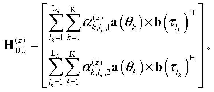
其中,
 表示基于第z个传输层反馈的第一极化方向上由第k个角度向量及其对应的第l
k个时延向量构成的角度时延对的加权系数;
表示基于第z个传输层反馈的第一极化方向上由第k个角度向量及其对应的第l
k个时延向量构成的角度时延对的加权系数;
 表示基于第z个传输层反馈的第二极化方向上与第k个角度向量及其对应的第l
k个时延向量构成的角度时延对的加权系数。
among them, It represents a weighting coefficient based on the angle of the first polarization direction of the z-transport layer composed of a feedback k-vector angles and the corresponding delay of the k-th vector of L delay pair; Represents the weighting coefficient of the angular delay pair formed by the k-th angle vector and its corresponding lk- th delay vector in the second polarization direction based on the z-th transmission layer feedback.
表示基于第z个传输层反馈的第二极化方向上与第k个角度向量及其对应的第l
k个时延向量构成的角度时延对的加权系数。
among them, It represents a weighting coefficient based on the angle of the first polarization direction of the z-transport layer composed of a feedback k-vector angles and the corresponding delay of the k-th vector of L delay pair; Represents the weighting coefficient of the angular delay pair formed by the k-th angle vector and its corresponding lk- th delay vector in the second polarization direction based on the z-th transmission layer feedback.
可以理解的是,当K个角度向量中的任意两个角度向量对应相同的L个时延向量时,上述计算式中的下角标l
k和L
k中的k可以省略。即,分别为
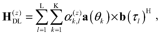 以及
以及
 It can be understood that when any two of the K angle vectors correspond to the same L delay vectors, the subscripts l k and k in L k in the above calculation formula can be omitted. That is, respectively as well as
应理解,上文对于2个极化方向定义的空频矩阵
 的计算式仅为示例,不应对本申请构成任何限定。例如,在不同的极化方向上加载的时延向量和/或角度向量的数量可以相同也可以不同,在不同的极化方向上加载是时延向量和/或角度向量可以相同,也可以不同。
It should be understood that the space-frequency matrix defined above for the two polarization directions The calculation formula of is only an example, and should not constitute any limitation to this application. For example, the number of delay vectors and/or angle vectors loaded in different polarization directions may be the same or different, and the delay vectors and/or angle vectors loaded in different polarization directions may be the same or different .
的计算式仅为示例,不应对本申请构成任何限定。例如,在不同的极化方向上加载的时延向量和/或角度向量的数量可以相同也可以不同,在不同的极化方向上加载是时延向量和/或角度向量可以相同,也可以不同。
It should be understood that the space-frequency matrix defined above for the two polarization directions The calculation formula of is only an example, and should not constitute any limitation to this application. For example, the number of delay vectors and/or angle vectors loaded in different polarization directions may be the same or different, and the delay vectors and/or angle vectors loaded in different polarization directions may be the same or different .
对于Z个传输层而言,网络设备可以分别基于每个传输层对应的P个加权系数确定与各传输层对应的空频矩阵
 至
至
 由此,网络设备可确定与各RB对应的预编码矩阵W
(n)。
For Z transmission layers, the network device can determine the space-frequency matrix corresponding to each transmission layer based on the P weighting coefficients corresponding to each transmission layer to Thereby, the network device can determine the precoding matrix W (n) corresponding to each RB.
由此,网络设备可确定与各RB对应的预编码矩阵W
(n)。
For Z transmission layers, the network device can determine the space-frequency matrix corresponding to each transmission layer based on the P weighting coefficients corresponding to each transmission layer to Thereby, the network device can determine the precoding matrix W (n) corresponding to each RB.
以N个RB中的第n个RB为例,网络设备可以首先确定与第n个RB对应的预编码矩阵W
(n)的共轭(W
(n))
*。可以是由上述基于Z个传输层分别确定的Z个空频矩阵

 至
至
 中每个空频矩阵中的第n个列向量构建。例如,将
 中的第n列作为下行信道矩阵(W
(n))
*的第一列,将
中的第n列作为下行信道矩阵(W
(n))
*的第一列,将
 中的第n列作为下行信道矩阵(W
(n))
*的第二列;以此类推,可以将
中的第n列作为下行信道矩阵(W
(n))
*的第二列;以此类推,可以将
 中的第n列作为下行信道矩阵(W
(n))
*的第z列。由此可以得到矩阵(W
(n))
*,进而可以确定与第n个RB对应的预编码矩阵W
(n)。
Taking the nth RB of the N RBs as an example, the network device may first determine the conjugate (W (n) ) * of the precoding matrix W (n) corresponding to the nth RB. May be Z space-frequency matrices respectively determined based on the Z transmission layers described above to The n-th column vector in each space-frequency matrix is constructed. For example, The nth column in is the first column of the downlink channel matrix (W (n) ) * , and The nth column in is used as the second column of the downlink channel matrix (W (n) ) * ; by analogy, the The nth column in is the zth column of the downlink channel matrix (W (n) ) * . From this, the matrix (W (n) ) * can be obtained, and further the precoding matrix W (n) corresponding to the n-th RB can be determined.
中的第n列作为下行信道矩阵(W
(n))
*的第z列。由此可以得到矩阵(W
(n))
*,进而可以确定与第n个RB对应的预编码矩阵W
(n)。
Taking the nth RB of the N RBs as an example, the network device may first determine the conjugate (W (n) ) * of the precoding matrix W (n) corresponding to the nth RB. May be Z space-frequency matrices respectively determined based on the Z transmission layers described above to The n-th column vector in each space-frequency matrix is constructed. For example, The nth column in is the first column of the downlink channel matrix (W (n) ) * , and The nth column in is used as the second column of the downlink channel matrix (W (n) ) * ; by analogy, the The nth column in is the zth column of the downlink channel matrix (W (n) ) * . From this, the matrix (W (n) ) * can be obtained, and further the precoding matrix W (n) corresponding to the n-th RB can be determined.
基于上述方法可以确定与各RB分别对应的预编码矩阵。Based on the above method, the precoding matrix corresponding to each RB can be determined.
应理解,上文仅为便于理解,以空频分量矩阵为例详细说明了网络设备确定预编码矩阵的具体过程。但这不应对本申请构成任何限定。网络设备也可以基于P个角度时延对确定P个空频分量向量,进而确定预编码矩阵。本领域的技术人员,基于P个角度时延对可以构造不同形式的P个空频基本单位,进而确定预编码矩阵。基于P个角度时延对而构造的不同形式的P个空频基本单位,进而基于P个空频基本单位的加权和来确定预编码矩阵的方式均应落入本申请要求的保护范围内。It should be understood that the above is only for ease of understanding. Taking the space-frequency component matrix as an example, the specific process of determining the precoding matrix by the network device is described in detail. However, this should not constitute any limitation on this application. The network device may also determine P space-frequency component vectors based on P angular delay pairs, and then determine the precoding matrix. A person skilled in the art may construct P basic units of space frequency in different forms based on P angular delay pairs, and then determine a precoding matrix. The P space frequency basic units of different forms constructed based on P angle delay pairs, and the method of determining the precoding matrix based on the weighted sum of the P space frequency basic units should all fall within the protection scope required by the present application.
还应理解,上文仅为示例,示出了网络设备根据第一指示信息确定预编码矩阵的可能实现方式,但这不应对本申请构成任何限定。本申请对于网络设备根据第一指示信息确定预编码矩阵的具体实现方式不作限定。本领域的技术人员基于相同的构思,对上文列举的矩阵运算进行变换或者等价的替换,确定预编码矩阵的方法均应落入本申请的保护范围内。It should also be understood that the above is only an example and shows a possible implementation manner in which the network device determines the precoding matrix according to the first indication information, but this should not constitute any limitation to this application. This application does not limit the specific implementation manner of the network device determining the precoding matrix according to the first indication information. Based on the same concept, those skilled in the art transform or equivalently replace the matrix operations listed above, and the method for determining the precoding matrix should fall within the protection scope of the present application.
还应理解,上文中确定的预编码矩阵是与RB对应的预编码矩阵。这里,RB为频域单元的一例。与RB对应的预编码矩阵,可以是指,以RB为粒度基于该RB对应的信道矩阵确定的预编码矩阵,或者说,基于该RB上接收到的预编码参考信号确定的预编码矩阵,可用于对通过该RB传输的数据做预编码。与RB对应的下行信道,可以是指,基于该RB上接收到的预编码参考信号确定的下行信道,可用于确定与该RB对应的预编码矩阵。It should also be understood that the precoding matrix determined above is a precoding matrix corresponding to RB. Here, RB is an example of a frequency domain unit. The precoding matrix corresponding to the RB may refer to the precoding matrix determined based on the channel matrix corresponding to the RB at the granularity of the RB, or the precoding matrix determined based on the precoding reference signal received on the RB, available Yu pre-codes the data transmitted through the RB. The downlink channel corresponding to the RB may refer to a downlink channel determined based on the precoding reference signal received on the RB, and may be used to determine the precoding matrix corresponding to the RB.
当频域单元的粒度较大,如频域单元为子带、PRG或者PRB时,网络设备可以根据每个频域单元中各RB对应的预编码矩阵确定与频域单元的预编码矩阵。When the granularity of the frequency domain unit is large, for example, the frequency domain unit is a subband, PRG, or PRB, the network device may determine the precoding matrix corresponding to the frequency domain unit according to the precoding matrix corresponding to each RB in each frequency domain unit.
若每个频域单元包括一个用于承载参考信号的RB,则网络设备可以将该RB对应的预编码矩阵作为所属的频域单元对应的预编码矩阵。若每个频域单元包括多个用于承载参 考信号的RB,则网络设备例如可以将同一个频域单元中与多个RB对应的预编码矩阵的相关矩阵求平均后进行SVD以确定该频域单元对应的预编码矩阵;网络设备又例如可以将同一个频域单元中与多个RB对应的预编码矩阵的平均作为该频域单元对应的预编码矩阵,等等。If each frequency domain unit includes an RB for carrying a reference signal, the network device may use the precoding matrix corresponding to the RB as the corresponding precoding matrix corresponding to the frequency domain unit. If each frequency domain unit includes multiple RBs for carrying reference signals, the network device may, for example, average the correlation matrices of the precoding matrices corresponding to multiple RBs in the same frequency domain unit and perform SVD to determine the frequency The precoding matrix corresponding to the domain unit; for example, the network device may use the average of the precoding matrix corresponding to multiple RBs in the same frequency domain unit as the precoding matrix corresponding to the frequency domain unit, and so on.
应理解,网络设备根据频域单元中多个RB对应的预编码矩阵确定该频域单元的预编码矩阵的具体方法可以参考技术,而不限于上文所列举。本申请对于网络设备频域单元中多个RB对应的预编码矩阵确定该频域单元的预编码矩阵的具体方法不作限定。It should be understood that the specific method for the network device to determine the precoding matrix of the frequency domain unit according to the precoding matrix corresponding to multiple RBs in the frequency domain unit may refer to the technology, and is not limited to the above. This application does not limit the specific method for determining the precoding matrix of the frequency domain unit by the precoding matrix corresponding to multiple RBs in the frequency domain unit of the network device.
还应理解,还应理解,上文中在描述时提及的与某一角度向量和某一时延向量对应的加权系数,也就是,与某一角度向量和某一时延向量构成的角度时延对对应的加权系数。例如,与第k个角度向量和第l个时延向量对应的加权系数,也就是,与第k个角度向量和第l个时延向量构成的角度时延对对应的加权系数。为了简洁,这里不再一一举例说明。It should also be understood that the weighting coefficients corresponding to a certain angle vector and a certain delay vector mentioned in the description above, that is, the angle delay pair formed by a certain angle vector and a certain delay vector Corresponding weighting factor. For example, the weighting coefficient corresponding to the k-th angle vector and the l-th delay vector, that is, the weighting coefficient corresponding to the angular delay pair composed of the k-th angle vector and the l-th delay vector. For brevity, no more examples are given here.
在本申请实施例中,网络设备基于上行信道测量所确定的角度,对下行参考信号进行预编码,使得终端设备根据预编码后的参考信号进行下行信道测量。由于网络设备基于上下行信道可互易的角度对参考信号进行了预编码,终端设备可以不必反馈空域的向量(如上述角度向量),仅反馈频域的向量(如上述时延向量)以及各角度时延对的加权系数。可以大大减小终端设备的反馈开销。此外,通过利用上下行信道的互易性,将终端设备对下行信道的测量过程简化,降低了终端设备在信道测量过程中的计算复杂度。并且,通过对下行参考信号进行空域预编码,可以减小参考信号的端口数,从而可以降低导频开销。In the embodiment of the present application, the network device pre-codes the downlink reference signal based on the angle determined by the uplink channel measurement, so that the terminal device performs downlink channel measurement according to the pre-coded reference signal. Since the network device pre-codes the reference signal based on the reciprocal angle of the uplink and downlink channels, the terminal device may not need to feedback the vector in the spatial domain (such as the above-mentioned angle vector), but only the vector in the frequency domain (such as the above-mentioned delay vector) and each The weighting factor of the angle delay pair. Can greatly reduce the feedback overhead of the terminal device. In addition, by utilizing the reciprocity of the uplink and downlink channels, the measurement process of the downlink channel by the terminal device is simplified, and the calculation complexity of the terminal device during the channel measurement process is reduced. Moreover, by performing spatial domain precoding on the downlink reference signal, the number of ports of the reference signal can be reduced, thereby reducing pilot overhead.
应理解,本申请实施例中仅为便于理解,示出了空频矩阵由真实的信道的转置得到的情况下,下行信道测量并确定预编码矩阵的具体过程。但这不应对本申请构成任何限定。真实的信道与空频矩阵H
DL的关系并不是固定不变的。对空频矩阵以及空频分量矩阵的不同定义,可能会使得真实的信道与空频矩阵H
DL之间的关系发生变化。例如,空频矩阵H
DL可以由真实的信道的转置得到,也可以由真实的信道的共轭转置得到。
It should be understood that the embodiments of the present application are for ease of understanding only, and show the specific process of measuring and determining the precoding matrix in the downlink channel when the space-frequency matrix is obtained by transposing the real channel. However, this should not constitute any limitation on this application. The relationship between the real channel and the space frequency matrix H DL is not fixed. Different definitions of the space-frequency matrix and the space-frequency component matrix may cause the relationship between the real channel and the space-frequency matrix H DL to change. For example, the space frequency matrix H DL may be obtained by transposing the real channel, or may be obtained by conjugate transposing the real channel.
当对空频矩阵与信道矩阵间的关系的定义不同时,在加载时延和角度时网络设备所执行的操作也有所不同,终端设备在进行信道测量并反馈时所执行的操作也相应地发生变化。但这只是终端设备和网络设备的实现行为,不应对本申请构成任何限定。本申请对于信道矩阵的定义、空频矩阵的维度及其定义以及二者间的转换关系不作限定。同理,本申请对于空频矩阵与预编码矩阵间的转换关系也不作限定。When the definition of the relationship between the space frequency matrix and the channel matrix is different, the operations performed by the network device when loading the delay and angle are also different, and the operations performed by the terminal device when performing channel measurement and feedback also occur accordingly Variety. However, this is only the implementation behavior of the terminal device and the network device, and should not constitute any limitation to this application. This application does not limit the definition of the channel matrix, the dimension and definition of the space-frequency matrix, and the conversion relationship between the two. Similarly, the application does not limit the conversion relationship between the space-frequency matrix and the precoding matrix.
上文方法实施例中,以基于角度向量对参考信号进行预编码为例,详细说明了本申请提供的信道测量方法。但这不应对本申请构成任何限定。网络设备也可以仅基于时延向量对参考信号进行预编码,以便于终端设备基于预编码参考信号进行下行信道测量。In the above method embodiments, taking the precoding of the reference signal based on the angle vector as an example, the channel measurement method provided by the present application is described in detail. However, this should not constitute any limitation on this application. The network device may also precode the reference signal based on the delay vector only, so that the terminal device performs downlink channel measurement based on the precoded reference signal.
为便于理解本申请实施例,下文实施例首先以发射天线的一个极化方向为例详细说明本申请实施例提供的信道测量方法400。应理解,该极化方向可以是发射天线的一个或多个极化方向中的任意一个极化方向。换句话说,一个或多个极化方向中的任意一个极化方向都可以基于本申请实施例提供的方法400进行信道测量。还应理解,本申请对于发射天线的极化方向数并不做限定,例如可以为一个,即,单极化方向;也可以为多个,如,双极化方向。In order to facilitate understanding of the embodiments of the present application, the following embodiment first uses a polarization direction of a transmitting antenna as an example to describe in detail the channel measurement method 400 provided by the embodiments of the present application. It should be understood that the polarization direction may be any one of one or more polarization directions of the transmitting antenna. In other words, any one of the one or more polarization directions can be used for channel measurement based on the method 400 provided in the embodiment of the present application. It should also be understood that the number of polarization directions of the transmitting antenna is not limited in this application, for example, it may be one, that is, a single polarization direction; it may also be multiple, such as a dual polarization direction.
图5是从设备交互的角度示出的本申请实施例提供的信道测量方法500的示意性流程图。如图所示,该方法500可以包括步骤510至步骤540。下面详细说明方法500中的各 步骤。FIG. 5 is a schematic flowchart of a channel measurement method 500 provided by an embodiment of the present application from the perspective of device interaction. As shown, the method 500 may include steps 510 to 540. The steps of method 500 are described in detail below.
在步骤510中,终端设备接收预编码参考信号,该预编码参考信号是基于L个时延向量对参考信号预编码得到。相应地,网络设备发送预编码参考信号。其中,L≥1,且L为整数。In step 510, the terminal device receives a precoding reference signal, which is obtained by precoding the reference signal based on L delay vectors. Correspondingly, the network device sends a precoding reference signal. Among them, L ≥ 1, and L is an integer.
在本实施例中,网络设备可以基于L个时延向量对参考信号进行预编码。由于该参考信号未经过空域预编码,基于一个时延向量预编码后得到的预编码参考信号可以与T个发射天线端口中的至少部分发射天线端口对应。其中,T为一个极化方向上的发射天线端口数,T≥1,且T为整数。In this embodiment, the network device may pre-code the reference signal based on L delay vectors. Since the reference signal has not been precoded in the spatial domain, the precoded reference signal obtained after precoding based on a delay vector may correspond to at least part of the T antenna ports. Where T is the number of transmit antenna ports in one polarization direction, T≥1, and T is an integer.
在一种可能的实现方式中,网络设备可以遍历L个时延向量,基于L个时延向量中的每个时延向量,对承载于每个RB的参考信号进行预编码,并通过T个发射天线端口发送预编码后的参考信号。通过遍历L个时延向量和T个发射天线端口,可以得到T×L种不同的组合,或者说,T×L个天线时延对。由于未涉及空域预编码,每种组合可对应一个时延向量。换句话说,通过将L个时延向量加载在不同发射天线端口的参考信号上,可以得到时延向量与发射天线端口的不同组合共T×L种。In a possible implementation manner, the network device may traverse L delay vectors, and based on each delay vector of the L delay vectors, precode the reference signal carried in each RB, and pass T The transmit antenna port sends the precoded reference signal. By traversing L delay vectors and T transmitting antenna ports, T×L different combinations, or T×L antenna delay pairs, can be obtained. Since spatial precoding is not involved, each combination can correspond to a delay vector. In other words, by loading L delay vectors on the reference signals of different transmit antenna ports, T×L different combinations of the delay vector and the transmit antenna port can be obtained.
在另一种可能的实现方式中,网络设备可以基于L个时延向量对承载于测量带宽中每个RB的参考信号进行预编码,并通过T个发射天线端口发送预编码后的参考信号。基于不同的时延向量预编码得到的预编码参考信号可以被映射至不同的RB上。即,至少有两个RB承载的预编码参考信号对应的时延向量不同。换句话说,通过将L个时延向量加载在不同发射天线端口的参考信号上,可以得到时延向量与发射天线端口的不同组合共T×L’种,1≤L’<L,L’为整数。In another possible implementation manner, the network device may precode the reference signal carried by each RB in the measurement bandwidth based on L delay vectors, and send the precoded reference signal through T transmit antenna ports. The precoding reference signals obtained based on different delay vector precoding can be mapped onto different RBs. That is, at least two RBs carry precoding reference signals corresponding to different delay vectors. In other words, by loading L delay vectors on the reference signals of different transmit antenna ports, different combinations of delay vectors and transmit antenna ports can be obtained, totaling T×L′, 1≦L′<L, L′ Is an integer.
由于时延具有上下行信道互易性,该L个时延向量均可以是基于上行信道测量确定。由于在上文方法200中已经详细说明了网络设备基于上行信道测量确定L个较强的时延的具体方法,为了简洁,这里不再赘述。Due to the reciprocity of the uplink and downlink channels, the L delay vectors can all be determined based on uplink channel measurements. Since the method 200 above has described in detail the specific method by which the network device determines the L strong delays based on the uplink channel measurement, for the sake of brevity, it will not be repeated here.
由于在FDD模式下,上下行信道的时延可互易,则可以将上行信道测量所得的L个时延向量加载至下行参考信号,以便终端设备基于接收到的预编码参考信号进行下行信道测量。In the FDD mode, the delays of the uplink and downlink channels are reciprocal, so the L delay vectors measured by the uplink channel can be loaded into the downlink reference signal, so that the terminal device can measure the downlink channel based on the received precoding reference signal .
网络设备可以基于该L个时延向量对下行参考信号,如CSI-RS,进行预编码,以得到预编码参考信号。网络设备还可以通过预先配置的参考信号资源传输该预编码参考信号。The network device may pre-code the downlink reference signal, such as CSI-RS, based on the L delay vectors to obtain a pre-coded reference signal. The network device may also transmit the pre-coded reference signal through a pre-configured reference signal resource.
可选地,该方法500还包括:终端设备接收第五指示信息,该第五指示信息用于配置一个或多个参考信号资源。相应地,网络设备发送该第五指示信息。Optionally, the method 500 further includes: the terminal device receives fifth indication information, where the fifth indication information is used to configure one or more reference signal resources. Correspondingly, the network device sends the fifth indication information.
该第五指示信息所配置的一个或多个参考信号资源可用于承载预编码参考信号。其中,同一参考信号资源上承载的预编码参考信号可对应一个或多个端口。在第五指示信息配置多个参考信号资源的情况下,各参考信号资源上承载的预编码参考信号对应的时延向量和/或发射天线端口可以是互不相同的,且各参考信号资源在频域和/或时域上互不重叠。在本实施例中,每个端口的预编码参考信号对应于一个发射天线端口和一个时延向量。One or more reference signal resources configured by the fifth indication information may be used to carry precoding reference signals. Wherein, the precoding reference signal carried on the same reference signal resource may correspond to one or more ports. In the case where the fifth indication information configures multiple reference signal resources, the delay vector and/or the transmit antenna port corresponding to the precoded reference signal carried on each reference signal resource may be different from each other, and each reference signal resource is The frequency domain and/or time domain do not overlap each other. In this embodiment, the precoded reference signal of each port corresponds to one transmit antenna port and one delay vector.
由于上文中已经对该第五指示信息做了详细说明,为了简洁,这里不再赘述。Since the fifth instruction information has been described in detail above, it will not be repeated here for brevity.
在一种实现方式中,网络设备可以遍历L个时延向量中的每个时延向量对每个发射天线端口上的参考信号进行预编码,以得到预编码参考信号。用于传输该预编码参考信号的 参考信号资源可以由网络设备预先通过高层信令配置,如上述第五指示信息。该参考信号资源可以包括一个或多个RB,如N个。每个RB上承载的预编码参考信号都是基于相同的L个时延向量进行预编码得到。In an implementation manner, the network device may traverse each of the L delay vectors to precode the reference signal on each transmit antenna port to obtain a precoded reference signal. The reference signal resource used to transmit the precoded reference signal may be pre-configured by the network device through high-layer signaling, such as the above-mentioned fifth indication information. The reference signal resource may include one or more RBs, such as N. The precoding reference signal carried on each RB is obtained by precoding based on the same L delay vectors.
在这种实现方式中,网络设备可以预先为终端设备配置一个参考信号资源。该参考信号资源中的每个RB上承载的预编码参考信号可以对应P(即T×L)个端口。每个端口的预编码参考信号可以是基于L个时延向量中的一个时延向量,对T个发射天线端口上的一个天线端口的参考信号进行预编码得到。In this implementation, the network device may configure a reference signal resource for the terminal device in advance. The precoding reference signal carried on each RB in the reference signal resource may correspond to P (that is, T×L) ports. The precoded reference signal of each port may be obtained by precoding a reference signal of one antenna port on T transmit antenna ports based on one delay vector of L delay vectors.
此外,由于将L个时延向量加载到参考信号资源中的每个RB上,每个RB对应的端口数较大,可能带来较大的导频开销。因此,网络设备可以通过高层信令,如上述第五指示信息,配置较小的导频密度,以减小导频开销。In addition, since L delay vectors are loaded on each RB in the reference signal resource, the number of ports corresponding to each RB is large, which may bring a large pilot overhead. Therefore, the network device may configure a lower pilot density through higher layer signaling, such as the fifth indication information, to reduce pilot overhead.
由于上文中已经结合图3详细说明了对RB不分组的情况下,参考信号资源的每个RB上承载的预编码参考信号与端口的对应关系。本实施例中每个RB上承载的预编码参考信号与端口的对应关系与之相似,只是将上文实施例中的角度向量替换为了发射天线端口。为了简洁,这里不再结合附图一一详细说明。As described above in detail in conjunction with FIG. 3 in the case where RBs are not grouped, the correspondence between the precoding reference signal and the port carried on each RB of the reference signal resource. In this embodiment, the correspondence between the precoded reference signal carried on each RB and the port is similar, except that the angle vector in the above embodiment is replaced with the transmit antenna port. For the sake of brevity, detailed description will not be given here in conjunction with the drawings.
如果每个RB上的预编码参考信号均是遍历L个时延向量预编码得到,则在RB数较多的情况下,会带来较大的导频开销。为了节省导频开销,可以将RB做分组,每个频域组中承载的预编码参考信号可以是基于角度向量和时延向量的P种组合中的部分组合,例如一个时延向量及其对应的角度向量,或者,一个角度向量及其对应的时延向量,或者,一个时延向量和一个角度向量,预编码得到。由此可以大大降低导频开销。If the precoding reference signal on each RB is obtained by traversing L delay vector precodings, then in the case of a large number of RBs, it will bring a large pilot overhead. To save pilot overhead, RBs can be grouped. The precoded reference signal carried in each frequency domain group can be a partial combination of P combinations based on angle vectors and delay vectors, such as a delay vector and its corresponding The angle vector of, or, an angle vector and its corresponding delay vector, or, a delay vector and an angle vector, are obtained by precoding. This can greatly reduce the pilot overhead.
在另一种可能的实现方式中,网络设备可以基于L个时延向量对参考信号进行预编码。基于不同的时延向量预编码所得到的预编码参考信号可以被映射至不同的RB上。每个RB上承载的预编码参考信号可以是基于L个时延向量中的部分时延向量预编码得到。在多个RB中,至少有两个RB承载的预编码参考信号是基于不同的时延向量预编码得到。In another possible implementation manner, the network device may pre-code the reference signal based on L delay vectors. The precoding reference signals obtained based on different delay vector precoding can be mapped onto different RBs. The precoding reference signal carried on each RB may be obtained by precoding a partial delay vector among L delay vectors. Among multiple RBs, the precoding reference signals carried by at least two RBs are obtained by precoding based on different delay vectors.
在这种实现方式中,用于传输预编码参考信号的参考信号资源可以为多个。网络设备可以预先通过高层信令,如上述第五指示信息,为终端设备配置多个参考信号资源。该多个参考信号资源中的每个参考信号资源可以包括一个或多个RB。每个参考信号资源中承载的预编码参考信号可对应一个或多个端口,且各参考信号资源承载的预编码参考信号对应的时延向量和/或发射天线端口不同。每个端口的预编码参考信号均可以是基于L个时延向量中的一个时延向量对一个发射天线端口的参考信号进行预编码得到。此外,各参考信号资源在频域上和/或时域上互不重叠。例如,各参考信号资源在频域上交错排布。因此,基于不同的时延向量预编码得到的预编码参考信号可以通过不同的时频资源承载。In this implementation manner, there may be multiple reference signal resources used to transmit the precoded reference signal. The network device may configure multiple reference signal resources for the terminal device in advance through high-layer signaling, such as the above-mentioned fifth indication information. Each reference signal resource in the plurality of reference signal resources may include one or more RBs. The precoded reference signal carried in each reference signal resource may correspond to one or more ports, and the delay vector and/or the transmit antenna port corresponding to the precoded reference signal carried in each reference signal resource are different. The precoding reference signal of each port may be obtained by precoding a reference signal of a transmitting antenna port based on one delay vector among L delay vectors. In addition, the reference signal resources do not overlap each other in the frequency domain and/or the time domain. For example, the reference signal resources are staggered in the frequency domain. Therefore, the precoding reference signals obtained based on different delay vector precoding can be carried by different time-frequency resources.
在这种实现方式中,每个RB上承载的预编码参考信号可以对应的端口数可能小于P。例如,每个RB上加载一个时延向量,则每个RB上承载的预编码参考信号可以对应T个端口,且至少有两个RB承载的预编码参考信号对应不同的时延向量。当两个RB承载的预编码参考信号对应不同的时延向量时,该两个RB承载的预编码参考信号对应的端口号可以相同,也可以不同,本申请对此不作限定。In this implementation manner, the number of ports corresponding to the precoded reference signals carried on each RB may be less than P. For example, if one delay vector is loaded on each RB, the precoding reference signal carried on each RB may correspond to T ports, and the precoding reference signals carried on at least two RBs correspond to different delay vectors. When the precoding reference signals carried by the two RBs correspond to different delay vectors, the port numbers corresponding to the precoding reference signals carried by the two RBs may be the same or different, which is not limited in this application.
网络设备可以对多个RB分组,并基于不同的频域组来进行频域预编码。具体地,N个RB可以被划分为多个频域组,如M个频域组,M>1且为整数。每个频域组中可以包括
 个RB。如果N不能被M整除,则最后一个频域组中的RB数可以是剩余的RB 数。即,第M个频域组中包含的RB数可能小于
 个。
The network device may group multiple RBs and perform frequency domain precoding based on different frequency domain groups. Specifically, N RBs may be divided into multiple frequency domain groups, such as M frequency domain groups, M>1 and an integer. Each frequency domain group can include RB. If N is not divisible by M, the number of RBs in the last frequency domain group may be the number of remaining RBs. That is, the number of RBs included in the Mth frequency domain group may be less Pcs.
个。
The network device may group multiple RBs and perform frequency domain precoding based on different frequency domain groups. Specifically, N RBs may be divided into multiple frequency domain groups, such as M frequency domain groups, M>1 and an integer. Each frequency domain group can include RB. If N is not divisible by M, the number of RBs in the last frequency domain group may be the number of remaining RBs. That is, the number of RBs included in the Mth frequency domain group may be less Pcs.
在对RB做分组的情况下,每个频域组中承载的预编码参考信号可以是基于L个时延向量中的部分时延向量预编码得到。In the case of grouping RBs, the precoding reference signal carried in each frequency domain group may be obtained by precoding a partial delay vector among L delay vectors.
可选地,M=L。即,频域组数可以等于时延向量的个数。则每个频域组中可以包括
 个RB。该L个频域组中的第l个频域组所包含的RB可以是N个RB中的第l个、第l+L个、第l+2L个直至第
 个。换句话说,该L个频域组中的第l个频域组包括N个RB中的第l+(i-1)×L个RB,
 Optionally, M=L. That is, the number of frequency domain groups may be equal to the number of delay vectors. Then each frequency domain group can include RB. The RB included in the lth frequency domain group of the L frequency domain groups may be the lth, l+Lth, l+2Lth through Nth RBs up to the Pcs. In other words, the lth frequency domain group of the L frequency domain groups includes the l+(i-1)×L RB of N RBs,
其中,N个RB中的第l个RB可以是第l个频域组中的第1个RB,N个RB中的第l+L个RB可以是第l个频域组中的第2个RB,N个RB中的第l+2L个RB可以是第l个频域组中的第3个RB,N个RB中的第个RB可以是第l个频域组中的第
 个RB。以此类推,N个RB中的第l+(n-1)×L个RB可以是第l个频域组中的第n个RB。
Among them, the lth RB in the N RBs may be the first RB in the lth frequency domain group, and the l+Lth RB in the N RBs may be the second RB in the lth frequency domain group RB, the 1st+2Lth RB of N RBs may be the 3rd RB in the 1st frequency domain group, and the 1st RB in N RBs may be the 3rd RB in the 1st frequency domain group RB. By analogy, the l+(n-1)×L RBs out of the N RBs may be the nth RBs in the lth frequency domain group.
个RB。以此类推,N个RB中的第l+(n-1)×L个RB可以是第l个频域组中的第n个RB。
Among them, the lth RB in the N RBs may be the first RB in the lth frequency domain group, and the l+Lth RB in the N RBs may be the second RB in the lth frequency domain group RB, the 1st+2Lth RB of N RBs may be the 3rd RB in the 1st frequency domain group, and the 1st RB in N RBs may be the 3rd RB in the 1st frequency domain group RB. By analogy, the l+(n-1)×L RBs out of the N RBs may be the nth RBs in the lth frequency domain group.
网络设备可以基于L个时延向量中的第l个时延向量对该L个频域组中的第l个频域组中各RB承载的参考信号进行频域预编码。每个频域组可对应于一个时延向量,且每个频域组中的RB可对应于时延向量中的一个元素。The network device may perform frequency domain precoding on the reference signal carried by each RB in the lth frequency domain group among the L frequency domain groups based on the lth delay vector among the L delay vectors. Each frequency domain group may correspond to a delay vector, and the RB in each frequency domain group may correspond to an element in the delay vector.
此时,每个RB上承载的预编码参考信号对应的端口数可以是T。该T个端口具体可以对应于T个发射天线端口。At this time, the number of ports corresponding to the precoding reference signal carried on each RB may be T. The T ports may specifically correspond to T transmit antenna ports.
图6示出了多个RB上承载多个端口的预编码参考信号的另一例。图中示出了RB数为16的一例。FIG. 6 shows another example of precoding reference signals carrying multiple ports on multiple RBs. The figure shows an example where the number of RBs is 16.
图6示出的16个RB中,每个RB上承载的预编码参考信号可以基于一个时延向量预编码得到。该16个RB可以分为4个频域组。RB#1、RB#5、RB#9和RB#13可以归为频域组#1,RB#2、RB#6、RB#10和RB#14可以归为频域组#2,RB#3、RB#7、RB#11和RB#15可以归为频域组#3,RB#4、RB#8、RB#12和RB#16可以归为频域组#4。Among the 16 RBs shown in FIG. 6, the precoding reference signal carried on each RB can be obtained by precoding based on a delay vector. The 16 RBs can be divided into 4 frequency domain groups. RB# 1, RB# 5, RB# 9 and RB# 13 can be classified as frequency domain group # 1, RB# 2, RB# 6, RB# 10 and RB# 14 can be classified as frequency domain group # 2, RB# 3. RB# 7, RB# 11 and RB# 15 can be classified as frequency domain group # 3, and RB# 4, RB# 8, RB# 12 and RB# 16 can be classified as frequency domain group # 4.
该16个RB可以分别属于四个参考信号资源。每个频域组可以是一个参考信号资源。该四个频域组可以是上述多个参考信号资源的一例。同一个频域组承载的预编码参考信号可以是基于同一个时延向量预编码得到。例如,L=4,L个时延向量例如可以包括b(τ
1),b(τ
2),b(τ
3)和b(τ
4)。每个频域组承载的预编码参考信号可以是基于一个时延向量预编码得到。即,上文所示的L’=1。则RB#1、RB#5、RB#9和RB#13上承载的预编码参考信号可以基于同一个时延向量预编码得到,如时延向量b(τ
1);RB#2、RB#6、RB#10和RB#14上承载的预编码参考信号可以基于同一个时延向量预编码得到,如时延向量b(τ
2);RB#3、RB#7、RB#11和RB#15上承载的预编码参考信号可以基于同一时延向量预编码得到,如时延向量b(τ
3);RB#4、RB#8、RB#12和RB#16上承载的预编码参考信号可以基于同一时延向量预编码得到,如时延向量b(τ
4)。
The 16 RBs may belong to four reference signal resources, respectively. Each frequency domain group may be a reference signal resource. The four frequency domain groups may be an example of the aforementioned multiple reference signal resources. The precoding reference signals carried in the same frequency domain group may be obtained by precoding based on the same delay vector. For example, L=4, and the L delay vectors may include b(τ 1 ), b(τ 2 ), b(τ 3 ), and b(τ 4 ), for example. The precoding reference signal carried in each frequency domain group may be obtained by precoding based on a delay vector. That is, L'=1 shown above. Then the precoding reference signals carried on RB# 1, RB# 5, RB# 9 and RB# 13 can be obtained by precoding based on the same delay vector, such as delay vector b(τ 1 ); RB# 2, RB# 6. The precoded reference signals carried on RB# 10 and RB# 14 can be precoded based on the same delay vector, such as delay vector b(τ 2 ); RB# 3, RB# 7, RB# 11 and RB The precoding reference signal carried on #15 can be obtained by precoding based on the same delay vector, such as delay vector b(τ 3 ); the precoding reference carried on RB# 4, RB# 8, RB# 12 and RB# 16 The signal can be pre-coded based on the same delay vector, such as delay vector b(τ 4 ).
由于同一频域组中承载的预编码参考信号是基于同一时延向量预编码得到,因此,同一频域组中承载的预编码参考信号可对应同一时延向量,也可以对应同一端口组,每个端口组包括T个发射天线端口。不同频域组中承载的预编码参考信号是基于不同的时延向量预编码得到,因此,不同频域组中承载的预编码参考信号可对应不同的时延向量。不同频域组中承载的预编码参考信号所对应的端口号可以相同,也可以不同。本申请对此不作限定。例如,频域组#1至频域组#4中承载的预编码参考信号均可对应端口#1至端口#T;又例如,频域组#1中承载的预编码参考信号可对应端口#1至端口#T;频域组#2中承载的预 编码参考信号可对应端口#T+1至端口#2T;频域组#3中承载的预编码参考信号可对应端口#2T+1至端口#3T;频域组#4中承载的预编码参考信号可对应端口#3T+1至端口#4T。Since the precoded reference signals carried in the same frequency domain group are precoded based on the same delay vector, the precoded reference signals carried in the same frequency domain group can correspond to the same delay vector or the same port group. Each port group includes T transmit antenna ports. The precoding reference signals carried in different frequency domain groups are obtained by precoding based on different delay vectors. Therefore, the precoding reference signals carried in different frequency domain groups may correspond to different delay vectors. The port numbers corresponding to the precoding reference signals carried in different frequency domain groups may be the same or different. This application does not limit this. For example, the precoded reference signals carried in frequency domain group # 1 to frequency domain group # 4 can all correspond to port # 1 to port #T; for another example, the precoded reference signals carried in frequency domain group # 1 can correspond to port # 1 1 to port #T; the precoded reference signal carried in frequency domain group # 2 can correspond to port #T+1 to port #2T; the precoded reference signal carried in frequency domain group # 3 can correspond to port #2T+1 to Port #3T; the precoded reference signal carried in frequency domain group # 4 may correspond to port #3T+1 to port #4T.
应理解,对每个频域组加载一个时延向量仅为便于理解而示例。本申请对每个频域组加载的时延向量个数不作限定。It should be understood that loading a delay vector for each frequency domain group is only an example for ease of understanding. This application does not limit the number of delay vectors loaded in each frequency domain group.
例如,图中示出的每个RB上承载的预编码参考信号可对应更多端口,例如2T个,即,L’=2。8个端口的预编码参考信号例如可以基于2个时延向量分别对T个发射天线端口的参考信号预编码得到。其中,2个时延向量可以是取自上述4个时延向量中的两个。For example, the precoding reference signals carried on each RB shown in the figure may correspond to more ports, for example, 2T, that is, L′=2. The precoding reference signals for 8 ports may be based on 2 delay vectors, for example The reference signals of T transmitting antenna ports are pre-coded respectively. Among them, the two delay vectors may be taken from two of the above four delay vectors.
应理解,上文列举的L的取值以及对每个频域组加载的时延向量个数L’仅为示例,不应对本申请构成任何限定。本申请对于L和L’的取值以及每个频域组加载的时延向量个数均不作限定。It should be understood that the values of L listed above and the number of delay vectors L'loaded on each frequency domain group are only examples, and should not constitute any limitation to this application. This application does not limit the values of L and L'and the number of delay vectors loaded in each frequency domain group.
可以理解的是,当每个频域组加载的时延向量的个数为L时,也就相当于没有对RB做分组。It can be understood that when the number of delay vectors loaded in each frequency domain group is L, it is equivalent to not grouping RBs.
应理解,图6仅为便于理解而示例,并未完整地示出一个RB中的全部RE,本申请对于每个RB中的RE数不作限定。此外,本申请对于每个RB上承载的预编码参考信号所对应的端口以及各端口的参考信号之间复用资源的具体方式不作限定。It should be understood that FIG. 6 is only an example for ease of understanding, and does not completely show all REs in one RB, and the number of REs in each RB is not limited in this application. In addition, the present application does not limit the port corresponding to the precoded reference signal carried on each RB and the specific way of multiplexing resources between the reference signals of each port.
进一步地,时延向量的长度为
 对于每个端口来说,所对应的时延向量中的
 个元素可以与
 个RB一一对应。每个端口的预编码参考信号在M个频域组的第m(1≤m≤M,m为整数)个频域组中第n个RB上的值至少由M个时延向量的第m个时延向量中的第n个元素确定。
Further, the length of the delay vector is For each port, in the corresponding delay vector Elements can be compared with One RB corresponds to each other. The value of the precoded reference signal of each port in the mth frequency domain group of the mth frequency domain group (1≤m≤M, m is an integer) on the nth RB of the frequency domain group is at least determined by the mth of the M delay vectors The nth element in a delay vector is determined.
个RB一一对应。每个端口的预编码参考信号在M个频域组的第m(1≤m≤M,m为整数)个频域组中第n个RB上的值至少由M个时延向量的第m个时延向量中的第n个元素确定。
Further, the length of the delay vector is For each port, in the corresponding delay vector Elements can be compared with One RB corresponds to each other. The value of the precoded reference signal of each port in the mth frequency domain group of the mth frequency domain group (1≤m≤M, m is an integer) on the nth RB of the frequency domain group is at least determined by the mth of the M delay vectors The nth element in a delay vector is determined.
可选地,时延向量的长度为
 对于每个端口来说,所对应的时延向量中的
 个元素可以与
 个RB一一对应。因此,每个端口的预编码参考信号在L个频域组的第l(1≤l≤L,l为整数)个频域组中第n个RB上的值至少由L个时延向量的第l个时延向量中的第n个元素确定。
Optionally, the length of the delay vector is For each port, in the corresponding delay vector Elements can be compared with One RB corresponds to each other. Therefore, the value of the precoded reference signal of each port on the nth RB in the lth frequency domain group of the L frequency domain groups (1≤l≤L, l is an integer) is at least determined by the L delay vectors. The nth element in the lth delay vector is determined.
个RB一一对应。因此,每个端口的预编码参考信号在L个频域组的第l(1≤l≤L,l为整数)个频域组中第n个RB上的值至少由L个时延向量的第l个时延向量中的第n个元素确定。
Optionally, the length of the delay vector is For each port, in the corresponding delay vector Elements can be compared with One RB corresponds to each other. Therefore, the value of the precoded reference signal of each port on the nth RB in the lth frequency domain group of the L frequency domain groups (1≤l≤L, l is an integer) is at least determined by the L delay vectors. The nth element in the lth delay vector is determined.
例如,该16个RB中的第1个RB(即,RB#1),也就是,频域组#1中的第1个RB,承载的预编码参考信号至少由时延向量b(τ
1)中的第1个元素确定;该16个RB中的第5个RB(即,RB#5),也就是,频域组#1中的第2个RB,承载的预编码参考信号至少由时延向量b(τ
1)中的第2个元素确定;该16个RB中的第9个RB(即,RB#9),也就是,频域组#1中的第3个RB,承载的预编码参考信号至少由时延向量b(τ
1)中的第3个元素确定;该16个RB中的第13个RB(即,RB#14),也就是,频域组#1中的第4个RB,承载的预编码参考信号至少由时延向量b(τ
1)中的第4个元素确定。
For example, the first RB of the 16 RBs (that is, RB#1), that is, the first RB in the frequency domain group # 1, the precoding reference signal carried by at least the delay vector b(τ 1 ); the first RB in the 16 RBs (ie, RB#5), that is, the second RB in the frequency domain group # 1, carries the precoded reference signal at least by The second element in the delay vector b(τ 1 ) is determined; the ninth RB of the 16 RBs (ie, RB#9), that is, the third RB in the frequency domain group # 1, carries The precoded reference signal of is determined by at least the third element in the delay vector b(τ 1 ); the 13th RB of the 16 RBs (ie, RB#14), that is, in the frequency domain group # 1 In the 4th RB of, the precoded reference signal carried is determined by at least the 4th element in the delay vector b(τ 1 ).
应理解,其他频域组中的各RB与时延向量中各元素的对应关系与之相似,为了简洁,这里就不一一列举。It should be understood that the correspondence between the RBs in other frequency domain groups and the elements in the delay vector is similar. For brevity, they are not listed here one by one.
需要说明的是,由于网络设备基于上行信道测量确定的L个时延向量的长度可能为N。而在对RB做了分组之后,用于对参考信号进行预编码的时延向量的长度为
 网络设备可以基于上行信道测量确定的L个时延向量,从每个时延向量中抽取出一部分元素形成新的L个时延向量。这里为方便区分和说明,将上行信道测量确定的L个时延向量称为L个原始时延向量。
It should be noted that the length of the L delay vectors determined by the network device based on the uplink channel measurement may be N. After grouping the RBs, the length of the delay vector used for precoding the reference signal is The network device may extract a part of elements from each delay vector to form new L delay vectors based on the L delay vectors determined by the uplink channel measurement. For the convenience of distinction and description here, the L delay vectors determined by the uplink channel measurement are called L original delay vectors.
网络设备可以基于上行信道测量确定的L个时延向量,从每个时延向量中抽取出一部分元素形成新的L个时延向量。这里为方便区分和说明,将上行信道测量确定的L个时延向量称为L个原始时延向量。
It should be noted that the length of the L delay vectors determined by the network device based on the uplink channel measurement may be N. After grouping the RBs, the length of the delay vector used for precoding the reference signal is The network device may extract a part of elements from each delay vector to form new L delay vectors based on the L delay vectors determined by the uplink channel measurement. For the convenience of distinction and description here, the L delay vectors determined by the uplink channel measurement are called L original delay vectors.
具体地,若将N个RB分为L个频域组。该L个频域组中的第l个频域组对应于L个原始时延向量中的第l个原始时延向量,且该第l个频域组中的第1个、第2个、第3个直至第
 个RB分别与第l个原始时延向量中的第l个、第l+L个、第l+2L个直至第
 个元素对应。以此类推,第l个频域组中的第n个RB可以对应于第l个原始时延向量中的第l+(n-1)×L个元素。
Specifically, if N RBs are divided into L frequency domain groups. The lth frequency domain group in the L frequency domain groups corresponds to the lth original delay vector in the L original delay vectors, and the first, second, and second in the lth frequency domain group No. 3 to No. RB and the lth, l+L, l+2L in the lth original delay vector up to the Elements. By analogy, the n-th RB in the l-th frequency domain group may correspond to the l+(n-1)×L elements in the l-th original delay vector.
个元素对应。以此类推,第l个频域组中的第n个RB可以对应于第l个原始时延向量中的第l+(n-1)×L个元素。
Specifically, if N RBs are divided into L frequency domain groups. The lth frequency domain group in the L frequency domain groups corresponds to the lth original delay vector in the L original delay vectors, and the first, second, and second in the lth frequency domain group No. 3 to No. RB and the lth, l+L, l+2L in the lth original delay vector up to the Elements. By analogy, the n-th RB in the l-th frequency domain group may correspond to the l+(n-1)×L elements in the l-th original delay vector.
应理解,上文仅为区分,定义了原始时延向量。在后文实施例中,并不涉及原始时延向量。后文实施例中所涉及的时延向量均可以理解为用于对参考信号进行频域预编码的时延向量。时延向量的长度可以为N,也可以为
 It should be understood that the above is only a distinction, and the original delay vector is defined. In the following embodiments, the original delay vector is not involved. The delay vectors involved in the following embodiments can be understood as delay vectors used for frequency domain precoding of reference signals. The length of the delay vector can be N or it can be
还应理解,上文仅为便于理解,结合附图详细说明了对N个RB分组以及基于L个时延向量对L个频域组上的参考信号进行频域预编码的过程。但这不应对本申请构成任何限定。本申请对于N个RB的分组方式不作限定。本申请对于每个频域组与时延向量的对应关系也不做限定。本申请对于每个频域组中各RB与时延向量中各元素的对应关系也不做限定。It should also be understood that the above is merely for ease of understanding, and the process of grouping N RBs and performing frequency domain precoding on reference signals on L frequency domain groups based on L delay vectors is described in detail with reference to the drawings. However, this should not constitute any limitation on this application. This application does not limit the grouping manner of N RBs. The application also does not limit the correspondence between each frequency domain group and the delay vector. The application also does not limit the correspondence between each RB in each frequency domain group and each element in the delay vector.
还应理解,上文仅为便于理解,列举了各个RB上承载的预编码参考信号与端口的对应关系,但这不应对本申请构成任何限定,本申请对于各个RB承载的预编码参考信号与时延向量和端口的对应关系不作限定。It should also be understood that the above is only for ease of understanding, and the corresponding relationship between the precoding reference signals carried on each RB and the ports is listed, but this should not constitute any limitation to this application. The correspondence between the delay vector and the port is not limited.
还应理解,图6仅为示例,详细说明了时延向量加载到参考信号上的具体过程。但应理解,这不应对本申请构成任何限定。It should also be understood that FIG. 6 is only an example, and details the specific process of loading the delay vector onto the reference signal. However, it should be understood that this should not constitute any limitation on this application.
还应理解,上文仅为便于理解,结合附图说明了基于多个时延向量对参考信号进行预编码并映射到RB上的具体过程,但这不应对本申请构成任何限定。本申请对于RB数、频域组数、时延向量数、发射天线端口数以及参考信号端口数均不做限定。本申请对于每个端口在各RB上对应的RE的位置也不做限定。It should also be understood that the above is only for ease of understanding, and the specific process of precoding and mapping the reference signal to the RB based on multiple delay vectors is described with reference to the drawings, but this should not constitute any limitation to the present application. This application does not limit the number of RBs, the number of frequency domain groups, the number of delay vectors, the number of transmit antenna ports, and the number of reference signal ports. This application also does not limit the position of the RE corresponding to each port on each RB.
还应理解,上文中基于每个RB来定义端口数仅为一种可能的实现方式,而不应对本申请构成任何限定。本申请另提出一种定义端口数的方法,即,端口数可以是指每个参考信号资源上承载的预编码参考信号所对应的端口的个数。换句话说,端口数可以跨RB定义。It should also be understood that the above definition of the number of ports based on each RB is only one possible implementation manner, and should not constitute any limitation to this application. This application also proposes a method for defining the number of ports, that is, the number of ports may refer to the number of ports corresponding to the precoded reference signals carried on each reference signal resource. In other words, the number of ports can be defined across RB.
这种定义端口数的方式可应用于对RB进行分组的情况。This way of defining the number of ports can be applied to the case of grouping RBs.
可选地,该方法500还包括:终端设备接收第六指示信息,该第六指示信息用于配置一个参考信号资源。相应地,网络设备发送该第六指示信息。Optionally, the method 500 further includes: the terminal device receives sixth indication information, where the sixth indication information is used to configure a reference signal resource. Correspondingly, the network device sends the sixth indication information.
该第六指示信息所配置的参考信号资源可用于承载预编码参考信号,且该参考信号资源承载的预编码参考信号可以是基于上述L个时延向量预编码得到的参考信号。并且,该参考信号资源中,至少有两个RB上承载的预编码参考信号是基于不同的时延向量预编码得到的。并且,当两个RB承载的预编码参考信号对应不同的时延向量时,该两个RB承载的预编码参考信号对应的端口号可以不同。换句话说,至少有两个RB上承载的预编码参考信号对应不同的端口。因此,在同一参考信号资源中,各RB上承载的预编码参考信号所对应的端口并不一定相同。The reference signal resource configured by the sixth indication information may be used to carry a precoding reference signal, and the precoding reference signal carried by the reference signal resource may be a reference signal obtained by precoding based on the L delay vectors. In addition, among the reference signal resources, at least two pre-coded reference signals carried on RBs are obtained based on different delay vector pre-coding. In addition, when the precoding reference signals carried by the two RBs correspond to different delay vectors, the port numbers corresponding to the precoding reference signals carried by the two RBs may be different. In other words, there are at least two RBs carrying precoded reference signals corresponding to different ports. Therefore, in the same reference signal resource, the ports corresponding to the precoded reference signals carried on each RB are not necessarily the same.
在本实施例中,参考信号资源例如可以包括上文结合图5描述的16个RB,也就是可以包括多个频域组。该参考信号资源中承载的预编码参考信号可以对应P个端口。In this embodiment, the reference signal resource may include, for example, the 16 RBs described above with reference to FIG. 5, that is, it may include multiple frequency domain groups. The precoded reference signal carried in the reference signal resource may correspond to P ports.
需要说明的是,当网络设备对RB做了分组,以通过不同的时延向量来对不同的RB上承载的参考信号进行预编码时,网络设备可以基于上述第五指示信息配置的多个参考信号资源来传输预编码参考信号,也可以基于上述第六指示信息配置的一个参考信号资源来传输预编码参考信号,本申请对此不作限定。It should be noted that when the network device groups the RBs to precode reference signals carried on different RBs by using different delay vectors, the network device may configure multiple references based on the fifth indication information The signal resource is used to transmit the precoding reference signal, and the precoding reference signal may also be transmitted based on one reference signal resource configured in the sixth indication information, which is not limited in this application.
在步骤520中,终端设备生成第三指示信息,该第三指示信息可用于指示至少一个角度向量和P个加权系数。In step 520, the terminal device generates third indication information, and the third indication information may be used to indicate at least one angle vector and P weighting coefficients.
由于预编码参考信号在经由无线信道被发送至终端设备时,经历了下行信道。因此,终端设备可以检测到不具有完全互易性的、下行信道的信息。终端设备可以基于接收到的预编码参考信号,确定可用于构建与下行信道相适配的预编码矩阵的角度向量及其对应的加权系数。终端设备可以基于所确定的角度向量和加权系数生成第五指示信息。Since the precoding reference signal is transmitted to the terminal device via the wireless channel, it goes through the downlink channel. Therefore, the terminal device can detect the downlink channel information without complete reciprocity. Based on the received precoding reference signal, the terminal device may determine an angle vector that can be used to construct a precoding matrix suitable for the downlink channel and its corresponding weighting coefficient. The terminal device may generate fifth indication information based on the determined angle vector and weighting coefficient.
首先,终端设备可以基于预编码参考信号,估计下行信道。First, the terminal device can estimate the downlink channel based on the precoding reference signal.
如前所述,终端设备接收到的预编码参考信号是基于L个时延向量对参考信号预编码得到。终端设备可以基于各端口对应的预编码参考信号估计下行信道,也就是,基于由L个时延向量预编码得到的预编码参考信号估计下行信道。As mentioned above, the precoded reference signal received by the terminal device is obtained by precoding the reference signal based on L delay vectors. The terminal device may estimate the downlink channel based on the precoding reference signal corresponding to each port, that is, the downlink channel based on the precoding reference signal obtained by L delay vector precoding.
若不考虑对参考信号做预编码,对于每个接收天线来说,下行信道的维度可以是N×T。在一个接收天线、一个RB上接收到的下行信道的维度可以是1×T。由于网络设备基于一个或多个时延向量对参考信号进行了预编码,则终端设备基于在每个接收天线、每个RB上接收到的、预编码参考信号进行信道估计得到的下行信道估计值的维度可以是1×(T×L)或1×(T×L’)。其中,T×L可以表示对T个发射天线端口中每个发射天线端口的参考信号加载L个时延向量,T×L’可以表示对T个发射天线端口中每个发射天线端口的参考信号加载L’个时延向量。If the precoding of the reference signal is not considered, for each receiving antenna, the dimension of the downlink channel may be N×T. The dimension of the downlink channel received on one receiving antenna and one RB may be 1×T. Since the network device precodes the reference signal based on one or more delay vectors, the terminal device estimates the downlink channel estimate based on the channel precoding reference signal received on each receiving antenna and each RB The dimension of can be 1×(T×L) or 1×(T×L'). Among them, T×L can represent the loading of L delay vectors to the reference signal of each of the T transmitting antenna ports, and T×L′ can represent the reference signal of each of the T transmitting antenna ports Load L'delay vectors.
应理解,终端设备基于预编码参考信号估计信道矩阵的具体方法可以参考现有技术中的信道估计方法,为了简洁,这里省略对该具体方法的详细说明。It should be understood that the specific method for the terminal device to estimate the channel matrix based on the precoding reference signal may refer to the channel estimation method in the prior art. For brevity, the detailed description of the specific method is omitted here.
此后,终端设备根据下行信道估计值,确定用于构成P个角度时延对的至少一个角度向量以及该P个角度时延对对应的P个加权系数。该至少一个角度向量和P个加权系数可以通过第三指示信息反馈给网络设备。Thereafter, the terminal device determines at least one angle vector for forming P angular delay pairs and P weighting coefficients corresponding to the P angular delay pairs according to the downlink channel estimation value. The at least one angle vector and the P weighting coefficients can be fed back to the network device through the third indication information.
该至少一个角度向量和P个加权系数可以是终端设备基于下行信道的信道估计值确定,因此也可以说,该至少一个角度向量和P个加权系数可以由基于L个时延向量预编码得到的预编码参考信号确定。或者说,该至少一个时延向量和P个加权系数可以基于由K个角度向量中的每个角度向量预编码得到的预编码参考信号确定。The at least one angle vector and the P weighting coefficients may be determined by the terminal device based on the channel estimation value of the downlink channel, so it can also be said that the at least one angle vector and the P weighting coefficients can be obtained by precoding based on the L delay vectors The precoding reference signal is determined. In other words, the at least one delay vector and the P weighting coefficients may be determined based on the precoding reference signal obtained by precoding each of the K angle vectors.
在一种实现方式中,终端设备可以针对每个时延向量分别确定至少一个角度向量。针对各时延向量确定的角度向量可以互不相同。针对各时延向量确定的角度向量也可以部分不同。当针对至少两个时延向量确定的角度向量不同时,终端设备可以基于每个时延向量确定对应的一个或多个角度向量。In an implementation manner, the terminal device may separately determine at least one angle vector for each delay vector. The angle vectors determined for each delay vector may be different from each other. The angle vector determined for each delay vector may also be partially different. When the angle vectors determined for at least two delay vectors are different, the terminal device may determine the corresponding one or more angle vectors based on each delay vector.
例如,针对第l个时延向量确定的角度向量的个数为K
l个,K
l≥1,且为整数。由于该K
l个角度向量是针对第l个时延向量确定,因此,可以与第l个时延向量构成K
l个角度时延对。L个时延向量以及与每个时延向量对应的角度向量可构成P个角度时延对,即,终端设备确定的角度向量的数量为P,
 1≤k≤K,且k为整数。
For example, the number of angle vectors determined for the l-th delay vector is K l , K l ≥1, and is an integer. Since the angles K l is the vector determined for the l-th delay vectors, and therefore, may be configured to delay angles K l and l -th delay vectors. L delay vectors and the angle vector corresponding to each delay vector may form P angle delay pairs, that is, the number of angle vectors determined by the terminal device is P, 1≤k≤K, and k is an integer.
1≤k≤K,且k为整数。
For example, the number of angle vectors determined for the l-th delay vector is K l , K l ≥1, and is an integer. Since the angles K l is the vector determined for the l-th delay vectors, and therefore, may be configured to delay angles K l and l -th delay vectors. L delay vectors and the angle vector corresponding to each delay vector may form P angle delay pairs, that is, the number of angle vectors determined by the terminal device is P, 1≤k≤K, and k is an integer.
可选地,P个角度向量包括针对L个时延向量中的每个时延向量确定的一个或多个角度向量。其中,基于第l个时延向量确定的K
l个角度向量可以是在多个RB上基于第l个时延向量预编码得到的预编码参考信号进行信道估计的多个信道估计值确定。
Optionally, the P angle vectors include one or more angle vectors determined for each of the L delay vectors. Wherein, based on the angular vectors K l l-th delay vectors may be determined based on the precoding l-th delay reference signal precoding vectors obtained on a plurality of channel estimation RB plurality of channel estimation values is determined.
其中,针对至少两个时延向量确定的角度向量不同,可以是指,至少有两个时延向量 对应的角度向量不同,但其他时延向量分别对应的角度向量可以相同,也可以不同,本申请对此不作限定。换句话说,针对各时延向量确定的角度向量可以部分或全部不同。Among them, the angle vectors determined for at least two delay vectors are different, which may mean that at least two delay vectors correspond to different angle vectors, but the angle vectors corresponding to the other delay vectors may be the same or different. The application does not limit this. In other words, the angle vector determined for each delay vector may be partially or completely different.
其中,两个时延向量对应的角度向量不同,可以是指,两个时延向量对应的角度向量完全不同,即,没有重复,或者说,没有交集;也可以是指,两个时延向量对应的角度向量部分不同,即,有部分重复,但不完全相同,或者说,有交集,但不完全相同。此外,两个时延向量对应的角度向量不同时,两个时延向量对应的角度向量的个数可以相同,也可以不同,本申请对此不作限定。Among them, the angle vectors corresponding to the two delay vectors are different, which can mean that the angle vectors corresponding to the two delay vectors are completely different, that is, there is no repetition, or there is no intersection; it can also mean that the two delay vectors The corresponding angle vectors are partially different, that is, there are partial repetitions, but they are not exactly the same, or there are intersections, but they are not exactly the same. In addition, when the angle vectors corresponding to the two delay vectors are different, the number of angle vectors corresponding to the two delay vectors may be the same or different, which is not limited in this application.
基于每个时延向量确定的角度向量的个数可以由网络设备指示。由于角度具有上下行信道互易性,网络设备可以根据上行信道测量所确定的角度个数,向终端设备指示下行信道测量需要反馈的角度个数。其中,每个角度可以通过一个角度向量来表征。可选地,在步骤520之前,该方法还包括:终端设备接收第四指示信息,该第四指示信息用于指示针对每个时延向量反馈的角度向量的个数。相应地,网络设备发送该第四指示信息。The number of angle vectors determined based on each delay vector may be indicated by the network device. Since the angle has reciprocity of the uplink and downlink channels, the network device can indicate the number of angles that need to be fed back for the downlink channel measurement to the terminal device according to the number of angles determined by the uplink channel measurement. Among them, each angle can be characterized by an angle vector. Optionally, before step 520, the method further includes: the terminal device receives fourth indication information, where the fourth indication information is used to indicate the number of angle vectors fed back for each delay vector. Correspondingly, the network device sends the fourth indication information.
基于每个时延向量确定的角度向量的个数也可以由终端设备确定,并上报网络设备。终端设备可以基于接收到的预编码参考信号,确定与各时延向量对应的一个或多个角度向量。终端设备在确定角度向量的同时,可以确定与各时延向量对应的角度向量的个数。可选地,该方法还包括:终端设备发送第四指示信息,该第四指示信息用于指示针对每个时延向量反馈的角度向量的个数。相应地,网络设备接收该第四指示信息。The number of angle vectors determined based on each delay vector may also be determined by the terminal device and reported to the network device. The terminal device may determine one or more angle vectors corresponding to each delay vector based on the received precoding reference signal. While determining the angle vector, the terminal device can also determine the number of angle vectors corresponding to each delay vector. Optionally, the method further includes: the terminal device sends fourth indication information, where the fourth indication information is used to indicate the number of angle vectors fed back for each delay vector. Correspondingly, the network device receives the fourth indication information.
由终端设备自行确定各时延向量对应的角度向量的个数时,终端设备可以根据下行信道的估计值来确定,后文中步骤220中会详细说明终端设备根据下行信道的估计值来确定各时延向量对应的角度向量的具体过程。这里暂且省略对该具体过程的详细描述。When the terminal device determines the number of angle vectors corresponding to each delay vector by itself, the terminal device can determine it according to the estimated value of the downlink channel, which will be explained in detail later in step 220 in which the terminal device determines each time based on the estimated value of the downlink channel The specific process of the angle vector corresponding to the extension vector. The detailed description of the specific process will be omitted here for the time being.
终端设备例如可以在下文所述的第一指示信息中指示各时延向量对应的角度向量的个数。即,上述第四指示信息可以和第三指示信息为同一指示信息。或者,该第四指示信息也可以独立于第三指示信息,终端设备例如可以通过CSI来携带该第四指示信息。The terminal device may, for example, indicate the number of angle vectors corresponding to each delay vector in the first indication information described below. That is, the fourth instruction information and the third instruction information may be the same instruction information. Alternatively, the fourth indication information may also be independent of the third indication information, and the terminal device may carry the fourth indication information through CSI, for example.
终端设备基于下行信道测量来确定各时延向量对应的角度个数,能够更准确地基于下行信道的状态来反馈,特别适用于角度的上下行互易性不是很好的场景。The terminal device determines the number of angles corresponding to each delay vector based on the downlink channel measurement, which can be more accurately fed back based on the status of the downlink channel, and is particularly suitable for scenarios where the uplink and downlink reciprocity of the angle is not very good.
可选地,基于每个时延向量确定的角度向量的个数也可以是预定义值。例如,可以由协议预定义。Optionally, the number of angle vectors determined based on each delay vector may also be a predefined value. For example, it can be predefined by the protocol.
本申请对于针对每个时延向量反馈的角度向量的个数及该个数的获取方式不作限定。The present application does not limit the number of angle vectors fed back for each delay vector and the method of acquiring the number.
下面详细说明终端设备基于接收到的预编码参考信号确定与各角度向量对应的时延向量以及各角度时延对的加权系数。The following describes in detail that the terminal device determines the delay vector corresponding to each angle vector and the weighting coefficient of each angle delay pair based on the received precoding reference signal.
如前所述,空频矩阵H
DL满足H
DL=SC
DLF
H。在本实施例中,H
DL的维度可以是T×N;角度向量可以为K个,每个角度向量的长度可以是T,则S的维度可以是T×K;每个时延向量可以为L个,每个时延向量的长度可以是N,则F的维度可以是N×L。对上式变形可以得到:(F
TH
DL
T)
T=SC
DL。H
DL
T是由真实信道确定的空频矩阵;F
TH
DL
T表示将时延向量加载到下行信道上,终端设备测得的信道估计值的和,其结果维度可以是L×T。
As described above, the space frequency matrix H DL satisfies H DL =SC DL F H. In this embodiment, the dimension of H DL may be T×N; the angle vectors may be K, and the length of each angle vector may be T, then the dimension of S may be T×K; each delay vector may be L, the length of each delay vector can be N, then the dimension of F can be N×L. Deformation of the above formula can be obtained: (F T H DL T ) T = SC DL . H DL T is the space-frequency matrix determined by the real channel; F T H DL T represents the sum of the channel estimates measured by the terminal device when the delay vector is loaded on the downlink channel, and the resulting dimension can be L×T.
终端设备可以基于接收到的预编码参考信号进一步确定用于构建下行信道的角度向量以及各角度时延对的加权系数。The terminal device may further determine the angle vector used to construct the downlink channel and the weighting coefficient of each angle delay pair based on the received precoding reference signal.
在本实施例中,若网络设备没有对RB做分组,则每个RB的预编码参考信号可对应T×L个端口。该T×L个端口可以理解为与L个时延向量对应的L组端口。该L组端口中 的第l组端口所对应的预编码参考信号例如可以是基于一个时延向量,如第l个时延向量,对参考下信号做预编码并通过T个发射天线端口发送的预编码参考信号。In this embodiment, if the network device does not group the RBs, the precoding reference signal of each RB may correspond to T×L ports. The T×L ports can be understood as L groups of ports corresponding to L delay vectors. The precoding reference signal corresponding to the lth port in the L group of ports may be based on, for example, a delay vector, such as the lth delay vector, precoding the reference signal and sending it through the T transmit antenna ports Precoded reference signal.
对于第l组端口的预编码参考信号,终端设备可以基于N个RB上接收到的下行信道确定第l个时延向量对应的至少一个角度向量及其对应的加权系数。该第l个时延向量对应的角度向量和加权系数分别可以由N个RB上的N个信道估计值叠加求和来确定。For the precoding reference signals of the lth group of ports, the terminal device may determine at least one angle vector corresponding to the lth delay vector and its corresponding weighting coefficient based on the downlink channels received on the N RBs. The angle vector and the weighting coefficient corresponding to the l-th delay vector can be determined by superimposing and summing N channel estimation values on N RBs, respectively.
对于第l组端口的预编码参考信号,终端设备可以基于N个RB上接收到的下行信道估计第l个时延向量对应的至少一个角度向量,以及由该第l个时延向量和至少一个角度向量确定的角度时延对的加权系数。For the precoding reference signals of the lth group of ports, the terminal device may estimate at least one angle vector corresponding to the lth delay vector based on the downlink channels received on the N RBs, and the lth delay vector and at least one The weighting coefficient of the angle delay pair determined by the angle vector.
假设终端设备基于第l组端口的预编码参考信号在一个RB上进行信道估计所得的下行信道的估计值记作
 该估计值
该估计值
 可以是维度为T×1的向量。则终端设备在N个RB上基于第l组端口的预编码参考信号进行信道估计得到的多个估计值的和可以表示为y
(l),
可以是维度为T×1的向量。则终端设备在N个RB上基于第l组端口的预编码参考信号进行信道估计得到的多个估计值的和可以表示为y
(l),
 则y
(l)也可以为维度为T×1的向量。
Assume that the terminal device estimates channel downlink estimates based on the precoding reference signal of the lth group of ports on one RB as the downlink channel The estimate It can be a vector with dimension T×1. Then, the sum of the multiple estimated values obtained by the terminal device performing channel estimation on the N RBs based on the precoding reference signals of the first group of ports can be expressed as y (l) , Then y (l) can also be a vector of dimension T×1.
则y
(l)也可以为维度为T×1的向量。
Assume that the terminal device estimates channel downlink estimates based on the precoding reference signal of the lth group of ports on one RB as the downlink channel The estimate It can be a vector with dimension T×1. Then, the sum of the multiple estimated values obtained by the terminal device performing channel estimation on the N RBs based on the precoding reference signals of the first group of ports can be expressed as y (l) , Then y (l) can also be a vector of dimension T×1.
终端设备可以根据该向量y
(l)确定第l个时延向量对应的至少一个角度向量以及加权系数。假设该角度向量均取自DFT矩阵,终端设备可以将该向量y
(l)投影至预先定义的角度向量集合中的各个角度向量上,以得到多个投影值。终端设备可以根据各投影值的模长大小,将模较大的K
l个投影值所对应的角度向量集合中的K
l个列确定为第l个时延向量对应的至少一个角度向量,即,与第l个时延向量对应的K
l个角度向量,可用于与第l个时延向量组合得到K
l个角度时延对。终端设备还可将上述模较大的K
l个投影值确定为与该K
l个角度时延对对应的加权系数。
The terminal device may determine at least one angle vector and weighting coefficient corresponding to the l-th delay vector according to the vector y (l) . Assuming that the angle vectors are all taken from the DFT matrix, the terminal device can project the vector y (l) onto each angle vector in the predefined set of angle vectors to obtain multiple projection values. The terminal device may determine the K l columns in the set of angle vectors corresponding to the K l projection values with larger modulus as at least one angle vector corresponding to the l-th delay vector according to the magnitude of the modulus length of each projection value, that is , and the l-th vector corresponding to the delay angles vectors K l, K l can be used to obtain angular delay of the l th time delay in combination with vector. The terminal device may also determine the above-mentioned K l projection values with a larger modulus as weighting coefficients corresponding to the K l angle delay pairs.
例如,与第l个时延向量对应的K
l个加权系数可以通过下文示出的矩阵运算获得:
 该向量
该向量
 中的模最大的K
l个元素即为上述与第l个时延向量对应的K
l个加权系数。
For example, K l weighting coefficients corresponding to the l-th delay vector can be obtained by matrix operations shown below: The vector The K l elements with the largest modulus in are the above K l weighting coefficients corresponding to the l-th delay vector.
中的模最大的K
l个元素即为上述与第l个时延向量对应的K
l个加权系数。
For example, K l weighting coefficients corresponding to the l-th delay vector can be obtained by matrix operations shown below: The vector The K l elements with the largest modulus in are the above K l weighting coefficients corresponding to the l-th delay vector.
需要说明的是,该K
l个加权系数可以是P个角度时延对中与第l个时延向量(或者说第l组端口)对应的K
l个角度时延对的加权系数。该K
l个角度时延对中的每个角度时延对可以是由上述第l个时延向量和与第l个时延向量对应的K
l个角度向量确定。因此,该K
l个加权系数可以称为与K
l个角度向量对应的加权系数,或者,与第l个时延向量对应的加权系数。
Note that the weighting factor K may be l P Delay Delay angular weighting coefficients of the l th time delay with the vector (or the first set of ports l) corresponding to angles K l. The delay of K l angles may be determined for each angle in the l th time delay by the delay vectors and the l-th vector corresponding to the delay angles l K vectors. Therefore, the K l weighting coefficients may be referred to as weighting coefficients corresponding to K l angle vectors, or weighting coefficients corresponding to the l-th delay vector.
若网络设备对RB做分组,则每个RB的预编码参考信号可对应T×L’个端口。该T×L’个端口可以理解为与L’个时延向量对应的L’组端口。终端设备可以根据预先定义的分组规则确定各端口的预编码参考信号占用的时频资源,进而可以在相应的时频资源上接收各组端口的预编码参考信号。If the network device groups RBs, the precoding reference signal of each RB may correspond to T×L' ports. The T×L' ports can be understood as L'group ports corresponding to L'delay vectors. The terminal device can determine the time-frequency resources occupied by the precoding reference signals of each port according to a predefined grouping rule, and then can receive the precoding reference signals of each group of ports on the corresponding time-frequency resources.
终端设备在接收到各组端口的预编码参考信号后,可以基于上文所述的方法进行信道估计。所不同的是,每组端口的预编码参考信号并不一定承载在N个RB上,而可能承载在N个RB中的部分RB上,例如某一频域组的RB上。此情况下,上述P个加权系数可以分别由各个频域组上承载的预编码参考信号确定。因此,终端设备在基于某一组端口的预编码参考信号对信道估计值做全带叠加时,可以将用于承载同一组端口的预编码参考信号的RB上估计得到的信道估计值求和,以得到与各组端口对应的信道估计值。After receiving the precoding reference signals of each group of ports, the terminal device may perform channel estimation based on the method described above. The difference is that the precoded reference signals of each group of ports are not necessarily carried on N RBs, but may be carried on some RBs among the N RBs, such as RBs in a certain frequency domain group. In this case, the P weighting coefficients may be determined by the precoding reference signals carried on each frequency domain group. Therefore, when the terminal device performs full-band superimposition on the channel estimation values based on the precoding reference signals of a certain group of ports, it can sum the channel estimation values estimated on the RB used to carry the precoding reference signals of the same group of ports, To obtain the channel estimation value corresponding to each group of ports.
终端设备并不感知网络设备对参考信号做预编码所使用的时延向量,也不感知各频域组与发射天线端口和时延向量的组合的对应关系。终端设备只需基于预先定义的分组规则,根据各个频域组上接收到的预编码参考信号进行信道估计即可。The terminal device does not perceive the delay vector used by the network device to pre-code the reference signal, nor does it perceive the correspondence between each frequency domain group and the combination of the transmit antenna port and the delay vector. The terminal device only needs to perform channel estimation according to the precoding reference signals received on each frequency domain group based on a predefined grouping rule.
以图5中所示的分组方式为例,RB#1、RB#5、RB#9和RB#13可以归为频域组#1;RB#2、RB#6、RB#10和RB#14可以归为频域组#2;RB#3、RB#7、RB#11和RB#15可以归为频域组#3;RB#4、RB#8、RB#12和RB#16可以归为频域组#4。Taking the grouping method shown in FIG. 5 as an example, RB# 1, RB# 5, RB# 9, and RB# 13 can be classified as frequency domain group # 1; RB# 2, RB# 6, RB# 10, and RB# 14 can be classified as frequency domain group # 2; RB# 3, RB# 7, RB# 11 and RB# 15 can be classified as frequency domain group # 3; RB# 4, RB# 8, RB# 12 and RB# 16 can Be grouped into frequency domain group # 4.
终端设备可以基于RB#1、RB#5、RB#9和RB#13上接收到的预编码参考信号确定至少一个加权系数,如K
1个,该K
1个加权系数可以是以及由时延向量b(τ
1)以及针对时延向量b(τ
1)确定的K
1个角度向量构成的K
1个角度时延对的加权系数;终端设备可以基于RB#2、RB#6、RB#10和RB#14上接收到的预编码参考信号确定至少一个加权系数,如K
2个,该K
2个加权系数可以是以及由时延向量b(τ
2)以及针对时延向量b(τ
2)确定的K
2个角度向量构成的K
2个角度时延对的加权系数;终端设备可以基于RB#3、RB#7、RB#11和RB#15上接收到的预编码参考信号确定至少一个加权系数,如K
3个,该K
3个加权系数可以是以及由时延向量b(τ
3)以及针对时延向量b(τ
3)确定的K
3个角度向量构成的K
3个角度时延对的加权系数;终端设备可以基于RB#4、RB#8、RB#12和RB#16上接收到的预编码参考信号确定至少一个加权系数,如K
4个,该K
4个加权系数可以是以及由时延向量b(τ
4)以及针对时延向量b(τ
4)确定的K
4个角度向量构成的K
4个角度时延对的加权系数。
The terminal device may determine a weighting coefficient based on at least 1, RB # 5, RB # precoded reference signal received on 9 and RB # 13 RB #, K 1 th as the weighting coefficients K 1, and the delay may be weighting coefficient vector b (τ 1) and the time delay determined for the vector b (τ 1) K 1 vector angular configuration angular delay of K 1; the terminal device based on RB # 2, RB # 6, RB # 10 and the precoding reference signal received on RB# 14 determines at least one weighting coefficient, such as K 2 , the K 2 weighting coefficients may be and are determined by the delay vector b(τ 2 ) and for the delay vector b(τ 2) the weighting coefficient K 2 of the delay angles determined angles K 2 vectors constructed; the terminal device may be determined based RB # 3, RB # 7, RB # precoded reference signals. 11 and received on the RB # 15 the at least one weighting factor, such as K 3, K 3 of the weighting coefficients may be determined for the delay, and K vector b (τ 3) by a delay vector b (τ 3), and K 3 consisting of three vector angle The weighting coefficient of the angle delay pair; the terminal device can determine at least one weighting coefficient based on the precoding reference signals received on RB# 4, RB# 8, RB# 12, and RB# 16, such as K 4 and K 4 weighting coefficients and the weighting coefficients may be angles K 4 (τ 4) determined by the delay for the delay vector b vector b (τ 4), and K 4 angles of vectors constituting the delay of.
由于网络设备在对RB做了分组的情况下,终端设备需要预先知道频域组数,因此,网络设备可以预先通过信令通知终端设备频域组数。Since the network device groups the RBs, the terminal device needs to know the number of frequency domain groups in advance. Therefore, the network device may notify the terminal device of the number of frequency domain groups in advance through signaling.
可选地,该方法还包括:终端设备接收第七指示信息,该第七指示信息用于指示频域组数。相应地,网络设备发送该第七指示信息。Optionally, the method further includes: the terminal device receives seventh indication information, where the seventh indication information is used to indicate the number of frequency domain groups. Correspondingly, the network device sends the seventh indication information.
如前所示,网络设备可以预先通过高层信令配置端口数。因此,终端设备可以基于已有信令确定每个RB上承载的预编码参考信号对应的端口数。在网络设备对RB做了分组的情况下,网络设备可以进一步通过第四指示信息指示频域组数。终端设备可以基于相同的分组规则,确定每个频域组中的RB,进而估计每个端口的下行信道,确定每个角度时延对的加权系数。As shown earlier, the network device can configure the number of ports in advance through high-level signaling. Therefore, the terminal device may determine the number of ports corresponding to the precoding reference signal carried on each RB based on existing signaling. When the network device groups the RBs, the network device may further indicate the number of frequency domain groups through fourth indication information. The terminal device can determine the RB in each frequency domain group based on the same grouping rule, and then estimate the downlink channel of each port, and determine the weighting coefficient of each angle delay pair.
需要说明的是,终端设备和网络设备可以预先约定RB的分组规则。双方可以根据预先定义的分组规则对RB进行分组,以便于双方确定的各频域组中包括的RB是一致的。It should be noted that the terminal device and the network device may pre-agreed the RB grouping rule. Both parties can group RBs according to a predefined grouping rule, so that the RBs included in each frequency domain group determined by both parties are consistent.
在本实施例中,频域组数可以为时延向量数。可选地,该第六指示信息用于指示L的值。又由于P=T×L,在RB分组的情况下,每个RB上承载的预编码参考信号对应的端口数为K,则终端设备可以由P和T求出L。因此,该第四指示信息可直接指示L的值,也可以通过指示P的值来间接指示L的值。本申请对此不作限定。换句话说,该第六指示信息可用于指示L和P中的任意一项。In this embodiment, the number of frequency domain groups may be the number of delay vectors. Optionally, the sixth indication information is used to indicate the value of L. Since P=T×L, in the case of RB grouping, the number of ports corresponding to the precoding reference signal carried on each RB is K, then the terminal device can find L from P and T. Therefore, the fourth indication information may directly indicate the value of L, or may indirectly indicate the value of L by indicating the value of P. This application does not limit this. In other words, the sixth indication information can be used to indicate any one of L and P.
因此,终端设备可以根据与各组端口对应的信道估计值,确定与L个时延向量中的每个时延向量对应的至少一个角度向量和加权系数。上文中已经对终端设备根据各组端口对应的信道估计值确定每个时延向量对应的角度向量和加权系数的具体方法做了详细说明,为了简洁,这里不再赘述。Therefore, the terminal device may determine at least one angle vector and weighting coefficient corresponding to each of the L delay vectors according to the channel estimation values corresponding to the ports of each group. The specific method for the terminal device to determine the angle vector and the weighting coefficient corresponding to each delay vector according to the channel estimation value corresponding to each group of ports has been described in detail above, and for the sake of brevity, it will not be repeated here.
应理解,终端设备根据各组端口对应的信道估计值确定与每个时延向量对应的角度向 量和加权系数的方式并不限于上文所列举。本申请对于终端设备确定各组端口对应的信道估计值确定与每个时延向量对应的角度向量和加权系数的具体方式不作限定。终端设备例如可以利用现有技术中的JADE算法等,或者通过上述DFT等方式确定各时延向量对应的角度向量和加权系数,为了简洁,这里不再一一举例说明。It should be understood that the manner in which the terminal device determines the angle vector and the weighting coefficient corresponding to each delay vector according to the channel estimation value corresponding to each group of ports is not limited to those listed above. The present application does not limit the specific manner in which the terminal device determines the channel estimation value corresponding to each group of ports to determine the angle vector and the weighting coefficient corresponding to each delay vector. The terminal device may use, for example, the JADE algorithm in the prior art, or determine the angle vector and the weighting coefficient corresponding to each delay vector through the above-mentioned DFT method, etc. For the sake of brevity, no one-by-one example will be described here.
还应理解,基于不同的实现方式和算法,终端设备可以通过同一处理步骤同时确定同一时延向量对应的角度向量和加权系数,也可以通过不同的处理步骤分别确定同一时延向量对应的角度向量和加权系数。本申请对此不作限定。It should also be understood that, based on different implementations and algorithms, the terminal device can simultaneously determine the angle vector and the weighting coefficient corresponding to the same delay vector through the same processing step, and can also determine the angle vector corresponding to the same delay vector through different processing steps. And weighting factors. This application does not limit this.
基于信道估计确定的K
l个角度向量及各角度向量的加权系数,下行信道的估计值y
(l)可以近似为:
 其中,
其中,
 表示与第l组端口(或者说,第l个时延向量)对应的K
l个角度向量中的第k
l个角度向量,
表示与第l组端口(或者说,第l个时延向量)对应的K
l个角度向量中的第k
l个角度向量,
 表示角度向量
 的加权系数。
Based on the K l angle vectors determined by channel estimation and the weighting coefficients of each angle vector, the estimated value y (l) of the downlink channel can be approximated as: among them, L represents the first set of ports (or, delay of the l th vector) of the angles K l K l vectors corresponding to angular vectors, Angle vector Weighting factor.
的加权系数。
Based on the K l angle vectors determined by channel estimation and the weighting coefficients of each angle vector, the estimated value y (l) of the downlink channel can be approximated as: among them, L represents the first set of ports (or, delay of the l th vector) of the angles K l K l vectors corresponding to angular vectors, Angle vector Weighting factor.
终端设备可以基于上文所述的方法,根据接收到的预编码参考信号估计得到L组角度向量和L组加权系数。每组角度向量可对应一组加权系数。其中,第l组角度向量可以包含K
l个角度向量,第l组加权系数可以包含K
l个加权系数。
The terminal device may obtain L sets of angle vectors and L sets of weighting coefficients based on the received precoding reference signal based on the method described above. Each set of angle vectors can correspond to a set of weighting coefficients. Wherein the first set of angles l l K vectors may comprise vectors angles, the first set of weighting coefficients may comprise l l K weighting coefficients.
可以理解的是,各组角度向量中包含的角度向量的个数可以各不相同,或者,各组角度向量中包含的角度向量的个数可以两两相同。由于各组角度向量中包含的角度向量的个数可能相同或不同,各组加权系数中包含的加权系数的个数也可能相同或不同。本申请对此不作限定。It can be understood that the number of angle vectors included in each group of angle vectors may be different, or the number of angle vectors included in each group of angle vectors may be the same. Since the number of angle vectors included in each group of angle vectors may be the same or different, the number of weighting coefficients included in each group of weighting coefficients may also be the same or different. This application does not limit this.
在另一种实现方式中,终端设备可以针对L个时延向量确定至少一个角度向量,例如记作K个,K≥1,且为整数。该K个角度向量可以是L个时延向量共用的角度向量,以用于构成P个角度时延对,即,P=K×L。In another implementation manner, the terminal device may determine at least one angle vector for L delay vectors, for example, K, K≥1, and an integer. The K angle vectors may be angle vectors shared by the L delay vectors, and are used to form P angle delay pairs, that is, P=K×L.
可选地,该第三指示信息用于指示K个角度向量时,该K个角度向量是基于L个时延向量反馈。该L个时延向量中的任意两个时延向量对应的K个角度向量相同。也就是说,L个时延向量中,针对第一时延向量反馈的一个或多个角度向量和针对第二时延向量反馈的一个或多个角度向量相同。该第一时延向量和第二时延向量为L个时延向量中的任意两个时延向量。换句话说,该K个角度向量可以被L个时延向量共用。终端设备在通过上述第三指示信息指示该K个角度向量时,可以仅生成一个用于指示该K个角度向量的信息。Optionally, when the third indication information is used to indicate K angle vectors, the K angle vectors are based on L delay vector feedback. The K angle vectors corresponding to any two delay vectors among the L delay vectors are the same. That is to say, among the L delay vectors, the one or more angle vectors fed back for the first delay vector and the one or more angle vectors fed back for the second delay vector are the same. The first delay vector and the second delay vector are any two delay vectors among the L delay vectors. In other words, the K angle vectors can be shared by L delay vectors. When the terminal device indicates the K angle vectors through the third indication information, it may generate only one piece of information for indicating the K angle vectors.
上述K的值可以是由网络设备预先通过信令指示。由于时延具有上下行信道互易性,网络设备可以根据上行信道测量所确定的时延个数,向终端设备指示下行信道测量需要反馈的时延个数。其中,每个时延可以通过一个时延向量来表征。可选地,在步骤220之前,该方法还包括:终端设备接收第四指示信息,该第四指示信息用于指示K的值。相应地,网络设备发送该第四指示信息。The value of K may be indicated by the network device through signaling in advance. Due to the reciprocity of the uplink and downlink channels, the network device may indicate to the terminal device the number of delays that need to be fed back for the downlink channel measurement according to the number of delays determined by the uplink channel measurement. Among them, each delay can be characterized by a delay vector. Optionally, before step 220, the method further includes: the terminal device receives fourth indication information, where the fourth indication information is used to indicate the value of K. Correspondingly, the network device sends the fourth indication information.
上述K的值也可以是由终端设备确定并上报网络设备。终端设备可以基于接收到的预编码参考信号,确定L个时延向量对应的K个角度向量。终端设备在确定角度向量的同时,可以确定与L个时延向量对应的角度向量的个数。可选地,该方法还包括:终端设备发送第四指示信息,该第四指示信息用于指示K的值。相应地,网络设备接收该第四指示信息。The value of K may also be determined by the terminal device and reported to the network device. The terminal device may determine K angle vectors corresponding to L delay vectors based on the received precoding reference signal. While determining the angle vector, the terminal device may determine the number of angle vectors corresponding to the L delay vectors. Optionally, the method further includes: the terminal device sends fourth indication information, where the fourth indication information is used to indicate the value of K. Correspondingly, the network device receives the fourth indication information.
终端设备例如可以在下文所述的第三指示信息中指示角度向量的个数。即,上述第四指示信息可以和第三指示信息为同一指示信息。或者,该第四指示信息也可以独立于第三指示信息,终端设备例如可以通过CSI来携带该第四指示信息。The terminal device may indicate the number of angle vectors in the third indication information described below, for example. That is, the fourth instruction information and the third instruction information may be the same instruction information. Alternatively, the fourth indication information may also be independent of the third indication information, and the terminal device may carry the fourth indication information through CSI, for example.
终端设备基于下行信道测量来确定各时延向量对应的角度个数,能够更准确地基于下行信道的状态来反馈,特别适用于角度的上下行互易性不是很好的场景。The terminal device determines the number of angles corresponding to each delay vector based on the downlink channel measurement, which can be more accurately fed back based on the status of the downlink channel, and is particularly suitable for scenarios where the uplink and downlink reciprocity of the angle is not very good.
可选地,上述K也可以是预定义值。例如,可以由协议预定义。Optionally, the aforementioned K may also be a predefined value. For example, it can be predefined by the protocol.
本申请对于K的值及其获取方式不作限定。This application does not limit the value of K and how to obtain it.
该K个角度向量可以是基于L个时延向量预编码得到的预编码参考信号确定的,也可以是基于某一时延向量预编码得到的预编码参考信号确定的,本申请对此不作限定。The K angle vectors may be determined based on the precoding reference signals obtained by L delay vector precoding, or may be determined based on the precoding reference signals obtained by a certain delay vector precoding, which is not limited in this application.
终端设备由基于L个时延向量预编码得到的预编码参考信号估计下行信道,并基于下行信道的估计值确定K个角度向量的具体方法,可以与上文所述的终端设备由基于K个角度向量预编码得到的预编码参考信号估计的下行信道估计值确定L个时延向量的具体方法相似。为了简洁,这里不再赘述。The terminal device estimates the downlink channel from the precoding reference signals obtained based on the L delay vector precoding, and determines the K angle vectors based on the estimated value of the downlink channel. The specific method for determining the L delay vectors by using the downlink channel estimated value of the precoding reference signal obtained by the angle vector precoding is similar. For brevity, I will not repeat them here.
应理解,终端设备基于L个时延向量预编码得到的预编码参考信号确定K个角度向量和P个加权系数的具体方法仅为便于理解而示例,不应对本申请构成任何限定。终端设备例如可以利用现有技术中的JADE算法等,或者通过上述DFT等方式,确定K个角度向量和P个加权系数为了简洁,这里不再一一举例说明。It should be understood that the specific method in which the terminal device determines the K angle vectors and the P weighting coefficients based on the precoding reference signals obtained by L delay vector precoding is only an example for ease of understanding, and should not constitute any limitation to this application. For example, the terminal device may use the JADE algorithm in the prior art or the above DFT to determine K angle vectors and P weighting coefficients. For brevity, examples are not described here.
还应理解,基于不同的实现方式和算法,终端设备可以通过同一处理步骤同时确定K个角度向量和P个加权系数,也可以通过不同的处理步骤分别确定K个角度向量和P个加权系数。本申请对此不作限定。It should also be understood that, based on different implementations and algorithms, the terminal device may simultaneously determine K angle vectors and P weighting coefficients through the same processing step, and may also determine K angle vectors and P weighting coefficients through different processing steps, respectively. This application does not limit this.
终端设备可以基于上文所述的方法,根据接收到的预编码参考信号估计得到一组角度向量和L组加权系数。其中,这一组角向量可以包含K个角度向量,每组加权系数可以包含K个加权系数。可以理解的是,由于这一组角度向量中的K个角度向量可以被L个时延向量共用,各组加权系数中包含的加权系数的个数均可以为K。The terminal device may estimate a set of angle vectors and L sets of weighting coefficients based on the received precoding reference signal based on the method described above. Among them, this set of angle vectors may contain K angle vectors, and each set of weighting coefficients may contain K weighting coefficients. It can be understood that, since K angle vectors in this group of angle vectors can be shared by L delay vectors, the number of weighting coefficients included in each group of weighting coefficients can be K.
在上文列举的多种实现方式中,终端设备可以针对每个时延向量分别反馈一个或多个角度向量,也可以针对L个时延向量共同反馈一个或多个角度向量。终端设备基于每个时延向量分别反馈还是基于多个时延向量共同反馈,可以是协议预先定义,也可以由网络设备预先通过信令指示,例如可以通过信令显式指示,也可以通过上述第四指示信息隐式指示,如,若指示针对每个时延向量反馈的角度向量的个数,则表示基于每个时延向量分别反馈;若仅指示一个角度向量的个数,则表示基于多个时延向量共同反馈。本申请对此不作限定。In the various implementation manners listed above, the terminal device may separately feed back one or more angle vectors for each delay vector, or may jointly feed back one or more angle vectors for the L delay vectors. The terminal device can feedback based on each delay vector or based on multiple delay vectors. It can be pre-defined by the protocol or can be indicated by the network device through signaling in advance, for example, can be explicitly indicated by signaling, or can be indicated by the above The fourth indication information implicitly indicates, for example, if the number of angle vectors fed back for each delay vector is indicated, it means that each delay vector is fed back separately; if only the number of one angle vector is indicated, it means that it is based on Multiple delay vectors are fed back together. This application does not limit this.
终端设备在确定了用于构成P个角度时延对的至少一个角度向量和P个加权系数后,可以生成第三指示信息,以指示上述至少一个角度向量和P个加权系数。After determining the at least one angle vector and P weighting coefficients for forming the P angle delay pairs, the terminal device may generate third indication information to indicate the at least one angle vector and the P weighting coefficients.
终端设备通过第三指示信息指示至少一个角度向量和P个加权系数的具体方法与上文方法200中通过第一指示信息指示至少一个时延向量和P个加权系数的具体方法相似。例如可以通过位图、索引等方式来指示至少一个时延向量,又例如可以通过归一化方式来指示P个加权系数。由于上文方法200中对第一指示信息指示至少一个时延向量和P个加权系数的具体方法做了详细说明,为了简洁,这里不再赘述。The specific method for the terminal device to indicate the at least one angle vector and the P weighting coefficients through the third indication information is similar to the specific method for indicating the at least one delay vector and the P weighting coefficients through the first indication information in the method 200 above. For example, at least one delay vector may be indicated by means of bitmaps, indexes, etc., and P weighting coefficients may be indicated by means of normalization, for example. Since the method 200 above describes a specific method in which the first indication information indicates at least one delay vector and P weighting coefficients, for the sake of brevity, details are not described here.
需要说明的是,上文中以一个极化方向、一个接收天线为例详细说明了终端设备生成 第五指示信息的具体过程。换句话说,上述P个加权系数可以是基于一个极化方向的发射天线发送且在一个接收天线上接收到的预编码参考信号确定的。但这不应对本申请构成任何限定。It should be noted that the specific process of generating the fifth indication information by the terminal device is described in detail above by taking one polarization direction and one receiving antenna as examples. In other words, the above P weighting coefficients may be determined based on the precoding reference signal sent by one transmit antenna in the polarization direction and received on one receive antenna. However, this should not constitute any limitation on this application.
当终端设备配置有多个接收天线时,上文举例描述的一个接收天线可以为终端设备配置的多个接收天线中的任意一个。也就是说,终端设备可以基于上文所述的方法,对每个接收天线分别确定P个加权系数。When the terminal device is configured with multiple receiving antennas, the one receiving antenna described by way of example above may be any one of the multiple receiving antennas configured for the terminal device. In other words, the terminal device may determine P weighting coefficients for each receiving antenna based on the method described above.
当网络设备配置有多个极化方向的发射天线时,上文举例描述的一个极化方向可以是多个极化方向中的任意一个极化方向。也就是说,终端设备可以基于上文所述的方法,基于每个极化方向的发射天线发送的预编码参考信号确定P个加权系数。When the network device is configured with transmitting antennas with multiple polarization directions, the one polarization direction described by way of example above may be any one of the multiple polarization directions. That is, the terminal device may determine P weighting coefficients based on the precoding reference signal sent by the transmit antenna in each polarization direction based on the method described above.
若极化方向数为1,接收天线数为R,R>1且为整数。该第三指示信息可用于指示与R个接收天线对应的R组角度向量和R组加权系数,每组角度向量可以包括与L个时延向量对应的一个或多个角度向量,每组加权系数可以包括P个加权系数。这里,与一个接收天线对应的P个加权系数,也就是基于这个接收天线上接收到的预编码参考信号确定的P个加权系数。If the number of polarization directions is 1, the number of receiving antennas is R, and R>1 is an integer. The third indication information can be used to indicate R sets of angle vectors and R sets of weighting coefficients corresponding to R receiving antennas, each set of angle vectors can include one or more angle vectors corresponding to L delay vectors, and each set of weighting coefficients P weighting coefficients may be included. Here, P weighting coefficients corresponding to one receiving antenna, that is, P weighting coefficients determined based on the precoding reference signal received on this receiving antenna.
由于上文方法200中已经对此情况下第一指示信息中的具体内容做了详细说明。为了简洁,这里不再赘述。Because the specific content in the first indication information in this case has been described in detail in the method 200 above. For brevity, I will not repeat them here.
若接收天线数为1,极化方向数为J,J>1且为整数。该第三指示信息可用于指示与J个极化方向对应的J组角度向量和J组加权系数,每组角度向量可以包括与L个时延向量对应的一个或多个角度向量,每组加权系数可以包括P个加权系数。这里,与一个极化方向对应的P个加权系数,也就是基于这个极化方向发射的预编码参考信号确定的P个加权系数。If the number of receiving antennas is 1, the number of polarization directions is J, and J>1 is an integer. The third indication information can be used to indicate J sets of angle vectors and J sets of weighting coefficients corresponding to J polarization directions, each set of angle vectors can include one or more angle vectors corresponding to L delay vectors, and each set of weights The coefficient may include P weighting coefficients. Here, P weighting coefficients corresponding to one polarization direction, that is, P weighting coefficients determined based on the precoding reference signal transmitted in this polarization direction.
由于上文方法200中已经对此情况下第一指示信息中的具体内容做了详细说明。为了简洁,这里不再赘述。Because the specific content in the first indication information in this case has been described in detail in the method 200 above. For brevity, I will not repeat them here.
若接收天线数为R,极化方向数为J,该第三指示信息可用于指示与J个极化方向、R个接收天线对应的J×R组角度向量和J×R×P个加权系数。If the number of receiving antennas is R and the number of polarization directions is J, the third indication information can be used to indicate J×R group angle vectors and J×R×P weighting coefficients corresponding to J polarization directions and R receiving antennas .
由于上文方法200中已经对此情况下第一指示信息中的具体内容做了详细说明。为了简洁,这里不再赘述。Because the specific content in the first indication information in this case has been described in detail in the method 200 above. For brevity, I will not repeat them here.
此外,在基于接收天线反馈加权系数的情况下,终端设备还可以进一步指示接收天线数。可选地,该方法200还包括:终端设备发送第八指示信息,该第八指示信息用于指示接收天线数。相应地,网络设备接收该第八指示信息。In addition, in the case of receiving the feedback weighting coefficient based on the receiving antenna, the terminal device may further indicate the number of receiving antennas. Optionally, the method 200 further includes: the terminal device sends eighth indication information, where the eighth indication information is used to indicate the number of receiving antennas. Correspondingly, the network device receives the eighth instruction information.
该第八指示信息和上述第三指示信息可以承载在同一个信令中发送,如PMI或CSI;也可以通过不同的信令发送,本申请对此不作限定。The eighth indication information and the third indication information may be carried in the same signaling, such as PMI or CSI, or may be sent through different signaling, which is not limited in this application.
应理解,终端设备的接收天线数也可以预先定义,如协议定义。此情况下,终端设备可以不通过额外的信令指示接收天线数。It should be understood that the number of receiving antennas of the terminal device may also be defined in advance, such as the protocol definition. In this case, the terminal device may not indicate the number of receiving antennas through additional signaling.
事实上,终端设备反馈下行信道的测量结果并不限于基于每个接收天线来反馈,终端设备也可以基于传输层来反馈下行信道的测量结果。In fact, the feedback of the measurement results of the downlink channel by the terminal device is not limited to feedback based on each receiving antenna, and the terminal device may also feedback the measurement results of the downlink channel based on the transmission layer.
在本实施例中,终端设备可以基于上文所述的方法确定每个极化方向、每个接收天线对应的加权系数之后,可以进一步对该加权系数进行处理,以得到基于每个传输层反馈的加权系数。In this embodiment, after determining the weighting coefficient corresponding to each polarization direction and each receiving antenna based on the method described above, the terminal device may further process the weighting coefficient to obtain feedback based on each transmission layer Weighting factor.
由于上文方法200中已经详细说明了终端设备确定每个传输层对应的P个加权系数的具体方法,也详细说明了终端设备通过第一指示信息指示每个传输层对应的加权系数的具体方法。本实施例中终端设备确定每个传输层对应的P个加权系数的具体方法和通过第五指示信息指示每个传输层对应的P个加权系数的具体方法可以与之相似。为了简洁,这里不再赘述。Since the method 200 above has described in detail the specific method by which the terminal device determines the P weighting coefficients corresponding to each transmission layer, it also specifies the specific method by which the terminal device indicates the weighting coefficients corresponding to each transmission layer through the first indication information . In this embodiment, the specific method for the terminal device to determine the P weighting coefficients corresponding to each transmission layer and the specific method for indicating the P weighting coefficients corresponding to each transmission layer through the fifth indication information may be similar to them. For brevity, I will not repeat them here.
在基于传输层反馈加权系数的情况下,终端设备还可进一步指示传输层数。可选地,该方法200还包括:终端设备发送第九指示信息,该第九指示信息用于指示传输层数。相应地,网络设备接收该第九指示信息。In the case of weighting coefficient feedback based on the transmission layer, the terminal device may further indicate the number of transmission layers. Optionally, the method 200 further includes: the terminal device sends ninth indication information, where the ninth indication information is used to indicate the number of transmission layers. Accordingly, the network device receives the ninth instruction information.
可选地,该第九指示信息为RI。Optionally, the ninth indication information is RI.
应理解,RI仅为第九指示信息的一例,不应对本申请构成任何限定。本申请对于第九指示信息的具体形式不作限定。It should be understood that the RI is only an example of the ninth instruction information, and should not constitute any limitation to this application. This application does not limit the specific form of the ninth instruction information.
还应理解,该第九指示信息和上述第三指示信息可以承载在同一个信令中发送,如CSI;也可以通过不同的信令发送,本申请对此不作限定。It should also be understood that the ninth indication information and the third indication information may be carried in the same signaling and sent, such as CSI, or may be sent through different signaling, which is not limited in this application.
还应理解,上文列举的通过构造系数矩阵并对系数矩阵进行SVD确定各传输层对应的加权系数的方法仅为示例,不应对本申请构成任何限定。本申请对于确定各传输层的加权系数的具体方法不作限定。It should also be understood that the methods listed above for determining the weighting coefficients corresponding to each transmission layer by constructing a coefficient matrix and performing SVD on the coefficient matrix are only examples, and should not constitute any limitation to this application. This application does not limit the specific method for determining the weighting coefficient of each transmission layer.
在步骤530中,终端设备发送第三指示信息。相应地,网络设备接收该第三指示信息。In step 530, the terminal device sends third indication information. Correspondingly, the network device receives the third indication information.
应理解,步骤530与方法200中的步骤230的具体过程相同,由于上文方法200中已经对步骤230做了详细说明,为了简洁,这里不再赘述。It should be understood that the specific process of step 530 is the same as that of step 230 in method 200. Since step 230 has been described in detail in method 200 above, for the sake of brevity, it will not be repeated here.
在步骤540中,网络设备根据第五指示信息确定预编码矩阵。In step 540, the network device determines the precoding matrix according to the fifth indication information.
如前所述,终端设备可以基于接收天线反馈角度向量和加权系数,也可以基于传输层反馈角度向量和加权系数。网络设备可基于不同的反馈粒度,根据第三指示信息确定预编码矩阵。As described above, the terminal device may feedback the angle vector and the weighting coefficient based on the receiving antenna, and may also feed back the angle vector and the weighting coefficient based on the transmission layer. The network device may determine the precoding matrix based on the third indication information based on different feedback granularities.
若终端设备基于接收天线反馈角度向量和加权系数,则该第三指示信息所指示的角度向量可以包括一个或多个接收天线对应的角度向量,该第三指示信息所指示的加权系数可以包括一个或多个接收天线对应的加权系数。网络设备可以基于每个接收天线所对应的角度向量和加权系数,重构下行信道,进而确定各RB的预编码矩阵。If the terminal device feeds back an angle vector and a weighting coefficient based on the receiving antenna, the angle vector indicated by the third indication information may include an angle vector corresponding to one or more receiving antennas, and the weighting coefficient indicated by the third indication information may include a Or weighting coefficients corresponding to multiple receiving antennas. The network device may reconstruct the downlink channel based on the angle vector and weighting coefficient corresponding to each receiving antenna, and then determine the precoding matrix of each RB.
具体地,由于每个接收天线所对应的P个加权系数可以分别与P个角度时延对一一对应。由于未对参考信号做空域预编码,网络设备可以基于每个接收天线对应的P个加权系数,以及P个角度时延对中与每个时延向量对应的一个或多个角度向量,构造与各接收天线对应的空频矩阵,基于各接收天线对应的空频矩阵重构与各RB对应的下行信道矩阵,进而确定与各RB对应的预编码矩阵。Specifically, since the P weighting coefficients corresponding to each receiving antenna can be in one-to-one correspondence with the P angular delays, respectively. Since the reference signal is not pre-coded in space domain, the network device can construct and build on the basis of P weighting coefficients corresponding to each receiving antenna and one or more angle vectors corresponding to each delay vector in the P angle delay pairs The space-frequency matrix corresponding to each receiving antenna is used to reconstruct the downlink channel matrix corresponding to each RB based on the space-frequency matrix corresponding to each receiving antenna, and then to determine the precoding matrix corresponding to each RB.
在本实施例中个,与第r个接收天线对应的空频矩阵可以通过与第r个接收天线对应的P个角度时延对和与第r个接收天线对应的P个加权系数确定。其中,P个角度时延对可以用于构造P个空频分量矩阵。如前所述,由L个时延向量中的第l个时延向量b(τ
l)和K
l个角度向量中的第k
l个角度向量
 可以构造空频分量矩阵
 与第r个接收天线对应的空频矩阵
 可以是上述P个空频分量矩阵的加权和。即,
 该空频矩阵的维度可以是T×N。其中,
 表示基于第r 个接收天线反馈的由第l个时延向量及其对应的第k
l个角度向量构成的角度时延对的加权系数。
In this embodiment, the space frequency matrix corresponding to the r-th receiving antenna can be determined by P angular delay pairs corresponding to the r-th receiving antenna and P weighting coefficients corresponding to the r-th receiving antenna. Among them, P angular delay pairs can be used to construct P space-frequency component matrices. As mentioned earlier, the lth delay vector b(τ l ) out of the L delay vectors and the k l angle vector out of the K l angle vectors Space frequency component matrix can be constructed Space-frequency matrix corresponding to the r-th receiving antenna It may be a weighted sum of the above P spatial frequency component matrices. which is, The dimension of the space frequency matrix may be T×N. among them, Represents the weighting coefficient of the angle delay pair composed of the lth delay vector and its corresponding klth angle vector based on the rth receiving antenna feedback.
表示基于第r 个接收天线反馈的由第l个时延向量及其对应的第k
l个角度向量构成的角度时延对的加权系数。
In this embodiment, the space frequency matrix corresponding to the r-th receiving antenna can be determined by P angular delay pairs corresponding to the r-th receiving antenna and P weighting coefficients corresponding to the r-th receiving antenna. Among them, P angular delay pairs can be used to construct P space-frequency component matrices. As mentioned earlier, the lth delay vector b(τ l ) out of the L delay vectors and the k l angle vector out of the K l angle vectors Space frequency component matrix can be constructed Space-frequency matrix corresponding to the r-th receiving antenna It may be a weighted sum of the above P spatial frequency component matrices. which is, The dimension of the space frequency matrix may be T×N. among them, Represents the weighting coefficient of the angle delay pair composed of the lth delay vector and its corresponding klth angle vector based on the rth receiving antenna feedback.
需要说明的是,上文为方便理解,以发射天线的一个极化方向为例来说明了确定与接收天线对应的空频矩阵的具体过程。但这不应对本申请构成任何限定。当发射天线的极化方向数大于1时,网络设备仍然可以基于如上所述的方法来确定与各接收天线对应的空频矩阵。It should be noted that, for convenience of understanding, the specific process of determining the space-frequency matrix corresponding to the receiving antenna has been described by taking one polarization direction of the transmitting antenna as an example. However, this should not constitute any limitation on this application. When the number of polarization directions of the transmitting antenna is greater than 1, the network device can still determine the space-frequency matrix corresponding to each receiving antenna based on the method described above.
例如,极化方向数为2,与第r个接收天线对应的空频矩阵可以通过如下计算式确定:For example, if the number of polarization directions is 2, the space-frequency matrix corresponding to the r-th receiving antenna can be determined by the following calculation formula:

其中,
 表示基于第r个接收天线反馈的第一极化方向上由第l个时延向量及其对应的第k
l个时延向量构成的角度时延对的加权系数;
表示基于第r个接收天线反馈的第一极化方向上由第l个时延向量及其对应的第k
l个时延向量构成的角度时延对的加权系数;
 表示基于第r个接收天线反馈的第二极化方向上由第l个时延向量及其对应的第k
l个时延向量构成的角度时延对的加权系数。
among them, It represents the angle based on the first polarization direction r th receiving antenna consisting feedback delay of the l th vector and the corresponding delay of the l-th vector of K weighting coefficients of delay; It represents a weighting coefficient based on a second direction of polarization angle r th receiving antenna consisting feedback delay of the l th vector and the corresponding delay of the l-th vector K for the delay.
表示基于第r个接收天线反馈的第二极化方向上由第l个时延向量及其对应的第k
l个时延向量构成的角度时延对的加权系数。
among them, It represents the angle based on the first polarization direction r th receiving antenna consisting feedback delay of the l th vector and the corresponding delay of the l-th vector of K weighting coefficients of delay; It represents a weighting coefficient based on a second direction of polarization angle r th receiving antenna consisting feedback delay of the l th vector and the corresponding delay of the l-th vector K for the delay.
可以理解的是,当L个时延向量中的任意两个时延向量对应相同的K个角度向量时,上述计算式中的下角标k
l和K
l中的l可以省略。即,分别为
 以及
以及
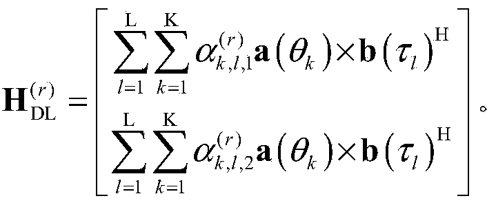 It can be understood that, when any two delay vectors among the L delay vectors correspond to the same K angle vectors, the subscripts k l and l in K l in the above calculation formula may be omitted. That is, respectively as well as
应理解,上文对于2个极化方向定义的空频矩阵
 的计算式仅为示例,不应对本申请构成任何限定。例如,在不同的极化方向上加载的时延向量和/或角度向量的数量可以相同也可以不同,在不同的极化方向上加载是时延向量和/或角度向量可以相同,也可以不同。
It should be understood that the space-frequency matrix defined above for the two polarization directions The calculation formula of is only an example, and should not constitute any limitation to this application. For example, the number of delay vectors and/or angle vectors loaded in different polarization directions may be the same or different, and the delay vectors and/or angle vectors loaded in different polarization directions may be the same or different .
的计算式仅为示例,不应对本申请构成任何限定。例如,在不同的极化方向上加载的时延向量和/或角度向量的数量可以相同也可以不同,在不同的极化方向上加载是时延向量和/或角度向量可以相同,也可以不同。
It should be understood that the space-frequency matrix defined above for the two polarization directions The calculation formula of is only an example, and should not constitute any limitation to this application. For example, the number of delay vectors and/or angle vectors loaded in different polarization directions may be the same or different, and the delay vectors and/or angle vectors loaded in different polarization directions may be the same or different .
对于R个接收天线而言,网络设备可以分别基于每个接收天线对应的P个加权系数确定空频矩阵
 至
至
 由此,网络设备可确定与各RB对应的下行信道矩阵。
For R receiving antennas, the network device may determine the space-frequency matrix based on the P weighting coefficients corresponding to each receiving antenna, respectively to Thus, the network device can determine the downlink channel matrix corresponding to each RB.
由此,网络设备可确定与各RB对应的下行信道矩阵。
For R receiving antennas, the network device may determine the space-frequency matrix based on the P weighting coefficients corresponding to each receiving antenna, respectively to Thus, the network device can determine the downlink channel matrix corresponding to each RB.
以N个RB中的第n个RB为例,网络设备可以确定与第n个RB对应的下行信道矩阵的转置(V
(n))
T。其中,矩阵(V
(n))
T可以是由上述基于R个接收天线分别确定的R个空频矩阵
 至
至
 中每个空频矩阵中的第n个列向量确定。例如,将
 中的第n列作为矩阵(V
(n))
T的第1列,将
中的第n列作为矩阵(V
(n))
T的第1列,将
 中的第n列作为矩阵(V
(n))
T的第2列;以此类推,可以将
中的第n列作为矩阵(V
(n))
T的第2列;以此类推,可以将
 中的第n列作为矩阵(V
(n))
T的第r列。由此可以得到矩阵(V
(n))
T,进而可以确定与第n个RB对应的下行信道矩阵V
(n)。
Taking the nth RB among the N RBs as an example, the network device may determine the transpose (V (n) ) T of the downlink channel matrix corresponding to the nth RB. Wherein, the matrix (V (n) ) T may be R space-frequency matrices respectively determined based on the R receiving antennas to The n-th column vector in each space-frequency matrix in is determined. For example, The nth column in is the first column of the matrix (V (n) ) T , and The nth column in is used as the 2nd column of the matrix (V (n) ) T ; The nth column in is the rth column of the matrix (V (n) ) T. Thus, the matrix (V (n) ) T can be obtained, and further the downlink channel matrix V (n) corresponding to the n-th RB can be determined.
中的第n列作为矩阵(V
(n))
T的第r列。由此可以得到矩阵(V
(n))
T,进而可以确定与第n个RB对应的下行信道矩阵V
(n)。
Taking the nth RB among the N RBs as an example, the network device may determine the transpose (V (n) ) T of the downlink channel matrix corresponding to the nth RB. Wherein, the matrix (V (n) ) T may be R space-frequency matrices respectively determined based on the R receiving antennas to The n-th column vector in each space-frequency matrix in is determined. For example, The nth column in is the first column of the matrix (V (n) ) T , and The nth column in is used as the 2nd column of the matrix (V (n) ) T ; The nth column in is the rth column of the matrix (V (n) ) T. Thus, the matrix (V (n) ) T can be obtained, and further the downlink channel matrix V (n) corresponding to the n-th RB can be determined.
基于上述方法可以确定与各RB分别对应的下行信道矩阵。Based on the above method, a downlink channel matrix corresponding to each RB can be determined.
网络设备可以进一步根据与各RB对应的下行信道矩阵确定各RB的预编码矩阵。例如,网络设备可以通过对下行信道矩阵或信道矩阵的协方差矩阵进行SVD的方式确定预编码矩阵,或者,也可以通过对下行信道矩阵的协方差矩阵进行特征值分解(eigenvalue decomposition,EVD)的方式确定。The network device may further determine the precoding matrix of each RB according to the downlink channel matrix corresponding to each RB. For example, the network device can determine the precoding matrix by performing SVD on the downlink channel matrix or the covariance matrix of the channel matrix, or it can also perform eigenvalue decomposition (EVD) on the covariance matrix of the downlink channel matrix. The way is determined.
应理解,网络设备根据信道矩阵确定预编码矩阵的具体方式可以参考现有技术,本申请对于预编码矩阵的确定方式不作限定。It should be understood that the specific method for the network device to determine the precoding matrix according to the channel matrix may refer to the prior art, and this application does not limit the determination method of the precoding matrix.
还应理解,上文中仅为便于理解,示出了网络设备基于空频矩阵确定下行信道矩阵,进而确定预编码矩阵的具体过程。但这不应对本申请构成任何限定。网络设备也可以根据空频矩阵直接确定预编码矩阵。例如,基于空频矩阵可以确定得到矩阵V
(n),网络设备可以通过对V
(n)进行SVD,然后取右特征向量的方式确定预编码矩阵;又例如,网络设备可以通过直接对(V
(n))
T进行SVD,然后取左特征向量的共轭的方式确定预编码矩阵。
It should also be understood that the foregoing is only for ease of understanding, and shows a specific process in which the network device determines the downlink channel matrix based on the space frequency matrix, and then determines the precoding matrix. However, this should not constitute any limitation on this application. The network device can also directly determine the precoding matrix according to the space frequency matrix. For example, the matrix V (n) can be determined based on the space-frequency matrix, and the network device can determine the precoding matrix by performing SVD on V (n) and then taking the right feature vector; for another example, the network device can directly determine the (V) (n) ) T performs SVD, and then takes the conjugate of the left feature vector to determine the precoding matrix.
若终端设备基于传输层反馈角度向量和加权系数,则该第三指示信息所指示的加权系数可以包括一个或多个传输层的加权系数。网络设备可以基于每个传输层对应的至少一个角度向量和加权系数,确定与传输层对应的空频矩阵,进而确定各RB的预编码矩阵。If the terminal device feeds back the angle vector and the weighting coefficient based on the transmission layer, the weighting coefficient indicated by the third indication information may include one or more weighting coefficients of the transmission layer. The network device may determine the space frequency matrix corresponding to the transmission layer based on at least one angle vector and weighting coefficient corresponding to each transmission layer, and then determine the precoding matrix of each RB.
具体地,由于每个传输层对应的P个加权系数可以分别与P个角度时延对一一对应。网络设备可以基于每个传输层对应的P个加权系数,以及P个角度时延对中与时延向量对应的一个或多个角度向量,构造与传输层对应的空频矩阵。Specifically, since the P weighting coefficients corresponding to each transmission layer can be in one-to-one correspondence with the P angular delays, respectively. The network device may construct a space-frequency matrix corresponding to the transmission layer based on P weighting coefficients corresponding to each transmission layer and one or more angle vectors corresponding to the delay vector in the P angular delay pairs.
在本实施例中,与第z个传输层对应的空频矩阵
 可以通过P个角度时延对和与第z个传输层对应的P个加权系数确定。其中,P个角度时延对可用于构造P个空频分量矩阵。如前所述,由L个时延向量中的第l个时延向量b(τ
l)和K
l个角度向量中的第k
l个角度向量
可以通过P个角度时延对和与第z个传输层对应的P个加权系数确定。其中,P个角度时延对可用于构造P个空频分量矩阵。如前所述,由L个时延向量中的第l个时延向量b(τ
l)和K
l个角度向量中的第k
l个角度向量
 可以构造空频分量矩阵
 与第z个传输层对应的空频矩阵可以是P个空频分量矩阵的加权和。即,
 表示基于第z个传输层反馈的由第l个时延向量及其对应的第k
l个角度向量构成的角度时延对的加权系数。该空频矩阵的维度可以是T×N。
In this embodiment, the space-frequency matrix corresponding to the z-th transmission layer It can be determined by P angular delay pairs and P weighting coefficients corresponding to the z-th transmission layer. Among them, P angular delay pairs can be used to construct P space-frequency component matrices. As mentioned earlier, the lth delay vector b(τ l ) out of the L delay vectors and the k l angle vector out of the K l angle vectors Space frequency component matrix can be constructed The space-frequency matrix corresponding to the z-th transmission layer may be a weighted sum of P space-frequency component matrices. which is, Represents the weighting coefficient of the angle delay pair composed of the lth delay vector and its corresponding klth angle vector based on the zth transmission layer feedback. The dimension of the space frequency matrix may be T×N.
表示基于第z个传输层反馈的由第l个时延向量及其对应的第k
l个角度向量构成的角度时延对的加权系数。该空频矩阵的维度可以是T×N。
In this embodiment, the space-frequency matrix corresponding to the z-th transmission layer It can be determined by P angular delay pairs and P weighting coefficients corresponding to the z-th transmission layer. Among them, P angular delay pairs can be used to construct P space-frequency component matrices. As mentioned earlier, the lth delay vector b(τ l ) out of the L delay vectors and the k l angle vector out of the K l angle vectors Space frequency component matrix can be constructed The space-frequency matrix corresponding to the z-th transmission layer may be a weighted sum of P space-frequency component matrices. which is, Represents the weighting coefficient of the angle delay pair composed of the lth delay vector and its corresponding klth angle vector based on the zth transmission layer feedback. The dimension of the space frequency matrix may be T×N.
需要说明的是,上文为方便理解,以发射天线的一个极化方向为例说明了确定与接收天线对应的空频矩阵的具体过程。但这不应对本申请构成任何限定。当发射天线的极化方向数大于1时,网络设备仍然可以基于如上所述的方法来确定与各接收天线对应的空频矩阵。It should be noted that, for ease of understanding, the specific process of determining the space-frequency matrix corresponding to the receiving antenna is explained by taking a polarization direction of the transmitting antenna as an example. However, this should not constitute any limitation on this application. When the number of polarization directions of the transmitting antenna is greater than 1, the network device can still determine the space-frequency matrix corresponding to each receiving antenna based on the method described above.
例如,极化方向数为2,与第r个接收天线对应的空频矩阵可以通过如下计算式确定:For example, if the number of polarization directions is 2, the space-frequency matrix corresponding to the r-th receiving antenna can be determined by the following calculation formula:

其中,
 表示基于第z个传输层反馈的第一极化方向上由第k个角度向量及其对应的第l
k个时延向量构成的角度时延对的加权系数;
表示基于第z个传输层反馈的第一极化方向上由第k个角度向量及其对应的第l
k个时延向量构成的角度时延对的加权系数;
 表示基于第z个传输层反馈的第二极化方向上与第k个角度向量及其对应的第l
k个时延向量构成的角度时延对的加权系数。
among them, It represents a weighting coefficient based on the angle of the first polarization direction of the z-transport layer composed of a feedback k-vector angles and the corresponding delay of the k-th vector of L delay pair; Represents the weighting coefficient of the angular delay pair formed by the k-th angle vector and its corresponding lk- th delay vector in the second polarization direction based on the z-th transmission layer feedback.
表示基于第z个传输层反馈的第二极化方向上与第k个角度向量及其对应的第l
k个时延向量构成的角度时延对的加权系数。
among them, It represents a weighting coefficient based on the angle of the first polarization direction of the z-transport layer composed of a feedback k-vector angles and the corresponding delay of the k-th vector of L delay pair; Represents the weighting coefficient of the angular delay pair formed by the k-th angle vector and its corresponding lk- th delay vector in the second polarization direction based on the z-th transmission layer feedback.
可以理解的是,当K个角度向量中的任意两个角度向量对应相同的L个时延向量时,上述计算式中的下角标k
l和K
l中的l可以省略。即,分别为
 以及
以及
 It can be understood that when any two of the K angle vectors correspond to the same L delay vectors, the subscripts k l and l in K l in the above calculation formula can be omitted. That is, respectively as well as
应理解,上文对于2个极化方向定义的空频矩阵
 的计算式仅为示例,不应对本申请构成任何限定。例如,在不同的极化方向上加载的时延向量和/或角度向量的数量可以相同也可以不同,在不同的极化方向上加载是时延向量和/或角度向量可以相同,也可以不同。
It should be understood that the space-frequency matrix defined above for the two polarization directions The calculation formula of is only an example, and should not constitute any limitation to this application. For example, the number of delay vectors and/or angle vectors loaded in different polarization directions may be the same or different, and the delay vectors and/or angle vectors loaded in different polarization directions may be the same or different .
的计算式仅为示例,不应对本申请构成任何限定。例如,在不同的极化方向上加载的时延向量和/或角度向量的数量可以相同也可以不同,在不同的极化方向上加载是时延向量和/或角度向量可以相同,也可以不同。
It should be understood that the space-frequency matrix defined above for the two polarization directions The calculation formula of is only an example, and should not constitute any limitation to this application. For example, the number of delay vectors and/or angle vectors loaded in different polarization directions may be the same or different, and the delay vectors and/or angle vectors loaded in different polarization directions may be the same or different .
对于Z个传输层而言,网络设备可以分别基于每个传输层对应的P个加权系数确定与各传输层对应的空频矩阵
 至
至
 由此,网络设备可确定与各RB对应的预编码矩阵W
(n)。
For Z transmission layers, the network device can determine the space-frequency matrix corresponding to each transmission layer based on the P weighting coefficients corresponding to each transmission layer to Thereby, the network device can determine the precoding matrix W (n) corresponding to each RB.
由此,网络设备可确定与各RB对应的预编码矩阵W
(n)。
For Z transmission layers, the network device can determine the space-frequency matrix corresponding to each transmission layer based on the P weighting coefficients corresponding to each transmission layer to Thereby, the network device can determine the precoding matrix W (n) corresponding to each RB.
以N个RB中的第n个RB为例,网络设备可以首先确定与第n个RB对应的预编码矩阵W
(n)的共轭(W
(n))
*。可以是由上述基于Z个传输层分别确定的Z个空频矩阵

 至
至
 中每个空频矩阵中的第n个列向量构建。例如,将
 中的第n列作为下行信道矩阵(W
(n))
*的第一列,将
中的第n列作为下行信道矩阵(W
(n))
*的第一列,将
 中的第n列作为下行信道矩阵(W
(n))
*的第二列;以此类推,可以将
中的第n列作为下行信道矩阵(W
(n))
*的第二列;以此类推,可以将
 中的第n列作为下行信道矩阵(W
(n))
*的第z列。由此可以得到矩阵(W
(n))
*,进而可以确定与第n个RB对应的预编码矩阵W
(n)。
Taking the nth RB of the N RBs as an example, the network device may first determine the conjugate (W (n) ) * of the precoding matrix W (n) corresponding to the nth RB. May be Z space-frequency matrices respectively determined based on the Z transmission layers described above to The n-th column vector in each space-frequency matrix is constructed. For example, The nth column in is the first column of the downlink channel matrix (W (n) ) * , and The nth column in is used as the second column of the downlink channel matrix (W (n) ) * ; by analogy, the The nth column in is the zth column of the downlink channel matrix (W (n) ) * . From this, the matrix (W (n) ) * can be obtained, and further the precoding matrix W (n) corresponding to the n-th RB can be determined.
中的第n列作为下行信道矩阵(W
(n))
*的第z列。由此可以得到矩阵(W
(n))
*,进而可以确定与第n个RB对应的预编码矩阵W
(n)。
Taking the nth RB of the N RBs as an example, the network device may first determine the conjugate (W (n) ) * of the precoding matrix W (n) corresponding to the nth RB. May be Z space-frequency matrices respectively determined based on the Z transmission layers described above to The n-th column vector in each space-frequency matrix is constructed. For example, The nth column in is the first column of the downlink channel matrix (W (n) ) * , and The nth column in is used as the second column of the downlink channel matrix (W (n) ) * ; by analogy, the The nth column in is the zth column of the downlink channel matrix (W (n) ) * . From this, the matrix (W (n) ) * can be obtained, and further the precoding matrix W (n) corresponding to the n-th RB can be determined.
基于上述方法可以确定与各RB分别对应的预编码矩阵。应理解,上文仅为便于理解,以空频分量矩阵为例详细说明了网络设备确定预编码矩阵的具体过程。但这不应对本申请构成任何限定。网络设备也可以基于P个角度时延对确定P个空频分量向量,进而确定预编码矩阵。本领域的技术人员,基于P个角度时延对可以构造不同形式的P个空频基本单位,进而确定预编码矩阵。基于P个角度时延对而构造的不同形式的P个空频基本单位,进而基于P个空频基本单位的加权和来确定预编码矩阵的方式均应落入本申请要求的保护范围内。Based on the above method, the precoding matrix corresponding to each RB can be determined. It should be understood that the above is only for ease of understanding. Taking the space-frequency component matrix as an example, the specific process of determining the precoding matrix by the network device is described in detail. However, this should not constitute any limitation on this application. The network device may also determine P space-frequency component vectors based on P angular delay pairs, and then determine the precoding matrix. A person skilled in the art may construct P basic units of space frequency in different forms based on P angular delay pairs, and then determine a precoding matrix. The P space frequency basic units of different forms constructed based on P angle delay pairs, and the method of determining the precoding matrix based on the weighted sum of the P space frequency basic units should all fall within the protection scope required by the present application.
还应理解,上文仅为示例,示出了网络设备根据第三指示信息确定预编码矩阵的可能实现方式,但这不应对本申请构成任何限定。本申请对于网络设备根据第五指示信息确定预编码矩阵的具体实现方式不作限定。本领域的技术人员基于相同的构思,对上文列举的矩阵运算进行变换或者等价的替换,确定预编码矩阵的方法均应落入本申请的保护范围内。It should also be understood that the above is only an example and shows a possible implementation manner in which the network device determines the precoding matrix according to the third indication information, but this should not constitute any limitation to this application. This application does not limit the specific implementation manner of the network device determining the precoding matrix according to the fifth instruction information. Based on the same concept, those skilled in the art transform or equivalently replace the matrix operations listed above, and the method for determining the precoding matrix should fall within the protection scope of the present application.
还应理解,上文中确定的预编码矩阵是与RB对应的预编码矩阵。这里,RB为频域单元的一例。与RB对应的预编码矩阵,可以是指,以RB为粒度基于该RB对应的信道矩阵确定的预编码矩阵,或者说,基于该RB上接收到的预编码参考信号确定的预编码矩阵,可用于对通过该RB传输的数据做预编码。与RB对应的下行信道,可以是指,基于该RB上接收到的预编码参考信号确定的下行信道,可用于确定与该RB对应的预编码矩阵。It should also be understood that the precoding matrix determined above is a precoding matrix corresponding to RB. Here, RB is an example of a frequency domain unit. The precoding matrix corresponding to the RB may refer to the precoding matrix determined based on the channel matrix corresponding to the RB at the granularity of the RB, or the precoding matrix determined based on the precoding reference signal received on the RB, available Yu pre-codes the data transmitted through the RB. The downlink channel corresponding to the RB may refer to a downlink channel determined based on the precoding reference signal received on the RB, and may be used to determine the precoding matrix corresponding to the RB.
当频域单元的粒度较大,如频域单元为子带、PRG或者PRB时,网络设备可以根据每个频域单元中各RB对应的预编码矩阵确定与频域单元的预编码矩阵。由于上文方法200中已经详细说明了网络设备根据每个频域单元中各RB对应的预编码矩阵确定与频域单元的预编码矩阵的具体方法,为了简洁,这里不再赘述。When the granularity of the frequency domain unit is large, for example, the frequency domain unit is a subband, PRG, or PRB, the network device may determine the precoding matrix corresponding to the frequency domain unit according to the precoding matrix corresponding to each RB in each frequency domain unit. Since the method 200 above has described in detail the specific method by which the network device determines the precoding matrix corresponding to the frequency domain unit according to the precoding matrix corresponding to each RB in each frequency domain unit, for the sake of brevity, no further description is provided here.
还应理解,上文中在描述时提及的与某一角度向量和某一时延向量对应的加权系数,也就是,与某一角度向量和某一时延向量构成的角度时延对对应的加权系数。例如,与第k个角度向量和第l个时延向量对应的加权系数,也就是,与第k个角度向量和第l个时延向量构成的角度时延对对应的加权系数。为了简洁,这里不再一一举例说明。It should also be understood that the weighting coefficients corresponding to a certain angle vector and a certain delay vector mentioned in the description above, that is, the weighting coefficients corresponding to the angle delay pair composed of a certain angle vector and a certain delay vector . For example, the weighting coefficient corresponding to the k-th angle vector and the l-th delay vector, that is, the weighting coefficient corresponding to the angular delay pair composed of the k-th angle vector and the l-th delay vector. For brevity, no more examples are given here.
在本申请实施例中,网络设备基于上行信道测量所确定的时延,对下行参考信号进行预编码,使得终端设备根据预编码后的参考信号进行下行信道测量。由于网络设备基于上下行信道可互易的时延对参考信号进行了预编码,终端设备可以不必反馈空域和频域的向量(如上述发射天线端口和时延向量),仅需反馈与角度时延对对应的加权系数,大大减小了终端设备的反馈开销。此外,通过利用上下行信道的互易性,将终端设备对下行信道的测量过程简化,降低了终端设备在信道测量过程中的计算复杂度。In the embodiment of the present application, the network device pre-codes the downlink reference signal based on the delay determined by the uplink channel measurement, so that the terminal device performs downlink channel measurement according to the pre-coded reference signal. Since the network device precodes the reference signal based on the reciprocal delay of the uplink and downlink channels, the terminal device does not need to feedback the vectors in the spatial and frequency domains (such as the above-mentioned transmit antenna port and delay vector), and only needs to feedback Extending the corresponding weighting coefficients greatly reduces the feedback overhead of the terminal equipment. In addition, by utilizing the reciprocity of the uplink and downlink channels, the measurement process of the downlink channel by the terminal device is simplified, and the calculation complexity of the terminal device during the channel measurement process is reduced.
应理解,本申请实施例中仅为便于理解,示出了空频矩阵由真实的信道的转置得到的情况下,下行信道测量并确定预编码矩阵的具体过程。但这不应对本申请构成任何限定。真实的信道与空频矩阵H
DL的关系并不是固定不变的。对空频矩阵以及空频分量矩阵的不同定义,可能会使得真实的信道与空频矩阵H
DL之间的关系发生变化。例如,空频矩阵H
DL可以由真实的信道的转置得到,也可以由真实的信道的共轭转置得到。
It should be understood that the embodiments of the present application are for ease of understanding only, and show the specific process of measuring and determining the precoding matrix in the downlink channel when the space-frequency matrix is obtained by transposing the real channel. However, this should not constitute any limitation on this application. The relationship between the real channel and the space frequency matrix H DL is not fixed. Different definitions of the space-frequency matrix and the space-frequency component matrix may cause the relationship between the real channel and the space-frequency matrix H DL to change. For example, the space frequency matrix H DL may be obtained by transposing the real channel, or may be obtained by conjugate transposing the real channel.
当对空频矩阵与信道矩阵间的关系的定义不同时,在加载时延和角度时网络设备所执行的操作也有所不同,终端设备在进行信道测量并反馈时所执行的操作也相应地发生变化。但这只是终端设备和网络设备的实现行为,不应对本申请构成任何限定。本申请对于信道矩阵的定义、空频矩阵的维度及其定义以及二者间的转换关系不作限定。同理,本申请对于空频矩阵与预编码矩阵间的转换关系也不作限定。When the definition of the relationship between the space frequency matrix and the channel matrix is different, the operations performed by the network device when loading the delay and angle are also different, and the operations performed by the terminal device when performing channel measurement and feedback also occur accordingly Variety. However, this is only the implementation behavior of the terminal device and the network device, and should not constitute any limitation to this application. This application does not limit the definition of the channel matrix, the dimension and definition of the space-frequency matrix, and the conversion relationship between the two. Similarly, the application does not limit the conversion relationship between the space-frequency matrix and the precoding matrix.
还应理解,上述实施例中,各过程的序号的大小并不意味着执行顺序的先后,各过程的执行顺序应以其功能和内在逻辑确定,而不应对本申请实施例的实施过程构成任何限定。It should also be understood that, in the above embodiments, the size of the sequence number of each process does not mean the order of execution, and the execution order of each process should be determined by its function and inherent logic, and should not constitute any implementation process of the embodiments of the present application. limited.
以上,结合图2至图6详细说明了本申请实施例提供的指示和确定预编码向量的方法。以下,结合图7至图9详细说明本申请实施例提供的通信装置。The instructions and the method for determining the precoding vector provided in the embodiments of the present application have been described in detail above with reference to FIGS. Hereinafter, the communication device provided by the embodiment of the present application will be described in detail with reference to FIGS. 7 to 9.
图7是本申请实施例提供的通信装置的示意性框图。如图所示,该通信装置1000可以包括通信单元1100和处理单元1200。7 is a schematic block diagram of a communication device provided by an embodiment of the present application. As shown, the communication device 1000 may include a communication unit 1100 and a processing unit 1200.
在一种可能的设计中,该通信装置1000可对应于上文方法实施例中的终端设备,例如,可以为终端设备,或者配置于终端设备中的芯片。In a possible design, the communication device 1000 may correspond to the terminal device in the foregoing method embodiment, for example, it may be a terminal device, or a chip configured in the terminal device.
具体地,该通信装置1000可对应于根据本申请实施例的方法200或方法500中的终端设备,该通信装置1000可以包括用于执行图2中的方法200或图5中的方法500中的终端设备执行的方法的单元。并且,该通信装置1000中的各单元和上述其他操作和/或功能分别为了实现图2中的方法200或图5中的方法500的相应流程。Specifically, the communication device 1000 may correspond to the terminal device in the method 200 or the method 500 according to the embodiment of the present application. The communication device 1000 may include the method 200 in FIG. 2 or the method 500 in FIG. 5. The unit of the method performed by the terminal device. In addition, each unit in the communication device 1000 and the other operations and/or functions described above are to implement the corresponding processes of the method 200 in FIG. 2 or the method 500 in FIG. 5, respectively.
其中,当该通信装置1000用于执行图2中的方法200时,通信单元1100可用于执行方法200中的步骤210和步骤230,处理单元1200可用于执行方法200中的步骤220。Wherein, when the communication device 1000 is used to perform the method 200 in FIG. 2, the communication unit 1100 can be used to perform steps 210 and 230 in the method 200, and the processing unit 1200 can be used to perform step 220 in the method 200.
当该通信装置1000用于执行图5中的方法500时,通信单元1100可用于执行方法500中的步骤510和步骤530,处理单元1200可用于执行方法500中的步骤520。When the communication device 1000 is used to perform the method 500 in FIG. 5, the communication unit 1100 may be used to perform steps 510 and 530 in the method 500, and the processing unit 1200 may be used to perform step 520 in the method 500.
应理解,各单元执行上述相应步骤的具体过程在上述方法实施例中已经详细说明,为了简洁,在此不再赘述。It should be understood that the specific process for each unit to execute the above corresponding steps has been described in detail in the above method embodiments, and for the sake of brevity, no further description is provided here.
还应理解,该通信装置1000为终端设备时,该通信装置1000中的通信单元1100可对应于图8中示出的终端设备2000中的收发器2020,该通信装置1000中的处理单元1200可对应于图8中示出的终端设备2000中的处理器2010。It should also be understood that when the communication device 1000 is a terminal device, the communication unit 1100 in the communication device 1000 may correspond to the transceiver 2020 in the terminal device 2000 shown in FIG. 8, and the processing unit 1200 in the communication device 1000 may This corresponds to the processor 2010 in the terminal device 2000 shown in FIG. 8.
还应理解,该通信装置1000为配置于终端设备中的芯片时,该通信装置1000中的通信单元1100可以为输入/输出接口。It should also be understood that when the communication device 1000 is a chip configured in a terminal device, the communication unit 1100 in the communication device 1000 may be an input/output interface.
在另一种可能的设计中,该通信装置1000可对应于上文方法实施例中的网络设备,例如,可以为网络设备,或者配置于网络设备中的芯片。In another possible design, the communication device 1000 may correspond to the network device in the foregoing method embodiment, for example, it may be a network device, or a chip configured in the network device.
具体地,该通信装置1000可对应于根据本申请实施例的方法200或方法500中的网络设备,该通信装置1000可以包括用于执行图2中的方法200或图5中的方法500中的网络设备执行的方法的单元。并且,该通信装置1000中的各单元和上述其他操作和/或功能分别为了实现图2中的方法200或图5中的方法500的相应流程。Specifically, the communication device 1000 may correspond to the network device in the method 200 or the method 500 according to an embodiment of the present application. The communication device 1000 may include the method 200 in FIG. 2 or the method 500 in FIG. 5. A unit of a method performed by a network device. In addition, each unit in the communication device 1000 and the other operations and/or functions described above are to implement the corresponding processes of the method 200 in FIG. 2 or the method 500 in FIG. 5, respectively.
其中,当该通信装置1000用于执行图2中的方法200时,通信单元1100可用于执行方法200中的步骤210和步骤230,处理单元1200可用于执行方法200中的步骤240。Wherein, when the communication device 1000 is used to perform the method 200 in FIG. 2, the communication unit 1100 can be used to perform steps 210 and 230 in the method 200, and the processing unit 1200 can be used to perform step 240 in the method 200.
当该通信装置1000用于执行图5中的方法500时,通信单元1100可用于执行方法500中的步骤510和步骤530,处理单元1200可用于执行方法500中的步骤540。When the communication device 1000 is used to perform the method 500 in FIG. 5, the communication unit 1100 may be used to perform steps 510 and 530 in the method 500, and the processing unit 1200 may be used to perform step 540 in the method 500.
还应理解,该通信装置1000为网络设备时,该通信装置1000中的通信单元为可对应于图9中示出的网络设备3000中的收发器3200,该通信装置1000中的处理单元1200可对应于图9中示出的网络设备3000中的处理器3100。It should also be understood that when the communication device 1000 is a network device, the communication unit in the communication device 1000 may correspond to the transceiver 3200 in the network device 3000 shown in FIG. 9, and the processing unit 1200 in the communication device 1000 may This corresponds to the processor 3100 in the network device 3000 shown in FIG. 9.
还应理解,该通信装置1000为配置于网络设备中的芯片时,该通信装置1000中的通信单元1100可以为输入/输出接口。It should also be understood that when the communication device 1000 is a chip configured in a network device, the communication unit 1100 in the communication device 1000 may be an input/output interface.
图8是本申请实施例提供的终端设备2000的结构示意图。该终端设备2000可应用于如图1所示的系统中,执行上述方法实施例中终端设备的功能。如图所示,该终端设备2000包括处理器2010和收发器2020。可选地,该终端设备2000还包括存储器2030。其中,处理器2010、收发器2002和存储器2030之间可以通过内部连接通路互相通信,传递控制和/或数据信号,该存储器2030用于存储计算机程序,该处理器2010用于从该存储器2030中调用并运行该计算机程序,以控制该收发器2020收发信号。可选地,终端设备2000还可以包括天线2040,用于将收发器2020输出的上行数据或上行控制信令通过无线信号发送出去。FIG. 8 is a schematic structural diagram of a terminal device 2000 provided by an embodiment of the present application. The terminal device 2000 can be applied to the system shown in FIG. 1 to perform the functions of the terminal device in the above method embodiments. As shown, the terminal device 2000 includes a processor 2010 and a transceiver 2020. Optionally, the terminal device 2000 further includes a memory 2030. Among them, the processor 2010, the transceiver 2002 and the memory 2030 can communicate with each other through an internal connection channel to transfer control and/or data signals. The memory 2030 is used to store a computer program, and the processor 2010 is used from the memory 2030 Call and run the computer program to control the transceiver 2020 to send and receive signals. Optionally, the terminal device 2000 may further include an antenna 2040 for sending uplink data or uplink control signaling output by the transceiver 2020 through a wireless signal.
上述处理器2010可以和存储器2030可以合成一个处理装置,处理器2010用于执行存储器2030中存储的程序代码来实现上述功能。具体实现时,该存储器2030也可以集成在处理器2010中,或者独立于处理器2010。该处理器2010可以与图7中的处理单元对应。The processor 2010 and the memory 2030 may be combined into a processing device. The processor 2010 is used to execute the program code stored in the memory 2030 to implement the above-mentioned functions. In specific implementation, the memory 2030 may also be integrated in the processor 2010 or independent of the processor 2010. The processor 2010 may correspond to the processing unit in FIG. 7.
上述收发器2020可以与图7中的通信单元对应,也可以称为收发单元。收发器2020可以包括接收器(或称接收机、接收电路)和发射器(或称发射机、发射电路)。其中,接收器用于接收信号,发射器用于发射信号。The above-mentioned transceiver 2020 may correspond to the communication unit in FIG. 7 and may also be referred to as a transceiver unit. The transceiver 2020 may include a receiver (or receiver, receiving circuit) and a transmitter (or transmitter, transmitting circuit). Among them, the receiver is used to receive signals, and the transmitter is used to transmit signals.
应理解,图8所示的终端设备2000能够实现图2或图5所示方法实施例中涉及终端设备的各个过程。终端设备2000中的各个模块的操作和/或功能,分别为了实现上述方法实施例中的相应流程。具体可参见上述方法实施例中的描述,为避免重复,此处适当省略详细描述。It should be understood that the terminal device 2000 shown in FIG. 8 can implement various processes involving the terminal device in the method embodiment shown in FIG. 2 or FIG. 5. The operations and/or functions of each module in the terminal device 2000 are respectively for implementing the corresponding processes in the above method embodiments. For details, please refer to the description in the above method embodiments. To avoid repetition, the detailed description is appropriately omitted here.
上述处理器2010可以用于执行前面方法实施例中描述的由终端设备内部实现的动作,而收发器2020可以用于执行前面方法实施例中描述的终端设备向网络设备发送或从网络设备接收的动作。具体请见前面方法实施例中的描述,此处不再赘述。The above-mentioned processor 2010 may be used to perform the actions described in the foregoing method embodiments that are internally implemented by the terminal device, and the transceiver 2020 may be used to perform the operations described in the foregoing method embodiments by the terminal device to or from the network device. action. For details, please refer to the description in the foregoing method embodiment, and no more details are provided here.
可选地,上述终端设备2000还可以包括电源2050,用于给终端设备中的各种器件或电路提供电源。Optionally, the terminal device 2000 may further include a power supply 2050, which is used to provide power to various devices or circuits in the terminal device.
除此之外,为了使得终端设备的功能更加完善,该终端设备2000还可以包括输入单元2060、显示单元2070、音频电路2080、摄像头2090和传感器2100等中的一个或多个,所述音频电路还可以包括扬声器2082、麦克风2084等。In addition, in order to make the functions of the terminal device more perfect, the terminal device 2000 may further include one or more of an input unit 2060, a display unit 2070, an audio circuit 2080, a camera 2090, a sensor 2100, etc. The audio circuit It may also include a speaker 2082, a microphone 2084, and so on.
图9是本申请实施例提供的网络设备的结构示意图,例如可以为基站的结构示意图。该基站3000可应用于如图1所示的系统中,执行上述方法实施例中网络设备的功能。如图所示,该基站3000可以包括一个或多个射频单元,如远端射频单元(remote radio unit,RRU)3100和一个或多个基带单元(BBU)(也可称为分布式单元(DU))3200。所述RRU 3100可以称为收发单元,与图7中的通信单元1200对应。可选地,该收发单元3100还可以称为收发机、收发电路、或者收发器等等,其可以包括至少一个天线3101和射频单元3102。可选地,收发单元3100可以包括接收单元和发送单元,接收单元可以对应于接收器(或称接收机、接收电路),发送单元可以对应于发射器(或称发射机、发射电路)。所述RRU 3100部分主要用于射频信号的收发以及射频信号与基带信号的转换,例如用于向终端设备发送指示信息。所述BBU 3200部分主要用于进行基带处理,对基站进行控制等。所述RRU 3100与BBU 3200可以是物理上设置在一起,也可以物理上分离设置的,即分布式基站。9 is a schematic structural diagram of a network device provided by an embodiment of the present application, for example, may be a schematic structural diagram of a base station. The base station 3000 can be applied to the system shown in FIG. 1 to perform the functions of the network device in the above method embodiments. As shown in the figure, the base station 3000 may include one or more radio frequency units, such as a remote radio unit (RRU) 3100 and one or more baseband units (BBU) (also called a distributed unit (DU) )) 3200. The RRU 3100 may be referred to as a transceiver unit, which corresponds to the communication unit 1200 in FIG. 7. Optionally, the transceiver unit 3100 may also be called a transceiver, a transceiver circuit, or a transceiver, etc., which may include at least one antenna 3101 and a radio frequency unit 3102. Optionally, the transceiving unit 3100 may include a receiving unit and a transmitting unit. The receiving unit may correspond to a receiver (or receiver, receiving circuit), and the transmitting unit may correspond to a transmitter (or transmitter, transmitting circuit). The RRU 3100 part is mainly used for the transmission and reception of radio frequency signals and the conversion of radio frequency signals and baseband signals, for example, for sending instruction information to terminal devices. The BBU 3200 part is mainly used for baseband processing and controlling the base station. The RRU 3100 and the BBU 3200 may be physically arranged together, or may be physically separated, that is, distributed base stations.
所述BBU 3200为基站的控制中心,也可以称为处理单元,可以与图7中的处理单元1100对应,主要用于完成基带处理功能,如信道编码,复用,调制,扩频等等。例如所述BBU(处理单元)可以用于控制基站执行上述方法实施例中关于网络设备的操作流程,例如,生成上述指示信息等。The BBU 3200 is the control center of the base station, and may also be referred to as a processing unit, which may correspond to the processing unit 1100 in FIG. 7 and is mainly used to complete baseband processing functions, such as channel coding, multiplexing, modulation, spread spectrum, and so on. For example, the BBU (processing unit) may be used to control the base station to perform the operation flow on the network device in the above method embodiment, for example, to generate the above instruction information.
在一个示例中,所述BBU 3200可以由一个或多个单板构成,多个单板可以共同支持单一接入制式的无线接入网(如LTE网),也可以分别支持不同接入制式的无线接入网(如LTE网,5G网或其他网)。所述BBU 3200还包括存储器3201和处理器3202。所述存储器3201用以存储必要的指令和数据。所述处理器3202用于控制基站进行必要的动作,例如用于控制基站执行上述方法实施例中关于网络设备的操作流程。所述存储器3201和处理器3202可以服务于一个或多个单板。也就是说,可以每个单板上单独设置存储器和处理器。也可以是多个单板共用相同的存储器和处理器。此外每个单板上还可以设置有必要的电路。In an example, the BBU 3200 may be composed of one or more boards, and multiple boards may jointly support a wireless access network (such as an LTE network) of a single access standard, or may support different access standards respectively. Wireless access network (such as LTE network, 5G network or other networks). The BBU 3200 also includes a memory 3201 and a processor 3202. The memory 3201 is used to store necessary instructions and data. The processor 3202 is used to control the base station to perform necessary actions, for example, to control the base station to perform the operation flow of the network device in the foregoing method embodiment. The memory 3201 and the processor 3202 may serve one or more single boards. In other words, the memory and processor can be set separately on each board. It is also possible that multiple boards share the same memory and processor. In addition, each board can also be equipped with necessary circuits.
应理解,图9所示的基站3000能够实现图2或图5的方法实施例中涉及网络设备的各个过程。基站3000中的各个模块的操作和/或功能,分别为了实现上述方法实施例中的相应流程。具体可参见上述方法实施例中的描述,为避免重复,此处适当省略详细描述。It should be understood that the base station 3000 shown in FIG. 9 can implement various processes involving the network device in the method embodiment of FIG. 2 or FIG. 5. The operations and/or functions of each module in the base station 3000 are respectively for implementing the corresponding processes in the above method embodiments. For details, please refer to the description in the above method embodiments. To avoid repetition, the detailed description is appropriately omitted here.
上述BBU 3200可以用于执行前面方法实施例中描述的由网络设备内部实现的动作,而RRU 3100可以用于执行前面方法实施例中描述的网络设备向终端设备发送或从终端设备接收的动作。具体请见前面方法实施例中的描述,此处不再赘述。The above-mentioned BBU 3200 can be used to perform the actions described in the foregoing method embodiments that are internally implemented by the network device, and the RRU 3100 can be used to perform the actions described in the previous method embodiments that the network device sends to or receives from the terminal device. For details, please refer to the description in the foregoing method embodiment, and no more details are provided here.
本申请实施例还提供了一种处理装置,包括处理器和接口;所述处理器用于执行上述 任一方法实施例中的通信的方法。An embodiment of the present application further provides a processing device, including a processor and an interface; the processor is used to execute the communication method in any of the above method embodiments.
应理解,上述处理装置可以是一个芯片。例如,该处理装置可以是现场可编程门阵列(field programmable gate array,FPGA),可以是专用集成芯片(application specific integrated circuit,ASIC),还可以是系统芯片(system on chip,SoC),还可以是中央处理器(central processor unit,CPU),还可以是网络处理器(network processor,NP),还可以是数字信号处理电路(digital signal processor,DSP),还可以是微控制器(micro controller unit,MCU),还可以是可编程控制器(programmable logic device,PLD)或其他集成芯片。It should be understood that the above processing device may be a chip. For example, the processing device may be a field programmable gate array (FPGA), an application specific integrated circuit (ASIC), or a system chip (SoC), or It is a central processor (CPU), it can also be a network processor (NP), it can also be a digital signal processing circuit (digital signal processor, DSP), or a microcontroller (micro controller) , MCU), can also be a programmable controller (programmable logic device, PLD) or other integrated chips.
在实现过程中,上述方法的各步骤可以通过处理器中的硬件的集成逻辑电路或者软件形式的指令完成。结合本申请实施例所公开的方法的步骤可以直接体现为硬件处理器执行完成,或者用处理器中的硬件及软件模块组合执行完成。软件模块可以位于随机存储器,闪存、只读存储器,可编程只读存储器或者电可擦写可编程存储器、寄存器等本领域成熟的存储介质中。该存储介质位于存储器,处理器读取存储器中的信息,结合其硬件完成上述方法的步骤。为避免重复,这里不再详细描述。In the implementation process, each step of the above method may be completed by an integrated logic circuit of hardware in the processor or instructions in the form of software. The steps of the method disclosed in conjunction with the embodiments of the present application may be directly embodied and executed by a hardware processor, or may be executed and completed by a combination of hardware and software modules in the processor. The software module may be located in a mature storage medium in the art, such as random access memory, flash memory, read-only memory, programmable read-only memory, or electrically erasable programmable memory, and registers. The storage medium is located in the memory, and the processor reads the information in the memory and completes the steps of the above method in combination with its hardware. In order to avoid repetition, they are not described in detail here.
应注意,本申请实施例中的处理器可以是一种集成电路芯片,具有信号的处理能力。在实现过程中,上述方法实施例的各步骤可以通过处理器中的硬件的集成逻辑电路或者软件形式的指令完成。上述的处理器可以是通用处理器、数字信号处理器(DSP)、专用集成电路(ASIC)、现场可编程门阵列(FPGA)或者其他可编程逻辑器件、分立门或者晶体管逻辑器件、分立硬件组件。可以实现或者执行本申请实施例中的公开的各方法、步骤及逻辑框图。通用处理器可以是微处理器或者该处理器也可以是任何常规的处理器等。结合本申请实施例所公开的方法的步骤可以直接体现为硬件译码处理器执行完成,或者用译码处理器中的硬件及软件模块组合执行完成。软件模块可以位于随机存储器,闪存、只读存储器,可编程只读存储器或者电可擦写可编程存储器、寄存器等本领域成熟的存储介质中。该存储介质位于存储器,处理器读取存储器中的信息,结合其硬件完成上述方法的步骤。It should be noted that the processor in the embodiment of the present application may be an integrated circuit chip with signal processing capabilities. In the implementation process, each step of the foregoing method embodiment may be completed by an integrated logic circuit of hardware in a processor or instructions in the form of software. The aforementioned processor may be a general-purpose processor, a digital signal processor (DSP), an application specific integrated circuit (ASIC), a field programmable gate array (FPGA) or other programmable logic devices, discrete gates or transistor logic devices, discrete hardware components . The methods, steps, and logical block diagrams disclosed in the embodiments of the present application may be implemented or executed. The general-purpose processor may be a microprocessor or the processor may be any conventional processor or the like. The steps of the method disclosed in conjunction with the embodiments of the present application may be directly embodied and executed by a hardware decoding processor, or may be executed and completed by a combination of hardware and software modules in the decoding processor. The software module may be located in a mature storage medium in the art, such as random access memory, flash memory, read-only memory, programmable read-only memory, or electrically erasable programmable memory, and registers. The storage medium is located in the memory, and the processor reads the information in the memory and completes the steps of the above method in combination with its hardware.
可以理解,本申请实施例中的存储器可以是易失性存储器或非易失性存储器,或可包括易失性和非易失性存储器两者。其中,非易失性存储器可以是只读存储器(read-only memory,ROM)、可编程只读存储器(programmable ROM,PROM)、可擦除可编程只读存储器(erasable PROM,EPROM)、电可擦除可编程只读存储器(electrically EPROM,EEPROM)或闪存。易失性存储器可以是随机存取存储器(random access memory,RAM),其用作外部高速缓存。通过示例性但不是限制性说明,许多形式的RAM可用,例如静态随机存取存储器(static RAM,SRAM)、动态随机存取存储器(dynamic RAM,DRAM)、同步动态随机存取存储器(synchronous DRAM,SDRAM)、双倍数据速率同步动态随机存取存储器(double data rate SDRAM,DDR SDRAM)、增强型同步动态随机存取存储器(enhanced SDRAM,ESDRAM)、同步连接动态随机存取存储器(synchlink DRAM,SLDRAM)和直接内存总线随机存取存储器(direct rambus RAM,DR RAM)。应注意,本文描述的系统和方法的存储器旨在包括但不限于这些和任意其它适合类型的存储器。It can be understood that the memory in the embodiments of the present application may be volatile memory or non-volatile memory, or may include both volatile and non-volatile memory. Among them, the non-volatile memory can be read-only memory (read-only memory, ROM), programmable read-only memory (programmable ROM, PROM), erasable programmable read-only memory (erasable PROM, EPROM), electronically Erase programmable EPROM (EEPROM) or flash memory. The volatile memory may be a random access memory (random access memory, RAM), which is used as an external cache. By way of example but not limitation, many forms of RAM are available, such as static random access memory (static RAM, SRAM), dynamic random access memory (dynamic RAM, DRAM), synchronous dynamic random access memory (synchronous RAM), SDRAM), double data rate synchronous dynamic random access memory (double SDRAM, DDR SDRAM), enhanced synchronous dynamic random access memory (enhanced SDRAM, ESDRAM), synchronous connection dynamic random access memory (synchlink DRAM, SLDRAM) ) And direct memory bus random access memory (direct RAMbus RAM, DR RAM). It should be noted that the memories of the systems and methods described herein are intended to include, but are not limited to these and any other suitable types of memories.
根据本申请实施例提供的方法,本申请还提供一种计算机程序产品,该计算机程序产品包括:计算机程序代码,当该计算机程序代码在计算机上运行时,使得该计算机执行图2和图5所示实施例中任意一个实施例的方法。According to the method provided in the embodiment of the present application, the present application further provides a computer program product, the computer program product includes: computer program code, when the computer program code runs on the computer, the computer is caused to perform the operations shown in FIGS. 2 and 5 The method of any one of the embodiments is shown.
根据本申请实施例提供的方法,本申请还提供一种计算机可读介质,该计算机可读介质存储有程序代码,当该程序代码在计算机上运行时,使得该计算机执行图2和图5所示实施例中任意一个实施例的方法。According to the method provided in the embodiments of the present application, the present application also provides a computer-readable medium, the computer-readable medium stores program code, and when the program code runs on the computer, the computer is caused to execute the operations shown in FIGS. 2 and 5. The method of any one of the embodiments is shown.
根据本申请实施例提供的方法,本申请还提供一种系统,其包括前述的一个或多个终端设备以及一个或多个网络设备。According to the method provided in the embodiments of the present application, the present application further provides a system, which includes the foregoing one or more terminal devices and one or more network devices.
在上述实施例中,可以全部或部分地通过软件、硬件、固件或者其任意组合来实现。当使用软件实现时,可以全部或部分地以计算机程序产品的形式实现。所述计算机程序产品包括一个或多个计算机指令。在计算机上加载和执行所述计算机指令时,全部或部分地产生按照本申请实施例所述的流程或功能。所述计算机可以是通用计算机、专用计算机、计算机网络、或者其他可编程装置。所述计算机指令可以存储在计算机可读存储介质中,或者从一个计算机可读存储介质向另一个计算机可读存储介质传输,例如,所述计算机指令可以从一个网站站点、计算机、服务器或数据中心通过有线(例如同轴电缆、光纤、数字用户线(digital subscriber line,DSL))或无线(例如红外、无线、微波等)方式向另一个网站站点、计算机、服务器或数据中心进行传输。所述计算机可读存储介质可以是计算机能够存取的任何可用介质或者是包含一个或多个可用介质集成的服务器、数据中心等数据存储设备。所述可用介质可以是磁性介质(例如,软盘、硬盘、磁带)、光介质(例如,高密度数字视频光盘(digital video disc,DVD))、或者半导体介质(例如,固态硬盘(solid state disc,SSD))等。In the above embodiments, it can be implemented in whole or in part by software, hardware, firmware, or any combination thereof. When implemented using software, it can be implemented in whole or in part in the form of a computer program product. The computer program product includes one or more computer instructions. When the computer instructions are loaded and executed on the computer, all or part of the processes or functions described in the embodiments of the present application are generated. The computer may be a general-purpose computer, a dedicated computer, a computer network, or other programmable devices. The computer instructions may be stored in a computer-readable storage medium or transmitted from one computer-readable storage medium to another computer-readable storage medium, for example, the computer instructions may be from a website site, computer, server or data center Transmission to another website, computer, server or data center via wired (such as coaxial cable, optical fiber, digital subscriber line (DSL)) or wireless (such as infrared, wireless, microwave, etc.). The computer-readable storage medium may be any available medium that can be accessed by a computer or a data storage device including a server, a data center, and the like integrated with one or more available media. The usable medium may be a magnetic medium (for example, a floppy disk, a hard disk, a magnetic tape), an optical medium (for example, a high-density digital video disc (DVD)), or a semiconductor medium (for example, a solid state disc, SSD)) etc.
上述各个装置实施例中网络设备与终端设备和方法实施例中的网络设备或终端设备完全对应,由相应的模块或单元执行相应的步骤,例如通信单元(收发器)执行方法实施例中接收或发送的步骤,除发送、接收外的其它步骤可以由处理单元(处理器)执行。具体单元的功能可以参考相应的方法实施例。其中,处理器可以为一个或多个。The network device in each of the above device embodiments corresponds exactly to the network device or terminal device in the terminal device and method embodiments, and the corresponding steps are performed by corresponding modules or units, for example, the communication unit (transceiver) performs the receiving or The steps of sending, other than sending and receiving, can be executed by the processing unit (processor). The function of the specific unit can refer to the corresponding method embodiment. There may be one or more processors.
在本说明书中使用的术语“部件”、“模块”、“系统”等用于表示计算机相关的实体、硬件、固件、硬件和软件的组合、软件、或执行中的软件。例如,部件可以是但不限于,在处理器上运行的进程、处理器、对象、可执行文件、执行线程、程序和/或计算机。通过图示,在计算设备上运行的应用和计算设备都可以是部件。一个或多个部件可驻留在进程和/或执行线程中,部件可位于一个计算机上和/或分布在2个或更多个计算机之间。此外,这些部件可从在上面存储有各种数据结构的各种计算机可读介质执行。部件可例如根据具有一个或多个数据分组(例如来自与本地系统、分布式系统和/或网络间的另一部件交互的二个部件的数据,例如通过信号与其它系统交互的互联网)的信号通过本地和/或远程进程来通信。The terms "component", "module", "system", etc. used in this specification are used to denote computer-related entities, hardware, firmware, a combination of hardware and software, software, or software in execution. For example, a component may be, but is not limited to, a process running on a processor, a processor, an object, an executable file, an execution thread, a program, and/or a computer. By way of illustration, both the application running on the computing device and the computing device can be components. One or more components can reside in a process and/or thread of execution, and a component can be localized on one computer and/or distributed between 2 or more computers. In addition, these components can execute from various computer readable media having various data structures stored thereon. The component may, for example, be based on a signal having one or more data packets (for example, data from two components that interact with another component between a local system, a distributed system, and/or a network, such as the Internet that interacts with other systems through signals) Communicate through local and/or remote processes.
本领域普通技术人员可以意识到,结合本文中所公开的实施例描述的各示例的单元及算法步骤,能够以电子硬件、或者计算机软件和电子硬件的结合来实现。这些功能究竟以硬件还是软件方式来执行,取决于技术方案的特定应用和设计约束条件。专业技术人员可以对每个特定的应用来使用不同方法来实现所描述的功能,但是这种实现不应认为超出本申请的范围。Those of ordinary skill in the art may realize that the units and algorithm steps of the examples described in conjunction with the embodiments disclosed herein can be implemented by electronic hardware, or a combination of computer software and electronic hardware. Whether these functions are executed in hardware or software depends on the specific application of the technical solution and design constraints. Professional technicians can use different methods to implement the described functions for each specific application, but such implementation should not be considered beyond the scope of this application.
所属领域的技术人员可以清楚地了解到,为描述的方便和简洁,上述描述的系统、装置和单元的具体工作过程,可以参考前述方法实施例中的对应过程,在此不再赘述。Those skilled in the art can clearly understand that for the convenience and conciseness of the description, the specific working process of the system, device and unit described above can refer to the corresponding process in the foregoing method embodiments, which will not be repeated here.
在本申请所提供的几个实施例中,应该理解到,所揭露的系统、装置和方法,可以 通过其它的方式实现。例如,以上所描述的装置实施例仅仅是示意性的,例如,所述单元的划分,仅仅为一种逻辑功能划分,实际实现时可以有另外的划分方式,例如多个单元或组件可以结合或者可以集成到另一个系统,或一些特征可以忽略,或不执行。另一点,所显示或讨论的相互之间的耦合或直接耦合或通信连接可以是通过一些接口,装置或单元的间接耦合或通信连接,可以是电性,机械或其它的形式。In the several embodiments provided in this application, it should be understood that the disclosed system, device, and method may be implemented in other ways. For example, the device embodiments described above are only schematic. For example, the division of the units is only a logical function division, and there may be other divisions in actual implementation, for example, multiple units or components may be combined or Can be integrated into another system, or some features can be ignored, or not implemented. In addition, the displayed or discussed mutual coupling or direct coupling or communication connection may be indirect coupling or communication connection through some interfaces, devices or units, and may be in electrical, mechanical, or other forms.
所述作为分离部件说明的单元可以是或者也可以不是物理上分开的,作为单元显示的部件可以是或者也可以不是物理单元,即可以位于一个地方,或者也可以分布到多个网络单元上。可以根据实际的需要选择其中的部分或者全部单元来实现本实施例方案的目的。The units described as separate components may or may not be physically separated, and the components displayed as units may or may not be physical units, that is, they may be located in one place, or may be distributed on multiple network units. Some or all of the units may be selected according to actual needs to achieve the purpose of the solution of this embodiment.
另外,在本申请各个实施例中的各功能单元可以集成在一个处理单元中,也可以是各个单元单独物理存在,也可以两个或两个以上单元集成在一个单元中。In addition, each functional unit in each embodiment of the present application may be integrated into one processing unit, or each unit may exist alone physically, or two or more units may be integrated into one unit.
所述功能如果以软件功能单元的形式实现并作为独立的产品销售或使用时,可以存储在一个计算机可读取存储介质中。基于这样的理解,本申请的技术方案本质上或者说对现有技术做出贡献的部分或者该技术方案的部分可以以软件产品的形式体现出来,该计算机软件产品存储在一个存储介质中,包括若干指令用以使得一台计算机设备(可以是个人计算机,服务器,或者网络设备等)执行本申请各个实施例所述方法的全部或部分步骤。而前述的存储介质包括:U盘、移动硬盘、只读存储器(read-only memory,ROM)、随机存取存储器(random access memory,RAM)、磁碟或者光盘等各种可以存储程序代码的介质。If the function is implemented in the form of a software functional unit and sold or used as an independent product, it can be stored in a computer-readable storage medium. Based on such an understanding, the technical solution of the present application essentially or part of the contribution to the existing technology or part of the technical solution can be embodied in the form of a software product, and the computer software product is stored in a storage medium, including Several instructions are used to enable a computer device (which may be a personal computer, server, or network device, etc.) to perform all or part of the steps of the methods described in the embodiments of the present application. The foregoing storage media include: U disk, mobile hard disk, read-only memory (ROM), random access memory (RAM), magnetic disk or optical disk and other media that can store program codes .
以上所述,仅为本申请的具体实施方式,但本申请的保护范围并不局限于此,任何熟悉本技术领域的技术人员在本申请揭露的技术范围内,可轻易想到变化或替换,都应涵盖在本申请的保护范围之内。因此,本申请的保护范围应以所述权利要求的保护范围为准。The above is only the specific implementation of this application, but the scope of protection of this application is not limited to this, any person skilled in the art can easily think of changes or replacements within the technical scope disclosed in this application. It should be covered by the scope of protection of this application. Therefore, the protection scope of the present application shall be subject to the protection scope of the claims.
Claims (64)
- 一种信道测量方法,其特征在于,包括:A channel measurement method, characterized in that it includes:接收预编码参考信号,所述预编码参考信号是基于K个角度向量对参考信号预编码得到;Receiving a precoding reference signal, which is obtained by precoding the reference signal based on K angle vectors;生成第一指示信息,所述第一指示信息用于指示至少一个时延向量以及对应于P个角度时延对的P个加权系数,所述至少一个时延向量和所述P个加权系数由所述预编码参考信号确定;其中,所述P个角度时延对中的每个角度时延对包括所述K个角度向量中的一个角度向量和所述至少一个时延向量中的一个时延向量,所述P个角度时延对及其对应的P个加权系数用于确定预编码矩阵;P和K均为正整数;Generate first indication information, the first indication information is used to indicate at least one delay vector and P weighting coefficients corresponding to P angular delay pairs, the at least one delay vector and the P weighting coefficients are determined by The precoding reference signal is determined; wherein each angular delay pair of the P angular delay pairs includes one of the K angular vectors and one of the at least one delay vector Delay vector, the P angular delay pairs and their corresponding P weighting coefficients are used to determine the precoding matrix; P and K are both positive integers;发送所述第一指示信息。Sending the first indication information.
- 如权利要求1所述的方法,其特征在于,所述至少一个时延向量包括针对所述K个角度向量中的每个角度向量反馈的一个或多个时延向量;其中,针对所述K个角度向量中的第k个角度向量,所述第一指示信息用于指示L k个时延向量,所述第k个角度向量和所述L k个时延向量用于确定所述P个角度时延对中的L k个角度时延对;L k≥1,且L k为整数。 The method of claim 1, wherein the at least one delay vector comprises one or more delay vectors fed back for each of the K angle vectors; wherein, for the K The kth angle vector of the angle vectors, the first indication information is used to indicate L k delay vectors, and the kth angle vector and the L k delay vectors are used to determine the P L k angular delay pairs in the angular delay pair; L k ≥1, and L k is an integer.
- 如权利要求1或2所述的方法,其特征在于,所述方法还包括:The method according to claim 1 or 2, wherein the method further comprises:接收第二指示信息,所述第二指示信息用于指示针对所述K个角度向量中的每个角度向量反馈的时延向量的个数。Receiving second indication information, where the second indication information is used to indicate the number of delay vectors fed back for each of the K angle vectors.
- 如权利要求1或2所述的方法,其特征在于,所述方法还包括:The method according to claim 1 or 2, wherein the method further comprises:发送第二指示信息,所述第二指示信息用于指示针对所述K个角度向量中的每个角度向量反馈的时延向量的个数。Sending second indication information, where the second indication information is used to indicate the number of delay vectors fed back for each of the K angle vectors.
- 如权利要求1或2所述的方法,其特征在于,针对所述K个角度向量中的每个角度向量反馈的时延向量的个数为预定义值。The method according to claim 1 or 2, wherein the number of delay vectors fed back for each of the K angle vectors is a predefined value.
- 如权利要求1至5中任一项所述的方法,其特征在于,针对所述K个角度向量中的第一角度向量反馈的时延向量与第二角度向量反馈的时延向量相同,所述第一角度向量和所述第二角度向量为所述K个角度向量中的任意两个角度向量;所述第一指示信息用于指示L个时延向量;L≥1,且L为整数。The method according to any one of claims 1 to 5, wherein the delay vector fed back to the first angle vector of the K angle vectors is the same as the delay vector fed back to the second angle vector, so The first angle vector and the second angle vector are any two of the K angle vectors; the first indication information is used to indicate L delay vectors; L≥1, and L is an integer .
- 如权利要求1至6中任一项所述的方法,其特征在于,所述P个加权系数包括针对所述K个角度向量中的每个角度向量反馈的一个或多个加权系数;其中,针对所述K个角度向量中的第k个角度向量,所述第一指示信息用于指示L k个加权系数,所述L k个加权系数与所述P个角度时延对中的L k个角度时延对对应,且所述L k个角度时延对中的每个角度时延对包括所述第k个角度向量及其对应的所述L k个时延向量中的一个时延向量;L k≥1,且L k为整数。 The method according to any one of claims 1 to 6, wherein the P weighting coefficients include one or more weighting coefficients fed back for each of the K angle vectors; wherein, for the K vector angle of the k-th vector of angle, the first indication information for indicating the weighting coefficients k L, k L of the weighting coefficients of the P L k delay angle of the Angular delay pairs correspond, and each angular delay pair in the L k angular delay pairs includes the k-th angle vector and one delay in the corresponding L k delay vectors Vector; L k ≥1, and L k is an integer.
- 如权利要求1至7中任一项所述的方法,其特征在于,所述K个角度向量基于上行信道测量确定。The method according to any one of claims 1 to 7, wherein the K angle vectors are determined based on uplink channel measurement.
- 如权利要求1至8中任一项所述的方法,其特征在于,所述P个加权系数对应于一个接收天线或一个传输层。The method according to any one of claims 1 to 8, wherein the P weighting coefficients correspond to a receiving antenna or a transmission layer.
- 一种信道测量方法,其特征在于,包括:A channel measurement method, characterized in that it includes:发送预编码参考信号,所述预编码参考信号是基于K个角度向量对参考信号预编码得到;Sending a precoding reference signal, which is obtained by precoding the reference signal based on K angle vectors;接收第一指示信息,所述第一指示信息用于指示至少一个时延向量以及对应于P个角度时延对的P个加权系数,所述至少一个时延向量和所述P个加权系数由所述预编码参考信号确定;其中,所述P个角度时延对中的每个角度时延对包括所述K个角度向量中的一个角度向量和所述至少一个时延向量中的一个时延向量,所述P个角度时延对及其对应的P个加权系数用于确定预编码矩阵;P和K均为正整数;Receiving first indication information, the first indication information is used to indicate at least one delay vector and P weighting coefficients corresponding to P angular delay pairs, and the at least one delay vector and the P weighting coefficients are determined by The precoding reference signal is determined; wherein each angular delay pair of the P angular delay pairs includes one of the K angular vectors and one of the at least one delay vector Delay vector, the P angular delay pairs and their corresponding P weighting coefficients are used to determine the precoding matrix; P and K are both positive integers;根据所述第一指示信息确定预编码矩阵。The precoding matrix is determined according to the first indication information.
- 如权利要求10所述的方法,其特征在于,所述至少一个时延向量包括针对所述K个角度向量中的每个角度向量反馈的一个或多个时延向量;其中,针对所述K个角度向量中的第k个角度向量,所述第一指示信息用于指示L k个时延向量,所述第k个角度向量和所述L k个时延向量用于确定所述P个角度时延对中的L k个角度时延对;L k≥1,且L k为整数。 The method of claim 10, wherein the at least one delay vector comprises one or more delay vectors fed back for each of the K angle vectors; wherein, for the K The kth angle vector of the angle vectors, the first indication information is used to indicate L k delay vectors, and the kth angle vector and the L k delay vectors are used to determine the P L k angular delay pairs in the angular delay pair; L k ≥1, and L k is an integer.
- 如权利要求10或11所述的方法,其特征在于,所述方法还包括:The method according to claim 10 or 11, further comprising:发送第二指示信息,所述第二指示信息用于指示针对所述K个角度向量中的每个角度向量反馈的时延向量的个数。Sending second indication information, where the second indication information is used to indicate the number of delay vectors fed back for each of the K angle vectors.
- 如权利要求10或11所述的方法,其特征在于,所述方法还包括:The method according to claim 10 or 11, further comprising:接收第二指示信息,所述第二指示信息用于指示针对所述K个角度向量中的每个角度向量反馈的时延向量的个数。Receiving second indication information, where the second indication information is used to indicate the number of delay vectors fed back for each of the K angle vectors.
- 如权利要求10或11所述的方法,其特征在于,针对所述K个角度向量中的每个角度向量反馈的时延向量的个数为预定义值。The method according to claim 10 or 11, wherein the number of delay vectors fed back for each of the K angle vectors is a predefined value.
- 如权利要求10至14中任一项所述的方法,其特征在于,针对所述K个角度向量中的第一角度向量反馈的时延向量与第二角度向量反馈的时延向量相同,所述第一角度向量和所述第二角度向量为所述K个角度向量中的任意两个角度向量;所述第一指示信息用于指示L个时延向量;L≥1,且L为整数。The method according to any one of claims 10 to 14, wherein the delay vector fed back to the first angle vector of the K angle vectors is the same as the delay vector fed back to the second angle vector, so The first angle vector and the second angle vector are any two of the K angle vectors; the first indication information is used to indicate L delay vectors; L≥1, and L is an integer .
- 如权利要求10至15中任一项所述的方法,其特征在于,所述P个加权系数包括针对所述K个角度向量中的每个角度向量反馈的一个或多个加权系数;其中,针对所述K个角度向量中的第k个角度向量,所述第一指示信息用于指示L k个加权系数,所述L k个加权系数与所述P个角度时延对中的L k个角度时延对对应,且所述L k个角度时延对中的每个角度时延对包括所述第k个角度向量及其对应的所述L k个时延向量中的一个时延向量;L k≥1,且L k为整数。 The method according to any one of claims 10 to 15, wherein the P weighting coefficients include one or more weighting coefficients fed back for each of the K angle vectors; wherein, for the K vector angle of the k-th vector of angle, the first indication information for indicating the weighting coefficients k L, k L of the weighting coefficients of the P L k delay angle of the Angular delay pairs correspond, and each angular delay pair in the L k angular delay pairs includes the k-th angle vector and one delay in the corresponding L k delay vectors Vector; L k ≥1, and L k is an integer.
- 如权利要求10至16中任一项所述的方法,其特征在于,所述K个角度向量基于上行信道测量确定。The method according to any one of claims 10 to 16, wherein the K angle vectors are determined based on uplink channel measurement.
- 如权利要求10至17中任一项所述的方法,其特征在于,所述P个加权系数对应于一个接收天线或一个传输层。The method according to any one of claims 10 to 17, wherein the P weighting coefficients correspond to a receiving antenna or a transmission layer.
- 一种通信装置,其特征在于,包括:A communication device, characterized in that it includes:通信单元,用于接收预编码参考信号,所述预编码参考信号是基于K个角度向量对参考信号预编码得到;The communication unit is configured to receive a precoding reference signal, which is obtained by precoding the reference signal based on K angle vectors;处理单元,用于生成第一指示信息,所述第一指示信息用于指示至少一个时延向量以及对应于P个角度时延对的P个加权系数,所述至少一个时延向量和所述P个加权系数由所述预编码参考信号确定;其中,所述P个角度时延对中的每个角度时延对包括所述K个角度向量中的一个角度向量和所述至少一个时延向量中的一个时延向量,所述P个角度时延对及其对应的P个加权系数用于确定预编码矩阵;P和K均为正整数;The processing unit is configured to generate first indication information, the first indication information is used to indicate at least one delay vector and P weighting coefficients corresponding to P angular delay pairs, the at least one delay vector and the P weighting coefficients are determined by the precoding reference signal; wherein each angular delay pair of the P angular delay pairs includes one of the K angular vectors and the at least one delay A delay vector in the vector, the P angular delay pairs and their corresponding P weighting coefficients are used to determine the precoding matrix; P and K are both positive integers;所述通信单元还用于发送所述第一指示信息。The communication unit is also used to send the first indication information.
- 如权利要求19所述的装置,其特征在于,所述至少一个时延向量包括针对所述K个角度向量中的每个角度向量反馈的一个或多个时延向量;其中,针对所述K个角度向量中的第k个角度向量,所述第一指示信息用于指示L k个时延向量,所述第k个角度向量和所述L k个时延向量用于确定所述P个角度时延对中的L k个角度时延对;L k≥1,且L k为整数。 The apparatus according to claim 19, wherein the at least one delay vector includes one or more delay vectors fed back for each of the K angle vectors; wherein, for the K The kth angle vector of the angle vectors, the first indication information is used to indicate L k delay vectors, and the kth angle vector and the L k delay vectors are used to determine the P L k angular delay pairs in the angular delay pair; L k ≥1, and L k is an integer.
- 如权利要求19或20所述的装置,其特征在于,所述通信单元还用于接收第二指示信息,所述第二指示信息用于指示针对所述K个角度向量中的每个角度向量反馈的时延向量的个数。The apparatus according to claim 19 or 20, wherein the communication unit is further configured to receive second indication information, and the second indication information is used to indicate for each of the K angle vectors The number of feedback delay vectors.
- 如权利要求19或20所述的装置,其特征在于,所述通信单元还用于发送第二指示信息,所述第二指示信息用于指示针对所述K个角度向量中的每个角度向量反馈的时延向量的个数。The apparatus according to claim 19 or 20, wherein the communication unit is further configured to send second indication information, and the second indication information is used to indicate for each of the K angle vectors The number of feedback delay vectors.
- 如权利要求19或20所述的装置,其特征在于,针对所述K个角度向量中的每个角度向量反馈的时延向量的个数为预定义值。The apparatus according to claim 19 or 20, wherein the number of delay vectors fed back for each of the K angle vectors is a predefined value.
- 如权利要求19至23中任一项所述的装置,其特征在于,针对所述K个角度向量中的第一角度向量反馈的时延向量与第二角度向量反馈的时延向量相同,所述第一角度向量和所述第二角度向量为所述K个角度向量中的任意两个角度向量;所述第一指示信息用于指示L个时延向量;L≥1,且L为整数。The device according to any one of claims 19 to 23, wherein the delay vector fed back to the first angle vector of the K angle vectors is the same as the delay vector fed back to the second angle vector, so The first angle vector and the second angle vector are any two of the K angle vectors; the first indication information is used to indicate L delay vectors; L≥1, and L is an integer .
- 如权利要求19至24中任一项所述的装置,其特征在于,所述P个加权系数包括针对所述K个角度向量中的每个角度向量反馈的一个或多个加权系数;其中,针对所述K个角度向量中的第k个角度向量,所述第一指示信息用于指示L k个加权系数,所述L k个加权系数与所述P个角度时延对中的L k个角度时延对对应,且所述L k个角度时延对中的每个角度时延对包括所述第k个角度向量及其对应的所述L k个时延向量中的一个时延向量;L k≥1,且L k为整数。 The apparatus according to any one of claims 19 to 24, wherein the P weighting coefficients include one or more weighting coefficients fed back for each of the K angle vectors; wherein, for the K vector angle of the k-th vector of angle, the first indication information for indicating the weighting coefficients k L, k L of the weighting coefficients of the P L k delay angle of the Angular delay pairs correspond, and each angular delay pair in the L k angular delay pairs includes the k-th angle vector and one delay in the corresponding L k delay vectors Vector; L k ≥1, and L k is an integer.
- 如权利要求19至25中任一项所述的装置,其特征在于,所述K个角度向量基于上行信道测量确定。The apparatus according to any one of claims 19 to 25, wherein the K angle vectors are determined based on uplink channel measurement.
- 如权利要求19至26中任一项所述的装置,其特征在于,所述P个加权系数对应于一个接收天线或一个传输层。The apparatus according to any one of claims 19 to 26, wherein the P weighting coefficients correspond to a receiving antenna or a transmission layer.
- 一种通信装置,其特征在于,包括:A communication device, characterized in that it includes:通信单元,用于发送预编码参考信号,所述预编码参考信号是基于K个角度向量对参考信号预编码得到;并用于接收第一指示信息,所述第一指示信息用于指示至少一个时延向量以及对应于P个角度时延对的P个加权系数,所述至少一个时延向量和所述P个加权系数由所述预编码参考信号确定;其中,所述P个角度时延对中的每个角度时延对包括所述K个角度向量中的一个角度向量和所述至少一个时延向量中的一个时延向量,所述P 个角度时延对及其对应的P个加权系数用于确定预编码矩阵;P和K均为正整数;The communication unit is configured to send a precoding reference signal, which is obtained by precoding the reference signal based on K angle vectors; and used to receive first indication information, where the first indication information is used to indicate at least one time Delay vector and P weighting coefficients corresponding to P angular delay pairs, the at least one delay vector and the P weighting coefficients are determined by the precoding reference signal; wherein, the P angular delay pairs Each angular delay pair in includes one of the K angle vectors and one delay vector in the at least one delay vector, the P angular delay pairs and their corresponding P weights The coefficient is used to determine the precoding matrix; P and K are positive integers;处理单元,用于根据所述第一指示信息确定所述预编码矩阵。The processing unit is configured to determine the precoding matrix according to the first indication information.
- 如权利要求28所述的装置,其特征在于,所述至少一个时延向量包括针对所述K个角度向量中的每个角度向量反馈的一个或多个时延向量;其中,针对所述K个角度向量中的第k个角度向量,所述第一指示信息用于指示L k个时延向量,所述第k个角度向量和所述L k个时延向量用于确定所述P个角度时延对中的L k个角度时延对;L k≥1,且L k为整数。 The apparatus of claim 28, wherein the at least one delay vector includes one or more delay vectors fed back for each of the K angle vectors; wherein, for the K The kth angle vector of the angle vectors, the first indication information is used to indicate L k delay vectors, and the kth angle vector and the L k delay vectors are used to determine the P L k angular delay pairs in the angular delay pair; L k ≥1, and L k is an integer.
- 如权利要求28或29所述的装置,其特征在于,所述通信单元还用于接收第二指示信息,所述第二指示信息用于指示针对所述K个角度向量中的每个角度向量反馈的时延向量的个数。The apparatus according to claim 28 or 29, wherein the communication unit is further configured to receive second indication information, and the second indication information is used to indicate an angle vector for each of the K angle vectors The number of feedback delay vectors.
- 如权利要求28或29所述的装置,其特征在于,所述通信单元还用于发送第二指示信息,所述第二指示信息用于指示针对所述K个角度向量中的每个角度向量反馈的时延向量的个数。The apparatus according to claim 28 or 29, wherein the communication unit is further configured to send second indication information, and the second indication information is used to indicate each of the K angle vectors The number of feedback delay vectors.
- 如权利要求28或29所述的装置,其特征在于,针对所述K个角度向量中的每个角度向量反馈的时延向量的个数为预定义值。The apparatus according to claim 28 or 29, wherein the number of delay vectors fed back for each of the K angle vectors is a predefined value.
- 如权利要求28至32中任一项所述的装置,其特征在于,针对所述K个角度向量中的第一角度向量反馈的时延向量与第二角度向量反馈的时延向量相同,所述第一角度向量和所述第二角度向量为所述K个角度向量中的任意两个角度向量;所述第一指示信息用于指示L个时延向量;L≥1,且L为整数。The device according to any one of claims 28 to 32, wherein the delay vector fed back to the first angle vector of the K angle vectors is the same as the delay vector fed back to the second angle vector, so The first angle vector and the second angle vector are any two of the K angle vectors; the first indication information is used to indicate L delay vectors; L≥1, and L is an integer .
- 如权利要求28至33中任一项所述的装置,其特征在于,所述P个加权系数包括针对所述K个角度向量中的每个角度向量反馈的一个或多个加权系数;其中,针对所述K个角度向量中的第k个角度向量,所述第一指示信息用于指示L k个加权系数,所述L k个加权系数与所述P个角度时延对中的L k个角度时延对对应,且所述L k个角度时延对中的每个角度时延对包括所述第k个角度向量及其对应的所述L k个时延向量中的一个时延向量;L k≥1,且L k为整数。 The device according to any one of claims 28 to 33, wherein the P weighting coefficients include one or more weighting coefficients fed back for each of the K angle vectors; wherein, for the K vector angle of the k-th vector of angle, the first indication information for indicating the weighting coefficients k L, k L of the weighting coefficients of the P L k delay angle of the Angular delay pairs correspond, and each angular delay pair in the L k angular delay pairs includes the k-th angle vector and one delay in the corresponding L k delay vectors Vector; L k ≥1, and L k is an integer.
- 如权利要求28至34中任一项所述的装置,其特征在于,所述K个角度向量基于上行信道测量确定。The apparatus according to any one of claims 28 to 34, wherein the K angle vectors are determined based on uplink channel measurement.
- 如权利要求28至35中任一项所述的装置,其特征在于,所述P个加权系数对应于一个接收天线或一个传输层。The apparatus according to any one of claims 28 to 35, wherein the P weighting coefficients correspond to a receiving antenna or a transmission layer.
- 一种通信装置,其特征在于,包括:A communication device, characterized in that it includes:收发器,用于接收预编码参考信号,所述预编码参考信号是基于K个角度向量对参考信号预编码得到;The transceiver is used to receive a precoding reference signal, which is obtained by precoding the reference signal based on K angle vectors;处理器,用于生成第一指示信息,所述第一指示信息用于指示至少一个时延向量以及对应于P个角度时延对的P个加权系数,所述至少一个时延向量和所述P个加权系数由所述预编码参考信号确定;其中,所述P个角度时延对中的每个角度时延对包括所述K个角度向量中的一个角度向量和所述至少一个时延向量中的一个时延向量,所述P个角度时延对及其对应的P个加权系数用于确定预编码矩阵;P和K均为正整数;A processor, configured to generate first indication information, where the first indication information is used to indicate at least one delay vector and P weighting coefficients corresponding to P angular delay pairs, the at least one delay vector and the P weighting coefficients are determined by the precoding reference signal; wherein each angular delay pair of the P angular delay pairs includes one of the K angular vectors and the at least one delay A delay vector in the vector, the P angular delay pairs and their corresponding P weighting coefficients are used to determine the precoding matrix; P and K are both positive integers;所述收发器还用于发送所述第一指示信息。The transceiver is also used to send the first indication information.
- 如权利要求37所述的装置,其特征在于,所述至少一个时延向量包括针对所述 K个角度向量中的每个角度向量反馈的一个或多个时延向量;其中,针对所述K个角度向量中的第k个角度向量,所述第一指示信息用于指示L k个时延向量,所述第k个角度向量和所述L k个时延向量用于确定所述P个角度时延对中的L k个角度时延对;L k≥1,且L k为整数。 The apparatus according to claim 37, wherein the at least one delay vector includes one or more delay vectors fed back for each of the K angle vectors; wherein, for the K The kth angle vector of the angle vectors, the first indication information is used to indicate L k delay vectors, and the kth angle vector and the L k delay vectors are used to determine the P L k angular delay pairs in the angular delay pair; L k ≥1, and L k is an integer.
- 如权利要求37或38所述的装置,其特征在于,所述收发器还用于接收第二指示信息,所述第二指示信息用于指示针对所述K个角度向量中的每个角度向量反馈的时延向量的个数。The apparatus according to claim 37 or 38, wherein the transceiver is further configured to receive second indication information, and the second indication information is used to indicate for each of the K angle vectors The number of feedback delay vectors.
- 如权利要求37或38所述的装置,其特征在于,所述收发器还用于发送第二指示信息,所述第二指示信息用于指示针对所述K个角度向量中的每个角度向量反馈的时延向量的个数。The apparatus according to claim 37 or 38, wherein the transceiver is further configured to send second indication information, and the second indication information is used to indicate each of the K angle vectors The number of feedback delay vectors.
- 如权利要求37或38所述的装置,其特征在于,针对所述K个角度向量中的每个角度向量反馈的时延向量的个数为预定义值。The apparatus according to claim 37 or 38, wherein the number of delay vectors fed back for each of the K angle vectors is a predefined value.
- 如权利要求37至41中任一项所述的装置,其特征在于,针对所述K个角度向量中的第一角度向量反馈的时延向量与第二角度向量反馈的时延向量相同,所述第一角度向量和所述第二角度向量为所述K个角度向量中的任意两个角度向量;所述第一指示信息用于指示L个时延向量;L≥1,且L为整数。The device according to any one of claims 37 to 41, wherein the time delay vector fed back to the first angle vector and the time delay vector fed back to the second angle vector among the K angle vectors are the same, so The first angle vector and the second angle vector are any two of the K angle vectors; the first indication information is used to indicate L delay vectors; L≥1, and L is an integer .
- 如权利要求37至42中任一项所述的装置,其特征在于,所述P个加权系数包括针对所述K个角度向量中的每个角度向量反馈的一个或多个加权系数;其中,针对所述K个角度向量中的第k个角度向量,所述第一指示信息用于指示L k个加权系数,所述L k个加权系数与所述P个角度时延对中的L k个角度时延对对应,且所述L k个角度时延对中的每个角度时延对包括所述第k个角度向量及其对应的所述L k个时延向量中的一个时延向量;L k≥1,且L k为整数。 The device according to any one of claims 37 to 42, wherein the P weighting coefficients include one or more weighting coefficients fed back for each of the K angle vectors; wherein, for the K vector angle of the k-th vector of angle, the first indication information for indicating the weighting coefficients k L, k L of the weighting coefficients of the P L k delay angle of the Angular delay pairs correspond, and each angular delay pair in the L k angular delay pairs includes the k-th angle vector and one delay in the corresponding L k delay vectors Vector; L k ≥1, and L k is an integer.
- 如权利要求37至43中任一项所述的装置,其特征在于,所述K个角度向量基于上行信道测量确定。The apparatus according to any one of claims 37 to 43, wherein the K angle vectors are determined based on uplink channel measurement.
- 如权利要求37至44中任一项所述的装置,其特征在于,所述P个加权系数对应于一个接收天线或一个传输层。The apparatus according to any one of claims 37 to 44, wherein the P weighting coefficients correspond to a receiving antenna or a transmission layer.
- 一种通信装置,其特征在于,包括:A communication device, characterized in that it includes:收发器,用于发送预编码参考信号,所述预编码参考信号是基于K个角度向量对参考信号预编码得到;并用于接收第一指示信息,所述第一指示信息用于指示至少一个时延向量以及对应于P个角度时延对的P个加权系数,所述至少一个时延向量和所述P个加权系数由所述预编码参考信号确定;其中,所述P个角度时延对中的每个角度时延对包括所述K个角度向量中的一个角度向量和所述至少一个时延向量中的一个时延向量,所述P个角度时延对及其对应的P个加权系数用于确定预编码矩阵;P和K均为正整数;The transceiver is used to send a precoding reference signal, the precoding reference signal is obtained by precoding the reference signal based on K angle vectors; and used to receive first indication information, the first indication information is used to indicate at least one time Delay vector and P weighting coefficients corresponding to P angular delay pairs, the at least one delay vector and the P weighting coefficients are determined by the precoding reference signal; wherein, the P angular delay pairs Each angle delay pair in includes one of the K angle vectors and one delay vector in the at least one delay vector, the P angle delay pairs and their corresponding P weights The coefficient is used to determine the precoding matrix; P and K are positive integers;处理器,用于根据所述第一指示信息确定所述预编码矩阵。The processor is configured to determine the precoding matrix according to the first indication information.
- 如权利要求46所述的装置,其特征在于,所述至少一个时延向量包括针对所述K个角度向量中的每个角度向量反馈的一个或多个时延向量;其中,针对所述K个角度向量中的第k个角度向量,所述第一指示信息用于指示L k个时延向量,所述第k个角度向量和所述L k个时延向量用于确定所述P个角度时延对中的L k个角度时延对;L k≥1,且L k为整数。 The apparatus according to claim 46, wherein the at least one delay vector comprises one or more delay vectors fed back for each of the K angle vectors; wherein, for the K The kth angle vector of the angle vectors, the first indication information is used to indicate L k delay vectors, and the kth angle vector and the L k delay vectors are used to determine the P L k angular delay pairs in the angular delay pair; L k ≥1, and L k is an integer.
- 如权利要求46或47所述的装置,其特征在于,所述收发器还用于接收第二指示信息,所述第二指示信息用于指示针对所述K个角度向量中的每个角度向量反馈的时延向量的个数。The apparatus according to claim 46 or 47, wherein the transceiver is further configured to receive second indication information, and the second indication information is used to indicate for each of the K angle vectors The number of feedback delay vectors.
- 如权利要求46或47所述的装置,其特征在于,所述收发器还用于发送第二指示信息,所述第二指示信息用于指示针对所述K个角度向量中的每个角度向量反馈的时延向量的个数。The apparatus according to claim 46 or 47, wherein the transceiver is further configured to send second indication information, and the second indication information is used to indicate each of the K angle vectors The number of feedback delay vectors.
- 如权利要求46或47所述的装置,其特征在于,针对所述K个角度向量中的每个角度向量反馈的时延向量的个数为预定义值。The apparatus according to claim 46 or 47, wherein the number of delay vectors fed back for each of the K angle vectors is a predefined value.
- 如权利要求46至50中任一项所述的装置,其特征在于,针对所述K个角度向量中的第一角度向量反馈的时延向量与第二角度向量反馈的时延向量相同,所述第一角度向量和所述第二角度向量为所述K个角度向量中的任意两个角度向量;所述第一指示信息用于指示L个时延向量;L≥1,且L为整数。The device according to any one of claims 46 to 50, wherein the delay vector fed back to the first angle vector of the K angle vectors is the same as the delay vector fed back to the second angle vector, so The first angle vector and the second angle vector are any two of the K angle vectors; the first indication information is used to indicate L delay vectors; L≥1, and L is an integer .
- 如权利要求46至51中任一项所述的装置,其特征在于,所述P个加权系数包括针对所述K个角度向量中的每个角度向量反馈的一个或多个加权系数;其中,针对所述K个角度向量中的第k个角度向量,所述第一指示信息用于指示L k个加权系数,所述L k个加权系数与所述P个角度时延对中的L k个角度时延对对应,且所述L k个角度时延对中的每个角度时延对包括所述第k个角度向量及其对应的所述L k个时延向量中的一个时延向量;L k≥1,且L k为整数。 The device according to any one of claims 46 to 51, wherein the P weighting coefficients include one or more weighting coefficients fed back for each of the K angle vectors; wherein, for the K vector angle of the k-th vector of angle, the first indication information for indicating the weighting coefficients k L, k L of the weighting coefficients of the P L k delay angle of the Angular delay pairs correspond, and each angular delay pair in the L k angular delay pairs includes the k-th angle vector and one delay in the corresponding L k delay vectors Vector; L k ≥1, and L k is an integer.
- 如权利要求46至52中任一项所述的装置,其特征在于,所述K个角度向量基于上行信道测量确定。The apparatus according to any one of claims 46 to 52, wherein the K angle vectors are determined based on uplink channel measurement.
- 如权利要求46至53中任一项所述的装置,其特征在于,所述P个加权系数对应于一个接收天线或一个传输层。The apparatus according to any one of claims 46 to 53, wherein the P weighting coefficients correspond to a receiving antenna or a transmission layer.
- 一种通信装置,其特征在于,所述装置用于实现如权利要求1至9中任一项所述的方法。A communication device, characterized in that the device is used to implement the method according to any one of claims 1 to 9.
- 一种通信装置,其特征在于,所述装置用于实现如权利要求10至18中任一项所述的方法。A communication device, characterized in that the device is used to implement the method according to any one of claims 10 to 18.
- 一种通信装置,其特征在于,包括处理器,所述处理器用于执行存储器中存储的计算机程序,以使得所述装置实现如权利要求1至9中任一项所述的方法。A communication device, characterized by comprising a processor for executing a computer program stored in a memory, so that the device implements the method according to any one of claims 1 to 9.
- 一种通信装置,其特征在于,包括处理器,所述处理器用于执行存储器中存储的计算机程序,以使得所述装置实现如权利要求10至18中任一项所述的方法。A communication device, characterized by comprising a processor for executing a computer program stored in a memory, so that the device implements the method according to any one of claims 10 to 18.
- 一种处理装置,其特征在于,包括:A processing device, characterized in that it includes:存储器,用于存储计算机程序;Memory, used to store computer programs;处理器,用于从所述存储器调用并运行所述计算机程序,以使得所述装置实现如权利要求1至9中任一项所述的方法。A processor for calling and running the computer program from the memory to cause the device to implement the method according to any one of claims 1 to 9.
- 一种处理装置,其特征在于,包括:A processing device, characterized in that it includes:存储器,用于存储计算机程序;Memory, used to store computer programs;处理器,用于从所述存储器调用并运行所述计算机程序,以使得所述装置实现如权利要求10至18中任一项所述的方法。A processor for calling and running the computer program from the memory to cause the device to implement the method according to any one of claims 10 to 18.
- 一种计算机可读介质,其特征在于,包括计算机程序,当所述计算机程序在计算 机上运行时,使得所述计算机执行如权利要求1至9中任一项所述的方法。A computer-readable medium, characterized by comprising a computer program, which when run on a computer, causes the computer to execute the method according to any one of claims 1 to 9.
- 一种计算机可读介质,其特征在于,包括计算机程序,当所述计算机程序在计算机上运行时,使得所述计算机执行如权利要求10至18中任一项所述的方法。A computer-readable medium, characterized by comprising a computer program, which when run on a computer, causes the computer to execute the method according to any one of claims 10 to 18.
- 一种计算机程序产品,所述计算机程序产品包括计算机程序,当所述计算机程序在计算机上运行时,使得计算机执行如权利要求1至9中任一项所述的方法。A computer program product, the computer program product includes a computer program, and when the computer program runs on a computer, causes the computer to perform the method according to any one of claims 1 to 9.
- 一种计算机程序产品,所述计算机程序产品包括计算机程序,当所述计算机程序在计算机上运行时,使得计算机执行如权利要求10至18中任一项所述的方法。A computer program product, the computer program product includes a computer program, and when the computer program runs on a computer, causes the computer to perform the method according to any one of claims 10 to 18.
Priority Applications (2)
| Application Number | Priority Date | Filing Date | Title |
|---|---|---|---|
| EP19900807.9A EP3886335A4 (en) | 2018-12-18 | 2019-12-12 | Channel measurement method and communication apparatus |
| US17/347,850 US11411623B2 (en) | 2018-12-18 | 2021-06-15 | Channel measurement method and communications apparatus |
Applications Claiming Priority (2)
| Application Number | Priority Date | Filing Date | Title |
|---|---|---|---|
| CN201811550128.X | 2018-12-18 | ||
| CN201811550128.XA CN111342873B (en) | 2018-12-18 | 2018-12-18 | Channel measurement method and communication device |
Related Child Applications (1)
| Application Number | Title | Priority Date | Filing Date |
|---|---|---|---|
| US17/347,850 Continuation US11411623B2 (en) | 2018-12-18 | 2021-06-15 | Channel measurement method and communications apparatus |
Publications (1)
| Publication Number | Publication Date |
|---|---|
| WO2020125534A1 true WO2020125534A1 (en) | 2020-06-25 |
Family
ID=71101060
Family Applications (1)
| Application Number | Title | Priority Date | Filing Date |
|---|---|---|---|
| PCT/CN2019/124792 WO2020125534A1 (en) | 2018-12-18 | 2019-12-12 | Channel measurement method and communication apparatus |
Country Status (4)
| Country | Link |
|---|---|
| US (1) | US11411623B2 (en) |
| EP (1) | EP3886335A4 (en) |
| CN (1) | CN111342873B (en) |
| WO (1) | WO2020125534A1 (en) |
Cited By (1)
| Publication number | Priority date | Publication date | Assignee | Title |
|---|---|---|---|---|
| WO2022188636A1 (en) * | 2021-03-10 | 2022-09-15 | 华为技术有限公司 | Method and apparatus for determining channel quality indicator |
Families Citing this family (9)
| Publication number | Priority date | Publication date | Assignee | Title |
|---|---|---|---|---|
| CN112054824B (en) | 2019-06-06 | 2021-07-16 | 华为技术有限公司 | Channel measurement method and communication device |
| CN113992309A (en) * | 2020-07-27 | 2022-01-28 | 华为技术有限公司 | Method and device for acquiring channel parameters |
| CN115244864A (en) * | 2020-07-31 | 2022-10-25 | 华为技术有限公司 | Precoding method and device |
| CN114204970A (en) * | 2020-09-02 | 2022-03-18 | 华为技术有限公司 | Method and device for channel measurement |
| CN116235415A (en) * | 2020-09-30 | 2023-06-06 | 华为技术有限公司 | Signal transmission method and related device |
| US11799710B2 (en) * | 2020-12-10 | 2023-10-24 | Qualcomm Incorporated | Techniques for signaling a source of dominant noise at a user equipment |
| JP2024504953A (en) * | 2021-01-17 | 2024-02-02 | 華為技術有限公司 | Channel information acquisition method and related devices |
| CN116455534A (en) * | 2022-01-06 | 2023-07-18 | 维沃移动通信有限公司 | Channel measurement method, terminal and network side equipment |
| WO2023184326A1 (en) * | 2022-03-31 | 2023-10-05 | Qualcomm Incorporated | Resource grouping information indication for time-domain channel reporting and resource selection |
Citations (2)
| Publication number | Priority date | Publication date | Assignee | Title |
|---|---|---|---|---|
| US20170302353A1 (en) * | 2016-04-19 | 2017-10-19 | Samsung Electronics Co., Ltd | Method and apparatus for explicit csi reporting in advanced wireless communication systems |
| CN108418612A (en) * | 2017-04-26 | 2018-08-17 | 华为技术有限公司 | A kind of method and apparatus of instruction and determining precoding vector |
Family Cites Families (8)
| Publication number | Priority date | Publication date | Assignee | Title |
|---|---|---|---|---|
| US8942302B2 (en) * | 2012-12-20 | 2015-01-27 | Google Technology Holdings LLC | Method and apparatus for antenna array channel feedback |
| KR101978776B1 (en) * | 2013-02-28 | 2019-05-16 | 삼성전자주식회사 | Method and apparatus for transmitting and receivintg feedback information in mobile communication system based on full dimension mimo |
| RU2677646C1 (en) * | 2015-05-22 | 2019-01-18 | Фудзицу Лимитед | Method and device for configuring resource of support signal and communication system |
| CN109450505B (en) * | 2016-05-13 | 2019-11-15 | 华为技术有限公司 | A kind of channel information sending method, data transmission method for uplink and equipment |
| CN107733603B (en) * | 2016-08-12 | 2022-03-01 | 中兴通讯股份有限公司 | Pilot frequency sending method and device |
| CN107733485B (en) * | 2016-08-12 | 2021-09-03 | 中兴通讯股份有限公司 | Feedback method and device of channel state information |
| CN108631891B (en) * | 2017-03-24 | 2022-06-17 | 中兴通讯股份有限公司 | Method and device for measuring link between communication nodes |
| CN110035450B (en) * | 2018-01-12 | 2020-06-23 | 维沃移动通信有限公司 | Measurement reporting method, terminal equipment and network equipment |
-
2018
- 2018-12-18 CN CN201811550128.XA patent/CN111342873B/en active Active
-
2019
- 2019-12-12 WO PCT/CN2019/124792 patent/WO2020125534A1/en unknown
- 2019-12-12 EP EP19900807.9A patent/EP3886335A4/en active Pending
-
2021
- 2021-06-15 US US17/347,850 patent/US11411623B2/en active Active
Patent Citations (2)
| Publication number | Priority date | Publication date | Assignee | Title |
|---|---|---|---|---|
| US20170302353A1 (en) * | 2016-04-19 | 2017-10-19 | Samsung Electronics Co., Ltd | Method and apparatus for explicit csi reporting in advanced wireless communication systems |
| CN108418612A (en) * | 2017-04-26 | 2018-08-17 | 华为技术有限公司 | A kind of method and apparatus of instruction and determining precoding vector |
Non-Patent Citations (3)
| Title |
|---|
| HUAWEI ET AL.: "Discussion on CSI enhancement", 3GPP TSG RAN WG1 MEETING #95 R1-1812242, 16 November 2018 (2018-11-16), XP051478408, DOI: 20200301234031X * |
| INTEL CORPORATION: "Discussion on Type II CSI compression", 3GPP TSG RAN WG1 #95 R1-1812511, 16 November 2018 (2018-11-16), XP051478740, DOI: 20200301234237X * |
| See also references of EP3886335A4 |
Cited By (1)
| Publication number | Priority date | Publication date | Assignee | Title |
|---|---|---|---|---|
| WO2022188636A1 (en) * | 2021-03-10 | 2022-09-15 | 华为技术有限公司 | Method and apparatus for determining channel quality indicator |
Also Published As
| Publication number | Publication date |
|---|---|
| EP3886335A1 (en) | 2021-09-29 |
| CN111342873A (en) | 2020-06-26 |
| EP3886335A4 (en) | 2022-01-05 |
| US11411623B2 (en) | 2022-08-09 |
| US20210314034A1 (en) | 2021-10-07 |
| CN111342873B (en) | 2021-11-30 |
Similar Documents
| Publication | Publication Date | Title |
|---|---|---|
| WO2020125510A1 (en) | Channel measurement method and communication device | |
| WO2020125534A1 (en) | Channel measurement method and communication apparatus | |
| WO2020125511A1 (en) | Channel measurement method, and communications device | |
| JP7238167B2 (en) | Precoding matrix display and determination method, and communication device | |
| WO2020143577A1 (en) | Parameter configuration method and communication apparatus | |
| WO2020083057A1 (en) | Method for indicating and determining pre-coding vector, and communication apparatus | |
| WO2020143580A1 (en) | Vector indication method for constructing precoding vector, and communication apparatus | |
| US11943014B2 (en) | Channel measurement method and communications apparatus | |
| CN111757382A (en) | Method for indicating channel state information and communication device | |
| WO2020211681A1 (en) | Channel measurement method and communication apparatus | |
| WO2020221117A1 (en) | Coefficient indication method for constructing precoding matrix, and communication apparatus | |
| WO2020143461A1 (en) | Method for indicating and determining pre-coding vector, and communication apparatus | |
| WO2021081847A1 (en) | Channel measurement method and communication apparatus |
Legal Events
| Date | Code | Title | Description |
|---|---|---|---|
| 121 | Ep: the epo has been informed by wipo that ep was designated in this application |
Ref document number: 19900807 Country of ref document: EP Kind code of ref document: A1 |
|
| NENP | Non-entry into the national phase |
Ref country code: DE |
|
| ENP | Entry into the national phase |
Ref document number: 2019900807 Country of ref document: EP Effective date: 20210621 |